EMIRATE OF ABU DHABI WORK ZONE TRAFFIC MANAGEMENT MANUAL 2014 (TR - 531)

Welcome message from author
This document is posted to help you gain knowledge. Please leave a comment to let me know what you think about it! Share it to your friends and learn new things together.
Transcript
EMIRATE OF ABU DHABI WORK ZONE TRAFFICMANAGEMENT MANUAL 2014
(TR - 531)
1 | 8
مقي
S.# Table of Contents Pages
1 Amendment Page 2
2 About the Abu Dhabi Quality and Conformity Council 3
3 Acknowledgement 4
4 Foreword 5
5 Working group 5
6 Purpose 5
7 Scope 5
8 Terms and definitions 6
9 General Requirements 7
10 References 8
11 Appendix (EMIRATE OF ABU DHABI WORK ZONE TRAFFIC MANAGEMENT MANUAL2020)
8
2 | 8 P a g e s DOC-ST-ADG-E-009
Classification: Restricted - مقيدة
1. Amendment Page
To ensure that each copy of this ADG contains a complete record of amendments, the Amendment
Page is updated and issued with each set of revised/new pages of the document. This ADG is a live
document which can be amended when necessary. QCC operates (project name) Group which
prepared this document and can review stakeholder comments in order to review and amend this
document and issue an updated version when necessary.
Edition Number
Year of Approval
Number of pages
Sections Changes Notes
2014 New
2019
2020
2020
Third
Third
Third
Third
2020
2020
First
Second
Section 1- Introduction
Glossary
CITED REFERENCES
Appendices B & C
4
2
2
1
Pages 217 & 218
Full replacement of 4 pages
New appendices, pages 215 & 216
Page 219
-

3 | 8 P a g e s DOC-ST-ADG-E-009
Classification: Restricted - مقيدة
2. About the Abu Dhabi Quality and Conformity Council
Abu Dhabi Quality and Conformity Council (QCC) is an Abu Dhabi government
entity established in accordance with Local Law No. (3) of 2009 to raise the
quality of Abu Dhabi’s exports and products traded locally. QCC consists of a
council of regulators and industry with a mandate to ensure provision of
quality infrastructure in line with global standards.
o QCC’s functions are divided into six key areas:
• Developing standards and specifications
• Capacity building of metrology systems
• Strengthening testing infrastructure
• Launching conformity schemes
• Protecting consumer interests
• Ensuring fair trade
o QCC’s key stakeholders include regulatory authorities, consumers,
retailers and wholesalers, industry, conformity assessment bodies (CABs)
and importers.
QCC supports regulators and government organizations through offering
quality and conformity facilities, expertise and resources that allow them to
implement products safety and compliance requirements and regulations.
Additionally, QCC works towards promoting a culture of quality and protecting
the interests of consumers. In doing this, QCC seeks to promote the Emirate’s
competitiveness to become one of the world's most attractive regions for
investments and human capital, and to support the competitiveness of
national industries in world markets.
4 | 8 P a g e s DOC-ST-ADG-E-009
Classification: Restricted - مقيدة
3. Acknowledgement
QCC would like to thank the members of the Working Group listed below.
S.# Name Entity
1 Engineer Manea Salem Al Sayari
Integrated Transport Centre
2 Engineer Ahmed Mohamed Hasan Alzarooni
Integrated Transport Centre
3 Engineer Abdul Rahman Al Shamsi
Abu Dhabi Police
4 Engineer Mohamed Nour Khairy
Integrated Transport Centre
5 Engineer Zahra Ali Alraeesi
Abu Dhabi Municipality
6 Expert Arshad Hussain Khan
Abu Dhabi Municipality
7 Engineer Fatima Salem Ali Al Jabiri
Al Ain Municipality
8 Engineer Ahmed Mohamed Almansoori
Al Dhafra Municipality
9 Engineer Saravanan paramasivam
Integrated Transport Centre
10 Abdul Razzak Zaytoun
Integrated Transport Centre

5 | 8 P a g e s DOC-ST-ADG-E-009
Classification: Restricted - مقيدة
4. Foreword
5. Working Group
6. Purpose
7. Scope

6 | 8 P a g e s DOC-ST-ADG-E-009
Classification: Restricted - مقيدة
8. Terms and definitions
Term Definition
8.1 NA Not applicable
8.2
8.3
8.4
8.5
8.6
8.7
8.8

7 | 8 P a g e s DOC-ST-ADG-E-009
Classification: Restricted - مقيدة
9. General Requirements
Term Definition
NA Not applicable
8 | 8 P a g e s DOC-ST-ADG-E-009
Classification: Restricted - مقيدة
10. References
11. Appendix
EMIRATE OF ABU DHABI WORK ZONE TRAFFIC MANAGEMENT MANUAL 2020
EMIRATE OF ABU DHABI WORK ZONE TRAFFIC MANAGEMENT MANUAL-
PRINCIPLES AND PRACTICE
Draft Document rev5 Page i February 2014
EMIRATE OF ABU DHABI WORK
ZONE MANUAL
DRAFT DOCUMENT
2014
EMIRATE OF ABU DH
ABI WORK ZONE - TRAFFIC M
ANAGEMENT M
ANUAL, 2014
EMIRATE OF ABU DHABI WORK ZONETRAFFIC MANAGEMENT MANUAL
2014
QCC-V1
Copy

QCC-V1
Copy
EMIRATE OF ABU DHABI WORK ZONETRAFFIC MANAGEMENT MANUAL
PRINCIPLES AND PRACTICE
2014
EMIRATE OF ABU DHABI WORK ZONETRAFFIC MANAGEMENT MANUAL
PRINCIPLES AND PRACTICE
2014
© Copyright 2014, by safety and traffic solutions committee - Abu DhabiThis document, or parts thereof, may not be reproduced in any form without written permission of the publisher.
EMIRATE OF ABU DHABI WORK ZONE
TRAFFIC MANAGEMENT MANUAL
2014QCC-V1
Copy
EMIRATE OF ABU DHABI WORK ZONETRAFFIC MANAGEMENT MANUAL
PRINCIPLES AND PRACTICE
DoT:
Eng. John Aldridge
Eng. Mohamed Nour Khairy
Eng. Mudar Tayem
Eng. Osama F Ali Al Kurdi
Eng. Saravanan Paramasivam
Abu Dhabi Municipality:
Dr.Jamal El Zarif
Eng.Rauf Iqbal
Eng. Mohammed Al Shateri
Eng.Ali Farhan
Eng.Harris Margaritidis
Eng.Hazem Qawasmeh
Eng.Khalid Mahmoud
Al Ain Municipality:
Eng. David George
Western Region Municipality
Eng. Mohamed A. Abdelsalam
Abu Dhabi Police
Eng. Abdullrazaq Zaytoun
Dr. Jamal Gibril
Eng. Abdulrahman Al Shamsi
Issue 1 Page ii February 2014
EMIRATE OF ABU DHABI WORK ZONETRAFFIC MANAGEMENT MANUAL
PRINCIPLES AND PRACTICE
TABLE OF CONTENTS
List of Figures ................................................................................................................... vii
List of Tables...................................................................................................................... ix
1 Introduction.................................................................................................................. 1
1.1 Overview................................................................................................................. 1
1.2 Purpose and Scope ................................................................................................ 1
1.2.1 Contractual Requirements ............................................................................... 2
1.2.2 Document Version Control ............................................................................... 2
1.2.3 Associated Manuals and Other Documents ..................................................... 3
1.3 Application of this Manual ....................................................................................... 3
1.4 Manual Structure .................................................................................................... 4
2 Principles of Work Zones ............................................................................................ 5
2.1 Overview................................................................................................................. 5
2.2 Introduction............................................................................................................. 6
2.2.1 Safety .............................................................................................................. 7
2.2.2 Clarity and Uniformity....................................................................................... 8
2.2.3 Functionality .................................................................................................... 8
2.3 Setting Out and Clearance of Temporary Traffic Management in a Work Zone (WZTM) ........................................................................................................................... 10
2.3.1 Setting Out..................................................................................................... 10
2.3.2 Removal of WZTM......................................................................................... 11
2.4 Inspection and Maintenance of WZTM.................................................................. 12
2.5 Types of Work....................................................................................................... 13
2.5.1 Static ............................................................................................................. 14
2.5.2 Inspection/Maintenance ................................................................................. 14
2.5.3 Mobile ............................................................................................................ 15
2.5.4 Emergency Traffic Incident ............................................................................ 16
2.6 Work Type Considerations.................................................................................... 17
2.6.1 Traffic Volumes.............................................................................................. 17
2.6.2 Traffic Speed ................................................................................................. 17
2.6.3 Method of Operation ...................................................................................... 18
Issue 1 Page iii February 2014
EMIRATE OF ABU DHABI WORK ZONETRAFFIC MANAGEMENT MANUAL
PRINCIPLES AND PRACTICE
2014
EMIRATE OF ABU DHABI WORK ZONETRAFFIC MANAGEMENT MANUAL
PRINCIPLES AND PRACTICE
2014Page ii Page iii
EMIRATE OF ABU DHABI WORK ZONETRAFFIC MANAGEMENT MANUAL
PRINCIPLES AND PRACTICE
2014
EMIRATE OF ABU DHABI WORK ZONETRAFFIC MANAGEMENT MANUAL
PRINCIPLES AND PRACTICE
2014
QCC-V1
Copy
EMIRATE OF ABU DHABI WORK ZONETRAFFIC MANAGEMENT MANUAL
PRINCIPLES AND PRACTICE
2.6.4 Duration of Work............................................................................................ 18
2.6.5 Work during the Hours of Darkness ............................................................... 18
2.6.6 Adverse Weather Conditions ......................................................................... 19
2.7 Carriageway Closures and Detours ...................................................................... 20
2.7.1 Dual Carriageway Closures ........................................................................... 21
2.7.2 Slip Road Closures ........................................................................................ 22
3 Work Zone Traffic Management Planning ................................................................ 23
3.1.1 Temporary Traffic Control Plan ...................................................................... 25
3.1.2 Transport Operations Plan ............................................................................. 26
3.1.3 Public Information Plan .................................................................................. 29
3.1.4 Method Statements........................................................................................ 30
4 Work Zone Components and Special Considerations ............................................ 32
4.1 Longitudinal Work Zone Components ................................................................... 32
4.1.1 Advance Warning Area .................................................................................. 33
4.1.2 Transition Area .............................................................................................. 37
4.1.3 Stabilisation Area........................................................................................... 41
4.1.4 Work Area...................................................................................................... 43
4.1.5 Termination Area ........................................................................................... 44
4.2 Lateral Work Zone Components ........................................................................... 46
4.2.1 Lateral Clearance .......................................................................................... 46
4.2.2 Use of Appropriate Barriers............................................................................ 49
4.3 Special Considerations ......................................................................................... 50
4.3.1 Curve Radii .................................................................................................... 50
4.3.2 Reduced Lane Widths.................................................................................... 50
4.3.3 Pedestrian/Pedal Cyclist Facilities and Safety................................................ 51
4.3.4 Speed Control through Work Zones............................................................... 55
4.3.5 Carriageway Narrowing on Single Carriageways ........................................... 59
4.3.6 Lane Reduction on Dual Carriageways .......................................................... 60
4.3.7 Off Carriageway Works Requirements........................................................... 61
4.3.8 Access Control............................................................................................... 61
4.3.9 Road Surface Condition................................................................................. 63
5 Risk Assessment ....................................................................................................... 64
Issue 1 Page iv February 2014
EMIRATE OF ABU DHABI WORK ZONETRAFFIC MANAGEMENT MANUAL
PRINCIPLES AND PRACTICE
5.1.1 Five Steps to Risk Assessment...................................................................... 64
5.1.2 Tolerance of Risk........................................................................................... 66
5.1.3 Incident Documenting Process ...................................................................... 67
5.1.4 Mitigating Measures....................................................................................... 67
6 Equipment and Traffic Control Devices (TCDs)....................................................... 69
6.1 Overview............................................................................................................... 69
6.2 Conflict with Permanent Traffic Control Devices ................................................... 69
6.3 Standards and Sizes............................................................................................. 69
6.3.1 Sign Sizes...................................................................................................... 71
6.3.2 Sign Locations ............................................................................................... 71
6.3.3 Sign Supports ................................................................................................ 72
6.4 Signs for Use in Work Zones ................................................................................ 73
6.4.1 Warning Signs ............................................................................................... 73
6.4.2 Regulatory Signs ........................................................................................... 75
6.4.3 Prohibitory Traffic Movement Signs ............................................................... 77
6.4.4 Movement Control Signs................................................................................ 78
6.4.5 Detour Signs.................................................................................................. 79
6.4.6 Information Signing........................................................................................ 79
6.4.7 Additional New Temporary Works Signs ........................................................ 80
6.5 Delineation Devices .............................................................................................. 81
6.5.1 Pavement Markings – Dealing with Temporary and Existing Markings........... 81
6.5.2 Temporary Barriers/Barricades ...................................................................... 83
6.5.3 Hazard Markers, Chevrons and Delineator Signs .......................................... 89
6.6 Work Zones at Night Time .................................................................................... 90
6.7 Other Devices and Equipment .............................................................................. 91
6.7.1 Warning Lamps/Beacons............................................................................... 91
6.7.2 Traffic Controllers/Flagger Control ................................................................. 91
6.7.3 Portable Temporary Traffic Signals................................................................ 92
6.7.4 Variable Message Signs (VMS) ..................................................................... 93
6.7.5 Vehicle Devices and Truck Mounted Attenuators........................................... 94
6.7.6 High Visibility Clothing ................................................................................... 96
7 Typical Layouts.......................................................................................................... 99
Issue 1 Page v February 2014
EMIRATE OF ABU DHABI WORK ZONETRAFFIC MANAGEMENT MANUAL
PRINCIPLES AND PRACTICE
2014
EMIRATE OF ABU DHABI WORK ZONETRAFFIC MANAGEMENT MANUAL
PRINCIPLES AND PRACTICE
2014Page iv Page v
EMIRATE OF ABU DHABI WORK ZONETRAFFIC MANAGEMENT MANUAL
PRINCIPLES AND PRACTICE
2014
EMIRATE OF ABU DHABI WORK ZONETRAFFIC MANAGEMENT MANUAL
PRINCIPLES AND PRACTICE
2014
QCC-V1
Copy
EMIRATE OF ABU DHABI WORK ZONETRAFFIC MANAGEMENT MANUAL
PRINCIPLES AND PRACTICE
7.1 Safety Zones Typical Layout ............................................................................... 101
7.2 Multilane Highway, Hard Shoulder Closure......................................................... 103
7.3 Multilane Highway, Single Lane Closure on Nearside ......................................... 105
7.4 Multilane Highway, Single Lane Closure on Offside (Fast Lane Closure)............ 108
7.5 Multilane Highway, Two Lane Stepped Closure from Nearside........................... 112
7.6 Multilane Highway, Contraflow Working .............................................................. 115
7.7 Mobile Working on a Multilane Highway.............................................................. 119
7.8 Mobile Working on a Single Carriageway Road .................................................. 121
7.9 Single Carriageway, Two Way Working .............................................................. 123
7.10 Single Carriageway, Work on Footway Requiring Pedestrian Detour.................. 126
7.11 Shuttle Working using Temporary Traffic Signals................................................ 129
7.12 Single Carriageway, Shuttle Working using Stop/Slow Signs.............................. 132
7.13 Single Carriageway Roadway T Junction, 60km/h and Below – Work at Nearside with Conspicuous Work Vehicle in Attendance .............................................................. 135
7.14 Multilane Four Way Signal Junction with Work Area on Exit from Junction ......... 137
7.15 Multilane Roundabout with Work Area around Central Island ............................. 141
7.16 Multilane Roundabout with Work Area on Exit from Roundabout ........................ 146
Appendix A: Extracts of Typical Layouts from ADM Work Zone Manual for Urban Roads............................................................................................................................... 149
Cited References............................................................................................................. 215
Other References ............................................................................................................ 216
Glossary .......................................................................................................................... 217
Issue 1 Page vi February 2014
EMIRATE OF ABU DHABI WORK ZONETRAFFIC MANAGEMENT MANUAL
PRINCIPLES AND PRACTICE
LIST OF FIGURES
Figure 1: Scheme type and required documentation .......................................................... 23
Figure 2: Scheme impact, duration and required documentation......................................... 24
Figure 3: Longitudinal Work Zone components ................................................................... 32
Figure 4: Typical layout for an Advance Warning Area (see also Table 1)........................... 34
Figure 5: Typical signing and layout arrangement of the Transition Area ............................ 38
Figure 6: Typical signing and layout arrangement of the Stabilisation Area......................... 41
Figure 7: Stabilisation area between two successive tapers (600m in length) ..................... 42
Figure 8: Typical signing and layout arrangement of the Work Area.................................... 43
Figure 9: Typical signing and layout arrangement of the Termination Area ......................... 45
Figure 10: Lateral working space components .................................................................... 46
Figure 11: Lateral Work Zone components (short and medium term works)........................ 48
Figure 12: Pedestrian provision........................................................................................... 54
Figure 13: Pedestrian provision (increased hazard) ............................................................ 54
Figure 14: Example of speed reduction signing requirements within Advance Warning Area........................................................................................................................................... 57
Figure 15: Risk assessment steps....................................................................................... 64
Figure 16: Risk assessment matrix ..................................................................................... 67
Figure 17: Detour signs....................................................................................................... 79
Figure 18: Variable message signs ..................................................................................... 94
Figure 19: High conspicuity vehicle markings and lighting................................................... 94
Figure 20: Truck mounted attenuator .................................................................................. 96
Figure 21: Safety zones typical layout ............................................................................... 101
Figure 22: Multilane highway, hard shoulder closure......................................................... 103
Figure 23: Multilane highway, single lane closure on nearside .......................................... 105
Figure 24: Multilane highway, single lane closure on offside (fast lane closure) ................ 108
Figure 25: Multilane highway, two lane stepped closure from nearside ............................. 112
Figure 26: Multilane highway, contraflow working ............................................................. 115
Figure 27: Mobile working on a multilane highway ............................................................ 119
Figure 28: Mobile working on a single carriageway road ................................................... 121
Figure 29: Single carriageway, two way working ............................................................... 123
Issue 1 Page vii February 2014
EMIRATE OF ABU DHABI WORK ZONETRAFFIC MANAGEMENT MANUAL
PRINCIPLES AND PRACTICE
2014
EMIRATE OF ABU DHABI WORK ZONETRAFFIC MANAGEMENT MANUAL
PRINCIPLES AND PRACTICE
2014Page vi Page vii
EMIRATE OF ABU DHABI WORK ZONETRAFFIC MANAGEMENT MANUAL
PRINCIPLES AND PRACTICE
2014
EMIRATE OF ABU DHABI WORK ZONETRAFFIC MANAGEMENT MANUAL
PRINCIPLES AND PRACTICE
2014
QCC-V1
Copy
EMIRATE OF ABU DHABI WORK ZONETRAFFIC MANAGEMENT MANUAL
PRINCIPLES AND PRACTICE
Figure 30: Single carriageway, work on footway requiring pedestrian detour .................... 126
Figure 31: Shuttle working using temporary traffic signals................................................. 129
Figure 32: Single carriageway, shuttle working using stop/slow signs ............................... 132
Figure 33: Single carriageway roadway T junction, 60km/h and below – work at nearside with conspicuous work vehicle in attendance .................................................................... 135
Figure 34: Multilane four way signal junction with Work Area on exit from junction ........... 137
Figure 35: Multilane roundabout with Work Area around central island ............................. 141
Figure 36: Multilane roundabout with Work Area on exit from roundabout......................... 146
Issue 1 Page viii February 2014
EMIRATE OF ABU DHABI WORK ZONETRAFFIC MANAGEMENT MANUAL
PRINCIPLES AND PRACTICE
LIST OF TABLES
Table 1: Advance Warning Area sign locations relative to start of the Transition Area on multi-lane highways ............................................................................................................ 35
Table 2: Advance Warning Area sign locations on single-carriageway roads ...................... 36
Table 3: Sign locations on multi-lane roads......................................................................... 38
Table 4: Sign locations on single lane roads ....................................................................... 39
Table 5: Taper ratios and lengths........................................................................................ 40
Table 6: Stabilisation distance to Work Area ....................................................................... 42
Table 7: Stabilisation distance between successive tapers ................................................. 42
Table 8: Minimum lateral safety buffer widths ..................................................................... 48
Table 9: Barrier/channelling device decision chart (for outer boundary of lateral clearance area) ................................................................................................................................... 49
Table 10: Operating speed and minimum curve radius ....................................................... 50
Table 11: Lane widths by speed.......................................................................................... 51
Table 12: Distances of temporary speed limit signs from start of Transition Area................ 58
Table 13: Traffic control decision chart for single carriageway roads (40km/h).................... 60
Table 14: Sign shape and colour standards ........................................................................ 70
Table 15: Sign size and visibility ......................................................................................... 71
Table 16: Warning signs ..................................................................................................... 73
Table 17: Regulatory signs ................................................................................................. 76
Table 18: Prohibitory signs.................................................................................................. 77
Table 19: Movement control signs....................................................................................... 78
Table 20: Information signing .............................................................................................. 80
Table 21: New temporary works signs ................................................................................ 80
Table 22: Temporary barriers and barricades ..................................................................... 84
Table 23: Traffic cone dimensions....................................................................................... 86
Table 24: Beacon and cone spacing ................................................................................... 87
Table 25: Overview of layout images .................................................................................. 99
Issue 1 Page ix February 2014
EMIRATE OF ABU DHABI WORK ZONETRAFFIC MANAGEMENT MANUAL
PRINCIPLES AND PRACTICE
2014
EMIRATE OF ABU DHABI WORK ZONETRAFFIC MANAGEMENT MANUAL
PRINCIPLES AND PRACTICE
2014Page viii Page ix
EMIRATE OF ABU DHABI WORK ZONETRAFFIC MANAGEMENT MANUAL
PRINCIPLES AND PRACTICE
2014
EMIRATE OF ABU DHABI WORK ZONETRAFFIC MANAGEMENT MANUAL
PRINCIPLES AND PRACTICE
2014
QCC-V1
Copy
EMIRATE OF ABU DHABI WORK ZONE
TRAFFIC MANAGEMENT MANUAL
PRINCIPLES AND PRACTICE
EMIRATE OF ABU DHABI WORK ZONE
TRAFFIC MANAGEMENT MANUAL
PRINCIPLES AND PRACTICE
Page 1 2014 2014 Page 2
1 INTRODUCTION
1.1 Overview The Emirate of Abu Dhabi is committed to the effective management of Work Zones and to
minimising the number of accidents that occur at Work Zones, and the severity of injuries
sustained by road users and road workers. The Department of Municipalities and Transport
(DMT) is responsible for managing the urban planning and transport sectors in the Emirate
with the mission to regulate, develop and manage urban growth and transport, for the
prosperity and happiness of community, by ensuring an integrated and sustainable approach
to pioneering and smart infrastructure, facilities and services. One of the key goal of DMT is to
achieve the highest level of economic growth, service, safety, security, environmental
protection and technological development in the Emirate's transport sector. To support the
above mission the Integrated Transport Centre (ITC) is established and it is affiliated with
DMT. One of the key tasks entrusted to ITC by the Executive Council (EC) through an
Executive Policy (Decision number 164/2019) is to regulate and manage the Work Zones in
the Emirate of Abu Dhabi.
The three Municipalities of Abu Dhabi Emirate (i.e. Abu Dhabi, Al-Ain and Al Dhafra Region)
are the responsible Road Authorities for the development and maintenance of the road
network in the Emirate on behalf of the DMT. The primary functions of all the authorities
are to maintain safety, journey time reliability and mobility and accessibility through
management of traffic, tackling congestion and providing information to road users and,
whilst respecting and minimising adverse impacts on the environment.
The earlier version of this Manual was developed by Department of Transport now
constituted as DMT in association with Abu Dhabi Quality and Conformity Council (QCC). In
coordination with QCC, Integrated Transport Centre (ITC) has revised this Manual to meet
the current requirements in consultation with the relevant roads authorities and Abu Dhabi
Police (ADP) to ensure the consistent application of competent forms of effective Work
Zone management to all roads across the Emirate of Abu Dhabi. This Manual draws on
international good practice (sources are cited in the references section at the end of this
document) that has been adapted to ensure consistent and effective Work Zone
management within the Emirate that is comparable with current regional practice.
As a part of improving the efficiency and align with Emirates digital transformation vision, ITC
established an online system to apply for “Traffic Detours Permit” (refer Appendix B for
details) and a support system to effectively manage the site inspection process and ensuring
the safety compliance. The details of violations with penalties are presented in Appendix C.
1.2 Purpose and Scope
This document sets out the requirements of all the Road Authorities in the Emirate of Abu
Dhabi in discharging the network management duty placed upon them in relation to the use
of Work Zone Traffic Management (WZTM). The purpose of this document is therefore to
ensure that a consistent approach is adopted across all roadway construction and
maintenance activities, irrespective of location within the Emirate or those responsible for
undertaking the work.
It is necessary to take a strategic approach to Work Zone management in order to ensure
that:
• The importance of an active and co-ordinated management approach of the road
network is acknowledged, accepted and implemented effectively; and
• Consistency of strategies and plans with the wider local, regional and national
policies is achieved, maximising safety for road users and personnel in Work Zones.
1.2.1 Contractual Requirements
All Work Zones within the Emirate of Abu Dhabi must comply with the requirements of
this Manual. Clients shall include this requirement as part of their relevant conditions
of contract for work undertaken by contractors/subcontractors, traffic management
specialist contractors and consultants.
This version of Manual (Version 2) supersedes all previous versions, standards and
guidelines relating to Work Zones with immediate effect from the date of formal publication.
The standards and procedures specified in this Manual shall apply to all works undertaken
on any part of the road network within the Emirate of Abu Dhabi requiring the use of Work
Zones to provide safe and effective work areas, which maximise safety of the travelling public
and construction workers whilst minimising the impact on normal traffic operation.
Additionally, the requirements set out within this Manual shall be considered as
supplementary to the requirements of the appropriate statutory Health, Safety and
Environment system and requirements in operation at the time.
1.2.2 Document Version Control
The requirement to conform to this Manual or parts thereof shall only be varied through the
issue of a general approval issued in writing by the ITC or its delegated representative body
that shall permit the use of alternative arrangements to those specified within this Manual at
Work Zones where the conditions (if any) given within the general approval are met.
Any Work Zone in place within the Emirate must be in compliance with the requirements of
this Manual and/or any general approvals issued in writing by the ITC or its delegated
representative body.
A specific approval may be issued in writing by the ITC or its delegated representative body
for use at a specific Work Zone situation allowing Departure from a required standard or
layout given within this Manual. This shall not be considered to set a precedent for future
Work Zones nor indicate a general approval for use of this approach in future Work Zones.
This Manual shall remain applicable unless directed otherwise by ITC.
The Manual shall be subject to continuous review through the ITC. Updates shall be
undertaken as necessary by ITC and QCC and communicated to all stakeholders by way of a
specific approval. That approval will specify the date and revision number of the current and
superseded manuals.
EMIRATE OF ABU DHABI WORK ZONE
TRAFFIC MANAGEMENT MANUAL
PRINCIPLES AND PRACTICE
EMIRATE OF ABU DHABI WORK ZONE
TRAFFIC MANAGEMENT MANUAL
PRINCIPLES AND PRACTICE
Page 3 2014 2014 Page 4
The date and revision number shall be stated on the front cover of the Manual itself. All
those involved in managing, implementing or removing Work Zones must make sure that
they are using the latest version of the Work Zone Manual and any general approvals.
1.2.3 Associated Manuals and Other Documents
The processes and procedures set out within this Manual will be most effective when
integrated with other planning, implementation and operational processes that exist within
the Emirate of Abu Dhabi.
This Manual therefore links or refers to the following documents:
• The Abu Dhabi Manual on Unified Traffic Control Devices (Published 2016).
• The Abu Dhabi Road Safety Audit Manual (Published 2018)
• The Abu Dhabi Road Geometric Design Manual (Published 2016).
This Manual should be used in conjunction with other design standards and standard detail
drawings used in Abu Dhabi.
1.3 Application of this Manual
This Manual shall apply to all roads and highways within the Emirate of Abu Dhabi.
It will therefore be used by staff in any of the Abu Dhabi Road Authorities, other
organisations and/or individuals involved in the planning, design, implementation and
maintenance of the temporary traffic management within Work Zones as part of roadway
construction. Categories of staff include:
• Technical staff including, but not limited to planners, engineers, designers and other
specialists engaged in construction Work Zones. Technical staff typically will be
involved in the development of Work Zone management strategies, the design of
temporary traffic management for the Work Zone throughout the different stages of
construction work and the assessment of Work Zone impact;
• Operational staff, including but not limited to construction management, design
engineers, construction and safety personnel and workers who are directly or
indirectly responsible for construction activities within Work Zones;
• Managerial Staff, including management level and directorate executive level staff
involved in the formulation of policy and transportation strategy at city, Municipality
and Emirate levels;
• Abu Dhabi Police and supporting agencies;
• Any other staff within the respective agencies, directorates or organisations that are
engaged in the planning, design and construction of roadway projects.
1.4 Manual Structure
The Manual consists of seven main sections and is constructed as follows:
Section 1: Introduction – This section provides a brief overview, scope and
application of the manual.
Section 2: Principles of Work Zones – This section details the different types of work that
may be undertaken and the differing requirements for each type of Work Zone.
Section 3: Work Zone Traffic Management Planning – This section provides details of the
processes and issues related to planning traffic management for Work Zones.
Section 4: Work Zone Components and Special Considerations – This section provides
details and requirements for each Work Zone component and provides guidance on special
considerations.
Section 5: Risk Assessment – This section outlines the required approach to risk
assessment.
Section 6: Equipment and Traffic Control Devices (TCDs) – This section describes all the
different types of equipment and devices that can be used in different Work Zone layouts
together with the key requirements for their performance and maintenance.
Section 7: Typical Layouts – This section provides a series of typical layouts for different
Work Zone situations and provides illustrations of the key components together with
specifications for their correct use and installation. These cannot cover every eventuality and
should not be taken as absolute. There will be circumstances where these layouts are not
appropriate and modifications have to be made in accordance with the principles described
in Sections 2 and 4. However, they provide the basis for all conforming arrangements of safe
WZTM across Abu Dhabi. Where it is considered that these principles cannot be applied
successfully then formal request to the relevant road authority must be made for an
authorised modification.
EMIRATE OF ABU DHABI WORK ZONETRAFFIC MANAGEMENT MANUAL
PRINCIPLES AND PRACTICE
2 PRINCIPLES OF WORK ZONES
2.1 OverviewThe purpose of a Work Zone is to provide a safe working environment for road works personnel involved in the construction and maintenance of the road itself and/or structures on, over or under it and for all road users who have to pass through or by such temporary work sites. This requires establishing traffic management at the Work Zone in order to establish and define the safe working environment.
The objective of traffic management for Work Zones is to guide all road users past the Work Zone in a safe and efficient manner whilst protecting the operatives in the zone itself. This requires that the traffic management is clear, consistent and appropriate for the Work Zone and considers the needs of all road users.
These core principles must be delivered at every Work Zone throughout the period that the Work Zone is in place. As each Work Zone will be unique, Work Zones must be assessed for hazards and appropriate steps taken to manage these effectively in order to achieve the requirements of the core principles.
The following is a list of the key safety factors affecting road users (drivers and pedestrians), road workers and traffic regulators that designers need to consider while developing the Work Zone Traffic Management Plan (WZTMP):
• Road markings and signing, including confusing or conflicting signs, markings and features;
• Clear zone safety issues, including adequate clearance to protect road workers and pedestrians from injury from moving vehicles;
• Roadway geometries, lane widths, configurations, merging tapers, crossovers and drop lanes;
• Provision for broken down vehicle refuges and emergency vehicle access for incident management;
• Night work visibility issues, daytime visibility and adverse weather conditions;
• Unstable traffic flow, unexpected queues and congestion-related accidents;
• Speed limits, management and enforcement;
• Vertical hazards, protection of excavations and drop offs.
Issue 1 Page 5 February 2014
EMIRATE OF ABU DHABI WORK ZONETRAFFIC MANAGEMENT MANUAL
PRINCIPLES AND PRACTICE
Additional consideration MUST be given to pedestrians as well as other non-motorised users who are potentially affected by Work Zone activity, this includes:
• Proximity of sensitive sites such as schools, Mosques, shopping areas and markets;
• The need to provide the same level of accessibility if closing a pedestrian route which is on a pedestrian travel desire line;
• Protection from hazards generated by any Work Zone activities, including dust screening;
• Protection from any traffic movements related to Work Zone activity or caused by the change in traffic patterns brought about by the temporary traffic management layout;
• The need to clearly define a pedestrian route, including advance information signing and clear demarcation of a pedestrian route;
• The need for temporary lighting;
• To ensure that the available footway widths can accommodate the level of pedestrian demand; and
• Frequent inspection and maintenance of the pedestrian route.
These core principles shall be addressed within the Work Zone Traffic Management Plan, which should consider as a minimum the key safety factors shown above. The remainder of this section sets out processes and approaches that will ensure compliance with these requirements.
It is considered by the DoT that Work Zones that comply with the layouts and requirements given in this Manual will be deemed to deliver these core principles.
2.2 IntroductionConsideration should always be given to ensuring that WZTM can be implemented, operated, maintained and removed in a safe manner and with minimal disruption to normal traffic operations. This is important for all roads but it can be critical for high speed roads and those within built-up and urban areas where space is often at a premium.
Although each Work Zone is unique, there are certain fundamental principles and procedures which should be considered when delivering the core principles (Section 2.1).These principles are outlined within this section and detail how the key safety factors should be approached in order to ensure Work Zones follow a consistent and good practice approach.
Issue 1 Page 6 February 2014
EMIRATE OF ABU DHABI WORK ZONETRAFFIC MANAGEMENT MANUAL
PRINCIPLES AND PRACTICE
2014
EMIRATE OF ABU DHABI WORK ZONETRAFFIC MANAGEMENT MANUAL
PRINCIPLES AND PRACTICE
2014Page 5 Page 6
EMIRATE OF ABU DHABI WORK ZONETRAFFIC MANAGEMENT MANUAL
PRINCIPLES AND PRACTICE
2014
EMIRATE OF ABU DHABI WORK ZONETRAFFIC MANAGEMENT MANUAL
PRINCIPLES AND PRACTICE
2014
QCC-V1
Copy

EMIRATE OF ABU DHABI WORK ZONETRAFFIC MANAGEMENT MANUAL
PRINCIPLES AND PRACTICE
There are a number of other common elements to each construction Work Zone which should ALWAYS be considered by the traffic management designer in preparation of the WZTMP, particularly in the design of traffic management. These are:
• The Work Area required (including allowance for appropriate safety zones);
• Access/egress arrangements for works vehicles and Work Zone personnel to and from the Work Area;
• Maintaining access to sector/Municipal network roads and ensuring safe circulation of traffic;
• The number and running lane widths for temporary lanes;
• The advance and works signing arrangements;
• Speed limits through the Work Zone.
Project design personnel are required to design safety into all Work Zones and safety considerations are to be addressed in all WZTMP documents prepared for approval.
In preparing a WZTMP, the following three aspects must be considered:
• Safety;
• Clarity and uniformity; and
• Functionality.
The WZTMP submitted for review must show how the proposed approach delivers against these four aspects. The level of evidence submitted for review shall be proportionate to the nature of the WZTMP submitted; for example less evidence would be required for approval of a WZTMP based on a standard layout from this Manual than for a layout developed from the core principles and needing a specific authority to depart from standard.
2.2.1 SafetyRoad user and worker safety on roads affected by Work Zones should be the primary aim of every roadway construction project from the design process until project construction is complete. Similarly, government and utility agencies must plan and conduct their maintenance and utility works with the safety of motorists, pedestrians and workers foremost in their minds.
The same geometric and safe design principles that apply to the design of permanent roadways should also apply to the design of temporary traffic control situations. Where this cannot be achieved, it will be necessary to depart from the standards by means of a specific authority.
Issue 1 Page 7 February 2014
EMIRATE OF ABU DHABI WORK ZONETRAFFIC MANAGEMENT MANUAL
PRINCIPLES AND PRACTICE
Temporary traffic control must not be allowed to be interpreted as being, in effect permission for, or acceptance of, substandard traffic control situations. If anything, the unusual and/or more restrictive conditions found in and around Work Zones may dictate the necessity of even higher standards of safety.
The aim should be to manage traffic in and around Work Zones using geometric design considerations and Traffic Control Devices (TCDs) comparable to those found in a normal permanent roadway operating at the speed anticipated on the road in and around the Work Zone.
During implementation, operation and removal of Work Zones, the level of safety for road users and the workforce must be maintained at an acceptable level.
The standards and practices set out in this Manual have been designed to provide a consistent level of safety, and any relaxation from these standards shall not be undertaken without an informed risk assessment of the consequences and subsequent specific authority being granted. An approach to carrying out risk assessment is described in Section 5.
2.2.2 Clarity and UniformityThe use of standardised TCDs (signs, delineation devices and road markings) is vital for the purpose of advising motorists of the change away from normal road conditions associated with Work Zones.
The colour yellow has been designated as a unique colour reserved for use in Work Zone areas. All TCDs within and unique to Work Zone areas should have yellow as their background colour which will reinforce the message to drivers that they are in a Work Zone. Black and/or red sign borders and/or symbols, in combination with yellow, should also be the predominant work area colours. The uniform application of these colours on TCDsthroughout a Work Zone area will provide motorists with a continuous visual indication that they are approaching and navigating through a Work Zone area where roadway conditions are not normal and that they should exercise additional caution.
Another aspect of uniformity is the standardisation of the application of Work Zone TCDs.Traffic control must not be executed in a Work Zone area using TCDs that are substandard or nonstandard in material, design, or placement as this will confuse road users and place them and Work Zone personnel at risk. Principles described throughout this Manual follow the approach taken for permanent traffic signing and are uniformly applicable to signing of Work Zones. Only devices described or permitted in this Manual or other authorised publications (such as the Manual of Unified Traffic Control Devices) shall be used at Work Zones and they shall be used in a uniform and standardised manner.
2.2.3 FunctionalityTraffic movements in and around a Work Zone area should be inhibited as little as possible. However, the speed of traffic through a Work Zone must be determined by the need to manage risk to both drivers and Work Zone personnel. It is not acceptable to assume that a speed limit will be reduced when designing the Work Zones; instead the approach taken
Issue 1 Page 8 February 2014
EMIRATE OF ABU DHABI WORK ZONETRAFFIC MANAGEMENT MANUAL
PRINCIPLES AND PRACTICE
2014
EMIRATE OF ABU DHABI WORK ZONETRAFFIC MANAGEMENT MANUAL
PRINCIPLES AND PRACTICE
2014Page 7 Page 8
EMIRATE OF ABU DHABI WORK ZONETRAFFIC MANAGEMENT MANUAL
PRINCIPLES AND PRACTICE
2014
EMIRATE OF ABU DHABI WORK ZONETRAFFIC MANAGEMENT MANUAL
PRINCIPLES AND PRACTICE
2014
QCC-V1
Copy
EMIRATE OF ABU DHABI WORK ZONETRAFFIC MANAGEMENT MANUAL
PRINCIPLES AND PRACTICE
should be to design the Work Zone to a safety standard that is appropriate to the traffic speed and only seek a speed reduction where this is considered necessary or beneficial. In practice, this approach is likely to mean that speed limits will need to be reduced at many, but not all, Work Zones and that any reductions in speed limits are more likely to be necessary on higher speed roads.
Nevertheless, traffic control for Work Zones should be designed acknowledging that motorists will reduce their speed only if they perceive a situation which warrants such a reduction. Therefore, speed limits must be clear and suitably signed and, if motorists do not consider them credible or if they contravene the speed limit for any other reason, then compliance must be achieved by the use of high-profile enforcement.
Lane drops, lane narrowing, sharp curves, or other abrupt or frequent geometric changes should likewise be avoided. When such changes are unavoidable, adequate warning, delineation and guidance of traffic by means of pavement markings, signing, and other devices must be used to provide motorists with clear and positive information regarding the safe path through the area. These devices must be effective under the anticipated conditions of traffic volumes, traffic speeds, and lighting conditions. In turn, this requirement will have an effect on the geometric design, which must provide sufficient space for standard levels of temporary signing.
To reduce complex traffic operational conditions to an acceptable level of simplicity, geometric changes should occur in individual stages, each of which requires only one basic driver action, with a Stabilisation Area between each stage. For example, the closure of two lanes should usually be done in two individual Transition Areas rather than using a single direct closure of two lanes. Likewise, a lane closure should not directly lead into a sharp horizontal curve, but there should be a suitable Stabilisation Area separating the two changes (see Section 4.1.3).
A particular functional problem in Work Zones is visibility of original pavement markings that conflict with the required safe path through the Work Zone. Permanent pavement markings that are inconsistent with the safe path through the Work Zone and which have the potential to mislead or confuse road users should be removed on all but short-term operations (see Section 2.6.4 for definition). For short-term operations, existing markings may be left in place unless in doing so a definite hazard will be created.
No original pavement marking should be left in place that may tend to lead drivers straight into a barrier, a physical obstruction of a lane or the Work Zone working area.
When inconsistent road/pavement markings are retained, particular attention shall be given to ensuring road users can easily follow the safe path through or around the Work Zone. This should be documented in the Work Zone Traffic Management Plan.
Issue 1 Page 9 February 2014
EMIRATE OF ABU DHABI WORK ZONETRAFFIC MANAGEMENT MANUAL
PRINCIPLES AND PRACTICE
2.3 Setting Out and Clearance of Temporary Traffic Management in a Work Zone (WZTM)
2.3.1 Setting OutInstallation of any temporary traffic measures should be carried out in a manner that ensures the safety of the workforce and road users. All personnel charged with designing or installing WZTM should be competent and be able to demonstrate competence against the expected standards set out by the DoT (for example by having achieved an appropriate qualification from an accredited training body).
The following are general considerations and objectives for the implementation and removal of WZTM:
• Installation of a Work Zone must not cause a hazard or danger to road users or the workforce;
• Installing long-term traffic management measures may require temporary traffic management measures to allow for their safe implementation;
• Planning the order of site establishment shall ensure a safe method of working and continued use of the road by all road users;
• All WZTM signing shall be positioned so as not to obscure sight lines of other WZTM elements;
• Setting out of WZTM should be performed such that workers face on-coming traffic and should begin with the placement of the “Work Zone” advance warning sign 7441;
• Work should always progress in sequence, moving in the direction of traffic back towards the Work Area. In order to encourage this method of deployment, the Typical Layouts in Section 7 provide the distance of each sign measured from the 7441 sign;
• Temporary traffic measures must be installed according to the agreed Work ZoneTraffic Management Plan (WZTMP);
• Ensure the correct use, installation and positioning of TCDs in accordance with the agreed proposals and manufacturers’ specifications;
• All signs and barriers should be secured with consideration given to expected weather conditions;
• TCDs should be positioned with due regard to all road users. They should not impede the free passage of drivers, pedestrians or cyclists along their designated routes, and shall be sited in accordance with specified lateral clearances or set back distances from the carriageway;
Issue 1 Page 10 February 2014
EMIRATE OF ABU DHABI WORK ZONETRAFFIC MANAGEMENT MANUAL
PRINCIPLES AND PRACTICE
2014
EMIRATE OF ABU DHABI WORK ZONETRAFFIC MANAGEMENT MANUAL
PRINCIPLES AND PRACTICE
2014Page 9 Page 10
EMIRATE OF ABU DHABI WORK ZONETRAFFIC MANAGEMENT MANUAL
PRINCIPLES AND PRACTICE
2014
EMIRATE OF ABU DHABI WORK ZONETRAFFIC MANAGEMENT MANUAL
PRINCIPLES AND PRACTICE
2014
QCC-V1
Copy
EMIRATE OF ABU DHABI WORK ZONETRAFFIC MANAGEMENT MANUAL
PRINCIPLES AND PRACTICE
• Site entrances and exits shall be appropriately signed to indicate to road users that they are not part of the safe path through the Work Zone;
• The length and ease of Work Zone accesses/exits will be determined by the expected speed of traffic during the construction works. The access points shall be designed to suit the types of vehicle that will be using them;
• Vehicular accesses and exits from Work Areas should not require the works vehicle to reverse and works vehicle movements should not disrupt the flow of other traffic or cause confusion to other road users;
• The Work Zone layout shall be checked by means of a drive through and/or visual check prior to the use of the temporary traffic measures by the public, or as soon as possible thereafter;
• This check shall be carried out by a competent person and shall be signed off to confirm that the site is safe, compliant and installed in accordance with the approved WZTMP, thus ensuring the signs and other devices give a clear message to the road users and workforce.
2.3.2 Removal of WZTMThe removal of the temporary traffic measures should normally be the reverse of the order of establishment, starting from the Termination Area and moving back towards the AdvanceWarning Area. This allows temporary signs, cones, etc. to be removed and existing signs reinstated against the flow of traffic, thereby avoiding confusion for the road user and, generally, allowing the workforce to face on-coming traffic. The following issues should be considered:
• Barriers and channelling devices should be removed using a safe system of work; this may be the use of an appropriately marked and signed works vehicle (in the case of delineation devices) or may require installation of a short-term temporary closure (in the case of barriers);
• At sites where it is difficult to install and remove traffic control signs and devices due to traffic conditions, traffic volume, shoulder width or road alignment, special arrangements to complement the general principles of installation and removal of these signs and devices should be given consideration, to maintain worker safety;
• In some situations vehicles may be required to move in a forward direction and signs and devices removed in the same order they were installed. In this situation care needs to be taken to ensure the safety of workers and approaching road users whilst ensuring road users are not confused by the removal sequence;
• Any methods of working to be employed in the safe installation and removal of WZTM must be specified in a detailed method statement as part of the approved WZTMP.
Issue 1 Page 11 February 2014
EMIRATE OF ABU DHABI WORK ZONETRAFFIC MANAGEMENT MANUAL
PRINCIPLES AND PRACTICE
2.4 Inspection and Maintenance of WZTMThe effectiveness of the Work Zone Traffic Management Plan depends on the approved layout of traffic management being installed, inspected and maintained during the life of the Work Zone. This in turn is dependent upon there being sufficient inspection and maintenance during the works.
Every Work Zone should be routinely inspected by a competent person under varying traffic conditions and at different times of day and night. The results from this inspection process should be formally recorded and used to ensure that the TCDs are maintained so that they are clearly visible, properly located, clean and in good repair, and are operating safely and effectively. An important part of this inspection process must include the immediate removal or covering of any traffic control device which is no longer relevant.
Inspections of the temporary traffic measures shall also continually verify that the measures have been implemented as intended and that all TCDs are still in place. Any defects should be rectified without delay and any operational issues or safety concerns should be reported for consideration and any necessary action.
The formal records of such inspections shall be maintained and copies kept on site for inspection and reference. The frequency of such inspections shall be commensurate with the standard of the road and the level of traffic flow using it and shall be specified as part of the WZTMP. As a guide, it is anticipated that hourly inspections will be necessary on the busiest sections of freeways during daylight, whereas daily inspections for Work Zones on roads with low traffic flows subject to a speed limit of 40 km/h. In the event of a complaint or concern being raised regarding the state of the temporary traffic measures at the Work Zone, an inspection should be carried out as soon as possible.
This level of control can best be achieved by assigning an authorised Work Zone Traffic Management Safety Officer to each work site. The WZTM Safety Officer at small sites should automatically be the work gang foreman. At all sites the WZTM Safety Officer must be accountable for ensuring the traffic management remains in its as-installed condition and should undertake or arrange any required maintenance of this system to ensure the safety of the workers, pedestrians, and drivers.
The temporary traffic measures should not be altered from that which has been agreed and approved within the WZTMP. Changes should not be undertaken in order to facilitate unanticipated works requirements as this could have detrimental and unforeseen effects on the overall effectiveness of the WZTMP. If a change is considered necessary, revised proposals should be designed and the appropriate consultation or approval procedures followed. Any such changes shall be documented.
The WZTM Safety Officer must be competent person, with the skill to ensure traffic control measures remain effective and the authority to halt construction in order to ensure traffic and site safety. The WZTM Safety Officer must keep a record of all accidents occurring at the site in sufficient detail to permit analysis to improve WZTM.
Issue 1 Page 12 February 2014
EMIRATE OF ABU DHABI WORK ZONETRAFFIC MANAGEMENT MANUAL
PRINCIPLES AND PRACTICE
2014
EMIRATE OF ABU DHABI WORK ZONETRAFFIC MANAGEMENT MANUAL
PRINCIPLES AND PRACTICE
2014Page 11 Page 12
EMIRATE OF ABU DHABI WORK ZONETRAFFIC MANAGEMENT MANUAL
PRINCIPLES AND PRACTICE
2014
EMIRATE OF ABU DHABI WORK ZONETRAFFIC MANAGEMENT MANUAL
PRINCIPLES AND PRACTICE
2014
QCC-V1
Copy
EMIRATE OF ABU DHABI WORK ZONETRAFFIC MANAGEMENT MANUAL
PRINCIPLES AND PRACTICE
Work Zones which are unoccupied overnight or at the weekend still require the traffic management to be inspected and maintained. The frequency of the inspections should be commensurate with the level of risk should the WZTMP not function as required. For unattended sites, the actual size of the work area should be reduced as much as possible and made safe, secure and stable. For small Work Zones it is likely to be possible to carry out inspections on foot. However, for the majority of Work Zones, inspection from a vehicle travelling as slow as traffic conditions will safely permit should be adequate. Such vehicle-based inspections should be double-manned with driver and ‘spotter’ (who should usually be the WZTM Safety Officer). On occasion it may be necessary to inspect parts of WZTM systems on foot by disembarking from the inspection vehicle but this should only be carried out in a safe manner and wherever possible from outside the ‘live’ roadway without causing danger to the general traffic or personnel within the Work Zone.
Where works are in the vicinity of a school, Mosque, recreational area or other public facilities there is an increased need for frequent inspections and prompt maintenance of the Work Zone area. In the event of remedial work or corrective maintenance being needed, it should be undertaken in accordance with the method statement and the approved WZTMP.
All equipment used in the WZTM measures should be kept clean, as the reflectivity of signs, cones, reflectors and road markings is greatly reduced by just a thin covering of dust or mud. Any damaged signs, carriageway markings, temporary barriers, traffic cones, other demarcation devices and raised pavement markers including studs etc. shall be replaced as soon as it is safe and practicable to do so.
Where a reduced temporary speed limit is required, the speed limit signs must be in place at all times. Additionally, as part of the routine inspection process to verify the WZTMP, the inspection of speed limit, lane restriction and prohibition signs should be formally recorded. This will provide evidence as to the adequacy of the WZTMP in the event of an incident and also allows recurrent problems or any deficiencies in the plan to be identified.
Queuing, delays and congestion should be monitored while temporary traffic measures are in place, and appropriate action should be taken to enable free-flow whenever possible so as to ensure the safety of road users. Should the works cause continuing unacceptable levels of congestion, steps should be taken to re-route traffic, commencing if need be some distance away from the works. As a minimum, the positioning of warning signs on the approach to the queue should be checked and, if necessary, adjusted. If it is considered practicable to revise measures to be revised in order to reduce delays and queue lengths then any such revisions must be appropriately authorised and documented.
2.5 Types of Work Work Zones can be categorised into four basic types, each of which is typically associated with a limited number of activity types. These are static works, inspection/maintenance works, mobile works and emergency traffic incident works.
Issue 1 Page 13 February 2014
EMIRATE OF ABU DHABI WORK ZONETRAFFIC MANAGEMENT MANUAL
PRINCIPLES AND PRACTICE
2.5.1 StaticStatic works can be broken down into three basic categories:
• Long Term;
• Medium Term; and
• Short term
Long-term works are any works that will take more than two weeks to complete and require that the Work Zone will remain in place for the entire duration of the works., The two-week duration may be extended to include shorter duration works subject to the engineering judgment of the designer and with due consideration for traffic flow and location of the works.Long-term works may have a significant impact upon traffic using the affected road network. For long-term works, it is essential that the designer has a good understanding of the flow profile throughout the day; this requires the use of traffic count data (either by use of existing data or by collection of specific site data). Traffic counts shall therefore be carried out to cover a full 72-hour period. The exact days shall be confirmed with the relevant road authority. The WZTMP shall contain details of the flow profile and indicate how any adverse effects of the Work Zone in busy periods will be managed. The majority of the templates for Typical Layouts contained in Section 7 relate to long-term works.
Traffic counts may also be required for short and medium term works, but these shall be determined on a case by case basis at the discretion of the relevant road authority.
Medium-term works are operations taking between 72 hours and 14 days including setting up and removal of associated WZTM. The level of signing and delineation for medium-term works follow the same principle as for long-term works but represent a relaxation of the full static WZTM requirements. The time span for medium-term works reflects that some of these works may be carried out overnight, or at other times when traffic volumes are low and consequently the impact of the works is reduced. The designer must ensure that traffic volumes are acceptably low for the entire period during which the Work Zone is in place. If this is not possible, then long-term static WZTM shall be considered.
Short-term works are operations that have a duration of 72 hours or less, including the setting up and removal of any associated WZTM, and may include tasks such as lamp changing, inspections or delivery of plant or equipment to a site which otherwise has no impact on traffic. Due to the short duration, cones may be used as an alternative to plastic temporary devices to delineate the tapers and to define the limits of the lateral clearances/safety buffers. Use of vehicles fitted with Truck Mounted Attenuators (TMAs) is strongly recommended for short term operations, particularly for high speed roads or where specific risks have been identified.
2.5.2 Inspection/MaintenanceInspection and maintenance work can be very varied in nature encompassing such tasks as inspection of a bridge structure during a principle inspection to routine minor maintenance
Issue 1 Page 14 February 2014
EMIRATE OF ABU DHABI WORK ZONETRAFFIC MANAGEMENT MANUAL
PRINCIPLES AND PRACTICE
2014
EMIRATE OF ABU DHABI WORK ZONETRAFFIC MANAGEMENT MANUAL
PRINCIPLES AND PRACTICE
2014Page 13 Page 14
EMIRATE OF ABU DHABI WORK ZONETRAFFIC MANAGEMENT MANUAL
PRINCIPLES AND PRACTICE
2014
EMIRATE OF ABU DHABI WORK ZONETRAFFIC MANAGEMENT MANUAL
PRINCIPLES AND PRACTICE
2014
QCC-V1
Copy
EMIRATE OF ABU DHABI WORK ZONETRAFFIC MANAGEMENT MANUAL
PRINCIPLES AND PRACTICE
tasks, such as replacement of damaged road furniture. In all such cases, it is assumed that the personnel involved will remain in approximately the same position on or adjacent to the road and therefore will require the appropriate level of traffic management measures to preserve the safety of the travelling public and the inspector/workforce. It is not possible to define the temporary traffic management measures for such operations and each case must be considered on its own merits taking into account the assessed level of risk.
On some occasions it will not be possible to avoid inspection personnel being on the hard shoulder or in a live traffic lane. In such instances the inspections shall be carried out either as mobile works (see below) or as static works requiring the appropriate level of traffic management discussed above.
Mobile works should be carried out wherever possible only during periods of low risk when traffic flows are low and when congestion is unlikely to be a consideration.
2.5.2.1 Regular non-emergency street cleaning activities
A particular concern with inspection and maintenance relates to personnel on foot on the highway either within live traffic lanes, hard shoulders or central reserve, this is unacceptable practice. All on-foot cleaning activities shall be avoided whenever possible. If such on-foot work is required then it shall be undertaken under the appropriate WZTTM layout and thework activity clearly specified including:
• Crew pick up and drop off locations;
• Protection system for vehicle and crew for duration for the work in line with 2.5.3 Mobile requirements
• No crossing of the live traffic lane shall be permitted;
• Work zones shall be restricted to one side of the carriageway at a time;
• Arrangements for set up and removal of TTM shall be agreed with the relevant authority.
• The NOC requirements of the respective road authority must be met before any works are undertaken including agreed schedule as per safety and work requirements; and
• NOC shall be obtained for the Cleaning crews from the appropriate agencies (depending on location) prior to undertaking such work.
2.5.3 MobileMobile works will require mobile traffic management (‘mobile convoy’ operation) and this is generally used for short duration lane closures, which may include continuous mobile operations as well as works which involve a series of short duration periodic stops which are not contained within a fixed Work Area. Mobile works will include activities such as line
Issue 1 Page 15 February 2014
EMIRATE OF ABU DHABI WORK ZONETRAFFIC MANAGEMENT MANUAL
PRINCIPLES AND PRACTICE
marking, road stud replacement, longitudinal work on the hard shoulder, cleaning activitiesand certain inspection operations. Mobile convoy operations utilise vehicles, some with
2.5.4 Emergency Traffic IncidentA traffic incident is an emergency road user occurrence, a natural disaster, or other unplanned event that affects or impedes the normal flow of traffic.
A traffic incident management area is an area of a roadway where an unplanned set of emergency temporary traffic controls are installed, as authorised by a public authority or the official having appropriate jurisdiction for the roadway, in response to a road user incident, natural disaster or other unplanned incident. It is an unplanned WZTM zone and extends from the first warning device (such as a sign, light, or cone) to the last WZTM device or to a point where vehicles return to the original lane alignment and are clear of the incident.
In an emergency, traffic management complying with the principles included in this Manual and any detailed further advice in the Abu Dhabi MUTCD may not always be possible. In such circumstances it may be necessary for those dealing with an incident to deploy emergency traffic management using such limited traffic management resources as are available to them upon arrival at the incident.
Emergency traffic management (ETM) shall only be deployed to:
• Provide short-term protection to those dealing with or involved in the incident;
• Prevent escalation of the incident;
• Protect and give direction to other traffic approaching the scene;
• Protect the scene of a crime until such time as the police take over; or
• Help manage incident-related congestion.
The primary aim of any ETM shall be to provide immediate basic guidance to road users and to create a sterile area for the protection of those involved with an incident. As with all traffic management, drivers should be given sufficient advance warning of an obstruction, so that they can adjust the speed and position of their vehicles on the road, in order to pass the obstruction in safety.
Emergency traffic management shall be deployed under the authority of a public authority or the official having appropriate jurisdiction for the roadway who shall have the necessary authority to permit the placement of traffic management in the absence of a Work Zone Traffic Management Plan.
Issue 1 Page 16 February 2014
EMIRATE OF ABU DHABI WORK ZONETRAFFIC MANAGEMENT MANUAL
PRINCIPLES AND PRACTICE
2014
EMIRATE OF ABU DHABI WORK ZONETRAFFIC MANAGEMENT MANUAL
PRINCIPLES AND PRACTICE
2014Page 15 Page 16
EMIRATE OF ABU DHABI WORK ZONETRAFFIC MANAGEMENT MANUAL
PRINCIPLES AND PRACTICE
2014
EMIRATE OF ABU DHABI WORK ZONETRAFFIC MANAGEMENT MANUAL
PRINCIPLES AND PRACTICE
2014
QCC-V1
Copy
EMIRATE OF ABU DHABI WORK ZONETRAFFIC MANAGEMENT MANUAL
PRINCIPLES AND PRACTICE
2.6 Work Type ConsiderationsThere are six fundamental elements that should be used to determine whether the work type is static, inspection/maintenance, mobile or an emergency traffic incident and the type of response that is appropriate. These are:
• Traffic volumes;
• Traffic speed;
• Method of operation;
• Duration of work;
• Time of day that the work is to be undertaken (whether the work is to be completed in the hours of darkness); and
• Actual or likely weather (whether the work is to be completed during adverse weather conditions).
On single-carriageway roads, the traffic volume and speed may dictate the type of control required (see Section 6.7). On divided carriageways detailed knowledge of traffic patterns can enable the designer to schedule the work to be carried out during low demand periods, thus minimizing their effect on the road network and potentially allowing use of lower-impact works types such as short-term or mobile works.
2.6.1 Traffic VolumesFor short term and mobile works an estimate of current traffic flows can be achieved using peak and off-peak counts. The need for these will be determined on a case by case basis at the discretion of the relevant road authority. For single carriageway roads the combined two-way flow shall be counted, and for divided carriageways the one-way flow past the works site. For all other work types, a formal traffic count shall be carried out that at least covers an equivalent period to that during which the Work Zone will be present. If it is intended to identify the period of lowest flow, a 24-hour count may be required even though the Work Zone itself may not be in place for this length of time.
2.6.2 Traffic SpeedSign sizes and locations will vary according to the speed of traffic. The type of barrier or channelling device that must be used is also a function of traffic speed, as are the dimensions of the lateral clearances and longitudinal safety buffer areas (see Sections 4.2.1and 4). High speed roads (i.e. those subject to a speed limit of 80km/h or more) can be particularly hazardous, and crash protection barriers are stipulated for all long-term works on high-speed roads (see Section 6.5.2).
Issue 1 Page 17 February 2014
EMIRATE OF ABU DHABI WORK ZONETRAFFIC MANAGEMENT MANUAL
PRINCIPLES AND PRACTICE
2.6.3 Method of OperationTo adequately assess the type of works that are to be undertaken it is necessary to have knowledge of how they will be carried out.
Setting out and removal of WZTM is itself a mobile works activity, and one which can present its own hazards to the workforce, such as the need to cross live carriageways in order to position signs. An assessment should therefore be made of the comparative risks associated with providing a full Short Term WZTM against the potential risk to road safety of using short-term solutions.
2.6.4 Duration of WorkWork duration can be split into three types and will have a direct bearing on the risk assessment to be applied to each situation requiring WZTM and hence the need for certain measures. These are:
• Short term works involving periods of up to 72 hours;
• Medium term works of duration 72 hours to 14 days;
• Long term works of duration more than 14 days.
2.6.5 Work during the Hours of DarknessTraffic flows and other factors dictate that some traffic management activities are conducted during the hours of darkness. Such operations require additional pre-planning, resources and procedures to those needed for daytime activities. For example, some maintenance activities are executed at night-time to take advantage of low traffic volumes.
Although the risk of encountering high traffic flows are reduced by working during the night, other factors such as poor driver behaviour, higher speeds, fatigue, difficulty in judging distances and limited vision will increase the risk of working during the night. Throughout the hours of darkness, any traffic barriers, including coning, water filled plastic barriers and temporary concrete/steel barriers in addition to any signing shall be equipped with appropriate permanently illuminated warning lights or high-intensity flashing beacons to alert approaching drivers to the presence of a hazard. In general, warning lights should be used to indicate to drivers the extent of an obstacle and high-intensity flashing beacons should be used to draw attention to a specific hazard. Over-use of flashing lights should be avoided as this can give a confusing effect to approaching drivers.
The following planning checks should be conducted during daylight hours prior to the works being conducted during the hours of darkness:
• Stopping points for works vehicles should be pre-determined, positively identified and marked if difficult to locate;
• The proposed location for temporary signs, the start and end of tapers, and longitudinal coning should be positively identified;
Issue 1 Page 18 February 2014
EMIRATE OF ABU DHABI WORK ZONETRAFFIC MANAGEMENT MANUAL
PRINCIPLES AND PRACTICE
2014
EMIRATE OF ABU DHABI WORK ZONETRAFFIC MANAGEMENT MANUAL
PRINCIPLES AND PRACTICE
2014Page 17 Page 18
EMIRATE OF ABU DHABI WORK ZONETRAFFIC MANAGEMENT MANUAL
PRINCIPLES AND PRACTICE
2014
EMIRATE OF ABU DHABI WORK ZONETRAFFIC MANAGEMENT MANUAL
PRINCIPLES AND PRACTICE
2014
QCC-V1
Copy
EMIRATE OF ABU DHABI WORK ZONETRAFFIC MANAGEMENT MANUAL
PRINCIPLES AND PRACTICE
• Relevant medians and road side areas should be inspected for hazards, and to ensure that there is adequate width to place the temporary signs safely;
• Consideration should be given to pre-placing signs in the median or verge so that they then only need to be stood up at night;
• Carriageway crossing points should be checked to ensure that there are adequate sight lines to see on-coming traffic.
Roadways in a Work Zone should be illuminated for all high-speed or high-volume roadways or in areas with difficult geometry. Generally, the illumination of a Work Zone area should seek to conform to the same lighting criteria applicable for the permanent roadway it is located on. The requirements of the Road Authority for the permanent roadway should equally apply to the Work Zone.
It is sometimes appropriate to floodlight the Work Area when undertaking construction work to occur during hours of darkness. Care must be taken to ensure that the placement of floodlights does not result in light shining directly toward approaching traffic, dazzling, or creating glare, in the eyes of drivers. If floodlighting is used within a Work Zone the Work Zone Traffic Management Safety Officer should check the adequacy of its placement. This is best done by driving through or past the Work Zone in each direction of travel to observe any floodlighting glare problems.
2.6.6 Adverse Weather ConditionsTraffic management operatives and contractors should be aware of the effects of adverse weather, such as decreased visibility in fog or the reflective glare from bright sunlight which can lead to increased reaction times and stopping distances. High winds, sand or rainwater on the roadway can result in vehicle instability or increased braking distances. It is essential that a risk assessment identifies clearly the hazards associated with adverse weather and that adequate controls are in place. Wherever possible, the traffic management operator should seek agreement with the client regarding the acceptable limits of adverse weather prior to work taking place, which should be documented in the Work Zone Traffic Management Plan.
When visibility of the signs and the works is seriously affected by the onset of adverse weather conditions, it may be appropriate to enhance the advance warning by the addition of high intensity flashing warning lights on the approach to the site.
If the conditions persist or if the situation cannot be safely managed then it may be advisable to cease work and to clear the site of all personnel in the interests of their safety.
Where there is an unacceptable risk to road users from leaving the Work Zone in place, it may be better to clear the carriageway of all obstructions associated with the works if this can be done safely. The initial decision in any of these eventualities is for those supervising the works and maintaining the traffic management, although the final decision is for the police and/or client and Work Zone Traffic Management Safety Officer and will depend on all
Issue 1 Page 19 February 2014
EMIRATE OF ABU DHABI WORK ZONETRAFFIC MANAGEMENT MANUAL
PRINCIPLES AND PRACTICE
the prevailing circumstances, including the nature of the works, the volume of traffic and the characteristics of the weather conditions.
2.7 Carriageway Closures and DetoursProposed road closures present significant difficulties to the designer and the contractor in ensuring the safety of the workforce and the travelling public. Alternative routes for traffic away from freeways to lesser standard routes should be put into effect only when absolutely necessary, in order to avoid lengthy delays and only after consultation with the relevant Road Authorities. The accident rate on single carriageway roads and some lesser standard dual carriageway roads is likely to be higher than that for works-affected freeways, so it will normally be safer to keep traffic on the freeway if possible. For short-term works however, closure of a carriageway overnight may be appropriate.
Traffic detours may be necessary in order to close a road or because of continuing congestion. Sometimes such a detour may be necessary only for traffic proceeding in one direction.
Any detour introduces new traffic movements, so that confusion and hazards may result. Detours should therefore be planned with the various authorities taking account of the suitability of the proposed alternative route for the expected traffic flows and consider amongst other things: comprehensive directional signing; priority at junctions; the available headroom at any over-bridges; and the effect of additional traffic on the environment. Many variants may be possible depending on the position of the required closure in relation to the available detour routes.
When designing such routes for Work Zones, the designer should consider carefully the needs of pedestrians and cyclists, who are unlikely to accept lengthy detours or long delays and are likely to ignore the alternative route signs and/or use inappropriate routes. This may require careful planning of measures to ensure cyclists and pedestrians are prevented from taking routes that are a hazard to themselves or others.
Where a side road is closed and traffic cannot turn into it, traffic should be diverted by travelling ahead. In these cases, the “no right turn” or “no left turn” sign to diagram 7346 or 7347 should be used (See Section 6.4.3).
The designer should ensure that the proposed alternative route is correctly signed throughout its length using appropriate direction signs. It should be noted that in re-routing traffic, and signing a detour, the needs of all types of vehicles, including public service vehicles, should be kept in mind. Where a bus stop is temporarily removed or relocated, the position of the nearest alternative bus stops should be indicated at the stop affected.
Some Work Zones may cause an increase in traffic on otherwise lightly-trafficked roads. The contractor should keep the roads in the vicinity of the works under observation and ensure that appropriate signs are provided. For example, “GIVE WAY” markings may have to be supplemented by the triangular road marking and a “GIVE WAY” sign because of increased
Issue 1 Page 20 February 2014
EMIRATE OF ABU DHABI WORK ZONETRAFFIC MANAGEMENT MANUAL
PRINCIPLES AND PRACTICE
2014
EMIRATE OF ABU DHABI WORK ZONETRAFFIC MANAGEMENT MANUAL
PRINCIPLES AND PRACTICE
2014Page 19 Page 20
EMIRATE OF ABU DHABI WORK ZONETRAFFIC MANAGEMENT MANUAL
PRINCIPLES AND PRACTICE
2014
EMIRATE OF ABU DHABI WORK ZONETRAFFIC MANAGEMENT MANUAL
PRINCIPLES AND PRACTICE
2014
QCC-V1
Copy
EMIRATE OF ABU DHABI WORK ZONETRAFFIC MANAGEMENT MANUAL
PRINCIPLES AND PRACTICE
traffic. The possible need to impose temporary no parking restrictions on the alternative route should be borne in mind.
Additional WZTM might still be needed within the closed section of a road as there are likely to be exemptions to the closure, for example for emergency services, premises requiring vehicular access and for pedestrians.
Advance warning of a detour is given by the “Detour” sign (7515). Distances up to but not exceeding 400m may be shown on the sign, to the nearest 10m, in place of the arrow.
The various detour signs have black legends on yellow backgrounds. This is to distinguish them from permanent directional signs and to attract the driver’s attention in the unusual surroundings of the alternative route. The “Detour” sign (7515) is not used to indicate a change of direction within the Work Zone; the sharp deviation of route sign (Table 16, sign 7456/7) is used in these circumstances.
If a pre-established detour route is used then the flap-type signs which can be opened to display the message in an emergency can be used, otherwise the signs used will be of the standard type. It may be possible in some cases to show this information on a variable message sign.
Details of the closure will also need to be advised to the various public authorities who may also be affected, such as transport operators, emergency services etc. as part of the planning and approval process.
2.7.1 Dual Carriageway Closures For short-term works, closure of the carriageway overnight or at a weekend may be appropriate since this allows the works to be carried out quickly with little risk to the workforce. Before the option of a carriageway closure is chosen, the suitability of the alternative route will need to be assessed along with the increased level of accident risk imposed on the alternative route.
It is good practice to give advance warning of the closure by advance warning information signs placed in the relevant area of road indicating the time and date when the carriageway will be closed. This may be supplemented by other mechanisms such as public information campaigns if the closure of the road will have a significant impact.
In order to close the carriageway, it will be necessary to deploy temporary traffic management to reduce the number of lanes before requiring the traffic to leave the carriageway. Appropriate traffic management should be designed in accordance with the principles given in this Manual for the Advance Warning Area and Transition Area.
An assessment should be made whether to keep one or two lanes open for traffic leaving the carriageway by the exit slip road; this will depend on traffic volumes expected. Usually one lane will be sufficient for an overnight closure.
Issue 1 Page 21 February 2014
EMIRATE OF ABU DHABI WORK ZONETRAFFIC MANAGEMENT MANUAL
PRINCIPLES AND PRACTICE
A line of delineation devices and a “ROAD CLOSED” sign should be positioned on the main carriageway downstream from the point where traffic is directed to exit the carriageway in order to ensure road users are aware the road is closed. In order to intercept any vehicles that may breach the closure, it is advisable for the closure point to be staffed, particularly if there is a works access point.
If the works site is a significant distance from the closure point, further transverse lines of delineation devices at 1.5m centres and a “ROAD CLOSED” sign should be positioned on the main carriageway at 1 km intervals.
For a short-term carriageway closure, the replacement of permanent road markings at the exit slip road with temporary ones will not usually be needed. For a medium-term closure, for example, over 3 or 4 days, the replacement of permanent road markings with temporary ones may be necessary.
2.7.2 Slip Road ClosuresBefore the option of a slip road closure is chosen, the consequences to drivers in terms of the length, quality and signing of the detour route should be considered. It is good practice to give advance warning of the closure by means of a temporary information sign positioned on the nearside of the road to indicate the time and date when the slip road will be closed together with a contact telephone number in case of query.
Details of the closure will also need to be advised to the various public authorities who may also be affected, such as transport operators, Civil Defence etc.
Issue 1 Page 22 February 2014
EMIRATE OF ABU DHABI WORK ZONETRAFFIC MANAGEMENT MANUAL
PRINCIPLES AND PRACTICE
2014
EMIRATE OF ABU DHABI WORK ZONETRAFFIC MANAGEMENT MANUAL
PRINCIPLES AND PRACTICE
2014Page 21 Page 22
EMIRATE OF ABU DHABI WORK ZONETRAFFIC MANAGEMENT MANUAL
PRINCIPLES AND PRACTICE
2014
EMIRATE OF ABU DHABI WORK ZONETRAFFIC MANAGEMENT MANUAL
PRINCIPLES AND PRACTICE
2014
QCC-V1
Copy
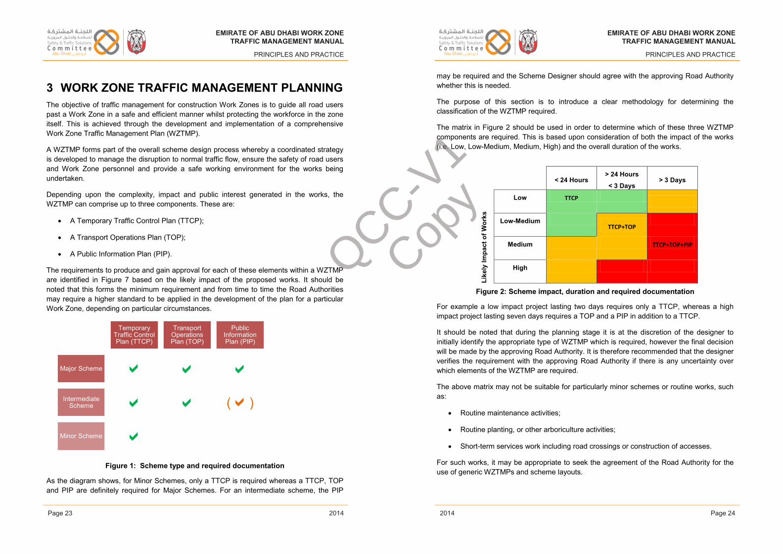
EMIRATE OF ABU DHABI WORK ZONETRAFFIC MANAGEMENT MANUAL
PRINCIPLES AND PRACTICE
3 WORK ZONE TRAFFIC MANAGEMENT PLANNINGThe objective of traffic management for construction Work Zones is to guide all road users past a Work Zone in a safe and efficient manner whilst protecting the workforce in the zone itself. This is achieved through the development and implementation of a comprehensive Work Zone Traffic Management Plan (WZTMP).
A WZTMP forms part of the overall scheme design process whereby a coordinated strategy is developed to manage the disruption to normal traffic flow, ensure the safety of road users and Work Zone personnel and provide a safe working environment for the works being undertaken.
Depending upon the complexity, impact and public interest generated in the works, the WZTMP can comprise up to three components. These are:
• A Temporary Traffic Control Plan (TTCP);
• A Transport Operations Plan (TOP);
• A Public Information Plan (PIP).
The requirements to produce and gain approval for each of these elements within a WZTMP are identified in Figure 7 based on the likely impact of the proposed works. It should be noted that this forms the minimum requirement and from time to time the Road Authoritiesmay require a higher standard to be applied in the development of the plan for a particular Work Zone, depending on particular circumstances.
Figure 1: Scheme type and required documentation
As the diagram shows, for Minor Schemes, only a TTCP is required whereas a TTCP, TOP and PIP are definitely required for Major Schemes. For an intermediate scheme, the PIP
? Temporary
Traffic Control Plan (TTCP)
Transport Operations Plan (TOP)
Public Information Plan (PIP)
Major Scheme
Intermediate Scheme ()
Minor Scheme
Issue 1 Page 23 February 2014
EMIRATE OF ABU DHABI WORK ZONETRAFFIC MANAGEMENT MANUAL
PRINCIPLES AND PRACTICE
may be required and the Scheme Designer should agree with the approving Road Authoritywhether this is needed.
The purpose of this section is to introduce a clear methodology for determining the classification of the WZTMP required.
The matrix in Figure 2 should be used in order to determine which of these three WZTMP components are required. This is based upon consideration of both the impact of the works (i.e. Low, Low-Medium, Medium, High) and the overall duration of the works.
Like
ly Im
pact
of W
orks
< 24 Hours> 24 Hours
< 3 Days> 3 Days
Low TTCP
Low-MediumTTCP+TOP
Medium TTCP+TOP+PIP
High
Figure 2: Scheme impact, duration and required documentation
For example a low impact project lasting two days requires only a TTCP, whereas a high impact project lasting seven days requires a TOP and a PIP in addition to a TTCP.
It should be noted that during the planning stage it is at the discretion of the designer to initially identify the appropriate type of WZTMP which is required, however the final decision will be made by the approving Road Authority. It is therefore recommended that the designer verifies the requirement with the approving Road Authority if there is any uncertainty over which elements of the WZTMP are required.
The above matrix may not be suitable for particularly minor schemes or routine works, such as:
• Routine maintenance activities;
• Routine planting, or other arboriculture activities;
• Short-term services work including road crossings or construction of accesses.
For such works, it may be appropriate to seek the agreement of the Road Authority for the use of generic WZTMPs and scheme layouts.
Issue 1 Page 24 February 2014
EMIRATE OF ABU DHABI WORK ZONETRAFFIC MANAGEMENT MANUAL
PRINCIPLES AND PRACTICE
2014
EMIRATE OF ABU DHABI WORK ZONETRAFFIC MANAGEMENT MANUAL
PRINCIPLES AND PRACTICE
2014Page 23 Page 24
EMIRATE OF ABU DHABI WORK ZONETRAFFIC MANAGEMENT MANUAL
PRINCIPLES AND PRACTICE
2014
EMIRATE OF ABU DHABI WORK ZONETRAFFIC MANAGEMENT MANUAL
PRINCIPLES AND PRACTICE
2014
QCC-V1
Copy
EMIRATE OF ABU DHABI WORK ZONETRAFFIC MANAGEMENT MANUAL
PRINCIPLES AND PRACTICE
3.1.1 Temporary Traffic Control PlanThe Temporary Traffic Control Plan (TTCP) is required for all WZTMPs (Low, Low-Medium, Medium, High). The TTCP deals with management of traffic (road users) in and around the Work Zone. The TTCP does not cover contractors' internal traffic management issues within the Work Zone/site boundaries, except at works accesses/works exits where works vehicles interact with road user traffic.
The TTCP describes the methods and approach to traffic control to be used in facilitating the safe passage of vehicle and pedestrian traffic through and around the Work Zone.
The detail of the TTCP will be dependent upon a number of factors such as complexity of work, duration and location. As such they will vary from a brief pro-forma document for the smallest works referencing standard drawings taken from this Manual, to a major document which details each phase of WZTM control and how is this to be implemented, maintained and removed at the end of the works.
The TTCP shall be specific to each project. Generic TTCPs will only be accepted for routine works carried out repeatedly in the same location such as minor landscape maintenance and public realm works (such as maintenance in medians and at the roadside, carriageway sweeping, planting etc.).
Project specific details will address for each stage of traffic management (where applicable):
• Agreed works timings (including setting out and removal times for temporary short-term traffic management);
• Phasing of works;
• Works setting out and detailed setting out information;
• Circulation and travel lanes;
• Temporary signing, road markings and traffic signal control (where appropriate);
• Details of any cancelled traffic movements;
• Traffic signal staging plans;
• Barricades and temporary detour routes;
• Maintenance of the temporary traffic management.
It is also required that the contractor shall provide the following information to supplement the TTCP:
• Location of construction Work Zone access/exit points
• Anticipated vehicle movements, including arrangements for material/plant delivery;
Issue 1 Page 25 February 2014
EMIRATE OF ABU DHABI WORK ZONETRAFFIC MANAGEMENT MANUAL
PRINCIPLES AND PRACTICE
• Staff and operations control plan;
• Incident management arrangements and/or plans.
For the concept design stage, the preparation of the TTCP will require the following information:
• Scheme location plan;
• Definition of Work Zone limits;
• Selected Work Zone management strategies;
• Typical traffic management layouts and details/specification;
• Specific traffic management layouts and details/specification;
• TCDs to be utilised;
• Construction/construction phasing plans;
• Geometric design information.
This list is not exhaustive and can be supplemented with additional information where required. If information is not relevant, this can be stated (for example, if standard layouts are used, these can be referenced as drawing numbers).
In order to facilitate a more integrated approach to the review and approval process, if a designer is aware that a Departure from normal standards (whether road geometric design or WZTM design) is required during the early planning stages the appropriate Road Authoritycan be contacted for approval in principle before more detailed work is completed.
3.1.2 Transport Operations PlanThe Transport Operations Plan (TOP) is required for anything other than Low impact WZTMPs and also for Low impact schemes which have a relatively long duration.
A Low/Medium WZTMP is applicable for a project which is likely to have more than a minor level of disruption on the travelling public at large, communities and businesses.
The characteristics of a project which requires a TOP are (but not limited to):
• More impact than minor construction or maintenance works;
• Involves single lane closures for a period of time;
• Located on, or near to the central business district or environmentally sensitive sites;
• On a priority route (as defined by DoT)
• Will last for more than one day;
Issue 1 Page 26 February 2014
EMIRATE OF ABU DHABI WORK ZONETRAFFIC MANAGEMENT MANUAL
PRINCIPLES AND PRACTICE
2014
EMIRATE OF ABU DHABI WORK ZONETRAFFIC MANAGEMENT MANUAL
PRINCIPLES AND PRACTICE
2014Page 25 Page 26
EMIRATE OF ABU DHABI WORK ZONETRAFFIC MANAGEMENT MANUAL
PRINCIPLES AND PRACTICE
2014
EMIRATE OF ABU DHABI WORK ZONETRAFFIC MANAGEMENT MANUAL
PRINCIPLES AND PRACTICE
2014
QCC-V1
Copy
EMIRATE OF ABU DHABI WORK ZONETRAFFIC MANAGEMENT MANUAL
PRINCIPLES AND PRACTICE
• Will have construction activities taking place during the peak am, midday and pm periods.
The Low/Medium WZTMP should include more detailed Work Zone impact analysis and management strategy information compared to the Low impact WZTMPs. This will includesome element of the PIP and/or TOP strategies, as well as cost estimates to enable the client to make an informed choice based on impact, cost and duration. It should include details of:
• Emergency vehicle access for the site;
• Emergency vehicle movements around the site;
• Public transport such as bus stops, taxi stands, designated drop off and pick up areas;
• School bus accesses;
• Incident management plan;
• Approach to enforcement and liaison with the AD Traffic Police;
• Environmental Management Plan;
• Safety Management Plan;
• Journey Time Reliability;
• Maintenance of the detour route specifications (traffic and NMU).
The TOP details the measures to mitigate the impact of construction Work Zones through the use of improved transportation operations and management of the roadway network.
It will detail the strategies to address the operational and management of the affected local network for the duration of the works. Strategies will include items such as Work Zone Intelligent Transportation System (ITS) components, law enforcement, environmental mitigation measures and incident management.
The TOP shall be specific to each project and a generic TOP will not be accepted. The level of detail required will be dependent upon a number of factors such as complexity of work, duration and location.
The TOP shall also detail the management strategies that are to be used in mitigating the effects of the construction Work Zone during the project life cycle and can include, but are not limited to:
• Demand management strategies, for example:
• Working time restrictions;
Issue 1 Page 27 February 2014
EMIRATE OF ABU DHABI WORK ZONETRAFFIC MANAGEMENT MANUAL
PRINCIPLES AND PRACTICE
• Temporary park and ride facilities;
• Temporary car parking facilities;
• Modal shift and increased accessibility to and of public transportation.
• Corridor and overall network management strategies, for example:
• Temporary strategies for enforcement (in conjunction with the police);
• Introduction of turning movement bans;
• Temporary ITS devices such as portable variable message signs;
• Temporary signals and or signal staging plans, or use of adaptive traffic signal control;
• Segregation of construction vehicles and or slower moving vehicles such as large trucks from normal vehicle flow;
• Ramp/access closure to limit access to the affected area;
• Journey time reliability.
• Work Zone safety management strategies, for example:
• Temporary speed limits and/or enforcement of existing speed limits;
• CCTV surveillance and/or police enforcement;
• Temporary traffic calming measures such as rumble strips and countdown distance markings;
• Use of concrete/steel temporary barrier instead of temporary plastic barrier (depending upon speed limit);
• Introduction of crash cushions in "at risk" locations; and
• Protection of the mobile workforce using crash cushions mounted on vehicles (TMAs).
• Work Zone Environmental Management Strategies, for example:
• Air and noise pollution;
• Spill prevention;
• Material storage;
• Waste management.
Issue 1 Page 28 February 2014
EMIRATE OF ABU DHABI WORK ZONETRAFFIC MANAGEMENT MANUAL
PRINCIPLES AND PRACTICE
2014
EMIRATE OF ABU DHABI WORK ZONETRAFFIC MANAGEMENT MANUAL
PRINCIPLES AND PRACTICE
2014Page 27 Page 28
EMIRATE OF ABU DHABI WORK ZONETRAFFIC MANAGEMENT MANUAL
PRINCIPLES AND PRACTICE
2014
EMIRATE OF ABU DHABI WORK ZONETRAFFIC MANAGEMENT MANUAL
PRINCIPLES AND PRACTICE
2014
QCC-V1
Copy
EMIRATE OF ABU DHABI WORK ZONETRAFFIC MANAGEMENT MANUAL
PRINCIPLES AND PRACTICE
• Incident management strategies, for example:
• Development of incident scenarios and management plans;
• Training of staff;
• Close liaison with the police, other Emergency Services and Civil Defence.
It is not intended that this list is exhaustive in the development of the TOP, however it gives an overall direction of the types of strategies that can be considered and employed during the works. It is expected that these measures identified will form a 'do minimum' case.
3.1.3 Public Information PlanThe Public Information Plan (PIP) is required for a High impact WZTMP and maybe required for some Low/Medium impact WZTMPs. The PIP details the methods employed to inform the travelling public, businesses and surrounding community concerning the construction project and the impact that the Work Zones will have on them and how these are being managed.
The PIP shall be specific to each project and a generic PIP will not be acceptable. The level of detail required will be dependent upon a number of factors such as complexity of work, duration and location. It is however expected to include the following:
Stakeholder engagement including but not limited to:
• The general public, including residents affected by the works;
• Road users;
• Business owners;
• Any schools, hospitals, government offices, or other official sites.
Communication of the project can be through:
• Printed media such as flyers, newspaper advertisements, official notices etc.;
• Public media such as radio, television, local broadcasts etc.;
• VMS;
• On-site project information board (mandatory);
• Web-based traffic management information.
The PIP does not replace the liaison and discussion that is required with identified Key Stakeholders throughout the planning, implementation, and removal of any WZTM, but can be a useful management tool in documenting the process to take place.
Issue 1 Page 29 February 2014
EMIRATE OF ABU DHABI WORK ZONETRAFFIC MANAGEMENT MANUAL
PRINCIPLES AND PRACTICE
3.1.4 Method StatementsA project-specific detailed method statement should be prepared for the implementation, maintenance, and removal of the detailed traffic management design.
Generic method statements are not generally acceptable and should only be used after they have been assessed and adapted to the particular circumstances of the site and the specific activity proposed. The method statement should be prepared by the organisation responsible for undertaking the activities. Its formulation should take into account the available resources, including the skill, knowledge and experience of the various elements of the workforce. For each activity, the method statement should identify the resource implication, both human and equipment.
Where the method statement sets out activities which interact with those of other organisations, detailed liaison should take place to facilitate co-operation and ensure a cohesive operation. Such liaison is likely to include the police, the Road Authority, and the organisation responsible for construction of the works.
To ensure sufficient scope in the production of the method statement, consideration will need to be given to points raised throughout this Manual. Although the issues raised below are not exhaustive, the following issues should be addressed:
• The amount of work which can be carried out in one working period;
• Positioning of vehicles (will the traffic management vehicle(s) be parked off the carriageway, or is it required to protect the workforce?);
• If parking the vehicle in a live traffic lane is unavoidable a risk assessment must be carried out and consideration given to equipping the vehicle with a Truck Mounted Attenuator (TMA) and high intensity flashing keep left/right arrow in addition to the normal arrow (on high speed roads the assumption should be made that the method statement will not be approved unless vehicles in live lanes are equipped with TMAs);
• Crossing the carriageway on foot: This is a hazardous activity. It should be planned so that the location provides adequate sight lines and gaps in the traffic and a place of safety at both sides of the carriageway;
• Pre-setting signs (i.e. placing signs out in advance ready for erection): This operation can often be the safest, most efficient method for implementing temporary traffic management arrangements;
• Storage of equipment;
• Erection of signs: The sequence of erection should ensure that the first sign erected provides protection for the erection of the remaining signs. Consideration should also be given to the associated manual handling implications;
Issue 1 Page 30 February 2014
EMIRATE OF ABU DHABI WORK ZONETRAFFIC MANAGEMENT MANUAL
PRINCIPLES AND PRACTICE
2014
EMIRATE OF ABU DHABI WORK ZONETRAFFIC MANAGEMENT MANUAL
PRINCIPLES AND PRACTICE
2014Page 29 Page 30
EMIRATE OF ABU DHABI WORK ZONETRAFFIC MANAGEMENT MANUAL
PRINCIPLES AND PRACTICE
2014
EMIRATE OF ABU DHABI WORK ZONETRAFFIC MANAGEMENT MANUAL
PRINCIPLES AND PRACTICE
2014
QCC-V1
Copy
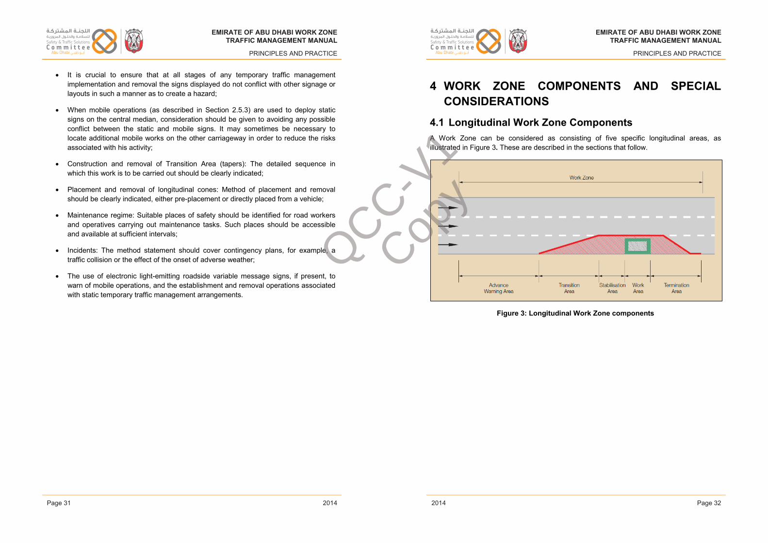
EMIRATE OF ABU DHABI WORK ZONETRAFFIC MANAGEMENT MANUAL
PRINCIPLES AND PRACTICE
• It is crucial to ensure that at all stages of any temporary traffic management implementation and removal the signs displayed do not conflict with other signage or layouts in such a manner as to create a hazard;
• When mobile operations (as described in Section 2.5.3) are used to deploy static signs on the central median, consideration should be given to avoiding any possible conflict between the static and mobile signs. It may sometimes be necessary to locate additional mobile works on the other carriageway in order to reduce the risks associated with his activity;
• Construction and removal of Transition Area (tapers): The detailed sequence in which this work is to be carried out should be clearly indicated;
• Placement and removal of longitudinal cones: Method of placement and removal should be clearly indicated, either pre-placement or directly placed from a vehicle;
• Maintenance regime: Suitable places of safety should be identified for road workers and operatives carrying out maintenance tasks. Such places should be accessible and available at sufficient intervals;
• Incidents: The method statement should cover contingency plans, for example, a traffic collision or the effect of the onset of adverse weather;
• The use of electronic light-emitting roadside variable message signs, if present, to warn of mobile operations, and the establishment and removal operations associated with static temporary traffic management arrangements.
Issue 1 Page 31 February 2014
EMIRATE OF ABU DHABI WORK ZONETRAFFIC MANAGEMENT MANUAL
PRINCIPLES AND PRACTICE
4 WORK ZONE COMPONENTS AND SPECIAL CONSIDERATIONS
4.1 Longitudinal Work Zone ComponentsA Work Zone can be considered as consisting of five specific longitudinal areas, as illustrated in Figure 3. These are described in the sections that follow.
Figure 3: Longitudinal Work Zone components
Issue 1 Page 32 February 2014
EMIRATE OF ABU DHABI WORK ZONETRAFFIC MANAGEMENT MANUAL
PRINCIPLES AND PRACTICE
2014
EMIRATE OF ABU DHABI WORK ZONETRAFFIC MANAGEMENT MANUAL
PRINCIPLES AND PRACTICE
2014Page 31 Page 32
EMIRATE OF ABU DHABI WORK ZONETRAFFIC MANAGEMENT MANUAL
PRINCIPLES AND PRACTICE
2014
EMIRATE OF ABU DHABI WORK ZONETRAFFIC MANAGEMENT MANUAL
PRINCIPLES AND PRACTICE
2014
QCC-V1
Copy
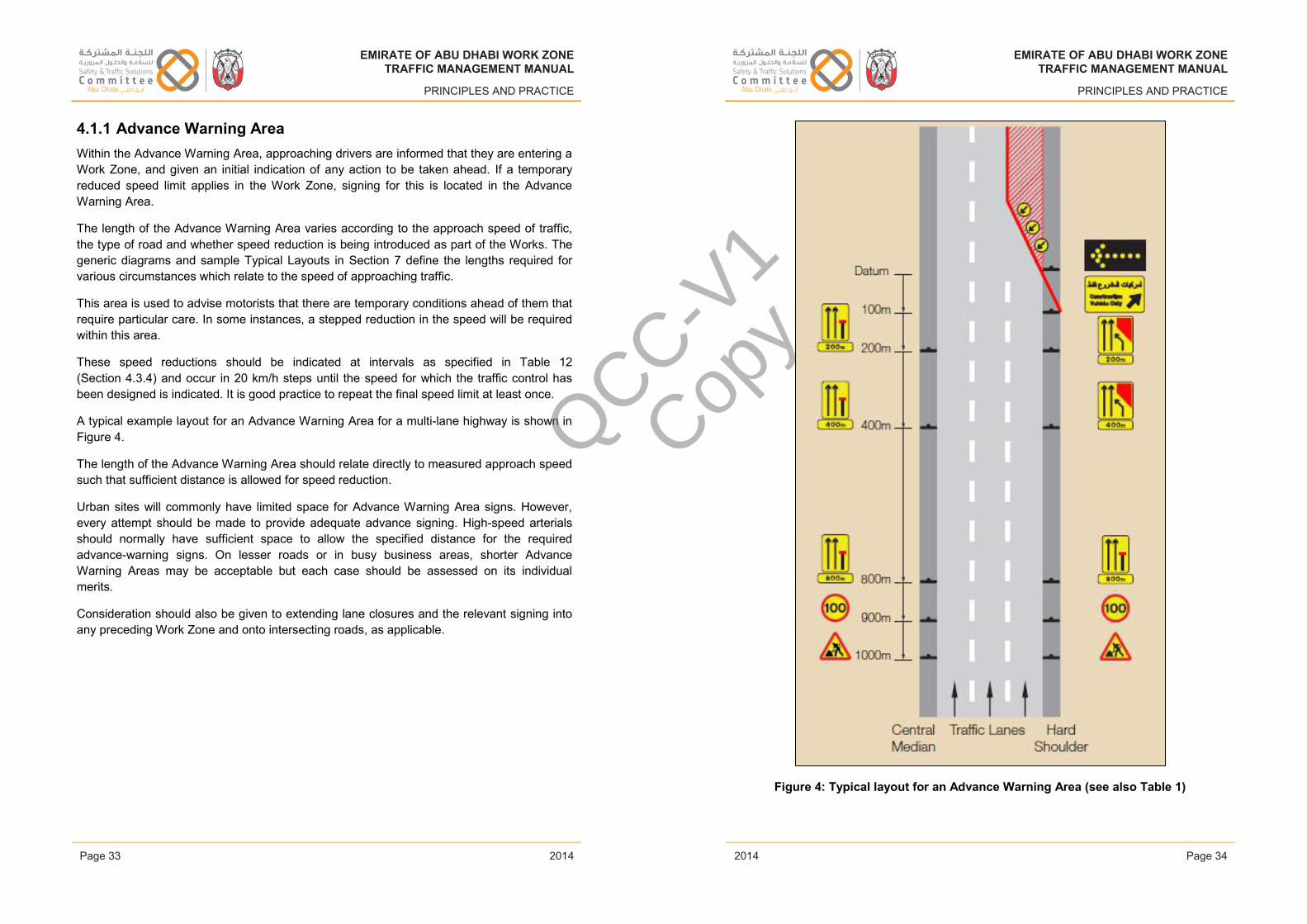
EMIRATE OF ABU DHABI WORK ZONETRAFFIC MANAGEMENT MANUAL
PRINCIPLES AND PRACTICE
4.1.1 Advance Warning Area Within the Advance Warning Area, approaching drivers are informed that they are entering a Work Zone, and given an initial indication of any action to be taken ahead. If a temporary reduced speed limit applies in the Work Zone, signing for this is located in the AdvanceWarning Area.
The length of the Advance Warning Area varies according to the approach speed of traffic, the type of road and whether speed reduction is being introduced as part of the Works. The generic diagrams and sample Typical Layouts in Section 7 define the lengths required for various circumstances which relate to the speed of approaching traffic.
This area is used to advise motorists that there are temporary conditions ahead of them that require particular care. In some instances, a stepped reduction in the speed will be required within this area.
These speed reductions should be indicated at intervals as specified in Table 12(Section 4.3.4) and occur in 20 km/h steps until the speed for which the traffic control has been designed is indicated. It is good practice to repeat the final speed limit at least once.
A typical example layout for an Advance Warning Area for a multi-lane highway is shown in Figure 4.
The length of the Advance Warning Area should relate directly to measured approach speed such that sufficient distance is allowed for speed reduction.
Urban sites will commonly have limited space for Advance Warning Area signs. However, every attempt should be made to provide adequate advance signing. High-speed arterials should normally have sufficient space to allow the specified distance for the required advance-warning signs. On lesser roads or in busy business areas, shorter Advance Warning Areas may be acceptable but each case should be assessed on its individual merits.
Consideration should also be given to extending lane closures and the relevant signing into any preceding Work Zone and onto intersecting roads, as applicable.
Issue 1 Page 33 February 2014
EMIRATE OF ABU DHABI WORK ZONETRAFFIC MANAGEMENT MANUAL
PRINCIPLES AND PRACTICE
Figure 4: Typical layout for an Advance Warning Area (see also Table 1)
Issue 1 Page 34 February 2014
EMIRATE OF ABU DHABI WORK ZONETRAFFIC MANAGEMENT MANUAL
PRINCIPLES AND PRACTICE
2014
EMIRATE OF ABU DHABI WORK ZONETRAFFIC MANAGEMENT MANUAL
PRINCIPLES AND PRACTICE
2014Page 33 Page 34
EMIRATE OF ABU DHABI WORK ZONETRAFFIC MANAGEMENT MANUAL
PRINCIPLES AND PRACTICE
2014
EMIRATE OF ABU DHABI WORK ZONETRAFFIC MANAGEMENT MANUAL
PRINCIPLES AND PRACTICE
2014
QCC-V1
Copy
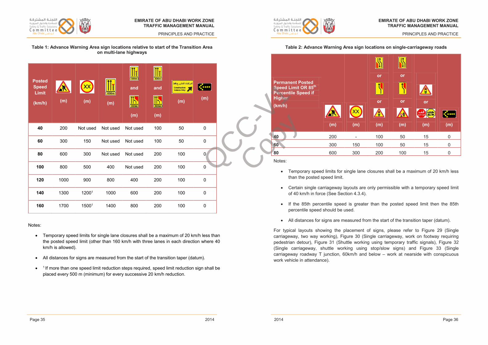
EMIRATE OF ABU DHABI WORK ZONETRAFFIC MANAGEMENT MANUAL
PRINCIPLES AND PRACTICE
Table 1: Advance Warning Area sign locations relative to start of the Transition Area on multi-lane highways
Issue 1 Page 35 February 2014
EMIRATE OF ABU DHABI WORK ZONETRAFFIC MANAGEMENT MANUAL
PRINCIPLES AND PRACTICE
Table 2: Advance Warning Area sign locations on single-carriageway roads
Permanent Posted Speed Limit OR 85th
Percentile Speed if Higher(km/h)
(m) (m)
or
or
(m)
or
or
(m)
or
(m) (m)
40 200 - 100 50 15 0
60 300 150 100 50 15 0
80 600 300 200 100 15 0
Notes:
• Temporary speed limits for single lane closures shall be a maximum of 20 km/h less than the posted speed limit.
• Certain single carriageway layouts are only permissible with a temporary speed limit of 40 km/h in force (See Section 4.3.4).
• If the 85th percentile speed is greater than the posted speed limit then the 85th percentile speed should be used.
• All distances for signs are measured from the start of the transition taper (datum).
For typical layouts showing the placement of signs, please refer to Figure 29 (Single carriageway, two way working), Figure 30 (Single carriageway, work on footway requiring pedestrian detour), Figure 31 (Shuttle working using temporary traffic signals), Figure 32(Single carriageway, shuttle working using stop/slow signs) and Figure 33 (Single carriageway roadway T junction, 60km/h and below – work at nearside with conspicuous work vehicle in attendance).
Issue 1 Page 36 February 2014
EMIRATE OF ABU DHABI WORK ZONETRAFFIC MANAGEMENT MANUAL
PRINCIPLES AND PRACTICE
2014
EMIRATE OF ABU DHABI WORK ZONETRAFFIC MANAGEMENT MANUAL
PRINCIPLES AND PRACTICE
2014Page 35 Page 36
EMIRATE OF ABU DHABI WORK ZONETRAFFIC MANAGEMENT MANUAL
PRINCIPLES AND PRACTICE
2014
EMIRATE OF ABU DHABI WORK ZONETRAFFIC MANAGEMENT MANUAL
PRINCIPLES AND PRACTICE
2014
Notes:
Temporary speed limits for single lane closures shall be a maximum of 20 km/h less thanthe posted speed limit (other than 160 km/h with three lanes in each direction where 40 km/h is allowed).
All distances for signs are measured from the start of the transition taper (datum).
1 If more than one speed limit reduction steps required, speed limit reduction sign shall beplaced every 500 m (minimum) for every successive 20 km/h reduction.
Posted Speed Limit
(km/h) (m) (m) (m)
and
(m)
and
(m)
(m) (m)
40 200 Not used Not used Not used 100 50 0
60 300 150 Not used Not used 100 50 0
80 600 300 Not used Not used 200 100 0
100 800 500 400 Not used 200 100 0
120 1000 900 800 400 200 100 0
140 1300 12001 1000 600 200 100 0
160 1700 15001 1400 800 200 100 0
QCC-V1
Copy
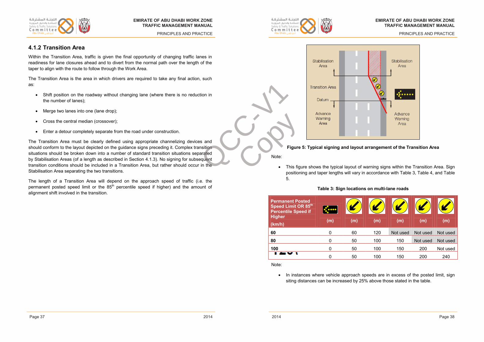
EMIRATE OF ABU DHABI WORK ZONETRAFFIC MANAGEMENT MANUAL
PRINCIPLES AND PRACTICE
4.1.2 Transition Area Within the Transition Area, traffic is given the final opportunity of changing traffic lanes in readiness for lane closures ahead and to divert from the normal path over the length of the taper to align with the route to follow through the Work Area.
The Transition Area is the area in which drivers are required to take any final action, such as:
• Shift position on the roadway without changing lane (where there is no reduction in the number of lanes);
• Merge two lanes into one (lane drop);
• Cross the central median (crossover);
• Enter a detour completely separate from the road under construction.
The Transition Area must be clearly defined using appropriate channelizing devices and should conform to the layout depicted on the guidance signs preceding it. Complex transition situations should be broken down into a number of standard transition situations separated by Stabilisation Areas (of a length as described in Section 4.1.3). No signing for subsequent transition conditions should be included in a Transition Area, but rather should occur in the Stabilisation Area separating the two transitions.
The length of a Transition Area will depend on the approach speed of traffic (i.e. thepermanent posted speed limit or the 85th percentile speed if higher) and the amount of alignment shift involved in the transition.
Issue 1 Page 37 February 2014
EMIRATE OF ABU DHABI WORK ZONETRAFFIC MANAGEMENT MANUAL
PRINCIPLES AND PRACTICE
Figure 5: Typical signing and layout arrangement of the Transition Area
Note:
• This figure shows the typical layout of warning signs within the Transition Area. Sign positioning and taper lengths will vary in accordance with Table 3, Table 4, and Table 5.
Table 3: Sign locations on multi-lane roads
Permanent Posted Speed Limit OR 85th
Percentile Speed if Higher(km/h)
(m) (m) (m) (m) (m) (m)
60 0 60 120 Not used Not used Not used
80 0 50 100 150 Not used Not used
100 0 50 100 150 200 Not used
0 50 100 150 200 240
Note:
• In instances where vehicle approach speeds are in excess of the posted limit, sign siting distances can be increased by 25% above those stated in the table.
Issue 1 Page 38 February 2014
EMIRATE OF ABU DHABI WORK ZONETRAFFIC MANAGEMENT MANUAL
PRINCIPLES AND PRACTICE
2014
EMIRATE OF ABU DHABI WORK ZONETRAFFIC MANAGEMENT MANUAL
PRINCIPLES AND PRACTICE
2014Page 37 Page 38
EMIRATE OF ABU DHABI WORK ZONETRAFFIC MANAGEMENT MANUAL
PRINCIPLES AND PRACTICE
2014
EMIRATE OF ABU DHABI WORK ZONETRAFFIC MANAGEMENT MANUAL
PRINCIPLES AND PRACTICE
2014
QCC-V1
Copy
abdulrazzak.zaytoun
Placed Image
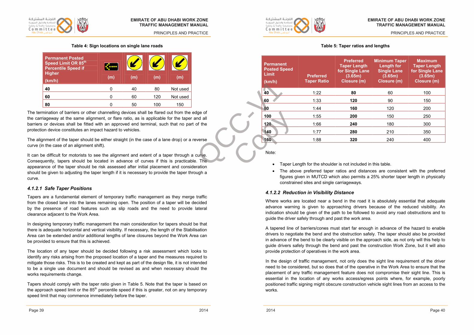
EMIRATE OF ABU DHABI WORK ZONETRAFFIC MANAGEMENT MANUAL
PRINCIPLES AND PRACTICE
Table 4: Sign locations on single lane roads
Permanent Posted Speed Limit OR 85th
Percentile Speed if Higher(km/h)
(m) (m) (m) (m)
40 0 40 80 Not used
60 0 60 120 Not used
80 0 50 100 150
The termination of barriers or other channelling devices shall be flared out from the edge of the carriageway at the same alignment, or flare ratio, as is applicable for the taper and all barriers or devices shall be fitted with an approved end terminal, such that no part of the protection device constitutes an impact hazard to vehicles.
The alignment of the taper should be either straight (in the case of a lane drop) or a reverse curve (in the case of an alignment shift).
It can be difficult for motorists to see the alignment and extent of a taper through a curve. Consequently, tapers should be located in advance of curves if this is practicable. The appearance of the taper should be risk assessed after initial placement and consideration should be given to adjusting the taper length if it is necessary to provide the taper through a curve.
4.1.2.1 Safe Taper Positions
Tapers are a fundamental element of temporary traffic management as they merge traffic from the closed lane into the lanes remaining open. The position of a taper will be decided by the presence of road features such as slip roads and the need to provide lateral clearance adjacent to the Work Area.
In designing temporary traffic management the main consideration for tapers should be that there is adequate horizontal and vertical visibility. If necessary, the length of the Stabilisation Area can be extended and/or additional lengths of lane closures beyond the Work Area can be provided to ensure that this is achieved.
The location of any taper should be decided following a risk assessment which looks to identify any risks arising from the proposed location of a taper and the measures required to mitigate those risks. This is to be created and kept as part of the design file, it is not intended to be a single use document and should be revised as and when necessary should the works requirements change.
Tapers should comply with the taper ratio given in Table 5. Note that the taper is based on the approach speed limit or the 85th percentile speed if this is greater, not on any temporaryspeed limit that may commence immediately before the taper.
Issue 1 Page 39 February 2014
EMIRATE OF ABU DHABI WORK ZONETRAFFIC MANAGEMENT MANUAL
PRINCIPLES AND PRACTICE
Table 5: Taper ratios and lengths
Note:
• The above preferred taper ratios and distances are consistent with the preferredfigures given in MUTCD which also permits a 25% shorter taper length in physically constrained sites and single carriageways.
4.1.2.2 Reduction in Visibility Distance
Where works are located near a bend in the road it is absolutely essential that adequate advance warning is given to approaching drivers because of the reduced visibility. An indication should be given of the path to be followed to avoid any road obstructions and to guide the driver safely through and past the work area.
A tapered line of barriers/cones must start far enough in advance of the hazard to enable drivers to negotiate the bend and the obstruction safely. The taper should also be provided in advance of the bend to be clearly visible on the approach side, as not only will this help to guide drivers safely through the bend and past the construction Work Zone, but it will also provide protection of operatives in the work area.
In the design of traffic management, not only does the sight line requirement of the driver need to be considered, but so does that of the operative in the Work Area to ensure that the placement of any traffic management feature does not compromise their sight line. This is essential in the location of any works access/egress points where, for example, poorly positioned traffic signing might obscure construction vehicle sight lines from an access to the works.
Issue 1 Page 40 February 2014
EMIRATE OF ABU DHABI WORK ZONETRAFFIC MANAGEMENT MANUAL
PRINCIPLES AND PRACTICE
2014
EMIRATE OF ABU DHABI WORK ZONETRAFFIC MANAGEMENT MANUAL
PRINCIPLES AND PRACTICE
2014Page 39 Page 40
EMIRATE OF ABU DHABI WORK ZONETRAFFIC MANAGEMENT MANUAL
PRINCIPLES AND PRACTICE
2014
EMIRATE OF ABU DHABI WORK ZONETRAFFIC MANAGEMENT MANUAL
PRINCIPLES AND PRACTICE
2014
Permanent Posted Speed Limit (km/h)
Preferred Taper Ratio
Preferred Taper Length
for Single Lane (3.65m)
Closure (m)
Minimum Taper Length for
Single Lane (3.65m)
Closure (m)
Maximum Taper Length
for Single Lane (3.65m)
Closure (m)
40 1:22 80 60 100
60 1:33 120 90 150
80 1:44 160 120 200
100 1:55 200 150 250
120 1:66 240 180 300
140 1:77 280 210 350
160 1:88 320 240 400
Taper Length for the shoulder is not included in this table.QCC-V1
Copy
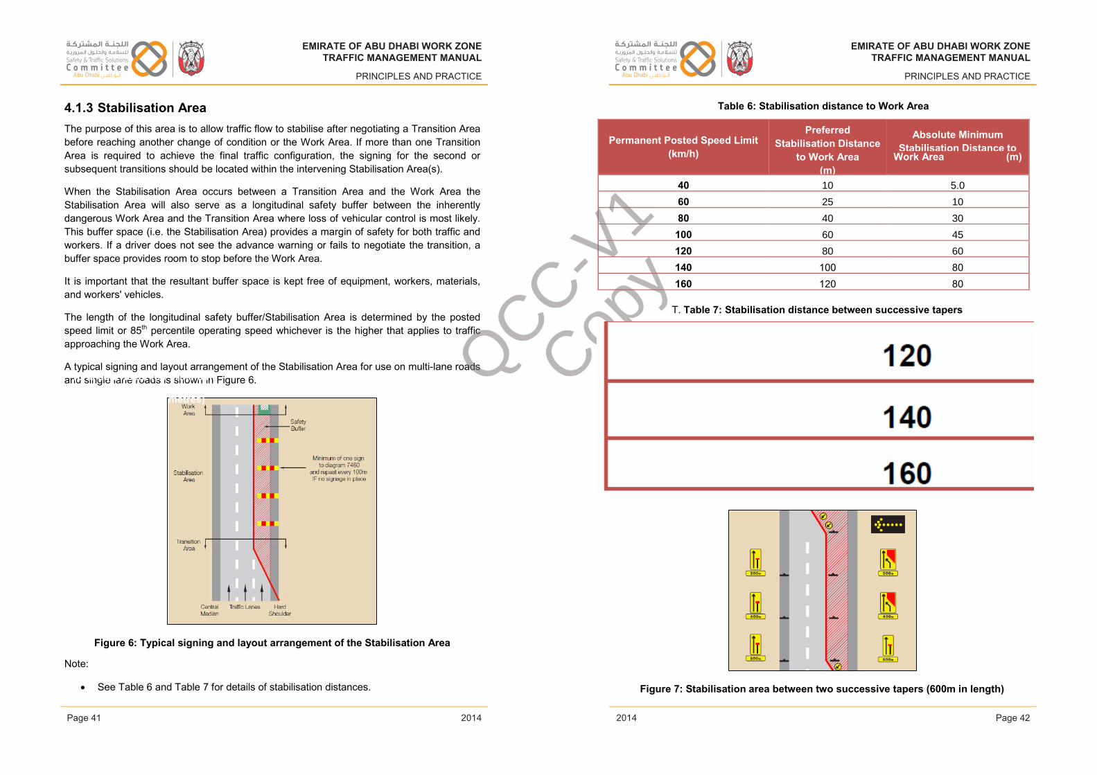
EMIRATE OF ABU DHABI WORK ZONETRAFFIC MANAGEMENT MANUAL
PRINCIPLES AND PRACTICE
4.1.3 Stabilisation Area The purpose of this area is to allow traffic flow to stabilise after negotiating a Transition Areabefore reaching another change of condition or the Work Area. If more than one Transition Area is required to achieve the final traffic configuration, the signing for the second or subsequent transitions should be located within the intervening Stabilisation Area(s).
When the Stabilisation Area occurs between a Transition Area and the Work Area the Stabilisation Area will also serve as a longitudinal safety buffer between the inherently dangerous Work Area and the Transition Area where loss of vehicular control is most likely. This buffer space (i.e. the Stabilisation Area) provides a margin of safety for both traffic and workers. If a driver does not see the advance warning or fails to negotiate the transition, a buffer space provides room to stop before the Work Area.
It is important that the resultant buffer space is kept free of equipment, workers, materials, and workers' vehicles.
The length of the longitudinal safety buffer/Stabilisation Area is determined by the posted speed limit or 85th percentile operating speed whichever is the higher that applies to traffic approaching the Work Area.
A typical signing and layout arrangement of the Stabilisation Area for use on multi-lane roads and single lane roads is shown in Figure 6.
Figure 6: Typical signing and layout arrangement of the Stabilisation Area
Note:
• See Table 6 and Table 7 for details of stabilisation distances.
Issue 1 Page 41 February 2014
EMIRATE OF ABU DHABI WORK ZONETRAFFIC MANAGEMENT MANUAL
PRINCIPLES AND PRACTICE
Table 6: Stabilisation distance to Work Area
T. Table 7: Stabilisation distance between successive tapers
Figure 7: Stabilisation area between two successive tapers (600m in length)
Issue 1 Page 42 February 2014
EMIRATE OF ABU DHABI WORK ZONETRAFFIC MANAGEMENT MANUAL
PRINCIPLES AND PRACTICE
2014
EMIRATE OF ABU DHABI WORK ZONETRAFFIC MANAGEMENT MANUAL
PRINCIPLES AND PRACTICE
2014Page 41 Page 42
EMIRATE OF ABU DHABI WORK ZONETRAFFIC MANAGEMENT MANUAL
PRINCIPLES AND PRACTICE
2014
EMIRATE OF ABU DHABI WORK ZONETRAFFIC MANAGEMENT MANUAL
PRINCIPLES AND PRACTICE
2014
Permanent Posted Speed Limit (km/h)
Preferred Stabilisation Distance
to Work Area (m)
Absolute Minimum Stabilisation Distance to
Work Area (m)
40 10 5.0
60 25 10
80 40 30
100 60 45
120 80 60
140 100 80
160 120 80
permanent Posted Speed Limit (km/h)
(S is equivalent to Permanent
Posted Speed in metres) QCC-V
1
Copy
abdulrazzak.zaytoun
Placed Image
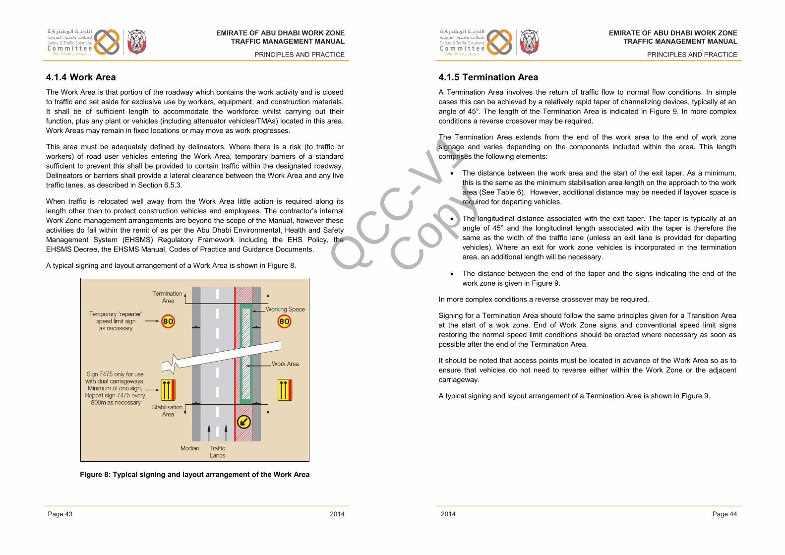
EMIRATE OF ABU DHABI WORK ZONETRAFFIC MANAGEMENT MANUAL
PRINCIPLES AND PRACTICE
4.1.4 Work Area The Work Area is that portion of the roadway which contains the work activity and is closed to traffic and set aside for exclusive use by workers, equipment, and construction materials. It shall be of sufficient length to accommodate the workforce whilst carrying out their function, plus any plant or vehicles (including attenuator vehicles/TMAs) located in this area. Work Areas may remain in fixed locations or may move as work progresses.
This area must be adequately defined by delineators. Where there is a risk (to traffic or workers) of road user vehicles entering the Work Area, temporary barriers of a standard sufficient to prevent this shall be provided to contain traffic within the designated roadway. Delineators or barriers shall provide a lateral clearance between the Work Area and any live traffic lanes, as described in Section 6.5.3.
When traffic is relocated well away from the Work Area little action is required along its length other than to protect construction vehicles and employees. The contractor’s internal Work Zone management arrangements are beyond the scope of the Manual, however these activities do fall within the remit of as per the Abu Dhabi Environmental, Health and Safety Management System (EHSMS) Regulatory Framework including the EHS Policy, the EHSMS Decree, the EHSMS Manual, Codes of Practice and Guidance Documents.
A typical signing and layout arrangement of a Work Area is shown in Figure 8.
Figure 8: Typical signing and layout arrangement of the Work Area
Issue 1 Page 43 February 2014
EMIRATE OF ABU DHABI WORK ZONETRAFFIC MANAGEMENT MANUAL
PRINCIPLES AND PRACTICE
4.1.5 Termination Area A Termination Area involves the return of traffic flow to normal flow conditions. In simple cases this can be achieved by a relatively rapid taper of channelizing devices, typically at an angle of 45°. The length of the Termination Area is indicated in Figure 9. In more complex conditions a reverse crossover may be required.
The Termination Area extends from the end of the work area to the end of work zone signage and varies depending on the components included within the area. This length comprises the following elements:
• The distance between the work area and the start of the exit taper. As a minimum, this is the same as the minimum stabilisation area length on the approach to the work area (See Table 6). However, additional distance may be needed if layover space is required for departing vehicles.
• The longitudinal distance associated with the exit taper. The taper is typically at an angle of 45° and the longitudinal length associated with the taper is therefore the same as the width of the traffic lane (unless an exit lane is provided for departing vehicles). Where an exit for work zone vehicles is incorporated in the termination area, an additional length will be necessary.
• The distance between the end of the taper and the signs indicating the end of the work zone is given in Figure 9.
In more complex conditions a reverse crossover may be required.
Signing for a Termination Area should follow the same principles given for a Transition Areaat the start of a wok zone. End of Work Zone signs and conventional speed limit signs restoring the normal speed limit conditions should be erected where necessary as soon as possible after the end of the Termination Area.
It should be noted that access points must be located in advance of the Work Area so as to ensure that vehicles do not need to reverse either within the Work Zone or the adjacent carriageway.
A typical signing and layout arrangement of a Termination Area is shown in Figure 9.
Issue 1 Page 44 February 2014
EMIRATE OF ABU DHABI WORK ZONETRAFFIC MANAGEMENT MANUAL
PRINCIPLES AND PRACTICE
2014
EMIRATE OF ABU DHABI WORK ZONETRAFFIC MANAGEMENT MANUAL
PRINCIPLES AND PRACTICE
2014Page 43 Page 44
EMIRATE OF ABU DHABI WORK ZONETRAFFIC MANAGEMENT MANUAL
PRINCIPLES AND PRACTICE
2014
EMIRATE OF ABU DHABI WORK ZONETRAFFIC MANAGEMENT MANUAL
PRINCIPLES AND PRACTICE
2014
QCC-V1
Copy
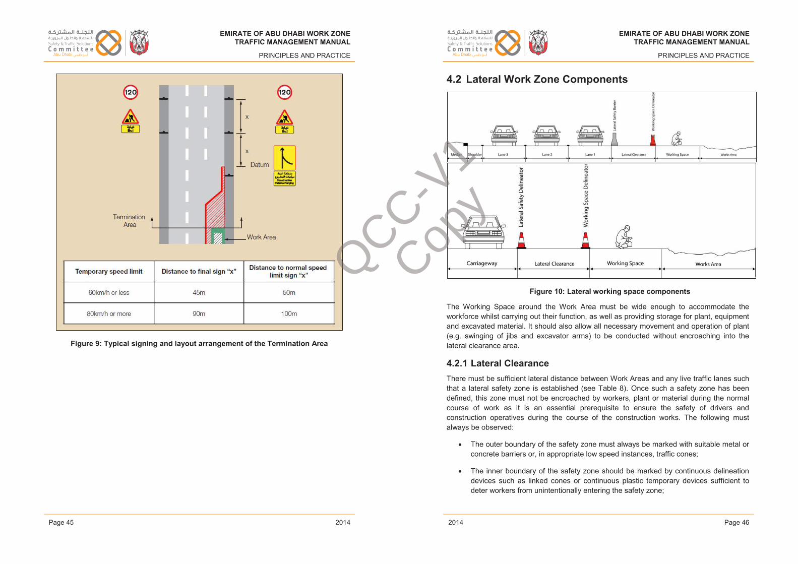
EMIRATE OF ABU DHABI WORK ZONETRAFFIC MANAGEMENT MANUAL
PRINCIPLES AND PRACTICE
Figure 9: Typical signing and layout arrangement of the Termination Area
Issue 1 Page 45 February 2014
EMIRATE OF ABU DHABI WORK ZONETRAFFIC MANAGEMENT MANUAL
PRINCIPLES AND PRACTICE
4.2 Lateral Work Zone Components
Figure 10: Lateral working space components
The Working Space around the Work Area must be wide enough to accommodate the workforce whilst carrying out their function, as well as providing storage for plant, equipment and excavated material. It should also allow all necessary movement and operation of plant (e.g. swinging of jibs and excavator arms) to be conducted without encroaching into the lateral clearance area.
4.2.1 Lateral ClearanceThere must be sufficient lateral distance between Work Areas and any live traffic lanes such that a lateral safety zone is established (see Table 8). Once such a safety zone has been defined, this zone must not be encroached by workers, plant or material during the normal course of work as it is an essential prerequisite to ensure the safety of drivers and construction operatives during the course of the construction works. The following must always be observed:
• The outer boundary of the safety zone must always be marked with suitable metal or concrete barriers or, in appropriate low speed instances, traffic cones;
• The inner boundary of the safety zone should be marked by continuous delineation devices such as linked cones or continuous plastic temporary devices sufficient to deter workers from unintentionally entering the safety zone;
Issue 1 Page 46 February 2014
EMIRATE OF ABU DHABI WORK ZONETRAFFIC MANAGEMENT MANUAL
PRINCIPLES AND PRACTICE
2014
EMIRATE OF ABU DHABI WORK ZONETRAFFIC MANAGEMENT MANUAL
PRINCIPLES AND PRACTICE
2014Page 45 Page 46
EMIRATE OF ABU DHABI WORK ZONETRAFFIC MANAGEMENT MANUAL
PRINCIPLES AND PRACTICE
2014
EMIRATE OF ABU DHABI WORK ZONETRAFFIC MANAGEMENT MANUAL
PRINCIPLES AND PRACTICE
2014
QCC-V1
Copy
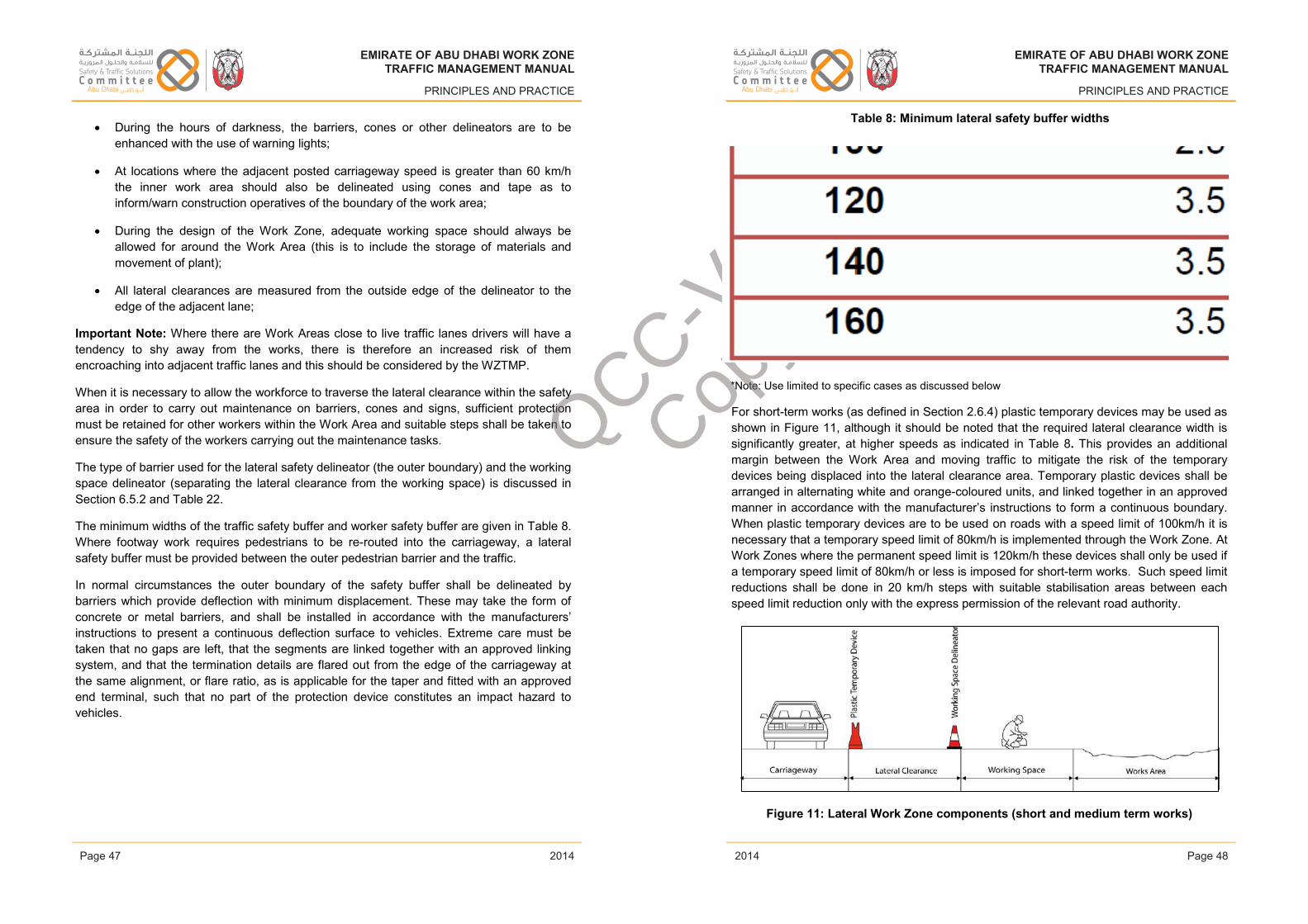
EMIRATE OF ABU DHABI WORK ZONETRAFFIC MANAGEMENT MANUAL
PRINCIPLES AND PRACTICE
• During the hours of darkness, the barriers, cones or other delineators are to be enhanced with the use of warning lights;
• At locations where the adjacent posted carriageway speed is greater than 60 km/h the inner work area should also be delineated using cones and tape as to inform/warn construction operatives of the boundary of the work area;
• During the design of the Work Zone, adequate working space should always be allowed for around the Work Area (this is to include the storage of materials and movement of plant);
• All lateral clearances are measured from the outside edge of the delineator to the edge of the adjacent lane;
Important Note: Where there are Work Areas close to live traffic lanes drivers will have a tendency to shy away from the works, there is therefore an increased risk of them encroaching into adjacent traffic lanes and this should be considered by the WZTMP.
When it is necessary to allow the workforce to traverse the lateral clearance within the safety area in order to carry out maintenance on barriers, cones and signs, sufficient protection must be retained for other workers within the Work Area and suitable steps shall be taken to ensure the safety of the workers carrying out the maintenance tasks.
The type of barrier used for the lateral safety delineator (the outer boundary) and the working space delineator (separating the lateral clearance from the working space) is discussed in Section 6.5.2 and Table 22.
The minimum widths of the traffic safety buffer and worker safety buffer are given in Table 8.Where footway work requires pedestrians to be re-routed into the carriageway, a lateral safety buffer must be provided between the outer pedestrian barrier and the traffic.
In normal circumstances the outer boundary of the safety buffer shall be delineated by barriers which provide deflection with minimum displacement. These may take the form of concrete or metal barriers, and shall be installed in accordance with the manufacturers’ instructions to present a continuous deflection surface to vehicles. Extreme care must be taken that no gaps are left, that the segments are linked together with an approved linking system, and that the termination details are flared out from the edge of the carriageway at the same alignment, or flare ratio, as is applicable for the taper and fitted with an approved end terminal, such that no part of the protection device constitutes an impact hazard to vehicles.
Issue 1 Page 47 February 2014
EMIRATE OF ABU DHABI WORK ZONETRAFFIC MANAGEMENT MANUAL
PRINCIPLES AND PRACTICE
Table 8: Minimum lateral safety buffer widths
*Note: Use limited to specific cases as discussed below
For short-term works (as defined in Section 2.6.4) plastic temporary devices may be used as shown in Figure 11, although it should be noted that the required lateral clearance width is significantly greater, at higher speeds as indicated in Table 8. This provides an additional margin between the Work Area and moving traffic to mitigate the risk of the temporary devices being displaced into the lateral clearance area. Temporary plastic devices shall be arranged in alternating white and orange-coloured units, and linked together in an approved manner in accordance with the manufacturer’s instructions to form a continuous boundary. When plastic temporary devices are to be used on roads with a speed limit of 100km/h it is necessary that a temporary speed limit of 80km/h is implemented through the Work Zone. At Work Zones where the permanent speed limit is 120km/h these devices shall only be used if a temporary speed limit of 80km/h or less is imposed for short-term works. Such speed limit reductions shall be done in 20 km/h steps with suitable stabilisation areas between each speed limit reduction only with the express permission of the relevant road authority.
Figure 11: Lateral Work Zone components (short and medium term works)
Issue 1 Page 48 February 2014
EMIRATE OF ABU DHABI WORK ZONETRAFFIC MANAGEMENT MANUAL
PRINCIPLES AND PRACTICE
2014
EMIRATE OF ABU DHABI WORK ZONETRAFFIC MANAGEMENT MANUAL
PRINCIPLES AND PRACTICE
2014Page 47 Page 48
EMIRATE OF ABU DHABI WORK ZONETRAFFIC MANAGEMENT MANUAL
PRINCIPLES AND PRACTICE
2014
EMIRATE OF ABU DHABI WORK ZONETRAFFIC MANAGEMENT MANUAL
PRINCIPLES AND PRACTICE
2014
QCC-V1
Copy
abdulrazzak.zaytoun
Placed Image
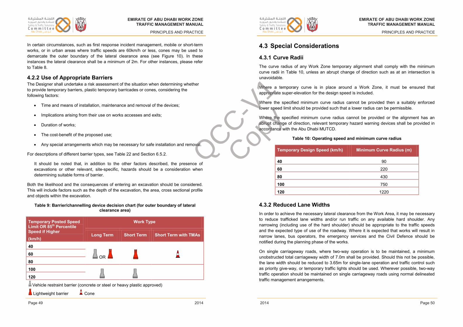
EMIRATE OF ABU DHABI WORK ZONETRAFFIC MANAGEMENT MANUAL
PRINCIPLES AND PRACTICE
In certain circumstances, such as first response incident management, mobile or short-term works, or in urban areas where traffic speeds are 60km/h or less, cones may be used to demarcate the outer boundary of the lateral clearance area (see Figure 10). In these instances the lateral clearance shall be a minimum of 2m. For other instances, please refer to Table 8.
4.2.2 Use of Appropriate BarriersThe Designer shall undertake a risk assessment of the situation when determining whether to provide temporary barriers, plastic temporary barricades or cones, considering the following factors:
• Time and means of installation, maintenance and removal of the devices;
• Implications arising from their use on works accesses and exits;
• Duration of works;
• The cost-benefit of the proposed use;
• Any special arrangements which may be necessary for safe installation and removal.
For descriptions of different barrier types, see Table 22 and Section 6.5.2.
It should be noted that, in addition to the other factors described, the presence of excavations or other relevant, site-specific, hazards should be a consideration when determining suitable forms of barrier.
Both the likelihood and the consequences of entering an excavation should be considered. This will include factors such as the depth of the excavation, the area, cross sectional profile and objects within the excavation.
Table 9: Barrier/channelling device decision chart (for outer boundary of lateral clearance area)
Temporary Posted Speed Limit OR 85th Percentile Speed if Higher(km/h)
Work Type
Long Term Short Term Short Term with TMAs
40
OR 60
80
100
120
Vehicle restraint barrier (concrete or steel or heavy plastic approved)
Lightweight barrier Cone
Issue 1 Page 49 February 2014
EMIRATE OF ABU DHABI WORK ZONETRAFFIC MANAGEMENT MANUAL
PRINCIPLES AND PRACTICE
4.3 Special Considerations
4.3.1 Curve RadiiThe curve radius of any Work Zone temporary alignment shall comply with the minimum curve radii in Table 10, unless an abrupt change of direction such as at an intersection is unavoidable.
Where a temporary curve is in place around a Work Zone, it must be ensured that appropriate super-elevation for the design speed is included.
Where the specified minimum curve radius cannot be provided then a suitably enforced lower speed limit should be provided such that a lower radius can be permissible.
Where the specified minimum curve radius cannot be provided or the alignment has an abrupt change of direction, relevant temporary hazard warning devices shall be provided in accordance with the Abu Dhabi MUTCD.
Table 10: Operating speed and minimum curve radius
Temporary Design Speed (km/h) Minimum Curve Radius (m)
40 90
60 220
80 430
100 750
120 1220
4.3.2 Reduced Lane WidthsIn order to achieve the necessary lateral clearance from the Work Area, it may be necessary to reduce trafficked lane widths and/or run traffic on any available hard shoulder. Any narrowing (including use of the hard shoulder) should be appropriate to the traffic speeds and the expected type of use of the roadway. Where it is expected that works will result in narrow lanes, bus operators, the emergency services and the Civil Defence should benotified during the planning phase of the works.
On single carriageway roads, where two-way operation is to be maintained, a minimum unobstructed total carriageway width of 7.0m shall be provided. Should this not be possible, the lane width should be reduced to 3.65m for single-lane operation and traffic control such as priority give-way, or temporary traffic lights should be used. Wherever possible, two-way traffic operation should be maintained on single carriageway roads using normal delineated traffic management arrangements.
Issue 1 Page 50 February 2014
EMIRATE OF ABU DHABI WORK ZONETRAFFIC MANAGEMENT MANUAL
PRINCIPLES AND PRACTICE
2014
EMIRATE OF ABU DHABI WORK ZONETRAFFIC MANAGEMENT MANUAL
PRINCIPLES AND PRACTICE
2014Page 49 Page 50
EMIRATE OF ABU DHABI WORK ZONETRAFFIC MANAGEMENT MANUAL
PRINCIPLES AND PRACTICE
2014
EMIRATE OF ABU DHABI WORK ZONETRAFFIC MANAGEMENT MANUAL
PRINCIPLES AND PRACTICE
2014
QCC-V1
Copy
EMIRATE OF ABU DHABI WORK ZONETRAFFIC MANAGEMENT MANUAL
PRINCIPLES AND PRACTICE
This system may be used provided that:
• The unobstructed carriageway is as wide as is practicable, and no narrower than theminimum width required for the appropriate conditions.
• The appropriate minimum safety clearances given are achieved.
• There is always clear visibility of and, except for very long sites, through the site bythe drivers of vehicles approaching from either direction.
Table 11 gives lanes widths (absolute minimum and preferred) to be observed during the design of temporary traffic management.
Table 11: Lane widths by speed
The absolute minimum lane widths given in Table 11 apply to normal, or typical, traffic compositions. Where heavy vehicles, including Civil Defence, Public Service Vehicles etc. are expected, the absolute minimum lane width for lane 1 of a multi-lane road is 3.5m and for lane 2 is 3.3m.
4.3.3 Pedestrian/Pedal Cyclist Facilities and SafetyPedestrian and pedal cyclist safety is an extremely high priority for all stages of the Work Zone process.
The need to accommodate pedestrians and cyclists in Work Zones can be identified by observing existing pedestrian/pedal cyclist usage and behaviour prior to the start of work.
The presence of pedestrians and cyclists in the area, existing footways and other pedestrian/cyclist paths, and pedestrian/pedal cyclist trip generators such as schools, residences, Mosques and parks, all indicate that pedestrians or pedal cyclists are likely to be present in the area affected by the Work Zone.
If existing footways or cycle facilities must be closed, relocated, or otherwise affected by the planned work activity, temporary facilities should be provided. The following considerations
Issue 1 Page 51 February 2014
EMIRATE OF ABU DHABI WORK ZONETRAFFIC MANAGEMENT MANUAL
PRINCIPLES AND PRACTICE
should be addressed when a need for pedestrian and/or cyclist routes in the Work Zone is identified:
• Direct conflicts between pedestrians/ pedal cyclists and vehicular traffic, work vehicles, and other work activities should be avoided;
• Temporary pedestrian/pedal cyclist facilities should provide safe, accessible routes that replicate as nearly as practical the most desirable characteristics of the existing facility;
• Covered walkways should be provided where pedestrians are exposed to potential injury from falling objects;
• Adverse economic consequences to business establishments in the Work Zone should be avoided by maintaining pedestrian access.
Key impact areas to consider:
• Impact of Work Zone on pedestrian/pedal cyclist generators;
• Impact of Work Zone on existing pedestrian/cyclist flow, including connectivity and accessibility;
• Pedestrian/pedal cyclist information needs;
• Footway/cycleway width, surface, boundaries, transitions, and channelization;
• Intersections — footway placement, additional signing/marking, traffic signals modification including cycle timings, pedestrian signals, and if present any pedestrian push buttons to call the pedestrian phase;
• Adequate and safe detour due to any footway closures or blockage;
• Adequate pedestrian protection — physical separation from the work space, including any hazards from the work space, such as noise or dust and vehicular traffic;
• Construction staging to maintain pedestrian/pedal cyclist access throughout all construction phases;
• Temporary night-time lighting;
• Location/access to business, residences, etc.
When designing for pedestrians and cyclists a balance is needed between the requirements for all road users. The facilities installed through the Work Zone needs to ensure that the works can be carried out safely and the road user protected, as part of both the WZTMP planning and Work Zone traffic management design.
Issue 1 Page 52 February 2014
EMIRATE OF ABU DHABI WORK ZONETRAFFIC MANAGEMENT MANUAL
PRINCIPLES AND PRACTICE
2014
EMIRATE OF ABU DHABI WORK ZONETRAFFIC MANAGEMENT MANUAL
PRINCIPLES AND PRACTICE
2014Page 51 Page 52
EMIRATE OF ABU DHABI WORK ZONETRAFFIC MANAGEMENT MANUAL
PRINCIPLES AND PRACTICE
2014
EMIRATE OF ABU DHABI WORK ZONETRAFFIC MANAGEMENT MANUAL
PRINCIPLES AND PRACTICE
2014
QCC-V1
Copy
abdulrazzak.zaytoun
Placed Image
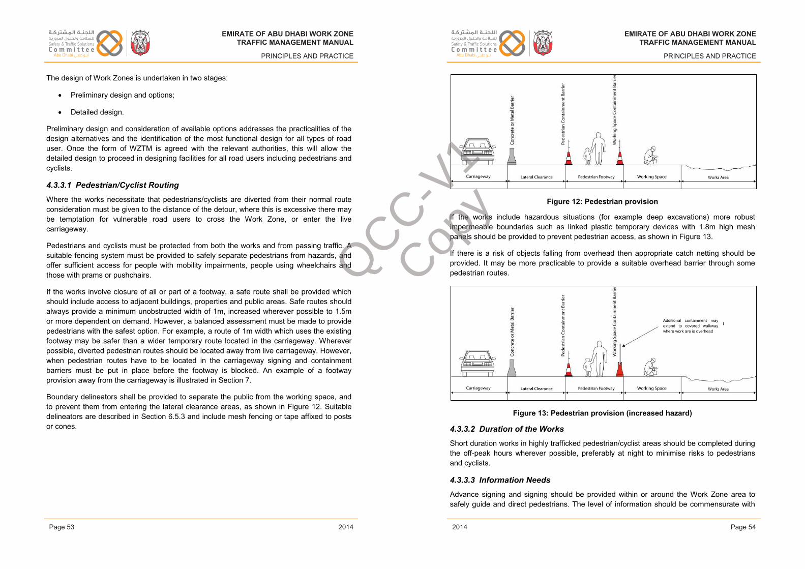
EMIRATE OF ABU DHABI WORK ZONETRAFFIC MANAGEMENT MANUAL
PRINCIPLES AND PRACTICE
The design of Work Zones is undertaken in two stages:
• Preliminary design and options;
• Detailed design.
Preliminary design and consideration of available options addresses the practicalities of the design alternatives and the identification of the most functional design for all types of road user. Once the form of WZTM is agreed with the relevant authorities, this will allow the detailed design to proceed in designing facilities for all road users including pedestrians and cyclists.
4.3.3.1 Pedestrian/Cyclist Routing
Where the works necessitate that pedestrians/cyclists are diverted from their normal route consideration must be given to the distance of the detour, where this is excessive there may be temptation for vulnerable road users to cross the Work Zone, or enter the live carriageway.
Pedestrians and cyclists must be protected from both the works and from passing traffic. Asuitable fencing system must be provided to safely separate pedestrians from hazards, andoffer sufficient access for people with mobility impairments, people using wheelchairs and those with prams or pushchairs.
If the works involve closure of all or part of a footway, a safe route shall be provided which should include access to adjacent buildings, properties and public areas. Safe routes should always provide a minimum unobstructed width of 1m, increased wherever possible to 1.5m or more dependent on demand. However, a balanced assessment must be made to provide pedestrians with the safest option. For example, a route of 1m width which uses the existing footway may be safer than a wider temporary route located in the carriageway. Wherever possible, diverted pedestrian routes should be located away from live carriageway. However, when pedestrian routes have to be located in the carriageway signing and containment barriers must be put in place before the footway is blocked. An example of a footway provision away from the carriageway is illustrated in Section 7.
Boundary delineators shall be provided to separate the public from the working space, and to prevent them from entering the lateral clearance areas, as shown in Figure 12. Suitable delineators are described in Section 6.5.3 and include mesh fencing or tape affixed to posts or cones.
Issue 1 Page 53 February 2014
EMIRATE OF ABU DHABI WORK ZONETRAFFIC MANAGEMENT MANUAL
PRINCIPLES AND PRACTICE
Figure 12: Pedestrian provision
If the works include hazardous situations (for example deep excavations) more robust impermeable boundaries such as linked plastic temporary devices with 1.8m high mesh panels should be provided to prevent pedestrian access, as shown in Figure 13.
If there is a risk of objects falling from overhead then appropriate catch netting should be provided. It may be more practicable to provide a suitable overhead barrier through some pedestrian routes.
Figure 13: Pedestrian provision (increased hazard)
4.3.3.2 Duration of the Works
Short duration works in highly trafficked pedestrian/cyclist areas should be completed during the off-peak hours wherever possible, preferably at night to minimise risks to pedestrians and cyclists.
4.3.3.3 Information Needs
Advance signing and signing should be provided within or around the Work Zone area to safely guide and direct pedestrians. The level of information should be commensurate with
Additional containment may extend to covered walkway where work are is overhead
Issue 1 Page 54 February 2014
EMIRATE OF ABU DHABI WORK ZONETRAFFIC MANAGEMENT MANUAL
PRINCIPLES AND PRACTICE
2014
EMIRATE OF ABU DHABI WORK ZONETRAFFIC MANAGEMENT MANUAL
PRINCIPLES AND PRACTICE
2014Page 53 Page 54
EMIRATE OF ABU DHABI WORK ZONETRAFFIC MANAGEMENT MANUAL
PRINCIPLES AND PRACTICE
2014
EMIRATE OF ABU DHABI WORK ZONETRAFFIC MANAGEMENT MANUAL
PRINCIPLES AND PRACTICE
2014
QCC-V1
Copy
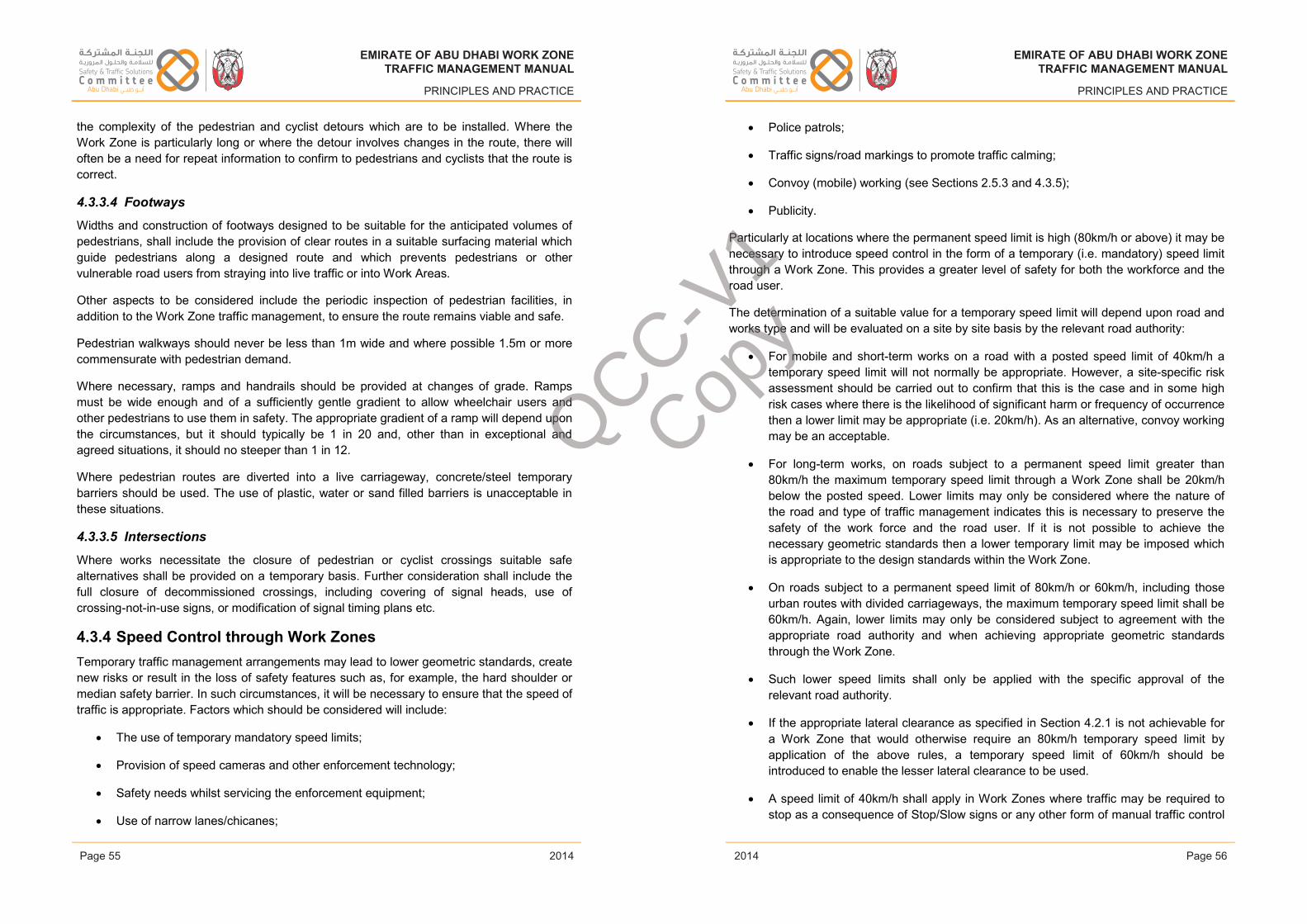
EMIRATE OF ABU DHABI WORK ZONETRAFFIC MANAGEMENT MANUAL
PRINCIPLES AND PRACTICE
the complexity of the pedestrian and cyclist detours which are to be installed. Where the Work Zone is particularly long or where the detour involves changes in the route, there will often be a need for repeat information to confirm to pedestrians and cyclists that the route is correct.
4.3.3.4 Footways
Widths and construction of footways designed to be suitable for the anticipated volumes of pedestrians, shall include the provision of clear routes in a suitable surfacing material which guide pedestrians along a designed route and which prevents pedestrians or other vulnerable road users from straying into live traffic or into Work Areas.
Other aspects to be considered include the periodic inspection of pedestrian facilities, in addition to the Work Zone traffic management, to ensure the route remains viable and safe.
Pedestrian walkways should never be less than 1m wide and where possible 1.5m or more commensurate with pedestrian demand.
Where necessary, ramps and handrails should be provided at changes of grade. Ramps must be wide enough and of a sufficiently gentle gradient to allow wheelchair users and other pedestrians to use them in safety. The appropriate gradient of a ramp will depend upon the circumstances, but it should typically be 1 in 20 and, other than in exceptional and agreed situations, it should no steeper than 1 in 12.
Where pedestrian routes are diverted into a live carriageway, concrete/steel temporary barriers should be used. The use of plastic, water or sand filled barriers is unacceptable in these situations.
4.3.3.5 Intersections
Where works necessitate the closure of pedestrian or cyclist crossings suitable safe alternatives shall be provided on a temporary basis. Further consideration shall include the full closure of decommissioned crossings, including covering of signal heads, use of crossing-not-in-use signs, or modification of signal timing plans etc.
4.3.4 Speed Control through Work ZonesTemporary traffic management arrangements may lead to lower geometric standards, create new risks or result in the loss of safety features such as, for example, the hard shoulder or median safety barrier. In such circumstances, it will be necessary to ensure that the speed of traffic is appropriate. Factors which should be considered will include:
• The use of temporary mandatory speed limits;
• Provision of speed cameras and other enforcement technology;
• Safety needs whilst servicing the enforcement equipment;
• Use of narrow lanes/chicanes;
Issue 1 Page 55 February 2014
EMIRATE OF ABU DHABI WORK ZONETRAFFIC MANAGEMENT MANUAL
PRINCIPLES AND PRACTICE
• Police patrols;
• Traffic signs/road markings to promote traffic calming;
• Convoy (mobile) working (see Sections 2.5.3 and 4.3.5);
• Publicity.
Particularly at locations where the permanent speed limit is high (80km/h or above) it may be necessary to introduce speed control in the form of a temporary (i.e. mandatory) speed limit through a Work Zone. This provides a greater level of safety for both the workforce and the road user.
The determination of a suitable value for a temporary speed limit will depend upon road and works type and will be evaluated on a site by site basis by the relevant road authority:
• For mobile and short-term works on a road with a posted speed limit of 40km/h a temporary speed limit will not normally be appropriate. However, a site-specific risk assessment should be carried out to confirm that this is the case and in some high risk cases where there is the likelihood of significant harm or frequency of occurrence then a lower limit may be appropriate (i.e. 20km/h). As an alternative, convoy workingmay be an acceptable.
• For long-term works, on roads subject to a permanent speed limit greater than 80km/h the maximum temporary speed limit through a Work Zone shall be 20km/hbelow the posted speed. Lower limits may only be considered where the nature of the road and type of traffic management indicates this is necessary to preserve the safety of the work force and the road user. If it is not possible to achieve the necessary geometric standards then a lower temporary limit may be imposed which is appropriate to the design standards within the Work Zone.
• On roads subject to a permanent speed limit of 80km/h or 60km/h, including those urban routes with divided carriageways, the maximum temporary speed limit shall be 60km/h. Again, lower limits may only be considered subject to agreement with the appropriate road authority and when achieving appropriate geometric standards through the Work Zone.
• Such lower speed limits shall only be applied with the specific approval of the relevant road authority.
• If the appropriate lateral clearance as specified in Section 4.2.1 is not achievable for a Work Zone that would otherwise require an 80km/h temporary speed limit by application of the above rules, a temporary speed limit of 60km/h should be introduced to enable the lesser lateral clearance to be used.
• A speed limit of 40km/h shall apply in Work Zones where traffic may be required to stop as a consequence of Stop/Slow signs or any other form of manual traffic control
Issue 1 Page 56 February 2014
EMIRATE OF ABU DHABI WORK ZONETRAFFIC MANAGEMENT MANUAL
PRINCIPLES AND PRACTICE
2014
EMIRATE OF ABU DHABI WORK ZONETRAFFIC MANAGEMENT MANUAL
PRINCIPLES AND PRACTICE
2014Page 55 Page 56
EMIRATE OF ABU DHABI WORK ZONETRAFFIC MANAGEMENT MANUAL
PRINCIPLES AND PRACTICE
2014
EMIRATE OF ABU DHABI WORK ZONETRAFFIC MANAGEMENT MANUAL
PRINCIPLES AND PRACTICE
2014
QCC-V1
Copy
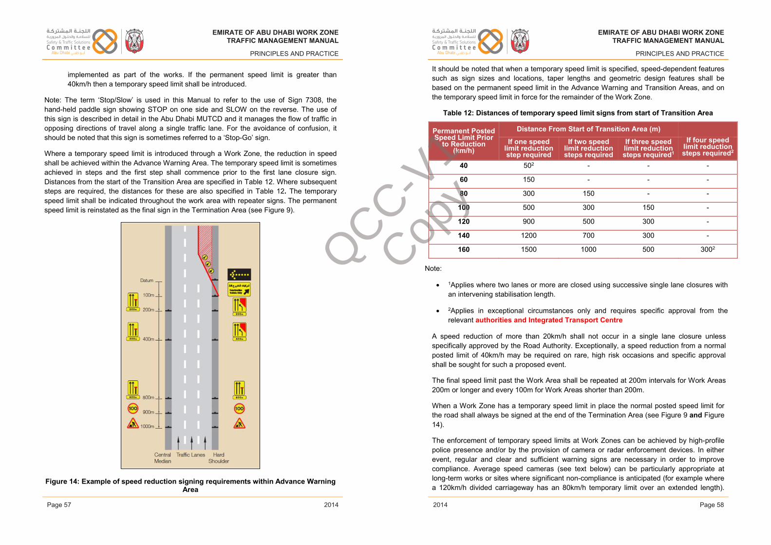
EMIRATE OF ABU DHABI WORK ZONETRAFFIC MANAGEMENT MANUAL
PRINCIPLES AND PRACTICE
implemented as part of the works. If the permanent speed limit is greater than 40km/h then a temporary speed limit shall be introduced.
Note: The term ‘Stop/Slow’ is used in this Manual to refer to the use of Sign 7308, the hand-held paddle sign showing STOP on one side and SLOW on the reverse. The use of this sign is described in detail in the Abu Dhabi MUTCD and it manages the flow of traffic in opposing directions of travel along a single traffic lane. For the avoidance of confusion, it should be noted that this sign is sometimes referred to a ‘Stop-Go’ sign.
Where a temporary speed limit is introduced through a Work Zone, the reduction in speed shall be achieved within the Advance Warning Area. The temporary speed limit is sometimes achieved in steps and the first step shall commence prior to the first lane closure sign. Distances from the start of the Transition Area are specified in Table 12. Where subsequent steps are required, the distances for these are also specified in Table 12. The temporary speed limit shall be indicated throughout the work area with repeater signs. The permanent speed limit is reinstated as the final sign in the Termination Area (see Figure 9).
Figure 14: Example of speed reduction signing requirements within Advance Warning Area
Issue 1 Page 57 February 2014
EMIRATE OF ABU DHABI WORK ZONETRAFFIC MANAGEMENT MANUAL
PRINCIPLES AND PRACTICE
It should be noted that when a temporary speed limit is specified, speed-dependent features such as sign sizes and locations, taper lengths and geometric design features shall be based on the permanent speed limit in the Advance Warning and Transition Areas, and on the temporary speed limit in force for the remainder of the Work Zone.
Table 12: Distances of temporary speed limit signs from start of Transition Area
A speed reduction of more than 20km/h shall not occur in a single lane closure unless specifically approved by the Road Authority. Exceptionally, a speed reduction from a normal posted limit of 40km/h may be required on rare, high risk occasions and specific approval shall be sought for such a proposed event.
The final speed limit past the Work Area shall be repeated at 200m intervals for Work Areas200m or longer and every 100m for Work Areas shorter than 200m.
When a Work Zone has a temporary speed limit in place the normal posted speed limit for the road shall always be signed at the end of the Termination Area (see Figure 9 and Figure 14).
The enforcement of temporary speed limits at Work Zones can be achieved by high-profile police presence and/or by the provision of camera or radar enforcement devices. In either event, regular and clear and sufficient warning signs are necessary in order to improve compliance. Average speed cameras (see text below) can be particularly appropriate at long-term works or sites where significant non-compliance is anticipated (for example where a 120km/h divided carriageway has an 80km/h temporary limit over an extended length).
Issue 1 Page 58 February 2014
EMIRATE OF ABU DHABI WORK ZONETRAFFIC MANAGEMENT MANUAL
PRINCIPLES AND PRACTICE
2014
EMIRATE OF ABU DHABI WORK ZONETRAFFIC MANAGEMENT MANUAL
PRINCIPLES AND PRACTICE
2014Page 57 Page 58
EMIRATE OF ABU DHABI WORK ZONETRAFFIC MANAGEMENT MANUAL
PRINCIPLES AND PRACTICE
2014
EMIRATE OF ABU DHABI WORK ZONETRAFFIC MANAGEMENT MANUAL
PRINCIPLES AND PRACTICE
2014
Note:
1Applies where two lanes or more are closed using successive single lane closures withan intervening stabilisation length.
2Applies in exceptional circumstances only and requires specific approval from therelevant authorities and Integrated Transport Centre
Permanent Posted Speed Limit Prior
to Reduction (km/h)
Distance From Start of Transition Area (m) If one speed
limit reduction step required
If two speed limit reduction steps required
If three speed limit reduction steps required1
If four speed limit reduction steps required2
40 502 - - -
60 150 - - -
80 300 150 - -
100 500 300 150 -
120 900 500 300 -
140 1200 700 300 -
160 1500 1000 500 3002 QCC-V1
Copy
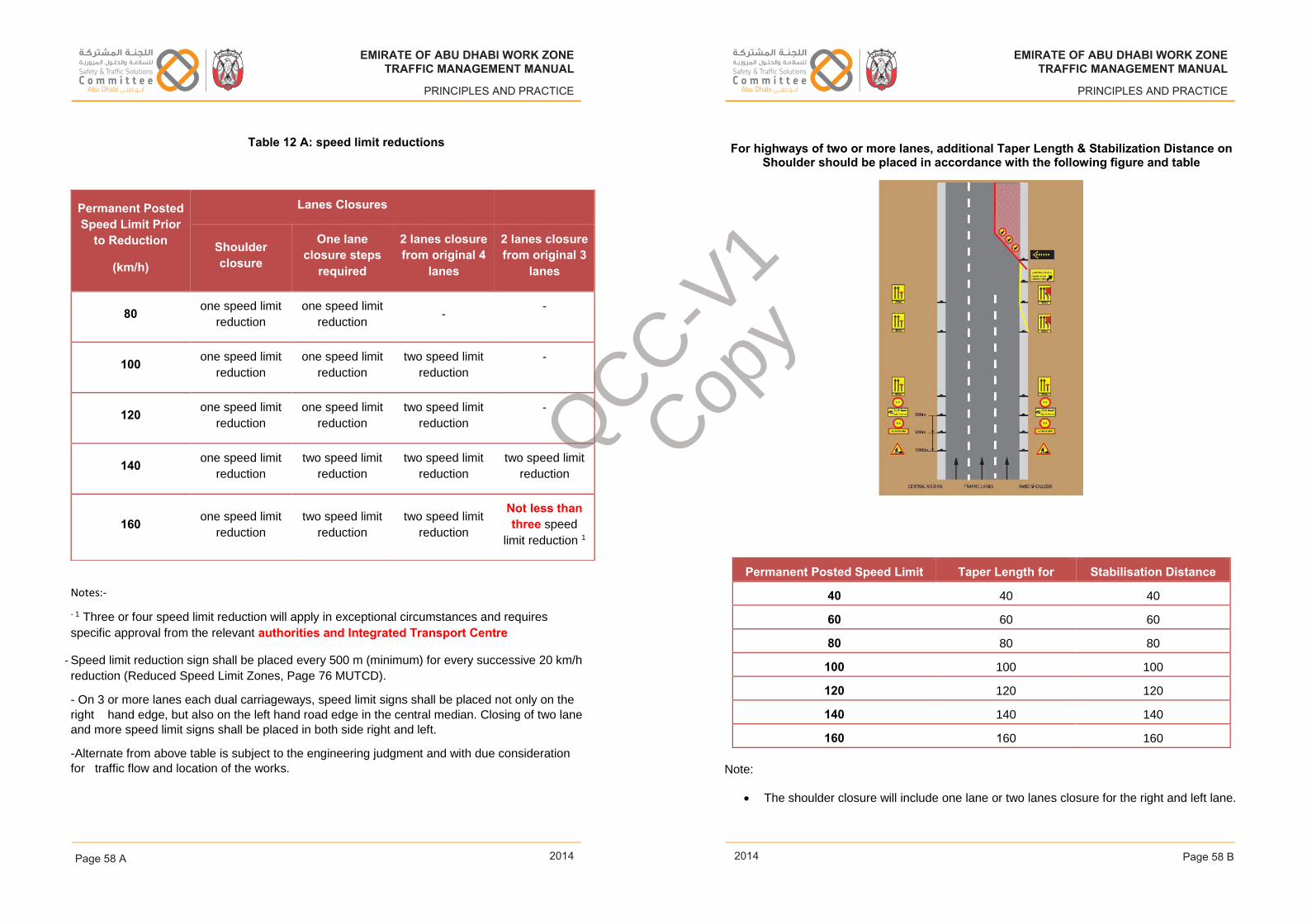
EMIRATE OF ABU DHABI WORK ZONETRAFFIC MANAGEMENT MANUAL
PRINCIPLES AND PRACTICE
Issue 1 Page 111 February 2014
EMIRATE OF ABU DHABI WORK ZONETRAFFIC MANAGEMENT MANUAL
PRINCIPLES AND PRACTICE
Issue 1 Page 112 February 2014
EMIRATE OF ABU DHABI WORK ZONETRAFFIC MANAGEMENT MANUAL
PRINCIPLES AND PRACTICE
2014
EMIRATE OF ABU DHABI WORK ZONETRAFFIC MANAGEMENT MANUAL
PRINCIPLES AND PRACTICE
2014
EMIRATE OF ABU DHABI WORK ZONETRAFFIC MANAGEMENT MANUAL
PRINCIPLES AND PRACTICE
2014
EMIRATE OF ABU DHABI WORK ZONETRAFFIC MANAGEMENT MANUAL
PRINCIPLES AND PRACTICE
2014
Notes:-
- 1 Three or four speed limit reduction will apply in exceptional circumstances and requires
specific approval from the relevant authorities and Integrated Transport Centre
- Speed limit reduction sign shall be placed every 500 m (minimum) for every successive 20 km/h
reduction (Reduced Speed Limit Zones, Page 76 MUTCD).
- On 3 or more lanes each dual carriageways, speed limit signs shall be placed not only on the
right hand edge, but also on the left hand road edge in the central median. Closing of two lane
and more speed limit signs shall be placed in both side right and left.
-Alternate from above table is subject to the engineering judgment and with due consideration
for traffic flow and location of the works.
Permanent Posted Speed Limit Prior
to Reduction
(km/h)
Lanes Closures
Shoulder closure
One lane closure steps
required
2 lanes closure from original 4
lanes
2 lanes closure from original 3
lanes
80 one speed limit
reduction
one speed limit
reduction -
-
100 one speed limit
reduction
one speed limit
reduction
two speed limit
reduction
-
120 one speed limit
reduction
one speed limit
reduction
two speed limit
reduction
-
140 one speed limit
reduction
two speed limit
reduction
two speed limit
reduction
two speed limit
reduction
160 one speed limit
reduction
two speed limit
reduction
two speed limit
reduction
Not less than three speed
limit reduction 1
For highways of two or more lanes, additional Taper Length & Stabilization Distance on Shoulder should be placed in accordance with the following figure and table
Permanent Posted Speed Limit Taper Length for Stabilisation Distance
40 40 40
60 60 60
80 80 80
100 100 100
120 120 120
140 140 140
160 160 160
Note:
The shoulder closure will include one lane or two lanes closure for the right and left lane.
Table 12 A: speed limit reductions
Page 58 BPage 58 A
QCC-V1
Copy
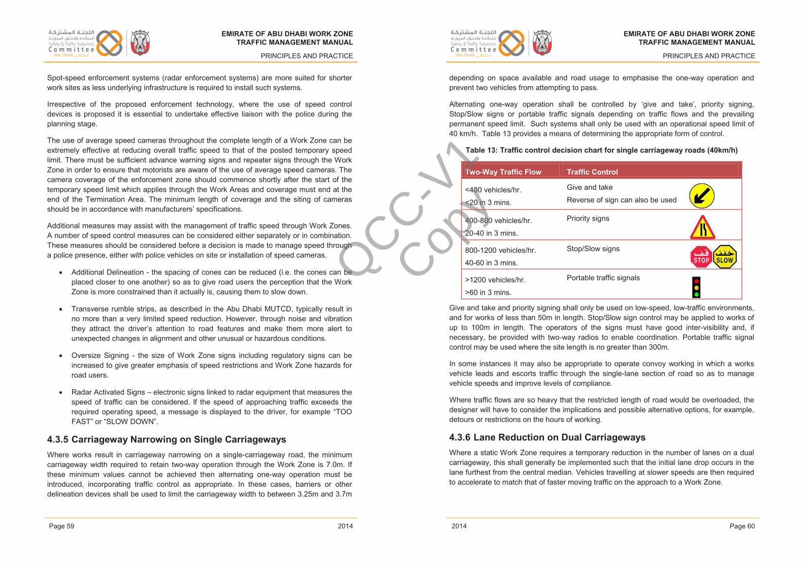
EMIRATE OF ABU DHABI WORK ZONETRAFFIC MANAGEMENT MANUAL
PRINCIPLES AND PRACTICE
Spot-speed enforcement systems (radar enforcement systems) are more suited for shorter work sites as less underlying infrastructure is required to install such systems.
Irrespective of the proposed enforcement technology, where the use of speed controldevices is proposed it is essential to undertake effective liaison with the police during the planning stage.
The use of average speed cameras throughout the complete length of a Work Zone can be extremely effective at reducing overall traffic speed to that of the posted temporary speed limit. There must be sufficient advance warning signs and repeater signs through the Work Zone in order to ensure that motorists are aware of the use of average speed cameras. The camera coverage of the enforcement zone should commence shortly after the start of the temporary speed limit which applies through the Work Areas and coverage must end at the end of the Termination Area. The minimum length of coverage and the siting of cameras should be in accordance with manufacturers’ specifications.
Additional measures may assist with the management of traffic speed through Work Zones. A number of speed control measures can be considered either separately or in combination. These measures should be considered before a decision is made to manage speed through a police presence, either with police vehicles on site or installation of speed cameras.
• Additional Delineation - the spacing of cones can be reduced (i.e. the cones can be placed closer to one another) so as to give road users the perception that the Work Zone is more constrained than it actually is, causing them to slow down.
• Transverse rumble strips, as described in the Abu Dhabi MUTCD, typically result in no more than a very limited speed reduction. However, through noise and vibration they attract the driver’s attention to road features and make them more alert to unexpected changes in alignment and other unusual or hazardous conditions.
• Oversize Signing - the size of Work Zone signs including regulatory signs can beincreased to give greater emphasis of speed restrictions and Work Zone hazards for road users.
• Radar Activated Signs – electronic signs linked to radar equipment that measures the speed of traffic can be considered. lf the speed of approaching traffic exceeds the required operating speed, a message is displayed to the driver, for example “TOO FAST” or “SLOW DOWN”.
4.3.5 Carriageway Narrowing on Single CarriagewaysWhere works result in carriageway narrowing on a single-carriageway road, the minimum carriageway width required to retain two-way operation through the Work Zone is 7.0m. If these minimum values cannot be achieved then alternating one-way operation must be introduced, incorporating traffic control as appropriate. In these cases, barriers or other delineation devices shall be used to limit the carriageway width to between 3.25m and 3.7m
Issue 1 Page 59 February 2014
EMIRATE OF ABU DHABI WORK ZONETRAFFIC MANAGEMENT MANUAL
PRINCIPLES AND PRACTICE
depending on space available and road usage to emphasise the one-way operation and prevent two vehicles from attempting to pass.
Alternating one-way operation shall be controlled by ‘give and take’, priority signing, Stop/Slow signs or portable traffic signals depending on traffic flows and the prevailing permanent speed limit. Such systems shall only be used with an operational speed limit of 40 km/h. Table 13 provides a means of determining the appropriate form of control.
Table 13: Traffic control decision chart for single carriageway roads (40km/h)
Two-Way Traffic Flow Traffic Control
<400 vehicles/hr.
<20 in 3 mins.
Give and take
Reverse of sign can also be used
400-800 vehicles/hr.
20-40 in 3 mins.
Priority signs
800-1200 vehicles/hr.
40-60 in 3 mins.
Stop/Slow signs
>1200 vehicles/hr.
>60 in 3 mins.
Portable traffic signals
Give and take and priority signing shall only be used on low-speed, low-traffic environments, and for works of less than 50m in length. Stop/Slow sign control may be applied to works of up to 100m in length. The operators of the signs must have good inter-visibility and, if necessary, be provided with two-way radios to enable coordination. Portable traffic signal control may be used where the site length is no greater than 300m.
In some instances it may also be appropriate to operate convoy working in which a works vehicle leads and escorts traffic through the single-lane section of road so as to manage vehicle speeds and improve levels of compliance.
Where traffic flows are so heavy that the restricted length of road would be overloaded, the designer will have to consider the implications and possible alternative options, for example,detours or restrictions on the hours of working.
4.3.6 Lane Reduction on Dual CarriagewaysWhere a static Work Zone requires a temporary reduction in the number of lanes on a dual carriageway, this shall generally be implemented such that the initial lane drop occurs in the lane furthest from the central median. Vehicles travelling at slower speeds are then required to accelerate to match that of faster moving traffic on the approach to a Work Zone.
Issue 1 Page 60 February 2014
EMIRATE OF ABU DHABI WORK ZONETRAFFIC MANAGEMENT MANUAL
PRINCIPLES AND PRACTICE
2014
EMIRATE OF ABU DHABI WORK ZONETRAFFIC MANAGEMENT MANUAL
PRINCIPLES AND PRACTICE
2014Page 59 Page 60
EMIRATE OF ABU DHABI WORK ZONETRAFFIC MANAGEMENT MANUAL
PRINCIPLES AND PRACTICE
2014
EMIRATE OF ABU DHABI WORK ZONETRAFFIC MANAGEMENT MANUAL
PRINCIPLES AND PRACTICE
2014
QCC-V1
Copy
EMIRATE OF ABU DHABI WORK ZONETRAFFIC MANAGEMENT MANUAL
PRINCIPLES AND PRACTICE
Any lane closure on a dual carriageway will result in a reduction in the capacity of the road.The designer shall develop a strategy for minimizing the effect of this loss of capacity, by judicial use as appropriate of hard shoulder running or contra-flow operation.
4.3.7 Off Carriageway Works RequirementsAs long as off-carriageway works are able to provide the necessary traffic safety buffer/lateral clearance and work space in the work area and appropriate width for pedestrians and cyclists, then temporary traffic management within the traffic lanes will not be required. However, there may be a need for protection of the work area by use of concrete/steel barriers depending on the nature of the work to be carried out in order to prevent errant vehicles entering the Work Area.
4.3.8 Access ControlRoutes for construction vehicles to the site and through the works can create significant problems. Access is required for works vehicles and plant, delivery vehicles and site staff vehicles. The means by which these vehicles will access the site can have a significant impact on the adjacent road, and on high speed roads it is a fundamental element of the design process. It can be particularly difficult where a full protection barrier is provided and safety buffer integrity needs to be protected. In particular, the following aspects need to be considered:
• Any issue arising from the consultation process;
• Determination of permitted/prohibited routes and design signing;
• Ensure adequate signing is provided;
• Imposition of site speed limits;
• Access to Work Area from adjacent network if available and appropriate;
• Integrity of the safety buffer/lateral clearance around the work area;
• Conflict with local land use patterns and timing of works;
• The need to minimise sand and debris left on road surfaces;
• Consultation with adjoining Road Authorities.
The inclusion of appropriate works access and exit arrangements should be considered as early as possible in the traffic management design stage, and should be considered in conjunction with the following points:
• Conflicts with other traffic movements;
• Traffic speeds;
Issue 1 Page 61 February 2014
EMIRATE OF ABU DHABI WORK ZONETRAFFIC MANAGEMENT MANUAL
PRINCIPLES AND PRACTICE
• Lane widths;
• Sight lines;
• Signing;
• Swept path for turning movements for all classes of vehicles using the access/exit;
• Acceleration/deceleration lanes;
• Separation of the access/exit from the main carriageway; and
• Unintentional movement or spillage of material such as soil/sand into the carriageway.
No works vehicles should be operated from the live carriageway without additional WZTM being considered. All vehicle related activates should be undertaken from within the defined WZTM arrangements and appropriate access/exit and operational space needs to be included within the approved WZTMP.
The preferred locations where access can be gained from the adjacent highway are where either plastic barrier or cones are used as delineators. These are universally used in the Termination Area and may, under certain circumstances, be used adjacent to the work area and also in the Transition Area. However the safety buffer should not be breached to permit access. Therefore access is most likely to be achievable at the start of the Transition taperwhere absence of barrier protection would not increase safety risk for workers or the travelling public.
Attempting to create access within the taper area could increase the risk of inadvertent public access and any defined access point needs clear demarcation and signing.
The works access and exit should be used in conjunction with the new signs “Construction Vehicles Only”, “Construction Vehicles Merging” and “Construction Vehicles Crossing”.
Access for emergency vehicles is to be maintained at all times during the works wherever it is practical to do so, this should be discussed during the planning stage of any temporary traffic management design with the Civil Defence Authority.
The designer should undertake a documented risk assessment to calculate any allowances in the Work Zone design for access points being created without compromising any safety zone requirements.
A full risk assessment of the impact of off-carriageway work is to be conducted where vehicles are unable to safely pull off the carriageway completely. Where the risk assessment identifies that advance works signing should be provided, the working area should be extended into the carriageway, and be subject to the same design criteria as live carriageway works as set out in this volume.
Issue 1 Page 62 February 2014
EMIRATE OF ABU DHABI WORK ZONETRAFFIC MANAGEMENT MANUAL
PRINCIPLES AND PRACTICE
2014
EMIRATE OF ABU DHABI WORK ZONETRAFFIC MANAGEMENT MANUAL
PRINCIPLES AND PRACTICE
2014Page 61 Page 62
EMIRATE OF ABU DHABI WORK ZONETRAFFIC MANAGEMENT MANUAL
PRINCIPLES AND PRACTICE
2014
EMIRATE OF ABU DHABI WORK ZONETRAFFIC MANAGEMENT MANUAL
PRINCIPLES AND PRACTICE
2014
QCC-V1
Copy
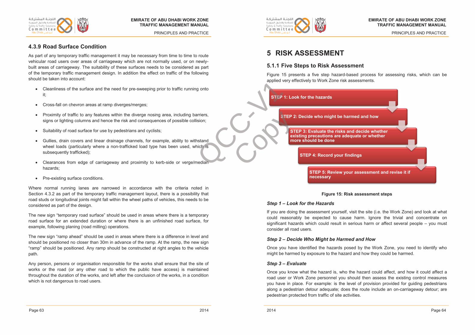
EMIRATE OF ABU DHABI WORK ZONETRAFFIC MANAGEMENT MANUAL
PRINCIPLES AND PRACTICE
4.3.9 Road Surface ConditionAs part of any temporary traffic management it may be necessary from time to time to route vehicular road users over areas of carriageway which are not normally used, or on newly-built areas of carriageway. The suitability of these surfaces needs to be considered as part of the temporary traffic management design. In addition the effect on traffic of the following should be taken into account:
• Cleanliness of the surface and the need for pre-sweeping prior to traffic running onto it;
• Cross-fall on chevron areas at ramp diverges/merges;
• Proximity of traffic to any features within the diverge nosing area, including barriers, signs or lighting columns and hence the risk and consequences of possible collision;
• Suitability of road surface for use by pedestrians and cyclists;
• Gullies, drain covers and linear drainage channels, for example, ability to withstand wheel loads (particularly where a non-trafficked load type has been used, which is subsequently trafficked);
• Clearances from edge of carriageway and proximity to kerb-side or verge/median hazards;
• Pre-existing surface conditions.
Where normal running lanes are narrowed in accordance with the criteria noted inSection 4.3.2 as part of the temporary traffic management layout, there is a possibility that road studs or longitudinal joints might fall within the wheel paths of vehicles, this needs to be considered as part of the design.
The new sign “temporary road surface” should be used in areas where there is a temporary road surface for an extended duration or where there is an unfinished road surface, for example, following planing (road milling) operations.
The new sign “ramp ahead” should be used in areas where there is a difference in level and should be positioned no closer than 30m in advance of the ramp. At the ramp, the new sign “ramp” should be positioned. Any ramp should be constructed at right angles to the vehicle path.
Any person, persons or organisation responsible for the works shall ensure that the site of works or the road (or any other road to which the public have access) is maintained throughout the duration of the works, and left after the conclusion of the works, in a condition which is not dangerous to road users.
Issue 1 Page 63 February 2014
EMIRATE OF ABU DHABI WORK ZONETRAFFIC MANAGEMENT MANUAL
PRINCIPLES AND PRACTICE
5 RISK ASSESSMENT5.1.1 Five Steps to Risk AssessmentFigure 15 presents a five step hazard-based process for assessing risks, which can be applied very effectively to Work Zone risk assessments.
Figure 15: Risk assessment steps
Step 1 – Look for the Hazards
If you are doing the assessment yourself, visit the site (i.e. the Work Zone) and look at what could reasonably be expected to cause harm. Ignore the trivial and concentrate on significant hazards which could result in serious harm or affect several people – you must consider all road users.
Step 2 – Decide Who Might be Harmed and How
Once you have identified the hazards posed by the Work Zone, you need to identify who might be harmed by exposure to the hazard and how they could be harmed.
Step 3 – Evaluate
Once you know what the hazard is, who the hazard could affect, and how it could affect a road user or Work Zone personnel you should then assess the existing control measures you have in place. For example: is the level of provision provided for guiding pedestrians along a pedestrian detour adequate; does the route include an on-carriageway detour; are pedestrian protected from traffic of site activities.
STEP 1: Look for the hazards
STEP 2: Decide who might be harmed and how
STEP 3: Evaluate the risks and decide whether existing precautions are adequate or whether more should be done
STEP 4: Record your findings
STEP 5: Review your assessment and revise it if necessary
Issue 1 Page 64 February 2014
EMIRATE OF ABU DHABI WORK ZONETRAFFIC MANAGEMENT MANUAL
PRINCIPLES AND PRACTICE
2014
EMIRATE OF ABU DHABI WORK ZONETRAFFIC MANAGEMENT MANUAL
PRINCIPLES AND PRACTICE
2014Page 63 Page 64
EMIRATE OF ABU DHABI WORK ZONETRAFFIC MANAGEMENT MANUAL
PRINCIPLES AND PRACTICE
2014
EMIRATE OF ABU DHABI WORK ZONETRAFFIC MANAGEMENT MANUAL
PRINCIPLES AND PRACTICE
2014
QCC-V1
Copy
EMIRATE OF ABU DHABI WORK ZONETRAFFIC MANAGEMENT MANUAL
PRINCIPLES AND PRACTICE
If the control measures proposed are not considered adequate based on the level of risk posed by a hazard to road users, including construction workers, you need to identify what else can be done, the objective where risk cannot be entirely removed, is to reduce it to as low as reasonably practicable.
In the event of a particular hazard posing a high level of risk even after the application of a control measure, you need to consider whether or not everything that could reasonably be done has been identified.
In controlling risks, apply the principles below in the following order:
1: Try a less risky approach or construction option;
2: Prevent access to the hazard; and then
3: Reorganise any construction work plan to limit the risk as much as possible.
Step 4: Record your findings
It is not enough to have identified your hazards and then any measures to control them, you MUST also then record what was identified and what is being done to reduce the risk. This record forms an essential component of the risk assessment process. You need to be able to show that:
• A proper check was made to identify the hazards;
• That when you identified the hazards you recorded your findings;
• That from the hazards identified, the affected road users were identified and how they could be affected;
• That a methodical approach to reducing any risk arising from the hazards identified was used;
• That the mitigating measures identified were suitable, recorded and then implemented; and finally
• That the mitigating measures used are reasonable and reduce any residual risk to an acceptable level.
Keep the written record for future reference or use; it can also remind you to keep an eye on particular hazards and precautions.
Step 5: Review your assessment and revise it if necessary
The first risk assessment conducted should be subject to review, particularly in the event of any site conditions changing once work has commenced or any new hazards which were previously unseen becoming apparent.
Issue 1 Page 65 February 2014
EMIRATE OF ABU DHABI WORK ZONETRAFFIC MANAGEMENT MANUAL
PRINCIPLES AND PRACTICE
It is essential that any new hazards or changes to existing ones are recorded in the risk assessment and that they are documented as part of the works.
5.1.2 Tolerance of RiskRisk is measured in terms of both the individual risk to a person and the overall concerns of society it gives rise to, and can be ranked as follows:
Unacceptable Risk: The risk cannot be justified except in extraordinary circumstances, whatever the level of benefit associated with the activity.
Tolerable Risk: The risk can be controlled by various measures, driving any residual risk towards being ‘broadly acceptable’. The residual risk is tolerable only if further risk reduction is impracticable or requires action that is grossly disproportionate to the riskreduction achieved.
Broadly Acceptable Risk: Minor, insignificant and adequately controlled risks regarded as acceptable and any further effort to reduce risk is not likely to be required as resources to reduce risk would be grossly disproportionate to the risk reduction achieved.
In assessing risks, consideration must be given to the likelihood of a risk being realised and the severity of any consequences as a result. The likelihood of a risk being realised will include such considerations as the probability of a vehicle leaving its running lane, the distance of the hazard from the running lane and the nature of the ground the errant vehicle would have to cross and any preventative measures employed (e.g. barriers). The severity of any consequences as a result of a risk being realised will include such considerations as the vehicle speed and aggressiveness of the hazard (i.e. the potential for the hazard to cause harm).
One method of assessing and recording these elements is by way of a risk matrix, an example of which shown in Figure 16. This must always be accompanied by factual statements and reasoned justification for the assigned risk level.
Various mitigating and control measures can be employed to reduce the risks identified. These may include revision to the road or WZTML, or introduction of a temporary speed limit. Conversely, if it is considered that requirements of this Manual are too onerous for a given situation, then an application can be made for certain requirements to be relaxed on the basis of a full and sufficient risk assessment (e.g. the use of plastic channelling devices instead of temporary concrete/steel barriers).
Clearly, any assessment involves an element of subjectivity and it is therefore important that an agreed and consistent approach is taken to the use of the classifications of incident severity and likelihood. This should be agreed by the Road Authority.
Issue 1 Page 66 February 2014
EMIRATE OF ABU DHABI WORK ZONETRAFFIC MANAGEMENT MANUAL
PRINCIPLES AND PRACTICE
2014
EMIRATE OF ABU DHABI WORK ZONETRAFFIC MANAGEMENT MANUAL
PRINCIPLES AND PRACTICE
2014Page 65 Page 66
EMIRATE OF ABU DHABI WORK ZONETRAFFIC MANAGEMENT MANUAL
PRINCIPLES AND PRACTICE
2014
EMIRATE OF ABU DHABI WORK ZONETRAFFIC MANAGEMENT MANUAL
PRINCIPLES AND PRACTICE
2014
QCC-V1
Copy
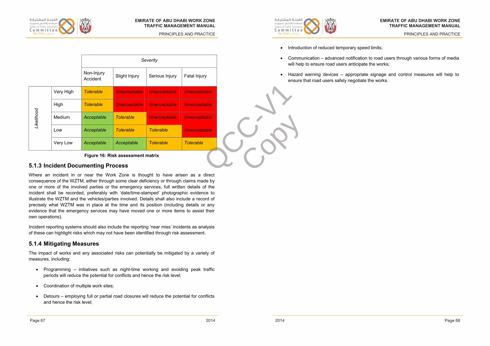
EMIRATE OF ABU DHABI WORK ZONETRAFFIC MANAGEMENT MANUAL
PRINCIPLES AND PRACTICE
Severity
Non-InjuryAccident Slight Injury Serious Injury Fatal Injury
Like
lihoo
d
Very High Tolerable Unacceptable Unacceptable Unacceptable
High Tolerable Unacceptable Unacceptable Unacceptable
Medium Acceptable Tolerable Unacceptable Unacceptable
Low Acceptable Tolerable Tolerable Unacceptable
Very Low Acceptable Acceptable Tolerable Tolerable
Figure 16: Risk assessment matrix
5.1.3 Incident Documenting ProcessWhere an incident in or near the Work Zone is thought to have arisen as a direct consequence of the WZTM, either through some clear deficiency or through claims made by one or more of the involved parties or the emergency services, full written details of the incident shall be recorded, preferably with ‘date/time-stamped’ photographic evidence to illustrate the WZTM and the vehicles/parties involved. Details shall also include a record of precisely what WZTM was in place at the time and its position (including details or any evidence that the emergency services may have moved one or more items to assist their own operations).
Incident reporting systems should also include the reporting ‘near miss’ incidents as analysis of these can highlight risks which may not have been identified through risk assessment.
5.1.4 Mitigating MeasuresThe impact of works and any associated risks can potentially be mitigated by a variety of measures, including:
• Programming – initiatives such as night-time working and avoiding peak traffic periods will reduce the potential for conflicts and hence the risk level;
• Coordination of multiple work sites;
• Detours – employing full or partial road closures will reduce the potential for conflicts and hence the risk level;
Issue 1 Page 67 February 2014
EMIRATE OF ABU DHABI WORK ZONETRAFFIC MANAGEMENT MANUAL
PRINCIPLES AND PRACTICE
• Introduction of reduced temporary speed limits;
• Communication – advanced notification to road users through various forms of media will help to ensure road users anticipate the works;
• Hazard warning devices – appropriate signage and control measures will help to ensure that road users safely negotiate the works.
Issue 1 Page 68 February 2014
EMIRATE OF ABU DHABI WORK ZONETRAFFIC MANAGEMENT MANUAL
PRINCIPLES AND PRACTICE
2014
EMIRATE OF ABU DHABI WORK ZONETRAFFIC MANAGEMENT MANUAL
PRINCIPLES AND PRACTICE
2014Page 67 Page 68
EMIRATE OF ABU DHABI WORK ZONETRAFFIC MANAGEMENT MANUAL
PRINCIPLES AND PRACTICE
2014
EMIRATE OF ABU DHABI WORK ZONETRAFFIC MANAGEMENT MANUAL
PRINCIPLES AND PRACTICE
2014
QCC-V1
Copy
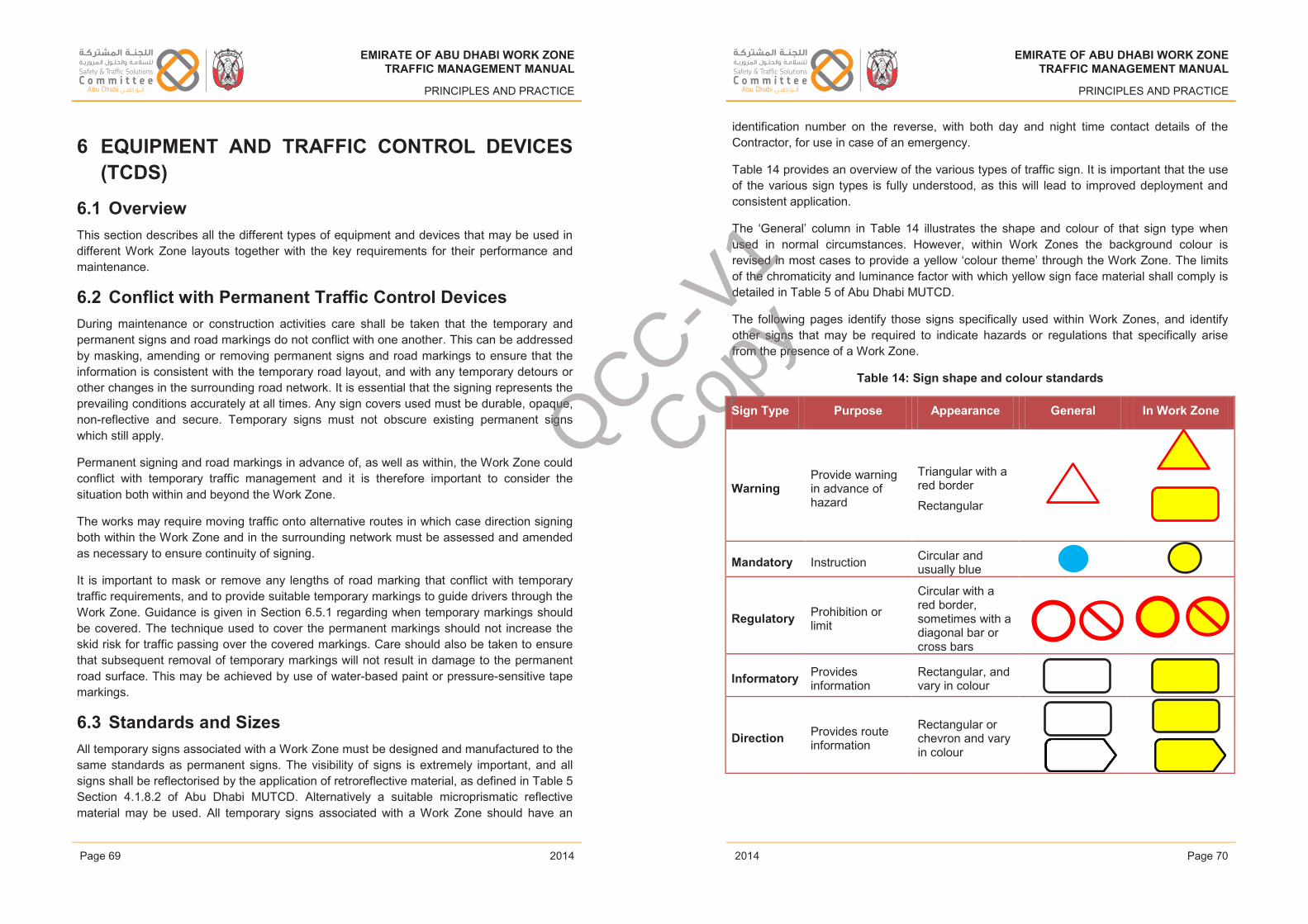
EMIRATE OF ABU DHABI WORK ZONETRAFFIC MANAGEMENT MANUAL
PRINCIPLES AND PRACTICE
6 EQUIPMENT AND TRAFFIC CONTROL DEVICES(TCDS)
6.1 OverviewThis section describes all the different types of equipment and devices that may be used in different Work Zone layouts together with the key requirements for their performance and maintenance.
6.2 Conflict with Permanent Traffic Control DevicesDuring maintenance or construction activities care shall be taken that the temporary and permanent signs and road markings do not conflict with one another. This can be addressed by masking, amending or removing permanent signs and road markings to ensure that the information is consistent with the temporary road layout, and with any temporary detours or other changes in the surrounding road network. It is essential that the signing represents the prevailing conditions accurately at all times. Any sign covers used must be durable, opaque,non-reflective and secure. Temporary signs must not obscure existing permanent signs which still apply.
Permanent signing and road markings in advance of, as well as within, the Work Zone could conflict with temporary traffic management and it is therefore important to consider the situation both within and beyond the Work Zone.
The works may require moving traffic onto alternative routes in which case direction signing both within the Work Zone and in the surrounding network must be assessed and amended as necessary to ensure continuity of signing.
It is important to mask or remove any lengths of road marking that conflict with temporary traffic requirements, and to provide suitable temporary markings to guide drivers through the Work Zone. Guidance is given in Section 6.5.1 regarding when temporary markings should be covered. The technique used to cover the permanent markings should not increase the skid risk for traffic passing over the covered markings. Care should also be taken to ensure that subsequent removal of temporary markings will not result in damage to the permanent road surface. This may be achieved by use of water-based paint or pressure-sensitive tape markings.
6.3 Standards and SizesAll temporary signs associated with a Work Zone must be designed and manufactured to the same standards as permanent signs. The visibility of signs is extremely important, and all signs shall be reflectorised by the application of retroreflective material, as defined in Table 5 Section 4.1.8.2 of Abu Dhabi MUTCD. Alternatively a suitable microprismatic reflective material may be used. All temporary signs associated with a Work Zone should have an
Issue 1 Page 69 February 2014
EMIRATE OF ABU DHABI WORK ZONETRAFFIC MANAGEMENT MANUAL
PRINCIPLES AND PRACTICE
identification number on the reverse, with both day and night time contact details of the Contractor, for use in case of an emergency.
Table 14 provides an overview of the various types of traffic sign. It is important that the use of the various sign types is fully understood, as this will lead to improved deployment and consistent application.
The ‘General’ column in Table 14 illustrates the shape and colour of that sign type when used in normal circumstances. However, within Work Zones the background colour is revised in most cases to provide a yellow ‘colour theme’ through the Work Zone. The limits of the chromaticity and luminance factor with which yellow sign face material shall comply is detailed in Table 5 of Abu Dhabi MUTCD.
The following pages identify those signs specifically used within Work Zones, and identify other signs that may be required to indicate hazards or regulations that specifically arise from the presence of a Work Zone.
Table 14: Sign shape and colour standards
Sign Type Purpose Appearance General In Work Zone
WarningProvide warning in advance of hazard
Triangular with a red border
Rectangular
Mandatory Instruction Circular andusually blue
Regulatory Prohibition orlimit
Circular with a red border, sometimes with a diagonal bar or cross bars
Informatory Providesinformation
Rectangular, and vary in colour
Direction Provides routeinformation
Rectangular or chevron and vary in colour
Issue 1 Page 70 February 2014
EMIRATE OF ABU DHABI WORK ZONETRAFFIC MANAGEMENT MANUAL
PRINCIPLES AND PRACTICE
2014
EMIRATE OF ABU DHABI WORK ZONETRAFFIC MANAGEMENT MANUAL
PRINCIPLES AND PRACTICE
2014Page 69 Page 70
EMIRATE OF ABU DHABI WORK ZONETRAFFIC MANAGEMENT MANUAL
PRINCIPLES AND PRACTICE
2014
EMIRATE OF ABU DHABI WORK ZONETRAFFIC MANAGEMENT MANUAL
PRINCIPLES AND PRACTICE
2014
QCC-V1
Copy
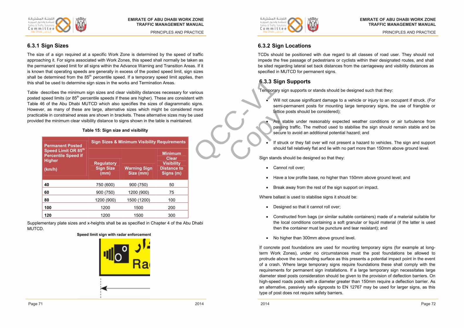
EMIRATE OF ABU DHABI WORK ZONETRAFFIC MANAGEMENT MANUAL
PRINCIPLES AND PRACTICE
6.3.1 Sign SizesThe size of a sign required at a specific Work Zone is determined by the speed of traffic approaching it. For signs associated with Work Zones, this speed shall normally be taken as the permanent speed limit for all signs within the Advance Warning and Transition Areas. If it is known that operating speeds are generally in excess of the posted speed limit, sign sizes shall be determined from the 85th percentile speed. If a temporary speed limit applies, then this shall be used to determine sign sizes in the works and Termination Areas.
Table describes the minimum sign sizes and clear visibility distances necessary for various posted speed limits (or 85th percentile speeds if these are higher). These are consistent with Table 46 of the Abu Dhabi MUTCD which also specifies the sizes of diagrammatic signs. However, as many of these are large, alternative sizes which might be considered more practicable in constrained areas are shown in brackets. These alternative sizes may be used provided the minimum clear visibility distance to signs shown in the table is maintained.
Table 15: Sign size and visibility
Permanent Posted Speed Limit OR 85th
Percentile Speed if Higher
(km/h)
Sign Sizes & Minimum Visibility Requirements
Regulatory Sign Size
(mm)Warning Sign
Size (mm)
Minimum Clear
Visibility Distance to Signs (m)
40 750 (600) 900 (750) 50
60 900 (750) 1200 (900) 75
80 1200 (900) 1500 (1200) 100
100 1200 1500 200
120 1200 1500 300
Supplementary plate sizes and x-heights shall be as specified in Chapter 4 of the Abu Dhabi MUTCD.
6.3.2 Sign LocationsTCDs should be positioned with due regard to all classes of road user. They should not impede the free passage of pedestrians or cyclists within their designated routes, and shall be sited regarding lateral set back distances from the carriageway and visibility distances as specified in MUTCD for permanent signs.
Issue 1 Page 71 February 2014
EMIRATE OF ABU DHABI WORK ZONETRAFFIC MANAGEMENT MANUAL
PRINCIPLES AND PRACTICE
6.3.3 Sign SupportsTemporary sign supports or stands should be designed such that they:
• Will not cause significant damage to a vehicle or injury to an occupant if struck. (For semi-permanent posts for mounting large temporary signs, the use of frangible or lattice posts should be considered);
• Are stable under reasonably expected weather conditions or air turbulence from passing traffic. The method used to stabilise the sign should remain stable and be secure to avoid an additional potential hazard; and
• If struck or they fall over will not present a hazard to vehicles. The sign and support should fall relatively flat and lie with no part more than 150mm above ground level.
Sign stands should be designed so that they:
• Cannot roll over;
• Have a low profile base, no higher than 150mm above ground level; and
• Break away from the rest of the sign support on impact.
Where ballast is used to stabilise signs it should be:
• Designed so that it cannot roll over;
• Constructed from bags (or similar suitable containers) made of a material suitable for the local conditions containing a soft granular or liquid material (if the latter is used then the container must be puncture and tear resistant); and
• No higher than 300mm above ground level.
If concrete post foundations are used for mounting temporary signs (for example at long-term Work Zones), under no circumstances must the post foundations be allowed to protrude above the surrounding surface as this presents a potential impact point in the event of a crash. Where large temporary signs require foundations these shall comply with the requirements for permanent sign installations. If a large temporary sign necessitates large diameter steel posts consideration should be given to the provision of deflection barriers. On high-speed roads posts with a diameter greater than 150mm require a deflection barrier. As an alternative, passively safe signposts to EN 12767 may be used for larger signs, as this type of post does not require safety barriers.
Issue 1 Page 72 February 2014
EMIRATE OF ABU DHABI WORK ZONETRAFFIC MANAGEMENT MANUAL
PRINCIPLES AND PRACTICE
2014
EMIRATE OF ABU DHABI WORK ZONETRAFFIC MANAGEMENT MANUAL
PRINCIPLES AND PRACTICE
2014Page 71 Page 72
EMIRATE OF ABU DHABI WORK ZONETRAFFIC MANAGEMENT MANUAL
PRINCIPLES AND PRACTICE
2014
EMIRATE OF ABU DHABI WORK ZONETRAFFIC MANAGEMENT MANUAL
PRINCIPLES AND PRACTICE
2014
Speed limit sign with radar enforcement
QCC-V1
Copy
abdulrazzak.zaytoun
Placed Image
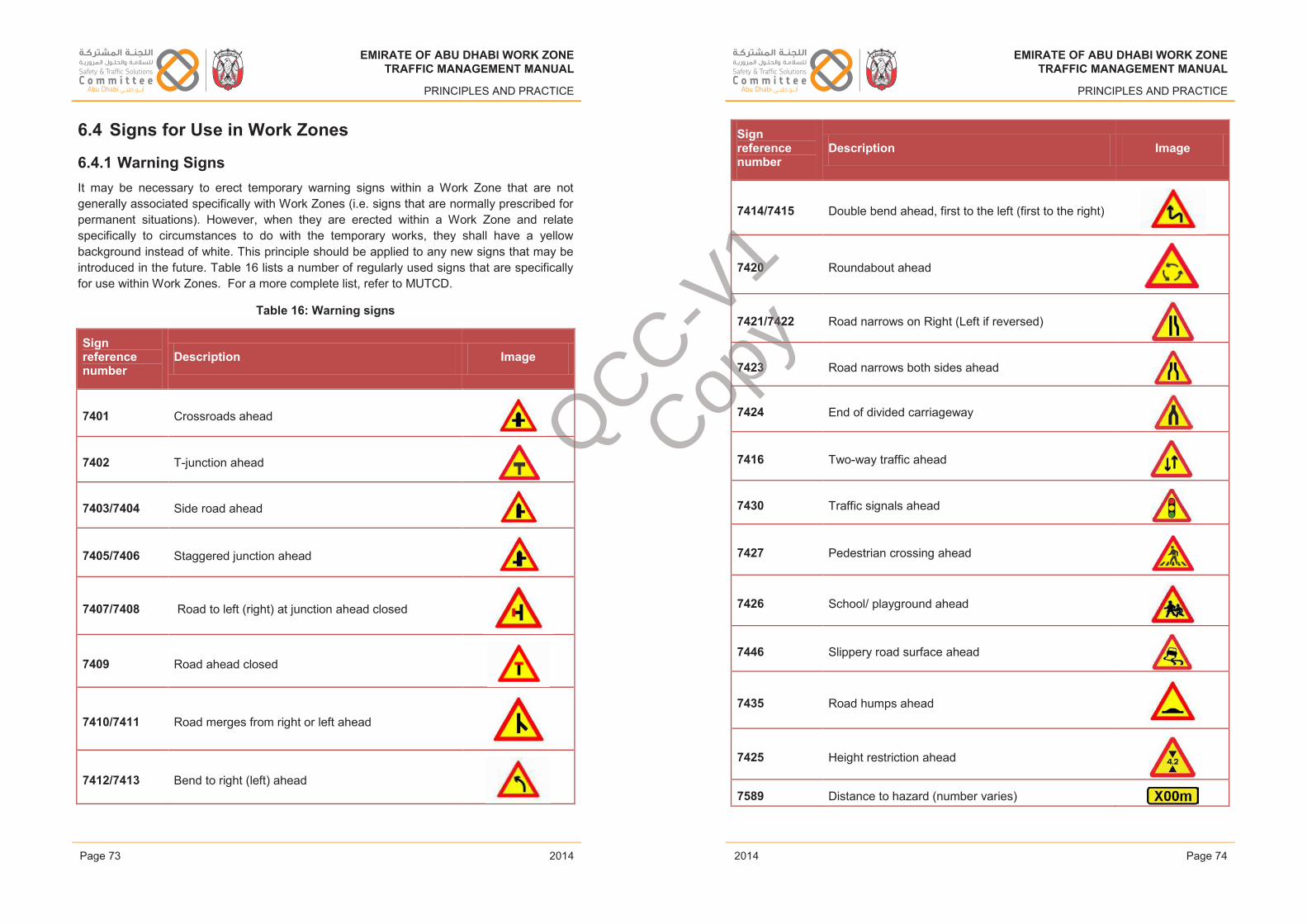
EMIRATE OF ABU DHABI WORK ZONETRAFFIC MANAGEMENT MANUAL
PRINCIPLES AND PRACTICE
6.4 Signs for Use in Work Zones
6.4.1 Warning SignsIt may be necessary to erect temporary warning signs within a Work Zone that are not generally associated specifically with Work Zones (i.e. signs that are normally prescribed for permanent situations). However, when they are erected within a Work Zone and relate specifically to circumstances to do with the temporary works, they shall have a yellow background instead of white. This principle should be applied to any new signs that may be introduced in the future. Table 16 lists a number of regularly used signs that are specifically for use within Work Zones. For a more complete list, refer to MUTCD.
Table 16: Warning signs
Sign reference number
Description Image
7401 Crossroads ahead
7402 T-junction ahead
7403/7404 Side road ahead
7405/7406 Staggered junction ahead
7407/7408 Road to left (right) at junction ahead closed
7409 Road ahead closed
7410/7411 Road merges from right or left ahead
7412/7413 Bend to right (left) ahead
Issue 1 Page 73 February 2014
EMIRATE OF ABU DHABI WORK ZONETRAFFIC MANAGEMENT MANUAL
PRINCIPLES AND PRACTICE
Sign reference number
Description Image
7414/7415 Double bend ahead, first to the left (first to the right)
7420 Roundabout ahead
7421/7422 Road narrows on Right (Left if reversed)
7423 Road narrows both sides ahead
7424 End of divided carriageway
7416 Two-way traffic ahead
7430 Traffic signals ahead
7427 Pedestrian crossing ahead
7426 School/ playground ahead
7446 Slippery road surface ahead
7435 Road humps ahead
7425 Height restriction ahead
7589 Distance to hazard (number varies)
Issue 1 Page 74 February 2014
EMIRATE OF ABU DHABI WORK ZONETRAFFIC MANAGEMENT MANUAL
PRINCIPLES AND PRACTICE
2014
EMIRATE OF ABU DHABI WORK ZONETRAFFIC MANAGEMENT MANUAL
PRINCIPLES AND PRACTICE
2014Page 73 Page 74
EMIRATE OF ABU DHABI WORK ZONETRAFFIC MANAGEMENT MANUAL
PRINCIPLES AND PRACTICE
2014
EMIRATE OF ABU DHABI WORK ZONETRAFFIC MANAGEMENT MANUAL
PRINCIPLES AND PRACTICE
2014
QCC-V1
Copy
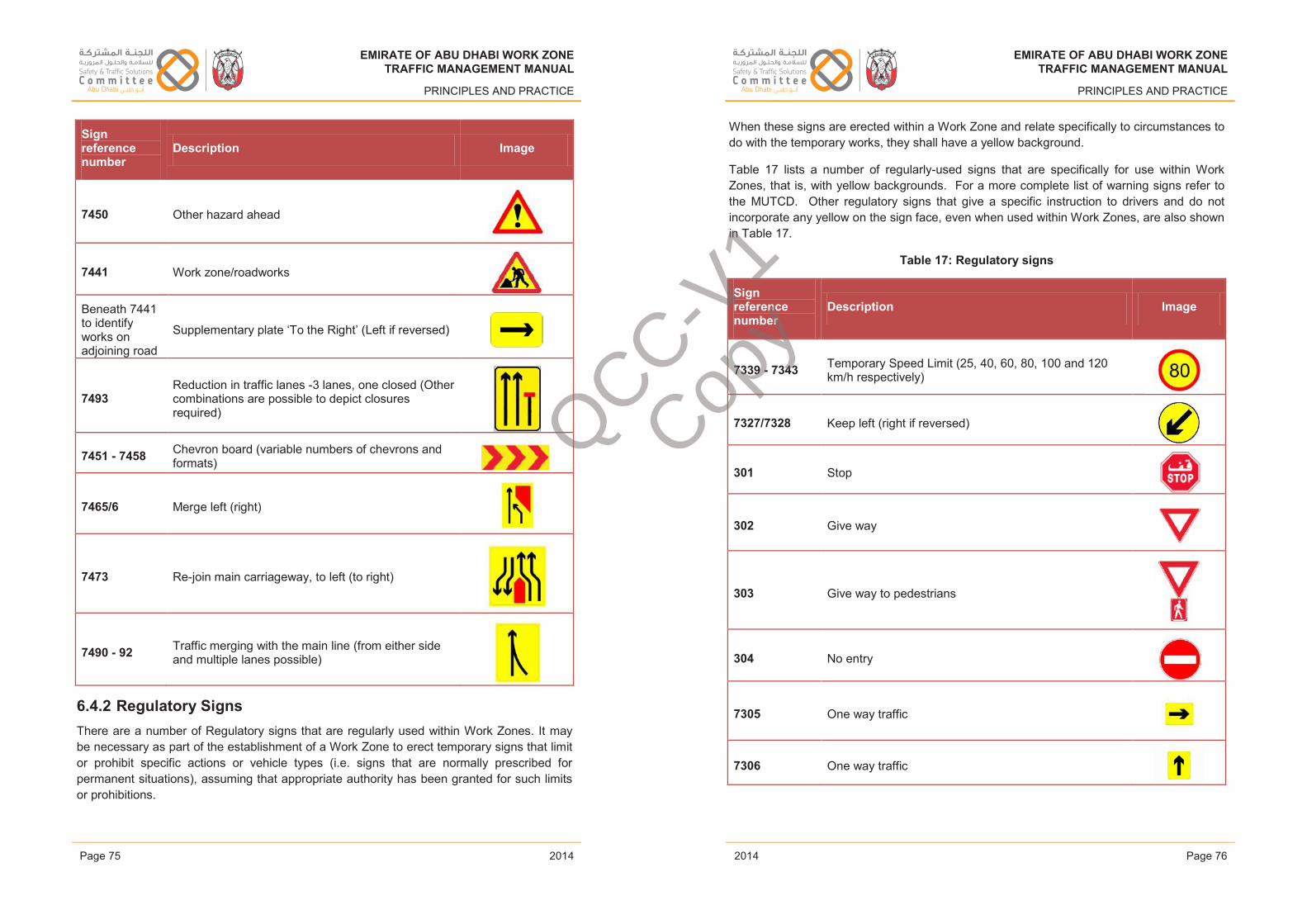
EMIRATE OF ABU DHABI WORK ZONETRAFFIC MANAGEMENT MANUAL
PRINCIPLES AND PRACTICE
Sign reference number
Description Image
7450 Other hazard ahead
7441 Work zone/roadworks
Beneath 7441 to identify works on adjoining road
Supplementary plate ‘To the Right’ (Left if reversed)
7493Reduction in traffic lanes -3 lanes, one closed (Other combinations are possible to depict closures required)
7451 - 7458 Chevron board (variable numbers of chevrons and formats)
7465/6 Merge left (right)
7473 Re-join main carriageway, to left (to right)
7490 - 92 Traffic merging with the main line (from either side and multiple lanes possible)
6.4.2 Regulatory SignsThere are a number of Regulatory signs that are regularly used within Work Zones. It may be necessary as part of the establishment of a Work Zone to erect temporary signs that limit or prohibit specific actions or vehicle types (i.e. signs that are normally prescribed for permanent situations), assuming that appropriate authority has been granted for such limits or prohibitions.
Issue 1 Page 75 February 2014
EMIRATE OF ABU DHABI WORK ZONETRAFFIC MANAGEMENT MANUAL
PRINCIPLES AND PRACTICE
When these signs are erected within a Work Zone and relate specifically to circumstances to do with the temporary works, they shall have a yellow background.
Table 17 lists a number of regularly-used signs that are specifically for use within Work Zones, that is, with yellow backgrounds. For a more complete list of warning signs refer to the MUTCD. Other regulatory signs that give a specific instruction to drivers and do not incorporate any yellow on the sign face, even when used within Work Zones, are also shown in Table 17.
Table 17: Regulatory signs
Sign reference number
Description Image
7339 - 7343 Temporary Speed Limit (25, 40, 60, 80, 100 and 120 km/h respectively)
7327/7328 Keep left (right if reversed)
301 Stop
302 Give way
303 Give way to pedestrians
304 No entry
7305 One way traffic
7306 One way traffic
Issue 1 Page 76 February 2014
EMIRATE OF ABU DHABI WORK ZONETRAFFIC MANAGEMENT MANUAL
PRINCIPLES AND PRACTICE
2014
EMIRATE OF ABU DHABI WORK ZONETRAFFIC MANAGEMENT MANUAL
PRINCIPLES AND PRACTICE
2014Page 75 Page 76
EMIRATE OF ABU DHABI WORK ZONETRAFFIC MANAGEMENT MANUAL
PRINCIPLES AND PRACTICE
2014
EMIRATE OF ABU DHABI WORK ZONETRAFFIC MANAGEMENT MANUAL
PRINCIPLES AND PRACTICE
2014
QCC-V1
Copy
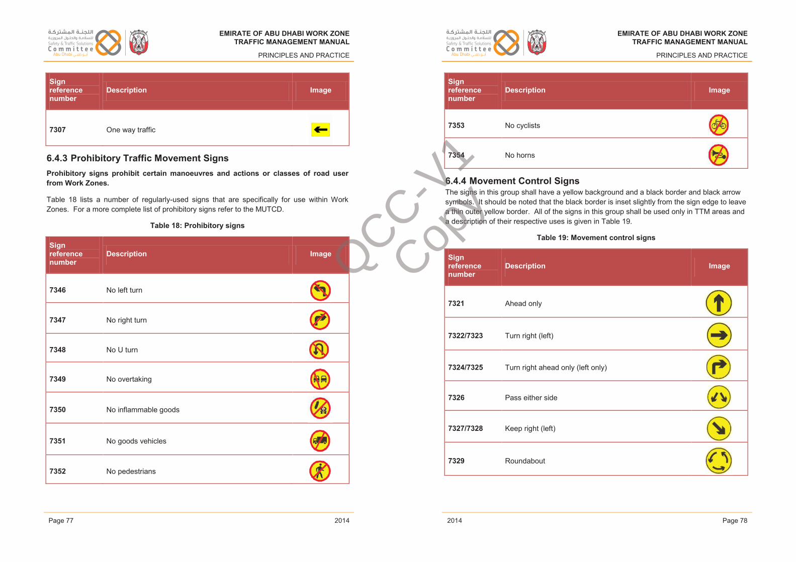
EMIRATE OF ABU DHABI WORK ZONETRAFFIC MANAGEMENT MANUAL
PRINCIPLES AND PRACTICE
Sign reference number
Description Image
7307 One way traffic
6.4.3 Prohibitory Traffic Movement SignsProhibitory signs prohibit certain manoeuvres and actions or classes of road user from Work Zones.
Table 18 lists a number of regularly-used signs that are specifically for use within Work Zones. For a more complete list of prohibitory signs refer to the MUTCD.
Table 18: Prohibitory signs
Sign reference number
Description Image
7346 No left turn
7347 No right turn
7348 No U turn
7349 No overtaking
7350 No inflammable goods
7351 No goods vehicles
7352 No pedestrians
Issue 1 Page 77 February 2014
EMIRATE OF ABU DHABI WORK ZONETRAFFIC MANAGEMENT MANUAL
PRINCIPLES AND PRACTICE
Sign reference number
Description Image
7353 No cyclists
7354 No horns
6.4.4 Movement Control SignsThe signs in this group shall have a yellow background and a black border and black arrow symbols. It should be noted that the black border is inset slightly from the sign edge to leave a thin outer yellow border. All of the signs in this group shall be used only in TTM areas and a description of their respective uses is given in Table 19.
Table 19: Movement control signs
Sign reference number
Description Image
7321 Ahead only
7322/7323 Turn right (left)
7324/7325 Turn right ahead only (left only)
7326 Pass either side
7327/7328 Keep right (left)
7329 Roundabout
Issue 1 Page 78 February 2014
EMIRATE OF ABU DHABI WORK ZONETRAFFIC MANAGEMENT MANUAL
PRINCIPLES AND PRACTICE
2014
EMIRATE OF ABU DHABI WORK ZONETRAFFIC MANAGEMENT MANUAL
PRINCIPLES AND PRACTICE
2014Page 77 Page 78
EMIRATE OF ABU DHABI WORK ZONETRAFFIC MANAGEMENT MANUAL
PRINCIPLES AND PRACTICE
2014
EMIRATE OF ABU DHABI WORK ZONETRAFFIC MANAGEMENT MANUAL
PRINCIPLES AND PRACTICE
2014
QCC-V1
Copy
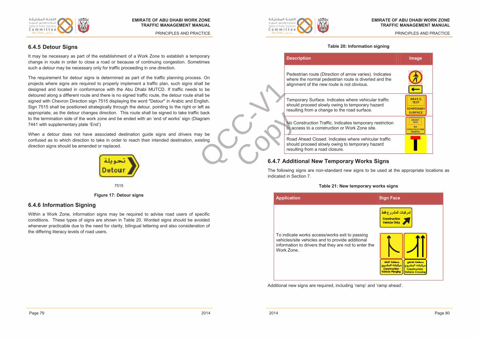
EMIRATE OF ABU DHABI WORK ZONETRAFFIC MANAGEMENT MANUAL
PRINCIPLES AND PRACTICE
6.4.5 Detour SignsIt may be necessary as part of the establishment of a Work Zone to establish a temporary change in route in order to close a road or because of continuing congestion. Sometimes such a detour may be necessary only for traffic proceeding in one direction.
The requirement for detour signs is determined as part of the traffic planning process. On projects where signs are required to properly implement a traffic plan, such signs shall be designed and located in conformance with the Abu Dhabi MUTCD. If traffic needs to be detoured along a different route and there is no signed traffic route, the detour route shall be signed with Chevron Direction sign 7515 displaying the word "Detour" in Arabic and English.Sign 7515 shall be positioned strategically through the detour, pointing to the right or left as appropriate, as the detour changes direction. This route shall be signed to take traffic back to the termination side of the work zone and be ended with an ‘end of works’ sign (Diagram 7441 with supplementary plate ‘End’)
When a detour does not have associated destination guide signs and drivers may be confused as to which direction to take in order to reach their intended destination, existing direction signs should be amended or replaced.
7515
Figure 17: Detour signs
6.4.6 Information SigningWithin a Work Zone, information signs may be required to advise road users of specific conditions. These types of signs are shown in Table 20. Worded signs should be avoided whenever practicable due to the need for clarity, bilingual lettering and also consideration of the differing literacy levels of road users.
Issue 1 Page 79 February 2014
EMIRATE OF ABU DHABI WORK ZONETRAFFIC MANAGEMENT MANUAL
PRINCIPLES AND PRACTICE
Table 20: Information signing
Description Image
Pedestrian route (Direction of arrow varies). Indicates where the normal pedestrian route is diverted and the alignment of the new route is not obvious.
Temporary Surface. Indicates where vehicular traffic should proceed slowly owing to temporary hazard resulting from a change to the road surface.
No Construction Traffic. Indicates temporary restriction to access to a construction or Work Zone site.
Road Ahead Closed. Indicates where vehicular traffic should proceed slowly owing to temporary hazard resulting from a road closure.
6.4.7 Additional New Temporary Works SignsThe following signs are non-standard new signs to be used at the appropriate locations as indicated in Section 7.
Table 21: New temporary works signs
Application Sign Face
To indicate works access/works exit to passing vehicles/site vehicles and to provide additional information to drivers that they are not to enter the Work Zone.
Additional new signs are required, including ‘ramp’ and ‘ramp ahead’.
Issue 1 Page 80 February 2014
EMIRATE OF ABU DHABI WORK ZONETRAFFIC MANAGEMENT MANUAL
PRINCIPLES AND PRACTICE
2014
EMIRATE OF ABU DHABI WORK ZONETRAFFIC MANAGEMENT MANUAL
PRINCIPLES AND PRACTICE
2014Page 79 Page 80
EMIRATE OF ABU DHABI WORK ZONETRAFFIC MANAGEMENT MANUAL
PRINCIPLES AND PRACTICE
2014
EMIRATE OF ABU DHABI WORK ZONETRAFFIC MANAGEMENT MANUAL
PRINCIPLES AND PRACTICE
2014
QCC-V1
Copy
EMIRATE OF ABU DHABI WORK ZONETRAFFIC MANAGEMENT MANUAL
PRINCIPLES AND PRACTICE
6.5 Delineation DevicesDelineation devices shall always be provided to present a physical separation of vehicles and pedestrians travelling through a Work Zone from areas in which members of a work force operate, and from hazards such as construction materials, equipment and excavations.For long-term static work, particularly on high speed roads, the default device to protect those areas described above shall be portable concrete or metal crash protection barriers capable of providing deflection to vehicles whilst experiencing minimal displacement. Such temporary barriers shall meet the containment and working width limits appropriate for the road and traffic anticipated at the Work Zone (see Section 6.5.2). Other devices may be considered for lower speed roads subject to risk assessment.
It is also necessary to provide safe indication to road users passing through Work Zones of the path they must follow. When concrete or metal barriers are provided, these can help to fulfil this role for vehicular traffic. However, there are occasions where concrete or metal barriers may not be appropriate.
These will include:
• Short-term works;
• Some medium-term works;
• Mobile works;
• Works in low-speed, low-traffic flow environments;
• Where the installation of barriers itself is a significant risk.
Section 6.5.2 of the Manual provides guidance as to the most appropriate form of barrier and Section 5 describes a risk assessment methodology that should be carried out to assist with this.
In addition, there will frequently be a need to delineate boundaries behind barriers (for example, between the working space and the traffic safety buffer), or to segregate on-coming traffic through the Work Zone. In such cases, the use of alternative delineation devices may be considered such as water filled plastic barricades or cones.
6.5.1 Pavement Markings – Dealing with Temporary and Existing Markings
For a complete list of pavement markings reference should be made to the Abu Dhabi MUTCD.
Care must be taken that any existing road markings do not cause road users to misinterpret the temporary alignment through a Work Zone. For any long-term static works, an assessment shall be made of existing permanent markings, and where appropriate these should be masked or removed and temporary markings provided. In determining the use of
Issue 1 Page 81 February 2014
EMIRATE OF ABU DHABI WORK ZONETRAFFIC MANAGEMENT MANUAL
PRINCIPLES AND PRACTICE
road markings within a Work Zone and the preservation of existing markings whilst works are carried out, the following needs to be considered:
• The duration of the works to be carried out;
• The requirement to use temporary markings on new surfaces;
• The requirement to cover/protect existing markings whilst work is carried out.
In order to improve the definition and clarity of lane definition through a Work Zone, a channelizing line marking 612 may be used in place of the conventional lane line marking 654.
If using permanent marking techniques within a Work Zone for traffic management, there is a possibility that a scarring effect of the road surface will remain when they are removed. This visual defect can have a detrimental effect on the quality of the road surface and the effectiveness of on-going road markings, particularly during hours of darkness. To prevent this, temporary marking methods should be used. A variety of temporary markings are available, including:
• Water based paint;
• Pressure sensitive marking tapes;
• Temporary raised reflective markers.
It may be necessary to cover up existing permanent road markings whilst works are carried out, to eliminate the possibility of confusion between existing markings and temporary markings associated with the Work Zone.
Any temporary road marking material, or material used to conceal permanent road markings, must have sufficient adhesive and frictional qualities such that it does not detach from the road surface prematurely or present a skidding risk (particularly to motorcycles or when wet).
Particular attention should be paid to the possibility of concealed markings or the residue of removed markings continuing to be visible, especially when wet or when reflecting headlights or when subjected to certain lighting conditions. When this occurs, the road layout and lane alignment can be very confusing and dangerous (both during the works and after they have concluded). When decommissioned road markings continue to be visible they can be very misleading and they must be properly concealed or removed.
Once all works are complete, all temporary TCDs associated with the works shall be removed, including temporary road markings. All permanent road markings that were covered up or removed as part of the works shall be uncovered or reinstated. Clearance of TCDs from the Work Zone should be undertaken as soon as practicably possible following completion of the works operation.
Issue 1 Page 82 February 2014
EMIRATE OF ABU DHABI WORK ZONETRAFFIC MANAGEMENT MANUAL
PRINCIPLES AND PRACTICE
2014
EMIRATE OF ABU DHABI WORK ZONETRAFFIC MANAGEMENT MANUAL
PRINCIPLES AND PRACTICE
2014Page 81 Page 82
EMIRATE OF ABU DHABI WORK ZONETRAFFIC MANAGEMENT MANUAL
PRINCIPLES AND PRACTICE
2014
EMIRATE OF ABU DHABI WORK ZONETRAFFIC MANAGEMENT MANUAL
PRINCIPLES AND PRACTICE
2014
QCC-V1
Copy
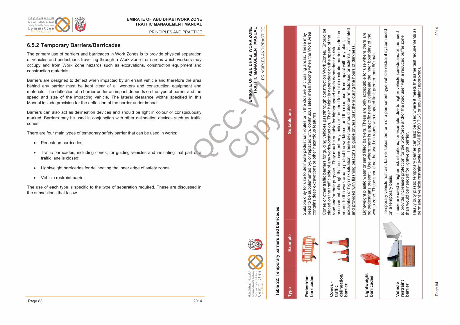
EM
IRA
TE
OF
AB
U D
HA
BI W
OR
K Z
ON
ET
RA
FF
IC M
AN
AG
EM
EN
T M
AN
UA
L
PR
INC
IPLE
S A
ND
PR
AC
TIC
E
2014
Pag
e 84
EMIRATE OF ABU DHABI WORK ZONETRAFFIC MANAGEMENT MANUAL
PRINCIPLES AND PRACTICE
6.5.2 Temporary Barriers/BarricadesThe primary use of barriers and barricades in Work Zones is to provide physical separation of vehicles and pedestrians travelling through a Work Zone from areas which workers may occupy and from Work Zone hazards such as excavations, construction equipment and construction materials.
Barriers are designed to deflect when impacted by an errant vehicle and therefore the area behind any barrier must be kept clear of all workers and construction equipment and materials. The deflection of a barrier under an impact depends on the type of barrier and the speed and size of the impacting vehicle. The lateral clearance widths specified in this Manual include provision for the deflection of the barrier under impact.
Barriers can also act as delineation devices and should be light in colour or conspicuously marked. Barriers may be used in conjunction with other delineation devices such as traffic cones.
There are four main types of temporary safety barrier that can be used in works:
• Pedestrian barricades;
• Traffic barricades, including cones, for guiding vehicles and indicating that part of a traffic lane is closed;
• Lightweight barricades for delineating the inner edge of safety zones;
• Vehicle restraint barrier.
The use of each type is specific to the type of separation required. These are discussed in the subsections that follow.
Issue 1 Page 83 February 2014
EM
IRAT
EO
FAB
UD
HAB
IWO
RK
ZON
ETR
AFFI
CM
ANAG
EM
ENT
MA
NU
AL
PRIN
CIP
LES
AN
D P
RA
CTI
CE
Tabl
e 22
:Tem
pora
ry b
arrie
rsan
d ba
rric
ades
Type
Exam
ple
Suita
ble
use
Pede
stria
n ba
rric
ades
Suita
ble
only
for u
se to
del
inea
te p
edes
trian
rout
es o
r in
the
clos
ure
of c
ross
ing
area
s.Th
ese
may
ne
ed to
be
supp
lem
ente
d by
, or r
epla
ced
with
,con
tinuo
us s
teel
mes
h fe
ncin
g w
hen
the
Wor
k Ar
eaco
ntai
ns d
eep
exca
vatio
ns o
r oth
er h
azar
dous
feat
ures
.
Con
es -
traf
fic
delin
eatio
n/ba
rrie
r
Con
es o
r oth
er tr
affic
bar
riers
for g
uidi
ng v
ehic
les
past
/thro
ugh
cons
truct
ion
Wor
k Zo
nes.
Shou
ld b
e pl
aced
on
the
traffi
c si
de o
f any
wor
ks/o
bstru
ctio
n. T
heir
heig
ht is
dep
ende
nt o
n th
e sp
eed
of th
e ro
ad a
nd/o
r the
ir pu
rpos
e. T
hey
may
be
suita
ble
for h
ighe
r spe
ed ro
ads
depe
nden
t on
risk
asse
ssm
ent a
lthou
gh th
at a
sses
smen
t may
indi
cate
the
need
for v
ehic
le re
stra
int b
arrie
r in
addi
tion
near
er to
the
wor
k ar
ea to
pro
tect
the
wor
kfor
ce, a
nd th
e ro
ad u
ser f
rom
impa
ct w
ith a
ny p
lant
, ex
cava
tion
or h
igh
risk
situ
atio
n.Th
ese
devi
ces
shou
ld a
lso
be re
flect
oris
ed o
r ext
erna
lly il
lum
inat
ed
and
prov
ided
with
flas
hing
bea
cons
to g
uide
driv
ers
past
them
dur
ing
the
hour
s of
dar
knes
s.
Ligh
twei
ght
barr
icad
esLi
ghtw
eigh
t pla
stic
wat
er o
r san
d fil
led
barr
iers
.The
se a
re o
nly
acce
ptab
le fo
r use
whe
re th
ere
are
no p
edes
trian
s pr
esen
t.U
se w
here
ther
e is
a s
peci
fic n
eed
to d
elin
eate
the
inne
r bou
ndar
y of
the
wor
ks z
one.
Thes
e sh
ould
not
be
used
on
road
s w
ith a
spe
ed li
mit
grea
ter t
han
80km
/h.
Vehi
cle
rest
rain
t ba
rrie
r
Tem
pora
ry v
ehic
le re
stra
int b
arrie
r tak
es th
e fo
rm o
f a p
erm
anen
t typ
e ve
hicl
e re
stra
int s
yste
m u
sed
on a
tem
pora
ry b
asis
.
Thes
e ar
e us
ed in
hig
her r
isk
situ
atio
ns, f
or e
xam
ple,
due
to h
ighe
r veh
icle
spe
eds
and/
or th
e ne
ed
to p
rovi
de in
crea
sed
prot
ectio
n fo
r the
wor
kfor
ce a
nd/o
r the
road
use
rwith
a re
duce
d bu
ffer z
one
than
wou
ld b
e ne
eded
for l
ight
wei
ght b
arrie
r.
Hea
vy d
uty
plas
tic te
mpo
rary
bar
rier c
an a
lso
be u
sed
whe
re it
mee
ts th
e sa
me
test
requ
irem
ents
as
perm
anen
t veh
icle
rest
rain
t sys
tem
s(N
CH
RP3
50TL
-3 o
r equ
ival
ent a
ppro
ved)
.
Issu
e 1
P
age
84Fe
brua
ry 2
014
EMIRATE OF ABU DHABI WORK ZONETRAFFIC MANAGEMENT MANUAL
PRINCIPLES AND PRACTICE
2014
EMIRATE OF ABU DHABI WORK ZONETRAFFIC MANAGEMENT MANUAL
PRINCIPLES AND PRACTICE
2014Page 83
EMIRATE OF ABU DHABI WORK ZONETRAFFIC MANAGEMENT MANUAL
PRINCIPLES AND PRACTICE
2014
EMIRATE OF ABU DHABI WORK ZONETRAFFIC MANAGEMENT MANUAL
PRINCIPLES AND PRACTICE
2014
QCC-V1
Copy
EMIRATE OF ABU DHABI WORK ZONETRAFFIC MANAGEMENT MANUAL
PRINCIPLES AND PRACTICE
6.5.2.1 Pedestrian Barricades
Pedestrian barricades are necessary where there are normally occurring pedestrian movements which are within the area of the Work Zone, or when the Work Zone requires the closure and revision of pedestrian routes.
Tapes
Containment tapes may be used to contain workers within the safe Work Zone boundary established at the work site. Tapes shall not be used to exclude pedestrians from a Work Area. The tape shall be a minimum of 100mm wide with alternate contrasting stripes (generally red and white) and be supported at up to 1m above ground level with a minimum height of 750 mm above ground level between supports.
Ropes
Containment ropes may be used in the place of tapes to establish a safe Work Zone boundary. The rope should have lengths of tape attached which shall not less than 300 mm long and which shall be tied or otherwise attached at maximum of 600 mm spacing.
Mesh Fencing
Mesh fencing shall be used to exclude pedestrians from a Work Area and can be used to delineate the working area for Work Zone personnel. Mesh fencing shall be a flexible mesh approximately 1m high and shall be securely attached to supports thus forming a continuous line preventing unauthorised access. Where mesh fencing is required to prevent pedestrian access adjacent to deep excavations or other hazardous situations/activities, it shall be 2m high.
Temporary Barricades
Water filled temporary barricades, as described below, may be used to exclude pedestrians from a Work Zone and can be used to contain workers as an alternative to traffic cones and the above devices.
6.5.2.2 Traffic Cones as Barricades and for Traffic Delineation
The purpose of traffic cones is to provide a visual indication to drivers that the carriageway ahead is realigned and to delineate a safe path past the Work Zone. They are particularlysuitable for short-term works in low speed environments and in conjunction with a vehicle or vehicles fitted with a Truck Mounted Attenuator (TMA), as a device to exclude traffic from one or more lanes of a live carriageway. They can be deployed quickly and are therefore often suitable for emergency response works. However, their exclusive use for high-speed roads where the workforce requires protection or the road user is vulnerable from impact with plant, excavations and other high risk features is not acceptable. In such cases, additional vehicle restraint systems will need to be used around the Work Area.
Issue 1 Page 85 February 2014
EMIRATE OF ABU DHABI WORK ZONETRAFFIC MANAGEMENT MANUAL
PRINCIPLES AND PRACTICE
Requirements:
• All traffic cones must be manufactured from a durable material, able to endure impacts from passing vehicles without suffering excessive damage or damaging the passing vehicle, or causing injury to pedestrians and workers in the vicinity;
• Traffic cones should be of a hollow, conical shape to enable them to be stacked one on top of another, when not in use;
• Traffic cones should be fluorescent red or orange/red in colour, with a white high intensity retro-reflective band that covers the middle third of the cone so as to be visible during both hours of daylight and darkness;
• All traffic cones should have an adequately weighted base, in order to withstand any minor collision or air buffeting as vehicles pass by. More robust bases should be used when cones are placed on freeways or expressways;
• In situations where traffic cones remain set out during hours of darkness, low intensity permanently illuminated warning lamps or high intensity flashing warning beacons should be must be provided, fixed either to the cone or mounted on a demarcation post which is positioned between each pair of cones;
• Selection of the type of lamp shall be in accordance with the guidance given in Section 6.7.1;
• The use of larger cones is generally preferred. Minimum cone sizes shall conform to those in Table 23.
Table 23: Traffic cone dimensions
Road CategoryMinimum Height
(mm)
Base Diameter or Base Width
(mm) Minimum weight
Freeway/Expressway 1000 500 9kg
Arterial 650 400 4kg
Collector/Local 750 400 6kg
Pedestrian Facilities 1000 500 9kg
The position and spacing of traffic cones, warning lights and flashing beacons within a Work Zone is governed by the nature of work being undertaken and the environment within which they are to be used. Traffic cones can be positioned on both or one side of a carriageway, at distances detailed in Table 24.
Issue 1 Page 86 February 2014
EMIRATE OF ABU DHABI WORK ZONETRAFFIC MANAGEMENT MANUAL
PRINCIPLES AND PRACTICE
2014
EMIRATE OF ABU DHABI WORK ZONETRAFFIC MANAGEMENT MANUAL
PRINCIPLES AND PRACTICE
2014Page 85 Page 86
EMIRATE OF ABU DHABI WORK ZONETRAFFIC MANAGEMENT MANUAL
PRINCIPLES AND PRACTICE
2014
EMIRATE OF ABU DHABI WORK ZONETRAFFIC MANAGEMENT MANUAL
PRINCIPLES AND PRACTICE
2014
QCC-V1
Copy
EMIRATE OF ABU DHABI WORK ZONETRAFFIC MANAGEMENT MANUAL
PRINCIPLES AND PRACTICE
Table 24: Beacon and cone spacing
SituationTraffic Cone
Spacing (m)
Warning Light or Beacon Spacing
(m)
Transition Area Taper:
1 in 22 1.5 3
1 in 33 3 6
1 in 44 or more 9 18
Transition Area Crossover:
Curve radius under 60 m 0.5 3
Curve radius over 60 m 3 6
Stabilisation Area 9 18
Long Straight Areas 9 18
Localised Minor Work Area 1.5 3 or as required
Pedestrian Channelisation 1.5 -
6.5.2.3 Lightweight Barricades/Plastic Temporary Devices
Plastic temporary devices should not be considered as an alternative type of crash protection/vehicle restraint barrier, as they do not offer the same degree of vehicle deflection, and when impacted can displace to a significant degree into the Work Area.Where it is not practicable to provide crash protection barriers which would otherwise be required, a risk assessment shall be carried out for the use of plastic temporary devices.
Plastic water- or sand-filled devices shall be linked together in an approved manner in accordance with the manufacturer’s guidance to form a continuous delineation boundary.Lightweight barriers are only suitable, and should only be used where the speed limit is below 60km/h. Plastic temporary devices should be filled with adequate levels of water or sand in accordance with the manufacturers’ specification, so as to ensure that they withstand excessive displacement as vehicles pass by or from interference by pedestrians or members of the work force.
6.5.2.4 Vehicle Restraint Barriers
More substantial barriers serve to prevent vehicles leaving the carriageway or from entering the Work Area. Their use is as indicated in Table 22 and should be determined by engineering judgement and risk assessment. However, by way of guidance, barriers are likely to be particularly important under the following circumstances and when high volumes of traffic are present:
• When a roadway is diverted from its normal path through a small radius curve (barriers may be required on one or both sides of the roadway); or,
Issue 1 Page 87 February 2014
EMIRATE OF ABU DHABI WORK ZONETRAFFIC MANAGEMENT MANUAL
PRINCIPLES AND PRACTICE
• To replace a wide median when this has to be eliminated to reduce road cross-section width as part of the Work Zone; or,
• To separate opposing streams of traffic where a temporary roadway has been constructed to accommodate traffic during construction works;
• To protect vulnerable roadside features against the risk of vehicle impact; or
• To protect the workforce and road users in high risk situations, for example, on a high speed road or where there are hazardous features which may be impacted by errant vehicles.
In the majority of the above situations, a temporary vehicle restraint barrier will also act as a channelisation device which will help to define the alignment of the roadway or taper. In order that it can satisfy this function it should be light in colour or conspicuously marked. The barrier can also be used in conjunction with other channelization devices such as traffic cones or delineators.
When used at a sharp change of direction it is recommended that the alignment of the barrier be made clear by means of single or multiple delineator signs 7454 to 7457 (Chevrons) mounted on or above the barrier at recommended intervals. Flashing beacons, particularly sequentially flashing beacons should also be used.
The introduction of short sections of temporary vehicle restraint barrier should be avoided. The risk of vehicular impact on the end of an introduced barrier should be mitigated by use of an appropriate end restraint.
Temporary vehicle restraint barriers must be provided with the same standard of end treatment as is specified for permanent installations. Approach ends of portable concrete barriers should be offset from the path of approaching traffic by 6 metres or more and should taper from the edge of the carriageway at a minimum rate of 1 in 6 or preferably 1 in 10.
Any barrier with an offset, or exposed, end (i.e. one which vehicles might collide with) must be protected by a crash cushion, or approved energy absorbing system.
Barriers may be used in a similar way at any other part of a deviation or detour when a shift in traffic alignment is required and space is available to accommodate the signs.
The use of barriers at minor works is not generally required unless there is a specific site requirement such as, for example, an area of deep excavation or particularly hazardous items of plant are present. The designer must also include suitable measures to protect pedestrians.
Much research and full scale impact testing has been undertaken globally to determine the optimum design for barriers. This has resulted in a wide variety of vehicle restraint systems from steel, concrete and plastic offering different levels of performance in terms of occupant
Issue 1 Page 88 February 2014
EMIRATE OF ABU DHABI WORK ZONETRAFFIC MANAGEMENT MANUAL
PRINCIPLES AND PRACTICE
2014
EMIRATE OF ABU DHABI WORK ZONETRAFFIC MANAGEMENT MANUAL
PRINCIPLES AND PRACTICE
2014Page 87 Page 88
EMIRATE OF ABU DHABI WORK ZONETRAFFIC MANAGEMENT MANUAL
PRINCIPLES AND PRACTICE
2014
EMIRATE OF ABU DHABI WORK ZONETRAFFIC MANAGEMENT MANUAL
PRINCIPLES AND PRACTICE
2014
QCC-V1
Copy
EMIRATE OF ABU DHABI WORK ZONETRAFFIC MANAGEMENT MANUAL
PRINCIPLES AND PRACTICE
protection, deflection and containment. When selecting a barrier for a particular location, all of these factors should be considered such that the optimum solution is found.
The following barriers are permitted for use within Abu Dhabi at the time of publication of this manual:
Concrete: Jersey barrier or ‘F’ shape single or double faced painted alternately yellow and black
Steel: No formal type approval
Plastic Water filled Barrier: Those with internal or external steel rails or frames, can also contain and redirect vehicles. Without these external steel rails or the internal steel framework, water filled longitudinal barricades do not have the capability to redirect vehicles and may not be substituted when a barrier requirement is specified.
The proposed use of any other vehicle restraint barrier designs shall be supported by documentary evidence that the option proposed has a performance that equals or exceeds these designs. As a minimum, any form of vehicle restraint barrier must conform to the requirements of NCHRP-350 Test Level 3.
Adjacent barrier sections shall be linked together in an approved manner in accordance with the manufacturer’s guidance to form a continuous boundary. They may also be anchored to the road surface in an approved manner if this facility is available. At the commencement of a barrier section the barrier shall be flared at a ratio as highlighted below such that the first segment of the barrier is outside the path of approaching vehicles.
Approach ends of portable concrete barriers should be offset from the path of approaching traffic by 6 metres or more and should taper from the edge of the carriageway at a minimum rate of 1 in 6 or preferably 1 in 10.
6.5.3 Hazard Markers, Chevrons and Delineator SignsIn permanent situations, signs 454 and 455, comprising a single red chevron on a white background, are typically used either individually or in sets to indicate a hazard or delineate the alignment or a road or the severity of a sharp curve. As such, they are often described as delineators. Signs 456 and 457 are similar but each sign comprises a minimum of three chevron arrows. Hazard plate signs 451 and 452 are narrower, comprise single chevron and are used to demarcate hazards such as open ditches.
Signs 7451 to 7458 inclusive are for use in Work Zones only and are similar in appearance to the signs described above except that they comprise red markings on a yellow background. They may be used in temporary Work Zones in the same way as their corresponding signs would be used in permanent situations.
Issue 1 Page 89 February 2014
EMIRATE OF ABU DHABI WORK ZONETRAFFIC MANAGEMENT MANUAL
PRINCIPLES AND PRACTICE
Delineators may be used on their own or to supplement other delineation devices such as traffic cones or barriers. When used with traffic cones, delineators should be mounted on separate supports (i.e. not attached to the cones). When used to delineate a travel path such as a sharp curve the signs shall be mounted at a consistent height such that they are clearly visible in the drivers' vision and above the top of any barrier.
6.6 Work Zones at Night TimeWhere possible, short-term works on high-volume roads should be carried out at off-peak times; which may include a need for night-time working. The human eye takes time to adjust from light to dark. If a Work Zone is well lit but the surrounding network is dark, then there could be issues with drivers not appreciating the layout for several seconds after exiting the area of the work zone. If there are bends or features which are not lit, this could lead to road safety issues.
For Work Zones that will be present during the hours of darkness additional factors need to be considered, such as:
• Traffic volumes will be less but traffic speeds may increase as the congestion has eased and drivers do not expect to encounter Work Zones;
• Visibility and awareness is reduced both for road users and site personnel due to tiredness and reduced visibility and lighting. The correct retroreflective materials must be used and kept clean to ensure proper visibility of signs, cones, etc. at night and during poor visibility;
• If tidal flow operations are in place during the day, it is possible that they may be different or that the layout may be changed at night, hence causing confusion toregular road users. Advance notification of a changed layout should be provided in addition to signs positioned for daytime operations;
• Additional temporary lighting, over and above the existing permanent lighting, may be required for pedestrian and cycle detours, the work area, elsewhere in the Work Zone or to highlight the presence of manual or other traffic controllers. The designer of the temporary traffic measures should determine the requirement for additional lighting;
• This temporary lighting should be positioned so as to not interfere with or dazzle road users. Light sources that produce glare should not be used at Work Zones;
• Beacons, warning lamps, rotating reflectors or reflective strips shall be installed on barriers, plastic temporary devices and cones to increase their conspicuity during the hours of darkness or poor visibility. Spacing of beacons shall be in accordance withTable 24;
• All signs shall be retroreflective. Beacons and warning lamps must be maintained in good operating order and reflective strips and signs kept clean;
Issue 1 Page 90 February 2014
EMIRATE OF ABU DHABI WORK ZONETRAFFIC MANAGEMENT MANUAL
PRINCIPLES AND PRACTICE
2014
EMIRATE OF ABU DHABI WORK ZONETRAFFIC MANAGEMENT MANUAL
PRINCIPLES AND PRACTICE
2014Page 89 Page 90
EMIRATE OF ABU DHABI WORK ZONETRAFFIC MANAGEMENT MANUAL
PRINCIPLES AND PRACTICE
2014
EMIRATE OF ABU DHABI WORK ZONETRAFFIC MANAGEMENT MANUAL
PRINCIPLES AND PRACTICE
2014
QCC-V1
Copy
EMIRATE OF ABU DHABI WORK ZONETRAFFIC MANAGEMENT MANUAL
PRINCIPLES AND PRACTICE
• Even when the actual works are limited to daylight hours, these principles must be observed for any Work Zone that is in place during hours of darkness.
6.7 Other Devices and Equipment
6.7.1 Warning Lamps/BeaconsRoad warning lamps or beacons should be solar powered, using a rechargeable battery, and contained within high impact polypropylene housing and bases. These should be impervious to ultraviolet degradation and approved to EN12352:2000.
They shall be capable of bi-directional illumination achieving Class L6 and a brightness intensity at the centre of the lens greater than 10cd discharged from a series of high intensity LEDs. The edge of the lens intensity should be 1:3.49 of centre intensity which should not exceed 17.1cd maximum intensity.
Light emitted from the LEDs should be viewable on a clear night from a distance of 1000 metres viewed through a high impact polycarbonate orange or yellow lens. They shall becapable of operating for 5 nights on a single charge, with automatic illumination when ambient light falls below 400 Lux. The flash rate should be at least 65 times per minute ±15% and the unit should be capable of operating in both flash and steady light mode.
The construction of the road warning lamps should include a universal mounting system with a mounting bracket that allows 180°swivel. The whole unit should be fully watertight, not require any maintenance and weigh no more than 9 kg.
Consideration should be given to the use of backlit sequentially flashing road danger lamps on the tapers to highlight the taper coning and distinguish it from the long straight stretches of coning.
6.7.2 Traffic Controllers/Flagger ControlThe use of traffic controllers is considered in the Abu Dhabi MUTCD and may be used to control traffic in Work Zones through the use of Stop/Slow sign 7308, for example to control construction vehicle access, one-way movement within a site or alongside maintenance operations. Advance warning STOP-SLOW CONTROL AHEAD sign 7443 must be in position before the use of the Stop/Slow signs begins and it should be located at the advance warning distance indicated in Table 2. At night traffic controller stations must be adequately illuminated.
Traffic controllers work in a high-risk environment and their use should be minimised through the use of other techniques wherever possible. Where their use is unavoidable, traffic controllers must wear high visibility clothing conforming with Section 6.7.6 and be sited sufficiently far in front of a STOP position that drivers have enough time in which to stop when required.
Issue 1 Page 91 February 2014
EMIRATE OF ABU DHABI WORK ZONETRAFFIC MANAGEMENT MANUAL
PRINCIPLES AND PRACTICE
Traffic controllers should:
• Stand on the shoulder adjacent to the lane being controlled or in the closed lane, well clear of the travelled way;
• Be aware of other workers in their vicinity who may be in danger if a driver fails to obey his signal and should be able to issue an audible warning to them (the use of a verbal warning is insufficient and some form of device such as a whistle or air horn shall be used).
Traffic controllers should:
• Not stand in a running traffic lane;
• Not allow other workers to congregate around their station or engage them in conversation unless absolutely necessary for the control of traffic.
When multiple traffic controllers are required, the controllers shall be equipped with hand-held two-way radios for communication and they shall always ensure that vehicles for other directions are clear of the Work Zone prior to other vehicles being released.
6.7.3 Portable Temporary Traffic SignalsNote: this section only refers to the set up and operation of small scale portable traffic signal equipment. There are instances where large schemes require the installation of more ‘permanent’ arrangements with full overhead gantry installations. Such arrangements must be considered in the same way as a permanent fixed signal installation. These installations may still require specific TTM arrangements to be provided.
Portable temporary traffic signals may be used at plant crossing points or site entrances and exits. They may also be used on single carriageway roads where the traffic is reduced to shuttle operation, at all times on low volume roads, and at off-peak times only on roads with high volumes. They should not be used to control shuttle lengths greater than 300m although, in exceptional circumstances and following an appropriate risk assessment, longer lengths may be practicable with the use of convoy working and a suitable escort vehicle.When traffic signals are not operating (removed from use) for any significant period of time, they should be covered over by the use of bags over the signal heads.
Advance warning of this form of control shall be provided by the provision of a Traffic Signal Ahead warning sign 7430. This sign should be placed on each approach, it should be located at the advance warning distance indicated in Table 12 and it should have an associated supplementary plate sign 7589 indicating the distance to the signals as necessary. Where located immediately in advance of the signal head, this warning sign shall be accompanied by a temporary transverse solid white line to indicate the position at which drivers should stop when a red signal is displayed.
If the signals are to be present for more than one day, a temporary stop line shall also be marked on the carriageway adjacent to the signals.
Issue 1 Page 92 February 2014
EMIRATE OF ABU DHABI WORK ZONETRAFFIC MANAGEMENT MANUAL
PRINCIPLES AND PRACTICE
2014
EMIRATE OF ABU DHABI WORK ZONETRAFFIC MANAGEMENT MANUAL
PRINCIPLES AND PRACTICE
2014Page 91 Page 92
EMIRATE OF ABU DHABI WORK ZONETRAFFIC MANAGEMENT MANUAL
PRINCIPLES AND PRACTICE
2014
EMIRATE OF ABU DHABI WORK ZONETRAFFIC MANAGEMENT MANUAL
PRINCIPLES AND PRACTICE
2014
QCC-V1
Copy
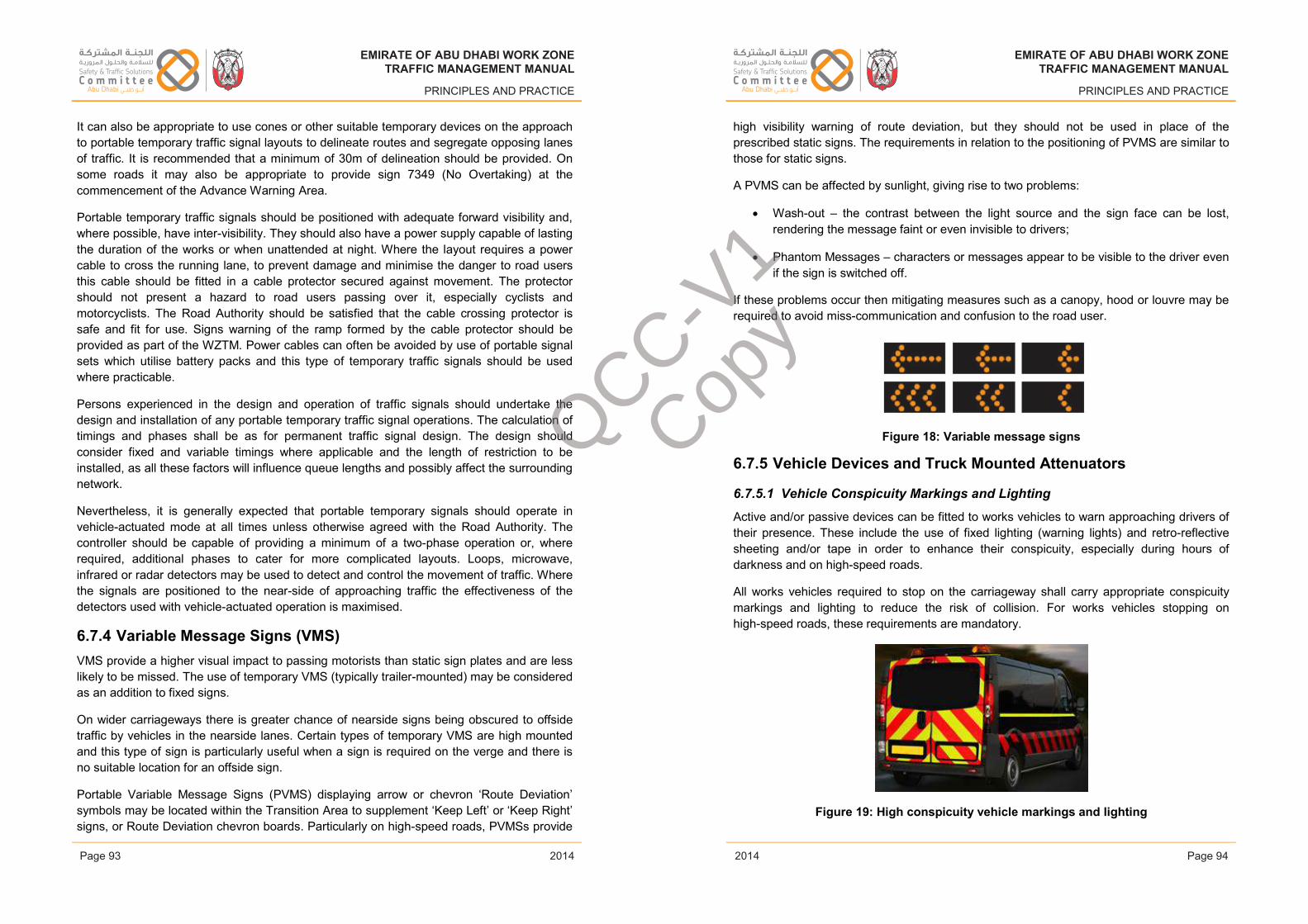
EMIRATE OF ABU DHABI WORK ZONETRAFFIC MANAGEMENT MANUAL
PRINCIPLES AND PRACTICE
It can also be appropriate to use cones or other suitable temporary devices on the approach to portable temporary traffic signal layouts to delineate routes and segregate opposing lanes of traffic. It is recommended that a minimum of 30m of delineation should be provided. On some roads it may also be appropriate to provide sign 7349 (No Overtaking) at the commencement of the Advance Warning Area.
Portable temporary traffic signals should be positioned with adequate forward visibility and, where possible, have inter-visibility. They should also have a power supply capable of lasting the duration of the works or when unattended at night. Where the layout requires a power cable to cross the running lane, to prevent damage and minimise the danger to road users this cable should be fitted in a cable protector secured against movement. The protector should not present a hazard to road users passing over it, especially cyclists and motorcyclists. The Road Authority should be satisfied that the cable crossing protector is safe and fit for use. Signs warning of the ramp formed by the cable protector should be provided as part of the WZTM. Power cables can often be avoided by use of portable signal sets which utilise battery packs and this type of temporary traffic signals should be used where practicable.
Persons experienced in the design and operation of traffic signals should undertake the design and installation of any portable temporary traffic signal operations. The calculation of timings and phases shall be as for permanent traffic signal design. The design should consider fixed and variable timings where applicable and the length of restriction to be installed, as all these factors will influence queue lengths and possibly affect the surrounding network.
Nevertheless, it is generally expected that portable temporary signals should operate in vehicle-actuated mode at all times unless otherwise agreed with the Road Authority. The controller should be capable of providing a minimum of a two-phase operation or, where required, additional phases to cater for more complicated layouts. Loops, microwave, infrared or radar detectors may be used to detect and control the movement of traffic. Where the signals are positioned to the near-side of approaching traffic the effectiveness of the detectors used with vehicle-actuated operation is maximised.
6.7.4 Variable Message Signs (VMS)VMS provide a higher visual impact to passing motorists than static sign plates and are less likely to be missed. The use of temporary VMS (typically trailer-mounted) may be considered as an addition to fixed signs.
On wider carriageways there is greater chance of nearside signs being obscured to offside traffic by vehicles in the nearside lanes. Certain types of temporary VMS are high mounted and this type of sign is particularly useful when a sign is required on the verge and there is no suitable location for an offside sign.
Portable Variable Message Signs (PVMS) displaying arrow or chevron ‘Route Deviation’ symbols may be located within the Transition Area to supplement ‘Keep Left’ or ‘Keep Right’ signs, or Route Deviation chevron boards. Particularly on high-speed roads, PVMSs provide
Issue 1 Page 93 February 2014
EMIRATE OF ABU DHABI WORK ZONETRAFFIC MANAGEMENT MANUAL
PRINCIPLES AND PRACTICE
high visibility warning of route deviation, but they should not be used in place of the prescribed static signs. The requirements in relation to the positioning of PVMS are similar to those for static signs.
A PVMS can be affected by sunlight, giving rise to two problems:
• Wash-out – the contrast between the light source and the sign face can be lost, rendering the message faint or even invisible to drivers;
• Phantom Messages – characters or messages appear to be visible to the driver even if the sign is switched off.
If these problems occur then mitigating measures such as a canopy, hood or louvre may be required to avoid miss-communication and confusion to the road user.
Figure 18: Variable message signs
6.7.5 Vehicle Devices and Truck Mounted Attenuators
6.7.5.1 Vehicle Conspicuity Markings and Lighting
Active and/or passive devices can be fitted to works vehicles to warn approaching drivers of their presence. These include the use of fixed lighting (warning lights) and retro-reflective sheeting and/or tape in order to enhance their conspicuity, especially during hours of darkness and on high-speed roads.
All works vehicles required to stop on the carriageway shall carry appropriate conspicuity markings and lighting to reduce the risk of collision. For works vehicles stopping on high-speed roads, these requirements are mandatory.
Figure 19: High conspicuity vehicle markings and lighting
Issue 1 Page 94 February 2014
EMIRATE OF ABU DHABI WORK ZONETRAFFIC MANAGEMENT MANUAL
PRINCIPLES AND PRACTICE
2014
EMIRATE OF ABU DHABI WORK ZONETRAFFIC MANAGEMENT MANUAL
PRINCIPLES AND PRACTICE
2014Page 93 Page 94
EMIRATE OF ABU DHABI WORK ZONETRAFFIC MANAGEMENT MANUAL
PRINCIPLES AND PRACTICE
2014
EMIRATE OF ABU DHABI WORK ZONETRAFFIC MANAGEMENT MANUAL
PRINCIPLES AND PRACTICE
2014
QCC-V1
Copy
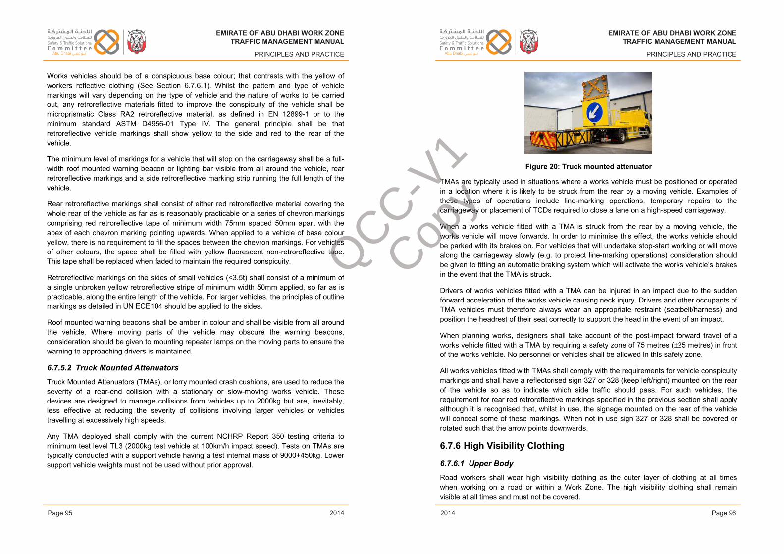
EMIRATE OF ABU DHABI WORK ZONETRAFFIC MANAGEMENT MANUAL
PRINCIPLES AND PRACTICE
Works vehicles should be of a conspicuous base colour; that contrasts with the yellow of workers reflective clothing (See Section 6.7.6.1). Whilst the pattern and type of vehicle markings will vary depending on the type of vehicle and the nature of works to be carried out, any retroreflective materials fitted to improve the conspicuity of the vehicle shall be microprismatic Class RA2 retroreflective material, as defined in EN 12899-1 or to the minimum standard ASTM D4956-01 Type IV. The general principle shall be that retroreflective vehicle markings shall show yellow to the side and red to the rear of the vehicle.
The minimum level of markings for a vehicle that will stop on the carriageway shall be a full-width roof mounted warning beacon or lighting bar visible from all around the vehicle, rear retroreflective markings and a side retroreflective marking strip running the full length of the vehicle.
Rear retroreflective markings shall consist of either red retroreflective material covering the whole rear of the vehicle as far as is reasonably practicable or a series of chevron markings comprising red retroreflective tape of minimum width 75mm spaced 50mm apart with the apex of each chevron marking pointing upwards. When applied to a vehicle of base colour yellow, there is no requirement to fill the spaces between the chevron markings. For vehicles of other colours, the space shall be filled with yellow fluorescent non-retroreflective tape. This tape shall be replaced when faded to maintain the required conspicuity.
Retroreflective markings on the sides of small vehicles (<3.5t) shall consist of a minimum of a single unbroken yellow retroreflective stripe of minimum width 50mm applied, so far as is practicable, along the entire length of the vehicle. For larger vehicles, the principles of outline markings as detailed in UN ECE104 should be applied to the sides.
Roof mounted warning beacons shall be amber in colour and shall be visible from all around the vehicle. Where moving parts of the vehicle may obscure the warning beacons, consideration should be given to mounting repeater lamps on the moving parts to ensure the warning to approaching drivers is maintained.
6.7.5.2 Truck Mounted Attenuators
Truck Mounted Attenuators (TMAs), or lorry mounted crash cushions, are used to reduce the severity of a rear-end collision with a stationary or slow-moving works vehicle. These devices are designed to manage collisions from vehicles up to 2000kg but are, inevitably, less effective at reducing the severity of collisions involving larger vehicles or vehicles travelling at excessively high speeds.
Any TMA deployed shall comply with the current NCHRP Report 350 testing criteria to minimum test level TL3 (2000kg test vehicle at 100km/h impact speed). Tests on TMAs are typically conducted with a support vehicle having a test internal mass of 9000+450kg. Lower support vehicle weights must not be used without prior approval.
Issue 1 Page 95 February 2014
EMIRATE OF ABU DHABI WORK ZONETRAFFIC MANAGEMENT MANUAL
PRINCIPLES AND PRACTICE
Figure 20: Truck mounted attenuator
TMAs are typically used in situations where a works vehicle must be positioned or operated in a location where it is likely to be struck from the rear by a moving vehicle. Examples of these types of operations include line-marking operations, temporary repairs to the carriageway or placement of TCDs required to close a lane on a high-speed carriageway.
When a works vehicle fitted with a TMA is struck from the rear by a moving vehicle, the works vehicle will move forwards. In order to minimise this effect, the works vehicle should be parked with its brakes on. For vehicles that will undertake stop-start working or will move along the carriageway slowly (e.g. to protect line-marking operations) consideration should be given to fitting an automatic braking system which will activate the works vehicle’s brakes in the event that the TMA is struck.
Drivers of works vehicles fitted with a TMA can be injured in an impact due to the sudden forward acceleration of the works vehicle causing neck injury. Drivers and other occupants of TMA vehicles must therefore always wear an appropriate restraint (seatbelt/harness) and position the headrest of their seat correctly to support the head in the event of an impact.
When planning works, designers shall take account of the post-impact forward travel of a works vehicle fitted with a TMA by requiring a safety zone of 75 metres (±25 metres) in front of the works vehicle. No personnel or vehicles shall be allowed in this safety zone.
All works vehicles fitted with TMAs shall comply with the requirements for vehicle conspicuitymarkings and shall have a reflectorised sign 327 or 328 (keep left/right) mounted on the rear of the vehicle so as to indicate which side traffic should pass. For such vehicles, the requirement for rear red retroreflective markings specified in the previous section shall apply although it is recognised that, whilst in use, the signage mounted on the rear of the vehicle will conceal some of these markings. When not in use sign 327 or 328 shall be covered or rotated such that the arrow points downwards.
6.7.6 High Visibility Clothing
6.7.6.1 Upper Body
Road workers shall wear high visibility clothing as the outer layer of clothing at all times when working on a road or within a Work Zone. The high visibility clothing shall remain visible at all times and must not be covered.
Issue 1 Page 96 February 2014
EMIRATE OF ABU DHABI WORK ZONETRAFFIC MANAGEMENT MANUAL
PRINCIPLES AND PRACTICE
2014
EMIRATE OF ABU DHABI WORK ZONETRAFFIC MANAGEMENT MANUAL
PRINCIPLES AND PRACTICE
2014Page 95 Page 96
EMIRATE OF ABU DHABI WORK ZONETRAFFIC MANAGEMENT MANUAL
PRINCIPLES AND PRACTICE
2014
EMIRATE OF ABU DHABI WORK ZONETRAFFIC MANAGEMENT MANUAL
PRINCIPLES AND PRACTICE
2014
QCC-V1
Copy
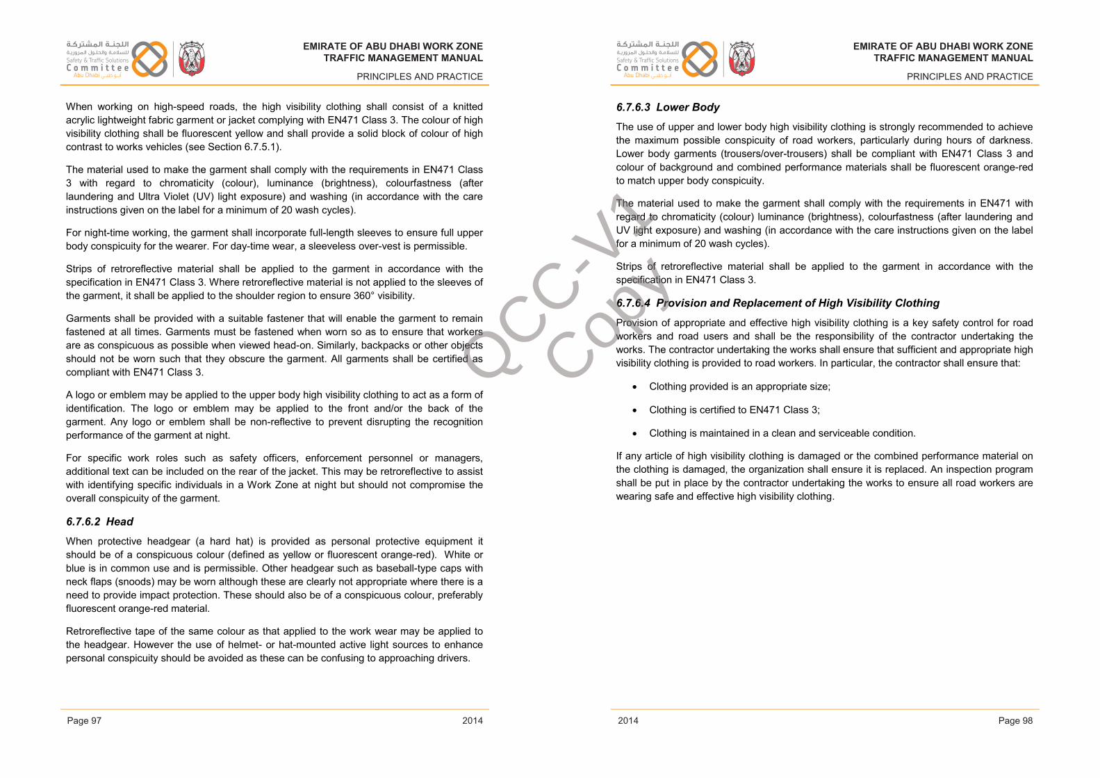
EMIRATE OF ABU DHABI WORK ZONETRAFFIC MANAGEMENT MANUAL
PRINCIPLES AND PRACTICE
When working on high-speed roads, the high visibility clothing shall consist of a knitted acrylic lightweight fabric garment or jacket complying with EN471 Class 3. The colour of high visibility clothing shall be fluorescent yellow and shall provide a solid block of colour of high contrast to works vehicles (see Section 6.7.5.1).
The material used to make the garment shall comply with the requirements in EN471 Class 3 with regard to chromaticity (colour), luminance (brightness), colourfastness (after laundering and Ultra Violet (UV) light exposure) and washing (in accordance with the care instructions given on the label for a minimum of 20 wash cycles).
For night-time working, the garment shall incorporate full-length sleeves to ensure full upper body conspicuity for the wearer. For day-time wear, a sleeveless over-vest is permissible.
Strips of retroreflective material shall be applied to the garment in accordance with the specification in EN471 Class 3. Where retroreflective material is not applied to the sleeves ofthe garment, it shall be applied to the shoulder region to ensure 360° visibility.
Garments shall be provided with a suitable fastener that will enable the garment to remain fastened at all times. Garments must be fastened when worn so as to ensure that workers are as conspicuous as possible when viewed head-on. Similarly, backpacks or other objects should not be worn such that they obscure the garment. All garments shall be certified as compliant with EN471 Class 3.
A logo or emblem may be applied to the upper body high visibility clothing to act as a form of identification. The logo or emblem may be applied to the front and/or the back of the garment. Any logo or emblem shall be non-reflective to prevent disrupting the recognition performance of the garment at night.
For specific work roles such as safety officers, enforcement personnel or managers, additional text can be included on the rear of the jacket. This may be retroreflective to assist with identifying specific individuals in a Work Zone at night but should not compromise the overall conspicuity of the garment.
6.7.6.2 Head
When protective headgear (a hard hat) is provided as personal protective equipment it should be of a conspicuous colour (defined as yellow or fluorescent orange-red). White or blue is in common use and is permissible. Other headgear such as baseball-type caps with neck flaps (snoods) may be worn although these are clearly not appropriate where there is a need to provide impact protection. These should also be of a conspicuous colour, preferably fluorescent orange-red material.
Retroreflective tape of the same colour as that applied to the work wear may be applied to the headgear. However the use of helmet- or hat-mounted active light sources to enhance personal conspicuity should be avoided as these can be confusing to approaching drivers.
Issue 1 Page 97 February 2014
EMIRATE OF ABU DHABI WORK ZONETRAFFIC MANAGEMENT MANUAL
PRINCIPLES AND PRACTICE
6.7.6.3 Lower Body
The use of upper and lower body high visibility clothing is strongly recommended to achieve the maximum possible conspicuity of road workers, particularly during hours of darkness. Lower body garments (trousers/over-trousers) shall be compliant with EN471 Class 3 and colour of background and combined performance materials shall be fluorescent orange-red to match upper body conspicuity.
The material used to make the garment shall comply with the requirements in EN471 with regard to chromaticity (colour) luminance (brightness), colourfastness (after laundering and UV light exposure) and washing (in accordance with the care instructions given on the label for a minimum of 20 wash cycles).
Strips of retroreflective material shall be applied to the garment in accordance with the specification in EN471 Class 3.
6.7.6.4 Provision and Replacement of High Visibility Clothing
Provision of appropriate and effective high visibility clothing is a key safety control for road workers and road users and shall be the responsibility of the contractor undertaking the works. The contractor undertaking the works shall ensure that sufficient and appropriate high visibility clothing is provided to road workers. In particular, the contractor shall ensure that:
• Clothing provided is an appropriate size;
• Clothing is certified to EN471 Class 3;
• Clothing is maintained in a clean and serviceable condition.
If any article of high visibility clothing is damaged or the combined performance material on the clothing is damaged, the organization shall ensure it is replaced. An inspection program shall be put in place by the contractor undertaking the works to ensure all road workers are wearing safe and effective high visibility clothing.
Issue 1 Page 98 February 2014
EMIRATE OF ABU DHABI WORK ZONETRAFFIC MANAGEMENT MANUAL
PRINCIPLES AND PRACTICE
2014
EMIRATE OF ABU DHABI WORK ZONETRAFFIC MANAGEMENT MANUAL
PRINCIPLES AND PRACTICE
2014Page 97 Page 98
EMIRATE OF ABU DHABI WORK ZONETRAFFIC MANAGEMENT MANUAL
PRINCIPLES AND PRACTICE
2014
EMIRATE OF ABU DHABI WORK ZONETRAFFIC MANAGEMENT MANUAL
PRINCIPLES AND PRACTICE
2014
QCC-V1
Copy
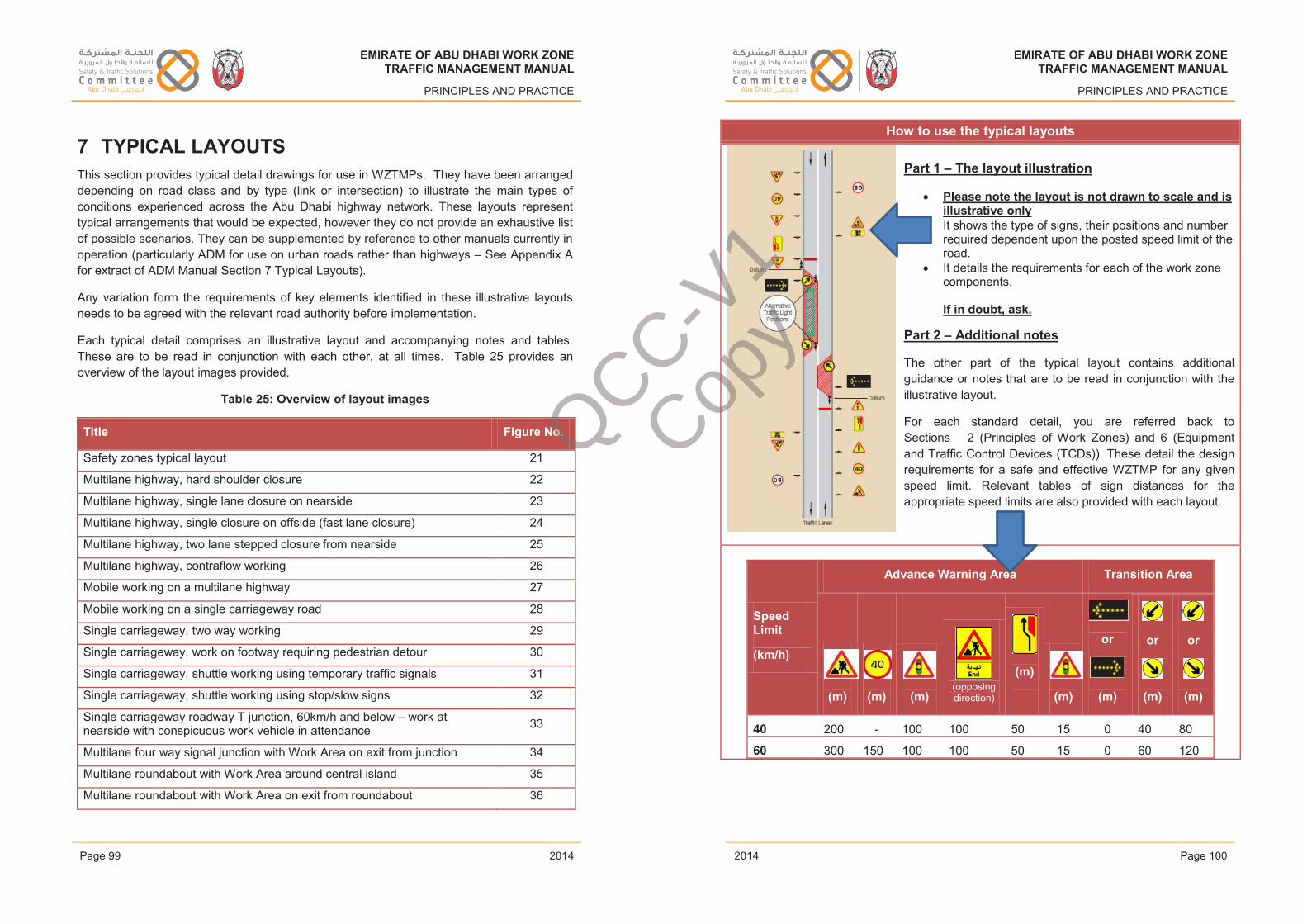
EMIRATE OF ABU DHABI WORK ZONETRAFFIC MANAGEMENT MANUAL
PRINCIPLES AND PRACTICE
7 TYPICAL LAYOUTSThis section provides typical detail drawings for use in WZTMPs. They have been arrangeddepending on road class and by type (link or intersection) to illustrate the main types of conditions experienced across the Abu Dhabi highway network. These layouts represent typical arrangements that would be expected, however they do not provide an exhaustive list of possible scenarios. They can be supplemented by reference to other manuals currently in operation (particularly ADM for use on urban roads rather than highways – See Appendix A for extract of ADM Manual Section 7 Typical Layouts).
Any variation form the requirements of key elements identified in these illustrative layouts needs to be agreed with the relevant road authority before implementation.
Each typical detail comprises an illustrative layout and accompanying notes and tables. These are to be read in conjunction with each other, at all times. Table 25 provides an overview of the layout images provided.
Table 25: Overview of layout images
Title Figure No.
Safety zones typical layout 21
Multilane highway, hard shoulder closure 22
Multilane highway, single lane closure on nearside 23
Multilane highway, single closure on offside (fast lane closure) 24
Multilane highway, two lane stepped closure from nearside 25
Multilane highway, contraflow working 26
Mobile working on a multilane highway 27
Mobile working on a single carriageway road 28
Single carriageway, two way working 29
Single carriageway, work on footway requiring pedestrian detour 30
Single carriageway, shuttle working using temporary traffic signals 31
Single carriageway, shuttle working using stop/slow signs 32
Single carriageway roadway T junction, 60km/h and below – work at nearside with conspicuous work vehicle in attendance 33
Multilane four way signal junction with Work Area on exit from junction 34
Multilane roundabout with Work Area around central island 35
Multilane roundabout with Work Area on exit from roundabout 36
Issue 1 Page 99 February 2014
EMIRATE OF ABU DHABI WORK ZONETRAFFIC MANAGEMENT MANUAL
PRINCIPLES AND PRACTICE
How to use the typical layouts
Part 1 – The layout illustration
• Please note the layout is not drawn to scale and is illustrative only
• It shows the type of signs, their positions and number required dependent upon the posted speed limit of the road.
• It details the requirements for each of the work zone components.
If in doubt, ask.
Part 2 – Additional notes
The other part of the typical layout contains additional guidance or notes that are to be read in conjunction with the illustrative layout.
For each standard detail, you are referred back to Sections 2 (Principles of Work Zones) and 6 (Equipment and Traffic Control Devices (TCDs)). These detail the design requirements for a safe and effective WZTMP for any given speed limit. Relevant tables of sign distances for the appropriate speed limits are also provided with each layout.
Speed Limit
(km/h)
Advance Warning Area Transition Area
(m) (m) (m)(opposing direction)
(m)
(m)
or
(m)
or
(m)
or
(m)
40 200 - 100 100 50 15 0 40 80
60 300 150 100 100 50 15 0 60 120
Issue 1 Page 100 February 2014
EMIRATE OF ABU DHABI WORK ZONETRAFFIC MANAGEMENT MANUAL
PRINCIPLES AND PRACTICE
2014
EMIRATE OF ABU DHABI WORK ZONETRAFFIC MANAGEMENT MANUAL
PRINCIPLES AND PRACTICE
2014Page 99 Page 100
EMIRATE OF ABU DHABI WORK ZONETRAFFIC MANAGEMENT MANUAL
PRINCIPLES AND PRACTICE
2014
EMIRATE OF ABU DHABI WORK ZONETRAFFIC MANAGEMENT MANUAL
PRINCIPLES AND PRACTICE
2014
QCC-V1
Copy
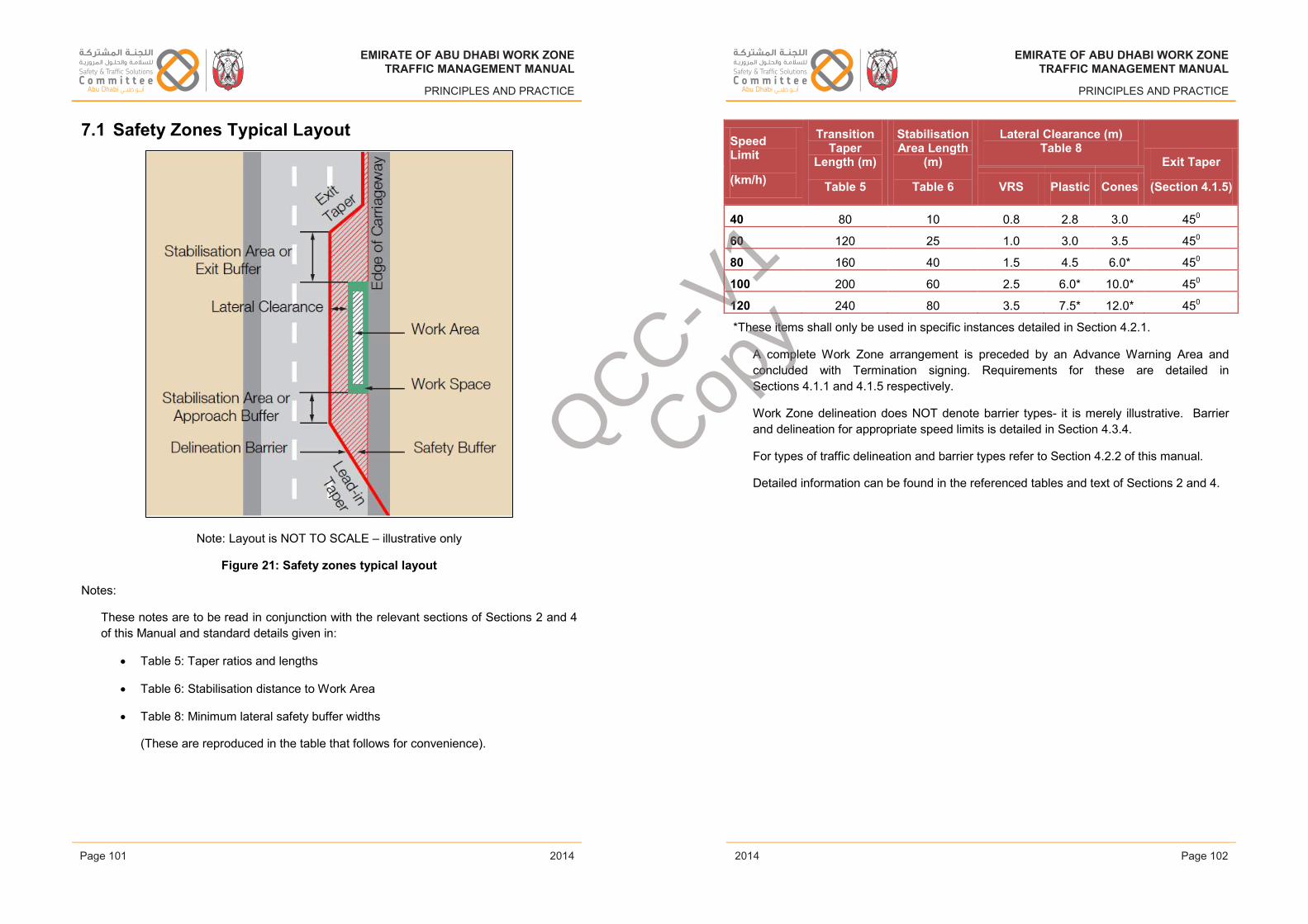
EMIRATE OF ABU DHABI WORK ZONETRAFFIC MANAGEMENT MANUAL
PRINCIPLES AND PRACTICE
7.1 Safety Zones Typical Layout
Note: Layout is NOT TO SCALE – illustrative only
Figure 21: Safety zones typical layout
Notes:
These notes are to be read in conjunction with the relevant sections of Sections 2 and 4of this Manual and standard details given in:
• Table 5: Taper ratios and lengths
• Table 6: Stabilisation distance to Work Area
• Table 8: Minimum lateral safety buffer widths
(These are reproduced in the table that follows for convenience).
Issue 1 Page 101 February 2014
EMIRATE OF ABU DHABI WORK ZONETRAFFIC MANAGEMENT MANUAL
PRINCIPLES AND PRACTICE
Speed Limit
(km/h)
Transition Taper
Length (m)
Table 5
Stabilisation Area Length
(m)
Table 6
Lateral Clearance (m) Table 8
Exit Taper
(Section 4.1.5)VRS Plastic Cones
40 80 10 0.8 2.8 3.0 450
60 120 25 1.0 3.0 3.5 450
80 160 40 1.5 4.5 6.0* 450
100 200 60 2.5 6.0* 10.0* 450
120 240 80 3.5 7.5* 12.0* 450
*These items shall only be used in specific instances detailed in Section 4.2.1.
A complete Work Zone arrangement is preceded by an Advance Warning Area and concluded with Termination signing. Requirements for these are detailed in Sections 4.1.1 and 4.1.5 respectively.
Work Zone delineation does NOT denote barrier types- it is merely illustrative. Barrier and delineation for appropriate speed limits is detailed in Section 4.3.4.
For types of traffic delineation and barrier types refer to Section 4.2.2 of this manual.
Detailed information can be found in the referenced tables and text of Sections 2 and 4.
Issue 1 Page 102 February 2014
EMIRATE OF ABU DHABI WORK ZONETRAFFIC MANAGEMENT MANUAL
PRINCIPLES AND PRACTICE
2014
EMIRATE OF ABU DHABI WORK ZONETRAFFIC MANAGEMENT MANUAL
PRINCIPLES AND PRACTICE
2014Page 101 Page 102
EMIRATE OF ABU DHABI WORK ZONETRAFFIC MANAGEMENT MANUAL
PRINCIPLES AND PRACTICE
2014
EMIRATE OF ABU DHABI WORK ZONETRAFFIC MANAGEMENT MANUAL
PRINCIPLES AND PRACTICE
2014
QCC-V1
Copy
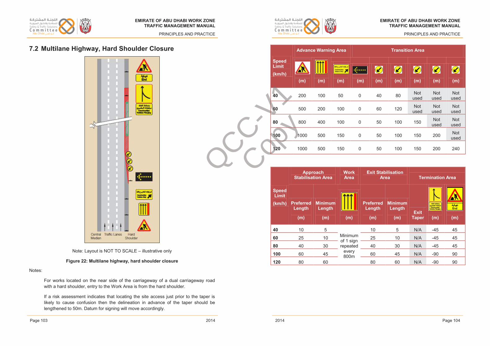
EMIRATE OF ABU DHABI WORK ZONETRAFFIC MANAGEMENT MANUAL
PRINCIPLES AND PRACTICE
7.2 Multilane Highway, Hard Shoulder Closure
Note: Layout is NOT TO SCALE – illustrative only
Figure 22: Multilane highway, hard shoulder closure
Notes:
For works located on the near side of the carriageway of a dual carriageway road with a hard shoulder, entry to the Work Area is from the hard shoulder.
If a risk assessment indicates that locating the site access just prior to the taper is likely to cause confusion then the delineation in advance of the taper should be lengthened to 50m. Datum for signing will move accordingly.
Issue 1 Page 103 February 2014
EMIRATE OF ABU DHABI WORK ZONETRAFFIC MANAGEMENT MANUAL
PRINCIPLES AND PRACTICE
Speed Limit(km/h)
Advance Warning Area Transition Area
(m) (m) (m) (m) (m) (m) (m) (m) (m)
40 200 100 50 0 40 80 Not used
Not used
Not used
60 500 200 100 0 60 120 Not used
Not used
Not used
80 800 400 100 0 50 100 150 Not used
Not used
100 1000 500 150 0 50 100 150 200 Not used
120 1000 500 150 0 50 100 150 200 240
Speed Limit
(km/h)
ApproachStabilisation Area
Work Area
Exit Stabilisation Area Termination Area
PreferredLength
(m)
Minimum Length
(m) (m)
Preferred Length
(m)
Minimum Length
(m)Exit
Taper (m) (m)
40 10 5Minimum of 1 sign repeated
every 800m
10 5 N/A -45 45
60 25 10 25 10 N/A -45 45
80 40 30 40 30 N/A -45 45
100 60 45 60 45 N/A -90 90
120 80 60 80 60 N/A -90 90
Issue 1 Page 104 February 2014
EMIRATE OF ABU DHABI WORK ZONETRAFFIC MANAGEMENT MANUAL
PRINCIPLES AND PRACTICE
2014
EMIRATE OF ABU DHABI WORK ZONETRAFFIC MANAGEMENT MANUAL
PRINCIPLES AND PRACTICE
2014Page 103 Page 104
EMIRATE OF ABU DHABI WORK ZONETRAFFIC MANAGEMENT MANUAL
PRINCIPLES AND PRACTICE
2014
EMIRATE OF ABU DHABI WORK ZONETRAFFIC MANAGEMENT MANUAL
PRINCIPLES AND PRACTICE
2014
QCC-V1
Copy
EMIRATE OF ABU DHABI WORK ZONETRAFFIC MANAGEMENT MANUAL
PRINCIPLES AND PRACTICE
7.3 Multilane Highway, Single Lane Closure on Nearside
Note: Layout is NOT TO SCALE – illustrative only
Figure 23: Multilane highway, single lane closure on nearside
Issue 1 Page 105 February 2014
EMIRATE OF ABU DHABI WORK ZONETRAFFIC MANAGEMENT MANUAL
PRINCIPLES AND PRACTICE
Notes:
For works located on the near side of the carriageway of a dual carriageway road with a hard shoulder, entry to the Work Area is from the hard shoulder.
If a risk assessment indicates that locating the site access just prior to the taper is likely to cause confusion then the delineation in advance of the taper should be lengthened to 50m. Datum for signing will move accordingly.
Where a temporary mandatory speed limit is in place, one pair of temporary speed limit signs is required, followed by repeater signs.
The final speed limit through the Work Area shall be repeated at 200m intervals for Work Areas 200m or longer and every 100m for Work Areas shorter than 200m.Where temporary speed limits have been used the permanent speed limit must be signed beyond the WZTTM layout.
Appropriate delineation devices are covered in Section 6.5.2.
Speed Limit(km/h)
Advance Warning Area
(m)
(Permanent Speed Limit
Less20km/h)
(m) (m)
and
(m)
and
(m) (m)
60 300 150 Not used Not used 100 50
80 500 300 Not used Not used 200 100
100 800 500 400 Not used 200 100
120 1000 900 800 400 200 100
Issue 1 Page 106 February 2014
EMIRATE OF ABU DHABI WORK ZONETRAFFIC MANAGEMENT MANUAL
PRINCIPLES AND PRACTICE
2014
EMIRATE OF ABU DHABI WORK ZONETRAFFIC MANAGEMENT MANUAL
PRINCIPLES AND PRACTICE
2014Page 105 Page 106
EMIRATE OF ABU DHABI WORK ZONETRAFFIC MANAGEMENT MANUAL
PRINCIPLES AND PRACTICE
2014
EMIRATE OF ABU DHABI WORK ZONETRAFFIC MANAGEMENT MANUAL
PRINCIPLES AND PRACTICE
2014
QCC-V1
Copy
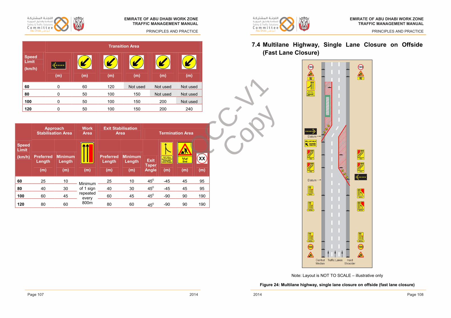
EMIRATE OF ABU DHABI WORK ZONETRAFFIC MANAGEMENT MANUAL
PRINCIPLES AND PRACTICE
Speed Limit(km/h)
Transition Area
(m) (m) (m) (m) (m) (m)
60 0 60 120 Not used Not used Not used
80 0 50 100 150 Not used Not used
100 0 50 100 150 200 Not used
120 0 50 100 150 200 240
Speed Limit(km/h)
Approach Stabilisation Area
Work Area
Exit Stabilisation Area Termination Area
PreferredLength
(m)
Minimum Length
(m) (m)
Preferred Length
(m)
Minimum Length
(m)
Exit TaperAngle (m) (m) (m)
60 25 10 Minimum of 1 sign repeated
every 800m
25 10 450 -45 45 95
80 40 30 40 30 450 -45 45 95
100 60 45 60 45 450 -90 90 190
120 80 60 80 60 450 -90 90 190
Issue 1 Page 107 February 2014
EMIRATE OF ABU DHABI WORK ZONETRAFFIC MANAGEMENT MANUAL
PRINCIPLES AND PRACTICE
7.4 Multilane Highway, Single Lane Closure on Offside(Fast Lane Closure)
Note: Layout is NOT TO SCALE – illustrative only
Figure 24: Multilane highway, single lane closure on offside (fast lane closure)
Issue 1 Page 108 February 2014
EMIRATE OF ABU DHABI WORK ZONETRAFFIC MANAGEMENT MANUAL
PRINCIPLES AND PRACTICE
2014
EMIRATE OF ABU DHABI WORK ZONETRAFFIC MANAGEMENT MANUAL
PRINCIPLES AND PRACTICE
2014Page 107 Page 108
EMIRATE OF ABU DHABI WORK ZONETRAFFIC MANAGEMENT MANUAL
PRINCIPLES AND PRACTICE
2014
EMIRATE OF ABU DHABI WORK ZONETRAFFIC MANAGEMENT MANUAL
PRINCIPLES AND PRACTICE
2014
QCC-V1
Copy
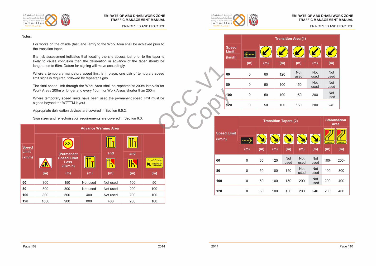
EMIRATE OF ABU DHABI WORK ZONETRAFFIC MANAGEMENT MANUAL
PRINCIPLES AND PRACTICE
Notes:
For works on the offside (fast lane) entry to the Work Area shall be achieved prior to the transition taper.
If a risk assessment indicates that locating the site access just prior to the taper is likely to cause confusion then the delineation in advance of the taper should be lengthened to 50m. Datum for signing will move accordingly.
Where a temporary mandatory speed limit is in place, one pair of temporary speed limit signs is required, followed by repeater signs.
The final speed limit through the Work Area shall be repeated at 200m intervals for Work Areas 200m or longer and every 100m for Work Areas shorter than 200m.
Where temporary speed limits have been used the permanent speed limit must be signed beyond the WZTTM layout.
Appropriate delineation devices are covered in Section 6.5.2.
Sign sizes and reflectorisation requirements are covered in Section 6.3.
Speed Limit(km/h)
Advance Warning Area
(m)
(Permanent Speed Limit
Less20km/h)
(m) (m)
and
(m)
and
(m) (m)
60 300 150 Not used Not used 100 50
80 500 300 Not used Not used 200 100
100 800 500 400 Not used 200 100
120 1000 900 800 400 200 100
Issue 1 Page 109 February 2014
EMIRATE OF ABU DHABI WORK ZONETRAFFIC MANAGEMENT MANUAL
PRINCIPLES AND PRACTICE
Speed Limit(km/h)
Transition Area (1)
(m) (m) (m) (m) (m) (m)
60 0 60 120 Not used
Not used
Not used
80 0 50 100 150 Not used
Not used
100 0 50 100 150 200 Not used
120 0 50 100 150 200 240
Speed Limit(km/h)
Transition Tapers (2) Stabilisation Area
(m) (m) (m) (m) (m) (m) (m) (m)
60 0 60 120 Not used
Not used
Not used 100- 200-
80 0 50 100 150 Not used
Not used 100 300
100 0 50 100 150 200 Not used 200 400
120 0 50 100 150 200 240 200 400
Issue 1 Page 110 February 2014
EMIRATE OF ABU DHABI WORK ZONETRAFFIC MANAGEMENT MANUAL
PRINCIPLES AND PRACTICE
2014
EMIRATE OF ABU DHABI WORK ZONETRAFFIC MANAGEMENT MANUAL
PRINCIPLES AND PRACTICE
2014Page 109 Page 110
EMIRATE OF ABU DHABI WORK ZONETRAFFIC MANAGEMENT MANUAL
PRINCIPLES AND PRACTICE
2014
EMIRATE OF ABU DHABI WORK ZONETRAFFIC MANAGEMENT MANUAL
PRINCIPLES AND PRACTICE
2014
QCC-V1
Copy
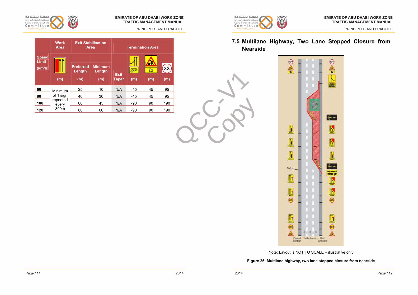
EMIRATE OF ABU DHABI WORK ZONETRAFFIC MANAGEMENT MANUAL
PRINCIPLES AND PRACTICE
Speed Limit(km/h)
Work Area
Exit Stabilisation Area Termination Area
(m)
Preferred Length
(m)
Minimum Length
(m)Exit
Taper (m) (m) (m)
60 Minimum of 1 sign repeated
every 800m
25 10 N/A -45 45 95
80 40 30 N/A -45 45 95
100 60 45 N/A -90 90 190
120 80 60 N/A -90 90 190
Issue 1 Page 111 February 2014
EMIRATE OF ABU DHABI WORK ZONETRAFFIC MANAGEMENT MANUAL
PRINCIPLES AND PRACTICE
7.5 Multilane Highway, Two Lane Stepped Closure from Nearside
Note: Layout is NOT TO SCALE – illustrative only
Figure 25: Multilane highway, two lane stepped closure from nearside
Issue 1 Page 112 February 2014
EMIRATE OF ABU DHABI WORK ZONETRAFFIC MANAGEMENT MANUAL
PRINCIPLES AND PRACTICE
2014
EMIRATE OF ABU DHABI WORK ZONETRAFFIC MANAGEMENT MANUAL
PRINCIPLES AND PRACTICE
2014Page 111 Page 112
EMIRATE OF ABU DHABI WORK ZONETRAFFIC MANAGEMENT MANUAL
PRINCIPLES AND PRACTICE
2014
EMIRATE OF ABU DHABI WORK ZONETRAFFIC MANAGEMENT MANUAL
PRINCIPLES AND PRACTICE
2014
QCC-V1
Copy
EMIRATE OF ABU DHABI WORK ZONETRAFFIC MANAGEMENT MANUAL
PRINCIPLES AND PRACTICE
Notes:
For works located on the near side of the carriageway of a dual carriageway road with a hard shoulder, entry to the Work Area is from the hard shoulder.
For works on the offside entry to the Work Area shall be achieved prior to the Transition taper.
If a risk assessment indicates that locating the site access just prior to the taper is likely to cause confusion then the delineation in advance of the taper should belengthened to 50m. Datum for signing will move accordingly.
Where a temporary mandatory speed limit is in place, one pair of temporary speed limit signs is required, followed by repeater signs.
The final speed limit through the Work Area shall be repeated at 200m intervals for Work Areas 200m or longer and every 100m for Work Areas shorter than 200m.
Where temporary speed limits have been used the permanent speed limit must be signed beyond the WZTTM layout.
Appropriate delineation devices are covered in Section 6.5.2.
Sign sizes and reflectorisation requirements are covered in Section 6.3.
Speed Limit(km/h)
Advance Warning Area (to first datum)
(m)
(Permanent Speed Limit
less 20km/h)
(m) (m)
(Permanent Speed Limit
less 40km/h)
(m)
and
(m)
and
(m) (m)
60 300 150 100 Not used Not used Not used 50
80 500 300 200 150 Not used 100 50
100 800 500 400 300 Not used 200 100
120 1000 900 800 500 400 200 100
Issue 1 Page 113 February 2014
EMIRATE OF ABU DHABI WORK ZONETRAFFIC MANAGEMENT MANUAL
PRINCIPLES AND PRACTICE
Speed Limit(km/h)
Transition Tapers Stabilisation Area
(m) (m) (m) (m) (m) (m) (m)
and
(m)
and
(m)
60 0 60 120 Not used
Not used
Not used 100 200 Not
used
80 0 50 100 150 Not used
Not used 100 300 Not
used
100 0 50 100 150 200 Not used 200 400 Not
used
120 0 50 100 150 200 240 200 400 480
Speed Limit(km/h)
Work Area
Exit Stabilisation Area Termination Area
(m)
Preferred Length
(m)
Minimum Length
(m)Exit
Taper (m) (m) (m)
60 Minimumof 1 sign repeated
every 800m
25 10 450 -45 45 95
80 40 30 450 -45 45 95
100 60 45 450 -90 90 190
120 80 60 450 -90 90 190
Issue 1 Page 114 February 2014
EMIRATE OF ABU DHABI WORK ZONETRAFFIC MANAGEMENT MANUAL
PRINCIPLES AND PRACTICE
2014
EMIRATE OF ABU DHABI WORK ZONETRAFFIC MANAGEMENT MANUAL
PRINCIPLES AND PRACTICE
2014Page 113 Page 114
EMIRATE OF ABU DHABI WORK ZONETRAFFIC MANAGEMENT MANUAL
PRINCIPLES AND PRACTICE
2014
EMIRATE OF ABU DHABI WORK ZONETRAFFIC MANAGEMENT MANUAL
PRINCIPLES AND PRACTICE
2014
QCC-V1
Copy
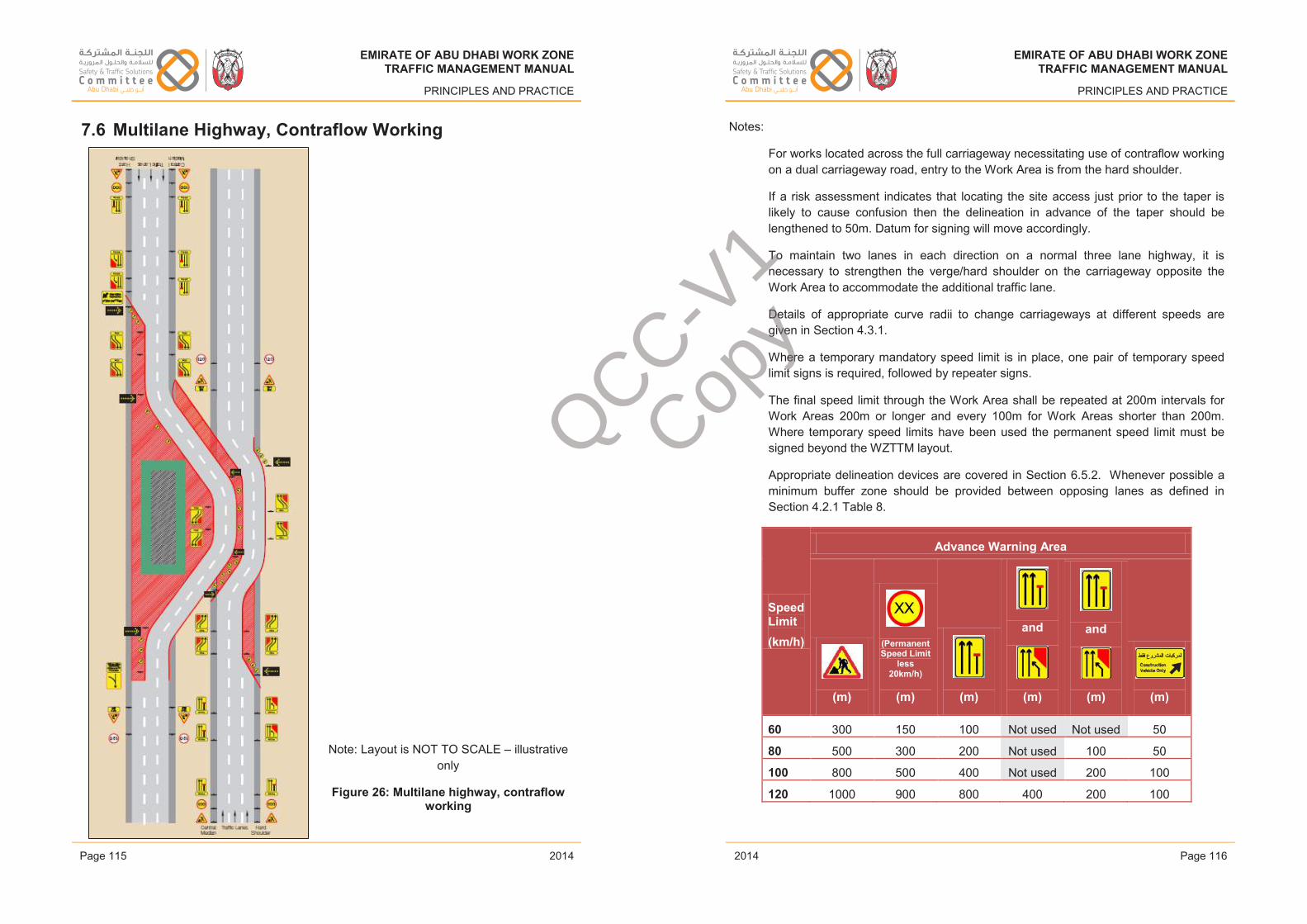
EMIRATE OF ABU DHABI WORK ZONETRAFFIC MANAGEMENT MANUAL
PRINCIPLES AND PRACTICE
7.6 Multilane Highway, Contraflow Working
Note: Layout is NOT TO SCALE – illustrative only
Figure 26: Multilane highway, contraflow working
Issue 1 Page 115 February 2014
EMIRATE OF ABU DHABI WORK ZONETRAFFIC MANAGEMENT MANUAL
PRINCIPLES AND PRACTICE
Notes:
For works located across the full carriageway necessitating use of contraflow working on a dual carriageway road, entry to the Work Area is from the hard shoulder.
If a risk assessment indicates that locating the site access just prior to the taper is likely to cause confusion then the delineation in advance of the taper should be lengthened to 50m. Datum for signing will move accordingly.
To maintain two lanes in each direction on a normal three lane highway, it is necessary to strengthen the verge/hard shoulder on the carriageway opposite the Work Area to accommodate the additional traffic lane.
Details of appropriate curve radii to change carriageways at different speeds aregiven in Section 4.3.1.
Where a temporary mandatory speed limit is in place, one pair of temporary speed limit signs is required, followed by repeater signs.
The final speed limit through the Work Area shall be repeated at 200m intervals for Work Areas 200m or longer and every 100m for Work Areas shorter than 200m.Where temporary speed limits have been used the permanent speed limit must be signed beyond the WZTTM layout.
Appropriate delineation devices are covered in Section 6.5.2. Whenever possible a minimum buffer zone should be provided between opposing lanes as defined in Section 4.2.1 Table 8.
Speed Limit(km/h)
Advance Warning Area
(m)
(Permanent Speed Limit
less 20km/h)
(m) (m)
and
(m)
and
(m) (m)
60 300 150 100 Not used Not used 50
80 500 300 200 Not used 100 50
100 800 500 400 Not used 200 100
120 1000 900 800 400 200 100
Issue 1 Page 116 February 2014
EMIRATE OF ABU DHABI WORK ZONETRAFFIC MANAGEMENT MANUAL
PRINCIPLES AND PRACTICE
2014
EMIRATE OF ABU DHABI WORK ZONETRAFFIC MANAGEMENT MANUAL
PRINCIPLES AND PRACTICE
2014Page 115 Page 116
EMIRATE OF ABU DHABI WORK ZONETRAFFIC MANAGEMENT MANUAL
PRINCIPLES AND PRACTICE
2014
EMIRATE OF ABU DHABI WORK ZONETRAFFIC MANAGEMENT MANUAL
PRINCIPLES AND PRACTICE
2014
QCC-V1
Copy
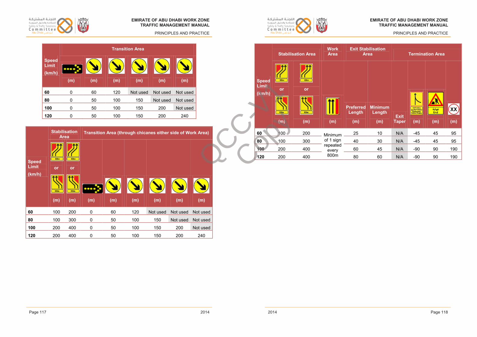
EMIRATE OF ABU DHABI WORK ZONETRAFFIC MANAGEMENT MANUAL
PRINCIPLES AND PRACTICE
Speed Limit(km/h)
Transition Area
(m) (m) (m) (m) (m) (m)
60 0 60 120 Not used Not used Not used
80 0 50 100 150 Not used Not used
100 0 50 100 150 200 Not used
120 0 50 100 150 200 240
Speed Limit(km/h)
Stabilisation Area
Transition Area (through chicanes either side of Work Area)
or
(m)
or
(m) (m) (m) (m) (m) (m) (m)
60 100 200 0 60 120 Not used Not used Not used
80 100 300 0 50 100 150 Not used Not used
100 200 400 0 50 100 150 200 Not used
120 200 400 0 50 100 150 200 240
Issue 1 Page 117 February 2014
EMIRATE OF ABU DHABI WORK ZONETRAFFIC MANAGEMENT MANUAL
PRINCIPLES AND PRACTICE
Speed Limit(km/h)
Stabilisation AreaWork Area
Exit Stabilisation Area Termination Area
or
(m)
or
(m) (m)
Preferred Length
(m)
Minimum Length
(m)Exit
Taper (m) (m) (m)
60 100 200 Minimum of 1 sign repeated
every 800m
25 10 N/A -45 45 95
80 100 300 40 30 N/A -45 45 95
100 200 400 60 45 N/A -90 90 190
120 200 400 80 60 N/A -90 90 190
Issue 1 Page 118 February 2014
EMIRATE OF ABU DHABI WORK ZONETRAFFIC MANAGEMENT MANUAL
PRINCIPLES AND PRACTICE
2014
EMIRATE OF ABU DHABI WORK ZONETRAFFIC MANAGEMENT MANUAL
PRINCIPLES AND PRACTICE
2014Page 117 Page 118
EMIRATE OF ABU DHABI WORK ZONETRAFFIC MANAGEMENT MANUAL
PRINCIPLES AND PRACTICE
2014
EMIRATE OF ABU DHABI WORK ZONETRAFFIC MANAGEMENT MANUAL
PRINCIPLES AND PRACTICE
2014
QCC-V1
Copy
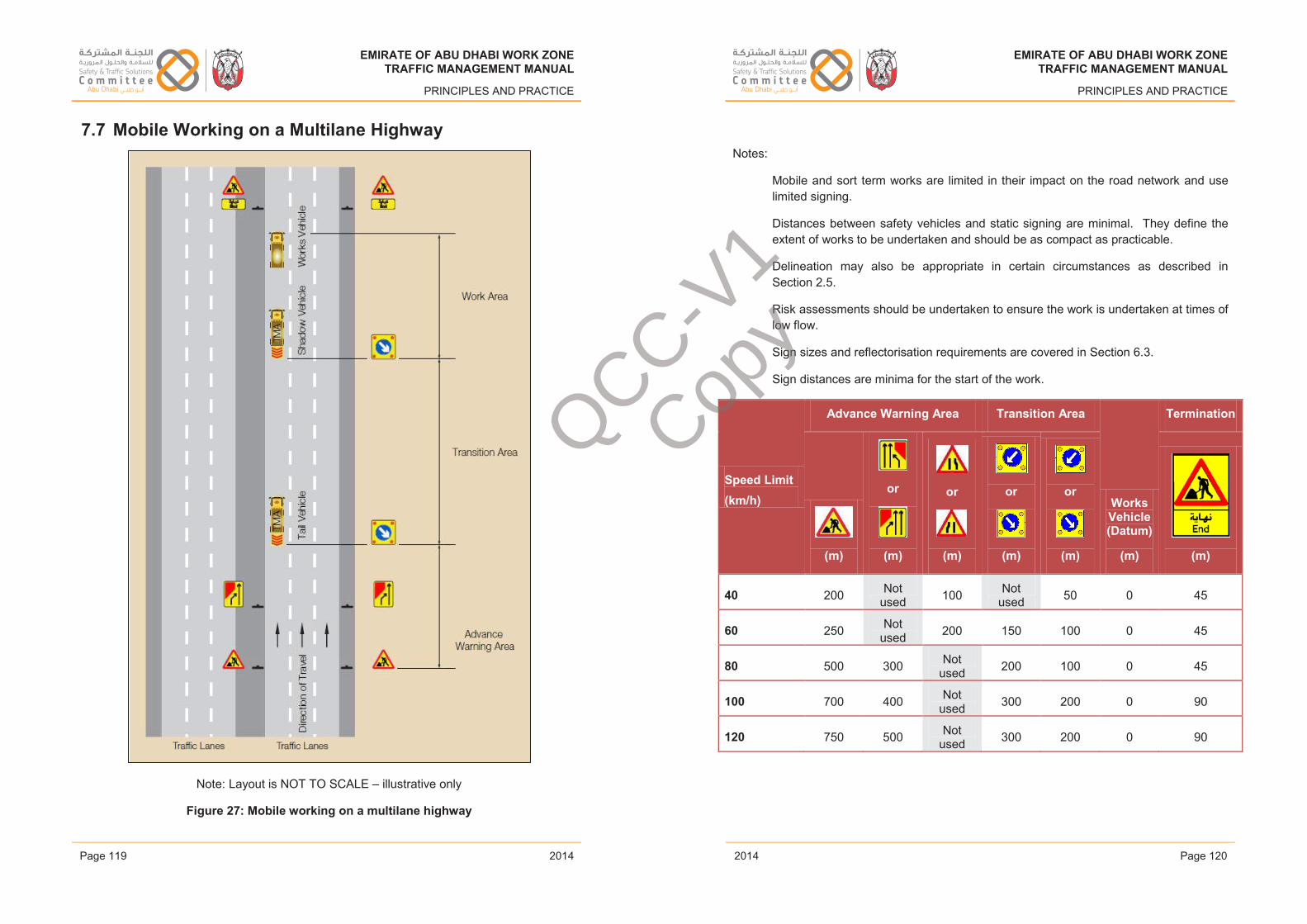
EMIRATE OF ABU DHABI WORK ZONETRAFFIC MANAGEMENT MANUAL
PRINCIPLES AND PRACTICE
7.7 Mobile Working on a Multilane Highway
Note: Layout is NOT TO SCALE – illustrative only
Figure 27: Mobile working on a multilane highway
Issue 1 Page 119 February 2014
EMIRATE OF ABU DHABI WORK ZONETRAFFIC MANAGEMENT MANUAL
PRINCIPLES AND PRACTICE
Notes:
Mobile and sort term works are limited in their impact on the road network and use limited signing.
Distances between safety vehicles and static signing are minimal. They define the extent of works to be undertaken and should be as compact as practicable.
Delineation may also be appropriate in certain circumstances as described in Section 2.5.
Risk assessments should be undertaken to ensure the work is undertaken at times of low flow.
Sign sizes and reflectorisation requirements are covered in Section 6.3.
Sign distances are minima for the start of the work.
Speed Limit(km/h)
Advance Warning Area Transition Area
Works Vehicle (Datum)
(m)
Termination
(m)
or
(m)
or
(m)
or
(m)
or
(m) (m)
40 200 Not used 100 Not
used 50 0 45
60 250 Not used 200 150 100 0 45
80 500 300 Not used 200 100 0 45
100 700 400 Not used 300 200 0 90
120 750 500 Not used 300 200 0 90
Issue 1 Page 120 February 2014
EMIRATE OF ABU DHABI WORK ZONETRAFFIC MANAGEMENT MANUAL
PRINCIPLES AND PRACTICE
2014
EMIRATE OF ABU DHABI WORK ZONETRAFFIC MANAGEMENT MANUAL
PRINCIPLES AND PRACTICE
2014Page 119 Page 120
EMIRATE OF ABU DHABI WORK ZONETRAFFIC MANAGEMENT MANUAL
PRINCIPLES AND PRACTICE
2014
EMIRATE OF ABU DHABI WORK ZONETRAFFIC MANAGEMENT MANUAL
PRINCIPLES AND PRACTICE
2014
QCC-V1
Copy
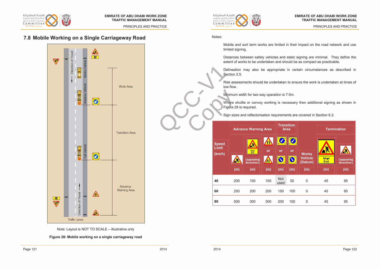
EMIRATE OF ABU DHABI WORK ZONETRAFFIC MANAGEMENT MANUAL
PRINCIPLES AND PRACTICE
7.8 Mobile Working on a Single Carriageway Road
Note: Layout is NOT TO SCALE – illustrative only
Figure 28: Mobile working on a single carriageway road
Issue 1 Page 121 February 2014
EMIRATE OF ABU DHABI WORK ZONETRAFFIC MANAGEMENT MANUAL
PRINCIPLES AND PRACTICE
Notes:
Mobile and sort term works are limited in their impact on the road network and use limited signing.
Distances between safety vehicles and static signing are minimal. They define the extent of works to be undertaken and should be as compact as practicable.
Delineation may also be appropriate in certain circumstances as described in Section 2.5.
Risk assessments should be undertaken to ensure the work is undertaken at times of low flow.
Minimum width for two way operation is 7.0m.
Where shuttle or convoy working is necessary then additional signing as shown inFigure 29 is required.
Sign sizes and reflectorisation requirements are covered in Section 6.3.
Speed Limit(km/h)
Advance Warning AreaTransition
Area
Works Vehicle (Datum)
(m)
Termination
(m)
(opposing direction)
(m)
or
(m)
or
(m)
or
(m) (m)
(opposing direction)
(m)
40 200 100 100 Not used 50 0 45 95
60 250 200 200 150 100 0 45 95
80 500 300 300 200 100 0 45 95
Issue 1 Page 122 February 2014
EMIRATE OF ABU DHABI WORK ZONETRAFFIC MANAGEMENT MANUAL
PRINCIPLES AND PRACTICE
2014
EMIRATE OF ABU DHABI WORK ZONETRAFFIC MANAGEMENT MANUAL
PRINCIPLES AND PRACTICE
2014Page 121 Page 122
EMIRATE OF ABU DHABI WORK ZONETRAFFIC MANAGEMENT MANUAL
PRINCIPLES AND PRACTICE
2014
EMIRATE OF ABU DHABI WORK ZONETRAFFIC MANAGEMENT MANUAL
PRINCIPLES AND PRACTICE
2014
QCC-V1
Copy
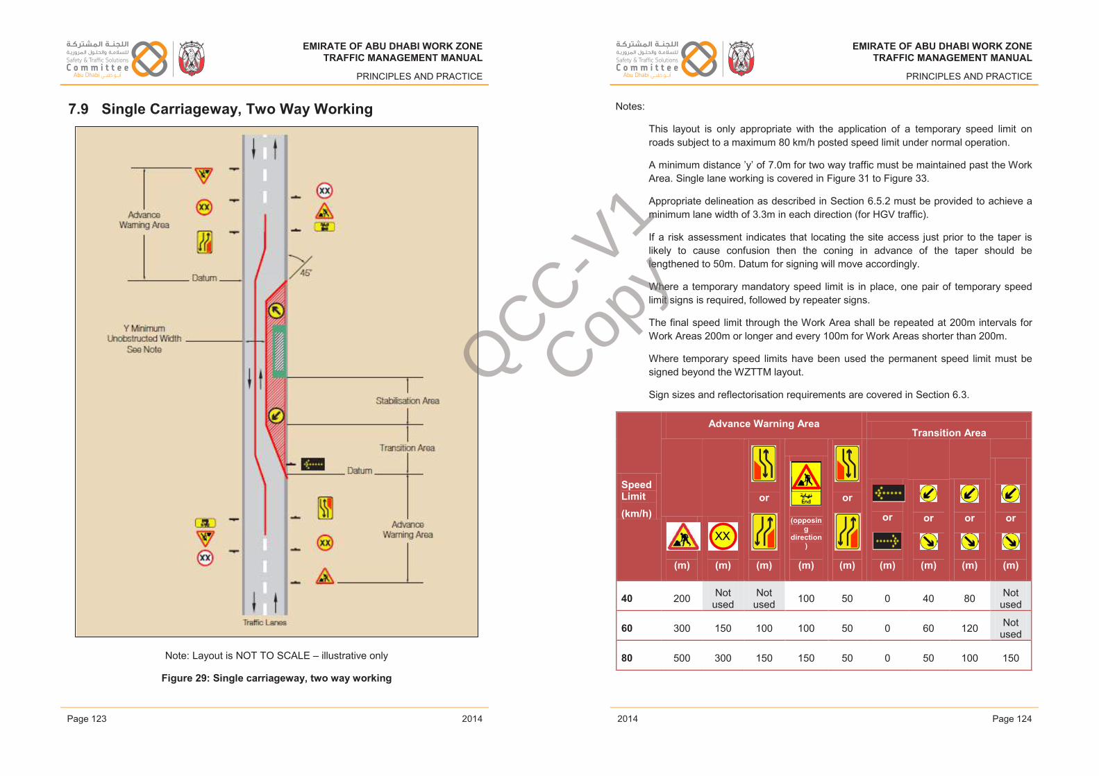
EMIRATE OF ABU DHABI WORK ZONETRAFFIC MANAGEMENT MANUAL
PRINCIPLES AND PRACTICE
7.9 Single Carriageway, Two Way Working
Note: Layout is NOT TO SCALE – illustrative only
Figure 29: Single carriageway, two way working
Issue 1 Page 123 February 2014
EMIRATE OF ABU DHABI WORK ZONETRAFFIC MANAGEMENT MANUAL
PRINCIPLES AND PRACTICE
Notes:
This layout is only appropriate with the application of a temporary speed limit on roads subject to a maximum 80 km/h posted speed limit under normal operation.
A minimum distance ’y’ of 7.0m for two way traffic must be maintained past the Work Area. Single lane working is covered in Figure 31 to Figure 33.
Appropriate delineation as described in Section 6.5.2 must be provided to achieve a minimum lane width of 3.3m in each direction (for HGV traffic).
If a risk assessment indicates that locating the site access just prior to the taper is likely to cause confusion then the coning in advance of the taper should be lengthened to 50m. Datum for signing will move accordingly.
Where a temporary mandatory speed limit is in place, one pair of temporary speed limit signs is required, followed by repeater signs.
The final speed limit through the Work Area shall be repeated at 200m intervals for Work Areas 200m or longer and every 100m for Work Areas shorter than 200m.
Where temporary speed limits have been used the permanent speed limit must be signed beyond the WZTTM layout.
Sign sizes and reflectorisation requirements are covered in Section 6.3.
Speed Limit(km/h)
Advance Warning AreaTransition Area
(m) (m)
or
(m)
(opposing
direction)
(m)
or
(m)
or
(m)
or
(m)
or
(m)
or
(m)
40 200 Not used
Not used 100 50 0 40 80 Not
used
60 300 150 100 100 50 0 60 120 Not used
80 500 300 150 150 50 0 50 100 150
Issue 1 Page 124 February 2014
EMIRATE OF ABU DHABI WORK ZONETRAFFIC MANAGEMENT MANUAL
PRINCIPLES AND PRACTICE
2014
EMIRATE OF ABU DHABI WORK ZONETRAFFIC MANAGEMENT MANUAL
PRINCIPLES AND PRACTICE
2014Page 123 Page 124
EMIRATE OF ABU DHABI WORK ZONETRAFFIC MANAGEMENT MANUAL
PRINCIPLES AND PRACTICE
2014
EMIRATE OF ABU DHABI WORK ZONETRAFFIC MANAGEMENT MANUAL
PRINCIPLES AND PRACTICE
2014
QCC-V1
Copy
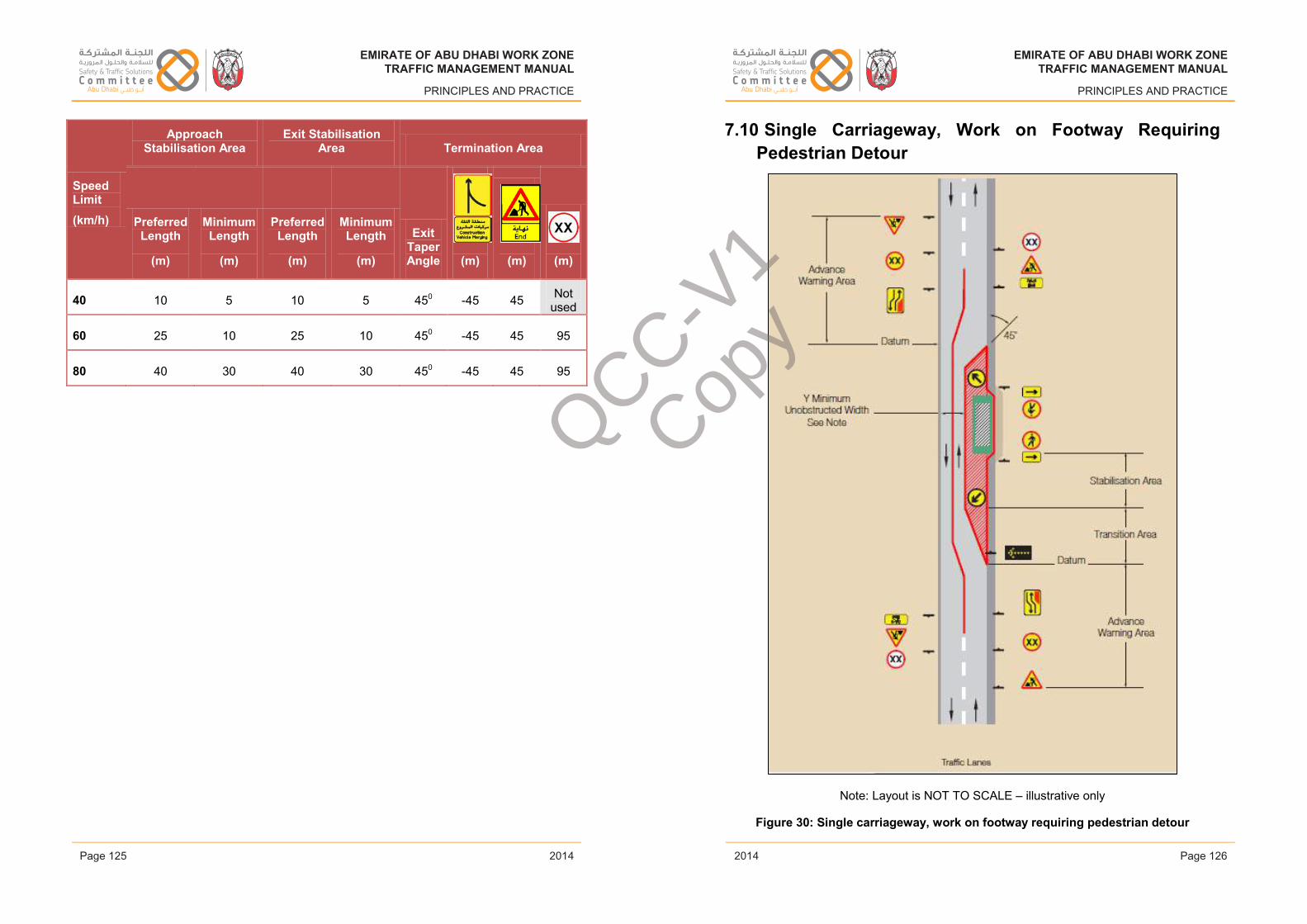
EMIRATE OF ABU DHABI WORK ZONETRAFFIC MANAGEMENT MANUAL
PRINCIPLES AND PRACTICE
Speed Limit(km/h)
Approach Stabilisation Area
Exit Stabilisation Area Termination Area
Preferred Length
(m)
Minimum Length
(m)
Preferred Length
(m)
Minimum Length
(m)
ExitTaperAngle (m) (m) (m)
40 10 5 10 5 450 -45 45 Not used
60 25 10 25 10 450 -45 45 95
80 40 30 40 30 450 -45 45 95
Issue 1 Page 125 February 2014
EMIRATE OF ABU DHABI WORK ZONETRAFFIC MANAGEMENT MANUAL
PRINCIPLES AND PRACTICE
7.10 Single Carriageway, Work on Footway Requiring Pedestrian Detour
Note: Layout is NOT TO SCALE – illustrative only
Figure 30: Single carriageway, work on footway requiring pedestrian detour
Issue 1 Page 126 February 2014
EMIRATE OF ABU DHABI WORK ZONETRAFFIC MANAGEMENT MANUAL
PRINCIPLES AND PRACTICE
2014
EMIRATE OF ABU DHABI WORK ZONETRAFFIC MANAGEMENT MANUAL
PRINCIPLES AND PRACTICE
2014Page 125 Page 126
EMIRATE OF ABU DHABI WORK ZONETRAFFIC MANAGEMENT MANUAL
PRINCIPLES AND PRACTICE
2014
EMIRATE OF ABU DHABI WORK ZONETRAFFIC MANAGEMENT MANUAL
PRINCIPLES AND PRACTICE
2014
QCC-V1
Copy
EMIRATE OF ABU DHABI WORK ZONETRAFFIC MANAGEMENT MANUAL
PRINCIPLES AND PRACTICE
Notes:
Additional pedestrian barriers may be provided either parallel to the kerbline or at right angles to it in order to guide pedestrians past the works as site conditions dictate.
The temporary footway width and surface needs to be comparable with the existing footway width and surface.
Any change in level needs to be achieved through a ramped area capable of accommodating wheelchairs and children’s pushchairs/prams.
If diversion away from the carriageway is not possible then additional provision between the safety buffer and traffic lane needs to be provided in accordance with Section 4.3.3.
The minimum width for two-way working is as described in Figure 29.
Sign sizes and reflectorisation requirements are covered in Section 6.3.
Speed Limit(km/h)
Advance Warning Area Transition AreaWork Area
(m) (m)
or
(m)
or
(m)
or
(m)
or
(m)
or
(m)
or
(m)
or
(m)
40 200 Not Used 100 50 0 40 80 Not
used 95
60 300 150 100 50 0 60 120 Not used 150
80 500 300 200 100 0 50 100 150 190
Issue 1 Page 127 February 2014
EMIRATE OF ABU DHABI WORK ZONETRAFFIC MANAGEMENT MANUAL
PRINCIPLES AND PRACTICE
Speed Limit(km/h)
Approach Stabilisation Area
Exit Stabilisation Area Termination Area
Preferred Length
(m)
Minimum Length
(m)
Preferred Length
(m)
Minimum Length
(m)
ExitTaperAngle (m) (m) (m)
40 10 5 10 5 450 -45 45 Not used
60 25 10 25 10 450 -45 45 95
80 40 30 40 30 450 -45 45 95
Issue 1 Page 128 February 2014
EMIRATE OF ABU DHABI WORK ZONETRAFFIC MANAGEMENT MANUAL
PRINCIPLES AND PRACTICE
2014
EMIRATE OF ABU DHABI WORK ZONETRAFFIC MANAGEMENT MANUAL
PRINCIPLES AND PRACTICE
2014Page 127 Page 128
EMIRATE OF ABU DHABI WORK ZONETRAFFIC MANAGEMENT MANUAL
PRINCIPLES AND PRACTICE
2014
EMIRATE OF ABU DHABI WORK ZONETRAFFIC MANAGEMENT MANUAL
PRINCIPLES AND PRACTICE
2014
QCC-V1
Copy
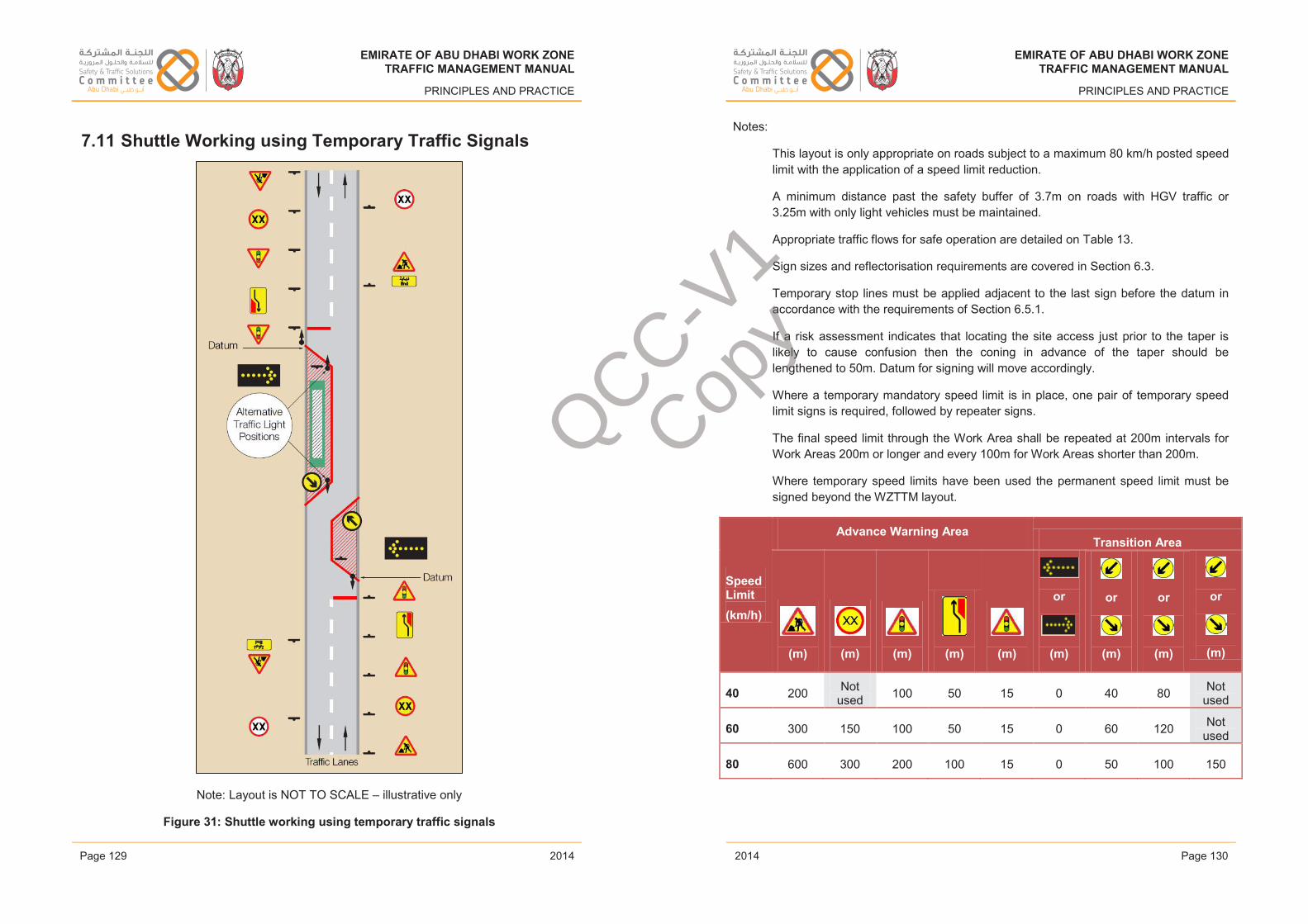
EMIRATE OF ABU DHABI WORK ZONETRAFFIC MANAGEMENT MANUAL
PRINCIPLES AND PRACTICE
7.11 Shuttle Working using Temporary Traffic Signals
Note: Layout is NOT TO SCALE – illustrative only
Figure 31: Shuttle working using temporary traffic signals
Issue 1 Page 129 February 2014
EMIRATE OF ABU DHABI WORK ZONETRAFFIC MANAGEMENT MANUAL
PRINCIPLES AND PRACTICE
Notes:
This layout is only appropriate on roads subject to a maximum 80 km/h posted speed limit with the application of a speed limit reduction.
A minimum distance past the safety buffer of 3.7m on roads with HGV traffic or 3.25m with only light vehicles must be maintained.
Appropriate traffic flows for safe operation are detailed on Table 13.
Sign sizes and reflectorisation requirements are covered in Section 6.3.
Temporary stop lines must be applied adjacent to the last sign before the datum in accordance with the requirements of Section 6.5.1.
If a risk assessment indicates that locating the site access just prior to the taper is likely to cause confusion then the coning in advance of the taper should be lengthened to 50m. Datum for signing will move accordingly.
Where a temporary mandatory speed limit is in place, one pair of temporary speed limit signs is required, followed by repeater signs.
The final speed limit through the Work Area shall be repeated at 200m intervals for Work Areas 200m or longer and every 100m for Work Areas shorter than 200m.
Where temporary speed limits have been used the permanent speed limit must be signed beyond the WZTTM layout.
Speed Limit(km/h)
Advance Warning AreaTransition Area
(m) (m) (m) (m) (m)
or
(m)
or
(m)
or
(m)
or
(m)
40 200 Not used 100 50 15 0 40 80 Not
used
60 300 150 100 50 15 0 60 120 Not used
80 600 300 200 100 15 0 50 100 150
Issue 1 Page 130 February 2014
EMIRATE OF ABU DHABI WORK ZONETRAFFIC MANAGEMENT MANUAL
PRINCIPLES AND PRACTICE
2014
EMIRATE OF ABU DHABI WORK ZONETRAFFIC MANAGEMENT MANUAL
PRINCIPLES AND PRACTICE
2014Page 129 Page 130
EMIRATE OF ABU DHABI WORK ZONETRAFFIC MANAGEMENT MANUAL
PRINCIPLES AND PRACTICE
2014
EMIRATE OF ABU DHABI WORK ZONETRAFFIC MANAGEMENT MANUAL
PRINCIPLES AND PRACTICE
2014
QCC-V1
Copy
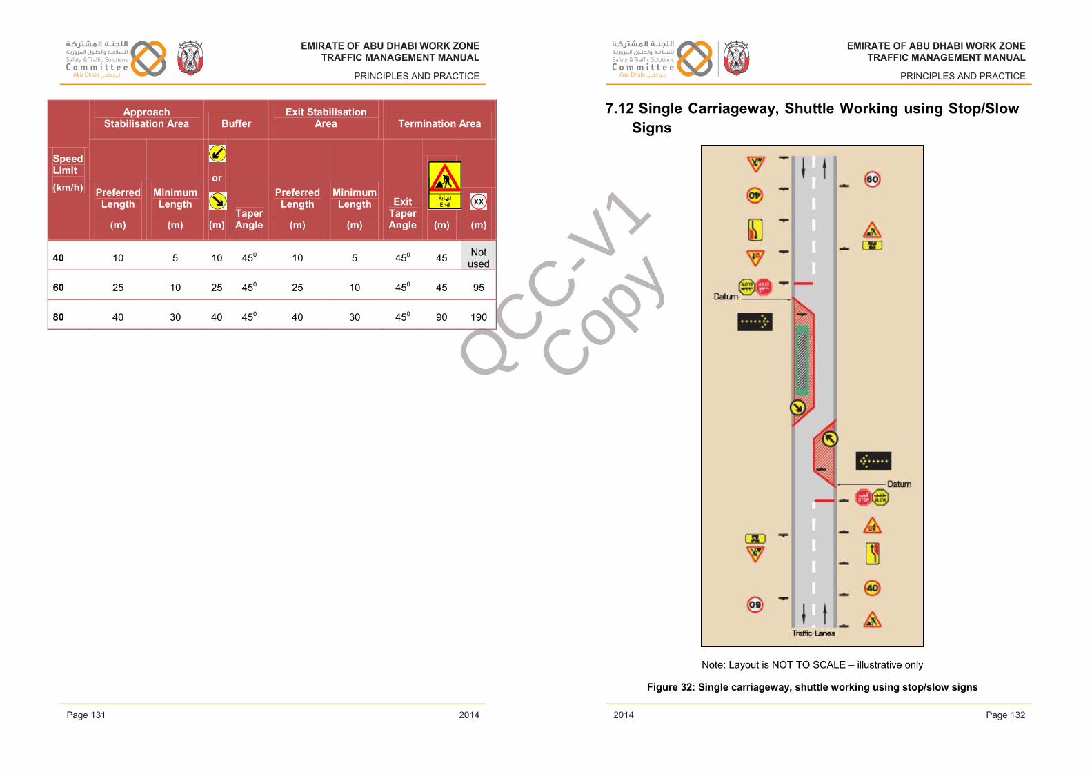
EMIRATE OF ABU DHABI WORK ZONETRAFFIC MANAGEMENT MANUAL
PRINCIPLES AND PRACTICE
Speed Limit(km/h)
Approach Stabilisation Area Buffer
Exit Stabilisation Area Termination Area
Preferred Length
(m)
Minimum Length
(m)
or
(m)TaperAngle
Preferred Length
(m)
Minimum Length
(m)
ExitTaperAngle (m) (m)
40 10 5 10 450 10 5 450 45 Not used
60 25 10 25 450 25 10 450 45 95
80 40 30 40 450 40 30 450 90 190
Issue 1 Page 131 February 2014
EMIRATE OF ABU DHABI WORK ZONETRAFFIC MANAGEMENT MANUAL
PRINCIPLES AND PRACTICE
7.12 Single Carriageway, Shuttle Working using Stop/Slow Signs
Note: Layout is NOT TO SCALE – illustrative only
Figure 32: Single carriageway, shuttle working using stop/slow signs
Issue 1 Page 132 February 2014
EMIRATE OF ABU DHABI WORK ZONETRAFFIC MANAGEMENT MANUAL
PRINCIPLES AND PRACTICE
2014
EMIRATE OF ABU DHABI WORK ZONETRAFFIC MANAGEMENT MANUAL
PRINCIPLES AND PRACTICE
2014Page 131 Page 132
EMIRATE OF ABU DHABI WORK ZONETRAFFIC MANAGEMENT MANUAL
PRINCIPLES AND PRACTICE
2014
EMIRATE OF ABU DHABI WORK ZONETRAFFIC MANAGEMENT MANUAL
PRINCIPLES AND PRACTICE
2014
QCC-V1
Copy
EMIRATE OF ABU DHABI WORK ZONETRAFFIC MANAGEMENT MANUAL
PRINCIPLES AND PRACTICE
Notes:
This layout is only appropriate with the application of a 40km/h speed limit on roads subject to a maximum 60 km/h posted speed limit.
A minimum distance past the safety buffer of 3.7m on roads with HGV traffic or 3.25m with only light vehicles must be maintained.
Appropriate traffic flows for safe operation are detailed on Table 13.
Sign sizes and reflectorisation requirements are covered in Section 6.3.
Maximum length of shuttle working is defined in Section 4.3.5 and clear line of sight between either end of the Work Area is mandatory.
If a risk assessment indicates that locating the site access just prior to the taper is likely to cause confusion then the coning in advance of the taper should be lengthened to 50m. Datum for signing will move accordingly.
Where a temporary mandatory speed limit is in place, one pair of temporary speed limit signs is required, followed by repeater signs.
The final speed limit through the Work Area shall be repeated at 200m intervals for Work Areas 200m or longer and every 100m for Work Areas shorter than 200m.
Where temporary speed limits have been used the permanent speed limit must be signed beyond the WZTTM layout.
Speed Limit(km/h)
Advance Warning Area Transition Area
(m) (m) (m) (m) (m)
or
(m)
or
(m)
or
(m)
40 200 Not used 100 50 15 0 40 80
60 300 150 100 50 15 0 60 120
Issue 1 Page 133 February 2014
EMIRATE OF ABU DHABI WORK ZONETRAFFIC MANAGEMENT MANUAL
PRINCIPLES AND PRACTICE
Speed Limit(km/h)
Approach Stabilisation Area Buffer Exit Stabilisation Area Termination Area
Preferred Length
(m)
Minimum Length
(m)
or
(m)TaperAngle
Preferred Length
(m)
Minimum Length
(m)
ExitTaperAngle (m) (m) (m)
40 10 5 10 450 10 5 450 -45 45 Not used
60 25 10 25 450 25 10 450 -45 45 95
Issue 1 Page 134 February 2014
EMIRATE OF ABU DHABI WORK ZONETRAFFIC MANAGEMENT MANUAL
PRINCIPLES AND PRACTICE
2014
EMIRATE OF ABU DHABI WORK ZONETRAFFIC MANAGEMENT MANUAL
PRINCIPLES AND PRACTICE
2014Page 133 Page 134
EMIRATE OF ABU DHABI WORK ZONETRAFFIC MANAGEMENT MANUAL
PRINCIPLES AND PRACTICE
2014
EMIRATE OF ABU DHABI WORK ZONETRAFFIC MANAGEMENT MANUAL
PRINCIPLES AND PRACTICE
2014
QCC-V1
Copy
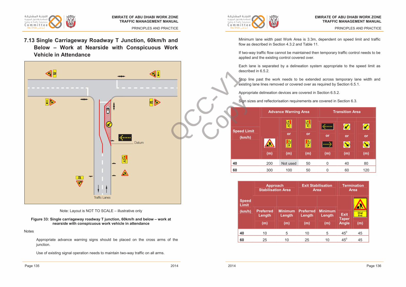
EMIRATE OF ABU DHABI WORK ZONETRAFFIC MANAGEMENT MANUAL
PRINCIPLES AND PRACTICE
7.13 Single Carriageway Roadway T Junction, 60km/h and Below – Work at Nearside with Conspicuous Work Vehicle in Attendance
Note: Layout is NOT TO SCALE – illustrative only
Figure 33: Single carriageway roadway T junction, 60km/h and below – work at nearside with conspicuous work vehicle in attendance
Notes
Appropriate advance warning signs should be placed on the cross arms of the junction.
Use of existing signal operation needs to maintain two-way traffic on all arms.
Issue 1 Page 135 February 2014
EMIRATE OF ABU DHABI WORK ZONETRAFFIC MANAGEMENT MANUAL
PRINCIPLES AND PRACTICE
Minimum lane width past Work Area is 3.3m, dependent on speed limit and traffic flow as described in Section 4.3.2 and Table 11.
If two-way traffic flow cannot be maintained then temporary traffic control needs to be applied and the existing control covered over.
Each lane is separated by a delineation system appropriate to the speed limit as described in 6.5.2.
Stop line past the work needs to be extended across temporary lane width and existing lane lines removed or covered over as required by Section 6.5.1.
Appropriate delineation devices are covered in Section 6.5.2.
Sign sizes and reflectorisation requirements are covered in Section 6.3.
Speed Limit(km/h)
Advance Warning Area Transition Area
(m)
or
(m)
or
(m)
or
(m)
or
(m)
or
(m)
40 200 Not used 50 0 40 80
60 300 100 50 0 60 120
Speed Limit(km/h)
Approach Stabilisation Area
Exit Stabilisation Area
Termination Area
PreferredLength
(m)
Minimum Length
(m)
Preferred Length
(m)
Minimum Length
(m)
Exit TaperAngle (m)
40 10 5 10 5 450 45
60 25 10 25 10 450 45
Issue 1 Page 136 February 2014
EMIRATE OF ABU DHABI WORK ZONETRAFFIC MANAGEMENT MANUAL
PRINCIPLES AND PRACTICE
2014
EMIRATE OF ABU DHABI WORK ZONETRAFFIC MANAGEMENT MANUAL
PRINCIPLES AND PRACTICE
2014Page 135 Page 136
EMIRATE OF ABU DHABI WORK ZONETRAFFIC MANAGEMENT MANUAL
PRINCIPLES AND PRACTICE
2014
EMIRATE OF ABU DHABI WORK ZONETRAFFIC MANAGEMENT MANUAL
PRINCIPLES AND PRACTICE
2014
QCC-V1
Copy
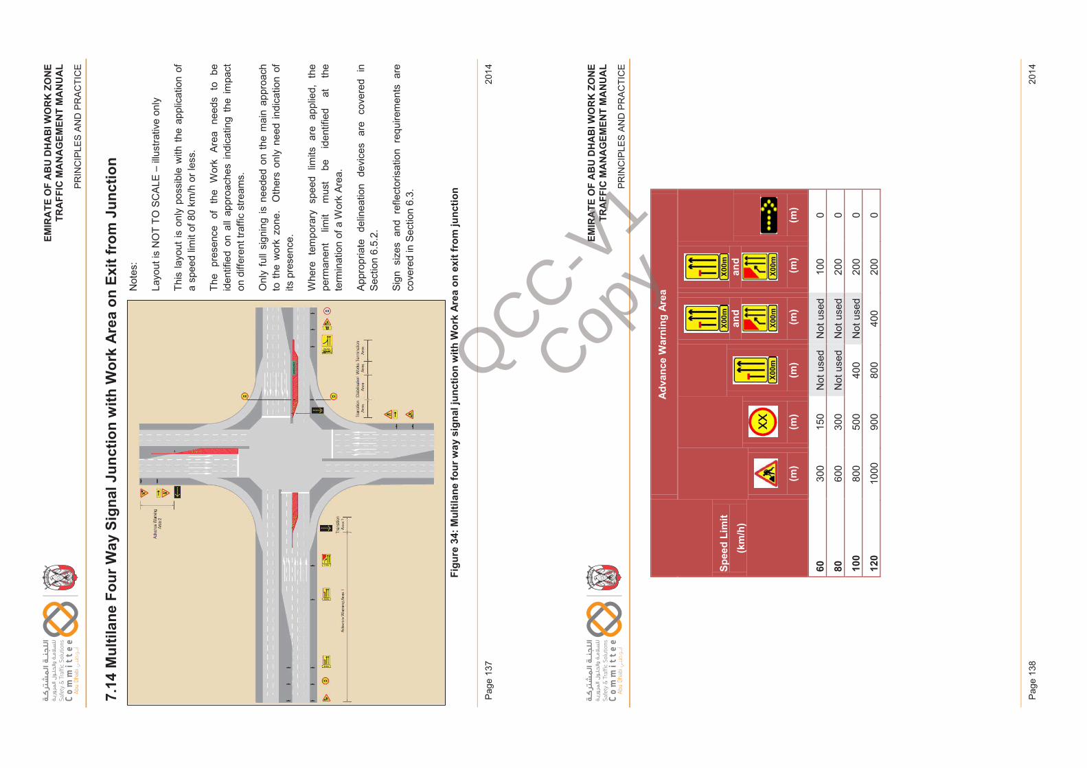
EM
IRA
TE
OF
AB
U D
HA
BI W
OR
K Z
ON
ET
RA
FF
IC M
AN
AG
EM
EN
T M
AN
UA
L
PR
INC
IPLE
S A
ND
PR
AC
TIC
E
2014
Pag
e 13
7
EM
IRA
TE
OF
AB
U D
HA
BI W
OR
K Z
ON
ET
RA
FF
IC M
AN
AG
EM
EN
T M
AN
UA
L
PR
INC
IPLE
S A
ND
PR
AC
TIC
E
2014
Pag
e 13
8
EM
IRAT
EO
FAB
UD
HAB
IWO
RK
ZON
ETR
AFFI
CM
ANAG
EM
ENT
MA
NU
AL
PRIN
CIP
LES
AN
D P
RA
CTI
CE
7.14
Mul
tilan
e Fo
ur W
ay S
igna
l Jun
ctio
n w
ith W
ork
Are
a on
Exi
t fro
m J
unct
ion
Not
es:
Layo
ut is
NO
T TO
SC
ALE
–illu
stra
tive
only
This
layo
ut is
onl
y po
ssib
le w
ith th
e ap
plic
atio
n of
a
spee
d lim
it of
80
km/h
or l
ess.
The
pres
ence
of
th
e W
ork
Area
need
s to
be
iden
tifie
d on
all
appr
oach
esin
dica
ting
the
impa
ct
on d
iffer
ent t
raffi
c st
ream
s.
Onl
y fu
ll si
gnin
g is
nee
ded
on t
he m
ain
appr
oach
to
the
wor
k zo
ne.
Oth
ers
only
nee
d in
dica
tion
of
its p
rese
nce.
Whe
re t
empo
rary
spe
ed l
imits
are
app
lied,
the
perm
anen
t lim
it m
ust
be
iden
tifie
d at
th
e te
rmin
atio
n of
a W
ork
Area
.
Appr
opria
te
delin
eatio
n de
vice
s ar
e co
vere
d in
Se
ctio
n 6.
5.2.
Sign
siz
es a
nd r
efle
ctor
isat
ion
requ
irem
ents
are
co
vere
d in
Sec
tion
6.3.
Figu
re 3
4:M
ultil
ane
four
way
sig
nal j
unct
ion
with
Wor
k Ar
eaon
exi
t fro
m ju
nctio
n
Issu
e 1
Page
137
Febr
uary
201
4
EM
IRAT
EO
FAB
UD
HAB
IWO
RK
ZON
ETR
AFFI
CM
ANAG
EM
ENT
MA
NU
AL
PRIN
CIP
LES
AN
D P
RA
CTI
CE
Spee
d Li
mit
(km
/h)
Adv
ance
War
ning
Are
a
(m)
(m)
(m)
and
(m)
and
(m)
(m)
6030
015
0N
ot u
sed
Not
use
d10
00
8060
030
0N
ot u
sed
Not
use
d20
00
100
800
500
400
Not
use
d20
00
120
1000
900
800
400
200
0
Issu
e 1
Page
138
Febr
uary
201
4
QCC-V1
Copy
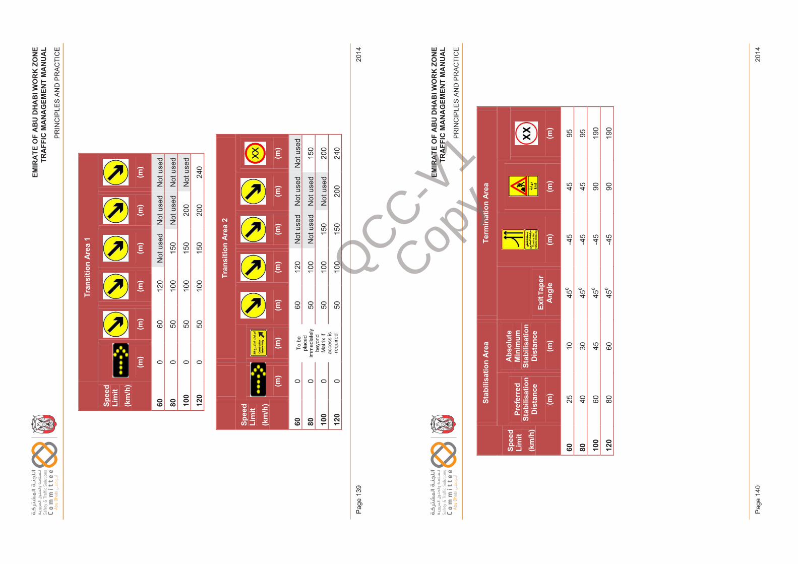
EM
IRA
TE
OF
AB
U D
HA
BI W
OR
K Z
ON
ET
RA
FF
IC M
AN
AG
EM
EN
T M
AN
UA
L
PR
INC
IPLE
S A
ND
PR
AC
TIC
E
2014
Pag
e 13
9
EM
IRA
TE
OF
AB
U D
HA
BI W
OR
K Z
ON
ET
RA
FF
IC M
AN
AG
EM
EN
T M
AN
UA
L
PR
INC
IPLE
S A
ND
PR
AC
TIC
E
2014
Pag
e 14
0
EM
IRAT
EO
FAB
UD
HAB
IWO
RK
ZON
ETR
AFFI
CM
ANAG
EM
ENT
MA
NU
AL
PRIN
CIP
LES
AN
D P
RA
CTI
CE
Spee
d Li
mit
(km
/h)
Tran
sitio
n Ar
ea 1
(m)
(m)
(m)
(m)
(m)
(m)
600
6012
0N
ot u
sed
Not
use
dN
ot u
sed
800
5010
015
0N
ot u
sed
Not
use
d
100
050
100
150
200
Not
use
d
120
050
100
150
200
240
Spee
d Li
mit
(km
/h)
Tran
sitio
n Ar
ea 2
(m)
(m)
(m)
(m)
(m)
(m)
(m)
600
To b
e pl
aced
im
med
iate
ly
beyo
nd
Mat
rix if
ac
cess
is
requ
ired
6012
0N
ot u
sed
Not
use
dN
ot u
sed
800
5010
0N
ot u
sed
Not
use
d15
0
100
050
100
150
Not
use
d20
0
120
050
100
150
200
240
Issu
e 1
Page
139
Febr
uary
201
4
EM
IRAT
EO
FAB
UD
HAB
IWO
RK
ZON
ETR
AFFI
CM
ANAG
EM
ENT
MA
NU
AL
PRIN
CIP
LES
AN
D P
RA
CTI
CE
Spee
d Li
mit
(km
/h)
Stab
ilisa
tion
Area
Term
inat
ion
Area
Pref
erre
d St
abili
satio
n D
ista
nce
(m)
Abs
olut
e M
inim
um
Stab
ilisa
tion
Dis
tanc
e
(m)
Exit
Tape
rA
ngle
(m)
(m)
(m)
6025
1045
0-4
545
95
8040
3045
0-4
545
95
100
6045
450
-45
9019
0
120
8060
450
-45
9019
0
Issu
e 1
Page
140
Febr
uary
201
4
QCC-V1
Copy
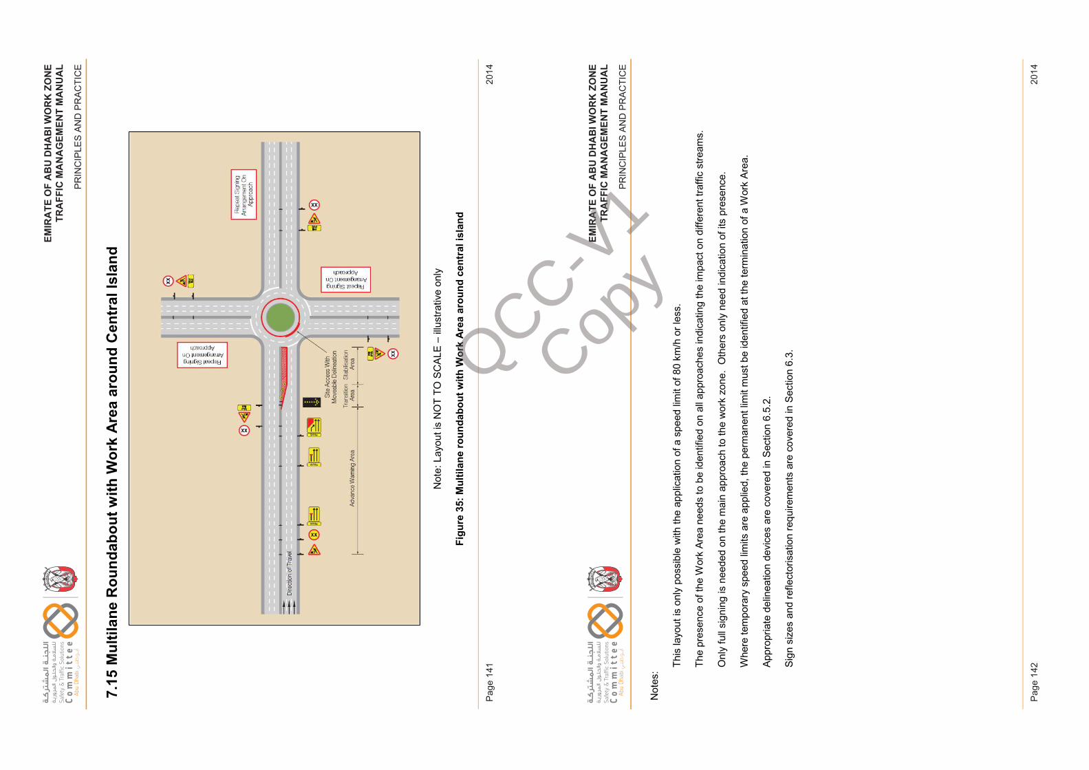
EM
IRA
TE
OF
AB
U D
HA
BI W
OR
K Z
ON
ET
RA
FF
IC M
AN
AG
EM
EN
T M
AN
UA
L
PR
INC
IPLE
S A
ND
PR
AC
TIC
E
2014
Pag
e 14
1
EM
IRA
TE
OF
AB
U D
HA
BI W
OR
K Z
ON
ET
RA
FF
IC M
AN
AG
EM
EN
T M
AN
UA
L
PR
INC
IPLE
S A
ND
PR
AC
TIC
E
2014
Pag
e 14
2
EM
IRAT
EO
FAB
UD
HAB
IWO
RK
ZON
ETR
AFFI
CM
ANAG
EM
ENT
MA
NU
AL
PRIN
CIP
LES
AN
D P
RA
CTI
CE
7.15
Mul
tilan
e R
ound
abou
t with
Wor
k A
rea
arou
nd C
entr
al Is
land
Not
e: L
ayou
t is
NO
T TO
SC
ALE
–illu
stra
tive
only
Figu
re 3
5:M
ultil
ane
roun
dabo
ut w
ith W
ork
Area
arou
nd c
entr
al is
land
Issu
e 1
Page
141
Febr
uary
201
4
EM
IRAT
EO
FAB
UD
HAB
IWO
RK
ZON
ETR
AFFI
CM
ANAG
EM
ENT
MA
NU
AL
PRIN
CIP
LES
AN
D P
RA
CTI
CE
Not
es: Th
is la
yout
is o
nly
poss
ible
with
the
appl
icat
ion
of a
spe
ed li
mit
of 8
0 km
/h o
r les
s.
The
pres
ence
of t
he W
ork
Area
need
s to
be
iden
tifie
d on
all
appr
oach
es in
dica
ting
the
impa
ct o
n di
ffere
nt tr
affic
stre
ams.
Onl
y fu
ll si
gnin
g is
nee
ded
on th
e m
ain
appr
oach
to th
e w
ork
zone
. O
ther
s on
ly n
eed
indi
catio
n of
its
pres
ence
.
Whe
re te
mpo
rary
spe
ed li
mits
are
app
lied,
the
perm
anen
t lim
it m
ust b
e id
entif
ied
at th
e te
rmin
atio
n of
a W
ork
Area
.
Appr
opria
te d
elin
eatio
n de
vice
s ar
e co
vere
d in
Sec
tion
6.5.
2.
Sign
siz
es a
nd re
flect
oris
atio
n re
quire
men
ts a
re c
over
ed in
Sec
tion
6.3.
Issu
e 1
Page
142
Febr
uary
201
4
QCC-V1
Copy
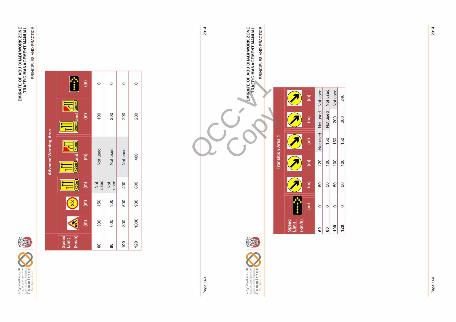
EM
IRA
TE
OF
AB
U D
HA
BI W
OR
K Z
ON
ET
RA
FF
IC M
AN
AG
EM
EN
T M
AN
UA
L
PR
INC
IPLE
S A
ND
PR
AC
TIC
E
2014
Pag
e 14
3
EM
IRA
TE
OF
AB
U D
HA
BI W
OR
K Z
ON
ET
RA
FF
IC M
AN
AG
EM
EN
T M
AN
UA
L
PR
INC
IPLE
S A
ND
PR
AC
TIC
E
2014
Pag
e 14
4
EM
IRAT
EO
FAB
UD
HAB
IWO
RK
ZON
ETR
AFFI
CM
ANAG
EM
ENT
MA
NU
AL
PRIN
CIP
LES
AN
D P
RA
CTI
CE
Spee
d Li
mit
(km
/h)
Adv
ance
War
ning
Are
a
(m)
(m)
(m)
and
(m)
and
(m)
(m)
6030
015
0N
ot
used
Not
use
d10
00
8060
030
0N
ot
used
Not
use
d20
00
100
800
500
400
Not
use
d20
00
120
1000
900
800
400
200
0
Issu
e 1
Page
143
Febr
uary
201
4
EM
IRAT
EO
FAB
UD
HAB
IWO
RK
ZON
ETR
AFFI
CM
ANAG
EM
ENT
MA
NU
AL
PRIN
CIP
LES
AN
D P
RA
CTI
CE
Spee
d Li
mit
(km
/h)
Tran
sitio
n Ar
ea 1
(m)
(m)
(m)
(m)
(m)
(m)
600
6012
0N
ot u
sed
Not
use
dN
ot u
sed
800
5010
015
0N
ot u
sed
Not
use
d
100
050
100
150
200
Not
use
d
120
050
100
150
200
240
Issu
e 1
Page
144
Febr
uary
201
4
QCC-V1
Copy
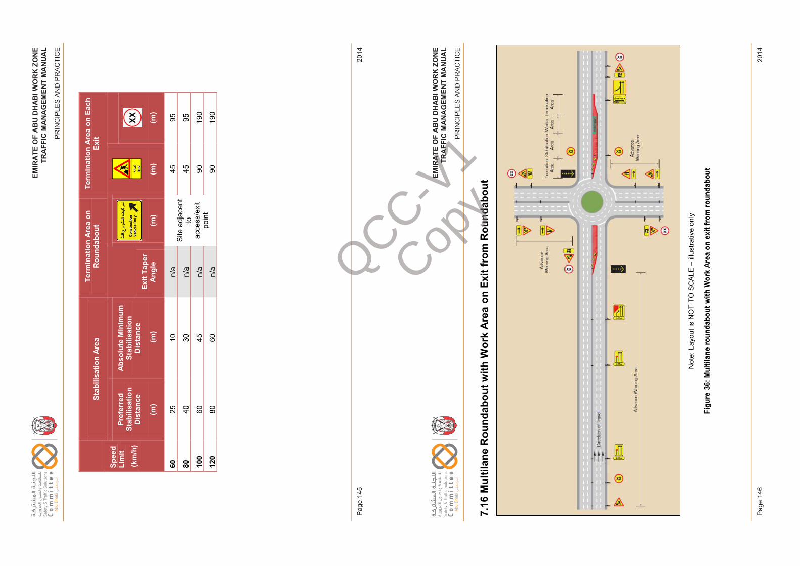
EM
IRA
TE
OF
AB
U D
HA
BI W
OR
K Z
ON
ET
RA
FF
IC M
AN
AG
EM
EN
T M
AN
UA
L
PR
INC
IPLE
S A
ND
PR
AC
TIC
E
2014
Pag
e 14
5
EM
IRA
TE
OF
AB
U D
HA
BI W
OR
K Z
ON
ET
RA
FF
IC M
AN
AG
EM
EN
T M
AN
UA
L
PR
INC
IPLE
S A
ND
PR
AC
TIC
E
2014
Pag
e 14
6
EM
IRAT
EO
FAB
UD
HAB
IWO
RK
ZON
ETR
AFFI
CM
ANAG
EM
ENT
MA
NU
AL
PRIN
CIP
LES
AN
D P
RA
CTI
CE
Spee
d Li
mit
(km
/h)
Stab
ilisa
tion
Area
Term
inat
ion
Area
on
Rou
ndab
out
Term
inat
ion
Area
on
Each
Ex
it
Pref
erre
d St
abili
satio
n D
ista
nce
(m)
Abs
olut
e M
inim
um
Stab
ilisa
tion
Dis
tanc
e
(m)
Exit
Tape
rA
ngle
(m)
(m)
(m)
6025
10n/
aSi
te a
djac
ent
to
acce
ss/e
xit
poin
t
4595
8040
30n/
a45
95
100
6045
n/a
9019
0
120
8060
n/a
9019
0
Issu
e 1
Page
145
Febr
uary
201
4
EM
IRAT
EO
FAB
UD
HAB
IWO
RK
ZON
ETR
AFFI
CM
ANAG
EM
ENT
MA
NU
AL
PRIN
CIP
LES
AN
D P
RA
CTI
CE
7.16
Mul
tilan
e R
ound
abou
t with
Wor
k A
rea
on E
xit f
rom
Rou
ndab
out
Not
e: L
ayou
t is
NO
T TO
SC
ALE
–illu
stra
tive
only
Figu
re 3
6:M
ultil
ane
roun
dabo
ut w
ith W
ork
Area
on e
xit f
rom
roun
dabo
ut
Issu
e 1
Page
146
Febr
uary
201
4
QCC-V1
Copy
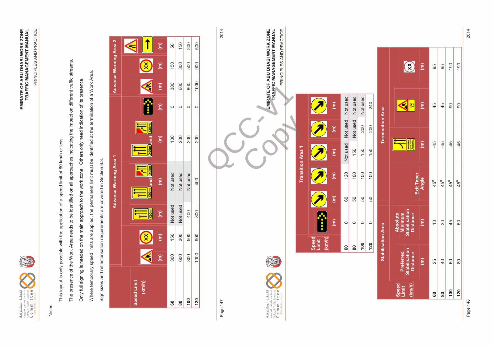
EM
IRA
TE
OF
AB
U D
HA
BI W
OR
K Z
ON
ET
RA
FF
IC M
AN
AG
EM
EN
T M
AN
UA
L
PR
INC
IPLE
S A
ND
PR
AC
TIC
E
2014
Pag
e 14
7
EM
IRA
TE
OF
AB
U D
HA
BI W
OR
K Z
ON
ET
RA
FF
IC M
AN
AG
EM
EN
T M
AN
UA
L
PR
INC
IPLE
S A
ND
PR
AC
TIC
E
2014
Pag
e 14
8
EM
IRAT
EO
FAB
UD
HAB
IWO
RK
ZON
ETR
AFFI
CM
ANAG
EM
ENT
MA
NU
AL
PRIN
CIP
LES
AN
D P
RA
CTI
CE
Not
es: Th
is la
yout
is o
nly
poss
ible
with
the
appl
icat
ion
of a
spe
ed li
mit
of 8
0 km
/h o
r les
s.
The
pres
ence
of t
he W
ork
Area
need
s to
be
iden
tifie
d on
all
appr
oach
es in
dica
ting
the
impa
ct o
n di
ffere
nt tr
affic
stre
ams.
Onl
y fu
ll si
gnin
g is
nee
ded
on th
e m
ain
appr
oach
to th
e w
ork
zone
. O
ther
s on
ly n
eed
indi
catio
n of
its
pres
ence
.
Whe
re te
mpo
rary
spe
ed li
mits
are
app
lied,
the
perm
anen
t lim
it m
ust b
e id
entif
ied
at th
e te
rmin
atio
nof
a W
ork
Area
.
Sign
siz
es a
nd re
flect
oris
atio
n re
quire
men
ts a
re c
over
ed in
Sec
tion
6.3.
Spee
d Li
mit
(km
/h)
Adv
ance
War
ning
Are
a 1
Adv
ance
War
ning
Are
a 2
(m)
(m)
(m)
and
(m)
and
(m)
(m)
(m)
(m)
(m)
6030
015
0N
ot u
sed
Not
use
d10
00
300
150
50
8060
030
0N
ot u
sed
Not
use
d20
00
600
300
150
100
800
500
400
Not
use
d20
00
800
500
300
120
1000
900
800
400
200
010
0090
050
0
Issu
e 1
Page
147
Febr
uary
201
4
EM
IRAT
EO
FAB
UD
HAB
IWO
RK
ZON
ETR
AFFI
CM
ANAG
EM
ENT
MA
NU
AL
PRIN
CIP
LES
AN
D P
RA
CTI
CE
Spee
d Li
mit
(km
/h)
Tran
sitio
n Ar
ea 1
(m)
(m)
(m)
(m)
(m)
(m)
600
6012
0N
ot u
sed
Not
use
dN
ot u
sed
800
5010
015
0N
ot u
sed
Not
use
d
100
050
100
150
200
Not
use
d
120
050
100
150
200
240
Spee
d Li
mit
(km
/h)
Stab
ilisa
tion
Area
Term
inat
ion
Area
Pref
erre
d St
abili
satio
n D
ista
nce
(m)
Abs
olut
e M
inim
um
Stab
ilisa
tion
Dis
tanc
e
(m)
Exit
Tape
rA
ngle
(m)
(m)
(m)
6025
1045
0-4
545
95
8040
3045
0-4
545
95
100
6045
450
-45
9019
0
120
8060
450
-45
9019
0
Issu
e 1
Page
148
Febr
uary
201
4
QCC-V1
Copy
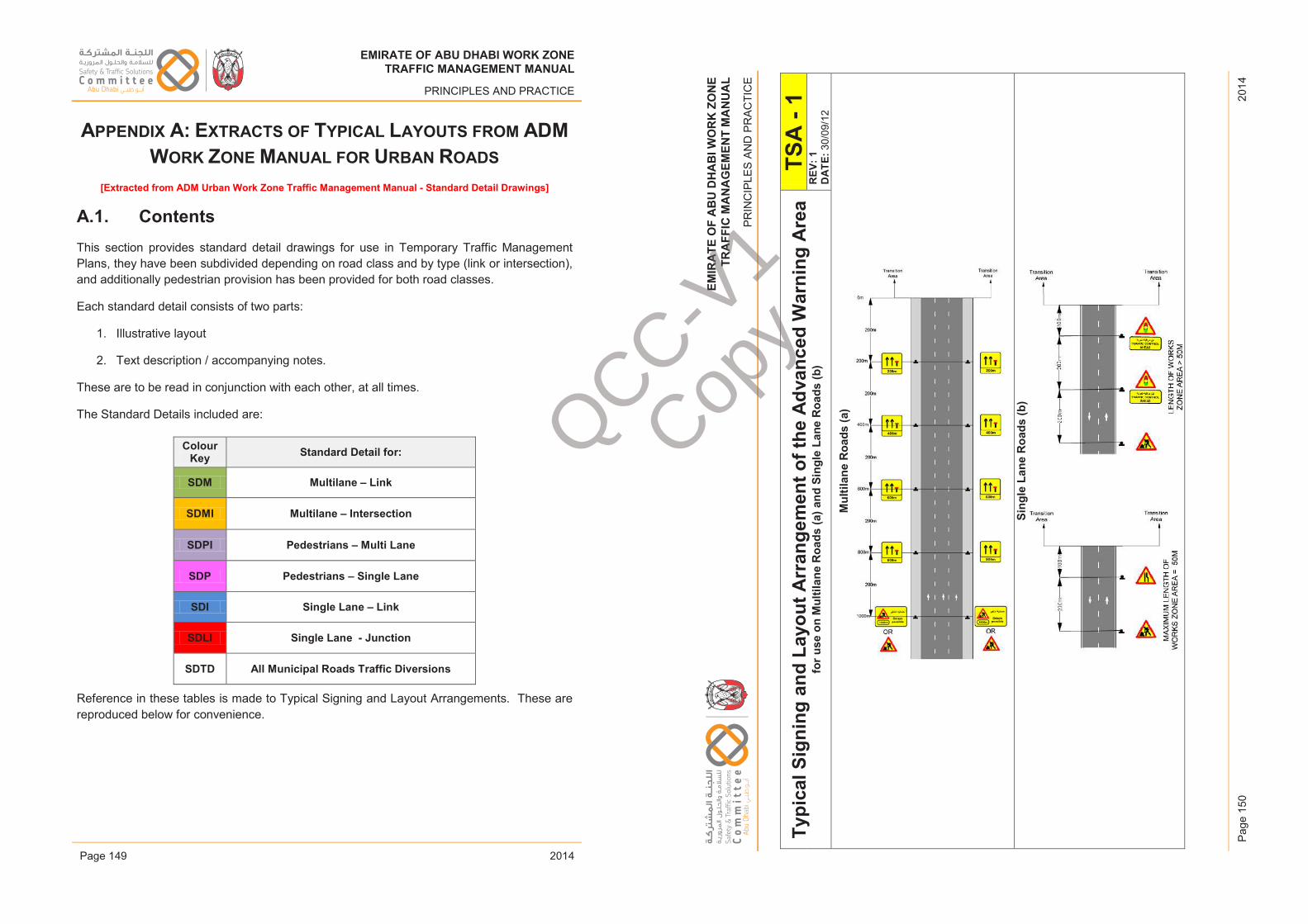
EM
IRA
TE
OF
AB
U D
HA
BI W
OR
K Z
ON
ET
RA
FF
IC M
AN
AG
EM
EN
T M
AN
UA
L
PR
INC
IPLE
S A
ND
PR
AC
TIC
E
2014
Pag
e 15
0
EMIRATE OF ABU DHABI WORK ZONETRAFFIC MANAGEMENT MANUAL
PRINCIPLES AND PRACTICE
APPENDIX A: EXTRACTS OF TYPICAL LAYOUTS FROM ADMWORK ZONE MANUAL FOR URBAN ROADS
[Extracted from ADM Urban Work Zone Traffic Management Manual - Standard Detail Drawings]
A.1. ContentsThis section provides standard detail drawings for use in Temporary Traffic Management Plans, they have been subdivided depending on road class and by type (link or intersection), and additionally pedestrian provision has been provided for both road classes.
Each standard detail consists of two parts:
1. Illustrative layout
2. Text description / accompanying notes.
These are to be read in conjunction with each other, at all times.
The Standard Details included are:
Colour Key Standard Detail for:
SDM Multilane – Link
SDMI Multilane – Intersection
SDPI Pedestrians – Multi Lane
SDP Pedestrians – Single Lane
SDI Single Lane – Link
SDLI Single Lane - Junction
SDTD All Municipal Roads Traffic Diversions
Reference in these tables is made to Typical Signing and Layout Arrangements. These are reproduced below for convenience.
Issue 1 Page 149 February 2014
EM
IRAT
EO
FAB
UD
HAB
IWO
RK
ZON
ETR
AFFI
CM
ANAG
EM
ENT
MA
NU
AL
PRIN
CIP
LES
AN
D P
RA
CTI
CE
Typi
cal S
igni
ng a
nd L
ayou
t Arr
ange
men
t of t
he A
dvan
ced
War
ning
Are
afo
r use
on
Mul
tilan
e R
oads
(a) a
nd S
ingl
e La
ne R
oads
(b)
TSA
-1
REV
: 1D
ATE:
30/0
9/12
Mul
tilan
e R
oads
(a)
Sing
le L
ane
Roa
ds (b
)
Issu
e 1
Page
150
Febr
uary
201
4
EMIRATE OF ABU DHABI WORK ZONETRAFFIC MANAGEMENT MANUAL
PRINCIPLES AND PRACTICE
2014
EMIRATE OF ABU DHABI WORK ZONETRAFFIC MANAGEMENT MANUAL
PRINCIPLES AND PRACTICE
2014Page 1
EMIRATE OF ABU DHABI WORK ZONETRAFFIC MANAGEMENT MANUAL
PRINCIPLES AND PRACTICE
2014
EMIRATE OF ABU DHABI WORK ZONETRAFFIC MANAGEMENT MANUAL
PRINCIPLES AND PRACTICE
2014
EMIRATE OF ABU DHABI WORK ZONETRAFFIC MANAGEMENT MANUAL
PRINCIPLES AND PRACTICE
2014
EMIRATE OF ABU DHABI WORK ZONETRAFFIC MANAGEMENT MANUAL
PRINCIPLES AND PRACTICE
2014Page 149
EMIRATE OF ABU DHABI WORK ZONETRAFFIC MANAGEMENT MANUAL
PRINCIPLES AND PRACTICE
2014
EMIRATE OF ABU DHABI WORK ZONETRAFFIC MANAGEMENT MANUAL
PRINCIPLES AND PRACTICE
2014
QCC-V1
Copy
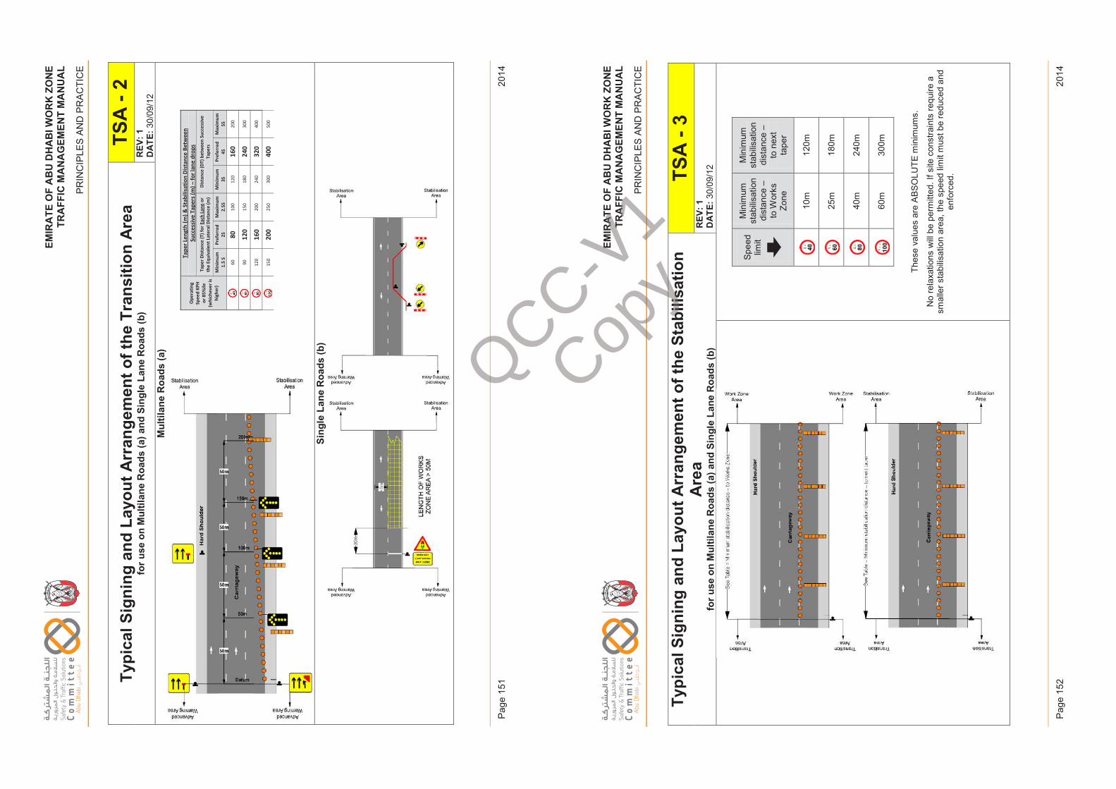
EM
IRA
TE
OF
AB
U D
HA
BI W
OR
K Z
ON
ET
RA
FF
IC M
AN
AG
EM
EN
T M
AN
UA
L
PR
INC
IPLE
S A
ND
PR
AC
TIC
E
2014
Pag
e 15
1
EM
IRA
TE
OF
AB
U D
HA
BI W
OR
K Z
ON
ET
RA
FF
IC M
AN
AG
EM
EN
T M
AN
UA
L
PR
INC
IPLE
S A
ND
PR
AC
TIC
E
2014
Pag
e 15
2
EM
IRAT
EO
FAB
UD
HAB
IWO
RK
ZON
ETR
AFFI
CM
ANAG
EM
ENT
MA
NU
AL
PRIN
CIP
LES
AN
D P
RA
CTI
CE
Typi
cal S
igni
ng a
nd L
ayou
t Arr
ange
men
t of t
he T
rans
ition
Are
afo
r use
on
Mul
tilan
e R
oads
(a) a
nd S
ingl
e La
ne R
oads
(b)
TSA
-2
REV
: 1D
ATE:
30/0
9/12
Mul
tilan
e R
oads
(a)
Sing
le L
ane
Roa
ds (b
)
Ope
ratin
g Sp
eed
KPH
or 8
5%ile
(w
hich
ever
is
high
er)
Tape
r Len
gth
(m) &
Sta
bilis
atio
n Di
stan
ce B
etw
een
Su
cces
sive
Tap
ers (
m) –
for l
ane
drop
s Ta
per D
ista
nce
(T) f
or E
ach
Lane
or
the
Equi
vale
nt L
ater
al D
ista
nce
(m)
Dist
ance
(DT)
bet
wee
n Su
cces
sive
Ta
pers
Min
imum
1.
5 S
Pref
erre
d 2S
M
axim
um
2.5S
M
inim
um
3S
Pr
efer
red
4S
M
axim
um
5S
60
80
100
120
160
200
90
120
150
180
240
300
120
160
200
240
320
400
15
0 20
0 25
0 30
0 40
0 50
0
Issu
e 1
Page
151
Febr
uary
201
4
EM
IRAT
EO
FAB
UD
HAB
IWO
RK
ZON
ETR
AFFI
CM
ANAG
EM
ENT
MA
NU
AL
PRIN
CIP
LES
AN
D P
RA
CTI
CE
Typi
cal S
igni
ng a
nd L
ayou
t Arr
ange
men
t of t
he S
tabi
lisat
ion
Are
afo
r use
on
Mul
tilan
e R
oads
(a) a
nd S
ingl
e La
ne R
oads
(b)
TSA
-3
REV
: 1D
ATE:
30/
09/1
2
Spee
d lim
it
Min
imum
st
abilis
atio
n di
stan
ce –
to W
orks
Zo
ne
Min
imum
st
abilis
atio
n di
stan
ce –
to n
ext
tape
r
10m
120m
25m
180m
40m
240m
60m
300m
Thes
e va
lues
are
ABS
OLU
TE m
inim
ums.
No
rela
xatio
ns w
ill be
per
mitt
ed. I
f site
con
stra
ints
requ
ire a
sm
alle
r sta
bilis
atio
n ar
ea, t
he s
peed
lim
it m
ust b
e re
duce
d an
d en
forc
ed.
Issu
e 1
Page
152
Febr
uary
201
4
QCC-V1
Copy
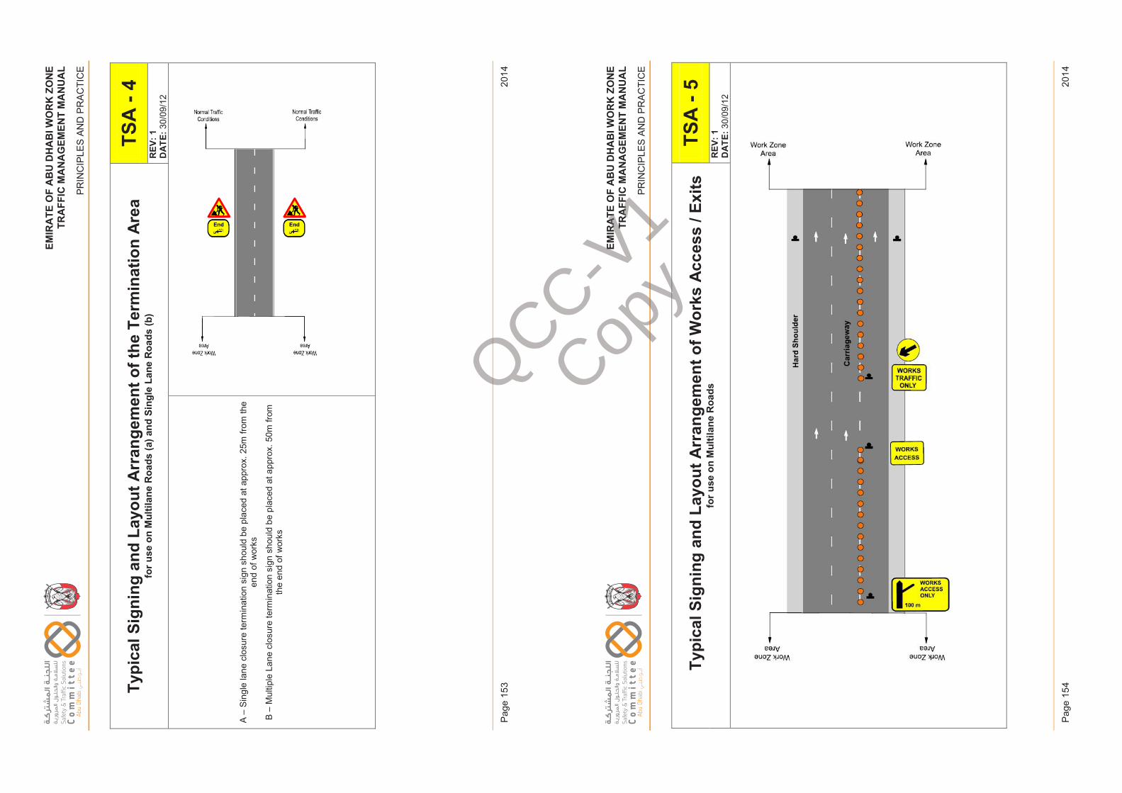
EM
IRA
TE
OF
AB
U D
HA
BI W
OR
K Z
ON
ET
RA
FF
IC M
AN
AG
EM
EN
T M
AN
UA
L
PR
INC
IPLE
S A
ND
PR
AC
TIC
E
2014
Pag
e 15
3
EM
IRA
TE
OF
AB
U D
HA
BI W
OR
K Z
ON
ET
RA
FF
IC M
AN
AG
EM
EN
T M
AN
UA
L
PR
INC
IPLE
S A
ND
PR
AC
TIC
E
2014
Pag
e 15
4
EM
IRAT
EO
FAB
UD
HAB
IWO
RK
ZON
ETR
AFFI
CM
ANAG
EM
ENT
MA
NU
AL
PRIN
CIP
LES
AN
D P
RA
CTI
CE
Typi
cal S
igni
ng a
nd L
ayou
t Arr
ange
men
t of t
he T
erm
inat
ion
Are
afo
r use
on
Mul
tilan
e R
oads
(a) a
nd S
ingl
e La
ne R
oads
(b)
TSA
-4
REV
: 1D
ATE:
30/0
9/12
A–
Sing
le la
ne c
losu
re te
rmin
atio
n si
gn s
houl
d be
pla
ced
at a
ppro
x. 2
5m fr
om th
e en
d of
wor
ks
B–
Mul
tiple
Lan
e cl
osur
e te
rmin
atio
n si
gn s
houl
d be
pla
ced
at a
ppro
x. 5
0m fr
om
the
end
of w
orks
Issu
e 1
Page
153
Febr
uary
201
4
EM
IRAT
EO
FAB
UD
HAB
IWO
RK
ZON
ETR
AFFI
CM
ANAG
EM
ENT
MA
NU
AL
PRIN
CIP
LES
AN
D P
RA
CTI
CE
Typi
cal S
igni
ng a
nd L
ayou
t Arr
ange
men
t of W
orks
Acc
ess
/ Exi
tsfo
r use
on
Mul
tilan
e R
oads
TSA
-5
REV
: 1D
ATE:
30/
09/1
2
Issu
e 1
Page
154
Febr
uary
201
4
QCC-V1
Copy
EM
IRA
TE
OF
AB
U D
HA
BI W
OR
K Z
ON
ET
RA
FF
IC M
AN
AG
EM
EN
T M
AN
UA
L
PR
INC
IPLE
S A
ND
PR
AC
TIC
E
2014
Pag
e 15
5
EM
IRA
TE
OF
AB
U D
HA
BI W
OR
K Z
ON
ET
RA
FF
IC M
AN
AG
EM
EN
T M
AN
UA
L
PR
INC
IPLE
S A
ND
PR
AC
TIC
E
2014
Pag
e 15
6
EM
IRAT
EO
FAB
UD
HAB
IWO
RK
ZON
ETR
AFFI
CM
ANAG
EM
ENT
MA
NU
AL
PRIN
CIP
LES
AN
D P
RA
CTI
CE
A.2
.In
dex
of S
tand
ard
Det
ails
(SD
’s) –
Mul
tilan
e Li
nks
Col
our
KEY
Roa
d ty
peW
orks
Lo
catio
nD
escr
iptio
n of
sta
ndar
d de
tail
SD
Ref
eren
cePa
ge n
o (D
iagr
am)
Page
no
(not
es)
Rev
isio
n
SDM
Mul
tilan
eLi
nk
Sing
le la
ne c
losu
re (n
ears
ide
lane
)SD
M-1
1
Sing
le la
ne c
losu
re (o
ffsid
e la
ne)
SDM
-21
Two
or m
ore
lane
clo
sure
s (fr
om th
e ne
arsi
de)
SDM
-31
Two
or m
ore
lane
clo
sure
s (fr
om th
e of
fsid
e)SD
M-4
1
Com
plet
e ro
ad c
losu
re (o
ne d
irect
ion
only
)SD
M-5
1
Com
plet
e ro
ad c
losu
re (b
oth
dire
ctio
ns
of tr
avel
)SD
M-6
1
Har
d sh
ould
er a
rea
clos
ure
SD
M-7
1
Nar
row
lane
sSD
M-8
1
Spee
d re
duct
ion
on a
ppro
ach
to w
orks
zo
ne
SDM
-91
Shou
lder
Run
ning
SDM
101
Con
traf
low
(Mul
tiple
Lan
e)SD
M-1
11
Issu
e 1
Page
155
Febr
uary
201
4
EM
IRAT
EO
FAB
UD
HAB
IWO
RK
ZON
ETR
AFFI
CM
ANAG
EM
ENT
MA
NU
AL
PRIN
CIP
LES
AN
D P
RA
CTI
CE
A.3
.In
dex
of S
tand
ard
Det
ails
(SD
’s) –
Mul
tilan
e In
ters
ectio
nsC
olou
rK
EYR
oad
type
Wor
ks
Loca
tion
Des
crip
tion
of s
tand
ard
deta
ilSD
R
efer
ence
Page
no
(Dia
gram
)Pa
ge n
o(n
otes
)R
evis
ion
SDMI
Mul
tilan
eIn
ters
ectio
ns
Lane
clo
sure
in th
e vi
cini
ty o
f an
exit
ram
pSD
MI-1
1
Lane
clo
sure
in th
e vi
cini
ty o
f an
entr
y ra
mp
SDM
I-21
Lane
clo
sure
in v
icin
ity o
f a s
igna
lised
in
ters
ectio
nSD
MI-3
1
Roa
d cl
osur
e in
vic
inity
of a
sig
nalis
ed
inte
rsec
tion
SDM
I-41
Unc
ontr
olle
d rig
ht tu
rn c
losu
re a
t in
ters
ectio
nSD
MI-5
1
Rou
ndab
out –
Lane
clo
sure
on
appr
oach
SDM
I-61
Rou
ndab
out –
Lane
clo
sure
on
exit
SDM
I-71
Rou
ndab
out –
Cen
tral
Isla
nd w
orki
ng
area
SDM
I-81
Issu
e 1
Page
156
Febr
uary
201
4
QCC-V1
Copy
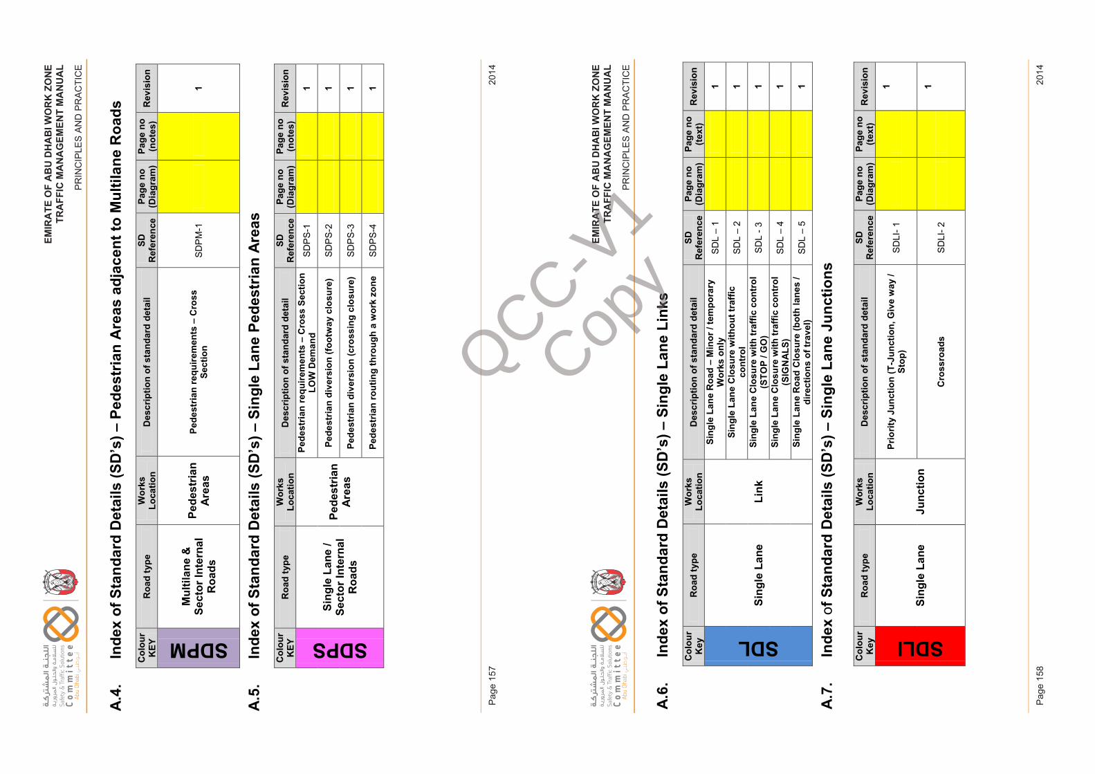
EM
IRA
TE
OF
AB
U D
HA
BI W
OR
K Z
ON
ET
RA
FF
IC M
AN
AG
EM
EN
T M
AN
UA
L
PR
INC
IPLE
S A
ND
PR
AC
TIC
E
2014
Pag
e 15
7
EM
IRA
TE
OF
AB
U D
HA
BI W
OR
K Z
ON
ET
RA
FF
IC M
AN
AG
EM
EN
T M
AN
UA
L
PR
INC
IPLE
S A
ND
PR
AC
TIC
E
2014
Pag
e 15
8
EM
IRAT
EO
FAB
UD
HAB
IWO
RK
ZON
ETR
AFFI
CM
ANAG
EM
ENT
MA
NU
AL
PRIN
CIP
LES
AN
D P
RA
CTI
CE
A.4
.In
dex
of S
tand
ard
Det
ails
(SD
’s) –
Pede
stria
n A
reas
adj
acen
t to
Mul
tilan
e R
oads
Col
our
KEY
Roa
d ty
peW
orks
Lo
catio
nD
escr
iptio
n of
sta
ndar
d de
tail
SD
Ref
eren
cePa
ge n
o (D
iagr
am)
Page
no
(not
es)
Rev
isio
n
SDPM
Mul
tilan
e &
Se
ctor
Inte
rnal
R
oads
Pede
stria
n A
reas
Pede
stria
n re
quire
men
ts –
Cro
ss
Sect
ion
SDP
M-1
1
A.5
.In
dex
of S
tand
ard
Det
ails
(SD
’s) –
Sing
le L
ane
Pede
stria
n A
reas
Col
our
KEY
Roa
d ty
peW
orks
Lo
catio
nD
escr
iptio
n of
sta
ndar
d de
tail
SD
Ref
eren
cePa
ge n
o (D
iagr
am)
Page
no
(not
es)
Rev
isio
n
SDPS
Sing
le L
ane
/ Se
ctor
Inte
rnal
R
oads
Pede
stria
n A
reas
Pede
stria
n re
quire
men
ts –
Cro
ss S
ectio
n LO
W D
eman
dSD
PS-
11
Pede
stria
n di
vers
ion
(foot
way
clo
sure
)SD
PS-
21
Pede
stria
n di
vers
ion
(cro
ssin
g cl
osur
e)SD
PS-
31
Pede
stria
n ro
utin
g th
roug
h a
wor
k zo
neSD
PS-
41
Issu
e 1
Page
157
Febr
uary
201
4
EM
IRAT
EO
FAB
UD
HAB
IWO
RK
ZON
ETR
AFFI
CM
ANAG
EM
ENT
MA
NU
AL
PRIN
CIP
LES
AN
D P
RA
CTI
CE
A.6
.In
dex
of S
tand
ard
Det
ails
(SD
’s) –
Sing
le L
ane
Link
sC
olou
r K
eyR
oad
type
Wor
ks
Loca
tion
Des
crip
tion
of s
tand
ard
deta
ilSD
R
efer
ence
Page
no
(Dia
gram
)Pa
ge n
o(te
xt)
Rev
isio
n
SDL
Sing
le L
ane
Link
Sing
le L
ane
Roa
d –
Min
or /
tem
pora
ry
Wor
ks o
nly
SDL
–1
1
Sing
le L
ane
Clo
sure
with
out t
raffi
c co
ntro
lSD
L –
21
Sing
le L
ane
Clo
sure
with
traf
fic c
ontr
ol
(STO
P / G
O)
SDL
-31
Sing
le L
ane
Clo
sure
with
traf
fic c
ontr
ol
(SIG
NA
LS)
SDL
–4
1
Sing
le L
ane
Roa
d C
losu
re (b
oth
lane
s /
dire
ctio
ns o
f tra
vel)
SDL
–5
1
A.7
.In
dex
of S
tand
ard
Det
ails
(SD
’s) –
Sing
le L
ane
Junc
tions
Col
our
Key
Roa
d ty
peW
orks
Lo
catio
nD
escr
iptio
n of
sta
ndar
d de
tail
SDR
efer
ence
Page
no
(Dia
gram
)Pa
ge n
o(te
xt)
Rev
isio
n
SDLI
Sing
le L
ane
Junc
tion
Prio
rity
Junc
tion
(T-J
unct
ion,
Giv
e w
ay /
Stop
)SD
LI-1
1
Cro
ssro
ads
SDLI
-21
Issu
e 1
Page
158
Febr
uary
201
4
QCC-V1
Copy
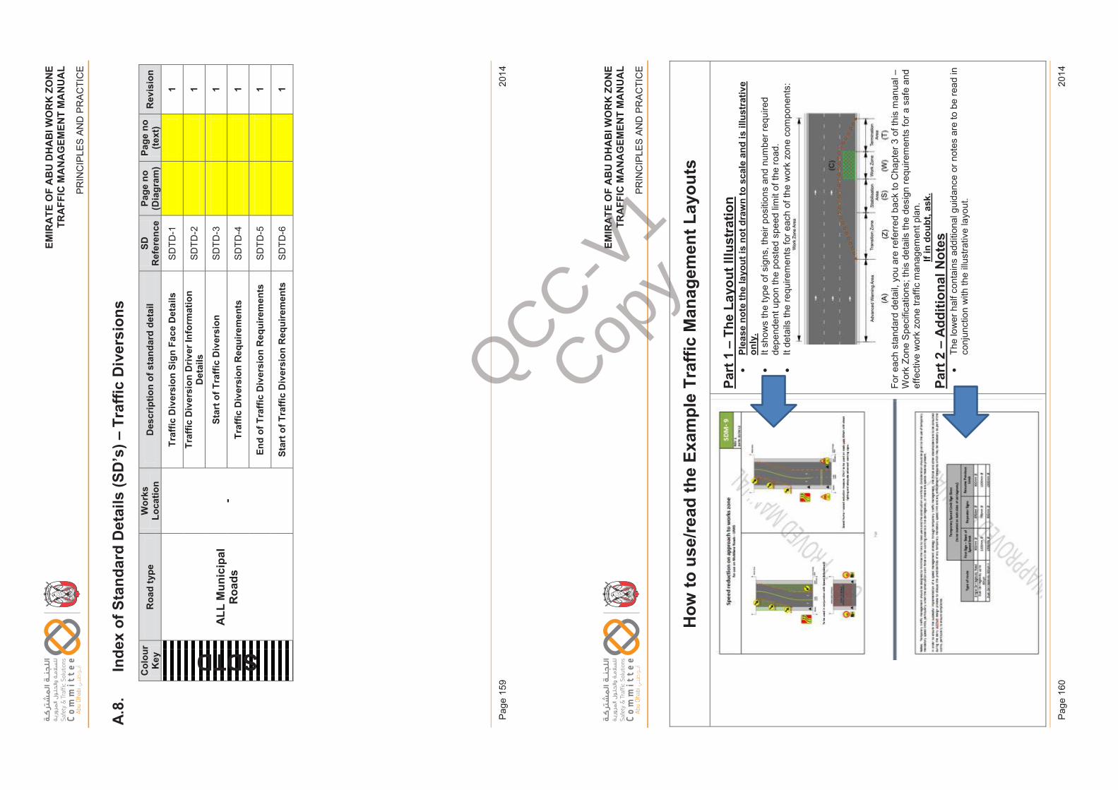
EM
IRA
TE
OF
AB
U D
HA
BI W
OR
K Z
ON
ET
RA
FF
IC M
AN
AG
EM
EN
T M
AN
UA
L
PR
INC
IPLE
S A
ND
PR
AC
TIC
E
2014
Pag
e 15
9
EM
IRA
TE
OF
AB
U D
HA
BI W
OR
K Z
ON
ET
RA
FF
IC M
AN
AG
EM
EN
T M
AN
UA
L
PR
INC
IPLE
S A
ND
PR
AC
TIC
E
2014
Pag
e 16
0
EM
IRAT
EO
FAB
UD
HAB
IWO
RK
ZON
ETR
AFFI
CM
ANAG
EM
ENT
MA
NU
AL
PRIN
CIP
LES
AN
D P
RA
CTI
CE
A.8
.In
dex
of S
tand
ard
Det
ails
(SD
’s) –
Traf
fic D
iver
sion
sC
olou
r K
eyR
oad
type
Wor
ks
Loca
tion
Des
crip
tion
of s
tand
ard
deta
ilSD
R
efer
ence
Page
no
(Dia
gram
)Pa
ge n
o(te
xt)
Rev
isio
n
SDTD
ALL
Mun
icip
al
Roa
ds-
Traf
fic D
iver
sion
Sig
n Fa
ce D
etai
lsSD
TD-1
1
Traf
fic D
iver
sion
Driv
er In
form
atio
n D
etai
lsSD
TD-2
1
Star
t of T
raffi
c D
iver
sion
SDTD
-31
Traf
fic D
iver
sion
Req
uire
men
tsSD
TD-4
1
End
of T
raffi
c D
iver
sion
Req
uire
men
tsSD
TD-5
1
Star
t of T
raffi
c D
iver
sion
Req
uire
men
tsSD
TD-6
1
Issu
e 1
Page
159
Febr
uary
201
4
EM
IRAT
EO
FAB
UD
HAB
IWO
RK
ZON
ETR
AFFI
CM
ANAG
EM
ENT
MA
NU
AL
PRIN
CIP
LES
AN
D P
RA
CTI
CE
How
to u
se/re
ad th
e Ex
ampl
e Tr
affic
Man
agem
ent L
ayou
ts
Part
1 –
The
Layo
ut Il
lust
ratio
n•
Plea
se n
ote
the
layo
ut is
not
dra
wn
to s
cale
and
is il
lust
rativ
e on
ly.
•It
show
s th
e ty
pe o
f sig
ns, t
heir
posi
tions
and
num
ber r
equi
red
depe
nden
t upo
n th
e po
sted
spe
ed li
mit
of th
e ro
ad.
•It
deta
ils th
e re
quire
men
ts fo
r eac
h of
the
wor
k zo
ne c
ompo
nent
s:
For e
ach
stan
dard
det
ail,
you
are
refe
rred
bac
k to
Cha
pter
3 o
f thi
s m
anua
l –W
ork
Zone
Spe
cific
atio
ns; t
his
deta
ils th
e de
sign
requ
irem
ents
for a
saf
e an
d ef
fect
ive
wor
k zo
ne tr
affic
man
agem
ent p
lan.
If
in d
oubt
, ask
.Pa
rt 2
–A
dditi
onal
Not
es•
The
low
er h
alf c
onta
ins
addi
tiona
l gui
danc
e or
not
es a
re to
be
read
in
conj
unct
ion
with
the
illust
rativ
e la
yout
.
Issu
e 1
Page
160
Febr
uary
201
4
QCC-V1
Copy
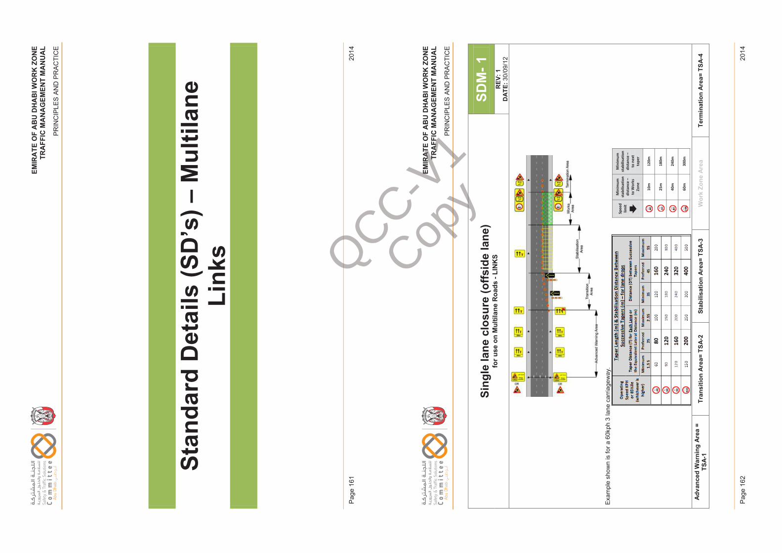
EM
IRA
TE
OF
AB
U D
HA
BI W
OR
K Z
ON
ET
RA
FF
IC M
AN
AG
EM
EN
T M
AN
UA
L
PR
INC
IPLE
S A
ND
PR
AC
TIC
E
2014
Pag
e 16
1
EM
IRA
TE
OF
AB
U D
HA
BI W
OR
K Z
ON
ET
RA
FF
IC M
AN
AG
EM
EN
T M
AN
UA
L
PR
INC
IPLE
S A
ND
PR
AC
TIC
E
2014
Pag
e 16
2
EM
IRAT
EO
FAB
UD
HAB
IWO
RK
ZON
ETR
AFFI
CM
ANAG
EM
ENT
MA
NU
AL
PRIN
CIP
LES
AN
D P
RA
CTI
CE
Stan
dard
Det
ails
(SD
’s) –
Mul
tilan
e Li
nks
Issu
e 1
Page
161
Febr
uary
201
4
EM
IRAT
EO
FAB
UD
HAB
IWO
RK
ZON
ETR
AFFI
CM
ANAG
EM
ENT
MA
NU
AL
PRIN
CIP
LES
AN
D P
RA
CTI
CE
Sing
le la
ne c
losu
re (o
ffsid
e la
ne)
for u
se o
n M
ultil
ane
Roa
ds -
LIN
KS
SDM
-1R
EV: 1
DAT
E:30
/09/
12
Exam
ple
show
n is
for a
60k
ph 3
lane
car
riage
way
.
Adv
ance
d W
arni
ng A
rea
= TS
A-1
Tran
sitio
n A
rea=
TSA
-2St
abili
satio
n A
rea=
TSA
-3W
ork
Zone
Are
aTe
rmin
atio
n A
rea=
TSA
-4
Spee
d lim
it
Min
imum
st
abili
satio
n di
stan
ce –
to
Wor
ks
Zone
Min
imum
st
abili
satio
n di
stan
ce –
to
nex
t ta
per
10
m
120m
25m
18
0m
40
m
240m
60
m
300m
Issu
e 1
Page
162
Febr
uary
201
4
QCC-V1
Copy
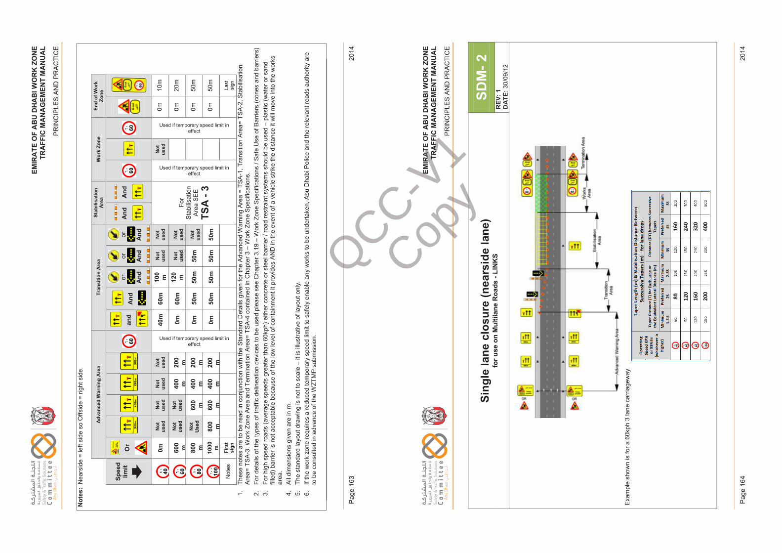
EM
IRA
TE
OF
AB
U D
HA
BI W
OR
K Z
ON
ET
RA
FF
IC M
AN
AG
EM
EN
T M
AN
UA
L
PR
INC
IPLE
S A
ND
PR
AC
TIC
E
2014
Pag
e 16
3
EM
IRA
TE
OF
AB
U D
HA
BI W
OR
K Z
ON
ET
RA
FF
IC M
AN
AG
EM
EN
T M
AN
UA
L
PR
INC
IPLE
S A
ND
PR
AC
TIC
E
2014
Pag
e 16
4
EM
IRAT
EO
FAB
UD
HAB
IWO
RK
ZON
ETR
AFFI
CM
ANAG
EM
ENT
MA
NU
AL
PRIN
CIP
LES
AN
D P
RA
CTI
CE
Not
es:
Nea
rsid
e =
left
side
so
Offs
ide
= rig
ht s
ide.
Adva
nced
War
ning
Are
aTr
ansi
tion
Area
Stab
ilisa
tion
Area
Wor
k Zo
neEn
d of
Wor
k Zo
ne
Spee
d lim
itO
r an
d A
nd
or And
or And
or And
And
And
0mN
ot
used
Not
us
edN
ot
used
Not
us
ed
Used if temporary speed limit in effect
40m
60m
100
mN
ot
used
Not
us
ed
For
Stab
ilisat
ion
Area
SE
E
TSA
-3
Used if temporary speed limit in effect
Not
us
ed
Used if temporary speed limit in effect
0m10
m
600
mN
ot
used
Not
us
ed40
0m
200
m0m
60m
120
mN
ot
used
Not
us
ed0m
20m
800
mN
ot
Use
d60
0m
400
m20
0m
0m50
m50
m50
mN
ot
used
0m50
m
1000 m
800
m60
0m
400
m20
0m
0m50
m50
m50
m50
m0m
50m
Not
esFi
rst
sign
Last
si
gn
1.Th
ese
note
s ar
e to
be
read
in c
onju
nctio
n w
ith th
e St
anda
rd D
etai
ls g
iven
for t
he A
dvan
ced
War
ning
Are
a =
TSA
-1, T
rans
ition
Are
a= T
SA-2
, Sta
bilis
atio
n Ar
ea=
TSA-
3, W
ork
Zone
Are
a an
d Te
rmin
atio
n Ar
ea=
TSA
-4 c
onta
ined
in C
hapt
er 3
–W
ork
Zone
Spe
cific
atio
ns.
2.Fo
r det
ails
of t
he ty
pes
of tr
affic
del
inea
tion
devi
ces
to b
e us
ed p
leas
e se
e C
hapt
er 3
.19
–W
ork
Zone
Spe
cific
atio
ns /
Safe
Use
of B
arrie
rs (c
ones
and
bar
riers
) 3.
For h
igh
spee
d ro
ads
(ave
rage
spe
eds
grea
ter t
han
60kp
h) e
ither
con
cret
e or
ste
el b
arrie
r / ro
ad re
stra
int s
yste
ms
shou
ld b
e us
ed –
plas
tic (w
ater
or s
and
fille
d) b
arrie
r is
not a
ccep
tabl
e be
caus
e of
the
low
leve
l of c
onta
inm
ent i
t pro
vide
s AN
D in
the
even
t of a
veh
icle
stri
ke th
e di
stan
ce it
will
mov
e in
to th
e w
orks
ar
ea.
4.Al
l dim
ensi
ons
give
nar
e in
m.
5.Th
e st
anda
rd la
yout
dra
win
g is
not
to s
cale
–it
is il
lust
rativ
e of
layo
ut o
nly.
6.If
the
wor
k zo
ne re
quire
s a
redu
ced
tem
pora
ry s
peed
lim
it to
saf
ely
enab
le a
ny w
orks
to b
e un
derta
ken,
Abu
Dha
bi P
olic
e an
d th
e re
leva
nt ro
ads
auth
ority
are
to
be
cons
ulte
d in
adv
ance
of t
he W
ZTM
P su
bmis
sion
.
Issu
e 1
Page
163
Febr
uary
201
4
EM
IRAT
EO
FAB
UD
HAB
IWO
RK
ZON
ETR
AFFI
CM
ANAG
EM
ENT
MA
NU
AL
PRIN
CIP
LES
AN
D P
RA
CTI
CE
Sing
le la
ne c
losu
re (n
ears
ide
lane
)fo
r use
on
Mul
tilan
e R
oads
-LI
NK
SSD
M-2
REV
: 1D
ATE:
30/0
9/12
Exam
ple
show
n is
for a
60k
ph 3
lane
car
riage
way
.
Issu
e 1
Page
164
Febr
uary
201
4
QCC-V1
Copy
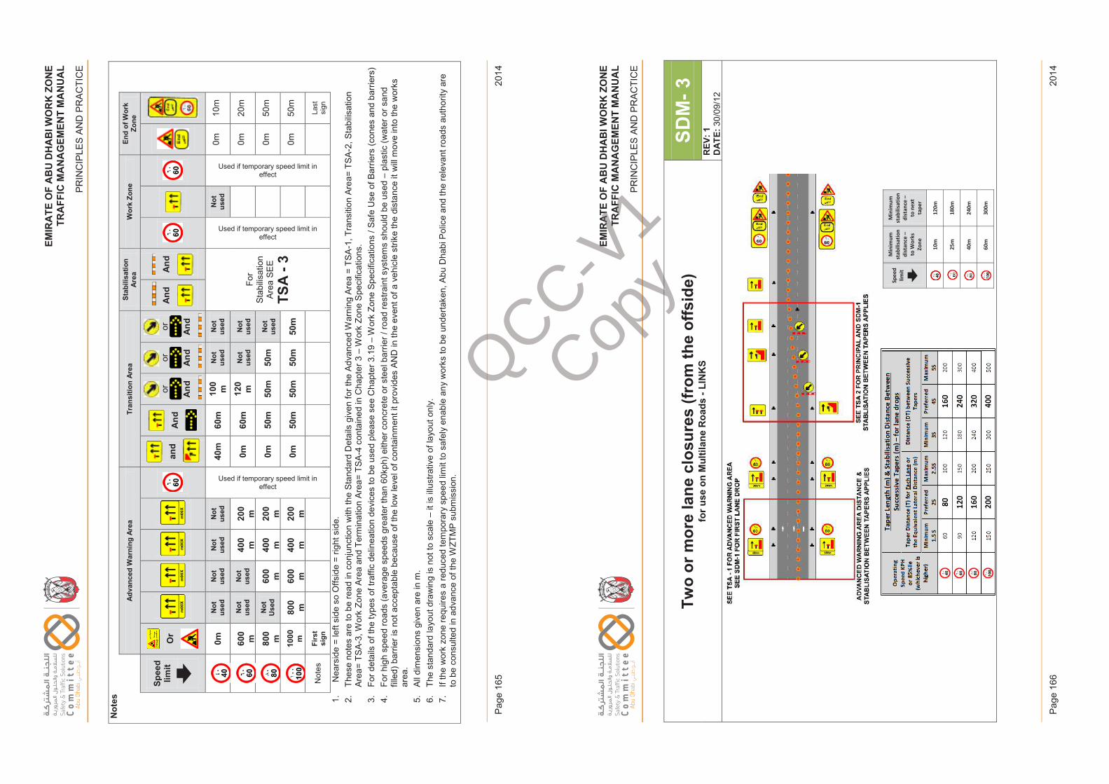
EM
IRA
TE
OF
AB
U D
HA
BI W
OR
K Z
ON
ET
RA
FF
IC M
AN
AG
EM
EN
T M
AN
UA
L
PR
INC
IPLE
S A
ND
PR
AC
TIC
E
2014
Pag
e 16
5
EM
IRA
TE
OF
AB
U D
HA
BI W
OR
K Z
ON
ET
RA
FF
IC M
AN
AG
EM
EN
T M
AN
UA
L
PR
INC
IPLE
S A
ND
PR
AC
TIC
E
2014
Pag
e 16
6
EM
IRAT
EO
FAB
UD
HAB
IWO
RK
ZON
ETR
AFFI
CM
ANAG
EM
ENT
MA
NU
AL
PRIN
CIP
LES
AN
D P
RA
CTI
CE
Not
es
Adva
nced
War
ning
Are
aTr
ansi
tion
Area
Stab
ilisa
tion
Area
Wor
k Zo
neEn
d of
Wor
k Zo
ne
Spee
d lim
itO
r an
d A
nd
or And
or And
or And
And
And
0mN
ot
used
Not
us
edN
ot
used
Not
us
ed
Used if temporary speed limit in effect
40m
60m
100
mN
ot
used
Not
us
ed
For
Stab
ilisat
ion
Area
SE
E
TSA
-3
Used if temporary speed limit in effect
Not
us
ed
Used if temporary speed limit in effect
0m10
m
600
mN
ot
used
Not
us
ed40
0m
200
m0m
60m
120
mN
ot
used
Not
us
ed0m
20m
800
mN
ot
Use
d60
0m
400
m20
0m
0m50
m50
m50
mN
ot
used
0m50
m
1000 m
800
m60
0m
400
m20
0m
0m50
m50
m50
m50
m0m
50m
Not
esFi
rst
sign
Last
si
gn
1.N
ears
ide
= le
ft si
de s
o O
ffsid
e =
right
sid
e.2.
Thes
e no
tes
are
to b
e re
ad in
con
junc
tion
with
the
Stan
dard
Det
ails
giv
en fo
r the
Adv
ance
d W
arni
ng A
rea
= TS
A-1
, Tra
nsiti
on A
rea=
TSA
-2, S
tabi
lisat
ion
Area
= TS
A-3,
Wor
k Zo
ne A
rea
and
Term
inat
ion
Area
= TS
A-4
con
tain
ed in
Cha
pter
3 –
Wor
k Zo
ne S
peci
ficat
ions
.3.
For d
etai
ls o
f the
type
s of
traf
fic d
elin
eatio
n de
vice
s to
be
used
ple
ase
see
Cha
pter
3.1
9 –
Wor
k Zo
ne S
peci
ficat
ions
/ Sa
fe U
se o
f Bar
riers
(con
es a
nd b
arrie
rs)
4.Fo
r hig
h sp
eed
road
s (a
vera
ge s
peed
s gr
eate
r tha
n 60
kph)
eith
er c
oncr
ete
or s
teel
bar
rier /
road
rest
rain
t sys
tem
s sh
ould
be
used
–pl
astic
(wat
er o
r san
d fil
led)
bar
rier i
s no
t acc
epta
ble
beca
use
of th
e lo
w le
vel o
f con
tain
men
t it p
rovi
des
AND
in th
e ev
ent o
f a v
ehic
le s
trike
the
dist
ance
it w
ill m
ove
into
the
wor
ks
area
. 5.
All d
imen
sion
s gi
ven
are
in m
. 6.
The
stan
dard
layo
ut d
raw
ing
is n
ot to
sca
le –
it is
illu
stra
tive
of la
yout
onl
y.7.
If th
e w
ork
zone
requ
ires
a re
duce
d te
mpo
rary
spe
ed li
mit
to s
afel
y en
able
any
wor
ks to
be
unde
rtake
n, A
bu D
habi
Pol
ice
and
the
rele
vant
road
s au
thor
ity a
re
to b
e co
nsul
ted
in a
dvan
ce o
f the
WZT
MP
subm
issi
on.
Issu
e 1
Page
165
Febr
uary
201
4
EM
IRAT
EO
FAB
UD
HAB
IWO
RK
ZON
ETR
AFFI
CM
ANAG
EM
ENT
MA
NU
AL
PRIN
CIP
LES
AN
D P
RA
CTI
CE
Two
or m
ore
lane
clo
sure
s (fr
om th
e of
fsid
e)fo
r use
on
Mul
tilan
e R
oads
-LI
NK
SSD
M-3
REV
: 1D
ATE:
30/0
9/12
Spee
d lim
it
Min
imum
st
abili
satio
n di
stan
ce –
to
Wor
ks
Zone
Min
imum
st
abili
satio
n di
stan
ce –
to
nex
t ta
per
10
m
120m
25m
18
0m
40
m
240m
60
m
300m
Issu
e 1
Page
166
Febr
uary
201
4
QCC-V1
Copy
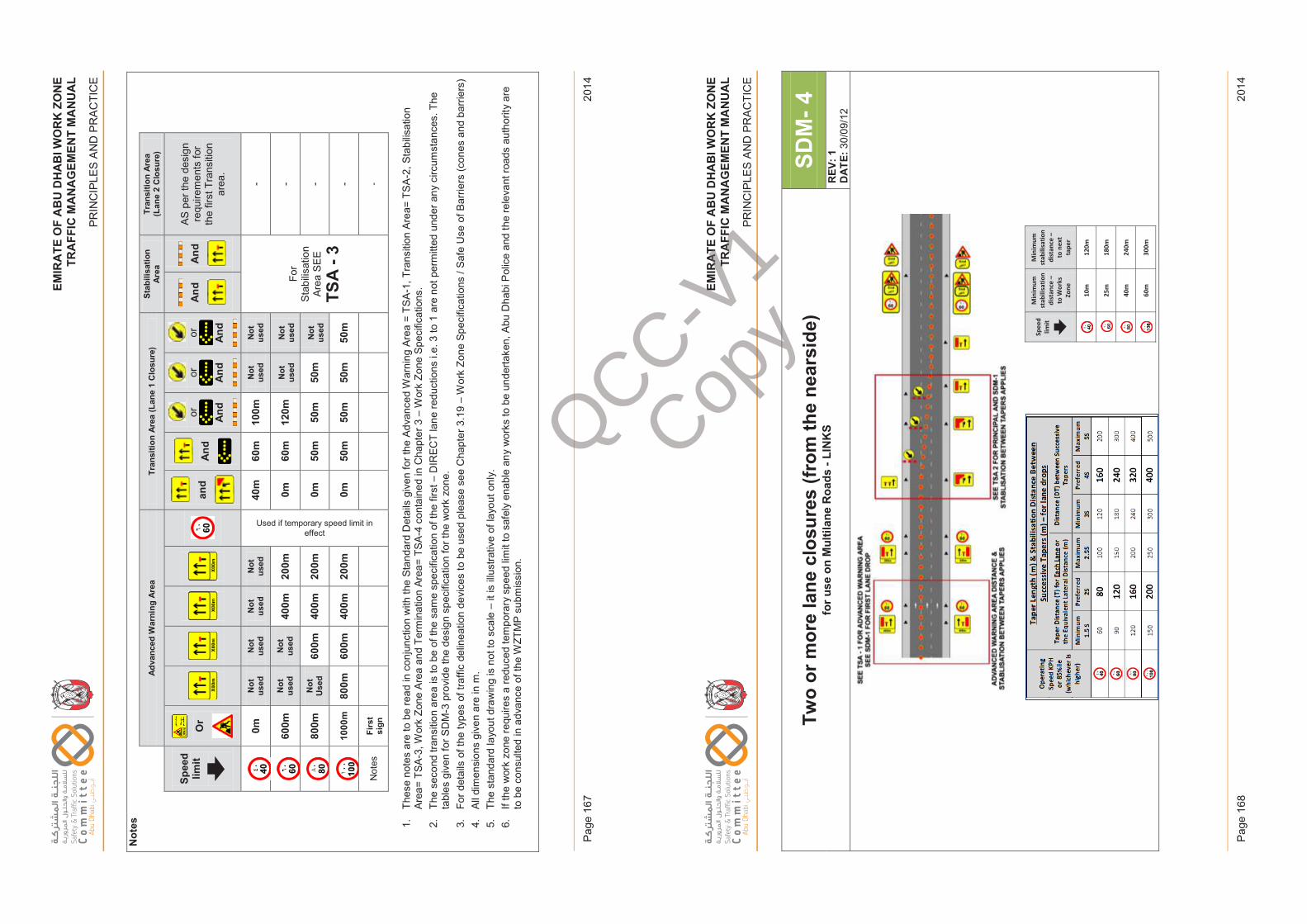
EM
IRA
TE
OF
AB
U D
HA
BI W
OR
K Z
ON
ET
RA
FF
IC M
AN
AG
EM
EN
T M
AN
UA
L
PR
INC
IPLE
S A
ND
PR
AC
TIC
E
2014
Pag
e 16
7
EM
IRA
TE
OF
AB
U D
HA
BI W
OR
K Z
ON
ET
RA
FF
IC M
AN
AG
EM
EN
T M
AN
UA
L
PR
INC
IPLE
S A
ND
PR
AC
TIC
E
2014
Pag
e 16
8
EM
IRAT
EO
FAB
UD
HAB
IWO
RK
ZON
ETR
AFFI
CM
ANAG
EM
ENT
MA
NU
AL
PRIN
CIP
LES
AN
D P
RA
CTI
CE
Not
es
Adva
nced
War
ning
Are
aTr
ansi
tion
Area
(Lan
e 1
Clo
sure
)St
abili
satio
n Ar
eaTr
ansi
tion
Area
(L
ane
2 C
losu
re)
Spee
d lim
itO
r an
d A
nd
or And
or And
or And
And
And
AS p
er th
e de
sign
re
quire
men
ts fo
r th
e fir
st T
rans
ition
ar
ea.
0mN
ot
used
Not
us
edN
ot
used
Not
us
ed
Used if temporary speed limit in effect
40m
60m
100m
Not
us
edN
ot
used
For
Stab
ilisat
ion
Area
SE
E
TSA
-3
-
600m
Not
us
edN
ot
used
400m
200m
0m60
m12
0mN
ot
used
Not
us
ed-
800m
Not
U
sed
600m
400m
200m
0m50
m50
m50
mN
ot
used
-
1000
m80
0m60
0m40
0m20
0m0m
50m
50m
50m
50m
-
Not
esFi
rst
sign
-
1.Th
ese
note
s ar
e to
be
read
in c
onju
nctio
n w
ith th
e St
anda
rd D
etai
ls g
iven
for t
he A
dvan
ced
War
ning
Are
a =
TSA
-1, T
rans
ition
Are
a= T
SA-2
, Sta
bilis
atio
n Ar
ea=
TSA-
3, W
ork
Zone
Are
a an
d Te
rmin
atio
n Ar
ea=
TSA
-4 c
onta
ined
in C
hapt
er 3
–W
ork
Zone
Spe
cific
atio
ns.
2.Th
e se
cond
tran
sitio
n ar
ea is
to b
e of
the
sam
e sp
ecifi
catio
n of
the
first
–D
IREC
T la
ne re
duct
ions
i.e.
3 to
1 a
re n
ot p
erm
itted
und
er a
ny c
ircum
stan
ces.
The
ta
bles
giv
en fo
r SD
M-3
pro
vide
the
desi
gn s
peci
ficat
ion
for t
he w
ork
zone
. 3.
For d
etai
ls o
f the
type
s of
traf
fic d
elin
eatio
n de
vice
s to
be
used
ple
ase
see
Cha
pter
3.1
9 –
Wor
k Zo
ne S
peci
ficat
ions
/ Sa
fe U
se o
f Bar
riers
(con
es a
nd b
arrie
rs)
4.Al
l dim
ensi
ons
give
n ar
e in
m.
5.Th
e st
anda
rd la
yout
dra
win
g is
not
to s
cale
–it
is il
lust
rativ
e of
layo
ut o
nly.
6.If
the
wor
k zo
ne re
quire
s a
redu
ced
tem
pora
ry s
peed
lim
it to
saf
ely
enab
le a
ny w
orks
to b
e un
derta
ken,
Abu
Dha
bi P
olic
e an
d th
e re
leva
nt ro
ads
auth
ority
are
to
be
cons
ulte
d in
adv
ance
of t
he W
ZTM
P su
bmis
sion
.
Issu
e 1
Page
167
Febr
uary
201
4
EM
IRAT
EO
FAB
UD
HAB
IWO
RK
ZON
ETR
AFFI
CM
ANAG
EM
ENT
MA
NU
AL
PRIN
CIP
LES
AN
D P
RA
CTI
CE
Two
or m
ore
lane
clo
sure
s (fr
om th
e ne
arsi
de)
for u
se o
n M
ultil
ane
Roa
ds -
LIN
KS
SDM
-4R
EV: 1
DAT
E:30
/09/
12
Spee
d lim
it
Min
imum
st
abili
satio
n di
stan
ce –
to
Wor
ks
Zone
Min
imum
st
abili
satio
n di
stan
ce –
to
nex
t ta
per
10
m
120m
25m
18
0m
40
m
240m
60
m
300m
Issu
e 1
Page
168
Febr
uary
201
4
QCC-V1
Copy
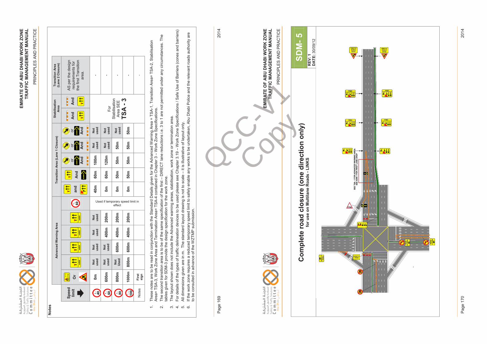
EM
IRA
TE
OF
AB
U D
HA
BI W
OR
K Z
ON
ET
RA
FF
IC M
AN
AG
EM
EN
T M
AN
UA
L
PR
INC
IPLE
S A
ND
PR
AC
TIC
E
2014
Pag
e 16
9
EM
IRA
TE
OF
AB
U D
HA
BI W
OR
K Z
ON
ET
RA
FF
IC M
AN
AG
EM
EN
T M
AN
UA
L
PR
INC
IPLE
S A
ND
PR
AC
TIC
E
2014
Pag
e 17
0
EM
IRAT
EO
FAB
UD
HAB
IWO
RK
ZON
ETR
AFFI
CM
ANAG
EM
ENT
MA
NU
AL
PRIN
CIP
LES
AN
D P
RA
CTI
CE
Not
es
Adva
nced
War
ning
Are
aTr
ansi
tion
Area
(Lan
e 1
Clo
sure
)St
abili
satio
n Ar
eaTr
ansi
tion
Area
(L
ane
2 C
losu
re)
Spee
d lim
itO
r an
d A
nd
or And
or And
or And
And
And
AS p
er th
e de
sign
re
quire
men
ts fo
r th
e fir
st T
rans
ition
ar
ea.
0mN
ot
used
Not
us
edN
ot
used
Not
us
ed
Used if temporary speed limit in effect
40m
60m
100m
Not
us
edN
ot
used
For
Stab
ilisat
ion
Area
SE
E
TSA
-3
-
600m
Not
us
edN
ot
used
400m
200m
0m60
m12
0mN
ot
used
Not
us
ed-
800m
Not
U
sed
600m
400m
200m
0m50
m50
m50
mN
ot
used
-
1000
m80
0m60
0m40
0m20
0m0m
50m
50m
50m
50m
-
Not
esFi
rst
sign
-
1.Th
ese
note
s ar
e to
be
read
in c
onju
nctio
n w
ith th
e St
anda
rd D
etai
ls g
iven
for t
he A
dvan
ced
War
ning
Are
a =
TSA
-1, T
rans
ition
Are
a= T
SA-2
, Sta
bilis
atio
n Ar
ea=
TSA-
3, W
ork
Zone
Are
a an
d Te
rmin
atio
n Ar
ea=
TSA
-4 c
onta
ined
in C
hapt
er 3
–W
ork
Zone
Spe
cific
atio
ns.
2.Th
e se
cond
tran
sitio
n ar
ea is
to b
e of
the
sam
e sp
ecifi
catio
n of
the
first
–D
IREC
T la
ne re
duct
ions
i.e.
3 to
1 a
re n
ot p
erm
itted
und
er a
ny c
ircum
stan
ces.
The
ta
bles
giv
en fo
r SD
M-3
pro
vide
the
desi
gn s
peci
ficat
ion
for t
he w
ork
zone
. 3.
The
layo
ut s
how
n do
es n
ot in
clud
e th
e Ad
vanc
ed w
arni
ng a
reas
, sta
bilis
atio
n, w
ork
zone
or t
erm
inat
ion
area
.4.
For d
etai
ls o
f the
type
s of
traf
fic d
elin
eatio
n de
vice
s to
be
used
ple
ase
see
Cha
pter
3.1
9 –
Wor
k Zo
ne S
peci
ficat
ions
/ Sa
fe U
se o
f Bar
riers
(con
es a
nd b
arrie
rs)
5.Al
l dim
ensi
ons
give
n ar
e in
m.
The
stan
dard
layo
ut d
raw
ing
is n
ot to
sca
le –
it is
illu
stra
tive
of la
yout
onl
y.6.
If th
e w
ork
zone
requ
ires
a re
duce
d te
mpo
rary
spe
ed li
mit
to s
afel
y en
able
any
wor
ks to
be
unde
rtake
n, A
bu D
habi
Pol
ice
and
the
rele
vant
road
s au
thor
ity a
re
to b
e co
nsul
ted
in a
dvan
ce o
f the
WZT
MP
subm
issi
on.
Issu
e 1
Page
169
Febr
uary
201
4
EM
IRAT
EO
FAB
UD
HAB
IWO
RK
ZON
ETR
AFFI
CM
ANAG
EM
ENT
MA
NU
AL
PRIN
CIP
LES
AN
D P
RA
CTI
CE
Com
plet
e ro
ad c
losu
re (o
ne d
irect
ion
only
)fo
r use
on
Mul
tilan
e R
oads
-LI
NK
SSD
M-5
REV
: 1D
ATE:
30/0
9/12
Issu
e 1
Page
170
Febr
uary
201
4
QCC-V1
Copy
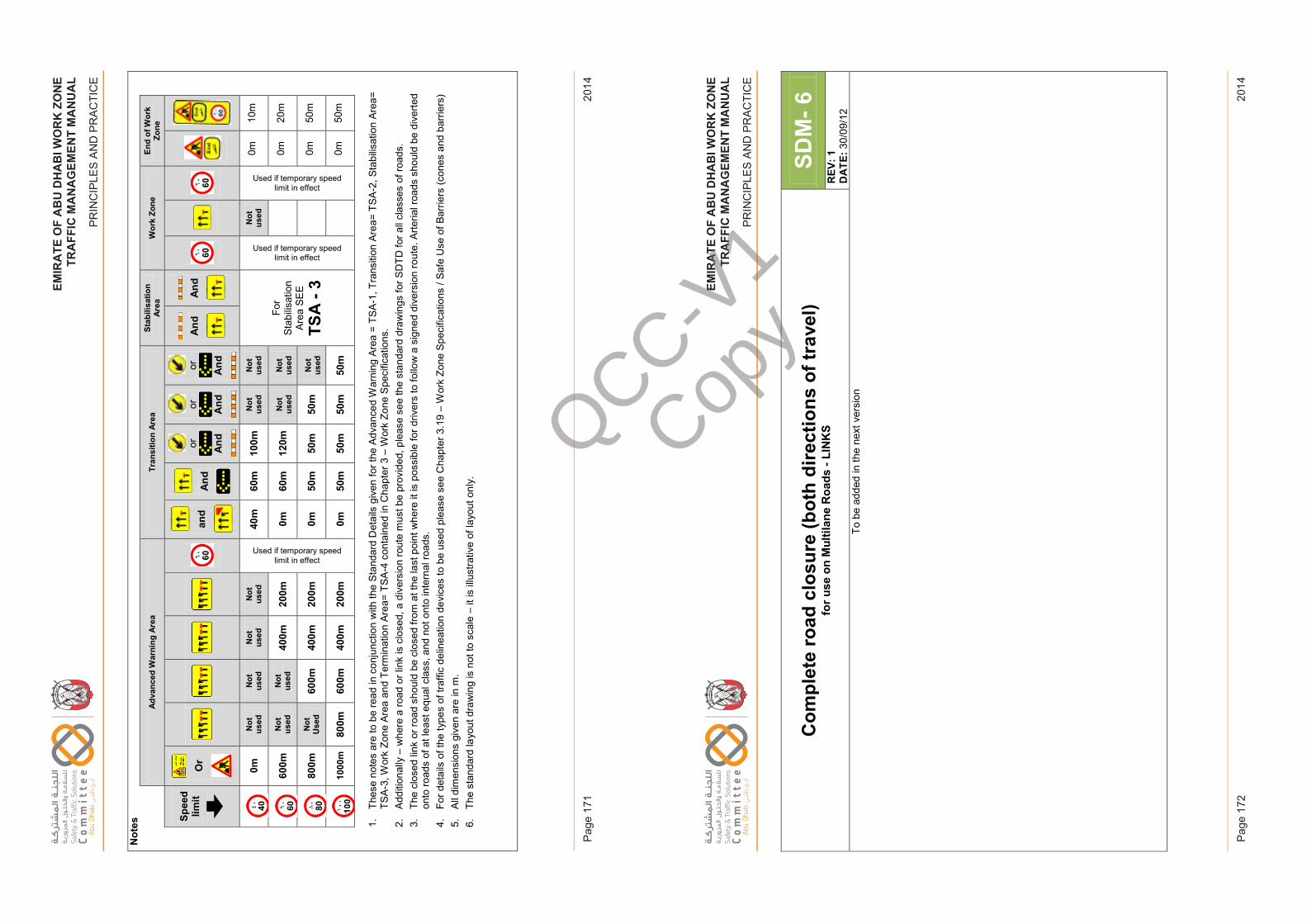
EM
IRA
TE
OF
AB
U D
HA
BI W
OR
K Z
ON
ET
RA
FF
IC M
AN
AG
EM
EN
T M
AN
UA
L
PR
INC
IPLE
S A
ND
PR
AC
TIC
E
2014
Pag
e 17
1
EM
IRA
TE
OF
AB
U D
HA
BI W
OR
K Z
ON
ET
RA
FF
IC M
AN
AG
EM
EN
T M
AN
UA
L
PR
INC
IPLE
S A
ND
PR
AC
TIC
E
2014
Pag
e 17
2
EM
IRAT
EO
FAB
UD
HAB
IWO
RK
ZON
ETR
AFFI
CM
ANAG
EM
ENT
MA
NU
AL
PRIN
CIP
LES
AN
D P
RA
CTI
CE
Not
es
Adva
nced
War
ning
Are
aTr
ansi
tion
Area
Stab
ilisa
tion
Area
Wor
k Zo
neEn
d of
Wor
k Zo
ne
Spee
d lim
itO
r an
d A
nd
or And
or And
or And
And
And
0mN
ot
used
Not
us
edN
ot
used
Not
us
ed
Used if temporary speed limit in effect
40m
60m
100m
Not
us
edN
ot
used
For
Stab
ilisat
ion
Area
SE
E
TSA
-3
Used if temporary speed limit in effect
Not
us
ed
Used if temporary speed limit in effect
0m10
m
600m
Not
us
edN
ot
used
400m
200m
0m60
m12
0mN
ot
used
Not
us
ed0m
20m
800m
Not
U
sed
600m
400m
200m
0m50
m50
m50
mN
ot
used
0m50
m
1000
m80
0m60
0m40
0m20
0m0m
50m
50m
50m
50m
0m50
m
1.Th
ese
note
s ar
e to
be
read
in c
onju
nctio
n w
ith th
e St
anda
rd D
etai
ls g
iven
for t
he A
dvan
ced
War
ning
Are
a =
TSA
-1, T
rans
ition
Are
a= T
SA-2
, Sta
bilis
atio
n Ar
ea=
TSA-
3, W
ork
Zone
Are
a an
d Te
rmin
atio
n Ar
ea=
TSA
-4 c
onta
ined
in C
hapt
er 3
–W
ork
Zone
Spe
cific
atio
ns.
2.Ad
ditio
nally
–w
here
a ro
ad o
r lin
k is
clo
sed,
a d
iver
sion
rout
e m
ust b
e pr
ovid
ed, p
leas
e se
e th
e st
anda
rd d
raw
ings
for S
DTD
for a
ll cl
asse
sof
road
s.3.
The
clos
ed li
nk o
r roa
d sh
ould
be
clos
ed fr
om a
t the
last
poi
nt w
here
it is
pos
sibl
e fo
r driv
ers
to fo
llow
a s
igne
d di
vers
ion
rout
e. A
rteria
l roa
ds s
houl
d be
div
erte
d on
to ro
ads
of a
t lea
st e
qual
cla
ss, a
nd n
ot o
nto
inte
rnal
road
s.
4.Fo
r det
ails
of t
he ty
pes
of tr
affic
del
inea
tion
devi
ces
to b
e us
ed p
leas
e se
e C
hapt
er 3
.19
–W
ork
Zone
Spe
cific
atio
ns /
Safe
Use
of B
arrie
rs (c
ones
and
bar
riers
)5.
All d
imen
sion
s gi
ven
are
in m
. 6.
The
stan
dard
layo
ut d
raw
ing
is n
ot to
sca
le –
it is
illu
stra
tive
of la
yout
onl
y.
Issu
e 1
Page
171
Febr
uary
201
4
EM
IRAT
EO
FAB
UD
HAB
IWO
RK
ZON
ETR
AFFI
CM
ANAG
EM
ENT
MA
NU
AL
PRIN
CIP
LES
AN
D P
RA
CTI
CE
Com
plet
e ro
ad c
losu
re (b
oth
dire
ctio
ns o
f tra
vel)
for u
se o
n M
ultil
ane
Roa
ds -
LIN
KS
SDM
-6R
EV: 1
DAT
E:30
/09/
12To
be
adde
d in
the
next
ver
sion
Issu
e 1
Page
172
Febr
uary
201
4
QCC-V1
Copy
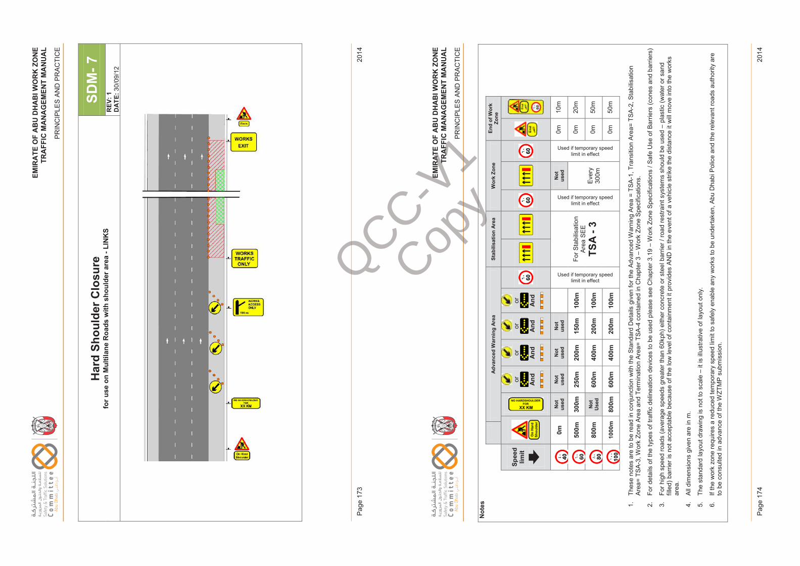
EM
IRA
TE
OF
AB
U D
HA
BI W
OR
K Z
ON
ET
RA
FF
IC M
AN
AG
EM
EN
T M
AN
UA
L
PR
INC
IPLE
S A
ND
PR
AC
TIC
E
2014
Pag
e 17
3
EM
IRA
TE
OF
AB
U D
HA
BI W
OR
K Z
ON
ET
RA
FF
IC M
AN
AG
EM
EN
T M
AN
UA
L
PR
INC
IPLE
S A
ND
PR
AC
TIC
E
2014
Pag
e 17
4
EM
IRAT
EO
FAB
UD
HAB
IWO
RK
ZON
ETR
AFFI
CM
ANAG
EM
ENT
MA
NU
AL
PRIN
CIP
LES
AN
D P
RA
CTI
CE
Har
d Sh
ould
er C
losu
re
for u
se o
n M
ultil
ane
Roa
ds w
ith s
houl
der a
rea
-LIN
KS
SDM
-7R
EV: 1
DAT
E:30
/09/
12
Issu
e 1
Page
173
Febr
uary
201
4
EM
IRAT
EO
FAB
UD
HAB
IWO
RK
ZON
ETR
AFFI
CM
ANAG
EM
ENT
MA
NU
AL
PRIN
CIP
LES
AN
D P
RA
CTI
CE
Not
es
Adva
nced
War
ning
Are
aSt
abili
satio
n Ar
eaW
ork
Zone
End
of W
ork
Zone
Spee
d lim
itor And
or And
or And
or And
0mN
ot
used
Not
us
edN
ot
used
Not
us
ed
Used if temporary speed limit in effect
For S
tabi
lisat
ion
Area
SE
E
TSA
-3
Used if temporary speed limit in effect
Not
us
ed
Used if temporary speed limit in effect
0m10
m
500m
300m
250m
200m
150m
100m
Ever
y 30
0m
0m20
m
800m
Not
U
sed
600m
400m
200m
100m
0m50
m
1000
m80
0m60
0m40
0m20
0m10
0m0m
50m
1.Th
ese
note
s ar
e to
be
read
in c
onju
nctio
n w
ith th
e St
anda
rd D
etai
ls g
iven
for t
he A
dvan
ced
War
ning
Are
a =
TSA
-1, T
rans
ition
Are
a= T
SA-2
, Sta
bilis
atio
n Ar
ea=
TSA-
3, W
ork
Zone
Are
a an
d Te
rmin
atio
n Ar
ea=
TSA
-4 c
onta
ined
in C
hapt
er 3
–W
ork
Zone
Spe
cific
atio
ns.
2.Fo
r det
ails
of t
he ty
pes
of tr
affic
del
inea
tion
devi
ces
to b
e us
ed p
leas
e se
e C
hapt
er 3
.19
–W
ork
Zone
Spe
cific
atio
ns /
Safe
Use
of B
arrie
rs (c
ones
and
bar
riers
)
3.Fo
r hig
h sp
eed
road
s (a
vera
ge s
peed
s gr
eate
r tha
n 60
kph)
eith
er c
oncr
ete
or s
teel
bar
rier /
road
rest
rain
t sys
tem
s sh
ould
be
used
–pl
astic
(wat
er o
r san
d fil
led)
bar
rier i
s no
t acc
epta
ble
beca
use
of th
e lo
w le
vel o
f con
tain
men
t it p
rovi
des
AND
in th
e ev
ent o
f a v
ehic
le s
trike
the
dist
ance
it w
ill m
ove
into
the
wor
ks
area
.
4.Al
l dim
ensi
ons
give
n ar
e in
m.
5.Th
e st
anda
rd la
yout
dra
win
g is
not
to s
cale
–it
is il
lust
rativ
e of
layo
ut o
nly.
6.If
the
wor
k zo
ne re
quire
s a
redu
ced
tem
pora
ry s
peed
lim
it to
saf
ely
enab
le a
ny w
orks
to b
e un
derta
ken,
Abu
Dha
bi P
olic
e an
d th
e re
leva
nt ro
ads
auth
ority
are
to
be
cons
ulte
d in
adv
ance
of t
he W
ZTM
P su
bmis
sion
.
Issu
e 1
Page
174
Febr
uary
201
4
QCC-V1
Copy
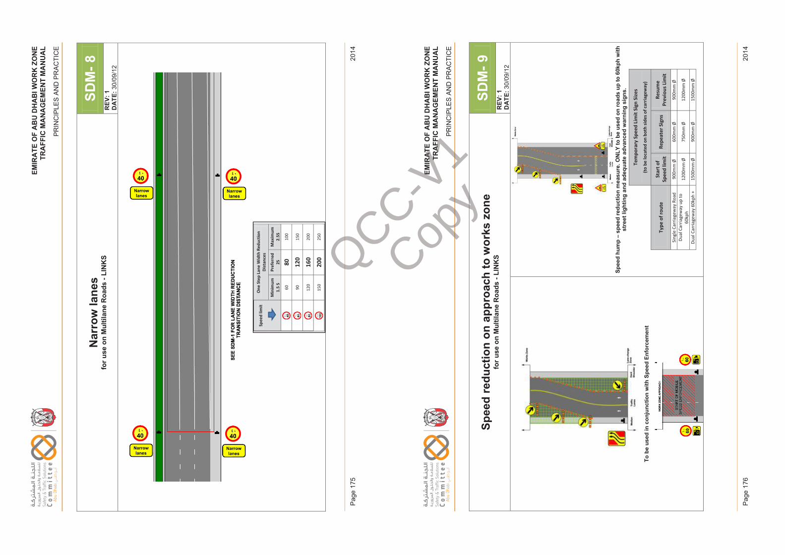
EM
IRA
TE
OF
AB
U D
HA
BI W
OR
K Z
ON
ET
RA
FF
IC M
AN
AG
EM
EN
T M
AN
UA
L
PR
INC
IPLE
S A
ND
PR
AC
TIC
E
2014
Pag
e 17
5
EM
IRA
TE
OF
AB
U D
HA
BI W
OR
K Z
ON
ET
RA
FF
IC M
AN
AG
EM
EN
T M
AN
UA
L
PR
INC
IPLE
S A
ND
PR
AC
TIC
E
2014
Pag
e 17
6
EM
IRAT
EO
FAB
UD
HAB
IWO
RK
ZON
ETR
AFFI
CM
ANAG
EM
ENT
MA
NU
AL
PRIN
CIP
LES
AN
D P
RA
CTI
CE
Nar
row
lane
sfo
r use
on
Mul
tilan
e R
oads
-LI
NK
SSD
M-8
REV
: 1D
ATE:
30/0
9/12
Spee
d lim
it O
ne S
tep
Lane
Wid
th R
educ
tion
Dist
ance
s
Min
imum
1.
5 S
Pref
erre
d 2S
M
axim
um
2.5S
60
80
100
90
120
150
120
160
200
15
0 20
0 25
0
Is
sue
1 Pa
ge 1
75Fe
brua
ry 2
014
EM
IRAT
EO
FAB
UD
HAB
IWO
RK
ZON
ETR
AFFI
CM
ANAG
EM
ENT
MA
NU
AL
PRIN
CIP
LES
AN
D P
RA
CTI
CE
Spee
d re
duct
ion
on a
ppro
ach
to w
orks
zon
e fo
r use
on
Mul
tilan
e R
oads
-LI
NK
SSD
M-9
REV
: 1D
ATE:
30/0
9/12
To b
e us
ed in
con
junc
tion
with
Spe
ed E
nfor
cem
ent
Spee
d hu
mp
–sp
eed
redu
ctio
n m
easu
re. O
NLY
to b
e us
ed o
n ro
ads
up to
60k
ph w
ith
stre
et li
ghtin
g an
d ad
equa
te a
dvan
ced
war
ning
sig
ns.
Te
mpo
rary
Spe
ed L
imit
Sign
Siz
es
(to
be lo
cate
d on
bot
h si
des o
f car
riage
way
)
Type
of r
oute
St
art o
f Sp
eed
limit
Repe
ater
Sig
ns
Resu
me
Prev
ious
Lim
it
Sing
le C
arria
gew
ay R
oad
900m
m Ø
60
0mm
Ø
900m
m Ø
Du
al C
arria
gew
ay u
p to
60
kph
1200
mm
Ø
750m
m Ø
12
00m
m Ø
Dual
Car
riage
way
60k
ph +
15
00m
m Ø
90
0mm
Ø
1500
mm
Ø
Issu
e 1
Page
176
Febr
uary
201
4
QCC-V1
Copy
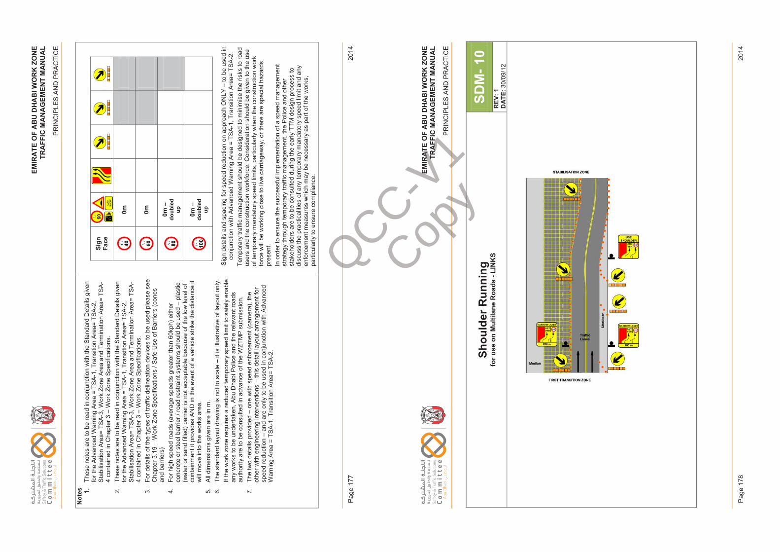
EM
IRA
TE
OF
AB
U D
HA
BI W
OR
K Z
ON
ET
RA
FF
IC M
AN
AG
EM
EN
T M
AN
UA
L
PR
INC
IPLE
S A
ND
PR
AC
TIC
E
2014
Pag
e 17
7
EM
IRA
TE
OF
AB
U D
HA
BI W
OR
K Z
ON
ET
RA
FF
IC M
AN
AG
EM
EN
T M
AN
UA
L
PR
INC
IPLE
S A
ND
PR
AC
TIC
E
2014
Pag
e 17
8
EM
IRAT
EO
FAB
UD
HAB
IWO
RK
ZON
ETR
AFFI
CM
ANAG
EM
ENT
MA
NU
AL
PRIN
CIP
LES
AN
D P
RA
CTI
CE
Not
es 1.Th
ese
note
s ar
e to
be
read
in c
onju
nctio
n w
ith th
e St
anda
rd D
etai
ls g
iven
fo
r the
Adv
ance
d W
arni
ng A
rea
= TS
A-1,
Tra
nsiti
on A
rea=
TSA
-2,
Stab
ilisat
ion
Area
= TS
A-3,
Wor
k Zo
ne A
rea
and
Term
inat
ion
Area
= TS
A-
4 co
ntai
ned
in C
hapt
er 3
–W
ork
Zone
Spe
cific
atio
ns.
2.Th
ese
note
s ar
e to
be
read
in c
onju
nctio
n w
ith th
e St
anda
rd D
etai
ls g
iven
fo
r the
Adv
ance
d W
arni
ng A
rea
= TS
A-1,
Tra
nsiti
on A
rea=
TSA
-2,
Stab
ilisat
ion
Area
= TS
A-3,
Wor
k Zo
ne A
rea
and
Term
inat
ion
Area
= TS
A-
4 co
ntai
ned
in C
hapt
er 3
–W
ork
Zone
Spe
cific
atio
ns.
3.Fo
r det
ails
of t
he ty
pes
of tr
affic
del
inea
tion
devi
ces
to b
e us
ed p
leas
e se
e C
hapt
er 3
.19
–W
ork
Zone
Spe
cific
atio
ns /
Saf
e U
se o
f Bar
riers
(con
es
and
barr
iers
)4.
For h
igh
spee
d ro
ads
(ave
rage
spe
eds
grea
ter t
han
60kp
h) e
ither
co
ncre
te o
r ste
el b
arrie
r / ro
ad re
stra
int s
yste
ms
shou
ld b
e us
ed –
plas
tic
(wat
er o
r san
d fil
led)
bar
rier i
s no
t acc
epta
ble
beca
use
of th
e lo
w le
vel o
f co
ntai
nmen
t it p
rovi
des
AND
in th
e ev
ent o
f a v
ehic
le s
trike
the
dist
ance
it
will
mov
e in
to th
e w
orks
are
a.
5.Al
l dim
ensi
ons
give
n ar
e in
m.
6.Th
e st
anda
rd la
yout
dra
win
g is
not
to s
cale
–it
is il
lust
rativ
e of
layo
ut o
nly.
If th
e w
ork
zone
requ
ires
a re
duce
d te
mpo
rary
spe
ed li
mit
to s
afel
y en
able
an
y w
orks
to b
e un
derta
ken,
Abu
Dha
bi P
olic
e an
d th
e re
leva
nt ro
ads
auth
ority
are
to b
e co
nsul
ted
in a
dvan
ce o
f the
WZT
MP
subm
issi
on.
7.Th
e tw
o de
tails
pro
vide
d –
one
with
spe
ed e
nfor
cem
ent (
cam
era)
, the
ot
her w
ith e
ngin
eerin
g in
terv
entio
ns –
this
det
ail l
ayou
t arr
ange
men
t for
sp
eed
redu
ctio
n –
and
are
only
to b
e us
ed in
con
junc
tion
with
Adv
ance
d W
arni
ng A
rea
= TS
A-1,
Tra
nsiti
on A
rea=
TSA
-2.
Sign
Face
0m 0m 0m –
doub
led
up 0m –
doub
led
up
Sign
det
ails
and
spa
cing
for s
peed
redu
ctio
n on
app
roac
h O
NLY
–to
be
used
in
conj
unct
ion
with
Adv
ance
d W
arni
ng A
rea
= TS
A-1,
Tra
nsiti
on A
rea=
TSA
-2.
Tem
pora
ry tr
affic
man
agem
ent s
houl
d be
des
igne
d to
min
imis
e th
e ris
ks to
road
us
ers
and
the
cons
truct
ion
wor
kfor
ce. C
onsi
dera
tion
shou
ld b
e gi
ven
to th
e us
e of
tem
pora
ry m
anda
tory
spe
ed li
mits
, par
ticul
arly
whe
n th
e co
nstru
ctio
n w
ork
forc
e w
ill be
wor
king
clo
se to
live
car
riage
way
, or t
here
are
spe
cial
haz
ards
pr
esen
t. In
ord
er to
ens
ure
the
succ
essf
ul im
plem
enta
tion
of a
spe
ed m
anag
emen
t st
rate
gy th
roug
h te
mpo
rary
traf
fic m
anag
emen
t, th
e P
olic
e an
d ot
her
stak
ehol
ders
are
to b
e co
nsul
ted
durin
g th
e ea
rly T
TM d
esig
n pr
oces
s to
di
scus
s th
e pr
actic
aliti
es o
f any
tem
pora
ry m
anda
tory
spe
ed li
mit
and
any
enfo
rcem
ent m
easu
res
whi
ch m
ay b
e ne
cess
ary
as p
art o
f the
wor
ks,
parti
cula
rly to
ens
ure
com
plia
nce.
Issu
e 1
Page
177
Febr
uary
201
4
EM
IRAT
EO
FAB
UD
HAB
IWO
RK
ZON
ETR
AFFI
CM
ANAG
EM
ENT
MA
NU
AL
PRIN
CIP
LES
AN
D P
RA
CTI
CE
Shou
lder
Run
ning
for u
se o
n M
ultil
ane
Roa
ds -
LIN
KS
SDM
-10
REV
: 1D
ATE:
30/0
9/12
Issu
e 1
Page
178
Febr
uary
201
4
QCC-V1
Copy
EM
IRA
TE
OF
AB
U D
HA
BI W
OR
K Z
ON
ET
RA
FF
IC M
AN
AG
EM
EN
T M
AN
UA
L
PR
INC
IPLE
S A
ND
PR
AC
TIC
E
2014
Pag
e 17
9
EM
IRA
TE
OF
AB
U D
HA
BI W
OR
K Z
ON
ET
RA
FF
IC M
AN
AG
EM
EN
T M
AN
UA
L
PR
INC
IPLE
S A
ND
PR
AC
TIC
E
2014
Pag
e 18
0
EM
IRAT
EO
FAB
UD
HAB
IWO
RK
ZON
ETR
AFFI
CM
ANAG
EM
ENT
MA
NU
AL
PRIN
CIP
LES
AN
D P
RA
CTI
CE
Not
es 1.Th
ese
note
s ar
e to
be
read
in c
onju
nctio
n w
ith th
e St
anda
rd D
etai
ls g
iven
for t
he A
dvan
ced
War
ning
Are
a =
TSA
-1, T
rans
ition
Are
a= T
SA-2
, Sta
bilis
atio
n Ar
ea=
TSA-
3, W
ork
Zone
Are
a an
d Te
rmin
atio
n Ar
ea=
TSA
-4 c
onta
ined
in C
hapt
er 3
–W
ork
Zone
Spe
cific
atio
ns.
2.Th
e us
e of
the
shou
lder
for t
raffi
c flo
w is
onl
y pe
rmis
sibl
e w
here
the
dept
h an
d ty
pe o
f con
stru
ctio
n is
acc
epte
d fo
r tra
ffic
load
ing
AND
any
edg
e of
car
riage
way
ha
zard
s ar
e ei
ther
out
side
of t
he c
lear
zon
e ar
ea O
R a
re p
rote
cted
.
3.Fo
r det
ails
of t
he ty
pes
of tr
affic
del
inea
tion
devi
ces
to b
e us
ed p
leas
e se
e C
hapt
er 3
.19
–W
ork
Zone
Spe
cific
atio
ns /
Safe
Use
of B
arrie
rs (c
ones
and
bar
riers
)
4.Fo
r hig
h sp
eed
road
s (a
vera
ge s
peed
s gr
eate
r tha
n 60
kph)
eith
er c
oncr
ete
or s
teel
bar
rier /
road
rest
rain
t sys
tem
s sh
ould
be
used
–pl
astic
(wat
er o
r san
d fil
led)
bar
rier i
s no
t acc
epta
ble
beca
use
of th
e lo
w le
vel o
f con
tain
men
t it p
rovi
des
AND
in th
e ev
ent o
f a v
ehic
le s
trike
the
dist
ance
it w
ill m
ove
into
the
wor
ks
area
.
5.Al
l dim
ensi
ons
give
n ar
e in
m.
6.Th
e st
anda
rd la
yout
dra
win
g is
not
to s
cale
–it
is il
lust
rativ
e of
layo
ut o
nly.
7.If
the
wor
k zo
ne re
quire
s a
redu
ced
tem
pora
ry s
peed
lim
it to
saf
ely
enab
le a
ny w
orks
to b
e un
derta
ken,
Abu
Dha
bi P
olic
e an
d th
e re
leva
nt ro
ads
auth
ority
are
to
be
cons
ulte
d in
adv
ance
of t
he W
ZTM
P su
bmis
sion
.
Issu
e 1
Page
179
Febr
uary
201
4
EM
IRAT
EO
FAB
UD
HAB
IWO
RK
ZON
ETR
AFFI
CM
ANAG
EM
ENT
MA
NU
AL
PRIN
CIP
LES
AN
D P
RA
CTI
CE
Stan
dard
Det
ails
(SD
’s) –
Mul
tilan
e &
In
terc
hang
es
Issu
e 1
Page
180
Febr
uary
201
4
QCC-V1
Copy
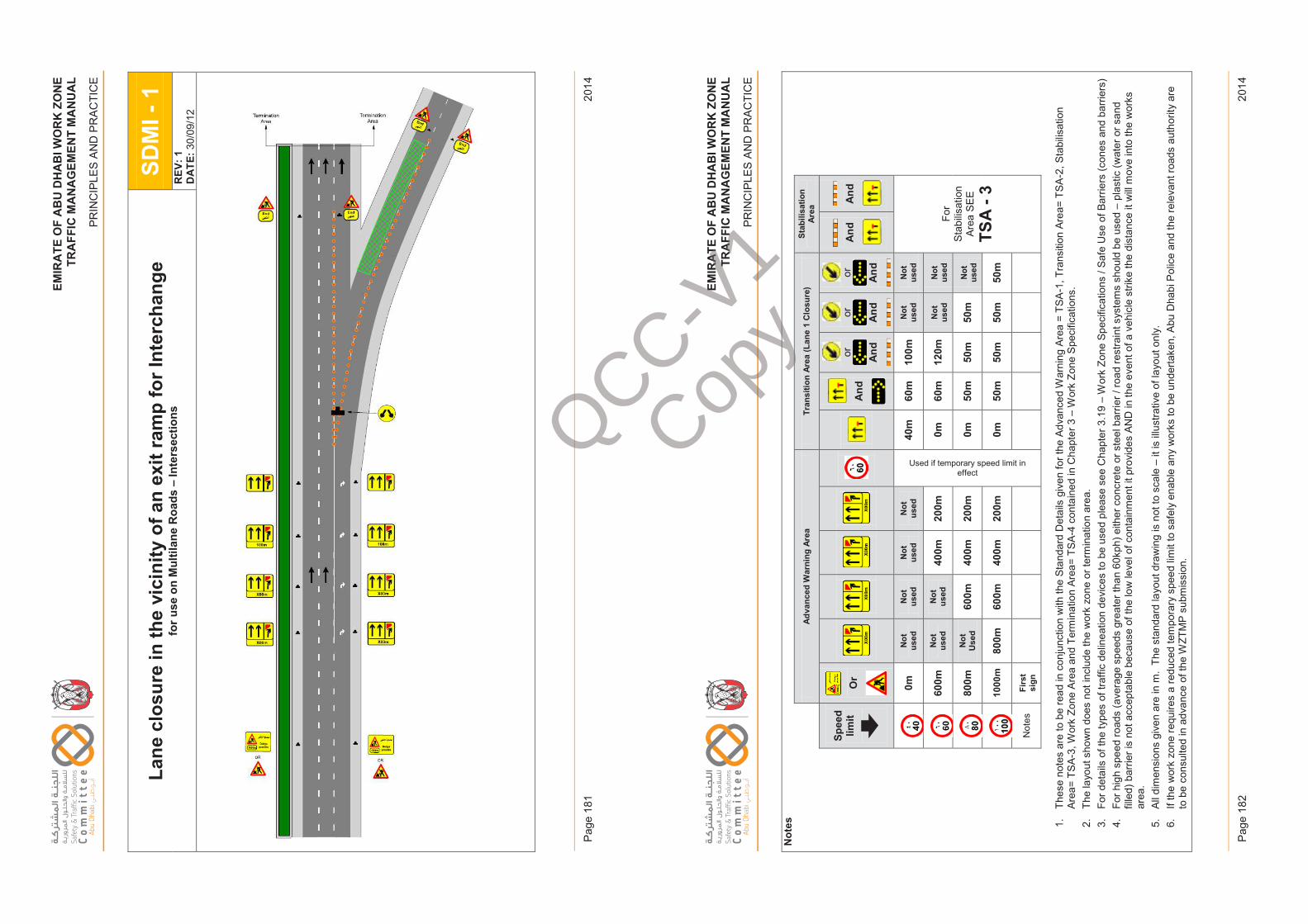
EM
IRA
TE
OF
AB
U D
HA
BI W
OR
K Z
ON
ET
RA
FF
IC M
AN
AG
EM
EN
T M
AN
UA
L
PR
INC
IPLE
S A
ND
PR
AC
TIC
E
2014
Pag
e 18
1
EM
IRA
TE
OF
AB
U D
HA
BI W
OR
K Z
ON
ET
RA
FF
IC M
AN
AG
EM
EN
T M
AN
UA
L
PR
INC
IPLE
S A
ND
PR
AC
TIC
E
2014
Pag
e 18
2
EM
IRAT
EO
FAB
UD
HAB
IWO
RK
ZON
ETR
AFFI
CM
ANAG
EM
ENT
MA
NU
AL
PRIN
CIP
LES
AN
D P
RA
CTI
CE
Lane
clo
sure
in th
e vi
cini
ty o
f an
exit
ram
p fo
r Int
erch
ange
for u
se o
n M
ultil
ane
Roa
ds –
Inte
rsec
tions
SDM
I -1
REV
: 1D
ATE:
30/0
9/12
Issu
e 1
Page
181
Febr
uary
201
4
EM
IRAT
EO
FAB
UD
HAB
IWO
RK
ZON
ETR
AFFI
CM
ANAG
EM
ENT
MA
NU
AL
PRIN
CIP
LES
AN
D P
RA
CTI
CE
Not
es
Adva
nced
War
ning
Area
Tran
sitio
n Ar
ea (L
ane
1 C
losu
re)
Stab
ilisa
tion
Area
Spee
d lim
itO
r A
nd
or And
or And
or And
And
And
0mN
ot
used
Not
us
edN
ot
used
Not
us
ed
Used if temporary speed limit in effect
40m
60m
100m
Not
us
edN
ot
used
For
Stab
ilisat
ion
Area
SE
E
TSA
-3
600m
Not
us
edN
ot
used
400m
200m
0m60
m12
0mN
ot
used
Not
us
ed
800m
Not
U
sed
600m
400m
200m
0m50
m50
m50
mN
ot
used
1000
m80
0m60
0m40
0m20
0m0m
50m
50m
50m
50m
Not
esFi
rst
sign
1.Th
ese
note
s ar
e to
be
read
in c
onju
nctio
n w
ith th
e St
anda
rd D
etai
ls g
iven
for t
he A
dvan
ced
War
ning
Are
a =
TSA
-1, T
rans
ition
Are
a= T
SA-2
, Sta
bilis
atio
n Ar
ea=
TSA-
3, W
ork
Zone
Are
a an
d Te
rmin
atio
n Ar
ea=
TSA
-4 c
onta
ined
in C
hapt
er 3
–W
ork
Zone
Spe
cific
atio
ns.
2.Th
e la
yout
sho
wn
does
not
incl
ude
the
wor
k zo
ne o
r ter
min
atio
n ar
ea.
3.Fo
r det
ails
of t
he ty
pes
of tr
affic
del
inea
tion
devi
ces
to b
e us
ed p
leas
e se
e C
hapt
er 3
.19
–W
ork
Zone
Spe
cific
atio
ns /
Safe
Use
of B
arrie
rs (c
ones
and
bar
riers
)4.
For h
igh
spee
d ro
ads
(ave
rage
spe
eds
grea
ter t
han
60kp
h) e
ither
con
cret
e or
ste
el b
arrie
r / ro
ad re
stra
int s
yste
ms
shou
ld b
e us
ed –
plas
tic (w
ater
or s
and
fille
d) b
arrie
r is
not a
ccep
tabl
e be
caus
e of
the
low
leve
l of c
onta
inm
ent i
t pro
vide
s AN
D in
the
even
t of a
veh
icle
stri
ke th
e di
stan
ce it
will
mov
e in
to th
e w
orks
ar
ea.
5.Al
l dim
ensi
ons
give
n ar
e in
m.
The
stan
dard
layo
ut d
raw
ing
is n
ot to
sca
le –
it is
illu
stra
tive
of la
yout
onl
y.6.
If th
e w
ork
zone
requ
ires
a re
duce
d te
mpo
rary
spe
ed li
mit
to s
afel
y en
able
any
wor
ks to
be
unde
rtake
n, A
bu D
habi
Pol
ice
and
the
rele
vant
road
s au
thor
ity a
re
to b
e co
nsul
ted
in a
dvan
ce o
f the
WZT
MP
subm
issi
on.
Issu
e 1
Page
182
Febr
uary
201
4
QCC-V1
Copy
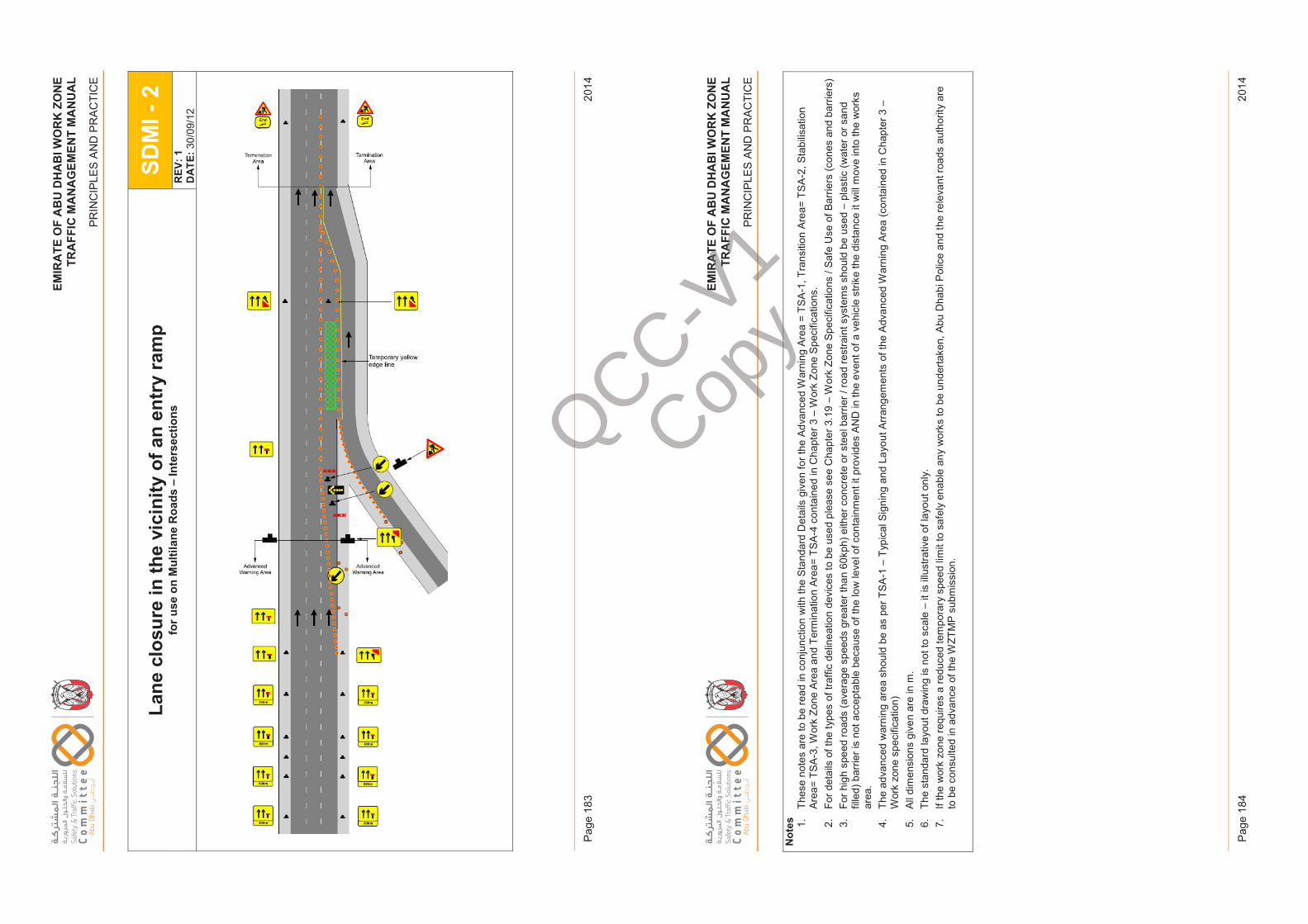
EM
IRA
TE
OF
AB
U D
HA
BI W
OR
K Z
ON
ET
RA
FF
IC M
AN
AG
EM
EN
T M
AN
UA
L
PR
INC
IPLE
S A
ND
PR
AC
TIC
E
2014
Pag
e 18
3
EM
IRA
TE
OF
AB
U D
HA
BI W
OR
K Z
ON
ET
RA
FF
IC M
AN
AG
EM
EN
T M
AN
UA
L
PR
INC
IPLE
S A
ND
PR
AC
TIC
E
2014
Pag
e 18
4
EM
IRAT
EO
FAB
UD
HAB
IWO
RK
ZON
ETR
AFFI
CM
ANAG
EM
ENT
MA
NU
AL
PRIN
CIP
LES
AN
D P
RA
CTI
CE
Lane
clo
sure
in th
e vi
cini
ty o
f an
entr
y ra
mp
for u
se o
n M
ultil
ane
Roa
ds –
Inte
rsec
tions
SDM
I -2
REV
: 1D
ATE:
30/0
9/12
Issu
e 1
Page
183
Febr
uary
201
4
EM
IRAT
EO
FAB
UD
HAB
IWO
RK
ZON
ETR
AFFI
CM
ANAG
EM
ENT
MA
NU
AL
PRIN
CIP
LES
AN
D P
RA
CTI
CE
Not
es 1.Th
ese
note
s ar
e to
be
read
in c
onju
nctio
n w
ith th
e St
anda
rd D
etai
ls g
iven
for t
he A
dvan
ced
War
ning
Are
a =
TSA
-1, T
rans
ition
Are
a= T
SA-2
, Sta
bilis
atio
n Ar
ea=
TSA-
3, W
ork
Zone
Are
a an
d Te
rmin
atio
n Ar
ea=
TSA
-4 c
onta
ined
in C
hapt
er 3
–W
ork
Zone
Spe
cific
atio
ns.
2.Fo
r det
ails
of t
he ty
pes
of tr
affic
del
inea
tion
devi
ces
to b
e us
ed p
leas
e se
e C
hapt
er 3
.19
–W
ork
Zone
Spe
cific
atio
ns /
Safe
Use
of B
arrie
rs (c
ones
and
bar
riers
)3.
For h
igh
spee
d ro
ads
(ave
rage
spe
eds
grea
ter t
han
60kp
h) e
ither
con
cret
e or
ste
el b
arrie
r / ro
ad re
stra
int s
yste
ms
shou
ld b
e us
ed –
plas
tic (w
ater
or s
and
fille
d) b
arrie
r is
not a
ccep
tabl
e be
caus
e of
the
low
leve
l of c
onta
inm
ent i
t pro
vide
s AN
D in
the
even
t of a
veh
icle
stri
ke th
e di
stan
ce it
will
mov
e in
to th
e w
orks
ar
ea.
4.Th
e ad
vanc
ed w
arni
ng a
rea
shou
ld b
e as
per
TSA
-1–
Typi
cal S
igni
ng a
nd L
ayou
t Arr
ange
men
ts o
f the
Adv
ance
d W
arni
ng A
rea
(con
tain
ed in
Cha
pter
3 –
Wor
k zo
ne s
peci
ficat
ion)
5.Al
l dim
ensi
ons
give
n ar
e in
m.
6.Th
e st
anda
rd la
yout
dra
win
g is
not
to s
cale
–it
is il
lust
rativ
e of
layo
ut o
nly.
7.If
the
wor
k zo
ne re
quire
s a
redu
ced
tem
pora
ry s
peed
lim
it to
saf
ely
enab
le a
ny w
orks
to b
e un
derta
ken,
Abu
Dha
bi P
olic
e an
d th
e re
leva
nt ro
ads
auth
ority
are
to
be
cons
ulte
d in
adv
ance
of t
he W
ZTM
P su
bmis
sion
.
Issu
e 1
Page
184
Febr
uary
201
4
QCC-V1
Copy
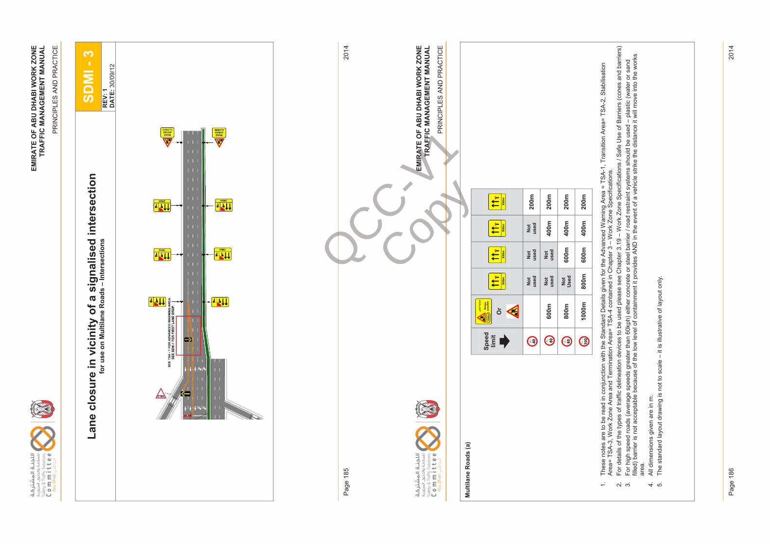
EM
IRA
TE
OF
AB
U D
HA
BI W
OR
K Z
ON
ET
RA
FF
IC M
AN
AG
EM
EN
T M
AN
UA
L
PR
INC
IPLE
S A
ND
PR
AC
TIC
E
2014
Pag
e 18
5
EM
IRA
TE
OF
AB
U D
HA
BI W
OR
K Z
ON
ET
RA
FF
IC M
AN
AG
EM
EN
T M
AN
UA
L
PR
INC
IPLE
S A
ND
PR
AC
TIC
E
2014
Pag
e 18
6
EM
IRAT
EO
FAB
UD
HAB
IWO
RK
ZON
ETR
AFFI
CM
ANAG
EM
ENT
MA
NU
AL
PRIN
CIP
LES
AN
D P
RA
CTI
CE
Lane
clo
sure
in v
icin
ity o
f a s
igna
lised
inte
rsec
tion
for u
se o
n M
ultil
ane
Roa
ds –
Inte
rsec
tions
SDM
I -3
REV
: 1D
ATE:
30/0
9/12
Issu
e 1
Page
185
Febr
uary
201
4
EM
IRAT
EO
FAB
UD
HAB
IWO
RK
ZON
ETR
AFFI
CM
ANAG
EM
ENT
MA
NU
AL
PRIN
CIP
LES
AN
D P
RA
CTI
CE
Mul
tilan
e R
oads
(a)
Spee
d lim
itO
r
Not
us
edN
ot
used
Not
us
ed20
0m
600m
Not
us
edN
ot
used
400m
200m
800m
Not
U
sed
600m
400m
200m
1000
m80
0m60
0m40
0m20
0m
1.Th
ese
note
s ar
e to
be
read
in c
onju
nctio
n w
ith th
e St
anda
rd D
etai
ls g
iven
for t
he A
dvan
ced
War
ning
Are
a =
TSA
-1, T
rans
ition
Are
a= T
SA-2
, Sta
bilis
atio
n Ar
ea=
TSA-
3, W
ork
Zone
Are
a an
d Te
rmin
atio
n Ar
ea=
TSA
-4 c
onta
ined
in C
hapt
er 3
–W
ork
Zone
Spe
cific
atio
ns.
2.Fo
r det
ails
of t
he ty
pes
of tr
affic
del
inea
tion
devi
ces
to b
e us
ed p
leas
e se
e C
hapt
er 3
.19
–W
ork
Zone
Spe
cific
atio
ns /
Safe
Use
of B
arrie
rs (c
ones
and
bar
riers
) 3.
For h
igh
spee
d ro
ads
(ave
rage
spe
eds
grea
ter t
han
60kp
h) e
ither
con
cret
e or
ste
el b
arrie
r / ro
ad re
stra
int s
yste
ms
shou
ld b
e us
ed –
plas
tic (w
ater
or s
and
fille
d) b
arrie
r is
not a
ccep
tabl
e be
caus
e of
the
low
leve
l of c
onta
inm
ent i
t pro
vide
s AN
D in
the
even
t of a
veh
icle
stri
ke th
e di
stan
ce it
will
mov
e in
to th
e w
orks
ar
ea.
4.Al
l dim
ensi
ons
give
nar
e in
m.
5.Th
e st
anda
rd la
yout
dra
win
g is
not
to s
cale
–it
is il
lust
rativ
e of
layo
ut o
nly.
Issu
e 1
Page
186
Febr
uary
201
4
QCC-V1
Copy
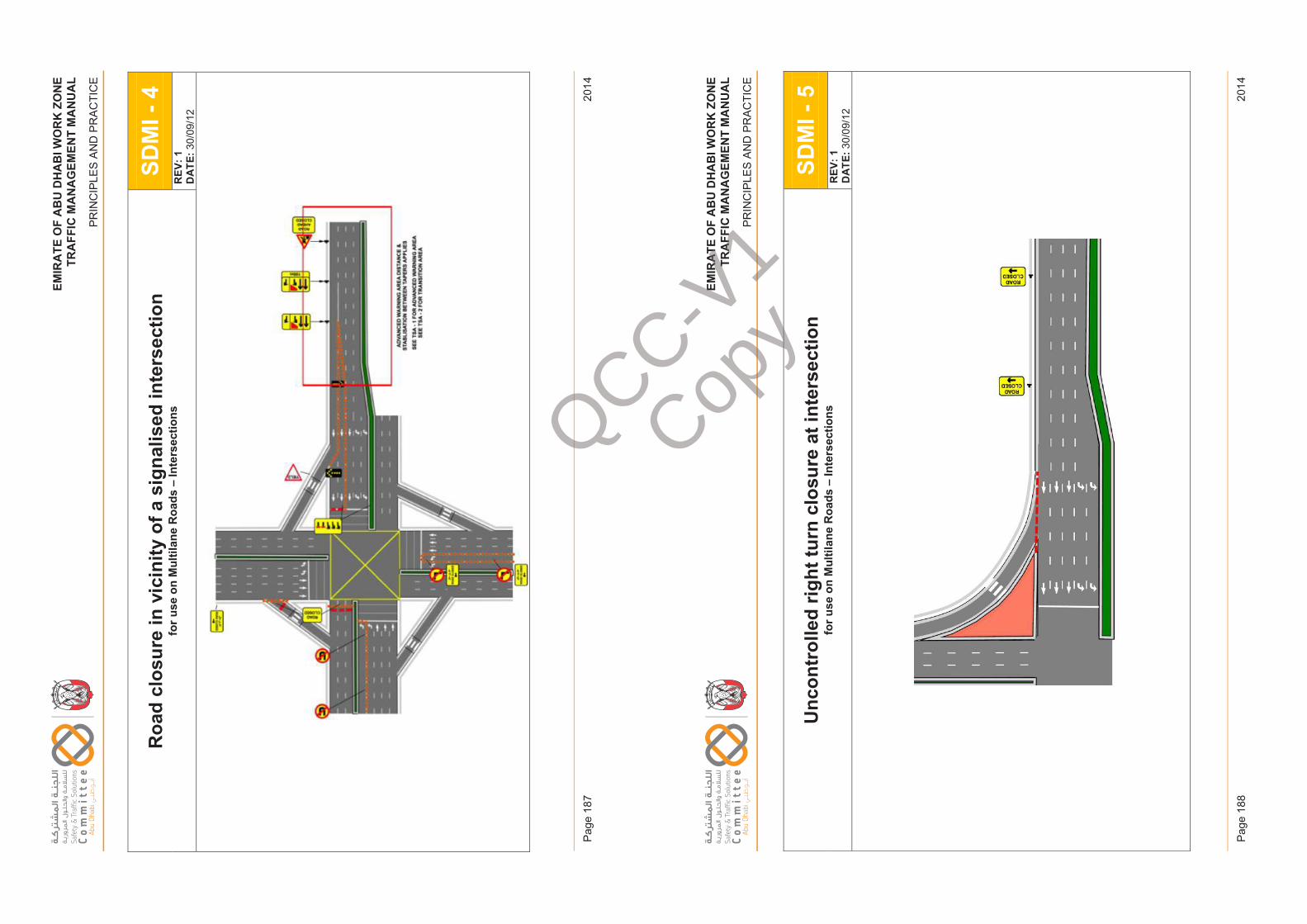
EM
IRA
TE
OF
AB
U D
HA
BI W
OR
K Z
ON
ET
RA
FF
IC M
AN
AG
EM
EN
T M
AN
UA
L
PR
INC
IPLE
S A
ND
PR
AC
TIC
E
2014
Pag
e 18
7
EM
IRA
TE
OF
AB
U D
HA
BI W
OR
K Z
ON
ET
RA
FF
IC M
AN
AG
EM
EN
T M
AN
UA
L
PR
INC
IPLE
S A
ND
PR
AC
TIC
E
2014
Pag
e 18
8
EM
IRAT
EO
FAB
UD
HAB
IWO
RK
ZON
ETR
AFFI
CM
ANAG
EM
ENT
MA
NU
AL
PRIN
CIP
LES
AN
D P
RA
CTI
CE
Roa
d cl
osur
e in
vic
inity
of a
sig
nalis
ed in
ters
ectio
nfo
r use
on
Mul
tilan
e R
oads
–In
ters
ectio
nsSD
MI -
4R
EV: 1
DAT
E:30
/09/
12
Issu
e 1
Page
187
Febr
uary
201
4
EM
IRAT
EO
FAB
UD
HAB
IWO
RK
ZON
ETR
AFFI
CM
ANAG
EM
ENT
MA
NU
AL
PRIN
CIP
LES
AN
D P
RA
CTI
CE
Unc
ontr
olle
d rig
ht tu
rn c
losu
re a
t int
erse
ctio
nfo
r use
on
Mul
tilan
e R
oads
–In
ters
ectio
nsSD
MI -
5R
EV: 1
DAT
E:30
/09/
12
Issu
e 1
Page
188
Febr
uary
201
4
QCC-V1
Copy
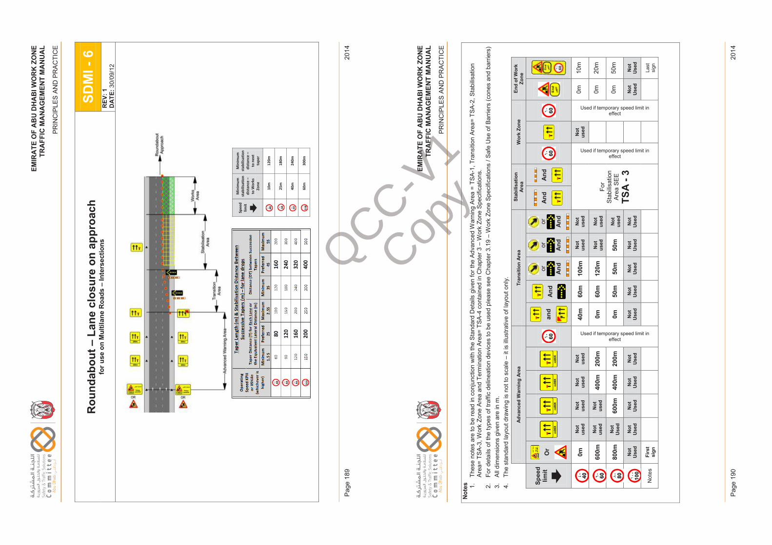
EM
IRA
TE
OF
AB
U D
HA
BI W
OR
K Z
ON
ET
RA
FF
IC M
AN
AG
EM
EN
T M
AN
UA
L
PR
INC
IPLE
S A
ND
PR
AC
TIC
E
2014
Pag
e 18
9
EM
IRA
TE
OF
AB
U D
HA
BI W
OR
K Z
ON
ET
RA
FF
IC M
AN
AG
EM
EN
T M
AN
UA
L
PR
INC
IPLE
S A
ND
PR
AC
TIC
E
2014
Pag
e 19
0
EM
IRAT
EO
FAB
UD
HAB
IWO
RK
ZON
ETR
AFFI
CM
ANAG
EM
ENT
MA
NU
AL
PRIN
CIP
LES
AN
D P
RA
CTI
CE
Rou
ndab
out –
Lane
clo
sure
on
appr
oach
for u
se o
n M
ultil
ane
Roa
ds –
Inte
rsec
tions
SDM
I -6
REV
: 1D
ATE:
30/0
9/12
Spee
d lim
it
Min
imum
st
abili
satio
n di
stan
ce –
to
Wor
ks
Zone
Min
imum
st
abili
satio
n di
stan
ce –
to
nex
t ta
per
10
m
120m
25m
18
0m
40
m
240m
60
m
300m
Issu
e 1
Page
189
Febr
uary
201
4
EM
IRAT
EO
FAB
UD
HAB
IWO
RK
ZON
ETR
AFFI
CM
ANAG
EM
ENT
MA
NU
AL
PRIN
CIP
LES
AN
D P
RA
CTI
CE
Not
es 1.Th
ese
note
s ar
e to
be
read
in c
onju
nctio
n w
ith th
e St
anda
rd D
etai
ls g
iven
for t
he A
dvan
ced
War
ning
Are
a =
TSA
-1, T
rans
ition
Are
a= T
SA-2
, Sta
bilis
atio
n Ar
ea=
TSA-
3, W
ork
Zone
Are
a an
d Te
rmin
atio
n Ar
ea=
TSA
-4 c
onta
ined
in C
hapt
er 3
–W
ork
Zone
Spe
cific
atio
ns.
2.Fo
r det
ails
of t
he ty
pes
of tr
affic
del
inea
tion
devi
ces
to b
e us
ed p
leas
e se
e C
hapt
er 3
.19
–W
ork
Zone
Spe
cific
atio
ns /
Safe
Use
of B
arrie
rs (c
ones
and
bar
riers
)3.
All d
imen
sion
s gi
ven
are
in m
. 4.
The
stan
dard
layo
ut d
raw
ing
is n
ot to
sca
le –
it is
illu
stra
tive
of la
yout
onl
y.
Adva
nced
War
ning
Are
aTr
ansi
tion
Area
Stab
ilisa
tion
Area
Wor
k Zo
neEn
d of
Wor
k Zo
ne
Spee
d lim
itO
r an
d A
nd
or And
or And
or And
And
And
0mN
ot
used
Not
us
edN
ot
used
Not
us
ed
Used if temporary speed limit in effect
40m
60m
100m
Not
us
edN
ot
used
For
Stab
ilisat
ion
Area
SE
E
TSA
-3
Used if temporary speed limit in effect
Not
us
ed
Used if temporary speed limit in effect
0m10
m
600m
Not
us
edN
ot
used
400m
200m
0m60
m12
0mN
ot
used
Not
us
ed0m
20m
800m
Not
U
sed
600m
400m
200m
0m50
m50
m50
mN
ot
used
0m50
m
Not
U
sed
Not
U
sed
Not
U
sed
Not
U
sed
Not
U
sed
Not
U
sed
Not
U
sed
Not
U
sed
Not
U
sed
Not
U
sed
Not
U
sed
Not
U
sed
Not
esFi
rst
sign
Last
si
gn
Issu
e 1
Page
190
Febr
uary
201
4
QCC-V1
Copy
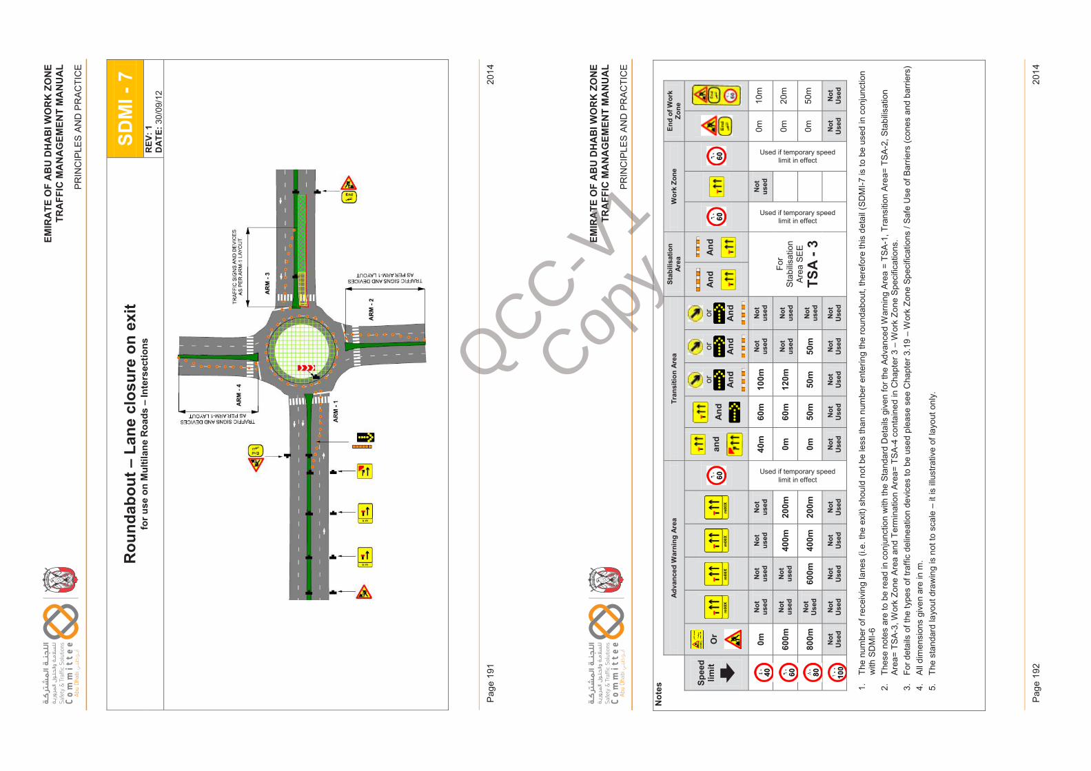
EM
IRA
TE
OF
AB
U D
HA
BI W
OR
K Z
ON
ET
RA
FF
IC M
AN
AG
EM
EN
T M
AN
UA
L
PR
INC
IPLE
S A
ND
PR
AC
TIC
E
2014
Pag
e 19
1
EM
IRA
TE
OF
AB
U D
HA
BI W
OR
K Z
ON
ET
RA
FF
IC M
AN
AG
EM
EN
T M
AN
UA
L
PR
INC
IPLE
S A
ND
PR
AC
TIC
E
2014
Pag
e 19
2
EM
IRAT
EO
FAB
UD
HAB
IWO
RK
ZON
ETR
AFFI
CM
ANAG
EM
ENT
MA
NU
AL
PRIN
CIP
LES
AN
D P
RA
CTI
CE
Rou
ndab
out –
Lane
clo
sure
on
exit
for u
se o
n M
ultil
ane
Roa
ds –
Inte
rsec
tions
SDM
I -7
REV
: 1D
ATE:
30/0
9/12
Issu
e 1
Page
191
Febr
uary
201
4
EM
IRAT
EO
FAB
UD
HAB
IWO
RK
ZON
ETR
AFFI
CM
ANAG
EM
ENT
MA
NU
AL
PRIN
CIP
LES
AN
D P
RA
CTI
CE
Not
es
Adva
nced
War
ning
Are
aTr
ansi
tion
Area
Stab
ilisa
tion
Area
Wor
k Zo
neEn
d of
Wor
k Zo
ne
Spee
d lim
itO
r an
d A
nd
or And
or And
or And
And
And
0mN
ot
used
Not
us
edN
ot
used
Not
us
ed
Used if temporary speed limit in effect
40m
60m
100m
Not
us
edN
ot
used
For
Stab
ilisat
ion
Area
SE
E
TSA
-3
Used if temporary speed limit in effect
Not
us
ed
Used if temporary speed limit in effect
0m10
m
600m
Not
us
edN
ot
used
400m
200m
0m60
m12
0mN
ot
used
Not
us
ed0m
20m
800m
Not
U
sed
600m
400m
200m
0m50
m50
m50
mN
ot
used
0m50
m
Not
U
sed
Not
U
sed
Not
U
sed
Not
U
sed
Not
U
sed
Not
U
sed
Not
U
sed
Not
U
sed
Not
U
sed
Not
U
sed
Not
U
sed
Not
U
sed
1.Th
e nu
mbe
r of r
ecei
ving
lane
s (i.
e. th
e ex
it) s
houl
d no
t be
less
than
num
ber e
nter
ing
the
roun
dabo
ut, t
here
fore
this
det
ail (
SDM
I-7 is
to b
e us
ed in
con
junc
tion
with
SD
MI-6
2.Th
ese
note
s ar
e to
be
read
in c
onju
nctio
n w
ith th
e St
anda
rd D
etai
ls g
iven
for t
he A
dvan
ced
War
ning
Are
a =
TSA
-1, T
rans
ition
Are
a= T
SA-2
, Sta
bilis
atio
n Ar
ea=
TSA-
3, W
ork
Zone
Are
a an
d Te
rmin
atio
n Ar
ea=
TSA
-4 c
onta
ined
in C
hapt
er 3
–W
ork
Zone
Spe
cific
atio
ns.
3.Fo
r det
ails
of t
he ty
pes
of tr
affic
del
inea
tion
devi
ces
to b
e us
ed p
leas
e se
e C
hapt
er 3
.19
–W
ork
Zone
Spe
cific
atio
ns /
Safe
Use
of B
arrie
rs (c
ones
and
bar
riers
)4.
All d
imen
sion
s gi
ven
are
in m
. 5.
The
stan
dard
layo
ut d
raw
ing
is n
ot to
sca
le –
it is
illu
stra
tive
of la
yout
onl
y.
Issu
e 1
Page
192
Febr
uary
201
4
QCC-V1
Copy
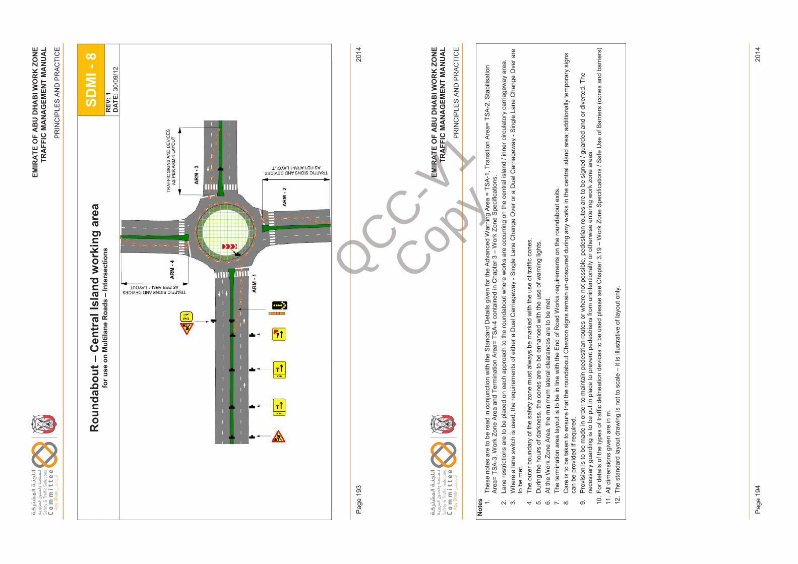
EM
IRA
TE
OF
AB
U D
HA
BI W
OR
K Z
ON
ET
RA
FF
IC M
AN
AG
EM
EN
T M
AN
UA
L
PR
INC
IPLE
S A
ND
PR
AC
TIC
E
2014
Pag
e 19
3
EM
IRA
TE
OF
AB
U D
HA
BI W
OR
K Z
ON
ET
RA
FF
IC M
AN
AG
EM
EN
T M
AN
UA
L
PR
INC
IPLE
S A
ND
PR
AC
TIC
E
2014
Pag
e 19
4
EM
IRAT
EO
FAB
UD
HAB
IWO
RK
ZON
ETR
AFFI
CM
ANAG
EM
ENT
MA
NU
AL
PRIN
CIP
LES
AN
D P
RA
CTI
CE
Rou
ndab
out –
Cen
tral
Isla
nd w
orki
ng a
rea
for u
se o
n M
ultil
ane
Roa
ds –
Inte
rsec
tions
SDM
I -8
REV
: 1D
ATE:
30/0
9/12
Issu
e 1
Page
193
Febr
uary
201
4
EM
IRAT
EO
FAB
UD
HAB
IWO
RK
ZON
ETR
AFFI
CM
ANAG
EM
ENT
MA
NU
AL
PRIN
CIP
LES
AN
D P
RA
CTI
CE
Not
es 1.Th
ese
note
s ar
e to
be
read
in c
onju
nctio
n w
ith th
e St
anda
rd D
etai
ls g
iven
for t
he A
dvan
ced
War
ning
Are
a =
TSA
-1, T
rans
ition
Are
a= T
SA-2
, Sta
bilis
atio
n Ar
ea=
TSA-
3, W
ork
Zone
Are
a an
d Te
rmin
atio
n Ar
ea=
TSA
-4 c
onta
ined
in C
hapt
er 3
–W
ork
Zone
Spe
cific
atio
ns.
2.La
ne re
stric
tions
are
to b
e pl
aced
on
each
app
roac
h to
the
roun
dabo
ut w
here
wor
ks a
re o
ccur
ring
on th
e ce
ntra
l isl
and
/ inn
er c
ircul
ator
y ca
rria
gew
ay a
rea.
3.W
here
a la
ne s
witc
h is
use
d, th
e re
quire
men
ts o
f eith
er a
Dua
l Car
riage
way
-S
ingl
e La
ne C
hang
e O
ver o
r a D
ual C
arria
gew
ay -
Sin
gle
Lane
Cha
nge
Ove
r are
to
be
met
. 4.
The
oute
r bou
ndar
y of
the
safe
ty z
one
mus
t alw
ays
be m
arke
dw
ith th
e us
e of
traf
fic c
ones
.5.
Dur
ing
the
hour
s of
dar
knes
s, th
e co
nes
are
to b
e en
hanc
ed w
ith th
e us
e of
war
ning
ligh
ts.
6.At
the
Wor
k Zo
ne A
rea,
the
min
imum
late
ral c
lear
ance
s ar
e to
be
met
. 7.
The
term
inat
ion
area
layo
ut is
to b
e in
line
with
the
End
of R
oad
Wor
ks re
quire
men
ts o
n th
e ro
unda
bout
exi
ts.
8.C
are
is to
be
take
n to
ens
ure
that
the
roun
dabo
ut C
hevr
on s
igns
rem
ain
un-o
bscu
red
durin
g an
y w
orks
in th
e ce
ntra
l isl
and
area
; add
ition
ally
tem
pora
ry s
igns
ca
n be
pro
vide
d if
requ
ired.
9.
Prov
isio
n is
to b
e m
ade
in o
rder
to m
aint
ain
pede
stria
n ro
utes
or w
here
not
pos
sibl
e, p
edes
trian
rout
es a
re to
be
sign
ed /
guar
ded
and
or d
iver
ted.
The
nece
ssar
y gu
ardi
ng is
to b
e pu
t in
plac
e to
pre
vent
ped
estri
ans
from
uni
nten
tiona
lly o
r oth
erw
ise
ente
ring
wor
k zo
ne a
reas
. 10
.Fo
r det
ails
of t
he ty
pes
of tr
affic
del
inea
tion
devi
ces
to b
e us
ed p
leas
e se
e C
hapt
er 3
.19
–W
ork
Zone
Spe
cific
atio
ns /
Safe
Use
of B
arrie
rs (c
ones
and
bar
riers
)11
.Al
l dim
ensi
ons
give
n ar
e in
m.
12.
The
stan
dard
layo
ut d
raw
ing
is n
ot to
sca
le –
it is
illu
stra
tive
of la
yout
onl
y.
Issu
e 1
Page
194
Febr
uary
201
4
QCC-V1
Copy
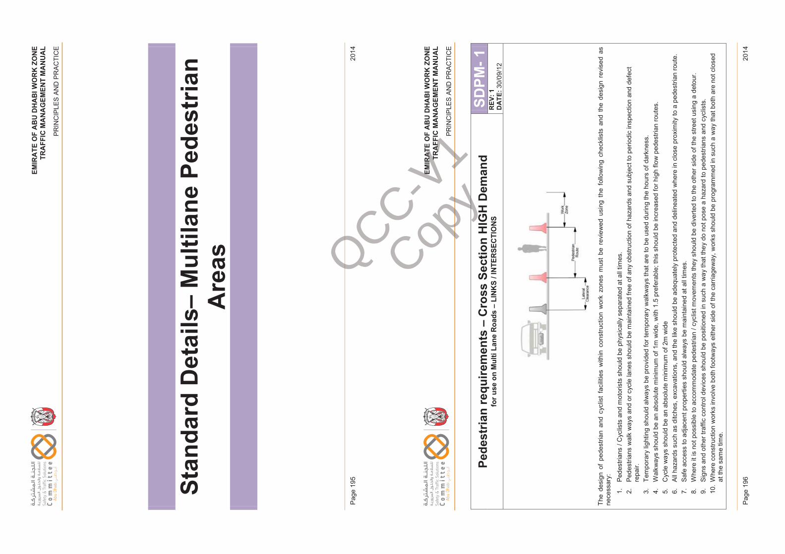
EM
IRA
TE
OF
AB
U D
HA
BI W
OR
K Z
ON
ET
RA
FF
IC M
AN
AG
EM
EN
T M
AN
UA
L
PR
INC
IPLE
S A
ND
PR
AC
TIC
E
2014
Pag
e 19
5
EM
IRA
TE
OF
AB
U D
HA
BI W
OR
K Z
ON
ET
RA
FF
IC M
AN
AG
EM
EN
T M
AN
UA
L
PR
INC
IPLE
S A
ND
PR
AC
TIC
E
2014
Pag
e 19
6
EM
IRAT
EO
FAB
UD
HAB
IWO
RK
ZON
ETR
AFFI
CM
ANAG
EM
ENT
MA
NU
AL
PRIN
CIP
LES
AN
D P
RA
CTI
CE
Stan
dard
Det
ails
–M
ultil
ane
Pede
stria
n A
reas
Issu
e 1
Page
195
Febr
uary
201
4
EM
IRAT
EO
FAB
UD
HAB
IWO
RK
ZON
ETR
AFFI
CM
ANAG
EM
ENT
MA
NU
AL
PRIN
CIP
LES
AN
D P
RA
CTI
CE
Pede
stria
n re
quire
men
ts –
Cro
ss S
ectio
n H
IGH
Dem
and
for u
se o
n M
ulti
Lane
Roa
ds –
LIN
KS
/ IN
TER
SEC
TIO
NS
SDPM
-1R
EV: 1
DAT
E:30
/09/
12
The
desi
gn o
f pe
dest
rian
and
cycl
ist
faci
litie
s w
ithin
con
stru
ctio
n w
ork
zone
s m
ust
be r
evie
wed
usi
ng t
he f
ollo
win
g ch
eckl
ists
and
the
des
ign
revi
sed
as
nece
ssar
y:
1.Pe
dest
rians
/ C
yclis
ts a
nd m
otor
ists
sho
uld
be p
hysi
cally
sep
arat
ed a
t all
times
.2.
Pede
stria
ns w
alk
way
s an
d or
cyc
le la
nes
shou
ld b
e m
aint
aine
d fre
e of
any
obs
truct
ion
of h
azar
ds a
nd s
ubje
ct to
per
iodi
c in
spec
tion
and
defe
ct
repa
ir.
3.Te
mpo
rary
ligh
ting
shou
ld a
lway
s be
pro
vide
d fo
r tem
pora
ry w
alkw
ays
that
are
to b
e us
ed d
urin
g th
e ho
urs
of d
arkn
ess.
4.
Wal
kway
s sh
ould
be
an a
bsol
ute
min
imum
of 1
m w
ide,
with
1.5
pre
fera
ble;
this
sho
uld
be in
crea
sed
for h
igh
flow
ped
estri
an ro
utes
. 5.
Cyc
lew
ays
shou
ld b
e an
abs
olut
e m
inim
um o
f 2m
wid
e 6.
All h
azar
ds s
uch
as d
itche
s, e
xcav
atio
ns, a
nd th
e lik
e sh
ould
be
adeq
uate
ly p
rote
cted
and
del
inea
ted
whe
re in
clo
se p
roxi
mity
to a
ped
estri
an ro
ute.
7.
Safe
acc
ess
to a
djac
ent p
rope
rties
sho
uld
alw
ays
be m
aint
aine
d at
all
times
. 8.
Whe
re it
is n
ot p
ossi
ble
to a
ccom
mod
ate
pede
stria
n / c
yclis
t mov
emen
ts th
ey s
houl
d be
div
erte
d to
the
othe
r sid
e of
the
stre
et u
sing
a d
etou
r. 9.
Sign
s an
d ot
her t
raffi
c co
ntro
l dev
ices
sho
uld
be p
ositi
oned
in s
uch
a w
ay th
at th
ey d
o no
t pos
e a
haza
rd to
ped
estri
ans
and
cycl
ists
. 10
.W
here
con
stru
ctio
n w
orks
invo
lve
both
foot
way
s ei
ther
sid
e of
the
carr
iage
way
, wor
ks s
houl
d be
pro
gram
med
in s
uch
a w
ay th
at b
oth
are
not c
lose
d at
the
sam
e tim
e.
Issu
e 1
Page
196
Febr
uary
201
4
QCC-V1
Copy
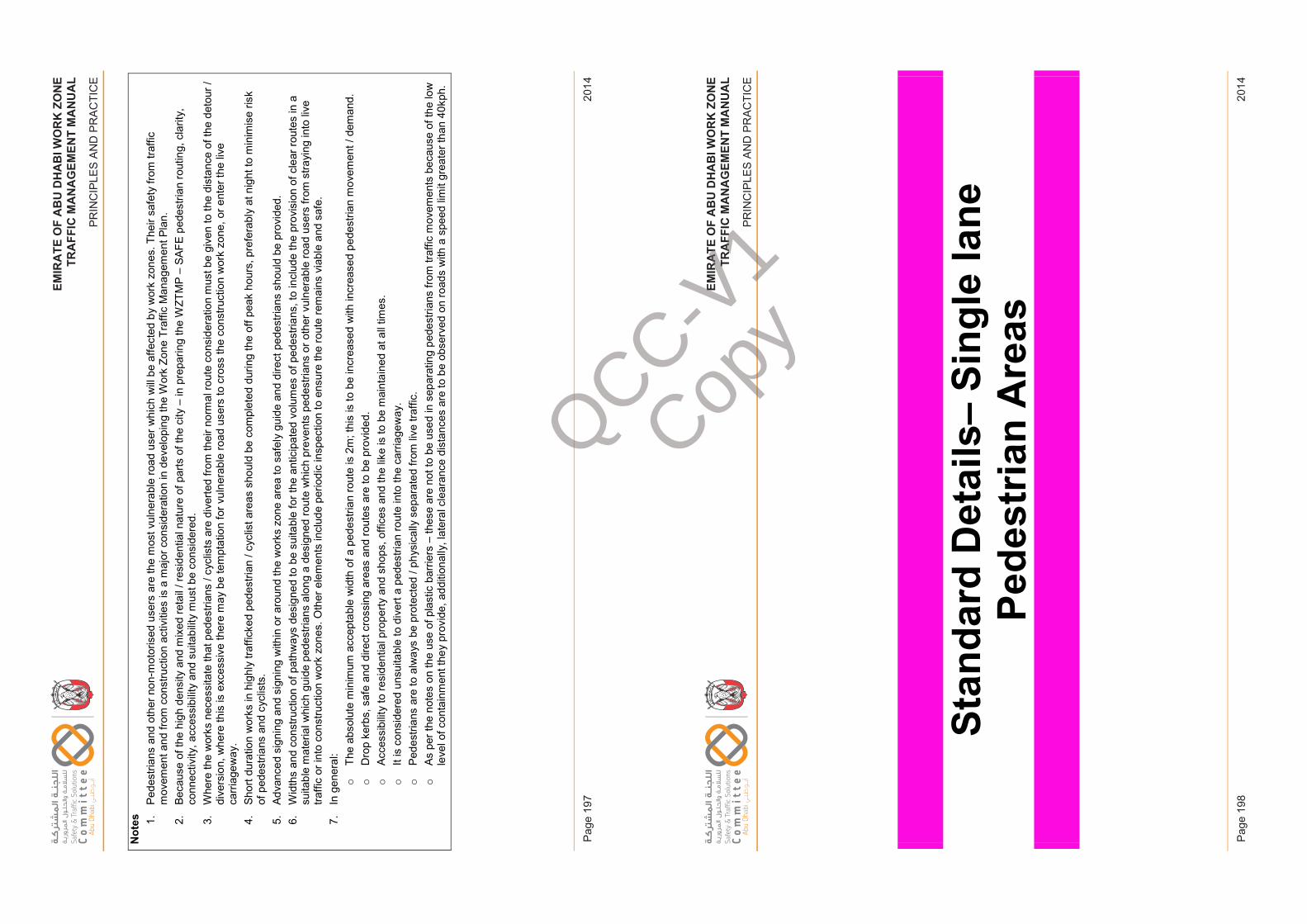
EM
IRA
TE
OF
AB
U D
HA
BI W
OR
K Z
ON
ET
RA
FF
IC M
AN
AG
EM
EN
T M
AN
UA
L
PR
INC
IPLE
S A
ND
PR
AC
TIC
E
2014
Pag
e 19
7
EM
IRA
TE
OF
AB
U D
HA
BI W
OR
K Z
ON
ET
RA
FF
IC M
AN
AG
EM
EN
T M
AN
UA
L
PR
INC
IPLE
S A
ND
PR
AC
TIC
E
2014
Pag
e 19
8
EM
IRAT
EO
FAB
UD
HAB
IWO
RK
ZON
ETR
AFFI
CM
ANAG
EM
ENT
MA
NU
AL
PRIN
CIP
LES
AN
D P
RA
CTI
CE
Not
es 1.Pe
dest
rians
and
oth
er n
on-m
otor
ised
use
rs a
re th
e m
ost v
ulne
rabl
e ro
ad u
ser w
hich
will
be a
ffect
ed b
y w
ork
zone
s.Th
eir s
afet
y fro
m tr
affic
m
ovem
ent a
nd fr
om c
onst
ruct
ion
activ
ities
is a
maj
or c
onsi
dera
tion
in d
evel
opin
g th
e W
ork
Zone
Tra
ffic
Man
agem
ent P
lan.
2.
Beca
use
of th
e hi
gh d
ensi
ty a
nd m
ixed
reta
il / r
esid
entia
l nat
ure
of p
arts
of t
he c
ity –
in p
repa
ring
the
WZT
MP
–SA
FE p
edes
trian
rout
ing,
cla
rity,
co
nnec
tivity
, acc
essi
bilit
y an
d su
itabi
lity
mus
t be
cons
ider
ed.
3.W
here
the
wor
ks n
eces
sita
te th
at p
edes
trian
s / c
yclis
ts a
re d
iver
ted
from
thei
r nor
mal
rout
e co
nsid
erat
ion
mus
t be
give
n to
the
dist
ance
of t
he d
etou
r /di
vers
ion,
whe
re th
is is
exc
essi
ve th
ere
may
be
tem
ptat
ion
for v
ulne
rabl
e ro
ad u
sers
to c
ross
the
cons
truct
ion
wor
k zo
ne, o
r ent
er th
e liv
e ca
rria
gew
ay.
4.Sh
ort d
urat
ion
wor
ks in
hig
hly
traffi
cked
ped
estri
an /
cycl
ist a
reas
sho
uld
be c
ompl
eted
dur
ing
the
off p
eak
hour
s, p
refe
rabl
y at
nig
ht to
min
imis
e ris
kof
ped
estri
ans
and
cycl
ists
. 5.
Adva
nced
sig
ning
and
sig
ning
with
in o
r aro
und
the
wor
ks z
one
area
to s
afel
y gu
ide
and
dire
ct p
edes
trian
s sh
ould
be
prov
ided
. 6.
Wid
ths
and
cons
truct
ion
of p
athw
ays
desi
gned
tobe
sui
tabl
e fo
r the
ant
icip
ated
vol
umes
of p
edes
trian
s, to
incl
ude
the
prov
isio
n of
cle
ar ro
utes
in a
su
itabl
e m
ater
ial w
hich
gui
de p
edes
trian
s al
ong
a de
sign
ed ro
ute
whi
ch p
reve
nts
pede
stria
ns o
r oth
er v
ulne
rabl
e ro
ad u
sers
from
stra
ying
into
live
tra
ffic
or in
to c
onst
ruct
ion
wor
k zo
nes.
Oth
er e
lem
ents
incl
ude
perio
dic
insp
ectio
n to
ens
ure
the
rout
e re
mai
ns v
iabl
e an
d sa
fe.
7.In
gen
eral
:o
The
abso
lute
min
imum
acc
epta
ble
wid
th o
f a p
edes
trian
rout
e is
2m
; thi
s is
to b
e in
crea
sed
with
incr
ease
d pe
dest
rian
mov
emen
t/ d
eman
d.
oD
rop
kerb
s, s
afe
and
dire
ct c
ross
ing
area
s an
d ro
utes
are
to b
e pr
ovid
ed.
oAc
cess
ibilit
y to
resi
dent
ial p
rope
rty a
nd s
hops
, offi
ces
and
the
like
is to
be
mai
ntai
ned
at a
ll tim
es.
oIt
is c
onsi
dere
d un
suita
ble
to d
iver
t a p
edes
trian
rout
e in
to th
e ca
rria
gew
ay.
oPe
dest
rians
are
to a
lway
s be
pro
tect
ed /
phys
ical
ly s
epar
ated
from
live
traf
fic.
oAs
per
the
note
s on
the
use
of p
last
ic b
arrie
rs –
thes
e ar
e no
t to
be u
sed
in s
epar
atin
g pe
dest
rians
from
traf
fic m
ovem
ents
bec
ause
of t
he lo
w
leve
l of c
onta
inm
ent t
hey
prov
ide,
add
ition
ally
, lat
eral
cle
aran
ce d
ista
nces
are
to b
e ob
serv
ed o
n ro
ads
with
a s
peed
lim
it gr
eate
r tha
n 40
kph.
Issu
e 1
Page
197
Febr
uary
201
4
EM
IRAT
EO
FAB
UD
HAB
IWO
RK
ZON
ETR
AFFI
CM
ANAG
EM
ENT
MA
NU
AL
PRIN
CIP
LES
AN
D P
RA
CTI
CE
Stan
dard
Det
ails
–Si
ngle
lane
Pe
dest
rian
Are
as
Issu
e 1
Page
198
Febr
uary
201
4
QCC-V1
Copy
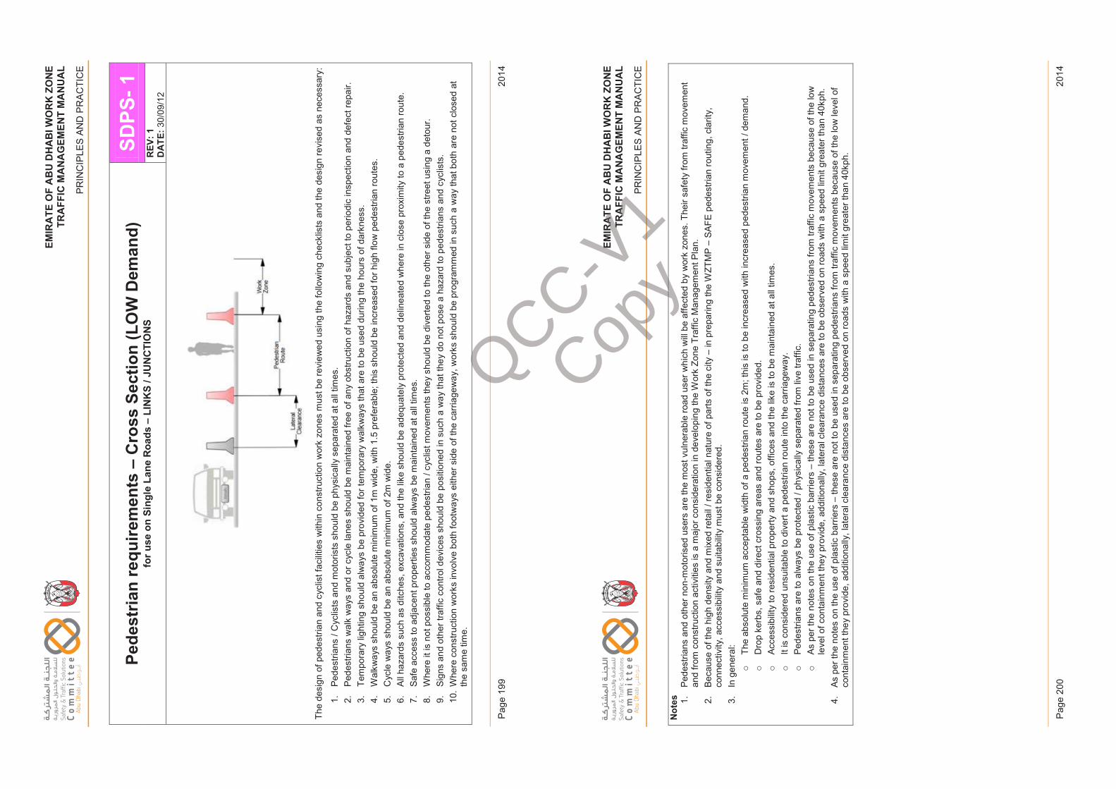
EM
IRA
TE
OF
AB
U D
HA
BI W
OR
K Z
ON
ET
RA
FF
IC M
AN
AG
EM
EN
T M
AN
UA
L
PR
INC
IPLE
S A
ND
PR
AC
TIC
E
2014
Pag
e 19
9
EM
IRA
TE
OF
AB
U D
HA
BI W
OR
K Z
ON
ET
RA
FF
IC M
AN
AG
EM
EN
T M
AN
UA
L
PR
INC
IPLE
S A
ND
PR
AC
TIC
E
2014
Pag
e 20
0
EM
IRAT
EO
FAB
UD
HAB
IWO
RK
ZON
ETR
AFFI
CM
ANAG
EM
ENT
MA
NU
AL
PRIN
CIP
LES
AN
D P
RA
CTI
CE
Pede
stria
n re
quire
men
ts –
Cro
ss S
ectio
n (L
OW
Dem
and)
for u
se o
n Si
ngle
Lan
e R
oads
–LI
NK
S / J
UN
CTI
ON
SSD
PS-1
REV
: 1D
ATE:
30/0
9/12
The
desi
gn o
f ped
estri
an a
nd c
yclis
tfac
ilitie
s w
ithin
con
stru
ctio
n w
ork
zone
s m
ust b
e re
view
ed u
sing
the
follo
win
g ch
eckl
ists
and
the
desi
gn re
vise
d as
nec
essa
ry:
1.Pe
dest
rians
/ C
yclis
ts a
nd m
otor
ists
sho
uld
be p
hysi
cally
sep
arat
ed a
t all
times
.2.
Pede
stria
ns w
alk
way
s an
d or
cyc
le la
nes
shou
ld b
e m
aint
aine
d fre
e of
any
obs
truct
ion
of h
azar
ds a
nd s
ubje
ct to
per
iodi
c in
spec
tion
and
defe
ct re
pair.
3.
Tem
pora
ry li
ghtin
g sh
ould
alw
ays
be p
rovi
ded
for t
empo
rary
wal
kway
s th
at a
re to
be
used
dur
ing
the
hour
sof
dar
knes
s.
4.W
alkw
ays
shou
ld b
e an
abs
olut
e m
inim
um o
f 1m
wid
e, w
ith 1
.5 p
refe
rabl
e; th
is s
houl
d be
incr
ease
d fo
r hig
h flo
w p
edes
trian
rout
es.
5.C
ycle
way
s sh
ould
be
an a
bsol
ute
min
imum
of 2
m w
ide.
6.Al
l haz
ards
suc
h as
ditc
hes,
exc
avat
ions
, and
the
like
shou
ld b
e ad
equa
tely
pro
tect
ed a
nd d
elin
eate
d w
here
in c
lose
pro
xim
ityto
a p
edes
trian
rout
e.
7.Sa
fe a
cces
s to
adj
acen
t pro
perti
es s
houl
d al
way
s be
mai
ntai
ned
at a
ll tim
es.
8.W
here
it is
not
pos
sibl
e to
acc
omm
odat
e pe
dest
rian
/ cyc
list m
ovem
ents
they
sho
uld
be d
iver
ted
to th
e ot
her s
ide
of th
e st
reet
usi
ng a
det
our.
9.Si
gns
and
othe
r tra
ffic
cont
rol d
evic
es s
houl
d be
pos
ition
ed in
suc
h a
way
that
they
do
not p
ose
a ha
zard
to p
edes
trian
s an
d cy
clis
ts.
10.
Whe
re c
onst
ruct
ion
wor
ks in
volv
e bo
th fo
otw
ays
eith
er s
ide
of th
e ca
rria
gew
ay, w
orks
sho
uld
be p
rogr
amm
ed in
suc
h a
way
that
bot
har
e no
t clo
sed
at
the
sam
e tim
e.
Issu
e 1
Page
199
Febr
uary
201
4
EM
IRAT
EO
FAB
UD
HAB
IWO
RK
ZON
ETR
AFFI
CM
ANAG
EM
ENT
MA
NU
AL
PRIN
CIP
LES
AN
D P
RA
CTI
CE
Not
es 1.Pe
dest
rians
and
oth
er n
on-m
otor
ised
use
rs a
re th
e m
ost v
ulne
rabl
e ro
ad u
ser w
hich
will
beaf
fect
ed b
y w
ork
zone
s.Th
eir s
afet
y fro
m tr
affic
mov
emen
t an
d fro
m c
onst
ruct
ion
activ
ities
is a
maj
or c
onsi
dera
tion
in d
evel
opin
g th
e W
ork
Zone
Tra
ffic
Man
agem
ent P
lan.
2.
Beca
use
of th
e hi
gh d
ensi
ty a
nd m
ixed
reta
il / r
esid
entia
l nat
ure
of p
arts
of t
he c
ity –
in p
repa
ring
the
WZT
MP
–SA
FE p
edes
trian
rout
ing,
cla
rity,
co
nnec
tivity
, acc
essi
bilit
y an
d su
itabi
lity
mus
t be
cons
ider
ed.
3.In
gen
eral
:o
The
abso
lute
min
imum
acc
epta
ble
wid
th o
f a p
edes
trian
rout
e is
2m
; thi
s is
to b
e in
crea
sed
with
incr
ease
d pe
dest
rian
mov
emen
t/ d
eman
d.
oD
rop
kerb
s, s
afe
and
dire
ct c
ross
ing
area
s an
d ro
utes
are
to b
e pr
ovid
ed.
oAc
cess
ibilit
y to
resi
dent
ial p
rope
rty a
nd s
hops
, offi
ces
and
the
like
is to
be
mai
ntai
ned
at a
ll tim
es.
oIt
is c
onsi
dere
d un
suita
ble
to d
iver
t a p
edes
trian
rout
e in
to th
e ca
rria
gew
ay.
oPe
dest
rians
are
to a
lway
s be
pro
tect
ed /
phys
ical
ly s
epar
ated
from
live
traf
fic.
oAs
per
the
note
s on
the
use
of p
last
ic b
arrie
rs –
thes
e ar
e no
t to
be u
sed
in s
epar
atin
g pe
dest
rians
from
traf
fic m
ovem
ents
bec
ause
of t
he lo
w
leve
l of c
onta
inm
ent t
hey
prov
ide,
add
ition
ally
, lat
eral
cle
aran
ce d
ista
nces
are
to b
e ob
serv
ed o
n ro
ads
with
a s
peed
lim
it gr
eate
r tha
n 40
kph.
4.As
per
the
note
s on
the
use
of p
last
ic b
arrie
rs –
thes
e ar
e no
t to
be u
sed
in s
epar
atin
g pe
dest
rians
from
traf
fic m
ovem
ents
bec
ause
of t
he lo
w le
vel o
f co
ntai
nmen
t the
y pr
ovid
e, a
dditi
onal
ly, l
ater
al c
lear
ance
dis
tanc
es a
re to
be
obse
rved
on
road
s w
ith a
spee
d lim
it gr
eate
r tha
n 40
kph.
Issu
e 1
Page
200
Febr
uary
201
4
QCC-V1
Copy
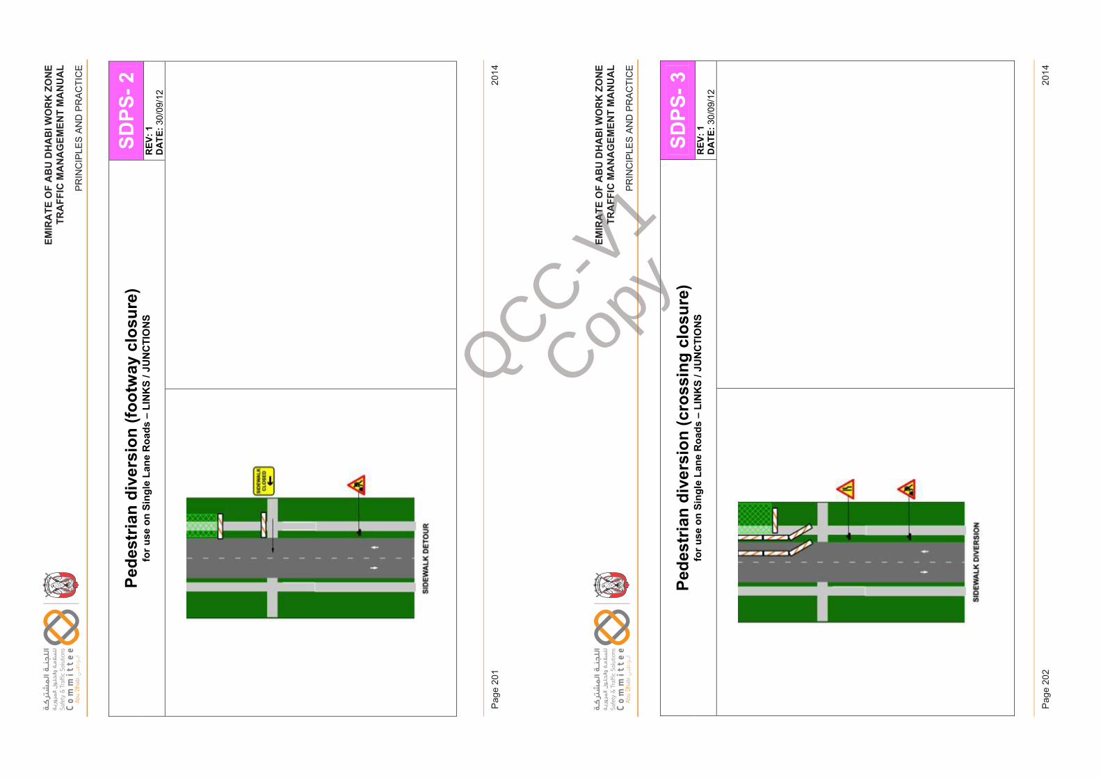
EM
IRA
TE
OF
AB
U D
HA
BI W
OR
K Z
ON
ET
RA
FF
IC M
AN
AG
EM
EN
T M
AN
UA
L
PR
INC
IPLE
S A
ND
PR
AC
TIC
E
2014
Pag
e 20
1
EM
IRA
TE
OF
AB
U D
HA
BI W
OR
K Z
ON
ET
RA
FF
IC M
AN
AG
EM
EN
T M
AN
UA
L
PR
INC
IPLE
S A
ND
PR
AC
TIC
E
2014
Pag
e 20
2
EM
IRAT
EO
FAB
UD
HAB
IWO
RK
ZON
ETR
AFFI
CM
ANAG
EM
ENT
MA
NU
AL
PRIN
CIP
LES
AN
D P
RA
CTI
CE
Pede
stria
n di
vers
ion
(foot
way
clo
sure
)fo
r use
on
Sing
le L
ane
Roa
ds –
LIN
KS
/ JU
NC
TIO
NS
SDPS
-2R
EV: 1
DAT
E:30
/09/
12
Issu
e 1
Page
201
Febr
uary
201
4
EM
IRAT
EO
FAB
UD
HAB
IWO
RK
ZON
ETR
AFFI
CM
ANAG
EM
ENT
MA
NU
AL
PRIN
CIP
LES
AN
D P
RA
CTI
CE
Pede
stria
n di
vers
ion
(cro
ssin
g cl
osur
e)fo
r use
on
Sing
le L
ane
Roa
ds –
LIN
KS
/ JU
NC
TIO
NS
SDPS
-3R
EV: 1
DAT
E:30
/09/
12
Issu
e 1
Page
202
Febr
uary
201
4
QCC-V1
Copy
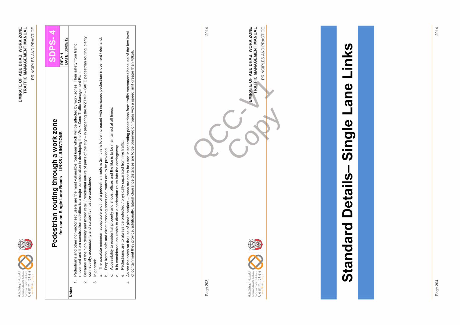
EM
IRA
TE
OF
AB
U D
HA
BI W
OR
K Z
ON
ET
RA
FF
IC M
AN
AG
EM
EN
T M
AN
UA
L
PR
INC
IPLE
S A
ND
PR
AC
TIC
E
2014
Pag
e 20
3
EM
IRA
TE
OF
AB
U D
HA
BI W
OR
K Z
ON
ET
RA
FF
IC M
AN
AG
EM
EN
T M
AN
UA
L
PR
INC
IPLE
S A
ND
PR
AC
TIC
E
2014
Pag
e 20
4
EM
IRAT
EO
FAB
UD
HAB
IWO
RK
ZON
ETR
AFFI
CM
ANAG
EM
ENT
MA
NU
AL
PRIN
CIP
LES
AN
D P
RA
CTI
CE
Pede
stria
n ro
utin
g th
roug
h a
wor
k zo
nefo
r use
on
Sing
le L
ane
Roa
ds –
LIN
KS
/ JU
NC
TIO
NS
SDPS
-4R
EV: 1
DAT
E:30
/09/
12N
otes
1.Pe
dest
rians
and
oth
er n
on-m
otor
ised
use
rs a
re th
e m
ost v
ulne
rabl
e ro
ad u
ser w
hich
will
be a
ffect
ed b
y w
ork
zone
s.Th
eir s
afet
y fro
m tr
affic
mov
emen
t and
from
con
stru
ctio
n ac
tiviti
es is
a m
ajor
con
side
ratio
n in
dev
elop
ing
the
Wor
k Zo
ne T
raffi
c M
anag
emen
t Pla
n.2.
Beca
use
of th
e hi
gh d
ensi
ty a
nd m
ixed
reta
il / r
esid
entia
l nat
ure
of p
arts
of t
he c
ity–
in p
repa
ring
the
WZT
MP
–SA
FE p
edes
trian
rout
ing,
cla
rity,
conn
ectiv
ity, a
cces
sibi
lity
and
suita
bilit
y m
ust b
e co
nsid
ered
.3.
In g
ener
al:
a.Th
e ab
solu
te m
inim
um a
ccep
tabl
e w
idth
of a
ped
estri
an ro
ute
is 2
m; t
his
is to
be
incr
ease
d w
ith in
crea
sed
pede
stria
n m
ovem
ent/
dem
and.
b.D
rop
kerb
s, s
afe
and
dire
ct c
ross
ing
area
s an
d ro
utes
are
to b
e pr
ovid
ed.
c.Ac
cess
ibilit
y to
resi
dent
ial p
rope
rty a
nd s
hops
, offi
ces
and
the
like
is to
be
mai
ntai
ned
at a
ll tim
es.
d.It
is c
onsi
dere
d un
suita
ble
to d
iver
t a p
edes
trian
rout
e in
to th
e ca
rria
gew
ay.
e.Pe
dest
rians
are
to a
lway
s be
pro
tect
ed /
phys
ical
ly s
epar
ated
from
live
traf
fic.
4.As
per
the
note
s on
the
use
of p
last
ic b
arrie
rs –
thes
e ar
e no
t to
be u
sed
in s
epar
atin
g pe
dest
rians
from
traf
fic m
ovem
ents
bec
ause
of t
he lo
w le
vel
of c
onta
inm
ent t
hey
prov
ide,
add
ition
ally
, lat
eral
cle
aran
ce d
ista
nces
are
to b
e ob
serv
ed o
n ro
ads
with
a s
peed
lim
it gr
eate
rtha
n 40
kph.
Issu
e 1
Page
203
Febr
uary
2014
EM
IRAT
EO
FAB
UD
HAB
IWO
RK
ZON
ETR
AFFI
CM
ANAG
EM
ENT
MA
NU
AL
PRIN
CIP
LES
AN
D P
RA
CTI
CE
Stan
dard
Det
ails
–Si
ngle
Lan
e Li
nks
Issu
e 1
Page
204
Febr
uary
2014
QCC-V1
Copy
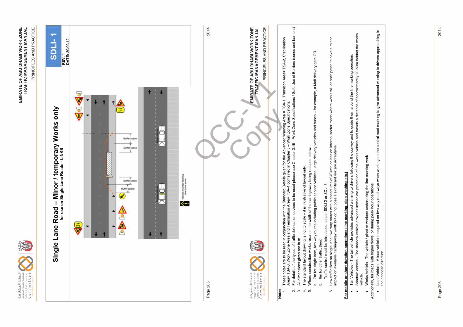
EM
IRA
TE
OF
AB
U D
HA
BI W
OR
K Z
ON
ET
RA
FF
IC M
AN
AG
EM
EN
T M
AN
UA
L
PR
INC
IPLE
S A
ND
PR
AC
TIC
E
2014
Pag
e 20
5
EM
IRA
TE
OF
AB
U D
HA
BI W
OR
K Z
ON
ET
RA
FF
IC M
AN
AG
EM
EN
T M
AN
UA
L
PR
INC
IPLE
S A
ND
PR
AC
TIC
E
2014
Pag
e 20
6
EM
IRAT
EO
FAB
UD
HAB
IWO
RK
ZON
ETR
AFFI
CM
ANAG
EM
ENT
MA
NU
AL
PRIN
CIP
LES
AN
D P
RA
CTI
CE
Sing
le L
ane
Roa
d –
Min
or /
tem
pora
ry W
orks
onl
yfo
r use
on
Sing
le L
ane
Roa
ds -
LIN
KS
SDLI
-1R
EV: 1
DAT
E:30
/09/
12
Issu
e 1
Page
205
Febr
uary
201
4
EM
IRAT
EO
FAB
UD
HAB
IWO
RK
ZON
ETR
AFFI
CM
ANAG
EM
ENT
MA
NU
AL
PRIN
CIP
LES
AN
D P
RA
CTI
CE
Not
es 1.Th
ese
note
s ar
e to
be
read
in c
onju
nctio
n w
ith th
e St
anda
rd D
etai
ls g
iven
for t
he A
dvan
ced
War
ning
Are
a =
TSA
-1, T
rans
ition
Are
a= T
SA-2
, Sta
bilis
atio
n Ar
ea=
TSA-
3, W
ork
Zone
Are
a an
d Te
rmin
atio
n Ar
ea=
TSA
-4 c
onta
ined
in C
hapt
er 3
–W
ork
Zone
Spe
cific
atio
ns.
2.Fo
r det
ails
of t
he ty
pes
of tr
affic
del
inea
tion
devi
ces
to b
e us
ed p
leas
e se
e C
hapt
er 3
.19
–W
ork
Zone
Spe
cific
atio
ns /
Safe
Use
of B
arrie
rs (c
ones
and
bar
riers
)3.
All d
imen
sion
s gi
ven
are
in m
. 4.
The
stan
dard
layo
ut d
raw
ing
is n
ot to
sca
le –
it is
illu
stra
tive
of la
yout
onl
y.5.
Whe
re c
onst
ruct
ion
wor
ks re
sult
in th
e w
idth
of t
he c
arria
gew
ay b
eing
redu
ced
belo
w:
a.7m
for s
ingl
e la
ne, t
wo
way
rout
es in
clud
ing
publ
ic s
ervi
ce v
ehic
les,
larg
e de
liver
y ve
hicl
es a
nd b
uses
–fo
r exa
mpl
e, a
Mal
l del
iver
y ga
te O
Rb.
6m fo
roth
er tr
affic
, the
n:Tr
affic
con
trol m
ust b
e in
trodu
ced,
as
per S
DLI
2 o
r SD
LI 3
6.Lo
w-tr
affic
flow
on
sing
le la
ne, t
wo
way
rout
es w
ith a
spe
ed li
mit
of 4
0km
h or
less
on
inte
rnal
sec
tor r
oads
whe
re w
orks
will
or a
ntic
ipat
ed to
hav
e a
min
or
impa
ct o
n av
aila
ble
carr
iage
way
wid
th b
ut d
o no
t pos
e a
sign
ifica
nt ri
sk a
re a
ccep
tabl
e.
For m
obile
or s
hort
dur
atio
n op
erat
ions
(lin
e m
arki
ng, s
ign
was
hing
etc
.)•
Tail
Vehi
cles
-Th
e ta
il ve
hicl
e pr
ovid
es a
dvan
ced
war
ning
to d
river
s fo
llow
ing
the
conv
oy a
nd to
gui
de th
em a
roun
d th
e lin
e m
arki
ng o
pera
tion.
•Sh
adow
Veh
icle
-Th
e sh
adow
veh
icle
pro
vide
sim
med
iate
pro
tect
ion
of th
e w
orks
veh
icle
and
trav
els
a di
stan
ce o
f app
roxi
mat
ely
20-5
0m b
ehin
d th
e w
orks
ve
hicl
e.•
Wor
ks V
ehic
le -
The
vehi
cle
/ pla
nt o
r wor
kers
und
erta
king
the
line
mar
king
wor
k.Ad
ditio
nally
, for
road
s w
ith h
ighe
r flo
ws,
or d
urin
g pe
ak h
our o
pera
tions
:•
Lead
Veh
icle
-A
lead
veh
icle
is re
quire
d on
two
way
road
way
s w
hen
wor
king
on
the
cent
ral r
oad
mar
king
to g
ive
adva
nced
war
ning
to d
river
s ap
proa
chin
g in
th
e op
posi
te d
irect
ion.
Issu
e 1
Page
206
Febr
uary
201
4
QCC-V1
Copy
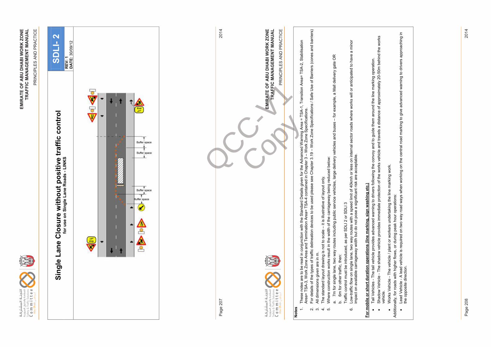
EM
IRA
TE
OF
AB
U D
HA
BI W
OR
K Z
ON
ET
RA
FF
IC M
AN
AG
EM
EN
T M
AN
UA
L
PR
INC
IPLE
S A
ND
PR
AC
TIC
E
2014
Pag
e 20
7
EM
IRA
TE
OF
AB
U D
HA
BI W
OR
K Z
ON
ET
RA
FF
IC M
AN
AG
EM
EN
T M
AN
UA
L
PR
INC
IPLE
S A
ND
PR
AC
TIC
E
2014
Pag
e 20
8
EM
IRAT
EO
FAB
UD
HAB
IWO
RK
ZON
ETR
AFFI
CM
ANAG
EM
ENT
MA
NU
AL
PRIN
CIP
LES
AN
D P
RA
CTI
CE
Sing
le L
ane
Clo
sure
with
out p
ositi
ve tr
affic
con
trol
for u
se o
n Si
ngle
Lan
e R
oads
-LI
NK
SSD
LI-2
REV
: 1D
ATE:
30/0
9/12
Issu
e 1
Page
207
Febr
uary
201
4
EM
IRAT
EO
FAB
UD
HAB
IWO
RK
ZON
ETR
AFFI
CM
ANAG
EM
ENT
MA
NU
AL
PRIN
CIP
LES
AN
D P
RA
CTI
CE
Not
es 1.Th
ese
note
s ar
e to
be
read
in c
onju
nctio
n w
ith th
e St
anda
rd D
etai
ls g
iven
for t
he A
dvan
ced
War
ning
Are
a =
TSA
-1, T
rans
ition
Are
a= T
SA-2
, Sta
bilis
atio
n Ar
ea=
TSA-
3, W
ork
Zone
Are
a an
d Te
rmin
atio
n Ar
ea=
TSA
-4 c
onta
ined
in C
hapt
er 3
–W
ork
Zone
Spe
cific
atio
ns.
2.Fo
r det
ails
of t
he ty
pes
of tr
affic
del
inea
tion
devi
ces
to b
e us
ed p
leas
e se
e C
hapt
er 3
.19
–W
ork
Zone
Spe
cific
atio
ns /
Safe
Use
of B
arrie
rs (c
ones
and
bar
riers
)3.
All d
imen
sion
s gi
ven
are
in m
. 4.
The
stan
dard
layo
ut d
raw
ing
is n
ot to
sca
le –
it is
illu
stra
tive
of la
yout
onl
y.5.
Whe
re c
onst
ruct
ion
wor
ks re
sult
in th
e w
idth
of t
he c
arria
gew
ay b
eing
redu
ced
belo
w:
a.7m
for s
ingl
e la
ne, t
wo
way
rout
es in
clud
ing
publ
ic s
ervi
ce v
ehic
les,
larg
e de
liver
y ve
hicl
es a
nd b
uses
–fo
r exa
mpl
e, a
Mal
l del
iver
y ga
te O
Rb.
6m fo
roth
er tr
affic
, the
n:Tr
affic
con
trol m
ust b
e in
trodu
ced,
as
per S
DLI
2 o
r SD
LI 3
6.Lo
w-tr
affic
flow
on
sing
le la
ne, t
wo
way
rout
es w
ith a
spe
ed li
mit
of 4
0km
h or
less
on
inte
rnal
sec
tor r
oads
whe
re w
orks
will
or a
ntic
ipat
ed to
hav
e a
min
or
impa
ct o
n av
aila
ble
carr
iage
way
wid
th b
ut d
o no
t pos
e a
sign
ifica
nt ri
sk a
re a
ccep
tabl
e.
For m
obile
or s
hort
dur
atio
n op
erat
ions
(lin
e m
arki
ng, s
ign
was
hing
etc
.)•
Tail
Vehi
cles
-Th
e ta
il ve
hicl
e pr
ovid
es a
dvan
ced
war
ning
to d
river
s fo
llow
ing
the
conv
oy a
nd to
gui
de th
em a
roun
d th
e lin
e m
arki
ng o
pera
tion.
•Sh
adow
Veh
icle
-Th
e sh
adow
veh
icle
pro
vide
s im
med
iate
pro
tect
ion
of th
e w
orks
veh
icle
and
trav
els
a di
stan
ce o
f app
roxi
mat
ely
20-5
0m b
ehin
d th
e w
orks
ve
hicl
e.•
Wor
ks V
ehic
le -
The
vehi
cle
/ pla
nt o
r wor
kers
und
erta
king
the
line
mar
king
wor
k.Ad
ditio
nally
, for
road
s w
ith h
ighe
r flo
ws,
or d
urin
g pe
ak h
our o
pera
tions
:•
Lead
Veh
icle
-A
lead
veh
icle
is re
quire
d on
two
way
road
way
s w
hen
wor
king
on
the
cent
ral r
oad
mar
king
to g
ive
adva
nced
war
ning
to d
river
s ap
proa
chin
g in
th
e op
posi
te d
irect
ion.
Issu
e 1
Page
208
Febr
uary
201
4
QCC-V1
Copy
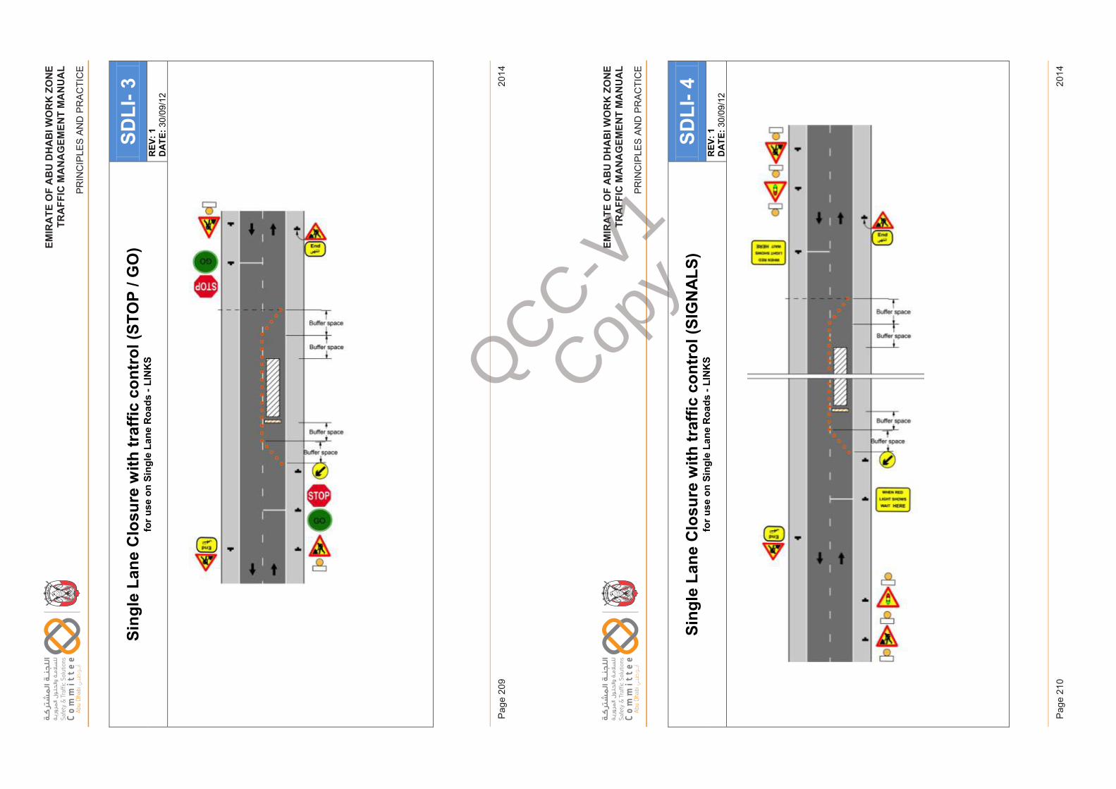
EM
IRA
TE
OF
AB
U D
HA
BI W
OR
K Z
ON
ET
RA
FF
IC M
AN
AG
EM
EN
T M
AN
UA
L
PR
INC
IPLE
S A
ND
PR
AC
TIC
E
2014
Pag
e 20
9
EM
IRA
TE
OF
AB
U D
HA
BI W
OR
K Z
ON
ET
RA
FF
IC M
AN
AG
EM
EN
T M
AN
UA
L
PR
INC
IPLE
S A
ND
PR
AC
TIC
E
2014
Pag
e 21
0
EM
IRAT
EO
FAB
UD
HAB
IWO
RK
ZON
ETR
AFFI
CM
ANAG
EM
ENT
MA
NU
AL
PRIN
CIP
LES
AN
D P
RA
CTI
CE
Sing
le L
ane
Clo
sure
with
traf
fic c
ontr
ol (S
TOP
/ GO
)fo
r use
on
Sing
le L
ane
Roa
ds -
LIN
KS
SDLI
-3R
EV: 1
DAT
E:30
/09/
12
Issu
e 1
Page
209
Febr
uary
201
4
EM
IRAT
EO
FAB
UD
HAB
IWO
RK
ZON
ETR
AFFI
CM
ANAG
EM
ENT
MA
NU
AL
PRIN
CIP
LES
AN
D P
RA
CTI
CE
Sing
le L
ane
Clo
sure
with
traf
fic c
ontr
ol (S
IGN
ALS
)fo
r use
on
Sing
le L
ane
Roa
ds -
LIN
KS
SDLI
-4R
EV: 1
DAT
E:30
/09/
12
Issu
e 1
Page
210
Febr
uary
201
4
QCC-V1
Copy
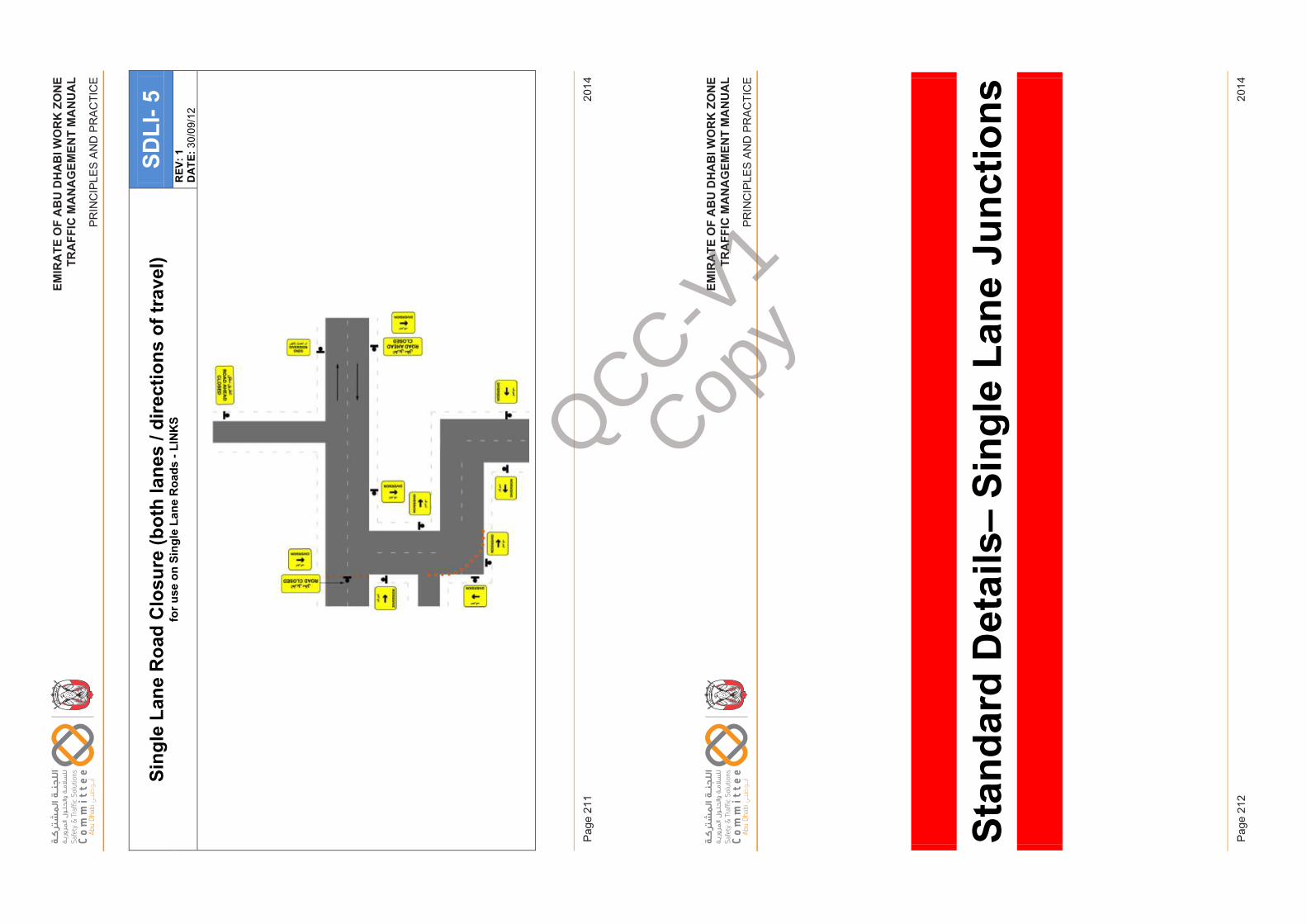
EM
IRA
TE
OF
AB
U D
HA
BI W
OR
K Z
ON
ET
RA
FF
IC M
AN
AG
EM
EN
T M
AN
UA
L
PR
INC
IPLE
S A
ND
PR
AC
TIC
E
2014
Pag
e 21
1
EM
IRA
TE
OF
AB
U D
HA
BI W
OR
K Z
ON
ET
RA
FF
IC M
AN
AG
EM
EN
T M
AN
UA
L
PR
INC
IPLE
S A
ND
PR
AC
TIC
E
2014
Pag
e 21
2
EM
IRAT
EO
FAB
UD
HAB
IWO
RK
ZON
ETR
AFFI
CM
ANAG
EM
ENT
MA
NU
AL
PRIN
CIP
LES
AN
D P
RA
CTI
CE
Sing
le L
ane
Roa
d C
losu
re (b
oth
lane
s / d
irect
ions
of t
rave
l)fo
r use
on
Sing
le L
ane
Roa
ds -
LIN
KS
SDLI
-5R
EV: 1
DAT
E:30
/09/
12
Issu
e 1
Page
211
Febr
uary
201
4
EM
IRAT
EO
FAB
UD
HAB
IWO
RK
ZON
ETR
AFFI
CM
ANAG
EM
ENT
MA
NU
AL
PRIN
CIP
LES
AN
D P
RA
CTI
CE
Stan
dard
Det
ails
–Si
ngle
Lan
e Ju
nctio
ns
Issu
e 1
Page
212
Febr
uary
201
4
QCC-V1
Copy
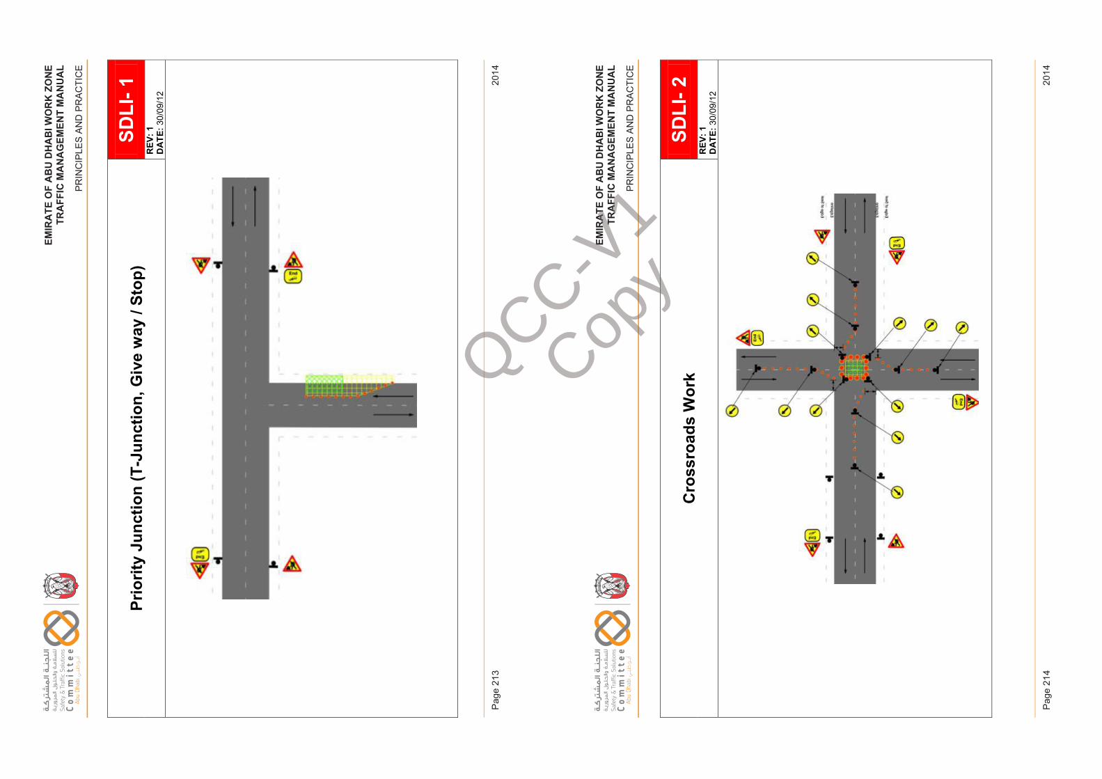
EM
IRA
TE
OF
AB
U D
HA
BI W
OR
K Z
ON
ET
RA
FF
IC M
AN
AG
EM
EN
T M
AN
UA
L
PR
INC
IPLE
S A
ND
PR
AC
TIC
E
2014
Pag
e 21
3
EM
IRA
TE
OF
AB
U D
HA
BI W
OR
K Z
ON
ET
RA
FF
IC M
AN
AG
EM
EN
T M
AN
UA
L
PR
INC
IPLE
S A
ND
PR
AC
TIC
E
2014
Pag
e 21
4
EM
IRAT
EO
FAB
UD
HAB
IWO
RK
ZON
ETR
AFFI
CM
ANAG
EM
ENT
MA
NU
AL
PRIN
CIP
LES
AN
D P
RA
CTI
CE
Prio
rity
Junc
tion
(T-J
unct
ion,
Giv
e w
ay /
Stop
)SD
LI-1
REV
: 1D
ATE:
30/0
9/12
Issu
e 1
Page
213
Febr
uary
2014
EM
IRAT
EO
FAB
UD
HAB
IWO
RK
ZON
ETR
AFFI
CM
ANAG
EM
ENT
MAN
UAL
-
PRIN
CIP
LES
AN
D P
RA
CTI
CE
Cro
ssro
ads
Wor
kSD
LI-2
REV
: 1D
ATE:
30/0
9/12
Issu
e 1
Page
214
Febr
uary
2014
QCC-V1
Copy
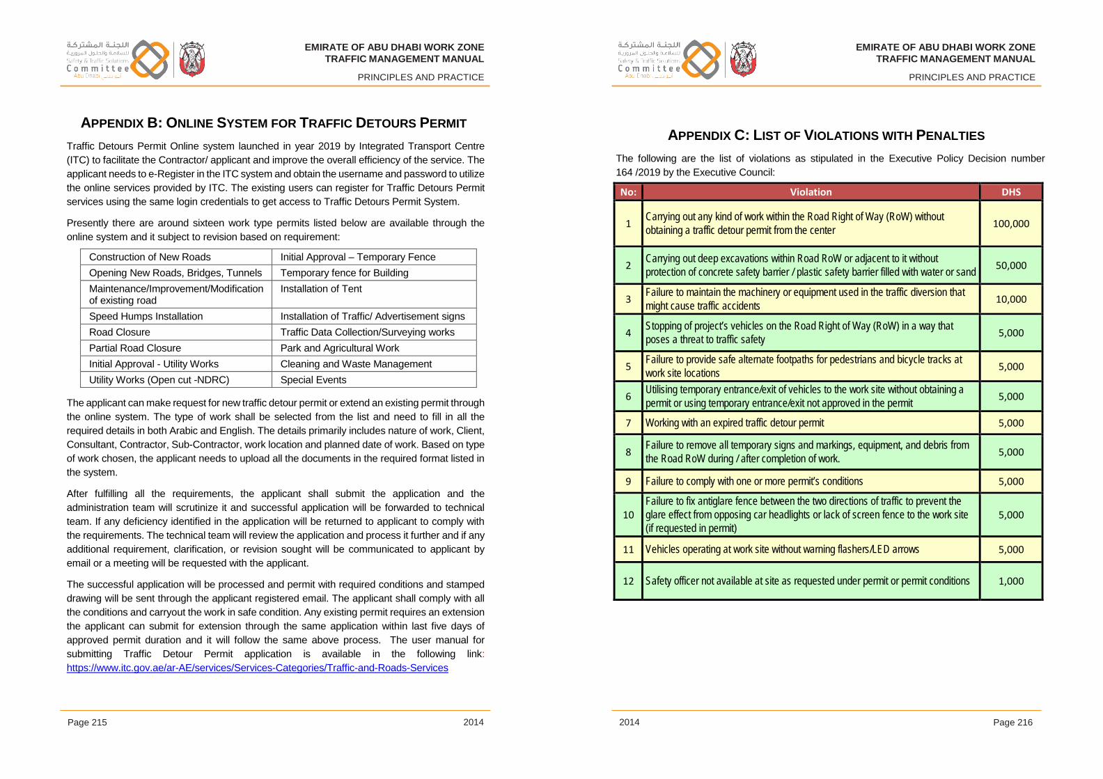
EMIRATE OF ABU DHABI WORK ZONE
TRAFFIC MANAGEMENT MANUAL
PRINCIPLES AND PRACTICE
EMIRATE OF ABU DHABI WORK ZONE
TRAFFIC MANAGEMENT MANUAL
PRINCIPLES AND PRACTICE
Page 215 2014 2014 Page 216
APPENDIX B: ONLINE SYSTEM FOR TRAFFIC DETOURS PERMIT
Traffic Detours Permit Online system launched in year 2019 by Integrated Transport Centre
(ITC) to facilitate the Contractor/ applicant and improve the overall efficiency of the service. The
applicant needs to e-Register in the ITC system and obtain the username and password to utilize
the online services provided by ITC. The existing users can register for Traffic Detours Permit
services using the same login credentials to get access to Traffic Detours Permit System.
Presently there are around sixteen work type permits listed below are available through the
online system and it subject to revision based on requirement:
Construction of New Roads Initial Approval – Temporary Fence
Opening New Roads, Bridges, Tunnels Temporary fence for Building
Maintenance/Improvement/Modification of existing road
Installation of Tent
Speed Humps Installation Installation of Traffic/ Advertisement signs
Road Closure Traffic Data Collection/Surveying works
Partial Road Closure Park and Agricultural Work
Initial Approval - Utility Works Cleaning and Waste Management
Utility Works (Open cut -NDRC) Special Events
The applicant can make request for new traffic detour permit or extend an existing permit through
the online system. The type of work shall be selected from the list and need to fill in all the
required details in both Arabic and English. The details primarily includes nature of work, Client,
Consultant, Contractor, Sub-Contractor, work location and planned date of work. Based on type
of work chosen, the applicant needs to upload all the documents in the required format listed in
the system.
After fulfilling all the requirements, the applicant shall submit the application and the
administration team will scrutinize it and successful application will be forwarded to technical
team. If any deficiency identified in the application will be returned to applicant to comply with
the requirements. The technical team will review the application and process it further and if any
additional requirement, clarification, or revision sought will be communicated to applicant by
email or a meeting will be requested with the applicant.
The successful application will be processed and permit with required conditions and stamped
drawing will be sent through the applicant registered email. The applicant shall comply with all
the conditions and carryout the work in safe condition. Any existing permit requires an extension
the applicant can submit for extension through the same application within last five days of
approved permit duration and it will follow the same above process. The user manual for
submitting Traffic Detour Permit application is available in the following link:
https://www.itc.gov.ae/ar-AE/services/Services-Categories/Traffic-and-Roads-Services
APPENDIX C: LIST OF VIOLATIONS WITH PENALTIES
The following are the list of violations as stipulated in the Executive Policy Decision number
164 /2019 by the Executive Council:
No: Violation DHS
1 Carrying out any kind of work within the Road Right of Way (RoW) without obtaining a traffic detour permit from the center 100,000
2 Carrying out deep excavations within Road RoW or adjacent to it without protection of concrete safety barrier / plastic safety barrier filled with water or sand 50,000
3 Failure to maintain the machinery or equipment used in the traffic diversion that might cause traffic accidents 10,000
4 Stopping of project’s vehicles on the Road Right of Way (RoW) in a way that poses a threat to traffic safety 5,000
5 Failure to provide safe alternate footpaths for pedestrians and bicycle tracks at work site locations 5,000
6 Utilising temporary entrance/exit of vehicles to the work site without obtaining a permit or using temporary entrance/exit not approved in the permit 5,000
7 Working with an expired traffic detour permit 5,000
8 Failure to remove all temporary signs and markings, equipment, and debris from the Road RoW during / after completion of work. 5,000
9 Failure to comply with one or more permit’s conditions 5,000
10Failure to fix antiglare fence between the two directions of traffic to prevent the glare effect from opposing car headlights or lack of screen fence to the work site (if requested in permit)
5,000
11 Vehicles operating at work site without warning flashers/LED arrows 5,000
12 Safety officer not available at site as requested under permit or permit conditions 1,000
EMIRATE OF ABU DHABI WORK ZONE
TRAFFIC MANAGEMENT MANUAL
PRINCIPLES AND PRACTICE
EMIRATE OF ABU DHABI WORK ZONE
TRAFFIC MANAGEMENT MANUAL
PRINCIPLES AND PRACTICE
Page 217 2014 2014 Page 218
CITED REFERENCES
Abu Dhabi EHS Centre. Abu Dhabi EHSMS Regulatory Framework – Abu Dhabi EHSMS
Decree. Abu Dhabi: Abu Dhabi EHS Centre, 2009. Available at www.adehsms.ae.
Abu Dhabi EHS Centre. Abu Dhabi EHSMS Regulatory Framework – Abu Dhabi EHS
Policy and Manual. Abu Dhabi: Abu Dhabi EHS Centre, 2012. Available at www.adehsms.ae.
ASTM. D4956-01a - Standard Specification for Retroreflective Sheeting for Traffic Control.
USA: ASTM International, 2001.
BSI. EN471 Specification for High Visibility Clothing. UK: BSI, 2003.
BSI. EN12899-1:2007 Fixed, Vertical Road Traffic Signs. Fixed Signs (incorporating
corrigenda May 2008, June 2009, and October 2011). EU: BSI 2011.
Road Safety Audit Manual. Abu Dhabi: Abu Dhabi Municipality, 2018.
Department of Municipalities & Transport. Manual of Unified Traffic Control Devices.
Abu Dhabi. 2016
EU. EN12352:2000 Traffic Control Equipment. Warning and Safety Light Devices. EU: EU,
2000.
EU. EN12767:2007 Passive Safety of Support Structures for Road Equipment.
Requirements, Classification and Test Methods. EU: EU, 2007.
National Cooperative Highway Research Program. Report 350 Recommended Procedures
for the Safety Performance Evaluation of Highway Features. USA: NCHRP, 1998.
United Nations Economic Commission for Europe. Regulation 104 Uniform Provisions
Concerning the Approval of Retro-reflective Markings for Vehicles of Category M, N and
O. EU: UNECE, Rev 2 1995.
OTHER REFERENCES
Department of Municipal Affairs. Urban Work Zone Traffic Management Manual. Abu Dhabi,
Al Ain, Western Region: Department of Municipal Affairs, 2013 (Final version unapproved
for use).
Health and Safety Executive (HSE). Five Steps to Risk Assessment (INDG163 rev3).
United Kingdom: HSE, 2011.
Public Works Authority ‘Ashghal’. Work Zone Traffic Management Guide. Qatar: Public
Works Authority ‘Ashghal’, 2013.
Road Transport Authority. Work Zone Traffic Management Manual. Dubai: Road Transport
Authority, 2007.
The Stationary Office (TSO). Traffic Signs Manual Chapter 8 – Traffic Safety Measures and
Signs for Road Works and Temporary Situations. UK: TSO, 2009.
EMIRATE OF ABU DHABI WORK ZONETRAFFIC MANAGEMENT MANUAL
PRINCIPLES AND PRACTICE
GLOSSARY
Specialised terms, abbreviations and acronyms frequently used in this Manual are listed and defined below. Where a term, abbreviation or acronym is defined in another Department of Transport Manual, that definition is applied to this Manual by reference.
G1 OrganisationsAAM: Al Ain Municipality
ADM: Abu Dhabi Municipality
ADP: Abu Dhabi Police
Consultant: A professional service firm (or individual) performing engineering design or other professional services under contract to a named client.
Contractor: A person or organisation responsible for the execution of the works under contract to a named client.
DMT: Department of Municipalities & Transport
MoF: Ministry of Finance
DRM: Al Dhafrah RegionMunicipality
Issue 1 Page 217 February 2014
EMIRATE OF ABU DHABI WORK ZONETRAFFIC MANAGEMENT MANUAL
PRINCIPLES AND PRACTICE
G2 General TerminologyCarriageway: The area of a Road that is specifically for vehicular use, generally separated from adjacent verges, medians and footways by a curb. Carriageways may include cycle lanes where they are at the same level.
Clearance Plan: A document that forms part of a WZTMP and details safe working practices and methodologies for the clearance of WZTM.
Competency standard: A standard setting out the competencies and assessment criteria to determine whether a person can be considered a competent person
Competent person: A person who has, through a combination of training, qualification and experience acquired knowledge and skills enabling that person to correctly perform a specified task or range of tasks.
Emergency Traffic Management (ETM): The control and/or alteration of physical measures and combination of TCDs by ADP to control and guide all road users through a Work Zonefor short periods whilst managing an incident within the road corridor.
High speed road: A road on which the posted speed limit or operating speed is 80 km/h or greater.
Implementation Plan: A document that forms part of a WZTMP and details safe working practices and methodologies for the implementation of a WZTMS.
Incident: An unplanned occurrence in the road corridor resulting in an unsafe situation for road users negotiating the Work Zone requiring ADP to implement ETM in consultation with the Lead Client, Road Authority and Scheme Contractor.
Line-marking: Work which entails vehicles involved with pavement marking moving continuously along the roadway at speeds significantly lower than other traffic. All devices are either vehicle mounted or are regularly moved along the road.
Low speed road: A road on which the posted speed limit and operating speed is less than 80 km/h.
Main Roads: Those roads that fall under the jurisdiction of DoT as Road Authority.
May: Indicates an option.
Mobile Works: That can be undertaken by equipment or plant that continually moves along the road, with associated mobile traffic management processes (for example line marking).
Municipal Roads: Those roads that fall under the jurisdiction of any of the Municipalities as Road Authority (AAM, ADM or WRM)
Must: Indicates that a statement is compulsory.
Issue 1 Page 218 February 2014
EMIRATE OF ABU DHABI WORK ZONETRAFFIC MANAGEMENT MANUAL
PRINCIPLES AND PRACTICE
2014
EMIRATE OF ABU DHABI WORK ZONETRAFFIC MANAGEMENT MANUAL
PRINCIPLES AND PRACTICE
2014Page 219 Page 220
EMIRATE OF ABU DHABI WORK ZONETRAFFIC MANAGEMENT MANUAL
PRINCIPLES AND PRACTICE
2014
EMIRATE OF ABU DHABI WORK ZONETRAFFIC MANAGEMENT MANUAL
PRINCIPLES AND PRACTICE
2014
QCC-V1
Copy
EMIRATE OF ABU DHABI WORK ZONETRAFFIC MANAGEMENT MANUAL
PRINCIPLES AND PRACTICE
Non-Motorised Users (NMU): A term used to refer to road users who are not in motor vehicles or on motorcycles (i.e. cyclists, pedestrians, wheelchair users.)
Notice of Closure (NOC): The formal notification from the relevant organisation (depending on location) for carrying out any activity within the highway.
Operating Speed: The speed of the majority of traffic approaching the work site which may be in excess of the speed limit applying to the road (if speed measurements are available the operating speed should equal the 85th percentile of measured speed, otherwise it should be established by the observation of an experienced traffic engineer).
Personal Protective Equipment (PPE): All equipment (including clothing affording protection against the weather) which is intended to be worn or held by a person at work and which protects them against one or more risks to their health or safety, including safety helmets, gloves, eye protection, high-visibility clothing, safety footwear and safety harnesses.
Public Information Plan (PIP): This details the methods employed to inform the travelling public, businesses and surrounding community concerning the construction project and the impact that the Work Zones will have on them and how these are being managed.
Road Corridor: The area of public road or highway including carriageways, cycle-ways, footways, verges and medians within the control of the relevant Road Authority.
Road Safety Audit: As defined in the Emirate of Abu Dhabi Road Safety Audit Manual
Road User: Any driver, rider, passenger, or pedestrian using the road
Safety Buffer: The area provided around the Working Space to protect site personnel from traffic. No-one must enter the Safety Buffer in the normal course of work. It should only be necessary to enter this area to maintain cones, barriers and road signs. Materials and equipment must not be placed in this area.
Shall: Indicates that a statement is compulsory.
Should: indicates a recommendation.
Standard Work: Work within the road corridor other than line-marking and defects rectification work. For standard work the time and effort to implement and remove the Work Zone traffic management is typically a small proportion of the effort and time required to undertake the actual work.
Temporary Traffic Control Plan (TTCP): Describes the methods and approach to traffic control to be used in facilitating the safe and informed passage of vehicle and pedestrian traffic through Work Zone traffic management. It is an integral part of any WZTMP.
Traffic: In general use, any road user or group of road users that pass along or across a road. The term may be qualified by ‘pedestrian’, ‘vehicular’ or ‘NMU’ to clarify the type of traffic.
Issue 1 Page 219 February 2014
EMIRATE OF ABU DHABI WORK ZONETRAFFIC MANAGEMENT MANUAL
PRINCIPLES AND PRACTICE
Traffic Control Devices (TCDs): Any signs (mandatory, warning and informatory), delineation devices (road markings, plastic barriers and cones) and Traffic Signals (temporary and permanent) the function of which is to regulate driver behaviour to suit the road environment.
Traffic Detour: The planning, design and implementation of the system that takes trafficfrom its original route within the road corridor to allow a safe Work Zone to be created, taking into account road capacity, traffic volumes and movements and Work Area requirements. Itmay only involve change within the existing road corridor, or include transfer onto a different road corridor.
Traffic Detour Route: A temporary change in route in order to close a road or because of continuing unacceptable levels of congestion. Sometimes such a detour may be necessary only for traffic proceeding in one direction. Such a route will involve use of a different road corridor to that which is affected by a WZ.
Traffic Flow:
Low: On a single-carriageway, where two-way vehicular traffic flow past the Work Zone is less than 20 vehicles counted in three minutes (400 vehicles per hour).
On a divided carriageway, where one-way vehicular traffic flow past the Work Zoneis less than 20 vehicles counted in three minutes (400 vehicles per hour).
Medium: On a single-carriageway, where two-way vehicular traffic flow past the Work Zoneis between 20 and 40 vehicles counted in three minutes (400-800 vehicles per hour).
On a divided carriageway, where one-way vehicular traffic flow past the Work Zoneis between 20 and 50 vehicles counted in three minutes (400-1000 vehicles per hour).
High: On a single-carriageway, where two-way vehicular traffic flow past the Work Zone is greater than 40 vehicles counted in three minutes (800 vehicles per hour).
On a divided carriageway, where one-way vehicular traffic flow past the Work Zoneis greater than 50 vehicles counted in three minutes (1000 vehicles per hour).
Transport Operations Plan (TOP): Details the measures to mitigate the impact of construction Work Zones through the use of improved transportation operations and management of the roadway network. It is a key requirement of any major or intermediate WZTMP.
Truck Mounted Attenuator (TMA): A shock-absorbing device mounted on the rear of a works vehicle intended to reduce the level of damage to vehicles, road users and the workforce resulting from an impact by an errant vehicle.
Work Area: That area of Road that is occupied by the actual construction or maintenance operation.
Issue 1 Page 220 February 2014
EMIRATE OF ABU DHABI WORK ZONETRAFFIC MANAGEMENT MANUAL
PRINCIPLES AND PRACTICE
2014
EMIRATE OF ABU DHABI WORK ZONETRAFFIC MANAGEMENT MANUAL
PRINCIPLES AND PRACTICE
2014Page 221 Page 222
EMIRATE OF ABU DHABI WORK ZONETRAFFIC MANAGEMENT MANUAL
PRINCIPLES AND PRACTICE
2014
EMIRATE OF ABU DHABI WORK ZONETRAFFIC MANAGEMENT MANUAL
PRINCIPLES AND PRACTICE
2014
QCC-V1
Copy
EMIRATE OF ABU DHABI WORK ZONETRAFFIC MANAGEMENT MANUAL
PRINCIPLES AND PRACTICE
Work Zone (WZ): The area which includes the Work Area(s) and any additional length or area of road required for advance signing, tapers, barriers, safety zones or other areas associated with Work Zone traffic management
Work Zone Traffic Management (WZTM): The physical measures and combination of TCDs used to guide all road users through a Work Zone whilst ensuring the safety of road users and the workforce.
Work Zone Traffic Management Layout (WZTML): A plan that shows all of the Work Zonetraffic management components and all of the TCDs in sufficient detail to allow the accurateand safe implementation of the Work Zone traffic management treatment. The TypicalArrangements in this Manual are examples of Work Zone traffic management layouts.
Work Zone Traffic Management Plan (WZTMP): Documentary part of an overall scheme design process whereby a coordinated strategy in managing the disruption to normal traffic flow is set out to operate in a safe a manner as possible for both members of the travelling public and construction workers whilst accommodating the works being undertaken.
Work Zone Traffic Management System (WZTMS): A system of procedures and guidelines that enable safe and efficient road construction and maintenance Works for all road users and the workforce.
Working Space: The space around the Work Area where tools, excavated materials, equipment and plant may be stored. It is also the area needed for the workforce to occupy in order to carry out the works.
Works: A general term relating to the construction or maintenance of the Road or of equipment or services located on, above, below or in the immediate vicinity of the road.
Short Term: Works that can be undertaken in full, in less than 72 hours, including the implementation and clearance of any required temporary traffic management.
Medium Term: Works that can be undertaken in full, in a period between 72 hours and 14 days, including the implementation and clearance of any required temporary traffic management.
Long Term: Works that take more than 14 days to carry out in full, including the implementation and clearance of any required temporary traffic management.
Issue 1 Page 221 February 2014
EMIRATE OF ABU DHABI WORK ZONETRAFFIC MANAGEMENT MANUAL
PRINCIPLES AND PRACTICE
2014
EMIRATE OF ABU DHABI WORK ZONETRAFFIC MANAGEMENT MANUAL
PRINCIPLES AND PRACTICE
2014Page 223
EMIRATE OF ABU DHABI WORK ZONETRAFFIC MANAGEMENT MANUAL
PRINCIPLES AND PRACTICE
2014
EMIRATE OF ABU DHABI WORK ZONETRAFFIC MANAGEMENT MANUAL
PRINCIPLES AND PRACTICE
2014
QCC-V1
Copy

EMIRATE OF ABU DHABI WORK ZONE TRAFFIC MANAGEMENT MANUAL-
PRINCIPLES AND PRACTICE
Draft Document rev5 Page i February 2014
EMIRATE OF ABU DHABI WORK
ZONE MANUAL
DRAFT DOCUMENT
2014
EMIRATE OF ABU DH
ABI WORK ZONE - TRAFFIC M
ANAGEMENT M
ANUAL, 2014
EMIRATE OF ABU DHABI WORK ZONETRAFFIC MANAGEMENT MANUAL
2014
QCC-V1
Copy
Related Documents