EMIR Optomechanics S. Barrera a , A. Villegas a , F.J. Fuentes a , S. Correa a , J. Pérez a , P. Redondo a , R. Restrepo a , V. Sanchez a , F. Tenegi a , F. Garzón a,b , J. Patrón a a Instituto de Astrofísica de Canarias (IAC), 38200 La Laguna (Tenerife) Spain b Departamento de Astrofísica, Universidad de La Laguna (Tenerife) Spain ABSTRACT EMIR is a NIR multiobject spectrograph with imaging capabilities to be used at the GTC. A general description of instrument performances, as well as the updated optical and mechanical layouts, can be found elsewhere on these proceedings (reference documents 4, 6 and 7). After the successful results of the Preliminary Design Review in March 2003, EMIR optical design is now completed. Some specific features of the optical components make it particularly difficult to mount them in the instrument. For example, the first collimator lens in EMIR is one of the largest Fused Silica lenses ever mounted to work under cryogenic conditions, and some other lenses in the system present features such as aspheric surfaces, tight centering tolerances etc. The analysis of the testing being done in order to validate different lens mounting design concepts is presented here, as well as the detailed status of the lens mounting design solutions adopted. Keywords: Optomechanics, Cryogenics, Large lenses, GTC. 1. INTRODUCTION The collimator and camera barrels are the mechanical devices designed in order to hold the lenses within the required positional and orientation tolerances in the instrument during operation. In EMIR, both collimator and camera include large, deeply curved and temperature sensitive lenses. The collimator and camera barrels must also ensure low stress on the lenses at all times, mitigate thermal shock on the lens, etc. The main design problems encountered when mounting large optics at cryogenic temperatures are: - Lenses must be installed warm and remain aligned to the design tolerances when the system is cooled down to nominal operating temperature (77 K) - Lens radial and axial position must be maintained under specified gravitational displacements when the instrument rotates during an observing run - Compensation for differential contraction between lens and holder must exist to avoid lens breaking when cooling - Cooling and warming speeds must be controlled and limited to avoid large temperature gradients on the lens that could stress and break it EMIR lens barrels have been designed according to the following criteria: 1. Whenever possible, lenses shall be mounted on athermal holders to maintain the specified alignment tolerances both at room and working temperatures. This permits the verification of the optics alignment before cooling and makes the AIV phase more simple. 2. Lens support system shall maintain the radial and axial positions under specified gravitational displacements when the instrument rotates. 3. Whenever possible, radially symmetrical systems with low friction shall be preferred due to the relative movement between parts during contraction. Radially symmetrical systems minimize radial displacements between lens and barrel and low friction facilitates relative displacement between parts 4. No alignment adjustments shall be needed after assembly. Positional tolerances will, whenever possible, be based on achievable manufacturing tolerances.

Welcome message from author
This document is posted to help you gain knowledge. Please leave a comment to let me know what you think about it! Share it to your friends and learn new things together.
Transcript
EMIR Optomechanics
S. Barreraa, A. Villegas
a, F.J. Fuentes
a, S. Correa
a, J. Pérez
a, P. Redondo
a, R. Restrepo
a, V. Sanchez
a,
F. Tenegia, F. Garzón
a,b, J. Patrón
a
aInstituto de Astrofísica de Canarias (IAC), 38200 La Laguna (Tenerife) Spain bDepartamento de Astrofísica, Universidad de La Laguna (Tenerife) Spain
ABSTRACT
EMIR is a NIR multiobject spectrograph with imaging capabilities to be used at the GTC. A general description of
instrument performances, as well as the updated optical and mechanical layouts, can be found elsewhere on these
proceedings (reference documents 4, 6 and 7). After the successful results of the Preliminary Design Review in March
2003, EMIR optical design is now completed. Some specific features of the optical components make it particularly
difficult to mount them in the instrument. For example, the first collimator lens in EMIR is one of the largest Fused
Silica lenses ever mounted to work under cryogenic conditions, and some other lenses in the system present features
such as aspheric surfaces, tight centering tolerances etc. The analysis of the testing being done in order to validate
different lens mounting design concepts is presented here, as well as the detailed status of the lens mounting design
solutions adopted.
Keywords: Optomechanics, Cryogenics, Large lenses, GTC.
1. INTRODUCTION
The collimator and camera barrels are the mechanical devices designed in order to hold the lenses within the required
positional and orientation tolerances in the instrument during operation. In EMIR, both collimator and camera include
large, deeply curved and temperature sensitive lenses. The collimator and camera barrels must also ensure low stress on
the lenses at all times, mitigate thermal shock on the lens, etc.
The main design problems encountered when mounting large optics at cryogenic temperatures are:
- Lenses must be installed warm and remain aligned to the design tolerances when the system is cooled down to
nominal operating temperature (77 K)
- Lens radial and axial position must be maintained under specified gravitational displacements when the
instrument rotates during an observing run
- Compensation for differential contraction between lens and holder must exist to avoid lens breaking when
cooling
- Cooling and warming speeds must be controlled and limited to avoid large temperature gradients on the lens
that could stress and break it
EMIR lens barrels have been designed according to the following criteria:
1. Whenever possible, lenses shall be mounted on athermal holders to maintain the specified alignment tolerances
both at room and working temperatures. This permits the verification of the optics alignment before cooling and
makes the AIV phase more simple.
2. Lens support system shall maintain the radial and axial positions under specified gravitational displacements
when the instrument rotates.
3. Whenever possible, radially symmetrical systems with low friction shall be preferred due to the relative
movement between parts during contraction. Radially symmetrical systems minimize radial displacements
between lens and barrel and low friction facilitates relative displacement between parts
4. No alignment adjustments shall be needed after assembly. Positional tolerances will, whenever possible, be
based on achievable manufacturing tolerances.
5. Lens shall be held securely at all times (warm, cold and transitory).
6. Maximum thermal gradients shall be limited during transitory.
7. Stress on lens must always be below the micro yield of the material, and lens shall not break or permanently
deform under any load/temperature conditions
8. The stress in the optical area shall never exceed 3.4 MPa
9. Common materials are preferred for optical mounts
The positioning of the lens into the lens barrel is achieved by means of radial and axial supports. Radial supports
ensure the radial positioning tolerances and axial supports ensure the axial positioning tolerances, the specified tilt
and the lens cooling. Radial supports are designed based on points 1,2,3,4,5,7,8 and 9 above, while axial supports
are designed based on points 1,2,4,5,6,7,8 and 9 above.
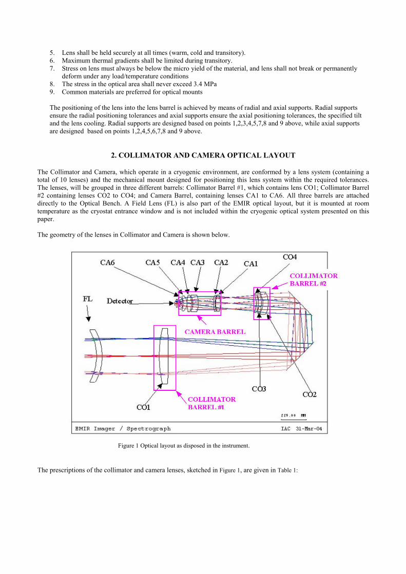
2. COLLIMATOR AND CAMERA OPTICAL LAYOUT
The Collimator and Camera, which operate in a cryogenic environment, are conformed by a lens system (containing a
total of 10 lenses) and the mechanical mount designed for positioning this lens system within the required tolerances.
The lenses, will be grouped in three different barrels: Collimator Barrel #1, which contains lens CO1; Collimator Barrel
#2 containing lenses CO2 to CO4; and Camera Barrel, containing lenses CA1 to CA6. All three barrels are attached
directly to the Optical Bench. A Field Lens (FL) is also part of the EMIR optical layout, but it is mounted at room
temperature as the cryostat entrance window and is not included within the cryogenic optical system presented on this
paper.
The geometry of the lenses in Collimator and Camera is shown below.
Figure 1 Optical layout as disposed in the instrument.
The prescriptions of the collimator and camera lenses, sketched in Figure 1, are given in Table 1:
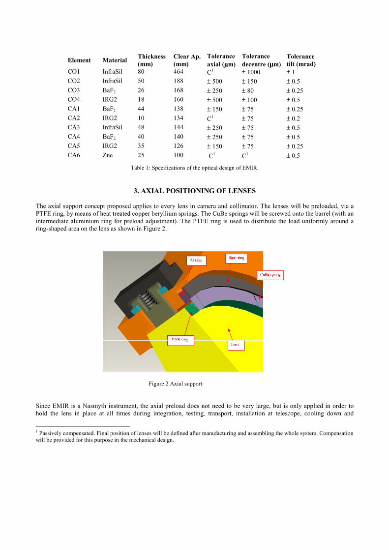
Table 1: Specifications of the optical design of EMIR.
3. AXIAL POSITIONING OF LENSES
The axial support concept proposed applies to every lens in camera and collimator. The lenses will be preloaded, via a
PTFE ring, by means of heat treated copper beryllium springs. The CuBe springs will be screwed onto the barrel (with an
intermediate aluminium ring for preload adjustment). The PTFE ring is used to distribute the load uniformly around a
ring-shaped area on the lens as shown in Figure 2.
Figure 2 Axial support.
Since EMIR is a Nasmyth instrument, the axial preload does not need to be very large, but is only applied in order to
hold the lens in place at all times during integration, testing, transport, installation at telescope, cooling down and
1 Passively compensated. Final position of lenses will be defined after manufacturing and assembling the whole system. Compensation
will be provided for this purpose in the mechanical design.
Element Material Thickness
(mm)
Clear Ap.
(mm)
Tolerance
axial (µµµµm)
Tolerance
decentre (µµµµm)
Tolerance
tilt (mrad)
CO1 InfraSil 80 464 C1 ± 1000 ± 1
CO2 InfraSil 50 188 ± 500 ± 150 ± 0.5
CO3 BaF2 26 168 ± 250 ± 80 ± 0.25
CO4 IRG2 18 160 ± 500 ± 100 ± 0.5
CA1 BaF2 44 138 ± 150 ± 75 ± 0.25
CA2 IRG2 10 134 C1 ± 75 ± 0.2
CA3 InfraSil 48 144 ± 250 ± 75 ± 0.5
CA4 BaF2 40 140 ± 250 ± 75 ± 0.5
CA5 IRG2 35 126 ± 150 ± 75 ± 0.25
CA6 Zne 25 100 C1 C
1 ± 0.5
operation. Temperature changes result in dimensional changes of the parts. These changes lead to a very slight axial
displacement of the lenses and retainer rings relative to the barrel. The dimensioning of the different components has
been done in such a way that the CuBe spring axial preload, applied to each lens is greater than 1.5* Lens Weight and
smaller than 2* Lens Weight at any temperature between 293K and 77K.
On the opposite side from the PTFE ring, each lens is resting on an aluminium ring machined directly on the barrel. An
intermediate self-adhesive kapton tape will be adhered to the axial support surface on the barrel for lower friction. The
contact area between the lens and the kapton tape will be as large as possible, i.e., the kapton will cover as much as
possible of the axial support surface on the barrel.
An exception for the axial assembly described can be expected in the final design of the camera and collimator barrel #2.
In the case the axial separation between two or more consecutive lenses becomes too small, axial separation between the
lenses will be given by an aluminium ring (or PTFE + aluminium ring) and two or more lenses will be preloaded by the
same CuBe spring.
4. RADIAL POSITIONING OF LENSES
Radial positioning concept has been frozen for all lenses except for lens CO1. This lens is being further studied, since it
is not comparable in size and weight to any of the others. Design alternatives are presented and discussed later in this
paper.
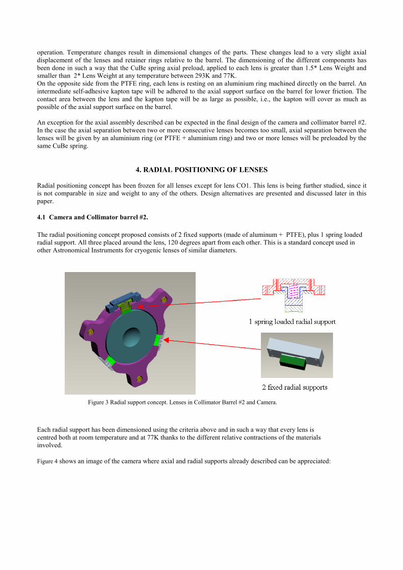
4.1 Camera and Collimator barrel #2.
The radial positioning concept proposed consists of 2 fixed supports (made of aluminum + PTFE), plus 1 spring loaded
radial support. All three placed around the lens, 120 degrees apart from each other. This is a standard concept used in
other Astronomical Instruments for cryogenic lenses of similar diameters.
Figure 3 Radial support concept. Lenses in Collimator Barrel #2 and Camera.
Each radial support has been dimensioned using the criteria above and in such a way that every lens is
centred both at room temperature and at 77K thanks to the different relative contractions of the materials
involved.
Figure 4 shows an image of the camera where axial and radial supports already described can be appreciated:
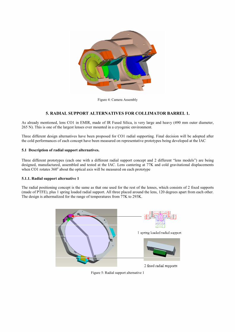
Figure 4: Camera Assembly
5. RADIAL SUPPORT ALTERNATIVES FOR COLLIMATOR BARREL 1.
As already mentioned, lens CO1 in EMIR, made of IR Fused Silica, is very large and heavy (490 mm outer diameter,
265 N). This is one of the largest lenses ever mounted in a cryogenic environment.
Three different design alternatives have been proposed for CO1 radial supporting. Final decision will be adopted after
the cold performances of each concept have been measured on representative prototypes being developed at the IAC
5.1 Description of radial support alternatives.
Three different prototypes (each one with a different radial support concept and 2 different “lens models”) are being
designed, manufactured, assembled and tested at the IAC. Lens cantering at 77K and cold gravitational displacements
when CO1 rotates 360o about the optical axis will be measured on each prototype
5.1.1. Radial support alternative 1
The radial positioning concept is the same as that one used for the rest of the lenses, which consists of 2 fixed supports
(made of PTFE), plus 1 spring loaded radial support. All three placed around the lens, 120 degrees apart from each other.
The design is athermalized for the range of temperatures from 77K to 293K.
Figure 5: Radial support alternative 1
This athermalization will be obtained using a block of PTFE (with very high CTE) screwed into an aluminum support
(with lower CTE). Detailed geometry is imposed by the athermalization criteria.
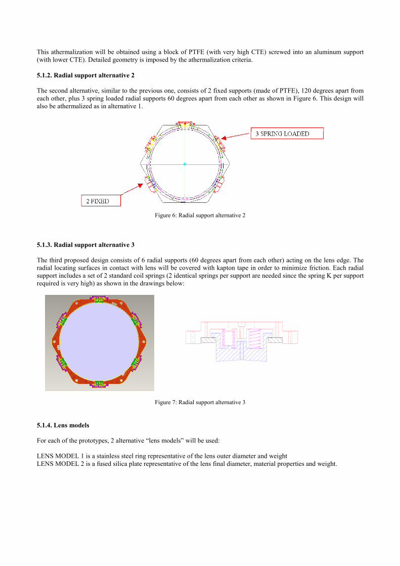
5.1.2. Radial support alternative 2
The second alternative, similar to the previous one, consists of 2 fixed supports (made of PTFE), 120 degrees apart from
each other, plus 3 spring loaded radial supports 60 degrees apart from each other as shown in Figure 6. This design will
also be athermalized as in alternative 1.
Figure 6: Radial support alternative 2
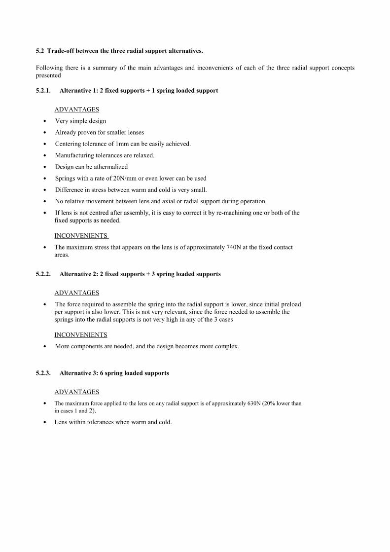
5.1.3. Radial support alternative 3
The third proposed design consists of 6 radial supports (60 degrees apart from each other) acting on the lens edge. The
radial locating surfaces in contact with lens will be covered with kapton tape in order to minimize friction. Each radial
support includes a set of 2 standard coil springs (2 identical springs per support are needed since the spring K per support
required is very high) as shown in the drawings below:
Figure 7: Radial support alternative 3
5.1.4. Lens models
For each of the prototypes, 2 alternative “lens models” will be used:
LENS MODEL 1 is a stainless steel ring representative of the lens outer diameter and weight
LENS MODEL 2 is a fused silica plate representative of the lens final diameter, material properties and weight.
5.2 Trade-off between the three radial support alternatives.
Following there is a summary of the main advantages and inconvenients of each of the three radial support concepts
presented
5.2.1. Alternative 1: 2 fixed supports + 1 spring loaded support
ADVANTAGES
• Very simple design
• Already proven for smaller lenses
• Centering tolerance of 1mm can be easily achieved.
• Manufacturing tolerances are relaxed.
• Design can be athermalized
• Springs with a rate of 20N/mm or even lower can be used
• Difference in stress between warm and cold is very small.
• No relative movement between lens and axial or radial support during operation.
•• IIff lleennss iiss nnoott cceennttrreedd aafftteerr aasssseemmbbllyy,, iitt iiss eeaassyy ttoo ccoorrrreecctt iitt bbyy rree--mmaacchhiinniinngg oonnee oorr bbootthh ooff tthhee
ffiixxeedd ssuuppppoorrttss aass nneeeeddeedd..
INCONVENIENTS
• The maximum stress that appears on the lens is of approximately 740N at the fixed contact
areas.
5.2.2. Alternative 2: 2 fixed supports + 3 spring loaded supports
ADVANTAGES
• The force required to assemble the spring into the radial support is lower, since initial preload
per support is also lower. This is not very relevant, since the force needed to assemble the
springs into the radial supports is not very high in any of the 3 cases
INCONVENIENTS
• More components are needed, and the design becomes more complex.
5.2.3. Alternative 3: 6 spring loaded supports
ADVANTAGES
• The maximum force applied to the lens on any radial support is of approximately 630N (20% lower than
in cases 1 and 2).
• Lens within tolerances when warm and cold.
INCONVENIENTS
• More complicated design
• Not proven design
• Centering tolerance is hard to achieve, and manufacturing tolerances are very strict.
• More complicated to assemble and centre (all 6 supports influence the centring of the lens)
• Very stiff springs with a rate of over 100 N/mm must be used
• There is a radial displacement of the lens during operation
• Friction between axial support and lens must be minimized, since it becomes a critical factor during
operation due to radial displacements
5.3 Test description.
Three prototypes are being made at the IAC according the three concepts for CO1 radial support already described.
- The prototypes are representative of the following items: Friction coefficient between lens and all supports; CTE of
all materials; Microyield strength in lens; Lens size and weight; Thermal conductivity of all materials; Radial and
axial supports; Lens cool down procedure.
- The prototypes are NOT representative of the following items: Lens geometry (curvature of optical surfaces);
Optical properties of lens material.
The following lens mounting performances will be measured during tests:
Specification Specified value
Lens Radial Tolerance Decentre less than 1 mm after cooldown and thermal cycling
Gravitational displacements Decentre less than 0.5 mm during a rotation of 360o about optical axis
Stress on lens Lens does not break during cool down/warm up
Cool down Cooling of the lens from 20ºC to 77 K in 96 hours
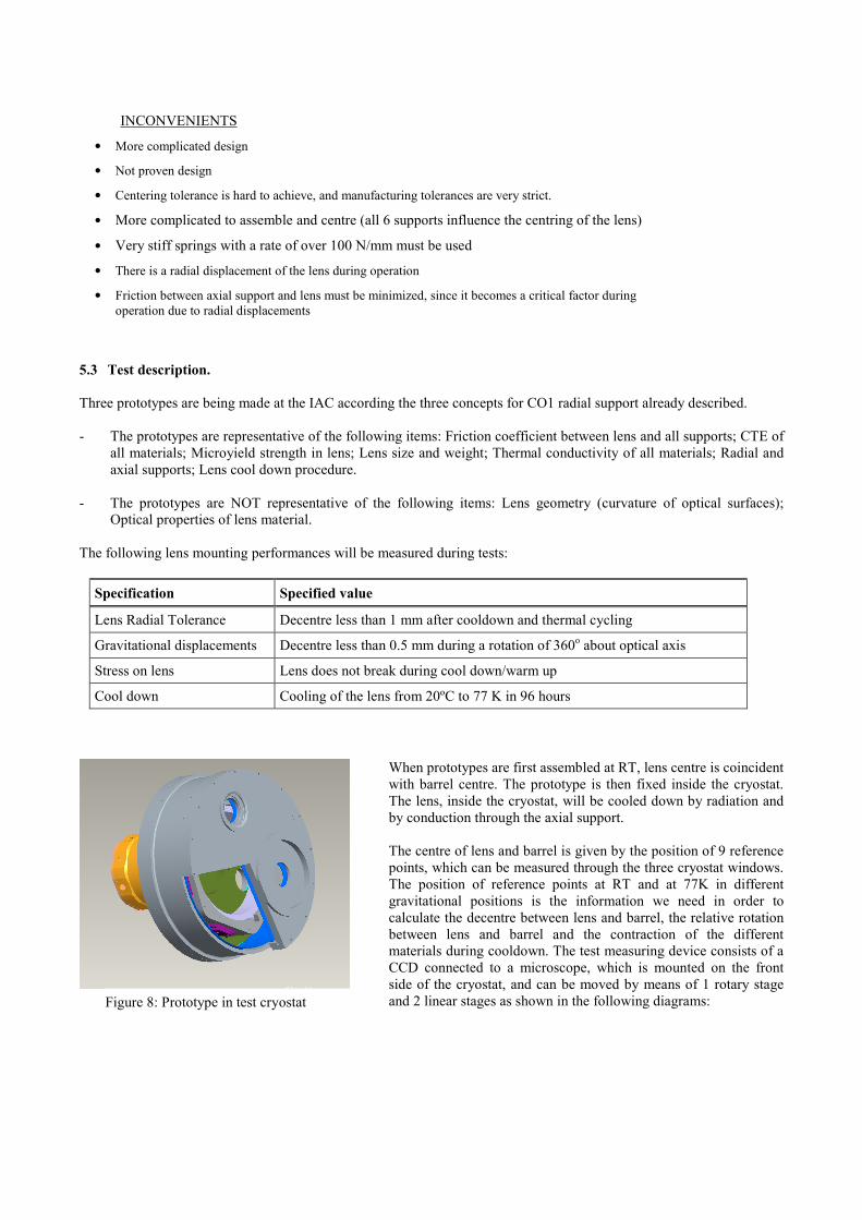
When prototypes are first assembled at RT, lens centre is coincident
with barrel centre. The prototype is then fixed inside the cryostat.
The lens, inside the cryostat, will be cooled down by radiation and
by conduction through the axial support.
The centre of lens and barrel is given by the position of 9 reference
points, which can be measured through the three cryostat windows.
The position of reference points at RT and at 77K in different
gravitational positions is the information we need in order to
calculate the decentre between lens and barrel, the relative rotation
between lens and barrel and the contraction of the different
materials during cooldown. The test measuring device consists of a
CCD connected to a microscope, which is mounted on the front
side of the cryostat, and can be moved by means of 1 rotary stage
and 2 linear stages as shown in the following diagrams: Figure 8: Prototype in test cryostat
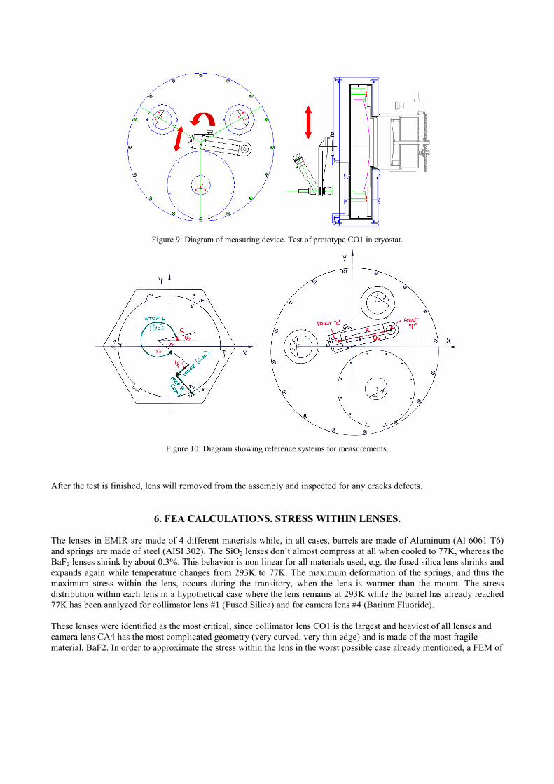
Figure 9: Diagram of measuring device. Test of prototype CO1 in cryostat.
Figure 10: Diagram showing reference systems for measurements.
After the test is finished, lens will removed from the assembly and inspected for any cracks defects.
6. FEA CALCULATIONS. STRESS WITHIN LENSES.
The lenses in EMIR are made of 4 different materials while, in all cases, barrels are made of Aluminum (Al 6061 T6)
and springs are made of steel (AISI 302). The SiO2 lenses don’t almost compress at all when cooled to 77K, whereas the
BaF2 lenses shrink by about 0.3%. This behavior is non linear for all materials used, e.g. the fused silica lens shrinks and
expands again while temperature changes from 293K to 77K. The maximum deformation of the springs, and thus the
maximum stress within the lens, occurs during the transitory, when the lens is warmer than the mount. The stress
distribution within each lens in a hypothetical case where the lens remains at 293K while the barrel has already reached
77K has been analyzed for collimator lens #1 (Fused Silica) and for camera lens #4 (Barium Fluoride).
These lenses were identified as the most critical, since collimator lens CO1 is the largest and heaviest of all lenses and
camera lens CA4 has the most complicated geometry (very curved, very thin edge) and is made of the most fragile
material, BaF2. In order to approximate the stress within the lens in the worst possible case already mentioned, a FEM of
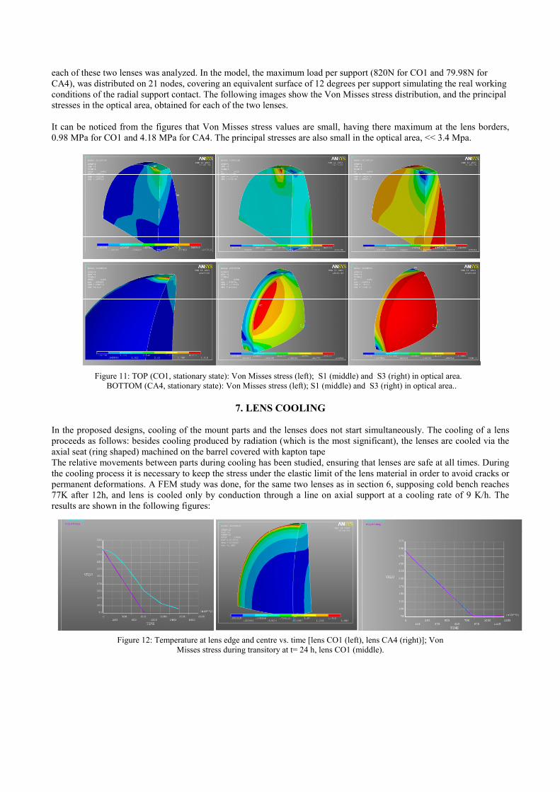
each of these two lenses was analyzed. In the model, the maximum load per support (820N for CO1 and 79.98N for
CA4), was distributed on 21 nodes, covering an equivalent surface of 12 degrees per support simulating the real working
conditions of the radial support contact. The following images show the Von Misses stress distribution, and the principal
stresses in the optical area, obtained for each of the two lenses.
It can be noticed from the figures that Von Misses stress values are small, having there maximum at the lens borders,
0.98 MPa for CO1 and 4.18 MPa for CA4. The principal stresses are also small in the optical area, << 3.4 Mpa.
Figure 11: TOP (CO1, stationary state): Von Misses stress (left); S1 (middle) and S3 (right) in optical area.
BOTTOM (CA4, stationary state): Von Misses stress (left); S1 (middle) and S3 (right) in optical area..
7. LENS COOLING
In the proposed designs, cooling of the mount parts and the lenses does not start simultaneously. The cooling of a lens
proceeds as follows: besides cooling produced by radiation (which is the most significant), the lenses are cooled via the
axial seat (ring shaped) machined on the barrel covered with kapton tape
The relative movements between parts during cooling has been studied, ensuring that lenses are safe at all times. During
the cooling process it is necessary to keep the stress under the elastic limit of the lens material in order to avoid cracks or
permanent deformations. A FEM study was done, for the same two lenses as in section 6, supposing cold bench reaches
77K after 12h, and lens is cooled only by conduction through a line on axial support at a cooling rate of 9 K/h. The
results are shown in the following figures:
Figure 12: Temperature at lens edge and centre vs. time [lens CO1 (left), lens CA4 (right)]; Von
Misses stress during transitory at t= 24 h, lens CO1 (middle).
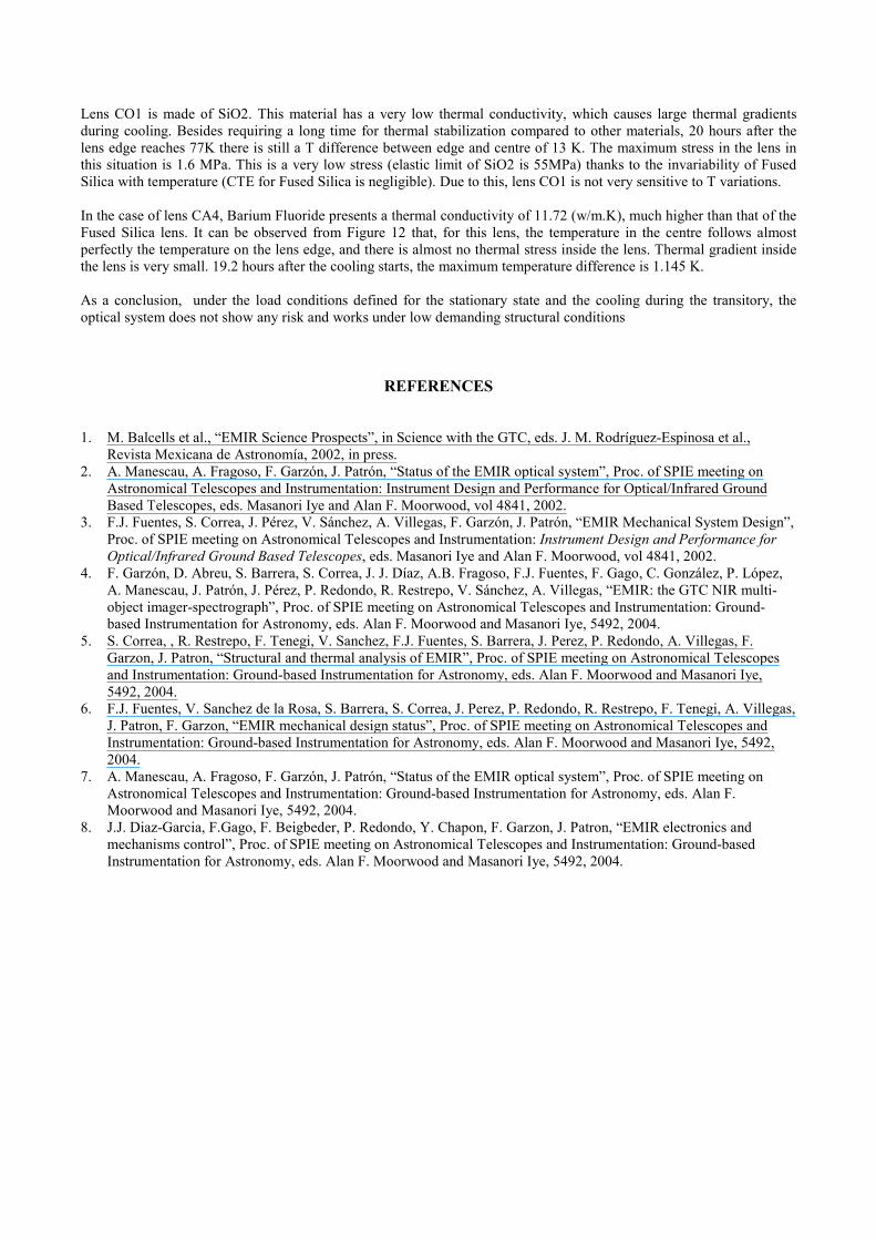
Lens CO1 is made of SiO2. This material has a very low thermal conductivity, which causes large thermal gradients
during cooling. Besides requiring a long time for thermal stabilization compared to other materials, 20 hours after the
lens edge reaches 77K there is still a T difference between edge and centre of 13 K. The maximum stress in the lens in
this situation is 1.6 MPa. This is a very low stress (elastic limit of SiO2 is 55MPa) thanks to the invariability of Fused
Silica with temperature (CTE for Fused Silica is negligible). Due to this, lens CO1 is not very sensitive to T variations.
In the case of lens CA4, Barium Fluoride presents a thermal conductivity of 11.72 (w/m.K), much higher than that of the
Fused Silica lens. It can be observed from Figure 12 that, for this lens, the temperature in the centre follows almost
perfectly the temperature on the lens edge, and there is almost no thermal stress inside the lens. Thermal gradient inside
the lens is very small. 19.2 hours after the cooling starts, the maximum temperature difference is 1.145 K.
As a conclusion, under the load conditions defined for the stationary state and the cooling during the transitory, the
optical system does not show any risk and works under low demanding structural conditions
REFERENCES
1. M. Balcells et al., “EMIR Science Prospects”, in Science with the GTC, eds. J. M. Rodríguez-Espinosa et al.,
Revista Mexicana de Astronomía, 2002, in press.
2. A. Manescau, A. Fragoso, F. Garzón, J. Patrón, “Status of the EMIR optical system”, Proc. of SPIE meeting on
Astronomical Telescopes and Instrumentation: Instrument Design and Performance for Optical/Infrared Ground
Based Telescopes, eds. Masanori Iye and Alan F. Moorwood, vol 4841, 2002.
3. F.J. Fuentes, S. Correa, J. Pérez, V. Sánchez, A. Villegas, F. Garzón, J. Patrón, “EMIR Mechanical System Design”,
Proc. of SPIE meeting on Astronomical Telescopes and Instrumentation: Instrument Design and Performance for
Optical/Infrared Ground Based Telescopes, eds. Masanori Iye and Alan F. Moorwood, vol 4841, 2002.
4. F. Garzón, D. Abreu, S. Barrera, S. Correa, J. J. Díaz, A.B. Fragoso, F.J. Fuentes, F. Gago, C. González, P. López,
A. Manescau, J. Patrón, J. Pérez, P. Redondo, R. Restrepo, V. Sánchez, A. Villegas, “EMIR: the GTC NIR multi-
object imager-spectrograph”, Proc. of SPIE meeting on Astronomical Telescopes and Instrumentation: Ground-
based Instrumentation for Astronomy, eds. Alan F. Moorwood and Masanori Iye, 5492, 2004.
5. S. Correa, , R. Restrepo, F. Tenegi, V. Sanchez, F.J. Fuentes, S. Barrera, J. Perez, P. Redondo, A. Villegas, F.
Garzon, J. Patron, “Structural and thermal analysis of EMIR”, Proc. of SPIE meeting on Astronomical Telescopes
and Instrumentation: Ground-based Instrumentation for Astronomy, eds. Alan F. Moorwood and Masanori Iye,
5492, 2004.
6. F.J. Fuentes, V. Sanchez de la Rosa, S. Barrera, S. Correa, J. Perez, P. Redondo, R. Restrepo, F. Tenegi, A. Villegas,
J. Patron, F. Garzon, “EMIR mechanical design status”, Proc. of SPIE meeting on Astronomical Telescopes and
Instrumentation: Ground-based Instrumentation for Astronomy, eds. Alan F. Moorwood and Masanori Iye, 5492,
2004.
7. A. Manescau, A. Fragoso, F. Garzón, J. Patrón, “Status of the EMIR optical system”, Proc. of SPIE meeting on
Astronomical Telescopes and Instrumentation: Ground-based Instrumentation for Astronomy, eds. Alan F.
Moorwood and Masanori Iye, 5492, 2004.
8. J.J. Diaz-Garcia, F.Gago, F. Beigbeder, P. Redondo, Y. Chapon, F. Garzon, J. Patron, “EMIR electronics and
mechanisms control”, Proc. of SPIE meeting on Astronomical Telescopes and Instrumentation: Ground-based
Instrumentation for Astronomy, eds. Alan F. Moorwood and Masanori Iye, 5492, 2004.
Related Documents