CE/61800-3 ReV.01 TEL: 886-4-2359-9009 FAX: 886-4-2359-8847 www.pmc.org.tw TEST REPORT NO.:N3E11-103R0103-009 ISSUE NO.: 1 EMC TEST REPORT TESTING OF MODEL:KSDG-02021MIP AC SERVO DRIVER FOR HOFO Automation Co., Ltd. Issued by Precision Machinery Research & Development Center No.27, 37 th Road Taichung Industrial Park, Taichung, Taiwan, R.O.C. Tel : 886-4-23599009 Fax : 886-4-23598847

Welcome message from author
This document is posted to help you gain knowledge. Please leave a comment to let me know what you think about it! Share it to your friends and learn new things together.
Transcript

CE/61800-3 ReV.01
TEL: 886-4-2359-9009 FAX: 886-4-2359-8847 www.pmc.org.tw
TEST REPORT NO.:N3E11-103R0103-009
ISSUE NO.: 1
EMC TEST REPORT
TESTING
OF
MODEL:KSDG-02021MIP
AC SERVO DRIVER
FOR
HOFO Automation Co., Ltd.
Issued by
Precision Machinery Research & Development Center
No.27, 37th Road Taichung Industrial Park, Taichung, Taiwan, R.O.C.
Tel : 886-4-23599009 Fax : 886-4-23598847

N3E11-103R0103-009 Page 1 of 48 CE/61800-3 ReV.01
TEL: 886-4-2359-9009
FAX: 886-4-2359-8847
www.pmc.org.tw N o . 2 7 , 3 7 t h R o a d , T a i c h u n g I n d u s t r i a l P a r k , T a i c h u n g , T a i w a n , R . O . C .
EMC TEST REPORT
Applicant : HOFO Automation Co., Ltd. No.21, Aly. 3, Ln. 468, Sec. 1, Minsheng N. Rd., Guishan Township, Taoyuan County 333, Taiwan (R.O.C.)
Manufacturer : HOFO Automation Co., Ltd.
No.21, Aly. 3, Ln. 468, Sec. 1, Minsheng N. Rd., Guishan Township, Taoyuan County 333, Taiwan (R.O.C.)
Product Name : AC SERVO DRIVER Model Name : KSDG-02021MIP Serial No. : KSDG-00821LIP, KSDG-01021MIP and KSDG-01521MIP Test Rate : 3 4w, 230V~, 50 Hz Test Standard : EN 61800-3:2004 (Environment II C3) Test Date : 2014/01/16 and 2014/01/27 Test Result : PASS Test Laboratory :
PMC Electromagnetic Compatibility Testing Laboratory No.27, 37th Road, Taichung Industrial Park, Taichung, Taiwan, R.O.C. TEL: +886-4-2359-9009 FAX:+886-4-2359-8847
Tested by Yu Chi Chou Signature
February 18, 2014 Date
Approved by Tim Hise Signature
February 18, 2014 Date
Note: The test results only responds to the tested sample, and is invalid as separately used. The test results are invalid without examination stamp and signature of this laboratory. The test results are not reproduced except in full without the written approved of PMC Lab.

N3E11-103R0103-009 Page 2 of 48 CE/61800-3 ReV.01
TEL: 886-4-2359-9009
FAX: 886-4-2359-8847
www.pmc.org.tw N o . 2 7 , 3 7 t h R o a d , T a i c h u n g I n d u s t r i a l P a r k , T a i c h u n g , T a i w a n , R . O . C .
Table of Contents
1. GENERAL DESCRIPTION OF EUT ...................................................................................................................... 5
1.1 OPERATION PROCEDURES OF THE EUT .............................................................................................................. 5
1.2 THE WORST CASE FOR TESTING EVALUATION ..................................................................................................... 5
1.3 COUNTERMEASURE .............................................................................................................................................. 5
1.4 DESCRIPTION OF MODEL ...................................................................................................................................... 6
1.5 NOMENCLATURE FOR MODELS ........................................................................................................................... 6
2. GENERAL INFORMATION OF TEST .................................................................................................................. 8
2.1 SUMMARY OF TEST RESULT ................................................................................................................................. 8
2.2 PERFORMANCE CRITERIA OF IMMUNITY TEST .................................................................................................... 9
2.3 TEST EQUIPMENT ............................................................................................................................................... 10
3. CONDUCTED EMISSION TEST .......................................................................................................................... 12
3.1 LIMITS OF TERMINAL DISTURBANCE VOLTAGE ................................................................................................ 12
3.2 TEST SETUP ......................................................................................................................................................... 12
3.3 ENVIRONMENTAL CONDITIONS .......................................................................................................................... 13
3.4 DESCRIPTION OF THE TEST ................................................................................................................................ 13
3.5 TEST RESULT ...................................................................................................................................................... 13
3.6 PHOTO DURING THE TEST .................................................................................................................................. 23
4. RADIATED EMISSION TEST .............................................................................................................................. 24
4.1 LIMITS OF TERMINAL DISTURBANCE VOLTAGE ................................................................................................ 24
4.2 TEST SETUP ......................................................................................................................................................... 24
4.3 ENVIRONMENTAL CONDITIONS .......................................................................................................................... 25
4.4 DESCRIPTION OF THE TEST ................................................................................................................................ 25
4.5 TEST RESULT ...................................................................................................................................................... 25
4.6 PHOTO DURING THE TEST .................................................................................................................................. 28
5. ELECTROSTATIC DISCHARGE IMMUNITY TEST ...................................................................................... 29
5.1 TEST SPECIFICATION AND PERFORMANCE CRITERIA ........................................................................................ 29
5.2 TEST SETUP ......................................................................................................................................................... 29
5.3 ENVIRONMENTAL CONDITIONS .......................................................................................................................... 30
5.4 DESCRIPTION OF THE TEST ................................................................................................................................ 30
5.5 TEST RESULT ...................................................................................................................................................... 30
5.6 PHOTO DURING THE TEST .................................................................................................................................. 32
6. IMMUNITY TEST OF RADIATED RADIO─FREQUENCY ELECTROMAGNETIC FIELD─
AMPLITUDE MODULATED ................................................................................................................................ 33
6.1 TEST SPECIFICATION AND PERFORMANCE CRITERIA ........................................................................................ 33
6.2 TEST SETUP ......................................................................................................................................................... 33

N3E11-103R0103-009 Page 3 of 48 CE/61800-3 ReV.01
TEL: 886-4-2359-9009
FAX: 886-4-2359-8847
www.pmc.org.tw N o . 2 7 , 3 7 t h R o a d , T a i c h u n g I n d u s t r i a l P a r k , T a i c h u n g , T a i w a n , R . O . C .
6.3 ENVIRONMENTAL CONDITIONS .......................................................................................................................... 34
6.4 DESCRIPTION OF THE TEST ................................................................................................................................ 34
6.5 TEST RESULT ...................................................................................................................................................... 34
6.6 PHOTO DURING THE TEST .................................................................................................................................. 36
7. ELECTRICAL FAST TRANSIENT/BURST IMMUNITY TEST ..................................................................... 37
7.1 TEST SPECIFICATION AND PERFORMANCE CRITERIA ........................................................................................ 37
7.2 TEST SETUP ......................................................................................................................................................... 37
7.3 ENVIRONMENTAL CONDITIONS .......................................................................................................................... 38
7.4 DESCRIPTION OF THE TEST ................................................................................................................................ 38
7.5 TEST RESULT ...................................................................................................................................................... 38
7.6 PHOTO DURING THE TEST .................................................................................................................................. 40
8. IMMUNITY TEST OF CONDUCTED DISTURBANCES INDUCED BY RADIO─FREQUENCY FIELDS .................................................................................................................................................................................... 41
8.1 TEST SPECIFICATION AND PERFORMANCE CRITERIA ........................................................................................ 41
8.2 TEST SETUP ......................................................................................................................................................... 41
8.3 ENVIRONMENTAL CONDITIONS .......................................................................................................................... 42
8.4 DESCRIPTION OF THE TEST ................................................................................................................................ 42
8.5 TEST RESULT ...................................................................................................................................................... 42
8.6 PHOTO DURING THE TEST .................................................................................................................................. 44
9. SURGE IMMUNITY TEST .................................................................................................................................... 45
9.1 TEST SPECIFICATION AND PERFORMANCE CRITERIA ........................................................................................ 45
9.2 TEST SETUP ......................................................................................................................................................... 45
9.3 ENVIRONMENTAL CONDITIONS .......................................................................................................................... 46
9.4 DESCRIPTION OF THE TEST ................................................................................................................................ 46
9.5 TEST RESULT ...................................................................................................................................................... 46
9.6 PHOTO DURING THE TEST .................................................................................................................................. 48
Attachment : Electronic Diagram of EUT
Attachment : Photograph of EUT

N3E11-103R0103-009 Page 4 of 48 CE/61800-3 ReV.01
TEL: 886-4-2359-9009
FAX: 886-4-2359-8847
www.pmc.org.tw N o . 2 7 , 3 7 t h R o a d , T a i c h u n g I n d u s t r i a l P a r k , T a i c h u n g , T a i w a n , R . O . C .
Laboratory Information Precision Machinery Research & Development Center (PMC) was founded by government and
Taiwan Association of Machinery Industry, established on June lst, 1993. We are a non-profit
organization to help manufacturers to value up the products and comply with the EMC and Safety
requirement. And, our facilities and ability of measurement are approved by the following
organizations and countries.
If you have any comments, please don’t hesitate to contact us. Our contact information is as below:
PMC Testing Laboratory :
No.27, 37th Road Taichung Industrial Park, Taichung, Taiwan, R.O.C.
TEL:+886-4-2359-9009 #312 / FAX:+886-4-2359-8847

N3E11-103R0103-009 Page 5 of 48 CE/61800-3 ReV.01
TEL: 886-4-2359-9009
FAX: 886-4-2359-8847
www.pmc.org.tw N o . 2 7 , 3 7 t h R o a d , T a i c h u n g I n d u s t r i a l P a r k , T a i c h u n g , T a i w a n , R . O . C .
1. General Description of EUT 1.1 Operation procedures of the EUT
1. Power on.
2. Setup the Revolution(s) Per Minute.
3. Do the test.
1.2 The worst case for testing evaluation
According to the requirement of manufacture, we (PMC) assist with executing EMI
test. After estimating, PMC have evaluated the EUT would be the worst case when
execute the program described by the sec.1.1.
1.3 Countermeasure
The power cores should be equipped with filter OERSTED FPM-3320G or EPCOS
B84143A0050R106 or SCHaffner FN258L-16-07.

N3E11-103R0103-009 Page 6 of 48 CE/61800-3 ReV.01
TEL: 886-4-2359-9009
FAX: 886-4-2359-8847
www.pmc.org.tw N o . 2 7 , 3 7 t h R o a d , T a i c h u n g I n d u s t r i a l P a r k , T a i c h u n g , T a i w a n , R . O . C .
1.4 Description of model Model KSDG-02021MIP KSDG-00821LIP KSDG-01021MIP KSDG-01521MIP Power Source
3Phase AC230V 50/60Hz
3Phase AC230V 50/60Hz
3Phase AC230V 50/60Hz
3Phase AC230V 50/60Hz
Input Power of Driver
2500W 937W 1250W 1875W
Input Current 10.87A
4.07A 5.43A 8.15A
Output Power of Driver
2000W 750W 1000W 1500W
Output Voltage / Current
0-230V/10A 0-230V/5.4A 0-230V/5.4A 0-230V/8A
Dimension 167*72*169.8
167*72*169.8 167*72*169.8 167*72*169.8
We evaluated the difference of series models, only difference of rated power and rated
current, the function design and electronic circuit are the same. According to test result, we
estimate all of the series models could be adapted the results.
1.5 Nomenclature for Models KS D G 0 20 21 M I P
Manufacture Drive Motor Type
Interface Type
Generation Output Power
Input Voltage
Use Motor Inertia
Encoder Type
Extended Codes
KS BP
D L
G C
0
08 10 15 20
21 23
L M H
I A G
P PF LP
Manufacture KS HOFO kingservo
BP OEM

N3E11-103R0103-009 Page 7 of 48 CE/61800-3 ReV.01
TEL: 886-4-2359-9009
FAX: 886-4-2359-8847
www.pmc.org.tw N o . 2 7 , 3 7 t h R o a d , T a i c h u n g I n d u s t r i a l P a r k , T a i c h u n g , T a i w a n , R . O . C .
Drive Motor Type D With Rotary motor drive
L With linear motor drive
Interface Type G Analogue, Pulse I/F
C Motionnet I/F
Generation
0
Output Power 08 750W
10 1000W
15 1500W
20 2000W
Input Voltage 21 230Vac
23 230V3ac
Use Motor inertia L Low inertia
M Mid inertia
H High inertia
Encoder Type I 2500P/R Incremental Encoder
A 20bit Absolute Encoder
G 20bit Incremental Encoder
Extended Codes P Standard
PF With Fisheries, Enhanced insulation cooling
LP Low Velocity, High Torque

N3E11-103R0103-009 Page 8 of 48 CE/61800-3 ReV.01
TEL: 886-4-2359-9009
FAX: 886-4-2359-8847
www.pmc.org.tw N o . 2 7 , 3 7 t h R o a d , T a i c h u n g I n d u s t r i a l P a r k , T a i c h u n g , T a i w a n , R . O . C .
2. General Information of Test 2.1 Summary of test result
Standard Edition Comment
EN 61800-3 2004 (Environment II C3) PASS
Electromagnetic Interference
Standard Edition Comment
EN 55011 2009/A1:2010 PASS
Electromagnetic Susceptibility
Standard Edition Comment
EN 61000-4-2 2009 PASS
EN 61000-4-3 2006/A2:2010 PASS
EN 61000-4-4 2004/A1:2010 PASS
EN 61000-4-5 2006 PASS
EN 61000-4-6 2009 PASS

N3E11-103R0103-009 Page 9 of 48 CE/61800-3 ReV.01
TEL: 886-4-2359-9009
FAX: 886-4-2359-8847
www.pmc.org.tw N o . 2 7 , 3 7 t h R o a d , T a i c h u n g I n d u s t r i a l P a r k , T a i c h u n g , T a i w a n , R . O . C .
2.2 Performance criteria of immunity test
Performance Criterion A:
The equipment shall continue to operate as intended without operator intervention.
No degradation of performance or loss of function is allowed below a performance
level specified by the manufacturer when the equipment is used as intended. The
performance level may be replaced by a permissible loss of performance.
Performance Criterion B:
After the test, the equipment shall continue to operate as intended without operator
intervention. No degradation of performance or loss of function is allowed after the
application of the phenomena below a performance level specified by the
manufacturer, when the equipment is used as intended. During the test, degradation of
performance is allowed. However, no change of actual operating state or stored data
is allowed to persist after the test.
Performance Criterion C:
Loss of function is allowed, provided the function is self recoverable or can be
restored by the operation of the controls by the user in accordance with the
manufacturer’s instructions.

N3E11-103R0103-009 Page 10 of 48 CE/61800-3 ReV.01
TEL: 886-4-2359-9009
FAX: 886-4-2359-8847
www.pmc.org.tw N o . 2 7 , 3 7 t h R o a d , T a i c h u n g I n d u s t r i a l P a r k , T a i c h u n g , T a i w a n , R . O . C .
2.3 Test equipment
Item Brand / Model Series No. Calibration Due Used
EMI Test Receiver ROHDE & SCHWARZ
ESCS 30 847793/004 18, Jul., 2014 Used
Bilog Antenna CHASE
CBL 6111B 2085 30, Jun., 2014 Used
L.I.S.N. SCHWARZBECK
MESS-ELEKTRONIK NNLK8129
8129129 02, Jan., 2015 Used
Power Clamp MDS-21 848818/012 19, Jan., 2015 Used
Harmonic and Flicker Analyzer
EM TEST/ DPA 500 V0503100065 10, Nov., 2014 Used
ESD Test Unit EM TEST/ESD 30C V0822103834 03, Jul., 2014 Used
Signal Generator ROHDE &
SCHWARZ/SMY01 844934/058 31, Oct., 2014 Used
Signal Generator Agilent 8648C
4037U03276 03, Jan., 2015 Used
Power Amplifier KALMUS/747LC 8680-1 20, Dec., 2014 Used
EFT Test Unit EM TEST/EFT 500 0596-32 04, Ju1., 2014 Used
Surge Generator EM TEST/VCS 500 0397-09 04, Ju1., 2014 Used
6 dB Attenuator BNOS ELECTRONICS 522055 20, Dec., 2014 Used
CDN FCC/801-M5-32A 9906 21, Feb., 2014 Used
Power Fail Simulator EM TEST/PFS 503 0897-03 10, Nov., 2014 Used

N3E11-103R0103-009 Page 11 of 48 CE/61800-3 ReV.01
TEL: 886-4-2359-9009
FAX: 886-4-2359-8847
www.pmc.org.tw N o . 2 7 , 3 7 t h R o a d , T a i c h u n g I n d u s t r i a l P a r k , T a i c h u n g , T a i w a n , R . O . C .
Item Brand / Model Series No. Calibration Due Used
PFMF Generator EM TEST/MC26100 N/A 10, Jun., 2014 Used
B.C.I. FCC/F-140A 155 08, May, 2014 Used
PFMF Antenna EM TEST/MS100 N/A 10, Jun., 2014 Used
FM Transmitter ICOM/IC-W32E 86AR0069 N/A Used
Mobile Phone MOTOROLA W220 M2AG7009D6 N/A Used
Wireless Router D-Link/DIR-300 P1DY18C003321 N/A Used

N3E11-103R0103-009 Page 12 of 48 CE/61800-3 ReV.01
TEL: 886-4-2359-9009
FAX: 886-4-2359-8847
www.pmc.org.tw N o . 2 7 , 3 7 t h R o a d , T a i c h u n g I n d u s t r i a l P a r k , T a i c h u n g , T a i w a n , R . O . C .
3. Conducted Emission Test
3.1 Limits of terminal disturbance voltage
Port Frequency Range Limits
AC mains
0.15 MHz-0.50 MHz100 dB (uV) quasi-peak
90 dB (uV) average
0.50 MHz-5 MHz 86 dB (pV) quasi-peak
76 dB (uV) average
5 MHz-30 MHz
90 dB (uV) quasi-peak, decreasing with log of frequency down to 70 dB
80 dB (uV) average, decreasing with log of frequency down to 60 dB
3.2 Test setup
EUT L.I.S.N AC Mains Power
EMI Receiver
Filter
80 cm
Filter

N3E11-103R0103-009 Page 13 of 48 CE/61800-3 ReV.01
TEL: 886-4-2359-9009
FAX: 886-4-2359-8847
www.pmc.org.tw N o . 2 7 , 3 7 t h R o a d , T a i c h u n g I n d u s t r i a l P a r k , T a i c h u n g , T a i w a n , R . O . C .
3.3 Environmental conditions
Test Date Ambient Temperature Relative Humidity Atmospheric Pressure
Jan., 16, 2014 23.2℃ 53.2 ﹪ 1016 mbar
3.4 Description of the test
Positive-peak was done first to find the frequency ranges required then to do the
quasi-peak value and average value measurement. Each phase of power lines was to be
tested.
The power cores should be equipped with filter OERSTED FPM-3320G or EPCOS
B84143A0050R106 or SCHaffner FN258L-16-07. Each of phase has tested as the
following pages.
3.5 Test result
The following pages show the results of conducted emission. Judging from these data, it is
reasonable to assume that the EUT would pass the test to the limits.

N3E11-103R0103-009 Page 14 of 48 CE/61800-3 ReV.01
TEL: 886-4-2359-9009
FAX: 886-4-2359-8847
www.pmc.org.tw N o . 2 7 , 3 7 t h R o a d , T a i c h u n g I n d u s t r i a l P a r k , T a i c h u n g , T a i w a n , R . O . C .
EMC Log Sheet of CE Test-L1 Phase OERSTED FPM-3320G
No. Freq.
(MHz)
Read AV
(dBuV)
Read QP
(dBuV)
Corr. (dB)
Result AV
(dBuV)
Result QP
(dBuV)
Limit AV
(dBuV)
Limit QP
(dBuV)
Margin AV (dB)
Margin QP
(dB)
1 0.165 55.383 63.143 10.311 65.694 73.454 90.000 100.000 -24.306 -26.546
2 4.444 60.482 63.477 10.500 70.982 73.977 76.000 86.000 -5.018 -12.023
3 7.001 42.894 47.413 10.636 53.529 58.048 76.242 86.242 -22.713 -28.194
4 11.148 49.491 54.039 10.843 60.333 64.881 71.050 81.050 -10.716 -16.168
5 19.512 28.995 38.113 11.226 40.221 49.339 64.802 74.802 -24.581 -25.463
6 28.671 23.885 27.817 11.825 35.710 39.642 60.506 70.506 -24.796 -30.864

N3E11-103R0103-009 Page 15 of 48 CE/61800-3 ReV.01
TEL: 886-4-2359-9009
FAX: 886-4-2359-8847
www.pmc.org.tw N o . 2 7 , 3 7 t h R o a d , T a i c h u n g I n d u s t r i a l P a r k , T a i c h u n g , T a i w a n , R . O . C .
EMC Log Sheet of CE Test- L2 Phase
OERSTED FPM-3320G
No. Freq.
(MHz)
Read AV
(dBuV)
Read QP
(dBuV)
Corr. (dB)
Result AV
(dBuV)
Result QP
(dBuV)
Limit AV
(dBuV)
Limit QP
(dBuV)
Margin AV (dB)
Margin QP
(dB)
1 0.161 57.030 65.602 10.312 67.341 75.913 90.000 100.000 -22.659 -24.087
2 1.773 35.542 42.091 10.418 45.959 52.508 76.000 86.000 -30.041 -33.492
3 2.677 38.569 43.505 10.447 49.015 53.951 76.000 86.000 -26.985 -32.049
4 4.667 60.313 63.843 10.512 70.825 74.355 76.000 86.000 -5.175 -11.645
5 10.955 49.623 54.915 10.834 60.457 65.749 71.245 81.245 -10.788 -15.496
6 27.782 23.559 26.667 11.766 35.325 38.433 60.857 70.857 -25.533 -32.425

N3E11-103R0103-009 Page 16 of 48 CE/61800-3 ReV.01
TEL: 886-4-2359-9009
FAX: 886-4-2359-8847
www.pmc.org.tw N o . 2 7 , 3 7 t h R o a d , T a i c h u n g I n d u s t r i a l P a r k , T a i c h u n g , T a i w a n , R . O . C .
EMC Log Sheet of CE Test- L3 Phase
OERSTED FPM-3320G
No. Freq.
(MHz)
Read AV
(dBuV)
Read QP
(dBuV)
Corr. (dB)
Result AV
(dBuV)
Result QP
(dBuV)
Limit AV
(dBuV)
Limit QP
(dBuV)
Margin AV (dB)
Margin QP
(dB)
1 0.164 55.771 63.389 10.311 66.082 73.700 90.000 100.000 -23.918 -26.300
2 0.241 50.931 62.555 10.309 61.239 72.863 90.000 100.000 -28.761 -27.137
3 1.915 35.535 40.326 10.426 45.961 50.752 76.000 86.000 -30.039 -35.248
4 4.538 57.031 60.841 10.505 67.536 71.346 76.000 86.000 -8.464 -14.654
5 10.803 46.872 52.595 10.828 57.700 63.423 71.401 81.401 -13.701 -17.978
6 19.443 25.373 33.118 11.223 36.596 44.341 64.841 74.841 -28.245 -30.500

N3E11-103R0103-009 Page 17 of 48 CE/61800-3 ReV.01
TEL: 886-4-2359-9009
FAX: 886-4-2359-8847
www.pmc.org.tw N o . 2 7 , 3 7 t h R o a d , T a i c h u n g I n d u s t r i a l P a r k , T a i c h u n g , T a i w a n , R . O . C .
EMC Log Sheet of CE Test-L1 Phase EPCOS B84143A0050R106
No. Freq.
(MHz)
Read AV
(dBuV)
Read QP
(dBuV)
Corr. (dB)
Result AV
(dBuV)
Result QP
(dBuV)
Limit AV
(dBuV)
Limit QP
(dBuV)
Margin AV (dB)
Margin QP
(dB)
1 0.157 49.768 57.597 10.312 60.079 67.908 90.000 100.000 -29.921 -32.092
2 1.707 46.480 51.726 10.414 56.893 62.139 76.000 86.000 -19.107 -23.861
3 4.475 57.899 61.439 10.502 68.401 71.941 76.000 86.000 -7.599 -14.059
4 7.776 42.189 46.626 10.676 52.865 57.302 75.071 85.071 -22.206 -27.769
5 10.765 51.256 56.261 10.826 62.082 67.087 71.440 81.440 -9.358 -14.353
6 20.065 27.359 34.506 11.254 38.613 45.760 64.489 74.489 -25.876 -28.729

N3E11-103R0103-009 Page 18 of 48 CE/61800-3 ReV.01
TEL: 886-4-2359-9009
FAX: 886-4-2359-8847
www.pmc.org.tw N o . 2 7 , 3 7 t h R o a d , T a i c h u n g I n d u s t r i a l P a r k , T a i c h u n g , T a i w a n , R . O . C .
EMC Log Sheet of CE Test- L2 Phase
EPCOS B84143A0050R106
No. Freq.
(MHz)
Read AV
(dBuV)
Read QP
(dBuV)
Corr. (dB)
Result AV
(dBuV)
Result QP
(dBuV)
Limit AV
(dBuV)
Limit QP
(dBuV)
Margin AV (dB)
Margin QP
(dB)
1 0.155 51.874 53.892 10.312 62.186 64.204 90.000 100.000 -27.814 -35.796
2 1.902 48.041 53.279 10.425 58.466 63.704 76.000 86.000 -17.534 -22.296
3 3.891 45.410 49.384 10.474 55.884 59.858 76.000 86.000 -20.116 -26.142
4 4.651 57.503 61.718 10.511 68.014 72.229 76.000 86.000 -7.986 -13.771
5 10.840 50.370 55.533 10.830 61.199 66.362 71.362 81.362 -10.163 -15.000
6 12.733 38.452 45.015 10.910 49.362 55.925 69.566 79.566 -20.204 -23.641

N3E11-103R0103-009 Page 19 of 48 CE/61800-3 ReV.01
TEL: 886-4-2359-9009
FAX: 886-4-2359-8847
www.pmc.org.tw N o . 2 7 , 3 7 t h R o a d , T a i c h u n g I n d u s t r i a l P a r k , T a i c h u n g , T a i w a n , R . O . C .
EMC Log Sheet of CE Test- L3 Phase
EPCOS B84143A0050R106
No. Freq.
(MHz)
Read AV
(dBuV)
Read QP
(dBuV)
Corr. (dB)
Result AV
(dBuV)
Result QP
(dBuV)
Limit AV
(dBuV)
Limit QP
(dBuV)
Margin AV (dB)
Margin QP
(dB)
1 0.155 50.201 56.427 10.312 60.512 66.738 90.000 100.000 -29.488 -33.262
2 2.032 50.689 56.133 10.432 61.120 66.564 76.000 86.000 -14.880 -19.436
3 4.002 46.890 51.142 10.477 57.367 61.619 76.000 86.000 -18.633 -24.381
4 4.634 55.192 59.320 10.511 65.702 69.830 76.000 86.000 -10.298 -16.170
5 11.070 49.607 54.768 10.839 60.446 65.607 71.128 81.128 -10.682 -15.521
6 12.778 38.635 45.516 10.912 49.546 56.427 69.527 79.527 -19.981 -23.100
N3E11-103R0103-009 Page 20 of 48 CE/61800-3 ReV.01
TEL: 886-4-2359-9009
FAX: 886-4-2359-8847
www.pmc.org.tw N o . 2 7 , 3 7 t h R o a d , T a i c h u n g I n d u s t r i a l P a r k , T a i c h u n g , T a i w a n , R . O . C .
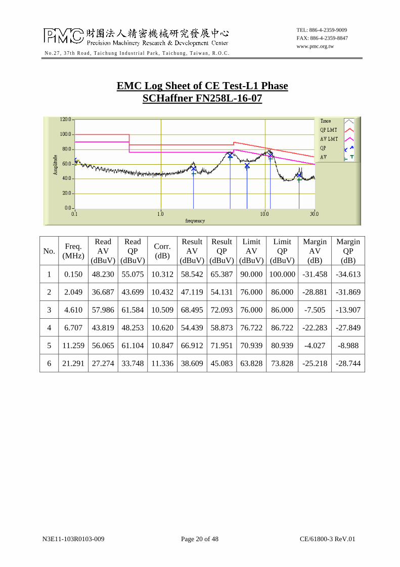
EMC Log Sheet of CE Test-L1 Phase
SCHaffner FN258L-16-07
No. Freq.
(MHz)
Read AV
(dBuV)
Read QP
(dBuV)
Corr. (dB)
Result AV
(dBuV)
Result QP
(dBuV)
Limit AV
(dBuV)
Limit QP
(dBuV)
Margin AV (dB)
Margin QP
(dB)
1 0.150 48.230 55.075 10.312 58.542 65.387 90.000 100.000 -31.458 -34.613
2 2.049 36.687 43.699 10.432 47.119 54.131 76.000 86.000 -28.881 -31.869
3 4.610 57.986 61.584 10.509 68.495 72.093 76.000 86.000 -7.505 -13.907
4 6.707 43.819 48.253 10.620 54.439 58.873 76.722 86.722 -22.283 -27.849
5 11.259 56.065 61.104 10.847 66.912 71.951 70.939 80.939 -4.027 -8.988
6 21.291 27.274 33.748 11.336 38.609 45.083 63.828 73.828 -25.218 -28.744

N3E11-103R0103-009 Page 21 of 48 CE/61800-3 ReV.01
TEL: 886-4-2359-9009
FAX: 886-4-2359-8847
www.pmc.org.tw N o . 2 7 , 3 7 t h R o a d , T a i c h u n g I n d u s t r i a l P a r k , T a i c h u n g , T a i w a n , R . O . C .
EMC Log Sheet of CE Test- L2 Phase
SCHaffner FN258L-16-07
No. Freq.
(MHz)
Read AV
(dBuV)
Read QP
(dBuV)
Corr. (dB)
Result AV
(dBuV)
Result QP
(dBuV)
Limit AV
(dBuV)
Limit QP
(dBuV)
Margin AV (dB)
Margin QP
(dB)
1 0.153 46.787 51.741 10.312 57.099 62.053 90.000 100.000 -32.901 -37.947
2 2.373 45.037 51.005 10.440 55.476 61.444 76.000 86.000 -20.524 -24.556
3 4.617 54.681 58.859 10.510 65.190 69.368 76.000 86.000 -10.810 -16.632
4 9.357 45.722 50.598 10.760 56.482 61.358 73.005 83.005 -16.524 -21.648
5 11.067 52.790 58.648 10.839 63.629 69.487 71.131 81.131 -7.502 -11.644
6 21.740 27.754 35.887 11.365 39.119 47.252 63.595 73.595 -24.476 -26.343

N3E11-103R0103-009 Page 22 of 48 CE/61800-3 ReV.01
TEL: 886-4-2359-9009
FAX: 886-4-2359-8847
www.pmc.org.tw N o . 2 7 , 3 7 t h R o a d , T a i c h u n g I n d u s t r i a l P a r k , T a i c h u n g , T a i w a n , R . O . C .
EMC Log Sheet of CE Test- L3 Phase
SCHaffner FN258L-16-07
No. Freq.
(MHz)
Read AV
(dBuV)
Read QP
(dBuV)
Corr. (dB)
Result AV
(dBuV)
Result QP
(dBuV)
Limit AV
(dBuV)
Limit QP
(dBuV)
Margin AV (dB)
Margin QP
(dB)
1 0.155 47.328 51.994 10.312 57.640 62.306 90.000 100.000 -32.360 -37.694
2 2.665 45.577 52.397 10.446 56.023 62.843 76.000 86.000 -19.977 -23.157
3 4.441 50.652 55.480 10.500 61.152 65.980 76.000 86.000 -14.848 -20.020
4 8.972 45.871 50.549 10.740 56.610 61.288 73.474 83.474 -16.863 -22.185
5 11.029 52.184 58.290 10.838 63.021 69.127 71.170 81.170 -8.148 -12.042
6 21.442 27.756 32.031 11.346 39.101 43.376 63.749 73.749 -24.648 -30.373

N3E11-103R0103-009 Page 23 of 48 CE/61800-3 ReV.01
TEL: 886-4-2359-9009
FAX: 886-4-2359-8847
www.pmc.org.tw N o . 2 7 , 3 7 t h R o a d , T a i c h u n g I n d u s t r i a l P a r k , T a i c h u n g , T a i w a n , R . O . C .
3.6 Photo during the test

N3E11-103R0103-009 Page 24 of 48 CE/61800-3 ReV.01
TEL: 886-4-2359-9009
FAX: 886-4-2359-8847
www.pmc.org.tw N o . 2 7 , 3 7 t h R o a d , T a i c h u n g I n d u s t r i a l P a r k , T a i c h u n g , T a i w a n , R . O . C .
4. Radiated Emission Test 4.1 Limits of terminal disturbance voltage
Port Frequency range 10m Limits
Enclosure
30 MHz - 230 MHz 50 dB (uV/m)quasi-peak, measured at 10m distance
230 MHz - 1000 MHz60 dB (uV/m) quasi-peak, measured at 10m distance
4.2 Test setup

N3E11-103R0103-009 Page 25 of 48 CE/61800-3 ReV.01
TEL: 886-4-2359-9009
FAX: 886-4-2359-8847
www.pmc.org.tw N o . 2 7 , 3 7 t h R o a d , T a i c h u n g I n d u s t r i a l P a r k , T a i c h u n g , T a i w a n , R . O . C .
4.3 Environmental conditions
Test Date Ambient Temperature Relative Humidity Atmospheric Pressure
Jan., 16, 2014 23.2℃ 53.2 ﹪ 1016 mbar
4.4 Description of the test
The receiving antenna was set 10 meters. The table is 80cm high, and wound rotate 360
angle. Measurement was made with the antenna having both horizontal and vertical
polarities between 1m and 4m.
4.5 Test result
The following pages show the results with antenna having both horizontal and vertical
polarities. And the following table shows quasi-peak values in some certain frequency
ranges which are local maximums in the curves.
Judging from these data, it is reasonable to assume that the EUT would pass the test to
the limits.

N3E11-103R0103-009 Page 26 of 48 CE/61800-3 ReV.01
TEL: 886-4-2359-9009
FAX: 886-4-2359-8847
www.pmc.org.tw N o . 2 7 , 3 7 t h R o a d , T a i c h u n g I n d u s t r i a l P a r k , T a i c h u n g , T a i w a n , R . O . C .
EMC Log Sheet of RE Test -Hor.
No. Freq.
(MHz)
Reading
(dBuV)
Corr.
(dB/m)
Result
(dBuV/m)
Limit
(dBuV/m)
Margin
(dB)
Azimuth
(° )
ANT
Height(cm)
1 30.000 19.556 19.730 39.286 50.000 -10.714 86.600 400.000
2 39.719 23.139 14.901 38.040 50.000 -11.960 0.200 400.000
3 68.878 21.722 8.140 29.862 50.000 -20.138 214.000 400.000
4 131.082 18.361 14.690 33.051 50.000 -16.949 293.000 400.000
5 208.838 15.944 12.557 28.502 50.000 -21.498 18.500 400.000
6 276.874 14.417 16.929 31.345 60.000 -28.655 36.100 400.000
7 298.257 14.556 17.402 31.958 60.000 -28.042 29.600 100.000

N3E11-103R0103-009 Page 27 of 48 CE/61800-3 ReV.01
TEL: 886-4-2359-9009
FAX: 886-4-2359-8847
www.pmc.org.tw N o . 2 7 , 3 7 t h R o a d , T a i c h u n g I n d u s t r i a l P a r k , T a i c h u n g , T a i w a n , R . O . C .
EMC Log Sheet of RE Test -Ver.
No. Freq.
(MHz)
Reading
(dBuV)
Corr.
(dB/m)
Result
(dBuV/m)
Limit
(dBuV/m)
Margin
(dB)
Azimuth
(° )
ANT
Height(cm)
1 32.344 23.222 18.713 41.935 50.000 -8.065 74.900 100.000
2 41.663 19.639 13.906 33.545 50.000 -16.455 292.600 100.000
3 68.878 22.472 8.140 30.612 50.000 -19.388 166.700 100.000
4 129.138 13.222 14.695 27.917 50.000 -22.083 57.200 100.000
5 267.154 7.611 17.115 24.726 60.000 -35.274 292.700 100.000
6 387.675 10.028 20.415 30.443 60.000 -29.557 357.900 100.000

N3E11-103R0103-009 Page 28 of 48 CE/61800-3 ReV.01
TEL: 886-4-2359-9009
FAX: 886-4-2359-8847
www.pmc.org.tw N o . 2 7 , 3 7 t h R o a d , T a i c h u n g I n d u s t r i a l P a r k , T a i c h u n g , T a i w a n , R . O . C .
4.6 Photo during the test

N3E11-103R0103-009 Page 29 of 48 CE/61800-3 ReV.01
TEL: 886-4-2359-9009
FAX: 886-4-2359-8847
www.pmc.org.tw N o . 2 7 , 3 7 t h R o a d , T a i c h u n g I n d u s t r i a l P a r k , T a i c h u n g , T a i w a n , R . O . C .
5. Electrostatic Discharge Immunity Test 5.1 Test specification and performance criteria
Test Port Test
Specification Units
Basic Standard
Performance Criteria
Enclosure
4 Contact
8 Air
Discharge
kV
(Charge Voltage)EN 61000-4-2 B
Note 1:The 4kV contact discharge shall be applied to conductive accessible parts. Metallic contacts, suck as in battery compartments or in socket outlets are excluded from this requirement.
5.2 Test setup

N3E11-103R0103-009 Page 30 of 48 CE/61800-3 ReV.01
TEL: 886-4-2359-9009
FAX: 886-4-2359-8847
www.pmc.org.tw N o . 2 7 , 3 7 t h R o a d , T a i c h u n g I n d u s t r i a l P a r k , T a i c h u n g , T a i w a n , R . O . C .
5.3 Environmental conditions
Test Date Ambient Temperature Relative Humidity Atmospheric Pressure
Jan., 27, 2014 22.8℃ 54.6 ﹪ 1020 mbar
5.4 Description of the test
1. Discharges were carried out both by conduct and through the air at vulnerable points
likely to easily touched or approached point on the operator’s panel and loading
/unloading area of EUT. For each test, increasing severity until the required level was
reached according to the standard did the discharge.
2. For each test point, ten discharges were done.
3. The performance was observed according to the intentional movement defined by the
manufacturer and any discrepancies were noted.
4. The test was repeated when the EUT was in operating state.
5.5 Test result
The following pages show the process of testing in both auto mode and idle state. It can be
seen that there were no unintentional movement on the EUT. And, according to the standard,
the test was passed successfully.

N3E11-103R0103-009 Page 31 of 48 CE/61800-3 ReV.01
TEL: 886-4-2359-9009
FAX: 886-4-2359-8847
www.pmc.org.tw N o . 2 7 , 3 7 t h R o a d , T a i c h u n g I n d u s t r i a l P a r k , T a i c h u n g , T a i w a n , R . O . C .
EMC LOG SHEET OF ESD TEST
Test Method
Air Contact V/HCP
Test Point Enclosure Screw 4 sides of EUT
Severity
Level
Requirement Performance Test Result
Air Contact V/HCP Air Contact V/HCP
2kV B B A A A A PASS
4kV B B A A A A PASS
8kV B N/R N/R A N/R N/R PASS
Note : 1. N/R means no requirement.
2. Test points :
2.1. air discharge for non- conducted parts.
2.2. contact discharge for conducted parts.

N3E11-103R0103-009 Page 32 of 48 CE/61800-3 ReV.01
TEL: 886-4-2359-9009
FAX: 886-4-2359-8847
www.pmc.org.tw N o . 2 7 , 3 7 t h R o a d , T a i c h u n g I n d u s t r i a l P a r k , T a i c h u n g , T a i w a n , R . O . C .
5.6 Photo during the test

N3E11-103R0103-009 Page 33 of 48 CE/61800-3 ReV.01
TEL: 886-4-2359-9009
FAX: 886-4-2359-8847
www.pmc.org.tw N o . 2 7 , 3 7 t h R o a d , T a i c h u n g I n d u s t r i a l P a r k , T a i c h u n g , T a i w a n , R . O . C .
6. Immunity Test of Radiated Radio─Frequency Electromagnetic Field─
Amplitude Modulated
6.1 Test specification and performance criteria
Phenomena Test
SpecificationUnits
Basic Standard
Performance Criteria
Radio-Frequency
Electromagnetic
Field.
Amplitude
Modulated.
80-1000
10
80
MHz
V/m
(Unmodulated,rms)
% AM (1KHZ)
EN 61000-4-3 A
6.2 Test setup

N3E11-103R0103-009 Page 34 of 48 CE/61800-3 ReV.01
TEL: 886-4-2359-9009
FAX: 886-4-2359-8847
www.pmc.org.tw N o . 2 7 , 3 7 t h R o a d , T a i c h u n g I n d u s t r i a l P a r k , T a i c h u n g , T a i w a n , R . O . C .
6.3 Environmental conditions
Test Date Ambient Temperature Relative Humidity Atmospheric Pressure
Jan., 27, 2014 22.8℃ 54.6 ﹪ 1020 mbar
6.4 Description of the test
1. During the test, the frequency range was swept from 80 to 1000MHz incrementally
with 1% step size of each frequency. The test signal was 80 % amplitude modulated
with 1 kHz sine wave.
2. The performance was observed according to the intentional movement defined by the
manufacturer and any discrepancies were noted.
3. The test was repeated when the EUT was in operating state.
6.5 Test result
The following pages show the process of testing in both auto mode and idle state. It can
be seen that there were no unintentional movement on the EUT. And, according to the
standard, the test was passed successfully.

N3E11-103R0103-009 Page 35 of 48 CE/61800-3 ReV.01
TEL: 886-4-2359-9009
FAX: 886-4-2359-8847
www.pmc.org.tw N o . 2 7 , 3 7 t h R o a d , T a i c h u n g I n d u s t r i a l P a r k , T a i c h u n g , T a i w a n , R . O . C .
EMS LOG SHEET OF RS TEST
Requirement Performance
A A
Observation on EUT
No unexpected movement was occurred.

N3E11-103R0103-009 Page 36 of 48 CE/61800-3 ReV.01
TEL: 886-4-2359-9009
FAX: 886-4-2359-8847
www.pmc.org.tw N o . 2 7 , 3 7 t h R o a d , T a i c h u n g I n d u s t r i a l P a r k , T a i c h u n g , T a i w a n , R . O . C .
6.6 Photo during the test

N3E11-103R0103-009 Page 37 of 48 CE/61800-3 ReV.01
TEL: 886-4-2359-9009
FAX: 886-4-2359-8847
www.pmc.org.tw N o . 2 7 , 3 7 t h R o a d , T a i c h u n g I n d u s t r i a l P a r k , T a i c h u n g , T a i w a n , R . O . C .
7. Electrical Fast Transient/Burst Immunity Test
7.1 Test specification and performance criteria
AC input and AC output power ports
Phenomena Test
SpecificationUnits
Basic Standard
Performance Criteria
Fast Transients
±2
5/50
5
kV (Peak)
Tr / Td ns
Rep. Frequency
kHz
EN 61000-4-4 B
7.2 Test setup
1m)(1mGRP
EFT Generator
AC Main Power CDN
EUT

N3E11-103R0103-009 Page 38 of 48 CE/61800-3 ReV.01
TEL: 886-4-2359-9009
FAX: 886-4-2359-8847
www.pmc.org.tw N o . 2 7 , 3 7 t h R o a d , T a i c h u n g I n d u s t r i a l P a r k , T a i c h u n g , T a i w a n , R . O . C .
7.3 Environmental conditions
Test Date Ambient Temperature Relative Humidity Atmospheric Pressure
Jan., 27, 2014 22.8℃ 54.6 ﹪ 1020 mbar
7.4 Description of the test
1. The test was setup by coupling/decoupling network and a series of positive and negative
polarity transients was direct injection on AC Input power cable, or Amps of the main
power of the EUT more than 32A use capacitive clamp to represent by coupling/
decoupling network.
2. The performance was observed according to the intentional movement defined by the
manufacturer and any discrepancies were noted.
3. The test was repeated when the EUT was in operating state.
7.5 Test result
The following pages show the process of testing in both auto mode and idle state. It can be
seen that there were no unintentional movement on the EUT. And, according to the standard,
the test was passed successfully.

N3E11-103R0103-009 Page 39 of 48 CE/61800-3 ReV.01
TEL: 886-4-2359-9009
FAX: 886-4-2359-8847
www.pmc.org.tw N o . 2 7 , 3 7 t h R o a d , T a i c h u n g I n d u s t r i a l P a r k , T a i c h u n g , T a i w a n , R . O . C .
EMS LOG SHEET OF EFT TEST
Coupling
Mode
Severity
Level
Requirement Performance Test
Result AC
Line
Earth
Port
AC
Line
Earth
Port
±0.25kV N/R B N/R A PASS
±0.5kV B B A A PASS
±1.0kV B B A A PASS
±2.0kV B B A A PASS
Note : N/R means no requirement.

N3E11-103R0103-009 Page 40 of 48 CE/61800-3 ReV.01
TEL: 886-4-2359-9009
FAX: 886-4-2359-8847
www.pmc.org.tw N o . 2 7 , 3 7 t h R o a d , T a i c h u n g I n d u s t r i a l P a r k , T a i c h u n g , T a i w a n , R . O . C .
7.6 Photo during the test

N3E11-103R0103-009 Page 41 of 48 CE/61800-3 ReV.01
TEL: 886-4-2359-9009
FAX: 886-4-2359-8847
www.pmc.org.tw N o . 2 7 , 3 7 t h R o a d , T a i c h u n g I n d u s t r i a l P a r k , T a i c h u n g , T a i w a n , R . O . C .
8. Immunity Test of Conducted Disturbances Induced by Radio─Frequency
Fields 8.1 Test specification and performance criteria
AC input and AC output power ports
Phenomena Test
SpecificationUnits
Basic Standard
Performance Criteria
Radio-Frequency
Common Mode
Amplitude
Modulated.
0.15-80
10
80
150
MHz
V(rms)
(Unmodulated,rms)
% AM (1kHz)
Source Impedance Ω
EN 61000-4-6 A
8.2 Test setup

N3E11-103R0103-009 Page 42 of 48 CE/61800-3 ReV.01
TEL: 886-4-2359-9009
FAX: 886-4-2359-8847
www.pmc.org.tw N o . 2 7 , 3 7 t h R o a d , T a i c h u n g I n d u s t r i a l P a r k , T a i c h u n g , T a i w a n , R . O . C .
8.3 Environmental conditions
Test Date Ambient Temperature Relative Humidity Atmospheric Pressure
Jan., 27, 2014 22.8℃ 54.6 ﹪ 1020 mbar
8.4 Description of the test
1. During the test, the frequency range was swept from 0.15 to 80 MHz incrementally with
1% step size of each frequency. The test signal was 80 % amplitude modulated with 1
kHz sine wave.
2. The performance was observed according to the intentional movement defined by the
manufacturer and any discrepancies were noted.
3. The test was repeated when the EUT was in operating state.
8.5 Test result
The following pages show the process of testing in both auto mode and idle state. It can be
seen that there were no unintentional movement on the EUT. And, according to the standard,
the test was passed successfully.

N3E11-103R0103-009 Page 43 of 48 CE/61800-3 ReV.01
TEL: 886-4-2359-9009
FAX: 886-4-2359-8847
www.pmc.org.tw N o . 2 7 , 3 7 t h R o a d , T a i c h u n g I n d u s t r i a l P a r k , T a i c h u n g , T a i w a n , R . O . C .
RESULTS OF CS TEST
Description Requirement Performance Test Result
AC Input Power Cable (L1,L2,L3)
A A PASS
Earth Port A A PASS
Note : N/R means no requirement.

N3E11-103R0103-009 Page 44 of 48 CE/61800-3 ReV.01
TEL: 886-4-2359-9009
FAX: 886-4-2359-8847
www.pmc.org.tw N o . 2 7 , 3 7 t h R o a d , T a i c h u n g I n d u s t r i a l P a r k , T a i c h u n g , T a i w a n , R . O . C .
8.6 Photo during the test

N3E11-103R0103-009 Page 45 of 48 CE/61800-3 ReV.01
TEL: 886-4-2359-9009
FAX: 886-4-2359-8847
www.pmc.org.tw N o . 2 7 , 3 7 t h R o a d , T a i c h u n g I n d u s t r i a l P a r k , T a i c h u n g , T a i w a n , R . O . C .
9. Surge Immunity Test
9.1 Test specification and performance criteria
Test Port Test
Specification Units
Basic Standard
Performance Criteria
A.C. Power Port
Line to PE
Line to Line
1.2/50(8/20) ±2
±1
Tr/Td μs
kV
kV
EN 61000-4-5 B
9.2 Test setup
1m)(1mGRP
EUT
AC Main Power
CDN
Surge Generator

N3E11-103R0103-009 Page 46 of 48 CE/61800-3 ReV.01
TEL: 886-4-2359-9009
FAX: 886-4-2359-8847
www.pmc.org.tw N o . 2 7 , 3 7 t h R o a d , T a i c h u n g I n d u s t r i a l P a r k , T a i c h u n g , T a i w a n , R . O . C .
9.3 Environmental conditions
Test Date Ambient Temperature Relative Humidity Atmospheric Pressure
Jan., 27, 2014 22.8℃ 54.6 ﹪ 1020 mbar
9.4 Description of the test
1. Overview 5 negative and 5 positive Impulses and Source impedance generator: line to
line=2Ω,line /neutral to earth=12Ω. Phase shifting in between 0~360 versus the A.C.
line phase angle and steps is 90 . 2. The performance was observed according to the intentional movement defined by the
manufacturer and any discrepancies were noted.
3. The test was repeated when the EUT was in operating state.
9.5 Test result
The following pages show the process of testing in both auto mode and idle state. It can be
seen that there were no unintentional movement on the EUT. And, according to the standard,
the test was passed successfully.

N3E11-103R0103-009 Page 47 of 48 CE/61800-3 ReV.01
TEL: 886-4-2359-9009
FAX: 886-4-2359-8847
www.pmc.org.tw N o . 2 7 , 3 7 t h R o a d , T a i c h u n g I n d u s t r i a l P a r k , T a i c h u n g , T a i w a n , R . O . C .
RESULTS OF SURGE TEST
Severity
Level Requirement Performance
Test Result
Coupling Mode
AC Line - Line
AC Line - PE
AC Line - Line
AC Line - PE
0.5kV B B A A PASS
1.0kV B B A A PASS
2.0kV N/R B N/R A PASS
Note : N/R means no requirement.
N3E11-103R0103-009 Page 48 of 48 CE/61800-3 ReV.01
TEL: 886-4-2359-9009
FAX: 886-4-2359-8847
www.pmc.org.tw N o . 2 7 , 3 7 t h R o a d , T a i c h u n g I n d u s t r i a l P a r k , T a i c h u n g , T a i w a n , R . O . C .
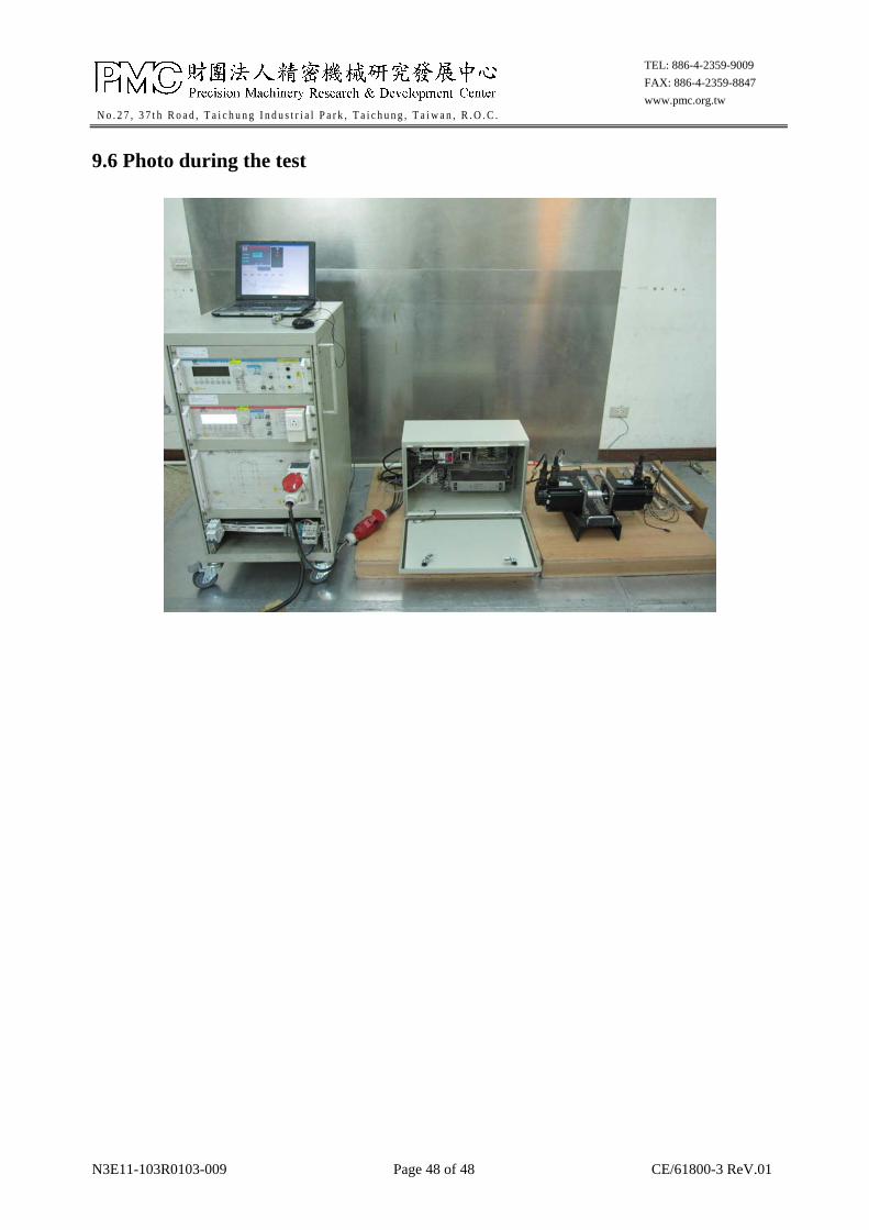
9.6 Photo during the test

ATTACHMENT
Electronic Diagram of EUT

N3E11-103R0103-009 Page 1 of 1
No.27, 37th Road, Taichung Industr ial Park, Taichung, Taiwan, R.O.C. .
TEL: 886-4-2359-9009FAX: 886-4-2359-8847www.pmc.org.tw
KSDG-02021MIP :

0
ATTACHMENT
Photograph of EUT

N3E11-103R0103-009 Page 1 of 8
No.27, 37th Road, Taichung Industr ial Park, Taichung, Taiwan, R.O.C. .
TEL: 886-4-2359-9009FAX: 886-4-2359-8847www.pmc.org.tw
KSDG-02021MIP :
1. Overview of EUT
2. Overview of EUT

N3E11-103R0103-009 Page 2 of 8
No.27, 37th Road, Taichung Industr ial Park, Taichung, Taiwan, R.O.C. .
TEL: 886-4-2359-9009FAX: 886-4-2359-8847www.pmc.org.tw
3. Overview of EUT
4. Overview of EUT

N3E11-103R0103-009 Page 3 of 8
No.27, 37th Road, Taichung Industr ial Park, Taichung, Taiwan, R.O.C. .
TEL: 886-4-2359-9009FAX: 886-4-2359-8847www.pmc.org.tw
5. Overview of EUT
6. Overview of EUT

N3E11-103R0103-009 Page 4 of 8
No.27, 37th Road, Taichung Industr ial Park, Taichung, Taiwan, R.O.C. .
TEL: 886-4-2359-9009FAX: 886-4-2359-8847www.pmc.org.tw
7. Inside of EUT
8. Inside of EUT

N3E11-103R0103-009 Page 5 of 8
No.27, 37th Road, Taichung Industr ial Park, Taichung, Taiwan, R.O.C. .
TEL: 886-4-2359-9009FAX: 886-4-2359-8847www.pmc.org.tw
9. Inside of EUT
10. Inside of EUT

N3E11-103R0103-009 Page 6 of 8
No.27, 37th Road, Taichung Industr ial Park, Taichung, Taiwan, R.O.C. .
TEL: 886-4-2359-9009FAX: 886-4-2359-8847www.pmc.org.tw
11. Inside of EUT
12. Inside of EUT

N3E11-103R0103-009 Page 7 of 8
No.27, 37th Road, Taichung Industr ial Park, Taichung, Taiwan, R.O.C. .
TEL: 886-4-2359-9009FAX: 886-4-2359-8847www.pmc.org.tw
13. Inside of EUT
14. Inside of EUT

N3E11-103R0103-009 Page 8 of 8
No.27, 37th Road, Taichung Industr ial Park, Taichung, Taiwan, R.O.C. .
TEL: 886-4-2359-9009FAX: 886-4-2359-8847www.pmc.org.tw
15. Inside of EUT
16. Inside of EUT
Related Documents