EMC Electromagnetic Compability

Welcome message from author
This document is posted to help you gain knowledge. Please leave a comment to let me know what you think about it! Share it to your friends and learn new things together.
Transcript

EMCElectromagnetic Compability
MCT Brattberg and Lycron are registered trademarks of MCT Brattberg AB, SE-371 92, Karlskrona, Sweden
Production: Boggi Reklambyrå, Värnamo.
We reserve the right to make changes to our products without prior notice.
Contents Page
Introducion 3
EMC protection 4
Design, Test and Quality 5
RGS 6-7
RGB 8
RGG 9
Frame Combinations 10
E-RGP för Round Penetrations 11
Components 12
Packing Space 13
Insert Blocks and Spare Blocks 14-15
Installation E-RGS, E-RGB 16
Installation E-RGP 17
Packing Plan 18-19
2

MCT Brattberg seals cabel and pipe penetrations in potentially hazardous
environmentsCable and Pipe Penetrations exist whenever services are routed through walls, floor, decks or bulkheads. In an emer-gency situation these penetrations could allow the passage of hazardus such as fire, water and gas.
The unique MCT Brattberg System has been approved by all leading Marine and Civil Authorities as a certified method of sealing such penetrations.
The MCT Brattbert system is a Multipurpose seal designed to allow penetration without compromising the security of the construction. Each and every cable and pipe is lead trough a frame by its own pair of halogen free module blocks which are then sealad by the use of a compression system.
The E-MCT seal system in addition to all benefits of the MCT system the specific E-MCT seal system provide protection against electromagnetic pulses, electronic sabotage and static electricity.
Where valuable assets are at riskFor almost half a century MCT Brattbergs´ original system for cable and pipe transits has set the standard at sea as well as on land.
The basic idea behind The MCT Brattberg concept is ingeniously simple. It is built around two components: the frame and the insert blocks. The seal is created when the blocks are pressed together in the frame by use of the compres-sion system. It gives a simple and secure installation.
3
The heart of the system is a rubber material called Lycron, from which the insert blocks are made. It is extremely resistant to fire but MCT Brattberg is much more than a fire and explosion barrier. In addition to extreme heat and enormous pressure changes, the transit withstand smoke, extreme temperature changes, vibrations, sound, damaging insects, chemicals and the effects of ageing.
Necessity for protectionWith the growing dependence on computers, communica-tion and control equipment the problem of sensitivity to inter-ference becomes more apparent, given the vulnerability of mod-ern electronic equipment.
The vulnerability can lead to expensive interruptions in pro-duction, communication and process control. Consequently, it is essential that two of the most important concerns with modern electronics must be to create a safe and secure environ-ment and to eliminate the risk of interference.

EMC protection from the E-MCT Brattberg
systems
4
Historically, protection of buildings, personnel and equipment from lightning was achieved by the use of lightning conductors. These measures, however, are inadequate as they provide protection from fire and personal injury only; to eliminate the Electromagnetic Interference (EMI), sometimes known as electronic smog, protection must be more specific.
The protection is achieved by a means known as Electromagnetic Compability (EMC) giving both external and internal inter-ference protection. The MCT Brattberg system is available in a specific EMC version.
Around and in close proximity to every electrical conductor exist a magnetic field. This magnetic field generates/interferes with the current flow, a feature known as induction.Such induction fields can easily cause important information to be destroyed and, in extreme cases, affect the electronic equipment.
The ability of any cable to intercept such energy depends on how and where it is installed, on its connection to other units and on its construction. The cables screening properties, therefore depend closely on the cable shielding. The cable screen is able to dissipate and absorb magnetic interference fields, therefore protecting its core
conductor. These electromagnetic interference pulses can be discharged from screen to earth.The E-MCT System contains a
sprung copper sheet which pre-vents transfer of interference in the cable. Consequently, every E-MCT Transit also works as an extended wall screen.
Benefits of E-MCT Brattberg systems
Pre-lubricated insert blocks for faster installation with assured continuity. Protects against electrical and magnetic interference (EMI), “bugging”, electronic sabotage (SEMP) and static electricity (ESD).
Assists cable management.
Integral earthing between cables and wall screen.
Also seals the penetration against the passage of fire, water, gas, sound and environmental hazards.

DesignAs with all MCT Brattberg products, the E-MCT Brattberg System comprises of a modular sealing system installed in a frame and sealed by compression system. Uniquely, however, the E-MCT system contains features which ensure earth con-tinuity and screening through the penetration.
5
Frames are welded into the wall structure to give earth bonding. For round penetrations a steel sleeve is welded to the structure prior to the installation of the RGP transit.
E-MCT moduel blocks have the facility to screen and earth cables and pipes when installed in such frames.
Stayplates are used to key blocks into frames and aid con-tinuity between module blocks.
The compression plate and E-STG endpacker whilst com-pressing the system, give the facility to allow full screen and earthing bond.
(Alternatively compression is with the E-PTG Presswedge, see page 12).
The E-MCT blocks consists of 2 different materials:– The special developed rubber material Lycron is halogen free, prelubricated and gives the advantages of fire resistance, low smoke emission, heat insu-lation an excellent chemical resistance.- The integral copper sheet allows the discharging and shielding protection between the cable and the system. In order to achieve continuity
approximately 10 mm of the outer cable insulation must be removed (see photo). The exposed braiding must be placed in the centre of the insert block.
Tested, approved and certified
We have always had and still have the ambition: to be the market´s best choice as regards pipe anc cable transits.
As early as 1983 our quality system was brought in line with the extreme demands applying to the nuclear power industry.
Today MCT Brattberg is assessed and certified by DNV in accordance with the standard EN ISO 9001:2000, for the design, manufacture and supply of fire barrier and sealed transit sys-tems associated with cable and pipe routes in building and marin environments.
As a direct result of this assessments achievement. Quality are carried out by DNV twice annually.
MCT ‘Brattberg also holds qual-ity certificates and approvals from a wide variety of classifica-tion institutions and customers, among them:
ABS (American Bureau of Shipping), ASC Pty Ltd (Australian Submarine Corp.), DNV (Det Norske Veritas) Lloyd´s Register Quality Assurance, US Navy, Framatone ANP, Bureau Veritas, LPCP BRE Certification Ltd
EMP/EMI tested by:
FFV (Research Institute for the Swedish National Defence), SwedenKarlskrona Shipyard, SwedenSaab Avionics AB, Sweden IRD Aish & Co Ltd, UK LPC H120 Firetest, UKSiemens AG Research Centre, Germany
E-STG Compression plate
Stayplate
E-MCT module block

HH
HH
W
W
W
W
RGS-6+6x3RGS-6+6
RGS-6x2RGS-6 60
W
6
RGSRGS is MCT Brattberg’s standard frame for marine applications. It has a standard in ter nal width of 120 mm and is 60 mm deep. There are four sizes of RGS, denoted by 2, 4, 6 and 8 de pending on their height. They may be used in both vertical and/or horizontal multiple frames (see page 10). The RGS is welded into an accurately pre-cut hole in the deck or bulkhead. As with all our frames, RGS is produced in steel, stainless steel, or alumin ium. For installations where cables are already in place, specify RGSO, which has a removable end. RGS weight charts can be found on the next page.
RGSO with removable end
RGSO WITH REMOVABLE END
RGS-2
RGS-4
RGS-6
RGS-8
RGS-2+2
RGS-2+4
RGS-2+6
RGS-2+8
RGS-4+4
RGS-4+6
RGS-4+8
RGS-6+6
RGS-6+8
RGS-8+8
RGS-2+2
RGS-2+4
RGS-2+6
RGS-2+8
RGS-4+4
RGS-4+6
RGS-4+8
RGS-6+6
RGS-6+8
RGS-8+8
121
179,5
238
296,5
242
300,5
359
417,5
359
417,5
476
476
534,5
593
232
290,5
349
407,5
349
407,5
466
466
524,5
583
140,5
- ,, -
- ,, -
- ,, -
140,5
- ,, -
- ,, -
- ,, -
- ,, -
- ,, -
- ,, -
- ,, -
- ,, -
- ,, -
271
- ,, -
- ,, -
- ,, -
- ,, -
- ,, -
- ,, -
- ,, -
- ,, -
- ,, -
- ,, -
- ,, -
- ,, -
- ,, -
401,5
- ,, -
- ,, -
- ,, -
- ,, -
- ,, -
- ,, -
- ,, -
- ,, -
- ,, -
- ,, -
- ,, -
- ,, -
- ,, -
532
- ,, -
- ,, -
- ,, -
- ,, -
- ,, -
- ,, -
- ,, -
- ,, -
- ,, -
- ,, -
- ,, -
- ,, -
- ,, -
Size in mm
Siz
e ch
art
in m
m
793
- ,, -
- ,, -
- ,, -
- ,, -
- ,, -
- ,, -
- ,, -
- ,, -
- ,, -
- ,, -
- ,, -
- ,, -
- ,, -
662,5
- ,, -
- ,, -
- ,, -
- ,, -
- ,, -
- ,, -
- ,, -
- ,, -
- ,, -
- ,, -
- ,, -
- ,, -
- ,, -
W = 10 +
130,5 x n
n = number of frames wide.Tolerances single frame: Height ± 1 mm, Width ± 0,8 mm.Material thickness is 10 mm.
All measurements are in millimeters.
H (height)
W (width)/Multiple Frames
FRAME SIZE x 1 x 2 x 3 x 4 x 5 x 6 x nRGS

7
RGS
Standard frames come in four sizes: 2, 4, 6 and 8. They are all the same width. Height differences are shown below.The material is 10 mm thick.
WEIGHT CHART
Wei
ght
char
t in
kilo
gram
s
MILD STEEL
SS1312
EN 10025-S235JRG2
DIN RST 37-2
ASTM A36
BS 4360 gr. 40
NS 17100
STAINLESS
STEEL
SS2348
EN 10088/1.4404
ASTM/A316L
BS 970 gr. 316
ALUMINIUM
SS4212
EN AW-6082
DIN ALMG SI 1F28
ASTM/A6082
BS 1474 gr. 6082
NS 17305
RGS-2
RGS-4
RGS-6
RGS-8
RGS-2+2
RGS-2+4
RGS-2+6
RGS-2+8
RGS-4+4
RGS-4+6
RGS-4+8
RGS-6+6
RGS-6+8
RGS-8+8
RGS-2
RGS-4
RGS-6
RGS-8
RGS-2+2
RGS-2+4
RGS-2+6
RGS-2+8
RGS-4+4
RGS-4+6
RGS-4+8
RGS-6+6
RGS-6+8
RGS-8+8
RGS-2
RGS-4
RGS-6
RGS-8
RGS-2+2
RGS-2+4
RGS-2+6
RGS-2+8
RGS-4+4
RGS-4+6
RGS-4+8
RGS-6+6
RGS-6+8
RGS-8+8
2,2
2,7
3,2
3,8
3,6
4,2
4,8
5,5
4,8
5,5
5,9
5,9
6,5
7,2
2,2
2,8
3,3
3,9
3,7
4,3
4,9
5,6
4,9
5,6
6,0
6,0
6,7
7,4
0,8
1,0
1,1
1,3
1,3
1,5
1,7
1,9
1,7
1,9
2,1
2,1
2,3
2,5
3,9
4,6
5,4
6,3
8,1
8,8
9,5
10,3
9,5
10,3
11,1
11,1
12,0
12,9
4,0
4,7
5,5
6,5
8,3
9,0
9,7
10,6
9,7
10,6
11,4
11,4
12,3
13,2
1,4
1,6
1,9
2,2
2,8
3,1
3,3
3,6
3,3
3,6
3,9
3,9
4,2
4,5
5,7
6,5
7,6
8,9
11,9
12,8
13,6
14,7
13,6
14,7
15,8
15,8
17,0
18,3
5,8
6,7
7,8
9,1
12,2
13,1
14,0
15,1
14,0
15,1
16,2
16,2
17,5
18,8
2,0
2,3
2,7
3,1
4,2
4,5
4,8
5,2
4,8
5,2
5,5
5,5
6,0
6,4
7,4
8,4
9,8
11,4
15,7
16,7
17,8
19,1
17,8
19,1
20,5
20,5
22,1
23,7
7,6
8,6
10,0
11,7
16,1
17,1
18,2
19,6
18,2
19,6
21,0
21,0
22,6
24,3
2,6
3,0
3,4
4,0
5,5
5,9
6,2
6,7
6,2
6,7
7,2
7,2
7,7
8,3
9,2
10,3
12,0
14,0
19,5
20,7
21,9
23,5
21,9
23,5
25,1
25,1
27,1
29,1
9,4
10,6
12,3
14,3
20,0
21,2
22,5
24,1
22,5
24,1
25,8
25,8
27,8
29,9
3,2
3,6
4,2
4,9
6,9
7,2
7,7
8,3
7,7
8,3
8,8
8,8
9,5
10,2
10,9
12,2
14,2
16,5
23,3
24,6
26,0
27,9
26,0
27,9
29,8
29,8
32,1
34,5
11,2
12,6
14,5
16,9
23,9
25,2
26,7
28,6
26,7
28,6
30,6
30,6
32,9
35,4
3,8
4,3
5,0
5,8
8,2
8,6
9,1
9,8
9,1
9,8
10,4
10,4
11,2
12,1
Weight in kilograms
FRAME SIZE
W (width)/Multiple Frames
MATERIAL x 1 x 2 x 3 x 4 x 5 x 6
120120
220280
120120
100160
RGS-2 RGS-4
RGS-6 RGS-8
RGB
�
� �
�
�
���
8
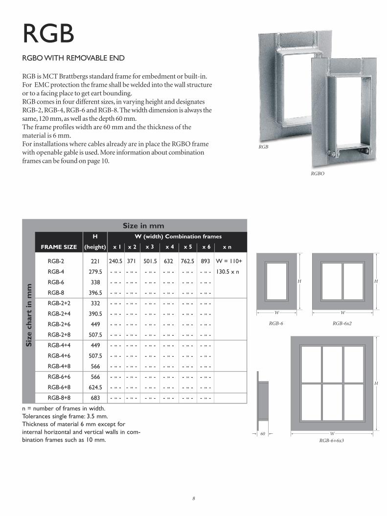
RGBRGB is MCT Brattbergs standard frame for embedment or built-in. For EMC protection the frame shall be welded into the wall structureor to a facing place to get eart bounding.RGB comes in four different sizes, in varying height and designates RGB-2, RGB-4, RGB-6 and RGB-8. The width dimension is always the same, 120 mm, as well as the depth 60 mm. The frame profiles width are 60 mm and the thickness of the material is 6 mm. For installations where cables already are in place the RGBO frame with openable gable is used. More information about combination frames can be found on page 10.
RGBO WITH REMOVABLE END
RGB-6 RGB-6x2
RGB-6+6x3
RGB-2
RGB-4
RGB-6
RGB-8
RGB-2+2
RGB-2+4
RGB-2+6
RGB-2+8
RGB-4+4
RGB-4+6
RGB-4+8
RGB-6+6
RGB-6+8
RGB-8+8
221
279.5
338
396.5
332
390.5
449
507.5
449
507.5
566
566
624.5
683
240.5
- ,, -
- ,, -
- ,, -
- ,, -
- ,, -
- ,, -
- ,, -
- ,, -
- ,, -
- ,, -
- ,, -
- ,, -
- ,, -
371
- ,, -
- ,, -
- ,, -
- ,, -
- ,, -
- ,, -
- ,, -
- ,, -
- ,, -
- ,, -
- ,, -
- ,, -
- ,, -
501.5
- ,, -
- ,, -
- ,, -
- ,, -
- ,, -
- ,, -
- ,, -
- ,, -
- ,, -
- ,, -
- ,, -
- ,, -
- ,, -
632
- ,, -
- ,, -
- ,, -
- ,, -
- ,, -
- ,, -
- ,, -
- ,, -
- ,, -
- ,, -
- ,, -
- ,, -
- ,, -
Size in mm
893
- ,, -
- ,, -
- ,, -
- ,, -
- ,, -
- ,, -
- ,, -
- ,, -
- ,, -
- ,, -
- ,, -
- ,, -
- ,, -
762.5
- ,, -
- ,, -
- ,, -
- ,, -
- ,, -
- ,, -
- ,, -
- ,, -
- ,, -
- ,, -
- ,, -
- ,, -
- ,, -
W = 110+
130.5 x n
H
(height)
W (width) Combination frames
FRAME SIZE x 1 x 2 x 3 x 4 x 5 x 6 x n
Siz
e ch
art
in m
m
n = number of frames in width.Tolerances single frame: 3.5 mm.Thickness of material 6 mm except for internal horizontal and vertical walls in com-bination frames such as 10 mm.
RGBO

���
��� ���
���
�������
������
Standard frames in four different sizes: 2, 4, 6 and 8 which mark different heights. All have the same width. See below.
9
RGB-6 RGB-8
RGB-2 RGB-4
Wei
ght
char
t in
kilo
gram
s
Weight in kilograms
STEEL
SS1312
SS EN 10025-S235JRG2
DIN RST 37-2
ASTM A36
BS 4360 gr. 40
NS 17100
STAINLESS
STEEL
SS2348
DIN 1,4404
ASTM/316 L
AiSi 316 L
BS 970 gr. 316 S11
NS 14450
ALUMINIUM
SS4212
DIN ALMG SI 1
A 6082
BS H30/6082 TF
NS 17305
RGB-2
RGB-4
RGB-6
RGB-8
RGB-2+2
RGB-2+4
RGB-2+6
RGB-2+8
RGB-4+4
RGB-4+6
RGB-4+8
RGB-6+6
RGB-6+8
RGB-8+8
RGB-2
RGB-4
RGB-6
RGB-8
RGB-2+2
RGB-2+4
RGB-2+6
RGB-2+8
RGB-4+4
RGB-4+6
RGB-4+8
RGB-6+6
RGB-6+8
RGB-8+8
RGB-2
RGB-4
RGB-6
RGB-8
RGB-2+2
RGB-2+4
RGB-2+6
RGB-2+8
RGB-4+4
RGB-4+6
RGB-4+8
RGB-6+6
RGB-6+8
RGB-8+8
3.1
3.8
4.4
5.0
5.0
5.6
6.2
6.9
6.2
6.9
7.4
7.4
8.1
8.9
3.2
3.9
4.5
5.2
5.1
5.8
6.3
7.1
6.3
7.1
7.6
7.6
8.4
9.1
1.1
1.4
1.6
1.8
1.8
2.0
2.2
2.4
2.2
2.4
2.6
2.6
2.9
3.2
15.0
15.9
16.8
17.7
17.9
19.0
19.9
11.0
19.9
11.0
11.8
11.8
13.0
14.2
15.1
16.1
16.9
17.9
18.1
19.2
10.1
11.3
10.1
11.3
12.1
12.1
13.3
14.6
11.8
12.1
12.4
12.7
12.8
13.2
13.5
13.9
13.5
13.9
14.2
14.2
14.6
15.0
16.9
18.1
19.2
10.4
10.9
12.4
13.6
15.1
13.6
15.1
16.2
16.2
17.9
19.5
17.1
18.3
19.4
10.7
11.2
12.7
13.9
15.5
13.9
15.5
16.6
16.6
18.3
20.0
12.5
12.9
13.2
13.7
13.9
14.4
14.8
15.3
14.8
15.3
15.7
15.7
16.3
16.9
18.8
10.2
11.5
13.1
13.9
15.7
17.3
19.2
17.3
19.2
20.6
20.6
22.7
24.9
19.0
10.5
11.8
13.5
14.2
16.1
17.8
19.7
17.8
19.7
21.1
21.1
23.3
25.5
13.1
13.6
14.1
14.6
14.9
15.5
16.1
16.7
16.1
16.7
17.2
17.2
18.0
18.7
10.7
12.4
13.8
15.8
16.8
19.1
21.0
23.3
21.,0
23.3
25.0
25.0
27.6
30.2
11.0
12.7
14.2
16.2
17.2
19.6
21.6
23.9
21.6
23.9
25.6
25.6
28.3
31.0
13.8
14.4
14.9
15.6
15.9
16.7
17.4
18.2
17.4
18.2
18.8
18.8
19.7
10.6
12.6
14.6
16.3
18.5
19.8
22.4
24.7
27.4
24.7
27.4
29.4
29.4
32.4
35.5
12.9
14.9
16.7
19.0
20.3
23.0
25.4
28.1
25.4
28.1
30.1
30.1
33.3
36.4
14.4
15.1
15.7
16.5
17.0
17,9
18.7
19.6
18.7
19.6
10.3
10.3
11.4
12.5
FRAME SIZE
W (width) Combination frames
MATERIAL x 1 x 2 x 3 x 4 x 5 x 6

10
Multiple Frames
VERTICAL MULTIPLE FRAMES
Vertical multiple frames are described by list ing the bottom frame type and size + the next frame type and size.
HORIZONTAL MULTIPLE FRAMES
Horizontal multiple frames are described by list ing the frame type and size x the desired number of horizontal openings.
VERTICAL AND HORIZONTAL MULTIPLE FRAMES List the entire vertical frames x the desired number of horizontal repetitions.
+6
6
RGS 6+ 6
+4
RGS 6+4+2
RGS 6+4+2x4
+2
6
Designation (starting at bottom):
6
RGS 6x4Designation:
+2
+4
6
x1 x2 x3 x4
x1 x2 x3 x4
Designationstarting at bottom:
NOTE: All multiple frame designations must be preceded by the frame type.
RGB 6+6 RGB 6+4+2
+6
6
+4
+2
6
+2
+4
6
x1 x2 x3 x4
RGB 6+4+2x4
RGS frame RGB frame
x1 x2 x3 x4
6
RGB 6x4

66
The E-RGP is a round Lycron frame forassembly in pipes. A copper sheet formsthe contact between insert block and pipe housing. The seal is available in 6 sizes with the designations E-RGP -50/L60, -70 , -100, -125, -150 and -200.
E-RGP 200
RGP SIZE PACKING SPACE
E-RGP 70
E-RGP 50/L60
40
20 50
70
74,5
69
20
40
60
60
E-RGP 100
E-RGP 150
The round sleeve is used to house the E-RGP seal.The sleeve is available in six different sizes.There are several types to choose from, with and without flanges, for welding and for bolting, plus an open version. For more information, request our special brochure, “RGP”.
E-RGP is a circular seal for holes or pipes.
E-RGP-round holes
Sleeves
11
Size in mm
Weight in kilogramsE-RGP 50/L60 E-RGP 70 E-RGP 100
0,25 0,4 0,7
1,8 3,0
LENGHT AND DIAMETER
66
120
90
90
120
200
150
80
80
E-RGP 125 127
1,0
E-RGP 200E-RGP 150E-RGP 125
66
74,5
100
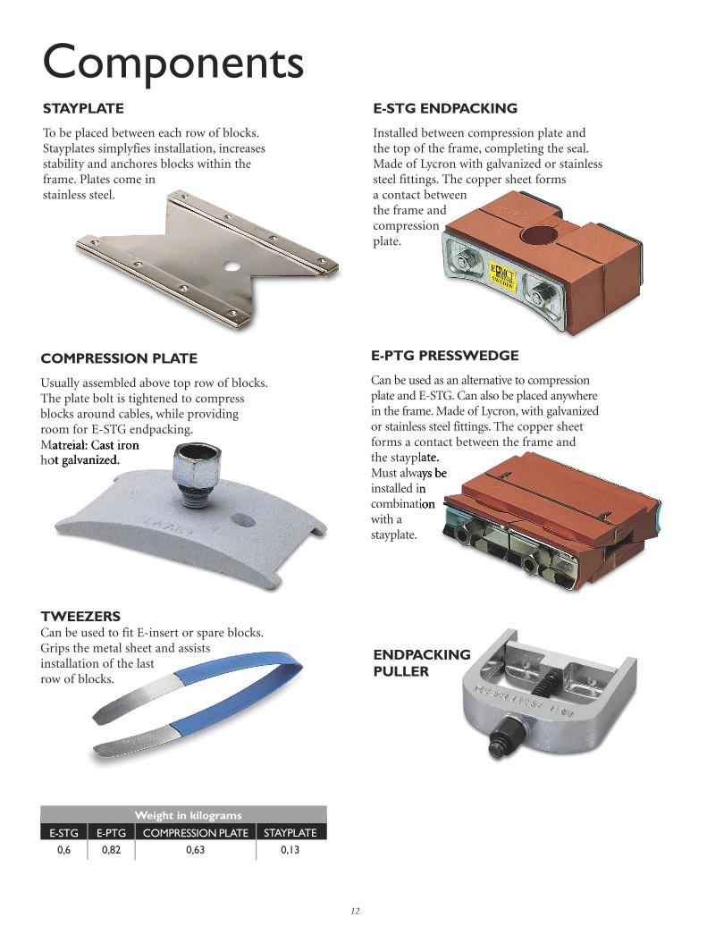
STAYPLATE
To be placed between each row of blocks. Stayplates simplyfies installation, increases stability and anchores blocks within the frame. Plates come in stainless steel.
COMPRESSION PLATE
Usually assembled above top row of blocks. The plate bolt is tightened to compress blocks around cables, while providing room for E-STG endpacking. Matreial: Cast ironhot galvanized.
Components
12
Weight in kilograms
E-STG E-PTG COMPRESSION PLATE STAYPLATE
0,6 0,82 0,63 0,13
E-PTG PRESSWEDGE
Can be used as an alternative to compression plate and E-STG. Can also be placed anywhere in the frame. Made of Lycron, with galvanized or stainless steel fittings. The copper sheet forms a contact between the frame and the stayplate. Must always be installed in combination with a stayplate.
the stayplate. Must always be installed in combination
Matreial: Cast ironhot galvanized.
ENDPACKING PULLER
TWEEZERSCan be used to fit E-insert or spare blocks. Grips the metal sheet and assistsinstallation of the lastrow of blocks.
E-STG ENDPACKING
Installed between compression plate and the top of the frame, completing the seal.Made of Lycron with galvanized or stainless steel fittings. The copper sheet forms a contact between the frame and compression plate.

13
RGS 2RGS 4RGS 6RGS 8
32 6496128
18365472
8162432
391218
2468
-122
-112
15 20 30 40 60 90 120
Sample packing space plans (RG-Plans) for RGS (below left) and RGP (below right). We recommend placing the larger cables at the bottom.
RGS-maximum number of cables and pipes
BLOCK SIZE
FRAME SIZE MAXIMUM NUMBER OF CABLES AND PIPES
E-RGP-50/L60E-RGP-70E-RGP-100E-RGP-125E-RGP-150E-RGP-200
1 416163664
149161636
-144916
-11449
--1114
----11
-----1
15 20 30 40 60 90 120
E-RGP-maximum number of cables and pipes
BLOCK SIZE
RGP SIZE MAXIMUM NUMBER OF CABLES AND PIPES
30/0
30/20 30/20
20/15 20/14 20/12 20/12 20/0 20/0
40/30 40/32 40/34
60/44 60/48
60/40
30/030/030/0
30/20
60/40
30/0 30/0 30/0 30/0
20/14
30/20
20/14
30/22
20/12 20/12
40/30 40/32 40/34
20/9 20/7
20/7
U30
20/7
U30
20/9 20/7
30/18
SIZE 8
SIZE 6
SIZE 4
SIZE 2
30/0
30/20 30/20
20/15 20/14 20/12 20/12 20/0 20/0
40/30 40/32 40/34
60/44 60/48
60/40
30/030/030/0
30/20
60/40
30/0 30/0 30/0 30/0
20/14
30/20
20/14
30/22
20/12 20/12
40/30 40/32 40/34
20/9 20/7
20/7
U30
20/7
U30
20/9 20/7
30/18
E-RGP 50/L60
E-RGP 70
E-RGP 100
E-RGP 150
E-RGP 200
E-RG
P 50/L60
E-RG
P 70
E-RG
P 100
E-RG
P 150
E-RG
P 200
Packing Space
E-RG
P 125
E-RGP 125

14
Choosing the correct E-Insert Blocks
Spare Blocks
Our standard range of E-blocks accomodates cables beween 4 and 54 mm in diameter. It is important that the insert block is the right size, with respect to the cable, to ensure a proper seal. Measure the cable diameters carefully and choose E-insert blocks accordingly. With the sizing chart on next page you can choose the correct size of E-insert blocks. E-Blocks are referred to by their width (A) and hole diameter (B). Thus a E-block with a width of 15 mm and a hole diameter of 4 mm is referred to as 15/4. This designation is moulded into the E-block. The E-MCT block has an integral copper sheet as discharging and shielding protection between the cable and the system.There are 2 different designs of copper sheets, one for outer cable diameters up to 10 mm and one for outer cable diameters over 10 mm.The design guarantees good contact without damaging the cable braid. In order to correctly install the E-MCT modules they are marked with a yellow E on one of the short ends. The marking also indicates that it is an E-MCT Brattberg System.
Surplus room in each frame is filled out with solid E-insert blocks. Called spares, they bear the designation A/0. The copper sheet forms contact between surrounding blocks and the frame. E-Blocks are referred to by their width (A), followed by the designation /0 (indicating solid). Thus a E-block with a width and height of 15 mm is referred to as 15/0. The length of E-insert blocks is always 60 mm.
5 x120
10 x120
15 x 15
20 x 20
30 x 30
40 x 40
60 x 60
E-BLOCK SIZEWidth (A) = Height (A)
E-BLOCK DESIGNATION
Right Wrong Wrong
60
A
B
A
A
60
E-24 x 5/0
E-12 x 10/0
E-15/0
E-20/0
E-30/0
E-40/0
E-60/0

CABLEDIAM.
B
E-60/32
E-60/34
E-60/36
E-60/38
E-60/40
E-60/42
E-60/44
E-60/46
E-60/48
E-60/50
E-60/52
E-60/54
E-40/32
E-40/34
31.5-33.5
33.5-35.5
35.5-37.5
37.5-39.5
39.5-41.5
41.5-43.5
43.5-45.5
45.5-47.5
47.5-49.5
49.5-51.5
51.5-53.5
53.5-55.5
32
34
36
38
40
42
44
46
48
50
52
54
40 60
A
4
5
6
7
8
9
10
11
12
13
14
15
16
3.5-4.5
4.5-5.5
5.5-6.5
6.5-7.5
7.5-8.5
8.5-9.5
9.5-10.5
10.5-11.5
11.5-12.5
12.5-13.5
13.5-14.5
14.5-15.5
15.5-16.5
15 20CABLEDIAM. 30
BA
15
E-24 x 5/0
E-12 x 10/0
E-15/0
E-20/0
E-30/0
E-40/0
E-60/0
E-15/4
E-15/5
E-15/6
E-15/7
E-15/8
E-15/9
E-20/4
E-20/5
E-BLOCK WEIGHT E-BLOCK WEIGHT E-BLOCK WEIGHT E-BLOCK WEIGHT
58
113
20
38
84
150
338
10
10
10
10
9
8
18
18
E-20/6
E-20/7
E-20/8
E-20/9
E-20/10
E-20/11
E-20/12
E-20/13
E-20/14
E-20/15
E-20/16
E-30/12
E-30/13
E-30/14
E-30/15
E-30/16
E-30/17
E-30/18
17
17
16
15
14
13
13
12
11
10
9
36
36
35
34
33
31
30
E-30/19
E-30/20
E-30/21
E-30/22
E-30/23
E-30/24
E-40/22
E-40/24
E-40/26
E-40/28
E-40/30
E-40/32
E-40/34
28
27
25
24
22
21
57
54
50
47
42
37
32
Blocks are referred to by their width (A) and hole diameter (B). Thus a mod ule with a width of 15 mm and a hole diameter of 4 mm is referred to as E 15 /4.
Weight in grams per half
A
A 2
B
CABLEDIAM. 30 40
BASize in mm
E-40/22
E-40/22
E-40/24
E-40/26
E-40/28
E-40/30
17
18
19
20
21
22
23
24
26
28
30
E-60/32
E-60/34
E-60/36
E-60/38
E-60/40
E-60/42
E-60/44
E-60/46
E-60/48
E-60/50
E-60/52
E-60/54
131
127
122
116
110
104
98
91
84
77
59
61
E-15/4
E-15/5
E-15/6
E-15/7
E-15/8
E-15/9
E-20/4
E-20/5
E-20/6
E-20/7
E-20/8
E-20/9
E-20/10
E-20/11
E-20/12
E-20/13
E-20/14
E-20/15
E-20/16
E-30/12
E-30/13
E-30/14
E-30/15
E-30/16
E-30/17
E-30/18
E-30/19
E-30/20
E-30/21
E-30/22
E-30/23
E-30/24
16.5-17.5
17.5-18.5
18.5-19.5
19.5-20.5
20.5-21.5
21.5-22.5
22.5-23.5
23.5-25.5
25.5-27.5
27.5-29.5
29.5-31.5
Special and larger modulescan be made to order.

16
Installation E-RGS, E-RGB
Clean the inside of the frame carefully to ensure good electrical contact between the metal sheet and the frame.
1Pull cables to final position. Mark cable 30 mm from front edge of frame. Remove cable sheat 5 mm on either side of the line.
2When packing the transit, ensure all the insert blocks have ”E” marking facing the installet.
3
Position the stayplates between each layer of insert blocks.
4Before the final row of blocks, the compres-sion plate is installed. Alternatively, the E-PTG Presswedge can be fitted.
5Tweezers can be used, if required to aid installation of the last row of blocks.
6
Tighten the compression plate bolt until the tongue of the E-STG-1 slides into posi-tion around the bolt (32 mm maximum from the inside of the frame to the top of the compression plate).
7Put the endpacking with the tongue aro-und the bolt. Tighten the nuts in the end-packing until approximately 10-12 mm of free threads are visible.
8

17
Installation E-RGP
Thorougly clean the inside of the frame. Check that frame dimensions agree with stated tolerances.
1Place the E-RGP in the correct position in the opening.
2Pull the cables to final position. Mark cable 30 mm from front edge of frame. Remove cable sheat 5 mm on either side of the line.
3
When packing the transit, ensure all the insert blocks have ”E” markings thread is visible.
4Tweezers can be used, if required, to aid installation of last row of blocks.
5Tighten the nuts so that 10-12 mm of the protruding thread is visible.
6
PRESSURE TIGHT INSTALLATIONThe contact surfaces between E-RGP plugs and the frame must be completely clean when E-RGP is instal-led. No lubrication shall be used on these surfaces. All sealing blocks shall be lubricated well with MCT Brattberg’s lubricant. The transit should not be pressure tested for at least 48 hours after installation. This is to ensure that pres-sure is evened out inside the transit. At temperatures lower than +20°C this time should be extended. Type approval pressure 2 bar (29.4 psi), test pressure 5 bar.
N.B. Once an installation has been subjected to pressure all components must be replaced with new materials.

The correct frame size can be determined by using this plan. The numbers 2, 4, 6 and 8 in the margin represent the packing space available in frames size 2, 4, 6 and 8 respectively. It is not neccessary to show stayplates and compression components as the required space has already been allowed for. RG-Packing Plans will be supplied free of charge upon request.
Packing Plan E-STG + Compression plate or E-PTG
SIZE 8
SIZE 6
SIZE 4
SIZE 2
18
E-STG
Compression plate
E-PTG
Stayplate
Lubricant
E-Blocks

E-Blocks
19
E-RGP 200
E-RGP 150
E-RGP 100
E-RGP 70
E-RGP 50/L60
E-RG
P 50/L60
E-RG
P 70
E-RG
P 100
E-RG
P 150
E-RG
P 200
E-RGP
E-RG
P 125
E-RGP 125

www.mctbrattberg.com
ww
w.b
oggi
.se
We have representatives in:
MCT Brattberg LtdCommerce StreetCarrs Industrial Estate HaslingdenLancashire BB4 5JTEnglandTel: +44 - 170 624 4890Fax: +44 - 170 624 4891E-mail: [email protected]
MCT Brattberg Inc.P.O. Box 374Spring Tx 77383USAPhone: +1 (281) 355 8191Fax: +1 (281) 355 8393E-mail: [email protected]
MCT Brattberg ABSE-371 92 KarlskronaSwedenPhone: +46 - 455 45 160Fax: +46 - 455 45 128E-mail: [email protected]: www.mctbrattberg.se
Austria - Australia - Belgium - Borneo - Brazil - Canada - China - Croatia - Denmark - Egypt - Finland - France - Germany - Greece - Hong Kong Iceland - India - Indonesia - Iran - Ireland - Israel - Italy - Japan - Korea - Malaysia - Netherlands - New Zealand - Norway - Oman
Philippine - Islands - Poland - Qatar - Singapore - Spain - South Africa - Switzerland - Taiwan - Thailand - Turkey - UAE - United Kingdom - USA
Please contact MCT Brattberg for details of your nearest distributor.
Related Documents