Embedding it better... µTasker Document µTasker – RNDIS (Remote Network Driver Interface Specification) uTaskerRNDIS.doc/1.00 Copyright © 2016 M.J.Butcher Consulting

Welcome message from author
This document is posted to help you gain knowledge. Please leave a comment to let me know what you think about it! Share it to your friends and learn new things together.
Transcript
Embedding it better...
µTasker Document
µTasker – RNDIS(Remote Network Driver Interface Specification)
uTaskerRNDIS.doc/1.00 Copyright © 2016 M.J.Butcher Consulting
www.uTasker.com µTasker – RNDIS
Table of Contents1.Introduction..............................................................................................................................32.RNDIS USB Class...................................................................................................................43.RNDIS Messages.....................................................................................................................5
3.1 Handling a Query.................................................................................................................................................53.2 Handling a Set Message.................................................................................................................................................53.3 Handling an Indicate Status Message from the Device ...................................................63.4 Data Message Details.................................................................................................................................................6
4.Initialisation.............................................................................................................................75.Keep-Alive.............................................................................................................................126.Reset.......................................................................................................................................137.Disabling and Re-enabling the RNDIS Network Connection................................................148.Configurations........................................................................................................................159.Monitoring RNDIS activity...................................................................................................2110.Installation............................................................................................................................2211.Conclusion...........................................................................................................................24
uTaskerRNDIS.doc/1.00 2/24 3.10.16
www.uTasker.com µTasker – RNDIS
1. Introduction
The RNDIS protocol is specified in the Microsoft document “Remote Network Driver InterfaceSpecification (RNDIS) Protocol” [M-RNDIS]. https://msdn.microsoft.com/en-us/library/ee524902.aspx
For more complete details of individual message see also https://msdn.microsoft.com/en-us/library/ff570659(v=vs.85).aspx
This discussion concentrates more on technical details to achieve said implementation, aspects that are possibly not handled (adequately) in the specification and general practical advice on making use of RNDIS in the µTasker project.
uTaskerRNDIS.doc/1.00 3/24 3.10.16
www.uTasker.com µTasker – RNDIS
2. RNDIS USB Class
RNDIS is based on the USB-CDC class and uses, as any CDC interface, bulk data (IN and OUT endpoint) for transport (specifically Ethernet frames packed in the REMOTE_IDS_PACKET_MSG), plus a control endpoint. The control endpoint is used by the device to signal that it has a message (not data content) to be collected by the host. Two or three endpoints are thus required for RNDIS, on top of endpoint 0 (if the data IN and OUT bulk endpoints are shared on a single endpoint two interface endpoints result).
Endpoint 0 is used extensively by RNDIS for non-data messaging, as explained in the following chapter.
uTaskerRNDIS.doc/1.00 4/24 3.10.16
www.uTasker.com µTasker – RNDIS
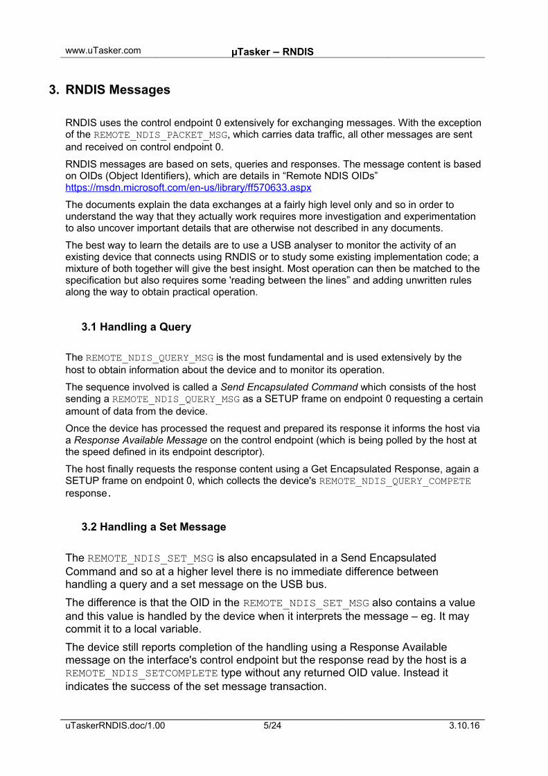
3. RNDIS Messages
RNDIS uses the control endpoint 0 extensively for exchanging messages. With the exceptionof the REMOTE_NDIS_PACKET_MSG, which carries data traffic, all other messages are sent and received on control endpoint 0.
RNDIS messages are based on sets, queries and responses. The message content is basedon OIDs (Object Identifiers), which are details in “Remote NDIS OIDs” https://msdn.microsoft.com/en-us/library/ff570633.aspx
The documents explain the data exchanges at a fairly high level only and so in order to understand the way that they actually work requires more investigation and experimentation to also uncover important details that are otherwise not described in any documents.
The best way to learn the details are to use a USB analyser to monitor the activity of an existing device that connects using RNDIS or to study some existing implementation code; a mixture of both together will give the best insight. Most operation can then be matched to the specification but also requires some 'reading between the lines” and adding unwritten rules along the way to obtain practical operation.
3.1 Handling a Query
The REMOTE_NDIS_QUERY_MSG is the most fundamental and is used extensively by the host to obtain information about the device and to monitor its operation.
The sequence involved is called a Send Encapsulated Command which consists of the host sending a REMOTE_NDIS_QUERY_MSG as a SETUP frame on endpoint 0 requesting a certainamount of data from the device.
Once the device has processed the request and prepared its response it informs the host via a Response Available Message on the control endpoint (which is being polled by the host at the speed defined in its endpoint descriptor).
The host finally requests the response content using a Get Encapsulated Response, again a SETUP frame on endpoint 0, which collects the device's REMOTE_NDIS_QUERY_COMPETE response.
3.2 Handling a Set Message
The REMOTE_NDIS_SET_MSG is also encapsulated in a Send Encapsulated Command and so at a higher level there is no immediate difference between handling a query and a set message on the USB bus.
The difference is that the OID in the REMOTE_NDIS_SET_MSG also contains a value and this value is handled by the device when it interprets the message – eg. It may commit it to a local variable.
The device still reports completion of the handling using a Response Available message on the interface's control endpoint but the response read by the host is a REMOTE_NDIS_SETCOMPLETE type without any returned OID value. Instead it indicates the success of the set message transaction.
uTaskerRNDIS.doc/1.00 5/24 3.10.16
www.uTasker.com µTasker – RNDIS
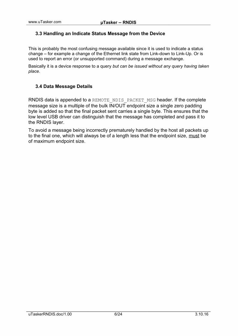
3.3 Handling an Indicate Status Message from the Device
This is probably the most confusing message available since it is used to indicate a status change – for example a change of the Ethernet link state from Link-down to Link-Up. Or is used to report an error (or unsupported command) during a message exchange.
Basically it is a device response to a query but can be issued without any query having takenplace.
3.4 Data Message Details
RNDIS data is appended to a REMOTE_NDIS_PACKET_MSG header. If the complete message size is a multiple of the bulk IN/OUT endpoint size a single zero padding byte is added so that the final packet sent carries a single byte. This ensures that the low level USB driver can distinguish that the message has completed and pass it to the RNDIS layer.
To avoid a message being incorrectly prematurely handled by the host all packets upto the final one, which will always be of a length less that the endpoint size, must be of maximum endpoint size.
uTaskerRNDIS.doc/1.00 6/24 3.10.16
www.uTasker.com µTasker – RNDIS
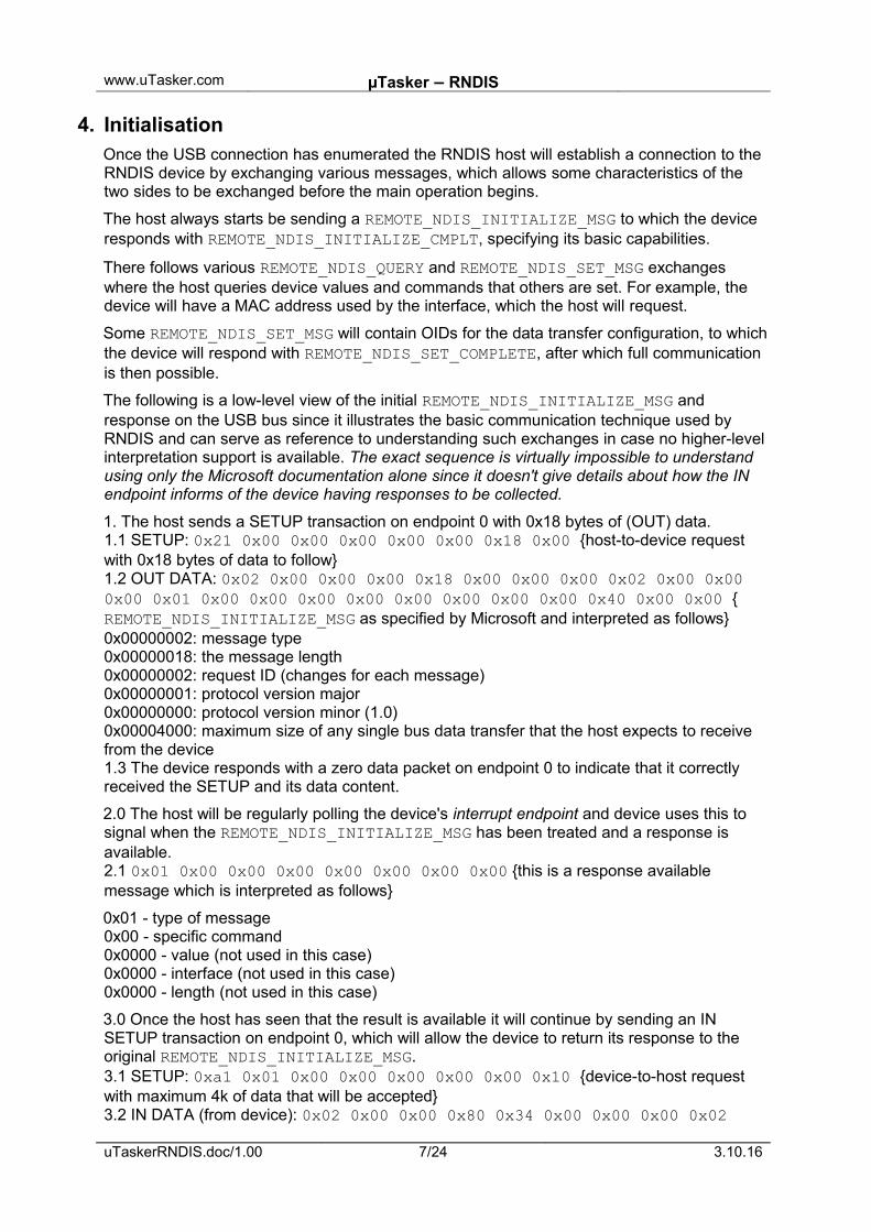
4. InitialisationOnce the USB connection has enumerated the RNDIS host will establish a connection to the RNDIS device by exchanging various messages, which allows some characteristics of the two sides to be exchanged before the main operation begins.
The host always starts be sending a REMOTE_NDIS_INITIALIZE_MSG to which the device responds with REMOTE_NDIS_INITIALIZE_CMPLT, specifying its basic capabilities.
There follows various REMOTE_NDIS_QUERY and REMOTE_NDIS_SET_MSG exchanges where the host queries device values and commands that others are set. For example, the device will have a MAC address used by the interface, which the host will request.
Some REMOTE_NDIS_SET_MSG will contain OIDs for the data transfer configuration, to whichthe device will respond with REMOTE_NDIS_SET_COMPLETE, after which full communication is then possible.
The following is a low-level view of the initial REMOTE_NDIS_INITIALIZE_MSG and response on the USB bus since it illustrates the basic communication technique used by RNDIS and can serve as reference to understanding such exchanges in case no higher-levelinterpretation support is available. The exact sequence is virtually impossible to understand using only the Microsoft documentation alone since it doesn't give details about how the IN endpoint informs of the device having responses to be collected.
1. The host sends a SETUP transaction on endpoint 0 with 0x18 bytes of (OUT) data.1.1 SETUP: 0x21 0x00 0x00 0x00 0x00 0x00 0x18 0x00 {host-to-device request with 0x18 bytes of data to follow}1.2 OUT DATA: 0x02 0x00 0x00 0x00 0x18 0x00 0x00 0x00 0x02 0x00 0x00 0x00 0x01 0x00 0x00 0x00 0x00 0x00 0x00 0x00 0x00 0x40 0x00 0x00 {REMOTE_NDIS_INITIALIZE_MSG as specified by Microsoft and interpreted as follows}0x00000002: message type0x00000018: the message length0x00000002: request ID (changes for each message)0x00000001: protocol version major0x00000000: protocol version minor (1.0)0x00004000: maximum size of any single bus data transfer that the host expects to receive from the device1.3 The device responds with a zero data packet on endpoint 0 to indicate that it correctly received the SETUP and its data content.
2.0 The host will be regularly polling the device's interrupt endpoint and device uses this to signal when the REMOTE_NDIS_INITIALIZE_MSG has been treated and a response is available.2.1 0x01 0x00 0x00 0x00 0x00 0x00 0x00 0x00 {this is a response available message which is interpreted as follows}
0x01 - type of message 0x00 - specific command0x0000 - value (not used in this case)0x0000 - interface (not used in this case)0x0000 - length (not used in this case)
3.0 Once the host has seen that the result is available it will continue by sending an IN SETUP transaction on endpoint 0, which will allow the device to return its response to the original REMOTE_NDIS_INITIALIZE_MSG.3.1 SETUP: 0xa1 0x01 0x00 0x00 0x00 0x00 0x00 0x10 {device-to-host request with maximum 4k of data that will be accepted}3.2 IN DATA (from device): 0x02 0x00 0x00 0x80 0x34 0x00 0x00 0x00 0x02
uTaskerRNDIS.doc/1.00 7/24 3.10.16
www.uTasker.com µTasker – RNDIS
0x00 0x00 0x00 0x00 0x00 0x00 0x00 0x01 0x00 0x00 0x00 0x00 0x00 0x00 0x00 0x01 0x00 0x00 0x00 0x00 0x00 0x00 0x00 0x01 0x00 0x00 0x00 0x16 0x06 0x00 0x00 0x03 0x00 0x00 0x00 0x00 0x00 0x00 0x00 0x00 0x00 0x00 0x00 {REMOTE_NDIS_INITIALIZE_CMPLT as specified by Microsoft and interpreted as follows}0x80000002: message type0x00000034: the message length (The Microsoft document is incorrect in that it suggests there MUST be 30 bytes here...)0x00000000: status = success0x00000002: request ID (changes for each message)0x00000001: protocol version major0x00000000: protocol version minor (1.0)0x00000001: device flags0x00000000: Ethernet0x00000001: maximum number of concatenated REMOTE_NDIS_PACKET_MSG that the device can handle in a single bus transfer to it.0x00000616: maximum transfer size (1558 bytes)0x00000003: packet alignment factor (2^3 = 8)0x0000000000000000: reserved - must be 0
3.3 Finally the host will send a zero data packet to indicate that it has correctly received the IN data.
After receiving and responding successfully to the REMOTE_NDIS_INITIALIZE_MSG the RNDIS device is in an initialised state but is not yet ready for data transfers.
4.0 The host will now collect information using several REMOTE_NDIS_QUERY_MSG messages. The host-to-device SETUPs are not shown in the following since they are essentially the same, apart from the amount of data that they specify will be sent.
4.1 REMOTE_NDIS_QUERY_MSG with OID of 01 01 01:
0x00000004: message type (REMOTE_NDIS_QUERY_MSG)0x0000001c: the message length0x00000003: request ID (changes for each message)0x00010101: OID - supported OID list request0x00000000: Information buffer length0x00000014: Information buffer offset0x00000000: Reserved for connection-oriented devices (always 0)
The interrupt endpoint's signalling of an available response is not shown here.
4.2 The device responds with details of the requested OID using a REMOTE_NDIS_QUERY_CMPLT, whereby the host SETUP is not displayed here.
80000004: Type of message (response indicated by 0x80000000 bit set)00000080: the message length00000003: response ID00000000: status (OK)00000064: information buffer length00000010: information buffer offset00010101: OID_GEN_SUPPORTED_LIST [start of general objects]00010102: OID_GEN_HARDWARE_STATUS
uTaskerRNDIS.doc/1.00 8/24 3.10.16
www.uTasker.com µTasker – RNDIS
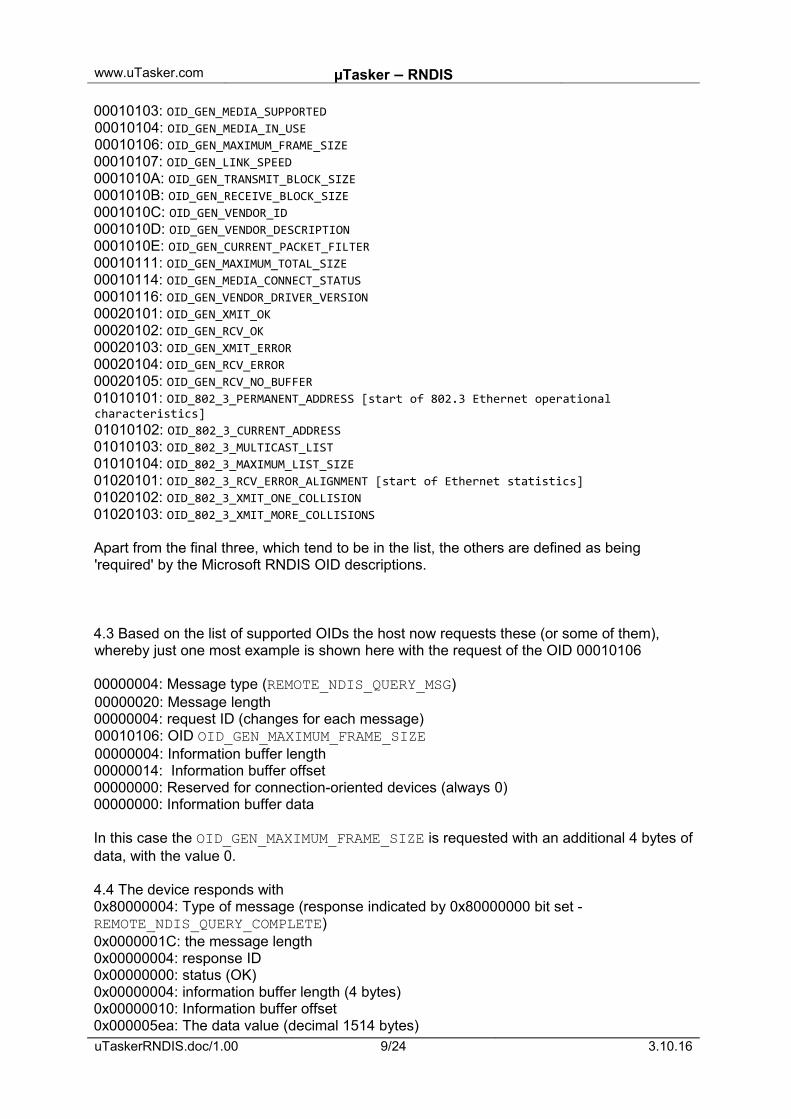
00010103: OID_GEN_MEDIA_SUPPORTED00010104: OID_GEN_MEDIA_IN_USE00010106: OID_GEN_MAXIMUM_FRAME_SIZE00010107: OID_GEN_LINK_SPEED0001010A: OID_GEN_TRANSMIT_BLOCK_SIZE0001010B: OID_GEN_RECEIVE_BLOCK_SIZE0001010C: OID_GEN_VENDOR_ID0001010D: OID_GEN_VENDOR_DESCRIPTION0001010E: OID_GEN_CURRENT_PACKET_FILTER00010111: OID_GEN_MAXIMUM_TOTAL_SIZE00010114: OID_GEN_MEDIA_CONNECT_STATUS00010116: OID_GEN_VENDOR_DRIVER_VERSION00020101: OID_GEN_XMIT_OK00020102: OID_GEN_RCV_OK00020103: OID_GEN_XMIT_ERROR00020104: OID_GEN_RCV_ERROR00020105: OID_GEN_RCV_NO_BUFFER01010101: OID_802_3_PERMANENT_ADDRESS [start of 802.3 Ethernet operational characteristics]01010102: OID_802_3_CURRENT_ADDRESS01010103: OID_802_3_MULTICAST_LIST01010104: OID_802_3_MAXIMUM_LIST_SIZE01020101: OID_802_3_RCV_ERROR_ALIGNMENT [start of Ethernet statistics]01020102: OID_802_3_XMIT_ONE_COLLISION01020103: OID_802_3_XMIT_MORE_COLLISIONS
Apart from the final three, which tend to be in the list, the others are defined as being 'required' by the Microsoft RNDIS OID descriptions.
4.3 Based on the list of supported OIDs the host now requests these (or some of them), whereby just one most example is shown here with the request of the OID 00010106
00000004: Message type (REMOTE_NDIS_QUERY_MSG)00000020: Message length00000004: request ID (changes for each message)00010106: OID OID_GEN_MAXIMUM_FRAME_SIZE00000004: Information buffer length00000014: Information buffer offset00000000: Reserved for connection-oriented devices (always 0)00000000: Information buffer data
In this case the OID_GEN_MAXIMUM_FRAME_SIZE is requested with an additional 4 bytes of data, with the value 0.
4.4 The device responds with0x80000004: Type of message (response indicated by 0x80000000 bit set - REMOTE_NDIS_QUERY_COMPLETE)0x0000001C: the message length0x00000004: response ID0x00000000: status (OK)0x00000004: information buffer length (4 bytes)0x00000010: Information buffer offset0x000005ea: The data value (decimal 1514 bytes)uTaskerRNDIS.doc/1.00 9/24 3.10.16
www.uTasker.com µTasker – RNDIS
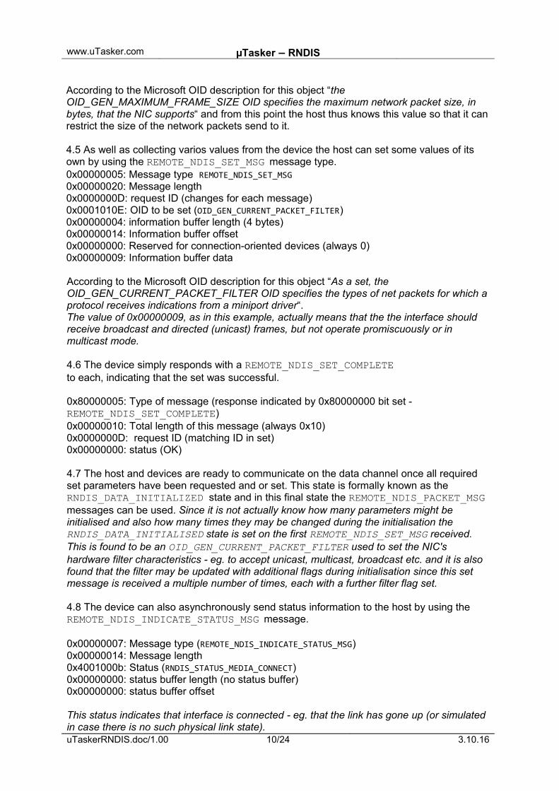
According to the Microsoft OID description for this object “the OID_GEN_MAXIMUM_FRAME_SIZE OID specifies the maximum network packet size, in bytes, that the NIC supports“ and from this point the host thus knows this value so that it can restrict the size of the network packets send to it.
4.5 As well as collecting varios values from the device the host can set some values of its own by using the REMOTE_NDIS_SET_MSG message type.0x00000005: Message type REMOTE_NDIS_SET_MSG0x00000020: Message length0x0000000D: request ID (changes for each message)0x0001010E: OID to be set (OID_GEN_CURRENT_PACKET_FILTER)0x00000004: information buffer length (4 bytes)0x00000014: Information buffer offset0x00000000: Reserved for connection-oriented devices (always 0)0x00000009: Information buffer data
According to the Microsoft OID description for this object “As a set, the OID_GEN_CURRENT_PACKET_FILTER OID specifies the types of net packets for which a protocol receives indications from a miniport driver“.The value of 0x00000009, as in this example, actually means that the the interface should receive broadcast and directed (unicast) frames, but not operate promiscuously or in multicast mode.
4.6 The device simply responds with a REMOTE_NDIS_SET_COMPLETEto each, indicating that the set was successful.
0x80000005: Type of message (response indicated by 0x80000000 bit set - REMOTE_NDIS_SET_COMPLETE)0x00000010: Total length of this message (always 0x10)0x0000000D: request ID (matching ID in set)0x00000000: status (OK)
4.7 The host and devices are ready to communicate on the data channel once all required set parameters have been requested and or set. This state is formally known as the RNDIS_DATA_INITIALIZED state and in this final state the REMOTE_NDIS_PACKET_MSG messages can be used. Since it is not actually know how many parameters might be initialised and also how many times they may be changed during the initialisation the RNDIS_DATA_INITIALISED state is set on the first REMOTE_NDIS_SET_MSG received. This is found to be an OID_GEN_CURRENT_PACKET_FILTER used to set the NIC's hardware filter characteristics - eg. to accept unicast, multicast, broadcast etc. and it is also found that the filter may be updated with additional flags during initialisation since this set message is received a multiple number of times, each with a further filter flag set.
4.8 The device can also asynchronously send status information to the host by using the REMOTE_NDIS_INDICATE_STATUS_MSG message.
0x00000007: Message type (REMOTE_NDIS_INDICATE_STATUS_MSG)0x00000014: Message length0x4001000b: Status (RNDIS_STATUS_MEDIA_CONNECT)0x00000000: status buffer length (no status buffer)0x00000000: status buffer offset
This status indicates that interface is connected - eg. that the link has gone up (or simulated in case there is no such physical link state).uTaskerRNDIS.doc/1.00 10/24 3.10.16
www.uTasker.com µTasker – RNDIS
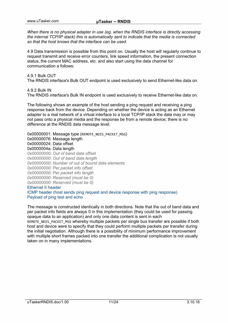
When there is no physical adapter in use (eg. when the RNDIS interface is directly accessingthe internal TCP/IP stack) this is automatically sent to indicate that the media is connected so that the host knows that the interface can be used.
4.9 Data transmission is possible from this point on. Usually the host will regularly continue torequest transmit and receive error counters, link speed information, the present connection status, the current MAC address, etc. and also start using the data channel for communication a follows:
4.9.1 Bulk OUTThe RNDIS interface's Bulk OUT endpoint is used exclusively to send Ethernet-like data on.
4.9.2 Bulk INThe RNDIS interface's Bulk IN endpoint is used exclusively to receive Ethernet-like data on.
The following shows an example of the host sending a ping request and receiving a ping response back from the device. Depending on whether the device is acting as an Ethernet adapter to a real network of a virtual interface to a local TCP/IP stack the data may or may not pass onto a physical media and the response be from a remote device; there is no difference at the RNDIS data message level.
0x00000001: Message type (REMOTE_NDIS_PACKET_MSG)0x00000076: Message length0x00000024: Data offset0x0000004a: Data length0x00000000: Out of band data offset0x00000000: Out of band data length0x00000000: Number of out of bound data elements0x00000000: Per packet info offset0x00000000: Per packet info length0x00000000: Reserved (must be 0)0x00000000: Reserved (must be 0)Ethernet II headerICMP header (host sends ping request and device response with ping response)Payload of ping test and echo
The message is constructed identically in both directions. Note that the out of band data and per packet info fields are always 0 in this implementation (they could be used for passing opaque data to an application) and only one data content is sent in each REMOTE_NDIS_PACKET_MSG whereby multiple packets per single bus transfer are possible if both host and device were to specify that they could perform multiple packets per transfer during the initial negotiation. Although there is a possibility of minimum performance improvement with multiple short frames packed into one transfer the additional complication is not usually taken on in many implementations.
uTaskerRNDIS.doc/1.00 11/24 3.10.16
www.uTasker.com µTasker – RNDIS
5. Keep-AliveDuring idle periods the host will send a REMOTE_NIS_KEEPALIVE_MSG every 5 seconds to check that he device is still responsive. It is optional for the device to do the same to check that the host is active.
The receiver of the message responds with a REMOTE_NDIS_KEEPALIVE_CMPLT which informs the status of the request.
If the host receives a REMOTE_NDIS_HALT_MSG from a device it will always stop sending keep-alive messages.
After a host receives a REMOTE_NDIS_RESET_CMPLT message form a device it will restart its keep-alive timer.
Should a device respond to a REMOTE_NDIS_KEEPALIVE_MSG with a REMOTE_NDIS_KEEPALIVE_CMPLT message indicating a status that is not RNDIS_STATIS_SUCCESS the host will reset the device using a REMOTE_NDIS_RESET_MSG. The host will also send this message if there is no response received to the REMOTE_NDIS_KEEPALIVE_MSG.
uTaskerRNDIS.doc/1.00 12/24 3.10.16
www.uTasker.com µTasker – RNDIS
6. Reset
The host can command a soft reset of the device using the REMOTE_NDIS_RESET_MSG. Thesoft reset is restricted to the RNDIS software [USB base protocols continues operating duringthe process], which responds with REMOTE_NDIS_RESET_CMPLT when completed. The complete message informs whether the multicast address list or packet filter values have been lost during the process or not, which can cause the host to resend any such information.
The host will command a device RNDIS reset if the device stops normally responding to keep-alive messages. It will also use this message if there are problems establishing the RNDIS connection to the device.
uTaskerRNDIS.doc/1.00 13/24 3.10.16
www.uTasker.com µTasker – RNDIS
7. Disabling and Re-enabling the RNDIS Network Connection
When the RNDIS network connection is disabled at the host the USB bus is set to the suspended state.
When the RNDIS network connection is re-enabled the USB bus is connected again (leaves the reset state) without any USB reset of RNDIS level reset or re-initialisation. The RNDIS operation continues form the state that it left off in.
uTaskerRNDIS.doc/1.00 14/24 3.10.16
www.uTasker.com µTasker – RNDIS
8. Configurations
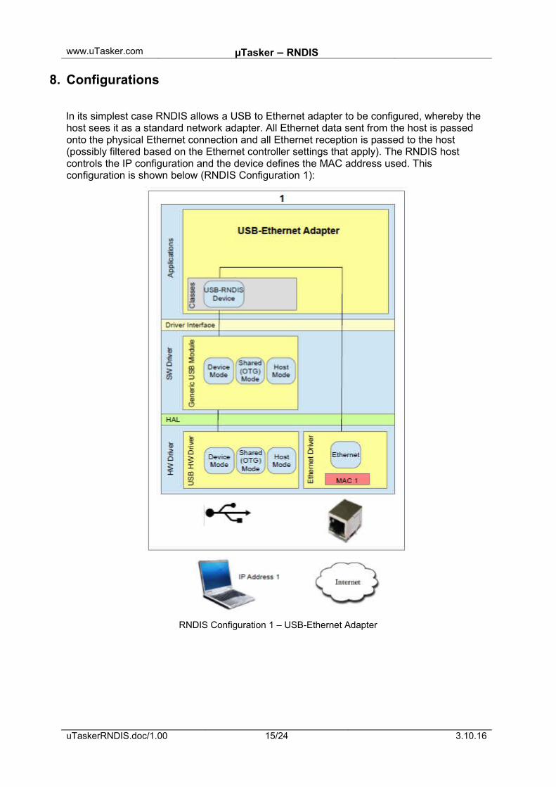
In its simplest case RNDIS allows a USB to Ethernet adapter to be configured, whereby the host sees it as a standard network adapter. All Ethernet data sent from the host is passed onto the physical Ethernet connection and all Ethernet reception is passed to the host (possibly filtered based on the Ethernet controller settings that apply). The RNDIS host controls the IP configuration and the device defines the MAC address used. This configuration is shown below (RNDIS Configuration 1):
RNDIS Configuration 1 – USB-Ethernet Adapter
uTaskerRNDIS.doc/1.00 15/24 3.10.16
www.uTasker.com µTasker – RNDIS
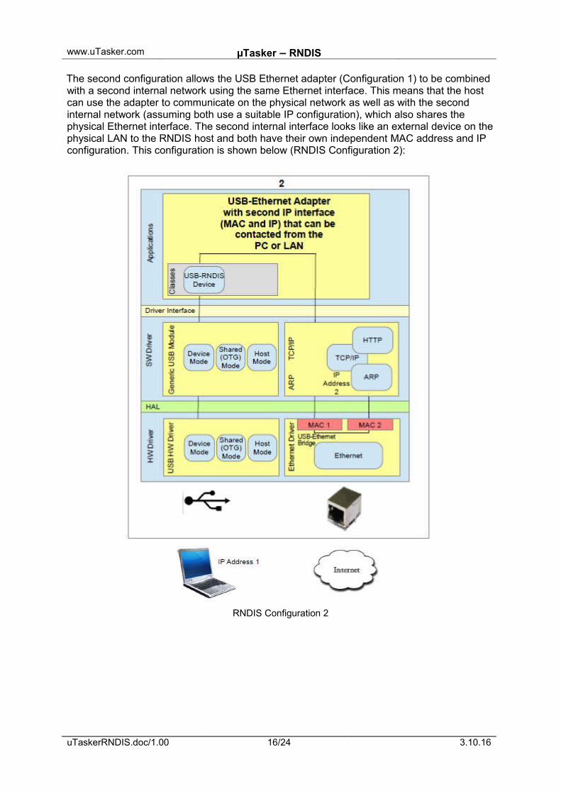
The second configuration allows the USB Ethernet adapter (Configuration 1) to be combined with a second internal network using the same Ethernet interface. This means that the host can use the adapter to communicate on the physical network as well as with the second internal network (assuming both use a suitable IP configuration), which also shares the physical Ethernet interface. The second internal interface looks like an external device on thephysical LAN to the RNDIS host and both have their own independent MAC address and IP configuration. This configuration is shown below (RNDIS Configuration 2):
RNDIS Configuration 2
uTaskerRNDIS.doc/1.00 16/24 3.10.16
www.uTasker.com µTasker – RNDIS
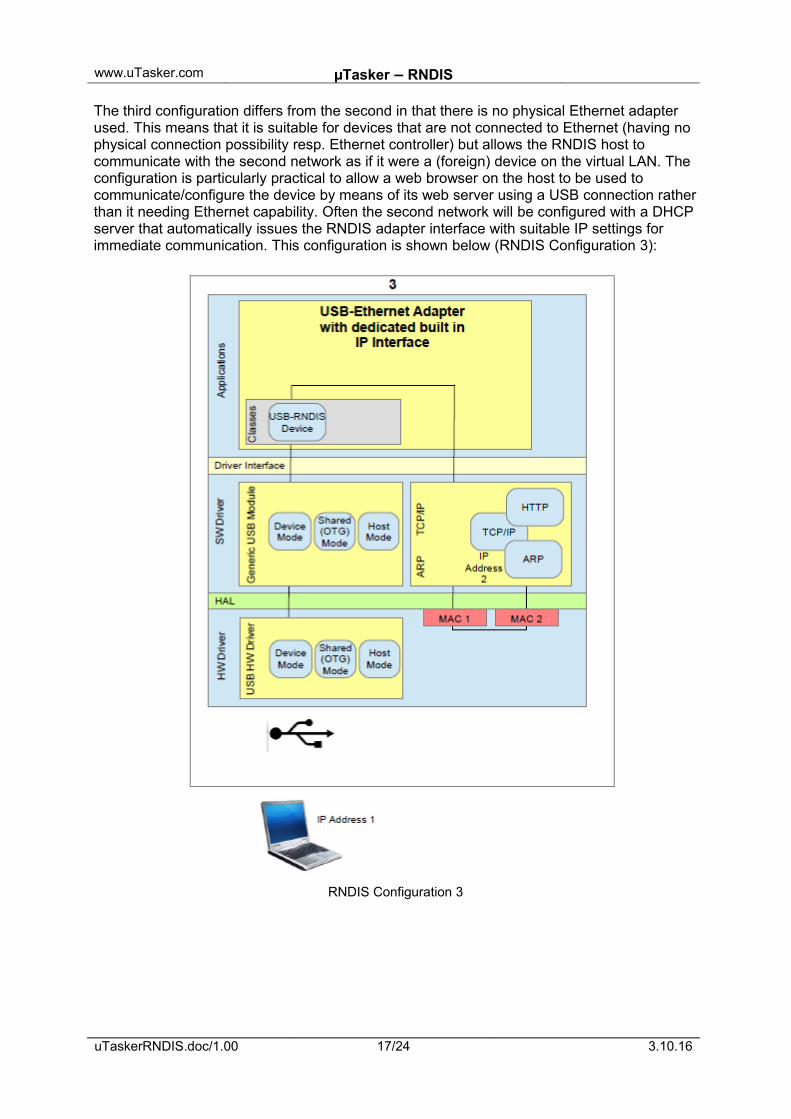
The third configuration differs from the second in that there is no physical Ethernet adapter used. This means that it is suitable for devices that are not connected to Ethernet (having no physical connection possibility resp. Ethernet controller) but allows the RNDIS host to communicate with the second network as if it were a (foreign) device on the virtual LAN. The configuration is particularly practical to allow a web browser on the host to be used to communicate/configure the device by means of its web server using a USB connection ratherthan it needing Ethernet capability. Often the second network will be configured with a DHCPserver that automatically issues the RNDIS adapter interface with suitable IP settings for immediate communication. This configuration is shown below (RNDIS Configuration 3):
RNDIS Configuration 3
uTaskerRNDIS.doc/1.00 17/24 3.10.16
www.uTasker.com µTasker – RNDIS
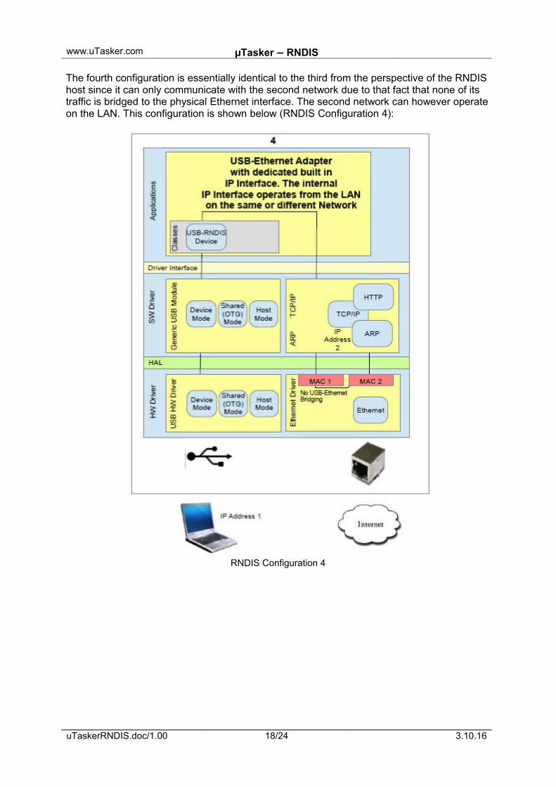
The fourth configuration is essentially identical to the third from the perspective of the RNDIS host since it can only communicate with the second network due to that fact that none of its traffic is bridged to the physical Ethernet interface. The second network can however operateon the LAN. This configuration is shown below (RNDIS Configuration 4):
RNDIS Configuration 4
uTaskerRNDIS.doc/1.00 18/24 3.10.16
www.uTasker.com µTasker – RNDIS
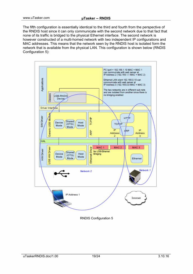
The fifth configuration is essentially identical to the third and fourth from the perspective of the RNDIS host since it can only communicate with the second network due to that fact that none of its traffic is bridged to the physical Ethernet interface. The second network is however constructed of a multi-homed network with two independent IP configurations and MAC addresses. This means that the network seen by the RNDIS host is isolated form the network that is available from the physical LAN. This configuration is shown below (RNDIS Configuration 5):
RNDIS Configuration 5
uTaskerRNDIS.doc/1.00 19/24 3.10.16
www.uTasker.com µTasker – RNDIS
To configure USB-CDC in the µTasker project the define USB_INTERFACE is enabled to have basic USB device operation. USE_USB_CDC is enabled for USB-CDC class (VCOM and/or RNDIS).
The number of VCOM interfaces required is set with
#define USB_CDC_VCOM_COUNT 1
which can be 0 if only RNDIS is to be used.
The number of RNDIS interfaces required is set with
#define USB_CDC_RNDIS_COUNT 1
where 1 should be used since Windows (Windows 8.1) doesn't presently support more than one on a single USB interface.
In order to build a pure RNDIS to Ethernet adapter an Ethernet controller must be available but no further RNDIS settings are necessary.
In order to not use an Ethernet controller, or to avoid communicating between RNDIS and an Ethernet interface, the define NO_USB_ETHERNET_BRIDGING can be enabled (used in configurations 2, 3 and 4).
The define USB_TO_TCP_IP can be enabled if the RNDIS interface should communicate directly with the internal TCP/IP stack (used in configurations 2, 3, 4 and 5).
If further interfaces are required in a composite device they can be enabled by using other USB class defines such as:
#define USE_USB_HID_MOUSE // human interface device (mouse)#define USE_USB_HID_KEYBOARD // human interface device (keyboard)#define USE_USB_MSD // mass storage device
See config.h for a complete list of available classes that can be combined.
uTaskerRNDIS.doc/1.00 20/24 3.10.16
www.uTasker.com µTasker – RNDIS
9. Monitoring RNDIS activity
Once the RNDIS adapter is connected it appears as an Ethernet based interface to Wireshark. This means that its data activity can be monitored in the same way that Ethernet activity on a physical LAN interface can be monitored, including full interpretation of the TCP/IP content. This does of course require that the RNDIS functionality is operation because it gives no information about the RNDIS header or USB class operation.
To monitor the RNDIS class activity a HW USB analyser can be used, whereby some will be able to decode the class activity once the device has successfully enumerated.
Wireshark can also be used to perform monitoring of the RNDIS USB layer, plus the data content by using its USBPcap plug-in. This is described at http://desowin.org/usbpcap/tour.html and allows even monitoring of enumeration. Although this feature is relatively new and requires some further development it already allows quite extensive monitoring an debugging USB and RNDIS USB without needing a dedicated USB analyser.
uTaskerRNDIS.doc/1.00 21/24 3.10.16
www.uTasker.com µTasker – RNDIS
10. InstallationThe first time that the USB device is connected to the USB host the RNDIS installation process has to be executed. Windows uses its drivers:
Rndismpx.sys
usb8023x.sys
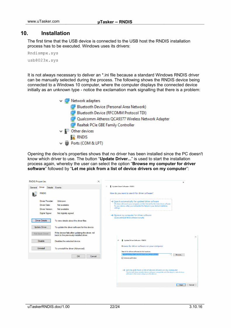
It is not always necessary to deliver an *.ini file because a standard Windows RNDIS driver can be manually selected during the process. The following shows the RNDIS device being connected to a Windows 10 computer, where the computer displays the connected device initially as an unknown type - notice the exclamation mark signalling that there is a problem:
Opening the device's properties shows that no driver has been installed since the PC doesn'tknow which driver to use. The button “Update Driver...” is used to start the installation process again, whereby the user can select the option “Browse my computer for driver software” followed by “Let me pick from a list of device drivers on my computer”:
uTaskerRNDIS.doc/1.00 22/24 3.10.16
www.uTasker.com µTasker – RNDIS
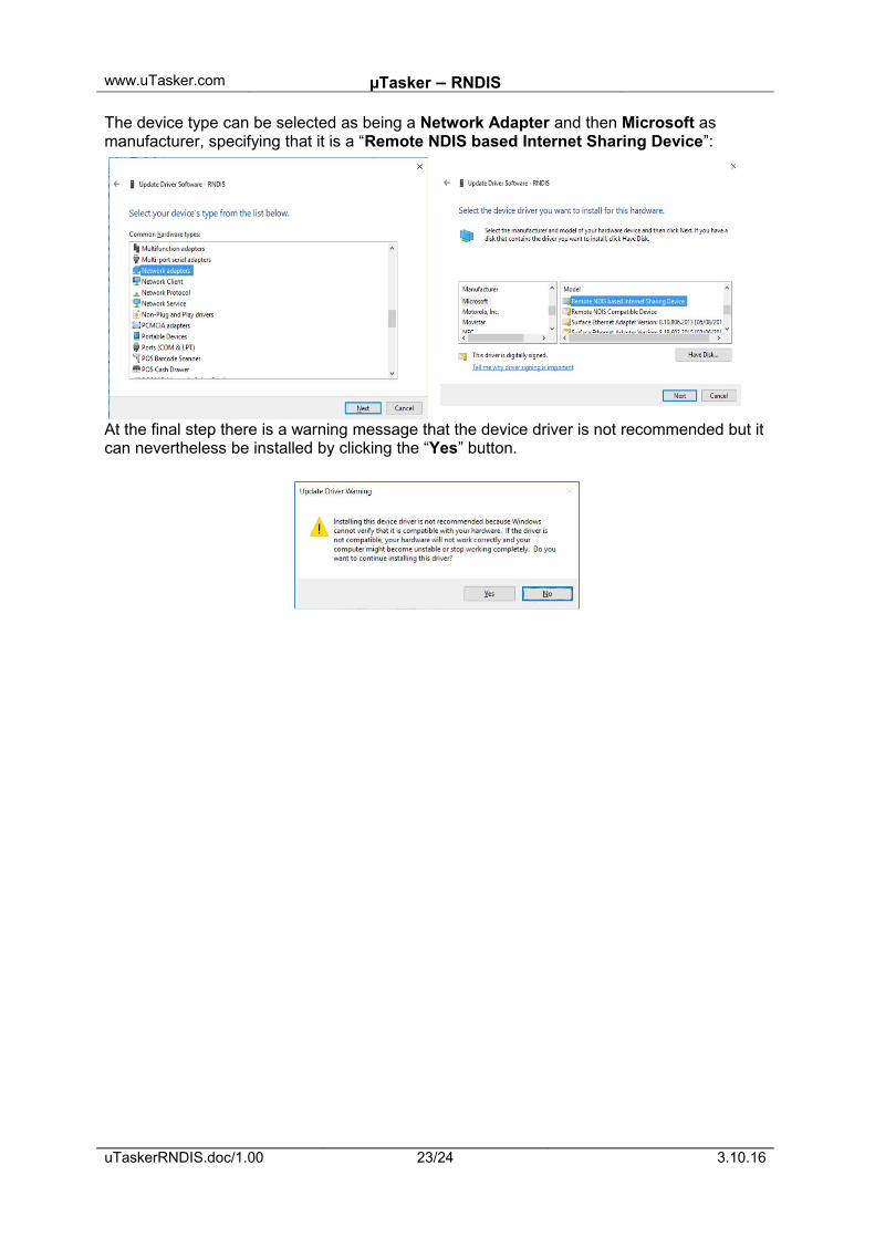
The device type can be selected as being a Network Adapter and then Microsoft as manufacturer, specifying that it is a “Remote NDIS based Internet Sharing Device”:
At the final step there is a warning message that the device driver is not recommended but it can nevertheless be installed by clicking the “Yes” button.
uTaskerRNDIS.doc/1.00 23/24 3.10.16
www.uTasker.com µTasker – RNDIS
11. Conclusion
RNDIS uses the USB-CDC class as base for its operation. It adds encapsulated commands and responses to establish a virtual networking connection that can be used to interface an Ethernet controller to a host or to allow a host to communicate with a connected device usingnetwork protocols. Various such configuration possibilities have been illustrated in the document.
A useful feature of devices that can communicate with a host as a virtual network device is that they can use infrastructure, such as Web Browsers and FTP servers, to allow data to be exchanged with them and also to allow a user interface to be implemented without needing to have a physical Ethernet interface. This allows products for a manufacturer to share such interfaces between Ethernet based equipment (those that have an Ethernet controller) and simpler USB based variants (those that have no Ethernet in order to save cost and power consumption). It is possible to, for instance, use a standard web browser based configurationand control tool for all parts rather than having to use different programs.
The document has explained the underlying operation of RNDIS communication, with some reference data for better understanding. Instructions for configuring, installing and monitoringoperation has further been given.
The µTasker project contains a RNDIS device implementation that can be easily activated and shared with other composite devices, including one or more USB-CDC VCOM connections at the same time.
Modifications:
- V0.01 7.2.2016: - First draft – in progress- V1.00 3.10.2016: - First release version
uTaskerRNDIS.doc/1.00 24/24 3.10.16
Related Documents


![[MS-RNDIS]: Remote Network Driver Interface …download.microsoft.com/download/5/0/1/501ED102-E53F-4CE0...Remote Network Driver Interface Specification (RNDIS) Protocol Copyright ©](https://static.cupdf.com/doc/110x72/5aa205c67f8b9a84398c7d7c/ms-rndis-remote-network-driver-interface-network-driver-interface-specification.jpg)


