1 Embedding Inertial-Magnetic Sensors in Everyday Objects: Assessing Spatial Cognition in Children Domenico Campolo 1 , Fabrizio Taffoni 2 , Domenico Formica 2 , Jana Iverson 3 , Laura Sparaci 4 , Flavio Keller 5 , Eugenio Guglielmelli 2 Abstract— This paper describes an interdisciplinary approach to the assessment of children development of spatial cognition, with a focus on the technology. An instrumented toy (block- box) is presented which embeds magneto-inertial sensors for orientation tracking, specifically developed to assess the ability to insert objects into holes. The functional specifications are derived from experimental protocols devised by neuroscientists to assess spatial cognition skills in children. Technological choices are emphasized with respect to ecological requirements. Ad- hoc calibration procedures are presented which are suitable to unstructured environments. Preliminary results based on experimental trials carried out at a day-care on typically developing children (12-36 months old) show how the instrumented objects can be used effectively in a semi-automatic fashion (i.e. rater-independent) to derive accurate measurements such as orientation errors and insertion time which are relevant to the object insertion task. This study indicates that a technological approach to ecological assessment of spatial cognition in children is indeed feasible and maybe useful for identification and early assessment of developmental delay. keywords: Neuro-Developmental Engineering, Ecological Assessment, Instrumented Toys, In-Field Calibration. I. I NTRODUCTION How does our conception of three-dimensionality of space emerge? Through careful observation of children of all ages, a few decades ago Jean Piaget laid the foundations to un- derstanding the development of spatial cognition in humans. Recent years have seen an effort towards more quantitative forms of assessment, as opposed to qualitative, observational and subjective methods used in classic studies since the early works of Piaget [1]. In this sense, motion analysis is becoming a fundamental tool for research as well as clinical practice. Despite the broad spectrum of available ‘ammunitions’ for motion analysis [2], ecological assessment imposes strict technological constraints. For example, the need for minimally structured environments makes the use of video-based tech- nologies difficult, also due to the line-of-sight issues (e.g. dur- ing manipulation tasks performed by children, markers might not always be visible). Furthermore, motion tracking devices should be minimally obtrusive to the natural movements of the children and this makes, for example, the use of mechani- cal sensing devices rather impractical. From a technological perspective, a very appealing possibility is represented by Running Title: Sensorized Toys for Assessing Spatial Cognition in Children Corresponding Author: Domenico Campolo, School of Mechanical and Aerospace Engineering, Nanyang Technological University, 50 Nanyang Av- enue - Singapore 639798. E-mail: [email protected]. Tel: +65 6790 5610. FAX: +65 6792 4062. sourceless devices such as inertial and geo-magnetic sensors [2], already proved suitable for clinical gait analysis [3]. Being sourceless, such devices produce no electromagnetic radiation and, in this sense, raise no concern for the safety of children. Restrictions to the use of this technology are due to the influence of external magnetic fields or distortion of the geo- magnetic field itself. In this sense, care must be taken to avoid large ferromagnetic objects (e.g. metal tables or chairs) or electromagnetic objects (electrical transformers, cellphones) in the immediate vicinity of the devices. While the naturalistic environments for children (e.g. kindergartens and daycares) typically use fully compatible materials such as plastic, rubber and wood, transportation of the devices from the laboratory to the experimental centre might cause de-calibration and loss of sensitivity for the sensors. For these devices to be useful in research, proper sensor calibration should be guaranteed in the first place, and various methods have been proposed which address the in-use [4] and the in-field calibration [5]. Based on our previous experience with such devices [6], [7], [8], we summarize issues related to the effective use of Inertial- Magnetic Units (IMU), i.e. design and fabrication of wireless IMU-based devices for assessing spatial cognition in children, in-field calibration procedures, and finally data analysis. In particular, in this paper we shall expand on our previous work and fully describe the algorithm behind attitude estimation and in-field calibration. We shall also briefly present the laboratory tests used to assess the overall accuracy, for which full details are reported in [7], as well as preliminary results of the final use of our device on regularly developing children. II. I NSTRUMENTED TOYS Virtually any toy, tool or piece of garment used by children could be a good candidate to host all sorts of technology and ‘see what comes out’ when the child wears it or plays with it. Our approach is based on a closed-loop dialogue between neuroscientists and bioengineers: iteratively, starting from es- tablished protocols, we select appropriate technologies for a given scenario and at the same time redesign the protocols to include the proposed technology. In the following, a platform specifically devised to in- vestigate the development of spatial cognition in children is presented for which functional specifications are derived from protocols of experiments of interest for neuroscientists. The aim is twofold: on one hand we wish to provide scien- tists with novel technological platforms for the unobtrusive and ecological assessment of behavioral development in children; Pre-print of the manuscript accepted for publication on: Journal of Integrative Neuroscience, Vol. 11, No. 1 (2012) 103-116 DOI: 10.1142/S0219635212500070

Welcome message from author
This document is posted to help you gain knowledge. Please leave a comment to let me know what you think about it! Share it to your friends and learn new things together.
Transcript
1
Embedding Inertial-Magnetic Sensors in EverydayObjects: Assessing Spatial Cognition in Children
Domenico Campolo1, Fabrizio Taffoni2, Domenico Formica2,Jana Iverson3, Laura Sparaci4, Flavio Keller5, Eugenio Guglielmelli2
Abstract— This paper describes an interdisciplinary approachto the assessment of children development of spatial cognition,with a focus on the technology. An instrumented toy (block-box) is presented which embeds magneto-inertial sensors fororientation tracking, specifically developed to assess the abilityto insert objects into holes. The functional specifications arederived from experimental protocols devised by neuroscientiststo assess spatial cognition skills in children. Technological choicesare emphasized with respect to ecological requirements. Ad-hoc calibration procedures are presented which are suitable tounstructured environments.
Preliminary results based on experimental trials carried outat a day-care on typically developing children (12-36 monthsold) show how the instrumented objects can be used effectivelyin a semi-automatic fashion (i.e. rater-independent) to deriveaccurate measurements such as orientation errors and insertiontime which are relevant to the object insertion task.
This study indicates that a technological approach to ecologicalassessment of spatial cognition in children is indeed feasibleand maybe useful for identification and early assessment ofdevelopmental delay.
keywords: Neuro-Developmental Engineering, EcologicalAssessment, Instrumented Toys, In-Field Calibration.
I. INTRODUCTION
How does our conception of three-dimensionality of spaceemerge? Through careful observation of children of all ages,a few decades ago Jean Piaget laid the foundations to un-derstanding the development of spatial cognition in humans.Recent years have seen an effort towards more quantitativeforms of assessment, as opposed to qualitative, observationaland subjective methods used in classic studies since the earlyworks of Piaget [1]. In this sense, motion analysis is becominga fundamental tool for research as well as clinical practice.
Despite the broad spectrum of available ‘ammunitions’for motion analysis [2], ecological assessment imposes stricttechnological constraints. For example, the need for minimallystructured environments makes the use of video-based tech-nologies difficult, also due to the line-of-sight issues (e.g. dur-ing manipulation tasks performed by children, markers mightnot always be visible). Furthermore, motion tracking devicesshould be minimally obtrusive to the natural movements ofthe children and this makes, for example, the use of mechani-cal sensing devices rather impractical. From a technologicalperspective, a very appealing possibility is represented by
Running Title: Sensorized Toys for Assessing Spatial Cognition in ChildrenCorresponding Author: Domenico Campolo, School of Mechanical and
Aerospace Engineering, Nanyang Technological University, 50 Nanyang Av-enue - Singapore 639798. E-mail: [email protected]. Tel: +656790 5610. FAX: +65 6792 4062.
sourceless devices such as inertial and geo-magnetic sensors[2], already proved suitable for clinical gait analysis [3]. Beingsourceless, such devices produce no electromagnetic radiationand, in this sense, raise no concern for the safety of children.
Restrictions to the use of this technology are due to theinfluence of external magnetic fields or distortion of the geo-magnetic field itself. In this sense, care must be taken to avoidlarge ferromagnetic objects (e.g. metal tables or chairs) orelectromagnetic objects (electrical transformers, cellphones) inthe immediate vicinity of the devices. While the naturalisticenvironments for children (e.g. kindergartens and daycares)typically use fully compatible materials such as plastic, rubberand wood, transportation of the devices from the laboratory tothe experimental centre might cause de-calibration and lossof sensitivity for the sensors. For these devices to be usefulin research, proper sensor calibration should be guaranteed inthe first place, and various methods have been proposed whichaddress the in-use [4] and the in-field calibration [5]. Basedon our previous experience with such devices [6], [7], [8],we summarize issues related to the effective use of Inertial-Magnetic Units (IMU), i.e. design and fabrication of wirelessIMU-based devices for assessing spatial cognition in children,in-field calibration procedures, and finally data analysis. Inparticular, in this paper we shall expand on our previous workand fully describe the algorithm behind attitude estimation andin-field calibration. We shall also briefly present the laboratorytests used to assess the overall accuracy, for which full detailsare reported in [7], as well as preliminary results of the finaluse of our device on regularly developing children.
II. INSTRUMENTED TOYS
Virtually any toy, tool or piece of garment used by childrencould be a good candidate to host all sorts of technology and‘see what comes out’ when the child wears it or plays with it.
Our approach is based on a closed-loop dialogue betweenneuroscientists and bioengineers: iteratively, starting from es-tablished protocols, we select appropriate technologies for agiven scenario and at the same time redesign the protocols toinclude the proposed technology.
In the following, a platform specifically devised to in-vestigate the development of spatial cognition in children ispresented for which functional specifications are derived fromprotocols of experiments of interest for neuroscientists.
The aim is twofold: on one hand we wish to provide scien-tists with novel technological platforms for the unobtrusive andecological assessment of behavioral development in children;
Pre-print of the manuscript accepted for publication on: Journal of Integrative Neuroscience, Vol. 11, No. 1 (2012) 103-116 DOI: 10.1142/S0219635212500070

2
on the other hand, these platforms should enable/facilitate thetransition from research to clinical practice.
A. Assessing Spatial Cognition Skills
By the end of the first year of life, children start to pile-up blocks, put lids on cans and insert objects into apertures.Through these activities, the child learns to plan actions thatinvolve more than one item. The ability to solve such problemsreflects the childs spatial, perceptual and motor development.In particular, the ability to represent objects in differentpositions and orientations must be in place before they canbe fit into apertures.
Recent studies by Ornkloo and von Hofsten [9] showdevelopmental curves, based on statistical rates of success ofobject-fitting tasks, relative to children aged 14-26 months.
apertureblock
Fig. 1. Block-box experimental scenario.
Specifically, the tasks consisted of inserting cylindricalobjects, hereafter ‘blocks’, with different cross-sections intoa box with similar holes on its lid. The experimental scenarioand the shapes of blocks inspired by [9] are shown in Fig. 1.All the blocks had similar dimensions, 1 mm smaller thanthe apertures. Different cross-sections were used which wouldrequire similar hand aperture in grasping. The only differencewas is the number of possibilities they could fit into the cor-responding aperture (i.e. infinite possibilities for the circularcross-section, 4 possibilities for the squared cross-section and3 possibilities for the triangular cross-section).
Ornkloo and von Hofsten [9] assessed (among other things)the horizontal and vertical pre-adjustments. The outcome wasyes/no (i.e. successful or unsuccessful) based on the alignmenterrors between the block and the box. Both the verticalerror (angular misalignment between the longitudinal axis ofthe block and verticality) and the horizontal error (angularmisalignment between the orientations of the cross-sectionand the aperture) were estimated from the videos acquiredwith two cameras. A trial was considered unsuccessful formisalignments exceeding 30 deg. Accuracy of such methodshighly depends on the quality of the videos. As highlightedby the authors themselves [9], the vertical and horizontalalignments were judged by two coders who disagreed on 31out of 302 cases, i.e. on more than 10% of the times. Moreover,
this method relies on the (time-consuming) manual scoring ofvideos, frame-by-frame.
B. Block-Box Platform
Inspired by such experiments and based on our previousexperience with sensorized toys [10], we developed a sen-sorized core (the overall architecture is shown in Fig. 2, CADdrawings and physical implementation are shown Fig. 3) tobe embedded in blocks with various cross-sections, shown inFig. 4.
batteriesLIR3048(2x 3.6V)
9-axis IMUMAG02
120S050
12-bits A/D converterMAX1238
µ-controllerPIC16F876A
Bluetooth Parani-ESD200
9
I2C bus
comm board
sensor board
PWR supply
UART
Fig. 2. Architecture of the sensorized core.
41 m
m
sensorboard
commboard
SENSOR
batteries
Fig. 3. CAD drawing and photograph of the sensorized core, consisting ofa kinematics sensing unit and communication board.
In particular, we found that from an ecological perspective,the sourceless orientation estimation via inertial and magneticsensors is especially suited to this application. Accelerometerscan in fact be used to measure tilt while magnetometers canbe used as compass to measure horizontal misalignments.Gyroscopes are required to compensate for non-static effects.
Pre-print of the manuscript accepted for publication on: Journal of Integrative Neuroscience, Vol. 11, No. 1 (2012) 103-116 DOI: 10.1142/S0219635212500070

3
Fig. 4. Photograph of the prototyped sensorized core and outer shells.
Fig. 2 and Fig. 3 show the sensing core, mainly consist-ing of a compact (17.8mm × 17.8mm × 10.2mm), micro-fabricated 9-axis inertial-magnetic sensor (model MAG02-1200S050 from Memsense Inc.). In particular, the device isdesigned to sense ±2g accelerations, ±1200 deg/sec angularrates, ±1 Gauss magnetic fields, all within a 50 Hz bandwidth.The sensors are coupled with a multi-channel, 12-bit ADconverter (model MAX1238 from Maxim Inc.) which canretransmit sampled data over a 4-wires I2C bus. For our appli-cation, we sample each of the 9 channels at 100 samples/sec.Such data are collected and rearranged in a specific messageformat by a microcontroller and then retransmitted via a blue-tooth device. Finally, two 3.6V Li-Ion Rechargeable batteries(LIR3048 from Powerstream Inc.) are used in series whichguarantee approximately an hour of autonomous operation.Data transmitted over the bluetooth interface are collected bya nearby PC, for off-line data analysis.
C. In-Field Calibration Protocol
Magnetometers are meant to sense the geomagnetic fieldand provide its components [bx, by, bz]
T along the x, y andz axes of the sensing device itself (such axes move with themoving frame). Similarly, the accelerometers are meant, instatic conditions, to read out the components of the gravita-tional field [gx, gy, gz]
T along the same axes.Calibration of such sensors is straightforward when one can
reliably count on precision alignment procedures, e.g. in alaboratory setting. In [5], a procedure for in-field calibrationof magnetometric sensors was presented which does not relyon previous knowledge of magnitude and direction of thegeomagnetic field and which does not require accurately pre-defined orientation sequences. Such a method can be appliedto accelerometers as well and is especially suited for clinicalapplications The procedure relies on the fact the geomagnetic(or gravitational) field has constant components in the fixedframe. As the orientation of the sensors vary, the componentsin the moving frame also vary but the magnitude of the fieldkeeps constant, i.e. the components are bound to lie on asphere. Readouts from non-calibrated sensors are thereforebound to lie on an ellipsoid, see [5] for details. Via the least-square method it is possible to robustly estimate the centroidand semi-axes length of the ellipsoid which coincide with thecalibration parameters (gain and offsets for each axis).
Based on this method, a calibration protocol was devised toprovide a sufficient number of measurements for the algorithm
to robustly converge. The instrumented toy (of whatever shape)is secured inside a wooden box, shaped as a parallelepiped,so that the toy does not move as the box is displaced around.
a) b)
2.53
3.5
2.5
3
3.5
2.5
3
3.5
Vx [V]V
y [V]
Vz [V
]
2
32
3
1.5
2
2.5
3
Vx [V]V
y [V]
Vz [V
]
c) d)
Fig. 5. Calibration sequences for magnetometers (a) and accelerometers (b).Plots of the measurements (i.e. voltages Vx, Vy and Vz from the triaxialsensors) derived from the calibration sequences for the magnetometers (c)and the accelerometers (d).
Magnetometers: as in Fig. 5-a, the box is placed on atable and an approximately 360 deg rotation (no need to beaccurate) is performed by keeping one face of the box alwaysparallel and in contact with the table. The same procedure isrepeated for four different faces.
Accelerometers: as in Fig. 5-b, the box is placed on a tableand smoothly (i.e. avoiding shocks) tilted by 90 deg alongone edge, this is repeated four times1 until the box returns inthe initial position. The whole procedure is repeated with adifferent initial position.
Gyroscopes: the procedure is similar to the one deployedfor the accelerometers.
Measurements derived from a calibration sequence areshown in Fig. 5-c and Fig. 5-d, respectively for the magne-tometers and for the accelerometers. The least-squares algo-rithm is then used to derive the best fitting ellipsoids (onefor the magnetometers and one for the accelerometers) whosesurfaces contain the two sets of measurements.
As previously mentioned, since the geomagnetic field isconstant, its components in the moving frame are bound tolie on the calibrating ellipsoid, not only during the calibrationsequences but for every possible movement. For this reason,also movements performed during the regular use of thetoy, i.e. when the children play with it, can be used forupdating the calibration parameters, or at least for an on-line check. Similar procedures apply to accelerometers, payingattention to consider only the quasi-static movements, i.e.
1Each time on a different edge: once a 90 deg rotation is performed alongone edge, the next edge is the non-consecutive one which also makes contactwith the table.
Pre-print of the manuscript accepted for publication on: Journal of Integrative Neuroscience, Vol. 11, No. 1 (2012) 103-116 DOI: 10.1142/S0219635212500070
4
when accelerations of the movement itself are negligible withrespect to gravity. Details about ‘in-use’ calibration can befound in [4].
D. Attitude Estimation from Calibrated Sensors
Complementary and Kalman filters have traditionally beenused to design attitude observers, especially in presence ofredundant measurements. Kalman filters work in the timedomain focusing on the noise corrupting the signals and leadsto optimality when the noise is Gaussian [12]. Complementaryfilters approach the problem from the frequency domain,falling in the category of the so called Wiener filters, i.e. lessgeneral when it comes to dealing with noise. It should be notedhowever that in real applications such as navigation assumingwhite, Gaussian noise is defintely a strong assuption.
The natural configuration space for a rigid body is the so-called Special Orthogonal group SO(3), i.e. the space of 3×3rotation matrices R such that R−1 = RT and detR = +1.As shown in [11], SO(3) is a three-dimensional space and,for every smooth curve on SO(3), the quantity
ω = RT R (1)
is a skew-symmetric matrix, where · is the hat operator (A-1)and ω is the body angular velocity (R is the time derivativeof the orientation matrix R).
The body angular velocity is a three-dimensional vectorwhich can be directly measured by a set of triaxial gyroscopesfixed on the rigid body. Ideally, we can get the orientation justby integrating (1) but noise, bias and sensitivity errors fromthe gyroscopes would rapidly lead to large drift errors.
In static conditions (ω = 0) calibrated data from ac-celerometers and magnetometers are sufficient to determinethe orientation R with respect to a global fixed frame definedby gravity and by the geomagnetic North [5]. In dynamicconditions, especially at higher frequencies, this estimate ismuch less reliable and is traditionally fused with informationfrom the gyroscopes for robust attitude tracking by means ofcomplementary and Kalman filters. Although Kalman filterscan be extended (EKF) to nonlinear cases, they fail to fullycapture the nonlinear and noncommutative of 3D rotations,with risks of instabilities. On the other hand, nonlinear filters[13], [14], in particular complementary filters, are better suitedto deal with 3D rotations. We developed a complementary filterfor attitude estimations, as fully detailed in [15], [16], [17],and in particular its numerical implementation:
ω∗n = ωn + kg(gn × (R∗T
n g0)) + kb(bn × (R∗Tn b0))
αn = sin ∥∆T ω∗n∥ / ∥∆T ω∗
n∥βn = (1− cos ∥∆T ω∗
n∥) / ∥∆T ω∗n∥2
R∗n+1 = R∗
n
(I + αn∆T ω∗
n + βn∆T ω∗2n
)(2)
where ∥·∥ is the standard Euclidean norm; kg and kb are scalargains2; ∆T is the sampling time (10 msec); g0 and b0 are the
2We typically set kg = 1/|g0|2 and kb = 1/|b0|2. This is in fact a way tonormalize the fields b and g as we only need the direction of each field andnot its magnitude. This allows to directly use the readings in volts withoutworrying about the actual sensitivity of the sensors.
readings at initial time t0 from, respectively, accelerometersand magnetometers; gn, bn, and ωn are the readings at dis-crete time tn = t0+n∆T from accelerometers, magnetometersand gyroscopes, respectively; R∗
n is the orientation matrixestimate at time tn. By construction, the numerical filter (2)guarantees that R∗
n ∈ SO(3) at all times [17]. The overallaccuracy for our sensorized core is less 2 degrees angular root-mean-square error, for details see [7].
When a cylinder is presented to the child, it is alwaysaligned with the hole and the initial frame of reference couldbe defined so that e3 := [0 0 1]T is the vertical axis alignedwith gravity while e1 := [1 0 0]T and e2 := [0 1 0]T are thehorizontal axes heading North and West, respectively. In thisway, at all time, the vertical (|ϵv|) and horizontal (|ϵh|) angularmisalignments can be determined directly from the projectionsof two moving axes (Rie3 and Rie1) onto the fixed axes (e1,e2, e3), i.e.
ϵv := acos(eT3 Rie3
) [wrap±π
2
](3)
ϵh := atan2(−eT2 Rie1,e
T1 Rie1
) [wrap± π
N
](4)
where the [wrap±π/N ] operation ensures that ϵh is wrappedwithin ±π/N , where N is the number of possible insertions3
of the block.
III. PRELIMINARY EXPERIMENTS WITH THE BLOCK-BOX
The block-box prototypes described in previous sectionswere tested with several typically-developing children, aged12-36 months, at a day-care in Rome.
A. Experimental Protocol
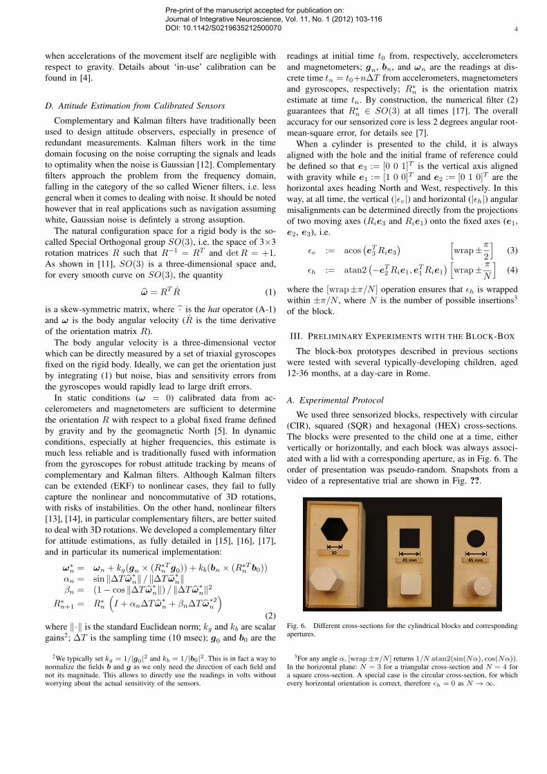
We used three sensorized blocks, respectively with circular(CIR), squared (SQR) and hexagonal (HEX) cross-sections.The blocks were presented to the child one at a time, eithervertically or horizontally, and each block was always associ-ated with a lid with a corresponding aperture, as in Fig. 6. Theorder of presentation was pseudo-random. Snapshots from avideo of a representative trial are shown in Fig. ??.
Fig. 6. Different cross-sections for the cylindrical blocks and correspondingapertures.
3For any angle α, [wrap±π/N ] returns 1/N atan2(sin(Nα), cos(Nα)).In the horizontal plane: N = 3 for a triangular cross-section and N = 4 fora square cross-section. A special case is the circular cross-section, for whichevery horizontal orientation is correct, therefore ϵh = 0 as N → ∞.
Pre-print of the manuscript accepted for publication on: Journal of Integrative Neuroscience, Vol. 11, No. 1 (2012) 103-116 DOI: 10.1142/S0219635212500070

5
Each task consisted of grasping the presented block, trans-porting it over the aperture, inserting with possible adjustmentsand releasing it into the aperture. For each presented blockthe task was repeated three times. Children were completelyfree to perform the task at their own pace. Often the childrenwere distracted by the environment (e.g. other children in thedaycare) and so most of the children interrupted the task.In this paper we present data relative to three children whocompleted the insertion tasks without interruptions.
B. Data Analysis
The raw data collected from the inertial-magnetic sensorsembedded in each presented block were processed off-line.Data were first fed into a complementary filter [15], [16], [17]to derive the sequence of orientations of the block (100 persecond).
0 1 2 3 4 5 6 70
30
60
90
time [s]
erro
r [d
eg]
ver. errorhor. error
0 1 2 3 4 5 6 70
1
2
3
time [s]
acce
lera
tion
[g]
Fig. 7. Representative data acquired during experiments with the block-box.(Top) Horizontal and vertical angular errors between the sensorized blockand corresponding aperture. (Bottom) Acceleration amplitude: the circle atapproximately t = 4.4s denotes the time of first contact between the blockand the lid of the box.
Once the orientation of the block was determined, thevertical and horizontal errors can be derived at any timeas, respectively, the angular tilt with respect to gravity andthe angular misalignment in the horizontal plane betweenthe current orientation and the orientation of the block, onceinserted. Pre-adjustment errors are defined as the vertical andhorizontal errors at the time of first contact, i.e. when the firstimpact between the sensorized block and the lid of the boxoccurs, which as in [9] was determined from inspecting thevideo.
Fig. 7 reports data from a representative trial. The blockis presented to the child, who grasps it approximately attime t = 2.1s (when the first vibrations appear in theaccelerometer plots, bottom figure). The time of first contactoccurs approximately at t = 4.4s and it corresponds to a peakin the acceleration trace (marked with a circle). At this time,both vertical and horizontal errors are below 30 deg, so thepre-adjustment would be considered correct according to [9].In the remaining time, the child tries to fit the the block into
the aperture and only at approximately time t = 6.4s bothvertical and horizontal alignment errors drop to zero and theblock can be successfully inserted4. The time interval betweenthe first contact and a successful insertion is called insertiontime, see Fig. 7 (bottom).
C. Preliminary Results
Preliminary tests have been carried out on four children,three 25 months old female and one 14 months old male ( i.e.the age range of interest for the development of orientationskills). Their data were grouped together for statistical anal-ysis. Table I reports data relative to horizontal and verticalerrors, i.e. angular misalignments from eq. (3)–(4), as wellas to the insertion time. For each measured variable, meanand standard error (SE) are reported. The first 3 rows arerelative to vertically presented blocks, the second three rowsare relative to horizontally presented blocks. Note that thehorizontal error is by definition zero for the block with circularcross-section (CIR) as all horizontal orientations are in factpossible for the block to fit the corresponding aperture.
Despite the small number of subjects and completed tasks,there are some considerations which can inferred from thedata reported in the table. The insertion time seems to dependon the initial presentation of the block. For all blocks, theinsertion time for the horizontal presentation was consistentlylarger than that measured for the vertical presentation. Thisis probably related to pre-adjustment errors which tend to beconsistently larger for horizontally presented blocks (exceptfor the horizontal error of the squared section block): a largerper-adjustment error may require more time to perform thecorrections necessary to insert the block into the hole. More-over such data are consistent with the fact that horizontallypresented blocks require greater computational efforts formotor planning (e.g. performing mental rotations) as well asin online control since the child has to correct both horizontaland vertical errors at the same time.
Note: Given the limited number of completed trials ouranalysis lacks statistical power and we might not be ableto detect some effects, e.g. due to shape. The presentedexperiments mainly aim at proving feasibility of the methodand acceptability of the device by the children.
IV. CONCLUSION
Developmental milestones of children have long been objectof study (e.g. see the works of Piaget [1]), nevertheless quanti-tative normative databases of sensorimotor integration skills inrelation to increasingly complex tasks are still lacking. Suchinformation extend the current knowledge on developmentalmechanisms, with an impact on Developmental Sciences aswell as on bio-inspired Robotics.
We propose a mechatronic platform for assessing the devel-opment of spatial cognition in children based on experimentalscenarios devised by psychologists. The selection of the tech-nology strictly follows the ecological requirements.
4Note: the exact time of dropping of the sensorized block can alsobe determined from the accelerometers because, for a body in free fall,acceleration always drops to zero.
Pre-print of the manuscript accepted for publication on: Journal of Integrative Neuroscience, Vol. 11, No. 1 (2012) 103-116 DOI: 10.1142/S0219635212500070

6
TABLE IMEAN VALUES (± STANDARD ERROR) OF THE HORIZONTAL ERROR (|ϵh|), VERTICAL ERROR (|ϵv |) AND THE INSERTION TIME (TIME) AVERAGED ON
THREE SUBJECTS FOR THREE SENSORIZED BLOCKS WITH DIFFERENT CROSS-SECTIONS (CIR, SQR, AND HEX) AND FOR TWO DIFFERENT
PRESENTATIONS (HORIZONTAL AND VERTICAL).
|ϵh| |ϵv| TimeMean ± SE [deg] Mean ± SE [deg] Mean ± SE [sec]
HorizontalPresentation
CIR - 23.4 ± 4.9 2.0 ± 0.8HEX 18.2 ± 3.3 22.3 ± 4.6 4.7 ± 1.5SQR 11.52 ± 3.54 16.9 ± 3.9 1.9 ± 0.6
VerticalPresentation
CIR - 14.9 ± 4.8 1.6 ± 0.4HEX 14.6 ± 2.0 18.3 ± 3.2 3.8 ± 1.0SQR 22.0 ± 4.04 11.81 ± 2.73 3.4 ± 0.9
In particular, we present an instrumented toy specificallydevised to assess the development of spatial cognition inchildren. The scientific focus is on the children’s ability tomentally rotate a block in order to fit the appropriate hole.
The experimental protocol is adapted from that originallyproposed by Ornkloo and von Hofsten [9], specifically devisedto assess vertical and horizontal pre-adjustments of the block(with various levels of difficulty in relation to the differentcross-sections) at the time of contact with the box. In the workof Ornkloo and von Hofsten [9], two video cameras monitoredthe experiment providing respectively a top and a side view.From the videos, after determining the frame during whichthe block came first into contact with the lid of the box, bothvertical and horizontal alignment of the block with the aperturewere evaluated from the specific frame, with a goniometer.
Accuracy of such methods highly depends on the qualityof the videos. As highlighted by the authors themselves [9],the vertical and horizontal alignments were judged by twocoders who disagreed on 31 out of 302 cases, i.e. on morethan 10% of the times. Moreover, this method relies on the(time-consuming) manual scoring of videos, frame-by-frame.
The block-box platform embeds magnetic-inertial sensorsfor attitude estimation. Both vertical and horizontal alignmentscan be derived automatically from the orientation estimatedfrom the raw data, with 1-2 deg accuracy (as shown in Tab.I). Furthermore, the proposed platform allows for analysis oforientation at all times, not only at the insertion time. Theplatform was also successfully tested with healthy children, toassess acceptability and robustness as well as to derive a firstset of normative data. Results from this pilot study will bepart of future publications. In conclusion, the proposed block-box platform proved suitable for use in day-cares, with thepotential of becoming a screening tool for a large number ofchildren.
ACKNOWLEDGEMENT
The authors are grateful to Claes von Hofsten and hisgroup for valuable feedback. This work was partly fundedby the Italian Ministry of Education, University and Researchunder the FIRB “Futuro in Ricerca” research program (TOUMproject, no. B81J10000160008) and under the FIRB ResearchProgram 2006 no. RBAP06SPK5, by the European UnionFP6-NEST/ADVENTURE program (contract no. 015636) and
FP7-ICT program (project no. ICT-2007.3.2-231722 - IM-CLeVeR), by the NIH R21 grant HD068584, and by theAcademic Research Fund (AcRF) Tier1 (RG 40/09), Ministryof Education, Singapore.
APPENDIX
APPENDIX
The hat operator maps a vector a = [a1 a2 a3]T into a
skew-symmetric matrix:
· : a =
a1a2a3
−→
0 −a3 a2a3 0 −a1−a2 a1 0
= a (A-1)
The Logarithmic map [18], [19] on SO(3) maps a rotationmatrix into a skew-symmetric one:
r = logR :=θ
2 sin θ(R−RT ) (A-2)
where θ satisfies 1 + 2 cos θ = trace(R). The physicalsignificance of this map is that any rotation R can be thoughtof as a pure rotation about a fixed axis r through an angle∥r∥ = θ.
REFERENCES
[1] J. Piaget The Origin of Intelligence in the Child, London: Routledgeand Kegan Paul, 1953.
[2] G. Welch, E. Foxlin, “Motion Tracking: No Silver Bullet, but a Re-spectable Arsenal”, IEEE Comput Graph, vol. 22, pp. 24-38, 2002.
[3] B. Kemp, A.J.M.W. Janssen, B. van der Kamp, “Body position can bemonitored in 3D using miniature accelerometers and earth-magnetic fieldsensors”, Electroen Clin Neuro, vol. 109, pp. 484-488, 1998.
[4] J.C. Lotters, J. Schipper, P.H. Veltink, W. Olthuis, P. Bergveld, “Pro-cedure for in-use calibration of triaxial accelerometers in medicalapplications”, Sensor Actuat A-Phys, vol. 68, pp. 221-228, 1998.
[5] D. Campolo, M. Fabris, G. Cavallo, D. Accoto, F. Keller, E.Guglielmelli, “A Novel Procedure for In-field Calibration of SourcelessInertial/Magnetic Orientation Tracking Wearable Devices”, in Proc.IEEE / RAS-EMBS Intl Conf. on Biomedical Robotics and Biomecha-tronics (BIOROB), pp.471-476, Pisa, Italy, Feb 20-22, 2006.
[6] F. Taffoni, D. Formica, D. Campolo, F. Keller, E. Guglielmelli, “Block-box instrumented toy: a new platform for assessing spatial cognition ininfants”, in Proc. of the Intl Conf of the IEEE Engineering in Medicineand Biology Society (EMBC’09), Minneapolis, Minnesota, USA, 2-6September, 2009
[7] D. Campolo, F. Taffoni, D. Formica, G. Schiavone, F. Keller, E.Guglielmelli, “Inertial-Magnetic Sensors for Assessing Spatial Cognitionin Infants”, IEEE T Bio-Med Eng, Vol. 58, No. 5, pp. 1499–1503, 2011.
[8] D. Campolo, F. Taffoni, D. Formica, F. Keller, E. Guglielmelli, “In-strumented toys for assessing spatial cognition in infants”, Frontiers ofMechanical Engineering, Vol. 6, No. 1, pp.82–88, 2011
Pre-print of the manuscript accepted for publication on: Journal of Integrative Neuroscience, Vol. 11, No. 1 (2012) 103-116 DOI: 10.1142/S0219635212500070
7
[9] H. Ornkloo, C. von Hofsten, “Fitting objects into holes: on the devel-opment of spatial cognition skills”, Dev Psychol vol. 43, pp. 404-16,2007.
[10] D. Campolo, E.S. Maini, F. Patane’, C. Laschi, P. Dario, F. Keller, E.Guglielmelli, “Design of a Sensorized Ball for Ecological BehavioralAnalysis of Infants”, Proc. IEEE Intl Conf. on Robotics and Automation(ICRA), Pasadena, California, USA, pp. 1318-1323, 2007.
[11] V.I. Arnold, Mathematical Methods of Classical Mechanics, 2nd ed.,New York: Springer-Verlag, 1989.
[12] R.G. Brown and P.Y.C. Hwang, “Introduction to random signals andapplied Kalman filtering”, New York: J. Wiley, 1992
[13] S.P. Won, W.W. Melek, F. Golnaraghi, “A Kalman/Particle Filter-Based Position and Orientation Estimation Method Using a PositionSensor/Inertial Measurement Unit Hybrid System”, IEEE T Ind Electron,Vol. 57, No. 5, pp. 1787-1798, 2010
[14] F. Daum, “Nonlinear filters: beyond the Kalman filter”, IEEE Aero ElSys Mag, vol. 20, pp. 57-69, 2005.
[15] D. Campolo, L. Schenato, L.J. Pi, X. Deng, E. Guglielmelli, “Multi-modal Sensor Fusion for Attitude Estimation of Micromechanical FlyingInsects: a Geometric Approach”, Proc. IEEE/RSJ Intl Conf on IntelligentRobots and Systems (IROS), Nice, France, pp. 3859 - 3864, Sept 22-26,2008.
[16] D. Campolo, L. Schenato, L.J. Pi, X. Deng, E. Guglielmelli, “AttitudeEstimation of a Biologically Inspired Robotic Housefly via MultimodalSensor Fusion”, Adv Robotics, vol. 23, pp. 955-977, 2009
[17] D. Campolo, G. Barbera, L. Schenato, L.J. Pi, X. Deng, E. Guglielmelli,“Attitude Stabilization of a Biologically Inspired Robotic Housefly viaDynamic Multimodal Attitude Estimation”, Adv Robotics, vol. 23, pp.2113-2138, 2009.
[18] F.C. Park, B.J. Martin, “Robot Sensor Calibration: AX=XB on theEuclidean Group”, IEEE T Robotic Autom, vol. 10, pp. 717-721, 1994.
[19] F.C. Park. “Distance Metrics on the Rigid- Body Motions with Appli-cations to Mechanism Design”. J Mech Design, vol. 117, pp. 48-54,1995.
Pre-print of the manuscript accepted for publication on: Journal of Integrative Neuroscience, Vol. 11, No. 1 (2012) 103-116 DOI: 10.1142/S0219635212500070
Related Documents


![Inertial Navigation Systems - Indico [Home]indico.ictp.it/event/a12180/session/23/contribution/14/material/0/... · Inertial Navigation Systems. Inertial Navigation Systems ... •](https://static.cupdf.com/doc/110x72/5a94bdc87f8b9a451b8c1652/inertial-navigation-systems-indico-home-navigation-systems-inertial-navigation.jpg)