Pulse width modulation Embedded Systems Design Course Applying the mbed microcontroller 1 These course notes are written by R.Toulson (Anglia Ruskin University) and T.Wilmshurst (University of Derby). (c) ARM 2012 These course notes accompany the textbook “Fast and effective embedded system design : Applying the ARM mbed”

Welcome message from author
This document is posted to help you gain knowledge. Please leave a comment to let me know what you think about it! Share it to your friends and learn new things together.
Transcript
Pulse width modulation
Embedded Systems Design Course Applying the mbed microcontroller
1
These course notes are written by R.Toulson (Anglia Ruskin University) and T.Wilmshurst (University of Derby). (c) ARM 2012
These course notes accompany the textbook “Fast and effective embedded system design : Applying the ARM mbed”
Pulse width modulation
2
• The concept of pulse width modulation (PWM)
• Applications using pulse width modulation
• Evaluating pulse width modulation on the mbed
• Controlling LED brightness with PWM
• Controlling servo position with PWM
• Outputting to a piezo buzzer

Introducing pulse width modulation (PWM)
What is Pulse Width Modulation?
• Pulse width modulation (PWM) is a simple method of using a rectangular digital waveform to control an analog variable
• PWM control is used in a variety of applications, ranging from communications to automatic control
3

Introducing pulse width modulation (PWM)
• The period is normally kept constant, and the pulse width, or “on” time is varied
• The duty cycle is the proportion of time that the pulse is ‘on’ or ‘high’, and is expressed as a percentage:
duty cycle = 100% * (pulse on time) / (pulse period)
4
Period, T
“on” time, ton
Average
value

Introducing pulse width modulation (PWM)
• Whatever duty cycle a PWM stream has, there is an average value, as indicated by the dotted line
• If the on time is small, the average value is low; if the on time is large, the average value is high
• By controlling the duty cycle, we control this average value
5
Period, T
“on” time, ton
Average
value

Introducing pulse width modulation (PWM)
• The average value can be extracted from the PWM stream with a low-pass filter
• In this case, and as long as PWM frequency and values of R and C are appropriately chosen, Vout becomes an analog output
6
R
C
Vin VoutR
C
Vin Vout
• In practice, this sort of filtering is not always required; many physical systems have response characteristics which, in reality, act like low pass filters

Applications using pulse width modulation
• Devices used in robotics – DC motors
– Servos
– Solenoids
– Closed loop control systems
– Communications and pulse code modulation
• Benefits include – Microprocessor control
– Efficient use of power
– Tolerance to analog noise
– Not susceptible to component drift
7

Pulse width modulation on the mbed
8
• The PwmOut interface is used to control the frequency and mark-space ratio of a digital pulse train
• The mbed has up to six PWM outputs, on pins 21 to 26, although these PwmOuts all share the same period timer
Pulse width modulation on the mbed
9
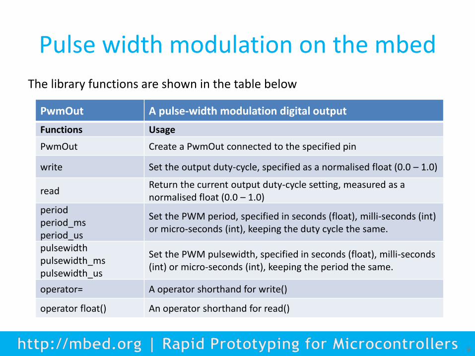
The library functions are shown in the table below
PwmOut A pulse-width modulation digital output
Functions Usage
PwmOut Create a PwmOut connected to the specified pin
write Set the output duty-cycle, specified as a normalised float (0.0 – 1.0)
read Return the current output duty-cycle setting, measured as a normalised float (0.0 – 1.0)
period period_ms period_us
Set the PWM period, specified in seconds (float), milli-seconds (int) or micro-seconds (int), keeping the duty cycle the same.
pulsewidth pulsewidth_ms pulsewidth_us
Set the PWM pulsewidth, specified in seconds (float), milli-seconds (int) or micro-seconds (int), keeping the period the same.
operator= A operator shorthand for write()
operator float() An operator shorthand for read()

Evaluating pulse width modulation on the mbed
• Exercise 1: Create a PWM signal which we can see on an oscilloscope. The following code will generate a 100 Hz pulse with 50% duty cycle
10
#include "mbed.h"
PwmOut PWM1(p21);
int main() {
PWM1.period(0.010); // set PWM period to 10 ms
PWM1=0.5; // set duty cycle to 50%
}

Evaluating pulse width modulation on the mbed
• Exercise 2: Change the duty cycle to some different values, say 0.2 (20%) and 0.8 (80%) and check the correct display is seen on the ‘scope, as shown below
11
Controlling LED brightness with PWM
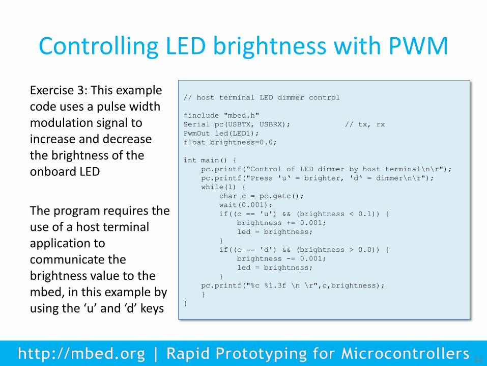
Exercise 3: This example code uses a pulse width modulation signal to increase and decrease the brightness of the onboard LED
The program requires the use of a host terminal application to communicate the brightness value to the mbed, in this example by using the ‘u’ and ‘d’ keys
12
// host terminal LED dimmer control
#include "mbed.h"
Serial pc(USBTX, USBRX); // tx, rx
PwmOut led(LED1);
float brightness=0.0;
int main() {
pc.printf(“Control of LED dimmer by host terminal\n\r");
pc.printf("Press 'u‘ = brighter, 'd‘ = dimmer\n\r");
while(1) {
char c = pc.getc();
wait(0.001);
if((c == 'u') && (brightness < 0.1)) {
brightness += 0.001;
led = brightness;
}
if((c == 'd') && (brightness > 0.0)) {
brightness -= 0.001;
led = brightness;
}
pc.printf("%c %1.3f \n \r",c,brightness);
}
}

Controlling servo motor position with PWM
• A servo is a small rotary position control device, used for example in radio-controlled cars and aeroplanes to position controllers such as steering, elevators and rudders
• The servo shaft can be positioned to specific angular positions by sending the servo a PWM signal
• As long as the modulated signal exists on the input line, the servo will maintain the angular position of the shaft
• As the modulated signal changes, the angular position of the shaft changes
13
Controlling servo position with PWM
14
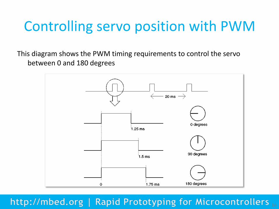
This diagram shows the PWM timing requirements to control the servo between 0 and 180 degrees

Controlling servo position with PWM
The servo requires a higher current than the USB standard can provide, and so it is essential that you power the servo using an external power supply
A 4xAA (6V) battery
pack meets the supply
requirement of the servo
15

Controlling servo position with PWM
16
• Exercise 4: Connect the servo to the mbed as indicated. Set the PWM period to 20 ms
• Try a number of different duty periods and observe the servo’s motion

Open loop control of a servo motor
• Exercise 5: Controlling servo position with the potentiometer
17
– Connect a servo to the mbed with a potentiometer connected to pin 20
– Write a program which allows the potentiometer to control servo position
– Scale input values so that the full range of potentiometer adjustment leads to the full range of servo position change

Outputting to a piezo buzzer
• We can connect the PWM output to a piezo buzzer to make sound
• If the duty cycle is set to 50% the PWM frequency will define the pitch of the sound heard
• Exercise 6: Connect a piezo buzzer one of the PWM outputs. Set duty cycle to 50% and frequency to 500 Hz. Ensure that you can create sound with the PWM. Change the frequency of the PWM output and notice the difference in sound with changes in frequency.
18

Outputting to a piezo buzzer
• Exercise 7: We are going to use the PWM to play the start of an old English folk tune ‘Oranges and Lemons’. If you’re a reader of music you will recognise this in the Figure below
• You just need to know that any note which is a minim lasts twice as long as a crotchet, which in turn lasts twice as long as a quaver
19
crotchet quaver minim

Outputting to a piezo buzzer
The following table converts the musical piece into frequencies and beat lengths
20

Outputting to a piezo buzzer
The following program implements the ‘Oranges and Lemons‘ musical output
21
// Oranges and Lemons program
#include "mbed.h"
PwmOut buzzer(p21);
float frequency[]={659,554,659,554,550,494,554,587,494,659,554,440};
//frequency array
float beat[]={1,1,1,1,1,0.5,0.5,1,1,1,1,2};
//beat array
int main() {
while (1) {
for (int i=0; i<=11; i++) {
buzzer.period(1/(frequency[i])); // set PWM period
buzzer=0.5; // set duty cycle
wait(0.5*beat[i]); // hold for beat period
}
}
}
Experiment with adding multipliers to the frequency and beat values to change the speed and pitch of the piece.

Summary
• The concept of pulse width modulation (PWM)
• Applications using pulse width modulation
• Evaluating pulse width modulation on the mbed
• Controlling LED brightness with PWM
• Controlling servo position with PWM
• Outputting to a piezo buzzer
22
Related Documents