Embedded Systems Design 1 Lecture Set B Interfacing the MCS-51 to: – 7 and 16 segment displays – a Multiplexed 7-Segment Display – a Keypad – an LCD

Welcome message from author
This document is posted to help you gain knowledge. Please leave a comment to let me know what you think about it! Share it to your friends and learn new things together.
Transcript

Embedded Systems Design 1
Lecture Set B
Interfacing the MCS-51 to:– 7 and 16 segment displays– a Multiplexed 7-Segment Display– a Keypad– an LCD

Embedded Systems Design 2
The 7-Segment Display
• The 7-segment display is nothing but 7 LEDs arranged to form the figure 8.– By turning on and off the appropriate segments
(LEDs), different combinations can be produced.– The 7-segment display is useful for displaying the
digits 0 through 9, and some characters.• However, it would be difficult to distinguish between
things like a D and a 0.a
b
c
f
e
g
d
Embedded Systems Design 3
The 7-segment Display (Contd.)
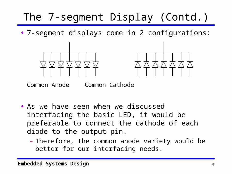
• 7-segment displays come in 2 configurations:
Common Anode Common Cathode
• As we have seen when we discussed interfacing the basic LED, it would be preferable to connect the cathode of each diode to the output pin.– Therefore, the common anode variety would be
better for our interfacing needs.

Embedded Systems Design 4
Interfacing a 7-segment display to the 8051
• Also, as seen with interfacing the LED, a resistor will be needed to control the current flowing through the diode.– This leaves two possibilities:
• Case 2 would be more appropriate as case 1 will produce different brightness depending on the number of LEDs turned on.

Embedded Systems Design 5
The 16-segment Display
• Similar to the 7-segment display except that it contains 16 LEDs.– With the 16 segments, it is possible to
represent all digits and letters in the alphabet (English).
– With 16 LEDs, the 16-segment display requires 16 pins and 16 bits to determine the exact character.
• All 16 values must be present at the same time.– Therefore, interfacing to a 16-segment display will require:
» Either external hardware such as a latch.
» Using two of the 8051 ports for connecting to a single display.

Embedded Systems Design 6
Multiplexed Displays
• 7-segment displays require a lot of power (~10 mA per LED) and a large number of pins (8 per LED).– Suppose that a battery-powered system has 10
displays.• If the system is displaying “8888888888”.
– All LEDs are on in all displays.
– The total current required just to activate the displays is ~700 mA.
• This would reduce the useful battery lifetime to a few hours at best.
– The solution is not to activate all displays at once.
Embedded Systems Design 7
Multiplexed Displays
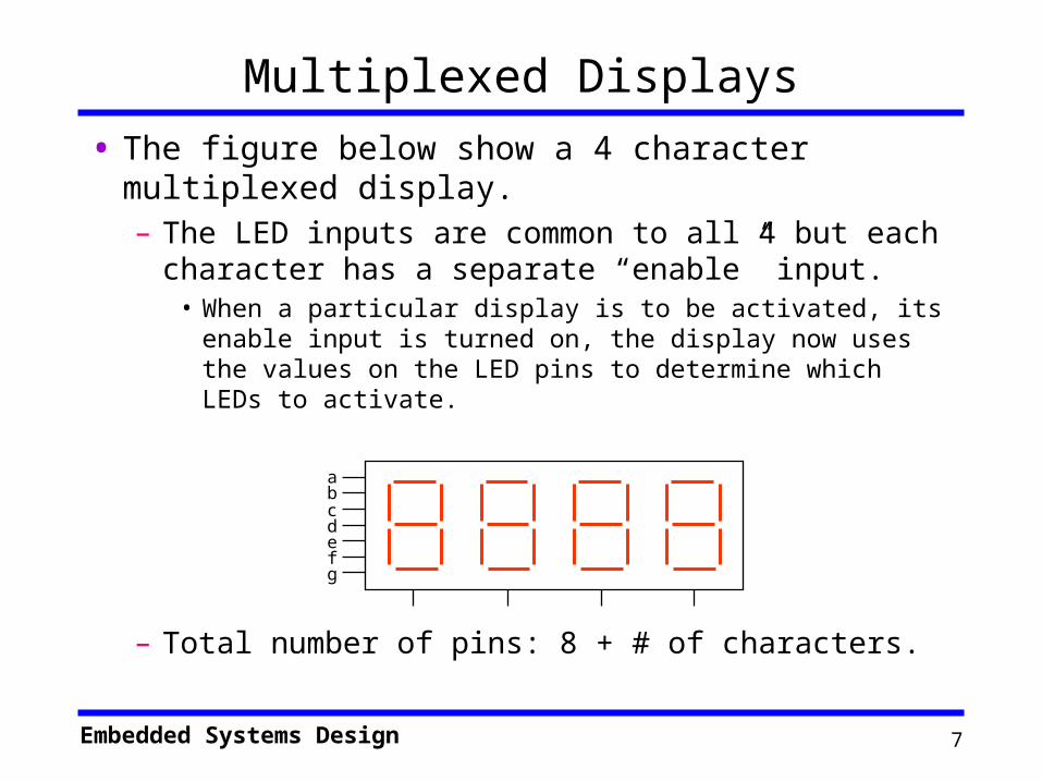
• The figure below show a 4 character multiplexed display.– The LED inputs are common to all 4 but each
character has a separate “enable” input.• When a particular display is to be activated, its enable
input is turned on, the display now uses the values on the LED pins to determine which LEDs to activate.
– Total number of pins: 8 + # of characters.
abcdefg

Embedded Systems Design 8
Interfacing to a Multiplexed Display• To use a multiplexed display, each character will be
flashed for a short period of time,• the first character is activated for a brief amount of time, then it
is turned off.• Then the next character and so on through the four characters.• Back to the first character.
– Only one character is activated at any point in time.• Worst case current requirement: ~70 mA.
– If the multiplexing is done fast enough, the human eye will filter out the flickering and it would look like all the displays are one constantly.
• Most humans cannot distinguish flashes at more than 20 per second. They would consider that to be steady light.
• The scanning frequency should be at least 30 Hz.– Each character is on for 1/30 of a second.
Embedded Systems Design 9
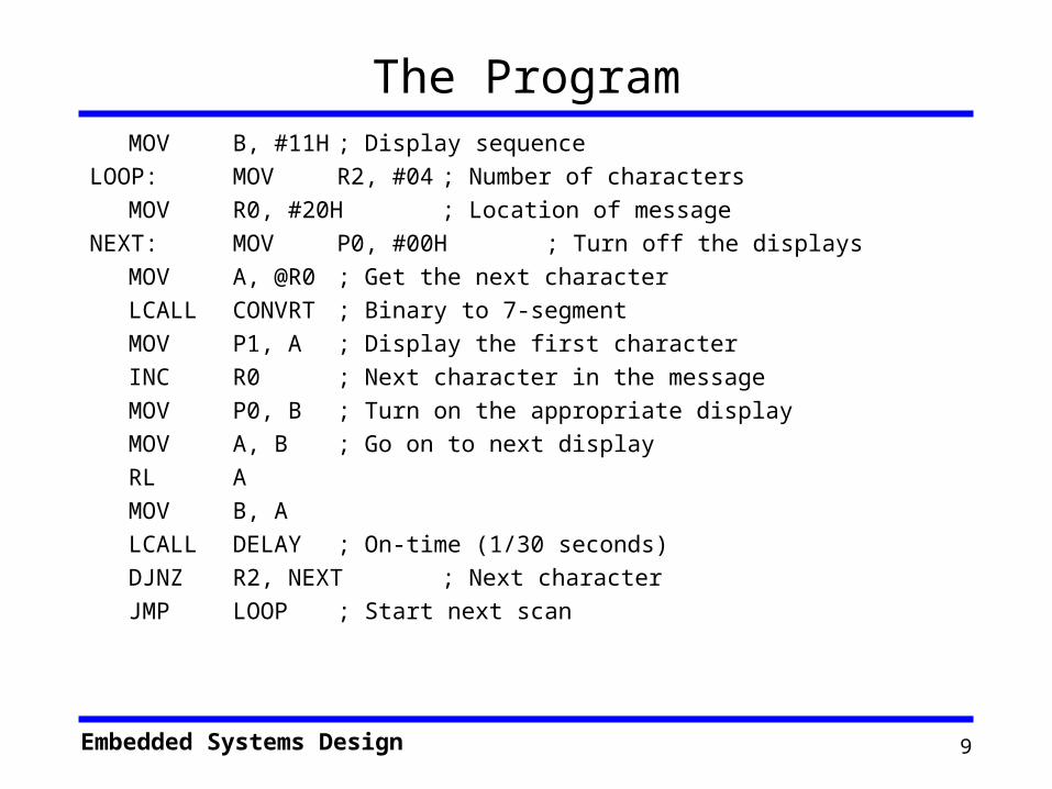
The ProgramMOV B, #11H ; Display sequence
LOOP: MOV R2, #04 ; Number of characters
MOV R0, #20H ; Location of message
NEXT: MOV P0, #00H ; Turn off the displays
MOV A, @R0 ; Get the next character
LCALL CONVRT ; Binary to 7-segment
MOV P1, A ; Display the first character
INC R0 ; Next character in the message
MOV P0, B ; Turn on the appropriate display
MOV A, B ; Go on to next display
RL A
MOV B, A
LCALL DELAY ; On-time (1/30 seconds)
DJNZ R2, NEXT ; Next character
JMP LOOP ; Start next scan

Embedded Systems Design 10
Interfacing a Keypad
• A 16-key keypad is built as shown in the figure below.– 16 keys arranged as
a 4X4 matrix.– Must “activate”
each row by placing a 0 on its R output.
• Then the column output is read.
• If there is a 0 on one of the column bits, then the button at the column/row intersection has been pressed.
• Otherwise, try next row.
– Repeat constantly.
C 1C 2C 3C 4
R 1R 2R 3
R 4

Embedded Systems Design 11
Interfacing a Keypad
• Algorithm:– Drive a “0” on a row– Read all the columns– If any key had been pressed, its column will be “0”,
else 1– Keep repeating in a loop for each successive row
• Example:– Switch 4 is pressed
• R1 0, C1:C4 = 1111• R2 0, C1:C4 = 0111
– Switch 2 is pressed• R1 0, C1:C4 = 1101

Embedded Systems Design 12
Bouncing Contacts
• Push-button switches, toggle switches, and electromechanical relays all have one thing in common: contacts.
• These metal contacts make and break the circuit and carry the current in switches and relays. Because they are metal, contacts have mass.
• Since at least one of the contacts is on a movable strip of metal, it has springiness.
• Since contacts are designed to open and close quickly, there is little resistance (damping) to their movement.

Embedded Systems Design 13
Bouncing
• Because the moving contacts have mass and springiness with low damping they will be "bouncy" as they make and break.
• That is, when a normally open (N.O.) pair of contacts is closed, the contacts will come together and bounce off each other several times before finally coming to rest in a closed position.
• The effect is called "contact bounce" or, in a switch, "switch bounce”.

Embedded Systems Design 14
Why is it a problem?
• If such a switch is used as a source to an edge-triggered input such as T0 or INT0, then the MCS-51 will think that there were several “events” and respond several times.
• The bouncing of the switch may last for several milliseconds.– Given that the MCS-51 operates at microsecond
speed, a short ISR may execute several times in response to the above described bounciness.

Embedded Systems Design 15
Hardware Solution
• The simplest hardware solution uses an RC time constant to suppress the bounce. The time constant has to be larger than the switch bounce and is typically 0.1 seconds.
• The buffer after the switch produces a sharp high-to-low transition.– If the button is pushed again
before the expiration of the time constant, the second press will not be recognized.
V c c
O U T

Embedded Systems Design 16
Software Solution
• It is also possible to counter the bouncing problem using software.
• This would require one of two approaches:– Delays: When the first edge is noticed, an
“appropriate” delay is executed, then the value of the line is checked again to make sure the line has stopped bouncing.
• Actually, it is also necessary to execute a similar delay on the button’s release to counter the release bouncing.
– Interrupts and Timers: When the first edge is noticed, a timer is started. When following edges appear, the value of the counter is checked. If the edges appear “too quickly”, they will be rejected.

Embedded Systems Design 17
LCD Interfacing
• LCDs have become a cheap and easy way to get text display for an embedded system – Various configurations (1 line by 20 characters upto 8 lines
by 80 characters), starting from around $5.– Graphics LCDs are also available
• Intelligent LCDs have internal ASCII decoders, Character Generators and LCD control circuitry
• Some also have custom character generation capacity– User defined character RAM– Program this RAM with the character pattern– Then use it like ordinary ASCII characters
• Usually MSB decides between std ASCII and custom characters
Embedded Systems Design 18
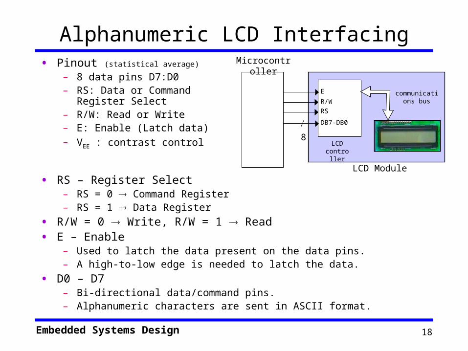
Alphanumeric LCD Interfacing• Pinout (statistical average)
– 8 data pins D7:D0– RS: Data or Command
Register Select– R/W: Read or Write– E: Enable (Latch data)– VEE : contrast control
• RS – Register Select– RS = 0 Command Register– RS = 1 Data Register
• R/W = 0 Write, R/W = 1 Read
• E – Enable– Used to latch the data present on the data pins.– A high-to-low edge is needed to latch the data.
• D0 – D7– Bi-directional data/command pins. – Alphanumeric characters are sent in ASCII format.
E
R/W
RS
DB7–DB0
LCD controller
communications bus
Microcontroller
8
LCD Module

Embedded Systems Design 19
LCD Commands• The LCD’s internal controller can accept several commands and
modify the display accordingly. These commands would be things like:– Clear screen– Return home– Decrement/Increment cursor– Shift display right/left
– Check the data sheet from the manufacturer.
• After writing to the LCD, it takes some time for it to complete its internal operations. During this time, it will not accept any new commands or data.– We can check if the LCD is busy or not by reading the busy flag.
• Set R/W = 1 and RS = 0, then read from the LCD– If D7 = 1, then the LCD is still busy, wait.

Embedded Systems Design 20
Example LCD Interface ProgramORG 100H
MOV A, #38H ; Initialize, 2-lines, 5X7 matrix.
ACALL Command
MOV A, #0EH ; LCD on, cursor on
ACALL Command
MOV A, #01H ; Clear LCD Screen
ACALL Command
MOV A, #06H ; Shift cursor right
ACALL Command
MOV A, #86H ; Cursor, line 1 position 6
ACALL Command
MOV A, #’N’ ; Character N
ACALL Data
MOV A, #’O’ ; Character O
ACALL Data
Wait: SJMP Wait
Command: ACALL Ready
MOV P1, A
CLR P2.0 ; RS=0
CLR P2.1 ; R/W=0 (Write)
SETB P2.2 ; E = 1
CLR P2.2 ; E = 0 – complete the 1-to-0 pulse
RET
Data: ACALL Ready
MOV P1, A
SETB P2.0 ; RS = 1
CLR P2.1 ; R/W = 0
SETB P2.2 ; Enable pulse
CLR P2.2
RET
Ready: SETB P1.7 ; bit 7 of port 1 set to input
CLR P2.0 ; RS = 0 – Command Reg.
SETB P2.1 ; RW = 1 – Read
Back: SETB P2.2 ; Enable pulse
CLR P2.2
JB P1.7, Back ; Wait till not busy
RET
Embedded Systems Design 21
The Cursor Location
• Whenever a new data character is sent to the LCD, the cursor position will be automatically updated one position to the right.
• It is also possible to place the cursor at a particular location using the “set address” command.– Set RS = 0 and R/W = 0– Set D7 = 1 – (set address command)– Set D6 = 0 for line 1 and D6 = 1 for line 2– Set D5 – D0 for the position on the line (in binary).
• 1st position (extreme left) is 0.

Embedded Systems Design 22
Interfacing an 8031 to an LCD
Source: Intel Application Brief AB-39
Related Documents