Embedded Systems Architecture Class Project USB 2.0 Function Controller December 12, 2008 Brandon Wolfe, Ben Marrou, Daniel Chan

Embedded Systems Architecture Class Project USB 2.0 Function Controller December 12, 2008 Brandon Wolfe, Ben Marrou, Daniel Chan.
Dec 25, 2015
Welcome message from author
This document is posted to help you gain knowledge. Please leave a comment to let me know what you think about it! Share it to your friends and learn new things together.
Transcript
Embedded Systems Architecture Class Project
USB 2.0 Function ControllerDecember 12, 2008
Brandon Wolfe, Ben Marrou, Daniel Chan
Contents
• Project Objectives
• USB Overview
• Hardware Implementation
• Software Driver Implementation
Project Objectives
• Configure USB 2.0 Function Controller from opencores.org to use on lab FPGA board.
• Develop a low-level driver to initialize USB 2.0 Function Controller registers.
• Implement driver functions to allow basic communication with a USB host.
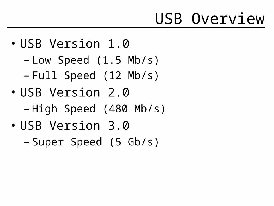
USB Overview
• USB Version 1.0– Low Speed (1.5 Mb/s)– Full Speed (12 Mb/s)
• USB Version 2.0– High Speed (480 Mb/s)
• USB Version 3.0– Super Speed (5 Gb/s)
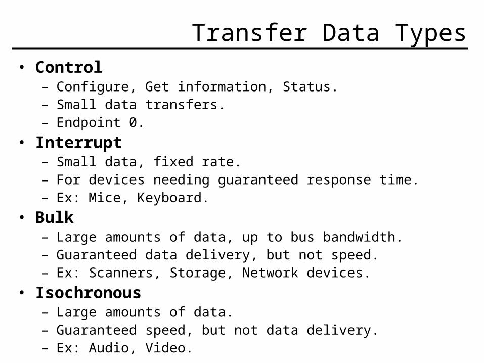
Transfer Data Types• Control
– Configure, Get information, Status.– Small data transfers.– Endpoint 0.
• Interrupt– Small data, fixed rate.– For devices needing guaranteed response time.– Ex: Mice, Keyboard.
• Bulk– Large amounts of data, up to bus bandwidth.– Guaranteed data delivery, but not speed.– Ex: Scanners, Storage, Network devices.
• Isochronous– Large amounts of data.– Guaranteed speed, but not data delivery.– Ex: Audio, Video.
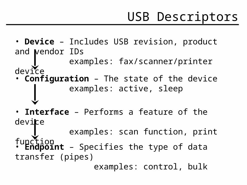
USB Descriptors
• Device – Includes USB revision, product and vendor IDs examples: fax/scanner/printer device
• Configuration – The state of the device examples: active, sleep
• Interface – Performs a feature of the device examples: scan function, print function
• Endpoint – Specifies the type of data transfer (pipes) examples: control, bulk
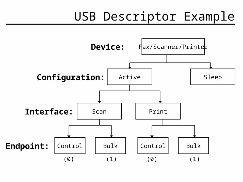
USB Descriptor Example
Fax/Scanner/Printer
Active Sleep
Scan Print
Control Bulk Control Bulk
Device:
Configuration:
Interface:
Endpoint:
(0) (0)(1) (1)
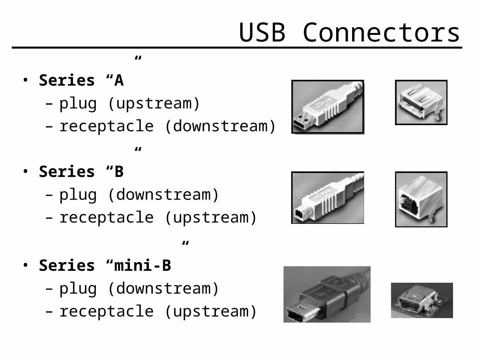
USB Connectors
• Series “A”– plug (upstream)– receptacle (downstream)
• Series “B”– plug (downstream)– receptacle (upstream)
• Series “mini-B”– plug (downstream)– receptacle (upstream)
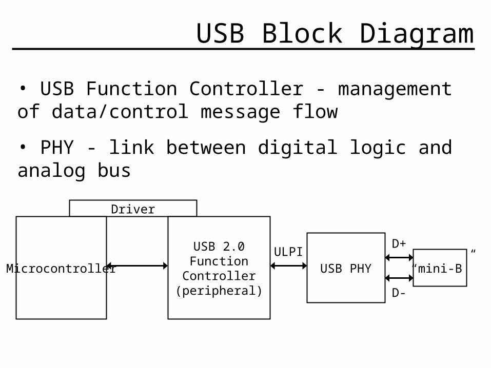
USB Block Diagram
• USB Function Controller - management of data/control message flow
• PHY - link between digital logic and analog bus
Driver
Microcontroller
USB 2.0FunctionController
(peripheral)
USB PHY “mini-B”ULPI
D+
D-
Major hardware Components:• As implemented in RTL from USB Opencore
• Additional implemented RTL • Register R/W• Memory R/W• ULPI-to-UTMI Wrapper
Hardware Implementation
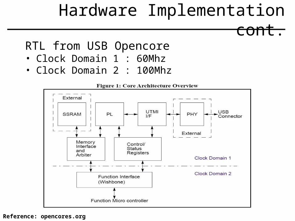
RTL from USB Opencore• Clock Domain 1 : 60Mhz• Clock Domain 2 : 100Mhz
Hardware Implementation cont.
Reference: opencores.org

Register R/W
Registers

Memory R/W
Memory
Reference: opencores.org

Memory R/W
Memory cont.
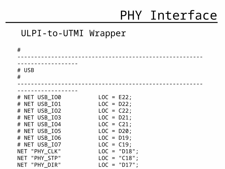
ULPI-to-UTMI Wrapper
# -------------------------------------------------------------------------# USB# -------------------------------------------------------------------------# NET USB_IO0 LOC = E22;# NET USB_IO1 LOC = D22;# NET USB_IO2 LOC = C22;# NET USB_IO3 LOC = D21;# NET USB_IO4 LOC = C21;# NET USB_IO5 LOC = D20;# NET USB_IO6 LOC = D19;# NET USB_IO7 LOC = C19;NET "PHY_CLK" LOC = "D18";NET "PHY_STP" LOC = "C18";NET "PHY_DIR" LOC = "D17";NET "PHY_NXT" LOC = "C17";NET "PHY_RESET" LOC = "E17";
PHY Interface
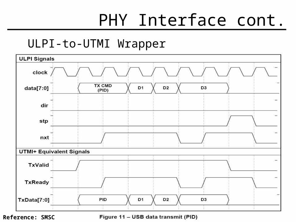
ULPI-to-UTMI Wrapper
PHY Interface cont.
Reference: SMSC
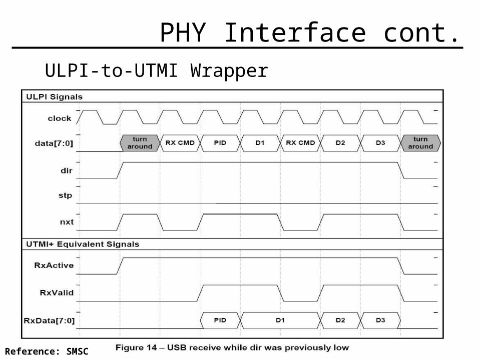
ULPI-to-UTMI Wrapper
PHY Interface cont.
Reference: SMSC
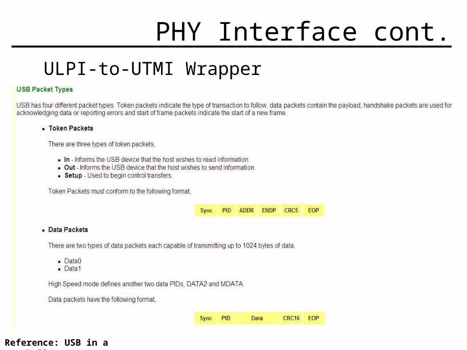
ULPI-to-UTMI Wrapper
PHY Interface cont.
Reference: USB in a NutShell
Revised Intentions for Software
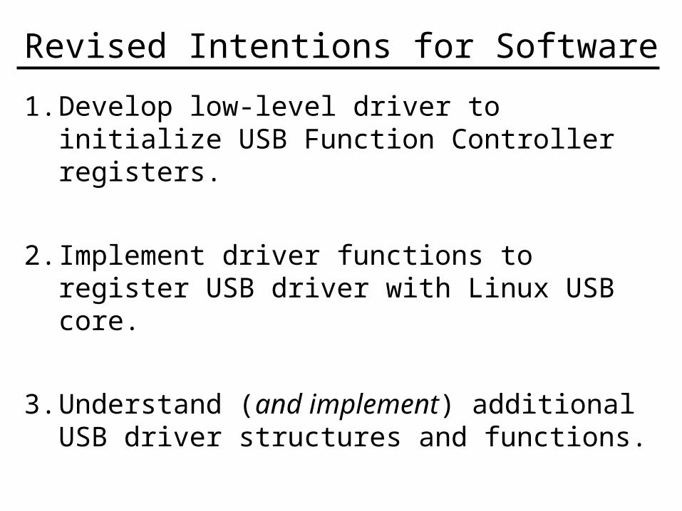
1. Develop low-level driver to initialize USB Function Controller registers.
2. Implement driver functions to register USB driver with Linux USB core.
3. Understand (and implement) additional USB driver structures and functions.

USB Function Controller Driver
• Register Initialization
• USB Driver Registration
• USB Driver Communication
• USB Driver Deregistration
Significant Registers
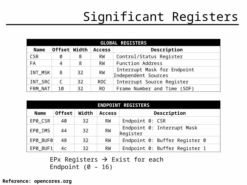
ENDPOINT REGISTERS
Name Offset Width Access Description
EP0_CSR 40 32 RW Endpoint 0: CSR
EP0_IMS 44 32 RW Endpoint 0: Interrupt Mask Register
EP0_BUF0 48 32 RW Endpoint 0: Buffer Register 0
EP0_BUF1 4c 32 RW Endpoint 0: Buffer Register 1
EPx Registers Exist for each Endpoint (0 – 16)
GLOBAL REGISTERSName Offset Width Access Description
CSR 0 8 RW Control/Status Register FA 4 8 RW Function Address INT_MSK 8 32 RW Interrupt Mask for Endpoint Independent Sources INT_SRC C 32 ROC Interrupt Source Register FRM_NAT 10 32 RO Frame Number and Time (SOF)
Reference: opencores.org
Core Register Descriptions
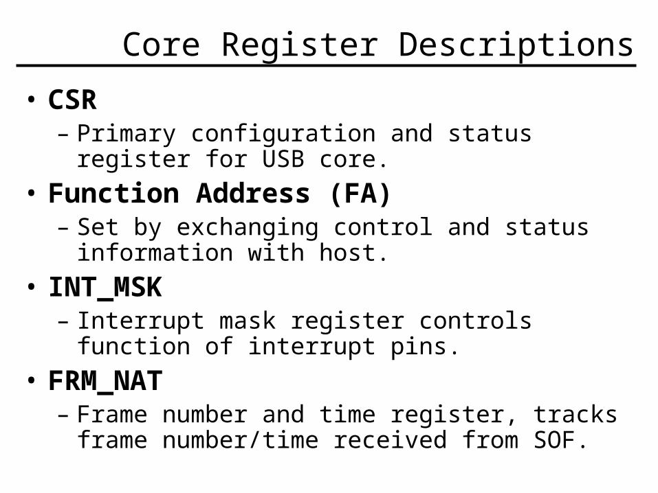
• CSR– Primary configuration and status register for USB
core.
• Function Address (FA)– Set by exchanging control and status information
with host.
• INT_MSK – Interrupt mask register controls function of interrupt
pins.
• FRM_NAT – Frame number and time register, tracks frame
number/time received from SOF.
Endpoint Register Descriptions
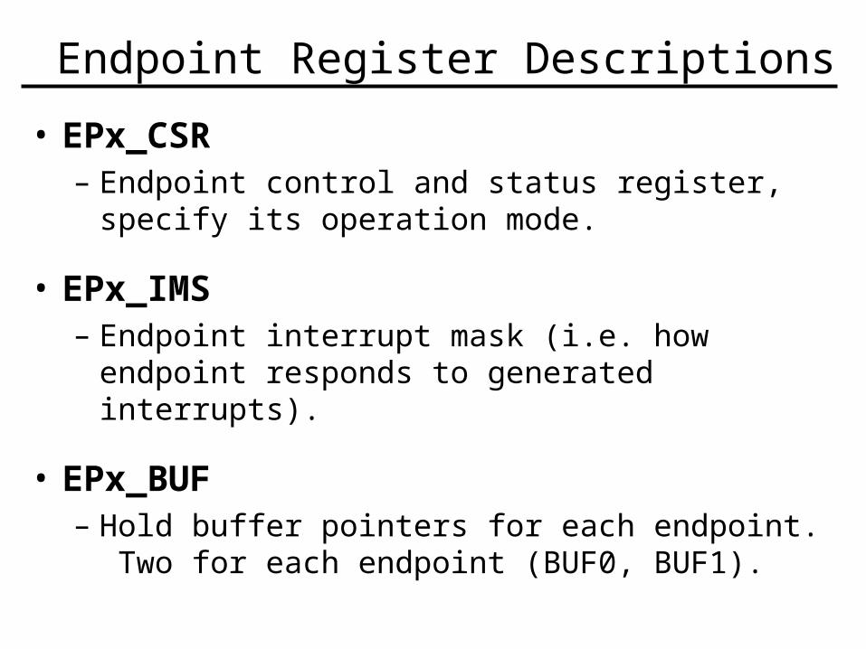
• EPx_CSR – Endpoint control and status register, specify its
operation mode.
• EPx_IMS – Endpoint interrupt mask (i.e. how endpoint responds
to generated interrupts).
• EPx_BUF – Hold buffer pointers for each endpoint. Two for
each endpoint (BUF0, BUF1).
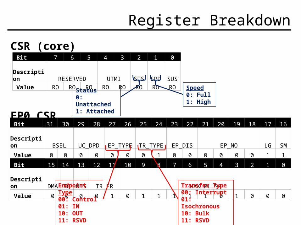
Register Breakdown
CSR (core)
EP0_CSR
Bit 7 6 5 4 3 2 1 0 Description RESERVED UTMI STS SPD SUS Value RO RO RO RO RO RO RO RO
Bit 31 30 29 28 27 26 25 24 23 22 21 20 19 18 17 16
Description BSEL UC_DPD EP_TYPE TR_TYPE EP_DIS EP_NO LG SM
Value 0 0 0 0 0 0 0 1 0 0 0 0 0 0 1 1
Bit 15 14 13 12 11 10 9 8 7 6 5 4 3 2 1 0
Description DMA RO OTS TR_FR MAX_PL_SZ
Value 0 0 0 0 1 0 1 1 1 1 1 0 1 0 0 0
Status0: Unattached1: Attached
Speed0: Full1: High
Endpoint Type00: Control01: IN10: OUT11: RSVD
Transfer Type00: Interrupt01: Isochronous10: Bulk11: RSVD
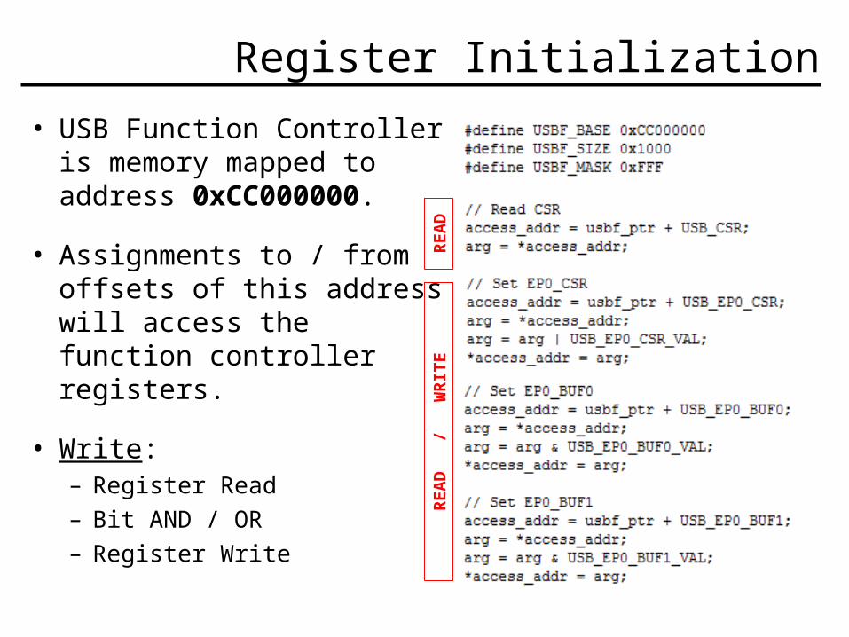
Register Initialization
• USB Function Controller is memory mapped to address 0xCC000000.
• Assignments to / from offsets of this address will access the function controller registers.
• Write: – Register Read
– Bit AND / OR
– Register Write
RE
AD
RE
AD
/
W
RIT
E

USB Declaration & Registration
• Device Driver must declare itself with OS (Linux) USB core.
• Struct USB_Driver serves this purpose, by providing basic function information.
• Additional functionality supported via Struct File_Operations.
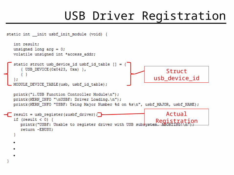
USB Driver Registration
Struct usb_device_id
Actual Registration
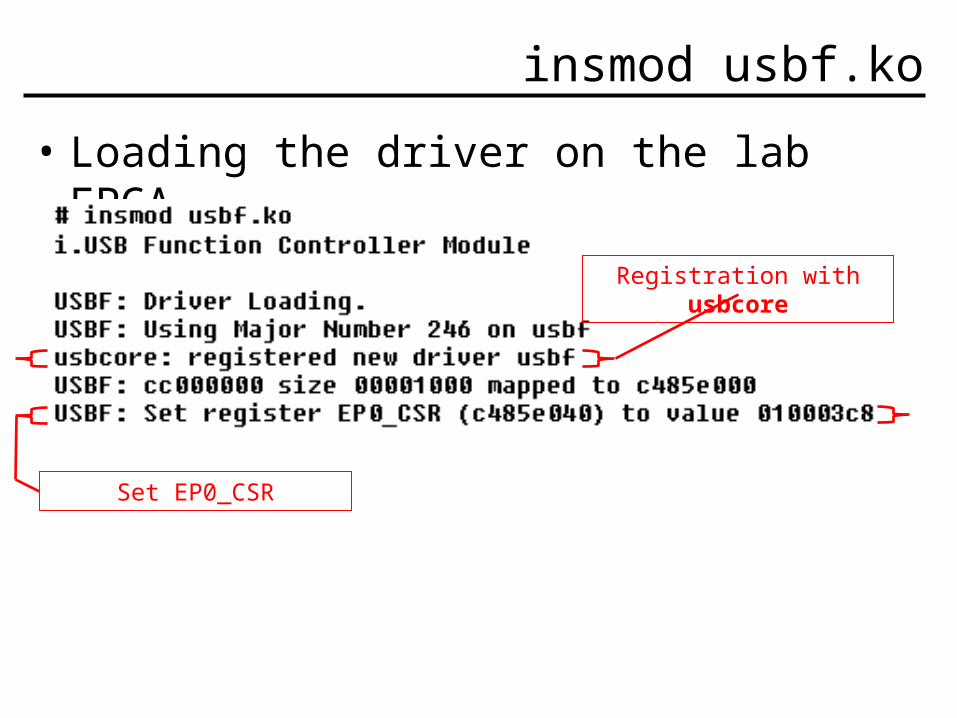
insmod usbf.ko
• Loading the driver on the lab FPGA…
Set EP0_CSR
Registration with usbcore
Probe() Function
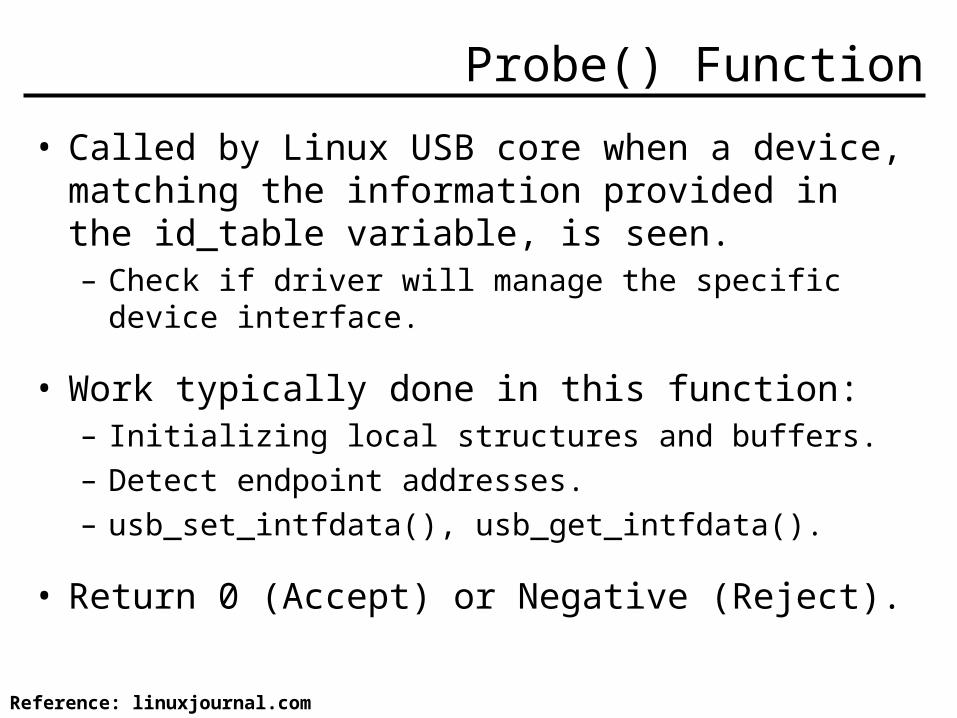
• Called by Linux USB core when a device, matching the information provided in the id_table variable, is seen.– Check if driver will manage the specific device interface.
• Work typically done in this function:– Initializing local structures and buffers.– Detect endpoint addresses.– usb_set_intfdata(), usb_get_intfdata().
• Return 0 (Accept) or Negative (Reject).
Reference: linuxjournal.com
USB Driver Communication
• The driver is loaded and the device is initialized and registered with USB core. It’s time to use it!
• Two methods:– URBs (USB Request Block).– Non-URB alternatives.
What is an URB?
• Structures used by the driver to asynchronously send or receive data to or from a specific USB endpoint.– Similar to packets in networking.
• Formal methods and structures to creating, submitting, executing, and completing URBs.
• Notion of “Pipes”: Control, Bulk, Interrupt, and Isochronous.
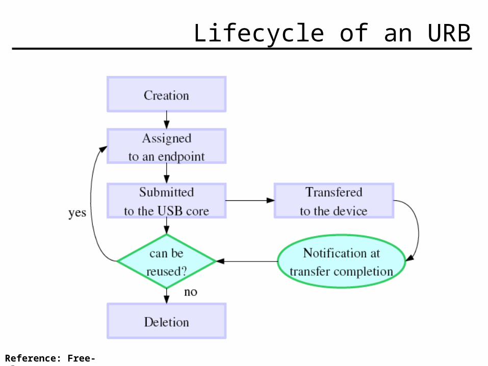
Lifecycle of an URB
Reference: Free-Electrons.com
Alternatives to URBs
• Basic functions exist within USB core to allow data transfer without URBs.– usb_bulk_msg()– usb_control_msg()
• Caters to ease of use, however, affords less control over the transfer.– Requests cannot be cancelled.– Synchronously performed, put code to sleep.
Disconnect() Function
• Called by Linux USB core when a device, matching the information provided in the id_table variable, is removed.
• Work typically done in this function:– Clean up any private data during its operation.– Close out pending transfers or URBs.
Reference: linuxjournal.com
USB Deregistration
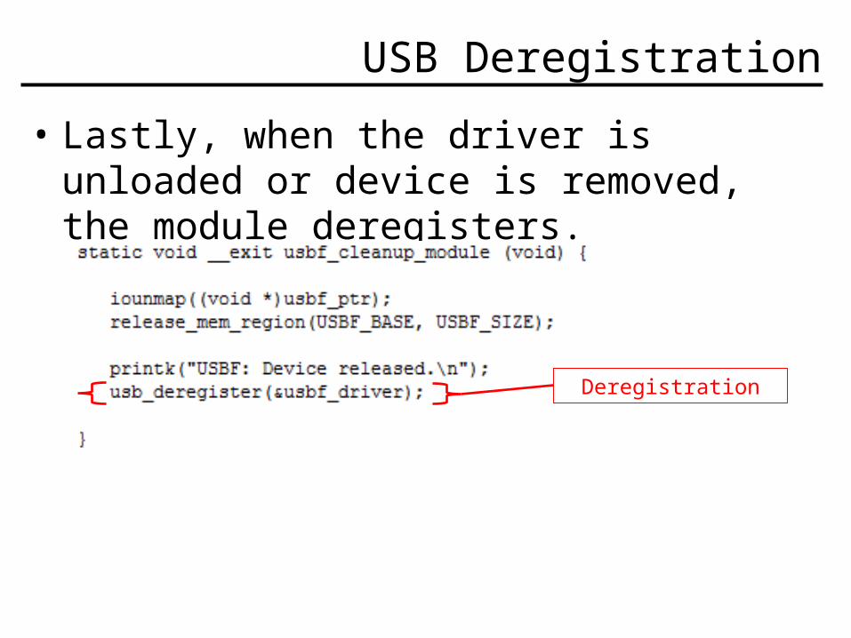
• Lastly, when the driver is unloaded or device is removed, the module deregisters.
Deregistration

THE END
Questions?

BACKUP

Original Intentions for Software
1. Develop low-level driver to initialize USB Function Controller registers.
2. Implement driver functions to allow very basic communication with a USB host.
Software Challenges
• New to Driver (and USB) development.– New concepts: Descriptors, URBs, Linux USB core and
handshaking.
• Understanding USB Function Controller.– Some function controllers can operate as a host
controller, which alters the driver’s role.
• Limited knowledge of USB Specification.
Assumptions
• USB Function Controller is used for a peripheral (slave) device.
• Controller uses only 3 of 16 available endpoints.– 0: Control– 1: IN– 2: OUT

USB Cable
• 4 Wires (Data+/-, Vbus, Gnd)
• Data Signals are Twisted Pair
Reference: www.usb.org
Related Documents