THE PUBLISHING HOUSE PROCEEDINGS OF THE ROMANIAN ACADEMY, Series A, OF THE ROMANIAN ACADEMY Volume 14, Number 2/200x, pp. 144–151 EMBEDDED RAPID CONTROL PROTOTYPING: BLDC MOTOR CONTROL Radu DUMA, Mirela TRUSCA, Petru DOBRA Technical University of Cluj-Napoca, Automatic Control Department E-mail: [email protected] A rapid control prototyping toolbox for the Renesas M32C87 microcontroller is described and a practical application for the control of brushless direct current (BLDC) motor using the implemented toolbox is presented. A closed loop control application using a PID controller is implemented. For controller tuning two experimental methods are used namely the relay feedback method and tuning with specified phase margin. The paper also describes the importance of rapid control prototyping (RCP) and presents some of the most relevant papers published in the literature. Key words: rapid control prototyping, real-time, embedded control system, brushless direct current motor. 1. INTRODUCTION Rapid control prototyping (RCP) refers to the use of rapid prototyping for the implementation and testing of control algorithms in a real-time environment. RCP is a usual application for engineers who model and simulate control systems. RCP consists of two main components, namely, a computer aided control system design (CACSD) software, and a dedicated hardware, capable of running tasks in real time. RCP is a dominant concept of computer aided design and a research topic for engineers as well as research teams due to several reasons that are presented below. CACSD tools are more and more widely used for automatic real-time code generation. The graphical programming paradigm eliminates the need to write software by hand and allows the engineer to focus, instead, on improving the functionality as well as the performance of the control system. The classical design approach of control systems is a laborious process. The design process involves the development of a mathematical model, algorithm design, implementation, offline simulation, validation, and optimization. The design process has to be restarted when an error occurs, thus making the development process time consuming and costly [1]. Rapid control prototyping is a solution for this situation, especially when the control algorithm is complex and numerous iteration steps are necessary. Object oriented programming has been proclaimed as the fourth generation of software evolution, while automatic code generation has emerged as a strong candidate to become the fifth [2]. Automatic code generation is a process which converts the model of a control algorithm in source code. Automatic code generation tools have given rise to the concept of model based design (MBD), in which complete system design is carried out within the simulation environment. The model is the core of MBD. The model is an executable specification that is improved continuously during the development process. The simulation shows whether or not the model complies with the requirements. The control system is designed, implemented, simulated, and validated in the CACSD environment. When the hardware and software requirements are satisfied, automated code source can be generated for the embedded application and testing modules can be created for the validation of the system. Existing legacy code can be integrated in the model. Nowadays, embedded processors are extensively used in industry and consumer fields. Thus, a transition from desktop application to embedded system applications can be observed. The capacity of embedded systems is growing fast, and at the same time their responsibilities extend. Embedded systems must preprocess data, and run an increasing number of complex applications.

Welcome message from author
This document is posted to help you gain knowledge. Please leave a comment to let me know what you think about it! Share it to your friends and learn new things together.
Transcript
THE PUBLISHING HOUSE PROCEEDINGS OF THE ROMANIAN ACADEMY, Series A, OF THE ROMANIAN ACADEMY Volume 14, Number 2/200x, pp. 144–151
EMBEDDED RAPID CONTROL PROTOTYPING: BLDC MOTOR CONTROL
Radu DUMA, Mirela TRUSCA, Petru DOBRA
Technical University of Cluj-Napoca, Automatic Control Department E-mail: [email protected]
A rapid control prototyping toolbox for the Renesas M32C87 microcontroller is described and a practical application for the control of brushless direct current (BLDC) motor using the implemented toolbox is presented. A closed loop control application using a PID controller is implemented. For controller tuning two experimental methods are used namely the relay feedback method and tuning with specified phase margin. The paper also describes the importance of rapid control prototyping (RCP) and presents some of the most relevant papers published in the literature.
Key words: rapid control prototyping, real-time, embedded control system, brushless direct current motor.
1. INTRODUCTION
Rapid control prototyping (RCP) refers to the use of rapid prototyping for the implementation and testing of control algorithms in a real-time environment. RCP is a usual application for engineers who model and simulate control systems. RCP consists of two main components, namely, a computer aided control system design (CACSD) software, and a dedicated hardware, capable of running tasks in real time.
RCP is a dominant concept of computer aided design and a research topic for engineers as well as research teams due to several reasons that are presented below.
CACSD tools are more and more widely used for automatic real-time code generation. The graphical programming paradigm eliminates the need to write software by hand and allows the engineer to focus, instead, on improving the functionality as well as the performance of the control system.
The classical design approach of control systems is a laborious process. The design process involves the development of a mathematical model, algorithm design, implementation, offline simulation, validation, and optimization. The design process has to be restarted when an error occurs, thus making the development process time consuming and costly [1]. Rapid control prototyping is a solution for this situation, especially when the control algorithm is complex and numerous iteration steps are necessary.
Object oriented programming has been proclaimed as the fourth generation of software evolution, while automatic code generation has emerged as a strong candidate to become the fifth [2]. Automatic code generation is a process which converts the model of a control algorithm in source code.
Automatic code generation tools have given rise to the concept of model based design (MBD), in which complete system design is carried out within the simulation environment. The model is the core of MBD. The model is an executable specification that is improved continuously during the development process. The simulation shows whether or not the model complies with the requirements. The control system is designed, implemented, simulated, and validated in the CACSD environment. When the hardware and software requirements are satisfied, automated code source can be generated for the embedded application and testing modules can be created for the validation of the system. Existing legacy code can be integrated in the model.
Nowadays, embedded processors are extensively used in industry and consumer fields. Thus, a transition from desktop application to embedded system applications can be observed. The capacity of embedded systems is growing fast, and at the same time their responsibilities extend. Embedded systems must preprocess data, and run an increasing number of complex applications.
2 Embedded rapid control prototyping: BLDC motor control 145
The articles [3–5] present the role of RCP in developing control systems and refer to the possibility of developing RCP environments with high efficiency. Paper [6] deals with direct-drive induction motor for railway traction application. Rapid control prototyping is not integrated only in the industry, but is also used in educational institutions. Articles [7–8] present integrated low cost environments that allow rapid prototyping of control algorithms. In [9] emphasis is laid upon the importance of automatic code generation for the academic environment. Article [10] presents an RCP environment based on Scilab/Scicos.
This paper presents a rapid control prototyping toolbox. In the case of this toolbox the dedicated hardware is the Renesas M32C87 microcontroller and the CACSD software is Matlab/Simulink/Real-Time Workshop. Using blocks of the implemented toolbox a closed loop control application for a brushless direct current (BLDC) motor is presented. Control algorithms and applications for different types of motors with permanent magnets are presented in [11–13]. Actuator control applications are presented in [14–15]. A method for prediction of human motion tracking failures is presented in [16].
2. TRADITIONAL DESIGN APPROACH COMPARED TO RAPID CONTROL PROTOTYPING
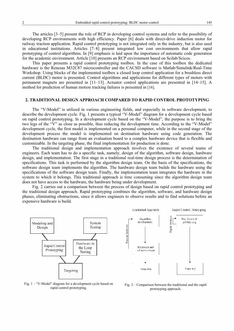
The “V-Model” is utilized in various engineering fields, and especially in software development, to describe the development cycle. Fig. 1 presents a typical “V-Model” diagram for a development cycle based on rapid control prototyping. In a development cycle based on the “V-Model”, the purpose is to bring the two legs of the “V” as close as possible, thus reducing the development time. According to the “V-Model” development cycle, the first model is implemented on a personal computer, while in the second stage of the development process the model is implemented on destination hardware using code generation. The destination hardware can range from an evaluation board to a complex hardware device that is flexible and customizable. In the targeting phase, the final implementation for production is done.
The traditional design and implementation approach involves the existence of several teams of engineers. Each team has to do a specific task, namely, design of the algorithm, software design, hardware design, and implementation. The first stage in a traditional real-time design process is the determination of specifications. This task is performed by the algorithm design team. On the basis of the specifications, the software design team implements the algorithm. The hardware design team builds the hardware using the specifications of the software design team. Finally, the implementation team integrates the hardware in the system to which it belongs. This traditional approach is time consuming since the algorithm design team does not have access to the hardware, the hardware being under development.
Fig. 2 carries out a comparison between the process of design based on rapid control prototyping and the traditional design approach. Rapid prototyping combines the algorithm, software, and hardware design phases, eliminating obstructions, since it allows engineers to observe results and to find solutions before an expensive hardware is build.
Fig. 1 – “V-Model” diagram for a development cycle based on
rapid control prototyping.
Fig. 2 – Comparison between the traditional and the rapid prototyping approach.
Radu Duma, Mirela Trusca, Petru Dobra 3 146
The graphical programming approach allows the engineer to perform changes directly in the model of the control algorithm, thus grouping the development process of algorithm, namely, code writing, compilation, and download to destination hardware. The main phases of a design based on RCP are, specifically, model design, model simulation, automatic code generation, and final target implementation.
3. RAPID CONTROL PROTOTYPING TOOLBOX FOR THE RENESAS M32C87 MICROCONTROLLER
This section presents an RCP toolbox which we have implemented for the Renesas M32C87 microcontroller. The toolbox Target for Renesas M32C87 uses Matlab/Simulink as CACSD tool and generates real-time C code for the Renesas M32C87 microcontroller. When employing the implemented RCP libraries, the engineer can develop control algorithms for the Renesas M32C87 microcontroller. Simulink blocks or user defined blocks can be integrated in the model. After the validation of the model, real-time C code is generated utilizing Real-Time Workshop.
A requirement for a RCP toolbox is to offer support for a complete post code generation process, which implies compilation and linking of generated code, downloading of the executable file to destination hardware, and starting the execution of the program on destination hardware. In order to support this process, the integration into the high performance embedded workshop (HEW) integrated development environment is implemented. HEW is an IDE that allows the development of embedded applications for the Renesas microcontrollers. At the end of the code generation process, using Microsoft Windows component object model automation, through the HEW target server component, the HEW IDE is automatically started, a new HEW project is created, the generated files are added to the project, the code is compiled, and the generated executable file is downloaded to destination hardware.
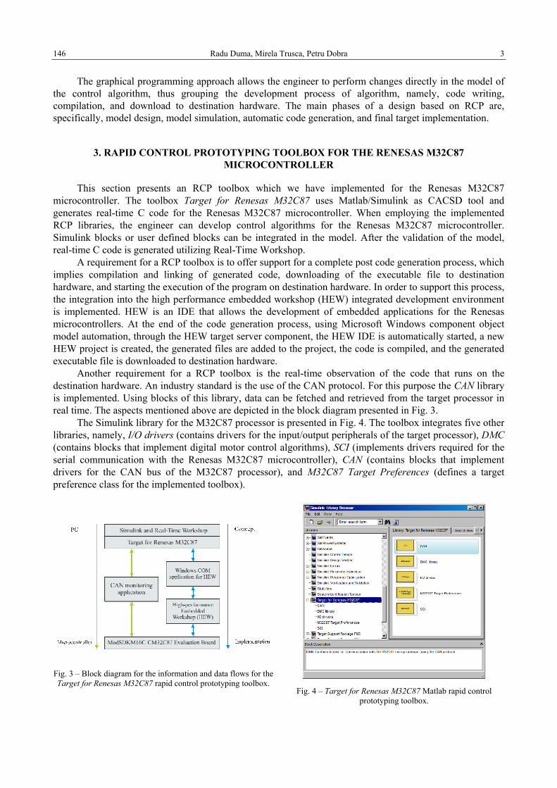
Another requirement for a RCP toolbox is the real-time observation of the code that runs on the destination hardware. An industry standard is the use of the CAN protocol. For this purpose the CAN library is implemented. Using blocks of this library, data can be fetched and retrieved from the target processor in real time. The aspects mentioned above are depicted in the block diagram presented in Fig. 3.
The Simulink library for the M32C87 processor is presented in Fig. 4. The toolbox integrates five other libraries, namely, I/O drivers (contains drivers for the input/output peripherals of the target processor), DMC (contains blocks that implement digital motor control algorithms), SCI (implements drivers required for the serial communication with the Renesas M32C87 microcontroller), CAN (contains blocks that implement drivers for the CAN bus of the M32C87 processor), and M32C87 Target Preferences (defines a target preference class for the implemented toolbox).
Fig. 3 – Block diagram for the information and data flows for the Target for Renesas M32C87 rapid control prototyping toolbox.
Fig. 4 – Target for Renesas M32C87 Matlab rapid control
prototyping toolbox.
4 Embedded rapid control prototyping: BLDC motor control 147
4. BRUSHLESS DIRECT CURRENT MOTOR SPEED CONTROL
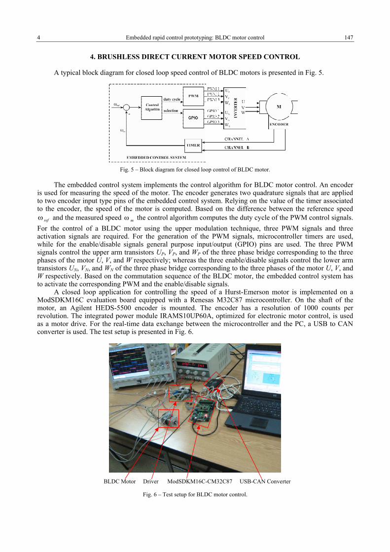
A typical block diagram for closed loop speed control of BLDC motors is presented in Fig. 5.
Fig. 5 – Block diagram for closed loop control of BLDC motor.
The embedded control system implements the control algorithm for BLDC motor control. An encoder is used for measuring the speed of the motor. The encoder generates two quadrature signals that are applied to two encoder input type pins of the embedded control system. Relying on the value of the timer associated to the encoder, the speed of the motor is computed. Based on the difference between the reference speed
refω and the measured speed mω the control algorithm computes the duty cycle of the PWM control signals. For the control of a BLDC motor using the upper modulation technique, three PWM signals and three activation signals are required. For the generation of the PWM signals, microcontroller timers are used, while for the enable/disable signals general purpose input/output (GPIO) pins are used. The three PWM signals control the upper arm transistors UP, VP, and WP of the three phase bridge corresponding to the three phases of the motor U, V, and W respectively; whereas the three enable/disable signals control the lower arm transistors UN, VN, and WN of the three phase bridge corresponding to the three phases of the motor U, V, and W respectively. Based on the commutation sequence of the BLDC motor, the embedded control system has to activate the corresponding PWM and the enable/disable signals.
A closed loop application for controlling the speed of a Hurst-Emerson motor is implemented on a ModSDKM16C evaluation board equipped with a Renesas M32C87 microcontroller. On the shaft of the motor, an Agilent HEDS-5500 encoder is mounted. The encoder has a resolution of 1000 counts per revolution. The integrated power module IRAMS10UP60A, optimized for electronic motor control, is used as a motor drive. For the real-time data exchange between the microcontroller and the PC, a USB to CAN converter is used. The test setup is presented in Fig. 6.
Fig. 6 – Test setup for BLDC motor control.
BLDC Motor Driver ModSDKM16C-CM32C87 USB-CAN Converter
Radu Duma, Mirela Trusca, Petru Dobra 5 148
5. CONTROLLER TUNING
Although there are many tuning methods for PID controllers, the Ziegler-Nichols tuning methods are still extensively used. In the case of the Ziegler-Nichols method [17], a limit cycle is obtained by gradually increasing the gain of the proportional controller. From the obtained limit cycle, the ultimate gain and the ultimate period are determined, and the parameters of the controller are computed. In [18] is proposed an extension of the Ziegler-Nichols method. In order to obtain the limit cycle, the process must not be brought to the stability limit, but a relay type nonlinearity is introduced in the control loop.
The reference speed is set by means of a potentiometer connected to an analog to digital converter of the evaluation board. The result of the conversion is read using an M32C87 ADC block. For speed measurement, an encoder is utilized and the value of the timer associated to the encoder is retrieved using a M32C87 Encoder block. If the difference between the reference and the measured speed is less than zero, the duty cycle of the PWM control signal is set to 170, whereas if the difference is greater than zero, the duty cycle of the PWM control signals is set to 230. The register for setting the value of the duty cycle for the PWM signals is an eight bits register. The value of the duty cycle has to range from 0 to 255.
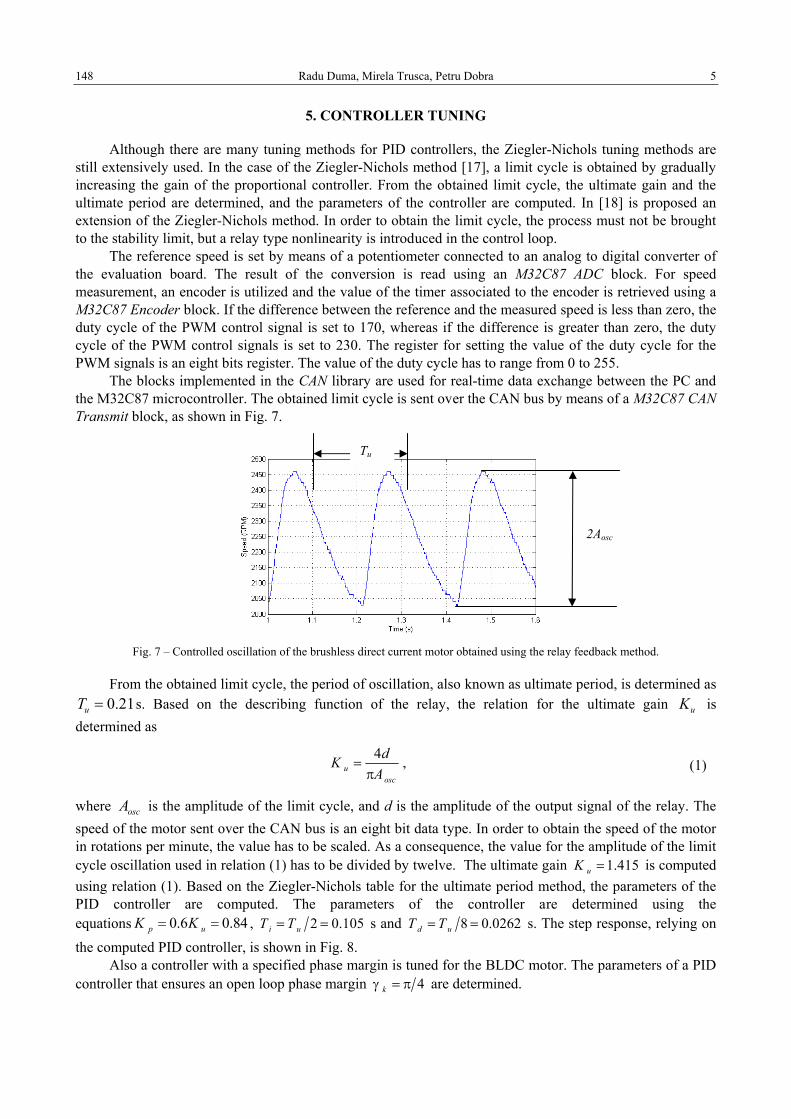
The blocks implemented in the CAN library are used for real-time data exchange between the PC and the M32C87 microcontroller. The obtained limit cycle is sent over the CAN bus by means of a M32C87 CAN Transmit block, as shown in Fig. 7.
Fig. 7 – Controlled oscillation of the brushless direct current motor obtained using the relay feedback method.
From the obtained limit cycle, the period of oscillation, also known as ultimate period, is determined as 21.0=uT s. Based on the describing function of the relay, the relation for the ultimate gain uK is
determined as
4u
osc
dKA
=π
, (1)
where oscA is the amplitude of the limit cycle, and d is the amplitude of the output signal of the relay. The speed of the motor sent over the CAN bus is an eight bit data type. In order to obtain the speed of the motor in rotations per minute, the value has to be scaled. As a consequence, the value for the amplitude of the limit cycle oscillation used in relation (1) has to be divided by twelve. The ultimate gain 1.415uK = is computed using relation (1). Based on the Ziegler-Nichols table for the ultimate period method, the parameters of the PID controller are computed. The parameters of the controller are determined using the equations 0.6 0.84p uK K= = , 2 0.105i uT T= = s and 8 0.0262d uT T= = s. The step response, relying on the computed PID controller, is shown in Fig. 8.
Also a controller with a specified phase margin is tuned for the BLDC motor. The parameters of a PID controller that ensures an open loop phase margin 4kγ = π are determined.
2Aosc
Tu

6 Embedded rapid control prototyping: BLDC motor control 149
The intersection point of the transfer locus with the negative real axis of the Nyquist diagram is the uω frequency. A condition that has to be fulfilled by the open loop system in order to have the kγ phase margin at uω frequency is that the controller should introduce the k+γ phase at the uω frequency. Therefore, the condition presented below has to be fulfilled
( )1 tan .u d ku i
TT
ω − = γω
(2)
Solving equation (2) for
i dT T= α , (3)
where (2 6)α∈ ÷ the derivative time constant is obtained as
( ) ( )( )21 tan 4 tan .2d k k
u
T = γ + α + γω
(4)
The open loop system has a kγ phase at the uω frequency only if the proportional gain of the controller is computed using relation
( )cos
cos( )( )
kp u k
BLDC u
K KH j
γ= = γ
ω. (5)
For 4α = , the computed derivative time constant using equation (4) has the value 0.0403 s, while the integral time constant computed using equation (3) has the value 0.1614 s. The proportional gain computed using equation (5) is 1. The closed loop step response, using the computed PID controller, is shown in Fig. 9. Using the PID controller tuned with specified phase margin a faster response time and smaller overshoot is obtained than in the case of the controller tuned with the relay feedback method.
Fig. 8 – Closed loop step response using the PID controller
determined with the Ziegler-Nichols tuning method.
Fig. 9 – Closed loop step response using the PID controller tuned
with a specified phase margin.
6. CLOSED LOOP CONTROL WITH PID CONTROLLER
After computing the parameters of the PID controller, using blocks from the Target for Renesas M32C87 toolbox, a closed loop algorithm for the BLDC motor control is implemented. The Simulink closed loop model is presented in Fig. 10. The reference speed is a rectangular signal, whose level is set over the CAN bus, using the M32C87 CAN Receive block. For speed measurement a M32C87 Encoder block is used. The reference speed and the measured speed are applied at the input ports of a M32C87 PID block. The M32C87 PID block computes a new value for the duty cycle of the PWM control signals. The duty cycle of the PWM signals is applied at the input port of a M32C87 BLDC Motor Control block. A configuration M32C87 CAN Configure block is added to the model. This block configures the CAN module of the microcontroller. The reference speed, the measured speed, and the duty cycle of the PWM signals are concatenated in an array, and are sent over the CAN bus using a M32C87 CAN Transmit block.
A target preference M32C87 Target block is added to the model to store the user preferences associated with the model of the control algorithm. After the validation of the model, the code generation process is invoked, and the generated executable file is downloaded to the M32C87 processor.
Radu Duma, Mirela Trusca, Petru Dobra 7 150
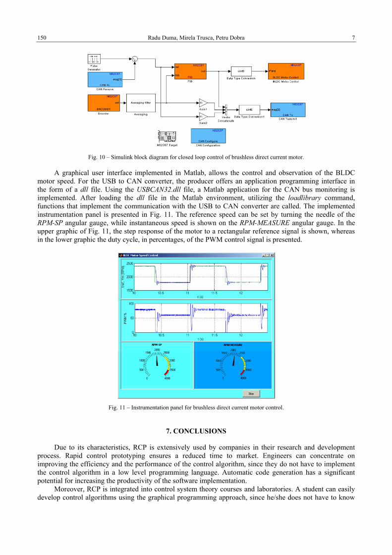
Fig. 10 – Simulink block diagram for closed loop control of brushless direct current motor.
A graphical user interface implemented in Matlab, allows the control and observation of the BLDC motor speed. For the USB to CAN converter, the producer offers an application programming interface in the form of a dll file. Using the USBCAN32.dll file, a Matlab application for the CAN bus monitoring is implemented. After loading the dll file in the Matlab environment, utilizing the loadlibrary command, functions that implement the communication with the USB to CAN converter are called. The implemented instrumentation panel is presented in Fig. 11. The reference speed can be set by turning the needle of the RPM-SP angular gauge, while instantaneous speed is shown on the RPM-MEASURE angular gauge. In the upper graphic of Fig. 11, the step response of the motor to a rectangular reference signal is shown, whereas in the lower graphic the duty cycle, in percentages, of the PWM control signal is presented.
Fig. 11 – Instrumentation panel for brushless direct current motor control.
7. CONCLUSIONS
Due to its characteristics, RCP is extensively used by companies in their research and development process. Rapid control prototyping ensures a reduced time to market. Engineers can concentrate on improving the efficiency and the performance of the control algorithm, since they do not have to implement the control algorithm in a low level programming language. Automatic code generation has a significant potential for increasing the productivity of the software implementation.
Moreover, RCP is integrated into control system theory courses and laboratories. A student can easily develop control algorithms using the graphical programming approach, since he/she does not have to know
8 Embedded rapid control prototyping: BLDC motor control 151
in detail the architecture and the registers of the processor to develop the control algorithm in a low level programming language. The parameters of the blocks that implement the control algorithm can be changed using the graphical user interface of each block and code can be generated.
Furthermore, the article presents a rapid control prototyping toolbox for the Renesas M32C87 microcontroller. The toolbox Target for Renesas M32C87 utilizes Matlab/Simulink as a CACSD tool and generates real-time C code for the Renesas M32C87 microcontroller. A practical application for the control of a BLDC motor is implemented using the implemented rapid control prototyping toolbox.
ACKNOWLEDGEMENTS
This paper was supported by the project “Progress and development through post-doctoral research and innovation in engineering and applied sciences– PRiDE - Contract no. POSDRU/89/1.5/S/57083", project co-funded from European Social Fund through Sectorial Operational Program Human Resources 2007-2013.
REFERENCES
1. H. Hanselmann, Automotive control: from concept to experiment to product, Proc. IEEE International Symposium on Computer-Aided Control System Design, Sept. 15–18, 1996, pp. 129–134.
2. T. Erkkinen, High-integrity production code generation, AIAA GN&C Conference, 2003. Available at www.mathworks.com/products/featured/12945_Production_Code_Generation_AIAA_GNC_2003.pdf.
3. H. Hanselmann and F. Schütte, Control system prototyping and testing with modern tools, PCIM, Nürnberg, 2001. 4. M. Beine, U. Eisemann, and R. Otterbach, Transforming a control design model into an efficient production application, Proc.
IEEE Computer Aided Control System Design, IEEE International Conference on Control Applications, IEEE International Symposium on Intelligent Control, Oct. 4–6, 2006, pp. 3019–3023.
5. R. E. Dorey and D. Maclay, Rapid prototyping for the development of powertrain control systems, Proc. IEEE International Symposium on Computer-Aided Control System Design, Sept. 15–18, 1996, pp. 135–140.
6. T. Dordea, V. Hoanca, S. Paun, Direct-drive induction motor for railway traction applications, Proceedings of the Romanian Academy – Series A: Mathematics, Physics, Technical Sciences, Information Science, 12, 3, pp. 239–248, 2011.
7. A. Stylo and G. Diana, An advanced real-time research and teaching tool for the design and analysis of control, Proc. IEEE AFRICON, Sept. 28–Oct. 1, 1999, Vol. 1, pp. 511–516.
8. D. Hercog, M. Curkovic, and K. Jezernik, DSP based rapid control prototyping systems for engineering education and research, Proc. IEEE Computer Aided Control System Design, IEEE International Conference on Control Applications, IEEE International Symposium on Intelligent Control, Oct. 4–6, 2006, pp. 2292–2297.
9. P. J. Mosterman, Automatic code generation: Facilitating new teaching opportunities in engineering education, Proc. Annual Frontiers in Education Conference, Oct. 27–31, 2006, pp. 1–6.
10. R. Duma, M. Trusca and P. Dobra, Tuning and Implementation of PID Controllers using Rapid Control Prototyping, Journal of Control Engineering and Applied Informatics, 13, 4, pp. 64–73, 2011.
11. M. L. Corradini, G. Ippoliti, S. Longhi, and G. Orlando, A Quasi-Sliding Mode Approach for Robust Control and Speed Estimation of PM Synchronous Motors, IEEE Transactions on Industrial Electronics, 59, 2, pp. 1096–1104, 2012.
12. A. Pisano, A. Davila, L. Fridman, and E. Usai, Cascade control of PM-DC drives via second-order sliding mode technique, IEEE Transactions on Industrial Electronics, 55, 11, pp. 3846–3854, 2008.
13. G.-D. Andreescu, C.I. Pitic, F. Blaabjerg, and I. Boldea, Combined Flux Observer With Signal Injection Enhancement for Wide Speed Range Sensorless Direct Torque Control of IPMSM Drives, IEEE Transactions on Energy Conversion, 23, 2, pp. 393–402, 2008.
14. Y. Li, H. Lu, S. Tian, Z. Jio and J.-T. Chen, Posture Control of Electromechanical-Actuator-Based Thrust Vector System for Aircraft Engine, IEEE Transactions on Industrial Electronics, 59, 9, pp. 3561–3571, 2012.
15. L. Vladareanu, O. I. Sandru, L.M. Velea, and H. Yu, Actuator control in continuous flux using winer filters, Proceedings of the Romanian Academy – Series A: Mathematics, Physics, Technical Sciences, Information Science, 10, 1, pp. 81–90, 2009.
16. S.L. Dockstader and N.S Imennov, Prediction for human motion tracking failures, IEEE Transactions on Image Processing, 15, 2, pp. 3846–3854, 2008.
17. J. Ziegler, and N. Nichols, Optimum settings for automatic controllers, ASME Transactions, pp. 759−768, 1942. 18. K. Astrom, and T. Hagglund, Automatic tuning of simple regulators with specifications on phase and amplitude margins,
Automatica, 20, 5, pp. 645−651.
Received April 28, 2012
Related Documents