Embedded Linux Development Guide Revision: January 14, 2013 1300 NE Henley Court, Suite 3 Pullman, WA 99163 (509) 334 6306 Voice | (509) 334 6300 Fax page 1 of 23 Copyright Digilent, Inc. All rights reserved. Other product and company names mentioned may be trademarks of their respective owners. This Embedded Linux Development Guide will provide some preliminary knowledge on how to build Linux for Digilent boards based on the Zynq-7000 TM All-Programmable System-on-Chip (ZYNQ AP SoC) to suit your customized hardware designs. This guide takes a bottom-up approach by starting from a hardware design on the ZYNQ AP SoC Board, moving through the necessary preliminary processes, and eventually giving instructions for running and debugging the Linux kernel. Section I: Hardware Customization begins with the Linux Hardware Design Package for ZYNQ AP SoC boards, available on the Digilent Inc. website. This section then illustrates the ZYNQ AP SoC basic architecture and explains how to create customized hardware using Xilinx Platform Studio (XPS) available in the Xilinx ISE Design Suite WebPack. Section II: Device Tree – Describe Your Hardware to the Linux Kernel examines how the Linux kernel gathers information about the customized hardware. Section II takes a closer look at a data structure called the Device Tree Blob (DTB), explains how to write a Device Tree Source (DTS) file, and how to compile the source into a DTB file. Section III: U-Boot – The Embedded Boot Loader introduces U-Boot, a popular boot loader for Linux used by many embedded systems. Section III presents preliminary knowledge about how to configure and build U-Boot, and provides an introduction of some commonly used U-Boot commands. After explaining all the prerequisites for running The Linux kernel (boot loaders, device trees, etc.), the guide moves to configuring the Linux kernel in Section IV: Linux Kernel Configuration. This section demonstrates customizable features useful for custom hardware design. This section also provides information for building and customizing the kernel, file system customization, and finally running the Linux kernel on ZYNQ AP SoC based boards. During the compilation and running of The Linux kernel on your customized hardware, there is a chance that the kernel will panic and generate an Oops message or completely cease functioning. The Appendix: How to Debug the Linux Kernel introduces you to some simple debugging techniques to follow when errors occur with the Linux kernel. Before creating custom hardware or using the Linux kernel, Digilent Inc. recommends that users have some experience with embedded Linux development on other embedded systems or they have read the Getting Started with Embedded Linux guide for their platform. Moreover, users can read this documentation along with the Embedded Linux Hands-on Tutorial for their specific Zynq AP SoC board. These documents are available on the Digilent Website, Embedded Linux page and the webpage for your product.

Welcome message from author
This document is posted to help you gain knowledge. Please leave a comment to let me know what you think about it! Share it to your friends and learn new things together.
Transcript
Embedded Linux Development Guide
Revision: January 14, 2013 1300 NE Henley Court, Suite 3
Pullman, WA 99163 (509) 334 6306 Voice | (509) 334 6300 Fax
page 1 of 23
Copyright Digilent, Inc. All rights reserved. Other product and company names mentioned may be trademarks of their respective owners.
This Embedded Linux Development Guide will provide some preliminary knowledge on how to build Linux for Digilent boards based on the Zynq-7000TM All-Programmable System-on-Chip (ZYNQ AP SoC) to suit your customized hardware designs. This guide takes a bottom-up approach by starting from a hardware design on the ZYNQ AP SoC Board, moving through the necessary preliminary processes, and eventually giving instructions for running and debugging the Linux kernel. Section I: Hardware Customization begins with the Linux Hardware Design Package for ZYNQ AP SoC boards, available on the Digilent Inc. website. This section then illustrates the ZYNQ AP SoC basic architecture and explains how to create customized hardware using Xilinx Platform Studio (XPS) available in the Xilinx ISE Design Suite WebPack. Section II: Device Tree – Describe Your Hardware to the Linux Kernel examines how the Linux kernel gathers information about the customized hardware. Section II takes a closer look at a data structure called the Device Tree Blob (DTB), explains how to write a Device Tree Source (DTS) file, and how to compile the source into a DTB file. Section III: U-Boot – The Embedded Boot Loader introduces U-Boot, a popular boot loader for Linux used by many embedded systems. Section III presents preliminary knowledge about how to configure and build U-Boot, and provides an introduction of some commonly used U-Boot commands. After explaining all the prerequisites for running The Linux kernel (boot loaders, device trees, etc.), the guide moves to configuring the Linux kernel in Section IV: Linux Kernel Configuration. This section demonstrates customizable features useful for custom hardware design. This section also provides information for building and customizing the kernel, file system customization, and finally running the Linux kernel on ZYNQ AP SoC based boards. During the compilation and running of The Linux kernel on your customized hardware, there is a chance that the kernel will panic and generate an Oops message or completely cease functioning. The Appendix: How to Debug the Linux Kernel introduces you to some simple debugging techniques to follow when errors occur with the Linux kernel. Before creating custom hardware or using the Linux kernel, Digilent Inc. recommends that users have some experience with embedded Linux development on other embedded systems or they have read the Getting Started with Embedded Linux guide for their platform. Moreover, users can read this documentation along with the Embedded Linux Hands-on Tutorial for their specific Zynq AP SoC board. These documents are available on the Digilent Website, Embedded Linux page and the webpage for your product.
Using Zynq with Linux
www.digilentinc.com page 2 of 23
Copyright Digilent, Inc. All rights reserved. Other product and company names mentioned may be trademarks of their respective owners.
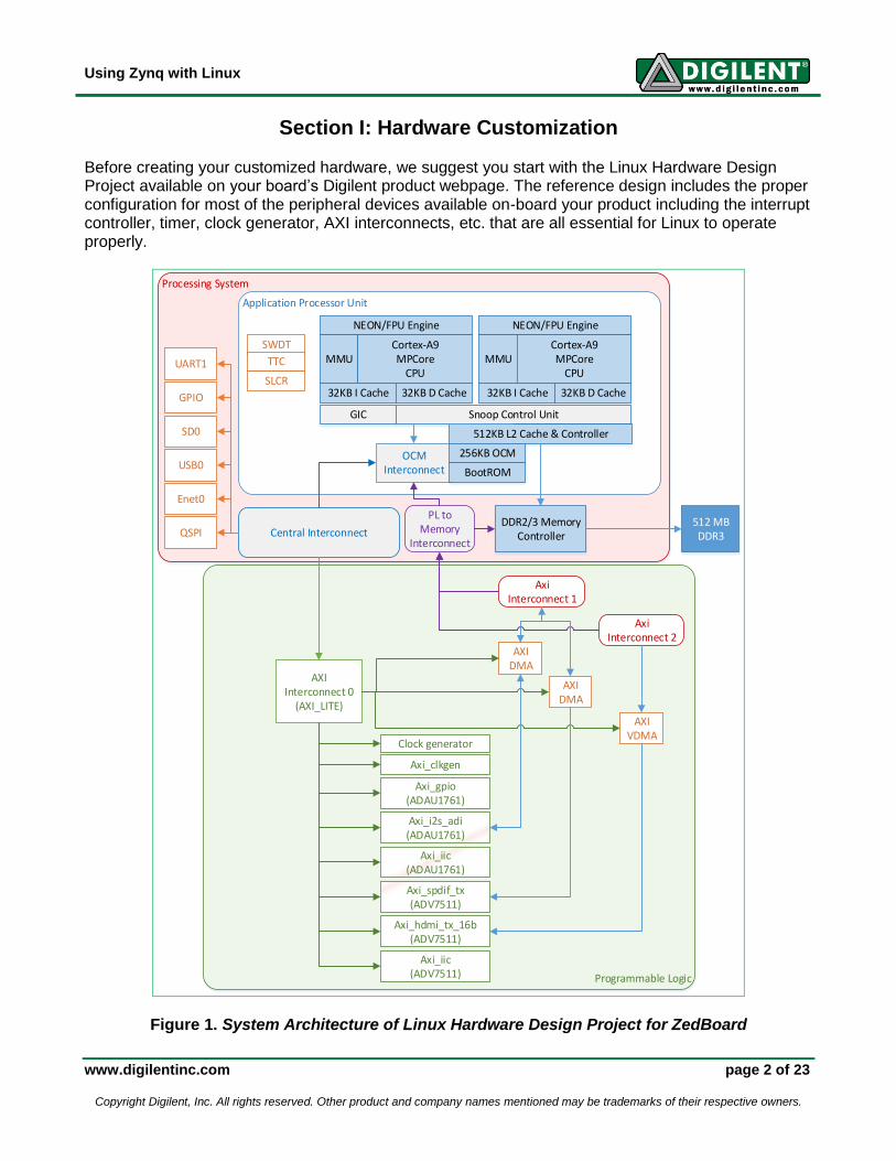
Section I: Hardware Customization Before creating your customized hardware, we suggest you start with the Linux Hardware Design Project available on your board’s Digilent product webpage. The reference design includes the proper configuration for most of the peripheral devices available on-board your product including the interrupt controller, timer, clock generator, AXI interconnects, etc. that are all essential for Linux to operate properly.
Processing System
Programmable Logic
Application Processor Unit
NEON/FPU Engine
MMUCortex-A9MPCore
CPU
32KB I Cache 32KB D Cache
NEON/FPU Engine
MMUCortex-A9MPCore
CPU
32KB I Cache 32KB D Cache
GIC Snoop Control Unit
512KB L2 Cache & Controller
SWDT
TTC
SLCR
OCM Interconnect
256KB OCM
BootROM
Central Interconnect
UART1
GPIO
SD0
USB0
Enet0
QSPI
AXI Interconnect 0
(AXI_LITE)
Clock generator
AXIDMA
AXIDMA
AXIVDMA
Axi_gpio(ADAU1761)
Axi_i2s_adi(ADAU1761)
Axi_iic(ADAU1761)
Axi_spdif_tx(ADV7511)
Axi_hdmi_tx_16b(ADV7511)
Axi_iic(ADV7511)
Axi Interconnect 1
Axi Interconnect 2
DDR2/3 Memory Controller
512 MB DDR3
PL to Memory
Interconnect
Axi_clkgen
Figure 1. System Architecture of Linux Hardware Design Project for ZedBoard
Using Zynq with Linux
www.digilentinc.com page 3 of 23
Copyright Digilent, Inc. All rights reserved. Other product and company names mentioned may be trademarks of their respective owners.
The Linux Hardware Design Project posted on the Digilent website usually contains the hardware controllers for all of your product peripheral devices and the GPIO for extension pins (e.g. Pmods, VHDC, FMC, etc.) Before you begin hardware customization, please read the documentation inside the Linux Hardware Design for your product, which explains the hardware in detail, and the Embedded Linux Hands-on Tutorial, which guides you through step by step instructions for making changes to the reference hardware design.
First Stage Boot Loader (FSBL) We discuss the First Stage Boot Loader (FSBL) here because of its integral relationship with hardware design. Digilent recommends that you recompile the FSBL every time you make hardware changes. The FSBL will do several simple initialization steps for the Processing System (PS), like setting up a clock generator. It also has board-specific modifications that perform several initialization steps for various on-board devices. For instance, the FSBL for the ZedBoard will toggle the reset pin of USB-OTG to perform a reset before Linux gets loaded. You just need to make a few clicks to generate the FSBL. The project guide within the Linux Hardware Design and hands-on tutorial for your specific board will guide you through it. You can also refer to the ZYNQ Software Developers Guide available on the Xilinx website at www.xilinx.com.
Using Zynq with Linux
www.digilentinc.com page 4 of 23
Copyright Digilent, Inc. All rights reserved. Other product and company names mentioned may be trademarks of their respective owners.
Section II: Device Tree – Describe Your Hardware to the Linux Kernel The Linux Kernel is a piece of embedded standalone software running on your hardware. The kernel provides a standardized interface for application programmers to utilize all hardware resources without knowing the details. Thus, the kernel has to know every detail about the hardware it is working on. The Linux Kernel uses the data structure known as Device Tree Blob (DTB) to describe your hardware. Sometimes DTB is called Flat Device Tree (FDT), Device Tree Binary, or simply Device Tree.1 Section II takes a closer look at the device tree and examines how the Linux kernel interprets and understands your hardware.
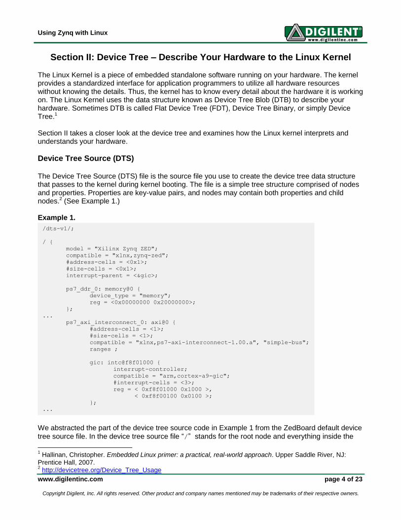
Device Tree Source (DTS) The Device Tree Source (DTS) file is the source file you use to create the device tree data structure that passes to the kernel during kernel booting. The file is a simple tree structure comprised of nodes and properties. Properties are key-value pairs, and nodes may contain both properties and child nodes.2 (See Example 1.) Example 1.
We abstracted the part of the device tree source code in Example 1 from the ZedBoard default device
tree source file. In the device tree source file “/” stands for the root node and everything inside the
1 Hallinan, Christopher. Embedded Linux primer: a practical, real-world approach. Upper Saddle River, NJ:
Prentice Hall, 2007. 2 http://devicetree.org/Device_Tree_Usage
/dts-v1/;
/ {
model = "Xilinx Zynq ZED";
compatible = "xlnx,zynq-zed";
#address-cells = <0x1>;
#size-cells = <0x1>;
interrupt-parent = <&gic>;
ps7_ddr_0: memory@0 {
device_type = "memory";
reg = <0x00000000 0x20000000>;
};
...
ps7_axi_interconnect_0: axi@0 {
#address-cells = <1>;
#size-cells = <1>;
compatible = "xlnx,ps7-axi-interconnect-1.00.a", "simple-bus";
ranges ;
gic: intc@f8f01000 {
interrupt-controller;
compatible = "arm,cortex-a9-gic";
#interrupt-cells = <3>;
reg = < 0xf8f01000 0x1000 >,
< 0xf8f00100 0x0100 >;
};
...
Using Zynq with Linux
www.digilentinc.com page 5 of 23
Copyright Digilent, Inc. All rights reserved. Other product and company names mentioned may be trademarks of their respective owners.
brackets “{}” are either properties of the root nodes or the children of the root node. In Example 1,
the first property of the root node is model. String “Xilinx Zynq ZED” is assigned to it. Property
compatible defines the compatibility of the node, and, in this case, is given the compatibility string
“xlnx,zynq-zed”; The children of the root nodes include the on-board DDR3 SDRAM,
ps7_ddr_0, and the central AXI interconnects for the whole system, ps7_axi_interconnect_0.
There are many more children of the root nodes in the default DTS file. The following sub-sections introduce the basic structures of nodes and some of the most common node properties. You can find more detailed information about the device tree under folder
Documentation/devicetree/ in the Linux kernel source.
Device Nodes Example 2 demonstrates the basic structure of device nodes. Example 2. The Name field is the name you assigned to the device tree node. The name of the node is not
required, but should be unique in the whole tree if assigned. You can obtain the phandler of the
device node with the notation &(name).
The part (Generic Name)@(Base Address)actually forms the full name of the device node.
According to conventions, the full name of the device is usually a generic name followed by the base address of the device. The Generic Name field describes the generic class of the device, such as
Ethernet, qspi, i2c, etc. The Base Address field gives the base address for the device node.
Some devices are virtual devices that do not have a physical memory mapped in the processor
memory space. For these devices, The code drops the @(Base Address) for devices with no
mapped physical memory. In Example 3, the leds defined in the DTS file does not have a base
address, because it utilizes a bit in the GPIO controller to control an on-board LED.
Example 3.
leds {
compatible = "gpio-leds";
mmc_led {
label = "mmc_led";
gpios = <&gpiops 7 0>;
linux,default-trigger = "mmc0";
};
};
(Name) : (Generic Name)@(Base Address) {
compatible: “(compatibility string)”;
reg: < (base address) (size) >;
interrupt-parents: < (interrupt controller phandle) >;
interrupts: < … >;
(param1): “(string value)”;
(param2): < (number value, decimal or hexical) >;
…
};
Using Zynq with Linux
www.digilentinc.com page 6 of 23
Copyright Digilent, Inc. All rights reserved. Other product and company names mentioned may be trademarks of their respective owners.
Properties Properties are key-value pairs. The value of a property can either be a character string (e.g. the value
for compatible property), or a list of either decimal or hexadecimal numbers (e.g. the value of reg
property).
Each node requires a compatible property. A compatibility string will be assigned to that property.
You can use it to match device drivers with devices defined in the device tree. In Example 3, the
compatible property for device node leds is set to string “gpio-leds”, which indicates the
gpio-leds driver will be used for the device.
Usually, the device node name includes the base address of the device. However, the kernel actually
obtains the physical address of device registers via the reg property. The value of the reg property
contains a list of paired numbers separated by commas. Each pair begins with the base address of the device, followed by the size of the register space. The corresponding kernel driver can usually
obtain the physical memory address with the function platform_get_resource and map the
physical memory into kernel virtual memory space by functions such as ioremap.
If your device has interrupt functionality, you must specify the interrupt number in the interrupt
property and set the interrupt-parent property to the phandler of the interrupt controller. You can
obtain the phandler of the interrupt controller with &(name field of interrupt controller).
For more in depth information on using the Zynq AP SoC interrupt controller with a device tree, see
Documentation/devicetree/bindings/arm/gic.txt within the kernel source.
OLED DTS Node: An Example We abstract the following codes from the ZedBoard default device tree.1 Example 4.
1 http://www.digilentinc.com/zedboard
gpiops: gpio@e000a000 {
compatible = "xlnx,ps7-gpio-1.00.a";
#gpio-cells = <2>;
reg = <0xe000a000 0x1000>;
interrupts = <0x0 0x14 0x0>;
interrupt-parent = <&gic>;
gpio-controller;
};
zed_oled {
compatible = "dglnt,pmodoled-gpio";
/* GPIO Pins */
vbat-gpio = <&gpiops 55 0>;
vdd-gpio = <&gpiops 56 0>;
res-gpio = <&gpiops 57 0>;
dc-gpio = <&gpiops 58 0>;
/* SPI-GPIOs */
spi-bus-num = <2>;
spi-sclk-gpio = <&gpiops 59 0>;
spi-sdin-gpio = <&gpiops 60 0>;
};
Using Zynq with Linux
www.digilentinc.com page 7 of 23
Copyright Digilent, Inc. All rights reserved. Other product and company names mentioned may be trademarks of their respective owners.
In Example 4, two devices are declared: the GPIO controller for Processing System of ZYNQ,
gpiops, and the on-board OLED display, zed_oled.
The device tree names the node for the GPIO controller gpiops, with the generic name of gpio and
a base address starting from 0xe000a000, according to conventional naming of the node. The full
name of gpiops is gpio@e000a000, as shown in the /sys file system and /proc file system. The
compatibility string of the GPIO controller is xlnx,ps7-gpio-1.00.a. The device will use the
xlnx-gpiops driver by matching the compatibility string of the node with that defined in the driver
source code. The reg property defines the gpiops GPIO controller by a physical address that begins
from 0xe000a000 with a size of 0x1000 (64KB). The interrupt is connected to the global interrupt
controller gic, as the phandler of gic (&gic in the DTS) passes to the interrupt-parent
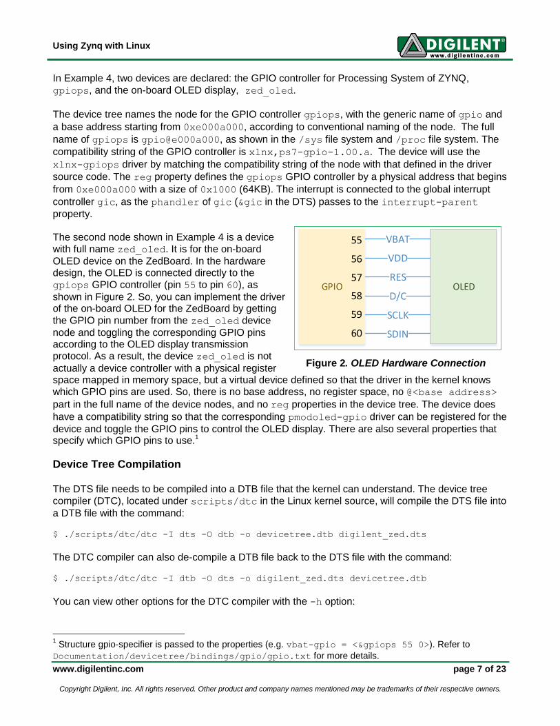
property. The second node shown in Example 4 is a device
with full name zed_oled. It is for the on-board
OLED device on the ZedBoard. In the hardware design, the OLED is connected directly to the
gpiops GPIO controller (pin 55 to pin 60), as
shown in Figure 2. So, you can implement the driver of the on-board OLED for the ZedBoard by getting
the GPIO pin number from the zed_oled device
node and toggling the corresponding GPIO pins according to the OLED display transmission
protocol. As a result, the device zed_oled is not
actually a device controller with a physical register space mapped in memory space, but a virtual device defined so that the driver in the kernel knows
which GPIO pins are used. So, there is no base address, no register space, no @<base address>
part in the full name of the device nodes, and no reg properties in the device tree. The device does
have a compatibility string so that the corresponding pmodoled-gpio driver can be registered for the
device and toggle the GPIO pins to control the OLED display. There are also several properties that specify which GPIO pins to use.1
Device Tree Compilation The DTS file needs to be compiled into a DTB file that the kernel can understand. The device tree
compiler (DTC), located under scripts/dtc in the Linux kernel source, will compile the DTS file into
a DTB file with the command:
$ ./scripts/dtc/dtc -I dts -O dtb -o devicetree.dtb digilent_zed.dts
The DTC compiler can also de-compile a DTB file back to the DTS file with the command:
$ ./scripts/dtc/dtc -I dtb -O dts -o digilent_zed.dts devicetree.dtb
You can view other options for the DTC compiler with the -h option:
1 Structure gpio-specifier is passed to the properties (e.g. vbat-gpio = <&gpiops 55 0>). Refer to
Documentation/devicetree/bindings/gpio/gpio.txt for more details.
OLED
VBAT
VDD
RES
D/C
SCLK
SDIN
GPIO
55
56
57
58
59
60
Figure 2. OLED Hardware Connection
Using Zynq with Linux
www.digilentinc.com page 8 of 23
Copyright Digilent, Inc. All rights reserved. Other product and company names mentioned may be trademarks of their respective owners.
$ ./scripts/dtc/dtc -h
Booting With Device Tree The boot loader needs to load the Device Tree into the system memory before starting the kernel. For
Zynq based platforms, the boot loader will load the DTB to a fixed memory address 0x010000001.
1 It is defined in line 112 of arch/arm/kernel/head.S
Using Zynq with Linux
www.digilentinc.com page 9 of 23
Copyright Digilent, Inc. All rights reserved. Other product and company names mentioned may be trademarks of their respective owners.
Section III: U-Boot – Embedded Linux Boot Loader Zynq AP SoC based platforms utilize a multi-stage booting scheme, consisting of BootROM (Stage 0), FSBL and a Second Stage Boot Loader (SSBL) if required. Section I: Hardware Customization discusses the FSBL in more detail. To boot Linux on the ZedBoard, Digilent Inc. recommends U-Boot, a fully supported Second Stage Boot Loader that prepares the basic environment to boot and run the embedded Linux software.
Booting Sequence When you power on the Zynq AP SoC based development platform, the Stage 0 Boot Loader, located
in BootROM, will start to run. The codes will check the BootMode pins of the Zynq chip to determine
from which interface to load the FSBL. ZYNQ AP SoC based platforms support loading the FSBL from five kinds of interfaces--JTAG, QSPI Flash, NAND Flash, NOR Flash, and SD card. Section III will demonstrate booting from the SD Card. Note: You must provide a kernel image, DTB, file systems, etc. to run embedded Linux. These files may take up storage space from several mega-bytes to even a few giga-bytes. An SD card with up to 32GB of storage is the best fit for embedded Linux development. This manual will focus on SD card booting as the fastest and most efficient means of booting. You have to do two things before you can boot with the SD card. First, ensure that you configure the
BootMode pins of your board to SD Boot Mode (refer to the documentation Getting Started With
Embedded Linux for your board). Second, make sure you have a properly partitioned SD card according to the guidelines in the Getting Started with Embedded Linux for your board. If properly
configured, the Stage 0 Boot Loader will load the file “BOOT.BIN” in the first partition of your SD card
into On-Chip Memory (OCM), and start executing from the beginning of OCM.
The file BOOT.BIN comprises the FSBL, PL logic bit files, and the SSBL (u-boot.elf in this case).
The FSBL will download the PL logic bit file to the PL system, set up the PLL in the PS system and execute some other fundamental bring-up routines for peripheral devices, and finally call up the SSBL to take over control and begin loading the operating system. Digilent Inc. uses U-Boot as the SSBL. U-Boot can obtain a kernel image from an SD Card, partitioned QSPI Flash, and even through Ethernet using TFTP (Trivial FTP) if you have a functional
TFTP server. By default, U-Boot starts the procedure called autoboot, which looks for the
BootMode pin settings again for the source of the kernel image (in our case, an SD card). So, U-Boot
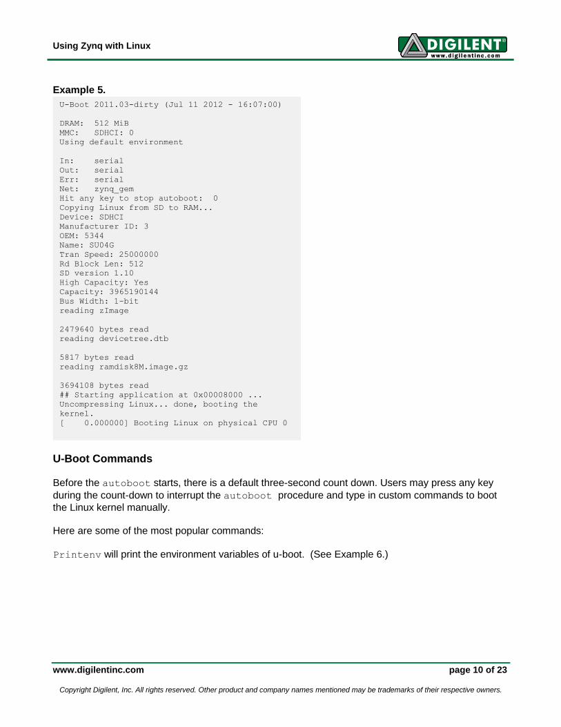
calls the procedure sdboot. The procedure sdboot does three things. First, sdboot reads the
kernel image (named zImage as shown below) from the FAT partition and copies it to 0x00008000.
Second, sdboot reads the DTB file (named as devicetree.dtb in Figure 5) and loads it to
0x01000000. Third, sdboot reads the zipped ramdisk file system named ramdisk8M.image.gz
(See Example 5.) and loads it to 0x00800000. After all the loading, U-Boot starts to run the kernel
image from where sdboot loaded it.
Using Zynq with Linux
www.digilentinc.com page 10 of 23
Copyright Digilent, Inc. All rights reserved. Other product and company names mentioned may be trademarks of their respective owners.
Example 5.
U-Boot Commands
Before the autoboot starts, there is a default three-second count down. Users may press any key
during the count-down to interrupt the autoboot procedure and type in custom commands to boot
the Linux kernel manually. Here are some of the most popular commands:
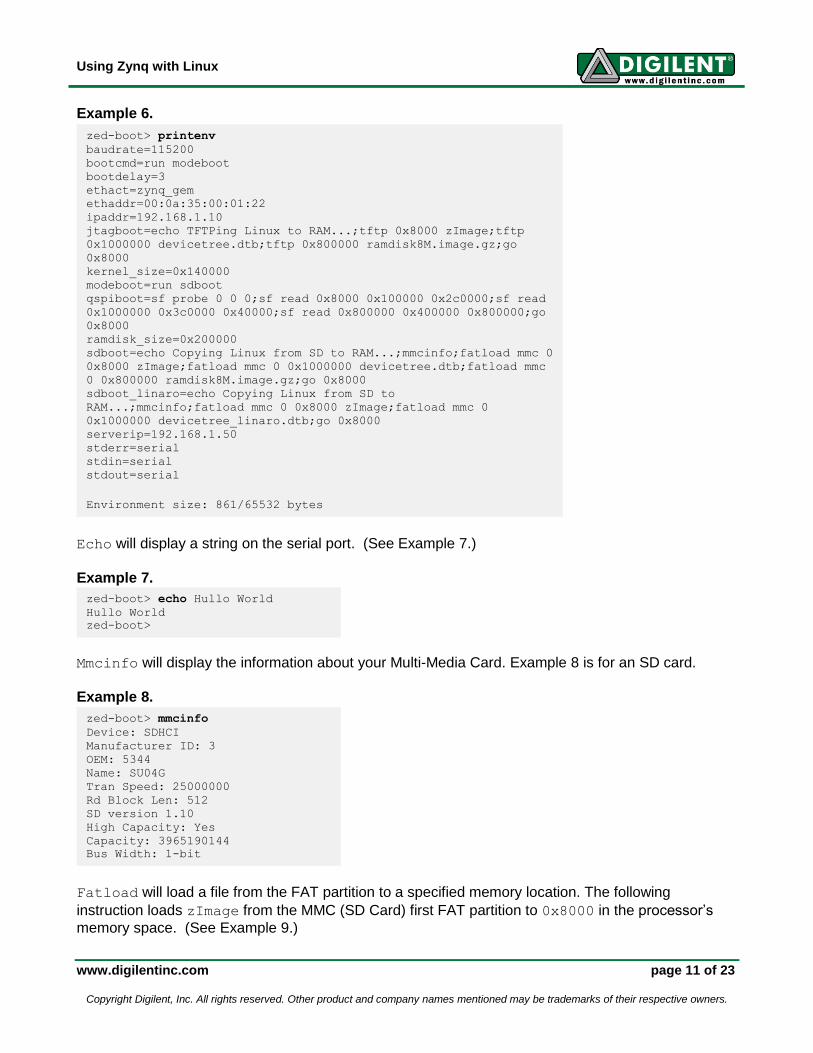
Printenv will print the environment variables of u-boot. (See Example 6.)
U-Boot 2011.03-dirty (Jul 11 2012 - 16:07:00)
DRAM: 512 MiB
MMC: SDHCI: 0
Using default environment
In: serial
Out: serial
Err: serial
Net: zynq_gem
Hit any key to stop autoboot: 0
Copying Linux from SD to RAM...
Device: SDHCI
Manufacturer ID: 3
OEM: 5344
Name: SU04G
Tran Speed: 25000000
Rd Block Len: 512
SD version 1.10
High Capacity: Yes
Capacity: 3965190144
Bus Width: 1-bit
reading zImage
2479640 bytes read
reading devicetree.dtb
5817 bytes read
reading ramdisk8M.image.gz
3694108 bytes read
## Starting application at 0x00008000 ...
Uncompressing Linux... done, booting the
kernel.
[ 0.000000] Booting Linux on physical CPU 0
Using Zynq with Linux
www.digilentinc.com page 11 of 23
Copyright Digilent, Inc. All rights reserved. Other product and company names mentioned may be trademarks of their respective owners.
Example 6.
Echo will display a string on the serial port. (See Example 7.)
Example 7.
Mmcinfo will display the information about your Multi-Media Card. Example 8 is for an SD card.
Example 8.
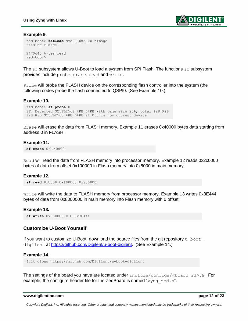
Fatload will load a file from the FAT partition to a specified memory location. The following
instruction loads zImage from the MMC (SD Card) first FAT partition to 0x8000 in the processor’s
memory space. (See Example 9.)
zed-boot> printenv
baudrate=115200
bootcmd=run modeboot
bootdelay=3
ethact=zynq_gem
ethaddr=00:0a:35:00:01:22
ipaddr=192.168.1.10
jtagboot=echo TFTPing Linux to RAM...;tftp 0x8000 zImage;tftp
0x1000000 devicetree.dtb;tftp 0x800000 ramdisk8M.image.gz;go
0x8000
kernel_size=0x140000
modeboot=run sdboot
qspiboot=sf probe 0 0 0;sf read 0x8000 0x100000 0x2c0000;sf read
0x1000000 0x3c0000 0x40000;sf read 0x800000 0x400000 0x800000;go
0x8000
ramdisk_size=0x200000
sdboot=echo Copying Linux from SD to RAM...;mmcinfo;fatload mmc 0
0x8000 zImage;fatload mmc 0 0x1000000 devicetree.dtb;fatload mmc
0 0x800000 ramdisk8M.image.gz;go 0x8000
sdboot_linaro=echo Copying Linux from SD to
RAM...;mmcinfo;fatload mmc 0 0x8000 zImage;fatload mmc 0
0x1000000 devicetree_linaro.dtb;go 0x8000
serverip=192.168.1.50
stderr=serial
stdin=serial
stdout=serial
Environment size: 861/65532 bytes
zed-boot> echo Hullo World
Hullo World
zed-boot>
zed-boot> mmcinfo
Device: SDHCI
Manufacturer ID: 3
OEM: 5344
Name: SU04G
Tran Speed: 25000000
Rd Block Len: 512
SD version 1.10
High Capacity: Yes
Capacity: 3965190144
Bus Width: 1-bit
Using Zynq with Linux
www.digilentinc.com page 12 of 23
Copyright Digilent, Inc. All rights reserved. Other product and company names mentioned may be trademarks of their respective owners.
Example 9.
The sf subsystem allows U-Boot to load a system from SPI Flash. The functions sf subsystem
provides include probe, erase, read and write.
Probe will probe the FLASH device on the corresponding flash controller into the system (the
following codes probe the flash connected to QSPI0. (See Example 10.) Example 10.
Erase will erase the data from FLASH memory. Example 11 erases 0x40000 bytes data starting from
address 0 in FLASH. Example 11.
Read will read the data from FLASH memory into processor memory. Example 12 reads 0x2c0000
bytes of data from offset 0x100000 in Flash memory into 0x8000 in main memory.
Example 12.
Write will write the data to FLASH memory from processor memory. Example 13 writes 0x3E444
bytes of data from 0x8000000 in main memory into Flash memory with 0 offset. Example 13.
Customize U-Boot Yourself
If you want to customize U-Boot, download the source files from the git repository u-boot-
digilent at https://github.com/Digilent/u-boot-digilent. (See Example 14.)
Example 14.
The settings of the board you have are located under include/configs/<board id>.h. For
example, the configure header file for the ZedBoard is named “zynq_zed.h”.
zed-boot> fatload mmc 0 0x8000 zImage
reading zImage
2479640 bytes read
zed-boot>
zed-boot> sf probe 0
SF: Detected S25FL256S_4KB_64KB with page size 256, total 128 KiB
128 KiB S25FL256S_4KB_64KB at 0:0 is now current device
$git clone https://github.com/Digilent/u-boot-digilent
sf erase 0 0x40000
sf write 0x08000000 0 0x3E444
sf read 0x8000 0x100000 0x2c0000
Using Zynq with Linux
www.digilentinc.com page 13 of 23
Copyright Digilent, Inc. All rights reserved. Other product and company names mentioned may be trademarks of their respective owners.
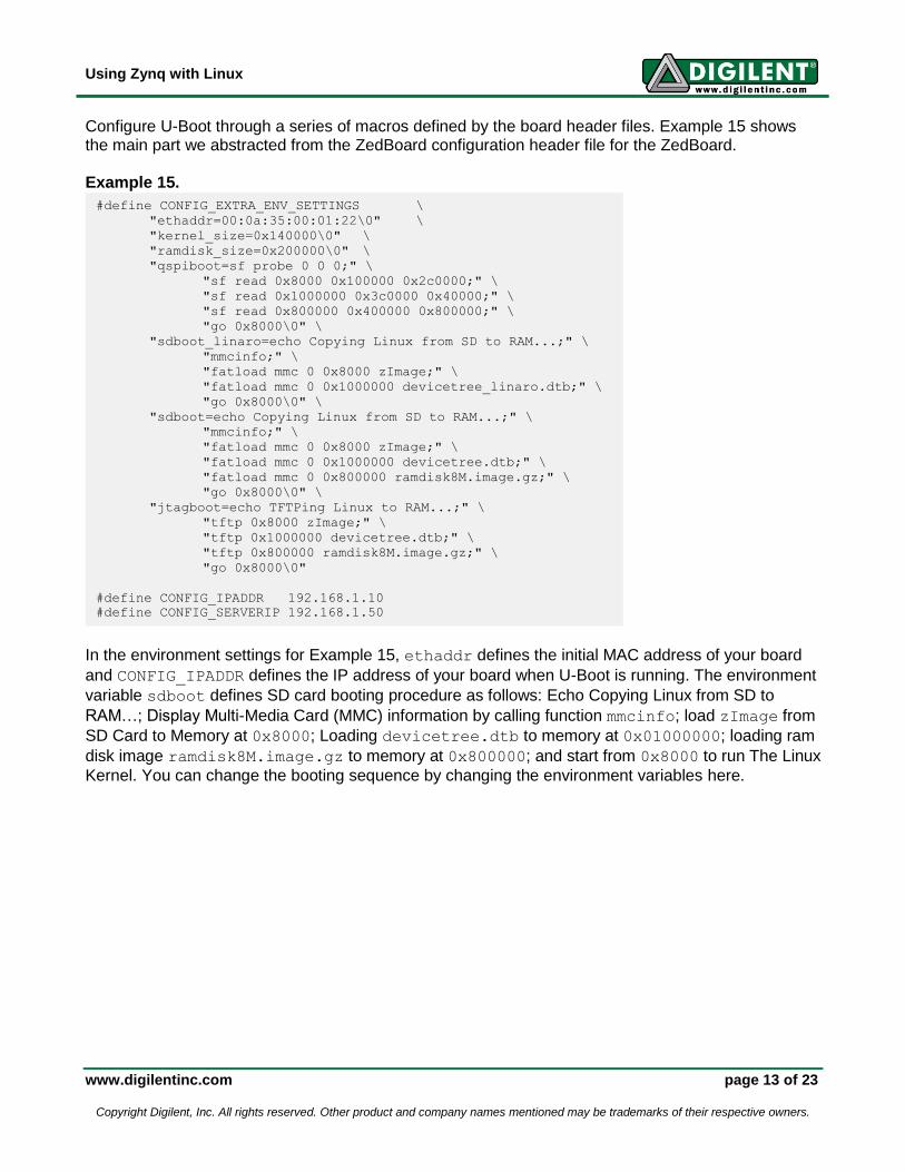
Configure U-Boot through a series of macros defined by the board header files. Example 15 shows the main part we abstracted from the ZedBoard configuration header file for the ZedBoard. Example 15.
In the environment settings for Example 15, ethaddr defines the initial MAC address of your board
and CONFIG_IPADDR defines the IP address of your board when U-Boot is running. The environment
variable sdboot defines SD card booting procedure as follows: Echo Copying Linux from SD to
RAM…; Display Multi-Media Card (MMC) information by calling function mmcinfo; load zImage from
SD Card to Memory at 0x8000; Loading devicetree.dtb to memory at 0x01000000; loading ram
disk image ramdisk8M.image.gz to memory at 0x800000; and start from 0x8000 to run The Linux
Kernel. You can change the booting sequence by changing the environment variables here.
#define CONFIG_EXTRA_ENV_SETTINGS \
"ethaddr=00:0a:35:00:01:22\0" \
"kernel_size=0x140000\0" \
"ramdisk_size=0x200000\0" \
"qspiboot=sf probe 0 0 0;" \
"sf read 0x8000 0x100000 0x2c0000;" \
"sf read 0x1000000 0x3c0000 0x40000;" \
"sf read 0x800000 0x400000 0x800000;" \
"go 0x8000\0" \
"sdboot_linaro=echo Copying Linux from SD to RAM...;" \
"mmcinfo;" \
"fatload mmc 0 0x8000 zImage;" \
"fatload mmc 0 0x1000000 devicetree_linaro.dtb;" \
"go 0x8000\0" \
"sdboot=echo Copying Linux from SD to RAM...;" \
"mmcinfo;" \
"fatload mmc 0 0x8000 zImage;" \
"fatload mmc 0 0x1000000 devicetree.dtb;" \
"fatload mmc 0 0x800000 ramdisk8M.image.gz;" \
"go 0x8000\0" \
"jtagboot=echo TFTPing Linux to RAM...;" \
"tftp 0x8000 zImage;" \
"tftp 0x1000000 devicetree.dtb;" \
"tftp 0x800000 ramdisk8M.image.gz;" \
"go 0x8000\0"
#define CONFIG_IPADDR 192.168.1.10
#define CONFIG_SERVERIP 192.168.1.50
Using Zynq with Linux
www.digilentinc.com page 14 of 23
Copyright Digilent, Inc. All rights reserved. Other product and company names mentioned may be trademarks of their respective owners.
Section IV: Linux Kernel Configuration The Linux kernel provides thousands of configurations to allow users to tailor kernel features based on their specific needs. Kernel configuration can be very tedious, so we recommend you begin with the default configuration as a baseline and start adding more features if you need them.
Configure the Linux Kernel
You can find the default configuration for your Digilent board at arch/arm/configs in the kernel
source under the name digilent_<board name>_defconfig (e.g. digilent_zed_defconfig
for ZedBoard). You can import the default board configuration by running command: $ make ARCH=arm CROSS_COMPILE=arm-xilinx-linux-gnueabi- digilent_<board
name>_defconfig
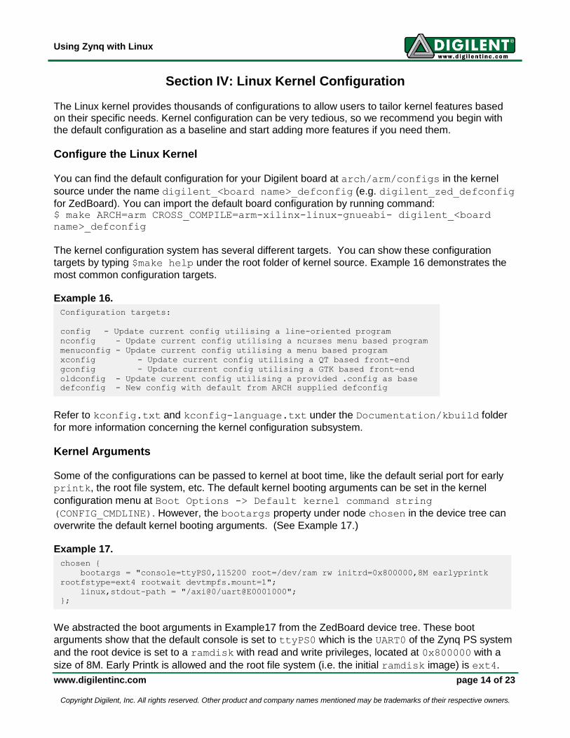
The kernel configuration system has several different targets. You can show these configuration
targets by typing $make help under the root folder of kernel source. Example 16 demonstrates the
most common configuration targets.
Example 16.
Refer to kconfig.txt and kconfig-language.txt under the Documentation/kbuild folder
for more information concerning the kernel configuration subsystem.
Kernel Arguments Some of the configurations can be passed to kernel at boot time, like the default serial port for early
printk, the root file system, etc. The default kernel booting arguments can be set in the kernel
configuration menu at Boot Options -> Default kernel command string
(CONFIG_CMDLINE). However, the bootargs property under node chosen in the device tree can
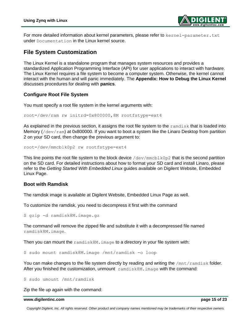
overwrite the default kernel booting arguments. (See Example 17.) Example 17.
We abstracted the boot arguments in Example17 from the ZedBoard device tree. These boot
arguments show that the default console is set to ttyPS0 which is the UART0 of the Zynq PS system
and the root device is set to a ramdisk with read and write privileges, located at 0x800000 with a
size of 8M. Early Printk is allowed and the root file system (i.e. the initial ramdisk image) is ext4.
chosen {
bootargs = "console=ttyPS0,115200 root=/dev/ram rw initrd=0x800000,8M earlyprintk
rootfstype=ext4 rootwait devtmpfs.mount=1";
linux,stdout-path = "/axi@0/uart@E0001000";
};
Configuration targets:
config - Update current config utilising a line-oriented program
nconfig - Update current config utilising a ncurses menu based program
menuconfig - Update current config utilising a menu based program
xconfig - Update current config utilising a QT based front-end
gconfig - Update current config utilising a GTK based front-end
oldconfig - Update current config utilising a provided .config as base
defconfig - New config with default from ARCH supplied defconfig
Using Zynq with Linux
www.digilentinc.com page 15 of 23
Copyright Digilent, Inc. All rights reserved. Other product and company names mentioned may be trademarks of their respective owners.
For more detailed information about kernel parameters, please refer to kernel-parameter.txt
under Documentation in the Linux kernel source.
File System Customization The Linux Kernel is a standalone program that manages system resources and provides a standardized Application Programming Interface (API) for user applications to interact with hardware. The Linux Kernel requires a file system to become a computer system. Otherwise, the kernel cannot interact with the human and will panic immediately. The Appendix: How to Debug the Linux Kernel discusses procedures for dealing with panics.
Configure Root File System You must specify a root file system in the kernel arguments with:
root=/dev/ram rw initrd=0x800000,8M rootfstype=ext4
As explained in the previous section, it assigns the root file system to the ramdisk that is loaded into
Memory (/dev/ram) at 0x800000. If you want to boot a system like the Linaro Desktop from partition
2 on your SD card, then change the previous argument to:
root=/dev/mmcblk0p2 rw rootfstype=ext4
This line points the root file system to the block device /dev/mmcblk0p2 that is the second partition
on the SD card. For detailed instructions about how to format your SD card and install Linaro, please refer to the Getting Started With Embedded Linux guides available on Digilent Website, Embedded Linux Page.
Boot with Ramdisk The ramdisk image is available at Digilent Website, Embedded Linux Page as well. To customize the ramdisk, you need to decompress it first with the command $ gzip -d ramdisk8M.image.gz
The command will remove the zipped file and substitute it with a decompressed file named
ramdisk8M.image.
Then you can mount the ramdisk8M.image to a directory in your file system with:
$ sudo mount ramdisk8M.image /mnt/ramdisk -o loop
You can make changes to the file system directly by reading and writing the /mnt/ramdisk folder.
After you finished the customization, unmount ramdisk8M.image with the command:
$ sudo umount /mnt/ramdisk
Zip the file up again with the command:
Using Zynq with Linux
www.digilentinc.com page 16 of 23
Copyright Digilent, Inc. All rights reserved. Other product and company names mentioned may be trademarks of their respective owners.
$ gzip -9 ramdisk8M.image.gz
The Ramdisk image will be loaded into the main memory before Linux boots. So, all the changes to the file system during runtime will only take place in the memory and will not get written back to Ramdisk image file when the system shuts down. If you want to preserve your changes, you need to consider hosting the file system on the SD card partition.
Boot from SD Card Partition To boot a filesystem loaded on an SD card requires at least two partitions be present on the SD card.
The first partition of the SD card should be formatted into FAT to hold design files (BOOT.BIN), the
DTB file (devicetree.dtb) and the kernel image (zImage). Format the second partition on the SD
into an ext file system (ext4 is recommended) to host the root file system. Most Linux distributions
provide tools like parted and fdisk to create a partition table on the SD card. Refer to Getting
Started with Embedded Linux found at the Embedded Linux page on the Digilent website for step-by-step instructions on how to partition an SD card to host the root file system.
Using Zynq with Linux
www.digilentinc.com page 17 of 23
Copyright Digilent, Inc. All rights reserved. Other product and company names mentioned may be trademarks of their respective owners.
APPENDIX: How to Debug the Linux Kernel Things may go wrong during your development – the kernel may panic and become dead without any notice during boot; there may be no messages that appear on your terminal; the kernel may say “Oops” at any time; or your system does not work as you expect. If you believe a bug in the Kernel source is responsible for an error, you may file a bug report to us via the email link on our Developer’s Wiki Page: https://github.com/Digilent/linux-digilent/wiki/Linux-Developer%27s-Wiki. Before filing a bug report, Digilent Inc. recommends that you do some debugging yourself to try and locate the problem. We encourage our users to file a bug-fix patch if you can locate and solve any problems with the software. This appendix section presents some easy ways to debug the kernel.
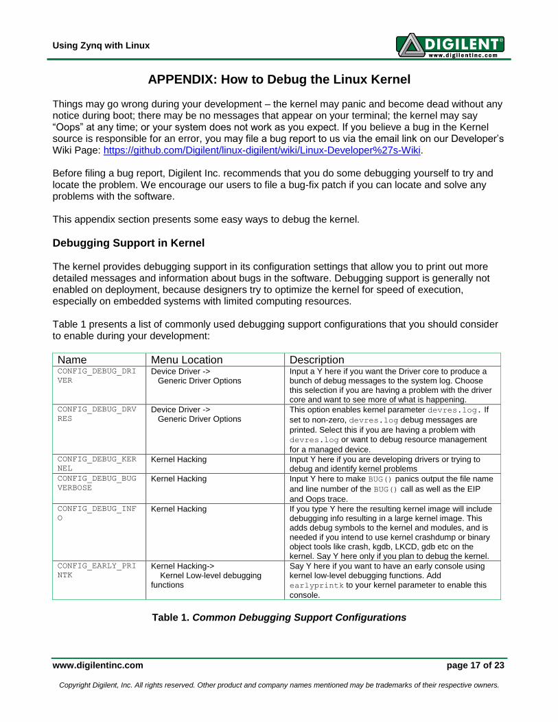
Debugging Support in Kernel The kernel provides debugging support in its configuration settings that allow you to print out more detailed messages and information about bugs in the software. Debugging support is generally not enabled on deployment, because designers try to optimize the kernel for speed of execution, especially on embedded systems with limited computing resources. Table 1 presents a list of commonly used debugging support configurations that you should consider to enable during your development:
Name Menu Location Description CONFIG_DEBUG_DRI
VER
Device Driver -> Generic Driver Options
Input a Y here if you want the Driver core to produce a bunch of debug messages to the system log. Choose this selection if you are having a problem with the driver core and want to see more of what is happening.
CONFIG_DEBUG_DRV
RES
Device Driver -> Generic Driver Options
This option enables kernel parameter devres.log. If
set to non-zero, devres.log debug messages are
printed. Select this if you are having a problem with devres.log or want to debug resource management
for a managed device. CONFIG_DEBUG_KER
NEL
Kernel Hacking Input Y here if you are developing drivers or trying to debug and identify kernel problems
CONFIG_DEBUG_BUG
VERBOSE
Kernel Hacking Input Y here to make BUG() panics output the file name
and line number of the BUG() call as well as the EIP
and Oops trace. CONFIG_DEBUG_INF
O
Kernel Hacking If you type Y here the resulting kernel image will include debugging info resulting in a large kernel image. This adds debug symbols to the kernel and modules, and is needed if you intend to use kernel crashdump or binary object tools like crash, kgdb, LKCD, gdb etc on the kernel. Say Y here only if you plan to debug the kernel.
CONFIG_EARLY_PRI
NTK
Kernel Hacking-> Kernel Low-level debugging functions
Say Y here if you want to have an early console using kernel low-level debugging functions. Add earlyprintk to your kernel parameter to enable this
console.
Table 1. Common Debugging Support Configurations
Using Zynq with Linux
www.digilentinc.com page 18 of 23
Copyright Digilent, Inc. All rights reserved. Other product and company names mentioned may be trademarks of their respective owners.
There are more options in the Kernel Hacking menu that you may choose to enable according to your needs.
Debug by Printing
Printing is always an easy and useful way to debug code. The kernel provides the printk function,
which works like printf in traditional C libraries. (See Example 18)
Example 18.
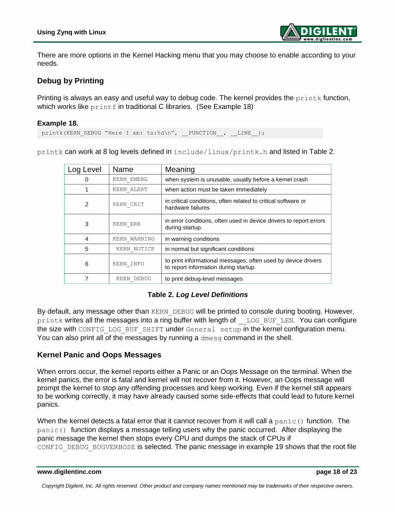
printk can work at 8 log levels defined in include/linux/printk.h and listed in Table 2.
Log Level Name Meaning
0 KERN_EMERG when system is unusable, usually before a kernel crash
1 KERN_ALERT when action must be taken immediately
2 KERN_CRIT in critical conditions, often related to critical software or hardware failures
3 KERN_ERR in error conditions, often used in device drivers to report errors during startup.
4 KERN_WARNING in warning conditions
5 KERN_NOTICE in normal but significant conditions
6 KERN_INFO to print informational messages, often used by device drivers to report information during startup.
7 KERN_DEBUG to print debug-level messages
Table 2. Log Level Definitions
By default, any message other than KERN_DEBUG will be printed to console during booting. However,
printk writes all the messages into a ring buffer with length of __LOG_BUF_LEN. You can configure
the size with CONFIG_LOG_BUF_SHIFT under General setup in the kernel configuration menu.
You can also print all of the messages by running a dmesg command in the shell.
Kernel Panic and Oops Messages When errors occur, the kernel reports either a Panic or an Oops Message on the terminal. When the kernel panics, the error is fatal and kernel will not recover from it. However, an Oops message will prompt the kernel to stop any offending processes and keep working. Even if the kernel still appears to be working correctly, it may have already caused some side-effects that could lead to future kernel panics.
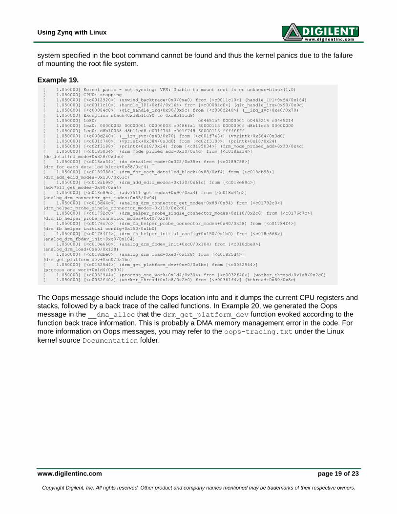
When the kernel detects a fatal error that it cannot recover from it will call a panic() function. The
panic() function displays a message telling users why the panic occurred. After displaying the
panic message the kernel then stops every CPU and dumps the stack of CPUs if
CONFIG_DEBUG_BUGVERBOSE is selected. The panic message in example 19 shows that the root file
printk(KERN_DEBUG “Here I am: %s:%d\n”, __FUNCTION__, __LINE__);
Using Zynq with Linux
www.digilentinc.com page 19 of 23
Copyright Digilent, Inc. All rights reserved. Other product and company names mentioned may be trademarks of their respective owners.
system specified in the boot command cannot be found and thus the kernel panics due to the failure of mounting the root file system. Example 19.
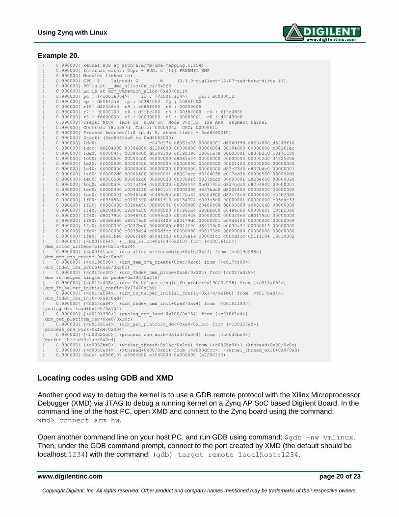
The Oops message should include the Oops location info and it dumps the current CPU registers and stacks, followed by a back trace of the called functions. In Example 20, we generated the Oops
message in the __dma_alloc that the drm_get_platform_dev function evoked according to the
function back trace information. This is probably a DMA memory management error in the code. For
more information on Oops messages, you may refer to the oops-tracing.txt under the Linux
kernel source Documentation folder.
[ 1.050000] Kernel panic - not syncing: VFS: Unable to mount root fs on unknown-block(1,0)
[ 1.050000] CPU0: stopping
[ 1.050000] [<c0012920>] (unwind_backtrace+0x0/0xe0) from [<c0011c10>] (handle_IPI+0xf4/0x164)
[ 1.050000] [<c0011c10>] (handle_IPI+0xf4/0x164) from [<c00084c0>] (gic_handle_irq+0x90/0x9c)
[ 1.050000] [<c00084c0>] (gic_handle_irq+0x90/0x9c) from [<c000d240>] (__irq_svc+0x40/0x70)
[ 1.050000] Exception stack(0xd8b11c90 to 0xd8b11cd8)
[ 1.050000] 1c80: c04651b4 00000001 c0465214 c0465214
[ 1.050000] 1ca0: 00000032 00000001 00000003 c0486fa1 60000113 0000000f d8b11cf5 00000000
[ 1.050000] 1cc0: d8b10038 d8b11cd8 c001f744 c001f748 60000113 ffffffff
[ 1.050000] [<c000d240>] (__irq_svc+0x40/0x70) from [<c001f748>] (vprintk+0x384/0x3d0)
[ 1.050000] [<c001f748>] (vprintk+0x384/0x3d0) from [<c02f3188>] (printk+0x18/0x24)
[ 1.050000] [<c02f3188>] (printk+0x18/0x24) from [<c0185034>] (drm_mode_probed_add+0x30/0x4c)
[ 1.050000] [<c0185034>] (drm_mode_probed_add+0x30/0x4c) from [<c018aa34>]
(do_detailed_mode+0x328/0x35c)
[ 1.050000] [<c018aa34>] (do_detailed_mode+0x328/0x35c) from [<c0189788>]
(drm_for_each_detailed_block+0x88/0xf4)
[ 1.050000] [<c0189788>] (drm_for_each_detailed_block+0x88/0xf4) from [<c018ab98>]
(drm_add_edid_modes+0x130/0x61c)
[ 1.050000] [<c018ab98>] (drm_add_edid_modes+0x130/0x61c) from [<c018e89c>]
(adv7511_get_modes+0x90/0xa4)
[ 1.050000] [<c018e89c>] (adv7511_get_modes+0x90/0xa4) from [<c018d44c>]
(analog_drm_connector_get_modes+0x88/0x94)
[ 1.050000] [<c018d44c>] (analog_drm_connector_get_modes+0x88/0x94) from [<c01792c0>]
(drm_helper_probe_single_connector_modes+0x110/0x2c0)
[ 1.050000] [<c01792c0>] (drm_helper_probe_single_connector_modes+0x110/0x2c0) from [<c0176c7c>]
(drm_fb_helper_probe_connector_modes+0x40/0x58)
[ 1.050000] [<c0176c7c>] (drm_fb_helper_probe_connector_modes+0x40/0x58) from [<c01784f4>]
(drm_fb_helper_initial_config+0x150/0x1b0)
[ 1.050000] [<c01784f4>] (drm_fb_helper_initial_config+0x150/0x1b0) from [<c018e668>]
(analog_drm_fbdev_init+0xc0/0x104)
[ 1.050000] [<c018e668>] (analog_drm_fbdev_init+0xc0/0x104) from [<c018dbe0>]
(analog_drm_load+0xe0/0x128)
[ 1.050000] [<c018dbe0>] (analog_drm_load+0xe0/0x128) from [<c01825d4>]
(drm_get_platform_dev+0xe0/0x1bc)
[ 1.050000] [<c01825d4>] (drm_get_platform_dev+0xe0/0x1bc) from [<c0032944>]
(process_one_work+0x1d4/0x304)
[ 1.050000] [<c0032944>] (process_one_work+0x1d4/0x304) from [<c0032f40>] (worker_thread+0x1a8/0x2c0)
[ 1.050000] [<c0032f40>] (worker_thread+0x1a8/0x2c0) from [<c00361f4>] (kthread+0x80/0x8c)
Using Zynq with Linux
www.digilentinc.com page 20 of 23
Copyright Digilent, Inc. All rights reserved. Other product and company names mentioned may be trademarks of their respective owners.
Example 20.
Locating codes using GDB and XMD Another good way to debug the kernel is to use a GDB remote protocol with the Xilinx Microprocessor Debugger (XMD) via JTAG to debug a running kernel on a Zynq AP SoC based Digilent Board. In the command line of the host PC, open XMD and connect to the Zynq board using the command:
xmd> connect arm hw.
Open another command line on your host PC, and run GDB using command: $gdb –nw vmlinux.
Then, under the GDB command prompt, connect to the port created by XMD (the default should be
localhost:1234) with the command: (gdb) target remote localhost:1234.
[ 0.990000] kernel BUG at arch/arm/mm/dma-mapping.c:254!
[ 0.990000] Internal error: Oops - BUG: 0 [#1] PREEMPT SMP
[ 0.990000] Modules linked in:
[ 0.990000] CPU: 1 Tainted: G W (3.3.0-digilent-12.07-zed-beta-dirty #3)
[ 0.990000] PC is at __dma_alloc+0x1c4/0x2f0
[ 0.990000] LR is at arm_vmregion_alloc+0xe0/0x110
[ 0.990000] pc : [<c0016064>] lr : [<c0017ad4>] psr: a0000013
[ 0.990000] sp : d8061da8 ip : 00384000 fp : c085f000
[ 0.990000] r10: d82436c0 r9 : c085f000 r8 : 00000005
[ 0.990000] r7 : 00000100 r6 : dfffc400 r5 : 00384000 r4 : fffc066f
[ 0.990000] r3 : fd600000 r2 : 00000000 r1 : 00000001 r0 : d82436c0
[ 0.990000] Flags: NzCv IRQs on FIQs on Mode SVC_32 ISA ARM Segment kernel
[ 0.990000] Control: 18c5387d Table: 0000404a DAC: 00000015
[ 0.990000] Process kworker/1:0 (pid: 8, stack limit = 0xd80602f0)
[ 0.990000] Stack: (0xd8061da8 to 0xd8062000)
[ 0.990000] 1da0: c047d174 d8061e78 00000001 d8249f98 d8204800 d8249f40
[ 0.990000] 1dc0: d8204800 00384000 d8204800 00000000 00000004 00384000 00000000 c00161ac
[ 0.990000] 1de0: 00000447 00384000 d8249f98 c0190598 d8061e78 00000001 d837bdc0 c017cc00
[ 0.990000] 1e00: 00000500 000002d0 00000020 d8061e24 00000000 00000500 000002d0 34325258
[ 0.990000] 1e20: 00000000 00000000 00000000 00000000 00000000 00001400 00000000 00000000
[ 0.990000] 1e40: 00000000 00000000 00000000 00000000 00000000 d82c7340 d837bdc0 00000001
[ 0.990000] 1e60: 000002d0 00000500 00000001 d8061ecc d8204038 c017ad38 00000500 000002d0
[ 0.990000] 1e80: 00000500 000002d0 00000020 00000018 d837bdc0 00000001 d8204800 00000020
[ 0.990000] 1ea0: d8200d00 c017af94 00000000 c0093144 05d1745d d837bdc0 d8204800 00000001
[ 0.990000] 1ec0: 00000000 c0093210 c04801c4 00000000 d837bdc0 d8204800 00000020 00000000
[ 0.990000] 1ee0: 00000001 c09464e8 c0486d5c c017ca84 d8204800 d82c76c0 00000000 c04b2360
[ 0.990000] 1f00: c093a834 c0191390 d8061f10 c0184774 c093a5e0 00000001 00000000 c03dae33
[ 0.990000] 1f20: 00000000 d8204a50 00000001 00000000 c0486c68 00000000 c0486c68 00000000
[ 0.990000] 1f40: d8204800 d8204a50 00000000 c01861a4 d80bbe00 c0486c68 00000001 c04b2360
[ 0.990000] 1f60: d80179c0 c0946400 c0949c00 c01914c8 00000000 c00325e0 d80179c0 00000000
[ 0.990000] 1f80: c0486d60 d80179c0 c0946400 d80179d0 00000001 c0946400 00000000 00000009
[ 0.990000] 1fa0: 00000000 c0032be0 00000000 d804ff00 d80179c0 c0032a34 00000013 00000000
[ 0.990000] 1fc0: 00000000 c0035e94 c000dfcc 00000000 d80179c0 00000000 00000000 00000000
[ 0.990000] 1fe0: d8061fe0 d8061fe0 d804ff00 c0035e14 c000dfcc c000dfcc 65111104 16010002
[ 0.990000] [<c0016064>] (__dma_alloc+0x1c4/0x2f0) from [<c00161ac>]
(dma_alloc_writecombine+0x1c/0x24)
[ 0.990000] [<c00161ac>] (dma_alloc_writecombine+0x1c/0x24) from [<c0190598>]
(drm_gem_cma_create+0x4c/0xc8)
[ 0.990000] [<c0190598>] (drm_gem_cma_create+0x4c/0xc8) from [<c017cc00>]
(drm_fbdev_cma_probe+0xa8/0x20c)
[ 0.990000] [<c017cc00>] (drm_fbdev_cma_probe+0xa8/0x20c) from [<c017ad38>]
(drm_fb_helper_single_fb_probe+0x190/0x278)
[ 0.990000] [<c017ad38>] (drm_fb_helper_single_fb_probe+0x190/0x278) from [<c017af94>]
(drm_fb_helper_initial_config+0x174/0x1b0)
[ 0.990000] [<c017af94>] (drm_fb_helper_initial_config+0x174/0x1b0) from [<c017ca84>]
(drm_fbdev_cma_init+0xa8/0xd4)
[ 0.990000] [<c017ca84>] (drm_fbdev_cma_init+0xa8/0xd4) from [<c0191390>]
(analog_drm_load+0x100/0x154)
[ 0.990000] [<c0191390>] (analog_drm_load+0x100/0x154) from [<c01861a4>]
(drm_get_platform_dev+0xe0/0x1bc)
[ 0.990000] [<c01861a4>] (drm_get_platform_dev+0xe0/0x1bc) from [<c00325e0>]
(process_one_work+0x1d4/0x304)
[ 0.990000] [<c00325e0>] (process_one_work+0x1d4/0x304) from [<c0032be0>]
(worker_thread+0x1ac/0x2c4)
[ 0.990000] [<c0032be0>] (worker_thread+0x1ac/0x2c4) from [<c0035e94>] (kthread+0x80/0x8c)
[ 0.990000] [<c0035e94>] (kthread+0x80/0x8c) from [<c000dfcc>] (kernel_thread_exit+0x0/0x8)
[ 0.990000] Code: e0866107 e5964000 e3540000 0a000000 (e7f001f2)
Using Zynq with Linux
www.digilentinc.com page 21 of 23
Copyright Digilent, Inc. All rights reserved. Other product and company names mentioned may be trademarks of their respective owners.
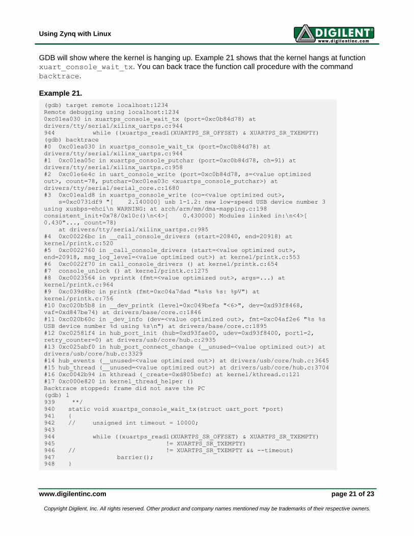
GDB will show where the kernel is hanging up. Example 21 shows that the kernel hangs at function
xuart_console_wait_tx. You can back trace the function call procedure with the command
backtrace.
Example 21.
(gdb) target remote localhost:1234
Remote debugging using localhost:1234
0xc01ea030 in xuartps_console_wait_tx (port=0xc0b84d78) at
drivers/tty/serial/xilinx_uartps.c:944
944 while ((xuartps_readl(XUARTPS_SR_OFFSET) & XUARTPS_SR_TXEMPTY)
(gdb) backtrace
#0 0xc01ea030 in xuartps_console_wait_tx (port=0xc0b84d78) at
drivers/tty/serial/xilinx_uartps.c:944
#1 0xc01ea05c in xuartps_console_putchar (port=0xc0b84d78, ch=91) at
drivers/tty/serial/xilinx_uartps.c:958
#2 0xc01e6e4c in uart_console_write (port=0xc0b84d78, s=<value optimized
out>, count=78, putchar=0xc01ea03c <xuartps_console_putchar>) at
drivers/tty/serial/serial_core.c:1680
#3 0xc01ea1d8 in xuartps_console_write (co=<value optimized out>,
s=0xc0731df9 "[ 2.140000] usb 1-1.2: new low-speed USB device number 3
using xusbps-ehci\n WARNING: at arch/arm/mm/dma-mapping.c:198
consistent_init+0x78/0x10c()\n<4>[ 0.430000] Modules linked in:\n<4>[
0.430"..., count=78)
at drivers/tty/serial/xilinx_uartps.c:985
#4 0xc00226bc in __call_console_drivers (start=20840, end=20918) at
kernel/printk.c:520
#5 0xc0022760 in _call_console_drivers (start=<value optimized out>,
end=20918, msg_log_level=<value optimized out>) at kernel/printk.c:553
#6 0xc0022f70 in call_console_drivers () at kernel/printk.c:654
#7 console_unlock () at kernel/printk.c:1275
#8 0xc0023564 in vprintk (fmt=<value optimized out>, args=...) at
kernel/printk.c:964
#9 0xc039d8bc in printk (fmt=0xc04a7dad "%s%s %s: %pV") at
kernel/printk.c:756
#10 0xc020b5b8 in __dev_printk (level=0xc049befa "<6>", dev=0xd93f8468,
vaf=0xd847be74) at drivers/base/core.c:1846
#11 0xc020b60c in _dev_info (dev=<value optimized out>, fmt=0xc04af2e6 "%s %s
USB device number %d using %s\n") at drivers/base/core.c:1895
#12 0xc02581f4 in hub_port_init (hub=0xd93fae00, udev=0xd93f8400, port1=2,
retry_counter=0) at drivers/usb/core/hub.c:2935
#13 0xc025abf0 in hub_port_connect_change (__unused=<value optimized out>) at
drivers/usb/core/hub.c:3329
#14 hub_events (__unused=<value optimized out>) at drivers/usb/core/hub.c:3645
#15 hub_thread (__unused=<value optimized out>) at drivers/usb/core/hub.c:3704
#16 0xc0042b94 in kthread (_create=0xd805befc) at kernel/kthread.c:121
#17 0xc000e820 in kernel_thread_helper ()
Backtrace stopped: frame did not save the PC
(gdb) l
939 **/
940 static void xuartps_console_wait_tx(struct uart_port *port)
941 {
942 // unsigned int timeout = 10000;
943
944 while ((xuartps_readl(XUARTPS_SR_OFFSET) & XUARTPS_SR_TXEMPTY)
945 != XUARTPS_SR_TXEMPTY)
946 // != XUARTPS_SR_TXEMPTY && --timeout)
947 barrier();
948 }
Using Zynq with Linux
www.digilentinc.com page 22 of 23
Copyright Digilent, Inc. All rights reserved. Other product and company names mentioned may be trademarks of their respective owners.
Sysfs, Proc and Debugfs File System Your applications run in user mode for Linux and have no access to kernel information but through
system calls. However, some pseudo file systems, e.g. sys file system, proc file system, debug file
system, create a window for users to interact with kernel parameters and inspect kernel status. For
more information on using these pseudo file systems, see debugfs.txt, proc.txt, and
sysfs.txt in the Documentation/filesystems folder of the kernel source.
Using Zynq with Linux
www.digilentinc.com page 23 of 23
Copyright Digilent, Inc. All rights reserved. Other product and company names mentioned may be trademarks of their respective owners.
Additional Resources Consult the following documents for additional information on designing embedded Linux systems for Digilent system boards.
Getting Started with Embedded Linux – ZedBoard This document describes how to obtain the Linux Hardware Design and use it with the Digilent Linux repository to build and run a fully functional Linux system on the ZedBoard. You can obtain this document from the ZedBoard product page on the Digilent website.
Embedded Linux Hands-on Tutorial – ZedBoard This document walks the reader through the process of modifying the ZedBoard Linux Hardware Design to include additional hardware, making this hardware accessible to Linux by modifying the device tree, and finally designing a custom driver that brings the hardware’s functionality up to the Linux user. It can be obtained from the ZedBoard product page on the Digilent website.
ZedBoard Linux Hardware Design Project Guide This document describes the ZedBoard Linux Hardware Design, and walks the reader through the process of building all the sources required to generate the BOOT.BIN file. It is packaged along with the ZedBoard Linux Hardware Design, which can be obtained from the ZedBoard product page.
Linux Developer’s Wiki This web page contains an up to date list of hardware that is supported by the Digilent Linux repository and an FAQ section that addresses some issues you may run into while using the current version of the kernel. It also contains information on submitting patches for those who are interested in contributing code. You can find the Linux Developer’s Wiki at: https://github.com/Digilent/linux-digilent/wiki/Linux-Developer%27s-Wiki.
Related Documents