Missouri University of Science and Technology Missouri University of Science and Technology Scholars' Mine Scholars' Mine International Conference on Case Histories in Geotechnical Engineering (2013) - Seventh International Conference on Case Histories in Geotechnical Engineering 02 May 2013, 4:00 pm - 6:00 pm Embankment Slope Stability Analysis of Dwight Mission Mine Site Embankment Slope Stability Analysis of Dwight Mission Mine Site Reclamation Project Reclamation Project Christopher D. Kiser Southern Illinois University Carbondale, Carbondale, IL Prabir K. Kolay Southern Illinois University Carbondale, Carbondale, IL Follow this and additional works at: https://scholarsmine.mst.edu/icchge Part of the Geotechnical Engineering Commons Recommended Citation Recommended Citation Kiser, Christopher D. and Kolay, Prabir K., "Embankment Slope Stability Analysis of Dwight Mission Mine Site Reclamation Project" (2013). International Conference on Case Histories in Geotechnical Engineering. 59. https://scholarsmine.mst.edu/icchge/7icchge/session03/59 This work is licensed under a Creative Commons Attribution-Noncommercial-No Derivative Works 4.0 License. This Article - Conference proceedings is brought to you for free and open access by Scholars' Mine. It has been accepted for inclusion in International Conference on Case Histories in Geotechnical Engineering by an authorized administrator of Scholars' Mine. This work is protected by U. S. Copyright Law. Unauthorized use including reproduction for redistribution requires the permission of the copyright holder. For more information, please contact [email protected].

Welcome message from author
This document is posted to help you gain knowledge. Please leave a comment to let me know what you think about it! Share it to your friends and learn new things together.
Transcript

Missouri University of Science and Technology Missouri University of Science and Technology
Scholars' Mine Scholars' Mine
International Conference on Case Histories in Geotechnical Engineering
(2013) - Seventh International Conference on Case Histories in Geotechnical Engineering
02 May 2013, 4:00 pm - 6:00 pm
Embankment Slope Stability Analysis of Dwight Mission Mine Site Embankment Slope Stability Analysis of Dwight Mission Mine Site
Reclamation Project Reclamation Project
Christopher D. Kiser Southern Illinois University Carbondale, Carbondale, IL
Prabir K. Kolay Southern Illinois University Carbondale, Carbondale, IL
Follow this and additional works at: https://scholarsmine.mst.edu/icchge
Part of the Geotechnical Engineering Commons
Recommended Citation Recommended Citation Kiser, Christopher D. and Kolay, Prabir K., "Embankment Slope Stability Analysis of Dwight Mission Mine Site Reclamation Project" (2013). International Conference on Case Histories in Geotechnical Engineering. 59. https://scholarsmine.mst.edu/icchge/7icchge/session03/59
This work is licensed under a Creative Commons Attribution-Noncommercial-No Derivative Works 4.0 License.
This Article - Conference proceedings is brought to you for free and open access by Scholars' Mine. It has been accepted for inclusion in International Conference on Case Histories in Geotechnical Engineering by an authorized administrator of Scholars' Mine. This work is protected by U. S. Copyright Law. Unauthorized use including reproduction for redistribution requires the permission of the copyright holder. For more information, please contact [email protected].
Paper No. 3.37b 1
EMBANKMENT SLOPE STABILITY ANALYSIS OF DWIGHT MISSION MINE SITE
RECLAMATION PROJECT
Christopher, D. Kiser, P.E. Prabir K. Kolay, Ph.D., M. ASCE Former Graduate Student, Assistant Professor,
Southern Illinois University Carbondale Southern Illinois University Carbondale
1230 Lincoln Drive, Carbondale-USA 62901 1230 Lincoln Drive, Carbondale-USA 62901
E-mail: [email protected] E-mail: [email protected]
ABSTRACT
The paper presents a slope stability analysis of a proposed embankment contained within an abandoned coal mine reclamation project
near Sallisaw, Oklahoma. The project involved the use of computer modeling to analyze the slope stability of the earth-filled
embankment. The project plans call for mine spoils and silty-clay borrow materials is used to construct a 74,000 cubic yard
embankment, which will be used as a water impoundment for a small lake. The embankment, as designed, consists of a central clay
core, mine spoils and a silty-clay material cap. The software program Galena was used as a modeling tool for the slope stability
analysis of the proposed embankment. Additionally, seven different variations on the embankment’s proposed design were modeled.
The ultimate goal was to determine the factor of safety (FS) for each variation. Results show that the Galena program provides a
higher factor of safety when compared with conventional methods using the Taylor stability chart. The difference in these values is
probably attributed to the general assumptions of the Taylor method.
INTRODUCTION
The purpose of this project is to perform a slope stability
analysis of an earth-filled embankment for an actual civil
engineering project near Sallisaw, Oklahoma. The project
design started in 2010, although no formal slope stability
analysis was performed on the embankment prior to this
project report. The US Department of the Interior, Office of
Surface Mining Reclamation and Enforcement (OSM), intends
to grade and cover existing coal mine spoil piles, eliminate
exposed high-wall segments, stabilize the slopes of a
hazardous water body and vegetate an existing abandon coal
mine site in Sequoyah County, Oklahoma. Due to the large
amount of excess spoil piles on the site, approximately
500,000 CY (cubic yard), about 80% of the spoil material
cannot be graded in place, as this would have resulted in a
large plateau in one area of the site that would not have
conformed to the contours of the surrounding geographic area.
Thus, about 400,000 CY of the spoil material will be
transported to the southern end of the project site to create a
large impoundment area, which will ultimately fill with water
and create a small recreational lake. The lake will be
surrounded by a long, earth-filled embankment, which is the
subject of this project report. The embankment will be
constructed using the mine spoil piles overburden containing
mostly shales, with some silts and clays. The embankment will
be approximately 1,800 feet long, 17 feet tall and 175 feet
wide (toe to toe) at its tallest and widest points and contain
about 74,000 CY of material. Borrow soils on the mine site,
such as clays and silts, will also be excavated and used in the
embankment for the impermeable core and slope blanket
materials.
BACKGROUND AND SCOPE OF WORK
The intent of the project is to evaluate the stability of the
embankment as currently designed (base-case scenario). The
slope geometry and material characteristics will also be altered
to study the effect of these changes on slope stability. Such
changes include altering the upstream (u/s) and downstream
(d/s) slope angles, changing material types, and altering the
headwater elevation. Figure 1 shows a cross-section of the
embankment and associated dimensions which will be used as
the base case scenario. The upstream side of the embankment
has a 4:1 slope and the downstream side has a 5:1 slope. A
central clay core is flanked by the mine spoils which constitute
the main body of the dam and provide a seepage deterrent.
Normal water surface (head pressure) on the upstream side is
assumed to be 13 feet, which corresponds to the primary

Paper No. 3.37b 2
spillway level during normal operating conditions. Because of
the project limitations, some assumptions have been made
using best engineering judgment, including material properties
such as density, friction angles, and cohesion.
It must be noted that no stability analysis was originally
performed during the actual design of the embankment, thus
the content of this report is unique. Furthermore, this study is
strictly for academic purposes only and the results should not
be used for the actual project’s design or construction of
Dwight Mission Mine Site Reclamation Project.
Fig. 1. Cross-section of the embankment base case, as
presently designed
Slopes can either occur naturally or are man-made structures,
as in the case of this project. The slope stability problems have
been encountered throughout history, when slopes have been
created or disturbed. The design of a foundation must consider
slope movement (Day 2006). The need for engineered
structures on construction projects continues to increase, as
well as the need for advanced analysis methods such as
computer modeling, investigative tools, and stabilization
methods to solve slope stability problems (Lou 2007).
Stability problems most often occur when an embankment is
built upon soft soils, such as clays with low bearing capacity,
silts or organic soils (Engineer Manual # 1110-2-1902 1986).
When a ground surface is not horizontal, a component of
gravity moves the soil downward. Embankments constructed
over relatively deep deposits of soft soils have displayed this
type of “circular arc failure”. The weight of the embankment
soils above the failure surface serve as the driving force of
movement. The driving moment is the product of the weight
of the embankment acting through its center of gravity times
the horizontal distance from the center of gravity to the center
of rotation. The resisting force against movement is the total
shear strength acting along the failure arc. The resisting
moment is the product of the resisting force times the radius of
the circle (FHWA 2001). Slope stability is a function of four
basic factors: density (or unit weight) of the soil, slope angle,
cohesion of the slope material, friction angle. Cohesion (c) can
be thought of as the inherent ability of a material to bond itself
together. The friction angle (ϕ) of a material measures the
amount of friction that keeps the block from moving when a
shear force is applied. The four elements listed above can be
used to demonstrate a soil blocks tendency for movement
when forces are applied. Forces encouraging failure depend on
the weight above the plane of weakness (Lou 2007).
Figure 2 shows the four major types of stability issues
encountered with embankments over weak foundations soils.
The stability problems shown in Figure 2 can be classified as
internal or external. Internal stability problems within
embankments result from poor quality embankment materials
or improper placement or compaction of embankment fills.
The infinite slope failure in Figure 4 is an internal stability
example, as material sloughs from the surface of the slope.
The issues with internal stability can be addressed through
project specifications such as compaction specifications
(FHWA 2001). The other failure modes shown in Figure 2 (b,
c, d) are examples of external stability problems (FHWA
2001). NAVFAC (1986) suggests that failure of embankment
fill slopes can be caused by overstressing the foundation soil,
drawdown and piping, and vibrations such as earthquakes,
blasting, etc.
Fig. 2. Embankment Failures: (a) Infinite slope failure in
embankment fill, (b) circular arc failure, (c) Sliding block
failure, (d) Lateral squeeze of foundation soil (FHWA 2001)
FACTOR OF SAFETY
After finding the soil profile, soil strengths and water table
location have been determined by laboratory testing or field
exploration, the stability of the embankment can be analyzed

Paper No. 3.37b 3
and the factor of safety can be determined (FHWA 2001). The
shear strength of the soil should be compared against the
stresses on the surface most likely to fail (Day 2006). The
factor of safety (FS) is the ratio of the forces resisting failure
(shear strength of the soil) to the forces causing failure (shear
stress developed along the failure surface) (Day 2006).
failurecausingForces
strengthResistingFS
A factor of safety below one implies the slope will fail, as the
resisting forces are less than the forces causing failure. The
greater the factor of safety, the greater is the slope’s resistance
to collapse. Generally, a value of 1.5 is acceptable for the
factor of safety of a stable slope (Day 2006), although a
minimum factor of safety as low as 1.25 is sometimes used for
highway embankment side slopes (FHWA 2001). Table 1
referred from the US Army Corps of Engineers provides a
good guide for minimum factors of safety for new earth-fill
dams. In general, when selecting an appropriate factor of
safety, an engineer should consider what method of stability
analysis was used, methods for determining shear strength,
degree of confidence in material data, how critical the
application and severity of failure if it were to occur (FHWA
2001).
Table 1. Minimum Required Factors of Safety for New Earth
and Rock-Fill Dams (Engineer Manual No. 1110-2-1902,
1986)
Analysis Condition1 Required
Minimum
Factor of
Safety
Slope
End-of-Construction
(including staged
construction)2
1.3 Upstream and
Downstream
Long-term (Steady
seepage, maximum storage
pool, spillway crest or top
of gates)
1.5 Downstream
Maximum surcharge pool3 1.4 Downstream
Rapid drawdown 1.1-1.34,5
Upstream
1For earthquake loading, see ER 1110-2-1806 for guidance;
An Engineer Circular, “Dynamic Analysis of Embankment
Dams”. 2For embankments over 50 feet high on soft foundations and
for embankments that will be subjected to pool loading during
construction, a higher minimum end-of-construction factor of
safety may be appropriate. 3Pool thrust from maximum surcharge level. Pore pressures
are usually taken as those developed under steady-state
seepage at maximum storage pool. However, for pervious
foundations with no positive cutoff steady-state seepage may
develop under maximum surcharge pool.
4Factor of safety (FS) to be used with improved method of
analysis. 5FS = 1.1 applies to drawdown from maximum surcharge
pool; FS = 1.3 applies to drawdown from maximum storage
pool.
For dams used in pump storage schemes or similar
applications where rapid drawdown is a routine operating
condition, higher factors of safety, e.g., 1.4-1.5, are
appropriate. If consequences of an upstream failure are great,
such as blockage of the outlet works resulting in a potential
catastrophic failure, higher factors of safety should be
considered.
SLOPE STABILITY ANALYSIS METHODS
There are several methods available for circular arc slope
stability analysis for embankments built upon soft ground.
These techniques can generally be classified into three broad
categories e.g., limit equilibrium methods, limit analysis, and
finite element methods (NAVFAC 1986). Many of the
methods for stability analysis fall into the limit equilibrium
category. The method of slices is commonly used in limit
equilibrium solutions. The soil mass within the slip surface is
divided into several slices, and the forces acting on each slice
is considered. The limit equilibrium method does not account
for load deformation characteristics of the materials, whereas
the limit analysis method considers yield criteria (NAVFAC
1986). The finite element method is used in more complex
problems where earthquake and vibrations are part of the total
loading system.
The analysis of slope stability can be performed by using
slope stability charts. The stability charts can be used as a
graphical tool to check factors of safety before a more detailed
computer analysis. They have been designed with the
assumptions of two-dimensional limit equilibrium, simple
homogeneous slopes and circular slip surfaces. The charts are
for ideal, homogeneous soils that are typically not encountered
in the field (NAVFAC 1986). The two most common stability
charts were developed by Taylor (1948) and Janbu (1968).
Janbu established stability charts for slopes in soils with
uniform strength for ϕ = 0 and ϕ > 0 conditions. Other charts
account for surcharge loading at the top of slope, submergence
and tension cracks.
Several methods are available for slope stability calculation.
These include the Bishop (1955) method, Janbu (1954)
method and the Spencer (1967) method. These methods are
basically variations on the Method of Slices (FHWA 2001).
Software programs, such as Galena which will be used for this
project, require the user to select the analysis method. The
method used for determining the factor of safety depends on
the soil type, source of soil strength parameters, level of
confidence in values and type of slope being designed (FHWA
2001). Some general guidelines for recommended methods are
shown in Table 2.
Paper No. 3.37b 4
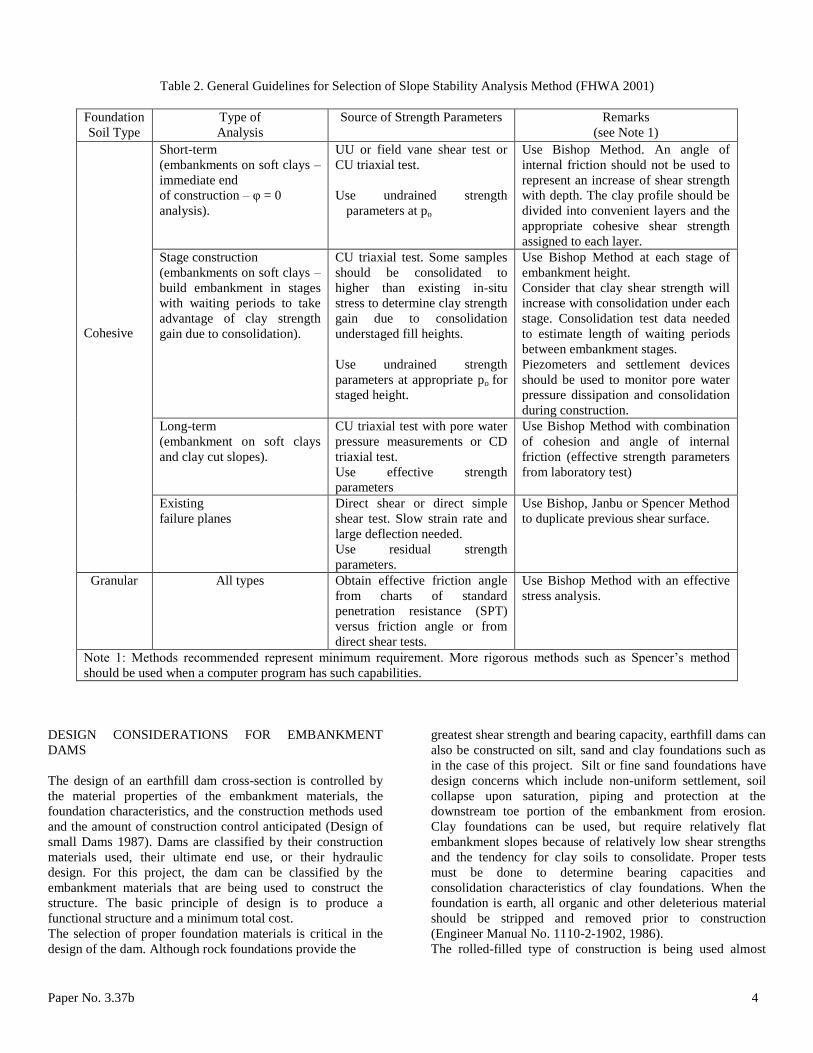
Table 2. General Guidelines for Selection of Slope Stability Analysis Method (FHWA 2001)
Foundation
Soil Type
Type of
Analysis
Source of Strength Parameters Remarks
(see Note 1)
Cohesive
Short-term
(embankments on soft clays –
immediate end
of construction – φ = 0
analysis).
UU or field vane shear test or
CU triaxial test.
Use undrained strength
parameters at po
Use Bishop Method. An angle of
internal friction should not be used to
represent an increase of shear strength
with depth. The clay profile should be
divided into convenient layers and the
appropriate cohesive shear strength
assigned to each layer.
Stage construction
(embankments on soft clays –
build embankment in stages
with waiting periods to take
advantage of clay strength
gain due to consolidation).
CU triaxial test. Some samples
should be consolidated to
higher than existing in-situ
stress to determine clay strength
gain due to consolidation
understaged fill heights.
Use undrained strength
parameters at appropriate po for
staged height.
Use Bishop Method at each stage of
embankment height.
Consider that clay shear strength will
increase with consolidation under each
stage. Consolidation test data needed
to estimate length of waiting periods
between embankment stages.
Piezometers and settlement devices
should be used to monitor pore water
pressure dissipation and consolidation
during construction.
Long-term
(embankment on soft clays
and clay cut slopes).
CU triaxial test with pore water
pressure measurements or CD
triaxial test.
Use effective strength
parameters
Use Bishop Method with combination
of cohesion and angle of internal
friction (effective strength parameters
from laboratory test)
Existing
failure planes
Direct shear or direct simple
shear test. Slow strain rate and
large deflection needed.
Use residual strength
parameters.
Use Bishop, Janbu or Spencer Method
to duplicate previous shear surface.
Granular All types Obtain effective friction angle
from charts of standard
penetration resistance (SPT)
versus friction angle or from
direct shear tests.
Use Bishop Method with an effective
stress analysis.
Note 1: Methods recommended represent minimum requirement. More rigorous methods such as Spencer’s method
should be used when a computer program has such capabilities.
DESIGN CONSIDERATIONS FOR EMBANKMENT
DAMS
The design of an earthfill dam cross-section is controlled by
the material properties of the embankment materials, the
foundation characteristics, and the construction methods used
and the amount of construction control anticipated (Design of
small Dams 1987). Dams are classified by their construction
materials used, their ultimate end use, or their hydraulic
design. For this project, the dam can be classified by the
embankment materials that are being used to construct the
structure. The basic principle of design is to produce a
functional structure and a minimum total cost.
The selection of proper foundation materials is critical in the
design of the dam. Although rock foundations provide the
greatest shear strength and bearing capacity, earthfill dams can
also be constructed on silt, sand and clay foundations such as
in the case of this project. Silt or fine sand foundations have
design concerns which include non-uniform settlement, soil
collapse upon saturation, piping and protection at the
downstream toe portion of the embankment from erosion.
Clay foundations can be used, but require relatively flat
embankment slopes because of relatively low shear strengths
and the tendency for clay soils to consolidate. Proper tests
must be done to determine bearing capacities and
consolidation characteristics of clay foundations. When the
foundation is earth, all organic and other deleterious material
should be stripped and removed prior to construction
(Engineer Manual No. 1110-2-1902, 1986).
The rolled-filled type of construction is being used almost
Paper No. 3.37b 5
exclusively for the construction of earth-filled dams. This
involves the construction of the dam in successive,
mechanically compacted layers. After the foundation of the
embankment has been properly prepared, material from
borrow areas is transported to the construction site by means
of trucks or scrapers. The layers (lifts) are compacted to the
required density and moisture contents using compaction
equipment such as rollers or the material hauling equipment
itself (proof rolling). Standard compaction tests (such as the
Proctor compaction test) can be used to determine these
values. Rolled-filled dams are categorized into three types:
diaphragm, homogeneous and zoned (Design of small dams
1987).
This project design involves the use of a zoned embankment
type. This is the most common type of rolled, earthfill dam.
Earth-fill dams are constructed with impervious cores when
local borrow materials do not provide adequate quantities of
impervious material (Engineer Manual No. 1110-2-1902,
1986). A central impervious core is flanked by zones of
materials considerably more pervious, called shells. The
pervious shells protect and support the impervious core, the
upstream section allows for protection against rapid drawdown
and the downstream pervious zone acts as a drain to control
seepage and lower the phreatic surface.
The design and construction of earth-filled dams is complex
because of the nature of the varying foundation conditions and
range of properties of the materials available. A detailed
geological and subsurface evaluation must first be conducted.
This allows for the proper characterization of the foundation,
abutment and borrow material. The next step involves a study
of the physical and engineering properties of the embankment
materials (Engineer Manual 1986).
The foundation of the embankment should provide an
adequate bearing surface and provide protection from
excessive seepage. If the foundation material is impervious
and comparable to the embankment material in structural
characteristics, little foundation treatment is required. At a
minimum, the foundation area should be stripped of sod,
organic topsoil and other deleterious material. The top several
feet of soil foundation lacks the density of the underlying
material because of frost action, runoff, wind, etc. [12].
When foundations consist of saturated fine grained soils, their
ability to resist shear stresses may be determined by their soil
group classification and relative consistency. The most
practical solution for saturated foundations of fined grained
soils is flattening the slopes of the embankment. This requires
the critical sliding surface to lengthen, thereby decreasing the
average shear stress along its path and increasing the factor of
safety against sliding (Design of Small Dams 1987). Table 2
shows some recommended slopes for embankments typical for
the groups within the Unified Soil Classification with different
consistency.
EMBANKMENT STABILITY IMPROVEMENT
TECHNIQUES
If an embankment design stability analysis returns a factor of
safety too low for safe operation, there are many available
solutions to solve stability issues and increase the factor of
safety. The solution method should be economical and
consider available materials, quality and cost, and construction
time schedules [4].
GALENA PROGRAM DESCRIPTION
Galena is a powerful slope stability analysis program designed
for engineers to solve geotechnical problems. The program
was selected because of popularity, reliability, ease of use and
availability as it relates to this project. Galena offers three
different analysis methods: Bishop, Spencer-Wright, and
Sarma. These are mathematical iteration methods that the
program uses to resolve forces acting on a slope. The method
is chosen by the user, and should be determined by slope
geometry, material properties and a general understanding of
geotechnical engineering. The Bishop method is used to
determine the stability of circular failure surfaces, the
Spencer-Wright method is used for both circular and on-
circular failure surfaces, and the Sarma method is used for
more complex stability problems (Lou 2007). Table 1 in this
project report can also be used as a general guide for analysis
method selection.
The program produces printable results which include cross
sections showing the failure surface along with the resulting
factor of safety. Galena allows shear strength properties to be
defined using traditional c and phi values, the Hoek-Brown
(1983) failure criterion (m, s and UCS), or with shear/normal
data from lab curves (Clover Technology 2003). Multiple
material types and locations within the embankment can be
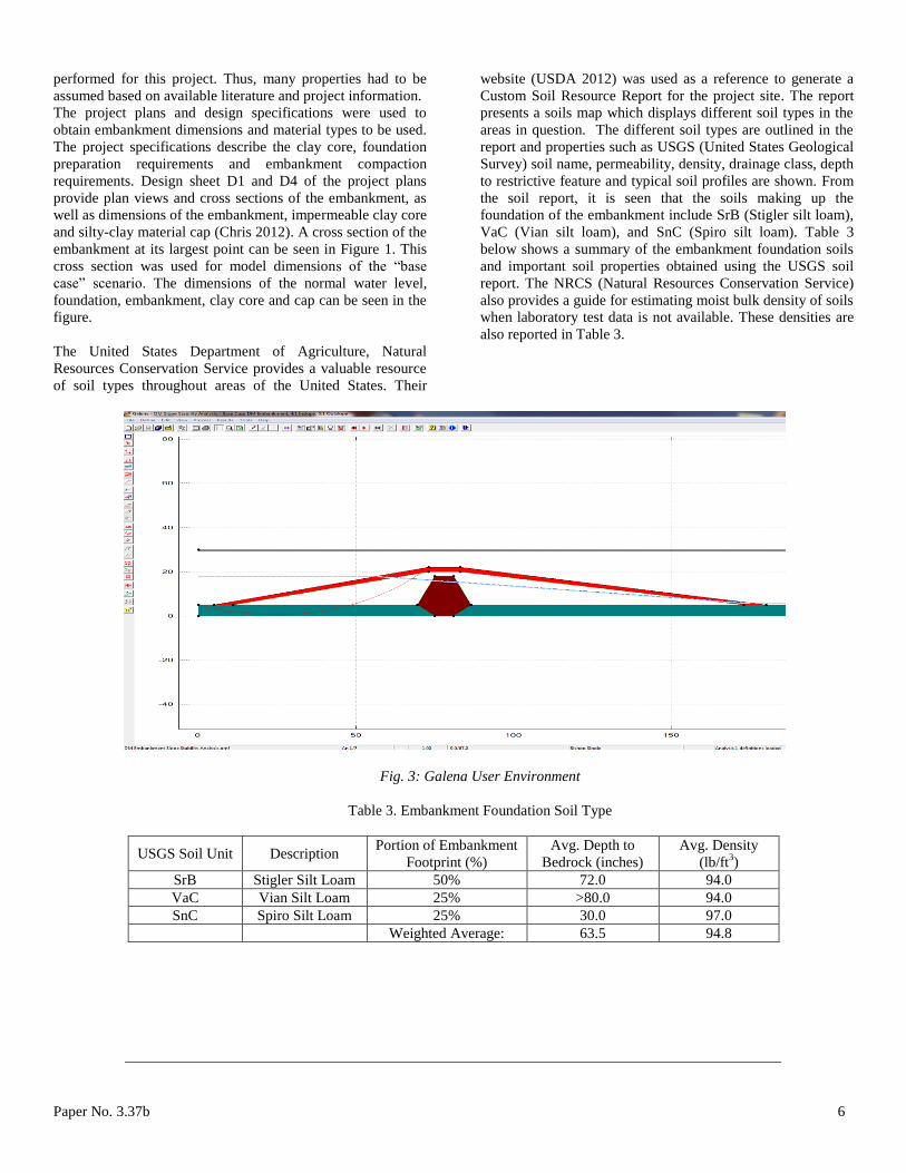
altered and shown in a graphical display. Figure 3 show a
screenshot of the Galena user environment with the
embankment for this project. The program allows for the input
of an assumed failure surface (location of failure curve, radius
of circle) and then this failure location can be altered to find
most probable failure surface with the minimum factor of
safety. The user can use a trial-and-error approach to
determine the failure surface with the lowest factor of safety
corresponding to the most probably failure surface.
PROJECT FINDINGS
Before any computer analysis could be performed with
Galena, information about the embankment needed to be
obtained. This information included material properties for
the embankment, foundation, clay core and embankment cap
such as soil types, depth of foundation, density, cohesion,
friction angle, and dimensions of the embankment and all
subsequent layers. Because of the remote location of the
project site, soil testing such as core drilling was not
Paper No. 3.37b 6
performed for this project. Thus, many properties had to be
assumed based on available literature and project information.
The project plans and design specifications were used to
obtain embankment dimensions and material types to be used.
The project specifications describe the clay core, foundation
preparation requirements and embankment compaction
requirements. Design sheet D1 and D4 of the project plans
provide plan views and cross sections of the embankment, as
well as dimensions of the embankment, impermeable clay core
and silty-clay material cap (Chris 2012). A cross section of the
embankment at its largest point can be seen in Figure 1. This
cross section was used for model dimensions of the “base
case” scenario. The dimensions of the normal water level,
foundation, embankment, clay core and cap can be seen in the
figure.
The United States Department of Agriculture, Natural
Resources Conservation Service provides a valuable resource
of soil types throughout areas of the United States. Their
website (USDA 2012) was used as a reference to generate a
Custom Soil Resource Report for the project site. The report
presents a soils map which displays different soil types in the
areas in question. The different soil types are outlined in the
report and properties such as USGS (United States Geological
Survey) soil name, permeability, density, drainage class, depth
to restrictive feature and typical soil profiles are shown. From
the soil report, it is seen that the soils making up the
foundation of the embankment include SrB (Stigler silt loam),
VaC (Vian silt loam), and SnC (Spiro silt loam). Table 3
below shows a summary of the embankment foundation soils
and important soil properties obtained using the USGS soil
report. The NRCS (Natural Resources Conservation Service)
also provides a guide for estimating moist bulk density of soils
when laboratory test data is not available. These densities are
also reported in Table 3.
Fig. 3: Galena User Environment
Table 3. Embankment Foundation Soil Type
USGS Soil Unit Description Portion of Embankment
Footprint (%)
Avg. Depth to
Bedrock (inches)
Avg. Density
(lb/ft3)
SrB Stigler Silt Loam 50% 72.0 94.0
VaC Vian Silt Loam 25% >80.0 94.0
SnC Spiro Silt Loam 25% 30.0 97.0
Weighted Average: 63.5 94.8

Paper No. 3.37b 7
Table 4. Other Embankment Materials
Material Source
Average
Density
(lb/ft3)
Friction
Angle
()
Compacted
Cohesion
(psf)
Saturated
Cohesion
(psf)
Clay Core VaC and SnC silty clay loam
(compacted) 111.4 32 2,000 300
Embankment Fill Mine Spoils (shales) 110.0 10 1,044 200
Silty Loam Cap VaC Silt Loam 97.0 28 1,550 300
Silty Clay Blanket SnC Silty Clay 97.0 25 1,750 300
Foundation VaC, SnC, SrB Soils 94.8 30 1,550 300
Because the foundation material appears to vary between these
3 soil types over the entire footprint, a weighted average
density, and depth to bedrock was assumed using the footprint
percentages of each soil type. This allowed for foundation
properties to be used in the cross-section of the Galena
computer model. The foundation depth was assumed to be 5
feet with an average density of 94.8 lb/ft3. It was assumed that
below the foundation competent rock exist as reported in
USDA soil report. Other embankment material properties can
be seen in Table 4. These material properties were also
estimated using the available literature mentioned above. Also,
a NAVFAC (1986) material properties guide provided a useful
table of approximate material properties that helped in
determination of friction angle () and cohesion (c) values for
the embankment materials. A copy of this material table is
included in report by Chris (2012). Other sources listed in the
references section of this project report were consulted for
material classification and assumed properties.
GALENA COMPUTER MODELING RESULTS
In this study embankment slope stability was analyzed by
using the Galena program. After defining all material
properties, dimensions, failure analysis method (Bishop),
phreatic surface, assumed failure surface (circle radius and
location) the program outputs a factor of safety for the
embankment. The failure surface was first assumed, and then
a trial-and-error approach was used to find the failure surface
with the lowest factor of safety.
The program allowed for multiple scenarios (analyses) to be
modeled. The eight different scenarios or analyses that were
considered as follows:
(i) Base Case (as designed). Includes clay core, spoils
and select material cap, Figure 1
(ii) Base Case without water behind embankment
(iii) Embankment with 3:1 in-slope
(iv) Embankment with 2:1 in-slope
(v) Embankment with 1:1 in-slope and 1:1 out-slope
(vi) Taller Embankment with 0.5:1 in-slope and 0.5:1 out-
slope
(vii) Same as #6 but without water behind embankment
(viii) Embankment with base case dimensions, but fully
homogeneous fill
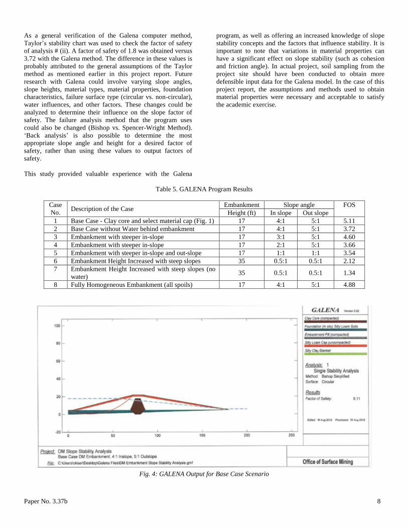
A screenshot of the Galena output file for the base case
scenario and the results of all eight analyses have been shown
in Figure 4 and Table 5, respectively. The Table 5 displays a
description of each scenario along with a corresponding factor
of safety for that scenario. Full Galena output files for all eight
scenarios can be obtained from the report by Chris [15].
For the current design (base case, analysis # (i)) the factor of
safety was found to be 5.11. This high factor of safety was
anticipated due to relatively flat slopes of the embankment as
well as the low design height of 17. From Table 2 earlier in
this project report, a 20 embankment built on clays of
medium stiffness is recommended to have a slope of at least
3:1. Thus, it is logical to obtain a higher factor of safety with
flatter slopes.
Also from Table 2, as the embankment height is increased, the
recommendations call for flatter slopes to maintain acceptable
factors of safety. The effect of slope height can be observed in
analysis # (vi), as the factor of safety was reduced to 2.12
when the embankment height was raised to 35 feet. Further
analysis can be done to compare slopes with the same slope
angles but varying heights to determine the relationships of the
slope heights on the factors of safety. The stress on the failure
surface is a direct result of the weight (and density) of the soil
above the failure surface, thus as the height is increased, this
weight of soil increases and factor of safety is reduced.
In comparing analysis # (viii) with analysis # (i), changing the
embankment to a fully heterogeneous fill (as compared with
the base case) did not have a significant effect on factor of
safety (5.11 vs. 4.88). Because slope geometry did not change
between the two analyses, the effect can be attributed to the
material properties that influence shear strength such as
cohesion (c) and friction angle (). The difference between the
two factors of safety can also be attributed to the estimated
location of the failure surface as discussed earlier in this
report.
Paper No. 3.37b 8
As a general verification of the Galena computer method,
Taylor’s stability chart was used to check the factor of safety
of analysis # (ii). A factor of safety of 1.8 was obtained versus
3.72 with the Galena method. The difference in these values is
probably attributed to the general assumptions of the Taylor
method as mentioned earlier in this project report. Future
research with Galena could involve varying slope angles,
slope heights, material types, material properties, foundation
characteristics, failure surface type (circular vs. non-circular),
water influences, and other factors. These changes could be
analyzed to determine their influence on the slope factor of
safety. The failure analysis method that the program uses
could also be changed (Bishop vs. Spencer-Wright Method).
‘Back analysis’ is also possible to determine the most
appropriate slope angle and height for a desired factor of
safety, rather than using these values to output factors of
safety.
This study provided valuable experience with the Galena
program, as well as offering an increased knowledge of slope
stability concepts and the factors that influence stability. It is
important to note that variations in material properties can
have a significant effect on slope stability (such as cohesion
and friction angle). In actual project, soil sampling from the
project site should have been conducted to obtain more
defensible input data for the Galena model. In the case of this
project report, the assumptions and methods used to obtain
material properties were necessary and acceptable to satisfy
the academic exercise.
Table 5. GALENA Program Results
Case
No. Description of the Case
Embankment Slope angle FOS
Height (ft) In slope Out slope
1 Base Case - Clay core and select material cap (Fig. 1) 17 4:1 5:1 5.11
2 Base Case without Water behind embankment 17 4:1 5:1 3.72
3 Embankment with steeper in-slope 17 3:1 5:1 4.60
4 Embankment with steeper in-slope 17 2:1 5:1 3.66
5 Embankment with steeper in-slope and out-slope 17 1:1 1:1 3.54
6 Embankment Height Increased with steep slopes 35 0.5:1 0.5:1 2.12
7 Embankment Height Increased with steep slopes (no
water) 35 0.5:1 0.5:1 1.34
8 Fully Homogeneous Embankment (all spoils) 17 4:1 5:1 4.88
Fig. 4: GALENA Output for Base Case Scenario

Paper No. 3.37b 9
REFERENCES
Day, Robert W. [2006]. Foundation Engineering Handbook.
McGraw-Hill Companies.
Hamm, Lou. [2007]. Galena Slope Stability, Analysis
Methods Background.
Engineer Manual No. 1110-2-1902 [1986]. Slope Stability,
Department of the Army Corps of Engineers.
FHWA, [2001]. Soil Slope and Embankment Design Reference
Manual. Report No. FHWA NHI-01-026.
NAVFAC, [1986]. Soil Mechanics Design Manual 7.01,
Naval Facilities Engineering Command, Alexandria, Va.
Taylor, D.W. [1948]. Fundamental of soil mechanics, John
Wiley, New York.
Janbu, N. [1968]. Slope Stability Computations. Institutt for
Geotknikk og Fundamenteringslære, Norges Tekniske
Høgskole. Soils Mechanics and Foundation Engineering, the
Technical University of Norway.
Bishop, A.W. [1955]. The Use of the Slip Circle in the
Stability Analysis of Slopes, Geotechnique, Great Britain, Vol.
5, No. 1, Mar., pp. 7-17.
Janbu, N. [1954]. Application of Composite Slip Surface for
Stability Analysis. European Conference on Stability
Analysis, Stockholm, Sweden.
Spencer, E. [1967]. A method for analysis of the stability of
embankments assuming parallel interslice forces.
Géotechnique, 17(1), 11-26.
Clover Technology [2003]. Galena Slope Stability Analysis
System User’s Guide. Version 4.0. Clover Associates Pty
Limited.
Design of Small Dams, [1987]. Third Edition. United States
Department of the Interior Bureau of Reclamation, U.S.
Government Printing Office, Washington D.C., USA.
USDA, [2012]. National Resources Conservation Service
Website. Accessed 7/31/12.
http://websoilsurvey.nrcs.usda.gov/app/WebSoilSurvey.aspx
Engineer Manual [1986]. General Design and Construction
Considerations for Earth and Rock-Fill Dams, Engineer
Manual No. 1110-2-2300. Department of the Army Corps of
Engineers.
Christopher, K. [2012]. Embankment Slope Stability Analysis
of Dwight Mission Mine Site Reclamation Project, Project
report submitted to Department of Civil & Environmental
Engineering, Southern Illinois University Carbondale, Illinois,
August 2012.
ACKNOWLEDGEMENT
Authors willing to thank US Department of the Interior, Office
of Surface Mining Reclamation and Enforcement (OSM).
Related Documents