ElmerGrid Manual CSC – IT Center for Science March 2, 2012

Welcome message from author
This document is posted to help you gain knowledge. Please leave a comment to let me know what you think about it! Share it to your friends and learn new things together.
Transcript

ElmerGrid Manual
CSC – IT Center for Science
March 2, 2012

ElmerGrid Manual
About this documentThe ElmerGrid Manual is part of the documentation of Elmer finite element software package. ElmerGridManual gives instruction on the usage of ElmerGrid, the mesh generation and manipulation utility of Elmer.
The present manual corresponds to Elmer software version 6.2. Latest documentations and programversions of Elmer are available (or links are provided) at http://www.csc.fi/elmer.
Copyright informationThe original copyright of this document belongs to CSC – IT Center for Science, Finland, 1995–2009. Thisdocument is licensed under the Creative Commons Attribution-No Derivative Works 3.0 License. To view acopy of this license, visit http://creativecommons.org/licenses/by-nd/3.0/.
Elmer program is free software; you can redistribute it and/or modify it under the terms of the GNUGeneral Public License as published by the Free Software Foundation; either version 2 of the License, or (atyour option) any later version. Elmer software is distributed in the hope that it will be useful, but withoutany warranty. See the GNU General Public License for more details.
Elmer includes a number of libraries licensed also under free licensing schemes compatible with theGPL license. For their details see the copyright notices in the source files.
All information and specifications given in this document have been carefully prepared by the best ef-forts of CSC, and are believed to be true and accurate as of time writing. CSC assumes no responsibility orliability on any errors or inaccuracies in Elmer software or documentation. CSC reserves the right to modifyElmer software and documentation without notice.
1

Contents
Table of Contents 2
1 Overview of ElmerGrid 31.1 Introduction . . . . . . . . . . . . . . . . . . . . . . . . . . . . . . . . . . . . . . . . . . . 31.2 Usage . . . . . . . . . . . . . . . . . . . . . . . . . . . . . . . . . . . . . . . . . . . . . . 31.3 Input formats . . . . . . . . . . . . . . . . . . . . . . . . . . . . . . . . . . . . . . . . . . 51.4 Output formats . . . . . . . . . . . . . . . . . . . . . . . . . . . . . . . . . . . . . . . . . 61.5 ElmerGrid command-line arguments . . . . . . . . . . . . . . . . . . . . . . . . . . . . . . 6
2 ElmerGrid format 112.1 ElmerGrid keywords . . . . . . . . . . . . . . . . . . . . . . . . . . . . . . . . . . . . . . 112.2 Command file keywords . . . . . . . . . . . . . . . . . . . . . . . . . . . . . . . . . . . . 142.3 Mapping modes . . . . . . . . . . . . . . . . . . . . . . . . . . . . . . . . . . . . . . . . . 17
3 ElmerGrid mesh generation examples 183.1 2D examples . . . . . . . . . . . . . . . . . . . . . . . . . . . . . . . . . . . . . . . . . . 183.2 3D examples . . . . . . . . . . . . . . . . . . . . . . . . . . . . . . . . . . . . . . . . . . 233.3 1D examples . . . . . . . . . . . . . . . . . . . . . . . . . . . . . . . . . . . . . . . . . . 30
4 ElmerGrid mesh manipulation examples 324.1 Mesh partitioning . . . . . . . . . . . . . . . . . . . . . . . . . . . . . . . . . . . . . . . . 324.2 Boundary layer creation . . . . . . . . . . . . . . . . . . . . . . . . . . . . . . . . . . . . . 334.3 Mesh extrusion . . . . . . . . . . . . . . . . . . . . . . . . . . . . . . . . . . . . . . . . . 34
5 ElmerGrid Interface Examples 365.1 Ansys mesh to Elmer . . . . . . . . . . . . . . . . . . . . . . . . . . . . . . . . . . . . . . 365.2 Comsol Multiphysics to Elmer . . . . . . . . . . . . . . . . . . . . . . . . . . . . . . . . . 375.3 Triangle mesh to Elmer . . . . . . . . . . . . . . . . . . . . . . . . . . . . . . . . . . . . . 37
2
Chapter 1
Overview of ElmerGrid
1.1 IntroductionElmerGrid is a simple mesh generator and mesh manipulation utility. It is an appropriate tool for generatingstructured meshes for simple 2D and 3D geometries. It can also read meshes generated by other meshgenerators and manipulate them. Among the possible operations are scaling, changing of element type,defining boundaries, or partitioning the mesh for parallel solution, for example.
ElmerGrid was originally a side product of research done in the area of silicon carbide crystal growth.The main goal was to write a simple mesh generator for multiphysical problems where different meshesbased on the same geometry were needed for different physical problems. Since that the software has beenmodified to meet the needs of Elmer development. Thus the name has been changed from Quickmesh toElmerGrid. Because ElmerGrid was never designed to be an stand-alone mesh generator it has been devel-oped in on uncontrolled manner. The data structures are not optimal for all the added features. Therefore thesoftware may at times cause problems.
This chapter shortly describes the main capabilities of the program.
1.2 UsageThe executable binary of the program is named ElmerGrid. It may be started with no arguments at all.Then the following help text is automatically displayed.
Starting program Elmergrid
****************** Elmergrid ************************This program can create simple 2D structured meshes consisting oflinear, quadratic or cubic rectangles or triangles. The meshes mayalso be extruded and revolved to create 3D forms. In addition manymesh formats may be imported into Elmer software. Some options havenot been properly tested. Contact the author if you face problems.
The program has two operation modesA) Command file mode which has the command file as the only argument
’ElmerGrid commandfile.eg’
B) Inline mode which expects at least three input parameters’ElmerGrid 1 3 test’
The first parameter defines the input file format:1) .grd : Elmergrid file format2) .mesh.* : Elmer input format
CSC – IT Center for Science
1. Overview of ElmerGrid 4
3) .ep : Elmer output format4) .ansys : Ansys input format5) .inp : Abaqus input format by Ideas6) .fil : Abaqus output format7) .FDNEUT : Gambit (Fidap) neutral file8) .unv : Universal mesh file format9) .mphtxt : Comsol Multiphysics mesh format10) .dat : Fieldview format11) .node,.ele: Triangle 2D mesh format12) .mesh : Medit mesh format13) .msh : GID mesh format14) .msh : Gmsh mesh format15) .ep.i : Partitioned ElmerPost format
The second parameter defines the output file format:1) .grd : ElmerGrid file format2) .mesh.* : ElmerSolver format (also partitioned .part format)3) .ep : ElmerPost format
The third parameter is the name of the input file.If the file does not exist, an example with the same name is created.The default output file name is the same with a different suffix.
There are several additional in-line parameters that aretaken into account only when applicable to the given format.-out str : name of the output file-in str : name of a secondary input file-decimals : number of decimals in the saved mesh (eg. 8)-triangles : rectangles will be divided to triangles-merge real : merges nodes that are close to each other-order real[3] : reorder elements and nodes using c1*x+c2*y+c3*z-centralize : set the center of the mesh to origin-scale real[3] : scale the coordinates with vector real[3]-translate real[3] : translate the nodes with vector real[3]-rotate real[3] : rotate around the main axis with angles real[3]-clone int[3] : make ideantilcal copies of the mesh-clonesize real[3] : the size of the mesh to be cloned if larger to the original-mirror int[3] : copy the mesh around the origin in coordinate directions-unite : the meshes will be united-polar real : map 2D mesh to a cylindrical shell with given radius-cylinder : map 2D/3D cylindrical mesh to a cartesian mesh-reduce int[2] : reduce element order at material interval [int1 int2]-increase : increase element order from linear to quadratic-bcoffset int : add an offset to the boundary conditions-discont int : make the boundary to have secondary nodes-connect int : make the boundary to have internal connection among its elements-removelowdim : remove boundaries that are two ranks lower than highest dim-removeunused : remove nodes that are not used in any element-bulkorder : renumber materials types from 1 so that every number is used-boundorder : renumber boundary types from 1 so that every number is used-autoclean : this performs the united action of the three above-bulkbound int[3] : set the union of materials [int1 int2] to be boundary int3-boundbound int[3] : set the union of boundaries [int1 int2] to be boundary int3-bulktype int[3] : set material types in interval [int1 int2] to type int3
CSC – IT Center for Science

1. Overview of ElmerGrid 5
-boundtype int[3] : set sidetypes in interval [int1 int2] to type int3-layer int[2] real[2]: make a boundary layer for given boundary-layermove int : apply Jacobi filter int times to move the layered mesh-divlayer int[2] real[2]: make a boundary layer for given boundary-3d / -2d / -1d : mesh is 3, 2 or 1-dimensional (applies to examples)-isoparam : ensure that higher order elements are convex-nobound : disable saving of boundary elements in ElmerPost format
The following keywords are related only to the parallel Elmer computations.-partition int[4] : the mesh will be partitioned in main directions-partorder real[3] : in the above method, the direction of the ordering-metis int[2] : the mesh will be partitioned with Metis-halo : create halo for the partitioning-indirect : create indirect connections in the partitioning-periodic int[3] : decleare the periodic coordinate directions for parallel meshes-saveinterval int[3] : the first, last and step for fusing parallel data
Thank you for using Elmergrid!Send bug reports and feature wishes to [email protected]
As may be seen the user may choose between several input and output formats. The format is specifiedby an integer number (or an appropriate string) and the filename that is given may or may not have theappropriate suffix.
1.3 Input formatsThe ElmerGrid code has two different operation modes. In the one all the information is read from a com-mand file. Alternatively all necessary data may be read from from the inline arguments.
The native formats of the code are thus the command file with the suffix .eg and the native geometryformat that has the suffix .grd. Note that most commands that may be given in the command file may alsobe given in the geometry format.
Additionally there are several other input formats that helps in linking the Elmer software with other pre-and postprocessors. The other formats may not always be used to create a complete model with boundaryconditions. Also their functionality does not include all the possible commands.
1) .grd : ElmerGrid file formatThe native ElmerGrid format is described in a separate section.
2) .mesh.* : Elmer output formatInput format for ElmerSolver consisting of separate header, node, coordinate and topology files.
3) .ep : Elmer input formatThis format is the same that ElmerSolver uses in saving the results to be postprosessed with ElmerPost.
4) .ansys : Ansys input formatThis format is the input format created by the preprosessor of Ansys using a special Ansys macro. Anexample is given in later chapters.
5) .inp : Abaqus input format by IdeasThis format is the input format created by Ideas preprocessor for Abaqus.
6) .fil : Abaqus output formatThis format is the output format created by the solver of Abaqus.
7) .FDNEUT : Fidap neutral fileAlso created by Gambit, the preprocessor of Fluent.
CSC – IT Center for Science

1. Overview of ElmerGrid 6
8) .unv : Universal mesh file formatA subset of the universal mesh file format commands may be read by ElmerGrid.
9) .mphtxt : Comsol mesh formatThe phhtxt format created by Comsol Multiphysics.
10) .dat : Fieldview formatThis may be used with Gridgen preprocessor.
11) .node,.ele: Triangle 2D mesh formatRead in meshes created by Triangle 2D Delaunay mesh generator.
.mesh : Medit mesh formatFormat of Medit mesh generation program.
13) .msh : GID mesh formatFormat of GID mesh generation program.
14) .msh : Gmsh mesh formatFormat of Gmsh mesh generation program.
15) .ep.i : Partitioned ElmerPost formatPartitioned Elmer results created by parallel computing.
1.4 Output formatsThe supported output formats are all different formats of Elmer software. Additionally, there are someundocumented formats. Thus, if you need to export some data from Elmer format you may ask for thepossibilities.
1) .grid : ElmerGrid file formatThe native format, may be used to refresh the input file if it becomes corrupted or outdated.
2) .mesh.* : ElmerSolver file formatFormat that may be used in Elmer calculations. In a single-processor version the input is dividedto four different files with suffixes, mesh.boundary, mesh.elements, mesh.header andmesh.nodes.
The command-line parameters -part and -metis activate the partitioned input format for theElmerSolver. The ending is .part.* and the files are saved to subdirectory with suffix .part.n,where n is the running number of the partition.
3) .ep : ElmerPost file formatFormat for Elmer postprosessing. This is particularly handy for tuning the mesh before it is used in thesolution. Then the only variable that is saved is the node index referred to by field variable Number.
1.5 ElmerGrid command-line argumentsElmerGrid has a lot of simple functionalities that may be activated with the right command-line arguments.Most of them may operate on all meshes, some or limited to 2D meshes, for example.
In the command-line operation mode there are only three mandatory arguments: The input format, theoutput format, and the name of the input file. All other arguments are optional.
-out StringGives an alternative name for the output file or directory. The default name is the same as the name ofthe input file attached with an appropriate suffix.
CSC – IT Center for Science

1. Overview of ElmerGrid 7
-in StringSometimes there are may be more than one input mesh. Then the name of the secondary input filemay be given after this keyword.
-decimals IntegerThe number of decimals for Elmer mesh is by default set to 6. Sometimes more decimals may beneeded and this command may then be used. This could be the case, for example, if the elements aresmall compared to the absolute values of the coordinates. The size of the ascii file is affected by thenumber of decimals and therefore the default is quite small.
-trianglesThe meshes consisting of rectangles may be divided into triangles. This operation may be performedon all 2D meshes, not only to the ones created using ElmerGrid format.
-merge RealSometimes when creating the computational mesh the different domains are not properly joined. Thenit is possible to use this option, where nodes that are close to each other are fused. The value givenfor the node separation should be smaller than the smallest element size. Otherwise there is a risk ofruining the mesh.
For optimal computational efficiency the merging of nodes is done in two stages. In the first stagethe nodes are ordered and in the second stage the nodes close to each other are checked for distance.If distance is smaller than the critical one the nodes are given one common coordinate and the othernode is eliminated from the holes mesh.
-order Real[DIM]The nodes may be ordered if the original ordering is uneconomical. The three components gives thedirection in which the nodes are reordered. More accurately, the nodes are ordered using the dotproduct ~c · ~r as a measure. The reordering of the degrees of freedom is usually performed withinElmerSolver and therefore it is usually not necessary to renumber the nodes within ElmerGrid.
-scale Real[DIM]This simply scales the coordinates of the mesh by multiplying with the given constants, i.e. x := cxx,y := cyy and z := czz. This is useful, for example, if the mesh is in other units that is preferable.
-translate Real[DIM]This option translates the mesh with a given vector by simly adding the given values to the originalcoordinates, i.e. ~r := ~r + ~r0.
-rotate Real[3]The mesh may be rotated around the main axis. The rotation is done consecutively in all three angles.This feature may be handy in the debugging of some equation – in cartesian grids the solution shouldbe rotation invariant.
-clone Integer[DIM]The mesh may be copied so that the same structure is repeated over and over. The number of copies ineach coordinate direction may be given independently. The total number of individual copies is theirproduct.
-clonesize Real[DIM]By default the copies of the mesh are performed so that the new meshes are set directly besides theold ones. This flag may be used to define a larger size for the mesh which enables empty space beingleft between the meshed.
-mirror Integer[DIM]The mesh may be mirrored over the main axis. The arguments tell over which axis the mesh should bemirrored. If all three axis are active then the original mesh will be eight times the size of the originalone. Note that the origin is assumed to be at zero in all directions.
CSC – IT Center for Science

1. Overview of ElmerGrid 8
-uniteThis option unites the ElmerGrid meshes. In every other format its currently not possible to createmore than one mesh at a time.
-polar RealThis option maps the 2D mesh an a cylindrical shell with the radius given as a parameter.
-cylinderThis option assumes that the original 3D mesh was given in cylindrical coordinates (r, θ, z) and mapsthem to cartesian coordinates (x, y, z).
-reduce int[2]This feature reduces the element order of materials at the interval defined by the two parameters. Itmay be used to lower the element order only in parts of the geometry. For example, in fluid-structure-interaction the fluid could be modeled with linear elements while the structure might need secondorder elements.
-increaseIncrease the element order in all the elements from one to two. This may be used to improve compu-tational accuracy of existing linear meshes by making the quadratic.
-bcoffset IntegerAdds on offset to the boundary condition numbering. This may be usefull for multimesh computationswhere it is advisable that the same boundary numbers are not defined in different meshes.
-discont IntegerSometimes the field variables behave discontinuously over a short distance. For example, in solvingthe heat equation there may be a small gap between different bodies. To account for such discontinu-ities the mesh should have duplicate nodes over the discontinuity. This feature does exactly that andsaves the boundary conditions for both sides.
-connect IntegerMakes the boundary to have internal connections between among its elements. This will enable con-nections in the resulting finite element matrices. The feature could be used in setting constraints in thefinite element solution.
-removelowdimRemoves boundary elements that are two or more dimensions lower than the highest dimensional bulkelements.
-bulkorderRenumbers the body indexes so that every number is used. This feature may be handy particularlywhen importing meshes that have a very wild numbering of bodies.
-boundorderRenumbers the boundary element types so that every number is used. This feature may be handyparticularly when importing meshes that have a very wild numbering of boundary elements types.
-autocleanThis flag activates several of the above procedures that simplifies the mesh for solution purposes. Thelower dimensional boundary elements are removed, and the body and boundary element types arerenumbered.
-bulkbound Integer[3]Sometimes the geometry does not include all the necessary boundary conditions. Then this inlineparameter may be used to define a new boundary (first parameter) on the interval of the two givenmaterials.
CSC – IT Center for Science

1. Overview of ElmerGrid 9
-boundbound Integer[3]Sometimes the geometry does not include all the necessary boundary conditions. Then this inlineparameter may be used to define a new boundary (first parameter) on the interval of two alreadyexisting boundaries. This makes it possible to define lines or even single points in 3D geometry thathas only surfaces defined.
-bulktype Integer[3]Sometimes there is a multitude of bodies that may be united with this option. It may be easier toperform the further analysis if the number of bodies is not too large. For example, in ElmerPost a verylengthy list of bodies or boundaries is difficult to visualize.
-boundtype Integer[3]This option does exactly the same as the above but now for the boundary elements. Again the ad-vantage may be that the command-file will be more economical as if the number of boundaries isreduced.
-layer Integer[2] Real[2]This option may be used to create boundary layers on an existing 2D mesh. The given boundary isextruded with the given number of layers. Also the total thickness of the layer and the desired ratiobetween first and last element is given.
-layermove intThis option activates a filter that is used to map the node coordinates so that the boundary layers arefitted within the original geometry.
-divlayer Integer[2] Real[2]This option may be used to create boundary layers on an existing 2D mesh. The layer is created bysplitting the trinagles or quadrilaterals along the boundary to give a structured boundary laer mesh.
-3d / -2d / -1dThis option is usually not needed as the files most often have the information of the space dimension.The exception is the creation of an example file. 3D is the default, thus the -2d should be used if onewants to create a 2D example file. Also some command-line parameter lists are by default assumed tohave three values if 2D dimension is not given.
-isoparamIn creating mapped meshes by ElmerGrid the higher-order nodes may sometimes be oddly displaced.This utility sets the intermediate nodes to lie on the connecting lines between the corner nodes.
-noboundDisable the saving of boundary elements. This may sometimes be useful if there are a lot of boundariesand one is just interested in the bulk elements.
There are a number of in-line parameters that are related only to the parallel Elmer computations.
-partition Integer[DIM+1]There are two methods to partition geometry for parallel computing. This method takes each coordi-nate direction and divides the mesh in the number of slices given in the parameter list. For exampleoption -part 2 3 5 would split the mesh into 2 × 3 × 5 = 30 partitions. Each split is done sothat the number of elements in each partition is almost equal. The method is best suited for simplegeometries where more generic strategies usually do not work as well.
The last flag is an optional flag which defines whether the geometric division is done primarily for thenodes or the elements. For value 0 the partition is first done for elements and thereafter for nodes,while for value 1 the order is opposite.
-partorder Real[DIM]The simple partitioning is done by dividing the elements into subgroups. The division is done by firstordering the nodes. This keyword is followed by the normal vector of the desired ordering.
CSC – IT Center for Science

1. Overview of ElmerGrid 10
-metis Integer[2]This utility does the partitioning utilizing the Metis library, see http://glaros.dtc.umn.edu/gkhome/views/metis. Metis has subroutines for basic linear elements. Also higher order ele-ments may be partitioned by first neglecting the higher order nodes.
The first integer defines the number of partitions while the second relates to the partitioning routine ofMetis. The following subroutines may be used when ablicable,
0: METIS PartMeshNodal
1: METIS PartMeshDual
2: METIS PartGraphRecursive
3: METIS PartGraphKway
4: METIS PartGraphVKway
In partitioning a major problem is to save just the right information needed by each processor. Thereare some very complicated dependencies that result from the parallel solution of the matrix equations.To simplify these the communication, ElmerGrid does some load-balancing so that each processorsowns roughly as many shared nodes. Also on the interfaces of more than two partitions the ownershipis optimized so that nodes cannot be indirectly related to each other in a way that is in conflict withthe parallel solution algorithm.
Note that this option may not be active if the code has been compiled without the Metis library.
-haloThis flag creates a halo for the partitioning. This must be provided, for example, in discontinuousGalerkin computations where at the boundaries the gradient information must also be computed.
-indirectCreates the indirect connections in the partitioning. These are connections in a finite element matrixthat exist between two nodes but would not be apparent if only the partition in question would bestudied.
-periodic Integer[3]If the solution of the mesh is known to be periodic ElmerSolver uses a special kind of boundarycondition. Also in partitioned meshes used in parallel computation the periodic boundaries must beknown as they require the flow of information between opposing sides. This option finds periodicboundaries in the given directions given by 0/1 logical values. If periodic boundary is found it is takeninto account in saving and partitioning the mesh. The determination of the periodic nodes only workswhen there is one-to-one mapping between the nodes on the boundaries.
CSC – IT Center for Science

Chapter 2
ElmerGrid format
The native mesh definition format of the program is the ElmerGrid format that has the suffix .grd. If theuser gives a name for the input file that doesn’t exist a simple geometry file is automatically created by theprogram. This may then be edited by any text editor to suite the needs of the particular case.
The ElmerGrid parser is not very bright. It knows only a handful of keywords. If the default values areused the corresponding commands may be neglected. The commands usually assume a format where the thekeyword is followed by its arguments. If the arguments are on the same line then a equality sign “=” shouldbe used in between. The parser is not case sensitive and thus the keywords may be written with capital orsmall letters, or any combination of them.
2.1 ElmerGrid keywordsVersion 210903
Gives the version of the current input file. This should not be changed unless the format is changed.The parser should be downward compatible also with the older format of the input file but the newformat is preferred.
MATC LogicalSetting this keyword to be true activates the MATC parser. As an effect all statements starting withthe $ sign will be evaluted by MATC. This enables parametrisized mesh generation, for example. Formore information look at the MATC manual. Note that if this does not work the version of ElmerGridmay have been compiled without MATC.
Coordinate System StringThe choices are Cartesian 1D, Cartesian 2D, Cartesian 3D, Polar and Axisymmetric. Axisymmetricand Cartesian 2D have currently no difference. A cartesian 3D grid is the default.
Subcell Divisions Integer[DIM]The mesh is composed of subcells that are topologically squares. This keywords should be followedby the number of subcells in the main directions, n1, n2 and n3. Thus the number of arguments maybe 1, 2 or 3 depending on the dimension of the geometry definition.
Subcell Limits i Real[]The size of the subcells are defined by ni + 1 boundaries in each coordinate direction. These valuesdefine the physical dimensions of the mesh before possible manipulation. This keyword exists for allactive coordinate directions.
Subcell Sizes i Real[]An alternative way to give the subcell sizes is to give the size of each subcell in each coordinatedirection. The subcell limits are then the cumulative sum of these sizes.
CSC – IT Center for Science
2. ElmerGrid format 12
Subcell Origin i Real[]When the subcells are defined by the sizes the user may also define the origin in each direction. Theorigin may be a real number or also some of the following strings, Left, Center, Right.
Material Structure Integer[][]The subcells form a n1 ×n2 matrix in 2D. The material structure of this plane may therefore be givenby a matrix consisting of integers relating to different materials. These numbers may then later bereferred when creating the mesh and boundary conditions. In 1D the structure is simply a vector. In3D the material structure refers to the structure of the xy-plane before extrusion of rotation takes place.
Materials Interval Integer[2]Elements are created only for those materials that lie in the interval defined by the two integers. Thisis on easy way to define different meshes for different physical phenomena. In 3D the interval refersto the materials that should be present in the extrusion.
Extruded SructureThe keyword may be used to define the layered structure of the geometry. Otherwise the extrudedstructure is just the same as the material structure in the plane. The definition must include n3 lineswith three integers on each. The first two integers define the materials interval that is extruded and thethird one the new material index of the extruded layer. Materials outside the interval are not extrudedand therefore materials may selectively be dropped out during extrusion process. If the new materialhas value zero then the corresponding material layer in the extruded structure remains unaltered. Thisfeature may, for example, be useful in MEM-applications.
When the 2D geometry is extruded the rectangular elements 404, 408 and 409 result to elementtypesare 808, 820 and 827 (using Elmer notation). Also linear triangles may be extruded and they result tolinear prisms of type 606.
Geometry MappingsThe grid is by default rectangular since all the subcells are also rectangular. Non-rectangular shapesmay be introduced my mapping the straight lines separating the subcells to lines represented by ana-lytical functions. The mapping may be performed in the xy-plane or out of the plane. The number ofthe mappings is calculated automatically and therefore the field should be ended by End.
If the mode of the mapping is more than 50 then the mapping is performed out of plane while mappingsin the plane is the default. Mapping out of the plane makes the 2D plates to become 3D shells.
This keyword activates mappings as in the case of mappings in plane but now the mapping is per-formed out of the plane. Thus the 2D geometry becomes 3D geometry. This way some simple 3Dshells may be created. If in addition, the coordinate system is set to be polar this third coordinate istreated as radius r and the second coordinate as angle φ.
Polar Radius RealIf the coordinate system is chosen to be polar then the values defining the are (z, θ). When saving themesh these are mapped into cartesian coordinates. There may be on offset in the radius when usingthe polar coordinates. This value is then added to the value of the r-coordinate before making thecoordinate transformation. This would result into simple pipes, for example. In addition there is apossibility to have the radius change as a function of position using special mappings.
Revolve Radius RealThere are three keywords that may be used to define how a 2D mesh is revolved around the y-axisto create 3D cylindrical meshes. Defining any of the keywords enforces revolation. Simple rotationwould result to singular elements at the origin. Therefore a square block is set at the origin. Bydefault this square has the same x-coordinate as the first subcell in x-direction. In rotation the materialstructure remains unaltered.
Revolve Blocks IntegerThe keyword has a parameter 1, 2, 3 or 4 depending on how many degrees of rotation is desired. Thevalues correspond to rotation of 90, 180, 270 or 360 degrees. If there is less than 4 blocks the programfinds the sides that form the symmetry axis and creates additional boundaries from them.
CSC – IT Center for Science

2. ElmerGrid format 13
Revolve Improve RealThis keyword controls the quality of the rotated mesh. The rotation creates elements that are notrectangular as the whole angle of 360 degrees needs to be divided between 3 elements. The defaultvalue for this keyword is one which means that the inner block is a square. The value zero results tothe angle being equally divided to three 120 degree angles by the three elements.
Revolve Curve Direct RealThe rotate structure may have a curve. This defines the direct part of the curve.
Revolve Curve Angle RealThis defines the angle of the curve.
Revolve Curve Radius RealThis defines the radius of the curve.
Boundary DefinitionsThere may be several boundaries. Each is defined by a line of four parameters. Note that this fieldshould be finished by End.
Each boundary requires a type that refers to the number of the boundary condition. It may then laterbe referred to when setting up the boundary conditions. The boundaries are created in such a way thatthe material int should have elements created. The out may be an empty subcell. If the value of theflag double is 2 or more secondary nodes on the boundary will be created. This enables the use ofdiscontinuous boundary conditions.
It is also possible to create boundary conditions on a given side of a material. The number −1 refersto down, −2 to right, −3 to top and −4 to left. This means that the boundary is created on the givenside of the material that is specified by the other index.
In order to make the creation of the boundary condition more robust there are some special numbersthat may be used. −11 refers to smaller, −9 to bigger, and −10 to anything. For example, if theintmat is 5 and the outmat is −9, then the boundary is created for all materials that have a largermaterial number than 5 and have a common boundary with material 5. This makes it possible to createseveral material boundaries with one definition.
Numbering Vertical/HorizontalThe keyword enforces the numbering of nodes and elements. The numbering affects the bandwidth ofthe resulting matrix equation. The numbering should rather be performed by the shorter axis.
Reference Density RealThis keyword defines the local global mesh parameter h that sets the maximum size of an element.Additionally a local element density may be defined with respect to this.
Surface Elements IntegerThis keyword may be used to roughly determine the number of elements on the surface. This uniquefeature makes it possible to change the mesh density by altering just one figure in the mesh definitionfile. Using the constraints on the relative mesh densities the program then tries to match this givennumber.
Volume Elements IntegerIn 3D it is not as easy to obtain the desired number of elements. In this case the desired number ofsurface elements if altered iteratively until also the number of volume elements is close to the desiredone.
Volume Nodes IntegerInstead of trying to meet the desired number of elements one may also try to optimize the number ofnodes using this keyword.
Element Degree IntegerThe mesh generator may produce linear, quadratic and cubic elements. The elements are initiallyalways topologically rectangles and may have 4, 5, 8, 9, 12 or 16 nodes.
CSC – IT Center for Science

2. ElmerGrid format 14
Element Midpoints LogicalFor higher order elements the user may choose whether to create nodes inside the elements. Forexample a second order rectangle may have 8 or 9 nodes. The default is False.
Triangles LogicalElmerGrid makes originally structured quadrilateral meshes. These may be divided into triangles usingthe shorter of the diagonals. The resulting mesh is still structured and often inferior in computations.For some purposes triangular meshes may however be favored. The default is False.
The quadrilateral elements may have 4, 5, 8, 9 or 16 nodes. The elements with 4, 9 and 16 nodes aredivided into two and the element with 5 nodes into four, correspondingly. The 8-node element cannotbe divided.
If the mesh is also extruded the triangles become prisms. In this case only linear triangles are applica-ble.
Elementtype IntegerAn alternative way to define the elementtype is to define the element type as in Elmer software. Theallowed types are 303, 306, 310, 404, 405, 408, 409, 412 and 416. Then the three flags above aretuned accordingly.
Coordinate Ratios Real[DIM-1]By default the relative density of the coordinate directions is the same. This keyword affects the meshdensity ratio between different directions. Thus the dimension is one less than the space dimensions.
Element Ratios i Real[]Defines the ratio of the first and last element in the particular subcell in direction i. The defaultvalue is 1. Does not compare the mesh density with other subcells. The ratio must be given for eachcoordinate direction separately. Value close to unity leads to linear meshing. Negative values activatesymmetric density profile within the subcell.
Element Densities i Real[]This keyword refers to densities compared to other subcells in direction i. The default value is 1. Alarger value means local mesh refinement on that particular subcell.
Minimum Element Divisions Integer[DIM]This keyword defines the minimum number of elements within each subcell for each coordinate di-rection. The default is 1 1 2, this is also the set of minimum values that may be used.
Element Divisions i IntegerThis keywords sets the number of elements in direction i in the subcells absolutely. Therefore itoverrides the desired number of elements and the relative element densities. By default the relativemesh density definition is used.
Start New MeshThe format includes the possibility to generate multiple meshes using one input file. This keywordinvokes the start of a new mesh. All properties are inherited from the previous mesh and therefore thenew mesh may be defined only by few changes.
2.2 Command file keywordsSometimes the necessary commands in the using the inline parameters should create an exhaustive andnoninformative list. Therefore most of the inline parameters may also be given in an command file. Here thedescription only deals only with the command file syntax. For other information on these commands a moreaccurate description will be found in the previous chapter where the inline arguments where explained.
Note that these commands may also be put to the end of the ElmerGrid mesh definition file.
CSC – IT Center for Science

2. ElmerGrid format 15
Input File StringThe name of the input file. The default name the same as the name of the command file (if any)attached with an appropriate suffix.
Output File StringThe name of the input file. The default name is the same as the name of the input file attached with anappropriate suffix.
Input Mode String/IntegerThe name of the Input mode or the corresponding integer. The choices are ElmerGrid(1), Elmer-Solver(2), ElmerPost(3), Ansys(4), Ideas(5), Abaqus(6), Fidap(7), Easymesh(8), FemLab(9), Field-view(10) and Triangle(11).
Output Mode String/IntegerThe name of the Input mode or the corresponding integer. The choices are ElmerGrid(1), Elmer-Solver(2), ElmerPost(3).
Decimals IntegerThe number of decimals in output.
Triangles LogicalDivide rectangles into triangles.
Merge Nodes RealMerges nodes close to one another, |~r − ~r0| < ε.
Unite LogicalUnite different meshes, default is False.
Order Nodes Real[DIM]Orders the nodes using ~c · ~r as the measure.
Scale Real[DIM]Scale the mesh coordinates.
Translate Real[DIM]Translate the mesh with the given vector.
Rotate Real[DIM]Rotate the mesh around the main axis with the given degrees.
Clone Integer[DIM]Make a multiple copies of the mesh.
Clone Size Real[DIM]The size of the mesh to be cloned.
Mirror Real[DIM]Mirror the mesh around the main axis.
Polar Radius RealGives the radius of the 2D mesh in polar coordinates and also enforces the new coordinate system.
Reduce Degree Integer[2]Reduces the element degree in the given interval.
Increase Degree LogicalIncrease the degree. Default is False.
CSC – IT Center for Science

2. ElmerGrid format 16
Power ElementsThis keyword activates the p-elements. There may be several p-element definition. Is has a separateline and defines with three integers the interval on which the p-element is applied and the power of theelement. The field should be ended with End.
Partition Integer[DIM]Activates the simple mesh partitioning. Gives the number of divisions in each coordinate direction.
Partition Order Real[DIM]The ordering used in making the simple partitioning.
Metis IntegerActivates the Metis partitioning.
Periodic IntegerEnforces periodic boundary conditions with the partitioning algorithms.
Material BoundaryDefine boundaries between materials. Each boundary is an a separate line and the field should beended with End
Boundary BoundaryDefine boundaries between boundaries. Each boundary is an a separate line and the field should beended with End
Renumber MaterialRenumbers the materials on the given interval to be of desired type. Each renumbering is an a separateline and the field should be ended with End
Renumber Boundary Integer[3]Renumbers the boundaries on the given interval to be of desired type. Each renumbering is an aseparate line and the field should be ended with End
Isoparametric LogicalSets the intermediate nodes in elements to be in between the corner nodes.
No Boundary LogicalDisables the saving of boundary information. Default is False.
Extruded Divisions IntegerA two-dimensional mesh may be extruded to multiple layers. This keyword gives the number ofsubcell in the extruded direction n3.
Extruded Limits Real[n3 + 1]The dimensions of the extruded layers.
Extruded Elements Integer[n3]The number of elements in each extruded layer.
Extruded Ratios Real[n3]Defines the ratio of the first and last element in the particular subcell in the extruded direction.
Extruded StructureFunctionality as in the ElmerGrid geometry format.
CSC – IT Center for Science

2. ElmerGrid format 17
2.3 Mapping modesThe use of different mapping options is quite an unintuitive matter. Unfortunately it is the only way tocreate non-rectangular shapes in ElmerGrid. The mesh mapping is activated by the keyword GeometryMappings. There are several mapping modes that define the type of mapping.
Most of the mappings operate on the lines separating different subcells. Positive mode refers to mappingof horizontal lines, and negative mode to mapping of vertical lines. The limits of the mapping define thedistance at which the mapping of the line settles down. If the distance is large compared to the size ofgeometry then the same mapping is performed to the whole geometry.
Several mappings may be applied at the same time. The coordinates are then mapped as a linear combi-nation of the individual mappings. Mappings may also be performed consecutively up to five levels. This isobtained by adding the figure 10 to the mode. Mappings of the same level are done at the same time whilemappings of different levels are done at on increasing order of modulo 10s.
In order to perform mappings out of plane a value of 50 may be added in the mapping mode.The parameters used in the mapping vary from case to case. Note that if a vertical line is mapped the
coordinates x and y are switched.
1: piecewise linearParameters are (x0, dy0), (x1, dy1), (x2, dy2), . . . Between the points linear interpolation is used.
2: piecewise power lawParameters are (x0, dy0), b1, (x1, dy1), b2, (x2, dy2), . . . Between the points the values for dy areinterpolated from ai(x − xi)bi .
3: piecewise circle arcParameters are (x0, dy0), r1, (x1, dy1), r2, (x2, dy2), . . . Between the points the values for dy arecalculated assuming that there is a circle with radius ri drawn through the lines. If radius is larger thanzero the origin of the circle is above the mapped line and vice versa.
4: line to circleParameters are x0, r0, x1, r1, . . . Different from other models also the other coordinate is transformed.In order to get a circle with radius ri as a result there must initially be a square with side length 2ri.The line to be mapped is originally one of the sides of this squares.
5: line to sinusParameters are x0, x1, c, dy1, where c is the number of waves between x0 and x1 and dy1 is the heightof the wave.
6: line to power seriesParameters are x0, x1, a0,. . . ,ai and the displacement is then
∑i aiu
i, where u is x normalized be-tween 0 and 1.
7: line to power series variationParameters are x0, x1, a0,. . . ,an and the displacement is then
∑i aipi(u), where u is x normalized
between 0 and 1. The polynom p0 = 1, p1 = u, p2 = u(u − 1), p3 = u(u − 1/2)(u − 1),p4 = u(u − 1/3)(u − 2/3)(u − 1), . . .
8: piecewise constant angleParameters are (x0, φ0), (x1, φ1), (x2, φ2), . . . This is used to create 3D shells only. The angle of theshell is φi if x ∈ [xi, xi+1]. May be used to create polygonal shells.
CSC – IT Center for Science

Chapter 3
ElmerGrid mesh generation examples
3.1 2D examples
Unit square: rect.grdThe first example is a simple unit square. The input file is the simplest possible as the geometry consistsof 1 × 1 subcells. The boundaries in x- and y-directions are 0 and 1. The desired number of elements is100 and the distribution is uniform. There is one boundary created that includes all four sides of the square.They are found by the fact that they are at the 0-1 material interface where 0 is the default material outsidethe square. The input file is given below.
***** ElmerGrid input file for structured grid generation *****Version = 210903Coordinate System = Cartesian 2DSubcell Divisions in 2D = 1 1Subcell Limits 1 = 0 1Subcell Limits 2 = 0 1Material Structure in 2D
1EndMaterials Interval = 1 1Boundary Definitions! type out int double of the boundaries
1 0 1 1EndElement Degree = 1Surface Elements = 100
The elements do not need to be bilinear. In 2D also second and third order elements are possible. They arecreated by setting the number of nodes to 5, 8, 9, 12 or 16 depending on the preferred element type. Sometypes may be divided to triangles. The first variation of the rectangle case has 200 second order trianglesthat are created with the lines.
Element Degree = 2Element Innernodes = TrueTriangles = True
Within the subcells the division of elements may be controlled in both directions independently. A variationof the unit square has different division in the x and y-directions. In x-direction the last and first elementshave a size ratio of 2.0. In y-direction the division is symmetric so that the middle element is 3.0 times largerthan the side elements.
CSC – IT Center for Science

3. ElmerGrid mesh generation examples 19
Figure 3.1: Unite square with different meshes. a) 100 bilinear rectangles b) 200 quadratic triangles c) 200bilinear elements with nonuniform division.
Element Ratios 1 = 2.0Element Ratios 2 = -3.0
Tube: tube.grdThe next case could be a simple 2D tube. Now the width is 5.0 which is reflected in the subcell boundaries.Again the mesh has some nonuniform division.
***** ElmerGrid input file for structured grid generation *****Version = 210903Coordinate System = Cartesian 2DSubcell Divisions in 2D = 1 1Subcell Limits 1 = 0 5Subcell Limits 2 = 0 1Material Structure in 2D
1EndMaterials Interval = 1 1Boundary Definitions! type out int double of the boundaries
1 -1 1 12 -2 1 13 -3 1 14 -4 1 1
EndNumbering = VerticalElement Degree = 1Element Innernodes = FalseTriangles = FalseSurface Elements = 200Coordinate Ratios = 1Minimum Element Divisions = 1 1Element Ratios 1 = 2Element Ratios 2 = -2Element Densities 1 = 1Element Densities 2 = 2
The variation of the case includes two mapping. The fist mapping maps the lower horizontal boundary sothat it goes linearly between four points. The second mapping sets the upper horizontal boundary to be asinusoidal function with three periods.
CSC – IT Center for Science
3. ElmerGrid mesh generation examples 20
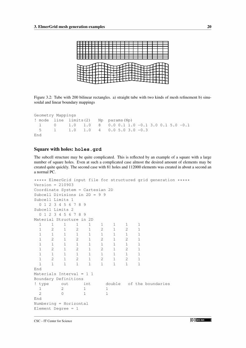
Figure 3.2: Tube with 200 bilinear rectangles. a) straight tube with two kinds of mesh refinement b) sinu-soidal and linear boundary mappings
Geometry Mappings! mode line limits(2) Np params(Np)
1 0 1.0 1.0 8 0.0 0.1 1.0 -0.1 3.0 0.1 5.0 -0.15 1 1.0 1.0 4 0.0 5.0 3.0 -0.3
End
Square with holes: holes.grdThe subcell structure may be quite complicated. This is reflected by an example of a square with a largenumber of square holes. Even at such a complicated case almost the desired amount of elements may becreated quite quickly. The second case with 81 holes and 112000 elements was created in about a second ana normal PC.
***** ElmerGrid input file for structured grid generation *****Version = 210903Coordinate System = Cartesian 2DSubcell Divisions in 2D = 9 9Subcell Limits 1
0 1 2 3 4 5 6 7 8 9Subcell Limits 2
0 1 2 3 4 5 6 7 8 9Material Structure in 2D
1 1 1 1 1 1 1 1 11 2 1 2 1 2 1 2 11 1 1 1 1 1 1 1 11 2 1 2 1 2 1 2 11 1 1 1 1 1 1 1 11 2 1 2 1 2 1 2 11 1 1 1 1 1 1 1 11 2 1 2 1 2 1 2 11 1 1 1 1 1 1 1 1
EndMaterials Interval = 1 1Boundary Definitions! type out int double of the boundaries
1 2 1 12 0 1 1
EndNumbering = HorizontalElement Degree = 1
CSC – IT Center for Science

3. ElmerGrid mesh generation examples 21
Figure 3.3: Squares with holes: a) square with 16 square holes and 1040 elements, b) square with 81 squareholes and 112000 elements.
Element Innernodes = FalseTriangles = FalseSurface Elements = 1024
Cross: cross.grdTo show that multiple mappings may be used at the same time a more complicated case is given. Here twohorizontal and two vertical lines are mapped. The mesher has the nice property that the same file may beused to created multiple meshes with different settings. The other mesh is now the external mesh and it isdivided to triangles.
***** ElmerGrid input file for structured grid generation *****Version = 210903Coordinate System = Cartesian 2DSubcell Divisions in 2D = 3 3Subcell Limits 1 = 0 2 3 5Subcell Limits 2 = 0 2 3 5Material Structure in 2D
2 1 21 1 12 1 2
EndGeometry Mappings! mode line limits(2) Np params(Np)
1 1 2 1 8 0 -1 2 0 3 0 5 -11 2 1 2 8 0 1 2 0 3 0 5 1-1 1 2 1 8 0 -1 2 0 3 0 5 -1-1 2 1 2 8 0 1 2 0 3 0 5 1
EndMaterials Interval = 1 1Boundary Definitions! type out int double of the boundaries
1 0 1 12 2 1 1
EndNumbering = Horizontal
CSC – IT Center for Science

3. ElmerGrid mesh generation examples 22
Figure 3.4: Cross with shape used to create 2 computational meshes: a) the internal mesh of 400 bilinearrectangles b) the external mesh of 800 linear triangles.
Element Degree = 1Element Innernodes = FalseTriangles = FalseSurface Elements = 400Coordinate Ratios = 1Minimum Element Divisions = 1 1Element Ratios 1 = 0.5 1 2Element Ratios 2 = 0.5 1 2Element Densities 1 = 1 1 1Element Densities 2 = 1 1 1
Start New MeshMaterials Interval = 2 2Boundary Definitions! type out int double of the boundaries
1 0 2 12 1 2 1
EndNumbering = HorizontalElement Degree = 1Element Innernodes = FalseTriangles = TrueSurface Elements = 400Coordinate Ratios = 1Minimum Element Divisions = 1 1Element Ratios 1 = 0.5 1 2Element Ratios 2 = 0.5 1 2Element Densities 1 = 1 1 1Element Densities 2 = 1 1 1
Hand-weight: weight.grd
***** ElmerGrid input file for structured grid generation *****Version = 210903Coordinate System = Cartesian 2DSubcell Divisions in 2D = 3 3
CSC – IT Center for Science

3. ElmerGrid mesh generation examples 23
Subcell Limits 1 = 0 2 4 6Subcell Limits 2 = 0 0.8 1.2 2Material Structure in 2D
1 0 11 1 11 0 1
EndGeometry Mappings! mode line limits(2) Np params(Np)
4 0 2 2 4 1 1 5 1EndMaterials Interval = 1 2Boundary Definitions! type out int double of the boundaries
1 0 1 1EndNumbering = VerticalElement Degree = 1Element Innernodes = FalseTriangles = TrueSurface Elements = 500Coordinate Ratios = 1Minimum Element Divisions = 1 1Element Ratios 1 = 1 1 1Element Ratios 2 = 1 1 1Element Densities 1 = 1 1 1Element Densities 2 = 1 2 1
The extrusion requires that there are subcells also in the z-direction. In this case only one subcell is set.
Coordinate System = Cartesian 3DSubcell Divisions = 3 3 1
In addition all information that is given for x and y must now also be given for z. For example, the subcellboundaries in the extruded direction must be given.
Subcell Limits 3 = 0.0 0.5
3.2 3D examples
Shell of waves: waves.grdThe originally 2D mesh may be given a third dimension with the help of mapping. In this example twosinusoidal mappings are used. They have a amplitude with different sign and therefore there is a phase-shiftof 180 degrees between the two opposing sides.
***** ElmerGrid input file for structured grid generation *****Version = 210903Coordinate System = Cartesian 2DSubcell Divisions in 2D = 1 1Subcell Limits 1 = 0 100Subcell Limits 2 = 0 100Material Structure in 2D
1End
CSC – IT Center for Science

3. ElmerGrid mesh generation examples 24
Figure 3.5: Hand-weight consisting of two spheres and a joining tube a) 2D mesh with 1000 linear trianglesb) extruded 3D mesh with 1200 prisms.
Figure 3.6: A shell with a wave pattern
CSC – IT Center for Science

3. ElmerGrid mesh generation examples 25
Figure 3.7: A 2D mesh mapped into two 3D cones
Geometry Mappings! mode line limits(2) Np params(Np)
55 0 50 50 4 0 100 5 1055 1 50 50 4 0 100 5 -10
EndMaterials Interval = 1 1Boundary Definitions! type out int double of the boundaries
1 0 1 1EndNumbering = HorizontalElement Degree = 1Element Innernodes = FalseTriangles = FalseSurface Elements = 10000
Shell consisting of two adjacent cones: cones.grdThere are some cases where a mesh consisting of 2D elements may be used to model also 2D geometries.This is the case for thin shells, for example. ElmerGrid does offer limited functionality for creating these.Only shells with rotational symmetry are possible to be created. Then the computational mesh is done forthe z and φ variables. The missing radius must also be given. After that x = r cos φ and y = r sinφ. Alsolimited possibilities to alter the radius as a function of positions is given. The same mappings may be usedas for 2D meshes in cartesian coordinates.
The examples shows a simple cylinder where a mapping is used to create two cones.
CSC – IT Center for Science

3. ElmerGrid mesh generation examples 26
Figure 3.8: A rolled shell with a spiraling structure
***** ElmerGrid input file for structured grid generation *****Version = 210903Coordinate System = 2D PolarSubcell Divisions in 2D = 1 1Subcell Limits 1 = 0 100Subcell Limits 2 = 0 360Material Structure in 2D
1EndGeometry Mappings! mode line limits(2) Np params(Np)
51 0 1e+06 1e+06 6 0 0 50 -25 100 0EndPolar Radius = 30Materials Interval = 1 1Boundary Definitions! type out int double of the boundaries
1 -1 1 12 -3 1 1
EndNumbering = HorizontalElement Degree = 1Element Innernodes = FalseTriangles = FalseSurface Elements = 1000Coordinate Ratios = 1Element Ratios 1 = -0.25Element Ratios 2 = 1
A rolled shell: cones.grdThe mappings out of plane may also be used to create a simple roll. Now the angles extends to 3600 degreesmaking 10 full rotations. The radius goes linearly from 1 to 101 and thus the roll has a spiraling structure.
CSC – IT Center for Science

3. ElmerGrid mesh generation examples 27
***** ElmerGrid input file for structured grid generation *****Version = 210903Coordinate System = 2D PolarSubcell Divisions in 2D = 1 1Subcell Limits 1 = 0 100Subcell Limits 2 = 0 3600Material Structure in 2D
1EndGeometry Mappings! mode line limits(2) Np params(Np)
-51 0 1e+06 1e+06 4 0 0 3600 100EndPolar Radius = 1Materials Interval = 1 1Boundary Definitions! type out int double of the boundaries
1 -1 1 12 -3 1 1
EndNumbering = HorizontalElement Degree = 1Element Innernodes = FalseTriangles = FalseCoordinate Ratios = 1Minimum Element Divisions = 1 1Element Ratios 1 = 1Element Ratios 2 = 1Element Divisions 1 = 10Element Divisions 2 = 1000
A hexagonal frame: hexframe.grdThere is also a very special mapping for creating 3D shell structures. The mapping is used to give an anglefor the shell. The angle is stepwise constant which makes is possible to create polygonal 3D shells.
***** ElmerGrid input file for structured grid generation *****Version = 210903Coordinate System = Cartesian 2DSubcell Divisions in 2D = 6 1Subcell Limits 1 = 0 1 2 3 4 5 6Subcell Limits 2 = 0 2Material Structure in 2D
1 1 1 1 1 1EndGeometry Mappings! mode line limits(2) Np params(Np)
58 0 1e+06 1e+06 14 0 0 1 60 2 120 3 180 4 240 5 300 6 360EndMaterials Interval = 1 1Boundary Definitions! type out int double of the boundaries
1 -1 1 12 -3 1 1
End
CSC – IT Center for Science

3. ElmerGrid mesh generation examples 28
Figure 3.9: A hexagonal 3D frame made by mapping by angle
Numbering = VerticalElement Degree = 1Element Innernodes = FalseTriangles = FalseSurface Elements = 200
Rotated step structure: barrel.grd
***** ElmerGrid input file for structured grid generation *****Version = 210903Coordinate System = Cartesian 2DSubcell Divisions in 2D = 3 3Subcell Limits 1 = 0 1 2 3Subcell Limits 2 = 0 1 2 3Material Structure in 2D
1 0 01 1 01 1 1
EndRevolve Blocks = 2Revolve Radius = 2Materials Interval = 1 1Boundary Definitions! type out int double of the boundaries
1 0 1 1EndNumbering = HorizontalElement Degree = 1Element Innernodes = FalseTriangles = FalseSurface Elements = 100
CSC – IT Center for Science

3. ElmerGrid mesh generation examples 29
Figure 3.10: Step structure rotated 180 degrees to create 3D object with 1312 elements
Coordinate Ratios = 1Minimum Element Divisions = 1 1Element Ratios 1 = 1 1 1Element Ratios 2 = 1 1 1Element Densities 1 = 1 1 1Element Densities 2 = 1 1 1
Extruded structure: blocks.grdThe 2D structures may be extruded in the third dimension. Then the third dimension is added to the subcellsboundaries and to the mesh definitions.
The material structure is always 2D. The given material structure may be extruded as is, or alternativelya selective extrusion for different materials may be performed as is done in this example. It is thereforepossible to omit some materials, and to rename the extruded layer to some new material.
***** ElmerGrid input file for structured grid generation *****Version = 210903Coordinate System = Cartesian 3DSubcell Divisions in 3D = 4 5 5Subcell Limits 1 = 0 0.1 0.4 0.5 0.6Subcell Limits 2 = 0 0.1 0.2 0.4 0.5 0.6Subcell Limits 3 = 0 0.05 0.1 0.2 0.25 0.3Material Structure in 2D
1 1 1 11 3 3 11 2 3 11 3 3 11 1 1 1
EndMaterials Interval = 1 3
CSC – IT Center for Science

3. ElmerGrid mesh generation examples 30
Figure 3.11: Simple 3D structure created by selective extrusion. The upper part has been removed forvisualization purposes.
Extruded Structure! 1stmat lastmat newmat
1 3 11 1 21 2 31 1 41 3 5
EndBoundary Definitions! type out int double of the boundaries
1 3 1 12 2 1 13 3 2 14 0 1 1
EndNumbering = HorizontalElement Degree = 1Element Innernodes = FalseTriangles = FalseSurface Elements = 200Coordinate Ratios = 1 1Minimum Element Divisions = 2 2 2
3.3 1D examplesThe ElmerGrid program was originally written for 2D mesh generation. However, it is also possible to makeeven more trivial one dimensional grids. This is rarely needed as most FEM computations are at least twodimensional.
CSC – IT Center for Science

3. ElmerGrid mesh generation examples 31
Figure 3.12: A line segment where the element nodes are marked with polygons. The mesh has 50 elementsand thus 51 nodes.
Line: line.grdThe example of the 1D case is naturally a line segment – there are no other kind of basic 1D structures. Itconsists of two sections, the first one has a increasing mesh density to the right and the second one has aneven distribution of nodes.
***** ElmerGrid input file for structured grid generation *****Version = 210903Coordinate System = Cartesian 1DSubcell Divisions in 1D = 3Subcell Limits 1 = 0 1 3 4Material Structure in 1D
1 1 1EndMaterials Interval = 1 1Boundary Definitions! type out int
1 -1 1 12 -2 1 1
EndElement Degree = 1Element Innernodes = FalseTriangles = FalseSurface Elements = 40Element Ratios 1 = 2 1 0.5Element Densities 1 = 1 0.5 1
CSC – IT Center for Science

Chapter 4
ElmerGrid mesh manipulationexamples
ElmerGrid may often be used as a grid manipulation tool even though the computational mesh would orig-inally have been made by some other mesh generator. There are many basic operations, such as scaling orrotation, which do not require any special attention. Here we look at some more advanced things that maybe performed an a mesh.
4.1 Mesh partitioningNowadays the best performance from computers is obtained using parallel solution techniques. In finiteelement method this means that the mesh must be divide into separate domains that are solved by single pro-cessors. The domains should be chosen so that the extra work needed for the communications is minimized.This procedure is called mesh partitioning. ElmerGrid offers two different techniques for this. The first oneused Metis library and the second one divides the mesh using simple ordering schemes.
As an example we choose an L-shaped domain of bilinear elements. The grid file for creating this one isgiven below.
***** ElmerGrid input file for structured grid generation *****Version = 210903Coordinate System = Cartesian 2DSubcell Divisions in 2D = 2 2Subcell Limits 1 = 0 1 2Subcell Limits 2 = 0 1 2Material Structure in 2D
1 01 1
EndMaterials Interval = 1 1Boundary Definitions! type out int
1 0 1 1EndElement Degree = 1Element Innernodes = FalseTriangles = FalsePlane Elements = 30000
The partitioning may be invoked using command line arguments, or as here using command file. Belowis the command file for using the simple partitioning scheme to partition the mesh into 2 × 2 domains.
CSC – IT Center for Science

4. ElmerGrid mesh manipulation examples 33
Figure 4.1: A simple mesh partitioned with a simple geometrical scheme and Metis library.
Input File = angleOutput File = angleInput Mode = ElmerGridOutput Mode = ElmerPostPartition = 2 2
In the start of the command file the user defines the input and output formats and filenames. The onlyadditional command is the last line that defines how the mesh is partitioned. Another choice is to use Metiswhich is invoked with the line
Metis = 4
The resulting partitionings are shown in Figure 4.1. In this case the partitionings are almost equally good. Invery simple cases the simple geometrical algorithm may give better results but in general cases Metis shouldbe favored.
4.2 Boundary layer creationIn nature there are often sharp changes in the physical behavior which may be seen in forms of boundarylayers. Particularly in the area of fluid dynamics boundary layers are often of special interest. A physicalboundary layer requires a suitable computational mesh if one wants to model the physical phenomena accu-rately. Equally tight mesh is not usually needed elsewhere and thus an optimal solution is a proper boundarylayer mesh. Ideally the mesh is such that the elements are small only in the direction of the gradient.
ElmerGrid includes a simple 2D capability for creating boundary layer meshes. There the user maychoose the boundary conditions of interest and extrude them in the direction of the normal to create a struc-tured mesh just on the boundary. The new mesh may also be fitted into the size of the original mesh usinga simple Jacobian smoother which tries to maintain the geometrical shape of the mesh. Often this is not soeasy and therefore the methodology may create some complications on the corner nodes, for example.
The example case chosen is the same one as for the partitioning example except the number of planeelements is reduced to 300 to make the boundary layer more visible. In the geometry there is only oneboundary and therefore only one boundary layer is also created. There can however be several boundarylayers at a time. In the intersections of different boundary layers one should however notice that the numberof new elements should be the same. The resulting mesh is shown in Figure 4.2.
CSC – IT Center for Science

4. ElmerGrid mesh manipulation examples 34
Figure 4.2: A simple boundary layer created on an angle mesh
Input File = angleOutput File = layerInput Mode = ElmerGridOutput Mode = ElmerPostBoundary Layer Move = 1000Boundary Layer Epsilon = 1.0e-4Boundary Layer
1 5 0.2 5.0 0END
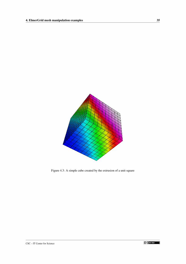
4.3 Mesh extrusionElmerGrid enables that any mesh on a plane may be extruded in the third dimension by given the specifica-tions on how to extrude. For example the command file below may be used to extrude the mesh created inthe first example in the third dimension. The result is a unit cube with 1000 trilinear elements.
Input File = rectOutput File = cubeInput Mode = ElmerSolverOutput Mode = ElmerSolverExtruded Divisions = 1Extruded Limits = 0 1Extruded Ratios = 1.0Extruded Elements = 10
CSC – IT Center for Science
4. ElmerGrid mesh manipulation examples 35
Figure 4.3: A simple cube created by the extrusion of a unit square
CSC – IT Center for Science

Chapter 5
ElmerGrid Interface Examples
ElmerGrid understands a number of different mesh formats which enables the import from meshes createdby other mesh generators into the Elmer solution cycle. Supported formats includes those by Ansys (separatemacro), Abaqus, Gambit (FDNET), Comsol Multiphysics, Fieldview, Triangle, Medit, Gsmh, and GiD.
5.1 Ansys mesh to ElmerThe APDL macros and the following documentation have been written by Antti Pursula (email: [email protected]).He will answer any further questions related to the macros.
Two APDL (Ansys parametric design language) macros has been created which allow writing geometrydata in ASCII format out of Ansys. The macros can be activated from Ansys GUI using custom addedbuttons in the Ansys Toolbar. The ASCII format files can further be converted in the Elmer format by usingElmerGrid.
The information written out by the macros consists of four files that are named ExportMesh.* (* =header, node, elem, or boundary). The files include all the information Elmer needs for using themesh ie., besides the obvious node and element definitions, also information about the boundary nodes.
In Ansys, the geometry model is often created combining several elementary geometries. This meansthat the model usually includes boundaries, that have no physical meaning. These do not disturb the anal-ysis neither in Ansys nor in Elmer, but they can make the definition of boundary conditions quite cumber-some in Elmer. Therefore, there are two possible macros for exporting data from Ansys: ELMER AU andELMER CH. The first writes all the boundaries of the model automatically while the second asks the user tographically pick the boundaries that have physical meaning. It is worthwhile to notice that Elmer does notnecessarily need boundary information for all the physical boundaries, but only those on which a boundarycondition is to be applied.
To use Ansys to Elmer interface you need to download two macro files and an Ansys start-up file and copythem into your working directory. After the files have been copied, start Ansys and the buttons ELMER AUand ELMER CH appear in the Toolbar. The conversion of the resulting ASCII files into Elmer format is doneby the ElmerGrid program. The files as well as ElmerGrid can be downloaded from the Elmer downloadpage.
In ElmerGrid the Ansys input format is 4 and output format can be Elmer mesh format (3) or ElmerPostformat (2). So, creating Elmer meshes from Ansys input is done with the command: ElmerGrid 4 3ExportMesh. There are also many command-line options available. The most important ones in this caseare:
• -o name for saving output with the name specified.
• -order cx cy cz for reordering nodes and elements using c1x + c2y + c3z.
• -scale cx cy cz for scaling the mesh using the constant to multiply the coordinate values.
• -merge epsilon for merging nodes that are at most distance epsilon apart.
CSC – IT Center for Science

5. ElmerGrid Interface Examples 37
Figure 5.1: Pictures of the same mesh in Ansys desktop and in ElmerPost window.
The -merge option is important in a case where Ansys creates multiple nodes on a boundary of twoelementary geometries. These nodes are often noticed only when Elmer is not able to use a mesh createdfrom Ansys. In such a case, use -merge option with a suitable value for the node separation.
5.2 Comsol Multiphysics to ElmerComsol Multiphysics is a widely used finite element tool with highly automated mesh generation. Previouslythe software was known as Femlab. In the older versions of Comsol Multiphysics/Femlab there wasn’t anyexport format that would have included the boundary definitions. However, since version 3.2 of ComsolMultiphysics there is a suitable export format that may be directly used to export meshes in Elmer – themphtxt format. The ElmerGrid program understands a sufficient subset of the commands in mphtxt-file ofComsol multiphysics.
The procedure for importing meshes to Elmer is
• In Comsol Multiphysics chooseFile -> Export -> Mesh to File
• Select the export format‘‘COMSOL Multiphysics text file’’ (mphtxt)
• Give the mesh a file name, e.g. mymesh and you obtain the file mymesh.mphtxt
• Call then ElmerGrid with the following command line options to obtain E ElmerSolver mesh fileformatElmerGrid 9 2 mymesh.mphtxt
• And with the following options to obtain ElmerPost result formatElmerGrid 9 3 mymesh.mphtxt
5.3 Triangle mesh to ElmerTriangle is a two-dimensional quality mesh generator and Delaunay triangulator. written by JonathanRichard Shewchuk in University of California at Berkeley (email: [email protected]).
The format written by Triangle is very similar to that one needed by Elmer. The only problem is tofind the boundaries defined by the nodes known to lie on the boundary. The current implementation of thealgorithm may result to problems at the corners. Also the functionality hasn’t been tested for cases withseveral materials or several boundaries.
Assuming we have a triangle input file name tri.poly. This may be meshed with second ordertriangles having all corners above 32.0 degrees and area below 0.001 with the command
CSC – IT Center for Science

5. ElmerGrid Interface Examples 38
Figure 5.2: Pictures of the same mesh in Femlab desktop and in ElmerPost window.
Figure 5.3: Picture of the Triangle example case in ElmerPost.
triangle -pq32.0 -a.0001 -o2 tri
This creates files tri.i.ele and tri.i.node (i=1, 2, . . .), which may be used to create the Elmermodel.
The Triangle format corresponds to input mode 11 at ElmerGrid. Therefore the mesh for ElmerSolver iscreated with command
ElmerGrid 11 2 tri.1
which results to a computational mesh being saved at ElmerSolver format in subdirectory tri.
CSC – IT Center for Science
Related Documents