OS License Number : 100020449 Ellesmere Port - Proposed Well Site Interpretative Report for IGas Energy Engineer : Moorhouse Petroleum Project Number : PN112482 July 2011 Issuing office : North West Office Geotechnics Limited The Geotechnical Centre Unit 1, Borders Industrial Park River Lane, Saltney Chester CH4 8RJ T: 01244 671 117 F: 01244 671 122 [email protected] Head Office Coventry Geotechnics Limited The Geotechnical Centre 203 Torrington Avenue Tile Hill Coventry CV4 9AP T: 024 7669 4664 F: 024 7669 4642 [email protected] South West Office Geotechnics Limited The Geotechnical Centre 7 Pinbrook Units Venny Bridge Exeter EX4 8JQ T: 01392 463 110 F:01392 463 111 [email protected] Geotechnics Limited, Registered in England No. 1757790 at The Geotechnical Centre, 203 Torrington Avenue, Tile Hill, Coventry CV4 9AP

Welcome message from author
This document is posted to help you gain knowledge. Please leave a comment to let me know what you think about it! Share it to your friends and learn new things together.
Transcript

OS License Number : 100020449
Ellesmere Port - ProposedWell Site
Interpretative Report
for
IGas Energy
Engineer : Moorhouse Petroleum
Project Number : PN112482
July 2011Issuing office :
North West OfficeGeotechnics LimitedThe Geotechnical CentreUnit 1, Borders Industrial ParkRiver Lane, SaltneyChesterCH4 8RJT: 01244 671 117F: 01244 671 [email protected]
Head Office Coventry
Geotechnics Limited
The Geotechnical Centre
203 Torrington Avenue
Tile Hill
Coventry
CV4 9AP
T: 024 7669 4664
F: 024 7669 4642
South West Office
Geotechnics Limited
The Geotechnical Centre
7 Pinbrook Units
Venny Bridge
Exeter
EX4 8JQ
T: 01392 463 110
F:01392 463 111
Geotechnics Limited, Registered in England No. 1757790 at The Geotechnical Centre, 203 Torrington Avenue, Tile Hill, Coventry CV4 9AP

Interpretative Report
Ellesmere Port - Proposed Well Site
forIGas Energy
Engineer : Project No:
Moorhouse Petroleum PN112482
July 2011

LIST OF CONTENTS
Page No
1.0 INTRODUCTION 1
2.0 OBJECT AND SCOPE OF THE INVESTIGATION 1
3.0 PRESENTATION 1
4.0 THE SITE 1
4.1 Location
4.2 Description
5.0 PROCEDURE 1-2
5.1 Commissioning
5.2 General
5.3 Window Sample Boreholes
5.4 In Situ Farnell Probe (CBR) Tests
6.0 LABORATORY TESTING 2
6.1 Geotechnical
6.2 Contamination
7.0 INTERPRETATION 2-5
7.1 Geotechnical Engineering
7.2 Site History
7.3 Contamination
7.4 Pavement DesignC
ON
TE
NT
S

APPENDICES
APPENDIX 1 Site Location Plan
APPENDIX 2 Window Sample Borehole Records
APPENDIX 3 In Situ Farnell Probe (CBR) Tests
APPENDIX 4 Laboratory Test Results - Contamination
APPENDIX 5 NRM Laboratory Results
APPENDIX 6 Landscape Proposals Drawing
APPENDIX 7 Design Loading Calculations
APPENDIX 8 Exploratory Hole Location Plan
APPENDIX 9 Investigation Techniques and General Notes
AP
PE
ND
ICE
S
Geotechnics Limited Ellesmere Port – Proposed Well Site
The Geotechnical Centre, Interpretative Report, Project No PN112482, (July 2011).
Unit 1 Borders Industrial Park,
River Lane, Saltney, Chester, CH4 8RJ Page 1 of 5
1.0 INTRODUCTION
A geotechnical investigation was undertaken by
Geotechnics Ltd at the site of a proposed
exploratory gas production well. The investigation
was carried out to the instructions of Moorhouse
Petroleum on behalf of the Client, IGas Energy. This
report describes the work undertaken and presents
the data obtained together with an evaluation of
their significance in relation to the proposed works.
2.0 OBJECT AND SCOPE OF
THE INVESTIGATION
The object of the investigation was to obtain
information on the ground and groundwater
conditions relating to the design of the proposed
works within the limitations posed by trial hole
numbers, locations, depths, methods adopted and
the scope of approved in situ and laboratory testing.
The investigation comprised window sample
boreholes, in situ and laboratory testing and
reporting. A geotechnical and basic
geoenvironmental interpretation and evaluation of
the data obtained was also commissioned.
3.0 PRESENTATION
A description of the site and a summary of the
procedures followed during the investigation process
are presented in Sections 4 to 6. The factual data so
obtained are presented in Appendices 1 to 8 of this
report.
An interpretation of the data obtained is presented
in Section 7.
Attention is drawn to the General Notes and
Investigation Procedures presented in Appendix 9 to
aid an understanding of the procedures followed and
the context in which the report should be read.
4.0 THE SITE
4.1 Location
The site is located approximately 1.65km northwest
of Ellesmere Port Railway Station and approximately
0.15km northeast from the M53 Motorway. The
approximate Ordnance Survey Grid Reference for
the site is SJ 396 780 and an extract from the
relevant 1:50,000 Scale O.S. Map is included as
Appendix 1
4.2 Description
The site comprises a portion of cleared land situated
between industrial units. The site is irregular in
shape with maximum dimensions of approximately
100m (northwest to southeast) by 85m (southwest
to northeast). The site is surfaced with rough and
vegetation and is generally level. In the vicinity of the
northern site boundary some tipping of unidentified
spoil materials has occurred.
5.0 PROCEDURE
5.1 Commissioning
The work was awarded following submission of a
proposal for ground investigation of the site in
accordance with the Client’s requirements.
5.2 General
The procedures followed in this site investigation are
based on BS 5930:1999 + A2:2010 - Code of Practice
for Site Investigations.
The Exploratory Hole locations were specified by
the Engineer and their positions are shown on the
Exploratory Hole Location Plan in Appendix 8.
Levels and co-ordinates shown on the Exploratory
Hole Records were obtained by surveying using the
global positioning system.
Ground Investigation Interpretative Report
at
Ellesmere Port – Proposed Well Site Project No : PN112482
July 2011

Geotechnics Limited Ellesmere Port – Proposed Well Site
The Geotechnical Centre, Interpretative Report, Project No PN112482, (July 2011).
Unit 1 Borders Industrial Park,
River Lane, Saltney, Chester, CH4 8RJ Page 2 of 5
5.3 Window Sample Boreholes
Six (6 No.) Window Sample Boreholes (numbered
WS1 to WS5 and WS4A) were undertaken at the
site to depths varying between 2.30m and 6.65m
below ground level. The work was carried out on
5th May 2011.
Prior to the commencement of window sampling,
each exploratory hole position was scanned using a
cable avoidance tool (CAT) and then an inspection
pit was excavated as a precaution against damaging
any buried services present.
The Window Samples were taken using super-heavy
Dynamic Probe apparatus which drives lined steel
tubes into the ground in 1m lengths. Samples are
taken direct from the sampling tube and placed in
Jars. Standard Penetration Tests (SPTs) were
undertaken at the depths indicated on the borehole
records in accordance with BS EN ISO 22476-3:2005
to obtain a measure of the engineering properties of
the proved strata. The hole is not cased and
progress depends on the nature of the strata
penetrated.
The Window Sample Boreholes were backfilled with
arisings on completion. The Window Sample
Borehole Records are presented in Appendix 2.
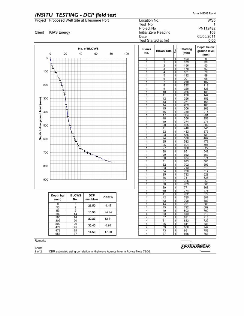
5.4 In Situ Farnell Probe (CBR)
Tests
Farnell CBR Probes were undertaken immediately
adjacent to each window sample location on 5th May
2011. The tests were commenced from Ground
Level and were performed to give an indication of
CBR values at shallow depths to aid pavement
design. The test comprises the measurement of
increments of penetration of a 60° cone driven into
the ground using an 8kg hammer falling a distance of
575mm. The CBR is obtained from the relationship
between the CBR and the DCP readings; Log10(CBR)
= 2.48 – 1.057 x Log10(mm/blow) as defined in
Interim Advice Note 73/06 "Design Guidance for
Road Pavement Foundations" published by the
Highways Agency. The results are presented in
Appendix 3.
6.0 LABORATORY TESTING
6.1 Geotechnical
Initially Geotechnics Ltd were not instructed to
undertake either geotechnical analysis or
geotechnical testing. No geotechnical testing has
been scheduled on the samples recovered thus far.
6.2 Contamination
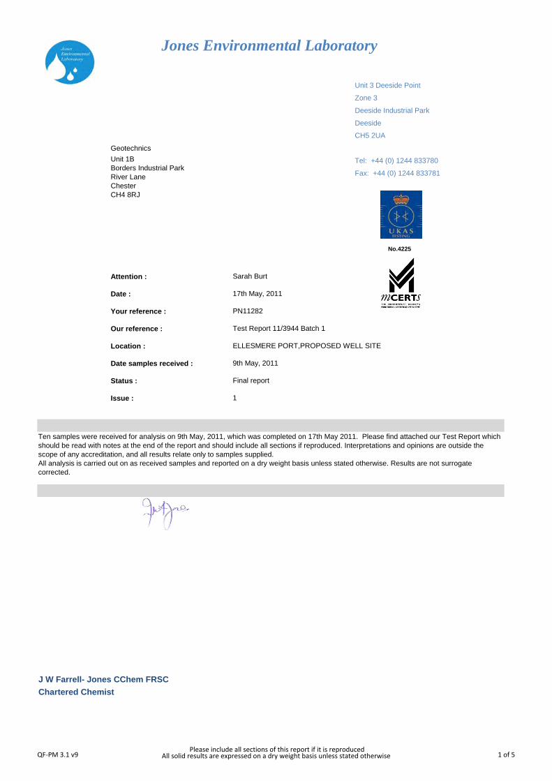
Selected samples of soil were tested in at the
laboratories of Jones Environmental Forensics Ltd
for a number of determinands in order to check on
potential site contamination. The determinands were
selected by Geotechnics Limited.
The results are presented in Appendix 4.
7.0 INTERPRETATION
7.1 Geotechnical Engineering
7.1.1 General
On the basis of the available window sample
boreholes the ground conditions at the site can be
represented (in simplistic terms) by the following
sketch section:
The basic stratigraphy of the soils encountered is
described further below.
7.1.2 Made Ground
Made Ground was encountered in all the Window
Sample Boreholes to depths ranging between 1.50m
and 3.40m below ground level.
The composition of the Made Ground across the
site is variable with the following generic materials
present:
• A poor quality ashy topsoil, with rootlets
and other natural materials
• Reworked locally derived glacial till

Geotechnics Limited Ellesmere Port – Proposed Well Site
The Geotechnical Centre, Interpretative Report, Project No PN112482, (July 2011).
Unit 1 Borders Industrial Park,
River Lane, Saltney, Chester, CH4 8RJ Page 3 of 5
• A general ash, clinker and brick fill material
brick and pottery fragments
• A black, apparently hydrocarbon
contaminated, gravelly sand or sandy gravel
associated with bituminous pipework
fragments
• A concrete obstruction, the nature of
which remains undetermined.
The black gravel with bituminous pipework
fragments is seen to occur beneath the general ash
fill materials.
It should be noted that in both WS 4 and WS4A the
base of the Made Ground was not proven. It will be
necessary to establish the nature of the obstruction
encountered to assess the likely maximum depth of
Made Ground present.
The mean SPT N value with depth for all the
granular Made Ground materials is 8.3, indicating
typically, a loose relative density
7.1.3 Alluvium
Alluvium was absent in WS2, and not proven in
WS4. In WS1 and WS5 it was represented
(immediately beneath the Made Ground) by a sand
stratum where it was noted to be between 0.95m
and 1.30m thick.
In WS3 the alluvium was represented by a 0.30m
thick layer of soft sandy silt and a 0.10m thick soft
sandy clay, thought likely to represent an overbank
deposit.
7.1.4 Glacial Till
Glacial Till was proven in all the Window Sample
Boreholes except WS4 and WS4A. This material
was shown to have a mean SPT N value of 16 –
generally consistent with an undrained shear
strength of the order of 90kN/m2.
Consistency descriptions were somewhat variable,
raging from firm to very stiff.
7.2 Site History
No formal desk study has been commissioned s part
of this investigation. However, given concerns with
respect to the potential impact of the obstruction at
WS4 and WS4A, we have reviewed some historical
information on the Cheshire County Records Office
on-line "e-mapping" facility. The 1875 mapping shows
a building which may lie close to the positions of
WS4/ 4A. The other available mapping and aerial
photography do not show any significant structures.
Aerial photography from the early 1970s suggests
that the northern part of the site was used for
storage of timber.
7.3 Contamination
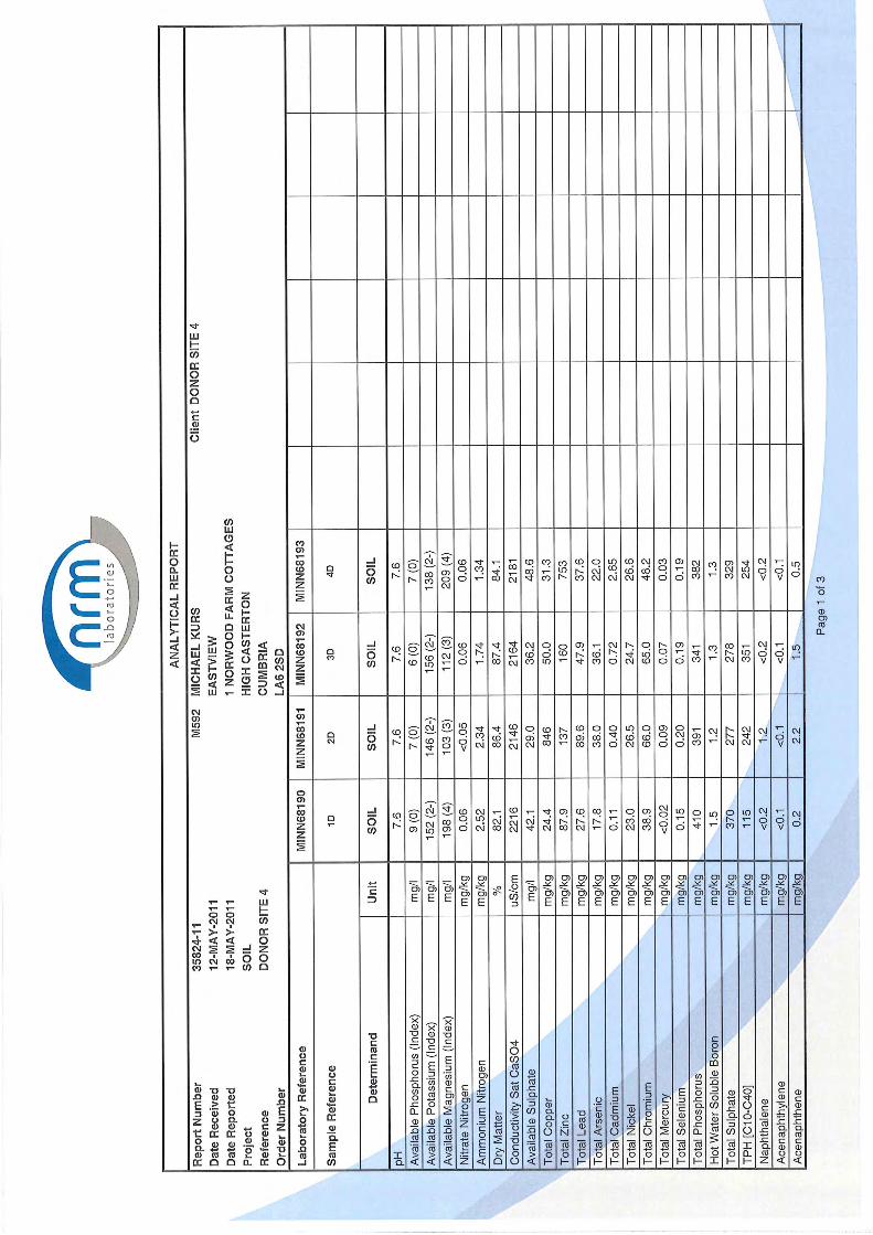
In addition to testing undertaken by Geotechnics Ltd
additional results have been made available from a
batch of testing undertaken by NRM Laboratories
(see Appendix 5).
This work comprised batches of shallow samples
taken from the general site area (hereafter referred
to as the "donor site") and a batch of shallow
samples taken from the northern corner of the site
(referred to as the "receptor site"). It is intended
that species rich grassland soil removed from the
donor site be stored at the receptor site, with
topsoil stored at the site's southern corner (see the
Landscape Proposals Drawing included in Appendix
6).
On the basis of this information it is clear that the
receptor site is in most cases more potentially
contaminated than the donor site and placing the
donor materials would not therefore present a
significant increase in chemical risk if placed on it.
Any physical risk would depend on the nature of the
deposition and state of the material when deposited.
Any handling will need to satisfy the regulator's
criteria in this regard. The Local Authority are
responsible for human health issues, whilst the
Environment Agency deal with any risk to
Controlled Waters.
The donor site would best be dealt with by
disturbing as little as possible of the material. To put
the levels of potential contamination in perspective,
the site would not be considered suitable for
housing or public open space but levels are not
significantly higher than those acceptable for
commercial development. As such the anticipated
land use should not lead to a significant risk to users.
However, it may be that the regulators will require
some form of written confirmation and
analysis/assessment of this beyond the works already
undertaken, and in particular it is likely that a formal
historical / industrial Desk Study is likely to be
required.
Off-site disposal from the donor site should be
feasible and the material is considered likely to be
Geotechnics Limited Ellesmere Port – Proposed Well Site
The Geotechnical Centre, Interpretative Report, Project No PN112482, (July 2011).
Unit 1 Borders Industrial Park,
River Lane, Saltney, Chester, CH4 8RJ Page 4 of 5
classified as stable non reactive. However this may
require additional testing to confirm this to the
satisfaction of the waste receiver.
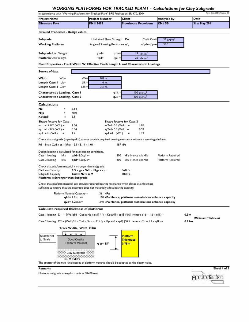
7.4 Pavement Design The working surface required for the proposed rig
should be constructed in accordance with BRE 470:
Working platforms for tracked plant.
BRE 470 outlines several factors that need to be
considered for the construction of the working
platform and issues that cause the platform to fail.
These are summarised below:
• Localised weaknesses associated with the
existence of 'soft' spots where the
subgrade is weaker than the surrounding
ground
• Inadequate backfilling of excavations leading
to 'soft' spots developing
• Difficulties caused by 'hard' spots such as
old foundations or basements
• Presence of exiting and abandoned services
• Issues with Brownfield sites and possible
contamination
• Steep slopes causing plant instability
• Open excavations, edges of the platform
and access ramps should be identified and
clearly marked
• Inadequate maintenance and repairs of both
the working platform and the rig
• Inappropriate operation of the rig
• The designer needs to be notified of any
differences in ground or groundwater
conditions than those expected during
installation of the platform
7.4.1 Site Conditions
Appropriate and sufficient ground investigation is
vital to ensure the provision of an adequate working
platform. During site preparation, weak or variable
areas should be indentified. It may be necessary to
excavate weaker areas, old foundations and
abandoned services. Such excavations should be
backfilled with suitable material and adequately
compacted.
It should be noted that the time between exposing
the subgrade and installation of the platform should
be minimised to prevent deterioration of the
subgrade. Where deterioration does occur, affected
material should be removed and replaced with
suitably compacted materials.
As previously discussed in Section 7.3, potentially
contaminating material has been proven to exist on
certain parts of the site. Hence the handling of this
material during the construction of the working
platform needs to be minimised.
During construction of the platform the existing
vegetation needs to be stripped and the roots
removed. It is proposed that the topsoil will be
removed and stored in the receptor area.
It is proposed that the full extent of the subgrade
should not be removed, as this would help reduce
the handling of material in order to prevent cross
contamination from the donor site to the receptor
site.
7.4.2 Quality of Subgrade
For a working platform, the soil and groundwater
conditions in the upper 2m are particularly
important as they were have a critical effect on the
design of the working platform.
During the ground investigation it revealed a mixture
of both cohesive and granular material existed within
the upper 2m. Due to the mixture of material in the
subgrade, the design loading calculations are based
on a cohesive subgrade, as this is considered the
worst case.
Groundwater strikes were encountered within the
upper 2m of the site and having a water table close
to the ground surface may result in a reduced
bearing resistance.
7.4.3 Quality of Platform Material
The specification for the platform material should be
such that the performance requirement in terms of
compactibility, durability, trafficability and drainage
will be met. Hence the materials that are brought in
to construct the platform need to be a Selected
Granular Fill (Class 6F2 as defined by Table 6:1 of
the Specification for Highway Works, 1998).
The material used for the platform should be free of
organic matter and clay. Unsorted Made Ground
such as that currently present on the site should not
be used as a platform material as it is likely to
compact poorly and may contain hazardous
substances. The material used to construct the
platform should not contain more than 15% fines
and be free draining. The material used should be
sampled and assessed at suitable frequencies to
ensure that it meets the design requirement.

1
APPENDIX 1
Site Location Plan

SITE LOCATION PLAN
Ellesmere Port - Proposed Well SiteforIGas Energy
© Crown Copyright Reserved, OS License Number: 100020449
2
APPENDIX 2
Window Sample Borehole Records
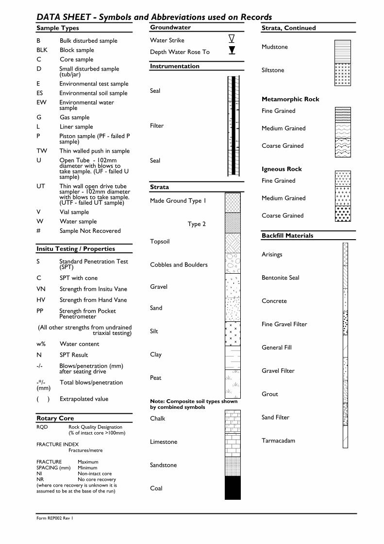
Form REP002 Rev 1
DATA SHEET - Symbols and Abbreviations used on Records Sample Types B Bulk disturbed sample
BLK Block sample
C Core sample
D Small disturbed sample (tub/jar)
E Environmental test sample
ES Environmental soil sample
EW Environmental water sample
G Gas sample
L Liner sample
P Piston sample (PF - failed P sample)
TW Thin walled push in sample
U Open Tube - 102mm diameter with blows to take sample. (UF - failed U sample)
UT Thin wall open drive tube sampler - 102mm diameter with blows to take sample. (UTF - failed UT sample)
V Vial sample
W Water sample
# Sample Not Recovered
Insitu Testing / Properties S Standard Penetration Test
(SPT) C SPT with cone VN Strength from Insitu Vane HV Strength from Hand Vane PP Strength from Pocket
Penetrometer (All other strengths from undrained
triaxial testing) w% Water content N SPT Result -/- Blows/penetration (mm)
after seating drive -*/- Total blows/penetration (mm) ( ) Extrapolated value
Rotary Core
RQD Rock Quality Designation (% of intact core >100mm) FRACTURE INDEX Fractures/metre FRACTURE Maximum SPACING (mm) Minimum NI Non-intact core NR No core recovery (where core recovery is unknown it is assumed to be at the base of the run)
Groundwater Water Strike Depth Water Rose To
Instrumentation Seal Filter Seal
Strata
Made Ground Type 1 Type 2 Topsoil Cobbles and Boulders Gravel
Sand Silt Clay Peat Note: Composite soil types shown by combined symbols Chalk Limestone Sandstone Coal
Strata, Continued Mudstone Siltstone Metamorphic Rock Fine Grained Medium Grained Coarse Grained Igneous Rock Fine Grained Medium Grained Coarse Grained
Backfill Materials Arisings Bentonite Seal Concrete Fine Gravel Filter General Fill Gravel Filter Grout Sand Filter Tarmacadam

BOREHOLE RECORDProject
Client
Engineer BoreholeProject No
Sampling Properties Strata
DepthSampleType kPa
w%
Scale
Description Depth Legend
Boring Groundwater
Depth Technique Crew of Hole Cased Water Date Struck Cased Rose to Sealed Groundwater
Remarks
Symbols andabbreviations areexplained on theaccompanyingkey sheet.
All dimensionsare in metres.
Time MinsDiaHole
DepthCased &
(to Water)Strength
ProgressDepth Depth Depth to Depth Depth Depth Remarks onin
PROPOSED WELL SITE AT ELLESMERE PORT MOORHOUSE PETROLEUM LIMITED PN112482
339651.73 ISLAND GAS LTD 377998.47 13.43
G.L. 13.43 0.00- 0.40 B Vegetation over MADE GROUND: Firm dark brown
slightly gravelly sandy clay with occasional 0.30 D rootlets. Gravel is fine to coarse angular to 0.40 13.03 0.30 ES subrounded of ash, clinker and brick fragments 0.40- 1.00 B 0.60 ES Reworked natural: Firm brown mottled grey slightly 0.70 D sandy slightly gravelly CLAY. Gravel is fine to
coarse subangular to subrounded of various lithologies
1.20- 2.20 B From 0.70m: Low cobble content 1.20- 1.65 D S11 Between 1.40-2.00m: No mottling 1.50 ES From 1.60m: Occasional brown fine to medium sand
lenses
2.00 D Between 2.20-2.50m: Brown fine to medium sand
2.50- 3.20 B
Between 2.80-2.90m: Black slightly gravelly fine to 2.80- 2.90 D coarse sand. Gravel is fine to medium subangular to
rounded of bitumen pipe fragments Between 3.20-3.40m: Soft dark brown and black sandy
3.20- 3.30 D clay with bitumen pipe fragments 3.20- 3.65 D S16 3.40 10.03 3.30- 4.05 B Brown slightly gravelly clayey fine to coarse SAND.
Gravel is fine to medium subangular to subrounded of various lithologies
4.05- 4.20 D 4.20- 4.70 D
4.70- 5.20 B 4.70 8.73 Firm brown slightly sandy slightly gravelly CLAY. Gravel is fine to medium subangular to subrounded of various lithologies
5.20 8.23 End of Borehole
1.20 0.40 Inspection Pit KP/SM G.L. 05/05/11 08:00 3.20 Damp 5.20 0.09 Windowless Sampler KP/SM 5.20 05/05/11 18:00 4.20 3.90 20 Slow inflow
Inspection pit hand excavated to 1.20m depth. ES Sample = 2 x 60ml VOC vials, 1 x 1kg plastic tub and 1 x 258ml amber jar Window Sample Borehole backfilled with arisings on completion. In situ Farnell Probe (CBR) Test was carried out adjacent to WS1 Detail as follows from base of hole: arisings up to ground level.
Windowless Sampler WS1
National Grid ENCoordinates
1:50 Ground Level m OD
Levelm OD
SPT N
Logged by SBu
Logged in accordance with BS5930:1999 + A2:2010
Figure 1 of 1 27/05/2011
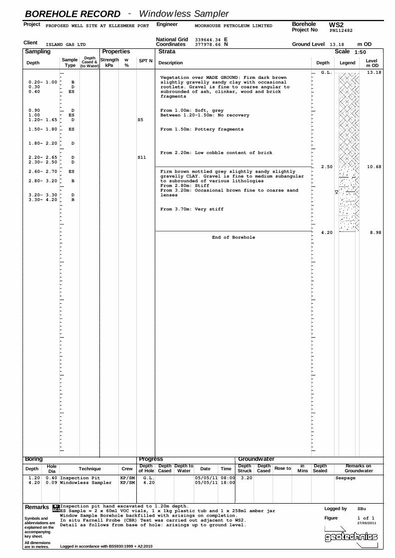
BOREHOLE RECORDProject
Client
Engineer BoreholeProject No
Sampling Properties Strata
DepthSampleType kPa
w%
Scale
Description Depth Legend
Boring Groundwater
Depth Technique Crew of Hole Cased Water Date Struck Cased Rose to Sealed Groundwater
Remarks
Symbols andabbreviations areexplained on theaccompanyingkey sheet.
All dimensionsare in metres.
Time MinsDiaHole
DepthCased &
(to Water)Strength
ProgressDepth Depth Depth to Depth Depth Depth Remarks onin
PROPOSED WELL SITE AT ELLESMERE PORT MOORHOUSE PETROLEUM LIMITED PN112482
339644.34 ISLAND GAS LTD 377978.66 13.18
G.L. 13.18 Vegetation over MADE GROUND: Firm dark brown
0.20- 1.00 B slightly gravelly sandy clay with occasional 0.30 D rootlets. Gravel is fine to coarse angular to 0.40 ES subrounded of ash, clinker, wood and brick
fragments
0.90 D From 1.00m: Soft, grey 1.00 ES Between 1.20-1.50m: No recovery 1.20- 1.65 D S5
1.50- 1.80 ES From 1.50m: Pottery fragments
1.80- 2.20 D
From 2.20m: Low cobble content of brick 2.20- 2.65 D S11 2.30- 2.50 D
2.50 10.68 2.60- 2.70 ES Firm brown mottled grey slightly sandy slightly
gravelly CLAY. Gravel is fine to medium subangular 2.80- 3.20 B to subrounded of various lithologies
From 2.80m: Stiff From 3.20m: Occasional brown fine to coarse sand
3.20- 3.30 D lenses 3.30- 4.20 B
From 3.70m: Very stiff
4.20 8.98 End of Borehole
1.20 0.40 Inspection Pit KP/SM G.L. 05/05/11 08:00 3.20 Seepage 4.20 0.09 Windowless Sampler KP/SM 4.20 05/05/11 18:00
Inspection pit hand excavated to 1.20m depth. ES Sample = 2 x 60ml VOC vials, 1 x 1kg plastic tub and 1 x 258ml amber jar Window Sample Borehole backfilled with arisings on completion. In situ Farnell Probe (CBR) Test was carried out adjacent to WS2. Detail as follows from base of hole: arisings up to ground level.
Windowless Sampler WS2
National Grid ENCoordinates
1:50 Ground Level m OD
Levelm OD
SPT N
Logged by SBu
Logged in accordance with BS5930:1999 + A2:2010
Figure 1 of 1 27/05/2011
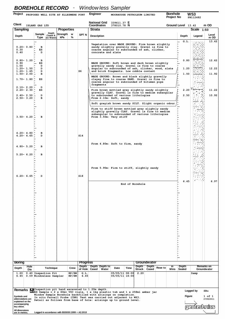
BOREHOLE RECORDProject
Client
Engineer BoreholeProject No
Sampling Properties Strata
DepthSampleType kPa
w%
Scale
Description Depth Legend
Boring Groundwater
Depth Technique Crew of Hole Cased Water Date Struck Cased Rose to Sealed Groundwater
Remarks
Symbols andabbreviations areexplained on theaccompanyingkey sheet.
All dimensionsare in metres.
Time MinsDiaHole
DepthCased &
(to Water)Strength
ProgressDepth Depth Depth to Depth Depth Depth Remarks onin
PROPOSED WELL SITE AT ELLESMERE PORT MOORHOUSE PETROLEUM LIMITED PN112482
339611.37 ISLAND GAS LTD 378010.78 13.42
G.L. 13.42 Vegetation over MADE GROUND: Firm brown slightly
0.20- 0.80 B sandy slightly gravelly clay. Gravel is fine to 0.30 ES coarse angular to subrounded of ash, clinker, 0.40 D concrete and slate
0.80- 1.20 B 0.80 12.62 0.90 ES MADE GROUND: Soft brown and dark brown slightly 1.00 D gravelly sandy clay. Gravel is fine to coarse 1.20- 1.50 D angular to subrounded of ash, clinker, wood, slate 1.20 12.22 1.20- 1.65 D S6 and brick fragments. Low cobble content 1.50- 2.00 B 1.50 11.92
MADE GROUND: Brown and black slightly gravelly 1.70- 1.80 ES clayey fine to coarse SAND. Gravel is fine to
coarse angular to subrounded of bitumen pipe fragments
2.10- 2.20 D 2.20- 2.30 ES Firm brown mottled grey slightly sandy slightly 2.20 11.22
gravelly CLAY. Gravel is fine to medium subangular 2.40- 2.50 D to subrounded of various lithologies 2.50 10.92 2.50- 3.20 B From 2.10m: Soft, sandy
Soft greyish brown sandy SILT. Slight organic odour
Firm to stiff brown mottled grey slightly sandy slightly gravelly CLAY. Gravel is fine to medium subangular to subrounded of various lithologies
3.50- 4.20 B From 3.50m: Very stiff
4.20- 4.80 B 4.20- 4.65 D S14
From 4.80m: Soft to firm, sandy 4.80- 5.20 B
5.20- 6.20 B
From 5.90m: Firm to stiff, slightly sandy
6.20- 6.65 D S18
6.45 6.97 End of Borehole
1.20 0.40 Inspection Pit KP/SM G.L. 05/05/11 08:00 2.20 Damp 6.45 0.09 Windowless Sampler KP/SM 6.45 05/05/11 18:00
Inspection pit hand excavated to 1.20m depth. ES Sample = 2 x 60ml VOC vials, 1 x 1kg plastic tub and 1 x 258ml amber jar Window Sample Borehole backfilled with arisings on completion. In situ Farnell Probe (CBR) Test was carried out adjacent to WS3. Detail as follows from base of hole: arisings up to ground level.
Windowless Sampler WS3
National Grid ENCoordinates
1:50 Ground Level m OD
Levelm OD
SPT N
Logged by SBu
Logged in accordance with BS5930:1999 + A2:2010
Figure 1 of 1 27/05/2011

BOREHOLE RECORDProject
Client
Engineer BoreholeProject No
Sampling Properties Strata
DepthSampleType kPa
w%
Scale
Description Depth Legend
Boring Groundwater
Depth Technique Crew of Hole Cased Water Date Struck Cased Rose to Sealed Groundwater
Remarks
Symbols andabbreviations areexplained on theaccompanyingkey sheet.
All dimensionsare in metres.
Time MinsDiaHole
DepthCased &
(to Water)Strength
ProgressDepth Depth Depth to Depth Depth Depth Remarks onin
PROPOSED WELL SITE AT ELLESMERE PORT MOORHOUSE PETROLEUM LIMITED PN112482
339600.72 ISLAND GAS LTD 378041.85 13.22
G.L. 13.22 0.00- 0.85 B Vegetation over MADE GROUND: Firm brown slightly
gravelly sandy clay with occasional rootlets. Gravel is fine to coarse angular to subrounded of
0.50 D ash, clinker, concrete, bitumen pipe fragments and 0.50 ES brick fragments
0.85- 1.00 B 0.85 12.37 0.90 D MADE GROUND: Soft dark brown slightly gravelly 1.00 ES sandy clay. Gravel is fine to coarse angular to 1.20- 1.65 D S8 subrounded of ash, clinker, wood and brick
fragments
1.60 D
2.00- 2.20 ES 2.00 11.22 MADE GROUND: Black slightly sandy fine to coarse angular to subrounded gravel of bitumen pipe
2.30 D fragments. Strong hydrocarbon odour 2.30 10.92 At 2.30m: Obstruction
End of Borehole
1.20 0.40 Inspection Pit KP/SM G.L. 05/05/11 08:00 1.30 1.15 20 Slow inflow 2.30 0.09 Windowless Sampler KP/SM 2.30 05/05/11 18:00
Inspection pit hand excavated to 1.20m depth. ES Sample = 2 x 60ml VOC vials, 1 x 1kg plastic tub and 1 x 258ml amber jar The Window Sample Borehole was terminated at a depth of 2.30 m due to the presence of an obstruction and the rig moved to WS4A. Window Sample Borehole backfilled with arisings on completion. In situ Farnell Probe (CBR) Test was carried out adjacent out WS4. Detail as follows from base of hole: arisings up to ground level.
Windowless Sampler WS4
National Grid ENCoordinates
1:50 Ground Level m OD
Levelm OD
SPT N
Logged by SBu
Logged in accordance with BS5930:1999 + A2:2010
Figure 1 of 1 27/05/2011

BOREHOLE RECORDProject
Client
Engineer BoreholeProject No
Sampling Properties Strata
DepthSampleType kPa
w%
Scale
Description Depth Legend
Boring Groundwater
Depth Technique Crew of Hole Cased Water Date Struck Cased Rose to Sealed Groundwater
Remarks
Symbols andabbreviations areexplained on theaccompanyingkey sheet.
All dimensionsare in metres.
Time MinsDiaHole
DepthCased &
(to Water)Strength
ProgressDepth Depth Depth to Depth Depth Depth Remarks onin
PROPOSED WELL SITE AT ELLESMERE PORT MOORHOUSE PETROLEUM LIMITED PN112482
339601.74 ISLAND GAS LTD 378042.51 13.21
G.L. 13.21 Vegetation over MADE GROUND: Firm brown slightly sandy clay with occasional rootlets. Gravel is fine to coarse angular to subrounded of ash, clinker, concrete, plastic and brick fragments
0.85 12.36 MADE GROUND: Soft dark brown slightly sandy slightly gravelly clay. Gravel is fine to coarse angular to subrounded of ash, clinker, wood and brick fragments. Slight organic odour
1.90 11.31 1.90- 2.20 B MADE GROUND: Black slightly sandy fine to coarse
angular to subrounded gravel of bitumen pipe fragments. Strong hydrocarbon odour
2.30 10.91 End of Borehole
1.20 0.40 Inspection Pit KP/SM G.L. 05/05/11 08:00 1.30 1.20 20 Slow inflow 2.30 0.09 Windowless Sampler KP/SM 2.30 05/05/11 18:00
Inspection pit hand excavated to 1.20m depth. The Window Sample Borehole was terminated at a depth of 2.30m due to the presence of an obstruction. Window Sample Borehole backfilled with arisings on completion. Detail as follows from base of hole: arisings up to ground level.
Windowless Sampler WS4A
National Grid ENCoordinates
1:50 Ground Level m OD
Levelm OD
Logged by SBu
Logged in accordance with BS5930:1999 + A2:2010
Figure 1 of 1 27/05/2011
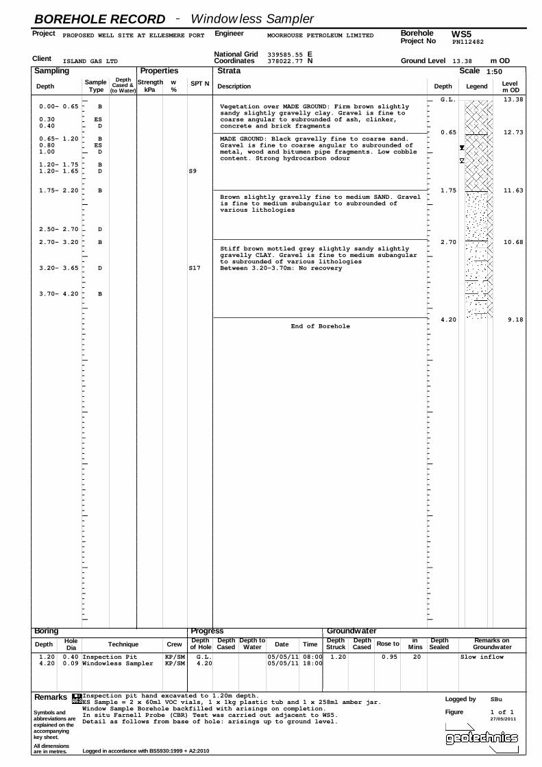
BOREHOLE RECORDProject
Client
Engineer BoreholeProject No
Sampling Properties Strata
DepthSampleType kPa
w%
Scale
Description Depth Legend
Boring Groundwater
Depth Technique Crew of Hole Cased Water Date Struck Cased Rose to Sealed Groundwater
Remarks
Symbols andabbreviations areexplained on theaccompanyingkey sheet.
All dimensionsare in metres.
Time MinsDiaHole
DepthCased &
(to Water)Strength
ProgressDepth Depth Depth to Depth Depth Depth Remarks onin
PROPOSED WELL SITE AT ELLESMERE PORT MOORHOUSE PETROLEUM LIMITED PN112482
339585.55 ISLAND GAS LTD 378022.77 13.38
G.L. 13.38 0.00- 0.65 B Vegetation over MADE GROUND: Firm brown slightly
sandy slightly gravelly clay. Gravel is fine to 0.30 ES coarse angular to subrounded of ash, clinker, 0.40 D concrete and brick fragments
0.65 12.73 0.65- 1.20 B MADE GROUND: Black gravelly fine to coarse sand. 0.80 ES Gravel is fine to coarse angular to subrounded of 1.00 D metal, wood and bitumen pipe fragments. Low cobble
content. Strong hydrocarbon odour 1.20- 1.75 B 1.20- 1.65 D S9
1.75- 2.20 B 1.75 11.63 Brown slightly gravelly fine to medium SAND. Gravel is fine to medium subangular to subrounded of various lithologies
2.50- 2.70 D
2.70- 3.20 B 2.70 10.68 Stiff brown mottled grey slightly sandy slightly gravelly CLAY. Gravel is fine to medium subangular to subrounded of various lithologies
3.20- 3.65 D S17 Between 3.20-3.70m: No recovery
3.70- 4.20 B
4.20 9.18 End of Borehole
1.20 0.40 Inspection Pit KP/SM G.L. 05/05/11 08:00 1.20 0.95 20 Slow inflow 4.20 0.09 Windowless Sampler KP/SM 4.20 05/05/11 18:00
Inspection pit hand excavated to 1.20m depth. ES Sample = 2 x 60ml VOC vials, 1 x 1kg plastic tub and 1 x 258ml amber jar. Window Sample Borehole backfilled with arisings on completion. In situ Farnell Probe (CBR) Test was carried out adjacent to WS5. Detail as follows from base of hole: arisings up to ground level.
Windowless Sampler WS5
National Grid ENCoordinates
1:50 Ground Level m OD
Levelm OD
SPT N
Logged by SBu
Logged in accordance with BS5930:1999 + A2:2010
Figure 1 of 1 27/05/2011
3
APPENDIX 3
In Situ Farnell Probe (CBR) Tests

INSITU TESTING - DCP field test
0 0 1 80 01 1 1 127 471 2 1 166 861 3 1 193 1131 4 1 221 1411 5 1 252 1721 6 1 263 1831 7 1 298 2181 8 1 321 2411 9 1 351 2711 10 1 376 2961 11 1 410 3301 12 1 461 3811 13 1 501 4211 14 1 546 4661 15 1 572 4921 16 1 591 5111 17 1 607 5271 18 1 632 5521 19 1 668 5881 20 1 700 6201 21 1 742 6621 22 1 783 7031 23 1 810 7301 24 1 818 7381 25 1 842 7621 26 2 60 7621 27 2 67 7691 28 2 80 7821 29 2 91 7931 30 2 100 8021 31 2 107 8091 32 2 112 8141 33 2 121 8231 34 2 128 8301 35 2 138 8401 36 2 144 8461 37 2 152 8541 38 2 160 8621 39 2 171 8731 40 2 181 8831 41 2 192 8941 42 2 204 9061 43 2 211 913
0 0 1 44 2 230 932172 5 1 45 2 242 944172 5 1 46 2 256 958662 21 1 47 2 268 970662 21 1 48 2 276 978762 26 1 49 2 287 989762 26 1 50 2 304 1006913 43 1 51 2 311 1013913 43 1 52 2 322 10241324 83 1 53 2 333 1035
Remarks
Proposed Well Site at Ellesmere Port
8.11
30.02
25.74
8.88
10.28
Form INS003 Rev 4
05/05/20110.00
WS11
PN11248280Client IGAS Energy
Location No.Test No Project No Initial Zero ReadingDate Test Started at (m)
Project
Sheet
1 of 2 CBR estimated using correlation in Highways Agency Interim Advice Note 73/06
Reading
(mm)
Depth bgl
(mm)
BLOWS
No.
12.73
Depth below
ground level
(mm)
30.63
20.00
Blows
No.Blows Total
34.40 7.18
DCP
mm/blowCBR %
Ro
d
0
200
400
600
800
1000
1200
1400
1600
0 20 40 60 80 100 120
No. of BLOWS
Dep
th b
elo
w g
rou
nd
level (m
m)

INSITU TESTING - DCP field testProposed Well Site at Ellesmere Port
Form INS003 Rev 4
05/05/20110.00
WS11
PN11248280Client IGAS Energy
Location No.Test No Project No Initial Zero ReadingDate Test Started at (m)
Project
1 54 2 338 10401 55 2 351 10531 56 2 366 10681 57 2 378 1080
1324 83 1 58 2 380 10821473 106 1 59 2 394 1096
1 60 2 402 11041 61 2 413 11151 62 2 428 11301 63 2 440 11421 64 2 450 11521 65 2 425 11271 66 2 468 11701 67 2 480 11821 68 2 491 11931 69 2 496 11981 70 2 508 12101 71 2 510 12121 72 2 524 12261 73 2 531 12331 74 2 546 12481 75 2 558 12601 76 2 561 1263
1 80 1 77 2 570 12722 60 1 78 2 581 12833 1 79 2 585 12874 1 80 2 596 1298
1 81 2 600 13021 82 2 610 13121 83 2 622 13241 84 2 630 13321 85 2 638 13401 86 2 648 13501 87 2 650 13521 88 2 656 13581 89 2 662 13641 90 2 672 13741 91 2 680 13821 92 2 691 13931 93 2 702 14041 94 2 706 14081 95 2 710 14121 96 2 712 14141 97 2 719 14211 98 2 731 14331 99 2 734 14361 100 2 738 14401 101 2 746 14481 102 2 750 14521 103 2 751 14531 104 2 762 14641 105 2 764 14661 106 2 771 1473
Remarks
CBR estimated using correlation in Highways Agency Interim Advice Note 73/06
Final Reading
842771
Zero
ReadingRod No
Depth bgl
(mm)
BLOWS
No.
DCP
mm/blowCBR %
6.48 41.91
Blows
No.
Reading
(mm)
Depth below
ground level
(mm)
Ro
d
Blows Total
Sheet
2 of 2

INSITU TESTING - DCP field test
0 0 1 110 01 1 1 150 401 2 1 161 511 3 1 173 631 4 1 187 771 5 1 202 921 6 1 210 1001 7 1 222 1121 8 1 228 1181 9 1 241 1311 10 1 243 1331 11 1 256 1461 12 1 261 1511 13 1 272 1621 14 1 282 1721 15 1 288 1781 16 1 291 1811 17 1 302 1921 18 1 309 1991 19 1 314 2041 20 1 321 2111 21 1 331 2211 22 1 342 2321 23 1 352 2421 24 1 362 2521 25 1 378 2681 26 1 392 2821 27 1 411 3011 28 1 432 3221 29 1 445 3351 30 1 453 3431 31 1 472 3621 32 1 481 3711 33 1 492 3821 34 1 511 4011 35 1 534 4241 36 1 560 4501 37 1 585 4751 38 1 608 4981 39 1 632 5221 40 1 667 5571 41 1 682 5721 42 1 692 5821 43 1 701 591
0 0 1 44 1 710 60040 1 1 45 1 716 60640 1 1 46 1 726 616
282 26 1 47 1 735 625282 26 1 48 1 740 630401 34 1 49 1 762 652401 34 1 50 1 773 663557 40 1 51 1 790 680557 40 1 52 1 804 694630 48 1 53 1 821 711
Remarks
Proposed Well Site at Ellesmere Port
27.41
9.65
29.18
26.00
9.13
Form INS003 Rev 4
05/05/20110.00
WS21
PN112482110Client IGAS Energy
Location No.Test No Project No Initial Zero ReadingDate Test Started at (m)
Project
Sheet
1 of 2 CBR estimated using correlation in Highways Agency Interim Advice Note 73/06
Reading
(mm)
Depth bgl
(mm)
BLOWS
No.
17.41
Depth below
ground level
(mm)
9.68
14.88
Blows
No.Blows Total
40.00 6.12
DCP
mm/blowCBR %
Ro
d
0
100
200
300
400
500
600
700
800
0 10 20 30 40 50 60
No. of BLOWS
Dep
th b
elo
w g
rou
nd
level (m
m)

INSITU TESTING - DCP field testProposed Well Site at Ellesmere Port
Form INS003 Rev 4
05/05/20110.00
WS21
PN112482110Client IGAS Energy
Location No.Test No Project No Initial Zero ReadingDate Test Started at (m)
Project
1 54 1 833 7231 55 1 844 7341 56 1 860 7501 57 1 871 761
630 48 1761 57 1
11111111111111111
1 110 12 13 14 1
111111111111111111111111111
Remarks
CBR estimated using correlation in Highways Agency Interim Advice Note 73/06
Final ReadingZero
ReadingRod No
Depth bgl
(mm)
BLOWS
No.
DCP
mm/blowCBR %
14.56 17.81
Blows
No.
Reading
(mm)
Depth below
ground level
(mm)
Ro
d
Blows Total
Sheet
2 of 2

INSITU TESTING - DCP field test
0 0 1 138 01 1 1 162 241 2 1 182 441 3 1 201 631 4 1 214 761 5 1 225 871 6 1 240 1021 7 1 249 1111 8 1 260 1221 9 1 262 1241 10 1 270 1321 11 1 272 1341 12 1 279 1411 13 1 280 1421 14 1 283 1451 15 1 286 1481 16 1 291 1531 17 1 297 1591 18 1 302 1641 19 1 311 1731 20 1 320 1821 21 1 332 1941 22 1 345 2071 23 1 367 2291 24 1 392 2541 25 1 410 2721 26 1 451 3131 27 1 480 3421 28 1 489 3511 29 1 510 3721 30 1 541 4031 31 1 563 4251 32 1 592 4541 33 1 629 4911 34 1 670 5321 35 1 708 5701 36 1 749 6111 37 1 823 6851 38 1 840 7021 39 1 851 7131 40 1 856 7181 41 1 860 7221 42 1 864 7261 43 1 870 732
0 0 1 44 1 872 73476 4 1 45 1 874 73676 4 1 46 1 879 741
122 8 1 47 1 881 743122 8 1 48 1 884 746164 18 1164 18 1207 22 1207 22 1532 34 1
Remarks
Depth below
ground level
(mm)
11.50
4.20
Blows
No.Blows Total
19.00 13.44
DCP
mm/blowCBR %
Ro
d Reading
(mm)
Depth bgl
(mm)
BLOWS
No.
66.26
Sheet
1 of 2 CBR estimated using correlation in Highways Agency Interim Advice Note 73/06
Client IGAS Energy
Location No.Test No Project No Initial Zero ReadingDate Test Started at (m)
Project
Form INS003 Rev 4
05/05/20110.00
WS31
PN112482138
Proposed Well Site at Ellesmere Port
22.85
24.54
9.24
10.75
27.08
0
100
200
300
400
500
600
700
800
0 10 20 30 40 50 60
No. of BLOWS
Dep
th b
elo
w g
rou
nd
level (m
m)

INSITU TESTING - DCP field test
Client IGAS Energy
Location No.Test No Project No Initial Zero ReadingDate Test Started at (m)
Project
Form INS003 Rev 4
05/05/20110.00
WS31
PN112482138
Proposed Well Site at Ellesmere Port
1111
532 34 1702 38 1702 38 1746 48 1
111111111111111
1 138 12 13 14 1
111111111111111111111111111
Remarks
Sheet
2 of 2
Reading
(mm)
Depth below
ground level
(mm)
4.40 63.08
Ro
d
Blows Total
Depth bgl
(mm)
BLOWS
No.
DCP
mm/blowCBR %
42.50 5.74
Blows
No.
Final ReadingZero
ReadingRod No
CBR estimated using correlation in Highways Agency Interim Advice Note 73/06

INSITU TESTING - DCP field test
0 0 1 93 01 1 1 138 451 2 1 154 611 3 1 166 731 4 1 174 811 5 1 190 971 6 1 203 1101 7 1 216 1231 8 1 227 1341 9 1 240 1471 10 1 252 1591 11 1 263 1701 12 1 280 1871 13 1 291 1981 14 1 306 2131 15 1 318 2251 16 1 332 2391 17 1 350 2571 18 1 364 2711 19 1 382 2891 20 1 402 3091 21 1 426 3331 22 1 448 3551 23 1 481 3881 24 1 512 4191 25 1 550 4571 26 1 573 4801 27 1 618 5251 28 1 671 5781 29 1 722 6291 30 1 763 6701 31 1 810 7171 32 1 842 7491 33 1 889 796
1111111111
0 0 145 1 145 1 1
309 20 1309 20 1480 26 1480 26 1796 33 1
11
Remarks
Proposed Well Site at Ellesmere Port
18.71
5.3845.14
Form INS003 Rev 4
05/05/20110.00
WS41
PN11248293Client IGAS Energy
Location No.Test No Project No Initial Zero ReadingDate Test Started at (m)
Project
Sheet
1 of 1 CBR estimated using correlation in Highways Agency Interim Advice Note 73/06
Reading
(mm)
Depth bgl
(mm)
BLOWS
No.
8.75
Depth below
ground level
(mm)
13.89
28.50
Blows
No.Blows Total
45.00 5.40
DCP
mm/blowCBR %
Ro
d
0
100
200
300
400
500
600
700
800
900
0 5 10 15 20 25 30 35
No. of BLOWS
Dep
th b
elo
w g
rou
nd
level (m
m)
INSITU TESTING - DCP field test
0 0 1 103 01 1 1 133 301 2 1 156 531 3 1 170 671 4 1 181 781 5 1 192 891 6 1 201 981 7 1 210 1071 8 1 222 1191 9 1 228 1251 10 1 236 1331 11 1 250 1471 12 1 256 1531 13 1 271 1681 14 1 283 1801 15 1 306 2031 16 1 318 2151 17 1 334 2311 18 1 356 2531 19 1 374 2711 20 1 405 3021 21 1 448 3451 22 1 482 3791 23 1 536 4331 24 1 570 4671 25 1 582 4791 26 1 604 5011 27 1 630 5271 28 1 651 5481 29 1 662 5591 30 1 674 5711 31 1 683 5801 32 1 702 5991 33 1 713 6101 34 1 720 6171 35 1 732 6291 36 1 741 6381 37 1 756 6531 38 1 763 6601 39 1 771 6681 40 1 774 6711 41 1 782 6791 42 1 785 6821 43 1 790 687
0 0 1 44 1 791 68853 2 1 45 1 792 68953 2 4 49 1 803 700
180 14 4 53 1 813 710180 14 4 57 1 821 718302 20 4 61 1 832 729302 20 4 65 1 841 738479 25 4 69 1 850 747479 25 4 73 1 861 758653 37 4 77 1 866 763
Remarks
Depth below
ground level
(mm)
10.58
20.33
Blows
No.Blows Total
26.50 9.45
DCP
mm/blowCBR %
Ro
d Reading
(mm)
Depth bgl
(mm)
BLOWS
No.
12.51
Sheet
1 of 2 CBR estimated using correlation in Highways Agency Interim Advice Note 73/06
Client IGAS Energy
Location No.Test No Project No Initial Zero ReadingDate Test Started at (m)
Project
Form INS003 Rev 4
05/05/20110.00
WS51
PN112482103
Proposed Well Site at Ellesmere Port
24.94
6.96
17.88
35.40
14.50
0
100
200
300
400
500
600
700
800
900
0 20 40 60 80 100
No. of BLOWS
Dep
th b
elo
w g
rou
nd
level (m
m)

INSITU TESTING - DCP field test
Client IGAS Energy
Location No.Test No Project No Initial Zero ReadingDate Test Started at (m)
Project
Form INS003 Rev 4
05/05/20110.00
WS51
PN112482103
Proposed Well Site at Ellesmere Port
4 81 1 874 771111
653 37 1710 53 1710 53 1771 81 1
111111111111111
1 103 12 13 14 1
111111111111111111111111111
Remarks
Sheet
2 of 2
Reading
(mm)
Depth below
ground level
(mm)
2.18 132.60
Ro
d
Blows Total
Depth bgl
(mm)
BLOWS
No.
DCP
mm/blowCBR %
3.56 78.85
Blows
No.
Final ReadingZero
ReadingRod No
CBR estimated using correlation in Highways Agency Interim Advice Note 73/06

4
APPENDIX 4
Laboratory Test Results - Contamination
Unit 3 Deeside Point
Zone 3
Deeside Industrial Park
Deeside
Geotechnics
No.4225
Attention :
Date :
Your reference :
Our reference :
Location :
Date samples received :
Status :
Test Report 11/3944 Batch 1
17th May, 2011
PN11282
ELLESMERE PORT,PROPOSED WELL SITE
9th May, 2011
Final report
Jones Environmental Laboratory
CH5 2UA
Tel: +44 (0) 1244 833780
Fax: +44 (0) 1244 833781
Sarah Burt
Unit 1B Borders Industrial Park
River Lane Chester
CH4 8RJ
Issue : 1
Ten samples were received for analysis on 9th May, 2011, which was completed on 17th May 2011. Please find attached our Test Report which should be read with notes at the end of the report and should include all sections if reproduced. Interpretations and opinions are outside the
scope of any accreditation, and all results relate only to samples supplied. All analysis is carried out on as received samples and reported on a dry weight basis unless stated otherwise. Results are not surrogate corrected.
J W Farrell- Jones CChem FRSCChartered Chemist
QF‐PM 3.1 v9Please include all sections of this report if it is reproduced
All solid results are expressed on a dry weight basis unless stated otherwise 1 of 5

Client Name: Report : Solid
Reference:Location: Solids: V=60g VOC jar, J=250g glass jar, T=plastic tub
Contact:JE Job No.: 11/3944
J E Sample No. 1-4 5-8 9-12 13-16 17-20 21-24 25-28 29-32 33-36 37-40
Sample ID WS1 WS1 WS2 WS2 WS3 WS3 WS4 WS4 WS5 WS5
Depth 0.3 1.5 0.4 2.60-2.70 0.9 1.70-1.80 1.0 2.0-2.20 0.3 0.8
COC No / misc
Containers V J T V J T V J T V J T V J T V J T V J T V J T V J T V J T
Sample Date 05/05/2011 05/05/2011 05/05/2011 05/05/2011 05/05/2011 05/05/2011 05/05/2011 05/05/2011 05/05/2011 05/05/2011
Sample Type Soil Soil Soil Soil Soil Soil Soil Soil Soil Soil
Batch Number 1 1 1 1 1 1 1 1 1 1
Date of Receipt 09/05/2011 09/05/2011 09/05/2011 09/05/2011 09/05/2011 09/05/2011 09/05/2011 09/05/2011 09/05/2011 09/05/2011
Arsenic #M 13.5 6.9 9.8 6.5 13.0 7.5 37.5 4.9 11.8 9.5 <0.5 mg/kg TM30/PM15
Cadmium #M 0.3 <0.1 0.1 <0.1 0.4 <0.1 0.4 0.9 <0.1 0.8 <0.1 mg/kg TM30/PM15
Chromium #M 32.4 28.3 26.8 40.8 27.6 35.6 57.6 74.3 36.7 35.9 <0.5 mg/kg TM30/PM15
Copper #M 38 24 20 15 44 16 68 25 27 24 <1 mg/kg TM30/PM15
Lead #M 83 5 44 8 119 8 435 65 21 88 <5 mg/kg TM30/PM15
Mercury #M <0.1 0.1 <0.1 <0.1 0.4 <0.1 0.1 0.2 <0.1 0.4 <0.1 mg/kg TM30/PM15
Nickel #M 35.1 30.9 24.5 39.8 29.3 36.5 33.7 137.5 35.9 59.3 <0.7 mg/kg TM30/PM15
Selenium #M <1 <1 <1 <1 1 <1 <1 2 <1 <1 <1 mg/kg TM30/PM15
Zinc #M 137 40 62 39 187 38 163 325 73 81 <5 mg/kg TM30/PM15
Sulphate as SO4 (2:1 Ext) #M 0.0228 0.0373 0.0135 0.0103 <0.0015 0.0041 0.0256 0.0901 <0.0015 0.0350 <0.0015 g/l TM38/PM20
Organic Matter 6.6 <0.2 2.1 <0.2 8.6 0.5 12.8 40.9 2.4 74.1 <0.2 % TM21/PM24
pH #M 8.12 8.53 7.62 7.53 7.47 7.36 7.39 6.95 7.69 7.47 <0.01 pH units TM73/PM11
Sample Type Sandy Clay Clay Sandy Clay Clay Sandy Clay Sandy Clay Sandy Clay Sandy Clay Sandy Clay Sandy Clay PM13/PM0
LOD Units MethodNo.
Jones Environmental LaboratoryGeotechnics
PN11282
ELLESMERE PORT,PROPOSED WELL SITE
Sarah Burt
Please see attached notes for all abbreviations and acronyms
QF‐PM 3.1 v9Please include all sections of this report if it is reproduced
All solid results are expressed on a dry weight basis unless stated otherwise 2 of 5
Sample Colour Medium Brown Medium Brown Medium Brown Medium Brown Medium Brown Medium Brown Dark Brown Dark Brown Medium Brown Medium Brown PM13/PM0
Other Items stones none stones nones wood stones stones vegatation stones stones PM13/PM0
QF‐PM 3.1 v9Please include all sections of this report if it is reproduced
All solid results are expressed on a dry weight basis unless stated otherwise 2 of 5

SOILS
G S S
As surface waters require different sample preparation to groundwaters the laboratory must be informed of the water type when submitting samples. All samples are treated as groundwaters and analysis performed on settled samples unless we are instructed otherwise.
Where appropriate please make sure that our detection limits are suitable for your needs, if they are not, please notify us immediately.
Please note we are not a Drinking Water Inspectorate (DWI) Approved Laboratory . It is important that detection limits are carefully considered when requesting water analysis.
If you have not already done so, please send us a purchase order if this is required by your company.
All analysis is reported on a dry weight basis unless stated otherwise. Results are not surrogate corrected. Samples are dried at 35°C unless otherwise stated. Moisture content for CEN Leachate tests are dried at 105°C
NOTES TO ACCOMPANY ALL SCHEDULES AND REPORTS
Please note we are only MCERTS accredited for sand, loam and clay and any other matrix is outside our scope of accreditation.
Asbestos screens where requested will be undertaken by a UKAS accredited laboratory.
WATERS
Where an MCERTS report has been requested, you will be notified within 48 hours of any samples that have been identified as being outside our MCERTS scope. As validation has been performed on clay, sand and loam, only samples that are predominantly these matrices, or combinations of them will be within our MCERTS scope. If samples are not one of a combination of the above matrices they will not be marked as MCERTS accredited.
All samples will be discarded one month after the date of reporting, unless we are instructed to the contrary. If we are instructed to keep samples, a storage charge of £1 (1.5 Euros) per sample per month will be applied until we are asked to dispose of them.
It is assumed that you have taken representative samples on site and require analysis on a representative subsample. Stones will generally be included unless we are requested to remove them.
UKAS accreditation applies to surface water and groundwater and one other matrix which is analysis specific, any other liquids are outside our scope of accreditation
QF‐PM 3.1 v9 Please include all sections of this report if it is reproducedAll solid results are expressed on a dry weight basis unless stated otherwise 3 of 5
DEVIATING SAMPLES
$
^
&
~
SURROGATES
AQC's
Samples must be received in a condition appropriate to the requested analyses. All samples should be submitted to the laboratory in suitable containers with sufficient ice packs to sustain an appropriate temperature for the requested analysis. If this is not the case you will be informed and any analysis that may be compromised highlighted on your schedule/ report by the use of a symbol.
The use of any of the following symbols indicates that the sample was deviating and the test result may be unreliable:
Sample temperature on receipt considered inappropriate for analysis requested.
Samples exceeding recommended holding times.
Samples received in inappropriate containers (e.g. volatile samples not submitted in VOC jars/vials).
No sampling date given, unable to confirm if samples are with acceptable holding times.
Surrogate compounds are added during the preparation process to monitor recovery of analytes. However low recovery is often due to peat, clay or other organic rich matrices. For waters this can be due to oxidants, surfactants, organic rich sediments or remediation fluids. Acceptable limits for most organic methods are 50 - 150%. Results are not surrogate corrected.
Where AQC's fall outside UKAS/MCERTS criteria analysis is repeated if possible.
QF‐PM 3.1 v9 Please include all sections of this report if it is reproducedAll solid results are expressed on a dry weight basis unless stated otherwise 3 of 5

#
M
NAD
ND
SS
*
W
+
++
SE
SV
DR
ABBREVIATIONS and ACRONYMS USED
UKAS accredited.
No Asbestos Detected.
Analysis subcontracted to a Jones Environmental approved laboratory.
Results expressed on as received basis.
AQC is outside our current performance criteria. Results should be considered as indicative only and are not accredited. However the AQC is within UKAS/MCERTS acceptance criteria.
Result outside calibration range, results should be considered as indicative only and are not accredited.
Dilution required.
Surrogate recovery outside performance criteria. This may be due to a matrix effect.
Surrogate recovery outside performance criteria. Results not accredited.
Calibrated against a single substance.
None Detected (usually refers to VOC and/SVOC TICs).
MCERTS accredited.
QF‐PM 3.1 v9 Please include all sections of this report if it is reproducedAll solid results are expressed on a dry weight basis unless stated otherwise 4 of 5QF‐PM 3.1 v9 Please include all sections of this report if it is reproducedAll solid results are expressed on a dry weight basis unless stated otherwise 4 of 5

Method Code Appendix
Test Method No. Description
Prep Method No. (if
appropriate)Description UKAS
MCERTS (soils only)
Analysis done on As Received (AR) or Air
Dried (AD)
Solid Results expressed on Dry/Wet basis
PM13 Soil Typing for MCERTS PM0 No Preparation AR
TM21 TOC and TC by Combustion PM24 Eltra preparation AD DRY
TM30 Metals by ICP-OES PM15 Aqua Regia extraction (Soils) Yes Yes AD DRY
TM38 SO4,Cl,NO3,NO2,F,PO4, Amm N2,ThioCN by Aquakem PM20 1:2 soil to water extraction Yes Yes AD DRY
TM73 pH in by Metrohm PM11 1:2.5 soil/water extraction Yes Yes AR WET
Jones Environmental Laboratory
QF‐PM 3.1 v9 Please include all sections of this report if it is reproduced 5 of 5QF‐PM 3.1 v9 Please include all sections of this report if it is reproduced 5 of 5

5APPENDIX 5
NRM Laboratory Results


6
APPENDIX 6
Landscape Proposals Drawing


7
APPENDIX 7
Design Loading Calculations
Analysed by
Cud= Cuk= 35 kN/m2
φ´pd= φ´pk= 35 º
Subgrade Unit Weight γ´sd= γ´sk= 19 kN/m3
Platform Unit Weight γpd= γpk = 20 kN/m3
Source of data
Width Wd= Wk= 0.8 m.
Length Case 1 Lld= Llk = 4 m.
Length Case 2 L2d= L2k = 3.5 m.
q1k = 100 kN/m2
q2k = 200 kN/m2
Calculations
Nc = 5.14
Nγp = 48.0
Kptanδ = 3.1
sc1 =1+ 0.2 (W/L) = 1.04 1.05
sγ1 =1 - 0.3 (W/L) = 0.94 0.93
sp1 =1+ (W/L) = 1.2 1.23
Rd = Nc x Cud x sc1 (kPa) = 35 x 5.14 x 1.04 = 187 kPa
Case 1 loading kPa 200 kPa Hence q1d>Rd
Case 2 loading kPa 300 kPa Hence q2d>Rd
Platform Capacity 361kPa
Subgrade Capacity 187kPa
361 kPa
q1d= 1.6xq1k= 160
q2d= 1.2xq2k= 240
Case 1 loading, D1 = {Wd[q1d - Cud x Nc x sc1] / [γ x Kptanδ x sp1] }^0.5 (where q1d = 1.6 x q1k) =
Case 2 loading, D2 = {Wd[q2d - Cud x Nc x sc2] / [γ x Kptanδ x sp2] }^0.5 (where q2d = 1.2 x q2k) =
Track Width, Wd = 0.8m
φ´p= 35º 0.75m
Cu = 35kPa
Remarks
Minimum subgrade strength criteria in BR470 met.
WORKING PLATFORMS FOR TRACKED PLANT - Calculations for Clay Subgrade
Subgrade Undrained Shear Strength Cu
Ellesmere Port
Project Number
Ground Properties - Design values
PN112482
DateProject Name
In accordance with "Working Platforms for Tracked Plant" BRE Publication BR 470, 2004
Client
Moorhouse Petroleum KN / SB
Characteristic Loading, Case 2
Characteristic Loading, Case 1
Plant Properties - Track Width W, Effective Track Length L and Characteristic Loadings
Shape factors for Case 1 Shape factors for Case 2
sufficient to ensure that the subgrade does not materially affect bearing capacity:
Platform Material Capacity =
31st May 2011
q1d=2.0xq1k=
Working Platform Angle of Shearing Resistance φ´p
sc2=1+0.2 (W/L) =
Design loading is calculated for two loading conditions.
Check that platform material is stronger than subgrade:
Platform Required
Calculate required thickness of platform:
Cud x Nc x sc =
kPa Hence, platform material can enhance capacity
0.3m
The greater of the two thicknesses of platform material should be adopted as the design value.
kPa Hence, platform material can enhance capacity
Platform is Stronger than Subgrade
sγ2=1- 0.3 (W/L) =
Check that subgrade (capacity=Rd) cannot provide required bearing resistance without a working platform
sp2 =1+ (W/L) =
q2d=1.5xq2k= Platform Required
0.5 x γp x Wd x Nγp x sγ =
Check that platform material can provide required bearing resistance when placed at a thickness
Form CALC001c Version 1.0
0.75m
(Minimum Thickness)
Sheet 1 of 2
Clay Subgrade
Good Quality
Platform Material
Platform
Thickness
Sketch Not
to Scale

Analysed by
WORKING PLATFORMS FOR TRACKED PLANT - Calculations for Clay Subgrade
Ellesmere Port
Project Number
PN112482
DateProject Name
In accordance with "Working Platforms for Tracked Plant" BRE Publication BR 470, 2004
Client
Moorhouse Petroleum KN / SB 31st May 2011
Form CALC001c Version 1.0
Geogrid Properties
Strength, Tult kN/m = 30 Td=Tult/2= 15 Data for
Case 1 loading D1={Wd [q1d - Cud x Nc x sc1 - (2Td/Wd)] / [ γ x Kptanδ x sp1]}^0.5 where q1d=1.6q1k
D1= 0.3m
Case 2 loading D2={Wd [q2d - Cud x Nc x sc2 - (2Td/Wd)] / [ γ x Kptanδ x sp2]}^0.5 where q2d=1.2q2k
D2= 0.39m
namely 0.39 m
q1d = 1.25 q1k = 125 Rd= 201.07 condition met
q2d = 1.05q2k = 210 Rd= 203.22
0.47 m
Check q1d>Rd and q2d>Rd
Case 1 - Rd = 207.88 >q1d Condition Met
Case 2 - Rd = 210.20 >q2d Condition Met Therefore adopt thickness of 0.47 m
Summary
Track Width, Wd = 0.8m
φ´p= 35º 0.47
Cu= 35kPa
Thickness= 0.75 m.
Thickness= 0.47 m.
Geosynthetic Reinforcement adopted is Tensar TriAX Geogrids
Remarks
Without geosynthetic reinforcement
condition not met
The minimum acceptable cover to the reinforcement should be 0.30m.
When effect of reinforcement is ignored, Rd should be >both q1d and q2d where:
The larger of the two thicknesses should be used for design purposes,
This does not satisfy conditions. PLATFORM THICKNESS MUST BE INCREASED.
Rd = Cud x Nc x sc + (D2/Wd) x γp x Kptanδ x sp
The design thickness of platform should also satisfy the following conditions:
Tensar TriAX Geogrids
To meet these conditions increase platform thickness to
However, it might be preferable to use geosynthetic reinforcement and a platform that is not so thick.
Sheet 2 of 2
With geosynthetic reinforcement
Good Quality
Platform Material
Clay Subgrade
Platform
Thickness
mGeosynthetic
Reinforcement
Sketch Not
to Scale

8
APPENDIX 8
Exploratory Hole Location Plan


9
APPENDIX 9
Investigation Techniques and General Notes
Geotechnics Limited © The Geotechnical Centre, 203 Torrington Avenue, Tile Hill, Coventry. CV4 9AP
INVESTIGATION TECHNIQUES INTRODUCTION The following brief review of Ground Investigation techniques, generally used as part of most Site Investigations in the UK, summarises their methodology, advantages and limitations. Detailed descriptions of the techniques are available and can be provided on request. This review should be read in conjunction with the accompanying General Notes. TRIAL PITS The trial pit is amongst the most simple yet effective means of identifying shallow ground conditions on a site. Its advantages include simplicity, speed, potential accuracy and cost-effectiveness. The trial pit is most commonly formed using a backacting excavator which can typically determine ground conditions to some 4 metres below ground level. Hand excavation is often used to locate, expose and detail existing foundations, features or services. In general, it is difficult to extend pits significantly below the water table in predominantly granular soils, where flows can cause instability. Unless otherwise stated, the trial pits will not have been provided with temporary side support during their construction. Under such circumstances ground conditions to some 1.20 metres can be closely inspected, subject to stability assessment, but below this depth, entrance into the pit is not permitted in the absence of shoring and hence observations will have been made from ground surface and samples taken from the excavator bucket. Trends in strata type, level and thickness can be determined, shear surfaces identified and the behaviour of plant, excavation sides and excavated materials can be related to the construction process. They are particularly valuable in land slip investigations. Some types of insitu test can be undertaken in such pits and large disturbed or block samples obtained. CABLE PERCUSSION BORING The light Cable Percussion technique of soft ground boring, typically at a diameter of 150mm, is a well established simple and flexible method of boring vertical holes and generally allows data to be obtained in respect of strata conditions other than rock. A tubular cutter (for cohesive soils) or shell with a flap valve (for granular soils) is repeatedly lifted and dropped using a winch and rope operating from an “A” frame. Soil which enters these tools is regularly removed and either sampled for subsequent examination or test, or laid to one side for backfilling. Steel casing will have been used to prevent collapse of the borehole sides where necessary. A degree of disturbance of soil and mixing of layers is inevitable and the presence of very thin layers of different soils within a particular stratum may not be identified. Changes in strata type can only be detected on recognition of a change in soil samples at surface, after the interface has been passed. For the foregoing reasons, depth measurements should not be considered to be more accurate than 0.10 metre. In cohesive soils cylindrical samples are retrieved by driving or pushing in 100mm nominal diameter tubes. In soft soils, piston sampling or vane testing may be undertaken. In granular soils and often in cohesive materials, insitu Standard Penetration Tests (SPT’s) are performed. The SPT records the number of standard blows required to drive a 50mm diameter open or cone ended probe for 300mm after an initial 150mm penetration. A modified method of recording is used in more dense strata. Small disturbed samples are obtained throughout. The technique can determine ground conditions to depths in excess of 30 metres under suitable circumstances and usually causes less surface disturbance than trial pitting. ROTARY DRILLING Rotary Drilling to produce cores by rotating an annular diamond-impregnated tube or barrel into the ground is the technique most appropriate to the forming of site investigation boreholes through rock or other hard strata. It has the advantage of being able to be used vertically or at an angle. Core diameters of less than 100mm are most common for site investigation purposes. Core is normally retrieved in plastic lining tubes. A flushing fluid such as air, water or foam is used to cool the bit and carry cuttings to the surface. Examination of cores allows detailed rock description and generally enables angled discontinuity surfaces to be observed. However, vertical holes do not necessarily reveal the presence of vertical or near-vertical fissures or joint discontinuities. The core type and/or techniques used. Where open hole rotary drilling is employed, descriptions of strata result from examination at surface of small particles ejected from the borehole in the flushing medium. In consequence, no indication of fissuring, bedding, consistency or degree of weathering can be obtained. Small scale plant can be used for auger drilling to limited depths where access is constrained. Depths in excess of 60 metres can be achieved under suitable circumstances using rotary techniques, with minimal surface disturbance.
WINDOW SAMPLING This technique involves the driving of an open-ended tube into the ground and retrieval of the soil which enters the tube. The term “window sample” arose from the original device which had a “window” or slot cut into the side of the tube through which samples were taken. This has now been superseded by the use of a thin-walled plastic liner within a sampler which has a solid wall. Diameters range from 36 to 86mm. Such samples can be used for qualitative logging, selection of samples for classification and chemical analysis and for obtaining a rudimentary assessment of strength. Driving devices can be hand-held or machine mounted and the drive tubes are typically in 1m lengths. The hole formed is not cased, however, and hence the success of this technique is limited when soils and groundwater conditions are such that the sides of the hole collapse on withdrawal of the sampler. Obstructions within the ground, the density of the material or its strength can also limit the depth and rate of penetration of this light-weight investigation technique. Nevertheless, it is a valuable tool where access is constrained such as within buildings or on embankments. Depths of up to 8m can be achieved in suitable circumstances but depths of 4m to 6m are more common. EXPLORATORY HOLE RECORDS The data obtained by these techniques are generally presented on Trial Pit, Borehole, Drillhole or Window Sample Records. The descriptions of strata result from information gathered from a number of sources which may include published geological data, preliminary field observations and descriptions, insitu test results, laboratory test results and specimen descriptions. A key to the symbols and abbreviations used accompanies the records. The descriptions on the exploratory hole records accommodate but may not necessarily be identical to those on any preliminary records or the laboratory summaries. The records show ground conditions at the exploratory hole locations. The degree to which they can be used to represent conditions between or beyond such holes, however, is a matter for geological interpretation rather than factual reporting and the associated uncertainties must be recognised. DYNAMIC PROBING This technique typically measures the number of blows of a standard weight falling over a standard height to advance a cone-ended rod over sequential standard distances (typically 100mm). Some devices measure the penetration of the probe per standard blow. It is essentially a profiling tool and is best used in conjunction with other investigation techniques where site-specific correlation can be used to delineate the distribution of soft or loose soils or the upper horizon of a dense or strong layer such as rock. Both machine-driven and hand-driven equipment is available, the selection depending upon access restrictions and the depth of penetration required. It is particularly useful where access for larger equipment is not available, disturbance is to be minimised or where there are cost constraints. No samples are recovered and some techniques leave a sacrificial cone head in the ground. As with other lightweight techniques, progress is limited in strong or dense soils. The results are presented both numerically and graphically. Depths of up to 10m are commonly achieved in suitable circumstances. The hand-driven DCP probing device has been calibrated by the TRL to provide a profile of CBR values over a range of depths of up to 1.50m. INSTRUMENTATION The most common form of instrument used in site investigation is either the standpipe or else the standpipe piezometer which can be installed in investigation holes. They are used to facilitate monitoring of groundwater levels and water sampling over a period of time following site work. Normally a standpipe would be formed using rigid plastic tubing which has been perforated or slotted over much of its length whilst a standpipe piezometer would have a filter tip which would be placed at a selected level and the hole sealed above and sometimes below to isolate the zone of interest. Groundwater levels are determined using an electronic “dipmeter” to measure the depth to the water surface from ground level. Piezometers can also be used to measure permeability. They are simple and inexpensive instruments for long term monitoring but response times can limit their use in tidal areas and access to the ground surface at each instrument is necessary. Remote reading requires more sophisticated hydraulic, electronic or pneumatic equipment. Settlement can be monitored using surface or buried target plates whilst lateral movement over a range of depths is monitored using slip indicator or inclinometer equipment.

Geotechnics Limited © The Geotechnical Centre, 203 Torrington Avenue, Tile Hill, Coventry. CV4 9AP
GENERAL NOTES 1. The report is prepared for the exclusive use of the Client named in the
document and copyright subsists with Geotechnics Limited. Prior written
permission must be obtained to reproduce all or part of the report. It is
prepared on the understanding that its contents are only disclosed to
parties directly involved in the current investigation, preparation and
development of the site.
2. Further copies may be obtained with the Client's written permission,
from Geotechnics Limited with whom the master copy of the document
will be retained.
3. The report and/or opinion is prepared for the specific purpose stated in
the document and in relation to the nature and extent of proposals
made available to Geotechnics Limited at that time. Re-consideration
will be necessary should those details change. The recommendations
should not be used for other schemes on or adjacent to the site without
further reference to Geotechnics Limited.
4. The assessment of the significance of the factual data, where called for,
is provided to assist the Client and his Engineer and/or Advisers in the
preparation of their designs.
5. The report is based on the ground conditions encountered in the
exploratory holes together with the results of field and laboratory testing
in the context of the proposed development. The data from any
commissioned desk study and site reconnaissance are also drawn upon.
There may be special conditions appertaining to the site, however, which
are not revealed by the investigation and which may not be taken into
account in the report.
6. Methods of construction and/or design other than those proposed by the
designers or referred to in the report may require consideration during
the evolution of the proposals and further assessment of the
geotechnical and any geoenvironmental data would be required to
provide discussion and evaluations appropriate to these methods.
7. The accuracy of results reported depends upon the technique of
measurement, investigation and test used and these values should not be
regarded necessarily as characteristics of the strata as a whole (see
accompanying notes on Investigation Techniques). Where such
measurements are critical, the technique of investigation will need to be
reviewed and supplementary investigation undertaken in accordance
with the advice of the Company where necessary.
8. The samples selected for laboratory test are prepared and tested in
accordance with the relevant Clauses of BS 1377 Parts 1 to 8, where
appropriate, in Geotechnics Limited’s UKAS accredited Laboratory,
where possible. A list of tests is given.
9. Tests requiring the use of another laboratory having UKAS accreditation
where possible are identified.
10. Any unavoidable variations from specified procedures are identified in
the report.
11. Specimens are cut vertically, where this is relevant and can be identified,
unless otherwise stated.
12. All the data required by the test procedures are recorded on
individual test sheets but the results in the report are presented in
summary form to aid understanding and assimilation for design
purposes. Where all details are required, these can be made
available.
13. Whilst the report may express an opinion on possible
configurations of strata between or beyond exploratory holes, or on
the possible presence of features based on either visual, verbal,
written, cartographical, photographic or published evidence, this is
for guidance only and no liability can be accepted for its accuracy.
14. Classification of materials as Made Ground is based on the
inspection of retrieved samples or exposed excavations. Where it is obvious that foreign matter such as paper, plastic or metal is present, classification is clear. Frequently, however, for fill materials that arise from the adjacent ground or from the backfilling of excavations, their visual characteristics can closely resemble those of undisturbed ground. Other evidence such as site history, exploratory hole location or other tests may need to be drawn upon to provide clarification. For these reasons, classification of soils on the exploratory hole records as either Made Ground or naturally occurring strata, the boundary between them and any interpretation that this gives rise to should be regarded as provisional and subject to re-evaluation in the light of further data.
15. The classification of materials as Topsoil is generally based on
visual description and should not be interpreted to mean that the material so described complies with the criteria for Topsoil used in BS 3882 (2007). Specific testing would be necessary where such definition is a requirement.
16. Ground conditions should be monitored during the construction of
the works and the report should be re-evaluated in the light of
these data by the supervising geotechnical engineers.
17. Any comments on groundwater conditions are based on
observations made at the time of the investigation, unless specifically stated otherwise. It should be noted, however, that the observations are subject to the method and speed of boring, drilling or excavation and that groundwater levels will vary due to seasonal or other effects.
18. Any bearing capacities for conventional spread foundations which
are given in the report and interpreted from the investigation are for bases at a minimum depth of 1m below finished ground level in naturally occurring strata and at broadly similar levels throughout individual structures, unless otherwise stated. The foundations should be designed in accordance with the good practice embodied in BS 8004:1986 - Foundations, supplemented for housing by NHBC Standards. Foundation design is an iterative process and bearing pressures may need adjustment or other measures may need to be taken in the context of final layouts and levels prior to finalisation of proposals.
19. Unless specifically stated, the investigation does not take account
of the possible effects of mineral extraction or of gases from fill or
natural sources within, below or outside the site.
20. The costs or economic viability of the proposals referred to in the
report, or of the solutions put forward to any problems
encountered, will depend on very many factors in addition to
geotechnical or geoenvironmental considerations and hence their
evaluation is outside the scope of the report.
Related Documents


