ELG4139: Passive Filters • A filter is a system that processes a signal in some desired fashion. • There are two broad categories of filters: – An analog filter processes continuous-time signals – A digital filter processes discrete-time signals. • The analog or digital filters can be subdivided into four categories: – Lowpass Filters – Highpass Filters – Bandstop Filters – Bandpass Filters

Welcome message from author
This document is posted to help you gain knowledge. Please leave a comment to let me know what you think about it! Share it to your friends and learn new things together.
Transcript

ELG4139: Passive Filters
• A filter is a system that processes a signal in some desired
fashion.
• There are two broad categories of filters:
– An analog filter processes continuous-time signals
– A digital filter processes discrete-time signals.
• The analog or digital filters can be subdivided into four
categories:
– Lowpass Filters
– Highpass Filters
– Bandstop Filters
– Bandpass Filters
Series Resonance
LCf
LCf
CfLf
resonanceFor
fCjRfLjfZ s
2
1
)2(
1
2
12
:
2
12)(
0
2
20
00
CRfQ
LCffrom
CfLSubstitute
R
Lf
Resistance
resonance at inductance of ReactanceQ
s
s
0
020
2
0
2
1
2
1
)()2(
1
2

Series Resonance
f
f
f
fjQRfZ
R
LfQand
LCfSubstitute
LCfff
f
R
LfjR
fRCR
fLjR
fCjfLjRfZ
ss
s
s
0
0
00
02
0
0
1)(
2
2
1
)2(
121
2
121
2
12)(
f
f
f
fjQ
f
f
f
fjQ
R
f
f
f
fjQ
R
fZ
ss
R
s
sR
s
s
s
s
0
0
0
0
0
0
1
1
1
1
/
)(
V
VVIV
VVI
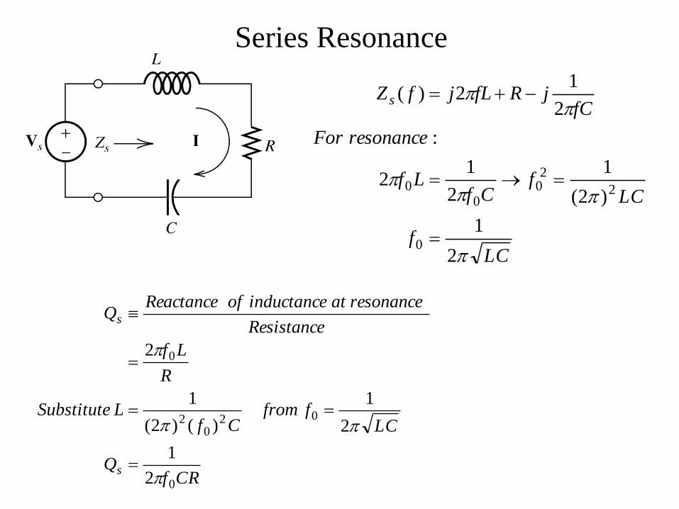
Parallel Resonance
fLjfCjRZ p
2121
1
At resonance ZP is purely resistive:
LC
fLfjCfj
2
1212 000
CRfQ
LCffrom
CfLSubstitute
Lf
R
resonance at inductance of Reactance
ResistanceQ
P
P
0
020
2
0
2
2
1
)()2(
1
2
10)2.159)(101(2
10
2101
2
1
2.159,2.159,10,010
6
4
0
60
3
HHzxLf
RQHzx
LCf
pFCHLkR
P
I
901010
010
2
901010
010
2
01010
010
10
010)10(010
2
3
0
2
30
3
44
43
j
Cf
jZ
jLfjZ
R
R
out
C
outC
out
L
outL
outoutR
out
VVI
VVI
VVI
IV
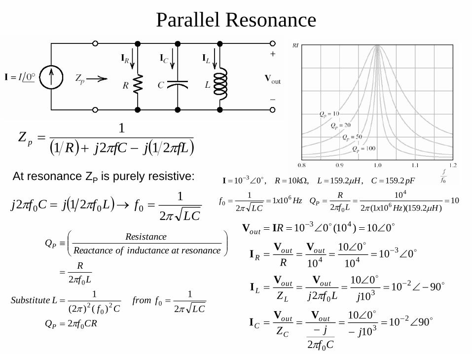
Second Order Low-Pass Filter
f
f
f
fjQ
ffjQ
LCfff
f
R
Lfj
fRC
j
fH
LCfff
f
R
Lfj
fRC
j
fC
jfLjR
fC
j
ZZZ
Z
S
S
in
out
inininCLR
Cout
0
0
0
00
0
00
0
1
)/(
2
121
2)(
2
121
2
22
2
V
V
VVVV
200
2
0
0012
002
0
00
0
1
1
90
1
ffffQ
ffQfH
ffffQTanffffQ
ffQ
ffffjQ
ffjQfH
S
s
sS
s
s
s
in
out
V
V

Second Order High-Pass Filter
At low frequency the capacitor
is an open circuit
At high frequency the
capacitor is a short and the
inductor is open

Second Order Band-Pass Filter
At low frequency the capacitor
is an open circuit
At high frequency the inductor
is an open circuit

Second Order Band-Reject Filter
At low frequency the
capacitor is an open
circuit
At high frequency the
inductor is an open
circuit

Example: Design a filter with QS = 1 that passes frequency
components lower than 5 kHz and rejects components higher than
5 kHz. Chose L=5 mH.
FxxLf
CLC
kHzf
2026.0)105()105()2(
1
)2(
1
2
15
323220
20
1.1571
)105)(5(222 300 HxkHz
Q
LfR
R
LfQs
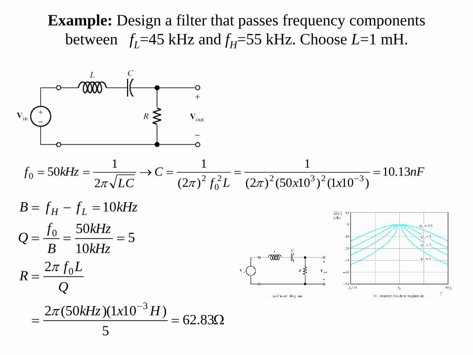
Example: Design a filter that passes frequency components
between fL=45 kHz and fH=55 kHz. Choose L=1 mH.
nFxxLf
CLC
kHzf 13.10)101()1050()2(
1
)2(
1
2
150
323220
20
83.625
)101)(50(2
2
510
50
10
3
0
0
HxkHz
Q
LfR
kHz
kHz
B
fQ
kHzffB LH
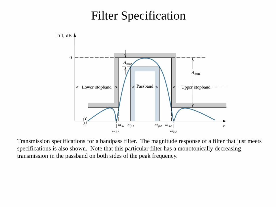
Transmission specifications for a bandpass filter. The magnitude response of a filter that just meets
specifications is also shown. Note that this particular filter has a monotonically decreasing
transmission in the passband on both sides of the peak frequency.
Filter Specification
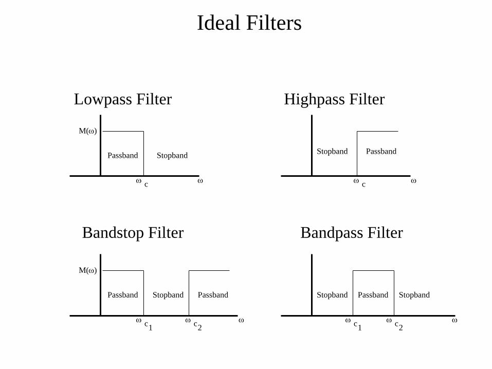
Ideal Filters
Passband Stopband Stopband Passband
Passband Passband Stopband
Lowpass Filter Highpass Filter
Bandstop Filter
Passband Stopband Stopband
Bandpass Filter
M(w)
M(w)
w w
w w
w c
w c
w c 1
w c 1
w c 2
w c 2
Passive and Active Filters
• Passive filters employ resistors, capacitors, and inductors (RLC networks). To minimize distortion in the filter characteristic, it is desirable to use inductors with high quality factors, however these are difficult to implement at frequencies below 1 kHz, because.
– They are non-ideal (lossy)!
– They are bulky and expensive!
• Active filters overcome these drawbacks and are realized using resistors,
capacitors, and active devices (usually op-amps) which can all be integrated:
– Active filters replace inductors using op-amp based equivalent circuits.
• The Problem of the Inductor!
• High accuracy (1% or 2%), small physical size, or large inductance values are
required!
• Standard values of inductors are not very closely spaced.
• Difficult to find an off-the-shelf inductor within 10 percent of any arbitrary value.
• Adjustable inductors are used.
• Tuning such inductors to the required values is time-consuming and expensive for
larger quantities of filters.
• Inductors are often prohibitively expensive.

Op Amp-based Active Filters
• Advantages:
– Reduced size and weight, and therefore parasitics.
– Increased reliability and improved performance.
– Simpler design than for passive filters and can realize a wider range of
functions as well as providing voltage gain.
– In large quantities, the cost of an IC is less than its passive counterpart.
• Disadvantages:
– Limited bandwidth of active devices limits the highest attainable pole
frequency and therefore applications above 100 kHz (passive RLC
filters can be used up to 500 MHz).
– The achievable quality factor is also limited.
– Require power supplies (unlike passive filters).
– Increased sensitivity to variations in circuit parameters caused by
environmental changes compared to passive filters.
• For applications, particularly in voice and data communications, the
economic and performance advantages of active RC filters far outweigh
their disadvantages.

Bode Plots and dB • Bode plots are important when considering the frequency response
characteristics of amplifiers. They plot the magnitude or phase of a transfer
function in dB versus frequency.
• Two levels of power are compared using a unit of measure called the bel.
1
210log
P
PB
The decibel is defined as:
1 bel = 10 decibels (dB)
1
210log10
P
PdB
A common dB term is the half power point which is the dB value when the P2
is one- half P1.
dBdB 301.32
1log10 10
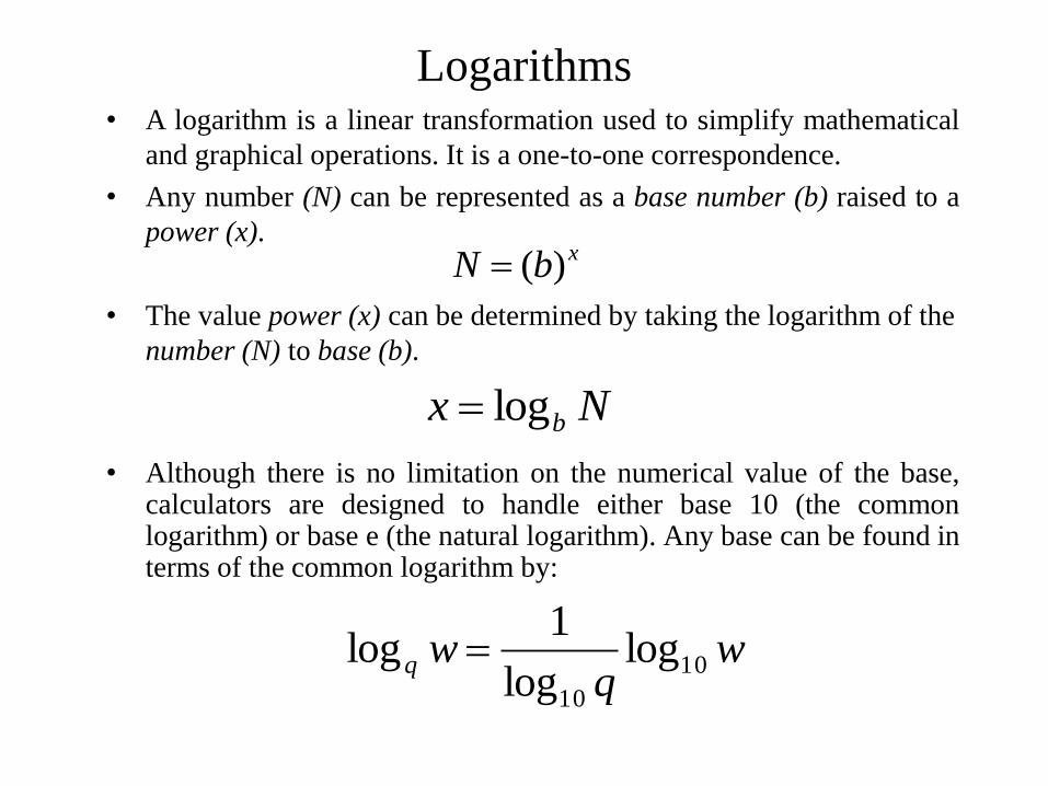
Logarithms • A logarithm is a linear transformation used to simplify mathematical
and graphical operations. It is a one-to-one correspondence.
• Any number (N) can be represented as a base number (b) raised to a
power (x).
• The value power (x) can be determined by taking the logarithm of the
number (N) to base (b).
• Although there is no limitation on the numerical value of the base, calculators are designed to handle either base 10 (the common logarithm) or base e (the natural logarithm). Any base can be found in terms of the common logarithm by:
xbN )(
Nx blog
wq
wq 10
10
loglog
1log
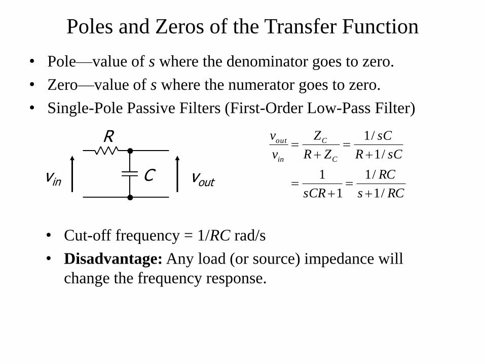
Poles and Zeros of the Transfer Function
• Pole—value of s where the denominator goes to zero.
• Zero—value of s where the numerator goes to zero.
• Single-Pole Passive Filters (First-Order Low-Pass Filter)
vin vout C
R
RCs
RC
sCR
sCR
sC
ZR
Z
v
v
C
C
in
out
/1
/1
1
1
/1
/1
• Cut-off frequency = 1/RC rad/s
• Disadvantage: Any load (or source) impedance will
change the frequency response.
Related Documents