Anlage / Blatt - Verzeichnis: Annexe / page - liste: Impianto / Elenco Fogli Enclosure / page - list: Bijlage/pagina - lijst Auftrag Nr. No de commande N° ordine Commision No. Bestelnr E D C B F A E D C B F A Total Bl./Pg Blatt/Page Aenderung/Modific. Elektroschema Schéma électrique Schema elettrico Electrical documentation Elektrisch schema Anlage Installation Impianto Installation Installatie Wärmeerzeugertyp Type de producteur de chaudière Tipo di produttore di calore Heat generator type Keteltype Wärmeerzeuger-Ausführung Version de producteur de chaleur Versione di produttore di calore Heat generator type Versie keteltype Schema Artikelnummer Art. No. de schéma Art. N° schema Diagram order number Art.nr schema + Ort: = Anlage: Schema/Draw Elektrodokumentation Das Installationsmaterial, sowie alle Anschlüsse und Erdungen müssen der EN 60335-1 + EN 60335-2-102 und den örtlichen Vorschriften entsprechen. Le Matériel d' installation ainsi que les connections et les mises à la terre doivent être conforms aux EN 60335-1 + EN 60335-2-102 et prescriptions locals. Il materiale, come pure i raccordi e le messe a terra, devono corrispondere alle prescrizioni locali e alle EN 60335-1 + EN 60335-2-102 Installation material, as well as connections and grounding must the EN 60335-1 + EN 60335-2-102 and local regulations. Het installatiemateriaal zowel als aansluitingen en aarding dienen conform te zijn aan de EN 60335-1 + EN 60335-2-102 en de lokaal geldende voorschriften Bez./Des.1 Bez./Des.2 a b c d Zustand Datum Name Gez. Dess. Gepr. Contr. Name Datum 4 8 7 6 5 4 3 2 1 8 7 6 5 4 3 2 1 1 =A Deckblatt K 01.1.0804 23.07.2015 wf 10 Thision S PLUS Standard 3-(A)B-C 3740976 Feuille d'ensemble Parameter 10.03.2016 wf Gas-Wand-Brennwertkessel Thision-S PLUS A 1, 2 B 1, 2 P 1-6

Welcome message from author
This document is posted to help you gain knowledge. Please leave a comment to let me know what you think about it! Share it to your friends and learn new things together.
Transcript

Anlage / Blatt - Verzeichnis:Annexe / page - liste:Impianto / Elenco FogliEnclosure / page - list:Bijlage/pagina - lijst
Auftrag Nr.No de commandeN° ordineCommision No.Bestelnr
E
D
C
B
F
A
E
D
C
B
F
A
Total Bl./Pg
Blatt/Page
Aenderung/Modific.
ElektroschemaSchéma électriqueSchema elettricoElectrical documentationElektrisch schema
AnlageInstallationImpiantoInstallationInstallatie
WärmeerzeugertypType de producteur de chaudièreTipo di produttore di caloreHeat generator typeKeteltypeWärmeerzeuger-AusführungVersion de producteur de chaleurVersione di produttore di caloreHeat generator typeVersie keteltypeSchema ArtikelnummerArt. No. de schémaArt. N° schemaDiagram order numberArt.nr schema
+ Ort:= Anlage:
Schema/Draw
Elektrodokumentation
Das Installationsmaterial, sowie alle Anschlüsse und Erdungen müssen derEN 60335-1 + EN 60335-2-102 und den örtlichen Vorschriften entsprechen.Le Matériel d' installation ainsi que les connections et les mises à laterre doivent être conforms aux EN 60335-1 + EN 60335-2-102 et prescriptions locals.Il materiale, come pure i raccordi e le messe a terra, devonocorrispondere alle prescrizioni locali e alle EN 60335-1 + EN 60335-2-102Installation material, as well as connections and grounding must theEN 60335-1 + EN 60335-2-102 and local regulations.Het installatiemateriaal zowel als aansluitingen en aarding dienen conform te zijnaan de EN 60335-1 + EN 60335-2-102 en de lokaal geldende voorschriften
Bez./Des.1
Bez./Des.2
abcd
Zustand Datum Name
Gez.Dess.
Gepr.Contr.
NameDatum
4
87654321
87654321
1=ADeckblatt K 01.1.0804
23.07.2015 wf
10
Thision S PLUS Standard 3-(A)B-C
3740976
Feuille d'ensemble
Parameter 10.03.2016 wf
Gas-Wand-BrennwertkesselThision-S PLUS
A 1, 2B 1, 2P 1-6

THK
M
Gas VL RL
THISION S PLUS
E
D
C
B
F
A
E
D
C
B
F
A
Total Bl./Pg
Blatt/Page
Aenderung/Modific.
+ Ort:= Anlage:
Schema/DrawBez./Des.1
Bez./Des.2Zustand Datum Name
Gez.Dess.
Gepr.Contr.
NameDatum
abcd
Type
87654321
87654321
Parameter 10.03.2016 wf 23.07.2015 wf
FunktionsschemaStandard 3-(A)B-C
Gas-Wand-BrennwertkesselThision-S PLUS =A
K 01.1.0804
2
10
T
=B/1.G4-STB1
T=B/2.E3-B12
MB
A
AB
=B/2.E5
-Y5
+VL
RL
VL
RL
=B/1.G4-Q2
=B/2.E4-Q6
VL
RL
VL
RL
(A)
=B/1.D5-N1
T=B/1.G6-B10
Schienenvorlauffühler Sonde de temp. départ du rail Sonda termica mandata esterna Header supply line sensor Verdelervoelver
T
=B/2.D4-STB2
=B/1.G5
-RG1QAA55
=B/1.G4
-RG2QAA55
T=B/1.G7
-B9
AussenfühlerSonde extérieureSonda esternaOutside sensorBuitenvoeler
STB
EG ExpansionsgefässVase d'expansionVaso d'espansioneExpansion tankExpansievat
B9 RG
LegendeLégendeLegenda
B1 Q2Q6
Y1 MischerantriebEntraînement de mélangeComando valvola miscelazioneMixing valve3-weg mengkraan
VorlauffühlerSonde de départSonda mandataFlow sensorvertrekvoeler
HeizkreispumpePompe de circuit de chauffagePompa di circuito di riscald.Heating zone pumpCV pompRaumgerät (Option)Appareil d`ambiance (Option)Comando a distanza (Opzione)External command (Option)ruimte unit (Optie)
Achtung: Funktionsschema nur für den Elektriker gültig!Attention : Modèle de fonction seulement pour l'électricien valable!Attenzione: Modello di funzione soltanto per l'elettricista valido!Note: Operation diagramme only for the electrician valid!Opm: werkingsdiagramma enkel voor geschoold elektrieker !
HK1HK2
EG*
Bei Standard (A) entfällt das ExpansionsgefässPour standard (A) du vase d'expansion est omisPer standard (A) il vaso di espansione viene omessoFor standard (A) the expansion tank is omittedVoor standaard (A) van het expansievat wordt weggelaten
*GasGazGasGasGas
B10 Sicherheitsthermostat für Bodenheizung (Option)Thermostat de sécurité pour chauffage par le sol (Option)Termostato di sicurezza per pannelli radianti (Opzione)Safety limit thermostat of floor heating (Option)Veiligheidsaquastaat voor vloerverwarming (Optie)
EG

/2.D3X50
230 V~Clip-In
230 V~QX1
230 V~QX2
230 V~QX3 QAA75
PE
N
L1 2 3 4 5 6 7 8 9 10 11 12
N
HZ WW CL- G+13 14 15 16 17 18
CL+PE
N
L PE
N
L H1 GND H6
GP
BX1 BX219 20 21
GND22
GND H5 GND23 24
B9 GND
SE TNK
B327 28
GND25 26
Total Bl./Pg
Blatt/Page+ Ort:= Anlage:
Schema/DrawBez./Des.1Bez./Des.2
Typ
Aenderung/Modific.Zustand Datum Name
Gez.Dess.Gepr.Contr.
NameDatum
abcd
G
F
E
D
C
B
A
H
A
B
C
D
E
F
G
H
121110987654321
2 3 4 5 6 7 8 9 10 11 121
Steuerung LMS 14...
Gas-Wand-BrennwertkesselThision-S PLUS =B
K 01.1.08041
10
Parameter 10.03.2016 wf 23.07.2015 wf
2 1 3
Auto
0 4 8 12 242016+-
ESC OK
0 I
X1a
X1d
X1c
X1e
X18aX2a
X17X5b X6b X10b
X11
X4a
X7b
X30
X50X8dX15aX16a
X13X60
X12
RFOCI430
AGU2.56...
1
2
2
1
2
1
4
3
1
2
3
4
5
12345 5 4 3 2 110 9 8 7 612 11 5 4 3 2 18 7 6 12
1
14
8
1
1
2
3
4
5
6
1
9
1 2 3 4 5 1 2 1 2 3 4 1 2 3 4 5
LMS 14...
/1.D8
/1.D8
/1.B3
/1.C3
/1.D
6
/1.C10
/1.E7/1.E6
/1.E7
/1.E6
/1.A8
/1.A9
/1.A8
/1.A8
OCI34
5
MB DB141
QAC34QAD36
/2.A3/2.B3
-Y2Y1 Y2
2 1PE
1
2
+THISION S PLUS
1 2 3
P
Wasserdrucksensor min.Capteur de pression d'eau min.Sensore di pressione acqua min.Water pressure sensor min.Waterdruk sensor min.
M1~
PWM
L N PE
+ -
PE
1 2 3
-S31
2
3
4
G
F
G
F
A
A
CB
E
D
E
C
D
B
-N2
AVS 37...BedieneinheitUnité de contrôleUnità di controlloOperator interfaceBedieneenheid
-T1
KesselvorlauffühlerSonde dèpartSonda mandataBoiler supply line sensorKetel vetrekvoeler
-T2
KesselrücklauffühlerSonde retourSonda ritornoBoiler return line sensorKetel retourvoeler
-T1a/T5
1 2 34215
2 1
=A/2.B2-B9
AussenfühlerSonde extérieureSonda esternaOutside sensorBuitenvoeler
1 2
-S1
1 2 PE
P
GasdruckwächterManostat gazPessostato gasGas pressure switchGasdrukschakelaar
=A/2.C3-N1
=A/2.D5-B10
B M
LN
L N PE
M1~
=A/2.D8-Q2
HeizkreispumpePompe de circuit de chauffagePompa di circuito di riscald.Heating zone pumpCV pomp
1 2
=A/2.B8
-RG1QAA55
RaumgerätAppareil d`ambianceComando a distanzaExternal commandruimte unit
1 2
=A/2.B7
-RG2QAA55
T=A/2.C8
-STB1
Sicherheitsthermostat für Bodenheizung (Option)Thermostat de sécurité pour chauffage par le sol (Option)Termostato di sicurezza per pannelli radianti (Opzione)Safety limit thermostat of floor heating (Option)Veiligheidsaquastaat voor vloerverwarming (Optie)
1234
21
GNDH5
H6BX1GNDBX2GND
B3GNDB9GND
B3GNDB9GND
GNDH5
GNDH1
G+CL-CL+
GND
GND
H6BX1
BX2
BX3GND
H1GND* Anschluss verriegelnd
Raccordement verrouillesCollegamento chiusoLinking lockVergendelende ingang
*
LMS 2x T6,3A H 250V
LPB-Bus
(Option)
(Option)(Option)
L N PE
3
4
Brücke entfällt beim Anschluss des GerätesEnlever raccordement avec appareilsTogliere il cavallotto raccordando l'apparecchioRemove link by connection of optionverwijder brug als toestel wordt aangesloten
**
**
SchienenvorlauffühlerSonde de temp. départ du railSonda termica mandata esternaHeader supply line sensorVerdelervoelver
STB
Absicherung 10A230V~50HzFusible 10A230V~50HzProtezione 10A230V~50Hz10A fusing230V ac 50Hz10A zekering 230V ac 50Hz
EinspeisungAlimentationAlimentazionePower supplyVoeding
T1a - 46-54kW2. Vorlauffühler2. Sonde de départ2. Sonda mandata2. Flow sensor2. vertrekvoeler
HK1

ON
1 2X50
X2
X1ON
1 2ON
1 2
1
2
ON
1 23
-N3
AGU2.550
L N QX23 N QX22 N QX21
H2 M BX21 M BX22 U+
1 2 3 4 5
/1.E9 X50
E
D
C
B
F
A
E
D
C
B
F
A
Total Bl./Pg
Blatt/Page
Aenderung/Modific.
+ Ort:= Anlage:
Schema/DrawBez./Des.1
Bez./Des.2Zustand Datum Name
Gez.Dess.
Gepr.Contr.
NameDatum
abcd
Type
87654321
87654321
Parameter 10.03.2016 wf 23.07.2015 wf
Heizkreis 2
Gas-Wand-BrennwertkesselThision-S PLUS =B
K 01.1.0804
2
10
/1.F4/1.F3
QAD36
+THISION S PLUS
LN
L N PE
M1~
=A/2.D7-Q6
HeizkreispumpePompe de circuit de chauffagePompa di circuito di riscald.Heating zone pumpCV pomp
Y2 N Y1
=A/2.D7-Y5
MischerantriebEntraînement de mélangeComando valvola miscelazioneMixing valve3-weg mengkraan
=A/2.C7-B12
VorlauffühlerSonde de départSonda mandataFlow sensorvertrekvoeler
B M
PE
T=A/2.C7
-STB2
Heizkreis 2Circuit de chauffage 2
Circuito riscaldamento 2Heating circuit 2
Verwarmingskring 2
Sicherheitsthermostat für Bodenheizung (Option)Thermostat de sécurité pour chauffage par le sol (Option)Termostato di sicurezza per pannelli radianti (Opzione)Safety limit thermostat of floor heating (Option)Veiligheidsaquastaat voor vloerverwarming (Optie)
STB

E
D
C
B
F
A
E
D
C
B
F
A
Total Bl./Pg
Blatt/Page
Aenderung/Modific.
+ Ort:= Anlage:
Schema/DrawBez./Des.1
Bez./Des.2Zustand Datum Name
Gez.Dess.
Gepr.Contr.
NameDatum
abcd
Type
87654321
87654321
Parameter 10.03.2016 wf 23.07.2015 wf
Programmierung
Gas-Wand-BrennwertkesselThision-S PLUS =P
K 01.1.0804
1
10
InbetriebsetzungMise en serviceMessa in servizio
FachmannChauffagisteSpecialista
EndbenutzerUtilisateur finalUtente finale
GrundanzeigeAffichage de base
Visualizzazione base(Tasten-Ebene)(niveau touches)
(livello tasti)
ProgrammierungProgrammationProgrammazione
Taste OK drücken (1x)appuyer sur la touche OK (1x)premere 1 volta il tasto OK Taste INFO drücken (4 sec.)
appuyer sur la touche INFO (4 sec.)premere il tasto INFO per 4 secondi
Taste OK drücken (1x)appuyer sur la touche OK (1x)premere 1 volta il tasto OK
gewünschtes Menü auswählenChoix du menu souhaitéSelezionare il menu desiderato
mit Taste OK bestätigenConfirmer avec la touche OKConfermare con il tasto OK
gewünschten Parameter auswählenChoix du paramètre souhaitéSelezionare il parametro desiderato
mit Taste OK bestätigenConfirmer avec la touche OKConfermare con il tasto OK
mit + - Rad verändernle modifier par bouton rotatif + -Modificare con la manopola + -
mit Taste OK bestätigenConfirmer avec la touche OKConfermare con il tasto OK
mit Taste ESC zurück zur Grundanzeigepar touche ESC, retour à l'affichage de basePremere ESC per tornare alla visualizzazione base
-
-
-
-
-
-
-
gewünschte Benutzer-Ebene auswählenSélectionner le niveau utilisateur souhaitéSelezione il livello utente desiderato
mit Taste OK bestätigenConfirmer avec la touche OKConfermare con il tasto OK
gewünschtes Menü auswählenChoix du menu souhaitéSelezionare il menu desiderato
mit Taste OK bestätigenConfirmer avec la touche OKConfermare con il tasto OK
mit + - Rad verändernle modifier par bouton rotatif + -Modificare con la manopola + -
mit Taste OK bestätigenConfirmer avec la touche OKConfermare con il tasto OK
mit Taste ESC zurück zur Grundanzeigepar touche ESC, retour à l'affichage de basePremere ESC per tornare alla visualizzazione base
-
-
-
-
-
-
-
gewünschten Parameter auswählenChoix du paramètre souhaitéSelezionare il parametro desiderato
-
mit Taste OK bestätigenConfirmer avec la touche OKConfermare con il tasto OK
-

E
D
C
B
F
A
E
D
C
B
F
A
Total Bl./Pg
Blatt/Page
Aenderung/Modific.
+ Ort:= Anlage:
Schema/DrawBez./Des.1
Bez./Des.2Zustand Datum Name
Gez.Dess.
Gepr.Contr.
NameDatum
abcd
Type
87654321
87654321
Parameter 10.03.2016 wf 23.07.2015 wf
ParameterlisteLMS 14...
Gas-Wand-BrennwertkesselThision-S PLUS =P
K 01.1.0804
2
10
MenüMenueMenuMenuMenu
LMS14... ZNR. EbeneNiveauLivelloLevel
Niveau
FunktionFonctionFunzioneFunctionFunctie
StandardwertValeur standardValore standardStandard setting
Standaard instelling
Min.Min.Min.min.min.
Max.Max.Max.max.max.
EinheitUnitéUnitàUnit
Eenheid
AenderungModification
ModificaModification
WijzigingBedieneinheitUnité de commandeUnità di commandoOperator interfaceBedieneenheid
20 E
SpracheLangueLinguaLanguageTaal
DeutschAllemandTedescoGerman
Duits
*
Uhrzeit und Datumhoraire et dateorario e dataTime and dateDatum en tijd
00:00 23:59 hh:mm *1 E
StundenHeuresOreHoursUren
01.01 31.12 tt.MM *2 E
Tag / MonatJour / moisMese / giornoday / monthDag / maand
2004 2099 JJJJ *3 E
JahrAnAnnoYearJaar
Zeitprogramm Heizkreis 1Prog horaire circuit chauff 1Programma orario circuito di riscaldamento 1Heating circuit 1 timer programKlokprog. verw. groep 1
Mo-SoLun-DimLu-DoMo-suma-zo
*500 E
VorwahlPréselectionPreselezioneDefaultVoorselectie
06:00 00:00 24:00 hh:mm *501 E
1. Phase Ein1ère phase EN1° periodo OnFirst phase on1e fase AAN
22:00 00:00 24:00 hh:mm *502 E
1. Phase Aus1ère phase Hors1° periodo OffFirst phase off1e fase UIT
Zeitprogramm Heizkreis 2Prog horaire circuit chauff 2Programma orario circuito di riscaldamento 2Heating circuit 2 timer programKlokprog. verw. groep 2
Mo-SoLun-DimLu-DoMo-suma-zo
*520 E
VorwahlPréselectionPreselezioneDefaultVoorselectie
06:00 00:00 24:00 hh:mm *521 E
1. Phase Ein1ère phase EN1° periodo OnFirst phase on1e fase AAN
22:00 00:00 24:00 hh:mm *522 E
1. Phase Aus1ère phase Hors1° periodo OffFirst phase off1e fase UIT
ErgänzungenSupplémentsAggiunteSupplementsUitbreidingen

E
D
C
B
F
A
E
D
C
B
F
A
Total Bl./Pg
Blatt/Page
Aenderung/Modific.
+ Ort:= Anlage:
Schema/DrawBez./Des.1
Bez./Des.2Zustand Datum Name
Gez.Dess.
Gepr.Contr.
NameDatum
abcd
Type
87654321
87654321
Parameter 10.03.2016 wf 23.07.2015 wf
ParameterlisteLMS 14...
Gas-Wand-BrennwertkesselThision-S PLUS =P
K 01.1.0804
3
10
MenüMenueMenuMenuMenu
LMS14... ZNR. EbeneNiveauLivelloLevel
Niveau
FunktionFonctionFunzioneFunctionFunctie
StandardwertValeur standardValore standardStandard setting
Standaard instelling
Min.Min.Min.min.min.
Max.Max.Max.max.max.
EinheitUnitéUnitàUnit
Eenheid
AenderungModification
ModificaModification
WijzigingKonfigurationConfigurationConfigurazioneConfigurationConfiguratie
EinEN
InseritoONAAN
Aus Ein
EinEN
InseritoONAAN
5710 I
Heizkreis 1Circuit de chauffage 1Circuito riscaldamento 1Heating circuit 1Verwarmingskring 1
AusArrét
DisinseritoOFFUit
Aus Ein
EinEN
InseritoONAAN
5715 I
Heizkreis 2Circuit de chauffage 2Circuito riscaldamento 2Heating circuit 2Verwarmingskring 2
KeinAucun
NessunoNoneGeen
0 43
Heizkreispumpe HK1 Q2Pompe circuit chauffage PC1 Q2
Pompa circ risc CR1 Q2Heating circuit pump HC1 Q2
Verw grp pomp HC1 Q2
5890 I
Relaisausgang QX1Sortie de relais QX1Uscita del relè QX1Relay output QX1Relaisuitgang QX1
KeinAucun
NessunoNoneGeen
0 19
Schienenvorlauffühler B10Sonde de temp. départ du rail B10
Sonda termica mandata esterna B10Header supply line sensor B10
Aanvoertemp opnemer B10
5930 I
Fühlereingang BX1Entrée de sonde BX1Entrata di sonda BX1Sensor input BX1Opnemeringang BX1
KeinAucun
NessunoNoneGeen
0 7
Heizkreis 2Circuit de chauffage 2
Circuito riscaldamento 2Heating circuit 2
Verwarmingskring 2
6021 I
Funktion Erweiterungsmodul 2Fonction module 2Funzione modula 3Function expansion module 2Functie uitbreidingsmodule 2
NeinNonNoNo
Nee
0 1
JaOuiSi
YesJa
6200 F
Fühler speichernenrégistrer sondesregistrare sondeSave sensorOpnemer opslaan
ErgänzungenSupplémentsAggiunteSupplementsUitbreidingen
EinEN
InseritoONAAN
deaktivieren wenn kein Aussenfühler montiert istdésactiver si aucune sonde extérieure n'est installée
disattivare se nessun sonda esterna installatodeactivate if no outdoor sensor installed
deactiveren als er geen buitenvoeler geïnstalleerd
6120 F
AnlagenfrostschutzProtection hors-gel de l'installation, CC1 et CC2Protezione fuori-gelo dell'impianto, CC1 et CC2System freeze protectionVorstbeveiliging installatie

E
D
C
B
F
A
E
D
C
B
F
A
Total Bl./Pg
Blatt/Page
Aenderung/Modific.
+ Ort:= Anlage:
Schema/DrawBez./Des.1
Bez./Des.2Zustand Datum Name
Gez.Dess.
Gepr.Contr.
NameDatum
abcd
Type
87654321
87654321
Parameter 10.03.2016 wf 23.07.2015 wf
ParameterlisteLMS 14...
Gas-Wand-BrennwertkesselThision-S PLUS =P
K 01.1.0804
4
10
MenüMenueMenuMenuMenu
LMS14... ZNR. EbeneNiveauLivelloLevel
Niveau
FunktionFonctionFunzioneFunctionFunctie
StandardwertValeur standardValore standardStandard setting
Standaard instelling
Min.Min.Min.min.min.
Max.Max.Max.max.max.
EinheitUnitéUnitàUnit
Eenheid
AenderungModification
ModificaModification
WijzigingEin-/AusgangstestTest des entrées/ sortiesTest delle entrate/ usciteInput/output testIn-/uitgangtest
Kein TestAucun test
Nessun testNo test
Geen test
0 20 *7700 I
RelaistestTest des relaisTest relèRelay testRelaistest
0 -50 50
WertIndication
Indicazionevaluationwaarde
°C7730 I
Aussentemperatur B9Temp. extérieure B9Temperatura esterna B9Outside temperature B9Buitentemperatuur B9
0 -28 350
WertIndication
Indicazionevaluationwaarde
°C7820 I
Fühlertemperatur BX1Température sonde BX1Temperatura sonda BX1Sensor temp BX1Opnemertemperatuur BX1
Schienenvorlauffühler B10Sonde de temp. départ du rail B10Sonda termica mandata esterna B10Header supply line sensor B10Aanvoertemp opnemer B10
0 -28 350
WertIndication
Indicazionevaluationwaarde
7832 I
Fühlertemp BX21 Modul 2Température sonde BX21 module 2Temperatura sonda BX21 modulo 2Sensor temp BX21 module 2Opnemertemp BX21 module 2
Vorlauffühler B12Sonde de départ B12Sonda mandata B12Flow sensor B12vertrekvoeler B12
Heizkreis 1Circuit de chauffage 1Circuito riscaldamento 1Heating circuit 1Verwarmingskring 1
20 BZ 712 BZ 716 °C *710 E
KomfortsollwertConsigne confortSetpoint comfortComfort setpointGewenste wrde comfort
16 BZ 714 BZ 710 °C *712 E
ReduziertsollwertConsigne réduitTemperatura ridottaSetback settingGewenste wrde gereduceerd
10 4 BZ 712 °C *714 E
FrostschutzsollwertConsigne hors-gelSetpoint protezione antigeloFreeze protection setpointGewenste wrde vorst
1.5 0.1 4 Rad. 1.5/FBH 0.8720 E
Kennlinie SteilheitPente de la courbeRipidità curva caratteristicaCurve slopeSteilheid stooklijn
20 8 30 °C *730 E
Sommer-/WinterheizgrenzeLimite chauffe été/hiverValore limite estate/invernoSummer/winter heating limitZomer/Winter verw grens
-3 -10 10 °C *732 F
TagesheizgrenzeLim. chauffage diurneValore limite riscald. diurnoDay heating limit24 h verwarmingsgrens
80 BZ 740 95 °C Rad 80°/FBH 50°741 I
Vorlaufsollwert MaximumMaximum consigne de départSetpoint di mandata massimaMaximum supply setpointMax gewenste aanvoertemp

E
D
C
B
F
A
E
D
C
B
F
A
Total Bl./Pg
Blatt/Page
Aenderung/Modific.
+ Ort:= Anlage:
Schema/DrawBez./Des.1
Bez./Des.2Zustand Datum Name
Gez.Dess.
Gepr.Contr.
NameDatum
abcd
Type
87654321
87654321
Parameter 10.03.2016 wf 23.07.2015 wf
ParameterlisteLMS 14...
Gas-Wand-BrennwertkesselThision-S PLUS =P
K 01.1.0804
5
10
MenüMenueMenuMenuMenu
LMS14... ZNR. EbeneNiveauLivelloLevel
Niveau
FunktionFonctionFunzioneFunctionFunctie
StandardwertValeur standardValore standardStandard setting
Standaard instelling
Min.Min.Min.min.min.
Max.Max.Max.max.max.
EinheitUnitéUnitàUnit
Eenheid
AenderungModification
ModificaModification
WijzigingHeizkreis 2Circuit de chauffage 2Circuito riscaldamento 2Heating circuit 2Verwarmingskring 2
20 BZ 1012 BZ 1016 °C *1010 E
KomfortsollwertConsigne confortSetpoint comfortComfort setpointGewenste wrde comfort
16 BZ 1014 BZ 1010 °C *1012 E
ReduziertsollwertConsigne réduitTemperatura ridottaSetback settingGewenste wrde gereduceerd
10 4 BZ 1012 °C *1014 E
FrostschutzsollwertConsigne hors-gelSetpoint protezione antigeloFreeze protection setpointGewenste wrde vorst
0.8 0.1 4 Rad. 1.5/FBH 0.81020 E
Kennlinie SteilheitPente de la courbeRipidità curva caratteristicaCurve slopeSteilheid stooklijn
20 8 30 °C *1030 E
Sommer-/WinterheizgrenzeLimite chauffe été/hiverValore limite estate/invernoSummer/winter heating limitZomer/Winter verw grens
-3 -10 10 °C *1032 F
TagesheizgrenzeLim. chauffage diurneValore limite riscald. diurnoDay heating limit24 h verwarmingsgrens
50 BZ 1040 95 °C Rad 80°/FBH 50°1041 I
Vorlaufsollwert MaximumMaximum consigne de départSetpoint di mandata massimaMaximum supply setpointMax gewenste aanvoertemp
KesselChaudièreCaldaiaBoilerKetel
geräteabhängigdépandant de la Chaudière
caldaia tip dipendentedevice-dependent
afhankelijk van het apparaat
BZ 9525 BZ 9530
Nur CH oder bei BedarfSeulement CH ou au besoin
Solo CH o quando necessarioOnly CH or when needed
Slechts CH of naar behoefte
U/min2441 F
Gebläsedrehzahl Hz MaximumVentilateur Hz maximumFan Hz massimoFan Speed Hz maximumFan Speed Hz maximaal
ErgänzungenSupplémentsAggiunteSupplementsUitbreidingen
E
D
C
B
F
A
E
D
C
B
F
A
Total Bl./Pg
Blatt/Page
Aenderung/Modific.
+ Ort:= Anlage:
Schema/DrawBez./Des.1
Bez./Des.2Zustand Datum Name
Gez.Dess.
Gepr.Contr.
NameDatum
abcd
Type
87654321
87654321
Parameter 10.03.2016 wf 23.07.2015 wf
ParameterlisteLMS 14...
Gas-Wand-BrennwertkesselThision-S PLUS =P
K 01.1.0804
6
10
MenüMenueMenuMenuMenu
LMS14... ZNR. EbeneNiveauLivelloLevel
Niveau
FunktionFonctionFunzioneFunctionFunctie
StandardwertValeur standardValore standardStandard setting
Standaard instelling
Min.Min.Min.min.min.
Max.Max.Max.max.max.
EinheitUnitéUnitàUnit
Eenheid
AenderungModification
ModificaModification
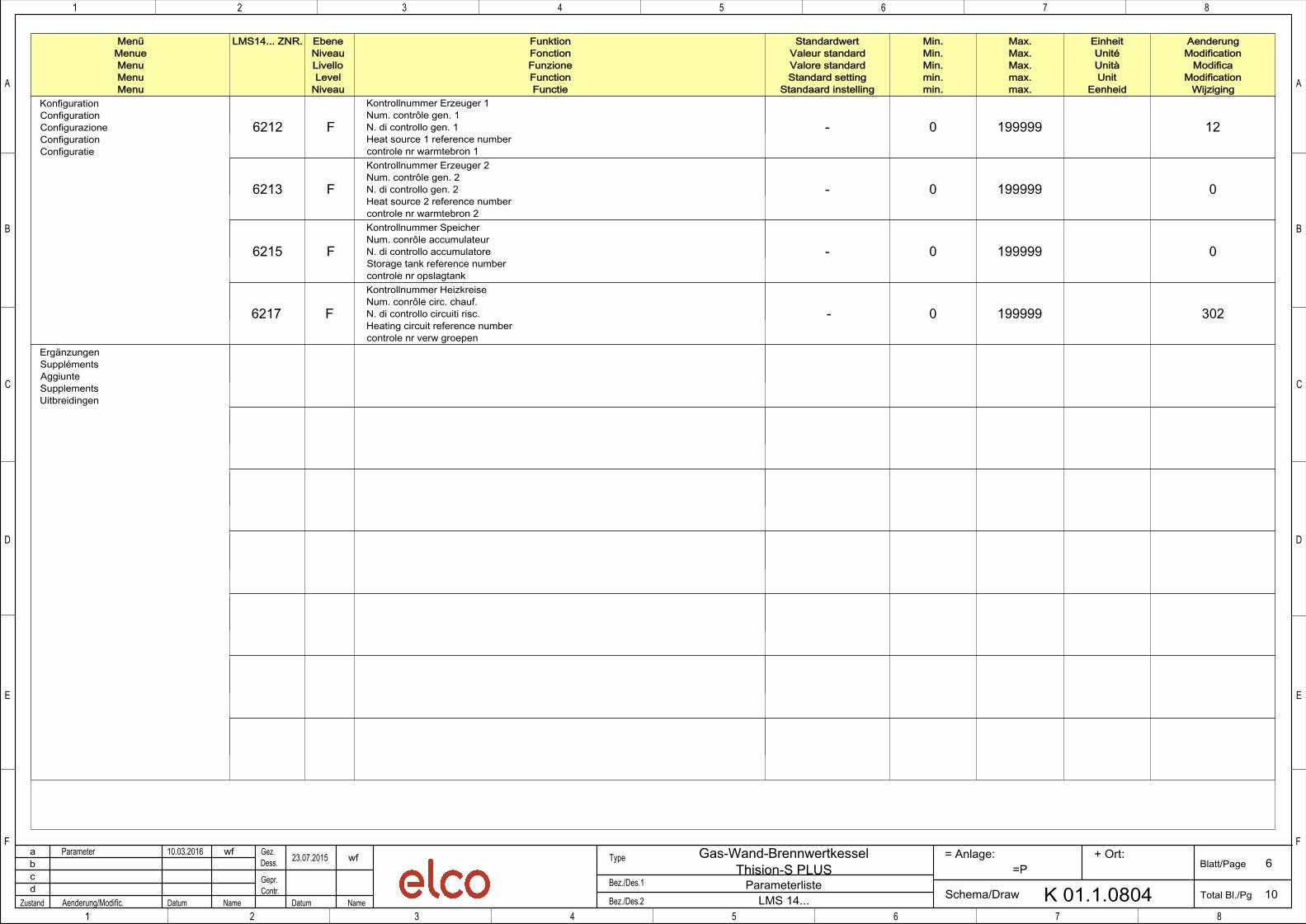
WijzigingKonfigurationConfigurationConfigurazioneConfigurationConfiguratie
- 0 199999 126212 F
Kontrollnummer Erzeuger 1Num. contrôle gen. 1N. di controllo gen. 1Heat source 1 reference numbercontrole nr warmtebron 1
- 0 199999 06213 F
Kontrollnummer Erzeuger 2Num. contrôle gen. 2N. di controllo gen. 2Heat source 2 reference numbercontrole nr warmtebron 2
- 0 199999 06215 F
Kontrollnummer SpeicherNum. conrôle accumulateurN. di controllo accumulatoreStorage tank reference numbercontrole nr opslagtank
- 0 199999 3026217 F
Kontrollnummer HeizkreiseNum. conrôle circ. chauf.N. di controllo circuiti risc.Heating circuit reference numbercontrole nr verw groepen
ErgänzungenSupplémentsAggiunteSupplementsUitbreidingen
Related Documents


