ELECTRONICS WORLD + WIRELESS WORLD JUNE 1994 £1.95 RADIOCOMMS Designer's guide to selcall ANALOGUE Synchronous alternative to PLLs? APPLICATIONS Picking up on wireless LANs DIGITAL Using 12C beyond the board PC ENGINEERING Motherboards through the ages COMPONENTS Digital signal processor for FM demodulation 9 1 1 1 770959 III83300 0 6> III Denmark DKr. 70.00 Germany DM 15.00 Greece Dra.760 Holland Dfl. 14 Italy L. 7300 IR £3.30 Spain Pts. 780 Singapore SS 12.60 USA $6.70 SOR DISTRIBUTION A REED BUSINESS PUBLICATION MAINTAIN CONTROL WITH RS232

Welcome message from author
This document is posted to help you gain knowledge. Please leave a comment to let me know what you think about it! Share it to your friends and learn new things together.
Transcript

ELECTRONICSWORLD+ WIRELESS WORLDJUNE 1994 £1.95
RADIOCOMMSDesigner's guide toselcall
ANALOGUESynchronousalternative to PLLs?
APPLICATIONSPicking up onwireless LANs
DIGITALUsing 12C beyondthe boardPC ENGINEERINGMotherboardsthrough the ages
COMPONENTSDigital signalprocessor for FMdemodulation
91 1 1
770959 III83300
0 6>
III
Denmark DKr. 70.00Germany DM 15.00
Greece Dra.760Holland Dfl. 14
Italy L. 7300IR £3.30
Spain Pts. 780Singapore SS 12.60
USA $6.70
SOR DISTRIBUTION
A REED BUSINESS PUBLICATION
MAINTAIN CONTROL WITH RS232

THE WORLDS No.1 BEST SELLINGUNIVERSAL PROGRAMMING AND TESTING SYSTEM.
The PC82 Universal Programmer and Tester is aPC -based development tool designed toprogram and test more than 1500 ICs. The latestversion of the PC82 is based on the experiencegained after a 7 year production run of over100,000 units.
The PC82 is the US version of the SunshineExpro 60, and therefore can be offered at a verycompetitive price for a product of such highquality. The PC82 has undergone extensivetesting and inspection by various major ICmanufacturers and has won their professionalapproval and support. Many do in fact use thePC82 for their own use!
The PC82 can program E/EPROM, Serial PROM,BPROM, MPU, DSP, PLD, EPLD, PEEL, GAL, FPL,MACH, MAX, and many more. It comes with a 40pin DIP socket capable of programming deviceswith 8 to 40 pins. Adding special adaptors, thePC82 can program devices up to 84 pins in DIP,PLCC, LCC, QFP, SOP and PGA packages.
The unit can also test digital ICs such as the TTL74/54 series, CMOS 40/45 series, DRAM (evenSIMM/SIP modules) and SRAM. The PC82 caneven check and identify unmarked devices.
Customers can write their own test vectors toprogram non standard devices. Furthermore itcan perform functional vector testing of PLDsusing the JEDEC standard test vectors createdby PLD compilers such as PALASM, OPALjr,ABLE, CUPL etc. or by the user.
The PC82's hardware circuits are composed of 40set pin -driver circuits each with TTL I/O control,D/A voltage output control, ground control,noise filter circuit control, and OSC crystalfrequency control. The PC82 shares all the PC'sresources such as CPU, memory, I/O hard disk,keyboard, display and power supply.
A dedicated plug in card with rugged connectingcable ensures fast transfer of data to theprogrammer without tying up a standard parallelor serial port. Will work in all PC compatiblesfrom PC XT to 486.
The pull -down menus of the software makes thePC82 one of the easiest and most user-friendlyprogrammers available. A full library of fileconversion utilities is supplied as standard.
The frequent software updates provided bySunshine enables the customer to immediatelyprogram newly released ICs. It even supportsEPROMs to 16Mbit.
Over 20 engineers are employed by Sunshine todevelop new software and hardware for thePC82. Not many competitors can boast of similarsupport!
Citadel, a 32 year old company are the UK agentsand service centre for the Sunshine range ofprogrammers, testers and in circuit emulatorsand have a team of engineers trained to givelocal support in Europe.
* More sold worldwide than any other ofits type.
* UK users include BT, IBM, MOD, THORNEMI, MOTOROLA, SANYO, RACAL
* High quality Textool or Yamaichi zeroinsertion force sockets.
* Rugged screened cabling.* High speed PC interface card designed
for use with all PC models from XT to486.
* Over 1500 different devices (includingmore than 100 MPU's) supported.
* Tests and or identifies a wide range oflogic devices.
NOW SUPPLIED WITH SPECIAL VALUEADDED SOFTWARE (worth over £300 ifbought seperately):
* MICROTEC disassemblers for Z8, 8085,8048. 8051, 6809 & 68HC11
Our stocked range of own manufactured andimported Sunshine products include:
* Super fast EPROM Erasers.* 1, 4 & 8 gang EPROM 8Mbit production
programmers.* Battery operated portable EPROM
programmers.* "In circuit" Emulators.* Handy pocket IC testers.
ORDERING INFORMATION
PC82 complete with interface card,cable, software and manual only ma U3
Please add £7 carriage (by overnight courier) forUK orders, £20 for export orders, and VAT whereapplicable.
ACCESS, MASTERCARD, VISA or CWO.Official orders are welcome from Governmentbodies & local authorities.
Free demo disk with device list available.
* Software supplied to write own testvectors for custom ICs and ASICs etc.
* Protection circuitry to protect againstwrong insertion of devices.
* Ground control circuitry using relayswitching.
* One model covers the widest range ofdevices, at the lowest cost.
* No need to tie up a slow parallel port.
Two year free software update.
* Speed optimised range ofprogramming algorithms.
* NATIONAL SEMICONDUCTOR OPALjrPAL/PLD development software.
* BATCH SOFTWARE for productionprogramming.
CPCITADEL PRODUCTS LTDDEPT. WW, 50 HIGH ST.,EDGWARE, MIDDX. HA8 7EP.
Phone now on: 081 951 1848/9
VISA

CONTENTS
FEATURES
APPLIED I/O DESIGNFOR THE PC 452Comprising little more than a uartand buffering, an i/o controlinterface taking advantage of thePC serial port has many benefits.Bill Teliki details such aninterface together withapplications - including scanningpictures via a dot-matrix printer.
PC ENGINEERING 461Evolution: David Guest reviews the PC's progression froman 8bit CP/M-like machine to a 32bit computer with agraphical user interface capable of handling video images.
ONE-TO-ONE RADIOCOMMS 466Mobile radio's equivalent of telephone numbers - selectivecalling - is explained by communications engineer JamesVincent in the complete guide to selcall.
NEW WAVE MICROWAVES 472With hybrid IC technology, it is possible to form reactivecomponents directly on the substrate. Mike Hosking looks atdesign procedures for lumped microwave components.
BUSMAN'S GUIDE TO I2C 479Although it has only two signalling wires, the I2C bus isdesigned for flexibility. Mike Button considers thehardware and software problems involved withimplementing I2C and presents ideas for increasingcommunications distance.
ARNOLD SUGDEN 486Reg Williamson reminds us of the remarkableachievements of Arnold Sugden - founder of the companythat produced the famous Connoisseur turntable kit andinventor of the main contender to modern stereo vinyldiscs.
MEASURING PULSES DIIGITALLY .498A chip capable of producing a digital outputproportional to input pulse width has uses not only inperiod measurement applications but also in frequencycounting. With the aid of a signal processor, such a chipcan even be used for precise fm demodulation.
USING RF TRANSISTORS 517Choosing a filter for rf power amplifiers depends as muchon available components as on the intended application.Norm Dye and Helge Granberg present the theory andpractice of good filter design.
Win a spectrum analyser see page 512
REGULARS
COMMENT 443Right to communicate
NEWS 444Radio spectrum licensing shakeup, Poor reception for newsatellite, Camera chip for less than $10, Microsoft in space,Powered -up power PC, Auto radar avoids collisions,Channel 2'/2, TV double decoder, vehicle radar.
RESEARCH NOTES 448Unwanted signals that sap op -amp performance, NRPBpicks up amateur gauntlet, Could safety net make airtravel safer? Supercomputer previews Jupiterblockbuster, Mains hum - or ear drum, MIT robot getsa healing hand.
DESIGN BRIEF 490Offering an alternative to the PLL for recovering signalsfrom noise, the synchronous oscillator is a fascinatingdevice to play with, as Ian Hickman demonstrates.
NEW PRODUCTS 503Comprehensive round -up of new products presented inthe industry's most readable format.
LETTERS 508Amplified defence, Brass monkeys, On the defensive, Ins
and outs of amplifiers, Quiescent and controlled, Power -amp comments, Cables for hi-fi equipment, Tack to basics,Who do voodoo, Its life... but not as we know it, Unstableconclusions, Engineers see sense, Dos not dozzzzzz, PCparanoia, Bose and Bouquets.
CIRCUIT IDEAS 512Capacitance ratio meter, A simple route to high-passand band-pass filters, Binary -to -BCD converter, Carradio loop aerial, High -voltage, current -limited powersupply, High -voltage current-limiter/stabiliser.
APPLICATIONS 522Designing antennas for wireless networks, ±18bit a -to -dconversion at 60µA, Solar -powered battery charger, Faxmachine design.
In next month's issue: Designers' guide to Hall effect devices.In conjunctions with Allegro distributor Ambar Cascom, wepresent a technology primer and a free samples service forthe first 500 readers replying with the special card bound intothe journal. Discover the benefits of the latest magnetictransducer technology.Plus a mass review of instrumentation amplifier chips.
THE JULY ISSUE IS ON SALE FROM JUNE 30
June 1994 ELECTRONICS WORLD + WIRELESS WORLD 441

Low cost data acquisition for IBM PCs & compatiblesEasy to use data acquisition products that allow your PC to be used as a range of useful test and measurement instruments,or as an advanced data logger. Installed in seconds they simply plug into the parallel port (except the ADC -16 which connectsto the serial port). They require no power supply and take up no expansion slots. Each comes with a comprehensive manual.C, Pascal and Basic drivers are included for users who wish to write their own software Software supplied on 3.5" disk.
PicoScope=I7,-
'Virtual instrument' software. Storagescope with trigger, timebase, rulers r
and offset. Real time spectrumanalysis with min/maxfrequency and ,
CC)signal averaging. Multiple meters onscreen (digital and bargraph). Printerand file handling support.
PicoLog Advanced data logging softwarepackage. Collect, store, display and_.,,,....,,,
I print datafrom 1 sample per ms to1 perday. Record average, min/max or
,-1 scaled values (linear, equation, tablelook -up). Report types: monitor (with
- min/max alarms), y -t graphs, x -y-- graphs, tabulation
PricesADC -10 with PicoScopeADC -11 with PicoScope
ADC -12 with PicoScope
ADC -16 with PicoLog
The ADC -10/11/12 are£49 availible with bothpa9 PicoScope and PicoLog for
an additional £10. ExistingPR5 ADC -10/11/12 users can£109 add PicoLogfor £25.
It
ADC -10/12
ADC -1 1
ADC -16
Single channel of analog input
8 bit resolution 24kHzsampling (ADC -10)
12 bit resolution 18kHzsampling(ADC-12)
(sampling speed based on 33MHz/386 PC)
Oto 5V input range
BNC input allows use of scope probes
11 channels of analog input
1 digital output
10 bit resolution, 18kHz sampling
(sampling speed based on 33MHz/386 PC)
Oto 2.5Vinput range
D25 input connector
8 channels of analog input
t5V reference outputs
Resolution programmable between 8 bits(200Hz sampling) and 16 bits +sign (2Hz)
t2.5V input range
D25 input connector
Pico Technology Ltd. Broadway House, 149-151 St Neots Road, Hardwick, Cambridge. CB3 7QJ.
TEL: 0954-211716 FAX: 0954-211880Access
Phone or FAX for sales, ordering information, data sheets, technical support. All prices exclusive of VAT
CIRCLE NO. 103 ON REPLY CARD
SEETRAX CAE - RANGER - PCB DESIGNRangerl £100
* Schematic capture linked to PCB* Parts and wiring list entry* Outline (footprint) library editor* Manual board layout* Full design rule checker* Back annotation (linked to schematic)* Power, memory and signal autorouter - L50
All systems upward compatible. Trade-in deals available.
Call Seetrax CAE for further information \demo packs.
Tel 0705 591037 Fax 0705 599036
Seetrax CAE, Hinton Daubnay House, Broadway Lane,Lovedean, Hampshire, P08 OSG
All trademarks acknowledged.
Ranger2 £599All the features of Ranger! plus* Gate & pin swapping (linked to schematic)* Track highlighting* Auto track necking* Copper flood fill* Power planes (heat -relief & anti -pads)* Rip -up & retry autorouter
Ranger3 £3500All the features of Ranger2 plus* UNIX or DOS versions* I Micron resolution and angles to I/10th degree* Hierarchical or flat schematic* Unlimited design size* Any -shaped pad* Split power planes* Optional on-line DRC* 100% rip -up & retry, push & shove autorouter
Outputs to:* 8/9 and 24 pin dot-matrix printers* HP Desk/Laser Jet, Canon BJet, Postscript (R3 only)* HP -GL, Houston Instruments plotters* Gerber photoplotters* NC Drill Excellon. Sieb & Meyer* AutoCAD DXF
CIRCLE NO. 104 ON REPLY CARD
442 June 1994 ELECTRONICS WORLD+WIRELESS WORLD

COMMENT
EDITORFrank Ogden081-652 3128
DEPUTY EDITORMartin Eccles081-652 8638
CONSULTANTDerek Rowe
DESIGN &PRODUCTIONAlan Kerr
EDITORIALADMINISTRATIONLorraine Spindler081-652 3614
ADVERTISEMENTMANAGERRichard Napier081-652 3620
DISPLAY SALESEXECUTIVEMalcolm Wells081-652 3620
ADVERTISINGPRODUCTIONPaul Burgess081-652 8355
PUBLISHERSusan Downey
EDITORIAL FAX081-652 8956
CLASSIFIED FAX081-652 8956
SUBSCRIPTIONHOTLINE0622 721666Quote ref INJ
SUBSCRIPTIONQUERIES0444 445566
NEWSTRADEDISTRIBUTIONMartin Parr081 652 8171
BACK ISSUESAvailable at £2.50081 652 3614
ISSN 0959-8332
*la REEDBSINESS
mi.. PUUBLISHING
Right to communicate
0 ne cannot always say thatadvances in electronics bringuniversal benefits but one
development here in the UK looks morepromising than most.
Last month saw the launch of a newmobile telephone service, Orange, run bythe Hong Kong operator, HutchisonTelecom. This brings the number ofmobile phone systems operators in theUK to four.
The new service is causing someconsternation among telecoms industrypundits who would claim that fourseparate systems is at least one toomany... They fear that competition willjeopardise payback on the investmentrequired to set these services up. The oldbut profitable analogue mobile phonenetworks represent well over £1 billioneach. We don't know yet how much theoperators will eventually have to spendon the newer networks for acceptablycomplete coverage but it will be a lotmore than this.
The existing analogue services canprovide between the two of them roomfor 6.5 million users. The digital GSMservices - One -2 -One and Orange - willhave a capacity three or four times that insubscriber numbers. This expansionrepresents a wireless network capacitywhich begins to rival the standard publicservice wired network. Phones and phonecalls where you want and when you want,but not yet at a price which matches thepublic telephone system call charges.
This strikes me as odd. Buried wiresare as expensive to maintain as they areinflexible to use. How much investmentdoes the existing wired network
represent? One can only guess. £50billion does not seem like anunreasonable estimate with a maintenancecost to match. Yet land line call and rentalcharges are cheap in comparison to themobile subscriber charges. Could not themobile operators begin to compete withmass market tariffs?
Network installation is more or less afixed charge such that increased trafficvolumes do not significantly increasesystem operating costs. Yet the social andcommercial benefits of wider mobilephone ownership are not oftenmentioned: more efficient manpowerusage in business,'easier communicationsfor vulnerable sectors of the population,greater public involvement in theprevention of crime.
It all comes down to the fact thataccessible communications makes for abetter society. And there is nothing moreaccessible than a mobile phone.
One might argue that the Governmenthas done enough by allowing free marketcompetition to throw up competingtelecomms operators with their ownmarketing agendas. But it could beequally argued that a tilt towards a masssubscriber market would not have beenout of place in the licensingarrangements. After all, the Governmentis happy to do this when it comes tobroadcasting which is why it empowersbodies such as the ITC.
Electronics has given us at little costone-way communication to wherever wehappen to be in the form of radio and tv.It seems logical that it should do the samein enabling us to talk to each other.
Frank Ogden
Electronics World + Wireless World is published monthly. Bypost, current issue £2.25, back issues (if available) £2.50.Orders, payment and general correspondence to L333,Electronics World + Wireless World, Quadrant House, TheQuadrant, Sutton, Surrey SM2 5AS. Tlx:892984 REED BP G.Cheques should be made payable to Reed BusinessPublishing Group.Newstrade: IPG Marketforce, 071 261-5108.Subscriptions: Quadrant Subscription Services, OakfieldHouse, Perrymount Road, Haywards Heath, Sussex RH163DH. Telephone 0444 445566. Please notify change ofaddress. Subscription rates 1 year (normal rate; £30 UK and£43 outside UK.USA: $52.00 airmail. Reed Business Publishing (USA),Subscriptions once, 205 E. 42nd Street, NY 10117.
Oversees advertising agents: France and Belgium: PierreMussard, 18-20 Place de la Madeleine, Paris 75008. UnitedStates of America: Ray Barnes, Reed Business Publishing Ltd,205 E. 42nd Street, NY 10117.Telephone 1212) 867-2080.Tlx 23827.USA mailing agents: Mercury Airfreight International Ltd Inc,10(b) Englehard Ave, Avenel NJ 07001. 2nd class postagepaid at Rahway NJ Postmaster. Send address changes toabove.Printed by BPCC Magazines (Carlisle) Ltd, Newtown TradingEstate, Carlisle. Cumbria, CA2 7NRTypes by Marlin Graphics 2-4 Powerscroft Road, Sidcup,Kent DA14 5DT
©Reed Business Publishing Ltd 1992 ISSN 0959 8332
June 1994 ELECTRONICS WORLD + WIRELESS WORLD 443

NEWS
Licensing shakeapspectrum sell-off
The British government is rethinking itspolicy on licensing radio spectrum. In
the future it will be easier to get licences touse radio technology, but they will costmore, especially if the technology does notmake efficient use of the spectrum. Thelicences will probably be auctioned to thehighest bidder. By the DTI's own estimate,electronics will be the world's largestindustrial sector in the year 2000. Much ofthe new technology will rely on radio linksinstead of wires. The DTI says it wants tostimulate innovation with the increased useof radio technology. But although theoutbreak of peace has encouraged themilitary to relinquish some of the radiofrequencies it was holding on a just -in -casebasis, demand will always far exceed supply.
"There can never be any completely newspectrum" says Jim Norton, Chief Executiveof the DTI's Radiocommunications Agency,which currently allocates frequencies. "Butnew technology can make more efficient useof what there is. We have to encouragepeople to use that technology".
The RA has now published a consultativedocument, Future Management of the RadioSpectrum, and is inviting comments.
When licensing frequencies the RAcurrently charges enough to cover itsadministration costs. There is thus noincentive for licence -holders to use theirspectrum efficiently. The RA wants moreflexibility when charging so that those who
heralds
waste spectrum by using old-fashioned radiosystems will have to pay more than thosewho use new technology which wastes lessspectrum. The transition from analogue todigital technology, says the RA, would havea "profound effect" on spectrum efficiency.
The RA would like Britain to followAustralia and New Zealand, and auctionfrequencies to the highest bidders.Successful bidders could then sell orsubcontract the frequencies. Radioallocations cannot currently be transferred inthe UK.
The RA also wants to subcontract the jobof allocating some frequency blocks toindependent spectrum managementorganisations. The RA would then act as awholesaler. The aim is to make it easier forpeople to get licences.
The status of licence -exempt serviceswhich pay no licence fee would also have tobe resolved. These services rely onequipment which the public can buy and usewithout needing any licence. They alreadyinclude cordless phones, remote controls,security devices, and burglar alarms whichpeople can fit without needed to lay wires.
The consultative document is availablefree from the Radiocommunications Library,Waterloo Bridge House, Waterloo Road,London SE I 8UA. Comments should besent to Laurence Green, PO Box 3989,London SE1 8YD. Cut-off date is 22 July.
Barry Fox
Camera chip for less than $10Edinburgh-based camera -on -a -chipdesigner VLSI Vision (VVL) has
introduced its first high volume standardproduct -a single chip camera which costsless than $10. VVL already has customerslined up for the device which integrates a160 x 160 pixel array with the A/Dconverters necessary to produce a digitisedimage. One application is expected to be inthe emerging video communicationsmarket.
The device, called the WLI070, includesall the control circuits required for anautoexposing camera and its 30mA currentconsumption will allow it to be used inhand-held cameras. The device has asingle element plastic lens.
VVL has been integrating image sensing
arrays with A/D conversion and digitalsignal processing functions for the lastthree years.
Poor reception fornew satellite
Three million homes in the UK, and 12million mole round Europe will find that
their dish systems will need modification orreplacement to receive signals from the newsatellite which Astra plans to launch thisautumn.
Luxembourg company Societe Europeennedes Satellites, launched its first satellite fiveyears ago, and now has three, known as Astra1A, 1B and IC, at the same point in space, at19° East. Each broadcasts 16 tv channels in thefrequency range 10.95-11.7GHz. Thus onedish aerial and one receiver can receive a totalof 48 channels.
SES will launch a fourth satellite, 1D, thisautumn. Although ID was planned as abackup, to take over transmission duties ifthere is any technical failure on 1A, B or Cfail, broadcasters want more channels for newprogrammes. So Astra has said it will let themuse ID to provide 16 new channels.
The 1D satellite will have to broadcast thenew channels between 10.7 and 10.95GHz.Astra's estimate is that 90% of existing dishsystems will not work properly in this band.
SES says it started warning receiver -makersabout the need for wider frequency design inearly 1992, and published a technicalspecification in December 1992. Butmanufacturers are only now starting to sellwideband receivers, labelled "ID compatible".SES fears that some firms will now try and selloff old stock, which cannot receive from ID,before the public understands the problem.
British companies Pace and NTL (formerlythe research laboratories of the disbandedIndependent Broadcasting Authority) havejoined forces to make digital receivers forhome use. Nokia of Finland has teamed upwith US company TV -Corn to make rivalmodels. All will use MPEG-2 digitalcompression. Pictures compressed to a rate of2MBit/s give quality similar to VHS tape, andlet each satellite channel carry up to 16programmes. At rates of 4 or 8 Mbit/s, picturequality is perfect, but each satellite channelcan carry only four or eight programmes.
European satellite operator Eutelsat hasdemonstrated the technical viability of a noveltwist to the idea. Its transmitters have afrequency range of 36MHz. Eutelsat will use27MHz to broadcast a programme inconventional analogue form, and the other9MHz to deliver an 8MBit/s data stream,which carries 1, 2 or 4 digital tv programmes.
B.F.
444 ELECTRONICS WORLD + WIRELESS WORLD June 1994

NEWS
Microsoft in spacek °thing grabs the headlines like big
N numbers, especially when they comefrom Bill Gates, the multi -billionairefounder of Microsoft. But even the mostimaginative aerospace engineers caught theirbreath last month when Gates revealed aplan to build a $9bn global computernetwork using no fewer than 840 low Earthorbit (LEO) satellites.
The scale of what Gates and his partnermobile phone entrepreneur Craig McCaware proposing is so much larger than anysatellite project past. present or planned thatit is all too easy to either dismiss it out ofhand or marvel at the audacity.
But Gates and McCaw, with the help ofNASA space scientists, are only part of thelatest drive, which includes many of theworld's largest telecommunicationsoperators, to build mobile communicationsnetworks using extraterrestrialinfrastructure.
This is virgin territory and opinion isdivided on the most feasible technology. Butengineers with years of experience ofbuilding and launching satellite systemshave expressed doubts over the feasibility ofusing a network of over 800 satellites.
Teledesic, the company Gates and McCawhave set up to develop their global LAN, isproposing to create an orbiting packet -switched data network of 840 LEOs, 40satellites in each of 21 polar orbits some700km above the earth. Computers and handheld terminals will be connected around theworld using 30GHz uplinks and signals willbe routed in space around the network ofsatellites.
The question is, even if it were feasible tolaunch and maintain that many satellites,would they be able to offer an acceptableservice which is proposed to includecarrying and switching not only 16kbit/sdata links, but also broadband videotransmissions up to 2Gbit/s?
International satellite operator Inmarsathas already rejected the use of LEOs for itssatellite -based mobile phone system, whileMotorola's Iridium satellite phone projecthas already revised the number of LEOs itwill use from 77 to 66.
Inmarsat decided there were too manyuncertainties in launching and maintaining anetwork of 54 LEOs. But an importantfactor was system complexity with mostcalls needing to be switched between LEOsatellites.
There is no technical precedent for theproposal. A single network of 50 LEOs - letalone 840 LEOs - has yet to be created. Thenearest equivalent is the US and Russianglobal positioning systems. The GPSsatellite system created by the US defencedepartment uses a network of 24 LEDs. "Butthat took 15 years to create and manysatellites were lost along the way," said aspokesman for Inmarsat. However, that may
not be a fair comparison, as the US defencedepartment had no obligation and littlemotivation to rapidly roll out all thesatellites needed for a commercial GPSservice. The proposed mobilecommunications services will have everycommercial) incentive to overcome thetechnical and regulatory hurdles and launchsatellites quickly. Chris Elliott, a satellitespecialist at Smith System Engineering,believes the only questions facing Teldesicand Iridium are financial and regulatoryrather than technical: "Least of the worriesis the technology, you can buy your way outof most problems," said Elliott.
But it costs money to launch and maintaina network of LEOs, which may each cost aslittle as $2m. The Russian Glonast satellite
positioning system has had more problems.Its LEOs have failed after as few as 18months' operation. The scale of theTeledesic plan magnifies the difficultiesassociated with launching LEOs. Even a10% failure rate could be cost crippling tothe dreams of Bill Gates. Even if thelaunches were successful, there are stilluncertainties over the feasibility ofconstructing a digital communicationsnetwork with the latest asynchronoustransfer mode (ATM) switches in space.Satellite links at 30GHz are certainly nottrivial, said Elliott. Another option is toroute signals back down to earth stationswhere they could be switched usingterrestrial networks. The speech delays dueto the multiple hop satellite links could beanything up to a second.
Teledesic's plan relies on being able toswitch traffic in space at up to 2Gbit/s. Thatis state-of-the-art digital switchingtechnology in land -based systems. It is farfrom certain how they can be built into asatellite payload which requires the use of
specialised radiation -hardenedsemtconductors to withstand the spaceenvironment.
Teledesic's plans are being taken seriouslyby other operators including Inmarsat. Theuse of the 30GHz band, if Teledesic isallowed to use it worldwide, will mean thesystem will not be bandwidth limited as maybe the case with Iridium, according to Elliott.
Secondly, the large number of satelliteswill ensure areas of high population willhave more than one LEO overhead atanyone time. This improves coverage inbuilt-up areas and it also makes in -buildingaccess a possibility, said Elliott.
Perhaps the most important factor is thatTeledesic has two of the most successful ITpioneers behind it.
Microsoft founder Bill Gates plans to build a$9bn global network relying on 840 satellites.
Powered up PowerPCPuwerPC partners IBM and Motorola are toproduce a faster version of the PowerPCmicroprocessor as the race to push ahead ofIntel Pentium performance continues.
The new PowerPC 604 will run at100MHz with a SPEC integer rating ofat out 140. It will be used in new computersfr3m IBM and Apple to be launched mid-N3vember at the Comdex/Fall trade show.
Samples of the 100MHz chip are expectedin the next quarter at a US price of around$600. Intel says that it will have a 150MHzversion of the Pentium, code named the P6,ready by the middle of 1995 or earlier.
IBM and Motorola are expected to havecompleted the port of Microsoft WindowsNT operating system to the PowerPC by theriddle of this year which will open up alarge part of the market that was formerlystuck with Intel architecture systems.
June 1994 ELECTRONICS WORLD + WIRELESS WORLD 445

NEWS
Auto radar avoids collisionsI magine you are driving along and the car
in front stops abruptly and, before youknow it, your car also starts to brake thusavoiding a costly shunt.
The system which allows a constant timeinterval between the vehicle in front andyour car is called Autonomous IntelligentCruise Control (AICC) developed by thePhilips Research Centre. Jaguar Cars.British Aerospace and Rover are also a partof this project which resulted in a prototyperadar which in its trials has proved a cheapsafety aid to drivers.
The AICC needs a sensor to determine thedistance to the car in front at all times. Astrong candidate for the task is millimetre -wave radar.
Front-end hardware comprises antenna.microwave head and associated controlcircuitry and a signal and data processor sub-system where the sensor data is processed.The user interface is connected to the vehiclecontroller via a bi-directional link.
The controller's decisions are based oninformation gathered from the radar and thedriver and then passed onto the brake andthrottle actuators. The driver can overridethe system's actions at any stage.
According to Dr Andrew Stove, theproject leader who has worked on car radarssince the late '80s, the most novel part of thewhole concept is the antenna designed bythe Philips Research Centre.
The basic principle of a frequency scannedantenna is not new," said Stove. "But we've, developed a 94GHz and 77GHz antennathat can be injection moulded, meaning lowcost."
The antenna, 160mm in length, is an arrayof 28 smaller phase -array antennas asradiation elements which are based onFrequency Modulated Continuous Wave(FMCW).
FMCW works on the principle of mixingthe transmitted and received frequencies inthe GHz range to generate a beat frequencyin the kHz range making it easy to process.
By measuring the beat frequency, therange to the target can be calculated byfollowing a simple formula involving thebeat frequency and the velocity of the signalpropagation.
Using FMCW modulation according to DrStove proves a good choice for anautomotive radar. Because its transmissionis continuous, the radar can use a transmitterwith a much lower peak output power(approx. 10mW) and allows a simple Gunn -effect device to be used for the transmitterand the receiver oscillators, making theoverall transmitter design simple and cheap.
The electronically scanned antenna scansthe beam to map out the area ahead of thecar. Previously, for automotive applicationsmechanically scanned antennas were used,but they proved expensive and somewhatunreliable.
As there is usually more than one targetpresent in the scanned scene, the spectrumof the IF signal is analysed, to find theposition of possible targets, by a 56001 DSPchip which performs a FFT (Fast FourierTransform) of 256 to 1024 points,depending on the system used. Theprototype system operates at a typical rangeof I50m.
The project is part of Prometheus andstarted two years ago under the ARIADNE(Application of a Realtime Intelligent Aidfor Driving and Navigation Enhancement),part of the DRIVE 2 initiative. The systemwas developed a year ago and tested on aRover, and more recently on a JaguarSovereign. It is expected to go in upperrange model cars with a volume price ofaround £10.
Traffic news in a flash: one ofMetro Traffic Control's fleet offour traffic spotting aircraftequipped with air to groundbroadcast link equipment. Eachaircraft station comprises awide audio bandwidth 400 to500MHz transmitter for thebroadcast downlink and twomonitor receivers. One receiverwould normally be tuned to theradio station's output while theother supplies the uplink studiocue. The airborne station alsoincludes some simple mixingequipment. The complete setupis powered by an acid gelbattery.Metro uses the Wood&Douglassupplied equipment to service24 radio stations in and aroundLondon including LBC, Invictaand Spectrum. Metro plans toexpand the service to a furthersix metropolitan areas.
Channel 21/2hannel 5 Broadcasting Ltd, theconsortium of MAI, Pearson and Time
Warner that wants to launch a fifth terrestrialtv channel in Britain, has come up with anew answer for critics who argue that itsplans to start another old-fashioned analogueservice will block the UK's future plans for acompletely new digital service.
Believing that the government is on thepoint of making a final decision, theconsortium says it will use only one of thetwo frequencies earmarked by thegovernment for Channel 5 (UHF tv channel37), leave the other (35) free for digital useand make up the difference by usingcompletely different frequencies which itclaims are available.
This, argues the consortium, will also havethe happy effect of "significantly reducing"the interference which a fifth channel willcause to many millions of existing VCRs,satellite tuners and video games. Theconsortium estimates that retuning costs dueto the new service will be £20 million.
The new plan halves the capacity of anyfuture digital service, from 8 newprogrammes to 4, or 4 to 2, depending onwhich of the consortium's figures you pick.Viewers will be less likely to buy a digitaldecoder if there is little extra choice. B. F.
TV decoder in doublestandards
General Instruments has demonstrated adual -mode set top video decoder which
is compatible with both MPEG-2 and its ownDigiCipher digital TV compressionalgorithms. Products based on the newDigicipher II technology were demonstratedat the recent Cable and Satellite exhibition inLondon.
US MPEG-2 chip maker C -CubeMicrosystems and Motorola have agreed withGI to licence the DigiCipher II technology.
Digicipher II is a follow-on from GI'sDigiCipher technology and gives the optionof two compression modes (DigiCipher andMPEG-2), which ultimately allowsinteroperability between the two.
DigiCipher provides high quality videotransmission with fast channel acquisition(300ms) and low system end -to -end delay. Itis significantly cheaper to implement thanMPEG-2 as it has eliminated the use of B -frames (bi-directional frames).
Although DigiCipher provides desirablefeatures for consumer television, interactivevideo and video -on -demand, it has retainedits open architecture so it can provide futureservices such as computer generated imagesand still images sent down low bit ratecommunication channels.
DigiCipher was introduced in the US lastyear and is already used by US broadcastoperators such as Primestar, a digital serviceis capable of delivering 77 channels.
446 ELECTRONICS WORLD + WIRELESS WORLD June 1994

SEALED LEAD ACID Battery, 6v 8D/100 AH made for BT, exequipment but ok E45 each ref APR47. Ideal electric vehicle etc.ASTEC SWITCHED MODE PSU Gives +5 0 3.75A, +12(p 1.5A,-12e .4A 230/110, cased, BM41012. £9.99 ref APR10P3.TORRODLAL TX 30-0-30 480VA, Perfect for Mosfet amplifiersetc 120mm die 55mm thick. E18.99 ref APR19MOD WIRE Perfect for repairing PCB's, wire wrap etc. Thininsulated wire on 500m reels. Our price just £9.99 ref APR 10P8.12v MOVING LIGHT Controller. Made by Hella, 6 channelsrated at 90watts each. Speed control. cased. £34.99 ref APR35.ELACTRON FLASH TUB EAs used in pdice car flashing lightsetc. full spec supplied, 60-100 flashes a min. E9.99 ref APR10P5.
24v 96WATT Cased power supply. New. £13.99 ref APR14.STETHOSCOPE Fully functioning stethoscope, ideal for listen-ing to hearts, pipes, motors etc. E6 ref MAR6P6.OUTDOOR SOLAR PATH LIGHT Captures sunlight duringthe day and automatically switches on a built in lamp at dusk.Complete with seales lead add battery etc.E19.99 ref MAR2OP1.ALARM VERSION Of above unit comes with built in alarm andpir to deter intruders. E24.99 ref MAR25P4.CLOCKMAKER KIT Hours of tun malting your own clock,complete instructions and everything you need. £7.99 ref MAR8P2.
CARETAKER VOLUMETRIC Alarm, will cover the whole ofthe ground Boor against forcred entry. I °dudes mai ns power suppl yand integral battery backup. Powerful intemal sounder, will takeexternal bell if req'd. Retail £150+, ours? E49.99 ref MAR50P1.TELEPHONE CABLE White 6 core 100m reel complete with a
pack of 100 dips. Ideal phone extns etc. £7.99 ref MAR8P3.VIEVVDATA RETURNSE6 made by Tandata, includes 1200.75modem, k/bd, RGB and comp oip. printer po, No PSU.E6 MAG6P7
IBM PC CASE AND PSU Ideal base for building your own PC.Ex equipment but OK. £14.00 each REF: MAG14P2SOLAR POWER LAB SPECIAL You get TWO 6'x6' 6v130mA solar cells, 4 LED's, wire, buzzer, switch plus 1 relay ormotor. Superb value kit just £5.99 REF: MAG6P8SOLID STATE RELAYS Will switch 25A mains. Input 3.5-26vDC 57x43x21mm with terminal screws £3.99 REF MAG4P 10
300DPI A4 DTP MONITOR Brand new, TTUECL inputs, 15'landscape, 1203)(1664 pixel complete with circuit diag to help youinterface with your projects. JUST £24.99. REF MAG25P 1ULTRAMINI BUG MIC 6mmx3.5mm made by AKG,.5-12velectret condenser. Cost E12 ea, Ou r? fourfor E9.99 REF MAG10P2
RGBICGA/EGA/TTL COLOUR MONITORS 12' in goodcondition. Back anodised metal case £99 each REF MAG99P1GX4000 GAMES MACHINES returns so ok for spares orrepair £9 each (no games) REF MAG9P1C64 COMPUTERS Returns, so ok forsparesetcE9 ref MAG9P2FUSELAGE LIGHTS 3 foot by 4' panel 118 thick with 3 panelsthat glow green when a voltage is applied. Good for night lights frontpanels, signs. disco etc. 50-100v per strip. £25 ref MAG25P2ANSWER PHONES Returns with 2 faults, we give you the bitsfor 1 fault, you have to find the other yourself. BT Response 2005E18 vu REF MAG18P 1. PSU £5 ref MAG5P12.SWITCHED MODE PSU ex equip, 60w +5v G5A, -5Wa.5A.+12vQ2A.-12ve 5A 120/220v cased 245x88x55mm IECinputsocket E6 99 REF MAG7P1PLUG IN PSU 9V 200mA DC £2.99 each REF MAG3P9PLUG IN ACORN PSU 19v AC 14w . £2.99 REF MAG3P 10POWER SUPPLY fully cased with mains and rip leads 17v DC900mA output Bargain pnce £5.99 ref MAG6P9ACORN ARCHIMEDES PSU +5v a 4AA. on/off sw uncased,selectable mains input, 145x 100x45mm E7 REF MAG7P2GEIGER COUNTER KIT Low cost professional twin tube,complete with PCB and components. E29 REF MAG29P1SINCLAIR C6 13' wheels complete with tube. tyre and cyde stylebeanng E6 ea REF MAGEP 10AA NICAD PACK encapsulated pack of 8 AA nicad batteries(tagged) ex equip, 55x32x32mm. £3 a pack. REF MAG3P 1113.8V 1.9A psu cased with leads. Just £9.99 REF MAGI OP3360K 6.26 brand new half height floppy drives IBMcornpatbleindustry standard Just E6.99 REF MAG7P3PPC MODEM CARDS. These are high spec plug in cards madefor the Amstrad laptop computers. 2400 baud dial up unit completewith leads Clearance price is £5 REF: MAG5PIINFRA RED REMOTE CONTROLLERS Originally made forhi spec satellite equipment but perfect for all sorts of remote controlprojects. Our clearance pnce is just £2 REF: MAG2
TOWERS INTERNATIONAL TRANSISTOR GUIDE. Avery useful book for finding equivalent transistors, readouts, specsetc. £20 REF: MAG20P1SINCLAIR C6 MOTORS we have a few left without gearboxesThese are 12v DC3.300 rpm 6N4', 1/4' OP shaft. E25 REF: MAG25UNIVERSAL SPEED CONTROLLER KIT Designed by usfor the above motor but ok for any 12v motor up to 30A. Completewith PCB etc. A heat sink may be reqU red. £17.00 REF: MAG17VIDEO SENDER UN IT. Transmits both audio and video signalsfrom either a video camera, video recorder, TV or Computer etc toany standard TV setin a 100' rangel(tune TVto a sparechanne) 12vDC op. Priceis£15 REF: MAG15 12v psu 15E5 extra REF: MAG5P2
FM CORDLESS MICROPHONE Small hand held unit with a500' range( 2 transmit power levels. Pegs PP3 9v battery. Tuneableto any FM receiver. Pnce is El5 REF: MAG15P1LOW COST WALKIE TALKIES Pair cA battery operated unitswith a range of about 200' Ideal for garden use oras an educationaltoy. Price is E8 a pair REF: MAG 8P1 2 x PP3 req'd.
'MINATURE RADIO TRANSCEIVERS A pair of walkietalkies with a range of up to 2 kilometres in open country. Unitsmeasure 22X52x155mm. Cornpletewithcasesand earpieces. 2xPP3req'd £30.00 pair REF: MAG30COMPOSITE VIDEO KIT. Converts composite video intoseparate H sync, V sync. and video 12v DC. £8.00 REF: MAG8P2LQ3600 PRINTER ASSEMBLIES Made by Amstrad they areentire mechanical punter assemblies including p Mead. steppermotors etc etc In fact everything bar the case and electronics, a goodstripper' E5 REF: MAG5P3 or 2 for E8 REF: MAG8P3
NEW BULL ELECTRICAL STORE
WOLVERHAMPTONBRANCH
NOW OPEN AT 55A WORCESTERST TEL 0902 22039
100MHZ OSCILLOSCOPES now instock, 12x10cm screen, delayedsweep, 1 Mohm / 25 pf inputs, modes-chl, ch2, add, chop, alt, dual. 460 x305 x 200mm, 17kgs, £267+Vat in-cludes insurance and carriage.
INFRARED LASER NIGHT SCOPESSecond generation image intensifiercomplete with hand grip attachmentwith built in laser lamp for zero lightconditions. Supplied with Pentax42mm camera mount, 1.6kg, uses1 xPP3,3xAA's (all supplied )<C245+Vat
NEW HIGH POWER LASERS1 5mW, Helium neon, 3 switchablewave lengths .63um,1. 1 5um,3.39um(2 of them are infrared) 500:1polarizer built in so good for hologra-phy. Supplied complete with mainspower supply.790x65mm. Use withEXTREME CAUTION AND UNDERQUALIFIED GUIDANCE. £349+Vat.
'PC PAL' VGA TO TV CONVERTERJust plug in and it coverts your col-our television into a basic VGAscreen,perfect for laptops, saves lugging
about or just as acheapupgrade. Intro price £49.99 +Vat.
AMSTRAD 1512DD1512 BASE UNIT AND KEYBOARD AND TWO5.25" 360K DRIVES. ALL YOJ NEED IS A MONITORAND POWER SUPPLY WAS £59.00
NOW ONLY £39.00REF: MAG39
3FT X 1FT 10WATT SOLAR PANELS14.5v/700mA
NOW AVAILABLE BY MAIL ORDER£33.95
(PLUS 5200 SPECIAL PACKAGING CHARGE)
TOP QUALITY AMORPHOUS SILICON CELLS HAVE ALMOST ATIMELESS LIFESPAN WITH AN INFINETE NUMBER OF POSSIBLEAPPLICATIONS, SOME OF WHICH MAY BE CAR BATTERYCHARGING, FOR USE ON BOATS OR CARAVANS, OR ANYWHERE A PORTABLE 12V SUPPLY IS REQUIRED. REF: MAG34
SSLISfSWE BUY SURPLUS STOCK££££££LTURN YOUR SURPLUS STOCK INTO CASH.
IMMEDIATE SETTLEMENT. WE WILL ALSO QUOTE FORCOMPLETE FACTORY CLEARANCE.
1994 CATALOGUE.PLEASE SEND 45P , A4 SIZED SAE FOR YOUR FREE COPY.
MINIMUM 000DS ORDER 1.3 OD TRADE ORDERS FROM GOVERNMENT SCHOOLSUNIVEASMES, & LOCAL AUTHORMES WELCOME ALL GOODS SUPPIIED SUBJECT TOOUR CONDITIONS OF SALE AND UNLESS OTHERWISE STATED GUARANTEED FOR 30DAYS RIGHTS RESERVED TO CHANGE PRICES & SPECIFICATIONS WITHOUT PRIORNCTICE ORDERS =MCI TO STOCK QUOTATIONS WILLINGLY GIVENFOR QUANTITII IRONER THAN THOSE STATED
SPEAKER WIRE Brown 2 core 100foot hank E2 REF. MALED PACK of 100 standard red 5m leds £5 REF MAGSP4UNIVERSAL PC POWER SUPPLY complete with fly1switch, fan etc. Two types available 150w at E15 REF:MAG(23x23x23mm) and 200w at £20 REF: MAG20P3 (23x23x23mmFILLTRANSM fTTER housed in a standard working 13Aadapternthe :Jug runs directly off the mains so lasts forever? why pay £700"?or price is £26 REF. MAG26 Transmits to any FM radio.'FM BUG KIT New design with PCB embedded coil for extrastatany. Works to any FM radio 9v battery req'd. £5 REF: MAG5P5 FIR BUG BUILTA NDTESTED supenor design Iola Suppliedto detective agencies 9v battery req'd. £14 REF MAG14TALKING COIN BOX STRIPPER originally made to retail at£79 each, these units are designed to convert and ordinary phoneinto a payphone. The units have the locks missing and sometimesbroken hinges. However they can be adapted for their original useor used for something else?? Price is just E3 REF: MAG3P1
100 WATT MOSFET PAIR Same spec as 2SK343 and 2SJ413(8A.140v.100w) 1 N channel, 1P channel, £3 a pair REF: MAG3P2TOP QUALITY SPEAKERS Made for HI Fl televisions theseare 10 watt 4R Jap made 4' round with large shielded magnetsGnod quality. E2 each REF: MAG2P4 or 4 for E6 REF: MAG6P2TWEETERS 2 diameter good quality tweeter 140R (ok with theabove speaker) 2 for £2 REF: MAG2P5 or 4 for £3 REF: MAG3P4AT KEYBOARDS Made by Apricot these quality keyboards needjest a small mod to run on any AT, they work perfectly but you willhave to put up with 1 or 2 foreign keycaps! Price E6 REF: MAG6P3PC CASES Again mixed types so you take a chance next one offthe pile £12 REF:MAG12 or two the same for £20 REF: MAG20P4COMMODORE MICRODRIVE SYSTEM mini storagedevice for C64's 4 times faster than disc drives, 10 times fasterthan tapes. Complete unit just E12 REF:MAG12P1SCHOOL STRIPPERS We have quite a few of the aboveuNts which are 'returns as they are quite comprehensive unitsthey could be used for other projects etc. Let us know how many youteed at just 50p a unit (minimum 10)14 EA DPHONES Ex Virgin Atlantic. 8 pairs forE2 REF: MAG2P8PROXPArrY SENSORS These are small PCB's with what looklike a source and sensor LED on one end and lots of components onthe rest of the PCB. Complete with Pt/leads. Pack of 5 £3 REF: HAG:3P5 or 20 for ES REF: MAG8P4SNOOPERS EAR? Original made to dip over the earpiece oftelephone to amplify the sound -it also works qtite well on the cablecunning along the wall! Price is E5 REF: MAG5P7DOS PACKS Microsoft version 3.3 or higher complete with allmanuals or price just E5 REF: MAG5P8 Worth It just for the verycomprehensive manuall 5.25' only.DOS PACK Microsoft version 5 Original software but no manu-als hence only E3 REF: MAG3P8 5.25' only.CTM644 CO LO U R MONITOR Made to wor1( with the CPC464home computer. Standard RGB input so will work with other ma-chines. Refurbished £59.00 REF:MAG59PIR DETECTOR Made by famous UK alarm manufacturer theseare hi spec, long range internal units 12v operation. Slight marks oncase and unboxed (although brand new) E8 REF: MAG8P5WINDUP SOLAR POWERED RADIO AM/FM radio completewith hand charger and solar panel! £14 REF: MAG14P1COMMODORE 64 TAPE DRIVES Customer returns at E4REF MAG4P9 Fully tested units are El2 REF: MAG12P5.MAINS CABLES These are 2 core standard black 2 metre mainscables fitted with a 13A plug on one end, cable the other. Ideal forprojects, low cost manufacturing etc. Pack of 10 for E3 REF: MAG3P8Pack of 100 £20 REF: MAG20P5MICROWAVE TIMER Electronic timer with relay output suitableto make enlarger timer etc £4 REF: MAG4P4MOBILE CAR PHONE E6.99 Well almost! complete in carphone excluding the box of electronics normally hidden under seatCan be made to illuminate with 12v also has built in light sensor sodisplay onN illuminates w hen dark. Totaly convincing! REF: MAG6P6ALARM BEACONS Zenon strobe made to mount on an eztemaibell box but could be used for caravans etc. 12v operation. Justconnect up and it lashes regularly) £5 REF: MAG5P 11FIRE ALARM CONTROL PANEL High quality metal casedalarm panel 350x 165x80mm.With key. Comes with electronics butno information. sale price 7.99 REF: MAG8P6REMOTE CONTROL PCB These are receiver boards forgarage door opening systems Another use? £4 ea REF: MAG4P56"X12- AMORPHOUS SOLAR PANEL 12v 155x310mm130mA. Bargain pnce just E5.99 ea REF MAG6P12.FIBRE OPTIC CABLE BUMPER PACK 10 metres for £4.99ref MAG5P13 ideal for experimenters! 30 m forE12.99 ref MAG13P1LOPTX Line output transforrners believed to be for hi res colourmonitors but useful forgetting high voltages from low ones! £2 eachREF: MAG2P12 bumper pack of 10 for E12 REF: MAG12P3.
BOTH SHOPS OPEN 9-5.30SIX DAYS A WEEK
'SOME OF OUR PRODUCTS MAY DE UNLICENSABLE IN THE UK
BULL ELECTRICAL250 PORTLAND ROAD HOVE SUSSEX
BN3 5QTMAIL ORDER TERMS: CASH PO OR CHEQUEWITH ORDER PLUS £3.00 POST PLUS VAT.
PLEASE ALLOW 7 -10 DAYS FOR DELIVERYTELEPHONE ORDERS WELCOME
TEL: 0273 203500FAX: 0273 323077
VIL4
PORTABLE RADIATION DETECTOR
£49.99A Hand held personal Gamma and X Ray detec-tor. This unit contains two Geiger Tubes, has a 4digit LCD display with a Piezo speaker, giving anaudio visual indication. The unit detects highenergy electromagnetic quanta with an energyfrom 30K eV to over 1.2M eV and a measuringrange of 5-9999 UR/h or 10-99990 Nr/h. Suppliedcomplete with handbook.
REF: MAG50
CIRCLE NO. 105 ON REPLY CARD
June 1994 ELECTRONICS WORLD+WIRELESS WORLD 447

RESEARCH NOTES
Unwanted signals that sap op -amp performanceE ver-growing concern aboutI.- electromagnetic compatibility has led tonumerous studies of the effects of rf signals onthe performance of most common electroniccomponents. Bipolar transistors, fets andcommon op -amps have been extensivelyinvestigated. Most investigations have lookedinto the tendency of such components torectify amplitude -modulated rf signals andturn them into unwanted radio programmes orrequests for taxis.
But A. S. Poulton (Electronics Letters, Vol30, No 4) has taken things a stage further byexamining the dc performance of variouscommon op -amps with out -of -band -interference present at the input terminals.Poulton says that while some forms ofinduced noise may be acceptable whenintegrated over a long period, electromagneticinterference can have more subtle nuisanceeffects that do not cancel out, particularly achange in the dc offset voltage.
Poulton's experimental set-up simulates thesort of situation that might occur in mixedanalogue and digital circuitry, where highfrequency square waves are loosely coupled tothe op -amp's input. The 10MHz frequencychosen is well outside the op -amp's normalpass band and is coupled via 10pF capacitorsfrom a balanced signal generator. The thirdpiece of experimental kit is a dc millivoltmeterconnected to the op -amp's output to monitorthe effects of the simulated interference. Allthree are independently powered to avoidground or supply line loops.
The standard test circuit employs theinverting amplifier arrangement shown in thefigure, although Poulton also tests a non -
10°
10
102
to
1 2 5 10V, (V peak to peak)
Rectification increasesrapidly with increasinginput voltage.
Amplifiers were connected inan inverting circuit and tested
with 10MHz square waveinput to assess their emi
susceptibility.
0-1
10p
10°
.102
103
2 5 10V,, (V peak to peak)
1k
Output
+Vs
-Vs
OV
inverting buffer circuit which produces broadlysimilar results.
Balanced square waves at 10MHz, varyingfrom IV to lOy pk-pk, were fed to the variousop -amps - including 741, TL074, TL084,TLC27I , LT1077 and LMC6062. In each case,with the exception of the 741, the outputvoltage increased sharply and in a positivedirection, with increasing rf input signal.
Poulton concludes that all op -amps appearto rectify rf to some extent, though jfet andcmos types appear to be less susceptible thatthose with bipolar input circuitry.
A variety of other factors, including bias
NRPB picks up amateur gauntletA mateur astronomer Anthony Hopwood's
r1observations on the power line/leukaemialink (Natural radiation focused by powerlines: new evidence, EW + WW, November,pp.912-915) have prompted the professionalsat the National Radiological Protection Boardto test his hypothesis - with a negative result.
At first sight this may appear a triumph ofthe professional scientist over the amateur. Inreality, Hopwood has made a worthwhilecontribution and prompted the professionalsinto carrying out the detailed measurementsfor which they alone are equipped.
In purely scientific terms, the debate stilllacks some plausible theory to underpin thepresent rather weak epidemiologicalevidence. Research is progressing on twobasic fronts: improvement of statistical datafrom population studies, and exploration ofpossible mechanisms that might link powercables with biological changes that wouldlead to cancer.
Based on measurements made with a
simple Geiger -Muller instrument, Hopwoodtheorised that power lines might somehowfocus cosmic rays, concentrating them in twoparallel strips, either side of the line. Sincecosmic rays are high energy particles that can- like x-rays - cause ionisation in biologicalmaterial, here was what appeared to be a veryplausible hypothesis. But one of manytheoretical difficulties is the fact that 11 kVoverhead lines - the type under which MrHopwood made his measurements - radiateonly a fraction of the energy necessary todeflect a cosmic ray.
The National Radiological Protection Board(NRPB) was one of the agencies stimulatedby Hopwood's work. After an initial negativeresult - using professional instruments butunder the medium voltage lines whereHopwood made his first measurements - theNRPB team sought the cooperation ofNational Grid Company to repeat theexperiment under a major 440kVtransmission power line at Walland Marsh.
levels, interference pulse length and parasiticcapacitances also play a part. Poulton observesthat feedback capacitance does very little toreduce susceptibility, probably because open -loop ac gain is already low at the frequenciesin question.
The measured changes in dc performancenoted may not be huge, but Poulton says thatthey can be enough to compromise the lowoffset that is normally taken for granted inthese devices. An effective cure in manycases, is to fit a capacitor between the inputpins. It must be of a sufficiently high value tobypass the rf, but still be small at frequencies
The geology was uniform and theexperimenters had access to records of theactual power flowing in the cable.
In the end, the NRPB scientists still foundno significant variation in cosmic ray count atany position under the power lines. TheNRPB concludes, with minor reservations,that there is no way in which a focusingprocess could account for any suggestedelevation in the risk of cancer under powerlines.
Replying, Hopwood says that the failure ofthe professional scientists (and himself) tofind any focusing of cosmic rays in recentexperiments could be due to the decline insolar activity since the last solar maximum.
Undoubtedly, even within the world ofprofessional science, there are many researchroads that lead nowhere... or can occasionallyproduce unexpected and spectacular results.
But we should never underestimate thecreativity of the amateur scientist. Long livekitchen table experimenters!
448 ELECTRONICS WORLD + WIRELESS WORLD June 1994

RESEARCH NOTES
Could safety netmake air travel safer?
Neural networks being developed at theGeorgia Institute of Technology in
Atlanta could help make the world a littlesafer - particularly for airline passengers.Georgia networks are currently being usedto help identify the risk factors that lead to afire when an aircraft crashes.
The study, led by Dr James Mahaffey,began with a commission to help make thetransport of weapons less dangerous. But inprinciple the technique could be used topredict the outcome of hazardous wastespills, disease epidemics or indeed anysituation in which there are a large numberof complex inter -relating factors.
A problem is that when risk factors are ascomplex and numerous as they are inaircraft operations, traditional probabilisticrisk assessments are limited in what they cantell you. Mahaffey explains that you startmultiplying rare probability by rareprobability and end up with very smallnumbers that can be meaningless.
Neural networks, on the other hand, canspot weak correlations between thousands ofdifferent types of data - compared with thedozen or so that even the best human mindcan visualise.
To learn enough about what happens in anaircraft crash, Mahaffey's neural network,running on a Microway computer, had to befed with a vast amount of data. Records of17,000 crashes, covering different aircrafttypes, weather conditions, pilot experienceand thousands of other likely factors provedbarely adequate to train the networkproperly.
Nevertheless, when put through its pacesusing data from 2000 real -life crashes, thesystem correctly predicted the extent of firein around 70% of cases. This compares witha figure of around 10% using standardprobabilistic techniques.
Mahaffey's neural network shows, perhapssurprisingly, that almost every measurablefactor is correlated to some extent withwhether or not an aircraft will bum when itcrashes. Obviously, some factors are more
Fire could be less of a risk in aircraft crashes following the work of lames Mahaffey at Georgia
Institute of Technology.
closely and more strongly associated thanothers.
What the neural network doesn't seem tohave learned yet are the sheer practicalitiesof air transport. When asked to predict thesafest type of aircraft with which totransport weapons it came up with two
rather intriguing suggestions: a glider and ahelium balloon. Next on the list of fireproofpossibilities was any aircraft flying overwater with empty fuel tanks.
As Mahaffey readily admits, the lastexample might not burn, but it wouldcertainly crash.
Supercomputer previews Jupiter blockbusterThe impact of ShoemakerLevy 9 onI Jupiter is expected to be one of the most
spectacular celestial events in the SolarSystem_ There's only one snag as far as weon Earth are concerned; the collision willtake place on the side of Jupiter facing awayfrom us. But scientists at Sandia NationalLaboratories are hoping that by riding on theback of the fastest supercomputer in theworld, they could, in effect, be transportedinto the heart of the action.
As the impact will happen on Jupiter'sdark side, no-one will see the collisiondirectly and its evidence will reach ussecond-hand, either from reflections offJupiter's moons or else by surveying thedamage to the planet's surface as the impactsite rotates to face us.
So researchers at Sandia are using their1840 -CPU Intel Paragon to improve theirpredictions of what is going to happen. Theteam, from the Computational Sciences andMathematics Center have been concernedmainly with the processes that are expectedto occur as the cometary fragments hitJupiter's atmosphere and disintegrateexplosively. The latest update, presented at aLunar and Planetary Science Conference atthe Johnson Space Center, suggests that asthe cometary fragments break up in thehydrogen/helium atmosphere they willdeposit their energy in a column of hot gasat high pressure. The column will thenexpand explosively into the surroundingatmosphere, creating a fireball that growsupwards supersonically, at speeds
June 1994 ELECTRONICS WORLD + WIRELESS WORLD 449

RESEARCH NOTES
approaching that of the incoming cornet,only in the opposite direction.
The researchers are also seeking theanswer everyone wants to know; what, ifanything, will be visible from the Earth?
Earlier estimates have suggested thatastronomers would have to rely onreflections or observations from spacecraft.
Updated orbits calculated from new imagestaken from the recently repaired HubbleSpace Telescope now put the impactstantalisingly close to the limb of Jupiter, theedge of the planet as seen from Earth. Infact, according to the new calculations, someof the cometary fragments will not disappearbehind the planet until they have already
Mains hum - or ear drumHum, such as that generated by themains, can be a nuisance. But for some,
it could be much more of a headache thanthey realise.
There can be few engineers brought upbefore the days of monolithic stabiliser chipswho are not conversant with hum. Even inprofessional recording or broadcastingstudios, the usual way of telling whether theequipment was switched on was to put anear to the speaker and listen for the ever-present 50 or 100Hz. But though mains humis now a rarity in good audio equipment. ithas not disappeared from our lives entirely.
An editorial in the British Medical Journal(Vol 308, No 6925) by professor C G Riceof the Institute of Sound and VibrationResearch at Southampton University saysthat hum - from whatever source - stillcauses much annoyance and ill -health.Moreover, many reported cases of low
frequency hum remain unresolved, evenafter extensive investigation.
Rice points out that mysterious hums havebeen the subject of scientific investigationfor more than 20 years, in everything fromuniversities to research establishments,companies and charities.
The BM.I editorial says that some 90% ofall reported cases of noises or vibrations inthe 1-150Hz region call be identified anddealt with by acoustic consultants orenvironmental health officers. Causesinclude supply utilities, industrial plant,electromagnetic radiation equipment andfurnaces. But there remains a mysterious10% of reported cases of hum where noexternal source can be found.
Once the obvious environmental causeshave been eliminated, says Rice, aninvestigator should take a look at thecomplainant. Some variants of tinnitus, he
MIT robot gets a healing handn lying your limbs a good work outV could soon take on a new meaning.Because engineers at the MassachusettsInstitute of Technology (MIT) havedeveloped a robot that can learn exerciseroutines from a physiotherapist and then goon to guide a patient through those same
Arm twisting: MIT's robot can guide patientsthrough physical therapy and assess theirprogress.
exercises. Uniquely, according to itsdevelopers, the robot can also record all theresulting biomechanical data and use it tomake objective measurements of thepatient's condition, together with his or herprogress.
Professor Neville Hogan. leader of theteam that developed the robot, says it willbe used in clinical trials this Autumn onpeople who suffer mechanical deficitsarising from strokes.
At present there is a great deal of debateover whether manual manipulation ofstroke victims' limbs really helps themrecover. The new robot has two propertiesthat should help decide the matter once andfor all. In the first place it can take thepatient through a completely standardisedexercise routine; secondly, it can monitorprecisely the patient's response to thatexercise.
The system can record exactly theamount of force a patient applies, thevelocity of any movements and theabsolute position of the limb at anymoment in time. Normally, suchmovements can only be assessedqualitatively by touch and feel.
entered the thin atmosphere 400km above thedenser clouds. Less than a minute later, thehot fireball is expected to rise back into view.
Whether it is bright enough to be visiblefrom Earth is still an open question, though itis expected to emit detectable radiation atother wavelengths - enough to validate thelatest calculations.
says. can manifest themselves as acontinuous or throbbing low frequency hum.
But if the victim resorts to extrememeasures - such as moving house - toescape the noise, then a brain tumour is avery likely cause.
A less dramatic possibility is that somepeople may have increased hearingsensitivity at certain specific lowfrequencies. though laboratory studies haveso far failed to demonstrate thisunequivocally. For such people a hum whichis tolerable or even unnoticed by normalpeople may well cause annoyance.
More research into hum is clearly needed.though as professor Rice points out, onealmost insuperable difficulty is the highlyindividual nature of each and every case.
Mystery hums, it seems, will continue tobe a feature of life for a minority of thepopulation.
The robot, called 'Manus' (Latin for'hand'), is decidedly user-friendly. As wellas performing the basic mechanicalfunctions, it also provides video games tohold a patient's attention during what canoften be very monotonous exercises. Thegames correspond to a patient'sperformance at any given exercise andprovide a visual clue that he or she is notpushing hard enough or pushing too hard.Four different games have been designedfor patients at different levels of recovery.
As well as operating in its therapeuticmode, Manus could also become animportant teaching tool. Professor Hogansuggests that it could be used to record thehand movements of a skilled doctor,surgeon or physiotherapist as that personmanipulated a dummy (or even a realpatient). A trainee could then repeat theexercise while the machine recorded everydifference in detail. With a second slavemachine, the "expert" could even feeldirectly what the trainee was doing - or notdoing. And of course the slave machinecould be thousands of miles away on theend of data link.
Research Notes is written by John Wilsonof the BBC World Service.
450ELECTRONICS WORLD + WIRELESS WORLD June 1994

8 CAVANS WAY,BINLEY INDUSTRIAL ESTATE,COVENTRY CV3 2SFTel: 0203 650702Fax: 0203 650773Mobile: 0860 400683
(Premises situated close to Eastern -by-pass in Coventry with easyaccess to MI, M6, M40, M42, M45 and M69)
OSCILLOSCOPESGould 400 - 20MHz D S.0. 100 Ms sGoult11602 -2 channel D S 0 20MHzGould 1604 -4 channel D S.0. 20MHzGould 1421 -2 channel D S O. 20MHz ...Gould 054000, 064200, 064020, 06245Hewlett Packard 1707A, 170713 - 75MHz dual ch from £275Hewlett Packard 1740A, 1741A, 1744A, 100MHz dual ch from £350Hewlett Packard 182C - 100MHz 4 ch. C350
Hitachi V-422- 40MHz dual ch . £300Nlcolet 3091- Low treq D.S Elle°
£1000£1300£1750
C375from £125
Philips 3055 - 60MHz dual ch.Tektronix 2201 - 20MHz D.S.O.dual chTektronix 2213 - 60MHz dual ch.Tektronix 2215 - 60MHz dual ch.Tektronix 2235 - 100MHz dual ch. (portable)Tektronix 2246 - 100MHz 4 channel (as new)Tektronix 2335 - 100MHz dual ch (portable)Tektronix 465/46513 - 100MHz dual ch.Tektronix 475 - 200MHz dual chTektronix 468 - 100MHz D S.0. dual chTektronix 7313, 7603, 7613, 7623, 7633, 100MHz 4 chTektronix 7704 - 250MHz 4 ch.Tektronix 7834/7844 - 400MHz 4 ch.
£550£675C425C450£800C995C750
from £350£450£850
from £300from £650from £750
Tektronix 7904 - 500MHz from £850Philips 3070 - 100MHz 2 1 channel + cursors, as new C900Philips 3206, 3211, 3212, 3217, 3226, 3240, 3243, from £125 to E3503244, 3261, 326212th 4 ch ISolartron Schlumbergor CD1740 - 20MHz 4 ch £250
Other scopes available too
IIEMESIMMOSEIZIMMMAlltech 727 - 20GHz £2200Advantest TR4131 - 10KHz - 3.5GHz £4500Hewlett Packed 3580A - 5Hz - 50KHz £1250Hewlett Packard 8590A - 10MHz - 1.5GHz (as new) .. £4500Hewlett Packard 182T with 8559A (10MHz - 21GHz) £3750
£4500Hewlett Packard 4953 Protocol analyser C2500Marconi 2370 - 110MHz 01250Tektronix 7L 18 with 7603 mainframe (1 5- 18GHz £3500Tektronix 492 - 21 GHz £6000
Terse. AL51A I Sr,
1111111111.11.1.11Anrltsu ML93B/M1_928 Optical power meter welt sensor ...... £2000AnrIteu ME538C Microwave system analyser (Rx + Tx) ... £350086K 2511 1621 Vibration test set £2000BAK 2511 Vibration meter ... £1500BILK 2515 Vibration analyser ..... £4500Dsymarc 1735 Transistor tester/sorter (with all figs) £5000Dranetz 305 Phase meter £250Dymar 1585 AF Power meter £175
Dymar 2085 AF Power meter £200Farnell RB 1030-35 Electronic load 1Kw £450
Farnell AMM.B Automatic modulation meter . £150Farnell 2081 R F Power meterFeedback TWG300 Test waveform generator 0200Fischer Betascope 2040/2060 Coating thickness computer 8 nondestructive coatirg measurement instrument & many jigs and extras
all for C2000Fluke 8840A Mutimeter (IEEE)Fluke 515A Portable calibrator .........Fluke 5200A Programmable AC calibratorFluke 80194 Digial multimeterFluke 8922A True RMS voltmeterFluke 95020 Curent shuntGay Milano FTPAC/FTM3C - FTM - Fast transient -nonitor £250General Red 1668 LCR Digibridge £250General Rad 16:1 Precision capacitance measurement system POAHewlett Packers 180TR Display unit with 8755B swept amp an. 0350Hewlett Packarc 32008 VHF oscillator, 10-500MHz £175Hewlett Packarc 3400A RMS voltmeter £150Hewlett Packer° 3406A Broadband sampling voltmeter C175
Hewlett Packard 3437A System voltmeter . . 0350Hewlett Packard 3476A Digital multimeter . C100Hewlett Packard 3478A Digital voltmeter 4 wire system. IEEE £650Hewlett Packard 3490 Digital multimeterHewlett Packard 3702B/3705A/3710A/3716A Mimowave linkanalyserHewlett Packard 3730A Down converter (with 37345 or 3737A) £200Hewlett Packard 3760/3761 Data gen error detector each £300Hewlett Packard 3762/3763 Data gen error dete ctor each C350Hewlett Packard 3777A Channel selector . 0250Hewlett Packard 3779A Primary multiplex analyser £800Hewlett Packer 1 400E/F AC voltmeter £150Hewlett Packard 4193A Vector impedance meter £3500Hewlett Packard 4204A Oscillator 10Hz - 1MHz _ . C250Hewlett Packard 435A Power meter (less sensor) £350Hewlett Packard 456A AC current probe POAHewlett Packard 415E SWR meter £275
Hewlett PackardHewlett PackardHewlett PackardHewlett Par kartHewlett PackardHewlett PackardHewlett PackardHewlett PackardHewlett PackardHewlett PackedHewlett Packard
5335A Universal counter with IEEE5342A Microwave freq. count. ISGH,7402 Recorder with 17401A x 2 plug -ins800513 Pulse generator8011A Pulse gen 0 1Hz - 20MI-801213 Pulse generator801313 Pulse gen. 1Hz - 50MHz8406A Frequency comb generdor8443A Tracking gen/counter will 1 EEE84458 Automatic presetter8601A 110MHz Geresweeper 1 OMHz
Hewlett Packer 8620C Sweep oscillator mainframe C500
Hewlett Packard 8750A Storage normaliser _ £400Hewlett Packarl 938A Freq. doubler . _ £250Hewlett Packard 86408 with opt 001 £825Keithley 197 2VMHz with IEEE ... £400
Lyons PG73NPG75/PG213/PG Pulse generator from £225Marconi 20190 80KHz - 1040MHz sig gen £1800Marconi 2236 Programmable interlace £500
Marconi 2337 Automatic dint meter .POA
Marconi 2356 ZOMHz level oscillator £300
Marconi 24328 500MHz digital Freq. meter C.200
Marconi 2610 -rue RMS voltmeter £900Marconi 2830 Multiplex tester £1250Marconi 2631 Channel access switch £500
Marconi 5390 GHz signal gen £1250Marconi 6920 'owe, sensor £400
£300C500POA£125POAPOA
£1500
£1800£1400£300£250£500C750£750C500£450£700C350
Marconi.2022E (10KHz-1.01GHz) sig. gen. £1850Marconi2019A (10KHz-1 04GHz) sig gen f1850Philips F M 2525 Multimeter WF 1 EEE C850
Philips I M 5167 10MHz functiongen. £400Philips I M 5190 LF synthesizer w/th GPIB £800Philips PM 5519 Colour TV pattern gen .
£400
Philips PM 5716 Pulse generator high freq mos £600
Philips PM 5770 Pulse gen. - 1MHz -100MHz E150
Philips PM 6672 1GHz timer/counter WF IEEE £650Philips PM 8272 XYT chart recorder £500
Photo& ne 800 Fibre optic atlenuator £350
Projectile CH9345 Microscope £800
Racal Dana 202 Logic analyser is 68000 disassemoler . C250
Racal Dana 3100 40-130MHz synthesiser C750
Racal Dena 5002 Wideband level meter £650Racal Dana 5003 Digital m/meter C150
Racal Dana 9000 Microprocessing timer/count 52MHz 0250
Racal Dan 9009 Modulation meter £225
Racal Dana 9081 Synth sig gen. 520MHz £550Racal Dana 9084 Synth sig gen. 104MHz £450
Racal Gana 9242D Programmable PSU 25V -2A 0300Racal Cana 92465 Programmable PSU 25V-1 c A £400Racal Cana 9303 True RMS/RF level meter £650
Racal Cana 9341 LCR databridge C250
Racal Cana 9500 Universal timer/counter 100MHz £200
Racal Cana 9917 UHF frequency meter 560MHz .. . 0175
Racal Cana 9919 UHF frequency meter 1GHz . £275
Rohde I Schwarz BN36711 Digital 0 meter £400
Solartron Schlumb 1170 Freq response analyser £500Tektrorix TM503, SG503, PG506, TG501 Scope calibrator 02200Tektror ix 834 Data comms analyser £500
WAG SPM12 Level meter 200Hz-6MHz £500
WAG F512 Level generator 200Hz-6MHz £500
W&G S:18460 Level meter 6KHz-18.6MHz £500
WAG F560 Level generator 6KHz-18.6MHz 0500
W&G FS6 Level generator 6KHz-18.6Mhz 0250
WAG SPM6 Level meter 6KHz 18.6MHz £250
Watans be 1NTR211 3 pen plotter £250
Waved* 157 Programmable waveform synthesiser £300Waynarerr B424/N LCR Component meter set £200
WaynwKerr 4250 LCR meter (as new) . £1000Waynekerr 642 Autobaiance universal bridge £200
Weller 3800/D801 Desoldering station £175
Weller 3900 Desoldenng station £150
Wiltror 352 Low freq differential input phase met ar £350
SPECIAL OFFERS - Phoenix 5500A Telecoms analyser. ex.demo as new with 12 months calibration 12 months guaranteefitted with V24 interface A variety of interlace options available -Ring/'ax for details. Navtel 9440 Protocol analyser. ex demo asnew 811000 new - cost now £3500. Naytel 9410 PCB based protocolanalyser ex demo as new £3000 new - cost now £1500.
&ANY MORE ITEMS AVAILABLE - SENDLARGE S.A.E. FOR LIST OF EQUIPMENT
ALL EQUIPMENT IS USED- W TH 30 DAYSGUARANTEE. PLEASE CHECK FORAVAILABILITY BEFORE ORDERING -
CARRIAGE & VAT TO BE ADDEDTO ALL GOODS
CIRCLE NO. 106 ON REPIV CARD
KENWOODTEST S. MEASURING INSTRUMENTSA SUPERB RANGE OF OVER 100
QUALITY INSTRUMENTS.Available from
B.K. ELECTRONICS
FM -AM Signal Generators * Colour PattenGenerators * Video Signal Analyser * Video
Timing Analyser * Video Noise Meter* Distortion Meter * Waveform Monitor
* Vectorscopes *Audio Generators * Wow a-ld FlutterMeters * Electronic Voltmeters
* Digital Multimeters * Function Generatcrs* Frequency Counters * Bus Analyser
* Resistance Attenuator * Oscilloscopes * FullyProgrammable Digital Storage Oscilloscopes
* Regulated D.C. Power SuppliesA free, 50 page colour brochure, including pricelist, is available on request. Please make yourrequest on company headed notepaper, by postor by fax, to:
B.K. ELECTRONICSUnit '1 Comet Way,
SOUTHEND-ON-SEA, OMNIEssex, SS2 BTR. VISA
Tel.: 0702-527572Fax: 0702-420243
(Z8 Z80 Super86502 6581668HC1168000...8051...and many more
Gbfrom only t
Call 'for data sheetsTel: 081-441 3890
Fax: 081-441 1843
Ne:iA A\RT
CIRCLE NO. 107 ON REPLY CARD
June 1994 ELECTRONICS WORLD +WIRELESS WORLD
CIRCLE NO. 108 ON REPLY CARD
451
DESIGN
Applied i/ofor the PC
Controlling i/o from a PCvia a free RS232 port issimple, convenient and fastenough for mostapplications. Bill Telikidiscusses the topic - fromsending and receiving datato scanning photgraphs ona dot-matrix printer.
here are three main ways of control-ling input/output devices from a PC,via the Centronics printer port, via adedicated i/o card or via the serial
port. Although faster than the serial alterna-tive, the Centronics port is difficult to readfrom and write to. It also has the drawbackthat it prohibits use of the printer.
A dedicated i/o card can be fast and inex-pensive. However it takes up a slot and tiesthe interface card to one machine.Additionally, laptops have no card slots so theinterface cannot easily be made portable.Input/output cards can also be inflexible, oftenrequiring one card for each function.
Most PCs have two serial ports and one isusually free. The interface is well documentedand programmable in a variety of languages.If correctly buffered, a serial interface alsoprovides some immunity against powersurges. In the event of an overload, the bufferchips will usually fail, leaving the PC intact.
Circuit descriptionData to and from the serial line is buffered byIC3 of Fig. 1. Using a MAX232 minimisespower supply requirements. From a single+5V rail, it produces the ±10V levels neededfor correct RS232 transmission.
Serial data is converted to parallel bytes andvice versa by the universal asynchronousreceiver/transmitter, IC4. Data bytes arebuffered by IC5,6. To send data presented atthe inputs to IC6 down the serial line, a nega-tive pulse needs to be applied to the transmit-ter -buffer register load input, /TBRL, on pin23. When a low level is applied to the pin,data present at TBR 1_8 is transfered into thetransmitter -buffer register. When the /TBRLgoes high, data is transfered to the transmitterregister from which it is transmitted serially.
Conversion of data from serial to parallel is
equally straightforward. Whenever a byte ofdata arrives down the serial line, the data-
received output, DR, goes high on pin 19. Ifthis output is then inverted and fed into thedata received reset, /DRR, on pin 18, the data -
received output will be reset. In this case theinversion is carried out by a BC I 09.
This arrangement means that multiple bytedata can be sent down the serial line and thedata -received output used to drive latches, etc.It also avoids wasting a data bit line.
Because all data in/out lines are terminatedwith 10kfl pullup resistors, the length of rib-bon cable that can be driven is approximatelyseven feet. Bit rate limits of the board are 600and 76,800, although for 76,800 a special soft-ware communications library unit will beneeded together with a faster uart in the hostPC. One such device is the NS16550.
Serial input/outputStandard PCs have a set of bios routines thatcan be accessed by a high level language suchas Pascal. These routines allow a maximumbit rate of 9600baud, or 19,200 for the PS2.This means that you can output data in bytesat 960Hz, assuming one start bit, eight databits, no parity, and 1 stop bit.
Digitisation is limited to half the rate of dataoutput. This is because any a -to -d converterhas to be triggered before it will convert, andthe trigger signal usually comes down the seri-al line.
One way of increasing the data rate for a -to -d conversion is to send one trigger signal andthen collect a predetermined number of databytes. In this way data can be gathered inbursts interspersed with minimal gaps.
ProgrammingThe kernel software Listing 1, shows theessential procedures that can be used to com-
452ELECTRONICS WORLD + WIRELESS WORLD June 1994
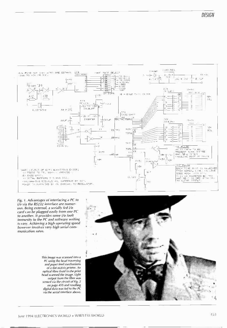
DESIGN
ALL PINS NOT INDICATED ARE EITHER ICETIED TO +5v OR GNG. 74HC4040
IC174L504 10tiF
2 40
470
2.4576MHz
+51.)
560
9
65
BAUD RATE SELECT
3
a43
6 76.21-0-.
22uF
SW DIPS1,5v
IC3MAX232 16
2T 22.F
3
+5V TO 10UDOUBLER
4 .10U TO -10)6
I
22uF
.----isp
5
INVERTER '"22uFI25a ..-6 _L 14
13
000o ; ,-------
e20Q
0
2215F21
00CONN
1
DS
10K
THREE LEVELS OF DATA BUFFERING ExI ST.1) RS232 TO TTL BUFFER (MAX232).2) 6402 UART.3) OCTAL BUFFERS 105 AND ICG.HANDSHAKING SIGNALS ARE BUFFERED BY IC7.PO -:ER IS SUPPLIED BY AN ONBOARD 5V REGULATOR.
38.4kHz19.2KHz9.61<H7460024001200600
1N4004
D4.7uF,-,
0
16 BAUD RATE CLOCK
- I Ca1 7 40
6402
RRCTRC RBR9 5
TRO
RRI
MR
ReR1,2
TBR 1
TSRL
3626
23
DR 9
DRR8
7905 REG
IN OUTGNG
IC574HC24I
0 +51,,
4.7uF 0.1uF
0
202 C 1817 C 34 C 165 C 5
6 1413
8 C 129
ICG74HC241
2K
20183 GJ 1716 - 4
5 1514 <I 67 <I 1312 cz3
9 <1 11
0+511
BIT OUT --0
6543
0-5VBIT IN
6
432
O
10k
SIL
10K
SIL
107
10K
'5U
(
+911 74HC4050 10K
N.5410K /
BC109
41(7
-VE PULSEVALID DATA TO BEPRESENT 50ns BEFOREAND 70ns AFTERTRAILING EDGE OF PULSE
+UE PULSEEACH TIME BYTE IS RECEIVEDFROM SERIA,_ LINE, DR LINEGOES HIGH (PIN 19).THIS IS INVERTED BY TR1AND SENT TO DRR (FIN 18)TO CLEAR ITSELF.
Fig. 1. Advantages of interfacing a PC toi/o via the RS232 interface are numer-ous. Being external, a serially fed i/ocard can be plugged easily from one PCto another. It provides some i/o faultimmunity to the PC and software writingis easy. Achieving a high operating speedhowever involves very high serial com-munication rates.
This image was scanned into aPC using the head traversingand paper feed mechanisms
of a dot matrix printer. Anoptical fibre fixed to the print
head scanned the image. Lightoutput from the fibre was
sensed via the circuit of Fig. 2on page 455 and resulting
digital data was fed to the PCvia the serial interface above.
June 1994 ELECTRONICS WORLD + WIRELESS WORLD 453

DESIGN
municate with the board. The functions of bitsin the MOV AL, 11100011B statement are,
Bits76543210000
001
010
011
100
101
110
111
00
01
10
11
0
1
10
11
Function
110 baud150 baud300 baud600 baud1200 baud2400 baud4800 baud9600 baudno parityodd parityno parityeven parity1 stop bit2 stop bits7 bit word length8 bit word length
A -to -d conversionFigure 2 shows the circuit diagram of an a -to -
d converter with associated circuitry for digi-tising light intensity. Whenever a byte of datafrom the host computer is sent down the seri-al line, a brief positive pulse is sent out fromthe RS232 board. This is used to trigger the a -
to -d converter.When conversion is complete, the INT line
output of the a -to -d fires the 74121 monos-table. This in turn provides the negative pulseto the board which then sends the data to thehost.
The op -amps are single supply rail types. Ifa photodarlington transistor is used then prob-lems will occur due to the high sensitivity ofthe device. This will make it difficult to obtaina linear response from dark to light.
I have tried the circuit with a few differenttypes of photo -transistor and without prob-lems. Even a BC 1D9 with its top cut off pro-duced acceptable results, although the 10kS2potentiometer in Fig. 2 had to be replaced aIMO type. Listing 2 shows a program frag-ment using the routines of the kernel listing tocommunicate with the board and take datafrom the a -to -d.
Hardware/software availabilityA fully populated board following theRS232 interface circuit in this articlecan be obtained from B. Teleki,8 Victoria Court, Brampton Road,Maybank, Newcastle -Under -Lyme,Staffordshire ST5 OSL, Tel. 0782662099 after 6pm. Its cost is £89,including software, postage and VAT.The board has a 5cm by 7cmprototyping area and all i/o lines areavailable via a 40 -way IDC header.This offer is made in good faith, butplease note that EW&WW has noinvolvement in it and therefore cannotaccept responsibility for any problemsthat may arise relating to transactionsbetween Mr Teliki and readers.
Listing 1. Kernel routine in Pascal for communicating with the PCi/o card over an RS 232 link.PROGRAM SERIAL (INPUT,OUTPUT);USESDOS, CRT;
VARBYTE_RCVD : BYTE;
DATA,RT_CD : BYTE;PROCEDURE INIT_COM;BEGINASM
MOV AL,11100011B; (9600 BAUD, 8 BITS, NO PARITY, 1 STOP BIT.}MOV DX,1; {0=COM1, 1=COM2, 2=COM3, 3=COM4MOV AH,O; {SPECIFY SERVICE 0INT 14H; {BIOS COMM, INTERRUPT
END;
END;
PROCEDURE SEND_BYTE(BYTE_TO_SEND:BYTE);BEGIN
ASM
MOV AL,BYTE_TO_SEND;{SPEC THE BYTEMOV DX,1; {SET COM2MOV AH,1; (SPECIFY SERVICE 1INT 14H; {BIOS COMM, INTERRUPT
END;
END;
PROCEDURE GET_BYTE;BEGINASM
MOV AL,O; (CLEAR ALMOV DX,1; {SET COM2
}
MOV AH,2; (SPECIFY SERVICE 2INT 14H; {BIOS COMM, INTERRUPT
}
MOV BYTE_RCVD,AL; (PUT THE BYTE INTO BYTE_RCVDEND;
END;
PROCEDURE QUIT_COM;BEGINASM
MOV RT_CD,AL; (RETURN CODE :: LOOK AT IF SOMETHING WRONG)MOV AH,4CH; (CLEAN UP AFTER FINISHEDINT 21H; (DOS SERVICES INTERRUPT
END;
END;
BEGININIT_COM;
(SEND DATA AND/OR GET DATA USING SEND_BYTE AND GET_BYTE}QUIT_COM;
END.
454ELECTRONICS WORLD + WIRELESS WORLD June 1994

DESIGN
t,EPULSEOUTPUT 4, -
I} i
I OF'
BC.109
10k POT I E PC/JUE,T EDFOR itIN I TF. LEVEL.
10t.
I 2 LM 3.58N
3K
-OE PULSE WIuIH.T .Ft .L,
HERE Itt . 97,JE
IT=
10k ,,t1L, tIOCI,F GI. ES
10
IF
1K POT IS 1.,C.JUSTEDFOR BLACY LEIIEL
0.75' REFERENCE
200,,
E CLI,P1
L IR DB I
, I, GEI2
NT 003Is .10 DB4
IN Des:,ND DB6REF/2 ce7
-1-, ,SND Dee
Fig. 2. Measuring light intensity via a PC. A -to -d conversion of light intensity to 8 bits provides atheoretical dynamic range of 48dB. More elaborate biasing around the opto transistor could
improve this.
Figure 3 shows a ZN429E d -to -a converterdriving a v-fet for power amplification. Manyloads could be connected to the fet drain, butin this case a loudspeaker has been chosen.Listing 3(a) is a simple example of how tosend data to this circuit to provide waveformsynthesis. Depending on the output data rateand application, an interpolation filter may berequired.
Replacing the loudspeaker with a dc motorneeds a diode in parallel with the motor to pre-vent back emf damaging the driving circuitry.A 1N4001 with its cathode connected to thepositive rail should suffice. Listing 3(b) showshow the motor can be accelerated up to maxi-mum speed, held there a moment, and thendecelerated.
Pascal backgroundPascal is a procedural language, which means that all functionsare first declared as procedures and then called up at the end ofthe program.
For example:
PROGRAM TEST;USES DOS, CRT, PRINTER, GRAPH;
VARA, B,C, D : REAL;
PROCEDURE BLAH(E:REAL;VAR F: REAL);
BEGINF := E/2;
END;
PROCEDURE STUFF ( ZARQ, BLARQ :REAL; VAR RESULT :REAL) ;
BEGINRESULT := SQRT (SQR ( ZARQ) +SQR (BLARQ) ) ;
END;
BEGINWRITE ( 'VALUE OF A, B = ?' ) ;
READLN (A, B) ;
BLAB (A, C) ;
THE 16K RESISTORLINEAPISES THE OUTPUT.THE ZN429 HAS AN OUTPUTRESISTANCE OF 101 -.OHM. SO
FOR CERTAIN APPLICATION=A BUFFER AMPLIFIER WILLBE REQUIRED.
45VZN429E-8 D/A
BIT 6
BIT 7
BIT 8
551)
NC
BIT
BIT 4
BIT 3
BIT 2 FROM DATA OUT.
BIT 1
NC
BITS 1 TO 8 ARE
Udd8+5N 'CAN BE MORE THAN 51)/
8 OHMSPEP,ER
UN66AF
Fig. 3. This circuit uses a ZN429E d -to -aconverter driving a VFET for high power.Depending on the output data rate andapplication, an interpolation filter may berequired.
Controlling a stepper motorFigure 4 shows a high -power stepping motorinterface and Listing 4 its driver software.Since the motor in this example is a four -phase type requiring a ring counter sequence,binary values of each step have to be convert-ed to decimal numbers before transmission. Avalue of 11002 for example represents 12,value 01101 is 6, 00112 is 3 and 10012 is 9.
STUFF (B, C, D) ;
WR ITELN ( 'VALUE OF PARAMETER = , D) ;
END.
The USES statement calls up various inbuilt library units to dostandard operations. DOS is a unit that allows you to invoke doscalls such as GETTIME, SETTIME, DISKSIZE, etc. Unit CRTmanipulates text screens and controls sound while PRINTERenables you to output to the printer.
GRAPH is for Hercules to VGA graphics functions.Declaration VAR defines the global variables you are to use and
their types. The PROCEDURE statement allows you to group asequence of operations into one self contained sub program.When declaring a procedure, local incoming variables aredeclared first, together with their types and then the outgoing vari-ables, preceded by the word VAR.
Pascal also has the capability of being extended. For example ifyour version doesn't have a complex maths library unit, it is fair-ly easy to write the unit that performs the complex maths. Whenit is compiled, you have all the types and operations available inyour program that were declared in the unit. You simply addCOMPLEXMATH to the USES clause at the top of the program.
It is also possible to put assember statements into a procedure,as in the kernel listing, so that hardware can be directly con-trolled.
June 1994 ELECTRONICS WORLD + WIRELESS WORLD 455

DESIGN
Fig. 4. High -power stepper motor controllerincorporating a mosfet driver. Supply voltage tothe motor windings can be more than 5V butnot more than 60V using, say, a VN66AF powermosfet.
Image acquisitionWith a dot-matrix printer that can emulate thestandard IBM printer graphics mode, it is pos-sible to make the printhead scan across anyhard -copy image in the printer's paper path.Most dot matrix printers can emulate the IBMgraphics mode.
By attaching one end of an optical fibre tothe print head and the other end to the opto-transistor shown in Fig. 2, it is possible to reada bit -map of the image passing the print headinto the PC. An example of the reproductionobtainable via this method is the photographof Bogart on the front cover of the magazine.
A light source is needed for this application,usually positioned about 300 to 600mm awayand to the side of the printer. Listing 5 showsthe procedure that controls the printer andacquires the data from the a -to -d converter.
Because the data length of the printer in theselected mode is 960 bytes and resolution of aVGA screen is 640 -pixel, line -scan is not100% straightforward. One byte of data is sentto the printer on the odd count and two byteson the even count. After each data transmis-sion moves the head, the image light level issampled.
Resolution attainable is approximately 80dots per inch. Epson and IBM type printersalso have a 480 -byte line mode but it producesvery poor scans. The software that does thescanning redefines the VGA palette to 16 greyshades and brackets the 256 levels that comefrom the a -to -d to one of these shades. Imagesare saved in standard paintbrush (.PCX) for-mat with palette information.
Windows quite happily accepts the image,as long as it is in a 256 colour mode or higher.If in sixteen colour mode, Windows willremap the incoming palette to its own colourset and the result will make you want to go fora quiet lie down somewhere.
Due to the large lmm diameter of the opti-
Listing 2. Very little software needs to be linked into the kernel routine in order to readan a -to -d converter.BEGIN
INIT_COM;
FOR K := 1 TO 1000 DO {K and DATA previously defined}BEGIN
SEND_BYTE(0);GET_BYTE;DATA := BYTE_RCVD;{DO SOMETHING TO DATA}
END;
QUIT_COM;END.
Listing 3(a). Sending information to a d -to -a converter provides waveform synthesis fordriving, say, the loudspeaker of Fig. 3.BEGIN
INIT_COMREPEAT
DATA := 0 ; SEND_BYTE(DATA); {To transmit complex waveformsDATA := 255 ; SEND_BYTE(DATA);
UNTIL KEYPRESSED = TRUE;QUIT_COM;
END.
(as integer and byte types
just}{send a different sequence of data.}{But the more samples that are sent}{will mean a lower base frequency
}
Listing 3(b). This routine runs a motor up to full speed, holds it there a while then decel-erates it. It can be used with the d -to -a converter of Fig. 3 by replacing the loudspeakerwith a small dc motor.BEGIN
INIT_COMFOR K := 0 TO 255 DOBEGIN
SEND_BYTE(K);DELAY(300); {DELAY FOR 300ms}
END;
DELAY(2000); {HOLD AT MAX SPEED FOR 2 SECONDS}FOR K := 255 DOWNTO 0 DOBEGIN
SEND_BYTE(K);DELAY(300);
END;
QUIT_COM;END.
Listing 4. Driving a four -phase stepping motor involves a ring -counter sequence.
A := 12;BYTE}
B := 6;C := 3;D := 9;
REPEAT
SEND_BYTE(A); DELAY(300);SEND_BYTE(B); DELAY(300);SEND_BYTE(C); DELAY(300);SEND_BYTE(D); DELAY(300);
UNTIL KEYPRESSED TRUE;END.
cal fibre - the cheapest I could find - sam-pling problem occurs due to aliasing. To beprecise, the problem is spacial aliasing causedby the relatively large diameter of the opticalfibre compared to the resolution of the printer.
As the fibre scans across an image, the sam-ple points are slightly overlapped whichresults in some of the data from one samplepoint appearing in the next. This means thatdark striations appear on the scanned image.
{A,B,C,D previously defined as
{Delay for 300ms between each step}
However with the use of some filtering soft-ware the interference can be removed. A line -array ccd could produce much better results.
Temperature measurementBy using a diode -1N4148 will do - and alkil series resistor instead of the opto-tran-sistor and 3k0 resistor of Fig. 2, a reasonably
Continued on page 458
456ELECTRONICS WORLD + WIRELESS WORLD June 1994

DESIGN
Listing 5. Image scanning with the aid of a dot-matrix printer involves moving thehead across the image and sampling light level at each increment. In the variable dec-laration, stuff is declared as type TEXT; later on in the program assign it to the printerport with ASSIGN(STUFF,'LPT1').
PROCEDURE SCAN; {FULL PAGE SCAN ; EQUIV TO APPROX 80
BEGIN WRITE(STUFF,#27,#60); {RESET PRINTER }
WRITE(STUFF,#27,#85,#1); {UNIDIRECTIONAL PRINTING
FOR Y := 0 TO 479 DOBEGINWRITE(STUFF,#27,#51,#03); {MOVE PAPER BY 3/216 INCHWRITE(STUFF,#27,#76,#192,#3);{SLOW MODE =
FOR X := 0 TO 639 DOBEGINIF ODD (X) THEN
BEGINWRITE (STUFF, #00) ;
DATAGET;ENDELSEBEGINWRITE(STUFF,#00,#00);DATAGET;
END;
IF KEYPRESSED = TRUE THENBEGINX := 639;Y := 479;
END;
END;
END;
END;
DPI)
ON }
#76:960 DOTS/SCAN RES)
{DATAGET IS A DATA ACQUISITION PROCEDURE{CONTROLLING THE A -TO -D CCNVERTER AND PLOTS){THE DATA ONTO A VGA SCREEN }
Listing 6. Routines for plotting temperature against lime.
PROCEDURE SETUPGRAPHICS;BEGINGD := DETECT; INITGRAPH(GD,GM,"); {INITIALISE GRAPHICS SYSTEM}
IF GRAPHRESULT <> GROK THEN {ALL SCREEN OUTPUT ASSUMES THAT)
HALT(1); {A VGA ADAPTER IS PRESENT}
SETVIEWPORT(0,0,GETMAXX,GETMAXY,CLIPON);SETWRITEMODE(ORPUT);SETCOLOR(15);RECTANGLE(0,0,639,240);LINE(0,15,639,15);SETTEXTJUSTIFY(LEFTTEXT,CENTERTEXT);SETTEXTSTYLE(DEFAULTFONT,HORIZDIR,1);OUTTEXTXY(240,09,'TEMPERATURE MEASUREMENT'); {PUT TITLE AT TOP OF
SCREEN)K := 0;REPEATLINE(K,15,K,240);STR(K*30,SCREENTEXT); {SCREENTEXT DEFINED AS TYPE STRING}OUTTEXTXY(K+2,235,SCREENTEXT+'ms'); {PW TIMING TICKS ON X AXIS}
INC(K,64);UNTIL (K>639);
END;
BEGINSETUPGRAPHICS;INIT_COM2;FOR K := 1 TO GETMAXX DOBEGINSEND_BYTE(0); {START
GET_BYTE; {GET THE
PUTPIXEL(K,3*BYTE_RCVD-200,15);OFFSET)
DELAY(30);END;
READLN;CLOSEGRAPH;
END.
CONVERSION)DATA}
{PLOT DATA WITH SCALING AND
{WAIT FOR 30mS}
ADC0804 a -to -d converterThis converter is suitable for both micropro-cessor bus based systems and stand-alone a -to -d applications. Its conversion time of100ms limits its use to audio frequencies andbelow.
Low speed is offset by the device's cheap-ness - at around £4.25 - and ease of use. Itson -board clock generator needs only twoexternal components. As you can see fromFig. 1, driving the device is straightforward.
With a single 5V supply and 2.5V appliedto. Vref/2, the analogue input voltage range is0 to 5V. Fig. 2 uses a forward biased diode toprovide the reference voltage of 0.7V whichleads to an input voltage range of 0 to 1.4V.
Voltage reference 1Uref/2 can be any valueunder 2.5V. As a result, any voltage span canbe converted with a full eight bits of resolu-tion. Also, by connecting -Vin to a voltageother than ground (note the 1kS2 pot in Fig. 2)the voltage conversion range need not start atOV.
Stepping motor backgroundConsider the simplified diagram of the typicalstepping motor shown below with windingsA to D. The armature is a cylindrical magnetwith poles N and S.
Applying a voltage to phases A and Bresults in the poles of the motor armaturealigning with the two phases in an orienta-tion depending on the polarity of the appliedsignal.
If phase A is switched off and phase Cswitched on while B is still on, the motorarmature realigns itself with the new phase.Similarly if B is switched off and D on, thearmature again aligns itself with the newphase. In this way the motor rotates.STEPP R MOTOR WITH FOUR PHASES A DSTEP ANGLE = 360%8 = 45'ENDS MARKED .ARE ALL TIED TO ONECOMM N POINT, EITHER POSITIVE ORNEGATIVE POWER.
Excitation sequence is AB, BC, CD, DA,AB. In practice the phases are wound withhigher multiples of each other so that the stepangle is much less. A typical example is 200steps per revolution, which is equivalent to1.8° per step.
It is possible to double the resolution of astepping motor by half stepping it. Instead ofexciting it as in the above sequence, if thefollowing sequence A, AB, B, BC, C, CD, D,DA, A is fed to the motor, then 400 steps perrevolution will result.
Stepping motors are found in plotters, flop-py disk drives, hard disk drives, pick andplace machinery and sewing machines. Theyare extensively used in industry, particularlyfor robotic manipulators.
June 1994 ELECTRONICS WORLD + WIRELESS WORLD 457

DESIGN
FIG (5) TEMPERATURE MEASUREMENT
OMs
_____.._ - ..... ._ ..__ __
080 C
0 c
15360ms 17280ms1920ms 3840ms 57601s 7680ms 9600ms 11520ms 13440ms
accurate measurement of temperature can bemade. The configuration is the same as thediode resistor combination that provides the0.7V reference.
This arrangement ignores the non-lineartemperature dependance of the pn junction butat 5p each as opposed to £1.20 for theLM335Z or £3.45 for the LM35DZ, a degreeof non -linearity is a small penalty. Note thatthe temperature sensing diode is followed by again block to amplify its approximate-2mV/°C to a level that the a -to -d convertercan handle.
You may have noticed that the circuit uses adiode to provide a reference voltage to the
a -to -d converter. This will always be at thelocal ambient temperature, so its voltage vari-ation is going to be relatively small comparedto the amplified voltage of the temperaturesensing diode.
Listing 6 shows routines for plotting tem-perature against time. Figure 5 is a typicaltemperature plot against time. The 0° pointwas measured by putting the diode into melt-ing ice, while the 80° point was obtained byputting the diode into a convenient cup of hottea.
For a faster data acquisition rate. theDELAY(30) (30ms delay) command can beremoved from the listing.
Fig. 5. Simplyreplacing the lightsensor of Fig. 1 witha general purposediode allowstemperature to beread into the PC.
References1. Jourdain, R., Programmer's problem solverfor the IBM PC, XT & AT, Brady.2. Wyatt Sr, A. L., Using assembly language,Que.3. Marston, R. M., Optoelectronics circuitsmanual, Newnes.4. 6402 Data sheet.5. High-speed cmos logic data book, TexasInstruments, Bedford.6. Nadolski, J., Replacing LSTTL with highspeed CMOS, Electronic Engineering, Sept1985.
PCBs for Douglas Self's poweramplifier seriesCircuit boards for Douglas Self's high-performance power amplifier are now availablevia EW+WW.
Detailed on page 139 of the February issue,Douglas Self's state-of-the-art power amplifier isthe culmination of ideas from one of the mostdetailed studies of power amplifier design everpublished in a monthly magazine. Capable ofdelivering up to 100W into 8Q, the amplifierfeatures a distortion figure of 0.0015% at 50Wand is designed around a new approach tofeedback.
Designed by Douglas himself, the fibreglassboards have silk-screened component IDs andsolder masking to minimise the possibility ofshorts. Sold in pairs, the boards are supplied withadditional detailed constructional notes.
Each board pair costs £45, which includes VATand postage, UK and overseas. Credit card orderscan be placed 24 hours on 081 652 8956.Alternatively, send a postal order or cheque madepayable to Reed Business Publishing to EW+WW,The Quadrant, Sutton, Surrey SM2 5AS.
458
IALL
0/PSIG
-r-R31 DZ2
0/PGND

Surplus always THE ORIGINAL SURPLUS WONDERLAND!wanted for cash! THIS MONTH'S SELECTION FROM OUR VAST EVER CHANGING STOCKS
LOW COST PC's - ALL EXPANDABLE - ALL PC COMPATIBLE
Surplus alwayswanted for cash!
THE OFFER OF 1994 !
SPECIAL BUYAT 286
40Mb HD + 3Mb RamLIMBED QUANTITY only of these 12Mhz HI GRADE 286 systemsMade in the USA to an industrial specification, the system wasdesigned for reliability. The compact case houses the motherboard,PSU and EGA video card with single 51/4" 1.2 Mb floppy disk drive &Integral 40Mb hard disk drive to the front. Real time clock with bat-tery backup is provided as standard. Supplied in good used conditioncomplete with enhanced keyboard, 640k + 2Mb RAM, DOS 5.0.and 90 DAY Full Guarantee. Ready to Run !Order as HIGRADE 286 ONLY .£169.00 (E)Optional Fitted extras: VGA graphics card1.4Mb 3W floppy disk drive (instead of 1.2 Mb)NE2000 Ethernet (thick, thin or twisted) network card
£29.00£32.95£49.00
FLOPPY DISK DRIVES 3.5"- 8"5.25" from £22.95 - 3.5" from £24.95
Massive purchases of standard 5.25' and 3.5' drives enables us topresent prime product at industry beating low prices! All units (unlessstated) are BRAND NEW or removed from often brand new equip-ment and are fully tested, aligned and shipped to you with a 90 dayguarantee and operate from standard voltages and are of standardsize. All are IBM-PC compatible (if 3.5' supported on your PC).3.5" Panasonic JU363/4 720K or equivalent £24.95 B3.5' Mitsubishi MF355C-L 1.4 Meg. Laptops only £36.95 B3.5' Mitsubishi MF355C-D. 1.4 Meg. Non laptop £29.95 B5.25" Teac FD-55GFR 1.2 Meg £29.95 B5.25" BRAND NEW Mitsubishi MF501B 360K £22.95 B Data cable included in price.Shugart 800/801 8' SS refurbished & testedShugart 851 8" double sided refurbished & tested £250.00Mitsubishi M2894-63 8" sided switchable NEW £250.00Mitsubishi M2896 -63-02U 8' DS slimline NEW £285.00Dual 8" drives with 2 mbyte capacity housed in a smart case withbuilt in power supply. Ideal as exterior drives! £499.00(F)
EE
E
HARD DISK DRIVESEnd of line purchase scoop! Brand new NEC D2246 8" 85 Mbyteof hard disk storage! Full industry standard SMD Interface. Ultra hispeed data transfer and access time, replaces Fujitsu equivalentmodel. complete with manual. Only £299.00(E)3.5' FUJI FK-309-26 20mb MFM I/F RFE £59.95(C3.5" CONNER CP3024 20 mb IDE I/F (or equiv )RFE £69.95 C3.5' CONNER CP3044 40mb IDE I/F (or equiv.)RFE £99.00 C3.5" RODIME R03085S 70mb SCSI I/F (Mac & Acorn) £129.00 C5.25' MINISCRIBE 3425 20mb MFM I/F (or equiv.) RFE £49.95 C5.25' SEAGATE ST -238R 30 mb RLL I/F Refurb5.25' CDC 94205-51 40mb HH MFM I/F RFE tested £89.95 C8" FUJITSU M2322K 160Mb SMD I/F RFE tested £195.00 EHard disc controllers for MFM , IDE, SCSI, RLL etc. from £16.95
THE AMAZING TELEBOXConverts your colour monitor into a DUALITY COLOUR TV!!
TV SOUND& VIDEOTUNER!
The TELEBOX consists of an attractive fully cased mains poweredunit, containing all electronics ready to plug into a host of video moni-tors made by manufacturers such as MICROVITEC, ATARI,SANYO, SONY, COMMODORE, PHILIPS, TATUNG, AMSTRADand many more. The composite video output will also plug directlyinto most video recorders, allowing reception of TV channels not nor-mally receivable on most television receivers' (TELEBOX MB). Pushbutton controls on the front panel allow reception of 8 fully tuneable'off air' UHF colour television channels. TELEBOX MB covers virtual-ly all television frequencies VHF and UHF including the HYPER -BAND as used by most cable TV operators. A composite videooutput is located on the rear panel for direct connection to mostmakes of monitor. For complete compatibility - even for monitorswithout sound - an integral 4 watt audio amplifier and low level Hi Fiaudio output are provided as standard.TELEBOX ST for composite video input type monitors £32.95TELEBOX STL as ST but with integral speaker £36.50TELEBOX MB Multiband VHF -UHF -Cable- Hyperband tuner £69.95For overseas PAL versions state 5.5 or 6mhz sound specification.'For cable / hyperband reception Telebox MB should be connectedto cable type socket. Shipping code on all Teleboxes is (B)
FANS & BLOWERSM 1 : 1 H 25 mm 12v £4 10 £4MITSUBUSHI MMF-09B12DH 92 x 25 mm 12v DC £5.95 10 / £53PANCAKE 12-3.5 92 x 18 mm 12v DC £7.95101E69EX -EQUIP 120 x 38mm AC fans - tested specify 110 or 240 v £6.95EX -EQUIP 80 x 38mm AC fans - tested specify 110 or 240 v £5.95VERO rack mount 1U x 19" fan tray specify 110 or 240v £45.95IMHOF B26 1900 rack mnt 3U x 19 Blower 110/240v NEW £79.95Shipping on all fans (A). Blowers (B). 50,000 Fans Ex Stock CALL
IC's TRANSISTORS DIODESOBSOLETE - SHORT SUPPLY - BULK
5,000,000 items EX STOCKFor MAJOR SAVINGS - SAE or CALL FOR LATEST LIST
PC SCOOPCOMPLETE
COLOUR SYSTEMONLY £99.00
A massive bulk purchase enables us to bring you a COMPLETEready to run colour PC system at an unheard of price!The Display Electronics PC99 system comprises of fully com-patible and expandable XT PC with 256k of RAM, 5W 360k floppydisk drive, 12 CGA colour monitor, standard 84 key keyboard,MS DOS and all connecting cables - lust plug in and go Idealstudents, schools or anybody wishing to learn the world of PC'son an ultra low budget. Don't miss this opportunity.Fully guaranteed for 90 Days.
Order as PC99COL £99.00 (E)
Optional Fitted extras: 640k RAM2nd floppy drive, specify 51/4' 360k or 31/2' 720k
Above prices for PC99 offer ONLY.
£29.00.£29.95.
VIDEO MONITOR SPECIALSSuperb quality 14' FOREFRONT MTS-9600 SVGA Multisync -
Multimode monitor 0.28" dot pitch with resolution of 1024 x 768. The multi mode input allows direct con-
nection to a host of computers including IBM PCs XiCGA, EGA, VGA & SVGA modes, BBC, COM-MODORE (including Amiga 1200), ARCHIMEDESetc. The H version will also function with the ATARI in
. all modes inc HI RES monochrome. Complete with'text' switching for WP use. Syncs down to 15 kHz.
Supplied in EXCELLENT little used condition with full 90 day guarantee.Order as MTS-9600/ H for ATARI £159.00 (E)All modes as above Order as MTS-9600/S £139.00 (E)ELECTROHOME ECM-1211SBU 12" VGA multisync monitor withresolution 640 x 480. Multi input selection; 9pin CGA/ EGA ; 15 pinVGA or 5 BNC connectors. 0.31 pitch. Compatible with PCs, Amiga,Atari and others. In good used condition (possible minor screenbums). 90 day guarantee. £99.00 (E)KME 10" high definition colour monitors. Nice tight0.28" dot pitch for superb clarity and modernstyling. Operates from any 15.625 khz sync RGBvideo source, with RGB analog and compositesync such as Atari, Commodore Amiga, AcornArchimedes & BBC. Measures only 13.5' x 12' x11'. Only £125 (E)Good used condition. 90 day guarantee.KME 10" as above for PC EGA standard £145.00 (E)NEC CGA 12" colour IBM-PC compatible. highquality ex -equipment fully tested with a 90 dayguarantee. In an attractive two tone ribbed greyplastic case measuring 15'L x 13'W x 12'H. Thefront cosmetic bezel has been removed for con-tractual reasons. Only £49.00(E)
20" 22" and 26" AV SPECIALSSuperbly made UK manufacture. PIL all solid state colour monitors,complete with composite video & sound inputs. Attractive teak stylecase. Perfect for Schools, Shops, Disco, Clubs, Point of Sale etc.In EXCELLENT little used condition with full 90 day guarantee.
20"....£135 22"....£155 26"....£185(99" Mono casec, Black & White for CCTV Used /Tested £49.00 (C)
DC POWER SUPPLIES10,000 Power Supplies Ex Stock
Call for info / listPower One SPL200-5200P 200 watt (250 w peak).Semi openframe giving +5v 35a, -5v 1.5a, +12v 4a (8a peak), -12v 1.5a, +24v4a (6a peak). All outputs fully regulated with over voltage protectionon the +5v output. AC input selectable for 110/240 vac. Dims13* x5' x 2.5'. Fully guaranteed RFE. £85.00 (B)Power One SPL130. 130 watts. Selectable for 12v (4A) or 24 v(2A). 5v @ 20A. & 12v 0 1.5A. Switch mode.New. £59.95(B)Astec AC -8151 40 watts. Switch mode. +5v @ 2.5a. +12v B 2a.-12v B 0.1a. 6-1/4' x 4' x 1-3/4" RFE tested £22.95(B)Lambada LYS-PV-12 200 watt switch mode.+12V DC B 29asemi enclosed, 10' x 5' x 5". RFE and fully tested. £59.95(C)Conver AC130. 130 watt hi -grade VDE spec.Switch mode.+5v B15a, -5v B la,+12v B 6a.27 x 12.5 x 6.5cms.New. £49.95(C)Boshert 13090.Switch mode.ldeal for drives & system. +5v@ 6a,+12v B 2.5a, -12v Q 0.5a, -5v B 0.5a. £29.95(B)Fame!! G6/40A. Switch mode. 5v B 40a.Encased £95.00(C)
SPECIAL INTERESTZeta 3220-05 AO 4 pen HPGL RS232 fast drum plotterAvitel VDA-3100 Video Distribution Amps.1 in 92 outTrio 0-18 vdc bench PSU. 30 amps. NewFujitsu M3041 600 LPM band printerDEC LSI/1102 CPU boardRED TOP IR Heat seeking missile (not armed !!)Rhode & Schwarz SBUF TV test transmitter 25-1000mhz.
complete with SBTF2 ModulatorCalcomp 1036 large drum 3 pen plotterThurlby LA 1608 logic analyserGEC 1.5kw 115v 60hz power sourceBrush 2Kw 400 Hz 3 phase frequency converterAnton Pillar 75 kW 400 Hz 3 phase frequency converterNewton Derby 70 KW 400 Hz 3 phase frequency converter POANikon PL -2 Projection lens meter/scope £750Sekonlc SD 150H 18 channel digital Hybrid chart recorder £1995HP 7580A Al 8 pen HPGL high speed drum plotter £1850Kenwood DA -3501 CD tester, laser pickup simulator £350Computer MCA1613APC 16mm auto iris lenses 'C' mount £125Seaward PAT 2000 dual voltage computerised PAT tester £585
£2100£575£470
£2950£95
POA
£5995£450£375£950£850
ComputerControlled
wm v.. Laser VideoOne of the most amazing surplus deals Disk Playerthat we ever been able to offer you!The Philips VP410 LaserVision player, in as new condition, unit lea -fuses full computer control, Plays standard 12' LaserVision disks withstartling visual and audio quality in two channel stereo or mono.When controlled by a computer, it may also be used as a versatilehigh quality storage / retrieval medium. It will play back eitherLaserVision CAV (active play) or CLV (Long Play) discs (which cov-ers most types of commercially available video discs). Some of themany features of this incredible machine are:RS -232 INTERFACE RGB / COMPOSITE VIDEO OUTPUTBNC+SCART INTERFACE PAL/RGB DECODERIR+WIRED REMOTE CONTROL FAST RANDOM ACCESS
SPECIAL PURCHASE £399.00(F)
BBC Model B APM Board£1 00 CASH FOR THE MOSTNOVEL DEMONSTRABLE
APPLICATIONBBC Model B type computer on a board. A major purchase allows usto offer you the PROFESSIONAL version of the BBC computer at aparts only price. Used as a front end graphics system on large net-worked systems the architecture of the BBC board has so many sim-ilarities to the regular BBC model B that we are sure that with a bit ofexperimentation and ingenuity many useful applications will be foundfor this board!! It is supplied complete with a connector panel whichbrings all the I/O's to 'D' and BNC type connectors - all you have todo is provide +5 and +12 v DC. The APM consists of a single PCBwith most major ic's socketed. The ic's are too numerous to list butinclude a 6502 / 6512 CPU, RAM and an SAA5050 teletext chip.Three 27128 EPROMS contain the custom operating system onwhich we have no data, On application of DC power the systemboots and provides diagnostic information to
and jumpers select the ECONET addressOnly £29.95the video output. On board DIP switches
and enable the four extra EPROM sockets for 53far user software. Appx. dims: main board13' x 10". I/O board 14' x 3'. Supplied test-ed with circuit diagram, data and competition entry form.
19" RACK CABINETSSuperb quality 6 foot 40u
Virtually New, Ultra SmartLess than Half Price!
Top quality 19" rack cabinets made in UK byOptima Enclosures Ltd. Units feature design-er, smoked acrylic lockable front door, fullheight lockable half louvered back door andremovable side panels. Fully adjustable inter-nal fixing struts, ready punched for any config-uration of equipment mounting plus readymounted integral 12 way 13 amp socketswitched mains distribution strip make theseracks some of the most versatile we have
ever sold. Racks may be stacked side by side and therefore requireonly two side panels to stand singly or in baysOverall dimensions are: 77-1/2' H x 32-1/2' D x 22' W. Order as:
Rack 1 Complete with removable side panels. £295.00 (G)Rack 2 Rack, Less side panels £175.00 (G)
Over 400 racks in all sizes from stock !Call with your requirements.
LOW COST RAM UPGRADESINTEL 'ABOVE' Memory Expansion Board. Full length PC -XT andPC -AT compatible card with 2 Mbytes of memory on board. Card isfilly selectable for Expanded or Extended (286 processor andabove) memory. Full data and driver disk supplied. In good usedcondition fully tested and guaranteed.Windows compatible. Order as: ABOVE CARD £59.95(A1)Half length 8 bit memory expansion cards for PC AT XTexpands memory either 256k or 512k in 64k steps. May also beused to fill in RAM above 640k DOS limit. Complete with data andsoftware diagnostics. Order as: XT RAM UG. 256k £32.95(A1Specify 5.25 or 3.5' software diskette. 512k £38.95(A11 MEG x 9 SIMM 9 chip 120ns only £29.95(Ai
No Break Uninterruptible PSU'sBrand new and boxed 230 volts 1 KVa uninterruptible power supplyfrom system from Dense!. Model MUD 1085-AHBH. Complete withsealed lead acid batteries in matching case. Approx time from inter -'opt is 15 minutes. Complete with full manual. Aft
(G).1.11.1Order as: MUD 1 Z.EMERSON ACCUCARD UPS, brand new 8 Bit half length PC com-patible card for all IBM XT/AT compatibles. Card provides DC powero all internal system components in the event of power supply fail-ure. The Accusaver software provided uses only 6k of base RAMand automatically copies all system, expanded and video memory tothe hard disk in the event of loss of power. When power is returnedthe machine is returned to the exact status when the power failed !the unit features full self diagnostics on boot and is supplied with fullfitting instructions and manual. Normal price £189.00
Only £99.00(3) or 2 for £195(c)
Issue 12 of Display News now available - send large VIE - PACKED with bargains!
S. S.
-ELECTROIYIES-
LONDON SHOPOpen Mon -Sat 9:00-5:30
215 Whitehorse LaneSouth NorwoodLONDON SE25
DISTEL © The OriginalFREE On line DatabaseInfo on 1000's of items
V21,V22, V22 BIS
081 679 1888
ALL MAIL & OFFICESOpen Men -Fri 9.00-5:30
Dept WW. 32 Biggin WayUpper Norwood
LONDON SE19 3XF
ALL 17 ENQUIRIES
081 679 4414FAX 081 679 1927
VISAS ESTABLISHED
25 YEARS
All prices for UK Mainland. UK customers add 17.5% VAT to TOTAL order amount. Minimum order £10. Bona Fide account orders accepted from Government,Schools, Universities and Local Authorities - minimum account order £50. Carriage charges (A)=£3, (A1)=£4.00, (B).£5.50, (C)=£8.50, (D)=£12.00, (E)=£15.00,(F)=£18.00, (G)=CALL Allow approx 6 days for shipping - faster CALL. Scotland surcharge CALL. All goods supplied to our Standard Conditions of Sale andunless stated guaranteed for 90 days. All guarantees on a return to base basis. All rights reserved to change prices / specifications without prior notice. Orderssubject to stock. Discounts for volume. Top CASH prices paid for surplus goods. All trademarks etc acknowledged. Display Electronics 1994. E & 0 E.
CIRCLE NO. 109 ON REPLY CARD

SMALL SELECTION ONLY LISTED - EXPORT TRADE AND QUANTITY DISCOUNTS - RING US FOR YOUR REQUIREMENTS WHICH MAY BE IN STOCK
NEW LOW PRICE - NEW COLOUR
HP141TSPECTRUM ANALYSERS
TESTEDHP141T + 8552A or B IF RF- 1kHz- 110Mc/s-
A IF £600 or B IF - £700.HP141T + 8552A or B IF - 8554B RF - 100kHz -
1250Mc/s -A IF £800 or B IF - £900.HP141T + 8552A or B IF - 8555A RF - 10Mc/s - 18GHz
-A IF £1400 or B IF - £1600. The mixer in this unitcosts £1000, we test every one for correct gainbefore despatch.
HP141T + 8552A or B IF - 8556A RF - 20Hz - 300kHz -A IF £600 or BIF - £700.
HP ANZ UNITSAVAILABLE SEPARATELYNEW COLOUR - TESTED
HP141T Mainframe - £350 - 8552A IF - £200 - 8552BIF - £300 - 8553B RF - 1kHz -110Mc/s- £200 - 8554BRF - 100kHz - 1250Mc/s - £400. 8555A RF - 10Mc/s -18GHz -£1000. 8556A RF- 20HZ - 300KHZ - £250.
HP8443A Tracking Generator Counter - 100kHz -110Mc/s- £300 - £400.
HP8445B Tracking Pre -selector DC - 18GHz - £400-£600 or HP8445A- £250.
HP8444A Tracking Generator - £750 -1300Mc/s.HP8444A Opt 059 Tracking Generator- £1000 -1500Mc/s.
SPECIAL OFFER -14 ONLYHP140T (NON -STORAGE)
Mainframe Plus 8552A IF Plug -In Plus 8556A RF Plug-
-In 1kHz -110Mc/s. Tested with instructions -000.
Marconi TF2008 - AM -FM signal generator - also sweeper - 101(c/s - 510McJs - from £250 - testedto £400 as new with manual - probe kit in wooden carrying box.
HP Frequency comb generator type 8406 - £400.HP Vector Voltmeter type 8405A - £400 to £600 - old or new colour.HP Sweep Oscillators type 8690 A & B plug -ins from 1 OMc/s to 18GHz also 18-40GHz. P.O.R..HP Network Analyzer type 8407A + 8412A + 8501A - 100Kc/s - 110Mc/s -E500 - E1000.HP Amplifier type 8447A - 1-400Mc/s £200 - HPB447F. 1-1300Mc/s £400.HP Frequency Counter type 5340A - 18GHz £1000 - rear output £800.HP 8410 -A -B -C Network Analyzer 110Mc/s to 12GHz or 18GHz - plus most other units and
displays used in this set-up - 841Ia 8412 8413 8414 8418 8740 8741 8742 87438746 - 8650. From £1000.
Racal/Dana 9301A - 9302 RF Millivoltmeter - 1.5-2GHz - £250-E400.Racal/Dana Counters 9915M - 9916 -9917 - 9921 - £150 to E450. Fitted FX standards.Racal/Dana Modulation Meter type 9009 - 8Mc/s - 1.5GHz - E250.Marconi RCL Bridge type TF2700 -£150.Marconi/Saunders Signal Sources type - 60598 - 6070A - 6055A - 6059A - 6057A - 6056 -
E250 -E350. 400Mc/s to 18GHz.Marconi TF1245 Circuit Magnification meter + 1246 & 1247 Oscillators -£100-£300.Marconi microwave 6600A sweep osc., mainframe with 6650 PI - 18-26.5GHz or 6651 PI - 26.5-
40GHz - £1000 or PI only £600. MF only E250.Marconi distortion meter type TF2331 - £150. TF2331A - 200.Tektronix Plug -Ins 7A13 - 7A14 - 7A18 - 7A24 - 7A26 -7A11 -7M11 -7S11 - 7D10 - 7S12 - S1
- S2 - S6 - S52 - PG506 - SC504 - SG502 - SG503 - SG504 - DC503 -00508 - DD501 -WR501 - DM501A - FG501A - TG501 - PG502 - DC505A - FG504 -7E180 + 85-7892A
Gould J3B test oscillator + manual - £200.Tektronix Mainframes - 7603 - 7623A - 7613 - 7704A -7844 - 7904 - TM501 -TM503 -TM506 -
7904 - 7834 - 7104 - 7623 - 7633.Alltech 757 Spectrum Analyser - 001 22GH, - Digital storage 4 readout - £2000.Marconi 6155A Signal Source - 1 to 2GHz - LED readout - E400.Barr & Stroud Variable filter EF3 0.1Hz - 100kc/s 4 high pass -4 low pass -£150.Marconi TF2163S attenuator - 1GHz. E200.Farnell power unit H60/50 - E400 tested. H60/25 - £250.Racal/Dana 9300 RMS voltmeter -E250.HP 8750A storage normalizer - 400 with lead - S.A or N,A Interface.Marconi TF2330 - or TF2330A wave analysers - £100-£150.Racal/Dana signal generator 9082 - 1.5-520Mc/s - E500.Racal/Dana signal generator 9082H - 1.5-520Mc/s - £600.Tektronix -7S14 -7711 -7511 - 7S12 - SI - S2 - S39 -S47 -S51- S52- S53 -7M11.Marconi mod meters type TF2304 - £250.HP 5065A rubidrum vapour FX standard -E2.5k.Systron Donner counter type 6054B - 20Mds - 24GH, - LED readout -Elk.Racal/Dana 9083 signal source - two tone - £250.Systron Donner - signal generator 1702 -synthesized to 1 GHz - AM/FM -£600.Tektronix TM515 mainframe 4 TM5006 mainframe - £450 - £850.Rhodes & Schwartz power signal generator SLRD-280 - 2750Mc/s - £250-f600.Ball Efratom rubidrum standard PT2568--FRKL - £1000.Farnall electronic load type RB1030-35 -E350.Racal/Dana counters - 9904 - 9905 - 9906 - 92'.5 - 9916 - 9917 - 9921 - 50Mc/s - 3GHz - E100 -
E450 - all fitted with FX standards.HP4815A RF vector impedance meter c/w probe- 000-£600.Marconi TF2092 noise receiver. A, B or C plus filters -£100-£350.
Marconi TF2091 noise generator. A, B or C plus filters - f100-£350.HP180TR, HP182T mainframes 000-000.Fluke 8506A thermal RMS digital multimeter. £400.Philips panoramic receiver type PM7900 - 1 to 20GHz - E400.Marconi 6700A sweep oscillator + 6730A -1 to 2GHz - £500.HP8505A network ANZ + 8503A S parameter test set + 8501A normalizer - £4k.Racal/Dana VLF frequency standard equipment. Tracer receiver type 900A + difference meter
type 527E + rubidium standard type 9475- E2750.HP signal generators type 626 - 628 - frequency 10GHz - 21GHz.HP 432A -435A or B - 436A - power meters + powerheads - Mc/s - 40GHz - E200 -E1000.Bradley oscilloscope calibrator type 192- £600.Barr & Stroud variable filter EF3 0.1Hz - 100Kcis + high pass + low pass -£150.Marconi TF2370 spectrum ANZ -110Mc/s -E900.Marconi TF2370 spectrum ANZ + TK2375 FX extender 1250Mc/s + 1st gen -£1.5k.HP8614A signal generator 800Mc/s-2.4GHz, new colour £400.HP8616A signal gen 1.8GHz - 4.5GHz, new colour £400.HP 3325A syn function gen 20Mc/s -£1500.HP 3336A or B syn level generator - £500-E600.HP 35868 or C selective level meter - £750-E1000.HP 3575A gain phase meter 1Hz - 13Mc/s - £400.HP 8671A syn microwave 2- 6.2G Hz - E2k.HP 8683D S/G microwave 2.3- 13G Hz - opt 001 - 003 - £4.5k.HP 8660 A -B -C syn S/G. AM + FM + 10KcJs to 110Mc/s PI - 1Mc/s to 1300Mc/s - 1Mc/s to
2500Mds - f750 -f2800.HP 86408 S/G AM -FM 512Mc/s or 1024Mc/s. Opt 001 or 002 or 003 - E800 -E1250.HP 8656A S/G AM -FM 0.1 - 990Mc/s - £1500.HP 8622B Sweep PI -01 -2.4GHz + ATT -£1750.HP 8629A Sweep PI -2 - 18GHz -£1000.HP 862908 Sweep PI -2- 18GHz - El 250.HP 86 Series Prs in stock - splitband from 10Mc/s-18.6GHz -£250-E1k.HP 8620C Mainframe - f250. IEEE - E500.HP 8615A Programmable signal source -1 MHz -50Mc/s- opt 002 -Elk.HP £1601A Sweep generator .1 -110Mc./s- £300.HP 4261A LCR meter + 16038A test leads -E400.HP42718 LCR meter 1MHz digital meter + 16063A test adaptor -£850.HP 4342A Q meter 22kHz - 70Mc/s 16462A + qty of 10 inductors - E850.HP 3488A HP - IB switch control unit - f500 + control modules various -£175 each.HP 3561A Dynamic signal ANZ - E3k.HP 8160A 50Mds programmable pulse generator - £1400.HP 853A MF ANZ + 8558B -0.1 -1500Mc/s- £2500.HP 8349A Microwave Amp 2- 20GHz Solid state -£1500HP 3585A Analyser 20Hz -40Mc/s- f 4k.HP 85698 Analyser .01 - 22GHz - f5k.HP 3580A Analyser 5Hz - 50kHz -Elk.HP 1980B Oscilloscope measurement system - £600.HP 3455A Digital voltmeter - E500.HP 3437A System voltmeter - £300.HP 3581C Selective voltmeter - £500.HP 5370A Universal time interval counter - f450.HP 5335A Universal counter - 200Mc/s - £500.HP 5328A Universal counter - 500Mc/s - £250.HP 6034A System power supply -0 - 60V -0 - 10 amps - £500.HP 3960A 3964A Instrumentation tape recorders - 000-000.HP 5150A Thermal printer - £250.HP 1645A Data error analyser -£150.HP 4437A Attenuator - E150.HP 3717A 70Mc/s modulator - £400.HP 3710A - 3715A - 3716A - 37028 - 37036 - 3705A - 3711A - 37918 - 3712A - 3793B
microwave link analyser-P.O.R.HP 3730A+B RF down converter- P.O.R.HP 3552A Transmission test set - £400.HP 3763A Error detector - £500.HP 3764A Digital transmission analyser - £600.HP 3770A Amp delay distortion analyser - £400.HP 3780A Pattern generator detector - £400.HP 3781A Pattern generator - £400.HP 3781B Pattern generator (bell) - £300.HP 3782A Error detector - E400.HP 37828 Error detector Weill- £300.HP 3785A Jitter generator + receiver -E750-E1k.HP 8006A Word generator - E100 -E150.HP 8016A Word generator - £250.HP 8170A Logic pattern generator -£500.HP 59401A Bus system analyser - £350.HP 59500A Multiprogrammer HP -18 -000.Philips PM5390 RF syn - 0.1 - 1GHz - AM + FM - E1250.Philips PM5519 Colour T.V. pattern generator - £250.S.A. Spectral Dynamics SD345 spectrascope 111 - LF ANZ - E2500.Tektronix R7912 Transient waveform digitizer - programmable - E400.Tektronix 496 Analyzer 1kHz - 1.8G Hz - £3.5k.Tektronix TR503 TM503 tracking generator 0.1 - 1.8GHz - E1 k - or TR502.Tektronix 576 Curve tracer + adaptors - £900.Tektronix 577 Curve tracer + adaptors -£900.Tektronix 1502/1503 TDR cable test set -£1000.Tektronix 7L5 LF analyser -0 - 5Mc/s -E800. OPT 25- £1000.Tektronix AM503 Current probe + TM501 m/frame -£1000.Tektronix SC501 - SC502 - SC503 - SC504 oscilloscopes- 05-050.Tektronix 465 - 46513 - 475 2213A 2215 2225 2235 2245 2246 E250 E1000.Kikusui 100Mc/s Oscilloscope COS6100M - £350.Farnell PSG520 Signal generator -f400.Nicolet 3091 LF oscilloscope -£1000.Racal 1991 -1992 -1988 - 1300Mc/s counters - 000-000.Tek 2445 150Mc/s oscilloscope - £1400.Fluke 80K.40 High voltage probe in case - BN - £100.Racal Recorders - Store 4 -4D- 7 - 14 channels in stock -E250 - E500.Racal Store Horse Recorder & control - £400-£750 Tested.EIP 545 microwave18GHz counter - £1200.Fluke 510A AC ref standard - 400Hz - £200.Fluke 355A DC voltage standard - £300.Schlumberger 5229 Oscilloscope - 500Mc/s - £500.Solartron 1170 FX response ANZ - LED dislay - E280.Wiltron 610D Sweep Generator + 6124C PI -4 - 8G Hz - E400.Wiltron 6100 Sweep Generator + 61084D PI - 1 Mc/s - 1500Mc/s - £500.Time Electronics 9814 Voltage calibrator - £750.Time Electronics 9811 Programmable resistance -£600.Time Electronics 2004 D.C. voltage standard- E1000.HP 86998 Sweep PI YIG oscillator .01- 4GHz -£300.86908 MF - £250. Both £500.Schlumberger 1250 Frequency response ANZ - 0500.Dummy Loads & power att up to 2.5 kilowatts FX up to 18GHz - microwave parts new and ex
equipt - relays - attenuators - switches - waveguides - Yigs - SM A -APC7 plugs - adaptors,etc.
B&K Items in stock - ask for list.W&G Items in stock -ask for list.Power Supplies Heavy duty + bench in stock - Farnell -HP-Weir-Thurlby - Racal etc. Ask for list.
ITEMS BOUGHT FROM HM GOVERNMENT BEING SURPLUS. PRICE IS EX WORKS. SAE FOR ENQUIRIES. PHONE FOR APPOINTMENT OR FOR DEMONSTRATION OF ANY ITEMS, AVAILABILITY ORPRICE CHANGE. VAT AND CARRIAGE EXTRA
ITEMS MARKED TESTED HAVE 30 DAY WARRANTY. WANTED: TEST EQUIPMENT -VALVES -PLUGS AND SOCKETS-SYNCROS-TRANSMITTING AND RECEIVING EQUIPMENT ETC.
Johns Radio, Whitehall Works, 84 Whitehall Road East, Birkenshaw, Bradford BD11 2ER. Tel, No: 02141 684001, Fax: 651160
460
CIRCLE NO. 110 ON REPLY CARD
ELECTRONICS WORLD+WIRELESS WORLD June 1994

PC ENGINEERING
From humble beginnings,the PC has grown into oneof the world's mostwidely used officemachines. David Guestencapsulates the PC'shistory and takes a brieflook at its architecture.
LOTIONEarty computers - mainframes - inter-faced to numerous terminals comprisinga keyboard and monitor. Combined with
a multitasking operating system, this alloweda number of users to access the same comput-er simultaneously. Only large companies andresearch establishments could justify the highcapital and subsequent maintenance costs.
In 1971 Intel released its first microproces-sor - the 4 -bit 4004 - developed for a calcu-lator company called Busicom.
Further development resulted in the first 8 -bit processor, the 8008, which ultimately ledto the manufacture of the well known 8080processor in 1973.
Initially, the 8080 was used for video games.It eventually devolved into a computer avail-able in kit form only - the Altair - with a hexkeypad and LED display. It was not until twofurther breakthroughs that the 8080 micro-processor found its way into business appli-cations. These were development of the CP/Moperating system by Gary Kildall, founder ofDigital Research, and invention of the floppydisk for data storage by John Torode.
Computing machines adapted quickly, asdid spreadsheet and word processing type soft-ware. By now, other microprocessor manu-facturers had introduced their own devices.The most common of these was the Motorola6800, adopted for Apple's range of computers.
From 1976, a vast variety of computers wereintroduced, the main core being aimed pri-marily at video games for the domestic mar-ket. Due to their lack of serious software how-ever, CP/M based systems continued todominate the business sector.
In 1979, Intel brought out the first 16 -bitprocessor - the 8086. This device could han-dle 16 -bit data but, more significantly, it couldaddress up to 1Mbyte of memory. This over-came the serious restrictions of the 64Kbytelimit imposed by existing 8 -bit alternatives.Due to manufacturing problems and cost con-
siderations, the 8086 was modified to supportan 8 -bit external data bus. Called the 8088, thenew device maintained a true 16 -bit core and1Mbyte addressing capability.
At this time Motorola had not yet developedits 16 -bit 68000 series microprocessors. Intel,as a result, had a market edge, which ulti-mately led to IBM selecting the Intel proces-sor and associated support chips for the IBMPC, launched in 1981.
The disk operating system associated withthe PC - originally PC -DOS - rapidly becamean industry standard. In the same way thatCP/M systems had brought about the stan-dardisation of 8in floppy -disk drives, DOScaused the standardisation off their 5.25in suc-cessors. The overnight success of the PC sur-prised everyone, even IBM, spurring them torelease the PC -XT at the end of 1982. As stan-dard, the XT had 64Kbyte of memory and a10Mbyte hard disk drive, providing rapidaccess to frequently used software.
Subsequent release of the PC-jr, more com-monly known as the Peanut, saw IBM fail inan attempt to gain access to the small businessand domestic market. Poor quality keyboardand disk drive problems, together with a highcost compared to other machines in the sector,caused the Peanut's withdrawal from the mar-ket in 1985.
Released in 1984, the high end PC -AT wasmore successful. It performed between fiveand six times faster than the PC -XT, and had512Kbyte of memory and a 20Mbyte harddisk drive as standard. Contrary to IBM'sbelief that the PC -AT would be used to runmultitasking UNIX based operating systems, itwas bought mainly as a means of runningDOS software more quickly.
Popularity of the PC attracted other manu-facturers. They responded by producingcheaper PCs - or clones - with improvedspecifications. The first of these to gain towide acceptance was the Olivetti M24.
June 1994 ELECTRONICS WORLD + WIRELESS WORLD 461

PC ENGINEERING
4.77 MHz0
82C848088
Processor
DRAM
r.r.r.
III
82C88
Bus Controller
DRAMInterface
*MI*
4.77MHz
S
S
EM
A
D
ESS
D
T
BUS
In 1986, Intel launched the 32 -bit 80386DXfeaturing a 4Gbyte memory addressing capa-bility. It succeeded where the 80286 failed inthat is supported a virtual real mode of opera-tion. This meant that dos applications could berun in any 1Mbyte window of the systemmemory. Multitasking software, such asWindows, could now run dos based programs,and became a popular choice for users of the80386 based systems.
A cheaper version of the 80386 was soonreleased, namely the 80386SX. This had a 16 -bit external data bus while supporting the full32 -bit core of the 80386DX. Due to the grow-ing popularity of software and the falling priceof hardware, 386SX-based computers quicklytook the lead in the early 1990s.
Intel continued to improve its technologyand developed an optimised 386DX processor.Called the 80486DX, it combined the mainprocessor, memory cacheing and a mathscoprocessor on a single chip. This device hasfound its way into the high end of the market,used for CAD and similar systems.
Building on the performance of the 80486,Intel recently released the Pentium. This chip
7
IRO to
9099
8259A
ProgrammableInterrupt
Controller020-021h
IRQO
TO
\inn.n7
040-041h
Inn
Inn
innsinnsIan?
SystemTimer
8254CounterTimerChip
T1
NDREQOrin 071/
A N\fir_Alv
000-00Fh
From Keyboard I FR
To ExpansionSlots
SpeakerLogic
T2GATF
T2
DRAMRefresh
napni8237ADirect
MemoryAccess
naCkin5F09IrlACK9nnprn
<nn-nv060-0635
ToExpansion
Slots
8255Programmable
ParallelInterface
Ii191911119661
DIP Switchidentifyingsupportedhardware
has received mixed reviews in the press. Itrequires recompilation of existing PC softwaresource code to take full advantage of itsenhanced capabilities.
Inside the PCAs illustrated in Fig. 1, the original PC -XTarchitecture was built around Intel's supportchips developed for 8086/8088 based proces-sor systems. Most of these devices are pro-grammable, each supporting a specific rolewithin the PC architecture.
Clocking for the processor is derived fromthe 82C84, which also handles system reset-ting and synchronisation of the processor'shandshake signal. All bus -control signals arehandled by the 82C88.
There were no facilities on the processor forperforming tasks at regular intervals, such asrefreshing the systems dram and updating thesystem clock. As a result, designers usedIntel's 8254 counter -timer chip. This devicecontains three independently programmabletimers, each capable of producing an outputsignal at predefined intervals.
Timer zero of the 8254 generates eight sys-
Extended memory, XMSLaunch of the AT coincided with the introduction of processors capable of access-ing memory above 1Mbyte. However, the so-called 'extended' memory could onlybe accessed with the processor running in protected mode.
Extended memory area was not maintained by DOS, resulting in the introductionof the extended memory driver HIMEM.SYS. This driver gave a well defined interfaceto DOS based software, providing access to memory above the 1Mbyte boundary.
In addition, HIMEM.SYS controls gating of the A20 address line, providing DOSbased software with access to the first 64Kbyte of extended memory as part of thereal -mode memory map. As a result, there is access to 1098Kbyte eventhoughlMbyte is only 1024Kbyte.
The extra memory space is achieved by a quirk of the 8086 family address mech-anism whereby addresses are offset by a segment register. If the register is loadedwith values above FFFF16, the resulting memory address exceeds the 1Mbyte limit.
External hardware is needed to gate the processor A20 signal, controlled byHIMEM.SYS. For 80386 and later processors, the expanded memory driver uses theHIMEM.SYS driver to allocate system memory above 1 Kbyte for use as expandedmemory.
SerialInterface
CLK Data
Keyboard,Connectos,
Fig.1. In the originalPC XT the 8088processor was 16 -bitinternally but had an8 -bit data externalbus. It could howeveraddress a megabyte ofmemory directly.
tem timer interrupts via an 8259A pro-grammable interrupt controller. These main-tain the system clock, keyboard and i/o slotcards. Direct memory access is under controlof timer one. An additional three interrupts areproduced by the DMA chip for use by i/o
Table 1. I/o mapI/o address (hex)000-00F
020-021
040-043
060-063
060-067070-071
080-08F
0A0 -0A1
OAO-OAF
OCO-ODF
OFO-OFF
1 F0-1 FF
200-20F210-21F
238-23B
23C -23F
278-27F
2B0-2BF
2C0-2CF
2D0-2DF2E0 -2E7
2E8-2EF
2F8-2FF
300-30F
310-31F
320-32F
378-37F
380-38F
3A0-3AF
3B0-3BB3BC-3BF
3C0-3CF
3D0-3DF
3E8-3EF3F0 -3F7
3F8-3FF
for the XT and AT.Usage
8237 DMA #1
8259 PIC #1
8253 CTC8255 PIO (XT)
8742 Keyboard I/F (AT)
CMOS RAM & NMI Mask (AT)DMA Page Registers
8259 PIC #2 (AT)
NMI Mask Register (XT)8237 DMA #2 (AT)
80287 Coprocessor (AT)Hard disk (AT)
Game/Control
Expansion Unit (XT)
Bus Mouse
Alt Bus Mouse
Parallel Printer (LPT3)EGA
EGA
EGA
GPIB (AT)
Serial Port (COM4)Serial Port (COM2)
Prototype CardPrototype Card
Hard Disk (XT)
Parallel Printer (LPT2)SDLC
SDLC
MDA
Parallel Printer (LPT1)EGA
CGA
Serial Port (COM3)Floppy Disk
Serial Port (COM1)
462 ELECTRONICS WORLD + WIRELESS WORLD June 1994

PC ENGINEERING
slots. Interrupts for the 8255A programmableparallel interface are derived from timer two.This chip adapts counter two output to pro-duce audio output from the speaker. The par-allel interface chip also connects to the key-board and gives the processor access to arange of status and control lines in the system.
Interfaces to communications ports and stor-
History of dosWritten by Tim Patterson for SeattleComputer Products in 1980, dos hasbecome the most widely used primaryoperating system for microcomputers.Originally called 86_DOS, it wasintended to simplify porting of applica-tions f-om CP/M, produced by DigitalResearch, which was then the leadingmicrocomputer operating system.
Although only a few people knew ofits existence, they were all impressedwith it. and SCP acquired several dozencustomers. Some months laterMicrosoft, acting secretly for IBM, com-mandeered SCP for a customised ver-sion. To effect this, Tim Patterson leftSCP to join Microsoft in April 1981.
Consequently, in August 1981, IBMbrought out its Personal Computer withMicrosoft following suit with MS DOS1.0. Microsoft went from strength tostrength thanks to its established andcontinued reputation for producingwell -supported business programmes,establishing DOS as the industry stan-dard operating system.
8 MHz
F1017
82C284
Clock
Reset
8 bit slotscompatible
with XT
Extended Slotsfor additional
data lines andaddress linesplus OMA4-7and IR08-15
Ready
80286
Processor
82C288
Bus Controller
DO -D7
\IAO-A19
IOWIORMEMWMEMRDIACK
DRAM DRAMInterlace
8 Expans on s ots fo add-on cardsAll can be used for 8 bit cardsonly 6 have the AT 16 bit extension,
DO D7
AO -A19
D0 -D7
AO -A19
8 MHz
<D8-016
<A17 -A23
age media. such as floppy and hard disk drives,had well defined positions within the architec-ture. They had specific i/o addresses, Table 1,and interrupt or DMA channels Table 2. Sinceonly the lower ten address lines on the originalperipheral cards were decoded, the addressmap has become overcrowded. This forces i/odevices to reside exclusively in the first 1Kbyteof i/o space, instead of in the full 64Kbyte sup-ported by the processor.
Interfacing to the graphics display hasevolved alongside display adapters. Featuresand resolutions have been extended whilemaintaining compatibility with the originalmonochrome display adapter, MDA, add-oncard released with the original PC.
The first graphics card was the Hercules. Itadded 720 by 350 pixel graphics on to the 80 -column by 25 -line text only potential of theMDA card. Soon after came the colour -graphicsadapter, or CGA standard, which supported twocolours with a resolution of 640 by 200 pixels,or four colours at a resolution of 320 by 200.
Graphics resolution was further extendedwith the enhanced graphics adapter, or EGA,which supported 16 colours at resolutions up to640 by 350. It is now superseded by the videographics array standard, VGA, offering up to720 by 400 pixels in text mode or 16 colours at640 by 480 for graphics. Super VGA extendsthis capability even further and state-of-the-artPC graphics cards are now capable of 1280 by1024 pixels with 16.7 million colours.
Table 2. Hardware interrupts and dmachannels.IRO Level Use
(XT and AT)NMI Parity
!ROO System Timer
IRQ1 Keyboard
IRQ2 Cascade for IRQ8-15
IRQ3 COM2
IRQ4 COM1
IRQ5 Hard disk(XT)/LPT2(AT)
IRO6 Floppy Disk
IRQ7 LPT1
(AT only)IRQ8 Real Time Clock
IRQ9 Re -directed to IRQ2
IRQ10 Unassigned
113011 Unassigned
IR012 Unassigned
IR013 80287 Co -processor
IP014 Hard Disk
IP015 Unassigned
DMA channel Use, 8 -bit transfers
(XT and AT)
DMAO Memory Refresh
DMA1 SDLC
DMA2 Floppy Disk
DMA3 Unassigned
DMA channel Use, 16 -bit transfers
(AT only)DMA4 Unassigned
AT architecture DMA5 Unassigned
Architecture of the AT contained features of DMA6 Unassigned
DMA7 Unassigned
S
STEM
A
D
ESS
D
T
BUS
D0 -D7
to IRQ2
0A0-0A1h
<DO 07
IRO to
80286
Continued on page 465
8259A
ProgrammableInterrupt
Controller
020-021h
<00-07
040-043h
<00-07
<AO A19
IRO8
RO9ROID0012
R013R014R015
8259A
ProgrammableInterrupt
Controller
MOO
TO
SystemTimer
8254
CounterTimerChip
T1
DREQO
000-OOFh
<DO -D7
<AO- 19
OCO-ODFh
IRO
torn Real Time Clock
To 16 bitExpansion slots
From Keyboard IT
RO Cascade inpLt from other PIC
RODR04Rot',ROFRCr
To Expansionslots Speaker
Logic
T2GATE
T2
DRAMRefresh
8237A
DirectMemoryAccess
8237A
DirectMemoryAccess
DREQIDACKIDREO2DACK2DF1E03DACK3
DFEQ4DACK4DRE05DACK5DRECI6DACK6DFIE07DACK7
00-07
060-063h
8742
KeyboardController
To 8 bitExpansion slots
<D0 -D7
70-71h
CLK Data
keyboard,onnecto!.,
32768 Hz
MC146818
Read Time Clockwith 50 bytes -1
of SRAM
To 16 bitExpansion slots
Fig. 2. A significantadvance on the XT,the PC AT had afully 16 -bitprocessor andadditional DMAcapability. Unlikethe XT, the AT alsohad the ability todate -stamp filesfrom real-timeclock information.
June 1994 ELECTRONICS WORLD + WIRELESS WORLD 463

PC ENGINEERING
PC memory mapTo avoid the dependency of software onhardware configurations, a standardisedbasic i/o system, or bios, was developed.In attempts to speed up their programshowever, many writers produced softwarethat communicated directly with i/o,bypassing the bios. As a result, future PCdesigns had to maintain hardware com-patibility to maximise the usefulness ofexisting software.
In the original PC, 640Kbyte of memo-ry was reserved for use by the operatingsystem and programs while the areabetween 640Kbyte and 1Mbyte cateredfor the video adapter and other add-oncards. Most 80386 based computers sup-port a minimum of 1Mbyte of memory inthe area above 640K. This memory occu-pies the same address space as the biosroms and video memory.
Originally the bios and video memoryarea was only used for shadowing thebios roms to improve system perfor-mance. Software, like QEMM byQuarterdeck, and more recently DOS 5,makes this area of memory available toDOS programs, freeing up the valuable640K of DOS memory for use by softwareapplications.
Using a technique that pages out and
Expanded memory, EMS
When the PC became available, memoryaccess capability rose from the 64Kbytepossible with 8 -bit microprocessors to arelatively massive 1Mbyte. However, thisrapidly became inadequate due to theincreasing complexity of software and itsassociated data.
In response, Lotus, Intel and Microsoftinitiated a joint venture to overcome the1Mbyte limit imposed by PC -XT8088/8086 processors. They introducedthe expanded memory specification calledLIM EMS 3.0.
DFFFF
PAGEFRAME
D0000
PC MEMORY MAP
16Kbyte Page A
relocates memory interactively, QEMMgoes a step further than DOS. Even withDOS taking advantage of High Memoryand the Upper Memory Area, it still takesmemory in the lower 640Kbyte of mem-ory space, Table 3.
The first kilobyte of memory stores theinterrupt vector table for redirecting hard-ware interrupts to the necessary softwareroutines. The following 256 bytes is theBIOS data area that provides informationon the system architecture and parame-ters related to BIOS calls, Table 4. DOSreserves the next 512 bytes, called theDOS communication area, for its ownuse. Immediately following this is theDOS kernel, i.e. the hidden IO.SYS andMSDOS.SYS files, and the internal DOSdrivers. Then come the drivers that relateto entries in the CONFIG.SYS file. Devicedriyers appear first, followed by memoryareas for file handles, disk buffers, stacksand so on. Remaining memory is used byprograms, the first always being the partof COMMAND.COM, known as the res-ident portion. Remaining space is filledby terminate and stay resident programs,or TSRs, that always remain in memoryand by any programme being executed.
This standard provided DOS with up to8Mbyte of additional memory, resident ona plug-in i/o card. The memory was organ-ised as banks of 16Kbyte pages. Four ofthese could reside in the DOS memorymap at a time, typically from D0000 toDFFFF. Banks could be selected via hard-ware registers, accessed via an expandedmemory driver.
Development of the AT computer withits 16Mbyte of memory was expected tosee the demise of the requirement forexpanded memory. Loyalty to DOS by
16Kbyte Page B
16Kbyte Page C
16Kbyte Page D
Address Translation for Page A
Address Translation for Page B
Address Translation for Page C
Address Translation for Page D
LARGE MEMORY ARRAY
up to 8 Mbytesof 16 KB blocks
Add-on expanded memory card
Fig. 3. Allowing up to 8Mbyte of paged memory, expanded memory concept wasdeveloped to counter the 1Mbyte addressing limitation of earlier PCs.
Extended memory
High memory area(64Kbytes)
System bios
Rom expansion (VT)
Expanded memory page frame
XT hard disc bios
EGA VGA bios
Video memory
Available memory
Resident portion of command.com
DOS conlipsys entries '
DOS kernel and Internal device drivers
DOS communication area
Rom-bios data area(256 bytes)
Bios stack user vectors(256 bytes)
User vectors(288 bytes)
Interrupt vectors(480 bytes)
op ofnemory
00000h
FFFFFho F0000h
EFFFFhtoE0000h
OFFFFhto
D0000h
CFFFFhto
C8000h
C7FFFhto
CO00011
BFFFFh
to
A0000h
9FFFFh
to
00600h
005FFh
to
0000h
Table 3. The computer's memory map.
most PC users however meant that thisextra memory could not be accessed byprograms.
Software running under DOS cannottake advantage of the memory manage-ment unit made available in the later pro-cessors. They only execute in real mode,preventing access to memory beyondthel Mbyte boundary. For this reason EMSwas still extensively used; however, intro-duction of the 80386 processor with itssophisticated internal memory manage-ment unit removed the need for externalhardware for bank switching.
In revision 4.0, the EMM system driverwas redefined to take advantage of bankswitching. It made use of system memoryabove 1Mbyte, allowing DOS based pro-grams access to extended memory. Thedriver's implementation of extended mem-ory makes it dependent on the extendedmemory driver, HIMEM.SYS. This drivermust always be loaded prior to theexpanded memory driver, EMM386.EXE.
Version 5 of DOS also needs theexpanded memory driver in order to makeuse of the upper memory area between640Kbyte and 1Mbyte. This area is nor-mally associated with the system bios andthe video driver.
464 ELECTRONICS WORLD + WIRELESS WORLD June 1994

PC ENGINEERING
Table 4. PC interrupt vectors and their uses.
Interrupt No PurposeOOH Hardware divide by zero
01H Hardware single step strap
02H Nonmaskable interrupt
03H Debugger breakpoint set
04H Arithmetic overflow
05H BIOS print screen
08H IRQO clock tick
09H IRQ1 keyboard
OAH IRQ2
OBH 1803 COM2
OCH 1R04 COM1
ODH IRQ5 PC/XT hard disk or PC/ATLPT2
OEH IRQ6 Diskette
OFH IRQ7 LPT1
10H BIOS video services
11H BIOS equipment list service
12H BIOS memory size service
13H BIOS disk services
14H BIOS communication services
15H BIOS miscellaneous services
16H BIOS keyboard services
17H BIOS printer services
18H Invoke ROM -BASIC
19H System reboot
1AH BIOS time -of -day services
1BH CTRL -BREAK handler
1CH Called by Int 08H handler
Interrupt1DH
1EH
1FH
20H
21H
22H
23H
24H
25H
26H
26H
27H
28H
29H
2AH
2EH
2FH
33H
40H
41H
42H
43H
44H
5CH
67H
70H
71H
75H
NoPuoposeVideo parameter table1EH
Disk parameter table
Graphics character table
DOS terminate program
DOS system services
Program terminate
DOS CTRL -BREAK
DCS critical -error handler
DCS disk read
DCS disk write
DCS :erminate resident
DCS Jdle
DOS fast putchar
MS -NET services
DOS primary shell program loaderDOS multiplex interrupt
Mouse servicesDiskette vector if hard disk present
Hard disk parameter table
EGA BIOS redirection
EGA parameter table
EGA character table
PC/AT Int 70H alarm
NetE lOS services
EME services
IFQ8 PC/AT real-time clockIFQ9 PC/AT redirect of Int OMIRQ13 PC/AT match coprocessor
SYSTEM 200 DEVICE PROGRAMMER
SYSTEM:
DESIGN:
SUPPORT:
Programs 24,28,32 pin EPROMS, EEPROMS,FLASH and Emulators as standard,quickly, reliably and at low cost.
Expandable to cover virtually any prog-rammable part including serial EEPROMs,PALs, GALs, EPLDs and microcontrollers, inmany different packages.
Not a plug in card but connecting to the PCserial or parallel port; it comes completewith powerful yet easy to control software,cable and manual.
UK design, manufacture and support. Sameday dispatch, 12 month warranty. 10 daymoney back guarantee. ASK FOR FREE
INFORMATIONPACK
IRELAND 1-2800395GERMANY 089/4602071
mMOP ELECTRONICS Ltd.
Park Road CentreMalmesbury, Wiltshire. SN16 OBX. UKTEL. 0666 825146 FAX. 0666 825141
VISA
NORWAY 0702-17890ITALY 02 92 10 35 54FRANCE 1 69 30 13 79SWEDEN 08 590 32185
the original PC -XT and supported most of itssoftware, Fig 2. Additionally, the AT had afurther DMA controller and an extra 8259Ainterrupt controller for supporting more i/oslots.
File date stamping, introduced with DOSV1.1, brought about the need for the comput-er to maintain clock and calendar informationeven after power down. A Motorola real timeclock, the MC146818, carried out this task andprovided an additional 50byte battery -backedram. This memory was used by the AT basicinput/output system, or BIOS, to store thehardware parameters, circumventing the needfor programming DIP switches.
Also introduced in the AT was Intel's 8742microcontroller, used to interface to anupgraded 101 -key keyboard. This chip couldtransmit data to the keyboard to control itsnew functions and status indicator LEDs.Additional i/o lines on the 8742 controllerreplaced the remaining functions provided bythe 8255 in the XT, removing it from the ATarchitecture.
Further readingDettrnan, T & Kyle, J, DOS programmer's refer-ence (2nd edn), Que Corporation and PrecisionPrinting, Carmel, 1989.Jamsa, K, DOS programming : The complete ref-erence, Osborne McGraw-Hill, California, 1991.Norton, P, Peter Norton inside the IBM PC,Simon and Schuster Inc, New York, 1986.
UNIVERSALNVA PROGRAMMER
Supports over 2300 ICs:-EPROMs, E2PROMs, Bipolars, Flash, Serial PROMsover 150 microcontrollers - including PIC17C42PLDs, EIPLDs, PEELS, PALs, GALs, FPGAsincluding MACH, MAX and MAPL parts
Very few adaptersUniversal Adapter PACs for:
40 pin DIL and 44,68,84 PLCC partsAlso 4 and 8 gang PACs
256 pin drive capability for future expansionUses standard pc printer portPowerful full colour menu driven softwareRegular updates
Contact SMART Communications for our full range of ProgrammersEmulators, Cross -Assemblers, Compilers and Simulators
Tel: 081-441 3890
Fax: 081-441 1843iA \RICOMMUNICATIONS
Also from ELECT SPEED UK
CIRCLE NO. 111 ON REPLY CARD
CIRCLE NO. 112 ON REPLY CARD

COMMUNICATIONS
ONE-TO-ONERADIOCOMMSTo contact someoneon the telephonenetwork, you dialtheir telephonenumber. Withmobile radio, thatinitial contact is notso easy. Signallingprotocols haveevolved which allowselective calling.Communicationsengineerlames Vincent*explains the designconsiderations.
*James Vincent works for a majoraerospace company
The simplest way of trying to contact a spe-cific radio user is to make the initial call oneither the channel in use or on a predeter-
mined calling channel. This procedure is fine if thefrequency is relatively clear and the users well dis-ciplined. However on a crowded radio channeleven radio discipline cannot ensure that the initialcall will get through.
With the increasing demand for radio spectrum,techniques such as digital modulation, spread spec-trum and amplitude companded single sideband arebeing employed to increase channel capacity.Unfortunately the majority of these techniques arenot backward compatible with the hardware alreadyin use, such as conventional narrowband am and fmsystems. Often the considerable investment in thesystem infrastructure limits the options available.The simplest approach to increasing the efficiencyof a radio communication system is to use specialsignals to call selectively a particular user or usergroup. Such techniques are called 'selective calling'or selcall.
Selcall techniquesSingle toneburst. The simplest selective call sys-tem is based around a single audio tone which,when transmitted, causes a tone detector in thereceiver to unmute and enable the audio output(this can be as simple as connecting the loud-speaker). Although simple, it carries significant dis-advantages: Only tones within the audio passbandof the radio system can be used. This limits thenumber of tones which can be used and hence thenumber of stations that can be called; Most tone
decoders can only reliably decode tones which havean adequate frequency separation. This results inthe creation of guard bands around each tone fre-quency. This further limits the number of toneswhich can be used and reduces the number of sta-tions (addresses) which can be called.
A typical example of a single toneburst system isthe 1750Hz, 600ms toneburst used to access ama-teur VHF and UHF repeaters in the UK and partsof Europe.
Sequential single tones. An obvious way ofincreasing the number of addresses which can becalled is by sending tones sequentially. Each tone issent for a short duration (typically 33 to 100ms)and the number of tones sent is predetermined (fre-quently five tones). This sequential approachincreases the number of addresses and hence sta-tions that can be called to theoretically 100,000 fora 5 -tone system.
In comparison the single toneburst systems canusually only support up to 40 or so tones within theaudio passband of the radio. The CCIR, EEA andZVEI 5 tone (see Table 1) selcall systems are thecommonest examples of sequential tone systems.
Sequential dual tone systems. Dual tone multi -fre-quency (DTMF) tones are the signalling tones asused on the public telephone system. With DTMFtwo tone frequencies are transmitted simultaneouslyfor typically 40ms, each tone pair representing adigit or a character in the extended DTMF tonegroup; 0 to 9, * , #, and A to D.
These tone pairs may be sent sequentially just as
Command Tone sequence Stations callled
Sub -audible tones Normal 5 -tone selcall 43891F4 F3 F9 F9 F,
(eg.CTCSS)5 -tone selcall with repeated 42227F4 F2 FR F2 F7
Voice bandwidth digit
300 to 3500Hz 10 address group call F, F2 F3 F4 FG 12340 To 12349
a.100 address group call 29005 To 29995F2 F9 FG FR F5//4
Outof
bandtones
In band audibletones
(eg. CCIR, EIA)
All address call FG FR FG FR FG 00000 To 99999
Call
Transpond function F, F2 F3 F4 F5
67 250 400 2800300 Hz frequency 3500
Fig. 1. Typical radio system audio spectrum showing the differencebetween audible in -band signalling (eg CCIR 5 -tone selcall) andsub -audible out of band signalling (eg CTCSS).
Fa - F9 = Decimal 0 to 9 tonesFR = Repeated dig/character toneFA = Group call tone. Acknowledgement-"transpond"
Fig. 2. Typical 5 -tone selcall format indicating its flexibilityand power.
TimeH delay
F, F2 F3 F4 F5
466 ELECTRONICS WORLD + WIRELESS WORLD June 1994

COMMUNICATIONS
in a telephone number to call a station and canprovide a versatile approach to selcall. And ofcourse the DTMF tone pairs may be used onthe public telephone network during phone -patches from the radio system.
Sub -audible tone signalling. An alternativeto the in voice -band signalling uses signallingfrequencies outside of the radio's nominal300-3500Hz audio passband. By using fre-quencies below 300Hz, a tone may be contin-uously transmitted allowing receiver audiooutput only when the sub -audible tone is pre-sent. This is in contrast to the in -band sig-nalling systems, where the loudspeakerremains unmuted after a valid selcall tone ortone sequence allowing unwanted traffic to getthrough.
The sub -audible squelch system is known ascontinuous tone coded sub -audible squelch(CTCSS). Only receivers set to the sameCTCSS tone frequency as that assigned to thetransmitter will unmute on reception of atransmission. Other receivers set to differentCTCSS tones will remain muted and the trans-missions will not be heard. This privacy fea-ture prompted Motorola - the inventors of thetechnique - to call it Private Line or PL.
Obviously if the user bypasses the CTCSScircuit then he will be able to hear all trans-missions, even if they are not intended for thestation. This by-pass feature allows monitor-ing for a free channel before making a trans-mission.
Digital selective calling. Although tone basedselcall techniques were designed for analogueradio systems, digital selcall can be used onboth digital and analogue systems. Digitaltechniques provide more addresses, highertransmission rates and error detection and cor-rection protocols.
One such scheme is the digital selective call-ing (DSC), part of the Global MaritimeDistress and Safety System (GMDSS). TheDSC system is integral to the GMDSS con-cept (which becomes law by the 1st February1999 for all ships at sea) as it provides themeans of transmission and reception of dis-tress messages between ships and coast radiostations. It also enables use as a conventionalselcall system for normal voice traffic.
The DSC system is designed so that, byvarying the data rate and modulation format, itcan be configured for either HF or VHFmarine communication systems.
Selcall in detailWith the advent of multi -tone and digital tech-niques, single tone in -band selcall systemshave almost disappeared except for the accessof repeater systems, etc. The toneburst is sentat the beginning of the initial transmission andis produced by a high stability audio oscillatorusing a crystal or ceramic timebase.
The usual tone detector circuit block is aphase locked loop although vibrating reedswere used on early systems. Two tone sequen-tial (two single tones sent one after each other)selcall systems are still used in some basic
FX803 audio signalling processorIncreased usage of mixed analogue and digital functions in asics have revolutionised approachesto selcall system design. The FX803 is an audio signalling processor for 'in -band' tone signallingfor radio systems. The FX803 uses a non -predictive decoder and a programmable tone encoder toallow the encoding and decoding of standard or custom tone sets.
For example the device can support selcall in the following formats: CCIR; ZVEI I, II and III; EEA.In addition the chip supports two-tone selcall, single tone encoding/decoding and dual tone (DTMF)generation using either a microcontroller or a microprocessor to program the device.
Signal input BiasRx filler
Digitalnoisefilter 1
switchDigital Programable
no tonetimer
Command data
Quality Reply data(Rx)
noisefilter 2 meter
Audio inInput
C.businterface
Chip selectGate timegenerator and
VDD
amplifiercontrollogic Se rlinatlecrlrolcpkt
frequencycounter
Programable(Tx period)
timerLogic input
Veins Tone 1 outTone 1generator
5 x 2 -tone DTMF
Lowpassfilter
1
Sum in
Switched sum outvVsiks
123 Summing switch Sum out- Cues® Cal/cues switch Cal/cues out
XTAL/clock Summingamplifier Cal}
Tone 2 outClock
generator Tone 2generator
LowPass
XTAL Cues/DTMF 2 Filter
Audio switch in Audio switch out
Audio switch
Consumer microcircuits FX803 is an advanced microprocessor controlled tone generator/decodercapable of supporting in -band selcall formats including CCIR, ZVEI, EEA, 2 -tone selcall and DTMF.
Table 1
Standard ZVEI EIA CCIR EEA CCITT EURO
Tone Duration (ms) 70 33 100 40 100 100Pause Duration (ms) 0 0 0 0 0 0Code 0 (Hz) 2400 600 1981 1981 400 980Code 1 1060 741 1124 1124 697 903Code 2 1160 882 1197 1197 770 833Code 3 1270 1023 1275 1275 852 767Code 4 1400 1164 1358 1358 941 707Code 5 1530 1305 1446 1446 1209 652Code 6 1670 1446 1540 1540 1335 601
Code 7 1830 1587 1640 1640 1477 554Code 8 2000 1728 1747 1747 1633 511
Code 9 2200 1869 1860 1860 1800 471Repeat 2600 459 2110 2110 2300 1063Alarm 970 2247 2247Free tone 1153Group tone 2800 2151 2400 1055
Note: Alarm tone frequencies can vary between manufacturers. Those shown above are for the chipsets producedby Consumer Microcircuits Ltd.The above abbreviations stand for the following national and international standards organisations:
EEA - Electronic Engineering Association (UK).EIA - Electronic Industries Association (USA).CCIR - Comae Consultatif International Radio CommunicationCCITT -Comite Consultatif International Telegraphique et TelephoniqueZVEI - Zentralverband der Elektrotechnischen Industrie (German).
communication systems such as the CitizenBand radio system in the Scandinavian coun-tries I .
Multiple sequential tone selcallThe sequential tone selcall systems and in par-ticular the five tone variants are perhaps themost common selcall systems encountered inPrivate Mobile Radio (PMR). There are six
major national and international tone -setswhich are listed in Table 1.
The selcall sequence usually consists of asequence of five single tones each tone repre-senting a specific digit of the called station'sSelcall address or identity. In addition to the 0to 9 tones there are additional tones:
Repeat tone - The repeat tone is provided to
June 1994 ELECTRONICS WORLD + WIRELESS WORLD 467

COMMUNICATIONS
Rx sub -audioin
Rx lowpass
Out
In
VDD
Rx sub -audioout
180Hz/260Hz
Rx amp
VBIAS
XTAL/clock
XTAL
Vss
Clockgenerator
Audio signal path
t
InComparator
Out
Digitalnoisefilter
Comparator amp
ir Raw NRZ "Data"
NRZ Rxdata andbaud rateextractor
NRZ RDa a
NRZRx baud rate
Frequencyassessment
Frequencymeasurement
(counter)
No tonetimer
No tone
NRT Tx baudrate
IRx
Tx
Data butlerand
shit register
NRZ Tx Data
CTCSSTx tone
NRZ Rxclock rate
CTCSS "sub -audio" frequency
Audio in
FX805 Sub -Audio Signalling Processor
Sub -audio bandstop
Tx leveladjust
Audio bypass
C.businterface
andControllog c
Command data
Reply data
Chip select
Interrupt
Serial clock
Wake
Address select
variable bandwidth
Txsub -audio
Tx sub -audio lowpass
Audio out
Consumer Microcircuits (FX805) is a microprocessor controlled integrated circuit for the encoding and non -predictive decoding of both CTCSS and CDCS (continuous continually coded squelch) formats.
FX805 sub -audiosignalling processor
The FX805 is thecompanion device to theFX803 for sub -bandaudible and digitalsignalling in radiosystems. This asicprovides the encodingand non -predictivedecoding for continuoustone coded sub -audiblesquelch (CTCSS) usingboth standard and customtone sets. It coversdigitally coded squelch(DCS/DPL). This devicealso requires microcontrol.
TABLE 2
HA continuous tone coded sub -audible squelch tone set
67.0-XY 97.4-ZB 141.3-4A 206.5-8Z
TABLE 3Dual Tone Multi -Frequency tone set
High Group Tones69.3-WZ 100.0-1Z 146.2-4B 210.7-M271.9-XA 103.5-1A 151.4-5Z 218.1-M3 H1 H2 H3 H474.4 -WA 107.2-18 156.75A 225.7-M4 1209Hz 1336Hz 1477Hz 1633Hz77.0-XB 110.9-2Z 162.2-5B 229.1-9Z Ll 697Hz 1 2 3 A79.7-WB 114.8-2A 167.9-6Z 233.6-M5 Low group L2 770Hz 4 5 682.5-YZ 118.8-2B 173.8-6A 241.8-M6 tones L3 852Hz 7 8 985.4-YA123.0-3Z 179.9-68 250.3-M7 L4 941Hz 088.5-YB 127.3-3A 186.2-7Z 254.1-0Z91.5-ZZ 131.8-38 192.8-7A94.8-ZA 136.5-4Z 203.5-M
prevent a single tone transmission whensequential digits in the selcall address areidentical. The utilisation of the repeat tone toindicate that a digit has been repeated avoidsdifficulties at the selcall decoder, particularlyin determining the actual number of digitsalready sent.
Free tone - The free tone is used in some net-works to allow determination of received sig-nal quality and to confirm that the receiver iswithin the service area of the transmitter. Thistone is interrupted by selcall and voice datatransmissions.
Group tone - The group tone is provided forsimultaneous group calling of stations ingroups of 10 (four digits of selcall addresscommon i.e. 1234X where X= 0 to 9), 100(three digits common i.e. 456XX), 1000 (twodigits common i.e. 98XXX and even 10000(five digits common i.e. 5XXXX).
To call 10 stations whose selcall addressesbegin with the same four digits, the group tonewill be sent as the fifth tone i.e. 1234G willsimultaneously call radios with the followingselcall addresses; 12340, 12341, 12342,12343, 12345, 12346, 12347, 12348 and
70 ms.Tone durations
F
697 Hz
1477 Hz
3
Tone1
70 ms 70 ms
697 Hz
1633 Hz
A
Tone 2
In7ter-aig0rns
itgap 70 ms 70 ms 70 ms
770 Hz
1209 Hz
4
Tone 3
852 Hz
1336 Hz
8
Tone 4
Fig. 3. A DTMF selcall sequence for address 3A48 (The sequence could be of any lengthdependent on selcall system.)
12349. This is a powerful way of calling pre-determined user groups.
Alarm tone - The alarm tone may be used totrigger circuitry to indicate a predeterminedalarm condition at the transmitter.
Some systems use an approach where thefirst tone in the selcall sequence is lengthened.This is so that a receiver may be woken from astandby or sleep mode. The lengthened firsttone allows time for the receiver and selcalldecoder to settle and decode the selcallsequence. The same approach is also imple-mented to prevent time delays caused by theoperation of repeaters within the radio networkfrom possibly corrupting the selcall sequence.
Frequently a selcall system provides atransponder function where, after a valid selcallhas been received and decoded, the called sta-tion will transmit an acknowledgement signalback to the calling station. This is known asrevertive signalling and provides confirmationthat the selcall has been received. Selcalldecoders are configured not to transpond togroup calls as this could cause an overload ofthe channel in use and the selcall system itself.
Continuous tone codedsub -audible squelchCTCSS is frequently used in combination withother selective calling techniques to provide anadditional safeguard to prevent the reception
468 ELECTRONICS WORLD + WIRELESS WORLD June 1994

COMMUNICATIONS
of unwanted transmissions. It was originallydeveloped as a means to minimise the effectsof co -channel interference in systems utilisingrepeaters.
By requiring a radio to continuously trans-mit a sub -audible tone to gain access to therepeater, the accidental re -transmission of sig-nals caused by weak mixing products of othertransmissions (which will not normally havethe correct CTCSS access tone present) is pre-vented.
The standard Electronic Industries Association(EIA) frequency codes2, in hertz, with theirMotorola alphanumeric designators, areshown in Table 2.
DTMF touch-toneThe DTMF touch-tone technique was devel-oped by Bell Laboratories in the mid1960s toreplace the conventional pulse (rotary) diallingused on the public switched telephone net-work. The advantages of DTMF have lead toworldwide adoption. DTMF decoders in sin-gle chip format decode the 16 possible DTMFtone pairs shown in Table 3.
Often the 2 of 8 tone system reduces to a 2of 7, as signals in the 1633Hz column are notused for conventional signalling on the publictelephone network. However they can, andare, often used in radio selcall systems whereDTMF tones are used for signalling. TheDTMF tones were selected to avoid problems
that can occur on telephon} channels, forexample frequencies used for each tone pairare chosen to avoid false triggering by voicesignals (known as falsing).
The DTMF signalling format on the publictelephone system is a 40ms tone duration anda 40ms inter -digit time. It has been found thatradio systems function better with at least a50ms tone duration and a corresponding 50msinter -digit time (tone duration and inter -digittimes of 70ms are common). DTMF has beensuccessfully used on FM radio systems3.4.5.6but, like many other tone based selcall systemsit is unusable on single sideband radio. This isbecause the necessary carrier regeneration atthe receiver can cause unwanted phase and
Silicon Systems DTMFSilicon Systems range of low-cost DTMF receivers (decoders)detect and decode DTMF tones. The introduction of thesesingle chips has considerably simplified the design of DTMFselcall and signalling system which use this standard.
Until the introduction of these devices it was common to seecomplete 12 tone decoders constructed from seven 567 PLLICs plus decoding logic. Each 567 required precise frequencyadjustment and frequently the system's performance woulddegrade over time due to drift in each tone decoding sect on.
A simple DTMF selcall can be built around such a device asthe 551204, the circuit diagram above (from the SSI databookt4)shows the operational simplicity. With the addition of asequence detector (either constructed from standard logic or forexample a LS7225 custom sequence detector/keyless lock IC)after the 4514 4 -to -16 decoder IC, a selcall system can beeasily realised.
Mitel Semiconductors produce a similar range of DTMFencoders and decoders and their applications noteApplications of the MT8870 Integrated DTMF Receiver3 givesexamples of typical radio communication systems using DTMFsignalling for Selcall and control.
Analoguesignals in
Silicon Systems (SSI)based DTMF ToneDecoder. The detecteddigit from the 4514could drive a keylesslock and sequencedetector IC such as theLS7225 to produce alow cost selcall system.
GND GND
6 or 9Vbanrey
Interconnecting
link
Inter-7- connecting
link
Communicationslink
repeater
User mobileSystemFm
transceiverLocalrepeater To telephonePhone'
patch
MT8870 MT5089exchange
DTMFreceiver
DTMFgenerator Aucho switching
(MT8804 crosspointswitch)
ID
decoderDTMFkeypad 3
Micro-processorcontrolMT8870 MT5089
DTMFreceiver
DTMFgenerator
Hornswitch
Callindicator
User mobile system
OpF
Features include selective calling. intercommunity RF link and automatic phone patch.
IN1633
ColV
Col 2
Col 3
COI 4
ROW 1
ROW 2
ROW 3
ROW 4
4
9
14
13
12
11
MK 5087
6
6
16
1+1328
DI
02
D8
EN
Mitel Semiconductorssuggested approach to aDTMF controlled radiosystem (MT devices areMitel ICs).
H11328
19CLROV
12
I Tra emission !
ANALOG IN
3.579545 I medium I yNz10M
VLo
0,
SSI DTMFRECEIVER
V-
F
3
57
9
A
C
0,
24
0 vpo I2-E1 I 2
D2 134514 121
04122
STROBE
ENB
2
XOUT: '4 745 MHz11100A
%IN511T
20%
I 001aF20%
0.120
I 2202 /-7,01
DV :
June 1994 ELECTRONICS WORLD + WIRELESS WORLD 469

COMMUNICATIONS
The NE566 VCO and NE567 PLL tone decoderThe 566 is a general purpose voltage controlled oscillator whichproduces high stability square and triangular waves. The outputfrequency is a function of an external capacitor and resistor and, ifdesired, it may be linearly modulated by a control voltage. This devicecan used as the basis of a tone generator in a simple tone callingsystem.
The output frequency of a 566 (10) is found from the equation:
2.4(V'- Hz
where R1 is between 2kS2 and 20k0, C1 is in farads and V5 is thevoltage between pins 5 and 1 of the IC. The 1nF capacitor betweenpins 5 and 6 is to prevent parasitic oscillations that may occur duringVCO switching. One should note that the output waveform does notfall to zero volts and a suitable coupling capacitor will be necessary.
The NE567 is a phase -locked loop IC designed for general purposetone and frequency decoding. The IC operates over a wide frequencyrange 0.01 Hz to 500kHz and contains a logic compatible outputwhich can sink up to 100mA. The bandwidth, centre frequency andoutput delay are determined using four external passive components.
The detection frequency (4,) is determined from the following:
f = Hz"
where RI is between 2ki2 and 20kL2 and C1 is in farads.C3 forms a simple lowpass post detection filter to eliminate
spurious outputs due to out -of -band signals. The value of C3is notcritical for most applications and, to eliminate the possibility of falsetriggering by spurious signals, the application sheet recommends thatC3>=2 C2 where C2 is the loop filter capacitance.
The detection bandwidth, BW, is the frequency range centredabout fo for which a input signal (greater than the 20mV detectionthreshold voltage) will be detected by the IC. The detectionbandwidth represented as a percentage of the centre frequency canbe found from the approximation:
11BW = 1070 %LC,
where V; is the input voltage (volts rms) and C2 is the loop filter
1k5
5 NE 566
10k
0.01 pF
Input OALow pass
filter
"AAA C2
output
Typical circuits forNE566 function (tone)generator and NE567PLL tone decoder (forfurther design detailssee data sheets fromNationalSemiconductor or Exar.)
A dual tone (DTMF)decoder constructed from567 tone decoder ICs.
OV
Inputchannelreceiver
Outputfilter
VW
V cc
I
Tones A & B simultaneously detected
FIL could
be an indicator
or relay
vo
capacitance in pF. The 567 can be used to detect single tones andwith additional 567 devices and components dual tones (as in DTMF)and sequential tones. Details can be found in Exar Semiconductors'applications sheets.
frequency shifts in the tones preventing reli-able decoding. For SSB systems, techniquessuch as DSC and the approach used in aero-nautical selcall, are employed.
Aeronautical selcall systemsThe aeronautical radio service frequently usesselective calling techniques on HF radio tocontact aircraft on transoceanic flights. Aninteresting aspect of the aeronautical selcallsystem is that only ground to air selective call-ing is available: the aircraft cannot selcall anyother aircraft or ground station78. The purposeof the selcall system is solely to minimise theaircrew workload and remove the stress ofcontinuously monitoring a noisy communica-
Tone pulse 1 Tone pulse 2 Time
Fig. 4. Aeronautical Mark 3 Selcall structurefor selcall address AG -CE.
tion channel for calls.The selcall signal sent by the ground station
consists of two consecutive tone pulses of1.0i -0.25s duration, separated by an interval of0.2±0.1s, each tone pulse consists of twosimultaneously transmitted tones (similar toDTMF). The call should consist of one selcalltone sequence without repetition. A typicalselcall address would be AG -CE which refer-ring to Table 4, would consist of an initialburst of 312.6 and 582.1Hz tones followed bya second burst of 384.6 and 473.2Hz tones.
It is important to note that even thoughvoice communications are predominantly inUSB in the northern hemisphere, the selcall isalways sent in a full carrier transmission,either full DSB or amplitude modulationequivalent (USB plus inserted carrier - l -13E).This is because the selcall system cannot oper-ate in the suppressed carrier single sidebandmode. The necessary carrier insertion at thereceiver can cause frequency translationerrors, which would prevent satisfactory andreliable decoding of the selcall tones. As aresult a dedicated AM detector is provided inthe receiver solely for the demodulation andsubsequent decoding of the transmitted selcalltones. This is unnecessary for aeronauticalVHF radio which operates on AM.
With the tones above the number of avail-
able codes is 10,920. On detection of a validselcall an audible warning (often a chime) andan indicator is triggered to warn the aircrewthat they are being called by a ground station.
Digital selective callingThe maritime radio digital selective calling(DSC) system format is the same for both HFand VHF, only the modulation formats andsignalling rates differ9.10. A 7 -bit binary codeis used with three error correcting check bits,providing a total of 128 characters. The char-acters 00 to 99 are decimal numbers whereas100 to 127 are reserved for specific servicecommands. These 10 -bit character streams areformed into data fields where the selcall mes-sage is formatted. The user is able to selectvarious formats for his selcall message:
1. Calls to all ships in a given area.2. Distress call.3. Calls to certain groups of ships (such as
calls to one particular fleet).4. All -ships call.5. Calls to an individual ship or coast sta-
tion.6. Calls to a coast station providing auto-
matic connection to the public telephone net-work.
The DSC system is very powerful and in thecase of a distress call allows the inclusion of
470 ELECTRONICS WORLD + WIRELESS WORLD June 1994

COMMUNICATIONS
Table 4AR INC Mark 3 airborne selcall tones
Designation Frequency (Hz)A 312.6B 346.7C 384.6D 426.6E 473.2F 524.8G 582.1H 645.7J 716.1K 794.3L 881.0M 977.2P 1083.9
1202.31333.5
S 1479.1
data fields describing the nature of the distress,the ship's position (which can be providedautomatically by the sat nay system) in addi-tion to the time and ship identification. It iseven possible to specify the preferred com-munication mode (radiotelephone or radioteleprinter) for subsequent radio traffic.
The digital data stream is modulated usingfrequency shift keying. A frequency shift of±85Hz is used on HF, +85Hz for logic 0 and-85Hz for logic I. For a SSB signal thisequates to modulating tones of I785Hz (logic0) and 1615Hz (logic 1). The frequency shift
keying is modified for the FM VHF service.The system modulates the carrier with tones of2100Hz (logic 0) and 1300Hz (logic I ). HFsignalling rate is 100 baud while on VHF1200 baud is used (due to the wider channelbandwidths on VHF).
Maritime Mobile channel 70 ( I56.525MHzFM simplex) has been allocated exclusivelyfor GMDSS. It is hoped that the introductionof DSC will increase the safety of all vesselsand reduce the congestion of the InternationalCalling and Distress channel 16 156.800MHzFM simplex).
Selcall circuitsSingle tone selcall decoders often consist of aPLL tore decoder such as the LM567 anddriver circuitry to mute the audio and activatecall indicators. (It should be noted that thisdevice k particularly sensitive to input drivelevels fer reliable tone detection).
Multiple sequential tone selcall encoders anddecoders tend to use custom asics which com-bine all the necessary functions onto a singleIC - bulding a sequential tone coder out ofseparate building blocks is definitely doing itthe hard way. The British company ConsumerMicrocircuits produce a wide range of audioprocessing and signalling devices for this sortof thing. Their databook is essential readingfor anyone designing a selcall system".
References1. Handic Komradio Catalogue, Handic
Electronic ab , Sweden.2. EIA-220-B, Minimum Standards for LandMobile Communication Continuous Tone -Controlled Squelch Systems (CTCSS), December1988, Electronic Industries Association,Washington DC, USA.3. Microelectronics Data Book, Issue 6 , MitelSemiconductors.4. New Australian DTMF Mike and Phone Patchfor Mobile Radio, Neil J Boucher, ElectronicsAustralia November 1992.5. The Practical Handbook of Amateur RadioFM and Repeaters, Pasternak & Morris, TabBooks ISBN 0-8306-1212-2 pbk.6. The ARRL Handbook for the Radio Amateur,ARRL ISBN 0-87259 -166-2.7. Mark 3 Airborne Selcal System , ARINCCharacteristic 714-4, Aeronautical RadioIncorporated, December 6, 1982.8. Airborne HF/SSB System, ARINCCharacteristic 719-2, Aeronautical RadioIncorporated, May 29, 1981.9. A Selective Calling Decoder for MF/HF RadioSystems, Paul Newland, QEX, April 1989.10. Digital Selective Calling for MarineRadiocommunication, John O'Sullivan BA IEngFIRE, Electrotechnology, April/May 1993.11. Integrated Circuits Data Book, Edition 2,Consumer Microcircuits Limited.12. Economical Mobile Radio Selcall UsesStandard PPM Chips, R. Macairo and T. Froggat,Communications Engineering International,October 1982.13. Hexadecimal Sequential Code (HSC)Signalling, Publication D/274, ConsumerMicrocircuits Limited.14. Silicon Systems Data Book Silicon SystemsInc
PCB & SCHEMATIC CAD DIGITAL SIMULATION ANALOGUE SIMULATION SMITH CHART CAD
EASY -PC £98 PULSAR £98 ANALYSER III £98 Z -MATCH II £195
k. ....:.12/1ta..8 ... ...JCL -it, 6.a. I ma
W 46.4r "°10..."..: s.0. 1.0 .r,.. . 41,,,E1.147% 4Itt.':-ii''W... ..zr40,
1. I inINIMP . ..".*
.0 OM
...
. ..
7B OM
...
,/ \ ,P,
V \ .,-.
r-/\ %
\--,s11 1
0../
-a p
sp Op
We MD
pmN111up:,, OM -1-1-1-1_,..11-1_,,,,-1-1_111,,,,1
:k,Le."
Ras
',i:,,
-41)-4--"-Ip
''. -t 1 WM"' :..-...7.
, c -1L lif441/V :mi. 10.4te . 04..._ .... "rele . . Vi s ' ......,
4, .. .Z, .-.,.:,,.-,,-- ,
I
el
It-1-c,,
PEIS
.,,,r17OM,,,i
PI
Mi
,,,, I .96^I., Ms
....
Design Single sided, Doublesided and Multilayer boards.
One software package forSchematics and PCB's.
Standard output includes DotMatrix / Laser / Inkjet printers,Pen Plotters, Photo -plottersand NC Drill.
Award Winning EASY -PC is inuse in over 18,000installations in 80 CountriesWorld -Wide.
Runs on PC/XT/AT/286/386with Herc, CGA, EGA, VGA.
Optional libraries S.M. Corn-ponents etc. From £38.00
At last! A full featured DigitalCircuit Simulator for less than£1000!
Pulsar allows you b test yourlogic designs without the needfor expensive test equipment.
Catch glitches down :o apico-second per week!
Includes 4000 Series CMOSand 74LS Libraries.
Runs on PC/XT/A-7286/386/486 with EGA or VGA.Hard disk recommended.
74HC / HCT Libratie s optionalat £48.00 each.
NEW powerful ANALYSER IIIhas LII graphical output.
Handles R's,L's,C s, BipolarTran Sstors, FET's, Op -Amp's,Tapped and UntappedTransformers, anc Microstripand Co -axial transmission Lines.
Plots Input and OutputImpedances, Gair, Phase andGrot.p Delay.
Cove's 0.001 Hz to >10GHz Runs on PC/XT/AT/286/386/486
with EGA or VGA displays. Very fast computation.
Z -MATCH II takes the drudgeryout of RF matchingproblems and includes manymore features than thestandard Smith Chart.
Provides quick accuratesolutions to many matchingproblems using transmissionline transformers, stubs,discrete components etc.etc..
Supplied with comprehensiveuser instructions includingmany worked examples.
Runs on PC/XT/AT/386/486,CGA,EGA,VGA.
Ideal for both education andindustry.
For full info' Phone, Fax or Technical support free for life!
use Enquiry card! Number One Systems Ltd. 1 Programs not copy protected.
The Electronics CAD Specialists Special prices for Education.
REF: WW, HARDING WAY, ST.IVES, HUNTINGDON, CAMBS, PE17 4WR, ENGLAND.Telephone: 0480 461778 (7 lines) Fax: 0480 494042 International: +44-480-461778 Fax: +44-480-494042
Prices Exclude P&P and VAT ACCESS, AMEX, MASTERCARD, VISA Welcome.
CIRCLE NO. 113 ON REPLY CARD
June 1994 ELECTRONICS WORLD + WIRELESS WORLD 4 7 I

RF ENGINEERING
Inductive and capacitive effects can be producedfrom a length of transmission line as opposed tothe discrete (or lumped) elements used at lowerfrequencies.
Take, for example, a length of 5052 microstrip trans-mission line on alumina operating at a frequency of3000MHz. This requires a width to thickness ratio ofunity, so that the effective dielectric constant is about6.7 and the transmission line wavelength is about 4cm.A distance of lcm, therefore represents a phase shift of900: sufficient to change an inductive reactance into acapacitive reactance.
In a conventional electronic circuit though, operatingat, say, 300kHz, the same distance of 1 cm might betypical of the size of a resistor or capacitor. But the
New waveMICROWAVES
phase change across this component would be just0.0036° and would not affect its particular value of R,C or L. A lumped element, therefore, is one whosevalue does not change significantly with frequency.
Generally, lumped elements measure less than about/20th of the transmission line wavelength.Conventional components start to show distributedeffects above a few hundred MHz and they alsobecome very lossy, so that different techniques mustbe used to produce the circuits. Fortunately, the high-er the frequency, the smaller the value of inductanceand capacitance necessary to produce a given effectand, at microwave frequencies, one is usually con-cerned with quantities of less than a few nH and lessthan a few pF.
3: lumped components and waveguides
Microwave hybridsand integratedcircuits make use ofprinted features toimplement reactivecomponents.Mike Hosking*explains the designrules behind thepatterns in the foilwhich replacecomponents.
*Mike Hosking is a lecturer intelecommunications andmicrowaves at the University ofPortsmouth.
472 ELECTRONICS WORLD + WIRELESS WORLD June 1994

RF ENGINEERING
Fabrication of the lumped ele-ments is carried out using a photo -etching process to define the cir-cuits on low -loss substrates. Thetechnology used is most importantas, in order to be competitive withdistributed circuits, high Q factorsmust be achieved. Inductors areformed from a length of narrowconductor track which, for induc-tances greater than about I nH, canbe extended into a planar spiral asin Fig. 1a.
Single -layer capacitances can beformed from the etched conductorribbon by an interdigital arrange-ment shown in Fig. 1 b, where useis made of the microwave fringingfields. This makes circuit process-ing simpler but, if a higher capac-itance per unit area is required,then a three -layer metal-dielec-tric/metal sandwich can be used asin Fig. lc for monolithic circuitry,or else an actual chip capacitormay be bonded into the circuit.
Lumped inductorsAny conductor possesses induc-tance, the value depending uponits geometry. For a strip whosethickness is very much smallerthan its width, the inductance perunit length is a function of thelength to width ratio, l/w. If the
Substrate
(a)
Microstrip track
Zo
(b)
Zo/
Dielectric(C)
Fig. 1. Various forms of lumped -element components:a. Square spiral inductor;friftnterdigital series capacitor;c. Integrated single layer capacitor. These lumped elements areusually less than about '/20th of a guide wavelength in size to avoidshowing distributed effects.
operatingwavelength were, say 10cm, and the restric-tion that a component must be smaller than 1/20of a wavelength were applied, then the per-missible inductor length would be 5mm. For awidth of '/4mm, the //w ratio is 20 and theinductance would be about 4nH, neglectingthe conductor thickness. By decreasing theconductor width, the inductance may beincreased or, alternatively, a shorter strip couldbe used. However, another factor must betaken into account before reducing the size toomuch and that is the inductor Q. This can berepresented as the ratio of the reactance to theresistance and this resistance is the high -fre-quency value, which takes into account theskin effect.
The skin effect increases the dc resistanceand is also a function of conductor geometry,the lowest resistance being obtained with awide strip. In addition, the conductor thicknessmust be several times the skin depth.Theoretically, the Q factor of a lumped ele-ment inductor increases as the square root offrequency and this relationship is achieved in
Fig. 2. 4 'umped-element, varador tunedbipolar transistor oscillator on an aluminasubstrate and packaged within a TO -8 can.Frequency of operation is between 1000 to2000MHz with about 20mW of output power.(ADE France)
practice for a strip inductor at fre-quencies well into S -band (2000-4000MHz). Thereafter, the rate ofincrease of Q slows down as, forthe same //w ratio, the inductorbecomes less 'lumped'.
Q factors greater than about 50are required in order to achieveelement losses of several tenths ofa dB and, by taking care with sub-strate and conductor, such valuescan be obtained at 1000MHz, ris-ing to a maximum of about 100 asthe frequency increases.
So far, attention has been con-fined to the strip inductor but, forhigher inductance values, this canbe formed as a circular or squarespiral such as that shown in Figla. Provided that the outsidedimensions meet the size require-ments, such an element will stillappear as lumped. Its inductance,however, will be less than that of astrip of the same unwound length,due to the mutual proximity of theturns. Once again, the highest Qfactor results from wide stripswhich, for a given inductor size,results in small, inter -turn spacingsof the order of 1/2o to 1/ of a mil-limetre. Typically, circuits at Lband (1000-2000MHz) or S band(2000-4000MHz) frequencies
require inductances of less than 5nH, whichcan be produced by less than two turns.
However, when printed dc bias lines are alsoincluded on the substrate, it is necessary toprovide an rf choke (low-pass filter) to keepthe rf out of the bias circuit, and inductancesof 20-40nH are commonly used. A goodexample of spiral inductors on a GaAs mono-lithic circuit can be seen in the wireless LANcircuit in Fig. 5a of Part 1 (EW+WW April1994). The closely -wound, larger spirals areabout 0.4mm square comprising nine turns ofhigh impedance line and would given aninductance of about 0.4nH.
Connection to the centre of multi -turn spi-rals can be made either by a conductor trackdeposited beneath the coil and insulated fromit or by a bonded wire looped directly over theturns. In this way, some circuit tuning is pos-sible either by shorting out part of the turns orby bonding to different parts of the spiral.
CapacitorsCapacitors can be produced by the thin film,vacuum deposition technique in the two forms
June 1994 ELECTRONICS WORLD + WIRELESS WORLD 473

RF ENGINEERING
d
Fig. 3. The important dimensions of coplanarwaveguide in which the approximate phase velocityis given by:
c(er I)2 2
and the characteristic impedance is:
s+2w
shown in Fig. lb and lc. The interdigitalcapacitor is economical to construct as itinvolves no more processing steps than arenormally used with microwave ICs, that is,one plating and one etching operation. On theother hand, the parallel plate capacitor requiresthe deposition and etching of both a dielectriclayer and another conductor.
The interdigital capacitance is produced bythe if fringing fields across the gap betweenfingers: to achieve usable values, the spacingmust be small. Typically the finger gaps rangefrom 0.05 to 0.02mm and, by varying the
number of fingers, produce capacitance valuesup to 1pF.
Using such small gaps demands attention tothe substrate surface finish, conductor thick-ness and the photo -etching process for con-sistent results. Values of capacitance less than1pF generally find circuit application at fre-quencies into X band (8200-12,400MHz) andthis type of structure can still remain a lumpedelement at these frequencies.
Considerably higher values of capacitancecan be produced by using the parallel platetype of Fig. lc: it does; however, involve addi-
Faster than light
Due to the boundary constraints imposed by the enclosing walls, the wavelength ofthe microwave signal within the waveguide Aog is no longer the same as its value infree space. Instead, it is given by:
I
-I
Ag A ;
where A.0 is the free space wavelength and k is the cut-off wavelength.However, assuming that the denominator cannot be negative, then this relationship
will make A.g>k i.e. if the frequency f remains the same, then the velocity of prop-agation in the guide fkg is apparently greater than fko=c, the velocity of light.
Let us evaluate this numerically. Taking, say, a frequency of 10GHz in X -bandwaveguide of cut-off frequency 6.557GHz, then X°. 30.0mm, ?= 45.75mm and soA=39.74mm. This would give a velocity of 3.97 x 10⁸ ms -1 in the guide, i.e. some32% faster than the velocity of light, of 3 x 10⁸ ms -1, an apparent anomaly.
However, the velocity which we have just calculated is not the velocity at whichinformation, or energy, travels along the guide but is known as a phase velocity andis the velocity of a point on the sinusoidal waveform of the microwave signal. Lawsof physics are not contravened because it is information which cannot travel fasterthan light.
One could create another apparent anomaly of this nature by considering a rotat-ing scanning laser beam on Earth traversing the surface of the Moon. Knowing theMoon's diameter, its distance from Earth and the scan rate, we could compute thespeed at which the laser beam travelled across the Moon's surface. For a scan rateexceeding about seven revolutions per minute, the rate of traverse exceeded thevelocity of light. This rate could be made arbitrarily large. However, an observeronthe Moon would only see the information (i.e. the light intensity) changing at a max-imum rate equal to the speed of light.
Thus, inside the waveguide there is another velocity involved, which is that ofinformation transfer by the signal and this is termed the group velocity. The two arerelated by the expression Vphasex Vgroup = c2, so one of the basic physical laws is notviolated.
tional deposition and etching. For compatibil-ity with the vacuum deposition process, acommonly used dielectric material is silicondioxide (Si02), although air -bridge designscan be used where the dielectric is air and thetop conductor a self-supporting bridge. Thecapacitance of this type of structure is direct-ly proportional to the area and, with a I pmSi02 film, 0.022p F/in2 can be obtained. Thus,an rf bypass capacitor of. say, 40pF, is onlyabout 1mm square.
Much effort has been spent developing chipcapacitors for microwave frequencies; single -
layer ceramic capacitors can operate up tolOGHz, with values of capacitance between1pF and 1000pF depending on the frequency.These components must achieve high Q -fac-tors through low dielectric loss and low resis-tance contacts. However, the contacts them-selves introduce self-inductance and, hence, apotential problem of self resonance. WHenselecting chip capacitors, such self resonancemust be placed outside the operating frequen-cy range and, indeed, manufacturers now char-acterise microwave capacitors with a completeset of s -parameter data.
Within the range of frequencies so far men-tioned, the Q factor of capacitors tend to behigher than those for inductors. In the case ofthe parallel plate and ground plane aidedtypes, dielectric losses must be taken intoaccount as well as those of the conductor.However, with good quality dielectrics, mostloss can be attributed to the conductor materialand the Q factor decreases with increasing fre-quency. At 1000MHz, Qs of several 100 ormore may be achieved depending on tech-nique. falling to 100 or less at 10,000MHz.
Lumped assembliesThe loss of lumped elements compares wellwith the measured loss in distributedmicrostrip circuits and this is important whendesigning such circuits as amplifiers. Higherpower transistors, for example, have portimpedances of a few ohms and, besides theinherent waste of power in the external circuit,the loss limits the degree of impedance match-ing, and hence power output, that can beachieved.
Figure 2 shows a lumped element voltagecontrolled oscillator covering the I -2GHz fre-quency band. The central transistor is bipolarand is tuned by a varactor diode, emitter cou-pled LC circuit. The inductance is formed bythe single turn loop in the upper left hand cor-ner and the varactor is mounted in the centreof the loop. The circuit includes two moscapacitors (black squares) and a larger ceram-ic chip capacitor. Various values of circularand rectangular spiral inductors may be seen,all printed on a ceramic substrate within a TO-
8 encapsulation.
Coplanar waveguideAlthough microstrip circuitry offers a highdegree of component integration and is a rel-atively mature technology in terms of theavailability and accuracy of design tools, itdoes have some restrictions. It is not truly uni-
474 ELECTRONICS WORLD + WIRELESS WORLD June 1994

RF ENGINEERING
planar, due to the ground plane being on theopposite side of the substrate to the circuitryand it is thus inconvenient for designing andfabricating shunt components. In addition,lumped elements such as the spiral inductorsand interdigital capacitors described previ-ously have parasitic capacitance due to theground plane. This reduces the self -resonantfrequency of these components and, hence,their useful operating range.
CPW, Fig. 3, overcomes these problems andalso offers a higher level of integration (about30%). Consequently, much microwave circuitdesign effort, particularly for the communica-tions industry, is being concentrated on CPW.Circuits will operate well into the millimetrewave region above 30GHz and monolithic cir-cuits on GaAs have been produced at 60GHz.
As Fig. 3 shows, both the circuit itself andthe ground plane are on the same side of thesubstrate, thus no holes need be made forshunt components and parasitic affects arereduced. In fact, lumped elements are used upto 30GHz. The fields propagate in a mode pat-tern confined to the main conductor strip ofwidth w and the two slots of width s. Thecharacteristic impedance is a function of theratio:
s+ 2w
A typical range of values is shown in Fig. 4for the cases of a fused quartz substrate (6,.=4)and a GaAs substrate (er=13). The actualthickness, h, of the substrate is no longer amajor parameter as was the case formicrostrip, provided that it is several times theground -ground spacing d.
A CPW circuit on quartz, for example mighthave h = 1mm and d = 0.2mm. To a goodapproximation, the mode of propagation canbe described as transverse electromagnetic(TEM), ie, no field components in the direc-tion of propagation, but there is a trade-offwith spacing d before this mode becomes non-TEM. Because of this close approximation,CPW shows very little dispersion (about 2%)at frequencies up to about 60GHz and thuscomplex circuit shapes and discontinuities can
Table 1. Rectangular Waveguide Data
RecommendedFrequency Range (GHz)
TEio cutoffFrequency (GHz)
be analysed using a more straightforwardquasi -static technique.
Probably one of the main design differencesin using CPW compared with microstrip isthat there are many instances where lines mustcross each other. This may be seen in the caseof the simple cross -junction of Fig. 5, wherethe integrity of the ground planes must bemaintained. For this and many othermicrowave circuit elements, the solution is toform an air -bridge by raising one track overthe other. This, of course, has a significanteffect on how the fields 'see' such a disconti-nuity and ;t must be analysed. Most cad toolsfor microstrip are essentially two-dimension-al; software development effort is going intothree-dimensional synthesis methods forCPW.
We can expect to see further developmentand application of the coplanar technology,including attention to two disadvantages:slightly higher attenuation than microstrip andmore difficulty with heat dissipation.
WaveguideAlthough all transmission lines are waveg-uides, the term has come to apply to thedielectric -filled conducting tube; the dielectricusually being air. Nowadays, waveguide ismainly used when high powers are involved -radar for instance - to guide the signal fromtransmitter to antenna and in certain complexantenna feeds where minimum loss isparamount. However, the size and weight ofwaveguide, together with a relatively narrowfrequency range for a particular size, prohibitsits use in integrated circuits.
For a given size of waveguide (a x h) thereis a lower frequency limit below which nomicrowave field can propagate; this is termedthe cut-off frequency. As the frequency israised, the first sustainable mode will form,termed the dominant mode and, with furtherincreases in frequency, then other, higher -order modes will appear. Thus, waveguide(and all transmission lines) behave as high-pass filters but are almost invariably restrictedto operation in the dominant mode.
To operate at a higher frequency, the wave -
Inside dimensions(inches)
120 -
E 100 -0
1.12 - 1.7 0.908 6.500 x 3.2502.60 - 3.95 2.078 2.840 x 1340 2 80-5.85 - 8.208.20 - 12.412.4 - 18.0
4.3016.5579.486
1.372 x 0.6220.900 x 0.4000.622 x 0.311
2a)a.E 60 -
18.0 - 26.5 14.047 0.420 x 0.170cn
26.5 - 40.0 21.081 0.280 x 1.40 w 4C -40 - 6050 - 75
31.35739.863
0.188 x 0.0940.148 x 0.074 0
co
75 - 110 59.010 0.100 x 0.050 20 -
110 - 170 90.854 0.065 x 0.0325140 - 220 115.75 0.051 x 0.0255 0
Coaxial impedance and loss
For any low -loss transmission line, thecharacteristic impedance Z. can beexpressed as:
Z = L
C
where L and C are the inductance andcapacitance per unit length, respectively.It is relatively simple to evaluate L andC for coaxial line to yield:
Zo = j -t-° 11111-3-)\aThis is the equation plotted in Fig. 4.
Attenuation is caused by loss in theconductors and loss in the dielectric fill-ing the transmission line. Conductor lossor, is given by:
I (1+1) rer27 .6tro-5, a b ) 111(6)
a )
in dB per unit length.Dielectric loss is given by:
a, =
. aD = 27.3- ant 3,o
also in dB per unit length, where Milo isthe loss tangent of the dielectric (4x10"for polyethylene and PTFE).
Loss in the conductors is proportionalto the square root of frequency while thedielectric loss is linearly proportional tofrequency. So, at higher frequencies, thedielectric loss becomes more dominantthan conductor loss.
IIP
Fig. 4. The characteristic impedance of coplanarwaveguide as a function of conductor width fortwo substrate dielectric constants. The substratethidmess in each case was assumed to begreater than 500pm.
0 50 100 150 200
Conductor width (pm)
June 1994 ELECTRONICS WORLD + WIRELESS WORLD

RF ENGINEERING
guide cross sectional dimensions must be pro-gressively reduced so as to prevent the for-mation of higher order modes. This leads to arange of standard waveguide sizes, some ofwhich are shown in Table 1 for rectangularguide. With few exceptions, the aspect ratio isfixed at 2:1, this being a compromise betweenpower handling, losses and over-moding. The
internal dimensions of waveguide operatingabove 100GHz become quite small, so that thedifficulty of creating circuit components with-in these dimensions increases.
The longest wavelength which can propa-gate down rectangular waveguide (that cone-sponding to the dominant mode) is equal totwice the width of the guide, 2a. In practice,
Fig. 5. Continuity of the ground planes must be maintained in coplanar waveguide andso the technique of forming air bridges over the conductor tracks is used.Consequently, a 3D CAE analysis must be developed for accurate calculation andsimulation of the fields.
1.4
1.2
1.0
0.8
0.6
0.4
0.2
attenuation
voltage
impedance
power
-140
-120
-100
-80
-0
E60 '-
40
-20
3 4 5 6
b/a
7 8 10
Fig. 6. There is an optimum ratio of outer to inner radii for a coaxial line depending on thetransmission characteristics required. These are shown here for the case of an air -filled line where itcan be seen that the usual 500 impedance gives a compromise between these optima.
the centre frequency is made equal to about1.5 times the cut-off frequency and actualoperation is restricted to within about ± 20%of this. For circular waveguide, the cut-offwavelength of the dominant mode is 3.42r.
The reason for restricting waveguide trans-mission to microwave frequencies becomesapparent from Table 1: to cover the FM broad-cast band from 88MHz would require a rect-angular waveguide of a size which couldgarage two family cars side by side.
Coaxial lineUnlike waveguide, coaxial line has no cut-offfrequency: a given size will propagate signalsdown to zero frequency and up to infinity. Theprinciple mode of transmission in coaxial lineis termed transverse electromagnetic (TEM)meaning that all components of electric andmagnetic field are at right angles to the direc-tion of propagation. This mode requires ageometry of at least two conductors and,hence, cannot exist in waveguide. Higherorder modes are possible but are almostalways undesirable and start to occur whentheir wavelength approaches the mean cir-cumference of the line. Thus, in practice, thereis a restriction on the upper frequency of coax,usually around 40GHz.
Coaxial cable is normally filled with adielectric material, usually polyethylene orPTFE and so the velocity of propagation isslowed from that in free space by an amountdependant upon the dielectric constant (rela-tive permittivity) of the material, Er. For theTEM mode, the phase and group velocities areequal, so that the velocity in the line is simplyv=c/Ve,.. Typical values for er at 1 OGHz (thereis a slight frequency dependence) are 2.25 forpolyethylene and 2.08 for PTFE.
The value of 50Q characteristic impedancehas become the most widely used standard forcoaxial connectors and instrumentationinput/output ports. 7552 is largely used for sig-nal connections to dipole -type antennas sincethe basic X/2 dipole has an input impedance ofapproximately 73Q. Characteristic impedanceand several other parameters of coaxial lineare functions of the ratio of outer and innerdiameters, as shown in Fig. 6 for the case ofPTFE dielectric. Coaxial impedances found inpractice range typically from 2052 to 1500,with standard 500 line having a diameter ratiob/a = 3.3 for this dielectric.
It is interesting to note that, for characteris-tics such as attenuation, voltage breakdownand power handling, there are optimum, butdifferent, ratios of b/a.
Lowest conductor loss occurs for a value of3.6, maximum voltage capability for 2.7 andmaximum power handling for 1.65 corre-sponding to impedances of 53.30, 41.30 and20.80 respectively.
Next month: circuits using lmpatt and Gunn devices.
476 ELECTRONICS WORLD + WIRELESS WORLD June 1994

POWERFUL SCHEMATIC CAPTURE,PCB DESIGN AND AUTOROUTING
ALL FOR JUST £395...PROPAK AR for DOS provides all the features you need to create complex PCB designs quickly
and easily. Draw the circuit diagram using the powerful facilities of ISIS DESIGNER+ and then netlist
into ARES AUTOROUTE for placement, autorouting and tidy up. Advanced real time design rulechecks guarantee that the final PCB will correspond exactly with the schematic thus saving you from
costly layout errors and time consuming debugging.
CI 1111111111K1114111111111111111111611141:11111111111104 ELBE'
Attractive, easy to use graphical interface. Object oriented schematic editor with automatic wire routing,
dot placement and mouse driven place/edit/move/delete. Netlist generation for most popular CAD software.
Bill of Materials and Electrical Rules Check reports. Two schemes for hierarchical design. Automatic component annotation and packaging. Comprehensive device libraries and package libraries
including both through hole and SMT parts. User definable snap grids (imperial and metric) and Real
Time Snap to deal with tricky SMT spacings. Manual route editing features include Auto Track Necking,
Topological editing and Curved tracks. Autorouting for single, double and multi -layer boards. Non autorouting PROPAK is available for just £250 if you do
not need or want the router.Full connectivity and design rule checking.
Power plane generator with thermal relief necking. Graphics support to 800x600 Super VGA. Output to dot matrix and laser printers, HP and Houston
plotters, Postscript devices, Gerber and Excellon NCmachines plus DXF and other DTP file formats.
CADPAKTwo Programs for the Price of One
ISIS SUPERSKETCHA superb schematic drawing programfor DOS offering Wire Autorouting,Auto Dot Placement, full componentlibraries, export to DTP and much more.
Exceptionally easy and quick to use. For example, youcan place a wire with just two mouse clicks - the wireautorouter does the rest.
PCB IIHigh performance yet easy to use manual PCB layoutpackage. Many advanced features including curved tracks,auto track necking, DXF export, Gerber and NC filegeneration, Gerber viewing and more.
Alan Chadwick writing in ETI (January 94) concluded..."At £79 I thought this was an excellent buy."
abconerElectronics
ISIS ILLUSTRATORSchematic Drawing for Windows
Running under Windows 3.1, ISIS ILLUSTRATOR letsyou create presentalion quality schematic drawings likeyou see in the magazines. Furthermore, when thedrawing is done, transferring it to another document isjust a matter of pasting it through the Clipboard.
Now used by a number of prominent technical authors toillustrate their latest books and magazine articles.
#11911113
aMVW *iv.
Call us today on 0756 753440 or fax0756 752857 for a demo pack - stateDOS or Windows. Multi -copy andeducational discounts available.
WE HAVE MOVED - NOTE NEW ADDRESSPnces exclude p&p (£5 for U K) and VAT
All manufacturers' trademarks admowledged
53-55 Main St, Grassington, North Yorks. BD23 5AA.CIRCLE NO. 114 ON REPLY CARD
June 1994 ELECTRONICS WORLD+WIRELESS WORLD 477
Tektronix Das 9100 Logic analysers. Complete - £700.Nicolet 800A Logic Analysers - 48 Ch -16 Bit - £450.HP7580B-7585B Drafting Plotter -£1,000.Bradley 127 DC Voltage Calibrator - £250.Bradley 125B AC Calibrator + Ration Transformer 1255 + PI 12548 50 C/s60-400-1KC/s - £250.Marconi 6460/1 Power Meters + Heads RF various - £250 ea.Marconi 6460 Power Meters + Heads RF various - £150 ea.Marconi CT499 Mkll RF Watt Meter Absorption 1-3-10-30-100W - 50ohm+70ohmConvertor Adaptor- £350. Includes RF Adaptors Low Loss.HP59500A Multiprogrammer Interface.HP6940B Multiprogrammer or HP6941B - £100-£200.Data lab DL1200 Waveform Recorder - £300.Solatron 1170 FX Response ANZ-Led - £300.HP59401A Bus System ANZ.STC Optical Fibre Reflectometer OFR6 - £300.HP3497A Data Acquisition Control Unit- £300.Redifon Synthesized Receiver R1001-CW-AM-USB-LSB-PIC-STORE-LedReadout - 15KC/s-30MC/s- £600.Racal LA1117 Piccolo Modem - £150.Redifon RFS11 Pre -Selector - Post Selector -1MC/s-32MC/s - £200.Sayrosa 3-39MC/s Programmable Freq Syn-Type607+607B - £200-£300.Racal TA1816 1Kw Solid State Transmitter - MA1034+3 Pare Amps -£1,000.H.C.D. Research Ltd Precision Oscillator 1519 5000/1000KHz - £250.Nimbus 400Hz Convertor Mains - 240AC-500C/s Input -Output 115V-400Hz -500V/A Programmable 0-125V. G500 FPL- £300. G200R as above -200V/A - £200.Hedinair + Montford Environmental Ovens etc. Big +Small -£200-£1,000.ICL Clean Linez Unit - £300.HP6943A Multiprogrammer extenders - £300.HP6525A DC P.U.0.-4000V-50M/A - £350.Polaroid +CR-9 Cameras for Oscilloscopes - £100.HP3710A IF -BB Transmitter, HP3702B IF/BB Receiver +3705A Phase Detector- £250.Moor & Reed Frequency Convertor 400C/s 3 Phase Type SFC 6K/3AXR - SolidState - 20Amps/Mains 240V AC-50C/s Input - £600.HP7586B Plotter Large Quantity Accessories Pens etc- HP-113-RS2320 -£1,000.Benson 16 BZ80 Asynchrome Interface + Accessories & Pens etc- £600.lmtec 6000 Microfilm Reader & Printer, A4 -A2 sizes -Plain Paper - Various Lenses - £750.Fluke Y5020 Current Shunt -£150.B&K 2107 FX Analyser - £250.B&K BFO 1022 - £200.Tektronix Spectrum ANZ-1L5-50HZ - 1MC/s - £150 -1L20-10MC/s-4200MC/s - £250.FARNELL P.U. AP60-50-60V-50Amps -£1,000.Tracor 527E Frequency Difference Meter - £350.HP8900B Peak Power Calibrator - £250.B&K 2425 Electronic Voltmeter- £200.HP4437A 600 ohms Attenuator -£150.HP6177C DC Current Source - £250.B&K Two Channel Level Recorder- £400.Tektronix 2213 60MC/s Oscilloscope - £300 - 2213A - £350.Tektronix 2215 60MC/s Oscilloscope - £350.Tektronix 2445 150MC/s Oscilloscope -£1,200.Tektronix 2246 100MC/s Oscilloscope -£1,000.Tektronix 2225 150MC/s Oscilloscope - £800.Tektronix 2245 100MC/s Oscilloscope - £700.Tektronix 491 Spectrum ANZ 10ML/s-40GHC -£1,000.Farnell P.U. H30/100 - £500.Schlumberger S1 4922 Radio Code ANZ - £400.Aerial Array on metal plate 9"x9" containing 4 aerials plus Narda detector. 100-11GHZ using N type and SMA Plugs & Sockets - ex equip -£100.Marconi TF2175 Power Amplifier - 1.5MC/s-520MC/s + Book - £100.Schlumberger 2741 Programmable Microwave Counter - 10HZ-7.1GHZ - £750.Schlumberger 2720 Programmable Universal Counter- 0-1250MC/s - £600.Tektronix 576 Calibration Fixture - 067-0597-99 - £250.Texscan Rotary Attenuators BNC/sMA -0-10-60-100DBS - £50-£150.HP809C Slotted Line Carriage - Various frequencies to 18GHZ -£100-£300.HP532-536-537 Frequency Meters Various Frequencies -£150-£250.S.E. Lab SM215 MkII Transfer Standard Voltmeter - 1000 Volts.Alltech Stoddart P7 Programmer - £200.HP6181 DC current source - £150.HP59501A HP-IB Isolated D/A Power supply programmer.HP3438A Digital Multimeter -£150.HP6177c DC Current Source - £150.HP6207B DC Power Supply - £100.HP741B AC/DC differential voltmeter standard (old colour) - £100.HP6209B DC Power Unit - £100.Fluke 431C High voltage DC supply.Tektronix M2 Gated Delay Calibration fixture -067-0712-00.Tektronix Precision DC Divider Calibration fixture - 067-0503-00.Tektronix Overdrive Recovery Calibration fixture - 067-0608-00.HP50117 Logoc Trouble Shooting Kit - £150.PPM 8000 Programmable Scanner.Fluke 730A DC Transfer Standard.B&K 4815 Calibrator Head -£150.B&K 4812 Calibrator Head -£150.HP FX Doubler 938A or 940A - £300.HP461A Amplifier 1KC-150MC/s - Old Colour- £100.Ailtech Precision Automatic noise figure indicator type 75 - £250.Adret FX Synthesizer 2230A - 1MC/s - £250.Marconi TF2512 RF Power Meter - 10 or 30 Watts - 50 ohms- £80.Marconi 2830 Multiplex Tester.Marconi 2828A Digital Simulator.Marconi 2831 Channel Access Switch.Marconi TF2337A Automatic Distortion Meter -£150.HP489A Micro -Wave Amp-1-2GHZ - £500.Fluke 893A Differential Meters -£100 ea.EG&G Parc Model 4001 Indicator 4203 Signal Averager Pl.
Tecktronix Plug -In AM503-PG501-PG508-PS503A-PG502.Cole Power Line Monitor T1085- £250.Claude Lyons LCM1P Line Condition Monitor- £250.Bell & Howell TMA3000 Tape Motion Analyser- £250.HP5345A Automatic Frequency Convertor - .015-4GHZ- £350.HP3200B VHF Oscillator - 10-500MC/s- £200.Sencore SC61 Waveform ANZ-Microprocessor 60-100MC/s- £350.Schlumberger 3531D Date Acquisition System - £300.Marconi 6700A Sweep Oscillator with 1-2GHZ PI 6730A - £400.B&K 2218 Sound Level Meter- £600.EIP 331 18GHZ Counter -Microwave - Led - £700.EIP 351D 18GHZ Counter -Microwave - Led - £800.EIP 451 18GHZ Counter -Microwave- Led - £900.EIP 545 18GHZ Counter -Microwave - Led -£1,200.Systron Donner 6054D 18GHZ Counter - Led - £800.Systron Donner 6057 18GHZ Counter - Microwave - Nixey- £600.HP5340A 18GHZ Counter Microwave - Led -£1,200.HP5340A 18GHZ Counter Microwave - Nixey - £800.Systron Donner 6061 18GHZ Counter Microwave- Nixey- £500.Austron 6014 FX Multiplier - £250.Austron 2004 Receiver Loran - £250.Austron 1201A Linear Phase Recorder- £250.Austron 2010A Disciplined FX Standard - £250.Microtel MSR-903 Microwave Receiver - .03-18GHZ - AM -FM - £2,000.Microtel MSR-903 Microwave Receiver - .1-18GHZ - AM -FM- £2,000.Microtel MSR-903A 18GHZ FX Counter for Above -£1,000.Ailtech NM17/27 EMI/Field Intensity Meter - .01-32MC/s -£1,000.Ailtech NM37/57 EMI/Field Intensity Meter -30-1000MC/s- £1,000.Ailtech NM65T EMI/Field Intensity Meter- 1-10GHZ -£1,000.Fluke 5205A Power Amp -£1,200.B&K 1623 Tracking Filter.B&K 2607 Measuring Amp.B&K 2134 Sound Intensity AnalyserB&K 280 Microphone Power Supply.B&K 4408 Two Channel Microphone Selector.B&K 4910 Stroboscope.B&K 1606 Pre -Amp Vibration.B&K 4420 Distribution Analyser.B&K 1014 B.F.O. Oscillator.B&K J2707 Power Amplifier.B&K 2305 Level Recorders.B&K 2307 Level Recorders.B&K 7003 Tape Recorders.B&K 2615 Charge Amplifier.Fluke 9010A Micro -systems trouble shooter & many Pods - £350 + Pods or Probe.Racal/Dana 5002 Wide Bano Level Meter.Racal/Dana 5006 Digital Multimeter.Racal/Dana 5005-S-4622 Digital Multimeter.AVO RM215 - L/2 AC/DC Breakdown Leakage & Ionisation Tester - £400-1450.Fluke 80K - 40 High Voltage Probes- New in Case - £100.Watkins Johnson 340A-4 RX LF-1-800KC/s AM-FM-CW - Led Readout- £750.Watkins Johnson DMS - 105A Demodulator-AM-FM-SSB - Led Readout - £600.Watkins Johnson RS -111-1B-40 VHF Receiver - 30MC/s-1000MC/s - AM-FM-CW - Pan Display - £700.Watkins Johnson 373A-2 HF Receiver- 0.5-30MC/s -AM-FM-CW - £400-£500.Watkins Johnson Receivers from 1KC/s to 10,000MC/s also Tuning Heads-Amps -Counter Readouts - Signal Displays- Distribution Amps - HF Multicouplers -IF Demodulators- Signal Monitors etc.Racal MA1720 TX Drive Units 1-30MC/s - £500-£750.Racal MA1723 TX Drive Units 1-30MC/s -£1,000-£1,500.Racal MA1724 TX Drive Units 1.6-25MC/s - £500.Racal RA1792 HF RX-100KG/s-30MC/s -£1,000 Back Lighting.Racal RA1772 HF RX-15KC/s-30MC/s - £600.Racal RA17L HF RX .5MC/s-30MC/s- £100-£250.Plessy PR2250G & H-HF RX LF to 30 MC/s-Memory-Led Readout- £650-£1,000.B&K 2609 Measuring Amp - £250.B&K 1613 Filter- £100.B&K 4215 Artificial Mouth - £250.B&K 4219 Artificial Voice - £250.B&K 4220 Piston Phone -£120.Dynamic Sciences R-1250 Tempet Receiver -100HZ-1000MC/s - AM -FM - £2,000HP3406A Sampling Voltmeter (Broadband) - New Colour- £200.HP7404A Oscillograph Recorder -4 Track - £350.HP9872B Plotter -4 pen - £300.HP117108 .01-11MC/s - Down Convector for 8640B - £350.HP11720A Pulse Modulator - 2-18GHz -£1,000.HP8403A Modulator -0.4-12.4GHz (8731-8735B) Modulators - £100-£250.HP Pin Modulators for above - Various frequencies -0.4-12.4GHz - £150.HP8699B Sweep Plug-in - 0.1-4GHz - Using Yigs-Solid State - £300.HP8690B Mainframe - £250. All PI available - .1-40GHz Sweep.Racal -SG Brown Comprehensive Headset Tester(with artificial head) Z1A200/1 - £350.Marconi 893B AF Power Meter - £200.Microwave Systems MOS/3600 Microwave Frequency Stabilizer -1GHz-40GHz -£1,000.ACL SR -209-6 Field Intensity Meter Receiver - Pt's - 5MC/s-4GHz - P.O.R.Ailtech 136 Precision Test RX+ 13505 Head - 2-4GHZ- £350.SE Lab Eight Four FM 4 Channel Recorder- £200.Datron 1065 Auto Cal Digital Multimeter & Instruction Manual - £400.Datron 1061 Auto Cal Digital Multimeter & Instruction Manual - £400.Racal MA259 FX Standard - Output 100 KC/s- 1-5MC/sInternal Nicad Battery - £150.Edwards E2M8 Rotary Vacuum Pumps- Brand New & Boxed - £500 ea.Fluke 9100A Troubleshooter & Pods - New Boxed -£750-£1,000.HP1140 & 1743 Oscilloscopes 100MC/s - £300-£450.Tektronix PI 7A19 -7A29 -3A -4 -6 -7m11 -Tektronix 7000 Series Oscilloscopes We can supply all variations of Main Framesand Plug -ins for this range from stock up to 1GHz - £300-£3,000.
All items in this advert are in stock at time of printing, most items are held i quantity at both our warehouses which is protablythe largest stock of electronic surplus in the UK.Bulk and trade buyers from UK and abroad are welcome by appoin ment to bring own transport for quick purchasing and loading of listed andnon -listed items.
Johns Radio, Whitehall Works, 84 Whitehall Road East Birkenshaw, Bradford BD11 2ER. Tel. No. (0274) 684007. Fax (0274) 651160.
478
CIRCLE NO. 115 ON REPLY CARD
ELECTRONICS WORLD+WIRELESS WORLD June 1994

DESIGN
Mike Button looks at themore practical side of 12C
design - including aworked example of an 12Cfrequency synthesiser -having covered 12Ctheory in the Januaryissue.
Busman's guide to IBCesigned by Philips, the inter -inte-grated circuit bus allows bi-direc-tional data communication over two
wires at up to 100kbaud. Abbreviated to 12C,the bus has a defined protocol allowing trans-fer between any number of master and slavedevices - in theory. There is automatic arbi-tration for multi -masters and devices can beadded or removed without transgressing thebus protocol.
A list of the more popular master and slavebus ICs is presented in Table 1.
Writing 12C driversIn most control applications, a single micro -controller performs all functions. As a result,
the I2C bis multi -master feature is not essen-tial. Nat all proprietary slave devices needclock timing and synchronisation control sothese are not always needed either.
Prov_ded that the microconroller has suit-able spare i/o pins and there is room in itsrom, a simple software driver for an I2C buscan be added to enhance existing systems.Note than the I2C bus specification states thatdevices can be added or removed at any timeand that the bus should function correctly evenif the DOwer supply to a part.cular device orboard is removed.
In the event of a power failure, the open col-lector )utput on the bus leads s needed to pre-vent the wire being pulled tc ground via the
inherent parasitic diode at the connection.This requirement is automatically fulfiled withthe specified open collector wired -And logicfunction.
If all devices connected to the bus are sup-plied from a single power source - as is nor-mally the case -a further relaxation in the busspecification is allowable. Both SDA and SCLcan be connected directly to the quasi bi-direc-tional ports of an 8048 or 8051 type micro -controller.
Using microcontrollers with active pull-upports whose direction is software defined willneed two pins per I2C bus lead. One forms anoutput connected to the bus via an open -col-lector device, the other an input connected
June 1994 ELECTRONICS WORLD + WIRELESS NA.ORLD 479

DESIGN
Table 1. A multitude of I2C controllable devices is now available. In the slave address bitdescriptions, U represents a user -defined bit which is normally a hardware strap. Letter A signifies asoftware -defined or pre -allocated bit. Symbols in the read/write column, i.e. bit 0 of the slaveaddress, are '1' for read only, '0' for write only and 'A' for read or write. Slave devices are listedbelow, microcontrollers bottom right.
Device
MemoryCAT24CO2CAT24C04NM24C016NM24CO2NM24C04NM24C08PCF8581PCF8582PCF8594PCF8598X24C01X24CO2X24C04X24C16PCF8570PCF8571PCF8583
I/OPCF8566PCF8568PCF8569PCF8574PCF8574APCF8576PCF8577PCF8577APCF8578PCF8579SAA1064SAA1300
AnaloguePCF8591TDA8444TDA8442
AudioPCD3311PCD3312PCF8200TEA6300TEA6310TDA8420/1TDA8425
RadioTSA5510TSA5511TSA5512TSA6057UMA1010UMF1009UMA1000TTEA6100
TelevisionSAA1136SAA5243/4SAA7191SAA7192SAA7199SAA9020SAA9050/1SAA9068SAB3035/6SAF1135TDA4670TDA4680TDA8440TDA8442TDA8443ATDA8461
Description
EEPROM 256 x 8EEPROM 2 x 256 x 8EEPROM 8 x 256 x 8EEPROM 256 x 8EEPROM 2 x 256 x 8EEPROM 4 x 256 x 8EEPROM 128 x bitsEEPROM 256 x 8EEPROM 2 x 256 x 8EEPROM 4 x 256 x 8EEPROM 128 x 8 bitsEEPROM 256 x 8 bitsEEPROM 2 x 256 x 8 bitsEEPROM 8 x 256 x 8 bitsRAM 256 x 8RAM 128 x 8RAM 256 x 8 with clock calendar
LCD Driver, 96 segmentsLCD Row DriverLCD Column Driver8 bit I/O8 bit I/OLCD Driver 160 segmentsLCD Driver, 64 segmentsLCD Driver, 64 segmentsLCD Row/Column Matrix DriverLCD Row/Column Matrix DriverLED driver 4 digits5 bit high current driver
4 channel 8 bit ADC with 8 bit DACOctal 6 bit DACQuad 6 bit DAC
Tone Generator. DTMF - Modem - MusicTone Generator. DTMF - Modem - MusicVoice SynthesizerSound Fader ControlSound Fader ControlHi Fi Stereo Audio ProcessorAudio Processor with LS channel
1.3 GHz Frequency SynthesizerPLL Frequency synthesizer for TVPLL Frequency synthesizer for TVPLL Frequency synthesizer for RadioPLL Frequency synthesizer Low PowerPLL Frequency synthesizerCellular Radio Data ProcessorFM/IF Tuning interface
PCM Audio indent word interfaceEnhanced Teletext CircuitS -VHS digital multistandard decoderDigital colour space converterDigital EncoderField Memory ControllerDigital Multi -Standard TV decoderPicture in picture controllerCPU interface for tuning & controlData Line Decoder. (Teletext)Picture in Picture Improvement Cct.Video ProcessorCTV Receiver SwitchColour Decoder InterfaceYUV/RGB interfacePAL/NTSC colour decoder
Bus ControllersPCD8584 Bus Controller
Slave Address ManufacturerHigh Low R/W
1010 UUU A CATALYST1010 UUU A CATALYST1010 UUU A Nat Semi1010 UUU A Nat Semi1010 UUU A Nat Semi1010 UUU A Nat Semi1010 UUU A Philips1010 UUU A Philips1010 UUA A Philips1010 UAA A Philips1010 UUU A Xicor1010 UUU A Xicor1010 UUA A Xicor1010 AAA A Xicor1010 UUU A Philips1010 UUU A Philips1010 UUU A Philips
0111 11U 0 Philips011110U 0 Philips011110U 0 Philips0100 UUU A Philips0111 UUU A Philips0111000 0 Philips0111 010 0 Philips0111 011 0 Philips011110U 0 Philips011110U 0 Philips0111 OUU A Philips0100 OUU 0 Philips
1001 UUU A Philips0100 UUU 0 Philips1000 100 0 Philips
010010U 0 Philips010010U 0 Philips0010 000 A Philips1000 000 0 Philips1000 000 0 Philips1000 OOU 0 Philips1000 001 0 Philips
1100 OUU A Philips1100 OUU A Philips1100 OUU A Philips1100 01U 0 Philips1100 OOU A Philips1100 OUU ? Philips1101 1UU A Philips1100 001 A Philips
0011 110 0 Philips0010 001 A Philips1000 1U1 ? Philips1110 OOU ? Philips1011 000 ? Philips0010 1UU A Philips1000 101 A Philips0010 01U 0 Philips1100 OUU A Philips0010 OUU 1 Philips1000 100 ? Philips1000 100 ? Philips1001 UUU 0 Philips1000 100 0 Philips1101 UUU 0 Philips100010U 0 Philips
N/A Philips
directly to the bus wire.Flow of the functions needed for a simple
I2C bus software driver is shown in Fig. 1.Suitable for any microcontroller, this routineprovides for minimum SCL high and lowtimes. It also takes advantage of the fact thatthe SCL clock high and low periods can beany ratio.
Master transmitter/receiver facilities only areprovided for by the driver. It assumes that noother master will attempt to access the bus andthat any slave will not attempt to perform SCLclock synchronisation.
Subroutines for the start, transmit, receiveand stop conditions are shown. These need acontrol software routine designed to access theparticular slave device being used, examplesof which are given later.
The start routine assumes that the bus is inan idle state as left by the stop routine, i.e.SDA and SCL high, or that SCL is low as leftby the transmit or receive routines. On initial-isation, the control routine should set SCL andSDA high. Both transmit and receive routinescount and control SCL timing. They assumethat the software instruction set can shift, i.e.rotate, the contents of an eight bit data registerfor parallel -to -serial conversion.
To transfer data, the required slave devicemust first be accessed by sending its address.This is achieved by sending a start conditionfollowed by a transmit with the data registerloaded with the required address. For a mastertransmit function, the data register must beloaded with the slave address bit 0 at logiczero, signalling write. The master receiverfunction requires that the data register must beloaded with the slave address with bit 0 atlogic one, representing a read.
In the transmit routine, the data register ispreloaded from the control software. All eightbits are shifted through bit 7. The SDA lead is
Table 1 continued. Micro -controllers with I2C hardware. Thenumber of different microcontrollers is great. There is normal-ly more than one version of a particular type. Each device hasa base code with variant prefixes, suffixes or code change.Most of the micros are manufactured with some or all of thevariants below:
PROM type, ie mask programmable, EEPROM or external. PROM size. Working temperatures. CMOS. NMOS or other technologies. Packaging. Working frequency. Working voltage.
Base code of some of the more popular devices:
3315 8048 wide volt range for telephony functions68000 68000 CPU with MMU/UART/DMA/timer83C524 8051 micro -controller with 512 bytes RAM83C552 8051 micro -controller with 256 bytes RAM
8 channel 10 bit ADC, 2 8 bit PWM,Timer 2 with capture & compare
83C652 8051 micro -controller with 256 byes RAMSame as standard 8052
87C751 24 pin package87C752 28 pin package84C00 8048 256 byte RAM. Bond out version.
480ELECTRONICS WORLD + WIRELESS WORLD June 1994

DESIGN
Fig. 1. In hardware terms, I2C bus is relativelyeasy to implement. Since there can be manydevices on its two-way, two -wire bus however,software drivers are more involved.
given the state of bit 7 prior to raising the SCLlead thus the transmitting contents of the dataregister to the bus in a serial fop).
The routine assumes that the control routinewill monitor the number of bytes to be sent. Ifa NACK is received from the slave or after allthe bytes are transmitted to the slave, a stop orrepeated start routine must be executed.
To receive a byte the slave should first beaddressed by using the transmit routine. Eachtime the SCL lead is set high, bit 0 of the dataregister is loaded with the state of SDA by thereceive routine. Data is then shifted left untilall eight bits are loaded.
Receiving assumes that the control routineindicates whether to send an ACK or a NACKafter receipt of each byte. After sending aNACK signal, the control routine must thenexecute either a repeated start or stop to ter-minate the receive procedure. The stop routineassumes that SCL is low, i.e. that the start,transmit or receive routines have been previ-ously executed.
Note that these routines produce a relaxedform of the bus protocol. Checks for arbitra-tion and clock synchronisation are not per-formed. Under the I2C patent, buying PhilipsI2C components conveys a license to use thedevices provided that the system they are usedin conforms to the true I2C specification.
Where speed is not important, the routinescan be written in a high level language such asBasic and run via a microcomputer. For moreserious applications, there are microcontrollerswith dedicated I2C input/output lines andinternal functions.
There is also a dedicated I2C bus interfacefor use with almost any 8 or 16 bit micropro-cessor or microcontroller, the PCD8584. It
provides for multi -master, multi -slave con-figurations and can be accessed as a DMA(direct memory access) port.
I2C frequency synthesiserOne of several I2C-controlled frequency syn-thesizers, namely the TSA5510, was men-tioned in the article Closing the loop,EW+WW June '93. This device operates atfrequencies to 1.3GHz.
In the design shown in Fig. 2, a 74HCT4046provides the voltage -controlled oscillator anda TSA6057 radio tuning frequency synthesiz-er acts as the I2C bus device to keep costdown and simplify the circuit.
Control of the TSA6057 is achieved by send-ing instructions to five write -only control reg-isters, Table 2. A low cost 80552 Cameodevelopment system connected to a PC com-patible produced the I2C bus signals.
Made by TDR, the Cameo board is a low -
Fig. 2. Although this frequency synthesiseroperates at megahertz frequencies, the signalsneeded to control it can be convenientlyconveyed via the economical I2C bus.
( START
DELAY5ms Min
Set SDAHIGH
Set SCLHIGH
Set SDALOW
( end )(TRANSMIT)
Set SCLLOW
REPEATI 8 times
DELAY5us Min
DELAY5µs Min
DELAY5µs Min
DELAY5µs Min
Set SDAto equal
DATA bit 7
Set SCLHIGH
Set SCLLOW
Set SCLHIGH
STATEof
SDA
ROTATEDATALEFT
DELAY5ms Min
DELAY5µs Min
jDELAYSus Min
1DELAY5µs Min
SDA = "0"
SDA = "1"
SETflag
NACK
end
IIC BusI SDA
ISCL
Set SCLLOW
SETflagACK
DELAY5us Min
ICI74HC4046 T
I PC01
CIN N PCO2H PC03
14SIN PCPO
VCOUT9
VCOIN DOUTR1vm11 R1:3k0 12 C- 192 1
1
A B
C439 n
RECEIVE
REPEAT8 times
Set SCLHIGH
DELAY5µs Min
Set DATAbit 0 to
equal SDA
Set SCL.ILOW
ROTATEDATALEFT
LastDATAbyte?
Yes
DELAY5us Min
Set SDAHIGH
(NACK)
Set SCLHIGH
end
STOP
Set SCLLOW
DELAY5iis Min
Set SDALOW
Set SCLHIGH
end
4
Set SDAHIGH
6 C1b
22 pC1a
22 p
7
10
Set SDAHIGH
fNACK)
DELAY5i.ts Min
DELAY5ps ,v1in
DELAY5us Min
DELAYSus Min
DELAYSus Min
`Out !Output 7 - 22 MHz
R3100 k
910
R2 C2 II -42k7 220 n
11-45V 6
IC 2 C5
FREF BS8 22 n
SDA AMI II-SCL DEC '-111---il R4AS FMI C6
4 4k7FMO VEE 711 10 nLOOP VCC1 ,,.. 5 V -AMO XTAL2 i 1 X1 ,,,,..C3
VCC2 XTAL1 ' 4, III111. II
TSA60574 MHz 27 p
40 kHz 40 kHz reference output
June 1994 ELECTRONICS WORLD + WIRELESS WORLD 481

DESIGN
cost system for developing andtesting 8051 source code. Its mon-itor program has an I2C driver builtin. The system is supplied with anapplications program which usesthis driver to provide a simpleRS232-to-I2C converter.
Commands sent from a commu-nications program called Procommare loaded via a PC RS232 port tothe Cameo board. They then passvia Cameo's I2C bus program tothe TSA6057. Using these com-mands, oscillation frequency of theVCO is variable from 7 to 22MHz.
Setting of a particular frequencyis easy. First, the Cameo I2C-to-RS232 converter is loaded. Aninterrogator function then checksfor slave devices by sending outaddresses and looking for aresponse. Finally, the slave addressis set.
To set a frequency of 8.192MHzfor example, i.e. a IkHz referencefrequency multiplied by 8192, theinternal registers need to be setaccordingly,
Subaddress0016 ;start at address 0
Data byte 00016 ;Cp=0, S0.6=0
Data byte 14016 ;S13=1
Data byte 21016 ;AM with S15_16=0
Data byte 30016 ;test bits=0
Table 2. Control of the frequency synthesiser Fig. 2 is carried out onchip via five write -only control registers.
Slave Address register
7 6 5 4 3 2 1 0Al AO
Register 0
7 6 5 4 3 2 1 0S06 S05 SO4 S03 SO2 SOl SOO CP
Register 1
Register selector
Charge pump control
7 6 5S14 S13 S12
1 1 1
4S11
1
3S10
1
2 1
S09 SO81 1
0S07
1 Frequency multiplier
Max 216 = 65536
Register 2
4 3 2 1 07 6 5Rf1 Rf2 FM OA BS S16 S15
I
1
Register 3
7 6 5 4 3 2 1 0T1 T2 T3
1 1 1
Bandswitch output controlFM/AM op amp selectorFM/AM switchReference frequency00 1 kHz01 10 kHz 4MHz crystal00 25 kHz11 none
Test bits, always "000"
Using the converter command T0000401000,data transmitted to the TSA6057 prototyperesulted in a frequency reading of around8.192MHz. Other code combinations weretried and the frequency output varied propor-tionately to the sent code.
I noticed considerable frequency jitter whichwas due to the loop coming in and out of lock.As I took no particular care with board layoutand capacitor choice this jitter was not sur-prising. The prototype circuit did prove, how-ever, that a synthesiser using the TSA6057 wasa practicable proposition provided care wastaken in the layout and choice of components.
Date and time via I2CWhere accurate time of day and calendar dataare needed the PCF8583 provides a lowpower source. The eight -pin device has a fouryear calendar, giving time and date to a reso-lution of 10ms, and a 256byte ram. An alarmfunction can be set to any time up to fouryears away. There is also a timer which can beset to count an elapsed time up to 99 in sec-onds, minutes, hours or days, Table 3.
An open -drain interrupt pin can be config-ured to pull low when a clock or timer alarmis activated and there is provision for allowingtwo devices to be connected to the bus. Clock,calendar. alarm and timing functions use the
first 16 bytes of the internal ram, the remain-ing 240 bytes are available to the user.
While in operating mode, maximum currentconsumption of the device is 50µA. Currenttaken during access by the I2C bus is 200µAmaximum. Timing can be derived from eithera 32.768kHz crystal or a mains -derived 50Hzsignal.
One application, which is not immediatelyobvious, is the provision of a `wake-up' facil-ity on systems where current consumption isimportant. For example, during the periodbetween taking samples, automatic data log-ging equipment normally performs no func-tion. During these periods, power to all systemcomponents except the 8583 can be turned offto conserve the batteries.
By using the alarm function and interruptoutput of the 8583 it is possible to provide ahardware power switch on to devices previ-ously switched off.
Power down and power up facilities may beachieved as follows. Prior to switch off, writethe relevant status data into the 8583 ram, i.e.what the processor should do next after wak-ing up. Set the alarm or timer to activate at therequired time in the future. Go to the switchedoff condition by programming the processor toremove the power -on latch.
On receipt of the wake up signal, the 8583interrupt goes low, turning on the power.Power is latched on when the processor pow-ers up. Next, status and any other relevantinformation is read from the 8583 ram. At theend of operating period, the system isswitched off as explained above.
Driving ledsPrimarily the SAA 1064 led driveris intended for controlling fourseven segment leds. However ithas the capability to drive 16wires with maximum current of21mA at up to 15V. The onlyrestriction is the maximum chipdissipation of 1W.
The device makes an excellentrelay or lamp driver. Functions ofthe eight internal registers aregiven in Table 4. Up to fourdevices may be connected to asingle bus.
Arranged as constant currentdrivers, the 16 outputs can becontrolled to sink current up to21mA. Output current can be setin steps of 3mA from 0 to 21mA.Provided that the maximum chipdissipation is not exceeded, eachoutput can drive a led or incan-descent lamp without needing aseries resistor.
Four different slave addressescan be chosen.
Provision is made to multiplexthe 16 outputs to allow for 32lamps or segments. In this modeaverage current per output is 50%of the set current. Both multiplexoutputs are active high and candrive a minimum of 50mA.
Make I2C go furtherOpen -collector And connections are used toimplement the I2C bus. These allow flexibili-ty but at the expense of limiting interconnect-ing bus -line lengths. This is why it is calledthe inter -integrated -circuit bus.
All devices on the bus are guaranteed towork only if the rise time and fall times of theelectrical signal on the SDA and SCL lines arebelow a certain minimum. Open -collectordrivers need a resistor to pull them to V.Total capacitance presented to this bus pull-upresistor restricts rise and fall times.
Total bus capacitance is the sum of inputcapacitances of all connected devices pluscapacitance of the bus wire. As the distancebetween devices increases, capacitance of thebus wire also increases. Signal rise timedepends, therefore, on the number of devicespresent and the capacitance of the bus wire.
Under normal circumstances bus capaci-tance limits the distance over which satisfac-tory data transfer can be performed.
Transmission line techniques can be used toassure that bus rise and fall times meet the I2Cbus specification over any length of line.Propagation velocity of the line then becomesthe limiting factor, restricting maximum bitrate.
12C specification summaryMax. bus frequencyMin. SCL high timeMin. SCL low timeMax. input rise time
100kHz4.7ps4ps1 ps
482ELECTRONICS WORLD + WIRELESS WORLD June 1994

DESIGN
Table 3. In addition to real-time clock information, this 12C -controlled IC has a256byte non-volatile ram.
Clock Function
Dev. Bit Number DescriptionAddr00 7654 3210 Control/Status
I 1- Timer Flag- Alarm Flag
Alarm EnableData & Month MaskFunction.00 Clock 32kHz Xtal01 Clock 50Hz Mains10 Event Counter11 TestHold CountStop Count
01 7654
1111
3210 Function of seconds1-1-1-1- Hundredths
Tenths
02 7654 3210 Seconds
IIIII -1-U- Units
Tens
03 7654 3210 MinutesUnitsTens
04 7654 3210 Hours
III1-1-11- Units
TensAM/PM Flag12/24 hour format
05 7654 3210 Days/YearLW- Units
TensYear
06 7654 3210 MonthsI Units
TensWeekdays
07 7654 3210 Timer
1111U -U- Units
Tens
Max. input fall time 300nsTime SDA must be stableprior to rising edge on SCL 250nsMax. input low voltage 1.5VMin. input high voltage 3.0VMax. output low voltage 400mVTyp. high leakage current 10pAMax. input capacitanceper device wire 10pFMax. bus capacitance 400pF
Alarm Function
Dev. Bit NumberAddr I
08 7654 3210
09
OA
OB
OC
OD
LLL-
71111
flit
7654
I'll
7654
I I
Description
Alarm FunctionsTimer Control000 No timer001 hundredths010 seconds0'1 minutes100 hours101 days110 not used1 '1 testTimer interrupt enableGock Alarm Enable00 no alarm01 daily alarm10 weekly alarm11 dated alarmTimer alarm enableAlarm interrupt enable
3210 Alarm fractionI -1-U- Hundredths
Tenths
3210 Alarm secondsU -U- Units
Tens
3210 Alarm Minutes
T.rsr
3210 Alarm HoursUnasTensAM/PM Flag12/24 hour format
7654
1"
3210 Alarm Days/YearLW- Units
TensYear
OE 7654 3210 Alarm Months
1111
TUenlitss
Weekdays
OF 7654 3210 Alarm Timer
1111Timer unitsTimer tens of units
A start condition is defined as a falling edge on theSDA line while SCL is high. Similarly, a rising edgeon SDA when SCL is high defines the stopcondition.
Bus capacitance limitationsIn practical systems, bus capacitance is eitherknown or can be estimated. A good approxi-mation is to assume each device on a singlecircuit board presents 20pF. This comprises10pF input capacitance and 10pF track capac-
Table 4. Although the SAA1064 is intended for driving two seven -segment leds, its flexible control registers and 21mA drivecapability open -up other applications.
Instruction byte
Bit No.
7 6 50 0 0
4 3 20 0 SC
1
SB0
SA Select Register0 0 0 Control Register0 0 1 Digit 10 1 0 Digit 20 1 1 Digit 31 0 0 Digit 41 0 1 Reserved1 1 0 Reserved1 1 1 Reserved
Control byte
Bit No.
7 6 5 40 C6 C5 C4
3 2 1 0C3 C2 C1 CO
I- 0 = Static Mode. Digits 1 & 2 only1 = Dynamic Mode. Digits 1 -4
Data Digit 1
Bit No.
7 6 5P8 P7 P6
4 3 2 1 0 -P5 P4 P3 P2 P1
Data Digit 2
Bit No.
7 6 5 4 3 2 1 0P16 P15 P14 P13 P12 P11 P10 P9 -
Data Digit 3
Bit No.
7 6 5 4 3 2 1 0 -P8 P7 P6 P5 P4 P3 P2 P1
Data Digit 4
Bit No.
7 6 5 4 3 2 1 0P16 P15 P14 P13 P12 P11 P10 P9 -END.
0 = Black digits 1 + 31 = Display digits 1 + 30 - Black digts 2 + 41 = Display digits 2 + 4
1 = All outputs "on" (Test)
1 - add 3mA to output current1 - add 6mA to output current1 - add 12mA to output current
Controls Specified Output Pinsin non multiplexed mode orwhen Mx1 is high inmultiplexed mode
itance. Capacitance per metre of interconnectneeds to be obtained from the manufacturer'sdata. Typically, 7552 television antenna cableis 70pF/m.
A good approximation for bus voltage risetime is obtainable by multiplying the pull-upresistor value by the bus capacitor. This valueshould not exceed 1ps. Although not strictlycorrect, the CR time constant gives a nearenough approximation for most applications.
The minimum value of the pull-up resistor isrestricted by pull -down current which shouldnot exceed 3mA for unbuffered devices.Account of the 10pA leakage current fromeach device on the bus needs to be taken whencalculating the pull-up resistor.
It is sometimes necessary to protect devicesfrom bus voltage transients by inserting aresistor in series with the device pin. This fur-ther complicates the calculations. Furtherinformation on this subject is available inPhilips' data sheets.
Controls Specified Output Pins- when Mx2 is high in
multiplexed mode
Propagation velocity restrictionsDue to the I2C bus open -collector And func-tion, all master transmitting devices monitortheir own signals to detect for the presence ofother masters. A received logic low whentransmitting a high indicates the presence ofanother device.
In most systems, the delay caused by thetime taken for an electrical signal to passdown a wire can be ignored. When attemptingto use the I2C bus over long distances, trans-mission delay time of the bus wires limits thedata rate.
When calculating the maximum line lengthfor a given data rate, response and hold timesof all devices have to be taken into account, inaddition to propagation delay.
The acknowledge signal is a typical exam-ple. A low acknowledge signal on SDA fromthe remote end must be received 250ns priorto the local end SCL rising edge. At100kbaud, the local SCL clock is low for
June 1994 ELECTRONICS WORLD + WIRELESS WORLD 483

DESIGN
vcc
011 Long line/cablemai 828715
ec DevicesMasters
andSlaves
I2C DevicesMasters
andSlaves
Fig. 3. Adding current buffers at each end of the 12C link extends communication distanceconsiderably. It also allows cheaper cabling.
Vccl
SDASCL0
Vcct OPTO COUPLER
OPTO COUPLER
kyHCPL2200
Fig. 4. Normally, an I2C link relies on a commonreturn path. Adding high-speed opto couplersnot only provides galvanic isolation but can alsoextend communication distance or increase thepermissible number of devices connected.
Vccl
SDA/SCL0
GND1
SDA/SCL
1GND2
Fig. 5. Transmission -line techniques add a little complexity to 12C but in returnthey increase communication distance to infinity -in theory.
vcc1
Line driver/receiver
Transmission Line
4.7µs. This leaves 4.45µs, from the fallingedge of SCL to detect the state of the distantSDA signal.
Where propagation velocity is light speed,maximum bus length is 4.45µsx300/2=667m.This calculation ignores device response timeand the velocity factor of the cable. It isunlikely that a line length of 500m can beexceeded for a rate of 100kbaud.
Dedicated I2C bus extenderWithin the 82B715 bipolar integrated circuitare two identical buffer circuits. These enablethe I2C bus to be extended over longer dis-tances without degrading performance.
Each buffer preserves the bi-directionalopen -collector characteristic of the I2C SDAand SCL lines. The circuit is supplied in plas-tic eight pin DIL or small outline packaging.
Practical communication distances are lim-ited to a few metres by the I2C bus capaci-tance limit of 400pF. Using one 82B7 I 5 pairat each end of longer cables reduces effectiveloading capacitance on the bus. This allowscommunication via low cost general-purposewiring.
Each of the buffers has a current gain of ten.Impedance seen at an input is therefore tentimes the output (line) impedance.
Figure 3 shows a typical minimum systemconfiguration.
Galvanic isolationThe I2C bus assumes that there is a commonreturn between all connected devices. It issometimes necessary to run two or more sys-tems each with their own independent powersupply.
Under these circumstances, a direct con-nection between the different systems is unde-sirable, impossible or even dangerous.
High speed opto-couplers now availablemake it possible to provide a galvanic barrierbetween I2C bus systems, Fig. 4. Two suchcircuits are needed, one each for the SCL andSDA lines. Note that bus capacitance on oneside of the isolator does not reflect to the otherside.
By using two or more sets of isolators, one
Line driver/receiver
Vccl
vcc1
SDA/SCL0
484 ELECTRONICS WORLD + WIRELESS WORLD June 1994

DESIGN
at each end of the bus, it is possible to extendthe distance between systems and/or increasethe number of connected devices beyond the400pF limit.
I2C via transmission -lineAn extension of the previous isolation princi-ple is to separate send and receive signals foreach of the SCL and SDA signals and sendthem down independent transmission lines,Fig 5.
With this arrangement the distance betweenends can approach infinity. The only limitationis the velocity of propagation of the transmis-sion lines which restricts the maximum baudrate. The main disadvantage of this system isthe cost of two transmission lines per I2C buslead.
SummaryThe I2C' bus was created to provide a low cost,yet adaptable intercommunication medium foruse in the television and audio market.Although it was originally intended to be aninter -integrated -circuit bus for devices on thesame PCB, the range of about 4m made it avery useful media for data exchange betweenunits on the same shelf.Using 82B7 I 5 buffer ICs can extend the rangeto several tens of meters making the bus use-
ful for ccntrol and monitoring functions inbuildings.
Further readingThe following Philips component applicationnotes and data handbooks provide definitiveinformation on the I2C bus specification andavailable devices.
I2C bus specification, 9398-336-70011. I2C bus compatible ICs, book 4, parts 12a &
12b 1989. /2C peripherals for microcontrollers, 1992. Single chip 8 -bit microcontrollers,
PC1383C552/562 handbook. Interfacing PCD8584 I2C, application note,
Feb. 90. Applications report PCF8584, I2C-Bus
Controller, Mar 93, 9390-316-20112. Busman's Guide to I2C, Electronics World &
Wireless World, Jan 94.
Other publications of interest: Embedded Applications Journal No 1, Intel. FPROMS, EPOTs, NOVRAMs Data Book
\ icor. Cameo Applications, TDR Ltd. I2C Bus Specification, Philips 82B715 Data Sheet, Philips
driver on diskAi assembly -language listing for asimple I2C driver is available on
This listing is written specifical-ly for the PCB83C552 controller in8051 code. It can be obtained bysending El 0 all inclusive toQuadrant House, The Quadrant,Sutton, Surrey SM2 5AS. Pleasenark your envelope I2C software.
I2C bus devices and data sheets can beobtained from Philips and their distributors.I have found Gothic Crellon at Wokingham,Tel. 0734 788876 and Quarndon at Derby Tel.0332 332651 very helpful.
Help and further information on bus devicesand the Cameo board may be obtained fromme at TDR Ltd. Tel 0666 577464. TDR canobtain specific devices for experimentation.
DESIGN AND BUILDYOUR OWN OPAMP WITH OPAMP CREATORFOR JUST £30 + VAT.You have heard about SpiceAge for Windowsbeing able to simulate all manner of usefulconditions in a circuit. Now with OPAMPCREATOR, you can invent or model opamps, someideal, others with maybe large offsets and non-linerarities to check how your circuit behaves.OPAMP CREATOR works via DDE with Level 3 (orhigher) of SpiceAge for Windows to create alibrary circuit that conforms to your definingparameters. The model synthesized is usually asaccurate as SPICE models (which may be used in level 7SpiceAge's special polynomial pragmas to give account oftypically 5 times faster.
tlow-lEng wooers
Elk EdO Search
SpiceAge Library Model CreatorEarstrzters SpiceAge Window help
Op -amp type:IJA741C
Open Loop Bandwidth Open Loop Coln Slew Rate Output Cunent Limit Oulescerd Covent= 1.7m Input Offset Voltage Input Offset Current Input Bias Cuerent Input Resistance Output Resistance
= 6.00= 200k= 500k= 25m
= 1.0m= ZOn= ItOn= 2.0M= 75.0
Pin connectitms In,. 'In
AVCCS
VCVS
biasInoffsetgainpole'pole2slewOuirlt
p2,pl.ln p2:1ffpl An. p2:in-rouLae
p2,pl p2,Vintpl p2:sense0.511=r outoutv
or higher) but becausenon-linear behaviour, it
it exploitscalculates
Do you really need such an expensive opamp or were you just lucky when it worked that once?
These are just some of the questions SpiceAge users are now finding out for themselves. For
more information, contact Those Engineers, specialists in circuit simulation since 1982.Those Engineers Ltd, 31 Birkbeck Road, LONDON NW7 4BP. Tel 081-906 0155, FAX 081-9060969
CIRCLE NO. 116 ON REPLY CA RD
June 1994 ELECTRONICS WORLD + WIRELESS WORLD 485

HISTORY
Arnold Susdenpioneer of single-groove stereoHad vertical/lateral groovemodulation won the battle fora stereo disc reproductionstandard, Connoisseur mighthave been a leading recordlabel and Arnold Sugden aleading figure in the industry.As it is, the company and itsfounder - pioneer of single -groove stereo recording -have drifted into obscurity.Reg Williamson looks atArnold Sugden's achieve-ments.
Reg Williamson is a visiting lecturer at the Universityof Keele.
Arnold Sugden - founder of Connoisseur andpioneer of single -groove disc recording.
For those of us active in high -quality audioengineering, the 1950s were excitingtimes. The tautological term'hifi' had yet
to find its way across the Atlantic, and the fewcommercial products that were available wereproduced by small specialist companies run byenthusiasts - among them Leak and Quad.
One such small company was Connoisseur,based in Brighouse, West Yorkshire. It wasthere, in 1953, that one of the most importantsteps forward in domestic sound reproductionwas made, namely the single groove stereo disc.Sadly, the man who originated that development- Arnold Sugden - is now all but forgotten.
The idea of recording stereophonic sound ondisc was not new. In the USA, Emory Cookwas already establishing himself with his 'bin-aural' discs. These had a separate tracks foreach channel. As a result, they required twopickups on the disc started simultaneously toreproduce the recorded material. Althoughthey made it impossible to preserve phasecoherence, Cook's records were novel.
In 1933, the system that modern techniquesare based on was patented by Alan Blumlein.He was working in the British laboratories ofEMI - parent company of the familiar 'dogand horn' record label. Similar, but in myopinion less impressive work was also beingcarried out at Bell Laboratories in the USA. Atthe time EMI, with what was to become itshabitual lack of commercial foresight, saw nofuture in it. In any case, the imminence of warforestalled any further development.
Blumlein's patents languished until around1958, when an international standard waseventually agreed using his proposed 45°/45°system of groove modulation, shown in thediagram. Paradoxically, most of EMI's com-petitors demonstrated their enterprise by mar-keting records in that same year.
Blumlein's old company however misguid-edly placed all its commercial faith in 19cm/stwo -track stereo tapes - their Stereosonic sys-tem. Inevitably, because of the cost of both thesoftware and the hardware, it failed. Belatedly,the company conceded defeat and began toproduce stereo long-playing records the sameas those of its competitors.
Arnold Sugden was the enthusiastic manag-ing director, technical director and owner ofthe Connoisseur company. For some time, thecompany had been enjoying considerablecommercial success in producing many high
quality record playing products.One of Sugden's most notable products was
the first British belt -driven turntable. This sub-sequently became available in kit form andwas an unusual introduction in the new marketfor such audio products. Even today, the BD1turntable is much sought after by enthusiasts.
Practically everything to do with soundreproduction and recording was tackled by thetireless innovator. Connoisseur's first post-warproduct designed by him was a miniaturelightweight cartridge and arm for qualityreproduction of the old 78rev/min discs. Heeven invented a technique for mass producingthe miniature chrome tipped steel needles thatwere in very short supply just after the war.
Pickup arms, cartridges, amplifiers, loud-speakers - even microphones - all appearedbearing the Connoisseur label. As early as1950, Connoisseur was manufacturing a com-bined 33 and 78rev/min turntable, a high qual-ity pickup with interchangeable heads and atwin -speed disc recording system.
All this is the more remarkable when, as Ilearned during a visit to see Arnold Sugden,he had left school at fourteen and had neverhad any formal engineering training. But, fromthe outset of his career, he demonstrated a nat-ural flair for engineering design of an intuitivekind that is all too rare these days.
An engineer with a passion for musicSugden's interest in high quality audio was, incommon with many of us in those days, linkedwith a passion for music. This is no longerconsidered an essential pre -requisite. Shortlyafter the introduction of the long-playingrecord, he became convinced that there was afuture for single -groove stereo on disc.
In 1953, he set to work in a disused churchnear the Connoisseur factory, often workingalone until the early hours of the morning. Hefinally perfected a stereo cutter head. It wasdesigned to be fitted to a disc -cutting table thecompany had already developed.
By methods both intuitive and empirical -an approach that would be frowned on today -he evolved a remarkable design that one can-not easily fault. He already knew that the massof the cutter had to be as low as practicable.This mass, linked with compliance of themovement, has to push the first fundamentalresonance of the system as high as possible.
His use of balsa wood as the former materi-
486 ELECTRONICS WORLD + WIRELESS WORLD June 1994

HISTORY
al vividly demonstrates his unorthodox, butimaginative approach. With it he achieved afundamental system resonance of 4.5kHz, andit was well damped. This he corrected by atuned circuit in the driver amplifier.
An equally unusual feature of the systemwas its efficiency, requiring as little as 5W tofully modulate the cutter assembly. A heavy,powerful magnet was mounted separately onthe cutter carrier. Only the comparatively lightweight of the cutter assembly rested the styluson the surface of the master lacquer disc.
A cartridge capable of playing his recordshad to be designed and made. Sugden's solu-tion clearly demonstrates his uninhibitedimagination. At that time, there was a verypopular monophonic crystal cartridge. It wasdesigned by Stanley Kelly for the Cosmocordcompany and called the Acos. It was verymuch ahead of its time, being the first crystaltype with any claim to a wide frequencyresponse and low tracking weight.
Sugden simply took two of these cartridges,mounted them together at right angles, andcoupled the two styli with a fine wire link. Hemounted this combination in a special mould-ing. As a short-term solution to an engineeringproblem, it was an extraordinary approach.
Inevitably however, later tests showed thatits performance was markedly inferior to thatof the cutter. So Sugden went on to design ahigh -quality crystal cartridge himself, whichhe marketed for the emerging 45°/45° discs.
First stereo demonstrationsBy 1956, Sugden was ready to demonstratehis system. He had produced master tapesusing spaced Neumann U47 capacitor micro-phones and a tape recorder fitted with a stag-gered extra head. Learning from his experi-ence, Sugden later reduced the spacing in hismiking technique. He used as little as 6in sep-arating the pair and angled them outwards byapproximately 90°. This basic configuration isstill favoured today by some purists.
While he had finally decided on vertical andlateral groove modulation, his cutter couldalso be used for 45°/45°, given an appropriatematrix. Since doubts about the validity ofBlumlein's original patents had emerged, thegroove modulation had to be vertical/lateral,for the time being at least.
No conventions or standards existed at thattime. On the basis that the most critical soundswould be from the string section of an orches-tra, Sugden determined that the lateral cutshould carry the left channel. Additionally,there appeared to be no advantage for any par-ticular phase relationship between channels, solong as it was always consistent with the arbi-trarily chosen standard. Incidentally, the lackof knowledge of what the original phase rela-tionship was created some difficulty whenattempts were made to re -matrix some of hisoriginal pressings for playback.
In the preceding three years, Sugden hadrecorded a diverse range of material locally.This included orchestral concerts, brass bands-a speciality of his native county, Yorkshire -and cinema organs. From this wide variety, he
Sum(or L + R)
Todiskcentre
Right
I Lett
subsequently cut lacquer stereo discs.Now, he looked for a platform to demon-
strate his achievement to his peers.Commercial hifi shows of the kind commontoday were non-existent in 1956. Most newdevelopments were demonstrated every yearin London, at a two day exhibition. It wasorganized by what was then called BritishSound Recording Society which was eventu-ally absorbed in to the AES British Section.
In audio advancement terms, 26 May 1956was a particularly memorable date. At thatsame show, Sugden first introduced his stereodiscs. Peter Walker of Quad also demonstrat-ed his prototype electrostatic speaker - anoth-er significant development in audio design. Asyou might expect, there were many queuing tohear these twin wonders, including me.
To put this into perspective, neither of thetwo major record companies in the UK were,at that time, showing any great interest in adisc system based on vertical/lateral or450/45° techniques. As mentioned earlier,EMI had placed its faith in tapes. Decca wasworking independently on an hf carrier systemfor vinyl discs, presumably to bypass theBlumlein patents, but with little urgency. Inpassing, the original Decca pickup wasdesigned for this system and it is still popular.
To say Sugden's demonstration caused a stirwould be an understatement. Almost immedi-ately, he was besieged in Brighouse by all therecord companies anxious to take advantageof his pioneering work. EMI even sent a largemobile recording studio to his factory, so thatsample discs could be cut from a variety ofearly EMI stereo master tapes.
Many of these masters were subsequentlypressed, revealing some difficulties in thepressing technique. The problems to overcomethese too, were given a demonstration at theBSRA exhibition of 1957. Having acquired apair of These pressings and using a suitableactive matrix, I have been able to play themwith an orthodox 45°/45° cartridge; and veryimpressive they are, too.
Even the record sleeves were readyHad vertical/lateral recording been adopted asthe standard, there might now have been aConnoisseur label on the market. Four discswere in fact prepared, ready for issue, and sixmore planned for release. Even the sleeveswere designed by the enterprising Arnold.
But it was not to be. Illness, probablybrought on by overwork, slowed all progress
Right
Todiskcentre
Lett
Sugden's vertical/lateral recordings, leftgroove, involved a 45°/45° pick-up cartridgewith electronic decoding. On the right is the45°/45° standard showing each channelmodulated identically and in phase. Basic sumand difference matrix circuitry for Sugden'svertical/lateral technique is also shown.
on producing stereo discs. Eventually, it hadto be dropped altogether when commercialstereo discs to the universally agreed 45°/45°standard were released in 1958.
As `hifi' arrived and highly competitive,consumer -orientated products began to appearfrom the Far East, the viability of Sugden'scompany was diminished. In the early 1970s,Arnold Sugden sold his company and retired.
The final chapter in the story of his enter-prise ends on a sad note, for the company fellinto the hands of asset strippers. Now, theonce familiar name of Connoisseur has disap-peared and the historically -important hardwareis lost - an unhappy, but all too common talein today's commercial world of hifi.
However, not so for the name of ArnoldSugden. Within audio history, he has writtenhis own personal paragraph and undoubtedlyearns a prime place amongst the pioneers.Together with many of his contemporaries, headvanced the science and art of sound record-ing and reproduction to a significant degree.
In the preparation of this article I gratefullyacknowledge the supply of drawings andmuch information from the veteran ArnoldSugden himself, now into his 82nd year and towhom I offer this as a warm tribute.
June 1994 ELECTRONICS WORLD + WIRELESS WORLD 487

OR AND FETCM IS
CiNUALo,i
INSTRUMENTATIONAND TEST GEAR
CIRCUITS MANUAL
Programmable LogicHandbookGeoff BostockLogic circuit designers areincreasingly turning toprogrammable logic devices as ameans of solving problems. Thisbook, for the establishedelectronics engineer, student andtechnician, is a thoroughintroduction to programmablelogic. Geoff Bostock will take youto a level where you, as adesigner, can take full advantageof the growing product range ofASICs and other self -
programmable arrays used incomputer and control systems.Paperback 256 pages.Price £19.95 0 7506 0808 0
Understand Electrical andElectronic MathsOwen BishopPeople who find maths difficultoften have, as a result, difficulty
in grasping electrical andelectronics theory. This book hasbeen written to help suchstudents to understand themathematical principlesunderlying their subject so thatthey can go on with confidenceto tackle problems in practicalcircuits. Paperback 256 pages.Price £14.95 0 7506 0924 9
CIRCUIT MANUALSRay MarstonA series of books dealing withtheir subjects in an easy -to -readand non -mathematical manner,presenting the reader with manypractical applications andcircuits. They are specificallywritten, for the design engineer,technician and the experimenter,as well as the electronics studentand amateur. All the titles arewritten by Ray Marston, afreelance electronics designengineer and international writer.
Op -amp Circuits ManualPaperback 224 pagesPrice £13.95 0 434 912077
Audio IC Circuits ManualPaperback 168 pagesPrice £13.95 0 434 912107
CMOS Circuits ManualPaperback 192 pagesPrice £13.95 0 434 912123
Electronic Alarm CircuitsManualPaperback 144 pagesPrice £13.95 0 7506 00640
Timer Generator CircuitsManualPaperback 224 pagesPrice £13.95 0 434 912913
Diode. Transistor and FETCircuits ManualPaperback 240 pagesPrice £13.95 0 7506 0228 7
Instrumentation and Test GearCircuits ManualRay MarstonModern instrumentation and testgear circuits of value to theindustrial, commercial, oramateur electronic engineer ordesigner make up this book.Almost 500 outstandingly usefuland carefully selected practicalcircuits are in here. This is onebook you must have if you needaccess to practical workingcircuits ranging from simpleattenuators and bridges tocomplex digital panel meters,waveform generators, and scopetrace doublers. Paperback 400pages.Price £16.95 0 7506 0758 0
Logic Designers HandbookAndrew ParrEasy to read, but none the lessthorough, this book on digitalcircuits is for use by students andengineers and provides anaccessible source of data ondevices in the TTL and CMOSfamilies. It's a 'DesignersHandbook' that will five on thedesigner's bench rather than onthe bookshelf. The basic theoryis explained and then supportedwith specific practical examples.Paperback 488 pages.Price £25.00 0 7506 0535 9
Digital Audio and CompactDisc TechnologyLuc Baert, Luc Theunissen &Guido VergultEssential reading for audioengineers, students and hi-fienthusiasts. A clear and easy -to -
follow introduction and includes atechnical description of DAT(digital audio tape). Contentsincludes principles of digitalsignal processing, sampling,quantization, A/D conversionsystems, codes for digitalmagnetic recording, principles oferror correction, the compactdisc, CD encoding, opto-electronics and the optical block,servo circuits in CD players,signal processing, digital audiorecording systems, PCM, Video8, R-DAT and S-DAT. Paperback240 pages.Price £16.95 0 7506 0614 2
NEWNES POCKET BOOKSA series of handy, inexpensive,pocket sized books to be kept byyour side and used every day.Their size makes them an ideal'travelling' companion as well.
Newnes ElectronicsEngineer's Pocket BookKeith BrindleyHardback 319 pagesPrice f12.95 0 7506 0937 0
Newnes Electronics AssemblyPocket BookKeith BrindleyHardback 304 pagesPrice £10.95 0 7506 0222 8
Newnes Television aid VideoEngineer's Pocket BookEugene TrundleHardback 384 pagesPrice £12.95 0 7506 0677 0
Newnes Circuit CalculationsPocket BookT DaviesHardback 300 pagesPrice £10.95 0 7505 0195 7
Newnes Data CommunicationsPocket BookMichael TooleyHardback 192 pagesPrice £12.95 0 7506 0427 1
Newnes TelecommunicationsPocket BookJE Varrall & EA EdisHardback 400 pagesPrice £12.95 0 7506 0307 0
Newnes Z80 Pocket BookChris RobertsHardback 185 pagesPrice 12.95 0 7506 0308 9
Newnes 68000 Pocket BookMike TooleyHardback 257 pagesPrice £12.95 0 7506 0309 7
Newnes Electrical PocketBook21st editionE A ParrPaperback 526 pagesf12.95 0 7506 05138
Newnes Electric CircuitsPocket Book Linear ICRay MarstonHardback 336 pagesPrice f12.95 0 7506 0132 9
Newnes Guide to Satellite TVD J StephensonA practical guide, withoutexcessive theory of mathematics,to the installation and servicing ofsatellite TV receiving equipmentfor those professionallyemployed in the aerial rigging/TVtrades. Hardback 256 pages.Price £17.95 0 7506 0215 5
Newnes Practical RFHandbookIan HickmanPressure on the RF spectrumhas never been greater and it'speople with knowledge and skillsof RF design who are now indemand in the electronicsindustry to design, produce,maintain and use equipmentcapable of working in thiscrowded environment. Thispractical introduction to modernRF circuit design will equip youwith the necessary RFknowledge and skills to enableyou to compete effectively in theindustry. Paperback 320 pages.Price £16.95 0 7506 0871 4
Troubleshooting AnalogCircuitsR A PeaseBob Pease is one of the legendsof analog design. Over the years,he's developed techniques andmethods to expedite the often -
difficult tasks of debugging and

troubleshooting analog circuits.Now, Bob has compiled his'battle -tested' methods in thepages of this book. Based on hisimmensely popular series in EDNMagazine, the book contains awealth of new material andadvice for Digital/Analogelectronics engineers on usingsimple equipment totroubleshoot. Paperback 217pages.Price £14.95 0 7506 16326
PC -Based Instrumentation andControlM TooleyDo you need information toenable you to select thenecessary hardware andsoftware to implement a widerange of practical PC -basedinstrumentation and controlsystems? Then this book is foryou. Paperback 320 pages.Price £14.95 0 7506 1631 8
Electronic Circuits HandbookM TooleyProvides you with a uniquecollection of practical workingcircuits together with supportinginformation so that circuits canbe produced in the shortestpossible time and withoutrecourse to theoretical texts.Paperback 345 pages.Price £24.95 0 7506 0750 5
Communication Services viaSatelliteG E LewisDBS is already with us, and willcreate a series of new technicalproblems forengineers/technicians intelevision and communicationservices. This book gives you thesolutions to these problems by:
AUDIO ICCIRCUITS MANUAL
1/A1<,1()1/
MI( )1'ROCESSokAl III I CTURFAND ,,yvirTms
( 1%C. &DS1
..teve
explaining how the systemfunctions; describing severalactual systems and givingseveral analyses and designrules. You can't afford to bewithout this invaluabletechnology update if you're asystems design engineer, serviceengineer or technician.Paperback 400 pages.Price £25.00 0 7506 0437 9
Digital Logic DesignBrian HoldsworthAs one of the most successfuland well established electronicstextbooks on digital logic design,this book reflects recentdevelopments in the digital fields.The book also covers newfunctional logic symbols andlogic design using MSI andprogrammable logic arrays.Paperback 448 pages.Price £19. 50 0 7506 0501 4
The Circuit DesignersCompanionT WiliamsThis compendium of practicalwisdom concerning the real -world aspects of electronic circuitdesign is invaluable for linearand digital designers alike.Hardback 320 pages.Price .£25 00 0 7506 1142 1
Credit cardordersaccepted byphone
081 652 3614
Troubleshooting
DIGITAL AUDIO 4AnalogA N 0 Circuits
COMPACT DISCTECIINOIOGY
Return to: Lorraine Spindler, Room L333, Quadrant House,The Quadrant, Sutton, Surrey SM2 5AS
Please supply the following titles:
Qty TitleProgrammable Logic HandbookUnderstanding Electrical & Elec MathsOp -amp Circuits ManualAudio IC Circuits Manual
II--TMOS Circuit ManualI Electronic Alarm Circuits Manual
Power Control Circuits Manual.-Timer/Generator Circuits Manual
Diode, Transistor & FET Circuits ManInstrumentation & Test Gear Circuits Man 07506 0758 0....16.95
I Logic Designers HandbookDigital Audio and Compact DiscNewnes Elec Engineers Pkt BkNewnes Elec Assemby Pk Bk
ISBN Price07506 0808 0 19.9507506 0924 9 14.950434 912077 13.950434 912107 13.950434 912123 13.9507506 0064 0 13.9507506 06908 13.950434 91291 3 13.9507506 0228 7 13.95
07506 0535 9....25.0007506 0614 2....16.950 7506 0937 0...12.9507506 0222 8....10.95
I Newnes TV and Video Eng Pkt Bk 07506 0677 0....12.951.--r\lewnes Circuit Calculations Pkt Bk 07506 0427 1....10.95
07506 0308 9,...12.9507506 0307 0....129507506 0308 9....12.95
1--1-\'ewnes 68000 Pkt Bk 07506 0309 7....12.9507506 05138 12.9507506 0132 9 12.9507506 0215 5 17.95
Newnes Practical RF Handbook 07506 0871 4....16.95Troubleshooting Analog Circuits 07506 16326 14.95PC -Based Instrumentation and Control 07506 1631 8....14.95
07506 0750 5....24.9507506 0437 9....25.00
Digital Logic Design 07506 05014 19.50
Newnes Data Communications Pkt BkNewnes Telecommunications Pkt BkNewnes Z80 Pkt Bk
I Newnes Electrical Pk BkNewnes Electric Circuits Pocket BkNewnes Guide to Satelite TV
1Electronic Circuits HandbookI Communication Services via Satellite
PLEASE ADD £2.50 FOR POSTAGEAdd VAT at local rateNB ZERO RATE FOR UK & EIRE TOTAL
Business purchase: Please send me the books listed with an invoice. I willarrange for my company to pay the accompanying invoice within 30 days. I
will attach my business card/letterhead and have signed the form below.Guarantee: If you are not completely satisfied, books may be returnedwithin 30 days in a resaleable condition for a full refund.
Remittance enclosed £Cheques should be made payable to Reed Book Services Ltd.Please debit my credit card as follows:
Access/Master Barclay/Visa Amex Diners
Credit Card No. Exp date
NAME (Please print)
ORGANISATION
STREET
TOWN
L
COUNTY POST CODE COUNTRY
DATE TELEPHONE NUMBER
SIGNATURE
T3000VAT RATES6% Belgium, 25% Denmark, 5.5% France, 7%, Gemany, 4% Greece, 4%Italy, 3% Luxembourg, 6% Netherlands, 5% Portugal, 3% Spain. FORCOMPANIES REGISTERED FOR VAT, PLEASE SUPPLY YOURREGISTRATION NUMBER BELOW (customers outside the EEC should leavethis part blank)VAT NO.If in the UK please allow 28 days for delivery. All prices are correct at time ofgoing to press but may be subject to change.Please delete as appropriate. I do/do not wish to recieve further details aboutbooks, journals and information services.Reed Business Publishing - Registered Office - Quadrant Hse The QuadrantSutton Surrey SM2 5AS Registered in England 151537

DESIGN BRIEF
Synchronous oscillators:Alternative to pll?Thesynchronousoscillator is afascinatingcircuit to playwith, offeringas it does analternativeapproach tothe PLL forsignalextraction in anoisyenvironment.The possiblevariations onthe theme arelimitless. IanHickmaninvestigates.
The phase -locked loop is a tried and testedcircuit, well understood, capable of extractingsignals buried in noise. However, it is not the
only way of pulling out a wanted signal from noise.An ISSCC report on the efficiency of the synchronousoscillator prompted me to investigate the circuitfurther.
It is well known that an oscillator can besynchronised with an external signal of the same (orvery nearly the same) frequency. This applies tooscillators of all sorts so that, for example, a Wienbridge audio oscillator can be locked over a smallrange of frequencies to a signal injected into themaintaining amplifier. This signal does not need to bea sinewave; the oscillator will lock to a low-levelsquarewave while delivering its normal sinewaveoutput... in effect a high Q filter.
At rf, a weakly oscillating LC oscillator can be usedin a similar way -a scheme which under the name"reaction" (or, in the USA, the more colourful term"tickling") is as old as the hills. Where thesynchronous oscillator differs from this scheme is inthe means by which the external signal, to which it isdesired to lock the oscillator, is injected.
Fig. 1 shows the basic circuit of a synchronousoscillator as it appears in Ref. 1 and several other ofthe referenced papers. Here, Tr2 is arranged as aColpitts oscillator, with its emitter current suppliedfrom Tr! 's collector. In the absence of any externalsynchronising input, the oscillator runs at thefrequency determined by its tank circuit. An appliedexternal signal modulates Trr collector current to alesser or greater extent, even chopping it up into
Fig. 1. Basicsynchronousoscillator circuitas it appears inRef. l.
pulses in the case of a large applied signal. Thismodulation will synchronise the oscillator if theinjected signal is close enough to the free -runningfrequency, though with a standing phase differencebetween the injected signal and the oscillator's outputof up to ±90° over the extremes of the frequencyrange for which lock is maintained.
Critical dc operating pointThe stated theory of operation points out that theoscillator transistor Tr2 is designed to run biased wellinto class C, with a small conduction angle, with theresult that it is insensitive to noise accompanying theexternally applied signal for most of each and everycycle.
Anyone used to analogue design will instantly seesome shortcomings in Fig. 1, in particular the verypoorly defined dc conditions, due to the use of highresistance bias sources for two devices in series. Theauthor of Ref. 1 states that the circuit is set up so thatthe transistors have equal collector -emitter voltagesand thus both run in a linear regime. While it ispossible to select transistors or bias -resistors or bothto achieve this, tracking with varying temperature andaging cannot be guaranteed even with transistors ofthe same type. Indeed, some of the circuits in thereferenced papers actually use different transistortypes at Tr] and Tr2.
From Ref. 1 it appears that the circuit is run from+5V, which leaves only 2.5V 1/ce for each device,assuming the biasing is perfectly balanced. Thus themaximum achievable tank circuit amplitude is about4V peak to peak and the amplitude at the emitter ofTri will typically be a third of this. So the conductionangle will in fact be significant.
The circuit of Fig. 2 was therefore chosen for initialexperiments. Here, the dc conditions are well defined,with the oscillator transistor's emitter current suppliedfrom one half of a long-tailed pair. With the tankcomponents shown, the free -running frequency was893kHz. Fig. 3a shows the input waveform (lowertrace) and the output (tank circuit) waveform with asignal input of 1V p/p at 875kHz (the lower end of thelock range) where the output is leading the input by90°. Figs 3b and c show the same at 893kHz (inputand output in phase) and at 919kHz (output lagging by90°) respectively. Fig. 3d shows the output of thesynchronous oscillator with a swept input frequency.
To maintain the light circuit loading provided by the'scope probe, the spectrum analyser was notconnected to the circuit directly, but driven from theoscilloscope's Channel 2 signal output, whichprovides a 5052 output impedance. The input signalwas swept from just above the lower limit of lock tojust above the upper limit. At this point numerous FM
490 ELECTRONICS WORLD + WIRELESS WORLD June 1994

DESIGN BRIEF
sidebands appear, mainly on the low frequency side.related to the rate at which the synchronous oscillatorslips cycles in an unsuccessful attempt to retain lock.
Note that the amplitude of the oscillator's output is amaximum at the centre of the lock range, i.e. at thefrequency at which it free -runs in the absence of aninput. Ref. 6 states that this is a characteristic of aninjection -locked oscillator, whereas in a truesynchronous oscillator, the output amplitude is constantover the whole lock range. Why the Fig. 2 circuitexhibits this departure from the expected synchronousoscillator performance I am unable to say.
Another aspect of the synchronous oscillator'scharacteristics is its ability to lock to an input frequencywhich is an integer multiple (harmonic) of its outputfrequency or to a submultiple. This behaviour is shownin Fig. 4a and 4b respectively, again using the Fig. 2circuit. In each case, the input signal amplitude was-10dB ref. 1V p/p. In 4a, the 890kHz output (uppertrace) is locked to an input at three times that frequency,i.e. the circuit is operating as a divider. In 4b, the890kHz output is locked to an input at one third of thatfrequency, i.e. it is acting as a tripler.
The apparent amplitude modulation of the output atone half of the input frequency is one of those littlemysteries that crop up all the time in electronics. Iwould have pursued it further, but I began to feel that insome respects, the circuit of Fig. 2 departed from thebasic synchronous oscillator philosophy. Thus, forexample, unlike the SO of Fig. 1, the circuit will notreadily act as a doubler, quadrupler, etc., since thebalanced nature of the LTP stage feeding the Colpittsoscillator results in a minimal level of even harmonicsin its output.
It was oscillatorcircuit as published in Ref. 1.
Is it a synchronous oscillator?I constructed a version of the basic synchronous
(a)
(c)
Tr,-Tr3: BC184
Input
°A I100n
Scope probeCh2 0.5V/div
+10v
6n8
2n2
100R
2k7
7100n
14mH nom.Slot ten 1-08unshieldedcarbonyl core
Scope probeCh1 5V/div
-6V
100n '
-12V
10k
oscillator circuit of Fig. 1 with Tr1 and Tr, both 2N9 I 8s(selected for equal hFE), G=2201a GB=100W,L=14pH, C1=4n7, C2 and C3 both 100p and Le = 22p H.This gave an operating frequency of around 6MHz,with a +5V supply rail.
Although the two transistors operated withapproximately equal values of V, the oscillatortransistor was bottoming heavily, viz. not operating in alinear regime. The two bias resistors were raised first to1M and 470k, then 2M2 and 1M, but still the oscillatorbottomed. Clearly the operating dynamic resistance Rd
( b
Fig. 2. Synchronousoscillator circuit usedfor initial experiments.
Fig. 3a. Input at 875kHz(lower trace, 0.5V/div)and output (upper trace,5V/div) of a synchronousoscillator whose centrefrequency is 893kHz,showing the outputleading the input by 90°(0.5ps/div horizontal)b. As a but at the 893kHzcentre frequencyc. As a but input at919kHz, output laggingby 90"d. Showing the outputwhen the input signalwas swept from justabove the lower limit oflock to just above theupper limit. At the latter,a whole range of out -of -lock sidebands appear.(Vertical, 10d8/div;horizontal, 20kHz/div,centre frequency880kHz; IF bandwidth3kHz, video filter off.Input to LTP -10d8 ref1 Vp/p)
June 1994 ELECTRONICS WORLD + WIRELESS WORLD 491

DESIGN BRIEF
Fig. 4a. The synchronousoscillator of Fig. 2operating as a divider,synchronised by an input(lower trace) at threetimes its outputfrequency. Scopesettings as Fig. 3 a. At b.is the synchronousoscillator of Fig. 2operating as a multiplier,synchronised by an input(lower trace) at onethird of its outputfrequency. Scopesettings as Fig. 3a except1 iis/div horizontal.
(a)
of the tank circuit was rather high, despite the heavyloading set by equal values for C2 and C3, but otherworries about the circuit were beginning to niggle. Forinstance, although GB in conjunction with the hFE ofthe oscillator transistor sets the mean or dc value ofthe base potential, rf-wise, the base voltage can flapabout. Tr1 has a high output resistance and so will notdefine Tr -2's emitter potential, while the presence ofthe rf choke means that the top end of the tank is notclamped to the supply rail voltage (rf ground).
Is the rf choke really necessary, and if it is, whatdefines the rf voltage at the ends of the tank circuit -and hence the voltage delivered to GL, which in mycase was a 'scope probe? Doubts about the chokewere confirmed by Fig. 8 of Ref. I, where a 10pH rfchoke is used in a circuit operating at 560MHz. Thereactance of an ideal 10pH inductor at 560MHz isover 35142 with a capacitance ofjust 0.008pF. Thus the impedance of the (unspecified)10pH rf choke at the circuit's operating frequency isanybody's guess. Incidentally, this "improved"synchronous oscillator circuit has a bias source for thelower transistor consisting of 111mV from a 51d2source, so that in the absence of an input ofconsiderable amplitude, the lower transistor will becut off, supplying zero emitter current to the Colpittsoscillator transistor.
On to a new circuit for investigation, Fig. 5a. As in
+10V
100n
133p
69Scope probeCh2 0.5 V/div
10k
Input 100n
47R
100p
BFY90
10k
22k
14µHnom.
BFY90
le
220µA
n
(a) I _lov
Fig. 5a. Modified synchronous oscillatorcircuit with robust definition of dcconditions. b. Gain and bandwidth of asynchronous oscillator as reported inthe published papers.
20dBm
-10dBm
OdBm
(b)
(b)
Fig. 2, the oscillator transistor's emitter current isclosely defined, while the emitter of the lowertransistor is at ac ground as in Fig. 1. With no externalinput, the circuit oscillated at about 6.5MHz, with10V p/p at the collector of the upper transistor, a littleover 2V p/p at the emitter, Fig. 6a.
The double exposure also shows the 'scope inputsgrounded, indicating the emitter reaching a peaknegative -going excursion of -0.8V relative to ground(upper trace) and the collector voltage swing centredabout the +10V rail. Thus the oscillator transistoroperates with a narrow conduction angle and thecollector voltage well clear of bottoming at all times. Ihoped it would reproduce the performance shown inFig. 5b, which indicates the gain of an synchronousoscillator versus input level as described in thereferences. Incidentally, Fig. 6b shows the typicalperformance of an oscillator when the mean emittercurrent is not controlled to a level appropriate to thedynamic resistance of the tank circuit. Not only doesthe base emitter junction become forward biased, butthe base collector junction does likewise at thenegative extreme of its excursion. It thus appears as aforward biased diode connected directly across thetank circuit, providing heavy damping which reducesthe effective operating Q.
The waveforms shown here resulted from a lowervalue of resistor (101M) in the emitter of the lowerBFY90 in Fig. 5a, but are typical of the result when anoscillator circuit provides the active device with afixed base current. High gain samples of the oscillatortransistor will try to pass more collector current thanis appropriate, and the negative going collector swingthen mops up the excess base current, charging theassociated base capacitors negatively in the process.The result is an overlong conduction angle, as shown.
Figure 7a shows the output of the synchronousoscillator circuit of Fig. 5 as a OdBm input is slowlyswept over a 500kHz range centred on 6.7MHz. Atthe start of the sweep, the oscillator is not in lock andso runs at its natural centre frequency, producing abright trace there, while the applied frequency can beseen to be well down the skirt of the tuned circuit.However, as the sweep proceeds, the amplitude of theapplied signal does not trace out the shape of the tankcircuit's response curve, but suddenly jumps up to thesame level as the oscillation, as the latter synchroniseswith it.
The lower level responses that are visible are due tothe various out -of -lock sidebands seen in Fig. 3d: theywould not have been visible if a spectrum analyserwith a built-in tracking generator had been used.However, the top of the trace indicates the output at
492 ELECTRONICS WORLD + WIRELESS WORLD June 1994

CESIGN BRIEF
(a)
the wanted frequency, whether in lock or out. Figs 7band 7c show the synchronous oscillator output withthe input reduced from OdBm to -20dBm and-30dBm respectively. The result with -l0dBm wasintermediate between the two.
Since the amplitude of the synchronous oscillatoroutput in lock is independent of the level of the input, itfollows that the smaller the input, the larger the "gain"to the signal. Fig. 7d shows tracings of the results in 7a -7c superimposed such that the edge of screen levels arealigned, illustrating this point and giving the same sortof result as in the published papers.
At OdBm input, the lock range was 105kHz or1.56% of the centre frequency, and 0.62%, 0.21% at-20dBm, -30dBm respectively. The acquisition oflock appears to be virtually instantaneous, unlike asecond order PLL using a simple ex -OR phasedetector, where the time to acquire lock may run tomany cycles of the input.
(c)
(b)
Acquiring signals in noiseMy tests to date have only covered the performance ofthe synchronous oscillator with a clean CW input -avery high SNR (signal to noise ratio) - whereas one ofits main uses is said to be recovering a signalaccompanied by noise. It seems that they are not idealfor recovering signals deeply buried in noise, Ref. 4stating that the types experimented with and employedin various digital radio subsystems are not used belowEb/No= -3dB. I intend carrying out further tests inconjunction with a suitable noise generator, whichwill entail building a permanent version of the circuitreported in Ref. 7.
It was my hope that the synchronous oscillatorwould prove suitable for pulling out a signal with alarge negative SNR that prompted the use of an LTPin Fig. 2. With suitable emitter degeneration, the LTPwould modulate the input signal plus noise onto theoscillator's emitter current in a linear manner. This is
(b)
(d)
Fig. 6a Waveformsassociated with thesynchronous oscillator ofFig. 5a. The emitter voltagereaches a peak of 0.8Vnegative with respect to thebase, which is at OVground, as indicated by thesuperimposed grounded -input trace (upper trace,1V/div) The collectorvoltage (lower trace)swings 1OVp/p about the+10V rail, i.e. always atleast 5V dear of thesuperimposed ground trace(lower trace, 5V/div.)Timebase 0.1 ps/div.b. As a but with too high anemitter current. Thesewaveforms are typical of anoscillator circuit where afixed base current ratherthan a fixed emitter currentis used.
Fig. 7a. Output of thesynchronous oscillator ofFig. 5a, level of input signalOdBm. (Spectrum analysersettings: vertical, 10dB/div;horizontal, 50kHz/div,centre frequency 6.7MHz;IF bandwidth 3kHz, videofilter off. Spectrum analyserdriven from oscilloscope'sChannel 2 output)b. As a but -20dBm inputc. As a but -30dBm inputd. Traces a -csuperimposed
June 1994 ELECTRONICS WORLD + WIRELESS WORLD 493

DESIGN BRIEF
important, since with a large noise voltage applied tothe LTP (and no degeneration) the signal plus noiseinput would in effect be hard limited. Now, while hardlimiting a signal well above noise improves the SNRby 3dB, hard limiting a signal buried well down innoise makes it 3dB worse. Perhaps this is the reasonfor the limited performance of the type ofsynchronous oscillator shown in Fig. I, where thereare no specific measures to linearise the transistorforming part of the signal injection network.
Ref. 6 quotes results with inputs up to OdBm which,in a 5051 system, corresponds to 636mV p/p. This iscertainly more than the injection transistor (with noemitter degeneration or other linearising measures)can be expected to handle linearly. In fact, thetransistor will start to bias itself back towards class C,so that both it and the oscillator transistor operate in asampling mode. But with a negative SNR, this sort oflimiting (by "dc restoring" the signal negative going)probably risks suppressing the wanted signal energyeven more than the symmetrical hard limitingproduced by an LTP.
The synchronous oscillator shares with the PLL adifficulty in giving a reliable in -lock indication withacquired signal. In a PLL used in a high SNRapplication, e.g. in a synthesiser, a lock detector oftencomes for free in the phase detector chip, along withan edge triggered "Type II" phase detector for rapidlock acquisition. However, in a PLL used forrecovering a signal buried in noise, edge -triggeredlogic -machine type phase detectors don't work andmust be replaced with an ex -OR variety, with thesmaller ±90° phase range. With this type of phase
detector, the pull -in time can become quite longespecially at poor signal to noise ratios. (Thedistinction between pull -in range and lock -in range isexplained in Ref. 8, which further states that thedistinction between the two can become rather blurredif appreciable noise is present in the circuit.) It will beinteresting to see if the synchronous oscillator stilllocks up instantly to a wanted signal buried in noise.
References1. The Synchronous Oscillator: A Synchronisation andTracking Network V Uzunoglu and M H White IEEEJournal of Solid State Circuits. Vol. SC -20 No 6, Dec1985. (With list of references to 20 other papers)2. Some Important Properties of Synchronous OscillatorsV Uzunoglu and M H White Proceedings of the IEEE,Vol. 74, No.3, Mar 1986, pp 516 - 5183. Coherent Phase -Locked Synchronous Oscillator VUzunoglu IEE Electronics Letters 25 Sept 1986 Vol. 22No. 204. Synchronous and the Coherent Phase -LockedSynchronous Oscillators: New Techniques inSynchronization and Tracking V Uzunoglu and M HWhite IEEE Transactions on Circuits and Systems, Vol.36, No. 7, July 19895. Theoretical Analysis of a Coherent Phase SynchronousOscillator M Tam, M H White and Zhigang Ma IEEETransactions on Circuits and Systems -1: FundamentalTheory and Applications, Vol. 39, No. 1, Jan 19926. The Synchronous Oscillator V Uzunoglu ElectronicEngineering May 1993 pp 41 - 47.7. Design Brief "White Noise - White Knight", IanHickman EW + WW Nov 19938. Phase Lock Techniques Floyd M Gardner John Wileyand Sons Inc 1966.
"... there is no doubt that running under Windows puts it ahead of thefield and makes it a visually attractive package." Electronics World +
Wireless World July 1993High Quality PCB and Schematic Design for Windows 3/3.1 and DOS
- MEd
eill
Mill
11.111
C11)
=elmillh"
(ID
0 -", "'''''"'"Z"-1`'"'"°""-"°'Supports over 150 printers/plotters including 9 or _., , .. m ,24 dot-matrix, DeskJet, LaserJet, Postscript, worrusucilra-,r0.4 'xtse - I ivco- i iidt Ipin
:411-'
and HPGL. Professional Edition imports GERBER ? 0 . . .. .files, and exports GERBER and NC -DRILL files. 9
0 Up to 200,000 pads/track nodes depending on ....memory. Simple auto -router and schematic capturec,...tools with SPICE compatible net -list output.
-= Tiiiiiiooc
...,0., 0..0
0500
0 Low cost DOS version (reduced features) also
L imam% 1-10( 2100 Y 2300
J___.....s.
available. Ring for full details! , 0 III Inn If " ' I 11-2:5L-1
"Quickroute provides a comprehensive and effective introduction to PCBdesign which is a pleasure to use" Radio Communication May 1993.
from
49I...-.--
SoftwarPOe
WERware- -. Design
POWERware, Dept EW, 14 Ley Lane, Marple Bridge, Stockport, SK6 5DD, UK.Ring us on 061 449 7101 or write, for a full information pack.
Quickroute is available for Windows 3/3.1 in Professional (£99.00) and Standard (£59.00) editions,and for DOS with reduced features (£49.00). All prices inclusive. Add £5 P+P outside UK.
CIRCLE NO. 118 ON REPLY CARD
494 ELECTRONICS WORLD + WIRELESS WORLD June 1994
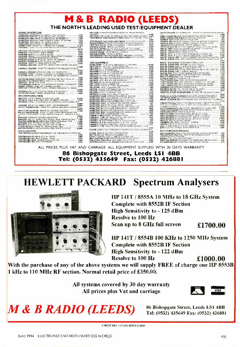
M & B RADIO (LEEDS)THE NORTH'S LEADING USED TEST/EQUIPMENT DEALER
SIGNAL GENERATORSMARCONI 1018 80KHZ TO 520MHZ SYNTHESIZED £750MARCONI 7020 SOKHZ TO 520MHZ SYNTHESIZED (500MARCONI 1008 10KHZ TO 520MHZ INC RF PROBE KIT 000MARCONI 2015/2171 SYNCRONIZER I ()MHZ TO 520MHZ (325MARCONI 2016 10KHZ TO I 20MHZ AM/FM £200MARCONI 2015 10MHZ TO S20MHZ AM/FM (195ADRET 740A 100KHZ TO I I 20MHZ SYNTHESIZED £1450HP8683D 2.3GHZ TO I 3GHZ OPT001 /003 SOUD STATE GENERATOR
(4750HP3336A SYNTHESIZER/LEVEL GENERATOR DEOHP8640A 500KHZ TO 5 1 2MHZ OPT001 CEOHP8640B 500KHZ TO 512MHZ OPT001 [650HP8640B SOOKHZ TO 5 1 2MHZ OPT004 AVIONICS VERSION L1000HP8620C SWEEPER MAINFRAMES (AS NEW) 000HP8620C/86220A RF PLUG-IN I OMHZ TO I 300MHZ L1200HP8620C/86290B RF PLUG-IN 2GHZ TO 1 8.6GHZ (2750HP4204A I OKHZ TO IMHZ OSCILLATOR LEOPARNELL S5G1000 I OKHZ TO 100MHZ SYNTHESIZED (AS NEW)
£1500FARNELL 55G2000 10KHZ TO 2000MHZ SYNTHESIZED (AS NEW)
£2250FARNELL 550520 I OMHZ TO 520KHZ SYNTHESIZED (400POLRAD 1106ET 1 8GHZ TO 4.6GHZ WITH MODULATOR (400GIGAGR110IA I 2GHZ TO 18GHZ PULSE GENERATOR (AS NEW)
050SAYROSA MA30 FREQUENCY OSCILLATOR I OHZ TO OKHZ (200RHODE & SCHWARZ SMC I 4.9GHZ TO 12.6GHZ 4450HP8616A 18GHZ TO 4.5GHZ L295TEKTRONIX 141A PAL TELEVISION TEST SIGNAL GENERATOR 0500ADRET 20230A I MHZ SYNTHESIZED SOURCE C195HP8672A SYNTHESIZED SIGNAL GENERATOR 2GHZ TO 18GHZ
£6200HP3586A SELECTIVE LEVEL METER 50HZ TO 32.5MHZ L1850TEXSCAN VS -60C SWEEP GENERATOR 1000MHZ (450SPECTRUM ANALYSERSB&K 2033 I HZ TO 20KHZ AUDIO ANALYSER L2750HP35111A WAVE ANALYSER I SHZ TO SOKHZ (AS NEW) (850HP3582A 0.02HZ TO 25.5KHZ DUAL CHANNEL AUDIO ANALYSER
£3000HP85588 10MHZ TO 1500M HZ WITH 1827 MAINFRAME L2000HP141T 85526/85536 110MHZ WITH 8443A TRACKING GENERATOR
C2000HP141T 85!2A/85548 100KHZ TO 1 250MHZ (AS NEW L1250HP1 41 T 8555A/8552B 10MHZ TO I 8GHZ SPECTRUM ANALYSERSUPPLIED WITH ADDITIONAL HP85538 1KHZ TO I I OMHZ RF PLUG-IN C2000HP8444A TRACKING GENERATOR OPT058 0500HP8553B I HZ TO 1 10MHZ LATE MODEL ANALYSER PLUG -INS L200WAYNE KERR RA200 FREQUENCY RESPONSE ANALYSER £400
SE (1 500HP358 1 C SELECTIVE VOLTMETER I SHZ TO SOKHZ (750TEXSCAN ALS I 4MHZ TO 1000MHZ ANALYSER C750EATON 2075B NOISE GAIN ANALYSER 10MHZ TO 2GHZ 42000OSCILLOSCOPESTEKTRONIX SC504/TM503/DM50 I PORTABLE 80MHZ SCOPE/DVM
C600TEKTRONIX 475 200MHZ DUAL TRACE £400TEKTRONIX 465 100MHZ DUAL TRACE 045TEKTRONIX 46513 I 00MHZ OSCILLOSCOPE L400TEKTRONIX 466 100MHZ STORAGE 095
(HPI7228) 2/5MHZ MICROPROCESSOR CAL MEASUREMENTS 0HP1725A 275111-12 DELTA TIME AND DELAYED SWEEP (AS NEW) L55000TEKTRONIX 7633/IA26/7a13/IBS) 200MHZ 4 CHANNEL STORAGE
£600TEKTRONIX 7603/7A26/7A29/71353A I GHZ OSCILLOSCOPE 4750PHIUPS PM3217 50MHZ 2 CHANNEL DELAYED TIMEBASE 075IWATSUI SS4122 100MHZ 4 CHANNEL CURSOR READOUT £900KIKUSUI COB 100 100MHZ 5 CHANNEL (500NICOLET 4014A DIGITAL OSCILLOSCOPE (TO CLEAR) UMTELEQUIPMEN7 D34 I SMHZ PORTABLE NICADS FITTED L150GOULD 054100 'MHZ DIGITAL STORAGE LI 95GOULD 0525813 5MHZ 2 CHANNEL L95TEKTRONIX 7784/7A13/7A26/78 I 5/MEAN 4 CHANNEL L500TEKTRONIX 5103N/SB I ON/51120N/5A2ON OSCILLOSCOPE /250
TEST EOUIPME4TEFRATROM -RT ATOMIC FREQUENCY STANDARDHP3779A PRI -1AF Y MULTIPLEX ANALYSERHP3780A PA-FELN GENERATOR/ERROR DETECTORHP3762A DA 'A GENERATORHP3468D DIO TA/ MULTIMETER LCDHP3466A DICITAL MULTIMETER LEDHP8750A STORAZA NORMALISERHP8405A VECTOR VOLTMETER 8 ACCESSORIES I COOMHZH P3400A TRUE IRS VOLTMETER ANALOGUEHP3403C TREE RMS VOLTMETER DIGITALHP3406A BROADBAND SAMPLING VOLTMETERHPI 1683A RANCE CALIBRATORHP I 1 667A POWER SPLITTER 18GHZ (NEW)HP 10529A LOGIC COMPARATORHP394A VAR -AB A ATTENUATOR I GHZ TO 2GHZHP334A DISTORTION METER OPT H 15HP3488A SW.TC-I CONTROL UNITHP5382A 223IFEZ FREQUENCY COUNTERMARCONI MOB MODULATION METER 1200MHZMARCONI 2131 DISTORTION FACTOR METERMARCONI 2132 560MHZ FREQUENCY COUNTERMARCONI 7131-5 560MHZ FREQUENCY COUNTERMARCONI 2304 ELECTRONIC VOLTMETER I 500MHZMARCONI 2103 OF MILLIVOLTMETER 1500MHZMARCONI NI 0 4 TV LINEAR DISTORTION ANALYSERMARCONI MI 3 TEST LINE GENERATOR INSERTORMARCONI 79145 INSERTION SIGNAL GENERATORMARCONI 1306PROGRAMMABLE INTERFACE UNITMARCONI 70004CR BRIDGE BATTERYFARNELL 6111070/35 ELECTRONIC LOADFARNELL TOPS 3D TRIPLE OUTPUT DIGITAL PSLFARNELL LB0/520mA POWER SUPPLYFARNELL B:0/5 POWER SUPPLY 0-30 VOLT 5 AMF
£2500L600£3500501400C2000954650£14541504225£300L500
C85(115
(2504450(125(300(100(150£200
(65L95
L6013£600L600£450
prices from (95£495L225
(95445
FARNELL 6-8/251 POWER SUPPLY 0-30 VOLT 20 AMP 4100FARNELL LA521 RF AMPLIFIER I .5MHZ TO 520M1 -Z LI 55FARNELL T 48 RUE RMS SAMPUNG RF METER (AS NEW) I GHZ
050FLUKE 333013 FROG CONSTANT CURRENTNOLTAGE CALIBRATOR
050FLUKE 103A FREQUENCY COMPARATOR L295ROTEK AC/DC PRECISION CALIBRATOR (650EXACT 334 PRECISION CURRENT CALIBRATOR (195BALLANTINE L 125C PROG TIME/AMPLITUDE TESTSET £500HALCYON 5008/521 A UNIVERSAL TEST SYSTEM C500AVO RM2IS L/2 AC/DC BREAKDOWN/IONISATION TESTER 000
Al LTECH 533X -I I CALIBRATOR I HP355C/I HP355D ATTENUATORS(400
BIRD 1 ENUUNE 8343 100W 6DB ATTENUATORS (NEW) £100BIRD 1 ERMAIJNE BIB 80W COAXIAL RESISTOR LIISNARDA 769/6 I SOW 6DB ATTENUATORS 465NARDA 3001 -30 DIRECTIONAL COUPLER 460MHZ TO 9SOMHZ £100NARDA 3022 BI-DIRECTIONAL COUPLER I GI-JZ TO 4GHZ £250REMO DPI PHASE METER I HZ TO 100KHZ (NEW) £150IWATSUI SC7104 10HZ TO 1000MHZ FREQUENCY COUNTER L325RACAL 9009 MODULATION METER 30MHZ TO 1500 MHZ £275RACAL 9903 50MHZ TIMER COUNTER 495RACAL 9904M 50MHZ TIMER COUNTER L145RACAL 9915 I OHZ TO 520MHZ FREQUENCY COUNTER L150RACAL 9919 10HZ TO I I 00MHZ FREQUENCY COUNTER 000RACAL DANA 1998 10HZ TO I 300MHZ FREQ/TIMER COUNTER L500RACAL DANA 9000 520MHZ MICROPROCESSING TIMER COUNTER
£250RACAL DANA 6000 MICROPROCESSING DVM . 4300RACAR- DANA 5002 WIDEBAND LEVEL METER 4700RACAL DANA 9303 TRUE EMS RF LEVEL METER £700RACAL DANA 488 IEEE -STD BUS ANALYSER £200RACAL DANA 9302 RF MILLIVOLTMETER I OK HZ TO 1500MHZ £400RACAL DANA 1002 THERMAL PRINTER LI 50RACAL 9063 TWO TONE GENERATOR SYNTHESIZED CEOWAYNE KERR CT496 LCR BRIDGE BATTERY PORTABLE (95PHIU M PM8252A DUAL PEN RECORDER C295DYMAR 2085 AF POWER METER 0200TEKTRONIX 528A VIDEO WAVEFORM MONITOR OMTEKTRONIX 576 CURVE TRACER/172 FROG TEST FIXTURE IC650TEKTRONIX 338 LOGIC ANALYSER 32 CHANNEL 20MHZ (400TEKTRONIX 318 LOGIC ANALYSER 16 CHANNEL 50MHZ C450SIEMENS U2233 PSOPHOMETER(NEW) 4500SIEMENS D2108 LEVEL METER 200HZ TO 30MHZ (650SIEMENS W2108 LEVEL OSCILLATOR 30MHZ . (MOWAN OEL & GOLTERMAN SAM 19 LEVEL METER 50HZ TO 25MHZ
C650WANSEL & GOLTERMAN PSS I9 LEVEL GENE FATOR 25MHZ £650SAMOSA AMM AUTOMATIC MODULATION METER 2GHZ C200BRUEL & KjOER 2425 ELECTRONIC VOLTMETER 0 5HZ TO 500KHZ
L195DRAPIETZ 626A MAINS DISTURBANCE ANA _Y ZER FITTED WITH6036 ul4er-face/6002A dc monitor/6001 Ime analrzar/6006 ac monitor/6020broadUnd rf monitor L 1250SCHUJMBERGER 7702 DIGITAL TRANSMISS.ON ANALYSER L1250MARCONI 6950/6910 POWER METER 10MHZ TO 20GHZMAR6bNl 65935 VSWR INDICATOR (495HP43 tA/4711A RF POWER METER 10MHZ TO I OGHZ 4400HP4314/8482H RF POWER METER TO KHZ TO 4.2GHZ £650HP4343/8482H RF POWER METER 100KHZ TO 4.2GHZ £850HP43M/84111A RF POWER METER 10MHZ TC I EGHZ (1000HP4344k DIGITAL POWER METER OMHP84U7D AMPLIFER 0.I MHZ TO I 300MHZ (500MARNA CRYSTAL DETECTOR £150SCD J AMPLIFIER I OMHZ TO 1000MHZ 10 WATT 46dB i I 000BIRD -COAXIAL ATTENUATOR 500W 3008 L200
BULK PURCHASE SPECIALSB ECKMAN DM 110 DIGITAL MULTIMETERS WITH CASE/PROBES ...LSOSOLARTRON 7045 HIGH SPECIFICATION BENCH DVM DOAVOB MKV MULTIMETERS £60B IRD -43 THRULINE WATTMETERS (75SIEMENS PDRM82 PORTABLE LCD RADIATION METER (NEW) 445EX GERMAN ARMY PORTABLE RADIATION METERS I.35
ALL PRICES PLUS VAT AND CARRIAGE ALL EQUIPMENT SUPPLIED WITH 30 DAYS WARRANTY
86 Bishopgate Street, Leeds LSI 41313Tel: (0532) 433649 Fax: (0532) 426881
HEWLETT PACKARD Spectrum AnalysersHP 141T / 8555A 10 MHz to 18 GHz SystemComplete with 8552B IF SectionHigh Sensitivity to - 125 dBmResolve to 100 HzScan up to 8 GHz full screen £1700.00
HP 141T / 8554B 100 KHz to 1250 MHz SystemComplete with 8552B IF SectionHigh Sensitivity to - 122 dBmResolve to 100 Hz £1000.00
With the purchase of any of the above systems we will supply FREE of charge one HP 8553B1 kHz to 110 MHz RF section. Normal retail price of £350.00.
All systems covered by 30 day warrantyAll prices plus Vat and carriage
M & B RADIO (LEEDS)
Acres
4M4W
86 Bishopgate Street, Leeds LS1 4BBTel: (0532) 435649 Fax: (0532) 426881
CIRCLE NO. 117 ON REPLY CARD
June 1994 ELECTRONICS WORLD+WIRELESS WORLD 495

ELECTRONIC ENGINEERS
REFERENCE BOOKThis reference book is divided into five parts:
techniques, physical phenomena, materials andcomponents; electronic design and applications. Tie sixthedition was updated throughout to take into accountchanges in standards and materials as well aE advancesin techniques, and was expanded to include mawchapters on surface mount technology, hardware andsoftware design techniques, semi -custom electronics anddata communications.
6th Edition
EtECTRON1CSENGINEER'S
REFERENCEBOOK
rft.i. 1-7 0.17
Edited by F F Mazda
Fraic oon Mazdahas worked in theelect onics andtelecommunica-tions industry forover wenty years,and is currentlyProduct andOperationsManager, GenericNetworkManagement,with NorthernTelecom. He isthe author of sixtechn cal books(transated intofour languages)and the ed tor oftheCommunicationsEngineersReference Bookpublisied byButterworth -Heine manr.
CONTENTS:Techr iquesTrigonometricfuncticns andgeneral formulae;
Calculus; Series and transforms; Matrices and determinants;Electric circuit theory; Statistics. Physical Phenomer aQuantities and units: Electricity; Light; Radiation: The ionosphereand troposphere. Materials and components Resistvematerials and components; Dielectric materials and components;Magnetic materials; Inductors and transformers; Relads;Piezoelectric materials and components; Connectors: Printedcircuits; Power sources; Discrete semiconductors; Microwavesemiconductor devices; Optical digital integrated circuits; Linearintegrated circuits; Semiconductor memories; Microprocessors;Application -specific integrated circuits; Electron microcopy;Digital design; Software engineering; Digital systems analysis;Control systems; Antennas and arrays; Noise managemen- inelectronic hardware; Noise and communication; Computer aideddesign; Television and sound broadcasting. ApplicationsCommunication satellites, Point-to-point communication; Fiore -optic communication; The integrated services digital network(ISDN); Local area networks; Radar systems; Computers andtheir application; Videotape recording; Office communcations;Medical electronics.
1006 pages PAPERBACK ISBN 07506 0809 9£42.50 (inc post & packaging)
6th EditionF F Mazda
* Now available to Electronics World & Wireless World readersin paperback." Expert coverage of all aspects of electronics* Over 50 contributors
For electronic engineers, technicians and students
Please supply me - copies of the ELECTRONICENGINEERS REFERENCE BOOK (ISBN 07506 0809 9) @£42.50 (INC POST & PACKAGING)
Add VAT at local rateNB ZERO RATE FOR UK & EIRE TOTAL
Business purchase: Please send me the books list-ed with an invo ce. I will arrange for my company to pay theaccompanying nvoice within 30 days. I will attach my businesscard/letterhead and have signed the form below.
Guarantee: If you are not completely satisfied, books may bereturned within 30 days in a resalable condition for a full refund.
Remittance enclosed £Cheques should be made payable to Reed Book Services Ltd.
Please debit my credit card as follows:
Access/Master Barclay/Visa
Amex Diners
Credit Card No. Exp date
NAME (Please print)
ORGANISATION
STREET
TOWN
COUNTY
COUNTRY
DATE
SIGNATURE
T3000
POST CODE
TELEPHONE NUMBER
VAT RATES6% Belgium, 25% Denmark, 5.5% France, 7% Germany, 4%Greece, 4% Italy, 3% Luxembourg, 6% Netherlands, 5%Portugal, 3% Spain. FOR COMPANIES REGISTERED FORVAT, PLEASE SUPPLY YOUR REGISTRATION NUMBERBELOW (customers outside the EEC should leave this partblank)VAT NO.
If in the UK please allow 28 days for delivery. All prices are correct attime of going to press but may be subject to change.
Please delete as appropriate. I dodo not wish to receive further detailsabout books, journals and information services.
Credit card ordersaccepted by phoneCall 081 652 3614.
Please return to: Lorraine Spindler, Room L333,Quadrant House, The Quadrant, Sutton, Surrey 3M2 5AS

.. . £.211,asta"4111111,11wdThier ( 951 ..._. . 0.,. :1114
ORIN, DONTRQL-60/ or useOpts Isolatec_DieitsTITP (16 Clairol) ' . , 03.2 .
16,Chenntif Fell* 11/P Scald., .-:. -..... ,...
01 E Channel Samp_eitIMoTd Carl
3CLD-788 '. Relay3cannsrAsutiplexer Board 2.,)
3CLD-779 t48 Crane& Iselatsd Relay Mux awl A .-
aCLD-789 ( Remliter & Ile ,e:qr Snarl ,...-MMIOUNICCOONS . zAcr BOP'S.
-104 Pat Serial B' Otfidcisi \,.'CL -743 ' troctilS12 5 PfhIBIrtico Gird
x'CL -44. ..! '''. t 8 3 :32 PC Card wth on -board
RE10011 485 PC Interlace Card5 Cenverter Adeeler, Self Poems
Beard! ... ---,-
MODULAR BATkAtinav,,,,,,,ef
M.1111/11.411j1. AnalMAIII-492r *nal
ifako-4050ADAM --4060
Apom, ORO
19" RA1111;1PC1
-IPC
Industrie Mika*industrial 1WIndentrial 1W Rack Mount Ch
a1'441CRali Mount ChssIneeleiptor Kit for 1E4 Non r
tlire,...1141tainel, Tel
'C -BUS CAPC -6706 P
PC -6806 BMAR-IPC6MP IS.MBPC-640 '3CXU-205 s" o It
PC -6010 a p ceid411CC61, WV; cltp
16 Bit)
AR- -AO C annAR -B3201 AM+AR -B3204 16 Channe ,"CL -7118 8 Channel, 1!81t DILA
'CL -812 -PG 16 Channel,tilr'CL -813 32 Channel, fa in'CL -818H HletrPerforrrants 16 Chanel, 12E'CL -814 votlkitar Mul Manton 16 Mum, 13CL-816 IModbfar Mul Hue clkop 10.,3CL-860 412 olrilit Itmet3et11011/
AR -B2001 S¢ Chiple oiliplatedARIii Chen 1-AP - irS.Clranne
16:Chan
6 Chan
StepperProto
Slot ExtP,C,Bue8
la Acq Codicil CaAc Coital Card £994
. . £369
PCL-7"CtLY2
'CL -726'CL -838'CL -750'CL -755A
POW.,"0L
,"C1A/-7ID-
-787
ot,
/Board fof
's
1.40.1
r-Pef1/11',4110-`1;11
#11'1144117117r:
1 146:0"1/4SHISRiM
11R -B7 44.4 ROM o 2WiKfirs ........ .
K ROM Deb41049: -*BB Flash/SAFI/1f 'Mak ///
. £96
n11-801 rMB FlashfiRAMVROM B141 f Ial Floppy Em . £199,
"CD -09211 ??lB Flash/ROM Dist Card .
9
98
717644
4,
£178
tr
.... .4117RP<> irk _
-.
Plus MICH more -. -
Pleas t IL 'or your FREE7opy of ourkelkgpfitliiifoviries144/cili
/NY\ INTEqRATEd kw:sated Measur.reee( Sbstem; _td.305-308 Sokol t Business Cen-se Mil ber dk It Nest
VAY MEASUREMENT Sou hampton SO1 CHI", IPMP: i RESYSTEMS Tel: (613) 771143 Fri: .7031 )1113111
Designers & Supp iers of Measure -new, Test & Control 3f sn- s 3 Software
MEGAPAOM device programmer. EP& OMS, E2PROMS, and FLASH merrur es from 2k (27161 to8 Meg (27C080). Runs on IBM PC via the centronics port using standard print, .iable. Works on allPC comp:. tibles. laptops, and r utebooks. No special port requirements.
Uses approved programming iLgorithms. Very fast program and verify 270(64K. Bytes) in 45 seconds.
Full scree t editor software sup3UTIS Bin, Intel Hex, motorola 5 and A. for -nuts Only £99.95
Top quali y components used tmoughout including production ZIF socket.
Requires .ixternal power supply 18-25v AC or DC (ni, 250ma. (optional extra (C6.50)
PICPROC Programs Piel6C54-55.56-57-71-84. Centronics port interface same as Megaprom.Powerful Aiting software to 122.ad, write & copy Pic devices including data memory in Picl6C84.
Unit suipplied with IBM software & 12 nunths parts & labour guarantee. Only £69.95
Requires ,ixternal power 15.204 AC or IX; Lt 250ma. (optional extra /6.50).
EPROM EMULATOR Works on ANY computer with centronics printer port. Data scot to theprinter appears in the target beard Eprora socket. Emulates from lk to 32k Byte ( 27 C.1?6i roues.board swi chable. Power suppl ed front tiirget Rom socket (less than 10ma ). Vex,' fast download.
Software .upplied fur IBM PC to convert and send Intel Hex, Motorola S, AS.:and Bin It es. Only £49.95
Board sin plied with software and 12 mor -hs parts and labour guarantee.
PC SCOPE Convert your IBM PC into Storage Oscilloscope with our AD converter. Simply pluginto the p -inter port (no power required) Sample rate 10k to 30k per second.
Software .upplied for Scope and Voltmekr. All) source to write your ownprograms Only £29.95
DEVELOPMENT SOFTWAREDevelop software on your IBM PC for oti.er Microprocessors, Controllers, Piifs etc. Software hasfully integated Text Editor, Assembler, Disassembler and Simulator.The Simu ator displays all regiiters along '.with disassembled code program cm_ nm r, Condition coderegister. The user can single-step, go will breakpoints, watch memory etc. chimge 'avian registers/memory I ',cations at any time (on the fly).
Code can be Saved to disk and.or downloaded directly to our EPROM Emula or. All softwaresupplied with sample ASM file: and user Joeumentation.
Very powerful software as supplied to um ve rsities. colleges 1TECS and Industry
Available for the following:-
MC.S8051 /52/552 series Software £1 J.95 MCS8048/49 series Software £19.95PIC I 6C5,./5/6/7 Software £25.95 PIC I6C71/84 Software £29.95HD63/681:19 Software £45.95
LOW COST PIC ICE (In-Ci -cult LmuLtor)Plus into Ate printer port and r J11, in contametion with the PIC development simulator software.Appears irr the target system a: a normal Pic device including OSC2 and RTC... in/out. Runs in realtime front the IBM PC changer made to File registers reflected on target.Supplied with Software of your choice Pir54-57 or Pic 71/84 Only £89.95
All hardware carrier a 12 months parts and labour Guarantee. No VAT payable.Please add £1.50 for Carriage. SAL or TEL for further details
JOHN MORRISON DEPT WW4 Rein Gardens, Tingley
West Yorkshire nemTel (or Fax): 0532 537507
VISA
CIRCLE NO. 120 ON REPLY CARO
THE DEF@N1TiVE 'OFF -AM'FREQUENCY STANDARD
* Providei 10MHz, 5MHz & 1MHz* Use it fa calibrating equipmen that relies on quartz crystals, TCXOs.
VXCOs oven crystals* Phase locks to DROITVVICH (rrbidium co -trolled and traceable to NPL)* For ADDED VALUE also phase locks to A_LOUIS (cesium controlled
and traceable to OP - French eq to NPL)* British cosigned and British me nufacturec* Sine wade option 0110, 5 & 1MHz. Nominal I V into 500* 13MHz mtion for G.S.M.
Still Only
£195. +VATcarriage extra
Output frequencies -10MHz, 5MHz. 1MHzSnot term stability - bettertrap lx10 (1 sec)T xpcal - 4x 10- 9 (1 sec)Long term - tends to2:10-19 (1000 sec)
IDEAL BEGINNERS SCOPE, SCOPEX 1S6 AQUILASCOPE 6MHz SINGLE TRACE, INT/EXT TRIG,
TRACE LOCATE, BRIGIT UNE AUTO, 10mV SENSMVITY,14-100mS/cm, etc. £95DAWE 14050(R.S.) SOUND LEVEL METERQUAD 303 STEREO POWER AMPSDRAKE MN2700 MATCHING NNVOFK & PS7 PSJPHILIPS PM3065 100MHz DUAL TRACE & T/BPLESSEY TCT10 SIG GEN/ANAL 50-300 BDSLEADER LBO -9C ALIGNMENT SCOPE
£95£95
POA£750
£95
£195
'EDNALITE PROJECTORLEADER LCG396 MTSC COL P4TT. GEN.UDI2026 SONAR SCANNER SLRFACE UNIT7SEG 12"x0 DISPLAYS DIGITEX/SIGNALE X £15RADIOMETER BKF6 DIST. METER 20Hz-20KHzWOK CX6000 6 -PEN A4 PLOTTER. CENT/RS232
£39£395£975
& £10£POA£135
TELEOUIPMENT D61A 10MHz DUAL TRACE FROM £99 GENERAL RADIO 1531A XENON STROBOTAC £79
IWATSUSSi116 DUAL TRACE 10MHz £175 BACHARACH MV2 MERCURY SNIFFERS £59
TELEOUIPNENT D1011 10MHz DUN_ TRACE E165 FISONS FI-MONITORS LIO LEVEL SENSORS £85
IWATSU SS5802 DIGITAL STORAGE £295 COMMODORE PETS. D/DRIVES, PRINTERS EnosTEKTRONIX 2215 60MHz DUAL TRACE DEL TIE £450 COMARC 2303 MV SOURCES. DUAL RANGE £49
TEKTRONIX 453A 50MHz DUAL TRACE DEL T/E £249 INTRON IFG422 FUNC GEN 0.1Hz-2MHz E125
H.P. 8405A SECTOR V/METER 1Gft: £395 GOULD 2400 4 -PEN CHART RECORDER £149
TELEOU1PMENT D67A 25MHz, 2T, C EL T/B £215 X -Y RECORDERS A3 8 64 FROM £35 TO £139HITACHI VC6015 10MHz DIGITAL STORAGE £295 PHILIPS PM6456 FM STEREO GENERATOR £175HP1340A X -( DISPLAYS £149 MARCONI TF2300 FM/AM MOD JLATION METER £195
OERTLING no SINGLE PAN SALO. I mg/200g £69 McKENZ1E 7DAY TEMP/HUMID TY RECORDER E95
ANALYTICAL BALANCES WITH WEGHTS 250g £69 FEEDBACK SS0603 1MHz SINE/SO OSC £125VACUUM PUMPS 1.5 & 2.8m3ytir is 25 & £149 FARNELL E350 PSU'S 0-350. 100mA, 2 x 6.3V E59 to £69KINGSHILL .15154015V 40A PSUs. CASED. AS -IEW £195 COMMUNICATIONS RECEOAEFS, HF, LF, VHF POAACRON 4020 SYNCHRONISING PU _SE GEN & 335P LCR BRIDGE WAYNE KERR .:',7492 £79
ENCODER £375ee. f695/pr LCRO BRIDGE AVO 8151 £195
MARCONI T=2330 WAVE ANALYSE 20Hz-SOK -1z £149 LCR BRIDGE MARCONI TF2"00 £145H.P.5315A 13Hz F/CTR. OPTS 1,2, A 3 £595 LCR BRIDGE MARCONI TF2'01 £125LEVELL TMs8 MICRO V -METER 45CMHz £95 LCR MARCONI TF1313 0.25% C95
LEVELL TM;EIMICROViMETER 3MHz £85 LCR COMPONENT COMPAFATOR AVO CZ457/S C95
LIST A.AILABLE BUT 100040F UNLISTED BARGAINS FOR CALLERS. ALL PRICES EXC. OF P&P AND VAT
QUALITY ELECRONIC EQUIPMENT ALWAYS WANTED
HAL ONAtECTRONICS423, KINGSTON ROAD, WINIJOEDON CHASE, LONDON SW20 8JR%ROMP/$$ -5.30 MON-SA:1.4EL 081-5426383, FAX.081-542 0340,
CIRCLE NO. 113 ON REPLY :ARID
June 1994 ELECTRONICS WORLD+WIRELESS WORLD
CIRCLE NO. 121 ON REPLY CARD
497
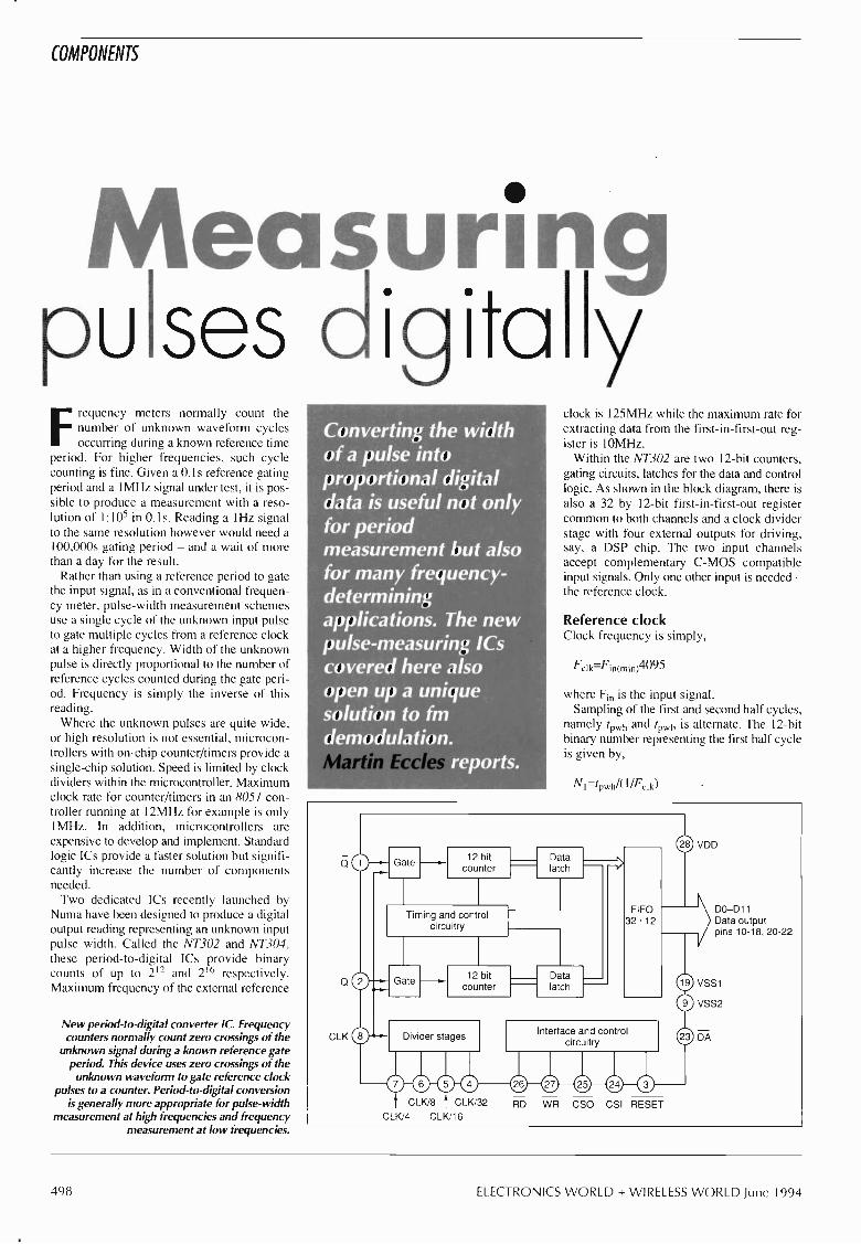
COMPONENTS
Measuringpulses digita
Frequency meters normally count thenumber of unknown waveform cyclesoccurring during a known reference time
period. For higher frequencies, such cyclecounting is fine. Given a 0.1s reference gatingperiod and a 1MHz signal under test, it is pos-sible to produce a measurement with a reso-lution of 1:105 in 0.1s. Reading a 1Hz signalto the same resolution however would need a100,000s gating period - and a wait of morethan a day for the result.
Rather than using a reference period to gatethe input signal, as in a conventional frequen-cy meter, pulse -width measurement schemesuse a single cycle of the unknown input pulseto gate multiple cycles from a reference clockat a higher frequency. Width of the unknownpulse is directly proportional to the number ofreference cycles counted during the gate peri-od. Frequency is simply the inverse of thisreading.
Where the unknown pulses are quite wide,or high resolution is not essential, microcon-trollers with on -chip counter/timers provide asingle -chip solution. Speed is limited by clockdividers within the microcontroller. Maximumclock rate for counter/timers in an 8051 con-troller running at 12MHz for example is only1MHz. In addition, microcontrollers areexpensive to develop and implement. Standardlogic ICs provide a faster solution but signifi-cantly increase the number of componentsneeded.
Two dedicated ICs recently launched byNuma have been designed to produce a digitaloutput reading representing an unknown inputpulse width. Called the NT302 and NT304 ,these period -to -digital ICs provide binarycounts of up to 212 and 216 respectively.Maximum frequency of the external reference
New period -to -digital converter IC. Frequencycounters normally count zero crossings of the
unknown signal during a known reference gateperiod. This device uses zero crossings of the
unknown waveform to gate reference clockpulses to a counter. Period -to -digital conversion
is generally more appropriate for pulse -widthmeasurement at high frequencies and frequency
measurement at low frequencies.
Converting the widthof a pulse intoproportional digitaldata is useful not onlyfor periodmeasurement but alsofor many frequency-
determiningapplications. The newpulse -measuring ICscovered here alsoopen up a uniquesolution to fm
II I
Martin Eccles eports.
yclock is 125MHz while the maximum rate forextracting data from the first -in -first -out reg-ister is 10MHz.
Within the NT302 are two 12 -bit counters,gating circuits, latches for the data and controllogic. As shown in the block diagram, there isalso a 32 by 12 -bit first -in -first -out registercommon to both channels and a clock dividerstage with four external outputs for driving,say, a DSP chip. The two input channelsaccept complementary C-MOS compatibleinput signals. Only one other input is needed -the reference clock.
Reference clockClock frequency is simply,
Feik=Fin(min)4095
where Fir, is the input signal.Sampling of the first and second half cycles,
namely tpwh and tpw1, is alternate. The 12 -bitbinary number representing the first half cycleis given by,
Ni=tp,01(11Fc0
VDD12 bit Data0CI latch
Timing of ol
FIFO32 12
DO-D11Data outputpins 10-18, 20-22
12 bit Datacounter latch
CLK Ili
VSS2
O Divider stages Interface and controlcircuitry DA
CLK/8 CLK/32
CLK/4 CLK/16
PARD WR CSO CSI RESET
498 ELECTRONICS WORLD + WIRELESS WORLD June 1994

COMPONENTS
Signal input
In P
C1 R20.22µF
R1 150 k
4.7 k
+5 V
3
R34.3 k
TLE 2428 CD
C2 C3
U1
TLC 22018 CD
R4
LT 1016
2 Q 7
= 0.1 µF 1.0 I.LF2
470
U3
Q 8LE 5
R5
100 k
NT 302
14131211
10987
65
43
D4D3D2D1
DO
VSS1CLKCLK/4CLK/8CLK/16CLK/32RESET00
15D5 -17.D6D7D8
VSS2D9
D10D11DA
CS1CS0
RDWR
VDD
U4
18192021
22232425262728
Zero -crossing input circuitryneeded for correct operation ofthe period -to -digital converter. A2.5V reference feeds the non -inverting input of the first op -ampwhile dc -blocked input feeds theother. Gain of this stage squaressmall input signals ready for thecomparator that follows.
and for the second by,
N2=tp,,1/(1/Fcik).
For the whole period, the 12 -bit binary num-ber becomes simply,
Np=Ni+N2
or
Np=(tp,h+tp,,i)/(1/Fdk).
Once clock frequency is found, the mini-mum input frequency is established. This fre-quency causes a count of 4096. Should thefrequency fall lower, the counters will over-flow producing a false result.
In the circuit diagram is a zero -crossingdetector which ensures correct operation of theNT302. On the left is a regulator producing afixed 2.5V reference. This voltage may varydepending on the application. Input is capaci-tor coupled to inverting input of the first op -amp, whose gain ensures that the input wave -
FM demodulation via DSPReciprocal count scaling allows precisefm demodulation using non -floating-point DSP. It is difficult to see thedifference between the least -squares fitand the reciprocal -fit methods. Point -for -point, the difference betwen the twomethods is negligible, given a range of65,520 data values.
Reciprocal count scaling calculatesthe reciprocal of the period -to -digitalcount values in a fixed-pointmicroprocessor without needingmathematical division. The operationinvolves a look -up table performing alinearised inverse -transfer function.Should a floating-point processor beused, the reciprocal fit process is notneeded.
form is square. Next, the comparator producesthe complementary waveform necessary forthe NT302.
On a high -to -low transition at the 302's Q
inputs, the count is transferred from the 12 -bitcounter to the data latches then into the fifo.Next, the counters are reset and the systemsamples the next half cycle.
Latching and resetting takes approximatelyeight reference clock cycles and continues aslong as there is an input signal. Maximumduty cycle of the input signal becomes a func-tion of the eight clock cycle transition timeand is given by,
DC<1-8(tp,/T)
where is tpw is 1/Folk and T is 1/Fin. For aninput frequency of 1MHz and a system clockof 100MHz, maximum duty cycle would be92%.
Data in the fifo is shifted out on a fallingedge at the READ input. If data is present atthe fifo output, the data -available line, DA,goes active low. In the event of no data, DA
4
3
2
1
o.
0a)
-1a)Ca
-2
-3
-4
remains high, allowing the presence of validdata to be signalled to software or hardware.Since there are two zero crossings per cycle,data can be extracted from the fifo at twice therate of the input frequency.
The two counters are enabled alternately andthere are two zero crossings per cycle. Thismeans that 12 -bit binary numbers representingeach half cycle are extracted from the fifoalternately. They can be added to produce aperiod result, divided to define duty cycle orused as an address to access a look -up table.
Sending the data to a digital -to -analogueconverter provides an analogue representationof the binary word. Relative to analoguepulse -width measurement techniques, this dig-ital approach results in an accurate and linearanalogue signal which is highly immune toDC offsets and temperature drift.
Novel fm demodulatorThis approach to fm demodulation is said tobe unique. Incoming fm analogue signals areamplified by a high -gain IF stage in which fmsquare waves are produced by limiting action.
.104 Figure - Least square and reciprocal fits
160 170 180 190 200 210 220
Integer count input value
230 240 250
June 1994 ELECTRONICS WORLD + WIRELESS WORLD 499

COMPONENTS
x104 Input signal (thin) & demodulated signal (thick)
Time (ms)
Results obtained from a new approach to fin demodulation. Applying a high gain stage to theincoming IF information produces squarewaves that can be sampled by the period -to -digital chipwith the aid of a high-speed system clock. These digitised samples then feed a digital signal processorwhich uses estimation techniques to produce frequency -demodulated audio data. Part of theprocessing involves a technique called reciprocal count scaling. In addition to being high quality, theoutput also has a high signal-to-noise ratio.
Using high-speed clock and counting circuits,the square waves are digitised into binarycounts. These counts are sampled and sent to adigital signal processor without using any ana-logue -to -digital conversion.
Counts are subsequently processed in the
DSP system using estimation. Noise is said tobe inherently low since the technique has anoise limiting as opposed to the noise additiveeffect common in traditional analogue fmdemodulators.
Under the proposed demodulation technique,
incoming IF is squared then sampled directly toobtain its zero -crossing information. Digitallyencoded, this information is fed to a DSP chipwhere the modulating signal is extracted usinga reciprocal count -scaling software routine.
Extracted signal can be further digitally fil-tered before being passed to a digital -to -ana-logue converter. Adopting reciprocal countscaling for demodulation is said to guaranteethe most accurate results attainable from a sys-tem of this type in terms of s -to -n ratio, har-monic distortion and scaling accuracy.
Digitised count information is produced sothat the lowest number of reference clockcounts for a given sample corresponds to thehighest modulating signal amplitude.Conversely, the highest clock count representsthe lowest modulation amplitude.
Numeric processing hardware in the demod-ulator system receives a binary representationof fm data directly from the zero -crossing cir-cuitry in the IF strip. Estimations are made ofsuccessive digital samples.
An application article entitled DSP peripheralIC does period -to -digital conversion is avail-able from Clere Electronics at Kingsclere inNewbury, Tel. 0635 298574, fax 297717. Itincludes full design equations for the fm decod-ing technique.
Algorithms for implementing the new fmdecoding method are also avaliable to designengineers. These are based on the AnalogDevices 2100 DSP family.
Ericsson's TBT is used in over50 countries world-wide
Our commitment to Training does notCommitment to training is essential in the rapidly changing communicationsworld. At Ericsson the importance of training has long been recognised.Since the early 1980s Ericsson has developed Technology Based Training(TBT) which allows personnel to be trained where and when the userneeds it.
Ericsson's TBT presents complex and difficult training material in aninteresting and exciting way. It is a self -paced, interactive, user-friendlyand cost effective method of enhancing technical competence.
Ericsson's generic range of IBM PC- compatible coursewareincludes the following courses:-
Introduction to Telecommunications ISDN Overview and ISDN Advanced OSI & Data Networks and OSI Advanced X.25 and Related Protocols and X.25 Advant.t.(I C7 Signalling System Part 1 and Part 2 Understanding Modems PCM Principles Cellular Mobile Radio X.400 Overview
For further information please contact your local Ericsson office or
Marketing Department,Ericsson Systems Expertise Limited,Adelphi Centre, Upper George's Street, Dun Laoghaire, Co. Dublin, Ireland.Tel: + 353 1 2800455. After 5pm: + 353 1 2843030. Fax: + 353 1 2805914.
CIRCLE NO. 122 ON REPLY CARD ERICSSON 0500 ELECTRONICS WORLD + WIRELESS WORLD June 1994

JPG ElectronicsInvertor toroidal transformers 225VA 10.5-0-10.5 Sinclair hght gun terminated with a Jack plug and
primary 0-260-285 secondary £29.95 PPS clip gives a signal when pointed at 50hzLEDs 3mm or 5mtn, red or green 6p each flickering light with out pu.. wave formYellow I 1 p each chart . £3.95High intensity red. green or yellow 5mm .... 30p each DC -DC convertor Reliability model VI2P5 I2v in 5vCable ties, I p each, £5.95 per 1000, £49.50 per 200rna out 300v input to output Isclation with
10,000 data...£4.95 each or pack of 10 £39.50Higllqulity photo resist copper dad epoxy glass Hour counter used 7 digit 240v ac 50 Hz £1.45
boards QWERTY keyboard 58 key good quality switchesDimensions single sided double sided new £5.00354 inches £1.09 f 1.23 Airpax A82903 -C large stepping motor 14v 7 5' step458 inches £2.75 £2.99 27ohm 68mm dia body 6.5mm nnhatt...£8 95 or6512 inches £6.20 - £200.00 fora box of 3012512 inches £12.25 - Polyester capacitors boxype 22.5mm lead ptchRechargeable batteries 0.9uf 250vdc 18p each 14p...100+ (p ..1000+A A I H P 7) AA 500mAH with solder 'of 250Vdc 20ach 15p...100+ 10p...1000+
500mAH £0.99 tags £1.55 2.2uf 250vdc (27.omm pitch)._ 30p each 20p 100+AA 700mA H £1.75 C(14P11) 1.8AH £2.20 15p...1000+C 2A H with solder D(HP2) 1.2 AH £2.60 3.3uf 100vdc.. 30p each 20p...100, 15p...10010+
D '411-1 with solder P P 110mAH8 . 4 V luf 50v bipolar electrolytic axial leads
£4.95 each 7.5p...1000+51
jam j4d.:.)..5, Sub C with solder 0.2242,500 polyester axial leads ... ..... 15p each, 7.5p
AAA:1.55 1/3 'AItswith tags (Philips Polypropylene luf 400vdc (Wima NEKPI 0) 27.5mm
( H P I 6 ) pitch 32529517mm case 75p each 60p 100+180mAll £1.75 Philips 123 series solid aluminium anual leads - 33uf
Standard charger charges 4 AA cells in 5 hours or 10v & 2.2uf 40v 40p catch 251100+4Cs or Ds in 12-14 hours+ I5PP311. 2. 3 or 4 cells Philips 108 series 220f 630 axial 30pmay be charged at a Unit') £5.95 each 15p...1000+
High power charger as above but charges the Cs and Nfultilayer AVX ceramic capacitors all 5mm pitchDs in 5 hours. AAs, Cs and Ds must be charged M 1000 100pf, I 50pf, 220pi. 10,000npf (10n) 10p2s or 4s £10.95 each 5p...100+ 3.5p...1000+
Nickel Meml Hydryde AA cells high capacity with no of500 compression trimmer 60pmemory. 1000mA H £3.85 1200mAH £4.40 40 f motor start calm, nor (dralectrol type
Special offers,. please check for availability. containtng no pd.) £5.95 .o- 4.49.50 for 1042 x 16mm dta I .2v £1.45 Welwyn W23 9W 120ohm 35p each 20p 100+Stick of 4 171mmx16inm dia with red & black leads 680 ohm 2W meml film resistor 4p 130-1 213 1000,
.1.8v . £5.95 Solid carbon resistors very low inducmnce ideal forComputer _grade capacitors with screw terminals OF circuits - 27ohm 2W, 68iihm 2W 25p
38000uf 20v £2.50 each 15p each 100+8 7 0 0 0 u 1 1 0 v... £ 1 . 95 6 8 0 0 0 u f We have a range of 0.25w 0.5w Ily and 2w solid
I 5v...£2.95 100000£ 16v...f1.50 5804 resistors. please send SAE for list600 £4.95 P.C. 400W PSU (Intel part 2(1103amo I) with smn-
7 segment cot -ninon anode led display 12mm £0.15 dard motherboard and 5 disk drive connectors.LM2931AT5.0 low drop out 5v regulator T0220 fans and mains on back
781 and 912 12v IA regulators £26.00 per 100and switch on the side (top for tower case) dimsVal' £0.8521251495149mm excluding swinch. £26.00 each
L.M337k '103 case variable regulator £1.95(£1.44 0138.00 for 6100+) MX180 Digital multinteter 17 Ranges 1000vdc
GaAs FET low leakage current S8873 012.95 each 750vac 2Mohm 200mA transistor Hfe 9v and(£9.95 10+. £7.9a 10(1+) 1.50 battery test . £12.95
BS250 P channel moslet...£0.45 13C559 AMD 27256-3 Eproms £2.00 each £1.25...100+transistor £3.95 DIP switch 3PCO 12 pin (ERG SDC-3-023) 60pper 100 each 40p...100+
741505 hex invert.- £10.00 per 100 Used 8748 Disk drive boxes for 5.25 disk drive with mom for aMicrocontniller £3.50 power supply, light rew plastic.
SL952 UHF Limiting amplifier LC 16 surface 6752685247mm £7.95 E49.50 for 10mounting package with darn sheet £1.95 Hand held ultrasonic remote contro £3.95
A M 27 S 0 2 ...£1. 2 5 e a c h 9 0 p I 0 0+ CV2486 gas relay. 30510mm dia ooh 3 wire termi-CD4007UB 10p nals. will also work as a neon light....20p
100+(6p. 1(100+) each £7.50 per 100A23 12v battery for car alarms or lighten -s 75p
each 050.00 per 100
All products advertised are new and unused unless otherwise stated.Wide range of CMOS TM 74HC 74F Linear Transistors kits. Rechargeable batteries, capacitors, tools etc
always in stock. Please add £1.95 towards p&p. VAT included in all prices.
JPG Electronics, 276.278 Chatsworth Road, Chesterfield S40 2B11Access/Visa (0246) 211202 Callers welcome
CIRCLE NO. 123 ON REPLY CARD
KESTRELELECTRONIC
COMPONENTS LTD* All items guaranteed to manufacturers' spec.* Many other items available.
'Exclusive of V.A.T. and post and package'
1+ 100+ 1+ 100+
EPROMS STATIC RAMS2764A 2.50 2.20 62256ALP-10 3.00 2.30
27C64-150 2.30 1.90 6264ALP-10 1.85 1.40
27128A-250 2.40 2.10 6116ALP-10 1.10 0.70
27256-250 2.40 1.90 6522P 2.40 1.80
27C256-150 2.90 2.30 65CO2P2 2.90 2.50
27C512-150 3.30 2.50 65C21P2 2.90 2.50
27C010-150 5.80 4.00 65C22P2 2.80 2.40
MAX232 1.35 0.95 146818AP 2.20 1.65
D8748H 4.20 3.20 75176BP 1.60 0.80
D8749H 4.40 3.40 Z80A CPU 1.33 0.99
80C31-12 2.60 2.10 Z80A CTC 1.20 0.75
80C39P 2.80 2.20 Z80A DAR7 2.10 1.40
82C55-2 1.95 1.58 ULN2803A 0.70 0.46
74LS, 74HC, 74HCT Series availablePhone for full price list
All memory prices are fluctuating daily, please phone toconfirm prices
178 Brighton Road,Purley, Surrey CR8 4HA
Tel: 081-668 7522. Fax: 081-668 4190.CIRCILE NO. 124 ON REPLY CARD
RF TELEVISION EQUIPMENTWIDEBAND AMPLIFIERSType 9301 100KHz-500MHz. NF 2dB at 500MHz. Gain 30dB. Output 12.5dBm,
18mW. 50 ohms £175Type 9302 10MHz-1GHz. NF 2dB at 500MHz. Gain 30dB. Output 12.5dBm,
18mW. 50 ohms £175Type 9008 Gasfet. 10MHz-2GHz. NF 2.5dB at 1GHz. Gan 10dB. Output
18dBm, 65mW. 50 ohms £175Type 9009 Gasfet. 10MHz-2GHz. NF 3.8dB at 1GHz. Gain 20dB. Output
20dBm, 100mW. 50 ohms £195
WIDEBAND LINEAR POWER AMPLIFIERSType 9246 1 watt output. 100KHz-175MHz. 13dB gain £240Type 9248 1 watt output. 100KHz-300MHz. 10dB gain £260Type 9306 1 watt output. 10MHz-1.2GHz. 15dB gain £360Type 9249 4 watts output. 100KHz-300MHz. 17dB gain £420Type 9051 4 watts output. 20-200MHz. 13dB gain £260Type 9176 4 watts output. 1-50MHz. 26dB gain £395Type 9177 4 watts output. 20-200MHz. 26dB gain £395Type 9173 20 watts output. 1-50MHz. 17dB gain £450Type 9174 20 watts output. 20-160MHz. 10dB gain £450Type 9271 40 watts output. 1-50MHZ. 16dB gain £795Type 9172 40 watts output. 20-160MHz. 10dB gain £795Type 9660 60 watts output. 25-75MHz. 17.5dB gain £950
VHF LINEAR POWER AMPLIFIERSTuned to your specified frequency in the range 250-470MHzType 9123 500mW input, 5 watts output £385Type 9124 2-3 watts input, 25 wats output £545Type 9126 8 watts input, 50 watts output £1495
TELEVISION LINEAR POWER AMPLIFIERS??? output powers available from 1/2 watt to 150 watts
GASFET LNAs 5 MHz - 2GHzTwo -stage. High Q filters. Masthead or local use.Type 9006 Freq: 5-250MHz. B/W up to 40% of CF. Gain 10-40dB variable. 50
ohms. NF 0.6dB £135Type 9004 Freq: 250-1000MHz. B/W up to 10% of CF. NF 0.7dB. Gain 25dB.
50 ohms £185Type 9304 Freq: 1-2GHz. B/W up to 10% of CF. NF 0.7dB. Gain 20dB. 50
ohms £250Type 9035 Transient protected mains power supply for above
preamplifiers £65Type 9010 MAsthead weatherproof unit for preamplifiers £18
PHASE LOCK LOOP FREQUENCY CONVERTERType 9115 Up/Down converter. l/p & o/p frequencies 20MHz-2GHz. B/W up to
50MHz. NF 0.7dB. Gain 60dB variable. 0/p up to 10mW, +10dBm.AGC £750
PHASE LOCK SIGNAL SOURCES 20-2000 MHzType 8034 Freq. as specified im the range 20-250MHz. 0/p 10mW £250Type 9036 Freq. as specified in the range 250-1000MHz. 0/p 10mW £350Type 9038 Freq. as specified in the range 1-2GHz. 0/p 10mW £420Type 9282 FM up to ±KHz max. Freq. as specified in the range 30-2000MHz.
0/p 10mW £465
TELEVISION TRANSMISSION MODULESType 9169 Voltage tunable TN modulator. Bands I or III or IV or V. 0/p 50mW.
Sound channel £395Type 9269 PLL TN exciter. Single channel. Bands I, Ill, IV or V. 0/p
10mW £750Type 9115B PLL TN transposer. Up to 10 adjacent chs in bands I, Ill, IV or V.
0/p 10mW £750
Prices exclude p&p charges and VAT
RESEARCH COMMUNICATIONS LTDUnit 1, Aerodrome Industrial Complex, Aerodrome Road, Hawkinge, Folkestone, Kent CT18 7AG, UK
Tel: (UK) 0303 89 3631 Tel: (Overseas) 44 303 89 3631
Fax: (UK) 0303 89 3838 Fax: (Overseas) 44 303 89 3838
CIRCLE NO. 125 ON REPLY CARD
June 1994 ELECTRONICS WORLD+WIRELESS WORLD 501

COMPUTER ICSP8271 BBC DISC CONTROLLER CHIP EX EOPT £25SAA5050 TELETEXT CHIP EX EQPT £52817A-20 (2K x8) EEPROM ex eqpt £2D41256C-15 256Kx1 PULLS 9 FOR £580C31 MICRO £2P8749H MICRO £5D8751-8 NEW £10MK48Z02-20 ZERO POWER RAM EOUIV 6116LP £4NEW 4164-15 £1USED 41256-15 £1USED 4164-15 60pBBC VIDEO ULA £108051 MICRO £1.259 x 41256-15 SIMM £108 x 4164 SIP MODULE NEW £8FLOPPY DISC CONTROLLER CHIPS 1771 £16FLOPPY DISC CONTROLLER CHIPS 1772 £17.5068000-8 PROCESSOR NEW £61106384-8 £5ALL USED EPROMS ERASED AND BLANK CHECKED2716-45 USED £2 100/£12732-45 USED £2100/£12764-30 USED £2100/£1.6027C256-30 USED £227C512 USED £3.501702 EPROM EX EQPT £52114 EX EOPT 50p 4116 EX EOPT 70p6264-15 8k STATIC RAM £2GR281 NON VOLATILE RAM EOUIV 6116 £5Z80A S10-0 £1.257126 392 DIGIT LCD DRIVER CHIP £2 ea2816A-30 HOUSE MARKED £2TMS9000NL PROCESSOR £20TMS9902NL, TIM9904NL £5TIM9904NL £5HM6167LP-8 65pM27C4001.15 £868000-10 PROCESSOR £6
REGULATORSLM338K £6LM323K 5V 3A PLASTIC £21_101323K 5VA METAL £3SANKEN STR451 USED IN AMSTRAD MONITORS £578H12ASC 12V 5A £578M05 5V 0.5A 7/E1LM317H T05 CAN £1LM317T PLASTIC TO220 variable £1LM317 METAL £2.207812 METAL 12V lA £17805/12/15/24 25p7905/12/15/24 25pCA3085 T099 variable reg 2/£1
CRYSTAL OSCILLATORS2M4576 3M6864 5M0 5M76 6M144 7M000 7M3728 8M00012M000 14M3181 17M6256 16M257 18M000 20M000 23M58724M000 25M175 27M0 27M036 28M322 32M000 35M481640M000 44M4444 44M900 48M000 64M000 1 M000 1 M84324M000 10M000 16M000 18M432000 19M0500 20M050038M10000 56M6092 76M1 84M0 £1.50 each
CRYSTALS4M0256 10M368 17M6256 18M432 25M000 28M4694 31M469648M000 55M500 111M80 112M80 114M318 114M80 IMO1M8432 2M000 2M4576 2M77 3M00 3M2768 3M5795453M58564 3M93216 4M000 4M19304 4M433619 4M608 4M91525M000 5M0688 6M0000 6M400 8M000 8M488 9M8304 10M24010M245 10M70000 11M000 12M000 13M000 13M270 14M00014M381818 15M000 16M000 16M5888 17M000 20M00021M300 21M855 22M1184 24M000 34M368 36M7562536M76875 36M78125 36M79375 36M80625 36M8187536M83125 36M84375 38M900 49M504 54M19166 54M741657M75833 60M000 69M545 69M550 BN 26M995 RD27M045OR27M095 YW27M145 GN27M195 BL27M245 El each
TRANSISTORSMPSA92 10/£12N2907A 10/£1BC477, BC488 10/E1BC107 BCY70 PREFORMED LEADSfull spec El £4/100 E30/1000BC557, BC238C, BC30813 £1/30 £3.50/1002N3819 FETS short leads 4/£1
POWER TRANSISTORS0C29P POWER FET IRF9531 8A 60VN POWER FET IRF531 8A 60V2SC1520 sim BF259 3/£1 100/£22TIP 141/2 £1 ea TIP 112/42B 2/£1SE9301 100V 1DA DAFIL SIM TIP121 2/E1BUZ31 POWER FET TO -220 200V 12.5A 2/£1
£1.35 ea3/E12/£1
TEXTOOL ZIF SOCKETS28 PIN USED £3 40 PIN NEW £10SINGLE IN LINE 32 WAY CAN BE GANGED FOR USE WITHANY DUAL IN LINE DEVICES COUPLING SUPPLIED 2/£1.50
QUARTZ HALOGEN LAMPS12V 50watt LAMP TYPE M312 V ea HOLDERS 60p ea24V 150 WATTS LAMP TYPE A1/215 E2.50 each
MISCELLANEOUSMINIATURE FERRITE MAGNETS 4x4x3mm 10/£1
KEYTRONICSTEL. 0279-505543FAX. 0279-757656
P 0 BOX 634BISHOPS STORTFORD
HERTFORDSHIRE CM23 2RX
lONF 63V X7R PHILIPS SURFACE MOUNT 160Kavailable £30/4000 boxSWITCHED MODE PSU 40 WATT UNCASED OTY.AVAILABLE +5v 5A, + 12V 2A, 12V 500mA FLOATING
£9.95 (£2)330nF 10% 250V X2 AC RATED PHILIPS f20/100220R 2.5W VOREWOUND RESISTOR 60K AVAILABLE
£50/1000CMOS 555 TIMERS 2/£12/3 AA LITHIUM cells as used in compact cameras 21E1.50ICM7126CPL CMOS 31/2 DIGIT LCD DRIVER CHIP £2ea36 CORE 7/0.2mm OVERALL SCREENED E50/100mLITHIUM CELL 1/2 AA SIZE 2 FOR £1PASSIVE INFRA RED SENSOR CHIP + MIRROR + CIRCUIT
£2 eachEUROCARD 21 -SLOT BACK PLANE 96/96 -WAY £25 ea"PROTONIC 24 VARIBUS" 16.7"x5" FIBREGLASSMULTILAYER PRH PCBEUROCARD 96 -WAY EXTENDER BOARD 290x 100mm
£10 ea"PROTONIC 24" c/w 2 SUPPORT ARMS/EJECTORS.DIN 41612 96 -WAY A/B/C SOCKET PCB RIGHT ANGLE £1.30DIN 41612 96 -WAY A/B/C SOCKET WIRE WRAP PINS ... £1.30DIN 41612 64 -WAY A/C SOCKET WIRE WRAP PINS ElDIN 41612 64 -WAY A/C PLUG PCB RIGHT ANGLE ElDIN 41612 64 -WAY A/B SOCKET WIRE WRAP (2 -ROW BODY)
£1BT PLUG +LEAD 3/£113A MOULDED PLUG +2m lead £1MIN. TOGGLE SWITCH 1 POLE Go PCB type 5/£1LCD MODULE sim. LM018 but needs 150 to 250V AC for display40 x2 characters 182 x 35 x 13mm £10TL431 2.5 to 36V TO92 ADJ. SHUNT REG 2/£16-32 UNC 5/16 POZI PAN SCREWS £1/100
NUTS £1 .25/100PUSH SWITCH CHANGEOVER 2/E1RS232 SERIAL CABLE D25 WAY MALE CONNECTORS
£5.90 ea (E1.30)25 FEET LONG, 15 PINS WIRED BRAID + FOIL SCREENS
INMAC LIST PRICE £30LCD DISPLAY sim Hitachi LM016L £6.50AMERICAN 2/3 PIN CHASSIS SOCKET 2/£1WIRE ENDED FUSES 0.25A 30/£1NEW ULTRASONIC TRANSDUCERS 32kHz £2/prAlso available 28 slot van -bus backplane same size +Price NEWPOWERFUL SMALL CYLINDRICAL MAGNETS 3/£1BNC 500HM SCREENED CHASSIS SOCKET 2/£1SMALL MICROWAVE DIODES AE1 OC1026A 2/£1D.I.L. SWITCHES 10 -WAY El 8 -WAY 80p 4/5/6 -WAY 80p180VOLT 1WATT ZENERS also 12V 8 75V 20/E1MIN GLASS NEONS 10/£1RELAY 5V 2 -pole changeover looks like RS 355-741 markedSTC 47WBost El eaMINIATURE CO -AX FREE PLUG RS 456-071 2/£1MINIATURE CO -AX PCB SKT RS 456-093 2/£1PCB WITH 2N2646 UNIJUNCTION WITH 12V 4 -POLE RELAY
£1400 MEGAOHM THICK FILM RESISTORS 4/£1STRAIN GAUGES 40 ohm Foil type polyester backed balco gridalloy £1.50 ea 10+ ElELECTRET MICROPHONE INSERT £0.90Linear Hall effect IC Micro Switch no 613 SS4 sim RS 304-267
£2.50 100+ £1.50HALL EFFECT IC UGS3040 + magnet ElOSCILLOSCOPE PROBE SWITCHED x 1 x10 £121 pole 12 -way rotary switch 4/£1AUDIO ICS LM380 LM386 TDA 2003 £1 ea555 TIMERS £1 741 OP AMP 6/E1ZN414 AM RADIO CHIP 80pCOAX PLUGS nice ones 4/£1COAX BACK TO BACK JOINERS 3/£14x4 MEMBRANE KEYBOARD £1.50INDUCTOR 20pH 1.5A 5/£11.25" PANEL FUSEHOLDERS 3/£1CHROMED STEEL HINGES 14.5 x OPEN El each12V 1.2W small w/e lamps fit most modern cars 10/£1STEREO CASSETTE HEAD £2MONO CASS. HEAD £1 ERASE HEAD 50pTHERMAL CUT OUTS 50 77 85 120°C £1 eaTHERMAL FUSES 220°C/121°C 240V 15A 5/£1TRANSISTOR MOUNTING PADS TO-5/TO-18 £3/1000TO -3 TRANSISTOR COVERS 10/£1PCB PINS FIT 0.1" VERO 200/£1TO -220 micas - bushes 10/50p 100/£2TO -3 micas + bushes 15/£1Large heat shrink sleeving pack £2IEC chassis plug filter 10A £3POTS SHORT SPINDLES 2K5 10K 25K 1M 2M5 4/E140k U/S TRANSDUCERS EX-EOPT NO DATA £1/prLM335Z 10MV/degree C £1LM234Z CONST. CURRENT I.C. £1BNC TO 4MM BINDING POST SIM RS 455-961 £1MIN PCB POWER RELAYS 10.5v COIL 6A CONTACTS 1 polec/o ElAVEL-LINDBERG MOULDED TRANSFORMER TYPE OB1015+15V 10VA QTY. AVAILABLE £2 eaBANDOLIERED COMPONENTS ASSORTED Rs, Cs, ZENERS
£5/1000LCD MODULE 16 CHAR. X 1 LINE (SIMILAR TO HITACHILM10) ESKYNAR WIRE WRAP WIRE £1/REELOPI1264A 10kV OPTO ISOLATOR £1.35 ea 100+ £1 ea'LOVE STORY' CLOCKWORK MUSICAL BOX MECHANISMMADE BY SANKYO El eaTelephone cable clips with hardened pins 500/£2
DIODES AND RECTIFIERSAl 1 5M 3A 600V FAST RECOVERY DIODE 4/£11N5407 3A 1000V 8/£11N4148 100/£1.501N4004 SD4 lA 300V 100/£31N5401 3A 100V 10/£1BA158 lA 400V fast recovery 100/£3
BY127 1200V 1.2A 10/£1BY254 800V 3A 111/£1
BY255 1300V 3A 6/£16A 100V SIMILAR MR751 4/£11A 600V BRIDGE RECTIFIER 4/£14A 100V BRIDGE 3/£16A 100V BRIDGE 2/E110A 200V BRIDGE £1.5025A 200 V BRIDGE E2 10/£1825A 400V BRIDGE £2.50 10/£222KBP02 IN LINE 2A 200V BRIDGE REC 8/£1
SCRSPULSE TRANSFORMERS 1:1+1 £1.252P4M EQUIV C106D 3/£1TICV106D 800mA 4000 SCR 3/£1 100/£15MEU21 PROG. UNIJUNCTION 3/£1
TRIACS DIACS 4/£1NEC TRIAC ACO8F BA 600V T0220 5/£2 100/£30TXAL225 BA 500V 5mA GATE 2/£1 100/£35BTA 08-400 ISO TAB 400V 5mA GATE 90pTRAL2230D 30A 400V ISOLATED STUD £5 eaTRIAC 1A 800V TLC3817 16k AVAILABLE
5 FOR E1 £15/100
CONNECTORSD25 IDC PLUG OR SOCKET £134 -way card edge =CONNECTOR (disk drive type) £1.25CENTRONICS 36 WAY IDC PLUG £2.50CENTRONICS 36 WAY IDC SKT £4.00BBC TO CENTRONICS PRINTER LEAD 1.5M £3CENTRONICS 36 WAY PLUG SOLDER TYPE £4USED CENTRONICS 36W PLUG +SKT £314 WAY IDC BLOCK HEADER SKT. 5/£1
PHOTO DEVICESHI BRIGHTNESS LEDS CC/X24 RED 5/£1SLOTTED OPTO-SWITCH OPCOA OPB815 £1.302N5777 50pTIL81 PHOTO TRANSISTOR ElTIL38 INFRA RED LED 5/£14N25, OP12252 OPTO ISOLATOR 50pPHOTO DIODE 50P 6/£2MEL12 (PHOTO DARLINGTON BASE n/c) 50pLED's RED 3 or 5mm 12/£1 100/£6LED's GREEN OR YELLOW 10/£1 100/£6FLASHING RED OR GREEN LED 5mm 50p 100/£40HIGH SPEED MEDIUM AREA PHOTODIODE RS651-995 E10 ea
STC NTC BEAD THERMISTORSG22 220R, G13 1K, G23 2K, G24 20K, G54 50K, G25 200K,RES 20°C DIRECTLY HEATED TYPE El eaFS22BW NTC BEAD INSIDE END OF 1" GLASS PROBE RES20°C 200R £1 eaA13 DIRECTLY HEATED BEAD THERMISTOR lk res. ideal foraudio Wien Bridge Oscillator £2 ea
CERMET MULTI TURN PRESETS 3/4"lOR 20R 100R 200R 250R 500R 2K 2K2 2K5 5K 10K 47K 50K100K 200K 500K 2M 50p ea
IC SOCKETS14/16/18/20/24/28/40 -WAY DIL SKIS £1 per TUBE8 -WAY OIL SKITS £2 per TUBE24,28,32 -WAY TURNED PIN SKIS 4/£1SI MM SOCKET FOR 2 x 30 -way SIMMS £1
POLYESTER/POLYCARB CAPS330nF 10% 250V AC X2 RATED PHILIPS TYPE 330.... £20/100100n, 220n 63V 5mm 20/£1 100/£31n/3n3/5n6/8n2/10n 1% 63V lOmm 100/£510n/15n/22n/33rV47n/66n lOmm red 100/£3.50100n 250V radial 10mm 100/£3100n 600V Sprague axial 10/£1 100/£6 (£l)2p2 160V rad 22mm, 2112 100V rad 15mm 100/£1010n/33n/47n 250V AC x rated 15mm 10/E11p 600V MIXED DIELECTRIC 50p ea1pO 100V rad 15mm 11.10 22mm rad 100/£6
RF BITSMARCONI MICROWAVE DIODES TYPES DC2929, DC2962,DC4229F1/F2 £1 EAXTAL FILTERS 21M4 55M0 £2 eaALL TRIMMERS 3 for 50pVIOLET 5-105pFYELLOW 5-65pF RED 10-110pF GREY 5-25pFSMALL MULLARD 2 to 22pF 3 FOR 50p £10100TRANSISTORS 2N4427, 2N3866, 2N5109 80p
ea.CERAMIC FILTERS 4M5/6M/9M/10M7 60p ea10-60pF PI HER CERAMIC TRIMMER 4/50p 10k STOCKFEED THRLI CERAMIC CAPS 1000pF 10/£1SL610 £56 VOLT TELEDYNE RELAYS 2 POLE CHANGEOVER(BFY51 TRANSISTOR CAN SIZE)2N2222 METAL 5/£1P2N2222A PLASTIC 10/£12N2369A 5/£1VN1OKM 4/£1
PLESSEY ICS EX -STOCKSL350G SL360G SL362C SL403D SL423ASL521B SL523C SL541B SL850C SL1021ASP8655 SP8719DG
MONOLITHIC CERAMIC CAPACITORS10n 50V 2.5mm 100i[4.50100n 50V 2.5mm or 5mm 100/f6100n ax short leads 100'f3100n ax long leads 100T5100n 50V dil package 0.3" rad . 100/f81µF 50v 5mm £6/100
SEND £1 STAMPS FOR CURRENT IC + SEMI STOCK LIST- ALSO AVAILABLE ON392" FLOPPY DISK
MAIL ORDER ONLYMIN. CASH ORDER £5.00. OFFICIAL ORDERS WELCOME
UNIVERSITIES/COLLEGES/SCHOOLS/GOVT. DEPARTMENTSMIN. ACCOUNT ORDER £10.00
PEP AS SHOWN IN BRACKETS (HEAVY ITEMS) OTHERWISE 95p
ADD 171/2% VAT TO TOTALELECTRONIC COMPONENTS BOUGHT FOR CASH
5012
CIRCLE NO. 126 ON REPLY CARD
ELECTRONICS WORLD+WIRELESS WORLD June 1994

NEW PRODUCTS CLASSIFIED
ACTIVEAsicsA -to -D and D -to -A converters5MHz, 12 -bit sampling A -to -D.Datel's ADS -118 sampling analogue -to -digital converter, a 12 -bit deviceworking at 5MHz from the inputleading edge only rather than a fullpulse, is guaranteed to generate nomissing codes over the -55°C to125°C temperature range. Signal-to-noise ratio is 70dB and THD -69dB.Requirements are ±5V at a maximumof 1.5W. Packaging is smaller thanusual in a 24 -pin double -wide ceramicdip.Datel (UK) Ltd. Tel., 0256 880444;fax, 0256 880706.
Linear integratedcircuitsRF/video switch. Siliconix's DG64Xseries video switches exhibit low onresistance, the DG643, for example,presenting only 80 with an on -statecapacitance of 10pF. Bandwidth to-3dB is 500MHz and current -handlingability 75mA. Packaging is SO -16 or16 -pin dip.Siliconix/Temic Marketing. Tel., 0344485757; fax, 0344 427371.
850MHz buffer. An 850MHz bufferamplifier by Harris, the HFA1114, isintended for video andinstrumentation work and eases theproblem of holding the full bandwidthover long cables by allowing accessto the summing junction at the internalamplifiers inverting input, so thatcompensation networks are moreeasily and effectively applied. Theamplifier also allows gainprogramming to +2, +1 and -1.Salient characteristics are 1500V/psslewing at a gain of +1, 2400V/ps at-1 and 1900V/ps at +2, 11ns settlingtime to 0.1%, gain flatness to 30MHz
and 0.07dB to 100MHz. Outputcurrent is 60mA.Harris Semiconductor UK. Tel., 0276686886; fax, 0276 682323.
500 pulse amplifier. Bandwidth ofthe Mini -Circuits ZPUL-21 500,24V/350mA pulse amplifier is 2.5kHz-700MHz and it is usable up to 1GHzwith a flatness of ±0.6dB. Rise and falltime is 1.1ns and delay time 1.5ns.Mini -Circuits Europe. Tel., 0252835094; fax, 0252 837010.
GaAs switch. GSWA-4-300R is agallium arsenide switch from Mini -Circuits with a bandwidth of 0-3GHz.It switches at 25ns and isolation is 30-40dB to 3GHz, video leakage to 500RF ports 30mVpk-pk typ cal in500MHz bandwidth.Mini -Circuits Europe. Tel., 0252835094; fax, 0252 837010.
PWM controller. UC3848 byUnitrode is the first family of current -mode PWM controllers designed forsingle switch forward converters,allowing primary -side control ofsecondary -side current in isolatedswitching power supplies. It offers lowpeak:average current ratio. low ripplecurrent and a start-up current of500pA. It copes with continuous ordiscontinuous inductor current,allowing a smaller inductor. Duringswitch -on the device monitors switchcurrent and synthesises inductorcurrent down -slope to simulateinductor current during switch -off.Unitrode (UK) Ltd. Tel., 081 3181431; fax, 081 318 2549.
Logic building blocksAutomotive relay driver. Zetex'savalanche -rated ZVN4206AVn -channel mosfet is designed forautomotive use and removes theneed for driver -relay interlace andprotection. It supports a drain -sourcevoltage of 60V and exhibi's an onresistance of 10. operating from a 5V
Low -power 0.5pmembedded array3V cmos embedded arays in0.5pm technology frorr Toshibanow offer the option of 5V working.TC183E has the same ccre as the3V TC180E series, hawinj gatepropagation delay of 0 2Ens and isclaimed to outperform 3.8pm, 5Vasics. Each i/o pin is irdividuallyprogrammable from a ibeary of 3Vor 5V interface cells. The devicesyield up to 340,000 usabe gates.Toshiba Electronics (L K) Ltd. Tel.,0276 694600; fax, 027-6 691583.
Largest -memory rnicrocontrollerHitachi's H8/3048 is a variant of the company's H8/300H series of16 -bit microcontrollers, which has, says Hitachi, the largest on -chip nemory in the world at 128K of rom and 4K of ram.
It otters a high-performance CPU that gives up to 1.9Mips in aDhrystone benchmark at 16MHz and a large linear memoryaddressing space of 16Mbyte. Versions operating at 3.3V work at13W -it to 1.54fAips.
The device is particularly suited to use in embedded systemswhere large look -up or data tables must be accessed, the largememory allowing greater flexibility while maintaining compatibilitywith other members of the family.
For use in GSM handsets, there is a serial port to interface to theGSM subscriber interface nodule and several power -down modesof operation. On-chi3 peripherals include an integrated timer unitproviding timing operations such as PWM and multiphase outputsto drive three-phase motors. There are also a full DMA controller,a 10 -bit 8 -channel A -to -D cc nverter, an 8 -bit 2 -channel D -to -Aconverter, a 2 -channel serial comms interface and a watchdogtimer. A timing pattern controller connecting the DMA, timer unitand i'o ports to generate tined patterns to the output pins to drivestepper motors without inv3Iving the CPU.
Hitachi Europe Ltd. Tel., (628 585000; fax, 0628 585200.
gate drive. Although the device willdrive 600mA coils, it needs no catchdiodes, all energy being dissipatedthrough avalanche breakdown of theintrinsic body diode, which alsohandles reverse -battery accidentsand 50j, 65V load dumps.Zetex plc. Tel., 061-627 5105; fax,061-627 5467.
18 -bit bidirectional buffer.Combining the functions of twotransparent octal latches and an 18 -bit wide. 4 -deep fifo in one 56 -pinpackage, IDT's FCT162701T has apropagation delay of 5.5ns and solvesthe bandwidth mismatching betweenCPU and memory or CPU and i/o inR44001134600, Pentium and PowerPCapplications. It also saves around80% of board area and reduces thenumber of ICs by eight to one. The162701T allows zero wait -stateworking up to 75MHz and more thandoubles system performance. Groundbounce is less than 600mV.Integrated Device Technology. Tel.,0372 363734; fax, 0372 378851.
Clock distribution. Output skew ofthe TI CDC330 clock distributioncircuit is 0.4-0.5ns maximum and theprocess skew 1ns maximum.Maximum clock frequency is 67MHzfor two 1 -to -3 paths and 100MHz forthe divide -by -two path, both for a dutycycle of 40-60%, all these figures fora maximum output current of ±32mA.Each set of outputs per path isindividually switchable into tri-state.Texas Instruments. Tel., 0234270111; fax, 0234 223459.
Memory chipsLow -voltage memory. Made byMicrochip, the 24AAxx family of 1.8Vserial eeproms in 1K, 2K, 4K, 8K and16K versions draw only 50pA readcurrent and 3pA on standby. Theyoperate over the full voltage range oftwo AA batteries, which have an end -of -life terminal voltage of 0.9V.Features include Schmitt triggerinputs, output slope control toeliminate ground bounce and user -selectable write protection. They alsohave a page -write buffer holding up to16 bytes.Polar Electronics. Tel., 0525 377093;fax, 0525 378367.
Microprocessors andcontrollersPrinter chip. 68322 from Motorola isthe first in a series of microprocessorsintended for use in low-cost printers. Itis a single -chip, dual -processordevice optimised for eight page -per -minute, 600 DPI PCL/Postscript laserprinters, but is also suitable formultifunction peripherals, inkjets, andother general embedded applications.The 68322 offers graphicsacceleration on the one chip and is areplacement for current 68000designs with companion asics. Thedevice supports banding, in which apage is stored in compressed formatin the printer, being output in bandsas the printer runs, so reducing printermemory needs.Motorola Inc. Tel., 0908 614614; fax,0908 618650.
June 1994 ELECTRONICS WORLD + WIRELESS WORLD 503
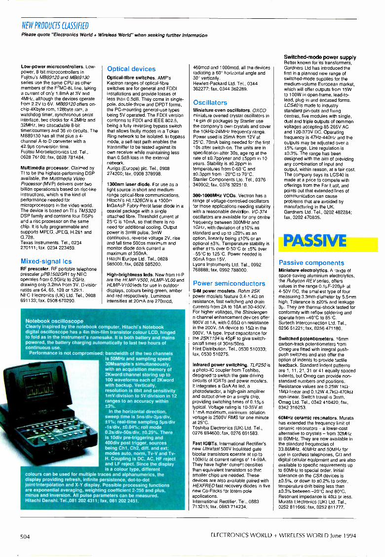
NEW PRODUCTS CLASSIFIED
Please quote "Electronics World + Wireless World" when seeking further information
Low -power microcontrollers. Low -power, 8 -bit microcontrollers inFujitsu's MB89120 and MB89130series use the same CPU as othermembers of the F2MC-8L line, takinga current of only 1.8mA at 3V and4MHz, although the devices operatefrom 2.2V to 6V. MB89120 offers on -chip 4Kbyte rom, 128byte ram, awatchdog timer, synchronous serialinterface, two clocks for 4.2MHz and32MHz, two cascadable 8 -bittimer/counters and 36 i/o circuits. TheMB89130 has all that plus a 4 -channel A -to -D converter with a42.9ps conversion time.Fujitsu Microelectronics Ltd. Tel.,0628 76100; fax, 0628 781484.
Multimedia processor. Claimed byTI to be the highest -performing DSPavailable, the Multimedia VideoProcessor (MVP) delivers over twobillion operations/s based on risc-likeinstructions, which is the kind ofperformance needed formicroprocessors in the video world.The device is based on TI's TMS320DSP family and contains four DSPsand a risc processor on the samechip. It is fully programmable andsupports MPEG, JPEG, H.261 andG.728.Texas Instruments. Tel., 0234270111; fax, 0234 223459.
Mixed -signal IcsRF prescaler. RF portable telephoneprescaler pPB1502GR1 by NECoperates from 0.5GHz to 2GHz,drawing only 3.2mA from 3V. Divisionratios are 64, 65, 128 or 129:1.NEC Electronics (UK) Ltd. Tel., 0908691133; fax, 0908 670290.
Optical devicesOptical -fibre switches. AMP'sKaptron ranges of optical -fibreswitches are for general and FDDIinstallations and provide losses ofless than 0.5dB. They come in single -pole, double -throw and DPDT forms,the PC -mounting general -use typesbeing 5V operated. The FDDI versionconforms to FDDI and IEEE 802.5,being a fully reversing bypass switchthat allows faulty modes in a TokenRing network to be isolated. In bypassmode, a self -test path enables thetransmitter to be tested against itsown receiver while maintaining lessthan 0.5dB loss in the externalnetwork.Auriga (Europe) plc. Tel., 0908274200; fax, 0908 378998.
1300nm laser diode. For use as alight source in short and medium -range optical -fibre communications,Hitachi's HL1326CN is a 1300mInGaAsP Fabry-Perot laser diode in acoaxial package with a singleattached fibre. Threshold current at25°C is 10mA, so that there is noneed for additional cooling. Outputpower is 3mW pulse, 3mWcontinuous, reverse voltage 2V, riseand fall time 500ps maximum andmonitor diode dark current amaximum of 350nA.Hitachi Europe Ltd. Tel., 0628585000; fax, 0628 585200.
High -brightness leds. New from H -Pare the HLMP-V500, HLMP-VLOO andHLMP-V100 leds for use in outdoordisplays, colours being green, amberand red respectively. Luminousintensities at 20mA are 270mcd,
Notebook oscilloscopeClearly inspired by the notebook computer, Hitachi's Notebookdigital oscilloscope has a 4in thin-film transistor colour LCD, hingedto fold as in the instrument's namesake. It is both battery and mainspowered, the battery charging automatically to last two hours ofcontinuous use.
Performance is not compromised; bandwidth of the two channelsis 50MHz and sampling speed30Msample/s simultaneously,with an acquisition memory of2Kword/channel storing up to100 waveforms each of 2Kwordwith backup. Vertically,resolution is 8bit and sensitivity1mV/division to 5V/division in 12ranges to an accuracy within±3%.
In the horizontal direction,sweep time is 5ns/div-2ps/div,±1%; real-time sampling 5ps/div-1s/div, ±0.04%; roll mode0.2s/div-50s/div, ±0.25%. Thereis 10div pre -triggering and400div post trigger, sourcesbeing Ch1, Ch2, diff. and ext;modes auto, norm, Tv -V and Tv -H. Coupling is DC, AC, HF rejectand LF reject. Since the displayis a colour type, different
colours can be used for multiple traces and alphanumerics, thedisplay providing refresh, infinite persistence, dot -to -dotjoint/interpolation and X -Y display. Possible processing functionsare exponential averaging, weighting coefficient 2-256 and plus,minus and inversion. All pulse parameters can be measured.Hitachi Denshi. Tel.,081 202 4311; fax, 081 202 2451.
- --Nyo.
460mcd and 1000mcd, all the devicesradiating a 60° horizontal angle and30° vertically.Hewlett-Packard Ltd. Tel., 0344362277; fax, 0344 362269.
OscillatorsMiniature oven oscillators. OXCOminiature ovened crystal oscillators in14 -pin dil packages by Stanler usethe company's own crystals and coverthe 10kHz-24MHz frequency range.Power used is 25mA from 12V at25°C, 70mA being needed for the firstlOs after switch -on. The units are inspecification after 30s, ageing at therate of ±0.7pp/year and ±5ppm in 10years. Stability is ±0.2ppm intemperatures from 0-60'C and±0.3ppm from -20°C to 70°C.Stanler Components Ltd. Tel., 0376340902; fax, 0376 322510.
300-1000MHz VCOs. Vectron has arange of voltage -controlled oscillatorsfor those applications needing stabilitywith a reasonable deviation. VC -374oscillators are available for any centrefrequency between 300MHz and1GHz, with deviation of ±10% asstandard and up to ±20% as anoption, linearity being ±10% or anoptional ±3%. Temperature stability iseither ±1% over 0-50°C or ±5% over-55°C to 125°C. Power needed is50mA from 15V.Lyons Instruments Ltd. Tel., 0992768888; fax, 0992 788000.
Power semiconductorsS -M power mosfets. Rohm 2SKpower mosfets feature 0.4-1.452 onresistance, fast switching and draincurrents from 2A to 10A at 30-450V.For higher voltages, the Shindengenn -channel enhancement devices offer900V at 1A, with 0.6552 on resistancein the 200V, 5A device to 150 in the900V, 1 A type. Input capacitance forthe 2SK1194 is 45pF to give switch-on/off times of 3Ons/50ns.Flint Distribution. Tel., 0530 510333;fax, 0530 510275.
Infrared power switching. TLP250 isa photo -IC coupler from Toshiba,designed to switch the gate drivingcircuits of IGBTs and power mosfets.It integrates a GaAlAs led, aphotodetector, a high -gain amplifierand output drive on a single chip,providing switching times of 0.15pstypical. Voltage rating is 10-35V at11mA maximum; minimum isolationvoltage is 2500V RMS for one minuteat 25°C.Toshiba Electronics (UK) Ltd. Tel.,0276 694600; fax, 0276 691583.
Fast IGBTs. International Rectifier'snew Ultralast 500V insulated -gatebipolar transistors operate at up to100kHz at current ratings of 14-59A.They have higher current densitiesthan equivalent transistors so thatsmaller chips are needed. Thesedevices are also available paired withHEXFRED fast recovery diodes in fivenew Co -Packs for totem -poleapplications.International Rectifier. Tel., 0883713215; fax, 0883 714234.
Switched -mode power supplyBetter known for its transformers,Gardners Ltd has introduced thefirst in a planned new range ofswitched -mode supplies for themedium -volume European market,which will offer outputs from 15Wto 100W in open -frame, lead -to -lead, plug-in and encased forms.LCS40 is made to industry -standard pin -outs and fixingcentres, five modules with single,dual and triple outputs of commonvoltages accepting 85-265V ACand 120-370V DC. Operatingfrequency is 47Hz-440Hz and theoutputs may be adjusted over a±5% range. Line regulation is±0.3%. The range has beendesigned with the aim of providingany combination of input andoutput, within reason, at a fair cost.The company says its LCS40 ismade at a price to compete withofferings from the Far East, andpoints out that extended lines ofcommunication can causeproblems that are avoided bymanufacturing in the UK.Gardners Ltd. Tel., 0202 482284;fax, 0202 470805.
PASSIVEPassive componentsMiniature electrolytics. A range ofspace -saving aluminium electrolytics,the Rubycon REV series, offersvalues in the range 0.1p F-220pF at4-50V DC, the smallest type of fourmeasuring 3.3mm diameter by 5.5mmhigh. Tolerance is ±20% and leakage3p. They are thermal -shock tested forconformity with reflow soldering andoperate from -40°C to 85°C.Surtech Interconnection Ltd. Tel.,0256 51221; fax, 0256 471180.
Switched potentiometers. 16mmcarbon -track potentiometers fromOmeg are fitted with integral push -push switches and also offer theoption of indents to provide tactilefeedback. Standard indent patternsare 1, 11, 21, 31 or 41 equally spacedindents, but Omeg can provide non-standard numbers and positions.Resistance values are 0.25W 1k.Q-1MQ linear and 0.12W 4.71(52-470k.Qnon-linear. Switch travel is 3mm.Omeg Ltd. Tel., 0342 410420; fax,0342 316253.
60MHz ceramic resonators. Muratahas extended the frequency limit ofceramic resonators -a lower -costalternative to crystals - from 32MHzto 60MHz. They are now available inthe standard frequencies of33.86MHz, 40MHz and 50MHz foruse in cordless telephones, CD anddigital cellular equipment and are alsoavailable to specific requirements upto 60MHz to special order. Initialtolerance on the CSA devices is±0.5%, or down to ±0.2% to order,temperature drift being less than±0.3% between -20°C and 80°C.Resonant impedance is 40S2 or less.Murata Electronics (UK) Ltd. Tel.,0252 811666; fax, 0252 811777.
504 ELECTRONICS WORLD + WIRELESS WORLD June 1994

NEW PRODUCTS CLASSIFIED
Crystals60MHz ceramic resonators. Muratahas extended the frequency limit ofceramic resonators -a lower -costalternative to crystals - from 32MHzto 60MHz. They are now available inthe standard frequencies of33.86MHz, 40MHz and 50MHz foruse in cordless telephones, CD anddigital cellular equipment and are alsoavailable to specific requirements upto 60MHz to special order. Initialtolerance on the CSA devices is±0.5%, or down to 10.2% to order,temperature drift being less than±0.3% between -20°C and 80°C.Resonant impedance is 400 or less.Murata Electronics (UK) Ltd. Tel.,0252 811666; fax, 0252 811777.
SM crystals. HC49/4HSMX is asurface -mounted version of theestablished HC49/4H crystal package,measuring 4.9mm by 13.4mm and4.3mm high. Frequencies available liein the 3.2MHz-50MHz range, withfrequency tolerance and stability in theoperating temperature range ofi-50ppm and ±100ppm, although tighterspecifications can be supplied for manyfrequencies. Load capacitance is5-7pF, shunt capacitance 2-9pF anddrive level 100pW maximum.IQD Ltd. Tel., 0460 77155; fax, 046072578.
Small crystals. Seiko Epson's CA -303H mini -cylinder quartz crystal nowoperates over the temperature range-40°C to 85°C and has a range offundamentals from 12MHz to 24MHz.Temperature stability is ±3ppm to±15ppm, depending on temperature,and ages at ±2ppm/year. Thepackage measures 8.9mm long and3.1mm in diameter.Advanced Crystal Technology. Tel.,0635 528520; fax, 0635 528443.
DisplaysBright multi -led indicators.Indicators using bright led arrays forsunlight viewing combine thebrightness of tungsten filaments withthe long life of semiconductors. TheDialight 556 series provides theoption of red, yellow or green withintensities up to 6120cd/m2 in flat lensversions and 340cd/m2 in 180° -viewing domed lens types. 12V, 24Vand 120V versions are available, allfitting into a 1 in cutout.Dialight. Tel., 0638 665161; fax, 0638660718.
FiltersSaw filters. New, miniature surfaceacoustic -wave filters by Murata aredesigned for use in mobilecommunications from GSM to PCNand DECT. Height off the board is2mm and the devices come in arange of packages. An example is theSAFC71.0MA50T, which is a 71MHzversion with 4.5dB insertion loss in apackage measuring 6.5 by 13.3mm.Another is a 244MHz filter forPCN/DSC1800 systems, providingout -of -band attenuation of over 50dBwith an insertion loss of 3.5dB.Murata Electronics (UK) Ltd. Tel.,0252 811666; fax, 0252 811777.
C Lc% °c
4_
Please quote "Electronics World f Wireless World" when seeking further information
LCSCrttcttt
tottrot E
,71MEMEMMIN
400MHz logic analyserAt a maximum asynchronous sampling rate of 400MHz, TTI's TA4000logic analyser captures events down to 5ns in its full 8Kword memory.Timing resolution is 2.5ns. In synchronous acquisition, a 50MH:sampling rate enables handling of the fastest csc processors. Compac,high -impedance probes minimise loading and channel -to -channel skew.Thurlby Thandar Ins ru-nents Ltd. Tel., 0480 412451; fax, 0480 450409
InstrumentationEMC measurement. A 16A line -impedance stabilisation network, theLISN1600 by Thurlby Thandar,enables accurate measurement ofEMC emissions at the supply input ofany electrical equipment operatingfrom a single-phase supply. It meetsthe CISPR 16 requirements for BandA in the 10kHz-150kHz range andBand B from 150kHz to 30MHz. Aswitchable 150kHz filter limits LFsignals for Band B measurement,thereby reducing the requireddynamic range. The measuring circuitis connected to either supply line orcan be disconnected for checking thenoise floor.Thurlby Thandar Instruments Ltd.Tel., 0480 412451; fax, 0480 450409.
Low-cost oscilloscopes. Newinstruments from Goldstar are theOS -9020A, 0S -9040D, OS-904RDand OS -3020, the lowest price beingfor the 20MHz dual -trace 9020A at£229.75 plus vat. This, the 9040D40MHz type at £340 and the 904RDat £425 are all analogue instruments,the latter having digital screenreadout. At the top of the range is the3020 20MHz digital storageoscilloscope at £638.MPS Electronics. Tel., 0702 554171;fax. 0702 553935.
Clamp -on multimeters. New fromITT is a range of clamp -onmultimeters which measure voltageas well as current and will computepower in PWM and other non -sinusoidal waveforms. A4X210 andMX215 measure current up to 200ARMS, other functions beingfundamental frequency of current andvoltage, total RMS voltage andcurrent, RMS voltage of fundamentalvoltage and current, total apparentpower and effective power at thefundamental. Filters exclude switchingfrequencies for measurement up to100Hz and a 1V FS analogue outputproportional to the current can beswitched from instantaneous to RMS.Jaw size is 23mm.ITT Instruments. Tel., 0753 511799;fax, 0753 694983.
Valve and photodiode Spicemodels. Several application notes inthe February Intusoft Newsletter areconcerned with Spice modelling of12AU7A double triodes, EL9000pentodes, BPW34 semiconductorphotodiodes and photodiodes ingeneral. Also described is theinteractive IsSPICE4 program forWindows 3.1, Windows NT and theMacintosh. A disk containing all circuitdiagrams and Spice modelsdescribed is on offer.Technology Sources Ltd. Tel., 0638561460; fax, 0638 561721.
Harris power. Full specifications ofHarris's power devices are given in anew Databook, which describesultrafast and hyperlast recoverydiodes, the MCT class of moscontrolled thyristors and insulated -gate bipolar transistors. Applicationnotes included describe the use ofIGBTs, MCTs and fast diodes inmotor control and power supplies.Among the diodes described aresome operating at up to 1200V and150A.Harris Semiconductor UK. Tel., 0276686886; fax, 0276 682323.
3.3V SM power supplies. Offeringsingle, 3.3V outputs, BICC-Vero'sPK60 gives 15A and the PK240 45A,both at 3.3V, the PK240 having afront-end filter for use in harshconditions. Features of both include110V or 230V wide -tolerance ACinput, long-term overvoltage andshort-circuit protection, <40mV ripple,regulation <0.2% and remote on -offswitching. PK60 is in a 3U by 8HPcassette and the PK240 in either a 3Uby 24HP or 6U by 14HP type, bothbeing compatible with DIN41494subracks.BICC-Vero Electronics Ltd. Tel., 0489780078; fax, 0703 264159.
Inductorless DC -to -DC converter.LTC1144 is a switched -capacitorvoltage converter that accepts inputsfrom 2V to 18V and generates -2V to-18V. It is primarily intended toprovide -15V from a positive input inautomotive, applications or in batterysystems with chargers and in dataacquisition, and is effectively a higher -voltage upgrade for LTC1044 andICL7660 devices. Only two external,non -critical capacitors are needed forcharge -pump and charge -reservoir
1GHz digital real-time oscilloscope.Claimed by Tektronix to be theworld's first 1GHz digital real-timeoscilloscope, the TDS684A is part ofa new range of equipment for thedevelopment of advanced digitalsystemsIt provides four channels of 1GHz,single -shot data capture, sampling at5Gsample/s simultaneously on eachchannel, so that non -repetitive eventsare captured at full bandwidth. Thereare 25 automatic measurements andbetter than 50ps time accuracy, plusall the features associated with theearlier TDS644A. New triggeringcapabilities, slew -rate triggering andSet-up and Hold trigger addresscommon timing problems andapparent random failures in high-speed circuitry.
LiteratureAFDEC members guide. TheAssociation of Franchised Distributorsof Electronic Components haspublished its 1994 Members andProducts Guide for 1994, in whichnearly 60 UK distributors have theirproducts listed, with telephone andfax numbers. Any value-addedservices such as assembly work andkitting are mentioned. The guide isfree.AFDEC. Tel., 0763 27109; fax, 0763273 255.
MiNiature blowerMicronel's U97 blower is aracial type providingpressures up to 750Pa andairlow of 5651/mir at noiselevals down to 57dB(A).Oparating voltages of 5V. 12Vor 24V are available in the twoversions, the larger onemeasuring 98mm in diameterand weighing 1953. Theblcwer's body material ispo yphenylenoxide.Radiatron Components Ltd.Te ., 081 891 1221; fax, Oil891 6839.
June 1994 ELECTRONICS WORLD + WIRELESS WORLD 505

NEW PRODUCTS CLASSIFIED
Please quote "Electronics World + Wireless World" when seeking further information
functions. The device runs at 10kHzfrom its internal oscillator, slowingdown with an external C, and anultrasonic frequency can be obtainedby using the boost pin. Typical powerefficiency is 93% and quiescentcurrent 8pA.Linear Technology (UK) Ltd. Tel.,0276 677676; fax, 0276 64851.
5W DC -to -DC converters. NewportComponents' range of IS9001-approved converters provides outputpowers of 250mW-5W and are amongthe smallest available, measuring19.5 by 7.5 by 10mm, some of thevarious package styles being surface -mounted and suitable for reflowsoldering. There are 450 differentmodels from 3V -48V in single anddual versions. Isolation is 1kV.XP plc. Tel., 0734 845515; fax, 0734843413.
Switches and relaysStackable pushbutton switch. FromEAO-Highland is the Grayhill 32series of miniature pushbuttonswitches, which are stackable to allowcustom switch assemblies on 0.2incentres. The switches have aninternally sealed plunger and arecompatible with flow -soldering andcleaning operations. Status/reset orpress -to -test functions are provided,with led indication. Single-pole/single-throw normally open and normallyclosed forms are in the samepackage.EAO-Highland Electronics Ltd. Tel.,0444 236000; fax, 0444 236641.
SIP reed relays. Miniature 4 -pinsingle -in -line reed relays for high -density mounting are announced byCoto Wabash. The 9090 Series Mini-
. 1 ;le 1,1.1 vl 'I
SIP relays measure 3.81mm by15.24mm by 6.6mm high and are insingle -pole normally open form, ratedfor over 109 operations at low loads.They have 5V or 12V coils and handleup to 10W. Options include a diodeand/or magnetic shielding.Coto Europe. Tel., (Netherlands)01031 45 320838; fax, 01031 45320838.
Transducers andsensorsGear -tooth sensor. Allegro's type3059 AC -coupled Hall -effect sensor isfor the non -zero -speed sensing offerrous targets and incorporates avoltage regulator. two quadraticsensing elements, temp. comp.circuitry, gain amplifier, filtering, aSchmitt trigger and an open -collectoroutput driver switching up to 20mA.The differential band-pass filtervirtually eliminates the effects ofmagnetic and system offsets andconfers a degree of immunity to RFinterference. Two versions cover the-20°C to 85°C and -40°C to 125°Cranges.Allegro MicroSystems Inc. Tel., 0932253355; fax, 0932 246622.
Pressure transducers. Subminiatureversions of Kulite's LQ-080/125 thin -line pressure sensors, the LQ-062series, measure 1.6 by 4.7mm by0.4mm high, with a view to mountingthem on turbine blades and otheraerodynamic profiles. The sensorsare available in pressure rangesbetween 25psi full scale and 200psi.Excitation is 5V or 10V and nominalpressure output is 100mV.Kulite Sensors Ltd. Tel., 0256461646; fax, 0256 47951
WIWI,. I lool I /OP
JJJJ A2_1_1_11 =iJ J J fl 2111
dIJ
New Mathcad versionsMathsoft has announced new versions of its Mathcad calculationsoftware, Mathcad 5.0 and Mathcad PLUS 5.0. Mathcad 5.0 is noweasier to use and is provided with extra functions such as trace and zoomfor graphics, print preview and a technical spell checker. Mathcad PLUShas the same features, but also has an entirely new set of functions suchas differential equation solvers and advanced matrix algebra for moreadvanced users.New features in Mathcad 5.0 include easier equation and text editing withpull -down menus and a function list, an on-line tutorial, new numericfunctions including roots of polynomials and 2-D curve fitting and DDEsupport. For Mathcad PLUS 5.0, new algebraic functions includedetermination of matrix decompositions, finding eigenvalues and acomplete matrix analysis system. Users may write their own routines in Cor C++ or use Function Packs from Mathsoft.Mathsoft Europe. Tel., 0344 23491; fax, 0344 873461.
, ode jrce Design , s Tools 11elp
Iw1w,l.rw. ulna I
NI IMO C owe1 IMMO .10 111,10
511
521
512
firnesaloo 1111111111
11 NINON
FIN Mo,h Ewan, Mode
1111 j 1 irr_
mith charts for Windows-MATCH for Windows by Number One Systems uses Smith chartethods to provide a set of rf circuit and system design tools inne package. It woks with ordinary units, needing noormalisation, and can be switched between impedance anddmittance charts. There is direct readout from the chart. Circlesf constant SWR, resistance, conductance, reactance andusceptance are drawn automatically and the cursor locked toem. A receiver and system design tool calculates overall gain,se figure and third -order input intercept point for a number of
terconnected stages of filtering, amplification, mixing andttenuation. Included is a library of over 600 sets of s -parameterto for Motorola devices.
umber One Systems Ltd. Tel., 0480 461778; fax, 0480 494042.
COMPUTERComputer board -level
productseripheral interface. PC36AT fromAmplicon Liveline is a programmableperipheral interface board using the8255 IC to give 24 TTL-compatibledigital i/o lines by way of a single 37 -way type D connector. The lines areat three 8 -bit ports, two of which areprogrammable to be all inputs or alloutputs, the third being four inputsand four outputs, if required. A lower -power version for laptops is available,both types coming with demosoftware in Turbo Pascal and Basic.Amplicon Liveline Ltd. Tel., 0800 525335 (free); fax, 0273 570215.
Scorpion K4 i/o. MicroRobotics'sScorpion K4 embeddedmicrocontroller now has a newapplication module, the K4ic, whichprovides a set of analogue and digitalinput/output facilities to form ready -to -use hardware for much typicalmachine control and automation work.K4ic is in PCB form or in a metal caseto CE EMC standards. Digital i/oconsists of two uncommitted relayoutputs handling 3A at 240V, four 2A,24V outputs and four universal inputs,while the analogue facilities includefour 8 -bit inputs and an 8 -bit outputwith selectable voltage ranges. Thereare also two channels of serial i/o andtwo g -p expansion interfaces.MicroRobotics Ltd. Tel., 0223 323100;fax, 0223 462242.
Stand-alone audio DSP. From theFinnish company Sample RateSystems Oy, the M4 -0202-A is an
audio digital signal -processing boardoperating independently of any hostcomputer, needing only anunregulated supply and a case. It isbased on the Motorola 56004 signalprocessing chip, has stereo analogueinput and an 18 or 20 -bit analogue -to -digital converter and an 18 -bit outputdigital -to -analogue converter, which isfollowed by a programmable gaincontrol. The module accommodatesup to 32Kbyte of program memoryand 4Mbyte of data memory, inaddition to external expansionfacilities. Unique to this board is theboot rom, which confers itsindependence from a host. Outputdynamic range is over 95dBSample Rate Systems Oy. Tel., 010358 31 3165 045; fax, 010 358 313165 046.
PCMCIA adaptors. CARDport is arange of PCMCIA adaptors for usersof laptops, notebooks and desktopcomputers not provided with aPCMCIA socket. Three models areavailable: CARDport eX, which is aportable card adaptor with its ownrechargeable battery, connecting tothe parallel printer port of any PC andaccepting memory and disk drivecards; CARDport isa goes in the ISAexpansion bus, an additional modulefitting in a disk drive bay, to providetwo sockets for any PCMCIA cards;and CARDport ide is a low-costdesktop PC adaptor for micro harddisk drives. All are supplied withsoftware.Chase Advanced Technologies. Tel.,0274 841316; fax, 0274 841302.
506 ELECTRONICS WORLD + WIRELESS WORLD June 1994

NEW PRODUCTS CLASSIFIED
Data communicationsHDSL transceiver. Brooktreeannounces the Bt8952 single -chiphigh -bit -rate digital subscriber linetransceiver, claimed to be the first all -digital embodiment of the HDSLtechnique for upgrading standardtwisted -pair telephone lines to takehigher bit rates for fast digitalservices. Brooktree's Bt8953interfaces the 8952 to T1/E1 framersto provide a complete solution. Thetransceiver incorporates adaptiveecho cancellation and alsoequalisation to compensate for phaseand amplitude distortion caused byboosting the bandwidth of low -frequency copper wires.Brooktree Ltd. Tel., 0844 261989; fax,261906.
Notebook data acquisition. Using a486 notebook computer as acontroller, Keithley's DacPac is aportable data acquisition systemwhich avoids the restrictions of theprinter port or PCMCIA slot. The unitruns all software written for the PCwithout modification. It is the samesize as the computer and can beconfigured for the application byselecting the acquisition board from awide range, two such boards beingpossible for high channel counts ormore interfaces. DacPac has its ownpower system working from ACmains.Keithley Instruments Ltd. Tel., 0734575666; fax, 0734 596469.
OEM modem. Socket Modem 136 byTDC supports fax, voice and data,providing a BABT-approved methodof providing connectivity to PSTN andcellular networks. It can be fitted witha range of component options to allowconfigurations for 9600b/s data,9600b/s fax send and receive andvoice, supporting V.22bis, V.22, V.23and V.21, plus V.42bis and MNP-5data compression and errorcorrection. Mobile systems aresupported with MNP-10 protocol forcellular and poor landlines. ADPCMcompression is used for voice data.Telecom Design Communications Ltd.Tel., 0256 332800; fax 0256 332810.
Data acquisition box. A compact,lightweight, external data acquisitionbox by National, the DAQPad-1200 iscompatible with the parallel printerport of a PC and includes an ACadaptor or a 9-13 hour rechargeablebattery pack. It has a 12 -bit A -to -Dconverter accepting signals from eightsingle -ended or four differential inputsat up to 83.3ksample/s, withprogrammable gain of 1-100, a 512 -sample fifo A -to -D buffer, two 12 -bitD -to -A converters, 24 lines of TTL-compatible digital i/o and three 16 -bitcounter;timer channels accessible bythe user. The unit measures 5.75 by8.375 by 1.5in.National Instruments UK. Tel., 0635523545: fax. 0635 523154.
Development andevaluation78K0 starter kit. NEC's distributor,Sunrise Electronics, has a low-coststarter kit for the 78K0 series of 8 -bit
Please quote "Electronics World + Wireless World" when seeking further information
microcontrollers which includes aboard with a shrink -dip probe,software, OTP programmer, cableand documentation. Assembler anddebugger software provide full -screeninterface, real-time execution andsingle-step, and multiple breakpoints.Program loading is via an RS232Cinterface to a terminal or PC, theprogram being downloaded andstarted under monitor controL ThepP78P014YDW used has 32Kbyte ofrom and 1056byte of ram, 53i/o ports,16 -bit and 8 -bit counter timers, clockand watchdog timers, and twochannels of serial interface, one ofwhich being used, if requirec, as an12C bus interface.Sunrise Electronics Ltd. Tel. 0908263999; fax, 0908 263003.
A different ICE. To avoid theproblems caused by the growingnumber of microprocessor derivativesand, therefore, an increasing numberof pins, Hitex has a new method ofemulation in which the processorstays where it is, soldered in ifrequired, and is interfaced to theemulator by a standard interfaceadaptor, the ICE/connect, which issupplied with a subset of theprocessor's signals. The adaptor isidentical for all derivatives of aprocessor family. teletest51Professional and teletest51 Junior aresupported for the 8051 family andteletest32 for 80C165/166/' 67families.
fax, 0203 692131.
£300 16 -bit development. At a muchlower cost than that of in -circuitemulation, The RCS DB16 Designer'sBoard forms a complete developmentkit for Mitsubishi microcontrollers. Itconsists of the board, Mitsubishi'scross assembler, communicationspackage and debug monitor, powersupply cable, example programs insource code and documentation. Theuser needs only a PC with textediting.RCS Microsystems Ltd. Tel., 081 9792204; fax, 081 979 6910.
Computer peripheralsSolid-state disk. AMC has a 'harddisk' on a PC card, having cold -bootand full disk emulation. The PC FlashDisk is based on flash memory andthe Flash File System to provide srammemory at lower cost. It provides32Mbyte capacity on one board, isnon-volatile and needs no batteries,plugging into an ISA bus :o replaceboth the disk and disk controller withits built-in software. The board iscompatible with dos and Windowsand works on 8 -bit and 16 -bitISA/EISA buses and will operate asdrive D: when other drives arepresent or as drive C: in disklesssystems.Advanced Modular Computers Ltd.Tel., 0753 580660; fax, 0753 580653.
SoftwareMaths training. A training packageintended to increase the mathematicalskills of student engineers in
Computer voice controlTalk... s a computer system by Responsive Systems that listens to avoice arid displays the -.ext on screen, no intervention from the keyboardbeing r eeded. It uses Dragon Dictate and IBM Voice Type 2.
A but -in tutorial allows the system to learn one's unique speechpatterns, three vocabularies, o 5000, 7000 and 30,000 words, beingavailable in different versions. The package consists of a 486 notebook,although Talk... can be used with any desktop computer, hardwareincluding 12MB of ram a microphone designed to pick up very littleambient noise, 2000 code words in addition to the vocabulary, a 100,000word cictionary for spell check -1g, adaptive learning to accommodateregional accents and speech impairments, and multiple user voice modelsfor system sharing.
It woks with many common dos applications such as Wordperfect,Wordstar, Word, Lotus 123 and Quicken, options including Windows voicecontra and Voice Tools to allow the development of specialist voice -driven applications.
Punctuation and formatting commands can be spoken or input from thekeyboard, speed of text creation being around 30-40 words per minute;blocks of text can be input by a single spoken word. The whole process isfaster than handwriting and faster than some typists.
This type of voice response may be added to any 386 or 486 computerproviced that it has at least 1;MB of ram, the cost being £999 for a 5000word version. Completes sysbms start at £2899,in the 486/5000 wordform. The system is modular and can therefore be upgraded.Responsive Systems. Tel., 0;1 602 4107; fax, 071 603 2109.
electronics, microcomputers,biomedic'ne and industrial subjects isavailable from Feedback. It containsfundamentals such as basic maths,algebra, trigonometry, calculus,compute- maths and measurement.Emphasis is on graphics andanimation and each subject area hasa number of modules that can betaken as a complete programme orused selectively. Speed of learning iscontrolled by the student Thepackage automatically recordsperformance and will provide classreports.Feedback Test and Measurement.Tel., 0892 653322; fax, 0892 663719.
Graphical debugging. Designed forInnovate's 9000 board -test system,the company's Index is an interactivedevelopment system providinggraphical waveform displays ofstimulus and response data, withmouse -driven editing tools. It reeds,modifies and writes test patterns andautomatically checks for potentialinvalid data, data and address busesbeing handled in both hex and binaryformats. Innovate Ltd. Tel., 0604661000; fax, 0604 660021.
Forth 5 cross -compiler. MPE's PC -hosted Forth 5 cross -compilersgenerate code for a wide range oftarget processors, offering interactivedevelopment, high compilation speedand on-line help to speed thedevelooment of embedded software.Target code supplied includes a multi-tasker with message passing andevent handlers; high-level interruptsinteract with tasks.Microprocessor Engineering Ltd. Tel.,0703 339691; fax, 0703 631441.
Real-time data analysis forWindows. Hydra-Digis from SciTechis a Windows 3 -based, multiprocessordata acquisition and control system,handling data capture, real-timeanalysis and display and results
documentation. A measurement andanalysis process is designed onscreen graphically, using a mouse toconnect function blocks from a library,users adding their own functions or C -code routines where necessary. Thetransputer object code is generatedby the software, the PC being freedfor interface functions. Included is onecard providing 16 analogue inputs,two analogue outputs, 16 digitalinputs and outputs, a trigger input anda T805 25MHz transputer. The basicsystem will perform a 1024 -point FFTto floating-point precision at a 5kHzreal-time rate.SciTech. Tel., 0734 758857; fax, 0734758748.
Multimedia chips. Mwave is IBM'ssolution to the problem of expandingthe PC's area of activity toencompass multimedia working. It isbased on the company'sIBM38MW500 digital signalprocessing chip and allows thesoftware implementation of all theexpansion functions for a PC orworkstation, including stereo sound,speech recognition, fax, modems andtelephony. All this is performed by asingle chip.
Blue Micro, IBM's British OEMrepresentative, can supply evaluationboards in standard PC AT expansioncard format, a range of softwaremodules for basic functions alreadybeing in existence. Intermetrics has acomplete developer's tookit, Mwavefor Windows, and IBM has licensedSound Blaster compatibility fromCreative Technology, so that Mwavewill be compatible with existing audioand multimedia applications. It isalready compatible with CD-romtechnology and the MPC standards.Mwave is also available to incorporateat chip level, with support availablefrom Blue Micro.Blue -Micro Electronics. Tel., 0604603310; fax, 0604 603320.
June 1994 ELECTRONICS WORLD + WIRELESS WORLD 507
LETTERS
From Douglas Self -
Amplified defence...I thank Ben Duncan for his kindcomments on my investigations intoamplifier distortion (Letters, May1994). But I also note with genuinesadness that his letter attempts tounderpin a raft of unsupportedassertions.
While I would happily slug it outline -by-line on every dubiousstatement, I doubt if The Editorwould stand for it [No. Ed], so I willonce more confine myself to power -supply rejection and "thermaldistortion".
I don't know what Ben means by"economical with the facts". Therewere eight articles full of them. Hisplaintiff cry of "...where are thosemeasurements?" is a bit rich in viewof his propensity to complainwithout ever offering any hard factsto support his views.
Where Ben got the idea that Irejected ht regulators without tryingthem I do not know. I tried severalversions of linear regulators in the1970s - I still have one system in
that this was a good way to reducehum injection. But I was dead
wrong. They are complicated,expensive, difficult to design for HFstability under all conditions, andgenerally a pain to use. It may bethat Ben has some insights thatrender these criticisms outdated. Butunless he is more forthcoming withinformation, it looks as if we shallnever know.
Admittedly the generic amplifier Iconcentrated on is only onetopology. But it is the basic structureof 98% of power amplifiers, and issurely a reasonable place to start. Ido feel that I have shown that first-class 851 thd figures are obtainablewith a simple unregulated supply,using reservoirs no larger than10,000pF. I assure Ben that this alsoholds true for 4 and 2S2 loads, withor without various amounts ofparallel capacitance up to 21.1F.
Perhaps the topology that Benprefers, but refuses to disclose,cannot emulate this performance. Ifso it seems like a good reason not touse it, because he has so far failed tospecify any countering advantages.All we have to go on are the nuggetsof data published in his article (PSU
pp.8I8-822, EW+WW, October1992) which I reproduce below:
On the defensive"For years industry has been crippled by the imperative for militarydevelopment... Billions of pounds destined for the military have distortedthe UK electronics industry grossly... The electronics industry must be ledby marketing departments, not politicians..."
Frank Ogden, Comment, EW + WW, June 1990.
"Much of the relative prosperity in the UK can be traced back ultimatelyto our defence manufacturing activities... Arms, petrochemicals, nucleartechnology ... are what separate us from a rural peasant economy".
Frank Ogden, Comment, EW + WW, April 1994.
Frank Ogden and Frank Ogden - are they by any chance related?Hypocrisy or MP bashing?Richard GreatorexLondon
Like it or not, the UK technology and electronics industry is stillgeared to defence interests and anyone who denies this wouldbevery foolish. I don't welcome the situation, and I shall work to changeit. However, I am not so much of an idealist as to ignore the moneywhich it generates. Neither should our politicians throughpoliticalexpediency.Frank Ogden
Brass monkeysThank you for Help with hypocrisy (Comment, April 1994).
As a professional observer and amateur practitioner for more than 50years I have been horrified at the ineptitude of the top brass in BritishIndustry and in particular the electronics, aerospace and automotive fields.GEC is certainly an outstanding example.H Archer Watford
10Hz 1 kHz 20kHzPSR with unreg psu nil -24dB -57dBTHD with unreg psu <0.002% not stated 0.04%THD with regulator <0.006% <0.006% <0.006%
The data tells us that Ben's basictopology passes If rail -perturbationsstraight through to the output - anunpromising start. Such an amplifiercertainly appears to be unusablewithout very good supply regulationand I think it is only fair to wonderwhat is wrong with it.
The thd figures are even moreenigmatic. 0.04% is fairlyreasonable for hf crossoverdistortion at 40, but it is difficult tosee how any amount of supplyregulation can improve thisdistortion mechanism. Furthermore,the 10Hz thd appears to havedeteriorated by a factor of three andis deeply suspicious. I don't see whywe should accept this withoutexplanation.
As for my own psr vs frequencyplots, I must admit that theylanguish in a big file labelled"pending".
PSR in a typical power amplifier
mechanisms, not unlike distortion,and it will take a little time todisentangle properly. In themeantime, I would dearly like toknow about these ominous "PSR-reducing real -world compromises"that Ben waves at us, but have littlehope that he will tell us.
A brief explanation for Ben as towhy regulated supplies are universalfor powering the op -amps in mixingconsoles. Typically, a poweramplifier consists of one or twoactive stages, with all the circuitnodes available for judiciousdecoupling to keep the ripple out.Mixing consoles are made up ofhundreds or thousands of activeblocks, and the power distributionsystem is both extensive andintimately interlaced with the signalcircuitry. Op -amps have a given psr,and if it proves inadequate there islittle that can be done about it.Obviously in this case it is moresensible to remove the noise andripple just once, rather than manytimes over. In particular it is vital tokeep the garbage out of the audiogrounding system.Turning to thermal distortion, I
find Ben's complaints unimpressive.The reason I am wasting my timelooking for thermal distortion in theoutput devices is because he startedthis particular hare. But I must pointout that closely examining the thdfigures at 10Hz would disclose athermal mechanism no matter where
it lurked in the amplifier: a class -Boutput stage would be the likeliestplace to find such distortion becausethe dissipation varies so radicallyover a cycle. It is also fair to assumethat it would rise with fallingfrequency.
However, nothing can be found,even at the 0.0005% level.
I do not accept that my results arespecific to the generic/Lin topology.There is no reason why they shouldnot apply to any power amplifier-unless it has a very peculiararchitecture. Possibly Ben's mysterytopology is as susceptible to thermaldistortion as it is to non -ideal power -
supplies.As for "thermal distortion being
the HiFi industry's best hypothesis",it is news to me and certainlydoesn't seem to have appeared inaudio magazines recently.
I also protest about the currentvogue for calling sine -wave testing
having non -zero differentials up toas high an order as you care to go.Obviously Ben hopes to imply thatsuch testing is naive and outmodedcompared with some unspecifiedholistic new -age approach. But,mathematics is mathematics, and soa single frequency is always goingto be best for finding out whatactually happens inside an amplifier.
I was saddened to see that Benregards me as an "adversary" when Ihad hoped we were fellow -seekersafter Truth. But it is so easy tocriticise if you never produce a rivaldesign yourself. So I challenge Bento publish an amplifier design thatmeets all his criteria for quality.Then we may all look at it. OKBen... over to you.
...sad reignitionI read Jerry Mead's letter (EW +WW, March) with a certain sadness,which was I fear the only emotion Ifelt when composing my previousletter.
While I have no wish to reignitesubjectivist wars in the letterssection of EW + WW, I feel it mustbe wrong to let pass unchallengederroneous statements on matters Ihave studied closely.
Regrettably Mead has answerednone of the specific queries I raised;we still have no idea how he copeswith the Hafler and Baxandalldemonstrations that mystic amplifierdifferences just don't exist, and the
508ELECTRONICS WORLD + WIRELESS WORLD June 1994

LETTERS
amplifier circuitry around thenauseating CMRR trimmer appearsfated to remain shrouded in secrecy-a sort of Trimmer Celeste.
Mead has simply come back withmore of the usual unverifiable,unattributable claims. He says that'research has shown...' but whatresearch? When was it done? Wherecan I can read it? If he has data thatcorrelates his own audio prioritieswith sales figures, then can we notshare some of this importantinformation? If not, why not? Andhow do 'customers' in his letter turninto 'professional listeners' twolines further on?
Mead says one of his primeconcerns is to correlate what hehears with measurement, and theimplication of his first letter was thathe wasn't making a lot of headway,though I hope he will forgive me ifthis is a misinterpretation. To say itone more time, there is a huge bodyof psychoacoustical knowledgealready available for study, though Iget the distinct impression this is ofvanishingly small interest tosubjectivists: a most strange state ofaffairs.
I fully sympathise with and shareAlun Thomas' weariness with thisdebate (EW + WW, March), whichin truth was resolved a long timeago, initially by a series of listeningtests commissioned by Quad andcarried out by James Moir in 1978.
Three radically different amplifiertechnologies (valve, conventionalBJT, and current dumping) weresubjected to blind testing and properstatistical analysis. The result wasunequivocal: the amplifiers couldnot be distinguished by listening tothem. Since then various other testshave produced similar results, andthose that have not have proved tobe fatally flawed as regards thestatistical design of the experiment.It is in the light of these results thatengineers feel little enthusiasm forrepeating experiments that require agreat deal of care and effort if theyare to be of any use at all, and whichcan only confirm existingknowledge.
I'm sorry if Mead finds it irksometo have attention drawn to the fatalinadequacies of his experimentaltechnique, but then EW + WW is
hardly the right arena for thoseseeking uncritical adulation.
Whatever personal limitationsMead may choose to accuse me of -I assume he is trying to imply I havehearing difficulties, which is notvery nice - he may rest assured thatI shall continue to take an activeinterest in the phenomenon ofuncontrolled listening tests.Douglas SelfForest Gate,London
Ins and outs ofamplifiersDouglas Self's eight part amplifierseries was an informative read. Itbrought back memories of myinvestigative audio experimentationtwenty years ago and awoke somedormant ideas.
Amplifiers have two external audioinputs: normal signal input: and theloudspeaker output via the nfb(negative feedback) loop connection.
Suppose we connect one end of a4S2 resistor to the live outputterminal of an amplifier and drive theother with as little as I Vrnis withrespect to output ground. Tomaintain zero output potential, theamplifier must then sequentially sinkan extra 350mA in each half of itspush-pull output stage.
In class A, device currents changeequally but oppositely, smoothly andonly fractionally, so there is little nibloop disturbance.
In class B, virtually all current isderived from nth -energised openloop gain. The output stage is thusdriven through both device nonlinearities, inducing negativefeedback modulation at frequenciestwo and four times that of theapplied disturbance.
Composite loudspeakers have twoor more driver resonances, withenclosures, cross-overs and leadsturning up several more - welldamped we hope.
Conceivably, complex programmedrive will cause odd andunforeseeable back emfs, couplingalmost directly with an amplifier ntbreturn. In class B designs, these inturn intermodulate any medium- andhigh -frequency audio componentsriding on large amplitude low notes.
It follows that higher levels of classB ntb increase the audible confusionwhile apparently improving dummyload measured performance figures.This could be the real reason whyclass A designs are subjectivelypleasing, and we may need toreappraise testing procedures: whatabout measuring output stagedistortion when it itself is driven andswept through 10Hz-50kHz by areference power amplifier throughcomplex impedances or real lifeloudspeakers? Or we could quiet testwith both input and output driven -independently but synchronously.
Moving to another subject area,20W of audio is weak by today'sstandards, but in class A it generates45W of heat. Scale upwards toproduce a decent 2x100W stereoamplifier and you have a small roomheater.
Back in 2N3055 days, I hadencouraging results with a slidingbias class A 100W rms design thatquiesced with 'reasonable'
Sliding bias success
dissipation. There is now an openingto try this idea with Self's (Fig. 7)blameless design: I suggest the verysimple circuit shown.
Note that with sliding A the outputbias increases linearly withamplitude, differently to otherclasses, including AB and sustainedcurrent B.
The values shown in the circuit areestimates only. The 6k8 valueshould be carefully chosenaccording to power/impedancederivatives. C4 should he as small aspossible consistent with hf stability,and Vref set to approximately fourtenths of normal.
Induced current changes occursmoothly after voltage amplificationstages and all is enclosed by the ntbloop, so measured distortion figuresshould hardly increase.
Standing currents are adequate tocope with real -life loudspeakerreactances and the output should stillsound like good class A.Tiny feet, now big, saw off myaudio work and I'm unable to trythese ideas. But if someone could dothe soldering and testing. I'd bepleased to read their findings in thiscolumn.Graham MaynardNewtownabbeyN Ireland
Quiescent andcontrolledIn the last part of his series ondistortion in audio power amplifiers(EW+WW, March 1994) DouglasSelf suggests that it is not possible tocontrol the quiescent current in class(A)B amplifiers by using an extranegative feedback loop. But I mustdisagree.
It can be controlled with a specialkind of common -mode loopcontaining a non-linear networks 2.3.Using this technique. the quiescentcurrent can be made independent ofthe temperature of output transistors,and a smooth transition from oneside of the output stage to the othercan be realised with ease.
The output transistors can be madeto operate in a non -switchingmanner - although some parts of thenon-linear feedback network will
usually be cut off (nearly)completely when the output currentis large, the non-linear network doesnot 'switch'.
Besides, with this method,common -source or common -emitterstages can be biased in class AB.Unlike Mr Self, I use the term classAB whenever the quiescent currentis large compared with the junctionleakage currents, but smaller thanone half of the peak output current.Hence the output stage does notnecessarily have to be some sort of(complementary) voltage follower.
Operational amplifiers using theseclass AB control loops have beendescribed 1.2, as has a monolithicpower amplifier with a class ABcontrol loop3.Marcel van de GevelHaarlemThe Netherlands
References1. Johan H Huijsing and Frans Tol."Monolithic operation amplifier designwith improved hf behaviour". IEEE
Journal of Solid State Circuits, SC -11,No 2, April 1976, pp.323-328.2. Ruud G H Eschauzier, Leo P TKerklaan and Johan H Huijsing. "A100MHz 100dB operational amplifierwith multipath nested Millercompensation structures". IEEE Journal
of Solid State Circuits, Vol 27, No 12,
December 1992, pp.1709-1717.3. Evert Seevinck, Wim de Jager andPiet Buitendijk. "A low distortionoutput stage with improved stability formonolithic power amplifiers". IEEE
Journal of Solid State Circuits. Vol 23,
No 3, June 1988, pp.794-801.
Power amp commentsI have been following with interestDouglas Sells series on audiopower amp design.
On thermal runaway in Class Aamplifiers, Self controls these bytight control of the quiescentcurrent. The resulting intrusion ofthe stabilising circuitry into theamplifier circuitry seems to me to beinelegant. Given that Class A doesnot need to be precisely controlled, Iwould like to call attention to acouple of other methods.
First, constant power output PSU.If memory serves me correctly,Linsley Hood's 'Simple Class Aamplifier' (WW, April 1969) used aPSU whose power output wasessentially constant over timeslonger than a second or two, short-term peaks being supplied from thereservoir capacitors following theregulators. The amplifier normallyconsumes slightly less power thanthe PSU's maximum output. Shouldthe amplifier move into thermalrunaway, the system stalls like anoverloaded gen-set and the output
June 1994 ELECTRONICS WORLD + WIRELESS WORLD 509

LETTERS
transistor dissipation does not rise.This approach also provides ameasure of short circuit protection,and the circuit complexity iscomparable with Self's stabiliser.
Secondly, boiling liquid cooling.To a first approximation, thisapproach will maintain the transistorcase temperature at the boiling pointof the liquid irrespective of thepower dissipation. Heat is removedfrom the system by a condenser. It isobviously unsuitable for acommercial product below the levelof the single -crystal pcb trackmerchants, but is not a problem forthe enthusiast. Suitably meatytransistors will allow the use ofwater as the coolant (the air-cooled2N3055s in my amplifier have beenrunning at boiling point for eightyears), which brings twoadvantages: the availability andharmlessness of the coolant: and thepossibility of tapping off the coolantto make the tea.
On dual -rail supplies versusspeaker coupling capacitors, it isaccepted practice to provide anamplifier with supply rails centredabout OV and a C -coupled output toavoid placing the speaker -couplingcapacitor in the signal path. Thelogic behind this is obscure. Sincethe PSU rectifiers only conduct onthe peak of each half cycle, for mostof the time the amplifier outputcurrent is flowing through the PSUreservoir capacitors. If these are nota problem, what is so terrible aboutthe speaker coupling capacitor'? Is itsimply that it is more obviously inthe output signal path than thereservoir capacitors? The AC -coupled approach has twoadvantages: PSU circuit complexityis halved, and it is no longernecessary to ensure that thequiescent output voltage is preciselyOV.Chris BulmanMilton Keynes
Cables for hi-fiequipmentThere is a grain of truth in some ofGraham Nalty's statements(Complex cables defy physics, EW+ WW, January) but the question is- how big a grain?
The veracity of any two statementsdoes not mean one is contingent onthe other. The door is green, thetable is brown are both true, but thegreenness of the door need not beanything to do with the brownnessof the table.
The supercable suppliers andmanufacturers are very good atselecting a diverse, convenient rangeof technical and scientific truths and
implying that they are consistent.If Nalty would qualify his
assertions (and thereby propose atheory to explain his perception ofan improved performance) then itmight he possible to assess theirvalidity.
For example, if, as he claims,silver (or silver coated ) conductorsmake the system perform better thenit must be because such conductorsimprove the signal in some way. Thepremise here, of course, is that ifsilver is better, then copper is worse,implying that copper in some waydegrades the signal. If not, then theyboth degrade, but the silver less thanthe copper.
It would be helpful if Nalty wouldexplain in quantitative terms howthis occurs.Drs R Yorke and BC Blake -ColemanSouthampton and Salisbury
Tack to basicsDouglas Self, (EW + WW, January),while preferring proper audiomeasurements to (improper?)listening tests, leaves out that theformer are subject to restrictionsinherent in Fourier's theory.
Theories are, after all, onlyconvenient fictions to describecomplex physical behaviour. Toreach a manageable approximationof this complexity, theories arebased on some selected simplifyingpresumptions.
In the audio field, for example, atheory built on well chosenassumptions would yieldmeasurements in line with reality, sothose with golden ears would agreewith the engineers.
However, these well chosenassumptions will, apparently, haveto come from thinking outsideFourier, considering thatconventional reasoning merelyresulted in 40 years of fruitlessfeuding across a gap betweenhearing and engineering. To try andbridge that gap, science couldperhaps reveal how to computeFourier's relevance to reality -maybe rated as percentage FRTR forcommon audio, radio and television,as well as for audio in discos andrailway stations.
Trying to close the gap meansresearch with Fourier kept on holdand only apt subjectivism to rely onin an exercise of purely practicalpioneering.
Lately, perseverance in extensive,unorthodox experimentation hasculminated in the deduction ofprecisely what, added to Fourier'stheory, is needed to realise thebreakthrough to novel, clearlysuperior responses; not to artificial
signals, but to reality.As this concerns not only electronicsand acoustics, but also mechanics,especially suspensions. At leastguessing FRTR has come withinreach for all three disciplines.HG GroeneveltRotterdam, Netherlands
Who do voodoo?Some of the results of looking alittle beyond today's simple audioperformance criteria, as advocatedby Jerry Mead (EW + WW, March),are to be found in the specialistmagazines read by many hi-fienthusiasts.
A non -technical acquaintance ofmine is one such, and the methodshe has been persuaded to employ inthe search for improved sonicperformance include: pinning thecorners of his curtains back: stickingsmall pieces of transparent plasticaround the room; variously usingLitz, linear -crystal oxygen -freecopper, gold-plated, bundled ribbonand ordinary mains wire for speakercables; replacing mains plug fuseswith solid copper rod; reversing onepair of speaker connections (onlyeffective if done at the amplifierend!): painting the edges of all hisCDs (to stop the light escaping!):and freezing his CDs, then wrappingthem in damp towels and thawingthem gradually in the fridge.
More voodoo than science, but allappeals to common sense and/orphysics are dismissed as irrelevant.All that counts is that performance isperceived by the listener to beimproved, as it invariably is.
Some may find these incidentsamusing and relatively harmless, butserious money is involved as well.Hi-fi buffs are induced to part withlarge amounts of cash for specialmains filters, passive preamps (sic),sand -filled speaker stands, sub -woofers and other paraphernalia.Moreover they must forever beupgrading their systems under theguidance of the magazine gurus inthe endless quest for perfection.
I do not question Mead's sincerity,nor wish to imply that he isexploiting anyone. But would hetake part in the sort of independentlistening tests suggested by AlunThomas? I doubt it.Alan DykeRomsey, Hants
It's life... but not aswe know itVirtual reality is the currentelectronics hot issue. Now, byputting together several new
Unstable conclusionsWhat is the universe and how didit come about? When we see astationary object we think of it asstable but it is not. The only way itcan exist is to be in chaos. If itwere stable it would have noenergy and would not exist .
There was no 'before' the Bigbang, because 'no energy' equals'no time' and only chaos can exist.At the instant of the beginningonly energy was produced.
We are told the big bang lastedonly a billionth of a second, it mayhave taken a billion years becausetime was running slow. Energy isstill being produced, though only afraction of that at the beginning,and time is still fixing it into whatwe perceive as matter. The chaosof the universe is what has slowednew energy to virtually nil.
What the universe consists oftoday is exactly the same as whenit did not exist. 'Nothing' time andenergy have there equal andopposites rather like an equationthat equates to zero. We exist butequal nothing .
The speed of light is treated as aconstant but as it is energy and hasno time in what time frame shouldit be measured?: big bang time orEW+WW letters time.I HancockBournemouth
technologies, we are probably asnear as we will ever get to a StarTrek transporter.
The basic device would consist ofa transmitter and receiver that can beplugged into a telephone socket. Thereceiver will be a virtual realityhelmet with stereo headphones andtwo video displays. It will beconnected to a box that decodes thevideo and audio data from the fractalcompression system used to send itdown the telephone system.
The transmitter will be a head -sized object with binauralmicrophones and a pair of televisioncameras, and data will be fed via afractal compression unit to thetelephone line.
Next stage would be to mount the'head' on a small airship -type flyingmachine, and set its computer tokeep it at head height. Thendirectional signals could also be sentto it from the receiving person.
Unfortunately, people would notbe able to use this product to visiteach other, as the person receivingthe visit would still see the'animated dustbin' or whatever thetransmitter looked like where their
510 ELECTRONICS WORLD + WIRELESS WORLD June 1994

friend was supposed to be.But a simple trick could be used to
get over this. The person beingvisited could also wear a virtualreality helmet. It would display hishome image, but instead of theanimated dustbin it would displaythe image of the person making thevisit, recorded by camera at thereceiver end. Editing out the VRhelmets would not be impossible, soeach person would see the other as ifthey were a real person.John de RivazCornwall
Engineers see sense?I was interested to read the letter byJohn R Owen (EW + WW, April1994). At long last, engineers arebeginning to understand thesubjective effect of physicalphenomena on the sense organs. Inthe past we have described neuralnetworks purely in terms of circuitsand signals. Living biological cellsare different, especially in vision,where artificial systems do notappear to have any subjectiveexperience of the images that they'see'. Artificial vision is but amathematical and analyticalabstraction of biological vision. Thatis probably why, after forty years,researchers still ask why it is sodifficult to get computers to do thesimple things we humans take forgranted?
In Machine vision for people,(Update, EW +WW, April) reportingon work being done at MIT, youmentioned the vital problem of thebiological neural cell and electronicsmicrochip interface. In the sameissue, Research Notes reported howprofessor Warwick's roboticsresearch was shedding light on thedifferences between animate andartificial robot systems.
Finally, the never-ending saga onaudio reproduction quality andperception reminds us of thesubjective nature of our senses.There might never be a machine thatwill experience pleasure as we livingentities do. Perhaps the Bible mayyet prove to be the ultimateauthority on these matters.Thomas MclndoeGlasgow
Dos not dozzzzzzYour magazine is probably not theplace for extensive Windows vs dosdebate, but I would like to take issuewith Jason Ross (Letters, April 94)who makes the common mistake ofassuming an unnecessarycomplexity in the operation of asystem with which he is not familiar.
Ross's criticism of dos refers to"...changing to the directory
containing the required program andthen trying to remember its namebefore typing it".
Believe me, if I kept all my wordprocessor files in a single directorythere would be so many I wouldnever find the one I wanted.
Ever since I read Kris Jamsa'suseful book (MS dos Batch Files,Kris Jamsa, Microsoft Press, £9.95)I organise my files on the followinglines: a directory reserved for batchfiles in my default path defined by aPATH statement inAUTOEXEC.BAT; sub -directoriesfor each project and batch filesassociated with them. These havesuitable mnemonic names andchange activity to the sub -directory,send a set-up string to the printer(my word processor is oldfashioned); use PATH and APPENDcommands to provide access to theWP and associated files; call the WPprogram (with any appropriatecommand line switches): restore toroot directory, and restore thedefault PATH.
A similar system is used forengineering projects which requireseveral programs: a draughtingprogram, a WP program, andpossibly Power Basic for specialisedcalculations, etc. Batch files in theproject directory would call up eachprogram (preceded as necessary byPATH and APPEND) and a furtherbatch file QUIT restores to the rootdirectory and the default PATH.
Two tips are to change thePROMPT when in the projectdirectory and restore the standardPROMPT when QUITing. Also, ifusing for programming, arrangeyour edit batch file (E BAT) toassemble the program automaticallywhen editing is completed.
It sounds complicated, but it onlyneeds to be done once. Setting up anew project merely involves raisinga new directory, copying theinitiating batch file with a new nameand editing the directory name.
Finally, a gui (graphical userinterface) is not a panacea.Inevitably there will be problems,however standardised theapplications interfaces underWindows or the Mac. My feeling isthat three quarters of these will notbe solved by introduction of a gui.
For example, I am very pleasedwith the ability of my recently -purchased Wordstar Laptop to makeuse of Times proportional font in myHP Deskjet printer. It can dofootnotes and endnotes: and canprint in two columns. But I cannotget the footnotes and endnotes to fitin columns. (Any advice would beappreciated).David NobleEssex
PC paranoiaJason Ross (Letters, April 1994). hasmisunderstood the views I attemptedto express in a previous letter(December 1993). My aim was toquestion the motivation of theelectronics and computer press inexcluding machines not using aMicrosoft operating system. Theyalso ignore the fact that Windows isso poor in comparison with, forexample, Acorn Risc OS.
Many of arguments used to jinti fythe `PC only' policy are spurious.Reviewing an Acorn A3020 machineone expert complained: "...it onlyhas 2Mbyte of ram and a floppydisc, I use a PC with 4Mbyte and a225Mbyte hard drive".
Bully for him! But perhaps heshould have been asking why ittakes so much extra hardware to getfrom Windows anything like thesame level of functionality given byRise OS on the Acorn.
Another recently urged schools toreplace their BBCs with PCs. Onereason was that: flyers willneed to know how to installWindows applications".
Ignoring the fact that he assumedschools were still limited to 32K -byte machines designed in 1981,surely the question is why it shouldbe so difficult a task. Working underRise OS, which many schools willbe running on Acorn machines, thetask is trivial. Why not underWindows?
Most personal computers probablyrun no more than two or threeprograms regularly. So if you arenever going to need them, what doesit matter that there are several timesmore programs available for the PCthan for the Atari, Amiga andArchimedes put together?
A good wimp based gui (graphicaluser interface) is a pleasure to use,as Joel Sciamma found with his Mac(Letters, April 1994). The reluctanceof some PC users to swap from dosto Windows suggests that for themits advantages fail to outweigh theproblems.
No doubt Windows will eventuallymutate into a fast, compact andconvenient operating system to behailed as yet another triumph forMicrosoft. But this would happen agreat deal faster if the trade mediadropped their infatuation with dosand Windows machines. In particularit might be useful to differentiatebetween what is vaguely promisedin press releases and what is actuallybeing delivered today.
Simon Wyre, (Letters, March1994), suggests Acorn open up itsarchitecture to third parties. Armchip sets, used in Acorn's machines,can be bought by any manufacturer.
but British computer makers don'tappear to want them. So the Arni600chip is exported back to us in theApple Newton.
Is no one planning to incorporateArm chips into a new product? Itmight even merit a mention inEW+WW.Les MayLancs
Bose and bouquetsSeveral readers have pointed out thatin my article (Using montentunz todethrone Einstein. EW+WW,September 1993) I omitted tomention the important work ofIndian physicist Satyendra Bose,which provided a firm mathematicalbasis for quantum theory.
Although Planck described theradiation of energy in terms ofquanta, he did not regard light asactually consisting of packets ofenergy. For him, the concept wasonly a mathematical device - onewhich could explain the interactionbetween light and matter.
The Indian physicist MeghnadSaha thought that photons weremore like particles than waves, andhe was able to explain radiationpressure in terms of light quantum.
Bose, working in obscurity in EastBengal, took a similar view. In1923, he attempted a mathematicalderivation of Planck's law of blackbody radiation. He succeeded onlywhen he treated photons as thoughthey were particles. His paper onthe subject makes not even amention of either waves orelectromagnetism.
To derive Planck's formula, Bosehad to employ a new kind ofstatistics. Uncertain of its validity,he sent his paper to Einstein, whorecognised its implications,translated it into German, and had itpublished in the journal Zeitschriftfar Phv.cc. Einstein sent a copy ofBose's paper to Erwin Schrodinger,together with Louis de Broglie'sfamous paper which predicted thatelectrons can behave either as wavesor as particles.
In a letter to Einstein, Schrodingerfrankly admitted that it was Bose'spaper that made him realise theimportance of de Broglie'sprediction.
The years that followed saw thedevelopment of quantum theory. ButBose took no further part in it. Hereturned to a subject nearer to hisheart - the teaching and popularisingof science. Just before his death in1974, he described himself, rathersadly, as a cornet which came onceand never returned again".John FergusonSurrey
June ELECTRONICS WORLD + WIRELESS WORLD 511

CIRCUIT IDEAS SEND YOUR CIRCUIT IDEAS TO THE EDITOR, ELECTRONICS WORLD,
QUADRANT HOUSE, THE QUADRANT, SUTTON, SURREY SM2 5AS
Do you have an original circuit idea for publication? We are giving £100 cashfor the month's top design. Other authors will receive £25 cash for each circuitidea published. We are looking for ingenuity in the use of modern components.
Capacitance ratio meterWith only two ICs and without the needfor a regulated supply or a crystal clock.
this arrangement measures the capacitanceratio between two components to within 0.3%.presenting the reading digitally.
A latch -up -free astable flip-flop, made up ofthe four gates G1_4, produces complememtarysquare waves, the on times of which areindependently determined by C, and Cref. Atswitch -on, the two capacitors are at zero andQA and QA\ are both I. the second flip-flopaccepting this input condition and toggling oneway or the other indeterminately. Assumingthat QB is 0 and QB\ is I. QB\ charges C,f tothe supply voltage by way of Di. GI and G,inputs are now I nd 0 respectively and theoutputs become QA and QB\ = 0, QA\ and QB= I. Cx now charges and Cref discharges viaRI, this voltage toggling the flip-flop whenit reaches the threshold of Set A. The newstate discharges C, and the cycle repeats.
The ICL7107 3.5 -digit A -to -D converternow indicates the ratio of integratedaverage voltages at the high and lowinputs, its "thousands" decimal point beingturned on. A potentiometer on the referenceinput is set so that the display shows areciprocal reading when the capcitors areinterchanged.M S NagarajISRO Satellite CentreBangaloreIndia
d
Crel
Set -A
ICD
4093B
FF-A
WAR, 0.1%
QA
1N4148
10k0.1%
-5 V
10k0.1%
R2 0.1%'Mt
Reset -A
D21N4148
Cro - range R, = R2
50 - 100 P100 - 1000 P
0.001 - 0.01 p0.01 - 0.1 p
0.1 - 1 p
1M100 k10k10k1k
10k0.1%Mr
o.
0
0.1pf
1M
0.1fd
IN Hi OSC 1
100 kOSC-2
100 PIN Lo OSC-3
Gnd C,e,
ICL-7107
COM C,e,
Ref -Lo A Z
Ref -H, Butt
Int
0.1
0.047
470 k
0.22
1 1 11 1 1
I.! 11 11
Capacitance ratio meter with a maximum reading of 2:1 and a range of 50pF-1 pr.Accuracy is 0.3"/. and no voltage regulation or clock input is needed.
YOU COULD BE USING A 1GHzIl
- 4_1 SPECTRUM ANALYSER ADAPTOR!4-16 Got a good idea? TI -en tiis Thurlby-Thandar Instruments
TSA1000 spectrum analyser adaptor could be yours.Covering the frequency range 400kHz to over 1GHz with a
logarithmic display ra lge of 70dB ±1.5dB, it turns a basicoscilloscope into a precision spectrum analyser with digital readoutcalibration.
Recognising the importance of good design, TTI will be givingaway one of these excellent instruments every six months tothe best circuit idea published in the preceding period until furthernotice. This incentive will be in addition to our £100 monthlystar author's fee tog ether with £25 for all other ideas published.
Our judging criteria are irgenuity and originality in the use ofmodern components with simplicity particularly valued.
512 ELECTRONICS WORLD + WIRELESS WORLD June 1994

CIRCUIT IDEAS
A simple way to high-pass and band-pass filtersUsing only a love -pass filter consisting 01an R and a C, this circuit will function
as an active high-pass filter and, with theaddition of a similar circuit with othervalues, a band-pass filter.
Inputs to the AD620 instrumentationamplifier are direct and via the RC low-passsection. At low frequencies, both inputs seethe same signal, since the RC filter passesthe signal and there is a common -modeinput to the amplifier. Higher frequenciesare attenuated by the filter and the amplifierreceives the difference, which is amplified.
LP FILTER
Ri
Input
V1
56R
e
G
56R
ElfectiN.ely, the output of the circuit is theamplified output of the derivative of the RCsection:
V2 =AI1-VI
s=A
14 -sr
where T=R ICI and s is the complexfrequency variable.
A band-pass filter can be made byinserting another RC section, preferably inthe common input before the original filter
100n
V2 inputOutput
100n INSTRUMENTATIONAMPLIFIER Input
mmon input
input
to give the usual low-pass/high-passcascade, or in the non -inverting lead. Thesearrangements give different results and, ifthe cut-off frequencies are identical, thesecond connection gives zero output, whilethe first still behaves as a band-pass filter.
The circuit has found application in theamplification of a small, higher frequencysignal superimposed on a slowly changingone.laroslav ChumGeophysical InstitutePrague, Czech Republic
LOWPASS
ut
INSTRUMENTATIONAMPLIFIER
I
HIGHPASS
20loq hit [OBI
/1.
Output
One RC low-pass section followed by a differential amplifier becomes a high-pass filter and can be made into a band-pass type.
Binary -to -BCD converteronverting an eight -bit binary input tobinary-coded decimal can, on occasion,
be useful in showing the output of ananalogue -to -digital converter in decimalform.
In essence, the circuit clocks binary andBCD counters together until the output fromthe binary counter equals the input from thebinary A -to -D converter, only the BCDoutput being indicated.
A 555 -based clock at 7.3kHz drives bothsets of counters to a maximum of 99 countsor until equality between the inputs from theA -to -D converter and the binary counter isdetected by the 684 comparator. At thispoint, the comparator triggers a monostableflip-flop, which latches the BCD counteroutput so that the count is displayed. After ashort delay, the same signal resets thecounters, which remain reset and the countdisplayed for about I s until the monostablepulse finishes, when the process recycles.Very little flicker is evident, since theprocess is fast.
To avoid the circuit cycling when thecount is correct, a second latch between thebinary counter and the comparator, so that aconstant equality signal from the comparatorand monostable ensure that the display onlyupdates when the input from the A -to -Dconverter changes.Richard MaggsRhiwbinaCardiff
°Output
ASTABLE
AA -0A
2k2 2k2-AAAA0-10-1AAA.,-
-> B:,A
BCD
A
8 -bit Latch
74LS373
330R
Display Driver
74LS47
5V
splay Drivel
74LS47
BCD
A
\, BCA B
8 -bit Latch
74LS373
Output from A to D
111111118 -bit Comparator
74LS684
MONOSTABLE
Clocking BCD and binary counters together and displaying the BCD output effectivelyconverts binary to decimal, allowing the display ot, for example, the output of an A -to -Dconverter. As it stands, the circuit is suitable for a 99 -count input.
Special-purpose 74 -series binary -to -BCD parts are a simpler solution for two digits butthis circuit may prove more convenient as the number of digits increases - Ed.
June 1994 ELECTRONICS WORLD + WIRELESS WORLD 513

CIRCUIT IDEAS
Car radio loop aerialhis windscreen loop aerial is suitableT for long and medium waves and VHF
FM. An existing whip can be left in situ oran extra wire can be run parallel to one legof the loop.
The 100nF capacitor, series inductance ofL2 and the loop tune the aerial to longwave, while medium waves are tuned byLi and the capacitance of the coaxial cablefrom the aerial to the radio. For VHF, thering core Ti has an outside diameter of
6.5mm and T, is the oscillator coil from aMW receiver, with the slug fully in.There is a performance improvement overa whip, particularly in tunnels.D Di MarioMilanItaly
Windscreen loop aerial foils vandals andimproves performance.
High -voltage, current limited power supplyhis inexpensive supply was designed to
I test the breakdown voltage ofcomponents and high -voltagesemiconductors, using switching techniquesto supply current -limited outputs from 100Vto 500V at low dissipation. The outputvoltage is unregulated, ramping up until theset current limit is reached.
Input is up to 500V of raw DC, anyreservoir capacitor being removed andpossibly reused as Cres at the output. Aswitch at the input would allow the testvoltage to be applied after connecting thedevice under test. Collector/emitter voltages
of Tr1,3,or 7))+2,3+4 if the the extra devicesto double the voltage rating are used, mustwithstand the input voltage but, since all thetransistors are either on or off, dissipation islow and safe operating -area derating isunnecessary; TO -92, E -line or TO -126packaged devices may be used. Collector-
current ratings should be well above thecurrent limit. The reservoir capacitor Cres
should have low equivalent series resistance,Rum being set to limit inrush current.
Amplifier ICib reads the voltage dropcaused by output current in Rsens, which canbe varied in value to allow current limits
Windscreen loopaerial
LST 2
300µH
To car radioco -ax
470p
3pH
other than 20mA. Although common -modevoltage is irrelevant in a floating supply, theinput to the amplifier is attenuated to allowgrounded HT supplies, ICib's ±10V CMlimit coping with ±500V at the input if the1MSI resistors are properly rated.
Gain of the second amplifier sets thecurrent limit and its 3MHz gain bandwidthproduct limits servo loop bandwidth and rateto around 15kHz at a gain of 200. Used as acomparator, the third amplifier controls theopto-couplers.Ben DuncanLincoln
HV supplywithoutreservoir
100k2W
10ki-J\AAP-500 VI 220n1M
I
1M
PR1
set dc CMRnull nil I
IC1B
TL072
3k35W
4k7
1M
Try
220k-NAAAP- 10k
lit-NA/VV`-
IC2B
1N4007
14
1M
Tr2
220k10k110-AAM-
> I+
Riim monitor39 1V/mARsens
1kIIP-VVVV-111
--> I -220k o Gres 0 +
170µ output
400V
option to double Vcs withstand Tr3
current limitSet max 500p
VR1
to >35m4 +15Vcurrent limitorangeflashes 'IqEat limit
10k
1M 14k
+13V=discharge 220k
10k OV=charge
TL072 IC2A1N4148 150
Tr4
9k1100pI 220n 16V 1k
20T2k
TL072
15V --10k
10k
Rds12k 6W
514 ELECTRONICS WORLD + WIRELESS WORLD June 1994

CIRCUIT IDEAS
High -voltage current limiter/stabiliserThe basic circuit shown in Fig.1 is a
current limiter using a junction fet,which operates according to
him = -Vss/R >lss,in which 0<-Vec-Vg"ff).For higher power, the circuit of Fig. 2 is
better, the mosfet being fitted with a heatsink. The mosfet holds off the supplyvoltage and R4 is a current sensor, thevoltage across it driving the bipolartransistor base to apply feedback round thecircuit. A 10V zener provides a supply toR2Tr1 and, since it is connected to the top ofR4, takes into account the current in R1.
Asthe circuit stands, the current limits at100mA, with an output impedance of around1001d1 and with a maximum applied voltageof about 175V although, since 1000Vmosfets are available, the circuit can bescaled up.
Replacing the bipolar transistor with aprogrammable zener gives better stabilityand a higher output impedance of about1MS1, both the quoted impedances beingestimated from the performance tableshown.CID CattoCambridge
voltage 10 15 20 35 50 100 110Fig 2 current 94.0 96.5 97.5 98.5 99.0 100.0 100.1
Fig 3 current 67.0 93.0 99.5 100.0 100.05 100.1 100.1
TrT
Tr,
Z2
IRF612 on efw heatsink2N3704BZY88C10TL430C
Fig. 1. Essentials of afet current limiter,where R4 senses thecurrent.
M.P. 66408 Sig Gen 20H/ - 1024604 ..... .. 01500
II.P.116200 Sweep Osc with 862456 69-12 4GHT 0750
WARM 2435 Model Iraq Meter 2GHT 0900
MARLEY 9 Osellos.06 CAIMFAIN BOO
MILLION 560 Scale Network Analyser with Detector, 01000
FERROGRAPH RTS2 Audio Test Set with ATU 0550
LINDOS LAI M428 Auda Analyser._ 0511
DATRIN 1061A- 67R digit True RMS AC Cu nera 01250
CARON 1065 %Aimee, 574 digit AC,DC Dim, 1E( i 0601)
HEWLETT PACPARO 34906 Bench Mutineer 57,2 die AC DC Ohms E200
PHILIPS RA2534 Multilunctian DAM 67/2 ego UNEL TEE fA50
11111111C0111 Digital Frequency Meter 24306 1011,8011110 0125
MARCONI Digital frequency Meter 24314 IONE-20011N SIMMARCOS Universal Counter Inv 2437DC100M/Ii t175
MARCOM [inverse I Career Timer 24380C-520MHz 0225
FEENACS FG600 SineSdiln 0.0111TIOOKHT E60
MULTI METERS Hand Held M2355-32 ranges AC, DC 10 Amps Dade'
transistot Tester. Freq counter .... 032.50
WE HAVE THE WIDEST CHOICE OFUSED OSCILLOSCOPES IN THE COUNTRY
TEKTRONIX 7000 SERIES OSCILLOSCOPESAVAILABLE FROM £200. PLUG -INS SOLD
SEPARATELY
TEKTROMX 2235 Dual Trace 100M110 Delay Sweep 0600
PHILLIPS 30652+ 1 Channels 100MHZ Dual 1B Delay Sweep 0700
MEMNON( 475 Dual ham 2011M14 Delay Sweep.__.....E550TER1101111 465 Dual NC, 200 MRS Delay Sweep.... E450
II P :7154 Dual Trace 20MNIT Delay Sweep 0510
HARES 605 Owl ince 60/AFIT Delay .... 0400
P11111M5 RA3217 Dual Time 501AHE Delay Sweet, 0400
TEKTRONIX SC504 Duel Tree BONN, in TM503 0500
TEKTRONIX 2215 Dual Tree 60MHT Delay Sweep 0450
TEKTRONIX 455 DnI Tr.. 50Mili Delay Sweep . 1400
HITACHI 2605E Dual Trace 60MHE Delay Sweep ... E400
TRIO CS1830 Dual Trace 3001111 Delay Sweet, 0300
COULD 081100 Dual Trace 30M10 E160
trona 005702 Dual Trace 20161! 0225
GRAB 05300 Dual Trace 2066ir 0200
GOULD 0525013 Dual Trace 15MH: 0125
TEKTRONIX 2430 Dual Trace 150MH: Neal Stange EP 0 A
TEKTRONIX 466 Dual Trace 1004110 Delay Sweep Analogue Storage 0450
N.P. 17416 Dual Trace 100MI6 Delay Sweep Analogue Storage 0450
1/115 IS JUST A SAMPLE. NWT OTHERS AVAILAKE
SMANITION/SCHUMMENSFA 1250 Frequency Response An a Ns, 03500
HP 8690 Sweep Osc with 86874 Plug-in 26.5-9041, 0300
RACALMANA RF Paver Meter 9104. 0400
MANE KERR 8905 Automatic Precisan Bodge t. 05', 0900
MAYNE KEW 8605 Automatic Component Bodo, 0 :',. 0350
FARRELL PSU WS/OMR?. 70V 54306I06 - 0380
FARRELL PSI X60250600 0-25Arnas Mettler 1400
FARRELL 830200-302. 20Amps .. 0250
FRRIELL 830,100-309. 'Damps 1200
II P n/096 0-3206. 0.0.1Amps Metered .. 0125
BRANOSIMEN6 4726 PRI. -T7-2Ky ....... 0200
RNM01111E2700 Universe LCR Bridge. hoer frog 0150
AVO Valve Tester CTI60............ . EIS,,,,,,u ,,,,, M is,.. ,. I 5_5200,, 30," 0175
RACAL 9100 Alisaralsoe Wattmeter IMM-IGHT 31.1 0100
WILMS RA5193 hamarernable synthesizer/Function Generator0 IMHT-506111r 110E-1011 As raw .... ...................E1W8
WACO* 2018 Synthemed PM/FIN Sm Gen 80KHT-520IMIT......... £800
RACAL 9081 SynnesiTed NADA Sig Gen 1.5-520WO 0600
EIPIANA 351D ecrowave f '<lunacy Counter 20112-18GHt .... 0060
RACAL 9521 Frequency Counts 3G11e 0360
640461919 1991 Nanosemnd Untversal Career . ONRACAL 9302 Millivottrneler MR RMS 1000-IS094T.. ...... 0458
RACAL 93029 RF Millivottmeter True RIOS IOW:- I.5Glir 0300
RACAL 9009 Automem Mod. Meet 10/1110-1.93111 Wide Deviation 1250
LYONS PG7399 Pulse Gen. PRE III -20M14, 015
WNW. PS052011 Synthesised Sig Gen AWN 1001(Hr-520601T 060
PHILIPS PM6309 Distortion Meter 0 01% .. 030
FIEWELL Isolating 'Inn:tome,511500. 240v 500YA mused_ 050
NEW EQUIPMENTHAMER OSCILLOSCOPE 911005 Triple Tree It OMR/ Delay !nee< 0847
NANIEG OSCILLOSCOPE 104604 Dual Irate 60MHT Delay Sweep --.-.0653
HAME6 OSCILLOSCOPE 11M203 7 Dual Tree ZOMEIr Component Tester 0362
HANES OSCILLOSCOPE HM205. 3 Out Tree EOM Medal Storage 0653
All eke models mutate- MI Renames unpile with 2 probes
NULL A MOEN Vibe/ton Exeter System Consisting of exciter control1047. PowerAmp 270(1 & Exciter lady 4802 Ion to 11806 - 400nt,
0111.11 MIK FOINIMENT AVAILMIEIMAMS WM EMI IT IPM all units 051
WIWI 10-10011HiCountei Tuner Ratio/Peediliwe interval etc 0222
APOLLO 100-1001M: its above with mon !untwist ... ... 0325
14016111 100 FREQUENCY COURIER 100010 0111
WWI 600 FREQUENCY COURIER 60091l1 0145
NIMINE 1000 MUMMY COLORER Mk . 0169
MINIM 500 FUNCTION GEN 0.1X:-500468, SineSc 7, 0119
ORION COLOUR la GENERATOR PaLIV,Videa 0229
All other Black Slat Eautfimmi eatt406
SPECTRUM ANALYSERSRP 14IT with 8555A 8 If Plug-in LOAM: 1804, 07000
W 1411 with 155414 isin 500k110-1256M4t £1309
OP 1401 with $554110552A 500LIO-1250MHE 01100
HP 1411 with 8556A 185528 20111-300614l 01000
NP 140T with 85531 & 8552A 111111-110MHt '87)77MARCONI 1E2370 30M-1100117 ...... 015111
HP 162C m0185588 100W/4500MHz E1501
RP 35826 0.02111-25.51W MIROOSCILLOSCOPE WOKS Switchable 0 1 x 10 IFERP 031 112
Used Keel - GUARANTEED. Manuals supplied If possible.This is a VERY SMALL SAFAPLE OF STOCK SAE or Telephone for lists. Please check availability before ordering
CARRIAGE all units £16. VAT to be added to Total of Goods and Carnage.
STEWART of READING110 WYKEHAM ROAD, READING, BERKS RG6 1PLTelephone: (0734) 268041. Fax: (0734) 351696 mftm
- Callers Welcome gam-5.30pm Monday to hider, (until Ape Thursday(
4,11.
Fig. 2. A mosfethandles higher power,the bipolar deviceproviding feedback to(he mosfet base.
Z2
Ihrn
Fig. 3. For improved current stabilityand higher output impedance, theprogrammable zener replaces thetransistor. From the table shown, anestimate of output impedance is1M11. Note the 3W resistor at R4.
10 OUTLET DISTRIBUTIONAMPLIFIER 4
A compact mains powered unit with one balanced inputand ten AC and DC isolated floating line outputs. Exemplary RF breakthrough specifications giving
trouble -free operation in close proximity to radio tele-phones and links.
Excellent figures for noise, THD, static and dynamicIMD.
Any desired number of outlets may be provided atmicrophone level to suit certain video and audiorecorders used at press conferences.
Meets IEC65-2, BS415 safety.*Advanced Active Aerial 4kHz-30MHZ *PPM10 in -vision PPMand chart recorder 'Twin Twin PPM Rack and Box Units'Stabilizers and Fixed Shift Circuit Boards for howl reduction'Broadcast Monitor Receiver 150kHz-30MHz 'Stereo VariableEmphasis Limited 3 *Stereo Disc Amplifier 'Peak Deviation Meter'PPM5 hybrid, PPM9 microprocessor and PPM8 IEC/DIN -50/+6dB drives and movements 'Broadcast Stereo Coders.
SURREY ELECTRONICS LTDThe Forge, Lucks Green, Cranleigh,
Surrey GU6 7BGTelephone: 0483-275997 Fax: 276477
CIRCLE NO. 127 ON REPLY CARD
June 1994 ELECTRONICS WORLD + WIRELESS WORLD

MOTORS - BATTERY 1-12V3 different model motors, £1, Order Ref 35.Spin to start 3v DC motors for model aircraft etc, 5for £1, Order Ref 134.Cassette Motor 1.5-9v, powerful, speed increases withvoltage, £1, Order Ref 224.Mini Cassette Motor 6-9v working, £1, Order Ref 944.High Efficiency Motor for solar cell working, £1, OrderRef 643.12V Motor ex BSR record player, £1, Order Ref 687.9V Cassette Motor, brushless, £1.50, Order Ref1.5P14.1/10HP 12V DC Motor, Smiths, £4, Order Ref 4P22.1/8HP 12V Motor, Smiths, £6, Order Ref 6P1.1/6HP 12V Motor, Smiths, £8, Order Ref 8P14.1/3HP Motor (Sinclair C5) £18, Order Ref 18P7.
MAINS MOTORS WITH GEARBOXES5RPM 60W, £5, Order Ref 5P54.25RPM 60W, £6, Order Ref 6P35.50RPM 60W, £5, Order Ref 5P168.110RPM 60W, £5, Order Ref 5P172.150RPM 60W, £5, Order Ref 5P169.200RPM 60W, £5, Order Ref 5P216.500W Motor with gearbox & variable speed selection,100rpm upwards, £5, Order Ref 5P220.1 Rev per 24hrs 2W Motor, £1, Order Ref 89.1 Rev per 12hrs 2W Motor, £1, Order Ref 90.1 Rev per 4hrs 2W Motor, £1, Order Ref 2P239.1 Rev per hour 2W Extra Small Motor, 2 for £1, OrderRef 500.12RPH Motor, £2, Order Ref 2P342.2ORPH Motor, £1, Order Ref 1010.1/3RPM 2W Motor, £2, Order Ref 2P346.1R PM Motor, £2, Order Ref 2P328.4RPM 2W Motor, £1, Order Ref 446.15RPM 2W Motor, £2, Order Ref 2P321.25RPM 2W Motor, £2, Order Ref 2P322.200RPM 2W Motor, £1, Order Ref 175.250RPM 2W Motor, £1, Order Ref 750.
MAINS MOTORS3/4 Stack Motor with 1/4" spindle, £1, Order Ref 85.Motor 1I/2" Stack with good length spindle from eachside, £2, Order Ref 2P55.Motor 11/4" Stack with 4" long spindle, £2, Order Ref2P203.Motor by Crompton. .06HP but little soiled, £3, OrderRef 3P4.JAP made Precision Motor balanced rotor reversible,1500rpm, £2, Order Ref 2P12.Tape Motor by EMI 2 speed & reversible, £2, OrderRef 2P70.Very Powerful Mains Motor with extra long (21/2")shafts extending out each side. Makes it ideal for areversing arrangement for, as you know, shaded polemotors are not reversible, £3, Order Ref 3P157.
MOTORS - STEPPERMini Motor by Philips 12V-7.5 degree step, quitestandard, data supplied, only £1, Order Ref 910.Medium Powered Jap made 1.5 degree step, £3,Order Ref 3P162.Very Powerful Motor by American Philips 10-14V 7.5degree step, £5, Order Ref 5P81.
MAINS TRANSFORMERS5V 45A, £20, Order Ref 20P16.6V 1A, 2 for £1, Order 9.8V 1A, £1, Order Ref 212.9V 1/2A, 2 for £1, Order Ref 266.9V 1A, £1, Order Ref 236.101/ 1A, £1, Order Ref 492.12V 1/2A, 2 for £1, Order Ref 10.12V 1A, £1, Order Ref 436.12V 2A, £2, Order Ref 2P337.15V 1A, £1, Order Ref 267.17V 1A, £1, Order Ref 492.18V 1/2A, £1, Order Ref 491.20V 4A, £3, Order Ref 3P106.24V 1/2A, £1, Order Ref 337.30V 2'/2A, £4, Order Ref 4P24.36V 3A, £3, Order Ref 3P14.40V 2A, £3, Order Ref 3P107.43V 31/2A, £4, Order Ref 4P14.50V fully shrouded, £5, Order Ref 5P139.50V 15A, £20, Order Ref 20P2.90V 1A, £4, Order Ref 4P39.675V 100mA, £5, Order Ref 5P166.3kV 3mA, £7, Order Ref 7P7.4kV 2mA, £5, Order Ref 5P139.6-0-6V 10VA, £1, Order Ref 281.9-0-9V 5VA, £1, Order Ref 661.12-0-12V 2V 3VA, £1, Order Ref 636.12-0-12V 6VA, £1, Order Ref 811.15-0-15V 1VA, £1, Order Ref 937.15-0-15V 15VA, £2, Order Ref 2P68.18-0-18V 10VA, £1, Order Ref 813.20-0-20V 10VA, £1, Order Ref 812.20-0-20V 10VA, £2, Order Ref 2P85.20-0-20V 20VA, £2, Order Ref 2P138.20-0-20V 80VA, £4, Order Ref 4P36.36-0-36V 20VA, £2, Order Ref 2P156.90-0-90V 100VA, £4, Order Ref 4P39.
SPECIAL TRANSFORMERS15VA gives 1V, 7V, 8V, 9V or 10y, £1, Order Ref 744.8V+8V 200VA, £15, Order Ref 15P51.38-0-38V 150VA with regulator winding, £10, Order Ref10P36.250-0-250V 60mA with 6.3V 5A additional windingmade for valve circuits, £5, Order Ref 5P167.230-115V auto transformer 100VA, £2, Order Ref 2P6.Ditto but 10VA, £1, Order Ref 822.Ditto but 150VA, £3, Order Ref 3P142.Ditto but 1kVA, £20, Order Ref 20P.
ISOLATION TRANSFORMERS230-230V 10VA, £1, Order Ref 821.230-230V 150VA, £7.50, Order Ref 7.5P.230-230V with adjustable tappings 250VA, £10, OrderRef 10P97.440-240V 100VA, £10, Order Ref 10P115.
BARGAINS NOTPREVIOUSLY ADVERTISED
Speed Controller for 12v DC Motors. Suitable for the C5 andother DC motors with horsepowers up to' one third. Gives verygood control to speed. Uses mosfets and is based upon a circuitgiven in the Model Engineer some time ago. Complete kit withcase and separate motor reversing switch, £18, Order Ref: 18P8.
Slightly Faulty Insulation Testers. Ex -British Telecom. They arealso a multi tester, ref 9083. Moving coil movement is guaranteedto be okay and the instrument has not been tampered with.Supplied complete with circuit diagram, £3, Order Ref: 3P176.Fig 8 Flex. Fig 8 flat white pvc, flexible with .4 sq.mm cores. Idealfor speaker extensions and bell circuits. Also adequately insulatedfor mains lighting. 50m coil £2, Order Ref: 2P345, 12m coil £1,Order Ref: 1014.
Friedland Underdome Bell. Their ref 792, a loud ringer but veryneat, 3" diameter, complete with wall fixing screws, £4, Order Ref:4P75.
A very slow Geared Motor. Does just one rev in 5 minutes, verygood make (Crouzet), mains operated, £3, Order Ref: 3P175.High Voltage Caps. Ideal if you are making laser power suppliesor ionizers, PCB mounting, 2000v working, 12NF+or -5%. 4 forEL Order Ref: 1007. Quantity price 15p each + VAT for 350 lots.
Powerful Waterproof Speaker. 31/2" diameter, Bohm, 12W. Canbe completely submerged, only £1.50, Order Ref: 1.5P27.
Extension Lamp. Real motonsts friend. Will take 60W lamp andcan be hung or gripped or held by its own moulded handle. A realbargain, price £4, Order Ref: 4P31.
12v 10A Switch Mode Power Supply. For only £9.50 and a littlebit of work because you have to convert our 135W PSU.Modifications are relatively simple - we supply instructions.Simply order PSU Ref: 9.5P3 and request modification details,price still £9.50.
WHEN YOU ORDER THIS MONTHYou will receive our current newsletter and two lists giving
details of well over 1,000 of our special bargains.
Its Lawn Mowing Time. We can still supply a very flexible 2 corecable ideal for Black 8 Decker and similar tools and at only 10pa metre. Minimum 20m for £2, Order Ref 2P20.
Field Telephone Bargain. You can have a really modern fieldtelephone. Ex -British Telecom but refurbished, almost as new.Original cost over £100 each, yours for only f15, Order Ref:15P52. These normally work in pairs and require only PP3batteries to call each other.We still have a few of the old field telephones and you can havethem at a very low price, only £8.50 but you will have to makeyour own handle to wind the ringing generator.
Are you Making a Minl Bug? We can offer the ideal box. Whiteplastic without any decoration or printing. This has an on/offswitch in the top left-hand corner and a hole just above to taketelescopics or wire aerial.The case is large enough to take a PP3 battery and a PCB andwhen finished it will have a really professional look. Box withswitch £1, Order Ref: 1006, size approx 4"x3"x11/2" thick.
Making ionisers or Other High Voltage Devices? We have bigstocks of 1, 11/2 and 2KV caps. Mostly tubular but some oblongPCB mounting types. In small quantities 25p including VAT? in500's or more 15p + VAT.
Battery Operated Solenoid. Will work on 41/2v but is best at 6v.Quite compact, only 35mm long and 14mm square. Has a verygood pull, 2 for f1, Order Ref: 1012.
Siren/Hooter/Klaxon. It isn't any of these - it does the same jobis quite nice to look at and could even be described asornamental. It is Swiss made and in a grey plastic case, could befree standing or screwed down indoors or out. It is mains drivenand when switched on it makes a shocking noice (its loudness isadjustable). You could switch it on to scare an intruder or arrangefor your burglar alarm to do the same. Price £5, Order Ref: 5P226.
Another Remarkable Low Priced Otter. Our burglar alarm,Order Ref: 10P76. This is ultrasonic and is a complete transmitterand receiver. The transmission is reflected back by a person orobject and it triggers the alarm, which can be noiseless or verynoisy, as you wish. These were originally made to sell at over £40each but if you just want one the price is £10 or a box of 12 for£100.
Twin Cassette Mechanism. We have just acquired a largequantity of these, all brand new and intended to be incorporatedin a midi system. It is a complete twin casette mechanism with allthe controls and tape counter. Only £2, Order Ref: 2P351.
Unusual Motorised Pump. Mains operated, the motor is coupledto a small bellows pump, to which flex tubes can be connected.Won't give a big flow but it will lift and can develop quite apressure. Price £4, Order Ref: 4P77.
Solenoid Valve. Is mains operated but the flow stops when it isswitched on, price £3, Order Ref: 3P178.
POWER SUPPLIES - SWITCH MODE(all 230v mains operated)
Astec ref 951052 with outputs +12v .5A, -12v .1A, +5v3A, +10v .05A, +5v .02A unboxed on pcb size 180x130mm,£5, Order Ref 5P188.Astec ref BM41004 with outputs +5v 312A, +12v 1.3A, -12v .2A, £5, Order Ref 5P199.Astec No 12530 +12v 1A, -12v .1A, +5v 3A, uncased onpcb size 160x100mm, £3, Order Ref 3P141.Astec No BM41001 110W 38v 2.5A, 25.1v 3A part metalcased with instrument type main input socket & on/off dprocker switch size 354x118x84mm, £8.50, Order Ref 8.5P2.Astec model no BM135-3302 +12v 4A, +5v 16A, -12v0.5A, totally encased in plated steel with mains input plug,mains output socket & double pole on/off switch size400x130x65mm, £9.50, Order Ref 9.5P4.
POWER SUPPLIES - LINEAR(all cased unless stated)
4.5v dc 150mA, £1, Order Ref 104.5v dc 21/2A psu with filtering & volt regulation, uncased, £4,Order Ref 4P63.6v dc 700mA, £1, Order Ref 103.6v dc 200mA output in 13A case, £2, Order Ref 2P112.6-12v dc for models with switch to vary voltage and reversepolarity, £2, Order Ref 2P3.9v dc 150mA, £1, Order Ref 762.9v dc 2.1A by Sinclair, £3, Order Ref 3P151.9v dc 100mA £1, Order Ref 733.12v do 200mA output in 13A case, £2, Order Ref 2P114.12v 500mA on 13A base, £2.50, Order Ref 2.5P4.12v dc 1A filtered & regulated on pcb with relays & piezosounder, uncased, £3, Order Ref 3P80.Amstrad 13.5v dc at 1.8A or 12v dc at 2A, £6, Order Ref6P23.24v dc at 200mA twice for stereo amplifiers, £2, Ref 2P4.9.5v ac 60mA made for BT, £1.50, Order Ref 1.5P7.15v 320mA ac on 13A base, £2, Order Ref 2P281.AC out 9.8v @ 60mA & 15.3v @ 150mA, £1, Order Ref751.
BT power supply unit 206AS, charges 12v battery andcuts off output should voltage fall below pre-set, £16, OrderRef 16P6.
Sinclair microvision psu, £5, Order Ref 5P148.
LASERS & LASER BITS2MW Laser. Helium neon by Philips, full spec. £30, OrderRef: 30P1. Power supply for this in kit form with case is£15, Order Ref: 15P16, or in larger case to house tube aswell £18, Order Ref: 18P2. The larger unit, made up, testedand ready to use, complete with laser tube £69, Order Ref:69P1.
SOLAR CELLS & PROJECTS100mA solar cell, £1, Order Ref 631.400mA solar cell, £2, Order Ref 2P119.700mA solar cell, £3, Order Ref 3P42.1A solar cell, £3.50, Order Ref 3.5P2.3V 200mA solar cell, £2, Order Ref 2P324.15V 200mA solar cell, £15, Order Ref 15P47.Solar Educational Kit with parts to make solar fan, £8,Order Ref 8P42.Solar khs - make vintage gramophone, £7.50, Order Ref7.5P3.Make helicopter, £7.50, Order Ref 7.5P17.Make monoplane, £7.50, Order Ref 7.5P18.
The above prices include VAT but please add £3 towardsour packing and carriage if your order is under £25. Sendcheque or postal orders or phone & quote credit cardnumber.
M&B ELECTRICALSUPPLIES LTD
Pilgrim Works (Dept. WW),Stairbridge Lane, Bolney,
Sussex RH17 5PATelephone (0444) 881965 -
phone for FaxCallers to 12 Boundary Road,
Hove, Sussex.
516
CIRCLE NO. 128 ON REPLY CARD
ELECTRONICS WORLD+WIRELESS WORLD June 1994

RF ENGINEERING
USING RF TRANSISTORSFiltering out design problems
Choice of a filter for rfpower amplifiers must notonly take account ofintended applications, butalso of the componentsavailable. Norm Dye andHelge Granberg explainthe theory - and practice- of good filter design.From the book RF
Transistors: principles andpractical applications.
Norm Dye is Motorola's productplanning manager in the SemiconductorProducts Sector, and Helge Granberg isMember of Technical Staff, RadioFrequency Power Group(Semiconductor Products) at Motorola.Their rf transistors book includespractical examples from the frequencyspectrum from 2MHz to microwaves,with special emphasis on the uhffrequencies .
RF Transistors: Principles and practicalapplications is available by postalapplication to room L333 EW+WW,Quadrant House, The Quadrant,Sutton, Surrey, SM2 5AS.
Cheques made payable to Reed BooksServices. Credit card orders accepted byphone (081 652 3614).
288pp HARDBACK 07506 9059 3 Cost£19.95 + Postage f2.50
Filtering for output harmonic reduction isneeded in virtually all solid state rfpower amplifiers - especially those for
radio communications. Specifications dependon the application, frequency of operation andpower level.
Wide -band amplifiers have much higherharmonic content than narrow -band ones, theworst cases existing at the lowest frequencies.An amplifier with a bandwidth of 10-175MHz, for example, would not only passthe second harmonic up to 85-90MHz and thethird harmonic up to about 60 MHz, but willamplify these frequenciesfundamental.
Harmonics generated at higher than thesefrequencies fall outside the amplifier'sbandwidth. Their amplitudes will graduallydiminish at increasing frequencies, at a ratedepending, on the amplifier's gaincharacteristics outside its intended pass band.
At 10MHz, the same amplifier would passand amplify signals all the way up to theseventh even and fourth odd order harmonic.Viewing the fundamental waveform on anoscilloscope would show it to resemble asquare wave more than a sine wave - which isnormal considering the wide distribution ofharmonics. In a single -ended amplifier, thesecond harmonic is the most troublesome. Butin push-pull amplifiers, the even -order
harmonics are suppressed. In one with a 4-5octave bandwidth, the amplitude of the secondharmonic can be 30-50dB below thefundamental, depending on the circuit balance,yet the third order harmonic may be attenuatedonly 10-12dB.
In narrow -band systems, band-pass filterscan be used for rf power amplifier outputharmonic filtering. But such filtering is almostexclusively done with low-pass filters.
Extending normalised tablesNormalised tables that help in designing low-
publications - can be used for designing high-pass, band-pass or low-pass varieties. Only afew simple calculations are necessary toderive the normalised values from the tables,and filters so designed can be computeranalysed to verify their accuracy.
The technique is applicable up tofrequencies where lumped constant elementscease to be practical. But at high uhf andmicrowave frequencies, microstrip techniquescan be used to realise the components neededin the low-pass filter design. Chip capacitorscan be used up to 800-1000MHz, but lumpedinductors become ineffective above 500MHz.
When calculating lengths of line inmicrostrip to obtain distributed Ls and Cs,remember that microstrip is not a true
Fig. 1. Effectivedielectricconstant versusthe vvidth-to-height ratio forsome of the mostpopularmicrostripsubstratematerials.
10
9
8
7
LIT 5
4
3
2
1
.8
Glass-ego/o/MONTeflon -fibreglass
Er = 2.55
Duroid Er = 2.3
01 1
Microstrip W/H
10 100
June 1994 ELECTRONICS WORLD + WIRELESS WORLD 517

RF ENGINEERING
50
45
40
35
30
25
20
15
10
5
00
V
1 2 3 4 5 6 7 8
Line inductance (nH/")
00.7
NCO
0.8 E0
0.9 .15
1.0
9 10
U)w
Fig. 2.
Conversion ofmicrostrip lineimpedance toinductance perunit length. Thescale at the rightshows the ceffrelative to Er vsline impedance.
transverse electric magnetic (tern) mode ofpropagation. Velocity of propagation isreduced by the medium in a similar manner tothat encountered in true tern modetransmission lines such as coaxial cable andstripline, but, to lesser extent.
Velocity reduction, similar to wavelengthreduction discussed previously (March, EW +WW), can be expressed as Urn = vo/\LE,-.
In the case of microstrip, the 'effective'relative dielectric constant Eeff is related to Erby a formula involving the W/h ratio of themicrostrip line.
The formula:
Eat=(Er+ )/2-F((E,- )/2)( -F( 2./i/W))-() 5
shows that Leff approaches Er as the term h/14becomes small - the condition occurring asthe characteristic impedance of the lineapproaches zero.
Microstrip designCommon practice when designing microstripcircuits is to use curves that show the effectiverelative dielectric constant as a function ofW/h of the microstrip (Fig. 1).
By using the 'effective relative dielectricconstant,' velocity vaf can still be referred toin the medium, given by the expression:
iefl = l'OA'reff
where v0 is the velocity of light in a vacuum
(3 x 10⁸m/s) and Eat' is the effective relativedielectric constant. The length / of a microstripline for a specific inductance is:
= Ll'efrao
where L is inductance in nH, veff is effectivevelocity in the medium given in the expressionabove, and Z0 is the characteristic impedanceof the line in ohms.
If we select the desired value of L to be2.5nH and use microstrip line made withalumina (Er = 10) having a Z0 of 10Q, then Eeff= 8.9 (Fig. 1) and ve0-= 30/-4.8.9 = 10.1 cm/ns.Substituting in the above formula: / = (2.5 x10.1)/10 = 2.53cm.
A plot of inductance for different lineimpedances is shown in Fig. 2. Forconvenience, Leff normalised to Er is alsoplotted on the vertical axis. The graph clearlyshows how the value of Eeff approaches Er asline impedance approaches zero.
Note that in the above example, Z0 = 10Qand Zip and Zo, are assumed to be 50Q.
We have seen previously (Fig. 6, March,EW + WW) that W/h = 10 for 10Q line if thedielectric material has a relative dielectricconstant of 10. In practice, if the lineimpedance is not more than 10% of Zin andZou, - ie less than 551 the value of Eeff can beassumed equal to Er.
The industry standard characteristicimpedance for rf power test systems andequipment is 50Q, so all subsequent material
Chebyshev or Butterworth?
Twobasic types of low pass filters are commonly used
to suppress harmonics of the desired frequency in the rfoutput of solid state amplifiers: Chebyshev and Butterworth.
Several variations of each include the elliptic function filter(also called the Cauer-parameter filter), the constant -K filter, andthe m -derived filter.
Each has its own characteristics, performance, advantagesand disadvantages. In addition filters can be divided intoinductive input and capacitive input categories.
Most rf power applications make use of either a straight
03
0
Fig. 3. Typical response curve of a sixelement elliptic function low-pass filter.The A and f designations refer to thedefinitions given in text.
In
Ap
Chebyshev or one modified to provide the elliptic functioncharacteristics - having a sharper cut-off, but lower far bandattenuation, as shown below.
The modification also provides deep and sharp notches in theout -of -band attenuation. Some of these notches can be fine-tuned to the specific harmonic frequencies, improving out -of-
band attenuation but decreasing return loss. The option is alsoonly practical in fixed frequency or very narrow frequencyrange applications.
RL1Ll
r
(f) Frequency
L2 L3RL2
Fig. 4. Schematic of a six element L -input elliptic function low-pass filter.The relays RL1 and RL2 were added tomake possible switching of multiplefillers.
Out
518 ELECTRONICS WORLD + WIRELESS WORLD June 1994

RF ENGINEERING
and data refer to this impedance unlessotherwise noted.
Choosing a filterUsing only a plain Chebyshev or Butterworthfilter to suppress harmonics of the desiredfrequency in the rf output of solid stateamplifiers makes it is difficult to obtainsufficient attenuation. This is especially so forthe second harmonic, except with a wellbalanced push-pull circuit which provideseven order harmonic suppression by itself: thepush-pull configuration has a cancellationeffect, as mentioned earlier.
Low pass filters have - in general -characteristics which attenuate unwantedharmonics by reflecting them back to thesource. The effect is to alter the impedance forthe harmonics, which was originally 50Qwithout the filter.
Series -L input type low pass filters present ahigh impedance for the harmonics; with ashunt -C input type, the harmonics will see alow impedance load. In each case, linearityand efficiency of the signal source are affecteddepending on the original harmonic amplitude.
A series -L input low-pass filter, when usedwith a solid state amplifier, can be expected tohave superior efficiency characteristics. On theother hand, the shunt -C input filter results inbetter linearity and harmonic suppression,though it can result in abnormally high rfcurrents in the line connecting the signalsource to the filter.
In the shunt -C input filter, harmonics aredirected to ground, so the amplifier will see alower than optimum output load line -especially at the harmonic frequencies.
The filter's effect is reduced wheninductance is added between the amplifieroutput and filter input. Also, a transmissionline will convert it to a series -L input type.
In a series -L input filter the harmonics areeither dissipated in the series inductance of thefilter or reflected back to the amplifier output,presenting a higher than normal load line tothe amplifier.
Severity of the above characteristics for eachfilter depends on the initial harmonic contentof the amplifier and on frequency of operationin the pass band of the filter. The exactconditions under load mismatch in each casedepend on the phase angle of the mismatchedload, in addition to phase delay of the filter.
One solution to avoid problems is to use adiplexer in the amplifier output.
The device is actually nothing but a dual setof filters, one low pass and one high pass.Their cut-off frequencies are designed so thatthe low pass filter passes only the fundamentalfrequency to the primary load. The high passfilter presents a high impedance to thefundamental, but passes the harmonics and'dumps' them into a secondary load. Thesolution looks ideal, since 5052 loads would bepresented to both the fundamental frequencyand the harmonics. The secondary load is onlyrequired to handle the power level of theharmonics, typically up to about 10% of thepower level at the primary load.
Table 1. Component values for six filters covering the 1.6-30MHz spectrum. The normalised values,as well as the actual values of the low-pass filters, are shown in the lower part of the table. Theupper part shows the specified numbers from which the normalised and actual values are derived.
30MHz 21MHz 14MHz 7MHz 3.5MHz 1.6MHz
fp (MHz) 32.0 23.0 14.5 7.5 4.0 2.10
fs (MHz) 48.0 34.0 20.0 10.0 5.8 3.20
Os (fsifp) 1.50 1.48 1.38 1.34 1.45 1.52
Ap (passbard ripple) 0.044 0.044 0.044 0.044 0.044 0.044
As (dB) - 45 -45 -45 -45 -45 -45Cref (pF) 100.0 140.0 220.0 420.0 760.0 1430.0
Lret (nH) 250.0 349.0 525.0 1050.0 1970.0 3650.0
Normalisec valuesfor CN or LW
Actual values = CNCret (pF) or Lryl-ref (mH)
C1 =1.190 119.0 161.0 262.0 500.0 905.0 1700.0
C2 = 0.426 42.7 60.0 94.0 179.0 324.0 610.0C3 = 1.312 131.2 184.0 288.0 551.0 997.0 1875.0
C4 =0.232 23.2 32.5 51.0 97.5 177.0 332.0
C5 = 0.696 69.6 97.5 153.0 292.0 529.0 995.0L1 = 0.899 225.0 314.0 472.0 944.0 1770.0 3280.0L2 = 1.118 279.5 390.0 587.0 1174.0 2200.0 4080.0L3 = 1.181 295.0 412.0 620.0 1240.0 2325.0 4310.0
But in spite of its advantages, the diplexer ispractical only in single -frequency or extremelynarrow spectrum applications, except forcertain military equipment where space andeconomy are of less importance.
Design procedureDesign of low-pass filters using tablesnormalised element values is relativelystraightforward. All that is required is to setthe specifications (Fig. 3):
1) Cut-off frequency fp (in MHz);2) Stop -band frequency fs (in MHz);3) Reference low-pass (Ws) =f,/fp;4) Required stop -band attenuation A, (in dB)
at frequency fs;5) Allowable return loss RL (in dB) or
voltage reflection coefficient I/1 in %), whichdetermines the band-pass ripple Ap (in dB);
6) Input and output impedances (Z).
Using the tables - from several sources -afilter type can be selected and its degree (howmany elements are required to satisfy theconditions specified) determined.
Sometimes the compromise necessary toreduce the number of elements andcomplexity of the filter may result in only aminor degradation in performancecharacteristics. Normally eight filters are
required to cover the 1.6-30MHz hf frequencyspectrum without gaps, even with sharper cut-off elliptic designs. But sometimes frequencybands such as the ham radio spectrum up to30MHz (1.6, 3.5, 7.0, 14, 21, and 30MHz) canbe covered with only six filters of the sametype because continuous coverage is notrequired.
Putting theory into practiceLet us eurnine a low-pass filter design withfp= 32MHz and the lowest usable frequency of
24M1-Iz, for example. Then f, would be 2 x24, a' 48MHz, resulting in S2, =f,/f = 48/32 =1.50 As is set at -45dB and the maximumallowable reflection coefficient 1/1 at 10%.
For all the above reasons, a series -L inputtype filter seems to be the best choice. Twodifferent configurations could be used: one
elements ; theothe- with shunt -LC series elements. Shunt LCis fa: more popular and is easier to implementin p-actice, since it uses fewer inductors. Tomale the filter a series -L input type, it must bean even degree, meaning that it must have aneven number of elements.
Tables of normalised values for elliptic low-pass filters indicate that at least six elementsare required for As = -45dB, In = 10% and f2,= 1.50. If the reflection coefficient In isconverted into a decimal: 5/100 = 0.050, themismatch loss or pass band ripple can becalculated as -10logi0(1 - (0.05)2) = 0.011dB.This - as well as the actual values - istheoretical, assuming an infinite Q for theelements. There will not be a large change ifthe loaded Q is 100. A Q of 20 howeverwould result in a considerable loss in Ap and a1-2dB decrease in A,. The largest influence ofthe reduced Q can be notice: in the depth ofthe notches, which are not of primaryimportance.
Next we find the reference L and C values:
Lief R/21cfp = 50/201 = 249nH
and
Cref = I IR )121rfp = 0.020/201 = 99.5pF.
These values multiplied by the numbersfrom the normalised tables will result in theactual L and C values required for the filterelements. So values of the actual elements ofthe six element L -input elliptic function low -
June 1994 ELECTRONICS WORLD + WIRELESS WORLD 519

RF ENGINEERING
R L2
Fig. 5. Layout of a low-pass filter. Note the 90' positioning of the inductors and the paralleledcapacitors in C1-05. The grey area represents a ground plane on top of the board. RL1 and RL2 areprovided for switching of multiple filters.
Fig. 6. Switched filter shown in Fig. 4.
pass filter (Fig. 4) will be: L1 = 225nH, Ci =I 19pF, L, = 280nH, C, = 43pF, L3 = 295nH,C3 = 13IpF, C4 = 23pF, and C5 = 70pF. Thecomponent values for six filters covering the1.6 to 30MHz spectrum are given in Table 1.
In a practical design these numbers can berounded to the nearest standard values. Theinductors are somewhat limited in theirtolerances, since fractions of turns, of course,cannot be realised and the capacitor tolerancesare 5%. at best, as standard stock items.Figure 7 is a computer plot of the expectedresponse of the filter.
Component characteristicsParalleled multiple capacitors filters are notalways recommended. But in this case noabnormalities were noticed when theresponses were checked with a sweeper and aspectrum analyser - although this may not bethe case at higher frequencies. Paralleling ofmultiple capacitors allows their currentcarrying capabilities to be increased, andallows inexpensive disc types to be used.Composing values closer to the non -standardsrequired in many instances is easier too. Highvoltage (3000V) types were selected, since
under certain load mismatch conditions theymay be subjected to high rf voltages.Typically the rf voltage ratings of suchcapacitors are approximately 30-35% of theirdc ratings.
Inductors should be located so that adjacentones are at 90° angles to each other,minimising the possibility of mutual coupling.Li is an air -wound inductor and L, and L3 arewound on phenolic, non-magnetic toroids fortheir more convenient shape factor.
At lower frequencies (below 15MHz) allinductors can be toroidal to reduce theirphysical sizes. The toroid materialpermeabilities (Pr) should he 10 or less,limiting selection to powdered iron since theminimum pr of ferrites is around 30.
Relays can be relied on for filter switchingat hf, (Figs. 5, 6 and 7) but they should be of alow contact inductance type such as OntronG2R or equivalent manufactured byMagnecraft and several other companies.
At higher frequencies, where excessiveparasitic inductances become increasinglycritical, pin diode switches are probably theonly choice for a designer.
Calculation of the rf voltages and currents in
each element tell us the wire size required forthe inductors and what the ratings for thecapacitors should be.
For certain elements such as Lt, C1 and C5(Fig. 4), manual calculation would be fairlystraightforward. For the remainder, it wouldbe complex, but programs now exist for the pcand Macintosh which optimise existingdesigns and plot the Sit and 5,1, etc.
Other programs handle a morecomprehensive design and calculate the nodalcurrents and voltages as well.
Skin effectIn the design example, L, and C4 are exposedto the highest currents and C3 is subjected tothe highest rf voltage.
At a power level of 2000W, for example,the numbers are 11.7, 11.4A and 556Vrespectively. Since the skin -effect makes thecurrent carrying capability of copper wireunder rf conditions frequency -dependent, useas heavy gauge wire as practically possible toincrease the conductor's surface area.
In addition to heating effects, conductor sizeaffects the inductor Q values.
Skin depth (d) of a copper conductor isapproximately 0.009mm at 100MHz. Basedon this reference, for practical purposes, theskin depth versus frequency is:
d = 0.009 x '4.(1000)
where f is the actual frequency in MHz and100 is the reference frequency in MHz. Theresulting final numbers for 1.6 and 30MHz are0.071mm and 0.016mm respectively. Usuallyfive to six skin depths are considered adequatefor good engineering practice, although rfcurrent carrying capabilities diminish in thedeeper layers.
Prompted by these numbers, experimentswere conducted with inductor wire sizes ofAWG #16 and #14, and no significantdifferences in performance or operation of thefilter were noticed.
But for rf voltages in high power filterelements, the wire wound on ferrite orpowdered iron toroids should be covered withsome type of high temperature sleeving suchas ptfe to prevent possible arcing to the core.High voltage, inexpensive disc capacitorssuitable for high power filter applications upto 30-40MHz are available from severalmanufacturers.
The filter described here has been tested andoperated, at length, a power level of 2kW.Common pc board construction techniqueswere used, with a ground plane on thecomponent side, continuous except forclearances provided for feed-throughs (Fig. 6).The pc board material is G/O epoxy -fibreglasswith a dielectric thickness of 1.6mm and 2ozcopper on each side.
There were questions in the early designstages, over whether G10 dielectric materialwould have excessive losses at 30MHz, butthis has not proven to be true.
At vhf (up to 200MHz) power levels of2kW would be difficult to obtain without use
520 ELECTRONICS WORLD + WIRELESS WORLD June 1994

RF ENGINEERING
Fig. 7. Computer analysis of the response of the30MHz filter shown in Figs. 4, 5 and 6 with thecomponent values given in the text. The marker
is set at 32MHz and the response is shown up to100MHz. 521 is the actual filter response versus
frequency and 511 is the return loss in dB.
of high quality components. Toroidalinductors as used in a hf design may beimpractical and multi -layer ceramic capacitorssuch as ATC type 100E or Tansitor type MPHare recommended.
At uhf, the high power filter design requiresa completely different mechanical concept,such as etching or depositing the inductors andcapacitors on a low loss substrate. Leadlesschip capacitors would also be required toprovide any degree of repeatability.
A single unit can always be 'tweaked in' tomeet the specifications. But there may be aproblem if the item has to be mass produced -especially with the inductors, which mustdefinitely be air -wound or of striplineconstruction. As the frequency increases, thepower handling capabilities of the componentsdecrease exponentially due to higher lossesand shallower skin depth of the conductors.
Filter switching with relays, feasible at hf
Approved ro BS5750 P
rstnotion No 05
st1 .macS21 .mag
El dB/deg
Grid
(Find)Marker
f: .032y: -.062822
30 MHz10.00
10.00/div
90 0
AIL
-41 -
1.0e-4 .010/div
Freq (GHz)
.100
with certain types, is not possible at higherfrequencies because of the high seriesinductances of the relay contacts.
In rf power applications at vhf and uhf, pindiode switches are about the only way toswitch signals. But at higher power levels thenumber of diodes required per filter makesthis technique costly.
41)Designed for numerous applications ranging from flange and lid gaskets b enclosuredoor seals, ZEMREXTM shields can be supplied from stock in standard or custom shapes.Highly durable beryllium copper finger strips prcvide a constant low resigant contactwith low closure force for door seals. Wire mesh and loaded elastomers provideeconomic attenuation and good environmental sealing. Ask for catalogue.
Worth International Ltd., Charlwoods Business Centre, Charlwoods Rood, East
Gnnstead, Sussex RH19 2HH, England. Tel: (0342) 315344. Fax: (03c2) 312969.
ZEMREXsSHIELDING PRODUCTS A reliable force in eer-ronics
CIRCLE NO. 129 ON REPLY CARD
8051 In -Circuit Emulator £225Cost-effective ICE, Assembler and Source -Level
Symbolic Debugger for 8051 family devices
I
SupportedDevices:8051/5280051/528031/3280C31/32(EA' -0)
colourcatalogueavailable
Adapters for 8751, 8051 (EA*= 1), 80C451, 800552, 800562,800552, 87C751, 87C752
Up to 48K emulation memory for program or data Powerful windowed menu -driven symbolic debugger Built-in assembler - output loads directly to emulator Source -level debug ASM, PL/M-51 and C programs Optional EPROM and 8751, 8752, 87C552, 87C751,
87C752 programmers available from £39 10 day money back guarantee Call us today for further information
KARE ELECTRONICS32 Pear Tree Avenue, Ditton, Aylesford
Kent ME20 6EB Tel: 0732 844633
June 1994 ELECTRONICS WORLD + WIRELESS WORLD
CIRCLE NO. 130 ON REPLY CARD

APPLICATIONSPlease mention Electronics World + Wireless World when seeking further information.
Designing antennas for wireless networksWireless local -area networks generallyuse lower microwave and upper uhf,
typically between 800MHz and 3G1-Iz andoften at 2.5GHz. Antennas for such systemsare the subject of application note AN143-1.3 from GEC Plessey, which provides bothan explanation of the various types ofantenna and two worked examples.
Antennas for wireless lans are installed onthe equipment enclosure which is eitherrectangular or cylindrical. They are usuallyaround one or two wavelengths in size.Since the enclosure is in the near field of theantenna it significantly affects performance.It is best to think of both the antenna and theenclosure as a composite radiating structure.
Gain is usually defined relative to anidealised isotropic antenna; an isotropicelement would produce a gain of OdBi in alldirections. Higher gain in one direction canonly be achieved at the expense of reducedgain in another direction. The isotropicantenna is however unrealisable.
Usually, an electrically small antennaproduces a dipole -type polar diagram withnulls in two directions and omnidirectionalin the plane normal to the null axis. Inwireless-lan applications, it is desirable tohave these nulls vertically upward anddownwards, and the omnidirectional planehorizontal. Vertical monopoles or dipoles, ornormal -mode helixes all have theappropriate characteristics.
Radiated energy from an antenna ispolarised, usually either linearly orcircularly. In linear polarisation the electricfield vector lies in a defined directionnormal to the direction of propagation.Circular polarisation involves an electricvector rotating around the propagationdirection so as to lie always in the planenormal to that direction.
Most efficient power transfer is obtainedwhen transmit and receive antennapolarisations are matched. In the extremecase of orthogonal polarisation, very littlecoupling, i.e. around -8dB, takes placebetween antennas. As a result, a verticaldipole and a horizontal dipole will notcouple, while two vertical dipoles will.
Linear polarisation generally leads tosimpler antennas; circular polarisation isproduced by helixes or by phased feeding ofa pair of linear antennas. This isolationbetween orthogonal antennas can be used toadvantage in multiple access systems.
In order to maximise power transferefficiency, the antenna must present areasonable match to the transmitter/receiver.
A poor match can also cause excessivereflected power in transmit mode which isreturned to the transmitter with unfortunateconsequences for the output devices. Low
voltage -standing -wave ratio is relativelyeasy to achieve in wireless lans due to theirnarrow bandwidth.
Bandwidth should be qualified by defining
DipoleDipoles are simple antennas with well-knowncharacteristics. If there are particular space constraints, theycan be configured in free form with modification to theradiation pattern. The dipole is linearly polarised andtypically a half wavelength long. The best location is on topof equipment such as a cellular phone or walkie-talkie. It ispossible to print the dipoles onto a dielectric substrate forinternal mounting but performance is reduced.
MonopoleClosely related to the dipole is the monopole. Itrequires a ground plane or counterpoise, whichmay be the equipment enclosure. Mounted on topof the equipment, a monopole will give arelatively clean radiation pattern, but will notgenerally be aesthetically acceptable. It does,however, provide a simple reference case forcomparison with other antennas. Departures fromthe ideal monopole patternare readily identified andattributed to the equipment enclosure.A monopole will be typically one
quarter wavelength tall.
SlotSlot antennas are closelyrelated to the dipole, and arevery suited to integration intoan equipment enclosure.However they need a groundplane, and often a backingcavity. This can lead to theantenna being relatively narrowband. The antenna can bedriven from an unbalanced feedacross the slot, the feed pointbeing chosen to give anacceptable input impedance. Loop
The loop is a dual of the dipole, but usuallyrequires more space. Its polarisation iscomplementary to that of a dipole.
522 ELECTRONICS WORLD + WIRELESS WORLD June 1994

APPLICATIONS
the parameter being considered. An antennamay produce acceptable gain over aparticular bandwidth, but its VSWR mayonly be acceptable over a much smallerfrequency range. It is common however totalk of bandwidth as the frequency rangeover which all parameters of interest meettheir specified values.
Bandwidth is often quoted as a percentage,and is obtained from the ratio of the highestfrequency to the lowest. Bandwidths of 5%to 10% are common; an antenna with abandwidth over 20% would be consideredbroadband while one with less than 2%would be narrow band. Special antennadesigns are available with theoreticallyunlimited bandwidth, but they are physicallylarge.
Enclosure interactionInteraction between an antenna and objectsnear to it is particularly marked when theobject is a few wavelengths in size. If thebody is very small, say less than onewavelength, the total radiation pattern isusually dipole in form.
When the body is very large, say morethan ten wavelengths, the antenna canusually be designed to be independent of thebody by providing a ground plane. Betweenthese limits, the body is not sufficientlylarge for a suitable ground plane to beincorporated, nor is it so small that thedipole pattern is obtained.
Interaction of the antenna with itssurroundings needs to be considered.Scattering from nearby objects such as theequipment operator and desk top will affectthe radiation pattern. Anechoic chambersshould be used for antenna characterisationsince they allow evaluation in a scattering -free environment.
EMCSince an antenna is designed to provideelectromagnetic coupling between free spaceand the interior of an equipment enclosure,there are EMC implications. As far as
possible, the rf 'window' represented by theantenna should exclude out -of -bandfrequencies.
In addition, the antenna structure must notpenetrate the EMC screening surroundingthe equipment. These constraints canpresent a challenge to the antenna designer,who can only achieve acceptable antennaperformance if the antenna is adequatelyseparated from conductors and groundplanes.
MultipathWireless Ian antennas operate in a highmultipath environment. This is combated toa degree by diversity working using twoantennas spaced a quarter wavelength apart.Reflections from vertical and horizontalsurfaces tend to preserve linear polarisation,while changing the handedness ofpolarisation. Linear polarisation is thereforepreferaboc.
Simple sleeve antennaA sleeve antenna can be made using tubingfor one arm of a half wave dipole. Coaxialcable is passed through the tubing, and thecentre conductor of the coaxial cable formsthe other quarter wave arm of the dipole.
Screening of the coaxial cable is trimmedback and connected to the top of the tubing.For best performance, lengths of the tubingand the projecting section of the innerconductor should be adjusted using anetwork analyser for minimum VSWR at2.45GHz.
Tubing diameter is 4mm and the coaxialcable is 2mm outside diameter. An overallcovering of heat -shrink tubing could be usedto protect the antenna, with adjustments tothe length of the dipole elements to allow forthe consequent change in electrical length.
GEC Plessey Semiconductors, CheneyManor, Swindon, Wiltshire SN2 2QW.Tel. 0793 518000, fax 518411.
±18bit a -to -d conversion at 600D esolving ±500mV inputs to 2p V, the
MAX3 12 consumes only 60µA whileoperating or 1 A in sleep mode. Nointermediate signal conditioning is needed;thermocouples, strain gauges, etc, plugdirectly into the analogue switch and arerouted straight to the converter.
Serial interfacing reduces board space. Italso simplifies remote data acquisition andmakes isolation easier. To expand thenumber of channels, the ADC's four digitaloutputs can directly control a multiplexer orprogrammable gate array. This eliminatesglue logic and additional serial control lines.
Inherent 50/60Hz rejection makes theconverter suitable for industrialenvironments. Only brief details of how toapply the device are contained in Maxim's
fifth Analog Design Guide but an evaluationkit is available.
HelixThe helix antenna can be very compact. Ingeneral, helixes have several radiatingmodes. These include axial mode, in whichthe helix radiates a circularly polarisedwave along its axis, and normal mode,which is of particular interest in wireless Ianapplications. In normal mode, the helixradiates a linearly polarised wave with amaximum in the plane normal to the helixaxis. The radiation pattern is identical to thatof a monopole, but the helix is morecompact than the corresponding monopole.
ACTUAL SIZE
2.7cm
2 7cm
INSULATEDCOAX CORE
SCREEN SOLDERED4r TO OUTSIDE OF TUBE
Omm COPPERTUBE
COAX -111.
DETAIL
A simple dipole can be made using coaxialcable core for one pole and tubing slidover the cable insulation for the other.
Maxim Integrated Products, 20bHorseshoe Park, Pangbourne, Reading,RG8 7JW. Tel. 0734 845255, fax
ISOTHERMAL
THERM(- BLOCK
COUPLE
CJC**
STRAIN
GAUGE
IMPLY = SILA 'SUPPLY = 60µA-1µA SLEEP MODE
5V ,5V
-5V
SERIAL p.P INTERFACE
-5V
"CJC = Cold Jurcton Comoensation
NP
This high -resolution,low -noise analogue -to -digital converterhas a 10pA inputfigure and interfacesdirectly to low-leveloutput devices suchas thermocouplesand strain gauges.
June 1994 ELECTRONICS WORLD + WIRELESS WORLD 523

APPLICATIONS
Solar -powered battery chargerRemote instrumenation such as used for
weather analysis often relies on solarpower with battery back-up. Equipmentbeing driven can consume considerablepower in bursts while measurements arebeing made but very little averaged over rel-atively long standby periods.
Nickel -cadmium cells are ideal for thistype of application provided that chargingcircuitry prevents overcharging and con-tributes negligible current leakage duringhours of darkness. This circuit, from LinearTechnology Chronicle Vol. 2, No 2, pro-vides constant charge current over a widerange of light levels from a small solarpanel. When solar -panel output falls to zero,the circuit automatically disconnects fromthe battery.
Power for the LT1073, configured as aboost converter, is provided by a 6V solarcell array. Current is monitored via the 13Qresistor, which keeps charging constant at16mA.
The IC has a low -battery detector which,
Fax machine designCircuit -function outlines for a high-
performance fax machine are presentedin Motorola's DC4I I application noteentitled An MC68302-based fay machine.
Groups 2 and 3 are accommodated, whilegroup 4 is an expansion capability.Upgrading to group 4 involves using theMC68302 built-in ISDN channels andISDN interface chips to replace the group -3
22
2200µFlOy
6V
(12 CELLS)SOLARPANEL
1N5818
75k82µH
470µF -:---16V -1"-"
"9V" NiCd(6 CELLS)
BATTERY
OUTPUT
1N759300k 200k
V' LM SW1
SETLT1073
22k AO FB
GND SW2
1,IRLZ2413s2
Unattended data gathering instruments often rely on solar power with battery back-up. Chargingcircuits require two features - low leakage in hours of darkness and overcharging protection.
together with the mosfet, unloads the solarpanel until there is enough light to develop5V. At this point, the chip turns on andremains on until panel output falls to 4V.
Removing the battery can causes excessiveoutput voltage so a 12V clamping zener isadded. Note that the '9V' NiCd battery corn -
modem chip. Maximum communicationspeed is 14,400bit/s. The design supportserror correction and integrated voice/faxfacilties.
Although the note covers both hardwareand software, it is intended as a designconcept only. The functional block diagramand software chart shown here are the onlyillustrations presented. Since the note
Elements of a high-performance fax machine for groups 2 and 3.Communication at up to 14,400bit/s is possible.
HOST PORT
EIA-232LINE DRIVER
PRINTER SCANNER
SCC SCC& TIMERS
MC68302
DATABUS DMA SCC SCP
ROM
A TO DCONVERTER
REAL TIMECLOCK+ RAM
FAX MODEM LINETRANSCEIVER
Hi LINE8 or 16 /
CONNECTION
SPEAKER0.5 MBYTESDRAM ASIC LCD DISPLAY/8
HANDSET
C1 2 3
4 5 6
7 8 8
PAPER FEED, PRINTER & 0PAPER CUT MOTORS
KEYBOARD
prises six cells and actually provides about7.2V.
Linear Technology, Coliseum BusinessCentre, Riverside way, Camberley, SurreyGU15 3YL, Tel. 0276 677676, fax64851.
mentions specific devices for the variousfunctions however, all that remains for thedesigner to do is collect the various datasheets, interface the chips and write thesoftware - well almost.
Motorola, European Literature Centre,88 Tanners Drive, Blakelands, MiltonKeynes MK14 5BP. Tel. 0908 614614.
Using integrating components such as the MC68302 at the heart of afax machine reduces software complexity.
KEYPADDRIVER
SCANNERDRIVER
COMMANDS,CALL NUMBER
CALL NUMBER,LOCAL NUMBER.COMMANDS
INPUT DATA
TOP LEVELCONTROL
PROMPTS,CALL NUMBER.ERROR MESSAGES
LCD DISPLAYDRIVER
god.'"DATABASE
PHONE NUMBERS
TIME & DATE
ERRORS,COMMAND COMPLETE
1 T.30PROTOCOL
INPUT DATA (TX).LINE DATA (RX)
V
RTCDRIVER
OUTPUT DATA
LINE DATA
LINE DATA (TX),OUTPUT DATA (RX)
T.4ALGORITHMS
a.
PRINTERDRIVER
FAX MODEMDRIVER
524 ELECTRONICS WORLD + WIRELESS WORLD June 1994

CLASSIFIEDTEL 087 652 3620 FAX 081 652 8931
ARTICLES WANTED
WE WANT TO BUY !!
IN VIEW OF THE EXREMELYRAPID CHANGE TAKING PLACE
IN THE ELECTRONICSINDUSTRY, LARGE QUANTITIES
OF COMPONENTS BECOMEREDUNDANT. WE ARE CASH
PURCHASERS OF SUCHMATERIALS AND WOULD
APPRECIATE A TELEPHONECALL OR A LIST IF AVAILABLE.
WE PAY TOP PRICES ANDCOLLECT.
R.HENSON LTD.21 Lodge Lane, N.Finchley,
London N12 8JG.5 Mins, from Tally Ho Corner.
TELEPHONE081-445-2713/0749FAX 081-445-5702.
RECRUITMENT
RECRUITINGENGINEERS, SENIOR TECHNICIANS
DATA, TRANSMISSION, MICROWAVE, FIBER,SWITCHING, DACS, SDH, AND OTHERS - MINIMUM TENYEARS EXPERIENCE - EXCELLENT BENEFITS, MID -EAST,
1 OR 2 YEAR CONTRACT, NO FEES.FAX DETAILED CV/RESUME TO
KEN BEAMTEL: 966-3-894-6909
Place a lineage advertisement in next month's issue and it will cost,for a single insertion, only f2.10 per word.
Special rates:6 insertions £2.10 per word/issue(Advertisement can appear everymonth or every other month only).
WHY NOT PLACE A BOXED AD-VERTISEMENT TO GIVE MAXIMUMIMPACT?
Extras:Spot Colour 20%
Box number service £22.00
EXAMPLESIZE
3cm x1 column
For 1 insertion cost is: £45.00
ARTICLES FOR SALE
VISA
Cooke InternationalSUPPLIER OF QUALITY USED
TEST INSTRUMENTSANALYSERS, BRIDGES, CALIBRATORS,
VOLTMETERS, GENERATORS, OSCILLOSCOPES,POWER METERS, ETC. ALWAYS AVAILABLE
ORIGINAL SERVICE MANUALS FOR SALECOPIES ALSO AVAILABLE
EXPORT, TRADE AND U.K. ENQUIRIES WELCOME,SEND LARGE 'A3" S.A.E. + 50P POSTAGE FOR LISTS
OF EQUIPMENT AND MANUALS.
ALL PRICES EXCLUDE VAT AND CARRIAGEDISCOUNT FOR BULK ORDERS SHIPPING ARRANGED
OPEN MONDAY -FRIDAY 9AM-5PM
Cooke InternationalELECTRONIC TEST & MEASURING INSTRUMENTSUnit Four, Fordingbridge Site, Main Road, Barnham,
Bognor Regis, West Sussex, P022 OEB
Tel: (+44) 0243 545111/2 Fax: (+44) 0243 542457
HIGH END TEST & COMMUNICATIONSEQUIPMENT PURCHASED
CIRCLE NO. 133 ON REPLY CARD
CLASSIFIEDADVERTISEMENT
ORDER FORMLineage advertisements under £50 have to be pre -paid bycredit card or cheque.
ALL RATES QUOTED ARE EXCLUSIVE OF VAT:
All major credit cards accepted
Please debit my card a total of £
Expiry Date'
Please ensure that address given is where your credit cardstatement goes to.
NAME
ADDRESS
TEL NO SIGNATURE
All advertisements mus- be received five weeks prior to publicationdate.
All cancellations must be received by eight weeks prior to publicationdate. After that no advertisement can be cancelled.
Please send to Electronics World & Wireless World, Classified, 3rdFloor, Quadrant House. The Quadrant, Sutton, Surrey SM2 5AS.Tel: Malcolm Wells on C81-652-3620.

ARTICLES WANTED
WANTEDTest equipment, receivers, valves,transmitters, components, cable
and electronic scrap and quantity.Prompt service and cash.
M & B RADIO86 Bishopgate Street,
Leeds LS1 4BBTel: 0532 435649Fax: 0532 426881 9956
STEWART OF READING110 WYKEHAM ROAD,
READING, RG6 1PL.TEL. 0734 268041FAX: 0734 351696
TOP PRICES PAID FOR ALLTYPES OF SURPLUS TESTEQUIPMENT, COMPUTER
EQUIPMENT,COMPONENTS, etc.
ANY QUANITYT103
WANTEDHigh -end Test Equipment, only brand
names as Hewlett-Packard,Tektronix, Rhode & Schwarz, Marconi
etc. Top prices paid.Please send or fax your offer to:
HTB ELEKTRONIKAlter Apeler Weg 5, 2858 Schiftdort,
West GermanyTEL: 01049 4706 7044FAX: 01049 4706 7049
WANTEDReceivers, Transmitters, Test
Equipment, Components, Cableand Electronic, Scrap. Boxes,
PCB's, Plugs and Sockets,Computers, Edge Connectors.
TOP PRICES PAID FOR ALL TYPES OFELECTRONICS EQUIPMENT
A.R. Sinclair, Electronics, Stockholders,2 Normans Lane, Rabley Heath, Welwyn,Herts AL6 M. Telephone: 0438 812193.
Mobile: 0860 214302. Fax: 0438 812 387Telephone: 0763 246939
FREE CLASSIFIEDWANTED: Very old Philips televisions.Jac Janssen, Hogeham 117D, NL-5104JD Dongen (Netherlands). Tel: +31162318158; Fax (office): +3113 624664.
Explore your job,another culture..and yourself.Sharing your skill to help people in developingcountries become self-sufficient is one of themost challenging, rewarding jobs in the world.
Current opportunities include:
Radio and TV repair work: We have requestsfor volunteers to assist in training and repair.You will need a City & Guilds in Radio and TVservicing with some relevant work experience.The job mostly involves helping school leavers- who have a very basic education - to acquireskills for this kind of work.
Radio Engineer: Required by the Voice ofIslands Radio Dominica. The work includessome on the job staff training.
Electro-medical technicians: There is aconstant demand for technicians to help trainand up -grade the skills of technical students
who would then be able to repair and maintainequipment in small district and provincialhospitals.
Overall, we have a variety of requests forpeople qualified in electronics and welcomeenquiries. It is also essential that allcandidates have the right personal qualities.These include commitment, sensitivitytowards other cultures, resilience - and asense of humour!
For further details and an application form pleasesend the coupon below, as well as a briefsummary of your qualifications/work experience- quoting ref. EVVW06 - to: Atha Murphy,VSO Enquiries Unit, 317 Putney Bridge Road,London SW15 2PN.Or call 081-780 1331 (24hrs).
VSO provides medical insurance, NI contributions, return air fares & various grants. A modest living allowance& accommodation provided. Posts are usually for a minimum of two years. You should be aged between 20 & 70
Volunteersworking fora better world.
PLEASE PRINT CLEARLY
Name
Telephone
Address
Postcode
VSO enables men and women to work alongside people in poorer countries in order to share skills,build capabilitiesand promote international understanding and action, in the pursuit of a more equitable world.
Charity no. 3 I 3 7 5 7 Ref. F.WW 06
AOR3000A, ((11-2(136MHZ, SSB/CW/ 8514 MONITOR (IBM) Service Manual SCHLUMBERGER STABILOCK 19/31.AM/FW/WFM modes, RS232, receiver or Schematic urgently needed! Costs Communication Test Set 0.4-1,00 megs.swap for laptop/notebook. PCW8256 + reimbursed: Robert Mueller, Zum Gol- Certificated manufacturers specification,CPS8256 £250. HP33IA distortion ana- desacker 1(1, D52459 Inden-Pier, Ger- 8 modules. Offers. Tel: (1983-754546.lyser £2011. Phone 098 386 5154. many. Tel: (49)2461 61 42 59.
ARTICLES FOR SALE
PURCHASE FOR CASHSURPLUS - OBSOLETE - REDUNDANT - EXCESS stocks of
electronic, electrical components/accessories, part processed and/orfinished products. Please submit preliminary information or lists for
immediate response to:
K.B. COMPONENTS, 21 Playle Chase, Gt Totham,Maldon, Essex CM9 8UT
Telephone 0621.893204. Facsimile 0621-893180.
TOP PRICES PAIDFor all your valves, tubes,semi conductors and IC's.
Lang rex Supplies Ltd,1, Mayo Road, Croydon,
Surrey, CROTEL; 081 684 1166FAX 081 684 3056
TURN YOUR SURPLUSTRANSISTORS, ICS ETC, INTO CASH
Immediate settlement.We also welcome the opportunity to quote for
complete factory clearance.Contact:
COLES-HARDING & CO. 103 South BrinkWIsbech, Cambs PE14 ORJ.
ESTABLISHED OVER 15 YEARSBuyers of Surplus Inventory
Tel: 0945 584188 Fax: 0945 475216
VALVES AND CRTsONE MILLION ITEMS IN STOCK INCLUDING MAGNETRONS,
KYLSTRONS, VALVE SOCKETS FOR AUDIO RECEIVINGTRANSMITTING, OBSOLETE BRANDS SUCH AS MULLARD, GEC A
SPECIALITY. ALSO HUGE STOCKS OF RUSSIAN AND SOVTEK ITEMS.ASK FOR OUR 40 -PAGE VALVE CATALOGUE OR CRT CATALOGUE.
VALVES WANTED FOR CASHESPECIALLY KT66 KT77, KT88. PX4, PX25. VALVE HI-Fls e.g. QUAD.
LEAK, GARRARD 301. IF POSSIBLE SEND WRITTEN LIST.
BILLINGTON EXPORT LTD1E GILLMANS IND EST, BILLINGSHURST, SUSSEX RH14 9EZ
CALLERS STRICTLY BY APPOINTMENT ONLYTEL: 0403 784961 FAX: 0403 783519
MINIMUM ORDER 050.00 PLUS VAT

ELECTRONIC UPDATEContact Pat Bunce on
081-652 8339
24.taandpEPar: Ell7Rtals.
FLASH, Emundors' and OTPo op to 841
The system 2000 is an idealprogrammer for the produc-tion environment. Fast prog-ramming results in highthroughput and rigorous veri-fication leads to improvedquality control. Single keyfunctions and checks againstmisoperation facilitates itsuse by unskilled staff.
MQP ELECTRONICS LTD.Tel: 0666 825146Fax: 0666 825141
CIRCLE NO. 142 ON REPLY CARD
OLSON ELECTRONICS LIMITED isa leading manufacturer in the field ofmains distribution panels of everyshape and size to suit a variety ofneeds. For use in Broadcasting,Computing, Data Communications,Defence, Education, Finance,Health etc. All panels aremanufactured to BS5733. BRITISHAMERICAN, FRENCH, GE RMANCEE22/IEC and many othersockets. Most countries catered for.
All panels are available ex -stock andcan be bought direct from OLSON.
Olson Electronics LimitedTel: 081 885 2884Fax: 081 885 2496
CIRCLE NO. 143 ON REPLY CARD
ENGINEERING& SCIENTIFIC PC
The new 230 page 1994 PC -LABcatalogue covers an extensive rangeof PC -based data acquisition, mea-surement, control, and interfaceplug-in cards plus supporting soft-ware packages for engineering &scientific applications. Also inclu-des 19" rack mounting industrialPCS, custom OEM PC chassis andassociated sub -systems.
Please contact integrated measure-ment systems for a free cataloguecopy.
Tel: (0703) 771143Fax: (0703) 704301
PCbusCatalogue
*MI
INDUSTRIAL PCsArcom's PCbus range is expresslydeveloped for embedded control anddata acquisition, providing high integ-rity industrial solutions with:* full range of CPU and I/O functions* industrial EMC enclosures * mezza-nine bus expansion industry stan-dard signal conditioning * Windows I/0 drivers with predictable perform-ance.Arcom Control Systems makes plug -together PC solutions for industry areality!Please forward all enquiries to AlanTimmins at: Arcom Control SystemsLtd, Units 8-1(1 Clufton Road,
rcorn Cambridge CBI 4W1i , UK. Tel:+ 44 (0)233 411200 Fax: 410457
A regular advertising feature enablingreaders to obtain more informationon companies' products or services.
LabWindows/CVIBrochure
The LabWindows/CVI Brochure,from National Instruments,explains how users can buildinstrumentation applications onWindows PCs and Sun SPARCsta-tions using the ANSI C program-ming language and LabWindows/CVI data acquisition, analysis, andpresentation libraries.
NATIONAL INSTRUMENTSFor further information
FREEPHONE 0800 289877
CIRCLE NO. 146 ON REPLY CARD
SPICE A/D SimulationrilEC0-110CS 0Iv.. BY 2 CIRCUIT COMPLB
.
. . 300 400
Mixed Analogue and Digital All SPICE 2G6 analyses Behavioural Modelling Graphical post -processor FREE 10 transistor version 640K version £395 32 bit extd. mem. ver. £695 Schematic front-end £149
To receive your FREE working evaluation version just send a 1.44MBHD 3.5in disk to: EW+WW Offer, CRaG Systems, 8 Shakespeare Rd,Thatcham, Newbury, BerksRG13 4DG, Tel (0635) 873670 CIRCLE NO. 147 ON REPLY CARD
2nd EDITION TOKO RFCATALOGUE
Cirkit have just published the 2ndEdition of the Toko RF Catalogue,featuring details of Tokos' extensiverange of RF coils, inductors, filtersand comms ICs.
The 128 page catalogue includesmany new products such as;Surface mount high currentinductors, surface mount multilayerinductors, helical filters at 2.5GHzand a new section of push buttonand tact switches.Cirkit Distribution Ltd, Park Lane,Broxbourne, Herts, EN10 7N0Tel: (0992) 441306Fax: (0992) 441306
CIRCLE NO. 148 ON REPLY CARD
High Speed EPROM & FLASHProgramming from your PCO Programs EPROMs to 4 Mbits/
32 -pins111 Superfast 8, 16 & 32 -bit
programming Approved algorithmsO Menu driven software IncludedO Sophisticated editor functionsID Easy file managementO FREE demo disk available
Stag Programmers LimitedMarlintield Welwyn Garden City,Hedordshire, AL7 1 JT UKTel: (0707) 332148Fax: (0707) 371503
CIRCLE NO. 149 ON REPLY CARD

SPECTRUM ANALYSERS
re S. ,;"',1111111111ti:
* HP141718 Cliz system *Comprising 85528 I.F. unit, 8555A RF unit, unlike some others,
these are fully calibrated and guaranteed
PRICE £1000
RALFE ELECTRONICS36 EASTCOTE LANE, S HARROW, MIDDLESEX HA2 8DB
TEL. 081-422 3593 FAX. 081-423 4009
NOWIN
40thYEAR
ADVANTEST TR4133A 199kHz-200GHz Hi -spec spectrum
analyser £8500
TEKTRONIX 492 22GHz spectrum analyser £5000
IFR A7550 1GHz analyser synthesized, with tracking gen opl £5000
MARCONI INSTRUMENTS2017 signal generator 10kHz-1024MHz
microprocessor -controlled cavity -tuned low -noise
AM/FM, +194dbm output. Few only FREE CALIBRATION
INCLUDING FREE CALIBRATION - £2000 each.
2030 1.35GH:AM/FM synthesized signal generator
6460/6423 power meter 10MHz-12.4Gliz 0.3mW3W
2040 hi -specification signal generator, w options 163
6960/6910 digital RF power meter 10MHz-206Hz GPIB
6912 powersensor 30kHz-4.2GHz forabove series
8938 audio power meter
0A2805A PCM regenerator test set
TF2370 110MHz spectrum analyser
TF2910/4 non-linear distortion (video) analyser
TF2914A TV insertion signal analyser
TF2910 TV interval timer
ti _ I
-,-
*D1STRISUZIONE E ASS1STENZA, ITALY: TLC RADIO, ROMA, 10E1871 90254
TEST EQUIPMENTANRITSU ME518A PCM portable error rate test salBRUEL & KJAER 2511 vibration meter set/1621 fitterBRUEL & KJAER 2610 measuring amplifierBRUEL & KJAER 2307 level recorderBRUEL &KJAER 2317 portable level recorderBRUEL & KJAER 1618 band bass filterBRUEL & KJAER 3204 tapping machineBRUEL & KJAER 3513 portable vibration analyserBRUEL & KJAER 2515 vibration analyserAVORM215L-2 insulation & breakdown tester
£3010£2250E1000
£1000C1850
£750£1000£3500£5000
£650
RACAL -DANA 9082 520MHz SYNTHESIZED SIGNAL
GENERATORS 1.5-520MHz
AM/FM Phase & Pulse Mod. 0/P -13010 + 3dbm £600 each
MUCH MORE, FULLY RE -FURBISHED. FULL'? GUARANTEED TESTEQUIPM ENT AVAILABLE FROM STOCK. PLEASE REQUEST OUR
CURRENT LISTINGS. WE CAN FAX LISTS & SHIP GOODS WORLD-WIDE HIGH -END EQUIPMENT ALWAYS WANTED FOR STOCK
CALL US NOW
£4000
£400
£6000
£1000
£150
£350
£750
£1750
£1000
£1260
£500
MAURY MICROWAVE 8650ETNC-calibration kit
MARA Pi -SI tape recorder
PHILIPS PM5193 synthesized function generator
PHILIPS P612534 digital mutitmelet
PHILIPS PM82I2 XV 8 Xt dual -pen analogue plotter
RACAL 2101 Irequency counter 21GHz
RACAL 9008 automatic modulation meter E325. 9009
RACAL 9081 synthesized AWN sig' gen' 5-520m Hz
RACAL 9300 RMS voltmeter -80dB to +5003
RACAL 9341 LCR databridge component tester
RACA1-DANA 9302 Rf milli -voltmeter 1.5fift
RACAL -DANA 9303letrel meter. digital
ROBERTS & ARMSTRONG Vo-cable end -cut measure' unit
TEKTRONIX Tt4503/SG503/1G501/PG506 scope calibrator
TEIGRONIX116 digital photometer
TEKTROMX N1503 current amplif er31501,46302 20A probe
TEKTRONIX AA15034630314501 100A current probe
TEKTRONIX 2235 100MHz oscilloscope
TELONIC 1205A 1-1500Mliz sweep generator
WAVETEK 2000 0-1400MHz sweep enerator
£1500
£2000
MOE
£450
£550
C1600
DOC
C650
C325
£350
E450
£1000
£500
£2250
£250
£1250
£1500
£950
£1000
£750
HEWLETT PACKARD
, ---7----- T -..wl ':_ .
.,.,:11
SS: i ' ex..
.. .,
1 ell v 11111111 II t 1-0-4
331A distortion meter £200339A distortion meter £15003406A sampling voltmeter £250355C attenuator DC-1GHz 0-11db & 355D 0-120db
2
3325A synthesizer/function generator
£££11500511)5333350 synthesizer/level generator with option 013552A transmission test set £12503562A dynamic signal analyser £70003711A/3712A microwave link analyser (MLA) with 37938 & 37308/37368 RFdown -converter (1.7-4.2GHz) £40004192A LF impedance analyser £70004275A multifrequency LCR meter £5500400FL mV -Meter 100uV-300V fs. 20Hz-4MHz £325415E swr meter £3504274A multi -frequency (100Hz-100kHz)LCR component meter £40004276N001 LCZ meter £1750432A/478A microwave power meter 10MHz-10GHz £400432NR486A uwave power meter 26.5-40GHz (waveguide) £6005342A 18GHz frequency counter £12505343A 26GHz frequency counter £22506253A dual power supply 0-20V 0-3A twice £2256825A bipolar power supply/amp -20 to +20vdc 0-1A £35070300A tracking generator plug-in unit £200070907A external mixer for 70000-ser spectrum analyser £17507035B X -V single pen analogue chart recorder £350779D duakdirectional coupler 1.7-12 4G Hz (also others) £3508112A pulse generator £2508011A pulse generator 0.1Hz-20MHz £500816A slotted line 1.8-18GHz with carriage 809C & 447B £5008405A vector voltmeter, voltage & phase to 1000MHz £9508406A comb generator £10008447A RF amplifier 0.1-1300MHz, 22db gain, 0.1W o/p £50085050 network analyser system including 8503A S -parameter test set and8501A storage normaliser £500086010110MHz sweep generator £5008620Csweep generator, many plug-in units available £call8671A synthesized signal generator 2-6.2GHz £25008673 2-186Hz synthesized signal generator £7500
PLEASE NOTE: ALL OUR EQUIPMENT IS NOW OPERATIOALVERIF !CATION
TESTED BEFORE DESPATCH BY INDEPENDENT LABORATORY
We would be pleased to handle all grades of calibration or NAMAS certification
by same laboratory at cost pnce. All items covered by our 90 -day parts and labour
guarantee and 7 -day 'Right to Refuse' (money back) warranty.
ALL PRICES SUBJECTTO ADDITIONAL VAT ANDCARRIAGE
CIRCLE NO. 131 ON REPLY CARD
INDEX TO ADVERTISERS
PAGE
BK Electronics 451
Bull Electrical 447
Citadel Products Ltd IFC
Dataman Designs OBC
Display Electronics Ltd 459
Ericsson Systems 5(10
Field Electric Ltd 528
Halcyon Electronics Ltd 497
Integrated Measurement 497
John Morrison 497
John's Radio 460
John's Radio 478
JPG Electronics 501
Kare Electronics 521
Kest ral Electronics 501
Keytronics 502
Lab Center
M & B Electrical
M B Radio (Leeds)
MQP Electronics
Number One Systems
PAGE
477
516
495
465
471
Pico 442
Powerware 494
Ralfe Electronics 528
Research Communications 501
Seetrax Ltd
Smart Communications
Smart Communications
Stewart of Reading
Surrey Electronics
442
451
465
515
515
Telnet 451
Those Engineers Ltd 485
Ultimate Technology IBC
Warth 521
Field Electric Ltd.Tel: 0438-353781 Fax: 0438 359397Mobile: 0836-640328/0860-213370
Unit 2, Marymead Workshops,Willows Link, Stevenage, Herbs, SG2 8AB.
T150 multi -purpose communications terminal. Used for both voice and text comms. Mono display, detachablekeyboard. Too many features to list. New and boxed £40 C/P £10Apple II GS and Apple colour monitor etc £200 C/P £241.44Mb Laptop floppy disk drivers new £16 C/P £372 pin Simms for PS2 Compaq Dell etcParallel & Serial data switches up to 8 ways - Ring for detailsCompaq enhanced at keyboards (no cable)PC power supplies up to 600w, in stock - Prices start fromIBM 3363 optical disk drive102 key AT enhanced keyboard with PS2 type plugadpt-plugToshiba external 5.25" F.D. drive PA7225E new and boxedTEAC 5.25" BBC compatible F.D. drives 360K/720K refurbs16 bit hard disk/F. disk controller cardSCSI hard disk dove's new CDC 344MbNew and boxed 286/16 Motherboards, on board, hard and floppy tont senal/para ports on board VGA etc.takes Simms £21.00 C/P £4.00Yuasa maintenance -lee rechargeable battery NP7-12 12v 7.0Ah 15)6.4)(9.2 £12 C/P £4.50Rose die-cast box 17.5x5.6x7.8 new £4.25 C/P £1.80Sony 7" colour monitor KTX-9000 UB 240vAC input with manual: inbuilt modem, needs to be converted toRGB etc f85 C/P £16.00
£11 C/P £5£19 C/P £6
£100 C/P £20£13.95. PS2 to 5 pin Din
£3.25 C/P £3.50£45 C/P £7.50
£8.95 C/P £3.75£12.00 C/P £3
£350.00 C/P £10.00
TEST AND MEASUREMENT EQUIPMENTHP portable plus computer with LCD screen, lmbMEM drawer, software drawer etc £75HP portable Vectra CS with LCD screen optionABU etc £100Fluke 8010A digital murometer £105EH microwave swept osclator model 574-1.7-12.4 GHz £450Systron dormer pulse gen, 100c £95Complot sans 7000 digezer tablet with Complotseries 7000 digitizer £600Hydrostatic stability indicator HSM-400 P1 £800Astec SA 30/1306, new are boxed PSU 240V acinput, +5V at 2a + 15v at 1.8a - 15v at 0.3a VOAHP 7221A plotter £150HP 1332 x -Y display with options 215300 315/570/631 £150Hughes model 639 scan conversion memory MIX)JJ Inst PL4 recorder £75Sorensen SRL 40-12. 0-40 VDC 0-12A metered115 VAC input £125KSM SCT-200 15 power supply 0-200V 0-15A
£200
HML 411 high voltage 0-20KV cap charger new£200
AVO RM 215F3 AC Breakdown Tester £95Schlumberger 4000 Precision Sig: Gen: £150Schlumberger 4900 RF-AF Measuring Une £150Wyss 60A Terminals new & boxed with keyboards
£195Fluke 335A DC voltage standard: differentialvoltmeter: null detector £350Farrel B30/20 0-30VDC (020A U50AEI Gauss meter FB22 tome with probe 1117HP 432A Power meter amicable £217FMI Rotary attenuate: 27/11 POAHP Frequency meter X5326 POAHP 1740A 100MHZ oscilloscope. Dual CHN wrth3rd CHN, bigger view etc £325AS Eltek switch mode variable PSU 250vAC input.0-60vDC 25A max metered 17x12.5)(5" withmanual £325Inmac 300VA Batt: Be* up & bite conditionermodel F40 300VA £95HP 9872c plotter C175
All above equipment + 17.5% VAT - Please ring for rep prices
VISA
We would like the opportunity to tender for surplus equipmentOfficial orders, credit card telephone orders accepted with
Access, Amex, Diners, Visa cards. Overseas enquiries welcomec/p rates UK mainland only. Please ring for c/p rates not shown
All prices inc VAT unless stated. Stock list available
CIRCLE NO. 132 ON REPLY CARD
528 ELECTRONICS WORLD+WIRELESS WORLD June 1994

FROM CONCEPT TO ARTWORK IN 1 DAY
ULTlboard/ULTIcap evaluation system: all features of the bigger versions full set of manuals design capacity 350 pins C 751Price incl. S & H, excl. VAT:
Purchase price is 100% credited when upgrading toa bigger version. Able for study & hobby
I
CL
g n ideas are quickly cap'ured using the ULTIcap schematic design Tool. ULTIcap usesrIME checks to prevent locic errors Schematic ecitirg is painless: simply click your start and end
d ULTIcap automatically wires them for you. ULTIcap's auto snap to pin and auto Junction
ensure your netlist is complete. thereby relie ycu of tedious netlist checking.
-
ULTIsh
your dLTIc
tie integrated user interface. makes sure allr information is transferred correctly from
ULTlboard. Good manual placement tools arethe progress of your design. therefore ULTlboard
gives you E powerful suite of REAL-TIME functions suchas. FORCE VECTORS. RATS NEST RECONNECT andDENSITY 'HISTOGRAMS. Pin and gate swapping allows
you to farther optimise your layout.
Now y quickly route your critical tracks.
.LTIbo REAL-TIME DESIGN RULE CHECKnot you to make illegal connections or
violate your design rules. ULTlboard's powerfulTRACE SHOVE. and REROUTE -WHILE -MOVEalgorithms guarantee that any manual trackKiting is flawless. Blind and buried vias andsurface mount designs are fully supported.
red partial ground planes. thenDos extended board systems you
=1..,:omatically create copper polygons
my by drawing the outline. The polygon.s then filled with copper of the desired net.all correct pins are connected to thepolygon with thermal relief connectionsand user defined gaps are respectedaround all other pads and tracks.
ULTlboard's autorouter allows you tocontrol which parts of your board areautorouted. either selected nets. or acomponent, or a window of the board. orthe whole board. ULTlboard's intelligentrouter uses copper sharing techniques tominimise route lengths. Automatic viaminimisation reduces the number of vias todecrease production costs. The autorouterwill handle up to 32 layers, as well assingle sided routing.
ULTlboard's backannotation automaticallyupdates your ULTIcap schematic with any pinand gate swaps or component renumbering.Finally, your design is post processed to generatepen / photo plots, dot matrix/laser or postscriptprints and custom drill files.
CIRCLE NO. 101) ON REPLY CARD
ULTlboard PCB Design/ULTIcap
Schematic Design Systems are available
in low-cost DOS versions, fully compatible
with and upgradable to the 16 and 32 bit
DOS -extended and UNIX versions,
featuring unlimited design capacity.
T4 E44441"1444 144414,elix4444Vvz
LL- L, L
ULTImate Technology UK Ltd. 2 Bacchus House, Calleva Park, Aldermaston Berkshire RG7 4QW Fax: 0734 - 815323 Phone: 0734 - 812030

want it.What does it do?
di 8 -BIT EPROMg 16 -BIT EPROM*
EEPROMg SERIAL EEPROM*L1 FLASH )10.
g PIC*2i 8751* EMULATION1 FREE UPGRADESg TOTALLY HANDHELDt 3 YEAR GUARANTEEI AVAILABLE TODAY!
Requires optional modules.
A 32 pin ZIF socket programs a huge library ofEPROMs, EEPROMs and FLASH devices upto 8Mbit. And our unique user loadableLibrary means that new parts can be addedquickly, and at no cost. All software upgradesare free and available for 24hr download fromour high speed bulletin boards.
EmulationSee your code running before committing yourselfto an EPROM. With S4's powerful and easy -to -use internal emulation system, download yourcode to S4, press 'EMULATE', and your targetsystem runs in real time as if an EPROM wasplugged in to the socket. Use S4's 'EDIT'
command to make minor alterations to your codeand see the changes happen immediately - justone reason why S4 is used by the world's carmanufacturers to develop advanced enginemanagement systems in real time! With S4emulation there's no need for trailing cables orexternal power sources; earth loop problems area thing of the past. S4 even emulates RAM.
Remote ControlAs well as being totally stand alone and selfcontained, S4 can be operated remotely via it'sserial port at speeds up to 115,200 Baud. Wesupply you with a FREE disk containing customterminal software and a pop-up TSR communica-tions utility.
The CompanyIf you are looking for a supplier with longevity andstability, then you'll be pleased to learn that
Dataman has beendesigning and sellinginnovative programmers
world-wide for over 15 years.As well as having sales andsupport offices in both the UK andthe USA, we supply the worlddemand for our products via a networkof approved dealers stretching fromNorway to Australia.
S4 comes fully charged and configured forimmediate use. You get a mains charger,emulation lead, write lead, personalorganiser instruction manual, MS-DOScommunications software and a spare LibraryROM. Optional modules available for SerialEEPROMS, 40 -pin EPROMS, 8751's and PIC's.
AvailabilityS4 is always in stock. Phone through your creditcard details to ensure next working day delivery.Full 30 day no -risk refund.
Size:
186x111x467irmWeight: 515g
Credit card hotline:0300 320719for same -day dispatch
API
Station Road, Maiden Newton, Dorset DT2 OAE, UK. Telephone: 0300 320719; Fax: 0300 321012; Telex: 418442; BBS: 0300 321095 24hr; Modem: V32bis/16.8K HST22 Lake Beauty Drive, Suite 101, Orlando, FL 32806, U.S.A. Telephone: (407) 649-3335; Fax: (407) 649-3310; BBS: (407) 649-3159 24hr; Modem V32bis/16.8K HST
Related Documents