Welcome message from author
This document is posted to help you gain knowledge. Please leave a comment to let me know what you think about it! Share it to your friends and learn new things together.
Transcript

Electronics! December 11, 1967
$1.00
A McGraw-Hill Publication
Programing LSI arrays: page 90
All-transistor kilowatt amplifier: page 100
Special report, semiconductors in Japan: page 107 Below: Jun-ichi Nishizawa, pioneer in solid state, page 117

"SPECIAL"
o
10
920
930
m40
•
50
60 .2 4610 2 4 6
FREQUENCY-KILOCYCLES
CASE\K 1.3/16 3/16a 7/16
560 Telemetering low pass filter. Available from 400 ,--to 70 KC. -1- 7.5% band-width flat to —1 db. Attenua-tion greater than 35 db be-yond the 2nd harmonic of — 7.5% frequency. Impedance 47K ohms. MIL-F-18327B. Wt. 0.8 oz.
o ATTENUATION +60
'0 iej +40
20 ,+2,0
30 5 , to .
0 40 -20 -40
60 100 200400 11( 2K' 6940-20 0 .20.40 FREQ-NFER SEC. CYCLES-DEVIATION
FROM 400N
PHASE
CaSI
Band pass 400 cycle Gaussian filter. Linear phase response in pass band. Attenuation 380 cps to 420 cps within 0.5 db. 2nd harmonic down 25 db, 3rd harmonic down 45 db. Source and load 5K ohms. MIL-F-18327B Wt., 0.9 lbs.
35 2 3 4 5 6
FREQUENCY- CPS
Low frequency band pass fil-ter. Designed for 2.5 cps center frequency. At 2 to 3 cps within 3 db. At 1.5 cps and lower, and 4 cps and higher, greater than 30 db. Source and Load 10K ohms. Size: 4 x 4-11/16 x 6". MA MIL case, MIL-F-183278.
7
5
3 Là.+1
5
740 3020 -10 0 +10 20 30 40 CYCLES-DEVIATION FROM 400N
Minimum phase shift 400 cycle band pass filter. Within
1.5 db 370 to 430 cycles, greater than 45 db beyond 1100 cycles. IK ohms to 100K ohms. MIL-F-18327B; I lb.
Alo
0 e 20 Led' 30
40 IOKC 100KC
FREQUENCY MC 2MC
High frequency low pass fil-ter. Zero to 700 KC within 1 db. 1.95 mc to 10 mc 40 db minimum. Source and Load 1000 ohms. Molded flat construction for printed cir-cuit applications. Size: 1 x 2 x 1/2"; Wt: 1 oz. MIL-F-183278.
o
u, '‘j AJ CASE
1-5/6 1-5/13.2O/13 90 WT0703 I00
.1 510 510 .50100 FREOUENCY-KILOCYCLES
Band reject filters (two shown). The 1050 ,-- filter has 50 db attenuation and is only 3 db at 950 and 1150 cycles. The 12.75 KC filter has more than 100 db at-tenuation and is only 3 db at 10.8 and 15 KC. Source and load 600 ohms, both are MIL-F-183278.
Write for catalog of over 1,300 UTC TOP QUALITY
STOCK ITEMS IMMEDIATELY AVAILABLE from your local distributor.
CUSTOM BUILT
LTEHS TO YOUR
SPECIFICATIONS ILLUSTRATED ARE
TYPICAL SPECIAL FILTERS
RANGE OF FREQUENCIES ON SPECIAL UNITS IS FROM 0.1 CYCLE TO 400 MC.
Over thirty years of experience in the design and production of special filters have resulted in UTC being a first source for difficult units. Present designs both military and commercial incorporate a wide variety of core structures, winding methods, and capacitors to provide maximum performance, stability, and reliability. Fully experienced, top en-gineering talent backed by complete environmental testing and life testing facilities assure the highest standard in the industry. Full analysis and evalua-tion of materials are conducted in UTC's Material and Chemical Laboratories. Rigid quality control measures coordinated with exhaustive statistical findings and latest production procedures results in the industry's highest degree of reliability.
MILITARY AND COMMERCIAL TYPES FOR EVERY PHASE OF THE ELECTRONICS ART
POWER TRANSFORMERS • AUDIO TRANS-FORMERS • INDUCTORS • PULSE TRANS-FORMERS • ELECTRIC WAVE FILTERS • LUMPED CONSTANT DELAY LINES • HIGH Q COILS • MAGNETIC AMPLIFIERS • SAT-URABLE REACTORS • REFERENCE UNITS
UNITED' TRANSFORMER CO. DIVISION OF TRW INC. • 150 VARICK STREET, NEW YORK, N. Y. 10013
IN CANADA: A. C. SIMMONDS & SONS LIMITED, AGINCOURT, ONTARIO

FOUR DECADES IN ONE SWEEP
Expand Any Trace Portion with Easy-to-use START/STOP Controls
For the first time, you can sweep four decades without
switching ranges. The new hp 3305A Plug-In with the
hp 3300A Function Generator sweeps logarithmically
in any of three ranges from 0.1 Hz to loo kHz for narrow
or wide band testing.
Easy-to-set calibrated START and STOP frequency
controls establish sweep end points with ±10% ac-
curacy. The manual sweep can be used for close in-
spection of any point on the trace. It can also be used
for accurate frequency identification.
You can adjust START/STOP controls to bracket any
portion of the response curve, without readjusting the
X-axis of the oscilloscope or X-Y recorder.
Continuously adjustable sweep time of 0.01 sec to
100 seconds is slow enough for accurate response test-
ing of high-Q devices and fast enough for good visual
displays of wide band responses. For flicker-free view-
ing of slow sweeps, use the hp 141A Variable Persis-
tence Oscilloscope. The hp 7562A Logarithmic Con-
verter can be used as a detector (narrow band sweep
can have as much as 80 dB dynamic range).
For ease of automated testing, frequency can be ex-
ternally programmed and the sweep trigger also ex-
ternally controlled.
For the complete story on the new hp 3305A Sweep
Plug-In and the hp 3300A Function Generator, call your
hp field engineer. Or, write to Hewlett-Packard, Palo
Alto, California 94304. Europe: 54 Route des Acacias,
Geneva. Price: hp 3300A Function Generator, $625;
hp 3305A Sweep Plug-I n, $975.
097,, 18
HEWLETT hp PACKARD
SIGNAL SOURCES
3300A FUNCTION GENERATOR
••ole•po .1. " FREOeuer
\" 1 5 6
RANGE
POWER
CHANNEL A CHANNEL 13
alp .— TRIANGLE
men
AMPLITUDE
e AMPLITUDE
e OUTPUT OUTPUT
0
14..-f) 3305A SWEEP PUJO-IR
START FREQUENCY
RANCE
INPUT
STOP
SWEEP MODE
Tr.IG AUTO
txT fREO CONTROL FRANC
CL
NMI sleet
vars/moux ntem, »SEP ORTNT•ebloaRe. • IR.•••11
TRIO
• ••1
Electronics December 11, 1967
---111""'"
Circle 1 on reader service card 1

Vector Impedance Meter makes measurements in seconds
MODEL 4815A OFFERS DIRECT READOUT OF HIGH FREQUENCIES IN OPERATING CIRCUITS
The 4815A offers direct readout of impedance and phase angle measure-ments from 500 kHz to 108 MHz with continuous tuning. Probe on five-foot cable simplifies in-circuit measure-ments. Price: $2,650.00. Complete specifications are yours on request.
Now there's no excuse for not making all the impedance measurements that previously have been too bothersome to make. The Hewlett-Packard 4800A Impedance Meter eliminates bridge balancing and nulling. It does for AC mea-surement what the ohmmeter does for DC testing. Just plug it in and read it. The 4800A may be mechanically swept to produce measurements over its full fre-quency range. You get direct readings of impedance and phase angle from 5 Hz to 500 kHz. Analog outputs of frequency, impedance and phase are available for X-Y recording.
The 4800A is an all solid-state integrated vector impedance system that reads out directly in Z and a Low-level signal strength prevents overloading of the test component. Price: $1,650.00. For complete speci-fications, contact your local Hewlett-Packard field engineer or write: Hewlett-Packard, Green Pond Road, HEWLETT d i PACKARD Rockaway, N.J. 07866.
Circle 2 on reader service card IMPEDANCE INSTRUMENTS urns

Electronics Volume 40, Number 25 December 11, 1967
News Features
Probing the News
149 Crime fighting in real time
155 Intelsat 3: coming or going?
161 Santa's helpers shun electronics
45
45
47
47 50
Electronics Review Components: Brush off
Advanced technology: Unmasked
Medical electronics: Sound thinking
Space electronics: Band practice Consumer electronics: Pop op amp;
The quiet one
52 Companies: Hands across the sea
54 Avionics: Introspective radar
56 Manufacturing: Take-apart laser
58 Materials: Reclamation project
60 For the record
Electronics Abroad 253 France: A gauntlet thrown; Ahead in
infrared
254 Japan: Around the bend; High-octane GaAs
255 The Netherlands: A better weigh
256 Great Britain: Place in the sun
256 West Germany: Hazy market
259 Sweden: Care-full computer
New Products 177 Digital voltmeter dissects
waveforms 182 New components review 182 New components: Monolithic op amps
show it can be done; The jig is up— down if need be
193 New semiconductors review 193 New semiconductors: UJT offers a
choice; Matched FET's—a winning hand
202 New instruments review 202 New instruments: Heat can't hide
from this thermocouple; Testing plated wire for memories' sake
209 New subassemblies review 209 New subassemblies: Putting the
squeeze on recorded data; Making a splash with ink spray
215 New microwave review 215 New microwave: A strong case for
low loss 219 New production equipment review 219 New production equipment: Side-by-
side crimping; Printed circuits without etching; Low-melting solder puts call through
Title R registered U.S. Patent Office; © copyright 1967 by McGraw-Hill Inc. All rights reserved, including the right to reproduce the contents of this publication, in whole or in part.
Technical articles Computers 90 Programable logic arrays—
cheaper by the millions A technique makes large-scale integration feasible even for short production runs Sven E. Wahlstrom, Stanford Research Institute
Circuit design 96
Communications
Designer's casebook • Multivibrator sensitivity improved by MOS FETS • Magnetic resonance limits zener diode current • Dividing the frequency of an oscillator by 10 • Symmetrical gate delivers narrow pulses
100 Transistors share the load in a kilowatt amplifier Summing the outputs of transistor modules yields the first high-power solid state amplifier C.H. Wood Jr., A.W. Morse, and G.R. Brainerd, Westinghouse Electric Corp.
Special Report 107 Japanese Technology
108 Small loss of face yields big gain in semiconductors Japanese engineers hope to leapfrog their U.S. counterparts
110 Tailoring the device to suit the need Development is aimed at satisfying requirements that are peculiarly Japanese Takuya Kojima, Electrical Communications Laboratory, NTT
117 Optoelectronics goes digital (cover) Injection lasers are arranged as high-speed logic gates Jun-ichi Nishizawa, Tohoku University
125 Gunn devices are on target —but short of a bull's-eye The Japanese push continuous-wave
oscillators, but low power stalls commercial use Takanori Okoshi, University of Tokyo
Departments
4 Readers Comment 8 People
14 Meetings 16 Meeting Preview 23 Commentary
25 Electronics Newsletter
46 Index of activity 67 Washington Newsletter 227 New Books 234 Technical Abstracts 240 New Literature 247 Newsletter from Abroad
Electronics December 11, 1967 3

Electronics Editor-in-Chief: Lewis H. Young
Associate managing editors
Technical: Donald Christiansen News: Robert Henkel Copy: Sally Powell
Senior associate editors Joseph Mittleman, Stephen E. Scrupski, Harry
Department editors Advanced technology: Stephen E. Scrupski Avionics & Space: Alfred Rosenblatt Computers: Wallace B. Riley Communications: William Bucci Consumer electronics: John D. Drummond Design theory: Joseph Mittleman Industrial electronics: Harry R. Karp Instrumentation: Carl Moskowitz New Products: William P. O'Brien, Stephen Fields Solid state: Mark B. Leeds Staff writer: Peter Schuyten
Regional bureaus
Domestic
Boston: James Brinton, manager; Robin Carlson Los Angeles: Lawrence Curran, manager; June RaniII New York: Howard Wolff, manager San Francisco: Walter Barney, manager Washington: Robert Skole, manager; William D. Hickman, Paul Dickson, Patricia C. Hoehling
Foreign Bonn: John Gosch London: Michael Payne Tokyo: Charles Cohen
R. Karp
Section editors Electronics abroad: Arthur Erikson Electronics review: Stanley Zarowin New Products: H. Thomas Maguire Probing the news: Eric Aiken
Copy editors James Chang, Frederick Corey
Graphic design Art director: Saul Sussman Assistant art directors: Ann Mella, Valerie Betz Production editor: Arthur C. Miller
Editorial secretaries: Claire Benell, Lynn Emery, Kay Fontana, Patricia Gardner, Lorraine Longo Barbara Razulis, Frances Vacca
McGraw-Hill News Service Director: John Wilhelm; Atlanta: Fran Ridgway; Chicago: James Rubenstein; Cleveland: Arthur Zimmerman; Dallas: Marvin Reid; Detroit: J. Wirgo; Houston: Robert E. Lee; Los Angeles: Michael Murphy, Gerald Parkinson Pittsburgh: Louis Gomolak San Francisco: William F. Arnold Seattle: Ray Bloomberg; Washington: Arthur L. Moore, Charles Gardner, Herbert W. Cheshire, Seth Payne, Warren Burkett, James Canan, William Small
McGraw-Hill World News Service Bonn: John Johnsrud; Hong Kong: Don Kirk; London: John Shinn; Mexico City: Bruce Cross; Milan: Ronald Taggiasco; Moscow: Howard Rausch; Paris: Peter Kilborn; Rio de Janeiro: Wes Perry; Tokyo: Marvin Petal
Reprints: Susan Nugent
Circulation: Milton Drake
Publisher: Gordon Jones
Electronics: December 11, 1967, Vol. 40, No. 25 Published every other Monday by McGraw-Hill, Inc. Founder: James H. McGraw 1860-1948. Printed at 99 North Broadway. Albany, N.Y. 12207: second class postage paid at Albany, N.Y.
Executive, editorial, circulation and advertising addresses: McGraw-Hill Building, 330 W. 42nd Street New York, N. Y. 10036. Telephone (212) 971.343. Teletype TWX N.Y. 710-581-4235. Cable address: MCGRAVVHILL N.Y.
Subscriptions solicited only from those professionally engaged in electronics technology. Subscription rates' qualified subscribers in the United States and possessions and Canada, $8.00 one year, $12.00 two years. $16.00 three years; all other countries $25.00 one year. Non-qualified subscribers in the U.S. and possessions and Canada, $25.00 one year; all other countries $50.00. Air freight service to Japan $50.00 one year. Single copies: United States and possessions and Canada, $1.00; all other countries, $1.78.
Officers of McGraw-Hill Publications: Joseph H. Allen, President; Bayard E. Sawyer, Executive Vice•President; J. Elton Tuohig, Senior Vice•President-Operations; Vice Presidents: John R. Callaham, Editorial; John M. Holden, Marketing; Paul F. Cowie, Circulation; Angelo R. Venezian, Production: Jerome D. Luntz. Planning & Development; Robert M. Wilhelmv, Controller.
Officers of the Corporation: Donald C. McGraw, Chairman of the Board; Shelton Fisher, President; L. Keith Goodrich, Robert E. Slaughter. Executive Vice Presidents; Donald C. McGraw, Jr., Senior Vice-President; John J. Cooke, Vice-President & Secretary; John L. McGraw, Vice-President & Treasurer.
Title QC registered In U.S. Patent Office; (0 Copyright 1967 by McGraw-Hill, Inc. All rights reserved. The contents of this publication may not be reproduced either in whole or in part without the consent of copyright owner. Subscribers: The publisher, upon written request to our New York office from any subscriber, agrees to refund that part of the subscription price applying to copies not yet mailed. Please send change of address notices or complaints to Fulfillment Manager; subscription orders to Circulation Manager, Electronics at address below. Change of address notices should provide old as well as new address, including postal zip code number. If possible, attach address label from recent issue. Allow one month for change to become effective. Postmaster: Please send form 3579 to Fulfillment Manager, Electronics, P.O. Box 430, Hightstown, New Jersey 08520
Readers Comment
No paper tigers
To the Editor: As one who has been closely as-
sociated with the NASA technology utilization program since its in-ception, I question the item "NASA pushing space spin-offs" in the Washington Newsletter [Oct. 2, p. 63]. The NASA Office of Technology
Utilization (not Office of Space Technology Utilization) did not is-sue "more than 1,000 Tech Briefs last month." Also, its normal an-nual output of these briefs has averaged considerably less than this number over the approximately four years since March 1964, when the first Tech Brief (B64-10001) was issued. I believe that the peak monthly issuance (with perhaps one exception) of Tech Briefs has not exceeded one-tenth of the fig-ure quoted.
It should be realized that Tech Briefs are supposed to represent potentially useful innovations ‘`spun-off" from the NASA space ef-fort into specialized industrial, sci-entific, and commercial sectors of the general economy. The enor-mity of the task of screening the potential spin-off material (novel and apparently useful ideas, proc-esses, and hardware) from the re-ported run-of-the-mill outpouring of the NASA multibillion R&D activi-ties must be fully recognized. One thousand significant, publishable Tech Brief items per month, or even per year, would be rejected as a reasonable goal by knowledge-able technologists.
Established NASA space missions and expenditures can be justified objectively following systematic program reviews by the cognizant, goal-conscious technical, adminis-trative, and legislative authorities. Pressure for "switching to a harder sell on space 'spin-offs' to shine up its (NAsA's) image" by way of Tech Briefs as a subterfuge can-not have the support of informed NASA officials. Such pressure for numbers can
only lead to a serious sacrifice of standards in reporting the results of NASA'S outstanding scientific and engineering efforts. NASA, like every
4 Electronics December 11, 1967
News for Systems Designers
gates
nsec flip-flops
MHz Increase your system speed. Sprague SSL* is the fastest saturated logic. And it's pin compatible with series 8000. You should call us fast. For additional information on Sprague SSL Super-Speed Logic, write to: Semiconductor Division Sprague Electric Company 115 Northeast Cutoff Worcester, Mass. 01606
*Trademark for Super-Speed Logic
SPRAGUE WORCESTER...the world's finest microcircuit facility
SPRAGUE® THE MARK OF RELIABILITY
'Sprague and '0 are registered trademarks of the Sprague Electric Co. 450.7161
Electronics I December 11, 1967 Circle 5 on reader service card 5

II you ouy riliJ counters, we have news for you.
Systron-Donner makes advanced counter instrumentation that has no equivalent in the HP catalog. That's why it pays to check with Systron-Donner before you buy. You'll find equipment with unique capability like:
1. A plug-in that will extend your counter's frequency range to 15 GHz — measuring FM and pulsed RF as well as CW and AM. The only way to get the full dc to 15 GHz range in one cabinet. No calculations. Displays final answer.
3. "Thin Line" counters that take only 1/4" of rack space. Built with ultra-reliable integrated circuits to give you automatic frequency measurements — dc to 100 MHz or 0.3 to 12.4 GHz.
These are the highlights of expandable systems that will make just about any measurement possible with counters. The accuracy of our basic 50 MHz and 100 MHz counters is unsurpassed. (Time base aging rate is only 5 parts in 10") per 24 hrs.) All devices to extend the range or add functions are convenient plug-ins— not rack mounts. The newest are a prescaler to extend counter range to 350 MHz and a heterodyne converter to measure noisy signals in the 0.2 to 3 GHz range. Are you surprised that Systron-Donner is a step ahead of HP in counter technology? How else could we stay in business? Systron-Donner Corporation, 888 Galindo Street,
Concord, California 94520
SYSTRON
2. Plug-ins that produce automatic readings of microwave frequencies. By far the most compact and economical equipment for producing automatic readings in the 0.3 to 3 GHz band or the 3 to 12.4 GHz band.
Send for catalog.
DONNER
Circle 6 on reader service card
other national agency, cannot sub-mit to the tactics of the hard-sell advertisers, if it is to retain the respect of the American scientific and technical communities.
J. Pearlstein Arlington, Va.
• NAsA's goal for 1967 is 1,000 briefs. Electronics' source at NASA said "1,000 last month"—when he meant last year.
Forerunner moved to rear
To the Editor: The article "Righter light" [Sept.
18, p. 44] implies that the potential of matched light sources as laser pumps is going to waste and that such sources cannot even be tested as laser pumps because work on them is not being supported by the Government. Your taxpaying read-ers may be pleased to learn that re-search on matched light sources for laser pumping is being given Gov-ernment support and that success-ful demonstrations of laser pump-ing have already been made with these light sources. The Army Electronics Command
has supported for some time work at the Westinghouse Research Lab-oratories to demonstrate the effi-cacy of such lamps (also called "spectral additive lamps") as laser pumps. The "forerunner" shown in the photograph on page 45 of your article is actually a rear-runner; using a different lamp geometry, Westinghouse successfully demon-strated laser pumping using a spec-tral additive lamp over a year ago.
Further work at Westinghouse, sponsored by the Army Electronics Command, has included other suc-cessful demonstrations that addi-tives in mercury arc discharges pro-
vide significant enhancement in laser efficiency.
Successful attempts to adapt ad-ditive spectral enhancement tech-niques to laser pumping have profited greatly from the extensive research and development which has recently been carried out in several large lamp manufacturing firms to develop new high effi-ciency sources for illumination. The major difference is that for laser pumping one desires a narrow emis-sion in a selected spectral region from the lamp while for illumina-tion a broad spectrum in the visible is desired.
R. D. Hann Jr. tanager
Quantum Electronics R&D Westinghouse Electric Corp. Pittsburgh
Different ways home
To the Editor: You have probably had many
comments already about "Sunday pilots . . . not having 'vhf omni . . ." [Sept. 18, p. 266]. Most all planes that have a radio
at all have omni also, and each of the two most popular radios of the past five years has a localizer built in as well.
I'm glad they have a direction finder; my question is how does it compare to the ones the FAA is
using?
Palo Alto, Calif. Walton Ferris Jr.
• The FAA equipment works on both uhf channels for military air-craft and vhf channels for civil aircraft. The new West German equipment handles civil aircraft only and uses monopole antenna elements rather than dipoles.
SUBSCRIPTION SERVICE I Please Include an Electronics Magazine address
label to insure prompt service whenever you I write us about your subscription.
Mall to: Fulfillment Manager
ATTACH LABEL
P.O. Box 430 Electronics HERE Hightstown, N.J. 08520
, To subscribe mall this form with your payment and check f:1 new subscription D renew my present subscription
! Subscription rates: qualified subscribers in the I U.S.: 1 year $8; two years, $12; three years, • $16. Non-qualified: 1 year $25. Subscription I rates for foreign countries available on request.
L_ _ _ _ _ _eitY
CHANGE OF ADDRESS If you are moving, please let us know
five weeks before changing your address.
Place magazine address label here, print your new address below,
------J
name
address
state zip code
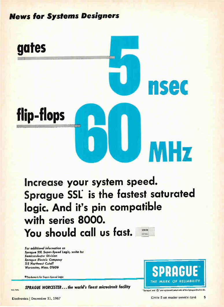
Galvanometer with brains
ESI has combined the best features
of the classic galvanometer and the
modern electronic voltmeter in the
Model 900 Nanovolt Galvanometer.
How do you create a galvanometer with true nanovolt sensitivity that is really practical to use ... an instru-ment that doesn't require hours of delicate dial twiddling, trapdoor ad-justments or experimental hook-ups? You give it brains. Brains in the
form of feedback circuits that auto-matically control speed of response and damping for each of its 12 cali-brated ranges. Our Model 900 Nan-ovolt Galvanometer operates from any source resistance without changes in speed of response or damping characteristics. Noise is less than 2 nanovolts for any source impedance. The instrument consists of two
units—the control unit shown above, which is the brains of the outfit, and a galvanometer unit. The Model 900 is ideal for use with high-accuracy and high-resolution potentiometers and bridges; for the calibration of thermo-couples, strain gauges, ther-mopiles, standard cells and the like. It also has applications in the mea-surement of tiny voltages or currents in experimental chemistry, physics, biology or medicine. A fixed input re-sistance of 1 kilohm allows calibrated ranges for both voltages and current. Through solid state circuitry,
we've been able to combine the best of two worlds in the Model 900. It has the high sensitivity and ac rejec-tion of mechanical galvanometers. But it also has the multiple cali-brated ranges, meter readout, and operation simplicity of modern elec-tronic voltmeters. It's an honest nanovoltmeter with high sensitivity and complete guarding to simplify measurements in the microvolt area.
You'll have more time to use your own brains if your galvanometer has some of its own.
ESI, 13900 NW Science Park Dr. Portland, Oregon 97229.
' Electro Scientific Industries IS 8
Electronics ; December 11, 1967 Circle 7 on reader service card 7

People
Now—a solid tantalum capacitor unbeatable at 1 MHz!
Designed particularly for computer and high frequency
power supply circuits, the THE has exceptional high fre-
quency characteristics.
At 1 MHz, it has half the impedance and double the ripple
current capacity of MIL-C-26655 solid tantalum capacitors.
Across the entire frequency band, capacitance change and
dissipation factor are lower than standard types. Tempera-
ture stability is excellent from —80° to +125°C.
Hermetically sealed construction. Available in MIL case
sizes C and D, in all capacitance values, 6 through 50 volts.
For data and samples, write Mallory Capacitor Company, a
division of P. R. Mallory &Co. Inc., Indianapolis, Ind. 46206.
Actual Size
MALLORY
November was an important month for Theodore H. Maiman. First his early work with ruby lasers was recognized with a patent, some 61/2 years after it was applied for. Then he re-signed as presi-dent of the Ko-rad Corp., the Santa Monica,
Theodore Maiman Calif., laser manufacturing firm he founded in 1962. Korad is being absorbed into its parent organization, the Union Carbide Corp. Maiman, 40, says Korad will be-
come the laser department within Union Carbide's Electronics divi-sion about Jan. 1, and he did not want to be part of the larger cor-poration. He is considering several offers from universities and indus-try to do research work. He will also be "very seriously looking into the possibility of founding a new company." Maiman will get no cash benefits
from the laser patent, which is as-signed to the Hughes Aircraft Co., where he was employed when he first made a ruby laser work in May 1960. He believes the patent award will trigger tests of the validity of a patent granted early in 1960 to Charles H. Townes and Arthur Schawlow covering optical and in-frared masers. Townes was at Co-lumbia University and Schawlow at Bell Telephone Laboratories when they developed the concept on which their patent was granted. Made it work. The theory out-
lined in that patent certainly is in doubt, Maiman asserts. "Patents are supposed to contain informa-tion that can be used by a person skilled in the art to make the prin-ciples work." He maintains that no one has been able to produce a functioning laser based on the ear-lier patent, "and it isn't because incompetent people have been try-ing it."
National Semiconductor Corp., less than a year after moving West, is expanding rapidly—both in new
8 Circle 8 on reader service card Electronics December 11, 1967

Performance inversely proportional to price.
No need to restrict your applications when using X-Y recorders. The newliewlett-Packard 7035B (81/2"x 11") and the 7005B (11"x 17") X-Y Recorders offer you dynamic performance better than ever before on low-cost recorders. Now applications are extended to microwave sweep testing with the same reliability and performance.
These recorders have high input impedance, floating, guarded input and 0.2% accuracy at full scale. Sensitivity
HEWLETT
The prices are very low.
from 1 mv/inch to 10 V/inch. No interaction between channels, with independent servo system for each axis, and the exclusive AUTOGRIP paper holddown reduces maintenance to occasional wiping of the surface. Bench or rack-mount. Price: 7035B, $945; 7005B, $1195.
For more information call your local HP field engineer or write Hewlett-Packard, Palo Alto, Calif. 94304; Europe: 54 Route des Acacias, Geneva.
PACKARD
GRAPH IC
Electronics l December 11, 1967
RECORDERS 117C23
Circle 9 on reader service card 9

0 eve te te tee
Do you have this new capacitor data?
DIPPED MICAS ... for entertainment and commercial equipment Single-film silvered-mica capacitors cost less than stacked mica or ceramic types. These capacitors are rated at 300 WVDC and have good stability and retrace characteristics over their operating temperature range of -55C to +85C. Capacitance values from 10 to 360 pF, -±-5% are available. Put this quality and performance into your next design. Ask for Engineering Bulletin 1010.
CIRCLE READER SERVICE NUMBER 506
SPARK GAPS and GAP CAPACITORS . . . for TV tube protection Spark gaps and gap capacitors suppress transient voltage surges and protect your expensive picture tube and allied circuitry. Spark gaps are available in 1.5 kV and 2.5 kV ratings with less than .75 pF capacitance. The gap capaci-tor is an air gap in parallel with a .01µF disc capacitor. All Sprague spark gaps and gap capacitors are 100% tested to insure your circuitry. Use them to protect your picture tube warranty. Ask for Engineering Bulletin 6145.
CIRCLE READER SERVICE NUMBER 507
DISC CERAMICS ... for general, temperature-compensating, and low-voltage applications in industrial, commercial, and consumer equipment
Cera-inite® general application discs for bypass and cou-pling at low cost. Nine disc sizes from .300 to .875 inches have 100, 250, 500, and 1000 WVDC ratings, in standard or temperature-stable formulations. Dual-section discs have up to .022e @ 1000 V. Ask for Engineering Bulletin 6101D.
CIRCLE READER SERVICE NUMBER 508
.4111,4.APPIXATION Doc one...woes
IIMP1.11.1.M.M.04.1113N0
ass CAPACTIORS
e, e
Cera-mite temperature-compensating discs for controlled capacitance change with temperature in R-F oscillators, precision amplifiers, timing circuits, other critical applica-tions. Select from ten linear temperature coefficients from NPO to N2200. Capacitance values from 1 to 2200 pF with 1000 WVDC ratings are available, plus popular values at 3000, 4000, and 5000 WVDC for TV yoke circuits. Mini-fied units in 250 WVDC ratings may be obtained with capacitance values ranging from 22 to 990 pF. Ask for En-gineering Bulletin 6102B.
CIRCLE READER SERVICE NUMBER 509
Hypercon® ultra-high capacitance discs for low-voltage circuits. Replace electrolytics with non-polar Hypercon capacitors only a fraction as large. The 2.2µF, 3 volt disc has a diameter of .875 inches; the 0.1µ,F, 25 volt unit measures .750 inches. Ask for Engineering Bulletin 6141F.
CIRCLE READER SERVICE NUMBER 510
For bulletins in which you are interested, write Technical Literature Service, Sprague Electric Co.,
25 Marshall St., North Adams, Mass. 01247
SPRAGUE COMPONENTS
CAPACITORS
TRANSISTORS RESISTORS
INTEGRATED CIRCUITS THIN-FILM MICROCIRCUITS
INTERFERENCE FILTERS
'Sc.,,,'
PACKAGED COMPONENT ASSEMBLIES FUNCTIONAL DIGITAL CIRCUITS MAGNETIC COMPONENTS
PULSE TRANSFORMERS
CERAMIC-BASE PRINTED NETWORKS PULSE-FORMING NETWORKS
SPRAGUE® THE MARK OF RELIABILITY
'Sprague and •,:e' ate fetostefed trademarks of the Sprague Elestoc Co.
People
products and manpower. Latest to join the ranks of the Santa Clara, Calif., manufacturer are Robert A. Hirschfeld, an expert in high-fre-quency I inear devices, and Thomas R. Thorkelson, an expert in digital devices.
Hirschfeld, 27, comes from Amelco Semiconductor, a sub-sidiary of Teledyne Inc., and Thor-kelson, 31, moves over from Texas Instruments.
Hirschfeld takes over as section head in the linear integrated-circuit department. "We're not sure yet how much we will second-source
R.A. Hirschfeld T.R. Thorkelson
or originate," he says, "but we're committing ourselves to the com-munications circuit business."
Says Hirschfeld: "The state of the market is such that there is little other than radio- and inter-mediate-frequency amplifiers. The state of the art, however, is far more advanced." He will investi-gate circuit functions and change a number of them. For example, he thinks there may be better ways to perform those now done by tran-sistors.
It is but isn't. Thorkelson is now in product marketing, managing the transistor-transistor-logic (TrL) line. For now, he points out, "we've accepted a second-source position with Tri., but we have some de-vices coming up that Texas Instru-ments doesn't have." Says Thorkel-son: "We want to present an image of similarity." National's DM7501, for example, resembles TI'S 5473 except that its construction is monolithic, its guaranteed clock skew is 15 nanoseconds instead of 10, and it is sealed hermetically. Thorkelson says National is de-
veloping an interface circuit be-tween semiconductor and Trx levels.
10 Electronics December 11, 1967

CH LEI)
AT VOA-GREENVILLE,N.C. MACHLETT ML-7482 VAPOR COOLED TRANSMITTING TUBES HAVE JUST LOGGED 645,000 HOURS.
Where dependable, high power counts— as at the Voice of America's 4.8 megawatt Greenville. N. C., relay station— specify Machlett transmitting tubes.
Available now: the new short form catalog from The Machlett Laboratories, Inc., 1063 Hope Street, Stamford, Conn. 06907. ezZt
Le>=11.
RAYTHEON
II THE MACHLETT LABORATORIES, INC.
A SUBSIDIARY OF RAYTHEON COMPANY
Electronics December 11, 1967 Circle 11 on reader service card 11

MI111111111111111111111111
.1111111111 III111111.1 1111111 1111111
.. wee, ...... ...... , 11114414#431414111.141411111111hi lingeliii; hi; ...... ¡Milli
, 11}h-4tiit17ilinv1riri' '1 1 111. 111. , —11 11,'11,1',,,,,,!!!!!!!...111!!!!!!!!!e! . ! .. !W.!it
111111111 11:4:11¡.j.141111111..111:11111111UUMUM11111111111 ... . 11 . ; ;q;¡;;;¡; •;;.1.;;" ...... nr; .. ;;;"" ...... ; ;;;:a;
111.41•1111111111111111. .....
WM1111111111 111111MttlIIMMIttlIt11 111111111111114111111f0tNitt111
Ill
III
MUM t11111ifittl
1 1114111141 4114à/41/141 .11âWi1J1111111111W1
iii t I !I I " "" I""
111 111 minimal 111111111
11111111111 11 1, 1
1121111 11, 11
Imo IL I " 1111111111 ihWeNtl,
II !WI!!
mu muumuu Im 111111 1 1110110 Ílllêllllltll III iillij1111111#111111114111 !NMI I!"" 11111 1111111m I Ill amen,
Eint 110 . ear"
"it was a very good y for 1\,A0TooLi\
Integrated Circuits
...............
111111 11111u11 11i1111111 11 .$$$ I ii 1 mom 1111. TM I 111111111 e hitUmmt1111111.te sip 1140111 1.11 11111111111q14
Ill MIIII 11111m Ill 1 1,11
t t mini Hill:11"1.1:1'I'llii MA,' u!!!!!!!!...,,i.!. 11 U I HIM OUR
in .11it rn u1 7 .11.11.1.111 I
1! . 1111UIPM11.1
111 u1 '''T1'7UMUMITMITI1TereUttre1r1Tre111eri.,1111 ... 111
1111M1111111 111111111111 ........... ..... ............. ......... . ............ ...... „ , ............
IMUft [11 i/
Hit 111111;;;;;;;;,;1111; ;11 ..... .. ......
11H t immun 1,11,674.111elliiiriMien25 T. .
e ll imintutmrymrommpre!"," 1111411....1111111111111111r"
..
11-1.1.1p,ffmn- ..... . . .
till ifluini 111111 mum 1111 H1111e111H1111 11111 1111! Mtn 1111 IM11 nuntm nut 11 .. ..
...... ' ....... " ................... ' ............. ..
1110 11 1H 111111
cie›
II 111111 11 111 mu Hu 11111 Mull 11111 11 111111111111 It
wÁe il'eAlledesd ihezedie, £4. ea/zei
12 Electronics December 11, 1967

In Motorola's
"It was a very good year"
Integrated Circuits Contest
Here's your chance to win $1,000 cash. And, it's almost as easy as writing your own name! Simply fill out the coupon below with your best guesses of the number of standard integrated circuits Motorola has formally introduced this year through its franchised distributors, in each linear and logic family.
HERE ARE SOME ADDITIONAL HINTS TO HELP YOU WIN $1,000
• As of October 31, Motorola has introduced 11 new MDTL logic circuits this year. More to come!
• As of November 30, Motorola has introduced 18 MECL integrated logic circuits. Still more on the way!
• Motorola has introduced 15 MTTL integrated logic circuits as of November 15 — and still more coming!
The entry that provides the exact or most nearly exact figures for each circuit category, and the resulting correct grand total, will be declared the winner. In case of ties, the Grand Prize will be divided equally among the winners. (Decision of the Motorola judges will be final, of course.)
I think that Motorola will have introduced the following numbers of new integrated circuits during the past year:
Number of Circuit Family Circuits:
MDTL (diode-transistor logic)
MRTL (resistor-transistor logic)
MTTL (transistor-transistor logic)
MECL (emitter-coupled logic)
Number of Circuit Family Circuits:
MHTL (high-threshold logic)
I/C Operational Amplifiers
I/C Diff./Sense Amplifiers
I/C Video, RF & IF Amplifiers
GRAND TOTAL
NAME TITLE
COMPANY
ADDRESS
CITY
V/DEPT
STATE ZIP CODE
MOTOROLA Semiconductors P.O. BOX 955, PHOENIX, ARIZONA 85001
ef3Cietw4ht...
Everyone who guesses the correct grand total (even though the individual circuit categories may be inaccurate) will receive a copy of the Frank Sinatra stereo album, that features "It Was a Very Good Year." So, enter your guesses now (one per en-trant, please) ... just make sure that your entry is postmarked no later than Decem-ber 23, 1967. Winning totals will be an-nounced after the contest closes.
Employees of Motorola Semiconductor Products Inc. and Motorola Inc., Semicon-ductor Products division, and its distribu-tors are not eligible. Contest is void where prohibited by law or by participant's company policy.
Electronics I December 11, 1967 13
JUST OFF THE. PRESS\
•-•41r
te. - „
,--rrrem 1..• re._ .1, --
RCL's NEW RESISTOR CATALOG the industry's most exten-sive and most accurate compilation of engineering information on wire-wound resistors
PRECISION/HI-SPEED POWER/WIRE-WOUND
RESISTORS
including: beryllium oxide core power resistors . . . 22 special temperature co-efficients from — 50 PPM to +6000 PPM . . . sub-miniature precision resis-tors . . . ladder and sum-ming networks.
Write for your free copy today!
RL ELECTRONICS, INC. 700 South 21st Street Irvington, New Jersey 07111
Meetings
Symposium on Reliability, IEEE; Sheraton-Boston Hotel, Boston, Jan. 16-18.
Power Meeting, IEEE; Statler-Hilton Hotel, New York, Jan. 28-Feb. 2.
Aerospace and Electronic Systems Convention, IEEE; International Hotel, Los Angeles, Feb. 13-15.*
International Solid-State Circuits Conference, IEEE; Sheraton Hotel, Philadelphia, Feb. 14-16.
Scintillation and Semiconductor Counter Symposium, IEEE; Shoreham Hotel, Washington, Feb. 28-March 1.
International Convention and Exhibition, IEEE; New York Coliseum and New York Hilton Hotel, New York, March 18-21.
Symposium on Microwave Power, International Microwave Power Institute; Statler Hilton Hotel, New York, March 21-23.
Joint Railroad Conference, IEEE; Conrad Hilton Hotel, Chicago, March 27-28.
International Magnetics Conference, IEEE; Sheraton Park Hotel, Washington, April 3-5.
Business Aircraft Meeting and Engineering Display, Society of Automotive Engineers; Broadview Hotel, Wichita, Kan., April 3-5.
Telemetering Conference, IEEE; Shamrock Hilton Hotel, Houston, April 9-11.
International Pulse Symposium, International Federation of Automatic Control; Budapest, Hungary, April 9-11.
Symposium on Law Enforcement Science and Technology, Illinois Institute of Technology Research; Chicago, April 16-18.
Southwestern Conference and Exhibition, IEEE; Sheraton Lincoln Hotel, Houston, April 17-19.
Frequency Control Symposium, U.S. Army Electronics Command; Shelburne Hotel, Atlantic City, N.J., April 22-24.
Region Ill Meeting, IEEE; Fontainebleau Motor Hotel, New Orleans, April 22-24.
Relay Conference, National Association of Relay Manufacturers and School of Electrical Engineering, Oklahoma State University; Stillwater, Okla., April 23-24.
Short Courses
Data communications, American University's Center for Technology and Administration, Washington, Feb. 5-8; $175 fee.
Precision and accuracy in measurements and calibration, Department of Commerce, National Bureau of Standards, Washington, Feb. 12-15; $100 fee.
Electronic circuit design by computers, National Electronics Conference, Pleasant Run Lodge, St. Charles, Ill., Feb. 19-21; $375 fee.
Call for papers
Microelectronic Packaging and Inter-connection Conference, Society of Auto-motive Engineers; Rickey's Hyatt House Hotel, Palo Alto, Calif., Nov. 20-22. Dec. 29 is deadline for submis-sion of abstracts to D.H. O'Neill, Society of Automotive Engineers, 485 Lexington Ave., New York 10017
Meeting of the Avionics Panel of the Advisory Group for Aerospace Research and Development on Techniques for Data Handling in Tactical Systems, Avionics Panel of the Advisory Group for Aerospace Research and Develop-ment; Amsterdam, Netherlands, Sept. 1968. March 1 is deadline for submis-sion of abstracts to Dr. Irving J. Gabel-man, program manager, Advanced Studies Group, RADC (EMD) Griffis AFB, N.Y. 13440
Association for Computing Machinery Conference and Exposition, Association for Computing Machinery; Las Vegas, Aug. 27-29. March 1 is deadline for submission of papers to Marvin W. Ehlers, program chairman, Ehlers, Maremont & Co., Inc., 57 West Grand Ave., Chicago. 60610
* Meeting preview on page 16.
14 Circle 14 on reader service card Electronics December 11, 1967

In the words of Virginia Woolf, iVs time for fun and games. For this new national pastime, you
simply need a smattering of history, mythology and current events. And some information about Microdot's cable prod-ucts. We'll supply you with the latter. For the rest, go listen to Walter Cronkite. We got started on this activity while
we were sitting around one evening with a bottle of Slivovitz (we ran out of Scotch), trying to think of memorable ways to remind you of the various unique features of Microdot cables. Like—
Like our Mini-Noise cable— reduces noise voltage from shock and vibration by a factor of more than 100 to 1 com-pared to untreated cable. This makes pos-sible the transmission of extremely faint signals through coax cable without audio frequency noise. Off-the-shelf.
Like our microminiature coax cable — uses a fine silver-plated copper steel-covered wire. You get 50 ohm impedance, and even with the addition of dielectric, outer shield and protective jacket, the nominal O.D. does not exceed .080". And we can get that O. D. down to .025" in a range of hundreds of different cables.
Like our new complete in-house capa-bility to produce precision quality multi-conductor cables, which includes twisting, extruding, shielding and jacket-ing—the whole deal. All under one roof. And we can cable hundreds of con-ductors into one unit.
Like we're the only one to produce a high temperature, low weight, low capa-citance coax cable through the use of a cellular Teflon dielectric. Especially suited to the requirements of video tape recorders.
THE connector THING A periodical periodical designed to further the sales of Microdot Inc. connectors and cables. Published entirely in the interest of profit.
everagbodg wine Pla9 ierodot
13toriectl
Like Microdot's Twinaxial cable —to be used when you need to send two signals from a single source which must both terminate at the same point. No need to use two coax cables; therefore lower cost and greater flexibility. Now when you
think of cables, you think of cablegrams. And when you drink a lot of Slivovitz, it sort of takes you back through time and you come up with stuff like this:
ghetli
WIN YOUR
OWN CABLE FORK
Low noise Spaghetti-Gram: You lose. Signed, Calvin Coolidge:'
High temperature Spaghetti-Gram: "Julius, honey, ain't nobody honte tonight but me. Signed, Cleopatra:'
Miniature size Spaghetti-Gram: "Cancel that order for bras. Signed, Twiggy:'
Dual shield Spaghetti-Gram: "I can lick any guy in the joint. Signed, Brunhilde!'
Large size multiconductor Spaghetti-Gram:
"Send more elephants. Signed, Hannibal!'
Get the idea. You can use any of the fea-tures of any of our cable products, such as low noise (Mini-Noise), special requirements (Multiconductors), high temperature, low weight, and, of course, small size. You don't really need the Slivovitz. It works well even with Sanka.
About the fork No, Melvin, we won't explain the relation-ship between cable and spaghetti. We call
• it a cable fork, and if you don't want to use it for eating cables that's your prob-
lem. The manufacturer describes this handy gadget as a "revolutionary breakthrough that leaps for-
ward from antiquated hand labor to the modern machine age!" We won't try to top that. We'll just explain that you stick it into the pasta and then turn the little handle to save getting spaghetti all over your celluloid collar. Want one for your very own? Okay.
Just send us a Microdot Spaghetti-Gram scribbled on company stationery and tak-ing off from any of the product features we've discussed. We'll send you a beau-tiful cable fork along with more litera-ture on our cable products than we care to mention.
But hurry. We've already run out of Slivovitz. It won't be long before we run out of cable forks. (That means offer is limited.)
FF)
MICR.ODOT INC 220 Pasadena Avenue
• South Pasadena, Calif. 91030.
Mini-Noise is a registered trade-mark of Microdot Inc. Cable Fork is open to question.
Electronics December 11, 1967 Circle 15 on reader service card 15

LESS DRIVE
POWER with Contiguous Comb Filter Sets by Damon
Damon has produced a bank of 200 contiguous comb crystal filters that requires a total of 6.6 watts of drive power to obtain 10 milliwatts from each of the Gaussian (non-overshoot) response filters. This is only 1/121 of the 800 watts of drive power normally required to achieve the same output using conventional re-sistive padding techniques.
This significant achievement is the result of two advances in crystal filter technology: high efficiency contiguous comb crystal filters com-bined w'th new synthesis techniques. These advances permit the adher-ence to both frequency and time response specifications and offer a
Typical Contiguous Comb Crystal Filter,
Model 5107A is 1 %6" Lx w x 7/Ei
new concept in the design of radar and other spectrum-based systems. Contiguous comb crystal filter banks are also the most reliable, efficient, compact and economical precision systems available for multichannel signal processing of all kinds.
Write for data on Gaussian Re-sponse Contiguous Comb Crystal Filters to Damon Engineering, Inc., Needham Heights, Mass. 02194, Tel. (617) 449-0800.
DAMON
Meeting preview
Computers and automata
Computers and communications will get the lion's share of attention at the ninth annual \ Vinter Con-vention on Aerospace and Elec-tronic Systems (Wincon) Feb. 13 to 15 at the International Hotel in Los Angeles. There will be three ses-sions on computers, including the Von Neumann general panel ses-sion, which will be chaired by Eu-gene Fubini, a vice president of the International Business Machines. Theme of the Von Neumann ses-
sion is Automata—Their Past, Present and Potential. Arthur W. Burks, chairman of the communica-tions sciences department at the University of Michigan, will dis-cuss self-reproducing automata, taking a philosophical look at fu-ture approaches to computer design that will produce machines at least as complex as the computer itself. Today's machines produce outputs substantially less complex than the machines. Herman H. Goldstine, di-rector of scientific development at IBM'S Data Processing division, will analyze what must be done to make computers less susceptible to shut-down when component failures oc-cur. Herbert Simon, a professor at Carnegie-Mellon University, will discuss artificial intelligence. Two other computer sessions
will deal with future trends, one from the producer's point of view and the other from the user's.
In one of two unclassified com-munications sessions, Sigmund Rei-ger, a vice president of the Com-munications Satellite Corp., will discuss traffic projections and dis-tribution of anticipated interna-tional service through 1975, cover-ing both satellite and cable-trans-mission techniques. As part of the same session, CBS Laboratories en-gineer James Parker will consider advances in technology needed to meet increasing communications demands. Another unclassified communica-
tions session will focus on projected technology, including wideband ca-ble systems, digital communica-tions techniques, direct broadcast satellites, and urban communica-tion systems.
16 Circle 16 on reader service card Electronics December 11, 1967

100V 100V NL NL FL
NOW... a low-cost line-voltage
regulator for every bench ...for every rack
Rack model, $325 in U.S.A. (115 V)
1591 Variace Automatic Voltage Regulator, $295 in U.S.A. (115 V)
High performance, proven reliability, small
size, and low cost are the key words that
identify GR's new 1-kVA line-voltage
regulator.
By performance we mean that this regulator will maintain a 115-volt output (adjustable
from 105 to 125 volts) within ±0.2 percent for simultaneous variations of: input-line
voltage from 100 to 130 volts, load from no load to full load, power factor from 1.0 to 0
leading or lagging, and line frequency over
a range of ±10%.
By reliability we mean continued high
performance even under conditions far
worse than those any regulator is likely to
encounter in actual use. The tests indicated
on the above chart were performed on a randomly selected unit that had already
been subjected to a one-year, round-the-
clock life test plus an accelerated life test in which the input signal was modulated at a
3.5-hertz rate. At the time this recording
was made, the motor-gear train, Variac®
autotransformer, and control circuitry had
been subjected to 10 million oscillations
while operating at nearly full-load rating. No
lubrication or adjustments were required.
By small size we mean 123% x 9 x5% inches and a weight of 17 pounds for the portable
model.
By low cost we mean a price of $295 for a
single portable model; rack and 230-volt
models are slightly higher. Quantity dis-
counts are available for all models.
Because there is no distortion added to the
input waveform, average and peak voltage
values are held as constant as the rms
value. Response time is 6 cycles +1.5 cycles
per volt under worst conditions for the
115-volt model.
For complete information, write General
Radio Company, W. Concord, Mass. 01781;
telephone (617) 369-4400; TWX (710)
347-1051.
GENERAL RADIO Circle 17 on reader service card

nobody else,
18 Electronics December 11, 1967

that's who delivers all these epoxies.
TO-105, TO-106, or In-Line. We make them all. From us, you get what you need, not just what we have to offer. Choose from over 100 different small signal, medium-power silicon transistors, either NPN or PNP.
So why waste a lot of time skipping between company A which offers only one epoxy package and company B or C which only makes one or two other types?
We're big in the epoxy business and getting bigger, but who knows it. Write for data and distributor list, then tell your friends.
National Semiconductor Corporation, 2975 San Ysidro Way, Santa Clara, California 95051 (408) 245-4320.
National Semiconductor
Electronics December 11, 1967 Circle 19 on reader service card 19
i1111«.1111061111,0111111111101•01•11114
e ROHDE 4 eMWAR2 Of 44Cte"2-4R .44 4444S-SE44144. -SO 4414 DECAIM S1GNAI. afr•e.RATOR TVP£ 5$4041 Mama
Cio i;
•
MHz kHz Hz
V. I» fie 4-0 41
40-
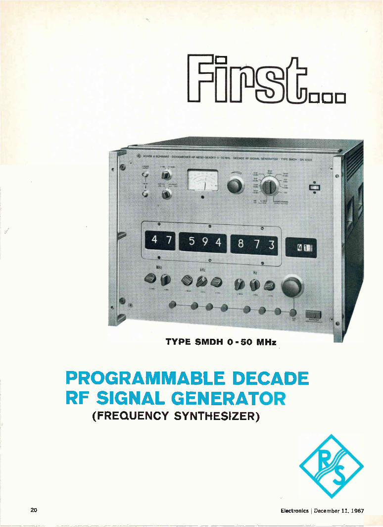
TYPE SMDH 0-50 MHz
PROGRAMMABLE DECADE RF SIGNAL GENERATOR
(FREQUENCY SYNTHESIZER)
20 Electronics , December 11, 1967

First With Commercial Frequency Synthesizer
First With True UHF Synthesizer (0.4740 GHz)
NOW, FIRST WITH PROGRAMMABLE RF SIGNAL GENERATOR In 1954 Rohde & Schwarz introduced a new type of signal source, continuously variable in frequency but with crystal stability. We called it the Type XUA Fre-quency Synthesizer. Hundreds of these instruments found homes in leading laboratories and production centers throughout the U.S.A. Most of them are still fully on the job. Since then we have developed 15 other models, including a complete series of Exciters for communications control of transmitters and high quality receivers.
We now take great pride in announcing our Type SMDH, an instrument which sets new standards of performance. This unit is more than just another synthesizer; it is a Programmable RF Signal Generator from 0-50 MHz. It provides variable calibrated output voltages (0.10-2.5V), modulation capability (AM & FM), and excellent stability (1 x 10 -9/day ). Since many applications of a synthe-sizer involve frequency multiplication, we have designed the Type SMDH to have the highest spectral purity -- 100 dB. To achieve this, a completely new method of internal shielding had to be developed. Also a new modular frequency standard was required with 130 dB signal/noise.
To meet the demands of automatic check-out systems and high speed production testing, we made the instru-ment programmable. Using a standard 10-line code, we can provide a new frequency in 100 kts maximum time. We can actually "switch" frequencies in 20 ,us like other synthesizers; however, let's make an honest appraisal. In addition to switching the digits, there is time required for the command (the old frequency is still on during the command time), and filter recovery time to assure full spectral purity. This is true for any synthesizer. Also we've designed a Programmable At-tenuator, Type DPHP, with a range of 0-99.9 dB using the 10-line code. You can now have the capability of both programmable frequency and level.
Another important feature is our eight digit, in-line dis-play tube readout. Remember when industry abandoned the hard-to-read staggered column readout on counters? Our readout is operative even in the programming mode. This feature provides a visual check verifying the pro-gram. It spots any operator or equipment error. Switch from program to manual control with a program still on the line without any ambiguity in output frequency. Careful elimination of ground loops makes this possible.
We do not utilize phase locked loops which impair short term stability. Our reference holds ± 3 x10 -- "/second. Included is an interpolation oscillator which can be used for search applications (continuously variable to 1.1 MHz) or as a vernier to the crystal digit decades. It provides an in-line numeric read-out from 0-111 with an additional 50 division vernier. Typical stability is one-half division on the vernier scale. Another feature is switchable automatic leveling to 0.5 dB. Type SMDH is all-silicon solid state design utilizing modular con-struction for easy servicing. An optional battery supply is available. Yet with all of the features of this Pro-grammable RF Signal Generator, it is competitively priced with 50 MHz synthesizers.
For communication applications, our new No. 280 Pro-grammable Exciter incorporates those specifications and features required for transmitter and receiver con-trol, with the price savings passed on to the customer.
R & S maintains its philosophy of a well-balanced de-sign — meaning the optimizing of all significant speci-fications. Judging from advertising, it appears that everyone is making frequency synthesizers today. But really good synthesizer design is a very tricky business. We should know; we've been designing them for 15 years — and after all, Rohde & Schwarz is still the leader. We're trying to maintain a stock position for immediate delivery, but with all its features and speci-fications we expect a heavy demand.
ROHDE 8t SCHWARZ 111 LEXINGTON AVENUE, PASSAIC, N. J. 07055 • 201 - 773-8010
Inquiries outside the U.S.A. should be made to: Rohde 8< Schwarz, Muehldorfstrasse 15, Munchen 8, West Germany
Electronics December 11, 1967 Circle 21 on reader service card 21

Design Sealed Delivered Helipot's New Model 77P Cermet Trimming Potentiometer
Here's the new Model 77P, the first low-cost, general pur-pose trimmer with a sealed housing and cermet resis-tance element! DESIGNED to wider performance para-meters than any other adjustment potentiometer in its
price range. It is directly interchangeable with com-petitive Models 3067 and 3068—SEALED to permit P.C.
board solvent cleaning and potting without trimmer con-tamination or failure—DELIVERED from local stock at the low list price of $1.95. In large quantities, Model 77P
sells for as little as $1.10. • Compare Model 77P specifi-cations with those of unsealed trimmers, then call your local Helipot representative for an evaluation sample.
_ e
Helitrim Model 77P
elFMIle Model 3067 Wirewound
reFir Model 3068
Carbon
Resistance Range, ohms 10 - 2 meg 50 - 20K 20K - 1 meg
Resolution Essentially Infinite
1.7 (100) to 0.3 (20K)
Essentially Infinite
Sealing Yes No No
Power Rating, watts 0.75 0.5 0.2
Maximum Operating Temp. °C
105 85 85
Beckman INSTRUMENTS, INC.
HELIPOT DIVISION
FULLERTON, CALIFORNIA • 92634
INTERNATIONAL SUBSIDIARIES: GENEVA; MUNICH; GLENROTHES, SCOTLAND; TOKYO; PARIS; CAPETOWN; LONDON; MEXICO CITY
22 Circle 22 on reader service card Electronics ¡ December 11, 1967

Electronics
Commentary
Nippon at our heels
December 11, 1967
The semiconductor is the essential ingredient of Japan's electronics business. Many Japanese be-lieve, and probably rightly, that their country would not occupy second place in world elec-tronics activity—behind the U.S.—if it weren't for the quick acceptance of the transistor by Japanese engineers in the early 1950's. So semiconductor technology has become the
most important concern of Japanese electronics firms, and a look at progress in that technology supplies a tip to what's happening with Japa-nese companies and products. The special report on page 107 shows that the Japanese are picking their R&D projects carefully to augment their al-ready considerable strengths with new discrete, optoelectronic, and bulk-effect devices.
There's a lot to be learned from what the Japa-nese are doing. Although they still build on others' basic technology, most notably American, they tend to add unique twists to processing and design and are particularly ingenious in finding new applications. They are adept at spotting strategic gaps in product lines.
In fact, the Japanese start in semiconductors can be traced back to that unusual ingenuity. When U.S. engineers were applying transistors only to computers and military gear, it was the Japanese who first saw the potential of transis-torized consumer products. They started the tran-sistor-radio craze and used solid state devices in phonographs, television sets and tape record-ers. The Japanese remain a force to be reckoned
with in the consumer products field, and they are also building an impressive record in the area of solid state communications. The communica-tions networks growing throughout Asia bear a clearly identifiable made-in-Japan look. Many U.S. companies are envious of the inte-
grated structure Japanese industry enjoys, a structure that would send the Justice Department rushing to courtrooms if it were copied here. The key is that every firm in Japan knows a lot about what everybody else is doing in fundamental re-search (though production techniques are pro-
prietary and are closely guarded). The ubiquitious Ministry of International
Trade and Industry (mm) maintains close scru-tiny over research and development, frowning on duplication of projects.
Japanese financial resources are skimpy—most companies are financed by bank debt rather than stockholders' equity—and if the management of a company doesn't discourage duplication of research efforts, Mm will step in. Through gov-ernment laboratories it operates and universities, the agency keeps tabs on what every company is doing. It helps parcel out research projects and encourages many of them even though paying only a small percentage of the cost.
Since many equipment companies are also semiconductor producers, the engineers who de-sign and produce semiconductors for these firms work within the same corporate structure as do the engineers designing the end products. Top management pressures these engineers to exchange information, and equipment designers who tend to be more conservative than semi-conductor engineers, aren't allowed to hold up the adoption of new devices.
Since the managements of most Japanese com-panies still view their research laboratories as incubators for new products, most of what Amer-ican engineers would call pure research takes place at Japanese universities.
So, for a comprehensive report on work in optoelectronics, the place to go is Tohoku Uni-versity in Sendai [p. 117]; advanced communica-tions research has top priority at Tokyo Univer-sity, and what's happening in Japan with Gunn and other bulk-effect devices is learned quickest from the school's researchers [p. 125]; and for a rundown on more prosaic devices, particularly those designed for high-frequency communica-tions applications, the place to go is the Elec-trical Communications Laboratory of the Nippon Telegraph & Telephone Public Corp. [p. 110]. Impressive as the Japanese effort is, the men
of Nippon are not perfect. They are following U.S. manufacturers down one garden path: the road to overcapacity. Incurably optimistic, Japa-nese semiconductor producers have expanded and expanded manufacturing capacity. Last year's unit sales remained relatively stable, but output capacity climbed sharply. And Japan next year will undergo a typically American experi-ence: widespread price-cutting to stimulate sales of discrete semiconductors.
Electronics December 11, 1967 23

LT 1.9
\
0,4 PERIALANCE COVEICIENT-21 13 25 10 31 Cl 60 110 10
\ \ \ \ \ \ \S\I \ 1 1111
EINEROTI1ROOUCT—Odéldx101 o y
5
2_
.1_
INTRINSIC CUR
Li II
10 2.5 .0 15 DEMAGNETIZING FORCE—N-111LO OERSTEDS
e
1.1
With a coercive force of 3200 oer-steds, Indox 7 has a higher resis-tance to demagnetization than any commercially available magnetic material except costly platinum-cobalt. It also has a high peak energy product and high intrinsic coercive force. New Indox 7 requires no critical
materials, is light weight and has high electrical resistance. Indox 7 opens new possibilities for de-signs and applications where greater resistance to demagne-
. tization is required, or where the
magnet length is limited compared to the magnet area. Indiana General pioneered ce-
ramic magnets, developed the first ceramic magnet for PM motors, and continues it's leadership in magnet technology with this new high in ceramic magnet materials. For a copy of the new bulletin on Indox 7, write Mr. C. H. Repenn, Manager of Sales, Magnet Divi-sion, Indiana General Corporation, Valparaiso, Indiana.
INDIANA GENERAL Ea
When it comes to resisting demagnetization, new Indox® 7 is in a class by itself.
Summa Cum Oersteds.
1967, The Indiana General Corporation

Electronics Newsletter
December 11, 1967
Intelsat 3 woes
make Comsat weigh
Hughes bid ...
... to supply
improved Intelsat 2
Lighter lighting
from RCA
Development problems with the Intelsat 3 satellite next month may force Comsat to buy an upgraded version of the Intelsat 2—the workhorse of the International Telecommunications Satellite Consortium. The possibility of falling back on Hughes Aircraft's earlier proposal for
a souped-up Intelsat 2 arose after a quick trip to TRW Systems, the Intel-sat 3 builder, by top Comsat officials [see p. 155]. They are understood to have given TRW until late this month to solve the Intelsat 3 problems, but insiders say Comsat's management isn't very optimistic.
Intelsat's Interim Committee, briefed last week on the situation, has directed a Comsat technical team to take a hard look at Intelsat 3 work and set a realistic delivery date, and another team to go over the Intelsat 2.5 design with Hughes. Both will report within two weeks. If Comsat decides it wants to buy the Hughes craft, the committee will hold an emergency meeting early in January. Intelsat 3 delivery, originally set for March, has slipped to August. The problems in the Intelsat 3, which is slated for Comsat's first global
system, currently revolve around the communications subsystem being built by ITT, Comsat sources say. If the Hughes satellites are purchased, it could mean that Comsat will cut back its six-satellite order with TRW.
If Comsat decides to order the upgraded Intelsat 2—dubbed 2.5—from Hughes, it will buy two of the craft at a price of about $4 million each. Hughes has promised Comsat that it can deliver the first one by next July. The Intelsat 2.5 design would incorporate up to 1,000 channels, against
the 240 of the Intelsat 2. Hughes has claimed that the craft would be comparable to the Intelsat 3 global system." The 2.5, an improvement of the Hughes 303A design, would use an electronically despun, phased-array antenna to boost Intelsat 2's 15.5 dbw of effective radiated power to 25 dbw, according to earlier plans [Electronics, May 2, 1966, p. 86]. An improved transponder that would quadruple the bandwidth from 125 megahertz to 500 Mhz has also been proposed.
The semiconductor spotlight may soon focus on markets so far untouched by solid state technology: illumination on highways, in factories and offices, and movie and television studios. At RCA, in fact, switching and control circuits using power transistor and thyristor devices will soon be introduced, substantially reducing the bulk of lighting systems and bringing other benefits as well. RCA's Electronic Components and Devices division has developed a
number of new regulator circuits for these jobs, employing new power semiconductors that have high enough voltage (200 to 300 volts) and current (1 to 5 amperes) ratings to handle lighting and low enough price tags to compete with conventional gear. Present regulator circuitry con-sists of inductor-capacitor filter networks, but these heavy, large arrange-ments have drawbacks: the regulation they provide is barely adequate and a strobe-effect (flicker) occurs whenever line voltage makes a transi-tion through zero potential. RCA's circuits consists of a rectifier, a filter, and a variable on-time
switching regulator, plus a novel feedback arrangement that uses a
-0—Circle 24 on reader service card 25

Electronics Newsletter
series inductor. The new approach cuts ballast size and weight sharply, provides smoother regulation, and, because of a built-in memory capa-bility, eliminates the strobe effect.
$5,000 tester
for linear IC's
Competition
for the 703
in hi-fi's
Electronic detector
of diabetes sought
Engineers in Grumman Aircraft Engineering's microelectronics depart-ment have developed a low-cost (under $5,000), universal tester for linear integrated circuits. It's the first relatively inexpensive unit capable of performing dynamic as well as d-c measurements, and accommodating differential, operational, and communication-type amplifier circuits.
Instrumentation for linear circuits has been scant. The few systems on the market are priced at $40,000 and up, and usually measure only a few parameters on a static basis. The Grumman unit, which performs 22 parameter measurements, contains a programing matrix and has pro-visions for hook-up to either vacuum-tube voltmeters or crt's. The equipment will probably be marketed by mid-1968. The company,
new to both IC making and instrumentation manufacture, hasn't yet decided whether to build and market the gear itself.
With Fairchild Semiconductor's AA 703E and RCA's CA 3012 (a more complex f-m/i-f amplifier than the 703) now widely used by the leading high-fidelity component makers, rival linear IC producers are starting to take aim at the hi-fi market with competitive devices. Amelco Semiconductor is already marketing its 911C, which set makers
say is similar in characteristics and circuit configuration to Fairchild's 703E. And Philco-Ford has begun sampling its PA 770339, and Raytheon is sampling its RM 703T; both are copies of the 703. As a further fillip, one semiconductor firm is working on an automatic-
gain control version of the 703; the currently available 703's lack age.
The Public Health Service's National Center for Chronic Disease Control is looking for an electronic diabetes-screening device that could be used instead of a chemical analyzer to determine glucose levels in the blood. Although now specifically seeking proposals for a'portable chemical an-alyzer that could process 60 to 120 samples per hour and would cost less than $2,000, the center would prefer a device that could detect a diabetic condition through a sensor applied to the body. One possible approach, according to a medical electronics specialist, would be to measure the fluorescence that can be produced in an ear lobe.
FAA immunity ruling Even sharper demand for significant improvement in air-traffic control and collision-avoidance systems is expected as a result of a new FAA
seen aiding push ruling that is expected to foster more-frequent reporting of near mid-air for air safety crashes. The ruling, granting immunity to the pilots and the traffic con-
trollers—when they are at fault—should lead to the compilation of solid statistics on air-traffic congestion sought by the agency.
Pentagon to cut
Asia stockpiling
Purchases of many kinds of electronic parts and equipment by the De-fense Department will begin tapering off in the next few months in an effort to reduce overstocks in Southeast Asia. Items found to be in excess include avionics, radios, radars, and replacement parts for these items.
26 Electronics 1 December 11, 1967

TTL Trends
from Texas Instruments
This rack contains electronics for the new
Bunker-Ramo 2100 machine tool numerical control
system. By using Series 74 TTL complex-function ICs from Texas Instruments, B-R keeps costs far below that of other systems of
similar capability. At the same time, the already high
reliability is further increased by an order of magnitude, while noise
immunity and computing speed capability are also
greatly improved (see page B). Many OEMs are building greater business
opportunities for tomorrow by going with the complex-function TTL trend in their
product designs today.
w "ums- IBM
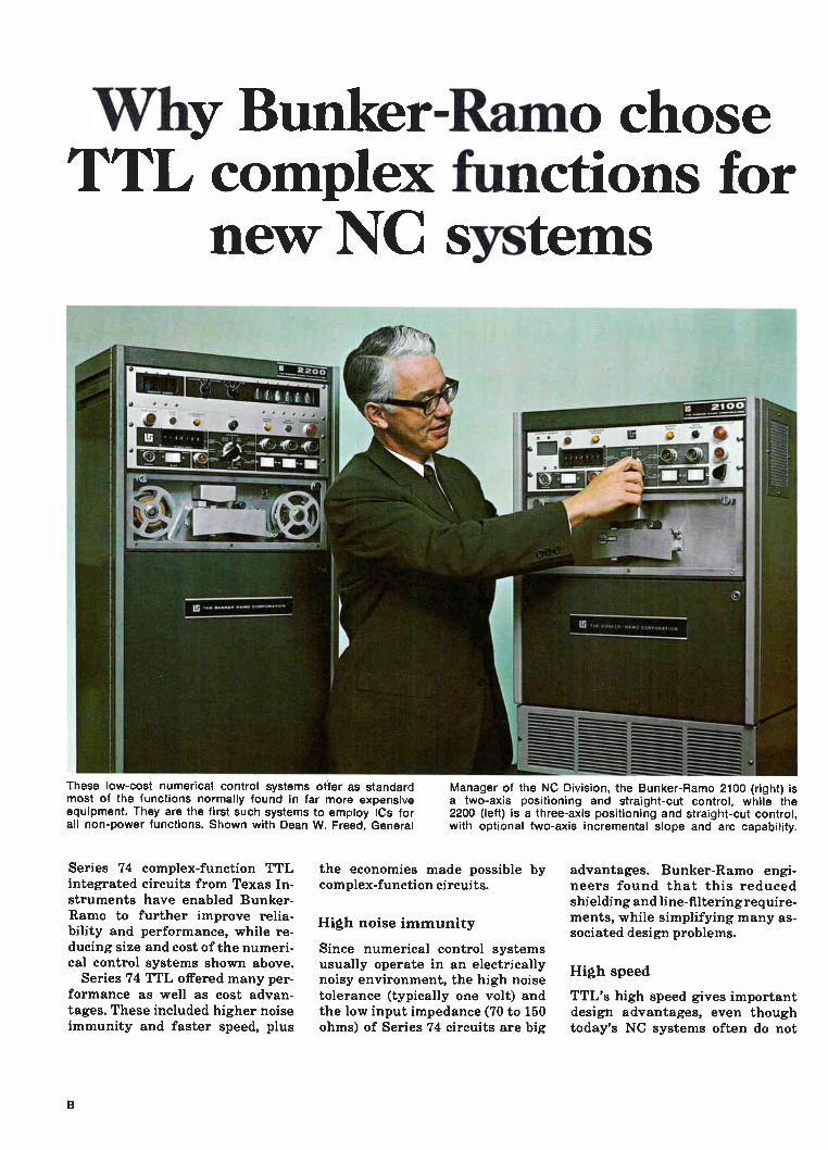
Why Bunker-Ramo chose TTL complex functions for
new NC systems
Manager of the NC Division, the Bunker-Ramo 2100 (right) is a two-axis positioning and straight-cut control, while the 2200 (left) is a three-axis positioning and straight-cut control, with optional two-axis incremental slope and arc capability.
These low-cost numerical control systems offer as standard most of the functions normally found in far more expensive equipment. They are the first such systems to employ ICs for all non-power functions. Shown with Dean W. Freed, General
Series 74 complex-function TTL integrated circuits from Texas In-struments have enabled Bunker-Ramo to further improve relia-bility and performance, while re-ducing size and cost of the numeri-cal control systems shown above.
Series 74 TTL offered many per-formance as well as cost advan-tages. These included higher noise immunity and faster speed, plus
the economies made possible by complex-function circuits.
High noise immunity
Since numerical control systems usually operate in an electrically noisy environment, the high noise tolerance (typically one volt) and the low input impedance (70 to 150 ohms) of Series 74 circuits are big
advantages. Bunker-Ramo engi-neers found that this reduced shielding and line-filtering require-ments, while simplifying many as-sociated design problems.
High speed
TTL's high speed gives important design advantages, even though today's NC systems often do not
B

Do IC s really cut costs?
Please send the following:
200 D 6-page case history brochure
201 D 48-page complex-function IC data book
202 III 48-page TTL brochure
203 El 84-page IC plastic package reliability report
204 D 24-page plastic S-C brochure
205 r] 16-page "Total Reliability at ir
NAME
TITLE
COMPANY
ADDRESS
CITY STATE ZIP
The answer is an emphatic yes! That's no promise. It's a fact... with proof to back it up. We've gathered some of the proof
in the folder pictured at the left. This 6-page brochure describes how other industrial manufac-turers have achieved revolution-ary product advances with ICs. Like these OEMs, you too can sig-nificantly reduce equipment size and weight . . . make major per-formance improvements.., achieve new systems capability .... dramat-ically reduce costs! For your copy, check No. 200 on the TI informa-tion service card. But that's not all! Check number
202 for the 48-page brochure that contains performance, application, and catalog information on all 180 Series 54/74 TTL ICs. An 84-page report provides re-
sults of TI's "Tougher-than-mili-tary" testing program. It's yours for the asking. Check number 203. A new 24-page color brochure
that gives information on all plas-tic-encapsulated semiconductors — including Series 54/74 ICs—is also available. Check No. 204.
N IN T! Airmail Information Service
To get the literature you want, check the appropriate numbers, fill out the card, and drop it in the mail. If you prefer, circle the same numbers on the magazine Reader Service card.
E
E
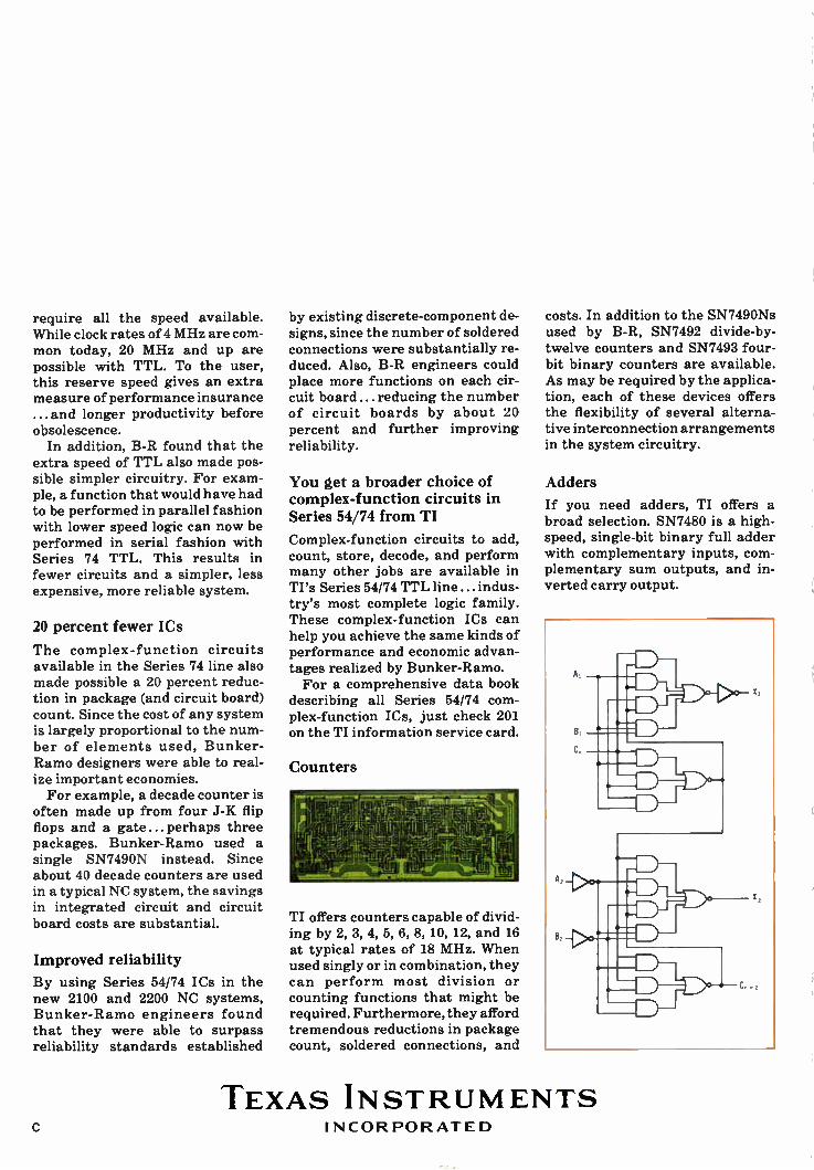
SN7482 is a two-bit binary adder that has a typical carry time of only 8 nsec per bit. The logic dia-gram shows the complexity of an SN7482. SN7483 is a four-bit binary adder
that is equivalent to 34 gates in a single package.
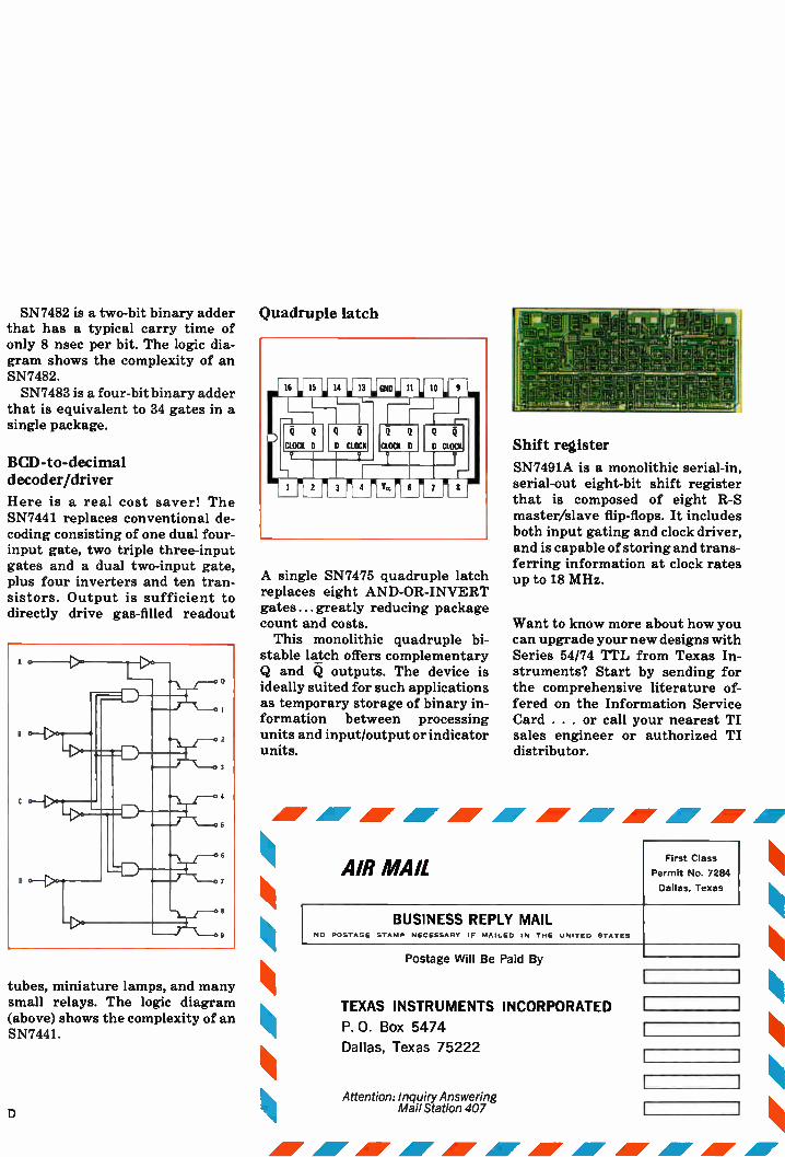
BCD-to-decimal decoder/driver
Here is a real cost saver! The SN7441 replaces conventional de-coding consisting of one dual four-input gate, two triple three-input gates and a dual two-input gate, plus four inverters and ten tran-sistors. Output is sufficient to directly drive gas-filled readout
tubes, miniature lamps, and many small relays. The logic diagram (above) shows the complexity of an SN7441.
Quadruple latch
A single SN7475 quadruple latch replaces eight AND-OR-INVERT gates ... greatly reducing package count and costs. This monolithic quadruple bi-
stable latch offers complementary Q and Q outputs. The device is ideally suited for such applications as temporary storage of binary in-formation between processing units and input/output or indicator units.
Shift register
SN7491A is a monolithic serial-in, serial-out eight-bit shift register that is composed of eight R-S master/slave flip-flops. It includes both input gating and clock driver, and is capable of storing and trans-ferring information at clock rates up to 18 MHz.
Want to know more about how you can upgrade your new designs with Series 54/74 TTL from Texas In-struments? Start by sending for the comprehensive literature of-fered on the Information Service Card . . . or call your nearest TI sales engineer or authorized TI distributor.
AV AI AlOr Air AdI AI AI AI AI AI AP
AIR MAIL
BUSINESS REPLY MAIL NO POSTAGE STAMP NECESSARY IF MAILED IN THE UNITED STATES
Postage Will Be Paid By
TEXAS INSTRUMENTS
P. O. Box 5474
Dallas, Texas 75222
INCORPORATED
First Class
Permit No. 7284
Dallas, Texas
D Attention: Inquiry Answering
Mail Station 407
require all the speed available. While clock rates of 4 MHz are com-mon today, 20 MHz and up are possible with TTL. To the user, this reserve speed gives an extra measure of performance insurance ... and longer productivity before obsolescence.
In addition, B-R found that the extra speed of TTL also made pos-sible simpler circuitry. For exam-ple, a function that would have had to be performed in parallel fashion with lower speed logic can now be performed in serial fashion with Series 74 TTL. This results in fewer circuits and a simpler, less expensive, more reliable system.
20 percent fewer ICs
The complex-function circuits available in the Series 74 line also made possible a 20 percent reduc-tion in package (and circuit board) count. Since the cost of any system is largely proportional to the num-ber of elements used, Bunker-Ramo designers were able to real-ize important economies. For example, a decade counter is
often made up from four J-K flip flops and a gate ... perhaps three packages. Bunker-Ramo used a single SN7490N instead. Since about 40 decade counters are used in a typical NC system, the savings in integrated circuit and circuit board costs are substantial.
Improved reliability
By using Series 54/74 ICs in the new 2100 and 2200 NC systems, Bunker-Ramo engineers found that they were able to surpass reliability standards established
by existing discrete-component de-signs, since the number of soldered connections were substantially re-duced. Also, B-R engineers could place more functions on each cir-cuit board ... reducing the number of circuit boards by about 20 percent and further improving reliability.
You get a broader choice of complex-function circuits in Series 54/74 from TI
Complex-function circuits to add, count, store, decode, and perform many other jobs are available in TI's Series 54/74 TTL line ... indus-try's most complete logic family. These complex-function ICs can help you achieve the same kinds of performance and economic advan-tages realized by Bunker-Ramo. For a comprehensive data book
describing all Series 54/74 com-plex-function ICs, just check 201 on the TI information service card.
Counters
TI offers counters capable of divid-ing by 2, 3, 4, 5, 6, 8, 10, 12, and 16 at typical rates of 18 MHz. When used singly or in combination, they can perform most division or counting functions that might be required. Furthermore, they afford tremendous reductions in package count, soldered connections, and
costs. In addition to the SN7490Ns used by B-R, SN7492 divide-by-twelve counters and SN7493 four-bit binary counters are available. As may be required by the applica-tion, each of these devices offers the flexibility of several alterna-tive interconnection arrangements in the system circuitry.
Adders
If you need adders, TI offers a broad selection. SN7480 is a high-speed, single-bit binary full adder with complementary inputs, com-plementary sum outputs, and in-verted carry output.
1
TEXAS INSTRUMENTS C INCORPORATED

Quality analysis... TI reliability starts here!
Any really successful reliability program must start with correct-ing the causes of failure before they occur in the field, and TI's Re-liability Analysis Laboratory... established in 1962...has been ex-amining the "where, what, when, how and why" aspects of IC fail-ures for more than five years. This lab has facilities to analyze
each individual element within even the most complex integrated circuit and can duplicate failure mechanisms under precisely con-trolled conditions. Typical of these quality-analysis
studies is the X-ray video monitor-ing facility shown at the left. This important analytical tool permits full 360° observations in both ver-tical and horizontal planes. It re-veals failure mechanisms that might otherwise escape detection. Following identification of fail-
ures, the analysis is forwarded to a corrective-action group. Here, TI's in-depth technical resources — including physicists, chemists, and metallurgists, as well as research, design, and manufacturing engi-neers — are focused on the problem. After evaluation of all data and reports, necessary corrective ac-tions are undertaken. Quality analysis is only one of
many steps taken by TI to ensure reliability of integrated circuits. Other important steps are de-scribed in a new 16-page brochure in full color... Total Re-liability at TI. Check number 205 on the TI information service card for your copy.
TEXAS INSTRUMENTS INCORPORATED F

THESE LITTLE
ERIF FRAI FII TER'S
ARE RESPONSIBLE FOR FILTERING
... ABOARD GRUMMAN'S LUNAR MODULE
ERIL GRUMMAN'S CHOICE FOR EMI FILTERS
These superior EMI FILTERS passed Grumman's critical qualification requirements — including random vibration and high transient withstanding capability. Most of these very small filters weigh less than 10 grams, and their inherent reliability make Erie a natural selection as Grumman's filter source.
Bonded Filter Stock .. . inventories under lock and key in our Quality Control Department ... is available for LM subcontractors or for other critical programs requiring Established Reliability Filters.
The typical 100 Vdc rated Erie Filter will provide an insertion loss of 67 db 150 kHz. A broad line of ERIE FILTERS is available — including MULTIPLE SECTION FILTERS and special configurations for STRIP LINE applications. Custom filters for your applications can be designed. Why not call in an Erie Filter specialist for your project?
Write for new catalog 9000 . . . ERIE ELECTRONIC FILTERS
Another Series of Components in Erie's Project "ACTIVE"
Advanced Components Through Increased Volumetric Efficiency
ERIE
TECHNOLOGICAL
PRODUCTS, INC
Erie,Penneylvania
Electronics I December 11, 1967 Circle 33 on reader service card 33
Thanks to an ancient shepherd named Magnes,
Amelco brings you the only complete high-voltage logic family in the world.
Thousands of years ago, according to Pliny the Elder, a shepherd named Magnes discovered the phenomenon of magnetism. High Noise
Immunity Logic developed by Amelco owes much to Mr. Magnes. Magnetic fields are used to measure the mobility of silicon material.
This important magnetic measure ensures that the raw materials used to create HNIL provide the fastest possible logic for high level operation.
Then, throughout production, quality control and cost economy depend on the use of magnetic ink to isolate those devices which fail to meet
operating standards. Fastidious control in the development and production of HNIL guarantees a superb product with consistent high-
voltage performance. This important new line developed by Amelco guarantees unexcelled
noise immunity, reduced can count, and overall reduction of systems costs. We've come a long way since Magnes discovered magnetism. But who knows, without his discovery, Amelco may not have brought you
the only complete high-voltage logic family available in the world today.
1r For quality in quantity
AMELCO SEMICONDUCTOR
A TELEDYNE COMPANY
34 Electronics! December 11, 1967
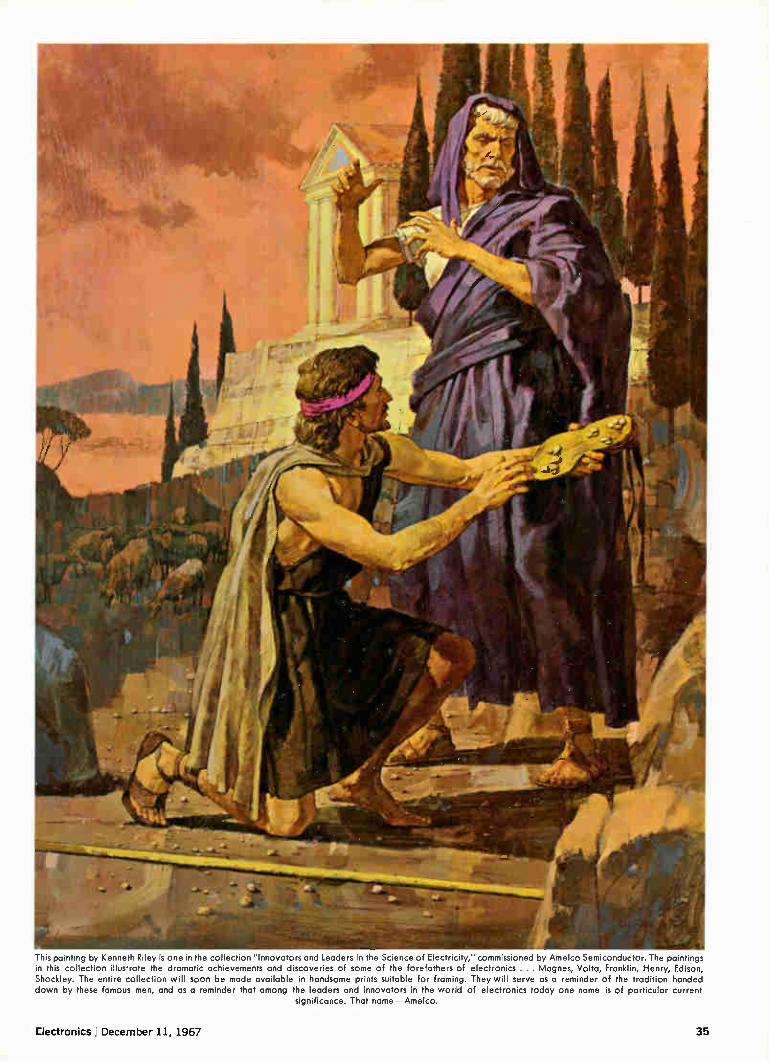
This painting by Kenneth Riley is one in the collection "Innovators and Leaders in the Science of Electricity," commissioned by Amelco Semiconductor. The paintings in this collection illustrate the dramatic achievements and discoveries of some of the forefathers of electronics .. . Magnes, Volta, Franklin, Henry, Edison, Shockley. The entire collection will soon be made available in handsome prints suitable for framing. They will serve as a reminder of the tradition handed down by these famous men, and as a reminder that among the leaders and innovators in the world of electronics today one name is of particular current
significance. That name—Amelco.
Electronics I December 11, 1967 35

WE AT COOK ELECTRIC ARE OUT TO CHANGE YOUR OUTLOOK
About sales and sales people. About service and delivery dead-lines. About quality you can depend on. About new products to meet new requirements before the need becomes an emer-gency. For example, our relays and pressure switches have been solving industrial problems for 20 years... ranging from small manufacturing operations to the national space program. Whether you need a component replacement today, or a
specially-designed unit to meet a future need, count on us. We specialize in having solutions on hand before problems arise. And if you're tired of promises unkept and delivery dates
unmet, we invite you to investigate the production and service facilities of Cook Electric. You'll find it's good business. With us, performance comes before promise.
COOK ELECTRIC
AUTOMATIC CONTROLS DIVISION
200 E. DANIELS ROAD • PALATINE, ILLINOIS 60067 • 312-359-2100
36 Circle 36 on reader service card Circle 37 on reader service card—).-

tricky tapers...
Allen-Bradley Type J hot molded variable resistor
shown twice actual size
Allen-Bradley Type J potentiometers offer tapers designed to your special needs!
When standard tapers fail to provide the control you desire, Allen-Bradley Type J potentiometers have the unique capability to provide a virtually limitless variety of curves to meet your specialized requirements. While not a precision device that is continuously taper-trimmed to very close tolerances, Allen-Bradley's control of the resistance-rotation characteristics during production assures a high degree of conformity.
Allen-Bradley Type J potentiometers have a solid hot molded resistance track made by an exclusive process which was pioneered and perfected by A-B. This solid resistance track assures smooth adjustment at all times—with none of the discrete changes in resistance that are encountered in wire-wound units. And being essentially noninductive, Type J controls can be applied in high frequency circuits where wire-wound units are useless.
Furthermore, A-B's solid molded resistance track assures low noise and long life. On accelerated tests, Type J potentiometers exceed 100,000 complete operations with less than 10% change in resistance.
For more complete details, please write: Allen-Bradley Co., 110 W. Green-field Ave., Milwaukee, Wis. 53204. In Canada: Allen-Bradley Canada Limited. Export Office: 630 Third Ave., New York, N.Y., U.S.A. 10017.
867E•3
ALLEN-BRADLEY QUALITY ELECTRONIC COMPONENTS
ADDITIONAL ALLEN-BRADLEY
HOT MOLDED VARIABLE RESISTORS
TYPE G CONTROLS are only 1/2 " in diameter Quiet, stepless opera non Rated 1/2 watt at /0°C Values to b meg ohms Type t are similar in construction but rated 1/2 watt at 100°C
TYPE F TRIMMERS are for mounting directly on printed wiring boards by means of their terminals Rated 1/4 watt at /0"C Values to b megohms Type 0 are sinular but rated 0 4 watt at /0°C
TYPE R ADJUSTABLE RESISTORS tor trimming applications are built to
withstand environmental extremes Only 11/4 " in length Flave stepless ad iustment Watertight arid an be enrapsulated
Rated 1/4 watt at /0 L Values to 1 ̀) meg,uhms I ype N kir less severe environments are rated '7, watt at 50 (
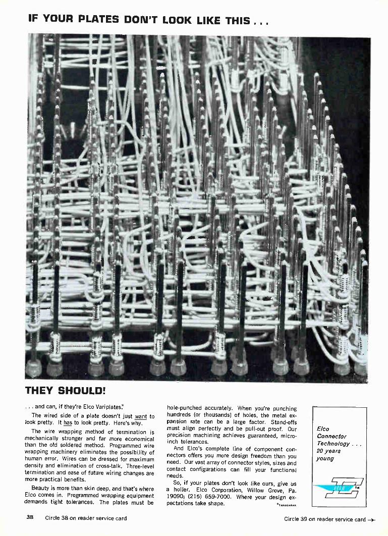
IF YOUR PLATES DON'T LOOK LIKE THIS...
THEY SHOULD!
... and can, if they're Elco Variplates.*
The wired side of a plate doesn't just want to look pretty. It has to look pretty. Here's why.
The wire wrapping method of termination is mechanically stronger and far more economical than the old soldered method. Programmed wire wrapping machinery eliminates the possibility of human error. Wires can be dressed for maximum density and elimination of cross-talk. Three-level termination and ease of future wiring changes are more practical benefits.
Beauty is more than skin deep, and that's where Elco comes in. Programmed wrapping equipment demands tight tolerances. The plates must be
hole-punched accurately. When you're punching hundreds (or thousands) of holes, the metal ex-pansion rate can be a large factor. Stand-offs must align perfectly and be pull-out proof. Our precision machining achieves guaranteed, micro-inch tolerances. And Elco's complete line of component con-
nectors offers you more design freedom than you need. Our vast array of connector styles, sizes and contact configurations can fill your functional needs.
So, if your plates don't look like ours, give us a holler. Elco Corporation, Willow Grove, Pa. 19090; (215) 659-7000. Where your design ex-pectations take shape. * TRADEMARK
Elco
Connector Technology. . 20 years young
38 Circle 38 on reader service card Circle 39 on reader service card —>-

;Of
"we have used many millions of
Allen-Bradley hot molded resistors.
The uniformity of quality from one
shipment to the next is truly astounding.
There can be no question about the
reliability of these resistors." Wang Laboratories
Model 320 Wang Electronic Calculator with 320K keyboard for scientific application. Readout provides 10-place accuracy with floating decimal point, and all calculations are displayed in one millisecond. Normally the 320 calculator is placed in a desk drawer rather than on the desk. It is shown here next to the keyboard to indicate compactness of the calculator.
One of the printed circuit cards from the Model 320 calculator. All resistors on this card are Allen-Bradley Type CB 1/4 watt hot molded resistors.
To insure the extremely accurate and high speed operation of the 300 Series Wang Electronic Calcu-lators, all components are selected with utmost care. Thus, it was only natural that Allen-Bradley hot molded resistors were chosen for this most exacting application. Composition resistors, not pro-
duced by the technique of hot mold-ing used by Allen-Bradley—using completely automatic machines— cannot equal the quality and uni-formity of production for which the hot molded Allen-Bradley resistors have a worldwide reputation. The precise control during manufacture results in such uniformity of one A-B resistor to the next—million after million —that long term resistor performance can be accurately pre-dicted. There is no record of any Allen-Bradley hot molded resistor having failed catastrophically.
Let the experience of the engineers at Wang Laboratories become your
own experience. Allen-Bradley fixed and variable hot molded resistors will do exactly as well for you as they have done for all other users. For complete specifications, please write for Technical Bulletin 5000: Allen-Bradley Co., 222 W. Greenfield Ave., Milwaukee, Wis. 53204. In Canada: Allen-Bradley Canada Limited. Export Office: 630 Third Ave., New York, N. Y., U.S.A. 10017.
nu)
TYPE BB 1/e WATT
en= TYPE CB 1/4 WATT
Type EB 1/2 WATT
a a Law TYPE GB 1 WATT
it 111111, /
TYPE KB 2 WATTS
HOT MOLDED FIXED RESISTORS are avail-able in all standard resistance values and tolerances, plus values above and below standard limits. Shown actual size.
73-07-7E AB ALLEN-BRADLEY \nor/ QUALITY ELECTRONIC COMPONENTS

1111111111111111111111
The more complex the data system gets, the simpler Cimron can make it for you! Let's face it. You shouldn't have to be an elec-tronics genius just to understand a system like the one shown here. You don't have to design the system to know what you want it to do—or to use it. That's where Cimron comes in. And the more complex the problem, the simpler Cimron can make it for you. That's what we're here for. To provide the expertise in this specialized field so you don't have to do it yourself. The Model 1130 Production Test Applications
System shown here monitors 100 channels of input signals, measures and records the data. It happens to employ .a Cimron DVM with converters, a scan-ner, a serializer and a digital recorder. It could have been designed to solve your special problems as easily. For help, call Cimron collect at (714) 276-3200, or write Department A-113, 1152 Morena Boulevard, San Diego, California 92110.
=imixt=ium A Division of rinJLIJJ.1
Lear Siegler, Inc.
40 Circle 40 on reader service card Electronics December 11, 1967

Five reasons why so many engineers specify Sigma relays.
Longer mechanical
life
Series 50 Series 62
Better conductivity
4
Price: 750
-*4L,
sicke HISTRU NrsT9.10
24
Series 65
And there are more reasons why each of these Sigma relays give you superior performance:
New Series 50: Rated for at least 10 million mechanical operations and fully recognized under the U.L. component program. These 1, 2 and 3 pole, 5 and 10 amp relays also feature an exclu-sive contact base design that extends contact life.
New Series 62: The larger contacts of this new Series (.093" & .058" dia.) assure excellent con-ductivity. And it has a thicker base for greater contact stability than other 2, 4 and 6 pole, 2 amp relays.
New Series 65: In addition to low price econ-omy, this new 1 amp SPDT relay provides supe-rior switching performance through its precision knife-edge hinge armature design. It has greater mechanical strength and better thermal stability than similar competitive types.
New Series 67: It not only assures faster in-
Faster installation
Series 67 Datacel®
Solid-state design
e.
, }, 2
• 56-4 C4±.
stallation with its simple snap-in socket but will outperform other 4PDT, 3 amp, AC-DC relays in life, adjustment stability and thermal resistance. New solid-state Datacel": This optoelectronic
switching device provides greater reliability and complete input-output circuit isolation. It also features AC-DC capability, compact construction and broad application versatility.
We'd like to give you one of these relays or any standard Sigma type. It's the best way we know to prove what we say about Sigma relay perform-ance. Just fill in and return the post-paid reply card—or the Reader Service Card. We'll send you the new Sigma relay catalog and a "free relay" request form. Return the form and your Sigma representative will see that you get the relay you need.
Need fast delivery? The Sigma Line is avail-able off-the-shelf from your Sigma distributor.
SIGMA INSTRUMENTS INC 'maw" Assured Reliability With Advanced Design/Braintree, Mass. 02185
Sigma Instruments (Canada) Ltd., P.O. Box 43, Toronto 18
Electronics December 11, 1967 Circle 43 on reader service card 43

Investigate Random or Periodic Processes with Correlation Function Computers
Correlation functions occupy a cardinal position in modern information theory and are basic to the analysis of random or periodic processes and the complex sig-nals they produce. In many application areas, autocor-relation analysis allows noisy periodic or random signals to be defined, whereas crosscorrelation can determine the degree of conformity between two different noisy signals as a function of their mutual delay.
PARTM Models 100 or 101 Correlation Function Com-puters simultaneously compute 100 points of the auto-or crosscorrelation function in real time over delay spans from 100 microseconds to 10 seconds. The Model 101 includes the capability for insertion of fixed delay increments ahead of the 100 computed points of the function, thereby providing greater resolution. The correlation function readout which may be obtained continuously as it is computed, is available at various rates consistent with the speed of the external readout device, e.g. oscilloscope or X-Y recorder.
Vibration analysis, radio astronomy, laser research, geophysics, radar, plasma physics, aero- and hydro-dynamics, and biophysics are only a few of the fields where correlation techniques are useful.
Price of the Model 100 is $8,500. The Model 101 is priced at $9,500 to $12,900. Export prices are approxi-mately 5% higher (except Canada).
For additional information, write Princeton Applied Research Corporation, Department D , P.O. Box 565, Princeton, New Jersey 08540 or call 609-924-6835.
PAR " CORRELATION FUNCTION COMPUTER mODEL 101
A PRINCETON APPLIED RESEARCH CORPORATION

December 11, 1967
Electronics Review Volume 40
Number 25
Components
Brush off
The carbon brush for d-c motors, like nature, abhors a vacuum. It cannot survive in space for more than a few seconds. The vacuum causes the brush to "weld" to whatever surface it touches. But because of the nature of the power sources in space—batteries, solar energy—d-c motors are, for all practical purposes, the only choice. The need, then, is for a brushless d-c motor, and NASA has been working on such designs for five years.
In the latest model, engineers at NASA'S Goddard Space Flight Cen-ter have developed an optoelec-tronic commutator to replace the motor's brushes. The optoelectronic scheme gives
the engineers more than just the opportunity to get rid of the brushes. It—along with a unique magnetic configuration—provides them a motor with a wide range of both speed and torque. For commutation of the arma-
ture coil, a disk at one end of the shaft has alternate black and white areas. A light beam directed at the disk is reflected to six photodiodes. The disk thus acts as a shutter and, as the shaft rotates, light strikes the diodes in sequence. Output of the diodes goes to switching transistors, and ampli-fied current is fed back to the armature to develop two magnetic fields that interact with the rotor field to create torque. NASA'S newest version, devel-
oped by Aeroflex Laboratories Inc. of Plainview, N. Y., is called the variable-field brushless d-c motor. Pancake-shaped field and arma-ture coils are stationary and both are concentric to the axis of the rotor. At each end of the rotor
Optoelectronic commutation. In a new variable-field d-c brushless motor with stationary coils, shuttered light beam commutates rotor field.
shaft are salient poles, which rotate in planes parallel to the flat surface of the pancakes. The d-c energized field coil gen-
erates an axial magnetic field, which travels along the shaft, through the poles, and into the commutated armature. Thus, the only rotating part is the slim rotor shaft and its thin poles.
Others in works. Meanwhile, five d-c brushless motors devel-oped earlier by Sperry Farragut division of the Sperry Rand Corp. under NASA sponsorship are being readied for long-term flight ap-plication in earth orbit on the Air Force's ov-113 satellite, now scheduled for launch in early March. The Sperry Farragut version,
using a permanent magnet rotor, does not have the range of speeds needed for some applications. The prototype of the Aeroflex
variable-field d-c brushless motor is rated at 28 volts d-c and draws up to 2 amperes. Speed can be adjusted from 0 to 2,400 revolu-tions per minute. The prototype's torque is rated at 0.5 foot-pounds per ampere. With a time constant of 1.2 milliseconds, the motor can
be fully reversed in 3 milliseconds. Now under test at Goddard, the motor, at most speeds, operates at about 50% efficiency. "So far," reports Philip A.
Studer, under whose direction it has been developed and tested, "the variable field d-c brushless motor has proven to be highly reli-able. But there are still some ques-tions as to how well it will perform at higher power." Even while the motor is being
tested, Goddard engineers are eye-ing a variety of space tasks for it. Studer mentions driving of solar panels and despinning of anten-nas, in which torque is the con-trolled variable, and attitude-con-trol and moment-gyro systems, in which both speed and torque ad-justment are significant.
Advanced technology
Unmasked
"For Sale: One laser-operated in-tegrated-circuit masking camera, never used. Cost one million dol-
-(—Circle 44 on reader service card 45
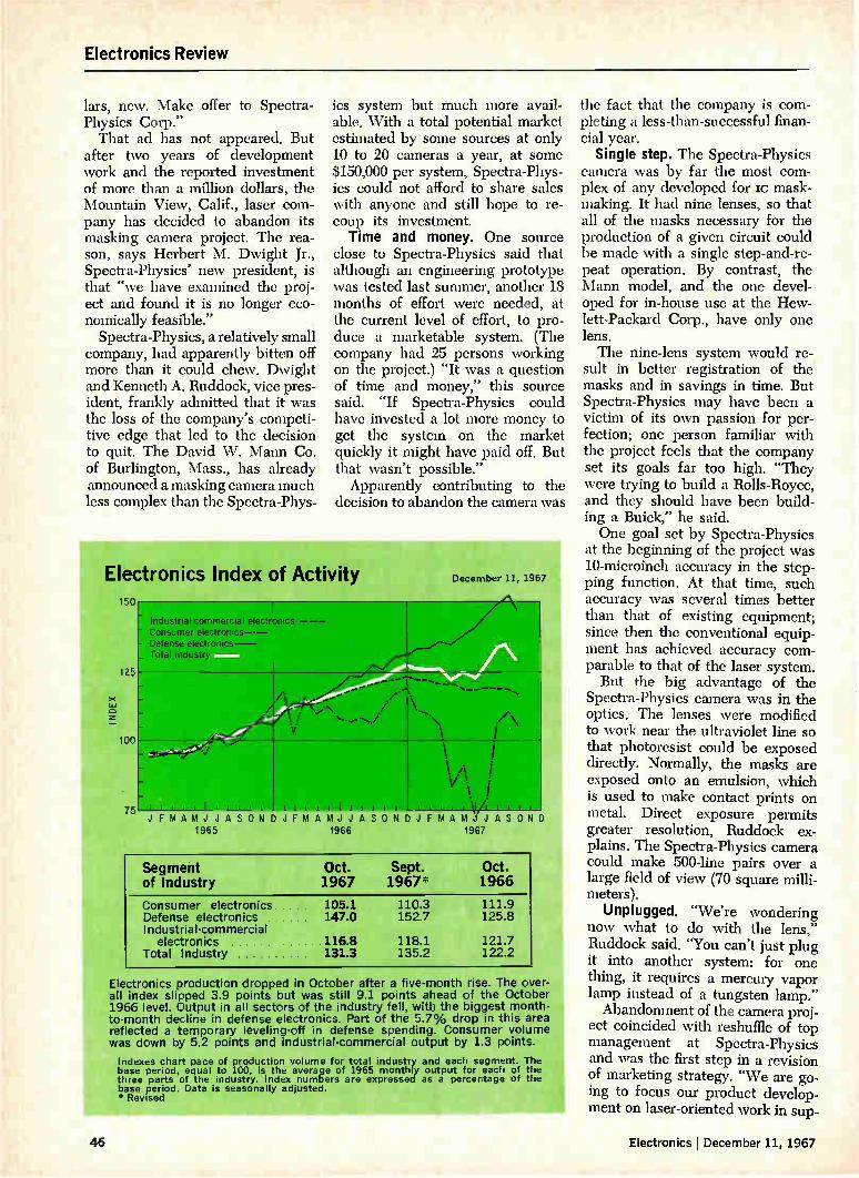
Electronics Review
lars, new. Make offer to Spectra-Physics Corp." That ad has not appeared. But
after two years of development work and the reported investment of more than a million dollars, the Mountain View, Calif., laser com-pany has decided to abandon its masking camera project. The rea-son, says Herbert M. Dwight Jr., Spectra-Physics' new president, is that "we have examined the proj-ect and found it is no longer eco-nomically feasible."
Spectra-Physics, a relatively small company, had apparently bitten off more than it could chew. Dwight and Kenneth A. Ruddock, vice pres-ident, frankly admitted that it was the loss of the company's competi-tive edge that led to the decision to quit. The David W. Mann Co. of Burlington, Mass., has already announced a masking camera much less complex than the Spectra-Phys-
ics system but much more avail-able. With a total potential market estimated by some sources at only 10 to 20 cameras a year, at some $150,000 per system, Spectra-Phys-ics could not afford to share sales with anyone and still hope to re-coup its investment. Time and money. One source
close to Spectra-Physics said that although an engineering prototype was tested last summer, another 18 months of effort were needed, at the current level of effort, to pro-duce a marketable system. (The company had 25 persons working on the project.) "It was a question of time and money," this source said. "If Spectra-Physics could have invested a lot more money to get the system on the market quickly it might have paid off. But that wasn't possible." Apparently contributing to the
decision to abandon the camera was
Electronics Index of Activity 150
125
75 JFMAMJJASONDJFMAMJJASONDJFMAM JASOND
1965 1966 1967
December 11, 1967
I - Industrial -commercial electronics - Consumer electronics--- Defense electronics— _ Total industry
---
\
ditrAliiii
- _
/. /
••••• ...../
—
• .. \- •-... •,,
'N, A I i
iiiiiliiiii
\./.1 i V "
\ I
iiiii .11/iiii iiiiiliiiii
Segment of Industry
Oct. Sept. Oct. 1967 1967* 1966
Consumer electronics 105.1 110.3 111.9 Defense electronics 147.0 152.7 125.8 Industrial-commercial
electronics 116.8 118.1 121.7 Total Industry 131.3 135.2 122.2
Electronics production dropped in October after a five-month rise. The over-all index slipped 3.9 points but was still 9.1 points ahead of the October 1966 level. Output in all sectors of the industry fell, witb the biggest month-to-month decline in defense electronics. Part of the 5.7% drop in this area reflected a temporary leveling-off in defense spending. Consumer volume was down by 5.2 points and industrial-commercial output by 1.3 points.
Indexes chart pace of production volume for total industry and each segment. The base period, equal to 100, is the average of 1965 monthly output for each of the three parts of the industry. Index numbers are expressed as a percentage of the base period. Data is seasonally adjusted. *Revised
the fact that the company is com-pleting a less-than-successful finan-cial year.
Single step. The Spectra-Physics camera was by far the most com-plex of any developed for lc mask-making. It had nine lenses, so that all of the masks necessary for the production of a given circuit could be made with a single step-and-re-peat operation. By contrast, the Mann model, and the one devel-oped for in-house use at the Hew-lett-Packard Corp., have only one lens. The nine-lens system would re-
sult in better registration of the masks and in savings in time. But Spectra-Physics may have been a victim of its own passion for per-fection; one person familiar with the project feels that the company set its goals far too high. "They were trying to build a Rolls-Royce, and they should have been build-ing a Buick," he said. One goal set by Spectra-Physics
at the beginning of the project was 10-microinch accuracy in the step-ping function. At that time, such accuracy was several times better than that of existing equipment; since then the conventional equip-ment has achieved accuracy com-parable to that of the laser system. But the big advantage of the
Spectra-Physics camera was in the optics. The lenses were modified to work near the ultraviolet line so that photoresist could be exposed directly. Normally, the masks are exposed onto an emulsion, which is used to make contact prints on metal. Direct exposure permits greater resolution, Ruddock ex-plains. The Spectra-Physics camera could make 500-line pairs over a large field of view (70 square milli-meters).
Unplugged. "We're wondering now what to do with the lens," Ruddock said. "You can't just plug it into another system: for one thing, it requires a mercury vapor lamp instead of a tungsten lamp." Abandonment of the camera proj-
ect coincided with reshuffle of top management at Spectra-Physics and was the first step in a revision of marketing strategy. "We are go-ing to focus our product develop-ment on laser-oriented work in sup-
46 Electronics I December 11, 1967

Electronics Review
port of less expensive and more reliable helium-neon and argon la-sers," Dwight said. (The company has also stopped work on the car-bon-dioxide laser which it showed earlier this year.) When Dwight assumed the pres-
idency of the company, Robert C. Rempel left that position to become vice president and technical direc-tor. The change, Dwight indicated, was more apparent than real. "It was really a formal recognition of what our responsibilities had be-come," he said. Dwight was for-merly a vice president and treas-urer.
Medical electronics
Sound thinking
Conventional hearing tests, where the subjects don earphones and in-dicate whether they can hear cer-tain recorded sounds, are fine for adults and children capable of com-municating. But for those incapable of replying, accurate testing has been almost impossible. However, a Princeton, N.J., firm, the Prince-ton Applied Research Corp., has developed a research instrument that doesn't depend on a reply—at least not a conscious one.
Instead, the instrument, called an evoked-response audiometer, is built around an electroencephalo-graphic (EEG) device. The EEG
signals are involuntary electrical
Now hear this. A subject's brain waves are monitored to determine whether she can hear sounds produced by this hearing-test equipment.
waves generated by the brain, and changes in their patterns can often be tied to specific motor or psy-chological stimuli. The principle behind the Princeton instrument is that perceived sound produces a predictable EEC wave form.
Pinpointing components. The problem is picking out the signifi-cant components of the wave form from the many in a complex EEG signal. The firm's feat was to de-velop a technique of detecting that portion of the wave that corre-sponds to the perception of sound. For this, it uses a signal-averaging computer. The audiometer-system design
was based on the suggestions of Dr. Hallowell Davis of the Central Institute for the Deaf in St. Louis, Mo., whose work on evoked re-sponses was supported by a grant from the Federal Public Health Service.
In addition to the computer, the instrument includes a programer, a tone generator, a strip-chart re-corder, and an EEG amplifier. The computer is basically a modified version of the company's Wave-form Eductor. It averages the noise components of the responses to zero while averaging the other components common to the same time segment of the EEG signal to a stable value.
In preparing for a run, the audiometer operator sets the de-sired stimulus characteristics—fre-quency, intensity, pulse rate, dura-tion, and rise and fall times; and the desired processing parameters
—integrating time constant, gain, window width, and high- and low-frequency rolloffs. The operator can choose either manual or automatic control of the number and repeti-tion rate of pulses, and the speed of the chart.
Stop and go. In the automatic mode, the audiometer operates at the preset rate and records both the raw and processed signals at low chart speeds. It speeds up the chart drive by a factor of 125 for the median and final two pulses, then erases the computer memory and resets itself for the next run. However, the operator may inter-rupt the run at any point and then resume it after a pause without affecting the total count. Also, he may call for an additional high-speed recording at any point dur-ing the run without affecting the program.
Recording pulses at a very low chart speed is used to monitor gross anomalies in the raw signal, such as those caused by the move-ment of an electrode. Although the low-speed recording yields no de-tail, it provides an amplitude en-velope in which gross variations are easily detected. The corre-sponding envelope for the proc-essed signal is convenient for ob-serving the buildup of the evoked signal with time. The actual wave-forms used for analysis are those obtained during the high-speed re-cordings at the middle and the end of each run.
Space electronics
Band practice
With the Apollo program behind schedule, crews at the unified S-band tracking stations around the world have had few opportunities to develop and maintain a prac-ticed hand in operating their gear. And with so much riding on the man-on-the-moon project, NASA has decided to loft an S-band trans-ponder to keep the crews in condi-tion. This week (Dec. 13) the space agency is to launch the 40-pound satellite that will ride piggyback
Electronics I December 11, 1967 47

Electronics Review
on the Thor-Delta vehicle that will loft a Pioneer space probe. The transponder is one of two
designed and built by the systems group of mw Inc. under a $550,-000 contract from NASA's Goddard Space Flight Center. To the track-ing gear on the ground, it will look like the Apollo command module, providing the crews with an op-portunity to both test their hand and check their electronic equip-ment. The Test and Training Satellite
(Trs) program is the result of an unsolicited proposal that lay dor-mant until the Apollo program fell behind. Then, last April, the space agency asked mw to proceed on its proposal. Something borrowed. The ITS
program, says Harold Adelson, has drawn on technology developed for three other mw programs: Pioneer, the Environmental Research Satel-
EARTH'S MAGNETIC FLUX
MAGNET
lite (ERs) series, and the space-ground link subsystem ( sms). Adelson is assistant director of the research applications laboratory at TRW Systems, Redondo Beach, Calif. The firm is prime contractor to NASA for Pioneer and is building the ERS series and some scLs flight hardware for the Air Force. The octahedral TTs package is essen-tially an ERs satellite. Its five-ele-ment, S-band omnidirectional slot-ted array antenna is one-half of a Pioneer antenna, says Ralph Miller of the information transmission de-partment, where the S-band trans-ponder was built. The satellite will have an orbital
apogee of 324 nautical miles, and a perigee of 166 miles. It will replace aircraft formerly used as spacecraft simulators. "The aircraft are expen-sive to maintain," notes Adelson, "and you can't check all the stations with them. With this satellite, each
..---------.... , -.. N N \\ i r • • \ / \ \ / \
I I
5 ELEMENT S-BAND SLOTTED ARRAY
r
VHF DIPOLE
VHF RECEIVE MONOPOLE
Workout. Satellite generates S-band signals to keep Apollo tracking crews in practice for the moon launch.
station will be able to acquire it, track it until it disappears, then hand it over to the next station." He explains that the satellite uses
a passive magnetic stabilization sys-tem to keep the spacecraft axis horizontal to the earth. Principal parts of the system are a bar mag-net and hysteresis rods to dampen any oscillations that occur. The ef-fective radiated power is "a little better than half a watt," notes Adel-son. "To produce this, we have to put in 17 watts when the trans-ponder is working. Solar panels deliver five watts, and a nickel-cadmium battery supplies the re-mainder." Ground trigger. Adelson says the
transponder has two modes. In the ready mode, it is quiet until it re-ceives an S-band signal on a fre-quency of 2,101.8-megahertz. It then retransmits the signal to the sending station at 2,282.5 Mhz. In the coherent, noncoherent mode, the transponder transmits a non-coherent S-band signal at all times, which allows automatic acquisition by the ground stations. The re-ceived signal is retransmitted co-herently, without any change in modulation. Either mode can be triggered by ground command.
Miller says the ground stations can send up any baseband or any modulation, and the transponder "will turn it around." "The coherent feature means
they can do ranging or determine range rate, and can send up tele-metry or voice and get it back. We have enough power onboard to turn these signals around at altitudes up to 1,500 nautical miles," he ex-plains. A 1.25-Mhz subcarrier will ac-
commodate voice transmissions, while telemetry signals will be placed on a 1.024-Mhz subcarrier. A standard NAsA/Air Force pseudo-random noise code is used for rang-ing. A diplexer—also borrowed from
the Pioneer program—permits si-multaneous reception and transmis-sion using only one antenna. The transponder receiver has a mini-mum sensitivity of -125 decibels, which yields a good signal-to-noise ratio on the up-link about 50 db;
48 Electronics j December 11, 1967

Up to 72% smaller than MIL-C-25C paper capacitors!
MIL-C-19978B/2 reduces capacitor size drastically—down to .125" diameter by long. At the same time electrical characteristics are upgraded sharply.
MIL-C-19978B/2 hermetically sealed mylar* capacitors are available now from TRW with immediate delivery in production quantities.
• REDUCED SIZE-35% to 72% smaller than MIL-C-25C.
• VOLTAGE CHOICE-30V, 50V, 100V, 200V, 600V, 1000V.
• CAPACITANCE CHOICE—.001 mfd through 10.0 mfd.
• TOLERANCE CHOICE—±10%, ±5%,
±2%, ±1%.
Product information is available from TRW Capacitor Division, TRW INC., Box 1000, Ogallala, Nebraska. Phone (308) 284-3611. TVVX: 910-620-0321. *Du Pont registered trademark
TRW® Electronics December 11, 1967 Circle 49 on reader service card 49

Electronics Review
that on the down-link depends on whether the signal carries voice, telemetry or ranging data. Turn off. Electronic subsystems
besides the main payload—the transponder—include a command receiver and decoder, and a house-keeping telemetry system. The telemetry information will be car-ried at 136 Mhz via a dipole whip antenna to NASA space tracking and data acquisition network stations that control the satellite. Com-mands from these stations will be detected, using a monopole whip antenna, and received at 149 Mhz in the command receiver. Adelson says the commands used are basi-cally those that turn the trans-ponder on and off.
Integrated circuits are used ex-tensively in the spacecraft's elec-tronics, except for the transponder. The satellite is designed for an or-bital life of seven months. The second launch is tentatively sched-uled about six months after the first, probably riding piggyback aboard another Pioneer probe.
Consumer electronics
Pop op amp The integrated circuit operational amplifier is widely used in data-processing systems, telemetry, and analog instrumentation. Now that's in a low-cost plastic in-line package, it may find wide use in consumer applications—such as in a pre-amplifier where its low-noise characteristics are especially ad-vantageous. The op amp is entering the con-
sumer market in H. H. Scott's new f-m stereo music system; a dual monolithic lc amp, Motorola's SC2914 ( essentially the MC1302 ), is used as a low-noise phono pre-amplifier with RIAA (Record In-dustry Association of America) equalization. Price of the system is about $300. Lower costs. Scott describes its
decision to replace discrete com-ponents with an lc as purely one of economics, but says improved per-
LEFT CHANNEL IN
8 C
I H\AteNte- "--1
C10 R10
•-is.e‘Af--111 RI1
7
1 4
5 14
cl2
LEFT CHANNEL OUT
14 B4-o
Higher fi. H.H. Scott is introducing an f-m stereo system with a monolithic operational amplifier, boosting performance and cutting costs.
formance and reliability were achieved as byproducts. The Motorola device is a plastic-
packaged version of the more ex-pensive TO-5 packaged MC1535G.
Daniel von Recklinghausen, Scott's engineering director, says, "We can't say exactly what the savings are since production costs are always difficult to determine. But while the costs of discrete re-sistors and capacitors is on an up-ward trend, the cost of ic's is going down." Furthermore, by replacing a large
number of discretes with a single device, fewer production operations are required, resulting in reduced labor costs.
Better performance. The inte-grated-circuit op amp is employed in a closed-loop configuration in the phono preamplifier with exter-nal d-c and a-c feedback circuitry.
In the diagram, shown above, only one channel of the dual-chan-nel amplifier is shown for simplic-ity. RIAA frequency response stand-ards at 500 hertz are provided in the a-c feedback circuit by Cg, Cg, and Rg, while R10 is added to the compensation circuit to achieve the required 75-microsecond rolloff fig-ure. Feedback for d-c stability and
low-frequency gain is established through R10 and R11. Resistor R13 provides the base current for the input stage and establishes the max-imum output limits. Biasing current is established through R14.
Over-all, the amplifier is designed to provide very low noise with im-proved high-frequency characteris-tics through the use of tantalum capacitors in frequency-sensitive circuits.
The quiet one
Although the first electronic (tran-sistor-controlled) wristwatch made its debut on the consumer market seven years ago [Electronics, Oct. 28, 1960, p. 35], the watches have generally been high-priced. Bul-ova's Accutron starts at $125 and goes up to $1,000, while Benrus' Technipower is priced from $120. The Sheffield Watch Co. of New York, however, is introducing a 17-jewel electronic watch — the company's first—that will retail for less than $50. The Sheffield watch is silent; most other eledtTonic watches hum. Competing with the Sheffield
watch are electric models pro-
50 Electronics December 11, 1967
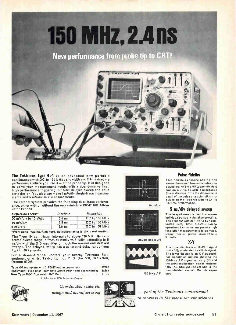
Pulse fidelity The Tektronix Type 454 is an advanced new portable oscilloscope with DC-to-150 MHz bandwidth and 2.4-ns risetime performance where you use it — at the probe tip. It is designed to solve your measurement needs with a dual-trace vertical, high performance triggering, 5-ns/div delayed sweep and solid state design. You also can make 1 mV/div single-trace measure-ments and 5 mV/div X-Y measurements.
The vertical system provides the following dual-trace perform-ance, either with or without the new miniature P6047 10X Atten-uator Probes:
Deflection Factor* Risetime Bandwidth
20 mV/div to 10 V/div 10 mV/div 5 mV/div
2.4 ns 3.5 ns
5.9 ns
DC to 150 MHz DC to 100 MHz DC to 60 MHz
•Front panel reading. With P6047 deflection factor is 10X panel reading.
The Type 454 can trigger internally to above 150 MHz. Its cali-brated sweep range is from 50 ns/div to 5 s/div, extending to 5 ns/div with the X10 magnifier on both the normal and delayed sweeps. The delayed sweep has a calibrated delay range from 1 ys to 50 seconds.
For a demonstration, contact your nearby Tektronix field engineer, or write: Tektronix, Inc., P. 0. Box 500, Beaverton, Oregon 97005.
Type 454 (complete with 2 P6047 and accessories) $2600 Rackmount Type R454 (complete with 2 P6047 and accessories) $2685
New Type 200-1 Scope-Mobile® Cart $ 75
u. S. Sales Prices FOB Beaverton, Oregon
Coordinated research,
design and manufacturing
10 ns/d iv
Double Exposure
150 MHz AM
This double-exposure photograph shows the same 12-ns-wide pulse dis-played on the Type 454 (upper display) and on a 7-ns, 50-MHz oscilloscope (lower display). Note the difference in detail of the pulse characteristics dis-played on the Type 454 with its 2.4-ns risetime performance.
5 ns/div delayed sweep The delayed sweep is used to measure individual pulses in digital pulsetrains. The Type 454 with its 1 izs-to-50 s cali-brated delay time, 5-ns/div sweep speed and 2.4-ns risetime permits high resolution measurements to be made. Upper trace is 1 dits/div; lower trace is 5 ns/div.
X-Y The upper display is a 150-MHz signal that is 50% modulated by a 2 kHz signal. The lower display is an X-Y trapezoi-dal modulation pattern showing the 150-MHz AM signal vertically (Y) and the 2kHz modulation signal horizon-tally (X). Straight vertical line is the unmodulated carrier. Multiple expo-sure.
... part of the Tektronix commitment
to progress in the measurement sciences
• . .• .••
Electronics December 11, 1967 Circle 51 on reader service card 51

"fine line" etcher for prototypes—limited runs
Model No. 201 (illus.), etches two 11' x 14" one-sided boards or one 11"x 14"
$795 two-sided board: Pat, applied for
---------------------------ETCH YOUR OWN P C BOARDS
AUTOMATICALLY (in less then 5 minutes)
from this -->-to 11" x 14" Shown Actual Size
• No cooling or venting required!
• Etches as fine as .001"!
• Cuts costs in half—saves time!
• Complete photo processing instructions!
• Work is illuminated while etching!
• No patterning ... minimum undercutting!
NOW IN USE BY:
AMP, Inc. Ampex Corp. Atomic Energy Com. Bendix Charles Brunning Esso Research General Dynamics General Electric IBM ITT Lear Siegler Magnavox Micro Switch Owens-Illinois Sonotone
Sprague Electric Union Carbide U.S. Air Force Western Electric Whirlpool M.I.T. Oklahoma State U. Purdue Univ. Washington Univ. Univ. of Calif. Univ. of Chicago Univ. of Colorado Univ. of Georgia Univ. of Hawaii Univ. of Penn.
CYCLO-TRONICS, INC. 3858 N. CICERO — CHICAGO, ILL. 60641
TELEPHONE: (312)-282-6141
Electronics Review
BATTERY + Ii
Q1
PICK UP COIL
DRIVING I COIL
BALANCE WHEEL
No hum. A transistor oscillator in this electronic watch controls the accuracy of the time piece's pendulum assembly.
duced by Timex, priced as low as $39.95. These watches, however, are not electronic; a battery powers an electromechanical device, which drives the movement. The Sheffield watch is guaran-
teed to be comparable in accuracy to any high-priced electronic watch on the market, according to the company's president, Henry A. Federman. Fewer parts. The major differ-
ence between the Sheffield and others of its type is its simplicity. Unlike the Accutron, which em-ploys an electromagnetic tuning fork in place of the balance wheel and hair-spring used by conven-tional watches, the Sheffield uses a simple rotor-type balance-wheel pendulum to drive the watch mechanism. This principle, Shef-field feels, is more suitable for mass production. The watch con-tains only nine moving parts, com-pared with about 15 for the tuning-fork controlled watches and an average of 24 for spring watches.
Electronic circuit. The Sheffield watch employs a Hartley-type os-cillator to accurately maintain a permanent magnet-tipped pen-dulum assembly balance wheel that drives the watch movement at six swings per second. Initially, as the pendulum swings pass the oscillator coil, sandwiched be-tween the magnet poles, it induces a voltage in the coil, causing capacitor C1 (see above) to charge through the transistor. Upon discharge, the capacitor
voltage sets up an opposing mag-netic field around the coil, which reacts with the magnet on the re-
turn swing of the pendulum to provide the necessary "kick" to sustain the balance wheel at a steady oscillating pace. The circuit is powered by a 1.35-
volt Mallory WH3 mercury cell that lasts 12 to 14 months. Sug-gested retail price of the cell is $1.15.
Companies
Hands across the sea
To many small electronic firms the idea of selling in Europe is attrac-tive, but a fear of import-export regulations and of undependable representation often causes mar-keting managers to shy away. The same is true of many European firms, which would otherwise sell their products in the U. S. Now a three-year-old test-equip-
ment builder, the Texscan Corp. of Indianapolis, is offering over-seas marketing services to U.S. firms and stateside marketing for foreign companies. According to Robert J. Shevlot, general manager of Texscan's technical products division, the service costs nothing, involves no risk, and includes mar-ket research, advertising, and serv-ice facilities. Why should an electronics firm
wish to become an export-import house? Also, if there's no fee or risk to the client, how does Tex-scan make its profit?
Different approach. Texscan en-tered the business , because it
52 Circle 52 on reader service card Circle 53 on reader service card—*-

you are looking a the first... and only megawatt PIN microwave switching diode
• low cost ... ultra-high reliability • PIV's to 2KV • Capacitance values suitable for X Band — to 0.5 pf ▪ Very low forward resistance — to 0.1 ohms • 300 KW dissipation for 1 psec pulse • 40 watt average dissipation • Switches megawatts of peak power in duplexer
applications Typical switching time — 1 ¡csec
Two diodes can switch: 9KW average in UHF, 5KW average in S Band, or 2KW average in C Band, all with better than 0.1 db insertion loss, 20 db isolation, and 10% Bandwidth. Two more diodes will add 40 db of isolation. Unitrode. 580 Pleasant St., Watertown, Mass. 02172. Telephone: (617) 926-0404.
liJNITRODE° THE UNIQUE UNITRODE CONSTRUCTION
With the silicon die metallurgically bonded between terminal pins of the same thermal coefficient, the hard glass sleeve is fused to the entire outer silicon surface. Result — a voidless, monolithic structure.
TLASS rUSED in SIL :01, SURFACt
8111
11 ACTUAL SOC
TERMINAL PIIIS METALLURGICALLY BONDED DIRECTLY TO SILICON

Electronics Abroad
*Wedge-Action
Wedge Action*
Relays Hermetically-sealed, electromagnetic relays that provide high performance and reliability under the most difficult operating conditions in dry-circuit to 2 amp applications.
2 PDT MARK II, SERIES 500
MIL-R-5757/9
2 PDT MARK 11, SERIES 400
(1.35" high) SERIES 410 (1" high)
MIL-R-5757/8
6 PDT 4 PDT (1" x 1")
MARK 11, SERIES 300 (6 PDT).
SERIES 350 (4 PDT). MIL-R-5757/1 and
MIL-R-5757/7
6 PDT MARKU, SERIES 085 (-55°C to +85°C)
SERIES 100 (-65°C to +125°C),
SERIES 200 (-65°C to +200°C).
MIL-R-5757/1.
The moving contacts are mounted between two stationary contacts. On actuation, they drive into the stationary contacts, creating high pressures and low
contact resistance at all current levels. In addition, wedge-action contact wipe provides self-cleaning of the precious-metal contacts. 'Patent No. 2,866,046 and others pending.
For complete data write Relay Sales and Engineering Office, P. 0. Box 667, Ormond Beach, Fla. 32074, Phone 904-677-1771, TWX 810-857-0305.
Electra-Teo Con SLIP RINGS • RELAYS • SWITCHES
411,
wanted to offer a broader line of electronic equipment. The even-tual goal is a product line as broad as that of Hewlett-Packard or General Radio. The least costly way of broadening its line was to offer products already developed, with no engineering expense to amortize. So Texscan now approaches
companies here and abroad and offers to act as their export agency —but with the added features of technical knowhow and aggressive salesmanship. The new venture grew out of
Shevlot's own unhappiness with exporters while he was marketing manager for Telonic Industries and U.S. sales manager for Eng-land's EMI. "In effect, they take on your line and forget about you," he says.
Thus, when Texscan was formed in 1965, Shevlot decided he'd be his own exporter and went abroad to select his own represent-atives. He also set up Texscan Ltd. in Hertfordshire, England, to act as a watchdog. "Texscan wanted aggressive representatives and got them—now we look over their shoulders to make sure they stay aggressive." As for the difficulties of acting
as one's own exporter, Shevlot minimizes them: "A few extra forms to fill out, and a few more regulations to consider—not hard at all."
Evaluation, absorption. "Tex-scan evaluates the market for a client's product and estimates its sales potential," he says. Then it buys the products outright from U.S. or foregn firms and absorbs the costs of marketing, shipping, payments, and any currency de-valuation.
In effect, foreign clients have ac-cess to a network of 100 stateside sales engineers and a Canadian re-presentative organization—all on Texscan's payroll. U.S. companies penetrate Europe and Japan through Shevlot's hand-picked rep-resentatives, and their interests are guarded by Texscan Ltd.
Clients' products often bear Texscan's trademark. Client firms can sell under their own brand names if they wish, but often com-
panies without a name or image in the marketplace elect to have Texscan's label placed on their gear. All of the European clients follow this pattern.
Avionics
Introspective radar
As the electronics aboard airliners multiplies, so does the problem of finding ground maintenance people who can troubleshoot the complex equipment. That's why equipment which performs automatic self-testing and diagnosis is increas-ingly important to pilots and air-lines. The Radio Corp. of America
thinks it has a good idea in its self-testing module that can be retro-fitted to its AvQ/10 weather radar. With more than 3,000 of these weather radars in service aboard domestic and foreign airline jets, RCA expects as many as 1,000 to be retrofitted. The modified AvQ/10 has self-
testing features not included in the original design, and bridges the gap between that system and an even more sophisticated unit — the AvQ/30—being built to airline specifications for its use in super-sonic airliners.
Finding faults. The older AvQ/ 10 could only meter crystal and magnetron current, and d-c volt-age. The line technician had no way of knowing whether the mag-netron was transmitting the power required. With the self-test modi-fications, he can measure mag-netron power, monitor the voltage standing wave ratio of the wave-guide antenna, and isolate faults in the unit. And the pilot can check the system's sensitivity time control and contour circuitry be-fore or after takeoff. Four of the upgraded AvQ/10's
have been built for American Air-lines and one has been successfully test-flown last month.
Checkout. To run a system diag-nosis, the pilot flips a test switch on the radar controls. A 60-mega-
54 Circle 54 on reader service card Electronics I December 11, 1967
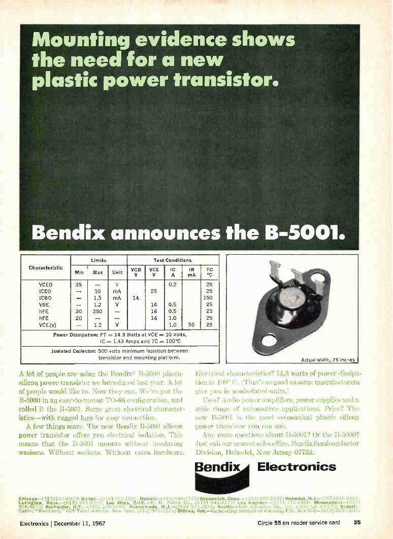
Mounting evidence shows the need for a new plastic power transistor.
Bendix announces the B-5001.
Characteristic
Limits Test Conditions
Min Max Unit VCB V
VCE V
IC A
IB mA
TC °C
VCEO 35 — V 0.2 25
ICE0 — 10 mA 25 25
ICBO 1.5 mA 14 150
VBE — 1.2 V 14 0.5 25
hFE 30 250 14 0.5 25
hFE 20 — 14 1.0 25
VCE(s) — 1.2 V 1.0 50 25
Power Dissipa ion: PT .= 14.3 Watts a VCE -.--- 10 Volts,
IC .---- 1.43 Amps and TC ---- 100'C
Isolated Collector: 500 volts minimum isolation between transistor and mounting platform.
A lot of people are using the Bendix— B-5000 plastic silicon power transistor we introduced last year. A lot
of people would like to. Now they can. We've put the B-5000 in an easy-to-mount TO-66 configuration, and called it the B-5001. Same great electrical character-istics—with rugged lugs for easy connection. A few things more. The new Bendix B-5001 silicon
power transistor offers you electrical isolation. This means that the B-5001 mounts without insulating washers. Without sockets. Without extra hardware.
Elec Heal characteristics? 14.3 watts of power dissipa-tion at 100° C. (That's as good as some manufacturers give you in nonisolated units.)
Uses? Audio power amplifiers, power supplies and a wide range of automotive applications. Price? The new B-5001 is the most economical plastic silicon power transistor you can use. Any more questions about B-5001? Or the B-5000?
.Just call our nearest sales office. Bendix Semiconductor Div ¡Finn, Holmdel. New Jersey 07722.
Bendix Electronics
Chicago—(312) 637-6929; Dallas—(214) 357-1972; Detroit, Conn.—(203) 869-7797; Holmdel, N.J.—(201) 946-9400: Lexington, Mass.—(617) 861-8350; Los Altos, Calif.—W. W. Posey Co., (415) 948-7771; Los Angeles—(213) 776-4100; Minneapolis—(612) 926-4633; Rochester, N.Y.—(716) 266-5550; Runnemede, N.J.—(609) 933-2550; Seattle—Ray Johnston Co., Inc. (206) LA 4-5170; Export— Cable: "Bendixint," 605 Third Avenue, New York, (212) 973-2121; Ottawa, Ont.— Computing Devices of Canada, P.O. Box 508—(613) 829.1800.
Electronics December 11, 1967 Circle 55 on reader service card 55

Electronics Review
VCR }ITT
TUNABLE
LOW PASS FILTER
SILICON., ASSUMES NO RESPONSIBILITY FOR TH CIRCUIT SHOWN. OR DO THEY REPRESENT OR WAR
RANT THAT IT DOES NOT INFRINGE ANY PATENTS
Corner frequency of this RC pi-filter is voltage tunable over a
100:1 range. A Siliconix VCR* has the equivalent circuit—drain
resistance and gate capacitances form the pi. V, controls the varia-tion by changing r. To change the frequency range ... shunt the gate and source with fixed capacitors.
Build this or other circuits with the VCR FET Designer's Kit
"DK6"— includes 6 VCR FETs worth $30 —available from your distributor for $19.50. Check in-
quiry card or write . . . we'll be happy to send literature.
* VCRs are voltage controlled resis-tors—a new family of FET devices — featuring a variable resistance range of typically 10,000 to 1.
Eiliconix incorporated 1140 W. Evelyn Avenue,
Sunnyvale, California 94086 Telephone (408) 245-1000
TWX: 910-339-9216
hertz pulse-modulated test signal is put into the intermediate-fre-quency strip, transmission auto-matically shuts off and a test pat-tern of four three-mile-wide rings appears on the scope. If they are evenly spaced, the pilot knows the system is working properly. He can then adjust the intensity control for proper sweep trace level and the gain control for the proper contour of rings on the test pattern. This can be done before takeoff so the test module can be switched on when airborne without further ad-justment. Testing also can be per-formed during flight. RCA plans to issue a service bul-
letin to airlines, outlining advant-ages of the self-test modification, components required, and how to install and test them. The work can be done by the airlines themselves, although RCA probably will supply a modification kit. Cost of the module has not yet been deter-mined. Work on the test module for the
Avg/ 10 was independent of RCA'S development of the Avc/30, which will have even more automatic test features and built-in monitoring of circuitry.
Manufacturing
Take-apart laser
Solid state lasers have come a long way since the first ones were built in 1960, but their reliability still lags behind that of conventional machine tools. Many of the present generation of laser drills, welders, resistor trimmers, and dynamic bal-ancers still suffer from faults that plagued the first laboratory devices —faults that must be corrected be-fore lasers can make a dent in the multimillion-dollar production-equipment market. The Applied Lasers division of
Spacerays Inc. now feels it has an engineering approach that can min-imize the laser's downtime, and will put its ideas to work in its forthcoming generation of equip-ment.
The Burlington, Mass., firm uses extra-rugged flashlamps as well as specially selected laser crystals to give its lasers a reliability cushion. But using such over-specified com-ponents where lesser ones would do is only part of the battle—flash-lamps will still fail eventually, cavi-ties will still tarnish, and pulse amplitude will still be uncertain.
Spacerays' answers to these problems are a power monitor-feedback circuit and—unique in the industry—a "breakaway" cavity.
Keeping tabs. An optional detec-tor monitors the laser's output at each successive pulse; if the detec-tor's output voltage drops, more power is fed to the flashlamp. The brighter flash compensates for the voltage drop and keeps the laser pulsing at the same amplitude time after time. The monitor - feedback circuit
thus overcomes flashlamp aging and cavity tarnishing—but only up to a certain point. A boost in pump power to compensate for the drop isn't enough at this point, and either the lamp must be replaced or the cavity polished. When this happens a panel lamp lights up, indicating to the operator that it's time to repair the laser. Bad old days. In the early 1960's,
flashlamp replacement was time-consuming. It meant taking apart the cavity, its cooling system, and its electrical connections. But re-assembling the parts in the right optical relationship was an even more difficult task. Engineers often fiddled for days to replace lamp and rod in just the right position to get maximum output. To both simplify and speed such
repairs, Spacerays came up with its breakaway cavity. Both single- and dual-eliptical cavities are machined in two parts, one holding the laser rod and the necessary mirrors and output optics, and the other hold-ing the flashlamp and almost all of the reflective surface. The quick-disconnect coolant and electrical fittings make it possible to remove and replace everything but the laser rod in less than three minutes. On a production line, spare cavi-
ties with prealigned flashlamps would be stored for replacement by the operator; the machining of the
56 Circle 57 on reader service card-*
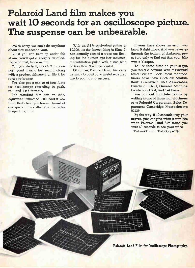
Polaroid Land film makes you wait 10 seconds for an oscilloscope picture. The suspense can be unbearable.
We're sorry we can't do anything about that 10-second wait.
But if you can bear up under the strain, you'll get a sharply detailed, high-contrast, trace record. You can study it, attach it to a re-
port, send it as a test record along with a product shipment, or file it for future reference. You also get a choice of four films
for oscilloscope recording in pack, roll, and 4 x 5 formats. The standard film has an ASA
equivalent rating of 3000. And if you think that's fast, you haven't heard of our special film called Polaroid Pola-Scope Land film.
044> 4>1 'it> tlbetre4> 4> 4te
4>40>isota„,,4>
With an ASA equivalent rating of 10,000, it's the fastest thing in films. It can actually record a trace too fleet-ing for the human eye [for instance, a scintillation pulse with a rise time of less than 3 nanoseconds]. Of course, Polaroid Land films are
as quick to point out a mistake as they are to point out a success.
1111101111111110 aluitawaguanariiii
Wail18111111WI 11111111111111111101
4110111111111111
If your trace shows an error, you know it right away. And you never go through the tedium of darkroom pro-cedure only to find out that your blip was a blooper. To use these films on your scope,
you need a camera with a Polaroid Land Camera Back. Most manufac-turers have them. Such as: Analab, Beattie-Coleman, BNK Associates, Fairchild, EG&G, General Atronics, Hewlett-Packard, and Tektronix. You can get complete details by
writing to one of these manufacturers or to Polaroid Corporation, Sales De-partment, Cambridge, Massachusetts 02139. By the way, if 10 seconds fray your
nerves, just imagine what it was like when Polaroid Land film made you wait 60 seconds to see your trace.
"Polaroid" and "PolaScope"8
111111111111
""«1111111•11111111111M111 11111111111111111111111111.1•1111 1:51111111111111.11111011
111.1111111111
Polaroid Land Film for Oscilloscope Photography.

CROSSOVER Electronics Review
KEPCO POWER
SUPPLIES Kepco's original CK design offers
true automatic crossover operation
with real equality of performance
for both voltage regulation and cur-
rent regulation. Vle' equipped, too.
Panel mode lights show at a glance
just how the power supply is regu-
lating (with signal provisions for re-
mote alarms, process control, etc.).
REGULATION
0.005% LINE — 0.01% LOAD
MODEL DC OUTPUT VOLTS AMPS
PRICE
CK 2-8M 0-2 0-8 $ 345.00 CK 8-5M 0-8 0-5 345.00 CK 18-3M 0-18 0-3 305.00 CK 36-1 5M 0-36 0-1.5 305.00 CK 40-0 8M 0-40 0-0.8 267.00 CK 60-0.5M 0-60 0-0.5 305.00
• Two Temperature Compensated Zener References and Two Ten-Turn Wirewound Controls (For both voltage and current modes)
• 16 Access Terminals for Operational Control (May be programmed by voltage, current or resistance commands)
WRITE DEPT. C-14
FOR LATEST CATALOG
CONTAINING COMPLETE
SPECIFICATIONS AND
APPLICATIONS NOTES
131-38 SANFORD AVE • FLUSHING, N.Y. 11352 (212) 461-7000 • TWX #710-582-2631
cavity makes removal and replace-ment noncritical. The replacement cavity slips into place only .002 to .003 inch away from the position of the old one. After it's removed, the old cavity can be polished or repaired at leisure without slowing produ ction.
Materials
Reclamation project
Don't write off tantalum scrap as a big loss. Metallurgical International Inc. has developed a process to re-claim the metal that can save money for manufacturers of tanta-lum capacitors. Most capacitor makers sell their
scrap and rejects for use in alloys and mill products. The going price for tantalum scrap is about $10 a pound, a far cry from the original cost of the metal, which is about $35 a pound. Metallurgical Inter-national, however, says capacitor-grade powder can be reclaimed for $15 a pound. This could mean a big savings for the manufacturers of these devices.
Slug it. Once the capacitors have been reduced to tantalum slugs, the company, with its patented Cold-stream process, pulverizes them into a powder. The particles are then recirculated and passed
through a mesh until they are about the same size. A reactant gas then separates all impurities from the powder. Finally, a furnace draws off residual gas, leaving the pow-der, which, according to Ira L. Friedman, executive vice president of the New Shrewsbury, N.J., firm, "is at least as pure as powder made directly from tantalum ore." Friedman says the shape of the
particles is superior to that pro-duced by conventional methods. Rather than being circular or den-dritic, the reclaimed particles are irregularly shaped. Tight packing provides high capacitance and less-ens the number of sharp points that invite voltage breakdown in capac-itors. Another spokesman for Metallur-
gical International says the Cold-stream process can also produce high-grade tantalum powder from virgin ore.
Jury still out. Samples of re-claimed powder are now being eval-uated by several tantalum capacitor makers. A spokesman for P.R. Mal-lory & Co. in Indianapolis says the powder seems to live up to its bill-ing. The Sprague Electric Co. of North Adams, Mass., which usually has from 5,000 to 10,000 pounds of tantalum scrap annually, says the powder seems to be of good qual-ity. However, he is quick to point out that the evaluation hasn't been completed. Other firms are also running studies.
Before and after. Tantalum scrap can now be reclaimed and reused in capacitors. Conventionally produced powder, at left, is spherical, while reclaimed powder is irregularly shaped—resulting in better electrical characteristics.
58 Circle 58 on reader service card Electronics December 11, 1967
LINEAR INTEGRATED CIRCUITS STATE-OF•THE-ART . ONE OF A SERIES
"Now we've put two I/C op amps
on ONE chip and, in one package !"
We've put two of our popular MC1709 (1LA709) integrated circuit operational amplifiers in a single 14-pin dual in-line Unibloc* plastic package. We call it the MC1437P.
The result? A staggering 1,600,000,000-voltage gain figure, among other things. Enough gain to permit design of the most stable summing ampli-fiers, integrators, or other uses where external feed-back is used. It is particularly useful for chopper-stabilized applications where extremely high gain is required with excellent stability.
With both MC1709 op amps on the same chip, you get superlative matching and tracking charac-teristics, too. (The MC1437P offers a low-
* Trademark of Motorola Inc.
leXeze depAiedem ik9Aediew à eme!
temperature drift of only ±3 p.V/°C, for example.) It also has the ability to swing almost the entire supply voltage — V.,,t = ±14 V typical @ 15 V supply. And, output impedance (Zoe) is only 30 ohms typical.
While you can't quite get two op amps for the price of one this way, it's pretty close — only $8.50 (100-up) vs. $6.00 for comparable single op amps!
For complete details on the MC1437P, or its 36,000,000-gain cousin, the MC1435P, drop us a note at Box 955, Phoenix, Arizona 85001. We'll include a copy of the WESCON paper, "A Dual Monolithic Operational Amplifier."
MOTOROLA Semiconductors
MOTOROLA SEMICONDUCTOR PRODUCTS INC. / P.O. BOX
Electronics December 11, 1967
955 / PHOENIX. ARIZONA 85001 / (602) 273-6900 / TWX 910-951-1334
Circle 59 on reader service card 59

NoW
SHOWN
ACTUAL SIZE
E New in name, packaging concept, reliability.
Mature in engineering input and system usage.
E datoMOD is a "generic name" for a class of solid state modules designed to handle data.
D The "260 Series" dc:toMOD in particular could
be called a "Differential Amplifier — Phase Sensitive
DeModulator" (if you don't mind using an eye-loupe on the nameplate).
E For Use In: Telemetry — Computation — Automatic
Control — Phase Discrimination -- Position Monitoring.
D Other Types or "Series": to be announced subse-quently.
MAYBERRY ELECTRONICS CO. 543 West Manchester Blvd. Inglewood, Calif. 90301 Telephone: (213) 678-4847 TWX 910-328-6188
Electronics Review
For the record
Unexpected bill. Shareholders of Laboratory for Electronics Inc. re-ceived a double blow last month. The Internal Revenue Service hit them for $4,840,000 in back taxes, plus interest. On top of that the Waltham, Mass., firm's second-half financial report showed that its Electronics division had pulled it $1.4 million into the red for the six months ended Oct. 27. The divi-sion's loss must have been much higher, since LFE'S other four divi-sions have been generating some profit. The tax claim is based on the con-
tention that LFE bought its Tracer-lab and Keleket divisions with the aim of applying their losses to its own tax returns. Although LFE did use them as write-offs in 1962, 1963, and 1964, company spokesmen, from company president Henry Harding on down, deny that tax reasons were behind the acquisi-tions. Some securities analysts side with them, noting that in the early 1960's up to 98% of LFE'S income was tied to a single F-105 avionics contract. Tracerlab and Keleket were acquired with the announced intention of broadening LFE'S prod-uct line to include commercial mar-kets. Its loss is tied to the fact that the Electronics division failed to deliver military avionics gear in time to avoid costly penalties.
Off base. The story describing efforts to develop a "computer on a slice" [Electronics, Nov. 27, p. 50] credited the Air Force's Rome Air Development Center, N.Y., for funding the work under way at Radio Corp. of America, Texas In-struments, and the Philco-Ford Microelectronics division. Wrong. The Wright-Patterson Air Force Base is putting up the money for the competing approaches to a large-scale integrated computer. Pay plan. Texas Instruments will
put all of its 25,000 hourly paid full-time employees on a salary basis starting Jan. 1. At the same time workers who are presently salaried but making less than $1,100 a month will become eligible for overtime pay.
60 Circle 60 on reader service card Electronics December 11, 1967

Your "ELECTRONICS TROUBLESHOOTER" —help him meet the challenges of today's expensive...
INSTRUMENTATION CONTROLS
NUMERICAL CONTROL SYSTEMS
INDUSTRIAL COMMUNICATIONS SYSTEMS
ELECTRONIC INDUSTRIAL CONTROLS
W HATEVER HIS TITLE in your particular operation, the "Electronics Troubleshooter" is on the payroll
to protect you against costly electronic equipment fail-ure. But he can't guard your investment if his skills and know-how aren't every bit as up-to-date as your equip-ment. Now there's a practical way you can "train up" your
troubleshooters to meet the challenges of today's—and tomorrow's—complex equipment. It's the "Grow Your Own" Program developed by the Cleveland Institute of Electronics.
With this program, training materials and methods are "tailored" to the needs of your operation ... and the capabilities of your employees. Training space and time are flexible. And "Grow Your Own" training can save you money and administrative time.
Want complete details? Just send the coupon below. Or, if you prefer, telephone collect—(216) 781-9400 and ask for Kenneth Ede, Vice President, Industrial Programs Division.
CIE Cleveland Institute of Electronics 1776 E.17th St., Cleveland, Ohio 44114
Attention: Kenneth Ede, Vice President, Industrial Programs Division
Please send me complete information on CIE's "Grow Your Own" training programs for Electronics Trouble-shooters.
Name
Title
Firm
Address
City
State Zip E-32
-1
Electronics l December 11, 1967 Circle 61 on reader service card 61

BEAM LEAD DIODES in flip-chips, axial-lead microdiodes and multi-diode modules You can now select from General Instrument's line of Beam Lead diode products, flip-chips, axial-lead microdiodes, and a complete line of multi-diode modules— all providing the extreme reliability of the Beam Lead structure.
The Beam Lead Technology: General Instrument's Beam Lead devices consist of gold bonding leads extending beyond the edges of the chip— in cantilever form. Securely bonded to the silicon and its passivating layer, Beam Leads make ohmic contact through a highly stable and low resistance platinum alloy. Beam Leaded devices are prepared on the slice in a batch process, thereby lowering costs and providing the utmost uniformity between Beam Lead interconnected devices. Beam Lead technology creates a total chip/bond system which is unusually rugged and yields extremely reliable package bonds by a variety of techniques.
Dilly from General Instrument
For information in Europe, write to: General Instrument Europe, Via Turati 28, Milano, Italy.
62 Electronics I December 11, 1967
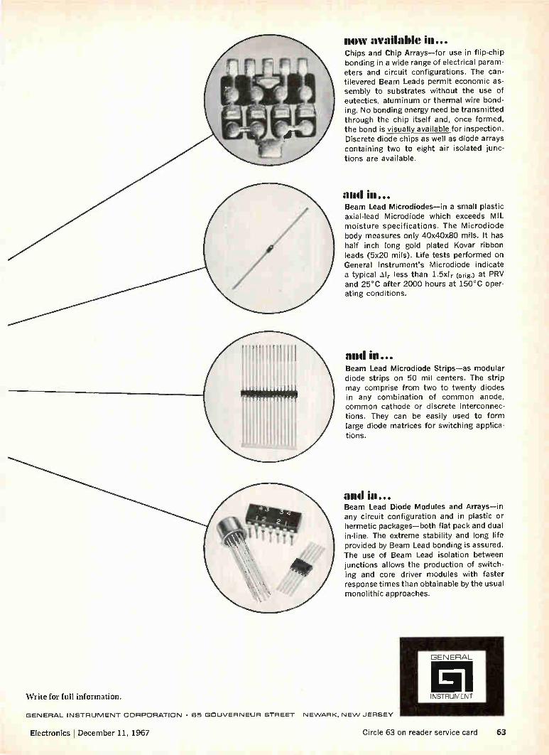
now available in... Chips and Chip Arrays—for use in flip-chip bonding in a wide range of electrical param-eters and circuit configurations. The can-tilevered Beam Leads permit economic as-sembly to substrates without the use of eutectics, aluminum or thermal wire bond-ing. No bonding energy need be transmitted through the chip itself and, once formed, the bond is visually available for inspection. Discrete diode chips as well as diode arrays containing two to eight air isolated junc-tions are available.
and Beam Lead Microdiodes—in a small plastic axial-lead Microdiode which exceeds MIL moisture specifications. The Microdiode body measures only 40x40x80 mils. It has half inch long gold plated Kovar ribbon leads (5x20 mils). Life tests performed on General Instrument's Microdiode indicate a typical Alr less than 1.5x1 r (orig.) at PRV and 25°C after 2000 hours at 150°C oper-ating conditions,
and in... Beam Lead Microdiode Strips—as modular diode strips on 50 mil centers. The strip may comprise from two to twenty diodes in any combination of common anode, common cathode or discrete interconnec-tions. They can be easily used to form large diode matrices for switching applica-tions.
and in... Beam Lead Diode Modules and Arrays—in any circuit configuration and in plastic or hermetic packages—both flat pack and dual in-line. The extreme stability and long life provided by Beam Lead bonding is assured. The use of Beam Lead isolation between junctions allows the production of switch-ing and core driver modules with faster response times than obtainable by the usual monolithic approaches.
'Write for full information.
GENERAL INSTRUMENT CORPORATION • 65 GOUVERNEUR STREET NEWARK. NEW JERSEY
Electronics l December 11, 1967 Circle 63 on reader service card 63
GENERAL
El INSTRUMENT

PROBLEM: YOUR CIRCUITS NEED THE LOW cosr OF HIGH VOLTAGE'
Application of Delco high voltage silicon power transistors: the switching regulator.
Delco high voltage silicon power transistors provide high energy capa-bility at the lowest possible cost. Take the applications pictured above: switching regulators, DC to DC convertors and DC voltage regulators. Unit prices? Just $1.70 for the DTS-410*, $4.95 for the DTS-423* and $3.95 for the DTS-413*. There are other cost cutting advantages to our high voltage silicon
power transistors. You can reduce the number and complexity of input-output and filtering components, which means more compact circuitry. Greater reliability. Lower assembly costs.
Other high energy circuits where Delco silicon power transistors have proved capabilities include: ultrasonic power supplies, VLF class C am-plifiers, off-line class A audio output, and magnetic CRT deflection (sev-eral major TV manufacturers are using them in big screen horizontal and vertical sweep circuits).
They're available in production quantities. For prices, delivery, data, or applications information, just give us a call. Or call your local Delco distributor. With Delco silicon power transistors, everything's high powered but
the price.
When purchased in quantities of 1,000 and up. Prices subject to change without notice.

TYPE VcEx VCEO (sus)
1 ' mac x.
hFE mi
V=n. cE5 y ® lc
P maox.
PRICE 1(100-and-up QUANTITIES
DIS-410 200V
300V
400V
200V 3.5A 10 ® 2.5A 80W $1.70
$2.20 DIS-411 300V 3.5A 10 ® 2.5A 100W
DTS-413 325V 2.0A 15 ® 1.0A 75W $3.95
DIS-423 400V 325V 3.5A 10 ® 2.5A 100W $4.95
DTS-424
DIS-425
DIS-430
700V 350V 3.5A 10 ® 2.5A 100W $7.00
700V
400V
400V
400V 3.5A 10 ® 2.5A 100W $10.00
300V 5.0A 10 ® 3.5A 125W $12.00
DIS-431 325V &OA 10 ® 3.5A 125W $18.00
NPN silicon transistors packaged in solid copper TO-3 case.
DELCO RADIO GM
Field Union, New Jersey* 07083 Detroit, Michigan 48202 Sales Box 1018 Chestnut Station 57 Harper Avenue Offices (201) 687-3770 (313) 873-6560
Syracuse, New York 13203 Chicago, Illinois* 60656 1054 James Street 5151 N. Harlem Avenue (315) 472-2668 (312) 775-5411
'Office includes field lab and resident engineer for applications assistance.
Santa Monica, Calif.* 90401 726 Santa Monica Blvd. (213) 870-8807 General Sales Office: 700 E. Firmin, Kokomo, led. 46901 (317) 459-2175
Division of General Motors, Kokomo, Indiana MARK OF ,,(LLENE
Circle 65 on reader service card
Good old, reliable, faithful,
trustworthy, proven, tested,
workable, dependable, consistent, versatile, SIgnetiCS
Sr-coo series Is now
better than ever Guaranteed fan-out has been increased from 4 to 8.
And the operating range is now 0°C to +75°C. Signetics SP-600 was the first DTL line in the industry to offer the
convenience of the dual in-line silicone package. Find-out for
yourself. Send for specs SIGN [TICS and reliability data based on two
years of extensive testing. INTEGRATED Write Signetics, 811 E. Argues,
Sunnyvale, California 94086. CIRCUITS Good old Signetics.
A SUBSIDIARY OF CORNING GLASS WORKS
SIGNETICS SALES OFFICES: Metropolitan New York (201) 992-3980; Upper New York State (315) 469.1072; Southwestern (214) 231-6344; Western Regional (213) 272-9421; Eastern Regional (617) 245-8200; Mid-Atlantic (609) 858.2864; Southeastern (813) 726-3734; Midwestern Regional (312) 259-8300; Northwestern (408) 738-2710.
DISTRIBUTORS: Compar at all locations listed below. Semiconductor Specialists, Inc. (312) 279.1000; Terminal Hudson Electronics (212) 243-5200; Wesco Electronics (213) 684.0880; Wesco Electronics (405) 968-3475; Hammond Electronics (305) 241-6601; Avnet Electronics Corp. of Massachusetts (617) 272-3060; Pioneer Standard Electronics Inc. (301) 427-3300.
DOMESTIC REPRESENTATIVES: Jack Pyle Company (415) 349-1266. Compar Corporation at the following locations: Alabama (205) 539-8476; Arizona (602) 947-4336; California (213) 245-1172; California (415) 697-6244; Colorado (303) 781-0912; Connecticut (203) 288-9276; Florida (305) 855-3964; Illinois (312) 775-5300; Maryland (301) 484-5400; Massachusetts (617) 969-7140; Michigan (313) 476-5758; Minnesota (612) 922-7011; Missouri (314) 428-5313; New Jersey (609) 429-1526; New Mexico (505) 265-1020; New York (518) 436-8536; New York (607) 723-8743; New York (716) 684-5731; New York (201) 471-6090; North Carolina (919) 724-0750; Ohio (216) 333-4120; Ohio (513) 878-2631; Texas (214) EM 3-1526; Texas (713) 649-5756; Washington (206) 725-7800.
INTERNATIONAL SALES: France, Germany, Italy, Belgium, Holland, Luxemburg, Spain —Sovcor Electronique, 11, Chemin de Ronde, Le Vesinet, (S.-A-0.) France. United Kingdom, Ireland, Sweden, Denmark, Norway, Switzerland, Austria, Portugal — Electrosil Ltd., Lakeside Estate, Colnbrook-By-Pass Slough. Buckinghamshire, Great Britain. Australia —Coming, 1202 Plaza Building, Australia Square, Sydney, N.S.W. 27-4318. Canada —Corning Glass Works of Canada, Ltd., Leaside Plant, Ontario, Canada (416) 421-150. Israel —Optronix, P.O. Box 195, Ramat-Gan, Israel 724-437.1apan—ASAH I Glass Co., Ltd., Corning Products Sales Dept. No. 2, 3-Chome Marunouchi, Chiyoda-ku. Tokyo, Japan.
66 Circle 66 on reader service card Electronics I December 11, 1967

Washington Newsletter
December 11, 1967
Ssb gets high marks
in satellite tests ...
... and endorsement
in study for Comsat
Task force
director named
Seismic center
gets off the ground
There's growing interest in the use of single-sideband modulation in frequency division multiplexing to give ground stations simultaneous, multiple access to communications satellites. Fanning this interest will be a report by NASA's Goddard Space Flight Center that ssb has come through a year of tests with Applications Technology Satellite 1 with flying colors. Goddard researchers will report that the narrow-bandwidth ssb pro-
vides more signal energy with less noise than conventional frequency-modulation techniques, and may utilize the frequency spectrum more efficiently. The tests on the ground-to-satellite link utilized 5.6 mega-hertz base bandwidths to give 600 two-way circuits. Twelve to 24 active circuits were transmitted, plus noise loading to simulate all-channel use, and a signal-to-noise ratio of 40 decibels was measured. A Hughes micro-wave transponder converted the ssb signals into a phase-modulated single carrier that was retransmitted to all ground stations. The ATS-1 tests went slowly at first because of problems with ground
equipment. Distortion also was a major factor initially, but the ssb equipment is now operating at a distortion level of 1%.
Also taking a hard look at ssb techniques is the Communications Satellite Corp. Philco-Ford is putting the finishing touches on a $500,000 study for Comsat of ssb and narrowband f-m techniques. Its report, which will be delivered later this month, indicates that ssb is feasible for application in commercial satellite programs. A Comsat official says there is a good chance that ssb equipment may be incorporated in the proposal for an aeronautical services satellite that the company is trying to sell the FAA.
President Johnson's task force on telecommunications finally has an executive director, but it doesn't look as if the group—which insiders say has been spinning its wheels up to now—will be able to meet its August 1968 deadline for a comprehensive study of a new U.S. com-munications policy.
Apparently because the right man couldn't be found outside the Gov-ernment, Alan R. Novak, special assistant to Eugene V. Rostow, Under-secretary of State for political affairs, has been named to head the group. He had been running the task force in the absence of a staff director [Electronics, Nov. 27, p. 59]. Aiding Novak, as director of research, is Leland Johnson, formerly with the Rand Corp.
A computer center to provide definitive data on both the location and nature—nuclear or natural—of seismic events is in test operation in Washington. Called Seismic Array Analysis Center, it was built and installed by IBM for the Air Force Systems Command, which is acting as project manager for the Pentagon's Advanced Research Projects Agency. The center will be operational next year. Data from the Large Aperture Seismic Array (LASA), made up of 525
seismometers installed in Montana in a ring about 125 miles in diam-eter, will feed into the analysis center to be processed by two IBM
Electronics I December 11, 1967 67
Washington Newsletter
360/40 computers—one to search for a seismic event and the other to analyze it. A third computer—an IBM 360/44—will be used for "special" event analysis and research in seismic-signal processing. Tapes of known events, flown to the center, are being used in current test operations.
Double audit aimed
at costs, not profits
EIA tearing down
all-electronic wall
Mobile radio group
covets tv preserve
Addenda
Defense contractors, unhappy over the Pentagon's double-check audits involving sole-source, fixed-price contracts [Electronics, Oct. 30, p. 57], will have at least one consolation: the scope of the audit has been limited to cost factors. Contractors feared the audit would be used to evaluate profit-cost relationships. The Council of Defense and Space Industry Associations had urged
deputy defense secretary Paul H. Nitze to rescind the double-audit order or, at the very least, modify it to prevent abuses by overzealous auditors. Nitze agreed to soften the original order, and the amended version is now part of the armed services procurement regulations.
A merger of the Electronic Industries Association's newly formed laser subdivision [Electronics, Nov. 13, p. 61] and the Laser Industry Associa-tion may be in the offing. The reason: the EIA is relaxing its "electronics-only" rule, opening the membership door to nonelectronic firms. This rule was one of the major reasons laser-equipment manufacturers—many of them optical firms—organized their own trade group.
The frequency-spectrum battle between television and land mobile radio users is heating up. After three and a half years of studying the problem of crowded frequencies, a committee of land mobile radio users and makers has come up with an 800-plus-page report that concludes: "Genuine relief, which is needed immediately, can only be achieved by the allocation of additional spectrum to these services." The FCC-ap-pointed panel didn't specify the needed spectrum as that now reserved for tv, but that's what it meant. With pressure building on Congress and the FCC to turn over more
frequencies to land mobile users, the television industry is expected to demand that every means to improve utilization of existing spectrum by land mobile users be used before any allocation changes are made. Some of the changes under consideration, which the advisory committee says would provide only temporary relief, include reduction of channel spacing in the 450-megahertz band, relaxation of the block allocation sys-tem to permit channel sharing on a geographical basis, greater use of low-power channels, and introduction of one-way and nonvoice systems.
Look for at least a 12% cutback—around $1 billion—in the $8 billion earmarked for Federal nonmilitary research and development in fiscal 1968. Affected will be the Department of Transportation, National Science Foundation, National Institutes of Health, and Atomic Energy Commission . . . The Air Force has delayed the announcement of the winner of a contract, expected to exceed $100 million, to produce up to 150 computers for housekeeping duties at air bases. The date has slipped from Dec. 5 to Dec. 20. This is the second time around. IBM originally was picked for the job, but Congressional criticism of the award, sparked by competitors' complaints, forced the Air Force to reopen the bidding.
68 Electronics I December 11, 1967

If Freon*is the"high-priced" cleaning agent
...how is it that Miniature
Precision Bearings estimates savings of $5,400 a year?
Miniature Precision Bearings, of Keene, N. H., greatly reduced cleaning time with a combination of FREON solvents and a new ultrasonic vapor degreaser. The new unit, which utilizes FREON PCA and FREON T-WD 602, replaced an aqueous-based detergent system. The new system can clean up to 38,000 miniature bearing parts each 8-hour shift. Result: 75% reduction in cleaning time and greatly reduced solvent costs.
Encouraged by this performance (and by the performance of a similar system using FREON solvents in their new plant in Medem-blik, Holland), Miniature Precision Bearings is considering similar equipment for its Standard Line white room. Methods Engineer James R. Walsh estimates that, because of reuse, solvent savings alone could hit $4,000 a year. And because FREON solvents need be changed less often, there's an additional $1,400 annual saving in maintenance costs.
FREON cuts solvent costs because, unlike many other solvents, it needs no inhibitors. Therefore, it's easy to clean and reuse again and again. MPB's new system uses only 50 gallons of FREON a month, with only one 3-hour change during that time. The former system required eight 3-hour changes a month. This reduction provides 21 extra hours of production time and almost eliminates overtime maintenance.
In addition to money savings, FREON does a better cleaning job. Being a dense liquid with low surface tension and high wetting power, FREON gets under dirt and literally forces oil-based contaminants off machined surfaces and from assemblies where toler-ances are held to within 20 millionths of an inch. How much can FREON, the "high-priced"
cleaning agent, save you? Find out. Write: Du Pont Co., Room 5618, Wilmington, Del. 19898. (In Europe, write: Du Pont de Nemours International S.A., FREON Products Div., 81, Route de l'Aire, CH 1211 Geneva 24, Switzer-land.) *Reg. U.S. Pat. Off. for Du Pont's fluorocarbon clearing agent.
*POO FREON®
Solvents
Electronics I December 11, 1967 Circle 69 on reader service card 69

RCA
Build with 3 more linear IC innovations from RCA... New Versatility for Commercial, Industrial, and Military Use
High-frequency wide-band amplifier/phase detector
+10V
Block diagram of typical AFC application in color TV receiver. Also suitable for B&W and FM receivers.
• For Automatic Fine Tuning in VHF and UHF receivers
• Dual phase detector with differential output amplifier
• Compensated reference voltage sup-ply
• Operating temperature range —55°C to +125°C
• Total current drain 9 mA (type) @ Vcc= 10V
• Output offset voltages between termi-nals #4 and #5 1.5V max. @ Vcc= 10V
• Input impedance 2K 1 typ
RCA CA3034 in 10-lead TO-5 package. Price $1.75 (1000+)
RCA CA3034V1 with preformed leads. Price $1.75 (1000+)
70 Electronics December 11, 1967

3-in-1 wide-band amplifier array 132 dB (typ) Gain!
.270 V
0.022 µF
REMOTE CONTROL
TRANSMITTER
CeoNECTED TO CASE
ao 3 0.0022
Ti • DRIVER
OF TRANSFORMER
Low noise performance and outstanding wide-band response make this three-in-one unit general purpose amplifier array ideal foi TV remote control.
• Three separate amplifiers; gain and bandwidth for each adjustable by external circuitry • Can operate as individual units—or in cascade for 132 dB gain (typ) @ 40 KHz • Voltage gain—Ampl. =1 44dB typ
Ampl. =2 46dB typ Ampl. =3 42dB typ
• Bandwidth @ —3 dB point—Ampl. =1 500 KHz Ampl. =2 2.5 MHz Ampl. =3 2.5 MHz
e Operating temperature range —55°C to +125°C
• All three amplifiers single-ended, only one power supply needed e Typical applications: TV remote control; IF systems; instrumentation amplifiers; chopper amplifiers
RCA CA3035 wide-band high-gain ampl. in TO-5 package. Price $1.50 (1,000+)
RCA CA3035V1 with pre-formed leads. Price $1.50 (1,000+)
Dual Darlington amplifier array
Block diagram of application as stereo phono pre-amp. Cartridges designed around the CA3036 can provide en-hanced fidelity, low hum pick-up without shielding. Response flat to 1MHz @ ft1 = 11<fl
• Voltage gain for either pair 26 dB (typ)
• Power gain for either pair 47 dB (typ) @ f= 1 KHz • Gain-bandwidth product for either pair 200 MHz • FIFE for either pair 4540 typ. @ Ici + Ic2 = lmA
• Operating temperature range —55°C to +125°C
• VcEo = 15V max. • VCBO = 30V max.
• VEBO = 5V max. • lc (each transistor) -= 50 mA max. • Emitter-follower output
• Typical applications: stereo phono amplifiers; dif-ferential ampls; op amp driver; mixer
RCA CA3036 Dual Darlington Array in 10-lead TO-5 package. Price 98e (1,000+)
Ask your RCA Distributor for his price and delivery. For Technical Data write to RCA Commercial Engineer-ing Section ICN12-2, Harrison, N.J. 07029.
RCA ELECTRONIC COMPONENTS & DEVICES
The Most Trusted Name in Electronics
71 Electronics December 11, 1967

First-of-a-kind connectors for sale from Amphenol Space And Missile Systems

4 • • • • • • • • 4 • • • • 4 •
• • • • • • • • • • • • • 4 • • • • • • • • • • • 0 • 4 • • • It •
Sometimes the right connector doesn't appear in a catalog. Especial-ly when it's destined for unusual uses.
That's why we developed our S AMS facility—to provide new so-lutions to interconnection problems.
At Amphenol, we've designed and produced interconnecting systems
1# 06111•••• • • • • • • • • • • • • • • * 1111411• ••••• • • • • • • • • • • • •
• • • • • • • 4 • • 1P • • • • • • • • •
for Minuteman, Titan, Agena, SST, and Poseidon—to name a few. Our mission profile includes every type of application from GSE to satellites. Every connector type, too. Some carry several hundred circuits, with-stand 1000F, offer "dead-facing" or resist exotic fuel corrosion damage.
Ask us to help you solve your in-terconnection problems. Write us. Amphenol Connector Division, Chatsworth, California 91311.
AMPHENOL Circle 73 on reader service card
Specify Amphenol ... the leading name in cable, connectors, assemblies, RF switches, potentiometers, microelectronics.

leatale 101.1111.111•1111110811. W
*;"
•
just part of the full Honeywell line, which includes: 0117 Visicorder direct-recording oscillographs in 6", 8", and 12" models; 0 2 Model 1806 fiber' optics CRTVisicorder oscillographs;@ 26 magnetic tape systems, including the 7600 Series in 10Y:" and 15" reel versions; 084 amplifiers and other signal-condi-
We build 847 instruments to be sure we have the exact you need.

V.
C
+1.2 SS
g2)'
• •
tioning units; Q78 analog recording systems; 046 electronic medical systems; 014 oscilloscopes; 037 digital multimeters; Q29 differential voltmeters;
0179 precision laboratory standards and test instruments; 0128 data loggers; Q9 analysis systems; 061 EMI products; 037 X-Y graphic recorders.
Your Honeywell sales engineer can zero in on the precise solution to your instrumentation problems. Quickly and efficiently. You won't have to settle for "almost" what you need because the Honeywell sales engineer isn't handicapped by a limited line. He can choose from 847 basic instruments whose combinations and permuta-tions approach the infinite.
The solution might be a Visicorder recording oscillo-graph. Or one of our modular magnetic tape systems. Or an X-Y recorder, a digital multimeter, or a portable po-tentiometer. But whether it's a single instrument or a complete data system,you can be sure the solution will be the right one, carefully thought out with your future requirements considered as well as your current needs.
• c es r • r t
Local èervice and nationwide metrology facilities back up your Honeywell instrument or system. And, we can even provide factory training courses-for your operating personnel. For the full story on how Honeywell can help you, call your local sales engineer or write: Honeywell, Test Instruments Division, Denver, Colorado 80217. Honeywell
Honeywell engineers sell solutions
Circle 75 on reader service card

.050" CONTACT CENTERS 1/16ffPC BOARD/BELLOWS CONTACT
NEW MICROMINIATURE
PRINTED CIRCUIT
CONNECTORS... your choice of 10, 14, 22, 40, 55 and
64 dual contacts now available with
Series 600-6 microminiature printed
circuit connectors. Single piece body
molding is glass reinforced Dially1
Phthalate Type SDG per MIL-M-14
specifications.
For complete specifications and outline
drawings ask for free brochure 6002-667,
Advertising Department, Continental
Connector Corporation, 34-63 56th
Street, Woodside, N.Y. 11377. Or phone
(212) 899-4422 for immediate action.
054 -071 PRINTED - CIRCUIT CARD THICKNESS
oil -4- b. 4-.075 TSP.
PATENTED "BELLOWFORM" CONTACT
Outline Cross-Section
600-6PC14 28 Terminals
600-6PC22 44 Terminals
600-6PCIO 20 Terminals
Series 600-6 Complete Line Now Available
ALL CONNECTORS SHOWN ACTUAL SIZE
For the Sales Representative Nearest You, See Our Listings in REM and VSMF Directories.
ii'!. j1f11j1j
600-6PC4° 80 Terminals
if
600-6PC55 110 Terminals
600-6PC64 128 Terminals
CONTINENTAL CONNECTORS CONTINENTAL CONNECTOR CORPORATION • WOODSIDE, NEW YORK 11377
76 Circle 76 on reader service card Electronics I December,11, 1967

Frenchtown/CFI can make you 5.000.000 ceramic transistor bases a week
For high volume, custom-made alumina and beryllia ceramic products, astute buyers make sure to contact Frenchtown/CFI, Inc. Shipping rates of more than 5,000,000 pressed parts per week are easily main-tained—month after month after month.
For complex parts, too, Frenchtown/CFI is a prime source.You can get them large or small, moly-manganese or gold-platinum metallized. Intricately shaped. Assem-
...or 5.000 ceramic missile gas generator igniter insulators a year
bled to other ceramics or metal parts. Optically flat. Hermetically sealed.
Whether your application is electronic, electrical, me-chanical or chemical, consult Frenchtown/CFI on prob-lems of ceramic production, metallizing and sealing. You can save weeks on your timetable. Describe your need and request a proposal. (We'll send you an informa-tive brochure too.) For fast action call:
•
4.
•
FRENCHTOWN/CFI, INC. A subsidiary of Alloys Unlimited, Inc.
Eighth Street, Frenchtown, New Jersey 08825 (201) 996-2121
FRENCHTOWN/CFI MEANS CERAMICS FOR INDUSTRY
left photo: 92% alumina—opaque—TO 18 configuration. right photo: 96% alumina-to-Kovar seal—withstands 8,000 psi.
Circle 77 on reader service card

Don't buy a DVM buy a measuring system. It's cheaper that way.
Because we designed our new DVM as part of an expandable measuring system, you get a complete digital voltmeter at a price of only $580. But you also get much more...
The only system that will accept two function modules at a time.
The digital display unit is the focus. Plug in one module, and you've got a DVM for measuring DC. Add another, and you can measure AC. Substitute others and you can measure frequency, period, time intervals and other parameters.
Our new Model 6200 DVM doesn't cost much more than a multimeter. But it's 10 to 30 times more
accurate. It's linear over the entire range. You change voltage ranges just by pressing buttons. You read off the voltage value as a number. You don't have to work at interpreting scales.
And the plug-in concept is the topper. Buy a plug-in for whatever function you need at a fraction of the cost of a single-purpose instrument.
For a demonstration, call (201) 229-4400. Or write for a complete technical description.
EAI 8ELEurRox IC ASSOCIATES. INC. IVest Long Branch, New Jersey
MODEL 6200 DISPLAY UNIT with long-life Nixie tube readout accepts two modules simultaneously. Gives you 4-place digital readout and "mix-or-match" of modules for flexibility. Compact: half rack width. Solid-state silicon and I.C. circuitry.
MODEL 6201 DVM MODULE. Measures DC voltages in 5 ranges from 100.0 my to 1000 volts. Accuracy is 2:0.1% -±-1 digit. Features: Push-button ranging. Automatic polarity selection. Integrating function for high accuracy even with a background of hum and noise. 40% overrange on 4 most sensitive ranges.
MODEL 6203 AC CONVERTER MODULE. Measures AC voltages accurately over a wide fre-quency range. Four pushbutton ranges to 300 volts rms. Frequencies from 20 Hz to 100 KHz. Used in conjunction with DVM Module.
MODEL 6202 COUNTER MODULE. Measures frequencies to 10 MHz with -±.005% count accuracy. Measures period or time intervals from 1 microsecond to 1000 seconds with 1 microsecond ±-1 count resolution.
JUST ADDED: MODEL 6240
RACK MOUNTED DVM. Self-contained DC DVM with optional BCD output and Model 6241 expansion chassis for plug-in modules.
78 Circle 78 on reader service card Electronics December 11, 1967
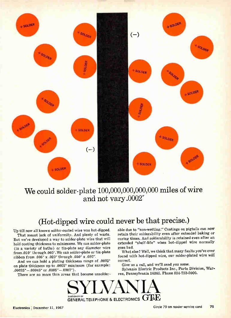
(—)
sOLDER
(-)
+ SOLDER . "
ksee
We could solder-plate 100,000,000,000,000 miles of wire and not vary .0002"
(Hot-dipped wire could never be that precise.) Up till now all known solder-coated wire was hot-dipped. That meant lack of uniformity. And plenty of waste.
But we've developed a way to solder-plate wire that will hold coating thickness to minimums. We can solder-plate (in a variety of baths) or tin-plate any diameter wire from .010" through .060". We can solder-plate or tin-plate ribbon from .005" x .020" through .050" x .080". And we can hold a plating thickness range of .0002"
on plate thickness up to .0005" minimum (for example: .00025"—.00045" or .0005"—.0007"). There are no more thin areas that become unsolder-
able due to "non-wetting." Coatings on pigtails can now retain their solderability even after extended baking or curing times. And solderability is retained even after an extended "shelf-life" when hot-dipped wire normally
goes bad. What else ? Well, we think that many faults you've ever
found with hot-dipped wire, our solder-plated wire will
correct. Give us a call, and we'll send you some. Sylvania Electric Products Inc., Parts Division, War-
ren, Pennsylvania 16365. Phone 814-723-2000.
SYLVAN GENERALTELEPHONE & ELECTRONICS GTE SUBSIDIARY OF
Electronics December 11, 1967 Circle 79 on reader service card 79

01% ACCURACY
MODEL #1313A
• Extremely High Accuracy: 0.1% of Reading
• No Factors: Dial callouts auto-matically change when function and range is selected.
• High Resolution: Discrimination 0.01% of full scale; 10,900 division/range (Dial Reads 46.66 mH)
• Wide Temperature Range Without Corrections
• Built-In Oscillator: lkHz and 10kHz, 20Hz — 35kHz with external oscillator
• Capacitor Bias: Up to 350VDC can be applied to polarize electrolytics
Inductance: ..0.1 ILH to 11H @ 1 and 10kHz
Capacitance: 0.1pF to 110 PF
Resistance: 0032 to 110M°
Q Range: 0 to 310
D Range: 0005 to 30
use the NEW
MARCONI
UNIVERSAL
BRIDGE
40
30
20
10
02
80
90
100
Accuracy high, interpolation precise, familiarization time minimal
. . . the model 1313A, latest in Bridges, is designed for use by
engineers and production personnel alike. Ask your Marconi
representative to show you.
MARCONI 111 Cedar Lane • Englewood, N. J. INSTRUMENTS
Division of English Electric Corporation
Telephone: 201-567-0607
80 Circle 80 on reader service card Circle 81 on reader service card--*-

Just 40¢ to ship a cubic foot of PELASPAN- PAC® loose-fill packing via 1st class (any-where within the U.S.). $3.20 for other kinds of packing ma-terials. Gives you an idea of the savings in truck and rail costs when you use PELASPAN- PAC. A cubic foot of it weighs only 8 oz., 8 times lighter than other packing materials. PELASPAN- PAC does a better job of cushioning delicate
electronic instruments on trips from here to there. The curled pieces of expanded polysty-rene interlock. They actually hold the packed item in sus-pension. Never wad into a lump or collapse like make-shift packing materials do. PELASPAN- PAC has other ad-
vantages. It's clean and dust free. So easy to work with, you'll realize major savings in labor time and cost. Now that you've weighed the facts, isn't PELASPAN- PAC the best? Your nearby distributor has it. Write us for his name. The Dow Chemical Company, Plastics Sales, Department 71230, Midland, Michigan 48640.
Packing for shipment? Weigh the cost.
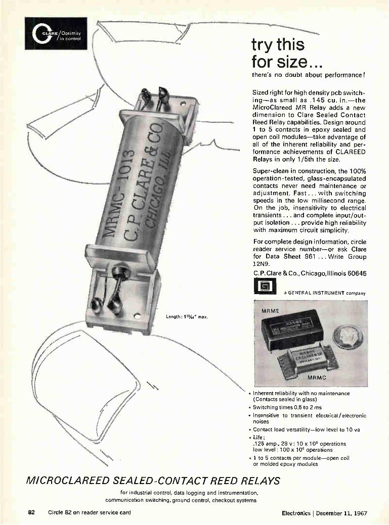
CLARE/ Upurully
cuffirol
Length: 11%4" max.
try this for size... there's no doubt about performance!
Sized right for high density pcb switch-ing—as small as .145 cu. in.—the MicroClareed MR Relay adds a new dimension to Clare Sealed Contact Reed Relay capabilities. Design around 1 to 5 contacts in epoxy sealed and open coil modules—take advantage of all of the inherent reliability and per-formance achievements of CLAREED Relays in only 1/5th the size.
Super-clean in construction, the 100% operation-tested, glass-encapsulated contacts never need maintenance or adjustment. Fast ... with switching speeds in the low millisecond range. On the job, insensitivity to electrical transients ... and complete input/out-put isolation ... provide high reliability with maximum circuit simplicity.
For complete design information, circle reader service number—or ask Clare for Data Sheet 961 ... Write Group 12N9.
C. P.Clare & Co., Chicago,Illinois 60645
fi a GENERAL INSTRUMENT company
• Inherent reliability with no maintenance (Contacts sealed in glass)
• Switching times 0.5 to 2 ms
• Insensitive to transient electrical/electronic noises
• Contact load versatility—low level to 10 va
• Life: .125 amp., 28 v : 10 x 106 operations low level: 100 x 106 operations
• 1 to 5 contacts per module—open coil or molded epoxy modules
MICROCLAREED SEALED-CONTACT REED RELAYS for industrial control, data logging and instrumentation,
communication switching, ground control, checkout systems
82 Circle 82 on reader service card Electronics I December 11, 1967
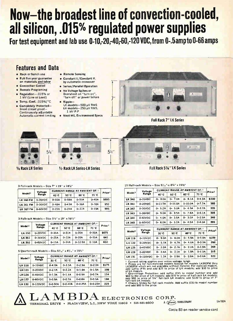
Now the broadest line of convection-cooled, all silicon, .015% regulated power supplies For test equipment and lab use 0-10,-20,-4(00,-120 VDC,from 0-.5ampto 0-66 amps
Features and Data • Rack or bench use
• Full five year guarantee
on materials and labor
• Convection Cooled
• Remote Programing
• Regulation-.015% or
1 MV (Line or Load)
• Temp. Coef..015%/°C
• Completely Protected-Short circuit proof-Continuously adjustable
Automatic current limiting
111 rj ..
1/4 Rack LH Series
• Remote Sensing
• Constant I./Constant V. by automatic crossover
• Series/Parallel Operation
• No Voltage Spikes or Overshoot on "turn on",
"turn off" or power failure
• Ripple-
LK models-500,uV RMS LH models-250,uV RMS, 1 MV P-P
• Meet MIL Environment Specs
41111111111111111111111. 1.1M'
5;‘i
1/2 Rack LK Series-LH Series
3 Full-rack Models - Size 7" x 19" x 18' z"
Model 2 Voltage Range
CURRENT RANGE AT AMBIENT OF:t Price 2
40°C 50°C 60°C 71°C
LK 360 FM 0-20VDC 0-66A 0-59A 1. 0-50A ' 0-40A $995
LK 361 FM 0-36VDC 0-48A 0-43A 0-36A 0-30A 950
LK 362 FM 0-60VDC 0-25A 0-24A 0-22A 0-19A 995
Full Rack 7" LK Series
Full Rack 51/4 " LK Series
3 Full-rack Models - Size 51/4 " x 19" x 16'/2"
Model 2 Voltage Range
CURRENT RANGE AT AMBIENT OF:' Price 2
40'C 50'C 60 C 71°C
LK 350 0-20VDC 0-35A 0-31A 0-26A 0-20A $675
LK 351 0-36VDC 0-25A 0-23A 0-20A 0-15A 640
LK 352 0-60VDC 0-15A 0-14A 0-12.5A 0-10A 650
5 Quarter-rack Models-Size 53A," x 43A6" x 151/2 "
Model' Voltage Range
CURRENT RANGE AT AMBIENT OF: i Price 2
30°C 50°C 60°C 71°C
LH 118 0-10VDC 0-4.0A 0-3.5A 0-2.9A 0-2.3A $175
LH 121 0-20VDC 0-2.4A 0-2.2A 0-1.8A 0-1.5A 159
LH 124 0-40VDC 0-1.3A 0-1.1A 0-0.9A 0-0.7A 154
LH 127 0-60VDC 0-0.9A 0-0.7A 0-0.6A 0-0.5A 184
LH 130 0-120VDC 0-0.50A 0-0 40A 0-0.35A 0-0.25A 225
LA TERMINAL DRIVE • PLAINVIEW, L.I., NEW YORK 11803 • 516-681-8300 A
_AillallallE111111111L_
11 Half-rack Models - Size 5,/"-x 83/8" x 155/8"
Model 2 Voltage Range
CURRENT RANGE AT AMBIENT OF:' Price 2
40°C 50°C 60°C 71°C
LK 340 0-20VDC 0- 8.0A 0- 7.0A 0- 6.1A 0-4.9A $330
LK 341 0-20VDC 0-13.5A 0-11.0A 0-10.0A 0-7.7A 385
LK 342 0-36VDC 0- 5.2A 0- 5.0A 0- 4.5A 0-3.7A 335
LK 343 0-36VDC 0- 9.0A 0- 8.5A 0- 7.6A 0-6.1A 395
LK 344 0-60VDC 0- 4.0A 0- 3.5A 0- 3.0A 0-2.5A 340
LK 345 0-60VDC 0- 6.0A 0- 5.2A 0- 4.5A 0-4.0A 395
Model 2 Voltage R ange
CURRENT RANGE AT AMBIENT OF: i Price 2
30°C 50°C 60°C 71°C
LH 119 0-10VDC 0- 9.0A 0- 8.0A 0- 6.9A 0-5.8A $289
LH 122 0-20VDC 0- 5.7A 0- 4.7A 0- 4.0A 0-3.3A 260
LH 125 0-40VDC 0- 3.0A 0- 2.7A 0- 2.3A 0-1.9A 269
LH 128 0-60VDC 0- 2.4A 0- 2.1A 0- 1.8A 0-1.5A 315
LH 131 0-120VDC 0- 1.2A 0- 0.9A 0- 0.8A 0-0.6A 320
I Curren rating apples over entire voltage range. 2 Prices are for non-metered models (except for models LK360FM thru LK362FM which are not available without meters). For metered models, add suffix (FM) and add $25 to price of LH models; add $30 to price of LK models.
Overvoltage Protection: add suffix (0V) to model number and add $60 to the price of LH models; add $70 to price of half-rack LK models: add $90 to price of 54" full-rack LK models; add $120 to price of 7" full-rack LK models. 4 Chassis Slides for full rack models: Add suffix (CS) to model number and add $60 to the price.
M B DA_ ELECTRONICS CORP. SUBSIDIARY LA•182A
Circle 83 on reader service card

This is AE's Class B relay.
Use it where a less expensive relay would cost too much.
The Class B is a premium-qual-ity telephone-type relay. It can give you at least 400 million operations with unfailing con-tact reliability. And it seldom needs maintenance.
That's why it's probably the most inexpensive relay you can use—where long-term reliability is a must.
In commercial and industrial control applications, the AE Class B delivers just what you'd expect of a telephone relay. It combines good sensitivity with excellent stability. Withstands extreme temperatures. Provides a wide range of practical oper-ate and release timing...a range much wider than possible with smaller types of relays. The Class B has two arma-
ture ratios (long, for fast acting
or pulsing — short, for slow-release and chatter-free AC operation). It also features twin contacts to insure against contact failure, a permanent wear-free backstop, pin-type armature bearings—plus a sturdy, stable heel-piece. Newest Class B relay is
the Series BRM latching version. When pulsed, rema-nent magnetism keeps the BRM latched without power consumption until it is restored by a second pulse.
Find out more about the Class B relay—the industry standard for long-term econ-omy. Ask for Circular 1993. Just write to the Director, Relay Control Equipment Sales, Automatic Electric Company, Northlake, Illinois 60164.
AUTOMATIC ELECTRIC SUBSIDIARY OF
GENERAL TELEPHONE & ELECTRONICS GTE
84 Circle 84 on reader service card Electronics j December 11, 1967

GOLD PLATED TERMINAL TABS
MULTI-WIRE WELDED TAB TERMINATION
GROOVED NYLON CASE
HARD GOLD PLATED CENTER TERMINAL
CONTACT
PRECIOUS METAL WIPER SPRING
UNIFORM, LOW TC WINDINGS
LOW-COST 10-TURN POTENT__ _ _ 7/8" diameter, 0.25% linearity, plus long life Here's a rugged high-performance potentiometer that means space and cost savings for your industrial and commercial applications. With only Ws" projection behind the panel, this 7/8" diameter unit has sta-bility and reliability features normally found only in MIL-type units.
• Rugged nylon housing and end plate—withstands rough handling and mechanical abuse.
• Grooved case—maintains uniformity of wire windings and provides for 0.25% independent linearity.
• Welded tab termination—means low end resistance and easier external connections.
• Longer winding-20"-long, low IC wire provides better stability and resolution over the entire resistance range.
• Precious metal wiper spring—assures better contact and long rotational life.
• Retaining "C"-ring—prevents possible snap-out of rear plate.
MOLDED NYLON WIPER BLOCK
RETAINING "C"-RING
Immediately available, this new I RC preci-sion potentiometer has popular side ter-minals and a 1/4" diameter shaft that per-mits knob or screwdriver adjustment. Write for data and prices. I RC, Inc., 401 N. Broad St., Philadelphia, Pa. 19108.
CAPSULE SPECIFICATIONS IRC TYPE 8400
SIZE /8 " diameter TURNS 10 POWER 2 watts @ 25°C INDEPENDENT LINEARITY +0.25% TOLERANCE ±5% RESISTANCE END RESISTANCE
100 to 100K n, 0.1% or 2n (whichever is greater)
Electronics ! December 11, 1967 Circle 85 on reader service card 85
IOMETER
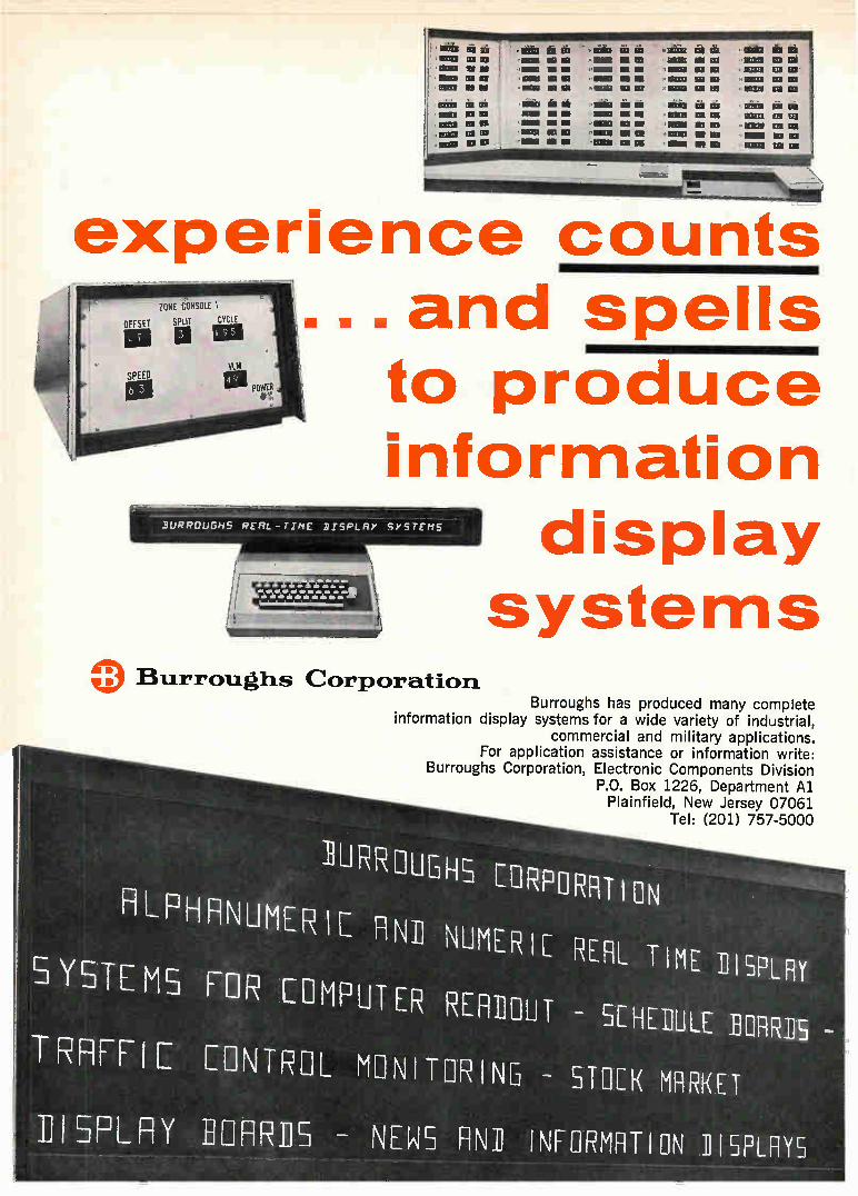
experience counts ZONE CONSOLE 1
OFFSET II
SPEED
1.11
Burroughs Corporation
and spells URI
POWER
DOPRCuGHS REAL-TIME DISPLAY sysrcHS
to produce information
display systems
Burroughs has produced many complete information display systems for a wide variety of industrial,
commercial and military applications. For application assistance or information write:
Burroughs Corporation, Electronic Components Division P.O. Box 1226, Department Al Plainfield, New Jersey 07061
Tel: (201) 757-5000
ILIRROLIGHS CORPORATION
F1LPH \UMERIE RNi NIJME:iIC .EFIL. TIME DISPLAY
5 YT E MS FOR COMPUTER READOUT - SCHEDULE EMUS -
T RIFF' LONTREIL N1 \IT RING - STOCK MARKET
I SPLAY - NEWS FINIJ INFORMATION 1115PLAYS
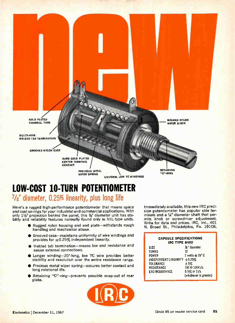
GOLD PLATED TERMINAL TABS
MULTI-WIRE WELDED TAB TERMINATION
GROOVED NYLON CASE
HARD GOLD PLATED CENTER TERMINAL
CONTACT
PRECIOUS METAL WIPER SPRING
UNIFORM, LOW TC WINDINGS
LOW-COST 10-TURN POTENTIOMETER 7/8" diameter, 0.25% linearity, plus long life Here's a rugged high-performance potentiometer that means space and cost savings for your industrial and commercial applications. With only 11/8" projection behind the panel, this 7/8" diameter unit has sta-bility and reliability features normally found only in MIL-type units.
• Rugged nylon housing and end plate—withstands rough handling and mechanical abuse.
• Grooved case—maintains uniformity of wire windings and provides for +0.25% independent linearity.
• Welded tab termination—means low end resistance and easier external connections.
• Longer winding-20"-long, low TC wire provides better stability and resolution over the entire resistance range.
• Precious metal wiper spring—assures better contact and long rotational life.
• Retaining "C"-ring—prevents possible snap-out of rear plate.
MOLDED NYLON WIPER BLOCK
RETAINING "C"-RING
Immediately available, this new I RC preci-sion potentiometer has popular side ter-minals and a 1/4" diameter shaft that per-mits knob or screwdriver adjustment. Write for data and prices. I RC, Inc., 401 N. Broad St., Philadelphia, Pa. 19108.
111•1•M•11.1•M
CAPSULE SPECIFICATIONS IRC TYPE 8400
SIZE 7/8" diameter TURNS 10 POWER 2 watts g 25° C INDEPENDENT LINEARITY +0.25% TOLERANCE ±5% RESISTANCE 100 to 100K n. END RESISTANCE 0.1% or 2n.
(whichever is greater)
Electronics December 11, 1967 Circle 85 on reader service card 85

Make them modern with heat-sealable
SCOtChp.q15: polyester film... tough, flat and flexible
Typical Applications: Pipe and tank-heating cable by Electro-Trace Corp.; printed circuit panels made by firms such as Flexible Circuit Corp.; flat cables by Tape Cable Corp.; and a variety of other uses including coil covers and wire wrap.
"SCOTCHPAK" film laminates easily — like a ther-
moplastic. And since it is a polyester, it is excep-tionally strong...chemically resistant...with
high dielectric properties. It's available in various types and thicknesses— probably one just right for your needs. Enables you to make cables that easily follow unusual contours ... that lie flat ... take up minimum space. Printed circuits that flex
... but don't snap. A market potential estimated at over $100 million by 1970!
Interested? For more information, write: Film &
Allied Products Div., 3M Co., 2501 Hudson Rd., St. Paul, Minn. 55119, Dept. ICL-127. 3rin
COMPANY
86 Circle 86 on reader service card
•ISCOTCEIPAK" IS A REG. TU. OF 31.1 CO.
Electronics December 11, 1967

A word to the do-it-yourself module builder:
Don't. Buy our J Series modules instead.
The J Series is our new family of general purpose, all integrated
circuit logic modules. Their per- 1 formance almost matches that -
of our famous T Series modules, but they cost about 25 % less. They're made to the same dimensions as the T Series, with the same 52 pin connec-tors, so they're physically interchangeable. We make them
for our own seismic recorder systems, so they're rugged
and reliable. Now, as of January, you can buy them (corn-
These will cost you less.
plete with mounting hardware, racks and power supplies,
if you wish) in any of 25 different functions. And save yourself the time and cost of making your
own: designing, assembling, testing, new procedures, new
equipment, new personnel, additional training, nothing of the added paper work.
If you're building systems, you must have better things to do than go into the module assembly business.
Such as reading our J Series catalog. It's free.
Scientif" e Dato Systems, Santa Monica, California
to say
Circle 265 on reader service card

experience counts ...and spells
to produce information
display systems
0: Burroughs Corporation Burroughs has produced many complete
information display systems for a wide variety of industrial, commercial and military applications.
For application assistance or information write: Burroughs Corporation, Electronic Components Division
P.O. Box 1226, Department Al Plainfield, New Jersey 07061
Tel: (201) 757-5000
1LIRROLIGHS CORPORFITIoN
RLPH\UMEIL FIN
SYSTEMS FOR COMPUTE
TRRFFIC EIN1L M
IISPLRY
NUMERIC EFIL TIME DISPLF1Y
REFinoui - SCHEDULE BOARDS -
I TER I NB - STOCK MARKET
_115 - NEWS FIN1 INFORMATION 115PLAY5
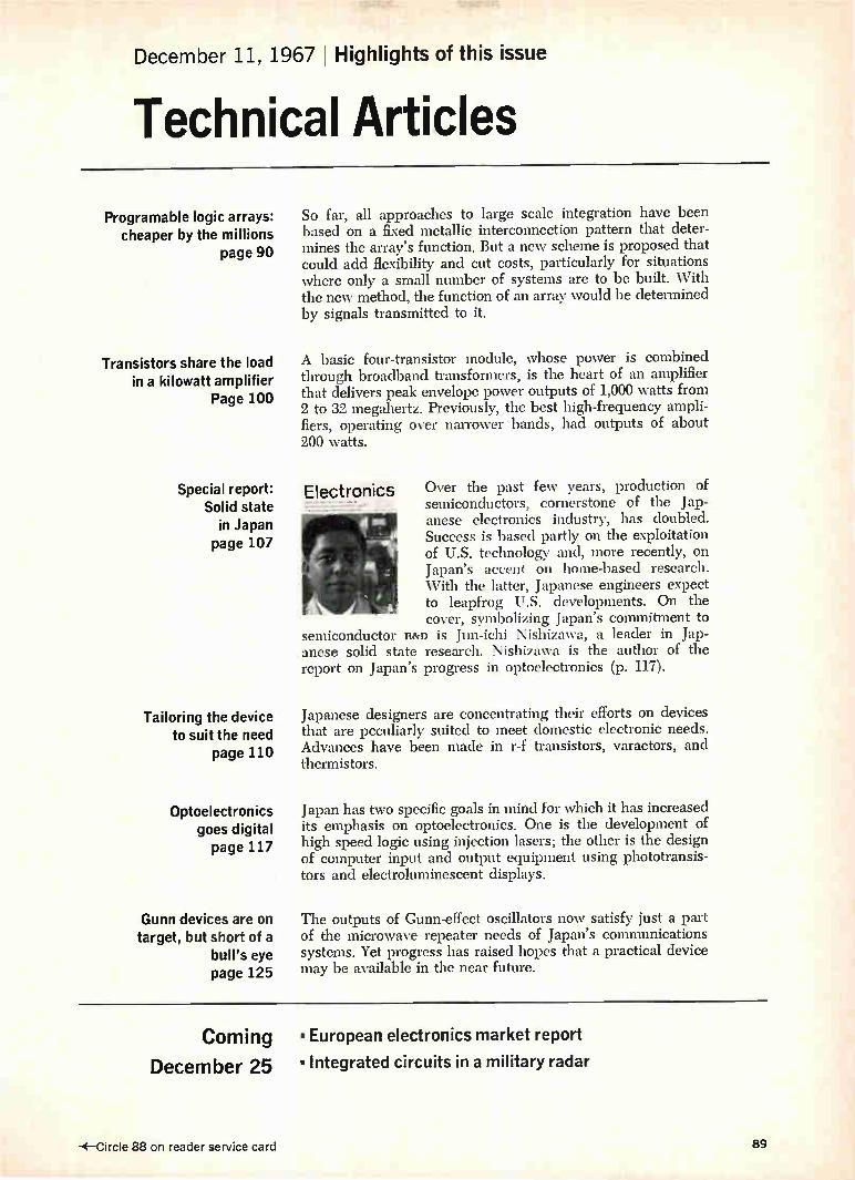
December 11, 1967 Highlights of this issue
Technical Articles
Programable logic arrays: cheaper by the millions
page 90
Transistors share the load in a kilowatt amplifier
Page 100
Special report: Solid state
in Japan page 107
Tailoring the device to suit the need
page 110
Optoelectronics goes digital page 117
Gunn devices are on target, but short of a
bull's eye page 125
So far, all approaches to large scale integration have been based on a fixed metallic interconnection pattern that deter-mines the array's function. But a new scheme is proposed that could add flexibility and cut costs, particularly for situations where only a small number of systems are to be built. With the new method, the function of an array would be determined by signals transmitted to it.
A basic four-transistor module, whose power is combined through broadband transformers, is the heart of an amplifier that delivers peak envelope power outputs of 1,000 watts from 2 to 32 megahertz. Previously, the best high-frequency ampli-fiers, operating over narrower bands, had outputs of about 200 watts.
Electronics Over the past few years, production of semiconductors, cornerstone of the Jap-anese electronics industry, has doubled. Success is based partly on the exploitation of U.S. technology and, more recently, on Japan's accent on home-based research. With the latter, Japanese engineers expect to leapfrog U.S. developments. On the cover, symbolizing Japan's commitment to
semiconductor R&D is Jun-ichi Nishizawa, a leader in Jap-anese solid state research. Nishizawa is the author of the report on Japan's progress in optoelectronics (p. 117).
Japanese designers are concentrating their efforts on devices that are peculiarly suited to meet domestic electronic needs. Advances have been made in r-f transistors, varactors, and thermistors.
Japan has two specific goals in mind for which it has increased its emphasis on optoelectronics. One is the development of high speed logic using injection lasers; the other is the design of computer input and output equipment using phototransis-tors and electroluminescent displays.
The outputs of Gunn-effect oscillators now satisfy just a part of the microwave repeater needs of Japan's communications systems. Yet progress has raised hopes that a practical device may be available in the near future.
Coming • European electronics market report
December 25 • Integrated circuits in a military radar
-E—Circle 88 on reader service card 89
Cornputers
Programable logic arrays cheaper by the millions
Standardized large-scale integrated circuits with fixed interconnections
and variable functions can be fabricated in huge quantities at low cost,
thus making short production runs of large systems more economical
by Sven E. Wahlstrom Stanford Research Institute, Menlo Park, Calif.
Flexibility and cost savings would be the payoff if many logic circuits within a single silicon chip could be interconnected in such a way that the function of the array were determined by signals transmitted to it instead of by a fixed, metallic in-terconnection pattern. After years of studying ways to organize digital integrated circuits in standard-ized arrays so they can be used as computer build-ing blocks, the Stanford Research Institute has de-vised such a scheme.
In contrast to conventional arrangements, arrays designed in this way could be reprogramed to handle several hundred functions. Ideally, the pro-gramable circuits would be identical. With fewer kinds of chips to deal with, development costs are less, and larger quantities of each kind of chip would cost less to produce. The proposed technique is particularly attractive
for situations in which only a small number of sys-tems are to be built. Generally, the programable logic would require several times the amount of circuitry to perform a given function as does a con-ventional assembly. And a very large number of custom-designed chips costs less to make than would a functionally equivalent number of pro-
The author
Sven E. Wahlstrom is a senior research engineer in the computer techniques laboratory at Stanford Research Institute. He has a master's degree from the Chalmers Institute of Technology in Gothenburg, Sweden, and has worked with Facit Electronics and with the Ampex Corp.
gramable arrays. While programable arrays would have to be reprogramed after any power shutdown, program signals could be kept on magnetic or paper tape to ease the process. Or an auxiliary power source could eliminate the problem al-together. Given the present state of large scale integration,
two or three different circuits would likely be re-quired. Several chips would have to be intercon-nected to provide an array of reasonable size, and, to simplify the programing, more than two termi-nals would probably be used as entry points. Programable arrays represent a step in large-
scale integration beyond such concepts as the cellular logic developed extensively at Stanford University and produced in modified form under the labels, Micromatrix and Polycell. In cellular logic, large numbers of arrays are produced exactly alike except for the last step, in which a metal in-terconnection pattern tailors the cells to a specific function. Only in this final step are the customer's special requirements met.
In conventional logic design, the engineer spe-cifies the wiring between fixed-function modules. With programable arrays, the engineer sets up the function after the design stage by feeding a se-quence of bits into programing buses, from a key-board or from tape.
Peas in a pod
The programable array consists of an orderly structure of 64 to 100 cells and fixed wiring that connects neighboring cells and carries data pro-grams over the entire assembly.
In an array, whose lower left-hand corner is shown above, all the cells are identical. Conceptually
90 Electronics I December 11, 1967

X23 Xi3 ZiLt
13
3
X 22 X12 Z11-12
X21
!
• CELL 13
I. CELL a CELL 33
ii. 23
i' i •
1
l
1
.CELL 12
CELL • ____. CELL
32 22 •
i I
i
CELL 11
CELL 21
CELL 31
•
¡ i t o cr. 2-- 2:r x 21"
" CO T. NJ X NI T•
K., 7.3 Cl- CC)
X NJ >7 »
Repeated interconnections. The programable array contains many identical cells (color blocks) with identical interconnections. Function of each cell is established by pulses sent along the program buses (colored lines). Because each cell is connectable to adjacent program buses as well as adjacent cells, any cell in the array is addressable through cell 11 at the lower left-hand corner.
the pattern stretches indefinitely to the right and up, with a repeating pattern of interconnections. The table below defines the line labels. Each cell contains four major sections, as shown
on page 92. The function control register (Fc:R) de-fines the logic function in accordance with the par-
Symbols for programable arrays
Symbol Interpretation
XPI, XP2, XP3 Horizontal program buses
Yin., YP2, YP3 Vertical program buses Xell, XP21, Xpa Connections to first horizontal
program bus from bottom edge of array
YP11, YP12, YP13 Connections to first vertical program bus from left edge of array
Z,Lii, ZIL42, Z1143 External input connections to cells on left edge of array, as if from cells at their left
Z,B22, ZiE122, Z1B22 External input connections to cells on bottom edge of array, as if from cells below them
Z11120, Zit.130, ZiU20 External input connections from cells on bottom edge of array, as if to cells be-low them
X., X22, X32, X22, X23, X23 Horizontal data buses
Yu, Y21, Vi,, Y2eg Y13, Y22 Vertical data buses
ticular combination of bits in it. A shift register, the FCR loads bits at one end during programing and shifts them along its length until they reach their proper positions. Flip-flops control the cell's basic logic definition and its input and output gates.
Theoretically, an n-bit FCR could define 2" dif-ferent functions because it can contain up to 2° dif-ferent combinations of bits. Actually, however, many of these combinations are not usable.
Network programing
One of the simplest ways to program the array would be a technique based on coincidence selec-tion. Pulses on one horizontal and one vertical pro-graming bus, whose trailing edges coincide in time, select the FCR in the cell at the intersection of the two buses, and shift all previously loaded bits one position along the register. Simultaneously they load a new bit into the first position of the FCR. If the leading edge of the pulse on the X bus is ahead of the leading edge of the Y pulse, a 1 bit is loaded; but if the Y pulse rises first, a 0 bit is loaded. A single pair of wires serves to link the array to
the outside world. The output of each cell is con-nected to the programing buses immediately above it and to its right; the input lines are connected to the lower left chip in the array and drive that chip to route programing signals to the adjacent buses and thence to the adjacent cells. A route is thus established, one cell at a time,
Electronics December 11, 1967 91

X DATA BUSES 1 FROM CELL
w -I > Li a co c.) a a
I—
I-> la o z
co < X
PROGRAM BUS
-
FROM CELL
TO CELL
AT RIGHT
TO NEXT
INPUT LOGIC
FUNCTION LOGIC
OUTPUT LOGIC AT LEFT
X PROGRAM BUS
é
... 81. le e
Y PROGRAM BUS
FUNCTION CONTROL REGISTER
COINCIDENT PULSE
DETECTOR s
Y PROGRAM BUS
FROM CELL
_à
o -J w a. CO I- 4
w trà m In
-I wi a CO »
Four major sections. The function control register contro!s input, output, and function gates to establish the logic function of the cell. The register itself is a shift register loaded by coincident signals on the program buses.
to the farthest cell in the upper right-hand corner. After the program establishes the desired function in that cell, it cranks in the functions of the in-tervening cells back down the line. Thus the pro-gram closes off the route, one cell at a time, as it retreats back to the lower left-hand corner. In large arrays, clear paths can be left for further reprograming.
Tactical withdrawal
Array programing can be likened to a campaign waged by an army invading a country criss-crossed by rivers and canals. The land areas between rivers correspond to programable cells.
After establishing a single beachhead, corre-sponding to the program input terminals, the in-vaders move materials through it to build a bridge across the first river that they reach. Then, through the beachhead and across that bridge they move material to build a second bridge further on. Thus, assuming no serious resistance, the invaders pro-gress through the country, bridge by bridge, until they reach the far frontier. Now they build an out-post at the far end of the last bridge, bringing in the materials through the original beachhead and across all the bridges. Having established the fort, they retreat, tearing down bridges one by one after they recross them, and using the materials from the bridges to build self-sufficient fortifications on each island. The forts, of course, are analogous to
the logic functions established in the cell. In this way they withdraw to the original beach-
head, where they use the materials of the first bridge to build a final fort. If the country is large and the rivers numerous, the invaders leave a few bridges standing so they can return to the distant frontier to relieve the garrisons left behind.
Swinging gates
Metal-oxide-semiconductor technology could serve to implement a programable array. For ex-ample, 13 mos NAND gates could be interconnected on a single cell controlled by a 13-position FCR, as at top of page 93. The input logic is formed by seven gates fed by two horizontal data buses, two vertical data buses, and the outputs of the cells immedi-ately above, below, and to the left of them. The seven outputs of these gates are connected to form a seven-way NOR gate; the function can be set up for any number of inputs fewer than seven by ad-justing the FCR. In the NOR function, if one or more of the seven inputs carries a binary 1 (a more posi-tive voltage level), the output is a binary 0 (a more negative voltage level); the output can be positive only if all the inputs are negative. The other six gates form the output logic; they
are connected to the same four data buses and to the programing buses immediately above and to the right of them. The NOR function output is also available, ungated, to the cells above, below, and
92 Electronics December 11, 1967
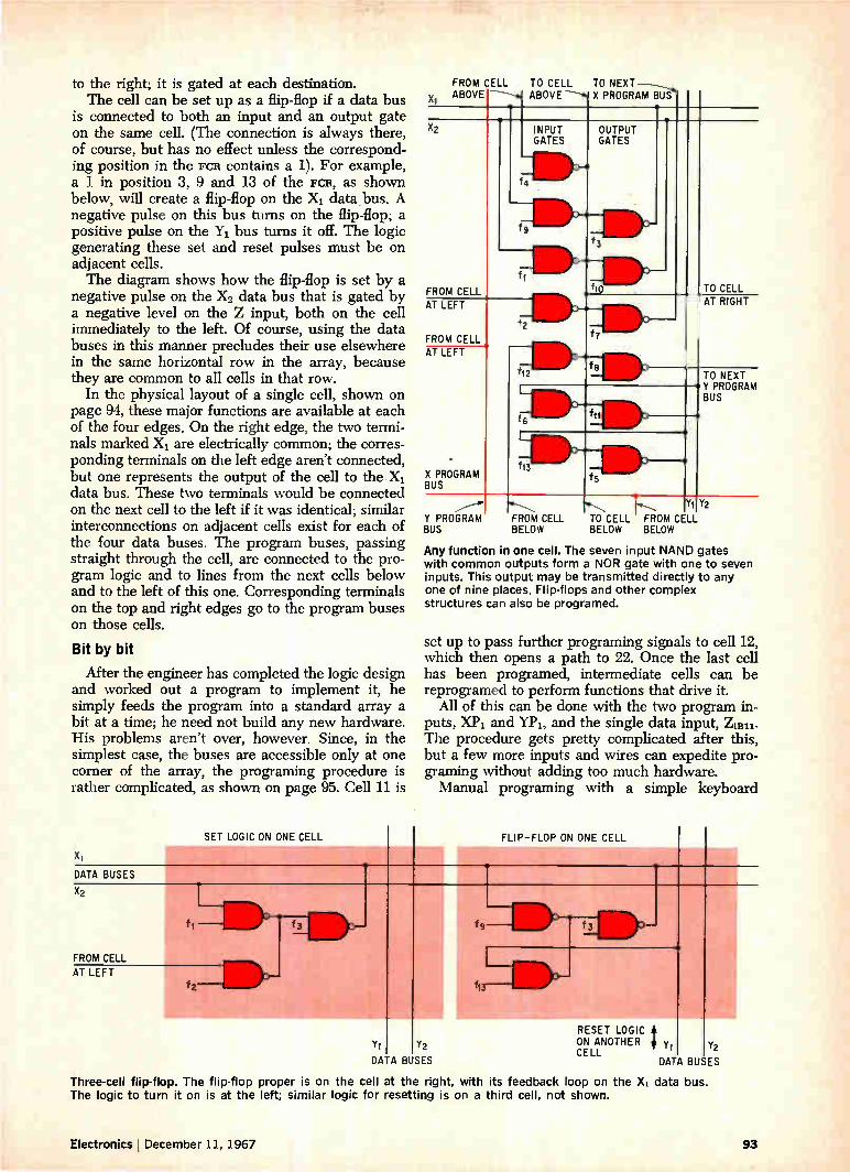
to the right; it is gated at each destination. The cell can be set up as a flip-flop if a data bus
is connected to both an input and an output gate on the same cell. (The connection is always there, of course, but has no effect unless the correspond-ing position in the FCR contains a 1). For example, a 1 in position 3, 9 and 13 of the FCR, as shown below, will create a flip-flop on the Xi data bus. A negative pulse on this bus turns on the flip-flop; a positive pulse on the Yi bus turns it off. The logic generating these set and reset pulses must be on adjacent cells. The diagram shows how the flip-flop is set by a
negative pulse on the X2 data bus that is gated by a negative level on the Z input, both on the cell immediately to the left. Of course, using the data buses in this manner precludes their use elsewhere in the same horizontal row in the array, because they are common to all cells in that row.
In the physical layout of a single cell, shown on page 94, these major functions are available at each of the four edges. On the right edge, the two termi-nals marked Xi are electrically common; the corres-ponding terminals on the left edge aren't connected, but one represents the output of the cell to the Xi data bus. These two terminals would be connected on the next cell to the left if it was identical; similar interconnections on adjacent cells exist for each of the four data buses. The program buses, passing straight through the cell, are connected to the pro-gram logic and to lines from the next cells below and to the left of this one. Corresponding terminals on the top and right edges go to the program buses on those cells.
Bit by bit
After the engineer has completed the logic design and worked out a program to implement it, he simply feeds the program into a standard array a bit at a time; he need not build any new hardware. His problems aren't over, however. Since, in the simplest case, the buses are accessible only at one corner of the array, the programing procedure is rather complicated, as shown on page 95. Cell 11 is
DATA BUSES
SET LOGIC ON ONE CELL
X2
FROM CELL
AT LEFT f2
FROM CELL TO CELL TO NEXT Xi ABOVE --------.1 ABOVE ----b X PROGRAM BUS-
s X2
FROM CELL
fli e
fg
INPUT GATES
-a
OUTPUT GATES
s
TO CELL
f3
e ft° AT RIGHT AT LEFT
FROM CELL
f 2i lle '
111,1111, f12
7f7111,
AT LEFT
K PROGRAM 3US
TO NEXT
f6 fit
Y PROGRAM BUS
i
»3---ile. . Is
.„..--• w---...,.. ..„, 1..., Y1 Y2
BUS L FROM CELL
BELOW BELOW BELOW
Any function in one cell. The seven input NAND gates with common outputs form a NOR gate with one to seven inputs. This output may be transmitted directly to any one of nine places. Flip-flops and other complex structures can also be programed.
set up to pass further programing signals to cell 12, which then opens a path to 22. Once the last cell has been programed, intermediate cells can be reprogramed to perform functions that drive it.
All of this can be done with the two program in-puts, XPi and YPI, and the single data input, Z11311. The procedure gets pretty complicated after this, but a few more inputs and wires can expedite pro-graming without adding too much hardware. Manual programing with a simple keyboard
Y1 Y2
DATA BUSES
FLIP-FLOP ON ONE CELL
113
RESET LOGIC ON ANOTHER yl Y2 CELL
DATA BUSES
Three-cell flip-flop. The flip-flop proper is on the cell at the right, with its feedback loop on the X1 data bus. The logic to turn it on is at the left; similar logic for resetting is on a third cell, not shown.
Electronics December 11, 1967 93

POWER CONNECTIONS
FROM CELL AT LEFT
TO X1 DATA BUS
FROM CELL AT LEFT
FROM CELL AT LEFT
POWER{ CONNECTIONS
•••., lo.i•MP IMMMI
2
Ammimk 'mumb 'il• > >
V3 1v3 I e 1j oil
:j I
f a f5
Yp 0 Age>r-Lp Age>r-Lp .1
I I I 1 X2
I 1—'-' f 3
I Z I r e 0 —•-1110. I I f
I I ff
[ I I f
l COINCIDENT PULSE
if)
LOGIC .430—L1
Xp IXp I
fl2 fll
I vil fl3 Ivi 1
GND 1 GND I
•
IMMI, n
o ..- >
III » >- N4 X CL
•
a- CM >
rn >
..... ..... .,.. AI • à••• .1 fflIk
03 2 cco
e o
1.1
o cc La_
cuU, >-
cx
«rdt3 o
o
CL U_
TO NEXT Y PROGRAM BUS
FROM CELL AT RIGHT
UNGATED OUTPUT
TO X2 DATA BUS
Chip layout. MOS circuits interconnected as shown here produce a single cell in a programable array. Up to four such cells on one chip are feasible with today's state of the art. The layout includes a 13-position shift register and 13 NAND gates as diagramed on page 93, together with programing logic, all necessary external signal connections, and power connections.
would be feasible for logic designs of limited com-plexity, but paper tape, magnetic tape, or punched cards would be better for a large system. The basic building block in any programable net-
work would be an approximately square array of 64 to 100 cells. With today's technology, four cells can be placed on a single chip with a reasonable yield; one array would therefore contain up to 25 chips.
Standardization exacts a price, of course—some chips in the programable array have to be used solely for programing. More circuit elements are needed—perhaps 20 times as many as in conven-tional arrays—to implement functions. Because the development cost can be spread over a very large number of chips, extra development effort becomes economical; more sophisticated programable chips
then become practicable, reducing the proportion of extra chips to perhaps 10.
Balance sheet
The cost of developing a 1,000-element array is currently about $30,000. The production cost might be several hundred dollars per chip if only a dozen or so were made, but this would drop to less than $10 apiece for quantities of a million or more. Assume that a chip 100 mils square with between 40 and 50 pins for external connections can be produced in lots of several million for $7 apiece, including the package. The per-unit devel-opment cost for such large quantities is negligible. The total cost of n systems with conventional
arrays is nP(n) 30,000 dollars, where P(n) is the production cost based on n systems. The same n
94 Electronics I December 11, 1967

X22 ,.
Xe2 CELL 12 CELL 22
Z iL 12
XP2 Jiliie
2
FCR 12
X21
X11 CELL 11 CELL 21
ZiB li
X P1
fl2
. FCR 21
F_il
YP1 i Y P 2 Y21 Y22
Step by step. Any desired function can be established in cell 22 by first opening a programing path through cells 11 and 12. After cell 22 has been programed, cell 12 can be reprogramed with a function to drive cell 22.
i 10 100 1,000 10,000 100,000
QUANTITY PRODUCED 1,000,000
Production cost. Unit cost of producing many thousands of identical IC's is two or three orders of magnitude less than that of producing only a few dozen; herein lies the key to the economics of programable arrays.
systems built with programable arrays would re-quire about K times as much hardware, where K is the ratio of programable chips to the number of cus-tomized chips that could perform the same function. At $7 per chip, the total cost would be 7nK. The break-even curve, established by the equation
nP(n) + 30,000 = 7nK determines the values of n and K below which pro-gramable arrays are more economical than their customized counterparts. This equation and the production costs in the
diagram at left above are the basis for the break-even point graphed at right above. Programable ar-rays are most practical where both n and K are small, though they can also pay their way with a small n and large K or large n and small K. An array of cells built with mos technology can
achieve a K factor of 10 to 25, which in turn leads
loo i,000 io,000 100000 NUMBER OF UNITS PRODUCED
1000000
Break-even point. Customized arrays become cheaper than programable arrays only if the number of units is very large, or if the additional number of programable arrays required for a given system is very large.
to a break-even point between 250 and 1,700 cus-tomized circuits. The diagram shows that even if the K value increases to 50 or 100, as it might with stacked arrays, as many as 50 to 150 programable systems could be built at an economic advantage.
If the other potential benefits of the programable array are taken into account—spare-part standard-ization, easy servicing, and system flexibility—the break-even point can well be several thousand.
Bibliography
Robert C. Minnick, "Cutpoint Cellular Logic," IEEE Transactions on Electronic Computers, Dec. 1964, p. 685.
Robert C. Minnick, "Survey of Microcellular Research," Scientific Report 1, Air Force Cambridge Research Laboratories, July 1966.
Cloyd E. Marvin and Robert M. Walker, "Customizing by interconnection" (Micromatrix), Electronics, Feb. 20, 1967, p. 157.
Lester Hazlett, "Computer accelerates design and production of large arrays" (Polycell), Electronics, Feb. 20, 1967, p. 166.
Electronics I December 11, 1967 95

e
Circuit design
Designer's casebook
Multivibrator sensitivity improved by MOS FET's
By Frederick G. Christiansen GPL Division, General Precision, Inc. Pleasantville, N.Y.
A small change in frequency control voltage pro-duces an extremely large frequency shift in a multi-vibrator because the field-effect transistors operate as voltage-variable resistors. The monolithic integrated circuit shown is a
single stage of a Darlington differential amplifier wired as a free-running multivibrator. Capacitors C and C' are the commutating capacitors and also serve as the capacitive portion of the RC timing network in the frequency-control circuit.
In many conventional voltage-controlled oscilla-tors, the frequency is determined by charging the commutating capacitors, C and C', to the control voltage through a fixed resistor (the resistive por-tion of the RC timing network). Thus, in conven-tional multivibrators, changes in frequency are achieved by varying control-voltage level, which alters current passing through the timing resistor.
Multivibrator. The magnitude of the charging current to commutating capacitors C and C' determines the frequency. Two MOS FET's operated as voltage-variable resistors vary the charging current in response to changes in frequency-control voltage.
MEM511A FREQUENCY-CONTROL VOLTAGE
*2y) +6v
MEM5118
10k
10k
470pf
Designer's casebook is a regular feature in Electronics. Readers are invited to submit novel circuit ideas, packaging schemes, or other unusual solutions to design problems. Descriptions should be short. We'll pay $50 for each item published.
In the multivibrator shown, however, the control voltage is applied indirectly to change the fre-quency. The voltage supply for the RC timing net-work is fixed at 6 volts and the charging current is varied by adjusting the resistance of the RC timing network. The fixed resistor in the network is re-placed by a pair of metal-oxide-semiconductor FET'S, Qi and Q.,, which function as voltage-variable resistors. The control voltage is applied to the gates of Qi and Q., (like an ordinary Vgs signal). Increases in the control-voltage level lower the drain-to-source impedance of Qi and Q.›; this action increases the charging current which, in turn, raises the fre-quency of the multivibrator. Frequency limits are set by resistors R1, 11", R3 and R4.
Sensitivity and linearity of the frequency-control circuitry depends on the bias point of the mos FET'S, Qi and Q. A plot of the FETS' impedance versus V, is quite linear above the knee of the curve. In addition, the slope of the curve above the knee is quite steep, so that extremely large changes in im-pedance can be made with very small changes in Vgs. The circuit's sensitivity is 40 kilohertz per volt —a parameter that is fairly constant over a wide range of temperature due to the thermal stability of the "MOS FET'S; the mos FET'S have input impedances greater than 101° ohms, so they do not load the con-trol voltage.
+10y
10k 10k
OUTPUT
470 pf
96 Electronics I December 11, 1967

N
Magnetic resonance limits zener diode current
By °taker A. Horne
Research Institute for Mathematical Machines Prague, Czechoslovakia
Zener diodes in a bridge rectifier prevent line volt-age variations and load current requirements from affecting the power supply output. The diodes' high current drain during regulation is limited as is any other high current when the secondary saturates the supply transformer.
In saturation, the transformer breaks into mag-netic resonance and behaves as an inductance be-tween its primary and secondary. This inductance and a capacitor in the primary constitute a low Q, series-resonant circuit that limits current flow. The current is converted to voltage and stored by the capacitor.
Since the primary capacitor, C1, is in a resonant circuit, its d-c voltage rating should be five times higher than the applied voltage VL. The capacitance value is directly proportional to the stored current and expressed by
Cl = 1.11
27rf n2
where Imax = short-circuit current or current through zener at high line voltage line frequency root mean square of the line voltage
number of turns on primary number of turns on secondary
CI = primary capacitor 7r = 3.14
f = Vr. =
ni/n2 =
Resonance results in a voltage on the secondary of the transformer that is 50% higher than the
0.53p, f
2 20v/50 hz 2 V300 ma
300
E 200
wz
mmix
c>
loo
0 1 I I 1 1 I 1 1 0 4 8 12 16
OUTPUT VOLTAGE (VOLTS)
Sharp regulation. During normal operation, current flows through the load until the output voltage reaches 16 volts. Above this, the current is shunted through the zeners.
300
É
I; 200 cr cc
0 -J 100
ZENER CONDUCTION BEGINS HERE
100 200 300 400 RIPPLE VOLTAGE (mv
Low ripple. Clipped waveshape that appears at the output of the bridge is a result of zener conduction. Since the clipped voltage is easily filtered a low ripple voltage occurs.
1N3194
1N2980 I C2 el. 200011f
D2 16v
1N2980
Short-circuit impedance. H gh ine voltages or short circuits cause D1 and D2 to draw high currents in the transformer's secondary w nding. These currents are limited when transformer T, and capacitor C, become series resonant and store the current in the magnetic field. Clipping in the output waveform is caused by zener conduction.
Electronics December 11, 1967 97

usual d-c voltage, and a current 40% higher than the usual secondary current.
Since the primary is removed from the circuit during the saturation of the transformer, its voltage and current requirements are the line voltage and 30 ma. To preserve symmetry in the output, the
zener diodes must be perfectly matched. Their power requirements, P, are expressed by
P = 0.25 Vz Imax where Vz = zener breakdown voltage
'maz= current through zener at high line voltage.
Dividing the frequency of an oscillator by 10
By John Althouse Escondido, Calif.
Adding a capacitor and potentiometer to form a modified crystal oscillator causes the fundamental resonant frequency to be divided by 10. This fre-quency division eliminates the necessity for a separate divide-by-ten multivibrator in the fre-quency standard for which the circuit was de-signed. The modified oscillator's 100-kilohertz fundamental frequency and 10-khz submultiple were used to check the dial calibration on a short-
r- — S
10 khz eitOOkhz
5k
4.7k
4.-----ADJUST FOR LOCK AT 20-khz
100 khz
wave receiver; marker pulses for fine calibration were provided by the 10-khz frequency. The basic crystal oscillator consists essentially
of a single, low-cost integrated circuit, the Fairchild 1.t1, 914 dual two-input gate, and associated com-ponents. If the oscillator's time constant approxi-mates the period of the crystal's fundamental reson-ance, the circuit oscillates at the crystal's funda-mental resonant frequency. When the time constant is increased, however, stable oscillations can be produced at submultiples of the crystal frequency. When switch S in the modified oscillator is
placed in the 100-khz position, the circuit oscillates at the crystal's fundamental resonant frequency of 100 khz. With the switch in the 10-khz position, however, the circuit oscillates at 20 khz but the waveform at this frequency is asymmetrical and has a strong 10-khz component.
470
OUTPUT
+3v
0.02 if
10 khz
S
100 khz
0.002 µf
1volt (100khz)
J_ 1 volt I il 1- ,, 110 20 30 40 5:C 60
TIME, µsec
Modified oscillator. Circuit oscillates at crystal's fundamental resonant frequency when time constant approximates the period of the crystal's resonance. With switch S in the 10-khz position, a large time constant is produced that generates a 10-khz submultiple.
(10 khz)
98 Electronics I December 11, 1967
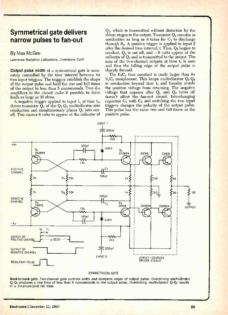
Symmetrical gate delivers narrow pulses to fan-out
By Max McGee
Lawrence Radiation Laboratory, Livermore, Calif.
Output pulse width of a symmetrical gate is accu-rately controlled by the time interval between its two input triggers. The triggers establish the shape of the output pulse and hold the rise and fall times of the output to less than 5 nanoseconds. Two d-c amplifiers in the circuit make it possible to drive loads as large as 30 ohms. A negative trigger applied to input 1, at time to,
drives transistor Q. of the Qi-Q2 multivibrator into conduction and simultaneously places Q1 into cut-off. This causes 6 volts to appear at the collector of
+6v
2%2894
F0:1: TI VE 1:H;.,NNEL
NEGATIVE CHANNEL
OUTPUT OF POSITIVE CHANNEL
2N918
OUTPUT OF NEGATIVE CHANNEL
RESULTANT PULSE
p. SECS
100 pf
100pf
Q2, which is transmitted without distortion by the driver stages to the output. Transistor Q2 remains in conduction as long as it takes for C1 to discharge through 111. A positive trigger is applied to input 2 after the desired time interval, t. Thus, Q3 begins to conduct, Q4 is cut off, and —6 volts appear at the collector of Q3 and is transmitted to the output. The sum of the two-channel outputs at time t, is zero and thus the falling edge of the output pulse is sharply formed. The 110C2 time constant is made larger than its
RIC]. complement. This keeps multivibrator Q3-Q4 in conduction beyond time t2 and thereby avoids the positive voltage from returning. The negative voltage that appears after and Q2 turns off doesn't affect the fan-out circuit. Interchanging capacitor Ci with C0 and switching the two input triggers changes the polarity of the output pulse. This pulse has the same rise and fall times as the positive pulse.
INPUT 1
20 k
IN914
100 pf
200pf
IN914
20k
,r.-- 200 pf
INPUT 2
SYMMETRICAL GATE
to ti
2N2894
2N918
28918 2N9:8
2N2894 2N2894
DIRECT—COUPLED DRIVER STAGES
68
68 30
OUTPUT
Back-to-back gate. Two-channel gate controls width and sharpens edges of output pulse. Overdriving multivibrator Qr-Q, produces a rise time of less than 5 nanoseconds in the output pulse. Overdriving multivibrator I:1-Q, results in a 5-nanosecond fall time.
Electronics j December 11, 1967 99

Communications
Transistors share the load in a kilowatt amplifier
Summing the outputs of 15 four-transistor modules in the power section
yields the first high-power solid state amplifier at 2 to 32 megahertz
By C.H. Wood Jr., A.W. Morse, and G.R. Brainerd
Westinghouse Electric Corp., Baltimore
High-power gain at very high frequencies using solid state devices—once a designer's dream—has become a reality. New techniques for combining power transistors have been incorporated in a solid state amplifier that has a peak envelope power out-put of 1,000 watts from 2 to 32 megahertz. Until now, the best high-frequency solid state amplifiers, operating over narrower portions of the band, had PEP outputs of about 200 watts. Developed by Westinghouse's Surface division
under a contract with the Air Force's Rome Air Development Center, the amplifier meets contract requirements for high reliability and linearity and operation at input drive levels as low as 0.25 watts PEP. It is intended for evaluation as a general-pur-pose, high-power solid state amplifier in communi-cation systems. Heart of the amplifier is a basic four-transistor
module whose power is summed by broadband transformers. Since the transistors are electrically isolated, they can't interact and carry unequal shares of the current. Paralleling the outputs of 15 such modules in the power stages makes possible the unprecedentedly high output. The combining technique and the single-stage circuit developed enable the same type transistor to be used in every part of the amplifier.
There's an added advantage to combining power this way. If a transistor within an electrically-iso-lated four-transistor group fails, output power drops slightly, but the amplifier continues operating.
Once over lightly
Previous work at Westinghouse in power combin-ing techniques influenced the final decision to use a basic four-transistor module in the amplifier. This decision—along with the results of studies recom-mending a goal of 40 watts PEP output per transis-
tor—helped determine the number of stages in each portion of the amplifier. And designers also had to produce a very reliable, linear device that would not change under different voltages or temperatures. With these constraints in mind, engineers speci-
fied Class A operation in the first two stages of the preamplifier for highest linearity and Class AB in the next two stages for high linearity with somewhat less power dissipation. The final preamplifier stage consists of four transistors combined in an elec-trically isolated module. To maintain the required drive level, the third stage requires slight peaking at 22 to 32 Mhz. The 0.25 watt input signal is amplified in the pre-
amplifier 25 db to about 80 watts. Such a large gain results in large power differences between the lower and higher frequencies. However, a variable attenu-ator immediately following the fourth stage of the preamplifier compensates for the difference, in-suring linear amplification. A tuned circuit then couples power into the driver. Composed of three four-transistor groups, paral-
leled in a 12-transistor module, the driver raises the power level to 320 watts, a gain of 6 db. Interstage tuning circuits match the driver output impedance to the very low input impedance of the power am-plifier section.
Five 12-transistor modules combine in the output portion of the amplifier, raising the power to the 1,000-watt output level. Like the driver, the power amplifier section operates Class B. Finally, a tuned circuit matches the output impedance of this sec-tion to 50 ohms, a widely used impedance in many communication systems. At the preamplifier input, a limiter protects the
amplifier from overdrive, and a drive control makes it possible to adapt the amplifier to different input drive levels.
100 Electronics December 11, 1967

Single-stage design
Although the amplifier combines 60 transistors in its power section, 12 in the driver, and four in the last preamplifier section, it was still possible to de-velop one basic circuit for all these transistors. The circuit is designed around an International Tele-phone & Telegraph transistor, 2N4130, which of-fered the highest available power gain at 2 to 32 Mhz. A 50-watt continuous wave output device at 70
Mhz, it consists of two transistors packaged in a single can with an emitter resistor to equalize cur-rent gain. The stage operates in the grounded emit-ter configuration and is biased for Class B opera-tion. Such a circuit offers a combination of high stability and power gain. As in most Class B power amplifiers, circuit load
impedance doesn't match the transistor impedance. Instead the load impedance is determined by Zr. (V„ — VsAT)2/2P. where Zr, equals load impedance \Tee collector voltage, VsAT saturated voltage, and P. power output. Load impedance is 10 ohms be-cause 40 watts is the stage output required, 32 volts the collector voltage and three volts the saturated voltage. The transistor selected has a maximum beta of
35 at 10 amps d-c. Primary advantage of using a low beta device in a high power amplifier is the greater linearity at high currents than with high-beta devices. Since stage gain is proportional to beta at high frequencies and to beta squared at low frequencies, high beta increases nonlinearity. In addition, at low frequencies high betas can cause circuits to oscillate. Although oscillation is a basic problem in the
design of any high power amplifier, it becomes par-ticularly troublesome in broadband circuits. Since each transistor and its accompanying circuit must be able to pass the entire range of frequencies it is potentially less stable than a narrowband tuned
PREAMPLIFIER 25db
LIMITER AND DRIVE CONTROL
STAGE 1 STAGE 2
POWER AMPLIFIER 80db
I2TRANSISTOR MODULE CLASS B
ITT transistor. The 2N4130, a dual-chip device, is used throughout amplifier. Resistors connected to thc chips prevent unequal load sharing.
circuit would be. Then, too, it's impossible to generate useful
equivalent circuits for power transistors at high frequencies. Certainly an equivalent circuit can be developed—after careful measurements—for a tran-sistor operating at a single high frequency and tem-perature, and at a specific voltage. But vary any of the parameters—frequency or voltage, for example —and the equivalent circuit ceases to be valid.
I2 TRANSISTOR MODULE ; CLASS
INTERSTAGE TUNING
I2TRANSISTOR MODULE CLASS B
Solid state amplifier. Combining 60 transistors in its power section—which can be tuned as a unit—the 1-kilowatt amplifier operates with input drive levels as low as 0.25 watts.
Electronics December 11, 1967 101

0.1 270
11 TI.02 T.02
Single stage. Incorporating a transistor that is throughout the entire amplifier.
TO COMBINER
+32v
1 1 1 1 1 1 I 1 T.02 T.02 I .1 T.1 T.1 T.1 14 T,000
ALL CAPACITORS ARE IN MICROFARADS operated at 40 watts PEP, this basic circuit is used repeatedly
Thus, it's very difficult to determine the circuit con-stants that will guarantee stability at all frequencies in a broadband circuit.
Eliminating the instabilities
At first the amplifier oscillated in two distinct ways: one random, sinusoidal and at a frequency lower than the tuned frequency, the other sinusoi-dal and always at half the amplifier's tuned fre-quency. The first type of oscillation came from the steeply
rising gain of the transistor at decreasing frequen-cies. This caused a feedback loop (with a gain of at least unity) to add positively to the signal, resulting in the first type of oscillation. At 32 Mhz—where gain is minimal—the amplifier remained stable at all voltages, temperatures, and input drive levels. However, at lower frequencies it did so only under certain conditions. One remedy considered—neutralization of the
transistor's internal feedback signal—works well
with narrowband, low-power tuned amplifiers. But over a four-octave high-frequency range, transistor parameters vary so widely that neutralization might work well at one frequency and actually increase positive feedback in the amplifier at another fre-quency. Another possible remedy—inserting losses into
the collector circuits—was also discarded because of the unpredictability of transistor parameters over wide frequency ranges. This method of reducing feedback would also have lowered the amplifier's gain excessively. That left negative feedback, which is incorpo-
rated in the amplifier, both in voltage and current form, to increase stability. Of course, negative feed-back has the added advantage of reducing noise and distortion. Because emitter feedback presented mechanical,
thermal, and electrical problems with the transistor used—the emitter was tied to the can—Westing-house tried collector-to-base feedback first. They
INPUT INPUT
Four-trans stor module. Broadband coaxial transformers sum the power output of four transistors, electrically isolating them from each other, and then are added in series by a larger transformer.
102 Electronics I December 11, 1967
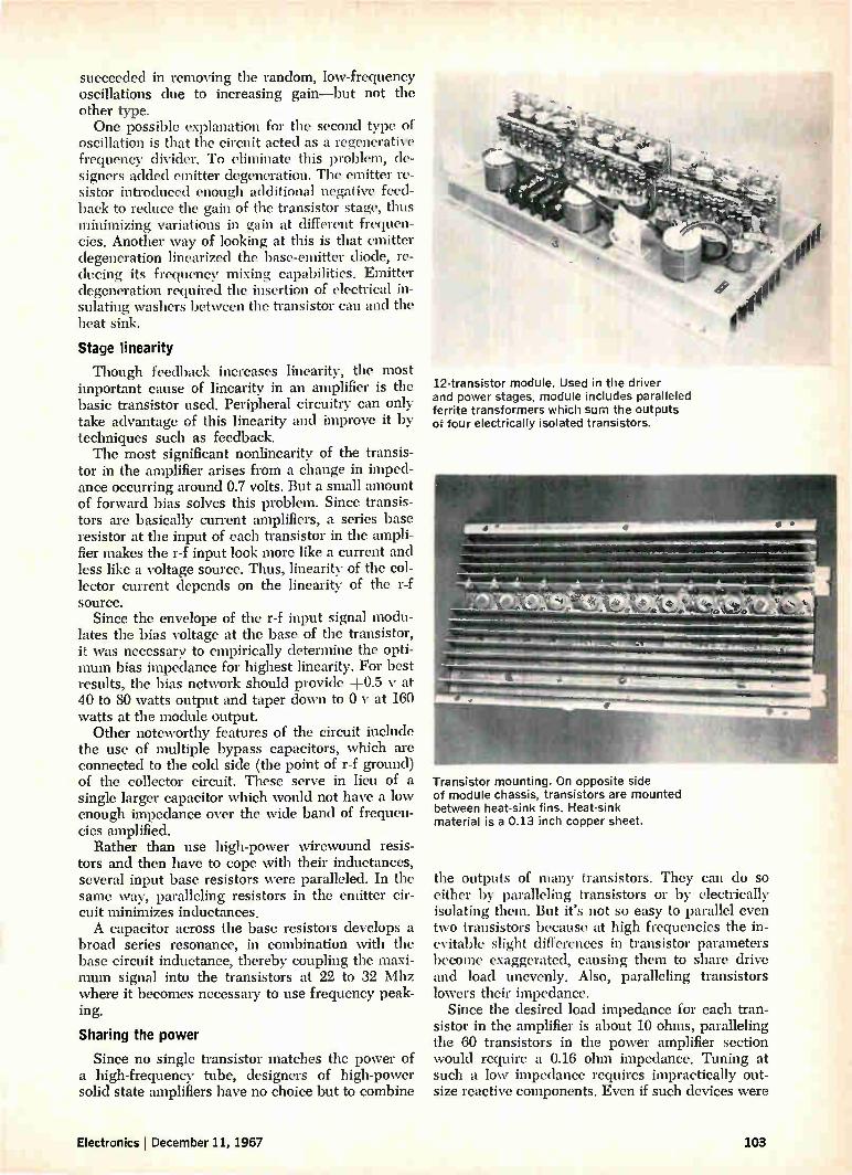
succeeded in removing the random, low-frequency oscillations due to increasing gain—but not the other type. One possible explanation for the second type of
oscillation is that the circuit acted as a regenerative frequency divider. To eliminate this problem, de-signers added emitter degeneration. The emitter re-sistor introduced enough additional negative feed-back to reduce the gain of the transistor stage, thus minimizing variations in gain at different frequen-cies. Another way of looking at this is that emitter degeneration linearized the base-emitter diode, re-ducing its frequency mixing capabilities. Emitter degeneration required the insertion of electrical in-sulating washers between the transistor can and the heat sink.
Stage linearity
Though feedback increases linearity, the most important cause of linearity in an amplifier is the basic transistor used. Peripheral circuitry can only take advantage of this linearity and improve it by techniques such as feedback. The most significant nonlinearity of the transis-
tor in the amplifier arises from a change in imped-ance occurring around 0.7 volts. But a small amount of forward bias solves this problem. Since transis-tors are basically current amplifiers, a series base resistor at the input of each transistor in the ampli-fier makes the r-f input look more like a current and less like a voltage source. Thus, linearity of the col-lector current depends on the linearity of the r-f source.
Since the envelope of the r-f input signal modu-lates the bias voltage at the base of the transistor, it was necessary to empirically determine the opti-mum bias impedance for highest linearity. For best results, the bias network should provide +0.5 y at 40 to 80 watts output and taper down to 0 y at 160 watts at the module output.
Other noteworthy features of the circuit include the use of multiple bypass capacitors, which are connected to the cold side (the point of r-f ground) of the collector circuit. These serve in lieu of a single larger capacitor which would not have a low enough impedance over the wide band of frequen-cies amplified.
Rather than use high-power wirewound resis-tors and then have to cope with their inductances, several input base resistors were paralleled. In the same way, paralleling resistors in the emitter cir-cuit minimizes inductances. A capacitor across the base resistors develops a
broad series resonance, in combination with the base circuit inductance, thereby coupling the maxi-mum signal into the transistors at 22 to 32 Mhz where it becomes necessary to use frequency peak-ing.
Sharing the power
Since no single transistor matches the power of a high-frequency tube, designers of high-power solid state amplifiers have no choice but to combine
12-transistor module. Used in the driver and power stages, module includes paralleled ferrite transformers which sum the outputs of four electrically isolated transistors.
Transistor mounting. On opposite side of module chassis, transistors are mounted between heat-sink fins. Heat-sink material is a 0.13 inch copper sheet.
the outputs of many transistors. They can do so either by paralleling transistors or by electrically isolating them. But it's not so easy to parallel even two transistors because at high frequencies the in-evitable slight differences in transistor parameters become exaggerated, causing them to share drive and load unevenly. Also, paralleling transistors lowers their impedance.
Since the desired load impedance for each tran-sistor in the amplifier is about 10 ohms, paralleling the 60 transistors in the power amplifier section would require a 0.16 ohm impedance. Tuning at such a low impedance requires impractically out-size reactive components. Even if such devices were
Electronics December 11, 1967 103

Two-tone tests on solid state amplifier
At right, both waveshapes result from measurements made at
1,000 watts PEP. Tests simulate single-sideband-type signal.
3.2 MHz
250 w PEP 500 w PEP
1500 w PEP 2000 w PEP
built, they'd cause enormous losses in the circuit. To avoid the problems of paralleling transistors,
Westinghouse developed the techniques for com-bining transistors in electrically isolated groups of four. Within these groups each transistor delivers its power to its transformer—a broadband device developed by Westinghouse. In addition to prevent-ing transistor interaction, the transformers step up the output impedance. A similar transformer sums the output of the four transistor-coupled transform-ers in the
o
- 10
-20
o -30 o
50
group.
t I 1 1 1 1 1
3 4 5 6 7 8 910 15 20 FREQUENCY ( Mhz
Intermodulation distortion. Measurements at 1,000 watt PEP of amplifier's third-order intermodulation distortion were taken at different frequencies. Plot indicates the high linearity of the amplifier.
30 40
22.5 MHz
1000 w PEP
These five waveshapes result from measurements of linear amplifier, all made at 12 Mhz at different power outputs.
Since the output of the combining transformer has summed the output of the four transistors, there's no problem in paralleling it with other com-biners. Four combiners are paralleled and then their output is paralleled in turn with four other 12-transistor modules to form the 60-transistor power section.
Tuning and matching
Since the power-combining transformers pass all frequencies in the 2 to 32 Mhz range, it's not neces-sary to tune every transistor individually on both base and collector. Instead all transistors in the power section can be tuned in toto. Tuning per-forms a triple function. It filters out harmonics in-herent in any single ended Class B amplifier limits bandwidth for rejection of wideband harmonics, and matches impedance. The transistor used is virtually broadband over
the entire high-frequency range. It's average col-lector capacitance is about 200 picofarads so that at 32 Mhz—the worst case—shunt reactance is only 25 ohms or 2.5 times greater than the de-sired resistive load. This simplifies tuning because the transformers need only present a correspond-ingly low reactive component of the opposite sign.
Nevertheless, the extremely low impedance levels in the amplifier required developing new tuning techniques. For simplicity, compromises had to be made between minimum reactance and maximum transfer of power from stage to stage.
104 Electronics I December 11, 1967
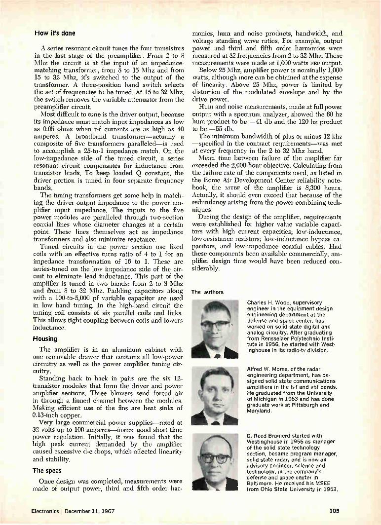
How it's done
A series resonant circuit tunes the four transistors in the last stage of the preamplifier. From 2 to 8 Mhz the circuit is at the input of an impedance-matching transformer, from 8 to 15 Mhz and from 15 to 32 Mhz, it's switched to the output of the transformer. A three-position band switch selects the set of frequencies to be tuned. At 15 to 32 Mhz, the switch removes the variable attenuator from the preamplifier circuit. Most difficult to tune is the driver output, because
its impedance must match input impedances as low as 0.05 ohms when r-f currents are as high as 40 amperes. A broadband transformer—actually a composite of five transformers paralleled—is used to accomplish a 25-to-1 impedance match. On the low-impedance side of the tuned circuit, a series resonant circuit compensates for inductance from transistor leads. To keep loaded Q constant, the driver portion is tuned in four separate frequency bands. The tuning transformers get some help in match-
ing the driver output impedance to the power am-plifier input impedance. The inputs to the five power modules are paralleled through two-section coaxial lines whose diameter changes at a certain point. These lines themselves act as impedance transformers and also minimize reactance. Tuned circuits in the power section use fixed
coils with an effective turns ratio of 4 to 1 for an impedance transformation of 16 to 1. These are series-tuned on the low impedance side of the cir-cuit to eliminate lead inductance. This part of the amplifier is tuned in two bands: from 2 to 8 Mhz and from 8 to 32 Mhz. Padding capacitors along with a 100-to-5,000 pf variable capacitor are used in low band tuning. In the high-band circuit the tuning coil consists of six parallel coils and links. This allows tight coupling between coils and lowers inductance.
Housing
The amplifier is in an aluminum cabinet with one removable drawer that contains all low-power circuitry as well as the power amplifier tuning cir-cuitry.
Standing back to back in pairs are the six 12-transistor modules that form the driver and power amplifier sections. Three blowers send forced air in through a finned channel between the modules. Making efficient use of the fins are heat sinks of 0.13-inch copper. Very large commercial power supplies—rated at
32 volts up to 100 amperes—insure good short time power regulation. Initially, it was found that the high peak current demanded by the amplifier caused excessive d-c drops, which affected linearity and stability.
The specs
Once design was completed, measurements were made of output power, third and fifth order har-
monies, hum and noise products, bandwidth, and voltage standing wave ratios. For example, output power and third and fifth order harmonics were measured at 82 frequencies from 2 to 32 Mhz. These measurements were made at 1,000 watts PEP output. Below 25 Mhz, amplifier power is nominally 1,000
watts, although more can be obtained at the expense of linearity. Above 25 Mhz, power is limited by distortion of the modulated envelope and by the drive power. Hum and noise measurements, made at full power
output with a spectrum analyzer, showed the 60 hz hum product to be —41 db and the 120 hz product to be —55 db. The minimum bandwidth of plus or minus 12 khz
—specified in the contract requirements—was met at every frequency in the 2 to 32 Mhz band. Mean time between failure of the amplifier far
exceeded the 2,000-hour objective. Calculating from the failure rate of the components used, as listed in the Rome Air Development Center reliability note-book, the MTBF of the amplifier is 8,300 hours. Actually, it should even exceed that because of the redundancy arising from the power combining tech-niques. During the design of the amplifier, requirements
were established for higher value variable capaci-tors with high current capacities; low-inductance, low-resistance resistors; low-inductance bypass ca-pacitors, and low-impedance coaxial cables. Had these components been available commercially, am-plifier design time would have been reduced con-siderably.
The authors
Charles H. Wood, supervisory engineer in the equipment design engineering department at the defense and space center, has worked on solid state digital and analog circuitry. After graduating from Rensselaer Polytechnic Insti-tute in 1956, he started with West-inghouse in its radio-tv division.
Alfred W. Morse, of the radar engineering department, has de-signed solid state communications amplifiers in the h-f and vhf bands. He graduated from the University of Michigan in 1963 and has done graduate work at Pittsburgh and Maryland.
G. Reed Brainerd started with Westinghouse in 1956 as manager of the solid state technology section, became program manager, solid state radar, and is now an advisory engineer, science and technology, in the company's defense and space center in Baltimore. He received his MSEE from Ohio State University in 1953.
Electronics December 11, 1967 105

Reader's Choice IEE bright, legible, wide-angle readouts: Any characters desired Any colors or combinations Any input, BCD or decimal Any input signal level Any mounting, vertical or horizontal
far
Many sizes Many configurations Many lamp lives (to 100,000 hours) Many brightness choices Many options and accessories
Standard Readouts: Rear projection principle, like all IEE read-outs. A lamp in the rear of the unit illuminates one of the 12 film messages, and projects it to the front viewing screen.
Unbeatable readability and versatility.
Large Screen Readouts: For reading distances up to 100 feet. Maximum character size 3%".
Miniature Readouts: Only 1" wide x 1-5/16" high, yet can be read at 30 feet because of clarity of one-plane projection. Character size: 3/4 ".
Micro-Miniature Readouts: Only wide x %" high, but 20 foot viewing distance and maximum 175° viewing angle because'of front-plane display. Character size: %".
ell Hi-Brite Readouts: Special lens system increases character brightness 50%. Particularly good when high ambient light conditions exist.
Cue-Switch Readouts: Rear projection readout with push-button viewing screen. Combination switch and display device.
Bina-View Readout: Accepts binary or teletype code, decodes, and displays the proper character.
Status Indicator Readout: Displays up to 12 different messages, individually or in combination. Viewing screen only 3 sq. in.
Indicator Assemblies: Available with up to 11 rear pro-jection readouts, for indicating seconds, minutes, hours, days, etc.
Driver/Decoder Module: Designed to work with IEE Readouts. Accepts a variety of binary codes for decimal conversion.
The new IEE Display Devices catalog gives complete information and specifications on these products, and their accessories. Ask for it.
IEE "I-double-E", the world's largest manufacturer of rear projection readouts.
Industrial Electronic Engineers, Inc. 7720 Lemona Avenue, Van Nuys, California
106 Circle 106 on reader service card Electronics I December 11, 1967

Japanese technology
Research in solid state pays off for Japan
The accent on home-based research begun by the Japanese
more than two years ago [Electronics, Dec. 13, 1965, p. 77]
is one of the big reasons for the soaring production of semi-
conductors in Japan. The success of such devices, now in
high-volume production, yields profits that can be plowed
back into further product development. Today's research
and development is meticulously calculated to meet the
future needs of Japan's thriving electronics industry.
Page 110 Japanese designers of discrete devices call their shots
Page 117 Optoelectronics goes digital
Page 125 Bulk effect devices focus on communications

Japanese technology I
Small loss of 'face' yields big gain in semiconductors
Building on a base largely borrowed from the U.S., Japan is now
setting its own course in this field and hopes to leapfrog ahead
Japan's initial efforts in solid state technology seemed aimed at refuting the old aspersion that Japanese technicians can only copy the designs of others. Striking out on its own a few years ago, Japanese industry wound up proving only that such pride goeth before a fall. Production levels and techniques weren't sufficient to keep prices down in the face of rising labor costs, and though a trickle of money was available for R&D, research facilities were inadequate and managers were in-sisting on overnight results. But in recent years, Japanese engineers have put
aside "face," and have set out to exploit U.S. tech-nological developments and to learn from mistakes made by U.S. firms. When necessary, Japanese companies have signed licensing agreements with foreign concerns. [Fujitsu Ltd. is the only firm that won't enter into such pacts with outside compa-nies.] Along with this, domestic research and develop-
ment has begun to pay off. And seeing the results of the modest projects launched a few years ago, managers are becoming conditioned to the neces-sarily slow pace of R&D. Even with a partly borrowed base, though, the
evolving solid state technology is uniquely Japa-nese. Most R&D programs today are tailored to the specific needs of the domestic electronics industry; work on bulk-effect devices, for example, is aimed at applications in communications equipment, a Japanese specialty. Japanese engineers hope to leap-frog U. S. developments whenever possible. A strong incentive here is that paying royalties to owners of U.S. patents is both costly and embarrassing.
Growth areas
Japan's stock in trade is consumer electronics. A few years ago, transistors were employed almost exclusively in radios. Today, they're being used in black-and-white television receivers, though not as extensively as Japanese marketers had anticipated. But transistorized sets should soon be directly com-petitive with tube sets as a result of work on high-
voltage transistors at firms like Toshiba (the Tokyo Shibaura Electric Co.) and the Matsushita Electron-ics Corp. The total production of discrete semiconductor
devices in Japan has almost doubled in the past two years (from 47.5 million in January 1965 to 88.9 million in January 1967). This year has seen a level-ing off in sales, and some inventory building.
Production of germanium transistors is up sharply, but silicon-transistor output has increased even more dramatically. Early in 1965, only one of every 20 transistors was silicon; today the ratio is about one in five. Silicon transistors, used until recently mostly in computers and other noncon-sumer equipment, are now being put in inexpen-sive radios. They are also finding their way into desk calculators, where their stability at high tem-peratures makes stabilization networks unnecessary and thus saves cabinet space.
Semiconductors for industrial use are attracting research interest, possible because the Japanese feel automation may be the answer to climbing la-bor costs. In particular, developments of thyristors and rectifier diodes are on the increase. Thyristors rated up to 2,500 volts at 400 amperes are being used in drives for mills, and are also being designed into new control gear for Japan's high-speed trains. Experimental thyristors have been built with rat-ings of 3,500 volts at 500 amps, and 2,500 volts at 800 amps.
Still larger thyristors are sought for high-voltage d-c transmission systems and for nuclear accelera-tor pulse modulators, but a spokesman for a re-search group at the electrotechnical laboratory of the Ministry of International Trade and Industry maintains that development is constrained by pres-ent design techniques. The present rating for rectifier diodes is 5,000
volts at 500 amperes; the goal is 10,000 volts at 1,000 amperes. The rectifiers arc used in d-c railway substations and in power supplies at aluminum and chemical plants.
If Japan was to continue to compete successfully
108 Electronics December 11, 1967

in world markets, a Japanese expert observed in 1965, she would have to become a highly automated producer. The advantages of cheap labor were dis-appearing; in the early 60's, labor costs rose at a rate of about 10% a year.
Penny-pinching
The advice was taken to heart by Japanese semi-conductor manufacturers. Cost reductions and high volume have become bywords with Japanese pro-duction experts, who are notably reticent about discussing proprietary manufacturing methods that can shave pennies from the cost of a device.
Like U.S. manufacturers, the Japanese seek the elusive transistor that can be universally applied. The Sony Corp. now has a single basic transistor for most low-power applications from audio ampli-fiers through i-f stages for f-m equipment. The ad-vantages of broad-use types lie in driving volume up and costs down. Many Japanese semiconductor makers are bank-
ing on plastic or epoxy encapsulation to help reduce transistor costs. Even the Nippon Electric Co.— long a holdout with its low-cost "microdisk" pack-age—has joined this group and is now producing plastic-covered transistors.
Big push
Japanese solid state researchers and device de-velopers are, in the main, concentrating their efforts in the areas of conventional discrete devices, opto-electronics, and bulk effects. A great deal of work is also being done on integrated circuits. Typical of the fields in which Japanese are trying
to jump ahead of American technology is high-fre-quency power transistors. The Kobe Industries
Semiconductor production in Japan 100
90
80
70
60 to o
50
40
30
20
10
o
Corp. has developed the mesh-emitter transmitter, a continuous emitter device that borrows from the overlay technology but which Kobe engineers think will provide twice the power-frequency product. A description of these devices, along with an assess-ment of new Japanese developments in varactor di-odes and thermistors, is given in the article begin-ning on the next page.
In the optoelectronics field, Japanese researchers have set their sights on two goals—high-speed logic using injection lasers, and computer input and out-put equipment using phototransistors and electro-luminescent diodes [see the article on page 117]. The Gunn-effect oscillator is being studied for
its potential use in the nation's communications system. Power outputs have so far been too low, but the hope is that a commercial device may be just around the corner [see the article on page 125].
Lineup
The major Japanese makers of transistors and diodes for consumer applications are Toshiba, Hitachi Ltd., Matsushita Electronics (a joint ven-ture of the Matsushita Electric Industrial Co. and Philips Gloeilampenfabrieken of the Netherlands), the Tokyo Sanyo Electric Co. (a subsidiary of the Sanyo Electric Co.), Nippon Electric, the Mitsu-bishi Electric Corp., Sony, and Kobe Industries (a subsidiary of Fujitsu). Other transistor manufac-turers include Fujitsu, the Oki Electric Industry Co., the Shindengen Electric Mfg. Co., the Sanken Electric Co., the Shiba Electric Co., and Kyodo Electrics Laboratories Inc. A good deal of jápan's solid-state research is sponsored, coordinated, and conducted by the government's Ministry of Inter-national Trade and Industry laboratories.
JFMAMJJASONDJFMAMJJASONDJFMAMJJASOND 1965 1966 1967
Graphs are based on figures from the Japanese Ministry of International Trade and Industry. The top line
represents factory shipments of transistors, diodes, rectifiers, and miscellaneous devices, but does not include integrated circuits. January 1965 shipments accounted for factory sales of $9.8 million; shipments in July 1967 represented factory sales of $11.3 million. Production exceeded sales in the first seven months this year, and factory inventories climbed by about 57 million units over that period.
Electronics December 11, 1967
L.11,1u,11,1,1111111,...1 11,
109

CONTACT
BASE
E
r MESH EMITTER
IL
II- X EMITTER
BASE
CONDUCTIVE DIFFUSION
«-b-»
I
OVERLAY
INTERDIGITATED
Comparing structures. R-f transistor geometries establish power-frequency capability. In these three devices, k is the smallest achievable unit dimension that can be fabricated, and is smaller than the region-defining dimensions x, b, and c.
R-f geometries: critical ratios compared Periphery-
Emitter area Transistor periphery, Collector ratio,
type PE area, Ac F=PE/Ac
Mesh emitter 4(2b+c) (x-I-2b+c)2 F,,,,E=0.75/k Overlay 4x (x-I-2b+c)2 Ft, =0.33/k Interdigitated 2y y(x--I-2b+c) F. =0.5/k
Interdigitated. Nippon Electric Co.'s interdigitated transistor has seven fingers (horizontal bars), four in the base portion, at left, and three in the emitter. Outer stripes have additional, widening elements to lower base resistance.
development stems largely from communications applications that require devices having a large change in capacitance in response to a small voltage shift. Among these are frequency- and phase-modulators, automatic frequency control circuits, and voltage-tuned networks, and oscillators and modulators for microwave telephony.
New types
Among the varactors recently developed is Nip-pon Electric's 1N1617-19 series. The voltage-capacitance characteristic of these hyperabrupt junction diodes is determined by an impurity pro-file. As the depletion layer is approached, the doping level increases. This layer's spreading re-gion has two sections—a high-impurity concentra-tion and a low-doped segment. Nominal capaci-tance in the high-impurity region is relatively large, while that in the low-doping section is much lower.
Unlike conventional diodes, the doping level in Nippon Electric's diodes decreases on the side of the junction into which the depletion layer extends when reverse voltage is applied. The result: a diode with a narrow depletion layer at zero bias. As the reverse bias increases, the depletion layer slowly extends to the far boundary of the high-impurity concentration. As the bias is further increased— even slightly—the depletion layer moves into the low-doped region and undergoes a large change in width. The net effect is a large change in capaci-tance for small change in applied voltage. The company's silicon hyperabrupt varactor
series have Q's of 20 and nominal capacitances of 30 pf, obtained at a frequency of 70 Mhz and with an applied voltage of 4 volts. As the voltage is varied from 0 to 15 volts, the capacitance changes from 70 pf initial value to a final value of less than 2 pf. Some of these diodes have already been de-signed into the f-m portion of a microwave system, to produce a -±-10-Mhz swing around a 70-Mhz center frequency.
Similar performance has been obtained by the Mitsubishi Electric Corp. Its hyperabrupt junction diodes, which have also been used to generate
112 Electronics December 11, 1967
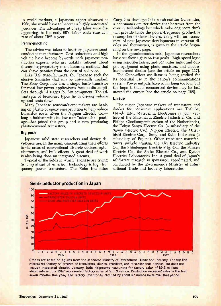
in world markets, a Japanese expert observed in 1965, she would have to become a highly automated producer. The advantages of cheap labor were dis-appearing; in the early 60's, labor costs rose at a rate of about 10% a year.
Penny-pinching
The advice was taken to heart by Japanese semi-conductor manufacturers. Cost reductions and high volume have become bywords with Japanese pro-duction experts, who are notably reticent about discussing proprietary manufacturing methods that can shave pennies from the cost of a device.
Like U.S. manufacturers, the Japanese seek the elusive transistor that can be universally applied. The Sony Corp. now has a single basic transistor for most low-power applications from audio ampli-fiers through i-f stages for f-m equipment. The ad-vantages of broad-use types lie in driving volume up and costs down. Many Japanese semiconductor makers are bank-
ing on plastic or epoxy encapsulation to help reduce transistor costs. Even the Nippon Electric Co.— long a holdout with its low-cost "microdisk" pack-age—has joined this group and is now producing plastic-covered transistors.
Big push
Japanese solid state researchers and device de-velopers are, in the main, concentrating their efforts in the areas of conventional discrete devices, opto-electronics, and bulk effects. A great deal of work is also being done on integrated circuits. Typical of the fields in which Japanese are trying
to jump ahead of American technology is high-fre-quency power transistors. The Kobe Industries
Semiconductor production in Japan 100
90
80
70
60
50
40
30
20
10
o
Corp. has developed the mesh-emitter transmitter, a continuous emitter device that borrows from the overlay technology but which Kobe engineers think will provide twice the power-frequency product. A description of these devices, along with an assess-ment of new Japanese developments in varactor di-odes and thermistors, is given in the article begin-ning on the next page.
In the optoelectronics field, Japanese researchers have set their sights on two goals—high-speed logic using injection lasers, and computer input and out-put equipment using phototransistors and electro-luminescent diodes [see the article on page 117]. The Gunn-effect oscillator is being studied for
its potential use in the nation's communications system. Power outputs have so far been too low, but the hope is that a commercial device may be just around the corner [see the article on page 125].
Lineup
The major Japanese makers of transistors and diodes for consumer applications are Toshiba, Hitachi Ltd., Matsushita Electronics (a joint ven-ture of the Matsushita Electric Industrial Co. and Philips Gloeilampenfabrieken of the Netherlands), the Tokyo Sanyo Electric Co. (a subsidiary of the Sanyo Electric Co.), Nippon Electric, the Mitsu-bishi Electric Corp., Sony, and Kobe Industries (a subsidiary of Fujitsu). Other transistor manufac-turers include Fujitsu, the Oki Electric Industry Co., the Shindengen Electric Mfg. Co., the Sanken Electric Co., the Shiba Electric Co., and Kyodo Electrics Laboratories Inc. A good deal of Japan's solid-state research is sponsored, coordinated, and conducted by the government's Ministry of Inter-national Trade and Industry laboratories.
JFMAMJJ 1965
ASON DJ FMAMJJA SOND JF MAMJJ 1967
AS ON 1966
Graphs are based on figures from the Japanese Ministry of International Trade and Industry. The top line represents factory shipments of transistors, diodes, rectifiers, and miscellaneous devices, but does not include integrated circuits. January 1965 shipments accounted for factory sales of $9.8 million; shipments in July 1967 represented factory sales of $11.3 million. Production exceeded sales in the first seven months this year, and factory inventories climbed by about 57 million units over that period.
D
Electronics December 11, 1967 109

Japanese technology II
Tailoring the device to suit the need
When it comes to radio-frequency transistors, varactors and thermistors,
designers are primarily aiming their devices at the domestic market
By Takuya Kojima
Electrical Communication Laboratory, Nippon Telegraph & Telephone Public Corp., Tokyo
Developments in discrete semiconductors are being tailored for the most part to meet requirements that are peculiarly Japanese. Among the major areas of concentration are radio-frequency power tran-sistors, varactors, and thermistors. In transistors, Japanese engineers have pioneered a continuous emitter structure called the mesh-emitter, a graft-base structure, and devices designed specifically for 13.5-volt mobile communications equipment. Developments in varactors are prompted by
communications applications such as frequency and phase modulation for the nation's microwave tele-phony systems. And in thermistors, they have come up with their own stable, rugged devices for use in gain-control systems for telephone carrier ampli-fiers.
Mesh-emitter transistor
Capitalizing on the development of overlay and interdigitated structures—the mainstays in Ameri-can-made transistors for generating power at high frequencies—engineers at the Kobe Industries Corp. decided to carry it a step further. Turning to a continuous emitter structure, Kobe researchers developed what they call the mesh-emitter tran-sistor. These devices have already produced 10 watts at 400 megahertz, with minimum efficiencies of 50%. American transistors, however, have pro-duced 50 watts at 500 Mhz with a slightly lower efficiency. At frequencies above 300 Mhz and power greater
than 1 watt, the current load concentration at the transistor's emitter periphery becomes a problem.
The author
Takuya Kojima is deputy director of the electronic device development at NTT's Electrical Communication Laboratory in Tokyo. Before turning to semiconductors in 1955, he designed vacuum tubes. Kojima holds a doctorate degree from Osaka University.
Depending on the size of the device, this unequal distribution of the load can lead to the transistor's destruction. To prevent saturation limitations as well as destruction, designers of r-f transistors seek a high ratio of practical emitter periphery length to collector area.
Kobe's approach is to have the device's base con-tacts consist of islands within the continuous emit-ter mesh, allowing the emitter to be narrowly shaped along large lengths. Thus, the base and collector areas are correspondingly reduced. De-pending on the geometry, the periphery length-to-collector area ratio of a mesh-emitter transistor can be as much as twice that of an overlay device and half again larger than that of an interdigitated structure.
Also critical to high-frequency performance is the device's base resistance: the lower it is, the larger the high-frequency gain. Early mesh tran-sistors had a heavily doped p+ region diffused into the base structure to lower the resistance. But by improving the resolution, Kobe was able to do away with the diffusion. Instead of the p+ region, present devices have shorter paths (and thereby lower im-pedances) between the base contacts and the active base regions.
Eliminating the extra diffusion has brought with it easier and less costly fabrication, narrower pat-terns because there no longer is an inner base struc-ture, and the outright elimination of slight area irregularities caused by spreading dopants.
Successful in improving resolution, Kobe is now turning its attention to increasing the collector area's current-handling per unit area by lengthen-ing the emitter periphery. Higher current density, the company believes, will lead to a smaller collec-tor area that will lower output capacitance and re-sult in a higher maximum frequency. Kobe is con-fident this will boost present power-frequency prod-ucts from the 4,000 watt-megahertz level-10 watts at 400 Mhz—to the 10,000 watt-megahertz range
110 Electronics December 11, 1967

within a year or so. Even higher products could be attained by joining transistor cells before the chip is diced. And, by reducing the collector area, even lower
fabrication costs are possible because more devices could be put on a given wafer area.
Overlay and interdigitated
Although Kobe is concentrating on mesh-emitter transistors, other companies are pressing on with overlay and interdigitated structures. Unlike their American counterparts, which are fabricating devices for 28-volt operation, these firms are tailor-ing devices for 13.5-volt operation—primarily for mobile communications equipment in the 300-to-470 Mhz frequency range. But instead of using the conventionally diffused
base, Japanese engineers have turned to the graft-base structure pioneered by the Nippon Electric Co. [Electronics, Dec. 13, 1965, p. 81]. The graft-base configuration, which is essentially a double-diffused structure, is claimed to reduce both contact and bulk resistance in the transistor's base—thus reducing parasitic capacitances and raising fre-quency capabilities. Nippon Electric considers the overlay transistor
best for large-signal r-f applications—a few watts or more in the very-high-frequency range—and the interdigitated structure best for small-signal appli-cations and for jobs requiring gigahertz frequency operation. More effort has been spent recently on the inter-
digitated types. Among the results of this effort is the V415, a transistor with a 3-Ghz cutoff fre-quency, a 10-decibel power gain at 2 Ghz, and a 6-db noise figure at these frequencies. A successor having a smaller dynamic range is the V417. This device has a 5-db power gain at 4 Ghz, a 1-Ghz bandwidth, and a 5-db noise figure at 2 Ghz. Both types are assembled in ceramic stripline packages to simplify matching with stripline wiring and minimize parasitics. And, both types have lead inductances of a frac-
tion of a nanohenry and interelectrode capacitances of 0.1 picofarad—about 10% of the parasitics found in TO-18 packages. Compared with American-made interdigitated
devices, the Japanese devices have shallower col-lector junctions (0.3 micron) and narrower bases (0.1 micron). These result in transistors with an extrinsic base resistance-collector capacitance prod-uct, rbb'C„ of only 1.0 picoseconds (typically), which is 33% lower than that of comparable U.S. semi-conductors. Among standard power devices developed for
the 13.5-volt operation are predrivers, drivers, and final-output stage transistors. At 500 Mhz, the pre-drivers develop 1.3 watts output with an input of 0.3 watt; the drivers, 3.2 watts at 1 watt; and final-output transistors, 7.5 watts at 3 watts. Collector efficiencies typically exceed 60% and the devices may be operated with bias supplies rated as low as 10 volts.
Extra diffusion. Early mesh-emitter transistor required a p+ diffusion (horizontal bars) within the emblem-shaped base region to lower base resistance.
Nippon Electric expects to fabricate an inter-digitated structure capable of handling 5 watts at 2 Ghz within the next 18 months. To do this re-quires a tradeoff—increasing the peripheral length of the emitter stripes at the expense of uniform emitter current distribution. Other improvements will have to be made in stripline packaging and heat-sink materials, but neither these nor the trade-off appear unrealistic.
Varactors a major front
When it comes to varactor diodes, virtually all Japanese semiconductor firms are either developing or manufacturing these variable capacitance de-vices. And their efforts embrace several state-of-the-art devices, including hyperabrupt junction diodes, gallium-arsenide varactors, and composite (series-connected) diode multipliers. The impetus for hyperabrupt junction diode
Characteristics of typical mesh-emitter transistor
Breakdown voltages: VBBo: VCEO:
VEBO:
Collector current, lc: Dissipation (at 25°C), PD: Output capacitance, Cob: Cutoff frequency, fT:
Output power at 400 Mhz, po (at VBE = 28 v, PIN = 2 w): (at VCB = 28 v, PIN = 1 w): (at VCE = 13.5 y, PIN = 2 w): (at VcE = 13.5 v, PIN = 1 w):
Emitter periphery-to-collector area ratio:
65 y (min.) 40 y (min.) 3 y (min.)
2.5 amps (max.) 10 w 5 pf (at VCB = 30 v) 600 Mhz (at Vcs=28v,
I.=200mA)
10 w (50% efficiency) 6.5 w (50% efficiency) 5 w (60% efficiency) 3 w (60% efficiency) 0.15 micron per
micron'
Electronics December 11, 1967 111
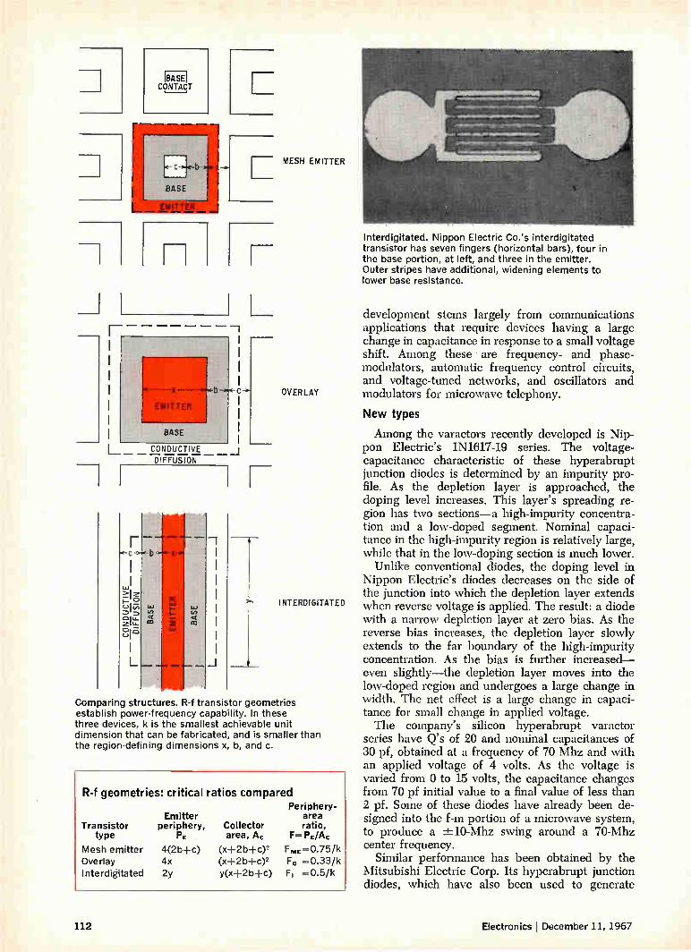
17[2i1 CONTACT
r — —
c-
BASE
-b
EMITTER
X
EMITTER
BASE
CONDUCTIVE DIFFUSION
LU (1)
CD
cc
e— LU
07.1
7
MESH EMITTER
OVERLAY
INTERDIGITATED
Comparing structures. R-f transistor geometries establish power-frequency capability. In these three devices, k is the smallest achievable unit dimension that can be fabricated, and is smaller than the region-defining dimensions x, b, and c.
R-f geometries: critical ratios compared Periphery-
Emitter area Transistor periphery, Collector ratio,
type P. area, A. F= PE/A.
Mesh emitter 4(2b+c) Overlay 4x (x-F2b+c)2
Interdigitated 2y y(x-1-2b+c)
FR,,E=0.75/k
Fo =0.33/k F, =0.5/k
Interdigitated. Nippon Electric Co.'s interdigitated transistor has seven fingers (horizontal bars), four in the base portion, at left, and three in the emitter. Outer stripes have additional, widening elements to lower base resistance.
development stems largely from communications applications that require devices having a large change in capacitance in response to a small voltage shift. Among these. are frequency- and phase-modulators, automatic frequency control circuits, and voltage-tuned networks, and oscillators and modulators for microwave telephony.
New types
Among the varactors recently developed is Nip-pon Electric's 1N1617-19 series. The voltage-capacitance characteristic of these hyperabrupt junction diodes is determined by an impurity pro-file. As the depletion layer is approached, the doping level increases. This layer's spreading re-gion has two sections—a high-impurity concentra-tion and a low-doped segment. Nominal capaci-tance in the high-impurity region is relatively large, while that in the low-doping section is much lower.
Unlike conventional diodes, the doping level in Nippon Electric's diodes decreases on the side of the junction into which the depletion layer extends when reverse voltage is applied. The result: a diode with a narrow depletion layer at zero bias. As the reverse bias increases, the depletion layer slowly extends to the far boundary of the high-impurity concentration. As the bias is further increased— even slightly—the depletion layer moves into the low-doped region and undergoes a large change in width. The net effect is a large change in capaci-tance for small change in applied voltage. The company's silicon hyperabrupt varactor
series have Q's of 20 and nominal capacitances of 30 pf, obtained at a frequency of 70 Mhz and with an applied voltage of 4 volts. As the voltage is varied from 0 to 15 volts, the capacitance changes from 70 pf initial value to a final value of less than 2 pf. Some of these diodes have already been de-signed into the f-m portion of a microwave system, to produce a -.10-Mhz swing around a 70-Mhz center frequency.
Similar performance has been obtained by the Mitsubishi Electric Corp. Its hyperabrupt junction diodes, which have also been used to generate
112 Electronics I December 11, 1967
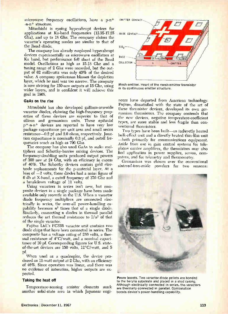
microwave frequency oscillations, have a p-n+ -n-n+ structure.
Mitsubishi is eyeing hyperabrupt devices for applications at Ku-band frequencies (15.35-17.25 Ghz), and up to 18 Ghz. The company claims the varactor's operating modes are similar to that of the Read diode. The company has already employed hyperabrupt
devices experimentally as microwave oscillators at Ku band, but performance fell short of the Read model. Oscillations as high as 15-18 Ghz and a tuning range of 2 Ghz were recorded, but the out-put of 62 milliwatts was only 40% of the desired value. A company spokesman blames the depletion layer, which he said was too narrow. The company is now striving for 150-mw outputs at 15 Ghz, using wider layers, and is confident it will achieve this goal in 1968.
GaAs on the rise
Mitsubishi has also developed gallium-arsenide varactor diodes, claiming the high-frequency prop-erties of these devices are superior to that of silicon and germanium units. These epitaxial p+-n-n+ devices are reported to have very low package capacitance per unit area and small series resistance-0.2 pf and 2.0 ohms, respectively. Junc-tion capacitance is nominally 0.3 pf, and cutoff fre-quencies reach as high as 700 Ghz. The company has also used GaAs to make mul-
tipliers and Schottky-barrier mixing devices. The frequency-doubling units produced output powers of 300 mw at 24 Ghz, with an efficiency in excess of 40%. The Schottky devices contain gold elec-trode replacements for the p-material layer. At a bias of —2 volts, these diodes had a noise figure of 6 db at X-band, a cutoff frequency of 370 Ghz and a breakdown voltage of 11 volts. Using varactors in series isn't new, but com-
posite devices in a single package have been made available only recently in the U.S. When n varactor diode frequency multipliers are connected elec-trically in series, the over-all power-handling ca-pability becomes n= times that of a single diode. Similarly, connecting n diodes in thermal parallel reduces the net thermal resistance to 1/n= of that of the single varactor.
Fujitsu Ltd.'s FC33B varactor unit contains two diode chips that have been connected in series. The composite has a voltage rating of 250 volts, a ther-mal resistance of 4°C/watt, and a nominal capaci-tance of 10 pf. Corresponding figures for U.S. state-of-the-art devices are 150 volts, 12°C/watt, and 5 pf. When used as a quadrupler, the device pro-
duced an 11-watt output at 2 Ghz, with an efficiency of 46%. Since operation was linear, and there was no evidence of saturation, higher outputs are ex-pected.
Taking the heat off
Temperature-sensing resistor elements mark another solid-state area in which Japanese engi-
EMITTER CONTACT
BASE CONTACT -----
Si02
BASE -
COLLECTOR ,
Mesh emitter. Heart of the mesh-emitter transistor is its continuous emitter structure.
neers have departed from American technology. Fujitsu, dissatisfied with the state of the art of these thermistor devices, developed its own ger-manium thermistors. The company contends that the new devices, negative temperature-coefficient types, are more stable and less fragile than con-ventional thermistors. Two types have been built—an indirectly heated
bulk-effect unit and a directly heated thin-film unit —both primarily for communications equipment. Aside from use in gain control systems for tele-phone carrier amplifiers, the thermistors may also find application in power supplies, servos, com-puters, and for telemetry and thermometry. Germanium was chosen over the conventional
sintered-iron-oxide powders for two reasons:
Power boosts. Two varactor diode pellets are bonded to the berylia substrate and placed in a stud casing. Although electrically connected in series, the varactors are thermally connected in parallel. Combination boosts device's power-handling capability.
Electronics December 11, 1967 113

State of the art in the States
Although Japan's solid state tech-nology has been given a big boost by advances in radio-frequency transistors, varactors, and ther-mistors, it still lags behind that of the U.S. Recent Japanese develop-ments can help narrow the gap and, in some cases, even close it, but by and large they reflect poten-tial, not off-the-shelf, semiconduc-tor products. How present American tech-
nology fares: Transistors. Typical character-
istics of radio-frequency inter-digitated devices include outputs of 50 watts at 500 megahertz and 5 watts at 1 gigahertz, collector cur-rents of 4 amperes, output capaci-tances of from 10 to 20 picofarads, and efficiencies of 40%. Typical characteristics of overlay devices: 75 watts at 30 Mhz and 1 watt at 3 Ghz. Interdigitated small-signal oscillators provide an output of more than 50 milliwatts at 4 Ghz,
and 1-to-4-Ghz amplifiers have noise figures of from 5 to 7 deci-bels; comparable overlay oscillators produce 250 mw at 3 Ghz.
Varactors. Typical characteristics of hyperabrupt diodes include nominal capacitances of 40-700 pf (at 2-volt bias) and Q's of 200 (at 1 Mhz). Typical parameters of gallium-arsenide varactors include series resistances of about 5 ohms, cutoff frequencies of a few hundred gigahertz, package capacitances of 0.2 pf, internal inductances of 0.4 nanohenry, and Q's in excess of 100. In general, however, U.S. semiconductor firms differ in their definitions of hyperabrupt junction varactors. Motorola Inc.'s Semi-conductor Products division calls it a retrograded junction device, and feels that it isn't compatible with standard microwave devices. Texas Instruments Incorporated considers the Schottky-barrier diode a hy-perabrupt junction type, and says
it has proven to be suitable for use in hybrid microwave integrated circuits.
Thermistors. A wide variety of these devices are available, en-abling users to select temperature-sensing elements with almost any resistance rating and temperature coefficient. Silicon is generally pre-ferred as the thermistor material because of its linear temperature coefficient and stability. Also, with silicon thermistors, the circuit itself —not a separate supply—furnishes the heat. Iron-oxide types, on the other hand, have been found to have less stable characteristics, a hysteresis effect, a higher ohmic value, and a potential for reversing the temperature coefficient's polar-ity. The state of the art has under-gone little change in recent years. The last major innovation was the introduction of a hermetically sealed package—but that dates back a few years.
familiarity with germanium, stemming from tran-sistor manufacture, and the material's intrinsic higher purity that is easily controlled.
In the indirectly heated type, two metal strips, evaporated onto the germanium, serve as the ther-mistor terminals. A silicon monoxide coating is ap-plied for insulation and passivation; a nichrome ele-ment, evaporated onto the SiO layer, functions as the heater. Two metallization strips of a chromium-
GOLD TERMINAL
HIGH-RESIST IVITY — G e THERMISTOR
SiO
HEATER
1101IR LOW-"' RESISTIVITY Ge HEATER
1_ SUBSTRATE
SiO INSULATION
-GOLD
. GERMANIUM THERMISTOR
SUBSTRATE
Dual role. Thin-film thermistor structure uses germanium for both heating and temperature-sensing.
gold alloy are formed onto the nichrome for ohmic contacts. A second SiO layer is deposited for addi-tional passivation. For heater currents between 6 and 28 milliamps
the logarithmic plot of resistance change is nearly linear, decreasing from 600 ohms (at 6 ma) down to 7 ohms. Nominal resistance is 250 ohms, and the thermal time constant is 2 seconds—a far cry from the 35 seconds required for conventional thermistors. For the thin-film thermistor, germanium is evap-
orated onto a glass substrate. The temperature of the substrate during the evaporation process estab-lishes the temperature coefficient. By merely chang-ing the evaporation temperature, a series of film thermistors—each having specific temperature be-havior—can easily be made. When low-resistivity films were evaporated onto
a substrate whose temperature was maintained at 400°C, the germanium showed little resistance variation with thermal change. Thus, germanium is used as both the heating and thermistor element in the composite thin-film device.
In a typical device, a change in heater current from an initial value of 5 ma to a final value of 30 ma produced a corresponding resistance change from 14 kilohms to 150 ohms (in linear fashion on a logarithmic scale).
Fujitsu engineers contend that the thin-film ap-proach is superior to the bulk effect for obtaining large resistance change with temperature, and the bulk method is preferable where greater stability is desired.
114 Electronics I December 11, 1967

The MilgrayAir Force We use it to rescue embattled Purchasing Departments.
Our redoubtable men in blue (and grey, and green, and maroon, etc.) keep the peace. It usually starts with a frantic phone call from the front. Any front. Within 45 minutes the part is on its way to the flight line. The sortie could be to any landing So, no matter where in the country you're threat-field in the U.S., many overseas and, in a real ened, Milgray Red Tag service means that within pinch, a make-do helicopter landing pad. hours we'll deliver virtually any reinforce-Just as often, we jet crucially needed parts M. ments you need. among our branches (New York, Cleveland, MI LG RAY Except coffee, tea or milk.
Washington, Philadelphia, Boston) and make the final sprint to your position with mobile ground forces under our command (which includes your local Milgray man's automobile).
Milgray/New England 617-272-6800 Milgray/New York 212-YU 9-1600
Milgray/Delaware Valley 215-BA 8-2000 Milgray/Washington 301-864-6330 Milgray/Cleveland 216-881-8800
Milgray/International 212-YU 9-1600
Electronics 1 December 11, 1967 Circle 115 on reader service card 115

SIGNALITE Has Acquired From MICROWAVE ASSOC.
the TUCOR
INCORPORATED SUBSIDIARY OF GENERAL INSTRUMENT CORPORATION
(ELECTRONIC SPECIALTY CO.)
Line of
GAS DISCHARGE
MICROWAVE
NOISE SOURCES AND
NOISE GENERATORS
NOW• • • Signalite is the largest source in the world for your noise source and noise generator requirements.
With this addition of the TUCOR (ESCO) line, Signalite now offers the largest range of noise source and noise generators(except for10'E. plane) available from a single source. The men, ma-chines, and methods which developed this quality line are now supported by unexcelled engineer-ing talent and production capabilities assuring you COMPETITIVE PRICES and FAVORABLE DELIVERY.
Wcuft-e kooul ueeeM? Contact: J. Moor, Sales Manager. (201) 775-2490 or
wire fat... Signalite's Noise Source Brochure ... which provides a complete dissertation on microwave noise sources and mini-ature generators available from S-band to K-band including fundamental noise measurement discussions, typical ap-plications, and detailed characteristics.
1933 HECK AVENUE. NEPTUNE. NEW JERSEY 07753 • (201) 775-2490
116 Circle 116 on reader service card Electronics I December 11, 1967

Japanese technology Ill
Optoelectronics goes digital
Researchers are arranging injection lasers as high-speed logic gates
and trying to build electroluminescent diodes into computer displays
By Jun-ichi Nishizawa Tohoku University, Sendai, Japan
After a slow start, Japanese researchers are step-ping up efforts in digital optoelectronics with an eye to two specific goals: • High-speed logic via injection lasers • Computer input and output equipment using
electroluminescent diodes and phototransistors. Farther off in the future, they see the possibility
of replacing cathode ray tubes in television sets with computer-type displays, a step toward a com-pletely solid state television system. The major drive now is to increase the efficiency
and reliability of both injection lasers and electro-luminescent diodes and to develop more convenient operating parameters. The injection laser is pro-jected as a nearly ideal optical logic element; it has a narrow beam of high-energy density, can be mod-ulated at high frequencies for high-speed logic and has an easily controlled intensity. The electrolumin-escent diode is compatible with the computer's ex-isting solid state circuitry, and the device's long life and high efficiency could make it an ideal light source for a large array. Commercial devices are scarce so fár, but early
results have borne out the opinion that optoelec-tronics will have a large part to play in electronic systems of the future. The first commercial laser diodes were put on the market in the fall of 1966, and though most electronics companies now pro-duce them in sample quantities, only one—the Mit-subishi Electric Corp.—markets them as a catalog item. Other firms offer electroluminescent diodes, but these are high-priced and still not widely avail-able.
Laser logic
Probably the most dramatic project in this field is the employment of injection lasers as logic gates, with the laser's on-off states corresponding to binary 1 and 0. This work is being carried on at the Nip-pon Electric Co., the Research Institute of Electri-
Sum and carry. Injection laser half-adder built by Nippon Electric has an enable input and two data inputs.
cal Communication of Tohoku University, and the Semiconductor Research Institute (mu) in Sendai. Results have been encouraging. Tests have shown that 50-gigahertz rates are possible with the small, high-speed switching elements. All basic logic gates, a half-adder, and a flip-flop have been built and op-erated experimentally. With a two-input AND gate, the inputs are applied
to two separate junctions located along the lasing direction of a single crystal. Lasing cannot occur if current is applied to only one input because the ac-tive diode region is too short compared with total length, and gain is too low. But when current is
Electronics December 11, 1967 117

Optical logic
By arranging laser junctions in series and in parallel, and by taking advantage of the fact that lasing along one axis can quench lasing along another axis, logic can be per-formed. Those sides of the devices where lasing is not desired are roughened, while the lasing ends of the crys-tal are cleaved to produce parallel planes. A detector would be used as an intermediate stage to sense the laser outputs.
OUTPUT LIGHT
A AND 8
A OR B
INPUT CURRENT
AND gate
NOT
OUTPUT LIGHT
AND CURRENT
NOT/AND gate
applied to both inputs, the gain increases and the element lases. The sides of the device are roughened to prevent lasing in a path perpendicular to the main direction. The NOT gate is similar to the AND except that
one diode has all edges cleaved to allow it to lase in either the short or long direction of the crystal. Lasing in the short direction occurs if current is applied only to this diode. Current to both diodes causes lasing in the long direction, lasing that takes most of the excited carriers and thus quenches the action of the first diode in the cross direction. With a constant input current greater than the
lasing threshold to the first diode, and with the de-tector along the short axis, the NOT gate gives a bi-nary output of 1 when there is no input to the sec-ond diode, and an output of 0 when the input to the second diode exceeds the lasing threshold by a small amount. With a detector along the long axis, this
A
OUTPUT LIGHT
A AND 8
A OR 13
A OR 8 CURRENT
OR gate
8
NAND
AND
A OR B
el
A AND
A OR B CURRENT
NAND/AND gate
OUTPUT LIGHT THROUGH Y
A OR B CURRENT
NOR/OR/AND gate
gate can be used for the AND function. The on gate consists of two diodes in parallel and
extending the length of the crystal along the lasing direction. Lasing occurs if current is applied to either diode or to both simultaneously, and the faces perpendicular to the junction are roughened to pre-vent lasing in the short direction of the crystal.
Three-diode gates
Two diodes in parallel and arranged so they are both in series with a third, single, diode along the long axis of a single crystal form the NOR gate. The single diode can lase in either the long or short direction. If the input to either or both of the other diodes exceeds the lasing threshold in the long di-ection, lasing will start in the long direction and be quenched in the short. The device performs the NOR function with a detector along the short direc-tion; with a detector along the long axis, it can be
118 Electronics I December 11, 1967

used for the OR function. The NAND gate is similar to the NOR except that
the three diodes are in line along the long axis of the crystal. The center diode can lase in either di-rection, but usually receives current sufficient to maintain lasing in the short direction. Simultaneous inputs to both diodes are needed to block lasing along the short axis and induce it in the opposite direction. A detector along the short axis yields a NAND function, and along the long axis, the AND function. The half adder, the most sophisticated of these
devices, consists of a NOR gate along the sum axis and an AND gate along the carry axis. Developed by Nippon Electric, it has an enable input and two addition, or data, inputs.
Normally, a current is applied to the enable in-put to cause lasing in conjunction with one of the other inputs; in operation, the enable pulse is wider than the data input pulses. With a pulse at just one input, lasing occurs along the sum axis (1+0=1). If both data inputs are pulsed, lasing in the sum direction in quenched and lasing along the carry axis is initiated ( 1 + 1 = + carry 1) because the device is longer along the carry axis and gain is thus higher.
Researchers at Tohoku University and mu have managed to get flip-flop action with a triode laser. This device has three junctions, one of which is in series with each of the other two and thus is com-mon to two lasing axes. There is no lasing when the common junction area is pulsed, but a pulse to either of the other junctions causes lasing along the axis the pulsed junction shares with the common junction. A pulse applied to the junction along the other (perpendicular) axis quenches the lasing in first direction and starts it in the second. To estimate the possible operational speed of la-
ser logic, groups at Toholcu and SRI have measured the wavelength shift in light produced by a modu-lated laser. They amplitude-modulated the laser with a 50-gigahertz signal, and detected the optical sidebands at wavelengths corresponding to frequen-cies 50 Ghz above and below the laser frequency. These experiments show the feasibility of modu-
lating a laser diode at millimeter-wave frequencies. They also indicate that the maximum frequency of this modulation is greater than 50 Ghz, and that the operational velocity of laser logic should be faster than 10—" seconds. ( Operational logic speed is gen-erally taken to be 1/7r—or about 1/2 —times the pe-riod of the highest frequency obtained from sine-wave frequency response measurements.)
In the computer
Optoelectronic devices have voltages and pack-ages that match those of present computer circuitry. Electroluminescent diodes could be used simply as high-reliability light sources in punched-tape read-ers, or phototransistors, which have been commer-cially available in Japan for years, could be used as image sensors to read input data off a printed page. Nippon Electric researchers have produced a linear
array of 40 phototransistors to operate as an image sensor. Since the array is one-dimensional, scanning in a second direction involves moving the paper un-der the array. The most pressing need here is development of
improved scanning circuitry rather than any break-through in optoelectronics. A pulse input to the scanning circuit—essentially a shift register with outputs available at each stage—must propagate through the circuit, with the array tapping off the pulse at intervals. Neuristors—circuits that act like nerve fibers and propagate pulses without attenua-tion—also can be used for scanning.
Chain reaction
In a neuristor built at Nippon Electric, each stage is composed of a laser, a photodiode, and a photo-conductor connected in series, plus a capacitor con-nected so it charges when the photoconductor turns
Contact closeup. Three contacts to half-adder, with enable input in the center.
Half-adder. Enable input X is pulsed with a broad pulse, while data inputs A and B take narrow pulses. With only one data input, device lases along the sum (S) axis; two inputs cause lasing along carry (C) axis.
Electronics December 11, 1967 119

Commercial GaAs light emitters
Manufacturer Model
Laser diodes:
Mitsubishi Electric Corp.
M L-3 IA ML-31B ML-66B
Peak power
Threshold current (amp)
Maximum peak
current (amp)
Operating Maximum pulse Temperature width/rep. rate (°K) Package
>5 w 0.1-1.0 >1 w 5-20 —0.1 w(d-c) <0.3
25 200 nsec/1000 pps 50 200 nsec/1000 pps 1 d-c
Electroluminescent diodes:
Hayakawa Electric Co.
Mitsubishi Electric Corp.
GLE-702
GLE-202
ME-01A
100 pw 50 mw 8 mw 1.2 mw 70 12w (0.05 amp)
0.1 (d-c) 10 (pulse) 0.1 (d-c) 2 (pulse)
0.1 (d-c) 1 (pulse)
77 300 77
TO-18 Pill Pill
5 msec/100 pps
5 msec/100 pps
1 ,usec/10", pps
123-343
123-343
253-333 Pill
on. To propagate a pulse through the circuit, light from one laser illuminates a photoconductor two stages further along in the direction of propagation, charging the photoconductor's capacitor.
Light from the same laser also turns on a photo-diode in the intervening stage, transferring energy to the laser of that stage from its capacitor, which has been charged when a previous laser diode ac-tivated its photoconductor. Light from this laser diode in turn activates another photoconductor and photodiode, and the impulse is propagated. A group at Tohoku University has made a neuris-
tor circuit that simulates a traveling-wave tunnel diode as it scans an image converter and image dis-play unit. Discrete tunnel diodes are triggered by transistors in sequence as the pulse moves through the circuit. The image converter is an 8 X 8 array of photo-
transistors. In preliminary experiments, patterns
Flip-flop. Laser bistable flip-flop can lase in either direction. An input to A and B causes lasing along the Y axis and an input to A and C causes lasing along X.
were formed by masking some of the phototransis-tors. After the array was scanned to detect the illu-minated pattern, the outputs arrived at the display panel in time sequence to drive a similar 8 X 8 array of gallium arsenide-phosphide electroluminescent diodes. (These diodes, GaAs0.021)1.38, were used be-cause they emit light in the visible portion of the spectrum, unlike pure GaAs, which emits light in the infrared.)
This unit's resolution is far from meeting the re-quirements of a television display, but the arrange-ment does demonstrate the feasibility of the prin-ciple. It could be used almost immediately in com-puters, however. A light-coupled system using a laser and photo-
diode is also being investigated at Tohoku. Although power-handling capacity is small, this unit can be useful as a true isolator at microwave frequencies; In the isolator, whose gain-bandwidth product is 6.3 Ghz, a GaAs diode and a p-i-n photodiode are coupled by an optical glass fiber.
Light-beam tv
A research group at Shizuoka University, in ex-periments aimed at optical transmission of television video signals, has amplitude-modulated the output of a GaAs electroluminescent diode. The purpose was to develop a system for transmitting closed-circuit tv over short distances—for example, be-tween buildings separated by a busy thoroughfare. One problem here was that the signal-to-noise ratio at receiving sites proved sensitive to noise from sun-light and other meteorological conditions, but bet-ter results have been achieved using the pulse code modulation of a GaAs laser diode. The variation of a photodiode's capacitance with
illumination has also been exploited at Shizuoka University. Illumination of a gallium-arsenide sur-face-barrier photodiode produces a voltage that de-creases the barrier thickness and thus increases the
120 Electronics December 11, 1967

Microwave isolator. A glass fiber couples an electroluminescent diode and p-i -n photodiode. The microwave input signal modulates a light-emitting diode.
0 0 0 0 0 0 0 0 0 0
•0 0 0 0 0 0 0 0 0 0
ae •
OnabOjt 0 9999090900
Number pick-up. Linear array of 40 phototransistors acts as a one-dimensional scanner for image
sensor. To generate the second dimension, as shown by the number display, image is
moved under the scanner.
0123456789ABCD
Electronics I December 11, 1967 121

D1
.
N N
D2
O _, ..., N-- 7N 7 N
N\
e ....., „..... D3 7 N 7 N N --1
.,,, ,....D4
><"-- 7 N N N
--.. ..-- D5 0 —
N-7 N. 7 N \
7'
\1\*71( \ \ /c E3- 1r
\ (
/ /Bi
// „...,r-•-•., 1 / / /
' N\ % ‘ SS
/\ C I
\ — / /.
\ -2 / w \ //, E \ N\ 1, N\ / ,
/\\ /1 \ ,/ \
\\ y \\ f \
/ CE2 .1 /\ \ \ — ./, \ / D3 \ / / xr N \ / , /„. \ v,
/ — 1/ // \\
,e f
\,/
\ — / ' \ - /1, \ / .4
— / \ / N \ / , \ N/ / N/ / " \
// \
C,1, \/
\ / \ 7 \ / /85 \ / \ / N \ / , \ \ /,/ \x/- /x\
// \\ // \\ // %
\
C5 i
\ 7. \\ ,. \ \ \ \
N / / / /7 / /
\ 1C / \ \ / i
Al —
A24 3 —
44 45
IPHOTOCELLS
PHOTODIODES
IINJECTION LASERS Neuristor. A pulse is propagated as an injection laser charges a capacitor two stages ahead and also turns on a photodiode one stage ahead. The photodiode releases the stored charge on its capacitor to turn on its injection laser.
barrier capacitance of the diode. In one application, the diode was used to frequency-modulate an oscil-lator tuned to 88 megahertz; capacitance-boosting illumination reduces the frequency of the oscillator.
Looking into the crystal
Studies of light-emitting diodes will help deter-mine the fundamental properties of crystals from which they are made, and may enable Japanese firms to produce their own high-quality crystals; the present supply of good crystals from the U.S. is in-sufficient for either research or production.
Researchers at the Nippon Light Metal Co. and the Kokusai Electric Co. have succeeded in produc-ing fairly good crystals, and material restrictions should disappear in the near future. Nippon Light Metal is an aluminum refiner that got into the gal-lium-arsenide business because gallium is one of the byproducts of aluminum production. Kokusai Elec-tric is one of Japan's leading manufacturers of semi-conductor production equipment.
Researchers at the Tokyo Institute of Technology have calculated that an injection laser's threshold
current can be cut by increasing the thickness of the active region where carriers are injected perpen-dicular to the junction surface. They obtained re-sults for directional radiation characteristics, effi-ciency, and transient characteristics, and concluded that because of the delay in emitting light, max-imum conversion efficiency occurs at a frequency corresponding to the reciprocal of lifetime. They now propose a method of determining lifetime by measuring the resonance. A team at the Mitsubishi Electric Corp. has de-
rived a new design equation showing that threshold current can be determined on the basis of the equil-ibrium of gain and loss. One of the conclusions of this group is that loss in small lasers is much greater than has been generally thought. Groups at Tohoku University and SRI are also
studying the directional radiation characteristics of the laser. They have analyzed laser operation in a one-dimensional mode, determining directional characteristics by a perturbation method, and these results llave enabled them to gather information on directional light intensity as a function of current.
In the vanguard Jun-ichi Nishizawa, whose photo appears on the cover, is a pioneer in laser technology. In a Japanese patent filed jointly with Ya-sushi Watanabe in April 1957, he proposed the basic idea for the injection laser. At that time, only microwave masers had been built, though studies had begun on optical masers, or lasers. Nishizawa and Watanabe postu-lated that the supply of high-energy elec-trons necessary for maser operation could just as well be provided by injection from outside the system as by boosting the en-ergy levels of the electrons inside.
Nishizawa and his assistants tried to build an injection laser, but gave up after two years. But research work at the General Elec-tric Co., the International Business Machines Corp., and Massachusetts Institute of Tech-nology spurred the Japanese group to return to the project and to succeed. Nishizawa's team has since moved on to laser logic.
Nishizawa, a professor at Tohoku Univer-sity. has been engaged since 1963 in studies at the solid state electronics division of the university's research institute. He received his doctorate in 1960.
122 Electronics I December 11, 1967

It comes clean out of our test bath
Temperature test your integrated or hybrid circuits in a 3M Brand Inert Fluorochemical Liquid and it'll drain clean, dry immediately and leave no residue.
Unlike conventional test bath fluids, with our Inert Liquids there's no costly cleaning stage to slow down production.
3M Brand Inert Liquids—FC-43, FC-75, FC-77, FC-78—also give you a wide liquid range so you can use them at both high and low temperatures, high dielectric strength for electrical insulation, compati-bility to prevent adverse effects on sensitive mate-rials, and non-flammability to make them safe.
With those properties and that kind of reliabil-ity—plus efficiency at removing heat—it's no wonder
,
our Inert Liquids work equally well as coolants. Test them for either application.
3M Chemical Division Dept. KAX-127, St. Paul, Minn. 55101
Send me all the details about 3M Brand Inert Liquids.
Name
Company
Address
City State__ Zip
COMPANY Chemical Division
Title
Electronics December 11, 1967 Circle 123 on reader service card 123

Your gain. One milliwatt to one kilowatt with a
single TWT amplifier.
Because of its high gain characteristics, Litton's new L-5126 traveling wave tube enables you to eliminate intermediate drivers
in certain systems. Your additional gain? The reduction of the size, weight, cost and complexity of your system while improving reliability.
The L-5126 is a broadband traveling wave tube which provides 1.0 kilowatt minimum peak power output with 60 db minimum
gain over the frequency range of 7.0 to 11.0 GHz. It may be driven to full power output by a standard signal generator, sweeper, or any conventional signal source. The L-5126 has a
metal-ceramic vacuum envelope for reliable performance under
the environmental extremes of MIL-E-5400, Class 2 environ-
ments, making it ideal for airborne and other similarly demanding applications. It is conduction cooled up to 1 % duty and utilizes low cost Alnico periodic permanent magnet focusing. Its unique design and internal construction result in open and short-circuit
stability. Tubes with comparable performance are also available
at C-band. For additional information on the L-5126 and other Litton TWT's, write Electron Tube Division, 960 Industrial Road,
San Carlos, California 94070 or call (415) 591-8411.
80
60
Length 15.69 inches.
80 90 100 11.0 12.0
FREQUENCY Gc
2500
2000
1500
1000
500
o 7.0 80 90 10.0
SATURATED POWER
FREQUENCY Go
11.0 12.0
nig LITTON INDUSTRIES LJ—I ELECTRON TUBE DIVISION
124 Circle 124 on reader service card Electronics I December 11, 1967

Japanese technology IV ,„:iitiapti-' -, e't
..4
i, ,. Gunn devices are on target
but short of a bull's-eye
Low output power remains the major difficulty in developing
continuous-wave, bulk-effect oscillators for communications
By Takanori Okoshi
University of Tokyo
Triggered by the need for solid state communica-tions devices, Japanese development of Gunn-effect oscillators since 1964 has stressed the con-tinuous-wave mode. Progress thus far has given rise to hope that a commercial product may be near. One firm, the Nippon Electric Co., has reported a c-w output high of 340 milliwatts at 7.7 gigahertz. At this point, however, outputs of Gunn devices
satisfy only part of the microwave repeater needs of the government-owned Nippon Telegraph & Telephone Public Corp., which controls most of the nation's communications systems and operates the world's densest microwave network. The repeaters used by NTT are heterodyne for
long-distance main routes and baseband for short-distance links. Gunn oscillators, at best, can only deliver sufficient power to satisfy the transmitter needs of the lower-power baseband system and the local oscillator needs of the heterodyne sys-tem. Spectral purity and stability, however, come close to the mark.
Less heat, more power
Because power efficiency for a c-w Gunn oscil-lator falls between 1% and 8%, below the theoreti-cal 15%, boosting the output necessitates raising the input. But increasing the input requires con-trolling the temperature rise that accompanies it.
The author
Takanori Okoshi is an associate professor of electronic engineering at the University of Tokyo, where he received his doctorate in 1960. His present research efforts are aimed at developing semi-conductor microwave devices and depressed collectors for traveling-wave tubes.
Thus, although solid state devices are small enough to lend themselves to multiple, parallel-connected units in a single package, heat dissipation in the individual devices can be troublesome. Although a c-w output of 1 watt has yet to be
achieved, several watts could be obtained in the 5- to 10-Ghz range if adequate heat sinks could be provided around the gallium-arsenide wafer, whether it is boat-grown or epitaxial material. Be-cause of the danger of thermal runaway caused by ionization of deep donors, it has been believed that boat-grown GaAs could only be operated with a 30°C temperature rise. However, Riro Nil of NIT'S Electrical Communication Laboratory recently re-ported that the temperature coefficient of resistivity becomes positive above 100°C. This means stable operation of boat-grown wafers is possible up to nearly 150°C, the maximum usually set for epi-taxial gallium-arsenide Gunn devices.
Thus, thermal design of the Gunn package has an important role in obtaining the maximum power from a device. In the package, the Gunn active layer is a pellet sandwiched between two contacts, which also act as thermal contact to the heat sinks, usually copper studs. To calculate the max-imum temperature rise, which determines the max-imum input, there are three regions that must be considered: the active Gunn area, the heavily doped area on each side of it, and the metal con-tacts and heat sinks. When the active region is thin enough, the
others are dominant in calculating the thermal resistance of the device. At frequencies above 5 Ghz, the active region is less than 20 microns thick. For example, a device with typical dimen-sions-100 microns radius and 10 microns thick— has a thermal resistance of about 1°C/watt. The total thermal resistance of the other two regions, on the other hand, is closer to 6.25°/watt. Thus,
Electronics December 11, 1967 125

Power: the highs are still low
The highest power yet reported for a Gunn oscillator operating in a continuous-wave mode was ob-tained with epitaxial samples by the Nippon Electric Co.-340 milli-watts at 7.7 gigahertz with 5.5% efficiency. In the millimeter range, the highest power attained is 13.5 mw at 47 Ghz with 0.82% effi-ciency. Nippon Electric's epitaxial sam-
ples have an n+-n-n++ structure. The active layer has a carrier mo-bility of 4,000 to 7,000 cm2/ volt-sec and a resistivity of 0.5 to 1.0 ohm-cm. It is epitaxially grown on an n+ substrate doped with silicon or tellurium at 2 x 10¹³ carriers/ cm3. The n++ layer, with 1010 car-
riers/ cm3 is formed with the tin-liquid regrowth technique. A cop-per stud is provided on the n++ end of the sample to act as a heat sink. On some samples, heat sinks are also provided on the n+ side. But since the n+ layer can be as thick as 35 to 55 microns, the im-portance of its heat sinks is mini-mized.
At frequencies below 4 Ghz, boat-grown samples predominate. In S band, the highest power ob-tained thus far is 280 mw at 2.5 Ghz, at the Mitsubishi Electric Corp. The material is oxygen-doped, boat-grown gallium arsen-ide. Purchased in the U.S., it has a room-temperature mobility of 5,800 to 6,100 cm2/volt-sec. Ohmic
Typical experimental results
OUTPUT POWER (mw)
BOAT-GROWN (TOSHIBA
contacts are provided by alloying tin on both ends of the sample, and a resonant coaxial cavity is used.
In L band, the highest power is 55 mw at 1.6 Ghz, obtained by the Tokyo Shibaura Electric Co. (Tosh-iba) with a high-resistivity (20 to 40 ohm-cm), boat-grown sample having evaporated tin contacts. The tin regrowth method has
Mitsubishi Electric's boat-grown oscillators
FREQUENCY (Ghz )
allowed 177 mw c-w output from a boat-grown pellet at 9 Ghz and with 8% efficiency, which may be the highest efficiency yet attained for a c-w Gunn oscillator. During operation the highest temperature in the boat grown sample is esti-mated to exceed 100°C. Operation is stable and the temperature co-efficient of resistivity is positive.
Nippon Electric's epitaxial oscillators
Sample no. Frequency for maximum power (Ghz) Maximum output power (mw) D-c input (w) Efficiency (%) Active layer thickness (microns) Threshold voltage (v)
1 2 3 2.5 3.7 8.3
280 212 215 7.5 6.7 3.8 3.6 3.0 5.7
42 25 12 10.8 8.1 5.7
1 2 3 4 5 3.7 7.7 9.5 34 47
160 340 145 28 13.5 5.9 6.2 5.8 1.9 1.55 2.7 5.5 2.5 1.47 0.82
30 15 15 3 2 7 4 4 2 1.5
the thermal resistance of the contact regions rather than the active region must be reduced. With a total thermal resistance of 7.25°/watt,
and with an allowable temperature rise of 150°C, the maximum allowable input power is about 20 watts. Based on an efficiency of 5%, the output power would be 1 watt. (However, even this ther-mal resistance is difficult to achieve, as evidenced by the 340-mw maximum power figure obtained at Nippon Electric.)
To achieve such thermal resistance, the heavily doped contact regions must be made as thin as possible. Usually, the substrate layer on an epi-taxial sample has a thickness of at least 30 mi-crons. Some form of etching is therefore necessary. One such technique that controls thickness pre-
cisely was experimented with at Nrr by Nil and others. An extension of the liquid regrowth tech-nique originally developed by Herbert Nelson of RCA Laboratories for forming junctions in laser
126 Electronics December 11, 1967

TMr
diodes, the NIT technique can be used to form a thin GaAs oscillator from a thick boat-grown pellet. Or, it can be used to reduce the thickness of the substrate layer of an expitaxially grown sample. Nil uses tin both as an etchant and as a contact. When the substrate is brought into contact with
the molten tin, the GaAs starts to dissolve and is partially absorbed by the molten solution. When the melt is cooled, a deposit builds up on the resulting thinner substrate. This process is re-peated—at increasing temperatures—until the sub-strate is at the desired thickness and has a heavy tin deposit, which is used as a contact.
Another approach that looks promising is the use of a special diamond type, called II-a, as the heat sink. This method was first used by C.B. Swan of Bell Telephone Laboratories. Compared with copper, this diamond conducts heat five times better at room temperature and 25 times better at liquid air temperature. Thus, with the same 100 microns radius and 10 microns thick-ness, total thermal resistance could be reduced to about 4°/watt, which means a 37.5-watt allowable input for the 150°C temperature rise. Apart from thermal resistance, output is limited
at higher frequencies by the Gunn diode's active length and the device's resistance. The relation-ship of the d-c input to the bias electric field, the sample resistance, and active length is expressed by:
Pde =E02 12/110
Since the active region thickness is, in turn, in-versely proportional to operating frequency, and E. is almost constant with frequency, if a minimum value is set for R., the maximum d-c input is also proportional to f2, and drops at high frequencies. Compounding this limitation is the oscillator's
output impedance-load impedance mismatches— device d-c impedance is typically about 1-ohm.
Spectral purity
Although boosting output has proved trouble-some, improving spectral purity has been relatively easy. Compared with reflex klystrons, frequency spectra measurements made last year indicated Gunn diodes were about 20 decibels poorer. To-day, the difference is so slight that the diodes can be considered just about on a par with klystrons.
Spectral purity is characterized by the oscillator's carrier-to-noise ratio for the ampltude- and fre-quency-modulated noise sidebands, measured with a specific bandwidth (typically 1 hertz) as a func-tion of frequency displacement from the carrier. For example, in a standard Japanese frequency-
division-multiplex (fdm) f-m microwave repeater, the required c/n ratio for the local oscillator is defined for a 1-hz bandwidth, single-sideband, ap-proximately as: at 100 kilohertz away from the carrier, 110 db; at 1 megahertz away, 130 db; and, at 10 Mhz away, 160 db. The ratios already achieved with Gunn oscillators just about meet
TEMPERATURE
REGIONS 2 (HEAVILY DOPED LAYERS
REGION 3 (STUD) REGION 3 (STUD) (HEAT-SINK/CONTACT) (HEAT-SINK/CONTACT)
REGION! (ACTIVE LAYER)
Thermal design. Heat must be dissipated to prevent temperature from reaching about 150°C. Gunn oscillator's active length is I, diameter is 2a.
ACTIVE LENGTH ( MICRONS)
Heat sinks. Use of a diamond as a heat sink can cut thermal resistance by as much as 100%.
Electronics December 11, 1967 127
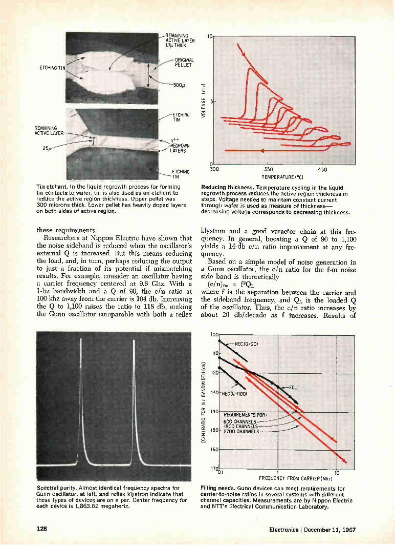
ETCHING TIN
REMAINING ACTIVE
25/L
REMAINING ACTIVE LAYER 1.7ki THICK
• ORIGINAL PELLET
ETCHING TIN
n+ REGROWN LAYERS
ETCHING TIN
Tin etchant. In the liquid regrowth process for forming tin contacts to wafer, tin is also used as an etchant to reduce the active region thickness. Upper pellet was 300 microns thick. Lower pellet has heavily doped layers on both sides of active region.
these requirements. Researchers at Nippon Electric have shown that
the noise sideband is reduced when the oscillator's external Q is increased. But this means reducing the load, and, in turn, perhaps reducing the output to just a fraction of its potential if mismatching results. For example, consider an oscillator having a carrier frequency centered at 9.6 Ghz. With a 1-hz bandwidth and a Q of 90, the c/n ratio at 100 khz away from the carrier is 104 db. Increasing the Q to 1,100 raises the ratio to 118 db, making the Gunn oscillator comparable with both a reflex
Spectral purity. Almost identical frequency spectra for Gunn oscillator, at left, and reflex klystron indicate that these types of devices are on a par. Center frequency for each device is 1,863.62 megahertz.
VOLTAGE ( m v)
10
5
o 300 350
TEMPERATURE ('C)
Reducing thickness. Temperature cycling in the liquid regrowth process reduces the active region thickness in steps. Voltage needed to maintain constant current through wafer is used as measure of thickness— decreasing voltage corresponds to decreasing thickness.
450
klystron and a good varactor chain at this fre-quency. In general, boosting a Q of 90 to 1,100 yields a 14-db c/n ratio improvement at any fre-quency. Based on a simple model of noise generation in
a Gunn oscillator, the c/n ratio for the f-m noise side band is theoretically
(c/n)f,„ cc f2QL where f is the separation between the carrier and the sideband frequency, and QL is the loaded Q of the oscillator. Thus, the c/n ratio increases by about 20 db/decade as f increases. Results of
(C/N) RATIO FO
R Ih
z BANDWIDTH (db
)
100
110
120
130
140
150
160
170
NEC (0.90)
-NEC(0.1100) ECL
REQUIREMENTS FOR: 600 CHANNELS 1800 CHANNELS-_j__"
' 2700 CHANNELS
10 FREQUENCY FROM CARRIER (Mhz)
Filling needs. Gunn devices can meet requirements for carrier-to-noise ratios in several systems with different channel capacities. Measurements are by Nippon Electric and NTT's Electrical Communication Laboratory.
128 Electronics December 11, 1967

experiments for frequency separations greater than about 50 khz bear out this simplified theory. For lower frequency separations, the noise in-creases more steeply than expected—about 25 db/decade. This may be due to the inherent noise of the semiconductor itself. Although the oscillator's Q has the greatest
known effect on spectral purity, it isn't the only factor that must be considered. The ratio of the operating frequency to the intrinsic frequency also effects spectral purity. Researchers at NTT have noted that at frequencies ±.10% away from the intrinsic frequency, noise is sometimes 10-db greater and at much lower frequencies, it can be as much as 20 db. However pure the signal is, it must also be
stable. In repeater applications, long-term fre-quency stability is particularly important. Standard Japanese fdm-f-m repeaters require a frequency stability of about 10-5 for both the local oscillator and the transmitter. Although much better stability may be obtained with a Gunn oscillator for several minutes, about 10-6, its characteristics are sensi-tive to temperature and tend to change with time. This problem may be solved with either a locking scheme or automatic frequency control. Experi-ments on locking a Gunn oscillator have thus far shown promising results.
Despite the stability problem, Hitachi Ltd. has experimented with an epitaxial Gunn device, biased just below the threshold voltage, as the oscillator transmitter in a 12-Ghz, pulse-coded, amplitude-modulated system. A signal-channel television signal was converted by a tunnel-diode modulator into a delta-modulated signal that had a pulse-repetition rate of 100 megabits per second. The amplified signal was added to the bias voltage to trigger the osicllations. The results, which Hitachi deemed satisfactory, proved the feasibility of using Gunn oscillators in short-haul communica-tions system.
Computers at work
In addition to practical development of the oscillator, theoretical analyses of the Gunn effect are being conducted at various laboratories. At the Tokyo Shibaura Electric Co. (Toshiba), Yoshihiko 110 Sawayama has performed a dynamic computer an-alysis of the Gunn diode, including the effects of the external circuit. At the University of Tokyo, a computer analysis
of the steadily traveling dipole domain was per-formed and a group headed by Hisayoshi Yanai has 120
proposed a simplified model to explain the load characteristics of a Gunn oscillator. Another group, headed by Sogo Okamura, has proposed a simpli-fied large-signal model of harmonic-mode oscilla-tions.
In Sawayama's analysis, the highest efficiency 130
achieved was about 10%, obtained with a light load; the load resistance was about 10 ohms-10 Intrinsic dip. Noise at the device's intrinsic frequency is times the low-field sample resistance. In one simu- decreased as much as 10 or 20 decibels, say researchers lation, the highest efficiency was about 7.5%, at NTT's Electrical Communication Laboratory.
C/N RAT
IO FOR I hz BANDWIDT
C/N RA
TIO
FOR 1 h z BANDWIDTH
((lb
)
3 OSCILLATION
4 5 FREQUENCY (Ghz)
6
Noise sidebands. At frequencies below the intrinsic frequency, a-m and f-m noise is reduced. This effect has not been fully studied, either theoretically or experimentally.
100
fi .5.4Ghz
50 55 OSCILLATION FREQUENCY (Ghz)
60
Electronics ¡ December 11, 1967 129
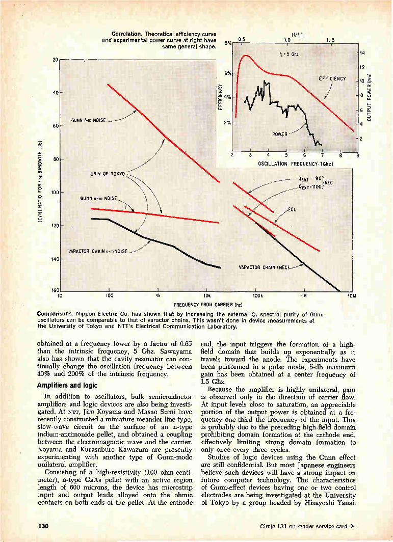
(C/N)
RATI
O FOR I hz BANDWITH (
db)
20
Correlation. Theoretical efficiency curve and experimental power curve at right have
same general shape.
60-
80
100
120
140
160 10
GUNN f-m NOISE
UNIV. OF TOKYO
GUNN o-m NOISE
VARACTOR CHAIN o-m NOISE
(Mtn 1.0 1. 5
100 1k 10k 100k 1M 10M
2 3 4 5 6 7 8
OSCILLATION FREQUENCY (Ghz)
VARACTOR CHAIN (NEC)
Q۔ " 1
' QExT'1100 NEC
FREQUENCY FROM CARRIER Du)
Comparisons. Nippon Electric Co. has shown that by increasing the external Q, spectral purity of Gunn oscillators can be comparable to that of varactor chains. This wasn't done in device measurements at the University of Tokyo and NTT's Electrical Communication Laboratory.
obtained at a frequency lower by a factor of 0.65 than the intrinsic frequency, 5 Ghz. Sawayama also has shown that the cavity resonator can con-tinually change the oscillation frequency between 40% and 200% of the intrinsic frequency.
Amplifiers and logic
In addition to oscillators, bulk semiconductor amplifiers and logic devices are also being investi-gated. At NTT, Jiro Koyama and Masao Sumi have recently constructed a miniature meander-line-type, slow-wave circuit on the surface of an n-type indium-antimonide pellet, and obtained a coupling between the electromagnetic wave and the carrier. Koyama and Kurasaburo Kawazura are presently experimenting with another type of Gunn-mode unilateral amplifier.
Consisting of a high-resistivity (100 ohm-centi-meter), n-type GaAs pellet with an active region length of 600 microns, the device has microstrip input and output leads alloyed onto the ohmic contacts on both ends of the pellet. At the cathode
end, the input triggers the formation of a high-field domain that builds up exponentially as it travels toward the anode. The experiments have been performed in a pulse mode; 5-db maximum gain has been obtained at a center frequency of 1.5 Ghz. Because the amplifier is highly unilateral, gain
is observed only in the direction of carrier flow. At input levels close to saturation, an appreciable portion of the output power is obtained at a fre-quency one-third the frequency of the input. This is probably due to the preceding high-field domain prohibiting domain formation at the cathode end, effectively limiting strong domain formation to only once every three cycles.
Studies of logic devices using the Gunn effect are still confidential. But most Japanese engineers believe such devices will have a strong impact on future computer technology. The characteristics of Gunn-effect devices having one or two control electrodes are being investigated at the University of Tokyo by a group headed by Hisayoshi Yanai.
9
14
8
4
2
130 Circle 131 on reader service card-*
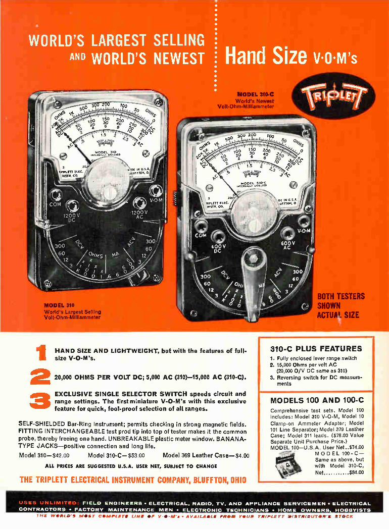
WORLD'S LARGEST SELLING AND WORLD'S NEWEST Hand Size v.o.m7s
DE IN U.S.A. MUMON,
MODEL 310 World's Largest Selling Volt-Ohm-Milliammeter
III HAND SIZE AND LIGHTWEIGHT, but with the features of full-size V-O-M's.
310-C PLUS FEATURES
MODEL 310-C World's Newest
Volt-Ohm-Mill iammeter
MODEL 310•C SMIEL010
BOTH TESTERS SHOWN ACTUA". SIZE
2 20,000 OHMS PER VOLT DC; 5,000 AC (310)-15,000 AC (310-C).
3 EXCLUSIVE SINGLE SELECTOR SWITCH speeds circuit and range settings. The first miniature V-O-M's with this exclusive feature for quick, fool-proof selection of all ranges.
SELF-SHIELDED Bar-Ring instrument; permits checking in strong magnetic fields. FITTING INTERCHANGEABLE test prod tip into top of tester makes it the common probe, thereby freeing one hand. UNBREAKABLE plastic meter window. BANANA-TYPE JACKS—positive connection and long life.
Model 310—$42.00 Model 310-C—$53.00 Model 369 Leather Case—$4.00
ALL PRICES ARE SUGGESTED U.S.A. USER NET, SUBJECT TO CHANGE
THE TRIPLETT ELECTRICAL INSTRUMENT COMPANY, BLUFFTON, OHIO
1. Fully enclosed lever range switch 2. 15,000 Ohms per volt AC
(20,000 0/V DC same as 310)
3. Reversing switch for DC measure-ments
MODELS 100 AND 100-C Comprehensive test sets. Model 100 includes: Model 310 V-O-M, Model 10
Clamp-on Ammeter Adapter; Model 101 Line Separator; Model 379 Leather Case; Model 311 leads. ($78.00 Value Separate Unit Purchase Price.) MODEL 100—U.S.A. User Net..$74.00
MODEL 100-C— Same as above, but with Model 310-C,
Net $84.00
1-/F. , Ine" -re.̂ - FIELD ENGINEERS • ELECTRICAL. RADIO, TV. AND APPLIANCE SERVICEMEN • ELECTRICAL
CONTRACTORS • FACTORY MAINTENANCE MEN • ELECTRONIC TECHNICIANS • HOME OWNERS. HOBBYISTS
THE W•RLII'S MIDST C•IMPLETE LINE OP -••118's • AVAILABLE FROM YOUR TRIPLETT IIISTRIBUTOR'S STOCK

What can closed circuit television do?
It's what it can't do that's in a minority. The applications are endless, particu-larly for the specialists. Anyone can
make a surveillance camera but not
everyone can handle film processing, view laser beams, perform in helicopters
for night time surveillance, monitor nocturnal animals, etc. because not
When you need to see where the eye can't be you need an MTI Image Orthicon Television Camera. everyone makes low light level camera systems like MTI.
And speaking of systems, we design them not only to watch a process but to watch and control the process. So whatever your problem; a single
camera off-the-shelf or a complete system to control a manufacturing process, call MTI.
UM 11 MARYLAND TELECOMMUNICATIONS, INC. York & Video Roads, Cockeysville, Maryland 301 - 666-2727 World's largest manufacturer of low light level television cameras.
132 Circle 132 on reader service card Circle 133 on reader service card—)-

From Westinghouse... the only 0.5 mil
resolution CRT in a plug-in package...
no design or assembly headaches.
It's simply not economical for you to design and assemble yokes, shields, and CRT's as well as Westinghouse does in its unique "plug-in" packages.
For example, the assembly above. It's a fiber-optic CRT package with 0.5 mil
resolution that meets mil-specs on shock and vibration. And it's ready to operate.
You save many, many hours of engineering and technician time.
This is only one of many Westinghouse CRT packages. For details, write. We have over 400 vacuum electronics engineers who want to help you.
Westinghouse Electronic Tube Division, Elmira, New York 14902.
ET-4008 You can be sure if it's Westinghouse

1 OZ.
2 PDT
2 AMPS
The HI-G
Electronics
Line Includes:
Fixed and Adjustable Time Delays — Up to 300 seconds delay . Contact
ratings up to 10 amps. Spe-
cial variations available to
accomplish delay-on-break
and interval timing.
Solid State Timing Modules — Solid state reliability offers flexi-
bility in choice of secondary switch-
ing capability
Voltage Sensors — DC and AC level sensing provides precise switching
:ogic over the temperature range of — 65
to 125 C Interface with transducers to
sense heat. light and pressure
Phase Sequence Relays — To protect phase sensitive loads against phase reversal, open
to grounded phase
Hi
eet
TIME DELAY 50ms to 100 sec Crystal Can Configuration
The new 2400 series Hi-G Time Delay Relays combines solid state timing circuits
with dependable half-size electro-mechanical relays.
Results? Small size (.4' x .8 x 1.5). Light weight (1 oz. typical). High current carrying capacity and the rugged performance of a Hi-G electro-mechani-cal relay. Long life and fast response of a hybrid circuit.
The Hi-G 2400 series operates in the range of 18 to 31 volts needs no regulated input voltages and requires no external resistance or capac-itance to obtain the maximum timing limit.
SPECIFICATIONS:
Delay Times . 50 milliseconds to 100 seconds on "make -
Delay Time Tolerance: 10: (5 on special request, Contact Rating: 2 amperes standard at 30 volts DC resistive. Temperature Range: — 55 C to — 85 C. Specials to 125 C. Vibration: 20G .s. 10 to 2000 Hz.
Shock: 50GS. 11 • 1 milliseconds duration.
Call. write, or check the reader service number for more
information. Ask for Product Bulletin 167A and a quota-tion. If you want application engineering assistance, an
experienced Hi-G representative awaits your call. Tel: 203-623-2481.
if you d like an engineering scale with decimal equiva-lents. like the one above ;ust write HI-G We Will send you a handy pocket edito; compliments of Hi-G
SPRING STREET & ROUTE 75 / WINDSOR LOCKS, CONNECTICUT 06096
134 Circle 134 on reader service card Electronics December 11. 1967

solid-state-encoded keyboard assemblies
Complete keyboards—assembled, encoded, and ready to interface with your equipment. These new keyboards feature
reliability, flexibility and custom-ized appearance that will give new sales appeal to your equipment. Exclusive new solid-state encoding and dry reed switch input assure your user the maximum in up time, and these features assure you the
minimum in maintenance. You get a wide choice of custom-
design opportunities to reduce your engineering and production costs. A unique new electronic interlock to increase operator speed and efficiency over existing approaches. An electronic strobe to delay the read cycle until the output is sta-bilized. Input flexibility to match your requirements.
MICRO SWITCH
MICRO SWITCH capabilities provide efficient factory assembly techniques to give you a custom-ized keyboard at a price competi-tive with fixed format keyboards. When you think of keyboards,
think of MICRO SWITCH. Our Field Engineers can be a valuable asset to your design team. Call a Branch Office today. Or write for complete information.
FREEPORT, ILLINOIS 61032
A DIVISION OF HONEYWELL Circle 135 on reader service card
HONEYWELL INTERNATIONAL • Sales and service offices in all principal cities of the world. Manufacturing in United States, United Kingdom, Canada, Netherlands, Germany. France, Japan.

Low-cost C106 SCR's?
Tell us how many you want
•iie01111UMil l•ettint UMIal•NR101, PRO=
f. airook+flwel Niera
proppre-
Oillagiltil• MOM 111111111111al•
imarienbe../1.1
appir e, 10•810111MIR male
1.1lior.doe•
-
11
.4.. •
^Mbar
All voltages are now available in all quantities.
Actual size GE C106 SCR
C106 RATINGS Choose from any of six 2-amp RMS
PRV/PFB voltage ratings and
C106Q 15 V many different lead configura-
cio6Y 30 V tions. GE C106's— C106F 50 V the industry's first C106A 100 V plastic encapsu-C10613 200 V C106C 300 V lated SCR's—are
priced from 30e to 60(,4 depending on voltage selection.
Peak current capability is now 25 amps, with 75-amp-capability devices soon to follow.
Sensitive, low-cost C106 SCR's have already brought new economies to a wide variety of applications including small and large appliance controls, gas igni-tion systems, motor controls, electronic switching, and temperature controls. See your local GE engineer/salesman or authqrized semiconductor distributor for comte details. Or write to Section 220-62, General Electric Company, Sche-nectady, N.Y. In Canada: Canadian Gen-eral Electric, 189 Dufferin St., Toronto, Ont. Export: Electronic Component Sales, IGE Export Division, 159 Madison Ave., New York, N.Y., U.S.A.
SEMICONDUCTOR PRODUCTS DEPARTMENT
GENERAL ELECTRIC
136 Circle 136 on reader service card Electronics December 11, 1967

Small wonder:
irii MONSANTO
COUNTER TIMER
POWER RESET
ON
DISPI. AY
MODEL 100A
OVER RANGE
t,A11 NSITIVITY
FUNc toN
INPUT A
Our new "4th-generation" 12.5 MHz universal counter/timer. Wonderful versatility in a wonderfully small package—
at an even more wonderfully small price.
With the new Model 100A you can measure average frequency, frequency ratio, single period or time interval, or count total events. It has a crystal-controlled clock, Monsanto integrated circuit construction, and built-in compatibility with a rapidly growing assemblage of accessory modules. With its $575* price tag (accessory
modules are pegged at comparably modest rates) you can have big-league counter/timer performance at
costs never before possible. Small wonder we are selling (and delivering) Model 100A's just as fast as we can build them.
Call your local Monsanto field engi-neering representative for full techni-cal details, or contact us directly at: Monsanto Electronics Technical Ctr., 620 Passaic Avenue, West Caldwell, New Jersey 07006. Phone (201) 228-3800; TWX 710-734-4334.
*U.S. Price. FOB West Caldwell, New Jersey
ELECTRONICS
Circle 137 on reader service card

MODEL VZM-1
envelope 11 ENVELOPE DELAY IN CABLE OR RADIO TRANSMISSION SYSTEMS AND COMPONENTS CAN BE PRECISELY MEASURED WITH WANDEL AND GOLTERMANN INSTRUMENTS; THE WORLD'S MOST COMPLETE LINE OF DELAY AND PHASE DISTORTION MEASURING SYSTEMS.
MODEL LID-1
MODEL LD-2
MODEL VZM-83
(01'.,̀(04-1 (te
:t: *-)
MODEL VZM-2
¡ e
1
MODEL LD-1 FOR WIDE BAND TRANSMISSION LINES AND TAPE SYSTEMS The Model LD-1 Group Delay Measuring System measures delay and loss distortion of transmis-sion systems having frequency dependent phase characteristics. Phase reference is automati-cally transmitted through circuits under test, allowing either loop or straight-away measure-ments.
Frequency Range Split Frequency Measuring Ranges Delay Distortion (full scale)
Lowest Value Measurable Loss Distortion (full scale)
Lowest Value Measurable
100 kHz to 14 MHz 20 kHz
-.±15 ns to -±-15 ±-1 no
-±0.75 dB to =20 dB ±-0.05 dB
MODEL ID-2 FOR LOW FREQUENCY DATA TRANSMISSION SYSTEMS AND COMPONENTS Similar to LD-1 except designed to cover lower portion of frequency spectrum (200 Hz to 600 kHz). Particularly useful in fields of Data Trans-mission over telephone lines where shape of transmitted pulses may be distorted because of frequency response of the group delay. Modula-tion frequency (40 Hz) allows analysis of very narrow filters and telemetry systems components.
Frequency Range Split Frequency Change Over Frequency Sweep Frequency Ranges Group Delay Range Loss Range
200 Hz to 600 kHz 40 Hz 4 Hz
±-200 Hz to ±-300 kHz -±1 gs to ±-10 ms *12.5 ms
=0.05 dB to ±-50 dB
MODEL VZM-83 DISTORTION METER FOR EQUALIZATION OF RADIO TRANSMISSION SYSTEMS
Designed to measure slope (amplitude) and de-lay (phase) vs. instantaneous drive of 2 and 4 pole networks, such as radio links, tubes, tran-sistors and wide-band amplifiers. Useful for loop or straight-away measurements and laboratory alignment of FM systems. Selectable test fre-quencies of 52, 304, 556 kHz. Delay resolution to 0.1 ns; slope distortion to 0.05%.
Test Frequencies-selectable Sweep Frequency Sweep Frequency voltage-
full scale ranges Delay Measurement-Lowest
Change Measurable Slope Measurement
Lowest Change Measurable
52, 304, 556 kHz 81.06 Hz
0.06, 0.2, 0.6, 2V
0.1 no
0.05%
MODEL VZM-2 DISTORTION METER FOR HIGH CHANNEL DENSITY RADIO LINK SYSTEMS Similar to VZM-83 except covers much wider range of frequencies. Fully transistorized. Meas-ures phase delay and slope distortion on micro-wave systems designed to cover up to 2700 voice channels of modulation. Use of higher test frequencies detects faults not observed with lower frequencies, commonly available in other instruments. Selectable test frequencies up to 12MHz available. Useful in both open and closed loop measurements.
Standard Test Frequencies Selectable (8 max.) (other frequencies available upon request)
Sweep Frequency (deflection voltage)
Deflection Voltage, full scale
Measuring ranges, amplitude (f.s.) Measuring Ranges, phase (f.s.) (1% = 0.57)
0.556, 2.4, 3.58. (or 4.429),
5.5 & 8.0 MHz
sawtooth (1.6 kHz) & triangular (800 Hz)
0.2, 0.6, 2, 6, 20, 60 volts
1, 2, 5, 10, 20, 50%
1, 2, 5, 10, 20, 50%
MODEL VZM-1 DISTORTION METER FOR PHASE AND AMPLITUDE DISTORTION IN COLOR TV TRANSMISSION Designed to measure amplitude (luminance) de-pendent gain and phase characteristics of chrominance information in color TV pictures. Test voltage frequency fixed at 3.579545 MHz. Phase resolution 0.1 degree; amplitude resolu-tion 0.5%.
A technical paper covering the subject of "Group Delay Measurement" is available by writing to Tel-Corn.
Wandel & Goltermann REPRESENTED IN U.S.A. BY
Input voltage required 20-200 mY Input resistance 750 Lowest phase change measurable 0.1 degree Lowest amplitude change
measurable Highest amplitude change
measurable
West Germany
mr E L- CO M 6 Great Meadow Lane, Hanover, New Jersey 07936 INSTRUMENTS, INC. Telephone: (201) 887-8700
0.5%
50%
138 Circle 138 on reader service card Electronics j December 11, 1967

Even the biggest IC order you give us is made in small pedigreed batches.
Mistakes don't get far at Sylvania. By making ICs in small batches and logging their perform-ance on charts that follow them through every step of production, we spot trends and make cor-rections early. You get reliable ICs, on time. To assure reliability, vendors' materials must
pass stringent tests. Parts made within Sylvania must pass the same tests. For reliability, processing areas are designed
to eliminate contamination. Ceilings, floors and
furnishings are impervious to dirt. Temperature, humidity and air are precisely-controlled. We've virtually eliminated damage to chip
substrates, metallizations and bond wires with mechanized handling equipment. And to make certain we achieve reliability, every IC must sur-vive 100% testing in 12 steps during production. And 100% testing again at the very end.
Sylvania Semiconductor Division, Electronic Components Group, Woburn, Mass. 01801.
SYNIA SUBSIDIARY OF
GENERAL TELEPHONE & ELECTRONICS GTE Circle 139 on reader service card

3.0watt @1GHz (35% efficiency, fT>1 GHz, 0 <10° c/watt)
How's that for power... It's the S 1000, our newest amplifier transistor for stripline applications.
The following are other devices available from stock:
Application Device Frequency (MHz)
Power Out (watts)
Power Gain min. (db)
Efficiency min. (%)
f, Typ. (MHz)
Tj (centigrade)
Vcc Case
Large Sig Hi Power Oscillator Amplifier
V409 260 40.0 6.0 50 300 200 28 TO-60
Large Sig Med. Power Oscillator Amplifier
2N3866 400 1.0 10.0 45 800 200 28 TO-39 S704 400 1.0 10.0 45 1,000 200 28 TO-39
VHF/UHF Oscillator Multiplier Amplifier
VX3375 400 4.0 6.0 50 650 200 28 VX* 2N3375 400 3.0 4.8 40 600 200 28 TO-60
Large Sig Hi Power Oscillator Amplifier
2N3733 400 10.0 4.0 45 400 200 28 TO-60
2N4440 400 5.0 4.7 45 600 200 28 TO-60 2N5016 400 20.0 5.0 50 700 200 28 TO-60 V410 400 25.0 5.5 50 700 200 28 TO-60
Large Sig VHF/UHF Oscillator Amplifier
VX3733 400 10.0 4.0 45 400 200 28 VX* VX3866 400 1.0 10.0 45 800 200 28 VX*
*stripline package
These RF power devices, as well as wafers and dice, channel- and lid-mounted units, high-speed NPN switches, small signal/high frequency amplifiers, differ-ential amplifiers, and silicon dioxide capacitors are available from the newly formed Electronic Components division of United Aircraft Corporation. For more information, call (215) 355-5000, TWX 510-667-1717, or write Marketing Manager.
Electronic United DIVISION OF
Components Aircraft TREVOSE, PENNSYLVANIA 19047
140 Circle 140 on reader service card Circle 141 on reader service card —3-
Systems Development turnea to /MFG() lui ItiLivuli
rime. At Essex Junction, Vermont, IBM uses
sure Airco nitrogen for inert atmospheres, gas
es & purging in the manufacture of micro-cir-
. Which adds up to a lot of nitrogen. We monitor
t.Jid gas during production & tag each trailer
with the purity count. & that adds up to total depeni
ability. Industrial gases delivered when, where &
the quantities needed: that's how we serve all o
customers, far & wide, large & small. For informatio
write us at 150 East 42nd St., New York, N. Y. 100
mc Industrial Ga

orne of our work i! ositively brilliant.
In fact, one of our lasers thr a beam 250 billion times brig than the sun.
It's the brightest laser in world. As leaders in lasers, w
made all kinds, up to giants 1000 megawatts per pulse. laser welders. And, of cours full family of laser accessorie
But lasers are only one of up-front activities that k Union Carbide on the frontie electronics. We are also leader the research, development production of solid state devi solid tantalum and foil-film pacitors, fuel cells, and si crystals and related products
They're reasons to keep Ti Carbide in mind before your p ects reach the breadboard sta
Union Car Corporation, E tronics Divis' 270 Park Ave New York 1001
UNION CARBIDE
ELECTRONICS
An Equal Opportunity Empl
Circle 142 on reader service
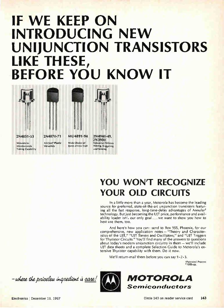
IF WE KEEP ON INTRODUCING NEW UNIJUNCTION TRANSISTORS LIKE THESE, BEFORE YOU KNOW IT
fa
2N4851-53
Minutes-to-Microseconds Timing Capability
2N4870-71
43-Cent' Plastic Versatility
MU4891-94
Wide Choke of Specs at Low Cost
2N4948-49, 2N3980 Industrial/Military Timing, Triggering and Sensing
witeze eziedem àtfzediew eade!
YOU WON'T RECOGNIZE YOUR OLD CIRCUITS
In a little more than a year, Motorola has become the leading source for preferred, state-of-the-art unijunction transistors featur-ing all the fast response, long-time-delay advantages of Annulart technology. But just becoming the UJT price, performance and avail-ability leader isn', our only goal ... we want to show you how to best use them, too.
And here's how you can: send to Box 955, Phoenix, for our comprehensive, new application notes — "Theory and Character-istics of the UJT," "UJT Timers and Oscillators," and "UJT Triggers for Thyristor Circuits." You'll find many of the answers to questions about today's modern unijunction circuitry in them — we'll include UJT data sheets and a complete Selection Guide to Motorola's ex-tensive Thyristor capability with them. Do it now.
We'll return-mail them before you can say 1-2-3. tPatented Process *1000-up.
MOTOROLA semiconductors
Electronics ' December 11, 1967 Circle 143 on reader service card 143

0ç .GEMINI eY%-i- ---AN
.0 t.ve e 44 ee .•.• ce,,,
P. e
e`o e 1) 4
Vital. High Reliability.
In the bone-snapping cold of outer space electronic components are on their own ... they must perform reliably. Increasingly stringent demands mean push-ing technology to its limit. McCoy has traditionally been a foremost manufacturer and supplier of the
highest quality crystals, filters and oscillators for NASA and U.S. military services. To maintain this position has required constant advances in tech-nology. Our new research and development laboratory (with White Room facilities)
is being built now to help McCoy meet the demand for even better products in the future. Coordination of engineering, manufacturing, quality control and management will keep us in the forefront in providing reliable products to meet customer specifications. When high reliability components are needed, turn to the leader... McCoy.
Engineering assistance is available of course. Write now for our new High Reliability literature.
OSCILLATORS
CRYSTALS
FILTERS
McCOY ELECTRONICS COMPANY MT. HOLLY SPRINGS, PENNSYLVANIA 17065
Tel. 717-4136-3411 TWX: 510—B50-354El
a subsidiary of OAK ELECTRO/NETICS CORP
144 Circle 144 on reader service card Electronics I December 11, 1967

_JL
SPE l'7‘T' RAND
The Electronic Countermeasures System, a valu-able penetration and survival tool for B-52's, posed a tough isolator problem which was suc-cessfully solved by Sperry. What was so tough about the isolator spec?
Among other things were power handling capa-bility (400W CW, 4kW peak); isolation VSWR limited to 1.18:1; insertion loss (only 1 db per-mitted), and RFI shielding to prevent interference with other aircraft systems. All parameters had to be met at altitudes up to 60,000 feet and over the temperature range of —55°C to +55°C with-out cooling.
Sperry met the challenge with Model No. D-44S9, a specially engineered isolator that helps assure the reliability of B-52 ECM.
Is there a particularly difficult isolator prob-lem Sperry can solve for you? There's a broad line of standard items, plus plenty of engineering talent if you need it. For full details, contact your Cain & Co. man or write Sperry Microwave Electronics Division, Sperry Rand Corporation, Box 4648, Clearwater, Florida 33518.
SPEIY MICROWAVE ELECTRONICS DIVISION
CLEARVVATER, FLORIDA
When B-52's count on ECM, they count on isolators from Sperry .... the first name in microwaves. Electronics December 11, 1967 Circle 145 on reader service card 145

PRESSURE MEASUREMENT REPORT CECM)))11111 REPORT NUMBER 7
Because of the unique versatility of CEC Electromanometers, pressure measure-ment systems can be customer designed to offer optimum performance and op-erating convenience at practical prices.
REASON: These electromanometers (and many other critical system com-ponents) are all standard CEC products. They've proven themselves in hundreds of applications. They're adaptable— without change or modification — to a wide variety of pressure measurement systems, and they are available in a suf-ficient number of types to free the sys-tem engineer from costly design restric-tions. Because they're available, their cost is far less than built-to-order instru-ments.
Why they are superior: CEC Electromanometers consist of a trans-ducer and a servo amplifier. Known as the Precision Pressure Balance, the transducer operates on the non-displacement, force-balance principle, affording outstanding accuracy and long-term calibration stabil-ity. So precise are these electromanome-ters, they assure an overall accuracy of 0.05% —often for as long as 30 days with-out recalibration. Reading errors are elim-inated, as is the need for specially-trained
CEC brings new advantages to pressure measurement systems
operators. There are no fussy controls to adjust, or scales to interpret.
FOR THE SYSTEMS ENGINEER: there are three distinct types of CEC Elec-tromanometers: Rack Mounted, Miniature, and Universal. They differ principally in package design. Between them, they offer pressure range capability from 1.5 psi to 10,000 psi, differential, gage or absolute. All offer the same accuracy, long-term stability and ease of operation and main-tenance.
Accessories are available for each to allow several Precision Pressure Balances to be time-shared by a single servo amplifier. These, and other proven techniques, allow the designer to reduce the per-channel cost of a multi-channel system, often below that of systems using transducers of much less performance capability.
The output of these electromanometers is a high-level analog voltage, linear with pressure. Data-processing is thus simpli-fied, and off-the-shelf components can gen-erally be used to meet system requirements.
TO THE MAN WITH A PRESSURE MEASURING SYSTEM REQUIRE-MENT: CEC is now prepared to meet your total system needs — with complete custom systems built to your requirements utilizing these electromanometers. We have developed specialized system technology which makes use of the unique and flexi-ble capabilities offered by CEC's Electro-manometers. This advance has made pos-sible the prompt fulfillment of any need, from simple calibration systems to com-puter-compatible, data-logging systems.
For further information or application es-timates, call your nearest CEC Field Of-fice. For information on our standard electromanometers, write to Consolidated Electrodynamics, Pasadena, California 91109. A subsidiary of Bell & Howell. Bulletin Kit #322-X2.
CEC/TRArISDUCER PRODUCTS
Il BELLE HOWELL 146 Circle 146 on reader service card Electronics December 11, 1967

_JL
SPEr.`ri RAND
Sperry has recently proved the performance of its X band klystron amplifiers through success-ful application in a military satellite communica-tion terminal.
The system demanded a tube that is tunable across the entire military frequency allocation; a tube that is easy to install, operate and main-tain; a lightweight tube that occupies a minimum of terminal space.
Sperry's answer is the SAX-4705, an 8 kW, 4-cavity klystron amplifier. The tube is tunable from 7.9 to 8.4 GHz. It delivers 48 db gain. It has a 1 db bandwidth of 40 MHz and is 36% efficient. Yet it occupies less than one cubic foot, including magnet, and the entire assembly weighs only 96 pounds. In addition, it has suc-cessfully passed testing to the most stringent military environmental specifications.
Other tubes in the SAX-4700 family include a 5-cavity version with 50 MHz, 1 db bandwidth, 53 db gain and 500 MHz mechanical tuning range; a 15 kW tube for operation from 10.0 to 10.5 GHz, and a 20 kW version for the 7.9 to 8.4 GHz band. For more details on any or all of these tubes, contact Cain and Co., or write Sperry Microwave Tube Division, Gainesville, Florida 32601.
STDE MICROWAVE TUBE DIVISION
GAINESVILLE, FLORIDA
SAX-4700 Series Klystron Amplifier
7.9-8.4 GHz 500 MHz
8.0-20.0 kW, CW 40-70 MHz 45-54 db 36-40%
96 lbs
Frequency range Tuning range Power output ldb bandwidth Gain Efficiency Weight
Military communication satellite terminal application proves versatility of Sperry klystron amplifiers.
Electronics I December 11, 1967 Circle 147 on reader service card 147

The new AO StereoStar/ZOOM Microscope gives you high resolution, new convenience, superior optics and wide magnification range. Here are a few of the outstanding advantages that make the new AO® StereoStar/ZOOM Microscope the finest instrument of this type avail-able today: III Widest total magnification range: 3.5-210X Ill High resolution to meet the most exacting needs II The most
convenient zoom control available III Choice of five interchangeable, rotatable zoom power bodies II Crisp, sharp images at all magnifications
Extra large field of view and high eyepoint eyepieces I Wide choice of stands for every purpose II Long working distance I Even illumina-
tion over the entire field II Coolest operating illuminator.
See for yourself. Contact your AO Sales Representative for a demon-stration, or write for our 24-page, full-color brochure on the newest in stereo microscopes—the AO Stereo-Star/ZOOM.
eTM Reg., American Optical Co.
AMERICAN
OPTICAL
COMPANY INSTRUMENT DIVISION
BUFFALO, NEW YORK 14215
Circle 148 on reader service card

Probing the News
Communications
Crime fighting in real time FBI's nationwide computerized information network steps up tempo of battle
by replying to questions from local authorities within seconds
By Paul A. Dickson Washington regional editor
Within six months the Federal Bu-reau of Investigation will have a criminal information network link-ing state and local law enforcement agencies in all 48 continental United States. They will be tied into the FBI'S National Crime Infor-mation Center in Washington, which was just an idea as recently as 1965. Moving with remarkable speed,
considering the complexity of the system and the usual official Wash-ington pace, the center now has its computers linked directly to 32 con-trol terminals in 24 states and Can-ada. Most of the terminals are tele-printers, but FBI officials predict that within five years each state will have at least one computer of its own on line.
I. Forerunner
Obviously the FBI center will pro-vide a market for computers and associated electronics equipment. But of greater significance is its role as the first system linking Fed-eral, state, and local governments in a computerized network, for it may serve as the protoype for other long-sought national networks. For example, the Department of Health, Education, and Welfare has shown interest in a national health infor-mation bank; the justice Depart-ment wants a coast-to-coast legal data bank; the Defense Depart-ment and the National Aeronautics and Space Administration also are interested in nationwide informa-tion storage and retrieval hookups. The three electronic subsystems
of the crime center are the central computer facility in Washington, a telecommunications system, and terminal equipment—teleprinters and computers at various locations from coast to coast. Communica-tions for the system are now pro-vided by 124 low-speed lines leased from the Western Union Telegraph Co. that handle transmissions of up to 135 words per minute. They link each terminal to the central file, containing more than 330,000 active criminal records. The center, han-dling some 13,000 transactions a day from the local terminals, serves as an automated file of records of
wanted persons, stolen vehicles, ve-hicles used in connection with a felony, stolen license plates, guns, and other items that may be identi-fied by serial numbers. The center answers queries in an
average of 10 seconds. Checking is done by one of two International Business Machines Corp. 360/40 computers. A typical query results from a policeman spotting a speed-ing car or one that is "acting sus-piciously." He radios the license number to headquarters where it's fed into the FBI system. Computers in Washington check their files and report back on the status of the ve-
Command center. This is the headquarters of the FBI's National Crime Information Center in the Old Post Office Building in Washington.
Electronics December 11, 1967 149

Who wants to know? While the FBI moves full speed ahead with its National Crime Informa-tion Center, alarms are being raised over possible abuses of any such system. A Rand Corp. engineer, leader of a project to provide protection for
strategic command and control systems, has called for "additional layers of protection" against invasion of privacy by electronic techniques applied to law enforcement.
Paul Baran, a 40-year-old computer expert, agrees that there are many possible electronic aids to police that do not threaten privacy. In fact, he says, technology for the general welfare has been a poor relative for too long. But he fears abuses. "Information," says Baran, "is dangerous stuff if misused." Watch it. "Unless those who control the system are honest and safe-
guards are adequate, we could easily end up with the most effective, oppressive police state ever created," Baran continues. "While research and development in better techniques for law enforcement are desirable, caution is needed lest we create a Frankenstein's monster."
People leave a trail of records from birth to death—schools, job, taxes, licenses, purchases, credit, and maybe court and police records, Baran says. Today, those records are usually hard to track down. With a cen-tralized system, especially with time-sharing—which Baran pinpoints as the gravest potential threat—data about an individual would be just too accessible. This could encourage eavesdropping and tampering. He adds: "While our computer systems may be foolproof, they're not 'smart-proof.' Information in the hands of the wrong person could turn a storage and retrieval network into an automated blackmail machine."
Progress. There's encouraging response, says Baran, from computer engineers, legal authorities, and civil liberties groups that are beginning to explore the dangers involved. "The computer industry itself should take the initiative and responsibility of building in the safeguards," he maintains.
Baran offers this partial list of checks: • Provide cryptographic protection to discourage eavesdropping. • Never store file data completely in the clear. Perform some simple
but key controllable operation so that simple access will not necessarily mean full access. • Make random external audits of file-operating programs. • Detect and report abnormal information requests. • Verify and record sources of requests.
hide. Headquarters then radios in-formation to the officer in the car. The man in charge of the crime in-formation center, Inspector J. J. Daunt, sees this as an important function of the system because it serves as a warning to the police-man to be prepared for a danger-ous situation if the "suspicious" car turns out to be stolen or if it has been used in a robbery. Gangbusters' hardware. Besides
the two um 360's, the center con-tains peripheral equipment from the ism stable. There are four 2702 transmission control units to direct and control the flow between the computer and the users and two model 2314 disk pack storage de-vices, each of which can accommo-date nearly 2 million records of 125 characters each. This month, the FBI was to receive a 2703 transmis-sion control unit enabling the sys-tem to add 175 leased lines to hook
up new user police agencies. Terminals now in use are mostly
Teletype Corp. 35 or IBM 1050 tele-printers. But a variety of computers have been tied into or are sched-uled for interface with the system. Already functioning are: • A Radio Corp. of America 301
owned by the California Depart-ment of Justice; • Two Sperry Rand Corp. Univac
418's, one owned by the New York State Police, the other by the Loui-siana State Police; • Two IBM 7740's, one owned by
the California Highway Patrol, the other by the St. Louis Police De-partment; • Two Burroughs Corp. 5500's,
one owned by the New York State Identification and Intelligence Sys-tem, the other by the Michigan State Police. Within the next year, the Chi-
cago Police Department and the
Ohio State Patrol will acquire pm computers and the Georgia State Patrol will come in with a Honey-well Inc. model. Daunt points out that the addi-
tion of a single state master com-puter enables the system to grow rapidly within the state itself. A prime example is California. The Highway Patrol's Ism 7740 was the first computer to be interfaced, and that didn't happen until April. But the Golden State now boasts 270 local terminals tied to the 7740, which in turn is tied into the FBI center.
Subnetworks. Special Agent Don-ald Roderick, Daunes assistant, says that's the way the Fm wants things to work—with "every state running its own information net-work, keeping its own records, and coming up with its own statistics. The statistics will enable each state to make decisions and find answers to local problems." However, Rod-erick says that 25 or so metropoli-tan areas could have direct lines to Washington for quick checks of the files. Daunt says that as larger agen-
cies enter the system the burden of each agency will be to coordinate the efforts of the smaller outfits surrounding them. Several Cana-dian provinces tried to join the sys-tem but the FBI insisted that only one agency represent the country. Another recent addition—the Of-fice of the Provost Marshal of the U.S. Army—is being asked to co-ordinate the law enforcement needs of all the armed forces.
II. Unified front
When conceived in 1965, the ob-jective of the center was to place in the hands of the law enforcement community a national information network to complement similar lo-cal systems. The FBI moved fast. In early 1966, with the International Association of Chiefs of Police and representatives of a number of state and local groups, they held the first meeting. Also early last year, the FBI went to the Commerce Department's Environmental Sci-ence Services Administration in Boulder, Colo., to study the con-cept and provide the crime center's communications design. Late in 1966, at the annual conference of the police chiefs, the delegates adopted a basic set of standard
150 Electronics I December 11, 1967

codes, formats, and procedures to be used by the center and all other law enforcement information sys-tems. With the help of a half-mil-lion-dollar grant from the Justice Department and close technical li-aison with the Commerce Depart-ment, the system was put into op-eration.
Lesson plan. Says Roderick: "Frankly, it has expanded far more rapidly than we had anticipated." Daunt says that the key to the suc-cess of the system thus far has been "the very important business of standards, accuracy, and rigid format." The American Standard Code for Information Exchange is the telecommunications code used by the center and the procedures are those adopted by the police chiefs. "We could see early in the
game," says Daunt, "that we would all have to adopt the some pro-cedures. And it was clear to users that to benefit from the system they have to conform." Standardization, according to Daunt, eliminates in-terface problems and will help other government officials who have long been discussing informa-tion networks but not getting them off the ground. Whoops. "The biggest payoff of
the system so far," says Daunt, "is that we are now getting a new ap-preciation of the value and accu-racy of information. In manual files, errors of omission and com-mission are made. These errors sel-dom came to light. Now, with the FBI center to check against local agencies, we are finding these er-rors." Daunt says that the national file has already been used for a check against state manual files— in one case the state found that it had misfiled records on four wanted persons. Another benefit gained from entering local records in the national bank is that, if the local file is destroyed, replacement could be provided by the national file (which is also being duplicated in case of catastrophe at the national center). While the center has gotten into
operation in short order it was not without problems, though they were of the most mundane variety. Two showstoppers: an improperly set time clock kept shutting the system off last March, and a gummed label, stuck to a drum
FASTEN THIS
INTO YOUR
NEW YIG FILTER
RECEIVER PLANS
Consider the new WJ-652 —the first of a new family of Watkins-Johnson fixed— or mechanically-tuned YIG filters produced in a miniature, lightweight configuration (3/4 -inch cubed) to meet rugged environmental conditions. A simple screwdriver adjustment allows for tuning plus/minus 250 MHz at any center frequency between 1-5 GHz.
As shown below, a number of these filters can be stacked to provide multichannel receiver operation —especially where driving power is either minimal or not available or where rapid switching is a requirement. Also, the WJ-652 is ideal for use as a frequency selective limiter at some frequencies and as a premature decline limiter at others.
Input
PN Diode Switch Matrix
Output
WATKINS D JOHNSON
3333 HILLVIEW AVENUE STANFORD INDUSTRIAL PARK PALO ALTO, CALIFORNIA 94304
Electronics I December 11, 1967 Circle 151 on reader service card 151
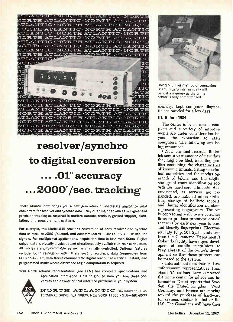
• 11" 1_, _A_ -N
C:) T AT • TANTIC
0 T H. AT • T'LANTIC RT H AT
• T L_AN T I C . R. T Pi AT
• TLA_NTIC
0 12,T I-1 AT • T A.1\T T 10
0 R.,
•
0 R., TLANTIC
0 R. T 1-1 AT TLANTIC 0 T H AT TLANTIC • R, T H. AT T LAN TI C • R, T AT
• •
ANTIC • NORTH AT • NORTH' AT LAN T IC • LANTIC • NOR T H AT •NORTH AT LAN T I C • .L_A_N TIC • NORTH AT •NORTH AT LANTI 0' • LAN TIC • NO R. T H AT • -NORTH AT LAN T I C •
T _AT •
• NO
_A_N TIC • NORTH • N R. T AI T I C • LAN T I 0' • N 0 R. T PI AT • NORTH ATLANTIC • LANTIC • NO R. T AT • NO T H LANTIC •
LANTIC • NORTH AT
LAN T I R,T
LAN TI NORM LAN TI
RT LAN TI NO 12, T LAN T I
I •
T. I •
TI R.T
TI I\T CD 1'2_, T _LAN T I
1:2_,T LAN TI NO R. 'T LAN T I
alb
resolver/synchro
to digital conversion
... .01° accuracy
...2000°/sec. tracking
North Atlantic now brings you a new generation of solid-state analog-to-digital
converters for resolver and synch ro data. They offer major advances in high-speed
precision tracking as required in modern antenna readout, ground support, simu-
lation, and measurement systems.
For example, the Model 545 provides conversion of both resolver and synchro
data at rates to 2000° /second, and accommodates 11.8v to 90v 400Hz line-line
signals. For multiplexed applications, acquisition time is less than 50ms. Digital
output data is visually displayed and simultaneously available on rear connectors.
All modes are programmable as well as manually controlled. Optional features
include .001° resolution with 10 arc second accuracy, data frequencies from
60Hz to 4.8KHz, data freeze command for digital readout at a critical instant, and
programmed mode where difference angle computation is required.
Your North Atlantic representative (see EEM) has complete specifications and
application information. He'll be glad to show you how these con-
verters can answer critical interface problems in your system.
1•TCDR.T1-1 _ATLANTIC industries, inc. TERMINAL DRIVE, PLAINVIEW, NEW YORK 11803 • 516-681-8600
Going out. This method of comparing latent fingerprints manually will be just a memory as the crime center is fully computerized.
memory, kept computer diagnos-ticians puzzled for a few days.
II I. Before 1984
The center is by no means com-plete and a variety of improve-ments are under consideration be-yond the expansion to state computers. The following are be-ing examined: • New criminal records. Roder-
ick sees a vast amount of new data that might be filed, including pro-files containing the characteristics of known criminals, listing of crim-inal associates and the modus op-erandi of felons, and the digital storage of court identification rec-ords for hard-core criminals. Also envisioned, as services are ex-panded, are national crime statis-tics, storage of ballistic reports, and digital identification numbers representing fingerprints. The FBI is contracting with two electronics firms to produce prototype optical scanners by early next year to read and identify fingerprints [Electron-ics, July 10, p. 50]. System advisers from the Commerce Department's Colorado facility have urged devel-opers of mobile teleprinters to keep abreast of the center's devel-opment so that these printers can be mated to the system. • International coordination. Law
enforcement representatives from about 75 nations have contacted the crime center for advice and in-formation. Daunt reports that Swe-den, the United Kingdom, West Germany, and France are moving toward the purchase of hardware for systems similar to that of the U.S. The Canadians will have their
152 Circle 152 on reader service card Electronics I December 11, 1967
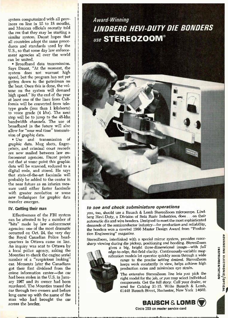
system computerized with all prov-inces on line in 12 to 18 months, and Mexican officials recently told the FBI that they may be starting a similar system. Daunt hopes that all countries adopt the same proce-dures and standards used by the U.S., so that some day law enforce-ment agencies all over the world can be united. • Broadband data transmission.
Says Daunt, "At the moment, the system does not warrant high speed, but the program has not yet gotten down to the patrolman on the beat. Once this is done, the vol-ume on the system will demand high speed." By the end of the year at least one of the lines from Cali-fornia will be converted from tele-type grade (less than 1 kilohertz) to voice grade (4 khz). The next step will be to jump to the 48-khz bandwidth channels. The use of broadband in the future will also allow for "near real time" transmis-sion of graphic data. • Use and transmission of
graphic data. Mug shots, finger-prints, and criminal court records are now mailed between law en-forcement agencies. Daunt points out that at some point this graphic data will be scanned, reduced to a digital code, and stored. He says that state-of-the-art facsimile will probably be added to the center in the near future as an interim mea-sure until either faster facsimile with greater resolution or some new techniques for graphic data transfer emerges.
IV. Getting their man
Effectiveness of the FBI system can be attested to by a number of "hits" made by law enforcement agencies: one of the most dramatic occurred on Oct. 24, the very day the Royal Canadian Police head-quarters in Ottawa came on line. An inquiry was sent to Ottawa by a local police agency, asking the Mounties to check the engine serial number of a "suspicious looking" car. Moments later the Canadians got their first dividend from the crime information center—the car had been stolen in the U.S. in Janu-ary 1967 and its owner had been murdered. The Mounties traced the car through two owners and before long came up with the name of the man who had brought the car across the border.
Award-Winning
LINDBERG HEVI-DUTY DIE BONDERS
use STEREOZOOM®
to see and check subminiature operations you, too, should use a Bausch & Lomb StereoZoom microscope. Lind-berg Hevi-Duty, a Division of Sola Basic Industries, does . . . on their automatic die and wire bonders. Designed to meet the most sophisticated demands of the semiconductor industry—for production and reliability, the bonders won a coveted 1966 Master Design Award from "Produc-tion Engineering" magazine.
StereoZoom, interlinked with a special mirror system, provides razor-sharp viewing during die pickup, positioning and bonding. StereoZoom
gives a big, bright three-dimensional image—with full edge-to-edge, flat-field clarity. Continuously-variable mag-nification models let operator quickly zoom through a wide
range to the precise setting desired. StereoZoom keeps work constantly in view, helps achieve high production rates and minimizes eye strain.
The extensive StereoZoom line lets you pick the right model for the job, or you may select individual components. Get the full story. Call your dealer, or send for Catalog 31-15. Write Bausch & Lomb, 61448 Bausch Street, Rochester, New York 14602.
BAUSCH & LOMB CD Circle 153 on reader service card
9NI3NVACIV

Communicate clear as a Bell ... by tropo-radio, between points 35 to 150 miles apart — common distances in modern battle areas. AN/TRC-104 is an ultra-reliable, lightweight, troposcatter radio system developed by Bell Aerosystems for the U.S. Air Force. Weighing less than 500 pounds, the complete terminal equipment can be set up anywhere by a small crew in less than an hour. The channels available can handle voice or digital data and simultaneous transmission and reception. The 104 achieved its design goals and in field tests demonstrated its increased reliability, reduced size and weight. This is another example of clear thinking by the scientists and engineers of Bell.
BELL AEROSYSTEMS—A tMexon COMPANY Buffalo, New York
154 Circle 154 on reader service card Electronics I December 11, 1967

Space electronics
Intelsat 3: coming or going? Comsat, pushing for FCC approval of Intelsat 4, is getting edgy
about the pace of work on its first global communications satellite
Nagging difficulties in the con-struction of Intelsat 3—the satel-lites slated for launching begin-ning next year as the first global communications system—are dis-tracting the Communications Sat-ellite Corp. just as the company is making an all-out effort to win ap-proval for its giant next-genera-tion Intelsat 4.
Just how big these problems are no one will say, but Comsat man-agement is described as having a definite "lack of confidence" in the Intelsat 3 development work. Com-sat's president, Joseph V. Charyk, was disturbed enough to make a hurried flight late last month to the TRW Systems Group of TRW Inc., the builder of Intelsat 3, to take a look. His trip with Siegfried H. Rei-ger, Comsat's technical vice pres-ident, added weight to the rumors about Intelsat's problems. One insider says Comsat blames
the holdup on sloppy management of the program, troubles with for-eign subcontractors, and problems in the communications system be-ing built by the International Tele-phone & Telegraph Corp.'s Defense Communications division. Other re-ported difficulties include getting channel separation and multiple-beam interference.
Denial. TRW'S Intelsat 3 program manager, Morris Feigen, calls those reports of major technical difficul-ties untrue. He admits there are minor problems, such as bad solder-ing, but maintains that no redesign has been necessary. "We're having the customary minor difficulties that occur in any spacecraft pro-gram," he says, but they're readily solvable." And he insists mw will come "reasonably close" to a late June delivery date for the first sat-ellite. Insiders say Comsat was told by mw that it will deliver the sat-
ellite by Aug. 17, five months late.
I. Backstage
All this is unfolding against a background of international mach-inations concerning the type of sat-ellite that will follow Intelsat 3. While looking nervously over its shoulder at the rrtw project, Com-sat finds itself engaged in a battle pitting its proposed Intelsat 4 against a beefed-up version of the Intelsat 3—dubbed the 3.5—for the second global system.
Hurdles. Standing in the way of the next-generation craft is: • The Federal Communications
Commission, which still hasn't given its blessing to the program. • A proposal before the Interna-
tional Telecommunications Satel-lite Consortium to build the 3.5. • The plan of an international
common-carrier consortium to build the TAT-5, a 720-channel transatlan-
Undersea threat A bitter feud has developed be-tween backers of cables and satel-lites over how best to expand transatlantic communications ca-pacity. International carriers, led by American Telephone & Tele-graph Co., are pushing to get TAT-5, a $75 million, 720-channel transistorized cable, installed by 1970 between Rhode Island and Cadiz, Spain. Approval of this scheme would kill any chance the Communications Satellite Corp. has to move ahead with its plan to have the Intelsat 4 satellite on the air by 1970. The controversy dominated cor-
ridor and cocktail-party conversa-tions at the second world planning meeting of the International Tele-communications Union in Mexico City last month. It was clear to all parties that the r..ble backers don't intend to stop with TAT-5. They are determined that future expansions of international com-munications will be split 50-50 be-
tween cable and satellite circuits. Vested interests. Pushing hard
for cables are U.S. carriers and European countries that would share in cable ownership. Cables bring their owners far more eco-nomic rewards than a satellite net-work simply because ownership— and profits—are divided among only a half dozen or so interests, compared with 60 or more for a satellite system. Cable owners also control the communications traffic, and in the past they have made sure that the cables are busy be-fore they turned to satellite cir-cuits.
Comsat, Latin American coun-tries, and a sprinkling of other de-veloping nations are dead set against the new cables. They are backed to some extent by the U.S. Government, which wants to pro-mote a global satellite communi-cations system.
Complicating the issue is the fact that the cable backers are also
major shareholders in the 60-na-tion Intelsat consortium.
Leverage. By early next year, the U.S. Government should pre-sent its new position on future cable expansion. U.S. landing rights for cables must be ap-proved by the Government, and this gives Washington a big ace in the hole. The U.S. can't be cir-cumvented because the bulk of in-ternational communications sought for cables either originates or terminates in this country. As a re-sult, the foreign concerns need U.S. cooperation for cables as much as the U.S. needs theirs for satellite development. One proposal to avoid a long,
head-on fight: merge all interna-tional communications carriers into a new organization that would own both the U.S. satellite and cable interests. This is expected to be considered by the special com-munications task force created last August by President Johnson.
Electronics December 11, 1967 155

NEW ALL-II VI II SILICON
DIGITALLY TUNED
VARIABLE FILTER FEATURES
ULTRA LOW FREQUENCY
96 OB/OCTAVE SLOPE
fee». dso4i)
MODEL 3342 DUAL-CHANNEL, MULTI-FUNCTION FILTER provides low-pass and high-pass operation with 96 db attenuation slope or 48 db slopes as band pass or band reject filter. The digital frequency control provides cut-off frequencies from 0.001 Hz to 100 kHz with 2% calibration accuracy and excellent resettability. Size: 51/4" H x 19" W X 16V2" D.
The new Krohn-Hite Series 3300 operates on either line or batteries, with 0.1% distortion and provides gain of 20 db.
MI •••••••••
N •
1 RECORDING ILLUSTRATES gain and selec-tive response of Model 3342, in minimum band-pass operation, to a 0.01 Hz square wave. Output consists primarily of third harmonic component of input.
This kind of low-frequency perform-ance is backed by other important specifications. Examples are:
Filter Characteristics: Either 4 or 8-pole Butterworth (maximally flat) and R-C for transient-free opera-tion.
Digital Tuning: Six bands, 3 digits; rotary switches.
Maximum Attenuation: 80 db.
Dynamic Range: 80 db.
Input Impedance: 10 megohms.
Output Impedance: 50 ohms.
Write for Data
811-1 KROHN-HITE 580 Massachusetts Avenue, Cambridge, Mass. 02139
Telephone: 617/491-3211
I Bird. Model of Intelsat 3, satellite causing anxious moments at Comsat.
tic transistorized cable that would siphon business away from the sat-ellite system. While there's no guarantee that
either the Intelsat 4 or 3.5 will be built, the 18-member Interim Com-munications Satellite Committee, which handles the day-to-day busi-ness for the 60-nation Intelsat con-sortium, has given Comsat permis-sion to request proposals from industry for both craft. But there's some question about when and if this call will go out. Comsat doesn't want the 3.5 satellite but some of the Europeans show more interest in it than in the Intelsat 4, primar-ily because the 3.5 would provide more work for them. The interim committee met late
last month to mull the alternatives. Comsat made a vigorous pitch for Intelsat 4, says one source, but "didn't have a prayer of getting it through." A decision can't be made before January at the earliest; that's when the interim committee's tech-nical subcommittee has its next meeting, and, a Comsat official ex-plains, "It would be highly doubtful that the interim group would make a decision without the recommenda-tion of its technical panel."
Complications. The IIughes Air-craft Co., meanwhile, has been mak-ing informal approaches to Comsat with the aim of reviving a plan to build an Intelsat 2.5. This craft would have between 800 and 900 channels, gained by "squinting" the antenna beam—focusing it on a
small area on earth rather than an entire hemisphere. Hughes' original Intelsat 2 design employed only 240 channels; Intelsat 3 is to have 1,200; Intelsat 3.5 would have 2,100 with a squinted beam; and Intelsat 4 would have 5,000 channels or, with a squinted beam, 10,000. Comsat officials concede that a
prolonged delay on Intelsat 4 might force them to exercise their option to buy as many as 18 Intelsat 3's in addition to the six already called for. This would make foreign mem-bers of the consortium happy be-cause a second Intelsat 3 increment of just six satellites would boost their share of the program's con-tracts to 70% or 80%. What it boils down to, says
Comsat, is that if no decision is made on Intelsat 4 before the sec-ond half of 1968, the company may have to order more Intelsat 3's to provide the channels necessary to accommodate users clamoring to get into the system. If the 3.5 ver-sion is approved by the consortium, the Intelsat 3 order could be cut to fewer than the six covered by the contract.
II. Star-crossed
Intelsat 3 was saddled with one problem from the beginning—its antenna. Five months after mw won the contract in June 1966— Hughes and the Radio Corp. of America were the other bidders— the electronically despun antenna built for the craft by Sylvania Elec-tronic Systems' Central division in Buffalo, N.Y., was discarded [Elec-tronics, July 24, p. 49].
This antenna was replaced by a mechanically despun unit from Syl-vania's Eastern division in Wal-tham, Mass., and it took another two months to confirm that the new antenna would meet specifications. That seven-month delay might have been avoided had Comsat gone along with TRW'S suggestion that a mechanically despun antenna be developed concurrently for insur-ance. As it turned out, the electronic model had the required directivity but experienced losses in the phase shifters of about 1 to 2 decibels more than could be tolerated.
Tug-of-war. Even the first ver-sion of the mechanically despun an-tenna presented a problem. With a parabolic reflector and cornucopia horn, it presented a squint problem:
156 Circle 156 on reader service card Electronics I December 11, 1967

if the transmit beam pointed at the receiving station, the receive beam was off station, and vice versa. This was solved by using a simple flat plate reflector.
Neville Barter, assistant project manager at mw, brands as "abso-lutely untrue" industry reports that the combination of problems in the mechanically despun anterma and the communications transponders would reduce channel capacity from 1,200 to 900. In fact, according to Feigen, the antenna is working out better than specified. He as-serts that Sylvania's engineering tests have produced better than the specified 13.2-db gain at the worst point of the beam—the edge.
Furthermore, says Feigen, Syl-vania is getting better gain in both transmit and receive modes than specified; he notes that gain plays a big part in channel capacity. If the number of carriers is limited to the 10 that Intelsat 3 was designed for, more than 1,200 channels will be available, he adds.
Switch. TRW'S phase-one study of Intelsat 3 projected a medium-altitude (18,000 miles) satellite us-ing gravity-gradient stabilization. Going to a stationary-orbit design presented no problem, says Bar-ter. TRW had already used spin stabilization for the 1958-59 Able series, on Pioneer 5 in 1960, on Explorer 6, and for the Vela pro-gram. The solar arrays on Intelsat 3, Barter says, are very similar to those used in the Pioneer program. TRW has kept foreign subcontrac-
tors up to date, says Barter, by in-viting those firms' design engineers to reside at the mw facilities at Redondo Beach, Calif., early in the design and development stages. The subcontractors are following TRW'S designs, and TRW is buying all the high-reliability components needed, such as transistors, capacitors, and resistors, and sending them over-seas. The foreign firms perform burn-
ins-250 hours for passive compo-nents, 1,000 for active—and then build preproduction versions of the hardware, with raw representatives providing support where needed. Finally, Trtw tests the hardware.
Ill. Blueprint
Barter says there is nothing that can be considered state-of-the-art hardware on Intelsat 3. The two
If you use recorders... shouldn't you check flutter before you gather
valuable data? VIDAR'S 720 analyzes and measures
flutter accurately, quickly, and conveniently in
accordance with IRIG 106-66 and recorder
manufacturers' recommendations. The oscilloscope
display helps you analyze and track down flutter
components as low as 0.02% peak-to-peak over
flutter bandwidths ranging from 0.2 Hz to
20 KHz. For complete details on this VIDAR
laboratory-quality instrument contact Carl Smith,
(415) 961-1000, VIDAR Corporation, 77 Ortega
Avenue, Mountain View, California 94040.
"\TID.,A.1:z
Circle 157 on reader service card—*

Little Emancipator You can often do away with a separate slave relay or lock-in circuitry, simply by using a Heinemann Silic-O-Neti& time-delay relay. Its continuous-duty
coil can remain energized in-definitely after actuation, and
its SPDT or DPDT contacts are rated up to 5 amps (for the Type B shown). Your saving shows up not only in circuit
simplicity but in the remarkably low price of the one relay that'll be doing two jobs ex-tremely well. The five Silic-O-Netic models
offer a combination of fast re-cycling, good repeatability, and low power consumption—vir-tues inherent in their hydraulic-magnetic actuation. No thermal
elements, and therefore no 374)
"heat-loading" on frequent re-cycling, and only minor effect on delay from ambient-temperature changes.
We offer sixteen standard timings, 1/4, to 120 seconds, with reset time about 25% of the rated delay; coil ratings (for continuous duty, mind you) up to 250 vac or 120 vdc; plug-in models, hermetic models, open-
frame and enclosed-contact mod-els. Bulletin 5006—yours for the
asking—will tell you all you want to know about these versa-tile little t/d relays. Heinemann
Electric Company, 2600 Bruns-wick Pike, Trenton, N. J. 08602.
HEINEMANN
EARTH
ROTATING METAL REFLECTOR (FLAT PLATE)
BICONICAL HORN OMNI ANTENNA
NON-ROTATING PARTS
RECEIVER OUTPUT TRANSMITTER INPUT
Horn. Mechanically despun antenna uses fiber glass, shown in green.
wide-bandwidth transponders (225 megahertz each) and high-gain an-tenna are extensions of existing technology. And the official notes that because Intelsat 3 is to be the first satellite with a despun an-tenna, the transponders' effective radiated power (erp) of 22 db above 1 watt is "significantly more" than that of previous satellites. Give and take. The antenna sub-
system receives communications signals at a frequency of 6 giga-hertz and transmits them at 4 Ghz. It transmits telemetry signals and receives command signals at both these frequencies. Transmitted sig-nals are circularly polarized to the right, received signals to the left. The antenna is stepped in a di-
rection counter to the satellite's spin by a motor that takes its reference from the spacecraft's earth refer-ence pulse. The circuitry here con-sists of the motor and fault logic, a motor driver, a d-c to d-c con-verter, and associated filters.
Trtw is developing all subsys-tems except the Sylvania antenna; the communications, telemetry, and command unit, which are be-ing built by ITT; and the apogee thrust motor, being furnished by the Aerojet-General Corp. Now hear this. The communica-
tions, telemetry, and command sys-tem is another pacing item in Intel-sat 3. A single diplexer in the corn-
158 Circle 158 on reader service card Electronics December 11, 1967

munications subsystem allows the two amplifier chains to operate simultaneously with or separately from the same antenna, and feeds the two amplifier ch-.ns. TRW'S Feigen says: "Because we have to diplex into each transponder, one of the very difficult tasks we have is getting linear performance near the band edges of the diplexer. He describes the diplexer rrr is using as "the best that can be built at the moment to meet various con-straints, but still a difficult pacing item in the subsystem." The total erp rating of Intelsat 3
is 25 dbw. Signals received at 6 Ghz are to be amplified without any modulation change and con-verted to the 4-Ghz fr-Tmency for retransmission to earth stations in the 3,700-to-4,200-Mhz common carrier band. Communications signals received in the 5,925-to-6,155-Mhz band are first amplified in a two-stage tunnel-diode ampli-fier that provides a 35-db gain. The amplifier output is then translated to the 4-Ghz common carrier band by a mixer using a 2,225-Mhz local oscillator. And the translated signal is amplified by an integrated trav-eling-wave tube made up of a 0.1-watt low-level tube and an 11.7-watt output stage with a total gain of 80 db. Obey. Feigen explains: "Point-
ing the antenna must be done either by onboard sensors and logic or by ground signals, and we have to be able to select either method on ground command." To despin the antenna by on-
board means, leading-edge horizon pulses from the earth sensors are applied to the antenna's control electronics. The speed of antenna beam rotation in relation to satel-lite rotation is then controlled by the frequency of earth pulses. An-tenna control from the ground is achieved by -commanding the sys-tem to function on artificial pulses, and then transmitting these pulses to the satellite at its rotational rate. Two radial and two axial thrust-
ers triggered by ground commands position and orient t. . satellite.
The reporting for this article was done by Lawrence Curran in Los Angeles, and Paul Dickson and Seth Payne in Washington. Howard Wolff in New York wrote the story.
Compacks even control
tempers
Read all about
them in
Bulletins 48 and .1D.
You won't fume or fret over delivery of API's versatile little controllers. Both the upright and edge-reading styles are waiting on the shelf in the most popular current, voltage or temperature ranges. Compacks contain integral solid-state
circuitry behind vibration-resistant taut-band meter movements. Just specify the control action you need for any unamplified signal, DC or AC.
Either single or double set points are adjustable immediately. The existing signal is always displayed. Compacks not only preserve your good
nature—they'll downright soil you.
INSTRUMENTS CO. CHESTERLAND, OHIO 44026 • (CLEVELAND- 216) 729-1611 • TWX: 810-427-9230
In Canada: hawa, Ontario • (416) 576-1541
Electronics December 11, 1967 Circle 15 J n reader service card 159

PUSHBUTTON designed for computers
Computer manufacturers no longer have to "make-do" with a pushbutton switch designed for non-computer use. These new Oak switches give you highest reliability—with double-wiping clips locked firmly into recessed barriers for high voltage break-down characteristics, and a Kel-F slider insulator for smooth action. Response is fast...with stroke as short as 5/32"...and operating pressure is light and consistent from button to button. Maximum circuitry available, 4 PDT. Inboard or outboard mount-ing; molded stator case has interlocking lugs for firmness... almost unlimited stacking. Many options available: Normal inter-lock, push-to-latch, push-to-release, momentary...or any com-bination of these. Also multiple latch bar arrangements for any number of buttons up to 12 buttons maximum. (Example: 4 groups of 3 buttons on a 12-button bank.) Pushbuttons are 3/4" on center with 23/s" maximum push rod length. Rated 0.5 amp. @ 115 vac or 1 amp @ 28 vdc. For full details, write for Bulletin CD-280.
OAK MANUFACTURING CO. A DIVISION OF OAK ELECTRO/NETICS oo
CRYSTAL LAKE, ILLINOIS 60014
Phone: 815-459-5000 TWX: 910-634-3353 CABLE: OAKMANCO
And, for other computer applications Oak has the 184 Lever Switch.., small, molded diallyl phthalate stator, long life, more clips per stator, low electrical leakage, no extra cost. Many options. For full details, write for Bulletin \ SP 240.
160 Circle 160 on reader service card Electronics I December 11, 1967

Consumer electronics
Santa's helpers shun electronics Technological toys will fill few Christmas stockings this year;
prices are high and most children prefer conventional playthings
By Peter J. Schuyten Staff writer
Santa Claus is coming to town again without much in the way of electronic toys. Neither toy makers nor the electronics industry are particularly to blame for the lack of such marvels in Christmas'stock-ings. That tyrant of the market-place—the American child-4s pri-marily responsible, never having shown any great interest in com-plex, electronic playthings. .
Aside from a minority group of prodigies who assemble miniver-sions of the latest in scientific gear like computers, telescopes, and atomic energy labs, most kids are content with such perennial best-sellers as Lincoln Logs, burp guns, Erector sets, toy soldiers, and Rag-gedy Ann dolls.
o,
I. Mournful numbers
"Back in 1960 toy makers began marketing electronic items like ro-bots, radio-controlled cars, and bullhorn devices," says Pat To-maro, engineering vice president at Remco Industries Inc., Harrison, N.J. "But they didn't sell. The bull-horns were unreliable and ineffi-cient; the radio-controlled cars were too expensive; and the robots lacked the user participation factor that is so essential for holding the child's attention."
Proving the rule. Every now and then, of course, there comes along a successful electronic toy like Remco's Tommy the Turtle [Elec-tronics, Sept. 18, p. 47], which in-
corporates a 27-cent silicon con-trolled rectifier. This device, which responds to audio signals—a whis-tle or voice command, for example —starts and stops a battery-oper-ated motor that propels the turtle. Tommy's list price is $14.95.
Until recently, the DeLuxe Top-per Corp. of Elizabeth, N.J., man-ufactured a doll called Baby Boo that didn't sell. It cries whenever light hits a photodiode implanted in its stomach. The device draws current to turn on a transistor which pulls in a relay activating a motor that makes the doll squeal. Baby Boo, still in distribution, lists for $18 and retails for about $13.
Special situations. Perhaps the largest market for electronic play-
MOTOR DRIVE
TRANSDUCER
Crybaby. DeLuxe Topper's Baby Boo cries whenever light hits a photodiode in its body; the device conducts, energizing a transducer tied to a reed bellows. The patent-protected doll, a marketing failure, is no longer being produced by firm.
Electronics December 11, 1967 161

l'JaIJJL.;3[13'Y çI UL A F 1;1!
This is General Electric's T1 1-i lamp. A little bit broader around the middle than the GE Ti. Just about 40 thousandths broader. Otherwise, identical in nearly every way. Except price.
The General Electric Ti costs just one-third as much as the Ti!
So if you've got space in your design for a little bit of extra bulk, you can save a bundle. For aircraft indicators, computers, photo-chopper and photoexcitation jobs, check up on the chubby T1i.
Economy-rated General Electric performing T1'4 lamps:
GE Lamp Design Design Number Volts Amps
583 5 .06 580 5 .06 515 5 .115
Approx. Mean Spherical
Candlepower
.05±25%
.03±2596 15±25%
Filament Desig-nation
C-2R C-2R C-2R
Max. Overall Length (Inch) 1/4
Rated Average Lab. Life (Hours)
100,000+ 100,000+ 40,000+
Miniature Lamp Department
GENERAL ELECTRIC
... many electronic toys
carry high price tags...
things is in the audio-visual field where so-called educational toys are numerous. For example, the General Electric Co.'s Consumer Electronics division markets a toy called Show 'n Tell, which is essen-tially a slide projector synchronized with a transistorized phonograph. The toy's appeal, however, is some-what diminished by its retail price of about $22—a large outlay for a single item.
General Electric says it is the only consumer electronics company with a separate marketing opera-tion for products aimed at the 3-to-12-year-old age group. But a GE spokesman concedes: "Children's electronics items like Show 'n Tell are nothing more than adaptations of adult products."
Mattel Inc. of Hawthorne, Calif., also has come up with an educa-tional toy based on a transistorized phonograph, but with a new twist—rectangular-shaped records. Called the Talking Learning Ma-chine With Talking Tiles, the toy's tiles—or records—have English, Spanish, and French phrases, along with appropriate sound effects and background music to help the child associate the words with specific objects and situations. But at $25 this toy, too, is an expensive prop-osition.
Electronic kits represent another segment of the toy market. How-ever, this rather specialized field caters to a limited number of chil-dren. Outfits like the Heath Co. of Benton Harbor, Mich., and the Electronic Instrument Co. of Flush-ing, N.Y., merchandise a broad se-lection of electronic kits that center on simplified electronics including integrated circuits, transistors, scn's and integrated circuits. However, because of the nature of the prod-ucts and their limited appeal, the size of this market is infinitesimal when compared with the multibil-lion-dollar toy industry with its broad appeal.
IL Sad experience
Several electronics firms have made toys with components that failed to meet tight specifications for military contracts. For exam-ple, the International Rectifier
162 Circle 162 on reader service card Electronics I December 11, 1967

Setting. Educational audio-visual toys like General Electric's Show 'n Tell machines have only a small niche in the multimillion-dollar industry.
Corp. of El Segundo, Calif., brought out a line of electronic toys only to come a cropper. Seven years ago International
Rectifier started making playthings with an eye to establishing a profit-able outlet for photocells which did not meet the standards of defense contracts it was working on. The company offered such items as lab-oratory sets and racing cars that stopped and started in response to flashlight commands.
Five years later, in 1965, Interna-tional Rectifier withdrew from the toy market, somewhat sadder and wiser. Glenn Geissinger, the con-cern's marketing manager, says of the venture: "We made a slight profit, but we also learned that an electronics firm wishing to break into the toy market better come up with a new gimmick, one that hasn't already been beaten to death by the industry. Then they should tie in with a well-known toy com-pany, capitalizing on its name and national distribution channels." Unique selling proposition. In-
ternational Rectifier's experience in the toy industry suggests that elec-tronics must make a special contri-bution to a plaything if it is to cap-ture any significant portion of the toy market. A spokesman for Mat-tel feels there is a "reasonable pros-pect" for electronics in toys. But he adds: "The straightforward use of discrete components and associ-ated hardware is rarely the easiest or most reliable way of manufac-
There's a rumor in engineering circles...critical circuits need Nytronics Ceramic Capacitors.
It's tru
HI CAP t
NYT•CHIP El 111 o
e•.• because con-tinuous Nytronics research and develop-ment, linked with our unique standard line concept, have achieved the highest degree of precision performance together with rapid volume production. Our wide range of miniature capacitors has an ex-ceptionally large capacitance-to-size ratio. HY-CAP: .01 to 2.5 mfd.; ±-20% tol-
erance; 100 WVDC; no derating to 125 °C; and meets MIL-C-11015. NYT-CAP: Molded epoxy package 0.1"
diameter by 0.250" long ....4.7 to 220 pf; and 0.350" by 0.250" by 0.1" 270 to 4700 pf: TIC does not exceed ±-40
ppm / °C —55 °C to +125 °C); and 200 WVDC. DECI-CAP: Epoxy molded envelope
0.100" diameter by 0.250" long .... 4.7 to 27,000 pf; and -±10% tolerance. NYT-CHIP: 0.170" by 0.065" by 0.070"
...4.7 to 220 pf; and 0.280" by 0.195" by 0.070".... 270 to 4700 pf; TIC does not ex-ceed ±-40 ppm/ °C ( —55 °C to +125 °C); and 200 WVDC.
In addition to ceramic capacitors and inductors, we maintain inventories of high quality delay lines and resistors. Complete engineering data on all products will be sent on request.
a.erz cr sr 19
lor Preaston C&ntû Lbiyonenis
550 Springfield Ave, Berkeley Heights, N J. 07922 (201) 464-9300 TWX: 710.984.7977
Electronics! December 11, 1967 Circle 163 on reader service card 163

who meets exacting specs
for stainless strip and supplies it in
production quantities?
Foxboro differential pressure transmitter
316 STAINLESS STEEL DIAPHRAGMS
An important component in this force-balance transmitter used
for process control is a pair of stainless steel diaphragms. The
material from which they are made must be strong enough to
resist sudden surges of up to 6,000 psi on one side against
no pressure on the other, yet thin enough to measure very
slight pressure differences. For uniformity of operation, thinness
tolerances must be held to ±0.0001".
Hamilton Precision Metals, with their unmatched capability
and productivity, ',easily met the critical specifications and
satisfied the requirements for repetition of those properties
from lot to lot.
Hamilton Precision Metals is your prime source for ultra-pre-
cision-rolled metals in mass production quantities. 7 proprie-
tary metals, 12 pure metals and 112 commercial alloys are
available from Precision Metals. Write today for new 48-page
data book.
HAMMON PRECISION METALS division of Hamilton Watch Company, Lancaster, Pa. 17604
Market profile Toys, as industry data attests, are very big business. The Toy Manu-facturers Association of America estimates that playthings will ring up $1.53 billion in sales by year-end 1967. During the Christmas season—November and Decem-ber—six of 10 adults buy toys. About 53% of the industry's dol-lar volume accrues in this period.
turing a plaything. Most toys can perform complex functions using electromechanical components." Besides, he says, low-cost compo-nents are often just too unreliable, even for toys, and manufacturers who use expensive devices price themselves out of the market.
Poor economy. Jay Cooper, di-rector of product development at the Ideal Toy Corp. of New York City, agrees: "Once you put high-quality capacitors and resistors in a circuit, you've run up quite a bill. The few manufacturers involved with electronic toys use transistors that are below milspecs, which means that they've got to build better-than-military circuits." Cooper stresses that toy manu-
facturers usually don't know enough about electronic circuitry, nor do they like the idea of invest-ing in expensive, but necessary, test equipment. "Why go to the trouble? Toys can perform an in-tricate series of instructions with mechanical components," he says.
I II. On the track
One area in which electronics may eventually have a significant impact is the electric train busi-ness. A spokesman for the Lionel Corp. which, besides being a ma-jor producer of electric trains, has several electronic components op-erations under its wing, says that while it did not introduce electron-ics into its offerings this year, there is every reason to believe that it will do so in the future. Whether Santa's helpers will
ever keep pace with the advanced technology revolution is a secret known only to the Remco's, the Ideal's, and the Mattel's. Most are at least studying the possibility. But a spokesman at one firm says: "While cost is a factor, the main question is can electronics do what cant' be done another way."
164 Circle 164 on reader service card Electronics! December 11, 1967

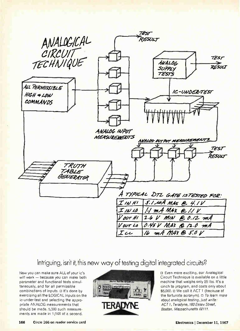
7 757
ANALÜGICA1-deuir efibti/Qa'
ALL P6RMIsS/BLE H/// 4.41411 come4405
( 7;ifzez&--ageieeeree,f
;ED
?ED
R'ES0/.7-
4A/Azoemear hiedlel£E,4e-»75
intric
44/4£46-SoPPLy 76-5.7-5
7e-Sr
XE51147-
/G - 04/06-2-7-6:57-
A4/A1-06- eereger erAfsoefeeçurs s.vi y re-sr
eese.r
A rfieYe44 DTZ, Gdre /-5 resre-D Foe* "..7-.4.,,efi -- ..r./.iedi Aux, e ie. /i/ .zie Li // emA /ex e t/ 7 -rear's« 2.4 1/ new e D./2- ',IA Vaer-z4 ¿'* V 41Atx e it ,«A
1/6 In Al en, e fray
uinc, isn't it, this new way of testing diçita Now you can make sure ALL of your ic's will work — because you can make both parameter and functional tests simul-taneously, and for all permissible combinations of inputs. D It's done by exercising all the LOGICAL inputs on the ic-under-test and selecting the appro-priate ANALOG measurements that should be made. 5,000 such measure-ments are made in 1 /100 of a second.
integrated circuits? CI Even more exciting, our Analogical Circuit Technique is available on a little machine that weighs only 25 lbs. It's a cinch to program, and costs only about $5,000. o We call it ACT 1 (because of the fortunate acronym). o To learn more about analogical testing, just write: ACT 1, Teradyne, 183 Essex Street, Boston, Massachusetts 02111.
166 Circle 166 on reader service card Electronics I December 11, 1967
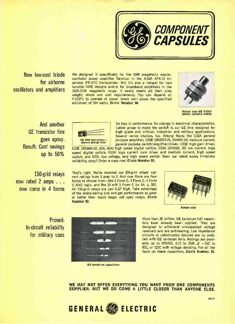
New low-cost triode for airborne
oscillators and amplifiers
And another GE transistor line
goes epoxy. Result: Cost savings
up to 50%
150-grid relays now rated 2 amps . . . now come in 4 forms
Proved: In-circuit reliability
for military uses
GE tantalum capacitors
We designed it specifically for the 1090 megahertz master-oscillator power amplifier function in the AIMS APX-72 tri-service IFF-ATC transponder. But it's also a natural for new tunable DME designs and/or for broadband amplifiers in the 1025-1150 megahertz range. It easily meets all their size, weight, shock and cost requirements. You can depend on Y-1537's to operate at power levels well above the specified minimum of 500 watts. Circle Number 90.
Actual size GE Y-1537 planar ceramic triode
No loss in performance. No change in electrical characteristics. Latest group to make the switch is our GE line designed for high grade and critical, industrial and military applications. Several series choices, too. Among them: the D33A general
GE 033 transistor— purpose amplifier; D33B (2N3973-76, 2N4951-54) medium current, general purpose switch/amplifier/driver; D33D high gain driver;
D33E (2N3605-07, 05A, 06A) high speed digital switch; D33G (2N5029, 30) low current, high speed digital switch; D33K high current core driver and medium current, high speed switch; and D33L low voltage, very high speed switch. Seen our latest epoxy trnnsistor reliability story? Order a copy now. Circle Number 91.
shown actual size
That's right. We've doubled our 150-grid relays' cur-rent ratings from 1 amp to 2. And now there are four forms to choose from—the 2 Form C, 4 Form C, 4 Form C AND logic, and the 50 mW 1 Form C (or lA ± 1B). All 150-grid relays are just 0.32" high. Take advantage of the space-saving size and get performance as good or better than much larger mil spec relays. Circle Number 92.
Actual size
More than 20 million GE tantalum foil capaci-tors have already been applied. They are designed to withstand unsuspected voltage reversals and are self-healing. Low impedance circuits or catastrophic failures are no prob-lem with GE tantalum foils. Ratings are avail-able up to 450VDC, 0.15 to 3500 pf —55C to 85C, or 125C with voltage derating. For all the facts on these capacitors, Circle Number 93.
WE MAY NOT OFFER EVERYTHING YOU WANT FROM ONE COMPONENTS SUPPLIER. BUT WE DO COME A LITTLE CLOSER THAN ANYONE ELSE.
285-32
GENERAL ELECTRIC

"The secret of success is for a m an to be ready for his opportnnay when it comes.n--Disraeli.
In electronics, advances at Lockheed have never been greater. As Lockheed programs expand throughout land, sea and space environ-ments, so do the opportunities. New concepts and major technical advances, for example, are required to accomplish scheduled Agena flights in years to come—new approaches in digital communication systems for data transmission and command, optical and infrared sensors, solar power panels, power conditioning, digital and analog flight control systems. The number one deterrent force of the future—the Poseidon fleet ballistic missile —requires advances in postulation, establishing requirements, integration, design and use of electronics test and checkout equipment. While on land, advanced vehicle systems and hospital information systems pose unique problems. Undersea, Lockheed offers programs like the Deep Submergence Rescue Vehicle and ocean mining with fresh opportunities in such areas as undersea instrumentation. Por more information, write Mr. R. C. Birdsall, P.O. Box 504, Sunnyvale, California 94088. Lockheed is an equal opportunity employer.
LOCKHEED MISSILES & SPACE COMPANY A GROUP DIVISION OA LOC,MEED AIRCRAIT COnPORATIOne
168 Circle 168 on reader service card Electronics December 11, 1967

indui
uomsod
ApAMSUOS
Xpnwsues
p.JOA9
OZZ >12:1VIN
ifsimq-3111A313
nr
Write-side up?
GLL GL g dois
ousitul&J peods puyo
Why not? New Mark 220 by Brush features pressurized -ink writing. Puts trace into the paper . . . not just on it. And you can see you don't have to pamper it! Now, anyone can take this remarkable new 25 lb. portable anyplace, plug it in . . . and put it in writing. And what writing! Fine, sharp traces you can read at a distance-99% accurate! Rectilinear writing, of course, on two easy-to-read 40mm analog channels plus left and right-hand event markers. And there's enough ink in the throw-
away ink cartridge to last for about a thousand miles. There's more. Rugged, reliable solid state electronics to give you position feedback pen control...no springs, no strings. Pushbutton choice of chart speeds. Fre-quency response that's flat (± 2%) from d-c to 40 cps at 50 div, or from d-c to 100 cps at 10 divisions. The price? Less than $1700. For a portable chart recorder the likes of which you've never seen! Bulletin 942-1 has all the details. Call or write: Clevite Corporation, Brush Instruments Divi-sion, 37th 85 Perkins, Cleveland, Ohio 44114.
CLEVITE —1:weesh INSTRUMENTS DIVISION
Circle 169 on reader service card
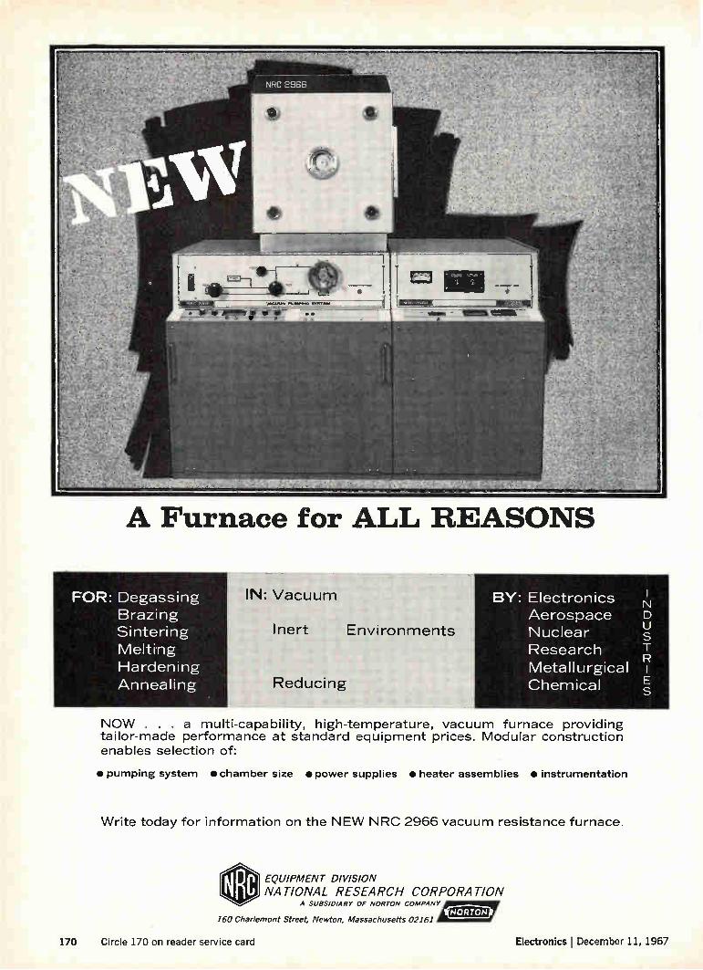
A Furnace for ALL REASONS
FOR: Degassing Brazing Sintering Melting Hardening Annealing
IN: Vacuum
Inert
Reducing
Environments
BY: Electronics Aerospace Nuclear Research Metallurgical Chemical
N D U
E S
NOW . . . a multi-capability, high-temperature, vacuum furnace providing tailor-made performance at standard equipment prices. Modular construction enables selection of:
• pumping system • chamber size • power supplies • heater assemblies • instrumentation
Write today for information on the NEW NRC 2966 vacuum resistance furnace.
EQUIPMENT DIVISION
NATIONAL RESEARCH CORPORATION A SUBSIDIARY OF NORTON COMPANY yrNORTOPill
160 Charlemont Street, Newton, Massachusetts 02161
170 Circle 170 on reader service card Electronics I December 11, 1967

JL -1r STeE ÍZ‘r" R.AND
We learned it just like this youngster is learn-ing it ...only we have a 50-year jump on him.
Take one of our hottest new assignments: Develop and manage the Navy's Integrated Light Attack Avionics System (ILAAS). It's the first integrated system approach to fixed-wing aircraft avionics. Our responsibility: De-fine system requirements. Develop the tech-nology. Establish specs. Award subcontracts. Integrate and test completed systems. Deliver the prototype this year.
It's taken a lot of innovative systems engi-neering. And a lot of pioneering work in pro-gram management techniques.
The result: Sperry Systems Management Division has the know-how and know-where to develop and deliver systems or sub-sys-tems that can integrate a variety of key elec-tronic functions for tactical, strategic and ASW aircraft or supersonic transports. Func-tions like weapons delivery, navigation, flight control, displays, communications.
If this is the kind of demonstrated sys-tems management skill your program re-quires, seek out the group that can deliver reliable, maintainable equipment, on time, within cost and performance specs. Just write: Marketing Manager, Advanced Avion-ics. Or phone: (516) 574-2216.
SP E ÍZ‘I'l SYSTEMS MANAGEMENT DIVISION GREAT NECK, NEW YORK 11020
Know how Sperry learned about advanced avionics systems management?
From the ground up. Electronics 1 December 11, 1967 Circle 171 on reader service card 171

for Instant Analog Systems
Burr-Brown Encapsulated Function Modules Cut costs, simplify design, and achieve maximum perform-ance from your analog and hybrid circuits by utilizing Burr-Brown encapsulated function modules. These com-patible sub-systems are designed to mount and work side by side with operational amplifiers. You save money on component and assembly costs, design time is reduced to an absolute minimum, and you gain the performance advantage of Burr-Brown's specialized experience in analog applications.
Currently, Burr-Brown is supplying fifteen 10V, encapsulated function modules from stock. Each one pro-vides the type of performance you'd expect from the com-pany that "wrote the book" on operational amplifier applications. Available units include: E Quarter Square Multiplier — Fast, E. = —E, E2/10. E Squaring Modules —
Four separate units are offered. LI Noise Generator — Ran-dom digital output. 0 Logarithmic Amplifiers — Both 40 db and 60 db log units. E Adaptive Analog Comparator — Switched hysteresis. E Electronic Switches — Including Fast Sample/Hold, Sample/Hold, Integrate/Hold, and Reset/Integrate/Hold units.
Rack Mounting Units — For your rack-mounting applications, Burr-Brown offers fourteen modules. These pre-engineered circuits are ready for you to plug in, wire together, and put to use immediately.
FOR COMPLETE INFORMATION on these maximum value units, contact your nearest Burr-Brown Engineering Representative and ask him for a copy of the new 20-page Burr-Brown catalog. He also has demonstrator units avail-able for your immediate evaluation.
BURR-BROWN RESEARCH CORPORATION International Airport Industrial Park • Tucson, Arizona 85706
TELEPHONE: 602-294.1431 • TWX: 910-952-1111 • CABLE: BBRCORP
BB Operational Amplifiers Instrumentation Amplifiers Function Modules Analog Simulators Geophysical Instruments
ENGINEERING REPRESENTATIVES: ALABAMA, HUNTSVILLE (205) 534 1648 / ALASKA. ANCHOR-AGE (907) 272-5231 / ARIZONA, PHOENIX (602) 254-6085 / CALIF., LOS ANGELES (213) 665-5181, SAN FRANCISCO (408) 245-3321 / COLO., DENVER (303) 388-4391 CONN., ENFIELD (203) 749-7888 / D.C., WASHINGTON (SEE MARYLAND) / FLORIDA, ORLANDO (305) 425-2764 ILLINOIS, CHICAGO (312) 286-6824 / LA., NEW ORLEANS (504) 888-2266 / MD., SILVER SPRING (301) 588-8134 / MASS., BOSTON (617) 245-4870 / MICH., DETROIT (313) 353-3822 MINN., MINNEAPOLIS (612) 781-1611 / MO., ST. LOUIS (314) 524-4800 / N.C., GREENSBORO (919) 273-1918 / N.1., CAMDEN (215) 925-8711 / N.M., ALBUQUERQUE (505) 255-1638 1 N.Y.,
ALBANY (518) 436-9649, BINGHAMTON (607) 723-9661, MT VERNON (914) 968-2200, NEW HARTFORD (315) 732-3775, ROCHESTER (716) 473-2115 / OHIO, CINCINNATI (513) 761-5432, CLEVELAND (216) 237-9145, DAYTON (513) 277-8911 / OKLA., TULSA (918) 835-2481 / OREGON PORTLAND (503) 292-8762 / PENN., PHILADELPHIA (SEE CAMDEN, N.1 ), PITTSBURGH (412) 243-6655 / TEXAS, CALLAS (214) 363-1671, HOUSTON (713) 928-5251 / UTAH, SALT LAKE CITY (801) 466-3709 1 VIRGINIA, (SEE MARYLAND) / WASH., SEATTLE (206) 767-4260 / CANADA, TORONTO (416) 293-7011. VANCOUVER (604) 736-6377
172 Circle 172 on reader service card Circle 173 on reader service card—›-

GM MACK OF EXCEL FNCE
EE'S with military communications
equipment experience
all us collect area code 317/459-2808 Rapid expansion of our ground based and airborne military communications capabil-ity has created urgent requirements for electrical engineers (B.S. or M.S.) at Delco Radio.
Opportunities at all levels—beginning, through supervisory, with 2-10 years ex-perience—in the following areas:
Digital communications in the HF, VHF, and UHF bands
Single side band design, HF,and VHF
Frequency synthesizer techniques in all frequency ranges
Wide range electronic tuning
Retransmission techniques
Secure communications techniques
Man-portable and vehicular battle area communi-cations equipment
Acoustic transducers, antennas, and micro-electron-ics applications.
Call us collect for an interview or more information. Area Code 317/459-2808. Ask for C. D. Longshore. Or send your resume to Mr. Longshore, Supervisor, Salaried Employment, Dept. 204, Delco Radio Divi-sion of General Motors, Kokomo, Indiana.
DELCO RADIO DIVISION OF GENERAL MOTORS • KOKOMO, INDIANA
An equal opportunity employer

Dow fight
join them with thick film interconnections
We don't live in a world of EITHER/OR. To spend our thm arguing whether silicon integrated circuits will or will not be low cost is not productive. The answer is already clear—they will be low cost. The questions are how low and how soon. May we uggest that there are a number of other mat-
ters which deserve attention, like—what kind of circuit board—what type passive components—what packaging tecl-nique will be needed when IC's are in the economic bai. park. If you'll pardon our brashness, we feel you should think of your own system.
Is there a packaging, circuit boarding, interconnecting, or outboard component system which lets you use to-day's active device configurations, yet is versatile enough to incorporate the next generation of technology too? We think thick film circuit and packaging systems will give you that kind of security.
After all, what other circuit technology allows you to bond active devices by parallel gap welding, thermo-compression bonding, direct and reflow soldering, ultra-sonic bonding, precious metal brazing? Allows you to use conventional leads, flip chips, leadless inverted devices, 'beam leads, or most any other configuration that you can conceive?
If you're thinking about using IC's, think about what el.:e you .eed. Ask 'our own experts where your com-pany stands.
E./. du Pont de Nemours & Co. (Inc.), Electronic Products,Electrochemicals Dept. Wilmington, Delaware 19898
getter things for better living ...through chemistry
174 Circle 174 on reader service card Ele mks I December 11, 1967

you get a choice,
not a challenge
51 standard shapes of laminations
simplify solid-state circuit design
Magnetics maximizes your chances
of finding laminations that dovetail
precisely into your designs for transformers, chokes, reactors and
transistor circuits. We offer 51
standard shapes in Permalloy 80,
Alloy 48 and Orthonol'. Thick-nesses of 0.004", 0.006", and 0.014"
are available, with sizes ranging
from DU-87 and El-12 down to the
EF EEE.
.11111111
solid-state circuitry sizes—EI-093,
EE-30-31, DU-63 and F-094.
All Magnetics' laminations are
hydrogen-annealed and manu-
factured to guaranteed minimum
permeability limits. In addition to
the catalog shapes and sizes, we
have the capability to make special shapes to fit specific needs, includ-
ing rotors, stators and recording
head laminations. Our photo-etch
process is ideal for making
prototype-run laminations and
small intricate configurations.
Furnishing a broad spectrum of
shapes, sizes and materials is
Magnetics' way of saving you
valuable design time—we believe
in giving our customers a choice,
not a challenge. Complete informa-
tion on Magnetics' laminations can
be had by writing today for our
Catalog ML-303-R, Magnetics Inc.,
Butler, Pennsylvania 16001
11111017ETICS inc. _MAW ®

THESE CIRCUIT PROTECTORS ARE ENTIRELY MAGNETIC TRIP Hermetically sealed AP Protectors meet or exceed MIL-C-39019. They repeatedly rupture 300A 250V AC, 500A 125V AC, 500A 50V DC, have magnetic time delay, but open a 1000% overload in 4 milliseconds. There is no trip at 100G shock or 20 G vibration, carrying rated current. Available 10 MA to 20A, with a wide variety of circuit combinations, delay curves and auxiliary signal circuits. Ask for bulletin 16E-4.
r.
4-1
• SERIES WITH L .REMOTE
01 1
L RELAY _ I
Type UPL1, UPL11, and UPL111 are Underwriters' Laboratory recognized for appliance protection.
UPL1 UPL11 UPL111
UL RATED at: .050-50.0 Amps, 50V DC.; .050-50.0 Amps, 120V AC, 60 Hz.; .050-20.0 Amps, 240V AC, 60 Hz.
Series units with enclosed remote switches are available in any combination of delays (Fast — 0.4 to 4.0 sec., Slow —4.0 to 40 sec., Motor Start — 1.0 sec. at 600%) or UL listed ratings are available in a single pole, two pole or a three pole appliance protector.
AIRPAX ELECTRONICS Cambridge, Maryland 21613 (301) 228-4600
176 Circle 176 on reader service card Electronics December 11, 1967
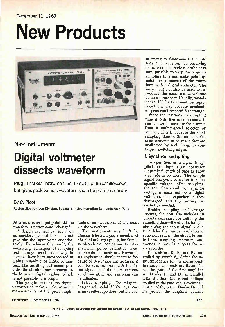
December 11, 1967
New Products
es," t n.0
e
A 1604
• • •'fi-,• 11111
New instruments
Digital voltmeter dissects waveform Plug-in makes instrument act like sampling oscilloscope
but gives peak values: waveforms can be put on recorder
By C. Picot
Rochar Electronique Division, Societe d'Instrumentation Schlumberger, Paris
At what precise input point did the transistor's performance change? A design engineer can see it on
an oscilloscope, but this does not give him the input value quantita-tively. To achieve this result, the measuring techniques of sampling and storage—used extensively in scopes—have been incorporated in a plug-in module for digital voltme-ters. The resulting instrument pro-vides the absolute measurement, in the form of a digital readout, which is not possible in a scope. The plug-in enables the digital
voltmeter to make quick, accurate measurements of the peak ampli-
Electronics December 11, 1967
tude of any waveform at any point on the waveform. The instrument was built by
Rochar Electronique, a member of the Schlumberger group, for French semiconductor companies, to make precision pulsed-saturation mea-surements of transistors. However, its application should increase be-cause of two important features: it can be synchronized with the in-put signal, and the time between synchronization and sampling can be adjusted.
Select sampling. The plug-in, designated model A1604, operates as an oscilloscope does, but instead
of trying to determine the ampli-tude of a waveform by observing its trace on a cathode-ray tube, it is now possible to vary the plug-in's sampling time and make point-by-point measurements of the wave-form with a digital voltmeter. The instrument can also be used to re-produce the measured waveforms on an x-y recorder. Usually, signals above 100 hertz cannot be repro-duced this way because mechani-cal pens can't respond fast enough.
Since the instrument's sampling time is only five microseconds, it can be used to measure the outputs from a multichannel selector or scanner. This is because the short sampling time of the unit enables measurements to be made that are unaffected by such things as con-tingent switching edges.
I. Synchronized gating
In operation, as a signal is ap-plied to the input, a gate opens for a specified length of time to allow a sample to be taken. The sample signal charges a capacitor to some specific voltage. After sampling, the gate closes and the capacitor voltage is measured by a digital voltmeter. The capacitor is then discharged and the process re-peated as needed.
Besides sampling and storage circuits, the unit also includes all circuits necessary for defining the sampling time—the circuits for syn-chronizing the input signal and a time delay that varies in relation to synchronization—the circuit to con-trol the sampling operation, and circuits to provide outputs for an x-y recorder. The resistors RI, 112, and R3 con-
trolled by switch SIa define the in-put impedance for the correspond-ing range. The resistors R5 and R5 set the gain of the first amplifier Al. Diodes D1 and D2, in parallel with R5, limit the output voltage applied to the gate and prevent sat-uration of the tester. Diodes D3 and D4 protect the amplifier against
177
IF HIV w, yuvi leudigicuu Fur 3pectut cietrruntt iebr fur 11111 L111.11 ye/
Electronics December 11, 1967 Circle 179 on reader service card 179
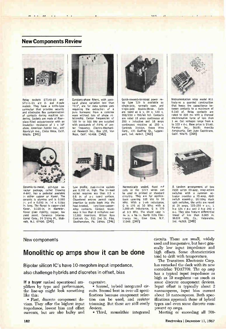
••• • • ed• cx71 .1
New Components Review
Relay sockets ST140-Ul. and ST141-U1 are 2- and 4-pole models. They have a knife-type connector that provides security and eliminates flux contamination of contacts during machine sol-dering. Sockets are made of fiber-glass-filled polycarbonate with an insulation resistance of 1 x 10° ohms. American Zettler Inc., 697 Randolph Ave., Costa Mesa, Calif. 92626. [341]
Ceramic-to-metal, pill-type va-ractor package, called Drawing A-847, has a pedestal available in either copper or Kovar. The ceramic is alumina and is 0.080 in. o-d x 0.050 in. i-d x 0.066 in. long. The flange is copper-clad Kovar, 0.120-in, in diameter. Kovar gives rigidity; copper, low yield point. Ceramics Interna-tional Corp., 39 Siding Pl., Mah-wah, N.J. 07430. [345]
Constant-phase filters, with pass-band phase variation less than -±0.3°, are for data system uses requiring the extraction of a pure harmonic from a complex wave without loss of phase re-lationship. Center frequencies of 100 hz to 500 khz are supplied with passbands of -±5% of cen-ter frequency. Electro-Mechani-cal Research Inc., Box 130, Van Nuys, Calif. 91408. [342]
Low profile, dual-in-line sockets are 0.192 in. high. The 14-lead socket requires less than 0.5 x 0.8 in. of p-c board surface. Chamfered entries permit rapid insertion to guide leads into the heat-treated, beryllium-copper-alloy contacts. Contact resist-ance is less than 8 milliohms over 12,000 insertions. Milton Ross Controls Co., 511 2nd St. Pike, Southampton, Pa. 18966. [346]
Quick-connect-terminal power re-lay type 129 is available as single-pole, normally open, and single-pole double-throw. Coils are rated at 6 v, 24 v, 120 v, 208/230 I/ (50/60 hz). Contacts are rated 18 amps continuous at 250 y inductive and 18 amps continuous resistive at 250 v. Controls Division, Essex Wire Corp., 131 Godfrey St., Logans-port, Ind. 46947. [343]
Hermetically sealed, fixed r-f coils in the 1219 series can be used in printed or standard circuitry. They are for applica-tions covering 100 khz to 30 Mhz. With a 1-ph inductance, Q is 170 at 10 Mhz; with a 1,000-mh inductance, Q is 170 at 0.5 Mhz. The shield case is 3/4 in. x We in. North Hills Elec-tronics Inc., Glen Cove, N.Y. 11542. [347]
Instrumentation relay model R11 features a guarded construction that keeps the capacitance be-tween contacts to a maximum of 0.150 pf. Relay contacts are rated to 200 ma with a thermal electromotive force of less than 1 /LI/. Coil voltages range from 6 to 115 v d-c. Base price is $9.60. Parelco Inc., 26181 Avenida Aeropuorto, San Juan Capistrano, Calif. 92675. [344]
A tandem arrangement of two 2650 series 20-amp, snap-action switches with a common ac-tuator provides a 25-amp, dpdt switch assembly. Utilizing stock spdt switches, the units are rated at 25 amps, 125-250 y a-c; 1 h-p 125 y a-c and 2 h-p 250 y a-c. They also feature differential travel of less than 0.005 in. McGill Mfg. Co., Valparaiso, Ind. 46383. [348]
New components
Monolithic op amps show it can be done
Bipolar silicon IC's have 10-megohm input impedance,
also challenge hybrids and discretes in offset, bias
If a buyer ranked operational am-plifiers by type and performance, the line-up might look something like this: • First, discrete component de-
vices. They offer the highest input impedance, lowest bias and offset currents, but are also bulky and
expensive. • Second, hybrid integrated cir-
cuits. Second best in over-all speci-fications because component selec-tion can be used, and resistor trimming. But these are still costly devices. • Third, monolithic integrated
circuits. These are small, widely used and inexpensive, but have gen-erally low input impedance and high offsets. Some characteristics tend to drift with temperature. The Transitron Electronic Corp.
has restacked the deck with its new monolithic TOA7709. The op amp has a typical input impedance as high as 10 megohms—as much as some discrete component devices. Input offset is typically about 2 nanoamperes, input bias current about 10 nanoamperes. Both spec-ifications approach those of hybrid types and even some discrete com-ponent op amps.
Meeting or exceeding all 709-
182 Electronics I December 11, 1967

December 11, 1967
New Products
-MULTIMÈTRE NUMÉRIQUE A 14A6
id$OWM
Non iréthant6,ornue A 1664 ,
New instruments
Digital voltmeter dissects waveform Plug-in makes instrument act like sampling oscilloscope
but gives peak values; waveforms can be put on recorder
By C. Picot Rochar Electronique Division, Societe d'Instrumentation Schlumberger, Paris
At what precise input point did the transistor's performance change? A design engineer can see it on
an oscilloscope, but this does not give him the input value quantita-tively. To achieve this result, the measuring techniques of sampling and storage—used extensively in scopes—have been incorporated in a plug-in module for digital voltme-ters. The resulting instrument pro-vides the absolute measurement, in the form of a digital readout, which is not possible in a scope. The plug-in enables the digital
voltmeter to make quick, accurate measurements of the peak ampli-
tude of any waveform at any point on the waveform. The instrument was built by
Rochar Electronique, a member of the Schlumberger group, for French semiconductor companies, to make precision pulsed-saturation mea-surements of transistors. However, its application should increase be-cause of two important features: it can be synchronized with the in-put signal, and the time between synchronization and sampling can be adjusted.
Select sampling. The plug-in, designated model A1604, operates as an oscilloscope does, but instead
of trying to determine the ampli-tude of a waveform by observing its trace on a cathode-ray tube, it is now possible to vary the plug-in's sampling time and make point-by-point measurements of the wave-form with a digital voltmeter. The instrument can also be used to re-produce the measured waveforms on an x-y recorder. Usually, signals above 100 hertz cannot be repro-duced this way because mechani-cal pens can't respond fast enough.
Since the instrument's sampling time is only five microseconds, it can be used to measure the outputs from a multichannel selector or scanner. This is because the short sampling time of the unit enables measurements to be made that are unaffected by such things as con-tingent switching edges.
I. Synchronized gating In operation, as a signal is ap-
plied to the input, a gate opens for a specified length of time to allow a sample to be taken. The sample signal charges a capacitor to some specific voltage. After sampling, the gate closes and the capacitor voltage is measured by a digital voltmeter. The capacitor is then discharged and the process re-peated as needed.
Besides sampling and storage circuits, the unit also includes all circuits necessary for defining the sampling time—the circuits for syn-chronizing the input signal and a time delay that varies in relation to synchronization—the circuit to con-trol the sampling operation, and circuits to provide outputs for an x-y recorder. The resistors R1, 112, and 113 con-
trolled by switch SIa define the in-put impedance for the correspond-ing range. The resistors R5 and 116 set the gain of the first amplifier Al. Diodes DI and D2, in parallel with R5, limit the output voltage applied to the gate and prevent sat-uration of the tester. Diodes D3 and D4 protect the amplifier against
Electronics I December 11, 1967 177

. field effect transistor presents a
practically infinite impedance to capacitor. .
excessive input voltages. Approaching the infinite. The
gate, which uses a field effect transistor, is between the input cir-cuit and a storage capacitor and presents a practically infinite im-pedance to the capacitor when closed. The amplifier Ao has a dif-ferential input stage consisting of a double FET. Thus the parasitic in-put current is low and the storage capacitor C discharges negligibly when a measurement is made by the associated digital voltmeter.
Synchronization control can be external or internal and is selected by switch So. When it is internal, the attenuator formed by 117, Rs, Ro, Rio is switched by S11, simul-taneously with changes in the mea-
SIP
INP:L7I °
R8
RANGE SWITCH
RI
R2
EXTERNAL SYNCHRONIZATION
ARMING AND SLOPE START SIGNAL o
REFERENCE VOLTAGE V1
SIB o /
o
surement range. A third position of So makes recurrent sampling by the internal time-device or the clock of the digital voltmeter.
II. Ramp control The internal or external synchro-
nization signal drives a trigger. Switch S3 selects a positive or neg-ative control signal from the ramp generator corresponding to whether synchronization is to take place on the positive or negative edge of the input signal. A normally opened gate is between the trigger and the ramp generator. When triggered, the gate's output voltage varies un-til it reaches one of the reference voltages, in this case V1. At this time the first comparator reverses.
Rio
4. S3 o
TRIGGER o
R4
When the ramp generator's output voltage reaches Vo, the second com-parator reverses. The second comparator drives a
monostable multivibrator that in-hibits the signal from the trigger by closing the gate. The second multivibrator also controls the re-turn of the ramp and resets both comparators. The reversing time of of this multivibrator is selected so that it protects the ramp generator from being damaged by a control signal when the ramp is being re-set. As the first comparator reverses,
it starts the first multivibrator. This defines the sampling time and opens the sampling circuit's gate. The calibrated time delay is ob-
tained by varying the slope of the ramp initiated from the ramp gen-erator at the time synchronization starts. Since the reference voltage V1 is fixed, the reversing time of the
MARKING CIRCUIT
TO Y INPUT OF XY RECORDER
TO INPUT OF le- DIGITAL VOLTMETER
SAMPLE SIGNAL
DELAY GATE SLOPE
GEN
10-SECOND SLOPE GENERATOR FOR AUTOMATIC RECORDING
INHIBIT SIGNAL
SIGNAL RESET
FIRST MONOSTABLE MULTIVIBRATOR
FIRST COMPARATOR
SECOND COMPARATOR
ARMING SIGNAL
SECOND MONOSTABLE MULTIVIBRATOR
AUTOMATIC RECORDING
•""er\sj 4
MANUAL RECORDING
MARKING PULSE (AT INSTANT OF SAMPLING)
SAMPLE COMMAND TO DIGITAL VOLTMETER
TO X INPUT OF XY RECORDER
REFERENCE VOLTAGE V2 1V21)IVII
INTERNAL CLOCK PULSES
Command measurement. Input signal charges capacitor C when sample gate is opened. When the gate closes, the voltage on the capacitor is read by the digital voltmeter. The sampling command is synchronized to the input signal or an external source. A plot of the measurements can be made by connecting an x-y recorder to dvm. Unit handles up to 200 volts.
178 Electronics I December 11, 1967

lo Making Masks for Electronic Components...
... there's no Margin for Error!
With sharp blade, cutline the areas to be masked. Do not cut through the backing sheet. The Ulano Swivel Knife does the job quickly, easily.
Now carefully peel oft the film as outlined leaving a completed photo mask, positive or negative, that corresponds exactly to the desired pattern.
THAT'S WHY EXPERIENCED DESIGNERS
AND ENGINEERS ALWAYS INSIST ON...
THE KNIFE-CUT, LIGHT-SAFE MASKING FILM LAMINATED TO A STABLE POLYESTER BASE
The most versatile line of hand-cut masking films, including
.0075—RUBYLITH 75 DR* .005 RUBYLITH 5 DR .005 AMBERLITH 5 DA
These new, thick Ulano films provide the positive answers where exact register assumes a critical importance.
• Available in sheets only, cut fo your specifications.
ulanc15
BYLITH HAND-CUT MASKING FILM FOR THE GRAPHIC ARTS
610 DEAN STREET, BROOKLYN, N.Y. 11238
NEW YORK • CALIFORNIA. CHICAGO •ZURICH
In Europe: ULANO A. G., Uniere Heslibachstrasse 22, Kusnacht 8700, Switzerland
Write on your letterhead for special electronic test kit (no charge) No. 4148
Electronics December 11, 1967 Circle 179 on reader service card 179

You're a year behind the times if you think our
RF1 vacuum relay is just for the
communications industry.
Sure our RF 1 vacuum relay is ideal
for such typical communications uses
as antenna switching and band
switching. But in the year since it was
introduced this remarkable little relay
has proven itself in a multitude of
markets and in applications where
vacuum relays had never been
considered.
Ounce for ounce, the RF 1 controls
more power for more applications
than any other relay in the world. It's
replacing mercury wetted contacts for
switching in capacitor circuits for
protection on arc lamps. It's used environmental conditions • Rapid
for circuit control aboard railway operation (10 ms maximum).
locomotives and in automated re- _emir> For complete information on
mote control systems for controlling the RF 1 and a copy of our new
locomotives. It's also control- ileepew- .teer'evacuum relay catalog, write to
ling power supplies in laser ITT Jennings, a division of
range finders and making International Telephone and
millisecond tuning possible in Telegraph Corporation, 970
digitally tuned transmitters, logic McLaughlin Avenue, San Jose,
circuit all electronic tuning and California 95108
binarily tuned HF radio transcievers.
We could go on and on about the
merits of these 3/4 -ounce relays with
their superclean contacts. They cost no more than other relays of their
power level, but look at their per-
formance: 4 kv peak 60 cycle test
voltage • 2 kv peak operate voltage at
16 mc • 4 amps rms at 16 mc • Inter-rupt 1 kw dc power; interrupt induc-
tive loads • .020 ohms maximum
contact resistance at 32 mc remains
permanently low • 10 g to 2000 cps
vibration resistance • Impervious to
Shown actual size
JENNINGS ITT
... first multivibrator
initiates measurements...
first comparator, which controls sampling, is delayed with respect to the time of synchronization. When the first comparator re-
verses it also produces a marking pulse to enable observation of the sampling time with reference to the signal. Also, the first multivibrator initiates the measurement by the digital voltmeter of the voltage sampled and stored.
Switch S4 is used to select the recording mode—manual or auto-matic. During manual recording, the voltage applied to the first comparator is varied manually from 0 to Vi by potentiometer R11. This corresponds to a range of cali-brated time delays. In automatic recording the voltage applied to the comparator is varied linearly from 0 to Vi during a long time, say 10 seconds, enabling the recorder to follow easily and with fidelity the shape of the input signal.
In both cases the voltage to be sampled is scanned from the point of synchronization to the point corresponding to the time delay. Therefore, the recording will be in a curve corresponding to the volt-age variation between these two points . A matter of shape. There are cer-
tain restrictions on the A1604. NVhile it is not possible to define a general frequency limit, measure-ment does depend on the shape of the signal. It is necessary that the variations of the voltage measured during the sampling time be lower than the desired accuracy. Also, it is important that the delay between the edge of a rectangular signal and the beginning of sampling be at least 10 microseconds. Therefore, for a square wave, the maximum fre-quency is 30 kilohertz. For an asymmetrical rectangular signal the frequency can be higher.
If a measurement at one point on a sawtooth signal is desired, it is necessary that the voltage varia-tion during the sampling be lower than 1/1000 of the maximum ampli-tude of the wave. Therefore the waveform's period must be higher than 1,000 x 5 !Ls—corresponding to a frequency less than 200 hz. At present the plug-in is designed
180 Circle 180 on reader service card Electronics December 11, 1967

Studying damped sine wave. The maximum and minimum values of a damped sine wave such as that shown can be obtained by manually scanning the waveform. The time axis is calibrated from the delay control of the plug-in unit, enabling such typical characteristics to be calculated from these amplitude measurements as the logarithmic decrement, the decrement, the damping coefficient, the time constant, and pseudo-period.
Voltage level tests. Plug-in is useful for checking stepped signals such as shown above, composed of a number of voltage levels that appear apparently flat on an oscilloscope. However, analyzing this signal with the plug-in by setting the sample delay times for the beginning and end of each step permits checking to determine whether the steps are in fact level.
to be used only with a digital volt-meter made by Rochar. However, it is being modified so that it will work with any digital voltmeter on the market now, as well as those that appear in the future.
Specifications
Input voltage
Accuracy
Input impedance
Sampling time Time delay be-
tween synchro-nization and sampling
Price
2, 20, 200 with a 5-digit display
-±0.1% of reading, -±0.25% of full scale
10 kilohms in parallel with 50 picofarads for the 2-v range, 100 kilohms in parallel with 20 picofarads for the 20-v range, 1 meg-ohm in parallel with 20 picofarads for the 200-v range
5 gsec Adjustable continuously
from 10 gsec to 0.1 sec
$1,100
Rochar Electronique Division, Societe d'Instrumentation Schlumberger, Paris [338]
To turn off rejects of 3rd generation circuits:
Turn on Barnstead's New Micro-Cleaner There's no better way to make micro-circuits come clean!
Barnstead's new microelectronic cleaning station provides
an ultra-pure final rinse — in a totally clean environment —
at minimum cost.
Write for Bulletin 211, describing this 3rd generation
cleaning station.
Barnstead Subsidiary of Ritter Pfaudler Corp. 516 Rivermoor Street Boston, Mass. 02312
Positive-pressure hood keeps work area free of airborne contaminants, with absolute air filter; quiet, spark-free blower. Meets or exceeds applic-able MIL SPECS.
Five hot, cascading pure water rinses in tinlined monel tanks do a thorough cleaning Job. Final rinse, measuring 111 megohms'cm @ 25°C and free of organics, gases, biologicals — is much purer than deminera-lized water.
Purity meter checks quality of rinse water, both "upstream" and "downstream" from final rinse.
To make a few gallons do the work of thousands, water is continuously recirculated, repurified. System Includes ...
Demineralizer. Automatic still. Organic removal bed. 0.1 micron particle filter. Sump, protected by ultraviolet unit, Ventgard® air fitter. Regenerative heat exchanger. Cuts electrical load by more than 50%
Electronics l December 11, 1967 Circle 181 on reader service card 181

New Components Review
Relay sockets ST140-111 and ST141-U1 are 2- and 4-pole models. They have a knife-type connector that provides security and eliminates flux contamination of contacts during machine sol-dering. Sockets are made of fiber-glass-filled polycarbonate with an insulation resistance of 1 x 10° ohms. American Zettler Inc., 697 Randolph Ave., Costa Mesa, Calif. 92626. [34].]
Ceramic-to-metal, pill-type va-ractor package, called Drawing A-847, has a pedestal available in either copper or Kovar. The ceramic is alumina and is 0.080 in. o-d x 0.050 in. i-d x 0.066 in. long. The flange is copper-clad Kovar, 0.120-in, in diameter. Kovar gives rigidity; copper, low yield point. Ceramics Interna-tional Corp., 39 Siding Pl., Mah-wah, N.J. 07430. [345]
Constant-phase filters, with pass-band phase variation less than
are for data system uses requiring the extraction of a pure harmonic from a complex wave without loss of phase re-lationship. Center frequencies of 100 hz to 500 khz are supplied with passbands of ±50/0 of cen-ter frequency. Electro-Mechani-cal Research Inc., Box 130, Van Nuys, Calif. 91408. [342]
Low profile, dual-in-line sockets are 0.192 in. high. The 14-lead socket requires less than 0.5 x 0.8 in. of p-c board surface. Chamfered entries permit rapid insertion to guide leads into the heat-treated, beryllium-copper-alloy contacts. Contact resist-ance is less than 8 milliohms over 12,000 insertions. Milton Ross Controls Co., 511 2nd St. Pike, Southampton, Pa. 18966. [346]
Quick-connect-terminal power re-lay type 129 is available as single-pole, normally open, and single-pole double-throw. Coils are rated at 6 v, 24 v, 120 v, 208/230 y (50/60 hz). Contacts are rated 18 amps continuous at 250 y inductive and 18 amps continuous resistive at 250 v. Controls Division, Essex Wire Corp., 131 Godfrey St., Logans-port, Ind. 46947. [343]
Hermetically sealed, fixed r-f coils in the 1219 series can be used in printed or standard circuitry. They are for applica-tions covering 100 khz to 30 Mhz. With a 1-4 inductance, Q is 170 at 10 Mhz; with a 1,000-Ah inductance, Q is 170 at 0.5 Mhz. The shield case is 3/4 in. X 5/8 in. North Hills Elec-tronics Inc., Glen Cove, N.Y. 11542. [347]
Instrumentation relay model R11 features a guarded construction that keeps the capacitance be-tween contacts to a maximum of 0.150 pf. Relay contacts are rated to 200 ma with a thermal electromotive force of less than 1 iv. Coil voltages range from 6 to 115 y d-c. Base price is $9.60. Parelco Inc., 26181 Avenida Aeropuorto, San Juan Capistrano, Calif. 92675. [344]
A tandem arrangement of two 2650 series 20-amp, snap-action switches with a common ac-tuator provides a 25-amp, dpdt switch assembly. Utilizing stock spdt switches, the units are rated at 25 amps, 125-250 y a-c; 1 h-p 125 y a-c and 2 h-p 250 v a-c. They also feature differential travel of less than 0.005 in. McGill Mfg. Co., Valparaiso, Ind. 46383. [348]
New components
Monolithic op amps show it can be done
Bipolar silicon IC's have 10-megohm input impedance,
also challenge hybrids and discretes in offset, bias
If a buyer ranked operational am-plifiers by type and performance, the line-up might look something like this: • First, discrete component de-
vices. They offer the highest input impedance, lowest bias and offset currents, but are also bulky and
expensive. • Second, hybrid integrated cir-
cuits. Second best in over-all speci-fications because component selec-tion can be used, and resistor trimming. But these are still costly devices. • Third, monolithic integrated
circuits. These are small, widely used and inexpensive, but have gen-erally low input impedance and high offsets. Some characteristics tend to drift with temperature. The Transitron Electronic Corp.
has restacked the deck with its new monolithic TOA7709. The op amp has a typical input impedance as high as 10 megohms—as much as some discrete component devices. Input offset is typically about 2 nanoamperes, input bias current about 10 nanoamperes. Both spec-ifications approach those of hybrid types and even some discrete com-ponent op amps.
Meeting or exceeding all 709-
182 Electronics I December 11, 1967

A low-profile socket for 16-lead plug-in IC's permits packaging on 3/2-in. centers. Socket terminals are the same dimension as IC leads for direct interchangeability. Wiping-type beryllium copper con-tacts permit easy IC insertion. Units are 0.89 x 0.49 x 0.31 in. Price is from 32 to 83 cents each, depending on quantity and type. Augat Inc., 33 Perry Ave., Attle-boro, Mass. 02703. [349]
Form C (single-pole, double-throw) reed switch type DR138 is suited for applications involving both re-sistive and inductive loads. With a contact rating of 5 w (50 y at 100 ma) d-c resistive, it has a life expectancy of 20 million oper-ations. Initial contact resistance limit is 100 milliohms. It has both industrial and military appli-cations. General Electric Co., Louisville, Ky. 40205. [353]
Hermetically sealed connectors withstand pressure up to 40,000 psi. Designed for pneumatic, hy-draulic and pyrotechnic applica-tions, they are available in many shell sizes, mounting styles and basic materials. Operating tem-perature range is —320° to +300°F; vibration, 5 to 2,000 hz at 100 g rms. Gulton Industries Inc., 1644 Whittier Ave., Costa Mesa, Calif. 92627. [350]
4.10
EISZ919"
Sealed, commercial wirewound pot model 3005, measuring 3/4 x 5/16 X 11/64 in., has a standard resis-tance range of 10 to 20,000 ohms, a power rating of 1 w at 40°C, and an operating tempera-ture range of —55° to +125°C. Vibration is 20 g's; shock, 50 g's. Price is $1.30 each in 1,000-lot quantities. Bourns Inc., 1200 Co-lumbia Ave., Riverside, Calif. 92507. [354]
Solid state zero-voltage power switch ZVS-1 handles 20 amps rms per phase in the 3-phase model or up to 32 amps rms for single-phase units. It comes in a 6 x 4 x 3-in, plug-in case. The company says it virtually elimi-nates conductive and radiated rfi and surge control current prob-lems. Curry, McLaughlin & Len Inc., East Malloy Rd., Syracuse, N.Y. 13211. [351]
Encapsulated incandescent lamp PC-Lite measures 3/4 X 3/16 in. Mounting pins are spaced Ve in. apart. It is designed for printed circuit and instrumentation appli-cations, including panel and sub-panel utilization. Units are avail-able in a power range from 11/4 through 28 y and in a variety of colors. Leecraft Manufacturing Co., 21-10 44th Road, L. I. C., N.Y. 11101. [355]
Adjustable coils in the 600 series are shielded and designed for p-c use. They cover from 1 to 1,000 ah and can be employed over the 100-khz to 30-Mhz range. The coils measure 0.3 x 0.4 in. and plug into a p-c board. Applica-tions include video, r-f and 1-f circuitry, both commercial and military. North Hills Electronics Inc., Glen Cove, N.Y. 11542. [352]
Spst pressure switch 91MG, meas-uring 0.5 x 0.5 in., operates in the pressure range of 3 to 300 psig. It has a contact rating of 5 amps resistive at 115 y a-c, 60 hz or 28 y d-c. Factory ad-justed, the switch point is re-peatable to 0.2%. The unit weighs 0.4 oz. Price is approximately $50. Servonic Instruments Inc., 1644 Whittier Ave., Costa Mesa, Calif. 92627. [356]
type op amp specifications, the new unit is also a direct plug-in replace-ment for them. By contrast. The 709's are speci-
fied for input impedances of about 400,000 ohms, input bias current of 200 nanoamperes (maximum is 500), and input offset current of 50 nanoamperes ( maximum is 200). Thus, Transitron's new op amp of-fers at least 25 times the 709's input impedance, 5% of the 709's input bias current, and 4% of the 709's input offset current. ". . . And at a price only 30% higher than for standard 709's," says Stan Harris, Transitron product sales manager for linear lc's and special products.
Comparing prices, Harris says that Transitron's military-quality 709 equivalent, the TOA1709, costs $9.90 each in lots of 100; the new TOA7709 costs $12.80. The TOA8709 with less impressive specifications, is Transitron's com-mercial version and sells for $8.35, compared with $6.45 for its 709 equivalent TOA2709.
Firstest-mostest. Transitron has entered the marketplace with the highest-impedance monolithic op amps available, at a competitive price. Motorola and Raytheon are developing op amps which use field-effect transistors to achieve high input impedance. Motorola's
Low draw. High impedance IC has
17 transistors including 4 Dar-
lington pairs and 2 pnp elements.
Electronics December 11, 1967 183

w
.60
Standard and custom military knobs,
aluminum cap knobs, color control knobs for
every panel requirement. Send for data kit.
With Raytheon control knobs, you can meet military specifications—or select styles and colors that har-monize or contrast with any com-mercial panel decor. And you can get these knobs immediately— through Raytheon distributors from coast to coast.
Meet MS91528C Military Specifica-tions from the more than 300 stand-ard types and the 2,000 "specials" Raytheon has designed. All knobs are functionally designed. All styles have an integrated design to give uniformity to your panel. And all knobs meet specifications for resist-ance to flame, torque, temperature and humidity extremes, salt spray, and ultraviolet radiation.
MECHANICAL COMPONENTS
Handsome aluminum cap knobs are made of strong plastic with satin finish aluminum caps that are treated with an epoxy coating for corrosion resistance.
Commercial color knobs—available in nine colors and ten styles—har-monize or contrast with commercial equipment design. Raytheon makes these 400 Series knobs of durable, high-impact ABS.
Custom-made control knobs. Ray-theon also designs and manufac-tures control knobs to meet special requirements for color, shape, size, finish. Call your nearest Raytheon regional sales office or write to us. Raytheon Company, Components Division, Quincy, Mass., 02169.
Send for Raytheon
Control Knob Data Kit
—contains complete specifications
on all standard and custom knobs.
Just send the
reader service card.
RAYTHEON
... it started as quest
for higher beta ...
uses more than one chip and thus can be classed as a hybrid.
Transitron once worked on FET op amps too, and now it wonders why. The firm has clone the job on one silicon chip using bipolar tran-sistors and a Darlington input to achieve high input impedance. The work that led to the new op
amps was started in a quest for lower noise and high transistor beta (common emitter current gain) at low collector currents. Noise isn't a guaranteed specification for op amps but users of a variety of 709 types had complained of noise-caused error in their applications, so Transitron embarked on a pro-gram to reduce leakage to a min-imum and retain beta. They succeeded through im-
provements in surface technology, according to Douglas Sullivan, op-erations manager for linear lc's at Transaron. Very low leakage levels were achieved, and transistors with typical betas of 100 at collector cur-rents as low as 100 nanoamperes could be built; at 20 microamperes and higher, beta was about 200.
Sullivan says that not only was the type of oxide used a factor, but also the method and control of its deposition.
Skeptics. Because of the low leakages attained, and the high betas, Transitron ran a computer analysis of the performance of a Darlington input op amp. The printout looked good but it didn't prepare the engineers for what fol-lowed. When they built the first batch they found input impedances of 100 million ohms or more. This was unbelievable, says Sullivan, and the engineers' first reaction was to take the devices from tester to tester, thinking that each had mal-functioned. The same reaction followed when
they tried to measure leakage and offset currents. With standard pro-duction gear, these parameters just could not be measured. Only under clean-room conditions with the best laboratory gear Transitron had available, and even then with scale multipliers, could they measure these specifications. The engineers eventually con-
184 Circle 184 on reader service card Electronics December 11, 1967

hp 17" Video Monitor Achieves Increased Reliability and Improved Picture Quality through Advanced Circuit Techniques
A
CONSISTENT IMAGE QUALITY Keyed back porch clamp assures less than 1% black level
shift for 100% video amplitude change.
Displays sine 2 1/2 pulse without distortion (62.5nsec).
I a Option 46 pulse cross position.
Less than 1.5% geometric distortion over-all • Feedback insures excellent gain stability over full video bandwidth • Unity interlace results from novel sync circuitry.
D
MAINTENANCE FREE OPERATION
All Solid State Circuitry • No periodic alignment or adjustment required • Highest quality components and workmanship.
New Patterns of Performance
6 El
EASE OF OPERATION Display linearity independent of size adjustment • Unique deflection circuits have feedback active over entire raster • No sync controls — synchronization is automatic on both North American and CCIR Standards.
OTHER IMPORTANT FEATURES
Fully regulated high voltage and low voltage power supplies • Balanced input with loop-through facility • 46 db input com-mon mode rejection • Size: 172/,6" W x 151/2 " H x 201/2 " D. Price: Model 6946A—$950. Option 46—$45.
For more information, call your local HP field engineer or write Hewlett-Packard, 100 Locust Ave., Berkeley Heights, New Jersey 07922. Europe: 54 Route des Acacias, Geneva.
HEWLETT h PACKARD
COMMUNICATION INSTRUMENTS
Circle 185 on reader service card
21101

DUPLICATE THESE PARTS AND MORE IN YOUR OWN PLANT
WITHOUT DIES! Here's a way to produce short runs of simple parts quicker than an
order can be processed to get them "outside." Versatile Di-Acro "Die-
less Duplicating" equipment sets up quickly for cutting stock to size
and forming it to die accuracy — without
costly dies. Get full information in the new
"Die-less Duplicating" catalog. See your dis-
tributor or write us.
division of 4312 EIGHTH AVENUE
LAKE CITY, MINNESOTA 55041
Input pair. High impedance level is due to Darlington input. Transistor element betas exceed 100.
vinced themselves that they had a potentially excellent product, but there was a drawback: gain was only 20,000 to 25,000. For the prod-uct to compete with the 709 types, voltage gain had to be at least equivalent—about 45,000. This was achieved by throttling back typical input impedance to 10 million ohms. There was a side benefit in going
to the 10-million-ohm figure. It raised bias and offset currents to the point at which they could be measured on the production line— with some beefing up of the line's test equipment. According to Harris, Transitron
can now take orders in thousand lots and deliver in three weeks. In fact, Sullivan says, without any changes in the production line or shifts in delivery schedules for the other items, Transitron is equipped to produce 5,000 of these lc's a week—and inside of a month could be making 10 times that many.
Specifications
Input impedance Input offset current
Input bias current
Input offset voltage Input offset voltage drift Open loop voltage gain Common mode
rejection ratio Packages
Prices in lots of 100: TOA7709 (mil-spec version) TOA8709 (commercial version)
10 megohms typical 2 na typical 10 na max. 10 na typical 30 na max. ±-1 mv ±-6 mv/°C 45,000
90 db dual in-line, flat pack, TO-99
$12.80 in TO-99
$8.35 in TO-99
Transitron Electronic Corp., Wakefield, Mass., 01881 [357]
186 Circle 186 on reader service card Electronics I December 11, 1967

Move With Advanced Computer Technology At NCR Electronics Division
SYSTEMS FORMULATION Analysis and development of advanced systems specifications; consultation on systems design, hardware configuration, software trade-offs; analysis of competitive systems. Applicant should have familiarity with very high speed memories, large-scale integration, disc files, drum files, communications and time sharing plus related BS degree and 3 to 5 years' experi-ence in one or more areas mentioned.
SOFTWARE SYSTEMS Programmers to develop executive and operating systems for third-generation computer systems. Desire experience with medium- and large-scale general-purpose systems employing high speed peripheral units, tapes, random-access files, disc files, drum files, on-line, time sharing and multi• programming. Requires related BS degree and 3 to 5 years' directly related experience. Posi-tions also open for hardware-oriented program-mers to do systems diagnostic work.
EDP ANALYST/PROGRAMMERS Analyst position entails systems analysis in financial and administrative areas. One year of EDP experience required, degree desirable. Pro-gramming positions involve accounting and manufacturing systems. Degree and recent experience on medium- to large-scale systems desired.
OPTICAL SYSTEMS To do computer-aided design of specific elements in complex optical systems, such as field and condenser, as well as image-forming elements.
Activity includes optical-electronic lab work, sys-tems layout and design, technical liaison. Involves geometrical and physical optics. Requires BS in physics or optics plus 2•5 years' directly related experience.
MEMORIES RESEARCH To design high-speed magnetic memory circuits. Requires knowledge of nanosecond pulse tech-niques and magnetic memory organization. Familiarity with plated-wire and mass-storage memory concepts desirable. Requires BSEE plus five years' experience.
SYSTEMS ENGINEER For systems design on advanced computers. Requires extensive knowledge of memory tech-nology, systems logic and large-scale integration as applied to medium- to large-scale general-purpose computing systems. Minimum of BSEE and five years' direct experience required.
LOGIC DESIGN Several positions available for EE's with 2-5 years' experience in logic design on either special- or general-purpose equipment. Positions require thorough knowledge of logic as related to real-time hardware development or automatic test equipment.
CIRCUIT DESIGN Positions for both systems- and device-oriented circuits men to work either in developmental projects or standard circuits group. BSEE required plus 3-5 years' design experience and thorough understanding of IC technology. Knowl-edge of large-scale integration concepts and
NCR Electronics Division is the largest com-mercial computer manufacturing facility in Southern California and one of the most advanced in the world. The Los Angeles plant and laboratories have recently been doubled, and an additional manufacturing facility is now under construction in San Diego. At NCR you will enjoy stable, non-defense activity in a
thoroughly professional environment. Your job and your future: the creation of advanced busi-ness automation for NCR markets in 121 coun-tries.
Challenge, opportunity and Southern California are waiting for you. Look into these opportuni-ties now,
ramifications desirable. Projects include thin-film memories, IC utilization and development, project/vendor liaison, systems applications.
FACILITI ES/LAYOUT Work entails projecting needs of expanding divi-sion, development of proposals, program imple-mentation. Requires three years of facilities and layout experience, preferably in electronics industry; BSIE or equivalent; ability to deal effec-tively with all levels of personnel. Knowledge of safety codes desirable.
MACHINE DESIGN Creative mechanical engineer capable of design-ing sophisticated manufacturing hardware and of developing machines to do jobs which here-tofore have not been encountered. Requires BSME and minimum of two years' experience.
CHEMICAL PROCESSES Positions in both engineering and manufactur-ing for man with BSChe and 2-5 years' experi-ence in electroplating and electrodeposition in thin and thick films. Thorough knowledge of related materials, pre-plating surfaces, plating equipment required. Work entails development of advanced processes and techniques for com-puter development and production.
QUALITY ASSURANCE ENGINEERS Q.C. assignments include process capability, studies, failure analysis, design reviews, estab-lishment of inspection standards. Position requires 2-3 years' experience with EDP equip-ment, knowledge of magnetic materials, BSME degree. Reliability positions involve planning, conducting and reporting reliability tests of electronic components, assemblies and units. BSEE required plus experience with reliability mathematics, computer circuitry. Positions also available in systems test.
TO ARRANGE A CONFIDENTIAL INTERVIEW send resume including salary history to: TOM E. LYON
NCR
• The National Cash Register Company ELECTRONICS DIVISION 2816 W. El Segundo Blvd., Hawthorne, Calif. Telephone: (213) 777-7296 An equal-opportunity employer
Electronics December 11, 1967 Circle 187 on reader service card 187
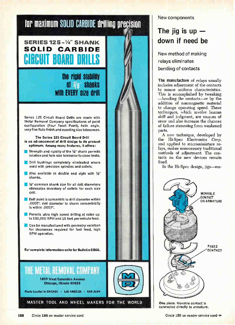
tor maximum SOLID CARBIDE drilling precision
SERIES 125 -1/4 " SHANK
SOLID CARBIDE
CIRCUIT BOARD DRILLS me rigid slake
01 shanks with EVERY size drill
Series 125 Circuit Board Drills are made with Metal Removal Company specifications of point configuration (Four Facet Point), helix angle, very fine flute finish and exacting size tolerances.
The Series 125 Circuit Board Drill is an advancement of drill design to its present
optimum. Among many features, it offers:
la Strength and rigidity of the 1/8" shank permits location and hole size tolerance to close limits.
1.1 Drill bushings completely eliminated where used with precision spindles and collets.
Also available in double end style with 1/8" shanks.
1/8" common shank size for all drill diameters eliminates inventory of collets for each size drill.
Drill point is concentric to drill diameter within .0005"; drill diameter to shank concentricity is within .0003".
Permits ultra high speed drilling at rates up to 150,000 RPM and 15 feet per minute feed.
Can be manufactured with geometry variation for clearances required for fast feed, high RPM operation.
For complete information write for Bulletin CB66.
1859 West Columbia Avenue Chicago, Illinois 60626
Plants Located in CHICAGO • LOS ANGELES • SAN JUAN
MASTER TOOL AND WHEEL MAKERS FOR THE WORLD
New components
The jig is up —
down if need be
New method of making
relays eliminates
bending of contacts
The manufacture of relays usually includes adjustment of the contacts to assure uniform characteristics. This is accomplished by tweaking —bending the contacts—or by the addition of nonmagnetic material to change operating speed. These techniques, which involve human skill and judgment, are sources of error and also increase the chances of failure stemming from weakened parts. A new technique, developed by
the Hi-Spec Electronics Corp. and applied to microminiature re-lays, makes unnecessary traditional methods of adjustment. The con-tacts on the new devices remain fixed.
In the Hi-Spec design, jigs—me-
MOVABLE CONTACT ON ARMATURE
FIXED CONTACT
One piece. Movable contact is connected directly to armature.
188 Circle 188 on reader service card Circle 189 on reader service card—*-

Specify CORNING® Capacitors for confidence.
Will the capacitor you take for granted take out your entire system?
Considering the finality of capacitor failure, anything less than the reliability of glass is false economy. Protect all the critical design work you put into your active circuits. Back them up with the documented reliability of glass dielectric capacitance in the vital roles of coupling, bypass, filtering. Corning offers this confidence in a full range of types, sizes, values and costs.
CYFR Capacitors, from .5 to 10,000 pf, substantially exceed the requirements of Mil-C-11272, including environmental performance and Quality/Reliability Assurance, and are backed by a heritage that includes use in Surveyor, Minuteman, Gemini, among others.
CORNING' CYFM Capacitors offer low cost, high reliability, from .5 to 10,000 pf. Give you CYFR-type environment-proof performance at substantial savings.
CORNING® TYO Capacitors from 1 to 2700 pf, radial leads, precision case for snug, upright mounting. Dense circuitry without doubts. Meet or exceed all performance requirements of Mil-C-11272.
CORNING® Glass-K Capacitors cram from 1000 to 100,000 pf in a quarter-inch case size with a new dielectric material for guaranteed reliability.
In all types, standard items are shipped in two weeks or less. Tell us what you want in capacitance; we'll tell you which CORNING® Capacitor will give you the confidence you need.
For complete specs, write to: Corning Glass Works, Electronic Products Division, 3913 Electronics Drive, Raleigh, N. C.
CORNING ELECTRONICS

The Model 6000 Modular Frequency Meter will measure frequencies 10 KHz to 600 MHz with .000125% accuracy. Special plug-in modules allow the instrument to be used as an audio frequency meter from 500 Hz to 20 KHz full scale and in addition to be used as a dc voltmeter (10,000 ohms/volt).
The wide variety of plug-in oscillator accessories and range modules makes the Model 6000 adaptable to a number of jobs in the field and in the laboratory. Portable, battery operated with rechargeable batteries.
Model 6000 with 601A charger, less plug-in modules $195.00
INTERNATIONAL MODEL 6000 FREQUENCY METER
measures frequencies 10 khz to 600 mhz with accuracy as close as .000125%
CHARGER Range Modules (Mixers) $25.00 to $45.00 each
Oscillator Modules (Crystal Controlled For Frequency Measurement)
$30.00 to $90.00 each
Special Modules Audio Frequency $45.00 DC Voltmeter 25.00
a. Range Modules
b. Oscillator Modules
. For complete information write International today.
where accuracy counts!
INTERNATIONAL
CRYSTAL MFG. CO., INC. 10 NO. LEE • OKLA. CITY, OKLA. 73102
. . relay operates with
minimum bounce...
chanical alignment devices—are used to set the contact tolerance. Therefore, each assembled relay must meet its design specifications. If a batch does not meet the specs, the jig is readjusted, not the relays. Jig manufacturing methods were made possible by using only one point to measure set-up dimensions. This one datum point also elimin-ates tolerance build-up—dimen-sional errors that are small but in-crease with the size and complexity of the device.
Solid contact. Because of the con-struction method, the movable con-tacts are fixed directly to the arma-ture. No intermediate actuator or movable contact springs are re-quired. As the armature responds to the magnetic force of the ener-gized coil, the contact moves with it. Both the fixed and movable con-tacts are cylindrical in shape, solid, and made of a gold alloy. This re-sults in the elimination of point wear that is associated with gold plating, and also keeps contact re-sistance low. The movable contacts and arma-
ture travel only one-third the dis-tance covered in comparable relays, in approximately the same time. The lower average speed means the relay operates with minimum bounce. It also means a lower ki-netic energy has to be converted upon mating of contacts. Even though the speed of travel is slower than in some relays, the operate-and-release time combined with the reduced bounce means faster trans-fer to the steady state condition. The cumulative effect, according to the company, is an increase in operational life.
In most microminiature relays enclosed in TO-5 cans, the leads pass through a glass seal and con-nect directly to the contacts and coil. If the leads are bent or flexed too much, internal relay parts may be damaged. In the Hi-Spec units, the leads pass through the seal and stop. From this point, inside the header, ribbon leads connect the relay parts to the outside world, eliminating one cause of damage to the device. Hi-Spec Electronics Corp., Newbury Park, Calif. [358]
190 Circle 190 on reader service card Electronics l December 11, 1967

At ECI in St. Petersburg, Florida...
Communication Systems Opportunities
For a special breed of engineer If you're one of that special breed of communication engineers who finds a challenge in projects beginning with applied research and advanced development and continuing through prototype and product design, you may well be the kind of person we're looking for.
Check this partial list of systems engineering activities at ECI. If you'd like to help push the state-of-the-art in any of these or other areas in communications, send us your resume. You'll design systems and equipment for satellite communications, multiplexing, electronic switching, command and control and advanced radio communications for some of the nation's major defense and space programs.
Communication Systems Engineering Activities:
• Propagation Analysis
• Advanced Antennas
• Coding Theory
• Detection Techniques
• Communication System Design
• Communication System Integration
• Reliability Techniques
CHALLENGE, GROWTH . . . and LOCATION TOO!
At ECI your job will be challenging. At ECI you'll find real opportunity for growth instead of just another confining groove — two-thirds of all advanced development is done in regular engineering development areas. And, at ECI you'll like where you're living just as much as you'll like your job. We'll match subtropical, sunny St. Petersburg against any location in the U. S. for stimulating, comfortable living.
SEND YOUR RESUME TODAY — in confidence — to K. E. Nipper, Supervisor of Professional Placement, Electronic Communications, Inc., P. 0. Box 12248, St. Petersburg, Florida 33733. (An equal opportunity employer, M & F.)
ELECTRONIC COMMUNICATIONS, INC.
ST. PETERSBURG DIVISION
Electronics December 11, 1967 Circle 191 on reader service card 191

We're number one 2, 3, 4, 5, 6,7, 8, 9...
No matter how it all adds up, w leaders in thumbwheel switch —in sales, in product features and quality... and in service. We like leading, and here's w means to you: Mtn Our switches Digiswitc an ch"
are the simplest, most easily read, easiest to operate, smallest, biggest, and looking for your panel. And they have both and simple electrical output capabilities.
Did we get to be number on .ecause we are so smart? We like to think s ut being there first sure helped. We pioneered the thumbwheel switch. And we're the kH, of engineers who continually improve o product. [Drives the competition crazy.] im But maybe our real advantage is that we like to sell things. This makes us easy to buy from. Send for our catalog. It's as easy as one, two, three.
THE DIGITRAN COMPANY Subsidiary of Becton, Dickinson and Company
855 S. Arroyo Pkwy./Pasadena, Calif. 91105
Tel: (213) 449-3110/TWX 910-588-3794

New Semiconductors Review
SCR series, types 4ORCS5-60, handle 40 amps with ratings from 50 to 600 v. They withstand extreme temperature and humidity per Mil-Std-750. They offer 800-amp-max. peak surge current; 63-amps rms max. on-state current; and 0.5 w max. average gate power. Prices (100-up), $9.15 to $19.90 each. International Recti-fier, 233 Kansas St., El Segundo, Calif. 90245. [436]
P-channel FET 2N5033 has a pinch-off voltage from 0.3 to 2.5 y when drain-to-source voltage is —10 y and drain current is 1 iza. Equivalent input noise voltage is 0.1 /Ay per the sq rt of frequency at 1 khz, and the frequency noise figure is 2 db max. at 1 megohm. Price is $1.80 (1-99); 72 cents (10,000-24,999). Fairchild Semi-conductor, Mountain View, Calif. 94041. [440]
N-channel junction FET CH13N is a high transconductance-to-drain current device for low level amplifier use. Minimum transcon-ductance is 25,000 at 10 ma, ensuring a voltage gain of 25 minimum. As a source follower, the FET has a typical output im-pedance of 25 ohms. Noise voltage is less than 2 ny at 10 khz. Crys-talonics Inc., 147 Sherman St., Cambridge, Mass. 02140. 1E4373
A series of 200-amp silicon rec-tifiers, 20OUB5-50, has a silver-plated flat tab anode terminal that forms a heat sink and allows cable connections directly to the device rather than through ter-minal posts or blocks. Maximum repetitive pry's range from 50 to 500; prices (1-9), $6 30 to $17.80. International Rectifier, 233 Kansas St., El Segundo, Calif. 90245. [441]
Triple-diffused, silicon planar npn transistors 40581 and 40582 are mounted in TO-39 hermetic-metal packages. They are designed for use in the output stages of 27-Mhz amplifier chain of citizens band radio transmitters. Price In quantities of 1,000 and up is $2.95 each for the 40581; $3.25 each for the 40582. RCA Elec-tronic Components and Devices, Harrison, N.J. 07029. [438]
Superconductive selenium recti-fiers in the Super-Sel series are typically 5/3 the size of conven-tional selenium assemblies. Plate temperatures to 85°C are allowed for 100,000 hours of operation before internal voltage drop dou-bles. Output currents are from 0.1 to 10,000 amps; voltage, 12.5 to 190 y d-c. Sarkes Tarzian Inc., 415 N. College Ave., Bloomington, Ind. 47401. [442]
Ratings of 200 and 400 y in the 50- to 1,000-v plastic Surmetic rectifier series are now available to meet Mil-S-19500/228D. The nominally rated 1-amp-at-75°C device is capable of 2.5-amp, 80°C performance, resistive or induc-tive load. Prices (100-up) are 99 cents and $1.30 for the 200 and 400 y units, respectively. Motor-ola Semiconductor Products Inc., Phoenix, Ariz. 85001. [439]
Monolithic differential compara-tors are for use where fast re-sponse times are required over the temperature range —55° to +125°C (type TDC 1710 and 1711) or 0° to +70°C (type TDC 2710 and 2711). Voltage gain for the TDC 1710 is 1700; for the others, 1500. All have 40-nsec response time. Transitron Elec-tronic Corp., 168 Albion St., Wakefield, Mass. 01881. [443]
New semiconductors
UJT offers a choice
By changing two external resistors, a unijunction transistor's
characteristics can be suited to a variety of applications
Not too long ago, the Semiconduc-tor division of the General Electric Co. accounted for 90% of the $5 million-a-year unijunction transistor (urr) market. It was selling alloy types in commercial, industrial, and military grades, all in metal cans. Then Texas Instruments Incor-
porated came up with its plastic-packaged planar units, and these cut GE'S market share to 60% within a year and a half. Motorola also made headway in this area with sophisticated planar ujes similar to GE'S. For consumer products, especially lamp dimmers and small-
motor controls, customers didn't feel they needed the higher-priced metal can units. Faced with these challengers,
GE started making planar plastic units itself, but ran into problems. About 10% of the new units in each production run didn't meet the specifications for operation at high temperatures. Because the com-pany didn't want to invest the time and money needed to weed out the bad units, the whole project was scrapped and a new one started. From scratch. GE engineers felt
that as long as they were going to develop a new unijunction, they might as well try to eliminate the
4-Circle 192 on reader service card 193

Something new under the sun! Bissett-Berman E-CELL° Timers
plAlaTT urne 8111111 CIRCUIT Glues SUBTOT81.8 ano TOTalle Problem: measure the operating time of major components of a system, while also summing the operating time of the system. The old way: use two parallel meters, with their readout gears. The new way: use the Bissett-Berman E-CELL* "time sink" circuit below for a total up to 1000 hours (which can be read out in 30 minutes), in a matchbox-size package that: uses only 1/100 watt-hour; has no moving parts; withstands mil spec shock and vibration; and is directly com-patible with solid-state circuitry. Cost? a fraction of just one of the meters. Try it yourself!
OP
-10 DC REGULATED
SUBTOTAL
EiF
TOTAL
Eigt.101;ee
10M OP
Voue TOTAL
VTOTAL
* The Bissett-Berman E-CELL9 is a unique "liquid state"electrochemi-cal timing and integrating component now being manufactured in high vol-ume on fully automatic production lines. E-CELLs are designed for single use or re-cycling, can be set or re-set in the field, and are furnished in wire-lead or plug-in versions. A multiple-electrode E-CELL enables complex functions such as two-phase timing — or subtotaling and totaling — with
00788.200 PORTABLE PERIOD METER 1
Actual size
JE signal outputs at each step. E-CELLs can generate accurate time delays ranging from a fraction of one sec-ond to months; can integrate events from one to infinity; and can operate in the nanowatt range. Operating/ storage temperature is —55°C to 75°C. E-CELLs have been tested and approved by users for severe shock and vibration tolerance in accordance with military specifications. Patents applied for.
For technical information and application notes, contact:
Components Division. The Bissett-Berman Corporation, la I 5-rr 3860 Centinela Avenue, Los Angeles, California 90066;
Telephone: Area Code 213, 390-3585.
Replaced. In SCR trigger applications, the unijunction and its two base resistors, RBI and R132, are replaced by a programable unijunction and its two limiting resistors, Ri and R1.
major drawback of the traditional uyr—fixed valley and peak cur-rents. The result of their effort is a new planar passivated pnpn device called a programable uni-junction transistor (ruT). Unlike the standard uyr with its emitter and two base leads, the PUT has an anode, cathode, and gate—an ar-rangement similar to that of a sili-con controlled rectifier. In some applications, in fact, the PUT func-tions like an scn. Operating param-eters such as peak current, valley current, interbase resistance, and forward voltage can be selected by choosing appropriate values for resistors Ri and Ro, and one rur can thus be used in a variety of applications. Turning on. In operation, Ri and
Ro control the voltage at which the diode (anode to gate) becomes for-ward biased. After the diode con-ducts, the regeneration inherent in a pnpn device causes the PUT to switch on, and this generates a negative resistance characteristic from anode to cathode, simulating the modulation of Ri with a con-ventional unijunction.
In this case, Ri and R2 are equivalent to the interbase resist-ance of a conventional unijunction. For anode voltages less than the gate potential (established by R1 and R0), the PUT is in a noncon-ducting state. As the anode voltage
194 Circle 194 on reader service card Electronics December 11, 1967

New Semiconductors Review
SCR series, types 4ORCS5-60, handle 40 amps with ratings from 50 to 600 v. They withstand extreme temperature and humidity per Mil-Std-750. They offer 800-amp-max. peak surge current; 63-amps rms max. on-state current; and 0.5 w max. average gate power. Prices (100-up), $9.15 to $19.90 each. International Recti-fier, 233 Kansas St., El Segundo, Calif. 90245. [436]
P-channel FET 2N5033 has a pinch-off voltage from 0.3 to 2.5 y when drain-to-source voltage is —10 y and drain current is 1 ma. Equivalent input noise voltage is 0.1 /Iv per the sq rt of frequency at 1 khz, and the frequency noise figure is 2 db max. at 1 megohm. Price is $1.80 (1-99); 72 cents (10,000-24,999). Fairchild Semi-conductor, Mountain View, Calif. 94041. [440]
N-channel junction FET CH13N is a high transconductance-to-drain current device for low level amplifier use. Minimum transcon-ductance is 25,000 at 10 ma, ensuring a voltage gain of 25 minimum. As a source follower, the FET has a typical output im-pedance of 25 ohms. Noise voltage is less than 2 ny at 10 khz. Crys-talonics Inc., 147 Sherman St., Cambridge, Mass. 02140. [437]
A series of 200-amp silicon rec-tifiers, 200U135-50, has a silver-plated flat tab anode terminal that forms a heat sink and allows cable connections directly to the device rather than through ter-minal posts or blocks. Maximum repetitive pry's range from 50 to 500; prices (1-9), $6 30 to $17.80. International Rectifier, 233 Kansas St., El Segundo, Calif. 90245. [441]
Triple-diffused, silicon planar npn transistors 40581 and 40582 are mounted in TO-39 hermetic-metal packages. They are designed for use in the output stages of 27-Mhz amplifier chain of citizens band radio transmitters. Price In quantities of 1,000 and up is $2.95 each for the 40581; $3.25 each for the 40582. RCA Elec-tronic Components and Devices,
Harrison, N.J. 07029. [438]
Superconductive selenium recti-fiers in the Super-Sel series are typically 1/3 the size of conven-tional selenium assemblies. Plate temperatures to 85°C are allowed for 100,000 hours of operation before internal voltage drop dou-bles. Output currents are from 0.1 to 10,000 amps; voltage, 12.5 to 190 y d-c. Sarkes Tarzian Inc., 415 N. College Ave., Bloomington, Ind. 47401. [442]
Ratings of 200 and 400 y in the 50- to 1,000-Y plastic Surmetic rectifier series are now available to meet Mil-S-19500/228D. The nominally rated 1-amp-at-75°C device is capable of 2.5-amp, 80°C performance, resistive or induc-tive load. Prices (100-up) are 99 cents and $1.30 for the 200 and 400 y units, respectively. Motor-ola Semiconductor Products Inc., Phoenix, Ariz. 85001. [439]
Monolithic differential compara-tors are for use where fast re-sponse times are required over the temperature range —55° to +125°C (type TDC 1710 and 1711) or 0° to +70°C (type TDC 2710 and 2711). Voltage gain for the TDC 1710 is 1700; for the others, 1500. All have 40-nsec response time. Transitron Elec-tronic Corp., 168 Albion St., Wakefield, Mass. 01881. [443]
New semiconductors
UJT offers a choice
By changing two external resistors, a unijunction transistor's
characteristics can be suited to a variety of applications
Not too long ago, the Semiconduc-tor division of the General Electric Co. accounted for 90% of the $5 million-a-year unijunction transistor (ITO market. It was selling alloy types in commercial, industrial, and military grades, all in metal cans. Then Texas Instruments Incor-
porated came up with its plastic-packaged planar units, and these cut GE'S market share to 60% within a year and a half. Motorola also made headway in this area with sophisticated planar up's similar to GE'S. For consumer products, especially lamp dimmers and small-
motor controls, customers didn't feel they needed the higher-priced metal can units. Faced with these challengers,
GE started making planar plastic units itself, but ran into problems. About 10% of the new units in each production run didn't meet the specifications for operation at high temperatures. Because the com-pany didn't want to invest the time and money needed to weed out the bad units, the whole project was scrapped and a new one started. From scratch. GE engineers felt
that as long as they were going to develop a new unijunction, they might as well try to eliminate the
-4—Circle 192 on reader service card 193

Something new under the sun! Bissett-Berman E-CELL° Timers
OM tune 81111{ CIRCUIT Wes SUBTOT812 ano TOMS Problem: measure the operating time of major components of a system, while also summing the operating time of the system. The old way: use two parallel meters, with their readout gears. The new way: use the Bissett-Berman E-CELL* "time sink" circuit below for a total up to 1000 hours (which can be read out in 30 minutes), in a matchbox-size package that: uses only 1/100 watt-hour; has
no moving parts; withstands mil spec shock and vibration; and is directly com-patible with solid-state circuitry. Cost? a fraction of just one of the meters. Try it yourself!
-10 DC VTOTAL REGULATED
* The Bissett-Berman E-CELLS is a unique "liquid state"electrochemi-cal timing and integrating component now being manufactured in high vol-ume on fully automatic production lines. E-CELLs are designed for single use or re-cycling, can be set or re-set in the field, and are furnished in wire-lead or plug-in versions. A multiple-electrode E-CELL enables complex functions such as two-phase timing — or subtotaling and totaling — with Actual size
VOLTAGE DROP ACROSS E CELL (MILLIVOLTS)
JE signal outputs at each step. E-CELLs can generate accurate time delays ranging from a fraction of one sec-ond to months; can integrate events from one to infinity; and can operate in the nanowatt range. Operating/ storage temperature is —55°C to 75°C. E-CELLs have been tested and approved by users for severe shock and vibration tolerance in accordance with military specifications. Patents applied for.
For technical information and application notes, contact:
Components Division. The Bissett-Berman Corporation, El I BB
3860 Centinela Avenue, Los Angeles, California 90066;
Telephone: Area Code 213, 390-3585. BERMAN
Replaced. In SCR trigger applications, the unijunction and its two base resistors, RBi and RBI, are replaced by a programable unijunction and its two limiting resistors, R, and R2.
major drawback of the traditional uyr—fixed valley and peak cur-rents. The result of their effort is a new planar passivated pnpn device called a programable uni-junction transistor (pin). Unlike the standard urr with its emitter and two base leads, the PITT has an anode, cathode, and gate—an ar-rangement similar to that of a sili-con controlled rectifier. In some applications, in fact, the PUT func-tions like an SCR. Operating param-eters such as peak current, valley current, interbase resistance, and forward voltage can be selected by choosing appropriate values for resistors Ri and Ro, and one PUT can thus be used in a variety of applications.
Turning on. In operation, Ri and Ro control the voltage at which the diode (anode to gate) becomes for-ward biased. After the diode con-ducts, the regeneration inherent in a pnpn device causes the Per to switch on, and this generates a negative resistance characteristic from anode to cathode, simulating the modulation of Ri with a con-ventional unijunction.
In this case, Ri and R, are equivalent to the interbase resist-ance of a conventional unijunction. For anode voltages less than the gate potential (established by Ri and R,), the PUT is in a noncon-ducting state. As the anode voltage
194 Circle 194 on reader service card Electronics I December 11, 1967

VSMF is a product supermarket
John Manning, Missiles Systems Division, Raytheon Company, Bedford, Mass., lias installed 4 VSMF Files: Defense Design, Documentation, Mil Specs and Mil Standards.
look into it! Design engineers have been telling us for years that VSMF is much like a product super-market. That's because Visual Search Microfilm Files contain more than 1,000,000 products from over 15,000 manufacturers—all arranged with design engineers in mind.
Of course, VSMF isn't exactly a supermarket. At Information Handling Services, we've col-lected 11/4 million pages of product data, indexed them, microfilmed them, put them in compact consoles, and combined them with the most modern microfilm retrieval equipment. VSMF has all the advantages of a product supermarket ... complete, easy-to-use and up-to-date. We know that when you design a product you want to use the best components and materials. And, to do this, you need to compare all that is available. VSMF can help you in this com-parison because VSMF supplies the data on all products. You supply the judgment.
Manufacturers who place their data in VSMF know this and invite comparison. The con-stantly changing "state of the art" is reflected in the pages of VSMF.
More than 125,000 engineers in 500 great corporations now shop in the VSMF supermarket. If you have VSMF in your company, look into it. If you don't, you might look into that, too. Write for "Looking into VSMF."
Circle 195 on reader service card
-emir information
HANDLING SERVICES, INC. Dept. E-1211
Denver Technological Center Englewood, Colo. 80110
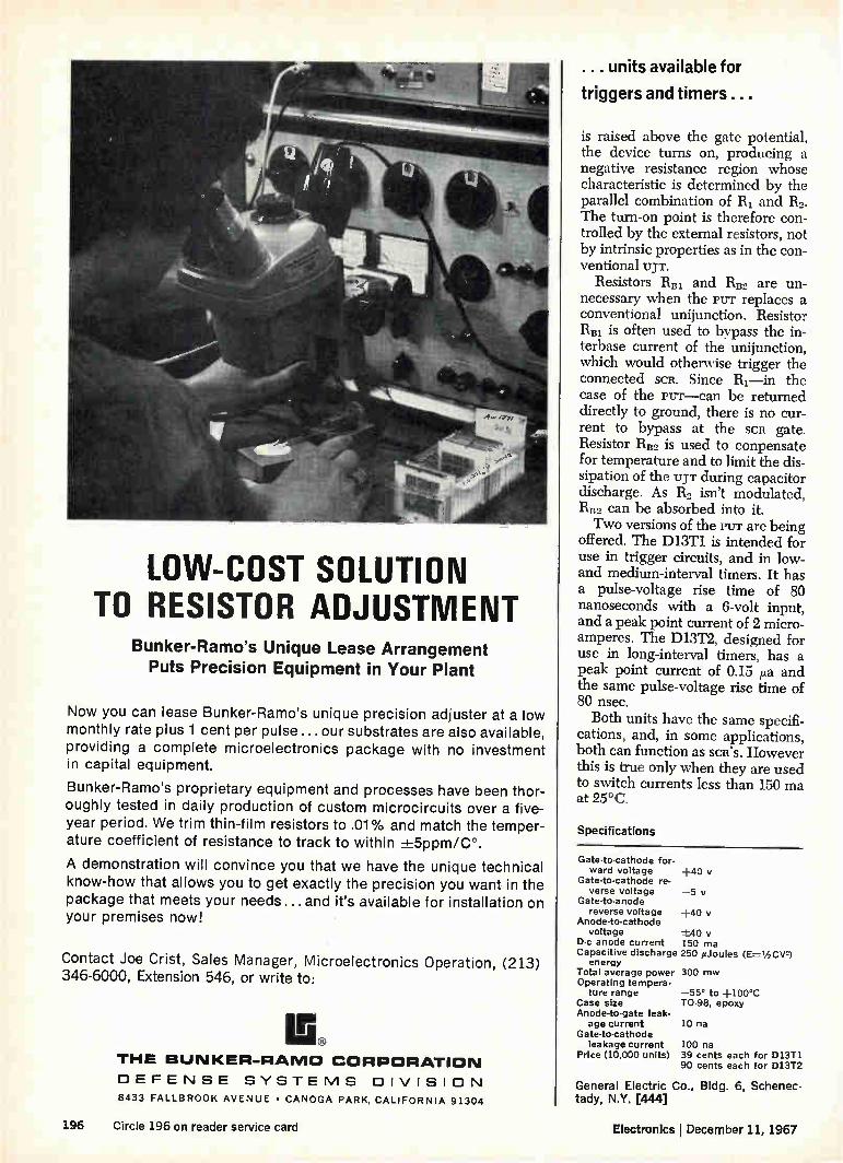
LOW-COST SOLUTION TO RESISTOR ADJUSTMENT
Bunker-Ramo's Unique Lease Arrangement Puts Precision Equipment in Your Plant
Now you can lease Bunker-Ramo's unique precision adjuster at a low monthly rate plus 1 cent per pulse ... our substrates are also available, providing a complete microelectronics package with no investment in capital equipment.
Bunker-Ramo's proprietary equipment and processes have been thor-oughly tested in daily production of custom microcircuits over a five-year period. We trim thin-film resistors to .01% and match the temper-ature coefficient of resistance to track to within ±-5ppm/C°.
A demonstration will convince you that we have the unique technical know-how that allows you to get exactly the precision you want in the package that meets your needs ... and it's available for installation on your premises now!
Contact Joe Crist, Sales Manager, Microelectronics Operation, (213) 346-6000, Extension 546, or write to:
THE BUNKER-RAMO CORPORATION
DEFENSE SYSTEMS DIVISION
8433 FALLBROOK AVENUE • CANOGA PARK, CALIFORNIA 91304
... units available for
triggers and timers .. .
is raised above the gate potential, the device turns on, producing a negative resistance region whose characteristic is determined by the parallel combination of R1 and Ro. The turn-on point is therefore con-trolled by the external resistors, not by intrinsic properties as in the con-ventional uyr.
Resistors RB1 and RHo are un-necessary when the rur replaces a conventional unijunction. Resistor RBi is often used to bypass the in-terbase current of the unijunction, which would otherwise trigger the connected scR. Since Ri—in the case of the rw—can be returned directly to ground, there is no cur-rent to bypass at the SCR gate. Resistor RB2 is used to conpensate for temperature and to limit the dis-sipation of the up. during capacitor discharge. As Ro isn't modulated, RB2 can be absorbed into it. Two versions of the PUT are being
offered. The D13T1 is intended for use in trigger circuits, and in low-and medium-interval timers. It has a pulse-voltage rise time of 80 nanoseconds with a 6-volt input, and a peak point current of 2 micro-amperes. The D13T2, designed for use in long-interval timers, has a peak point current of 0.15 /la and the same pulse-voltage rise time of 80 nsec. Both units have the same specifi-
cations, and, in some applications, both can function as sai's. However this is true only when they are used to switch currents less than 150 ma at 25°C.
Specifications
Gate-to-cathode for-ward voltage +40
Gate-to-cathode re-verse voltage —5 y
Gate-to-anode reverse voltage +40 y
Anode-to-cathode voltage -±-40
D-c anode current 150 ma Capacitive discharge 250 pJoules (E-= 1/2 CV2)
energy Total average power 300 mw Operating tempera-
ture range —55° to +100°C Case size TO-98, epoxy Anode-to-gate leak-
age current 10 na Gate-to-cathode
leakage current Price (10,000 units)
100 na 39 cents each for D13T1 90 cents each for 013T2
General Electric Co., Bldg. 6, Schenec-tady, N.Y. 044]
196 Circle 196 on reader service card Electronics December 11, 1967

any Ditell. do f One DIP or Headerall DIP's. Mount it on your panel. e 1 d Wire posts automatically —sharp corners bite wire. One-piece posts stand true, stand up. Plug, unplug your DIP's quickly, easily. Low cost.
AMP
PUT YOUR IDEAS INTO ACTION WITH THE HELP OF AMP ENGINEERING. WORLDWIDE.
Circle 197 on reader service card
•4e e
• • DO".
/ ci « e . ...... 41
/ & N ellie .\eNe° `‘,4e / <I
/ A le /
/ di / e e
// ‘%' le e 4 e / ,.. e e et • 9 44 44' <fr 00 9 9-
/ cite

aluminum outer conductor
continuous polyethylene dielectric
solid copper inner conductor
stock diameters of 3/8" 1/2", 7/4" lengths of 1000'
50 and 75 ohm impedance
SPI AFILIE Here's the most significant break-
through in coaxial cable design since we introduced Foamflex in 1959. Spirafil® is ideal for high frequency communica-tions and UHF air-to-ground communica-tions.
What makes Spirafil® IC so radically different is a solid polyethylene helix which completely covers the solid copper center conductor without interruption. Among other things, this means great
mechanical stability with an absolutely non-collapsible helix and higher voltage breakdown. Add to this the advantage of unusually attractive electrical character-istics: low attenuation, extremely high velocity of propagation and excellent dielectric constant.
Price, believe it or not, is competitive with conventional foam cables.
Can we tell you more? Write for your copy of Bulletin SL Issue 1.
PHELPS DODGE ELECTRONIC PRODUCTS NORTH HAVEN. CONNECTICUT
eiaw. •ale
kittelree ‘zwillee
New semiconductors
Matched FET's
a winning hand
Paired by a computer,
junction units have
better balance than IC's
One way to hold off the encroach-ment of linear integrated circuits on discrete semiconductors—or at least reduce it—is to come up with transistors matched close enough to produce tracking, drift, and other electrical characteristics to rival those of the ic's.
Generally, the device balance of monolithic circuits is 10 times bet-ter than that of discrete circuits. Balance in an lc reflects how alike the transistors are, and how alike they remain through environmental changes. This matching in linear ic's is usually an order of magni-tude closer than the best match possible with discrete components. The balance of an lc is enhanced
by the arrangement of the output; each half-circuit response can be summed at the output in such a way that unwanted changes (such as increased leakage) offset one another, and desirable changes (higher gain with rising tempera-tures, for instance) complement each other.
Thus, the integrated circuit usu-ally provides excellent electrical tracking, maintaining balance in the face of changes in signal levels and temperature. It also provides uni-form linearity in the reproduction of input signals, and can compen-sate for such changes as tempera-ture variations and power supply shifts. But this has changed with the development of a new tech-nique for producing matched, dual field effect transistors.
Siliconix Inc., a manufacturer of field-effect devices, digital ic's, and semiconductor test equipment, is now using a computer-aided match-ing process for its new dual FET'S. The new FET'S are n-channel
units whose balance surpasses that of linear ic's. They are designed to be used in high-input-impedance
198 Circle 198 on reader service card Electronics December 11, 1967

differential amplifiers. The company guarantees a 0.97
matching (transconductance ratio) for the 2N5196, the first in the se-ries, making it comparable to Union Carbide's 2N3954 dual, n-channel FEZ But the tracking specification of the Siliconix unit—less than 5-microvolt drift per °C tracking—is twice as good as that of Union Car-bide's, 10 e per °C. And the new FET has a maximum offset of 5 milli-volts.
Computer's aid. Although select-ing adjacent dice on the silicon wa-fer is effective in matching bipolar transistors, this method isn't reli-able for FET'S. The actual dice must be accurately measured before packaging. Siliconix uses a compu-ter to keep track of dice in a given batch, then pairs dice having very close characteristics. The yields are very good, says the company.
Siliconix' process isn't a radical technological change. Says one en-gineer: "It's not a matter of getting the match once and announcing it for every device and then guaran-teeing it for everyone. Instead, it's like a car maker guaranteeing his cars for 180 miles per hour. To do this, he must build them for 200 mph." The other devices in the series
include the 2N5197, with a trans-conductance ratio of 0.97 and a tracking specification of 10 e; the 2N5198, 0.95 and 20e; and the 2N5199, 0.95 and 40e. Because the tracking specifications are de-rived from maximum and minimum input measurements, the company says they are really a slope and not point-by-point measurements.
All of the units have low-leakage input-gate current of less than 15 picoamps at 25°C and equivalent input noise voltages of 0.020 ,Ltv per
Matched. Dual field effect transistors have matched characteristics that rival those of integrated circuits.
It all began here!
Edwin H. Hall (Fogg Art Museum, Harvard University)
* * * * * *
THE HALL EFFECT " In short, the phenomena observed were just such as we should expect to see if the electric current were pressed, but not moved, toward one side of the conductor." When Edwin H. Hall wrote these
words in 1880, he was not thinking about semiconductors or the effect that now bears his name. In fact, he was a 25-year old graduate student at Johns Hopkins who was looking for a way to prove or disprove a statement made by Maxwell.
In his text "Electricity and Magnet-ism" Maxwell had said that "a mag-netic field acts not upon the current in a conductor, but upon the conductor itself. The conductor will move in obe-dience to this force."
Hall reasoned that if the current itself is attracted by the magnet, the current should be drawn to one side of the wire and its resistance path should be increased. To test this theory he used "a mag-
net that was worked by a battery of twenty Bunsen's cells joined four in a series and five abreast. The strength of the magnetic field . . . was probably fifteen or twenty times H, the horizon-tal intensity of the earth's magnetism." A strip of gold leaf mounted on a
glass plate was placed between the poles of the electromagnet, with the plate cutting across the lines of force. "The two poles of a sensitive galvano-meter were then placed in connexion with different parts of the disk, through which an electric current was passing, until nearly equipotential points were found. The magnet-current was then turned on and the galvanometer was observed in order to detect any indica-tion of a change in the relative poten-tial of the two points.
"I succeeded on the 28th of October in obtaining, as the effect of the mag-net's action, a decided deflection of the galvanometer-needle."
*("On the New Action of the Mag-net on Electric Currents," The London, Edinburgh and Dublin Philosophical Magazine and Journal of Science, Vol. 9.1880)
and NOW from
INC
New Hall effect GAUSSMETERS with performance and versatility
unmatched anywhere
Model 620 Precalibrated Gaussmeter A medium priced, precision instrument designed to take full advantage of recently developed high-linearity Hall elements and solid-state circuitry. Unit features precal-ibrated probes that may be interchanged without recalibration. With built-in cal-ibration accuracy of 0.3%, instrument accuracy is ± 1.0% to 30 kG (3 tesla) and Lk- 0.5% to 10 kG (1 tesla) when used with high-linearity probes. Direct ac and dc field readout One volt FS calibrated output. Temperature compensated probes allow high-stability operation in labora-tory or production.
ullM1108.011 4 tilm—
Model 640 Precalibrated Gaussmeter High performance instrument designed to fulfill all the requirements of the Model 620 plus many more never before offered. The Model 640 offers 1000X scale expan-sion with automatic and true zero center meter readout. Permits direct measure-ment of small incremental variations in both a positive and negative direction. Controlled feedback permits incremental operation up to 30 kG. Absolute field measurement accuracy is -4-- 1.0% to 30 kG and 0.5% to 10 kG using high-linearity probes. Five volt dc auxiliary output. Field measurements can be ex-tended to 100 kG with high field probes.
"BELL PRODUCTS for PLANNED PROGRESS"
ELL INC. 1356 Norton Avenue Columbus, Ohio 43212 Phone, 614/294-4906 TWX: 810/482-1716
Electronics December 11, 1967 Circle 199 on reader service card 199

T-FORMATION I I II______
A winning combination for any heat dissipation problem, As-trodyne's patented "T" fin pro-vides 20% or greater cooling surface area than straight fin designs. Available only on As-trodyne heat sinks, the T-fin shortens the thermal path from heat source to fin tip, reduces the space needed for proper heat sinking, and,with proper fin spacing, gives better chim-ney effect in natural convec-tion cooling.
When the heat's on, don't punt. Try Astrodyne's T-formation.
(Free Short Form Catalog of Standard stock heat sinks and list of Distributors in principal
cities.)
astrociyne, inc. SUBSIDIARY OF ROANVVELL CORPORATION
207 CAMBRIDGE STREET / BURLINGTON, MASSACHUSETTS 01803
(617) 277.3850
Circle 268 on reader service card
Put VARISTORS in your circuit
They will protect your components, limit
noises, and do all others to assure your
circuit works all right.
Select right one from varieties of ginl<Pn
Silicon and SiC Varistors.
Silicon varistors
11 types SiC varistors
27 types
Other Products: Silicon Diodes, Silicon Power Transistors, Selenium Rectifiers, CdS Photo Cells.
SANKEN ELECTRIC CO., LTD.
1-22-8 NISHI- IKEBUKURO, TOSHIMA - KU, TOKYO
PHONE 986-6151 CABLE: SANKELE TOKYO
... chips can be bought
for hybrid IC's...
square root of the frequency. Other tightly matched parameters tested at 25°C are differential-gate-source voltages running from 5 to 15 mv, common-source forward transcon-ductance from 1,000 to 4,000 micro-mhos, and a maximum common-source output conductance of 50 pmhos.
Stability up front. While such tightly matched parameters may be more than most designers need, Siliconix is aiming the FET'S at users seeking extremely stable de-vices at the front end of their equip-ment. Most likely application is in military gear. The 2N5196 is de-signed for primary standards-type equipment, such as clocks, d-c am-plifiers, and the front ends of lc amplifiers. Customers wouldn't buy the 2N5196—priced at $29.20 each in lots of 100—for $250 analog com-puters, but the government might for a satellite.
Siliconix thinks that the others in the series—the 2N5197, priced at $18.60, the 2N5198 at $9.30, and the 2N5199 at $7.75—will find wide-spread use because of their stabil-ity across wide temperatures and extreme accuracy, particularly for preamplifier stages. The company believes that for
the present, dual FET'S are preferred for preamplifier stages. Its reason: lc's still can't match dual FET'S spec-ifications. The FET input current is 15 picoamps for a dual FET, com-pared with 200 nanoamps for a typ-ical linear lc. However, Siliconix, which second-sources some digital -lc's, is experimenting with linear ic's, but has none ready for market. The company also sells chips to hy-brid-circuit makers and to users who have facilities for assembling their own hybrids. To make FET pair selection easy,
Siliconix offers a designer's kit, DK7, containing the four differen-tial-amplifier pairs plus two current-limiter diodes, CL4710 and CL6810. The current limiters are two-termi-nal FET'S that provide current loads of 470 and 680 microamps respec-tively. The kits are sold through Siliconix' distributors for $84.50.
Siliconix Inc., Sunnyvale, Calif. [445]
200 Circle 267 on reader service card Electronics 1 December 11, 1967

CREI THE CAPITOL RADIO ENGINEERING INSTITUTE A Division of McGraw-Hill, Inc.
Dept 1850-E, 3224 Sixteenth Street, N.W. Washington, D.C. 20010
Gentlemen: The men listed at right are high school graduates working in some phase of electronics. Please send them your FREE book, "How to Prepare Today for Tomorrow's Jobs" and complete information about CREI Home-Study Programs.
And please send me the free brochure which tells how we can use CREI Home Study Programs to supplement our educational program for electronics personnel.
Name
Title
Company
Address
City State 7ip Code
Don't sit there wishing your support people knew more electronics...
do somettlin Look over your men. Pick out a few who are intelligent enough to profit from more education in electronics, ambitious enough to work hard to get it. Send us their names and addresses. We'll send them complete information about CREI Home Study Programs in Electronics, tell them how these programs have helped thousands of young men increase their value to their employers. We'll explain how they can study at home, at their own pace, on their own schedule
without traveling to classes. We'll give them the names of the more than 80 leading scientists and engineers who help us develop and update programs related directly to the needs of industry.
Yes, we'll do all that. If you're lucky some of your men may enroll. Why not give it a try? Fill out the coupon and get it in the mail today.
Founded 1927
MIMI IMMI IIIIIII Milli 111111 MI IIIMI
/Name
Accredited Member of the National Home Study Councd
CREI Programs cover these special-
ized areas of advanced electronics:
• Communications Engineering • Aeronautical and Navigational Engi-neering • Television Engineering • Computers • Nuclear Instrumentation and Control • Automatic Control En-gineering • Missile and Spacecraft Guidance • Radar and Sonar Engi-neering • Nuclear Engineering Tech-nology • Industrial Electronics for Automation • Computer Systems Technology.
Iffl Ma NM MI MI MN BIM
Address
City State 7ip Code
Name
Address
City State 71p Code
Name
Address
City State 7ip Code
Name
Address
City State 7ip Code
Name
Address
City State 7ip Code
(Not enough room? Attach sheet of paper with additional names and addresses)
Electronics December 11, 1967 Circle 269 on reader service card 201
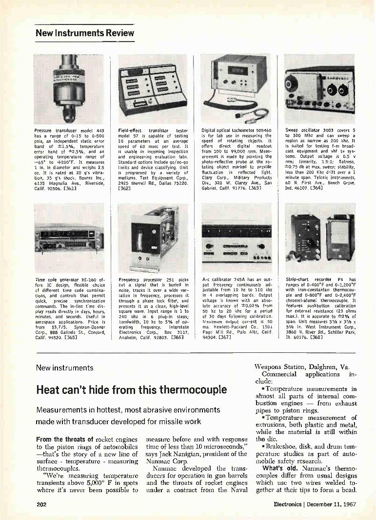
New Instruments Review
Pressure transducer model 443 has a range of 0-15 to 0-500 psia, an independent static error band of ±-1.5%, temperature error band of ±25%, and an operating temperature range of —65° to +200°F. It measures 1 in. in diameter and weighs 2.5 oz. It is rated at 20 g's vibra-tion, 35 g's shock. Bourns Inc., 6135 Magnolia Ave., Riverside, Calif. 92506. [361]
Time code generator HI-160 of-fers IC design, flexible choice of different time code combina-tions, and controls that permit quick, precise synchronization commands. The in-line time dis-play reads directly in days, hours, minutes, and seconds. Useful in aerospace applications. Price is from $3,775. Systron-Donner Corp., 888 Galindo St., Concord, Calif. 94520. [365]
Field-effect transistor tester model 57 is capable of testing 10 parameters at an average speed of 60 msec per test. It is usable in incoming inspection and engineering evaluation labs. Standard options include go/no-go limits and device classifying. Unit is programed by a variety of mediums. Test Equipment Corp., 2925 Merrell Rd., Dallas 75220. [362]
Frequency processor 251 picks out a signal that is buried in noise, tracks it over a wide var-iation in frequency, processes it through a phase lock filter, and presents it as a clean, high-level square wave. Input range is 1 to 240 khz in 6 plug-in steps; bandwidth, 10 hz to 5% of op-erating frequency. Interstate Electronics Corp., Box 3117, Anaheim, Calif. 92803. [366]
Digital optical tachometer 505460 is for lab use in measuring the speed of rotating objects. It offers direct digital readout from 100 to 99,000 rpm. Meas-urement is made by pointing the photo-reflective probe at the ro-tating object marked to provide fluctuation in reflected light. Clary Corp., Military Products Div., 320 W. Clarey Ave., San Gabriel, Calif. 91776. [363]
1Plelonesnellffl
CHU
A-c calibrator 745A has an out-put frequency continuously ad-justable from 10 hz to 110 khz in 4 overlapping bands. Output voltage is known with an abso-lute accuracy of ±0.02% from 50 hz to 20 khz for a period of 30 days following calibration. Maximum output current is 50 ma. Hewlett-Packard Co., 1501 Page Mill Rd., Palo Alto, Calif. 94304. [367]
Sweep oscillator 3003 covers 5 to 500 Mhz and can sweep a region as narrow as 200 khz. It is suited for testing f-m broad-cast equipment and vhf tv sys-tems. Output voltage is 0.5 I/ rms; linearity, 1.5:1; flatness, ±-0.75 db at max. sweep; stability, less than 200 Khz drift over a 1 minute span. Telonic Instruments, 60 N. First Ave., Beech Grove, Ind. 46107. [364]
Strip-chart recorder F4 has ranges of 0-400°F and 0-1,200°F with iron-constantan thermocou-ple and 0-800°F and 0-2,400°F chromel-alumel thermocouple. It features pushbutton calibration for external resistance (23 ohms max.). It is accurate to ±-2% of span. Unit measures 55/a x 35/e x 57/e in. West Instrument Corp., 3860 N. River Rd., Schiller Park, Ill. 60176. [368]
New instruments
Heat can't hide from this thermocouple
Measurements in hottest, most abrasive environments
made with transducer developed for missile work
From the throats of rocket engines to the piston rings of automobiles —that's the story of a new line of surface - temperature - measuring thermocouples. "We're measuring temperature
transients above 5,000° F in spots where it's never been possible to
measure before and with response time of less than 10 microseconds," says Jack Nanigian, president of the Nanmac Corp. Nanmac developed the trans-
ducers for operation in gun barrels and the throats of rocket engines under a contract from the Naval
Weapons Station, Dalghren, Va. Commercial applications in-
clude: • Temperature measurements in
almost all parts of internal com-bustion engines — from exhaust pipes to piston rings. • Temperature measurement of
extrusions, both plastic and metal, while the material is still within the die. • Brakeshoe, disk, and drum tem-
perature studies as part of auto-mobile safety research. What's old. Nanmac's thermo-
couples differ from usual designs which use two wires welded to-gether at their tips to form a bead.
202 Electronics December 11, 1967

Thermistor thermometers are of-fered for research, testing, and quality control. Temperatures from —100° to +300°C are cov-ered by a choice of ranges on 4-in, taut-band meter scales. There is 10% overlap between ranges and choice of 0.1 °, 0.25°, 0.5°, 1°, and 2° scale division markings. Accuracy is to 1% of span. Atkins Technical Inc., Gainesville, Fla. 32603. [369]
Voltmeter type 415A blends dig-ital and analog circuitry. It measures d-c voltages from the low mv region to 10 kv. Read-ings provide 4 digits of informa-tion with resolution of tenths of a millivolt in the lowest range. About 90% of an input value is presented in digital form; the remainder as analog vernier. J-Omega Co., 2271 Mora Dr., Mtn. View, Calif. 94041. [373]
Probe and amplifier P6046, for use with the company's oscillo-scopes, have these differential rejection capabilities at the probe tip: 10,000 to 1 at d-c; 1,000 to 1 at 50 Mhz; and 100 to 1 at 100 Mhz. Bandwidth and rise time (3.5 nsec) are constant over deflection factor range from 1 mv/div. to 200 mv/div. Tek-tronix Inc., Box 500, Beaverton, Ore. 97005. [370]
Model 304 dvm features 100-Av sensitivity on the 100-mv range. Nonsegmented, in-line, high-in-tensity 3-digit readout is pro-vided in 5 ranges: --L-100 mv, 1 V, 10 v, 100 v and 1,000 v. In addition, a fourth digit provides over-range readout at full rated accuracy to 120% of full scale for all ranges. Roback Corp., 602 Buck Rd., Huntingdon Valley, Pa. 19006. [374]
e • • 0 • •
D-c amplifier model 140 provides 10-nv resolution, 0.01% accu-racy, and 20-msec rise time for small signal changes. It offers gain ranges of 100 to 100,000, a 50-megohm input impedance, and up to 5 decades dynamic range. Common mode rejection is greater than 140 db. Price is $1,795. Keithley Instruments Inc., 28775 Aurora Rd., Cleveland, Ohio 44139. [371]
Resistance temperature coefficient plotter TR204A can be set to record deviations of ±0.5% to ±-50% full scale over a resist-ance range of 1 ohm to 100 megohms and a temperature range of —55° to +165°C. Var-iable slope controls provide heat-ing and cooling rates of 5° to 16°C per minute. Trott Electron-ics Inc., 30 Ridgeland Road, Roch-ester, N.Y. 14623. [375]
e e>
tf.
St • • It
, 1 I. +I 111111111•11
ØC o
.{ Multichannel analyzer model 5400A, a 1024-channel unit for nuclear measurements, has a 100-Mhz a-d converter. It can proc-ess a pulse within 13 Asec. The analyzer also functions as a multi-scaler. Pulse pair resolution in this mode is 100 nsec. Memory cycle time is 2.2 gsec. Price is $9,500. Hewlett-Packard Co., 1501 Page Mill Rd., Palo Alto, Calif. 94304. [372]
A-c power amplifier model 2200 furnishes 200 v-a of a-c power over a frequency range of 10 to 10,000 hz. Output is 0 to 130 v; total harmonic distortion, 0.25%; line regulation, 0.02%/ v; load regulation is adjustable to zero. The unit measures 31/2 in. high by 8 in. wide. Price is $595. California Instruments Corp., 3511 Midway Dr., San Diego, Calif. 92110. [376]
As temperature changes, the volt-age across the thermocouple also changes, and this change can be converted into a temperature read-ing. But standard devices do not have the response time of the Nan-mac units—as low as 2-3 micro-seconds in some applications. Nor will they withstand the punish-ment of operation in shock tubes or rocket engines where pressures often exceed 50,000 pounds per square inch. The new unit can tell the temperature of grindstone even as it cuts away the device's sensing tip. What's new. Rather than welded
wires, Nanmac's sensing tip is
made of 0.001-inch thick metal al-loy strips insulated from each other by mica strips about 0.0002-inches thick. This sandwich is pressed into a tapered well in its mount under 50,000 pounds of pressure to form a gas-tight seal. The mount itself can be any material—plastic, ceramic, or the hardest metal al-loys. The thermal junction that re-
places the bead used in common thermocouples is formed by grind-ing and polishing the sensing tip. Since the junction is formed abra-sively, wear in the cylinders of an engine or on a missile nose cone continually forms new iunctions in
Heat seekers. Units can be used in surface, in-wall or immersion jobs.
Electronics December 11, 1967 203

SHIELDED
BLACK BOXES To package, protect and
SHIELD custom test circuits (voltage dividers, attenuators, isola-tion and impedance, networks, etc.). Rugged die-cast aluminum box with aluminum cover, available in 16 dif-ferent connector combinations. Write for free catalog.
2390 2392 2411 2413
POMONA ELECTRONICS CO., INC.
1500 E. Ninth Street, Pomona, Calif. 91766
... keeps on measuring
as tip wears away...
the form of hundreds of tiny welds between the two metal strips. The thermocouples can be worn down % of an inch before they fail. Even then it is the pressure seal, not the thermal junction, that gives way to the abrasive force. Nanmac has sold large numbers
of the devices to the Air Force, for studies of airframe heating or abla-tion. Ohio State University and Re-public Aircraft have used the thermocouples in ablation studies and for the first time have been able to gauge the exact tempera-ture of ablative material as it heats and peels away. The thermocouple tip erodes too, but the device goes right on measuring.
Formerly, standard thermocou-ples were buried in the ablative and, since they were below the sur-face, the temperature "on top" had to be extrapolated. Sometimes the estimates were as much as 1,000 degrees off, says Nanigian, adding that his devices are accurate to ±1°F and that the university got readings in 2 microseconds.
Early risers. While other thermo-couples do not seem to be as rug-ged as Nanmac's, laboratory types using thin film sensors on ceramic substrates can equal their rise-time. But Nanigian says that these aren't as accurate, since they mea-sure the temperature of the sub-strate rather than that of the ma-terial being studied. The new thermocouples can do
other things besides measuring temperatures. With a fine enough finish on the sensing surface, the electrodes become electrically sep-arate. General Electric Co. has used such finely polished devices to measure ion densities in plasma. The ions bridge the gap between the electrodes; thus the higher the ion density, the greater the flow of electricity through the device.
It can also act as a laser power measuring device. Heat generated by the beam changes the thermo-couple's output voltage. Users could also build the thermocouple into the cutting tool of a lathe to gauge the temperature of the ma-terial being turned—and thus regu-late the rate of cut to keep delicate
YOUR NO.1
SOURCE FOR ALL MAGNETIC MATERIALS
Complete magnetic material inventory ... permanent magnets, high permeability, shielding and core materials and ferrites. Full fabrication facilities. Skilled engineering staff. 24-hour delivery.
PERMAG PACIFIC CORP. 5441 WEST 104th ST., LOS ANGELES, CALIFORNIA 90045 Telephone Area Code (213)776-5656 TWX 19101328-6547
PERMAG CENTRAL CORP. 5301-D OTTO AVE., ROSEMONT, ILL. 60018 Telephone Area Code (312) 678-1120
PERMAG MAGNETICS CORP. formerly EMPIRE MAGNETICS 3130 SOUTH AVENUE, TOLEDO, OHIO 43609 Telephone Area Code (419)385-4621
PERMAG NORTHEAST CORP. 50 THAYER ROAD, WALTHAM, MASSACHUSETTS 02154 Telephone Area Code (617)484-0550
PERMAG CORP. 88-06 VAN WYCK EXPRESSWAY. JAMAICA, N.Y. 11418 Telephone Area Code (212) 657-1818 TWX 17101582-295;
Circle 270 on reader service card
NORTON Magnetic Tape
Heads ,
4514 1" Tape
4507 1'2" Tape
4504 Tape
SERIES 4500 Crosstalk-50 DB
+75°C Temperature Operation
Send now for complete technical literature.
NORTON ASSOCIATES, INC.
10 Di Tomas Court, Copiague, N.Y. 11726
Phone: 516 598-1600
204 Circle 272 on reader service card Circle 271 on reader service card
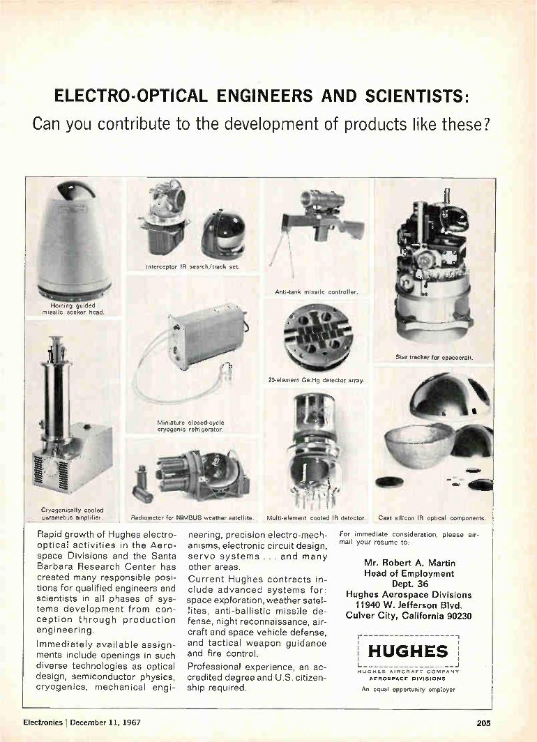
Homing guided missile seeker head.
Cryogenically cooled parametric amplifier.
ELECTRO-OPTICAL ENGINEERS AND SCIENTISTS:
Can you contribute to the development of products like these?
Interceptor IR search/track set.
Miniature closed-cycle cryogenic refrigerator.
Radiometer for NIMBUS weather satellite.
Rapid growth of Hughes electro-optical activities in the Aero-space Divisions and the Santa Barbara Research Center has created many responsible posi-tions for qualified engineers and scientists in all phases of sys-tems development from con-ception through production engineering.
Immediately available assign-ments include openings in such diverse technologies as optical design, semiconductor physics, cryogenics, mechanical engi-
Anti-tank missile controller.
20-element Ge :H detector array.
Star tracker for spacecraft.
Multi-element cooled IR detector. Cast silicon IR optical components.
neering, precision electro-mech-anisms, electronic circuit design, servo systems ... and many other areas.
Current Hughes contracts in-clude advanced systems for: space exploration, weather satel-lites, anti-ballistic missile de-fense, night reconnaissance, air-craft and space vehicle defense, and tactical weapon guidance and fire control.
Professional experience, an ac-credited degree and U.S. citizen-ship required.
For immediate consideration, please air-mail your resume to:
Mr. Robert A. Martin Head of Employment
Dept. 36 Hughes Aerospace Divisions
11940 W. Jefferson Blvd. Culver City, California 90230
-11
HUGHES HUGHES AIRCRArT LOMPANY
AEROSPACE DIVISIONS
An equal opportunity employer
Electronics December 11, 1967 205
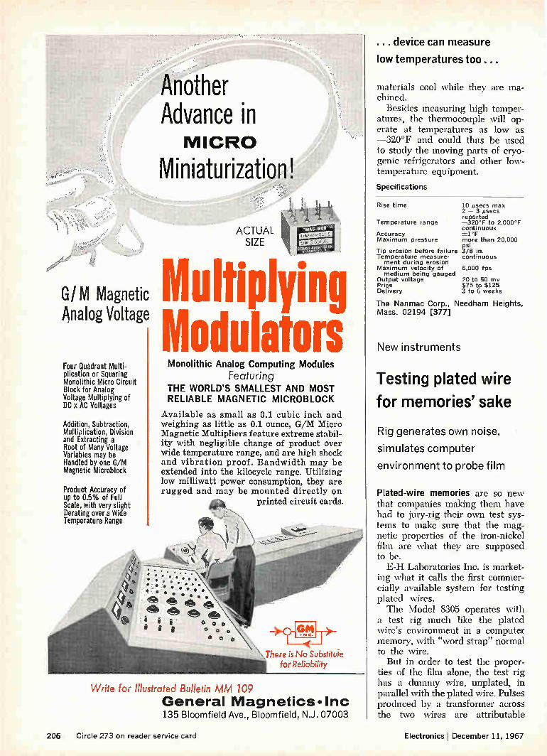
... device can measure
low temperatures too...
G/IVI Magnetic Analog Voltage
Four Quadrant Multi-plication or Squaring Monolithic Micro Circuit Block for Analog Voltage Multiplying of DC x AC Voltages
Addition, Subtraction, Multiplication, Division and Extracting a Root of Many Voltage Variables may be Handled by one G/M Magnetic Microblock
Product Accuracy of up to 0.5% of Full Scale, with very slight Derating over a Wide Temperature Range
Another Advance in MICRO
Miniaturization.
ACTUAL SIZE
ultiplying odulators
Monolithic Analog Computing Modules
Featuring THE WORLD'S SMALLEST AND MOST RELIABLE MAGNETIC MICROBLOCK
Available as small as 0.1 cubic inch and weighing as little as 0.1 ounce, G/M Micro Magnetic Multipliers feature extreme stabil-ity with negligible change of product over wide temperature range, and are high shock and vibration proof. Bandwidth may be extended into the kilocycle range. Utilizing low milliwatt power consumption, they are rugged and may be mounted directly on
printed circuit cards. e‘,
0 0 0 00
• 0 0
Write for Illustrated Bulletin MM 109
\There is No Substitute for Reliability
General Magnetics•Inc 135 Bloomfield Ave., Bloomfield, N.J. 07003
materials cool while they are ma-chined.
Besides measuring high temper-atures, the thermocouple will op-erate at temperatures as low as —320°F and could thus be used to study the moving parts of cryo-genic refrigerators and other low-temperature equipment.
Specifications
Rise time
Temperature range
Accuracy Maximum pressure
Tip erosion before failure Temperature measure-ment during erosion
Maximum velocity of medium being gauged
Output voltage Price Delivery
10 µsecs max 2 — 3 gsecs reported —320°F to 2,000°F continuous -±.1 °F more than 20,000 psi 3/8 in. continuous
6,000 fps
20 to 50 mv $75 to $125 3 to 6 weeks
The Nanmac Corp., Needham Heights, Mass. 02194 [377]
New instruments
Testing plated wire
for memories' sake
Rig generates own noise,
simulates computer
environment to probe film
Plated-wire memories are so new that companies making them have had to jury-rig their own test sys-tems to make sure that the mag-netic properties of the iron-nickel film are what they are supposed to be. E-H Laboratories Inc. is market-
ing what it calls the first commer-cially available system for testing plated wires. The Model 8305 operates with
a test rig much like the plated wire's environment in a computer memory, with -word strap- normal to the wire.
But in order to test the proper-ties of the film alone, the test rig has a dummy wire, unplated, in parallel with the plated wire. Pulses produced by a transformer across the two wires are attributable
206 Circle 273 on reader service card Electronics December 11, 1967

solely to the plating. The tester uses three word
straps—one to test a bit position on the wire and one on each side to determine the effect of nearby pulses in a real memory.
Noisemaker. To approximate more closely actual memory condi-tions, the system generates its own noise. Although a plated wire is a nondestructive readout mem-ory element, explains Robert Broughton, applications engineer, its memory content will be de-graded somewhat by many "reads." After 100,000 readings, the bit pulse may have lost as much as a fifth of its strength, but it should remain fairly constant after that. Many of the outputs of the word generator, consequently, provide only "disturbs" on the wire. A spe-cial strobing voltmeter is pulsed four times during any one cycle, to determine undisturbed voltage for a 0, disturbed voltage for a 0, undis-turbed voltage for a 1, and dis-turbed voltage for a 1. The total test pattern, with some
bits repeated, takes 40 microsec-onds. During this time the wire moves 5 to 10 millionths of an inch. "The manufacturer is actually
testing his process," says E-H Product Manager Doug Curs. "He provides a stimulus and measures its effect.- But Cura says that the E-H system provides resolution 10 times as great as equipment that does not include the special volt-meter. This instrument, which stretches and amplifies pulses, can pick off pulses that change at the rate of one or two microseconds per millivolt (risetime for both word and bit currents is 25 nsec.).
Normally, Broughton says, bit currents will be supplied and picked off with mercury cups through which the wires can run. The sense output can be fed to a logic unit which controls a wire chopper, so that bad chunks of wire can be discarded automati-cally. The Model 8305 system is sup-
plied in a two-bay cabinet with the word generator, two six-channel pulse drivers, four six-channel tim-ing units, the strobing voltmeter, a four-channel analog comparator, and a five-inch x-y oscilloscope dis-play unit. E-H Research Laboratories Inc., Oak-land, Calif. 94607 [378]
reliable switches
FOR THE BOEING 727
HSI sealed switches have successfully performed critical tasks on the Boeing 727 since the start of the program. That means faithful per-formance during thousands of flight hours. The HSI Flap, Leading Edge Slat, and Landing Gear Switches have patented elastomer-bonded rotary seals and heliarc welded stainless steel enclosure. These features provide positive protection against severe environmental conditions of humidity, altitude and temperature. The HSI hermetically sealed Engine Thrust Reverser Lockout Switches operate in ambient temperatures of —65° to +660°F. This capability comes from years of experience with high temperature applications. Furthermore, the one-piece blade design of these switches provides unusually high contact pressures making the switches insensitive to severe vibration conditions. Call HSI for answers to special switch-ing problems. Send for data sheets.
HAYDON SWITCH & INSTRUMENT, INC. Where Optimum Performance is Standard
1500 Menden Road. Waterbury. Conn. 06720/Area Code (203) 756-7401
Electronics December 11, 1967 Circle 274 on reader service card 207

Our abrasion-resistant TFE wire keeps on flying after others call it quits. Keeps flying up to 12 times longer, as proved in use on six leading types of commercial and military jets. Reason? It's 100% more abrasion resistant than other airframe wires. Because it has a tough insulation core of mineral-reinforced TFE bonded between pure TFE layers. Our wire also averages 50% smaller in diameter and 60% lighter
in weight than comparably rated wires. It can operate continuously at 500°F and remain tough at —450°F. It's nonflammable, nonhygroscopic, highly resistant to chemicals, has optimum dielectric properties and good flexibility.
Right now, it's reducing wire replacements in aviation, mining, refining, ground transportation and railroad equipment manufacturing. It can do the same for your application. For a free test sample and further data, write: ITT Wire and Cable Division, International Telephone and Telegraph Corporation, Clinton, Mass. 01510.
WIRE AND CABLE ITT 208 Circle 275 on reader service card Electronics December 11, 1967
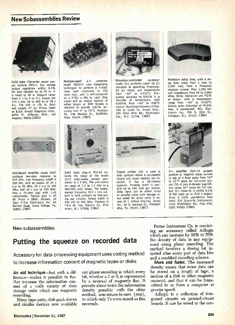
New Subassemblies Review
Solid state Thinverter power sup-ply module PHU-L has voltage output regulation within 0.2% for load changes up to 20 w. It is rated at 40 w. Outputs range from 2 y to 5 kv d-c. Inputs are 115 V rms, 50 to 500 hz or 28 d-c. The unit is 1% in. thick and weighs 27 oz. Prices begin at $160. Arnold Magnetics Corp., 6050 W. Jefferson Blvd., Los Angeles, 90016 [381]
dame Distributed amplifier model 4007 produces low-pass response to 225 Mhz. Low frequency cutoff is 100 khz, with an output of 20 p-p to 50 Mhz, 15 y p-p to 100 Mhz, and 10 y p-p to 200 Mhz, into a 75-ohm load with 1-db compression. Typical gain is 20 db. Price is $800; delivery, 30 days. C-Cor Electronics Inc., 60 Decibel Road, State College, Pa. 16801. [385]
Medium-speed a-d converter model AN2317 uses integrating techniques to perform a 4-digit (plus sign) conversion in 150 msec max., and is self-contained on a 21 116 x 4% in. card. Only power and an output register of either binary or BCD format is required to provide 0.01% ac-curacy over 0° to 70 °C. Analogic Co., 296 Newton St., Waltham, Mass. 02154. [382]
Solid state plug-in P124A ex-tends the range of the model 121C wide-sweep marker gen-erator to 1.7 Ghz. The unit covers its range of 1.3 to 1.7 Ghz in a 400-Mhz wide sweep. The funda-mental frequency (0.5 y rms out-put) is held constant by fast-act-ing agc circuits. Sweep width is 500 khz to 400 Mhz. Flatness is ±0.5 db. Kay Electric Co., Pine Brook, N.J. 07058. C3861
Noc,C,111(111011111E OSCillA7011 -
FRECIII(SCY MURMUR 110
MI« (“Pliii,01 110.1.1110 Vet. tr• ren
Resonator-controlled oscillator model 211 performs under 10 g's vibration at operating frequency, 50 g's shock, and temperature from —65° to +125°C. Fre-quency accuracy to 0.01% is a function of temperature, with 0.025% from —40° to +80°C typical. Operating frequency is from 400 to 2,500 hz. Armec Corp., 195 West Hills Rd., Huntington Sta., N.Y. 11746. [383]
7:z.=
rummoillim .1
Digital printer 152 is used in data systems where a permanent record and visual readout are re-quired. It has a 30-column capacity. Printing speed is vari-able up to 240 lines per minute. Data input can be either serial or parallel entry with storage in-put speed for serial entry in ex-cess of 1 million bits/sec. Sonex Inc., 20 E. Herman St., Philadel-phia, Pa. 19144. [387]
Miniature delay lines, with a de-lay time range from 1 nsec to 1,000 gsec, have a frequency response greater than 1,000 khz and impedances from 50 to 2,000 ohms. Relay tolerances are ±-2% or better, with a temperature range from —55* to +125°C. Output pulse distortion of -1:10% max. is maintained. RCL Elec-tronics Inc., 700 S. 21st St., Irvington, N.J. 07111. [384]
D-c amplifier ESA-75 accepts positive or negative input current in any of 4 fixed gains from 10-4 to 10 -4° amps for full-scale out-put (10 v) plus 8-decade logarith-mic range 10-4 amps for full out-put. D-c linearity is within 0.1% of full scale up to ±-10 y output. Price is $595, availability from stock. EAI Scientific Instruments, 4151 Middlefield Rd., Palo Alto, Calif. 94303. [388]
New subassemblies
Putting the squeeze on recorded data
Accessory for data-processing equipment uses coding method
to increase information content of magnetic tapes or disks
An old technique—but with a dif-ference—makes it possible to fur-ther increase the information con-tent of a wide variety of data storage units which use magnetic recording. Many tape units, disk-pack drives
and similar devices now available
use phase encoding in which every bit, whether a 1 or 0, is represented by a reversal of magnetic flux. It permits about twice the information density possible with the older method, non-return-to-zero (xRz), in which only l's were stored as flux reversals.
Potter Instrument Co. is market-ing an accessory called Adlogic which can increase by 50% to 70% the density of data in any equip-ment using phase encoding. The method involves a timing bit in-serted after every pair of data bits and a modified encoding scheme. More and faster. The increased
density means that more data can be stored on a length of tape, a section of a disk or other magnetic material, and that it can be trans-mitted to or from a computer at greater speed. Adlogic is a collection of inte-
grated circuits on printed-circuit boards. It can be wired to the con-
Electronics I December 11, 1967 209

Who's foolhardy enough to pay people to try to put his business out of business?
Some company called Poly-Scientific.
For years we've been in the slip-ring business. We make them in every size and shape. And to any parameter. So we like to think we're experts in the field. But we've often thought "Maybe something else would work better."
Recently, we decided to explore the idea.
With the help of our next-door neighbor, Virginia Tech, we set up a Scientific Advisory Board. Its mission: To think new processes, new materials, new products.
Four regular members— Ph.D.'s and professors who periodically meet with our own top people—make up the SAB. Each represents a separate scientific discipline. Often a visiting VIP sits in on the brainstorming sessions.
Naturally, some of their ideas get pretty far out—but we've already seen some practical benefits. Our new Captach Switch described on the opposite page is an example.
It's just one of the many useful ideas resulting from our Scientific Advisory Board. You'll be hearing about more in the future. If anybody puts us out of business—we're going to make sure it's us.
Care to have a foolhardy company like this working for you?
POLY-SCIENTIFICW A DIVISION OF LITTON INDUSTRIES
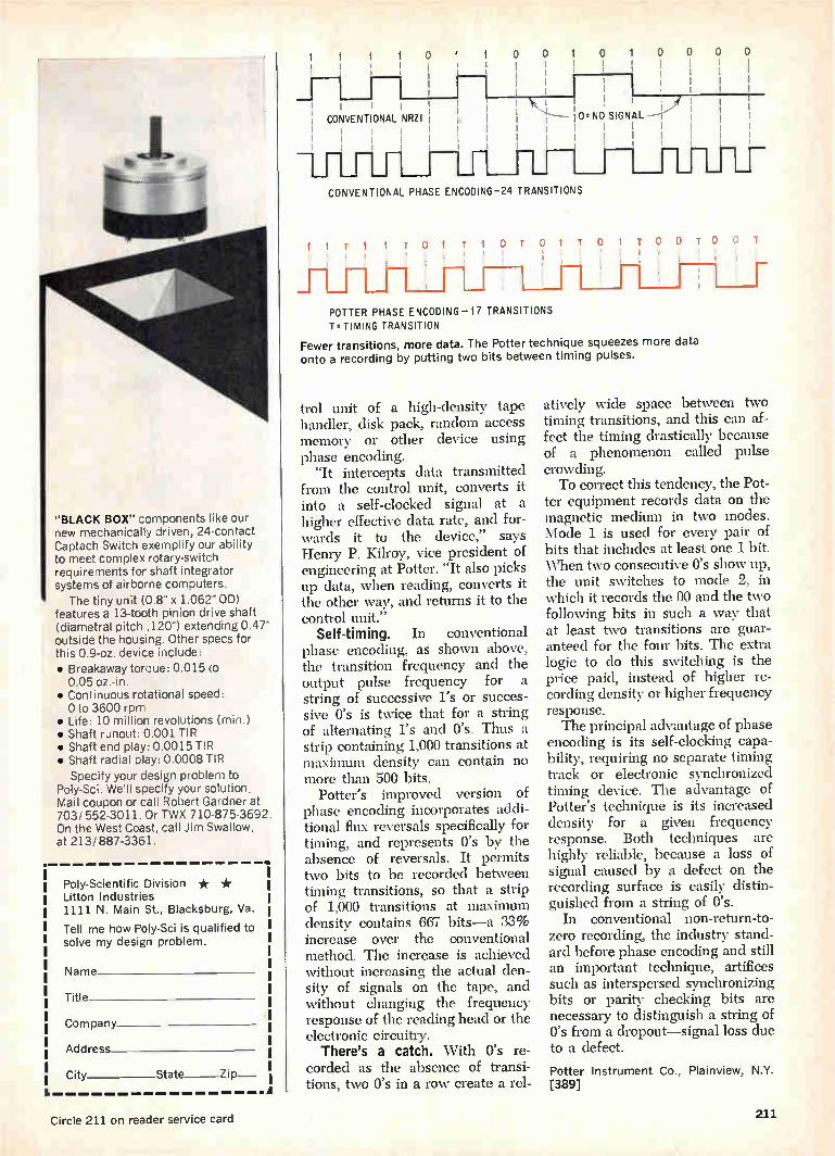
"BLACK BOX" components like our new mechanically driven, 24-contact Captach Switch exemplify our ability to meet complex rotary-switch requirements for shaft integrator systems of airborne computers.
The tiny unit (0.8" x 1.062" OD) features a 13-tooth pinion drive shaft (diametral pitch .120") extending 0.47" outside the housing. Other specs for this 0.9-oz. device include: • Breakaway torque: 0.015 co 0.05 oz.-in.
• Continuous rotational speed: 0 to 3600 rpm
• Life: 10 million revolutions (min.) • Shaft runout: 0.001 TIR • Shaft end play: 0.0015 TIR • Shaft radial play: 0.0008 TIR
Specify your design problem to Poly-Sci. We'll specify your solution. Mail coupon or call Robert Gardner at 703/ 552-3011. Or TWX 710-875-3692. On the West Coast, call Jim Swallow, at 213/887-3361.
Poly-Scientific Division * * Litton Industries 1111 N. Main St., Blacksburg, Va.
Tell me how Poly-Sci is qualified to solve my design problem.
Name
Title
Company
Address
City State Zip .1
CONVENTIONAL NRZI
1 0 1 0 0 I I
1
I 1 • 10. NO SIGNAL —VI 1111 1111
1
CONVENTIONAL PHASE ENCODING-24 TRANSITIONS
0 0
1 1 1 1
1
IITIITO1TIOTO 1 TOI TOOT ii 1
_ii i I , i
i
i 1
POTTER PHASE ENCODING-17 TRANSITIONS T. TIMING TRANSITION
Fewer transitions, more data. The Potter technique squeezes more data onto a recording by putting two bits between timing pulses.
trol unit of a high-density tape handler, disk pack, random access memory or other device using phase encoding.
"It intercepts data transmitted from the control unit, converts it into a self-clocked signal at a higher effective data rate, and for-wards it to the device," says Henry P. Kilroy, vice president of engineering at Potter. "It also picks up data, when reading, converts it the other way, and returns it to the control unit."
Self-timing. In conventional phase encoding, as shown above, the transition frequency and the output pulse frequency for a string of successive l's or succes-sive O's is twice that for a string of alternating l's and O's. Thus a strip containing 1,000 transitions at maximum density can contain no more than 500 bits.
Potter's improved version of phase encoding incorporates addi-tional flux reversals specifically for timing, and represents O's by the absence of reversals. It permits two bits to be recorded between timing transitions, so that a strip of 1,000 transitions at maximum density contains 667 bits—a 33% increase over the conventional method. The increase is achieved without increasing the actual den-sity of signals on the tape, and without changing the frequency response of the reading head or the electronic circuitry.
There's a catch. 'With O's re-corded as the absence of transi-tions, two O's in a row create a rel-
T
atively wide space between two timing transitions, and this can af-fect the timing drastically because of a phenomenon called pulse crowding. To correct this tendency, the Pot-
ter equipment records data on the magnetic medium in two modes. Mode 1 is used for every pair of bits that includes at least one 1 bit. When two consecutive O's show up, the unit switches to mode 2, in which it records the 00 and the two following bits in such a way that at least two transitions arc guar-anteed for the four bits. The extra logic to do this switching is the price paid, instead of higher re-cording density or higher frequency response. The principal advantage of phase
encoding is its self-clocking capa-bility, requiring no separate timing track or electronic synchronized timing device. The advantage of Potter's technique is its increased density for a given frequency response. Both techniques are highly reliable, because a loss of signal caused by a defect on the recording surface is easily distin-guished from a string of O's.
In conventional non-return-to-zero recording, the industry stand-ard before phase encoding and still an important technique, artifices such as interspersed synchronizing bits or parity checking bits are necessary to distinguish a string of O's from a dropout—signal loss due to a defect.
Potter Instrument Co., Plainview, N.Y. [389]
Circle 211 on reader service card 211
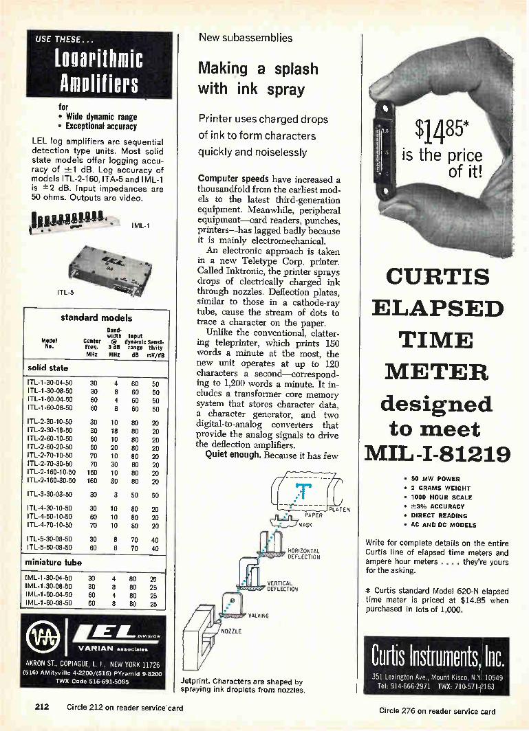
USE THESE...
Louarithmic Amplifiers for • Wide dynamic range • Exceptional accuracy
LEL log amplifiers are sequential detection type units. Most solid state models offer logging accu-racy of ±-1 dB. Log accuracy of models ITL-2-160, ITA-5 and IML-1 is 7=2 dB. Input impedances are 50 ohms. Outputs are video.
I ML-1
TL-5
standard models Band-width Input
Model Center @ dynamic Sensi-No. Freq. 3 dB range tivity
MHz MHz dB mV/dB
solid state
ITL-1-30-04-50 30 4 60 50 ITL-1-30-08-50 30 8 60 50 ITL-1 -60-04-50 60 4 60 50 ITL-1-60-08-50 60 8 60 50
ITL-2-30-10-50 30 10 80 20 ITL-2-30-18-50 30 18 80 20 ITL-2-60-10-50 60 10 80 20 ITL-2-60-20-50 60 20 80 20 ITL-2-70-10-50 70 10 80 20 ITL-2-70-30-50 70 30 80 20 ITL-2-160-10-50 160 10 80 20 ITL-2-160-30-50 160 30 80 20
ITL-3-30-03-50 30 3 50 50
ITL-4-30-10-50 30 10 80 20 I TL-4-60-10-50 60 10 80 20 ITL-4-70-10-50 70 10 80 20
ITL-5-30-08-50 30 8 70 40 ITL-5-60-08-50 60 8 70 40
miniature tube
i M L-1-30-04-50 30 4 80 25 I ML-1-30-08-50 30 8 80 25 I M L-1-60-04-50 60 4 80 25 I M L-1-60-08-50 60 8 80 25
IA Irà E a» AL DIVISION/
VARIAN associates
AKRON ST, COPIAGUE, L I, NEW YORK 11726 (516) AMityville 4-2200/(516) PYrarnud 9-8200
TWX Code 516-691-5085 Jetprint. Characters are shaped by spraying ink droplets from nozzles.
New subassemblies
Making a splash with ink spray
Printer uses charged drops
of ink to form characters
quickly and noiselessly
Computer speeds have increased a thousandfold from the earliest mod-els to the latest third-generation equipment. Meanwhile, peripheral equipment—card readers, punches, printers—has lagged badly because it is mainly electromechanical. An electronic approach is taken
in a new Teletype Corp. printer. Called Inktronic, the printer sprays drops of electrically charged ink through nozzles. Deflection plates, similar to those in a cathode-ray tube, cause the stream of dots to trace a character on the paper.
Unlike the conventional, clatter-ing teleprinter, which prints 150 words a minute at the most, the new unit operates at up to 120 characters a second—correspond-ing to 1,200 words a minute. It in-cludes a transformer core memory system that stores character data, a character generator, and two digital-to-analog converters that provide the analog signals to drive the deflection amplifiers.
Quiet enough. Because it has few
NOZZLE
HORIZONTAL DEFLECTION
VERTICAL DEFLECTION
VALVING
CURTIS
ELAPSED
TIME
METER
designed to meet
MIL-I-81219 • 50 MW POWER
• 2 GRAMS WEIGHT
• 1000 HOUR SCALE
• -±-3% ACCURACY • DIRECT READING
• AC AND DC MODELS
Write for complete details on the entire Curtis line of elapsed time meters and ampere hour meters . . . . they're yours for the asking.
* Curtis standard Model 620-N elapsed
time meter is priced at $14.85 when purchased in lots of 1,000.
Curtis Instruments, Inc. 351 Lexington Ave, Mount Kisco, N.Y. 10549
Tel: 914-666-2971 TWX: 710-571-2163
212 Circle 212 on reader service card Circle 276 on reader service card

MATSU° Highly Reliable Capacitors
POLYESTER FILM CAPACITORS.
Type MFK
Type MXT
Type MFK
Type MFL
.041m1het/
Type MXT
Type MR
In plastic tube. Capacitance Range: .001 MU to .22 NFL Voltages :100v,200v,400v,600v OC.
Dipped flat shape non-inductive construction. capacitance Range: .01 MID to .47 MID. Voltages :100v,200v,400v.600v OC.
Dipped flat shape. Capacitance Range ..001 MID to 22 MID vanes; 50v,100v,200v OC,.
METALLIZED POLYESTER FILM CAPACITORS.
Type FNX-H Mylar wrapped seminal with epoxy end seal
Capacitance Range:1 MID to 10 MID
Voltages: 100v,200v, 400v,600v OC.
SOLID TANTALUM CAPACITORS.
Type TAX
Type TOO
Type TSL
Type TAX MIL-C-26655A hermetically sealed.
Type TSX •TSL Sealed with epoxy ream Capacitance Range' 226110 to 330 WO.
Voltages :3v,6v,10v,15v,20v, 25v,05v, 511v DC.
for full details, contact :
MATSUO ELECTRIC CO.,LTD.
3-chome.Sennori-cho, Toyonaka-sh ,,Osaka, Japan Coble Address "NCC MATSUO"OSAKA
moving parts, the printer is virtu-ally silent—except for the flapping of the paper. There are no keys and the carriage doesn't move from side to side. Characters are formed by spraying small drops of ink se-quentially through 40 nozzles— each capable of printing two char-acters. The drops are drawn out of the nozzles when a voltage is ap-plied to a valve at each nozzle. Electrodes then deflect the drops vertically and horizontally to form the characters. Up to 80 characters per line can be printed on conven-tional teletypewriter paper. A one-nozzle printer was in-
troduced last spring by Recognition Equipment Inc., but it prints only coded marks on moving paper as part of a sorting process.
Inktronic accepts data in ASCII
(American Standard Code for In-formation Interchange), but the company plans to have it accept five-level Baudot code as well.
Stream of characters. Like con-ventional teletypewriters, the ma-chine prints one character at a time. As every other character is received, one ink nozzle is energized by a reed relay, then the others are acti-vated in sequence. Each character is decoded to
select one of 64 subroutines in a read-only memory, and each sub-routine contains 32 words of seven bits each—four of which set up a vertical deflection to 1 of 10 pos-sible positions while the remainder set up a horizontal deflection to one of eight positions. The 32 words in the subroutine deflect 32 droplets to different positions so they trace out a character on the paper. The digital-to-analog converters
(one for vertical and the other for horizontal) convert the digital signals to 5- to 10-volt analog out-puts, which are used by three sets of two operational amplifiers to direct the ink jets. The d-c ampli-fiers operate at 800 to 2,800 volts, depending on the amount of de-flection needed to shape the charac-ters. Gain is 300 for the horizontal and 200 for the vertical amplifiers. Major applications, the company
feels, are computer printout, input or interrogation when the machine is furnished with a keyboard; moni-tor for high-speed tape-to-tape sys-tems; and communication terminals for voice-grade channels. Teletype Corp., Skokie, III. [390]
ECCO REFLECTOR'
RADAR TARGET
NEW FOLDER
Based on the Luneberg Lens, the Ecco Reflector is a wide-angle, con-stant cross section radar reflective device. Four-page folder in color describes monostatic, bistatic, omni-azimuthal and omni-directional types.
Circle 503 on reader service card
ECCOSORB ANECHOIC CHAMBERS
NEW DESIGNS 7
Illustrated folder gives details on anechoic and shielding performance of several new chambers used for an-tenna pattern, radar cross section, VSWR and RF compatibility meas-urements.
Circle 504 on reader service card
STYCASr H iK High Dielectric Constant
Plastics
lIllllilLdilLÍ Machineable rod and sheet with K' ranging from 1.8 to 25. Dissipation factor is below 0.002—for wave-guide, coax, antennas. Stable in se-vere environments. Proven in hun-dreds of applications.
Circle 505 on reader service card
Emerson & Cuming, Inc. CANTON, MASS.
GARDENA, CALIF.
NORTHBROOK, ILL. Sales Offices in Principal Cities
EMERSON & CUMING EUROPE N.Y., Oriel, Belgium
Circle 213 on reader service card 213
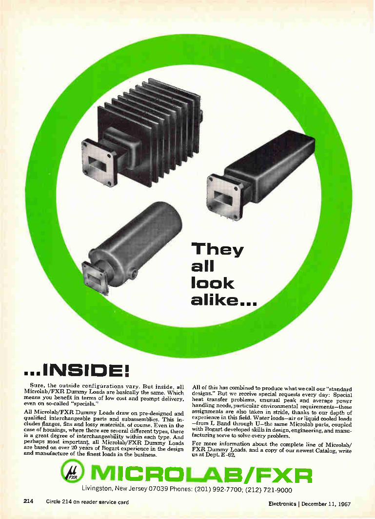
They all look alike...
Ite
‘equenamoe Sure, the outside configurations vary. But inside, all
Microlab/FXR Dummy Loads are basically the same. Which means you benefit in terms of low cost and prompt delivery, even dn so-called "specials."
All Microlab/FXR Dummy Loads draw on pre-designed and qualified interchangeable parts and subassemblies. This in-cludes flanges, fins and lossy materials, of course. Even in the case of housings, where there are several different types, there is a great degree of interchangeability within each type. And perhaps most important, all Microlab/FXR Dummy Loads are based on over 20 years of Bogart experience in the design and manufacture of the finest loads in the business.
All of this has combined to produce what we call our "standard designs." But we receive special requests every day: Special heat transfer problems, unusual peak and average power handling needs, particular environmental requirements—these assignments are also taken in stride, thanks to our depth of experience in this field. Water loads—air or liquid cooled loads —from L Band through U—the same Microlab parts, coupled with Bogart-developed skills in design, engineering, and manu-facturing serve to solve every problem.
For more information about the complete line of Microlab/ FXR Dummy Loads, and a copy of our newest Catalog, write us at Dept. E -02.
MICROLAB/FXR Livingston, New Jersey 07039 Phones: (201) 992-7700; (212) 721-9000
214 Circle 214 on reader service card Electronics December 11, 1967

New Microwave Review
Solid state traveling-wave-tube amplifier series 2000 is a 20-w unit. It is available in the fre-quency ranges of 1 to 18 Ghz, covered in 5 bands. Noise figure is 35 db maximum, and cold in-sertion loss of 80 db is specified. Dimensions are 5.25 x 16 x 16 in.; weight, 48 lbs. Delivery takes 30 to 60 days. Servo Corp. of America, 111 New South Road, Hicksville, N.Y. 11802. [401]
Portable f-m/tv relay links in the MRS series features output powers to 2 w. They are available from 1.7 to 7.725 Ghz. Receivers and transmitters are each com-plete with tripod, pan-head and antenna. The receiver or trans-mitter is integrally mounted to the antenna structure and is rfi protected. RHG Electronics Lab-oratory Inc., 94 Milbar Blvd., Farmingdale, N.Y. 11735. [405]
Oscillator/multiplier 2969-9900 is for use as an X-band local oscillator or a noise-modulated source to drive a twt amplifier. It has a mechanical tuning range of 10.15 to 10.55 Ghz. Output power is 4 mw minimum; input power, 150 y at 30 ma max., 6.3 y at 275 ma nominal; tempera-ture range, —54° to +95°C. Trak Microwave Corp., Tampa, Fla. 33614. [402]
Low-pass filter TLT cuts off at any frequency from 2 to 10 Ghz. It is a tubular type avail-able with 2 to 12 sections de-pending on the filtering charac-teristics desired. Impedance is 50 ohms; max. pass band vswr 1.5:1; insertion loss, 0.23 db to 1.13 db depending on number of sections. Telonic Engineering Co., P.O. Box 277, Laguna Beach, Calif. 92652. [406]
Broadband voltage-tuned oscilla-tors cover a frequency range of 140 Mhz to 9.5 Ghz, with out-put power ranging from 7 mw to 200 mw. Tuning voltage is 0 to 60 v. Input power is —28 y d-c at 125 ma max. Operating tem-perature is —40° to +70°C. Size ranges from 2 to 3 x 11/2 x 1 in. Western Microwave Labora-tories Inc., 1045 DiGiulio Ave., Santa Clara, Calif. 95050. [403]
Solid state, uhf-band receiver protector switch MA-8307-1L3S is capable of high isolation in a radar receiver during trans-mitter pulse interval with low loss during the interpulse period. It operates in the 400- to 1,100-Mhz range with max. insertion
loss of 0.5 db, vswr of 1.4 max., and isolation of 80 db minimum. Microwave Associates Inc., Bur-lington, Mass. 01803. [407]
Attenuator series AX features a maximum vswr of 1.1 up to 1 Ghz, with attenuation accuracy of 5%. Standard values are 3, 6, 10, 20, and 30 db; other values by special order. L-pad configuration is standard, 1-pad optional. Typical price for a 10-db, 100-w L pad attenuator is $175. Electro Impulse Labora-tory, 116 Chestnut St., Red Bank, N.J. 07701. [404]
A series of 13 microwave ampli-fiers span power levels from 0.5 to 2 w and frequencies from 250 Mhz to 18 Ghz in octave band coverage. Small signal gain ranges from 30 to 37 db and noise figure ranges from 20 to 40 db depending upon instru-ment. Prices vary from $3,308 to $6,475. Alto Scientific Co., 4083 Transport St., Palo Alto, Calif. 94303. [408]
New microwave
A strong case for low loss
Switch design puts characteristics of package
to work for device, not against it
Microwave switches keep getting smaller, but not the problem of parasitics, those unwanted and energy-wasting signal currents. At high frequencies, the capacitance of the package itself couples it to the circuit and results in high in-sertion loss and high voltage-stand-
ing-wave ratio. Isolation between switch and case must be provided, and this increases cost.
Instead of trying to eliminate the package parasitics, one com-pany is using them as part of the device. As a result, its switch will sell for half the price of competing
units, says Société Européenne des Semiconducteurs (sEsco), the com-ponent subsidiary of Compagnie Francaise Thomson Houston-Hotchkiss Brandt. According to SESCO design engi-
neer Robert Ponnet, the nearest competing device is Hewlett-Packard's 3604, which sells for about $175 in small quantities. Ponnet says the SESCO modules will cost half that. "We use a standard package that
adapts easily to mass production," Ponnet says, "while American com-petitors are using specially de-signed packages. The device is al-most as easy to assemble on the
Electronics I December 11, 1967 215

e
Package
TRIPLE GUARANTEE Highest quality
Absolute reliability Immediate delivery
Mitsubishi Microwave Gallium Arsenide Diffused Epitaxial Varactor Diodes
MV8000V Series (parametric amplifier applications)—This series of p-i- nn + diffused epitaxial high-cutoff-frequency varactor diodes are designed for use in low-noise parametric amplifiers. They come in a metal-ceramic-metal micro-wave pill package and feature hermetic. welded seal construction. Specially de-signed units can be used at liquid helium temperatures.
ELECTRICAL CHARACTERISTICS
TYPE BV(V) min.
fco ( —6V) (GHz) min.
Ce (pF) min. max.
MV8152A 6 150 0.2 0.7 MV8203A 6 200 0.3 0.7 MV8253A 6 250 0.3 0.7 MV8303A 6 300 0.3 0.7
MV8000B, C, D Series (frequency multiplier applications)—This series of p+ nn+ diffused epitaxial high-breakdown, high-cutoff-frequency varactor di-odes are designed for use in frequency multipliers over x-band. They are capable of multiplication to millimeter frequencies. They come in a metal-ceramic-metal microwave low-loss pill package and feature hermetic-welded seal construction.
ELECTRICAL CHARACTERISTICS
BV (V) (min.) 6 18 30 Cio (min.) 0.3-0.7 (pF) 0.7-1.0 (pF) 0.3-0.7 (pF) 0.7-1.0 (pF) 0.3-0.7 (PF)
fco ( —6V) 150 MV8153B MV8157B MV8153C MV8157C MV8153D GHz 200 MV8203B MV82078 MV8203C MV8207C MV8203D
(min.) 250 MV8253B MV8253C MV8253D 300 MV8303B MV8303C MV8303D
Write for full technical data and application information. Chicago Representative: 119 East Lake Street Prudential Plaza,
Chicago, Ill. 60601 Phone: (312) 222-6079
AlIt MITSUBISHI ELECTRIC CORPORATION Head Office: Mitsubishi Denki Bldg., Marunouchi, Tokyo. Cable Address: MELCO TOKYO
Circle 216 on reader service card
Headway. Mircrowave switch consists of three chips mounted to header.
production line as our silicon tran-sistors." The SESCO switches are mounted in TO-3 or TO-5 cans, de-pending on the specifications. SESCO found it could use stand-
ard packages, says Ponnet, "by in-corporating the package's parasitic elements in the definition of a wideband filter in which switching diodes also intervene." Thus the characteristics of the case are made to work for the device instead of against it. SESCO'S first units are a low-
power, high-speed switch in a TO-3 can and a high-power, slow-speed switch in a TO-5 can. The faster module operates at power levels up to 2 watts and switching speeds up to 2 nanoseconds. The slower device is rated at 5 kw and 1 micro-second. Insertion loss for both is equal to or less than 1.5 decibels, with an isolation of 70 decibels. In the operating range of 500 mega-hertz to 7 Ghz, the switches have a vswr of 1.5. The company doesn't expect to
sell more than 1,000 units in the U.S. and Europe during the next year. If the demand increases, SESCO says, higher production will permit further price cuts. The first applications for the device will be in replacing transmit-receive tubes in low-power radar, and for switch-ing in backup microwave systems. The low-power power switch also has applications in testing equip-ment such as frequency synthe-sizers and pulse shapers.
Societe Europeenne des Semiconduc-teurs, Paris [409]
216 Electronics ¡ December 11, 1967

MAGNETIC TAPE RECORDERS?
ask Hewlett-Packard
ANALOG or DIGITAL... Reliability, ease of use, flexibility.. these are the built-in extras you get with Hewlett-Packard magnetic tape re-corders: today's most dependable tape transport; sturdy mechanical construction permitting long-term perform-ance that can't be matched by more expensive recorders; electronics that are easy to adapt to your specific appli-cation; minimum maintenance. And, Hewlett-Packard service is only a phone call away. All this makes the low HP prices even more attractive.
For complete information on analog or digital magnetic tape recorders, call your local HP field engineer or write Hewlett-Packard, 690 Middlefield Road, Mountain View, California 94040; Europe: 54 Route des Acacias, Geneva.
ANALOG RECORDERS
IRIG compatible
7 or 14 tracks
1/2" or 1" tape
Direct and FM recording
Bandwidths to 1.5 MHz
Price: $10,000 to $20,000
CIRCLE 206 ON READER SERVICE CARD
HEWLETT hp PACKARD
DIGITAL RECORDERS
IBM compatible
7 or 9 tracks
3 standard densities
1/2 " tape
choice of tape speed to 75 ips
Read and write
Price: $5000 to $15,000
CIRCLE 207 ON READER SERVICE CARD
Electronics 1 December 11, 1967
MAGNETIC RECORDERS 217

BOURNS 3 NEW COMMERCIAL MODELS ME IT!
eLUWEM, SOAWEM, CLEAWE
. . . that's right because the new E-Z-TRIM® potentiometers have been designed and built to meet today's production require-ments. Sealed to prevent damage from fluxing, soldering and cleaning, the new Models 3005, 3065 and 3066 are available in two sizes . . . with wirewound or non-wirewound elements . . . yet the unit price is less than competitive models with lower specs.
Don't live with unnecessary production problems ... when your design and production needs call for sealed, low-cost poten-tiometers, specify these E-Z-TRIM units ... they're big in every-thing but size and price!
Write today for complete data or contact your nearest Bourns office or representative.
Size (L, W, H) Standard Resistance Range Resistance Tolerance
(Standard) Resolution Power Rating Temperature Range Seal Price (500 piece)
fee*
Model 3005 Wirewound Element
.75 x .14 x .31 100 to 25K
±-10% 0.2 to 1.6% 1 watt
—65°C to +125°C Immersion Proof
$1.45
Model 3065 Model 3066 Wirewound Carbon Element Element
1 x .29 x .36 1 x .29 x .36 500 to 20K 20K to 1 Meg
-±10% -.±20% 0.32 to 1.39% Infinite
0.5 watt 0.2 watt —55°C to +85°C —55°C to +85°C Immersion Proof Immersion Proof
$1.44 $1.44
BOURNS, INC., TRIMPOT DIVISION • 1200 COLUMBIA AVE., RIVERSIDE, CALIF.
TELEPHONE (714) 684.1700 • TWX: 910 332.1252 • CABLE: BOURNSINC.
TRIMPOT® and Precision Potentiometers - Miniature Relays - Electronic Modules - Microcomponents Circle 218 on reader service card

New Production Equipment Review
Jar-rolling machine Slo-Rol 202 slowly and continuously rolls jars of inks or resistor compo-sitions for printed and fired cir-cuits to maintain an even distri-bution of the metallic particles suspended in the vehicle, thus eliminating nonuniform circuit elements. Its gear motor has a fixed speed of 1 rpm. Precision Systems Co., Box 148, Somerville, N.J. 08876. [421]
Ramsey core laundry CL-500 in-creases core-handler efficiency by cleaning and deburring cores be-fore handling. It uses a polish-ing station consisting of a vi-brating bowl partially filled with abrasive powder. After deburring, cores are sieved to remove abra-sive, washed in an organic solvent, and dried by moving air stream. Computer Test Corp., Cherry Hill, N.J. 08034. [425]
Flatpack sealer FP-VP-1 is a bench-type, single-head unit. It will seal glass, Kovar and ceramic packages and will handle, with proper tooling, packages ranging in size from 1/4 x Va in. through 13/4 x 13/4 in. Its versatility and size suit it for use in laboratories and pilot line operations. Dix Engineering Div., GTI Corp., 1399 Logan Ave., Costa Mesa, Calif. 92626. [422]
Welding power supply AC-12 fea-tures pulse shaping and resist-ance feedback control. Maximum output is 1 kva. The unit is suited for low- to medium-range insulated wire welding, butt weld-ing, and regular resistance weld-ing where resistance between elec-trodes varies from one weld to another. Wells Electronics Inc., 1701 S. Main St., South Bend, Ind. 46623. [426]
Bench-top vibratory deburring and finishing machine, called Vi-bratub 33, eliminates costly manual finishing of exposed and internal surfaces of small elec-tronic stampings and precision parts. It has a working capacity of 1/3 cu.ft. or 21/2 gallons. No water or drain connections are required. Price is from $415. Vibraslide Inc., 95 Prospect Ave., Binghamton, N.Y. 13902. [423]
An automatic vacuum encapsu-lation system is capable of her-metically sealing as many as 1,000 crystals or other compo-nents every 7 hours. It employs a cold-weld technique that is effected by fusion of clean metals through pressure alone; no heat or solder flux is involved. Vacuum pressure is 2 x 10 -7 torr. Varian Associates, 611 Hansen Way, Palo Alto, Calif. 94303. [427]
Solder cream dispenser RS2 Mini-Stroke, for automatic pro-duction systems, dispenses pre-determined quantities of solder and flux mixture to a repeat-able accuracy of -±3%. It uses compressed air to force the cream from cartridge to work area. Dispenser costs $385.80; control console, $371.70. S.A.C. Consult-ants Ltd., 36-38 Baldwin St., Bristol, England. [424]
Automatic lead straightener de-signated Leadomat can handle a wide range of component sizes, wire-lead lengths and diameters. Its smooth motion prevents defor-mation of wires. Both manual and automatically-fed models are available. The automatic unit handles about 2,500 components per hour. Advanced Technology and Systems Corp., Riverside, Conn. 06878. [428]
New production equipment
Side-by-side crimping
Precision machine cold-welds terminals to solid
or stranded wire, decreasing contact resistance
Terminals fed end to end into a crimping machine can be cut off at the wrong spot, causing an im-proper crimp. With the small-di-ameter wire used in solid state equipment, the misalignment can damage the wire and cause a con-nector to break off.
TO get around this problem, a new system developed by the Cinch Manufacturing Co. attaches the terminals to a carrier strip and moves them along side by side.
Pilot holes punched in the car-rier strip help align the terminals to within 0.0003-inch.
Exact placement of the terminals in the crimping head and precise operation of the Cinch machine make for a cold weld between ter-minal and wire. The wire is com-pletely encircled and a nearly ho-mogeneous crimp connection re-sults—even fine 26 AWG wire will not be cut by the action of the auto-matic machine.
Corseted. The crimping head is designed so that the sides of the barrel cannot expand sideways when the crimper comes down and engages the sides to close them over the top of the wire. The same crimp height—that is,
the height of the finished crimp—
Electronics I December 11, 1967 219

Last Tuesday morning
a lot of people on Pleasant Avenue were glum.
But not "Smiling" Sam Price. He's one of the Twelve Cranks on Pleasant Avenue. And last Tuesday he found a lousy connection in a Trygon Liberator Power Supply that was coming off the line! It made his day! The point is, of course, that loused-
up Liberators never leave Trygon. Not with Sam Price and his un-merry men around. Their job is finding problems for us; so you don't get any problems from us.
Sam's pet, the Liberator, gives you the ultimate in IC and transistor system power in minimum size at lowest pos-sible cost. Wide slot adjustment ranges with voltages up to 160v. Output cur-rent levels up to 40 Amp (31/2 ") and 70 Amp (51/4 "). .005% regulation/.5 mv ripple/ 3mv P-P noise/ .01% stability/ extremely low output impedance/ MIL Spec. performance / integral slide mounting/automatic load share paral-leling/ overvoltage protection. And you can be sure of this. Every
Trygon Liberator Power Supply comes off the line under Sam's baleful eye. Order one and see.
Trygon Power Supplies Ill Pleasant Avenue, Roosevelt, N.Y. 11575 Trygon GmbH 8 Munchen 60, Haidelweg 20, Germany
... wire is not elongated
or necked-down ...
is nominally achieved for all wires in a range. This height can be ad-justed with a positive micrometer adjustment independent of crimp head positioning. Once crimp height is set for a wire range, it need not be adjusted again for that range. An important detail in the ter-
minal design is the grooved wire-lock on the interior of the wire bar-rel into which the wire, deformed by the pressure of the crimper, is forced. Calculated squeeze. Since crimp
terminals are used in almost all electronic equipment from aero-space components to pinball ma-chines, connections must not only meet the stringent electrical re-quirements of these circuits, but must also have the mechanical strength to provide reliability. The wire-lock in the Cinch terminals— a series of tiny "C's" embossed into the side of the wire barrel—is de-signed so a predetermined amount of wire will be squeezed into these areas. The wire is not elongated or necked-down even though the crimper exerts about three tons of pressure. The wire-lock is further designed so the resulting tensile strength of the connection is 70% to 75% that of the wire. The tin-plated brass terminals,
with maximum surface contacting
Tight grip. Top shows cross section of terminal crimped to stranded wire. Bottom is a section from a reel with terminals attached to feeder strip.
1M-6 High RF Voltage
Quartz Trimmer Capacitor
The new Johanson GQ 11115 quartz trimmer capacitor permits a working voltage of 2500 VDC and 2500v peak RF at 30 mc with a dielectric strength of 7000 VDC. It bridges the application gap be-tween the low power handling capa-bilities of conventional piston trim-mer capacitors and the extremely high power handling capabilities of vacuum capacitors.
Tubular Electrodes • Low losses and low inductance
at microwave frequencies. • Components can be attached to the
capacitors utilizing shorter leads. • Higher voltages (RF) and higher Q
are a result of the "gripping" action of bands on glass.
Call or write for complete information.
MANUFACTURING CORPORATION 400 Rockaway Valley Road
Boonton, N.J. 07005 • (201) 334-2676
Electronic Accuracy Through Mechanical Precision
220 Circle 220 on reader service card Circle 278 on reader service card

3 2
o
lives
forms
uses
crystal
voids
The TOTALLY TOKIN TOTAL:
1. '64 Olympics: Japan Broadcasting Corporation developed unique slow-speed video tape recorders to catch the win-fling moments beyond doubt. To get long life and super-sensitivity for their VTR recording heads, they chose TO-KIN to make the tips. Just last year TOKIN began to
produce them internationally. 2. TOKIN heads the heads with Ferrite Single Crystals.
These TOKIN single crystals quadruple recording head life, vastly improve electrical characteristics because voidless ceramic materials with high electrical resistivity
are used. 3. TOKIN single crystals can be produced along customer-
specifications in 1) round ingot form, in (2) blocks and in (3) chips—and even cores. These extraordinary crystals head the heads in (1 VTR's and audio recorders, and work as well in (2) computers and data processing equipment.
4. TOKIN was the first to do it, stays in first place interna-tionally: TOKIN manufactures nearly 100% of ferrite single crystals in Japan, stands almost alone among world-makers. (TOKIN also manufactures a complete line of head-materials including Sendust alloys.) And like everything else TOKIN takes up, TOKIN single crystals are, start-to-finish, totally TOKIN.
5. Write:
Tohoku Metal Industries, Ltd. 4, 7-chome, Gmza•Higashi, Chuo-ku, Tokyo, Japan Telephone: Tokyo 542 6171
Cable Address: TOHOKUMETAL TOKYO
Isn't this the darndest cable you ever saw?
It just goes to show you that Markel can make just about any cable you can dream up! We make not only a wide variety of standard construc-tions, including all standard RG/U coaxial cables, but also a tremen-dous number of special constructions to customers' specifications. These may provide single, twisted pair or multiple conductors—bare copper or with tin, silver or nickel coatings; may combine insulations of Teflon*, silicone rubber, fiberglass and nylon; braided metal shields; fillers, liners and jackets of various materials. Just give us your specs . . . we'll make your cable. For free samples, write:
L. FRANK MARKEL & SONS Norristown Pa.19404 • 215-272-8960
INSULATING TUBINGS AND SLEEVINGS HIGH TEMPERATURE WIRE AND CABLE
- TM of DuPont
COAXIAL CABLES
AND SPECIAL CONSTRUCTIONS
Circle 279 on reader service card Circle 221 on reader service card 221

computer data
records incrementally
or digitally
Recording inputs from digital com-
puters, incremental encoders, pulsers,
pulse generators, BCD digital data or
parallel binary data?
Try Model 6650 Omnigraphict,„ Re-
corder with features such as: Z-fold
paper (tears out to std. 81/2 " x 11");
18,000 Increments/min. Speed; 0.01 Res-
olution; for a cost of only $2850 ;
Infinite Scale Expansion optional.Or Model
6710: 40 inches/sec. Slewing Speed;
both Digital and Discrete Analog opera-
tions; 11/2 sec. Access—Single Point
Memory for a cost of only $3725.
Or, ask about the new Omnigraphict.
style X-Y recorders.
nCiMel'ibD[h] DIVISION OF BAUSCH & LOMB* Instrument
• p N, 1 ^, L ..... ..... , • 17131 ••7 710. CA•ell• metNICCI
. uses ring-and-tongue,
spade-type terminals...
the conductor, provide high con-ductivity with minimum voltage drop in low-voltage circuitry—less than 10 millivolts with 24 AWC wire. Also, the terminals don't be-come brittle when heated by cur-rent. Another aspect of the Cinch de-
sign is the grip—suited to a variety of wire diameters—that holds the wire over the insulation to a meas-ured tensile value; the conven-tional insulation support only pro-tects the wire at the point it enters the wire barrel. Overlapping slid-ing fingers can be crimped around and into any of the common insu-lating materials to provide a true grip. With the Cinch system, produc-
tion efficiency is increased because regardless of the terminal config-uration, only two sets of machine tools are needed. This depends on the wire size range-18 to 22 AWG or 22 to 26 AWG wire. In addition, a change of crimper and anvil in the machine takes only 20 minutes, and a change of terminals within the same wire range requires only a change of terminal reels.
Reel or bulk. Both ring-and-tongue and spade-type terminals are available for crimping to AWG sizes 18 to 26, and any of three ma-terial thicknesses may be chosen-0.016, 0.020, and 0.025 inch. Termi-nals are available either on 5,000-piece reels in a side-by-side design on a carrier strip for automatic crimping, or in bulk for use with manual tools. Cinch terminals are designed to fit any barrier block in common use, stud sizes 4 through 12. The automatic crimping machine
has a synthetic, molydisulphide grease lubricating system, and operates on 110-120 volt/60-hertz a-c power. Current requirement is approximately 7 amperes. For manual crimping, a racheted
cycle tool for repetitive production work ensures complete crimping before the tool opens to insert an-other terminal. This tool produces an exact crimp height every time, regardless of the skill of the user.
Cinch Manufacturing Co., Chicago [429]
FREE SELECTOR
CHART
FOR
REFRACTORIES
This Free New Selector Chart / Bro-chure describes a line of crystalline oxide refractory and insulating ware for use by industry and laboratories. These new products are designed for high resistance to heat, low reaction with metals and chemicals, low po-rosity and high thermal conductivity. The Selector Chart provides instant technical, mechanical and application data for apparatus made of Alumi-nous Porcelain, Recrystallized Alu-mina, Thoria, Zirconia and Magnesia. Write for your copy today.
vomit. 7,77".
THERMAL AMERICAN
FUSED QUARTZ CO. RT. 202 & CHANGE BRIDGE RD.
MONTVILLE, NEW JERSEY
ZIP CODE 07045
222 Circle 222 on reader service card Circle 280 on reader service card

for maximal performance in critical applications...
COAXITUBE Li PRE-FAB PARTS
& ASSEMBLIES
Orders of Coaxitube can be furnished cut to size, stripped, preformed to shape or assembled with connectors to meet your exact specifications. Semirigid construction assures the retention of shape and closely held tolerances. We'll gladly send data or quote your needs . . . no obligation.
New production equipment
Printed circuits without etching
Engraving technique used
to produce prototype
from pencil layout
From a research or development engineer's standpoint, making pro-totype printed-circuit boards can be a troublesome proposition. If the work is sent out to a photoen-graving house, the cost can run as high as $100 for two boards. If the boards are handmade, in house, re-producibility is sacrificed. This is especially crucial if the boards
Dry copy. The finished p-c board requires no rinsing or cleaning.
are to be used for high-frequency circuits, because placement of the parts is critical. And if the boards are handmade, the chances of their being alike are slim. Applying their experience in
electronic engraving machines to the problem of p-c boards, Graphic Electronics Inc. developed the Directron. It produces printed-cir-cuit boards by cutting the pattern into a copper-clad epoxy or fiber glass sheet. A hand-drawn pen or pencil lay-
out of the desired circuit is placed on a drum. The copper-clad mate-rial is placed on a second drum. As the drums rotate, the machine optically scans the drawing and produces a signal representative of the desired pattern. This signal is
PRECISION Semi-rigid COAXITUBE These high perform-ance solid-jacketed cables offer broad frequency response, low attenuation, zero radiation and lowest possible VSWR. The splined, air-articu-lated types provide
minimum attenuation and high-est cutoff frequencies, eliminate periodicity phenomena, and in-sure phase stability in the order of 20 PPM/ °C from 10°C to 40°C, end 35 PPM/°C from —40°C to +125°C. They also provide excellent external RF shielding. For critical applica-tions in severe environments, your best decision is Precision.
PRECISION TUBE COMPANY, INC. SPECIAL PRODUCTS DIVISION
North Wales, Pennsylvania 19454 Phone 215-699-4806 TWX 510-661-8427
Circle 223 on reader service card Circle 223 on reader service card 223

/ten/ Concept in Digital-Analog
Converters The use of Model DIC 2760 Digital-to-Current Converter with any opera-tional amplifier provides the designer with a variety of high performance digital-to-analog converters with premium specifications.
3/4 " x 3/4 "x 11/2"
MODEL DIC 2760 converts TTL logic levels to weighted currents in less than 50 nanoseconds. This module contains reference supply, resistor network, and up to 12 high-speed precision switches.
11/8"x 11/8"x 1/2 "
MODEL HSA X Digital Operational Amplifier with FET input provides current-to-voltage conversion for volt-age outputs of up to -1.-10 volts at -±10 mas. The combination of HSA X and DIC 2760 results in a very high performance digital-to-analog converter with: • Input levels of up to 12 bits resolu-
tion at TTL logic levels.
• Total conversions in 1 microsec.
• Complete DAC, in two modules, re-quiring less than 2 sq. in. of P.C. card.
E o
1: ELECTRONICS, INC.
385 Elliot St., Newton Upper Falls, Mass. 02164
(617) 332-2131
111111M11111111111111111111111111 1111Beillgil11111111111. 1111111111111baigibimmill
1 ,sec/cm
Response of D/A converter output to a full-scale change of 10 volts.
Write for detailed specifications and application data.
PASTORIZA
. .. boards as large as
12 by 18 in. can be made...
fed to a lathe-type cutter mounted on the second drum. As the signal dictates, the pattern is cut into the copper-clad board. The Directron can handle a
board as large as 12 by 18 inches, but it takes about three hours to reproduce it. This makes large boards a problem, but the machine can be used to make the same type, or different boards, of smaller size at the same time. Thus the first board might be finished in only 30 minutes, and by the time it is wired up, the second board will be ready, and so on until all the boards are produced. The only other restric-tion on the machine is that the max-imum board thickness that can be handled is :;12- of an inch. The machine weighs 750 pounds
and is priced at $3,750. Delivery takes 10 days. Graphic Electronics Inc., La Salle, Ill. [430]
New production equipment
Low-melting solder
puts call through
Alloy joins core wires
for telephone switching
without cracking, burning
The problem was how to solder lead wires to ferrite memory cores without heat-cracking the cores. Conventional tin-lead solders re-quired too much heat. The customer was Western Elec-
tric Co., a part of the Bell System and manufacturer of core memories for telephone switching networks. The solution, by Cerro Corpora-
tion, was an alloy of indium and tin which softens at 240°F and is liquid above 260°F, compared to 400 to 600°F for other solders. Use of the low-melting-tempera-
ture indium alloy, which is called Cerroseal 35, for soldering the two lead wires was begun after West-ern Electric's repeated experience with destruction of the core mate-rial from overheating. The Cerro
this DIMCO nuclide fastener...
holds assemblies securely...
Instantly enuaues/releases...
*write for Hew
handbook Dimco-Gray Snapslide Fasteners hold assemblies firmly despite shock or vibration ... never need adjustment, even with repeated use. Instant snap action engages or releases fastener... no tools required. Approved under Military Standards. Handbook illustrates typical appli-cations, stimulates design ideas, describes at-tachment methods. Write for free copy today.
DIMCO-GRAY CO., 204 E. SIXTH ST., DAYTON, OHIO 45402
224 Circle 224 on reader service card Circle 281 on reader service card

free! new
1968 NEWARK
INDUSTRIAL ELECTRONICS
CATALOG Industry's Most Complete Buying Guide
Over 70,000 items-500 Standard Brand lines
700 Pages
Over $7,000,000 Industrial Electronics Inventory— your assurance that NEWARK has it now.
LISTING
3909 STOCK TYPES OF
PRECISION, SEMI-PRECISION AND SUBMINIATURE
RESISTORS Electra metal film resistors equal or surpass precision wire wound re-sistors in accuracy, reliability and stability. They meet all applicable MIL specifications and are priced to compete with composition resistors.
Resistances from 1/20 to 112 watt are stocked in quantity.
ilmmediate delivery from stock—factory OEM prices —fast efficient service from 10 Newark warehouses.
eer imullimmtiftmee.
-71.1111 I t New Main Office & Warehouse
EWARK 500 North Pulaski Chicago, Illinois 60624
ELECTRONICS CORPORATION
WAREHOUSES IN
alg, Chicago, Illinois ". (312) 638-4411 àk. Cincinnati, Ohio 'e (513) 421-5282
Denver, Colorado (303) 757-3351
4/ Detroit, Michigan (313) 548-0250
it. New York City "1"- (212) 255-4600
Los Angeles Area (213) OR 8-0441 Grand Rapids, Michigan (616) 452-1411
New Orleans, Louisiana ilk (504) 834-9470 Dallas, Texas (214) BR 2-3571 Houston, Texas Opening Soon
Cool. Low-temperature solder is used to wire ferrite memories.
alloy is supplied as 1A6-inch wire which is sliced into 1A,)-inch but-tons. According to Cerro Corp., no problems with wafer material or leads, which withstand a 200-gram pull test, have been reported since switching to the low-melting-point alloy. The telephone company's 1-inch-
square core is produced by high-pressure compacting of a ferrite powder. Copper is evaporated and plated on the wafer to provide a conductive track. When a tele-phone in the switching system is dialed, dialing signals are stored in this magnetized wafer. A central processor scans the memory and uses the stored information to set up the switching circuits to estab-lish a communication path. Two hundred and fifty-six bits of in-formation can be stored in the square to provide an erasable memory for a switching system.
According to Dick Becker, man-ager of Cerro's alloys department, "the extremely low vapor pressure of the indium-tin alloy also permits it to be used in high-vacuum ap-paratus requiring a seal between glass and glass or glass and metal." Besides adhering to glass, the alloy will also adhere to mica, quartz, thermosetting plastics and some glazed ceramics. Being rich in tin, it will bond to any metal which can be tinned with lead-tin solder, pro-viding tinning is done at the same temperature required for ordinary solders with flux.
Cerro Corp., 300 Park Avenue, New York, N.Y. 10022 [431]
IT'S TAKEN 150 YEARS
But Now There's A New Way To Convert Energy
PARAMETRIC POWER The New Discovery by WANLASS See What It Means!
Trans-former
Electrical Isolation Voltage Transformation Voltage Regulation Noise Rejection Bilateral Operation yes
excel lent
excellent
none
none
Ferro-resonant Trans- Para. former former n4
excellent
excellent
good
poor
excellent
excel lent
excellent
excel lent
no yes
For information: write, wire or call today.
WANLASS ELECTRIC CO. A subsidiary of American Bosch Arma Corporation 2175 South Grand Avenue, Santa Ana, California
Phone: (714) 546-8990
WANLASS
Circle 282 282 on reader service card Circle 225 on reader service card 225

shielded luseholfirs For use where fuse and fuseholder could pick up radio
frequency radiation which interferes with circuit contain-ing fuseholder — or other nearby circuits.
Fuseholder accomplishes both shielding and grounding. Available to take two sizes of fuses — x 1W' and x 1" fuses. Meets performance specifications of both MIL-I-6181D
and MIL-F-19207B.
INSIST ON
Iliss QUALITY BUSSMANN MFG. DIVISION. McGraw-Edison Co., ST. LOUIS, MO. 63107
Circle 226 on reader service card
"Slow blowing" fuses prevent needless outages by not opening on harmless overloads—yet provide safe, pro-tection against short-circuits or dangerous overloads.
FUSETRON dual-element FUSES
Write for BUSS Bulletin SFB
INS /ST ON
PISS QUALITY BUSSMANN MFG. DIVISION, McGraw Edison Co., St. Louis, Mo. 63107
Circle 226 on reader service card
BUSS: The Complete Line of Fuses and ...
yes, CCTV Cameras work best
with C OSM I CA ReLENSES Superior cameras deserve superior lenses. COSMICAR's proven precision performance is the combined result of advanced optical engineering and exquisite workmanship.
Now widely used, COSMICAR LENSES come in 23 models for focal lengths ranging from 12.5 mm to 500 mm, and in 3 zoom models including a remote control zoom.
Your CCTV camera and COSMICAR LENSES will make an unbeatable team. For tech-nical data and other particulars, please write.
Effective September 1, 1967, ICHIZUKA OPTICAL CO., LTD. changed its name to
COSMICAR OPTICAL CO., LTD.
568, Shimoochiai, 2-chome, Shinjuku-ku, Tkoyo CABLE ADDRESS: "MOVIEKINO TOKYO"
226 Circle 283 on reader service card Electronics I December 11, 1967

New Books
Out of Line
Transistors for Audio Frequency Guy Fontaine Hayden Book Co. 384 pp., $7.95
Audio frequency applications con-tinue to engage the attention of electronics engineers. Despite a ple-thora of published works on the subject, more information is needed constantly, largely because of the dynamism of solid state. Here we have a book intended to fill the in-formation gap, but it fails.
Fontaine's opus lacks organiza-tion; it rambles, sometimes leaving the reader bewildered. It has loop-holes, particularly in the sections devoted to applications and those apparently aimed at revealing the "whys" of audio frequency design, so that the entire discussion is frag-mented and sketchy. But the great-est sins are those of omission. Fon-taine has virtually ignored silicon
devices (which have replaced the germanium units he is discussing), and has failed to provide enough data to enable an engineer to select the best device for a given job.
Other shortcomings: characteris-tic curves accompanied by too-brief descriptive material in the text; not enough definitions of terms; too strong an emphasis on the tutorial. One of the few saving graces is
the use of color in the diagrams to highlight those portions of a sche-matic or curve that are paramount. Fontaine's effort has little value for working engineers, technicians, teachers or students of electronics
Who'll save the robot?
The Search for the Robots Alfred J. Cote, Jr. Basic Books, Inc. 242 pp., $5.95
Mr. Unimate, a die-casting oper-ator at Stewart-Warner's Chicago
plant, works a 20-hour day, saves the company $15,000 a year, doesn't eat, sleep, or complain, and is one of the few blue-collar workers in the Chicago area who doesn't be-long to a labor union. Unimate is a robot doing work
that normally requires four men on two, 10-hour shifts. Despite this blessing, neither Unimate nor others of his kind are being sought primarily as part of management's desire to automate production.
Instead, robots, or "intelligence machines" (as their creators prefer to call them) are desired for other, less sensitive purposes. Among these are jobs in environments too dangerous for man; for performing boring manual tasks, and for quan-titative work characterized by streams of numbers, facts, and other data. But the robot state-of-art is still fairly primitive, largely because the electronics know-how needed to advance it hasn't been channeled in that direction. For example, microelectronics
techniques are only now being ap-
Fuseholders of Unquestioned High Quality
Screw type slotted knob that
is recessed in holder body and requires use of screwdriver to
remove or insert it.
Screw type knob designed
for easy gripping, even with
gloves. Has a "break-away" test prod hole
in knob.
SPACE SAVER Panel Mounted Fuseholders
Fuseholder only 1% inches long, extends just 25i inch behind front of panel. Takes x inch fuses. Holder i•ated at 15 ampere for any voltage up to 250.
Write for BUSS Bulletin SFH-10
NS ST ON
Piss QUALITY BUSSMANN MFG. DIVISION, McGraw-Edison Co., ST. LOUIS, MO. 63107
SUB-MINIATURE
PIGTAIL FUSES BODY SIZE ONLY .145 x .300 INCHES ii
For use on miniaturized de-vices, or on gigantic space tight multi-circuit electronic devices. Glass tube construction per-mits visual inspection of ele-ment. Smallest fuses available with wide ampere range. Twenty-th ree ampere sizes f rom 1/100 thru 15 amps. Hermetically sealed for pot-ting without danger of sealing material affecting operation. Extremely high resistance to shock or vibration. Operate without exterior venting.
VISUAL INDICATING
Tell us what you need or... Write for BUSS Bulletin SFR.
INSIST ON
PIS S QUALITY BUSSMANN MEG. DIVISION, McGraw Edison Co., St. Louis, Mo. 63107
Circle 226 on reader service card Circle 226 on reader service card 227
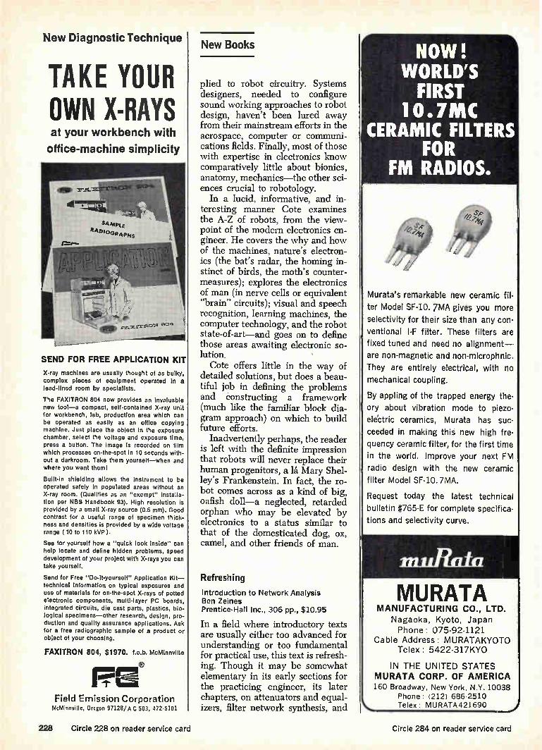
New Diagnostic Technique
TAKE YOUR OWN X-RAYS at your workbench with
office-machine simplicity
SEND FOR FREE APPLICATION KIT X-ray machines are usually thought of as bulky, complex pieces of equipment operated In a lead-lined room by specialists.
The FAXITRON 804 now provides an invaluable new tool—a compact, self-contained X-ray unit for workbench, lab, production area which can be operated as easily as an office copying machine. Just place the object in the exposure chamber, select the voltage and exposure time, press a button. The image is recorded on film which processes on-the-spot in 10 seconds with-out a darkroom. Take them yourself—when and where you want theml
Built-in shielding allows the instrument to be operated safely in populated areas without an X-ray room. (Qualifies as an "exempt" Installa-tion per NBS Handbook 93). High resolution is provided by a small X-ray source (0.5 mm). Good contrast for a useful range of specimen thick-ness and densities is provided by a wide voltage range ( 10 to 110 kVP ).
See for yourself how a "quick look inside" can help locate and define hidden problems, speed development of your project with X-rays you can take yourself.
Send for Free "Do-it-yourself" Application Kit— technical Information on typical exposures and use of materials for on-the-spot X-rays of potted electronic components, multi-layer PC boards, integrated circuits, die cast parts, plastics, bio-logical specimens—other research, design, pro-duction and quality assurance applications. Ask for a free radiographic sample of a product or object of your choosing.
FAXITRON 804, $1970. f.o.b. McMinnville
FE Field Emission Corporation
McMinnville, Oregon 97128/A C 503, 472-5101
New Books
plied to robot circuitry. Systems designers, needed to configure sound working approaches to robot design, haven't been lured away from their mainstream efforts in the aerospace, computer or communi-cations fields. Finally, most of those with expertise in electronics know comparatively little about bionics, anatomy, mechanics—the other sci-ences crucial to robotology.
In a lucid, informative, and in-teresting manner Cote examines the A-Z of robots, from the view-point of the modern electronics en-gineer. He covers the why and how of the machines, nature's electron-ics (the bat's radar, the homing in-stinct of birds, the moth's counter-measures); explores the electronics of man (in nerve cells or equivalent "brain" circuits); visual and speech recognition, learning machines, the computer technology, and the robot state-of-art—and goes on to define those areas awaiting electronic so-lution. Cote offers little in the way of
detailed solutions, but does a beau-tiful job in defining the problems and constructing a framework (much like the familiar block dia-gram approach) on which to build future efforts.
Inadvertently perhaps, the reader is left with the definite impression that robots will never replace their human progenitors, a lá Mary Shel-ley's Frankenstein. In fact, the ro-bot comes across as a kind of big, oafish doll—a neglected, retarded orphan who may be elevated by electronics to a status similar to that of the domesticated dog, ox, camel, and other friends of man.
Refreshing
Introduction to Network Analysis Ben Zeines Prentice-Hall Inc., 306 pp., $10.95
In a field where introductory texts are usually either too advanced for understanding or too fundamental for practical use, this text is refresh-ing. Though it may be somewhat elementary in its early sections for the practicing engineer, its later chapters, on attenuators and equal-izers, filter network synthesis, and
NOW! WORLD'S FIRST
10.7MC CERAMIC FILTERS
FOR FM RADIOS.
Murata's remarkable new ceramic fil-ter Model SF-10. 7MA gives you more selectivity for their size than any con-ventional I-F filter. These filters are fixed tuned and need no alignment— are non-magnetic and non-microphnic. They are entirely electrical, with no mechanical coupling.
By appling of the trapped energy the-ory about vibration mode to pieza-electric ceramics, Murata has suc-ceeded in making this new high fre-quency ceramic filter, for the first time in the world. Improve your next FM radio design with the new ceramic filter Model SF-10.7MA.
Request today the latest technical bulletin #765-E for complete specifica-tions and selectivity curve.
in ill:tau
MURATA MANUFACTURING CO., LTD.
Nagaoka, Kyoto, Japan Phone: 075-92-1121
Cable Address: MURATAKYOTO Telex: 5422-317KYO
IN THE UNITED STATES MURATA CORP. OF AMERICA 160 Broadway, New York, N.Y. 10038
Phone: (212) 686-2510 Telex. MURATA421690
228 Circle 228 on reader service card Circle 284 on reader service card

PEARL HARBOR NAVAL SHIPYARD needs
Electronic, Electrical, Marine, Mechanical, General, Nuclear Power
Engineers and Naval Architects
STARTING SALARIES: $7,345 to $13,001 depending on experience
Salaries include 15% cost-of-living allowance, which is subject to change.
El Opportunities for professional growth, advancement. D Pleasant living for you and your family. D Pearl Harbor Naval Shipyard, the largest indus-trial organization in the Pacific, plays a vital role in today's nuclear Navy. The activities of the Yard create a broad range of assignments for engineers and naval architects.
Transportation to Hawaii and back provided for employees and their dependents. Household effects will be shipped at government expense. Transporta-tion for home leave provided if employment agree-ment is renewed after three years.
These are career Civil Service positions with regular salary increases, generous benefits, liberal retire-ment plan, and will be filled on an Equal Oppor-tunity basis. Send resume of professional experience or Standard Form 57 to:
PEARL HARBOR NAVAL SHIPYARD (CODE 170)
BOX 400, FPO SAN FRANCISCO 96610
RECORDER
THE MOST ACCURATE and SIMPLEST WAY:
UNKNOWN DIGITAL
PHASE METER TYPE S24A3
Read phase angle in 4-digits and automatically plot phase curve vs. frequency from 10 Hz to 500 KHz.
DIGITAL PHASE METER Type 524A3 Phase angle in degrees directly represented in four dig-its. No amplitude adjustment. No frequency adjustment. Analog output available for external recorder or pro-grammable systems. Accuracy ±0.03 °. Phase response from 5 Hz to 500 KHz.
Write for free technical
bulletin— "DIGITAL PHASE MEASUREMENT".
NUM MUSE •...,
11.•Y EMMONS, le
WORLD FAMOUS IN PHASE-TIME MEASUREMENT
ELECTRONICS, INC. 249 TERHUNE AVE., PASSAIC, N. J.
PHONE: (20E) 472.5622 CARLE: ADYU PASSAIC
Circle 301 on reader service card Circle 229 on reader service card 229

New Books Catch 1 ps
voltage peaks.
To pinpoint transients foul-ing up your cir-cuits, or to monitor peaks in testing and research.
With PEAK LOK. It measures positive, negative or bipolar peaks
with 1% full scale accuracy, holds
its reading in an analog state until
it's reset. Use it to measure phys-
ical parameters in environmental
tests, record surges in power lines and supplies, detect overload tran-
sients in electronic and electrical
systems . . . everywhere precise determination of voltage peaks
can help solve a problem. It has
an output for data logging, can be
remotely reset, has nine ranges
from 0.1 to 1000v full scale, and
can go up to 30 kv with a high
voltage probe. When you're not catching transients, use PEAK
LOK as a sensitive DC voltmeter,
to measure that hard to get to voltage with a quick touch of the
probe.
For complete specifications write to PEAK LOK Sales, Dept. 228, Analog-Digital Systems Division, Control Data Corporation. 4455 Eastgate Mall, La Jolla, California 92037. Or phone 714/453-2500.
CONTROL DATA CORPORATION
4455 Eastgate Mall. La Jolla. Calif.
tuned voltage amplifiers, could be of great help to many engineers who are occasionally called upon to design such circuits. The author's strong suit is his
ability to demonstrate theoretical concepts with concrete, practical problems. Thus, the early chapters, which deal with such topics as net-work theorems, Laplace transforms, and pole-zero techniques for analy-sis of resonant and coupled circuits, are definitely worth reading for many engineers. Though they would find no additions to the basic body of knowledge they studied as undergraduates, they should gain in understanding more clearly con-cepts which may have become blur-red through lack of use.
Attenuators and equalizer design are covered in detail with a set of tables summarizing the nehvork types and their respective design equations.
There is a good description of fil-ter network synthesis, particularly Chebyshev filter design, which is much clearer than explanations found in many other books which presume to instruct on such sub-jects. The final chapter, on tuned volt-
age amplifiers, also includes ex-amples of transistor circuits, trans-former coupling, and stagger-tuned circuits on a highly practical level, seldom found in such texts.
Dishing it out
Microwave Communications Diogenes J. Angelakos and Thomas E. Everhart McGraw-Hill Series in Electrical and Electronic Engineering McGraw-Hill Publishing Co., Inc. 248 pp., $11.50
Here at last is a book that truly communicates microwave tech-nology. It is one of the few works that presents an interrelated, sys-tematic view of the subject. Many previous texts suffered
from two major faults: the numer-ous elements of microwave systems were treated as isolated topics, leaving it to the reader to pull the pieces together; the physics of microwave theory were cluttered with lengthy derivations and com-plex equations not reduced to forms
2009
Meet the Marcon
C PACK (Thick-Film IC)
An Audio Amplifier Circuit, the Marcon Model D-2009 is a thick-film integrated circuit incorporating silicon planar tran-sistors. To obtain the gain and frequency characteristics you desire, just place a suitable external network between out-put and NFB terminals. Solid, flat and packed, this circuit exhibits excellent performance and durability.
Ideal for digital and analog circuits. Of-fers greater applicability because it can be hybridized with semi-conductor IC's.
The Marcon MC PACK standard pro-ducts include :
Audio amplifier D-2009 (9V to 12V, Tone control amplifier D-2011
(12V to 18V; Flip-Flop circuit D-3044
(12V and 4.3V 10Mci Flip-Flop circuit D-3046
(12V and-6V, 100Kc Schmitt trigger circuit D-3060
(12V, 500Kc, Flip-Flop circuit D-3100 112V, 1Mc) Flip-Flop circuit D-3101 (6V, 1Mc)
Tokyo Denki will MC-PACK other digital and analog circuits to meet your special requirements. For detailed information, write today.
TOKYO DENKI CO., LTD. 3-13, 5-chome, Minamishinagawa,
Shinagawa-ku, Tokyo, Japan Cable Address: ELECTROMARCON TOKYO
230 Circle 230 on reader service card Circle 285 on reader service card

NEW from Cramer
ADJUST-A-LOK STOOLS Adjust to every worker like fine tools!
Cramer Adjust-A-Lok is immediately adjustable to any workers height. Just release the safety stop, and lift or lower. It can be done just that quick. Since fatigue is a critical factor in efficiency of seated workers, it's just good economics to provide tools that minimize fatigue. With Adjust-A-Lok every worker can find his own most comfortable and efficient level. 6 seat styles and 5 base types provide 30 available models. For more information: write V. P. Sales, Cramer In-dustries, Inc., 625 Adams, Kansas City, Kansas 66105.
Industrial supplier inquiries invited
CRAMER CRAMER INDUSTRIES INC • KANSAS CITY, KANSAS
A Subsicherv oT U S M 0,1 Co
Cramer—The leader in style and quality. Circle 286 on reader service card
NYLO
CONNECTORS Up to 15 circuit capacity with these low-cost, miniature nylon connectors! Contacts automatically crimped to leads, then securely snap-lock into the housings. Positive polarity prevents misconnec-tions and integral mounting ears provide easy panel installation.
Write for complete specifications and samples on any of these connectors.
MOLEX® PRODUCTS COMPANY 5241 Katrine Avenue Downers Grove, Illinois 60515 (312) 969-4550 TWX 910- 695-3533
ORE POWER 7\j TO YOU!
06 /
CAStrO ."0
we nowt
eet
“).‘ REEDAC
PAT meb
SYNCHRO-REEDAC froGRIGSBV 1BARTON
The First Fully Solid State Power Relay To Offer The Benefits
of Synchronous Switching.
Incorporating virtually infinite life and the environ-mental characteristics of the famous Grigsby-Barton REEDAC, the Class II SYNCHRO REEDAC* now opens new horizons. The Class Il SYNCHRO REEDAC* is a second generation, fully solid state, heavy-duty power relay engineered for switch-on at 4 volts or less ... and switch-off at current zero. The result: No strain . .. no R.F.I. problems . . . no "dirty switching". . . no complex filtering necessary for switching up to 15 amp loads at 115 or 240 Volts AC. Compact size ... available in standard solder type case or octal plug in can.
DESIGNERS AND PRODUCERS OF: REED RELAYS • LOGIC CARDS • SWITCHING SYSTEMS A.0
INPUT
Orr' LINE
0-C INPUT SIGNAL .,
LOAD VOLTAGE SO ViCAI
LOAD VOLTAGE OS v/cm
Ov 7 w
\./
*Patent Pending
MAXIMUM RATINGS
Applied Voltage-400 volts, peak. Load current—up to 15 AMPS, RMS. Operating Temperature —0 to 70°C. Storage Temperature-40°C to +100°C.
GRIGSBY-BARTON, INC. 107 NORTH HICKORY STREET ARLINGTON HEIGHTS, ILL. 60006 PHONE AREA 312 / 392-5900
Circle 287 on reader service card Circle 231 on reader service card 231
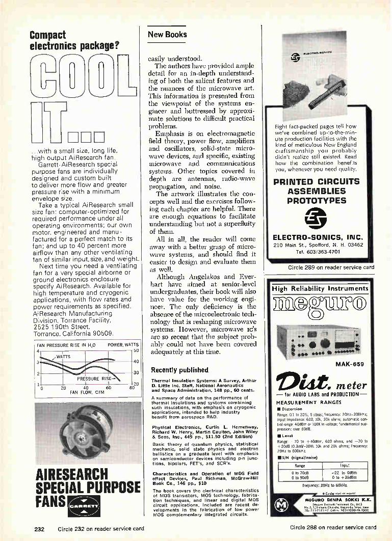
Compact electronics package?
7 ...with a small size, long life, high output AiResearch fan.
Garrett-AiResearch special purpose fans are individually designed and custom built to deliver more flow and greater pressure rise with a minimum envelope size. Take a typical AiResearch small
size fan: computer-optimized for required performance under all operating environments; our own motor, engineered and manu-factured for a perfect match to its fan; and up to 40 percent more airflow than any other ventilating fan of similar input, size, and weight.
Next time you need a ventilating fan for a very special airborne or ground electronics enclosure specify AiResearch. Available for high temperature and cryogenic applications, with flow rates and power requirements as specified. AiResearch Manufacturing Division, Torrance Facility, 2525 190th Street, Torrance, California 90509.
FAN 4
PRESSURE RISE IN F120 POWER, WATTS 50
/ WATTS 40
30
PRESSURE RISE 20
20 40 60 80 FAN FLOW, CFM
AIRESEARCH SPECIAL PURPOSE FANS •kor
(GIRtIlit .E)111r Albs.
New Books
easily understood. The authors have provided ample
detail for an in-depth understand-ing of both the salient features and the nuances of the microwave art. This information is presented from the viewpoint of the systems en-gineer and buttressed by approxi-mate solutions to difficult practical problems. Emphasis is on electromagnetic
field theory, power flow, amplifiers and oscillators, solid-state micro-wave devices, and specific, existing microwave and communications systems. Other topics covered in depth are antennas, radio-wave propagation, and noise. The artwork illustrates the con-
cepts well and the exercises follow-ing each chapter are helpful. There are enough equations to facilitate understanding but not a superfluity of them.
All in all, the reader will come away with a better grasp of micro-wave systems, and should find it easier to design and evaluate them as well. Although Angelakos and Ever-
hart have aimed at senior-level undergraduates, their book will also have value for the working engi-neer. The only deficiency is the absence of the microelectronic tech-nology that is reshaping microwave systems. However, microwave lc's are so recent that the subject prob-ably could not have been covered adequately at this time.
Recently published
Thermal Insulation Systems: A Survey, Arthur D. Little Inc. Staff, National Aeronautics and Space Administration, 148 pp., 60 cents.
A summary of data on the performance of thermal insulations and systems combining such insulations, with emphasis on cryogenic applications, intended to help industry benefit from aerospace R&D.
Physical Electronics, Curtis L. Hemenway, Richard W. Henry, Martin Caulton, John Wiley & Sons, Inc., 449 pp., $11.50 (2nd Edition)
Basic theory of quantum physics, statistical mechanic, solid state physics and electron ballistics on a graduate level with emphasis on semiconductor devices including p-n junc-tions, bipolars, FET's, and SCR's.
Characteristics and Operation of MOS Field effact Devices, Paul Richman, McGraw-Hill Book Co., 146 pp., $10
The book covers the electrical characteristics of MOS transistors, MOS technology, fabrica-tion techniques, and linear and digital MOS circuit applications. Included are recent de-velopments in the fabrication of low power MOS complementary integrated circuits.
Eight fact-packed pages tell how we've combined up-to-the-min-ute production facilities with the kind of meticulous New England craftsmanship you probably didn't realize still existed. Read how the combination benefits you, whenever you need quality.
PRINTED CIRCUITS ASSEMBLIES PROTOTYPES
ELECTRO-SONICS, INC. 210 Main St., Spofford, N. H. 03462
Tel. 603 363-4701
Circle 289 on reader service card
High Reliability Instruments
BEU,CFUEM
" • Mr fee,e ewe. 4Ib **AAA**
MAK- 659
Dide mete r — for AUDIO LABS and PRODUCTION--
MEASUREMENT RANGES
II Distortion Range: 0.1 to 30%, 5 steps:. frequency: 20Hz-200kHz; r-iput impedance: 600, 10k, 20k ohms; automatic con-trol range: 40dBm or 100X in voltage; fundamental sup-pression: over 60dB.
Rilliangeev:e-1 70 to +40dBm, 600 ohms, and -70 to 20dB (0.3mV-10V), 10k and 20k ohms; frequenc.,
20Hz to 600kHz.
1115/N (signal/noise)
Range Input
0 to 70dB -22 to OdBm 0 to 90dB 0 to +38dBm
frequency: 20Hz to 60kHz.
^ • . MEGURO DENPA SOKKI K.K.
No. 5, CC,. ;'.r1.2. 1,:the"rgre.C..,"Tekca.1,12,r_n TEL, / 1 e •7 1 9 1 Coble.; MEGUROoENPA Imo
232 Circle 232 on reader service card Circle 288 on reader service card

These new heat-shrinkables devour vinyl spec by spec.
Yet cost no more. That's because new Insultite® CP-I 50 and Insultite SRT arc polyolefins. Heat-shrinkable, irradiated polyolefins that provide protection at a polyvinyl price. New CP-I 50 insulates and encapsulates any subject. And is particularly ideal for commercial, automotive, appliance, and computer applications. From 3/54" to 2" I.D. In black. As for new SRT? This clear, tough, thin-wall polyolefin is perfect for components subject to shock and strain and where visual identification is important. From 3/4 6" to 2" I.D. Write for free samples today. (Specify diameters, please.)
ELECTRONIZED CHEMICALS CORPORATION A subsidiary of High Voltage Engineering Corporation Burlington, Mass. 01803. Area Code 617-272.2850
E.C.C. heat shrinkables are recognized under UI component file E39100.
Circle 290 on reader service card
8of a series
TRANSICOIL SOLVES SERVO PROBLEMS
INPUT
SERVO ANIFtIFIER MOTOR GEAR TRAIN CT
GENERATOR
New Transicoil position servo assembly shown without cover
Weston-Transicoil built this position servo assembly for an Increased Maneuverability Kit used on the BMQ-34A Firebee target drone. Designed with provision for hermetic sealing, it provides accurate and constant error voltages per degree of bank angle, guaranteeing precision control of the Firebee during high g maneuvers. Synchro output closely follows analog voltage input with the 10-turn potentiometer connected by precision gearing to a size 10 motor generator driven by a standard size 11 amplifier. Typical of Transicoil engineered servo packages, all components in the position servo are supplied by Weston and the entire assembly is designed for plug-in installation.
PERFORMANCE: Feedback Potentiometer: 1K 10-turn size 5 • Output: Size 8 control transformer • Slew Speed: 1 Rad/sec • Accuracy: 1° (over range of —90° to +90° at synchro) • Power Required: 26V, 400 CPS; 28V DC • Size: 21/2" dia. x 314" length.
Weston Instruments, Inc., Weston-Transicoil Division, Worcester, Pa. 19490, a Schlumberger company
WESTON Electronics December 11, 1967
prime source for precision., since 1888
Circle 233 on reader service card 233

Technical Abstracts
Skin deep
Full-color and three-dimensional radiograph displays Wilfred Roth Dept. of Electrical Engineering and Dept. of Radiology University of Vermont, Burlington
An X-ray photograph (radiograph) contains a wealth of permanently stored information, probably more than can be interpreted even by the skilled observer. Two new types of electronic displays can en-hance subtleties that would nor-mally go undetected. Both relate to the radiographic gray scale, a measure of the depth below the skin's surface or the thickness of an object. The first display converts to full
color the radiographic gray scale; the second display converts the gray scale to the third dimension in an isometric view, which appears almost three-dimensional rather than planar.
Both displays are generated from a television camera focused on a conventional radiograph. In the color conversion system, electronic circuits sort the information in the video signals into three channels corresponding to the density of the respective elements of the radio-graph. High-density elements are assigned to a blue channel, me-dium-density elements to a red channel, and low-density elements to a green channel. The outputs of the three channels control the blue, red, and green electron guns of a conventional tv color picture tube. The final display is a full-color con-version of the original black-and-white radio-graph in which density is converted to hue. For the isometric display, the
output of the tv camera vertically deflects an electron beam pro-ducing an x-y scanning raster on a monochrome cathode-ray tube in synchronism with the scanning
beam of the tv camera. The hori-zontal scan lines of the raster are deflected vertically by an amount depending on the density of the radiograph at each scanned posi-tion, since height in the isometric view corresponds to depth.
Both systems have the advantage that an electronic light measure-ment can be performed on an ab-solute basis, whereas the human eye is sensitive primarily to rela-tive light levels, not to a gradual change in light levels. If the radio-graphic density varies slowly across an area, the eye will detect it only if the gradient exceeds a certain threshold, depending upon the particular observer and the absolute light level. An electronic detector can judge the density of a particular picture element without being influenced by adjacent ele-ments. The techniques are equally ap-
plicable to the presentation of data from fluoroscope screens, radio-isotope scans, electron micro-graphs, and similar sources of stored information. The technique
1/Formica know-
Case #1695-Problem: 4 different copper clad grades were purchased and inventoried, cre-ating multiple paper work, record-keeping. Idea activated: One FORMICA. FR-45 laminate, created to meet NEMA C-10, C-11, FR-4, FR-5.
Case #6520-A-Problem: Pad slippage causing poor registration in production of multi-layer circuitry boards. Idea activated: FORMICA® laminate MLC system created a sandwich with better copper bond strength and registration control at elevated temperatures.
Electronics December 11, 1967 234
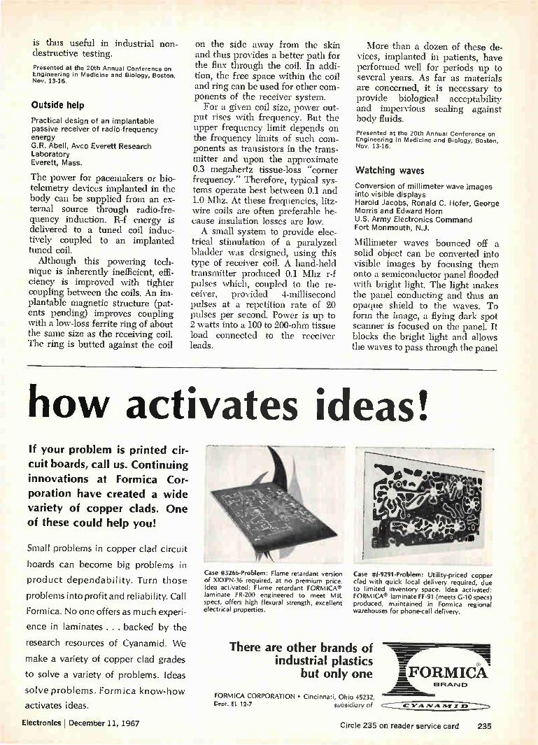
is thus useful in industrial non-destructive testing.
Presented at the 20th Annual Conference on Engineering in Medicine and Biology, Boston, Nov. 13-16.
Outside help
Practical design of an implantable passive receiver of radio-frequency energy G.R. Abell, Avco Everett Research Laboratory Everett, Mass.
The power for pacemakers or bio-telemetry devices implanted in the body can be supplied from an ex-ternal source through radio-fre-quency induction. R-f energy is delivered to a tuned coil induc-tively coupled to an implanted tuned coil. Although this powering tech-
nique is inherently inefficient, effi-ciency is improved with tighter coupling between the coils. An im-plantable magnetic structure (pat-ents pending) improves coupling with a low-loss ferrite ring of about the same size as the receiving coil. The ring is butted against the coil
on the side away from the skin and thus provides a better path for the flux through the coil. In addi-tion, the free space within the coil and ring can be used for other com-ponents of the receiver system. For a given coil size, power out-
put rises with frequency. But the upper frequency limit depends on the frequency limits of such com-ponents as transistors in the trans-mitter and upon the approximate 0.3 megahertz tissue-loss "corner frequency." Therefore, typical sys-tems operate best between 0.1 and 1.0 Mhz. At these frequencies, litz-wire coils are often preferable be-cause insulation losses are low. A small system to provide elec-
trical stimulation of a paralyzed bladder was designed, using this type of receiver coil. A hand-held transmitter produced 0.1 Mhz r-f pulses which, coupled to the re-ceiver, provided 4-millisecond pulses at a repetition rate of 20 pulses per second. Power is up to 2 watts into a 100 to 200-ohm tissue load connected to the receiver leads.
More than a dozen of these de-vices, implanted in patients, have performed well for periods up to several years. As far as materials are concerned, it is necessary to provide biological acceptability and impervious sealing against body fluids.
Presented at the 20th Annual Conference on Engineering in Medicine and Biology, Boston, Nov. 13-16.
Watching waves
Conversion of millimeter wave images into visible displays Harold Jacobs, Ronald C. Hofer, George Morris and Edward Horn U.S. Army Electronics Command Fort Monmouth, N.J.
Millimeter waves bounced off a solid object can be converted into visible images by focusing them onto a semiconductor panel flooded with bright light. The light makes the panel conducting and thus an opaque shield to the waves. To form the image, a flying dark spot scanner is focused on the panel. It blocks the bright light and allows the waves to pass through the panel
how activates ideas! If your problem is printed cir-
cuit boards, call us. Continuing innovations at Formica Cor-poration have created a wide
variety of copper clads. One of these could help you!
Small problems in copper clad circuit
boards can become big problems in
product dependability. Turn those
problems into profit and reliability. Call
Formica. No one offers as much experi-
ence in laminates .. . backed by the
research resources of Cyanamid. We
make a variety of copper clad grades
to solve a variety of problems. Ideas
solve problems. Formica know-how
activates ideas.
Electronicsl December 11, 1967
Case #5266-Problem: Flame retardant version of XXXPN-36 required, at no premium price. Idea activated: Flame retardant FORMICA® laminate FR-200 engineered to meet MIL specs, offers high flexural strength, excellent electrical properties.
Case #1-9291-Problem: Utility-priced copper clad with quick local delivery required, due to limited inventory space. Idea activated: FORMICA® laminate FF-91 (meets G-10 specs) produced, maintained in Formica regional warehouses for phone-call delivery.
There are other brands of industrial plastics
but only one
"'Maim '•••••••• ••//d. MIMP 1M .M11, g ffll, 'MOW
Z-FORMICA Mfflik
1E3 Ft ixr•u--3
FORMICA CORPORATION • Cincinnati, Ohio 45232, Cept. EL 12-7 subsidiary of c- DP
Circle 235 on reader service card 235

$1,000,000 INVENTORY
OF ELECTRONIC TEST EOUIPIPT
Name brand test equipment fully calibrated with certifi-cate of traceability if desired. Maintenance provided and all equipment is insured against fire, theft and damage in ship-ment. 0 Short term rentals our specialty but yearly rental available. Fast delivery. Wide variety and depth. D If you need equipment NOW, call Jim Powers or Frank Cassidy at (301) 424-2333. If you want a copy of our rental list or more information write:
RENTAL ELECTRONICS, INC. 16203 FREDERICK ROAD ROCKVILLE, MARYLAND 20850
Technical Abstracts
whenever they occur at the same place as the dark spot.
If the flying spot is synchronized with the trace on a cathode ray tube, the position of the electron beam in the tube corresponds to the dark spot position on the panel. The beam intensity, in turn, is con-trolled by the wave signal transmit-ted by the panel. The visible dis-play on the CRT then represents the radiation pattern produced by the waves on the semiconductor panel.
In an experimental 70-gigahertz system, the panel consisted of ger-manium of 40-ohm-centimeter re-sistivity, cut, polished and etched to a square 1.5 centimeters on a side and 3.21 millimeters thick. Overall, the panel was 9 cm square. A lucite sheet was used to sup-
port the germanium blocks. Behind the sheet was a large horn antenna to pick up the transmitted milli-meter waves, applying them to a detector diode. The output of the diode, which corresponds to the image, controlled the intensity of the CRT beam. A conventional slide projector off
to one side flooded the panel with light. A rotating lucite wheel, con-taining opaque metal spots in a helical pattern, was put in front of the projector. This device causes the dark spots to scan across the light-sensitive germanium panel.
Presented at Nerem, Boston, Nov. 1-3.
Biological design
A structural preconscious Piaget: heed without habit Avery R. Johnson Massachusetts Institute of Technology, Cambridge
To provide the best data for a sub-sequent manned mission, the sens-ing and control systems of an un-manned vehicle landing on another planet should emulate biological sensing and control systems. If this could be done perfectly, the men on the first manned mission would have nearly as much useful data to draw on as those on the second manned mission. [The Piaget of the title is J. Piaget, French psychol-ogist famed for his studies of learn-ing and behavior in children.] Most sensing and control sys-
FASTENERS FROM DIE CAST
ZINC ALLOY
Wing Nuts re'A.
Cap Nuts
Thumb Nuts
1-\\ Thumb &
Wing Screws
MOLDED NYLON & DELRIN
,Vcrews
Hex Nuts
Washers
Screw Insulators
Big help for your tiny assemblies!
MINIATURE molded
NYLON SCREWS
ie Now as small as #00
GRC Small & miniature screws simplify designs—at lower cost. • Sizes #00, #0, #1, #2, #3 and .#4.
• Many head types, lengths. Set screws, too.
• Flash-free, precise and uniform. • Corrosion-resistant, vibration -
proof, electrical insulating with high strength to weight.
Ask for sample kit prices . . data about other GRC Plastic Fasteners— screws, nuts, washers, etc.
GRIES REPRODUCER CO. flirtation of Coats & Clark lye.
151 Beachwood Ave, New Rochelle, N.Y. 10802 (914) 633-8600
World's Foremost Producers of Small Die Castings and Plastic Moldings
Circle 291 on reader service card
DIFFERENTIAL TRANSFORME S For measurement and remote control use
Capable of obtaining output voltages exactly proportional to any kind of mechanical variation. Measuring value:1/100,000-100mm More than 500 types are available.
Features: *Outstanding interchangeability
*Quite free from outer magnetic
field *Insensitive to ordinary shock,
water and heat
'du mum man wmmum mummu Ram« mum mum' mum min» inum mmwmul mumm immimummomm mommumumm mummummum ammumiaz
Manufacturers of Differential Transformers
NIPPON COIL CO., LTD. Amakawa Bldg. 1, 1-chome, Hommachl, Higashi-ku, Osaka, Japan
236 Circle 236 on reader service card Circle 292 on reader service card
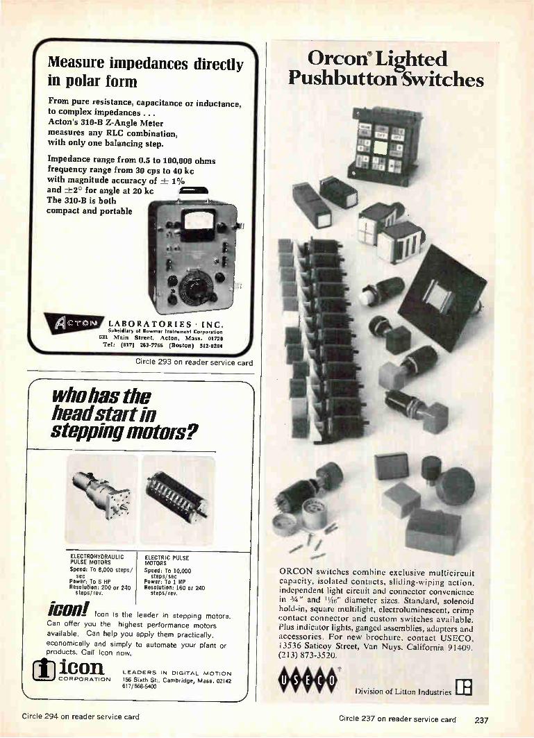
e Measure impedances directly in polar form From pure resistance, capacitance or inductance, to complex impedances ...
Acton's 310-B Z-Angle Meter measures any RLC combination, with only one balancing step.
Impedance range from 0.5 to 100,000 ohms frequency range from 30 cps to 40 kc with magnitude accuracy of 1_1-_ 1% and -±-2° for angle at 20 kc Ii=11
The 310-B is both
compact and portable
LABORATORIES • INC. Subsidiary of Bowman. Instrument Corporation
531 Main Street, Acton, Mass. 01720 Tel: (617) 263-7756 (Boston) 542-0284
Circle 293 on reader service card
who has the head stair in stopping motors?
ELECTROHYDRAULIC PULSE MOTORS Speed: To 8,000 steps/
sec Power: To 6 HP Resolution: 200 or 240
steps 'rev.
¡OWL Icon is the leader in stepping motors. Can offer you the highest performance motors available. Can help you apply them practically,
economically and simply to automate your plant or products. Call Icon now.
ELECTRIC PULSE MOTORS Speed: TO 10,000
steps/ sec Power: To 1 HP Resolution: 160 or 240
steps! rev.
[1] ic on LEADERS IN DIGITAL MOTION
CORPORATION 156 Sixth St:, Cambridge, Mass. 02142 617/868-5400
Orcon Lighted Pushbutton 'Switches
ORCON switches combine exclusive multicircuit capacity, isolated contacts, sliding-wiping action, independent light circuit and connector convenience in 3/4 " and ",..if;" diameter sizes. Standard, solenoid hold-in, square multilight, electroluminescent, crimp contact connector and custom switches available. Plus indicator lights, ganged assemblies, adapters and accessories. For new brochure, contact USECO, 13536 Saticoy Street, Van Nuys, California 91409. (213) 873-3520.
Division of Litton Industries [1]
Circle 294 on reader service card Circle 237 on reader service card 237

Technical Abstracts
Measure Film Thickness ... accurately and conveniently... INTERFERENCE MICROSCOPE
measures the thickness of thin film layers, coatings, platings, etc. successfully used in.. Semi-conductor metallurgy Semi-conductor device engineering Computor research Capacitor manufacture Quartz Crystal manufacture Precision engineering Paint laboratories Printing, ceramics, canning industry, etc. More effective, convenient and economical than much more expensive systems.
-1Iacer INSTRUMENTS
WILLIAM J. HACKER & CO., INC.
box 646, W. Caldwell, N. J. 07006 phone (201) 226-8450 Circle 295 on reader service card
Specifically Engineered for RF COMPONENTS
1111 A-27 Superfine
ax EXTREMELY LOW-LOSS
RF LACQUER
g-max A-27
RADIO FREQUENCY LACQUER
CI-MAK CORPORATION
Q-MAX impregnating and coating composition penetrates deeply, seals out moisture, provides a surface finish. Q-MAX imparts ri-gidity and promotes stability of the electrical constants of high fre• quency circuits. Effect on the "Q" of RF windings is negligible.
Write for catalog today.
Q-max Corporation MARLBORO, NEW JERSEY
Telephone: 462-3636 (Area Code 201)
Reed Relay Problems? A special AND logic relay in the new "UF" configuration.
Can We Solve your Problem? Operating Inputs: low as lmA. and 15mW. Standard Coil Voltages: 6, 12, 24, 32, 48V in stock
for immediate delivery. Special Voltage or Resistance, multiple windings for
flip flop, memory and crosspoint selection appli-cations — to customer specifications.
Relay Contacts in Form A, 8, C and latching. Also high vacuum type 5000V Form A.
Write for catalog and prices of our standard line of magnetic reed relays. For special requirements,
give complete details for quotation.
Coto-Coil COMPANY INC.
61 Pavilion Ave. Providence, R. I. 02905 Phone: (401) 941-3355
tems designed up to now have failed to exploit man's knowledge of biological systems. In today's operating system, the sensor is a pattern-recognition device that identifies objects placed in front of it. The control portion of the sys-tem reacts to the output of the pattern recognizer. Steps are se-quential whereas in biological sys-tems they are simultaneous and inseparable. The controller output, in general, modulates the input to the pattern recognizer to increase the system's knowledge of its sur-roundings; the pattern-recognizer-controller system therefore is closed-loop, each part affecting the operation of the other. A rudimentary visual system can
be built that can recognize certain simple patterns and simultaneously react to them, altering them if nec-essary to improve its own rate of success. The system would consist of two arrays of photodetectors, two lenses, two mirrors, and elec-tronic circuits that would react to the photodetector outputs, adjust the focusing with the lenses and mirrors, and drive motors and other mechanical devices to respond to what it sees. The photodetector arrays would
be more densely concentrated at their center than around the edges, to permit the system to "look" straight at anything interesting. Measurement of the array out-
puts would be through a bridge cir-cuit that gives an output only when unequal amounts of light fall on corresponding cells in the two ar-rays. The controller would react so as to minimize the difference in outputs of all the pairs of cells in the arrays, to maximize the differ-ences between two such pairs, and to minimize the rate of change of cell pair outputs. These reactions would respectively insure that the images on both arrays were as nearly alike as possible; that the system's attention was concen-trated on high-contrast boundaries, permitting it to "find" an object, and that, in the presence of an ob-ject of interest, the system did not continue to scan randomly as long as that object was present. Presented at the National Electronics Confer-ence, Chicago, Oct. 23-25.
238 Circle 238 on reader service card Circle 296 on reader service card Electronics I December 11, 1967

esporseelrlifri
* dcamirpreeiresticess
BOBBINS
IgeoUlhei
= 101%
41..1114 nee
ee RADIO — Moldcrafters of trans-former bobbins oscilla-tor I.F. and R.F. coil forms and stereo tape cartridges.
TELEVISION — Producers of color yoke insulators, terminal boards, housing and convergence coil bob-bins.
SEND FOR OUR
NEW CATALOG TODAY!
G 41r)›-
oa7 c. : 1:1:1 „,
SrOtw
„Jell bobbin
COMPUTER AND TELEPHONE — Wide selection magnetic tape reels and containers, cartridges, disc packs, reed relay bobbins for computers, audio reels for tape recorders and players, bobbins for switching circuits and reed relays for telephone.
Complete line of patented Lead Slot bobbins.
AMERLINE CORPORATION 1800 FULLERTON AVENUE
CHICAGO, ILLINOIS 60614
(312) 348-4300 - TWX: 312-222-9410 Circle 297 on reader service card
your POSTMASTER _nueefi`g
SHOPe»/MAIL EARLY "MAIL PARCELS > FOR OUT OF TOWN DELIVERY NO LATER THAN DECEMBER 511.
> FOR LOCAL DELIVERY NO LATER THAN DECEMBER 1411,
GREETING CARDS' >TOTtUlTOe TOWN DELIVERY BY DECEMBER 10tE
>FOR LOCAL DELIVERY BY DECEMBER I5N,
USE
WRAP Pieeele ZIP CODE NUMBERS J'EellifELY IN ALL ADDRESSES
Saving a few pennies in the initial cost of a
capacitor is a fine idea. But, suppose the toler-
ance specifications are so rigid that you may have
to buy ten for every one you can actually use. Not
very economical! This is where WESCO fills the
need for top quality capacitors that can be
ordered in any quantity with close tolerances to
+0.1%. They may cost a few pennies more, but think of the dollars saved by eliminating bulging
inventories.
Call or write for complete pricing information.
( We're talking .1 pennies...
WESCO ELECTRICAL COMPANY, Inc. 27 OLIVE STREET / GREENFIELD, MASSACHUSETTS 01301
POSTmASTER
Electronics December 11, 1967 Circle 239 on reader service card 239

New Literature
Timers and counters. Eagle Signal Divi-sion, E.W. Bliss Co., 736 Federal St., Davenport, Iowa 52808. Sixteen-page catalog No. 15 covers a variety of in-dustrial and commercial timers and counters. Circle 446 on reader service card.
Beacon magnetron. Microwave Asso-ciates Inc., Burlington, Mass. 01803, offers technical bulletin 1523 describ-ing the compact model MA-250, a 4-kw, X-band beacon magnetron. [447]
Interconnection products. AMP Inc., Harrisburg, Pa. 17105. A 10-page cata-log describes an expanded line of Ampmodu modular interconnection products for printed circuitry. [448]
Digital measuring system. Electronic Associates Inc., West Long Branch, N.J. 07764. Bulletin 67251 on the series 6200 digital measuring system, a modular system, featuring plug-in versatility, is now available. [449]
High-fidelity relays. General Electric Co., Schenectady, N.Y. 12305. Bulletin GEA-7382C provides engineering data, ordering information, and outline draw-ings for the CR120 type K, a high fidel-ity, 300-v relay. [450]
Photoresist products. Shipley Co., 2300 Washington St., Newton, Mass. 02162. Data sheet S-111/9 describes two adaptable photoresists (AZ-111 and AZ-119) for low-cost processing of printed circuits. [451]
Microwave materials. Harshaw Chemi-cal Co., 1945 E. 97th St., Cleveland, Ohio 44106, offers data sheets featur-ing magnetic saturation versus tem-perature curves for single crystals and polycrystalline microwave materials. [452]
Materials for semiconductors. Transene Co., Route One, Rowley, Mass. 01969. A 20-page catalog describes chemical products and materials used in pro-cessing solid state devices. [453]
Attenuation calibrator. PRO Electronics Inc., 1200 Prospect Ave., Westbury, N.Y. 11590, has issued a data sheet on the type 915-B microwave attenuation calibrator. [454]
Edge-lit indicators. Inter-Market Inc., 312 Waukegan Rd., Glenview, Ill. 60025. Engineering catalog 67-100 de-scribes the KGM line of edge-lit indi-cators, giving details on 26 models. [455]
SOLVE NOISE AND FILTERING PROBLEMS WITH CERAMAG FERRITE BEADS
• Ceramag® ferrite beads are low cost,
easy to install, and save space. • Effective r.f. decoupling, shielding and parasitic suppression without sacri-ficing low-frequency power or -signal level. • Installed by simply sliding one or several over conductor leads. • Beads can, but need not, be grounded. • Sizes from .040" ID — .100" OD — 100" L. • Sample quantities available.
STACKPOLE CARBON COMPANY
Electronic Components Division st. Marys, Pa. 15857
Plug-in relay. Deltrol Controls Corp., 2745 S. 19th St., Milwaukee, Wis. 53215. Bulletin 1095 provides com-plete technical information on the series 105 general purpose plug-in relay. [456]
Vibration-control mountings. Lord Man-ufacturing Co., 1635 W. 12th St., Erie, Pa. 16512, has issued bulletin D-944 covering bonded-rubber-metal Flex-Bolt mountings for low-cost vibration and shock control. [457]
Microwave components. Sperry Rand Corp., P.O. Box 4648, Clearwater, Fla. 33518. A 14-page catalog contains specifications and performance data on a line of microwave components in-cluding production-ready isolators, cir-culators and phase shifters. [458]
Monitor/controller. Airborne Accesso-ries Corp., 1414 Chestnut Ave., Hill-side, N.J. 07205. Capabilities, speci-fications and applications of a solid state monitor/controller are described in bulletin PS-18. [459]
Drafting aids. Bishop Industries Corp., 11728 Vose St., N. Hollywood, Calif. 91605. A 28-page catalog lists thou-sands of standard and special electrical and electronic engineering and drafting aids. [460]
Optical scanning system. Digital Scan-ning Corp., Route 332 East, Newtown,
NEW SPECIAL PURPOSE RESISTOR PROTECTION
• Currently in use on lightning arrest. ors, circuit breakers, spark plugs. • Available in rods, sleeves, rings, spe-cial shapes, up to 15" in length and 5" in diameter. • Ceramic composition favors high voltage applications with high surges. • Organic Special Purpose Resistors are inexpensive solution where heat dissipa-tion is necessary. • Both ceramic and organic available in wide range of resistivity values. • Write for technical assistance.
STACKPOLE CARBON COMPANY
Electronic Components Division St. Marys, Pa. 15857
ENVIRONMENT PROOF ROTARY SWITCHES
Series 600 1W8" Dia. —Series 100 We" Dia.
• Both index mechanism and electrical sections are completely enclosed.
• Corrosive atmospheres, dust, dirt and
moisture are permanently sealed out, lubricants sealed in.
• Solder or quick-connect terminals molded permanently into position mini-mize production damage.
• Standard index angles include 15°, 30', 36°, 60° and 90°, special angles available on request.
• Write for engineering bulletin.
STACKPOI.E COMPONENTS COMPANY
P. 0. Box 14466 Raleigh, N. C. 27610
240 Circle 240 on reader service card Circle 302 on reader service card Circle 303 on reader service card

Pa. 18940. A 12-page brochure for users of data processing describes the Digitek 70 optical scanning system. [461]
Laser interferometer. Heidenhain Corp., 7952 N. Waukegan Rd., Niles, Ill. 60648, offers a four-page brochure de-scribing a laser interferometer for measurement of displacements. [462]
Digital translator-display. Sigma Instru-ments Inc., 170 Pearl St, Braintree, Mass. 02185. Optoelectronic digital translator-display type 321 is illustrated and described in bulletin 1173 [463]
Digital timing control. Artisan Electron-ics Corp., 5 Eastmans Rd., Parsippany, N.J. 07054. Operational details, fea-tures and specifications for the model 490 electronic digital timing control are contained in bulletin 605. [464]
Operational amplifiers. Fairchild Instru-mentation, 475 Ellis St., Mountain View, Calif. 94040. A six-page brochure includes specifications of FET, hybrid, chopper-stabilized, and general pur-pose operational amplifiers. [465]
Ultrasonic thickness testers. Branson Instruments Inc., Progress Drive, Stam-ford, Conn. 06904. The Vidigage ultra-sonic, nondestructive thickness testers are described in a 12-page brochure. [466]
F-m vhf transmitter. Sonex Inc., 20 E. Herman St., Philadelphia, Pa. 19144, has issued a four-page bulletin on a 2-w true f-m vhf transmitter for air-borne telemetry applications. [467]
Vswr measurement. Telonic Engineering Co., Box 277, Laguna Beach, Calif. 92652. An eight-page booklet presents a detailed report on error analysis of several types of voltage standing-wave ratio measurement systems. [468]
Continuous wideband recorders. Radio Corp. of America, Defense Electronic Products Div., Camden, N.J. 08102. Catalog B-155 describes the TR7O-CVR series of video and r-f recorders. [469]
Printed circuits. Scientific Data Sys-tems, 1649 17th St., Santa Monica, Calif. 90404, has available a 12-page brochure describing its capabilities in manufacturing custom-designed p-c boards for industrial and military appli-cations. [470]
Molded memory plane. Indiana General Corp., Keasbey, N.J. 08832. Engineer-ing data bulletin MP-80 illustrates and describes the Cor-Gard molded memory plane with 20- and 30-mil ferramic cores. [471]
Ultraviolet analyzer. Technical Measure-ment Corp., 441 Washington Ave., North Haven, Conn. 06473. Product
bulletin No. 55 discusses the model 1056B ultraviolet analyzer for continu-ous column monitoring. [472]
Mass spectrometer. Bendix Corp., 3625 Hauck Rd., Cincinnati, Ohio 45241, offers a brochure on the model MA-1 time-of-flight mass spectrometer. [473]
DTL integrated circuits. Raytheon Co., Lexington, Mass. 02173. A 28-page catalog on the 930 series DTL IC's de-scribes flip-flops, gate expanders, mul-tiple gates, dual buffers, a-c binary cir-cuits, and monostable multivibrators. [474]
Microwave equipment. Electronics Di-vision, LFE Inc., 1075 Commonwealth Ave., Boston, Mass. 02215, has pub-lished a six-page brochure on micro-wave oscillators, synchronizers, and stability testers. [475]
Small motors. IMC Magnetics Corp., 570 Main St., Westbury, N.Y. 11591, has published an eight-page catalog on 16- and 22-frame torque and synchro-nous motors. [476]
Digital and linear IC's. Westinghouse Molecular Electronics Division, Box 7377, Elkridge, Md. 21227. An eight-page quick reference guide presents schematic diagrams, design features, and model designations of more than 50 digital and linear IC's. [477]
UNEXCELLED QUALITY FOR LESS THAN 4e
• Rated from 1 to 10 amps with full UL AND CSA approval. • 7960 slide switch combinations— 23 basic types. • New rugged solder lug terminal, de-signed for use with quick connectors. • Uniform quality assured by automated assembly. • Electro-silver plated terminals and contacts—shorting and non-shorting. • Phenolic or nylon triggers in a variety of colors. • Write for engineering bulletin.
STACICPCILE COMPONENTS COMPANY
P. 0. Box 14466 Raleigh, N. C. 27610
UNIQUE DESIGN ADDS VALUE AND APPEAL
• 23 rocker switch configurations, in-cluding 2-3 positions, spring return and center-off. • Variety of rocker designs available in a spectrum of colors and hot-stamped lettering. • 1 to 10 amp UL AND CSA ratings at 125V and 250V. — • Solder lug, space saver, quick-con-nect or printed circuit terminals. • Field-proven quality same as famous Stackpole slide switches. • Prices start at less than 15e. • Write for engineering literature.
COMPONENTS COMPANY P. 0. Box 14466
Raleigh, N. C. 27610
CERAMAG® FERRITE MATERIALS CONSISTENT IN PERFORMANCE, QUALITY
• Select from over 30 grades. • Available in toroids; cup, insert and thread cores; bobbins; sleeves; trans-former cores; deflection yokes; and rec-tangular solids. • A wide range of sizes held to exact tolerances. • Maximum permeability and high Q. • Tooling available for hundreds of parts. • Offers the advantage of complete moldability. • Write for bulletin.
STACKPOLE CARBON COMPANY
Electronic Components Division st. Marys, Pa. 15857
Circle 304 on reader service card Circle 305 on reader service card Circle 241 on reader service card 241

New Literature
Sample and hold. Sample and hold. Do dah. Do dah. The closed-loop performance of Redcor/Modules' new Sample-and-Hold will put a smile on your face and a spring in your step. The 770-715 has an accuracy of 0.01%. If that don't get you, try a settling time of 5 microseconds for 20V step input. Or how about an input impedance of 10 megohms at 1 kc? Maybe a frequency response of DC to over 50 kHz? This performance, friends, is yours for a mere $250 in quantities of 50. Redcor makes equally appealing comparators,
dynamic bridge and buffer amplifiers, 8-channel multiplexers, plus 0.1% Sample-and-Holds. They all have a great new pin layout that for the first time lets you easily interconnect modules with dual in-lines. So quit clapping your hands long enough to request complete data.
REDCOR 7800 DEERING AVENUE CANOGA PARK. CALIFORNIA 91304
(213) 348-5892 • TWX 910-494-1228
Circle 298 on reader service card
Ultra-miniature Neon or Incandescent
UALLI'AllArge Meet most space-saving, multiple readout requirements
Datalites offer a system of indication for computer, data processing and other readout applications.
Datalites are ultra-miniature in size...can be mounted in 3/8" clearance hole. Lampholders can be spaced in any center-to-center measuring from 1/2"up.
507-3918-1471-600
508-4538-504 Holder Flexibility is provided by a choice of Neon or Wan. w/ 507-3836-1531-600 cartridge
descent light sources...with a wide range of lens colors and/or legend presentations available.
Typical Datalites are shown. For the many pos-
sibilities open to you and your application— ask for our latest 12 page Datalite catalog.
Why not do it today!
SAMPLES ON REQUEST—AT ONCE—NO CHARGE
DIALCÓ
250-8738-3331-504
250-8745-1531-504 (Illus. approx. actual size)
Foremost Manufacturer of Indicator Lights
DIALIGHT CORPORATION 60 STEWART AVE., BROOKLYN, N.Y. 11237 AREA CODE 212 497-7600
Switchboard instruments. Voltron Prod-ucts Inc., 1020 S. Arroyo Parkway, Pasadena, Calif. 91105. Short-form catalog S667A describes a line of 41/2- in. switchboard instruments. [478]
Magnetic shielding material. Magnetic Metals Co., 2110 Hayes Ave., Camden, N.J. 08101, offers a bulletin giving technical data on Shieldmu 30CU mag-netic shielding material for full-spec-trum shielding from 1 hz to 10 Ghz. [479]
Digital data collection. Technical Meas-urement Corp., 441 Washington Ave., North Haven, Conn. 06473. A modular solution to problems in scientific data collection is discussed in product bulle-tin 51. [480]
Electrolytic capacitors. Cornell-Du biller Electronics, 50 Paris St., Newark, N.J. 07101, offers a four-page Color-Lytic listing that categorizes electrolytic ca-pacitors by capacitance instead of volt-age. [481]
Heat sinks and coolers. Technical Ac-cessories Co., Rt. 1 at Raymond Rd., Princeton, N.J. 08540. A four-page folder lists more than 100 types of semiconductor heat sinks and coolers with dimensions and application data. [482]
High-vacuum equipment. CHA Indus-tries, 1215 Chrysler Drive, Menlo Park, Calif. 94025, has published two eight-page booklets, one dealing with high-vacuum modules and pumping stations, the other with deposition systems. [483]
Counters. N. Zivy & Cie., S.A., Oberwil, Basel, Switzerland. A 48-page catalog illustrates and describes a wide line of counters. [484]
Temperature control. Blue M Electric Co., 138th & Chatham St., Blue Island, Ill. 60406. Bulletin 6710 describes the Power-O-Matic 70, a solid state propor-tioning control system. [485]
Instruments and systems. Winslow Tele-Tronics Inc., 1005 First Ave., As-bury Park, N.J. 07712, offers an eight-page catalog entitled "Electronic In-struments and Systems for Education, Research, Development, Production, and Field Support". [486]
Phase shifters. DeMornay-Bonardi, Di-vision of Datapulse Inc., 1313 N. Lin-coln Ave., Pasadena, Calif. 91103, has issued a bulletin on the DB-X-198 direct-reading phase shifters for 7.05 to 90 Ghz. [487]
Power supply. Power/Mate Corp., 163 Clay St., Hackensack, NJ. 07601, has released brochure 125 describing the Uni 76 module power supply. [488]
242 Circle 242 on reader service card Electronics December 11, 1967

EG&G IS IN A STATE OF EXCITEMENT. Engineers and Scientists . . . investigate assignments with EG&G, Las Vegas, working on projects of national impor-tance involving nuclear rocket development and underground testing. Diversified projects, modern facilities, advanced equipment ... in one of the most stimulating and challenging engineering and scientific environments in the West. Inquiries and resumes invited. U.S. Citizenship Required. An Equal Opportunity Employer.
More than ever Nevada is leading the Westward Movement... because Nevada offers more. More growth! More excitement! More personal and professional benefits! Dynamic Nevada . . . outstanding schools, facilities, services, entertainment and climate. Write EG&G, Personnel, 680 E. Sunset Road, Las Vegas, Nevada 89101.
EGEG Las Vegas • Nevada
CIRCLE 956 ON READER SERVICE CARD

engineers, your ship
just came in!
Another nuclear aircraft carrier, boosting our contract backlog to $500 mil-
lion, creates added engineering career openings in all these disciplines:
Mechanical Engineers Electrical Engineers Marine Engineers Industrial Engineers Naval Architects Nuclear Engineers
Civil Engineers Metallurgical Engineers Data Programmers Systems Analysts Chemists Laboratory Analysts
If your training and experience are in or close to these fields, get details on
immediate opportunities and long-range career security with the world's
largest, most advanced shipbuilding company. Write our employment man-
ager, John J. Gaughan. You'll get fast action.
(9 SHIPBUILDING AND DRY DOCK COMPANY, NEWPORT NEWS, VIRGINIA
iVe-vvp>cort
An Equal Opportunity Employer
CIRCLE 951 ON READER SERVICE CARD
Electronics Field Engineers This Is a Discriminatory Ad!
Major N. Y. metropolitan area aerospace manufacturer is seeking the services of top-flight electronics field engineers to work on and master extremely complex airborne electronic equipment. The men accepted for these positions must have exceptional com-petence, be of a high order of intelligence, with a mental attitude of not being fazed by the unexpected. Possessed of good health and drive, these men will have the attri-butes of a "team captain." Indeed, many will be just that . . . able to get the most out of electronics equipment and the men who keep it working.
Applicants must be experienced in one or more of the following areas: search and track radars, digital computers, inertial guidance systems, transistorized equipment. BS degree in Electronics or Physics, is desirable, but candidates demonstrating the equivalency will be considered. In-plant training will be given to the applicants chosen.
These are unique career opportunities for qualified
Weapons or ECM Systems Engineers.
SALARIES TO s18,000 commensurate with background and experience
Arrange interview by sending comprehensive resume in strictest confidence to:
Box P-4277, Electronics
Class. Adv. Div., P. 0. Box 12, New York, N. Y. 10036
An Equal Opportunity Employer (M/F)
EMPLOYMENT OPPORTUNITIES The advertisements in this section include all employment opportunities — executive,
management, technical, selling, office, skilled, manual, etc.
Send new advertisements to:
Electronics
Class Adv. Div., P. O. Box 12, N. Y., N. Y. 10036
Antenna Specialist
Starting Salary $11,306 to $14,717
To be responsible for developing new or revised radar specifications and proce-dures, both electrical and mechanical, to increase radar antenna reliability.
Will hold conferences with operating and maintenance personnel to determine
maintenance and operating procedures used during actual operations and the sequence of events noted at the time of
unsatisfactory performance. Will conduct a variety of experiments and tests to de-termine cause of equipment deterioration, failure or change in operational charac-teristics.
Requires B.S. degree plus 3 years of professional experience, one year of which must be specialized experience in electronic
engineering leading to a thorough knowl-edge of electronics relating to radar an-
tennas.
Career Civil Service position with liberal benefits. U. S. Citizenship required.
Send resume or 5F-57 to: Employment
Division (Code 174-5D), San Francisco Bay
Naval Shipyard, Vallejo, California 94592.
An Equal Opportunity Employer
CIRCLE 952 ON READER SERVICE CARD
SALES AND MARKETING MANAGER
We are seeking a National Sales and Marketing Manager who has the desire and drive to get into a very high income Market by way of his own effort and ability. Qualifications required: engineering degree in electronics, experience in selling electronic capital goods equipment, good knowledge of computers and allied equipment, plus some familiarity witlt programming, numerical control and software. If you have these qualifications and are looking for TIIB opportunity, send resume and starting salan. requirements to
JOHN ROTTE ASSOCIATES 6100 Belleair Place,
Cincinnati, Ohio 45224.
CIRCLE 953 ON READER SERVICE CARD ..... mu ms gm
We have been placing B.S.. M.S., & Ph.D.
ELECTRONIC ENGINEERS in FEE PAID positions throughout the U.S. since 1959 through our PERSONALIZED SERVICE. Over 1000 client companies rely on us to provide carefully screened, technical referrals. We are staffed by experienced graduate engineers WORKING FULL TIME FOR YOU!
SEND RESUME TODAY If none, send this ad with your name and address for confidential application.
ATOMIC PERSONNEL, INC. Suite L, 1518 Walnut St., Phila., Pa. 19102 AN EMPLOYMENT AGENCY FOR ALL TECHNICAL FIELDS
men Rem mml um mg Mgm Men iimm gm an
CIRCLE 954 ON READER SERVICE CARD
SALES ENGINEER Real opportunity for young, energetic engineer who knows electronics, computers, and is familiar with programming, numerical control and software to move into high income bracket selling electronic capital goods equipment. Should have Bachelors Degree in engineering-electronics. Outline your qualifications in resume to John Bette Assocs., 6100 Belluaire Pl., Cincinnati, Ohio 45224.
244
CIRCLE 955 ON READER SERVICE CARD
Electronics December 11, 1967
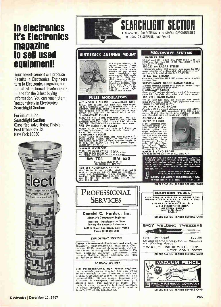
In electronics HS Electronics magazine to sell used equipment! Your advertisement will produce Results in Electronics. Engineers turn to Electronics magazine for the latest technical developments - and for the latest buying information. You can reach them inexpensively in Electronics Searchlight Section.
For information: Searchlight Section Classified Advertising Division Post Office Box 12 New York 10036
Electr irial sees better than the hailer"),
..44r1 stored charge on a cher
'1'design biotelernetrY gee le
SEARCHLIGHT SECTION • CLASSIFIED ADVERTISING • BUSINESS OPPORTUNITIES • USED OR SURPLUS EQUIPMENT
AUTOTRACK ANTENNA MOUNT
360 degree azimuth, 210 degree elevation sweep with better than 1 mil. accuracy. Missile velocity acceleration and mewing rates. Amplidyne and servo control. Will handle up to 20 ft. dish. Sup-plied complete with con-trol chassis. In stock-immediate delivery. Used world over by NASA. USAF, MP-61-B. Type SCR-584. Nike Ajax mounts also in stork.
PULSE MODULATORS
MIT MODEL 9 PULSER 1 MW-HARD TUBE Output 25kv 40 amp. Duty cycle. 002. pulse lengths .25 to 2 nticrosec. Also .5 to 5 microsec. and .1 to .5 mIcrosec. Uses 6C2I. Input 115v 60 cycle AC. Mfg. GE. Complete with driver and high voltage power supply. Ref: MIT Rad. Lab. Series, Vol. 5. p. 152.
2 MEGAWATT PULSER Output 30 kv at 70 amp. Duty cycle .001. Rep rates. I micros«, 600 pps. I or 2 mace 300 pps. Uses 5948 hydrogen thyratron. Input 120/208 VAC 60 cycle. Mfr. GE. Complete with high voltage power supply
250 KW HARD TUBE PULSER Output 16 kv 16 amp. Duty cycle .002. Pulses ran he coded. Uses 5021, 715C or 4P1160A. Input 115 v 60 cy. AC $1200 ea. 18 MEGAWATT PULSER Output 150KV at 120 amps. Rep rate: 50-500 ITS. Pulse length: 5 msec. 15KV 120 amp, into pulse transformer. Rise time 1.5 mseo. Filament supply 5V SO amp. Incl. 17.5KV 1.5 amp DC power supply. Input: 220V 60 CY AC.
VARIAN KLYSTRONS V-45: .15W output CW 9 to 10 KDIC V'. .000: 10 KW output CW 1.7 to 2.4 KMc VA -80611: I KW output ('W 7.5 to 8.0 EMI'
IBM 704 IBM 650 These computers in stock for Immediate dellvery
SCR 584 AUTOTRACK RADARS Our 584s in like new condition. ready to go, and In stock for immediate delivery. Ideal for telemetry re-search and development, missile tracking, satellite tracking Fully Deer. MIT Rad. Lab. Series. Vol. 1. pos. 207-210, 228. 284-286. Comp. Inst. Itk avail
%able $25.00 each.
MICROWAVE SYSTEMS L BAND RF PKG. 25 K.W peak 000 to 1040 .110. Pulse nidth .7 to 1.2 mien sec. Rep. rate 180 to 420 pps. Input 115 van incl. Receiver $1200
200-225 mc RADAR SYSTEM I Megawatt output. 200 nautical mile range for long range detection of medium and high altitude jet air-craft as well as general search. AN/TPS-28.
10 KW CW S-BAND Complete 1700-2400 SOCS Itle system using VA-800 klystron. New.
SURVEILLANCE DRONE RADAR SYSTEM X-Stand tracking system with plotting boards. Type AN/MPQ-29. Drone also in stock. 5 MEGAWATT C-BAND Klystron RF package delivering nominal 5 megawatt pulse Itle. Complete with pulser and power supply.
500 KW L BAND RADAR 500 kw 1220-1359 ruse 160 nautical mile search range P.P.I. and A scopes. SETO. thyratron mod 5J26 magnetron. Complete system.
100 KW X BAND RADAR Complete 100 kw output airborne system with AMTI. 5022 th>r. mod. 4J52 magnetron. PPI, 360 deg as sweep, 60 deg. elev. sweep, gyro stabilizer, hi-gain reyr. Cotnplete with all plugs and cables. AN/GPG-1 SKY-SWEEP TRACKER 3 cm, automatic track-ing radar system. Com-plete package with in-dicator system. Full target acquisition and automatic tracking. In-put 115 volts 60 cycle New. In stock for im-mediatedelivery. Entire System 6' long. 3' wide. 10' high. Ideal far Infrared Tracker. Drone Tracker. Missile Tracker, It. & D. 500KW S BAND RADAR 250 miles search 115V 60 cy AC. Mfg. G.E.
RADAR SYSTEMS GROUND AND AIRBORNE AUTOMATIC TRACKING ANTENNA SYSTEMS. NIKE AJAX. NIKE HER-CULES M-33 MSO-IA. MPS-19 MPS-9 SCR 584. IPS-10 TPS-213 FAA-ASS-2 AIRBORNE SYSTEMS. APN-84. APN-102. APS-20. APS•27. APS-45. DPN-19. DIGITAL COMPUTERS IBM 650. IBM 704. e LARGEST INVENTORY OF RADAR AND
MICROWAVE EQUIPMENT IN THE WORLD.
RADIO RESEARCH INSTRUMENT CO. 45 WEST 45TH ST N Y. 10036 212-JO 6-4691
CIRCLE 960 ON READER SERVICE CARD
PROFESSIONAL SERVICES
Donald C. Harder., Inc. Magnetic Component Engineers
Reactors-Transformers-Filters Serving the Research Laboratory
2580 K Street, San Diego, Calif. 92102 Phone (714) 239-8021
EMPLOYMENT SERVICES
Career Advancement-Electronic and electrical engineers, mathematicians, physicists. Chal-lenging R&D. product development, QC sys-tems manufacturing and sales positions. Fee paid. National exposure. Confidential. Send resume. Multiple Career Listings, Inc., 322 W. Jefferson Blvd., Dallas.
POSITION WANTED
Vice President/Gen'l. Mgr. Proven engineer-ing graduate seeks broader position where he can materially contribute to growth and profits. Outstanding record includes full P&L responsibility, 10 yrs. mgmt., business dev. & admin. in aerospace, industrial mach'y & aircraft eqpt. Top nationwide mgmt. con-tacts, 9 years responsible technical positions in stress analysis, struc. design & machine design. PW-4390, Electronics.
ELECTRON TUBES KLYSTRONS • AIR & TR • MAGNETRONS SUBMINIATURES • C.R.T. • T.W.T. • 5000-
E000 SERIES • SEND FOR NEW CATALOG A2 •
A 8. A ELECTRONICS CORP. 1063 PERRY ANNEX WHITTIER, CALIF.
696-7544
CIRCLE 961 ON READER SERVICE CARD
SPOT WELDING TWEEZERS
TWI - 36" Lead $11.65
AC and Stored Energy Power Supplies and Welding Heads
EWALD INSTRUMENTS CC1RP. KENT, CONN. 06757
CIRCLE 962 ON READER SERVICE CARD
CIRCLE 963 ON READER SERVICE CARD
Electronics 1 December 11, 1967 245
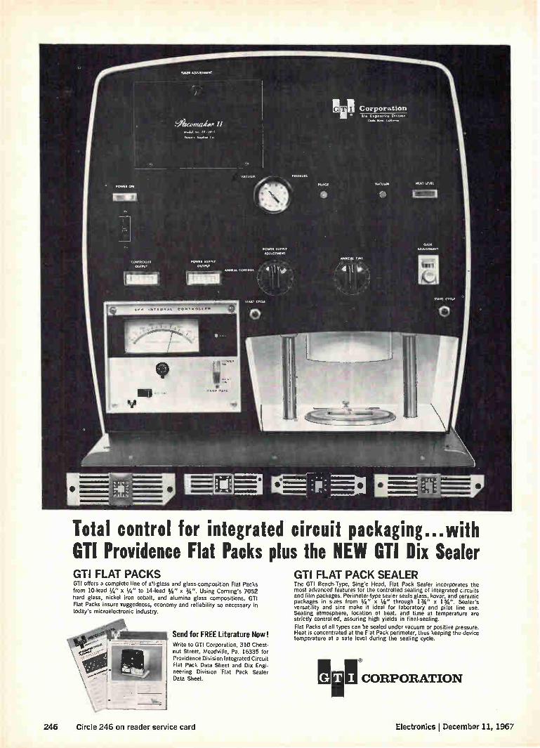
Total control for integrated circuit packaging...with GTI Providence Flat Packs plus the NEW GT1 Dix Sealer GTI FLAT PACKS GTI offers a complete line of all-glass and glass-composition Flat Packs from 10-lead 3/4 " x 3/4 " to 14-lead 3/4 " x 3/4 ". Using Corning's 7052 hard glass, nickel iron cobalt, and alumina glass compositions, GTI Flat Packs insure Tuggedness, economy and reliability so necessary in today's microelectronic industry.
Send for FREE Literature Now! Write to Gil Corporation, 310 Chest. nut Street, Meadville, Pa. 16335 for Providence Division Integrated Circuit Flat Pack Data Sheet and Dix Engi• neering Division 'Flat Pack Sealer Data Sheet.
GTI FLAT PACK SEALER The GTI Bench-Type, Single Head, Flat Pack Sealer incorporates the most advanced features for the controlled sealing of integrated circuits and film packages. Perimeter-type sealer seals glass, kovar, and ceramic packages in sizes from 1/4" x 3/4 " through 13/4" x 13/4 ". Sealer's versatility and size make it ideal for laboratory and pilot line use. Sealing atmosphere, location of heat, and time at temperature are strictly controlled, assuring high yields in final-sealing.
Flat Packs of all types can be sealed under vacuum or positive pressure. Heat is concentrated at the Flat Pack perimeter, thus keeping the device temperature at a safe level during the sealing cycle.
MIN !!CORPORATION 8
246 Circle 246 on reader service card Electronics I December 11, 1967

Newsletter from Abroad
December 11, 1967
Computer merger
near in Britain
Nippon Electric
to make Ise's
Digitron tubes
Elliott to start
beam lead process
Britain's International Computers & Tabulators Ltd. and the English Electric Co. are expected to announce a merger, or at least a close alli-ance, of their computer activities early in the new year. Such a link would have government support and might even be blessed by a government loan, as in the case of English Electric's tieup with Elliott-Automation Ltd.
Talks between ICT and English Electric already have resulted in agreement to use certain common peripherals. Terms of the final deal will probably take this form: neither company would abandon its major com-puter line—ICT's 1900 series and English Electric's System 4. A single unified computer design would most likely have to wait until a new gen-eration of equipment was due. However, marketing, research and devel-opment, purchasing, administration, and perhaps some other activities would be amalgamated progressively so that the next-generation joint computer would be launched by a single consolidated organization.
ICT's revenues, including rentals, come to about $150 million a year. English Electric's income from its commercial computer operation, hurt this year by System 4 production troubles, is likely to be running at an annual rate of $30 million by next spring.
Nippon Electric Co. will produce Ise Electronics Corp.'s Digitron, a cold-cathode readout tube, for use in its line of calculators. The deal calls for Nippon Electric to make an initial cash payment and then pay royalties, and Ise to provide technical assistance.
Unlike conventional readout tubes that have the cathode at the rear, Digitron's cathode is up front [Electronics, May 29, p. 212]. One reason Nippon Electric turned to Digitron is that the tube doesn't require special processing to make the fluorescent material on numeral segments glow at low voltages. And, according to informed sources, Ise was willing to make the deal because it had more business than it could handle.
Meanwhile, Nippon Electric has launched an all-out campaign to pre-vent the Japanese government from granting a patent to Burroughs Corp. for its Nixie tube [Electronics, June 26, p. 203].
Elliott-Automation Microelectronics Ltd. of England will be in pilot pro-duction in about six months with semiconductor components using in-tegral beam leads electrodeposited in gold. The method isn't new; scien-tists at Bell Telephone Laboratories reported on it almost two years ago. But Elliott believes it's the first European company to reach production with beam leads.
Elliott developed its own production procedures and will not pay license fees to Bell specifically for this technique. However, the firm does pay fees to cover use of some basic electronic techniques.
Like Bell's, Elliott's technique uses platinum silicide for ohmic contact with the silicon through the contact holes in the silicon dioxide layer. The oxide layer and the platinum silicide are then covered with titanium, which acts primarily as an adhesive between the oxide and platinum sili-cide, and a layer of pure platinum. The gold beam is electroformed atop the platinum [Electronics, March 20, p. 91]. Beam lead has two advan-
Electronics December 11, 1967 247

Newsletter from Abroad
tages. First, it's cheaper because beam formation is part of the automatic production process; second, reliability is increased.
Danish devaluation
perils F-5 sale
Bull-GE and Czechs
in computer deal ...
... and Prague
may buy tv plants
Poland to make
Grundig recorders
East Germany
importing workers
Denmark's devaluation of the kroner and budget tightening have created shock waves that are being felt in the Pentagon. The reason: concern that the Danes will put off buying about $100 million worth of U.S. jet aircraft or turn to Sweden with the 50-plane order. Denmark has been weighing the Northrop F-5 against the more versa-
tile Saab Traken, the Mach 2-plus mainstay of the Swedish Air Force that's designed for both fighter-bomber and interceptor use.
If Saab makes the sale, it would be Sweden's first fighter plane deal with a NATO nation, and it could open the door to further sales, particu-larly in Scandinavia. One move making Northrop take notice is the ap-pointment, effective Jan. 1, of one of Sweden's top export salesmen, Kurt Mileikosky, as managing director of Saab.
Bull-GE, the French computer affiliate of the General Electric Co., is expected to reach an accord with the Czechoslovakian electronics indus-try combine, Tesla, for the production by Tesla of one of Bull-GE's medium-range computers. Although French and Czech governmental red tape has delayed the signing of the licensing agreement, informed sources say that all details have now been worked out and that the pact will soon be signed.
Czechoslovakia is expected to buy a television-receiver factory and pos-sibly a tube plant from France. In his visit to Prague to arrange the com-puter licensing agreement between Bull-GE and Tesla, French science minister Maurice Schumann also discussed color television with the Czechs, who like most Eastern bloc countries, will adopt the French Secam system.
Grundig Werke GmbH, giant West German consumer electronics firm, has licensed Poland's state-owned foreign trade association, Universal, to make tape recorders. This is the latest in a series of efforts to import Western electronics knowhow through licensing deals. A Warsaw-based firm, Kasprzak, will start producing four tape-recorder models next year. The units, conventional 3.75-inches-per-second types, will be marketed
in Communist-bloc countries only.
East Germany's high-riding electronics industry, the second largest in Eastern Europe, is increasingly turning to foreign workers to help ease its chronic labor shortage. Under an agreement made this year between East Berlin and Budapest, a contingent of Hungarian workers has arrived in Dresden and Karl-Marx-Stadt, primarily to work in the electronics industry. It's estimated that eventually 100,000 Hungarians may be employed.
East German officials figure that the country is lacking some 250,000 technicians, a shortage they attribute to large-scale defections to the West and a low postwar birth rate. In the past, workers have been brought in from such Communist countries as North Vietnam and Poland.
248 Electronics I December 11, 1967

SPEER COMPONENT All about a new economical method for selecting the right precision industrial resistors... It's called "looking for the particular precision resistors that deliver the exact functional characteristics you need at the lowest possible price."
Perhaps this highly sensible meth-od isn't new to you. But it will be to a lot of people. We've been amazed to discover just how many design engineers specify their industrial precision resistors on the basis of arbitrary (and non-functional) labels —such as the fact that the resistors meet certain MIL specs or feature "wire-wound" construction.
Don't get us wrong. MIL-spec re-sistors are fine—for military applica-tions. But is it really logical to pay a premium for a wider range of envi-ronmental adaptability — and more documentation—than your industrial application actually involves? Wire-wound resistors are fine, too.
Even when they're evaluated on a functional basis, they may prove to be better than metal film resistors for certain industrial applications. But if you still assume that wire-wounds are better for every application, you simply haven't been paying sufficient attention to what's been happening in precision resistor technology in recent years. Thanks in part to important ad-
vances by the Speer research and development people, our JXP resis-tors now are competitive with wire-wounds as far as resistance-temper-ature stability is concerned. And their statistical reliability is greater. Ditto their power density, when perform-ance is equivalent. And their prices are not only competitive but are in many cases even lower than wire-wounds. Our JXP metal film resistors, be-
cause of our exclusive manufacturing process, can be produced to tighter tolerances than wire-wounds at sig-
nificantly less cost for most resist-ance ranges. Furthermore, they auto-matically incorporate faster response and settling times at no additional cost. You can get JXP's with tolerances
and TCs as low as ± 0.023/4 and -± 2 PPM/ C, respectively, upon request. These "white room" metal film resis-tors have other startling functional characteristics that you should also be aware of. Use the coupon, and we'll send you the full details.
...and the right industrial precision resistor networks
As we've just demonstrated, evaluat-ing industrial precision resistors on the basis of functional characteris-tics rather than arbitrary labels may change your buying habits.
Well, the same goes for resistor networks. Our JXP precision resistors are
available in all kinds of packaged networks and assemblies, needless to say. In addition, we can furnish you
with any network engineering assist-ance you might need—from proto-type preparation to testing and certi-fication. For complete information, mail us the coupon.
How's your frequency on Typical Error #4 in inductor testing?
Continuing our review of the errors often made when measuring induc-tance and O (see MIL-C-15305), error dh4 is letting your test frequency be-come inaccurate.
Needless to say, preventing this particular lapse is easy. Just check it at regular intervals using accepted instruments of at least 0.1% accu-racy.
For additional errors—and how to adjust for them—check with us.
ARCO Speer Electronic Components
St. Marys, Pa. 15857
CI Rush details on just how functional your JXP precision resistors really are.
C3 Ditto on your JXP precision resistor networks.
Name
Title
Company
Street
City State Zip
Electronics December 11, 1967 Circle 249 on reader service card 249

NEW KEMET D's
The "DIET CAPACITORS:

They take off inches.
1_11,111 ill .,111
The new KEMET D's with their
s low profile pack twice the ca-pacitance in 60% of the size of
the standard military A and B
cases.
This size reduction is actual size combined with a unique trans-
fer molding technique to produce a 3 case
line (A', A' and 13') especially suited for high
speed automatic insertion equipment. These
new KEMETD's can be punched readily, along
with resistors and diodes, onto computer
cards and printed circuit boards.
Typical applications of the new KEMET
D's are commercial computers and peripheral
equipment, communications systems and
many other areas of electronics requiring
high density packaging.
With an impedance rating of less than
1 ohm at 10 MHz for 12 ,uF, the new K EMET
D's are just great for computer applications
with high clock rates that require low impe-
dance at high frequencies.
Other important performance charac-
teristics of the new KEMETD's are as follows:
Capacitance Range . . from .0047 iLF to 68 F.
Voltage Range from 6V to 35V.
Temperature Range. .from --55°C to ±85°C.
D.C. Leakage Current...less than Ilia at 25°C.
Temperature Cycling...exceeds MIL-STD-202.
There's a new products catalog that ex-
plains the new KEMETD's in great detail. To
get your copy simply contact your local Union
Carbide Representative or write us direct.
The new KEMETD's, the diet capacitors,
from Union Carbide, The Discovery Company.
UNION CARBIDE
Electronics I December 11, 1967 Circle 251 on reader service card 251
Why get lost looking for a switch?
SUB-SUBMINIATURE SWITCH
PRESS-TO.TEST INDICATOR LIGHT
TOGGLE, 55/64" LONG
RFI-SHIELDED PUSHBUTTON
KEYBOARD SWITCH
Head straight for these Control Switch references!
Send for all the Control Switch catalogs and bul-letins listed below . . . now! Keep them handy. When you need a different switch or indicator light, check Control Switch data first.
Odds are you'll find exactly what you want in ten minutes. For Control Switch makes more switches and indicator lights for the fields we serve than any other manufacturer.
What's more, they are high reliability com-ponents for applications where you cannot afford a failure. Sensitive control systems, for example. And missiles, computers, industrial equipment.
C CONTROLS COMPANY OF AMERICA
CONTROL SWITCH DIVISION 1420 Delmar Drive, Folcroft. Pennsylvania 19032
A Subsidiary of
General Precision Equipment Corp.
Control Switch advances include RFI-shielded switches and indicator lights, sub-subminiature switches, ultra compact pushbuttons. And indi-cator lights of only .200" diameter.
Order through us or your Control Switch dis-tributor. He specializes in selected lines of electro-mechanical and electronic components. He knows your needs and has the Control Switch inventory to get your order out pronto!
SEND FOR THESE TODAY
Check numbers on the Reader Service Card corresponding to those at left below for any or all of these Control Switch references. While you're at it, get 'em all!
e 511 Condensed Switch Catalog 100
# 512 BasicSnap-Action Switch Catalog 110
# 513 Toggle Catalog 180
#514 Indicator Light Catalog 120
# 515 Hermetic Switch Catalog 130
# 516 Switchlite Catalog 220
# 517 Pushbutton Catalog 190
# 518 RFI-Shielded Component Bulletin 62A
252 Electronics December 11, 1967

December 11, 1967
Electronics Abroad Nrub:`
France
A gauntlet thrown
U.S. electronics companies in Eur-ope generally take pains not to flaunt their strength. But all the same they've found themselves front-page news in recent weeks. In a spectacular best seller, French journalist Jean-Jacques Servan-Schreiber has singled out the U.S. electronics industry as a leader in the challenge that threatens to turn Europe into an underdeveloped area.
Servan-Schreiber's book, "Le Défi Américain" (The American Challenge) mounts a scathing at-tack against the centuries-old struc-ture of Europe—political, social, educational, and, above all, corpo-rate. The $10 billion that American industry has invested in Europe since 1958, he insists, is only the effect of Europe's inability to cope. Servan-Schreiber, in fact, all but de-ifies the American way of manage-ment, of education, of innovation.
Tocsin. Servan-Schreiber calls his work a "book of action," in-tended to galvanize Europe to face the challenge. And it has provoked much the same reaction as Ralph Nader's "Unsafe at Any Speed" or Rachel Carson's "The Silent Spring" did in the U.S.
In this year's National Assembly budget debates, "Le Défi" was cited to back up the arguments of both Gaullists and their leftist op-position. The book has sparked de-bate on television, in the press, and in countless cafes. Even President de Gaulle has read it. Since its pub-lication in October, the book has sold nearly 200,000 copies, making it a smashing best seller.
Crucial. Servan-Schreiber wor-ries most about the industries of the future. The most critical of these, he says, is electronics. At present, he writes, American firms control 15% of consumer electron-
Gadfly. Jean-Jacques Servan-Schreiber wants Europe to stand up to the challenge of U.S. industry.
ics production in Europe, 50% of semiconductor production, 80% of computer production and 95% of the integrated-circuit production.
"Electronics," he adds, "is not just any industrial sector." He calls it the harbinger of the second in-dustrial revolution during which computers will take over human mental tasks just as machines took over human physical tasks in the 18th century. Huge supranational European
enterprises are the only means of taking on the Americans effectively, he says. Nationalization of U.S. firms in Europe would be the worst solution: "What counts for a com-pany today is not its walls or its machines, but immaterial elements that can't be nationalized." He says, for example, that nationalization of IBM-France would be intellectual, scientific, and industrial suicide. U.S.-trained managers would emi-grate. The company would collapse after losing its link with its parent, the center of decision that fuels the subsidiary.
Federate. Restricting investment in Europe is no better, Servan-Schreiber adds. It would only in-crease the necessity to import prod-ucts made in America. France, he points out, once tried to keep Amer-
ican firms from setting up shop in the country. But the de Gaulle gov-ernment soon found that U.S. firms could thwart the ban simply by locating their new plants in other Common Market countries.
"Europe's tool," he says, "should be the Common Market—including Great Britain, the best possible ally of France in the Market." He urges elevation of the Market to federal stature, with its own budget and freedom of decision, a far cry from the present confederal structure that de Gaulle has succeeded in preserving. For the moment the Common
Market is only a tariff union for everyone but one big nonmember, the U.S. "While French, German or Italian companies are still grop-ing in the vast space opened to them by the Treaty of Rome," he says, "the heavy units of American industry, after learning the pecu-liarities of the terrain, maneuver now from Naples to Amsterdam with the ease and rapidity of Is-raeli tanks in the Sinai."
Defense. Unchallenged, Servan-Schreiber says, American industry in Europe will become the world's third greatest power, after the Uni-ted States and the Soviet Union. In his view, Europe's salvation lies in big companies. But bigness isn't all. "La force moderne," says Servan-Schreiber, "is the capacity to invent—that is, research—and the capacity to put inventions into products—that is, technology."
Ahead in infrared
Although the Société Anonyme de Télécommunications largely does what its name says it does, the com-pany nonetheless has just about cor-nered the French market for infra-red devices.
All the guided missiles the de Gaulle government has in mind for its nuclear striking force, for ex-ample, will carry SAT infrared de-
Electronics December 11, 1967 253

Electronics Abroad
tection systems. And, SAT supplies the infrared hardware already in French reconnaissance planes. The bulk of the infrared business
comes from military and space cus-tomers, but SAT sees other promis-ing markets ahead. Jean Turck, head of the company's missiles and space division, says he expects to find new outlets in clear-air-turbu-lence detection equipment and in laser communications.
Playing it cool For both, SAT is developing hardware based on its latest infrared detector, the sensing element of which is a single crystal of mercury telluride-cadmium tel-luride with a spectral range from 8 to 14 microns. The crystal's time constant is less than 10 nanoseconds and its composition can be varied to suit peak response to various ap-plications. SAT packages the detec-tor in a dewar flask filled with liq-uid nitrogen to hold the tempera-ture at 77°K. The new device will be the king-
pin component in a 45-pound clear-air-turbulence detector SAT will in-troduce late next year or early in 1969. The detector will have a hor-izontal field of 37°, a vertical field of 5°, and a range of 30 miles. Turd( says the 30-mile range will give the pilot of a supersonic transport enough time to skirt a dangerous air pocket. The aircraft SAT sees as the most likely prospect is, of course, the Franco-British Con-corde.
Linear link. The helium-cooled infrared detector also turns up in a long-range laser communications System SAT expects to start testing late next year or early in 1969. The forerunner of the system is
already being tried out at one of SAT'S plants. Range of the system, which has a 3-watt output, is about two miles. But Turck sees a chance of stepping up laser power so that the laser link can span the same dis-tances as microwave relays, which can be spaced up to 50 miles apart. The laser links, though, would need waveguide-like tubes to prevent at-tenuation by rain. Like the laser radar being devel-
oped in the U.S. by the Autonetics division of the North American Rockwell Corp. [Electronics, Nov. 27, p. 48], SAT'S system uses a pair
of carbon-dioxide lasers. One of them, which operates at 10 microns and 100 milliwatts, serves as a pi-lot oscillator. Its output passes through a gallium-arsenide modula-tor and then pumps the second, more powerful laser. Tho two-step technique, with the modulation ini-tially applied at low power levels, makes it much easier to work up to higher powers than does straight modulation. Bandwidth for the system is 100
megahertz, about the limit for a 10-micron laser. But this isn't a serious drawback; 100 Mhz of band-width is enough for six television and 400 telephone channels.
Japan
Around the bend
A race to get onto the market with a book-size television set seems to be shaping up in Japan. The con-tenders so far: The Hayalcawa Elec-tric Co. and the Tokyo Shibaura Electric Co. (Toshiba).
Last summer, Hayakawa demon-strated a development version of the flat cathode-ray tube for the set it has in mind [Electronics, June 12, p. 246]. Now, Toshiba has readied a prototype of its flat crt. Both tubes have front-to-back
dimensions of 2 inches, but with that the resemblance ends. The bulb in Hayalcawa's 8-inch tube is roughly the shape of a book with a funnel tacked onto the bottom for the electron gun. Toshiba's 6-inch tube is wedge-shaped, with the electron-gun funnel projecting from the side. What's more, the Toshiba tube has a noticeably curved face-
COLLIMATOR
SCREEN
plate, crucial to its low-power hori-zontal-deflection scheme,
Linear. In the Toshiba tube, ver-tical deflection is across a 90° angle, much the same as in con-ventional small crt's. The horizon-tal-deflection angle, however, is only 22°—about one-fifth the usual angle. Because of the small angle, the power needed to drive the hori-zontal-deflection coil is something like a tenth of that needed for a conventional tube. Since horizontal-deflection power commonly runs about three times vertical-deflec-tion power, the over-all deflection-power requirement is cut by two-thirds—a big advantage in small, transistorized tv sets. The faceplate actually is a sec-
tion of cylinder. The center point of the horizontal deflection lies at a point that would be on the cylin-der were it projected into the neck of the tube. Because of the center point's location, a sweep with lin-ear angular velocity moves the elec-tron beam at a linear velocity along the faceplate. Thus conventional saw-tooth deflection circuitry—but with lower power—can be used. The horizontal-deflection geom-
etry also means the beam-spot size on the faceplate can be held con-stant by dynamic focusing. Even without focusing, changes in spot size aren't a problem because mod-ern electron guns have a large depth of focus.
Collimated. Vertical deflection is essentially conventional. But a cor-rection is needed to prevent key-stone distortion. This is done by a collimator made up of permanent magnets spotted around the tube where the funnel joins it.
Although Toshiba says it could go into production soon, there is no definite plan for doing so. The
tee ABOUT 22%
HORIZONTAL DEFLECTION COIL
DE ELECTION CENTER POINT
In good shape. Top view of Toshiba flat crt shows how curved faceplate and deflection center point's location keep horizontal deflection angle at a low 22°.
ELECTRON GUN
254 Electronics I December 11, 1967

Electronics Abroad
Svelte. Toshiba now has a prototype flat cathode-ray tube and may be first on the market with a book-size television set
big problem is the bulb, made up of three major pieces—none of them simple shapes. The production tube, too, will need a shorter over-all length than the prototype's 10.5 inches. To do this, Toshiba will bend the neck slightly and use a shorter electron gun.
High-octane GaAs
Every day and every way—almost —gallium arsenide looks better and better. The GaAs story started a decade
ago when the semiconductor mate-rial scored its first practical success in varactors for low-noise para-metric amplifiers. Since then GaAs has been put to work in lasers, light-emitting diodes, microwave diodes, and microwave bulk-power sources.
Still another chapter was written last month when two researchers at the Japanese government's Elec-trotechnical Laboratories reported they've developed a new kind of GaAs oscillator. The two, Hiroshi Tateno and
Shoei Kataoka, still haven't pinned down exactly what makes their os-cillator oscillate. They do know, though, that it's neither the Gunn-effect nor the limited space-charge
accumulation mode; both of these have been exploited in the U.S. to build oscillators with frequencies in the tens of gigahertz. And they know that the new oscillator can operate from several tens on up to several hundred gigahertz. What's more, it can be tuned across its range by an external circuit. It's this circuit, not the size of the device, that sets the frequency.
Notched. Starting material for the oscillator is a slab of GaAs 3 millimeters long, 1 mm wide, and 0.5 mm thick. The material has a carrier concentration of 1.2 x 10¹⁶ electrons/cm3. A notch cut near the center of the bar makes the cross section there 1 by 0.15 mm. An ohmic contact is formed at each end with a layer of tin. Around the notch, there's a control electrode insulated from the bulk GaAs by a layer of barium titanate. Two other insulated contacts, one near each end, serve as output electrodes. The control electrode is con-
nected to one of the ohmic con-tacts. When 60-nanosecond pulses of 800 to 1,000 volts are applied to the contacts, the slab oscillates. The frequency depends on the length of the shorted coaxial cable connected to the output electrodes. Thus far, Tateno and Kataoka have pushed the device to 380 Ghz.
Accent the negative. The Jap-anese researchers believe a suppressed space-charge layer causes the oscillation. As the volt-age pulse is applied, the layer starts to form and move. But the high field applied by the control electrode works against it. The net result: a negative resistance be-tween the two ohmic contacts.' Whatever the mechanism, it
points to a device having great promise. As their next step, Tateno and Kataoka will try for continu-ous-wave operation. [For more on Japanese developments in GaAs Gunn-effect devices, see p. 125]. Since there appears to be little limitation on size, it should be fairly easy to boost the power output. Finally, the device could be a sleeper as a logic element. After the driving pulse decays, the device continues to oscillate for some time.
The Netherlands
A better weigh
In the everyday art of weighing things, innovations are rare. For some 7,000 years after the ancient Egyptians invented the balance, all the world's scales were essentially balances. It wasn't until the 18th century that scales based on pen-dulums and springs—the kinds that still prevail in small shops—came into use.
But with electronics, there's al-ways something new. Researchers at Maatschappij Van Berkels' Pat-ent NV have designed a scale that works with vibrating strings and digital integrated circuits. H.H. Thooft, business manager of the Berkel subsidiary in West Germany where the scale will be manufac-tured, claims it's going to revolu-tionize the business. On the counter. Berkel expects to
have the scale in production early
CONTROL ELECTRODE (CAPACITIVE) -
Ga As--
----INPUT ELECTRODE (OHMIC)
)NPUT z ELECTRODE (OHMIC)
OUTPUT -ELECTRODE (CAPACITIVE)
COAXIAL CABLE (SHORTED)
CONTROL ELECTRODE (CAPACITIVE)
OUTPUT ELECTRODE (CAPACITIVE)
Call the tune. Length of coaxial cable connected to output contacts determines operating frequency of new Japanese GaAs oscillator.
Electronics December 11, 1967 255
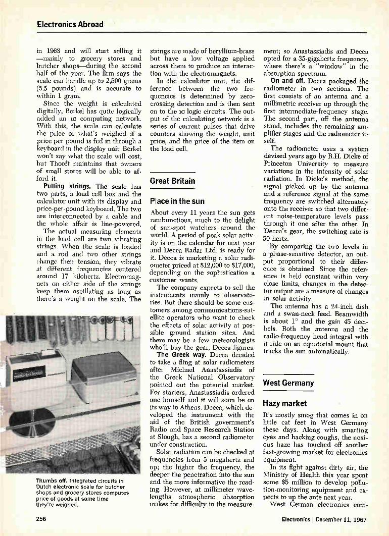
Electronics Abroad
in 1968 and will start selling it —mainly to grocery stores and butcher shops—during the second half of the year. The firm says the scale can handle up to 2,500 grams (5.5 pounds) and is accurate to within 1 gram.
Since the weight is calculated digitally, BerIcel has quite logically added an lc computing network. With this, the scale can calculate the price of what's weighed if a price per pound is fed in through a keyboard in the display unit. Berkel won't say what the scale will cost, but Thooft maintains that owners of small stores will be able to af-ford it.
Pulling strings. The scale has two parts, a load cell box and the calculator unit with its display and price-per-pound keyboard. The two are interconnected by a cable and the whole affair is line-powered. The actual measuring elements
in the load cell are two vibrating strings. When the scale is loaded and a rod and two other strings change their tension, they vibrate at different frequencies centered around 17 kilohertz. Electromag-nets on either side of the strings keep them oscillating as long as there's a weight on the scale. The
'
40 I I • .••••
Thumbs off. Integrated circuits in Dutch electronic scale for butcher shops and grocery stores computes price of goods at same time they're weighed.
strings are made of beryllium-brass but have a low voltage applied across them to produce an interac-tion with the electromagnets.
In the calculator unit, the dif-ference between the two fre-quencies is determined by zero-crossing detection and is then sent on to the lc logic circuits. The out-put of the calculating network is a series of current pulses that drive counters showing the weight, unit price, and the price of the item on the load cell.
Great Britain
Place in the sun
About every 11 years the sun gets rambunctious, much to the delight of sun-spot watchers around the world. A period of peak solar activ-ity is on the calendar for next year and Decca Radar Ltd. is ready for it. Decca is marketing a solar radi-ometer priced at $12,000 to $17,000, depending on the sophistication a customer wants. The company expects to sell the
instruments mainly to observato-ries. But there should be some cus-tomers among communications-sat-ellite operators who want to check the effects of solar activity at pos-sible ground station sites. And there may be a few meteorologists who'll buy the gear, Decca figures. The Greek way. Decca decided
to take a fling at solar radiometers after Michael Anastassiadis of the Greek National Observatory pointed out the potential market. For starters, Anastassiadis ordered one himself and it will soon be on its way to Athens. Decca, which de-veloped the instrument with the aid of the British government's Radio and Space Research Station at Slough, has a second radiometer under construction.
Solar radiation can be checked at frequencies from 5 megahertz and up; the higher the frequency, the deeper the penetration into the sun and the more informative the read-ing. However, at millimeter wave-lengths atmospheric absorption makes for difficulty in the measure-
ment; so Anastassiadis and Decca opted for a 35-gigahertz frequency, where there's a "window" in the absorption spectrum. On and off. Decca packaged the
radiometer in two sections. The first consists of an antenna and a millimetric receiver up through the first intermediate-frequency stage. The second part, off the antenna stand, includes the remaining am-plifier stages and the radiometer it-self. The radiometer uses a system
devised years ago by R.H. Dicke of Princeton University to measure variations in the intensity of solar radiation. In Dicke's method, the signal picked up by the antenna and a reference signal at the same frequency are switched alternately onto the receiver so that two differ-ent noise-temperature levels pass through it one after the other. In Decca's gear, the switching rate is 50 hertz. By comparing the two levels in
a phase-sensitive detector, an out-put proportional to their differ-ence is obtained. Since the refer-ence is held constant within very close limits, changes in the detec-tor output are a measure of changes in solar activity. The antenna has a 24-inch dish
and a swan-neck feed. Beamwidth is about 1° and the gain 45 deci-bels. Both the antenna and the radio-frequency head integral with it ride on an equatorial mount that tracks the sun automatically.
West Germany
Hazy market
It's mostly smog that comes in on little cat feet in West Germany these days. Along with smarting eyes and hacking coughs, the noxi-ous haze has touched off another fast-growing market for electronics equipment.
In its fight against dirty air, the Ministry of Health this year spent some $5 million to develop pollu-tion-monitoring equipment and ex-pects to up the ante next year. West German electronics corn-
256 Electronics December 11, 1967

• COMMUTATOR • SAMPLE & HOLD
analog switching puzzle?
Analog switching got you puzzled? Here's the an-
swer — an integrated circuit with drivers and FET
switches all in one package. Drive the input with
almost any integrated logic — only 0.8 volt swing
is required. The output FET with ON resistance as
low as 80 ohms and leakage less than 1 nA can
switch plus or minus 20 volt signals.
Pick the driver-switch combination for your appli-
cation: 2 to 5 channels; inverting drivers or not;
MOS or junction FETs —see table. These prod-
ucts add to the wide variety of Siliconix drivers
and FET switches that are now available from your
distributor. Write or check inquiry card for data.
Franchised Distributors ALABAMA Cramer Electronics, Inc.
Huntsville (205) 536-4493
ARIZONA Kierulff Electronics, Inc. Phoenix (602) 273-7331
CALIF. Hollywood Radio & Elec. Hollywood (213) 466-3181 Menlo Park (415) 322-3431
Kierulff Electronics Los Angeles (213) 685-5511 San Diego (714) 278-2112
Elmar Electronics, Inc. Mountain View (415) 961-3611 Oakland (415) 834-3311
Electronic Supply, Inc. Riverside (714) 683-8110
COLORADO Kierulff Elec., Inc. Denver (303) 825-7033
CONNECTICUT Cramer Elec., Inc. Hamden (203) 288-7771
FLORIDA Perrott Associates, Inc. Clearwater (813) 446-2535 Orlando (305) 275-1132 West Palm Beach (305) 585-7761
ILLINOIS Semiconductor Spec. Chicago (312) 279-1000
solved with integrated driver and FET switches
SILICONIX DRIVER-FET SWITCHES
Type No. of Channels
Logic Input for ON Switch
Type FET Switch
DG102F 2 DG103F 2 DG104F 2 DG110F 2 DG111F 2 DG112F 2 DG126F DG116F 4 DG118F 4 DG123F 5 DG125F 5 DG122F 2* DG132F 2* DG120F 3* DG121F 3*
Differential — two common output.
O Jct 1 Jct O Jct 1 MOS O MOS 1 MOS 1 Jct 1 MOS o MOS 1 MOS o MOS 1 MOS 1 MOS 1 MOS o MOS
gate switches with common
MARYLAND Milgray Elec., Inc. Hyattsville (202) 864-6330
MASS. Cramer Electronics, Inc. Newton (617) 969-7700
MICH. Semiconductor Spec., Inc. Detroit (313) 255-0300
MINN. Semiconductor Spec., Inc. Minneapolis .(612) 866-3434
MISSOURI Semiconductor Spec. St. Louis (314) 521-8866
NEW JERSEY Tech. Elec. Dist. Bergenfield .. (201) 384-3643
NEW MEXICO Kierulff Elec., Inc. Albuquerque (505) 268-3901
NEW YORK Summit Dist., Inc. Buffa lo (716) 884-3450
Milgray Electronics, Inc. New York City (212) 989-1600 East. Semiconductor Sales, Inc. Syrlcuse (315) 455-6641
niliconix incorporated 1140 W. Evelyn Avenue, Sunnyvale, California 94086
Telephone (408) 245-1000 TWX: 910-339-9216
)>—*OUTPUT
NEW LOW COST FET TESTER The SI200 Semiconductor Tester features plug-ins for expandable test capability, simplicity of operation, and low cost. Price: SI200 Tester-5960. Price: SI201 (DC & gf.) Plug-in Module — $1335.
NORTH CAROLINA Kirkman Elec. Winston-Salem (919) 724-0541
OHIO Alpine Industries, Inc. Dayton (513) 278-5861
OKLA. Oil Capitol Elec. Corp. Tulsa (918) 836-2541
PENNSYLVANIA Milgray Elec., Inc. Philadelphia (215) 228-2000
TEXAS Sterling Electronics, Inc. Austin (512) 452-0271 Dallas (214) 357-9131 Houston (713) 666-4061
Lenert Company Houston (713) 225-1465
WASHINGTON Washington Elec. Seattle (206) 682-8981
Electronics, December 11, 1967 257

Service...Engineering...Experie ce Electronics Abroad
MAKE THE BIG DIFFERENCE
BETWEEN A YOKE SPECIALIST
AND A YOKE SUPPLIER
Stator Type Y65 Miniature Encapsulated Precision 1" ID Yoke
Syntronic Yoke Specialists have, more yoke knowledge and provide more engineering assistance than anyone else in the field.
The most extensive line of deflectio yokes available is offered by Syn tronic . in production quantities o custom designed to special require ments. See the BIG Difference fo yourself the next time you specit a yoke.
•
ntronic INSTRUMENTS, INC. 100 Industrial Road, Addison, Illinois Phone 312, 543-6444
Circle 299 on reader service card
New high efficiency, high frequency Photochopper Modules
• High stability from —25 to +75C, efficiency varies less than 5% over temperature range
• 50% efficiency at 1000 Hz
• Internal electrostatic shielding
• CdS cells for fast warm up
Write for new Bulletin 201/IT03-67
CLAIREI ELEC1110111CS. INC. • 1239 BROADWAY, NEW YORK, N.Y. 10001
panies, too, have leen doing much research on their own hook, ready-ing for what seems a lusty market. It's estimated that some $500 mil-lion has been spent on air pollution monitoring and control equipment, much of it electronic, during the past five years. And the outlay apparently is
headed up. Next year, Germany will become the first West Euro-pean country to set limits on the pollutants in automobile exhaust. Within the next 10 years, one com-ponents manufacturer estimates, some $50 million annually in elec-tronic components will be going into automakers' pollution-control devices. Volkswagenwerk AG, the country's largest auto producer, al-ready has adopted an electronic fuel injection unit so that the VW 1600's it sells in the U.S. will meet antipollution regulations [Electron-ics, Oct. 2, p. 235].
Towering job. Cities around the country also are turning attention to the air pollution problem. Mu-nich, for instance, plans to spend $40,000 for monitoring gear. It will be spotted at seven points on the city's 950-foot-high television tower. Data on sulfur dioxide levels and
air temperatures picked up by the instruments on the tower will be fed over telephone lines to a cen-tral station at the city hall. The data, along with that from existing checkpoints around the city, will be analyzed by computer. Eventually, the system will be able to sound an alarm when a dangerous situation is imminent. A similar monitoring and alarm system is in the works at Frankfurt. Well stacked. Another burgeon-
ing market for air-pollution elec-tronics turns up at industrial plants. Under German regulations, any power plant rated at 3.2 million BTU'S per hour or more must have monitoring equipment in its stack. The latest stack equipment—for
continuously checking the density of smoke and dust—is that of AEG-Telefunken. It has a single lamp and a single photocell but operates nonetheless on a twin-beam sys-tem. In such systems, a light beam that passes through the smoke and across the stack is checked against
258 Circle 258 on reader service card Electronics December 11, 1967

CONSIDER COLORADO ¡INDUSTRIAL COLORADO
a reference beam. In the measuring head, a semi-
reflecting mirror splits the light from the lamp into the two beams. The measuring beam is bounced off a reflector on the opposite side of the stack; the reference beam passes out through the head optics, but is bounced back without cross-ing the stack. Both beams go through a chop-
per before they hit the photocell. The cell's output pulses are ampli-fied and then demodulated in phase to sort out the reference and mea-surement signals. Comparing the two beams provides a measure-ment of the dust and smoke parti-cles. And because of the compari-son, there's inherent compensation for soiling of the head's windows, aging of the lamp, amplifier drift, and like factors that otherwise would introduce error in the mea-surement.
Sweden
Care-full computer
Sweden, long a leader in biomedi-cal engineering, is planning another first—a medical profile data bank covering the citizenry of Stock-holm. The data will be stored at a main
information center, the new Hud-dinge hospital, which will be linked with other hospitals via closed-cir-cuit television. By dialing a pa-tient's registration number, a doc-tor will be able to obtain the complete medical history of that patient. Everyone in the country is covered by a unified medical-care plan. The system will also keep track
of the availability of hospital beds and doctors, as well as stocks of blood, plasma, medicines, and hos-pital supplies. A $500,000 Univac computer has
been ordered for a smaller hospital in the Stockholm area as the first step toward implementing the plan. The main system is scheduled to go into operation by 1972, by which time Stockholm's population will have reached 2 million.
• . . where research and education set an accelerated pace . . .
Innovating for industry. Providing information and qualified personnel. Through government, university and private sources.
Consider basic and applied research being conducted in Colorado by over 100 organizations. More than 3,500 graduate scientists directing the activities of thousands of specialized personnel to gather, correlate and apply data about everything from marketing to missiles, from the arctic to aerospace.
Consider Colorado's scientific and academic community. Fifth ranking state for percentage of scientists in its population. 10.7% of the population in the 25 and older age group with 4 years of college, the highest percentage in the nation. A professional atmosphere and a pleasant and varied "living" environment that attracts and holds scientists, engineers and technical ad-ministrators. A recent survey of graduating college students points up the desirability of locating in Colorado by ranking Denver among the top 3 major U. S. cities preferred for living.
Consider the excellence of Colorado's education system. 16 colleges and universities. 6 junior colleges. Per capita spending for institutions of higher learning ranks the State fourth in the nation. 23% of the State's an-nual budget earmarked for education.
If a burgeoning scientific and academic community would be an asset to your business, consider Industrial Colorado for your expansion or re-
location.
DIPLOMA [S
MENDAT ION
DN THE 7 TH D,
•H YEAR OF TI
0-667
A well-educated population, numerous centers of basic and applied research, and a desire to find practical applications for new discoveries char-acterize Colorado. Write fora complimentary copy of Industrial Colorado, a revised-to-the-minute, factual, spiral-bound portfolio. It covers im-portant considerations pertinent to plant expan-sion or relocation in any part of the State. Address inquiries to Ronald D. Lemon, Director, Industrial Research & Development, Division of Commerce and Development, 56 State Services Building, Denver, Colorado 80203.
Electronics l December 11, 1967 259

Paul R. Tratrtmann, President Spectrol Electronics Corporation
Welcome to your new trimmer and potentiometer facility! For years, we have been doing our best to provide you wit the industry's finest precision potentiometers and trimmers. But we've been doing something else, too. We've been listening when you had something to say. So to continue to give you what you want in product and service, we've developed the industry's most complete capability. We built a new main plant in the fast-growing industrial
suburb of Los Angeles, the City of Industry. This new Spectrol building is thought by many to be the best in the industry. It was planned, built, and equipped exclusively for the design, development, and volume production of high quality, competitively priced, electromechanical components.
But the whole story cannot be told by machines, bricks and mortar. Outstanding people and procedural know-how
Circle 260 on reader service card
are also necessary to turn a facility into a capability. That's why we expanded our research and engineering
staff and further streamlined our organization and pro-cedures to reflect the most modern and up-to-date adminis-trative and production techniques. Our regular customers have already felt the impact of the
new Spectrol capability. If you aren't a regular customer yet, why don't you find out more about us? Be our guest at the facility we built for you. We're confident that you'll like what you see. You'll like our products, too. Let us send you our Short-Form Catalog. ell1111•1111111,
Spectrol Electronics Corporation 17070 East Gale Avenue City of Industry, California 91745 Better Components for Better Systems

11,47.11b...re,
Electronics advertisers December 11, 1967
• Acton Laboratories, Inc. 237 Impact Advertising,Inc.
Ad-Yu Electronics, Inc. 229 P & G Advertising Agency
Airco Speer Electronic Components 249 Hazard Adv. Co., Inc.
Airpax Electronics, Inc. 176 Welch, Mirabile & Co., Inc.
Air Reduction Co., Inc., Airco Industrial Gases Div. 141 Fuller & Smith & Ross, Inc.
Allen-Bradley Co. 37, 39 Fensholt Advertising Agency
• Amelco Semiconductor, Div. of Teledyne, Inc. 34, 35 Campbell-Ewald Co.
American Optical Co., Instrument Div. 148 Fuller & Smith & Ross, Inc.
Amerline Corp. 239 Carlson Advertising Co.
II AMP, Inc. 197 Garceau, Hallahan & McCullough, Inc.
• Amphenol Corp., Connector Div. 72, 73 Marsteller, Inc.
• A.P.I. Instruments 159 George Z. Griswold Advertising
• Astrodyne, Inc. 200 Tech/Reps, Inc.
Automatic Electric Co., Sub. of General Telephone & Electronics Corp. 84 Marsteller, Inc.
• Barnstead, Sub. of Ritter Pfaudler Corp. 181 Creamer, Trowbridge, Case & Basford
• Bausch & Lomb, Inc. 153, 263 Wolff Associates, Inc.
• Beckman Instruments, Inc., Helipot Div. 22 Hixson &Jorgensen, Inc.
Bell Aerosystems Co. 154 Comstock Advertising, Inc.
• Bell, Inc., F. W. 199 Wheeler, Kight & Gayney, Inc.
Bendix Corp., Semiconductor Products Div. 55 MacManus, John & Adams, Inc.
Bissett-Berman Corp. 194 S. F. Associates
Bourns, Inc., Trimpot Div. 218 Lester Co., The
• Brush Instruments, Div. of Clevite Corp. 169 Carr Liggett Adv., Inc.
Bunker-Ramo Co. 196 • Burr-Brown Research Corp. 172
N. A. Winter Adv. Agcy. • Burroughs Corp.,
Electronic Components Div. 88 Conti Adv. Agcy., Inc.
• Bussmann Mfg. Div. of McGraw Edison Co. 226, 227 Henderson Adv. Co.
Capitol Radio Engineering Institute Henry .1. Kaufman & Associates
Cimron, Div. of Lear Siegler, Inc. Phillips-Ramsey, Inc.
• Clairex Corp. Michel-Cather, Inc.
Clare & Company, C.P. Reincke, Meyer & Finn Adv., Inc.
Cleveland Institute of Electronics Foote, Cone & Belding, Rapp &Collins Div.
Colorado, State of, Industrial Development Div. Buchen Adv., Inc.
Consolidated Electrodynamics Corp., Sub. of Bell & Howell Hixson &Jorgensen, Inc.
Continental Connector Corp. Dunwoodie Associates
Control Data Corp., Analog-Digital Systems Div. Barnes-Champ Advertising
• Control Switch, Div. of Control Co. of America Harry P. Bridge Co.
• Cook Electric Co., Automatic Controls Div. Grant/Jacoby, Inc.
Corning Glass Works, Electronic Products Div. Rumrill Hoyt Co., Inc.
• Cosmicar Optical Co., Ltd. Matsushita, Inc.
Coto Coil Co., Inc. Williams Co., The
Cramer Industries, Inc. Bryan/Donald Adv., Inc.
• Curtis Instruments, Inc. Lescarboura Adv., Inc.
Cyclo-Tronics, Inc. Bernard J. Hahn & Assoc.
201
40
258
82
61
259
146
76
230
• Dale Electronics, Inc., Sub. of Lionel Corp. 3rd Cover Swanson, Sinkey, Ellis, Inc.
Damon Engineering, Inc. 16 L. K. Frank Co., Inc.
Delco Radio Div., General Motors Corp. 173 Macbill/Ross, Inc.
Delco Radio Div. of General Motors Corp. 64, 65 Campbell-Ewald Co.
Di-Acro Corporation, Div. of Houdaille Industries, Inc. 186 Charles E. Brown Adv. Agcy.
Dialight Corp. 242 H. J. Gold Co.
Digitran Co., The 192 Smith-Klitten, Inc.
• Dimco Gray Co. 224 Weber, Geiger & Kalat, Inc.
Dow Chemical Co., The 81 MacManus, John & Adams, Inc.
• DuPont de Nemours & Co., E.I., Electrochemicals Div. 174 Rumrill-Hoyt, Inc.
• DuPont de Nemours & Co., Freon Div. 69 Batten, Barton, Durstine & Osborn, Inc.
Elco Corp. Fien and Schwerin, Inc.
Electro Scientific Industries Nadler & Larimer, Inc.
Electro-Sonics, Inc. Mead-Ross Associates
s Electro Tec Corp. Wilson, Haight & Welch, Inc.
Electronic Associates, Inc. Gaynor & Ducas, Inc.
Electronic Communications, Inc. Neals & Hickok, Inc.
Electronized Chemicals Corp. Kenyon & Eckhardt, Inc.
Emerson & Cuming, Inc. Edwin F. Hall
Erie Technological Products Co., Inc. Altman-Hall Associates
• Field Emission Corp. Ken Webber Advertising
• Formica Corp., Div. American Cyanamid Co. Clinton E. Frank, Inc.
Frenchtown/CFI, Inc. Mort Barish Associates, Inc.
38
7
232
54
78
191
233
213
33
228
234,235
77
Garrett Corp., Airesearch Mfg. Div. 232 J. Walter Thompson Co.
• General Electric Co., Electronic Components Sales Operation 167 Robert S. Cragin, Inc.
• General Electric Co., Miniature Lamp Div. 162 Batten, Barton, Durstine & Osborn, Inc.
• General Electric Co., Semiconductor Products Div. 136 Robert S. Cragin, Inc.
• General Instrument Corp., Semiconductor Products Div. 62, 63 Norman Allen Associates
General Magnetics, Inc. 206 George Homer Martin Assoc.
General Radio Co. 17 Horton, Church & Goff, Inc.
Gries Reproducer Co. 236 Harold Marshall Advertising
Grigsby Barton, Inc. 231 Sprinkle and Green, Inc.
G.T.I. Corp. 246 Meek and Thomas, Inc.
252 Hacker & Co., Inc., Wm. J. Raymond-Nicholas Advertising
Hamilton Watch Co. 36 Beaumont, Heller & Sperling, Inc.
• Haydon Switch & Instruments, Inc. Reynolds & Foster, Inc.
189 Heinemann Electric Co. Thomas R. Sundheim, Inc.
226 • Hewlett Packard, Harrison Div. Healy Adv. Agcy.
238 ri Hewlett Packard, Loveland Div. Tallant/Yates Adv., Inc.
231 • Hewlett Packard, F.L. Moseley Co. Div. Lennen & Newell, Inc.
212 u Hewlett Packard, Mt. View Div. Lennen & Newell, Inc.
52 mu Hewlett Packard, Rockaway Div. Culver Adv., Inc.
238
164
207
158
185
1
9
217
2
HI-G, Inc. 134 Marketing Assistance, Inc.
• Honeywell, Micro Switch Div. 135 Batten, Barton, Durstine & Osborn, Inc.
• Honeywell, Test Instruments Div. 74, 75 Campbell Mithun, Inc.
Houston Instrument, Div. of Bausch 8« Lomb 222 Ray Cooley & Associates, Inc.
Hughes Aircraft Co. 205 Foote, Cone & Belding
Icon Corp. Van Christo Assoc., Inc.
• Indiana General Corp., Magnet Div. Griswold & Eshleman Co.
Industrial Electronic Engineers Gumpertz, Bentley & Dolan, Inc.
Information Handling Services Martz & Associates
International Crystal Mfg. Co. Robert V. Freeland & Associates
I R C, Inc. Gray & Rogers, Inc.
• ITT Jennings Mfg. Co. West, Weir & Bartel, Inc.
ITT Wire & Cable West, Weir & Bartel, Inc.
• Johanson Mfg. Co. Josephson, Cuffari & Co.
• Kepco, Inc. Weiss Advertising
Keystone Carbon Co. Downing Industrial Adv., Inc.
Krohn-Hite Corp. L.K. Frank Co., Inc.
• Lambda Electronics Corp. Michel Cather, Inc.
BLEL Div. of Varian Associates Snow & Depew Adv., Inc.
Litton Industries, Inc., Electron Tube Div. West, Weir & Bartel, Inc.
Litton Industries, Inc., Poly-Scientific Div. West, Weir & Bartel, Inc.
Litton Industries, USECO Div. West, Weir & Bartel, Inc.
Lockheed Missiles & Space Co. McCann Erickson, Inc.
237
24
106
195
190
85
180
208
220
58
264
156
83
212
124
210, 211
237
168
McCoy Electronics Co., Div of Oak Electro/Netics Corp. 144 Buchen Adv., Inc.
• Machlett Laboratories, Div. of Raytheon Co. 11 Fuller & Smith & Ross Inc.
• Magnetics, Inc. 175 Lando Adv. Agcy., Inc.
• Mallory & Co., P.R., Mfg. Div. 8 Aitkin-Kynett Co.
Marconi Instruments 80 McCarthy, Scelba & DiBiasi Adv. Agcy., I nc.
• Markel & Sons, L. Frank 221 George Moll Adv., I nc.
Maryland Telecommunications, Inc. 132 Raymond E. Finn Advertising
• Matsuo Electric Co., Ltd. 213 Daiyusha, Inc.
Mayberry Electronics 60 Kinney Advertising, Inc.
• Meguro Electronic Instrument 232 General Adv., Agcy., Inc.
Metal Removal Co., The 188 Advertising Producers Associates
Microdot, Inc. 15 Gumpertz, Bentley & Dolan Advertising
Microlab/FXR 214 Frank Best & Co., Inc.
• Milgray Electronics 115 Bliss/Gruenwald, Inc.
zi Minnesota Mining & Manufacturing Co., Chemical Div. 123 Young & Rubicam, Inc.
• Minnesota Mining & Manufacturing Co., Scotchpar Div. 86 Klau-Van Pietersom-Dunlap, Inc.
Mitsubishi Electric Corp. 216 Hakuhodo, Inc.
Electronics December 11, 1967 261

(with three new, forward-looking unitized DVMs) Trymetrics' new 4243 Digital Multimeter with AC, DC and OHM readings—auto polarity — full four digit — .01% ($850) . . . a tremendous step backwards. And so are the 4240 DVM ($695) and 4230 DVM ($595). We started with our Model 4100: stored
display—precision .01%, four-digit DVM and its full range of plug-ins for the price of an ordinary 3-digit job—just $740 with the 1_9.999v DC head; $1045 with a com-plete multimeter head; and eight other plug-ins to choose from. For an encore, the only way to go was down. Down $195 to $850 for the versatile
4243 Digital Multimeter: DC-AC-OHMS
.01% — auto polarity ±.999.9mv to -±999.9v. Same 4-digit stored display—no plug-ins. Sorry—unless you don't need plug-ins. Down again, $155, to $695, for the 4240
DVM. Same high accuracy, same stored display, same -±999.9mv DC to -±-999.9v
DC 4-digit measurements. But, no AC or OHMS—unless, of course you don't need AC or OHMS.
Once more, down, to $595 for the Trymetrics 4230 DVM. Still the same pre-
cise 4-digit unit with readings +9.999v DC to -.±999.9v DC. Don't buy this one if you need to measure in the low millivolts. You don't need true 4-digit readout
with .01% accuracy at a 3-digit, .05% price? Sorry—but we can't keep back-tracking forever. May we send you our new catalog that shows ALL our models, all our plug-in versatility, all our reasons for going backwards?
>Ow- TRYMETRICS Corporation
204 Babylon Tpke.. Roosevelt, L.I., N.Y. Phone 516-378-2800 11575
Molex Products Co. 231 J.D. Culea Adv., Inc.
Monsanto Co. 137 Foote, Cone 8, Belding
Motorola Semiconductor Products, Inc. 12, 13, 59, 143
Lane & Bird Adv., Inc. • Murata Mfg. Co., Ltd.
Dentsu Adv., Ltd.
National Cash Register Allen Dorsey & Hatfield
National Research Corp., Furnace Div. S. Gunnar Myrbeck & Co., Inc.
National Semiconductor Corp. Jay Chiat 8, Assoc.
• Newark Electronics Corp. Stra I Adv. Co.
• Nippon Coil Co., Ltd. Dai-lchi International, Inc.
• North Atlantic Industries, Inc. Murray Heyert Associates
• Norton Associates Inc. J.J. Coppo Co.
Nytronics, Inc. The Stukalin Adv. Agcy.
• Oak Manufacturing Co., Div. of Oak Electro/Netics Corp. Buchen Advertising, Inc.
Pastoriza Electronics Co. L.K. Frank Co., Inc.
• Permag Corp. Schneider, Allen, Walsh, Inc.
Phelps Dodge Electronics Products Corp. Smith, Dorian & Burman, Inc.
Polaroid Corp. Doyle, Dane, Bernbach, Inc.
Pomona Electronics Co. Buxton Advertising Agency
• Precision Tube Co. George Moll Adv., Inc.
Princeton Applied Research Corp. Mort Barish Assoc., Inc.
Q MAX Corp. George Homer Martin Assoc.
228
• Syntronic Instruments, Inc. Burton Browne Advertising
Systron-Donner Corp. Bonfield Associates, Inc.
• Tektronix, Inc. Hugh Dwight Adv., Inc.
Tel-Corn Instruments, Inc. Kniep Associates
Teradyne, Inc. 187 Quinn & Johnson Adv., Inc.
Texas Instruments Incorporated 170 Components Group
Don L. Baxter, Division of Albert 18, 19 Frank-Gunther Law, Inc.
Thermal American Fused Quartz 225 Kniep Associates
• Tohoku Metal Industries, Ltd. 236 Hakuhodo, Inc.
Tokyo Denki Co., Ltd. 152 Asia Advertising Agency, Inc.
Triplett Electrical Instrument Co. 204 Burton Browne Advertising
TRW Electronics, Capacitors Div. 163 Fuller & Smith 8, Ross, Inc.
• Trygon Electronics, Inc. Kameny Associates, Inc.
Trymetrics Corp. Ka meny Associates, Inc.
ink $.0 ABP
eim1 P"I
160
258
6
51
138
166
27 to 32
222
221
230
131
49
220
262
Ulano Products Co., Inc. 179 Lory Roston Associates
Union Carbide Corp., Electronics Div. 142 224 J. M. Mathes, Inc.
Union Carbide Co., 204 Solid Tantalum Capacitor 250, 251
Windfield, Inc. Adv. United Aircraft-Electronic Components 140 Cunningham & Walsh, Inc. Adv.
II United Transformer Co., Div. of TRW, Inc. 2nd Cover Philip Stogel Co.
• Unitrode Corp. 53 Silton Brothers, Inc.
U. S. Navy Pearl Harbor Naval Shipyard 229 Henry J. Kaufman & Associates
198
57
204
223
44
238
Radio Corporation of America 4th Cover, 70, 71
Al Paul Lefton Co. ii Raytheon Co., Components Div. 184
Fuller & Smith & Ross, Inc. • RCL Electronics, Inc. 14
Morvay Adv. Agcy. Redcor Corp. 242
Smith-Klitten, Inc. Rental Electronics, Inc. 236 Raymond E. Finn Advertising
Rohde & Schwarz 20, 21 Walker 8, Gessell, Inc.
Sanken Electric Co., Ltd. Seikosha Adv., Inc.
Scientific Data Systems Doyle, Dane, Bernbach, Inc.
Sigma Instruments, Inc. 41, Marschalk Co., Inc.
Signalite, Inc. McCarthy, Scelba, DiBiasi Adv. Agcy., Inc.
Signetics Corp., Sub. Corning Glass Works Cunningham & Walsh, Inc.
• Siliconix, Inc. Graphics West
Solitron Devices, Inc., Transistor Div. Haselmire Pearson Adv., Inc.
Spectrol Electronics Corp. Jones, Maher, Roberts, Inc.
Sperry Gyroscope Co. Sperry Rand Corp.,
Microwave Components Neals & Hickok, Inc.
Sprague Electric Co., The Harry P. Bridge Co.
• Stackpole Carbon Co., Electronic Components Div. Meek & Thomas, Inc.
Sylvania Electric Products, Inc., Electronic Tube Div. Doyle, Dane, Bernbach, Inc.
Sylvania Electric Products, Inc., Parts Div. Doyle, Dane, Bernbach, Inc.
200
87
42, 43
116
66
56, 257
165
260
171
145, 147
5, 10
240, 241
139
Vidar Corp. Hal Lawrence, Inc.
157
Wanlass Electric Co. 225 Leland Oliver Co., Inc.
Watkins-Johnson Co. 151 William C. Estler Public Relations
Wesco Electrical Co., Inc. 239 Folta & Schaffer Advertising
Westinghouse Electric Corp., Electronic Tube Div. 133 McCann/ITSM
• Weston Instruments, Inc., Transicoil Div. 233 Arndt, Preston, Chapin, Lamb & Keen, Inc.
Classified Advertising F. J. Eberle, Manager
PROFESSIONAL SERVICES
EMPLOYMENT OPPORTUNITIES
EQUIPMENT (Used or Surplus New) For Sale
ADVERTISERS INDEX A & A Electronics Corp
Atomic Personnel, Inc.
Ewald Instruments Corp.
Phillip Fishman Co.
Newport News Shipbuilding & Dry Dock Co.
Radio Research Instrument Co.
John Rotte Associates
U.S. Navy San Francisco Bay Naval Shipyard
245 243-244
245
245
244
245
245
244
245
244
244
• For more information on complete product 79 line see advertisement in the latest Elec-
tronics Buyers' Guide
262 Circle 262 on reader service card Electronics December 11, 1967

Advertising sales staff Frank E. LeBeau [212] 971-6464 Advertising sales manager
Wallis Clark [212] 971-2127 Assistant to sales manager
Donald J. Austermann [212] 971-3139 Promotion Manager
Atlanta, Ga. 30309: Michael H. Miller, 1375 Peachtree St., N.E. [404] 892-2868 Boston, Mass. 02116: William S. Hodgkinson McGraw-Hill Building, Copley Square [617] CO 2-1160 Chicago, III. 60611: Robert M. Denmead, J. Bradley MacKimm, Ralph Harming, 645 North Michigan Avenue,. [312] MO 4-5800 Cleveland, Ohio 44113: William J. Boyle, 55 Public Square, [216] SU 1-7000 Dallas, Texas 75201: Richard P. Poole, 1800 Republic National Bank Tower, [214] RI 7-9721 Denver, Colo. 80202: Joseph C. Page, David M. Watson, Tower Bldg., 1700 Broadway, [303] 255-5484 Detroit, Michigan 48226: Ralph Henning 856 Penobscot Building [313] 962-1793 Houston, Texas 77002: Kenneth George, 2270 Humble Bldg., [713] CA 4-8381 Los Angeles, Calif. 90017: Ian C. Hill, John G. Zisch, 1125 W. 6th St., [213] HU 2-5450 Minneapolis, Minn. 55402: J. Bradley MacKimm, 1104 Northstar Center [612] 332-7425
New York, N.Y. 10036 500 Fifth Avenue Donald R. Furth [212] 971-3615 James R. Pierce [212] 971-3616 Jeffrey M. Preston [212] 971-3617 Philadelphia, Pa. 19103: Warren H. Gardner, 6 Penn Center Plaza, [215] LO 8-6161 Pittsburgh, Pa. 15222: Warren H. Gardner, 4 Gateway Center, [412] 391-1314 Portland, Ore. 97204: James T. Hauptli, 218 Mohawk Building, 222 S.W. Morrison Street, Phone [503] 223-5118 Rochester, N.Y. 14534: William J. Boyle, 9 Greylock Ridge, Pittsford, N.Y. [716] 586-5040 St. Louis, Mo. 63105: Robert M. Denmead The Clayton Tower, 7751 Carondelet Ave. [314] PA 5-7285 San Francisco, Calif. 94111: James T. Hauptli, 255 California Street, [415] DO 2-4600 London Wl: Edwin S. Murphy Jr., 34 Dover Street, Hyde Park 1451 Paris: Pierre Braude, European Director lena Commercial Bldg., 33 rue Galilee Phone: 553-47-79 Milan: Robert Seidel 1 via Baracchini Phone: 86-90-656 Frankfurt/Main: Hans Haller Elsa-Brandstroem Str. 2 Phone: 72 01 81 Geneva: Mike Zeynel 1, rue du Temple Phone: 31 95 60 Tokyo: Nobuyuki Sato, 1, Kotohiracho Shiba, Minato-Ku [502] 0656 Osaka: Ryoji Kobayashi 163, Umegae-cho Kita-ku [362] 8771
Business Department Wallace C. Carmichael, Manager [212] 971-3191 Stephen R. Weiss, Production Manager [212] 971-2044 Thomas M. Egan, Assistant Production Manager [212] 971-3140 Dorothy Carmesin, Contracts and Billings 1212] 971-2908 Frances Vallone, Reader Service Manager [212] 971-2865
Circulation and Research Milton Drake, Manager [212] 971-3485 lsaaca Siegel, Assistant Circulation Manager [212] 971-6057 David Stressler, Assistant Research Manager [212] 971-6058 Chloe D. Glover, Research Associate [212] 971-6057
Electronics Buyers' Guide George F. Werner, General Manager [212] 971-2310 Ray Smyth, Eastern Regional Manager [212] 971-6538 Regina Hera, Directory Manager [212] 971-2544 Thomas M. Egan, Production Manager [212] 971-3140
Dust oo o° o( Detective 000 0o 0 22
0 0 .Z 0
o o
0 2
The new Bausch & Lomb Aero-
sol Dust Counting System keeps a watch on dust in your clean room. Airborne contamination is detected, counted and recorded
... automatically, accurately, dependably. Particles of
different refractive indexes are correctly sized the only accurate
way . . . using near-forward light scattering. The efficient con-centric optical system can classify particles of any shape and
orientation by equivalent diameter. Any particle concentration - -up to one million per cubic foot--is read and printed directly. Response is instantaneous. Counts all particles greater than the preset size. Seven presettable sizes can be selected--0.3,
0.5, 1.0, 2.0, 3.0, 5.0 and 10 microns. And, surprisingly, this
superior system is priced far below any other commercial unit. Ask for our new Catalog 38-2190 ... it has the full story. Write Bausch & Lomb, 99748 Bausch Street, Rochester, N. Y. 14602.
BAUSCH & LOMB In Canada. Bausch & Lomb Optical Co., Ltd 16 Grosvenor St., Toronto, Ontario.
d Circle 263 on reader service card
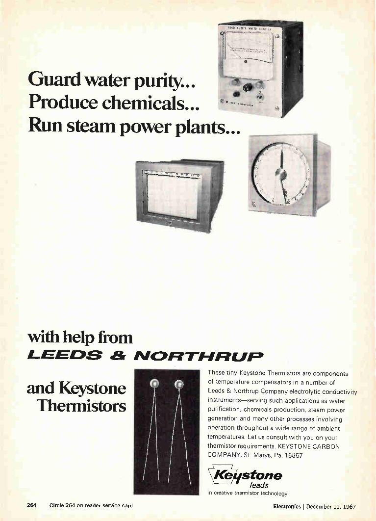
Guard water purity... Produce chemicals... Run steam power plants...
with help from LEEE:IS ar ISIGIFITIFIFILJFe
and Keystone Therrnistors
These tiny Keystone Thermistors are components
of temperature compensators in a number of
Leeds & Northrup Company electrolytic conductivity
instruments—serving such applications as water
purification, chemicals production, steam power
generation and many other processes involving
operation throughout a wide range of ambient
temperatures. Let us consult with you on your
thermistor requirements. KEYSTONE CARBON
COMPANY, St. Marys, Pa. 1 5857
stone leads
in creative thermistor technology
264 Circle 264 on reader service card Electronics 1 December 11, 1967

December 11, 1967
Electronics reader service Warning: The Post Office now requires your ZIP CODE on all mail. Please include your ZIP CODE
number when tilling out your reply card
Use these handy post cards
for more detailed information
on: products advertised, new products, new literature.
Circle the number on the Reader Serv-ice post card that corresponds to the number at the bottom of the advertise-ment, new product item, or new liter-ature in which you are interested.
Please print clearly. All written in-formation must be legible to be effi-ciently processed.
If someone has beaten you to the post cards, you may obtain the needed information by writing directly to the manufacturer, or by sending your name and address, plus the Reader Service number, to Electronics Reader Service department.
All inquiries from outside the U.S. that cannot reach Electronics before the expiration dates noted on the Reader Service post card, must be mailed directly to the manufacturer. The manufacturer assumes all respon-sibilities for responding to inquiries. Electronics merely provides and clears requests for information from inquirer to manufacturer.
Correct amount of postage must be affixed for all mailings from outside the U.S.
To subscribe to or to renew Electronics
Fill in the "For Subscriptions" area on the card if you desire to subscribe to or renew your present subscription to Electronics. Send no money. Elec-tronics will bill you at the address in-dicated on the Reader Service post card.
Multi-product advertisements For information on specific items in
multi-product advertisements which do not have a specific Reader Service num-ber indicated write directly to man-ufacturer for information on precise product in which you are interested.
r25 Please Print Clearly *For employment inquires fill in home address. 14
Name title December 11, 1967
Card Expires Company'_
February 11, 1968
Address
City State Zip Code
1 20 39 58 77 96 115 134 153 172 191 210 229 248 267 286 305 324 343 362 381 400 419 438 457 476 495 514 962
2 21 40 59 78 97 116 135 154 173 192 211 230 249 268 287 306 325 344 363 382 401 420 439 458 477 496 515 963
3 22 41 60 79 98 117 136 155 174 193 212 231 250 269 288 307 326 345 364 383 402 421 440 459 478 497 516 964
4 23 42 61 80 99 118 137 156 175 194 213 132 251 270 289 308 327 346 365 384 403 422 441 460 479 498 517 965
5 24 43 62 81 100 119 138 157 176 195 214 233 252 271 290 309 328 347 366 385 404 423 442 461 480 499 518 966
6 25 44 63 82 101 120 139 158 177 196 215 234 253 272 291 310 329 348 367 386 405 424 443 462 481 500 900 967
7 26 45 64 83 102 121 100 159 178 197 216 235 254 273 192 311 330 349 368 387 406 425 444 463 482 501 901 968
8 27 46 65 84 103 122 141 160 179 198 217 236 255 274 293 312 331 350 369 388 407 426 445 464 483 502 902 969
9 28 47 66 85 104 123 142 161 180 199 218 237 256 275 294 313 332 351 370 389 408 427 446 465 484 503 951 970
10 29 48 67 86 105 124 143 162 181 200 219 238 257 276 295 314 333 352 371 390 409 428 447 466 485 504 952 971
11 30 49 68 87 106 125 144 163 182 201 220 239 258 277 296 315 334 353 372 391 410 429 448 467 486 505 953 972
12 31 50 69 88 107 126 145 164 183 202 221 240 259 178 297 316 335 354 373 392 411 430 449 468 487 506 954 973
13 32 51 70 89 108 127 146 165 184 203 222 241 260 279 298 31/ 336 355 374 393 412 431 450 469 488 507 955 974
14 33 52 71 90 109 128 147 166 185 204 223 242 261 280 299 318 337 356 375 394 413 432 451 470 489 508 956 975
15 34 53 72 91 110 129 148 167 186 205 224'243 262 281 300 319 338 357 376 395 414 433 452 471 490 509 957 976
16 35 54 73 92 Ill 130 149 168 187 206 225 244 263 282 301 320 339 358 377 396 415 434 453 472 491 510 958 977
17 36 55 74 93 112 131 150 169 188 207 226 245 264 283 302 321 340 359 378 397 416 435 454 473 492 511 959 978
18 37 56 75 94 113 132 151 170 189 208 227 246 265 284 303 322 341 360 379 398 417 436 455 474 493 512 960 979
19 38 57 76 95 114 133 152 171 190 209 228 247 266 285 304 323 342 361 380 399 418 437 456 475 494 513 961 980
25 Please Print Clearly *For employment inquires fill in home address. 14
Name title December 11, 1967
Company' Card Expires
February 11, 1968
Address
City State Zip Code
I 20 39 58 77 96 115 134 153 172 191 210 229 748 267 286 305 324 343 362 381 400 419 438 457 476 495 514 962 2 21 40 59 78 97 116 135 154 173 192 211 230 249 268 287 306 325 344 363 382 401 420 439 458 477496 515 963
3 22 41 60 79 98 117 136 155 174 193 212 231 250 269 288 307 326 345 364 383 402 421 440 459 478 497 516 964
4 23 42 61 80 99 118 137 156 175 194 213 232 251 270 289 308 327 346 365 384 403 422 441 460 479 498 517 965
5 24 43 61 81 100 119 138 157 176 195 214 233 252 271 290 309 328 347 366 385 404 423 442 461 480 499 518 966
6 25 44 63 82 101 120 139 158 177 196 215 234 253 272 291 310 329 348 367 386 405 424 443 462 481 500 900 967
7 26 45 64 83 102 121 140 159 178 197 216 235 254 273 292 311 330 349 368 387 406 425 444 463 482 501 901 968
8 27 46 65 84 103 122 141 160 179 198 217 236 255 274 293 312 331 350 369 388 407 426 445 464 483 502 902 969
9 28 47 66 85 104 123 142 161 180 199 218 237 256 275 294 313 332 351 370 389 408 427 446 465 484 503 951 970
10 29 48 67 86 105 124 143 162 181 200 219 238 257 276 295 314 333 352 371 390 409 428 447 466 485 504 952 971
11 30 49 68 87 106 125 144 163 182 201 220 239 258 277 296 315 334 353 372 391 410 429 448 467 486 505 953 972
12 31 50 69 18 107 126 145 164 183 202 271 740 259 278 297 316 335 354 373 392 411 430 449 468 487 506 954 973
13 32 51 70 89 108 127 146 165 184 203 777 241 260 279 298 317 336 355 374 393 412 431 450 469 488 507 955 974
14 33 52 71 90 109 128 147 166 185 204 223 242 261 280 299 318 337 356 375 394 413 432 451 470 489 508 956 975
15 34 53 72 91 110 129 148 167 186 205 224 243 262 281 300 319 338 357 376 395 414 433 452 471 490 509 957 976
16 35 54 73 92 Ill 130 149 168 187 206 225 244 263 282 301 320 339 358 377 396 415 434 453 472 491 510 958 977 17 36 55 74 93 112 131 15o 169 188 207 226 245 264 283 302 321 340 359 378 397 416 435 454 473 492 511 959 978
:8 37 56 75 94 113 132 151 170 189 208 227 246 265 284 303 322 341 360 379 398 417 436 455 474 493 512 960 979
19 38 57 76 95 114 133 152 171 190 209 728 247 266 285 304 323 342 361 380 399 418 437 456 e75 494 513 961 980
Electronics New subscription application Please start my three year subscription for only $16 — I save $8!
[I] 1 Year $8 E Bill Me E Bill Company E Payment Enclosed Subscription Includes 1,200 Page Annual Buyers' Guide Issue
Name Title Please Fill in All Spaces
Company
Company address Zip A
City State codel)
Product or Service manufactured performed
Are you involved in the specification of electronic or allied products? Yes " No
Please check your department or function:
E Research Design, development E; Production, operation, maintenance
El Other (please describe)
Above rates apply only to those professionally engaged in electronics technology. All others. $26 per year.
05,

Reprint service All Electronics editorial matter available in reprint form:
3
For reprints of special reports and feature articles see list on right side of this page. Send your order to Electronics Reprint Department at the address indicated. To expedite mailing of your order for single reprints please send cash, check or money order with your order. Allow 3-4 weeks for delivery.
Bulk reprints of editorial matter can be ordered from current or past issues. The minimum quantity is 100 copies. Prices quoted on request: call 212-971-2274, or write to address below.
Warning: The Post Office now requires your ZIP CODE on all mail. Please include your ZIP CODE number when filling out your reply card.
----- i
Business reply mail No postage stamp necessary if mailed in the United States
Postage will be paid by
Electronics
Reader service department Box 444
Hightstown, N. J. 08520
Business reply mail No postage stamp necessary if mailed in the United States
Postage will be paid by
Electronics
Reader service department
Box 444
Hightstown, NJ. 08520
----
Business reply mail No postage stamp necessary if mailed in -the United States
Postage will be paid by
Electronics P. O. Box 514 Hightstown, N. J. 08520
First class Permit no. 42
Hightstown, N. J.
•
MalalfflfflilaalaMlaMial
First class Permit no. 42
Hightstown, N. J.
First class Permit no. 42
Hightstown, N. J.
WilatlIMIIM11111111
Key no. R-86a
Key no. R-79
Key no. R-78
Key no. R-75
Key no. R-74
Key no. R-64
Key no. R-60
Key no. R-31
To order reprints, or for further informa-tion, please write to: Electronics Reprint Department, 330 West 42nd Street, New York, N.Y. 10036.
You may order any of the below listed re-prints by key number. Discounts on quan-tities over 10.
Key no. R-01 Computer-aided Design: Part I, The Man-machine Merger. 16 pages. $1.25.
Key no. R-02 Vietnam Communications Net-work Growing Into Southeast Asia's Best. 3 pages. 250.
Key no. R-03 Sense Amplifier Fits Any Prod-uct. 6 pages. 250
Key no. R-04 Multilayer Circuit Boards: Sharpening An Imperfect Art. 7 pages. 50C.
Key no. R-05 Topology Cuts Design Drudg-ery. 12 pages. 50e.
Key no. R-06 Report on Japanese Technol-ogy: Sony. 20 pages. 50e.
Key no. R-07 European Electronics Markets 1967. 22 page forecast report with 4 page foldout chart. $1.00.
Key no. R-08 U.S. Electronics Markets 1967. 26 page forecast report with 6 page foldout. $1.00.
Key no. R-09 1966 Electronics Index to Technical Articles and Authors Free.
Key no. R-010 Special Report on Large Scale Integration. 54 pages. $1.50.
Key no. R-011 Medical Electronics (1967). 8 part series, 44 pages. $1.25.
Key no. R-87a The Packaging Revolution in Microelectronics. Parts I through VI. 64 pages. $2.00.
Computer Time Sharing. Parts I and II. 32 pages. $1.00.
MOS Integrated Circuits. 12 pages. 50e.
The Overlay Transistor. 15 pages. 50e.
Biotelemetry. 2 part series, 16 pages. 500.
Unijunction Transistors. 24 pages. 50e.
Field Effect Transistors. Parts I, Il, and III. 64 pages. $1.00.
Transistor Heat Dissipators. 32 pages. 50e.
Electromagnetic Spectrum Chart. (22" x 30" foldout chart). $1.00.
Subscription department

Dale RH Wirewounds have BONUS capacity to handle any power or stability problem. Dale's RH Wirewound line offers 6 models, 5 to 250 watts. Each has bonus ability to dissipate heat beyond MIL-R-18546D requirements—see chart. In addition, you get an extra bonus of ex-ceptional stability when RH models are derated to mil levels. To achieve this bonus performance, Dale combines precision wirewound elements with specially-conductive extruded aluminum housings and special molding compounds. The result is exceptional heat transfer ability matched by no other housed wirewound line.
NEW HIGH-REL MODELS
The ARH, a high-rel version of the RH, is now available in four models: 5, 10, 15 and 30 watts. ARH resistors meet the requirements of M IL-R-39009 and are being produced on the same line as Dale's ARS and AGS —the world's most reliable wirewounds.
For complete housed resistor information including non-inductive and thru-chassis models—write for Catalog A.
RH RESISTOR SPECIFICATIONS
DALE TYPE
EQUIV. MIL TYPE
DALE RATING.
MIL RATING
RESISTANCE FtANGE (OHMS)
STANDARD HEAT SINK
RH-5 RE-60 7.5 (5) 5 .1-24K 4x6x2x.040 Aluminum Chassis RH-10 RE-65 12.5 (10) 10 .1-47K
RH-25 RE-70 25 20 .1-95K 5x7x2x.040 Aluminum Chassis
RH-50 RE-75 50 30 .1-273K 12x12x.059 Aluminum Panel
RH-100 RE-77 100 75 .1-50K 12x12x.125 Aluminum Panel RH-250 RE-80 250 120 .1-75K
ELECTRICAL & ENVIRONMENTAL SPECIFICATIONS
Tolerance: .05%, .10%, .25%, .5%, 1%, 3%
Load Life: 1% max.à R (RH-5 — 50) 3% max. à R (RH-100 — 250) in 1000-hour load life.
Operating Temp: —55° C to +275° C
Overload: +.5% max.à R per MIL-R-18546D *Power Rating based on 275° C max. internal hotspot temperature with resistor mounted on standard heat sink Figures in parentheses indicate wattage printed on RH-5 and RH-la New construction allows higher ratings as shown, but these resistors will be printed with the higher rating only on customer request. e
DALE ELECTRONICS, INC. e. 4._
1300 28th Avenue, Columbus, Nebraska In Canada: Canada: Dale Electronics, Canada, Ltd.
Circle 901 on reader service card

G-2 "Cup"
Caught with their "ceramics" down all similarly rated tubes are not equa Construction of the high-gain Cermolox® RCA-4628 is far superior. For example, the G-1 and G-2 "cups" are locked together in a rigid assembly, then simultaneously electrically machined to produce grid wires precisely aligned with respect to each other. The result: a simpli-fied, unitized construction. In SSB Communications and FM Broadcast service, particularly, the RCA-4628 de-livers even more outstanding performance as a result of its compact coaxial structure, precision-aligned electron-ically-machined grids, and ceramic-to-metal seals. •
RCA-4628, rated to 400 MHz, provides 10 kW PEP out-put in the 2 to 30 MHz range with lower distortion and better gain than its nearest counterpart. In FM Broad-cast service, it offers higher gain with non-critical broad-band neutralization techniques.
0 From now on, look "inside" as well as outside when you need tubes. In the RCA-4628, you'll find rug-gedness, compactness, and long-life reliability. Mechanically-in-duced noise is very low and, because
Electrical of UHF capabilities, you have no Machining
Tool need for complex neutralization circuits at HF. The RCA-4628 is your obvious choice.
For more information on this and other RCA Cermolox® tubes, see your RCA Representative. For technical data on specific tube types, write: RCA Commercial Engineering, Section L 1 9Q-2, Harrison, New Jersey 07029. ALSO AVAILABLE FROM YOUR RCA INDUSTRIAL TUBE DISTRIBUTOR
RCA Electronic Components and Devices
The Most Trusted Name in Electronics
Related Documents