
Welcome message from author
This document is posted to help you gain knowledge. Please leave a comment to let me know what you think about it! Share it to your friends and learn new things together.
Transcript
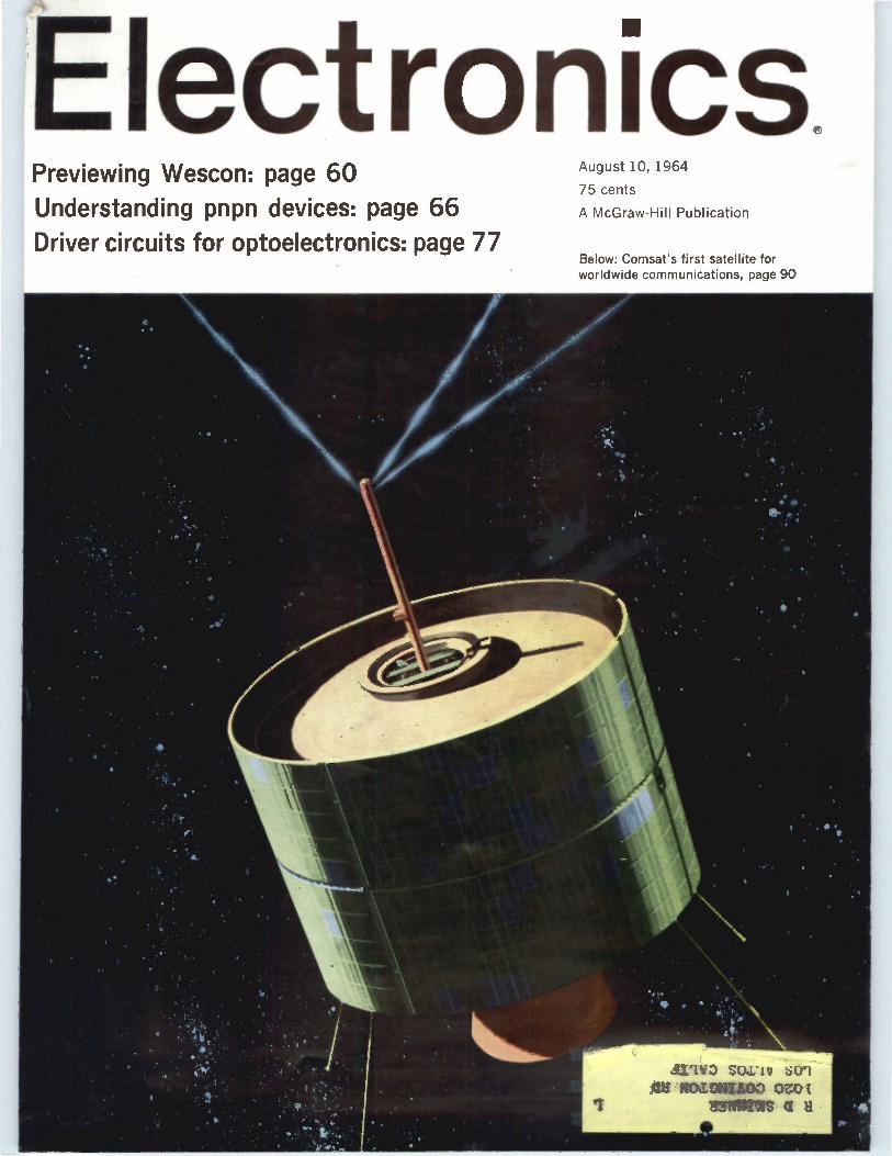
'Electronics. Previewing Wescon: page 60 August 10, 1964
75 cents
Understanding pnpn devices: page 66 A McGraw-Hill Publication
Driver circuits for optoelectronics: page 77 Below: Comsat's first satellite for worldwide communications, page 90
•
• •e
• • . . .. •
.1. • •.‘
Ire
" • •
.1 •
• . ehb: '..-• -.. • • .•,: ts e
e - • •
' • ' ; 1 . I • e't .." ..
•••-•
,vi
h
'1
r „ • •
Arit 1. • • .
T :1
• ..
•
•111
a . •
* • • • 1•,.. er•'!
.• • • .
.11.1110 Seely •Jori GL 1/0.1.01-11100, OZOt
113N111118
•
•:a
fr j'
At M
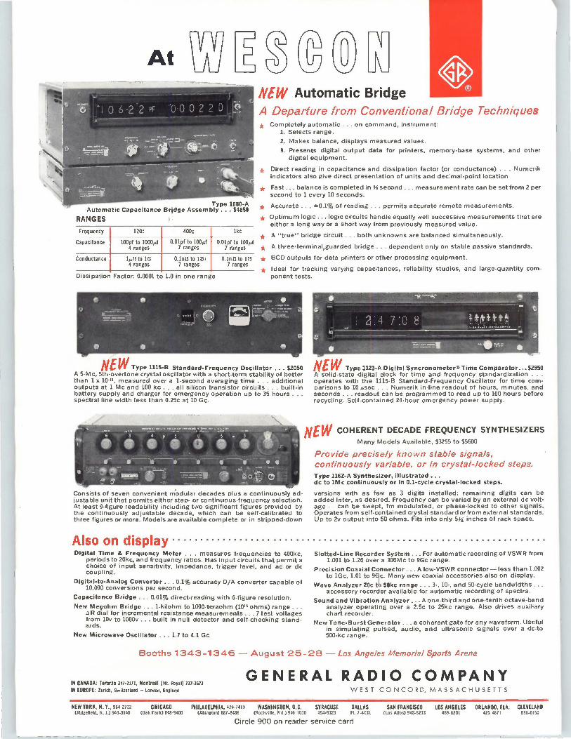
Type 1680-A Automatic Capacitance Bridge Assembly ... $4850
RANGES 1
Frequency 120c 400c lkc
Capacitance 100pf to 1000mf 4 ranges
0.01pf to 100µf 7 ranges
0.01pf to 100»f 7 ranges
Conductance IMO to 173 4 ranges
0.1nn to In' 7 ranges
°Ann to 173 7 ranges
Dissipation Factor: 0.0001 to 1.0 in one range
C NEW Automatic Bridge A Departure from Conventional Bridge Techniques * Completely automatic ... on command, instrument:
1. Selects range.
2. Makes balance, displays measured values.
3. Presents digital output data for printers, memory-base systems, and other digital equipment.
• Direct reading in capacitance and dissipation factor (or conductance) . . . Numerik indicators also give direct presentation of units and decimal-point location
* Fast... balance is completed in .1‘9 second ... measurement rate can be set from 2 per second to 1 every 10 seconds.
* Accurate ... 0.1% of reading ... permits accurate remote measurements.
* Optimum logic ... logic circuits handle equally well successive measurements that are either a long way or a short way from previously measured value.
* A "true" bridge circuit ... both unknowns are balanced simultaneously.
* A three-terminal,guarded bridge ... dependent only on stable passive standards.
* BCD outputs for data printers or other processing equipment.
• Ideal for tracking varying capacitances, reliability studies, and large-quantity com-ponent tests.
NEW Type 1115-B Standard-Frequency Oscillator ... $2050 A 5-Mc, 5th-overtone crystal oscillator with a short-term stability of better than 1 x 10-", measured over a 1-second averaging time . . . additional outputs at 1 Mc and 100 kc all silicon transistor circuits ... built-in battery supply and charger for emergency operation up to 35 hours ... spectral line width less than 0.25c at 10 Gc.
Consists of seven convenient m'odular decades plus a continuously ad-justable unit that permits either step- or continuous-frequency selection. At least 9-figure readability including two significant figures provided by the continuously adjustable decade, which can be self-calibrated to three figures or more. Models are available complete or in stripped-down
Also on display Digital Time & Frequency Meter . . . measures frequencies to 400kc,
periods to 20kc, and frequency ratios. Has input circuits that permit a choice of input sensitivity, impedance, trigger level, and ac or dc coupling.
Digital-to-Analog Converter ... 0.1% accuracy DIA converter capable of 10,000 conversions per second.
Capacitance Bridge ... 0.01% direct-reading with 6-figure resolution.
New Megohm Bridge ... 1-kilohm to 1000-teraohm (10" ohms) range ... dial for incremental resistance measurements ... 7 test voltages
from 10v to 1000v ... built in null detector and self-checking stand-ards.
New Microwave Oscillator ... 1.7 to 4.1 Gc
NEW Type 1123-A Digital SyncronometerS Time Comparator ...$2950 A solid-state digital clock for time and frequency standardization . . . operates with the 1115-B Standard-Frequency Oscillator for time com-parisons to 10 gsec . Numerik in-line readout of hours, minutes, and seconds ... readout can be programmed to read up to 100 hours before recycling. Self-contained 24-hour emergency power supply.
NEW COHERENT DECADE FREQUENCY SYNTHESIZERS Many Models Available, $3255 to $5600
Provide precisely known stable signals, continuously variable, or in crystal-locked steps. Type 1162-A Synthesizer, illustrated ... dc to 1Mc continuously or in 0.1-cycle crystal-locked steps.
versions with as few as 3 digits installed; remaining digits can be added later, as desired. Frequency can be varied by an external dc volt-age — can be swept, fm modulated, or phase-locked to other signals. Operates from self-contained crystal standard or from external standards. Up to 2v output into 50 ohms. Fits into only 5;1: inches of rack space.
Slotted-Line Recorder System ... For automatic recording of VSWR from 1.001 to 1.20 over a 300Mc to 9Gc range.
Precision Coaxial Connector .... A low-VSWR connector — less than 1.002 to 1Gc, 1.01 to 99c. Many new coaxial accessories also on display.
Wave Analyzer 20c to 50kc range ... 3-, 10-, and 50-cycle bandwidths ... accessory recorder available for automatic recording of spectra.
Sound and Vibration Analyzer ... A one-third and one-tenth octave-band analyzer operating over a 2.5c to 25kc range. Also drives auxiliary chart recorder.
New Tone-Burst Generator ... a coherent gate for any waveform. Useful in simulating pulsed, audio, and ultrasonic signals over a dc-to 500-kc range.
Booths 1343-1346 — August 25-28 — Los Angeles Memorial Sports Arena
IN CANADA: Toronto 247-2171, Montreal (mt. RoYall 737-3673 IN EUROPE: Zurich, Switzerland — London, England
GENERAL RADIO COMPANY WEST CONCORD, MASSACHUSETTS
NEW YORK, N.Y., 964-2722 CHICAGO PHILADELPHIA, 424-7419 WASHINGTON, D.C. SYRACUSE DALLAS (Ridgefield, N. J.) 943-3140 (Oak Park) 848-9400 (Abington) 887-8486 (Rockville, Md.) 946-1600 454-9323 FL 7-4031
Circle 900 on reader service card
SAN FRANCISCO LOS ANGELES ORLANDO, FLA. CLEVELAND (Los Altos) 948-8233 469-6201 425 467 I 886-0150
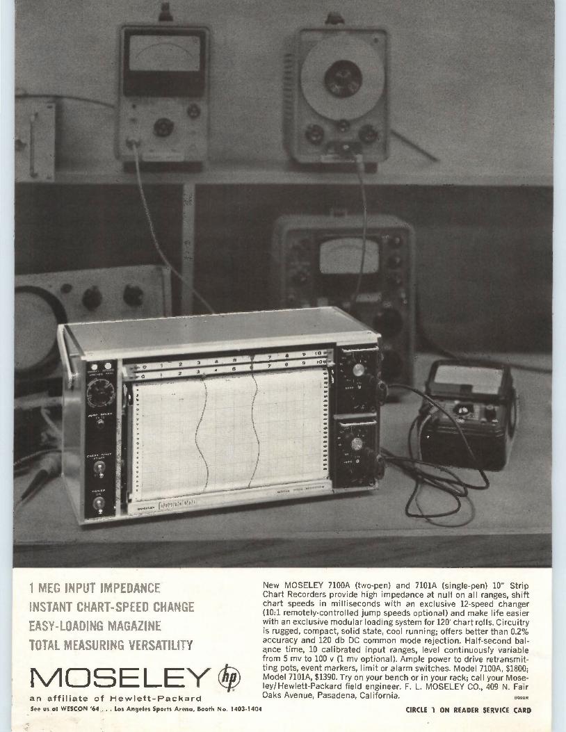
1 MEG INPUT IMPEDANCE
INSTANT CHART-SPEED CHANGE
EASY-LOADING MAGAZINE
TOTAL MEASURING VERSATILITY
MOSELEY an affiliate of Hewlett-Packard
New MOSELEY 7100A (two-pen) and 7101A (single-pen) 10" Strip Chart Recorders provide high impedance at null on all ranges, shift chart speeds in milliseconds with an exclusive 12-speed changer (10:1 remotely-controlled jump speeds optional) and make life easier with an exclusive modular loading system for 120' chart rolls. Circuitry is rugged, compact, solid state, cool running; offers better than 0.2% accuracy and 120 db DC common mode rejection. Half-second bal-ance time, 10 calibrated input ranges, level continuously variable from 5 my to 100 y (1 my optional). Ample power to drive retransmit-ting pots, event markers, limit or alarm switches. Model 7100A, $1800; Model 7101A, $1390. Try on your bench or in your rack; call your Mose-ley/Hewlett-Packard field engineer. F. L. MOSELEY CO., 409 N. Fair Oaks Avenue, Pasadena, California. 9099 It
See us at WESCON '64 ... Los Angeles Sports Arena, Booth No. 1403-1404 CIRCLE 1 ON READER SERVICE CARD
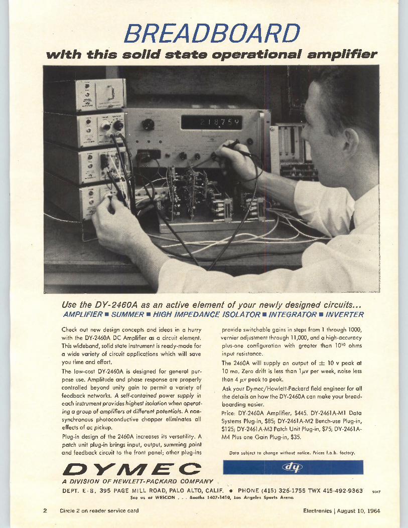
BREADBOARD with this solid state operational amplifier
Use the DY-2460A as an active element of your newly designed circuits... AMPLIFIER. SUMMER • HIGH IMPEDANCE ISOLATOR n INTEGRATOR • IN
Check out new design concepts and ideas in a hurry
with the DY-2460A DC Amplifier as a circuit element. This wideband, solid state instrument is ready-made for a wide variety of circuit applications which will save
you time and effort.
The low-cost DY-2460A is designed for general pur-pose use. Amplitude and phase response are properly controlled beyond unity gain to permit a variety of feedback networks. A self-contained power supply in
each instrument provides highest isolation when operat-ing a group of amplifiers at different potentials. A non-
synchronous photoconductive chopper eliminates all effects of ac pickup.
Plug-in design of the 2460A increases its versatility. A
patch unit plug-in brings input, output, summing point and feedback circuit to the front panel; other plug-ins
GP Y11/1 E"
provide switchable gains in steps from 1 through 1000, vernier adjustment through 11,000, and a high-accuracy plus-one configuration with greater than 1010 ohms input resistance.
The 2460A will supply an output of -± 10 y peak at 10 ma. Zero drift is less than 1 1.1.v per week, noise less
than 4 ¡Iv peak to peak.
Ask your Dymec/Hewlett-Packard field engineer for all the details on how the DY-2460A can make your bread-boarding easier.
Price: DY-2460A Amplifier, $445. DY-2461A-M1 Data Systems Plug-in, $85; DY-2461A-M2 Bench-use Plug-in, $125; DY-2461A-M3 Patch Unit Plug-in, $75; DY-2461A-M4 Plus-one Gain Plug-in, $35.
Data subject to change without notice. Prices f.o.b. factory.
A DIVISION OF HEWLETT-PACKARD COMPANY
DEPT. E -8, 395 PAGE MILL ROAD, PALO ALTO, CALIF. • PHONE (415) 326-1755 TWX 415-492-9363 See us at WESCON . . . Booths 1407-1410, Los Angeles Sports Arena
9047
2 Circle 2 on reader service card Electronics I August 10, 1964
Page 4 8
10 15 17 45
121 158 161 163
August 10, 1964 Volume 37, Number 22
Electronics
Readers comment People Meetings ahead Editorial Electronics newsletter Washington newsletter New products New literature New books Technical abstracts
In this issue
Title R registered U.S. Patent Office; 0 copyright 1964 by McGraw-Hill, Inc. All rights reserved, including the right to reproduce the contents of this publication, in whole or in part.
Page 29 30
30 31 32
Meeting report
Components
Circuit design
Solid state
Avionics
Electronics review
Ranger succeeds at last 32 Production 32 breakthrough 34 Ring, dish and tire Digital weather 34 Crystals: drop by drop 36
Probing the news 103 What makes Wescon run? 104 Dude goes West 106 How the West wins business 112 Our man in Washington
Technical articles
GE expands X-ray subtracter Computers in cement An inside job Weather by wire
1. Design
60 Significance of Wescon's technical program The decline in West Coast electronics business shows up in the region's technology Lewis H. Young, editor
66 Transistor analog: the pnpn device There's more to be learned about pnpn devices if you consider them in terms of transistors . Richard A. Stasior, General Electric Co.
74 Designer's casebook Oscillator generates sine and cosine functions simultaneously; 1,500-volt hybrid switch has low "on" impedance; servo comparator amplifier handles high voltages
77 Driver circuits for light-emitting diodes Behind the light-emitting diode must be a driver circuit; here are some useful transistorized ones Edward L. Bonin, Texas Instruments, Inc.
II. Application
83 Straining the noise out of radar data A new technique makes the air traffic controller's job easier William J. Evanzia, avionics editor
Space electronics 90 The Early Bird: bigger and better (cover) Comsat's first satellite will be bigger and better than any yet launched Joel A. Strasser, space electronics editor
Readers Comment
Electronics Editor: Lewis H. Young
Managing editor: John M. Carroll
Senior editors Technical: Samuel Weber News: Kemp Anderson, Jr.
Senior associate editors: John F. Mason, George Sideris
Department editors Advanced technology: George V. Novotny Avionics: W.J. Evanzia Circuit design: Jerome Eimbinder Communications: Alexander A. McKenzie Components: Michael F. Tomaino Computers: Stephen B. Gray
Industrial electronics: Louis S. Gomolak Instrumentation: George J. Flynn Manufacturing: George SIderis Military electronics: John F. Mason New products: William P. O'Brien Solid state: G.G. Tirellis Space electronics: Joel A. Strasser Staff writers: Leon H. Dulberger, Peggy Jackson
Regional editors Boston: Thomas Maguire, editor; Susan Turner
Chicago: Cletus M. Wiley, editor; Leslie Krimston Los Angeles: Harold C. Hood, editor San Francisco: Laurence D. Shergalis, editor; Mary Jo Jadin London: Derek Barlow, editor
Copy editors Howard Rausch, Sally Powell
Illustration Art director: Howard R. Berry Assistant art director: John C. Wright, Jr. Editorial production: Ann Melia, Sandra A. LeMond
Editorial secretaries: Claire Benell, Lynn Emery, Kay Fontana, Lorraine Rossi, Lorraine Werner
McGraw-Hill news service Director: John Wilhelm; Atlanta: Fran Ridgeway; Chicago: Bruce Cross; Cleveland: Arthur Zimmerman; Dallas: Marvin Reid; Detroit: Donald MacDonald; Los Angeles: Michael Murphy, Ron Lovell; San Francisco: Margaret Ralston, Ed. Addeo;
Seattle: Ray Bloomberg; Washington: George Bryant Jr., Glen Bayless, Charles Gardner
McGraw-Hill world news service Bonn: Richard Mikton; Brussels: Arthur Erikson; London: John Shinn; Mexico City: Wesley Perry; Milan: Bruce Bendow; Moscow: Donald Winston; Paris: Dan Smith; Rio de Janeiro: Leslie Warren; Tokyo: Richard Halloran, Charles Cohen
Circulation manager: Hugh Quinn Reprints: T.M. Egan
Publisher: C.C. Randolph
Electronics: August 10, 1964, Vol. 37, No. 22
Printed at 99 North Broadway, Albany, N.Y. Second class postage paid at Albany, N.Y.
Subscriptions are solicited only from those actively engaged in the field of the publication. Position and company connection must be indicated on orders. Subscription prices: United States and Possessions and Canada, $6.00 one year, $9.00 two years, $12.00 three years. All other countries $20.00 one year. Single copies, United States and Possessions and Canada Mt. Single copies all other countries $1.50.
Published every other Monday by McGraw-Hill Inc. 330 West 42nd Street, New York, N.Y.10036. Founder: James H. McGraw, 1860-19413.
Subscribers: The Publisher, upon written request to our New York office from any subscriber, agrees to refund that part of the subscription price applying to copies not yet mailed. Please send change of address notices, subscription orders or complaints to Fulfillment Manager, Electronics, at the address below. Change of address notices should provide old as well as new address, including postal zone number if any. If possible, attach address label from recent issue. Allow one month for change to become effective.
Postmaster: Please send Form 3579 to Fulfillment Manager, Electronics, P.O. Box 430, Hightstown, New Jersey 08520
Mail sorting
We need more men in high posi-tions in the federal service with the insight that S.H. McNeill and A. Kiron showed in their July 13 letters [p. 6]. May I take this op-portunity to encourage them to present their ideas to the Post Of-fice Department? They should pre-sent their ideas to a man who is big enough to have no need to build a research empire. Maybe the greater consciousness of the effectiveness-to-cost ratio, which has been evident in the govern-ment in recent months, will give them an audience that will be more responsive than I had in June, 1963, when I presented a similar con-cept to an official in the Office of Research and Engineering for the Post Office. I do not deny that we have a
distinct need for readers that can read any alphabet in any font or even in script—but I do not agree that the Post Office is justified in financially supporting such re-search for developing machines for its use.
Charles P. Hedges General Electric Co. Santa Barbara, Calif.
To add to the references to "Scan-ning the Mails" [June 15, p. 115; Comment, July 13, p. 6], here are a few state-of-the-art ideas that could easily be installed:
1. The most important key in-formation, the zip code, is now the last bit of information at the end of the address. If the mail moves through several sortings, each time several lines must be scanned to get to the zip code. I would think the Post Office would want the code first, and the addressee's name last. For instance:
10036 N. Y., New York West 42 St., 330 Electronics Magazine Editor
2. Really simple sorting could be done by the stamps being placed in predetermined areas on the envelope. . . . Other squares around the periphery of the en-velope could designate large cities, states, etc. . . . Also, the stamps
4 Electronics I August 10, 1964
(Aavemsement)
New Bridge Design For Safe, Accurate, Easy Measurement of 'Lytic Capacitors
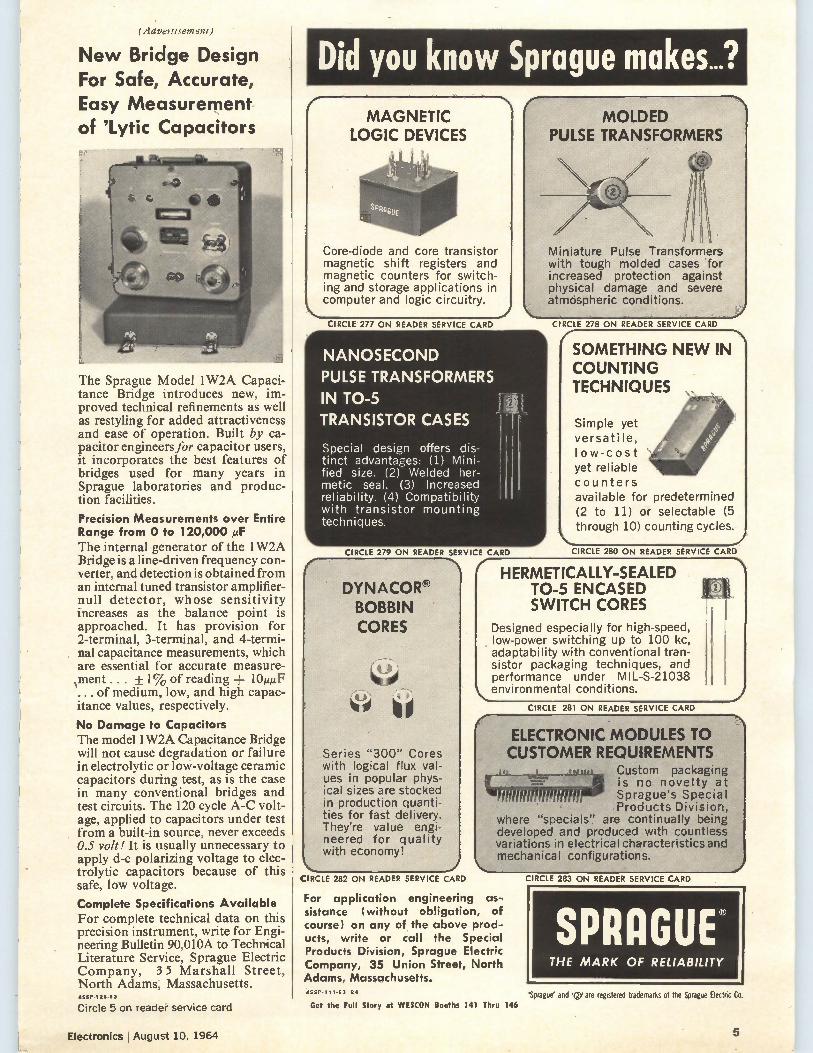
The Sprague Model 1W2A Capaci-tance Bridge introduces new, im-proved technical refinements as well as restyling for added attractiveness and ease of operation. Built by ca-pacitor engineersfor capacitor users, it incorporates the best features of bridges used for many years in Sprague laboratories and produc-tion facilities.
Precision Measurements over Entire Range from 0 to 120,000 µF The internal generator of the 1W2A Bridge is a line-driven frequency con-verter, and detection is obtained from an internal tuned transistor amplifier-null detector, whose sensitivity increases as the balance point is approached. It has provision for 2-terminal, 3-terminal, and 4-termi-nal capacitance measurements, which are essential for accurate measure-ment . . . + 1% of reading + 10,F ... of medium, low, and high capac-itance values, respectively.
No Damage to Capacitors The model 1W2A Capacitance Bridge will not cause degradation or failure in electrolytic or low-voltage ceramic capacitors during test, as is the case in many conventional bridges and test circuits. The 120 cycle A-C volt-age, applied to capacitors under test from a built-in source, never exceeds 0.5 volt! It is usually unnecessary to apply d-c polarizing voltage to elec-trolytic capacitors because of this safe, low voltage.
Complete Specifications Available For complete technical data on this precision instrument, write for Engi-neering Bulletin 90,010A to Technical Literature Service, Sprague Electric Company, 3 5 Marshall Street, North Adams, Massachusetts.
Did you know Sprague makes...? MAGNETIC
LOGIC DEVICES
Core-diode and core transistor magnetic shift registers and magnetic counters for switch-ing and storage applications in computer and logic circuitry.
CIRCLE 277 ON READER SERVICE CARD
NANOSECOND PULSE TRANSFORMERS IN TO-5 TRANSISTOR CASES
Special design offers dis-tinct advantages: (1) Mini-fied size. (2) Welded her-metic seal. (3) Increased reliability. (4) Compatibility with transistor mounting techniques.
CIRCLE 279 ON READER SERVICE
DYNACOR® BOBBIN CORES
Series "300" Cores with logical flux val-ues in popular phys-ical sizes are stocked in production quanti-ties for fast delivery. They're value engi-neered for quality with economy!
CIRCLE 282 ON READER SERVICE CARD
CARD
f MOLDED
PULSE TRANSFORMERS
Miniature Pulse Transformers with tough molded cases for increased protection against physical damage and severe atmdspheric conditions.
CIRCLE 278 ON READER SERVICE CARD
f SOMETHING NEW IN COUNTING TECHNIQUES
Simple yet versatile, I ow-cost yet reliable counters available for predetermined (2 to 11) or selectable (5 through 10) counting cycles.
CIRCLE 280 ON READER SERVICE CARD
HERMETICALLY-SEALED TO-5 ENCASED SWITCH CORES
Designed especially for high-speed, low-power switching up to 100 kc, adaptability with conventional tran-sistor packaging techniques, and performance under MIL-S-21038
...environmental conditions.
CIRCLE 281 ON READER SERVICE CARD
\ ELECTRONIC MODULES TO CUSTOMER REQUIREMENTS
.4elip Custom packaging is no novelty at
idlleffealS Sprague's Special Products Division,
where "specials'! are continually being developed and produced with countless variations in electrical characteristics and mechanical configurations.
For application engineering as-sistance (without obligation, of course) on any of the above prod-ucts, write or call the Special Products Division, Sprague Electric Company, 35 Union Street, North Adams, Massachusetts. 45SP-111.63 R
CIRCLE 283 ON READER SERVICE CARD
SPRAGUE® THE MARK OF RELIABILITY
ASSP-116 69
Circle 5 on reader service card
Electronics August 10, 1964
Get the Full Story at WESCON Booths 141 Thru 146 'Sprague' and '0' are registered trademarks of the Sprague Electric Co.
5
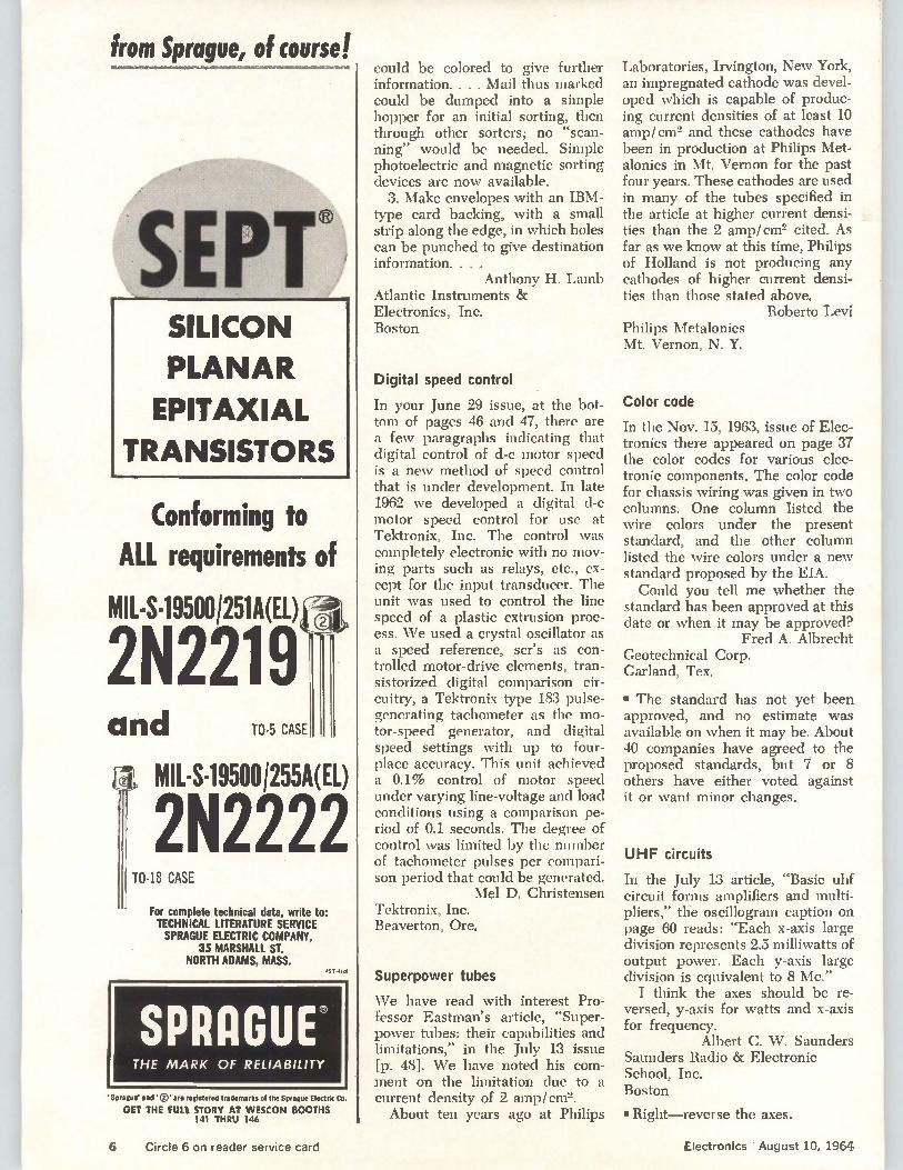
from Sprague, of course!
SILICON
PLANAR
EPITAXIAL
TRANSISTORS
Conforming to ALL requirements of
MIL-S-19500/251A(EL)
2N2219
and TO-5 CASE
iTOMIL-S-19500 1255A(EL)
2N2222 18 CASE
For complete technical data, write to: TECHNICAL LITERATURE SERVICE SPRAGUE ELECTRIC COMPANY,
35 MARSHALL ST. NORTH ADAMS, MASS.
45,1126
SPRAGUE' THE MARK OF RELIABILITY
'Sprague' and'CY are registered trademarks of the Sprague Electric Co.
GET THE FULE STORY AT WESCON BOOTHS 141 THRU 146
could be colored to give further information. . . . Mail thus marked could be dumped into a simple hopper for an initial sorting, then through other sorters; no "scan-ning" would be needed. Simple photoelectric and magnetic sorting devices are now available.
3. Make envelopes with an IBM-type card backing, with a small strip along the edge, in which holes can be punched to give destination information. . . .
Anthony H. Lamb Atlantic Instruments & Electronics, Inc. Boston
Digital speed control
In your June 29 issue, at the bot-tom of pages 46 and 47, there are a few paragraphs indicating that digital control of d-c motor speed is a new method of speed control that is under development. In late 1962 we developed a digital d-c motor speed control for use at Tektronix, Inc. The control was completely electronic with no mov-ing parts such as relays, etc., ex-cept for the input transducer. The unit was used to control the line speed of a plastic extrusion proc-ess. We used a crystal oscillator as a speed reference, scr's as con-trolled motor-drive elements, tran-sistorized digital comparison cir-cuitry, a Tektronix type 183 pulse-generating tachometer as the mo-tor-speed generator, and digital speed settings with up to four-place accuracy. This unit achieved a 0.1% control of motor speed under varying line-voltage and load conditions using a comparison pe-riod of 0.1 seconds. The degree of control was limited by the number of tachometer pulses per compari-son period that could be generated.
Mel D. Christensen Tektronix, Inc. Beaverton, Ore.
Superpower tubes
We have read with interest Pro-fessor Eastman's article, "Super-power tubes: their capabilities and limitations," in the July 13 issue [p.. 48]. We have noted his com-ment on the limitation due to a current density of 2 amp/cm2. About ten years ago at Philips
Laboratories, Irvington, New York, an impregnated cathode was devel-oped which is capable of produc-ing current densities of at least 10 amp/cm2 and these cathodes have been in production at Philips Met-alonics in Mt. Vernon for the past four years. These cathodes are used in many of the tubes specified in the article at higher current densi-ties than the 2 amp/cm2 cited. As far as we know at this time, Philips of Holland is not producing any cathodes of higher current densi-ties than those stated above.
Roberto Levi Philips Metalonics Mt. Vernon, N. Y.
Color code
In the Nov. 15, 1963, issue of Elec-tronics there appeared on page 37 the color codes for various elec-tronic components. The color code for chassis wiring was given in two columns. One column listed the wire colors under the present standard, and the other column listed the wire colors under a new standard proposed by the EIA. Could you tell me whether the
standard has been approved at this date or when it may be approved?
Fred A. Albrecht Geotechnical Corp. Garland, Tex.
• The standard has not yet been approved, and no estimate was available on when it may be. About 40 companies have agreed to the proposed standards, but 7 or 8 others have either voted against it or want minor changes.
UHF circuits
In the July 13 article, "Basic uhf circuit forms amplifiers and multi-pliers," the oscillogram caption on page 60 reads: "Each x-axis large division represents 2.5 milliwatts of output power. Each y-axis large division is equivalent to 8 Mc." I think the axes should be re-
versed, y-axis for watts and x-axis for frequency.
Albert C. \V. Saunders Saunders Radio & Electronic School, Inc. Boston
• Right—reverse the axes.
6 Circle 6 on reader service card Electronics I August 10, 1964
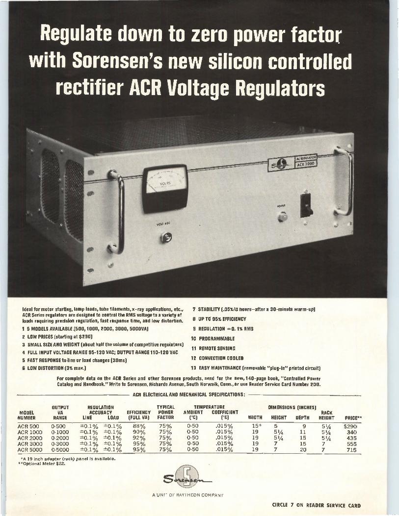
Regulate down to zero power factor with Sorensen's new silicon controlled
rectifier ACR Voltage Regulators
Ideal for motor starting, lamp loads, tube filaments, x-ray applications, etc., ACR Series regulators are designed to control the RMS voltage to a variety of loads requiring precision regulation, fast response time, and low distortion.
1 5 MODELS AVAILABLE (500, 1000, 2000, 3000, 5000VA)
2 LOW PRICES (starting at $290)
3 SMALL SIZE AND WEIGHT (about half the volume of competitive regulators)
4 FULL INPUT VOLTAGE RANGE 95-130 VAC; OUTPUT RANGE 110-120 VAC
5 FAST RESPONSE to line or load changes (30ms)
6 LOW DISTORTION (3% max.)
7 STABILITY (.05%/B hours—after a 30-minute warm-up)
8 UP TO 95% EFFICIENCY
9 REGULATION O. 1% RMS
10 PROGRAMMABLE
11 REMOTE SENSING
12 CONVECTION COOLED
13 EASY MAINTENANCE (removable "plug-in" printed circuit)
For complete data on the ACR Series and other Sorensen products, send for the new, 140-page book, "Controlled Power Catalog and Handbook." Write to Sorensen, Richards Avenue, South Norwalk, Conn., or use Reader Service Card Number 200.
ACR ELECTRICAL AND MECHANICAL SPECIFICATIONS:
OUTPUT REGULATION TYPICAL TEMPERATURE DIMENSIONS (INCHES) MODEL VA ACCURACY EFFICIENCY POWER AMBIENT COEFFICIENT RACK NUMBER RANGE LINE LOAD (FULL VA) FACTOR (°C) (°C) WIDTH HEIGHT DEPTH HEIGHT PRICE**
ACR 500 0-500 -±0.1% -±0.1% 88% 75% 0-50 .015% 15* 5 9 51/4 $290 ACR 1000 0-1000 ±-0.1% ±-0.1% 90% 75% 0-50 .015% 19 51/4 11 51/4 340 ACR 2000 0-2000 -1--0.1% ±-0.1% 92% 75% 0-50 .015% 19 51/4 15 51/4 435 ACR 3000 0-3000 ±-0.1% -±0.1% 95% 75% 0-50 .015% 19 7 15 7 555 ACR 5000 0-5000 --t:0.1% ±-0.1% 95% 75% 0-50 .015% 19 7 20 7 715
*A 19 inch adapter (rack) panel is available. •*Optional Meter $22.
A UNIT OF RAYTHEON COMPANY
CIRCLE 7 ON READER SERVICE CARD
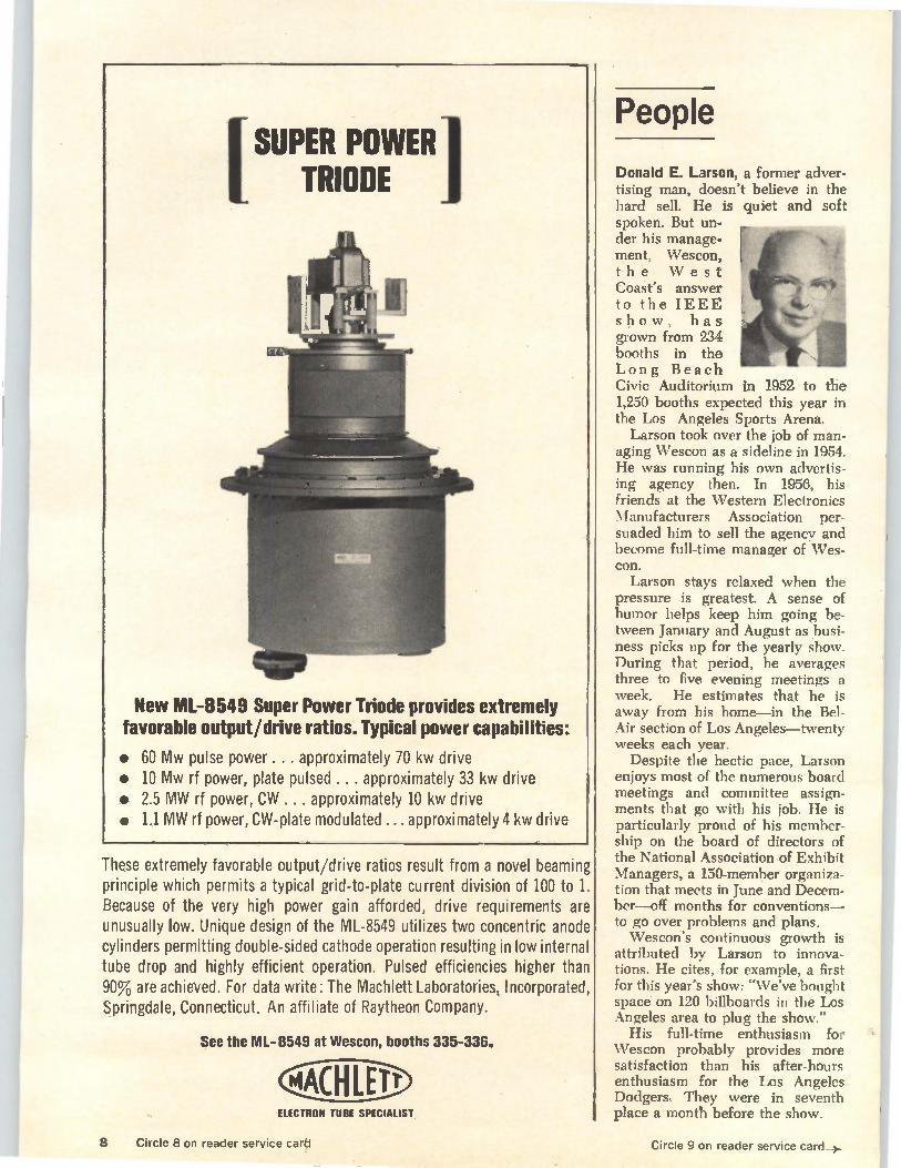
I POWER' TRIODE
New ML-8549 Super Power Triode provides extremely favorable output/drive ratios. Typical power capabilities:
• 60 Mw pulse power .... approximately 70 kw drive • 10 Mw rf power, plate pulsed .. . approximately 33 kw drive • 2.5 MW rf power, CW ... approximately 10 kw drive • 1.1 MW rf power, CW-plate modulated ... approximately 4 kw drive
These extremely favorable output/drive ratios result from a novel beaming principle which permits a typical grid-to-plate current division of 100 to 1. Because of the very high power gain afforded, drive requirements are unusually low. Unique design of the ML-8549 utilizes two concentric anode cylinders permitting double-sided cathode operation resulting in low internal tube drop and highly efficient operation. Pulsed efficiencies higher than 90% are achieved. For data write: The Machlett Laboratories, Incorporated, Springdale, Connecticut. An affiliate of Raytheon Company.
See the ML-0549 at Wescon, booths 335-336.
MACH LEI' ELECTRON TUBE SPECIALIST
People
Donald E. Larson, a former adver-tising man, doesn't believe in the hard sell. He is quiet and soft spoken. But un-der his manage-ment, Wescon, the West Coast's answer to the IEEE show, has grown from 234 booths in the Long Beach Civic Auditorium in 1952 to the 1,250 booths expected this year in the Los Angeles Sports Arena.
Larson took over the job of man-aging Wescon as a sideline in 1954. He was running his own advertis-ing agency then. In 1956, his friends at the Western Electronics Manufacturers Association per-suaded him to sell the agency and become full-time manager of Wes-con.
Larson stays relaxed when the pressure is greatest. A sense of humor helps keep him going be-tween January and August as busi-ness picks up for the yearly show. During that period, he averages three to five evening meetings a week. He estimates that he is away from his home—in the Bel-Air section of Los Angeles—twenty weeks each year.
Despite the hectic pace, Larson enjoys most of the numerous board meetings and committee assign-ments that go with his job. He is particularly proud of his member-ship on the board of directors of the National Association of Exhibit Managers, a 150-member organiza-tion that meets in June and Decem-ber—off months for conventions— to go over problems and plans. Wescon's continuous growth is
attributed by Larson to innova-tions. He cites, for example, a first for this year's show: "We've bought space on 120 billboards in the Los Angeles area to plug the show."
His full-time enthusiasm for \Vescon probably provides more satisfaction than his after-hours enthusiasm for the Los Angeles Dodgers. They were in seventh place a month before the show.
8 Circle 8 on reader service card Circle 9 on reader service card_)..
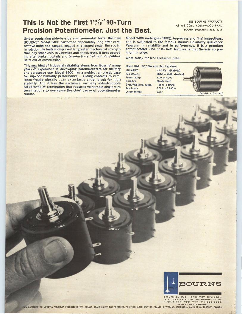
This Is Not the First M6"10-Turn Precision Potentiometer. Just the Best. Under punishing side-by-side environmental tests, the new BOURNS® Model 3400 performed dependably long after com-petitive units had sagged, sogged or snapped under the strain. In rotation-life tests it displayed far greater mechanical strength than any other unit. In vibration and shock tests, it kept operat-ing after broken pigtails and terminations had put competitive units out of commission.
This new kind of industrial reliability stems from Bourns' many years of experience in developing potentiometers for military and aerospace use. Model 3400 has a molded, all-plastic case for superior humidity performance... sliding contacts to elim-inate fragile pigtails...an extra-large slider block for high stability. And it has the exclusive, virtually indestructible SILVERWELD® termination that replaces vulnerable single-wire terminations to overcome the chief cause of potentiometer failure.
SEE BOURNS PRODUCTS
AT WESCON, HOLLYWOOD PARK
BOOTH NUMBERS 363, 4, 5
Model 3400 undergoes 100% in-process and final inspections, and is subjected to the famous Bourns Reliability Assurance Program. In reliability and in performance, it is a premium potentiometer. One of its best features is that there is no pre-mium in price.
Write today for free technical data.
Model 3400, 1.%" Diameter, Bushing Mount
LINEARITY:
Resistances:
Power rating:
Humidity:
Operating temp. range:
Resolution:
Length (body):
-±0.15%, STANDARD
10051 to 500K, standard
5.0W at 40°C
Steady state
—65 to +105°C
0.005 to 0.045% 135"
ONE,HAL/ AC/UAL SI2C
7E3 CYLT 12, 1\7" S
BOURNS. INC.. TRIMPOT DIVISION
1200 COLUMBIA AVE.. RIVERSIDE. CALIF.
PHONE 684-1700 • TWX: 714-682 9562
CABLE:. BOURNSINC.
raNUFACTURER, TRIMPOTY & PRECISION POTENTIOMETERS, RELAYS; TRANSDUCERS FOR PRESSURE, POSITION, ACCELERATION. PLANTS: RIVERSIDE, CALIFORNIA; AMES, IOWA; TORONTO, CANADA
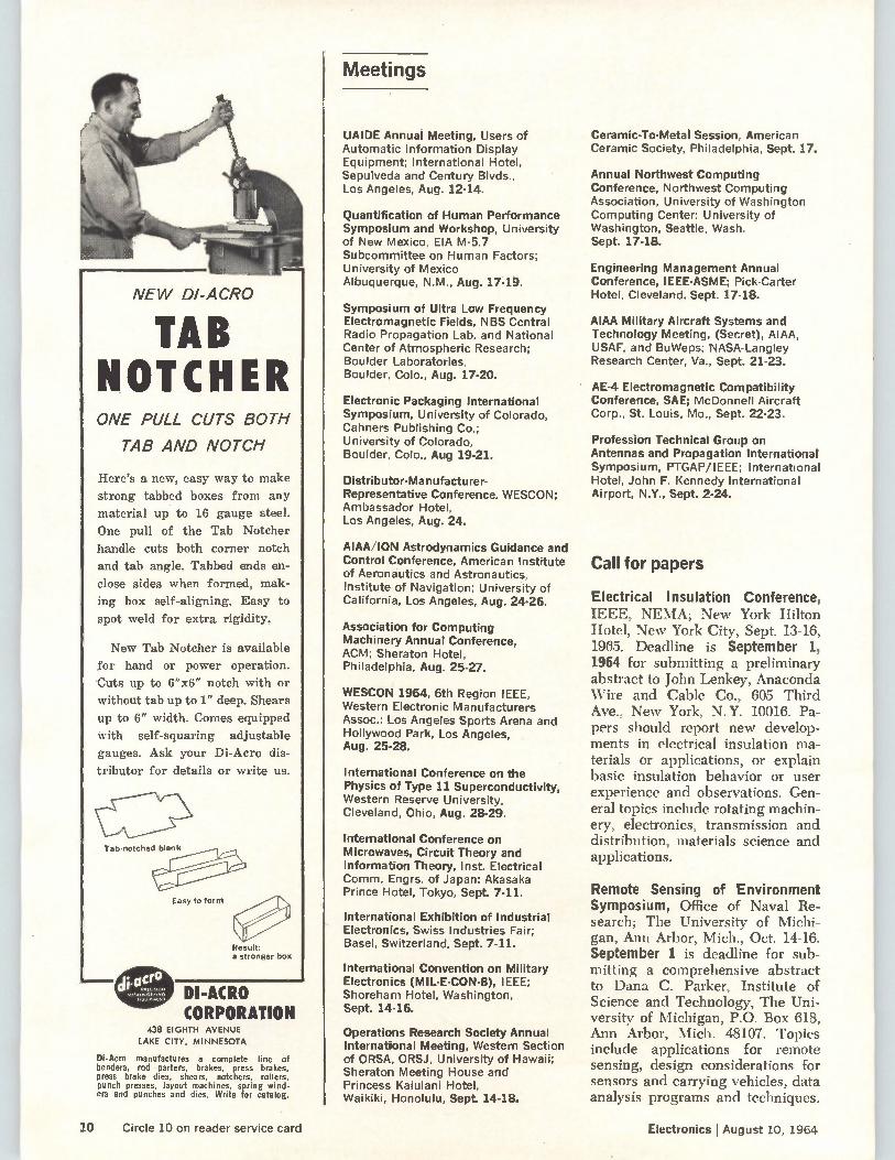
NEW DI-AGRO
TAB NOTCHER ONE PULL CUTS BOTH
TAB AND NOTCH
Here's a new, easy way to make
strong tabbed boxes from any
material up to 16 gauge steel.
One pull of the Tab Notcher
handle cuts both corner notch
and tab angle. Tabbed ends en-
close sides when formed, mak-
ing box self-aligning. Easy to
spot weld for extra rigidity.
New Tab Notcher is available
for hand or power operation.
Cuts up to 6"x6" notch with or
without tab up to 1" deep. Shears
up to 6" width. Comes equipped
with self-squaring adjustable
gauges. Ask your Di-Acro dis-
tributor for details or write us.
Tab-notched blank
Easy to form
Result: a stronger box
DI-ACRO CORPORATION
438 EIGHTH AVENUE
LAKE CITY, MINNESOTA
Di-Acro manufactures a complete line of benders, rod partera, brakes, press brakes, press brake dies, shears, notchers, rollers, punch presses, layout machines, spring wind-ers and punches and dies. Write for catalog.
Meetings
UAIDE Annual Meeting, Users of Automatic Information Display Equipment; International Hotel, Sepulveda and Century Blvds., Los Angeles, Aug. 12-14.
Quantification of Human Performance Symposium and Workshop, University of New Mexico, EIA M-5.7 Subcommittee on Human Factors; University of Mexico Albuquerque, N.M., Aug. 17-19.
Symposium of Ultra Low Frequency Electromagnetic Fields, NBS Central Radio Propagation Lab. and National Center of Atmospheric Research; Boulder Laboratories, Boulder, Colo., Aug. 17-20.
Electronic Packaging International Symposium, University of Colorado, Cahners Publishing Co.: University of Colorado, Boulder, Colo., Aug 19-21.
Distributor-Manufacturer-Representative Conference, WESCON; Ambassador Hotel, Los Angeles, Aug. 24.
AIAA/ION Astrodynamics Guidance and Control Conference, American Institute of Aeronautics and Astronautics, Institute of Navigation; University of California, Los Angeles, Aug. 24-26.
Association for Computing Machinery Annual Conference, ACM; Sheraton Hotel, Philadelphia, Aug. 25-27.
WESCON 1964, 6th Region IEEE, Western Electronic Manufacturers Assoc.; Los Angeles Sports Arena and Hollywood Park, Los Angeles, Aug. 25-28.
International Conference on the Physics of Type 11 Superconductivity, Western Reserve University, Cleveland, Ohio, Aug. 28-29.
International Conference on Microwaves, Circuit Theory and Information Theory, Inst. Electrical Comm. Engrs. of Japan: Akasaka Prince Hotel, Tokyo, Sept. 7-11.
International Exhibition of Industrial Electronics, Swiss Industries Fair; Basel, Switzerland, Sept. 7-11.
International Convention on Military Electronics (MIL-E-CON-8), IEEE; Shoreham Hotel, Washington, Sept. 14-16.
Operations Research Society Annual International Meeting, Western Section of ORSA, ORSJ, University of Hawaii; Sheraton Meeting House and Princess Kaiulani Hotel, Waikiki, Honolulu, Sept. 14-18.
Ceramic-To-Metal Session, American Ceramic Society, Philadelphia, Sept. 17.
Annual Northwest Computing Conference, Northwest Computing Association, University of Washington Computing Center; University of Washington, Seattle, Wash. Sept. 17-18.
Engineering Management Annual Conference, IEEE-ASME; Pick-Carter Hotel, Cleveland, Sept. 17-18.
AIAA Military Aircraft Systems and Technology Meeting, (Secret), AIAA, USAF, and BuWeps; NASA-Langley Research Center, Va., Sept. 21-23.
AE-4 Electromagnetic Compatibility Conference, SAE; McDonnell Aircraft Corp., St. Louis, Mo., Sept. 22-23.
Profession Technical Group on Antennas and Propagation International Symposium, PTGAP/IEEE; International Hotel, John F. Kennedy International Airport, N.Y., Sept. 2-24.
Call for papers
Electrical Insulation Conference, IEEE, NEMA; New York Hilton Hotel, New York City, Sept. 13-16, 1965. Deadline is September 1, 1964 for submitting a preliminary abstract to John Lenkey, Anaconda Wire and Cable Co., 605 Third Ave., New York, N. Y. 10016. Pa-pers should report new develop-ments in electrical insulation ma-terials or applications, or explain basic insulation behavior or user experience and observations. Gen-eral topics include rotating machin-ery, electronics, transmission and distribution, materials science and applications.
Remote Sensing of Environment Symposium, Office of Naval Re-search; The University of Michi-gan, Ann Arbor, Mich., Oct. 14-16. September 1 is deadline for sub-mitting a comprehensive abstract to Dana C. Parker, Institute of Science and Technology, The Uni-versity of Michigan, P.O. Box 618, Ann Arbor, Mich. 48107. Topics include applications for remote sensing, design considerations for sensors and carrying vehicles, data analysis programs and techniques.
10 Circle 10 on reader service card Electronics I August 10, 1964
Q-1 LEJ
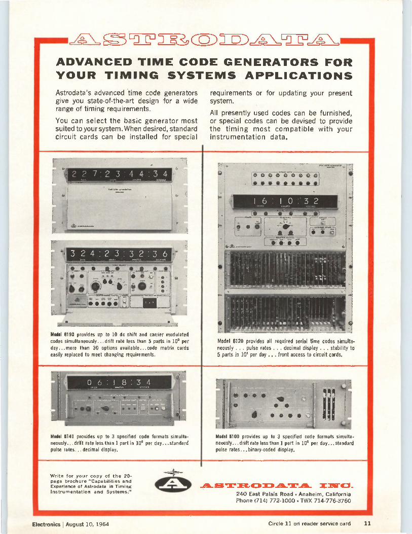
ADVANCED TIME CODE GENERATORS FOR
YOUR TIMING SYSTEMS APPLICATIONS
Astrodata's advanced time code generators give you state-of-the-art design for a wide range of timing requirements.
You can select the basic generator most suited to your system. When desired, standard circuit cards can be installed for special
[4, • • • • fl
-7"--11311111r..7 ..;..c..11O1111111111111111101MIL,...11111
Model 6190 provides up to 10 dc shift and carrier modulated codes simultaneously... drift rate less than 5 parts in 109 per day...more than 30 options available.., code matrix cards easily replaced to meet changing requirements.
requirements or for updating your present system.
All presently used codes can be furnished, or special codes can be devised to provide the timing most compatible with your instrumentation data.
Model 6120 provides all required serial time codes simulta-neously . .. pulse rates ... decimal display . . . stability to 5 parts in 10 per day ... front access to circuit cards.
Model 6140 provides up to 3 specified code formats simulta-neously...drift rate less than 1 part in 109 per day...standard pulse rates.., decimal display.
Model 6100 provides up to 3 specified code formats simulta-neously... drift rate less than 1 part in 109 per day...standard pulse rates... binary-coded display.
Write for your copy of the 20-page brochure "Capabilities and Experience of Astrodata in Timing Instrumentation and Systems."
A. et T 0 DATA. X 240 East Palais Road • Anaheim, California Phone (714) 772-1000 • TWX 714-776-3760
Electronics August 10, 1964 11 Circle 11 on reader service card
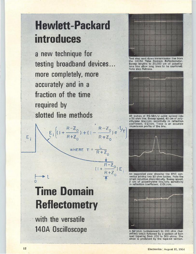
Hevidett-Packar introduces a new technique for
testing broadband devices...
more completely, more accurately and in a
fraction of the time
required by
slotted 'line methods
E•P+ R+Zo R+Z o
R—Z R—Zo
WHERE T =
o
Time Domain Reflectometry
R+Zo
R—Zo (1+ R+Z -)E i
o
with the versatile 140A Oscilloscope
Test step sent down transmission line from the 1415A Time Doma'n Reflectometer. Sweep lengths to 20,000 cm of polyethy-lene line' allow long lines to be examined. Note step flatness.
48 inches of RG-58A/U cable spliced into a 50 ohm line. Sweep speed, 40 cm of poly-ethylene line/cm; .sensitivity in reflection coefficient, 0.2/cm. Trace is an accurate impedance profile of the line.
An expanded view show ng the BNC con-nector joining two 50 ohm cables. Note the small inductive discontinuity. Sweep speed, 2 cm of polyethylene line/cm; sensitivity in reflection coefficient, 0.01/cm.
A 50-ohm (unbalanced) to 200 ohm (bat-ariCed) balun fo lowed by a section of twin lead tapering from 200 to 300 ohms. The slope is produced by the tapered section.
12 Electronics j August 10, 1964
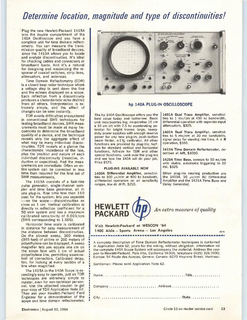
Determine location, magnitude and type of discontinuities!
Plug the new Hewlett-Packard 1415A into the double compartment of the 140A Oscilloscope and you have a complete unit for time domain reflect-ometry. You can measure the trans-mission quality of broadband devices, since the 1415A allows you to locate and analyze discontinuities. It's ideal for checking cables and connectors or broadband loads. And it's a natural for designing and maximizing the re-sponse of coaxial switches, strip lines, attenuators, and antennas.
Time Domain Reflectometry (TDR) is a closed loop radar technique where a voltage step is sent down the line and the echoes displayed on a scope. Each reflection from a discontinuity produces a characteristic echo distinct from all others. Interpretation is ex-tremely simple, and the effect of changes can be seen instantly. TDR avoids difficulties encountered
in conventional SWR techniques for testing broadband devices. SWR meas-urements must be made at many fre-quencies to determine the broadband quaility of a device, and the technique reveals only the aggregate effect of what may be many individual discon-tinuities. TDR reveals at a glance the characteristic impedance of the line, plus the position and nature of each individual discontinuity (resistive, in-ductive or capacitive). And the meas-urements are immediate. Often an en-tire system can be corrected in less time than required for the first set of SWR measurements.
The 1415A consists of a fast-rise pulse generator, single-channel sam-pler and time base generator, all in one plug-in. Rise time less than 150 psec for the system, lets you separate —on the scope—discontinuities as close as 1 cm. Vertical calibration is directly in reflection coefficient for a 50 ohm system and has a maximum calibrated sensitivity of 0.005/cm (SWR corresponding to L005).
Horizontal time scale is calibrated in distance for easy measurement of the distance between discontinuities. On the slowest sweep, 300 meters (985 feet) of airline or 200 meters of polyethylene can be displayed. A sweep magnifier lets you equate one cm on the scope face with 1 cm of actual polyethylene line, permitting examina-tion of connectors. Calibrated delay, too, for looking at every section of a line when magnified.
The 1415A in the 140A Scope is ex-ceedingly easy to operate, just as TDR techniques are extremely simple to master, even for non-technical person-nel. Use the attached coupon to get your copy of TDR Application Note 62. Then ask your Hewlett-Packard Field Engineer for a demonstration of the scope and time domain reflectometer.
Electronics I August 10, 1964
hp 140A PLUG-IN OSCILLOSCOPE
The hp 140A Oscilloscope offers you the best value today and tomorrow. Basic unit incorporates big, no-parallax 10 cm x 10 cm crt with 7.5 kv accelerating po-tential for bright traces; large, heavy-duty power supplies with enough reserve power for any new plug-in; push-button beam finder; -±1% calibrator. All other functions are provided by plug-ins: half-size for standard vertical and horizontal functions, full-size for TDR and other special functions. Look over the plug-ins and see how the 140A will do your job. Price $575.
PLUG-INS AVAILABLE NOW
1400A Differential Amplifier, sensitivi-ties to 100 pv/cm at 400 kc bandwith, differential operation on all sensitivity ranges, low dc drift, $210.
HEWLETT PACKARD
1401A Dual Trace Amplifier, sensitivi-ties to 1 mv/cm at 450 kc bandwidth, differential operation with separate input attenuators, $325.
1402A Dual Trace Amplifier, sensitivi-ties to 5 mv/cm at 20 mc bandwidth, signal delay for viewing rise time, A + B operation, $550.
1415A Time Domain Reflectometer, de-scribed at left, $1050.
1420A Time Base, sweeps to 50 ns/cm with stable, automatic triggering to 20 mc, $325.
Other plug-ins nearing production are the 1403A, 10 liv/cm AC Differential Amplifier and the 1421A Time Base and Delay Generator.
An extra measure of quality
Visit Hewlett-Packard at WESCON '64
1400 Aisle — Sports - Arena — Los Angeles 9376
A complete description of Time Domain Reflectometer techniques is contained in Application Note 62, yours for the asking, without obligation. Information on the complete 140A Scope System will accompany the material. Address the cou-pon to Hewlett-Packard, Palo Alto, California 94304, telephone (415) 326-7000; Europe: 54 Route des Acacias, Geneva; Canada: 8270 Mayrand Street, Montreal.
Gentlemen: Please send Application Note 62.
Name Title
Company Address
City State
Circle 13 on reader service card 13
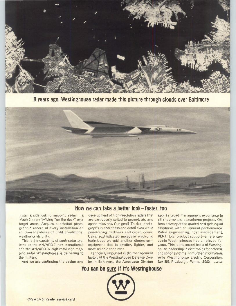
Now we can take a better look—faster, too
8 years ago, Westinghouse radar made this picture through clouds over Baltimore
Install a side-looking mapping radar in a Mach 2 aircraft-flying "on the deck" over target areas. Acquire a detailed photo-graphic record of every installation en route—regardless of light conditions, weather or visibility. This is the capability of such radar sys-
tems as the AN/APD-7, now operational, and the AN/APQ-97 high resolution map-ping radar Westinghouse is delivering to the military. And we are continuing the design and
Circle 14 on reader service card
development of high-resolution radars that are particularly suited to ground, air, and space missions. Our goal? To rival photo-graphs in sharpness and detail even while penetrating darkness and cloud cover. Using sophisticated molecular electronic techniques we add another dimension— equipment that is smaller, lighter, and more reliable than ever. Especially important is the management
factor. At the Westinghouse Defense Cen-ter in Baltimore, the Aerospace Division
applies broad management experience to all airborne and spaceborne projects. On-time delivery at the quoted cost gets equal emphasis with equipment performance. Value engineering, cost management, PERT, total product support—all are con-cepts Westinghouse has employed for years. This is the sound basis of Westing-house leadership in electronics for defense and space systems. For further information, write Westinghouse Electric Corporation, Box 868, Pittsburgh, Penna. 15222. J-02360
You can be sure if it's Westinghouse
Electronics August 10, 1964
Editorial
Whose side are we on?
Last month in the Caribbean, one of the Navy's keenest trouble-shooting units carried out a mock evacuation of nationals as part of an exercise to keep its fighting men razor sharp. In one phase of the maneuver, the Navy landed a battalion of marines for the peaceful occupation of the evacuation areas. The marines performed superbly but the electronic equipment
nearly snafued the whole operation. At the start, a planned assault had to be postponed when one
reconnaissance team apparently disappeared. Air-sea rescue operations discovered the team was not lost; its voice communication transmitter had conked out.
Later, helicopters patrolled the captured beachhead communicating with a command center aboard a converted aircraft carrier. At one time, all four electronic communication systems the 'copters used were out of action, simultaneously. Not tactically struck down, just plain malfunction.
VVhat is so distressing about all this is most of the marines' electronic equipment was World War II vintage. In this day of microelectronics, solid state, and magnetic components, our ground forces are carrying tubed equipment. And this gear still has a lot of the faults that hurried the switch to transistor design.
Questioned about their electronic equipment, marines complained that too many of the designs engineers produce today are just too complex for battlefield use. And too much of it can't be maintained by troops on the move in a hurry. The marines who scamper ashore from landing boats know
exactly what they need: 1) light, reliable and easily maintained radio equipment; and 2) a battlefield radar that will work when it has to. Why don't they have these things? None of them sound beyond
the reach of current technology. For one thing, the big money has gone to the spectacular
projects, those that make good publicity as well as good weapons. You don't find many tubes in missile guidance systems, either in the birds or on the ground. For another, engineers caught up in sophisticated military electronics programs don't seem able to handle the simple straightforward design needed in battlefield electronics. Today the military has focused its attention on limited warfare.
The big projects are phasing out and reverses in Vietnam and Laos have forced new attention in this direction. Despite the decline in over-all military procurement, spending is increasing for the items that can be used to fight guerilla warfare. For companies used to doing business with the military, here is
a relatively untapped market. Although the business procedures remain the same, the engineering has to be totally different. For this market, simplicity and reliability have to be paramount. And cost is important too. Many of these electronic communications systems will be given away to native troops of another country so the. cost has to be low enough that the taxpayers can afford such gifts in large numbers. We feel it's bitterly ironic that taxi drivers in many U.S. cities
have transistorized radio transmitters but our marines and infantry do not.
15
WESCON Booth 441
Hollywood Park
T. SILICON POWER INDUSTRIAL TRANSISTORS 2N3233 2N3234 2N3235 2N3236 2N3237
2N3238 2N3239 2N3240 Silicon Transistor Corporation, the leading manufacturer of silicon power products, is now producing an entirely new series of low-cost, industrial power transistors. Our basic product philosophy of manu-facturing high quality devices will not deviate, despite the low prices on these new power transistors.
This series is in the all-copper TO-3 header with a maximum junction temperature of 200°C. The D.C. power capabilities range from 117 to 200 watts, with peak switched power ratings for approximately 20 times the D.C. ratings. Maximum collector current capability ranges from 7.5 to 20 amps with BVcEo ratings ranging from 60 to 160 volts. Saturation resistance values range from types having 0.1 ohms eIc = 10A to others having 0.8 ohms @, lc = 3A. This series is now available from stock and from your local Silicon Transistor Corporation distributor.
For complete specifications and information on reducing your silicon power transistor costs for indus-trial applications, contact:
o CARLE PLACE Li., NEW YORK 516-Pioneer 2-4100
DISTRICT OFFICES: LONG BEACH 2, CALIF., 217 ELM AVE. (213) 437-2788. TWX 2115494972.
DAYTON 19, OHIO, 49 PARK AVE. (513) 298-9913. TWX 513-944-0372. HUNTSVILLE, ALA., POST OFFICE BOX 1467. (205) 881-4793
osugum Tumeuenn cummtamil0 o 16 Circle 16 on reader service card Electronics I August 10, 1964
.11 , ‘" •C -
Not much room
for improvement
Circuit makers
seek new market
Electronics Newsletter August 10, 1964
While justifiably proud of the smashing success scored by Ranger 7 last week (p. 29), one scientist at the Jet Propulsion Laboratories of the Cali-fornia Institute of Technology cannot help but feel a little disappointed that the lunar photographs were so good. For several years Robert Nathan has been developing a complex
computer program, used with the lab's IBM 7094, to improve the quality of televised pictures. Paradoxically, the excellence of the transmitted pictures, didn't give the Ranger scientist a chance to add lustre to an already shining achievement. He was ready to do a spectacular cleaning-up job if the images had been inferior. But despite the excellent quality of the pictures, they can be improved, and the job is now under way. The pre-launch calibration procedures included a computerized
ground check out of Ranger's cameras for photometric distortion— uneven response over the surface of the vidicon to a given intensity of light—and for geometric distortion. The crosses in the moon photos provide bench marks for correcting this type of distortion. The 7094 compensates for both conditions. The first post-launch chore performed in cleaning up pictures is the
digitizing of a video analog signal received from magnetic tape. The computer, programed to search for any "noise bursts" along television raster scan lines, removes and replaces these with the average of corre-sponding light intensities along neighboring lines—six pictures showing a common lunar area are superimposed to obtain this average. If not removed, the noise bursts would appear as spots on the picture. Another set of programs enables removal of the distortion-correction crosses from the pictures. Nathan is now working with the simpler 300-line pictures from the
partial-scan cameras, to make sure his process is working. Later, he will "clean up" the 1,152-line pictures from the full-scan cameras. Since the cameras slated for the Surveyors are of lower quality than the Ranger cameras, it is expected that much more computerized cleanup will be needed on those pictures.
Two more leading integrated-circuit manufacturers are getting into the business of selling equipment developed for their own production lines. Equipment sales, however, are still restricted to the assembly and test end of a line, rather than the highly proprietary equipment that is used to make the actual circuits. The two new sellers are the Semiconductor Products division of Motor-
ola, Inc., and the Semiconductor division of the Fairchild Camera & Instrument Corp. Motorola will sell scribers, used to cut up semiconduc-tor slices into individual circuits or chip components, equipment for bonding the chips or dies to headers and for bonding connector wires to the dies, and package welders. It will also be selling high-speed test equipment. These products will put Motorola into direct competition with Texas
Instruments, Inc., which has been selling both test and assembly equip-ment. The Signetics Corp., another major producer, has been selling fiat-Pack test jigs and elevated-temperature test sets. The Instrument division of Fairchild has been selling test instru-
17
Electronics Newsletter
ments. With Fairchild Semiconductor selling such assembly equipment as wire bonders and welders, it looks like a three-way competition between Texas Instruments Inc., Motorola Inc. and the Fairchild division.
Breakthrough for
guidance system
Persuading
the Pentagon
FCC middleman
for home tv
The Sperry Gyroscope division of the Sperry Rand Corp: has scored a breakthrough into the commercial market. It's a sign of things to come. Inertial air navigation systems, heretofore used in quantity only aboard guided missiles, will now be used for the first time on commercial air-liners for long-range navigation. The Sperry system can be used, with a few changes, in the supersonic
transport planes. The Raytheon Co., now building a suitcase-sized guid-ance computer for the Apollo project, is readying a proposal for use of another system aboard commercial supersonic aircraft. It would provide the navigation computations and automatic guidance needed for Mach 3 speeds. The Pan American World Airways Corp. has given Sperry a $12.5-
million order for Sperry SGN-10 inertial platforms. Pan American expects the Sperry system to release some 170 experienced fliers, now being used as navigators, for pilot duty. The system will perform the navigating chores. Airlines have had trouble recruiting trained pilots because of the Air Force emphasis on missiles over manned aircraft.
Air Force communications planners go before Pentagon officials this month seeking funds for new systems for survivable communications. This brings up an old problem. Before granting the funds, the Pentagon must be convinced that the Air Force needs can't be met by existing commercial systems, since it may have to justify the expenditure to Congress. Congress customarily has refused to fund any special military communications where the need can be filled adequately by commercial systems. But it and the military don't always see eye to eye on what comprises an adequate system. This year, the Air Force is interested in four-way microwave communications which would temporarily "heal" a network if ground stations were blown up. The microwave links, acting as temporary systems until ground forces reestablished communications, would function air-to-air and air-to-ground, would permit airborne switching and trunking of ground links on a temporary basis. The Air Force is also• interested in development programs to get
aircraft into the sphere of communication satellites. Proposed programs include air-to-air communications via satellite, air-to-ground via satellite —in fact, all combinations of satellite, air and ground.
Viewers in areas far from television stations may get better reception and a greater program choice, thanks to a Federal Communications Commission proposal to establish a Community Antenna Relay Service. The service would absorb the microwave systems licensed under the Business Radio Service that now relay programs to community antennas for transmission to home sets. Twenty 12.5-megacycle channels would occupy frequencies from 12,700 to 12,950 Mc. After February, 1971, new technical standards would double the number of channels that are avail-able now.
18 Circle 19 on reader service card-÷-
M_rW fi 1.10 IT 1TZ 17Un'OM
....... 000k:46ote - 4ieme•- •"""iiiiè o
_ 0000dsooes — 0
emeweimpee
RM. lefICOeUt
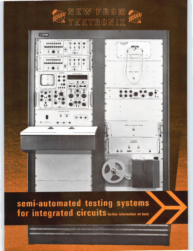
semi-automated testing systems for integrated circuits further information on back
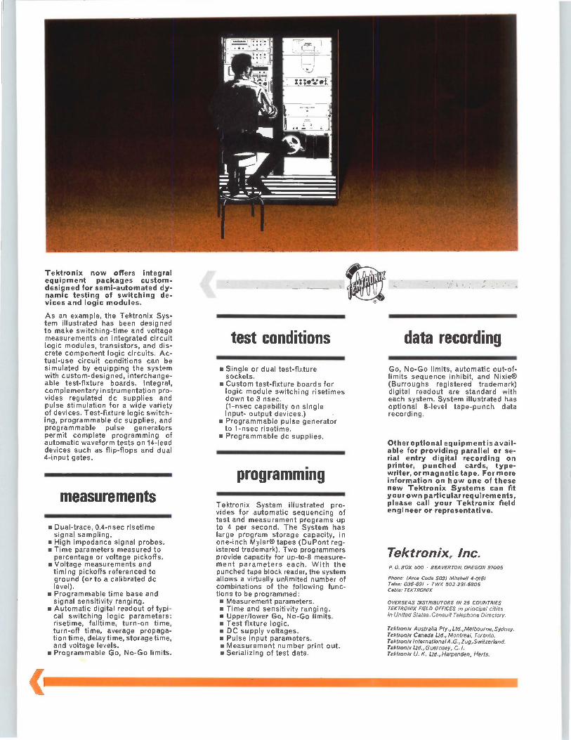
Tektronix now offers integral equipment packages custom-designed for semi-automated dy-namic testing of switching de-vices and logic modules.
As an example, the Tektronix Sys-tem illustrated has been designed to make switching-time and voltage measurements on integrated circuit logic modules, transistors, and dis-crete component logic circuits. Ac-tual-use circuit conditions can be simulated by equipping the system with custom-designed, interchange-able test-fixture boards. Integral, complementary instrumentation pro-vides regulated dc supplies and pulse stimulation for a wide variety of devices. Test-fixture logic switch-ing, programmable dc supplies, and programmable pulse generators permit complete programming of automatic waveform tests on 14-lead devices such as flip-flops and dual 4-input gates.
measurements
• Dual-trace, 0.4-nsec risetime signal sampling. • High impedance signal probes. • Time parameters measured to percentage or voltage pickoffs. • Voltage measurements and timing pickoffs referenced to ground (or to a calibrated dc level). • Programmable time base and signal sensitivity ranging. • Automatic digital readout of typi-
cal switching logic parameters: risetime, falltime, turn-on time, turn-off time, average propaga-tion time, delay time, storage time, and voltage levels.
II Programmable Go, No-Go limits.
;21.161111.111
test conditions
• Single or dual test-fixture sockets.
ou Custom test-fixture boards for logic module switching risetimes down to 3 nsec. (1-nsec capability on single input- output devices.) • Programmable pulse generator to 1-nsec risetime. • Programmable dc supplies.
programming
Tektronix System illustrated pro-vides for automatic sequencing of test and measurement programs up to 4 per second. The System has large program storage capacity, in one-inch Mylar® tapes (DuPont reg-istered trademark). Two programmers provide capacity for up-to-8 measure-ment parameters each. With the punched tape block reader, the system allows a virtually unlimited number of combinations of the following func-tions to be programmed: • Measurement parameters. • Time and sensitivity ranging. • Upper/lower Go, No-Go limits. • Test fixture logic. • DC supply voltages. • Pulse input parameters. • Measurement number print out. • Serializing of test data.
data recording
Go, No-Go limits, automatic out-of-limits sequence inhibit, and Nixie® (Burroughs registered trademark) digital readout are standard with each system. System illustrated has optional 8-level tape-punch data recording.
Other optional equipment isavail-able for providing parallel or se-rial entry digital recording on printer, punched cards, type-writer, or magnetic tape. For more information on how one of these new Tektronix Systems can fit your own particularrequirements, please call your Tektronix field engineer or representative.
Tektronix, Inc. P. 0. BOX 500 • BEAVERTON, OREGON 97005
Phone: (Area Code 503) Mitchell 4-0161 Telex: 036-691 • TWX 503-291-6805 Cable: TEKTRONIX
OVERSEAS DISTRIBUTORS IN 25 COUNTRIES TEKTRONIX FIELD OFFICES in principal cities in United States. Consult Telephone Directory.
Tektronix Australia Pty., Ltd.,Melbourne,Sydney. Tektronix Canada Ltd., Montreal, Toronto. Tektronix International A.G.,Zug,Switzerland. Tektronix Ltd., G uernsey, C. I. Tektronix U. K. Ltd., Harpenden, Herts.
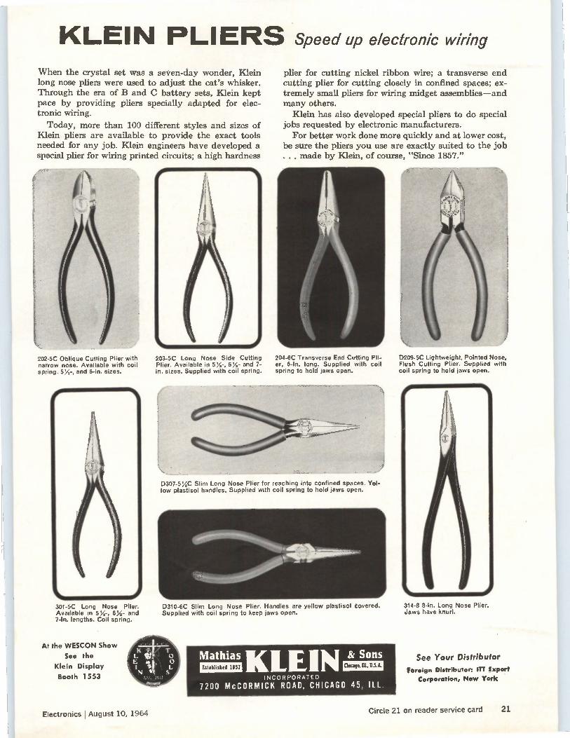
KLEIN PLIERS Speed up electronic wiring When the crystal set was a seven-day wonder, Klein long nose pliers were used to adjust the cat's whisker. Through the era of B and C battery sets, Klein kept pace by providing pliers specially adapted for elec-tronic wiring.
Today, more than 100 different styles and sizes of Klein pliers are available to provide the exact tools needed for any job. Klein engineers have developed a special plier for wiring printed circuits; a high hardness
202-5C Oblique Cutting Plier with narrow nose. Available with coil spring. 5%-, and 6-in. sizes.
203-5C Long Nose Side Cutting Plier. Available in 5'/,, 6%, and 7-in. sizes. Supplied with coil spring.
204-6C Transverse End Cutting Pli-er, 6-In. long. Supplied with coil spring to hold jaws open.
D209-5C Lightweight, Pointed Nose, Flush Cutting Plier. Supplied with coil spring to hold jaws open.
301-5C Long Nose Plier. Available in 5;4-, 614- and 7-In. lengths. Coil spring.
At the WESCON Show
See the
Klein Display
Booth 1553
plier for cutting nickel ribbon wire; a transverse end cutting plier for cutting closely in confined spaces; ex-tremely small pliers for wiring midget assemblies—and many others.
Klein has also developed special pliers to do special jobs requested by electronic manufacturers.
For better work done more quickly and at lower cost, be sure the pliers you use are exactly suited to the job . . . made by Klein, of course, "Since 1857."
D307-5%C Slim Long Nose Plier for reaching into confined spaces. Yel-low plastisol handles. Supplied with coil spring to hold jaws open.
D310-6C Slim Long Nose Plier. Handles are yellow plastisol covered. Supplied with coil spring to keep jaws open.
314-8 8-in. Long Nose Plier, Jaws have knurl.
Mathias KLEIN Established 1857
INCORPORATED
7200 McCORMICK ROAD, CHICAGO 45, ILL.
8/ Sons Chicago, DL,
See Your Distributor
Foreign Distributor: ITT Export Corporation, New York
Electronics I August 10, 1964 Circle 21 on reader service card 2/
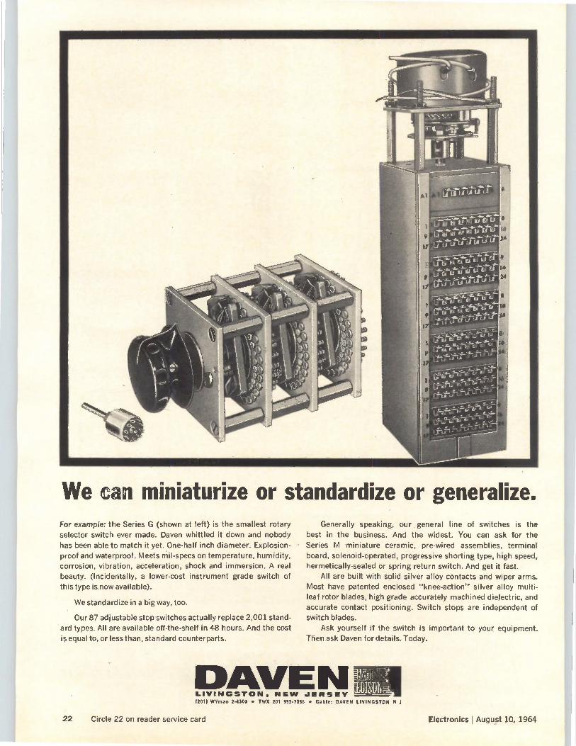
We can miniaturize or standardize or generalize.
ii
For example: the Series G (shown at left) is the smallest rotary
selector switch ever made. Daven whittled it down and nobody
has been able to match it yet. One-half inch diameter. Explosion-proof and waterproof. Meets mil-specs on temperature, humidity,
corrosion, vibration, acceleration, shock and immersion. A real
beauty. (Incidentally, a lower-cost instrument grade switch of this type is now available).
We standardize in a big way, too.
Our 87 adjustable stop switches actually replace 2,001 stand-
ard types. All are available off-the-shelf in 48 hours. And the cost
is equal to, or less than, standard counterparts.
Generally speaking, our general line of switches is the
best in the business. And the widest. You can ask for the Series M miniature ceramic, pre-wired assemblies, terminal
board, solenoid-operated, progressive shorting type, high speed, hermetically-sealed or spring return switch. And get it fast.
All are built with solid silver alloy contacts and wiper arms.
Most have patented enclosed "knee-action" silver alloy multi-leaf rotor blades, high grade accurately machined dielectric, and
accurate contact positioning. Switch stops are independent of switch blades.
Ask yourself if the switch is important to your equipment.
Then ask Daven for details. Today.
LIVINGSTON, NEW JERSEY (201) Wyman 2-4300 • TWX 201 9924356 • Cable: DAVEN LIVINGSTON N .1
22 Circle 22 on reader service card Electronics l August 10, 1964
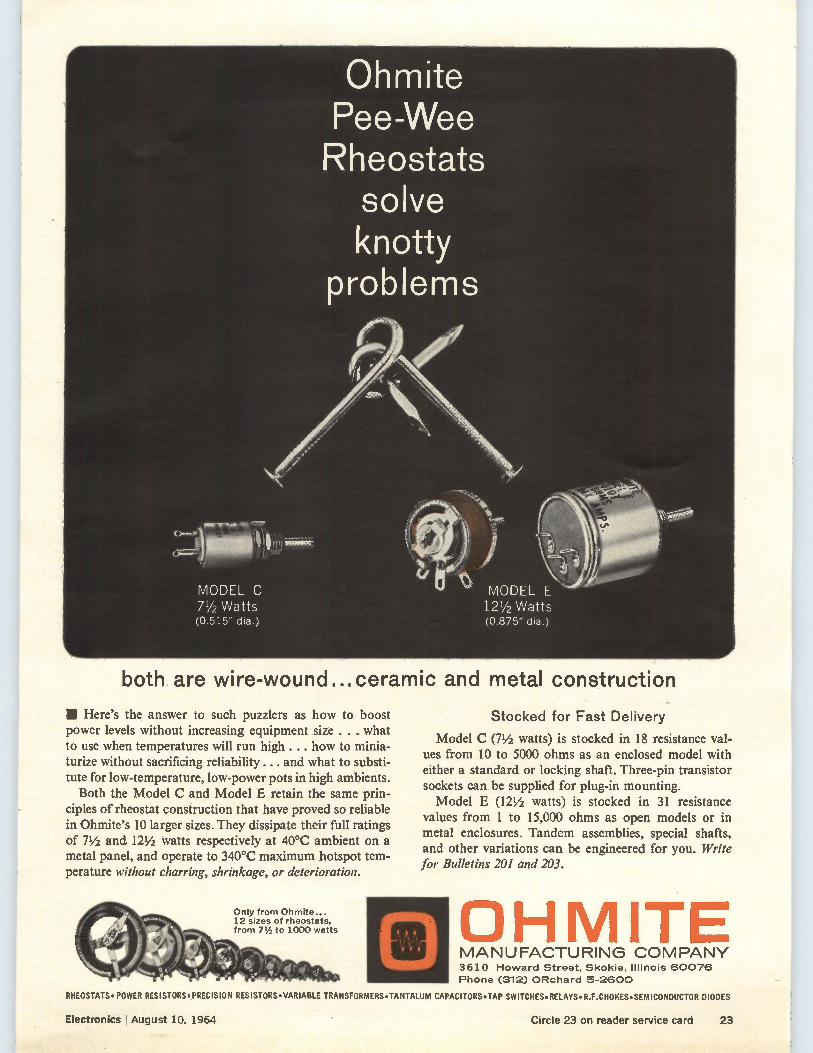
Ohmite Pee-Wee Rheostats
solve knotty
problems
MODEL C 71/2 Watts (0.515" dia.)
MODEL E 12 1/2 Watts (0.875" dia.)
both are wire-wound...ceramic and metal construction
Here's the answer to such puzzlers as how to boost power levels without increasing equipment size . . . what to use when temperatures will run high . . . how to minia-turize without sacrificing reliability.. . and what to substi-tute for low-temperature, low-power pots in high ambients.
Both the Model C and Model E retain the same prin-ciples of rheostat construction that have proved so reliable in Ohmite's 10 larger sizes. They dissipate their full ratings of 71/2 and. 121/2 watts respectively at 40°C ambient on a metal panel, and operate to 340°C maximum hotspot tem-perature without charring, shrinkage, or deterioration.
Only from Ohmite... 12 sizes of rheostats, from 71/2 to 1000 watts
Stocked for Fast Delivery
Model C (71/2 watts) is stocked in 18 resistance val-ues from 10 to 5000 ohms as an enclosed model with either a standard or locking shaft. Three-pin transistor sockets can be supplied for plug-in mounting. Model E (121/2 watts) is stocked in 31 resistance
values from 1 to 15,000 ohms as open models or in metal enclosures. Tandem assemblies, special shafts, and other variations can be engineered for you. Write for Bulletins 201 and 203.
OHMITE MANUFACTURING COMPANY 3610 Howard Street, Skokie, Illinois 60076
Phone (312) ORchard 5-2600
RHEOSTATS • POWER RESISTORS. PRECISION RESISTORS•VARIABLE TRANSFORMERS•TANTALUM CAPACITORS•TAP SWITCHES•RELAYS•R.F.CHOKES•SEMICONDUCTOR DIODES
Electronics August 10, 1964 Circle 23 on reader service card 23
So -when I got back from lunch Jake was still up to his eyeballs in strip charts. They were spilling from the table onto the floor, and there was a big pile in the corner that he hadn't even touched. There was this wild gleam in his eye. "Found out yet why Test Op Twenty-
seven went ker-boom?" I asked innocently. "Don't be a wise guy," Jake snarled. "I just got word from the Chief Engineer that he has to have some preliminary answers by fourteen hundred. Hah! I'd like to see hilt, trying to line up forty-three channels on eight strip charts that were recorded at four different speeds." "All it takes is a little patience," 1 reminded him. "You told me so yourself." "All right, smart apple," he growled, "maybe I wish I'd re-corded with one of those time code rigs like you said, but it's too late now. Don't just stand there, see if you can help me unscramble this mess." "I'll do better than that," I said, "I'll give you your birthday
present early this year." I pulled a reel of mag tape out from behind my back and showed it to him. "What's that?" Jake said, looking as if it might bite him. "1 have to admit I played a dirty trick on you," I said. "I bor-rowed a time code generator' from Dr. Adams over at stan-
dards lab and patched it into the extra recorder along with the telemetry signal from the firing stand. The whole sequence is right here, timed with IRIG Format B."' Jake's mouth was doing a beautiful imi-
tation of a dying mackerel. "I also borrowed a tape search and con-
trol system," 1 continued. "Step over to my test rack and see how the big boys do it." I threaded the tape into the transport and selected the dis-
criminators for the channels we were most interested in. "Do we know yet when the beast blew?" I asked Jake as 1 turned on the power. "About T-zero plus eight," he told me weakly, "and I hope
you're not wasting my time. In just ten minutes the Chief
Engineer is going to walk in here roaring like a million pound booster." "We'll be ready for him," I said. I translated T-zero plus eight
into clock time. I preset the automatic start time at ten seconds before the engine had exploded and the stop time at five seconds after. You do it with decimal switches, and it's easier than playing Yankee Doodle on the piano with one finger. I set the T S and C to "Automatic" and
pushed the "auto search start" button.The transport revved up to search speed and the Nixie tube time display lit up showing days, hours, minutes and seconds. In a few moments the transport had reached the preset start time and overshot. It automatically reversed until it was positioned in advance of the starting spot on the tape. Then the search and control system's "drive playback" in-dicator light came on and traces started appearing on the oscillograph paper. "What's that picket fence on Channel 1?" Jake asked, eyeing
it suspiciously. "That's the time code," I told him. "No more counting hun-dreds of pulses to correlate events. You can read days, hours,
minutes, and seconds directly from the pattern of pulse widths in any segment of the recording." "Who can?" "You'll learn. It's easy." Before the system had even reached the
preset stop time, we were starting to get somewhere.
"Look," 1 said, "Channel 6 shows that flame was established at 10:48:19, but Channel 14 says the main fuel control valve still hadn't opened all the way at 10:48:22. Now look at Chan-nel 20. By 10:48:24 pump pressure had gone off scale. Then it drops to zero." "That must mean the fuel line ruptured. Fuel would have
started spilling into the combustion chamber," Jake theorized. "Yes, and she blew at just a hair beyond 10:48:26, that's when all the on-board transducers go dead. Now will you sign those requisitions for a time code generator and an automatic tape search and control of our own?" "Wait a minute," Jake said. "Let's see if we can tell why the main fuel valve didn't open all the way." Some people are never satisfied.
It was hard to spot the fine-scale sequence of events at the tape playback rates we were using, so I showed him another jazzy trick. I set the system to magnify the time scale in the short critical interval just where the valve had failed to open. Then the answer became obvious. The combustion chamber pressure switch should have closed before the valve actuation signal from the sequencer, but it had closed several millisecs late. The blame was pinned on the switch. "So now you're ready for the Chief," I said, rubbing it
in, "and you still have thirty seconds to spare." He didn't know whether to hit me or kiss me, so he did
both. I forgot to mention that I'm pretty cute for a test engi-neer. In fact, I'm the only female in the department. Which goes to show that not even a woman needs to rely on intuition, much less on counting pulses, when there's a time code system' handy.
1 Wise Dr. Adams loaned them an EECO 811 Time Code Generator. All solid-state, rugged card construction. Less than 40 pounds. Power consump-tion under 100 watts. Easy access to test points for simple maintenance. Fre-quency stability 5 parts in 10' per day. This and other models available immed-iately for ground, mobile airborne or seaborne applications. Brochures on request.
See
2 Model 811 produces any four code formats simultaneously in both level shift and modulated forms including choice of any IRIG, NASA, AMR, etc. Other models furnish 17-bit binary, 20-or 24- bit BCD codes. BE 3-58R3
us at WESCON
3 It was an EECO 831 Tape Search and Control System (TS & C) which automat-ically searches modulated-time-code-referenced tape in IRIG or NASA BCD formats. It speeds up to 100 times record-ing speed or slov, s to 1/20 recording speed, forward or backward.They might have used an EECO 835, for which interchangeable decoder modules can handle 1RIG, NASA, AMR, PM R, WS I I7L, Eglin AFB, and White Sands,
4 If you're wondering where to go for your time code system, here are some hints. Our first one was designed way back in 1949. Every major test base in the U.S. uses EECO products or systems. Circle this footnote and mail to EECO, Mail Station 1910, Box 58, Santa Ana, Calif., 92702. You'll receive FREE a wallet-size guide for reading IRIG B and AMR Di, the two most commonly used time codes.
either modulated or level shift.
• Hollywood Park • Booths 524-525
24 Circle 24 on reader service card Electronics I August 10, 1964
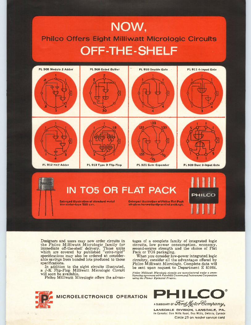
Phiico Offers Eight Milliwatt Micrologic Circuits
Enlarged illustration of standard metal transistor-type 105 can.
Designers and users may now order circuits in the Philco Milliwatt Micrologic family for immediate off-the-shelf delivery. Those units which are covered by published "extra-rigid" specifications may also be ordered at consider-able savings from bonded lots produced to those specifications.
In addition to the eight circuits illustrated, a J-K Flip-Flop Milliwatt Micrologic Circuit will soon be available.
Philco Milliwatt Micrologic offers the advan-
Enlarged illustration of Philco Flat Pack all-glass hermetically-sealed package.
tages of a complete family of integrated logic circuits, low power consumption, economy, second-source strength and the choice of Flat Pack or TO5 packaging. When you consider low-power integrated logic
circuitry, consider all the advantages offered by Philco Milliwatt Micrologic. Complete data will be sent upon request to Department E 81064. Philco Milliwatt Micrologic circuits are manufactured under a cross-licensing agreement with Fairchild Camera and Instrument Corporation using the Planar Epitaxial Process.
MICROELECTRONICS OPERATION PH I LCCY A SUBSIDIARY OF (51.77,-2(,,eeterWOMACte/e)
LANSDALE DIVISION, LANSDALE, PA. In Canada: Don Mills Road, Don Mills, Ontario, Canada
Circle 25 on reader service card
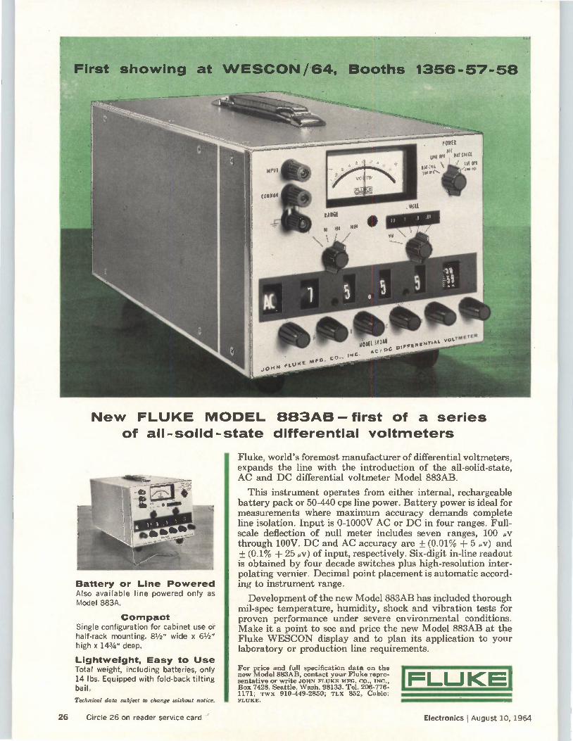
New FLUKE MODEL 883AB first of a series of all-solid-state differential voltmeters
Battery or Line Powered Also available line powered only as Model 883A.
Compact Single configuration for cabinet use or half-rack mounting. 81/2 " wide x 61/2 " high x 143/4 " deep.
Lightweight, Easy to Use Total weight, including batteries, only 14 lbs. Equipped with fold-back tilting bail.
Technical data subject to change without notice.
Fluke, world's foremost manufacturer of differential voltmeters, expands the line with the introduction of the all-solid-state, AC and DC differential voltmeter Model 883AB.
This instrument operates from either internal, rechargeable battery pack or 50-440 cps line power. Battery power is ideal for measurements where maximum accuracy demands complete line isolation. Input is 0-1000V AC or DC in four ranges. Full-scale deflection of null meter includes seven ranges, 100 0/ through 100V. DC and AC accuracy are + (0.01% + 5 ,v) and + (0.1% + 25 'AT) of input, respectively. Six-digit in-line readout is obtained by four decade switches plus high-resolution inter-polating vernier. Decimal point placement is automatic accord-ing to instrument range.
Development of the new Model 883AB has included thorough mil-spec temperature, humidity, shock and vibration tests for proven performance under severe environmental conditions. Make it a point to see and price the new Model 883AB at the Fluke WESCON display and to plan its application to your laboratory or production line requirements.
For price and full specification data on the new Model 883AB, contact your Fluke repre-sentative or write JOHN FLUKE MFG. CO., INC., Box 7428, Seattle, Wash. 98133. Tel. 206-776-1171; TWX 910-449-2850; TLX 852, Cable: FLUKE.
FLUKE
26 Circle 26 on reader service card Electronics ! August 10, 1964
FLUKE WESCON/64
'441 ERONTIERS ELECTRONICS
SPORTS ARENA
BOOTHS
1356-57-58 New Instruments
on display
ALL SOLID STATE
DIFFERENTIAL VOLTMETERS
Models 883AB-881AB
Battery or line powered
Also available line powered only
DC POWER SUPPLIES
408B-410B-412B
THERMAL TRANSFER
STANDARD 5405
ISOLATION AMPLIFIER A88
ELECTRONIC GALVANOMETERS
MODELS 840B-840C
FLUKE PRECISION
POTENTIOMETERS-RHEOSTATS
MONTRONICS FREQUENCY
EQUIPMENT—See the
new VLF receiver Model 205
FLUKE
FLUKE DECADE
and
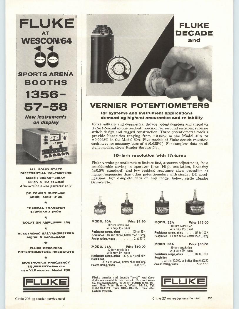
VERNIER POTENTIOMETERS for systems and instrument applications
demanding highest accuracies and reliability
Fluke military and commercial decade potentiometers and rheostats feature coaxial in-line readout, precision wirewound resistors, superior switch design and rugged construction. Three potentiometer models provide linearities ranging from ± 0.05% in the Model 40A to ± 0.0025% in the Model 60A. Five models of Fluke decade rheostats each have an accuracy base of ± (0.025%). For complete data on all eight models, circle Reader Service No.
10-turn resolution with 11/2 turns
Fluke vernier potentiometers feature fast, accurate adjustment, for a considerable saving in operator time. High resolution, linearity (±0.5% standard) and low residual reactance allow operation at higher frequencies than other potentiometers with similar DC speci-fications. For complete data on any model below, circle Reader Service No.
«e,
MODEL 20A Price $8.50 10 turn resolution with only 11/2 turns
Resistance range, ohms . . 1 . 100 to 25K Resolution . 1K and above, better than 0.02% Power rating, watts 2 at 20°C
MODEL 21A Price $10.00 10 turn resolution with only 11/2 turns
Resistance range, ohms .30 K, 40K and 50K Resolution
30K and above, better than 0.008% Power rating, watts 3 at 20°C
MODEL 22A Price $15.00 10 turn resolution with only 11/2 turns
Resistance range, ohms . , 1K to 100K Resolution . 1K and above, better than 0.02%
MODEL 30A Price $30.00 40 turn resolution with only 21/2 turns
Resistance range, ohms . . . . 1K to 100K Resolution
1 part in 50,000, or better than 0.002% Power rating, watts 5 at 20°C
Fluke vernier and decade "pots" and rheo-stats are available from stock. Contact near-est representative, or JOHN FLUKE MFG. CO., INC., Box 7428, Seattle, Wash. 98133. Tel. 206 776 1171; TWX 910 449 2850; TLX 852., Cable: FLUKE.
FLUKE
Circle 203 on reader service card Circle 27 on reader service card 27
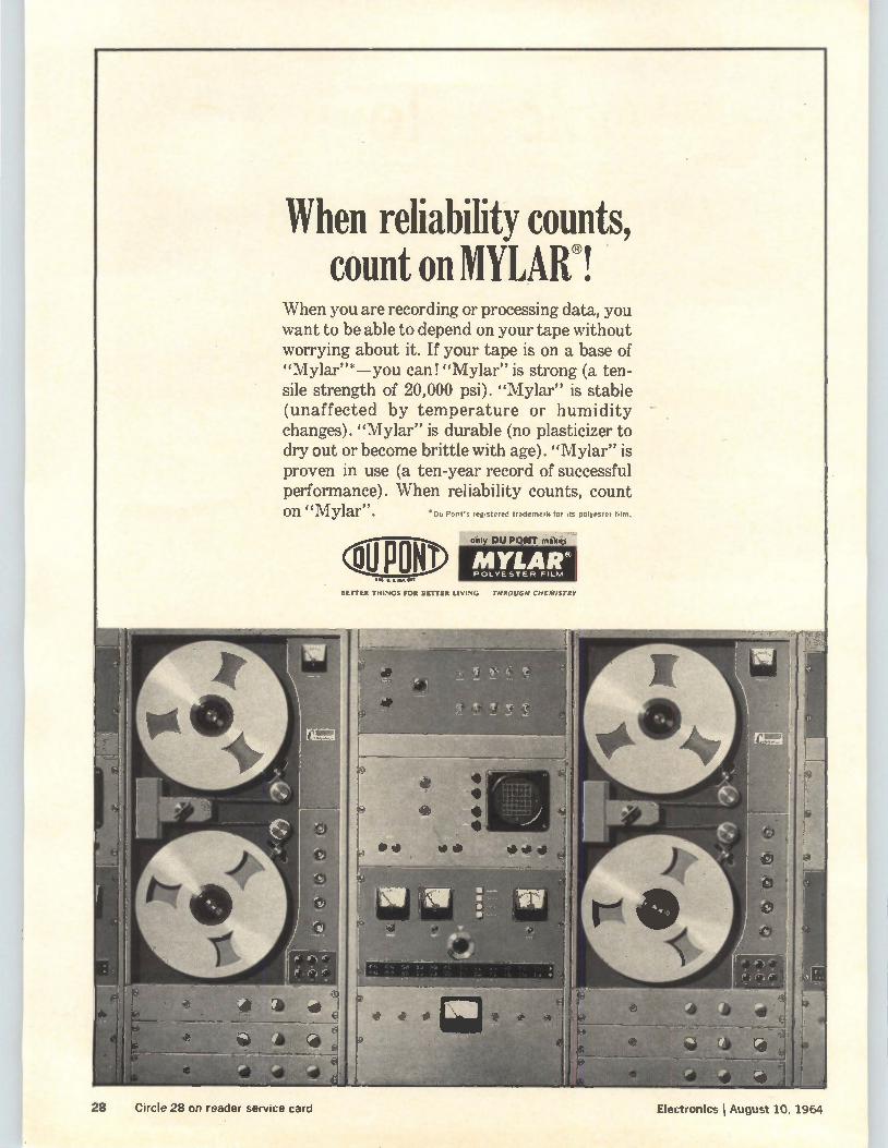
When reliability counts, count on MYLAR®!
When you are recording or processing data, you want to be able to depend on your tape without worrying about it. If your tape is on a base of "Mylar"*—you can! "Mylar" is strong (a ten-sile strength of 20,000 psi). "Mylar" is stable (unaffected by temperature or humidity changes). "Mylar" is durable (no plasticizer to dry out or become brittle with age). "Mylar" is proven in use (a ten-year record of successful performance). When reliability counts, count on "Mylar". •Do Pont's reg.stered trademark for Is polyester lam.
epoo only DU PONT maker MYLAW POLYESTER FILM
BETTER THINGS FOR BETTER LIVING THROUGH CHEMISTRY
Electronics I August 10, 1964 28 Circle 28 on reader service card
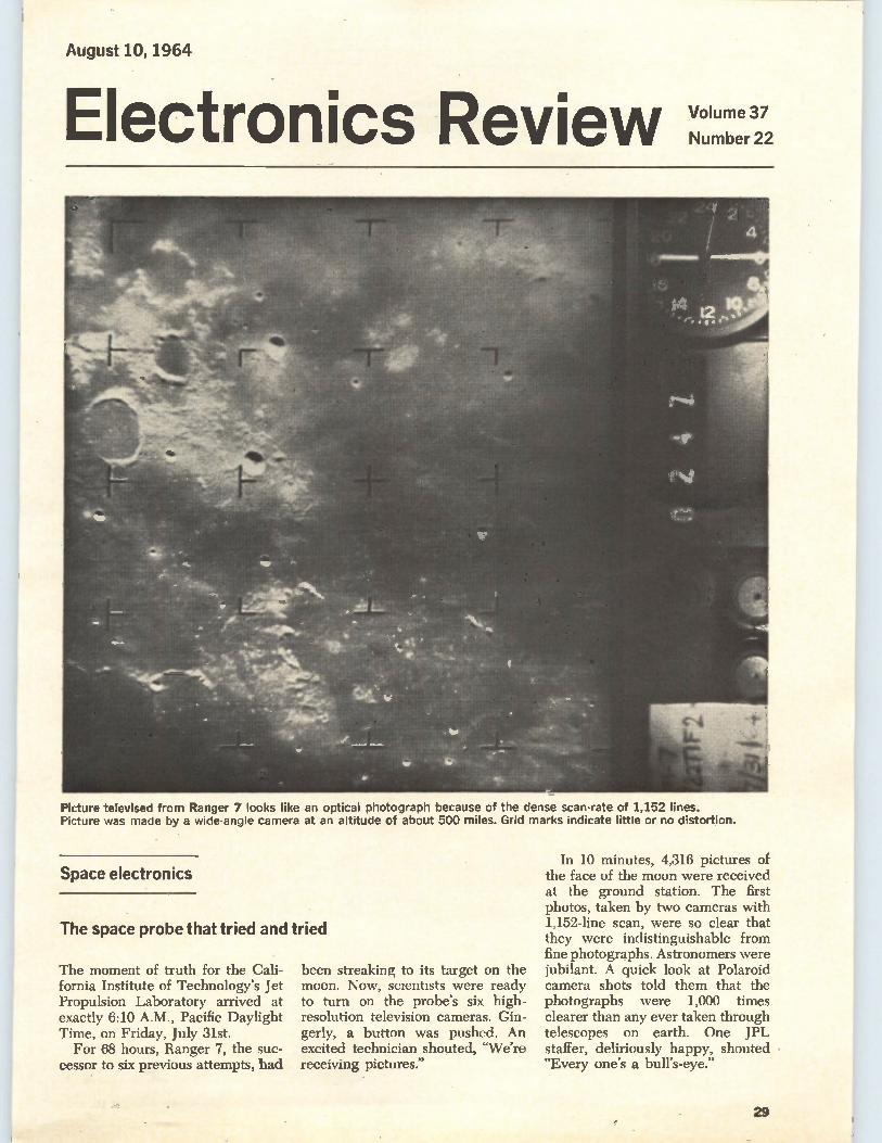
August 10, 1964
Electronics Review Volume 37
Number 22
Picture televised from Ranger 7 looks like an optical photograph because of the dense scan-rate of 1,152 lines. Picture was made by a wide-angle camera at an altitude of about 500 miles. Grid marks indicate little or no distortion.
Space electronics
The space probe that tried and tried
The moment of truth for the Cali-fornia Institute of Technology's Jet Propulsion Laboratory arrived at exactly 6:10 A.M., Pacific Daylight Time, on Friday, July 31st.
For 68 hours, Ranger 7, the suc-cessor to six previous attempts, had
been streaking to its target on the moon. Now, scientists were ready to turn on the probe's six high-resolution television cameras. Gin-gerly, a button was pushed. An excited technician shouted, "We're receiving pictures."
In 10 minutes, 4,316 pictures of the face of the moon were received at the ground station. The first photos, taken by two cameras with 1,152-line scan, were so clear that they were indistinguishable from fine photographs. Astronomers were jubilant. A quick look at Polaroid camera shots told them that the photographs were 1,000 times clearer than any ever taken through telescopes on earth. One JPL staffer, deliriously happy, shouted "Every one's a bull's-eye."
29
Electronics Review
The happiness was not feigned. JPL was in deep trouble with the Ranger program. It had had six failures in a row and in June the National Aeronautics and Space Administration stepped in to re-organize the laboratory. Ranger 6 had been a monumental disappoint-ment. It flew beautifully, landed successfully, but failed to get any pictures.
Failure insurance. Special design precautions taken in Ranger 7 paid off. Acting on the assumption that the television system in Ranger 6 had turned on while the probe was still in the atmosphere and had burned up, engineers designed safe-guards against any accidental turn on of the camera system.
First payoff of the successful op-eration, which stirred people around the world, is in new tan-gible information about the moon. For example, astronomers discov-ered that the moon's dry seas are pitted with small craters, not smooth as they appear on tele-scopes. The dust layer is probably only 2 to 12 inches deep, not bot-tomless as has been imagined. There are a myriad of tiny craters clotting the lunar surface, some as small as 11/2 feet in diameter. Survey next. Recognizing suc-
cess, NASA announced it would transfer some engineers from the Ranger project to the follow-on Surveyor program. Seventeen Sur-veyors probes are planned to land softly on the moon and take more television pictures. For the tv contractor, the Radio
Corp. of America, Ranger 7's suc-cess had added meaning. Never has the ability of television to peer into inaccessible places been demon-strated so effectively. The clarity of the pictures was likely to stir up a lot of new tv applications. The control supplier, the North-
rop Corp., had something to boast about too. Ranger's electronic con-trols brought the probe to within 10 miles of its target on the moon after a journey of a quarter of a million miles. The flight was so per-fect that at the end of the trip, the tv cameras were pointed just as they should have been—right at the moon.
Impact on Apollo. Ranger's find-ings are not expected to lead to any significant changes in the design of the Surveyor spacecraft or in the Lunar Excursion Module of the Apollo spacecraft. The landing control systems of
both Surveyor and the manned-landing module were designed "right down the middle," NASA officials said. They could be used whether the surface was bare rock or a layer of dust. The rigid surface apparently found by Ranger, how-ever, means an added margin of safety.
Television system. Ranger 7's television system began taking pic-tures about 1,000 miles above the moon's surface. First, two cameras with wide-angle lenses went into operation. They scanned the lunar scenes with 1,152 lines. Then, four narrower-angle cameras scanning at 300 lines were started up. The vidicon-camera signals were con-verted to f-m signals and trans-mitted to earth by two 60-watt transmitters operating at frequen-cies of 959.52 and 960.58 mc.
Solid state
Production breakthrough?
In about a year, Anthony van den Heuval of the Illinois Institute of Technology Research Institute in Chicago hopes to solve one of the major problems in thin-film tech-nology: producing a complete cir-cuit with transistors and passive elements on a single substrate. At present, transistors are processed separately and attached to thin-film passive circuits. Van den Heuval has macle, in
the laboratory, cadmium-sulfide crystals with promising character-istics. He is now doing research on methods of producing the crys-tals in such a way that complete circuits can be made by a single automated process. High mobility. Van den Heuval
has grown cadmium-sulfide crystals as large as one square centimeter and with unusually high mobilities. He has attained mobilities of 1,500
em2/volt-second, compared with values of 200 and 300 cm2/ volt-second previously reported by other researchers. He accomplished this the hard way, making his measurements in the dark. Light pumps the crystals and makes their mobilities even higher.
Electron mobility is the figure of merit for thin-film crystals. A high figure must be achieved if thin-film transistors are to have useful gains at frequencies around 100 megacycles. Van den Heuval says he realizes
that the figures obtained in the laboratory may be higher than can be achieved consistently in a pro-duction process. He would be sat-isfied with production of 400 cm2/ volt-second for cadmium sulfide.
Production methods. Van den Heuval has tried three production methods: the Gilles-Van Caken-berghe flux-diffusion technique, mi-cro-zone melting and squashing.
Flux diffusion has given the highest mobility, Crystals are melted to a film; then they are re-crystallized by adding silver to the film and baking it in argon. The silver diffuses into the cadmium-rich film, neutralizes excess cad-mium, causing recrystallization.
Micro-zone melting involves melting the crystal in the middle by using a radio-frequency coil or an electron beam, then allowing the film to recrystallize.
In squashing, molten cadmium sulfide is compressed between glass or quartz. One surface is covered with carbon, so the film sticks only to the other surface. This produces a single-crystal layer on the substrate.
Communications
Ring, dish and tire If the Army, Navy and Air Force had tried to come up with three directional antennas that looked less alike, they could not have done better than three new antennas now going into service or sched-uled for tests. The ring. The Navy has finally
30 Electronics I August 10, 1964
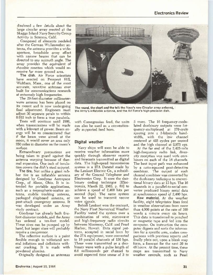
Electronics Review
disclosed a few details about the large circular array erected at the Skaggs Island Navy Security Group Activity in Sonoma, Calif. Composed of elements modeled
after the German \Vullenweber an-tenna, the antenna provides a wide-aperture, broadside array effect with narrow beams that can be directed to any azimuth angle. The array provides the equivalent of rhombic rosettes which would re-require far more ground area. The dish. Air Force scientists
have erected on Prospect Hill, Waltham, Mass., one of the most accurate, sensitive antennas ever built for communications research at extremely high frequencies. The 29-foot-diameter millimeter-
wave antenna has been placed on its mount and is now undergoing final adjustment. Engineers must adjust 30 separate petals to within 0.012 inch to form a true parabola.
Tests will continue until 1966, when transmissions will be made with a kilowatt of power. Beam en-ergy will be so concentrated that if the beam were aimed at the moon, it would cover an area only 250 miles in diameter on the moon's surface.
Extraordinary precautions are being taken to guard against the antenna warping because of ther-mal expansion. One inch of insula-tion covers the dish's steel support. The tire. Not unlike a giant rub-
ber tire is an inflatable antenna designed by Goodyear Aerospace Corp., of Akron, Ohio. It is in-tended for portable applications, such as a tropospheric-scatter an-tenna, mobile tracking antenna, packaged shipboard antenna, or post-attack emergency antenna. It was developed under an Army study contract. Goodyear has already built five-
foot-diameter models, and the Army has ordered a ten-foot model. These sizes can be pumped up by hand, but larger sizes will probably require a compressor. The reflective surface is a paint
flexible enough to withstand sev-eral inflations and deflations with-out cracking. It is made with powdered alumina.
Originally designed as antennas
The round, the short and the tall: the Navy's new Circular array antenna, I the Army's inflatable antenna, and the Air Force's high-precision dish.
with Cassegranian feed, the units can also be used as a convention-ally supported feed horn.
Digital weather Navy ships will soon be able to
receive weather information more quickly through observer reports and forecasts transmitted as digital data. The high-speed transmission system is a 27A Datatel made by the Lenkurt Electric Co., a subsidi-ary of the General Telephone and Electronics Corp. It uses the duo-binary coding technique [Elec-tronics, March 22, 1963, p. 61] to achieve a speed of 2,400 bits per second (bps). The same system can be used to transmit secure voice s.lenals.
Before Lenkurt won the contract, the Navy Fleet Numerical Weather Facility tested the system over a combination of wire, microwave and high-frequency radio circuits between Monterey, Calif. and Pearl Harbor, Hawaii. Data signal pat-terns, accepted in serial form by the 27A equipment, were converted to 16 parallel channels of 150 bps. These were transmitted as a duo-binary wave with a pulse length of 6.6 milliseconds per channel to avoid expected time smear of 3 to
5 msec. The 16 frequency-modu-lated duobinary outputs were fre-quency-multiplexed at 170-cycle spacing into a 3-kilocycle band-width, with the low channel centered at 425 cycles per second and the high channel at 2,975 cps. At the far end of the 2,425-mile
high-frequency radio link, diver-sity reception was used with com-biners on each of the 16 channels. The best input path was enhanced by a ratio-squared post-detection combiner. The output of each channel combiner was converted by the duobinary technique to conven-tional binary data at 15 bps. The 16 channels in a parallel-to-serial con-verter produced binary serial data at synchronous speed of 2,400 bps. Raw material. At the weather
facility, eight teleprinter lines feed in weather observations from more than 4,000 points at the rate of 100 words a minute every six hours. This data is transferred to punched or magnetic tape and fed into the computer. On instruction the com-puter digests and sorts the informa-tion for a specific area, makes com-parisons with previous reports and finally plots out, upon a blank map form, a forecast for the next 30 to 48 hours. At the present time, these maps are transmitted to Navy weather centrals, such as Pearl
Electronics I August 10, 1964 31
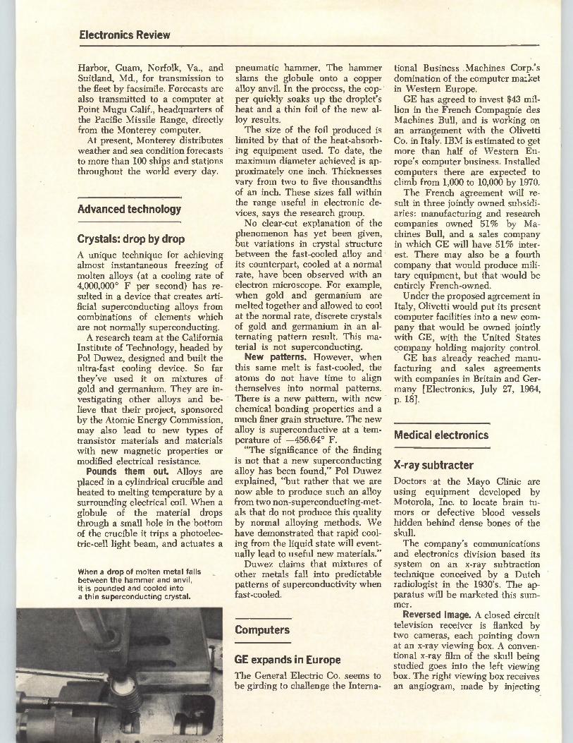
Electronics Review
Harbor, Guam, Norfolk, Va., and Suitland, Md., for transmission to the fleet by facsimile. Forecasts are also transmitted to a computer at Point Mugu Calif., headquarters of the Pacific Missile Range, directly from the Monterey computer. At present, Monterey distributes
weather and sea condition forecasts to more than 100 ships and stations throughout the world every day.
Advanced technology
Crystals: drop by drop
A unique technique for achieving almost instantaneous freezing of molten alloys (at a cooling rate of 4,000,000° F per second) has re-sulted in a device that creates arti-ficial superconducting alloys from combinations of elements which are not normally superconducting. A research team at the California
Institute of Technology, headed by Pol Duwez, designed and built the ultra-fast cooling device. So far they've used it on mixtures of gold and germanium. They are in-vestigating other alloys and be-lieve that their project, sponsored by the Atomic Energy Commission, may also lead to new types of transistor materials and materials with new magnetic properties or modified electrical resistance. Pounds them out. Alloys are
placed in a cylindrical crucible and heated to melting temperature by a surrounding electrical coil. When a globule of the material drops through a small hole in the bottom of the crucible it trips a photoelec-tric-cell light beam, and actuates a
When a drop of molten metal falls between the hammer and anvil, it is pounded and cooled into a thin superconducting crystal.
pneumatic hammer. The hammer slams the globule onto a copper alloy anvil. In the process, the cop-per quickly soaks up the droplet's heat and a thin foil of the new al-loy results. The size of the foil produced is
limited by that of the heat-absorb-ing equipment used. To date, the maximum diameter achieved is ap-proximately one inch. Thicknesses vary from two to five thousandths of an inch. These sizes fall within the range useful in electronic de-vices, says the research group. No clear-cut explanation of the
phenomenon has yet been given, but variations in crystal structure between the fast-cooled alloy and its counterpart, cooled at a normal rate, have been observed with an electron microscope. For example, when gold and germanium are melted together and allowed to cool at the normal rate, discrete crystals of gold and germanium in an al-ternating pattern result. This ma-terial is not superconducting. New patterns. However, when
this same melt is fast-cooled, the atoms do not have time to align themselves into normal patterns. There is a new pattern, with new chemical bonding properties and a much finer grain structure. The new alloy is superconductive at a tem-perature of —456.64° F. "The significance of the finding
is not that a new superconducting alloy has been found," Pol Duwez explained, "but rather that we are now able to produce such an alloy from two non-superconducting-met-als that do not produce this quality by normal alloying methods. We have demonstrated that rapid cool-ing from the liquid state will event-ually lead to useful new materials." Duwez claims that mixtures of
other metals fall into predictable patterns of superconductivity when fast-cooled.
Computers
GE expands in Europe
The General Electric Co. seems to be girding to challenge the Interna-
tional Business Machines Corp.'s domination of the computer malket in Western Europe. GE has agreed to invest $43 mil-
lion in the French Compagnie des Machines Bull, and is working on an arrangement with the Olivetti Co. in Italy. IBM is estimated to get more than half of Western Eu-rope's computer business. Installed computers there are expected to climb from 1,000 to 10,000 by 1970. The French agreement will re-
sult in three jointly owned subsidi-aries: manufacturing and research companies owned 51% by Ma-chines Bull, and a sales company in which GE will have 51% inter-est. There may also be a fourth company that would produce mili-tary equipment, but that would be entirely French-owned. Under the proposed agreement in
Italy, Olivetti would put its present computer facilities into a new com-pany that would be owned jointly with GE, with the United States company holding majority control. GE has already reached manu-
facturing and sales agreements with companies in Britain and Ger-many [Electronics, July 27, 1964, p. 18].
Medical electronics
X-ray subtracter
Doctors at the Mayo Clinic are using equipment developed by Motorola, Inc. to locate brain tu-mors or defective blood vessels hidden behind dense bones of the skull. The company's communications
and electronics division based its system on an x-ray subtraction technique conceived by a Dutch radiologist in the 1930's. The ap-paratus will be marketed this sum-mer.
Reversed image. A closed circuit television receiver is flanked by two cameras, each pointing down at an x-ray viewing box. A conven-tional x-ray film of the skull being studied goes into the left viewing box. The right viewing box receives an angiogram, made by injecting
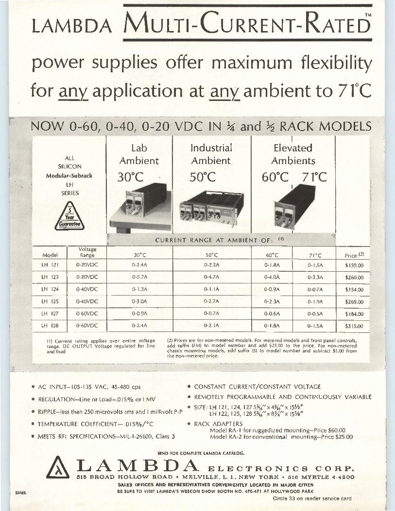
LAMBDA MULTI-CURRENT-RATE6 power supplies offer maximum flexibility
for any application at any ambient to 71°C
ALL
SILICON
Modular-Subrack
LH
SERIES
Model Voltage Range 30°C
Industrial Ambient
50°C
RACK MODELS •
Elevated Ambients
60°C 71°C
URRENT RANGE AT AMBIEN1 OF
50°C Price (2) 60°C 71°C
LH 121 0-20VDC 0-2.4A 0-2.2A 0- I.8A 0-1.5A $159.00
LH 122 0-20VDC 0-5.7A 0-4.7A 0-4.0A 0-3.3A $260.00
LH 124 0-40VDC 0-1.3A 0-1.IA 0-0.9A 0-0.7A $154.00
LH 125 0-40VDC 0-3.0A 0-2.7A 0-2.3A 0-1.9A $269.00
LH 127 0-60VDC 0-0.9A 0-0.7A 0-0.6A 0-0.5A $184.00
LH 128 0-60VDC 0-2.4A 0-2. IA 0- I .8A 0-1.5A $315.00
(I) Current rating applies over entire voltage range. DC OUTPUT Voltage regulated for line and load
(2) Prices are for non-metered models. For metered models and front panel controls, add suffix (FM) to model number and add $25.00 to the price. For non-metered chassis mounting models, add suffix (S) to model number and subtract $5.00 from the non-metered price.
• AC INPUT-105-135 VAC, 45-480 cps
• REGULATION-Line or Load-.015% or 1 MV
• RIPPLE-less than 250 microvolts rms and 1 millivolt P-P
• TEMPERATURE COEFFICIENT- .0150/0/°C
• MEETS ÙI SPECIFICATIONS-MIL-1-26600, Class 3
• CONSTANT CURRENT/CONSTANT VOLTAGE
• REMOTELY PROGRAMMABLE AND CONTINUOUSLY VARIABLE
• SIZE: LH 121, 124, 127 56" x 46" x 151/2" LH 122, 125, 128 56" x 83A" x 155/8"
• RACK ADAPTERS Model RA-I for ruggedized mounting-Price $60.00 Model RA-2 for conventional mounting-Price $25.00
SEND FOR COMPLETE LAMBDA CATALOG.
LAMBDA ELECTRONICS CORP. 515 BROAD HOLLOW ROAD • MELVILLE, L. I., NEW YORK • 516 MYRTLE 4-4200
SALES OFFICES AND REPRESENTATIVES CONVENIENTLY LOCATED IN MAJOR CITIES
BE SURE TO VISIT LAMBDA'S WESCON SHOW BOOTH NO. 470-471 AT HOLLYWOOD PARK
Circle 33 on reader service card
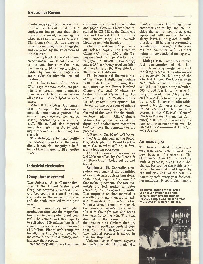
Electronics Review
a substance opaque to x-rays, into the blood vessels of the skull. The angiogram images are then elec-tronically reversed, converting the white areas to black and vice versa. The images from the two viewing boxes are matched by an integrator and delivered by the tv camera to the receiver.
Since the black of the skull bones on one image cancels out the white of the same bones on the other, the tumors or blood vessel defects hidden by bone in the angiogram are revealed for identification and treatment.
Dr. Colin Holman of the Mayo Clinic says the new technique per-mits five percent more diagnoses than before. It is of some help in all cases and very helpful in some cases. When B. B. Ziedses des Plantes
first developed this diagnostic method, more than a quarter of a century ago, there was no way of sharply contrasting vessels in the skull. His method also required long photo lab time; the tv tech-nique produces matched images in seconds. The Motorola system can modify
the contrast density of the x-ray films. It can also magnify a half-inch of the film area to fill an entire screen.
Industrial electronics
Computers in cement
The Universal Atlas Cement divi-sion of the United States Steel Corp. has ordered a General Elec-tric Co. computer control system, the tenth in the cement industry and the sixth installed in the past year. Product consistency and higher
production rates are the major fac-tors spurring computer plant con-trol. The cement industry expects to sell about 360 million barrels of cement this year at a cost of around $1.1 billion. Plants with computer installations find they can sell bet-ter cement, spend less money, and increase their profits. Where they are. The other nine
computers are in the United States and Japan. General Electric has in-stalled its GE-312 at the California Portland Cement Co. It runs on-line, closed loop, and controls blending and kiln burning. The Bunker-Ramo Corp. has a
300 (closed-loop) in the Chichibu Cement Co. and a 330 at the To-kuyama Soda Naugo Works, both in Japan. A BR-300 (closed-loop) and a 330 are being used on kilns at two plants of the Riverside Ce-ment Co. in California. The International Business Ma-
chines Corp. installations include 1710 control systems (using 1620 computers) at the Huron Portland Cement Co. and Northwestern States Portland Cement Co. Ac-cording to Lynn A. Wallace, direc-tor of systems development for Huron, on-line operation of mixing and proportioning is expected by the end of this year. For the North-western plant, Allis-Chalmers Manufacturing Co. supplied the digital and analog instrumentation that connects the computer to the process. A Foxboro Co. 97400 will be in-
stalled later this year at the Petos-key, Mich. plant of Penn-Dixie Ce-ment Co., in what will be, at first, a data logging operation. The 10th computer system, an
LN-3000 installed by the Leeds & Northrop Co., is being set up and tested. Running a mill. Generally, com-
puters keep track of the quantities of raw materials such as limestone, shale, sand, gypsum and iron ore that make up cement. The raw ma-terials are fed, under computer direction, to raw-grinding mills. The output of crushed material is classified b3-7 x-ray, then fed in vari-ous quantities to blending silos. When a certain cement is needed, the computer selects the specific silo with the right mix and feeds the material to the kiln. The kiln, directed by the computer, burns the mixture into clinkers that go, along with specific amounts of gyp-sum, etc., to finish-grinding mills. The finished product is stored in silos for shipment.
Universal Atlas Cement expects to modernize its Hannibal, Mo.
plant and have it running under computer control by late '65. Be-sides the control computer, x-ray equipment will analyze the raw slurry leaving the grinding mills; this data will help in pro,,ortioning calculations. Throughout the proc-ess the computer will reset set points on conventional analog con-trollers.
Linings last. Computers reduce fuel consumption of the kiln through more accurate control of the firing process. This also makes the expensive brick lining of the kiln last longer. Production stops completely when the brick linings of the kilns, huge rotating cylinders 300 to 400 feet long, are periodi-cally replaced. The drive system on Universal's kiln will be powered by a GE Silcomatic adjustable-speed drive that uses silicon con-trolled rectifiers. The computer system is the GE/PAC (General Electric/Process Automation Com-puter) 4000 and the panel control-lers and instrumentation will be GE/MAC (Measurement And Con-trol) devices.
An inside job
The beer you drink in the future may taste even better than it does now because of electronics. The Continental Can Co. is working with a process, using glow dis-charge, for coating the inside of tin cans. The method could save the can industry 75% of the $30 mil-lion it spends every year for coat-ing materials. It could also mean a
Electronic coating of the inside of a tin can (within the dome at right) may save the canning industry some $22.5 million a year in the cost of coating materials.
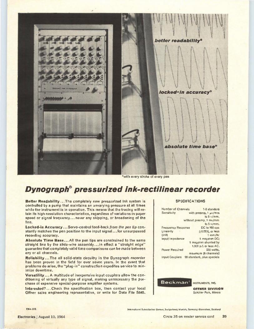
*with every stroke of every pen
Dynograple pressurized ink-rectilinear recorder
Better Readability...The completely new pressurized ink system is controlled by a pump that maintains an unvarying pressure at all times while the instrument is in operation. This means that the tracing will re-tain its high resolution characteristics, regardless of variations in paper speed or signal frequency... never any skipping, or broadening of the line.
Locked-in Accuracy... Servo-control feed-back from the pen tip con-stantly matches the pen position to the input signal...for unsurpassed recording accuracy.
Absolute Time Base...All the pen tips are constrained to the same straight line by the slide-wire assembly...in effect a "straight edge" guarantee that completely valid time comparisons can be made between any or all channels.
Reliability...The all solid-state circuitry in the Dynograph recorder has been proven in the field for over seven years. In the event that problems do arise, the "plug-in" construction expedites service to min-imize downtime.
Versatility...A multitude of inexpensive input couplers allow the con-ditioning of virtually any type of signal, making unnecessary the pur-chase of expensive special-purpose amplifier systems.
Interested?... Check the specification box, then contact your local Offner sales engineering representative, or write for Data File S645.
SPECIFICATIONS
Number of Channels 1-8 standard Sensitivity with preamp, 1 pv/mm
to 5 v/mm. without preamp, 1 mv/mm
to 5 v/mm. Frequency Response DC to 150 cps Linearity +0.25%,,or less Drift 1 mm/hr Input Impedance 1 megohm DC;
1 megohm shunted by
1,000 p.f. or less AC. Power Required 230 watts,
maximum (8 channels)
Input Couplers 28 standard, plus specials
Beckman° INSTRUMENTS, 1NC.
OFFNER DIVISION Schiller Park, Illinois
C64-101
Electronics August 10, 1964
International Subsidiaries: Geneva. Switzerland; Munich, Germany; Glenrothes, Scotland
Circle 35 on reader service card 35
Electronics Review
new market for electronics. Most tin cans have an inside
coating of lacquer to let foods and liquids keep their natural taste and color. If the lacquer separates from the sheet of tin when the can is be-ing formed—always a possibility— strange things happen. When the can is filled with beer, for example, the beer reacts chemically with the raw tinplate and tastes like iron. A drawback of lacquer as a coat-
ing material is that it can break away from a can under mechanical stress and flake into the contents.
Getting a glow on. Continental's scientists place a tin can in a vac-uum chamber and attach leads from a power supply to the can and to an electrode centered inside the can. The chamber is evacuated. A gaseous form of an organic
material, such as styrene plastic, is fed into the chamber. An operator flips the power supply switch and applies 500 volts, frequency-modu-lated at 1 to 50 kilocycles, between the can and the electrode. The difference in potential be-
tween the can and the electrode causes a current to flow that breaks down the gas, ionizing it. The ionized atoms of gas deposit evenly over the inside of the can. The glow is caused by energy re-leased from the gas atoms as they shift to a lower quantum, or energy, level.
Plastics. One advantage of glow discharge is that cans can be coated with plastics that resist at-tack by strong organic solvents. Another plus is that the inner
coatings can be applied after the can is formed. At present, flat tin-plate is coated in a lacquering ma-chine, then baked in a long oven to remove solvents and harden the coating. The new electronic proc-ess will eliminate this step and speed handling. The process may also be modified
for use by the paper industry where the extrusion coating proc-ess now used for paper containers is costly. The odds. But the glow is not all
rosy. The stocky, greying president of Continental Can, Ellison Haz-ard, says that "the chances are 50-50 that this process is commercially
feasible. So far it is limited to the lab bench models. It will be at least two years before we reach the pro-duction stage."
Continental will spend $1 mil-lion within the next two years to find the right material and then set up a pilot production line.
Electronics abroad
Weather by wire
Lighthouse keepers in Britain may soon be relieved of another job— telephoning weather information to a central station. The British Me-teorological Office is studying an automatic reporting system that would transmit weather informa-tion over telephone lines to a cen-tral point. The 12-channel system, designed
by E.M.I. Electronics, Ltd., of Hayes, England, can report on 10 weather parameters from as far as 500 miles from the central station. It provides relatively low-cost te-lemetry by using simple techniques and slow data-transmission. The United States \Veather Bu-
reau is using an automatic weather station, primarily for aviation, that measures more parameters than the E.M.I system but that costs $45,000—about triple the cost of the British system. Systems costing as little as $5,000 have been devel-oped in the United States—but, like one developed by the French, they measure fewer parameters than the British system and trans-mit information by radio rather than by telephone. By using tele-phone transmission, the operating charges for a weather report are equivalent to those for a two-min-ute call over the distance that is involved.
Push-button trigger. A receiver at the central station is connected by telephone lines to a telemetry transmitter at an unattended sta-tion. To obtain data from an out-lying point, an operator at the cen-tral station dials a telephone num-ber. The ringing current turns on the telemetry transmitter, which
announces its own telephone num-ber and location. When the opera-tor at the central station has re-ceived this information, he presses a button that triggers the remote transmitter to send meteorological data. Data transmission is by time-di-
vision multiplex, with the data con-verted into audio tones whose fre-quency is proportional to the standardized zero-to-one-volt out-put of the meteorological instru-ments. Each variable is sampled for 16 seconds. The incoming informa-lion is displayed on meters and punched out in digital form on tape.
Raining bucketsful. Of the 10 parameters, three—the barometric pressure, air temperature and wet-bulb depression—are measured by standard meteorological instru-ments. Total rainfall is measured with two tilting buckets. Each time one bucket fills to capacity and tilts, a pulse circuit advances a counter. The system can store up to 10,000 counts, representing a total rainfall of one meter—a little over three feet. The counter's out-put is converted into an analog sig-nal and fed to the telemetry trans-mitter. For rainfall rate, a metered open-
ing permits droplets of uniform size to pass between a light source and a photocell. The pulses pro-duced are counted for two to five minutes and result in an analog step voltage proportional to the rate of rainfall.
Visibility is determined by meas-uring light attenuation over a fixed path, using a fixed-intensity light source and a photocell detector. Sunshine measurement is from a phototransistor at the center of a rotating hemisphere with alternate opaque and transparent segments. When sunlight hits the hemisphere, a series of shadows passing over the phototransistor generates a pulse train output. The directness of the sunlight governs the sharp-ness of the shadow edges and thus the rise time of the pulses in the train. A relay operates when the rise time corresponds to the stand-ard meteorological definition of bright sunshine.
36 Electronics J August 10, 1964
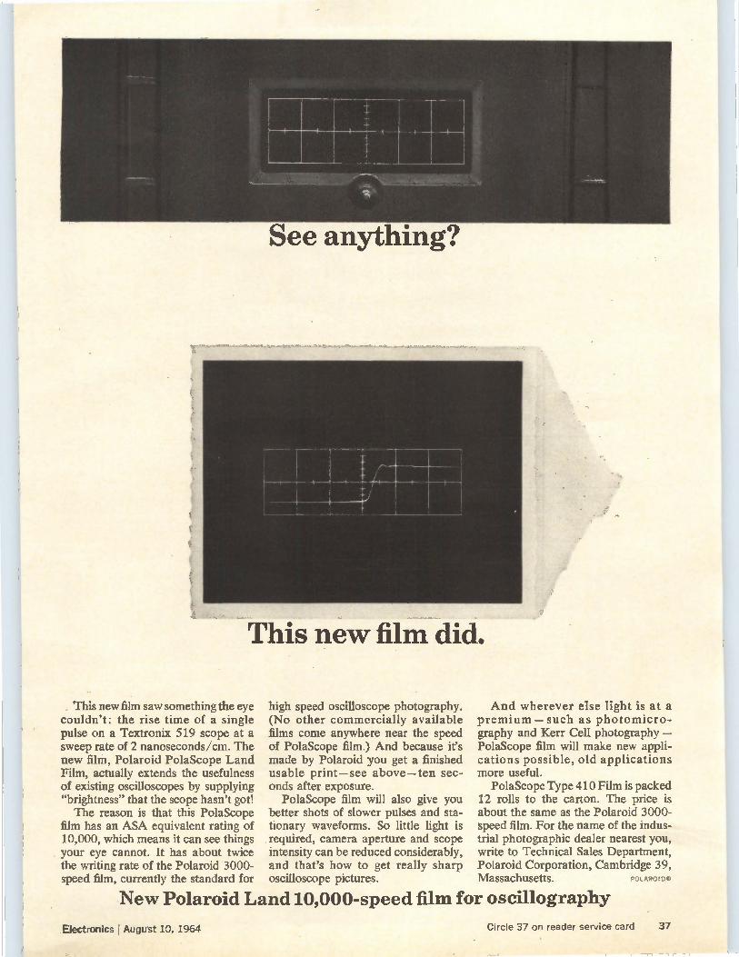
See anything?
This new film did.
This new film saw something the eye couldn't: the rise time of a single pulse on a Textronix 519 scope at a sweep rate of 2 nanoseconds/cm. The new film, Polaroid PolaScope Land Film, actually extends the usefulness of existing oscilloscopes by supplying "brightness" that the scope hasn't got! The reason is that this PolaScope
film has an ASA equivalent rating of 10,000, which means it can see things your eye cannot. It has about twice the writing rate of the Polaroid 3000-speed film, currently the standard for
high speed oscilloscope photography. (No other commercially available films come anywhere near the speed of PolaScope film.) And because it's made by Polaroid you get a finished usable print—see above—ten sec-onds after exposure.
PolaScope film will also give you better shots of slower pulses and sta-tionary waveforms. So little light is required, camera aperture and scope intensity can be reduced considerably, and that's how to get really sharp
And wherever else light is at a premium—such as photomicro-graphy and Kerr Cell photography — PolaScope film will make new appli-cations possible, old applications more useful.
PolaScope Type 410 Film is packed 12 rolls to the carton. The price is about the same as the Polaroid 3000-speed film. For the name of the indus-trial photographic dealer nearest you, write to Technical Sales Department, Polaroid Corporation, Cambridge 39,
oscilloscope pictures. Massachusetts. POLAROID!,
New Polaroid Land 10,000-speed film for oscillography
Electronics I August 10, 1964 Circle 37 on reader service card 37
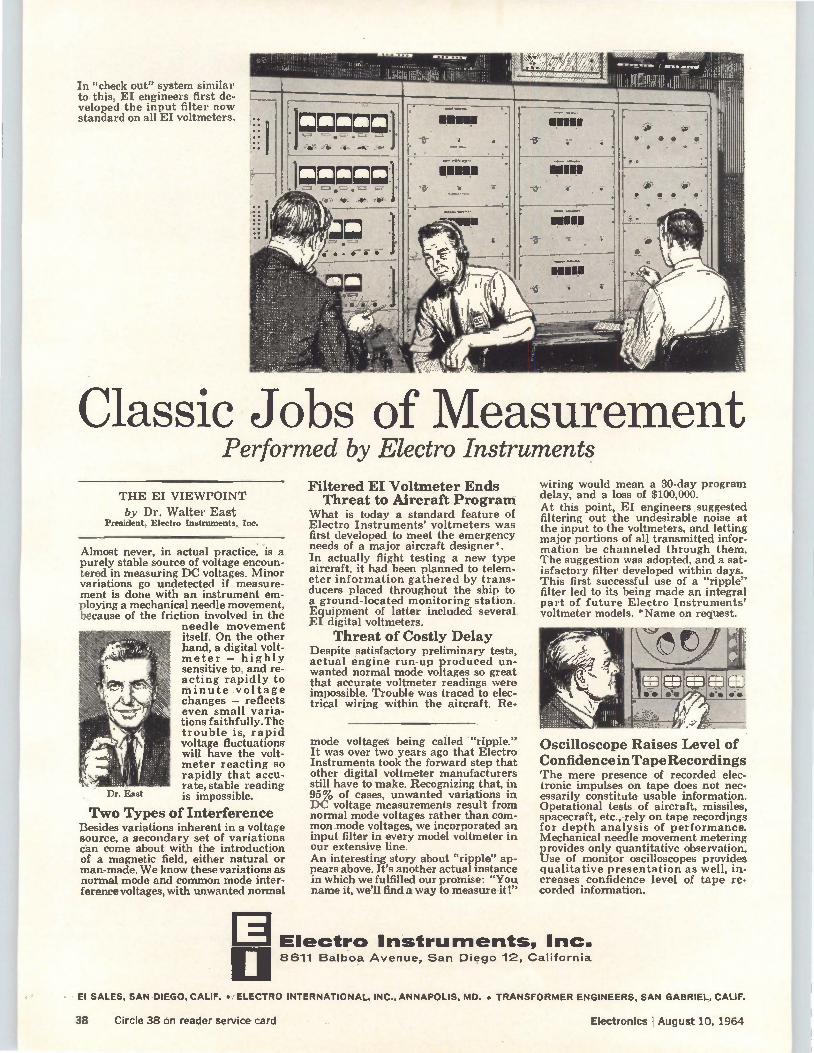
Dr. East
arrazs.,.. Sir .11e144, MI W. 11.1fi.11 11:51.117;là.Y.4.•• ..... eAtigh
'et 411"1"14neleaig:iii gingi4e. till II In "check out" system similar to this, EI engineers first de-veloped the input filter now standard on all EI voltmeters.
Classic Jobs of Measurement Performed by Electro Instruments
THE EI VIEWPOINT
by Dr. Walter East President, Electro Instruments, Inc.
Almost never, in actual practice, is a purely stable source of voltage encoun-tered in measuring DC voltages. Minor variations go undetected if measure-ment is done with an instrument em-ploying a mechanical needle movement, because of the friction involved in the
needle movement itself. On the other hand, a digital volt-meter — highly sensitive to, and re-acting rapidly to minute voltage changes — reflects even small varia-tions faithfully. The trouble is, rapid voltage fluctuations will have the volt-meter reacting so rapidly that accu-rate, stable reading is impossible.
Two Types of Interference Besides variations inherent in a voltage source, a secondary set of variations can come about with the introduction of a magnetic field, either natural or man-made. We know these variations as normal mode and common mode inter-ference voltages, with unwanted normal
E
Filtered EI Voltmeter Ends Threat to Aircraft Program
What is today a standard feature of Electro Instruments' voltmeters was first developed to meet the emergency needs of a major aircraft designer*. In actually flight testing a new type aircraft, it had been planned to telem-eter information gathered by trans-ducers placed throughout the ship to a ground-located monitoring station. Equipment of latter included several EL digital voltmeters.
Threat of Costly Delay Despite satisfactory preliminary tests, actual engine run-up produced un-wanted normal mode voltages so great that accurate voltmeter readings were impossible. Trouble was traced to elec-trical wiring within the aircraft. Re.
mode voltages being called "ripple." It was over two years ago that Electro Instruments took the forward step that other digital voltmeter manufacturers still have to make. Recognizing that, in 95% of cases, unwanted variations in DC voltage measurements result from normal mode voltages rather than com-mon mode voltages, we incorporated an input filter in every model voltmeter in our extensive line. An interesting story about "ripple" ap-pears above. It's another actual instance in which we fulfilled our promise: "You name it, we'll find a way to measure it!"
wiring would mean a 30-day program delay, and a loss of $100,000. At this point, EI engineers .suggested filtering out the undesirable noise at the input to the voltmeters, and letting major portions of all transmitted infor-mation be channeled through them. The suggestion was adopted, and a sat-isfactory filter developed within days. This first successful use of a "ripple" filter led to its being made an integral part of future Electro Instruments' voltmeter models. *Name on request.
Oscilloscope Raises Level of Confidence in Tape Recordings 'rhe mere presence of recorded elec-tronic impulses on tape does not nec-essarily constitute usable information. Operational tests of aircraft, missiles, spacecraft, etc., rely on tape recordings for depth analysis of performance. Mechanical needle movement metering provides only quantitative observation. Use of monitor oscilloscopes provides qualitative presentation as well, in-creases confidence level of tape re-corded information.
Electro Instruments, Inc. 8611 Balboa Avenue, San Diego 12, California
El SALES, SAN DIEGO, CALIF. •. ELECTRO INTERNATIONAL, INC., ANNAPOLIS, MD. • TRANSFORMER ENGINEERS, SAN GABRIEL, CALIF.
38 Circle 38 on reader service card Electronics I August 10, 1964
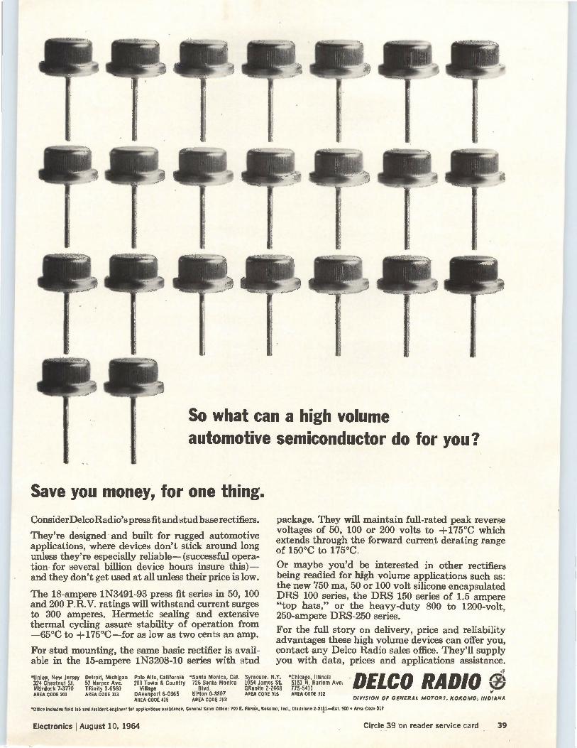
So what can a high volume automotive semiconductor do for you?
Save you money, for one thing.
ConsiderDelco Radio's press fit and stud base rectifiers.
They're designed and built for rugged automotive applications, where devices don't stick around long unless they're especially reliable— (successful opera-tion for several billion device hours insure this) — and they don't get used at all unless their price is low.
The 18-ampere 1N3491-93 press fit series in 50, 100 and 200 P.R.V. ratings will withstand current surges to 300 amperes. Hermetic sealing and extensive thermal cycling assure stability of operation from —65°C to +175°C—for as low as two cents an amp.
For stud mounting, the same basic rectifier is avail-able in the 15-ampere 1N3208-10 series with stud
"Union, New Jersey Detroit, Michigan Palo Alto, California 'Santa Monica, Cal. 324 Chestnut St. 57 Harper Ave. 201 Town & Country 726 Santa Monica MUrdock 7-3770 TRinity 3-6560 Village Blvd. AREA CODE 201 AREA CODE 313 DAvenport 6-0365 UPton 0-8807
AREA CODE 415 AREA CODE 213
package. They will maintain full-rated peak reverse voltages of 50, 100 or 200 volts to +175°C which extends through the forward current derating range of 150°C to 175°C.
Or maybe you'd be interested in other rectifiers being readied for high volume applications such as: the new 750 ma, 50 or 100 volt silicone encapsulated DRS 100 series, the DRS 150 series of 1.5 ampere "top hats," or the heavy-duty 800 to 1200-volt, 250-ampere DRS-250 series.
For the full story on delivery, price and reliability advantages these high volume devices can offer you, contact any Delco Radio sales office. They'll supply you with data, prices and applications assistance.
Syracuse. NY. 1054 James SL 'Chicago, Illinois Ave. DELCO RADIO
› .61 GRanite 2-2668 775-5411
DIVISION OF GENERAL MOTORS. KOKOMO, INDIANA AREA CODE 315 AREA CODE 312
*Office Includes field lab and resident engineer for applications assistance. General Sales Office: 700 E. Firmin, Kokomo, Ind., Gladstone 2-3211—Ext. 500 • Area Code 317
Electronics I August 10, 1964 Circle 39 on reader service card 39
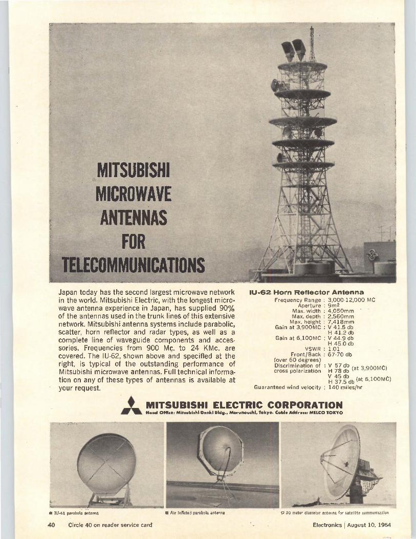
MITSUBISHI MICROWAVE ANTENNAS
FOR LECOMMUN1CATIONS
Japan today has the second largest microwave network in the world. Mitsubishi Electric, with the longest micro-wave antenna experience in Japan, has supplied 90% of the antennas used in the trunk lines of this extensive network. Mitsubishi antenna systems include parabolic, scatter, horn reflector and radar types, as well as a complete line of waveguide components and acces-sories. Frequencies from 900 Mc. to 24 KMc. are covered. The IU-62, shown above and specified at the right, is typical of the outstanding performance of Mitsubishi microwave antennas. Full technical informa-tion on any of these types of antennas is available at your request.
Mtik Heed Office: Mitsubishi Denkl Bldg Ma chi, Tokyo. Cable Address: MELCO TOKYO
ll1-62 Horn Reflector Antenna
Frequency Range Aperture
Max. width Max. depth Max. height
Gain at 3900 MC
Gain at 6,100MC
VSWR : Front/Back :
(over 60 degrees) Discrimination of : cross polarization
: 3,000-12,000 MC : 9m2 : 4,050mm : 2,560mm : 7,418mm : V 41.5 db H 41.2 db : V 44.9 db H 45.0 db 1.01 67-70 db
V 57 db H 78 db (at 3,900MC)
V 45 db H 37.5 db (at 6,100MC)
Guaranteed wind velocity : 140 miles/hr
MITSUBISHI ELECTRIC CORPORATION
Alr Inflated parabola antenna o 20 meter diameter antenna for satellite communication
Electronics August 10, 1964
• IU-61 parabola antenna
40 Circle 40 on reader service card
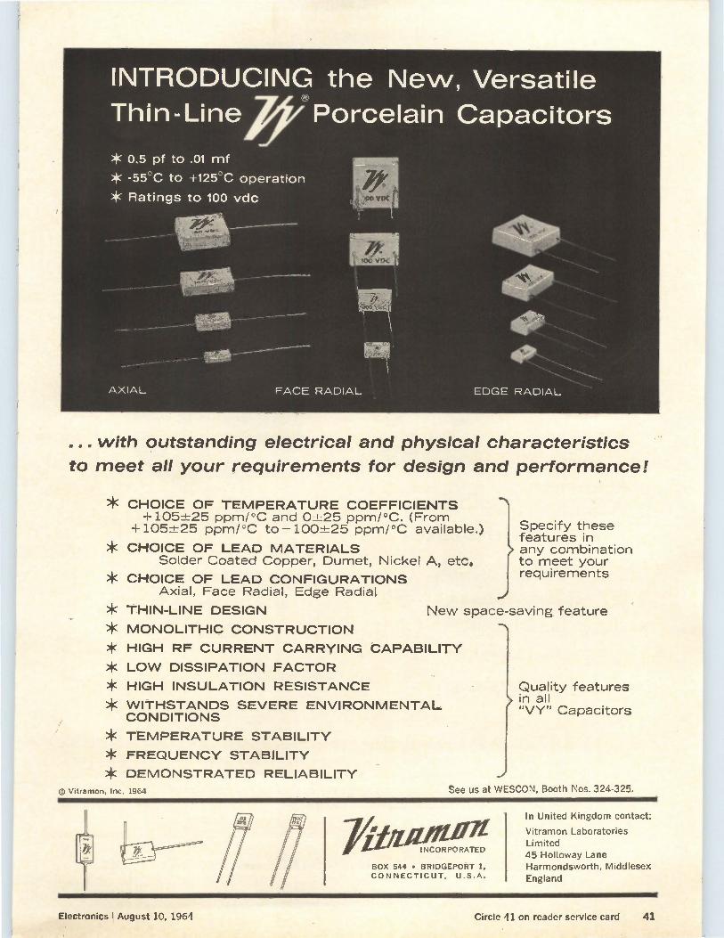
... with outstanding electrical and physical characteristics
to meet all your requirements for design and performance!
* CHOICE OF TEMPERATURE COEFFICIENTS +105±25 ppm/°C and 0±25 ppm/°C. (From
+105±25 ppm/°C to —100±25 ppm/°C available.)
* CHOICE OF LEAD MATERIALS Solder Coated Copper, Dumet, Nickel A, etc.
* CHOICE OF LEAD CONFIGURATIONS Axial, Face Radial, Edge Radial
THIN-LINE DESIGN
MONOLITHIC CONSTRUCTION
HIGH RF CURRENT CARRYING
LOW DISSIPATION FACTOR
HIGH INSULATION RESISTANCE
WITHSTANDS SEVERE ENVIRONMENTAL CONDITIONS
* TEMPERATURE STABILITY
* FREQUENCY STABILITY
* DEMONSTRATED RELIABILITY
© Vitramon, Inc. 1964
ISpecify these features in any combination to meet your requirements
New space-saving feature
CAPABILITY
Quality features in all "VY" Capacitors
See us at WESCON, Booth Nos. 324-325.
BOX 544 • BRIDGEPORT 1, CONNECTICUT, U.S.A.
INCORPORATED
In United Kingdom contact:
Vitramon Laboratories Limited 45 Holloway Lane Harmondsworth, Middlesex England
Electronics I August 10, 1964 Circle 41 on reader service card 41
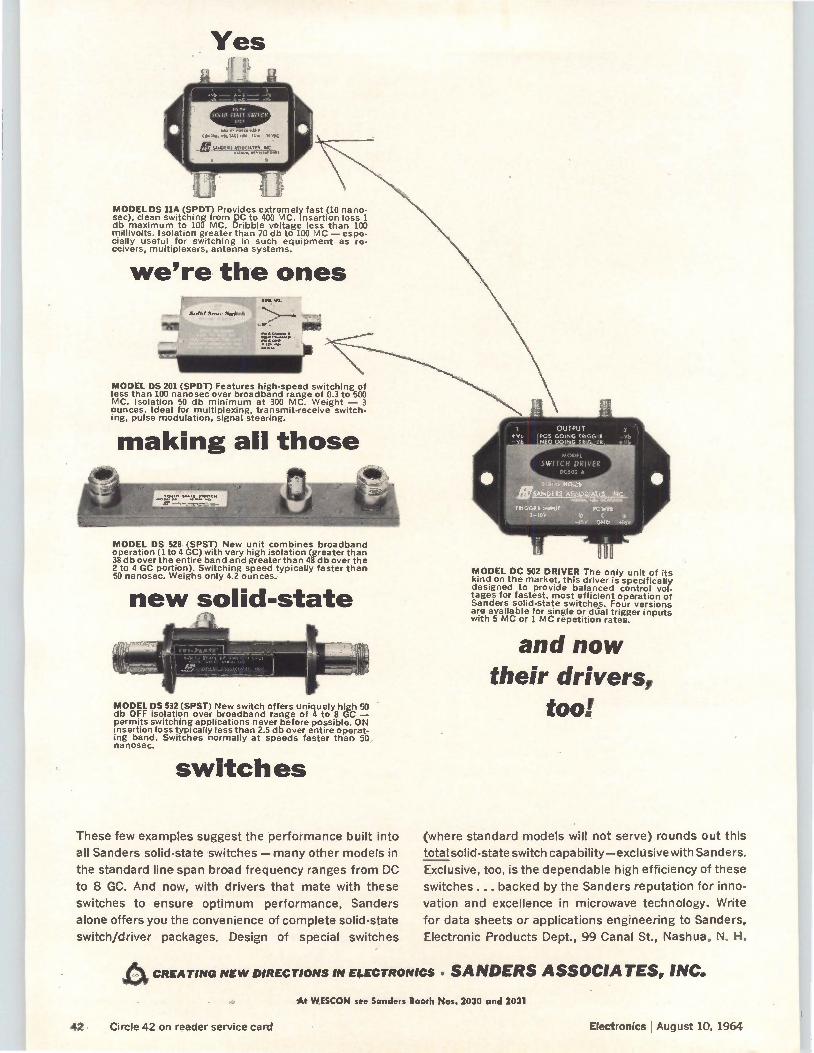
Yes
1.1.1111 (11111(0111.1/
CO,. MI,. PM 10 fie 13 ,11X
iIESC
MODEL DS 11A (SPDT) Provides extremely fast (10 na no. sec), clean switching from DC to 400 MC. Insertion loss 1 db maximum to 100 MC. Dribble voltage less than 100 millivolts. Isolation greater than 70 db to 100 MC — espe-cially useful for switching in such equipment as re-ceivers, multiplexers, antenna systems.
we're the ones
MODEL DS 201 (SPDT) Features high-speed switching of less than 100 nanosec over broadband range of 0.3 to 500 MC. Isolation 50 db minimum at 300 MC. Weight — 3 ounces. Ideal for multiplexing, transmit-receive switch-ing, pulse modulation, signal steering.
making all those
MODEL DS 528 (SPST) New unit combines broadband operation (1 to 4 GC) with very high isolation (greater than 38 db over the entire band and greater than 48 db over the 2 to 4 GC portion). Switching speed typically faster than 50 nanosec. Weighs only 4.2 ounces.
new solid-state
MODEL DS 532 (SPST) New switch offers uniquely high 50 db OFF isolation over broadband range of 4 to 8 GC — permits switching applications never before possible. ON insertion loss typically less than 2.5 db over entire operat-ing band. Switches normally at speeds faster than 50 nanosec.
switches
These few examples suggest the performance built into
all Sanders solid-state switches — many other models in
the standard line span broad frequency ranges from DC
to 8 GC. And now, with drivers that mate with these
switches to ensure optimum performance, Sanders
alone offers you the convenience of complete solid-state
switch/driver packages. Design of special switches
OUTPUT (POS GOING TRIGGER THEO GOING TRIGGER
MODEL DC 502 DRIVER The only unit of its kind on the market, this driver is specifically designed to provide balanced control vol. tages for fastest, most efficient operation of Sanders solid-state switches. Four versions are available for single or &jai trigger inputs with 5 MC or 1 MC repetition rates.
and now their drivers,
too!
(where standard models will not serve) rounds out this
total solid-state switch capability—exclusive with Sanders.
Exclusive, too, is the dependable high efficiency of these
switches ... backed by the Sanders reputation for inno-
vation and excellence in microwave technology. Write
for data sheets or applications engineering to Sanders.
Electronic Products Dept., 99 Canal St., Nashua, N. H.
A CREATING NEW DIRECTIONS IN ELECTRONICS • SANDERS ASSOCIATES, INC.
At W.ESCON see Sanders Booth Nos. 2030 and 2031
42 Circle 42 on reader service card Electronics I August 10, 1964
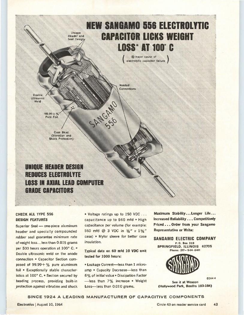
Double Ultrasonic
Weld
• Unique Header and Seal Desig
99.99+% Pure Foil
Case Bead (Vibration and
Shock Protection)
NEW SANGAMO 556 ELECTROLYTIC CAPACITOR LICKS WEIGHT
LOSS* AT 100° C
UNIQUE HEADER DESIGN REDUCES ELECTROLYTE Lin IN AXIAL LEAD COMPUTER GRADE CAPACITORS
CHECK ALL TYPE 556
DESIGN FEATURES
Superior Seal — one-piece aluminum
header and specially compounded
rubber seal guarantee minimum rate
of weight loss...less than 0.015 grams
per 500 hours operation at 100° C. •
Double ultrasonic weld on the anode
connection • Capacitor Section com-
posed of 99.99+ % pure aluminum
foil • Exceptionally stable character-
istics at 100° C. • Section secured by
beading process, providing built-in
protection against vibration and shock
(*major cause of electrolytic capacitor failure )
Welded Connections
• Voltage ratings up to 150 VDC
capacitance up to 560 mfd • High
capacitance per volume (for example:
560 mfd @ 3 VDC in 3/8" x
case) • Mylar sleeve for better case
insulation.
Typical data on 60 mfd 10 VDC unit
tested for 1000 hours:
• Leakage Current—less than 1 micro.
amp • Capacity Decrease—less than
6% of initial value • Dissipation Factor
—less than 7% increase • Weight
Loss—less than 0.010 grams.
Maximum Stability... Longer Life...
Increased Reliability ....Competitively
Priced ... Order from your Sangamo
Representative or Write:
SANGAMO ELECTRIC COMPANY P.O. Box 359
SPRINGFIELD, ILLINOIS 62705 Phone: 217-544-6411
EC64-4
See it at Wescon (Hollywood Park, Booths 183-184)
SINCE 1924 A LEADING MANUFACTURER OF CAPACITIVE COMPONENTS
Electronics I August 10, 1964 Circle 43 on reader service card 43
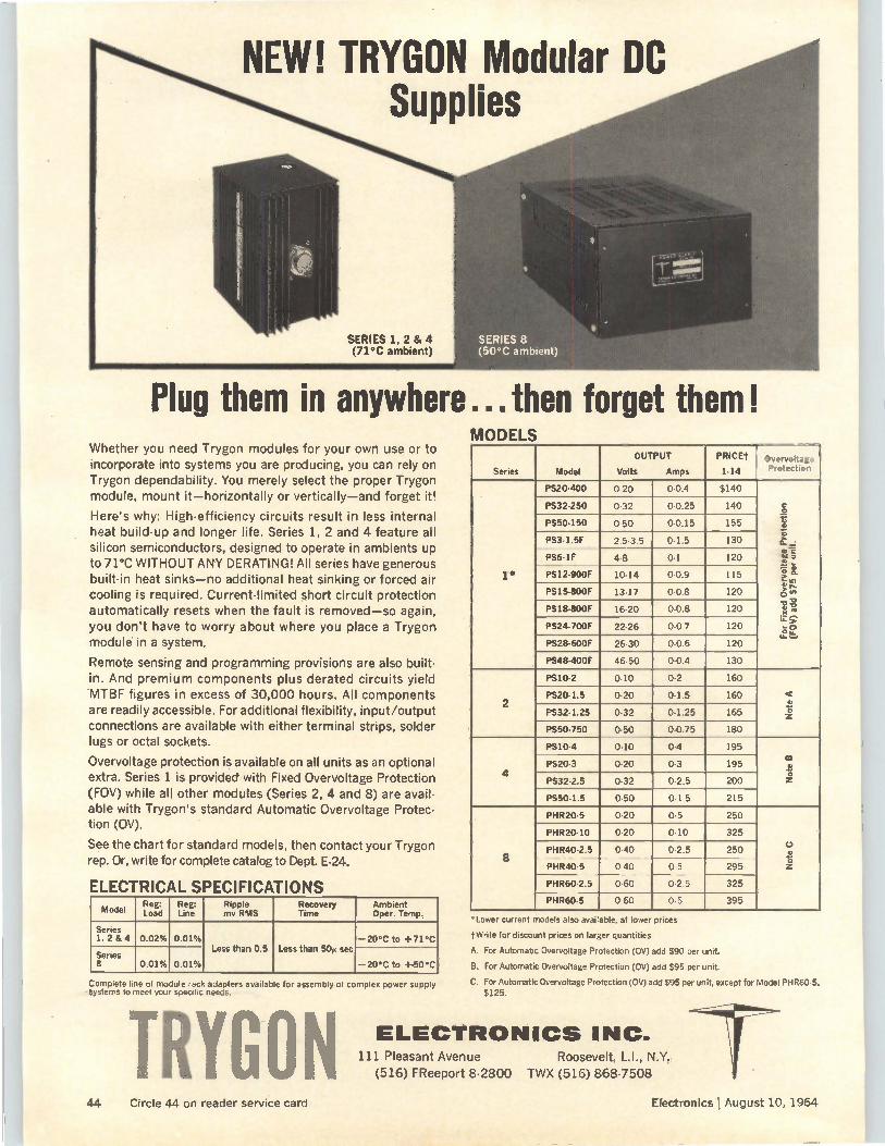
Plug them in anywhere ...then forget them!
NEW! TRYGON Modular DC Supplies
Whether you need Trygon modules for your own use or to incorporate into systems you are producing, you can rely on Trygon dependability. You merely select the proper Trygon module, mount it-horizontally or vertically-and forget it!
Here's why: High-efficiency circuits result in less internal heat build-up and longer life. Series 1, 2 and 4 feature all silicon semiconductors, designed to operate in ambients up to 71°C WITHOUT ANY DERATING! All series have generous built-in heat sinks-no additional heat sinking or forced air cooling is required. Current-limited short circuit protection automatically resets when the fault is removed-so again, you don't have to worry about where you place a Trygon module in a system.
Remote sensing and programming provisions are also built-in. And premium components plus derated circuits yield WITBF figures in excess of 30,000 hours. All components are readily accessible. For additional flexibility, input/output connections are available with either terminal strips, solder lugs or octal sockets.
Overvoltage protection is available on all units as an optional extra. Series 1 is provided with Fixed Overvoltage Protection (FOV) while all other modules (Series 2, 4 and 8) are avail-able with Trygon's standard Automatic Overvoltage Protec-tion (OV).
See the chart for standard models, then contact your Trygon rep. Or, write for complete catalog to Dept. E-24.
ELECTRICAL SPECIFICATIONS Model
Reg: Load
Reg: Line
Ripple mv RMS
Recovery Time
Ambient Oper. Temp.
Series 1, 2 & 4 0.02% 0.01% -20°C to +71°C
Less than 0.5 Less than 50µ see Series 8 0.01% 0.01% -20°C to +50C
Complete line of module rack adapters available for assembly of complex power supply systems to meet you specific needs.
TRYGON
SERIES 8 • (50°C ambient)
MODELS
Series Model
OUTPUT
Volts Amps
PRICET
1-14 Overvoltage Protection
1*
PS20-400 0-20 0.0.4 $140
For Fi
xed OvervoRage Pro
tect
ion
(F0V
) add ;75 per unit.
PS32-250 0-32 0-0.25 140
PS50-150 0-50 0-0.15 155
PS3.1.5F 2.5-3.5 0-1.5 130
PS6-1F 4-8 0-1 120
PS12-900F 10.14 0.0.9 115
PS15-800F 13-17 0.0.8 120
PS18-800F 16.20 0.0.8 120
PS24-700F 22-26 0.0.7 120
PS28-600F 26-30 0-0.6 120
PS48-400F 46.50 0-0.4 130
2
PS10-2 0-10 0-2 160
Note A
PS20-1.5 0-20 0-1.5 160
PS32-1.25 0-32 0-1.25 165
PS50-750 0-50 0.0.75 180
4
PS10.4 0-10 0.4 195
Note B
PS20-3 0.20 0-3 195
PS32-2.5 0.32 0-2.5 200
PS50-1.5 0.50 0-1.5 215
8
PHR20-5 0.20 0-5 250
Note C PHR20-10 0-20 0-10 325
PHR40-2.5 0.40 0-2.5 250
PHR40.5 0-40 0-5 295
PHR60-2.5 0-60 0-2.5 325
PHR60-5 0-60 0-5 395
°Lower current models also available, at lower prices
f Write for discount prices on larger quantities
A. For Automatic Overvoltage Protection (OV) add $90 per unit.
B. For Automatic Overvoltage Protection (OV) add $95 per unit.
C. For Automatic Overvoltage Protection (0V) add $95 per unit, except for Model PHR60-5. $125.
ELECTRONICS INC. 111 Pleasant Avenue Roosevelt, L.I., N.Y.
(516) FReeport 8-2800 TWX (516) 868-7508
44 Circle 44 on reader service card Electronics lAugust 10, 1964
• . • Oeielet‘r
Command-control
design changing
Crackdown on
citizens' band
19 nations adopt
Comsat formula
Check list for
sole-source buys
Washington Newsletter
August 10, 1964
The Strategic Air Command wants to make changes in the Defense Department's 487-L project, a highly reliable, secure survivable com-munications system for command and control messages. The news has shaken nine electronic suppliers who submitted bids for the multimillion dollar project on June 25. Their proposals were based on the original concept.
Since other agencies will also use the communications system Pentagon officials are still weighing SAC's proposal. A decision is expected by September.
The Federal Communications Commission is cracking down on abuses of the citizens' band and may even forbid use of the wavelength if the new regulations don't produce results. Originally intended for personal and business communications over short distances, the bandwidth is now used mostly by hobbyists who jam the channels with chatter. The new FCC regulations, effective Nov. 1, are designed to take the citizens' band away from the hobbyists and return it to use for business and essential personal communications.
The Communications Satellite Corp. has won the lion's share-61%— d the international communications satellite system, but this could drop as low as 50.6% if other countries exercise their option to join. A tentative agreement has been reached between the United States and 18 countries; it 'includes an ownership formula that reduces the shares of each country as new countries join. Each country will own its own ground station—either publicly or privately. Final signatures will be attached to the document beginning August 19. Only countries owning 1.5% of the system are eligible for a seat on the
12-man international committee that will decide all major technical and policy matters, and approve all contracts over $500,000. Decisions require the votes of the U. S. plus a combination representing 12.5% foreign ownership. In case of a deadlock, a 60-day clause reduces the necessary margin to the votes of the U. S. and 8.5% of the remaining ownership. The U. S. had wanted a 66.6% vote to swing decision; the foreign nations had hoped for a 76% vote plus veto power.
Suppliers for the $200-million system will be chosen on a "best buy" basis—without regard to nationality. If comparable offers are made, purchasing will be distributed on a percent-of-ownership basis. •
The Air Force is again trying to cure its sole-source headache. It has come up with a method of checking on prime contractors who buy parts from sole sources instead of in open competition. The first test of the new system covers air-frame and engine manufacturers, with missile and electronic system suppliers next on the list. The check system uses electronic data processing cards supplied to the contractors for parts purchases of $10,000 or more. Coding covers 11 justifications accepted for sole-sources buying in lieu of open competition. Screening is carried
45
Washington Newsletter
only to the point where the first valid justification is reached, such as requirement of special test or inspection facilities, need of proprietary data for satisfactory production, or a degree of reliability needed which isn't obtainable from other sources.
Traffic-control
parley planned
Computers studied
for mail routes
New plane plugs
military hole
Dual-sales
report readied
The Bureau of Public Roads will sponsor a conference in Washington on Sept. 14 and 15, to study the application of modern technology to existing highway systems. It hopes to persuade electronic suppliers and computer makers to attend. But the big obstacle to widespread automa-tion of traffic control remains: too few traffic engineers understand the electronic equipment or are willing to learn about it.
A new area of computer use is being explored by the Post Office Dept. It is studying the application of its IBM 1401 computers to airmail route selection; later it may add rail and truck routes, or any combination of rail, truck and air. The department itself—and a wide variety of ship-pers—could thus find the fastest, most economical routes. The National Bureau of Standards has done an experimental study
of air routes selection using- Fortran and IBM 7090. The program deter-mines all usable routes from among 2,000 trip segments, evaluates links, transfer-points and times, compares interline and intraline transfers, cost reliability factors, and even the ground distances involved. Currently, the bureau is working with the problem of deciding computer capability requirements that will make the technique feasible to a wide variety of shippers.
The new/billion-dollar strategic reconnaissance aircraft SR-71 announced by President Johnson is believed to be only a slightly modified version of the new high-flying A-11 craft shown in February. The Air Force has redesignated the A-11. It is now the YF-12-A (prototype fighter); it will be used as a 2,000 mph aircraft interceptor.
,Officially, the Pentagon will not talk about the SR-71's mission. Unoffi-cially it is expected to fill a current gap in the United States military, structure. The plane will be a forward spotter, assessing missile damage to targets. Additionally, it will augment satellites in peacetime aerial reconnaissance.
A report being prepared by the Small Business Subcommittee headed by Rep. James Roosevelt (D.-Calif.) will focus attention on dual distribution, a subject which interests both the Justice Dept. and the Federal Trade Commission. As the result of an inquiry into the practice in 45 industries, Roosevelt is proposing new legislation that would require the mainte-nance of price differentials by firms that are engaged in more than one level of sale. In consumer electronics, for example, a manufacturer could not charge less to his own captive outlet than he charges to an independent retailer or wholesaler. The independents complain that dual distribution abuses lead to discount competition they can't meet. The subcommittee can only investigate; it cannot legislate. Thus, any
proposed legislation will be referred to other committees, such as the Judiciary and Commerce, and in those committees it faces a fight.
46 Electronics I August 10, 1964
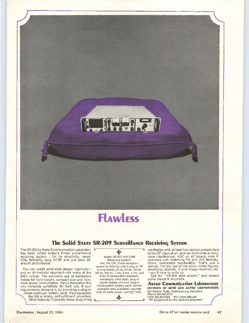
FLAWLESS
ThE Solid STATE SR-209 SURVEMANCE REcEiviNg SySTEM The SR-209 by Astro Communication Laboratory has been called today's finest surveillance receiving system ... for its sensitivity, versa-tility, flexibility, long MTBF and just plain all-around performance.
You can credit solid state design ingenuity— and an all-modular approach—for many of the 209's virtues. The exclusive use of transistors makes for light weight, compact size and mini-mum power consumption. We've translated this into complete portability for field use, if your requirements demand it, by providing a plug-in
nickel-cadmium battery pack; thus equipped, —....* the 209 is totally self-sufficient anywhere.
Other features ? Consider these :plug-in sig.
Model SR-209 VHF/UHF Receiving System:
AM, FM, CW, Pulse reception; covers 30-2000 mc with 5 plug-in RF tuning heads; 20 kc, 60 kc, 100 kc,
300 kc, 500 kc, 1 mc, 2 mc, 4 mc, and 8 mc IF bandwidths available; completely solid state; plug-in signal display unit and plug-in
rechargeable battery pack; carrier operated relay available; requires only 25 watts power; just 3%" high.
nal display unit, at least two section preselectors at the RF input of all receiver front ends to mini-mize interference; AGC on all tuners; nine IF channels with matching FM and AM demodu-lators; switchable bandwidths. That's just a sample. For the rest of the story—noise figures, sensitivity, stability, IF and image rejection, etc. —you'll have to write us. Ask for "SR-209 data sheets," and expect
some pleasant surprises.
ASTRO COMMUNiCATiON LAbORATORy DIVISION OF AERO GEO ASTRO CORPORATION 801 Gaither Road, Gaithersburg, Maryland Phone 301-948-5210 TWX 703-354-0334 • WU Telex 089-435 "RF Equipment for the Systems Engineer"
Electronics I August 10, 1964 Circle 47 on reader service card 47
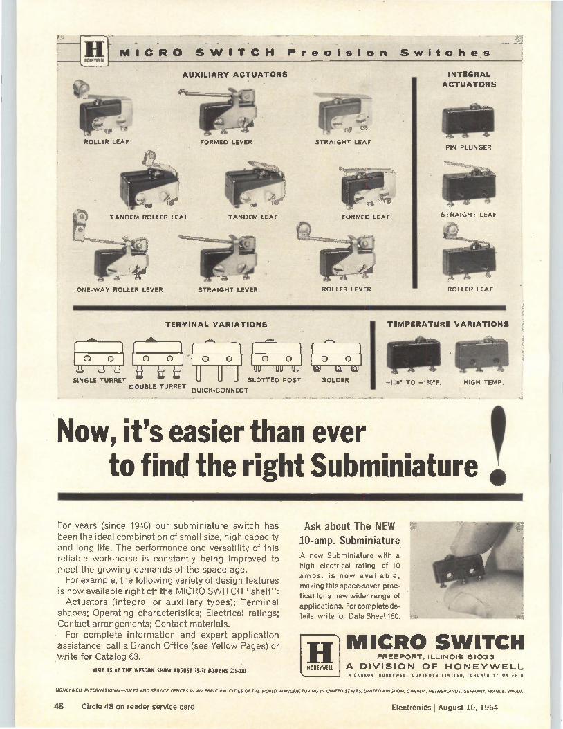
ROLLER LEAF FORMED LEVER
TANDEM LEAF
ONE-WAY ROLLER LEVER STRAIGHT LEVER
STRAIGHT LEAF
FORMED LEAF
ROLLER LEVER
Now, it's easier than ever
MICRO SWITCH Precision Switches HONEYWELL
AUXILIARY ACTUATORS
TANDEM ROLLER LEAF
INTEGRAL
ACTUATORS
PIN PLUNGER
STRAIGHT LEAF
ROLLER LEAF
TERMINAL VARIATIONS
SINGLE TURRET SLOTTED POST DOUBLE TURRET
QUICK-CONNECT
SOLDER
TEMPERATURE VARIATIONS
—100° TO +180°F. HIGH TEMP.
to find the right Subminiature e! 4
For years (since 1948) our subminiature switch has been the ideal combination of small size, high capacity and long life. The performance and versatility of this reliable work-horse is constantly being improved to meet the growing demands of the space age.
For example, the following variety of design features is now available right off the MICRO SWITCH "shelf": Actuators (integral or auxiliary types); Terminal
shapes; Operating characteristics; Electrical ratings; Contact arrangements; Contact materials.
For complete information and expert application assistance, call a Branch Office (see Yellow Pages) or write for Catalog 63.
VISIT US AT THE WESCON SHOW AUGUST 2548 BOOTHS 229-230
Ask about The NEW 10-amp. Subminiature A new Subminiature with a
high electrical rating of 10
amps. is now available,
making this space-saver prac-
tical for a new wider range of
applications. Forcomplete de-
tails, write for Data Sheet 180.
H HONEYWELL
MICRO SWITCH FREEPORT, ILLINOIS 61033
A DIVISION OF HONEYWELL IN CANADA: HONEYWELL CONTROLS LIMITED, TORONTO IT. ONTARIO
HONEYWELL INTERNATIONAL-SALES AND SERVICE OFFICES IN ALL PRINCIPAL CITIES OF THE WORLD. MANUFACTURING IN UNITED STATES, UNITED KINGDOM, CANADA, NETHERLANDS, GERMANY, FRANCE, JAPAN.
48 Circle 48 on reader service card Electronics I August 10, 1964
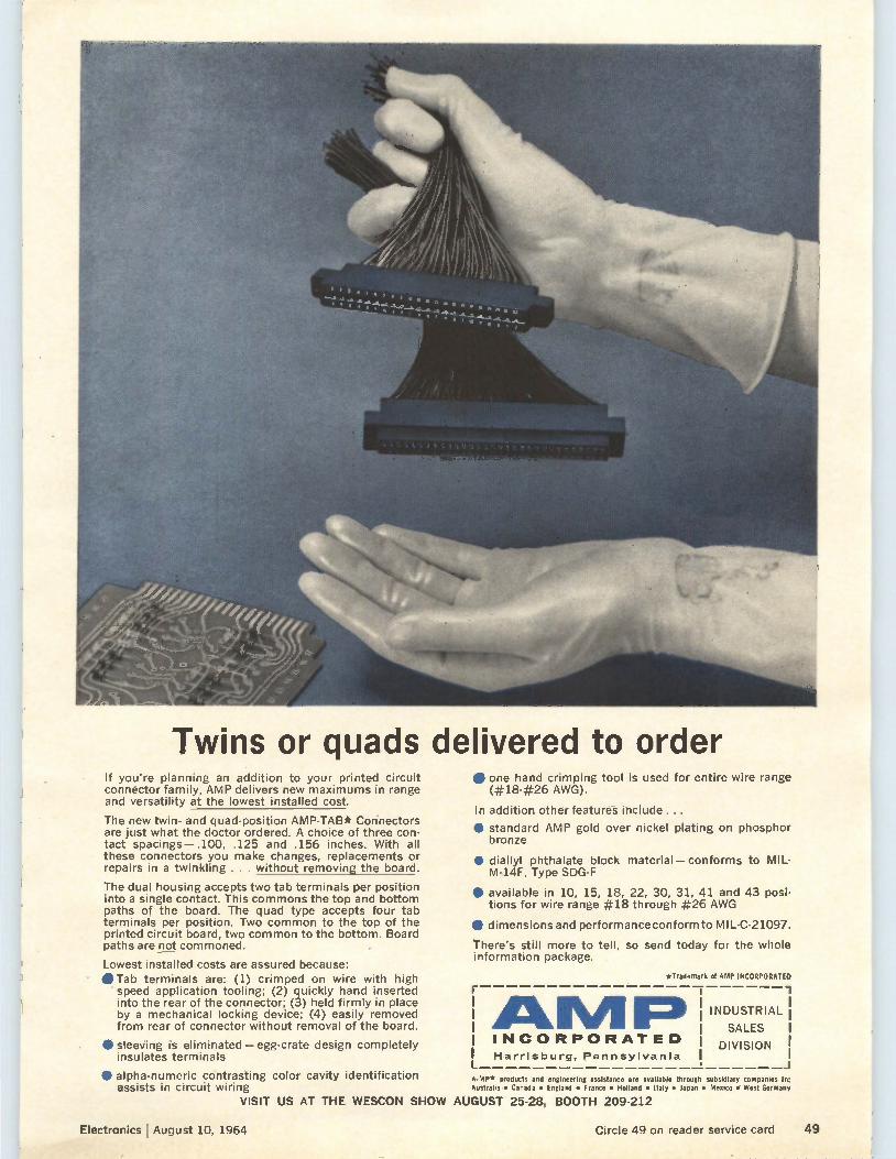
Twins or quads delivered to order If you're planning an addition to your printed circuit connector family, AMP delivers new maximums in range and versatility at the lowest installed cost.
The new twin- and quad-position AMP-TAB* Connectors are just what the doctor ordered. A choice of three con-tact spacings— .100, .125 and .156 inches. With all these connectors you make changes, replacements or repairs in a twinkling . . . without removing the board.
The dual housing accepts two tab terminals per position into a single contact. This commons the top and bottom paths of the board. The quad type accepts four tab terminals per position. Two common to the top of the printed circuit board, two common to the bottom. Board paths are not commoned.
Lowest installed costs are assured because: • Tab terminals are: (1) crimped on wire with high
speed application tooling; (2) quickly hand inserted into the rear of the connector; (3) held firmly in place by a mechanical locking device; (4) easily removed from rear of connector without removal of the board.
• sleeving is eliminated — egg-crate design completely insulates terminals
• alpha-numeric contrasting color cavity identification assists in circuit wiring
VISIT US AT THE WESCON SHOW
• one hand crimping tool is used for entire wire range (#18-#26 AWG).
In addition other features include ...
• standard AMP gold over nickel plating on phosphor bronze
• diallyl phthalate block material—conforms to MIL-M-14F, Type SDG-F
• available in 10, 15, 18, 22, 30, 31, 41 and 43 posi-tions for wire range #18 through #26 AWG
• dimensions and performance conform to MIL-C-21097. There's still more to tell, so send today for the whole information package.
*Trademark of AMP INCORPORATED
AMP» INCORPORATED
Harrisburg, Pennsylvania
A-MP* products and engineering assistance are available through Australia • Canada • England • France • Holland • Italy • Japan •
AUGUST 25-28, BOOTH 209-212
INDUSTRIAL I
SALES 1
DIVISION I 1
subsidiary companies In: mesico • West Germane
Electronics I August 10, 1964 Circle 49 on reader service card 49
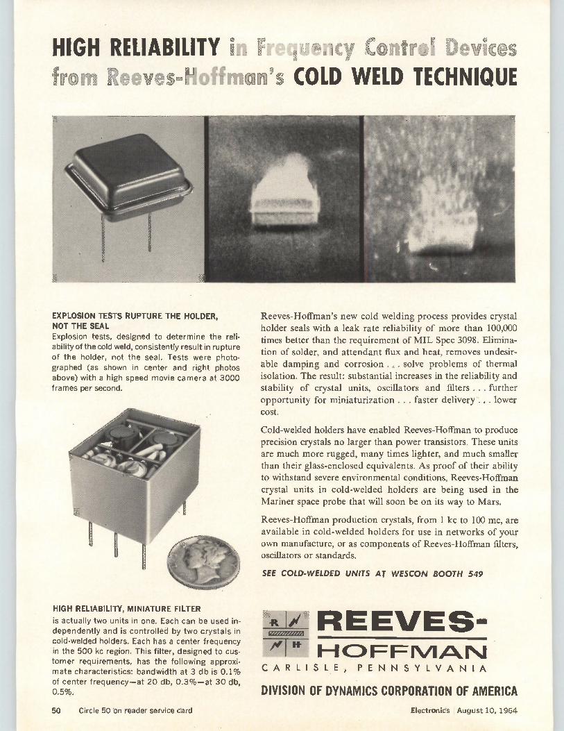
HIGH RELIABILITY 9
EXPLOSION TESTS RUPTURE THE HOLDER, NOT THE SEAL Explosion tests, designed to determine the reli-ability of the cold weld, consistently result in rupture of the holder, not the seal. Tests were photo-graphed (as shown in center and right photos above) with a high speed movie camera at 3000 frames per second.
HIGH RELIABILITY, MINIATURE FILTER
is actually two units in one. Each can be used in-dependently and is controlled by two crystals in cold-welded holders. Each has a center frequency in the 500 kc region. This filter, designed to cus-tomer requirements, has the following approxi-mate characteristics: bandwidth at 3 db is 0.1% of center frequency—at 20 db, 0.3%—at 30 db, 0.5%.
-y C n rc I x * esWELD TECHNIQUE
Reeves-Hoffman's new cold welding process provides crystal
holder seals with a leak rate reliability of more than 100,000 times better than the requirement of MIL Spec 3098. Elimina-tion of solder, and attendant flux and heat, removes undesir-able damping and corrosion . solve problems of thermal isolation. The result: substantial increases in the reliability and stability of crystal units, oscillators and filters ... further
opportunity for miniaturization. .. faster delivery .... lower cost.
Cold-welded holders have enabled Reeves-Hoffman to produce precision crystals no larger than power transistors. These units are much more rugged, many times lighter, and much smaller than their glass-enclosed equivalents. As proof of their ability to withstand severe environmental conditions, Reeves-Hoffman crystal units in cold-welded holders are being used in the
Mariner space probe that will soon be on its way to Mars.
Reeves-Hoffman production crystals, from 1 kc to 100 mc, are available in cold-welded holders for use in networks of your own manufacture, or as components of Reeves-Hoffman filters, oscillators or standards.
SEE COW-WELDED UNITS AT WESCON BOOTH 549
r REEVES-11-10 FIF 10/IA1\1
CARLISLE, PENNSYLVANIA
DIVISION OF DYNAMICS CORPORATION OF AMERICA
50 Circle 50 on reader service card Eiectronic's I August 10, 1964
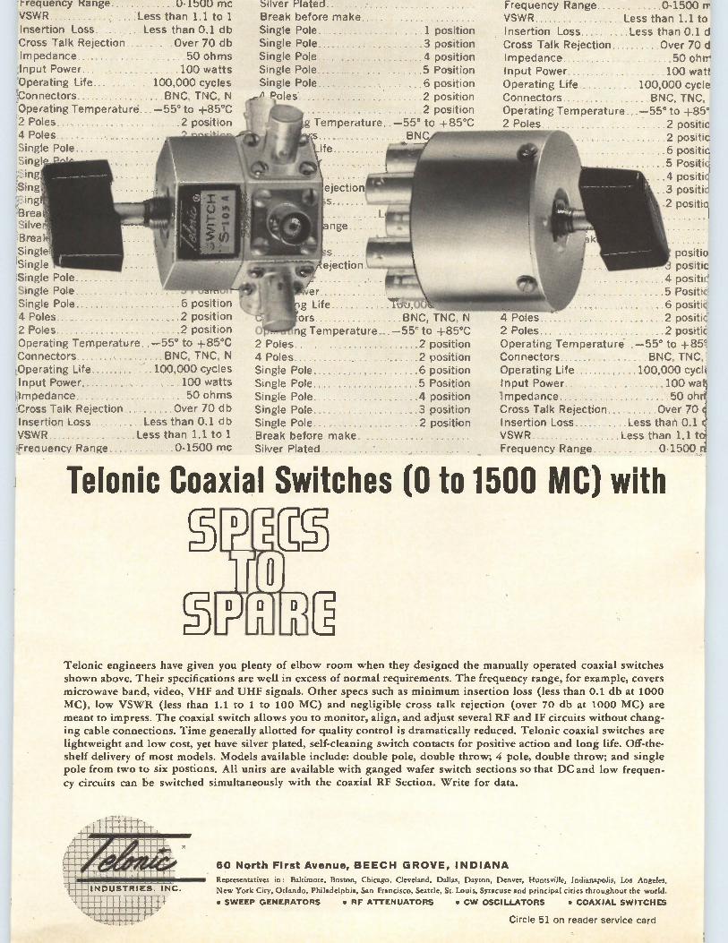
frequency Kange U-1500 mc VSWR 'Less than 1.1 to 1 Insertion Loss Less than 0.1 db Cross Talk Rejection Over 70 db Impedance 50 ohms Input Power. 100 watts Operating Life 100,000 cycles Connectors BNC, INC, Operating Temperature . —55° to -185°C 2 Poles... 2 pc Y [Ion 4 Poles 'Single Pole :Singl Sing Sing, .Sin4 'Bred!
Bred., Single ¡Single iSingle Pole Single Pule, Single Pole Í position 4 Poles ...... ..2 position Poles 2 position
Operating Temperature .-55° to +85°C Connectors BNC, INC, N Operating Life 100,000 cycles iInput Power .. 100 watts: Impedance 50 ohms Cross Talk Rejection, , ..Over 70 db Insertion Loss Less than 0.1 db VSWR Less than 1.1 to 1, Freauency Range.... . .0-1500 mc
Silver Plated Break before make Single Pole Single Pole Single Pole Single Pole Single Pole... P rj n s
Temperature
jection
1 position 3 position 4 position 5 Position 6 position 2 position 2 position
—55' to +85°C BNC
r
Life
ng Temperature —55 - to +do-C 2 Pt,' 2 position 4 Poles 2 position Single Pole 6 position Single Pole 5 Position Single Pole 4 position Single Pole 3 position Single Pole 2 position Break before make Silver Plated
Frequency Range. VSWR Insertion Loss. Cross Talk Rejection Impedance Input Power Operating Life Connectors Operating Temperature, 2 Poles
0-1500 rr Less than 1.1 to Less than 0.1 d
Over 70 d 50 ohrrei
100 watt' 100,000 cycle BNC, TNC,
—55° to +85°1 2 positic 2 positic 6 positré 5 Positk 4 positic' \3 positié 2 positid
1 positic positic'
4 positic' 5 Positid 6 positié
,; Poles positic 2 Poles 2 positic Operating Temperature —55° to +85e Connectors BNC, TNC, Operating Life 100,000 cyck Input Power 100 wet' Impedance 50 ohn. Cross Talk Rejection Insertion Loss.. VSWR........ Frequency Range
Over 70 e Less than 0.1 c
Less than 1.1 to. 0-1500 n'
Telonic Coaxial Switches (0 to 1500 MC) with
Telonic engineers have given you plenty of elbow room when they designed the manually operated coaxial switches shown above. Their specifications are well in excess of normal requirements. The frequency range, for example, covers microwave band, video, VHF and UHF signals. Other specs such as minimum insertion loss (less- than 0.1 db at 1000 MC), low VSWR (less than 1.1 to 1 to 100 MC) and negligible cross talk rejection (over 70 db at 1000 MC) are meant to impress. The coaxial switch allows you to monitor, align, and adjust several RF and IF circuits without chang-ing cable connections. Time generally allotted for quality control is dramatically reduced. Telonic coaxial switches are lightweight and low cost, yet have silver plated, self-cleaning switch contacts for positive action and long life. Off-the-shelf delivery of most models. Models available include: double pole, double throw; 4 pole, double throw; and single pole from two to six postions. All units are available with ganged wafer switch sections so that DC and low frequen-cy circuits can be switched simultaneously with the coaxial RF Section. Write for data.
60 North First Avenue, BEECH GROVE, INDIANA Representatives in: Baltimore, Boston, Chicago, Cleveland, Dallas, Dayton, Denver, Huntsville, Indianapolis, Los Angeles,
New York City, Orlando, Philadelphia, San Francisco, Seattle, St. Louis, Syracuse and principal cities throughout the world.
• SWEEP GENERATORS • RF ATTENUATORS • CW OSCILLATORS • COAXIAL SWITCHES
Circle 51 on reader service card
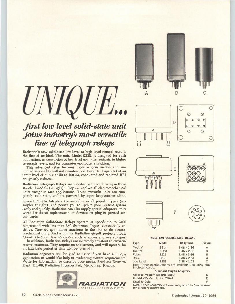
UNJO (Ibi. first low level solid-state unit joins industry most versatile
line of telegraph relays Radiation's new solid-state low level to high level neutral relay is the first of its kind. The unit, Model 9338, is designed for such applications as conversion of low level computer outputs to higher telegraph levels, and for computer/computer switching.
This advanced relay features modular construction and un-limited service life without maintenance. Because it operates at an input level of -± 6 y at 50 to 100 µa, conducted and radiated RFI are greatly reduced.
Radiation Telegraph Relays are supplied with octal bases in three standard models (at right). They can replace all electromechanical units except in rare applications. These versatile units are com-pletely solid state, and are powered by input loop current alone.
Special Plug-In Adapters are available in all popular types (ex-amples at right), and permit you to update your present system easily and quickly. Radiation can also supply special adapters, units wired for direct replacement, or devices on plug-in printed cir-cuit cards.
All Radiation Solid-State Relays operate at speeds up to 2400 bits/second with less than 3% distortion. Input is essentially re-sistive. They do not induce transients in the line as do electro-mechanical units. And a unique Radiation circuit protects inputs against abnormal line conditions such as spikes and overvoltages.
In addition, Radiation Relays are extremely resistant to environ-mental extremes. They require no adjustment, and will operate for an indefinite period of time without attention.
Radiation engineers will be glad to assist if you have a unique application or would like help in evaluating system requirements. Write for information, or describe your needs. Products Division, Dept. EL-08, Radiation Incorporated, Melbourne, Florida.
RADIATION INCORPORATED
o 0 ©© @ 0 o 0 0
0 G
RADIATION SOLID-STATE RELAYS
Type Model Body Size Figure
Neutral 9214 1.46 x 2.86 A Neutral 9220 1.46 x 2.86 A Polar 9212 1.46 x 3.66 B Univ. 9218 1.38 x 2.63 c Low Level 9338 1.38 x 2.63 c Note: Other configurations are available, including plug-in circuit cards.
Standard Plug-In Adapters Octal-to-Western Electric 255-A D Octal-to-Western Union 202-A E Octal-to-Octal F Note: Other adapters are available, or units can be wired for direct replacement.
52 Circle 52 on reader service card Electronics August 10, 1964
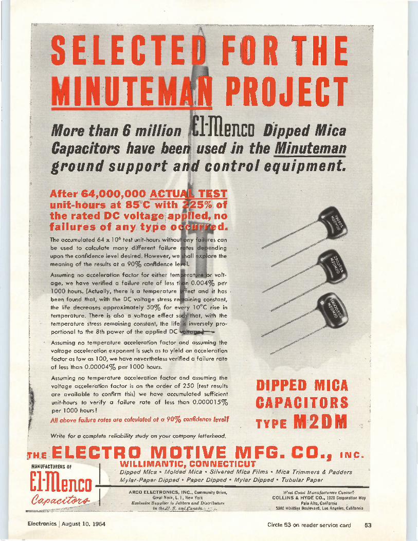
PROJECT More than 6 million H MCO Dipped Mica Capacitors have been. used in the Minuteman ground support and control equipment.
4
After 64,000,000 ACTUAL. TEST unit-hours at 85°C with lig5%' of the rated DC voltage applieeno failures of any type o The accumulated 64 x 106 test unit-hours withou res can
be used to calculate many different failure idepericling
upon the confidence level desired. However, wetall ex plor'e the
meaning of the results at a 90% confidence le
Assuming no acceleration factor for either tem rat r volt-
age, we have verified a failure rate of less t an 0.004% per
1000 hours. (Actually, there is a temperature Tect and it has
been found that, with the DC voltage stress regaining constant,
the life decreases approximately 50% for every 10°C rise in
temperature. There is also a voltage effect siWthat, with the
temperature stress remaining constant, the lifejis inversely pro-
portional to the 8th power of the applied DC
Assuming no temperature acceleration factor and assuming the
voltage acceleration exponent is such as to yield an acceleration
factor as low as 100, we have nevertheless verified a failure rate
of less than 0.00004% per 1000 hours.
Assuming no temperature acceleration factor and assuming the
voltage acceleration factor is on the order of 250 (test results
are available to confirm this) we have accumulated sufficient
unit-hours to verify a failure rate of less than 0.000015% per 1000 hours!
All above failure rates are calculated at a 90% confidence level!
Write for a complete reliability study on your company letterhead.
DIPPED MICA CAPACITORS TYPE 11112DM
THE ELECTRO MOTIVE MFG MANUFACTURERS OF
flille11C0 treeeeveet-,-1
WILLIMANTIC» CONNECTICUT Dipped Mica • Molded Mica • Silvered Mica Films • Mica Trimmers & Padders
Mylar-Paper Dipped • Paper Dipped • Mylar Dipped • Tubular Paper
. CO., INC.
ARCO ELECTRONICS, INC., Community Drive, Great Neck, L. I., New York
erclusire Supplier tu Jobbers and Distributors in the U. S. and Canada •
West Coast Manufacturers Contact: COLLINS & HYDE CO., 1020 Corporation Way
Palo Alto, California 5380 Whittier Boulevard, los Angeles, California
Electronics I August 10, 1964 Circle 53 on reader service card 53
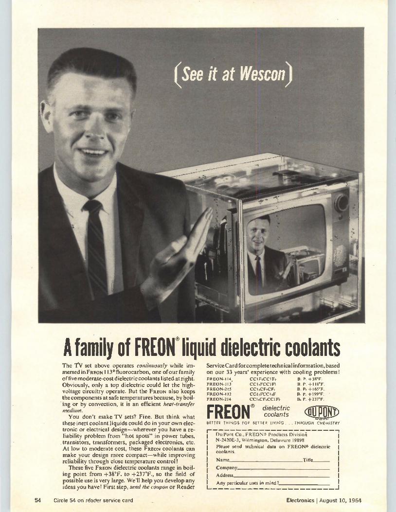
A family of FREON® liquid dielectric coolants The T.V set above operates confinuously while im-mersed in FREON 1135 fluorocarbon, one of our family of five moderate-cost dielectric coolants listed at right. Obviously, only a top dielectric could let the high-voltage circuitry operate. But the FREON also keeps the components at safe temperatures because, by boil-ing or by convection, it is an efficient heat-transfer medium. You don't make TV sets? Fine. But think what
these inert coolant liquids could do in your own elec-tronic or electrical design—wherever you have a re-liability problem from "hot spots" in power tubes,
.transistors, transformers, packaged electronics, etc. At low to moderate cost, these FREON coolants can make your design more compact—while improving reliability through close temperature control!
These five FREON dielectric coolants range in boil-ing point from +38°F. to +237°F., so the field of possible use is very large. We'll help you develop any ideas you have! First step, send the coupon or Reader
ServiceCard for complete technical information, based on our 33 years' experience with cooling problems! FREON-114. FREON-113 FREON-215 FREON-112 FREON-214
CC1F2CCIF2 CC12FCCI F2 CC 3CFIC Fa cci,Frct2E cc acFscciFs
FREON® dielectric coolants
B. P. +38°F. B. P. +118°F. B. Pe +165°F. B. P. +199°F. B. P. +237°F.
P 0 N• BETTER THINGS FOR BETTER LIVING . . . THROUGH CHEMISTRY
Du Pont Co., FREON Products Division N-2420E-3, Wilmington, Delaware 19898
Please send technical data on FREON & dielectric coolants.
Name Title
Company
Address
Any particular uses in mind?
54 Circle 54 on rader service card Electronics J August 10, 1964
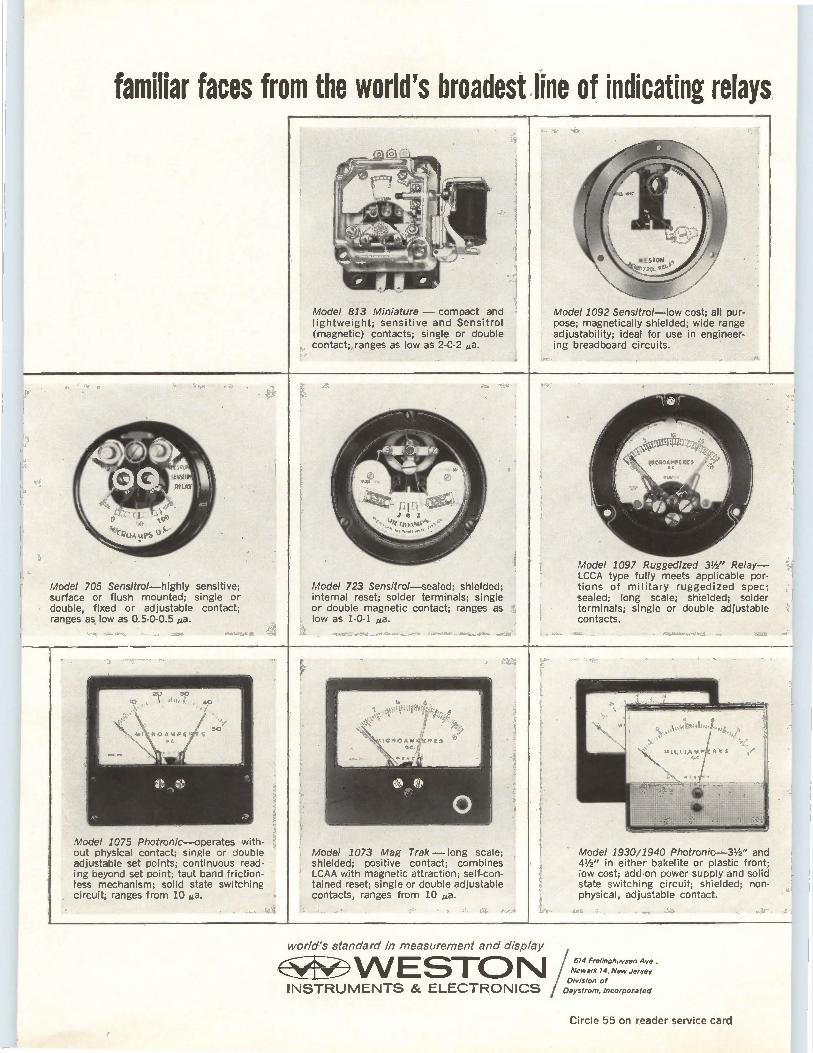
familiar faces from the world's broadest line of indicating relays
Model 813 Miniature — compact and lightweight; sensitive and Sensitrol (magnetic) çontacts; single or double contact; ranges as low as 2-0-2 eta.
Model 1092 Sensitrui—low cost; all pur-pose; magnetically ghielded; wide range adjustability; ideal for use in engineer-ing breadboard circuits.
Model 705 Sensitrol—highly sensitive; surface or flush mounted; single or double, fixed or adjustable contact; ranges as low as 0.5-0-0.5 1.4a.
Model 723 Sensitro/—sealed; shielded; internal reset; solder terminals; single 1
r or double magnetic contact; ranges as low as 1-0-1 ga.
<,
Model 1097 Ruggedized 31/2 " Relay— LCCA type fully meets applicable por-tions of military ruggedized spec; sealed; long scale; shielded; solder terminals; single or double adjustable contacts.
br,f)
Model 1075 Photronlc—operates with-out physical contact; single or double adjustable set points; continuous read-ing beyond set point; taut band friction-less mechanism; solid state switching circuit; ranges from 10 e.
Model 1073 Mag Trak — long scale; shielded; positive contact; combines LCAA with magnetic attraction; self-con-tained reset; single or double adjustable contacts, ranges from 10 ¡La.
Model 1930/1940 Photronic-31/2 " and 41/2 " in either bakelite or plastic front; low cost; add-on power supply and solid state switching circuit; shielded; non-physical, adjustable contact.
world's standard in measurement and display
N INSTRUMENTS & ELECTRONICS
614 Frelinghuysen
Newark 14. New Jersey
Division of
Daystrom, Incorporated
Circle 55 on reader service card
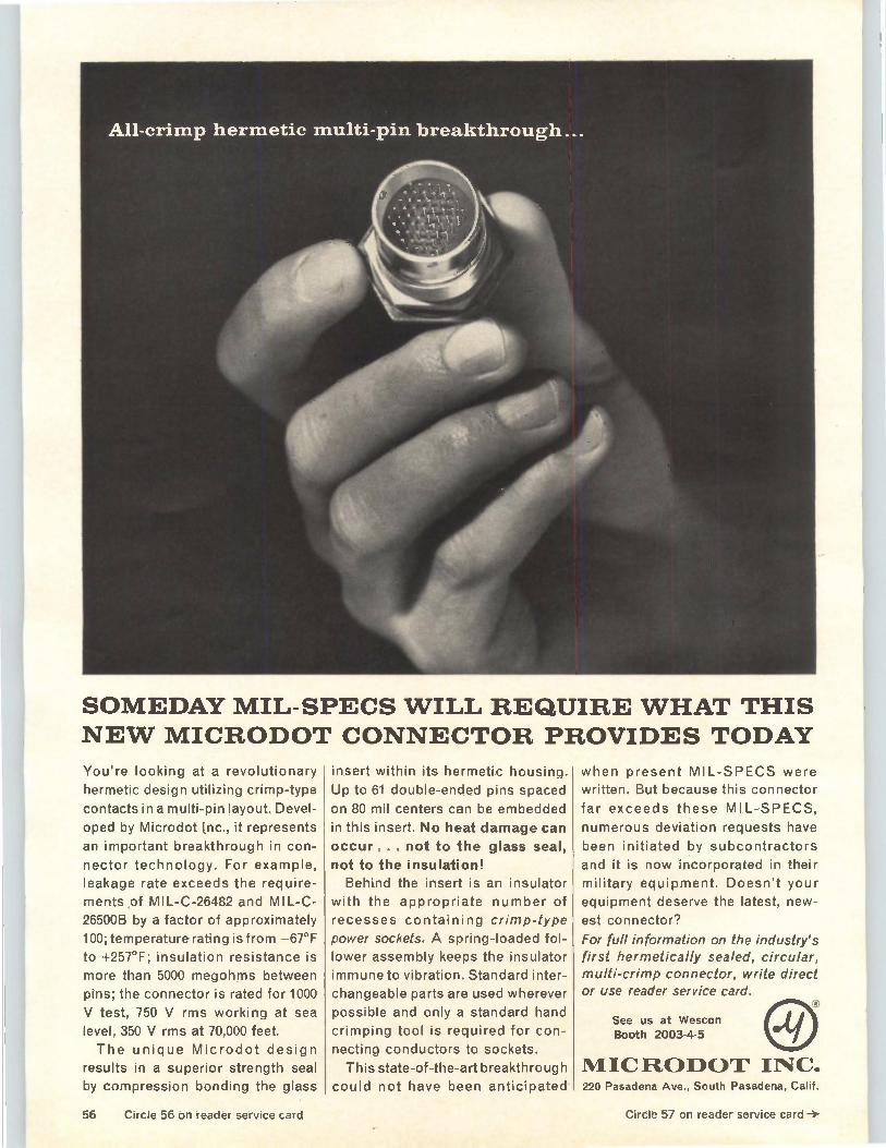
SOMEDAY MIL-SPECS WILL REQUIRE WHAT THIS NEW MICRODOT CONNECTOR PROVIDES TODAY
You're looking at a revolutionary
hermetic design utilizing crimp-type
contacts in a multi-pin layout. Devel-
oped by Microdot Inc., it represents
an important breakthrough in con-
nector technology. For example, leakage rate exceeds the require-
ments of MIL-C-26482 and MIL-C-26500B by a factor of approximately
100; temperature rating is from —67°F
to +257°F; insulation resistance is
more than 5000 megohms between
pins; the connector is rated for 1000
V test, 750 V rms working at sea
level, 350 V rms at 70,000 feet.
The unique Microdot design
results in a superior strength seal
by compression bonding the glass
insert within its hermetic housing.
Up to 61 double-ended pins spaced
on 80 mil centers can be embedded
in this insert. No heat damage can
occur ... . not to the glass seal,
not to the insulation! Behind the insert is an insulator
with the appropriate number of
recesses containing crimp-type
power sockets. A spring-loaded fol-lower assembly keeps the insulator
immune to vibration. Standard inter-
changeable parts are used wherever
possible and only a standard hand
crimping tool is required for con-
necting conductors to sockets.
This state-of-the-art breakthrough could not have been anticipated
when present MIL-SPECS were written. But because this connector
far exceeds these MIL-SPECS,
numerous deviation requests have
been initiated by subcontractors
and it is now incorporated in their
military equipment. Doesn't your
equipment deserve the latest, new-
est connector?
For full information on the industry's first hermetically sealed, circular, multi-crimp connector, write direct or use reader service card.
See us at Wescon Booth 2003-4-5
MICRODOT INC. 220 Pasadena Ave., South Pasadena, Calif.
56 Circle 56 on reader service card Circle 57 on reader service card
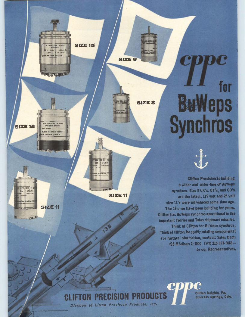
YNCHRO, TR 26 VOLTS
o 111704 fl
ti NAVV-11.1 Of
RESOLVER
WT. ORS
• 6V RIO CWIts
1501 5001101 14001/(11
U S NAVY-lu OF WEPS 5500400 0004055
trn ISTR4c
WORD DRAWING 5345504
555501101 100E11
SIZE 11
IS CEIREFIER111A1 NI, * 0.0*05
WWI EX TR ref 26,1E DSC%
CReElf•ct NEE6 E6ICMON sue
for BuWeps
Synchros
Clifton Precision is building
a wider and wider line of BuWeps
synchros. Size 8 CX's, CT's, and CO's
are the latest. 115 volt and 26 vol
size 11's were introduced some time ago.
The 15's we have been building for years.
Clifton has BuWepssynchros operational in the
important Terrier and Talos shipboard missiles.
Think of Clifton for BuWeps synch ros.
Think of Clifton for quality rotating components!
For further information, contact: Sales Dept.
215 1111Adison 2-1000, TWX 215 623-6068—
or our Representatives.
CLIFTON PRECISION PRODUCTS Division of Litton Precision Products, Inc.
(Mon Heights, Pa, Colorado Springs,
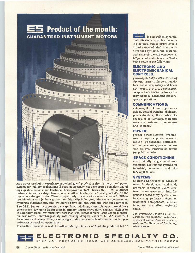
GUARANTEED INSTRUMENT MOTORS
As a direct result of its experience in designing and producing elec ric motors and power systems for military applications, Electronic Specialty has developed a complete line of high quality, reliable sub-fractional horsepower motors — Series 0211— for industrial instruments such as strip chart recorders. All units carry a two year guarantee on the motor and the gear train. These competitively priced motors meet or exceed NEMA specifications and include normal and high slip induction, reluctance synchronous, hysteresis synchronous, and low inertia servo designs, with and without gearheads. The 0211 Series incorporates: encapsulated windings; close tolerance through-bore construction; low noise Delrin gears in primary stages; heavy duty, standard-pitch gears in secondary stages for reliability; hardened steel motor pinions; stainless steel shafts; die cast rotors; interchangeability with existing designs; standard NEMA class 2-11 frame sizes and ratings. Thirty standard gear ratios are available off-the-shelf; other gear ratios can be provided upon request. For further information write to William Marcy, Director of Marketing, address below.
E5 is a diversified, dynamic, multi-divisional organization serv-ing defense and industry over a broad range of vital areas with advanced systems, sub-systems, and state-of-the-art components. Major contributions are currently being made in the following:
ELECTRONIC AND ELECTROMECHANICAL CONTROLS: gyroscopes, relays, static switching devices, sensors, flashers, regula-tors, converters, rotary and linear actuators, motors, generators, weapon and camera controls, elec-tromechanical assemblies for aero-space applications.
COMMUNICATIONS: antennas, flexible and rigid wave-guides, coaxial switches, diplexers, power dividers, filters, radio tele-scopes, solar furnaces, matching networks, antenna drive motors and controls.
POWER: precise power systems, dynamo-tors, computer power sources, motor - generators, actuators, starter generators, power conver-sion systems, transmission towers for public utilities.
SPACE CONDITIONING: electronically programmed envi-ronmental controls and systems for industrial, commercial, and mili-tary applications.
SYSTEMS: Systems Laboratories conduct research, development and study programs in reconnaissance, elec-tronic countermeasures, interfer-ometer phased array systems, and total energy packages; integrating divisional components, sub-sys-tems, and specialized technical skills.
For information concerning the cor-porate systems capability, product line, or research and development programs, write to the Director of Marketing, address below.
ELECTRONIC SPECIALTY CO. a lg 5121 SAN FERNANDO ROAD, LOS ANGELES, CALIFORNIA 90039
58 Circle 58 on reader service card Circle 204 on reader service card
Electronics I August 10, 1964
Technical articles
Highlights
Wescon preview: page 60 This year's technical program is a mixed bag of West Coast technology. The emphasis on tutorial articles reflects the region's concern about sagging business. Also, How Wescon and the West do business, page 103. New products at the show starts on page 121.
Understanding pnpn devices: page 66 Four-layer pnpn semiconductor devices are versatile: They can switch, control, rectify and latch current. Their ratings vary from a few microwatts to voltage ratings of 1,000 and higher.
Drivers for optical diodes: page 77 A variety of applications have put the semiconductor light-emitting diode to work in communications, computers and military equipment. An essential to proper application is how to drive them. Here are some suggested transistorized circuits.
Early bird—bigger and better: page 90 The first commercial communications satellite will be more powerful and versatile than any yet launched. Its design has profited from lessons learned with earlier satellites.
• A survey of logic trainers
Coming • Where to use ceramic tubes August 24 • More on learning machines
• A new technique for dense recording
59
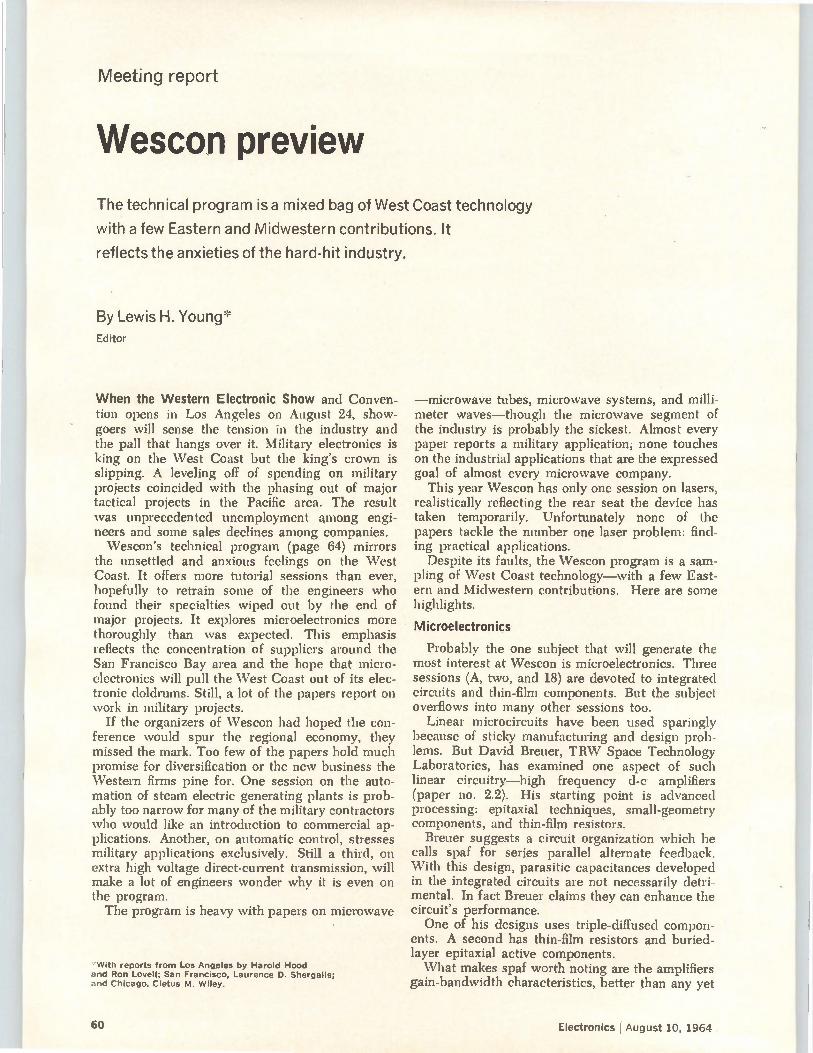
Meeting report
Wescon preview
The technical program is a mixed bag of West Coast technology
with a few Eastern and Midwestern contributions. It
reflects the anxieties of the hard-hit industry.
By Lewis H. Young* Editor
When the Western Electronic Show and Conven-tion opens in Los Angeles on August 24, show-goers will sense the tension in the industry and the pall that hangs over it. Military electronics is king on the \Vest Coast but the king's crown is slipping. A leveling off of spending on military projects coincided with the phasing out of major tactical projects in the Pacific area. The result was unprecedented unemployment among engi-neers and some sales declines among companies. Wescon's technical program (page 64) mirrors
the unsettled and anxious feelings on the \Vest Coast. It offers more tutorial sessions than ever, hopefully to retrain some of the engineers who found their specialties wiped out by the end of major projects. It explores microelectronics more thoroughly than was expected. This emphasis reflects the concentration of suppliers around the San Francisco Bay area and the hope that micro-electronics will pull the West Coast out of its elec-tronic doldrums. Still, a lot of the papers report on work in military projects.
If the organizers of Wescon had hoped the con-ference would spur the regional economy, they missed the mark. Too few of the papers hold much promise for diversification or the new business the Western firms pine for. One session on the auto-mation of steam electric generating plants is prob-ably too narrow for many of the military contractors who would like an introduction to commercial ap-plications. Another, on automatic control, stresses military applications exclusively. Still a third, on extra high voltage direct-current transmission, will make a lot of engineers wonder why it is even on the program. The program is heavy with papers on microwave
"With reports from Los Angeles by Harold Hood and Ron Lovell; San Francisco, Laurence D. Shergalis; and Chicago, Cletus M. Wiley.
—microwave tubes, microwave systems, and milli-meter waves—though the microwave segment of the industry is probably the sickest. Almost every paper reports a military application; none touches on the industrial applications that are the expressed goal of almost every microwave company.
This year \Vescon has only one session on lasers, realistically reflecting the rear seat the device has taken temporarily. Unfortunately none of the papers tackle the number one laser problem: find-ing practical applications.
Despite its faults, the Wescon program is a sam-pling of West Coast technology—with a few East-ern and Midwestern contributions. Here are some highlights.
Microelectronics
Probably the one subject that will generate the most interest at Wescon is microelectronics. Three sessions (A, two, and 18) are devoted to integrated circuits and thin-film components. But the subject overflows into many other sessions too.
Linear microcircuits have been used sparingly because of sticky manufacturing and design prob-lems. But David Breuer, TRW Space Technology Laboratories, has examined one aspect of such linear circuitry—high frequency d-c amplifiers (paper no. 2.2). His starting point is advanced processing: epitaxial techniques, small-geometry components, and thin-film resistors.
Breuer suggests a circuit organization which he calls spaf for series parallel alternate feedback. With this design, parasitic capacitances developed in the integrated circuits are not necessarily detri-mental. In fact Breuer claims they can enhance the circuit's performance. One of his designs uses triple-diffused compon-
ents. A second has thin-film resistors and buried-layer epitaxial active components. What makes spaf worth noting are the amplifiers
gain-bandwidth characteristics, better than any yet
60 Electronics I August 10, 1964
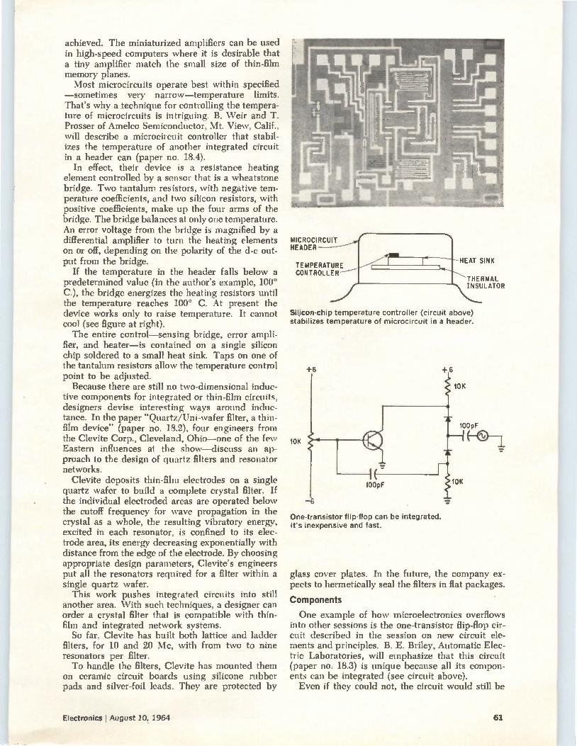
achieved. The miniaturized amplifiers can be used in high-speed computers where it is desirable that a tiny amplifier match the small size of thin-film memory planes. Most microcircuits operate best within specified
—sometimes very narrow—temperature limits. That's why a technique for controlling the tempera-ture of microcircuits is intriguing. B. Weir and T. Prosser of Amelco Semiconductor, Mt. View, Calif., will describe a microcircuit controller that stabil-izes the temperature of another integrated circuit in a header can (paper no. 18.4).
In effect, their device is a resistance heating element controlled by a sensor that is a wheatstone bridge. Two tantalum resistors, with negative tem-perature coefficients, and two silicon resistors, with positive coefficients, make up the four arms of the bridge. The bridge balances at only one temperature. An error voltage from the bridge is magnified by a differential amplifier to turn the heating elements on or off, depending on the polarity of the d-c out-put from the bridge.
If the temperature in the header falls below a predetermined value (in the author's example, 100° C.), the bridge energizes the heating resistors until the temperature reaches 100° C. At present the device works only to raise temperature. It cannot cool (see figure at right). The entire control—sensing bridge, error ampli-
fier, and heater—is contained on a single silicon chip soldered to a small heat sink. Taps on one of the tantalum resistors allow the temperature control point to be adjusted.
Because there are still no two-dimensional induc-tive components for integrated or thin-film circuits, designers devise interesting ways around induc-tance. In the paper "Quartz/Uni-wafer filter, a thin-film device" (paper no. 18.2), four engineers from the Clevite Corp., Cleveland, Ohio—one of the few Eastern influences at the show—discuss an ap-proach to the design of quartz filters and resonator networks.
Clevite deposits thin-film electrodes on a single quartz wafer to build a complete crystal filter. If the individual electroded areas are operated below the cutoff frequency for wave propagation in the crystal as a whole, the resulting vibratory energy, excited in each resonator, is confined to its elec-trode area, its energy decreasing exponentially with distance from the edge of the electrode. By choosing appropriate design parameters, Clevite's engineers put all the resonators required for a filter within a single quartz wafer.
This work pushes integrated circuits into still another area. With such techniques, a designer can order a crystal filter that is compatible with thin-film and integrated network systems. So far, Clevite has built both lattice and ladder
filters, for 10 and 20 Mc, with from two to nine resonators per filter. To handle the filters, Clevite has mounted them
on ceramic circuit boards using silicone rubber pads and silver-foil leads. They are protected by
MICROCIRCUIT HEADER
TEMPERATURE CONTROLLER
HEAT SINK
THERMAL INSULATOR
Silicon-chip temperature controller (circuit above) stabilizes temperature of microcircuit in a header.
10K
+6
—6
100pF
One-transistor flip-flop can be integrated. It's inexpensive and fast.
glass cover plates. In the future, the company ex-pects to hermetically seal the filters in flat packages.
Components
One example of how microelectronics overflows into other sessions is the one-transistor flip-flop cir-cuit described in the session on new circuit ele-ments and principles. B. E. Briley, Automatic Elec-tric Laboratories, will emphasize that this circuit (paper no. 18.3) is unique because all its compon-ents can be integrated (see circuit above). Even if they could not, the circuit would still be
Electronics j August 10, 1964 61
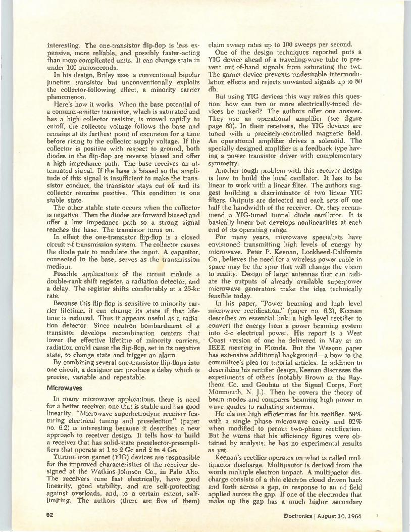
interesting. The one-transistor flip-flop is less ex-pensive, more reliable, and possibly faster-acting than more complicated units. It can change state in under 100 nanoseconds.
In his design, Briley uses a conventional bipolar junction transistor but unconventionally exploits the collector-following effect, a minority carrier phenomenon.
Here's how it works. When the base potential of a common-emitter transistor, which is saturated and has a high collector resistor, is moved rapidly to cutoff, the collector voltage follows the base and remains at its farthest point of excursion for a time before rising to the collector supply voltage. If the collector is positive with respect to ground, both diodes in the flip-flop are reverse biased and offer a high impedance path. The base receives an at-tenuated signal. If the base is biased so the ampli-tude of this signal is insufficient to make the trans-sistor conduct, the transistor stays cut off and its collector remains positive. This condition is one stable state. The other stable state occurs when the collector
is negative. Then the diodes are forward biased and offer a low impedance path so a strong signal reaches the base. The transistor turns on.
In effect the one-transistor flip-flop is a closed circuit r-f transmission system. The collector causes the diode pair to modulate the input. A capacitor, connected to the base, serves as the transmission medium.
Possible applications of the circuit include a double-rank shift register, a radiation detector, and a delay. The register shifts comfortably at a 25-kc rate.
Because this flip-flop is sensitive to minority car-rier lifetime, it can change its state if that life-time is reduced. Thus it appears useful as a radia-tion detector. Since neutron bombardment of a transistor develops recombination centers that lower the effective lifetime of minority carriers, radiation could cause the flip-flop, set in its negative state, to change state and trigger an alarm. By combining several one-transistor flip-flops into
one circuit, a designer can produce a delay which is precise, variable and repeatable.
Microwaves
In many microwave applications, there is need for a better receiver; one that is stable and has good linearity. "Microwave superhetrodyne receiver fea-turing electrical tuning and preselection" (paper no. 6.2) is interesting because it describes a new approach to receiver design. It tells how to build a receiver that has solid-state preselector-preampli-fiers that operate at 1 to 2 Cc and 2 to 4 Cc.
Yttrium iron garnet (YIG) devices are responsible for the improved characteristics of the receiver de-signed at the Watkins-Johnson Co., in Palo Alto. The receivers tune fast electrically, have good linearity, good stability, and are self-protecting against overloads, and, to a certain extent, self-limiting. The authors (there are five of them)
claim sweep rates up to 100 sweeps per second. One of the design techniques reported puts a
YIG device ahead of a traveling-wave tube to pre-vent out-of-band signals from saturating the twt. The garnet device prevents undesirable intermodu-lation effects and rejects unwanted signals up to 80 db.
But using YIG devices this way raises this ques-tion: how can two or more electrically-tuned de-vices be tracked? The authors offer one answer. They use an operational amplifier (see figure page 63). In their receivers, the YIG devices are tuned with a precisely-controlled magnetic field. An operational amplifier drives a solenoid. The specially designed amplifier is a feedback type hav-ing a power transistor driver with complementary symmetry. Another tough problem with this receiver design
is how to build the local oscillator. It has to be linear to work with a linear filter. The authors sug-gest building a discriminator of two linear YIG filters. Outputs are detected and each sets off one half the bandwidth of the receiver. Or, they recom-mend a YIG-tuned tunnel diode oscillator. It is basically linear but develops nonlinearities at each end of its operating range. For many years, microwave specialists have
envisioned transmitting high levels of energy by microwave. Peter P. Keenan, Lockheed-California Co., believes the need for a wireless power cable in space may be the spur that will change the vision to reality. Design of large antennas that can radi-ate the outputs of already available superpower microwave generators make the idea technically feasible today.
In his paper, "Power beaming and high level microwave rectification," (paper no. 6.3). Keenan describes an essential link: a high level rectifier to convert the energy from a power beaming system into d-c electrical power. His report is a West Coast version of one he delivered in May at an IEEE meeting in Florida. But the Wescon paper has extensive additional background—a bow to the committee's plea for tutorial articles. In addition to describing his rectifier design, Keenan discusses the experiments of others (notably Brown at the Ray-theon Co. and Goubau at the Signal Corps, Fort Monmouth, N. J.). Then he covers the theory of beam modes and compares beaming high power in wave guides to radiating antennas. He claims high efficiencies for his rectifier: 59%
with a single phase microwave cavity and 92% when modified to permit two-phase rectification. But he warns that his efficiency figures were ob-tained by analysis; he has no experimental results as yet.
Keenan's rectifier operates on what is called mul-tipactor discharge. Multipactor is derived from the words multiple electron impact. A multipactor dis-charge consists of a thin electron cloud driven back and forth across a gap, in response to an r-f field applied across the gap. If one of the electrodes that make up the gap has a much higher secondary
62 Electronics I August 10, 1964
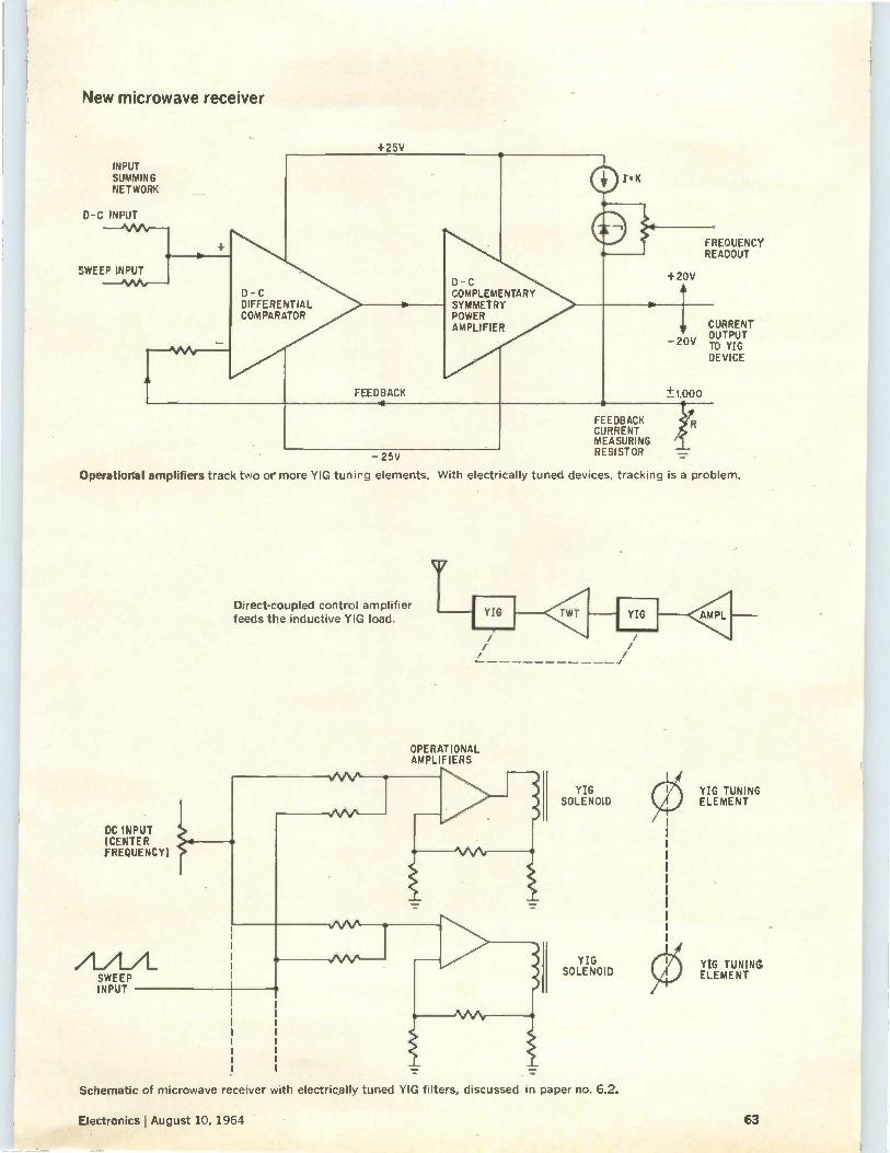
New microwave receiver
+25V
INPUT SUMMING NETWORK
D-C INPUT
SWEEP INPUT INPUT — 0‘AAr—
D -C DIFFERENTIAL COMPARATOR
FEEDBACK 4
D - C COMPLEMENTARY SYMMETRY POWER AMPLIFIER
I.K
II------FREQUENCY READOUT
+20V
-20V
CURRENT OUTPUT TO YIG DEVICE
-25V
FEEDBACK CURRENT MEASURING RESISTOR
eFt
Operational amplifiers track two or more YIG tunirg elements. With electrically tuned devices, tracking is a problem.
DC INPUT (CENTER FREQUENCY)
SWEEP INPUT
Direct-coupled control amplifier feeds the inductive YIG load.
OPERATIONAL AMPLIFIERS
YIG SOLENOID
YIG SOLENOID
YIG TUNING ELEMENT
YIG TUNING ELEMENT
Schematic of microwave receiver with electrically tuned YIG filters, discussed in paper no. 6.2.
Electronics August 10, 1964 63
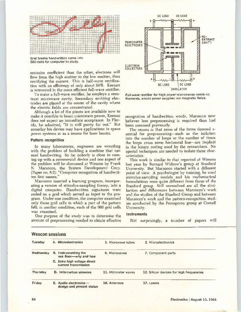
mummummummummum.nomemmummeammimumm MUMMEMOMMMUMMIIMMWeAUMMUMMIUMPAIMMMIUMMBM simmummummummummr ..ammeezraveum MMMMM no mum «.ntemmummor Ammummimen mural MMMMM mum um .eammig.zsmumpo.dmmummaream unararimmumm a .ammummemmeismedimprimmulp.amplawatammumm Ammummumumme.-dami .gtmenammedmmummummem ammizamarnagem ,.....--7,,iiimumumumrimpumm k MMUMMfflleeill WIIMMOMMMUMMUMMUMMIMIMMIUMU Ilib... ..01111111111111MBMIIMBMIIIIMEMMIIM BOB» 110MMUMUMMINUIUMMUMUMUMMUM MIMMUMUMM megmemmuummusummmummummummumm Aimmummu mummummiummimmumummummemmmmommummm mmummommummummummuummumumm imeammum MUMUMMUMMMIIMUMMIMIMMUMINIMMUMMIMM amimmommum mmmmmmmmmmmmmmmumnummmmmmmmmmmmmvaummmmmm
L MIIMIMMIMMUMMIIIMUM IM MEMMUMUMMMIAMMUUMMUMMOIM MEMIUMMUMUMMUUMMUMMUMMUMIMMBIrOMMUMM MUMMIUMMMIMMUUMMIMUMMIIMMUMUMMUMMIM .UMMMIMMUM UMUMUMMUMMUMMIIMMMMUMBMMIUMMUMMUMMU AUMIMMUMMUI
Gr'd breaks handwritten name into 980 cells for computer to study.
emission coefficient than the other, electrons will flow from the high emitter to the low emitter, thus rectifying the current. This is half-wave rectifica-tion with an efficiency of only about 24%. Keenan is interested in the more efficient full-wave rectifier. To make a full-wave rectifier, he employs a reen-
trant microwave cavity. Secondary emitting elec-trodes are placed at the center of the cavity where the electric fields are concentrated. Although a lot of the pieces are available now to
make it possible to beam microwave power, Keenan does not expect an immediate acceptance. In Flor-ida, he admitted, "It is still pretty far out." But someday his device may have applications in space power systems or as a sensor for laser beams.
Pattern recognition
In many laboratories, engineers are wrestling with the problem of building a machine that can read handwriting. So far nobody is close to com-ing up with a commercial device and one aspect of the problem will be discussed at Wescon by Frank N. Marzocco, the System Development Corp. (Paper no. 8.2): "Computer recognition of handwrit-ten first names." Marzocco inserted a learning program, incorpor-
ating a version of stimulus-sampling theory, into a digital computer. Handwritten signatures were coded on a grid which served as input to the pro-gram. Under one condition, the computer examined only those grid cells in which a part of the pattern fell; in another condition, each of the 980 grid cells was examined. One purpose of the study was to determine the
amount of preprocessing needed to obtain effective
DC LOAD
PERFORATED ELECTRODES
ELECTRON COLLECTORS
DC LOAD
RE-ENTRANT CAVITY
DC LOAD DC LOAD
INSULATOR
Full-wave rectifier for high power microwaves needs no filaments, anode power supplies nor magnetic fields.
recognition of handwritten words. Marzocco now believes less preprocessing is required than had been assumed previously. The reason is that some of the items deemed s-
sential for preprocessing—such as the isolation into the number of loops or the number of times the loops cross some horizontal line—are implicit in the binary coding used by the researchers. No special techniques are needed to isolate these char-acteristics.
This work is similar to that reported at Wescon last year by Bernard Widrow's group at Stanford University. But Marzocco started with a different point of view. A psychologist by training, he used stimulus-sampling models and his mathematical formulations were quite different from those of the Stanford group. Still unresolved are all the simi-larities and differences between Marzocco's work and the studies of the Stanford Group and between Marzocco's work and the pattern-recognition stud-ies conducted by the Perceptron group at Cornell University.
Instruments
Not surprisingly, a number of papers will
Wescon sessions
Tuesday A. Microelectronics 1. Microwave tubes 2. Microelectronics
Wednesday B. Instrumenting the sea floor—why and how
C. Extra high voltage direct current transmission
6. Microwaves 7. Component parts
Thursday D. Information sciences 11. Millimeter waves 12. Silicon devices for high frequencies
Friday E. Apollo electronics— 16. Antennas design and present status
17. Lasers
64 Electronics I August 10, 1964
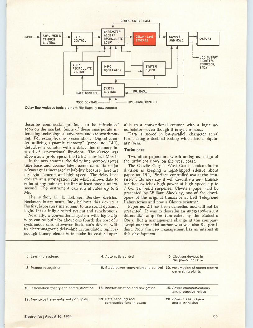
RECIRCULATING DATA
INPUT AMPLIFIER TRIGGER CONTROL
GATE CONTROL
ADD/ RECIRCULATE CONTROL
CHARACTER ADDER/ RECIRCULATE LOGIC
T-À:77F
1-MC OSCILLATOR
DELAY-LINE STORAGE
SYSTEM CLOCK
GATE CONTROL
SYSTEM CONTROL
SAMPLE AND HOLD
TIME BASE
MODE CONTROL—t L—TIME-BASE CONTROL
Delay line replaces logic element flip flops in new counter.
describe commercial products to be introduced soon on the market. Some of these incorporate in-teresting technological advances and are worth not-ing. For example, one presentation, "Digital coun-ter utilizing dynamic memory" (paper no. 14.1), describes a counter with a delay line memory in-stead of conventional flip-flops. The device was shown as a prototype at the IEEE show last March.
In the new counter, the delay line memory stores time-base and accumulated count data. Its major advantage is increased reliability because there are no logic elements and high speed. The delay lines operate at a propagation rate which allows data to enter at any point on the line at least once a micro-second. The instrument can run at rates up to 2 Mc. The author, D. E. Lehmer, Berkley division,
Beckman Instruments, Inc., believes this device is the first laboratory instrument to use serial dynamic logic. It is a fully« clocked system and synchronous.
Normally, a conventional system with logic flip-flops can be built for about one fourth the cost of a sychronous one. However Beckman's device, with its electromagnetic delay-line accumulator, replaces enough binary elements to make its cost compar-
DISPLAY
—0-BCD OUTPUT (PRINTER, RECORDER, ETC.)
able to a conventional counter with a logic ac-cumulator—even though it is synchronous. Data is stored in bit-parallel, character serial
form, using a decimal coding which has a biquin-ary form.
Turbulence
Two other papers are worth noting as a sign of the turbulent times on the west coast. The Clevite Corp.'s West Coast semiconductor
division is keeping a tight-lipped silence about paper no. 12.1, "Surface controlled avalanche tran-sistor". Rumors say it will describe a new transis-tor that switches high power at high speed, up to 7 C.c. To build suspense, Clevite's paper will be presented by William Shockley, one of the devel-opers of the original transistor at Bell Telephone Laboratories and now a Clevite scientist. Paper no. 2.4 has been cancelled and will not be
presented. It was to describe an integrated-circuit differential amplifier fabricated by the Molectro Corp. But a management change at the company swept out the chief author who was also the presi-dent. Now the new management has no interest in this development.
3. Learning systems 4. Automatic control 5. Electron devices in the power industry
8. Pattern recognition 9. Static power conversion and control 10. Automation of steam electric generating plants
13. Information theory and communication 14. Instrumentation and navigation 15. Power communications and protective relays
18. New circuit elements and principles 19. Data handling and communications in space
20. Power transmission and distribution
Electronics f August 10, 1964 65
Components
Helpful transistor analog: 4-layer pnpn 2 transistors
Characteristics of pnpn devices are discussed in terms
of the now-familiar type transistors to help designers
understand how and where to use them
By Richard A. Stasior General Electric Co., Syracuse, N.Y.
Four-layer pnpn semiconductor devices are ver-satile, efficient and inexpensive circuit elements. They are the equivalent of pnp and npn transistors connected in a positive feedback configuration but circuits designed with them have fewer con-nections, fewer parts and tighter parameter limits than possible with two separate transistors. And costs are lower. The devices can switch, control, rectify and latch
current, and are capable of extraordinary gain in inexpensive circuits. The smallest four-layer rec-tifier can be triggered in a few microseconds with control signals of only a few microwatts; large ones are capable of voltage ratings to 1,000 volts and higher. The two-transistor analog suggests many dif-
ferent applications. A four-layer pnpn diode can be used as a cross-point switch in telephone ap-plications. Pnpn silicon controlled rectifiers, scr's, have been used for motor speed control, light dimmers, voltage regulators, voltage inverters and thyratron replacements. More recently, they have joined pnpn silicon controlled switches, scs's, to invade the low-power industrial control market as neon and incandescent lamp drivers, solenoid drivers, ring counters, voltage-threshold sensors and d-c current amplifiers. In these applications, pnpn's feature pulse-actuated latching character-istics, low drive requirements and the ability to operate from a-c or d-c power.
In space applications, the small size, low weight and simple circuits of ses ring counters allow them to compete favorably with equivalent transistor circuits.
Many circuit designers are unfamiliar with the versatility and potential of pnpn devices. This is because discussion has been limited, mostly, to mathematical models intended to advance circuit design. The following examination of pnpn char-acteristics, derived from well-understood transistor behavior will help designers understand the op-eration, and appreciate the possibilities, of four-layer semiconductor devices.
The equivalent circuit
The four-layered pnpn device can be repre-sented in a number of ways, as shown in the diagram on page 69. The basic structure. A, can be considered a npn transistor with a diode in series with the collector, B; or a pnp transistor with a diode in series with its collector, C. But neither of these circuits suggest the regeneration inherent in a pnpn device. Thus, the two-tran-sistor circuit, D, is a more accurate representa-tion. To these two transistors, we can add the collector saturation resistance, R.t, base spread-ing resistor, rid and collector junction capacitance, C„,„ which are inherent in all semiconductor de-vices, and derive the circuit E. This circuit, in turn, leads to a distributed circuit, F, of several transistor pairs joined by the sheet resistance of each semiconductor layer. While circuit F is most versatile, it is not used generally. The common symbols for the silicon controlled
rectifier, G and H, ignore the central n region. The Shockley diode symbol I shows leads to the outside regions only; while the silicon controlled switch, represented in J and K has leads to all
66 Electronics I August 10, 1964
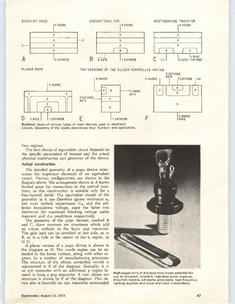
SHOCKLEY DIODE 4 ANODE
N
2--
N
A
PLANAR PNPN
1 CATHODE
4 ANODE
4.
D 2 GATE 1 CATHODE
CONVENTIONAL SCR WESTINGHOUSE TRINISTOR
14 ANODE
N
B 2 GATE
4 ANODE
1 CATHODE C (1)
TWO VERSIONS OF THE SILICON CONTROLLED SWITCH
2 CATHODE GATE
E
4 ANODE
- 1
P N
N
11 CATHODE
3 ANODE GATE
Sectional views of various types of pnpn devices used in electronic circuits. Geometry of the layers determines their function and application.
four regions. The best choice of equivalent circuit depends on
the specific parameters of interest and the actual physical construction and geometry of the device.
Actual construction
The detailed geometry of a pnpn device deter-mines the important elements of an equivalent circuit. Various configurations are shown in the diagram above. The arrangement shown in A leaves limited areas for connections to the central junc-tions, so this construction is suitable only for a four-layered diode. The equivalent circuit of the geometry in A can therefore ignore resistance rb, but must include capacitance Cob and the col-lector breakdown voltage, since the latter two determine the maximum blocking voltage under transient and d-c conditions respectively. The geometry of the pnpn devices, marked B
and C, show common ser structures which add an n-type cathode to the basic pnp transistor. The gate lead can be attached at one side, as in B, or in a hole at the center of the n region, as in C. A planar version of a pnpn device is shown in
the diagram as D. The anode region can be ex-tended to the lower surface, along with other re-gions, by a number of manufacturing processes. The structure of the silicon controlled switch is represented in E of the diagram. Basically, it is an npn transistor with an additional p region lo-cated to form a pnp transistor. A new planar ses structure is shown by F of the diagram. This de-vice also is basically an npn transistor surrounded
I I 2 GATE CATHODE 1 RING
2 CATHODE GATE
4 ANODE I II CATHODE I (4)
13 ANODE GATE
High-speed scr's of this type have broad potential for use as choppers, inverters, regulated power supplies, induction heaters, ultrasonic generators, high-frequency lighting supplies and sonar and radar transmitters.
Electronics I August 10, 1964 67
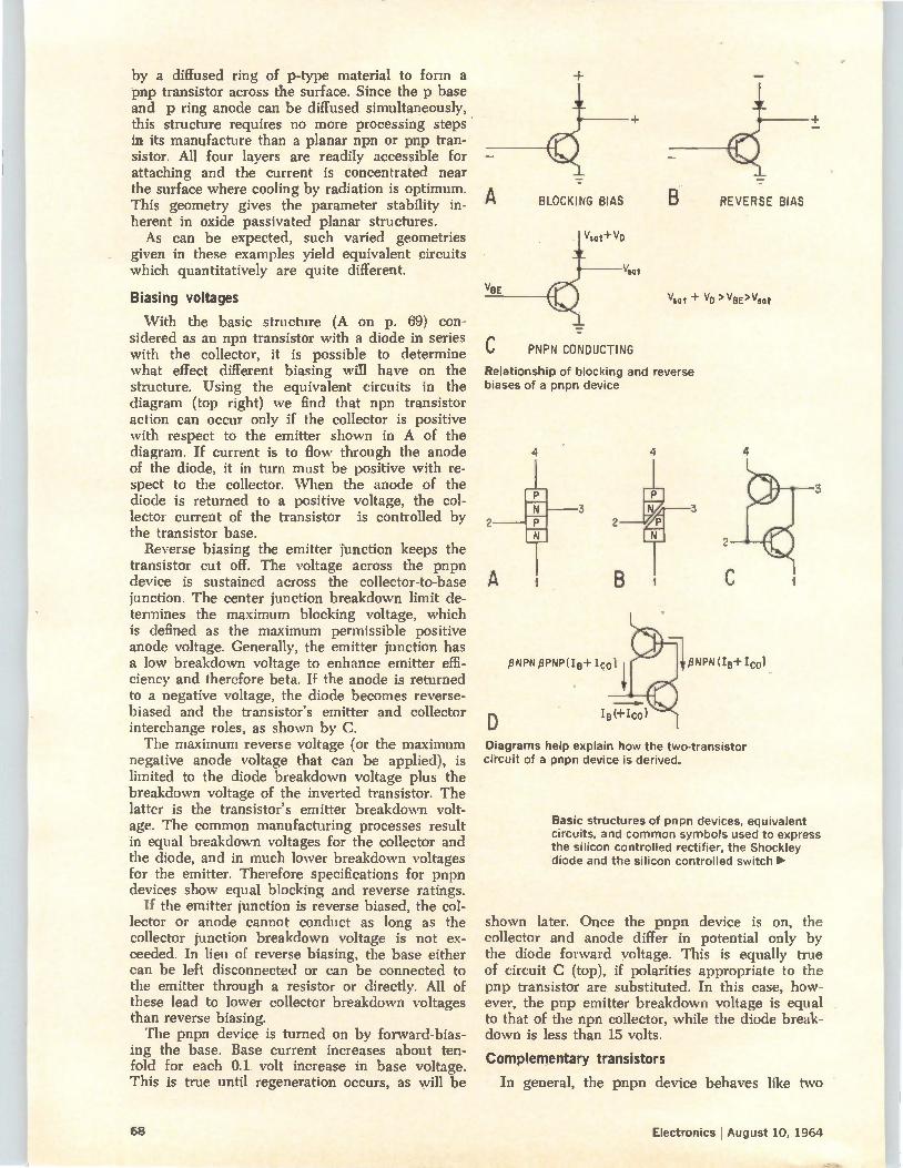
by a diffused ring of p-type material to form a pnp transistor across the surface. Since the p base and p ring anode can be diffused simultaneously, this structure requires no more processing steps in its manufacture than a planar npn or pnp tran-sistor. All four layers are readily accessible for attaching and the current is concentrated near the surface where cooling by radiation is optimum. This geometry gives the parameter stability in-herent in oxide passivated planar structures. As can be expected, such varied geometries
given in these examples yield equivalent circuits which quantitatively are quite different.
Biasing voltages
With the basic structure (A on p. 69) con-sidered as an npn transistor with a diode in series with the collector, it is possible to determine what effect different biasing will have on the structure. Using the equivalent circuits in the diagram (top right) we find that npn transistor action can occur only if the collector is positive with respect to the emitter shown in A of the diagram. If current is to flow through the anode of the diode, it in turn must be positive with re-spect to the collector. When the anode of the diode is returned to a positive voltage, the col-lector current of the transistor is controlled by the transistor base.
Reverse biasing the emitter junction keeps the transistor cut off. The voltage across the pnpn device is sustained across the collector-to-base junction. The center junction breakdown limit de-termines the maximum blocking voltage, which is defined as the maximum permissible positive anode voltage. Generally, the emitter junction has a low breakdown voltage to enhance emitter effi-ciency and therefore beta. If the anode is returned to a negative voltage, the diode becomes reverse-biased and the transistor's emitter and collector interchange roles, as shown by C. The maximum reverse voltage (or the maximum
negative anode voltage that can be applied), is limited to the diode breakdown voltage plus the breakdown voltage of the inverted transistor. The latter is the transistor's emitter breakdown volt-age. The common manufacturing processes result in equal breakdown voltages for the collector and the diode, and in much lower breakdown voltages for the emitter. Therefore specifications for pnpn devices show equal blocking and reverse ratings.
If the emitter junction is reverse biased, the col-lector or anode cannot conduct as long as the collector junction breakdown voltage is not ex-ceeded. In lieu of reverse biasing, the base either can be left disconnected or can be connected to the emitter through a resistor or directly. All of these lead to lower collector breakdown voltages than reverse biasing. The pnpn device is turned on by forward-bias-
ing the base. Base current increases about ten-fold for each 0.1 volt increase in base voltage. This is true until regeneration occurs, as will be
A BLOCKING BIAS
Vsot+VD
V„t
VBE
REVERSE BIAS
%/sat + VD > VDE>Vsat
C PNPN CONDUCTING
Relationship of blocking and reverse biases of a pnpn device
3
N
A
D Diagrams help explain how the two-transistor circuit of a pnpn device is derived.
Basic structures of pnpn devices, equivalent circuits, and common symbols used to express the silicon controlled rectifier, the Shockley diode and the silicon controlled switch I>
shown later. Once the pnpn device is on, the collector and anode differ in potential only by the diode forward voltage. This is equally true of circuit C (top), if polarities appropriate to the pnp transistor are substituted. In this case, how-ever, the pnp emitter breakdown voltage is equal to that of the npn collector, while the diode break-down is less than 15 volts.
Complementary transistors
In general, the pnpn device behaves like two
68 Electronics I August 10, 1964
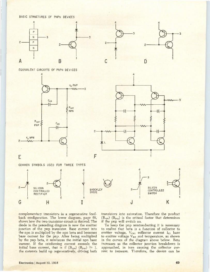
BASIC STRUCTURES OF PNPN DEVICES
2
A
4 4
N 3
N 2
EQUIVALENT CIRCUITS OF PNPN DEVICES
4
2
E COMMON
2_2
G
rb PNP
SYMBOLS USED FOR THREE
SILICON CONTROLLED RECTIFIER
H
4
TYPES
4
3
4
e SHOCKLEY DIODE
complementary transistors in a regenerative feed-back configuration. The lower diagram, page 68, shows how the two-transistor circuit is derived. The diode in the preceding diagram is now the emitter junction of the pnp transistor. Base current into the npn is multiplied by the npn beta and becomes base current for the pnp. After being multiplied by the pnp beta, it reinforces the initial npn base current. If the reinforcing current exceeds the initial base current, that is if (B„p„) (B„„p) 1,
the currents build up regeneratively, driving both
4
2
3
4
2
D
F -3
2 SILICON CONTROLLED SWITCH
transistors into saturation. Therefore the product (13„„„) (B1,„p) is the critical factor that determines if the pnp will switch on. To keep the pnp nonconducting it is necessary
to realize that beta is a function of collector to emitter voltage, VcE; collector current Ic; base to emitter voltage VRE and temperature, as shown in the curves of the diagram above below. Beta increases as the collector junction breakdown is approached, in turn causing the collector cur-rent to increase. Therefore, the device can be
Electronics PAugust 10, 1964 69
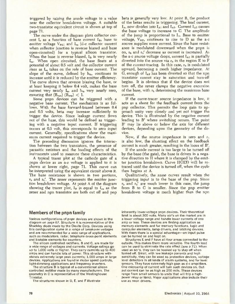
triggered by raising the anode voltage to a value near the collector breakdown voltage. A suitable two-transistor equivalent circuit is shown at top of page 71. The curve under the diagram plots collector cur-
rent I, as a function of base current lit; base to emitter voltage VBE; and 1,0 (d-c collector current when collector junction is reverse biased and base open-circuited) for a typical silicon transistor. When the base is reverse biased, In is very nearly I. When open circuited, the base floats at a potential of about 0.5 volt and the collector current rises as I,. takes on the role of base current. The slope of the curve, defined by hfe, continues to increase until it is reduced by the emitter efficiency. The curve shows that reverse biasing the base, or at least keeping it below 0.4 volt, makes the base current very nearly Ico and he,. very nearly zero, ensuring that (B0„0) (13) < 1. Some pnpn devices can be triggered with a
negative base current. The mechanism is as fol-lows. With the base forward-biased between 0.4 and 0.5 volts, beta may increase sufficiently to trigger the device. Since leakage current flows out of the base, this would be defined as trigger-ing with a negative input current. If triggering occurs at 0.5 volt, this corresponds to zero input current. Generally, specifications show the maxi-mum current required to trigger the device. The preceding discussion ignores the interac-
tion between the two transistors, the presence of parasitic resistors and the loading effects of the instruments used to measure these characteristics. A typical tracer plot at the cathode gate of a
pnpn device as an a-c voltage is applied to it is shown at lower right, page 71. This curve can be interpreted using the equivalent circuit above it. The base resistance is shown in two portions, rb and rb'. The zener represents the . emitter junc-tion breakdown voltage. At point A of the diagram showing the tracer plot, I is equal to Ico as the zener and npn transistor are both cut off and pnp
Members of the pnpn family Various configurations of pnpn devices are shown in the diagram on page 67. Structure A is representative of the Shockley diode made by the Clevite Corp. Devices using this configuration come in a range of breakover voltages and are recommended for a wide range of applications, such as modulators, radar, telephone cross-point elements and bistable elements for counters.
The silicon controlled rectifiers, B and C, are made for a wide range of voltages and currents. Voltage ratings go up to 1.000 volts or higher. They carry currents up to 400 amps and can handle lots of power. This structure with-stands extremely large peak currents; 1,000 amps in large devices. Applications are found in motor speed controls, light-dimming applications and frequency inverters. The structure B is typical of a conventional silicon
controlled rectifier made by many manufacturers. The geometry in C is representative of the Westinghouse Trinistor.
The structures shown in D, E, and F illustrate
beta is generally very low. At point B, the product of the betas results in triggering. The load current, IA, now divides into 'Al and IA0. Current IA. causes the base voltage to increase to C. The amplitude of the jump is proportional to IA. Base to emitter voltage, VBE, continues to rise to D as the a-c source supplies more current. Since the base resist-ance is modulated downward when the pnpn is on, rb and rb' decrease as current is increased. As the a-c source voltage drops, current IA2 is partially diverted into the source via rb in the region E to F of the current-tracing. In this case, rl, is modulated upward, becoming a much higher impedance. At G, enough of IA. has been diverted so that the npn transistor cannot stay in saturation and turn-off begins. It is obvious that if the device does not turn off, the zener clamps the negative excursion of the base, with rb determining the maximum base current.
If the curve-tracer source impedance is low, it acts as a shunt for the feedback current from the pnp collector. This permits the loop gain to ap-proach unity very closely and yet not trigger the device. This is illustrated by the negative current leading to B' where switching occurs. The point B' may lie above or below the axis for different devices, depending upon the geometry of the de-vice. Now, if the source impedance is zero and rb
is also low, the shunting effect on the feedback current is much greater, resulting in the locus of B'.
If the anode current is too large to be turned off by the base (the gate), the base is driven in a nega-tive direction to H where it is clamped by the emit-ter junction breakdown. Curve HGED will be re-traced until the device is turned off, when the cycle then begins at A.
Qualitatively, the same curves result when the triggering input is to the base of the pnp. Since rh and rb' are much lower in this case, the jump from B to C is smaller. Since the pnp emitter breakdown voltage is much higher than the npn
inherently lower-voltage pnpn devices. Their theoretical limit is about 300 volts. Many scr's on the market are in a lower voltage range and handle lower currents of one amp or less. These devices are finding application as memory elements and for memory functions, logic and computer elements, lamp drivers, and latching devices. With them there is a special advantage—an input pulse can be turned on and kept on.
Structures E and F have all four areas connected to the outside. This makes them more versatile. The fourth lead can be used to eliminate the rate effect (see p 71). When used as scr's, they can be hooked up to stay off when turned off. Small, with low leakage currents and high sensitivity, they can be used as protective devices, voltage level detectors in all kinds of alarm systems, and for level sensors. They have extremely high gain as d-c amplifiers. One microamp of current will turn such devices on. Out-put current can be as high as 200 mils. These devices range from small sensors to units that will trip a high. power relay or lamp. Major applications also include their use as neon drivers.
70 Electronics lAugust 10, 1964
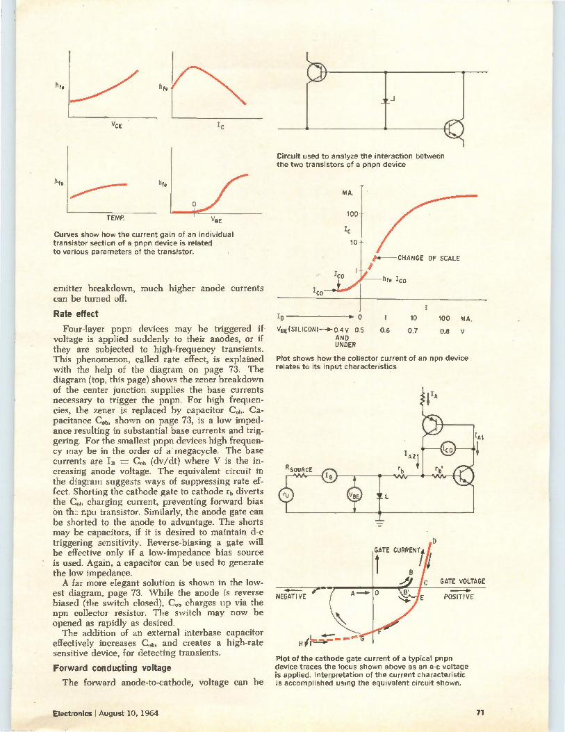
hfe
hfe
VCE
TEMP.
hfe
hfe
IC
VBE
Curves show how the current gain of an individual transistor section of a pnpn device is related to various parameters of the transistor.
emitter breakdown, much higher anode currents
can be turned off.
Circuit used to analyze the interaction between the two transistors of a pnpn device
MA.
100—
IC
10 —
ea—CHANGE OF SCALE
hfe ICo
Rate effect 1 10 100 MA.
Four-layer pnpn devices may be triggered if VBE(SILICON)----b-0.4v 0.5 0.6 0.7 0.8 voltage is applied suddenly to their anodes, or if AND
UNDER they are subjected to high-frequency transients.
This phenomenon, called rate effect, is explained
with the help of the diagram on page 73. The
diagram (top, this page) shows the zener breakdown
of the center junction supplies the base currents
necessary to trigger the pnpn. For high frequen-
cies, the zener is replaced by capacitor Cob. Ca-
pacitance C ob, shown on page 73, is a low imped-
ance resulting in substantial base currents and trig-
gering. For the smallest pnpn devices high frequen-
cy may be in the order of a• megacycle. The base
currents are IB = Cob (dv/dt) where V is the in-
creasing anode voltage. The equivalent circuit in
the diagram suggests ways of suppressing rate ef-
fect. Shorting the cathode gate to cathode rt, diverts
the C„1, charging current, preventing forward bias
on th:-; npn transistor. Similarly, the anode gate can
be shorted to the anode to advantage. The shorts
may be capacitors, if it is desired to maintain d-c
triggering sensitivity. Reverse-biasing a gate will
be effective only if a low-impedance bias source
is used. Again, a capacitor can be used to generate
the low impedance. A far more elegant solution is shown in the low-
est diagram, page 73. \Vhile the anode is reverse
biased (the switch closed), C„1, charges up via the
npn collector resistor. The switch may now be
opened as rapidly as desired.
The addition of an external interbase capacitor
effectively increases C„1„ and creates a high-rate
sensitive device, for detecting transients.
Forward conducting voltage
Plot shows how the collector current of an npn device relates to its input characteristics
GATE CURRENT t
NEGATIVE
GATE VOLTAGE
POSITIVE
Plot of the cathode gate current of a typical pnpn device traces the locus shown above as an a-c voltage is applied. Interpretation of the current characteristic
The forward anode-to-cathode, voltage can be is accomplished using the equivalent circuit shown.
Electronics I August 10, 1964 71
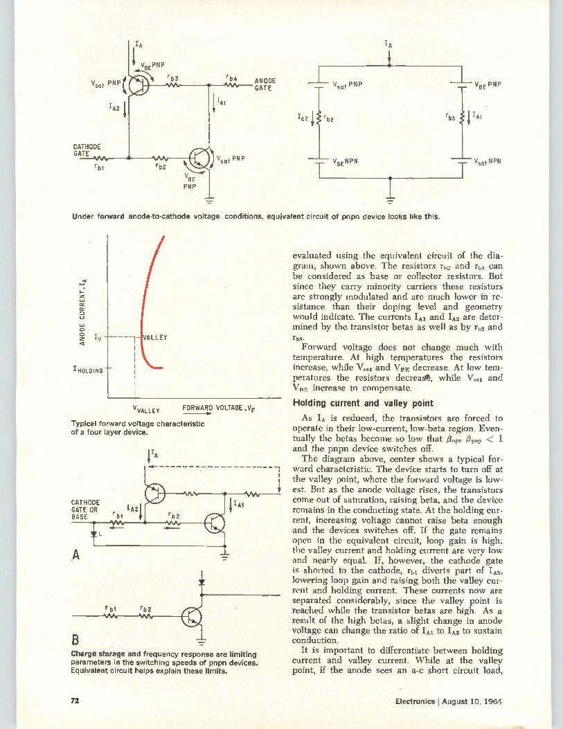
V„t PNP (
IA2
CATHODE GATE
rbt
ANODE GATE
IA
Vso PNP
I„ rb2
V NPN
T BE
Under forward anode-to-cathode voltage conditions, equivalent circuit of pnpn device looks like this.
ANODE CURRENT,IA
HOLDING
VVALLEY FORWARD VOLTAGE ,VF
Typical forward voltage characteristic of a four layer device.
CATHODE GATE OR BASE
rbi rb2
Charge storage and frequency response are limiting parameters in the switching speeds of pnpn devices. Equivalent circuit helps explain these limits.
evaluated using the equivalent circuit of the dia-gram, shown above. The resistors rb., and r1,3 can be considered as base or collector resistors. But since they carry minority carriers these resistors are strongly modulated and are much lower in re-sistance than their doping level and geometry would indicate. The currents 'Al and IA2 are deter-mined by the transistor betas as well as by fie, and rb3. Forward voltage does not change much with
temperature. At high temperatures the resistors increase, while Vat and VBE decrease. At low tem-peratures the resistors decreae, while V„at and VBE increase to compensate.
Holding current and valley point
As IA is reduced, the transistors are forced to operate in their low-current, low-beta region. Even-tually the betas become so low that /3„„,, < 1
and the pnpn device switches off. The diagram above, center shows a typical for-
ward characteristic. The device starts to turn off at the valley point, where the forward voltage is low-est. But as the anode voltage rises, the transistors come out of saturation, raising beta, and the device remains in the conducting state. At the holding cur-rent, increasing voltage cannot raise beta enough and the devices switches off. If the gate remains open in the equivalent circuit, loop gain is high; the valley current and holding current are very low and nearly equal. If, however, the cathode gate is shorted to the cathode, r1,1 diverts part of IA-, lowering loop gain and raising both the valley cur-rent and holding current. These currents now are separated considerably, since the valley point is reached while the transistor betas are high. As a result of the high betas, a slight change in anode voltage can change the ratio of 'Al to IA2 to sustain conduction.
It is important to differentiate between holding current and valley current. While at the valley point, if the anode sees an a-c short circuit load,
72 Electronics !August 10, 1964
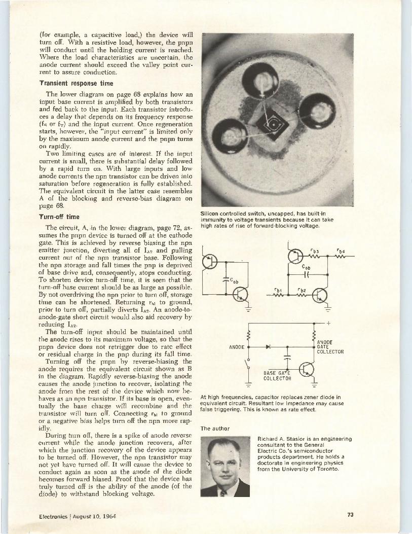
(for example, a capacitive load,) the device will turn off. With a resistive load, however, the pnpn will conduct until the holding current is reached. Where the load characteristics are uncertain, the anode current should exceed the valley point cur-rent to assure conduction.
Transient response time
The lower diagram on page 68 explains how an input base current is amplified by both transistors and fed back to the input. Each transistor introdu-ces a delay that depends on its frequency response (fa or fr) and the input current. Once regeneration starts, however, the "input current- is limited only by the maximum anode current and the pnpn turns on rapidly. Two limiting cases are of interest. If the input
current is small, there is substantial delay followed by a rapid turn on. \Vith large inputs and low anode currents the npn transistor can be driven into saturation before regeneration is fully established. The equivalent circuit in the latter case resembles A of the blocking and reverse-bias diagram on page 68.
Turn-off time
The circuit, A, in the lower diagram, page 72, as-sumes the pnpn device is turned off at the cathode gate. This is achieved by reverse biasing the npn emitter junction, diverting all of IA. and pulling current out of the npn transistor base. Following the npn storage and fall times the pnp is deprived of base drive and, consequently, stops conducting. To shorten device turn-off time, it is seen that the turn-off base current should be as large as possible. By not overdriving the npn prior to turn off, storage time can be shortened. Returning r1,1 to ground, prior to turn off, partially diverts IA.. An anode-to-anode-gate short circuit would also aid recovery by reducing 1A2. The turn-off input should be maintained until
the anode rises to its maximum voltage, so that the pnpn device does not retrigger due to rate effect or residual charge in the pnp during its fall time. Turning off the pnpn by reverse-biasing the
anode requires the equivalent circuit shown as B in the diagram. Rapidly reverse-biasing the anode causes the anode junction to recover, isolating the anode from the rest of the device which now be-haves as an npn transistor. If its base is open, even-tually the base charge ‘vill recombine and the transistor ‘vill turn off. Connecting rid to ground or a negative bias helps turn off the npn more rap-idly. During turn off, there is a spike of anode reverse
current while the anode junction recovers, after which the junction recovery of the device appears to be turned off. However, the npn transistor may not yet llave turned off. It will cause the device to conduct again as soon as the anode of the diode becomes forward biased. Proof that the device has truly turned off is the ability of the anode (of the diode) to withstand blocking voltage.
Silicon controlled switch, uncapped, has built-in immunity to voltage transients because it can take high rates of rise of forward-blocking voltage.
ANODE
BASE GATE COLLECTOR
ANODE GATE COLLECTOR
At high frequencies, capacitor replaces zener diode in equivalent circuit. Resultant low impedance may cause false triggering. This is known as rate effect.
The author
Richard A. Stasior is an engineering consultant to the General Electric Co.'s semiconductor products department. He holds a doctorate in engineering physics from the University of Toronto.
Electronics tAugust 10, 1964 73
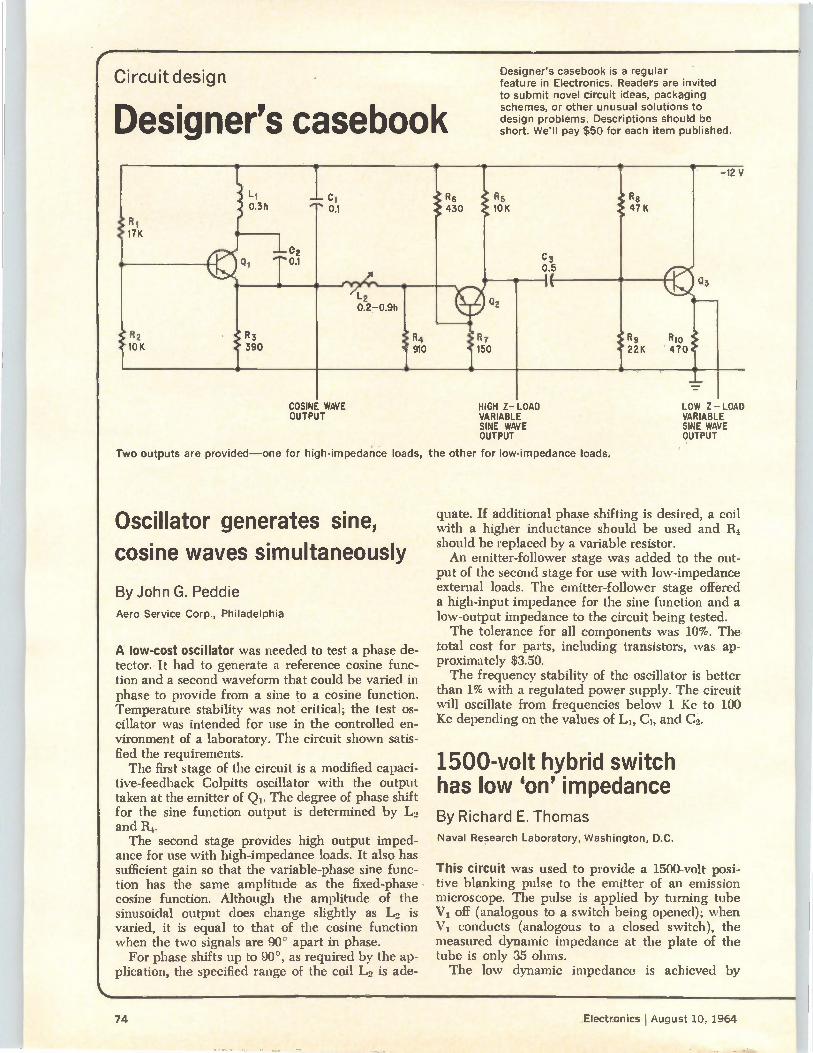
Circuit design
Designer's casebook
Designer's casebook is a regular feature in Electronics. Readers are invited to submit novel circuit ideas, packaging schemes, or other unusual solutions to design problems. Descriptions should be short. We'll pay $50 for each item published.
17K
Lj Cl 0.3h 0.1
02 0.1
R6 430
12 0.2-0.9h
R2 R3 10K 390
R4 910
R5 10K
Co
0.5
R7
150
COSINE WAVE OUTPUT
HIGH Z- LOAD VARIABLE SINE WAVE OUTPUT
Two outputs are provided—one for high-impedance loads, the other for low-impedance loads.
Oscillator generates sine, cosine waves simultaneously
By John G. Peddie
Aero Service Corp., Philadelphia
A low-cost oscillator was needed to test a phase de-tector. It had to generate a reference cosine func-tion and a second waveform that could be varied in phase to provide from a sine to a cosine function. Temperature stability was not critical; the test os-cillator was intended for use in the controlled en-vironment of a laboratory. The circuit shown satis-fied the requirements. The first stage of the circuit is a modified capaci-
tive-feedback Colpitts oscillator with the output taken at the emitter of Qi. The degree of phase shift for the sine function output is determined by L2 and R4. The second stage provides high output imped-
ance for use with high-impedance loads. It also has sufficient gain so that the variable-phase sine func-tion has the same amplitude as the fixed-phase cosine function. Although the amplitude of the sinusoidal output does change slightly as Lo is varied, it is equal to that of the cosine function when the two signals are 90° apart in phase.
For phase shifts up to 90°, as required by the ap-plication, the specified range of the coil L. is ade-
47K
11'4
22K R10 e470
-12 V
LOW Z - LOAD VARIABLE SINE WAVE OUTPUT
quate. If additional phase shifting is desired, a coil with a higher inductance should be used and R4 should be replaced by a variable resistor. An emitter-follower stage was added to the out-
put of the second stage for use with low-impedance external loads. The emitter-follower stage offered a high-input impedance for the sine function and a low-output impedance to the circuit being tested. The tolerance for all components was 10%. The
total cost for parts, including transistors, was ap-proximately $3.50. The frequency stability of the oscillator is better
than 1% with a regulated power supply. The circuit will oscillate from frequencies below 1 Kc to 100 Kc depending on the values of LI, C1, and Co.
1500-volt hybrid switch has low 'on' impedance By Richard E. Thomas Naval Research Laboratory, Washington, D.C.
This circuit was used to provide a 1500-volt posi-tive blanking pulse to the emitter of an emission microscope. The pulse is applied by turning tube V, off (analogous to a switch being opened); when
conducts (analogous to a closed switch), the measured dynamic impedance at the plate of the tube is only 35 ohms. The low dynamic impedance is achieved by
74 Electronics I August 10, 1964
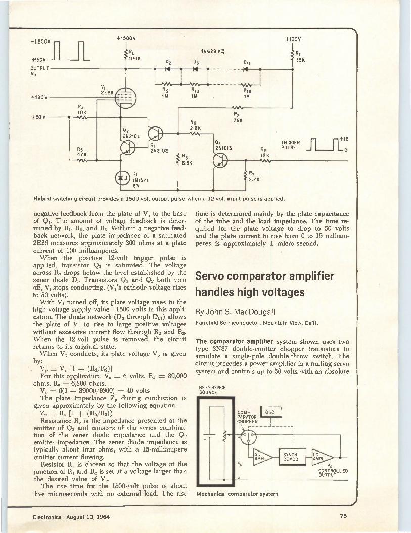
+1,500V
+150V--
OUTPUT Vp
+180V
+50 V
+1500V
RL e 100K
R4 10K
\t1
D2
14
1N629 (10)
03
R9 R10
1M 1M
14
+100V
R7 2.2 K
Re 12 K Vvy
R1
39K
TRIGGER PULSE
+12
o
Hybrid switching circuit provides a 1500-volt output pu se when a 12-volt input pulse is applied.
negative feedback from the plate of V, to the base of Q1. The amount of voltage feedback is deter-mined by RI, Ro, and 113. Without a negative feed-back network, the plate impedance of a saturated 2E26 measures approximately 300 ohms at a plate current of 100 milliamperes. 'When the positive 12-volt trigger pulse is
applied, transistor Q3 is saturated. The voltage across R3 drops below the level established by the zener diode DI. Transistors Q, and Q, both turn off, V, stops conducting. (Vi's cathode voltage rises to 50 volts). With VI turned off, its plate voltage rises to the
high voltage supply value-1500 volts in this appli-cation. The diode network (Dn through D11) allows the plate of V, to rise to large positive voltages without excessive current flow through R2 and R. When the 12-volt pulse is removed, the circuit returns to its original state. When V, conducts, its plate voltage V„ is given
by: Vp = Vz [1 ± (112/113)] For this application, Vz = 6 volts, 112 = 39,000
ohms, 113 = 6,800 ohms. V„ = 6(1 + 39000/6800) = 40 volts The plate impedance Z„ during conduction is
given approximately by the following equation: Z„ = Re [1 ± (R2/I13)] Resistance R. is the impedance presented at the
emitter of Q., and consists of the series combina-tion of the zener diode impedance and the Q2 emitter impedance. The zener diode impedance is typically about four ohms, with a 15-milliampere emitter current flowing.
Resistor R, is chosen so that the voltage at the junction of RI and R., is set at a voltage larger than the desired value of V. The rise time for the 1500-volt pulse is about
five microseconds with no external load. The rise
time is determined mainly by the plate capacitance of the tube and the load impedance. The time re-quired for the plate voltage to drop to 50 volts and the plate current to rise from 0 to 15 milliam-peres is approximately 1 micro-second.
Servo comparator amplifier
handles high voltages
By John S. MacDougall Fairchild Semiconductor, Mountain View, Calif.
The comparator amplifier system shown uses two type 3N87 double-emitter chopper transistors to simulate a single-pole double-throw switch. The circuit precedes a power amplifier in a nulling servo system and controls up to 50 volts with an absolute
REFERENCE SOURCE
COM-PARATOR CHOPPER \
AC AMR
SYNCH DEMOD
DC AMPL
VO CONTROLLED OUTPUT
Mechanical comparator system
Electronics August 10, 1964 75
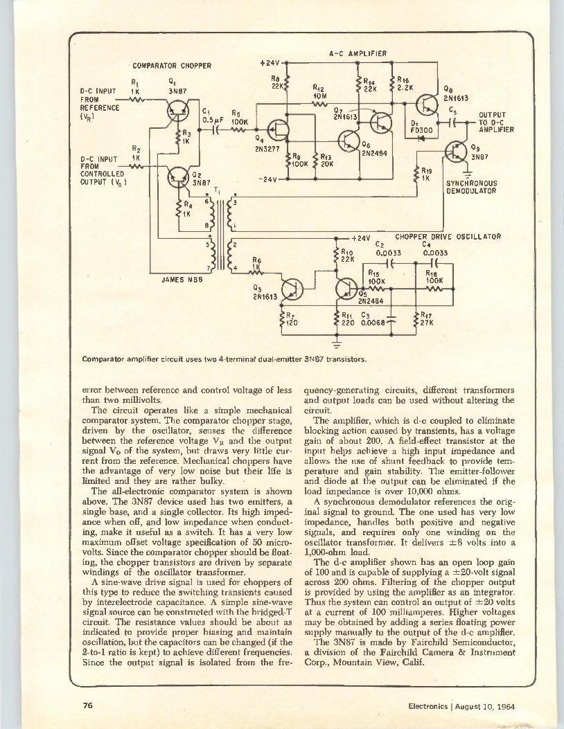
f N
A-C AMPLIFIER
D-C INPUT FROM REFERENCE (VR)
COMPARATOR CHOPPER
R1 Oi 1K
R2 D-C INPUT 1K FROM CONTROLLED OUTPUT (V0
3N87
JAMES MB8 Q3
OUTPUT TO D-C AMPLIFIER
09 3N87
SYNCHRONOUS DEMODULATOR
+24V CHOPPER DRIVE OSCILLATOR C2 C4
Rig 0.0033 0.0033 22K
Comparator amplifier circuit uses two 4-terminal dual-emitter 3N87 transistors.
error between reference and control voltage of less than two millivolts. The circuit operates like a simple mechanical
comparator system. The comparator chopper stage, driven by the oscillator, senses the difference between the reference voltage VI{ and the output signal Vo of the system, but draws very little cur-rent from the reference. Mechanical choppers have the advantage of very low noise but their life is limited and they are rather bulky. The all-electronic comparator system is shown
above. The 3N87 device used has two emitters, a single base, and a single collector. Its high imped-ance when off, and low impedance when conduct-ing, make it useful as a switch. It has a very low maximum offset voltage specification of 50 micro-volts. Since the comparator chopper should be float-ing, the chopper transistors are driven by separate windings of the oscillator transformer. A sine-wave drive signal is used for choppers of
this type to reduce the switching transients caused by interelectrode capacitance. A simple sine-wave signal source can be constructed with the bridged-T circuit. The resistance values should be about as indicated to provide proper biasing and maintain oscillation, but the capacitors can be changed (if the 2-to-1 ratio is kept) to achieve different frequencies. Since the output signal is isolated from the fre-
quency-generating circuits, different transformers and output loads can be used without altering the circuit. The amplifier, which is d-c coupled to eliminate
blocking action caused by transients, has a voltage gain of about 200. A field-effect transistor at the input helps achieve a high input impedance and allows the use of shunt feedback to provide tem-perature and gain stability. The emitter-follower and -diode at the output can be eliminated if the load impedance is over 10,000 ohms. A synchronous demodulator references the orig-
inal signal to ground. The one used has very low impedance, handles both positive and negative signals, and requires only one winding on the oscillator transformer. It delivers ±8 volts into a 1,000-ohm load. The d-c amplifier shown has an open loop gain
of 100 and is capable of supplying a ±20-volt signal across 200 ohms. Filtering of the chopper output is provided by using the amplifier as an integrator. Thus the system can control an output of ±20 volts at a current of 100 milliamperes. Higher voltages may be obtained by adding a series floating power supply manually to the output of the d-c amplifier. The 3N87 is made by Fairchild Semiconductor,
a division of the Fairchild Camera & Instrument Corp., Mountain View, Calif.
\.
76 Electronics I August 10, 1964
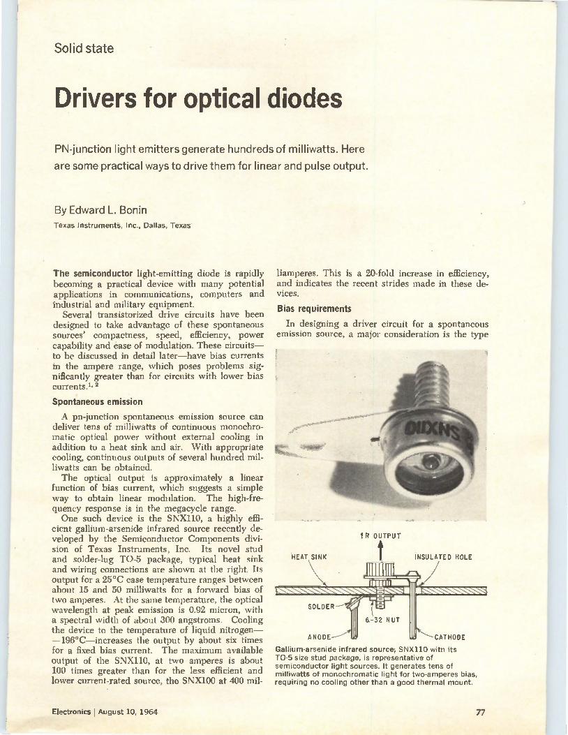
Solid state
Drivers for optical diodes
PN-junction light emitters generate hundreds of milliwatts. Here
are some practical ways to drive them for linear and pulse output.
By Edward L. Bonin Texas Instruments, Inc., Dallas, Texas
The semiconductor light-emitting diode is rapidly becoming a practical device with many potential applications in communications, computers and industrial and military equipment.
Several transistorized drive circuits have been designed to take advantage of these spontaneous sources' compactness, speed, efficiency, power capability and ease of modulation. These circuits— to be discussed in detail later—have bias currents in the ampere range, which poses problems sig-nificantly greater than for circuits with lower bias currents. 1, 2
Spontaneous emission
A pn-junction spontaneous emission source can deliver tens of milliwatts of continuous monochro-matic optical power without external cooling in addition to a heat sink and air. With appropriate cooling, continuous outputs of several hundred mil-liwatts can be obtained. The optical output is approximately a linear
function of bias current, which suggests a simple way to obtain linear modulation. The high-fre-quency response is in the megacycle range. One such device is the SNX110, a highly effi-
cient gallium-arsenide infrared source recently de-veloped by the Semiconductor Components divi-sion of Texas Instruments, Inc. Its novel stud and solder-lug TO-5 package, typical heat sink and wiring connections are shown at the right. Its output for a 25°C case temperature ranges between about 15 and 50 milliwatts for a forward bias of two amperes. At the same temperature, the optical wavelength at peak emission is 0.92 micron, with a spectral width of about 300 angstroms. Cooling the device to the temperature of liquid nitrogen--196°C—increases the output by about six times for a fixed bias current. The maximum available output of the SNX110, at two amperes is about 100 times greater than for the less efficient and lower current-rated source, the SNX100 at 400 mil-
liamperes. This is a 20-fold increase in efficiency, and indicates the recent strides made in these de-vices.
Bias requirements
In designing a driver circuit for a spontaneous emission source, a major consideration is the type
IR OUTPUT
HEAT SINK
SOLDER
ANODE
6-32 NUT
INSULATED HOLE
CATHODE
Gallium-arsenide infrared source, SNX110 with its TO-5 size stud package, is representative of semiconductor light sources. It generates tens of milliwatts of monochromatic light for two-amperes bias, requiring no cooling other than a good thermal mount.
Electronics I August 10, 1964 77
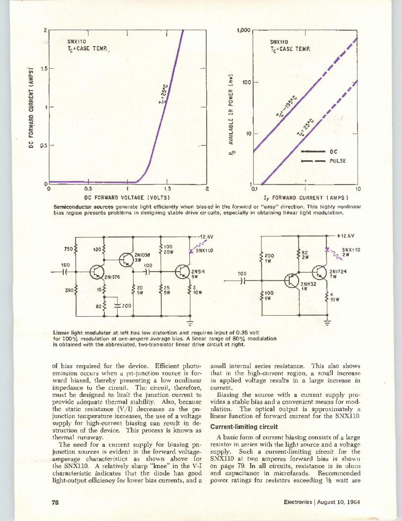
DC FORWARD CURRENT (AMPSÎ
2
1.5
0.5
SNX110 Tc.-- CASE TEMP.,
P AVAILABLE
IR POWER (m
w)
0.5 1 1.5 2
DC FORWARD VOLTAGE (VOLTS)
1,000
100
10
1 0.1 1
IF FORWARD CURRENT (AMPS)
10
Semiconductor sources generate light efficiently when biased in the forward or "easy" direction. This highly nonlinear bias region presents problems in designing stable drive circuits, especially in obtaining linear light modulation.
of bias required for the device. Efficient photo-emission occurs when a pn-junction source is for-ward biased, thereby presenting a low nonlinear impedance to the circuit. The circuit, therefore, must be designed to limit the junction current to provide adequate thermal stability. Also, because the static resistance (V/I) decreases as the pn-junction temperature increases, the use of a voltage supply for high-current biasing can result in de-struction of the device. This process is known as thermal runaway. The need for a current supply for biasing pn-
junction sources is evident in the forward voltage-amperage characteristics as shown above for the SNX110. A relatively sharp "knee" in the V-I characteristic indicates that the diode has good light-output efficiency for lower bias currents, and a
100
Linear light modulator at left has low distortion and requires input of 0.35 volt for 100% modulation at one-ampere average bias. A linear range of 80% modulation is obtained with the abbreviated, two-transistor linear drive circuit at right.
+12.6V
621r10
2N1724 7W
small internal series resistance. This also shows that in the high-current region, a small increase in applied voltage results in a large increase in current.
Biasing the source with a current supply pro-vides a stable bias and a convenient means for mod-ulation. The optical output is approximately a linear function of forward current for the SNX110.
Current-limiting circuit
A basic form of current biasing consists of a large resistor in series with the light source and a voltage supply. Such a current-limiting circuit for the SNX110 at two amperes forward bias is shown on page 79. In all circuits, resistance is in ohms and capacitance in microfarads. Recommended power ratings for resistors exceeding 1/2 watt are
78 Electronics j August 10, 1964
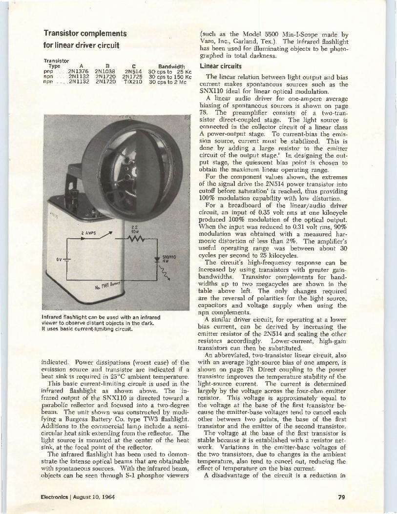
Transistor complements
for linear driver circuit
Transistor Type A
pnp .2N1376 2N1038 2N514 npn .2N1132 2N1720 2N1725 npn . .2N1132 2N1720 TIX210
Bandwidth 30 cps to 25 Kc 30 cps to 150 Kc 30 cps to 2 Mc
Infrared flashlight can be used with an infrared viewer to observe distant objects in the dark. It uses basic current-limiting circuit.
indicated. Power dissipations (worst case) of the emission source and transistor are indicated if a heat sink is required in 25°C ambient temperature.
This basic current-limiting circuit is used in the infrared flashlight as shown above. The in-frared output of the SNX110 is directed toward a parabolic reflector and focused into a two-degree beam. The unit shown was constructed by modi-fying a Burgess Battery Co. type TW3 flashlight. Additions to the commercial lamp include a semi-circular heat sink extending from the reflector. The light source is mounted at the center of the heat sink, at the focal point of the reflector. The infrared flashlight has been used to demon-
strate the intense optical beams that are obtainable with spontaneous sources. With the infrared beam, objects can be seen through S-1 phosphor viewers
(such as the Model 5500 Min-I-Scope made by Varo, Inc., Garland, Tex.). The infrared flashlight has been used for illuminating objects to be photo-graphed in total darkness.
Linear circuits
The linear relation between light output and bias current makes spontaneous sources such as the SNX110 ideal for linear optical modulation. A linear audio driver for one-ampere average
biasing of spontaneous sources is shown on page 78. The preamplifier consists of a two-tran-sistor direct-coupled stage. The light source is connected in the collector circuit of a linear class A power-output stage. To current-bias the emis-sion source, current must be stabilized. This is done by adding a large resistor to the emitter circuit of the output stage.' In designing the out-put stage, the quiescent bias point is chosen to obtain the maximum linear operating range. For the component values shown, the extremes
of the signal drive the 2N514 power transistor into cutoff before saturation' is reached, thus providing 100% modulation capability with low distortion. For a breadboard of the linear/audio driver
circuit, an input of 0.35 volt rms at one kilocycle produced 100% modulation of the optical output. When the input was reduced to 0.31 volt rms, 90% modulation was obtained with a measured har-monic distortion of less than 2%. The amplifier's useful operating range was between about 30 cycles per second to 25 kilocycles. The circuit's high-frequency response can be
increased by using transistors with greater gain-bandwidths. Transistor complements for band-widths up to two megacycles are shown in the table above left. The only changes required are the reversal of polarities for the light source, capacitors and voltage supply when using the npn complements. A similar driver circuit, for operating at a lower
bias current, can be derived by increasing the emitter resistor of the 2N514 and scaling the other resistors accordingly. Lower-current, high-gain transistors can then be substituted. An abbreviated, two-transistor linear circuit, also
with an average light-source bias of one ampere, is shown on page 78. Direct coupling to the power transistor improves the temperature stability of the light-source current. The current is determined largely by the voltage across the four-ohm emitter resistor. This voltage is approximately equal to the voltage at the base of the first transistor be-cause the emitter-base voltages tend to cancel each other between two points, the base of the first transistor and the emitter of the second transistor. The voltage at the base of the first transistor is
stable because it is established with a resistor net-work. Variations in the emitter-base voltages of the two transistors, due to changes in the ambient temperature, also tend to cancel out, reducing the effect of temperature on the bias current. A disadvantage of the circuit is a reduction in
Electronics I August 10, 1964 79
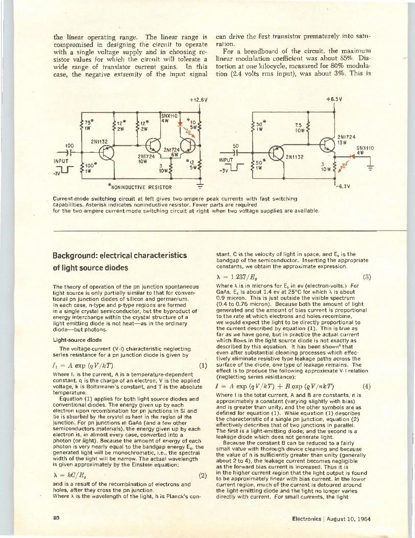
the linear operating range. The linear range is compromised in designing the circuit to operate with a single voltage supply and in choosing re-sistor values for which the circuit will tolerate a wide range of transistor current gains. In this case, the negative extremity of the input signal
+12.6V
*NONINDUCTIVE RESISTOR
can drive the first transistor prematurely into satu-ration. For a breadboard of the circuit, the maximum
linear modulation coefficient was about 85%. Dis-tortion at one kilocycle, measured for 80% modula-tion (2.4 volts rms input), was about 3%. This is
Current-mode switching circuit at left gives two-ampere peak currents with fast switching capabilities. Asterisk indicates noninductive resistor. Fewer parts are required for the two-ampere current-mode switching circuit at right when two voltage supplies are available.
+6.3V
2N1724 13W
SNX110 4W
Background: electrical characteristics
of light source diodes
The theory of operation of the pn ¡unction spontaneous light source is only partially similar to that for conven-tional pn junction diodes of silicon and germanium. In each case, n-type and p-type regions are formed in a single crystal semiconductor, but the byproduct of energy interchange within the crystal structure of a light emitting diode is not heat—as in the ordinary diode—but photons.
Light-source diode
The voltage-current (V-I) characteristic neglecting series resistance for a pn junction diode is given by
/1, = A exp (07 /kT) Where h is the current, A is a temperature-dependent constant, q is the charge of an electron, V is the applied voltage, k is Boltzmann's constant, and T is the absolute temperature.
Equation (1) applies for both light source diodes and conventional diodes. The energy given up by each electron upon recombination for pn junctions in Si and Ge is absorbed by the crystal as heat in the region of the ¡unction. For pn junctions in GaAs (and a few other semiconductors materials), the energy given up by each electron is, in almost every case, converted into a photon (or light). Because the amount of energy of each photon is very nearly equal to the bandgap energy E,, the generated light will be monochromatic, i.e., the spectral width of the light will be narrow. The actual wavelength is given approximately by the Einstein equation:
X = hC/E, and is a result of the recombination of electrons and holes, after they cross the pn junction. Where X is the wavelength of the light, h is Planck's con-
(1)
(2)
stant, C is the velocity of light in space, and E, is the bandgap of the semiconductor. Inserting the appropriate constants, we obtain the approximate expression.
X = 1.237/E, (3) Where X is in microns for E, in ev (electron-volts.) For GaAs, E, is about 1.4 ev at 25°C for which X is about 0.9 micron. This is just outside the visible spectrum (0.4 to 0.76 micron). Because both the amount of light generated and the amount of bias current is proportional to the rate at which electrons and holes recombine, we would expect the light to be directly proportional to the current described by equation (1). This is true as far as we have gone, but in practice the actual current which flows in the light source diode is not exactly as described by this equation. It has been shown that even after substantial cleaning processes which effec-tively eliminate resistive type leakage paths across the surface of the diode, one type of leakage remains. The effect is to produce the following approximate V-I relation (neglecting series resistance):
/ = A exp (qV/kT) B exp (qVInkT) (4) Where I is the total current, A and B are constants, n is approximately a constant (varying slightly with bias) and is greater than unity, and the other symbols are as defined for equation (1). While equation (1) describes the characteristic of a single pn junction, equation (2) effectively describes that of two junctions in parallel. The first is a light-emitting diode; and the second is a leakage diode which does not generate light.
Because the constant B can be reduced to a fairly small value with thorough device cleaning and because the value of n is sufficiently greater than unity (generally about 2 to 4), the leakage current becomes negligible as the forward bias current is increased. Thus it is in the higher current region that the light output is found to be approximately linear with bias current. In the lower current region, much of the current is detoured around the light-emitting diode and the light no longer varies directly with current. For small currents, the light
80 Electronics 1 August 10, 1964
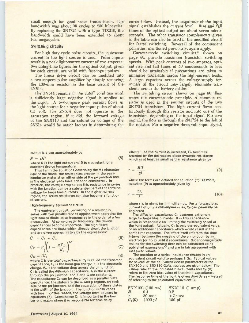
small enough for good voice transmission. The bandwidth was about 30 cycles to 250 kilocycles. By replacing the 2N1724 with a type TIX210, the bandwidth could have been extended to about two megacycles.
Switching circuits
For high duty-cycle pulse circuits, the quiescent current in the light source is zero. Pulse inputs result in a peak light-source current of two amperes. Switching-time figures for the optical output, given for each circuit, are valid with fast-input pulses. The linear drive circuit can be modified into
a two-ampere pulse amplifier by simply removing the 100-ohm resistor in the base circuit of the 2N514. The 2N514 remains in the cutoff condition until
a sufficiently large negative signal is applied to the input. A two-ampere peak current flows in the light source for a negative input pulse of about 0.5 volt. The 2N514 does not operate in the saturation region; if it did, the forward voltage of the SNX110 and the saturation voltage of the 2N514 would be major factors in determining the
current flow. Instead, the magnitude of the input signal establishes the current level. Rise and fall times of the optical output are about seven micro-seconds. The other transistor complements given in the table can also be used in the modified circuit for faster switching. Reversal of the component polarities, mentioned previously, again apply. Current-mode switching circuits,5 shown on
page 80, provide maximum transistor switching speeds. With peak currents of two amperes, opti-cal rise and fall times of 50 nanoseconds or less should be attainable if precautions are taken to minimize transients across the high-current leads. A large capacitor across the voltage-supply ter-minals of the circuit may largely eliminate tran-sients across the battery cables. The switching circuit shown on page 80 illus-
trates the current-mode principle. A common re-sistor is used in the emitter circuits of the two 2N1724 transistors. The high current flows con-tinuously through this resistor and into one of the transistors, depending on the input signal. For zero signal, the flow is through the 2N1724 to the left of the resistor. For a negative three-volt input signal,
output is given approximately by
N = DIn where N is the light output and D is a constant for a constant device temperature.
Thus far in the equations describing the V-I character-istic of the diode, the resistances present in the semi-conductor material on either side of the pn junction and in the electrical leads have not been considered. In practice, the voltage drop across this resistance in series with the junction can be a substantial part of the terminal voltage for large bias currents. In the higher current region, the series resistance can also become a function of current.
High-frequency equivalent circuit
The equivalent circuit, consisting of a resistor in series with two parallel diodes applies when operating the light source diode up to frequencies in the order of a few megacycles. At some greater frequency, the device capacitances become important. The significant capacitances are those which directly shunt the junction and are given approximately by the expressions:
C CT + CD
CT = 11(1 E, q171) (7)
CD = G11 (8) where C is the total capacitance, Cr is called the transition capacitance, E, is the band-gap energy, q is the electronic charge, VD is the voltage drop across the pn junction, CD is called the diffusion capacitance, h is the current through the pn junction, and F and G are constants. The capacitance CT can be described as a parallel-plate capacitance: the plates are the n- and p-regions on each side of the pn junction, and the separation of these plates is the width of the junction. The junction width varies with bias. For this reason, the voltage term appears in equations (7). Capacitance CT is important in the low-current region where it is responsible for time-delay
(5)
(6)
effects? As the current is increased, CT becomes shunted by the decreasing diode dynamic resistance which is at least as small as the resistance given by
KT r —
ql
where the terms are defined for equation (1). At 25°C, equation (9) is approximately given by
26 r =
(9)
(10)
where r is in ohms for I in milliamps. For a forward bias current I of only a millampere or so, CT Can generally be neglected. The diffusion capacitance CD becomes extremely
large for large bias currents. It is this capacitance which is responsible for limiting the switching speed of the light output. Actually, CD is only the equivalent value of an additional capacitance which would result in the same time response. The effect itself refers to the time interval between the crossing of the pn junction by an electron (or hole) until it recombines. Order-of-magnitude values for the switching time can be calculated using published expressions" and are in fair agreement with measured values.
The addition of a series inductance results in an equivalent circuit valid to perhaps 1 Gc. Typical values for several of the equivalent circuit parameters of the SNX100 and SNX110 GaAs sources are given below. The values refer to the indicated bias currents and CT (0) refers to the zero bias value of transition capacitance. The response time of the light is given directly as instead of referring to the calculated equivalent CD.
SNX100 (100 ma) I? 0.4
30 nsec Cr(0) 1000 pf
SNX110 (1 amp) 0.2 <7 nsec 150 pf
Electronics f August 10, 1964 81
)1/2
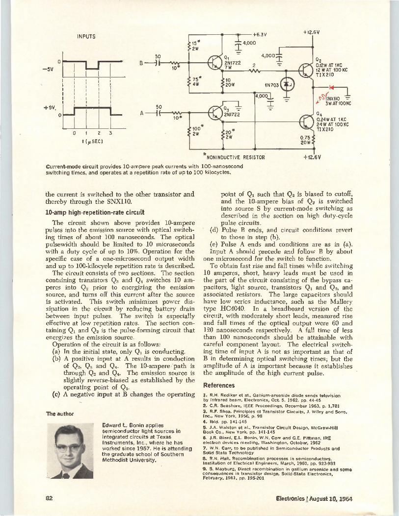
o —5V
INPUTS
+9V, p
o
1 2
t »SEC)
3
50
50 A —1
10
10*
+6.3V
—L 4,000
01 4,000
2 2N1722 7W
3 -= 2NI722
100 20* 2W
2W
VV1,.
+12.6V NONINDUCTIVE RESISTOR
Current-mode circuit provides 10-ampere peak currents with 100-nanosecond switching times, and operates at a repetition rate of up to 100 kilocycles.
the current is switched to the other transistor and thereby through the SNX110.
10-amp high-repetition-rate circuit
The circuit shown above provides 10-ampere pulses into the emission source with optical switch-ing times of about 100 nanoseconds. The optical pulsewidth should be limited to 10 microseconds with a duty cycle of up to 10%. Operation for the specific case of a one-microsecond output width and up to 100-kilocycle repetition rate is described. The circuit consists of two sections. The section
containing transistors Q3 and Q. switches 10 am-peres into Q2 prior to energizing the emission source, and turns off this current after the source is activated. This switch minimizes power dis-sipation in the circuit by reducing battery drain between input pulses. The switch is especially effective at low repetition rates. The section con-taining Q4 and Qo is the pulse-forming circuit that energizes the emission source.
Operation of the circuit is as follows: (a) In the initial state, only Q4 is conducting. (b) A positive input at A results in conduction
of Q2, Q3 and Q4. The 10-ampere path is through Qo and Q. The emission source is slightly reverse-biased as established by the operating point of Q. A negative input at B changes the operating (e)
The author
Edward L. Bonin applies semiconductor light sources in integrated circuits at Texas Instruments, Inc., where he has worked since 1957. He is attending the graduate school of Southern Methodist University.
+I2.6V
02 0.12W AT 1KC 12 W AT 100 KC TIX2I0
1411— i
SNX110 3W AT100KC
Q4 0.24W AT 1KC 24W AT 100 KC TIX2I0
0.75 20W
point of Q4 such that Q, is biased to cutoff, and the 10-ampere bias of Qo is switched into source S by current-mode switching as described in the section on high duty-cycle pulse circuits.
(d) Pulse B ends, and circuit conditions revert to those in step (b).
(e) Pulse A ends and conditions are as in (a). Input A should precede and follow B by about
one microsecond for the switch to function. To obtain fast rise and fall times while switching
10 amperes, short, heavy leads must be used in the part of the circuit consisting of the bypass ca-pacitors, light source, transistors Q4 and Q0, and associated resistors. The large capacitors should have low series inductance, such as the Mallory type HC4040. In a breadboard version of the circuit, with moderately short leads, measured rise and fall times of the optical output were 60 and 120 nanoseconds respectively. A fall time of less than 100 nanoseconds should be attainable with careful component layout. The electrical switch-ing time of input A is not as important as that of B in determining optical switching times; but the amplitude of A is important because it establishes the amplitude of the high current pulse.
References
1. R.H. Rediker et al., Gallium-arsenide diode sends television by infrared beam, Electronics, Oct. 5, 1962, pp. 44-45
2. C.R. Seashore, IEEE Proceedings, December 1963, p. 1,781
3. R.F. Shea, Principles of Transistor Circuits, J. Wiley and Sons, Inc., New York, 1956, p. 98
4. Ibid. pp. 141-145
5. J.A. Walston et al., Transistor Circuit Design, McGraw-Hill Book Co., New York, pp. 141-145
6. J.R. Biard, E.L. Bonin, W.N. Carr and G.E. Pittman, IRE electron devices meeting, Washington. October, 1962
7. W.N. Carr, to be published in Semiconductor Products and Solid State Technology
8. R.N. Hall, Recombination processes in semiconductors, Institution of Electrical Engineers, March, 1960, pp. 923-931
9. S. Mayburg, Direct recombination in gallium arsenide and some consequences in transistor design, Solid-State Electronics, February, 1961, pp. 195-201
82 Electronics August 10, 1964
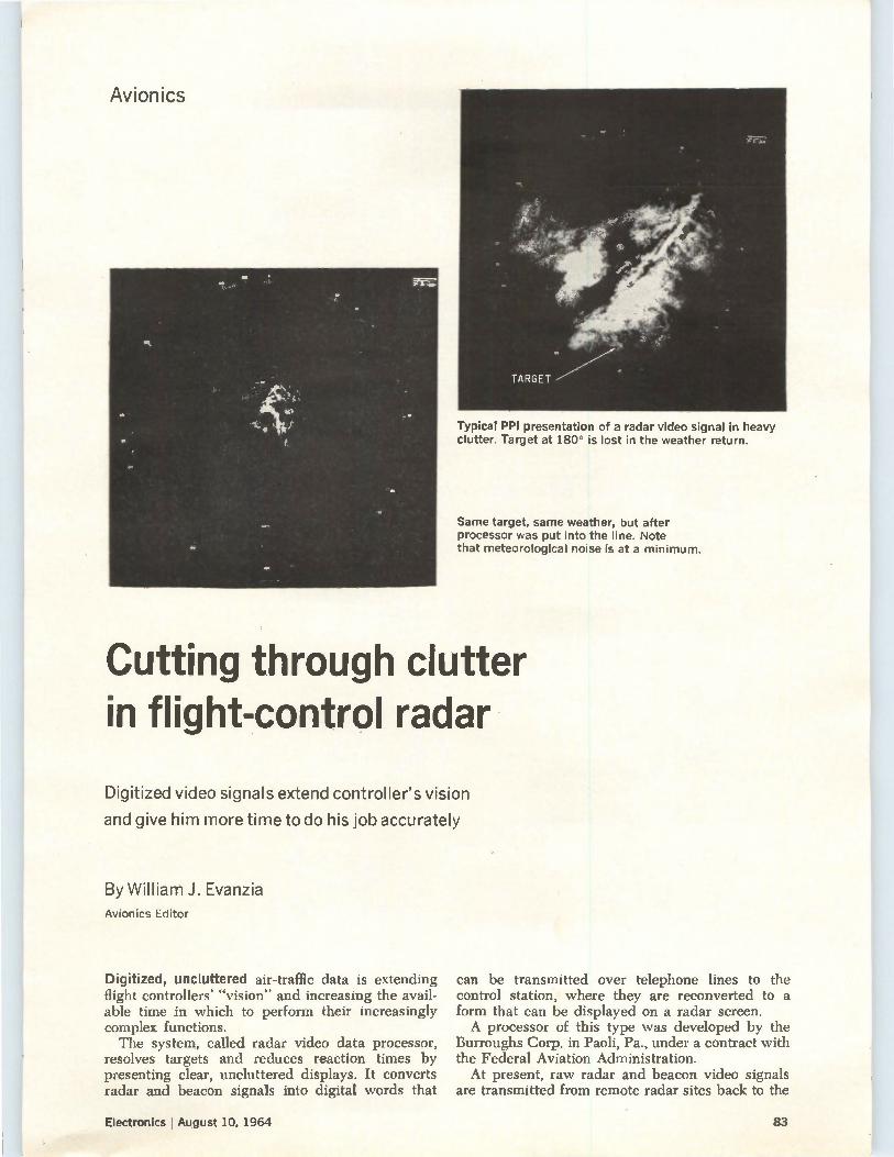
Avionics
Typical PPI presentation of a radar video signal in heavy clutter. Target at 180° is lost in the weather return.
Same target, same weather, but after processor was put into the line. Note that meteorological noise is at a minimum.
Cutting through clutter in flight-control radar
Digitized video signals extend controller's vision
and give him more time to do his job accurately
By William J. Evanzia Avionics Editor
Digitized, uncluttered air-traffic data is extending flight controllers' -vision- and increasing the avail-able time in which to perform their increasingly complex functions. The system, called radar video data processor,
resolves targets and reduces reaction times by presenting clear, uncluttered displays. It converts radar and beacon signals into digital words that
can be transmitted over telephone lines to the control station, where they are reconverted to a form that can be displayed on a radar screen. A processor of this type was developed by the
Burroughs Corp. in Paoli, Pa., under a contract with the Federal Aviation Administration. At present, raw radar and beacon video signals
are transmitted from remote radar sites back to the
Electronics I August 10, 1964 83
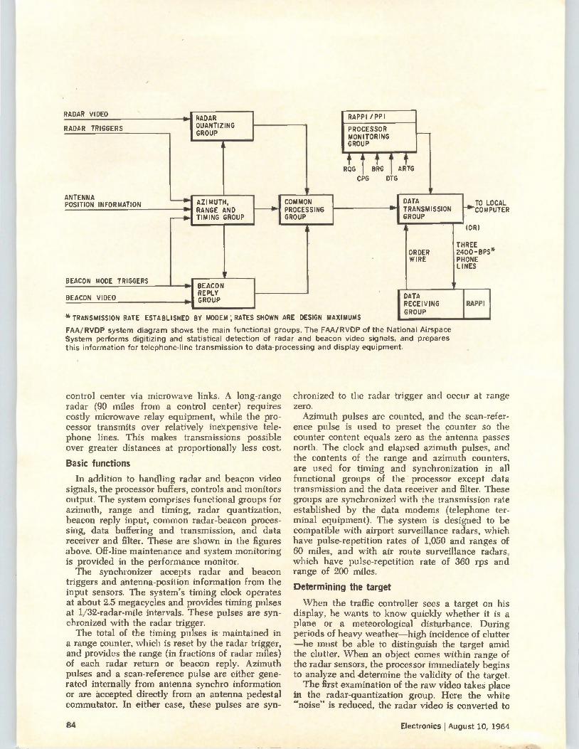
RADAR VIDEO
RADAR TRIGGERS
ANTENNA POSITION INFORMATION
BEACON MODE TRIGGERS
RADAR QUANTIZING GROUP
1 lir
AZIMUTH, RANGE AND
TIMING GROUP
w [COMMON PROCESSING
GROUP
BEACON VIDEO
BEACON REPLY GROUP
RAPPI /PPI
PROCESSOR MONITORING GROUP
ttt ROG BRG ARTG
C PG DTG
*TRANSMISSION RATE ESTABLISHED BY MODEM; RATES SHOWN ARE DESIGN MAXIMUMS
FAA/RVDP system diagram shows the main functional groups. The FAA/RVDP of the National Airspace System performs digitizing and statistical detection of radar and beacon video signals, and prepares this information for telephone-line transmission to data-processing and display equipment.
DATA TRANSMISSION GROUP
ORDER WIRE
[...TO LOCAL COMPUTER
(OR)
THREE 2400-BPS* PHONE LINES
DATA RECEIVING GROUP
RAPPI
control center via microwave links. A long-range radar (90 miles from a control center) requires costly microwave relay equipment, while the pro-cessor transmits over relatively inexpensive tele-phone lines. This makes transmissions possible over greater distances at proportionally less cost.
Basic functions
In addition to handling radar and beacon video signals, the processor buffers, controls and monitors output. The system comprises functional groups for azimuth, range and timing, radar quantization, beacon reply input, common radar-beacon proces-sing, data buffering and transmission, and data receiver and filter. These are shown in the figures above. Off-line maintenance and system monitoring is provided in the performance monitor. The synchronizer accepts radar and beacon
triggers and antenna-position information from the input sensors. The system's timing clock operates at about 2.5 megacycles and provides timing pulses at 1/32-radar-mile intervals. These pulses are syn-chronized with the radar trigger. The total of the timing pulses is maintained in
a range counter, which is reset by the radar trigger, and provides the range (in fractions of radar miles) of each radar return or beacon reply. Azimuth pulses and a scan-reference pulse are either gene-rated internally from antenna synchro information or are accepted directly from an antenna pedestal commutator. In either case, these pulses are syn-
chronized to the radar trigger and occur at range zero. Azimuth pulses are counted, and the scan-refer-
ence pulse is used to preset the counter so the counter content equals zero as the antenna passes north. The clock and elapsed azimuth pulses, and the contents of the range and azimuth counters, are used for timing and synchronization in all functional groups of the processor except data transmission and the data receiver and filter. These groups are synchronized with the transmission rate established by the data modems (telephone ter-minal equipment). The system is designed to be compatible with airport surveillance radars, which have pulse-repetition rates of 1,050 and ranges of 60 miles, and with air route surveillance radars, which have pulse-repetition rate of 360 rps and range of 200 miles.
Determining the target
When the traffic controller sees a target on his display, he wants to know quickly whether it is a plane or a meteorological disturbance. During periods of heavy weather—high incidence of clutter —he must be able to distinguish the target amid the clutter. When an object comes within range of the radar sensors, the processor immediately begins to analyze and determine the validity of the target. The first examination of the raw video takes place
in the radar-quantization group. Here the white "noise" is reduced, the radar video is converted to
84 Electronics I August 10, 1964
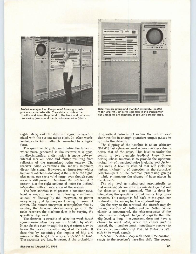
Data receiver group and monitor assembly, located at the Central Computer Complex. If the transmitter and computer are together, these units are not used.
Project manager Paul Pasquine of Burroughs tests processor at a radar site. The cabinets contain the monitor and azimuth generator, the basic and common processing groups and the data-transmission group.
digital data, and the digitized signal is synchro-nized with the system range clock. In other words, analog radar information is converted to a digital form. The quantizer is a dynamic noise-discriminator,
where noise generated in the receiver is clipped. In discriminating, a distinction is made between internal receiver noise and clutter resulting from reflection of the transmitted radar energy. The receiver noise determines the radar's minimum discernible signal. However, an integrator—either human or machine—looking at the sum of the signal plus noise, can see a valid target even though some noise is still present. Therefore, the problem is to present just the right amount of noise for optimal integration without saturation of the system. The best solution is to present a constant noise
level in areas of no clutter, allowing a minimum amount of filtering by the integrator, to permit more noise, and to increase filtering in areas of clutter. The human integrator accomplishes this by varying the intermediate-frequency gain of the radar receiver; the machine does it by varying the quantizer clip level. The detector is capable of selecting weak target
signals even when they are surrounded by noise. It can do this even though the target return may be below the mean discernible signal of the radar. It does this by examining the number of hits and misses of the target for a specific period of time. The statistics are lost, however, if the probability
of quantized noise is set so low that white noise alone results in enough quantizer output pulses to saturate the detector. The clipping of the baseline is at an arbitrary
RVDP input reference level whose average value is below that of the noise. This level is under the control of two dynamic feedback loops (figure below) whose function is to provide the optimum probability of quantized noise in clutter and clutter-less areas.. A level is selected that will yield the highest probability of detection in the statistical detector—part of the common processing groups —while minimizing the chance of false alarms in the detector. The clip level is maintained automatically so
that weak signals are not discriminated against and the detector is not saturated. This is done by integrating the quantizer output over a long time-constant. This output is fed back to the quantizer to develop the analog for the clip-level input. On the way to the terminal, the aircraft may fly
through sections of clutter and no clutter. \Vhen clutter is encountered, the characteristics of the radar receiver output change so rapidly that the clip level, a long time-constant, does not have a chance to react. Also, when the clutter area is passed, the quantizer must immediately recover to the stable, no-clutter clip level to retain its sen-sitivity to weak signals. A second feedback loop with short time-constant
reacts to the receiver's base-line shift. The second
Electronics August 10, 1964 85
feedback loop is switched in and out. Its move-ment is controlled by circuitry that determines the presence of clutter by examining the total of quan-tized returns in an area surrounding the last quantized return being added to the statistical detector. The effect is to break up the clutter so that the statistics of a target in the clutter can be recognized by the detector.
In this way, clutter discrimination is automatic. Clutter, which causes an increase in the noise passed by the quantizer, also increases the amount of integrator filtering by raising the threshold of detection. When the clutter is passed, the preset thresholds--quantizer and integrator—return the system to normal (figure below). The resulting effect is analogous to the human operator changing the receiver's i-f gain to pick-out the white ash on the white rug" without degrading the rest of his display. The circuitry automatically determines the pre-
sence and density of clutter by examining the dis-tribution of hits stored in the memory circuits. An analog of the number of hits present is pro-duced in a function generator which has, as a reference, a constant Pfa (probability of false alarms, or false targets) curve. Pfa is an exponential curve resulting from a plot of Pd vs P„ set in as a fixed bias in the function generator. This analog is then used to raise the detection level to a value above the number of hits from clutter alone.
Since the hits reinforce target signals as well as indicating the presence of clutter, the probability of detection (Pd) is not significantly affected by raising the detection thresholds. As an aid in the detection of incoming targets,
the processor uses both moving-target indication (MTI) and normal video signals. A crossover gate selects either quantized MTI or quantized normal video at any range. The selected MTI/normal video can then be fitted around a clutter area. Since normal video is more sensitive than MTI, this feature of the processor permits the optimum adjustment for clutter cancellation without loss of sensitivity where MTI is not required (figure on page 87).
Statistical detection
The next operation on the target video is statis-tical detection. The statistical detector is part of
editor's note
Surveillance of airspace over the continental United States, for air-fraffic control and air defense, has been performed for several years by radars operated jointly by the Air Force and the Federal Aviation Administration.
Evaluations by FAA and Air Force engineers have indicated that such joint uses result in substantial savings. The processor described in this article provides for common usage of an economical means of data remoting.
Evidence of the high interest in joint use is shown by recent government contracts for equipment, installation and maintenance of radar remoting equipment. These awards were made under the communications agreement of February, 1963, between the FAA and the Department of Defense Commercial Communications Office. The awards were to the Southern Bell Telephone and Telegraph Co. of Atlanta, Ga., and the American Telephone and Telegraph Co.
the common processing group, where the quantized video is statistically examined for validity. Quanti-zed video is the sum of reflected radar signal and a percent of the receiver noise. Examination of the target is made by a technique
known as the "sliding window", the window is really a register, or memory-case, capable of storing the maximum number of quantized returns—radar hits—on a target as the radar beam scans it. As the target approaches, the processor must
declare that a target is indeed present. Quantized returns (hits) are written into the register, which has been addressed (selected) by the processor's range counter. The contents are shifted through the register each time the range-counter addresses it, and if no quantized returns are present, a zero (miss) is written. An examination of the history stored in the
window, plus the presence or absence of a return in the current radar period, is made every radar period during each radar interval (memory read-write cycle). This is shown in the figure on page 88. The basis for target declaration is a threshold set-ting that is normally greater than one-half of the capacity of the register. The declaration of target is made when the examination shows that the total of returns is greater than the threshold, usually one more than half the possible number of hits in a window. This is called the target-leading edge TL. End of target, or target-trailing edge TT, is declared when the returns fall below a second preset value (figure on page 87). A window is provided for each radar range
interval—the transmitted pulse width—in which the basic radar can resolve a target. The radar window size is the result of a determined number of radar periods; therefore, the sliding window con-tains the total of returns for one antenna beam-width.
Target azimuth is also determined in the detec-tion memory. The process is called beam-splitting. One-half of the run length of the target—the elapsed azimuth between TL and TT—is subtracted from the azimuth counter contents at TT to deter-mine the target's true azimuth. High target resolution or optimum target pro-
cessing is achieved by registers for every range at which a target is expected. This permits targets with the minimum allowable slant-range separation to be identified separately. The registers are se-quentially addressed in synchronism with the radar timing. The number of required registers is de-termined by resolution capability of the radar times the maximum nominal radar range (r„ X R.). The target reports that are transferred out of the
processor contain range accuracy information that indicates in which quarter or half of the range-resolution interval (memory address) the target was received. Thus the separation capability of the radar-1/2 radar mile for a one microsecond trans-mitted pulse, and 1/4 radar mile for a 3 psee trans-mitted pulse—is corrected for 1/16 radar-mile accuracy—quantizer sampling interval—by the
86 Electronics August 10, 1964
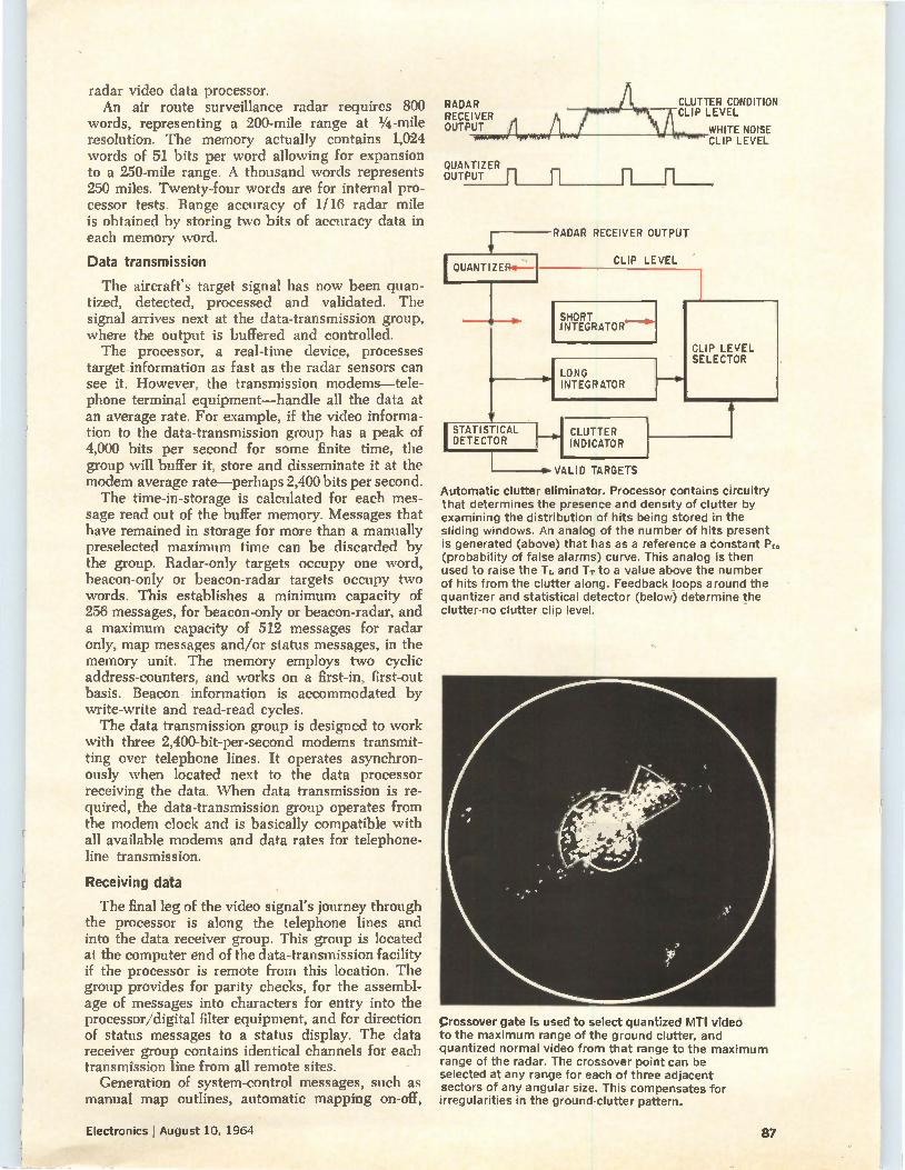
radar video data processor. An air route surveillance radar requires 800
words, representing a 200-mile range at 1/4 -mile resolution. The memory actually contains 1,024 words of 51 bits per word allowing for expansion to a 250-mile range. A thousand words represents 250 miles. Twenty-four words are for internal pro-cessor tests. Range accuracy of 1/16 radar mile is obtained by storing two bits of accuracy data in each memory word.
Data transmission
The aircraft's target signal has now been quan-tized, detected, processed and validated. The signal arrives next at the data-transmission group, where the output is buffered and controlled. The processor, a real-time device, processes
target information as fast as the radar sensors can see it. However, the transmission modems—tele-phone terminal equipment—handle all the data at an average rate. For example, if the video informa-tion to the data-transmission group has a peak of 4,000 bits per second for some finite time, the group will buffer it, store and disseminate it at the modem average rate—perhaps 2,400 bits per second. The time-in-storage is calculated for each mes-
sage read out of the buffer memory. Messages that have remained in storage for more than a manually preselected maximum time can be discarded by the group. Radar-only targets occupy one word, beacon-only or beacon-radar targets occupy two words. This establishes a minimum capacity of 256 messages, for beacon-only or beacon-radar, and a maximum capacity of 512 messages for radar only, map messages and/or status messages, in the memory unit. The memory employs two cyclic address-counters, and works on a first-in, first-out basis. Beacon information is accommodated by \'rite-write and read-read cycles. The data transmission group is designed to work
with three 2,400-bit-per-second modems transmit-ting over telephone lines. It operates asynchron-ously when located next to the data processor receiving the data. When data transmission is re-quired, the data-transmission group operates from the modem clock and is basically compatible with all available modems and data rates for telephone-line transmission.
Receiving data
The final leg of the video signal's journey through the processor is along the telephone lines and into the data receiver group. This group is located at the computer end of the data-transmission facility if the processor is remote from this location. The group provides for parity checks, for the assembl-age of messages into characters for entry into the processor/digital filter equipment, and for direction of status messages to a status display. The data receiver group contains identical channels for each transmission line from all remote sites.
Generation of system-control messages, such as manual map outlines, automatic mapping on-off,
RADAR RECEIVER OUTPUT
QUANTIZER OUTPUT
IOUANTIZER4
CLUTTER CONDITION CLIP LEVEL
WHITE NOISE CLIP LEVEL
RADAR RECEIVER OUTPUT
CLIP LEVEL
SHORT I NTEGRATOR".>
LONG INTEGRATOR
I STATISTICAL 1_41 DETECTOR
CLUTTER INDICATOR
CLIP LEV.EL SELECTOR
• VALID TARGETS
Automatic clutter eliminator. Processor contains circuitry that determines the presence and density of clutter by examining the distribution of hits being stored in the sliding windows. An analog of the number of hits present is generated (above) that has as a reference a constant Pr. (probability of false alarms) curve. This analog is then used to raise the T1. and TT to a value above the number of hits from the clutter along. Feedback loops around the quantizer and statistical detector (below-) determine the clutter-no clutter clip level.
Crossover gate is used to select quantized MTI video to the maximum range of the ground clutter, and quantized normal video from that range to the maximum range of the radar. The crossover point can be selected at any range for each of three adjacent sectors of any angular size. This compensates for irregularities in the ground-clutter pattern.
Electronics August 10, 1964 87
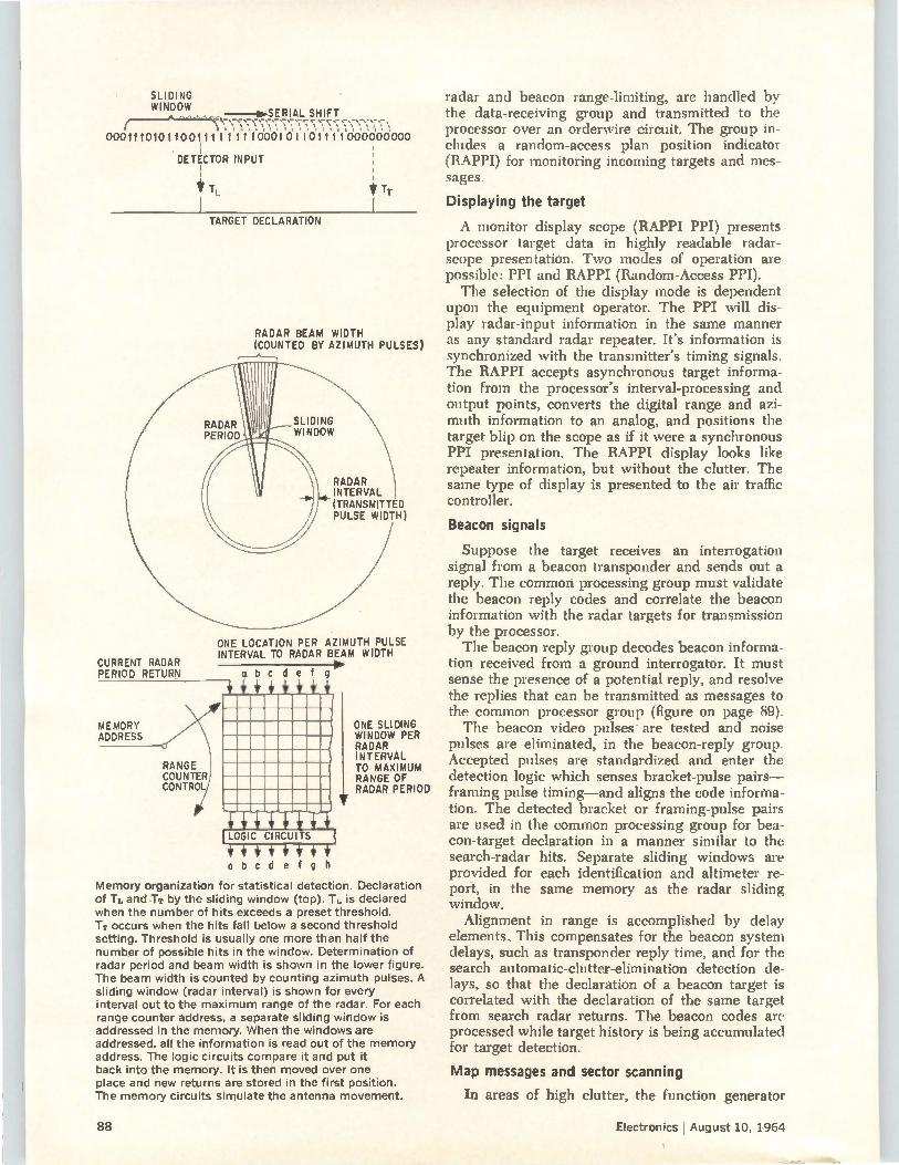
SLIDING WINDOW
-sr...SERIAL SHIFT
00011101011001111 .1Y1 .1•DDDI .D1.1.6111IDDDDC/0.000
DETECTOR INPUT
TL TT
TARGET DECLARATION
CURRENT RADAR PERIOD RETURN
MEMORY ADDRESS
RADAR PERIOD
RANGE COUNTER CONTROL
RADAR BEAM WIDTH (COUNTED BY AZIMUTH PULSES)
SLIDING WINDOW
RADAR INTERVAL (TRANSMITTED PULSE WIDTH)
ONE LOCATION PER AZIMUTH PULSE INTERVAL TO RADAR BEAM WIDTH
abode f g
ONE SLIDING WINDOW PER RADAR INTERVAL TO MAXIMUM RANGE OF RADAR PERIOD
obcdefgh
Memory organization for statistical detection. Declaration of TL andTT by the sliding window (top). Ti. is declared when the number of hits exceeds a preset threshold. TT occurs when the hits fall below a second threshold setting. Threshold is usually one more than half the number of possible hits in the window. Determination of radar period and beam width is shown in the lower figure. The beam width is counted by counting azimuth pulses. A sliding window (radar interval) is shown for every interval out to the maximum range of the radar. For each range counter address, a separate sliding window is addressed in the memory. When the windows are addressed, all the information is read out of the memory address. The logic circuits compare it and put it back into the memory. It is then moved over one place and new returns are stored in the first position. The memory circuits simulate the antenna movement.
88
radar and beacon range-limiting, are handled by the data-receiving group and transmitted to the processor over an orderwire circuit. The group in-cludes a random-access plan position indicator (RAPPI) for monitoring incoming targets and mes-sages.
Displaying the target
A monitor display scope (RAPPI PPI) presents processor target data in highly readable radar-scope presentation. Two modes of operation are possible: PPI and RAPPI (Random-Access PPI). The selection of the display mode is dependent
upon the equipment operator. The PPI will dis-play radar-input information in the same manner as any standard radar repeater. It's information is synchronized with the transmitter's timing signals. The RAPPI accepts asynchronous target informa-tion from the processor's interval-processing and output points, converts the digital range and azi-muth information to an analog, and positions the target blip on the scope as if it were a synchronous PPI presentation. The RAPPI display looks like repeater information, but without the clutter. The same type of display is presented to the air traffic controller.
Beacon signals
Suppose the target receives an interrogation signal from a beacon transponder and sends out a reply. The common processing group must validate the beacon reply codes and correlate the beacon information with the radar targets for transmission by the processor. The beacon reply group decodes beacon informa-
tion received from a ground interrogator. It must sense the presence of a potential reply, and resolve the replies that can be transmitted as messages to the common processor group (figure on page 89). The beacon video pulses are tested and noise
pulses are eliminated, in the beacon-reply group. Accepted pulses are standardized and enter the detection logic which senses bracket-pulse pairs— framing pulse timing—and aligns the code informa-tion. The detected bracket or framing-pulse pairs are used in the common processing group for bea-con-target declaration in a manner similar to the search-radar hits. Separate sliding windows are provided for each identification and altimeter re-port, in the same memory as the radar sliding window.
Alignment in range is accomplished by delay elements. This compensates for the beacon system delays, such as transponder reply time, and for the search automatic-clutter-elimination detection de-lays, so that the declaration of a beacon target is correlated with the declaration of the same target from search radar returns. The beacon codes are processed while target history is being accumulated for target detection.
Map messages and sector scanning
In areas of high clutter, the function generator
Electronics I August 10, 1964
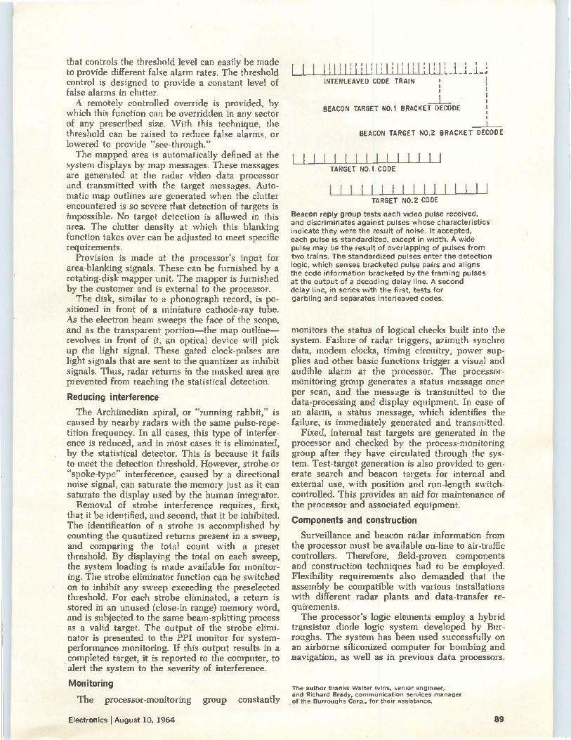
that controls the threshold level can easily be made to provide different false alarm rates. The threshold control is designed to provide a constant level of false alarms in clutter. A remotely controlled override is provided, by
which this function can be overridden in any sector of any prescribed size. With this technique. the threshold can be raised to reduce false alarms, or lowered to provide "see-through." The mapped area is automatically defined at the
system displays by map messages. These messages are generated at the radar video data processor and transmitted with the target messages. Auto-matic map outlines are generated when the clutter encountered is so severe that detection of targets is impossible. No target detection is allowed in this area. The clutter density at which this blanking function takes over can be adjusted to meet specific requirements.
Provision is made at the processor's input for area-blanking signals. These can be furnished by a rotating-disk mapper unit. The mapper is furnished by the customer and is external to the processor. The disk, similar to a phonograph record, is po-
sitioned in front of a miniature cathode-ray tube. As the electron beam sweeps the face of the scope, and as the transparent portion—the map outline— revolves in front of it, an optical device will pick up the light signal. These gated clock-pulses are light signals that are sent to the quantizer as inhibit signals. Thus, radar returns in the masked area are prevented from reaching the statistical detection.
Reducing interference
The Archimedian spiral, or "running rabbit," is caused by nearby radars with the same pulse-repe-tition frequency. In all cases, this type of interfer-ence is reduced, and in most cases it is eliminated, by the statistical detector. This is because it fails to meet the detection threshold. However, strobe or spoke-type" interference, caused by a directional
noise signal, can saturate the memory just as it can saturate the display used by the human integrator. Removal of strobe interference requires, first,
that it be identified, and second, that it be inhibited. The identification of a strobe is accomplished by counting the quantized returns present in a sweep, and comparing the total count with a preset threshold. By displaying the total on each sweep, the system loading is made available for monitor-ing. The strobe eliminator function can be switched on to inhibit any sweep exceeding the preselected threshold. For each strobe eliminated, a return is stored in an unused (close-in range) memory word, and is subjected to the same beam-splitting process as a valid target. The output of the strobe elimi-nator is presented to the PPI monitor for system-performance monitoring. If this output results in a completed target, it is reported to the computer, to alert the system to the severity of interference.
Monitoring
The processor-monitoring group constantly
I I I till. l':1 11:1i1:, I! Ill I 1,. I I. I .1.L J.
INTERLEAVED CODE TRAIN
BEACON TARGET NO.1 BRACKET DECODE
BEACON TARGET NO.2 BRACKET DECODE
1111[1111111111 TARGET NOA CODE
1111111111111111 TARGET NO.2 CODE
Beacon reply group tests each video pulse received, and discriminates against pulses whose characteristics indicate they were the result of noise. It accepted, each pulse is standardized, except in width. A wide pulse may be the result of overlapping of pulses from two trains. The standardized pulses enter the detection logic, which senses bracketed pulse pairs and aligns the code information bracketed by the framing pulses at the output of a decoding delay line. A second delay line, in series with the first, tests for garbling and separates interleaved codes.
monitors the status of logical checks built into the system. Failure of radar triggers, azimuth synchro data, modem clocks, timing circuitry, power sup-plies and other basic functions trigger a visual and audible alarm at the processor. The processor-monitoring group generates a status message once per scan, and the message is transmitted to the data-processing and display equipment. In case of an alarm, a status message, which identifies the failure, is immediately generated and transmitted.
Fixed, internal test targets are generated in the processor and checked by the process-monitoring group after they have circulated through the sys-tem. Test-target generation is also provided to gen-erate search and beacon targets for internal and external use, with position and run-length switch-controlled. This provides an aid for maintenance of the processor and associated equipment.
Components and construction
Surveillance and beacon radar information from the processor must be available on-line to air-traffic controllers. Therefore, field-proven components and construction techniques had to be employed. Flexibility requirements also demanded that the assembly be compatible with various installations with different radar plants and data-transfer re-quirements. The processor's logic elements employ a hybrid
transistor diode logic system developed by Bur-roughs. The system has been used successfully on an airborne siliconized computer for bombing and navigation, as well as in previous data processors.
The author thanks Walter lvins, senior engineer, and Richard Brady, communication services manager of the Burroughs Corp., for their assistance.
Electronics I August 10, 1964 89
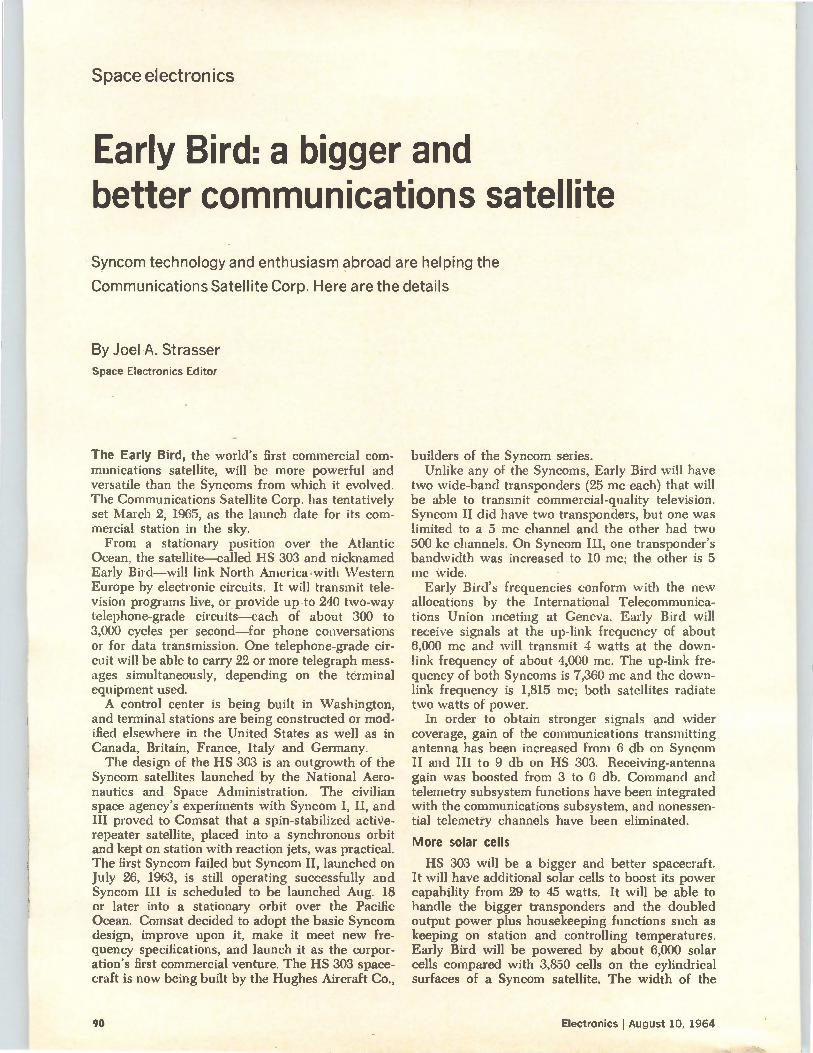
Space electronics
Early Bird: a bigger and better communications satellite
Syncom technology and enthusiasm abroad are helping the
Communications Satellite Corp. Here are the details
By Joel A. Strasser Space Electronics Editor
The Early Bird, the world's first commercial com-munications satellite, will be more powerful and versatile than the Syncoms from which it evolved. The Communications Satellite Corp. has tentatively set March 2, 1965, as the launch date for its com-mercial station in the sky. From a stationary position over the Atlantic
Ocean, the satellite—called HS 303 and nicknamed Early Bird—will link North America•with Western Europe by electronic circuits. It will transmit tele-vision programs live, or provide up to 240 two-way telephone-grade circuits—each of about 300 to 3,000 cycles per second—for phone conversations or for data transmission. One telephone-grade cir-cuit will be able to carry 22 or more telegraph mess-ages simultaneously, depending on the terminal equipment used. A control center is being built in Washington,
and terminal stations are being constructed or mod-ified elsewhere in the United States as well as in Canada, Britain, France, Italy and Germany. The design of the HS 303 is an outgrowth of the
Syncom satellites launched by the National Aero-nautics and Space Administration. The civilian space agency's experiments with Syncom I, II, and III proved to Comsat that a spin-stabilized active-repeater satellite, placed into a synchronous orbit and kept on station with reaction jets, was practical. The first Syncom failed but Syncom II, launched on July 26, 1963, is still operating successfully and Syncom III is scheduled to be launched Aug. 18 or later into a stationary orbit over the Pacific Ocean. Comsat decided to adopt the basic Syncom design, improve upon it, make it meet new fre-quency specifications, and launch it as the corpor-ation's first commercial venture. The HS 303 space-craft is now being built by the Hughes Aircraft Co.,
builders of the Syncom series. Unlike any of the Syncoms, Early Bird will have
two wide-band transponders (25 mc each) that will be able to transmit commercial-quality television. Syncom II did have two transponders, but one was limited to a 5 me channel and the other had two 500 kc channels. On Syncom III, one transponder's bandwidth was increased to 10 mc; the other is 5 me wide.
Early Bird's frequencies conform with the new allocations by the International Telecommunica-tions Union meeting at Geneva. Early Bird will receive signals at the up-link frequency of about 6,000 mc and will transmit 4 watts at the down-link frequency of about 4,000 mc. The up-link fre-quency of both Syncoms is 7,360 mc and the down-link frequency is 1,815 me; both satellites radiate two watts of power.
In order to obtain stronger signals and wider coverage, gain of the communications transmitting antenna has been increased from 6 db on Syncom II and III to 9 db on HS 303. Receiving-antenna gain was boosted from 3 to 6 db. Command and telemetry subsystem functions have been integrated with the communications subsystem, and nonessen-tial telemetry channels have been eliminated.
More solar cells
HS 303 will be a bigger and better spacecraft. It will have additional solar cells to boost its power capability from 29 to 45 watts. It will be able to handle the bigger transponders and the doubled output power plus housekeeping functions such as keeping on station and controlling temperatures. Early Bird will be powered by about 6,000 solar cells compared with 3,850 cells on the cylindrical surfaces of a Syncom satellite. The width of the
90 Electronics I August 10, 1964
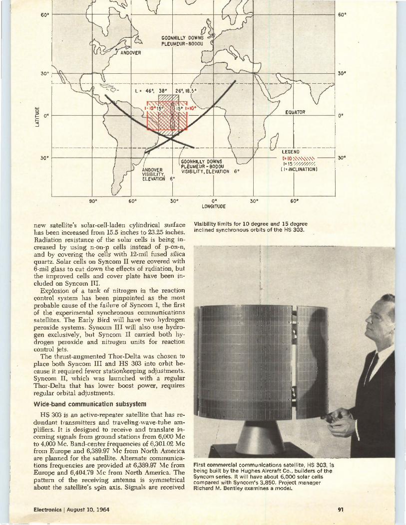
60°
30°
30 °
V
ANDOVER
GOONHILLY PLEUMEUR-BODOU
0 DOWNS
r... NO» L . 46°,
1.1015°
38° 26°, 18.5°
EQUATOR 15° 1.10*
LEGEND
ANDOVER VISIBILITY , ELEVATION 6°
I
GOONHILLY DOWNS PLEUMEUR - BODOU VISIBILITY, ELEVATION 6° (I. INCLINATION 1
90° 60° 30°
new satellite's solar-cell-laden cylindrical surface has been increased from 15.5 inches to 23.25 inches. Radiation resistance of the solar cells is being in-creased by using n-on-p cells instead of p-on-n, and by covering the cells with 12-mil fused silica quartz. Solar cells on Syncom II were covered with 6-mil glass to cut down the effects of radiation, but the improved cells and cover plate have been in-cluded on Syncom III.
Explosion of a tank of nitrogen in the reaction control system has been pinpointed as the most probable cause of the failure of Syncom I, the first of the experimental synchronous communications satellites. The Early Bird will have two hydrogen peroxide systems. Syncom III will also use hydro-gen exclusively, but Syncom II carried both hy-drogen peroxide and nitrogen units for reaction control jets. The thrust-augmented Thor-Delta was chosen to
place both Syncom III and HS 303 into orbit be-cause it required fewer stationkeeping adjustments. Syncom II, which was launched with a regular Thor-Delta that has lower boost power, requires regular orbital adjustments.
Wide-band communication subsystem
HS 303 is an active-repeater satellite that has re-dundant transmitters and traveling-wave-tube am-plifiers. It is designed to receive and translate in-coming signals from ground stations from 6,000 Mc to 4,000 Mc. Band-center frequencies of 6,301.02 Mc from Europe and 6,389.97 Mc from North America are planned for the satellite. Alternate communica-tions frequencies are provided at 6,389.97 Mc from Europe and 6,404.79 Mc from North America. The pattern of the receiving antenna is symmetrical about the satellite's spin axis. Signals are received
0° LONGITUDE
30° 60°
Visibility limits for 10 degree and 15 degree inclined synchronous orbits of the HS 303.
First commercial communications satellite, HS 303, is being built by the Hughes Aircraft Co., builders of the Syncom series. It will have about 6,000 solar cells compared with Syncom's 3,850. Project manager Richard M. Bentley examines a model.
60°
30°
0°
30°
Electronics August 10, 1964 91
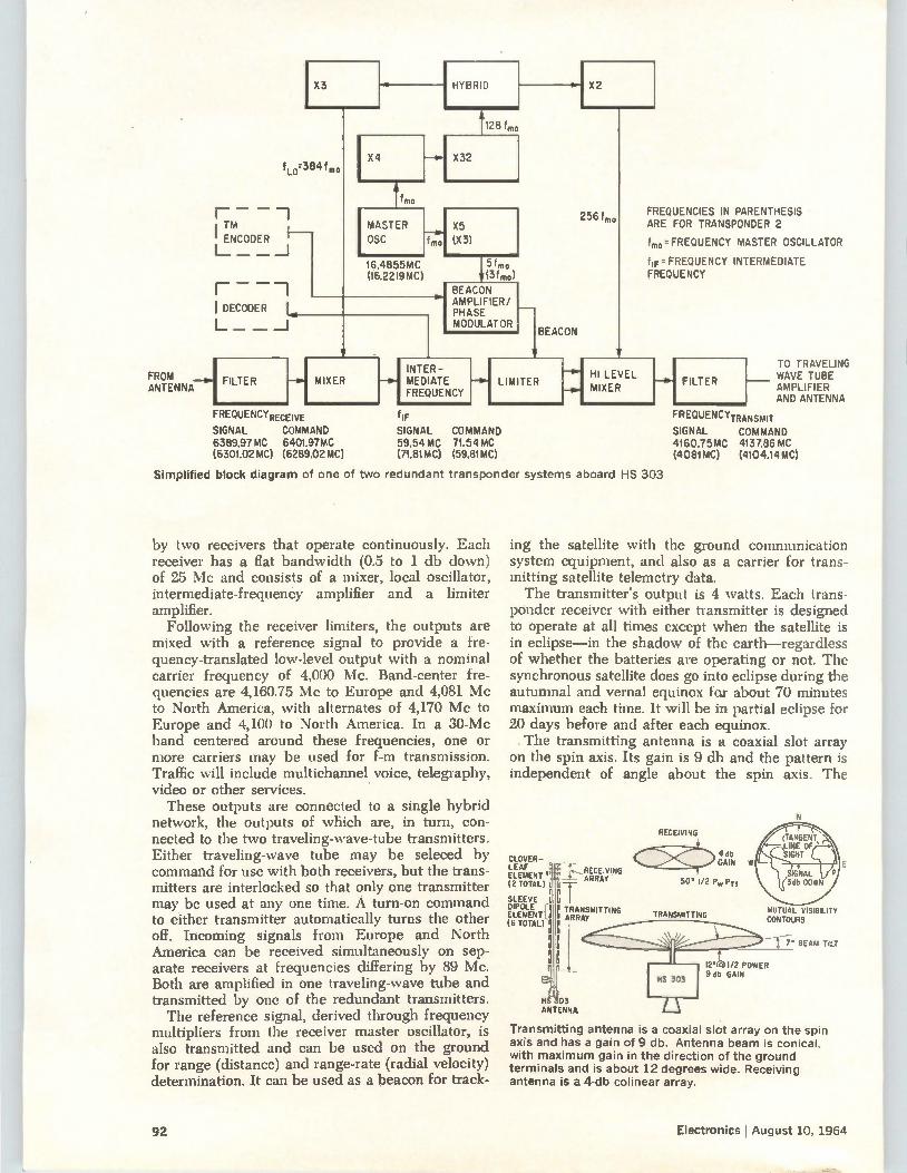
f10.384 fm°
r TM
I ENCODER I—
t— — _J
1— I DECODER
FROM FILTER ANTENNA
—01 MIXER
FREQUENCYRECEIVE
SIGNAL COMMAND 6389.97 MC 6401.97MC (630102 MC) (6289.02 MC)
f MO
128 f mo
5 f mo (340)
BEACON AMPL FIER/ PHASE MODULATOR
INTER-MEDIATE FREQUENCY
BEACON
LIMITER
f IF
SIGNAL COMMAND 59.54 MC 71.54 MC (71.81MC) (59.81MC)
X2
256 4, FREQUENCIES IN PARENTHESIS ARE FOR TRANSPONDER 2
tmo FREQUENCY MASTER OSCILLATOR
f IF. FREQUENCY INTERMEDIATE FREQUENCY
HI LEVEL MIXER
Simplified block diagram of one of two redundant transponder systems aboard
by two receivers that operate continuously. Each receiver has a flat bandwidth (0.5 to 1 db down) of 25 Mc and consists of a mixer, local oscillator, intermediate-frequenCy amplifier and a limiter amplifier. Following the receiver limiters, the outputs are
mixed with a reference signal to provide a fre-quency-translated low-level output with a nominal carrier frequency of 4,000 Mc. Band-center fre-quencies are 4,160.75 Mc to Europe and 4,081 Mc to North America, with alternates of 4,170 Mc to Europe and 4,100 to North America. In a 30-Mc band centered around these frequencies, one or more carriers may be used for f-m transmission. Traffic will include multichannel voice, telegraphy, video or other services. These outputs are connected to a single hybrid
network, the outputs of which are, in turn, con-nected to the two traveling-wave-tube transmitters. Either traveling-wave tube may be seleced by command for use with both receivers, but the trans-mitters are interlocked so that only one transmitter may be used at any one time. A turn-on command to either transmitter automatically turns the other off. Incoming signals from Europe and North America can be received simultaneously on sep-arate receivers at frequencies differing by 89 Mc. Both are amplified in one traveling-wave tube and transmitted by one of the redundant transmitters. The reference signal, derived through frequency
multipliers from the receiver master oscillator, is also transmitted and can be used on the ground for range (distance) and range-rate (radial velocity) determination. It can be used as a beacon for track-
HS 303
FILTER
TO TRAVELING WAVE TUBE AMPLIFIER AND ANTENNA
FREQUENCYTRANSMIT SIGNAL COMMAND 4160.75MC 4137.86 MC (4081MC) (4104.14MC)
ing the satellite with the ground communication system equipment, and also as a carrier for trans-mitting satellite telemetry data. The transmitter's output is 4 watts. Each trans-
ponder receiver with either transmitter is designed to operate at all times except when the satellite is in eclipse—in the shadow of the earth—regardless of whether the batteries are operating or not. The synchronous satellite does go into eclipse during the autumnal and vernal equinox far about 70 minutes maximum each time. It will be in partial eclipse for 20 days before and after each equinox. The transmitting antenna is a coaxial slot array
on the spin axis. Its gain is 9 db and the pattern is independent of angle about the spin axis. The
CLOVER— LEAF ELEMENT' (2 TOTAL)
SLEEVE DIPOLE ELEMENT 01 (6 TOTAL)
RECEIVING ARRAY
TRANSMITTING ARRAY
H 03 ANTENNA
RECEIVING
GAIN
50 1/2 Pvi PTs
TRANSMITTING MUTUAL VISIBILITY CONTOURS
I2' 1/2 POWER 9 db GAIN
7" BEAM TILT
Transmitting antenna is a coaxial slot array on the spin axis and has a gain of 9 db. Antenna beam is conical, with maximum gain in the direction of the ground terminals and is about 12 degrees wide. Receiving antenna is a 4-db colinear array.
92 Electronics August 10, 1964
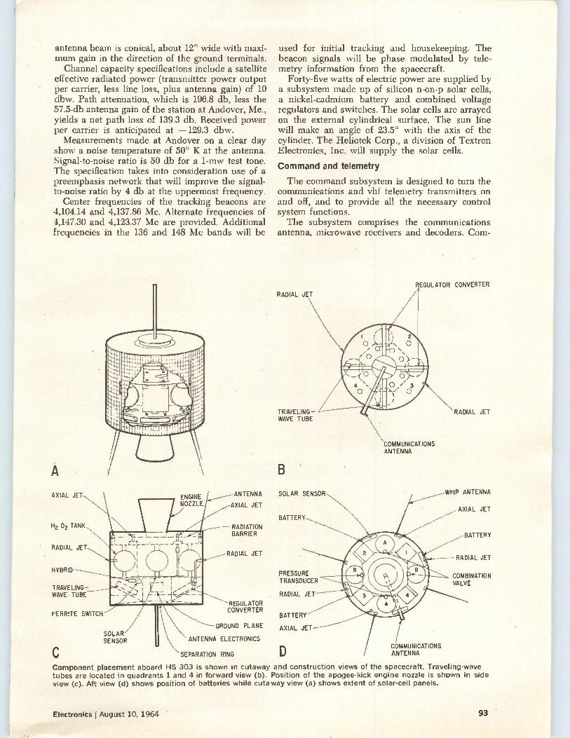
antenna beam is conical, about 12° wide with maxi-mum gain in the direction of the ground terminals. Channel capacity specifications include a satellite
effective radiated power (transmitter power output per carrier, less line loss, plus antenna gain) of 10 dbw. Path attenuation, which is 196.8 db, less the 57.5-db antenna gain of the station at Andover, Me., yields a net path loss of 139.3 db. Received power per carrier is anticipated at —129.3 dbw. Measurements made at Andover on a clear day
show a noise temperature of 50° K at the antenna. Signal-to-noise ratio is 50 db for a 1-mw test tone. The specification takes into consideration use of a preemphasis network that will improve the signal-to-noise ratio by 4 db at the uppermost frequency.
Center frequencies of the tracking beacons are 4,104.14 and 4,137.86 Mc. Alternate frequencies of 4,147.30 and 4,123.37 Mc are provided. Additional frequencies in the 136 and 148 Mc bands will be
AXIAL JET
H2 02 TANK
RADIAL JET
HYBRID
TRAVELING-WAVE TUBE
FERRITE SWITCH
SOLAR SENSOR
ENGINE NOZZLE
ANTENNA
AXIAL JET
RADIATION BARRIER
RADIAL JET
REGULATOR CONVERTER
GROUND PLANE
ANTENNA ELECTRONICS
SEPARATION RING
used for initial tracking and housekeeping. The beacon signals will be phase modulated by tele-metry information from the spacecraft.
Forty-five watts of electric power are supplied by a subsystem made up of silicon n-on-p solar cells, a nickel-cadmium battery and combined voltage regulators and switches. The solar cells are arrayed on the external cylindrical surface. The sun line will make an angle of 23.5° with the axis of the cylinder. The Heliotek Corp., a division of Textron Electronics, Inc. will supply the solar cells.
Command and telemetry
The command subsystem is designed to turn the communications and vhf telemetry transmitters on and off, and to provide all the necessary control system functions. The subsystem comprises the communications
antenna, microwave receivers and decoders. Com-
RADIAL JET
TRAVELING-WAVE TUBE
COMMUNICATIONS ANTENNA
SOLAR SENSOR
BATTERY
PRESSURE TRANSDUCER
RADIAL JET
BATTERY
AXIAL JET
() COMMUNICATIONS ANTENNA
REGULATOR CONVERTER
RADIAL JET
WHIP ANTENNA
AXIAL JET
BATTERY
RADIAL JET
COMBINATION VALVE
Component placement aboard HS 303 is shown in cutaway and construction views of the spacecraft. Traveling-wave tubes are located in quadrants 1 and 4 in forward view (b). Position of the apogee-kick engine nozzle is shown in side view (c). Aft view (d) shows position of batteries while cutaway view (a) shows extent of solar-cell panels.
Electronics I August 10, 1964 93
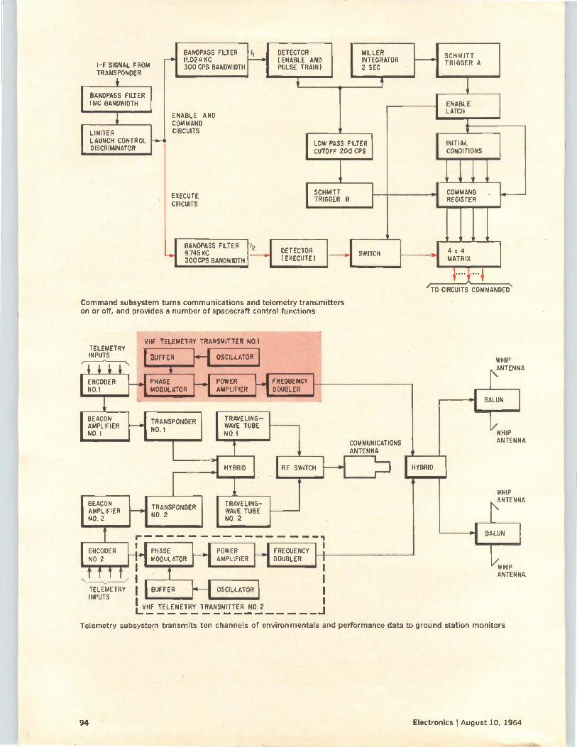
I-F SIGNAL FROM TRANSPONDER
BANDPASS FILTER 1MC BANDWIDTH
LIMITER LAUNCH CONTROL DISCRIMINATOR
BANDPASS FILTER 11.024 KC 300 CPS BANDWIDTH
ENABLE AND COMMAND CIRCUITS
EXECUTE CIRCUITS
1 BANDPASS FILTER 9.745 KC 300CPS BANDWIDTH
ft
f2
DETECTOR ( ENABLE AND PULSE TRAIN)
MILLER INTEGRATOR 2 SEC
LOW PASS FILTER CUTOFF 200 CPS
SCHMITT TRIGGER B
SCHMITT TRIGGER A
ENABLE LATCH
INITIAL CONDITIONS
DETECTOR (EXECUTE)
Command subsystem turns communications and telemetry transmitters on or off, and provides a number of spacecraft control functions
TELEMETRY INPUTS I SUFFER
VHF TELEMETRY TRANSMITTER NO.
IBEACON , TRANSPONDER AMPLIFIER NO.1 NO.1
41-1 OSCILLATOR
ENCODER PHASE H POWER NO.1 L MODULATOR AMPLIFIER
T
FREQUENCY DOUBLER
BEACON AMPLIFIER NO. 2
4
ENCODER NO. 2
TELEMETRY IN
L -VHF
1 TRANSPONDER NO. 2
TRAVELING-WAVE TUBE NO.1
TRAVELING-WAVE TUBE NO. 2
POWER AMPLIFIER
OSCILLATOR
TELEMETRY TRANSMITTER NO.2
FREQUENCY , DOUBLER
— I
SWITCH
COMMAND REGISTER
COMMUNICATIONS ANTENNA
HYBRID RF SWITCH HYBRID ,
4 x 4 MATRIX
N /TO CIRCUITS COMMANDED
WHIP .,ANTENNA
Le WHIP ANTENNA
WHIP N ANTENNA
BALUN
Li WHIP ANTENNA
Telemetry subsystem transmits ten channels of environmentals and performance data to ground station monitors
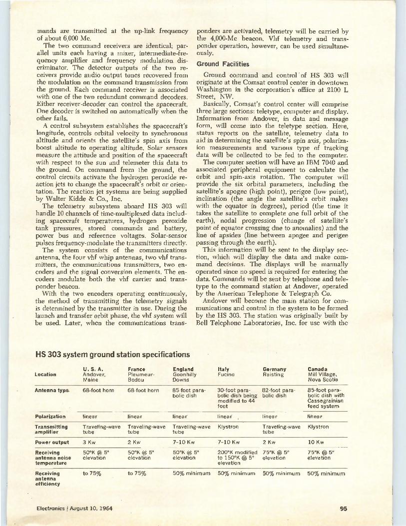
mands are transmitted at the up-link frequency of about 6,000 Mc. The two command receivers are identical; par-
allel units each having a mixer, intermediate-fre-quency amplifier and frequency modulation dis-criminator. The detector outputs of the two re-ceivers provide audio output tones recovered from the modulation on the command transmission from the ground. Each command receiver is associated with one of the two redundant command decoders. Either receiver-decoder can control the spacecraft. One decoder is switched on automatically when the other fails. A control subsystem establishes the spacecraft's
longitude, controls orbital velocity to synchronous altitude and orients the satellite's spin axis from boost altitude to operating altitude. Solar sensors measure the attitude and position of the spacecraft with respect to the sun and telemeter this data to the ground. On command from the ground, the control circuits activate the hydrogen peroxide re-action jets to change the spacecraft's orbit or orien-tation. The reaction jet systems are being supplied by Walter Kidde & Co., Inc. The telemetry subsystem aboard HS 303 will
handle 10 channels of time-multiplexed data includ-ing spacecraft temperatures, hydrogen peroxide tank pressures, stored commands and battery, power bus and reference voltages. Solar-sensor pulses frequency-modulate the transmitters directly. The system consists of the communications
antenna, the four vhf whip antennas, two vhf trans-mitters, the communications transmitters, two en-coders and the signal conversion elements. The en-coders modulate both the vhf carrier and trans-ponder beacon. With the two encoders operating continuously,
the method of transmitting the telemetry signals is determined by the transmitter in use. During the launch and transfer orbit phase, the vhf system will be used. Later, when the communications trans-
HS 303 system ground station specifications
Location U. S. A. Andover, Maine
France Pleumeur-Bodou
ponders are activated, telemetry will be carried by the 4,000-Mc beacon. Vhf telemetry and trans-ponder operation, however, can be used simultane-ously.
Ground Facilities
Ground command and control" of HS 303 will originate at the Comsat control center in downtown Washington in the corporation's office at 2100 L Street, NW.
Basically, Comsat's control center will comprise three large sections: teletype, computer and display. Information from Andover, in data and message form, will come into the teletype section. Here, status reports on the satellite, telemetry data to aid in determining the satellite's spin axis, polariza-ion measurements and various type of tracking data will be collected to be fed to the computer. The computer section will have an IBM 7040 and
associated peripheral equipment to calculate the orbit and spin-axis rotation. The computer will provide the six orbital parameters, including the satellite's apogee (high point), perigee (low point), inclination (the angle the satellite's orbit makes with the equator in degrees), period (the time it takes the satellite to complete one full orbit of the earth), nodal progression (change of satellite's point of equator crossing due to anomalies) and the line of apsides (line between apogee and perigee passing through the earth).
This information will be sent to the display sec-tion, which will display the data and make com-mand decisions. The displays will be manually operated since no speed is required for entering the data. Commands will be sent by telephone and tele-type to the command station at Andover, operated by the American Telephone & Telegraph Co. Andover will become the main station for com-
munications and control in the system to be formed by the HS 303. The station was originally built by Bell Telephone Laboratories, Inc. for use with the
England Goonhilly Downs
Italy Fucino
Germany Raisting
Canada Mill Village, Nova Scotia
Antenna type 68-foot horn 68-foot horn 85-foot para- 30-foot para- 82-foot para-bolic dish bolic dish being bolic dish
modified to 44 foot
85-foot para-bolic dish with Cassegrainian feed system
Polarization linear linear linear linear linear linear
Transmitting amplifier
Traveling-wave Traveling-wave Traveling-wave Klystron Traveling-wave Klystron tube tube tube tube
Power output 3 Kw 2 Kw 7-10 Kw 7-10 Kw 2 Kw 10 Kw
Receiving antenna noise temperature
50°K @ 5° elevation
50°K @ 5° 50°K @ 5° elevation elevation
200°K modified 75°K et 5° 75°K @ 5° to 150°K @ 5° elevation elevation elevation
Receiving antenna efficiency
to 75% to 75% 50% minimum 50% minimum 50% minimum 50% minimum
Electronics !August 10, 1964 95
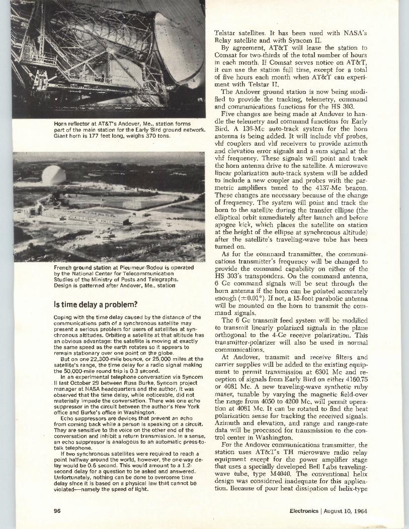
Horn reflector at AT&T's Andover, Me., station forms part of the main station for the Early Bird ground network. Giant horn is 177 feet long, weighs 370 tons.
French ground station at Pleumeur-Bodou is operated by the National Center for Telecommunication Studies of the Ministry of Posts and Telegraphs. Design is patterned after Andover, Me., station
Is time delay a problem?
Coping with the time delay caused by the distance of the communications path of a synchronous satellite may present a serious problem for users of satellites at syn-chronous altitudes. Orbiting a satellite at that altitude has an obvious advantage: the satellite is moving at exactly the same speed as the earth rotates so it appears to remain stationary over one point on the globe.
But on one 22,300-mile bounce, or 25,000 miles at the satellite's range, the time delay for a radio signal making the 50,000-mile round trip is 0.3 second.
In an experimental telephone conversation via Syncom II last October 29 between Russ Burke, Syncom project manager at NASA headquarters and the author, it was observed that the time delay, while noticeable, did not materially impede the conversation. There was one echo suppressor in the circuit between the author's New York office and Burke's office in Washington.
Echo suppressors are devices that prevent an echo from coming back while a person is speaking on a circuit. They are sensitive to the voice on the other end of the conversation and inhibit a return transmission. In a sense, an echo suppressor is analogous to an automatic press-to-talk telephone.
If two synchronous satellites were required to reach a point halfway around the world, however, the one-way de-lay would be 0.6 second. This would amount to a 1.2-second delay for a question to be asked and answered. Unfortunately, nothing can be done to overcome time delay since it is based on a physical law that cannot be violated—namely the speed of light.
Telstar satellites. It has been used with NASA's Relay satellite and with Syncom II. By agreement, AT&T will lease the station to
Comsat for two-thirds of the total number of hours in each month. If Comsat serves notice on AT&T, it can use the station full time, except for a total of five hours each month when AT&T can experi-ment with Telstar II. The Andover ground station is now being modi-
fied to provide the tracking, telemetry, command and communications functions for the HS 303.
Five changes are being made at Andover to han-dle the telemetry and command functions for Early Bird. A 136-Mc auto-track system for the horn antenna is being added. It will include vhf probes, vhf couplers and vhf receivers to provide azimuth and elevation error signals and a sum signal at the vhf frequency. These signals will point and track the horn antenna drive to the satellite. A microwave linear polarization auto-track system will be added to include a new coupler and probes with the par-metric amplifiers tuned to the 4137-Mc beacon. These changes are necessary because of the change of frequency. The system will point and track the horn to the satellite during the transfer ellipse (the elliptical orbit immediately after launch and before apogee kick, which places the satellite on station at the height of the ellipse at synchronous altitude) after the satellite's traveling-wave tube has been turned on. As for the command transmitter, the communi-
cations transmitter's frequency will be changed to provide the command capability on either of the HS 303's transponders. On the command antenna, 6 Ge command signals will be sent through the horn antenna if the horn can be pointed accurately enough (±0.01°). If not, a 15-foot parabolic antenna will be mounted on the horn to transmit the com-mand signals. The 6 Cc transmit feed system will be modified
to transmit linearly polarized signals in the plane orthogonal to the 4-Cc receive polarization. This transmitter-polarizer will also be used in normal communications. At Andover, transmit and receive filters and
carrier supplies will be added to the existing equip-ment to permit transmission at 6301 Mc and re-ception of signals from Early Bird on either 4160.75 or 4081 Mc. A new traveling-wave synthetic ruby maser, tunable by varying the magnetic field-over the range from 4050 to 4200 Mc, will permit opera-tion at 4081 Mc. It can be rotated to find the best polarization sense for tracking the received signals. Azimuth and elevation, and range and range-rate data will be processed for transmission to the con-trol center in Washington. For the Andover communications transmitter, the
station uses AT&T's TH microwave radio relay equipment except for the power amplifier stage that uses a specially developed Bell Labs traveling-wave tube, type M4040. The conventional helix design was considered inadequate for this applica-tion. Because of poor heat dissipation of helix-type
96 Electronics August 10, 1964
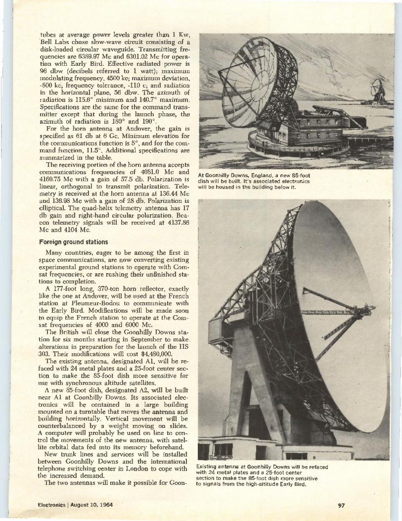
tubes at average power levels greater than 1 Kw, Bell Labs chose slow-wave circuit consisting of a disk-loaded circular waveguide. Transmitting fre-quencies are 6389.97 Mc and 6301.02 Mc for opera-tion with Early Bird. Effective radiated power is 96 dbw (decibels referred to 1 watt); maximum modulating frequency, 4500 kc; maximum deviation, -800 kc; frequency tolerance, -110 c; and radiation in the horizontal plane, 56 dbw. The azimuth of radiation is 115.6° minimum and 140.7° maximum. Specifications are the same for the command trans-mitter except that during the launch phase, the azimuth of radiation is 180° and 190°.
For the horn antenna at Andover, the gain is specified as 61 db at 6 Cc. Minimum elevation for the communications function is 5°, and for the com-mand function, 11.5°. Additional specifications are summarized in the table. The receiving portion of the horn antenna accepts
communications frequencies of 4081.0 Mc and 4160.75 Mc with a gain of 57.5 db. Polarization is linear, orthogonal to transmit polarization. Tele-metry is received at the horn antenna at 136.44 Mc and 136.98 Mc with a gain of 28 db. Polarization is elliptical. The quad-helix telemetry antenna has 17 db gain and right-hand circular polarization. Bea-con telemetry signals will be received at 4137.86 Mc and 4104 Mc.
Foreign ground stations
Many countries, eager to be among the first in space communications, are now converting existing experimental ground stations to operate with Com-sat frequencies, or are rushing their unfinished sta-tions to completion. A 177-foot long, 370-ton horn reflector, exactly
like the one at Andover, will be used at the French station at Pleumeur-Bodou to communicate with the Early Bird. Modifications will be made soon to equip the French station to operate at the Corn-sat frequencies of 4000 and 6000 Mc. The British will close the Goonhilly Downs sta-
tion for six months starting in September to make alterations in preparation for the launch of the HS 303. Their modifications will cost $4,480,000. The existing antenna, designated Al, will be re-
faced with 24 metal plates and a 25-foot center sec-tion to make the 85-foot dish more sensitive for use with synchronous altitude satellites. A new 85-foot dish, designated A2, will be built
near Al at Goonhilly Downs. Its associated elec-tronics will be contained in a large building mounted on a turntable that moves the antenna and building horizontally. Vertical movement will be counterbalanced by a weight moving on slides. A computer will probably be used on line to con-trol the movements of the new antenna, with satel-lite orbital data fed into its memory beforehand. New trunk lines and services will be installed
between Goonhilly Downs and the international telephone switching center in London to cope with the increased demand. The two antennas will make it possible for Goon-
At Goonhilly Downs, England, a new 85-foot dish will be built. It's associated electronics will be housed in the building below it.
Existing antenna at Goonhilly Downs will be refaced with 24 metal plates and a 25-foot center section to make the 85-foot dish more sensitive to signals from the high-altitude Early Bird.
Electronics I August 10, 1964 97
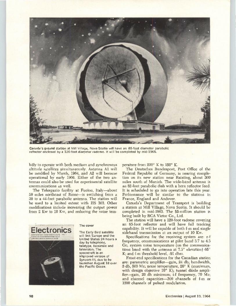
Canada's ground station at Mill Village, Nova Scotia will have an 85-foot diameter parabolic reflector enclosed by a 120-foot diameter radome. It will be completed by mid-1965.
hilly to operate with both medium and synchronous altitude satellites simultaneously. Antenna Al will be modified by March, 1964, and A2 will become operational by early 1966. Either of the two an-tennas could also be used for experimental satellite communications as well. The Telespazio facility at Fucino, Italy—about
50 miles northeast of Rome—is switching from a 30 to a 44-foot parabolic antenna. The station will be used to a limited extent with HS 303. Other modifications include increasing the output power from 2 Kw to 10 Kw, and reducing the noise tern-
Electronics Deaé«.4 regete pa,g, 42 A 6.01.10*Pf Ore te5e11: page 48
t d.iet el" eliKe 131
The cover
The Early Bird satellite will link Europe and the United States 24 hours a day by telephone, teletype, facsimile and television. The spacecraft is an improved version of Syncom Ill, due to be launched August 18 over the Pacific Ocean.
perature from 200° K to 150° K. The Deutsches Bundespost, Post Office of the
Federal Republic of Germany, is nearing comple-tion on its new station near Raisting, about 300 miles south of Munich. The wide-band antenna is an 82-foot parabolic dish with a horn reflector feed. It is scheduled to go into operation late this year. Performance will be similar to the stations in France, England and Andover.
Canada's Department of Transport is building a station at Mill Village, Nova Scotia. It should be completed in mid-1965. The $5-million station is being built by RCA Victor Co., Ltd. The station will have a 120-foot radome covering
an 85-foot reflector and will have full tracking capability. It will be capable of both f-m and single sideband transmission at an output of 10 Kw.
Specifications for the receiving system are: r-f frequency, communications at pilot band 3.7 to 4.3 Cc; system noise temperature (on the communica-tions band with the antenna at 7.5° elevation) 65° K; and f-m threshold level, -91 dbm. Front-end specifications for the Canadian station
are: parametric amplifier—gain, 24 db; bandwidth, 3 db, 500 Mc; noise temperature, 20° K (maximum, with design objective 10° K); tunnel diode ampli-fier—gain, 20 db minimum; i-f frequency, 70 Mc; and channel capacities-300 channels of f-m or 1200 channels of pulsed modulation.
98 Electronics I August 10, 1964
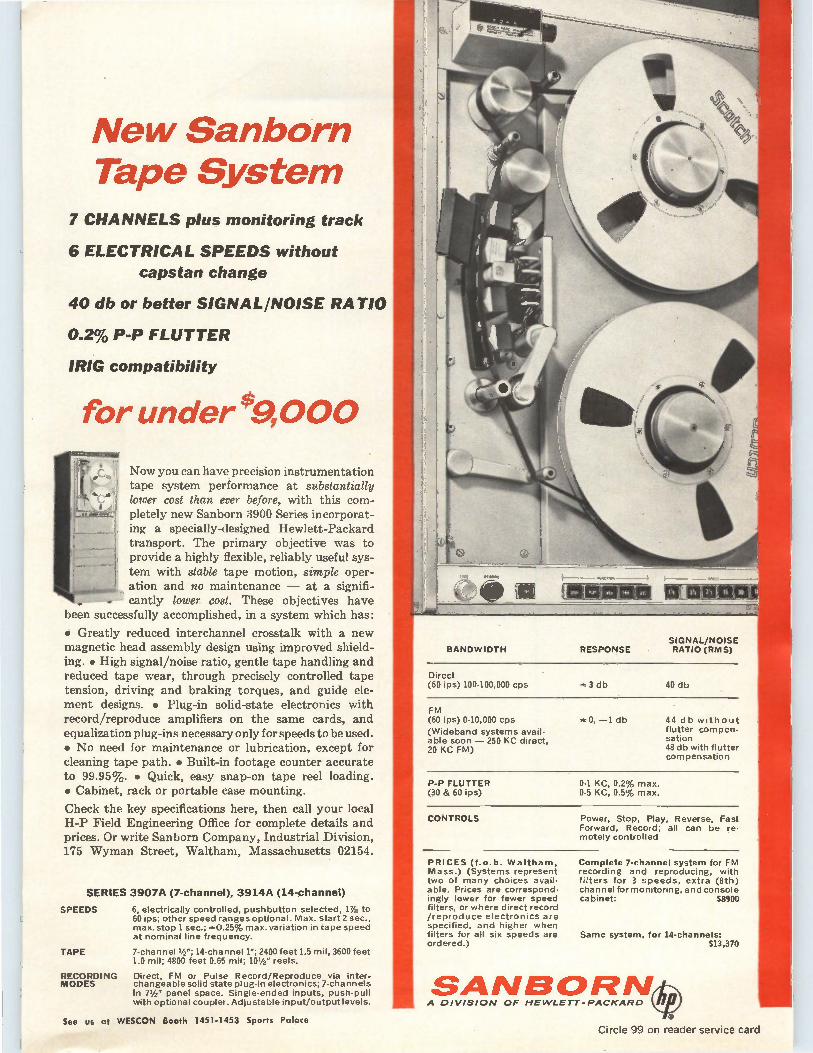
New Sanborn Tape System
7 CHANNELS plus monitoring track
6 ELECTRICAL SPEEDS without capstan change
40 db or better SIGNAL/NOISE RATIO
0.2% P-P FLUTTER
1RIG compatibility
for under s9,000 ueZEILUI=Clali
,
Now you can have precision instrumentation tape system performance at substantially
t lower cost than ever before, with this com-pletely new Sanborn 3900 Series incorporat-ing a specially-designed Hewlett-Packard transport. The primary objective was to provide a highly flexible, reliably useful sys-tem with stable tape motion, simple oper-ation and no maintenance — at a signifi-cantly lower cost. These objectives have
been successfully accomplished, in a system which has:
• Greatly reduced interchannel crosstalk with a new magnetic head assembly design using improved shield-ing. • High signal/noise ratio, gentle tape handling and reduced tape wear, through precisely controlled tape tension, driving and braking torques, and guide ele-ment designs. • Plug-in solid-state electronics with record/reproduce amplifiers on the same cards, and equalization plug-ins necessary only for speeds to be used. • No need for maintenance or lubrication, except for cleaning tape path. • Built-in footage counter accurate to 99.95%. • Quick, easy snap-on tape reel loading. • Cabinet, rack or portable case mounting.
Check the key specifications here, then call your local H-P Field Engineering Office for complete details and prices. Or write Sanborn Company, Industrial Division, 175 Wyman Street, Waltham, Massachusetts 02154.
SERIES 3907A (7-channel), 3914A (14-channel)
SPEEDS 6, electrically controlled, pushbutton selected, 1%8 to 60 ips; other speed ranges optional. Max. start 2 sec., max. stop 1 sec.; *0.25% max. variation in tape speed at nominal line frequency.
TAPE 7-channel 1/2 "; 14-channel 1"; 2400 feet 1.5 mil, 3600 feet 1.0 mil; 4800 feet 0.65 mil; 101/2 " reels.
RECORDING Direct, FM or Pulse Record/Reproduce via inter. MODES changeable solid state plug-in electronics; 7-channels
in 71/2- panel space. Single-ended inputs, push-pull with optional coupler. Adjustable input/output levels.
Direct (60 ips) 100-100,000 cps *3 db 40 db
FM (60 ips) 0-10,000 cps
(Wideband systems avail-able soon — 250 KC direct, 20 KC FM)
*0, —1 db 44 db without flutter compen-sation 48 db with flutter compensation
P-P FLUTTER (30 & 60 ips)
0-1 KC, 0.2% max. 0-5 KC, 0.5% max.
CONTROLS Power, Stop, Play, Reverse, Fast Forward, Record; all can be re-motely controlled
PRICES (f.o.b. Waltham, Mass.) (Systems represent two of many choices avail-able. Prices are correspond-ingly lower for fewer speed filters, or where direct record /reproduce electronics are specified, and higher when filters for all six speeds are ordered.)
Complete 7-channel system for FM recording and reproducing, with filters for 3 speeds, extra (8th) channel for monitoring, and console cabinet: $8900
Same system, for 14-channels: $13,370
SANBORN A DIVISION OF HEWLETT-PACKARD
See us at WESCON Booth 14514453 Sports Palace Circle 99 on reader service card

Il
CONTROL
1$,
TELEMETRY GUIDANCE
FAIRCHILD Elf*CAN MEET YOUR TOUGHEST SPECS
Practical evidence of Fairchild E•S•P* capability for meeting tough gyro specs is found in the broad array of Fairchild gyro packages and rate switches now in service.
Fairchild's three-axis rate gyro telemetry system, for example, is the smallest, lightest package of its kind. Solid state inverters and demodulators are included in the package where required to provide DC performance while maintaining the high linearity, low friction and noise characteristics of the AC gyros.
These gyro packages are built around service-proven sub-miniature floated rate gyros—the smallest, lightest production units made. Maximum rates from 5°/sec to 5000°/sec, threshold rates as low as 0.01 °/sec, 150g shock, 30g sinusoidal and 8g2 random vibration. Small size and high performance permits ready combination in multi-axis groups, or with Fairchild acceleration sensors, into miniature
measurement or control packages to your exact requirements. Self test is available. Call or write to have Fairchild E•SeP put its gyro experience at your service today.
MAI RCHI LD c o ; A DIVISION OF FAIRCHILD CAMERA AND INSTRUMENT CORPORATION
225 PARK AVENUE, HICKSVILLE, L. I., NEW YORK
TELEPHONE: (516) WE 8-5600 • TWX: 516 433-9146
E•S•12 Is the Fairchild Controls concept of Integrated Engineering, Service and Production that assures highest --/V performance and reliability in your specific application. Write for brochure that shows how E*S•P can serve you.
100 Circle 100 on reader service card Circle 101 on reader service card—›-
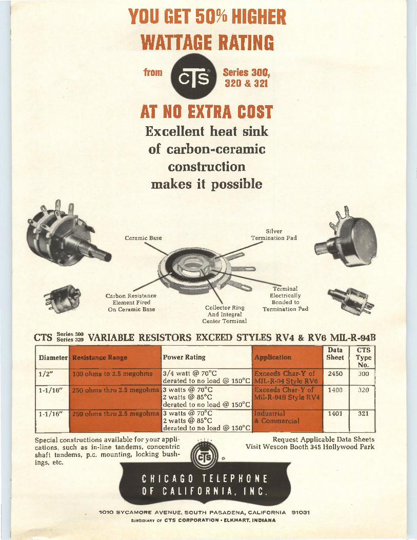
YOU GET 50% HIGHER WATTAGE RATING
C 11) from Series 300, 320 & 321
AT NO EXTRA COST Excellent heat sink of carbon-ceramic
construction makes it possible
CTS Series 300 Series 320
Ceramic Base
Carbon Resistance Element Fired
On Ceramic Base Collector Ring And Integral
Center Terminal
Silver Termination Pad
Terminal Electrically Bonded to
Termination Pad
VARIABLE RESISTORS EXCEED STYLES RV4 & RV6 MIL-R-94B
Diameter
_
Resistance Range Power Rating Application Data Sheet
CTS Type No.
1/2" 100 ohms to 2.5 megohms 3/4 watt @ 70°C derated to no load @ 150°C
Exceeds Char-Y of MIL-R-94 Style RV6
2450 300
1-1/16" 250 ohms thru 2.5 megohms 3 watts @ 70°C 2 watts @ 85°C derated to no load @ 150°C
Exceeds Char-Y of Mil-R-94B Style RV4
1400 320
1-1/16" 250 ohms thru 2.5 megohms 3 watts @ 70°C 2 watts @ 85°C derated to no load @ 150°C
Industrial & Commercial
1401 321
Special constructions available for your appli-cations, such as in-line tandems, concentric shaft tandems, p.c. mounting, locking bush-ings, etc.
Request Applicable Data Sheets Visit Wescon Booth 345 Hollywood Park
1010 SYCAMORE AVENUE, SOUTH PASADENA, CALIFORNIA 91031
SUBSIDIARY OF CTS CORPORATION • ELKHART, INDIANA
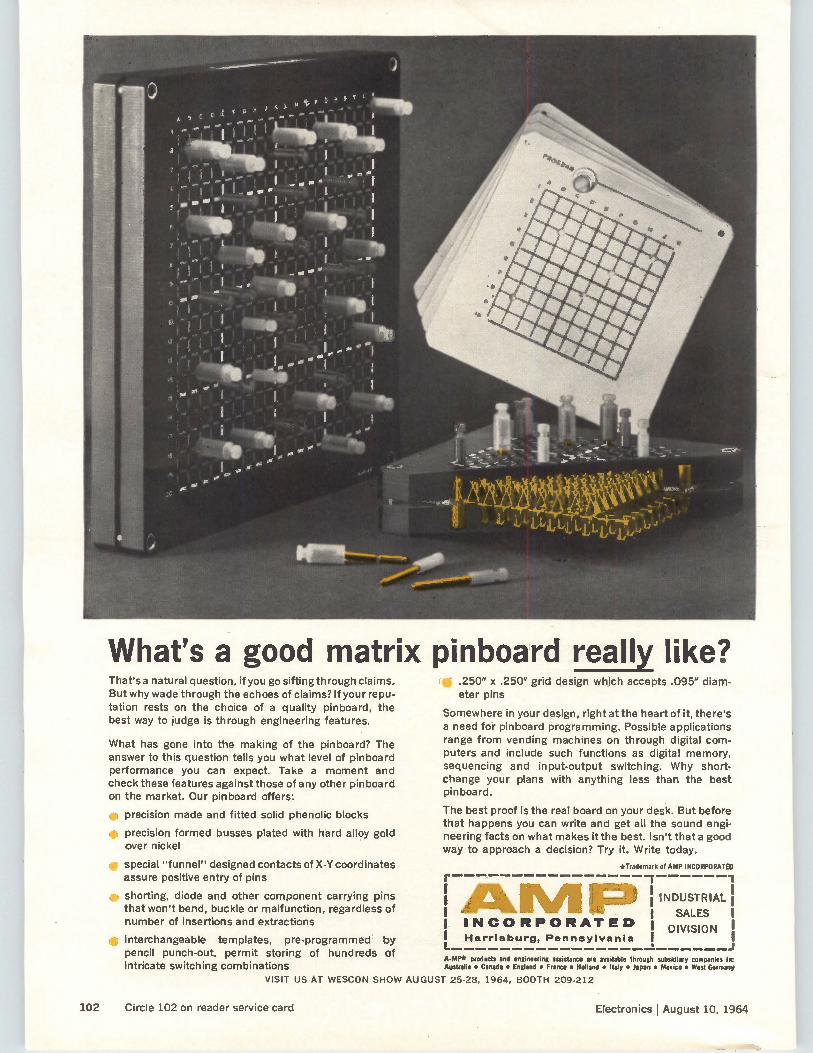
What's a good matrix pinboard really like? That's a natural question, if you go sifting through claims. But why wade through the echoes of claims? If your repu-tation rests on the choice of a quality pinboard, the best way to judge is through engineering features.
What has gone into the making of the pinboard? The answer to this question tells you what level of pinboard performance you can expect. Take a moment and check these features against those of any other pinboard on the market. Our pinboard offers:
e precision made and fitted solid phenolic blocks
• precision formed busses plated with hard alloy gold over nickel
e special "funnel" designed contacts of X-Y coordinates assure positive entry of pins
e shorting, diode and other component carrying pins that won't bend, buckle or malfunction, regardless of number of insertions and extractions
• interchangeable templates, pre-programmed by pencil punch-out, permit storing of hundreds of intricate switching combinations
• .250" x .250" grid design which accepts .095" diam-eter pins
Somewhere in your design, right at the heart of it, there's a need for pinboard programming. Possible applications range from vending machines on through digital com-puters and include such functions as digital memory, sequencing and input-output switching. Why short-change your plans with anything less than the best pinboard.
The best proof is the real board on your desk. But before that happens you can write and get all the sound engi-neering facts on what makes it the best. Isn't that a good way to approach a decision? Try it. Write today.
*Trademark of AMP INCORPORATED
ALM IP I INCORPORATED 1 L. A-MP* products and engineering assistance are available through subsidiary companies in: Australia • Canada • England • France • Holland • Italy • Japan • Mexico • West Germany
Harrisburg, Pennsylvania
1 INDUSTRIAL'
SALES 1
DIVISION I
VISIT US AT WESCON SHOW AUGUST 25-28, 1964, BOOTH 209-212
102 Circle 102 on reader service card Electronics !August 10, 1964
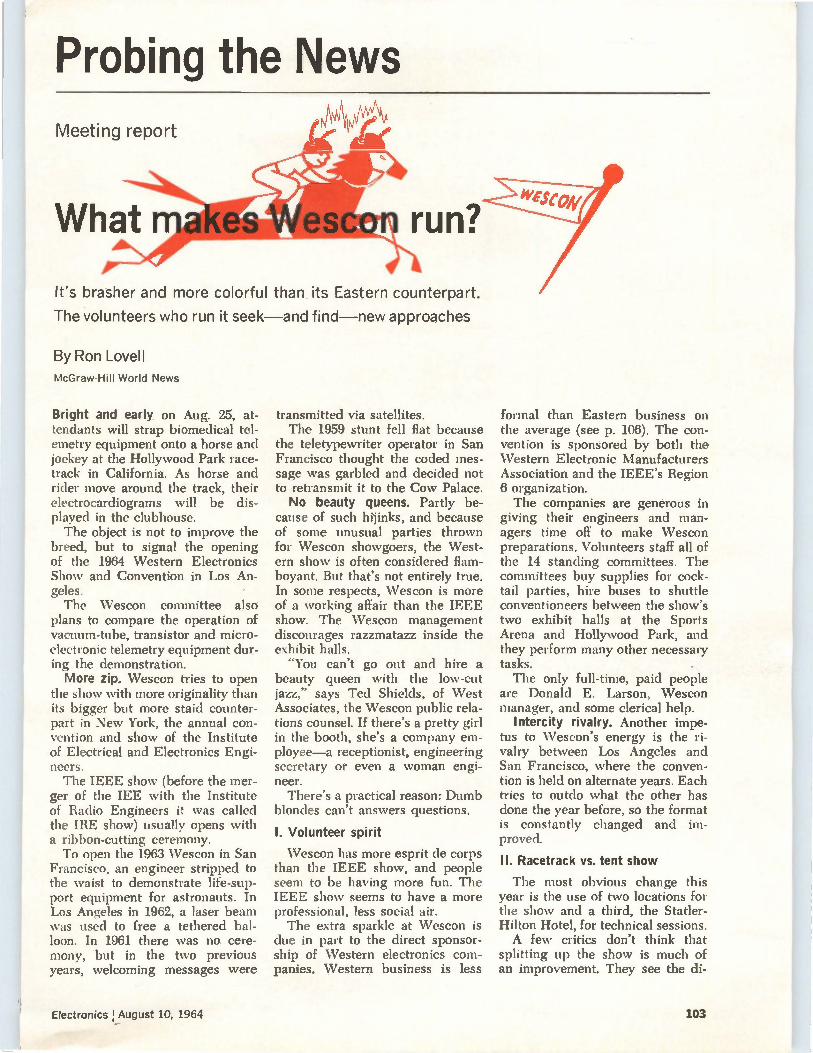
Probing the News Meeting report
It's brasher and more colorful than its Eastern counterpart.
The volunteers who run it seek—and find—new approaches
By Ron Lovell McGraw-Hill World News
Bright and early on Aug. 25, at-tendants will strap biomedical tel-emetry equipment onto a horse and jockey at the Hollywood Park race-track in California. As horse and rider move around the track, their electrocardiograms will be dis-played in the clubhouse. The object is not to improve the
breed, but to signal the opening of the 1964 Western Electronics Show and Convention in Los An-geles. The Wescon committee also
plans to compare the operation of vacuum-tube, transistor and micro-electronic telemetry equipment dur-ing the demonstration. More zip. Wescon tries to open
the show with more originality than its bigger but more staid counter-part in New York, the annual con-vention and show of the Institute of Electrical and Electronics Engi-neers. The IEEE show (before the mer-
ger of the IEE with the Institute of Radio Engineers it was called the IRE show) usually opens with a ribbon-cutting ceremony. To open the 1963 Wescon in San
Francisco, an engineer stripped to the waist to demonstrate life-sup-port equipment for astronauts. In Los Angeles in 1962, a laser beam was used to free a tethered bal-loon. In 1961 there was no cere-mony, but in the two previous years, welcoming messages were
transmitted via satellites. The 1959 stunt fell flat because
the teletypewriter operator in San Francisco thought the coded mes-sage was garbled and decided not to retransmit it to the Cow Palace. No beauty queens. Partly be-
cause of such hijinks, and because of some unusual parties thrown for Wescon showgoers, the West-ern show is often considered flam-boyant. But that's not entirely true. In some respects, Wescon is more of a working affair than the IEEE show. The Wescon management discourages razzmatazz inside the exhibit halls. "You can't go out and hire a
beauty queen with the low-cut jazz," says Ted Shields, of West Associates, the Wescon public rela-tions counsel. If there's a pretty girl in the booth, she's a company em-ployee—a receptionist, engineering secretary or even a woman engi-neer.
There's a practical reason: Dumb blondes can't answers questions.
I. Volunteer spirit
Wescon has more esprit de corps than the IEEE show, and people seem to be having more fun. The IEEE show seems to have a more professional, less social air. The extra sparkle at Wescon is
due in part to the direct sponsor-ship of NVestern electronics com-panies. Western business is less
formal than Eastern business on the average (see p. 106). The con-vention is sponsored by both the Western Electronic Manufacturers Association and the IEEE's Region 6 organization. The companies are generous in
giving their engineers and man-agers time off to make Wescon preparations. Volunteers staff all of the 14 standing committees. The committees buy supplies for cock-tail parties, hire buses to shuttle conventioneers between the show's two exhibit halls at the Sports Arena and Hollywood Park, and they perform many other necessary tasks. The only full-time, paid people
are Donald E. Larson, Wescon manager, and some clerical help.
Intercity rivalry. Another impe-tus to Wescon's energy is the ri-valry between Los Angeles and San Francisco, where the conven-tion is held on alternate years. Each tries to outdo what the other has done the year before, so the format is constantly changed and im-proved.
II. Racetrack vs. tent show
The most obvious change this year is the use of two locations for the show and a third, the Statler-Hilton Hotel, for technical sessions. A few critics don't think that
splitting up the show is much of an improvement. They see the di-
Electronics I August 10, 1964 103
vision as evidence that the show has grown too big. They fear not enough people will see their prod-ucts. This year there will be 1,250 exhibit booths occupied by more than 800 companies. "There is no question that some
companies decided to stay out," concedes Ted Shields of West As-sociates, "but they were replaced by others." Few booths, if any, are expected to be unoccupied by show time. The split is better than the alter-
natives—sweltering under the tent that was used as an annex to the Sports Arena in 1962, or being left out because of insufficient booths.
III. Survey of interests
Wescon began preparing for the split during last year's show. It asked the 40,000 attendees to fill out forms indicating their industry, occupation and interest in various types of products. The answers were put on
punched cards and tabulated into an analysis of the showgoers' per-sonal and practical interests. This is the breakdown, to the nearest tenth of a percent: circuit compon-ents were listed as their major in-terest by 22.9%; communication and detection, 21.6%; data process-ing and conversion, 13%; measure-ment, 9%; automatic control, 7.6%; air and space control systems, 5%; medical and educational, 5%; and audio and television, 4.2%. As a result of these findings, ex-
hibits featuring components, auto-matic control and data-processing and conversion will be at the race-track, while the other types of ex-hibits will be at the Sports Arena. Buses will shuttle visitors between the two locations, as well as to and from downtown Los Angeles and the airport. The survey results were given to
the industry well in advance of booth-renting time, as part of the plan to head off the din of dis-approval that was expected. The din never materialized.
First company seminars. An-other innovation at WESCON this year is a series of company-spon-sored technical seminars. In the past these have been rump sessions that sometimes conflicted with the regular technical sessions [Elec-tronics, Aug. 9, 1963, p. 29].
Dude goes West Is the electronics business on the West Coast different from the East Coast? After Electronics news people reported how companies did business in their regions copy editor Howard Rausch, a native New Yorker, put together this fanciful view of what it is like selling electronics out West. For an insight into the real differences, however, see the story which starts on page 106.
INTEROFFICE MEMORANDUM
TO: J. Frumington Hrumph, Pres.
FROM: Larry Lovewell, Sales Mgr.
RE: Expense account for West Coast trip
I realize some items on the expense sheet are unusual, so brief explanation of the ones might question.
Please try to remember that is done differently out there West, and you have to live like the natives if you want to sell
enclosed here's a you
business in the
tem.
Item (4). $9 for shirt.
To fully understand this one, you need a clear picture of a business meeting, Western style. The locale is one of California's 50,000 private swimming pools. In addition to scuba tanks and fins, everybody gets a pitcher of martinis. Near the end of the pitcher,
things sometimes get a little out of hand. I'm not sure of all the details;
\ettet"
suffice to say your boy held his own and got the contract. But the piano-shaped pool (it used to belong to Liberace, now it's the property of John O'Halloran, president of a
sales rep firm) had to be drained because the filter got clogged with my shirt—with me still in it.
Item (6). $30 for neckties.
I took a bunch of Motorola peo-ple, plus some of our boys, out to a truly ranch-flavor steak house called Pinnacle Peak, 20 spine-jar-ring miles across the desert from Phoenix. The Westerners wore open-neck sport shirts, but we main-tained our Eastern dignity with white shirts and ties.
Well, those cowgirl waitresses have some kind of a phobia about ties. A couple of them wiggled up to us and before we knew what was happening they whipped scissors out from under their trays and six ties got snipped off about two inches below the adam's apple. When I looked around I saw
hundreds of tie ends hanging from the rafters and walls. Each tie was exhibited like a scalp, with a busi-ness card attached—and you'd rec-ognize some of the names.
Another quaint custom at this beanery: Anybody who dares to
104 Electronics August 10, 1964
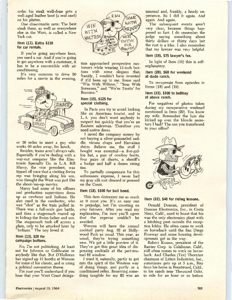
order his steak well-done gets a well-aged leather boot (a real one!) on his platter. One chauvinistic note: The best
steak there, as well as everywhere else in the West, is called a New York cut.
Item (11). Extra $110 for car rentals.
If you're going anywhere here, you need a car. And if you're going to get anywhere with a customer, it has to be a convertible with air conditioning.
It's very common to drive 50 miles for a movie in the evening,
or 30 miles to meet a guy who works 60 miles away, for lunch.
Besides, trains aren't always safe. Especially if you're dealing with a way-out company like the Elec-tronic Specialty Co. in L. A. Bill Marcy, the vice president, was tipped off once that a visiting Swiss rep was bringing along his son, who thought the \Vest was just like the shoot-'em-up movies. Marcy had some of his officers
and production supervisors dress up as cowboys and Indians. He also cued in the conductor, who was "shot" as the train pulled in. There was a full-scale gun battle, and then a stagecoach roared up to kidnap the Swiss father and son. The stagecoach took off across a plain, only to be attacked later by "Indians." The boy loved it.
Item (13). $20 for campaign buttons.
No, I'm not politicking. At least not for Johnson or Goldwater or anybody like that. But O'Halloran has signed up 12 booths at Wescon for some of his clients, and is using a political convention theme.
I'm sure you'll understand if you hear that your West Coast delega-
tion approached prospective cus-tomers while wearing 12-inch but-tons with some slogans that, frankly, I wouldn't have invented if it'd been up to me. Some said "Win With Wiltron," "Soar With Sorensen," and "We're Tootin' for Boonton."
Item (15). $125 for special clothing.
In Paris you try to avoid looking like an American tourist, and in L. A. you don't want anybody to suspect too quickly that you're an Eastern salesman. Therefore you need native dress. I saved the company money by
not buying a silver-pommeled sad-dle, vicuna chaps and Hawaiian shirts. Believe me, the stuff I bought was essential—a five-gal-lon hat, a pair of cowboy boots, four pairs of shorts, a sheriff's a badge and half a dozen string ties. To partially compensate for this
unforeseen expense, I never had my gray silk suit cleaned or pressed on the Coast.
Item (18). $100 for bail bond.
This item distresses me as much as it must you. It's an easy one to prejudge, but I'm counting on your fairness. After you read my explanation, I'm sure you'll agree that the expense couldn't be avoided. Wescon will have the annual
cocktail party Aug. 25 at Holly-wood Park as usual. This year, as usual, they're trying something new. We got a little preview of it. They've got this great idea of dis-pensing cocktails at the pari-mu-tuel $2 window. I tried it, naturally, partly to get
into the spirit of the Western way of doing things, and partly as a conditioned reflex. Receiving some-thing tangible for my $2 was an
unusual and, frankly, a heady ex-perience. So I did it again. And again. And again. The subsequent events aren't
very clear, because things hap-pened so .fast. I do remember the judge saying something about thirty dollars or thirty days but the rest is a blur. I also remember that my lawyer was very helpful.
Item (19). $75 lawyer's fee.
In light of Item (18) this is self-explanatory.
Item (20). $60 for weekend at dude ranch.
To recuperate from episodes in Items (18) and (19).
Item (21). $100 to bellboy at above ranch.
For negatives of photos taken during my recuperative weekend mentioned in Item (20). You know my wife. Remember the fuss she kicked up over the blonde secre-tary I had? The one you transferred to your office?
Item (22). $40 for riding lessons.
Donald Duncan, president of Duncan Electronics, Inc., in Costa Mesa, Calif., used to boast that his was the only electronics plant with a hitching post outside the recep-tion lobby. He often came to work on horseback until the San Diego Freeway and some housing devel-opments got in the way.
Robert Krausz, president of the Rantec Corp. in Calabasas, Calif., still often comes to work on horse-back. And Charles (Tex) Thornton chairman of Litton Industries, Inc., sometimes gets up at 5 a.m., flies from his home in Brentwood, Calif., to his ranch near Thousand Oaks, to ride for an hour or so before
Electronics I August 10, 1964 105
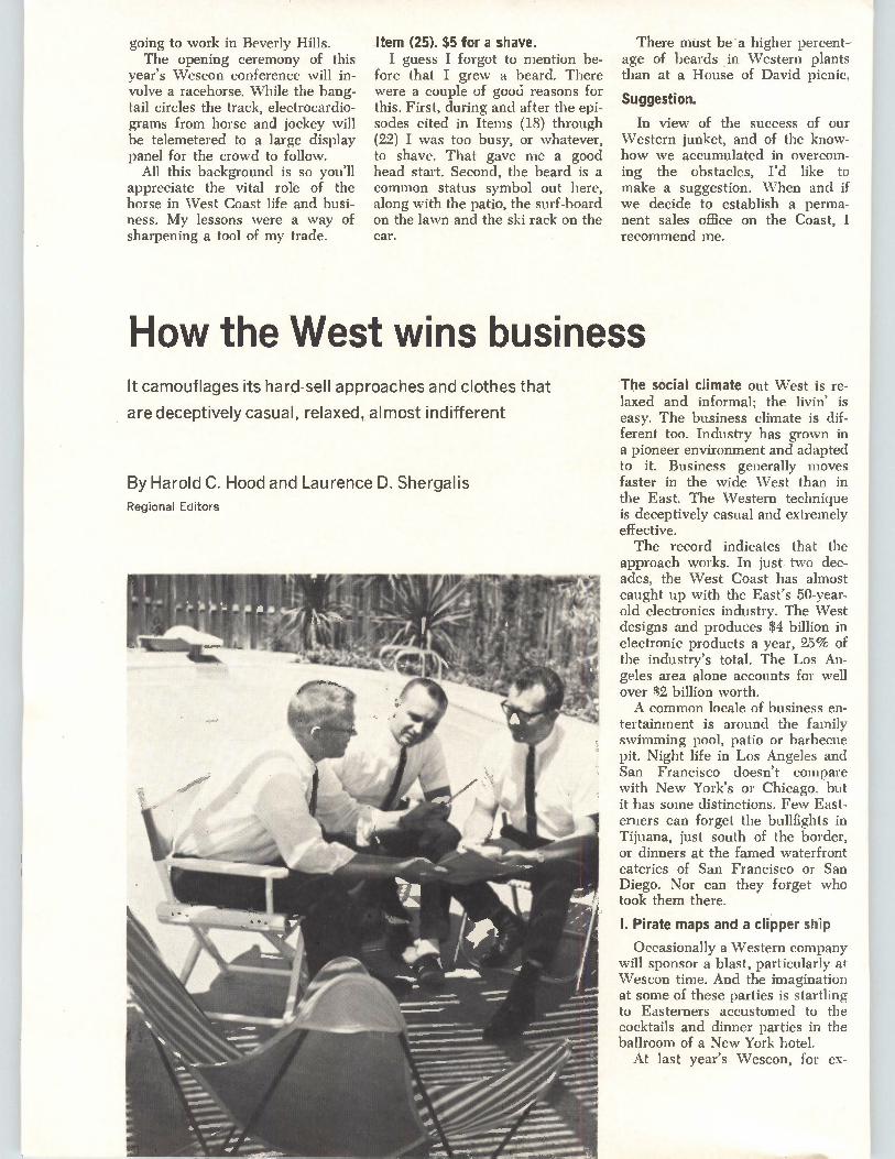
going to work in Beverly Hills. The opening ceremony of this
year's Wescon conference will in-volve a racehorse. While the bang-tail circles the track, electrocardio-grams from horse and jockey will be telemetered to a large display panel for the crowd to follow.
All this background is so you'll appreciate the vital role of the horse in West Coast life and busi-ness. My lessons were a way of sharpening a tool of my trade.
Item (25). $5 for a shave. I guess I forgot to mention be-
fore that I grew a beard. There were a couple of good reasons for this. First, during and after the epi-sodes cited in Items (18) through (22) I was too busy, or whatever, to shave. That gave me a good head start. Second, the beard is a common status symbol out here, along with the patio, the surf-board on the lawn and the ski rack on the car.
There must be a higher percent-age of beards in Western plants than at a House of David picnic.
Suggestion.
In view of the success of our Western junket, and of the know-how we accumulated in overcom-ing the obstacles, I'd like to make a suggestion. When and. if we decide to establish a perma-nent sales office on the Coast, I recommend me.
How the West wins business It camouflages its hard-sell approaches and clothes that
are deceptively casual, relaxed, almost indifferent
By Harold C. Hood and Laurence D. Shergalis Regional Editors
The social climate out West is re-laxed and informal; the livin' is easy. The business climate is dif-ferent too. Industry has grown in a pioneer environment and adapted to it. Business generally moves faster in the wide \Vest than in the East. The Western technique is deceptively casual and extremely effective. The record indicates that the
approach works. In just two dec-ades, the West Coast has almost caught up with the East's 50-year-old electronics industry. The West designs and produces $4 billion in electronic products a year, 25% of the industry's total. The Los An-geles area alone accounts for well over $2 billion worth. A common locale of business en-
tertainment is around the family swimming pool, patio or barbecue pit. Night life in Los Angeles and San Francisco doesn't compare with New York's or Chicago, but it has some distinctions. Few East-erners can forget the bullfights in Tijuana, just south of the border, or dinners at the famed waterfront eateries of San Francisco or San Diego. Nor can they forget who took them there.
I. Pirate maps and a clipper ship
Occasionally a Western company will sponsor a blast, particularly at Wescon time. And the imagination at some of these parties is startling to Easterners accustomed to the cocktails and dinner parties in the ballroom of a New York hotel. At last year's Wescon, for ex-
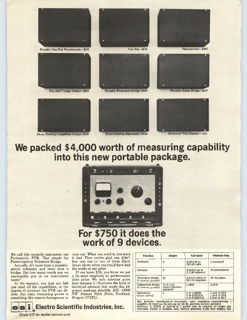
Portable Five-Dial Potentiometer: $535
< Fee-Dial Voltage Divider: $320
Direct Reading Comparison Bridge .: $500
olt Box: $135
Portable Wheatstone Bridge: $600
Direct Readingltatideneter: $450
Pico-ammeter: $485
Portable Kelvin Bridge: $650
Electronic Nult-Detécto'r: $325
We packed $4,000 worth of measuring capability into this new portable package.
We call this versatile instrument our Portametric PVB. That stands for Potentiometric Voltmeter Bridge.
Actually, it's more than a potentio-metric voltmeter and more than a bridge. But how many words can we reasonably put in an instrument name? At the moment, you may not feel
you need all the capabilities, or the degree of accuracy the PVB can de-liver. But extra measuring power is something like reserve horsepower in
ts, e
For $750 it does the work of 9 devices.
your car. When you need it, you need it bad. Then you're glad you didn't buy just one or two of those black boxes above when you could have had the works at our price.
If you know ESI, you know we put a lot more emphasis on performance than price. We only mention price here because it illustrates the kind of technical advance that made this 18-pound package possible. ES!, 13900 NW Science Park Drive, Portland, Oregon (97229).
Electro Scientific Industries, Inc.
Function Ranges Full Scale Minimum Step
Voltmeter 5 0.051110 to 511.10 volts
1 microvolt
Ammeter 8 0.51110 ga to 5.1110 amperes
10 picoamperes
Resistance Bridge (4 terminal, guarded)
10 0.51110 ohms to 511.10 megohms
10 microhms
Comparison Bridge (4 terminal, guarded)
To 5.1110 times reference standard
1.0000 0.01%
Ratiometer (Direct reading)
3 0 to 1.00000 0 to 0.051110 a to 0.0051110
1 part in 10-5 1 part in 10-6 1 part in 10-7
Null detector: Sensitivity-5 microvolts; Input impedance—approximately 1 megohm; AC rejection 60 cps and up; 80 db, guarded, battery operated. Accuracy: ±- 0.02% of reading or 1 switch step on virtually all ranges and functions.- Comes in portable case; battery operated; 2,000 hour battery life.
-Circle 107 on reader service card
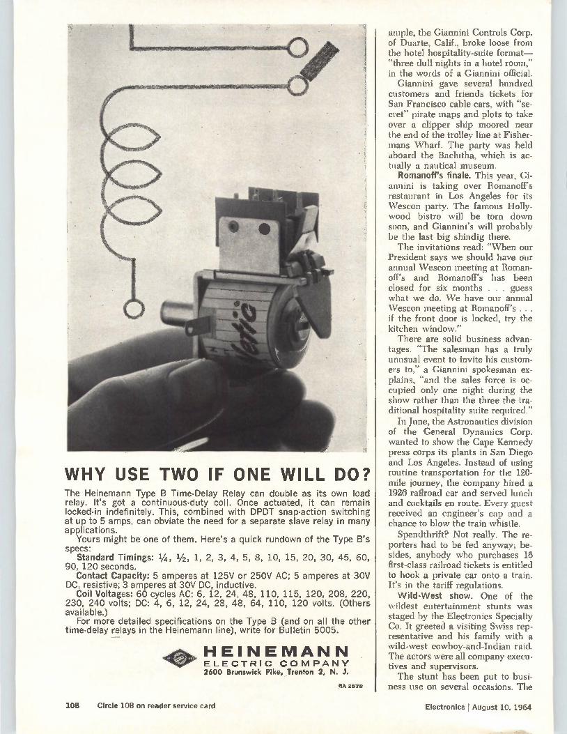
WHY USE TWO IF ONE WILL DO? The Heinemann Type B Time-Delay Relay can double as its own load relay. It's got a continuous-duty coil. Once actuated, it can remain locked-in indefinitely. This, combined with DPDT snap-action switching at up to 5 amps, can obviate the need for a separate slave relay in many applications.
Yours might be one of them. Here's a quick rundown of the Type B's specs:
Standard Timings: 1/4, 1/2, 1, 2, 3, 4, 5, 8, 10, 15, 20, 30, 45, 60, 90, 120 seconds.
Contact Capacity: 5 amperes at 125V or 250V AC; 5 amperes at 30V DC, resistive; 3 amperes at 30V DC, inductive.
Coil Voltages: 60 cycles AC: 6, 12, 24, 48, 110, 115, 120, 208, 220, 230, 240 volts; DC: 4, 6, 12, 24, 28, 48, 64, 110, 120 volts. (Others available.)
For more detailed specifications on the Type B (and on all the other time-delay relays in the Heinemann line), write for Bulletin 5005.
HEINEMANN ELECTRIC COMPANY 2600 Brunswick Pike, _Trenton 2, N. J.
SA 2578
ample, the Giannini Controls Corp. of Duarte, Calif., broke loose from the hotel hospitality-suite format-"three dull nights in a hotel room," in the words of a Giannini official.
Giannini gave several hundred customers and friends tickets for San Francisco cable cars, with "se-cret" pirate maps and plots to take over a clipper ship moored near the end of the trolley line at Fisher-mans Wharf. The party was held aboard the Baclutha, which is ac-tually a nautical museum.
Romanoff's finale. This year, Gi-annini is taking over Romanoff's restaurant in Los Angeles for its Wescon party. The famous Holly-wood bistro will be torn down soon, and Giannini's will probably be the last big shindig there. The invitations read: "When our
President says we should have our annual Wescon meeting at Roman-off's and Romanoff's has been closed for six months . . . guess what we do. We have our annual Wescon meeting at Romanoff's . . . if the front door is locked, try the kitchen window." There are solid business advan-
tages. "The salesman has a truly unusual event to invite his custom-ers to," a Giannini spokesman ex-plains,"and the sales force is oc-cupied only one night during the show rather than the three the tra-ditional hospitality suite required."
In June, the Astronautics division of the General Dynamics Corp. wanted to show the Cape Kennedy press corps its plants in San Diego and Los Angeles. Instead of using routine transportation for the 120-mile journey, the company hired a 1926 railroad car and served lunch and cocktails en route. Every guest received an engineer's cap and a chance to blow the train whistle.
Spendthrift? Not really. The re-porters had to be fed anyway; be-sides, anybody who purchases 16 first-class railroad tickets is entitled to hook a private car onto a train. It's in the tariff regulations. Wild-West show. One of the
wildest entertainment stunts was staged by the Electronics Specialty Co. It greeted a visiting Swiss rep-resentative and his family with a wild-west cowboy-and-Indian raid. The actors were all company execu-tives and supervisors. The stunt has been put to busi-
ness use on several occasions. The
108 Circle 108 on reader service card Electronics I August 10, 1964
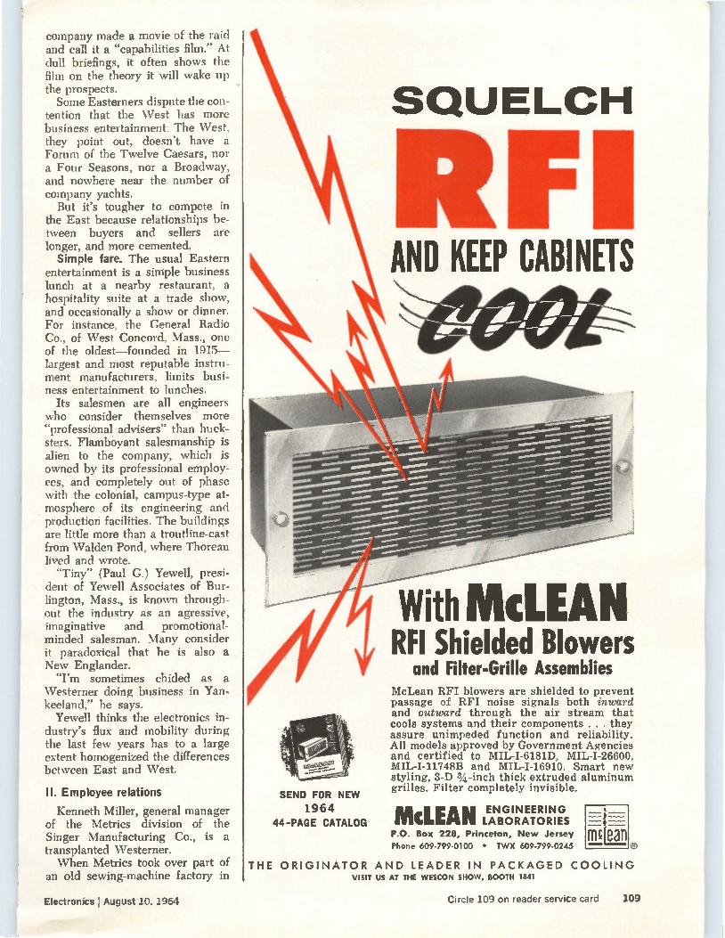
company made a movie of the raid and call it a "capabilities film." At chill briefings, it often shows the film on the theory it will wake up the prospects. Some Easterners dispute the con-
tention that the West has more business entertainment. The \Vest, they point out, doesn't have a Forum of the Twelve Caesars, nor a Four Seasons, nor a Broadway, and nowhere near the number of company yachts. But it's tougher to compete in
the East because relationships be-tween buyers and sellers are longer, and more cemented. Simple fare. The usual Eastern
entertainment is a simple business lunch at a nearby restaurant, a hospitality suite at a trade show, and occasionally a show or dinner. For instance, the General Radio Co., of \Vest Concord, Mass., one of the oldest—founded in 1915— largest and most reputable instru-ment manufacturers, limits busi-ness entertainment to lunches.
Its salesmen are all engineers who consider themselves more ‘`professional advisers" than huck-sters. Flamboyant salesmanship is alien to the company, which is owned by its professional employ-ees, and completely out of phase with the colonial, campus-type at-mosphere of its engineering and production facilities. The buildings are little more than a troutline-cast from \Valden Pond, where Thoreau lived and wrote. "Tiny" (Paul G.) Yewell, presi-
dent of Yewell Associates of Bur-lington, Mass., is known through-out the industry as an agressive, imaginative and promotional-minded salesman. Many consider it paradoxical that he is also a New Englander. "I'm sometimes chided as a
Westerner doing business in Yan-keeland," he says.
Yewell thinks the electronics in-dustry's flux and mobility during the last few years has to a large extent homogenized the differences between East and \Vest.
II. Employee relations
Kenneth Miller, general manager of the Metrics division of the Singer Manufacturing Co., is a transplanted Westerner. When Metrics took over part of
an old sewing-machine factory in
SEND FOR NEW
1964 44-PAGE CATALOG
SQUELCH
IF AND KEEP CABINETS
With IVIcLEAN RFI Shielded Blowers
and Filter-Grille Assemblies McLean RFI blowers are shielded to prevent passage of RFI noise signals both inward and outward through the air stream that cools systems and their components . . . they assure unimpeded function and reliability. All models approved by Government Agencies and certified to MIL-I-6181D, MIL-I-26600, MIL-I-11748B and MIL-I-16910. Smart new styling, 3-D 3/4 -inch thick extruded aluminum grilles. Filter completely invisible.
McLEAN ENGINEERING LABORATORIES P.O. Box 228, Princeton, New Jersey Phone 609-799-0100 • TWX 609-799-0245
THE ORIGINATOR AND LEADER IN PACKAGED COOLING VISIT US AT THE WESCON SHOW, BOOTH 1841
Electronics I August 10, 1964 Circle 109 on reader service card 109
Bridgeport, Conn., the employees called everybody "mister," Miller recalls. He's trying to change this.
Last year, Metrics held an open house for employees and served refreshments. It was the first time some of the employees—much less their families—had seen the entire plant.
This, however, is not typical of Eastern companies. The annual em-ployees' picnic, Christmas party and open house are fixtures at many Eastern concerns, as are bowling leagues and baseball or bridge teams.
Class System. There is less class-consciousness on the \Vest Coast, Miller says. "Here, the wife of a vice president cannot really play bridge with the wife of a more junior type, whereas on the Coast they wouldnt think twice about it."
In the older Eastern companies, managers have frequently spent far more time working their way up, and relationships are often more formal.
In the West, companies are gen-erally newer and employees are younger. Western electronics corn-
panies often have a higher propor-tion of engineers to factory work-ers, so average incomes and intellectual levels are higher. Em-ployees are less tradition-bound. One reason why the West is
more relaxed in its employee rela-tions is its long drive to recruit technical talent from the East. The beach-patio-shirtsleeves atmos-phere was stressed as an induce-ment.
Besides the usual employee ac-tivities, \Vestern companies go in heavily for golf tournaments, sportscar clubs and charter trips to Europe. At the Band Corp., em-ployees sponsor a chamber orches-tra. The \Vest's chief mode of trans-
portation, the automobile, is also more conducive to getting employ-ees together for social events. Hop-ping into a car is infinitely easier than figuring out train and bus schedules for a get-together at somebody's home. Fewer roots. The relative new-
ness of many Western companies is another factor. "So many people out here have only been here a
couple of years and don't have a lot of other social ties," explains Ted Shields of West Associates, a public relations concern. "They tend to go together a bit more in the company group than they would otherwise. The fact that new electronics
plants are outside of the cities in the \Vest—up and down the Cali-fornia coast, for example, or in the desert near Phoenix, Ariz.—also en-courages employee social activities. More people live near their jobs.
Ill. The sales meeting
\Vesterners take their jobs seri-ously, but they look casual.
Giannini Controls, for example, prides itself on its unusual and ef-fective sales meetings. This year, its salesmen met at an authentic working ranch and were outfitted with shorts and sheriffs' badges bearing their names. They were di-vided into competitive teams that attempted solutions to sales prob-lems. Team members even shared bunkhouses for the three-day meet-ing. The informal atmosphere en-
Electronics I August 10, 1964 110
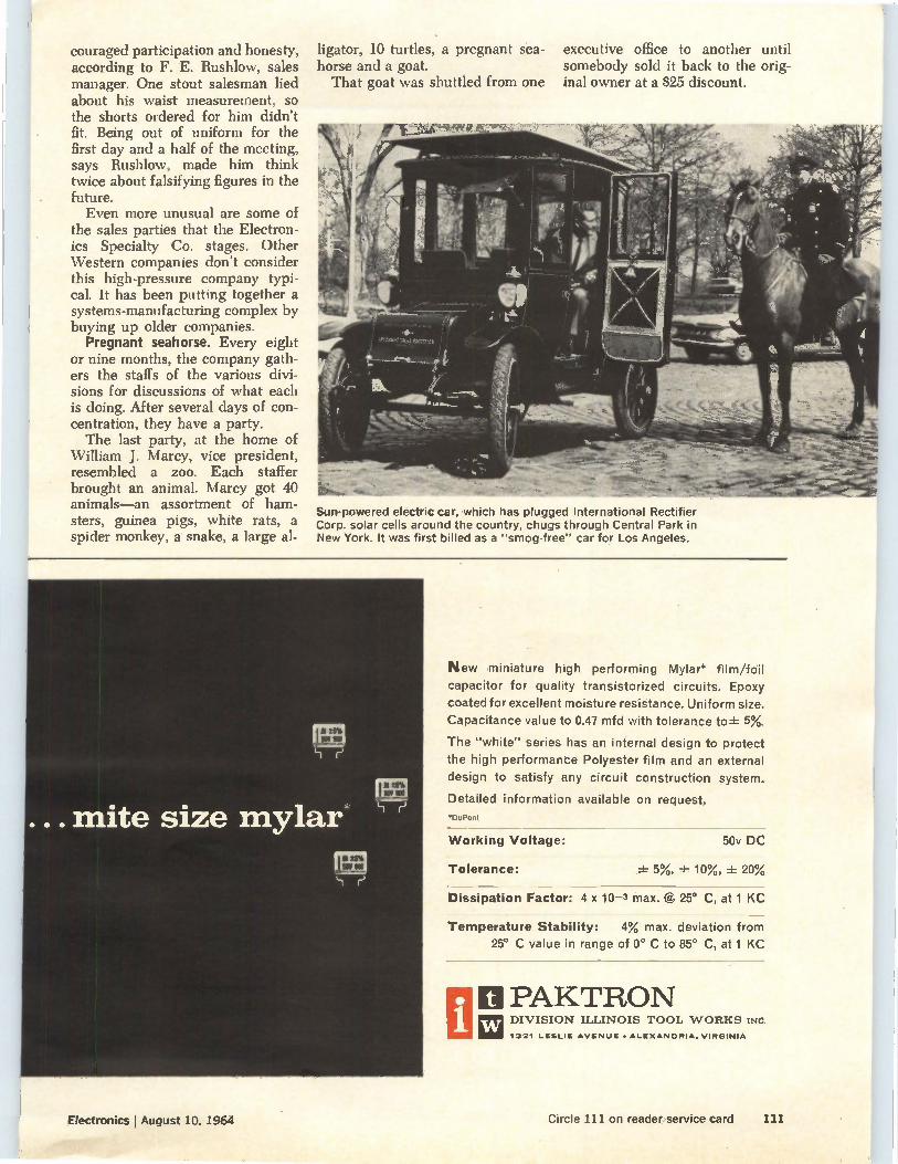
couraged participation and honesty, according to F. E. Rushlow, sales manager. One stout salesman lied about his waist measurement, so the shorts ordered for him didn't fit. Being out of uniform for the first day and a half of the meeting, says Rushlow, made him think twice about falsifying figures in the future. Even more unusual are some of
the sales parties that the Electron-ics Specialty Co. stages. Other Western companies don't consider this high-pressure company typi-cal. It has been putting together a systems-manufacturing complex by buying up older companies.
Pregnant seahorse. Every eight or nine months, the company gath-ers the staffs of the various divi-sions for discussions of what each is doing. After several days of con-centration, they have a party. The last party, at the home of
William J. Marcy, vice president, resembled a zoo. Each staffer brought an animal. Marcy got 40 animals—an assortment of ham-sters, guinea pigs, white rats, a spider monkey, a snake, a large al-
ligator, 10 turtles, a pregnant sea- executive office to another until horse and a goat. somebody sold it back to the orig-That goat was shuttled from one mal owner at a $25 discount.
Sun-powered electric car, which has plugged International Rectifier Corp. solar cells around the country, chugs through Central Park in New York. It was first billed as a "smog-free" car for Los Angeles.
New miniature high performing Mylar* film/foil
capacitor for quality transistorized circuits. Epoxy
coated for excellent moisture resistance. Uniform size.
Capacitance value to 0.47 mfd with tolerance to ± 5%.
The "white" series has an internal design to protect
the high performance Polyester film and an external
design to satisfy any circuit construction system.
Detailed information available on request.
'DuPont
Working Voltage:
Tolerance:
50v DC
± 5%, ± 10%, ± 20%
Dissipation Factor: 4 x 10⁻³ max. @ 25° C, at 1 KC
Temperature Stability: 4% max. deviation from
25° C value in range of 0° C to 85° C, at 1 KC
ti PAKTRON la DIVISION ILLINOIS TOOL WORKS INC.
1321 LESLIE AVENUE • ALEXANDRIA, VIRGINIA
Electronics August 10, 1964 Circle 111 on reader service card 111
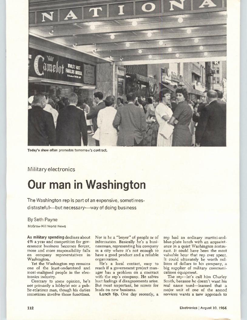
Today's show often promotes tomorrow's contract.
Military electronics
Our man in Washington The Washington rep is part of an expensive, sometimes-
distasteful—but necessary—way of doing business
By Seth Payne McGraw-F-1111 World News
As military spending declines about 4% a year and competition for gov-ernment business becomes fiercer, more and more responsibility falls on company representatives in Washington.
Yet the \Vashington rep remains one of the least-understood and most-maligned people in the elec-tronics industry.
Contrary to some opinion, he's not primarily a lobbyist nor a pub-lic-relations man, though his duties sometimes involve those functions.
Nor is he a "buyer" of people or of information. Basically he's a busi-nessman, representing his company in a city where it's not enough to have a good product and a reliable organization.
He's a local contact, easy to reach if a government project man-ager has a problem on a contract with the rep's company. He salves hurt feelings if disagreements arise. But roost important, he scouts for leads on new business. Lunch tip. One day recently, a
rep had an ordinary martini-and-blue-plate lunch with an acquaint-ance in a quiet Washington restau-rant. It could have been the most valuable hour that rep ever spent. It could ultimately be worth mil-lions of dollars to his company, a big supplier of military communi-cations equipment. The rep—let's call him Charley
Smith, because he doesn't want his real name used—learned that a major unit of one of the armed services wants a new approach to
112 Electronics l August 10, 1964
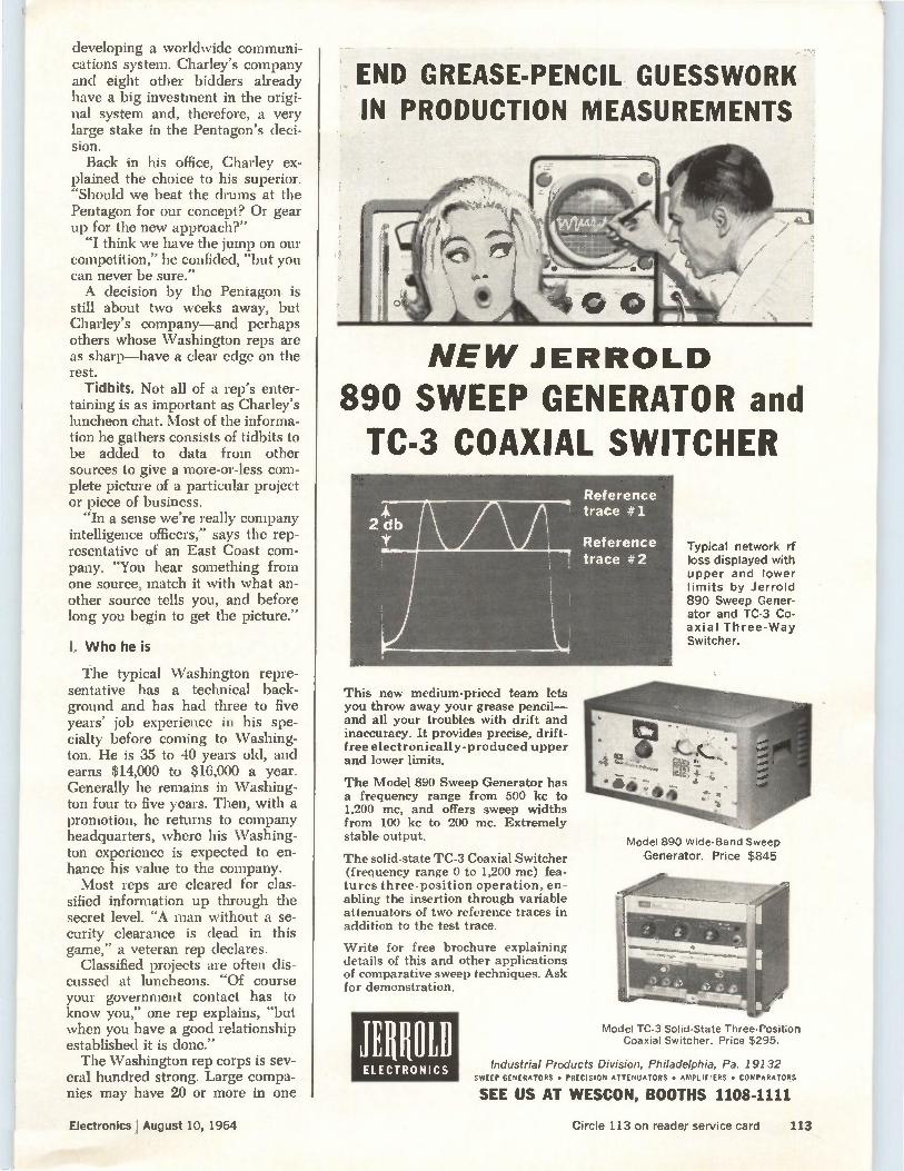
developing a worldwide communi-cations system. Charley's company and eight other bidders already have a big investment in the origi-nal system and, therefore, a very large stake in the Pentagon's deci-sion. Back in his office, Charley ex-
plained the choice to his superior. "Should we beat the drums at the Pentagon for our concept? Or gear up for the new approach?"
"I think we have the jump on our competition," he confided, "but you can never be sure." A decision by the Pentagon is
still about two weeks away, but Charley's company—and perhaps others whose Washington reps are as sharp—have a clear edge on the rest.
Tidbits. Not all of a rep's enter-taining is as important as Charley's luncheon chat. Most of the informa-tion he gathers consists of tidbits to be added to data from other sources to give a more-or-less com-plete picture of a particular project or piece of business.
"In a sense we're really company intelligence officers," says the rep-resentative of an East Coast com-pany. "You hear something from one source, match it with what an-other source tells you, and before long you begin to get the picture."
I. Who he is
The typical Washington repre-sentative has a technical back-ground and has had three to five years' job experience in his spe-cialty before coming to Washing-ton. He is 35 to 40 years old, and earns $14,000 to $16,000 a year. Generally he remains in Washing-ton four to five years. Then, with a promotion, he returns to company headquarters, where his Washing-ton experience is expected to en-hance his value to the company. Most reps are cleared for clas-
sified information up through the secret level. "A man without a se-curity clearance is dead in this game," a veteran rep declares.
Classified projects are often dis-cussed at luncheons. "Of course your government contact has to know you," one rep explains, "but when you have a good relationship established it is done." The Washington rep corps is sev-
eral hundred strong. Large compa-nies may have 20 or more in one
END GREASE-PENCIL GUESSWORK IN PRODUCTION MEASUREMENTS
NEW JERROLD
890 SWEEP GENERATOR and TC-3 COAXIAL SWITCHER
This new medium-priced team lets you throw away your grease pencil— and all your troubles with drift and inaccuracy. It provides precise, drift-free electronically-produced upper and lower limits.
The Model 890 Sweep Generator has a frequency range from 500 kc to 1,200 mc, and offers sweep widths from 100 kc to 200 mc. Extremely stable output.
The solid-state TC-3 Coaxial Switcher (frequency range 0 to 1,200 mc) fea-tures three-position operation, en-abling the insertion through variable attenuators of two reference traces in addition to the test trace.
Write for free brochure explaining details of this and other applications of comparative sweep techniques. Ask for demonstration.
JERROLD
ELECTRONICS
Typical network rf loss displayed with upper and lower limits by Jerrold 890 Sweep Gener-ator and TC-3 Co-axial Three-Way Switcher.
Model 890 Wide-Band Sweep Generator. Price $845
Model TC-3 Solid-State Three-Position Coaxial Switcher. Price $295.
Industrial Products Division, Philadelphia, Pa. 191 32 SWEEP GENERATORS • PRECISION ATTENUATORS • AMPLIFIERS • COMPARATORS
SEE US AT WESCON, BOOTHS 1108-1111
Electronics j August 10, 1964 Circle 113 on reader service card 113
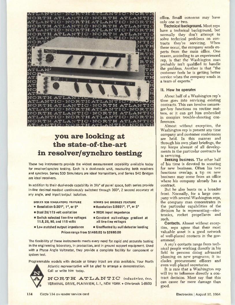
TLANTI OR.TH AT T .A.1\T 'I' I 0 FLU' I-1 AT T LA.N TIC NO R., T H AT AT I, A. I\T OR
.111111,
• 1\1. LAN T I C • • NORTH I., AN 1-1" C • • NORTH LA.NT I C •
LA • NORTH LANTIC • • NORTH LA.NT I • • NORTH LA.NT I C • • NO TH
I • I\ T
AT LAN TI d I c • 1\1" 0 R, ATLANTI c • NORTH
.A.T L.A.N rr I IC'NORT
I\T TIC Tu-±
iv= P_, ir ir I
I. 1R..T
IC T
"rzeRSB.5407
AT LAN rr NORTH AT LAN rr NORTH AT LAN T NO RT AT ',ANT
«PO
you are looking at the state-of-the-art
in resolver/synchro testing
These two instruments provide the widest measurement capability available today
for resolver/synchro testing. Each is a dual-mode unit, measuring both resolvers
and synchros. Series 530 Simulators are ideal transmitters, and Series 540 Bridges
are ideal receivers.
In addition to their dual-mode capability in 31/2 " of panel space, both series provide
in-line decimal readout continuously switched through 360°, 2 second accuracy at
any angle, and input/output isolation.
SERIES 530 SIMULATORS FEATURE
• Resolution 0.001°, 1°, or 5°
• Dual 26/115 volt excitation
• Switch selected line-line voltages 11.8,26, 90, and 115 volts
• Low matched output impedance
SERIES 540 BRIDGES FEATURE
• Resolution 0.0001 °, 1°, or 5°
• 500K input impedance
• Constant null-voltage gradient at all line-line voltages
• Unaffected by null detector loading
Prices range from $1480.00 to $2680.00
The flexibility of these instruments meets every need for rapid and accurate testing
in the engineering laboratory, in production, and in ground support equipment. Used
with a Phase Angle Voltmeter, they provide a complete facility for component or
system test.
Programmable models with decade or binary input are also available. Your North
Atlantic representative will be glad to arrange a demonstration.
Call or write him today.
NORTEE A.'', L I A. 1•T "PIC industries, inc.
TERMINAL DRIVE, PLAINVIEW, L. I., NEW YORK • OVerbrook 1-8600
office. Small concerns may have only one or two.
Technical background. Most reps have a technical background, but normally they don't attempt to solve technical problems on con-tracts they're servicing. When these occur, the company sends ex-perts from the main office. One reason, acecirding to an experienced rep, is that the Washington man probably isn't qualified to handle the problem. Another is that "the customer feels he is getting better service when the company sends in a team of experts."
II. How he operates
About half of a \Vashington rep's time goes into servicing existing contracts. This can involve messen-ger-boy functions on routine mat-ters, or it can get him embroiled in complex trouble-shooting con-ferences.
Almost without exception, the Washington rep is present any time company and customer conferences are held. In this manner and through his own plant briefings, the rep keeps abreast of all develop-ments in the particular contracts he is servicing.
Seeking business. The other half of his time is devoted to scouting for new business. Often his two functions overlap; a tip on new business may come from an office where his company already has a contract. But he also hunts on a broader
front. Normally, for a large com-pany with several Washington reps, the company man concentrates in the particular capabilities of the division he is representing—elec-tronics, rocket propellants and such.
Contacts. Almost without excep-tion, reps agree that their most valuable asset is a good network of well-placed contacts in the gov-ernment. A rep's contacts range from tech-
nical people working directly in his field to persons doing advanced planning on new programs; it in-cludes procurement officers and even well-placed secretaries.
It is rare that a Washington rep will try to influence directly a con-tract decision. Most say that this can cause far more damage than good.
114 Circle 114 on reader service card Electronics I August 10, 1964
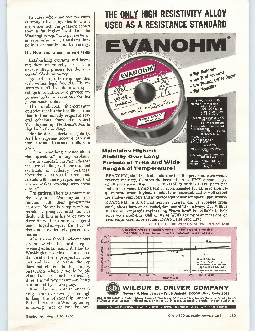
In cases where indirect pressure is brought by companies to win a major contract, the pressure comes from a far higher level than the Washington rep. "The pet system," as reps refer to it, translates into politics, economics and technology.
III. How and whom he entertains
Establishing contacts and keep-ing them on friendly terms is a never-ending process for the suc-cessful Washington rep. By and large, the rep operates
well within legal bounds. His re-sources don't include a string of call girls, or authority to provide ex-pensive gifts or vacations for his government contacts. The mink-coat, five-percenter
episodes that hit the headlines from time to time usually originate sev-eral echelons above the typical Washington rep. He doesn't deal in that kind of spending. But he does entertain regularly.
And his expense account can run into several thousand dollars a year.
"There is nothing sinister about the operation," a rep explains. "This is standard practice whether you are dealing with government contracts or industry business. Over the years you become good friends with these people, and that always makes working with them easier." The pattern. There is a pattern to
the way most Washington reps function with their government contacts. Normally a rep won't en-tertain a prospect until he has dealt with him in his office two or three times. Then he may suggest lunch together—just the two of them at a moderately priced res-taurant.
After two or three luncheons over several weeks, the next step is evening entertainment. A standard Washington practice is dinner and the theater for a prospective con-tact and his wife. Again, the rep does not choose the big, brassy restaurants where it would be ob-vious that his guest—particularly if he is a military person—is being entertained by a company. From then on, entertainment is
every month or two—just enough to keep the relationship smooth. But at this rate the Washington rep is having three or four business
THE ONLY HIGH RESISTIVITY ALLOY USED AS A RESISTANCE STANDARD
Maintains Highest Stability Over Long Periods of Time and Wide Ranges of Temperature!
Halt • High Resistivity Low IC of Resistance LOW Thermal Elif to Copp • er
• High Reliability
SPECIFICATIONS Nominal composition
75% Nickel 20% Chromium 2.5% Aluminum 2.5% Copper
Specific resistance 20°C 800 ohms/cmf 134 microhm cm
Temperature Coefficient of Resistance
—65°C to +150°C -1-.0000051°C
Coefficient of linear expansion 20° to 100°C
.0000141°C
Magnetic permeability 1.0005
Average tensile strength 180,000 psi
Mean thermal EMF vs copper —65°C to +150°C
.200°C
EVANOHM, the time-tested standard of the precision wire-wound resistor industry, features the lowest thermal EMF versus copper of all resistance alloys . . . with stability within a few parts per million per year. EVANOHM is recommended for all precision re-quirements where highest reliability is essential, and is well suited for analog computers and guidance equipment for space applications. EVANOHM, in .0004 and heavier gauges, can be supplied from stock, either bare or enameled, for immediate delivery. The Wilbur B. Driver Company's engineering "know how" is available to help solve your problems. Call or write WBD for recommendations on your requirements, or request EVANOHM brochure!
VISIT US AT THE WESCON SHOW—BOOTH 1740 Composite Graph of Mean Channe in ieUstO'nt'; of Enameled EVANOHM at Room Temperature for Prolonged Periods of Time
AA
•
• W.
•
B. Driver
B.
Co.
0 Independent A Proceedings
part
Laboratory l.E.E. Vol. 103,
No. 10, July 1956 - i
for several resistors. I
Each point represents I
e mean value I
10 20 30 40 50 100
TIME (DAYS) : 200 300 1 YEAR
C..1 WILBUR B. DRIVER COMPANY Newark 4, New Jersey-Tel. HUmboldt 2-5550 (Area Code 201)
MFG. PLANTS-1875 McCarter Highway, Newark 4, New Jersey; 50 Ronson Drive, Rexdale (Toronto), Ontario, Canada BRANCH OFFICES—Chicage, Philadelphia, Los Angeles*, Minneapolis, Cleveland*, Hartford (*Indicates Warehouse)
Melters and Manufacturers of Custom Electrical, Electronic, Mechanical and Chemical Alloys for all Industries,
Electronics I August 10, 1964 Circle 115 on reader service card 115
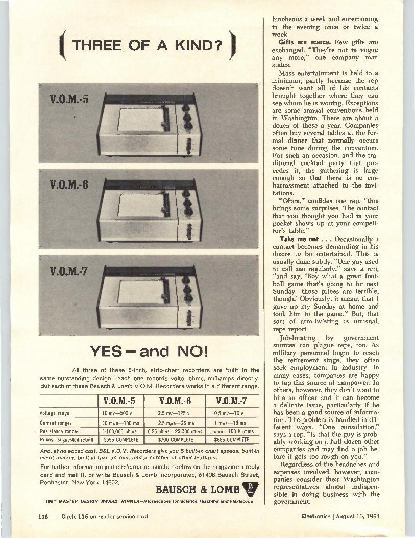
( THREE OF A KIND?
YES and NO! All three of these 5-inch, strip-chart recorders are built to the
same outstanding design—each one records volts, ohms, milliamps directly. But each of these Bausch & Lomb V.O.M. Recorders works in a different range.
V.O.M.-5 V.O.M.-6 V.O.M.-7 Voltage range: 10 mv-500 y 2.5 my-125 y 0.5 my-10 v
Current range: 10 mga-100 ma 2.5 mua-25 ma 1 mita-10 ma
Resistance range: 1-100,000 ohms 0.25 ohms-25,000 ohms 1 ohm-100 K ohms
Prices: (suggested retail) $595 COMPLETE $700 COMPLETE $885 COMPLETE
And, at no added cost, B&L V.O.M. Recorders give you 5 built-in chart speeds, built-in event marker, built-in take-up reel, and a number of other features.
For further information just circle our ad number below on the magazine s reply card and mail it, or write Bausch & Lomb Incorporated, 61408 Bausch Street, Rochester, New York 14602.
BAUSCH 8c LOMB 1964 MASTER DESIGN AWARD WINNER—Microscopes for Science Teaching and FlexIscope
luncheons a week and entertaining in the evening once or twice a week.
Gifts are scarce. Few gifts are exchanged. "They're not in vogue any more," one company man states. Mass entertainment is held to a
minimum, partly because the rep doesn't want all of his contacts brought together where they can see whom he is wooing. Exceptions are some annual conventions held in Washington. There are about a dozen of these a year. Companies often buy several tables at the for-mal dinner that normally occurs some time during the convention. For such an occasion, and the tra-ditional cocktail party that pre-cedes it, the gathering is large enough so that there is no em-barrassment attached to the invi-tations.
"Often," confides one rep, "this brings some surprises. The contact that you thought you had in your pocket shows up at your competi-tor's table." Take me out .. . Occasionally a
contact becomes demanding in his desire to be entertained. This is usually done subtly. "One guy used to call me regularly," says a rep, "and say, 'Boy what a great foot-ball game that's going to be next Sunday—those prices are terrible, though.' Obviously, it meant that I gave up my Sunday at home and took him to the game." But, that sort of arm-twisting is unusual, reps report.
Job-hunting by government sources can plague reps, too. As military personnel begin to reach the retirement stage, they often seek employment in industry. In many cases, companies are happy to tap this source of manpower. In others, however, they don't want to hire an officer and it can become a delicate issue, particularly if he has been a good source of informa-tion. The problem is handled in dif-ferent ways. "One consolation," says a rep, "is that the guy is prob-ably working on a half-dozen other companies and may find a job be-fore it gets too rough on you."
Regardless of the headaches and expenses involved, however, com-panies consider their Washington representatives almost indispen-sible in doing business with the government.
116 Circle 116 on reader service card Electronics I August 10, 1964
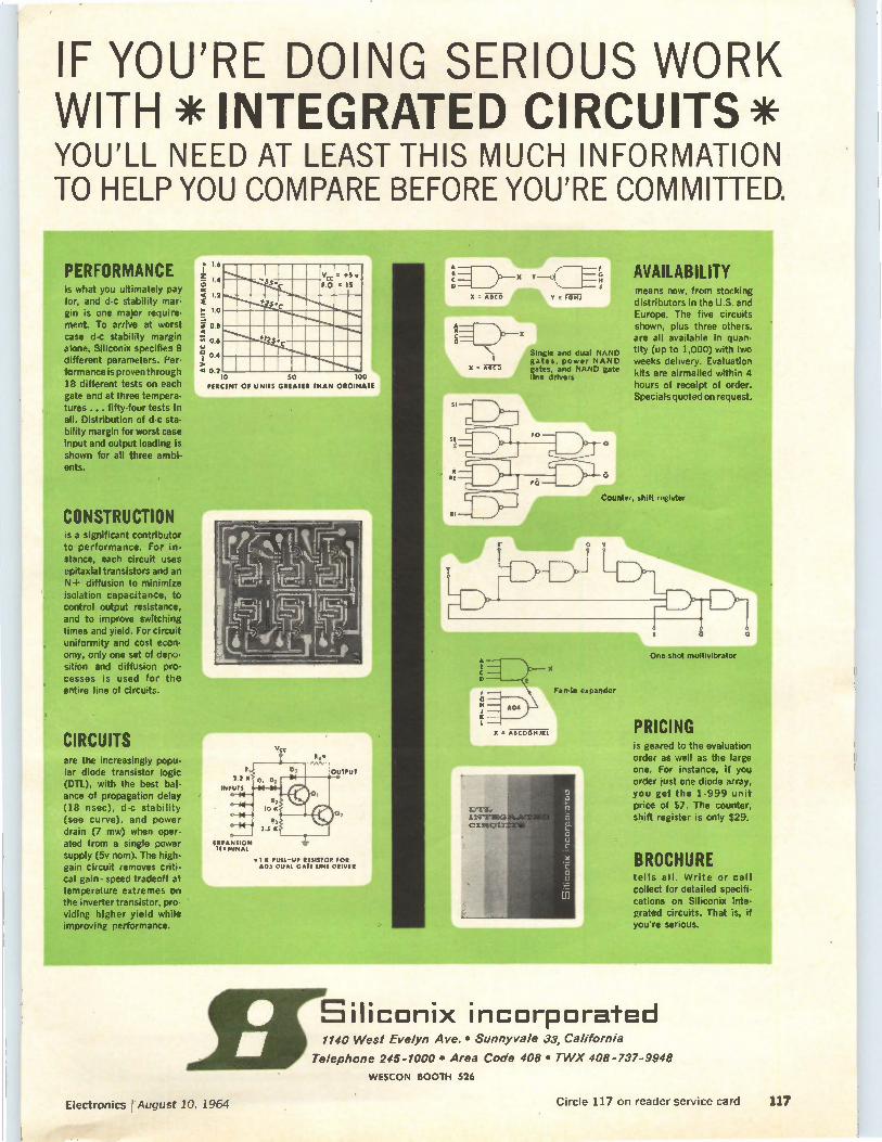
IF YOU'RE DOING SERIOUS WORK WITH*INTEGRATED CIRCUITS* YOU'LL NEED AT LEAST THIS MUCH INFORMATION TO HELP YOU COMPARE BEFORE YOU'RE COMMITTED.
PERFORMANCE is what you ultimately pay for, and d-c stability mar-gin is one major require-ment. To arrive at worst case d-c stability margin alone, Siliconix specifies 8 different parameters. Per.
nce is proven th rough 18 different tests on each gate and at three tempera-tures ... fifty-four tests in all. Distribution of cl-c sta. bility margin for worst ease input and output loading is shown for all three ambl-ents.
CONSTRUCTION is a significant contributor to performance. For in-stance, each circuit uses epitaxial transistors and an N+ diffusion to minimize isolation capacitance, to control output resistance, and to improve switching times and yield. For circuit uniformity and cost econ-omy, only one set of dep.°. sition and diffusion pro-cesses is used for the entire line of circuits.
are the increasingly popu-lar diode transistor logic (DTL), with the best bal. ance of propagation delay (18 nsec), d-c stability (see curve), and power drain (7 mw) when oper-ated from a single power supply (5v nom). The high. gain circuit removes criti-cal gain- speed tradeoff at temperature extremes on the inverter transistor, pro-viding higher yield while improving performance.
means now, from stocking distributors in the U.S. and Europe. The five circuits shown, plus three others, are all available in quan-tity (up to 1,000) with two weeks delivery. Evaluation kits are airmailed within 4 hours of receipt of order. Specials quoted on request.
PRICING Is geared to the evaluation order as well as the large one. For instance, if you order just one diode array, you get the 1-999 unit price of $7. The counter, shift register is only $29.
BROCHURE tells all. Write or call collect for detailed specifi-cations on Siliconix inte-grated circuits. That is, if you're serious.
E l 1140 West Evelyn Ave. • Sunnyvale 33, California
Telephone 245-1000 • Area Code 408 • TWX 408-737-9948
WESCON BOOTH 526
Eiliconix incorporated
Electronics August 10, 1964 Circle 117 on reader service card 117
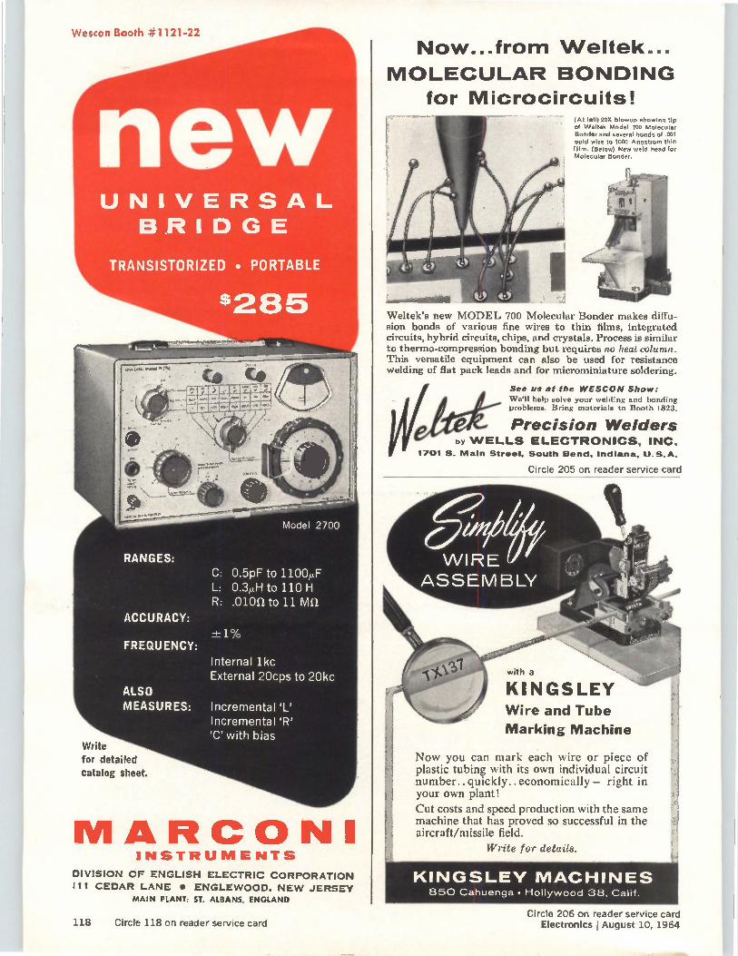
Wescon Booth #1121-22
UNIVERSAL BRIDGE
TRANSISTORIZED • PORTABLE
$285
RANGES:
ACCURACY:
FREQUENCY:
ALSO MEASURES:
Write
for detailed
catalog sheet.
MARCONI
Model 2700
C: 0.5pF to 1100,uF L: 0.3,uH to 110 H R: .010f1 to 11 Mfl
Internal lkc External 20cps to 20kc
Incremental 'L' Incremental 'R' 'C' with bias
INSTRUMENTS
DIVISION OF ENGLISH ELECTRIC CORPORATION
III CEDAR LANE • ENGLEWOOD. NEW JERSEY MAIN PLANT: ST. ALBANS, ENGLAND
Now...from Weltek...
MOLECULAR BONDING for Microcircuits!
(At left) 205 blowup showing tip of Weltek Model 700 Molecular Bonder and several bonds of .001 gold wire to 1000 Angstrom thin f ilm. (Below) New weld head for Molecular Bonder.
Weltek's new MODEL 700 Molecular Bonder makes diffu-sion bonds of various fine wires to thin films, integrated circuits, hybrid circuits, chips, and crystals. Process is similar to thermo-compression bonding but requires no heat column. This versatile equipment can also be used for resistance welding of flat pack leads and for microminiature soldering.
See us at the WESCON Show:
We'll help solve your welding and bonding problems. Bring materials to Booth 1823.
Precision Welders by WELLS ELECTRONICS, INC.
1701 S. Main Street, South Bend, Indiana, U.S.A.
Circle 205 on reader service card
KINGSLEY Wire and Tube
Marking Machine
Now you can mark each wire or piece of plastic tubing with its own individual circuit number., quickly.. economically — right in your own plant!
Cut costs and speed production with the same machine that has proved so successful in the aircraft/missile field.
Write for details.
4 KINGSLEY MACHINES 850 Chuenga • Hollywood 38, Calif.
118 Circle 118 on reader service card Circle 206 on reader service card
Electronics I August 10, 1964

eï,
Find the manufacturer... Fast! It's just a matter of seconds to get the valuable information you need about electronic manufacturers and suppliers in the Electronics Buyers' Guide. The EBG has over 200 pages listing the names, addresses, phone numbers and key individuals of manufacturers of electronics equipment, related components and materials. All this plus vital company statistics. At a glance you know important facts about the company, exactly what each company makes, and where to find the manufacturers' representatives in your area. No wonder the EBG is the industry's standard catalog-directory!
Electronics Buyers' Guide A McGraw-Hill Publication 330 West 42nd Street, New York, N. Y. 10036
Electronics, I August 10, 1964 119
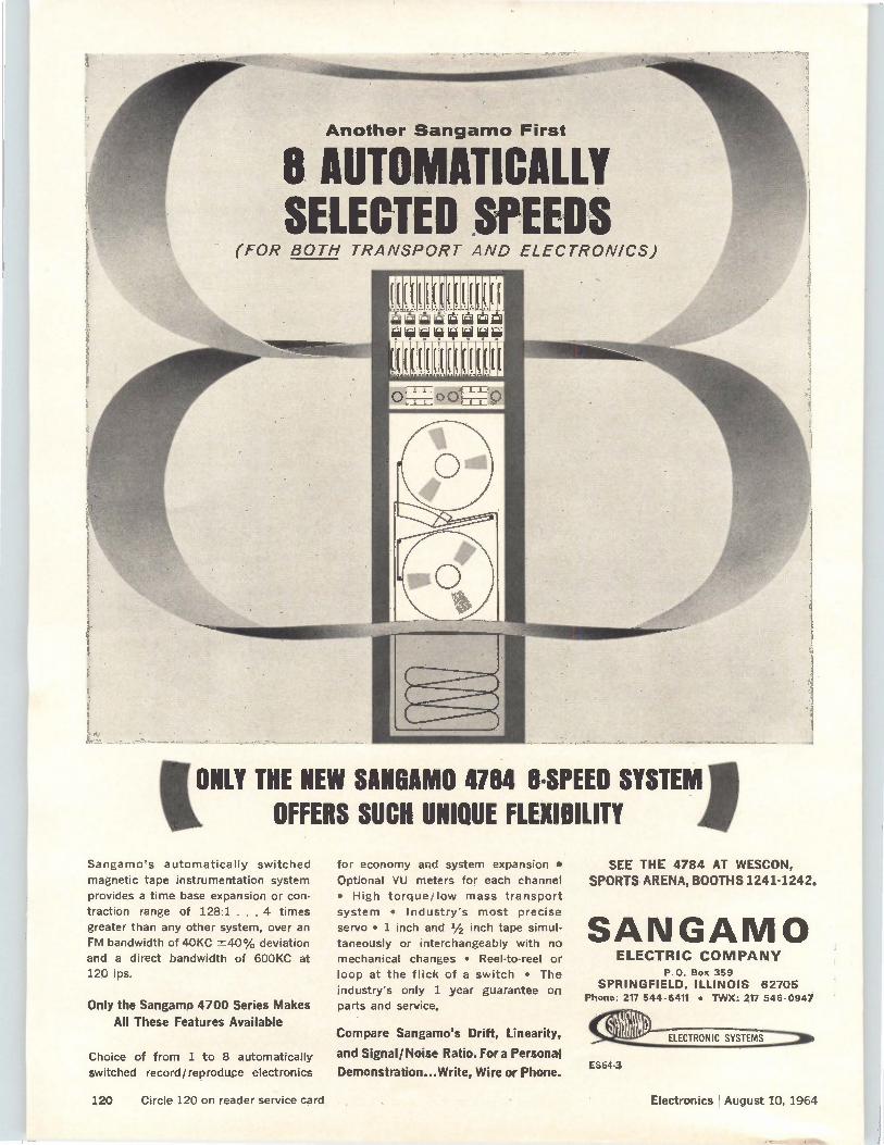
Another Sangamo First
O AUTOMATICALLY SELECTED SPEEDS
(FOR BOTH TRANSPORT AND ELECTRONICS)
aiàiâàiiÀ1Q&I QQIQQQiiiQQ
ONLY THE NEW SANOAMO 4784 8.SPEED SYSTEM OFFERS SUCH UNIQUE FLEXIBILITY
Sangamo's automatically switched
magnetic tape instrumentation system
provides a time base expansion or con-
traction range of 128:1 . . . 4 times
greater than any other system, over an
FM bandwidth of 40KC deviation
and a direct bandwidth of 600KC at
120 ips.
Only the Sangamo 4700 Series Makes All These Features Available
Choice of from 1 to 8 automatically switched record/reproduce electronics
for economy and system expansion •
Optional VU meters for each channel
• High torque/low mass transport
system • Industry's most precise
servo • 1 inch and 1/2 inch tape simul-
taneously or interchangeably with no
mechanical changes • Reel-to-reel or
loop at the flick of a switch • The
industry's only 1 year guarantee on
parts and service.
Compare Sangamo's Drift, Linearity,
and Signal/Noise Ratio. Fora Personal
Demonstration...Write, Wire or Phone.
SEE THE 4784 AT WESCON, SPORTS ARENA, BOOTHS 1241-1242.
SANGAMO ELECTRIC COMPANY
P.O. Box 359
SPRINGFIELD, ILLINOIS 62705 Phone: 217 544-6411 • TVVX: 217 546-0947
ES64-3
120 Circle 120 on reader service card Electronics I August 10, 1964
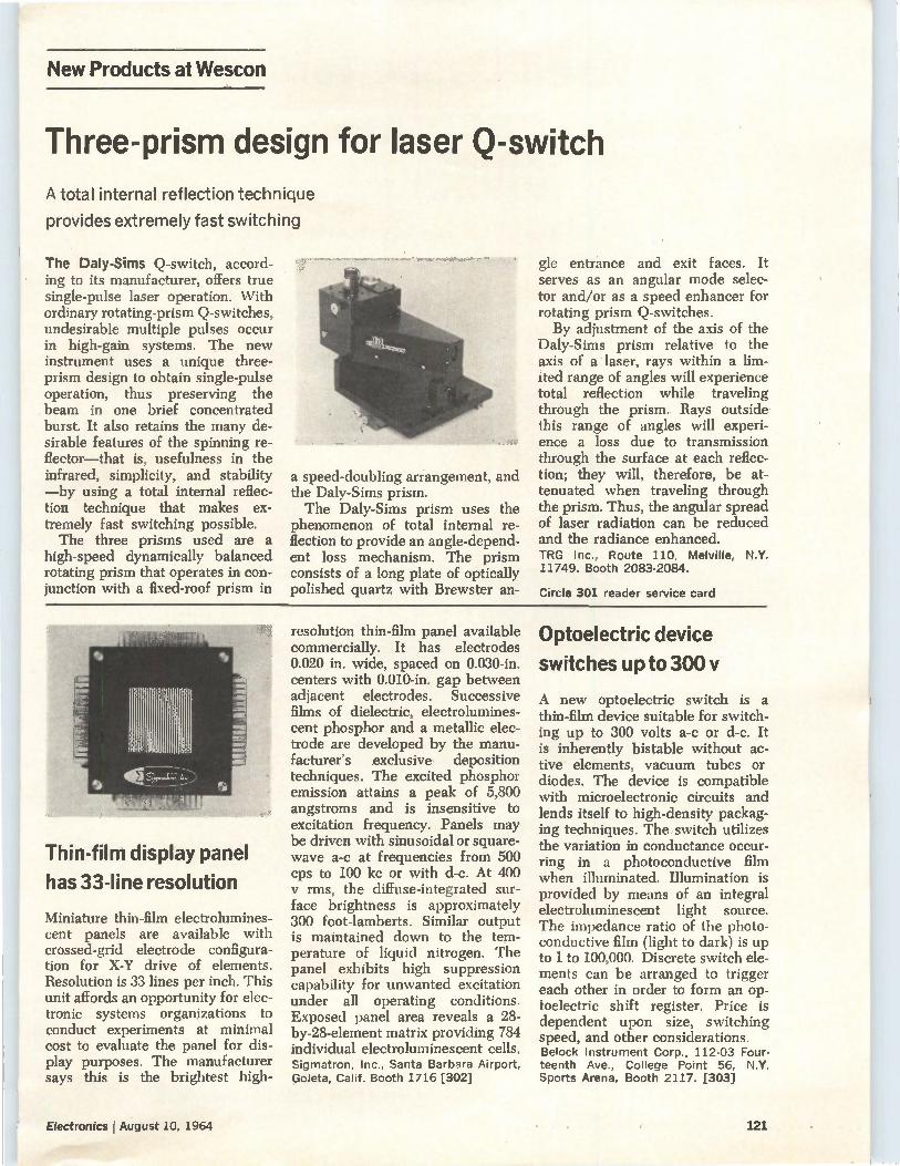
New Products at Wescon
Three-prism design for laser Q-switch A total internal reflection technique
provides extremely fast switching
The Daly-Sims Q-switch, accord-ing to its manufacturer, offers true single-pulse laser operation. With ordinary rotating-prism Q-switches, undesirable multiple pulses occur in high-gain systems. The new instrument uses a unique three-prism design to obtain single-pulse operation, thus preserving the beam in one brief concentrated burst. It also retains the many de-sirable features of the spinning re-flector—that is, usefulness in the infrared, simplicity, and stability —by using a total internal reflec-tion technique that makes ex-tremely fast switching possible. The three prisms used are a
high-speed dynamically balanced rotating prism that operates in con-junction with a fixed-roof prism in
a speed-doubling arrangement, and the Daly-Sims prism. The Daly-Sims prism uses the
phenomenon of total internal re-flection to provide an angle-depend-ent loss mechanism. The prism consists of a long plate of optically polished quartz with Brewster an-
gle entrance and exit faces. It serves as an angular mode selec-tor and/or as a speed enhancer for rotating prism Q-switches. By adjustment of the axis of the
Daly-Sims prism relative to the axis of a laser, rays within a lim-ited range of angles will experience total reflection while traveling through the prism. Rays outside this range of angles will experi-ence a loss due to transmission through the surface at each reflec-tion; they will, therefore, be at-tenuated when traveling through the prism. Thus, the angular spread of laser radiation can be reduced and the radiance enhanced. TRG Inc., Route 110, Melville, N.Y. 11749. Booth 2083-2084.
Circle 301 reader service card
Thin-film display panel
has 33-line resolution
Miniature thin-film electrolumines-cent panels are available with crossed-grid electrode configura-tion for X-Y drive of elements. Resolution is 33 lines per inch. This unit affords an opportunity for elec-tronic systems organizations to conduct experiments at minimal cost to evaluate the panel for dis-play purposes. The manufacturer says this is the brightest high-
resolution thin-film panel available commercially. It has electrodes 0.020 in. wide, spaced on 0.030-in. centers with 0.010-in, gap between adjacent electrodes. Successive films of dielectric, electrolumines-cent phosphor and a metallic elec-trode are developed by the manu-facturer's exclusive deposition techniques. The excited phosphor emission attains a peak of 5,800 angstroms and is insensitive to excitation frequency. Panels may be driven with sinusoidal or square-wave a-c at frequencies from 500 cps to 100 kc or with d-c. At 400
rms, the diffuse-integrated sur-face brightness is approximately 300 foot-lamberts. Similar output is maintained down to the tem-perature of liquid nitrogen. The panel exhibits high suppression capability for unwanted excitation under all operating conditions. Exposed panel area reveals a 28-by-28-element matrix providing 784 individual electroluminescent cells. Sigmatron, Inc., Santa Barbara Airport, Goleta, Calif. Booth 1716 [302]
Optoelectric device
switches up to 300 y
A new optoelectric switch is a thin-film device suitable for switch-ing up to 300 volts a-c or d-c. It is inherently bistable without ac-tive elements, vacuum tubes or diodes. The device is compatible with microelectronic circuits and lends itself to high-density packag-ing techniques. The switch utilizes the variation in conductance occur-ring in a photoconductive film when illuminated. Illumination is provided by means of an integral electroluminescent light source. The impedance ratio of the photo-conductive film (light to dark) is up to 1 to 100,000. Discrete switch ele-ments can be arranged to trigger each other in order to form an op-toelectric shift register. Price is dependent upon size, switching speed, and other considerations. Belock Instrument Corp., 112-03 Four-teenth Ave., College Point 56, N.Y. Sports Arena, Booth 2117. [303]
Electronics r August 10, 1964 121
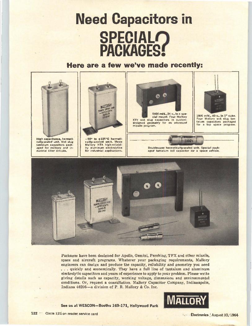
Need Capacitors in SPECIALn PACKAGES:
Here are a few we've made recently:
High capacitance, hermeti-cally-sealed unit. Wet slug tantalum capacitors pack-aged for military and in-dustrial filter circuits.
—55° to +125°C hermeti-cally-sealed unit. Three Mallory HTA high-reliabil-ity aluminum electrolytics for industrial applications.
5400 mfd., 24 v., in a spe-cial mount. Four Mallory
XTV wet slug capacitors in custom-designed geometry for an advanced missile program.
1000 mfd., 40 v., in 1" cube. Four Mallory wet slug tan-talum capacitors packaged for a top space program.
Double-ease hermetically-sealed unit. Special pack-aged tantalum foil capacitor for a space vehicle.
Packages have been designed for Apollo, Gemini, Pershing, TFX and other missile, space and aircraft programs. Whatever your packaging requirements, Mallory engineers can design and produce the capacity, reliability and geometry you need . . . quickly and economically. They have a full line of tantalum and aluminum electrolytic capacitors and years of experience to apply to your problem. Please write giving details such as capacity, working voltage, dimensions and environmental conditions. Or, request a consultation. Mallory Capacitor Company, Indianapolis, Indiana 46206—a division of P. R. Mallory & Co. Inc.
See us at WESCON—Booths 169-171, Hollywood Park MALLORY
122 • Circle 122 on reader service card Electronics August 10,'1964
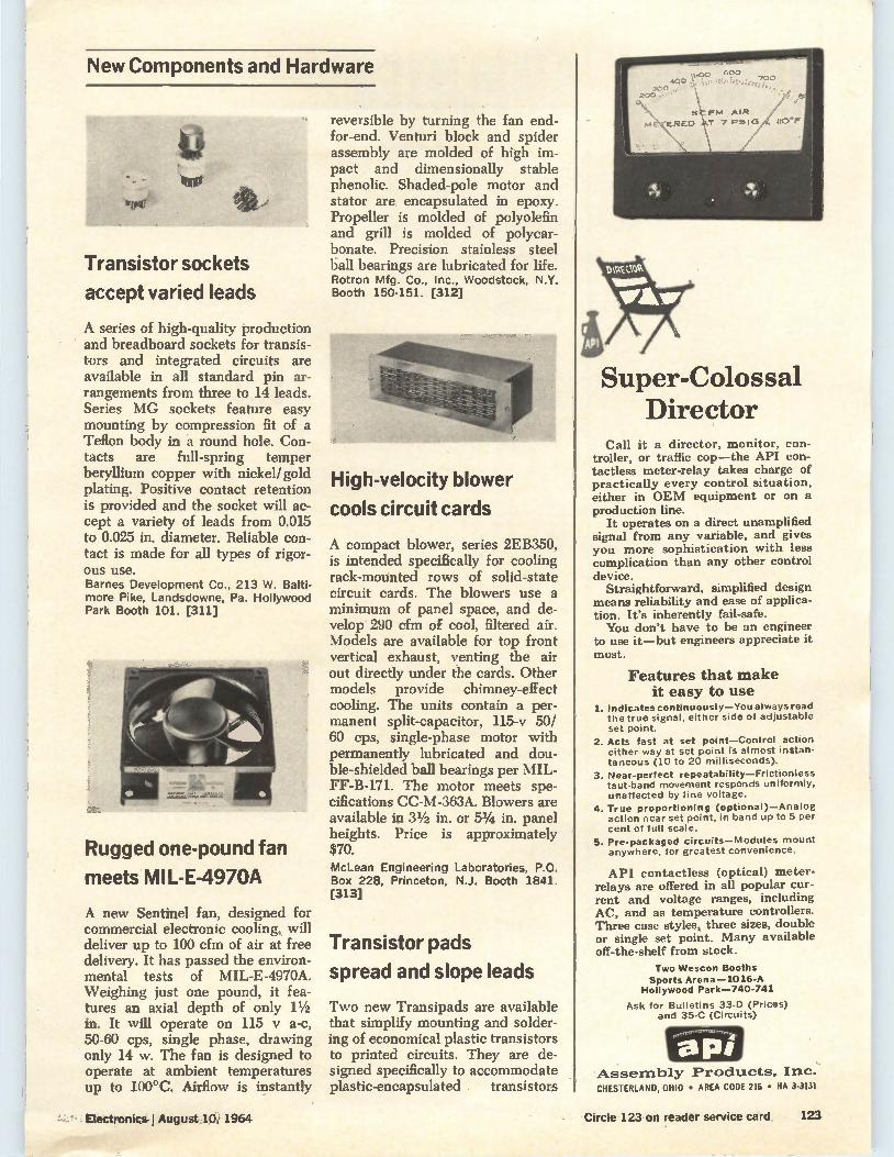
New Components and Hardware
Transistor sockets
accept varied leads
A series of high-quality production and breadboard sockets for transis-tors and integrated circuits are available in all standard pin ar-rangements from three to 14 leads. Series MG sockets feature easy mounting by compression fit of a Teflon body in a round hole. Con-tacts are full-spring temper beryllium copper with nickel/gold plating. Positive contact retention is provided and the socket will ac-cept a variety of leads from 0.015 to 0.025 in. diameter. Reliable con-tact is made for all types of rigor-ous use. Barnes Development Co., 213 W. Balti-more Pike, Landsdowne, Pa. Hollywood Park Booth 101. [311]
Rugged one-pound fan
meets MI L-E-4970A
A new Sentinel fan, designed for commercial electronic cooling, will deliver up to 100 cfm of air at free delivery. It has passed the environ-mental tests of MIL-E-4970A. Weighing just one pound, it fea-tures an axial depth of only 11/2 in. It will operate on 115 y a-c, 50-60 cps, single phase, drawing only 14 w. The fan is designed to operate at ambient temperatures up to 100°C. Airflow is instantly
reversible by turning the fan end-for-end. Venturi block and spider assembly are molded of high im-pact and dimensionally stable phenolic. Shaded-pole motor and stator are encapsulated in epoxy. Propeller is molded of polyolefin and grill is molded of polycar-bonate. Precision stainless steel ball bearings are lubricated for life. Rotron Mfg. Co., Inc., Woodstock, N.Y. Booth 150-151. [312]
High-velocity blower
cools circuit cards
A compact blower, series 2EB350, is intended specifically for cooling rack-mounted rows of solid-state circuit cards. The blowers use a minimum of panel space, and de-velop 290 cfm of cool, filtered air. Models are available for top front vertical exhaust, venting the air out directly under the cards. Other models provide chimney-effect cooling. The units contain a per-manent split-capacitor, 115-v 50/ 60 cps, single-phase motor with permanently lubricated and dou-ble-shielded ball bearings per MIL-FF-B-171. The motor meets spe-cifications CC-M-363A. Blowers are available in 31/2 in. or 5% in. panel heights. Price is approximately $70. McLean Engineering Laboratories, P.O. Box 228, Princeton, N.J. Booth 1841. [313]
Transistor pads
spread and slope leads
Two new Transipads are available that simplify mounting and solder-ing of economical plastic transistors to printed circuits. They are de-signed specifically to accommodate plastic-encapsulated . transistors
Super-Colossal Director
Call it a director, monitor, con-troller, or traffic cop—the API con-tactless meter-relay takes charge of practically every control situation, either in OEM equipment or on a production line.
It operates on a direct unamplified signal from any variable, and gives you more sophistication with less complication than any other control device.
Straightforward, simplified design means reliability and ease of applica-tion. It's inherently fail-safe. You don't have to be an engineer
to use it—but engineers appreciate it most.
Features that make it easy to use
1. Indicates continuously—You always read the true signal, either side of adjustable set point.
2. Acts fast at set point—Control action either way at set point is almost instan-taneous (10 to 20 milliseconds).
3. Near-perfect repeatability—Frictionless taut-band movement responds uniformly, unaffected by line voltage.
4. True proportioning (optional)—Analog action near set point, in band up to 5 per cent of full scale.
5. Pre-packaged circuits—Modules mount anywhere, for greatest convenience.
API contactless (optical) meter-relays are offered in all popular cur-rent and voltage ranges, including AC, and as temperature controllers. Three case styles, three sizes, double or single set point. Many available off-the-shelf from stock.
Two Wescon Booths Sports Arena —1016-A
Hollywood Park-740-741
Ask for Bulletins 33-D (Prices) and 35-C (Circuits)
-Assembly Products, Inc: CHESTERLAND, OHIO • AREA CODE 216 • HA 3-3131
Electronics I August 10; 1964
-e
Circle 123 on reader service card 123
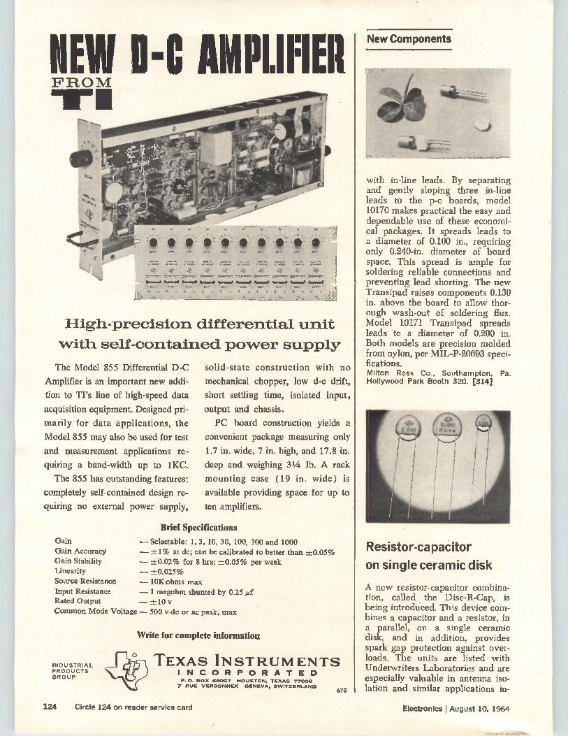
HEW Ike AMPLIFIER FROM
High-precision differential unit
with self-contained power supply
The Model 855 Differential D-C
Amplifier is an important new addi-
tion to TI's line of high-speed data
acquisition equipment. Designed pri-
marily for data applications, the
Model 855 may also be used for test
and measurement applications re-
quiring a band-width up to 1KC.
The 855 has outstanding features:
completely self-contained design re-
quiring no external power supply,
Gain Gain Accuracy Gain Stability Linearity
Source Resistance
Input Resistance Rated Output
Common Mode Voltage — 500 v-dc or ac peak,' max
solid-state construction with no
mechanical chopper, low d-c drift,
short settling time, isolated input,
output and chassis.
PC board construction yields a
convenient package measuring only
1.7 in. wide, 7 in. high, and 17.8 in.
deep and weighing 31/4 lb. A rack
mounting case (19 in. wide) is
available providing space for up to
ten amplifiers.
Brief Specifications
— Selectable: 1, 3, 10, 30, 100, 300 and 1000 — ±1% at dc; can be calibrated to better than ±0.05% — ±0.02% for 8 hrs; ±0.05% per week — ±0.025% — 10K ohms max
— 1 megohm shunted by 0.25 ef — ±10 v
INDUSTRIAL PRODUCTS GROUP
Write for complete information
‘!lenO TEXAS INSTRUMENTS LI INCORPORATED P.O. 'BOX 66027 HOUSTON, TEXAS 77006 7 RUE VERSONNEX GENEVA, SWITZERLAND
678
New Components
with in-line leads. By separating and gently sloping three in-line leads to the p-c boards, model 10170 makes practical the easy and dependable use of these economi-cal packages. It spreads leads to a diameter of 0.100 in., requiring only 0.240-in, diameter of board space. This spread is ample for soldering reliable connections and preventing lead shorting. The new Transipad raises components 0.130 in. above the board to allow thor-ough wash-out of soldering flux. Model 10171 Transipad spreads leads to a diameter of 0.200 in. Both models are precision molded from nylon, per MIL-P-20693 speci-fications. Milton Ross Co., Southampton, Pa. Hollywood Park Booth 320. [314]
Resistor-capaCitor
on single ceramic disk
A new resistor-capacitor combina-tion, called the Disc-R-Cap, is being introduced. This device com-bines a capacitor and a resistor, in a parallel, on a single ceramic disk, and in addition, provides spark gap protection against over-loads. The units are listed with Underwriters Laboratories and are especially valuable in antenna iso-lation and similar applications in-
124 Circle 124 on reader service card Electronics I August 10, 1964
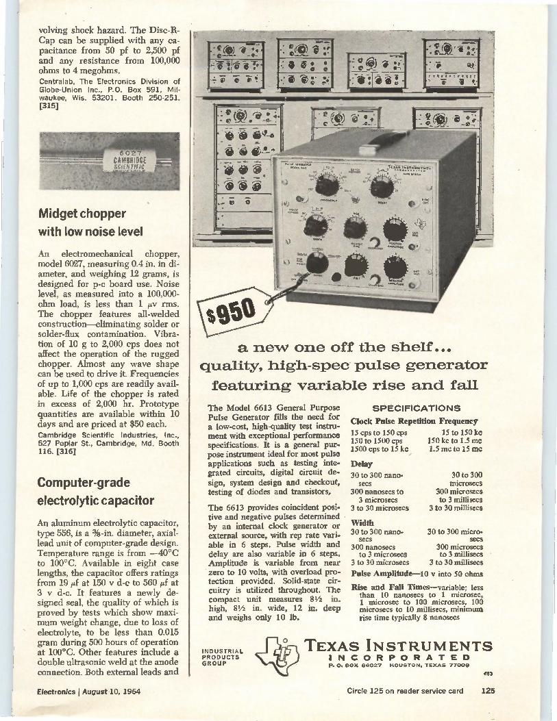
volving shock hazard. The Disc-R-Cap can be supplied with any ca-pacitance from 50 pf to 2,500 pf and any resistance from 100,000 ohms to 4 megohms. Centralab, The Electronics Division of Globe-Union Inc., P.O. Box 591, Mil-waukee, Wis. 53201. Booth 250-251. [315]
6 0 2 7 CRIOGE SY.!i Nrifie
Midget chopper
with low noise level
An electromechanical chopper, model 6027, measuring 0.4 in. in di-ameter, and weighing 12 grams, is designed for p-c board use. Noise level, as measured into a 100,000-ohm load, is less than 1 py rms. The chopper features all-welded construction—eliminating solder or solder-flux contamination. Vibra-tion of 10 g to 2,000 cps does not affect the operation of the rugged chopper. Almost any wave shape can be used to drive it. Frequencies of up to 1,000 cps are readily avail-able. Life of the chopper is rated in excess of 2,000 hr. Prototype quantities are available within 10 days and are priced at $50 each. Cambridge Scientific Industries, Inc., 527 Poplar St., Cambridge, Md. Booth 116. [316]
Computer-grade
electrolytic capacitor
An aluminum electrolytic capacitor, type 556, is a %-in. diameter, axial-lead unit of computer-grade design. Temperature range is from —40°C to 100°C. Available in eight case lengths, the capacitor offers ratings from 19 pf at 150 y d-c to 560 pf at 3 y d-c. It features a newly de-signed seal, the quality of which is proved by tests which show maxi-mum weight change, due to loss of electrolyte, to be less than 0.015 gram during 500 hours of operation at 100°C. Other features include a double ultrasonic weld at the anode connection. Both external leads and
• cei ) re • ;. • e • -0-
▪ 4> 6LS-6
a new one off the shelf...
quality, high-spec pulse generator
featuring variable rise and fall
The Model 6613 General Purpose Pulse Generator fills the need for a low-cost, high-quality test instru-ment with exceptional performance specifications. It is a general pur-pose instrument ideal for most pulse applications such as testing inte-grated circuits, digital circuit de-sign, system design and checkout, testing of diodes and transistors.
The 6613 provides coincident posi-tive and negative pulses determined by an internal clock generator or external source, with rep rate vari-able in 6 steps. Pulse width and delay are also variable in 6 steps. Amplitude is variable from near zero to 10 volts, with overload pro-tection provided. Solid-state cir-cuitry is utilized throughout. The compact unit measures 81/2 in. high, 81/2 in. wide, 12 in. deep and weighs only 10 lb.
INDUSTRIAL PRODUCTS GROUP
SPECIFICATIONS
Clock Pulse Repetition Frequency
15 cps to 150 cps 15 to 150 kc 150 to 1500 cps 150 kc to 1.5 mc 1500 cps to 15 kc 1.5 mc to 15 mc
Delay
30 to 300 nano. 30 to 300 secs microsecs
300 nanosecs to 300 microsecs 3 microsecs to 3 millisecs
3 to 30 microsecs 3 to 30 millisecs
Width 30 to 300 nano-
secs 300 nanosecs
to 3 microsecs 3 to 30 microsecs
30 to 300 micro-secs
300 microsecs to 3 millisecs
3 to 30 millisecs
Pulse Amplitude-10 v. into 50 ohms
Rise and Fall Times—variable: less than 10 nanosecs to 1 microsec, 1 microsec to 100 microsecs, 100 microsecs to 10 millisecs, minimum rise time typically 8 nanosecs
TEXAS INSTRUMENTS INCORPORATED e. O. BOX 66027 HOUSTON. TEXAS 77006
653
Electronics I August 10, 1964 Circle 125 on reader service card 125
Not Everyone Can Use This Logic Card
Maybe your logic system can get by with 100kc clock rates. Okay—perhaps this ad is not for you.
But if you have to work at rates above 10mc—or if you're working at very low rates, but want the advantages of short propagation delays, excellent noise rejec-tion and high fan-in fan-out capabil ity— Intercontinental's NAND logic cards will meet virtually any need you can name.
They're available for all digital logic op-erationi, at both 3mc and 10mc rates, and in either germanium or silicon typeS for extreme environments. Prices? No more than for run-of-the-Mill 100kc cards. For example:
indicates that 10mc unit is to be used.
GERMANIUM SILICON
3mc 10mc 3mc 10mc
Digital Gates (8) $40 $ 64 $ 67 $ 85
Diode Clusters 27 37 40 48
Basic Flip Flops (4) 40 64 70 98
Counter Flip Flops (4) 54 84 97 132
General Purpose Flip Flops (4) 60 90 100 138
Power Drivers (4) 75 110 96 150
Delay Multivibrators (2) " 110 " 135
Free-Running Multivibrators (2) ' 141 * 175
Crystal Oscillator and Power Amplifier ' 125 ' 149
Schmitt Trigger (2) " 120 • 140
Nixie Driver and Decimal Decoder 77 87 130 169
All tnodels are dip-so dered on 3{e" glass epoxy G-10 laminated board, have color-coded end - plates and 35-pin connectors for rack-mounted trays. Detailed specs? Just call or write.
INTERCONTINENTAL INSTRUMENTS INC. 123 Gana Blvd., Farmingdale, N.Y.
Phone: (516) MYrtle 4-6060"
New Components
:Peen
the cathode tab connection are also welded. High purity foil, 99.99+% pure, is used in section composi-tion. Sangamo Electric Co., Box 359, Spring-field, Ill. 62705. Hollywood Park Booth 183-184. [317]
Metal film resistors
are conformally coated
A line of conformally coated metal film resistors has been developed. They are claimed to be the first of their kind to meet characteristics C, D and E of MIL-R-10509. Avail-able units include a IA0 watt (MF4C), 1/2 watt (MF52C), 1/4 watt (MF62C) and 1/2 watt (MF72C), all at 125°C. Temperature coefficient for all characteristic D resistors is ±-100 ppm/°C, vs the MIL-R re-quirement of —200 to +500 ppm/ °C. For characteristic C it is -±-50 ppm/°C, while for characteristic E it is ±-25 ppm/°C. These resistors use a high-reliability compression end cap over a noble metal band to provide superior lead attach-ment without restricting resistance range, according to the manufac-
livability (an industrial location advantage)
There's fun-filled living for you and your em-ployees when you locate your plant in WESTern PENNsylvania. Ski on nearby slopes ... fish for wary trout and bass . . . hunt big and small game ... water-ski ... listen to music by a top symphony orchestra ... go to art festivals, opera and straw hat theaters ... or visit reminders of a romantic past Beautiful large-acreage sites, suit-able for industry, are available on many rivers and streams. There's room to spread out... room to live and grow in WESTern PENNsylvania.
WEST PENN POWER an operating unit of ALLEGHENY POWER SYSTEM
INDUSTRIAL SHELL BUILD-INGS available at $2.95 to $3.25 a sq. ft. completed to your specs in 60-90 days.
WESTern PENtisitvania
Area Development Department WEST PENN POWER Greensburg, Pa. 15602
Yes, I'd like more information sylvania:
El 4-Season Livability ID Financing Plans D Industrial Properties
1:1
Phone: 412—TE 74000
about WESTern PENN-
Favorable Tax Climate Pre-production Training
ADA4-12 E
Name
Title
Company
Address
City State
Zip Code Phone
126, — Circle 126 on reader service card Circle 207 on reader service card
Pectronics I August 10,1.964
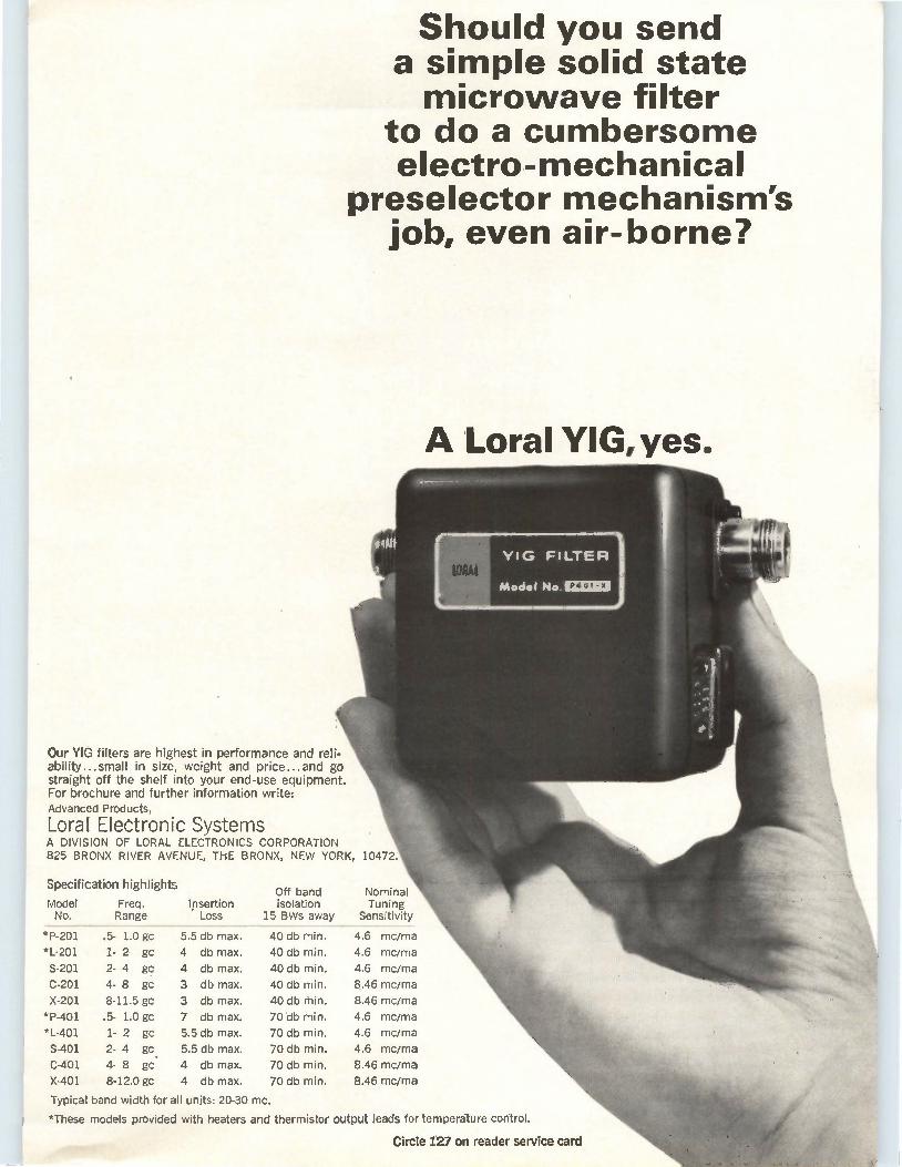
Should you send a simple solid state microwave filter
to do a cumbersome electro-mechanical
preselector mechanism's job, even air-borne?
A Loral YIG, yes.
Our YIG filters are highest in performance and reli-ability...small in size, weight and price.., and go straight off the shelf into your end-use equipment. For brochure and further information write: Advanced Products,
Loral Electronic Systems A DIVISION OF LORAL ELECTRONICS CORPORATION 825 BRONX RIVER AVENUE, THE BRONX, NEW YORK, 10472.
Specification highlights Off band Nominal
Model Freq. Insertion isolation Tuning No. Range Loss 15 BWs away Sensitivity
*P-201 .5- 1.0 gc 5.5 db max. 40 db min. 4.6 mc/ma
*L-201 1- 2 gc 4 db max. 40 db min. 4.6 mc/ma
S-201 2- 4 gc 4 db max. 40 db min. 4.6 mc/ma
C-201 4- 8 gc 3 db max. 40 db min. 8.46 mc/ma
X-201 8-11.5 gc 3 db max. 40 db min. 8.46 mc/ma
*P-401 .5- 1.0 gc 7 db max. 70 db min. 4.6 mc/ma
*L-401 1- 2 gc 5.5 db max. 70 db min. 4.6 mc/ma
S-401 2- 4 gc 5.5 db max. 70 db min. 4.6 mc/ma
C-401 4- 8 go. 4 db max. 70 db min. 8.46 mc/ma
X-401 8-12.0 gc 4 db max. 70 db min. 8.46 mc/ma
Typical band width for all units: 20-30 mc.
*These models provided with heaters and thermistor output leads for temperature control.
Circle 127 on reader service card
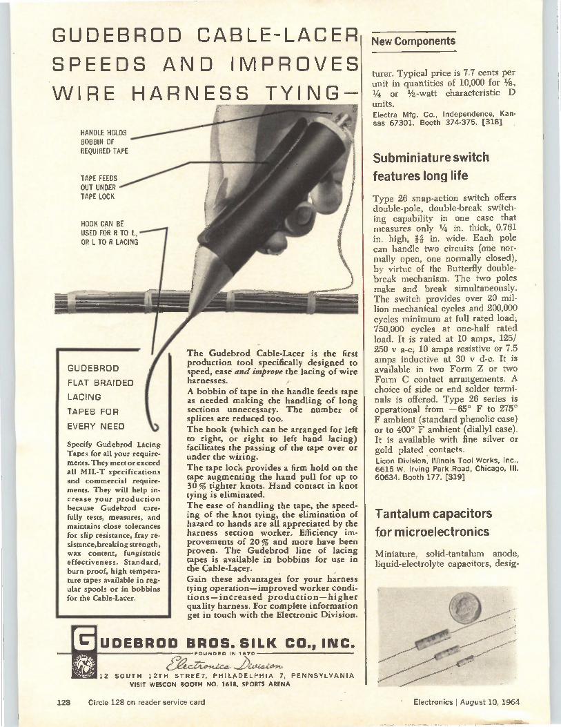
GUDEBROD CABLE-LACER
SPEEDS AND IMPROVES
WIRE HARNESS TYING-
HANDLE HOLDS BOBBIN OF REQUIRED TAPE
TAPE FEEDS OUT UNDER TAPE LOCK
HOOK CAN BE USED FOR R TO L, OR L TO R LACING
•
GUDEBROD
FLAT BRAIDED
LACING
TAPES FOR
EVERY NEED
Specify Gudebrod Lacing Tapes for all your require-ments. They meet or exceed all MIL-T specifications and commercial require-ments. They will help in-crease your production because Gudebrod care-fully tests, measures, and maintains close tolerances for slip resistance, fray re-sistance,breaking strength, wax content, fungistatic effectiveness. Standard, burn proof, high tempera-ture tapes available in reg-ular spools or in bobbins for the Cable-Lacer.
The Gudebrod Cable-Lacer is the first production tool specifically designed to speed, ease and improve the lacing of wire harnesses. A bobbin of tape in the handle feeds tape as needed making the handling of long sections unnecessary. The number of splices are reduced too. The hook (which can be arranged for left to right, or right to left hand lacing) facilitates the passing of the tape over or under the wiring. The tape lock provides a firm hold on the tape augmenting the hand pull for up to 30 % tighter knots. Hand contact in knot tying is eliminated. The ease of handling the tape, the speed-ing of the knot tying, the elimination of hazard to hands are all appreciated by the harness section worker. Efficiency im-provements of 20 % and more have been proven. The Gudebrod line of lacing tapes is available in bobbins for use in the Cable-Lacer. Gain these advantages for your harness tying operation—improved worker condi-tions—increased production—higher quality harness. For complete information get in touch with the Electronic Division.
UDEBROD BROS. SILK CO., INC. FOUNDED IN 1870
eger,LeLst. 12 SOUTH 1 2TH STREET, PHILADELPHIA 7, PENNSYLVANIA
VISIT WESCON BOOTH NO. 1618, SPORTS ARENA
New Components
hirer. Typical price is 7.7 cents per unit in quantities of 10,000 for Ve, V4 or 1/2 -watt characteristic D units.
Electra Mfg. Co., Independence, Kan-sas 67301. Booth 374-375. [318]
Subminiature switch
features long life
Type 26 snap-action switch offers double-pole, double-break switch-
ing capability in one case that measures only 1/4 in. thick, 0.761
in. high, in. wide. Each pole can handle two circuits (one nor-mally open, one normally closed),
by virtue of the Butterfly double-break mechanism. The two poles
make and break simultaneously.
The switch provides over 20 mil-lion mechanical cycles and 200,000 cycles minimum at full rated load;
750,000 cycles at one-half rated load. It is rated at 10 amps, 125/ 250 y a-c; 10 amps resistive or 7.5
amps inductive at 30 y d-c. It is available in two Form Z or two
Form C contact arrangements. A choice of side or end solder termi-nals is offered. Type 26 series is
operational from —65° F to 275°
F ambient (standard phenolic case)
or to 400° F ambient (diallyl case).
It is available with fine silver or gold plated contacts.
Licon Division, Illinois Tool Works, Inc., 6615 W. Irving Park Road, Chicago, Ill. 60634. Booth 177. [319]
Tantalum capacitors
for microelectronics
Miniature, solid-tantalum anode,
liquid-electrolyte capacitors, desig-
128 Circle 128 on reader service card Electronics I August 10, 1964
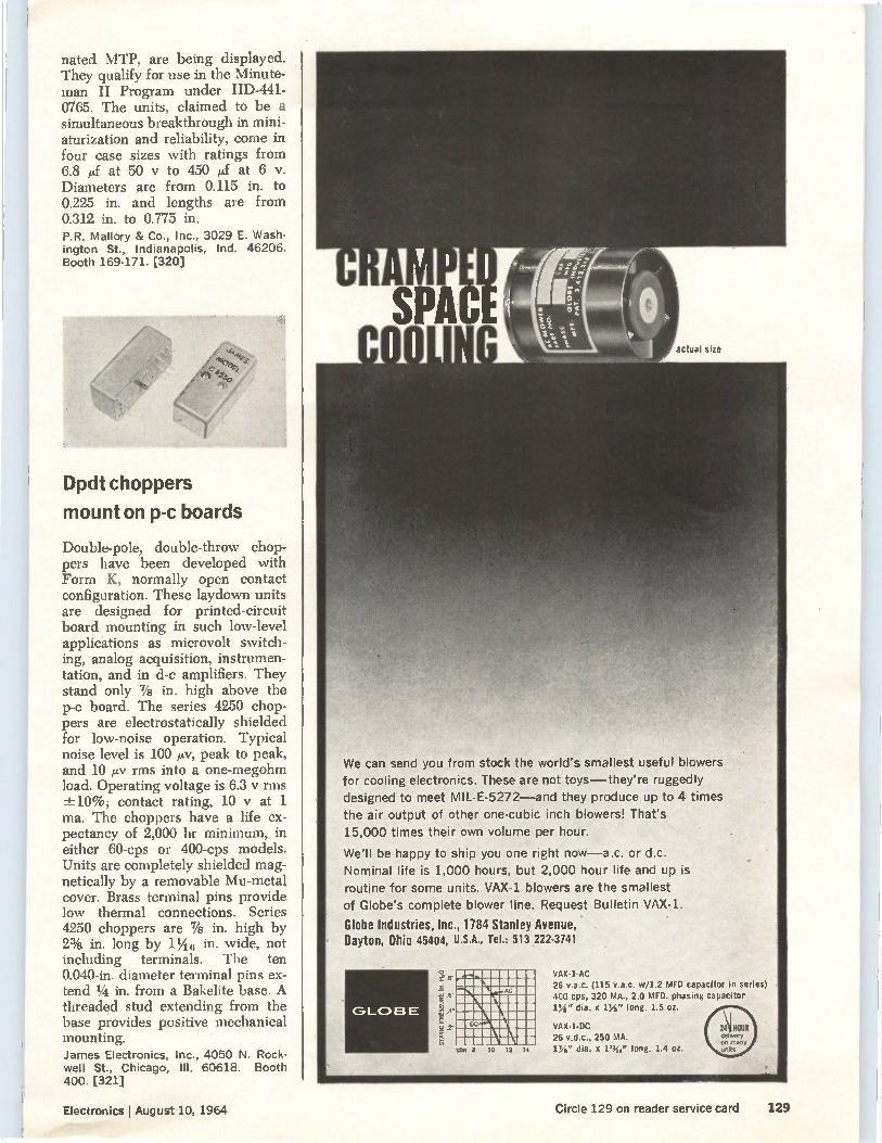
nated MTP, are being displayed. They qualify for use in the Minute-man II Program under IID-441-0765. The units, claimed to be a simultaneous breakthrough in mini-aturization and reliability, come in four case sizes with ratings from 6.8 /If at 50 y to 450 id at 6 V. Diameters are from 0.115 in. to 0.225 in. and lengths are from 0.312 in. to 0.775 in. P.R. Mallory & Co., Inc., 3029 E. Wash-ington St., Indianapolis, Ind. 46206. Booth 169-171. [320]
Dpdt choppers
mount on p-c boards
Double-pole, double-throw chop-pers have been developed with Form K, normally open contact configuration. These laydown units are designed for printed-circuit board mounting in such low-level applications as microvolt switch-ing, analog acquisition, instrumen-tation, and in d-c amplifiers. They stand only 7/s in. high above the p-c board. The series 4250 chop-pers are electrostatically shielded for low-noise operation. Typical noise level is 100 ixv, peak to peak, and 10 ¿Av rms into a one-megohm load. Operating voltage is 6.3 y rms -±10%; contact rating, 10 y at 1 ma. The choppers have a life ex-pectancy of 2,000 hr minimum, in either 60-cps or 400-cps models. Units are completely shielded mag-netically by a removable Mu-metal cover. Brass terminal pins provide low thermal connections. Series 4250 choppers are 7/s in. high by 2% in. long by 11,4 6 in. wide, not including terminals. The ten 0.040-in, diameter terminal pins ex-tend 1/4 in. from a Bakelite base. A threadcd stud extending from the base provides positive mechanical mounting. James Electronics, Inc., 4050 N. Rock-well St., Chicago, III. 60618. Booth 400. [321]
actual size
We can send you from stock the world's smallest useful blowers
for cooling electronics. These are not toys—they're ruggedly
designed to meet MIL-E-5272---and they produce up to 4 times
the air output of other one-cubic inch blowers! That's
15,000 times their own volume per hour.
We'll be happy to ship you one right now—a.c. or d.c.
Nominal life is 1,000 hours, but 2,000 hour life and up is
routine for some units. VAX-1 blowers are the smallest
of Globe's complete blower line. Request Bulletin VAX-1.
Globe Industries, Inc., 1784 Stanley Avenue, Dayton, Ohio 45404, U.S.A., Tel.: 513 222-3741
.1t
GLOBE
memmousil d11111113111111111111131111 iiiMIUM523111111
111•111111101111111111111 111111111110111M1111111111 111111=01110111•1111 11111111111111111111111111 1111111111111111:111101.11111 O,,8 10 12 14
VAX-I-AC 26 v.a.c. (115 v.a.c. w/I.2 MID capacitor in series) 400 cps, 320 MA., 2.0 MID. phasing capacitor VA" dia. x 11/2" long. 1.5 oz.
VAX-I-DC 26 v.d.c., 250 MA. 11/.' dia. X 1%," long. 1.4 oz.
Electronics I August 10, 1964 Circle 129 on reader service card 129
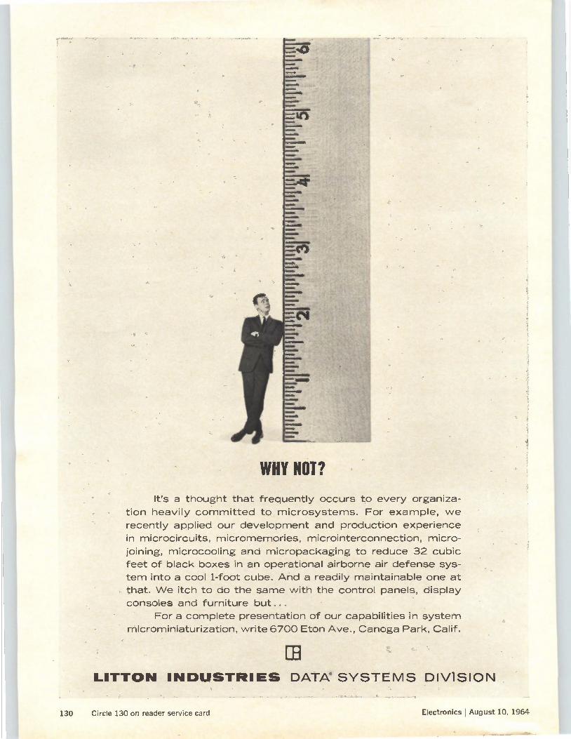
WHY HOT?
111.0•1».10b
Me»
room*
%M▪ OM,
40•11...
•••••••1•0111
we:Me
Ere)
•••••
*I\
.11101.111110e
Wee
•••••••••••••
Wm.
knoolY
emombelli
MIalk
• ,
mom/a
«Mt •
ellee
It's a thought that frequently occurs to every organiza-
tion heavily corn. mitted to microsystems. For example, we
recently applied our development and production experience
in microcircuits, micromemories, microinterconnection, micro-
joining, microcooling and micropackaging to reduce 32 cubic
feet of black boxes in an operational airborne air defense sys-
tem into a cool 1-foot cube. And a readily maintainable one at
that. We itch to do the same with the control panels, display
consoles and furniture but...
For a complete presentation of our capabilities in system
microminiaturization, write 6700 Eton Ave., Canoga Park, Calif.
LITTON INDUSTRIES DATA SYSTEMS DIVISION
130 Circle 130 on reader service card Electronics I August 10, 1964
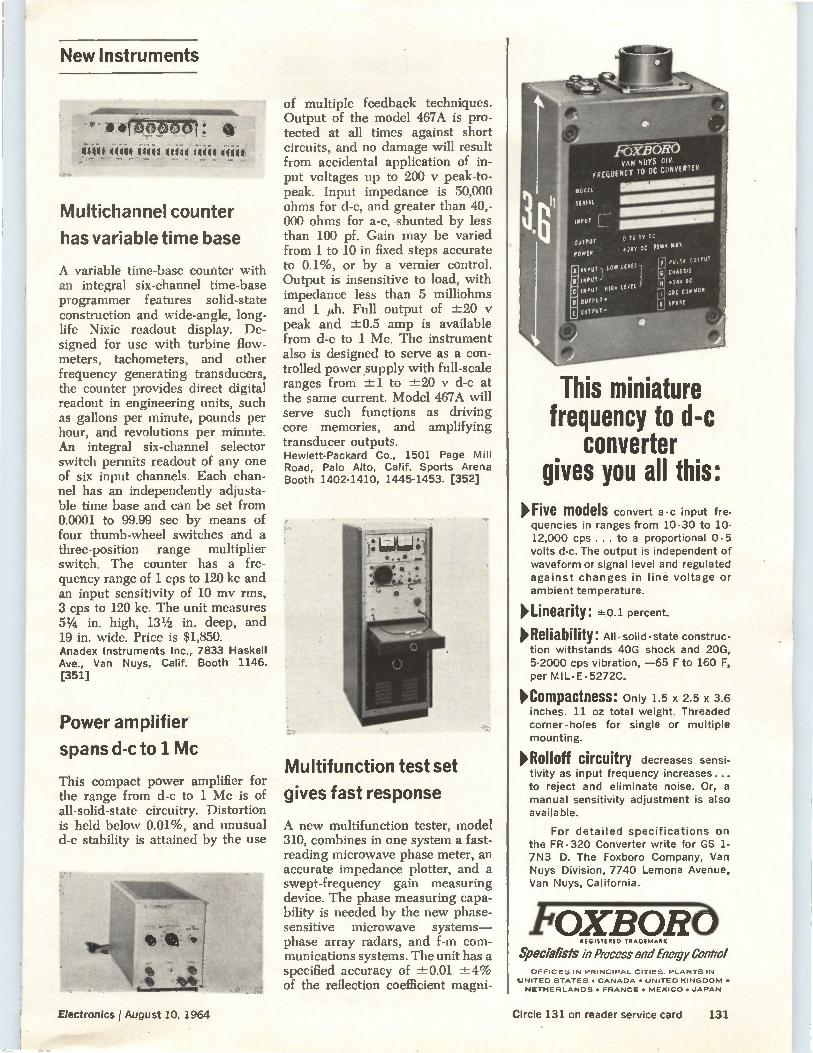
New Instruments
.-• difk)poop , met etgal t4g4g 41PM 44t41
Multichannel counter
has variable time base
A variable time-base counter with an integral six-channel time-base programmer features solid-state construction and wide-angle, long-life Nixie readout display. De-signed for use with turbine flow-meters, tachometers, and other frequency generating transducers, the counter provides direct digital readout in engineering units, such as gallons per minute, pounds per hour, and revolutions per minute. An integral six-channel selector switch permits readout of any one of six input channels. Each chan-nel has an independently adjusta-ble time base and can be set from 0.0001 to 99.99 sec by means of four thumb-wheel switches and a three-position range multiplier switch. The counter has a fre-quency range of 1 cps to 120 kc and an input sensitivity of 10 mv rms, 3 cps to 120 kc. The unit measures 51/4 in. high, 131/2 in. deep, and 19 in. wide. Price is $1,850. Anadex Instruments Inc., 7833 Haskell Ave., Van Nuys, Calif. Booth 1146. [351]
Power amplifier
spans d-c to 1 Mc
This compact power amplifier for the range from d-c to 1 Mc is of all-solid-state circuitry. Distortion is held below 0.01%, and unusual d-c stability is attained by the use
of multiple feedback techniques. Output of the model 467A is pro-tected at all times against short circuits, and no damage will result from accidental application of in-put voltages up to 200 y peak-to-peak. Input impedance is 50,000 ohms for d-c, and greater than 40,-000 ohms for a-c, shunted by less than 100 pf. Gain may be varied from 1 to 10 in fixed steps accurate to 0.1%, or by a vernier control. Output is insensitive to load, with impedance less than 5 milliohms and 1 p.h. Full output of ±20 peak and ±0.5 amp is available from d-c to 1 Mc. The instrument also is designed to serve as a con-trolled power supply with full-scale ranges from ±1 to ±20 y d-c at the same current. Model 467A will serve such functions as driving core memories, and amplifying transducer outputs. Hewlett-Packard Co., 1501 Page Mill Road, Palo Alto, Calif. Sports Arena Booth 1402-1410, 1445-1453. [352]
Multifunction test set
gives fast response
A new multifunction tester, model 310, combines in one system a fast-reading microwave phase meter, an accurate impedance plotter, and a swept-frequency gain measuring device. The phase measuring capa-bility is needed by the new phase-sensitive microwave systems— phase array radars, and f-m com-munications systems. The unit has a specified accuracy of ±0.01 ±4% of the reflection coefficient magni-
VAN NUYS 01V. FREQUENCY TO OC CONVERTER
1111.011111111111111111
HO SP RC
+21V OC 75IAA MAI
PUSS OW«
CHASSIS
.21R OC CPO COIASIOM
SPARE
This miniature frequency to d-c
converter gives you all this:
>Five models convert a -c input fre-quencies in ranges from 10-30 to 10-12,000 cps ... to a proportional 0-5 volts d-c. The output is independent of waveform or signal level and regulated against changes in line voltage or ambient temperature.
>Linearity: *o.i percent.
>Reliability: All construc-tion withstands 40G shock and 20G, 5-2000 cps vibration, —65 F to 160 F, per MIL- E. 5272C.
>Compactness: Only 1.5 x 2.5 x 3.6 inches. 11 oz total weight. Threaded corner-holes for single or multiple mounting.
>Rolloff circuitry decreases sensi-tivity as input frequency increases ... to reject and eliminate noise. Or, a manual sensitivity adjustment is also availa ble.
For detailed specifications on the FR -320 Converter write for GS 1-7N3 D. The Foxboro Company, Van Nuys Division, 7740 Lemona Avenue, Van Nuys, California.
OXI3ORÓ REGISTERED TRADEMARK
Specialists in Process and Energy Control OFFICES IN PRINCIPAL CITIES. PLANTS IN
UNITED STATES • CANADA • UNITED KINGDOM •
NETHERLANDS • FRANCE • MEXICO • JAPAN
Electronics I August 10, 1964 Circle 131 on reader service card 131
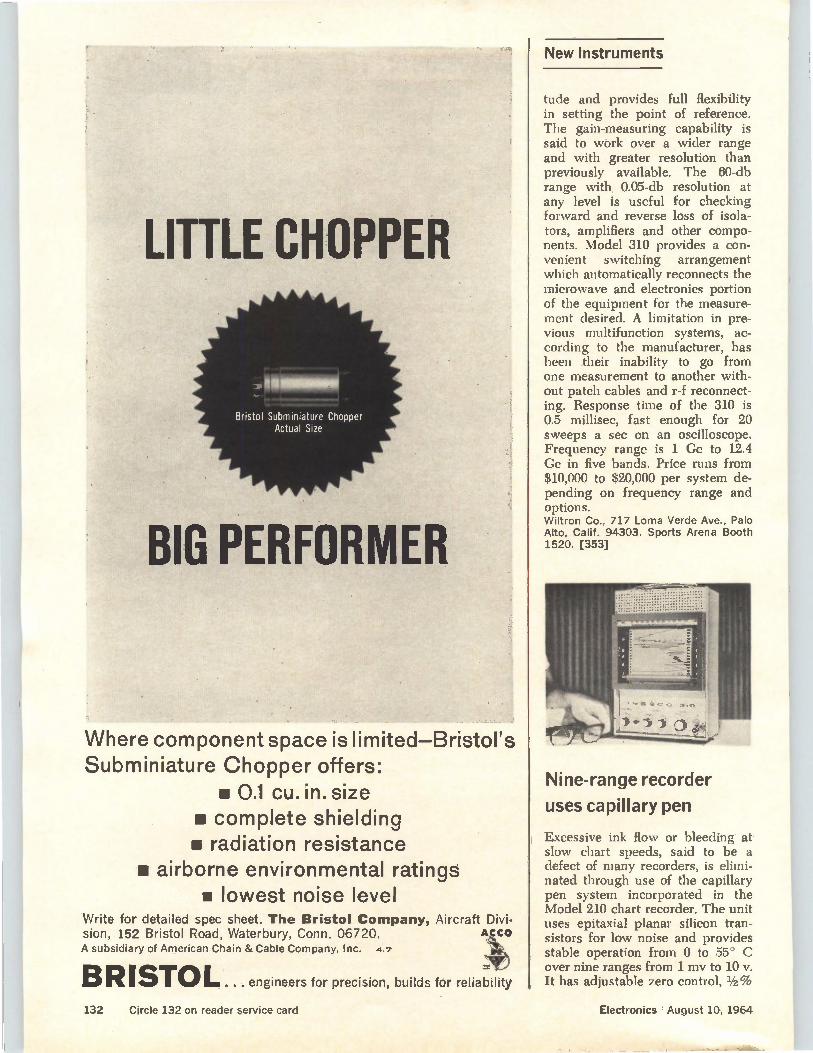
LITTLE CHOPPER
Bristol Subminiature Chopper Actual Size
BM PERFORMER
Where component space is limited—Bristol's Subminiature Chopper offers:
• 0.1 cu. in. size • complete shielding im radiation resistance
• airborne environmental ratings • lowest noise level
Write for detailed spec sheet. The Bristol Company, Aircraft Divi-sion, 152 Bristol Road, Waterbury, Conn. 06720. ACCO
A subsidiary of American Chain & Cable Company, Inc. 4.7
BR 1510 L . . . engineers for precision, builds for reliability
New Instruments
tude and provides full flexibility in setting the point of reference. The gain-measuring capability is said to work over a wider range and with greater resolution than previously available. The 60-db range with 0.05-db resolution at any level is useful for checking forward and reverse loss of isola-tors, amplifiers and other compo-nents. Model 310 provides a con-venient switching arrangement which automatically reconnects the microwave and electronics portion of the equipment for the measure-ment desired. A limitation in pre-vious multifunction systems, ac-cording to the manufacturer, has been their inability to go from one measurement to another with-out patch cables and r-f reconnect-ing. Response time of the 310 is 0.5 millisec, fast enough for 20 sweeps a sec on an oscilloscope. Frequency range is 1 Ge to 12.4 Ge in five bands. Price runs from $10,000 to $20,000 per system de-pending on frequency range and options. Wiltron Co., 717 Loma Verde Ave., Palo Alto, Calif. 94303. Sports Arena Booth 1520. [353]
Nine-range recorder
uses capillary pen
Excessive ink flow or bleeding at slow chart speeds, said to be a defect of many recorders, is elimi-nated through use of the capillary pen system incorporated in the Model 210 chart recorder. The unit uses epitaxial planar silicon tran-sistors for low noise and provides stable operation from 0 to 55° C over nine ranges from 1 mv to 10 v. It has adjustable zero control, 1/2%
132 Circle 132 on reader service card Electronics I August 10, 1964
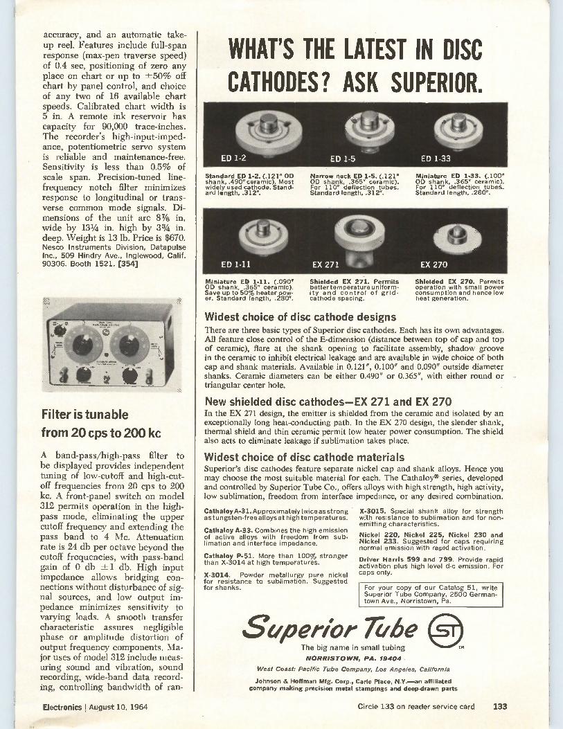
accuracy, and an automatic take-up reel. Features include full-span response (max-pen traverse speed) of 0.4 sec, positioning of zero any place on chart or up to ±-50% off chart by panel control, and choice of any two of 16 available chart speeds. Calibrated chart width is 5 in. A remote ink reservoir has capacity for 90,000 trace-inches. The recorder's high-input-imped-ance, potentiometric servo system is reliable and maintenance-free. Sensitivity is less than 0.5% of scale span. Precision-tuned line-frequency notch filter minimizes response to longitudinal or trans-verse common mode signals. Di-mensions of the unit are 87/8 in. wide by 131/4 in. high by 33/4 in. deep. Weight is 13 lb. Price is $670. Nesco Instruments Division, Datapulse Inc., 509 Hindry Ave., Inglewood, Calif. 90306. Booth 1521. [354]
Filter is tunable
from 20 cps to 200 kc
A band-pass/high-pass filter to be displayed provides independent tuning of low-cutoff and high-cut-off frequencies from 20 cps to 200 kc. A front-panel switch on model 312 permits operation in the high-pass mode, eliminating the upper cutoff frequency and extending the pass band to 4 Mc. Attenuation rate is 24 db per octave beyond the cutoff frequencies, with pass-band gain of 0 db -.±1 db. High input impedance allows bridging con-nections without disturbance of sig-nal sources, and low output im-pedance minimizes sensitivity to varying loads. A smooth transfer characteristic assures negligible phase or amplitude distortion of output frequency components. Ma-jor uses of model 312 include meas-uring sound and vibration, sound recording, wide-band data record-ing, controlling bandwidth of ran-
WHAT'S THE LATEST IN DISC CATHODES? ASK SUPERIOR.
Standard ED 1-2. (.121" OD shank, .490" ceramic). Most widely used cathode. Stand-ard length, .312".
Narrow neck ED 1-5. (.121" OD shank, .365" ceramic). For 110° deflection tubes. Standard length, .312".
Miniature ED 1-33. (.100" OD shank, .365" ceramic). For 110' deflection tubes. Standard length, .280".
Miniature ED 1-11. (.090" OD shank, .365" ceramic). Save up to 50% heater pow-er. Standard length, .280".
Shielded EX 271. Permits bettertemperature uniform-ity and control of grid-cathode spacing.
Shielded EX 270. Permits operation with small power consumption and hence low heat generation.
Widest choice of disc cathode designs There are three basic types of Superior disc cathodes. Each has its own advantages. All feature close control of the E-dimension (distance between top of cap and top of ceramic), flare at the shank opening to facilitate assembly, shadow groove in the ceramic to inhibit electrical leakage and are available in wide choice of both cap and shank materials. Available in 0.121", 0.100" and 0.090" outside diameter shanks. Ceramic diameters can be either 0.490" or 0.365", with either round or triangular center hole.
New shielded disc cathodes—EX 271 and EX 270 In the EX 271 design, the emitter is shielded from the ceramic and isolated by an exceptionally long heat-conducting path. In the EX 270 design, the slender shank, thermal shield and thin ceramic permit low heater power consumption. The shield also acts to eliminate leakage if sublimation takes place.
Widest choice of disc cathode materials Superior's disc cathodes feature separate nickel cap and shank alloys. Hence you may choose the most suitable material for each. The Cathaloy® series, developed and controlled by Superior Tube Co., offers alloys with high strength, high activity, low sublimation, freedom from interface impedance, or any desired combination.
Cathaloy A-31. Approximatelytwiceas strong as tungsten-free alloys at high temperatures.
Cathaloy A-33. Combines the high emission of active alloys with freedom from sub-limation and interface impedance.
Cathaloy P-51. More than 100% stronger than X-3014 at high temperatures.
X-3014. Powder metallurgy pure nickel for resistance to sublimation. Suggested for shanks.
X-3015. Special shank alloy for strength with resistance to sublimation and for non-emitting characteristics.
Nickel 220, Nickel 225, Nickel 230 and Nickel 233. Suggested for caps requiring normal emission with rapid activation.
Driver Harris 599 and 799. Provide rapid activation plus high level d-c emission. For caps only.
For your copy of our Catalog 51, write Superior Tube Company, 2500 German-town Ave., Norristown, Pa.
Superior lifbe The big name in small tubing
NORRISTOWN, PA. 19404
West Coast: Pacific Tube Company, Los Angeles, California
Johnson & Hoffman Mfg. Corp., Carle Place, N.Y.—an affiliated company making precision metal stampings and deep-drawn parts
Electronics !August 10, 1964 Circle 133 on reader service card 133
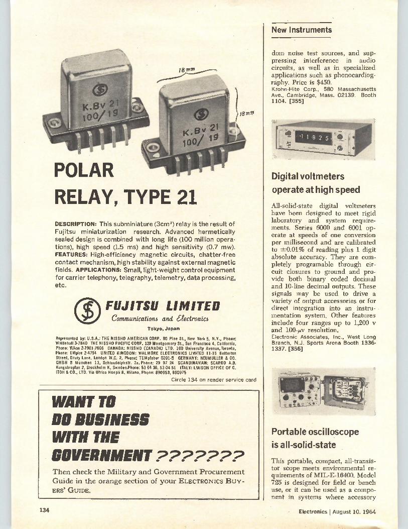
New Instruments
POLAR
RELAY, TYPE 21 DESCRIPTION: This subminiature (3cm 3) relay is the result of Fujitsu miniaturization research. Advanced hermetically sealed design is combined with long life (100 million opera-tions), high speed (1.5 ms) and high sensitivity (0.7 mw). FEATURES: High-efficiency magnetic circuits, chatter-free contact mechanism, high stability against external magnetic fields. APPLICATIONS: Small, light-weight control equipment for carrier telephony, telegraphy, telemetry, data processing, etc.
FUJITSU LIMITED Communication3 and aectronic6
Tokyo, Japan
Represented by: U.S.A.: THE NISSHO AMERICAN CORP. 80 Pine St., New York 5, N.Y., Phone: WHitehall 3.7840 THE NISSHO PACIFIC CORP. 120 Montgomery St., San Francisco 4, California. Phone: YUkon 2-7901-7906 CANADA: NISSHO (CANADA) LTD. 100 University Avenue, Toronto, Phone: EMpire 2-4794 UNITED KINGDOM: WALMORE ELECTRONICS LIMITED 11-15 Betterton Street, Drury Lane, London W.C. 2, Phone: TEMpleber 0201-5 GERMANY: NEUMULLER & CO. GMBH R Munchen 13, Schraudolphstr. 2a, Phone: 29 97 24 SCANDINAVIAN: SCAPRO A.B. Kungsbroplan 2, Stockholm K, Sweden,Phone: 53 04 36, 53 04 51 ITALY: LIAISON OFFICE OF C. ITOH & CO., LTD. Via Ulrico Hoepli 8, Milano, Phone: 890953, 890975
Circle 134 on reader service card
WANT TO DO BUSINESS WITH THE GOVERNMENT ??????? Then check the Military and Government Procurement
Guide in the orange section of your ELECTRONICS BUY-
ERS' GUIDE.
dom noise test sources, and sup-pressing interference in audio circuits, as well as in specialized applications such as phonocardiog-raphy. Price is $450. Krohn-Hite Corp., 580 Massachusetts Ave., Cambridge, Mass. 02139. Booth 1104. [355]
Digital voltmeters
operate at high speed
All-solid-state digital voltmeters have been designed to meet rigid laboratory and system require-ments. Series 6000 and 6001 op-erate at speeds of one conversion per millisecond and are calibrated to ±0.01% of reading plus 1 digit absolute accuracy. They are com-pletely programable through cir-cuit closures to ground and pro-vide both binary coded decimal and 10-line decimal outputs. These signals may be used to drive a variety of output accessories or for direct integration into an instru-mentation system. Other features include four ranges up to 1,200 y and 100-p,v resolution. Electronic Associates, Inc., West Long Branch, N.J. Sports Arena Booth 1336-1337. [356]
Portable oscilloscope
is all-solid-state
This portable, compact, all-transis-tor scope meets environmental re-quirements of MIL-E-16400. Model 725 is designed for field or bench use, or it can be used as a compo-nent in systems where accessory
134 Electronics j August 10, 1964
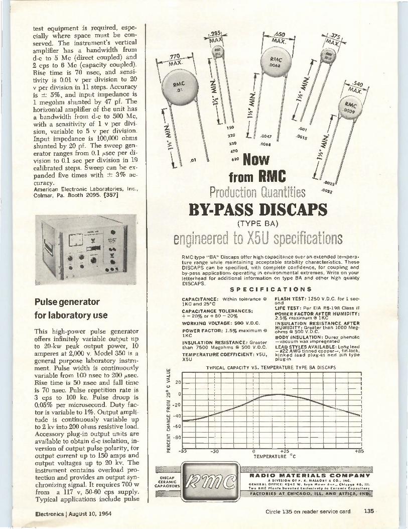
test equipment is required, espe-cially where space must be con-served. The instrument's vertical amplifier has a bandwidth from d-c to 5 Mc (direct coupled) and 2 cps to 6 Mc (capacity coupled). Rise time is 70 nsec, and sensi-tivity is 0.01 y per division to 20 per division in 11 steps. Accuracy
is ± 5%, and input impedance is 1 megohm shunted by 47 pf. The horizontal amplifier of the unit has a bandwidth from d-c to 500 Mc, with a sensitivity of 1 y per divi-sion, variable to 5 y per division. Input impedance is 100,000 ohms shunted by 20 pf. The sweep gen-erator ranges from 0.1 psec per di-vision to 0.1 sec per division in 19 calibrated steps. Sweep can be ex-panded five times with -± 3% ac-curacy. American Electronic Laboratories, Inc.,
Colmar, Pa. Booth 2095. [357]
Pulse generator
for laboratory use
This high-power pulse generator offers infinitely variable output up to 20-kw peak output power, 10 amperes at 2,000 v. Model 350 is a general purpose laboratory instru-ment. Pulse width is continuously variable from 100 nsec to 200 p sec. Rise time is 50 nsec and fall time is 70 nsec. Pulse repetition rate is 3 cps to 100 kc. Pulse droop is 0.05% per microsecond. Duty fac-tor is variable to 1%. Output ampli-tude is continuously variable up to 2 kv into 200 ohms resistive load. Accessory plug-in output units are available to obtain d-c isolation, in-version of output pulse polarity, for output current up to 150 amps and output voltages up to 20 kv. The instrument contains overload pro-tection and provides an output syn-chronizing signal. It requires 700 w from a 117 v, 50-60 cps supply. Typical applications include pulse
ro
Now from RMC
Production Quantities .0033
BY-PASS DISCAPS (TYPE BA)
engineered to X5U specifications
LLI
-J
20
o
Ce.1
o • -20 re
• 40
▪ 60 C.)
- 80
ce n_
RMC type "BA" Discaps offer high capacitance over an extended tempera-ture range while maintaining acceptable stability characteristics. These DISCAPS can be specified, with complete confidence, for coupling and by•pass applications operating in environmental extremes. Write on your letterhead for additional information on type BA and other high quality DISCAPS.
SPECIFICATIONS
CAPACITANCE: Within tolerance @ 1KC and 25°C
CAPACITANCE TOLERANCES: + - 20% or + 80 - 20%
WORKING VOLTAGE: 500 V.D.C.
POWER FACTOR: 1.5% maximum 1KC
INSULATION RESISTANCE: Greater than 7500 Megohms @ 500 V.D.C.
TEMPERATURE COEFFICIENT: Y5U, X5U
FLASH TEST: 1250 V.D.C. for 1 sec-ond LIFE TEST: Per EIA RS-198 Class II POWER FACTOR AFTER HUMIDITY: 2.5% maximum 0/ 1KC INSULATION RESISTANCE AFTER HUMIDITY: Greater than 1000 Meg. ohms @ 500 V.D.C. BODY INSULATION: Durez phenolic —vacuum wax impregnated LEAD STYLES AVAILABLE: Long lead - #22 AWG tinned copper—, fin-lock, kinked lead plug-in and pin type plug-in
TYPICAL CAPACITY VS. TEMPERATURE TYPE BA DISCAPS
-55
DISCAP
CERAMIC
CAPACITORS
-30 0 +25 TEMPERATURE °C
+85
RADIO MATERIALS COMPANY A DIVISION OF P. R. MALLORY 8. CO., INC.
GENERAL OFFICE: 4142 W. Bryn Mawr Ave., Chicago 46,111.
Two EMC Plants Devoted Exclusively to Ceramic Capacitors
FACTORIES AT CHICAGO, ILL. AND ATTICA, IND21
Electronics lAugust 10, 1964
ISP"
Circle 135 on reader service card 135
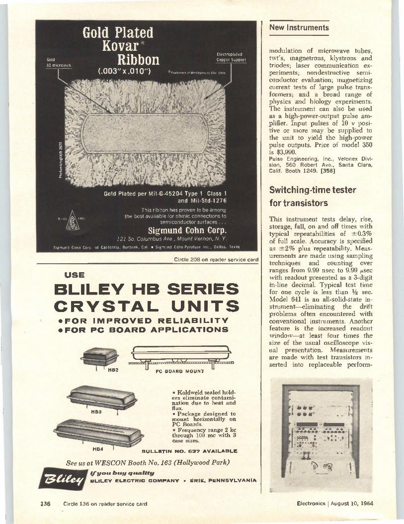
HB4
Gold 80 microinch.
Gold Plated Kovar
Ribbon
Since uii 1901
Electroplated Copper Support
Gold Plated per Mil-G-45204 Type 1 Class 1 and Mil-Std-1276
This ribbon has proven to be among the best available for ohmic connections to
semiconductor surfaces...
Sigmund Cohn Corp. 121 So. Columbus Ave., Mount Vernon, N. Y.
Sigmund Cohn Corp. of California, Burbank, Cal. • Sigmund Cohn-Pyrofuze Inc., Dallas, Texas
Circle 208 on reader service card
USE
BLILEY HB SERIES CRYSTAL UNITS •FOR IMPROVED RELIABILITY
•FOR PC BOARD APPLICATIONS
PC BOARD MOUNT
• Koldweld sealed hold-ers eliminate contami-nation due to heat and flux. • Package designed to mount horizontally on PC Boards. • Frequency range 2 kc through 100 mc with 3 case sizes.
BULLETIN NO. 537 AVAILABLE
See us at WESCON Booth No. 163 (Hollywood Park)
(fume buy quality
BLILEY ELECTRIC COMPANY • ERIE. PENNSYLVANIA
New Instruments
modulation of microwave tubes, twes, magnetrons, klystrons and triodes; laser communication ex-periments; nondestructive semi-conductor evaluation; magnetizing current tests of large pulse trans-formers; and a broad range of physics and biology experiments. The instrument can also be used as a high-power-output pulse am-plifier. Input pulses of 10 y posi-tive or more may be supplied to the unit to yield the high-power pulse outputs. Price of model 350 is $3,990. Pulse Engineering, Inc., Velonex Divi-sion, 560 Robert Ave., Santa Clara, Calif. Booth 1249. [358]
Switching-time tester
for transistors
This instrument tests delay, rise, storage, fall, on and off times with typical repeatabilities of ±0.3% of full scale. Accuracy is specified as ±2% plus repeatability. Meas-urements are made using sampling techniques and counting over ranges from 9.99 nsec to 9.99 ,usec with readout presented as a 3-digit in-line decimal. Typical test time for one cycle is less than 1/2 sec. Model 641 is an all-solid-state in-strument—eliminating the drift problems often encountered with conventional instruments. Another feature is the increased readout window—at least four times the size of the usual oscilloscope vis-ual presentation. Measurements are made with test transistors in-serted into replaceable perform-
136 Circle 136 on reader service card Electronics I August 10, 1964
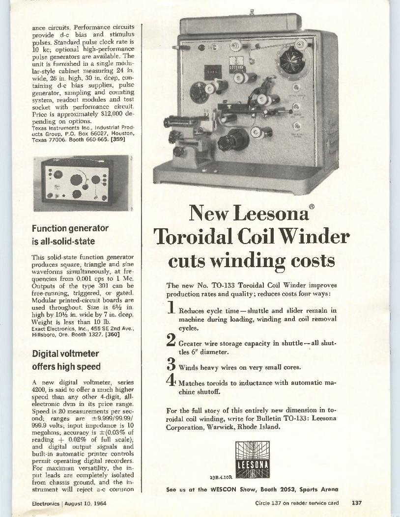
ance circuits. Performance circuits provide d-c bias and stimulus pulses. Standard pulse clock rate is 10 kc; optional high-performance pulse generators are available. The unit is furnished in a single modu-lar-style cabinet measuring 24 in. wide, 26 in. high, 30 in. deep, con-taining d-c bias supplies, pulse generator, sampling and counting system, readout modules and test socket with performance circuit. Price is approximately $12,000 de-pending on options. Texas Instruments Inc., Industrial Prod-ucts Group, P.O. Box 66027, Houston, Texas 77006. Booth 660-665. [359]
Function generator
is all-solid-state
This solid-state function generator produces square, triangle and sine waveforms simultaneously, at fre-quencies from 0.001 cps to 1 Mc. Outputs of the type 301 can be free-running, triggered, or gated. Modular printed-circuit boards are used throughout. Size is 61/2 in. high by 101/2 in. wide by 7 in. deep. Weight is less than 10 lb. Exact Electronics, Inc., 455 SE 2nd Ave., Hillsboro, Ore. Booth 1327. [360]
Digital voltmeter
offers high speed
A new digital voltmeter, series 4200, is said to offer a much higher speed than any other 4-digit, all-electronic dvm in its price range. Speed is 20 measurements per sec-ond; ranges are ±9.999/99.99/ 999.9 volts; input impedance is 10 megohms; accuracy is -±(0.03% of reading 4- 0.02% of full scale); and digital output signals and built-in automatic printer controls permit operating digital recorders. For maximum versatility, the in-put leads are completely isolated from chassis ground, and the in-strument will reject a-c common
New Leesond Toroidal Coil Winder cuts winding costs The new No. TO-133 Toroidal Coil Winder improves production rates and quality; reduces costs four ways:
2
3 4
Reduces cycle time—shuttle and slider remain in machine during loading, winding and coil removal
cycles.
Greater wire storage capacity in shuttle— all shut-
tles 6" diameter.
Winds heavy wires on very small cores.
Matches toroids to inductance with automatic ma-
chine shutoff.
For the full story of this entirely new dimension in to-roidal coil winding, write for Bulletin TO-133: Leesona Corporation, Warwick, Rhode Island.
23B.4.10R
qlrkl911/1 Lsteuddijg
LEESONA
See us at the WESCON Show, Booth 2053, Sports Arena
Electronics August 10, 1964 mew
Circle 137 on reader service card 137
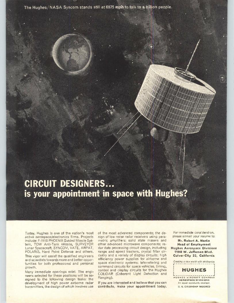
IRCUIT DESIGNE . r your appointment-In space Wi
Today, Hughes is one of the nation's most active aerospace/electronics firms. Projects include: F-111B PHOENIX Guided Missile Sys-tem, TOW Anti-Tank Missile, SURVEYOR Lunar Spacecraft, SYNCOM, VATE, ARPAT, POLARIS, Hard Point Defense and others.
This vigor will assist the qualified engineers and scientists towards more and better oppor-tunities for both professional and personal growth.
Many immediate openings exist. The engi-neers selected for these positions will be as-signed to the following design tasks: the development of high power airborne radar transmitters, the design of which involves use
of the most advanced components; the de-sign of low noise radar receivers using para-metric amplifiers; solid state masers and other advanced microwave components; ra-dar data processing circuit design, including range and speed trackers, crystal filter cir-cuitry and a variety of display circuits; high efficiency power supplies for airborne and space electronic systems; telemetering and command circuits for space vehicles, timing, control and display circuits for the Hughes COLIDAR (Coherent Light Detection and Ranging).
If you are interested and believe that you can contribute, make your appointment today.
For immediate consideration, please airmail your resume to:
Mr. Robert A. Martin Head of Employment
Hughes Aerospace Divisions 11940 W. Jefferson Blvd. Culver City 22, California
Creating a new world with electronics
HUGHES
HUGHES AIRCRAFT COMPANY
AEROSPACE DIVISIONS An equal opportunity employer.
U. S. CITIZENSHIP REQUIRED
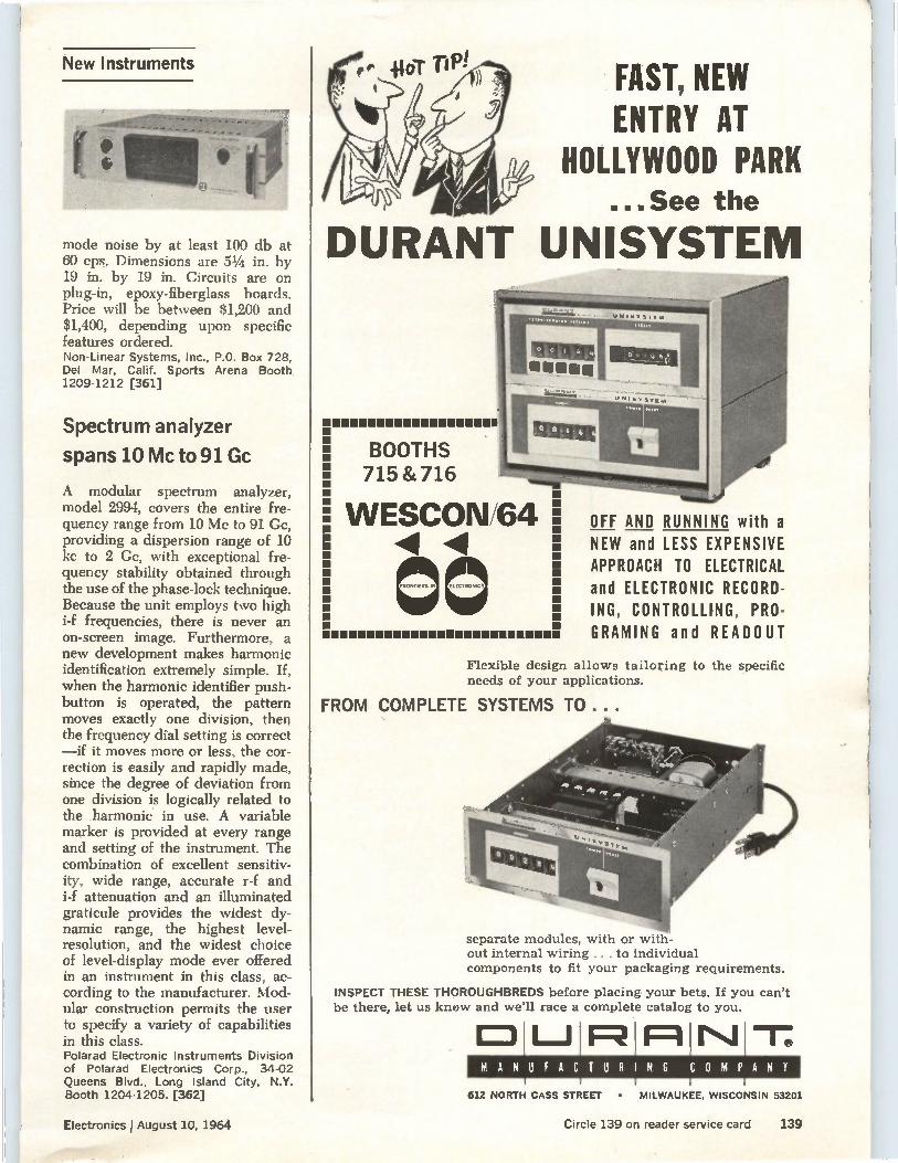
New Instruments
mode noise by at least 100 db at 60 cps. Dimensions are 51/4 in. by 19 in. by 19 in. Circuits are on plug-in, epoxy-fiberglass boards. Price will be between $1,200 and $1,400, depending upon specific features ordered. Non-Linear Systems, Inc., P.O. Box 728, Del Mar, Calif. Sports Arena Booth 1209-1212 [361]
Spectrum analyzer
spans 10 Mc to 91 Gc
A modular spectrum analyzer, model 2994, covers the entire fre-quency range from 10 Mc to 91 Cc, providing a dispersion range of 10 kc to 2 Cc, with exceptional fre-quency stability obtained through the use of the phase-lock technique. Because the unit employs two high i-f frequencies, there is never an on-screen image. Furthermore, a new development makes harmonic identification extremely simple. If, when the harmonic identifier push-button is operated, the pattern moves exactly one division, then the frequency dial setting is correct —if it moves more or less, the cor-rection is easily and rapidly made, since the degree of deviation from one division is logically related to the harmonic in use. A variable marker is provided at every range and setting of the instrument. The combination of excellent sensitiv-ity, wide range, accurate r-f and i-f attenuation and an illuminated graticule provides the widest dy-namic range, the highest level-resolution, and the widest choice of level-display mode ever offered in an instrument in this class, ac-cording to the manufacturer. Mod-ular construction permits the user to specify a variety of capabilities in this class. Polarad Electronic Instruments Division of Polarad Electronics Corp., 34-02 Queens Blvd., Long Island City, N.Y. Booth 1204-1205. [362]
FAST, NEW ENTRY AT
HOLLYWOOD PARK ...See the
DURANT UNISYSTEM
BOOTHS 715 & 716
WESCON/64 E 1
laZIMMIZZ111133111131131111111111.
OFF AND RUNNING with a NEW and LESS EXPENSIVE APPROACH TO ELECTRICAL and ELECTRONIC RECORD-ING, CONTROLLING, PRO-GRAMING and READOUT
Flexible design allows tailoring to the specific needs of your applications.
FROM COMPLETE SYSTEMS TO...
separate modules, with or with-out internal wiring ... to individual components to fit your packaging requirements.
INSPECT THESE THOROUGHBREDS before placing your bets. If you can't be there, let us know and we'll race a complete catalog to you.
MANUFACTURING COMPANY
612 NORTH CASS STREET • MILWAUKEE, WISCONSIN 53201
Electronics lAugust 10, 1964
Yenee
Circle 139 on reader service card 139
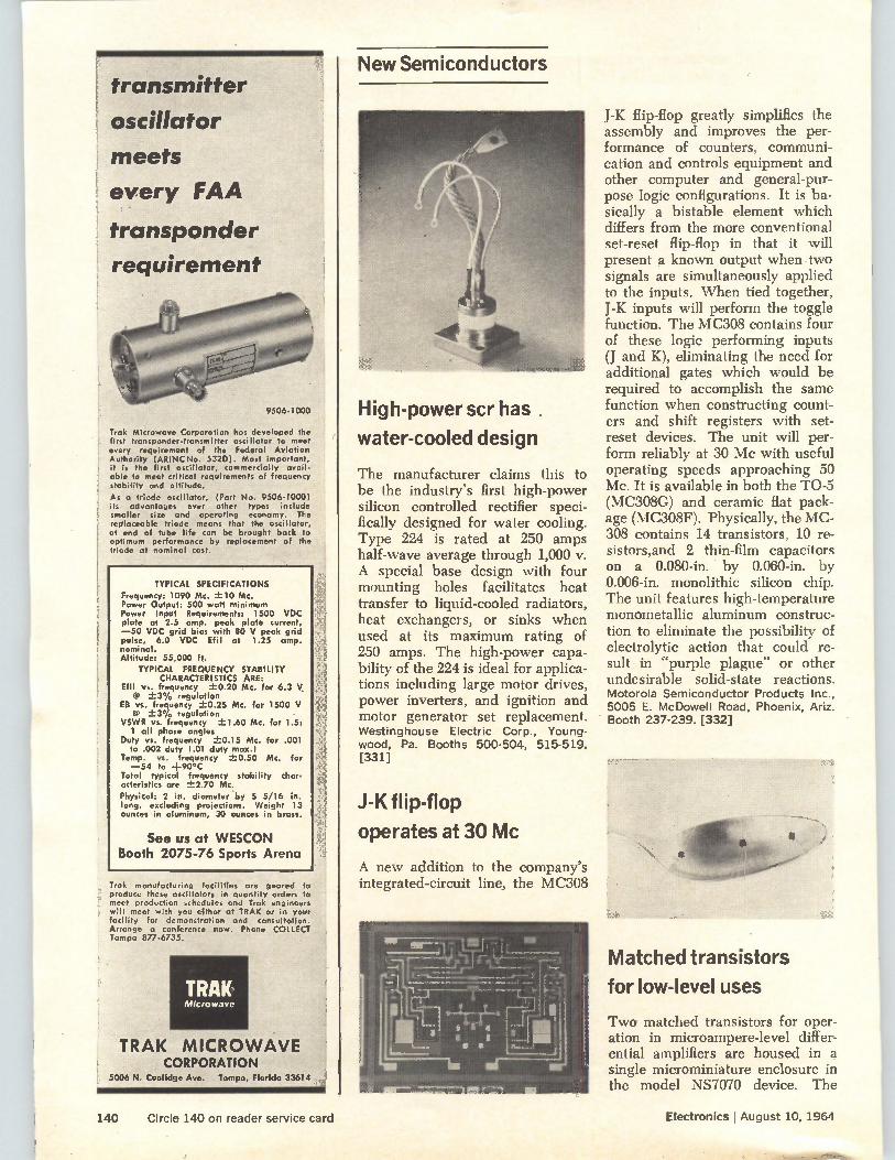
New Semiconductors transmitter
oscillator
meets
every FAA
transponder
requirement
9506-1000
Irak Microwave Corporation has developed the first transponder-transmitter oscillator to meet every requirement of the Federal Aviation Authority lARINCNo. 53201. Most important, it is the first oscillator, commercially avail-able to meet critical requirements of frequency stability and altitude.
As a triode oscillator, Cart No. 9506-10001 its advantages over other types include smaller size and operating economy. The replaceable triode means that the oscillator, at end of tube life can be brought bank to optimum performance by replacement of the triode at nominal cast.
TYPICAL SPECIFICATIONS
Frequency: 1090 Mc. --L-10 Mc. Power Output: 500 watt minimum Power Input Requirements: 1500 VDC plate at 2.5 amp. peak plate current, —50 VDC grid bias with 80 V peak grid pulse, 6.0 VDC Efil at 1.25 amp. nominal. Altitude: 55,000 ft.
TYPICAL FREQUENCY STABILITY CHARACTERISTICS ARE:
Efil vs. frequency 71-0.20 Mc. for 6.3 V. @ ±3% regulation
EB vs. frequency ±."0.25 Mc. for 1500 V @ -±3% regulation
VSWR vs. frequency -_f_-1.60 Mc. for 1.5: 1 all phase angles
Duty vs. frequency ±0.15 Mc. for .001 to .002 duty 1.01 duty max.)
Temp. vs. frequency ±0.50 Mc. for —54 to +90°C
Total typical frequency stability char-acteristics are z1z2.70 Mc.
Physical: 2 in. diameter by 5 5/16 in. long, excluding projections. Weight 13 ounces in aluminum, 30 ounces in brass.
See us at WESCON Booth 2075-76 Sports Arena
Irak manufacturing facilities are geared to produce these oscillators in quantity orders to meet production schedules and Irak engineers will meet with you either at IRAK or in your facility for demonstrotion and consultation Arrange a conference now. Phone COLLECT Tampa 877-6735.
TRAK. Microwave
TRAK MICROWAVE CORPORATION
5006 N. Coolidge Ave. Tampa, Florida 33614
High-power scr has.
water-cooled design
The manufacturer claims this to be the industry's first high-power silicon controlled rectifier speci-fically designed for water cooling. Type 224 is rated at 250 amps half-wave average through 1,000 v. A special base design with four mounting holes facilitates heat transfer to liquid-cooled radiators, heat exchangers, or sinks when used at its maximum rating of 250 amps. The high-power capa-bility of the 224 is ideal for applica-tions including large motor drives, power inverters, and ignition and motor generator set replacement. Westinghouse Electric Corp., Young-wood, Pa. Booths 500-504, 515-519. [331]
J-K flip-flop
operates at 30 Mc
A new addition to the company's integrated-circuit line, the MC308
J-K flip-flop greatly simplifies the assembly and improves the per-formance of counters, communi-cation and controls equipment and other computer and general-pur-pose logic configurations. It is ba-sically a bistable element which differs from the more conventional set-reset flip-flop in that it will present a known output when two signals are simultaneously applied to the inputs. When tied together, J-K inputs will perform the toggle function. The MC308 contains four of these logic performing inputs (J and K), eliminating the need for additional gates which would be required to accomplish the same function when constructing count-ers and shift registers with set-reset devices. The unit will per-form reliably at 30 Mc with useful operating speeds approaching 50 Mc. It is available in both the TO-5 (MC308G) and ceramic flat pack-age (MC308F). Physically, the MC-308 contains 14 transistors, 10 re-sistors,and 2 thin-film capacitors on a 0.080-in. by 0.060-in. by 0.006-in, monolithic silicon chip. The unit features high-temperature monometallic aluminum construc-tion to eliminate the possibility of electrolytic action that could re-sult in "purple plague- or other undesirable solid-state reactions. Motorola Semiconductor Products Inc., 5005 E. McDowell Road, Phoenix, Ariz. Booth 237-239. [332]
Matched transistors
for low-level uses
Two matched transistors for oper-ation in microampere-level differ-ential amplifiers are housed in a single microminiature enclosure in the model NS7070 device. The
140 Circle 140 on reader service card Electronics August 10, 1964
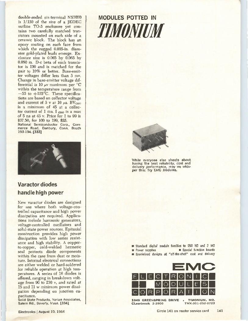
double-ended six-terminal NS7070 is 1/150 of the size of a JEDEC outline TO-5 enclosure yet con-tains two carefully matched tran-sistors mounted on each side of a ceramic block. The block has an epoxy coating on each face from which the rugged 0.005-in, diam-eter gold-plated leads emerge. En-closure size is 0.065 by 0.065 by 0.080 in. D-c beta of each transis-tor is 100 and is matched for the pair to 10% or better. Base-emit-ter voltages differ less than 5 mv. Change in base-emitter voltage dif-ferential is 10 ,uv maximum per °C within the temperature range from —55 to +125°C. These specifica-tions are based on collector voltage and current of 5 y at 10 !La. BVcflo is a minimum of 45 at a collec-tor current of 1 ma. I cite is a max of 5 na at 45 v. Price for 1 to 99 is $37.50; for 100 to 199, $25. National Semiconductor Corp., Com-merce Road, Danbury, Conn. Booth 193-194. [333]
Varactor diodes
handle high power
New varactor diodes are designed for use where both voltage-con-trolled capacitance and high power dissipation are required. Applica-tions include harmonic generators, voltage-controlled oscillators and solid-state power sources. Epitaxial construction provides high power dissipation with low series resist-ance and high stability. A copper-to-copper, cold-welded hermetic seal protects diode components within the case from dust or mois-ture. Internal electrical connections are either welded or hard-soldered for reliable operation at high tem-peratures. A series of 16 diodes is offered, ranging in breakdown volt-age from 90 to 230 v, and rated at 15 and 11 w minimum power dissi-pation depending on junction ca-pacitance. Solid State Products, Varian Associates, Salem Rd., Beverly, Mass. [334]
MODULES POTTED IN
111110i1111111
While everyone else shouts about having the best reliability, cost and delivery performance, may we whis-per this: Try EMC Modules.
R Standard digital module families to 250 KC and 2 MC • Power supplies • Special function boards a Specialized designs at "off-the-shelf" cost and delivery
E IIU R 0 MINIM 11111 MI 0 D LUIMIC111111 31O R POR ADDOJ 1949 GREENSPRING DRIVE . TIMONIUM, Mo. CLearbrook 2-2900 TWX-301-252-0723
Electronics August 10, 1964 Circle 141 on reader service card 141
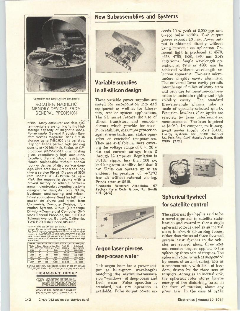
Computer and Data System Designers:
ROTATING MAGNETIC MEMORY DEVICES FROM GENERAL PRECISION
G3-3113
Discs—Many computer and data sys-tem designers are turning to the high storage capacity of magnetic discs. For example, General Precision Ran-dom Access Magnetic Discs furnish storage up to 7,680,000 bits per disc. "Flying" heads permit high packing density of 400 bits/inch. Exclusive GP-produced plated-cobalt disc coating gives exceptionally high resolution. Excellent thermal shock resistance. Heads replaceable without special tools or danger of disc surface dam-age. Ultra-precision Grade 9 bearings give a service life of 10 years at 3600 rpm. Meets MILE-4970A. DRUMS — Pick the magnetic drums with a proved history of reliable perform-ance in electronic computing systems designed for Navy, Air Force, NASA, business, engineering, and educa-tional applications. Send for full infor-mation on drums and discs, from Commercial Computer Division, Infor-mation Systems Group (Librascope Division/Commercial Computer Divi-sion) General Precision, Inc., 100 East Tujunga Avenue, Burbank, California. TWX BRB 9884, Phone 849-6061. For Series 1.100 and L.200 discs (all models):
Maximum bits per inch: 400. Head inductance: 25 to 150 rnicrohen-ies. Type of recording: phase modulation. Recording surface: plated obeli coating. Playback: 50 millivolts (undo, most conditions). Write urrents: 40 to 100 milliamperes. Ambient temperature: 32'F to 149'F imits. Thermal shock: AT ambient in CO seconds. Vibration: 15 to 55 cp. ( .015 db amp., 3 directions). Mechanical shock: 4-inch edge test 14 d oPs).
SERIES L100 SINGLE DISCS (ONE-SIDE MAGNETIC MEMORY)
Model No.
Disc Diameter
Maximum Tracks
Max. Bits per Track
Total Bd Capacity
Rotational Speed (rpm)
1104 4" 8 2400 19.200 3600-12.000 L106 r 16 3600 45,600 1800-12,000
L108 8* 31 4800 153,800 1803-12,900
L111 II 64 6600 422,400 1200- 8000
L116 16' 128 10,000 1 280 000 900. 3600
L124 24" 256 15.000 3.840.000 900- 3600
SERIES L200 DOUBLE DISCS SIZES 8" TO 24", 307,200 TO 7,680,000 TOTAL B T CAPACITY ALSO AVAILABLE.
LIBRASCOPE GROUP
cP: emmiEMML, [pmmoeuom
COMMERCIAL COMPUTER DIVISION
808 WESTERN AVENUE • GLENDALE 1,CAL1F.
New Subassemblies and Systems
Variable supplies
in all-silicon design
These variable power supplies are suited for incorporation into end equipment as well as for labora-tory, test or system applications. The SL series feature the use of silicon transistors and semicon-ductors which provide for maxi-mum stability, maximum protection against overloads, and stable oper-ation at extended temperatures. They are available in units cover-ing the voltage range of 0 to 36 d-c and current ratings from 2 through 12 amperes. Regulation is 0.01%; ripple, less than 500 /Iv; and long-term stability, less than 5 mv. Units can operate up to an ambient temperature of +71°C free air without external cooling. Prices start at $215. Electronic Research Associates, 67 Factory Place, Cedar Grove, N.J. Booth 191. [371]
Argon laser pierces
deep-ocean water
This argon laser has a power out-put at blue-green wavelengths matching the maximum-transmis-sion "windows" of deep-ocean and fresh water. Pulse operation is standard, but c-w operation is available. Pulse output power ex-
ceeds 10 w peak at 2,000 pps and 3-psec pulse widths. C-w output power exceeds 10 mw. Power out-put is obtained directly without using harmonic multiplication. Co-herent light is produced at 4579, 4658, 4765, 4880, 4960 and 5145 angstroms. Single wavelength op-eration at 4765 or 4880 can be achieved without wavelength se-lection apparatus. Two-axis micro-meters simplify cavity alignment. The universal Invar cavity permits interchange of tubes of many sizes and provides temperature-compen-sation to maintain rigidity and high stability cavity. The standard Brewster-angle plasma tube is made of specially-selected quartz. Precision, low-loss silica optics are selected by laser interferometric measurements. The laser is priced at $4,950. Its compact, multi-meg-awatt power supply costs $5,000. Energy Systems, Inc., 3180 Hanover St., Palo Alto, Calif. Sports Arena, Booth 2089. [372]
Spherical flywheel
for satellite control
The spherical flywheel is said to be a novel approach to satellite stabi-lization and control in that a single spherical rotor is used as an inertial mass to absorb disturbing forces, rather than the usual three-flywheel system. Disturbances to the vehi-cles are sensed along three axes and counter-torques applied to the sphere by three sets of torques. The spherical rotor, which is suspended by means of an air bearing, acts as a common rotor, with 360° of free-dom, driven by the three sets of torquers. Acting as an inertial sink, the spherical rotor stores kinetic energy of the disturbing force, in the form of rotation, about any given axis. In the case of cyclic
142 Circle 142 on reader service card Electronics I August 10, 1964
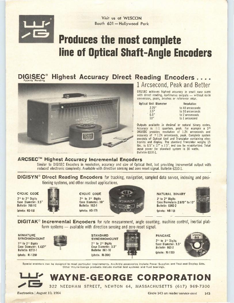
Visit us at WESCON
Booth 631 — Hollywood Park
Produces the most complete line of Optical Shaft-Angle Encoders
DIGISEC® Highest Accuracy Direct Reading Encoders.... Patents Pending
1 Arcsecond, Peak and Better DIGISEC achieves highest accuracy in small case sizes with direct reading, continuous outputs — without code conversion, gears, brushes or reference rotor.
Optical Unit Diameter Resolution
2.25" to 40 arcseconds 3.5" to 10 arcseconds 5.5" to 2 arcseconds 10" to 1 arcsecond
Outputs available in decimal or natural binary codes. Accuracy is -± 1 quantum, peak. For example a 2" DIGISEC provides resolution of 1.24 arcseconds and accuracy of ± 1.24 arcseconds, peak. Complete system consists of Optical Unit and Translator containing elec-tronics and display. The standard Translator weighs 15 lbs., is 6.5" x 17" x 7.5", and can be miniaturized. Total input power for standard system is 30 watts. Bulletin 6310-1.
ARCSECTM Highest Accuracy Incremental Encoders Similar to DIGISEC Encoders in resolution, accuracy and size of Optical Unit, but providing incremental output with reduced electronic complexity. Available with direction sensing and zero reset signal. Bulletin 6310-1.
DIGISYN® Direct Reading Encoders for tracking, navigation, sampled data servos, indexing and posi-tioning systems, and other readout applications.
CYCLIC CODE
2" to 2" Digits Case Diameter: 3.5" Bulletin 760-1C
(photo: RD-15)
CYCLIC CODE
26 to 2" Digits Case Diameter: 10" Bulletin 162-1
(photo: RD-17)
NATURAL BINARY
2' to 2" Digits Case Diameters: 2.625" to 10" Bulletin 6302-2
(photo: NB-1)
DIGITAK® Incremental Encoders for rate measurement, angle counting, machine control, inertial plat-form systems — available with direction sensing and zero reset signal.
MINIATURE SYNCHROMOUNT
2" to 2n Digits Case Diameter: 1.437" Bulletin 6212-1
STANDARD SYNCHROMOUNT
2n to 2" Digits Case Diameter: 3.5" Bulletin 861-1C
(photo: RI-12M) (photo: RI-20K)
PANCAKE
2" to 2'5 Digits Case Diameter: 3.5" Bulletin 862-2
(photo: RI-15S)
Special encoders can be designed to meet particular requirements. Available accessories include Power Supplies and Test and Display Sets. Other Wayne-George products include inertial test systems and fluid bearings.
1--1—ri e WAYNE-GEORGE CORPORATION •••••16.. 322 NEEDHAM STREET, NEWTON 64, MASSACHUSETTS (617) 969-7300
Electronics ?August 10, 1964 Circle 143 on reader service card 143
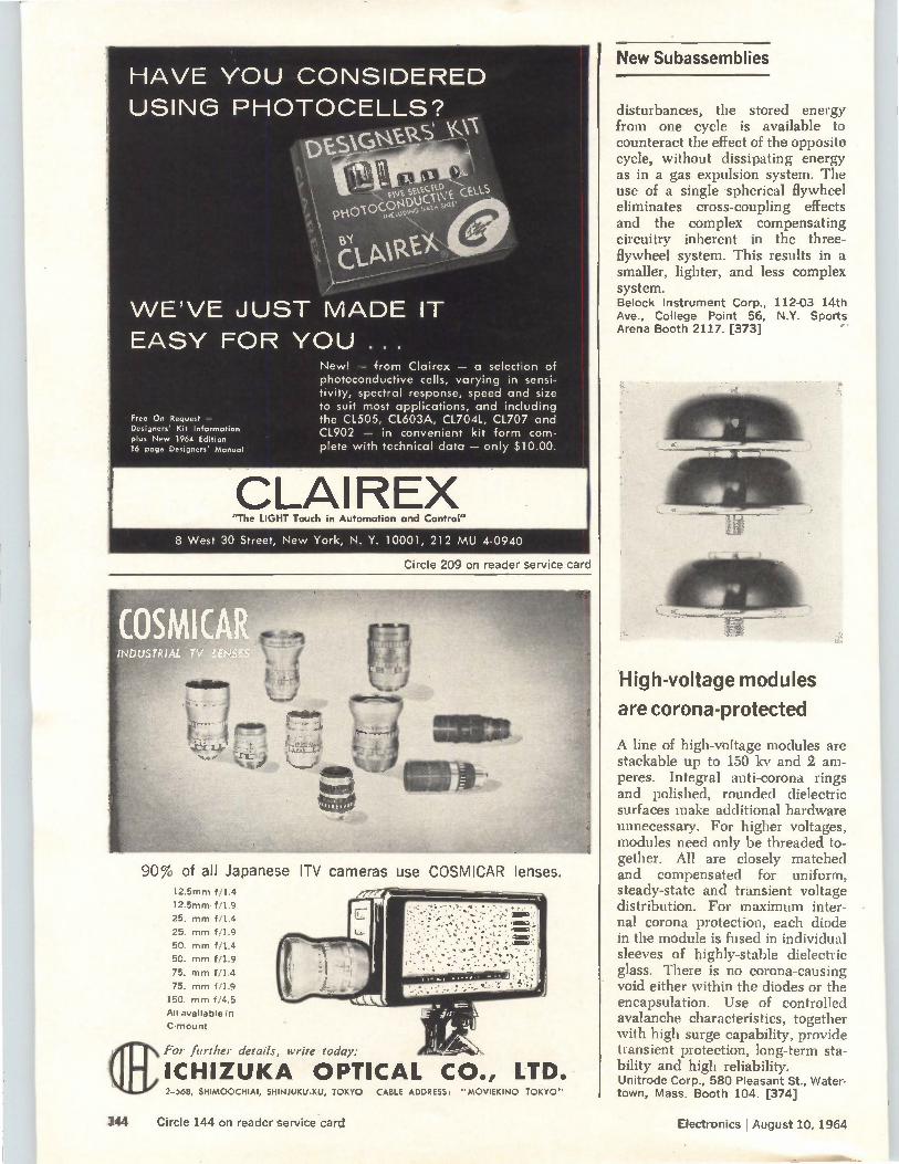
HAVE YOU CONSIDERED USING PHOTOCELLS?
e-se--nvt seta° "4",
PtiOl000NDUCIffi. looms° um. eel
aPà WE'VE JUST MADE IT EASY FOR YOU .. .
Free On Request — Designers' Kit Information plus New 1964 Edition 16 page Designers' Manual
New! — from Clairex — a selection of photoconductive cells, varying in sensi-tivity, spectral response, speed and size to suit most applications, and including the CL505, CL603A, C17041, CL707 and CL902 — in convenient kit form com-plete with technical data — only $10.00.
CLAIREX "The LIGHT Touch in Automation and Control"
8 West 30 Street, New York, N. Y. 10001, 212 MU 4-0940
Circle 209 on reader service card
90% of all Japanese ITV cameras use COSMICAR lenses. 12.5mm f/1.4
12.5mm f/1.9
25. mm f/1.4
25. mm f/1.9
50. mm f/1.4
50. mm f/1.9
75. mm f/1.4
75. mm f/1.9
150. mm f/4.5
All available in
C-mount
(ElFor further details, write today:
ICHIZUKA OPTICAL CO., LTD. 2-568, SHIMOOCHIAI, SHINJUKU-KU, TOKYO CABLE ADDRESS: "MOVIEKINO TOKYO"
New Subassemblies
disturbances, the stored energy from one cycle is available to counteract the effect of the opposite cycle, without dissipating energy as in a gas expulsion system. The use of a single spherical flywheel eliminates cross-coupling effects and the complex compensating circuitry inherent in the three-flywheel system. This results in a smaller, lighter, and less complex system. Belock Instrument Corp., 112-03 14th Ave., College Point 56, N.Y. Sports Arena Booth 2117. [373]
High-voltage modules
are corona-protected
,
A line of high-voltage modules are stackable up to 150 kv and 2 am-peres. Integral anti-corona rings and polished, rounded dielectric surfaces make additional hardware unnecessary. For higher voltages, modules need only be threaded to-gether. All are closely matched and compensated for uniform, steady-state and transient voltage distribution. For maximum inter-nal corona protection, each diode in the module is fused in individual sleeves of highly-stable dielectric glass. There is no corona-causing void either within the diodes or the encapsulation. Use of controlled avalanche characteristics, together with high surge capability, provide transient protection, long-term sta-bility and high reliability. Unitrode Corp., 580 Pleasant St., Water-town, Mass. Booth 104. [374]
244 Circle 144 on reader service card Electronics I August 10, 1964
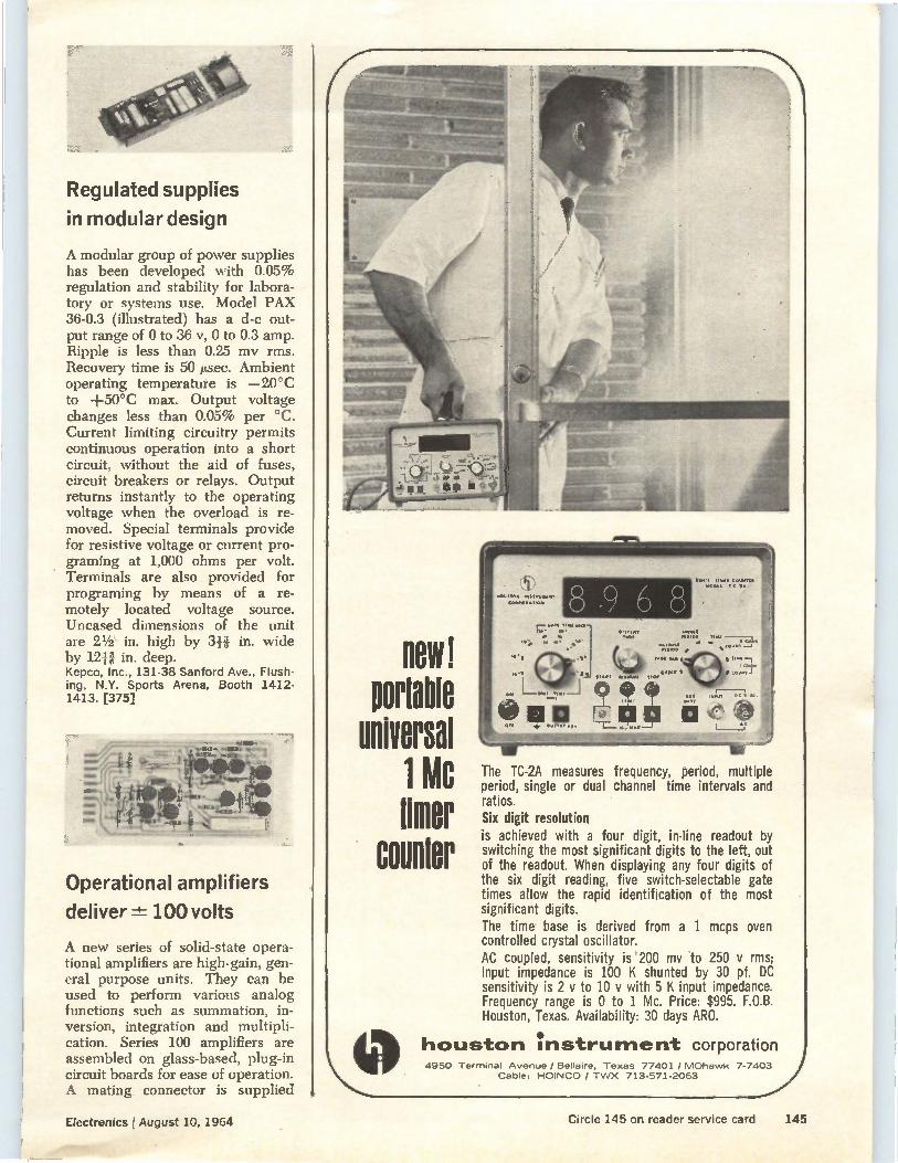
Regulated supplies
in modular design
A modular group of power supplies has been developed with 0.05% regulation and stability for labora-tory or systems use. Model FAX 36-0.3 (illustrated) has a d-c out-put range of 0 to 36 v, 0 to 0.3 amp. Ripple is less than 0.25 mv rms. Recovery time is 50 Lsec. Ambient operating temperature is —20°C to +50°C max. Output voltage changes less than 0.05% per °C. Current limiting circuitry permits continuous operation into a short circuit, without the aid of fuses, circuit breakers or relays. Output returns instantly to the operating voltage when the overload is re-moved. Special terminals provide for resistive voltage or current pro-graming at 1,000 ohms per volt. Terminals are also provided for programing by means of a re-motely located voltage source. Uncased dimensions of the unit are 21/2 in. high by 3-H in. wide by 12H in. deep. Kepco, Inc., 131-38 Sanford Ave., Flush-ing, N.Y. Sports Arena, Booth 1412-1413. [375]
Operational amplifiers
deliver 100 volts
A new series of solid-state opera-tional amplifiers are high-gain, gen-eral purpose units. They can be used to perform various analog functions such as summation, in-version, integration and multipli-cation. Series 100 amplifiers are assembled on glass-based, plug-in circuit boards for ease of operation. A mating connector is supplied
11810 portable
universal mc
tiffler counter
The TC-2A measures frequency, period, multiple period, single or dual channel time intervals and ratios. Six digit resolution is achieved with a four digit, in-line readout by switching the most significant digits to the left, out of the readout. When displaying any four digits of the six digit reading, five switch-selectable gate times allow the rapid identification of the most significant digits. The time base is derived from a 1 mcps oven controlled crystal oscillator. AC coupled, sensitivity is '200 my to 250 y rms; input impedance is 100 K shunted by 30 pf. DC sensitivity is 2 y to 10 y with 5 K input impedance. Frequency range is 0 to 1 Mc. Price: $995. F.O.B. Houston, Texas. Availability: 30 days ARO.
houston instrument corporation ,,.....1 4950 Terminal Avenue / Bellaire, Texas 77401 / MOhawk 7-7403
Cable: HOINCO / TWX 713-571-2063
Electronics I August 10, 1964
—adMr.
Circle 145 on reader service card 145
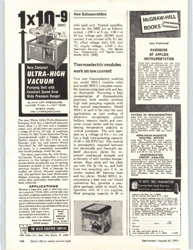
BLANK-OFF PRESSURE:
LOWER THAN 1 x 10⁻⁹ TORR
SPEED (AIR):
140 LITERS/SECOND
-9 (torr)
4)
PAT. ,0 NOS.
2.337.849 2.918,208
New, Compact
ULTRA-HIGH VACUUM Pumping Unit with Constant Speed Over Wide Pressure Range!
The new, Welch 3101A Turbo-Molecular Pumping Unit has a blank-off pressure lower than 1 x 10 torr and a constant speed (air) of 140 liters per second over a range of 10-2 to 10 torr. It combines a Welch No. 3101 Turbo-Molecular Pump (manufactured under a license of the Becker patent for the U.S.A. and Canada) with the well known Welch "Duo-Seal" No. 1397, two-stage mechani-cal pump in a completely assembled and tested package, ready for use. The clean, vapor-free, No. 3101 Turbo-
Molecular Pump embodies a major advance in the design of molecular pumps which permits the use of running clearance as much as ten times that of previous designs. Risk of damage by sudden air inrush, thermal expansion and dirt particles has been eliminated. Higher pumping speeds and pressure ratios than previously attainable, have been achieved.
APPLICATIONS Wherever a vapor-free, high or ultra -high vacu-um is required.TYPI CAL USES: • Solid state stud-ies • Semi-conductor production • Thin film met-allizing • Purification of metals such as silicon and germanium • Optics coating • Separation of gases of different molecular weights • Space simu-lation chambers • Mass spectrometer • Roughing ion pump systems • Particle accelerator and target cham-ber evacuation • Evacuation of power tubes and x-ray tubes.
Send for Bulletin
3101A today!
Booth 1502
WESCON SHOW
Aug. 25-28
foremost manurarturers of mciontific equipment
7300 Linder Ave., Dept. 906, Skokie, III. 60076
New Subassemblies
with each unit. Typical specifica-tions for the 100E are as follows: output, ±-100 y at 5 ma, ±-50 y at 10 ma; voltage gain, 20,000; input current, 3 na; current drift, 0.1 na/ °C; offset voltage drift, 0.01 mv/ °C; supply voltage, -±125 y d-c. Optimized Devices, Inc., 220 Marble Ave., Pleasantville, N.Y. Sports Arena Booth 1010. [376]
Thermoelectric modules
work on low current
Two new thermoelectric modules are model 3951-1 (module only) and model 3970-1 (complete assem-bly incorporating heat sink and fan, as illustrated). Featuring a high concentration of thermoelectric junctions, both models combine high heat pumping capacity with low current requirements. Model 3951-1 is said to be ideal for such applications as spot cooling of electronic components, crystal holders, memory stacks and com-puter circuit banks; and for main-taining temperature stability in critical processes. The unit oper-ates on a voltage of 6.4 y d-c yet has a high heat-pumping capacity of 20 w (68 BTU/hr). The module is permanently mounted between two electrically and thermally iso-lated aluminum plates for im-proved mechanical strength and uniformity of cold junction temper-atures. Base plate and top plate are both 11/2 by 11/2 in., and both have two mounting ears 2 in. on center, rotated 90° between base and top plates. Model 3970-1, in-corporating a heat sink and forced convection fan, provides a com-plete package, ready to install, for operation with 12 y d-c supplies. Heat pumping capacity is 40 w
Just Published
McGRAW-HILL
BOOKS
HANDBOOK OF APPLIED
INSTRUMENTATION With this Handbook you can find virtually any information you need on applied instrumentation. Pre-pared by 70 top experts, it gives full data on how instruments are used to control machines, opera-tions, processes, and even plants. Many examples demonstrate appli-cations in major industries and sci-entific fields. Included is vital in-formation on the kinds of variables subject to instrumentation and how they can be measured. Also pro-vided is information on the selec-tion of systems, advantages and limitations, and more. Editor-1n-Chief. D. Considine, Hughes Air-craft Co. 1,180 pages, 1,000 Illus., $32.50. Payable $8.50 in 10 days, $8 monthly
PHYSICS OF SEMICONDUCTORS Just Out. An authoritative refer-ence on semiconductor theory that starts with principles of quantum mechanics and develops the ideas of semiconductor physics and de-vices up to the present frontier of semiconductor research. By J. Moll, Stanford Univ. 304 pp., Illus., $11.50
NONLINEAR-MAGNETIC CONTROL DEVICES
Just Out. Treats the basic princ-iples, characteristics, and applica-tions of nonlinear-magnetic control devices. By W. A. Oeyger, U. 8. Naval Ordinance Lab. 375 pp., 135 Illus., $1 2.50. Payable $6.50 in 10 (lays and $6 in one month.
SEMICONDUCTOR CIRCUIT ANALYSIS
Just Out. From the fundamentals of semiconductor physics to the most advanced transistor applications— here are the most vital techniques, facts, and data on circuit analysis of transistor and semiconductor de-vices. By P. Cutler, North Amer-ican Aviation. 656 pp., 543 Illus., $10.00
10 DAYS' FREE EXAMINATION ( -•-"•* Convenient Mail Service
Direct from MCGRAW-HILL
MeGraw.HIII Book Co., 1.810X 327 W. 4Ist St., New York, N. Y. 10036 Send me book(s) checked below for 10 days on ap-proval. In 10 days I will remit for book(s) I keen Plus few cents for delivery costs, and return un-wanted book(s) postpaid. (If you remit with coupon. plus local tax, we pay delivery costs—ful) refund and roturo privilege.)
Connldine--Hdhk. of Applied Instru.. $32.50 Moll—Physics of Semiconductors, $11.50
.7] fleyger—Nonlinear-Mag. Control Devices. $12.50 1:1 Cutler—Semiconductor Ciro. Anlys., $10.00 D check here if you want to pay on terms
Name
Address Zip
City State Cade
Company
Position For price and terms outside U.S. write McGraw-Hill Int.1., N. Y. 10036 L-810X
146 Circle 146 on reader service card Electronics I August 10, 1964
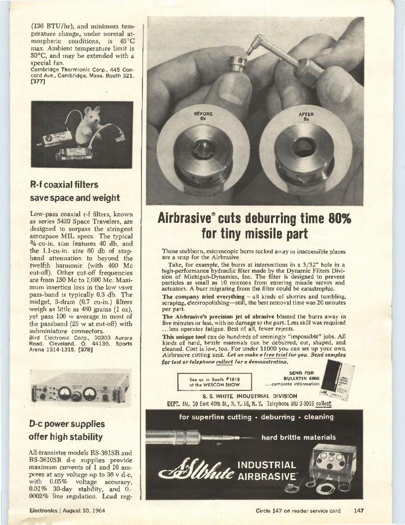
(136 BTU/hr), and minimum tem-perature change, under normal at-mospheric conditions, is 45°C max. Ambient temperature limit is 50°C, and may be extended with a special fan. Cambridge Thermionic Corp., 445 Con-cord Ave., Cambridge, Mass. Booth 321. [377]
R-f coaxial filters
save space and weight
Low-pass coaxial r-f filters, known as series 5420 Space Travelers, are designed to surpass the stringent aerospace MIL specs. The typical 3/4-eu-in. size features 40 db, and the 1.1-cu-in. size 60 db of stop-band attenuation to beyond the twelfth harmonic (with 400 Mc cut-off). Other cut-off frequencies are from 150 Mc to 1,000 Mc. Maxi-mum insertion loss in the low vswr pass-band is typically 0.3 db. The midget, 3-dram (0.7 cu-in.) filters weigh as little as 480 grains (1 oz), yet pass 100 w average in most of the passband (25 w at cut-off) with subminiature connectors. Bird Electronic Corp., 30303 Aurora Road, Cleveland, 0. 44139. Sports Arena 1314-1315. [378]
D-c power supplies
offer high stability
All-transistor models RS-361SR and RS-3610SR d-c supplies provide maximum currents of 1 and 10 am-peres at any voltage up to 36 y d-c, with 0.05% voltage accuracy, 0.01% 30-day stability, and 0.-0002% line regulation. Load reg-
Airbrasive® cuts deburring time 80% for tiny missile part
Those stubborn, microscopic burrs tucked away in inaccessible places are a snap for the Airbrasive. Take, for example, the burrs at intersections in a 3/32" hole in a
high-performance hydraulic filter made by the Dynamic Filters Divi-sion of Michigan-Dynamics, Inc. The filter is designed to prevent particles as small as 10 microns from entering missile servos and actuators. A burr migrating from the filter could be catastrophic.
The company tried everything — all kinds of slurries and tumbling, scraping, electropolishing—still, the best removal time was 20 minutes per part. The Airbrasive's precision jet of abrasive blasted the burrs away in five minutes or less, with no damage to the part. Less skill was required ...less operator fatigue. Best of all, fewer rejects.
This unique tool can do hundreds of seemingly "impossible" jobs. All kinds of hard, brittle materials can be deburred, cut, shaped, and cleaned. Cost is low, too. For under $1000 you can set up your own Airbrasive cutting unit. Let us make a free trial for you, Send samples for test or telephone collect for a demonstration.
See us in Booth #1818 at the WESCON SHOW
SEND FOR BULLETIN 6006
...complete information
f4e„ S. S. WHITE INDUSTRIAL DIVISION
DEPT. EU, 10 East 40th St., N. Y. 16, N. Y. Telephone MU 3-3015 collect
for superfine cutting • deburring • cleaning
hard brittle materials
INDUSTRIAL AIRBRASIVE°
Electronics fAugust 10, 1964
..01,19gle
Circle 147 on reader service card 147
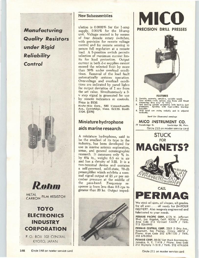
Manufacturing
Quality Resistors
under Rigid
Reliability
Control
ROW» METAL
FILM RESISTOR CARBON
TOY() ELECTRONICS
INDUSTRY CORPORATION
P. 0. BOX 103 CENTRAL
KYOTO, JAPAN
New Subassemblies
ulation is 0.0005% for the 1-amp supply, 0.001% for the 10-amp unit. Voltage control is by means of four decade rotary switches, with provision for remote voltage control and for remote sensing to secure full regulation at a remote load. A 5-position switch permits selection of maximum current lim-its for load protection. Output current in both d-c supplies cannot exceed the selected limit by more than 30% under overload condi-tions. Removal of the load fault automatically restores operation. Overvoltage and overload condi-tions are indicated by panel lights for output deviation of 1 mv from the set value. Simultaneously a 3-v step signal is generated for use by remote indicators or controls. Price is $850. Krohn-Hite Corp., 580 Massachusetts Ave., Cambridge, Mass. 02139. Booth 1104. [379]
Miniature hydrophone
aids marine research
A miniature hydrophone, said to be the smallest of its type in the industry, has been developed for use in marine seismic exploration, sonar, and general oceanographic research. It measures only 3/4 in. by 61/4 in., weighs 6.5 oz in air and has a density of 3.25. It is a two-terminal device and contains a self-powered, solid-state, 70-db preamplifier which exhibits a nom-inal signal output of 25 /Iv per mi-crobar pressure at the middle of the pass-band. Frequency re-sponse is from less than 0.5 cps to greater than 20 kc. Output imped-
M1CO PRECISION DRILL PRESSES
FEATURES 1. Durable, accurate, sensitive, variable speed; 2. Four models—with various size bases and throat
dimensions from 61/2 " to 121/2”, 3. Ball bearing spindle assemblies with built-in dust
protectors. Spindles with taper-oilless bearings available.
4. Drill head can swing radially and is adjusted vertically.
Send for illustrated catalogs
MICO INSTRUMENT CO. 77 Trowbridge St. Cambridge 38, Mass.
Circle 210 on reader service card
STUCK FOR
MAGNETS?
CALL
PERMAG We stock all sizes, all shapes, all grades, for all uses . . . all ready for 24-HOUR DELIVERY. Also magnets engineered and fabricated to your needs.
PERMAG PACIFIC CORP. 6176 W. Jefferson Blvd., Los Angeles, Calif. 90016 / Phone: Area Code 213 VErmont 7-4479 / TWX: 213 836-0445
PERMAG CENTRAL CORP. 5301 D Otto Ave., Rosemont, Des Plaines, Illinois 60018 / Phone: Area Code 312 678-1120 / TWX: 312 678-2063
PERMAG CORP. 88-06 Van Wyck Expressway, Jamaica, N. Y. 11418 / Phone: Area Code 212 Olympia 7-1818 / TWX: 212 479-3654
148 Circle 148 on reader service card Circle 211 on reader service card
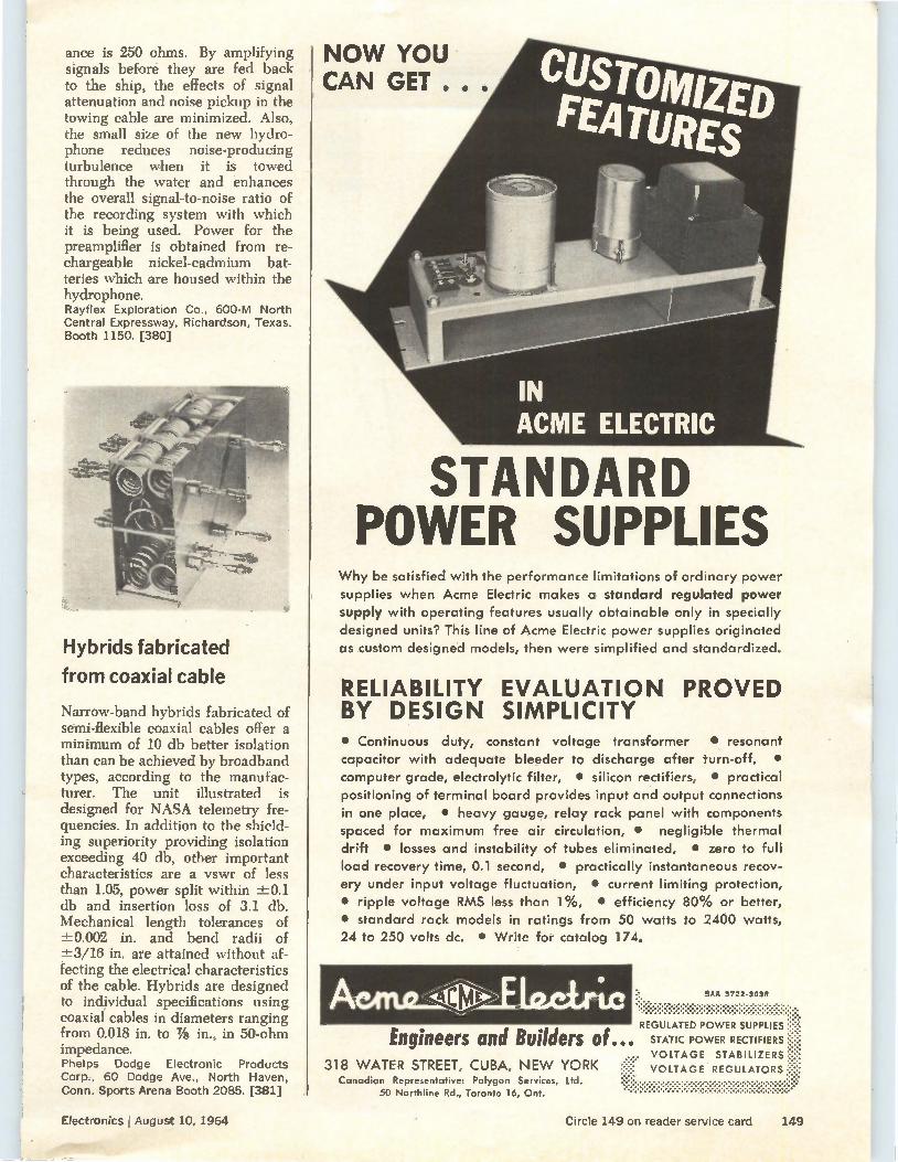
ance is 250 ohms. By amplifying signals before they arc fed back to the ship, the effects of signal attenuation and noise pickup in the towing cable are minimized. Also, the small size of the new hydro-phone reduces noise-producing turbulence when it is towed through the water and enhances the overall signal-to-noise ratio of the recording system with which it is being used. Power for the preamplifier is obtained from re-chargeable nickel-cadmium bat-teries which are housed within the hydrophone. Rayflex Exploration Co., 600-M North Central Expressway, Richardson, Texas. Booth 1150. [380]
Hybrids fabricated
from coaxial cable
Narrow-band hybrids fabricated of semi-flexible coaxial cables offer a minimum of 10 db better isolation than can be achieved by broadband types, according to the manufac-turer. The unit illustrated is designed for NASA telemetry fre-quencies. In addition to the shield-ing superiority providing isolation exceeding 40 db, other important characteristics are a vswr of less than 1.05, power split within ±.-0.1 db and insertion loss of 3.1 db. Mechanical length tolerances of -1-.0.002 in. and bend radii of ±-3/16 in. are attained without af-fecting the electrical characteristics of the cable. Hybrids arc designed to individual specifications using coaxial cables in diameters ranging from 0.018 in. to 7/8 in., in 50-ohm impedance. Phelps Dodge Electronic Products Corp., 60 Dodge Ave., North Haven, Conn. Sports Arena Booth 2085. [381]
NOW YOU CAN GET . . .
STANDARD POWER SUPPLIES
Why be satisfied with the performance limitations of ordinary power supplies when Acme Electric makes a standard regulated power supply with operating features usually obtainable only in specially designed units? This line of Acme Electric power supplies originated as custom designed models, then were simplified and standardized.
RELIABILITY EVALUATION PROVED BY DESIGN SIMPLICITY • Continuous duty, constant voltage transformer • resonant capacitor with adequate bleeder to discharge after turn-off, • computer grade, electrolytic filter, • silicon rectifiers, • practical positioning of terminal board prov;des input and output connections in one place, • heavy gauge, relay rack panel with components spaced for maximum free air circulation, • negligible thermal drift • losses and instability of tubes eliminated, • zero to full load recovery time, 0.1 second, • practically instantaneous recov-ery under input voltage fluctuation, • current limiting protection, • ripple voltage RMS less than 1%, • efficiency 80% or better, • standard rack models in ratings from 50 watts to 2400 watts, 24 to 250 volts dc. • Write for catalog 174.
SAA 3722.3030
REGULATED POWER SUPPLIES
Engineers and Builders of... STATIC POWER RECTIFIERS
VOLTAGE STABILIZERS 318 WATER STREET, CUBA, NEW YORK :re:* VOLTAGE REGULATORS
Canadian Representative: Polygon Services, Ltd. 50 Northline Rd., Toronto 16, Ont.
Electronics r August 10, 1964
__2081PIr
Circle 149 on reader service card 149
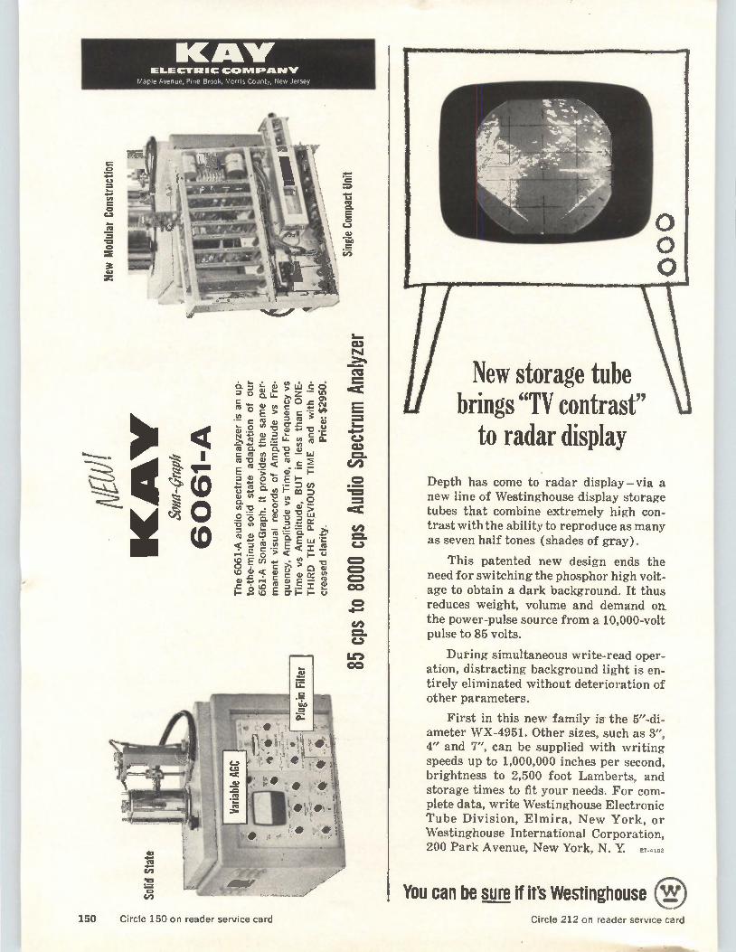
KM" ELECTRIC COW. IPA». If
Maple Avenue, Pine Brook, Morris County, New Jersey
New
Modular
Cons
truc
tion
03 NJ
6. t' IL ilt cf3 th z Cc; > cE so
a) o 0 lif C e to. E =
0 Cfl Er .c a— • .4.) 0 -- ..1 ,
• (-1 75 a ' " a •c3 iii CD
co y ru rti 2 ce) E > ..... o
0 u ..-. o• (t) i— co o IS a0 '2. 0 o = v) 0 E .d u 0 -0 73 0. " 0 LyiO '6 in ca c :.-. ct =ca E weL ..i'...". (1) 1.... •-•• :b., .=
=16 4-' ci3 ?) g• c C.1
> po• p
CCI 4= co E a- i=
0
V! =. C.1
Li") CO
New storage tube brings "TV contrast"
to radar display
Depth has come to radar display—via a new line of Westinghouse display storage tubes that combine extremely high con-trast with the ability to reproduce as many as seven half tones (shades of gray).
This patented new design ends the need for switching the phosphor high volt-age to obtain a dark background. It thus reduces weight, volume and demand on the power-pulse source from a 10,000-volt pulse to 85 volts.
During simultaneous write-read oper-ation, distracting background light is en-tirely eliminated without deterioration of other parameters.
First in this new family is the 5"-di-ameter WX-4951. Other sizes, such as 3", 4" and 7", can be supplied with writing speeds up to 1,000,000 inches per second, brightness to 2,500 foot Lamberts, and storage times to fit your needs. For com-plete data, write Westinghouse Electronic Tube Division, Elmira, New York, or Westinghouse International Corporation, 200 Park Avenue, New York, N. Y. ET-4102
You can be sure if it's Westinghouse 150 Circle 150 on reader service card Circle 212 on reader service card
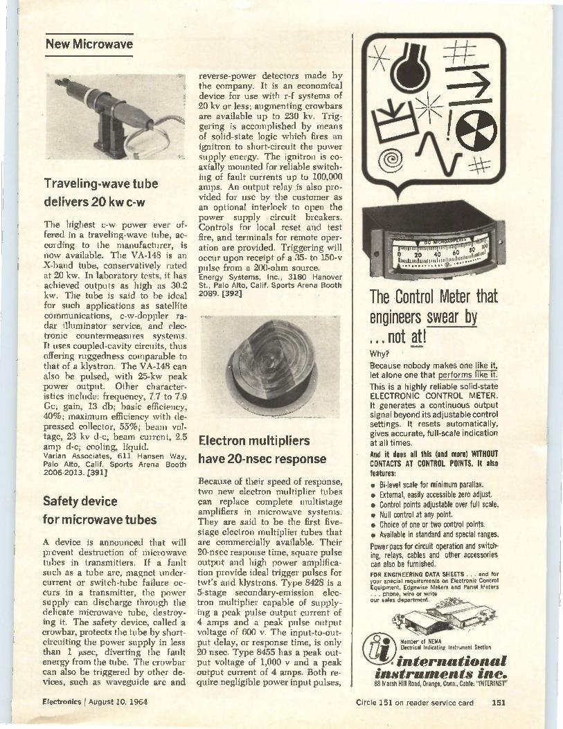
New Microwave
Traveling-wave tube
delivers 20 kw c-w
The highest c-w power ever of-fered in a traveling-wave tube, ac-cording to the manufacturer, is now available. The VA-148 is an X-band tube, conservatively rated at 20 kw. In laboratory tests, it has achieved outputs as high as 30.2 kw. The tube is said to be ideal for such applications as satellite communications, c-w-doppler ra-dar illuminator service, and elec-tronic countermeasures systems. It uses coupled-cavity circuits, thus offering ruggedness comparable to that of a klystron. The VA-148 can also be pulsed, with 25-kw peak power output. Other character-istics include: frequency, 7.7 to 7.9 Cc; gain, 13 db; basic efficiency, 40%; maximum efficiency with de-pressed collector, 55%; beam vol-tage, 23 kv d-c; beam current, 2.5 amp d-c; cooling, liquid. Varian Associates, 611 Hansen Way, Palo Alto, Calif. Sports Arena Booth 2006-2013. [391]
Safety device
for microwave tubes
A device is announced that will prevent destruction of microwave tubes in transmitters. If a fault such as a tube arc, magnet under-current or switch-tube failure oc-curs in a transmitter, the power supply can discharge through the delicate microwave tube, destroy-ing it. The safety device, called a crowbar, protects the tube by short-circuiting the power supply in less than 1 ktsec, diverting the fault energy from the tube. The crowbar can also be triggered by other de-vices, such as waveguide are and
reverse-power detectors made by the company. It is an economical device for use with r-f systems of 20 kv or less; augmenting crowbars are available up to 230 kv. Trig-gering is accomplished by means of solid-state logic which fires an ignitron to short-circuit the power supply energy. The ignitron is co-axially mounted for reliable switch-ing of fault currents up to 100,000 amps. An output relay is also pro-vided for use by the customer as an optional interlock to open the power supply circuit breakers. Controls for local reset and test fire, and terminals for remote oper-ation are provided. Triggering vill
occur upon receipt of a 35- to 150-v pulse from a 200-ohm source. Energy Systems, Inc., 3180 Hanover St., Palo Alto, Calif. Sports Arena Booth 2089. [392]
Electron multipliers
have 20-nsec response
Because of their speed of response, two new electron multiplier tubes can replace complete multistage amplifiers in microwave systems. They are said to be the first five-stage electron multiplier tubes that are commercially available. Their 20-nsec response time, square pulse output and high power amplifica-tion provide ideal trigger pulses for twt's and klystrons. Type 8428 is a 5-stage secondary-emission elec-tron multiplier capable of supply-ing a peak pulse output current of 4 amps and a peak pulse output voltage of 600 v. The input-to-out-put delay, or response time, is only 20 nsec. Type 8455 has a peak out-put voltage of 1,000 y and a peak output current of 4 amps. Both re-quire negligible power input pulses,
The Control Meter that engineers swear by ... not at! Why? Because nobody makes one like it, let alone one that performs like it. This is a highly reliable solid-state ELECTRONIC CONTROL METER. It generates a continuous output signal beyond its adjustable control settings. It resets automatically, gives accurate, full-scale indication at all times. And it does all this (and more) WITHOUT CONTACTS AT CONTROL POINTS. It also features: • Bi-level scale for minimum parallax. • External, easily accessible zero adjust. • Control points adjustable over full scale. • Null control at any point. • Choice of one or two control points. • Available in standard and special ranges. Power pacs for circuit operation and switch-ing, relays, cables and other accessories can also be furnished. FOR ENGINEERING DATA SHEETS ... and for your special requirements on Electronic Control Equipment, Edgewise Meters and Panel Meters ... phone, wire or write our sales department.
Member of NEMA Electrical Indicating Instrument Section
_ international instruments inc. 88 Marsh Hill Road, Orange, Conn., Cable: "INTERINST"
Electronics I August 10, 1964 Circle 151 on reader service card 151
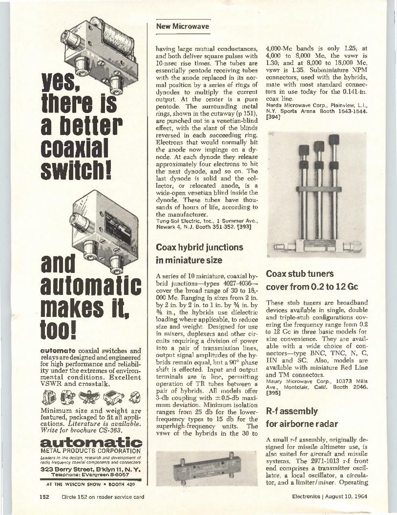
Yes, there is a better coaxial switch!
and automati makes it, tool automate coaxial switches and relays are designed and engineered for high performance and reliabil-ity under the extremes of environ-mental conditions. Excellent VSWR and crosstalk.
Minimum size and weight are featured, packaged to fit all appli-cations. Literature is available. Write for brochure CS-363.
a.utomatio METAL PRODUCTS CORPORATION. Leaders in the design, research and development of radio frequency coaxial components and connectors
323 Berry Street, B'klyn11, N.Y. Telephone: EVergreen 8-6057
AT THE WESCON SHOW • BOOTH 420
New Microwave
having large mutual conductances, and both deliver square pulses with 10-nsec rise times. The tubes are essentially pentode receiving tubes with the anode replaced in its nor-mal position by a series of rings of dynodes to multiply the current output. At the center is a pure pentode. The surrounding metal rings, shown in the cutaway (p 151), are punched out in a venetian-blind effect, with the slant of the blinds reversed in each succeeding ring. Electrons that would normally hit the anode now impinge on a dy-node. At each dynode they release approximately four electrons to hit the next dynode, and so on. The last dynode is solid and the col-lector, or relocated anode, is a wide-open venetian blind inside the dynode. These tubes have thou-sands of hours of life, according to the manufacturer. Tung-Sol Electric, Inc., 1 Summer Ave., Newark 4, N.J. Booth 351-352. [393]
Coax hybrid junctions
in miniature size
A series of 10 miniature, coaxial hy-brid junctions—types 4027-4036— cover the broad range of 30 to 18,-000 Mc. Ranging in sizes from 2 in. by 2 in. by 2 in. to 1 in. by 3/4 in. by 3/8 in., the hybrids use dielectric loading where applicable, to reduce size and weight. Designed for use in mixers, duplexers and other cir-cuits requiring a division of power into a pair of transmission lines, output signal amplitudes of the hy-brids remain equal, but a 90° phase shift is effected. Input and output terminals are in line, permitting operation of TB tubes between a pair of hybrids. All models offer 3-db coupling with -±0.5-db maxi-mum deviation. Minimum isolation ranges from 25 db for the lower-frequency types to 15 db for the superhigh-frequency units. The vswr of the hybrids in the 30 to
4,000-Mc bands is only 1.25; at 4,000 to 8,000 Mc, the vswr is 1.30; and at 8,000 to 18,000 Mc, vswr is 1.35. Subminiature NPM connectors, used with the hybrids, mate with most standard connec-tors in use today for the 0.141-in. coax line. Narda Microwave Corp., Plainview, L.I., N.Y. Sports Arena Booth 1543-1544. [394]
Coax stub tuners
cover from 0.2 to 12 Gc
These stub tuners are broadband devices available in single, double and triple-stub configurations cov-ering the frequency range from 0.2 to 12 Ge in three basic models for size convenience. They are avail-able with a wide choice of con-nectors—type BNC, TNC, N, C, HN and SC. Also, models are available with miniature Red Line and TM connectors. Maury Microwave Corp., 10373 Mills Ave., Montclair, Calif. Booth 2046. [395]
R-f assembly
for airborne radar
A small r-f assembly, originally de-signed for missile altimeter use, is also suited for aircraft and missile systems. The 2971-1013 r-f front end comprises a transmitter oscil-lator, a local oscillator, a circula-tor, and a limiter/mixer. Operating
152 Circle 152 on reader service card Electronics j August 10, 1964
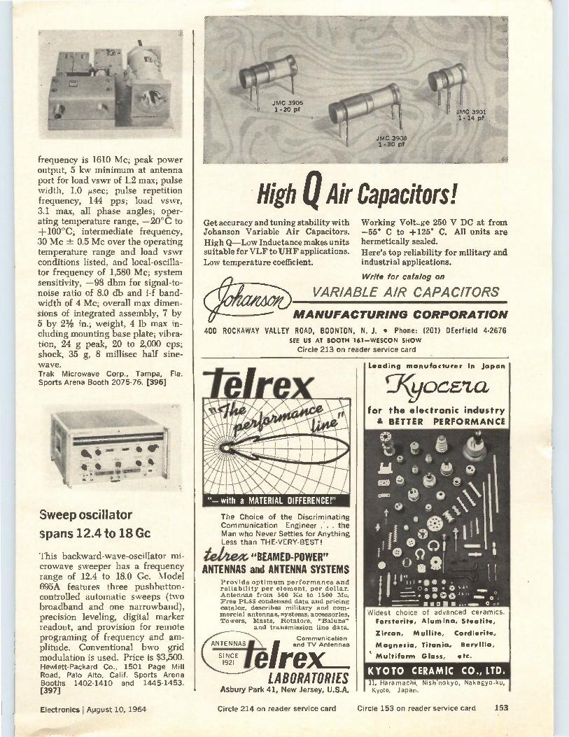
frequency is 1610 Mc; peak power output, 5 kw minimum at antenna port for load vswr of 1.2 max; pulse width, 1.0 ,usec; pulse repetition frequency, 144 pps; load vswr, 3.1 max, all phase angles; oper-ating temperature range, —20°C to +100°C; intermediate frequency, 30 Mc ± 0.5 Mc over the operating temperature range and load vswr conditions listed, and local-oscilla-tor frequency of 1,580 Mc; system sensitivity, —98 dbm for signal-to-noise ratio of 8.0 db and i-f band-width of 4 Mc; overall max dimen-sions of integrated assembly, 7 by 5 by 21/2 in.; weight, 4 lb max in-cluding mounting base plate; vibra-tion, 24 g peak, 20 to 2,000 cps; shock, 35 g, 8 millisec half sine-wave. Trak Microwave Corp., Tampa, Fla. Sports Arena Booth 2075-76. [396]
Sweep oscillator
spans 12.4 to 18 Gc
This backward-wave-oscillator mi-crowave sweeper has a frequency range of 12.4 to 18.0 Cc. Model 695A features three pushbutton-controlled automatic sweeps (two broadband and one narrowband), precision leveling, digital marker readout, and provision for remote programing of frequency and am-plitude. Conventional bwo grid modulation is used. Price is $3,500. Hewlett-Packard Co., 1501 Page Mill Road, Palo Alto, Calif. Sports Arena Booths 1402-1410 and 1445-1453. [397]
Electronics August 10, 1964
High Air Capacitors! Get accuracy and tuning stability with Johanson Variable Air Capacitors. High Q—Low Inductance makes units suitable for VLF to UHF applications. Low temperature coefficient.
Working Volt-ge 250 V DC at from —55° C to +125° C. All units are hermetically sealed. Here's top reliability for military and industrial applications.
Write for catalog on
VARIABLE AIR CAPACITORS
MANUFACTURING CORPORA TION
400 ROCKAWAY VALLEY ROAD, BOONTON, N. J. • Phone: (201) DEerfield 4-2676 SEE US AT BOOTH 161—WESCON SHOW
Circle 213 on reader service card
The Choice of the Discriminating Communication Engineer . the Man who Never Settles for Anything Less than THE-VERY-BEST!
iellte/X "BEAMED-POWER" ANTENNAS and ANTENNA SYSTEMS
Provide optimum performance and reliability per element, per dollar. Antennas from 500 lie to 1500 Mc. Free PL88 condensed data and pricing catalog, describes military and com-mercial antennas, systems, accessories, Towers, Masts, Rotators, "Baluns"
and transmission line data.
Communication and TV Antennas re . LABORATORIES
Asbury Park 41, New Jersey, U.S.A.
Circle 214 on reader service card
Leading manufacturer in Japan
yocez,a, for the electronic industry & BETTER PERFORMANCE
Widest choice of advanced ceramics. Forsterite, Alumina, Steatite,
Zircon, Mullite, Cordierite,
Magnesia, Titania, Beryllia,
t Multiform Glass, etc.
11, Haramacin, Nishinokyo, Nakagyo-ku, Kyoto, Japan.
Circle 153 on reader service card 153
-42111IR
New Production Equipment
100,000 MEGOHIVIS ±150 VOLTS
These unusual input specs describe the remarkable Adage HZATM isolation amplifier.
ï.'- 4• r ., 4e-selt ly 114e1 ererieg <
411r•O*00
More reasons why HZA has no equal: • Gain accuracy better than 1 part
in 1,000,000 • Dynamic range greater than
1,000,000 to 1 • 10 volts/sec. input swing rate • Input current less than 10-9 amps We not only meet these specs — we guarantee them. For your next isolation amplifier requirement, let us quote our HZA — available also as a differential amplifier. We think you'll like our prices, too.
hve
Main Office and Factory: 292 Main Street, Cambridge 42, Mass.
West Coast Plant: 1145 East Ash Avenue, Fullerton, California
Adage, Inc. welcomes employment inquiries from professional engineers.
Temperature chamber
gives precise control
A new, portable temperature cham-ber, model 5703, features high-tem-perature control accuracy and low-temperature gradients in relation to relatively large internal volume and low cost. Major applications are in rapid, convenient testing of materials and electronic, electrical, and mechanical devices. Other uses include general-purpose applica-tion in scientific laboratories, qual-ity control, and in manufacturing processes. Specifications are: range, —100°F to 4-600°F; internal test volume, 1.85 cu ft; coolant, liquid carbon dioxide. A stainless-steel in-ternal liner is durable, easy to clean, chemically inert and has low mag-netic effect. Price is $800. Delta Design, Inc., 8000 Fletcher Park-way, La Mesa, Calif. Sports Arena Booth 1212. [421]
Compact ultrasonic
production transducer
A new ultrasonic standard produc-tion transducer known as the SO-MAT, sound operated machine accessory transducer, has been in-troduced. SOMAT is designed for use in welding, soldering, grinding
and brazing. It can be operated in-termittently or continuously, with-out warmup, with model DS-221 ultrasonic generator. Its power handling capability is 200 w contin-uous, unloaded, at 21 kc resonant frequency. Cooling is achieved with a self-contained blower. The unit is 13 1/2 in. long, 51/2 in. in diameter, and weighs 7 lb. It comes equipped with a stepped horn me-chanical transformer and a 10-ft standard cable. Delta Sonics, Inc., 12918 Cerise Ave., Hawthorne, Calif. Sports Arena Booth 1729. [422]
Ultrasonic applicator
cleans p-c boards
Model USWA ultrasonic wave applicator satisfies cleaning and processing requirements in many fields. It produces a constantly flowing, smooth laminar wave with an even horizontal surface 12 in. by 12 in. in area and 1/2 in. high. It can be applied most effectively in the post-cleaning of printed-circuit boards for the removal of flux and oil residue. It can also be used for precleaning before fluxing, and may be used in straight-line soldering as an independent operation. Electrovert Mfg. Co., 3285 Cavendish Blvd., Montreal 28, Quebec, Canada. Canadian Exhibit, Area 800. [423]
Pressurized enclosure
for ultra-clean work
An ultra-clean work station with 360° visibility and 360° access to the work area has been developed for effectively removing and con-trolling air-borne contaminants. All units are available with an absolute type filter, 99.97% efficient on 0.3 micron particle size, and large ca-pacity blower. There are no cor-ners in the Cleansphere. The work opening height can be varied and microscope wells or ports can be installed. The 4-ft diameter Clean-sphere will seat six people comfort-ably in 50% less floor space than a conventional 6-ft wide laminar flow-type work station. The Clean-
154 Circle 154 on reader service card Electronics I August 10, 1964
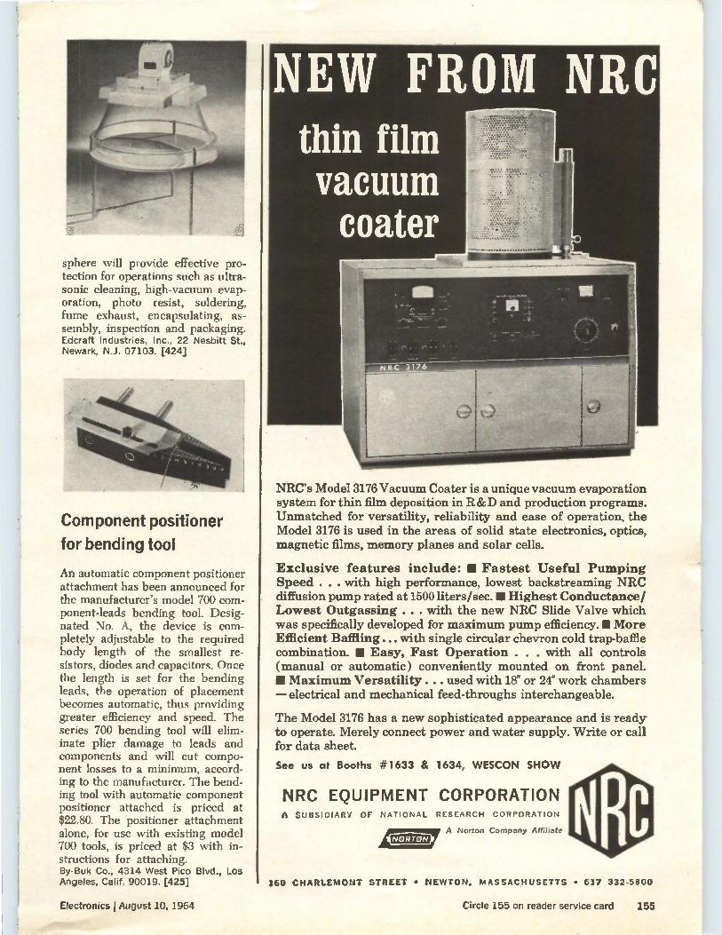
sphere will provide effective pro-tection for operations such as ultra-sonic cleaning, high-vacuum evap-oration, photo resist, soldering, fume exhaust, encapsulating, as-sembly, inspection and packaging. Edcraft Industries, Inc., 22 Nesbitt St., Newark, N.J. 07103. [424]
Component positioner
for bending tool
An automatic component positioner attachment has been announced for the manufacturer's model 700 com-ponent-leads bending tool. Desig-nated No. A, the device is com-pletely adjustable to the required body length of the smallest re-sistors, diodes and capacitors. Once the length is set for the bending leads, the operation of placement becomes automatic, thus providing greater efficiency and speed. The series 700 bending tool will elim-inate plier damage to leads and components and will cut compo-nent losses to a minimum, accord-ing to the manufacturer. The bend-ing tool with automatic component positioner attached is priced at $22.80. The positioner attachment alone, for use with existing model 700 tools, is priced at $3 with in-structions for attaching. By-Buk Co., 4314 West Pico Blvd., Los Angeles, Calif. 90019. [425]
NEW FROM NRC thin film vacuum coater
NRC's Model 3176 Vacuum Coater is a unique vacuum evaporation system for thin film deposition in R&D and production programs. Unmatched for versatility, reliability and ease of operation, the Model 3176 is used in the areas of solid state electronics, optics, magnetic films, memory planes and solar cells.
Exclusive features include: • Fastest Useful Pumping Speed . . . with high performance, lowest backstreaming NRC diffusion pump rated at 1500 liters/sec.11 Highest Conductance/ Lowest Outgassing . . . with the new NRC Slide Valve which was specifically developed for maximum pump efficiency. IM More Efficient Baffling ... with single circular chevron cold trap-baffle combination. II Easy, Fast Operation . . . with all controls (manual or automatic) conveniently mounted on front panel. • Maximum Versatility . . . used with 18" or 24" work chambers — electrical and mechanical feed-throughs interchangeable.
The Model 3176 has a new sophisticated appearance and is ready to operate. Merely connect power and water supply. Write or call for data sheet.
See us at Booths #1633 & 1634, WESCON SHOW
NRC EQUIPMENT CORPORATION A SUBSIDIARY OF NATIONAL RESEARCH CORPORATION
I(NoRrot4> A Norton Company Affiliate
160 CHARLEMONT STREET • NEWTON, MASSACHUSETTS • 617 332-5800
Electronics jAugust 10, 1964 Circle 155 on reader service card 355
Got A Mixer Hangover?
La's New- Broadband Mixers are better for your system...
Isolation too low? Mixers too big? Bandwidths too nar-row? New LEL Mixers are the perfect prescription to set your system right. LEL's multiple-octave coax and full waveguide range models cover the spectrum from 250 Mc to 18 Gc. High performance, low noise units like the LEL 12 - 18 Gc mixer come in pill-sized packages, measuring a mere 2 Cu. inches. Isolation in many models is in the order of 20 - 30 db.
Chances are you're already using other LEL top quality products, so you know what to expect in terms of reli-ability, economy and rugged construction. Send today for full information on LEL's new mixer line.
LEL Catalog '64
FREE...send for: it today'!
See us at WESCON Booth No. 2027
AKRON ST., COPIAGUE, L. I., NEW YORK 11726 (516) AMityville 4-2200 • (516) PYramid 9-8200 • TWX Code 516-691-5085
PLASTIC Dokinottre CASES& COVERS
r,
Break-resistant quality — excellent dielectric strength for insulation — high luster finish
requires no painting — in industry approved sizes that are ideal for housing test equipment, electrical
or electronic controls. STANDARD SIZES:
No. 220 4" long x Via" wide x MI6" deep No.240 — 61/4 " long x 33/4 " wide x 2" deep No. 260 — 6?;6" long x 5? 2" wide x 2-5/12" deep No. 241 — Mating cover for No. 240 case No. 261 — Mating cover for No. 260 case
HARRY DAVIES MOLDING COMPANY 1428 N. Wells Street • Chicago, Illinois 60610
owe
Samples and prices furnished promptly.
Circle 215 on reader service card
DELTA-T f\C' ELT^
KING SIZE (—,,,11,3;-'
HEAT SINKS ... for the latest
high power " semiconductors
SERIES WN FOOT-MOUNTED
NEW Series GN and WN HEAT SINKS ... for high power SCRs and rectifiers with 1-1/16", 1-1/4" or 1-3/4" hex. Natural Convection units . . . have radial fin design for increased fin efficiency.
ALSO . . . NEW
TECHNICAL BULLETINS
SERIES ON END-MOUNTED
WESCON SHOW / Booth 372, Hollywood Park
WAKEFIELD ENGINEERING, INC.
139 FOUNDRY Sr. / WAKEFIELD, MASS. (617) 245.5900 • TWX 617.245.9213
156 Circle 156 on reader service card Circle 216 on reader service card
New Materials
Thermally-conductive
dielectric resins
A family of dielectric resins that can be cast and molded is claimed to have thermal conductivities at least 10 times better than conven-tional filled resins and 100 times better than unfilled resins. The new Berlon composite materials include epoxies, phenolics, and sil-icones, filled with Berlox high-pur-ity beryllium oxide. Since beryl-lium oxide has excellent electrical properties as well as high thermal conductivity, there is no sacrifice of dielectric strength, volume re-sistivity, power factor, or other electrical or mechanical property. The new materials are available as pre-filled resins, for customer blending, with curing agent for potting or encapsulation, or in the form of fabricated sheet, block, and rod, or custom-machined shapes. National Beryllia Corp., Haskell, N.J. Booth 1619. [411]
Materials and finishes
for printed circuits
A variety of material types and circuit finishes are offered for users of printed circuits. Circuit finishes are available in copper, silver, gold, solder and tin. Plug-in contacts can be provided by electroplating— usually gold over nickel or rhodium over nickel—or by mechanical con-nectors attached to the printed circuit. In addition, flexible circuits are offered in several materials. Depending on the application and degree of flexibility desired, flexible circuits are availabe on Teflon, Mylar and other polyester bases,
and even on fiber glass epoxy laminates as thin as 0.003 in. Avionics, Ltd., P.O. Box 200, Niagara-on-the-Lake, Ontario, Canada. Canadian Exhibit, Area 800. [412]
Hook-up wire
meets new Mil spec
A high-temperature hook-up wire, in accordance with a new spec, MIL-W-81044, combines superior mechanical toughness with appre-ciable weight savings, thinner walls. smaller comparative sizes, ease of fabrication and lower cost than other fluorocarbon types, according to the manufacturer. The wire is a two-layer construction of radiation crosslinked materials. The inner layer is a polyalkene and the outer layer a thin jacket of Kynar (poly-vinylidenc fluoride). Temperature rating is 135°C continuous. Using conventional techniques, the wire is easily marked, stripped, potted and fabricated into harnesses. Raychem Corp., Oakside at Northside, Redwood City, Calif. Booth 1844-1845. [413]
Semiconductive tape
sheds static charges
A new semiconductive tape has properties that make it useful in equipment programing and com-puters. The tape, in which a special graphite coating is bonded directly to polyester film, will not build up static charges. It is lighter, more flexible and more resistant to fray-ing than conventional laminated tapes, according to the manufac-turer. When used as a cable wrap-ping, it provides an extremely light shielding with a considerable range of conductivity. The tape is available in various resistances from 1,000 ohms/sq. Even in thin gages it is 100% opaque, with high tensile and dielectric strength. It will withstand temperatures to 400 degrees, about 200° higher than currently available tapes. It can be laminated, embossed, metallized and punched. Custom Coating & Laminating Co., 717 Plantation St., Worcester, Mass. [414]
PROBLEM? Send for Bulletin No. TR-81
AMPUE Thermostatic DELAY RELAYS
Delays: 2 to 180 seconds Actuated by a heater, they operate on A.C., D.C., or Pul-sating Current . . . Being hermetically sealed, they are not affected by altitude, mois-ture, or climate changes ... SPST only—normally open or normally closed . . . Com-pensated for ambient tem-perature changes from —55* to +80° C.... Heaters con-sume approximately 2 W. and may be operated continu-ously . . . The units are rugged, explosion-proof, long. lined, and—inexpensive!
TYPES: Standard Radio Octal, and 9-Pin Miniature.
List Price, $4.00
Individual inspection and double-checking assures top quality of Amperite products.
AMPERITE BALLAST REGULATORS
a 10
6 VOLTAGE or 14V 2.... BATTERY CHARGER
VARIES APPROX.
50%
101WW11
WITH AMPERITI VOLTAGE VARIES ONLY
2% Hermetically sealed, they are not affected by changes in alti-tude, ambient temperature (-50° to +70° C.), or humid-ity ... Rugged, light, compact, most inexpensive .
List Price, $3.00
Write for 4-page Technical Bulletin No. A13-51
AMPERITE 600 PALISADE AVE., UNION CITY, NJ.
Telephone: 201 UNion 4-9503
In Canada: Atlas Radio Corp., ltd., 50 Wingold Ave., Toronto 10
Electronics I August 10, 1964 Circle 157 on reader service card 157
CRITICAL ELECTRONIC FOIL REQUIREMENTS ?
He has had extensive experience in the develop-ment and production of consistently superior
aluminum foils ... the foil in every operation
from initial rolling is under the critical eye of the Quality Control Manager . . . he double-checks final gaging, for example, that takes place during the slitting operation. These in-process inspection procedures coupled with nu-merous laboratory tests result in a product guar-anteed to adhere to the most critical electronic foil requirements
Republic's complete aluminum foil line includes:
• LIGHT GAGE FOIL for paper and film wound capacitors of all types.
• ETCHED ANODE & CATHODE FOIL
• PLAIN FOIL FOR ETCHING
• PLAIN FOIL for electrolytic capacitors, coil winding, and other uses.
LET US SEND YOU . . . literature describing Republic's foil line along with the name of the man technically qualified to assist you with your foil problems.
REPUBLIC
QUALITY in foil for
LEADERSHIP electronics
REPUBLIC FOIL INC.
GENERAL OFFICES & ROLLING MILL DIVISION Danbury, Connecticut
ELECTROCHEMICAL DIV. — Salisbury, North Carolina
CONSOLIDATED BAG & FOIL DIV. — Somerville, Mass.
BRANCH SALES OFFICES — 5306 West Lawrence Ave., Chicago 30, Illinois
WEST COAST — Electrical Specialty Co., 158 Eleventh St., San Francisco 3, Cal.
New Literature
Delay lines. Phelps Dodge Electronic Products Corp., 60 Dodge Ave., North Haven, Conn. Company capability in the design and fabrication of coaxial-cable delay lines is discussed in an 8-page catalog. Circle 451 on reader service card
Capacitors and inductors. LRC Elec-tronics, Inc., 901 South Ave., Horse-heads, N.Y. 14845, has released a catalog illustrating a complete line of precision trimmer capacitors and in-ductors. [452]
Signal conditioning system. Allegany Instrument Co., 1091 Wills Mountain, Cumberland, Md. 21501. An eight-page booklet describes the SAM (sensor analog module) signal conditioning sys-tem. [453]
Phono connectors. Connector Corp., 6025 No. Keystone Ave., Chicago, Ill. 60646. Data sheet 29A contains dimen-sional drawings and description of a line of multi-purpose, high-reliability, modular phono-type male and female connectors. [454]
Pulse transformers. Gudeman Co. of California, Inc., 7473 Avenue 304, Visalia, Calif. 93278. A new catalog sheet helps eliminate the use of de-tailed mathematics in selecting pulse transformers for blocking oscillator circuits. [455]
Varactor diodes. Solitron Devices, Inc., 500 Livingston, St., Norwood, N.J. An 8-page catalog describes a line of silicon epitaxial, abrupt junction, volt-age-variable capacitor diodes. [456]
Microwave components. Radar Design Corp., 104 Pickard Dr., Syracuse, N.Y. 13211, has published a short-form cat-alog entitled "Stock Microwave Com-ponents for Military and Industrial Sys-tems." [457]
Semiconductor pressure transducer. Micro Systems, Inc., 170 North Daisy Ave., Pasadena, Calif., offers a data sheet covering an ultraminiature semi-conductor pressure transducer, type 1004. [458]
Integrated-circuit prices. Signetics Corp., 680 West Maude Ave., Sunny-vale, Calif., has published a price list reflecting a downward revision of up to 33% on a line of monolithic DTL inte-grated circuits. [459]
High-voltage capacitors. Sangamo Electric Co., Springfield, III. Bulletin 2425 describes a complete line of type HVC high-voltage capacitors. [460]
Regulated power modules. Kepco, Inc., 131-38 Sanford Ave., Flushing, N.Y. 11352. A 4-page illustrated brochure, No. 146-1054, covers power modules with ±--1% line regulation. [461]
Bushing-mount potentiometer. Bourns, Inc., 1200 Columbia Ave., Riverside, Calif., has published a bulletin on the model 3530, a single-turn, bushing-mount potentiometer of 7/8-in. diam-eter. [462]
Microcircuit checklist. Corning Elec-tronic Products division, Raleigh, N.C., offers a checklist containing questions that should be asked about microcir-cuit requirements before the design process begins. [463]
Thermistors. Victory Engineering Corp., 136 Springfield Ave., Springfield, N.J., has available a bulletin describing mili-tary-grade disk and rod thermistors de-signed to meet MIL-T-23648 require-ments. [464]
Ceramic permanent magnets. Indiana General Corp., Valparaiso, Ind. Manual 8 presents a comprehensive design guide for the application of Indox cer-amic magnet materials. [465]
Integrated circuits. General Micro-elec-tronics Inc., 2920 San Ysidro Way, Santa Clara, Calif. 95051, has published a brochure illustrating its capabilities for the manufacture of semiconductor integrated circuits. [466]
Mixers and crystal holders. Microwave Development Laboratories, Inc., 87 Crescent Road, Needham Heights, Mass. Catalog MS63-5 gives mechani-cal and electrical details on waveguide mixers and crystal holders. [467]
Mass soldering techniques. Hollis Engi-neering, Inc., Pine St. Extension, Nashua, N.H. 03060, offers a booklet intended to up-date all facets of auto-matic soldering and discuss factors contributing to quality assurance in soldering printed-circuit boards. [468]
Shielded power transformers. James Electronics, Inc., 4050 N. Rockwell St., Chicago, III. 60618. A 2-page data sheet contains power transformer data for low-signal applications. [469]
Selenium rectifiers. Electronic Devices, Inc., 21 Gray Oaks Ave., Yonkers, N.Y. 10710. A complete line of high-voltage selenium cartridges is described in catalog SE-1004. [470]
Microwave resistors. Pyrofilm Resistor Co., 3 Saddle Rd., Cedar Knolls, N.J. Catalog RD25 covers the company's rod-type and disk-type microwave car-bon-film resistors. [471]
Integrated circuits. Amelco Semicon-ductor, 1300 Terra Bella Ave., Moun-tain View, Calif., has published a com-prehensive technical bulletin (No. 3) describing its OMIC (Optimized MICro-circuits) design approach to integrated circuits. [472]
158 Circle 158 on reader service card Electronics I August 10, 1964
It stands alone
ralarnounT. 0111A.CAt CO..
p•leul,c/y.two Cm.°0 ,1,MW
Hydrazine-Activated Flux* and Core Solder offers an exclusive combination of advantages:
• High wetting properties for good "bite."
• Non-corrosive connections.
• Residues removed by heating or water rinse.
• No change on aging.
No one flux is best for all purposes. TEST HYDRAZINE FLUX AND CORE SOL-DER FOR YOURSELF. The liquid per-mits pre-fluxing, is useful for soft-soldering a wide range of copper and copper-based alloys. The core solder flows at an ideal rate, leaves a minimum of soldering resi-dues. Write for samples of either, or tech-nical literature.
Available only from Fairmount and its sales agents. 'U.S. Potent No. 2,612,459 and others
Fairmount CHEMICAL CO., INC. 136 Liberty St., N. Y. 6, N. Y.
Circle 217 on reader service card
eamAIRFTYPEDC HIGH VOLTAGE POWER SUPPLIES
MODEL
RG-30-1 CONTINUOUSLY VARIABLE 15-30 KV REGULATED DC POWER SUPPLY
WITH REGULATED FOCUS VOLTAGE
TAP
A continuous duty DC supply with highly filtered outputs and regulations against line, load and drift less than 0.1% at 1 ma. Ripple less than .005%. A variable focus tap 4-6 KV for use with flying spot tubes. 19" wide x 83/4" high x 15" deep.
With NV meter $450. Net Less meter $400. Net
MODEL RG-30--Same as RO-30.1 except regulations against line, load and drift less than 0.5% at 1 ma. 19" wide x 83/4" high x 13" deep.
With NV meter $375. Net Less meter $325. Net
MODEL
LAB-10 CONTINUOUSLY VARIABLE 1-15 KV REGULATED DC SUPPLY
Output current 2 ma. Regulations line and load better than .5%. Input: 117 V 60 cycles. Complete with NV and current meters. 19"W x 83/4 "H x 13"D $275 net MODEL LAB-10PN—Same specifications as above except reversible polarity $375 net
SPELLMAN HIGH VOLTAGE COMPANY, INC.
1930 Adee Ave., Bronx 69, N.Y. KIngsbridge 7-0306
Measuring instruments. Waveforms, Inc., 333 Sixth Ave., New York 10014. Catalog 15A gives a rundown on elec-tronic measuring instruments manufac-tured—covering sub-audio through low radio frequencies — and services offered. [473]
Transformers. Protran Co., Inc., 7 Com-mercial St., Hicksville, L.I., N.Y., has issued a condensed catalog on trans-formers and high-power pulse modula-tor components. [474]
Transistor chopper driver. Solid State Electronics Corp., 15321 Rayen St., Sepulveda, Calif. 91343. A catalog sheet describes model TCD-101 tran-sistor chopper driver designed to meet military specifications. [475]
Communication printer system. Anelex Corp., 150 Causeway St., Boston 14, Mass. A 4-page brochure describes a communication printer system that is compatible with any computer and op-erates on-line via Data-phone, micro-wave, and coaxial cable, or off-line from cards and tapes. [476]
Strip connectors. ITT Cannon Electric Inc., 3208 Humboldt St., Los Angeles, Calif. 90031, offers catalog MTS-2 on microminiature, 50-mil strip connec-tors. [477]
Magnetic definitions. Ferroxcube Corp. of America, Saugerties, N.Y. Bulletin 110 contains 12 pages of magnetic definitions, including mathematical de-rivations, of the most commonly used terms applied in the design of magnetic devices. [478]
Quartz crystals. Monitor Products Co., Inc., 815 Fremont Ave., South Pasa-dena, Calif., has published a bulletin on Koldweld frequency-control quartz crystals for missile and space applica-tions. [479]
Telemetry transmitters. Leach Corp., 1123 Wilshire Blvd., Los Angeles 17, Calif., offers a bulletin on solid-state, 2-watt telemetry transmitters. [480]
Random-access memory system. RCA Electronic Data Processing, Camden 8, N.J. A low-cost random-access memory unit capable of storing upwards of 5.4 billion characters for split-second recall is described in a new brochure. [481]
Scientific instruments. Scientific Instru-ment department, Fairchild Camera & Instrument Corp., Du Mont Laboratories divisions, Clifton, N.J. A 92-page cata-log contains detailed specifications of the latest instruments, oscilloscopes and cameras. It is available to those writing on company letterheads.
Cooling equipment. Kooltronic Fan Co., Princeton, N.J., A 24-page catalog spot-lighting 235 choices of fans, small blowers and packaged cooling units for all phases of electronic cabinet cooling is offered to qualified users who request it on company letterhead.
JEOL Precision Rubies and the
Dazzling LASER Since the first coherent, light beam
was developed, scientists have sought for materials that lase and have adequate output for the thousands of applications which science and industry envision for the laser. In the four short years of laser de-velopment, the spectrum of laser light sources has grown to include solids, liquids and gases. Yet even today the best source remains the precision artificial ruby. The highly efficient Bernoulli-type furnaces developed by JEOL can produce center-cut rubies 0.6" diameter and 6.0" long containing 0.05% chro-mium with up to 100% reflection for the most exacting performance demanded. End parallelism is 2-5 seconds, suface evenness is between 0.1 to 0.2 lambda. Final annealing results in rubies with no thermal distortion nor stria, reduced crystal lattice, and extremely homogeneous chromium distribution.
Research and development at JEOL, in the search for larger light sources and concomitant higher output, have produced a sensation-al ruby 50% longer than existing ones. The 30" source for optically pumped laser equipment has suc-cessfully passed trial experimenta-tion and after final standardization test by governmental and university agencies will be available for prac-tical applications to laboratories, industry and science.
Japan Electron Optics Laboratory (JEOL) Co., Ltd.
New Tokyo Bldg., Marunouchi, Chiyoda-ku. Tokyo
See these JEOL precision scientific instruments at the WESCON Show: • Variable Optical Attenuator Ion quantitative modification of laser beams using 3 Gland Thompson prisms. •Parametric Laser Detector to convert beams into microwave frequencies with simultaneous parametric amplification acting as an irreversible element for microwave-circuits. • Corner Cubes—Pentagonal Prisims—Fabry Perot—Inverted Telescopes—Interferrometers.
Circle 218 on reader service card Electronics I August 10, 1964 Circle 159 on reader service card 159
BUSS Space Saver Panel Mounted Fuseholder • Fuseholder takes 14 x 11/4 inch fuses. Converts to % x 11/4 inch fuses simply by changing screw type knob. Holder is rated at 30 ampere for any voltage up to 250.
• Also available in military type which meets all requirements of MIL-F-19207A.
BM'S S' Write for BUSS Bulletin SFH-10
MIMI=Mika "411. Men di
«are& rusir
AND qv/A
rustmot
rust: SIZI:
ONLY ?TO ;i5C
INCHES
BUSS Sub-Miniature FUSE-HOLDER COMBINATION
Light-weight, protective device for spacetight appli-cations. Fuse has window for inspection of element. Fuse may be mounted alone or used in holder.
Holder can be used with or without knob. Knob makes holder water-proof from front of panel.
Military type fuse FMOI meets all requiremeitts of MIL-F-23419. Military type holder FHN42W meets all military requirements of MIL-F-19207A.
KM'S S Write for BUSS Bulletin SFB
«MOE
BUSS: 1914-1964, Fifty years of Pioneering. .1 Circle 161 on reader service card Circle 161 on reader service card
To order reprints
Fill in, cut coupon below, insert in envelope and mail to:
Electronics reprint dept.
330 West 42nd Street, New York, N. Y. 10036
Reprint order form
For listing of reprints available see the reader service card
To help expedite mailing of your reprints please send cash, check, or money order with your order.
For reprints of the latest feature article:
Oceanography
Send me reprints of Key no. R-58 at 500 each.
For reprints of previous special reports fill in below:
Send me reprints of Key no. (s) Ø each
For prices see the reader service card.
Na me
Number and Street
City, Zone No., State
New Books
Space electronics
Space Vehicle Electronics David Bruce Newman D. Van Nostrand Co., Princeton, N.J., 1964, 397 pp. $15.75
This volume is the 11th in the gen-erally excellent series entitled Principles of Guided Missile De-sign. Aimed at the graduate student
and professional engineer, the book uses a systems approach in pre-senting technical areas that com-prise a space-vehicle design. Al-though labeled as an electronics volume, the book also presents a broad spectrum of nonelectronic technologies, and information use-ful to engineers of all specialties who are active in the aerospace field. Few circuit diagrams and electronic hardware details are in-cluded.
The first chapter discusses the flight objectives that a space vehi-cle might have. Typical space mis-sions are weather observation. communication (voice and televi-sion), navigation aids, manned flight and unmanned planetary exploration.
In the chapter on space environ-ments, basic information is listed on gravitational fields, radiation belts, temperature, density, pres-sure, molecular mean free path, brightness of stars and so on. More than one-fourth of the book is de-voted to this chapter, as the author covers the terrestrial, cislunar, lunar, solar and galactic environ-ments.
Basic information on vehicle mo-tion and flight trajectories in a gravitational field is included in the chapter on celestial mechanics.
Separate chapters deal with com-munications, guidance, vehicle con-trol and space-vehicle power sources. Payload considerations such as
operating laws, limitations, re-quired capabilities and interrela-tions with other system elements also are treated. Space, weight, power and reliability budgets are reviewed in conjunction with in-stallation requirements. Finally, the state of the art leading to a pre-liminary design for the Apollo lunar landing radar system is appraised. Space Vehicle Electronics should
be in the libraries of companies in the space business. It would also be a good textbook for train-ing courses by companies that are retraining their experienced engi-neers as they move into space proj-ects.
Sol Levine Deputy Technical Director, Gemini program Martin Co., Baltimore
L. .New Developments in Electrical Protection
UODY SIlL
ONLY
145 . 1104)
NC1US
BUSS Sub-Miniature PIGTAIL TRON FUSES
Use Tron fuses where space saving is vital—on miniaturized devices—or on gigantic multi-circuit elec-tronic devices.
Hermetically sealed for potting without danger of sealing material affecting operation. Extreme high resistance to shock or vibration. Operate without exterior venting.
¡MU'S E, 1 amialaikeziofflism
Write tor BUSS Bulletin SFB
THE NEWEST DEVELOPMENTS IN ELECTRICAL PROTECTION
v,h11 be shown at the • ••••••••••••••••••••• •
•
WESCON • • • •
• •
e SHOW • • • • • e • • Booth 339 • • • • Hollywood Park • • • • •••• ••••• e. ••••••••••
If you can't make the show, but have a prob-lem in electrical protection, our staff of fuse engineers is at your service to help you solve it. In any event, be sure to get latest information BEFORE final design is crystallized.
e JUST CALL OR WRITE
11111,1-v IAif
Circle 161 on reader service card Circle 161 on reader service card 161
NOW! MAGNETOTHERMOELECTRICITY
SINGLE CRYSTALS Operational, Ready-To-Use Fabricated, Infinite Cascade
Units of
BISMUTH-ANTIMONY SINGLE-STAGE BISMUTH CRYSTAL
TWO-STAGE DEVICE
INFINITE CASCADE CRYSTAL
Exploratory Cascade Units of
• BISMUTH TELLURIUM • BISMUTH LEAD • BISMUTH ARSENIC • BISMUTH SULPHUR • BISMUTH SELENIUM • TELLURIUM LEAD
VARIOUS SIZES AVAILABLE Operational Units From
$985 to $4,000 Exploratory Units From
$750 to $6,000 Magnetothermoelectricity utilizes Single Crys-tals of metals making possible temperature drops well over 100°C in a single cascade unit, and greater temperature drops are possible with specially designed units.
WRITE OR CALL FOR LITERATURE
eà mi - elements, inc. Saxonburg Boulevard, Saxonburg, Pa.
Phone: 412-352-1548
162 Circle 162 on reader service card
Series PC-SM 40 inch ounce
Series PC -DA 120 inch ounce
• Phase angle in degrees directly represented in four digits.
• Independent of signal amplitude and frequency.
• No frequency adjustment from 20 cps to 500 kc.
Visit our
- •
SPECIFICATIONS
Frequency Response: Continuous from 20 cps to 500 kc. Phase Range: 0 to 360.0° displayed in four digits without switching. Input Voltage: 0.3v to 50v rms. Accuracy: ±-0.1° relative, to ziz0.3° absolute. Analog Output: A d.c. output signal directly proportional is provided for plotting phase curve on external recorder. The d.c. potential is 0 for 0°, changes linearly to negative 3.6v for 360°. Input Impedance: 3 megohms shunted by 30 uuf. Price: $2,165.00.
--edezeeileceem: ELECTRONICS INC.
249,TERNUNE AVE. PASSAIC, N.1. 472-5622 2
Booth No. 1417 at The Wescon Snow
Circle 219 on reader service card
unidirection-reversible-start-stop
IN 10 MILLISECONDS! HURST n
Axy - D1.1 Ty SYNCHRONOUS
POSITIVE CLUTCH INSTANTANEOUS BRAKE
For extremely fast starts and stops, motor runs continuously
with clutch and brake controlled by switching actuator only.
This positive clutch will start the output shaft within 10 milli-
seconds and the brake will stop output shaft within 1/100 at
1 RPM or within 6° at 60 RPM. Other speeds proportional.
Write for complete literature today. Standard speeds stocked by your local distributor
a MANUFACTURING 1111"S CORPORATION
PRINCETON, INDIANA • Phone FU5-2564 Circle 225 on reader service card
Electronics I August 10, 1964
Technical Abstracts
Redundant microcircuitry
A self-adaptive triple-redundant flight-control system constructed with integral circuit logic elements.* E.A. Shemeta, Fairchild Space & Defense Systems, Palo Alto, Calif.
To demonstrate the advantages of integral circuits in computers for flight control, the author describes a laboratory model of a redundant system.
Integrated circuitry makes com-puters simpler, smaller and lighter than in discrete-component sys-tems. It also requires less power and increases the computer's reli-ability.
In the model described, the con-trol concept is a pre-filter model adaptive system. The model trans-fer function, 2/(p --I- 2), represents the desired aircraft performance. To assure that the model and air-craft responses are essentially the same, the sinusoidal dither gener-ated in the adaptive system ap-proach is compared with a fixed reference. The loop gain is con-trolled by detecting whether the dither amplitude is above or below the reference level. The computer used is a digital
differential analyzer. The basic components of the system are an increment memory, a magnetostric-five delay line (time-shared regis-ter), a diode-matrix network and interconnected adders and multi-pliers that generate the computer algorithms. A typical operating cy-cle of the computer is described; the generation of the two funda-mental algorithms, an integration algorithm
Pi= Pi_i—Sdzi_i+(ye_14-dyi +dy2)dx
and an addition algorithm
Sdzi,--1+41+42
are shown. These two algorithms are combined in the computer to perform the computations required by the control system. The importance of the packaged
integral circuits is also demon-strated. The device's package is carefully engineered, fabricated and handled so the reliability im-provements inherent in integral-circuit devices are not compro-
mised. The author finds that the integral-circuit package is 50% smaller and 40% lighter than an equivalent version using discrete components. Power consumption and the number of interconnections are reduced by an order of mag-nitude. In general, the complexity and logical capabilities could easily be doubled or tripled without in-creasing the size of the system by more than 10%.
Compact signal source
C-band solid-state klystron.* E. Guthrie, D. Lance, H. Etout, Fairchild Camera & Instruments Corp., Semiconductor division, Mountain View, Calif.
A small, compact solid-state signal source at microwave frequencies can be constructed with properties that will make it rival tubes for the low power local oscillator market. Typical units require three watts for operation with a voltage re-quirement of 25 volts at 120 mill-ampere. The unit, the size of a baseball, weighs one-half pound and has solid-state reliability and low power drain. This should make it especially attractive for missile applications. The transistor oscillator doubles
the normal fundamental oscillator frequency. The doubling is done by the transistor itself through its collect-to-base junction. An induc-tance is added to the base circuit whose reactance is negligible at the fundamental frequency. How-ever, at the doubled frequency this inductance, along with a parallel resonant circuit at the fundamental frequency, provides a short circuit which is needed for high efficiency varactor action. An additional par-allel resonant circuit is added to provide the proper impedance level for the doubled frequency output. With a quarter wavelength stub as the output circuit and the transis-tor can imbedded in the stub, the proper tuning is achieved with ex-cellent heat sinking for the tran-sistor. The desired output microwave
frequency of six gigacycles is ob-tained by a single fifth-order var-
EXTRA HOLDING POWER
EXTRA HOLDING POWER
EXTRA HOLDING POWER
EXTRA HOLDING POWER
SPECIFY
atlee COMPONENT HOLDERS
EXTRA HOLDING POWER EXTRA HOLDING POWER
for EXTRA HOLDING POWER During Severe Shock and Vibration
... because they automatically increase their protective grip during shock and vibration. Atlee component holders, beryllium copper and spring steel both, have a unique contour design. During shock and vibration, the holders acquire a closer "set" to the component being held. Holding power actually increases over that experienced during static con-ditions. This is due to the unique shape which has been designed into Atlee component holders. The result is extra holding power during shock and vibra• tion because of increased surface area contact between the component and the holder. To insure electrical/electronic circuit performance during adverse operating conditions, specify Atlee component holders. They deliver extra mechanical security when you need it. A complete selection of sizes from 0.154' to 3.25' in diameter, meeting applicable military specifications. Write for our illustrated catalog which gives complete specifications. Representatives throughout the U.S.A. and Canada.
2 LOWELL AVENUE, WINCHESTER. MASS. 01890
Electronics I August 10, 1964
4.1111MIL
Circle 163 on reader service card 163 A-
SERIES 12000
TWO
NEW MAGNELINE®
INDICATORS
FROM PATWIN
Subminiature (Y32" character) Series 12000 and large (3/4 6" character) Series 16000 indicators now broaden both ends of Patwin's line. Both of the new series feature the famous Magneline principle for reliability and long life. Like to know more?
Write, or phone 203-756-3636 for free literature
See us at WESCON—Booth 129
PAT WIN® ELECTRONICS A DIVISION OF THE PATENT BUTTON COMPANY
WATERBURY, CONNECTICUT • 06720
SERIES 16000
Circle 220 on reader service card
DinadrigAL THERMOMETER
Digital Display of Temperature
Featuring: • Thermistor Based Instrument —
• Over 15 types of Interchangeable Probes
• Four Integral and Selectable In-put Temperature Channels
• Portable or Rack Mounts
Options: • Provision for linear analog output
• BCD output for printer or computer
Typical Specifications: Model 500
Range: 59.0°F to 122.0°F Least Signifi-cant Digit: 0.1°F
Repeatability: 0.05°F
Accurate to
0.15°
Model 501 000.0°C to 100.0°C
0.1°C 0.05°C
Narrow Range Models Available (20.00°C or 40.00°F-Span) accurate to 0.05°C.
UNITED SYSTEMS CORPORATION 9113 Woodley Road, Clayton 3, Ohio (513)254-3567
Stocking Reps Throughout the United States, England and Canada
actor multiplier connected to the oscillator-doubler with doubling occurring from 600 to 1,200 Mc. Frequency stability over the entire bandwidth is about two parts in 103 from —50°C to +100°C. Fre-quency pulling characteristic over the entire band is about one Mc at a six Mc output when the source is terminated in a sliding mismatch of two to one. Presented at the National Aerospace
Electronics Conference, May 11-13, Dayton, Ohio.
Computer-controlled washer
An all-solid-state home-laundry programer. George D. Hanchett, Radio Corp. of America, Electronic Components and Devices Dept., Somerville, N.J.
An experimental all-solid-state elec-tronic programer installed in a popular-brand home washer has demonstrated that improved relia-bility and flexibility can be ob-tained. This was achieved by the substitution of solid-state timing and control circuits for the conven-tional electromechanical circuits.
In an electronic programer the wash cycle is initiated by the ap-plication of d-c power to dividers, spray-sinse circuits and function amplifiers. One of four pushbutton function switches is depressed to select the part of the cycle desired. The cycle selected—super-wash, regular-wash, tub-rinse, or spin-dry—determines the operating point of a shift register and the shift-register circuits to be acti-vated.
Conventional electromechanical programing methods use fixed in-crements of time to establish cycle periods. For example, if the fixed increment is 60 seconds, and a wash time of 12 minutes is desired. then 12 increments of the timer would be necessary. The experi-mental solid-state programer differs in that its basic clock rate is adapted to the functions required. Clock rates may be selected from a minimum of seven and one-half seconds to a maximum of 60 sec-onds to produce function times from two to 16 minutes by using dividers. The clock rate is auto-matically controlled by a d-c volt-age feedback circuit activated by the shift register. The low-level output of a shift
register is amplified to operate water solenoids, clutch solenoids
164 Circle 164 on reader service card Electronics I August 10, 1964
Acimmemim■—_
No matter how you figure it:
With. your heart . .. Consider that the objective of your United Fund or Community Chest is not just to raise money—but also to raise human hopes. That the objective is not simply to get a red line to the top of a cardboard thermometer, but to get people back on their feet. That the objective is really not to meet quotas, but to meet your responsibilities as a member of the community. It's this simple: the children you give health and hope to today could be the ones who will give vitality to your town and your firm—tomorrow. PHOTO BY P. OW.
With your head . The United Way's once-a-year appeal supports the health, welfare and recreation services that make your community a better place to live, work and raise a family. It operates on business principles. Through regular audits of budgets and services by local citizens, current community needs are fulfilled; through planning, future needs are pro-grammed. Help your company's standing in the com-munity by your own leadership, a generous corporate gift and an employees' payroll payment plan.
Your COMPailY should give lull support to this year's united way Campaign!
Electronics I August 10, 1964
«Mk-165
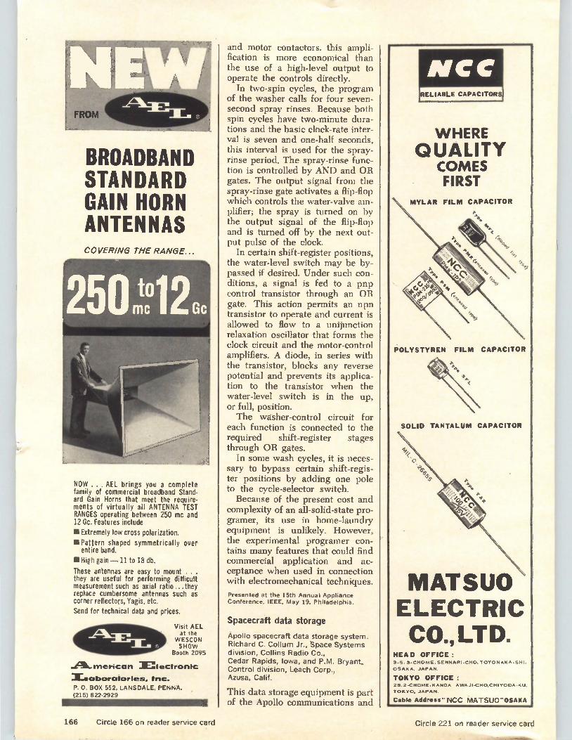
BROADBAND STANDARD GAIN HORN ANTENNAS COVERING THE RANGE...
NOW ... AEL brings you a complete family of commercial broadband Stand-ard Gain Horns that meet the require-ments of virtually all ANTENNA TEST RANGES operating between 250 mc and 12 Gc. Features include
MI Extremely low cross polarization.
la Pattern shaped symmetrically over entire band.
II High gain — 11 to 18 db.
These antennas are easy to mount . . . they are useful for performing difficult measurement such as axial ratio ...they replace cumbersome antennas such as corner reflectors, Yagis, etc.
Send for technical data and prices.
Visit AEL at the
WESCON SHOW
Booth 2095
.42A-merican lectronlc
Xnaboratories, Inc. P. 0. BOX 552, LANSDALE, PEN NA. (215) 822-2929
and motor contactors. this ampli-fication is more economical than the use of a high-level output to operate the controls directly.
In two-spin cycles, the program of the washer calls for four seven-second spray rinses. Because both spin cycles have two-minute dura-tions and the basic clock-rate inter-val is seven and one-half seconds, this interval is used for the spray-rinse period. The spray-rinse func-tion is controlled by AND and OR gates. The output signal from the spray-rinse gate activates a flip-flop which controls the water-valve am-plifier; the spray is turned on by the output signal of the flip-flop and is turned off by the next out-put pulse of the clock.
In certain shift-register positions, the water-level switch may be by-passed if desired. Under such con-ditions, a signal is fed to a pnp control transistor through an OR gate. This action permits an npn transistor to operate and current is allowed to flow to a unijunction relaxation oscillator that forms the clock circuit and the motor-control amplifiers. A diode, in series with the transistor, blocks any reverse potential and prevents its applica-tion to the transistor when the water-level switch is in the up, or full, position. The washer-control circuit for
each function is connected to the required shift-register stages through OR gates.
In some wash cycles, it is neces-sary to bypass certain shift-regis-ter positions by adding one pole to the cycle-selector switch. Because of the present cost and
complexity of an all-solid-state pro-gramer, its use in home-laundry equipment is unlikely. However, the experimental programer con-tains many features that could find commercial application and ac-ceptance when used in connection with electromechanical techniques.
Presented at the 15th Annual Appliance
Conference, IEEE, May 19, Philadelphia.
Spacecraft data storage
Apollo spacecraft data storage system. Richard C. Collum Jr., Space Systems division, Collins Radio Co., Cedar Rapids, Iowa, and P.M. Bryant, Control division, Leach Corp., Azusa, Calif.
This data storage equipment is part of the Apollo communications and
IVICC RELIABLE CAPACITORS
WHERE QUALITY
COMES FIRST
MYLAR FILM CAPACITOR
POLYSTYREN FILM CAPACITOR
SOLID TANTALUM CAPACITOR
MATSUO ELECTRIC CO., LTD.
HEAD OFFICE: 3-5, 3-CHOME.SENNARI-CHO, TOYONAKA.SHI.
OSAKA. JAPAN.
TOKYO OFFICE: 25.2•CHOME.KANOA AWAJI-CHO.CHIYODA-KO.
TOKYO, JAPAN.
Cable Address"NCC MATSUO"OSAKA
166 Circle 166 on reader service card Circle 221 on reader service card
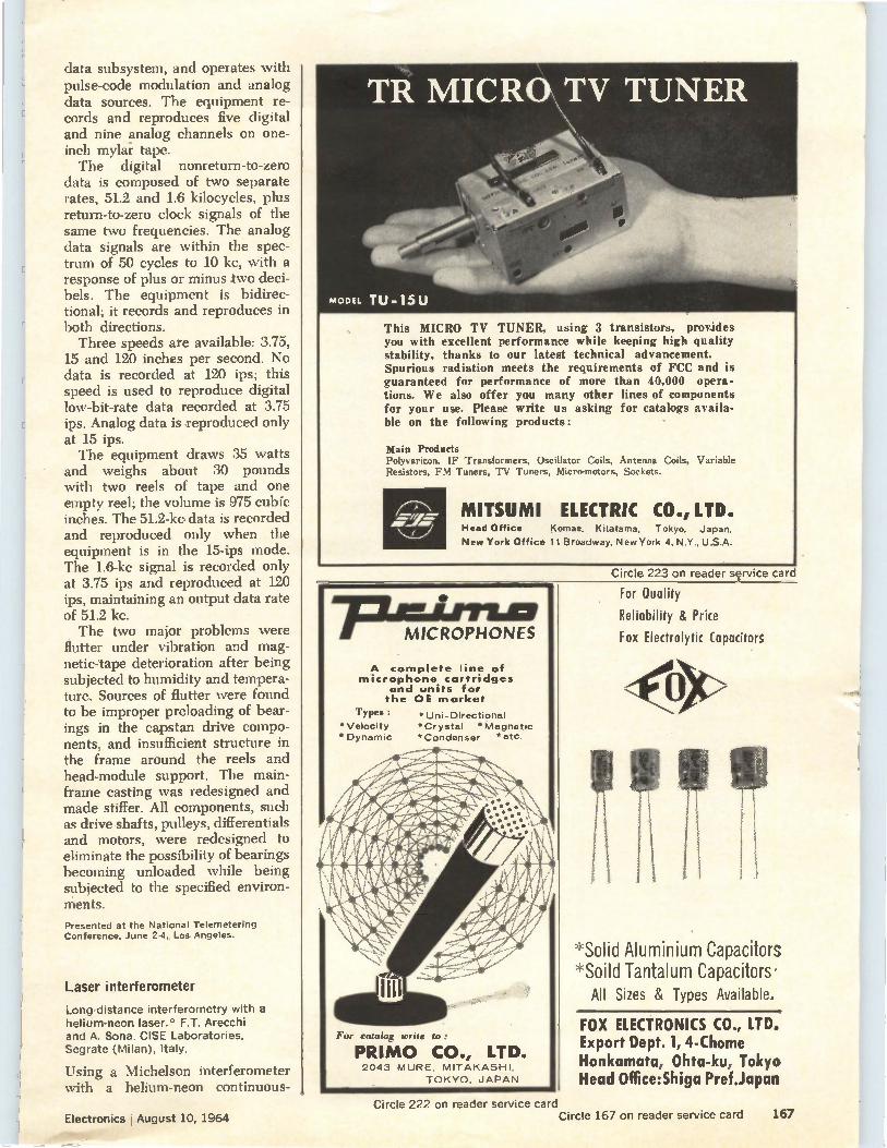
data subsystem, and operates with pulse-code modulation and analog data sources. The equipment re-cords and reproduces five digital and nine analog channels on one-inch mylar tape. The digital nonreturn-to-zero
data is composed of two separate rates, 51.2 and 1.6 kilocycles, plus return-to-zero clock signals of the same two frequencies. The analog data signals are within the spec-trum of 50 cycles to 10 kc, with a response of plus or minus two deci-bels. The equipment is bidirec-tional; it records and reproduces in both directions. Three speeds are available: 3.75,
15 and 120 inches per second. No data is recorded at 120 ips; this speed is used to reproduce digital low-bit-rate data recorded at 3.75 ips. Analog data is reproduced only at 15 ips. The equipment draws 35 watts
and weighs about 30 pounds with two reels of tape and one empty reel; the volume is 975 cubic inches. The 51.2-ke data is recorded and reproduced only when the equipment is in the 15-ips mode. The 1.6-kc signal is recorded only at 3.75 ips and reproduced at 120 ips, maintaining an output data rate of 51.2 kc. The two major problems were
flutter under vibration and mag-netic-tape deterioration after being subjected to humidity and tempera-ture. Sources of flutter were found to be improper preloading of bear-ings in the capstan drive compo-nents, and insufficient structure in the frame around the reels and head-module support. The main-frame casting was redesigned and made stiffer. All components, such as drive shafts, pulleys, differentials and motors, were redesigned to eliminate the possibility of bearings becoming unloaded while being subjected to the specified environ-ments.
Presented at the National Telemetering Conference, June 2-4, Los Angeles.
Laser interferometer
Long-distance interferometry with a helium-neon laser.* F.T. Arecchi and A. Sona. CISE Laboratories, Segrate (Milan), Italy.
Using a Michelson interferometer with a helium-neon continuous-
This MICRO TV TUNER, using 3 transistors, provides you with excellent performance while keeping high quality stability, thanks to our latest technical advancement. Spurious radiation meets the requirements of FCC and is guaranteed for performance of more than 40,000 opera-tions. We also offer you many other lines of components for your use. Please write us asking for catalogs availa-ble on the following products:
Main Products Polyvaricon, IF Transformers. Oscillator Coils, Antenna Coils, Variable Resistors, FM Tuners, TV Tuners, Micro-motors, Sockets.
MITSUMI ELECTRIC CO., LTD. Head Office Komae, Kitatama, Tokyo, Japan.
New York Office 11 Broadway, New York 4, N.Y., U.S.A.
Circle 223 on reader sçrvice card
MICROPHONES
A complete line of microphone cartridges
and units for the OE market
Types :
*Velocity Dynamic
For catalog write to:
Uni -Directional *Crystal *Magnetic *Condenser *etc.
PRIMO CO., LTD. 2043 MURE, MITAKASHI,
TOKYO, JAPAN
For Quality
Reliability & Price
Fox Electrolytic Capacitors
*Solid Aluminium Capacitors *Soild Tantalum Capacitors'
All Sizes & Types Available.
FOX ELECTRONICS CO., LTD. Export Dept. 1, 4-Chome Honkamata, Ohta-ku, Tokyo Head Office:Shiga Pref.Japan
Electronics I August 10, 1964 Circle 222 on reader service card
Circle 167 on reader service card 167
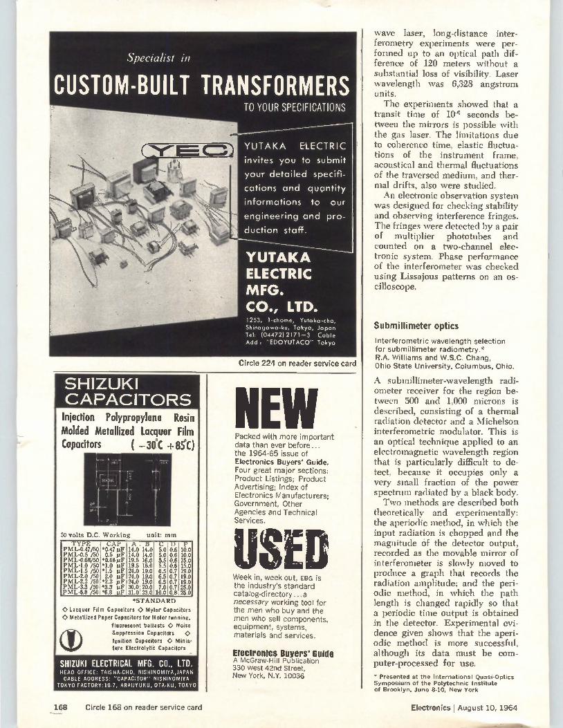
Specialist in
CUSTOM-BUILT TRANSFORMERS
SHIZUKI CAPACITORS Iniection Polypropylene Resin Molded Metallized Lacquer Film Capacitors ( -30°C +85PC)
50 volts D.C. Working
TYPE CAP AB C L) P PML-0.47/50 *0.47 pF 14.0 14.0 5.0 0.6 10.0 PML-0.5 /50 0.5 pF 14.0 14.0 5.0 0.6 10.0 PML-0.68/50 *0.68 pF 19.5 16.0 5.5 0.6 15.0 PML-1.0 /50 *1.0 pF 19.5 16.0 5.5 0.6 15.0 PML-1.5 /50 *1.5 pF 24.0 19.0 6.5 0.7 19.0 PML-2.0 /50 2.0 pF 24.0 19.0 6.5 0.7 19.0 PML-2.2 /50 *2.2 pF 24.0 19.0 6.5 0.7 19.0 PML-3.3 /50 .3.3 pF 30.0 20.0 7.0 0.7 25.0 PML-6.8 /50 *6.8 pF 31.0 23.0 10.0 0.8 25.0
unit: nun
*STANDARD
0 Lacquer Film Capacitors 0 My ar Capacitors 0 Metallized Paper Capacitors for Motor running,
fluorescent ballasts 0 Noise Suppression Capacitors O. Ignition Capacitors 0 Minia-ture Electrolytic Capacitors
SHIZUKI ELECTRICAL MFG. CO., LTD. HEAD OFFICE: TAISHA.CHO,, NISHINOMIYA,JAPAN CABLE ADDRESS: "CAPACITOR" NISHINOMIYA
TOKYO FACTORY: 10.7, ARALIYUKU, OTA•KU, TOKYO
TO YOUR SPECIFICATIONS
YUTAKA ELECTRIC
invites you to submit
your detailed specifi-
cations and quantity
informations to our
engineering and pro-
duction staff.
YUTAKA ELECTRIC MFG. CO., LTD. 1253, 1-chome, Yutoka-cho, Shinagawa-ku, Tokyo, Japan Tel; (04472)2171-3 Cable Addi "EDOYUTACO" Tokyo
Circle 224 on reader service card
NE Packed with more important data than ever before... the 1964-65 issue of Electronics Buyers' Guide. Four great major sections: Product Listings; Product Advertising; Index of Electronics Manufacturers; Government, Other Agencies and Technical Services.
SE Week in, week out, EBG is the industry's standard catalog-directory.., a necessary working tool for the men who buy and the men who sell components, equipment, systems, materials and services.
Electronics Buyers' Guide A McGraw-Hill Publication 330 West 42nd Street, New York, N.Y. 10036
wave laser, long-distance inter-ferometry experiments were per-formed up to an optical path dif-ference of 120 meters without a substantial loss of visibility. Laser wavelength was 6,328 angstrom units. The experiments showed that a
transit time of 10 -6 seconds be-tween the mirrors is possible with the gas laser. The limitations due to coherence time, elastic fluctua-tions of the instrument frame, acoustical and thermal fluctuations of the traversed medium, and ther-mal drifts, also were studied. An electronic observation system
was designed for checking stability and observing interference fringes. The fringes were detected by a pair of multiplier phototubes and counted on a two-channel elec-tronic system. Phase performance of the interferometer was checked using Lissajous patterns on an os-cilloscope.
Submillimeter optics
Interferometric wavelength selection for submillimeter radiometry.* R.A. Williams and W.S.C. Chang, Ohio State University, Columbus, Ohio.
A sub millimeter-wavelength radi-ometer receiver for the region be-tween 500 and 1,000 microns is described, consisting of a thermal radiation detector and a Michelson interferometric modulator. This is an optical technique applied to an electromagnetic wavelength region that is particularly difficult to de-tect, because it occupies only a very small fraction of the power spectrum radiated by a black body. Two methods are described both
theoretically and experimentally: the aperiodic method, in which the input radiation is chopped and the magnitude of the detector output, recorded as the movable mirror of interferometer is slowly moved to produce a graph that records the radiation amplitude; and the peri-odic method, in which the path length is changed rapidly so that a periodic time output is obtained in the detector. Experimental evi-dence given shows that the aperi-odic method is more successful, although its data must be com-puter-processed for use.
* Presented at the International Quasi-Optics Symposium of the Polytechnic Institute of Brooklyn, June 8-10, New York
168 Circle 168 on reader service card Electronics I August 10, 1964
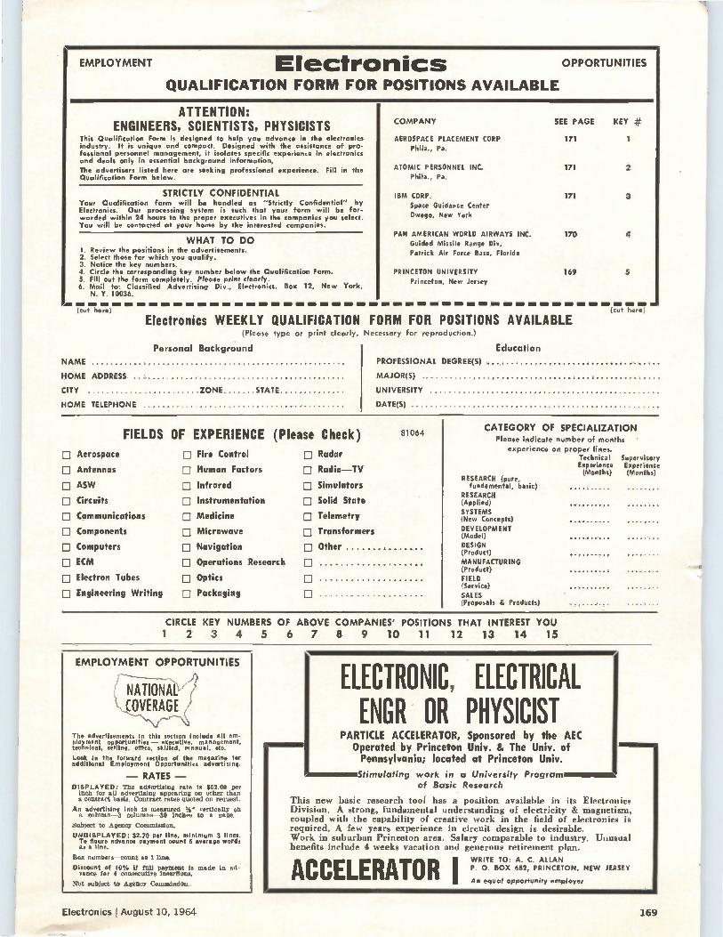
EMPLOYMENT Electronics QUALIFICATION FORM FOR POSITIONS AVAILABLE
OPPORTUNITIES
ATTENTION: ENGINEERS, SCIENTISTS, PHYSICISTS
This Qualification Form is designed to help you advance in the electronics industry. It is unique and compact. Designed with the assistance of pro-fessional personnel management, it isolates specific experience in electronics and deals only in essential background information. The advertisers listed here are seeking professional experience. Fill in the Qualification Form below.
STRICTLY CONFIDENTIAL Your Qualification form will be handled as "Strictly Confidential" by Electronics. Our processing system is such that your form will be for-warded within 24 hours to the proper executives in the companies you select. You will be contacted at your home by the interested companies.
WHAT TO DO 1. Review the positions in the advertisements. 2. Select those for which you qualify. 3. Notice the key numbers. 4. Circle the corresponding key number below the Qualification Form. 5. Fill out the form completely. Please print dearly. 6. Mail to: Classified Advertising Div., Electronics, Box 12, New York,
N. Y. 10036.
COMPANY
AEROSPACE PLACEMENT CORP Phila., Pa.
ATOMIC PERSONNEL INC. Phila., Pa.
IBM CORP. Space Guidance Center Owego, New York
PAN AMERICAN WORLD AIRWAYS INC. Guided Missile Range Div. Patrick Air Force Base, Florida
PRINCETON UNIVERSITY Princeton, New Jersey
SEE PAGE KEY #
171 1
171 2
171 3
170 4
169 5
(cut here)
Electronics WEEKLY QUALIFICATION FORM FOR POSITIONS AVAILABLE (Please type or print clearly. Necessary for reproduction.)
Personal Background
NAME
HOME ADDRESS
CITY ZONE STATE
HOME TELEPHONE
(cut here)
Education
PROFESSIONAL DEGREE(S)
MAJOR(S)
UNIVERSITY
DATE(S)
FIELDS OF EXPERIENCE (Please Check)
11 Aerospace
D Antennas
D ASW
D Circuits
D Communications (11 Components
D Computers D ECM
D Electron Tubes
D Engineering Writing
D Fire Control
D Human Factors
D Infrared
D Instrumentation
El Medicine
D Microwave
D Navigation
D Operations Research
D Optics
D Packaging
D
D
0
81064
Radar
Radio—TV
Simulators
Solid State
Telemetry
Transformers
Other
CATEGORY OF SPECIALIZATION Please indicate number of months
experience on proper lines. Technical Supervisory Experience Experience (Months) (Months)
RESEARCH (pure, fundamental, basic)
RESEARCH (Applied) SYSTEMS (New Concepts) DEVELOPMENT (Model) DESIGN (Product) MANUFACTURING (Product) FIELD (Service) SALES (Proposals & Products)
CIRCLE KEY NUMBERS OF ABOVE COMPANIES' POSITIONS THAT INTEREST YOU 1 2 3 4 5 6 7 8 9 10 11 12 13 14 15
EMPLOYMENT OPPORTUNITIES
The advertisements In this section include all em-ployment opportunities — executive. management. technical. selling, ofHce, Skilled, manual, etc.
Look in the forward section of the magazine for additional Employment Opportunities advertising.
— RATES — DISPLAYED: The advertising rate is $52.00 per
inch for all advertising appearing on other than a contract basis. Contract rates quoted on request.
An advertising Inch is measured % vertically on a column-3 colurans-30 inches to a. page.
Subject to Agency Commission.
UND1SPLAYED: $2.70 per line, minimum 3 lines. To figure advanoe payment count 5 average words as a line.
Box numbers—count as 1 line.
Discount of 10% if full payment is made in ad-vance for 4 consecutive Insertions.
Mat subject to Agency Commission,
IELECTRONIC, ELECTRICAL ENGR OR PHYSICIST
PARTICLE ACCELERATOR, Sponsored by the AEC Operated by Princeton Univ. & The Univ. of Pennsylvania; located at Princeton Univ.
Stimulating work in a University Program 1 of Basic Research
This new basic research tool has a position available in its Electronics Division. A strong, fundamental understanding of electricity & magnetism, coupled with the capability of creative work in the field of electronics is required. A few years experience in circuit design is desirable. Work in suburban Princeton area. Salary comparable to industry. Unusual benefits include 4 weeks vacation and generous retirement plan.
ACCELERATOR I WRITE TO: A. C. ALLAN P. 0. BOX 682, PRINCETON, NEW JERSEY
An equal opportunity employer
Electronics !August 10, 1964 169
+MU-
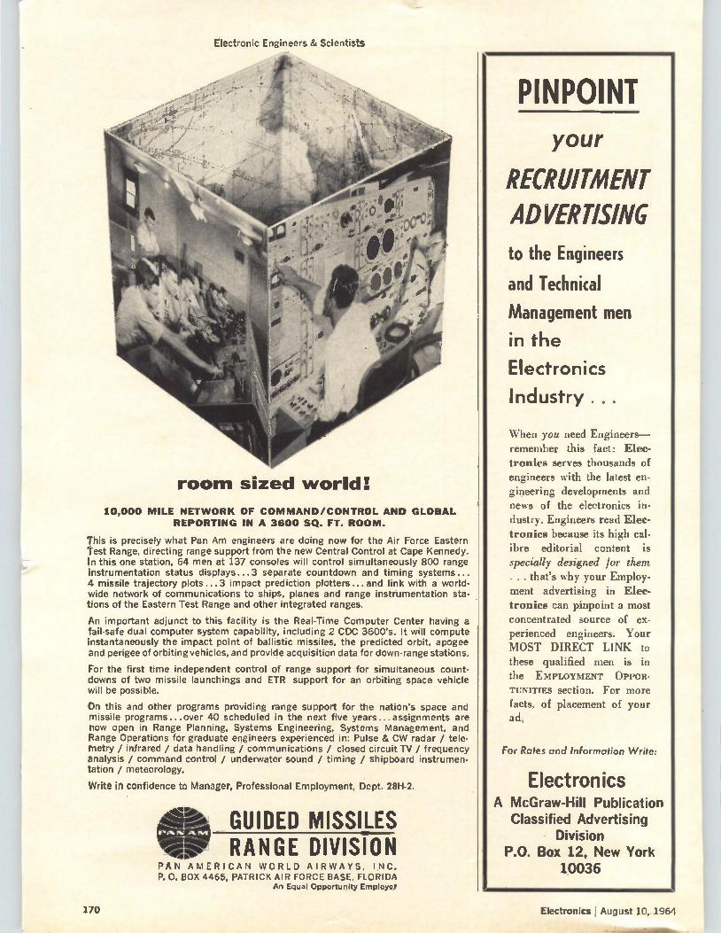
Electronic Engineers & Scientists
room sized world:
10,000 MILE NETWORK OF COMMAND/CONTROL AND GLOBAL REPORTING IN A 3600 SQ. FT. ROOM.
This is precisely what Pan Am engineers are doing now for the Air Force Eastern Test Range, directing range support from the new Central Control at Cape Kennedy. In this one station, 64 men at 137 consoles will control simultaneously 800 range instrumentation status displays...3 separate countdown and timing systems ... 4 missile trajectory plots...3 impact prediction plotters...and link with a world-wide network of communications to ships, planes and range instrumentation sta-tions of the Eastern Test Range and other integrated ranges.
An important adjunct to this facility is the Real-Time Computer Center having a fail-safe dual computer system capability, including 2 CDC 3600's. It will compute instantaneously the impact point of ballistic missiles, the predicted orbit, apogee and perigee of orbiting vehicles, and provide acquisition data for down-range stations.
For the first time independent control of range support for simultaneous count-downs of two missile launchings and ETR support for an orbiting space vehicle will be possible.
On this and other programs providing range support for the nation's space and missile programs...over 40 scheduled in the next five years...assignments are now open in Range Planning, Systems Engineering, Systems Management, and Range Operations for graduate engineers experienced in: Pulse & CW radar / tele-rnetry / infrared / data handling / communications / closed circuit TV / frequency analysis / command control / underwater sound / timing / shipboard instrumen-tation / meteorology.
Write in confidence to Manager, Professional Employment, Dept. 28H-2.
ear
11111.
PAN AMERICAN WORLD AIRWAYS, INC. P. O. BOX 4465, PATRICK AIR FORCE BASE, FLORIDA
An Equal Opportunity Employer
GUIDED MISSILES RANGE DIVISION
PINPOINT your
RECRUITMENT ADVERTISING to the Engineers
and Technical
Management men
in the
Electronics
Industry.
When you need Engineers— remember this fact: Elec-tronics serves thousands of engineers with the latest en-gineering developments and news of the electronics in-dustry. Engineers read Elec-tronics because its high cal-ibre editorial content is specially designed for them . . . that's why your Employ-ment advertising in Elec-tronics can pinpoint a most concentrated source of ex-perienced engineers. Your MOST DIRECT LINK to these qualified men is in the EMPLOYMENT OPPOR-TUNITIES section. For more facts, of placement of your ad,
For Rates and Information Write:
Electronics A McGraw-Hill Publication
Classified Advertising Division
P.O. Box 12, New York 10036
170 Electronics I August 10, 1964
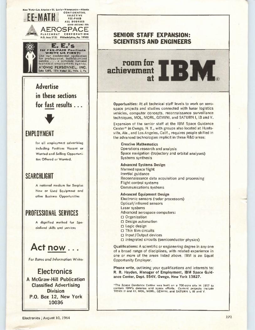
New York• Los Anodes • St. Louie • Minneapolis • Atlanta CONFIDENTIAL
SELECTIVE FEE-PAID
ALL DEGREES SENO RESUME Me
EEMATili AEROSPACE PLACEMENT CORPORATION P.O. Box 2125 Philadelphia, Po. 19103
for FEE-PAID Positions WRITE US FIRSTS
Use our confidential application for professional, individualized service .. a complete national technical employment agency.
ATOMIC PERSONNEL, INC. Suite 12071., 1518 Walnut St., Phila. 2, Pa.
Advertise in these sections for fast results ...
EMPLOYMENT for all employment advertising
including Positions Vacant or
Wanted and Selling Opportuni-
ties Offered or Wanted.
SEARCHLIGHT A national medium for Surplus
New or Used Equipment and
other Business Opportunities
PROFESSIONAL SERVICES A dignified method for Spe-
cialized skills and services
Act now ... For Rates and Information Write:
Electronics A McGraw-Hill Publication
Classified Advertising Division
P.O. Box 12, New York 10036
SENIOR STAFF EXPANSION: SCIENTISTS AND ENGINEERS
room for IB achievement
at
Opportunities: At all technical staff levels to work on aero-space projects and studies connected with lunar logistics vehicles, computer concepts, reconnaissance surveillance techniques, MOL, MORL, GEMINI, and SATURN I, IB and V.
Expansion of the senior staff at the IBM Space Guidance Center* in Owego, N.Y., with groups also located at Hunts-ville, Ala., and Los Angeles, Calif., requires people skilled in the advanced technologies implicit in these R&D areas:
Creative Mathematics Operations research and analysis Space navigation (trajectory and orbital analyses) Systems synthesis
Advanced Systems Design Manned space flight Inertial guidance Reconnaissance data acquisition and processing Flight control systems Communications systems
Advanced Equipment Design Electronic sensors (radar processors) Optical / infrared sensors Laser systems Advanced aerospace computers: D Organization D Design automation ID Logic design 0 Thin film circuits D Input/Output devices D Integrated circuits (semiconductor physics)
Qualifications: A scientific or engineering degree in any one of a broad range of disciplines, with related experience in one or more of the areas listed above. IBM is an Equal Opportunity Employer.
Please write, outlining your qualifications and interests to: R. R. Hayden, Manager of Employment, IBM Space Guid-ance Center, Dept. 554V, Owego, New York 13827.
°The Space Guidance Center was built on a 700-acre site in 1957 to contain IBM's defense and space efforts. Current projects include TITAN II and Ill, MOL, MORL, GEMINI, and SATURN I, IB and V.
Electronics August 10, 1964 171
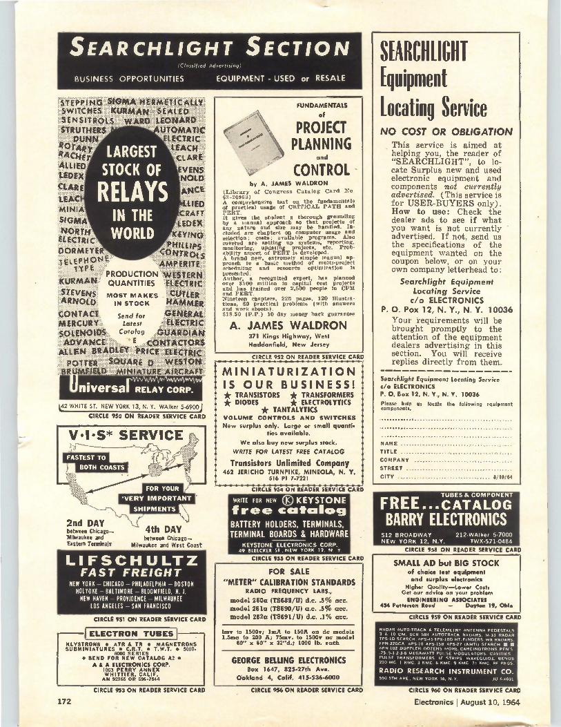
SEARCHLIGHT SECTION (Classified Advertising)
BUSINESS OPPORTUNITIES EQUIPMENT - USED or RESALE
!•SWITCHESeKUR.MAN.....:.: SEALED SENSITR . LS WARD LEONARD .STRUTHERS1' ' :1..WNN ItOrÀ RAcHEr LARGEST RI,
ARIED STOCK OF ..ÉDEX.
'CCAR i RELAYS Ate. ,LiÀc :. Ltdii
,M*ii,41-4 CRÁ.F,t !!!9MÀ IN THE •Kiblifii .tc.t.p .DORMEYER WORLD tcfiqd „oenft,:. ....PH/Liwe
',i.....: ..„,..„...OL-$ !iÉLÉ.P11:01,1.:. k
AMPERITE"
PRODUCTION 'ÏW.Ï .ÏER 'till KU.,. .Mili QUANTITIES '.-,g4.e.T:REC .s. : A.Uniye.: MOST M AKES CUTLER eL A n.7.‘"- ., IN STOCK HAMMER
CONTA CT,. Send for ii eiL c1T" -i.j. fot.E.e,Cu..e y..ià, Latest
SÓLENO.165:::, CatalogGUARDIAN ..... .. .
I.ECTRIC
AUTOMATIC
" LEACH LAR E.
YENS NOLD
ADVANCE
ÀttÉt:e:BeAt».POTTER SQUARE
.R,UMFIEfD:.:::MWÑ:art)
E PRICE ELECTRIC
WESTON AIRCRAFT
rW • • niversa RELAY CORP.
L42 WHITE ST. NEW YORK 13, N. Y. WAlker 5-6900
CIRCLE 950 ON READER SERVICE CARD
2nd DAY between Chicago— «Milwaukee and Eastern Terminals
4th DAY between Chicago—
Milwaukee and West Coast
LI FSCHULTZ FAST FREIGHT
NEW YORK — CHICAGO — PHILADELPHIA — BOSTON HOLYOKE — BALTIMORE — BLOOMFIELD, N. J. NEW HAVEN — PROVIDENCE — MILWAUKEE
LOS ANGELES — SAN FRANCISCO
CIRCLE 951 ON READER SERVICE CARD
ELECTRON TUBES KLYSTRONS • ATR & IR • MAGNETRONS SUBMIN1ATURES • C.R.T. • T.W.T. • 5000-
6000 SERIES • SEND FOR NEW CATALOG A2 •
A & A ELECTRONICS CORP. 1063 PERRY ANNEX WHITTIER. CALIF. AN 92865 OR 696.7544
FUNDAMENTALS
of
PROJECT PLANNING
and
CONTROL by A. JAMES WALDRON
(Library of Congress Catalog Card No. 63-20963) A comprehensive text on the fundamentals of practical usage of CRITICAL PATH and PERT. It gives the student a thorough grounding by a manual approach so that projects of any nature and size may be handled. In-cluded are chapters on computer usage and selection; costs; available programs. Also covered are setting up systems, reporting. monitoring, updating projects, etc. Prob-ability aspect of PERT is developed. A brand new, extremely simple manual ap-proach to a basic method of multi-project scheduling and resource optimization is presented. Author, a recognized expert, has planned over $100 million la capital cost projects and has trained over 2,500 people in CPII and PERT. Nineteen chapters. 225 pages, 120 illustra-tions, 00 practical problems (with answers and work sheets). $18.50 (P.P.) 10 day money back guarantee
A. JAMES WALDRON 371 Kings Highway, West
Haddonfield, New Jersey
CIRCLE 952 ON READER SERVICE CARD
MINIATURIZATION . IS OUR BUSINESS! • * TRANSISTORS * TRANSFORMERS ; * DIODES * ELECTROLYTICS • * TANTALYTICS •• VOLUME CONTROLS AND SWITCHES • New surplus only. Large or small quanti-• ties available.
We also buy new surplus stock.
WRITE FOR LATEST FREE CATALOG
. Transistors Unlimited Company
462 JERICHO TURNPIKE, MINEOLA, N. Y. 516 PI 7-7221
CIRCLE 954 ON READER SERVICE CARD
WRITE FOR NEW KEYSTONE
free catalog BATTERY HOLDERS, TERMINALS,
TERMINAL BOARDS & HARDWARE
KEYSTONE ELECTRONICS CORP. 49 IREECKER SI.. NEW YORK 12. N y,
CIRCLE 955 ON READER SERVICE CARD
FOR SALE
"METER" CALIBRATION STANDARDS RADIO FREQUENCY LABS.,
model 260a (TS689/U) d.c..5% acc.
model 261a (TS690/U) a.c..5% acc.
model 262a (TS691/U) d.c..1% acc.
lrnv to 1500v; 1mA to 150A on dc models 1.5ma to 200 A; 75mv. to 1500v an model
60" x 60" x 32"d.; 1000 lb. each
GEORGE BELLING ELECTRONICS Box 1647, 825-27th Ave.
Oakland 4, Calif. 415-5364000
SEARCHLIGHT Equipment Locating Service NO COST OR OBLIGATION
This service is aimed at helping you, the reader of "SEARCHLIGHT", to lo-cate Surplus new and used electronic equipment and components not currently advertised. (This service is for USER-BUYERS only). How to use: Check the dealer ads to see if what you want is not currently advertised. If not, send us the specifications of the equipment wanted on the coupon below, or on your own company letterhead to:
Searchlight Equipment Locating Service c/o ELECTRONICS
P. O. Pox 12, N. Y., N. Y. 10036
Your requirements will be brought promptly to the attention of the equipment dealers advertising in this section. You will receive replies directly from them.
Searchlight Equipment Locating Service c/o ELECTRONICS P. O. Box 12, N. Y., N. Y. 10036
Please help us locate the following equipment components.
NAME
TITLE
COMPANY
STREET
CITY 8/10/64
FREE... TEX"? Zaré: BARRY ELECTRONICS
512 BROADWAY 212-WAlker 5-7000 NEW YORK 12, N.Y. TWA-571.0484
CIRCLE 958 ON READER SERVICE CARD
SMALL AD but BIG STOCK of choice test equipment and surplus electronics
Higher Quality—Lower Costa Get our advice on your problem
ENGINEERING ASSOCIATES 434 Patterson Road — Dayton 19, Ohio
CIRCLE 959 ON READER SERVICE CARD
RADAR AUTO-TRACK & TELEMETRY ANTENNA PEDESTALS 3 & 10 CM. SCR 584 AUTOTRACK RADARS. M.33 RADAR TPS.113 SEARCH. APS.45 TPS.100 HT. FINDERS. WS RADARS. FPN-326CA. APS.10 APS.158 APS.27 (AMTI) SEARCH. • • APN.102 DOPPLER. DOZENS MORE.CARCINOTRONS PFN'S. .25,5.1.2.3.6 MEGAWATT PULSE MODULATORS, CAVITIES. PULSE TRANSFORMERS, IF STRIPS. WAVEGUIDE SENDS 200 MC. 1 KMC. 3 KMC. 6 KMC. 9 /0.1C. 24 KMC, RF PKGS.
RADIO RESEARCH INSTRUMENT CO. 550 5TH AVE., NEW YORK 36, N.Y. JU 6.4691
CIRCLE 953 ON READER SERVICE CARD
172
CIRCLE 956 ON READER SERVICE CARD CIRCLE 960 ON READER SERVICE CARD
Electronics I August 10, 1964
Electronics advertisers August 10, 1964
• AMP Incorporated 49, 102 Garceau, Hargrave & McCullough Inc.
• Acme Electric Corp. 149 Scheel Adv. Agency
Adage Inc. 154 Fuller & Smith & Ross Inc.
• Ad-Yu Electronics, Inc. 162 P & G Advertising Agency
American Electronic Laboratories, Inc. 166 Benn Associates
Amperite Co. 157 H.J. Gold Co.
Assembly Products 123 George Z. Griswold Adv.
Astro-Communication Laboratory 47 Astrodata Inc. 11
Bonfield Associates, Inc. Atlee Corporation 163
S. Gunnar Myrbeck & Company • Automatic Metal Products Corp. 152
Devon Service Corp.
Bausch & Lomb, Inc. 116 Wolff Associates, Inc.
Beckman Instruments Inc., Offner Division 35 Erwin Wasey, Ruthrauff & Ryan Inc.
• Bliley Electric Co. 136 Barber & Drullard Inc.
mi Bourns Inc., Trimpot Div. 9 Allen, Dorsey & Hatfield Inc.
Bristol Co., The 132 Chirurg & Cairns, Inc.
• Brush Instruments, Div. of Cievite 3rd Cover Carr Liggett Adv., Inc.
• Bussmann Mfg. Co., Div. of McGraw Edison Co. 160, 161 Henderson Advertising Company
• CTS Corporation Burton Browne Adv.
• Clairex Corp. S. Paul Sims Co.
• Clifton Precision Products Div. of Litton Precision Products Inc. Ivey Adv. Inc.
• Cohn, Sigmund Corp. William G. Seidenbaum & Co.
Daven, Div. of McGraw Edison 22 Keyes, Martin & Co.
Davies Molding Co., Harry 156 Sander Rodkin Adv. Agency, Ltd.
• Delco Radio 39 Campbell-Ewald Company
Di-Acro 10 Charles E. Brown Adv.
Driver Co., Wilbur B. 115 George Homer Martin Associates
DuPont de Nemours & Co., Inc., E. I. 28, 54 Batten, Barton, Durstine & Osborn, Inc.
Durant Manufacturing Co. 139 Keck Advertising Agency
• Dymec Div. of Hewlett Packard Co. 2 L.C. Cole Company Inc.
• Electro Instruments Inc. Teawell Inc. Adv.
• Electro Motive Mfg. Co. Inc., The Cory Snow Inc.
Electro Scientific Industries Inc. Nadler and Larimer Inc.
Electronic Engineering Co. of California Compton Advertising, Inc.
Electronic Modules Corp. Ray Thompson & Associates Inc.
Electronic Specialty Co. Grant Adv., Inc.
Fairchild Controls Corp. Dunwoodie Associates Inc.
Fairmount Chemical Co., Inc. G.M. Basford Co.
Fluke Mfg. Co., Inc., John Pollock & Loth, Inc.
Foxboro Co., The Reach, McClinton & Humphrey Inc.
Fox Electronics Co., Ltd. Nichiden Adv. Ltd.
• Fujitsu, Limited Hakuhodo Inc.
General Precision, Librascope Div. 142 Weekley and Valenti, Inc.
General Radio Co. 2nd Cover K.E. Moreno Co.
• Globe Industries Inc. 129 Odiorne Industrial Adv. Inc.
Gudebrod Bros. Silk Co., Inc. 128 Lee Ramsdell & Co. Inc.
101
144
57
136
38
53
107
24
141
58
100
159
26, 27
131
167
134
Heinemann Electric Co. Thomas R. Sundheim Inc.
• Hewlett Packard Co. L.C. Cole Company Inc.
• Houston Instrument Corp. Cooley & Pate Inc.
• Hughes Aircraft Company Foote, Cone & Belding
Hurst Mfg. Co. Franklin E. Katterjohn & Co. Inc.
Ichizuka Optical Co., Ltd. Matsushita Inc.
Intercontinental Instruments Inc. Murray Heyert Associates
International Instruments, Inc. Thomas R. Sundheim Inc.
Japan Electron Optical Laboratory Co., Ltd. Dentsu Adv. Ltd.
Jerrold Corp. Irving Gould Adv. Inc.
Johanson Mfg. Corp. Josephson, Cuffari & Company
Kay Electric Company Josephon, Cuffari & Co.
Kingsley Machine Company Nides Cini Advertising Inc.
• Klein & Sons, Mathias The Duchen Co.
Kyoto Ceramics Co., Ltd. International Ad Service, Inc.
• Lambda Electronics Corp. Michel Cather, Inc.
• Leesona Corp. Chirurg & Cairns, Inc.
L E L incorporated Snow & Depew Advertising
Litton Industries, Data Systems Div. West, Weir & Bartel, Inc.
Loral Electronics Corp. Pritchard, Wood Incorporated
Machlett Laboratories Inc., The Fuller & Smith & Ross Inc.
• Mallory & Co. Inc. P.R. The Aitkin-Kynett Co.
Marconi Instruments Armand Richards Adv. Agency
Matsuo Electric Co., Ltd. Asahi Advertising Agency & Co.
McGraw-Hill Book Co. Inc. • McLean Engineering Laboratories
Healy Adv. Agency Mico Instrument Company
• Micro Switch Div. of Honeywell Batten, Barton, Durstine & Osborn in
Microdot, Inc. Jones, Maher. Roberts Adv.
le Mitsubishi Electric Corp. Hakuhodo Inc.
• Mitsumi Electric Co., Ltd. Dentsu Advertising Ltd.
• Moseley, F.L. L.C. Cole Company Inc.
• NRC Equipment Co. S. Gunnar Myrbeck & Co. Inc.
North Atlantic Industries, Inc. Murray Heyert Associates
• Ohmite Mfg. Co. The Fensholt Adv. Agency
Paktron, Div. Illinois Tool Works Raymond E. Finn & Associates
Patwin Electronics Co. Graceman Advertising Inc.
Permag Corp. Schneider Allen Walsh Inc.
Philco a Sub. of Ford Motor Co. Maxwell Associates, Inc.
Polaroid Corporation Doyle, Dane, Bernbach Inc.
Primo Co., Ltd. General Adv. Agency
• Radiation Inc. 52 G.M. Basford Company
Radio Corporation of America 4th Cover Al Paul Lefton Co.
• Radio Materials Co., Div. of P.R. Mallory & Co. Rosenbloom, Elias & Associates
• Reeves Hoffman, Div. of Dynamics Corp. of America Adams Associates, Inc.
• Republic Foil Inc. John S. Kemble Advertising
108 • Sanborn Co., a Sub. of Hewlett-Packard Culver Adv., Inc.
12, 13 Sanders Associates Chirurg & Cairns, Inc.
145 Sangamo Electric Company Winius-Brandon Company
138 • Semi-Elements, Inc. Axelband & Brown Associates
162 Shizuki Electrical Mfg. Co. New Asia Trading News Agency Ltd.
Siliconix Incorporated Angus J. Mac Donald & Assoc.
Silicon Transistor Corp. A.D. Adams Adv. Inc.
• Sorensen Fuller & Smith & Ross Inc.
• Spellman High Voltage Co. Chelsea Advertising, Inc.
Sprague Electric Co. The Harry P. Bridge Co.
• Superior Tube Co. Gray & Rogers, Inc.
144
126
151
159
113
153 Tektronix Inc. Hugh Dwight Adv. Inc.
150 Telonic Industries Inc. Burton Browne Adv.
118 Telrex Laboratories George Homer Martin Associates
21 Texas Instruments Incorporated Industrial Products Group
153 Robinson-Gerrard, Inc. • Tokyo Shibaura Electric Co., Ltd.
Hakuhodo Inc. • Toyo Electronics Ind., Corp.
Dentsu Advertising Trak Microwave Corp.
Clayton & Mohler Adv. • Trygon Electronics
Carpenter, Matthews & Stewart, Inc.
United Systems Corporation 127 Advertising And Merchandising Inc.
• Vitramon, Inc. 8 Ted Sommers, Inc.
33
137
156
130
122 Wakefield Engineeririd Inc. Sales Promotion Services
118 o Wayne George Corp. L.K. Frank Co. Inc.
166 Welch Scientific Co., The Armstrong Adv. Agcy. Inc.
146 Wells Electronics Inc. 109 Weco Adv.
Westinghouse Electric Corp. 148 Ketchum, MacLeod & Grove Inc. 48 a Weston Instruments & Electronics
c. a Div. of Daystrom Inc. 56 G.M. Basford Co.
West Penn Power 40 Fuller & Smith & Ross Inc.
White, S.S. 167 W.L. Towne Co. Inc.
1 Yutaka Electric Mfg. Co., Ltd. Nichiden Adv., Ltd.
155
114
23
110, Ill
164
148
25
37
167
• For more information on complete product line see advertisement in the latest Electronics Buyers' Guide
99
42
43,120
162
168
117
16
7
159
5, 6
133
19, 20
51
153
124,125
174
148
140
44
164
41
156
143
146
118
14, 150
55
126
147
168
Classified advertising F.J. Eberle, Business Mgr. 1212)-971-2557 Employment Opportunities Equipment (Used or Surplus New)
Classified advertisers index For Sale A & Electronics Corp. Aerospace Placement Corporation Atomic Personnel Inc. Barry Electronics Engineering Associates Belling, George Engineering Associates International Business Machines Keystone Electronics Corp.
135 Lifschultz Fast Freight Pan American World Airways Inc. Princeton University
50 • Radio Research Instrument Co. Transistors Unlimited Company
158 • Universal Relay Corp. Waldron, A. James
169-171
172 172 171 171 172 172 172 172 171 172 172 170 169 172 172 172 172
Executive. editorial, circulation and advertising offices: McGraw-Hill Building, 330 West 42nd Street, New York, N.Y., 10036. Telephone Area Code 212-971-3333. Teletype TWX N.Y. 212-640-4646. Cable: McGrawhill, N.Y. Officers of the Publications Division: Shelton Fisher, President: Vice Presidents: Joseph H. Allen, Operations; Robert F. Roger; Administration; John R. Callaham, Editorial; Ervin E. DeGraff, Circulation: Donald C. McGraw, Jr., Advertising Sales; Angelo R. Venezian, Marketing. Officers of the Corporation: Donald C. McGraw, President; Hugh .1, Kelly. Harry L. Waddell, L. Keith Goodrich. Executive Vice Presidents: John L. McGraw. Treasurer; John J. Cooke, Vice President and Secretary. Title R registered U.S. Patent Office; '?_.) copyright 1964 by McGraw-Hill, Inc. All rights reserved, including the right to reproduce the contents of this publication, in whole or in part.
Electronics I August 10, 1964 173
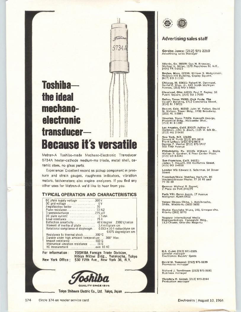
Toshiba— the ideal mechano-electronic transducer Because its versatile Metran-A Toshiba-made Mechano-Electronic Transducer
5734A heater-cathode medium-mu triode, metal shell, ce-
ramic stem, no glass parts.
Experience: Excellent record as pickup component in pres-
sure and strain gauges, roughness indicators, vibration
meters, tachometers; also engine analyzers. If you find any
other uses for Metran-A we'd like to hear from you.
TYPICAL OPERATION AND CHARACTERISTICS DC plate supply voltage 300 V DC grid voltage 0 V Amplification factor 20 Plate resistance 72 Kf2 Transconductance 275 id? DC plate current 1.5 mA Load resistance 75 K Deflection sensitivity 40 V/degree 2300 V/radian Moment of inertia of plate 3.4 milligram cm Rotational compliance of diaphragm . 0.013 x 10⁻³ radian/dyne cm
0.075 degreegram cm Resistance to thermal shock 300C Durable under high ambient temperature....300 Max. Impact resistance 500 G Mechanical vibration resistance 10 G KC measurement over 10 KC
For information : TOSHIBA Foreign Trade Division, Hibiya Mitsui Bldg., Yurakucho, Tokyo
New York Office: 530 Fifth Ave., New York 36, N.Y.
QUALITY SINCE 1675
Tokyo Shibaura Electric Co., Ltd. Tokyo, Japan
Advertising sales staff
Gordon Jones: [212] 971-2210 Advertising sales manager
Atlanta. Ga. 30309: Gus H. Krimsier, Michael H. Miller, 1375 Peachtree St. NE., [404] TR 5-0523
Boston, Mass. 02116: William S. Hodgkinson, McGraw-Hill Building, Copley Square, [617] CO 2-1160
Chicago, Ill. 60611: Robert M. Denmead, Daniel E. Shea, Jr., 645 North Michigan Avenue, [312] MO 4-5800
Cleveland, Ohio 44113: Paul T. Fegley, 55 Public Square, [216] SU 1-7000
Dallas, Texas 75201: Dick Poole, The Vaughn Building, 1712 Commerce Street, [214] RI 7-9721
Denver, Colo. 80202: John W. Patten, David M. Watson, Tower Bldg., 1700 Broadway, [303] AL 5-2981
Houston, Texas 77025: Kenneth George. Prudential Bldg., Halcombe Blvd., [713] RI 8-1280
Los Angeles, Calif. 90017: Ashley P. Hartman, John G. Zisch, 1125 W. 6th St., 1213] HU 2-5450
New York, N.Y. 10036: Donald R. Furth [212] 971-3616 Frank LeBeau [212] 971-3615 George F. Werner [212] 971-3617 500 Fifth Avenue
Philadelphia, Pa. 19103: William J. Boyle, Warren H. Gardner, 6 Penn Center Plaza, [215] LO 8-6161
San Francisco, Calif. 94111: James T. Hauptli, 255 California Street, [415] DO 2-4600
London Wl: Edward E. Schirmer, 34 Dover Street
Frankfurt/Main: Matthee Herfurth, 85 Westendstrasse Phone: 77 26 65 and 77 30 59
Geneva: Michael R. Zeynel, 2 Place du Port 244275
Paris VIII: Denis Jacob, 17 Avenue Matignon ALMA-0452
Tokyo: Shigeo Chiba, 1, Kotohiracho, Shiba, Minato-ku (502) 0656
Osaka: Kazutaka Miura, 163, Umegae-cho, Kita-ku [362] 8771
Nagoya: International Media Representatives. Yamagishi Bldg., 13,2-Chome, Oike-cho Naga-ku
R.S. Quint: [212] 971-2335 General manager Electronics Buyers' Guide
David M. Tempest: [212] 971-3139 Promotion manager
Richard J. Tomlinson: [212] 971-3191 Business manager
Theodore R. Geipel: [212] 971-2044 Production manager
174 Circle 174 on reader service card Electronics I August 10, 1964
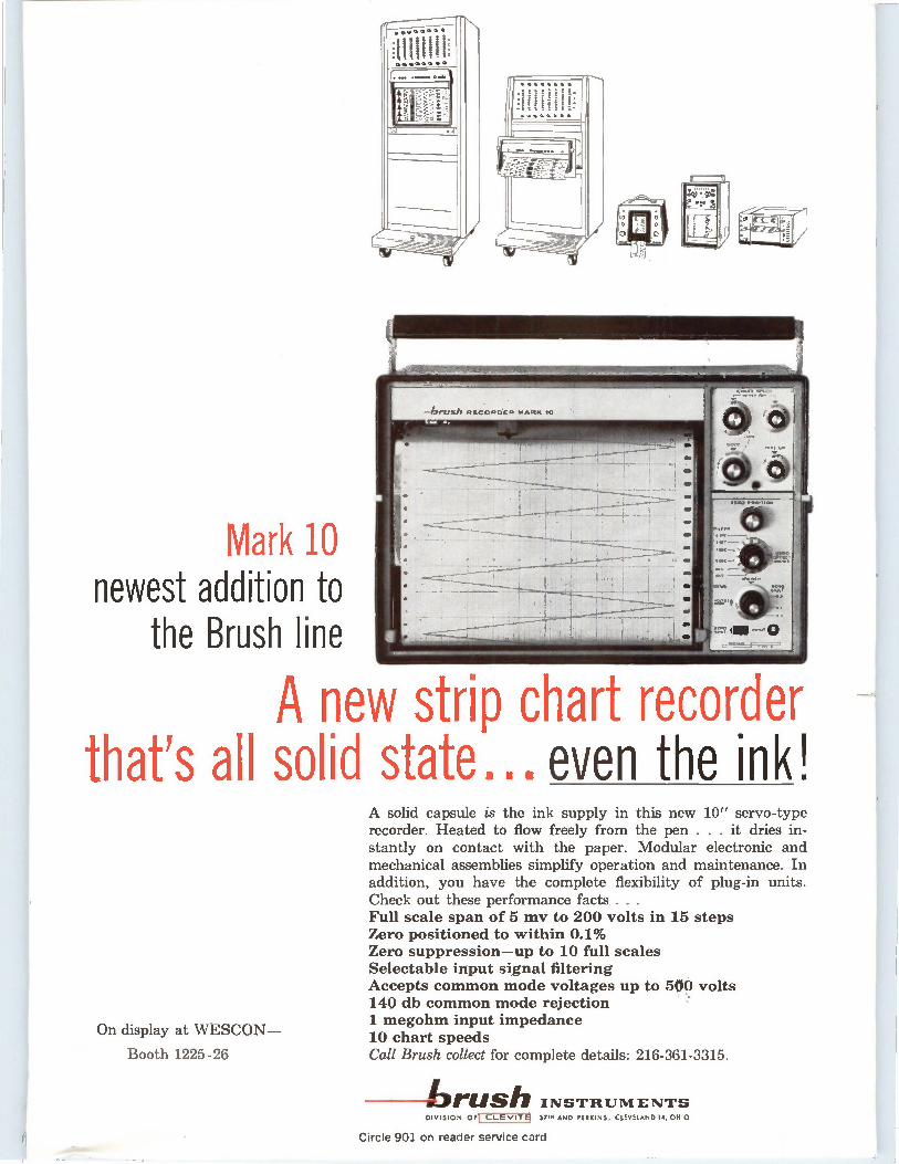
.11/01•••••••• ••••••• !MIR a aria...
Mark 10 newest addition to
the Brush line
A new strip chart recorder that's all solid state... even the ink!
On display at WESCON—
Booth 1225-26
A solid capsule is the ink supply in this new 10" servo-type recorder. Heated to flow freely from the pen . . . it dries in-stantly on contact with the paper. Modular electronic and mechanical assemblies simplify operation and maintenance. In addition, you have the complete flexibility of plug-in units. Check out these performance facts . . . Full scale span of 5 mv to 200 volts in 15 steps Zero positioned to within 0.1% Zero suppression—up to 10 full scales Selectable input signal filtering Accepts common mode voltages up to 500 volts 140 db common mode rejection 1 megohm input impedance 10 chart speeds Call Brush collect for complete details: 216-361-3315.
--brush IN S TRUM ENT'S DIVISION OF I cLEvirEl 37em AND PERKINS, CLEVELAND IA, OHIO
Circle 901 on reader service card
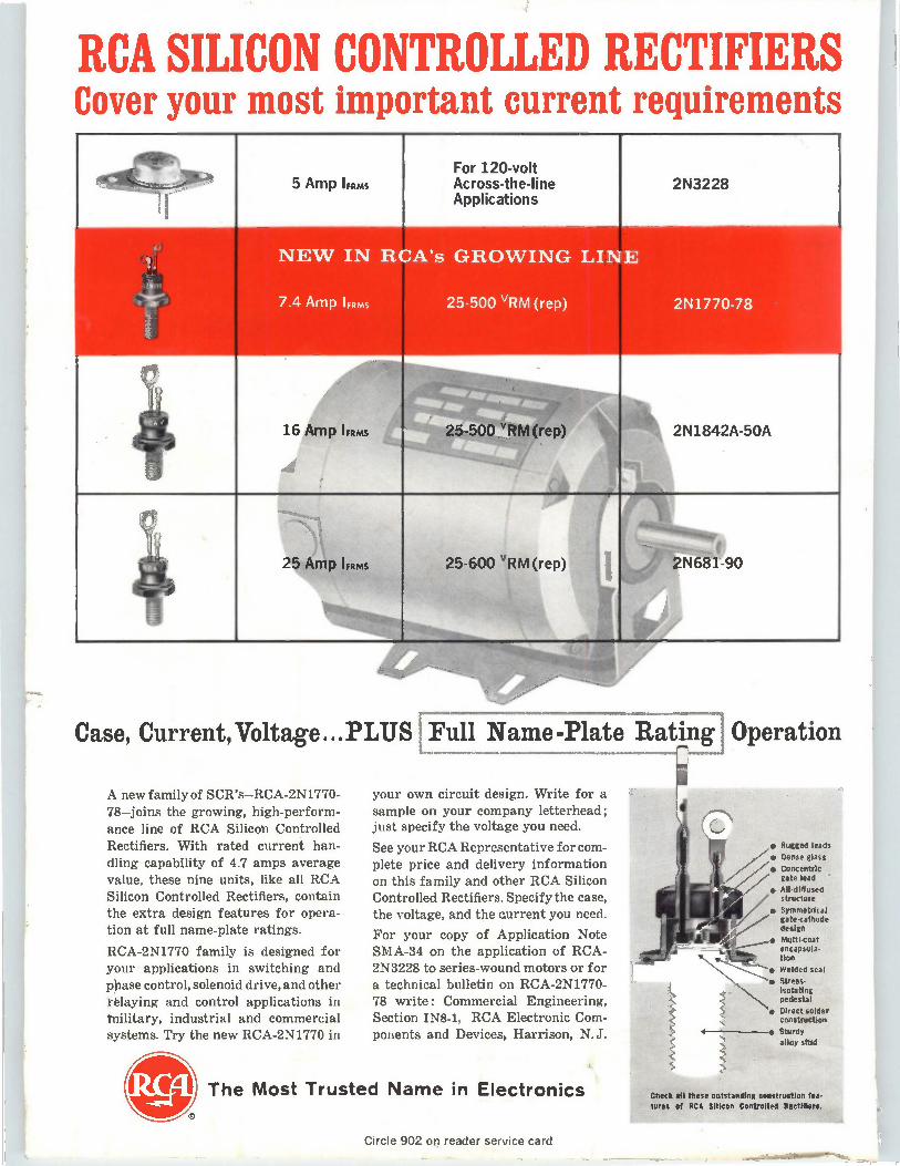
RCA SILICON CONTROLLED RECTIFIERS Cover your most important current requirements
Case, Current,Voltage...PLUS Full Name-Plate Rating Operation
5 Amp IFRms
25 Amp IFRMS
A new family of SCR's—RCA-2N1770-78—joins the growing, high-perform-
ance line of RCA Silicon Controlled Rectifiers. With rated current han-
dling capability of 4.7 amps average value, these nine units, like all RCA Silicon Controlled Rectifiers, contain the extra design features for opera-tion at full name-plate ratings.
RCA-2N1770 family is designed for your applications in switching and ppase control, solenoid drive, and other relaying and control applications in hillitary, industrial and commercial systems. Try the new RCA-2N1770 in
For 120-volt Across-the-line Applications
2N3228
2N1842A-50A
2N681-90
your own circuit design. Write for a
sample on your company letterhead; just specify the voltage you need.
See your RCA Representative for com-plete price and delivery information on this family and other RCA Silicon Controlled Rectifiers. Specify the case, the voltage, and the current you need.
For your copy of Application Note SMA-34 on the application of RCA-2N3228 to series-wound motors or for a technical bulletin on RCA-2N1770-78 write: Commercial Engineering, Section IN8-1, RCA Electronic Com-ponents and Devices, Harrison, N.J.
The Most Trusted Name in Electronics
• Rugged leads
• Dense glass
• Concentric gate lead
• All-diffused structure
• Symmetrical gate-cathode design
• ki,--- 41 ____,• Multi-coat
k-t....1., encapsula-sh.‹............„.„. tion
--"-• Welded seat
• Stress-Isolating pedesta l
• Direct snider construction
• Sturdy alloy stud
Check all these outstanding construction fea tares of RCA Silicon Controlled RectIners
Circle 902 on reader service card
Related Documents


