1 Electronics testing: Quality and Reliability Geert Willems IMEC & WTCM RMA 19 April 2007 Geert Willems 0498 91 94 64 [email protected] www.rohsservice.be Met steun van: RoHS Service Electronic Design and Manufacturing consultancy service • Design-for-X (incl. Manufacturing, Test, Reliability,…) • Electronic assembly • RoHS and lead-free soldering implementation

Welcome message from author
This document is posted to help you gain knowledge. Please leave a comment to let me know what you think about it! Share it to your friends and learn new things together.
Transcript
1
Electronics testing:Quality and Reliability
Geert WillemsIMEC & WTCM
RMA19 April 2007
Geert Willems0498 91 94 [email protected]
www.rohsservice.be
Met steun van:
RoHS Service
Electronic Design and Manufacturing consultancy service• Design-for-X (incl. Manufacturing, Test, Reliability,…)• Electronic assembly• RoHS and lead-free soldering implementation

2
© imec/restricted 2006 3
Electronics testing: Quality and ReliabilityContent
1. A few basic elements
2. Verification & qualification testing
3. Production quality testing and improvement
4. Testing supporting Design-for-Reliability
5. Examples of failure mechanisms in Electronics
© imec/restricted 2006 4
1. A few basic elements
Definition of reliability:
Probability that a product will perform its required function under stated conditions for a specific period of time.
• Product reliability is a relative not an absolute property.
• Depends on the product’s design and application.
3
© imec/restricted 2006 5
1. A few basic elements
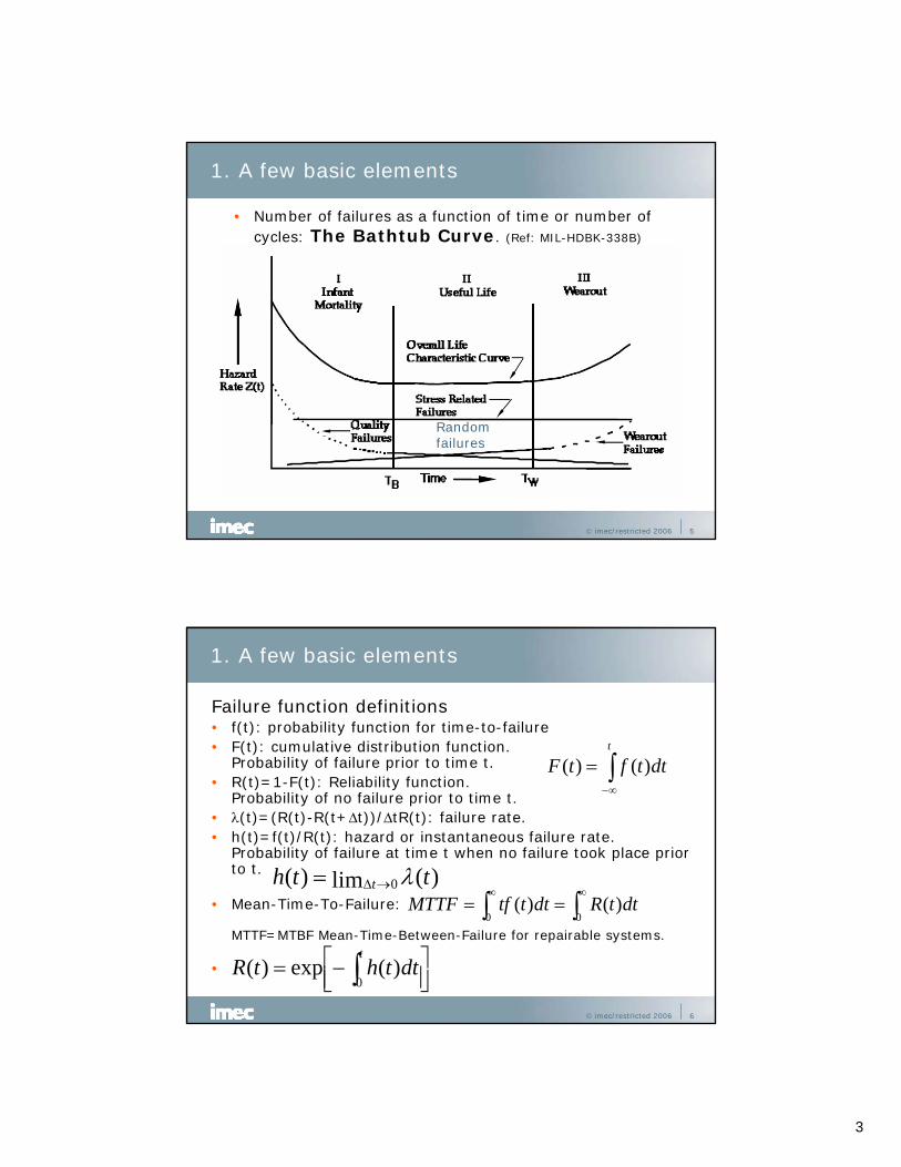
• Number of failures as a function of time or number of cycles: The Bathtub Curve. (Ref: MIL-HDBK-338B)
Randomfailures
© imec/restricted 2006 6
1. A few basic elements
Failure function definitions• f(t): probability function for time-to-failure• F(t): cumulative distribution function.
Probability of failure prior to time t.• R(t)=1-F(t): Reliability function.
Probability of no failure prior to time t.• λ(t)=(R(t)-R(t+Δt))/ΔtR(t): failure rate.• h(t)=f(t)/R(t): hazard or instantaneous failure rate.
Probability of failure at time t when no failure took place prior to t.
• Mean-Time-To-Failure:
MTTF=MTBF Mean-Time-Between-Failure for repairable systems.
•
∫∞−
=t
dttftF )()(
)(lim)( 0 tth t λ→Δ=∫∫∞∞
==00
)()( dttRdtttfMTTF
⎥⎦⎤
⎢⎣⎡−= ∫
tdtthtR
0)(exp)(
4
© imec/restricted 2006 7
1. A few basic elements
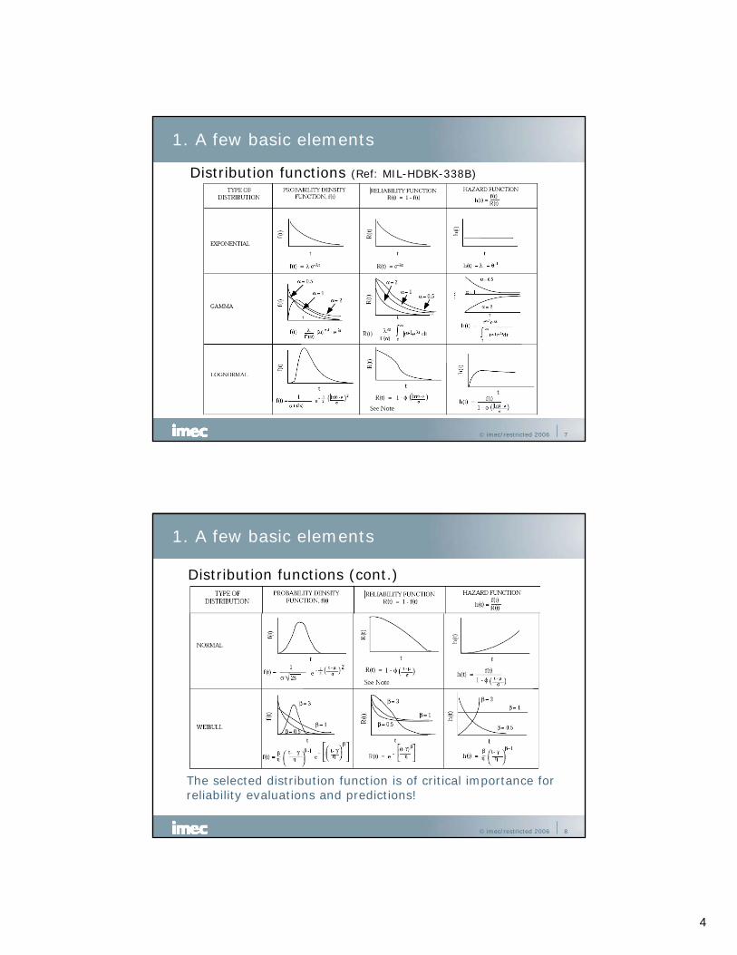
Distribution functions (Ref: MIL-HDBK-338B)
© imec/restricted 2006 8
1. A few basic elements
Distribution functions (cont.)
The selected distribution function is of critical importance forreliability evaluations and predictions!
5
© imec/restricted 2006 9
1. A few basic elements
Most versatile: Weibullβ: shape parameter, η: characteristic life (often θ used)=63,2% failures.
β<1 β>1β=1
Exponentialdistribution
Randomfailures
© imec/restricted 2006 10
1. A few basic elements
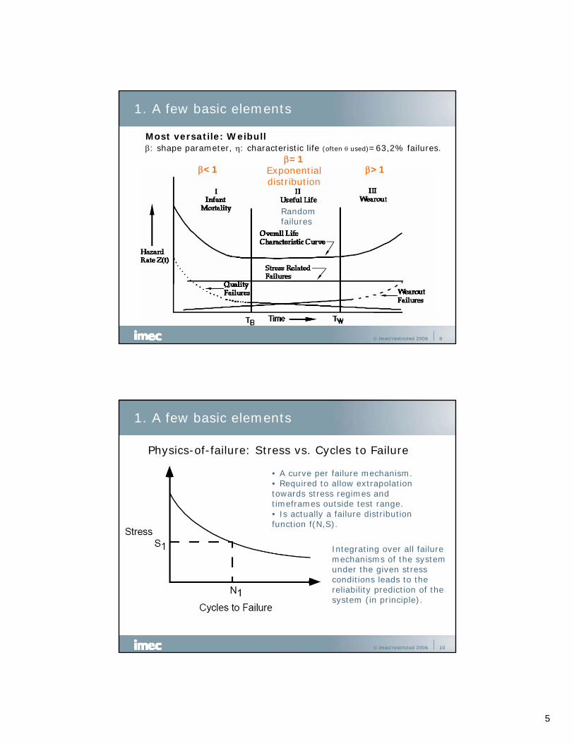
Physics-of-failure: Stress vs. Cycles to Failure
• A curve per failure mechanism.• Required to allow extrapolationtowards stress regimes andtimeframes outside test range.• Is actually a failure distributionfunction f(N,S).
Integrating over all failure mechanisms of the systemunder the given stress conditions leads to the reliability prediction of thesystem (in principle).
6
© imec/restricted 2006 11
1. A few basic elements
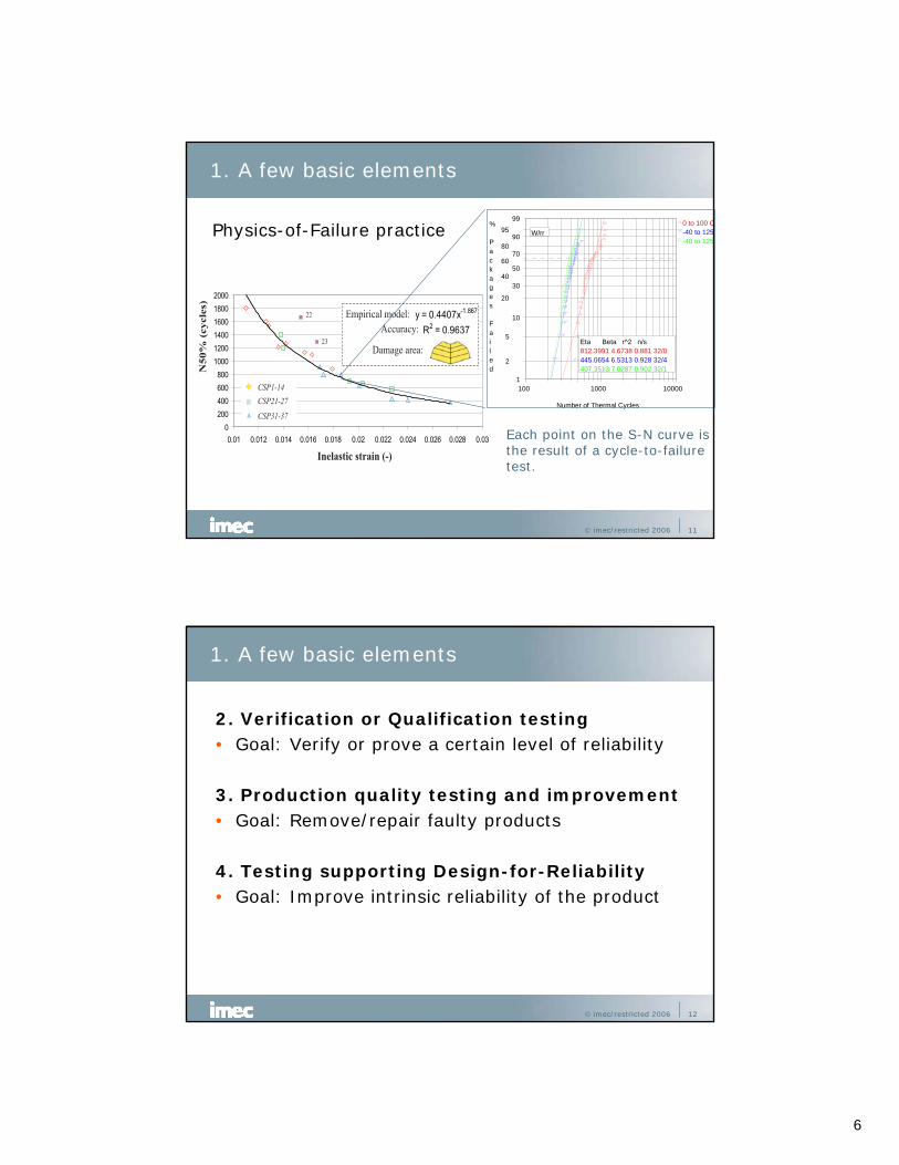
Physics-of-Failure practice
1
5
2
10
20
30 40
50 60
70 80
90 95
99
100 1000 10000
% Packages Failed
Number of Thermal Cycles
407.3513 7.0287 0.902 32/1 445.0654 6.5313 0.928 32/4 812.3991 4.6738 0.881 32/0 Eta Beta r^2 n/s
W/rr 0 to 100 C -40 to 125 -40 to 125
Each point on the S-N curve isthe result of a cycle-to-failuretest.
© imec/restricted 2006 12
1. A few basic elements
2. Verification or Qualification testing• Goal: Verify or prove a certain level of reliability
3. Production quality testing and improvement• Goal: Remove/repair faulty products
4. Testing supporting Design-for-Reliability• Goal: Improve intrinsic reliability of the product
7
© imec/restricted 2006 13
2. Verification/qualification testing
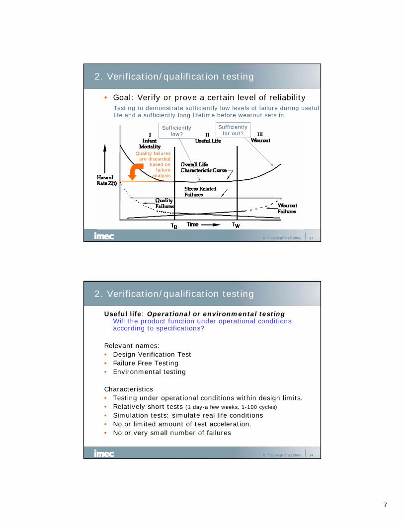
• Goal: Verify or prove a certain level of reliabilityTesting to demonstrate sufficiently low levels of failure during usefullife and a sufficiently long lifetime before wearout sets in.
Sufficientlylow?
Sufficientlyfar out?
Quality failuresare discarded
based onfailure
analysis
© imec/restricted 2006 14
2. Verification/qualification testing
Useful life: Operational or environmental testingWill the product function under operational conditions according to specifications?
Relevant names:• Design Verification Test• Failure Free Testing• Environmental testing
Characteristics• Testing under operational conditions within design limits.• Relatively short tests (1 day-a few weeks, 1-100 cycles)
• Simulation tests: simulate real life conditions• No or limited amount of test acceleration.• No or very small number of failures
8
© imec/restricted 2006 15
2. Verification/qualification testing
Examples:• Storage and transportation tests• Operation under different environmental conditions:
heat/cold, moisture, vibration, shock,…
Standards related to operational testing:• ETS 300 19 series: Environmental Conditions and
Environmental testing for Telecommunication Systems• IEC 60068 series: Environmental testing• IEC 60721: Classification of environmental conditions• ANSI
Result:• Functionality under operational/environmental conditions• No failure rate nor life time information is obtained!
© imec/restricted 2006 16
2. Verification/qualification testing
Useful life: MTTF/MTBF testingDetermination of failure rate/MTTF/MTBF in the useful life period of the equipment. Is it acceptable?
Relevant names:• Reliability testing
Characteristics• Testing under operational conditions within design limits.• Relatively long tests in the order of 10-100% of MTTF/MTBF• A statistical relevant number of failures must occur.• Shorter test on larger number of samples.• Simulation tests: simulate real life conditions.• No or limited amount of test acceleration.• MTTF/MTBF extraction depends strongly on the selected
failure distribution function used for the analysis:– Usually: Exponentional distribution: random failures/constant failure rate
9
© imec/restricted 2006 17
2. Verification/qualification testing
Standards related to Reliability testing• IEC 60605 series: Equipment Reliability Testing• IEC 1123: Reliability testing - Compliance test plans for
success ratio.• IEC 61124: Reliability testing – Compliance tests for
constant failure rate and constant failure intensity.• MIL-HDBK-781: Reliability Testing for Engineering
Development, Qualification, and Production
Results• MTTF/MTBF or other distribution function parameters
estimate. Highly dependent on choice of distribution function. Validity of constant failure rate assumption!?
• No physics, only statistics!• No lifetime information regarding wear out.
© imec/restricted 2006 18
2. Verification/qualification testing
Wearout: Life time testingDoes the product has a sufficiently long useful life before wearout starts?
Relevant names:• Life time testing• Accelerated testing• Reliability testing• Fatigue testing
Characteristics• Problematic for systems with long lifetimes: require
accelerated tests. In general not feasible at system level.• Systems: long (nearly) failure free testing under
operational or mildly stressed conditions.• Parts level: statistical meaningful number of failures to
determine failure distribution.

10
© imec/restricted 2006 19
2. Verification/qualification testing
Standards:• System level: Special cases of reliability testing using non-
exponential distribution functions. • Part level: see standards for Physics-of-Failure testing like
IPC-9701.
Results:• If sufficient failures are obtained during tests failure
distribution parameters can be derived.• If accelerated tests are used, acceleration factors must be
known to determine “real life” failure distribution. Issues:– knowledge of acceleration factor?
– does the failure distribution remain unaffected by the acceleration except for the acceleration factor?
– no other failure mechanisms introduced at accelerated test?
• Failure free tests give very little information about lifetime.
© imec/restricted 2006 20
3. Production quality testing and improvement
• Goal: Remove/repair faulty productsTesting to minimize “dead on arrival” (Time =0) and early failure rate.
11
© imec/restricted 2006 21
3. Production quality testing and improvement
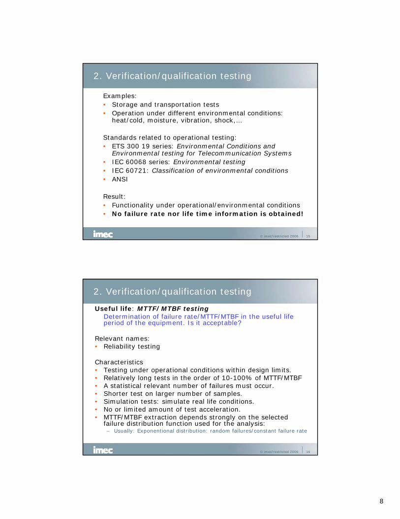
Production testing: Quality testing
Assembly testing:• Inspection (human, automatic, optical, X-ray,…)• Structural test (flying probe, ICT, Boundary scan,…)• Functional test
Characteristics• Fast, go-no go testing plus
trouble-shooting & repair• Factory environment• Product based test strategy
Results• Production quality and yield quantification.• Products that pass the tests. Quality of outgoing products
dependent on test coverage of production test.• Minimisation of numbers of “dead-on-arrival” products
© imec/restricted 2006 22
3. Production quality testing and improvement
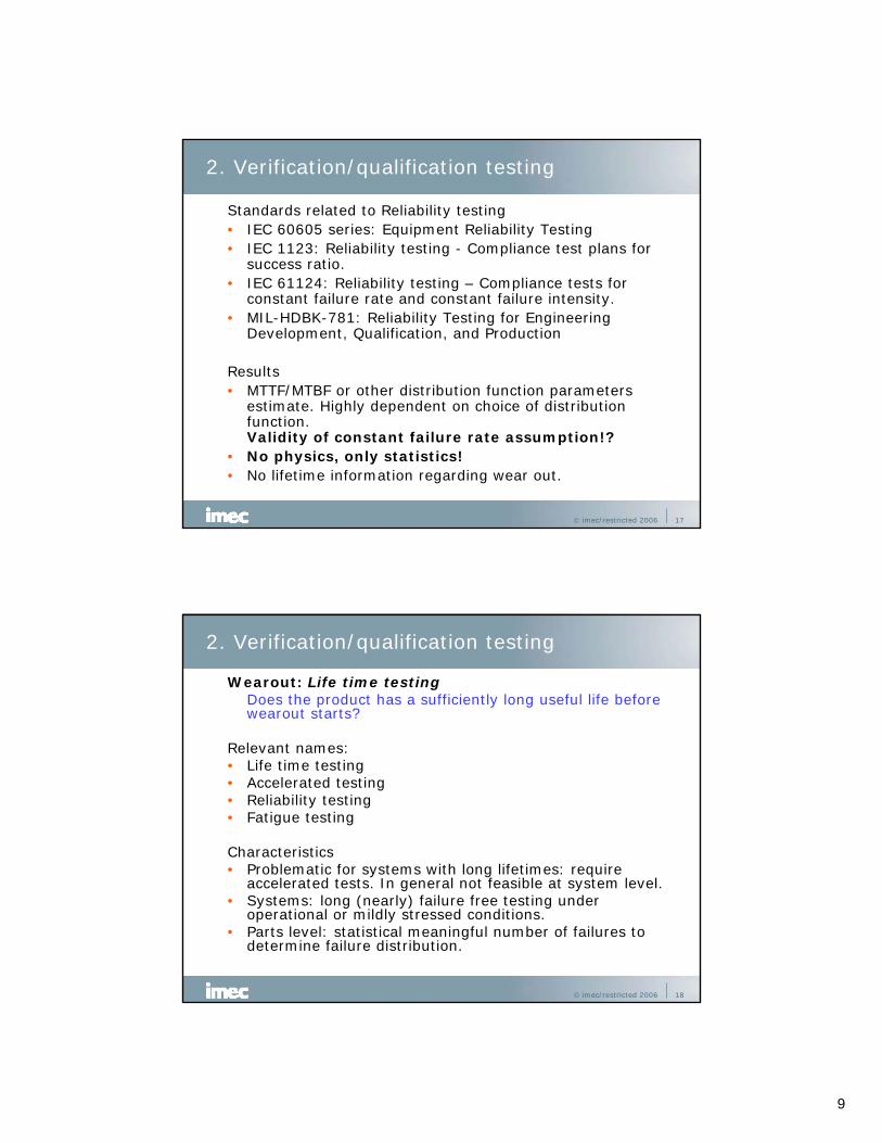
Product screening: stress testingGoal: To transform quality related latent failures that cause
early failures into patent failures that can be detected and removed/repaired.
Method:• Apply certain stress level(s)• Should not damage good
products• Impact on lifetime of good
products should be acceptable
Types of screening tests:• Burn-in• Environmental Stress Screening (ESS)• Highly Accelerated Stress Screening (HASS)• Highly Accelerated Stress Auditing (HASA)
Ref: IEC 61163-1
12
© imec/restricted 2006 23
4. Tests supporting Design-for-Reliability
Goal: • To improve the reliability of the product by design.• Gathering knowledge about potential failure modes.
Characteristics:• Accelerated tests• Test to failure• No qualification or demonstration testing
1. Parts qualification testing2. Highly Accelerated life Testing3. Failure mode based accelerated testing
© imec/restricted 2006 24
4. Tests supporting Design-for-Reliability
1. Parts qualification testing• Testing of parts to fulfill the quality and reliability
requirements of the electronic assembly• To avoid specific failure modes.
Examples• Component quality and reliability:
ex. Moisture sensitivity: J-STD-20C• Sn-Whisker propensity: JESD22a121/JESD201• Solder material induced corrosion and SIR:
J-STD-004A, GR-78-CORE,…• PCB delamination, decomposition, via-cracking,…• Solderability• Etc., etc.
13
© imec/restricted 2006 25
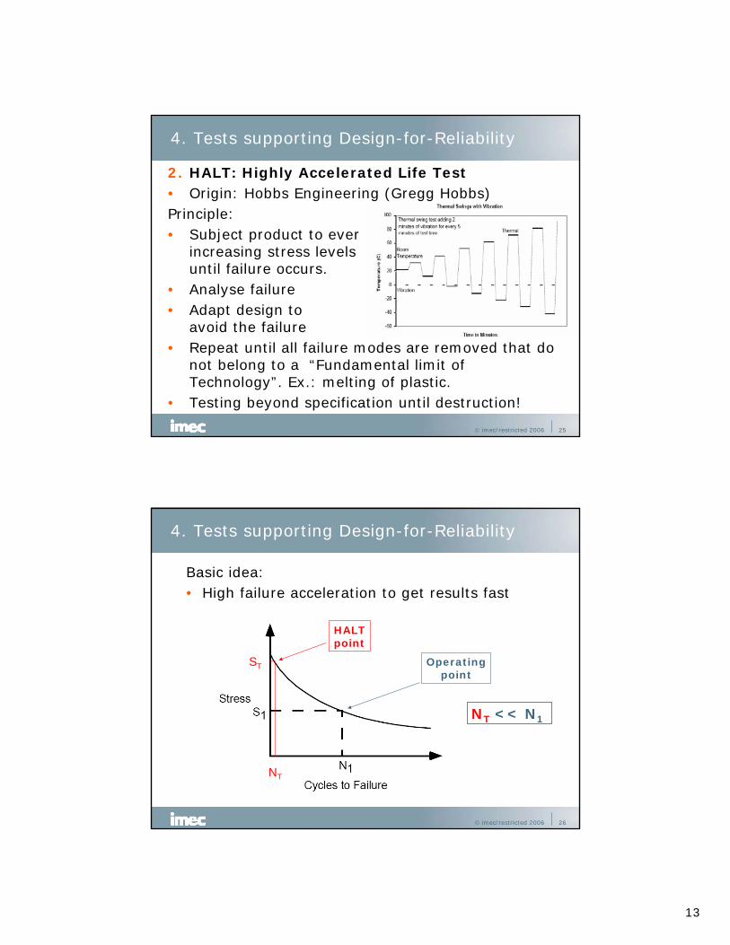
4. Tests supporting Design-for-Reliability
2. HALT: Highly Accelerated Life Test• Origin: Hobbs Engineering (Gregg Hobbs)Principle:• Subject product to ever
increasing stress levels until failure occurs.
• Analyse failure• Adapt design to
avoid the failure• Repeat until all failure modes are removed that do
not belong to a “Fundamental limit of Technology”. Ex.: melting of plastic.
• Testing beyond specification until destruction!
© imec/restricted 2006 26
4. Tests supporting Design-for-Reliability
Basic idea:• High failure acceleration to get results fast
Operatingpoint
ST
NT
HALTpoint
NT << N1
14
© imec/restricted 2006 27
4. Tests supporting Design-for-Reliability
Benefits• Fast availability of results.• Needs only a limited number of product
samples.• Improves robustness of product.• Knowledge of product capabilities outside
design specification range.• Identification of destruct limits mandatory to
establish a HASS/HASA screening.
© imec/restricted 2006 28
4. Tests supporting Design-for-Reliability
But… it is a controversial technique because:• Failure modes irrelevant to operational
conditions may be induced…• … which may lead to over-designing.• Relevant failure modes to operation may NOT
occur in HALT testing especially for electronics.Examples: Solder joint fatigue, Sn-whisker, corrosion,…
• Highly Accelerated Life Test is a misleading name. HALT cannot predict lifetime because acceleration factors at system level are not known. HALT is NOT a Life Time test!
• HALT = High Stress Test of which the benefits and relevancy must be critically evaluated.
15
© imec/restricted 2006 29
OperatingpointST
NT
Testpoint
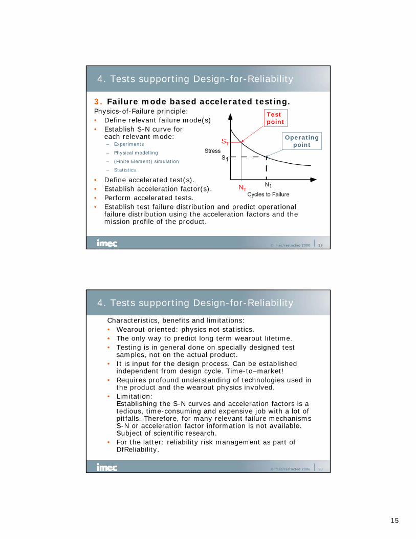
4. Tests supporting Design-for-Reliability
3. Failure mode based accelerated testing.Physics-of-Failure principle:• Define relevant failure mode(s)• Establish S-N curve for
each relevant mode:– Experiments
– Physical modelling
– (Finite Element) simulation
– Statistics
• Define accelerated test(s).• Establish acceleration factor(s).• Perform accelerated tests.• Establish test failure distribution and predict operational
failure distribution using the acceleration factors and the mission profile of the product.
© imec/restricted 2006 30
4. Tests supporting Design-for-Reliability
Characteristics, benefits and limitations:• Wearout oriented: physics not statistics.• The only way to predict long term wearout lifetime.• Testing is in general done on specially designed test
samples, not on the actual product.• It is input for the design process. Can be established
independent from design cycle. Time-to–market!• Requires profound understanding of technologies used in
the product and the wearout physics involved.• Limitation:
Establishing the S-N curves and acceleration factors is a tedious, time-consuming and expensive job with a lot of pitfalls. Therefore, for many relevant failure mechanisms S-N or acceleration factor information is not available. Subject of scientific research.
• For the latter: reliability risk management as part of DfReliability.
16
© imec/restricted 2006 31
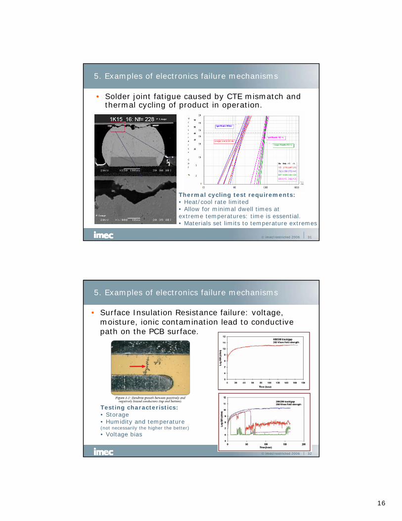
5. Examples of electronics failure mechanisms
• Solder joint fatigue caused by CTE mismatch and thermal cycling of product in operation.
Thermal cycling test requirements:• Heat/cool rate limited• Allow for minimal dwell times at extreme temperatures: time is essential.• Materials set limits to temperature extremes
© imec/restricted 2006 32
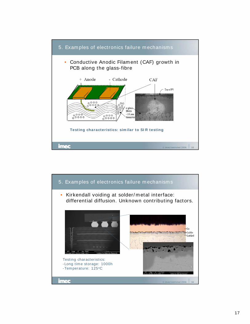
5. Examples of electronics failure mechanisms
• Surface Insulation Resistance failure: voltage, moisture, ionic contamination lead to conductive path on the PCB surface.
Testing characteristics:• Storage• Humidity and temperature(not necessarily the higher the better)• Voltage bias
17
© imec/restricted 2006 33
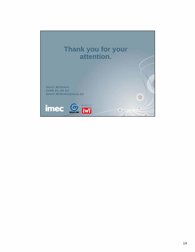
5. Examples of electronics failure mechanisms
• Conductive Anodic Filament (CAF) growth in PCB along the glass-fibre
Testing characteristics: similar to SIR testing
© imec/restricted 2006 34
5. Examples of electronics failure mechanisms
• Kirkendall voiding at solder/metal interface: differential diffusion. Unknown contributing factors.
Testing characteristics:-Long time storage: 1000h-Temperature: 125oC

18
© imec/restricted 2006 35
5. Examples of electronics failure mechanisms
• Sn-whisker growth on (nearly) pure Sn coatings: compressive stress driven
Matte Tin Plated 28 pin SOIC Stored at Ambient for 3 years
Testing characteristics:• Compressive stress introduction• Thermal cycling and storage (long duration: months!)• Too high/too low temperature: no whiskering!• Maximum whisker growth rate at 30-60oC
© imec/restricted 2006 36
5. Examples of electronics failure mechanisms
And there are many more:- Hot carrier degradation in Si components
- Electro-migration in conductors
- Dielectric breakdown, degradation
- PCB delamination
- PCB via cracking
- Pop-corning of plastic packages
- Corrosion
- Solder lead interface failures
- Brittle fracture of solder joint
- High cycle fatigue of solder joints
- ….
• Knowledge of Physics-of-Failure forms the basis of a reliable (electronic) product.
• Testing should be based on this knowledge.• “Black Box” testing of the product only tells you
that the product passes the test (or not).
Related Documents