Electronics World AUGUST, 1962 Special Feature: HI-Fl COLOR INSERT -"SOUND" 50 CENTS BUILD YOUR OWN TRANSISTORIZED IGNITION SYSTEM FACSIMILE A REVIEW OF TECHNIQUES & EQUIPMENT COIL- WINDING DESIGN CHARTS FOR R. F. APPLICATIONS COLOR TV iii OIHO NOIIISSVPI M S 1S H1£1 z 3C3121 V r.1 i71 C1 IFJI Ir.1 www.americanradiohistory.com www.americanradiohistory.com

Welcome message from author
This document is posted to help you gain knowledge. Please leave a comment to let me know what you think about it! Share it to your friends and learn new things together.
Transcript

Electronics World AUGUST, 1962
Special Feature: HI-Fl COLOR INSERT -"SOUND" 50 CENTS
BUILD YOUR OWN TRANSISTORIZED IGNITION SYSTEM
FACSIMILE A REVIEW OF TECHNIQUES & EQUIPMENT
COIL- WINDING DESIGN CHARTS FOR R. F. APPLICATIONS
COLOR TV
iii OIHO NOIIISSVPI M S 1S H1£1 z
3C3121 V r.1 i71 C1 IFJI Ir.1
www.americanradiohistory.comwww.americanradiohistory.com

Prepare Now For The Higher Rewards The Electronics Age Offers You
There is an immediate and grow- ing need for trained technicians in Industrial- Military Electron- ics, Radio -TV Servicing and Communications. Better than average jobs with high pay, in- teresting work, bright futures await you in the fast growing industry of the 1960's. Join thou- sands of NRI graduates now benefiting from career oppor- tunities in this Electronic Age.
Training Equipment Included NRI "learn-by -prac- tice" training is the time -proved way to higher earnings and advancement. Except for FCC License course, all NRI courses include -at
no extra cost -special training equip- ment to give shop and laboratory expe- rience in your own home. Makes NRI training come to life in an easy -to- grasp, interesting manner. Take the advice of job counselors, investigate Electronics if you are dissatisfied with your present job or pay, or you want to prepare for military service.
Oldest and Largest School For nearly 50 years NRI has featured Electronics training at reasonable cost because it is the old- est, largest home - study school of its kind. Take the first step to a new career now. Mail postage -free card. Approved for veterans -Korean GI Bill. National Radio Institute, Washington 16, D. C.
NEW Short Course MATH FOR ELECTRONICS
From basic arithmetic review to graphs and electronic formulas .
in a "short course" package of five carefully prepared texts. You'll learn short cuts to speed up and simplify circuit calculations, other ways math can help you in Electronics. Check and mail postage -free card for more information.
Industrial ELECTRONICS The NRI course in Electronics - Principles, Practices, Mainte- nance prepares you for a career as an Electronic Technician in industry, business, government. the military. Computers, teleme- try, automation, missiles, rockets all employ the same basic Elec- tronic principles ... and that is what this NRI course stresses with illustrated lessons, special training equipment.
Commercial FCC LICENSE You must have an FCC License if you want to operate or service transmitting equipment used in TV and Radio Broadcasting. aviation, marine, microwave, fac- simile or mobile communica- tions. Even a service Technician needs an FCC License today to work on C -Band Radio equip- ment. From Simple Circuits to Broadcast Operation, this new NRI course trains you quickly to take Government exams.
TV -Radio COMMUNICATIONS In NRI's Communications course you get actual experience as NRI trains you for your choice of Communications fields. Commer- cial methods and techniques of Radio -TV Broadcasting ; tele- type; facsimile ; microwave; ra- dar; mobile and marine radio; navigation devices; multiplexing are some of the subjects covered. You work with special training equipment.
Radio and TV SERVICING NRI's time -tested course in Serv- icing not only trains you to fix radios, TV sets, hi -fi. etc.. but also shows you how to earn spare - time money starting soon after enrolling. Fast growth in num- ber of sets means money- making opportunities for you in your own spare -time or full -time busi- ness. or working for someone else. Special training equipment at no extra cost. Mail postcard.
www.americanradiohistory.comwww.americanradiohistory.com

r
L J HOW TO BUY YOUR FIRST (OR YOUR LAST) SPEAKER SYSTEM If you demand magnificent sound ... un. distorted bass to beyond the limits of audibility -if you demand superb cabinet rc and decor flexibility (with five interchangi - able grille frames that snap on and off to match any decor) ... then consider the unique University Medallion XII 12" Three-Way Speaker System. Medallion owners stay Medallion owners. Let's look inside the Medallion and see why.
compare
UNIVERSITY (in every price category) against all other brands
- smooth and rich -from 28 to 40,000 cps (2db at 22,000 cps). And at your fingertips, network controls to balance the Medallion sound to match the acoustics of your room -any room.
Amplifier requirements? Any amplifier capable of delivering a modest ten clean watts. Medallion dimensions? Only 24" x 17' x 113f deep. Available with or without base -for use as highboy or low- boy. Finishes? Walnut, oiled walnut,
Integrated within its precisely -matched cabinet are three superlative speaker com- ponents: the 12' high compliance woofer that delivers bass frequencies down to the very threshold of feeling; a newly - engineered 8' speaker to assure you of all- important mid -range impact; and the Sphericon super tweeter for highs un- limited. Result: virtually uniform response
For a solution to a really difficult space problem, investigate the TAIS-2 single cabinet stereo speaker system.
fruitwood, mahogany and unfinished for custom installations. And the Medallion is the world's only system with "select -a. style" snap-on grilles. Want to change your decor at some later date? The Medallion stays where it is -all you change is the grille! In Contemporary, Italian or French Provincial, Colonial and Swedish Modern. Medallion prices start at $139.95, without grille. Grilles from $9.95. Base, 814.95.
Write for University's "Informal Guide to Component High Fidelity," Desk ':I. University Loudspeakers, Inc., White Plains, New York.
1 L For bookshelf speaker systems with astound - ing 'big system' sound, look into University's RRL speaker systems.
UNIVERSITY A Division 1 Ling- Tentco- Lblsgiu, Inc.
TIMELESS BEAUTY AND THE SOUND OF TRUTH
ELECTRONICS WORLD 1. ntll.11-Ind1 , Id' 1'l1:l.I1' lnn \ Ì :l :1 I
Ilir:'lvo C. I111111.1... 1n'Innt and pt. I.Inn N',. lanara nl I:n Amrit nll'nln ,I1, .....111.
' 1.- nt I:I-- In.taLt paid at I Illlnnl. :,,tI :
t :llitinn`iÌ Il:llin. \ltllnlizad1 .lnnl ela-" 11 Ita llleen nl. lill:ittaI.nant anla. pas In.tagt In 1002; Vol. 4114. No. J.
August, 1962 1
www.americanradiohistory.comwww.americanradiohistory.com

NEW LOW PRICES -ONLY CHANGE WE COULD THINK OF
tg4e'anhr-,
TO MAKE THESE SPEAKERS SOUND BETTER THAN EVER!
símpl a.,y Delco You've always been able to install Delco Auto Radio Speakers
with complete confidence in their quality. Now you can sell
this popular line at competitive prices as well!
And Delco hasn't sacrificed a single one of these out-
standing features: Highest sensitivity for greater range of
distortion -free sound from precision- engineered magnetic circuits Extra -efficient, premium grade Alnico -V magnets
Continuous life testing program to assure dependable
performance under the most severe climatic conditions.
There's news in Delco packaging, too. Your choice 6 x 9's in new bulk -packs, 20 speakers to a carton, or individually boxed speakers if you like. Now that you can sell top quality Delco Auto Radio Speakers at new, competitive prices, better stock up and start cashing in! Call your supplier and -simply say Delco. Delco Radio Service Parts are distributed nationally through United 33e1CO.
DELCO RAD ;O. D..i ion of Gcnc. s' Motors, Koiomo, Indiana
INO 2 ELECIRONICS WORLD
www.americanradiohistory.comwww.americanradiohistory.com

AUGUST 1962 / VOL. 68 NO. 2 EIcclronicsllórld CONTENTS
Publisher PHILLIP T. HEFFERNAN
Editor WM. A. STOCKLIN, B. S.
T ethnical Editor MILTON S. SNITZER, W20Y1
Service Editor SIDNEY C. SILVER
Associate Editor ROBERT D. FREED
Associate Editor P. B. HOEFER
Editorial Consultant OLIVER READ, D.Se.,W4TWV
Industrial Consultant WALTER H. BUCHSBAUM
Alt Editor MILTON BERWIN
Art and Drafting Dept. J. A. GOLANEK
Advertising Sales Manager LAWRENCE SPORN
Advertising Service Manage, ARDYS C. MORAN
ZIFF -DAVIS PUBLISHING COMPANY Editorial and Executive Offices One Park Avenue New York 16, New York ORegon 9 -7200
MIDWESTERN and CIRCULATION OFFICE
434 South Wabash Avenue Chicago 5, Illinois WAbash 2 -4911 Midwestern Advertising Manager Gilbert J. Jorgenson
WESTERN OFFICE 9025 Wilshire Boulevard Beverly Hills, California CRestview 4.0265 Western Advertising Manager Bud Dean
FOREIGN ADVERTISING REPRESENTATIVE
D. A. Goodall Ltd., London, England
INDUSTRIAL Integrated Circuitry (Editorial) Facs;-nile Techniques 8 Equipment
Recent Developments in Electronics
Coil- Winding Charts
Electronics Manufacturing Occupations
TEST EQUIPMENT Using the Oscilloscope Delayed Sweep
How to Make Your V.T.V.M. Reliable Compact, Transistorized Impedance Bridge
Directory of Color -TV Test -Pattern Generators EW Lab Tested (Eico Model 955 Capacitor Tester)
W. A. Stocklin 6 Arthur L. Plevy 21
28 Donald W. Moffat 54
66
Walter H. Buchsbaum 26 J. B. Stroughn 30
Stanley E. Bammel 46 51 72
HI -FI AND AUDIO EW Lab Tested (ESL T -200 "Gyro /Spension" Turntable; "Knight" KN -40018
Tape Preamplifier; Fisher KS -1 "Slim- Line" Speaker System, page 16) 12
Sound (Special Chart) 35 -36 Versatile Voltage, Power, and Decibel Nomograms
(Special Chart) Jim Kyle 37 -38 Automatic Switching for Multiplex Adapters George Mordwinkin 61 FM- Stereo Programs Reach 70- Million Listeners 75
GENERAL Status of Color TV
Analyzing Color Set Defects Semiconductor Noise Filter Patent Information for the Inventor (Part 2)
CONSTRUCTION High -Power Transistorized rrPhotorhythmicon" Transistor- Operated Portable Lamp
Transistorized Ignition System
COMMUNICATIONS Canadian Citizens Band
Using the Nuvistor on V.H.F. Bands
Low & Medium Frequency Converter
James E. Pugh, Jr.
Joseph F. Verruso
Leon A. Worturan
Thomas J. Barmore
Boghos N. Saatjian
Leo G. Sands
Joseph Marshall, WA4EPY
Ronald L. Ives
MONTHLY FEATURES Coming Next Month 4 Calendar of Events Letters from Our Readers .... 8 Radio & TV News (S.I.N.) Mac's Electronics Service .... 42 Electronic Crosswords Within the Industry 69 Technical Books
New Products and Literature for Electronics Technicians Canyrlght c 1962 by 2111- Davis Publishing Company. All rights reserved.
87
25 40 71 82
31 39 52
34 43 48
75 76 77 84
August, 1962 3
www.americanradiohistory.comwww.americanradiohistory.com
3 WAYS
TO SPEED YOUR PROGRESS IN
INDUSTRIAL ELECTRONICS
t, ELEMENTARY INDUSTRIAL ELECTRONICS by Leonard C. Lane
If you're ready to enter the fabulous field of industrial electronics, this two -volume course will arm you with the know -how necessary for success. If you're already in the field -- operating equip- ment, servicing or maintaining it - even selling it, you'll do your job better, because you'll have a firmer grasp of the fundamentals of industrial electronics. Only a basic knowledge of electricity and elec- tronics is required to get the most out of this two - volume course. All the major areas of industrial electronics that you are likely to encounter are made absolutely clear. relays and switching
magnetic amplifiers motor controls elec- tronic heating instrumentation and many other topics. Presentation is complete and clear so that you'll be abbe to progress rapidly from subject to sub- ject. Mathematics is held to an absolute minimum. Illustrations. simplified diagrams reinforce and make each technical point understandable. The course bridges the gap' between conventional radio and industrial electronics smoothly bringing you into the field 2 Vol. Course $7.$O i 33.90 ea. vol.)
New Rider Industrial Electronics Series
2. BASIC PRINCIPLES & APPLICATIONS OF RELAYS by Harvey Pollack
Lucid introduction to the construction, operation and application of relays. Discusses relay com- ponents - including coils and contacts- in terms of their individual functions. DC relays, their rectifier arrangements selected circuits and con- tact protection are covered. The chapter on elec- tronic relays, circuit covers thyratron circuits together with various light-operated, cold cathode and combination relays. Time delay circuits are discussed with practical applications. Factors gov- erning the choice of a particular relay for a
specific circuit are made clear. #250 -1, $2.90.
3. PHOTOELECTRIC CONTROL
by Harvey Pollack. Extremely informative text, illustrates how photo- electric devices are used in industrial electronic systems. It's so easy to understand how these com- ponents operate when you read this book. Espe- cially clear circuits and operation descriptions of modern photoelectric devices which control meas- uring, counting, testing and separating tasks gives you a special insight to their applications versatility. - 2 -.0 -1, $3.50.
NOW TO BUILD ELECTRONIC EQUIPMENT b5J. Richard Johnson. Saves money by helping you avoid com- mon mistakes made in building equipment. Saves you time by providing practical tips on chassis layout. #286, hard cover $0.95 USEFUL ELECTRONIC SHOP HINTS Edited by the staff of Electronic Technician Magazine - Crammed full of 200 practical, helpful and time saving shop hints. #295, $1.95. USING THE SLIDE RULE IN ELECTRONIC TECHNOLOGY Charles Alvarez - Transforms beginners into masters of this timesaving tool. #253, $2.50. Mail to your distributor, bookstore order direct:
ORDER TODAY - 10-DAY GUARANTEE lohn F. Rider Publisher Inc. A division of Hayden Publishing Co. Inc. 116 West 14th St., New York 11, N.Y.
I have enclosed 5 - -. Please send: G Elem. Indust. Elect. 2 Vol. Course $7.80
Vol. I $3.90 Vol. II $3.90 SBasic Principles & Application of Relays $2.90 Photoelectric Control $3.50 How To Build Electronic Equipment $6.95 Useful Electronic Shop Hints $1.95
G Using The Slide Rule in Electronic Technology $2.50
EW.8
NAMF
ADDRESS
CITY 70NE-STATF Satisfaction guaranteed, or I can return within 10 - -- -days of purchase for full refunds - --
4
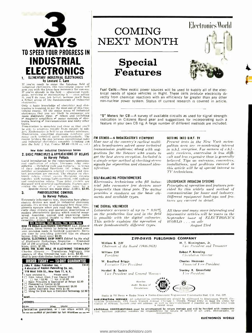
COMING NEXT MONTH
Special Features
I:Ieelronics World
.,
--4 . keib
Fuel Cells -New exotic power sources will be used to supply all of the elec- trical needs of space vehicles in flight. These cells produce electricity di- rectly from chemical reactions with an efficiency far greater than any other non -nuclear power system. Status of current research is covered in article.
"S" Meters for CB -A survey of available circuits as used for signal strength indication in Citizens Band gear and suggestions for incorporating such a feature in your own CB rig. A large number of different methods are included.
FM STEREO -A BROADCASTER'S VIEWPOINT
How one of the count ;v's earliest multi- plex broadcasters soloed some technical transmission problems: along with sug- gestions for the listener who wants to get the best stereo reception. Included is a simple scope method of checking stereo signals for separation and channel iden- tification.
SELF -BALANCING POTENTIOMETERS
Electronics technicians who fill indus- trial jobs encounter few devices more frequently than these pots. The author provides a rundown on the basic ele- ments and available types.
THE DIGITAL VOLTMETER
Laboratory accuracy of up to ± 0.01% on the production line and in the field is possible with the digital voltmeter. This article explains the operation of three fundamentally different types.
GETTING INTO U.H.F. TV
Present tests in the New York metro- politan area are re- awakening interest in u.lt.f. reception. For owners of v.h.f.- only receivers, conversion is less diffi- cult and less expensive than is generally believed. Tips on antennas, converters, installations, and problems covered in this article will be of special interest to TV technicians.
LOUDSPEAKER INTERCOM SYSTEMS
Principles of operation and features pro- vided by this widely used method of communication for home and industry. Different equipment hook -ups and fea- tures are covered in detail.
All these and many more interesting and informative articles will he yours in the September issue of ELECTRONICS WORLD ... on sale
August 23rd
ZIFF-DAVIS PUBLISHING COMPANY M. T. Birmingham, Jr.
rice President and Treasurer
Robert P. Breeding Lit cubition Director
William B. Ziff Chairman al the Board /1946.19.531
William Ziff President
W. Bradford Briggs E.rerutire lire President
Hershel B. Sarbin lice President and General Mon': o,
os;1ea e/ V
n`
Member Audit Bureau of
Charles Housman Pinanrinl r we President
Stanley R. Greenfield lire Irresident
Circulations Ì 11 N.11 FIPIIITt eala
Radio & TV News Radio News Radio- Electronic Eng:neoring Trademarks Reg. U.S. Pet. On.
SUBSCRIPTION SERVICE: All subscription correspondence should be addressed to Electronics World. Cir- culation Department. 434 South Wabash Avenue. Chicago 5. Illinois. Please allow at least six weeks for change of address. Include your old address. as well as new- enclosing if possible an address label from
a recent issue.
EDITORIAL CONTRIBUTIONS must be accompanied by return postage and will be handled with reasonable care: however publisher assumes no responsibility for return or safety of art work. photographs. or
manuscripts.
ELECTRONICS WORLD
www.americanradiohistory.comwww.americanradiohistory.com

- Robert T. Blanks Engineer, Research & Study Division
Vitro Laboratories, Silver Spring, Md. Division of Vitro Corporation of America
WHEN YOU ENROLL IN A CREI Home Study Program, you join more than 20,500 students working in electronics in all 50 states and most countries of the free world. One CREI Program helped Robert Blanks become an Electronics Engineer. Another helped Robert I. Trunnell become an Electronics Tech- nician. While John H. Scofield -a Mathe- matician-is enrolled in still a different CREI Program relating mathematics to electronics. All work at Vitro Laboratories.
INDUSTRY- RECOGNIZED CREI HOME STUDY PROGRAMS PREPARE YOU FOR INCREASED RESPONSIBILITIES, HIGHER - PAYING POSITIONS IN ELECTRONICS.
YOU CAN QUALIFY for a CREI Program if you have a basic knowledge of radio or electronics and are a high school graduate or the equivalent. If you are doubtful about your qualifications, let us check them for you. JUST OFF THE PRESS! If you qualify, send for FREE 58 -page book describing CREI Programs and career opportunities in advanced electronic engineering tech- nology -the latest edition is just off the press. Mail coupon or write to: The Capitol Radio Engineering Institute, Dept. 1108 -K, 3224 Sixteenth St., N.W., Washington 10, D. C.
"THROUGH A CREI HOME STUDY PRO- GRAM I learned the practical theory and technology I needed to become a fully - qualified engineer -not a 'handbook' en- gineer, either -and I did it while I was on the job," says Robert T. Blanks. To- day thousands of electronics personnel - engineering technicians, engineers, admin- istrators, executives -attribute present high salaries and positions to home study of CREI Programs in Electronic En- gineering Technology.
DEMAND FOR CREI- PREPARED MEN today far exceeds the supply -has ex- ceeded the supply for many years. Designed to prepare you for responsible positions in electronics, CREI Home Study Programs are the product of 35 years of experience in advanced technical education. Aiding in their development are leading engineers and scientists from in- dustry, government agencies and institu- tions of higher learning. Here Robert T. Blanks discusses CREI with Director Wayne G. Shaffer of Vitro Labs.
YOUR LIVING IS BETTER when you pre- pare for -and get -desired promotions through CREI Home Study. CREI alumnus Blanks is understandably proud of his home in a comfortable neighbor- hood. The positions of CREI- prepared men in such companies as Pan American Airways, Federal Electric Corporation, The Martin Company, Northwest Tele- phone Company, Mackay Radio, Florida Power and Light and many others attest to the high calibre of CREI Programs.
YOUR WHOLE FAMILY BENEFITS. Engineer Blanks' growing family pitched in to provide free time for his CREI Home Study. Now they share his success. We invite you to check the thoroughness and completeness of CREI Home Study Pro- grams in Electronic Engineering Tech- nology in the catalog provided on request. For those who can attend, CREI main- tains a Residence School in Washington, D. C. offering ECPD Accredited Technical Institute Curricula.
Now edition just oft the prou -Mall coupon today for FREE 58 -page book ,-J
A A The Capitol Radio Engineering Institute Founded 1927 t H l' V Y Dept. 1108 K, 3224 Sixteenth St., N.W., Washington 10, D. C.
Please send me details of CREI Home Study Programs and Free Book, Your Future in Electronics and Nuclear Engineering Technology." My qualifications are noted to obtain immediate service. CHECK Electronic Engineering Technology Nuclear Engineering Technology
FIELD OF Servo and Computer Engineering - Automation and Industrial Elec. GREATEST Technology Ironic Engineering Technology INTEREST:
Aero and Navigational Engineering Technology
s
-10.1
Name
Address
City Zone State
Employed by
Type of present work
Education: Years High School Other
Electronics Experience -
Check: Home Study Ì
Residence School G.I. Bill
Age
lOA
www.americanradiohistory.comwww.americanradiohistory.com

and most
versatíle ...slim-compact
a=1 0
Ilere is unbelievably excellent sound quality combined eith the ultimate in placement flexibility. Compact size (127/4 "H, 15% " \\', 207i4"I)) takes little space on desk, table or shelf. The slim- compact X -20 is ideal for wall mount- ing I% it Ii built -in brackets. Finish is oiled walnut. Convenient volume con- trol on the side. There's a refreshing decorator touch in the two -tone har- monizing custom fabric on the front. 3 speakers -a woofer and 2 t%eeters- provide smooth wide range sound. Perfect for FM Multiplex. very low cost stereo. other -room extensions.
X -20 3- speaker 2 -way system. ' I, Impedance, 8 ohms. Power rat-
ing, 6 watts. Adequate room sound with 1 watt to speaker. In Oiled Walnut $39.95
r r r ultra compact inimmpormymp O
L
n O.
Most popular ul a- compact hi fi speaker system. 2 -way sy tern in oiled walnut mea- suring l'A" H, 13 W, 4' /e' D.
X -I0 2- speaker 2 -way system. Impedance, 8 ohms. Power rating, 6 watts. Adequate room sound with 1 watt to speaker. In Oiled Walnut $29.75
ensen MANUFACTURING COMPANY
6601 SOUTH LARAMIE AVENUE, CHICAGO 38. ILLINOIS
CANADA: RADIO SPEAKERS OF CANADA, LTD., TORONTO
MEXICO: UNIVERSAL DE MEXICO, S.A.. MEXICO. D.F.
6
... for the Record By W. A. STOCKLIN
Ed tor
Integrated Circuitry IIE electronics industry has never
1 stood still. especially not since \\'orld War if. New developments, new techniques. new ideas -all having been accelerated by our military and space programs, make our industry an exciting one. especially to those who progress with it.
Much has been said recently about a
new art -that of integrated Circuitry. To get first -hand information, we went to Motorola's semiconductor plant in Phoe- nix and to Fairchild's plant near San
Francisco. We talked to engineers from Texas Instruments, RCA, and others. We have been convinced that a new com- ponent design technique is developing.
Every company in the field refers to this new technigne by its own coined phrase: llotorola calls it "integrated - circuit electronics ": Fairchild, "Micro- logic"; General Instrument, "nanocir- cuits"; etc. For want of a better name, let's just call it `integrated circuitry."
it is the art of fabricating complete circuits, including transistors, diodes. re- sistors- capacitors, and even inductors on a substrate similar in size to the active material used in our present -clay tran- sistor. The substrate may be ceramic with thin films deposited on it to produce the circuitry, or a silicon or germanium substrate may be employed with the cir- cuit elements being applied by a dif- fusion technique. The diffusion process is similar to that used in making some
transistors. but a great number of other components with their interconnections are added. Fairchild is actually produc- ing units using a diffusion technique having as many as 9 transistors and 13 resistors on a substrate only about lie," square.
As to which process will survive, or if both will he used- is relatively unim- portant for the moment. Let's just say that both may find diversified applica- tions and be able to compete profitably.
The point of interest is that these new techniques represent microminiaturiza - tion in the extreme. it is difficult to imagine the great number of individual components that could be mnuinted weithin a conventional transistor case.
The only limiting factor would be the number of external lead connections.
There are, of course, other circuit limitations. Large capacitance and in-
ductance values ai'e, at present, impossi- ble to attain. However, even at the pres- ent state of the art, integrated circuits are beginning to find applications in computer and high- frequency design. Some of these circuits can even be found right now on the shelves of your local in- dustrial parts distributor. Prices are high but, again, it is the hope of the industry to be able to produce these circuits at only a slightly higher price than that for a present -clay transistor.
Although this new industry, if we can refer to it as such, is in its embryo stage, it has all the earmarks of becoming gigantic in time. it will have wide effects, not only on the component industry as
such, but on design engineers and tech - nicians.
As pointed out by Robert C. Sprague in a recent address at the 1962 Electronic Components Conference in \\'ashington, our present -day concept of components such as resistors, capacitors, and induc- tors is not obsolete and will not be so for many years to come. However, our own guess is that ten years from now its ef- fects on the components industry will certainly be felt.
Engineers and technicians who today are involved in circuit- design work will, without a doubt, find that in time their particular functions will change. All basic design work in this new field of integrated circuitry will be done by the manufacturer of the circuit rather than by its ultimate user. Future engineers and technicians will be devoting more of their efforts toward the packaging and assembling of complete systems from these already fabricated building blocks, which will be furnished by semiconduc- tor manufacturers.
A new era and a new industry is in the formative stage now. With this thought in mind, we are making every effort to keep our readers abreast of these new developments. Our plans are to publish in an early issue an article from Motorola covering many of their philosophies in
this field. We will follow this up with an
article from Fairchild describing some of their production techniques and includ- ing problems involved and developments to date. Our hopes are that Texas Instru- ments, Sprague, and others will follow with articles on their approaches to this important phase of electronics.
ELECTRONICS WORLD
f
www.americanradiohistory.comwww.americanradiohistory.com

The only electronics home study program that guarantees*...
A Commercial FCC License ...Or Your Money Back!
No other electronics home study program can equal that offered by Cleveland Insti- tute. And that's why we make this ex- clusive guarantee: "Completion of our Master Course pre-
pares you for a First -Class Commercial Radio Telephone License with a Radar Endorsement. If you fail the FCC exam- ination for this license after successfully completing the Master Course, you will receive a full refund of all tuition pay - ments. This guarantee is valid for the en- tire duration of your enrollment period.
This Course Is Designed Specifically For Men With Previous Electronics Training or Experience and Provides...
Advanced electronic theory and math. (You will receive a special 10" Elec- tronic Slide Rule and complete in- structions).
Special training in the practical ap- plication of electronics skill in such advanced fields as Computers . . .
Servo- Mechanisms . . . Magnetic Amplifiers . . . AC Circuit Analysis ... Pulse Circuitry ... Color TV .. .
Radar ... Advanced Measuring Tech- niques ... Industrial Electronics .. .
Instrumentation ... Automation .. .
Radio Telemetry ... Semiconductors.
Get This Handy Pocket Electronics Data Guide Free ... Conversion factors, formulas, tables and color codes at your fingertips. Yours without obli- gation, simply for responding NOW to this opportunity to improve your future. - Send This Coupon Today..)
Cleveland V " Institute of Electronics 1776 E.17 St., Desk RN -68, Cleveland 14,0.
Accredited by the Accrediting Commission of the National Home Study Council (An Accrediting Commission Approved by the U. S. Office of Education).
August, 1962
Three Free Booklets Tell How CIE Training
Opens The Door To Unlimited Opportunities
More Reasons How CIE Will Help You Get
Ahead in Electronics Job Service ... every month, for three years, CIE will supply you with a listing of hundreds of job opportunities. High paying, interesting jobs ... with top companies throughout the world. See how CIE training opens a whole new world in electronics opportunity. Electron Bulletin every month, every student receives a free copy of this informative bulletin. Keeps you up to date on what's going on in electronics.
EiI want to know more about your electronics home
Xt study training program. Please send me your free
ICE booklets described above plus your handy pocket
; Electronics Data Guide. I understand there is no obligation. I have had training or experience in
Et electronics as indicated.
Mail Coupon To
Cleveland Institute of Electronics 1776 E. 17th St.,Desk ßN -68. Cleveland 11, Ohio
Military Amateur Radio Radio -T1' Sers icing Broadcasting Manufacturing Home Experimenting
p Communications Other
I'm now working in.
I want to know about the following area of electronics.- __
(plea.e pint) Name -_ _ Age
Address City ____.._ -- Zone Slate
It\-rk _J
7
www.americanradiohistory.comwww.americanradiohistory.com
antenna specialists M -82 "Black Box'
CBantenna amplifier
an entirely new class of citizens band power accessory that gives. you...
FANTASTIC
NEW
PERFORMANCE (
INTO
AND
OUT OF
YOUR
PRESENT
CB
EQUIPMENT
Forget everything you know about the "talk and hear" power of your present CB
equipment. This remarkable new, self -powered device has changed the standards of "talk and hear" power! How? Produces a constant 100% legal power at the antenna. Result? 20 db gain (minimum) received . .. over 10 db transmit modulation gain (plus varying carrier gain) from base. Benefit! Clarity and volume never before pos- sible at both ends. Drastic reduction of in- herent mobile interference. It's like having another full turn on your volume control. Meets F.C.C. limitations, naturally.
You've got to hear it to believe It.
Your local citizens band supplier probably is demon-
strating the Antenna Specialists brand M -82 right now!
Reg. T.M. "Stripes of Qualilg ... or write to
the antenna specialists co. 12435 Euclid Avenue Cleveland 6, Ohio
Export Div., 15 Moore St., New York 4, N.Y.
8
FROM OUR READERS SOVIET ENGINEERS
To the Editors: I get a kick out of a statement like
that by M.A.S. in the March issue that he has been reading "RAnto News and its progeny since 1946." That's 16 years of faithful readership, whereas I can go back prior to 1926 which is 36 years ago. And I still scan your worthy magazine, cover to cover, every issue.
That "USSR Technical Graduate" article on page 113 of the March issue was good, as far as it went, but it failed to give specific source information. And the article said nothing about the rela- tive number of women engineers in the Soviet Union. Compared to the 7 /10ths of 1',; of women engineers in the United States, Russia has 36 .
So not only are their men students getting a more intensive, and inclined - towards- science education, but so are their women. and their children, as re- vealed by : "Education and Professional Employment in the U.S.S.R." by Nich- olas DeWitt of the Harvard Russian Re- search Center. published by the Na- tional Science Foundation, NSF 61 -40, 1st Ed. 1961, 856 pages. 8 x 10W, GPO Cat, No. NS -1.2: So 8/3 I available from Superintendent of Documents, Govern- ment Printing Office. Washington 25, D.C. $5.501, and "What Ivan Knows That Johnny Doesn't" by Arthur S. Trace, a comparison of USA and USSR schools, published by Random House, 1961, 214 pages, $3.95.
PAUL S. SMITH Manager. Tech. Info. Service Motorola Inc. Franklin Park, Ill.
The source for the information about Soviet technical graduates in our March ¡Mlle tras the National Science Founda- tion, Washington. D. C.- Editors.
.. a
OSCILLOSCOPE DIRECTORY To the Editors:
The oscilloscope directory in your June issue was very good as far as it went. but it did not go far enough. For example, I noticed that Lavoie oscil- loscopes, among others. were not in- cluded in your list. Why not?
SIDNEY A. THOMAS East Rockaway, N. Y.
Severe space limitations prevented us from. running more than a repre- sentatire sampling of instruments. Here are some additional manufacturers of oscilloscopes along with their addresses. We suggest that our readers who want further information contact these manufacturers directly:
Allegany Instrument Co., 1091 Wills MouNctin: Q+unberhond, Md.
Atutlab Instrument Corp., 750 Bloom- field Are.. Clifton. N.J.
Edgerton. Germehausen ck Grier. 160 Brookline Arc.. Boston 15, Mass.
Electro-Instruments. Inc., 8611 Bal- boa Are.. San Diego. Calif.
Electronic Tube Corp. 1200 E. Mer- maid Leone. Philadelphia. Pa.
Electronic Measurements Corp., 625 Broadway, Neu, York, N.Y.
Hughes Industrial Systems Dir..Bldg. 116, Mail Station 25. International Air- port Station. Los Angeles 1t5. Calif.
I.T.I. Electronics, Inc., .369 Lexington Ave., Clifton. N.J.
Kingston Electronics. Div. Kingston Industries, Medfield. Mass.
Lavoie Industries, Inc., Matowan- Freeh.old Rd.. Morganville. N.J.
Lumat'on Electronics Corp., 116 County Courthouse Rd., New Hyde Park. L.I.
James Millen Mfg. Co., 150 Exchange St., Malden. Mass.
Precise Electronics of Development Corp., 76 E. Second St., Mineola, L.I.
Precision. Apparatus Co., Inc., 70 -31 84th St.. Glendale 27, N.Y.
Sierra. Electronics Corp., 3885 Bohan- non Dr.. Menlo Park. Calif.
Solartron. Inc., 17113 Zeyn St., Ana- heim, Calif.
Waters Mfg. Co.. Boston Post Rd., Wayland. Mass. Editors.
a c
BELOW THE BROADCAST BAND To the Editors:
No doubt many old- timers like my- self were interested in the article "Below the Broadcast Band" by R. Genaille (September 1961), and also the letter from Commander Harlow. USN (February 1962) on the same sub- ject. I was particularly interested in the details of USN v.l.f. transmitters given by Commander Harlow, as I have been picking up several of them here in Scotland for some time. using a rather old RCA marine (4 -tube) t.r.f. receiver. In particular, NAA (14.7 kc.) and NSS (22.3 kc.) come in at great strength, day and night, throughout the 24 hours. I also receive another station with a Navy call (NST) on around 65 kc., not listed by Commander Harlow.
For the benefit of readers in the United States, the following are a few European v.l.f. and 1.f. stations that are to be heard between 14 and 1(X) kc.: FUB; GBR (Rugby. 16 kc.) ; GBT; GYC: MSF (Rugby, 60 kc.); OXE /OXC; SAW. The two Rugby transmitters are held to a very close frequency tolerance, and can be used as standards.
In case treaders may be under the impression that a very long antenna is necessary for reception on .these low
ELECTRONICS WORLD
www.americanradiohistory.comwww.americanradiohistory.com

See Only the Scale You Want... in the Exact Range You Want
just set the range switch
and the correct scale appears
AUTOMATICALLY
V O MATIC 360 AUTOMATIC VOLT -OHM MILLIAMMETER
Greatly simplifies your VOM use. Individual full -size scale for each range -and only one scale visible at any one time, automatically. Once you set the range switch, it is impossible to read the wrong scale. Reading in the range you want is amazingly easy -and direct. No reading difficulties, no multiplying, no errors.
Sensitivity 20,000 ohms per volt DC; 5000 ohms per volt AC. Accuracy ±3 %a DC; ± 5% AC; (full scale). DC Volts in 6 ranges 0-6000. AC Volts in 6 ranges 0.6000. AF (Output) in 4 ranges 0-300 volts. DC Current in 5 ranges 0.10 amps. Resistance in 4 ranges 0-100 megohms. Supplemental ranges also provided on external overlay meter scales. Meter protected against extreme overload and burn -out. Polarity reversing switch. Automatic ohms -adjust control. Mirrored scale. Complete with 11/2-volt and 9 -volt batteries, test leads, and easy- viewing stand. Net, $5995
in the new
VOM and VTVM
DYNAMATIC 375 AUTOMATIC VACUUM -TUBE VOLTMETER
Once you set the range switch, you automatically sec only the scale you want and read the exact answer directly. Saves time, eliminates calcula- tion, avoids errors. Individual full -size direct -reading scale for each range. Simplifies true reading of peak -to -peak voltages of complex wave forms in video, sync and deflection circuits, pulse circuits, radar systems, etc. Includes DC current ranges, too.
Accuracy ±3 %a full scale AC and DC. Sensitive 100 microampere meter movement. DC Volts in 7 ranges 0-1500. AC Volts (rms) in 7 ranges 0.1500. AC Volts (peak -to- peak) in 7 ranges 0 -1500. DC Current in 3 ranges 0-500 ma. Ohms in 7 ranges 0-1000 megohms. Utilizes single DA -AC ohms probe and anti -parallax mirror. Swivel stand converts to carry -handle. Includes 11/2 volt battery. Operates on 117 volts 50-60 cycle AC. Net, $8995
Ask Your B &K Distributor for Demonstration, or
Write for Catalog AP2O-N
BaK MANUFACTURING CO. Div.sion of DYNASCAN CORPORATION
1801 W. BELLE PLAINE AVE. CHICAGO 13, ILL. Canada: Atlas Radio Corp., 50 Wingold, Toronto 19, Ont. Export: Empire Exporters, 277 Broadway, New York 7, U.S.A.
ugusr,
www.americanradiohistory.comwww.americanradiohistory.com

CLASSROOM TRAINING COURSES IN
LOS ANGELES AND NEW YORK CITY
START YOUR CAREER IN ELECTRONICS NOW AT RCA INSTITUTES...
Course Qualifications Length of Course
%i Electronics Technology (T3)
High School Grad, with Algebra, Geometry, Physics or Science
Day 21/4 yrs. (N.Y., L.A.)
Eve. 63/4 yrs. (N.Y.)
B Industrial and Communications Electronics (V -7)
2 yrs, High School with Algebra, Physics or Science
Day 142 yrs. (N.Y., L.A.)
Eve. 41/2 yrs. (N.Y.) Eve. 3 yrs. (L.A.)
C Electronics and Television Receivers (V -3)
2 yrs. High School with Algebra, Physics or Science
Day 9 mos. (N.Y., L.A.)
Eve. 21/4 yrs. (N.Y.) Eve. 11/2 yrs. (L.A.)
Radio Telegraph Operating (V.5)
2 yrs. High School with Algebra, Physics or Science
Day 9 mos. (N.Y.) Eve. 21/4 yrs. (N.Y.)
Electronic E Drafting (V -11, V -12)
2 yrs. High School with Algebra, Physics or Science
Eve. Basic: 1 yr. (N.Y.) Advanced: 2 yrs.
(N.Y.)
F Automation Electronics (V -14)
Radio Receiver and Transistor Background
Sat. 44 wks. (N.Y.) Eve. 9 mos. (N.Y.)
GDigital Computer Electronics (V -15)
Radio Receiver and Transistor Background
Sat. 32 wks. (N.Y.) Eve. 6 mos. (N.Y.)
H Computer Programming (C -1)
College Grad. or Industry Sponsored
Sat. 32 wks. (N.Y.) Eve. 6 mos. (N.Y.)
1 Computer Programming (C.2)
Programming Experience
Sat. 16 wks. (N.Y.) Eve. 3 mos. (N.Y.)
J Color Television Television Background Eve. 3 mos. (N.Y., L.A.)
K Transistors Radio Background Eve. 3 mos. (N.Y., L.A.)
L Technical Writing Electronics Background Eve. 3 mos. (N.Y.)
M Technical V -]0) Writing ing (
High School Graduate Eve. 142 yrs. (L.A.)
N Preparatory (P -1) 1 yr. High School Day 3
(N.Y.) 6 mos.
Day 3 mos. (L.A.)
Preparatory Mathematics Ma (P -OA) High School 1 yr. Hi g Eve. 3 mos. (N.Y.)
RCA Institutes is one of the largest technical insti- tutes in the United States devoted exclusively to electronics. Free Placement Service. Applications now being accepted for next term classes in Los Angeles and New York.
The Most Trusted Name in Electronics -o RADIO CORPORATION OF AMERICA
- - - - - Send to the school nearest you -
I RCA Institutes, Inc. Dept. EWR -82
Pacific Electric Building 350 West Fourth Street 610 S. Main St., L.A. 14, Calif. New York 14, New York Please send me your FREE catalog. I am interested in the courses circled below.
A B C D E F G H I J K L M N O
Name
Address
City Zone State
(please print)
For Home Study Courses See Ad On Opposite Page
frequencies, may I say that I have logged between 20 and 30 stations between 14 and about 150 kc., using no more than a semi -vertical piece of wire, 41 feet long, and very near to the roof of this building. which is a single story. The important thing is to use an antenna which is vertical, or mostly vertical, and is as high as possible. It should be as long as reasonably possible, but there is no need to worry if any horizontal part is not very long.
After starting in radio way back in 1921, listening to the old spark transmitters at Eiffel Tower (FL) on 2600 meters, and Nauen (Germany) on 3200 meters (we didn't talk in tic. then), it gives me a great kick to hear these modern tube transmitters on the l.f. and v.l.f. bands, and to think that after all these years (since the earliest days of long - distance radio communication, in fact there is still a field of usefulness for these bands. (After all, steady signals, night and day, with no fading, is quite something compared with communication on the h.f. bands.) The only trouble is atmospheric static. which can he bad at times. I am per- haps fortunate in this northerly latitude (the same as Hud- son Bay) in that static is rarely heard on these frequencies.
F.W.T. ATK IN Lionel, Port of Ness Isle of Lewis, Scotland
* * r
PARALLEL -LINE NOMOGRAM To the Editors:
The "Parallel -Line Impedance Nomogram" on page 31 of the February 1962 issue of ELECTRONICS Wau.D is not cor- rect. Mr. Kyle has apparently used the expression Z.. = 120 1. (2 s /d), where s is the center -to- center spacing, and d is the diameter. However, this approximation is valid only as (s /d) approaches infinity. The common values of impedance must be found from the precise expression: Z.. = 120 cosh (s /d), particularly when (s /d) approaches one.
ROB HAr,TOP Pasadena, California
The following is u portion of Author Kyle's reply. We roC sorry! for the delay. but Mr. Kyle has been moving aroma/ the country duite a bit, and his mail has just caught up with hits.- -Editors.
Dear Mr. Hartop: The formula you quote is the exact version, while the
one I used, Z = 276 loth., 12s/(1), is an approximation. However, I checked the amount of error at various ratios
of s and d, and found that for most practical applications the error involved is negligibly small. For instance, at the point used in the published example (s /d ratio of 10), the exact formula gives a Z.. of 359.8 ohms while the nomogram reads 359 ohms. In either case, this figure would usually be rounded to "360." At higher impedance levels, the error becomes smaller. At lower levels (smaller s/d ratios), the error increases. It reaches 5 per -cent at an s/d ratio of 2.0, and remains less than 10 per -cent clown to an s/d ratio of 1.6 (Z., = 126 ohms actual. 139 ohms from nomogram). At still smaller s/d ratios, the error rises rapidly, nearing 40 per -cent at the indicated 100 -ohm point.
My sincere apologies to you and any other reader who may have been led astray; however, in the higher -Z area (which applies to most of the values shown), I believe you will find the chart useful despite the very small percentage of error.
Jim KYLE Oklahoma City, Oklahoma
WASHING RADIOS IN WATER To the Editors:
The article "Salvaging Salt-Watered Radios" (March 19621 was very interesting. The procedure seems drastic, but is a common occurrence in our shops. When first told to clean a chassis with water, I balked. It took three senior technicians to stand over me, giving me instructions. But do you know, it really cleans things up.
CLYDF. L. MILLER, JR. Oklahoma City. Oklahoma
We felt the soue way tchen u'r rrnd if.- -Editor :4.
10 ELECTRONICS WORLD
www.americanradiohistory.comwww.americanradiohistory.com
TELEVISION SERVICING
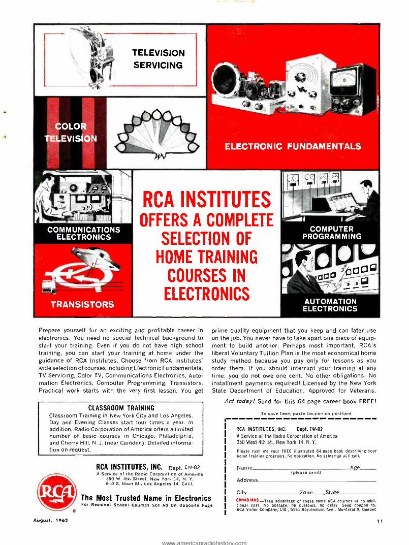
RCA INSTITUTES OFFERS A COMPLETE
SELECTION OF
HOME TRAINING
COURSES IN
ELECTRONICS
Prepare yourself for an exciting and profitable career in
electronics. You need no special technical background to start your training. Even if you do not have high school training, you can start your training at home under the guidance of RCA Institutes. Choose from RCA Institutes' wide selection of courses including Electronic Fundamentals, TV Servicing, Color TV, Communications Electronics, Auto- mation Electronics, Computer Programming, Transistors. Practical work starts with the very first lesson. You get
CLASSROOM TRAINING Classroom Training in New York City and Los Angeles. Day and Evening Classes start four times a year. In
addition, Radio Corporation of America offers a limited number of basic courses in Chicago, Philadelphia, and Cherry Hill, N. J. (near Camden). Detailed informa- tion on request.
RCA INSTITUTES, INC. Dept. EW -82 A Service of the Radio Corporation of America
350 W. 4th Street, New York 14, N. Y. 610 S. Main St., Los Angeles 14, Calif.
The Most Trusted Name in Electronics
prime quality equipment that you keep and can later use on the job. You never have to take apart one piece of equip- ment to build another. Perhaps most important, RCA's liberal Voluntary Tuition Plan is the most economical home study method because you pay only for lessons as you order them. If you should interrupt your training at any time, you do not owe one cent. No other obligations. No installment payments required! Licensed by the New York State Department of Education. Approved for Veterans.
Act today! Send for this 64 -page career book FREE!
For Resident School Courses See Ad On Opposite P,:ge
To save time, paste coupon on postcard
RCA INSTITUTES, INC. Dept. EW-82
A Service of the Radio Corporation of America 350 West 4th St., New York 14, N. Y.
Please rush me your FREE illustrated 64 -page book describing your home training programs. No obligation. No salesman will call.
Name Age (please print)
Address
City Zone State CANADIANS -Take advantage of these same RCA courses at no addi- tional cost. No postage, no customs, no delay. Send coupon to: RCA Victor Company, Ltd., 5581 Royalmount Ave., Montreal 9, Quebec
11
www.americanradiohistory.comwww.americanradiohistory.com

'r
ÉWLb fri .1(I)IO l'l :Hl)( L'IS TESTED In' HIRSCH-HOCCK LABS
T -200 "Gyro /Spension" Turntable "Knight" KN -4001B Tape Preamplifier Fisher KS -1 "Slim- Line" Speaker System (page 16)
Eico Model 955 Capacitor Tester (page 72)
ESL T -200 "Gyro /Spension" Turntable For copy of manufacturer's brochure, circle No. 57 on coupon t page 96).
THE ESL T -200 is a four -speed, belt - driven turntable with a simple and
foolproof design. The turntable is cast aluminum, weighing four pounds. Its spindle rests on a ball thrust hearing and rotates in low -friction graphite sleeve bearings.
The T -200 is driven by a four -pole motor with the removable drive capstan slipping onto the motor shaft. There are two interchangeable capstans, one for 33/45 rpm and one for 16/78 rpm. The rubber belt couples the motor di- rectly to an undercut portion of the turntable rim. Either of the two speeds on each capstan is selected by pushing the belt onto the upper or lower section of the capstan while the turntable is running. A metal cover hides the motor and belt during operation.
The T -200 has a rather novel motor mounting system, which is being paten- ted by the manufacturer. The motor is suspended on three soft rubber vibra- tion isolators. Two of them are elevated on a bracket which puts them in the plane of the capstan and the turntable rim. Because of this, the pull of the belt does not tend to tilt the motor.
With the motor remaining upright, the belt always runs true on the capstan, with no tendency to shift up or down or to slip.
The measured speed of the ESL T -200 was nearly exact ( very slightly slow at 331Já rpm). Li was unaffected by line - voltage variations from 90 to 130 volts. There was ample torque to overcome the frictional drag from any usable stylus force. The vertical rumble was -36 db and the lateral rumble was -46 db, measured according to the NAB standards. Flutter was very low, 0.085!; ,
and wow averaged 0.1 "; with an occa- sional peak of 0.2',;. The external hum field from the motor was very low. (Editor's Note: According to the man- ufacturer, the rumble figures indicate that the rubber isolators in the drive system may have been deformed slightly in shipping and the drive should be re- aligned. New instruction sheets, not available at the time this early produc- tion model was tested, explain this im- portant adjustment to the user.)
The T -200 turntable sells for $54.95. A walnut base is available for $9.95. It is also available, as the ESL C -71 "Con- cert Series" playback unit. complete with a mounted ESL S -2000 arm and "Red Head" cartridge. for $119.45.
"Knight" KN -4001B Tape Preamplifier For Copy of +aunularlu,cr's brochure, circle No. 58 ou coupon ( page 96).
SEVERAL manufacturers offer tape- transport mechanisms with various
head groupings, but without amplifiers. These cost much less than complete re- corders and are often used when only playback is required. Equalization is supplied by a regular stereo preampli- fier /control center.
The addition of a record 'playback preamplifier, including a bias and erase oscillator, converts a basic tape trans- port into a complete tape recorder. The Allied Radio "Knight" KN -1001ß is such a preamplifier, featuring in ad- dition to considerable operating flexi- bility, a full complement of adjustments affecting equalization, recording cur- rent, bias current, and erase current. These adjustments are vital to obtain- ing maximum performance from any tape transport and are a virtual neces- sity in a preamplifier designed for gen- eral application.
The KN -4001B contains four inde- pendent ampliters, two for playback and two for recording. A single slide :witch controls recording and playback equalization of both channels. for either 3.75 -ips or 7.5 -ips tape speed. The re-
12
cording amplifiers have high -level and low -level (microphone) inputs, with separate concentric level controls. Slip clutches allow differential adjustment of gain as well as simultaneous control of both channels. The inputs and out- puts are in the rear of the amplifier, except for the microphone jacks which are on the front panel.
The playback amplifiers also have concentric level controls, with a pair of standard phone jacks on the front panel for monitoring purposes. A slide switch permits monitoring the signal before recording or from the playback heads. In three -head machines, the latter po-
sition can be used for monitoring from the tape as the recording is being made.
There are two illuminated level me- ters, which indicate either recording or playback level, depending on the posi- tion of the monitor switch. There is also a switch which, with three -head ma- chines, permits making multiple (sound - on- sound) recordings by connecting the playback output of the left channel to the recording amplifier of the right channel. The usual external signals may be simultaneously reCorded on the right channel. Another setting of this switch connects the output of the left playback amplifier to the input of the left recording amplifier. This adds an echo effect to a recording as it is being made. The front -panel control comple- ment is completed by a six- position se-
ELECTRONICS WORLD
www.americanradiohistory.comwww.americanradiohistory.com
F.C.0 COMMERCIAL OPERATOR
LIC ;NSE F. C. C. LICENSE - KEY TO BETTER JOBS
An F. C. C. commercial (not amateur) license is your ticket to higher pay and more interesting employment. This license is Fed- eral Government evidence of your qualifications in electronics. Employers are eager to hire licensed technicians.
WHICH LICENSE FOR WHICH JOB? The THIRD CLASS radiotelephone license is of value primarily
in that it qualifies you to take the second class examination. The scope of authority covered by this license is extremely limited.
The SECOND CLASS radiotelephone license qualifies you to install, maintain and operate certain radiotelephone equipment but not commercial broadcast station equipment.
The FIRST CLASS radiotelephone license qualifies you to in- stall, maintain and operate every type of commercial radiotele- phone equipment including all radio and television stations in the United States, its territories and possessions. This is the highest class of radiotelephone license available. Many companies which employ industrial electronics technicians require this license.
GRANTHAM TRAINING PREPARES YOU The Grantham Communications Electronics Course prepares
you for a FIRST CLASS F. C. C. license, and it dOes this by TEACHING you electronics. Each point is covered simply and in detail, with emphasis on making the subject easy to understand. The organization of the subject matter is such that you progress, step -by -step, to your specific objective -a first class F. C.C. license.
CORRESPONDENCE OR RESIDENCE CLASSES Grantham training is available by correspondence or in resi-
dent classes. Either way, you are trained quickly and well. Write, or mail the coupon below, to any division of Grantham School of Electronics. Our free booklet will be sent to you immediately.
FOUR SCHOOLS TO SERVE YOU To better serve our many students throughout the entire coun-
try, Grantham School of Electronics maintains four Divisions - located in Hollywood. California; Kansas City, Mo.; Seattle, Wash.; and Washington, D.C.
GRANTHAM SCHOOL OF ELECTRONICS
This book /et
FREE!
This free booklet gives details of our training and explains what an F.C.C. license can do for your future.
VA
Upgrade Your Income with a First Class
F. C. C. LICENSE HERE'S PROOF.., that Grantham students prepare for F.C.C. examinations in a minimum of time. Here is a list of a few of our recent graduates, the class of license they got, and how long it took them:
License Weeks James C. Bailey, 217 Behrends Ave., Juneau, Alaska 1st 12 Edward R. Barber, 907 S. Winnitred, Tacoma, Wash. 1st 20 M. A. DIII, Jr., 20 Cherry St., Gardiner, Maine 1st 12 Bernhard G. Fokken, Route 2, Canby, Minn. 1st 12 Kenneth F. Foltz, Broad St., Middletown, Md. 1st 12 James C. Greer, Mound City, Kansas 1st 12 Thomas J. Hoof, 216 S. Franklin St., Allentown, Pa. 1st 22 Clyde C. Morse, 7505 Sharronlee Dr., Mentor, Ohio 1st 12 Louis W. Pavek, 838 Page St., Berkeley 10, Calif. 1st 16 Wayne Winsauer, 2009 B St., Bellingham, Wash. 1st 12
IAccredited by the National Home Study Council
MAIL COUPON TO SCHOOL NEAREST YOU
HOLLYWOOD
CALIF.
SEATTLE
WASH.
KANSAS CITY
MO.
WASHINGTON
D. C.
August, 1962
1505 N. Western Ave. 2
Hollywood, Calif.
408 Marion Street Seattle, Wash.
iMA 2.2221!
3123 Gillhorn Rood Kansas City, Mo.
.JE 1-6320.
T 821 - 19th Street, N. W
Washington, D. C. 3.3614.
(Mail in envelope or paste on postal card) 1
To: GRANTHAM SCHOOL OF ELECTRONICS 1505 N. Western
Hollywood e 408 Marion 3123 G,Ilham Rd. 521.19th, NW
Seattle e
Kansas City e Washington
Gentlemen: Please send me your free booklet telling how I can get my commercial F. C. C. license quickly. I understand there is no obligation and no salesman will call.
Name
Address
City ._
I am interested in:
Age
State 1
Home Study, Resident Classes ao E
J 13
www.americanradiohistory.comwww.americanradiohistory.com
BUY THIS GET THIS FREE
MASTER CARTRIDGI
SUBSTITUTION GUIDEBOOK by JACK STRONG
RIDER publication
POWERFUL PROFIT- PRODUCING COMBINATION -YOURS FROM SONOTONE
What a profit- making combination - the industry's finest replace- ment cartridges in the new, handy Sonotone 6 -PAK plus the new Rider "Master Cartridge Substitution Guidebook" (regularly $2.00), for the price of the cartridges alone. This guidebook, world's greatest source of cartridge replacement data, enables you to locate the exact or equivalent replacement for nearly every record player manu- factured since 1930. HERE'S HOW TO GET YOUR FREE GUIDEBOOK - Visit your distributor and select any 6 Sonotone cartridges. Or choose one of the pre -selected 6- PAK combinations that include the most needed cartridges for the most frequent replacements. With your purchase, your distributor will
14
give you a valuable coupon - one for every six Sonotone cartridges. Mail the coupon to Sonotone Corp., Electronic Applications Division, Elmsford, New York. You'll re- ceive your free Rider "Master Car- tridge Substitution Guidebook" by return mail. It will make your stock of Sonotone cartridges more valuable than ever before.
Visit your parts distributor today. Order a Sonotone 6 -PAK - and re- ceive your valuable "Cartridge Substitution Guidebook" Coupon. (This offer expires Aug. 15, 1962).
ELECTRONIC APPLICATIONS DIVISION
SONOTONE ® CORPORATION Elmsford, New York Canada: hies Radio Coro. ltd., Toronto
Cartridges Speakers Tape Benda Microphones Electron Tube. Batteries Bearing Aids
lector switch which provides either recording or playback on left channel. right channel, or both channels simul- taneously. A red light on the panel glows when the switch is in any of the record positions.
The bias,'erase oscillator is a push - pull type operating at a nominal fre- quency of 65 kc. It has a balance adjust- ment to minimize harmonic content and resulting distortion. On the rear of the chassis are adjustments for setting the recording and erase bias currents, as well as the recording signal current de- livered to the heads. There are four in- dividual adjustments of high -frequency recording equalization for each channel and tape speed. These match the am- plifier frequency response to the head characteristics for optimum high -fre- quency response.
The preamp uses nine dual triodes. plus silicon rectifier power supplies for plates and all tube heaters. The power switch controls two a.c. convenience outlets on the rear of the chassis which may be used to power the tape trans- port and power amplifiers.
The KN -4001B is available factory - wired or in kit form. (The unit we tested was factory wired.) It is a rather complex unit, which we imagine would take a good many hours to construct. Printed boards are used for much of the circuitry. The instruction manual is thorough in its description of the vari- ous modes of operation possible with this amplifier. and its application to various makes of tape decks. Set -up ad- justments are simplified by listing rec- ommended settings for the recording current, bias current. and erase current for a number of popular tape decks such as the "Knight" KN -4000 and KN- 4200. the Vikinfi 85 series. and the Sony 262D. Setting the bias currents for these machines is clone with the aid of the preamplifier's level meters. which can be switched to read bias levels. Com- plete instructions are also given for setting up the proper operating condi- tions with decks of unknown character- istics.
We tested the KN -4001B in conjunc- tion with the "Knight" KN -4000 tape transport (reported on in last month's issue), a three -head machine capable of utilizing the full flexibility of the pre- amplifier. Similar results should be ex- pected with other machines of compar- able quality.
The playback system was tested with the NCB Laboratories' 7.5 -ips alignment and NAB equalization test tape. The azimuth of the playback heads was aligned for best high- frequency re- sponse from this tape. which then yielded a playback frequency response within 4- 3.5 db from 50 to 15.000 cycles - per- second.
The recording heads were then aligned to match the playback heads (actually, all the heads were in good alignment as received). A series of tones was recorded at 20 db below maximum recording level and played hack to oh- tain an over -all frequency response. This was a smooth curve within 3 db from 30 to 13.500 cps at 7.5 ips. Inter- estingly enough, the response at 3.75 ips
ELECTRONICS WORLD
www.americanradiohistory.comwww.americanradiohistory.com

Brand New From Lafayette The All New HE -29B 10- Transistor
Citizens Band Walkie Talkie With
Additional RF Stage - 50% More Powerful For Greater
Sensitivity And Distance
1ALKIE TALKIE" 1M.
Ideal for Sportsmen - Boating - Fishing - Camping
s.
Transmits & Receives up to 2 miles Crystal Controlled on Both Transmit & Receive Push -to -Talk Operation 46" Telescoping Antenna Earphone For Personal Listening
Now Lafayette has done it again. The world Famous HE -29 has been further improved. Packed with power, 10 handpicked transistors plus 1 diode extend the range of the HE -29B up to two miles under average conditions i.e., no intervening obstructions. No license or permit required. Compact, pocket size unit provides complete portable two way communications. Transmitter section is crystal controlled. Crisp, clear reception is furnished by the efficient superheterodyne receiver. Power is supplied by 8 miniature stand- ard penlight batteries with a life expectancy of up to 50 hours. Housed in a handsome black and chrome case. Supplied with leather carrying case w /shoulder strap, earphone, antenna, batteries and crystals for channel 10. Size: 6a/ex31 /4x1s /e ". Shpg. wt., 3 lbs. HE -29BL Net 39.95 Set of 2 Net 78.88
3995 NO MONEY DOWN
SET OF 2 -78.88
Dual NARTB Equalized Transistor Preamps Frequency Response: 50- 15,000 CPS @ 71/2 ips Plays back: 1/4 & 1/2 Track Stereo; 1/2 Track & Full Track Monaural
LAFAYETTE'S NEW MAIL ORDER HEADQUARTERS
111 JERICHO TURNPIKE (2 Blocks West of South Oyster Bay Rd.)
SYOSSET, LONG ISLAND, NEW YbRK
JAMAICA, N. Y. 165-08 Liberty Ave.
NEW YORK, N. Y. 100 - 6th Ave. BRONX, N. Y.
542 E. Fordham Rd. BOSTON, MASS. 110 Federal St. NEWARK, N. J. 24 Central Ave.
PLAINFIELD, N. J. 139 W. 2nd St.
PARAMUS, N. J. 182 Route 17
August, 1962
New Lafayette 2 -Speed Stereo
Playback Tape Deck
Complete With Built -In 6- Transistor Dual Playback Preamps
FOR LESS THAN THE PRICE OF A RECORD CHANGER!
Now you can enjoy the superlative reproduction and fidelity of prerecorded tape at the price you'd expect to pay for a record changer. Precision engineered, the RK -141 is equipped with its own 6- transistor stereo preamplifiers designed to play back 1/4 track and 1/2 track stereo plus 1/2 track and full track monaural tape with true NARTB hi -fi tape equalization. Its tape handling mechanisms and heads are of a type found in costlier units. Accepts all size reels to 7 ". Measures 10%Dx143/43Wx5 "H. Complete with cables. RK -141WX Shpg. wt., 17 lbs Net 59.50 RK -148W Furniture Grade Walnut Base. Wt., 4 lbs. Net 6.95 RK -147W Portable Carrying Case. Wt., 5 lbs. Net 9.95
5950 NO MONEY DOWN
LAFAYETTE RADIO DEPT.RH -2 P.O. BOX 10, SYOSSET, L. I., N. Y.
D Rush my FREE Lafayette Summer Catalog Supplement
0 Please send me _ Shipping Charges ,Collect
I am enclosing S
FREE!
SUMMER
Name
Address
City Zone State J
15
www.americanradiohistory.comwww.americanradiohistory.com

Mutticore Sales Corp. Port Washington, NY,
For information. write Department MK 42
Ask By Name For GENUINE
your assurance of brand name quality
was flatter and almost as wide as at 7.5 ips, within ` 3 db from 30 to 9000 cps. On one channel the high -frequency re- sponse was not quite as good, which may have been due either to the pre- amplifier or to the heads.
The hum level was 43 db below maxi- mum recording level on one channel and only 30 db down on the other channel. This may have been due to a defective tube or component, but we did not at- tempt to locate the trouble. The stereo crosstalk at 1 kc. was below the hum level. The bias oscillato frequency was approximately 61 kc.
The listening quality of the preamp was excellent. In A -B comparison against the original program, no differ- ence could be heard when recording from FM stereo broadcasts. When wide - range phonograph records were used. the slight loss of highs in the tape re-
o W (D 20 z O +5 LL
corder could be detected, but only on direct comparison. There was no audible distortion and negligible increase in noise level.
The use of a separate amplifier and tape mechanism, which has certain ad- vantages, also has its hazards. There is no interlock between the recording bias oscillator and the tape transport. mak- ing it very easy to accidentally erase a tape. The warning light on the KN- 4001B is near the brightly lighted level meters and is easily overlooked. A much more prominent recording light. or one which could be mounted directly on the tape deck itself, would be more de- sirable.
The "Knight" KN -4001B sells for $139.95 factory -wired or $89.95 in kit form. A portable case capable of mount- ing the amplifier and the KN -1000 tape transport sells for $24.95.
+5.
-6
,
I.-:U-11 . .: _i . I . ( ; PLAYBACK RESPONSE
1 ( I
A ... ... _ .... ....... .... . ._..._
1 `.,-`
UI W
5
-10
50 100 200 sO0 IKC 2KC. EXC. tOKC. 20KC.
pm -1i
!IIII 111111 -__ = : 1 _ - 3761PS MI Mai I - OVER -ALL RECORD /PLAYBACK RESPONSE RE -^ -- - -'-'
FREOUENCY-CPS
Fisher KS -1 "Slim- Line" Speaker System For copy of Ma brochure. circle No. 59 on coupon (page 96).
L
OA
ti
FREE 01 with
ELECTRONIC
o Q CEMICAL s-
5" PLASTIC
EXTENDER Push butto,. AssenbilY For
Pin Point A onlic.,t ions -D OeS Not C.ms, Shorts
EleCtroniC Chemical n
tOnnul new .,
EC-44 Lubricates. CCnS álÌ Ih electrical
Contacts. Eco- Cal .
little lot7 . $350 C.,aY
ELECTRONIC CHEMICAL CORP. 813 Commun.pew Avenue Jersey City 4, N. J.
16
NOvV that bookshelf -sized speakers are an accepted part of the high -
fidelity scene, it seems that there is a trend toward even less conspicuous speakers. Some of these might be termed "slim" enclosures. whose depth is reduced to the point where they hardly protrude into the room. or may even be hung on the wall like a picture.
The new Fisher KS -1 "Slim- Line" speaker system belongs in this cate- gory. It is a three -way system, with full -sized speakers (not a cluster of small drivers), measuring only 15" x
24" x 5)tí" deep. It can stand on the floor (legs are available if desired) or hung on the wall. The KS -1 is available in kit forni with an unfinished enclo- sure or factory assembled.
The woofer is a 10" unit. with a com- pliant suspension. an 8 -ohm 1'z" di- ameter voice -coil. and a 4t_ -pound mag- net assembly. The frequencies from 1400 to 5000 cps are handled by a 5" cone speaker. The space behind its cone is packed with glass fiber damping ma- terial and it is fully enclosed in the rear to prevent the backwave from the woofer from interfering with its action.
A small 3" diameter cone tweeter carries the frequencies above 5000 cps. Like the mid -range speaker, it is fully enclosed and packed with clamping ma- terial. The three -way crossover net- work is contained within the enclosure. and has no level controls. The crossovers are gradual. with slopes of 6 db per oct ave.
The KS -1 kit is supplied with the wooden cabinet frame fully assembled. The speakers must be mounted on the front panel and wired to the pre- assem- bled crossover network. A tubular col- umn is glued between the front and rear panels to provide stiffening. A
sheet of glass fiber loosely fills the en- closure to damp internal resonances. The entire assembly took us about one hour. Even a neophyte should not re- quire more than two hours to build it.
The frequency response of the KS -1 is rated at 40 to 18.500 cps. In our fre-
(Coaltinucrl on pane 72)
ELECTRONICS WORLD
www.americanradiohistory.comwww.americanradiohistory.com
r eeSEND TODAY FOR
YOUR MONEY-SAVING
464 -PAGE
4111/Eli 1963 CATALOG
featuring the
new 1963
LLIEn DO
S ECTRpnII re ELECT
evergo
1963 our
CpTA1 Oß ZZD
INO9x. aoS ,Ee
mail now
411011, F 410 P ©
R .L L C 1 r 0
rao. A .,- -.oE
I M,MaTaww ^va. . cw,
MY Sack
Satisfaction OW
Your M9 rantead
or
SEND FOR IT NOW!
WORLD'S LARGEST ELECTRONICS CATALOG
BIGGEST SELECTION BIGGEST SAVINGS!
satisfaction guaranteed or your money back
NO MONEY DOWN: OVER W. MORE BUYING POWER WITH
YOUR ALLIED CREDIT FUND PLAN
For your FREE 1963 ALLIED Catalog, fill in card, detach and mail. (Please give second card to an interested friend.)
SEND CARD TODAY
now I
x
m
ó N
QLuEa ELECTRONIC9
OUR
LL D 63 CATALOG
o o I.
ALLIED ELECTRONICS
' ^ 1993 itlaw e i .
YOUR
LL/ED 63 CATALOG
www.americanradiohistory.comwww.americanradiohistory.com

ö o z
m rA -I m
z
m
o
FreeyOSTOENDDAYCFAORRDE
/.ILL /ED 1963 CATALOG
WORLD'S LARGEST BIGGEST SELECTION BIGGEST SAVINGS
1963 knight -kits Over 100 great do -it- yourself kits: Hi -Fi, Hobby, Intercom, Am- ateur, Citizens Band, Instrument- savings up to 50%.
Stereo Hi -Fi Complete selection of components and sys- tems; latest All -Tran- sistor equipment and Stereo Multiplex FM.
"a' Complete recorders, tape decks, recording and pre- recorded tapes at big savings.
Tape Recorders
O o z
m
m
z
m
o
2 m
m
iliD I!` T (
.
I
15I
Transistor, FM -AM Radios Best buys in all types of compact transistor radios, including quality FM -AM portables.
Citizens Band Radios Latest 2 -way radio -no exam required -com- plete selection of top - value CB equipment, in- cluding Walkie- Talkies.
840 Phonographs & Records
Big values in phono- graphs; latest stereo portables; famous - brand records at amaz- ing discounts.
Ham Station Equipment Largest selection of receivers, transmitters, antennas -everything in Ham station gear.
Test Equipment Save on every type of instrument for home or professional use -all leading makes available.
rH PLUS PA Systems & Intercoms Top values in Power Tools, Soldering Guns, Hardware
Biggest selection of TV Tubes, Antennas; Parts, Tubes, Transistors, Books
satisfaction guaranteed or your money back NO MONEY DOWN: Over 50% More Buying Power with Your Allied Credit Fund Plan!
UR 1963 ALLIED CATALOG
www.americanradiohistory.comwww.americanradiohistory.com
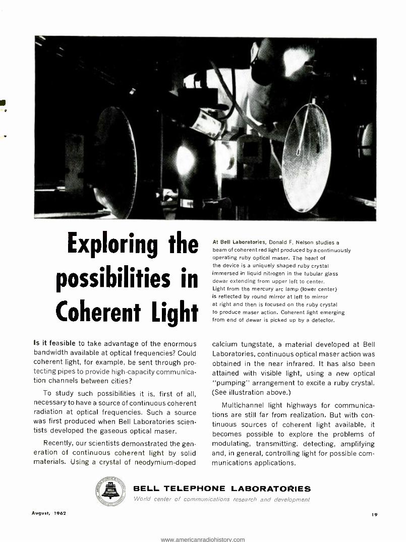
Exploring the
possibilities in
Coherent Light Is it feasible to take advantage of the enormous bandwidth available at optical frequencies? Could coherent light, for example, be sent through pro- tecting pipes to provide high- capacity communica- tion channels between cities?
To study such possibilities it is, first of all, necessary to have a source of continuous coherent radiation at optical frequencies. Such a source was first produced when Bell Laboratories scien- tists developed the gaseous optical maser.
Recently, our scientists demonstrated the gen- eration of continuous coherent light by solid materials. Using a crystal of neodymium -doped
At Bell Laboratories, Donald F. Nelson studies a
beam of coherent red light produced by a continuously operating ruby optical maser. The heart of the device is a uniquely shaped ruby crystal immersed in liquid nitrogen in the tubular glass dewar extending from upper left to center. Light from the mercury arc lamp (lower center) is reflected by round mirror at left to mirror at right and then is focused on the ruby crystal to produce maser action. Coherent light emerging from end of dewar is picked up by a detector.
calcium tungstate, a material developed at Bell
Laboratories, continuous optical maser action was obtained in the near infrared. It has also been attained with visible light, using a new optical "pumping" arrangement to excite a ruby crystal. (See illustration above.)
Multichannel light highways for communica- tions are still far from realization. But with con- tinuous sources of coherent light available, it
becomes possible to explore the problems of modulating, transmitting, detecting, amplifying and, in general, controlling light for possible com- munications applications.
BELL TELEPHONE LABORATORIES World cenlur or comm,,nijdv,ons rocarc;; <nú do.o/apr.enl
August, 1962 19
www.americanradiohistory.comwww.americanradiohistory.com
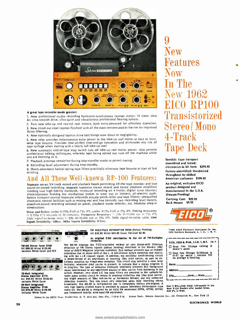
A great tape recorder made greater: 1. New professional studio recording hysteresis- synchronous capstan motor: 24 stator slots for ultra- smooth drive, ultra -quiet and vibrationless professional bearing system.
2. Two new take -up and rewind reel motors, both extra -powered for effortless operation.
3. New cored -out steel capstan flywheel with all the mass concentrated at the rim for improved flutter filtering. 4. New optimally designed capstan drive belt brings wow down to negligibility.
5. New relay provides instantaneous extra power to the take -up reel motor at start to mini- mize tape bounce. Provides near -perfect stop- and -go operation and eliminates any risk of tape spillage when starting with a nearly full take -up reel.
6. New automatic end -of -tape stop switch cuts off take -up reel motor power. Also permits professional editing techniques, whereby tape being edited out runs off the machine while you are listening to it 7. Playback preamps remain -on "during stop- standby mode to permit cueing.
8. Recording level adjustment during stop- standby.
9. Shock- absorbent helical spring tape lifters practically eliminate tape bounce at start of fast
winding.
And All These Well - known RP -100 Features: Separate stereo 1/4 track record and playback heads permitting off -the -tape monitor and true sound -on -sound recording; separate transistor stereo record and stereo playback amplifiers meeting true high fidelity standards; monaural recording on 4 tracks; digital turns counter; electrodynamic braking (no mechanical brakes to wear out or loosen); all- electric push- button transport control (separate solenoids actuate pinch -roller and tape lifters); unequalled electronic control facilities such as mixing mic and line controls, two recording level meters, sound -on -sound recording selected on panel, playback mode selector, etc. Modular plug -in construction.
Wow and flutter: under 0.15 °%o RMS at 71/4 IPS; under 0.23/4 RMS at 33/4 IPS. Timing Accuracy: 0.15 ° /o (`3 seconds in 30 minutes). Frequency Response: ± 2db 10- 15,000 cps at 71/2 II'S,
55db signal -to -noise ratio: _`- 2db 30- 10,000 cps at 33/4 IPS, 50db signal -to -noise ratio. Line
Inputs Sensitivity: 1O0niv. Mike Inputs Sensitivity: O.Smv.
9 New Features Now In The New 1962 EICO RP100 Transistorized Stereo I Mono 4-Track Tape Deck Semikit: Tape transport assembled and tested; electronics in kit form $299.95
Factory -assembled: Handwired throughout by skilled American craftsmen $399.95
An original, exclusive EICO product designed and manufactured in the U.S.A. (Patents Pending)
Carrying Case $29.95 Rack Mount $9.95
20
:0 FMAM Stereo Tuner ST96 Kit $89.95 Wired $129.95 Includes Metal Cover and FET
ou
ti rj ) :3 i ": ,: 70 -Watt Integrated Stereo Amplifier ST70 Kit $99.95 Wired $149.95 Includes Metal Cover 40 -Watt Integrated Stereo Amplifier ST40 Kit $79.95 Wired ;129.95 Includes Metal Cover
FM MULTIPLEX AUTOOAPTOR MX99 (Patent Pending)
Kit $39.95 Wired $64.95 Cover Optional $2.95
An original FICO contribution to the art of FM- Multiplex reception
The MX -99 employs the EICO- originated method of zero phase -shift filterless detection of FM Stereo signals (patent pending) described in the January 1962
issue of AUDIO Magazine (reprints available). This method prevents loss of channel separation due to phase shift of the L R sub -channel before detection and matrix - ing with the L +R channel signal. In addition, the oscillator synchronizing circuit is phase -locked at all amplitudes of incoming 19kc pilot carrier, as well as ex-
tremely sensitive for fringe -area reception. This circuit also operates a neon lamp indicator, whenever pilot carrier is present, to indicate that a stereo program is
in progress. The type of detection employed inherently prevents SCA background music interference or any significant amount of 38kc carrier from appearing in the output. However, very sharp L -C low pass filters are provided in the cathode -fol- lower audio output circuit to reduce to practical extinction any 19kc pilot carrier, any slight amounts of 38kc sub -carrier or harmonics thereof, and any undesired detection products. This can prove very important when tape recording stereo broadcasts. The MX -99 is self -powered and is completely factory pre- aligned. A
very high quality printed board is provided to assure laboratory performance from every kit. The MX -99 is designed for all FICO FM equipment (ST96, HFT90, HFT92)
and component quality, wide -band FM equipment.
Listen to the EICO Hour. WAIIC -FM. N. Y. 95.5 MC. Mon.Fri.. 7:15-8 P.M. Export Dept.. Roburn Agencies
*1962 E ICO Electronic Instrument Co. I ne.
3300 Northern Boulevard. L. I. C.. I. N. Y.
FICO, 3300 N. Blvd., L.I.C. 1, N.T. Ev
Send free 32 -page catalog &
dealer's name
Send new 36 -page Guidebook to HI -FI for which I enclose 25C for postage & handling.
L
Name
Address
City Zone - State-
Over 2 MILLION EICO Instruments In use.
Nest EICO Dealers offer budaet terms. Add 5% In West.
Inc.. 431 Greenwich St., New York 13
ELECTRONICS WORLD
www.americanradiohistory.comwww.americanradiohistory.com
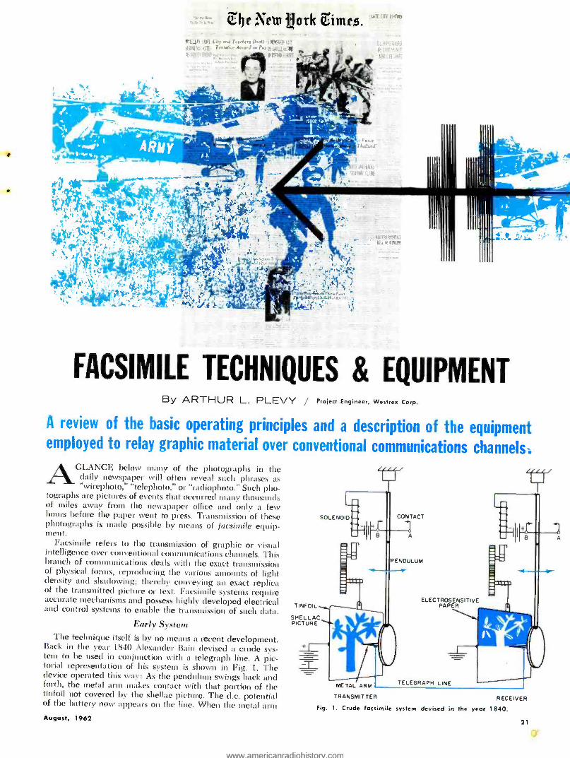
The Ncm ¡fork ,imc,s.
FACSIMILE TECHNIQUES & EQUIPMENT By ARTHUR L. PLEVY / Project Engineer, Westrex Corp.
A review of the basic operating principles and a description of the equipment employed to relay graphic material over conventional communications channels.
AGLANCE below many of the photographs in the daily newspaper will often reveal such phrases as "wirephoto," "telephoto," or "radiophoto." Such pho-
tographs are pictures of events that occurred many thousands of miles away from the newspaper office and only a few hours before the paper went to press. Transmission of these photographs is made possible by means of facsimile equip- ment.
Facsimile refers to the transmission of graphic or visual intelligence over conventional communications channels. This branch of communications deals with the exact transmission of physical forms, reproducing the various amounts of light density and shadowing; thereby conveying an exact replica of the transmitted picture or text. Facsimile systems require accurate mechanisms and possess highly developed electrical and control systems to enable the transmission of such data.
Early System The technique itself is by no means a recent development.
Back in the year 1840 Alexander Bain devised a crude sys- tem to be used in conjunction with a telegraph line. A pic- torial representation of his system is shown in Fig. 1. The device operated this way: As the pendulum swings back and forth, the metal arm makes contact with that portion of the tinfoil not covered by the shellac picture. The d.c. potential of the battery now appears on the line. When the metal aim August, 1962
TINFOIL ti^ SHELLAC PICTURE
ELECTROSENST PAPER
TELEGRAPH LINE
TRANSMITTER RECEIVER
Fig. 1. Crude facsimile system devised in the year 1840.
21
www.americanradiohistory.comwww.americanradiohistory.com

DRUM AND COPY TO BE TRANSMITTED
FREQUENCY STANDARD
ELECTRICAL UNIT
MECHANICAL UNIT
A high -speed facsimile transmitter that will send full -size newspaper pages over video lines in less than 4 min. o page.
touches the shellacked portion, no d.c. appears on the line. At the receiving end, another pendulum moves in syn-
chronism with the one at the transmitting end. When the battery's d.c. appears on the receiver contact arm, it burns it mark on an electrosensitive paper. When the transmitting metal arm is insulated by the shellac, no d.c. is transmitted and the paper at the receiving end is not marked. In this way the picture or text is reproduced. As the pendulum completes each arc, it touches contacts A and B. These actuate a mech- anism which lifts the tinfoil and the sensitive paper a slight amount, enabling the pendulum to transverse and record another line.
Bain's system was followed and improved upon by other men and manufacturers. Some of the more notable achieve- ments were those of Casselli of Italy and Korn of Germany. Companies like A. T. & T., RCA, Times Facsimile, and others improved the process and made facsimile available to the public.
At present there is an impressive variety of facsimile equipment available but the most widely used system, and the one to be discussed here, is that using the drum -type receiver and transmitter. Any facsimile system, whether it be the one devised by Alexander Bain or the most modern high -speed machine, has these things in common:
1..'t method of scanning the copy to determine the amounts of the Clark and light areas that are to be reproduced.
A facsimile recorder that is employed to print weather maps.
22
2. A method of moving the copy so that the entire copy is scanned and transmitted.
:3. A method of sending the information representing the scanned copy over conventional communications channels.
4. An accurate means of synchronizing the motion of the scanning systems both at the transmitting and at the receiving ends.
Simple Analogy Before we proceed any further, let's take a simple example
to illustrate the operation of a facsimile system. Let us take two indentical spools (Fig. 2). One spool has a single layer of thread around it upon which there is a picture painted: the other spool is empty. If we unravel the spool and look at the thread, we notice areas of different shading represent- ing portions of the original picture. If we take the empty spool and proceed, as shown, to wind the thread on it from the full spool, we would find the original picture transferred to the second spool of thread. The top spool in the illus- tration can be referred to as the "transmitter" and the bottom spool as the "receiver."
System Operation If reference is made to Fig. :3, we can see how the copy
PHOTOTUBE
MODULATOR
PRECISION MICROSCOPE OPTICAL SYSTEM
EXCITER LAMPS
FEEDSCREW
LENSES
The transmitter optical system. The modulator is mounted on
the optical -system carriage to minimize capacity and pickup.
is "unraveled" or scanned in an actual drum -type facsimile system. Such systems derive their name from the fact that the copy to be transmitted is wrapped around a drum. The exciter lamps illuminate an area at the surface of the drum. The light from these lamps is concentrated by means of lenses into a sharply focused spot of light. Light reflected from the copy is focused by means of an optical system onto the cath- ode of a phototube. The purpose of the aperture is to allow the phototube to see only a very small portion of the copy at a time so that picture definition is improved.
The phototube produces a d.c. level corresponding to the amount of light seen by its photo -cathode. Because of the fact that many communications channels cannot handle d.c. directly, the output of the phototube is used to modulate a carrier.
One such modulator is shown in Fig. 4. This type is called a "ring modulator." The circuit shown includes a phototube input and operates as follows. When the circuit is balanced and no light appears, there is no output from the system. When light appears on the photo -cathode of the tube, it causes a current to flow to the anode. This flow of current reduces the potential at the plate of the phototube. This change in voltage unbalances the bridge (changes the bias On the diodes) and alloys carrier signal to appear at the
ELECTRONICS WORLD
www.americanradiohistory.comwww.americanradiohistory.com

C
SPOOL D
EMPTY SPOOL
RECErvER
XI lll;;;;;"dl ( f ')pi swlhhII 1
IlI1IIÌiöö¡IIII II
'.\ 1\1N1\\\\NYP111'
(A) (a) (C) IDI
Fig. 2. Simple spools -of- thread analogy that illustrates the principles of scanning and facsimile transmission.
output. The signal is amplitude -modulated and the amount of modulation is strictly a function of the amount of light that the phototube sees, which naturally represents the amount of light that the copy reflects. By adjusting the bias on the diodes, one can balance the modulator in such a way that it is as easy to obtain a negative or a positive copy of the text at the receiver.
Synchronous Motors
Imagine what would occur in Bain's system if one pendu- lum moved slower or faster than the other. As one completed its arc the other might be only halfway through. This would cause markings to be made at the wrong position on the paper. The net result would be a total destruction of the information.
In most modern facsimile systems the drum is driven by a synchronous motor, whose speed is directly related to the frequency. Using stable frequency sources at both the trans- mitter and receiver assures that the drum at the transmitter rotates at the sanie speed as that at the receiver. If this were not so, a horizontal line would appear at the receiver with a significant slope. The phenomenon produced by different speeds of the drums at the receiving and transmitting sites is called "skew.,"
The same motor usually drives the scanning system by means of a feedscrew and proper gearing. If one optical system moved slower or faster than the other, the copy would
he enlarged or reduced in size. as the case might be. As can be seen from the diagram, the optical system moves parallel to the surface of the drum. The sharp spot of light and the revolving drum actually "unravel" the copy just as in the case of our spools -of- thread analogy.
Receiving System.
The output from the balanced modulator is amplified and transmitted through a conventional communications channel. This output could be sent over a radio link or a telephone line. The signal is thus sent to the receiver location where it is detected and amplified. The detected signal is feci into a power amplifier which has a stylus on its output. When the stylus is energized, it makes a mark on an electrosensitive paper and gives a direct reproduction of the transmitted text. This copy is usually not suitable for the reproduction of very fine detail as the stylus has a finite diameter and is unable to clearly reproduce fine text.
In high- definition systems photographic film and a light modulator are employed. The lamp used (called a "crater lamp ") produces an intensity of light corresponding to the current energizing it. Fig. 5 is a block diagram of a receiver employing such a device. As can be seen from the diagram, the motor- control circuitry and the feedscrew and gear train are identical to those of the transmitter. The signal is taken from the communications channel and detected by a con- ventional peak detector. After detection, the original photo-
Fig. 3. Simplified block diagram of the circuits and electro- optical system employed in o modern facsimile transmitter.
PHOTOTUBE
APERTURE
EXCITER LAMP
OPTICAL SYSTEM
FEEDSCREW
11:A MJ a.l
i GEAR TRAIN
SYNCHRONOUS
MOTOR
August, 1962
FOCUSED COPY LIGHT SPOT
PHASE - PULSE
AMPLIFIER
1
CLAMP
TO LINE
DRUM
POWER 14 AMPLIFIER
CARRIER OSCILLATOR
MODULATOR
AMPLIFIER
v
TO LINE
STABLE OSCILLATOR
23
www.americanradiohistory.comwww.americanradiohistory.com

FROM PHOTOTUBE
40000011
./ 015-0-61)
e 0
- OUTPUT
Fig. 4. Circuit diagram of ring modulator.
Relay rock of electronic equipment re- quired for the facsimile transmitter.
tube signal is restored and this signal is then amplified and used to modulate the beam of light put out by the crater lamp.
This varying -intensity light beam is sharply focused, by means of an optical system, onto the film which is wrapped around the receiver drum. The varying light exposes the filin in accordance with the amount of light and dark on the original copy. Hence, after a transmission is completed, one has a film of the original copy, which is then developed and used for further copies of the text. In this system the receiver has to be placed in a darkroom so as not to expose the film.
Before copy can be transmitted and restored, the drums at the transmitter and receiver have to be in- phase. Phasing insures that the copy will start at the beginning of the clamp and end at the correct point.
In this system, a phase- pickup bar is placed at the center of the clamp at the transmitter and at the center of the clamp
f- CARRIER -OSC. SUPPLY
-.CONTROL PANEL
-LINE AMPS.
-EXCITER--LAMP SUPPLY
I- FREQ. STD. AMPS.
I- DRUM DRIVER AMPS.
F -A.C. CKT. BREAKERS
PHASE -AMP. SUPPLY
PWR.- AMP. SUPPLY
at the receiver. Every time the bar passes the phase pickup, a pulse is produced. This pulse is amplified and, in the case of the transmitter, sent down the line before a transmission is to be made. The same events occur in the receiver -recorder where the pulse derived here is impressed on a comparator circuit. The pulse received from the transmitter is also ap- plied to the comparator. This circuit puts out a d.c. voltage when the pulses are displaced from each other, and this signal is used to shift the phase of the receiver motor. When the pulses are in- phase, there is no output from the com- parator, hence the drums are in -phase and the transmission can begin.
Applications Facsimile has played an increasingly important role in
the field of communications. A complete network of facsimile (Continued on page 93)
Fig. 5. Arrangement utilized In a facsimile recorder- receiver that produces a film negative of the received copy.
FOCUSED LIGHT SPOT
PHASE - PULSE
AMPLIFIER
FILM DRUM
PHASE PULSE FROM TRANSMITTER
i-k- COMPARATOR
GEAR TRAIN
SYNCHRONOUS
MOTOR
POWER
AMPLIFIER
PHASE
SHIFTER
f 1
VIDEO AMPLIFIER
_r-FL-FL
DETECTOR
FROM III TRANSMITTER
STABLE
OSCILLATOR
24 ELECTRONICS WORLD
www.americanradiohistory.comwww.americanradiohistory.com

STATUS OF COLOR TV
Newer and more handsomely housed color receivers plus increased programming may make this a 500,000 -set year for the industry.
AFTER eight full years of color television, the upcoming 1962 -63 season promises to be the biggest and best
» from every standpoint. With some ten or so firms now in production on color video sets and hundreds of hours of programming scheduled for the color cameras, those think- ing in terms of color set purchase never had a greater incen-
0. tive for going ahead with their plans. As indicated in the graph below, NBC alone is offering 68
per -cent of its night -time schedule in color. ABC, which has recently announced its entry into the field, has regular cartoon colorcasts on its schedule in addition to an as- vet -undeter- mined number of color films. CBS is still a hold -out in the color race but may be forced into it on a competitive basis. They have indicated that perhaps one or two "specials" will be telecast in color in the current season but that there will not be any regular color programming.
Since over 200 stations are equipped to handle color pro- gram material (live and network), as more and more of this type of material is fed into the lines, the pattern of color transmissions is expected to widen to include larger areas of the country.
As far as color receivers are concerned, the consensus is that between 800,000 and 1,200,000 sets are now in the hands of the public with between 170,000 and 175,000 sets sold last year. The Commerce Department estimates that this figure will increase by as much as 50 to 100 per -cent in the current year, while industry sources are predicting color sales in the 250,000- 500,000 range. A preliminary estimate for 1962 includes 200,000 sets for RCA, 100,000 for Zenith, from 50,000 to 75,000 for Admiral, and 50,000 for Warwick (mak- ing sets for Sears), and an over -all estimate of half a million receivers. This estimate in- cludes sets from Magnavox, Wells -Gardner (making sets for Montgomery Ward and other private -brand labels), Westinghouse Electric, General Electric. Emerson. Packard -Bell, Olympic, and Philco plus imported receiv- ers which will be marketed under the Delmonico brand - name.
RCA recently introduced its 1963 line to its distribu- tors and the press in an early showing. Aside from some re- arrangement of the chassis which permits reduc- tion of the over -all depth of the receiver, the most out- standing feature of the new line is the introduction of true furniture styling in the cabinets, eliminating the early `black box" appear- ance which characterized previous models.
Now available in hand- some wood finishes in a wide variety of furniture styles,
August, 1962
RCA is offering dec orator -designed hutches, breakfronts, and low -boys, some with FM -AM receivers and facilities for playing records. Some of the units are of open -front construc- tion while many of the sets in the line are equipped with doors to close off the picture tube when the set is not in use. (This was a common complaint from homemakers who ob- jected to the "blind eve" in their living minis.)
A plus feature in the new line is the fact that despite im- provements in circuitry and cabinet design, most of the new color sets will carry a lower price tag than comparable units of the previous year's line. The chassis has been re- designed to provide a shallower cabinet with less overhang of the color tube to the rear, making it possible to place the cabinet closer to the wall and in a less conspicuous position in the room.
The combination units provide stereo facilities -both record and broadcast -in addition to color reception, making the single cabinet serve as a complete entertainment center for the home.
Although there is widespread talk in the industry regarding the recently announced smaller, 90- degree color tube, sets marketed this fall %vill continue to include the current RCA color tube, with the new tube incorporated in next year's offerings at the earliest. In addition to RCA, Sylvania plans to resume the manufacture and marketing of color picture tubes. Present plans call for a 21 -inch, 90- degree round shadow -mask type tube. Tubes for Zenith sets (and others) will be supplied by Raldand. The Motorola- National Video 2:3 -inch rectangular 90- degree color tube won't be available for this year's models but there is hope that some sets can be so equipped by next fall.
NBC's night -time schedule for 1962 -63 will include an over -all total of 68 per -cent of its programs in color. Per -cent of color programs per night is shown in graph.
90 86%
so 81%
70 71 : 71'/. T14
SO in 62%
58%
:j. aot
t0 .
SUNDAY MONDAY TUESDAY WEDNESDAY THURSDAY FRIDAY SATURDAY
ESTIMATED TOTAL COLOR TV SETS SOLD FROM 1954 THROUGH 1961- 800,000- 1.200,000 ESTIMATED TOTAL COLOR TV SETS TO BE SOLD IN 1962 -500,000
Although the state of the general economy and the consumer's confidence in the future will intimately affect the color -TV set market, there is every indication that should the public continue buying durable goods at its present rate, the industry may come very close to meeting the estimates ad- vanced by various sources indicating record sales for color receivers.
One bright spot is that there should be less distaff resistance both because of the improved design of the receivers themselves and the increased programming (both daytime and evening) of a greater variety of mate- rial.
It now appears that after 8 long years, color TV is ready to assume its full role in the industry.
The circuits are ready, the programs are available and color can take off!
25
www.americanradiohistory.comwww.americanradiohistory.com
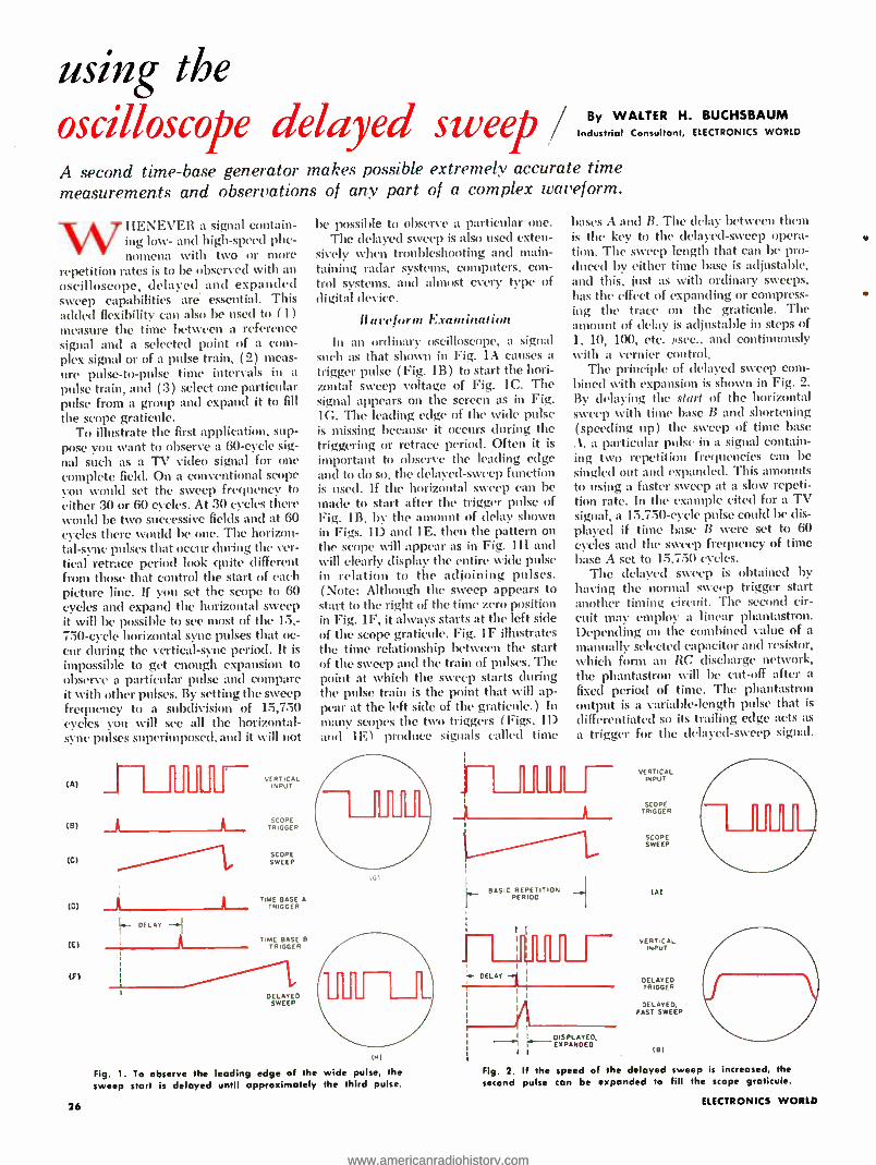
using the oscilloscope delayed sweep By WALTER H. BUCHSBAUM
Industrial Consultant, ELECTRONICS WORLD
A second time -base generator makes possible extremely accurate time measurements and observations of any part of a complex waveform.
WHENEVER a signal contain - ing low- and high -speed phe- nomena with two or more
repetition rates is to be observed with an oscilloscope, delayed and expanded sweep capabilities are essential. This added flexibility can also be used to (I) measure the time between a reference signal and a selected point Of a com- plex signal or of a pulse train, (2) meas- ure pulse -to -pulse time intervals in a
pulse train, and (3) select one particular pulse from a group and expand it to fill
the scope graticule. To illustrate the first application, sup-
pose you want to observe a 60 -cycle sig- nal such as a TV video signal for one complete field. On a conventional scope you would set the sweep frequency to either 30 or 60 cycles. At 30 cycles there would be two successive fields and at 60 cycles there would be one. The horizon- tal -sync pulses that occur during the ver- tical retrace period look quite different from those that control the start of each picture line. If you set the scope to 60 cycles and expand the horizontal sweep it will be possible to see most of the 15,- 750 -cycle horizontal sync pulses that oc- cur during the vertical -sync period. It is
impossible to get enough expansion to observe a particular pulse and compare it with other pulses. By setting the sweep frequency to a subdivision of 15,750 cycles you cvill see all the horizontal - sync pulses snperimposcd, and it will not
(A)
(8)
(C)
(D)
(C)
(F)
26
VERTICAL INPUT
TRIGGER RIOPER
SCOPE SWEEP
TIME BASE A TRIGGER
TIME BASE B TRIGGER
DELAYED SWEEP
be possible to observe a particular one. The delayed sweep is also used exten-
sively when troubleshooting and )main-
taining radar systems, computers, con- trol systems, and almost every type of digital device.
/fit reform Examination
In an ordinary oscilloscope, a signal such as that shown in Fig. IA causes a
trigger pulse (Fig. 1B) to start the hori- zontal sweep voltage of Fig. 1C. The signal appears on the screen as in Fig. 1C. The leading edge of the wide pulse is missing because it occurs during the triggering or retrace period. Often it is
important to observe the leading edge and to do so, the delayed -sweep function is used. If the horizontal sweep can be made to start after the trigger pulse of Fig. lB. by the amount of delay shown in Figs. ID and 1E. then the pattern on the scope will appear as in Fig. 1H and will clearly display the entire wide pulse in relation to the adjoining pulses. (Note: Although the sweep appears to start to the right of the time zero position in Fig. 1F, it always starts at the left side of the scope graticule. Fig. 1F illustrates the time relationship between the start of the sweep and the train of pulses. The point at which the sweep starts during the pulse train is the point that will ap- pear at the left side of the graticulc.) In many scopes the two triggers (Figs. 113
and 1E1 produce signals called time
t
L BASIC REPETITION
PERIOD
DE AY +1
bases A and B. The delay between them is the key to the delayed -sweep opera- tion. The sweep length that can be pro- duced by either time base is adjustable, and this, just as with ordinary sweeps, has the effect of expanding or compress- ing the trace on the graticule. The amount of delay is adjustable in steps of 1, 10, 100, etc. )Isec., and continuously with a vernier control.
The principle of delayed sweep com- bined with expansion is shown in Fig. 2. By delaying the start of the horizontal sweep with time base B and shortening (speeding up) the sweep of time base A, a particular pulse in a signal contain- ing two repetition frequencies can be singled out and expanded. This amounts to using a faster sweep at a slow repeti- tion rate. In the example cited for a TV signal, a 15,750 -cycle pulse could be dis- played if time base B were set to 60 cycles and the sweep frequency of time base A set to 15,750 cycles.
The delayed sweep is obtained by having the normal sweep trigger start another timing circuit. The second cir- cuit may employ a linear phantastron. Depending on the combined value of a manually selected capacitor and resistor, which form an RC discharge network, the phantastron ccill be cut -off after a fixed period of time. The phantastron output is a variable -length pulse that is
differentiated so its trailing edge acts as a trigger for the delayed -sweep signal.
Al
1 I
I I DISPLAYEC, -I I- E%PANOEO I I
VERTICAL INPUT
SCOPE TRIGGER
SCOPE SWEEP
(A)
VERTICAL INPUT
DELAYED TRIGGER
DELA, FAST SYEDWEEP
(e)
Fig. 1. To observe the leading edge of the wide pulse, the Fig. 2. If the speed of the delayed sweep is increased, the
sweep start is delayed until approximately the third pulse. second pulse can be expanded to fill the scope graticule.
ELECTRONICS WORLD
www.americanradiohistory.comwww.americanradiohistory.com

In other words, instead of using the nor- mal trigger, a second trigger spike is pro- duced, delayed by the length of the phantastron output. The phantastron pulse length is controlled by the "Time Cm. or Delay Time" switch, (Fig. fi) which selects the capacitor, and by a ton -turn potentiometer ("Delay- Time \Initiplicr ") which varies the resistance of the RC network. Various techniques are employed to keep the phantastron pulse length linear. despite different settings of the potentiometer, to produce a precise time delay.
In order to observe one of a group of pulses with the delayed sweep, all in- tensifying signal .strobe is used to brighten that portion of the tntdelaved display twhich is to be displayed ex- panded. \ran ing the speed of the de- layed sweep also vztries the brightened portion of the set pc trace. Varying the time -delay control varies the position of the brightened strobe.
The waveform in Fig. :3 shows a typ- ical train of pulses: the sweep speed is IO ',sec. ein. To observe a particular portion of the waveform, you would ad- just the "Delay -Timc Multiplier" to pro- duce the effect shown by the brightened portion to the left and right of the center line in Fig. 4. To really see the pulse shape clearly, the delayed sweep can be expanded still more. In Fig. 5, the de- layed sweep ( "Variable Time !Cm.") control is set to 1 ¡rsec. /cm. The time between the leading edge of the wide pulse and the leading edge Of the narrow pulse to the right quite clearly appears to be slightly less than 6 ',see.
Applications
The time -delay function in the Tek- tronix 535A and .545A oscilloscopes re- quires two separate time bases. One time -base generator is used for the basic repetition or sweep rate and the other is used for the delay. The "Horizontal Display" switch selects one of three time bases: "A Single Sweep," "A Del'd by B," or "B Intensified by A." The "A Del'd by B" setting produces the delayed sweep condition in Figs. 2A and 2B. The selection "B Intensified by A" produces the brightening effect in Fig. 4. It is pos- sible to adjust the trigger mode, stabil- ity, and the sweep length independently for each of the two time bases and to ad- just the delay time continuously by
August, 1962
EMI Fig. 3. Train of time- marker pulses dis- played with 10 ¡rsec. /cm. sweep speed.
Fig. 4. Intensiried center of waveform to be expanded to fill scope graticole.
Fig. 5. Intensified portion of waveform fills graticule with 1 fisecicm. sweep.
means of the calibrated ten -ttirn poten- tiometer ("Delay-Time Multiplier ").
The delayed sweep is most frequently used for two types of measurements: the first is general waveform study of a particular portion of a complex signal. In the example shown in Figs. 1 and 2 t rise :tile decay tithe of each pulse can he carefully measured. the flatness of the pulse top can be ohsenedl. and extrane- ous signals can also Ire seen.
The second applii. ttiun slakes use of the "Dolan -Time Multiplier" control. In Fig. 2 you will note that the tinIC bC- tween the trailing edge of the wide pulse and a narrow pulse is different front the time interval between the narrow pulses. You may want to measure this time pre- cisely to tvithin 0.1 ',sec.
Assume that the basic repetition rate is about 100 ',sec. and the entire signal is displayed on a 7-cm. portion of the scope face. The time interval between the wide pulse and the first narrow pulse will correspond to about 20 nsec. dis- played over 2 cm. This makes it very difficult to measure anything within I
!rsec. or less. When using the Textronix scope you would first view the pulse train with the undelavedl sweep and then set the "Horizontal Display" control to "B Intensified) by A." You would then set the sweep of the "Time Base A" gen- erator to a length of about 1 µsec. 4nt. to determine the size of the intensified portion. Next, move the brightening strobe to the trailing edge of the wide pulse by setting the "Delay -Time Mul- tiplier." When you switch to delayed sweep, it is possible to adjust the "Delay - Tin1e Multiplier" control so that the cen- ter of the trailing edge coincides with the center of the scope. Noting the dial reading on the "Delay -Time Multiplier"
control. you would aeljust it until the center of the leading edge of the first narrow pulse is in the center of the scope. The concentric vert tier dial of the "l)elay -Time \lulliplier" control will now read I psee. turn with the inner dial scaler of It) divisions of 0.1 /rsec. each. Yon cran note read the titile period aithiti t).1 psec. directly from the con- centric Glial of the potentiometer.
SINI V r r rncc.etx. rnt
MORI ZOKti
TIME 845f a .<
Fig. 6. Time -base controls on Tektronix 545A.
27
www.americanradiohistory.comwww.americanradiohistory.com

"Shotgun" Microphone Dubbed the "shotgun'. by Washington newsmer, this 7 -foot -long microphone has been used regu-
larly in President Kennedy's televised press conferences. The mike's ultra -directional charac- teristics permit pickup of questions from report- ers, even though they may be in the rear of the huge auditorium. The unit, an Electro -Voice Model 643. is a dynamic line type that combines a
cardioid pickup pattern for frequencies up to 100
cps with a much more highly directional pickup pattern at higher frequencies. This latter pattern is produced by distributed front openings in the long tubular housing.
Voiceprint Identification Voice patterns are so distinctive that some-
day they may be used for identification pur-
poses just as fingerprints are today. Bell Telephone Laboratories scientist, Lawrence G. Kersta, who is investigating voiceprint identification, is shown at the right making a print of his own voice. The spectrograph machine at right will make a voiceprint on
the paper -covered drum at the bottom. The
pattern produced is a voice spectrogram that shows the amount of voice energy at various frequencies. In tests, voiceprints were made of the same word spoken by dif- ferent persons, each person uttering it sev eral different times. Each utterance of the word was voice -printed on a separate card. Then the cards were shuffled, and trained subjects were asked to group the cards rep- resenting each voice. Out of about 25,000 decisions, these trained people made the right decisions more than 97% of the time.
28
RECENT DEVELOPMENTS IN ELECTRONICS
Small -Size Nuvistor To demonstrate the low noise factor of a new half -watt nuvistor triode, developed by RCA for the U.S. Navy, engineers constructed this 1000 -mc. coaxial r.f. ampli- fier. The tiny tube, one -half the size of commercial nuvistors, is expected to find use in miniaturized bat- tery- operated u.h.t. equipment. Tubes delivered to the Navy have a transconductance of 11,000 micromhos at a plate dissipation of 1/3 watt and a noise factor of 7.5 db at 700 mc. in a cathode -drive circuit. There are 8 full -size industrial and entertainment nuvistor types.
Microcircuit Package New thin -film microcircuits being developed by Sylvania are formed on high -strength ce-
ramic wafers smaller than a postage stamp and 1/100 inch thick. The wafers are stacked and interconnected through vertical, ceramic interwiring boards containing fused -on wir- ing-a method that packages the circuits in a small volume. The microcircuit package at the top of the photo contains the equiva- lent of 2 of the printed board shown. V
www.americanradiohistory.comwww.americanradiohistory.com

High -Speed Computer Element This experimental computer element, a full serial binary adder, has been operated at a 125 -mc. rate, one of the high- est yet recorded. The adder is composed of fourteen matched -pair tunnel diode circuits. The wire loops above the circuit board are coaxial cable delay lines, an important featLre of the new tunnel diode computer circuit developed at IBM's Research Center. Ordinarily, one of the more serious problems that arises with tunnel diode logic circuits is the tendency of one circuit to influence the switching of other circuits connected to the same power supply. This problem is eliminated by the delay lines. since the power supply does not "see" the switching of any given element until one nano- second (1/ 1000 usec.) has elapsed. This is much longer than the possible difference in time between the switching of any two circuits on the same power -supply terminals.
Japanese TV Satellite Research leading to the development of three or four Jap- anese satellites, to be used for planned television cover- age of the 1964 Tokyo Olympic Games, is now under way. The 105.5 -pound cylindrical satellites, equipped with solar batteries, are under development by the Nippon Electric Co., Ltd. NEC -1, as the firm's satellite will be known, is to be mounted on either an American "Scout" or "Thor -Delta" type rocket. Selection of the vehicle to be used will prob- ably be made by NASA. Choice of launching sites will also be left up to the discretion of the United States.
"Polaris" Computer Complex electronic computer which will give new assurance of accuracy to the Navy's longest- range. 2500 nautical mile "Polaris" missiles, is given a final checkout by Sperry Gyro- scope Co. technician prior to installation aboard the newest "Polaris" submarine "Lafayette." The computer is an im- proved version of a system developed three years ago by the company and produced for the navigations systems of the submarines. A unique combination of high- capacity and ultra - fast memory devices enables the computer to solve a navi- gational "fix" problem in spherical trigonometry in less time than it takes an operator to push the buttons on the console.
450 -Kv. Power Supply Cascade rectifier high -voltage power supply is part of a complete facility for high -potential testing of h.v. switch tubes and other components. The circuit operates at 400 cps and is able to de- liver an = liver an open -circuit voltage of up to 450 kv. Fully loaded, the supply is rated at 350 kv. at 50 ma. Radiation at Stanford engi- neers designed the power supply using a modular deck approach. ten Each deck is rated at 50 kv. and contains two silicon diode recti- fier assemblies with surge -limiting resistors and h.v. shunting capacitors. Nine decks are used to provide the total output.
ai 11111All
29
www.americanradiohistory.comwww.americanradiohistory.com

ATHOUGH THE v.o.m. is liked for its stability and conven- ience, it is inevitably replaced
in much service work by the v.t.v.m. The latter's high input resistance, espe- cially on lower -voltage scales, gives a truer picture of conditions in high -im- pedance circuits because of its lower loading effect. In addition, with a 2 -per- cent meter movement and 1 -per -cent resistors in its voltage dividers, it can provide accuracy in the order of ±3 per -cent on d.c., ±5 per -cent on a.c., and not much worse than this even on ohmmeter measurements, in which the bridge circuit is also used and its advan- tages continue to be realized.
However, there is another variable that can throw accuracy off consider- ably and, because it produces instability, cause inconvenience in use. By insta- bility, we mean the need to re- adjust the zero -set control when the voltage range is changed or to re- adjust the ohms control when the resistance range is switched. The variable in question is the normal gas content of the twin triode used in the balanced bridge of all conventional v.t.v.m. circuits.
Effect on Ohmmeter Function
To observe the effect of gas content, let us first examine the ohmmeter cir- cuit of a typical instrument. The one of Fig. 1 is used in the Conar 211 v.t.v.m. If you are using it in the R x 1
How to
Make Your V.T.V. M. Reliable By J. B. STRAUGHN Chief, Consultation Service, Nat'l Radio Inst.
Inaccuracy and constant need for re- adjustment go
hand in hand. Eliminate their common cause if
you want outstanding dependability and convenience.
meg. position. as shown. there is a re- sistance of 11.5 megohms (R, -R,) in the grid return for pin 2 with no ex- ternal connection to the probe. In operation, the gas molecules will ionize. Positive ions will be attracted to the grid, strike it, and remove electrons. These electrons must reach the grid by flowing through R, and R,, thus pro- ducing a voltage drop across the two resistors, with the grid end more posi- tive. As a result, the voltage on the grid is more positive than that provided by the ohmmeter battery alone. Since this tends to drive the meter needle off -scale to the right, the ohms -adjust control must be increased in value for correct full -scale indication.
Now suppose you switch to the R x 100k range. The resistance in the grid return for pin 2 is only 2.5 meg- ohms (R, and R,), a reduction of 9 megohms. The gas -produced voltage drop across these two resistors is less than on the higher ohms range, and the pointer will drop below full -scale de- flection. The ohms -adjust control must be reduced to bring the needle over the "infinity" mark.
If this nuisance were the only effect of normal gas content, it could be tolerated and the ohms -adjust knob could be re -set each time a different resistance range was selected. But something else takes place in actual use. Suppose you are going to measure
Fig. 1. How the v.t.v.m. bridge circuit is used to measure resistance. The arrange- ment has been simplified to show only range switching in the ohmmeter function. Used in the Conar 211, the configuration is typical of those in most v.t.v.m.'s.
PROBE
120n7 BRIDGE TUBE
RKWOK
RKiK RKIOK
o ,_,
-a_
51K
30
T 1.5V BRTTERY
a 10- megohm resistor. The circuit of Fig. 1 will be set up on the R x 1 meg. range, with 11.5 megohms in the grid, as already noted, and adjustment will be made for accurate full -scale deflec- tion with the external probe open. When the external, 10- megohm resistor is inserted, grid -return resistance drops to 6.5 megohms. The gas -produced
Fig. 2. Partial circuit of the Heath V -7A v.t.v.m., showing range switching in the d.c. voltage function, illustrates effect of gas- induced grid conduction.
voltage drop also reduces. and the meter will indicate some value less than 10 megohms. The degree of error will depend on how much gas there is in the tube, for a given resistance being measured. Also, for a given amount of gas, inaccuracy will increase as smaller values of resistance are measured on a given range.
This action explains another familiar experience. In the ohmmeter function, zero is often set first with the probes shorted; then the infinity reading is set with the probes open. When the probes are again shorted. the pointer swings below zero. Tube gas causes this. Ac- tually, on the lowest resistance range, it is more reasonable to encounter a slight, above -zero. resistance reading with the probes shorted, which repre- sents the resistance of the test probes. (A reading of several ohms, however, indicates a poor solder joint in the probe or associated wiring, a faulty contact in a switch. or some such connection in-
(Continued on page 70)
ELECTRONICS WORLD
www.americanradiohistory.comwww.americanradiohistory.com
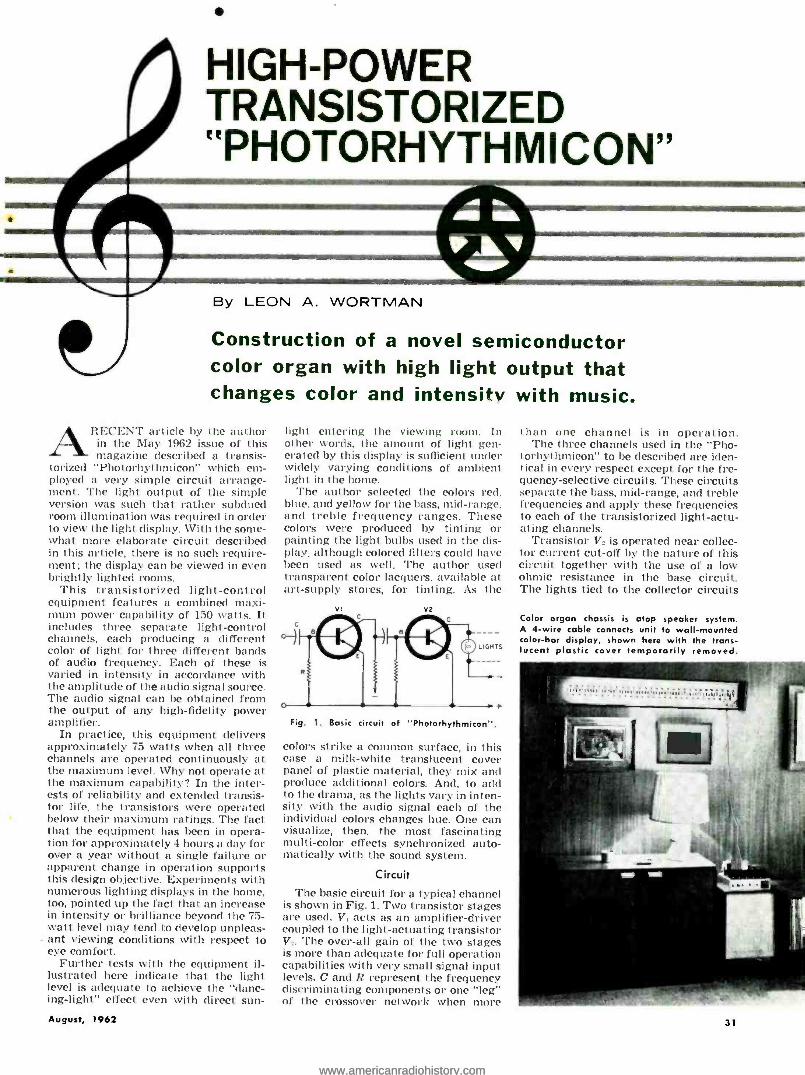
HIGH -POWER TRANSISTORIZED "PHOTORHYTHMICON"
By LEON A. WORTMAN
Construction of a novel semiconductor color organ with high light output that changes color and intensity with music.
ARECENT article by the author in the May 1962 issue of this magazine described a transis-
torized "Photorhyt hmicon" which em- ployed a very simple circuit arrange- ment. The light output of the simple version was such that rather subdued room illumination was required in order to view the light display. With the some- what more elaborate circuit described in this article, there is no such require- ment; the display can be viewed in even brightly lighted rooms.
This transistorized light -control equipment features a combined maxi- mum power capability of 150 watts. It includes three separate light -control channels, each producing a different color of light for three different bands of audio frequency. Each of these is varied in intensity in accordance with the amplitude of the audio signal source. The audio signal can be obtained from the output of any high -fidelity power amplifier.
In practice, this equipment delivers approximately 75 watts when all three channels are operated continuously at the maximum level. Why not operate at the maximum capability? In the inter- ests of reliability and extended transis- tor life, the transistors were operated below their maximum ratings. The fact that the equipment has been in opera- tion for approximately 4 hours a day for over a year without a single failure or apparent change in operation supports this design objective. Experiments with numerous lighting displays in the home, too, pointed up the fact that an increase in intensity or brilliance beyond the 75- watt level may tend to develop unpleas- ant viewing conditions with respect to eye comfort.
Further tests with the equipment il- lustrated here indicate that the light level is adequate to achieve the "danc- ing- light" effect even with direct sun-
August, 1962
light entering the viewing room. In other words, the amount of light gen- erated by this display is sufficient under widely varying conditions of ambient light in the home.
The author selected the colors red, blue, and yellow for the bass, mid -range. and treble frequency ranges. These colors were produced by tinting or painting the light bulbs used in the dis- play, although colored filters could have been used as well. The author used transparent color lacquers, available at art- supply stores, for tinting. As the
Fig. 1. Basic circuit of "Photorhythmicon ".
colors strike a common surface, in this case a milk -white translucent cover panel of plastic material, they mix and produce additional colors. And, to add to the drama, as the lights vary in inten- sity with the audio signal each of the individual colors changes hue. One can visualize, then, the most fascinating multi -color effects synchronized auto- matically with the sound system.
Circuit
The basic circuit for a typical channel is shown in Fig. 1. Two transistor stages are used. V, acts as an amplifier- driver coupled to the light- actuating transistor V. The over -all gain of the two stages is more than adequate for full operation capabilities with very small signal input levels. C and R represent the frequency discriminating components or one "leg" of the crossover network when more
than one channel is in operation. The three channels used in the "Pho-
torhythmicon" to be described are iden- tical in every respect except for the fre- quency- selective circuits. These circuits separate the bass, mid -range, and treble frequencies and apply these frequencies to each of the transistorized light -actu- ating channels.
Transistor V, is operated near collec- tor current cut -off by the nature of this circuit together with the use of a low ohmic resistance in the base circuit. The lights tied to the collector circuits
Color organ chassis is atop speaker system. A 4 -wire cable connects unit to wall -mounted color -bar display, shown here with the trans- lucent plastic cover temporarily removed.
31
www.americanradiohistory.comwww.americanradiohistory.com

o INPUT
PAD RI
C2
FI
-e-'t-o- sI' T4
117 V S.C.
R2 TREBLE
96
R7
R, --15 ohm "T" pad R :.R..R.,-15 ohm wirewound pot R:,R.,R: -330 oho:, I= te. res. R..11,,R10- 10,000 ohm. != w. res. R,,.Ru,R,r -.68 ohm, 1 w. res. C,.0 -S 4., So a. elec. capacitor C...0 : -50 pl.. 50 o. elec. capacitor CI -80 pl., 50 a. elec. capacitor
pf., SO o. elec. capacitor C. -25 pf. 50 o. elec. capacitor C. -2000 pf., 25 a. elec. capacitor
SR,,SR:,SR.,SRI- Siliron rectifier, 6 an:p.. 50 p.l.o. (International Rectifier #IN1341) S- S.ps.t. toggle switch
SO-4 -prang chassis mounted receptacle PLI-14.4 0., .10 amp pilot light (#1813) Fr-3 atop frise L -7 mhy. inductance (see Fig. 4) L -0.7 mhy. inductance (see Fig. 4) T,,T :,T, Transistor power output trans. 48
ohm r.t. pri., .7.2 ohm sec., 6 watts (Lafayette AR -503, renter tap not used)
T -. -Power trans.. 117 0. pri.. 10 a., 5 atop sec. (Staocor #1'6458 fol, trans.)
l'I,F F'. -2N301 or 2N301Á transistor V:, V;, V. -2N173 power transistor Heat sinks- Standard Defeo types
Fig. 2. Complete circuit diagram of the 3- channel unit. Input signal is obtained from voice -coil output of audio amplifier. Less than 1 watt of audio drive is needed.
are extinguished. When a signal is ap- plied to the base of V: from the collector of V,, then output current -and light intensity -increases in direct accord- ance with the signal amplitude. (Note: This eliminates the need for an extra diode at the grid of the 6CL6 tubes specified in the vacuum -tube version of the "Photorhythmicon" which appeared in the August 1958 issue of this maga- zine.) The amount of increase in collec- tor current depends on the beta of tran- sistor V..
The range of maximum to minimum limits for beta is usually 2 to 1 for high - power transistors. Variations from unit to unit within a given type can be ex-
i4
+2
ó o
w N 2 ñ -2 a CC
4
32
pected. However, this is of little impor- tance in the "Photorhythmicon" be- cause of the use of individual- channel balance controls as shown in the com- plete schematic of Fig. 2. These controls are potentiometers connected between the individual "legs" of the crossover network and the channels they feed.
Note, too, that transformer coupling is used between the amplifier- driver transistors and the light- actuating transistors. This takes maximum ad- vantage of the power output capabilities of the driver transistors. Also, the low d.c. resistance of the secondary winding of the coupling transformer is excep- tionally well suited to establish the
Fig. 3. Frequency responses of bass (red), mid -range (blue), treble (yellow) channels.
-1
20 50 100 200 500 IRC.
FREOUENCY-CPS 20RC.
quiescent level of the collector current at or near cut -off for the light- acentu- ating transistors.
Crossover Networks After experimentation, it was decided
that LC networks are more desirable than RC configurations for channel sep- aration. There are two reasons : (1) in- sertion losses are lower for an LC network and (2) sharper cut -off or better channel separation is obtained with an LC network. Hence, it was de- cided to use two of these networks in the unit for mid -range and bass chan- nels.
Commercially manufactured induc- tors for the network are expensive and two are needed in the circuit shown. The RC configuration might cost only one -fourth as much. A solution to the problem is offered by winding one's own coils. The materials for two coils cost about as much as the components for an RC arrangement. No special tools are required. Construction details for the author's inductors are given in Fig. 4.
To maintain frequency characteris- tics of the networks (see Fig. 3), a "T" pad is used at the input. This enables continuously variable control of over- all sensitivity and minimizes changes in loading effects of the "Photorythmicon" on the amplifier to which it is connected whenever that sensitivity control is ad- justed.
The Light Display
The circuit of the light bar favored by the author is given in Fig. 5. Sixty bayonet sockets for #47 pilot bulbs are mounted side by side on a white painted plywood board, 7>,á" x 52 ". The switch provides a selection of one of two en- tirely different lighting effects. When section B is in the circuit, one sees a distinct separation of the three basic red, blue, and yellow colors displayed as color groups with red at the left, yel- low at the right. This creates a fasci-
DIMENSIONS LI L2
A 3i 2
e 3i 2'
c I D li' IZ'
NUMBER OF TURNS NO. IBE.
LI 600
L2 .225
MASONITE OR PLYWOOD
Fig. 4.Construction details for coils L1
and L. Approximate inductance values are 7 mhy. for L, and 0.7 mhy. for L,.
Mounting bolts for the coil forms must be brass. After the proper number of turns of =18 enameled wire have been wound on the form, cover the winding with tape.
ELECTRONICS WORLD
www.americanradiohistory.comwww.americanradiohistory.com

T4
Top view of the color -organ chassis. Heat sinks may be omitted for transistors V, V:, V,. t míiI_fil !kin ( (a (4 (a ( (a
(MATCHING PLUG FOR SO11 Pt
SECTION A
SECTION 8
S2- 3P.D.T ROTARY SWITCH R -#47 PILOT LIGHT (6 -8V., 150MA.1 TINTED RED B -#47 .. ,TINTED BLUE Y -4,47 YELLOW
NOTE: EACH SECTION USES 30 W47 PILOT LIGHTS (10R, IOB, 10Y)
Fig. 5. Wiring for light display. With switch in the position shown, 30 bulbs in Section B are connected to output. Now, 10 red bulbs are at the left, 10 blue bulbs are in the center, and 10 yellow bulbs are at the right. Then when the switch is op-
erated to insert the 30 bulbs in Section A, the colored bulbs are interleaved (red, blue, yellow, red, blue, yellow, etc.) along the entire length of the color bar.
nating ping -pong effect which becomes especially exciting during music dia- logue such as tympani cont co strings.
With the switch in position for sec- tion A, the effect is created of a single full -length bar of light that is constantly and uniformly changing in hue and in- tensity along its length. In this display the bulbs are stagger -wired red. blue, and yellow. Bulbs of like color are wired in parallel. A great deal of visual excitement is provided by this display as the entire bar of light changes in intensity, repeatedly flashing a multi- tude of colors as it follows the music.
There are ten bulbs per color in both sections A and B. To obtain maximum light output the 47 bulbs are operated beyond their rated voltage on audio peaks. However, in view of the fact that the peaks are not usually sustained for long periods, together with the low cost of the bulbs, neither the life of the bulbs nor the condition of the construc- tor's budget is appreciably affected.
The milk -white translucent plastic August, 1962
Botto,,, of
panel referred to earlier is actually a cover for the 4 -foot fluorescent lighting fixtures installed in many business of- fices. It is U- shaped, highly durable. and striated to give high efficiency in for- ward transmission of light. It is easily installed as a wrapper for the board - mounted bulbs. It is available through lighting -fixture or electrical -supply houses at surprisingly low cost.
There is really no limit to the ar- rangements one can plan and construct inexpensively for lighting displays. The author has experimented extensively with many kinds of lights. including floods and 6- and 12 -volt high candle- power automobile lamps. Even auto- mobile headlights and spotlights have been used to create special effects.
In conducting your own experiments around the author's control circuit, it is recommended that you monitor the collector current of the individual light - actuating transistors. One can do it by "feel." Normal operation is indicated when the transistors are barely warm. More accurate, of course, would he to monitor the current with an ammeter. Should the quiescent current begin to climb, shut off power immediately and allow a moment or two for the tran- sistors to cool off. Overheating leads to thermal runaway and self -destruction of the transistor.
The author used good quality heat sinks, electrically insulated from the chassis, on all six transistors to insure high reliability and extended transistor life. However, if the circuit and the 8" x 10" x 21'2" chassis layout are du- plicated as shown, it is practicable to omit the radiator -like heat sinks from the 2N301 transistors. However, make certain the transistors are insulated from the chassis. Mica washers slightly larger than the outline of the transistor are available for the purpose.
It is entirely possible to use this dis- play in mobile installations. A 12 -volt storage battery will enable full opera- tion of the equipment. In such an in- stallation. the power- supply compo- nents are unnecessary.
chassis. Hone -made crossover coils are utilized for the device.
, t 1
T2 4
33
www.americanradiohistory.comwww.americanradiohistory.com

CANADIAN
CITIZENS
BAND By LEO G. SANDS
THE Canadian version of the Citizens Band was opened up on April first.
In Canada, Citizens Radio type opera- tions are permitted in what is known as the General Radio Service on 19 radiotelephone channels (similar to U. S. class D) and 4 radio -control chan- nels (similar to U. S. class C).
It is much easier to get a General Radio Service (GRS) license in Canada
Under new regulations,
Canadian residents
can use AM or FM
on 19 CB channels.
Here is a summary
of the regulations.
and landed immigrants are eligible for GRS licenses. As in the U. S., applicants must be at least 18 years of age.
Canadian GRS licensees may com- municate only with other similarly li- censed stations in Canada, utilizing ground -wave propagation exclusively. These requirements specifically prohibit communication with U.S. Citizens Radio stations and "skip" communications.
Channel Number Freq. (mc.)
27.005
Channel Number
10
Freq. (mc.)
27.115 2 27.015 11 27.125 3 27.025 12 27.135 4 27.035 27.145
27.045 13 27.155 5 27.055 14 27.165 6 27.065 15 27.175 7 27.075 16 27.185 8 27.085 27.195
27.095 17 27.205 9 27.105 18 27.215
19 27.225 *Radio Control (Same as U. S. class C Station)
Table 1. Canadian General Radio Service Citizens Radio frequency allocations.
than a Citizens Radio Station license in the U. S. Instead of mailing an ap- plication to the FCC and waiting sev- eral weeks to get a license, Canadians may call in person at a regional Radio Regulations Office to file an application. If eligible, the license is issued imme- diately. A small fee is charged for a license which is good for three years.
In the U. S. it is mandatory that the applicant be a citizen, but in Canada, British subjects, Canadian corporations,
Either FM or AM can be used by Canadian GRS stations, while only AM (A3) can be used by class D Citizens Stations in the U. S.
Under Canadian regulations, a GRS station can be patched into a telephone circuit with the approval of the tele- phone company. But, in the U. S. the use of a phone patch is in violation of CB rules since "third party" communi- cations are prohibited.
Only factory -built transmitters or
Table 2. Comparison between the United States and Canadian CB regulations.
Band Limits Number of Channels Transmitter Power Output Transmitter Power Input Transmitter Frequency Stability Type of Emission
Modulation
Spurious Emissions
License Applications License Fee
License Term
Type -Approved or Type -Accepted Equipment
Kit -Type Equipment Phone Patch
Antenna Height (maximum)
U. S.
26.96 - 27.26 mc.
23 Not specified
5 watts 0.005
AM (A3) 100 °.é max.
Down 50 db
By mail None
Five years
Optional Yes
No
20 above support. structure
CANADA 27.0 - 27.23 mc.
19
3 watts 5 watts
0.005% AM (A31 or FM (F3)
70% min. (AM) ±1 kc. min. (FM)
30 microwatts max.
In person
3.00 Three years
Required No
Yes
No limit
34
transceivers can be licensed. They must be type -approved by the Department of Transport, and the type- approved num- ber must be permanently attached to the transmitter chassis.
In general, the equipment will be similar to Citizens Band sets used in the U. S. Some U. S. -made sets might not qualify for type approval in Canada since Department of Transport tech- nical requirements are stricter than those imposed by the FCC on CB gear.
Transmitter power, in terms of watts input to the plate or collector of the final r.f. amplifier, is limited to 5 watts, the same as in the U. S. Power output, which is not specifically restricted in the U. S., is limited to 3 watts in Canada.
FCC regulations stipulate that modulation not exceed 100',; , but D.O.T. regulations require that AM transmit- ters be capable of at least 70!: modulation with rated audio input. Minimum FM transmitter deviation is --*1 kc. with rated audio input.
As in the U. S., transmitters must be crystal -controlled and frequency stabi- lized to 0.005x, . In addition, spurious emissions and harmonics must not ex- ceed 30 microwatts (about 50 db below carrier level) over the frequency range extending from the crystal oscillator frequency to 250 mc.
It is expected that U. S. manufactur- ers will find an eager Canadian market for Citizens Band sets. But, the bulk of the business, it is believed, will go to Canadian manufacturers who have been preparing for the opening of the GRS band. Equipment prices are ex- pected to be slightly higher than in the U. S.
Since FM transmission is permitted, some of the new Canadian -built sets now being developed are expected to be FM types. FM sets can be expected to cost more than AM sets. However, the generally superior performance, espe- cially with regard to ignition noise, should create considerable demand for such units.
Based on surveys, it is estimated that some 20,000 Canadians will apply for GRS licenses this year. GRS will not take off as slowly as Citizens Band radio did in the U. S. because of the wide publicity given CB radio during the past three years.
There are more potential GRS users per capita in Canada than potential CB users in the U. S. because it is not neces- sary to be a citizen to be eligible for a license. Since licenses are to be issued on the date of application, prospective GRS users can get on the air as soon as the equipment is installed.
While Canadian GRS licensees will be operating on the same frequencies as U. S. Citizens Band licensees, they will not be able to communicate with each other lawfully. Canadians cannot legally operate their GRS sets in the U. S. State -side CB licensees cannot operate their sets in Canada without the ap- proval of the Canadian government. Across -the -border communications are prohibited, and the FCC warns that violators will be subject to severe pen - dties.
ELECTRONICS WORLD
www.americanradiohistory.comwww.americanradiohistory.com

VersatiIeVoltage, Power,
and Deci bel_ Nomogra_ By JIM KYLE
Two useful charts that enable the audio technician to find amplifier gains and losses even when voltage
measurements are taken across different impedances.
EI E2 10
80
70
60
50
40
30
2 1 20
N
N
N N
P 1000
700
500 400
300
200
100
70
50 40
30
20
10
4
N3
2 \*N
0.7
0.5
0.4
0.3
¡ -0.2
0.1
N
RI 0.1- R2 10
0.2 20
0.3 30
0.4 40
0.5 50
0.770
I 100
2 200
' 3 300
4 400 \\
N _5- 500 ___y \
7 N
700
10 1000
www.americanradiohistory.comwww.americanradiohistory.com

VOICE
STRING{
PLUCKED STRING ll
BRASS
SOPRANO ALTO
TENOR BARITONE
BASS VIOLIN
VIOLA CELLO
BASS VIOL HARP
GUITAR BANJO TRUMPET
TROMBONE FRENCH HORN
BASS TUBA PICCOLO
FLUTE L SOPRANO CLARINET
WOOD- BASS CLARINET WIND SOPRANO SAXOPHONE
BASS SAXOPHONE 1 OBOE
ENGLISH HORN
BASSOON KETTLE DRUM I
PERCUSSION{ ?I XYLOPHONE I 1 1
MUSICAL FREQUENCY RANGES. Fundamen al fre-
quency ranges of voices and musical instruments. Note that
the range of the overtones, which give an instrument its
particular timbre, is not shown. Although these vary widely
depending on the instrument and how it is played, the
overtones may extend the frequency range required to re-
produce a given musical instrument by two or more octaves.
0
+5
+10
+15
+20
+25
lo-
10 19 a qwgww
1111I._- M _-
GES 19
149
MEN WOMEN
440 880 1760 3520 7040
HEARING LOSS WITH AGE. Curves show the loss of
hearing acuity with advancing age. Note that high- frequency
hearing loss of women is considerably less than for men.
IM11 )J TR S C EQUIPMENT II l1l II 11111r rarrsln
-II 1l11Y1117:i!i! ' .: 91ICFI*111Rn'E 110:+: üüilitüllIIIIIIIIU
-iié111¡111111111 l Illllli.
I!EMU' III1111 m, Eu
-1:.,11.1li CRICKET AFC 17 GRASSHOPPER ÌI'
II i I rinhlimmm
DIBLE FR QUENCY IN ANIMALS)
OKC. 20KC.
IT, OA
50KC. IOOKC.
CAN
ElectronicsWorld RE L AT
SOUND PRESSURE (DYNE /CM?
50 HP SI E (100')
THRESHOLD OF PAIN
PNEUMATIC CHIPPER (5)
200
HAMMERING ON STEEL PLATE, (2') -
INSIDE DC6 BOILER FACTORY
IVE LEVEL (DB)
140 POWER AT EAR (WATTS /CM ?)
F84 TAKE -OFF (80' FROM TAIL)
IO -3
AIRPLA to --
"- -ROOM - = MARINE ULC SPEE1
-moo 10'5- - U THUNDA
ti
-SUBWAY PASSING
X10 -6 RIVETING MACHINE,(35) RING PLANT
20
HEAVY STREET TRAFFIC (5') INSIDE BUS
2
STENOGRAPHIC ROOM
AVERAGE FACTORY
AVERAGE AUTOMOBILE
CONVERSATION (3')
.2
AVERAGE OFFICE
QUIET RESIDENTIAL STREET
VERY LOUD MUSIC, PEAKS
IO -7
I0-HP OUTBOARD (50)
IO -6 VERY LOUD MUSIC
HEAVY TRAFFIC (25 -50')
10 -9 LOUD MUSIC
VERY SOFT MUSIC
.002 QUIET WHISPER,(5')
ANECHOIC ROOM-
.0002
30 -10 -13 COUNTRY HOUSE
-10-14 141
QUIET ISO
10 -Kris 1
TUDIO I G >>-
Ip-'6 i ESHOL EARING
SOUND LEVELS. The relative levels of a number of common sounds and noises.
www.americanradiohistory.comwww.americanradiohistory.com

+14
+12
o +10 J
> +8 W
} +6
z +4 W
+2
e I z iIIIIrIIIIII1n al IIIIIII .41.11I11111 12
® . I a Iliiill_ 1 1 .c 1 IIIIIIk THR 1111n M11nind 1 11111111 `110 D OF
H
11W a
IIIr° -1IIr Ea.111t a
+140
+120
+100
+BO
+60
+40
+20
0
EL. ilangsssr BINAURAL MINIMUM
AUDIBLE FIELD AGE 20 AGE 60
20 50 100 200 500 IKC. 5KC. 20KC.
FREQUENCY & VOLUME RANGES. (Left) The approximate boundaries of normal hearing based on
Fletcher -Munson data. No sound is heard below the level indicated by the lower contour. Sound levels that are in excess of those indicated by the upper contour are felt rather than heard and may be accompanied by a
sensation of pain. Also shown are the volume levels and frequency ranges of music as well as speech.
EQUAL LOUDNESS CURVES. (Right) Sound intensities required to produce equal loudness at various sound levels. These curves, obtained by Robinson and Dadson, are slightly different from the older Fletcher - Munson data and have as yet to be internationally accepted. Both these curves and the Fletcher -Munson
curves of equal loudness show the need to boost the bass substantially and to boost the treble slightly when
listening at reduced volume levels. If this is not done, then bass and treble tones will appear to be lost.
SOUND AUDIBLE SPECTRUM. Some significant frequencies are shown
on the audible spectrum along with the fundamental frequencies
for notes on the piano keyboard. The equally tempered scale is
used and it is based on the American Standard Pitch (A -440). rtrrrrrrrr r
III II
I II IIIII III III1I
JJILJ141111111111111111i11111111111111111111111111 ABCDEFGABCDEFGABCDEFGABCDEFGABCOEFGABCDEFGABCDEFGABC
O(0m(0m0 O,nD,prrmOr-rn--OOPrntOrmOOCDUrn,OtoOnOr,nn,nO)00u7OrnOmóo-O t00t000otn omo-00 00(00?(0t000.0!tOtOtpN000?NmN00!or 0(0(0 otom0lr-m(0O-tON QtAmr-1-Ní0 O!-.4OQmt7tperiòtO4VtÓOtO-mmOtNtjmrrirtTmmptal-OrrGr- 0lamglmNlnma UrONto -rrjmtn- trisi rt;-Nm0t0r-01N0(001N001001N(0r01(0(0OD -mm,nr4-01OrnfD¡. to01-O mmm00OtntO,Dr-CD01 NNNNmmmaQtntn(D{p14-(001 NNNNmmmQ
11111111111i1111 mnujenlu 11 111
o JL' 1Ilmuu1Lo1111
11 DUI IIIIIII 1 118c gii11S1F11enn11111n1 IIIIn1111 IIIII111111111111111 IIr+uuonwn ni ume1n1u11nu Ili mmnnm laiYSllyacJCUn11onnno11nll'lln 111111111'1111111111
1111111M111.11111111 1111111 1 i¡I1111111111111
I 11111IM11u®11III1m 1 minim IIIIIIIIIII0IIFR4111/1111.f!
1 n
PI Mil 11. .1 I :M1 I!111111111 111 1 11111111 IIIII MIIIIII
RP 1.:1!.IIFIR! RI ! l'!!" IIINNIIillbiilih hl ilnldúl hill RAI i 1d 1i eiilbliI111111111111111111111111111NI 111111111 I11111 111h rlii Ia1d rIIIIIIIIIIIIIIIIII1111111111111111111IIIIII111111111IIII1111111111111IIIIIINI ,IIlIM b LEM 1111111111111111111111 1111111111 11111 111111 III II VIII I11111111111111I1111111IN
HIIIIIIIIIIIIIIIII IÌ I111111111111111111111111111111111111111M11111111 1IÌÌIÌÌÌIÌÌÌIIIq ® KEY E E3®22 1IIII Ì Ì II1111111111 111111111111I111I11111111 IIIIIU11111I1111 11111111111111111111111111111111111111111111111111111111II1111118r101
1111111111111111111011111111111
E= L:a!_C1lSi11:1111!!!d.'I 11.11i..,1111111111 Ill 11111111111111111111111111111111111111I111 11111111 II I111111 PE 111111111111111111111111 1111111I IIIIIII I II 1111111 11111111111111R 1111111111111111111111111111 I 111111111II11111111111111I 11111111 1 ' E' - 1IIÌ ÌÌIÌÌIIIIÌÌ11IÌIÌIÌÌÌÌIÌÌÌÌI11IÌI ÌÌÌÌÌÌÌIÌÌ IIIÌÌIIIIIIIIÌÌIIIÌÌÌÌÌ ÌÌ1II1II I1I I i111I I ÌI1
10 20 50 100 200 500 KC. 2KC. FREQUENCY -CPS
COPYRIGHT 1962 ZIFFDAVIS PUBLISHING COMPANY. ALL RIGHTS RESERVED.
5KC.
www.americanradiohistory.comwww.americanradiohistory.com
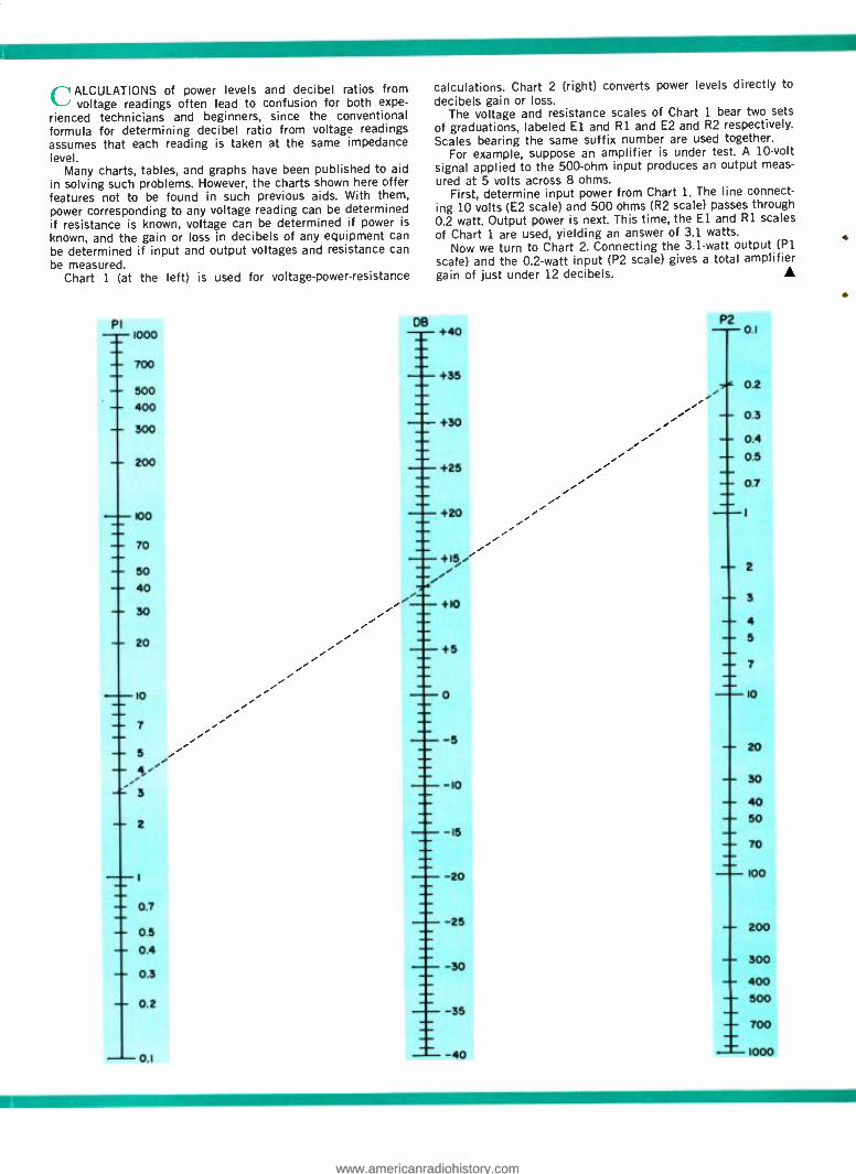
C~ ALCULATIONS of power levels and decibel ratios from voltage readings often lead to confusion for both expe-
rienced technicians and beginners, since the conventional formula for determining decibel ratio from voltage readings assumes that each reading is taken at the same impedance level.
Many charts, tables, and graphs have been published to aid in solving such problems. However, the charts shown here offer features not to be found in such previous aids. With them, power corresponding to any voltage reading can be determined if resistance is known, voltage can be determined if power is
known, and the gain or loss in decibels of any equipment can be determined if input and output voltages and resistance can be measured.
Chart 1 (at the left) is used for voltage -power- resistance
calculations. Chart 2 (right) converts power levels directly to
decibels gain or loss. The voltage and resistance scales of Chart 1 bear two sets
of graduations, labeled El and R1 and E2 and R2 respectively. Scales bearing the same suffix number are used together.
For example, suppose an amplifier is under test. A 10 -volt signal applied to the 500 -ohm input produces an output meas-
ured at 5 volts across 8 ohms. First, determine input power from Chart 1. The line connect-
ing 10 volts (E2 scale) and 500 ohms (R2 scale) passes through 0.2 watt. Output power is next. This time, the El and R1 scales
of Chart 1 are used, yielding an answer of 3.1 watts. Now we turn to Chart 2. Connecting the 3.1 -watt output (P1
scale) and the 0.2 -watt input (P2 scale) gives a total amplifier gain of just under 12 decibels.
Pl
'
DB
i
P2 0I
- -
1000
700
500
400
300
200
+40
7...0
- -
0.2
0.3
0.4
0.5
0.7
+35
+30
+25
+20
- -
100
70
50
40
30
20
- -
2
3
4
5 i 7
10
.. +15/
+10
+5
-a-
10
7
5
4
3
- 2
0
5 20
- 30 - 40 50
70
100
10
t
IS
20
0.7
0.5 25 - 200
- 0.4
30 300 - 0.3 400
- 0.2 35
- 500
700
0.1 40 1000
www.americanradiohistory.comwww.americanradiohistory.com

TRANSISTOROPERATED PORTABLE LAMP By THOMAS J. BARMORE
Construction details on a fluorescent utility or emergency light that is battery powered via a transistor oscillator.
OST of us in the electronic repair business have had to y work on equipment in the
dok, with only a flashlight as a source of illumination. Even if you don't fall into this classification. you will appreci- ate this unusual light source if you've ever had to change a tire in the dark or had the power go off in your home at a crucial moment.
This fluorescent lamp is small. bat- tery powered, and has a light output of 5 footcandles over an area of 16 square feet at a distance of two feet or 20 footcandles over an area of 4 square feet at a distance of one foot from the lamp. In order for a tungsten lamp to generate this same amount of light, 7.8 watts of power must be con- sumed while this unit draws only 3.7 watts (based on an average battery voltage of 5 volts and a power- supply efficiency of about 94'; 1.
Unlike a conventional tungsten lamp. a fluorescent lamp is an electric -dis- charge source. It is a tube coated with a special powder (in this case, calcium phosphate) and filled with mercury va- por and a small amount of argon vapor. In the ends of the tube are filaments much like those found in directly heated vacuum tubes. These filaments are coated with an electron- emitting ma- terial which will give off a dense cloud of electrons when heated. In operation, these filaments are first heated while an a.c. potential is applied between the ends of the tube. Once the filaments are heated and the electron cloud present, the filament voltage is removed and an arc is established along the length of the tube.
Electrons, in collision with the mer- cury atoms, release ultraviolet radiation which is absorbed by the wall coating. Light is then given off as this coating fluoresces.
Circuit Design Since fluorescents must have a po-
tential for starting and operation that is higher than can be conveniently sup- plied by batteries, the lamp employs a simple d.c.- to -a.c. converter. consist- ing of a transformer, two inexpensive power transistors, and two resistors.
This supply is much like those which use an electro- mechanical vibrator to switch the primary voltage. In this sup- ply. the primary circuit is actually a high -current multivibrator with feed- back supplied ria winding N2 and con- trolled by resistors R, and R_. The switched d.c., or square wave, is applied to the primary winding (Nit and stepped up to about 100 volts.
The transformer used may be a com-
mercial unit such as a Triad TY -100 (which costs around $121 or the con- structor may wind his own. The author used a small tape -wound toroid about 1% inches in diameter, but a small audio transformer may be used with reduced efficiency. Winding Nl is about 50 turns, center -tapped, of #18 enameled wound about the periphery of the core. N2 is a center -tapped feedback winding of the same number of turns but of #30 enameled, wound between the windings of Nl. Once these windings are in place and insulated with fiberglass tape, a secondary output winding of 600 turns may be wound over the top of the primaries. This secondary output wind- ing is then insulated with cambric tape.
VOLTAGE ACROSS
CAPACITOR
VOLTAGE ACROSS LAMP
LAMP LIGHT OUTPUT
ON-OFF
llllllll
5T06V. t CHEAPUGCORO
START SWITCH (NORM. OPEN PUSH.
SUTTON)
Ci cuit diagram of the portable lamp.
Ordinary 4 -watt fluorescent tube is used.
In operation, a fluorescent lamp be- haves in a strange manner. Since it is an arc, some sort of current -limiting device must be used in series with the lamp. Since the lamp operates on a frequency of 5000 cps, a capacitor serves as an excellent current -limiting ballast as it has no power loss even though there is a voltage drop across it.
Power Sources Power for the lamp may be supplied
by one of several sources. The author used a 5 -volt sintered -plate nickel -cad- mium battery that is normally used in the Black and Decker cordless drill, but this was used only because of its shape. It will supply about 1 amp. for over two hours and is rechargeable. A set of four Burgess #CD -7L nickel -cad- mium cells will power the lamp for an hour, while an Ereready cathodic enve- lope battery #2744 will operate the lamp for three hours. An Ereready #744 will supply power for about one -half hour, while four size D flashlight cells will operate it for about 15 minutes. Of course the unit can use an automobile battery as a power source, provided it is 6 volts. Otherwise, resistors R, and RI should be changed to a total of approximately 600 ohms. Resistor R, is made variable in order to increase battery life. Starting is facilitated with weak cells by increasing the bias on the transistor bases, while less current is actually needed to operate the lamp.
The unit is housed in a simple 3" x 3" x 6" case. One -half of the case houses all components, while the lamp sockets and lamp are mounted on a concave cover plate. All controls are mounted on the rear, enclosed by a handle. A
A rear view of the battery -powered lamp.
www.americanradiohistory.comwww.americanradiohistory.com

ANALYZING COLOR SET DEFECTS
AN EXPERIENCED technician enters a customer's home where the black -and -white TV set exhibits a
familiar defect: horizontal sync is lost and cannot
be restored by manipulation of the external bold control.
Without hesitation, he proceeds to rear adjustments tied in
with the horizontal circuit. If need be, be tries new tubes
for the oscillator, output, a.f.c., and sync-separator stages.
The chances are that one of these attempts will get him
out of the house in short order after a successful repair. If
not, he takes the set back to the shop. There he will know
where to start looking and how, hardly being aware of having
to think about the matter. What has happened here? Years of logical thinking and
experience have enabled him, almost instantaneously, to asso-
ciate a specific symptom with a specific part of the set and
the most probable trouble points. In a few years from now,
the same man will be handling color defects with the same
cleft assurance. But even today, he is probably better off
than he knows. A few years ago, monochrome defects did not "solve them-
selves" almost automatically. Our man had to stop and think.
If he has gone through that period successfully and clone his
color "homework" (kept up with color circuits and their
operation), he need only return to an earlier approach. He
has not lost his ability to think. Employing it once more, his
greatest difficulty will be the fact that color defects will take
somewhat more time to correct. Thus we are not concerned with the "how" of color service.
40
Scrupulous descriptions of convergence. chroma- alignment, and other special techniques abound. They are useless un-
less the technician knows "when" to apply them. Consider the out -of -sync monochrome set with which we
began. The receiver was doing something it shouldn't. \tore precisely (and more usually), it was not doing something it
should. It failed to lock the picture horizontally. The tech- nician immediately went to work on the horizontal section.
An Analogous Color Fault
Consider pattern A in the upper, right -hand section of the
facing page (shown more clearly on the cover). Signal is
applied to the receiver from a gated, color -bar generator. We
should see a series of separate, vertical bars, each of a differ- ent color in the sequence of Fig. IA. Instead distinct bars
can be seen, but color is scrambled. If the set were actually receiving a color broadcast, the picture would be quite recognizable, but indiscriminate bands of color would be
weaving through the image. The set is doing some of the things it should. It is reproduc-
ing a picture, so the video channels seem to be in order.
That picture is recognizable, so the conventional sync cir-
cuits appear to be behaving. The receiver is "making color," so we can disregard a good portion of the chroma circuitry and the CRT, for the time being at least. The thing the set
is not doing is the necessary matching of the produced colors
to the picture elements, where they belong.
Quite simply. we have a synchronization problem. Color
E:. ECTRON ICS WORLD
www.americanradiohistory.comwww.americanradiohistory.com

V1W1 1ri
sync is established by the 3.58-utc. oscillator in die receiser. Like the horizontal oscillator, the former should be locked in with specially transmitted synchronizing pulses -the "burst" signal. in this case. Burst is tapped off from the video channel, as are other sync pulses, fed to a separate burst amplifier, and then applied to the :3.5S -mc. oscillator through an a.f.c. circuit. We are immediately restricted to these cir- cuits as a starting point.
The first check will involve oscillator adjustments and the tube. If the oscillator appears to be working, the a.f.e. and burst stages are checked. As with the horizontal fault. some preliii iiiai checks can be made at once, in the customer's honte. In the illustrated case, a slop job was necessary. The oscillator was running, although out of sync. A little tracing led to an open resistor in the screen grid of the burst ampli- fier. This routine defect was unearthed with routine voltage and resistance readings in the affected stage -once simple recognition and analysis had directed the technician to that stage.
Faults in Monochrome Reception
The preceding case had the virtues of relating to another, familiar type of defect in black -and -white and of being rela- tively easy, which is all right to start out with. Others will be less obvious and also more frequent. \lost TV broadcasts today are in monochrome, so even the opt ncr of a color set will be doing most of his viewing in that medium. Defects that occur in these conditions are often dismissed as being familiar monochrome faults, pertaining to those circuits only. That will not always be true.
Fairly obvious exceptions will be monochrome pictures that show some color. \ \'here a single color appears to pre- dominate, the technician will first check tracking adjust- ments for the three guns of the CRT. A bluish cast to the pic- ture will suggest that blue -gun output is greater than it should be and, if the gun is proven to be balanced against the other two, some tracing back into the matrixing and am- plifying circuits feeding the blue gun is in order. Simple enough.
If the picture should happen to have a yellowish tinge, the matter is more complex, but not by much. In color TV, yellow is a combination of red and green. Blue -gun output would thus appear to be low or not present. If a color -signal generator is available -and some such equipment is indispen- sable -this is a propitious moment to hook it up. In a case like this, the blue bar in the center of the pattern (number 6 in
.
Fig. 1. Pattern (Al produced on a set from a color -bar generator. Theoretical signals IB, C, and DI at red, blue, and green guns with bar -pattern input to set.
Fig. 2. Red -grid signal showing overload,. as from high setting of saturation con- trol. Compare with the normal waveform at this point (topmost pattern of Fig. 3/.
August, 1962
Electronics Norlil
c`1
COVER STORY NONE OF the striking patterns on
the cover would be seen on a normally operating color set. The one in A is observed when receiver input is from a color -bar generator and the set's color circuits are unsynchronized. With normal video -channel processing, the still synchronized bars are seen as regu- larly spaced vertical elements. However, their discrete colors (see the top por- tions of E and F) are "running." In nor- mal reception, picture detail would be retained but colors would occur in ran- dom, unstable bonds in the background.
When only the red gun of the CRT is active, a pure red field should ordi-
narily be seen. In B, a degaussing coil fed from the a.c. line (the dark ring), is taped to the picture -tube face. Its field deflects red -gun electrons to strike other phosphors, in o pattern that colorfully matches the a.c. field.
A hum bar due to cathode- heater leakage in a monochrome set is familiar enough. Something is added (C) when a color set is similarly afflicted. The bar may have any color. It may occur on color programs only or lint o monochrome picture. Considering such variables helps identify the guilty circuit.
Many defects can cause of(- coloration at the roster edges. In D, purity - magnet misadjustment mars a pure red display by contaminating raster oreos away from the center.
Two conditions are combined for comparison in the split-screen effect of E. The top shows normal reproduction with input from a gated, color - bar generator. Colors at the bottom, though synchronized, are all of the wrong hue. A frequent cause of this condition is o misadjusted hue control.
The top of F is, once more, a normally displayed color -bar pattern. Too high a setting of the saturation control produces the overload at the bottom. Basic hues are correct, but abnormally deep and distorted. In o picture, pastels and shades would be lost, color heavy and smeared. Compare this with excessive contrast in monochrome: heavy blocks, few grays, and smearing would be noted.
(Illustration by George Kelvin)
Fig. IA; also see the top portions of patterns E and F on the cover) would not appear on the screen.
Also fairly clear -cut are those cases where the monochrome picture is acceptably black -and -white toward the center of the raster but there is some color contamination along one or more edges. \Ve have at fairly simple purity or convergence problem here, and the former will be checked before any- thing is done about the latter. Blue and green screen controls are generally turned clown to produce an all red display. If the latter is contaminated, purity adjustments are made first, not so much to cover as much of the screen with red as polsi_
(Continued on page 64)
c e s
n J l__.,' ^
= _ I I - s
P 2 >^ s
7 s s io- c-.
ui
Fig. 3. Displays at red, blue, and green, grids (top to bottom/ as seen with scope.
1 2 3 4 S 6 7 10
íllllllll
41
www.americanradiohistory.comwww.americanradiohistory.com

MAC' ELECTRONICS
SERVICE By JOHN T. FRYE
Openers, SURE took you long enough to
clean that tuner," Mac com- mented acidly to Barney, his
assistant, as the latter came into the service department. "Was the customer a good -looking girl ?"
"No; matter of fact. she was an el- derly widow." Barney retorted, parking his tube caddy on the side bench. "It didn't take me long to clean the tuner and reset the channels, but then the customer asked if I would look at her radio -controlled garage door opener that had gone on the fritz. Her late hus- band had bought the thing in kit form and had installed it himself. She could still operate the door with the push- button on the wall of the garage. but punching the button on the dashboard of her car had no effect whatever. She said the thing had worked perfectly un- til just this last week. Fortunately she is a methodical woman and had saved the instruction manuals that came with the transmitter and receiver: so I said I'd take a look at it.
"First I checked out the transmitter in the car. This was easy. Following in- structions in the manual. I simply pulled out the antenna plug and stuck in a little dummy antenna consisting of a
#47 pilot lamp fastened to an RCA phono plug. When I pushed the dash button. the bulb lighted to normal bril- liance: so I figured the transmitter was okay.
"Next I took the case off the receiver unit fastened on the framework of the door- opening mechanism next to the motor. A 6BH6 was stone cold: so I put in a new one. That took care of the trou- ble. The transmitter opened and closed the door perfectly. But by now I was interested in the circuits: so I took a
few minutes more to look over the dia- grams of the transmitter and receiver and figure out how they work. Remem- ber now: you're always telling me I should satisfy my curiosity about any electronic device, no matter if I expect to service it or not."
"Okay; so I talk too much," Mac grunted: but he grinned in spite of him- self.
"The transmitter uses one -half a
6AU8 as a crystal oscillator and the other half as a power amplifier-or 'final.' as we hams rail it. A 12RH7 with
42
Anyone? its plates. grids. and cathodes strapped together functions as a power audio oscillator whose output modulates the final r.f. amplifier. By connecting differ- ent amounts of available fixed capaci- tance across the audio oscillator coil. any one of three different modulating frequencies can be had. A non- synchro- nous vibrator and transformer convert the 12 -volt d.c. battery voltage into a
stepped -up a.c. voltage that is rectified by two silicon rectifiers in a voltage doubling circuit to produce 220 volts for the plates of the tubes. The filaments are connected between ground and the ignition switch so they light whenever the switch is on. The dash push- button activates the vibrator to produce output from the transmitter.
"The receiver, though, is more inter- esting. Input from a quarter -wave an- tenna fastened beneath the car goes to an antenna transformer whose slug - tuned secondary feeds the grid of a 6BH6. Another transformer, this time with its tuned primary in the plate cir- cuit of the 6BH6, feeds a crystal diode with the secondary. The d.c. voltage de- veloped by the rectification of the car-
The portion of the opener receiver Mac visualized on his "mental blackboard."
FROM DETECTOR
117V.0 C
rier by this diode is used on the grid of the tube as a.g.c. voltage to keep the detector output relatively equal over a
wide range of input signal strength. Audio recovered by the detector action is fed through a coupling capacitor to the grid of a 6AU6. A 5000 -ohm relay coil is in the plate circuit of this tube, but there is little current through the coil normally because the grid of the tube is biased to cut -off with voltage developed by rectifying and filtering the 6 -volt filament supply. Incidentally. this high bias keeps the tube from amplify- ing the audio on its grid by any ap- preciable amount.
"Now we come to the tricky part; so get out that mental blackboard of yours and let's see how good you are at follow- ing a word description of a circuit. Im- agine the familiar diamond shape of a
bridge circuit. The two right -hand legs are 220k resistors. Starting at the left corner and going up to the right, we see a 22k resistor and then a silicon diode with the plus terminal to the right. Starting at the same point and going down and to the right. we see a tapped variable inductance audio choke tuned with a 3000 -ppf. capacitor, and the tap goes through a 220k -ohm resis- tor across the bridge to the junction of the other two 220k resistors. On be- yond this notch filter -for that's what the resistor- choke -capacitor combina- tion really is-there's another silicon diode with its plus terminal also to the right. Okay so far ?"
"Drive on." "Well imagine a 2 -pf. capacitor con-
nected from top to bottom of our bridge, with the positive terminal at the top. Next picture a .01 capacitor connected from the right -hand corner to the bot- tom corner. Finally, in your mind's eye. connect the top of the bridge through a
220k resistor to the grid of the 6AU6, the bottom of it to our bias voltage de- veloped by rectifying the filament volt- age, and the left -hand corner through an .01 capacitor to the plate of the 6AU6. See how it works ?"
"Oh I think so." Mac said with a faint smile. "The bias for the 6AU6 is fed to the grid of the tube through the resis- tive right -hand half of the bridge and suffers no alteration as long as no audio signal is delivered to the bridge from the plate of the 6AU6. Even when such a
signal is delivered, as long as the fre- quency is far removed from the sharp resonant frequency of the notch filter, this bias voltage is not affected. This is because the notch filter presents very little impedance to the non -resonant sig- nal-no more than that of the 22k re- sistor in the other leg of the bridge -so the signal is presented equally to the two silicon diodes and produces two equal bucking voltages across their re- spective load resistors in the right -hand side of the bridge. These two equal and opposing voltages cancel each other, and there is no effect on the bias of the 6AU6.
"However, when the audio signal is of the frequency to which the notch fil- ter is tuned, this filter presents a very
(Continued on. page 74)
ELECTRONICS WORLD
www.americanradiohistory.comwww.americanradiohistory.com
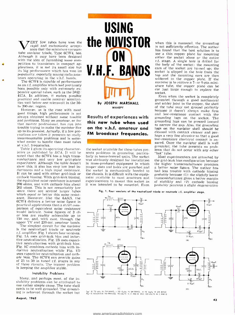
VERY few tubes have won the rapid and enthusiastic accept- ance that the miniature vacuum -
tube nuvistor triode, Type 6CW4, has. Although it may have been designed with the idea of furnishing some com- petition to transistors in compact ap- plications. it is not its small size but its big performance which has won its popularity, especially among radio ama- teurs operating in the v.h.f. bands. 4 The 6CW4 is capable of performance as an r.f. amplifier which had previously been possible only with extremely ex- pensive special tubes. such as the 5842/ 417A. In addition. it makes possible practical and usable receiver sensitivi- ties well below one microvolt in the 50- to 200 -mc. region.
However, as is the case with most good things. high performance is not always obtained without some trouble and problems. Many an amateur, or for that natter professional. has run into trouble trying to make the nuvistor live up to its promise. Actually, if a few pre- cautions are taken it presents no really insurmountable problems and is some- what easier to handle than most tubes at v.h.f. frequencies.
Table 1 gives its operating character- istics as published by RCA. It will be noted that the 6CW4 has a high trans - conductance and very low grid -plate capacitance. Although the table doesn't show this, it also has very low lead in- ductances and a high input resistance. It can be used with either grid -leak or cathode biasing. With grid -leak biasing. the equivalent noise resistance is around 200 ohms, and with cathode bias about 260 ohms. This is not remarkably low since there are several larger tubes which equal or better this noise resist- ance. However, like the 6AK5, the 6CW4 delivers a better noise figure in practical applications than a strict com- parison of equivalent noise resistance would indicate. Noise figures of 3 db or less are readily achievable up to 150 mc. and. with care, through the upper TV and 220 -mc. amateur bands.
The simplest circuit for the nuvistor is the neutralized triode or neutrode r.f. amplifier. Fig. 1 shows four versions. Fig. lA uses grid -leak bias and induc- tive neutralization. Fig. 1B uses capaci- tive neutralization with grid -leak bias. Fig. 1C combines cathode bias with in- ductive neutralization while Fig. ID uses capacitive neutralization and cath- ode bias. The 6CW4 can provide gains of 25 to 50 in tuned r.f. stages in any of these circuits. The biggest problem is keeping the amplifier stable.
Instability Problems Many, and perhaps most, of the in-
stability problems can be attributed to one rather simple cause. The tube shell needs to he well grounded. The ground- ing is achieved through the socket but
August, 1962
USING
the N ISTOR
ON
V.H. . BA DS
By JOSEPH MARSHALL WA4EPY
Results of experiences with this new tube when used on the v.h.f. amateur and FM broadcast frequencies.
the socket available for these tubes pre- sents problems in grounding. particu- larly in home -brewed units. The socket was obviously designed for installation in mass -produced equipment in which proper slots and holes are punched and the socket is mechanically bonded to the chassis. It is difficult with the equip- ment available to most amateurs and experimenters to mount this socket as it was intended to be mounted. Even
Fig. 1. Four versions of the
LN
when this is managed. the grounding is not sufficiently effective. The author has found that the best solution is to use a thin copper plate for mounting either the socket alone or the entire r.f. stage. A single hole is drilled for the body of the socket; the mounting ears of the socket are turned up; the socket is slipped in the hole from the top and the mounting ears are then soldered to the copper plate. If the nuvistor is to replace a 7- or 9 -pin mini- ature tube, the copper plate can be cut just large enough to replace the socket.
Even when the socket is completely grounded through a good mechanical and solder joint to the copper, the shell of the tube may not ground perfectly because it doesn't always make firm and low- resistance contact with the grounding lugs on the socket. The grounding lugs can be pressed inward to narrow the gap. Also. the grounding lugs on the nuvistor shell should be cleaned with contact cleaner and per- haps a very fine abrasive so that a good low -resistance electrical contact is as- sured. Once the nuvistor shell is well grounded, the tube presents no prob- lems that do not occur with any other "hot" tube.
Most experimenters are attracted by the grid -leak bias configuration because the higher transconductance promises a better noise figure. The author has had less trouble with cathode biasing probably because (1) the slightly lower transconductance gives a better margin of stability and (2) cathode biasing probably provides a slight degenerative
neutralized triode or neutrode ri. amplifier stage.
(Al
LN
B
(U L. 6 TO lyny. M FM BAND, TO I.Syny IN 6M BAND, .4 TO 6yny IN 2M SANO By -IS ADJUSTED TO PROVIDE 70 VOLTS M A AND 9 AND I00 VOLTS M C ANO D
(D)
43
www.americanradiohistory.comwww.americanradiohistory.com
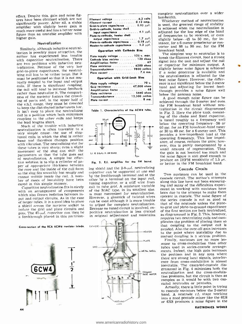
effect. Despite this. gain and noise fig-
ures have been obtained which are not significantly poorer. After all, a stable amplifier with slightly lower gain is
much more useful and has a better noise figure than an unstable amplifier with higher gain.
Neutralization
Similarly, although inductive neutral- ization is possibly more attractive, the author has experienced less trouble with capacitive neutralization. There are two problems with inductive neu- tralization. Because of the very low grid -to -plate capacitance. the neutral- izing coil has to be rather large. But it must be positioned so that it is not mu- tually coupled to the input and output coils. If there is significant coupling, the coil will tend to increase feedback rather than neutralize it. The compact- ness of the nuvistor fosters the crowd- ing of parts and. in the upper half of the v.h.f. range, they must be crowded to keep the distributed inductances low. It isn't easy to place the neutralizing coil in a position which both minimizes coupling to the other coils and keeps the lead lengths short.
Much of the trouble with inductive neutralization is often traceable to a very simple cause -the use of slug - tuned coils in which the slug is rather loose and therefore changes position with vibration. The neutralizing slot for these tubes is very sharp; even a slight movement of the slug can shift the parameters so that the tube goes out of neutralization. A simple but effec- tive solution is to slip a cylinder of pa- per of appropriate t hickness between the core and the inside of the coil form so the slug fits smoothly but snugly and cannot wobble inside the coil. A num- ber of cases of instability have been cured in this simple manner.
Capacitive neutralization fits in nicely with an arrangement of components which also favors isolation between in- put and output circuits. As in the case of larger tubes. it is a good idea to place a shield across the nuvistor socket to isolate the grid and plate circuits and pins. The 47 -lytf. capacitor can then be a feedthrough placed in this partition-
Filament voltage 6 3 volts
Filament current 0.13 amp. Grid -to -plate capacitance 0.92 µµf. Grid -to- cathode, heater shell
input capacitance 4.1 µµf. Plate -to- cathode, heater shell
output capacitance 1.7 µµf. Plate -to- cathode capacitance 0.18 ppf. Heater -to- cathode capacitance 1.3 ppf.
Operation with Cathode Bias
Plate supply voltage Cathode bias resistor Amplification factor Plate resistance Transconductance Plate current
125 v. max. 130 ohms
62 6300 ohms
9800 ',mhos 7 6 ma.
Operation with Grid -Leak Bias
Plate supply voltage 70 v.
Grid resistance 47,000 ohms
Amplification factor 68
Plate resistance 5440 ohms
Transconductance 12,500 /mhos Plate current 8 ma.
Table 1. Characteristics of the 6CW4 tube.
LI IS 5.6PM IN 6M BAND
Fig. 2. R.f. amplifier for the FM bond.
ing shield and the 2-8-pg. neutralizing capacitor can be supported at one end by the feedthrough terminal and at the other by a terminal on the input coil, tuning capacitor, or a stiff wire from coil to tube grid. A miniature variable of the MAC type. in its smallest size. is most convenient for neutralization. However, a gimmick of twisted wires can be used although it is more trouble to adjust for complete neutralization. Because no tuned circuit is involved, ca- pacitive neutralization is less critical in original adjustment and maintains
Cross- section of the RCA 6CW4 nuvistor triode. CATHODE
44
GRID
HEATER
PLATE
..-METAL SHELL
INDEXING LUGS
CERAMIC BASE WAFER
complete neutralization over a wider bandwidth.
Whichever method of neutralization is used, the greatest range of stability is achieved when the neutralization is adjusted for the low edge of the band of frequencies to be received, or even slightly below -45 to 50 mc., for in- stance, for a 6 -meter preselector or con- verter and 88 to 90 mc. for the FM broadcast band.
The simplest way to neutralize is to break the filament circuit. feed a strong signal into the unit and adjust the coil or capacitor for minimum output. A slightly better noise figure is achieved if a noise generator is available and the neutralization is adjusted for the best noise figure. However. the differ- ence is not significant below the 2 -meter hand and adjusting for lowest feed- through provides a noise figure well below the antenna noise.
A good enough noise figure can be achieved through the 6 -meter and even the FM broadcast band without neu- tralization in the circuit diagrammed in Fig. 2. Here the plate tank, consist- ing of the choke and fixed capacitor, is tuned roughly to a frequency well below the operating frequency -50 or 60 mc. for an FM broadcast -band tuner or 30 to 40 mc. for a 6 -meter unit. This provides a low- impedance load at the operating frequency. This low imped- ance, of course, reduces the gain; how- ever, this is partly compensated by a small amount of regeneration. Thus the gain is not lowered too much and the noise figure is still good enough to produce an IHFM sensitivity of 1.5 pv. or better in the FM broadcast band.
Cascade Circuits
Two nuvistors can be used in the cascode circuit. The author's attempts along this line have not been encourag- ing and many of the difficulties experi- enced in working with nuvistors have been due to the attempt to make them operate in cascode. The noise figure of the series cascode is not as good as that of the neutrode unless the plate - to -grid and plate -to- ground capacitance of the first section are both neutralized, as diagrammed in Fig. 3. This. however, requires two neutralizing coils and com- plicates the problem of placing them so that coupling to the output coil is avoided. Also the over -all gain increases to the point where instability due to mutual coupling is a serious problem.
Finally, nuvistors are no more im- mune to cross -modulation than other tubes used in series -cascode arrange- ments. Indeed, the high gain increases the problem and in any area where there are strong local signals, interfer- ence from cross -modulation is almost inevitable. The cascaded -cascode dia- grammed in Fig. 4 minimizes both the neutralization and the cross- modula- tion problems, but the circuit is then as complex as it would be with two cas- caded neutrodes or pentodes.
Actually, there is little point in trying to cascode nuvistors below the 2 -meter band. A neutrode r.f. stage working into a good pentode mixer like the 6U8 or 6X8 produces a noise figure in the
ELECTRONICS WORLD
www.americanradiohistory.comwww.americanradiohistory.com
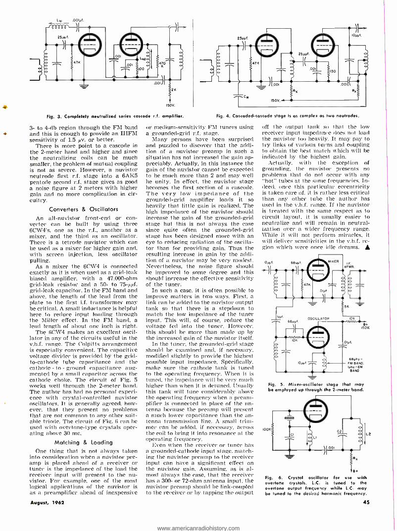
LNI
150V.
Fig. 3. Completely neutralized series cascade r.f. amplifier.
3- to 4 -db region through the FM band + and this is enough to provide an IHFM
sensitivity of 1.5 µv. or better. There is more point to a cascode in
the 2 -meter band and higher and since the neutralizing coils can be much smaller, the problem of mutual coupling is not as severe. However, a nuvistor neutrode first r.f. stage into a 6AK5 pentode second r.f. stage gives as good a noise figure at 2 meters with higher gain and no more complication in cir- cuitry.
Converters & Oscillators
An all -nuvistor front -end or con- verter can be built by using three 6CW4's, one as the r.f., another as a mixer, and the third as an oscillator. There is a tetrode nuvistor which can be used as a mixer for higher gain and, with screen injection, less oscillator pulling.
As a mixer the 6CW4 is connected exactly as it is when used as a grid -leak biased amplifier, with a 47,000 -ohm grid -leak resistor and a 50- to 75 -tfpf. grid -leak capacitor. In the FM band and above, the length of the lead from the plate to the first i.f. transformer may be critical. A small inductance is helpful here to reduce input loading through the Miller effect. In the FM band. a lead length of about one inch is right.
The 6CW4 makes an excellent oscil- lator in any of the circuits useful in the v.h.f. range. The Colpitts arrangement is especially convenient. The capacitive voltage divider is provided by the grid - to- cathode tube capacitance and the cathode - to - ground capacitance aug- mented by a small capacitor across the cathode choke. The circuit of Fig. 5 works well through the 2 -meter band. The author has had no personal experi- ence with crystal -controlled nuvistor oscillators. It is generally agreed. how- ever, that they present no problems that are not common to any other suit- able triode. The circuit of Fig. 6 can he used with overtone -type crystals oper- ating above 30 mc.
Matching & Loading One thing that is not always taken
into consideration when a nuvistor pre- amp is placed ahead of a receiver or tuner is the impedance of the load the receiver input will present to the nu- vistor. For example, one of the most logical applications of the nuvistor is as a preamplifier ahead of inexpensive
August, 1962
Fig. 4. Cascaded -cascode stage is as complex as two neutrodes.
or medium -sensitivity FM tuners using a grounded -grid r.f. stage.
Many persons have been surprised and puzzled to discover that the addi- tion of a nuvistor preamp in such a situation has not increased the gain ap- preciably. Actually, in this instance the gain of the nuvistor cannot be expected to be much more than 2 and may well he unity. In effect. the nuvistor stage becomes the first section of a cascode. The very low impedance of the grounded -grid amplifier loads it so heavily that little gain is realized. The high impedance of the nuvistor should increase the gain of the grounded -grid stage but this is not always the case since quite often the grounded -grid stage has been designed more with an eye to reducing radiation of the oscilla- tor than for providing gain. Thus the resulting increase in gain by the addi- tion of a nuvistor may be very modest. Nevertheless, the noise figure should be improved to some degree and this should increase the effective sensitivity of the tuner.
In such a case, it is often possible to improve matters in two ways. First, a link can he added to the nuvistor output tank so that there is a stepdown to match the low impedance of the tuner input. This will, of course, reduce the voltage fed into the tuner. However. this should he more than macle up by the increased gain of the nuvistor itself.
In the tuner, the grounded -grid stage should he examined and. if necessary. modified slightly to provide the highest possible input impedance. Specifically. make sure the cathode tank is tuned to the operating frequency. When it is tuned. the impedance will he very much higher than when it is detuned. Usually this tank will tune considerably above the operating frequency when a pream- plifier is connected in place of the an- tenna because the preamp will present a much lower capacitance than the an- tenna transmission line. A small trim- mer can he added. if necessary, across the coil to bring it into resonance at the operating frequency.
Even when the receiver or tuner has a grounded -cathode input stage, match- ing the nuvistor preamp to the receiver input can have a significant effect on the nuvistor gain. Assuming, as is al- most always the case. that the receiver has a 300- or 72 -ohm antenna input, the nuvistor preamp should be link -coupled to the receiver or by tapping the output
off the output tank so that the low receiver input impedance does not load the nuvistor too heavily. It may pay to try links of various turns and coupling to obtain the best match which will be indicated by the highest gain.
Actually. with the exception of grounding, the nuvistor presents no problems that do not occur with any "hot" tubes at the same frequencies. In- deed, once this particular eccentricity is taken care of, it is rather less critical than any other tube the author has used in the v.h.f. range. If the nuvistor is treated with the same respect as to circuit layout, it is usually easier to neutralize and will remain in neutral- ization over a wider frequency range. While it will not perform miracles, it will deliver sensitivities in the v.h.f. re- gion which were once idle dreams.
ï
OSCILLATOR 10
10yyf
Olyf.
B+ 1501.
eemhz- FM BAND. Iphy. -6M
BAND.
Fig. 5. Mixer- oscillator stage that may be employed up through the 2 -meter band.
1OOx C2
L
001
8+
Fly. b. Crystal oscillator for use with overtone crystals. LICE is tuned to the overtone output frequency while LC: may be tuned to the desired harmonic frequency.
L2
45
www.americanradiohistory.comwww.americanradiohistory.com
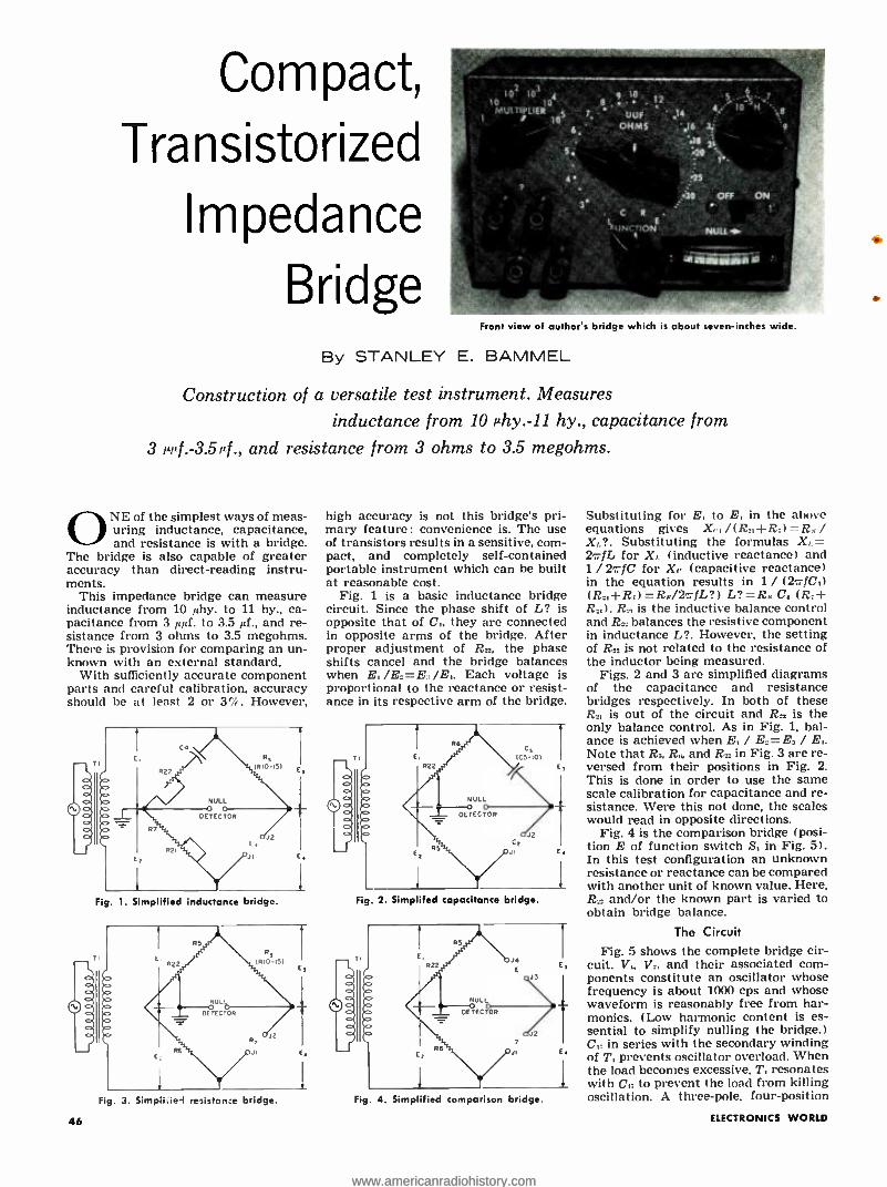
Compact,
Transistorized
Impedance
Bridge Front view of author's bridge which is about severs-inches wide.
By STANLEY E. BAMMEL
Construction of a versatile test instrument. Measures
inductance from 10 µhy. -11 hy., capacitance from
3 µri f . -3.5 ¡4., and resistance from 3 ohms to 3.5 megohms.
ONE of the simplest ways of meas- uring inductance, capacitance, and resistance is with a bridge.
The bridge is also capable of greater accuracy than direct- reading instru- ments.
This impedance bridge can measure inductance from 10 Ally. to 11 hy., ca- pacitance from 3 ,N¡,f. to 3.5 µf., and re- sistance from 3 ohms to 3.5 megohms. There is provision for comparing an un- known with an external standard.
With sufficiently accurate component parts and careful calibration, accuracy should be at least 2 or 3 %. However,
CO
Rs (R.0-ISI
522
NULL
DETECTOR
7
R2i L,
JI
Fig. 1. Simplified inductance bridge.
Fig. 3. Simplified resistan:e bridge.
46
high accuracy is not this bridge's pri- mary feature: convenience is. The use of transistors results in a sensitive, com- pact, and completely self- contained portable instrument which can be built at reasonable cost.
Fig. 1 is a basic inductance bridge circuit. Since the phase shift of L? is opposite that of C. they are connected in opposite arms of the bridge. After proper adjustment of R », the phase shifts cancel and the bridge balances when E, /E:= E. /E,. Each voltage is proportional to the reactance or resist- ance in its respective arm of the bridge.
Fig. 2. Simplifed capacitance bridge.
J<
E
J2 2
Fig. 4. Simplified comparison bridge.
Substituting for E, to E, in the above equations gives X, , /(R., +R:l R. / X,, ?. Substituting the formulas X,. = 2a/L for X,, (inductive reactance) and 1 / 2c fC for X,. (capacitive reactance) in the equation results in 1 / (2,4C,) (R +R)= RR /2r-fL ?) L ? =R,C. (R5+ R,). R. is the inductive balance control and R. balances the resistive component in inductance L ?. However, the setting of R. is not related to the resistance of the inductor being measured.
Figs. 2 and 3 are simplified diagrams of the capacitance and resistance bridges respectively. In both of these
is out of the circuit and R. is the only balance control. As in Fig. 1, bal- ance is achieved when E, / E_ =E, / E,. Note that R., R., and R. in Fig. 3 are re- versed from their positions in Fig. 2. This is done in order to use the same scale calibration for capacitance and re- sistance. Were this not done, the scales would read in opposite directions.
Fig. 4 is the comparison bridge (posi- tion E of function switch S, in Fig. 5). In this test configuration an unknown resistance or reactance can be compared with another unit of known value. Here, R» and /or the known part is varied to obtain bridge balance.
The Circuit
Fig. 5 shows the complete bridge cir- cuit. V,, V,. and their associated com- ponents constitute an oscillator whose frequency is about 1000 cps and whose waveform is reasonably free from har- monics. (Low harmonic content is es- sential to simplify nulling the bridge.) C,5 in series with the secondary winding of T, prevents oscillator overload. When the load becomes excessive, T, resonates with C., to prevent the load from killing oscillation. A three -pole, four -position
ELECTRONICS WORLD
www.americanradiohistory.comwww.americanradiohistory.com

-a,
R,- 33.000 ohm, .2 w. res. R:. R:- -1000 ohm. .2 se. res.
Rr- 10,060 ohm, .2 w. res. R. 11,- 3830 ohm. I = w. res. -` ! R. -2101 ohm, !;z w. res. y lr/ R., R- - 100.000 oha,, ii re. res. ± 1% R,a-1 megohnt. , a. res. ± 1% 11,-10.000 ohm. , z w. res. ± /7 R,.rlllllll ohm.. z se. res. ± 17e
100 ohm, !z se. res. + 1% R /ll ohm. 1/2 m. res. ± ¡'k R R;.- -220.100 ohm. ./2 m. res. R,. -22011 ohm. 1= w. res. R,.- 4711 ohm. !j w. res. R:,- 47,0011 ohm. .2 re. res.
N:- Vllll oha, linear -taper wireround pot ( "16 11 "l (Clarostat :IS82K or equiv.)
Re 10,010 ohm linear -taper wirrwoand pot ( "µµl'- Ohu,s "I (Clarostat d58l0K or toxin.)
C,, C':. C- .01 pi., 21111 n. capacitor C.-.1 4.. 10 v. capacitor C, -.0115 pf., 500 v. silrermica capacitor
pt.. 2110 v. capacitor --- I6 ;
C. -.l p!.. 2011 r. capacitor -- 111,;
C: -.0l pt., 2011 v. capacitor C,- .0111 al., 500 v. silver -mica capacitor Cs-- -100 p4,, 500 v. silvrrmice, capacitor C,.. --10 ppf., Sllll v. silver -mica capacitor C,r .2 p4.. 10 n. capacitor
pj.. let v. capacitor
2N229g 2N229 vD
p!., 3 v. elec. capacitor C:. C- -Ill pJ 6 v. elrc. capacitor Tr- Transistor audio trans.. pri: 100 ohms,
sec: 1000 ohms hGauror T.4.3 or equiv./ Sr- 3 -pole, 4 -pos. rotary switch ("Function") S.-D.p. 6 -pos. rotary switch ( "Slxltiplier") S.,-S.ps.t. toggle switch ("On-Off") SR,. SR: Low- or medians-current silicon
diode a í.V1642 or retain./ 81-6 -volt battery (I pealite cells) J,, J.. J:. J.- 5-way insulated jack Mr-0-10 ma. d.r. aster (Shurite 3303 or
eclair.) V,. V., F . l' , t' ",: p,," transistor (2.V229
or equiv., V.. "p -a -p" transistor 12N1265 or equiv.)
Fig. 5. Transistors V, and V_ constitute an oscillator whose output is coupled to bridge by T,. If loading is excessive, C,; and T, resonate and prevent oscillator from overloading. Null -detector amplifier consists of V. and V,. Vs and V.: drive M,.
switch (8, is used to change from one type of bridge to another.
In order to realize the full accuracy of this bridge. a sensitive null detector is incorporated in the circuit. Its ampli- fier, V. V,. V.;, and V,:, has a roughly logarithmic response which prevents overload yet still provides high sensitiv- ity, that is. the amplifier has high sensi- tivity at low levels and low sensitivity at high levels. Without this feature, the amplifier would overload. its bias would change. and the output to the meter would be lowered, giving a false null. Such operation would make it almost impossible to find the true null.
The logarithmic response is obtained by applying negative feedback through silicon diodes SR, and SR,. A silicon di- ode does not begin to conduct appre- ciably until about .7 volt of forward bias is applied to it. Therefore, there will be little feedback at a low -level input. As the input level increases, the feedback increases, causing the gain to decrease.
The low sensitivity of M, makes a conventional bridge rectifier impracti- cal. V.; and V.: act as amplifier- rectifiers and are both normally cut off. When an a.c. signal appears, V.; conducts on the positive peaks and V. conducts on nega- tive peaks. Amplified d.c. then flows through M,.
The total resistance in series with and including M, must be greater than 600 ohms or the needle will go off -scale at high -level inputs. The meter specified in the parts list has an internal resist- ance of approximately 800 ohms and therefore does not need an external re- sistance. However, if a different meter with an internal resistance less than 600 ohms is used, an appropriate resistor must be added.
Construction
Fig. 6 is a photo of the inside of the instrument and indicates layout. Three
2" screws mount T,. the two circuit boards, and the terminal strip. This method of mounting is sturdy and pre- vents marring the finish on the box.
The oscillator and amplifier are mounted on two small polystyrene boards. Similar material, such as per- forated phenolic boards with flea clips, is also suitable. It would also be feas- ible to use home -made printed circuits.
Accuracy of the bridge is no better than its built -in standards. One per -cent resistors are readily available, reason- ably priced, and a worthwhile invest- ment. Unfortunately, precision capaci- tors are not readily obtainable: ± 10% tolerance is common.
Calibration The bridge can be calibrated mathe-
TI
R2t
matically, empirically, or by a combi- nation of both methods. However, t he mathematical approach requires noth- ing in the way of standards (other than those which are built into the instru- ment) and is probably easier. It is as accurate as if precision parts were used in the instrument.
The method used by the author and described here is mathematical. Tables 1 and 2 show the calibration for R,_ and
in terms of per -cent of rotation. The following is the step -by -step calibra- tion procedure.
1. See Fig. 7. Determine the distance (arc) over which R_, and R. change re- sistance with an ohmmeter set on its lowest range. Al. each end of the poten- tiometers. the resistance is zero for a
I Co /I fin 11eä on pale R61
R7 R22 RIO CIO RII RI2 S2 R13 R14 RI5
.wr C5
t. RI-> R2 V4
C15
C7 C8 C9
C6
J3 J4
IMP V6 C14 V5 CII R6 SI C4 BI WO
Fig. 6. Amplifier, bottom left, is supported by two -inch machine screws that also hold left lug of terminal strip and right flange of T,. Another machine screw, extreme left, holds oscillator above amplifier and secures the left flange of T.
August, 1962 47
www.americanradiohistory.comwww.americanradiohistory.com

.:_ .. .: -t
Low &.. Converter /
e
'm Frequency Construction of a 150 -550 ke. crystal
converter to be added to any AM broadcast set to receive marine radiobeacons and continuous weather broadcasts.
By RONALD L. IVES
Wl'FH the recent establish- ment of a nation -wide net- work of continuous weather
broadcasting stations in the low- and medium- frequency range (190 -400 Ice.), and the increasing use of the adjacent marine information broadcasts, need for receiving equipment in the general range from 190 -.550 kc. has greatly in- creased.
Only a few receivers (such as the Na- tional NC -66, the Hututnurhutd RDF -10, and the Hcuthkit DF -2), currently in manufacture, will cover this frequency range. Military surplus receivers, cover- ing this range but usually needing from some to much modification and /or re- habilitation, include the BC -453, the BC -348, the ARB, and the RAK -7.
To the owner of a good general- cover- age receiver, the purchase or construc- tion of an entire new receiver to cover the low- and medium -frequencies seems wasteful, and possibilities of a converter seem quite attractive, both from the standpoint of operating convenience and for reasons of economy.
Although tunable converters which make use of the main receiver as a fixed -tuned i.f. system are entirely workable devices at all frequencies, in- cluding those in the low- and medium - frequency range', a crystal -controlled
fixed -tuned converter seems to offer the ultimate in operating convenience, con- comitant with a greater economy of components.
Circuit Principles
The general principles of a crystal converter are quite simple. The signal frequencies, which the receiver cannot tune. are combined with a locally gen- erated frequency. so chosen that either the sum or the difference of the signal frequency and the local frequency are within the tuning range of the receiver.
For a low- and medium -frequency range of 150 -550 kc., which covers the weather broadcasts with an ample mar- gin of safety at both ends of the fre- quency scale, a local oscillator fre- quency of 600 kc. will put the desired signals in the 750- 1150 -kc. frequency range, using the sum frequencies. The difference frequencies. 450 -50 kc. are outside the tuning range of most re- ceivers with which a converter must be used, and can be disregarded as long as they are not radiated.
To be useful, the converter must ac- cept only the desired frequencies and must reject the r.f. image (1350 -1750 Ice.). any spurious signals due to oscilla- tor harmonics (such as 1050 -650 kc. signals due to beating of the oscillator second harmonic with signals in the desired range). and second harmonic
Fig. 1. Block diagram of low- and medium- frequency crystal converter.
PASSES 60 -59050 A TENUATES OTHER FREQUENCIES 5006
ANTENNA
-.- BAND -PASS i
TRANSFORMER
511 ANTENNA TO 60011
66A6 -R.
AMPLIFIER
PASSES 6O -5506C AT ENUATES OTHER FREOUENCES 6-2006
PASSES TSO-NSOAC ATTENUATES OTHER FREQUENCIES ISM
CRTSTA
6006C
LC
AVORS 600 C. FUNDAMENTAL
604 CATHODE FOLLOWER
LC
LOW Z TO RECEIVER
INPUT
2 ATTENUATES 6006C. LOCAL OSCILLATOR
images from the 1950- 2350 -kc. range. Fundamentals in the desired tuning
range of the receiver (750 -1150 kc.) must not "feed through" the converter and there must be no radiation of either converted signals or oscillator frequen- cies. The magnitude of the "feed - through" problem is best realized when it is noted that in this area (Palo Alto, California). local broadcast signals are nearly 60 db above the signal from the nearest weather station (Oakland). and about 90 db above the weakest one normally receivable (Red Bluff).
Fig. 1 is a block diagram of the con- verter design finally adopted, along with a summary of component func- tions. The band -pass filters used here effectively attenuate the undesired fre- quencies while passing those to be re- ceived. These filters are not of the most advanced design, but were chosen be- cause they will perform the requisite functions when constructed of easily available "over the counter" compo- nents without the use of complicated adjusting procedures or special test equipment. The band -pass filters are contained in the vertical cans shown in the front -view photograph shown above. Note that the only control is the "Main Power" switch.
The circuit diagram of the converter, Fig. 2. is quite conventional except for the band -pass elements, which are di- agrammed separately in Fig. 3. Al- though additional amplification could be obtained by using a slightly more involved circuit, the extra gain would he useless, since the circuit as shown has the maximum amount of usable sen- sitivity.
Construction Construction is quite simple and
straightforward. A chassis measuring approximately 8" x 13" x 2" will hold all components without crowding. The
48 ELECTRONICS WORLD
www.americanradiohistory.comwww.americanradiohistory.com

ANT
GNO
RLI CONTACTS
BAND -PASS
6BA6 VI
613E6 V2
6C4 V3
5
LCI r
BAND -PASS 2 BAND -PASS 3
R8
JI OUTPUT
RTA CONTACTS
C21 _
R9
C16 R
CIT ® RIO RII XTAL
RIS r
G2
L
TI SI
SRI CHI { R18
C24 S + SR3 +
SR4
RIB
I50V.
+ C23 + C22
R20 R19
2A.
4
R,-- 100,0110 ohm. I m, res. R,.Re- 17 shin. 1 w. res. R..R5-- 22.000 ohm. 1 w. res. R- -6800 ohm. 2 w. res. 8,:470.0110 ohm, 1 ta. res. R,. -3.íl1 ohm. 1 w. res. 11 - 1.5,000 ohm, 2 n. res. R 1000 ohm, 1 w. res. Ro- 27.000 ohm, 2 w. rus. R,: 10 ohm, 2 w. res.
1110 shun. 1 w. .1 pf., 600 v rernu, ir capacitor
C,.- 15 nut., 600 a. tabular capacitor pro- S pf., 450 v. elec. capacitor
layout shown in the photographs seems to be about optimum, but any other reasonable arrangement of parts should also work. Construction is facilitated if the band -pass filters, whose constants and circuits are shown in Fig. 3, are made first as sub -assemblies. Mounting of filter components on epoxy board (Vector G -10) with suitable push -in terminals (Vector T -28) is most con- venient here as both sides of the epoxy board can be used for mounting. Care should be taken to prevent intercou- pling of the coils by mounting adjacent inductances with their axes at right angles. Heavier- than -usual shield cans are desirable on both the band -pass fil- ters and the LC components. to insure against intercoupling and radiation.
If coverage of other frequency ranges is desired, it can be arranged by using a crystal of different frequency and band -pass filters of other characteris- tics. These can be computed by using the formulas given by Terman', which require only simple algebra plus pa- tience and ingenuity.
The top view of the completed con- verter, showing the arrangement of the components, is given in one of the pho- tos. Note the mounting of the relay cans at the rear corners of the chassis to allow access for servicing if needed, and the placement of power rectifiers (SR, -SR,) vertically on a bracket, fac- ing toward the rear, for similar reasons. Filter capacitors are socket- mounted (Cinch 2 -C -7 sockets) to permit rapid testing and component replacement.
C .0 .1 pf.. 6110 v. tubular capacitor r ,(: 1N pf 4111 v. elec. capacitor 1Mallory
ll'/141 r .01 pf.. 600 v. tubular capacitor
5000 ohm relay //'otter & Brumfield R.S-Sn,
S, - S.p.s.t. topple .switch CH 15 hy., 75 ma. filter choke 1.Stauro
C1002, LC, .500-8(10 hr. uaretrap, shunt-connected
lMiller 812-RC31 1.C: Same as LC, Prl'ept series connected Pl.,- Type 41. 68 a. pilot light PL:-N651 bulb
Relays, which are wired to permit straight- through connection of the an- tenna when the converter is not in use and to automatically connect the con- verter between antenna and receiver when the converter power is on. are mounted on Bakelite disks bolted to gutted and reamed Cinch -Jones S -308- RP plugs. Covers are round shield cans which are a press fit over the inverted plug shells. The relay circuit, consisting of the two relays and a dropping resis- tor (R,,), all in series across the power
Fig. 2. Complete schematic of the converter.
SR SR:,SR .SR .11.50l? 101084 .silico,, rec- tifier
F,- 1 amp fuse , 7'ype. ?:I UI 7' Posner trans.. 125 r. .0 50 ara.: 6.3 v.
., 2 amps (Stance". 1'.-1 8121 r
T: Midehaud antenna trans.. 75 ohms to 600 ohms Worth Hills .12111:1, made by .Vorth /!ills Electronics. luir., Glen Core. .V.v. Type 1100:14 may also be used with no connection to itits renlrrrap.I
.1 ioI. 6011 kr. oscillato- , Wiley A I.3 or equiv.i
1 (.'oar. (.0 11 hm 68.46 tube
1 611E6 tate l', -- 6C4 tabe
supply. functions as a bleeder and re- quires no "spark suppressor" as it is shunted by the second filter capacitor
With a bit of careful planning. the under -chassis portion of this converter will acquire the "nothing to it" appear- ance of much well -constructed elec- tronic equipment. Note the use of tie - points to support major parts, as shown in the photo on the next page.
Wiring of the r.f. stage IV,) is en- tirely conventional and needs no more
Top view of the converter. Four rectifiers ore clip- mounted, one above the other.
OUT PU JI
RLI-'
T2
INPUT
SRI -4 A.C. FI PL2
IN TI C23 = CHI ink C 22
fRL2
LCI
t Q LC2
%TAL
BPI-
r..,. . ,.
51r VI 1,
PLI BP2 V2 BP3
C7
August, 1962 49
www.americanradiohistory.comwww.americanradiohistory.com

Bottom view of the home -built unit. Note the clean, uncluttered wiring layout.
precautions than an ordinary low -fre- quency i.f. stage. When this heater cir- cuit is wired, it is advisable to wire the heater circuits of the other tubes and the pilot light (PL,) at the same time. The 10 -ohm resistor in series with the pilot light (R,:) is to reduce the bril- liance of the bulb and extend its life expectancy.
Where the specified antenna- match- ing transformer is not available, its place may be taken by a small capaci- tor and resistor, connected as shown in Fig. 4. Under ideal conditions and with an antenna of approximately 75 ohms impedance, this works nearly as well as the transformer. Under unfavorable conditions (those usually prevailing), a signal loss of several decibels is to be expected when this expedient is used.
The converter stage (V,) will be rec- ognized as a self -excited arrangement with crystal control. The tuned circuit in the screen (LC,) causes the oscilla- tor to favor the fundamental frequency of the crystal (here 600 kc.), greatly re- ducing the harmonic output and, in con-
sequence. spurious frequencies there- from.
The cathode -follower output stage (Vs) isolates the last band -pass stage from the antenna circuit of the main receiver, reduces the converter output impedance, and permits use of a crystal - frequency attenuator (LC,) in the out- put. This makes the converter substan- tially independent of loads.
All connections are made on the rear chassis skirt, which also carries the fuse and the blown -fuse pilot. The au- thor used labels on front and rear skirts. including specifications on replacements for pilot lamps, fuses, etc. Labeling in- volves a bit of extra effort during con- struction but saves valuable servicing time later on.
The power supply is entirely conven- tional and has a very wide margin of safety in all components so that slight aging of any of them will not result in sudden failure. The small capacitor (C 1 across the power transformer sec- ondary suppresses switching transients in the silicon rectifier circuit so that
LI CI C2 L2 L] CD Ce L4
) cs u nP 600A
T T CA)
ICI
R 600 ohms (mode op of 3311 + 270 ohan res.)
R.R. : 2.1,5110 ohms /taro 17.000 ohm res. in Parallel/
R4.1? 22.000 ohms C,.Cr-.011259 pl. (made np of .002 Id., + .190
pp/. 7- 21111 pp/., C_,Ce-.011131 pf. (made ne of 750 l,pf- +
560 ppf., CC<,C.': 719 pif. hmade op of 6811 lvd +
39 ppl.l C.C., .1 pf.. 600 0. ceramic plate rapnrilor Cr,Crn 128 ppf. /mode op of 110 pp/. } 18
01,1.1
50
xl
R) OUT
Fig. 3. Circuits arrangements employed for IA) band -pass I, input; IBI band -pass 2, r.f.; and ICI band -pass 3, output networks.
Cor-20 pp/. rasaritnr C,u.ClI- 18 pp/. capacitor
ppl. (two IS pp /. in series, Note: Erie "CeramiCO, Type GI' -I -K capaci- tors Irere tiser/ by :he anchor for all values stated in p pf. Ix a .similar CONS. . IShnexco "Dur- Mira" Sr; capacitors worked satisfac- torily. La. -.24 mhy. r./. choke (Miller 1616 or
Stamm- RTC 85291 L:.L.- .52 inky. .f choke /Miller 951 or
3Ieissxer 19.6832, L3-100 Inky. r.l. choke l.1/iller 960 or any
r.f. choke from 80 too ISO Inky., L.. /. -- Ill rooky. r.f. choke /.%/iller 1672.
3trissner 19.2010, or National R -100, L., /. 8.2 mhy. r.f. choke I Miller 4671 or
Smacnr RTC 9179,
the converter will not insert hum bars in neighboring TV receivers.
Adjustments
After wiring is completed and a gen- eral check made of construction, a "smoke test" is in order, followed by alignment of the converter. Be sure that all tubes, pilot lights, fuses, and the crystal are in the correct sockets and that the tubes have approximately their correct supply voltages, then connect the output of the converter to the re- ceiver with a shielded lead. This lead must be shielded or it will act as an antenna and pick up signals in the broadcast band.
Tune the receiver to 600 kc. and ad- just the crystal oscillator circuit LC, to maximum "S" meter reading. Next adjust the output filter circuit LC,
One side of the circuit board used for band -pass filter 1. A shield can is later mounted over the assembly shown.
to minimum "S" meter reading. This completes the adjustment of the con- verter.
Connect antenna and ground to the converter input terminals. When the converter is turned off, the receiver should work as before. as the relay circuit feeds the antenna through to the receiver when the converter is de- energized.
When the converter is turned on, sig- nals in the aeronautical band will be tuned in, the receiver dial reading being exactly 600 kc. higher than the station frequency. Locations and frequencies of the radio -range stations are listed
(Continued on page 85)
ELECTRONICS WORLD
www.americanradiohistory.comwww.americanradiohistory.com

Directory of COLOR -TV Test-Pattern Generators SERVICE technicians tvhose shops are now %veil
equipped for black -and -white TV servicing should not have to make huge cash outlays for test equip-
ment to "tool up" for color. Assuming a wide -hand scope, v.t.v.m., sweep generator,
and a marker generator are at hand, only two new test in- struments twill be required: a color -pattern generator, and a tthite- clot /crosshatch- pattern generator.
e Color- Pattern generators are used to troubleshoot and ad- just the color circuits of the receiver. There are three differ- ent types: ;NTSC (National Television Systems Committee) color -bar generators produce a pattern of six fully saturated it color bars at equal brightness levels and a black and a white bar all in accordance with NTSC standards.
Rainbow generators, which operate on what is called the offset- subcarrier principle (their output frequency differs by 15.750 kc. from the 3.58 -inc. color subcarrier frequency) produce a pattern that is a smooth transition or blending of colors, like a spectrum or rainbow. The rainbow generator's principal usefulness is in determining if the color circuits are operating; it can be used in conjunction with a scope,
on tvhich Lissajous patterns Nlllllcl be clispla' cd. to slake chroma and demodulator phasing adjustments.
An improvement on this instrument's design is the sated rainbow generator. The pattern produced by this inshrunlcnt is basically a rainbow pattern that is gated (turned on and off) to produce a series of vertical color and black bars. Each of the ten color bars it creates, spaced precisely at 3O° phase intervals, is a small segment of the rainbow pattern. This instrument is also more useful than the basic rainbow gen- erator because it provides a horizontal -sync pulse and a color -burst signal.
White -Dot /Crosshatch -pattern generators are used for convergence adjustments. (Each of the three electron beams must strike only its associated color phosphor.) White, rather than black, lines and clots are more convenient to use since all three primary colors, produced simultaneously by the three guns, are required to generate white.
A number of currently available test instruments generate two or more of these patterns. Your decision to buy separate units or a multi- purpose generator depends on finances and whether you plan to do color work in homes or in the shop.
MANUFACTURER
B 3 K Manufacturing Co. 1801 W. Belie Plaine Ave. Chicago 13. Illinois
MODEL 8 8 W PATTERNS'
Dots V H
850 X X X
1076
COLOR PATTERNS
Rainbow
CH Simple Gated NTSC
X X,
X X X X
Heath Co. Benton Harbor, Mich.
CD-I
X X
X X X X X
Hickock Electrical Inst. Co. 10514 Dupont Avenue Cleveland, Ohio
Precision Apparatus Co. 7031 84th Street Glendale 27, E.I., N. Y.
656XC X X
660 X
661 X X
E-420 X X
X x
x x
X X
X X
E-440 X
Radio Corp. of America RCA Electron Tube Division Harrison, New Jersey
Robertson Instrument Co. 1760 W. First, P.O. Box 834 Azusa, California
WR-64A X X
Hycon 616
X X X
Sentore, Inc. 426 S. Westgate Drive Addison, Illinois
CA122 X X
Simpson Electric Co. 5200 W. Kinzie Street Chicago 44, Illinois
430
434A X
Winston Electronics Div., letronic Industries,lnc. Main and Cotton Streets Philadelphia 27, Pa.
150
250 X X
X
X,
2-6. .001-.05v
X 3, 4
2-6
OUTPUT
R.F. Channels Video Audio
3. 4. 5 4.5 mc. from pit
2-8, 12, 13 X 4.5 mc. from pie
2.6..0001 -.1v rt. 0.10v 4.5 mc. from pie
2-6..0001-.1v It., 0-2v 4.5 mc. from pis
xr
xr
4 ., 0-4v
X
0-6v
REMARKS
disables each color gun; automatic deconvergence; video level control; 15.750 kc. output
includes flying -spot scanner: provides a.g.c., sweep, and sync signals; performs other TV test functions
kit: shading bars for back- ground adjustments
PRICE
$199.95
$199.95
$ 64.95
$549.00
number of dots and bars is variable
3 0-8v
3 or 4
3, 4; .01v s, 0.10v
4.5 mc. from pie
4.5 mc. from pox
$243.00
$175.95
15.750 kc., luminance, and $264.95 3.5637 mc. output
15.750 kc. output $189.50
4, 5. 9, 10 Iv 4.5 mc. from pix
disables each color gun: provides r.f. output and sync pulses
$385.00
$187.50
2.6
2 -6
$395.00
adjustable dot size; provides $149.95 horiz. and vert. sync pulses
X 2-6
2
' V, vertical; H, horizontal; CH, crosshatch. ' NTSC color bars produced individually. Six NTSC color bars plus a black and white bar.
S 49.95
r $129.95
NTSC Rainbow Gated Rainbow White-Dot/Crosshatch
August, 1962
11\ iu, IN\ 11ti11111111111111 11111111 11111111111111 1111 Hll11 1111 T1111I \11 `\11111111/r
51
www.americanradiohistory.comwww.americanradiohistory.com

TRA NSISTORIZED IGNITION SYSTEM By BOGHOS N. SAATJIAN /Design Engineer, Triad Transformer Corp. (Div., Litton Industries)
Construction of simple system for 12 -volt, negative ground cars that delivers good high -voltage spark even at top engine speeds. Longer point life and easier starting are other advantages of the system.
SINCE the advent of power tran- sistors, many car enthusiasts have looked upon them as the
answer to their prayers for a non- mechanical switch to handle the rela- tively heavy currents encountered in an automobile ignition system.
Standard Ignition System
The standard ignition system (see Fig. 1A) has been in use since 1910, with little change. Essentially, the sys- tem revolves around the distributor points, which are nothing more than a simple overloaded electrical switch. They have to carry currents of 5 to 8 amperes. They open and close thou- sands of times per mile. On top of this, the ignition coil used with the standard ignition system requires a high pri- mary inductance to be able to generate enough self -induced voltage to be stepped up in the high -voltage second- ary to about 20.000- 25,000 volts to fire the spark plugs. Because of the high primary inductance and the reduced "on" time of the breaker points at high speeds, the primary current of the coil can not build up to its maximum design value at high engine rpm's. Hence, the spark plugs do not get the fat spark they require to fire the charge in the cylinders. Plug fouling and high -speed miss result.
The high primary current and self - induced voltage build up to such high power values across the points that arcing and pitting occur and points have to be replaced every 5000 miles or so.
Another consideration is cold - weather starting. At cranking speeds, the points, because they are opening and closing at a slow rate, have a much longer "on" time. This results in point oxidation or blueing, due to high point temperatures. The oxide on the points
52
is a poor conductor. Less and less power will thus be available for the coil primary, which means less high voltage at the spark plugs, and harder cold - weather starts.
The Transistorized Circuit
The transistor, being an electronic switch with no moving parts to pit, should be the ideal solution to ignition problems.
A small bias or trigger current (see Fig. 113) in the base circuit of the tran- sistor will let a much larger current flow through the emitter -collector junction of the transistor. The dis- tributor points can now be placed in the base circuit of the transistor, to serve as a trigger to fire the transistor at the correct instant. All other func- tions of the distributor remain the
Fig. 1. (Al Standard ignition system and (B1 basic transistorized ignition system.
TO CENTER POST ON DISTRIBUTOR
DISTRIBUTOR POINTS
- DISTRIBUTOR POINTS
(AI
1R1
TO CENTER POST ON DISTRIBUTOR
same. The points control a base current of about 350 ma. Also notice that any self -induced voltage in the ignition coil primary is now in the emitter -collector circuit of the transistor. The points have thus been spared this high self - induced voltage. All they have across them is the 12 -volt battery voltage at 350 ma. Compare this to about 200 -300 volts at 5 to 8 amps. and you will agree that the points should last the life of the car.
The ignition coil can now be rede- signed too, to provide for a fast cur- rent rise time. The coil primary can, therefore, have a lower inductance. Since this means fewer primary turns, a higher turns ratio is used to provide the needed voltage step -up. The new Mallory F -12T coil, for example, has a primary inductance of 1 mhy. and a turns ratio of 1 :250 as compared to 2.5 to 3 mhy. and 1: 100 turns ratio for the standard coil. The advantage of this design becomes apparent at high speeds. An ammeter placed in series with the primary of the coil in the author's car showed a current of ap- proximately 7 amps. at idle and 6 amps. at 4500 rpm. This is a drop of only 1
amp. from idle to 4500 rpm. It can therefore be seen that the transistor- ized system will have full high voltage at the spark plugs from idle to top en- gine speed.
To sum up the advantages of the transistorized ignition system: The points carry only triggering power to the transistor, so there is no pitting and oxidation, resulting in excellent cold - weather starts. Clean points also mean silken acceleration at all engine speeds, with better gas mileage due to less plug fouling and high -speed miss. The ca- pacitor across the points is not needed, so there is no capacitor breakdown.
After Mallory came out with a stock
ELECTRONICS WORLD
www.americanradiohistory.comwww.americanradiohistory.com

ignition coil, the F -12T, specially de- signed for transistorized ignition sys- tems, we decided to experiment with one and design a circuit around it. The following circuit was developed, after experimenting for about a month with different set -ups and various compo- nent values.
Transistors have several drawbacks. First, there is the matter of heat. Tran- sistors must be kept cool in operation or they start to conduct current even without base excitation. Second, they are ruined when a voltage higher than
'w their maximum design value is applied across their emitter -to- collector junc- tion, even for a period of a fraction of a second.
Construction Details
The first problem in our set -up. that of high temperature under the hood, was solved by mounting the transistor and associated circuitry under the dashboard and running leads to the ignition coil and distributor points through a grommet on the firewall. In the author's car, a 1961 Buick "Elec- tra." this was accomplished by running the wires through an existing grommet that had a few wires and could easily accommodate three more. We strongly recommend that builders of the circuit follow this procedure. If this is impossi- ble, the next best location would be in the space between the radiator and the front grille of the car. Usually there is quite a space in this area to accom- modate the heat sinks and the few parts. The resistors and the zener diode should now be enclosed in a small alu- minum case, instead of mounting them on a tag board as shown in the accom- panying photographs. Find a space as protected from spray water as possible. although no great damage would be in- flicted by water because of the low voltages involved. Do not mount the heat sinks or the circuit components on the engine or near the exhaust mani- folds.
The second drawback of transistors, that of breakdown voltage, was solved in the following manner. A look at the circuit diagram of Fig. 2 will show a 100- ,nitf. mica capacitor and a 60 -volt, 1 -watt zener diode across the emitter - collector junction of the transistor. The capacitor should be of the non- induc- tive type and should be soldered right on the transistor terminals, using as short leads as possible. This mica ca- pacitor attenuates any high- frequency spikes generated when the primary coil current is interrupted. The zener diode limits voltage across the transis- tor to a maximum of 60 volts. As the transistor specified has an emitter-to- collector voltage of 80, there is a margin of safety of 20 volts.
The 150 p.i.v. diode, SR,, shown in the circuit, has two functions. First, it guards the transistor against inadvert- ent reversal of input voltage polarity. Second, notice in the circuit diagram that a 500 -ohm, 5 -watt resistor (R:) is connected between the cathode of the diode and ground. This will allow a small current of about 30 ma. to flow
SRI
CRI
TO CENTER POST ON DISTRIBUTOR
PI SOI
PI
SOI
RI 2N174
SI
BI
R4
PI
Ysol
6iDISTRIBUTOR POINTS
Ti
R. -Three Defeo 0.11711 19.í71S4 ballast re- sistors connected in parallel or two I -ohm, 50 -rats power resistors in parallel.
Rr-25 ohm. S w. wireunnnd res. R. --51/0 ohm. ,S w. uirewonnd res. R1 -5 ohm. 25 w. wirewonnd res. (see text)
va( -. Stift v. man iadnetive miro co- paritor
SR.- Silicon rectifier. 25 amps.. ISO p.i.v. (International Rectifier 2.í11R15 or egniv.l
UV-Two 30 -v. zeurr diodes in series or equiv. 60 -volt. Iwatt unit (International Rectifier 1230T5)
S, -Car ignition switch 8, -12 -volt auto battery P, -Male pL,g (Janes I'- 303 -CCT) SO,- Female .socket /Jones :L.-S-303-CGT T,- itofded ignition coil for transistorized
ignition systems, 1:250 tarns ratio (Mallory available. at all auto parts dealers
handling Mallory lined 2- Neat sinks (Delco Radio #.7270725 or
V,-- l'ouer transistor (2.N174 or equiv.)
Fig. 2. Complete circuit of author's unit.
continuously through the diode. This will cause a 0.5 to 0.8 volt drop across SR, with the anode of the diode being positive with respect to the cathode. Now notice that the cathode side of the diode is tied to the emitter of the transistor and the anode is tied through a 25 -ohm resistor (R_) to the transistor base. The base is, therefore, 0.5 to 0.8 volt positive with respect to the emit- ter at the time the points open. This action of the diode guarantees transis- tor cut -off even at even relatively high transistor operating temperatures.
Both heat sinks, one for the diode SR, and the other for the transistor, should be insulated from each other and from the car chassis. Use the spe- cial stand -off insulators available for heat sinks. Be very careful that the heat sinks do not ground to the car body under the dashboard. Use fish- paper or pieces of cardboard to insulate, if there is any danger of shorts. If de- sired. the transistor and diode could be insulated from the heat sinks by the use of special mounting kits. In this case the heat sinks could be bolted di- rect to the car chassis, thus providing better heat dissipation.
Special brackets have to be designed for each application to suit the avail- able space under the dashboard. Parts location is not critical, except for the mica capacitor. Be sure to use silicone grease while mounting the transistor and rectifier on the heat sinks. A thin layer applied to the heat sink surface under the semiconductors will insure better heat transfer.
The ignition coil is mounted on the engine. We did not remove the stand- ard ignition coil, which could be used in case of trouble with the transistor- ized circuit. The old coil could be re- moved, if desired, and the new coil mounted in its location.
Since the capacitor on the distribu- tor will not be needed, it can be re- moved from the distributor and mounted somewhere near the standard coil with its leads connected to the negative side of the coil. The standard coil now serves as a standby.
The lead wires going to the coil from the circuit under the dashboard should be at least #14 to eliminate any volt- age drop in them. A male and female Jones plug and socket were used be- tween the circuit and the coil for greater flexibility and ease of removal of the circuit if necessary.
The ballast resistor used in the standard ignition system should be shorted out. Most GM cars use, as a ballast, a wire resistor that goes from
(Continued on page 68)
Top view of the electronics portion of the transistorized ignition system.
TRANSISTOR HEAT SINK R4
August, 1962 53
www.americanradiohistory.comwww.americanradiohistory.com

INDUCTANCE is only one of the characteristics that determines a coil's suitability in a specific appli-
cation. Distributed capacity is equally important because it, along with in- ductance, determines self -resonant fre- quency of the coil, the point at which the coil becomes useless as an inductor. In fact, above its self -resonant fre- quency, any coil will act for all the world as if it were a poor capacitor, ex- cept that it will not block direct current.
This article will explain how to use the dimensions of a coil to predict its inductance, distributed capacity, and self -resonant frequency. Nomograms are included so that all "calculations" are performed simply by drawing straight lines across the scales.
Inductance
Inductance is the property for which coils are used in circuits, and dis- tributed capacity is another property we must take into account in order to know the useful inductance available. Roughly speaking, inductance can be increased by increasing either the di- ameter of a coil or its number of turns.
Fig. 1. Basic coil geometry used In charts.
Increasing the number of turns is more effective because inductance increases as the square of the number of turns. In other words, doubling the number of turns will increase the inductance by a factor of four, tripling the number of turns will increase the inductance by a factor of nine. and so on.
However, many of the changes made to increase inductance will also increase distributed capacity, and the over -all effect is to reduce the self- resonant fre- quency at a rapid rate. We can consider a practical coil as consisting of an ideal coil (pure inductance, and no capacity) in parallel with an ideal capacitor, and therefore increasing either one will re- duce the resonant frequency according
to f =1/ (2s7 \ LC ). It is desirable, then. to have independent control over both inductance and distributed capacity. To a certain extent, such control is avail- able to those who wind coils, through manipulation of the coil's silhouette. A series of 20- microhenry coils can be made, ranging from long and thin ones to short and fat ones. Although each coil has the same inductance, the differ- ent silhouettes will dictate that they have different values of distributed ca- pacity and therefore different values of self -resonant frequency.
Distributed Capacity
Dependence of distributed capacity on coil dimensions is not as straight- forward as inductance is, but there are a few general rules to serve as guides. Coils that range from short
I those whose diameter is greater than the length) to medium (those whose length is two or three times the di- ameter) will just about double their dis- tributed capacity when the diameter is doubled. In longer coils, up to those whose length is 50 times the diameter, there is very little dependence on di-
COIL-WINDING CHARTS 44-
42-= 400
40,-z 300
38r 200
36
34ti -32
\- -100 50-C-
60
24-4 40 22=
20-,- '" - 30
181
16- 20
14-
1500
1000
700 - 500
- 300
200
E5
4
= 3
2
12- 12
WIRE TURNS GAUGE PER
INCH
-100 = 70 -50
-30 É
=20
_10 - 7
-5 -3 -2
TOTAL TURNS
-1.0
=0.8
.6
=0.4
-0.3
-0.2
-O.1 LENGTH OF WINDING IN
INCHES Nomogram 1. Chart used to find the length -to- diameter ratio and the di 'buted capacity of the air -core coils.
54
- SO
-40 -30
-20
- 10
-7 5
-4 - 3
-2
1.0
-0.6
-0.4 L-0.3
-0.2
-0.1 FIND
LENGTH DIAMETER
N
-- C15
-0.2 50
30
20 -0.3\N
-04
=- 0 S
0.6
0 7
-0 9
- 0 9
= 1.0 DIAMETER
_15
-10 -8
=6
-4 =3
-2
-LO 0.1 =
50.2 =0.8 3 dB N =0.6
0.5 N =
TRANSFER LENGTH
DIAMETER 0.4
TO THIS -0.3 SCALE
-0.2
- 0.15 DISTRIBUTED
CAPACITY IN }J}JF.
ELECTRONICS WORLD
w.
www.americanradiohistory.comwww.americanradiohistory.com

ameter. Beyond that. we have the very long coils, where there is a definite re- duction in distributed capacity as the diameter is increased.
The length of a coil has an effect on its value of distributed capacity, but the number of turns within a certain length has very little effect. For instance, a coil one -inch long could be wound with 24 turns of No. 18 wire, or it could be wound with 92 turns of No. 30 wire, but the distributed capacity will be about the same in both cases. This is a means of exercising separale control over in- ductance and capacity because you can take an existing coil design and switch to a finer size wire. This will allow you to put more turns in the same length, having little effect on distributed ca- pacity but increasing inductance by the square of the added turns.
These statements will prove helpful as long as you realize that they apply only in a very general way and are on the lookout for exceptions. The nomo- grams will give numerical answers which are adjusted to take care of ex- ceptions to these generalities.
Usually, the goal is to wind a coil with
ó
30 WIRE GAUGE 32 34 36 30
0.7
06
0.6
0.4
2 ¡ 44
SINGLE ENAMEL
DOUBLE - ENAMEL
SINGLE SIL
ENAMEL DOUBLE SILK 200 300 TURNS PER INCH
400
Fig. 2. The number of turns per inch for wire having various types of insulation.
Boo
Nomograms for determining the inductance, distributed By DONALD W. MOFFAT
capacitance, and the self -resonant frequency of coils.
50- 1500- 1000 - 1.0
40--- 700 1000--: 500 _-0.9
30- 700 300 - 0.8
500= 200 -0.7 20-
300- 100 0.6 70 50 200 - 0.5 30 10-
- 20 8- / - IOO-
\ 0.4
10 \ 6_ 70- 7
i y 50= 4- 03 3- 30-
2- 20- 10 0.7 0.5 0.2
I O- 03 10- 0.2
7 - 07- 0.5- 5- 0.1
INDUCTANCE, MICROHENRYS
03- 3- 02- 0.1- 2- 0.1 L LENGTH
DIAMETER
August, 1962
NUMBER TURNING OF TURNS SCALE
Nomogram 2. By using this chart, the inductance values of air -core coils of the sizes shown may be found.
DIAMETER, INCHES
55
www.americanradiohistory.comwww.americanradiohistory.com

as little distributed (..._)acity as possible. Even when a fair amount of capacity is acceptable, it should be controlled and its value known so that the coil will be compatible with the rest of the circuit. If minimum distributed capacity is the goal, the ideal coil is fatter than it is long, having a diameter about one and a quarter times its length. Unfortunately, this is not the most convenient shape to fit into an electronic chassis and it may be necessary to accept more than the minimum amount of capacity and arrive at a compromise coil shape. One advan- tage to the nomograms is that they make it easy to investigate various pos- sibilities, as will be explained shortly.
Coil Resistance
Every coil must have some resistance, which will determine the "Q" factor. However, this factor determines just t he sharpness of resonance and has very little bearing on the actual frequency of resonance. Since this article is restricted to an investigation of the interaction be- tween inductance and distributed ca- pacity, it will be assumed that the re- sults are independent of coil resistance.
Computations
One of the most important factors in single -layer coils is the length -to -diam- eter ratio, which is used in the compu- tations to follow. This ratio is found on Nomogram 1 and then is used as the first entry on the other two nomograms.
'seer the following instructions for using the nomograms, a simple nu-
merical example will be presented. Distributed Capacity: Nomogram 1 is
used for finding both the length- to -di- ameter ratio and the distributed ca- pacity.
There are two sets of numbers along the first scale. Turns per inch, on the right -hand side of the scale is the basic number that is used for computations. and can always be used. The left -hand side of the scale, Loire gauge, is for con- venience in the unique but common case where single enamel wire is used and there is no spacing between turns. For any other situation, the graph, along with Fig. 2, can be used to arrive at a value of turns per inch. If the windings are closely spaced, follow the line for the type of insulation out to where it crosses the line for wire gauge and at that crossing note the number of turns per inch. For instance. the line for No. 36 wire crosses the line for single silk insulation at 150 turns per inch. If the turns are not wound as close as possible, but have some space between them, de- termine the values of D and S 1 see Fig. 1) and then on Fig. 2 follow that line out until it crosses the line for wire gauge, at which point you will read the turns per inch. Remember that S in the figure includes the insulation over the wire, a quantity that becomes increas- ingly important for fine wires.
Once toles per inch is determined, locate that value on the first scale of Nomogram 1, and the total number of taras on the second scale. Draw a straight line through these two points
and extend it to cross the third scale, where you will read the length of wind- ing. The actual value at this crossing is not important. as it is only the point of crossing that is going to be used for drawing the next line. On the other hand, if you knew the length of the coil, it would not be necessary to perform this first computation; simply locate that value on the length scale, and you are ready for the next step.
Next, locate the correct value on the diameter scale, and draw a straight line from that point to the indicated point on the length scale. Where that line crosses the middle scale, read a value of length/ diameter, a value that will be used for each of the other computations. As with the length of the coil, this step does not have to be performed if the value is known. or if its computation can be rto le mentally. For instance, if your coil has a half -inch diameter and is one inch long. it is not necessary to draw the lines to determine that the ratio length /di- ameter is two.
The last step in determining distrib- uted capacity starts with locating. on the next to the last scale, the value which was found for length /diameter. Diameter has already been locate on its scale. Draw a straight line through these two points and extend the line to cross the last scale. Now read the ap- propriate value of distributed capacity.
50_ 20- 10- 6- 4- 311-
2- 1O
1 5- 20 1.0
0.6 O_ 50 \ N 0.6
O e- \ IDO
0.6- \0.4 0.3 200
0.5- 04- 0.2 \ 500
1000 0.3-
0.1 NUMBER DIAMETER, OF TURNS
INCHES 02-
0.1- TURNING LENGTH SCALE
DIAMETER
Nomogram 3. Chad employed to determine the self -resonant fre- quency of air -core coils from the number of turns and the size.
56
500
300
200
100
70
50
30
20
10
-7
3
-2
_1
- 0.7
=0.5 FREQUENCY,
MEGACYCLES ELECTRONICS WORLD
www.americanradiohistory.comwww.americanradiohistory.com
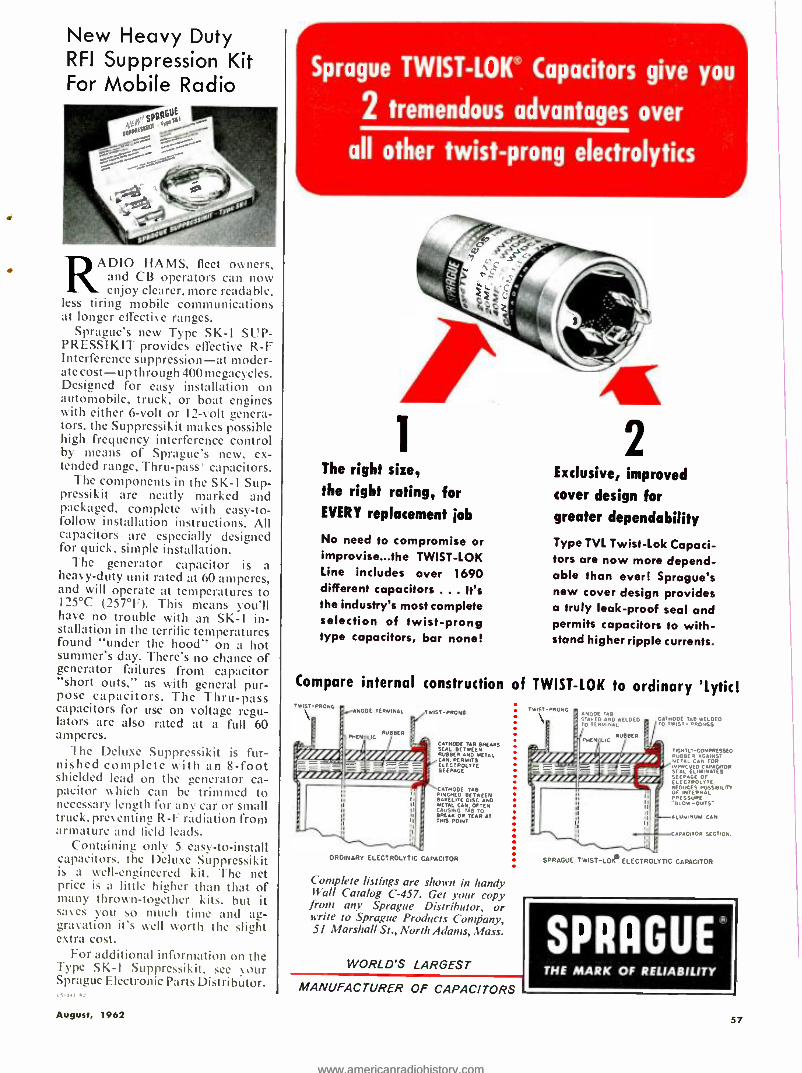
New Heavy Duty RFI Suppression Kit For Mobile Radio
RADIO HAMS, fleet owners, and CB operators can now enjoy clearer, more readable, le tiring mobile communications
at longer effective ranges. Sprague's new Type SK-1 SUP -
PRESSIKIT provides effective R -F Interference suppression -at moder- ate cost-up through 400 megacycles. Designed for easy installation on automobile, truck, or boat engines with either 6 -volt or 12 -volt genera- tors, the Suppressikit makes possible high frequency interference control by means of Sprague's new, ex- tended range, Thru -pass" capacitors.
The components in the SK -I Sup - pressikit are neatly marked and packaged, complete with easy -to- follow installation instructions. All capacitors are especially designed for quick, simple installation.
The generator capacitor is a heavy -duty unit rated at 60 amperes, and will operate at temperatures to I25 °C (257 °F). This means you'll have no trouble with an SK -1 in- stallation in the terrific temperatures found "under the hood" on a hot summer's day. There's no chance of generator failures from capacitor "short outs," as with general pur- pose capacitors. The Thru -pass capacitors for use on voltage regu- lators are also rated at a full 60 amperes.
The Deluxe Suppressikit is fur- nished complete with an 8 -foot shielded lead on the generator ca- pacitor which can be trimmed to necessary length for any car or small truck. preventing R -F radiation from armature and field leads.
Containing only 5 easy -to- install capacitors, the Deluxe Suppressikit is a well- engineered kit. The net price is a little higher than that of many thrown- together kits. but it saves you so much time and ag- gravation it's well worth the slight extra cost.
For additional information on the Type SK -I Suppressikit, see your Sprague Electronic Parts Distributor.
August, 1962
Sprague TWIST-LOW' Capacitors give you
2 tremendous advantages over
all other twist -prong electrolytics
The right size, the right rating, for EVERY replacement ¡ob
No need to compromise or improvise...the TWIST -LOK Line includes over 1690 different capacitors ... It's the industry's most complete selection of twist -prong type capacitors, bar none!
Compare internal construction TRES? PRpNE.
NooE TERNINAL TWIST -PRONG
LIC PUR BER
CATHODE TAB BREAKS SEAL BETWEEN
CANPERM T METAL
ELECTROLYTE SEEPAGE
CATHODE TAB
BAKELITE DISC AND
CIATB OFTEN
BREAM OR THIS POINT
[R AT
ORDINARY ELECTROLYTIC CAPACITOR
Complete listings are shown in handy Wall Catalog C -457. Get your copy
front any Sprague Distributor, or write to Sprague Products Company, 51 Marshall St., North Adams, Mass.
WORLD'S LARGEST
2 Exclusive, improved
cover design for greater dependability
Type TVL Twist -Lok Capaci- tors are now more depend- able than ever! Sprague's new cover design provides a truly leak -proof seal and permits capacitors to with- stand higher ripple currents.
of TWIST -LOK to ordinary 'Lytic! .,s7-P C,
ODE TAB TAMED ANO WELDED 0 TERMINAL
CATHODE TAB MELDED 0 TWIST- PRONGS
- /: % / / ///
Imo° = Iffltf,
MANUFACTURER OF CAPACITORS
TIGHTLY- aOMPBE$5E0 RUBBER AGAINST METAL CAN FOR
SEALFO CAPACITOR
[LI MiNATES SEEPAGE OF EEC FAO LT TE.
POSSIBILITY
F IER PRESSURE
ALUMINUM CAN
CAPACITOR SECTION.
SPRAGUE TWIST-LOO ELECTROLYTIC CAPACITOR
SPRAGUE' THE MARK OF RELIABILITY
57
www.americanradiohistory.comwww.americanradiohistory.com

Turn ON the QUIET ON
Turn OFF the NOISE
with QUIE TROL E The quality, proved lubricant for effective silenc- ing of noisy controls and switches on TV, radio and electronics instruments. And the FREE EX- TENDER TUBE makes those once pesky places easy to reach. Put quality QUIETROLE in your repair kit and see how quickly and easily you satisfy more of your customers.
M'S-L1111,
1 1 1 1
1 1 1
1
1
I 1 I:
1 6 Oz. SPRAY PACK CAN 1 2, 4, 8 oz. Bottles (withFREEExtenderTube) 1 (with Dropper)
Product of
QU1ETROLE COMPANY
Spartanburg, South Carolina in Canada: CROSS CANADA ELECTRONICS
12 Laurel Street, Waterloo, Ontario
THE INDUSTRY'S ONLY COMPLETE
"LOOK -ALIKE" LINE Exact Replacement Needles/Cartridges
Highest quality guaranteed! At your
E -V distributor's or write for FREE replacement guide, today! Electro- Voice, Inc.,
Buchanan, Michigan. Dept. 827N
58
Notice the peculiar layout of the sixth scale, to which the value of Length /di- ameter was transferred. Numbers go down from 50 to about 1 and then the rest of the scale, clown to 0.1, is folded back on itself, so that some spots on the scale are used as the location of two numbers. Another point of interest is that numbers at the lower end of the scale are quite crowded together, mean- ing that any ratios in this range will give about the same amount of distrib- uted capacity. Almost no accuracy would be lost by saying that any value of length /diameter between 1.2 and 0.6 is to he transferred to a location "near" the lower end of the scale.
Inductance: Once length /diameter has been determined from Nomogram 1. locate that value on the first scale of Nomogram 2, and locate number of hurts on the second scale. Draw a straight line through these two points, extending it to cross the third scale. On the last scale, locate the correct value of the diameter. Then a straight line drawn from that point to the point where the first line crossed the turning scale will cross the fourth scale at the inductance. of the coil.
One of the advantages to the use of nomograms can be illustrated at this time. If the inductance that is found is not the desired value, you can rotate a straight -edge about the crossing on the turning scale until it passes through the desired inductance. The straight- edge will then cross the diameter scale at the diameter necessary to give that inductance. You can then work the first nomogram backwards to find a new length of winding, and the coil is rede- signed for the required inductance.
Self -resonant Frequency: Once length/diameter has been determined from Nomogram 1, locate that value on the first scale of Nomogram 3, and lo- cate the diameter on the second scale. Draw a straight line through these two points, extending it to cross the third scale. On the fourth scale, locate the correct number of turns. and draw a straight line through that point and the point where the first line crossed the turning sale. Extend that line to the last scale, where it will cross the self - resonant frequency for that coil.
Any coil is normally designed to oper- ate at frequencies below self -resonance, where it has a useful inductance. At fre- quencies above self -resonance, nothing can be added to make the circuit reso- nate.
As with any other nomogram. it is easy to rotate a straight -edge about any point to see the effects of changing one or more of the numbers.
Example
In order to be certain the instructions are clear, let's run through it again, with numbers. Suppose you have 140 turns of No. 32 enameled wire on a quarter -inch form. On Nomogram 1,
locate 32 on the right -hand side of the first scale and 140 on the second scale. A straight line through these two points will cross the third scale at 1.25, the length of winding. Next, locate 0.25 ¡quarter inch) on the diameter scale
and draw a line front that point to 1.25 on the length scale. It was not neces- sary to note that the length was 1.25 because that value is not used in any of the other computations and only the location of the crossing on that scale is important to further computations. A straight line drawn through these two points shows that the length /diameter ratio is 5. Locate 5 on the next to last scale and draw a line from 0.25 on the diameter scale, through 5 just located, and this line will cross the distributed capacity scale at 0.51 turf.
Now, use Nomogram 2 to find the in- ductance. From 5 on its length/diam- eter scale, to 140 on its number of turns scale, draw a straight line and extend it to cross the turning scale. Draw another line from that crossing to 0.25 on the diameter scale and the answer of 22 microhenrys is found on the inductance scale.
Self- resonant frequency is found on Nomogram 3. Draw a straight line from 5 on the length/diameter scale to 0.25 on the diameter scale and extend it to cross the hunting scale. From that point of crossing on the turning scale, draw a line through 140 on the number of turns scale and extend it to cross the last scale. At that last crossing, read a self - resonant frequency of 48 megacycles.
Accuracy
Several equations have been devel- oped for computing the characteristics of a coil. Unfortunately, we do not have universal agreement on a single correct set of equations, each one seeming su- perior for different purposes. These nomograms have been based on equa- tions that have been supported experi- mentally over the ranges of values used for the scales.
Coil leads. even though only a piece of straight wire, have both inductance and capacity that add to those of the coil proper. In fact, a straight piece of wire has a self -resonant frequency. For these nomograms, it has been assumed that there are no leads on the coil, an as- sumption that introduces negligible error until the coil is operating at fre- quencies of hundreds of megacycles and above. You can generally figure that the calculated value of self- resonant fre- quency is the maximum possible, and in the actual circuit, the coil will reso- nate at some lower frequency; some safety margin should always be allowed.
Usually, the number of turns cannot be determined precisely because the last turn does not have a definite ending, but tapers away from the rest of the wind- ing. At least some part of the last turn (and of the first turn) is more of a lead than a part of the coil proper. Some- times the last turn is wrapped around a terminal or a pigtail and soldered in place. Any wraps not shorted by solder will form another little coil, the char- acteristics of which will add to those of the main coil.
Weather conditions, such as tempera- ture and humidity can have a noticeable effect on the characteristics of a coil. especially if sufficient and constant ten- sion was not maintained during the winding.
ELECTRONICS WORLD
www.americanradiohistory.comwww.americanradiohistory.com
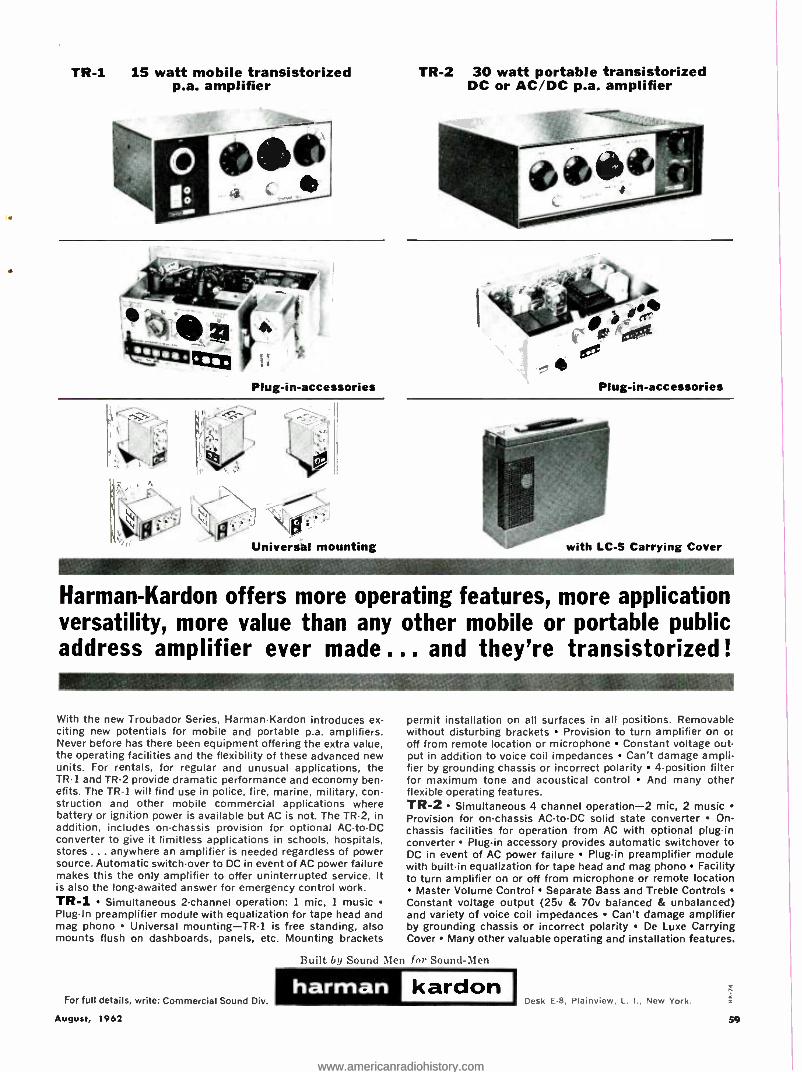
TR -1 15 watt mobile transistorized p.a. amplifier
Plug -in- accessories
.i: Universal mounting
TR -2 30 watt portable transistorized DC or AC /DC p.a. amplifier
Plug -in- accessories
with LC -5 Carrying Cover
Harman -Kardon offers more operating features, more application versatility, more value than any other mobile or portable public address amplifier ever made ... and they're transistorized !
With the new Troubador Series, Harman -Kardon introduces ex- citing new potentials for mobile and portable p.a. amplifiers. Never before has there been equipment offering the extra value, the operating facilities and the flexibility of these advanced new units. For rentals, for regular and unusual applications, the TR -1 and TR -2 provide dramatic performance and economy ben- efits. The TR -1 will find use in police, fire, marine, military, con- struction and other mobile commercial applications where battery or ignition power is available but AC is not. The TR -2, in addition, includes on- chassis provision for optional AC -to -DC converter to give it limitless applications in schools, hospitals, stores ... anywhere an amplifier is needed regardless of power source. Automatic switch -over to DC in event of AC power failure makes this the only amplifier to offer uninterrupted service. It is also the long-awaited answer for emergency control work. TR -1 Simultaneous 2- channel operation: 1 mic, 1 music Plug -In preamplifier module with equalization for tape head and mag phono Universal mounting -TR1 is free standing, also mounts flush on dashboards, panels, etc. Mounting brackets
For full details, write: Commercial Sound Div.
August, 1962
Built by Sound Men
permit installation on all surfaces in all positions. Removable without disturbing brackets Provision to turn amplifier on or off from remote location or microphone Constant voltage out- put in addition to voice coil impedances Can't damage ampli- fier by grounding chassis or incorrect polarity 4- position filter for maximum tone and acoustical control And many other flexible operating features. TR -2 Simultaneous 4 channel operation -2 mic, 2 music Provision for on- chassis AC -to -DC solid state converter On- chassis facilities for operation from AC with optional plug -in converter Plug -in accessory provides automatic switchover to DC in event of AC power failure Plug -in preamplifier module with built -in equalization for tape head and mag phono Facility to turn amplifier on or off from microphone or remote location
Master Volume Control Separate Bass and Treble Controls Constant voltage output (25v & 70v balanced & unbalanced) and variety of voice coil impedances Can't damage amplifier by grounding chassis or incorrect polarity De Luxe Carrying Cover Many other valuable operating and installation features.
for Sound -Men
harman kardon Desk E -8, Plainview, L. I., New York.
www.americanradiohistory.comwww.americanradiohistory.com
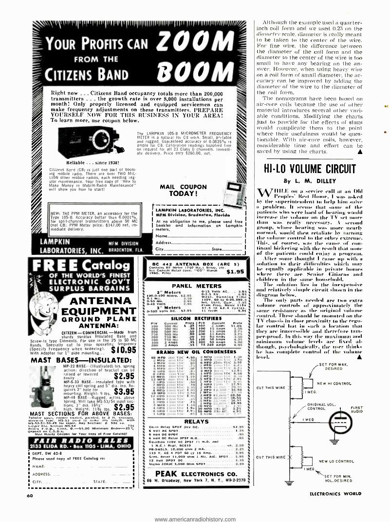
YOUR PROFITS CAN ZOOM
Right now ... Citizens Band occupancy totals more than 200,000 transmitters ... the growth rate is over 8,000 installations per month! Only properly licensed and equipped servicemen can make frequency adjustments on these transmitters. PREPARE YOURSELF NOW FOR THIS BUSINESS IN YOUR AREA! To learn more, use coupon below.
Reliable ... since 1938!
Citizens Band (CB) is just one part of boom. Ing mobile radio. There are over TWO MIL. LION other mobile radios, each needing reg- ular maintenance. Your free copy of How to Make Money in Mobile -Radio Maintenance" will show you how to start!
The LAMPKIN 105 -B MICROMETER FREQUENCY METER is a natural for CB wok. Small, prrtable and rugged. Guaranteed accuracy of 0.0025% is ample for CB. Calibration readings Supplied bee on request for all 23 Class D channels. Immedi. ate delivery. Price only $260.00, net.
NEW THE PPM METER. an accessory for the Type 105 -B. Accuracy better than 0.0001 °b, for split. channel transmitters above 50 MC (not CB). PPM Meter price: $147.00 net, im- mediate delivery.
r
LAMPKIN MFM DIVISION
LABORATORIES, INC. BRADENTON. RA
MAIL COUPON TODAY!
LAMPKIN LABORATORIES, INC. I MFM Division, Bradenton, Florida I At no obligation to me, please send free I booklet and information on Lompkin
meters. I
Stole I
" - OF THE WORLD'S FINEST ELECTRONIC GOV'T SURPLUS BARGAINS
ANTENNA EQUIPMENT GROUND PLANE
ANTENNA: CITIZEN- COMMERCIAL -Made from sturdy surplus Insulated Base and
Screw -In type Elements. For use in the 25 to 50 MC
Bands. Specially cut to your operating frequency (Specify Frequency when ordering). $ 1 0 95 With Adapter for 1" pipe mounting...
MAST BASES- INSULATED: A MP -22 BASE- (Illustrated) Ins. spring
l ' action: direction of bracket can be
r , raised or lowered $2 95 easily MP.S.33 BASE - Insulated type with heavy coil spring and 5" dia. Ins. Re- quires 2" hole for $3 95 mounting. Weight: 9 lbs. MP -41 BASE -Rugged, w /Ins. above spring. Will take MS -53/54
$2.95 mast sec-
tions. 3" dia. 1642" high. Weight: 113/4 lbs.
MAST SECTIONS FOR ABOVE BASES: Tubular steel. Copper coaled. painted. In 3 ft. sections.
MS -S3 used lo ,.,.e any length. with MS- 52-51.50.49 for taper. Any Section: ai SOC ea. Larger Oia. Section M553 75C Prices F.O.B.. Lima. 0. -35.00 Minimum Order -25 De posit
ail Handy Coupon for Your Copy Of Free Catalog!
FAIR RADIO SALES 2133 ELIDA RD. Box 1105 LIMA, OHIO
DEPT. EW 62 -8
Please send copy of FREE Catalog lo:
NAME: _ -_. -.
ADDRESS: -.
urY STATE
60
Name
Address
City
B C 442 ANTENNA BOX (ARC 5) Contains Ri Meter 1750 Ma.l Relay. ele. See Coaxial Relay Cony. C011 March $1.95 1960. PriCe .
PANEL 2" Meters
100.0.100 Mitre.. 52.95 0.1 Ma. 3.50
0.40 Volts 2.95 3" Meters
0 -500 Volts DC.. 53.95
METERS 0.15 Volts AC.. .. 3.95 0.2.5 MV. 6.95 West. Running Time 110V. 60 Cy 0. 99.999.9 hrs. Used. Guar 7.95 Cram Fret, Meter 11SV 57.5 to 62.5 CyCles. 11 reeds 9 95
SILICON RECTIFIERS P IV Current Price Ply Current Pelee 100 500 Ma S .25 400 2 Amps 91.00 200 500 Ma .30 LOO 15 Amps 1.50 400 Soo Ma .50 200 15 Amps 2.75 750 500 Ma .90 400 15 Amps 3.75 200 750 Ma .30 50 50 Amp. 3.50 400 750 Ma .50 100 50 Amos .25 100 2 Amps .35 200 SO Amps 5.00 200 2 Amos .55 75 240 Amps 4.95
BRAND NEW OIL CONDENSERS 50 MFD 2011 VUt' 4.50 2 MrU
2 MFD Oi ai YUe .50 3 MFD I \'I,t 60 6 MFU 4 MFD 011.1 s'UI" .75 s MEO , \'Ut' .8U 3
Mil, 8.9
6 MFD U \'Ut' .8', MFU B FD n Viti .95 I M o 4.50
10 MCD O \'U(' 1.19 2 Mill B. .. 12 MFD t'I,I' 1.50 .5 MFU 2.9+
I h1FD I U Silt' .50 1 r. 6." .
2 MCD Ilnm s'In' .70 2 PItIU 7.9', a MFO Innll l'UI' 1.35 2 MtI, 9.9" B MCD ImrO \'IIt- 1.95 2
"Mil
a 33.30 IO MFD I, n, s'Ut' 2.30
I i,
I2 mFn IUn rill' 2.95 0 1 MFO I t'Ut' .45 MFU I MEO I n VII(' .75 2 MCD 1 11 al yUt' 1.10
1 MF 4 hIFO I U VI t' 1.9: B MFD I 0 s'1,1' 2.9: 3 MF0 :1. -
S MFD :I:n, \ I min ,:en, VIA' As
i, \I.t 1.50 in 3.50
.un, VUC 5.50
12.9,
RELAYS Co -at Relay SPOT 24v DC. 53.95 6 Volt AC SPDT 1.25 6 Volt DC DPOT .95 6 Volt OC Relay 3PST N.O .65 Guardian 110V AC 2PS1 11 N.O. and
t N.C.1 Repl. 00610 2.50 PB.SMSLS. 10.000 ohm 2 MA 2.25 110 V. AC PDT 60 cy IS Amp 3.95 Sens. Relay 11.000 ohm 1 Ma. Adj. SPOT 1.95 12 Volt DPDT DC 1.35 Sigma 22RJC 5.000 Ohm SPOT 2.49
PEAK ELECTRONICS CO. 66 W. Broadway, New York 7, N. Y., W0.2.2370 ,
Although the example used a quarter - inch coil form and we used 0.25 on the diameter scale, diameter is really meant to be taken to the center of the wire. For fine wire. the difference between the diameter of the coil form and the diameter to the center of the wire is too small to have any bearing on the an- swer. However. when using heavy wire on a coil form of small diameter, the ac- curacy can be improved by adding the diameter of the wire to the diameter of the coil form.
The nomograms have been based on air -core coils because the use of other material introduces several other vari- able conditions. Modifying the charts just to provide for the effects of slugs would complicate them to the point where their usefulness would be ques- tionable. With air -core coils. however, considerable time and effort can be saved by using the charts.
HI -LO VOLUME CIRCUIT By L. M. DILLEY
W1111.E on a service call at an Old Peoples' Rest II , I war. asked
by the super' rodent to help him solve a problem. It seem. that of the patients who were hard of hearing would inrrea.e the vol on the TV sel than wa. really necessary. 1 sec group, whose hearing was nmre nearly normal, would then retaliate by turning the volume ronlrul lo the other extreme. This, ol course, was the cause of con- tinu;] bickering with the result that of the patients could enjoy a program.
liter s thought 1 ca up with a solution tu their tiillicultice. which may be equally applicable in private where there are tie Citizens and children in the -aloe 1 .hold.
The solut Iii in the inexpensive and relatively simple circuit shown in the diagram below.
The only parts needed are two extra volume control. of approximately the .allie resistance as the original volunu control. 'I lc.e .1 hi be mounted on the TV chas.is in close proximity tu the regu- lar control but in such a loci that they are inaicces.ible and therefore tam- per-proof. in this way the maximum and filin i nulle volume levels are fixed aí- 1l gis, psychologically, the user thinks he ha. c Mete control of the vol
level. /SET FOR MAX,
DESIRED
CUT THIS WIRE
CUT THIS WIRE
NEW NI CONTROL
ORIGINAL VOL. CONTROL
MEG
'G NEW LO CONTROL
SET FOR MIN. VO L.DE SIRED
ELECTRONICS WORLD
www.americanradiohistory.comwww.americanradiohistory.com
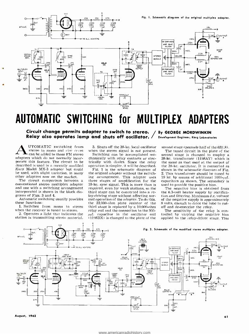
o- ycr-""
07BA.C'
1237AE PHASE 191íC.
MOLT PLC JHPUT
Y-7-)I .033 = yl.
IME6
T r _ r
330 330 A7K
+40 +40 +60 +40 yl.
TO ALL HEATERS
e
Fig. 1. Schematic diagram of the original multiplex adapter.
001
SOLI 02
0
220 270E. 0.
2.7E
SYNC 1900.
.033
Yr
22
470 270.E 70
74 r
FILTER 67 KC.
1 1194ÁY WC.
OUTPUT
AUTOMATIC SWITCHING for MULTIPLEX ADAPTERS Circuit change permits adapter to switch to stereo. / By GEORGE MORDWINKIN Relay also operates lamp and shuts off oscillator. Development Engineer, Karg laboratories
AUTOMATIC switching from stereo to mono and rice versa can be added to those FM stereo
adapters which do not normally incor- porate this feature. The circuit to be described is used in a recently modified Karg Model MX -3 adapter but could be used, with slight variation, in many other adapters now on the market.
The circuit comparison between a conventional stereo multiplex adapter and one with a switching arrangement incorporated is shown in the block dia- grams of Figs. 3 and 4.
Automatic switching usually provides these functions:
1. Switches from mono to stereo when the receiver is tuned to stereo.
2. Operates a light that indicates the station is transmitting stereo material.
117V.A.C.
vs7AA
MC.
MULTIPLEX INPUT
3. Shuts off the 38 -kc. local oscillator when the stereo signal is not present.
Switching can be accomplished me- chanically with relay contacts or elec- trically with diodes. Since the relay operation is simpler. it will be described.
Fig. 1 is the schematic diagram of the original adapter without the switch- ing arrangement. This adapter uses three stages of amplification for the 19 -kc. sync signal. This is more than is required, even for weak stations, so the third stage can be converted into a re- lay- driving stage without affecting nor- mal operation of the adapter. To do this. the 22.000 -ohm plate resistor of the third stage is replaced by a 10.000 -ohm relay coil and the connection to the 300- µuí. capacitor in the oscillator coil (1198BX) is changed to the plate of the
e
second stage (pentode half of the 6BL8). The tuned circuit in the plate of the
second stage is changed to employ a 38 -kc. transformer (1198AY) which is the same as that used at the output of the 38 -kc. oscillator. It is connected as shown in the schematic diagram of Fig. 2. This transformer should be tuned to 19 kc. by means of additional 1000 -;111f.
capacitors as shown. The secondary is used to provide the positive bias.
The negative bias is obtained from the 6.3 -volt healer supply by rectifica- tion and filtering. Maximum d.c. voltage of the negative supply is approximately 8 volts, enough to drive the tube to cut- off and de- energize the relay.
The sensitivity of the relay is con- trolled by varying the negative bias applied to the relay- driver stage. This
Fig. 2. Schematic of the modified stereo multiplex adapter.
NE.2
INDICATOR sIO
684
í00A EPARATICN
6 6OL,
2
2203 27C.
2.7
23V.
000 l. August, 1962 61
www.americanradiohistory.comwww.americanradiohistory.com

GREENLEE CHASSIS PUNCHES Make accurate, finished holes in I!_ minutes or less in metal, hard rubber and plastics. No tedious sawing or filing -a few turns of the wrench does the job. All standard sizes. .
round, square, key, or "D'. shapes for sock. tom. switches. meters. etc. At your elect r. sic parts dealer. Literature on rettill -t. - GREENLEE TOOL CO. Mgr 2027 Columbia Ave .. Rockford, Illinois
Build your own superb
SCOTT /KITS
i
HAVE FUN... SAVE MONEY
Have fun ... save money build the best, Now you can get world -famous Scott stereo com- ponents in kit form Think of it you can build the fabulous new LT I10 FM Multiplex Stereo Tuner . your choice of two complete stereo amplifiers, or a preamp and separate power amp
. all from H H Scott, Write today Find out about these exciting Scoll kits.
FREE Choice of 3 Booklets
SCOTT n Ii Scott. Inc , III Powdermill Road. Maynard, Mass
Dept. 160 -08 Send me the booklets checked below
20 -page "Guide to Custom Stereo- Complete technical information on kits 16 -page booklet explaining FM Stereo
Name
Address
City Zone_ _
State Export: Morhan Euportins Cora.. cgs Broadway, N.Y C
62
is adjusted so that the signal of the weakest stereo station will be able to operate the relay but not so sensitive that any incoming noise signal will trig- ger it.
For stabilization purposes. a capacitor is connected in parallel with the relay coil, introducing a slight delay action. Capacitor values from 2 to 5 yaf. are satisfactory.
When a stereo program is received, the 19 -kc. signal appears at the second- ary winding of the transformer, 1198AY (plate circuit of second stage). The signal is rectified and the resultant posi- tive bias is applied to the grid of the re- lay- driver tube. This makes it conduct and the relay energizes.
For initial calibration purposes, the 19 -kc. signal from a test generator can he applied to the multiplex input. This is tuned for maximum positive reading ( minimum negative bias) at the grid
COMPOSITE SIGNAL
19K6.
SYNC AMPLIFIER
t A
f JBKC. MATRIX OR
SWITCHING OSCILLATOR NETWORK
- 6 3v. HEATER
SUPPLY
B+
SUP,LY
-e-R
-L
17V A C.
Fig. 3. Conventional multiplex adapter.
COMPOSITE SIGNAL
19 KC
SYNC
AMPLIFIER
3BKC.
OSCILLATOR
6.3V. HEATER
SUPPLY
STEREO/
MONO
SWITCH
117V A.C.
NEGATIVE
BIAS
SUPPLY
RELAY
DRIVER
u POSITIVE
BIAS
SUPPLY
Fig. 4. Adapter with switching circuit.
of the relay -driver tube. When a 20 -mv. signal is applied, approximately 4 volts d.c. appears at the output of the trans- former and the negative bias at the grid of the relay- driver tube should chop from -8 volts to -4 volts.
In order to be able to perform the functions mentioned previously, the re- lay used should have two sets of "nor- mally closed" contacts and one set of "normally open" contacts.
The normally open contacts discon- nect the indicating light and the "B+" from the 38 -kc. oscillator tube when stereo signal is not present.
The normally closed contacts connect both output channels in parallel for mono operation.
POOR MAN' By JAMES E
FOR true "stereo' at its finest, it is hard to (glued the quality obtainable
with he'adpl listening. The full depth is always there nu nutter where you sit or how your head is held.
Many phono cartridges and head - pl s will work in the simple circuit below to stake a "happy" c bin. that gives good 'stereo" a1 the lowest possible cost. It is also a set -up that can be built in just a few hours. Both units being of the crystal type, they are a good nutcls in both impedance and signal level. Quality and put level depend on the particular cartridge and earphones used. Inexpensive c t gets have pro deiced surprisingly g 1 results.
S "STEREO"
. PUGH, JR.
Besides enjoyable liste ' g two other uses ore ili ' S. A simple de ira with this phono set -up will convince any rust r that stereo is superior t and thus raise your sales. Also, with this system it is easy to test all of your stereo records and label them according to pleas - ing. Later, when played on this or a tumore
elaborate system, the phase reversing switch is simply set in accordance with the label notat . There is no fines as to which is the correct phase.
Switch S: is used to de strafe the difference between stereo and re- produu ' using stereo records. It Call be 'tted if you have no need for this feature.
Schematic diagram of the poor man's "stereo" phonograph setup. Inexpensive crystal stereo cartridge is employed to drive a set of crystal headphones di- rectly. Switch S, permits quick comparison between stereo and mono playback.
PHASE SWITCH 70.P.0 T.
Si
CRYSTAL STEREO
CARTRIDGE REVERSE
MONO STEREO
52 SPST
VJ2 I
JI
PHONO MOTOR
53 5 P S T. P3 "I V - I17V.A.C.
CRYSTAL STEREO
HEADPHONES
ELECTRONICS WORLD
www.americanradiohistory.comwww.americanradiohistory.com

iew concept in citizen's band equipment in two years! ... Heathkit 4- Position Selective -Call kit
POWER CALL
MON. ALL
SELECTOR
OFF o
-D
T O N E SQUELCH OD ,57
CALL
an exclusive with
Heath, this inexpensive
unit converts your
CB station from
"party line" confusion
to "private line" calling
convenience
FEATURES (1) squelch time -delay control. (2) power indicator, (3) tone selector switch (4 tones plus "monitor all" position), (a) tone squelch "defeat" switch for normal operation (5) "lift-to-operate" microphone bracket, (9) "call" lever (7) "call" indicator. (I) external alarm contacts to signal received call. (9) input and out- put level controls.
r G W -11 3- channel
transceiver from $UIS
Here's welcome news for the serious user of Citizen's Band two -way radio. Heath's new Selective -Call Kit with tone squelch makes it possible for you to enjoy the calm of a CB station that is completely silent, yet ever alert for a personal call ... makes it possible for you to call your choice of four specific units in your system at the touch of a button. Using a unique new method, Heath's Selective -Call Kit features an e.reh(.yire 4- position rotary selected resonant -reed relay which responds only to calls transmitted by similarly equipped units using the same tone frequency. Upon receipt of the proper tone, your unit will automatically "cones to life" per- mitting you to hear the call letters transmitted ... you reply by merely lifting the microphone and acknowledging. At all other times, your station is peace- fully quiet, allowing you to perform your job without one car "cocked ", for this unit does your listening for you. To call another unit, just select the correct one of four tone frequencies, press the lever, and the called station will be waiting for you. Nothing could be simpler or more convenient. A "defeat" switch allows normal transceiver operation at any time. Equip all your CB units now with this economical new advance in communication ease ... instructions included for installation with most popular CB transceivers using PTT. Kit GD -162A (AC), no money down. $5 mo. $33.95; Kit GD -162D (DC) $37.95
t, G12 Single
channel all crystal controlled transceiver
Iron $34M
a.-
iiiiiiii Illllllt
6W-31 Low Cost "Walkie-TalMlé
from M.95
!;1
GW21 Superhel. "Walkie-Talkie-
from $44.95
HEATH COMPANY Benton Harbor 15, Michigan
Ordering instructions: Fill out the Enclosed is $ order blank. Include charges for parcel post according to weights shown. Ea- press orders shipped delivery charges collect. All prices F. O. B. Benton Harbor. Mich. A 20% deposit is required on all C.O.D. orders. Prices sublect to change without notice. Dealer and ex- port prices slightly higher.
City
J August, 1962 63
www.americanradiohistory.comwww.americanradiohistory.com

Guartaxteeeny.sates/ BUY NOW AND SAVE!!
OVERTONES: 10 to 30 Meg... Tol..005% 52.95 AMATEUR & NOVICE Fundamental..101. .005% HC-6 Herrn. Sealed 2.95 HC6 -6 Meters 15th Overtone) 4.25 MARINE FRED. 11C -6 (Herrn. Sealed)
T) l..005°ó $3.75
ALL MARINE FRED. -FT -243, DC -34 Hold 701..005 $2.50 POLICE, C.A.P., CD, MARS. Tol. .01% $2.00
CITIZENS BAND -11 METERS -.005°ó TOL. 26.965 to 27.225 MC, 3rd Over. Herm. Seal. or
FT -243 $2.95 13.4825 to 13.6125 MC, 2nd Harm. Herm. Seal. or
F1.243 $2.95
6741.25 to 6806.25 Kr. 4th Harm. F7.243 only .$2.50
SPECIAL! STOCK CRYSTALS
F7.243 Holders 5700 KC to
8700 KC in steps of 25 KC's
SEND FOR FREE CATALOG
0C -34 Hold. 1690 KC to 4440 KC steps of 10 KC, ea. $1.19
NOVICE BAND FT -243 Fund. ea. $
80 Met. 3701.3748 -Steps of 1 KC. FT -243 49 40 Met. 7150.7198 -Steps of 1 KC. F1-243 Dbl. to 40 Met. 3576 -3599. Steps of 1 KC. FT -243 15 Met. 5276-5312-7034-7083 Steps of 1 KC. Fr -243
FI -243 -2 Meters (Steps of 1 KC) $1.49 FI -243 -6 Meters ISteps of 1 KC) $1.49 FT- 243 -From 3000 -4000 $1.49 FT -243 -From 1005 -2999 (Steps of 5 KC) $2.50 FT- 243 -.005% Tel. From 3000.8750 $2.50 ET- 243 -.01 ee To!. From 3000 -8750 $2.00 FT -241 SSO Low Xtals 370 to 540 KC
(Steps of 1.852 and 1.388) .$ .69 FT -241 SSB Matched Pairs $2.39 FT- 241- AN /TRC- 1.721.167 KC-1040-625
(Steps of 1.042 KC- Except 1000 KC) $ .96 inciude Se per crystal postage. . U.S. only,. Calif. add 4 ,. lax. No C.O.D. Prices subject to chg. Ind. 2nd Choice. sub. may be neeess. Min. Order $2.50
"The House of Crystals"
U. S. CRYSTALS, Inc. 1342 S. La Brea Ave. Los Angeles 19, Cal.
NEVER FAIL - ZONE YOUR MAIL
The Post Office has divided
106 cities into postal delivery
zones to speed mail delivery.
Be sure to include zone num-
ber when writing to these
cities; be sure to include your
zone number in your return
address -after the city, before
the state.
Color Set Defects (Continued froh pule 41)
ble, so as to get the red area well cen- tered ( see pattern D on page -11 and on the cover). A similar procedure is
used for the blue and the green guns. Convergence adjustment then takes care of the rest.
But these straightforward faults are not the only color defects that may mar black -and -white reception. Consider the rather attractive hum bar in pattern C. It may be of any color. We already know that such bars are associated with a tube that has cathode- heater leakage. What lllay startle the unwary is the fact that it is colored. After all, color circuits aren't supposed to be (.working on a black and white signal -or are they? And this is
where we go back to some basic ques- tions.
\ \'hat is supposed to be (.working and (.vhat isn't? Some of the color circuits are "turned off," beyond question: the color killer takes care of that automati- cally. But it only shuts off color modula- tion (or color- difference signals) to the bandpass, chronia, or color- signal ampli- fiers. There is thus no modulation going into the color demodulators and succeed- ing amplifiers (if any), but these de- modulators and amplifiers are ou.-tive. In fact, they have to be if a monochrome picture is to be reproduced. Consider the fact that there is no separate "mono- chrome" gun in the CRT. All three color guns must be active for a proper black - and- .white picture, and these guns are driven by their respective demodulator - amplifier-matrixing systems. The only modulation, that of the video or lumi- nance signal, is applied equally to all guns. There is no information (color) applied to one gun only.
\\'ith our colored hum bar, we have obvious one -gun or two -gun modulation that doesn't belong there. Since the bandpass or chromes- signal section is cut off, 1111111 must be modulating an operat- ing demodulator or color- amplifier stage. The guilty tube in this instance was in a crnnbined demodulator- amplifier stage. In modern color sets. there are seldom more than three tubes that could be in- volved.
This defect might tend to confuse the inexperienced. Vet. with a little think- ing, it need never get beyond the house- call stage.
"Co/or-on-Color" Hum That last case leads right into a related
condition in which, once more, the best piece of test equipment is the brain. A colored hum bar is noted during color reception. How would you start? The first step should be a switch to a chan- nel with a monochrome transmission go- ing, or to a "dead" channel. If the bar
persists, the situation is similar to the one just described. But the bar may now disappear. If it does, it evidently origi- nates in those circuits that are cut off by the color killer during black-and- white reception. Localization is even closer here: there is likely to be only one tube in the bandpass or color- difference amplifier.
Need for a Color Generator Before analysis of what a symptom
means can begin, there must be objec- tive recognition of the nature of that symptom. That is not always so easy to determine in color reception. It may be obvious, for example, that tinting of objects in a picture is all wrong, but there may be no way of determining why because there is no way of determining what correct coloration should be. At such a time, nothing will serve better than a stable, standardized picture whose exact nature under normal condi- tions is known, remains unchanged, and can be recognized easily.
A color generator has many uses. but symptom identification is not the least of these. Cover patterns A, E, and F, for example, were taken with receiver input supplied by an RCA \\'R -64A, whose output is indicated in Fig. lA.
Consider an improperly tinted picture whose character is hard to determine. Using the generator, the bottom portion of E is observed, as compared to the normal sequence at the top. All (.)lors are present, although in the wrong order, and the hue control cannot correct the sequence. Since no color is missing. a
defect or misadjustment ill one of the CRT guns is not considered.
Color -bar signals for the red, blue, and green guns are shown in Figs. 1B, 1C, and 1D, respectively. As seen on one set through a scope, they appear, top to bottom, in Fig. 3. Suppose there were no blue in the pattern. Is the blue pm misbehaving? If the center wave- form in Fig. 3 cannot be obtained here, one would look ahead of the gun for the troullle.
Distorted tinting may be clue to over- load caused by excessive color- signal am- plitude. Such a condition is shown at the bottom of pattern F. When it oc- (urs, the waveform in Fig. 2 is seen (at the red gun, for example) instead of the display at the top of Fig. 3. The tech- nician can trace back to find the point where distortion begins. Establishing such conditions is all but impossible while observing the constantly changing signal developed during a regular color transmission.
While a generator makes symptoms recognizable, interpreting them still takes brain power. The examples dis- cussed certainly do not exhaust all pos- sibilities, but they do demonstrate the analytical approach needed.
64 ELECTRONICS WORLD
www.americanradiohistory.comwww.americanradiohistory.com

new in PH0T0FACT the world's finest electronic service data
2 great firsts to save you valuable servicing time!
SEPARATE FOLDERS FOR SUB -CHASSIS
AUTO RADIO REMOVAL INSTRUCTIONS
NOTE: To replace tubes remove lour 1/4" hex screws
holding cover and remove cover.
RADIO oft knobs.
eaker ads, "A" t
lead tharneeanel, Disconnect and pilot -lig lead wiring
bushings.
mot/ 2" hex nut from control h tenna P to rear mount. 3. Remove ra rear
panel. 4, Remove radio from rear obenre orn - 5, Remove Ford radios can
opening required if air -conditio
opening -- R REMOVAL (1862 FORD)
SPEAKER upper ening in 1. Reach though op
flute
left
and remove two wing
2. Rai
now it's far easier for you to service
Home Entertainment Combinations
Yes, PHOTOFACT now provides separate Folders (within each master TV Folder) on each of the sub - chassis which require servicing. Whether it's the TV section, Stereo amplifier, FM -AM tuner, or remote tuning device, you now conveniently select only the Folder required for the specific sub -chassis needing repair. There's no more searching; the separate Folders for each sub -chassis are easily identified and keyed within the master Folder. This ideal new system gives you more complete, handier coverage than ever -instantly locates de- tailed, separate data on all additional units used with the basic TV chassis. It's another great PHOTOFACT advance!
a wonderful time -saving, effort- saving feature Complete auto radio removal instructions are now included in all PHOTOFACT auto radio Folders! New step -by -step procedure tells you whether tubes are accessible without removing receiver; points out obstacles you may encounter; spells out tool requirements; gives wiring connections, etc. Data is based on actual unit removal research by the Sams Photo fact engineering staff. Here's another tremendous time -saver that puts an end to the tough job of removing auto radios- another great PHOTOFACT feature !
These new advances are just a few of the dozens of great features in PHOTOFACT for fastest, easiest, most profitable servicing. See your Sams Distributor for full details on an Easy Buy Library or Standing Order Subscription!
ONLY $10 DOWN puts the complete PHOTO - FACT Library in your shop -and you have up to 30 months to pay! And right now -to keep up with the indus- try -sign up for a standing order subscription to PHOTOFACT! See your Sams Distributor for full details on a Complete Library or Stand- ing Order purchase.
August, 1962
PHOTOFACT INDEX
Your invaluable guide to over 53,000
TV, Radio, Electronic listings, cov-
ering virtually every you o locate the
since 1946. Helps
solve erV
service need
model. solve any
coupon today for your model.
copy of the latest PHOTOFACT FREE COpy Index!
HOWARD W. SAMS & CO., INC. Howard W. Sams S. Co., Inc., Dept. 5 -H2
1 4300 W. 62nd St., Indianapolis 6, Indiana Send full information on:
Easy Buy Plan Standing Order Subscription Pi Send Free Photofact Cumulative Index
Shop Name
Attn
Address
City Zone State
65
www.americanradiohistory.comwww.americanradiohistory.com

ELECTRONICS MANUFACTURING OCCUPATIONS Job opportunities for technicians, engineers. scientists will continue to expand rapidly over the next ten years.
Em ioll's Non-: The following material is hayed an information supplied hr the Bureau of Lahar Statistic's, United Sates Department of Labor.
JOB OPPORTUNITIES in elec- tronics manufacturing are ex- pected to continue to expand
rapidly over the 1960 -70 decade. Elec- tronic products are being used increas- ingly in the Nation's defense and in factories, offices, homes, schools. and hospitals. Opportunities will be par- ticularly good for scientists, engineers, and technicians.
A large proportion of electronics workers are in engineering, scientific, and other technical jobs. Engineers and scientists alone made up about 15 per- cent of all electronics workers in 1960, according to an estimate by the Elec- tronic Industries Association.
Many thousands of technicians and draftsmen are employed by electronics manufacturing firms, mainly to assist engineers and scientists.
Electronics technicians comprise a large group among technicians. Many are engaged in research and develop- ment work, assisting engineers in the design and construction of experi- mental models. They are also employed by manufacturers to work on electronic equipment in customers' establish- ments. Other electronics technicians work in certain highly technical in- specting, testing, and assembly jobs in the engineering laboratories of firms manufacturing electronic products.
Engineering aides are another im- portant group of technicians. They as- sist engineers by making calculations, sketches, and drawings, and by con- ducting performance tests on compo- nents and systems.
Technical writers work closely with engineers, particularly in plants mak- ing military and industrial products and in establishments doing research and development work only. They pre- pare training and technical manuals describing the operation and mainte- nance of electronic equipment.
Training, Other Qualifications
Beginning engineering jobs are usually filled by recent graduates of engineering colleges (some with ad- vanced degrees). A small number of workers without college degrees have been upgraded to professional engineer- ing classifications from such occupa- tions as engineering assistant and elec- tronics technician. Workers who have become engineers in this way usually have taken advanced electronics courses in night school or under other training programs. To keep up with new de- velopments in their fields and to help them qualify for promotion, profes- sional and technical personnel obtain
66
additional training, react technical pub- lications. and attend lectures and tech- nical demonstrations.
Technicians generally need some spe- cialized training to qualify for their jobs. Most electronics technicians have attended a public, private, or Armed Forces technical school. Two years of training in a technical school and 5 or 6 years of experience are often the re- quirements for highly technical jobs. Some electronics technicians obtain their training through apprenticeships. Some testers and experimental assem- blers have been upgraded to the job of electronics technician after they have developed required skills on the job and acquired the necessary knowledge in basic electronics theory, mathematics, drafting, and reading of schematic dia- grams, by attending company -operated evening classes, or taking night school, junior college, technical school, cor- respondence, or other courses. Some technicians who do final testing that re- quires the operation of radio transmit- ting equipment must hold FCC licenses.
6.
.7; s o
R0
S
ö 3.0
20
0 TOTAL MILITARY CONSUMER INDUSTRIAL
EQUIPMENT PRODUCTS PRODUC S
Value of output of electronic equipment.
Employers look for job applicants with an avocation in electronics for production as well as some office jobs. Employees with hobbies or other inter- ests involving electronics, such as as- sembling radios, repairing radio and television sets, and ham -radio operation tend to show considerable interest in their jobs. Such employees are often given preference in promotion. Because of the nature of their work, assemblers, testers, inspectors. and electronics tech- nicians need good vision, including good color vision; patience; manual dexter- ity; and good eye -hand coordination. Electronics technicians and other tech- nical workers must be able to under- stand technical material.
Employment Outlook
Many thousands of job opportunities will be available for new workers in electronics manufacturing plants each year over the 1960 -70 decade. Elec-
ironies employment is expected to grow much more rapidly than manufacturing employment as a whole, but it probably will not increase as rapidly as it did over the 1950 -60 decade.
One of the main reasons why employ- ment in electronics manufacturing will expand will be rising expenditures for military electronic equipment.
Substantial growth in electronics pro- duction for industrial use is also ex- pected because the trend toward mod- ernization and automation of produc- tion processes will stimulate spending for new plants and equipment. An in- creasing proportion of these expendi- tures will be for the newer types of electronic equipment. such as com- puters and automatically controlled machine tools. Also. the demand for industry's older and more developed in- dustrial products, such as broadcasting equipment. radio communications equipment. test instruments. and navi- gational equipment, will continue to- expand. For example, the use of two- way radio communications equipment by police and fire departments. public utilities. taxicab and trucking com- panies. pipeline firms. and others is ex- pected to spread rapidly. Production of electronic equipment for the medical field will also expand greatly.
More home television sets. radios, phonographs. and stereophonic and high -fidelity equipment will be pur- chased as population and the standard of living continue rising over the 1960- 70 decade. These products will remain the principal electronic consumer items. In addition, other electronic consumer products which are already on the mar- ket or being developed (e.g., electronic ovens, garage door openers, dishwash- ers. lighting equipment, and air condi- tioners) may become standard house- hold equipment in the years ahead.
Rising expenditures for research and development in the electronics field will stimulate employment in electronics manufacturing. Also, research and de- velopment will result in new military, industrial. and consumer products and in new types of components. all of which will provide more employment in electronics manufacturing.
The rates of employment growth will differ among the occupational groups and individual occupations in elec- tronics manufacturing. Engineering, scientific. and other technical jobs will show the greatest rise over the next decade. because of the growing volume of research and development in elec- tronics manufacturing and the increas- ing application of scientific and engi- neering principles to production opera- tions. Employment of electronics engi- neers and electronics technicians will rise more quickly than that of most other technical workers.
ELECTRONICS WORLD
www.americanradiohistory.comwww.americanradiohistory.com

LIVELY READABLE HOW -TO BOOKS FOR THE
EXPERIMENTER AND ELECTRONIC HOBBYIST
THE ELECTRONIC EXPERIMENTER'S
MANUAL by David A. Findlay
The ABC's of electronics experimenta- tion and project construction are pre- sented in this book in such plain language and in a style so easy to read, that anyone will become absorbed from the very first chapter. The projects ad- vance from the simple to the more ad- vanced. Through these pages the reader will acquire the knowledge and skill to turn out his own short -wave receivers, intercom systems, transistor radios, etc. 169 pages, 170 illustrations. $4.95
VACUUM -TUBE CIRCUITS FOR THE ELECTRONIC EXPERIMENTER by Julian M. Sienkiewicz
How many times has the experimenter wanted a diagram of a basic vacuum -tube circuit which he could use as a guide in building some practical electronic device? At last, in one book, he can find all the basic diagrams, schematics, and other vital information on vacuum tubes and their circuits. One hundred vacuum -tube schematic dia- grams. plate- characteristic curves, simplified schematic diagrams, test circuits and other selected illustrations supplement the infor- mative text to make this new publication one of the most useful and informative books available for the rapidly growing legion of experimenters and electronics hobbyists. 192 pages, 100 illustrations.
$4.95
Class D
CITIZENS
` 1at RADIO .
.:. i
CLASS D CITIZENS RADIO
by Leo G. Sands
The first and only book to be published in this im- portant and rapidly expanding field. Leo Sands, au- thor of almost 500 technical articles and 4 books, gives complete information on this important com- mercial class of radio and explains just what Citizens Radio service is and what are its many applications. Many illustrative circuits are shown and there is a special appendix of FCC rules and regulations. 181 pages, 72 illustrations. $4.95
COMPUTERS AND HOW THEY WORK by James D. Fahnestock
A solid and acclaimed introduction to this ever -ex- panding field. A completely understandable and comprehensive study that describes in clear and pre- cise terms computer principles, manufacture, opera- tion and maintenance. Provides a solid foundation for the study of computer techniques. Discusses computer memories. flip -flops. programming, etc. The 113 special illustrations provide a visual explanation of computer operation and principles. 228 pages.
$4.95
USE THIS HANDY ORDER FORM
ELECTRONICS BOOK SERVICE -A. S. Barnes 8 Co. Inc. 151 -51 Seventh Avenue, Whitestone 57, N.Y. EW 5A
Please send me the books I have checked below:
I enclose $ _. __ __. _ (You pay all postal charges.I Send C.O.D. 11 pay charges)
-copyliesl VACUUM -TUBE CIRCUITS FOR THE ELECTRONIC EXPERIMENTER $4.95
_ _eopyliesl CLASS D CITIZENS RADIO $4.95
_copyliesl COMPUTERS AND HOW THEY WORK $4.95
_copyliesl THE ELECTRONIC EXPERIMENTER'S MANUAL $4.95
NAME
ADDRESS -_._ _ -___ ___ CITY -_ ___ __ZONE - _STATE -
If I am not fully satisfied I can return these books in seven days for a full and prompt refund.
August, 1962 67
www.americanradiohistory.comwww.americanradiohistory.com
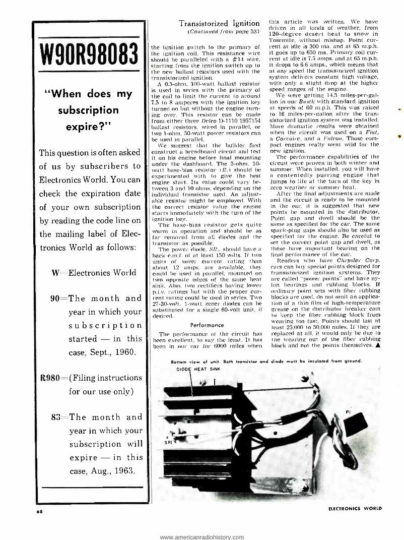
W90R98083
"When does my
subscription
expire ?"
This question is often asked
of us by subscribers to
Electronics World. You can
check the expiration date
of your own subscription
by reading the code line on
the mailing label of Elec-
tronics World as follows:
W- - Electronics World
90 = -The month and year in which your
subscription started - in this
case, Sept., 1960.
R980-(Filing instructions
for our use only)
83 -The month and year in which your
subscription will
expire - in this case, Aug., 1963.
68
Transistorized Ignition (Contin ed from page 53)
the ignition switch to the primary of the ignition coil. This resistance wire should be paralleled with a #14 wire, starting from the ignition switch up to the new ballast resistors used with the transistorized ignition.
A 0.5 -ohm. 100 -watt ballast resistor is used in series with the primary of the coil to limit the current to around 7.5 to 8 amperes with the ignition key turned on but without the engine turn- ing over. This resistor can be made from either three Delco D -1110 1957154 ballast resistors, wired in parallel. or two 1 -ohm. 50 -watt power resistors can be used in parallel.
We suggest that the builder first construct a breadboard circuit and test it on his engine before final mounting under the dashboard. The 5 -ohm. 10- watt base -bias resistor IR.) should be experimented with to give the best engine start. Its value could vary be- tween 3 and 10 ohms. depending on the individual transistor used. An adjust- able resistor might be employed. With the correct resistor value the engine starts immediately with the turn of the ignition key.
The base -bias resistor gets quite warm in operation and should be as far removed from all diodes and the transistor as possible.
The power diode. SR,. should have a back e.m.f. of at least 150 volts. If two units of lower current rating than about 12 amps. are available, they
I could lie used in parallel, mounted on I two opposite edges of the same heat
sink. Also, two rectifiers having lower p.i.v. ratings but with the proper cur - rent rating could be used in series. Two 27 -30 -volt. 1 -watt zener diodes can be substituted for a single 60 -volt unit, if desired.
Performance
The performance of the circuit has been excellent. to say the least. It has been in our car for 6000 miles when
this article was written. We have driven in all kinds of weather, from 120 -degree desert heat to snow in Yosemite, without mishap. Point cur- rent at idle is 300 ma. and at 65 m.p.h. it goes up to 650 ma. Primary coil cur- rent at idle is 7.5 amps. and at 65 m.p.h. it drops to 6.6 amps., which means that at any speed the transistorized ignition system delivers constant high voltage, with only a slight drop at the higher speed ranges of the engine.
We were getting 14.5 miles- per -gal- lon in our Buick with standard ignition at speeds of 60 m.p.h. This was raised to 16 miles- per -gallon after the tran- sistorized ignition system was installed. More dramatic results were obtained when the circuit was used on a Fiat, a Corraire. and a Falcon. Those corn- pact engines really went wild for the new ignition.
The performance capabilities of the circuit were proven in both winter and summer. When installed. you will have a contentedly purring engine that jumps to life at the turn of the key in zero weather or summer heat.
After the final adjustments are made and the circuit is ready to be mounted in the car, it is suggested that new points be mounted in the distributor. Point gap and dwell should be the same as specified for the car. The same spark -plug gaps should also be used as specified for the engine. Be careful to set the correct point gap and dwell, as these have important bearing on the final performance of the car.
Readers who have Chrysler Corp. cars can buy special points designed for transistorized ignition systems. They are called "power points" and have ny- lon bearings and rubbing blocks. If ordinary point sets with fiber rubbing blocks are used, do not omit an applica- tion of a thin film of high- temperature grease on the distributor breaker cam to keep the fiber rubbing block from wearing too fast. Points should last at least 25.000 to 50.000 miles. If they are replaced at all. it would only be clue to the wearing out of the fiber rubbing block and not the points themselves.
Bottom view of unit. Both transistor and diode must be insulated from ground.
DIODE HEAT SINK
ELECTRONICS WORLD
www.americanradiohistory.comwww.americanradiohistory.com
Within the Industry IRVING KOSS has been named general manager of the E. F. Johnson Company
of Waseca, Minn., leaving his post as general manager of the Motorola Inc. military electronics division to accept the new position.
He is a graduate of MIT in business and engineering adminis-
tration and holds a Masters degree in business administration from Harvard Graduate School. In his new post he will assume part of the administrative func- tions of the president who will devote greater time in other areas. including company growth and acquisition of other firms.
o a
HERBERT HOOVER, JR. has been elected president of The American Radio Relay League, Inc.. the national society of amateur radio operators in the United States and Canada. Serving with Mr. Hoover will be Wayland M. Groves. first vice -president; Alex Reid and Francis E. Handy, vice -presidents; John Hun - toon, secretary; and David H. Hough- ton. treasurer.
The board of directors also approved the building of a new headquarters of- fice at 225 Main Street. Newington. Conn. The new structure. totalling 26.000 square feet of office space. is expected to be ready for occupancy early next year.
.. a
JOHN H. FEDER, JR. has been appointed general sales manager of Cornell -Du-
biller Electronics. In his new position. Mr. Feder takes over the responsibilities of R. T. Leary, vice - president for sales. who has resigned to enter private busi- ness.
Mr. Feder has been associated with the company for over 12 years as a manufacturer's repre- sentative and more recently as district manager of the firm's Mid -Atlantic re- gion. Previously he was sales manager for Keystone Products. a New Jersey specialty transformer firm.
He will make his headquarters in Newark. New Jersey.
HAL F. BERSCHE, head of RCA Electron Dirision's Distributor Products, has been elected president of Producers of Associated Components for Electronics,
August, 1962
Inc. I PACE), succeeding 'Tomas B. Ure. vice -president of Hurdwicl. Hindle. Inc.
Officers and directors elected to serve with Mr. Bersche include: Howard Saltzman, Alpha Wire Corp., first vice- president ; George Silber, Rek -O -lint Co.. Inc.. second vice -president; Walter Jablon. Munro- Fcuron Corp., secretary- treasurer: and David Susser, executive vice -president and counsel. Directors in- clude Walter Goodman of Jerrold Elec- tronics Corp. and Abe Kosakowsky. of Silicon Transistor Corp. who will serve three -year terms.
Directors elected to serve two-year terms include Ed Abbo, Saxton Prod- ucts. Inc.: Robert Ferree, International Resistance Co.: and Edward Rothen- stein, Arco Electronics. Inc. Salo Nach- tigall, Fanon Electronic Industries. Inc., Herman Post, Robin Industries Corp.. and Lving Rosen. Keystone Electronics Corp. will serve one -year terms.
DATOM INDUSTRIES of Orange. N.J. has set up the MADISON FIELDING DIVISION for the manufacture and marketing of a complete line of AM, FM, and multi- plex radio-phonograph consoles ... SYSTRON -DONNER CORP. has acquired 85': of the outstanding stock of ELEC-
TROMAGNETICS, INC. of Los Angeles ... WATSCO, INC. of Hialeah. Florida has established a new electronics division which will handle the nunufactore of a capacity tester ... GENERAL PRECISION EQUIPMENT CORPORATION and the MITSUBISHI ELECTRIC MANUFACTURING CO., LTD. of Japan have joined in the forma- 1 ion of a new electronic and precision equipment manufacturing company to be known as MITSUBISHI PRECISION, INC. ... DELTA ELECTRONICS, INC. has been established at 4206 Wheeler Ave.. Alex- andria. Va. to undertake the develop- ment and custom fabrication of spe- cialized electronic equipment .
HAWLEY PRODUCTS LIMITED of England has been acquired by HAWLEY PRODUCTS COMPANY, St. Charles. Ill.... The for- mation of a new electronics firm. RCF
COM- TRONICS, INC., has been announced. This new manufacturer of electronic communical ion systems and components Nvill operate in Pulaski, N.Y.... RESIS- TOR CHEMICAL CO., INC. has acquired management cont of CWS WAVEGUIDE CORPORATION of Lindenhurst. L.I.... The Radio Standards Laboratory at the Boulder Laboratories of the NATIONAL BUREAU OF STANDARDS has been divided into a Radio Physics Division and a Circuits Standards Division to provide unified direction for a growing program
. . . KAWECKI CHEMICAL COMPANY and DURHAM CHEMICAL GROUP LTD. of Eng- land have agreed to form a joint enter- prise at Birtley, England to produce master alloys for the aluminum and high temperature metallurgical indus- tries.
DR. JAY TOL THOMAS has been appointed director of the newly established Sieg-
ler Research Labo- rato, ies with head- quarters in Los An- geles.
Prior to joining Siegler, Dr. Thomas was director of re- search for the Bos- ton Division of Min - neu pol is -Ho ney,vell.
He was responsible for the development of new products in the fields of electro- mechanical components. solid -state transducers, fuel cells and their con- trols. high -powered semiconductor am- plifiers. and magnetometers.
He has also been associated with Sylrania. DuPont, and the Naval Re- search Laboratory. He received his bachelor and master degrees from Har- vard and his doctorate from Rutgers. He is a Fellow of the American Physi- cal Society and a senior member of the IRE.
n
WILLIAM F.E. LONG, first manager of the Elect runic Indust vies Association's Mar - keting Data Department, has returned as the associa t ion's director of market- ing services. He succeeds George W. West fall who has resigned.
Mr. Long first joined the EIA staff in 1951. leaving the organization in 1959 to become associated with the Lansdale Tube Division of Philco Corporation.
J. R. CHRISTOPHERS has been appointed assistant general manager of Cossor In- struments Limited of London. He was formerly technical sales manager of Marconi Ins( ri,lin aIs Limited ...Oak Mint, Co. has announced the appointment of EARL OLENICK as general manager of its newly formed distributor division ... DR. JOHN E. McNAMARA has been promoted to the new position of staff scientist for materials at Mo- torol,r :s Scum irondaetor Products Di- rision in Phoenix ... DR. JULIEN KEILSON has been named senior scientist of Syl- vania Electric Products Inr.'s Applied Research Laboratory in Waltham, Mass. ... Radio Co,por(Nicm of .l aueuleu has named GEORGE A. FADLER to the post of staff vice -president. purchases ... E. H. KINNEAR, manager of audio products for Ampr..of Canada. Ltd.. has been elected president of the Dominion Hi Fi Asso- ciation ... HARRY LEMMENS has joined the engineering staff of National Transistor Mfg.. Inc. as development engineer in charge of special packaging and multi- ple- element devices ... C. GUS GRANT has been named to the newly created posi- tion of vice- president. marketing for Ampex Corporation ... JOHN SEVERINSEN and ROGER DIAMOND have joined the engineering stalls of Technical Appli- ance Corp.
69
www.americanradiohistory.comwww.americanradiohistory.com
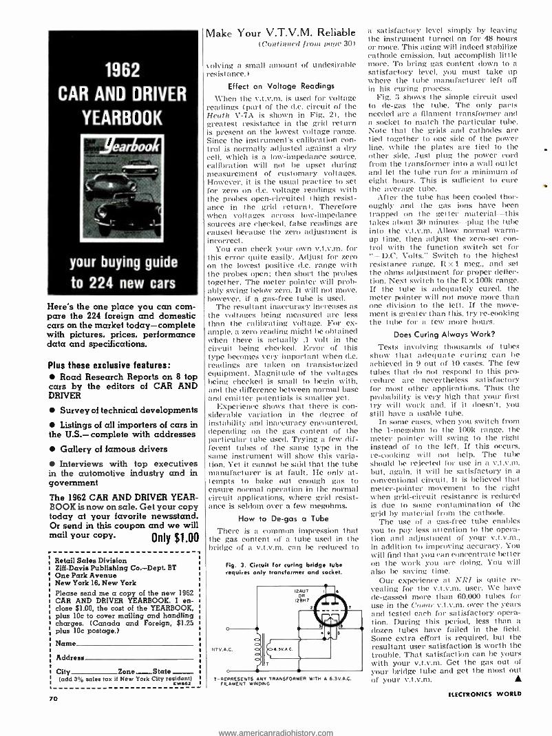
1962
CAR AND DRIVER
YEARBOOK
your buying guide
to 224 new cars
Here's the one place you can corn - pare the 224 foreign and domestic cars on the market today -complete with pictures, prices, performance data and specifications.
Plus these exclusive features:
Road Research Reports on 8 top cars by the editors of CAR AND DRIVER
Survey of technical developments
Listings of all importers of cars in the U.S.- complete with addresses
Gallery of famous drivers
Interviews with top executives in the automotive industry and in govemment
The 1962 CAR AND DRIVER YEAR- BOOK is now on sale. Get your copy today at your favorite newsstand. Or send in this coupon and we will mail your copy. Only $1.00
Retail Sales Division Ziff -Davis Publishing Co. -Dept. BT One Park Avenue New York 16, New York Please send me a copy of the new 1962 CAR AND DRIVER YEARBOOK. I en- close $1.00, the cost of the YEARBOOK, plus 10c to cover mailing and handling charges. (Canada and Foreign, $1.25 plus 10c postage.)
Name
Address
City Zone_State- (add 3 °ó sales tax if New York City resident)
E W 662
70
Make Your V.T.V.M. Reliable Continued front pale 30)
solving a small amount of undesirable resistance.)
Effect on Voltage Readings
When the v.t.v.m. is used for voltage readings (part of the d.c. circuit of the Heath V -7A is shown in Fig. 2), the greatest resistance in the grid return is present on the lowest voltage range. Since the instrument's calibration con - trol is normally adjusted against a dry cell. which is a low- impedance source, calibration will not be upset (luring measurement of customary voltages. However, it is the usual practice to set for zero on d.c. voltage readings with the probes open -circuited thigh resist- ance in the grid return). Therefore when voltages across low -impedance sources are checked, false readings are caused because the zero adjustment is incorrect.
You can check your own v.t.v.m. for this error quite easily. Adjust for zero on the lowest positive d.c. range with the probes open; then short the probes together. The meter pointer will prob- ably swing below zero. It will not move, however, if a gas-free tube is used.
The resultant inaccuracy increases as the voltages being measured are less than the calibrating voltage. For ex- ample. a zero reading might be obtained when there is actually .1 volt in the circuit being checked. Error of this type becomes very important when d.c. readings are taken on transistorized equipment. Magnitude of the voltages being checked is small to begin with, and the difference between normal base and emitter potentials is smaller yet.
Experience shows that there is con- siderable variation in the degree of instability and inaccuracy encountered. depending on the gas content of the particular tube used. Trying a few dif- ferent tubes of the same type in the same instrument will show this varia- tion. Yet it cannot be said that the tube manufacturer is at fault. He only at- tempts to bake out enough gas to ensure normal operation in the normal circuit applications, where grid resist- ance is seldom over a few megohms.
How to De -gas a Tube
There is a common impression that the gas content of a tube used in the bridge of a v.t.v.m. can be reduced to
Fig. 3. Circuit for curing bridge tube requires only transformer and socket.
T- REPRESENTS ANY TRANSFORMER WITH A 6.3V.A.C. FILAMENT WINDING
a satisfactory level simply by leaving the instrument turned on for 48 hours or more. This aging will indeed stabilize cathode emission, but accomplish little more. To bring gas content down to a satisfactory level, you must take up where the tube manufacturer left off in his curing process.
Fig. 3 shows the simple circuit used to de -gas the tube. The only parts needed are a filament transformer and a socket to match the particular tube. Note that the grids and cathodes are tied together to one side of the power line. while the plates are tied to the other side. Just plug the power cord from the transformer into a wall outlet and let the tube run for a minimum of eight hours. This is sufficient to cure the average tube.
After the tube has been cooled thor- oughly and the gas ions have been trapped on the getter material- -this takes about 30 minutes -plug the tube into the v.t.v.m. Allow normal warm - up time. then adjust the zero -set con- trol with the function switch set for
+D.C. Volts." Switch to the highest resistance range, R x 1 meg., and set the ohms adjustment for proper deflec- tion. Next switch to the Rx 100k range. If the tube is adequately cured. the meter pointer will not move more than one division to the left. If the move- ment is greater than this. try re- cooking the tube for a few more hoes.
Does Curing Always Work?
Tests involving thousands of tubes show that adequate curing can be achieved in 9 out of 10 cases. The few tubes that do not respond to this pro- cedure are nevertheless satisfactory for most other applications. Thus the probability is very high that your first try will work and. if it doesn't. you st ill have a usable t ube.
In some cases. when you switch from the 1- megohm to the 100k range, the meter pointer will swing to the right instead of to the left. If this occurs, re- cooking will not help. The tube should be rejected for use in a v.t.v.m. but, again. it will be satisfactory in a conventional circuit. It is believed that meter -pointer movement to the right when grid- circuit resistance is reduced is due to some contamination of the grid by material from the cathode.
The use of a gas -free tube enables you to pay less attention to the opera- tion and adjustment of your v.t.v.m.. in addition to improving accuracy. You will find that you can concentrate better on the work you are doing. You will also be saving time.
Our experience at h RI is quite re- vealing for the v.t.v.ni. user. We have de- gassed more than 60.000 tubes for use in the Conur v.t.v.m. over the years and tested each for satisfactory opera- tion. During this period, less than a dozen tubes have failed in the field. Some extra effort is required, but the resultant user satisfaction is worth the trouble. That satisfaction can be yours with your v.t.v.m. Get the gas out of your bridge tube and get the most out of your v.t.v.m.
ELECTRONICS WORLD
www.americanradiohistory.comwww.americanradiohistory.com

SEMICONDUCTOR
NOISE FILTER By JAMES E. PUGH, Jr.
Simple transistorized circuit eliminates superimposed noise.
1 N OISE from a d.c. motor o,.eratetl 1 on the same low- voltage supply as an amplifier can be particularly troublesome in portable transistor cir- cuits since there is generally not enough excess voltage above that actu- ally required to allow for the normal loss in an RC filter. Or, to state it an- other way, why waste battery power in an RC filter when it isn't necessary? LC filters are usually ruled out for portable equipment because of the in- ductor size and weight.
A semiconductor filter, essentially the same as is used to filter the ripple out of rectified d.c. power supplies, is well suited to this application. The voltage drop can be made low, it is an excellent filter, and the size and weight are both small.
Component values will be determined by the input voltage available, noise level, and load current and voltage. Select a transistor that will handle the required load current and at the same time see that its collector -to -base volt- age and dissipation ratings are not ex- ceeded.
Unless the load is heavy, the zener diode can be nearly any type with a dissipation rating of 150 to 500 mw. If voltage regulation is not critical, it can he operated close to the minimum zener current since most noise spikes will not be hard to remove from this filter. The resultant larger value of R, will minimize noise feedthrough from collector to base (through R,), and thus the output noise will be lowered.
Select a zener voltage as high as pos- sible to minimize voltage loss across the transistor, but at the same time it must not be so high as to impair filler action. Narrow noise pulses with a low repetition rate will make it possible to use a higher zoner voltage and thus higher usable output voltage will be .l
tarot. More severe noise will make it necessary to settle for a lower output voltage. Capacitors C, and C: are not critical -50 to 100 µf. will be more than adequate for most cases.
Small- sized, lightweight transistor cir- cuit the is designed to filter out noise.
August, 1962
Build the finest professional color TV Set ever designed
olor 0
0 0 - - Anyone Can Assemble -No Special Knowledge Required "Deluxe" Color Chassis vain controls mounted on panel in a vertical position.
This Color TV Kit is designed around the mos, expensive, thor- oughly engineered and newest RCA TV Color Receiver.
Transvision has added improvements, features, and heavy -duty parts to this RCA licensed receiver in order to accommodate those who seek better quality than is commercially available.
WITH or WITHOUT REMOTE CONTROL All critical circuitry is wired, aligned, and pre- tested by RCA.
Custom wall installation of "Deluxe' Color Chassis with horizo tal controls separated from chassis.
LEARN AS YOU BUILD: Learn Color TV Theory, Practice. and Servicing. Complete course of study available for use in conjunction with the Kit -no technical back- ground required to understand it.
Buy Assembly Manual and See Easy, Complete Instructions.
Exclusive Features: All controls are mounted separately from chassis for flexibility in custom installation... . Only the finest quality oversized, extra heavy -duty parts are used for long, trouble -free use, and they are FULLY GUARANTEED for ONE FULL YEAR. The 21" Color Tube is RCA's newest and best tube. The safety glass is bonded to the tube face to reduce re- flections and eliminate dust accumulation.... NEVER OBSOLETE -Your Transvision TV Color Kit is al- ways up -to -date because circuit improvements in Kit form are passed on to the Kit builder as they occur.
Buy on Installment Plan. PAY AS YOU WIRE: $50 gets you started on this fascinating TV Color Kit project.
CHOICE OF MODELS: With Hi- Fidelity Sound System, complete with Color Tube 5439.00. With Special Circuit (no audio) for connecting into your Hi -Fi System, complete with Color Tube $419.00. Remote Control optional $60.00 additional.
Also available as WIRED CHASSIS ... Full line of Cabinets.
- - -- START NOW - NAIL THIS COUPON. Send FREE Catalog on Color rV Kits... 0 I enclose S5 for Assembly Manual, refundable on purchase of N Color Kit. I enclose S50 for Starting hobage on papas-yoa.wire plan.
I Complete kits range trete $409 to $499.1 Dept. EWC.8
Name
Address
City Zone State
INSTRUCTION MANUAL: Send SS for complete Assembly Manual. so that you can see how easy it is to build and service the Trmsvision TV Color Kit. Cost of manual refundable upon purchase of Kit.
elLi tgvtf14 ELECTRONICS, Inc.
Grey Oaks Avenue, Yonkers, N. Y. Dept. EWC -8
Telephone: (914) YOnkers 5-6900
RADIO PARTS STORES & HI -FI SALONS! Ulundietls of dealers across the nation profit by selling ELECTRON ICS WORLD each month to their customers. Are you one of them? ELECTRONICS WORLD helps build store traffic ... keeps customers coming back month after month for the merchandise you sell -and. best of all. you earn a neat profit on each copy sold -No RISK INVOLVED.
So get details on selling ELECTRONICS WORLD. the world's largest selling technical electronics magazine. Or, order your copies now. Just use the handy coupon.
Retail Sales Department, Electronics World One Park Avenue, New York 16, New York
Send me copies of ELECTRONICS WORLD for resale in my store each month. No risk involved on my part. Send me details on selling ELECTRONICS WORLD in my store.
STORE NAME ADDRESS CITY -. ZONE
_ STATE SIGNATURE EW 862
71
www.americanradiohistory.comwww.americanradiohistory.com

i
2/I\
\I/
/41
EXPORT SPECIALS rC
BC.6tO.l BC -640, TCK. TDE It 6
I
i:l '.I lI'I'I Its . Many Other Specials. Send for Cony
tit linpor.0 Italog STOCK! ge inventory. Im-
mediate MODEL 80 SIGNAL GENERATOR
-.'l $450.00
FREQUENCY METER SPECIALS All Cel. Cond.! All 11 1. All guaranteed!
S 69.50 15 -1-74 U . 175.00 rá.17. 175.00
RT-82 APX-6 TRANSCEIVER $14.95
1.50
ID -6 APN -4 LORAN) INDICATOR
$8.95 ORDER 10 FOR
48 PAGE NEW CATALOG! FREE! GET YOUR COPY TODAY!
COMMAND RECVRS. 8 XrdTRS. II213 ARC-5 TWO-MET llt nl t I.1532.50 VIER
OVER: .1955 MC. Etc. il, r,1 il. 9.95 1.5.3 -] INC. RECEIVER
I_ÿMC. RECEIVER: MC. RECEIVEH: -
2.1.3 A1<. TRFrC51t11TTLIt 1.4 MC. TRANSMITTER 15.3 MC. TRANSMITiI R
..3.7 MC. TRANSMITT{ R
:.37 MC. AMTR: I .
M T ARCS PLATE MOOULiTOH
9.95 5.95 6.95 4.95 4.9S 2.95
4.95
TUBES! ALL NEW & GUARANTEED! + 150A 512.00 4E27 5 7.95 4.65A 9.95 100TH .95
25A 19.99 250TH 2.50 +x2500 22.50 8298 .95 4 -400A . 24.50 832A 195 ó1000A 75.00 832
BC -375 100 W. TRANSMITTER
$14.95
COLUMBIA ELECTRONICS 4365 WEST PICO BLVD. LOS ANGELES 19, CALIF.
engineering degree in 27 mos.
Become an I. let tronos enior hi}her
((.1.11, +_ne e nll.
.Idll.lno iI DI t . . tadt.lt t corporations t sn
r_ulIrF m .Ind tin-
ploy scniurs. I IIFI OK 1 1)1610li IN 2" .11U \ I 111 in 1 Icttricai ( lilcctronits I
putter Ina url. :lrrun.nuic.Il, Chcnot.11. \lecb.lor ical, (:it n_inrrrinc. I\ i! .1IO\I11.1 a H.S. Degree in Business Adin i ni sr rai joli. Small d.uses. Campus. New dorms. l...u rns(s. biter Sept., J:u1., Mar., June. rounded 1884.
II-rite I. H. .I4(.,n161' lr.r (.,d.Ildg ruJ iJ 'Yonl (air., in I uginrniug and Coua
meter- li,.,,/.
1682 College Avenue Angola, Ind.
--then you need us!1 GET STARTED RIGHT by writing for FREE S page catalog IDus
(rating over 30 business forms and systems designed specifi- cally for TY Radio Service.
ON SALE AT YOUR PARTS JOBBER
1,0elrich Publications 4308 N. Milwaukee Chicago 41, III.
DOWN TO EARTH Everyone's going for Audion's "Down to Earth" Hi -Fi Values.
Write for free catalog. áOdI .
.
lA. MASSAPEQUA, ROAD
Y.
72
EW Lab Tested (Continued from page 16)
IMO Valm.1
250 CPS
3KC.
660 CPS
10 KC.
quency-response measurements. we av- eraged the results of eight sets of data obtained indoors. with different micro- phone positions. The resulting curve was uniform within -'77.5 db from 35 to 5000 cps. dropping smoothly and grad- ually at higher frequencies. Our meas- urement technique actually takes into ;fccount the directional properties of the speaker. Speakers with flat axial frequency response characteristics, but having some high -frequency "beaming" oils all do to some extent!. will show a
falling high -frequency response in otir measurement s.
The over -all response was quite smooth. Below 100 cps the output fell abruptly. Considerable output could be developed down to 30 or 40 cps, but harmonic distortion became appreciable at frequencies below 100 cps. We used a 10 -watt input level at frequencies up to 1000 cps and 1 watt above 1 kc.
Tone -burst tests indicated a fairly good transient response at frequencies below 1000 cps and generally good tran- sient response at higher frequencies. At certain critical frequencies (such as 3 kc. ) there was some ringing between bursts, but at most higher frequencies the tone -burst response was excellent.
The system has a very pleasant listen- ing quality; quite exceptionally so for it speaker in its price class. It is bal- anced and musical. with a fullness be- lying its compact dimensions. A slight. 10 -kc. peak acids some sparkle, yet con- tributes surprisingly little background hiss level. At the love end. the subjec- tive impression is that it goes far below 100 cps. Possibly the harmonic distor- tion generated by very -low- frequency signals contributes to the sensation of bass response. In any event. the ab- sence of a low- frequency peak results in very nat ural voice reproduct ion, with- out any tendency to boominess.
The Fisher KS -1 sells (in kit form) for 559.30 in unfinished birch and $64.50 in unfinished walnut. II is also available assembled in finished birch or walnut, for $84.50 and $89.50 respectively.
Eico Model 955 Capacitor Tester For copy of manufacturer's brocllnre. click' Nu. 60 on coupon (page 96).
HE ability to save time with in- circuit testing is important in determining the practical
usefulness of a capacitor tester. The chief limi. lotion on in- circuit testing, in turn, is circuit load-
ing. Thus Eire: engineers have designed as much
immunity to loading as they could into the Model
955 Capacitor Tester.
It is rated to check shorted capacitors up to
2000 pf. out of the circuit or in circuit with shunt
resistance down to 1 ohm. It provides open indi- cation with shunt resistance as low as 35 ohms
and values down to 15 tr/rf., with normal adjust-
ment. Critically adjusted, it is rated to read
open" down to 5 p/tf. Permissible shunt resist-
C2 68MMF
cl I
T
r7 47 Li 005-MMFE 72!I ,MVT EUH)
V/ 6C4
R2 150K
once, however, goes up at the low- capacitance
end of this ronge (e.g.: 1500 ohms across 15
n/rf.). It reads value directly between .1 and 50
/If., in or out of the circuit. In addition, a simple,
one -step calculation and an included conversion groph yield dissipation- or power- factor read-
ings. Clear -cut indications are obtained with a
6FG6 electron -ray tube. The short test applies a 6 -volt, 60 -cps sig-
nal to the component. One ohm or more across
the test leads permits enough drop to keep the
eye open; a lower impedance closes the eye to
indicote a short. In the open test, output of on
internal 22 -mc. oscillator keeps the eye open.
I.5 Ó2 6MV
RI IOM_ 73
R12 61311
C5 001 6A1V
R4 6BOK
4 5 3 Jun "4IDJ
C4 I MMF
L2 IOU
R6 270
CCW
5K "RC - i
BALANCE'I 16-105POS1 L
CC
"RC RANGE" S2 Z3 (6-10.5 POS) . zx Z
12
RII 500
CCW "RC BALANCE" (7 -INF POSI
NOTES' AFL RESISTORS ARE IN OHMS, í,2W.10 .UNLESS OTHERWISE INDICATED
2 ALL CAPACITOR VALUES ARE INMFD, IO%,UNLESS OTHER- WISE INDICATED.
3 M MEGOHMS (1,000,0001 4 K'KILOHMS(I,000) 5 TEST LEAD CONNECTING TO
JI IS A QUARTER WAVE- LENGTH LINE AT 22MC, IMPORTANT FOR OPEN TEST.
3 RED
330 VAC
HT
TI
CCw R9 SI 2 10K
"TEST" SWITCH Si
POS. SHORT CAPACITY OPEN WIPER I-12,9-10 1 -2, 7-8,9-10 10 -II
YEL
.5A
ELECTRONICS WORLD
www.americanradiohistory.comwww.americanradiohistory.com
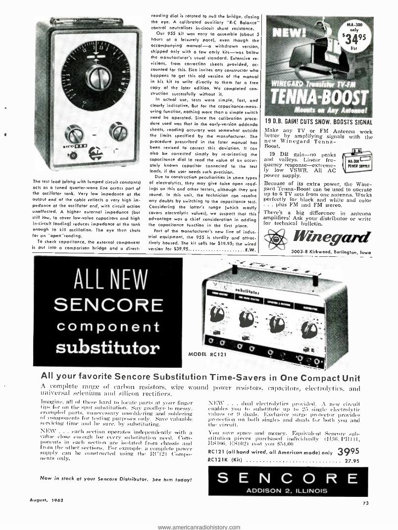
(0 aco® bO A., 11,
The lest lead (along with lumped circuit constants) acts as a tuned quarter -wave line across port of the oscillator tank. Very low impedance at the output end of the cable reflects a very high im- pedance at the oscillator end, with circuit action unaffected. A higher external impedance (but still low, to cover low -value capacitors and high in- circuit loading) reduces impedance at the tank enough to kill oscillation. The eye then shuts for on "open "reading.
To check capacitance, the external component is put into a comparison bridge and a direct-
reading dial is rotated to null the bridge, closing the eye. A calibrated auxiliary "R -C Balance" control neutralizes in- circuit shunt resistance.
Our 955 kit was easy to assemble (about S hours at a leisurely pace), even though the accompanying manual -a withdrawn version, shipped only with a few early kits -was below the manufacturer's usual standard. Extensive re- visions, from correction sheets provided, ac- counted for this. Eico invites any constructor who happens to get this old version of the manual in his kit to write directly to them for a free copy of the later edition. We completed con- struction successfully without it.
In actual use, tests were simple, fast, and clearly indicative. But for the capacitance -meas- uring function, nothing more than a simple switch need be operated. Since the calibration proce- dure used was that in the early. version addenda sheets, reading accuracy was somewhat outside the limits specified by the manufacturer. The procedure prescribed in the later manual has been revised to correct this deviation. It can also be corrected simply by re- orienting the capacitance dial to read the value of an accur- ately known capacitor connected to the test leads, if the user needs such precision.
Due to construction peculiarities in some types of electrolytics, they may give false open read- ings on this and other festers, although they are sound. In this unit, the technician can resolve any doubts by switching to the capacitance test. Considering the latter's range (which mostly covers electrolytic values), we suspect that this advantage was a chief consideration in adding the capacitance function in the first place.
Part of the manufacturer's new line of indus- trial equipment, the 955 is sturdily and attrac- tively housed. The kit sells for $19.95; the wired version for $39.95 E W.
ALL NEW SENCORE component substitutor
19 D.B. GAIN! CUTS SNOW. BOOSTS SIGNAL
Make any TV or FM Antenna work better by amplifying signals with the new Winegard Tenna- Boost.
19 DB gain -no peaks and valleys. Linear ft-e- KI.X0 quency response -extreme - N EU SIMLT ly low VSWR. All AC power supply. Because of its extra power, the Wine - gara Tenna -Boost can be used to operate up to 6 TV sets from one antenna. Works perfectly for black and white and color ... plus FM and FM stereo. There's a big difference in antenna amplifiers! Ask your distributor or write for technical bulletin.
Win wain" 3003 -8 Kirkwood, Burlington, Iowa
MODEL RC121
All your favorite Sencore Substitution A complete range of carbon resistors, wire wound universal selenium and silicon rectifiers. Imagine, all of these hard to locate parts at your finger tips for on the spot substitution. Say goodbye to messy, crumpled parts, unnecessay unsoldering and soldering of components for testing purposes only. Save valuable servicing time and be sure. by substituting. NEW . .. each section operates independently with a value close enough for every substitution need. Com- ponents in each section are isolated from chassis and from the other sections. For example- a complete power supply can he constructed using the RC121 Compo- nents only.
Now in stock at your Sencore Distributor. See him today!
August, 1962
Time -Savers in One Compact Unit power resistors, capacitors, electrolytics, and
Nl : \C . . . dual electrolytics provided. A new circuit enables you to substitute up to 25 single electrolytic values tor 9 duals. Exclusive surge protector provides protection on both singles and duals for both you and the circuit. You save space and money. Equivalent Sencore sub - stitution pieces purchased individually (H:36. YR1II, 1:S(06. 1'.5IÙ3) cost you $54.00
RC121 (all hand wired, all American mode) only 3995 RC121K (Kit)
. 27.95
S E N C O R E ADDISON 2, ILLINOIS
73
www.americanradiohistory.comwww.americanradiohistory.com

SEND
ELECTRONICS WORLD
EVERY Elect rolli('.,11orl,I
MONTH
name
address
city
state
IF -A§
zone
Check one:
3 years for $12
2 years for $9
1 year for $5
In the U.S., and possessions.
Payment enclosed
Bill me
Foreign rates: Canada and Pan
American Union countries.
add .50 per year; all other
foreign countries, add $1.00
per year.
New Renewal
11i1 to: ELECTRONICS WORLD
Dept. EW 862H. 434 S. Wabash Ave.
Chicago 5, III.
74
Mac's Electronics Service (Continued .from puye 42)
high impedance to the signal and prac- tically none of it reaches the diode in that leg of the bridge. The signal passes as before through the 22k resistor in the other leg, though and the rectifier in this leg produces a positive voltage across the 2 -4. capacitor that opposes the negative bias voltage flowing through the bridge. The bias on the 6AU6 goes down and the tube amplifi- cation goes up so that more signal is delivered to the unbalanced bridge, re- sulting in still more unbalance and more plate current through the 6AU6. This action continues to build up until the tube reaches a condition of saturated plate current and the relay contacts are closed, operating the door's opening and closing mechanism. That 2y/f. capacitor requires an appreciable length of time to charge. and this prevents short -dura- tion transients from tripping the mech- anism."
"Well. I'll be -!" Barney marvelled. "It took me a long time to figure out that circuit. even with the description right in front of me: yet you reeled it off as though you were reading over my shoulder."
"I gotta confess," Mac said with a
chuckle. "I did read the book. When you said that garage door opener came in a kit form, I suspected it might he the Heotlkit job, and I had read up on that circuit not more than a month ago. I, too. was rather intrigued by the clever circuits, and their operation stuck in my mind. I like to think I could have puzzled out the operation of that receiver circuit eventually. but I most certainly would not have understood it just from hearing you describe the dia- gram."
"Well, that makes me feel a little better," a mollified Barney replied. "This is a pretty far cry from the first garage door opener, I'll bet."
"That would be a safe wager. I know the first radio -controlled door I ever saw was a very simple affair indeed. Both the transmitter and receiver were variable -tuned and inclined to drift. Keeping both on the same frequency for a week at a time was an undertaking in itself, especially with changes in temperature and humidity and the kind of components available at that time. You didn't need any a.g.c. action to limit the amount of input signal to the detec- tor, either. The problem was to get enough r.f. to operate the simple squelch circuit that tripped the control relay that was used.
"Finally, though. this last problem was licked: and then came a silly period in which owners judged the quality of their garage door installations by the distance at which the car could control the door. I still remember one such owner complaining to me he could no longer control his garage door from two miles away! When I touched up the receiver for him so that he could make the door open when he was still a couple of miles from the city he was happy.
"As remote garage door openers be- came more common and as the v.h.f. channels became more crowded, how- ever, owners came to place less empha- sis on the 'remote' aspect and more on the 'reliable opening' of their gadgets. They discovered overly sensitive receiv- ers, necessary for long -range operation, responded too easily to spurious signals. The doors tried to following the keying of amateur transmitters in the vicinity or went up and down every time a neigh- bor changed channels on his TV re- ceiver. This led to the present era in which the transmitters are powerful and crystal -controlled and the receivers are made more selective and less sensi- tive and are keyed to certain specific audio modulation frequencies. If I re- member right, that Heuthkit transmit- ter inputs nearly five watts to the final; yet it is recommended that the receiving antenna be shortened until the car must be within sixty feet of the door to oper- ate it."
"Other signals than c.w. or modulated r.f. have been used to open the doors, haven't they ?"
"Oh, sure. Supersonic sounds, light shining on a photoelectric cell, low -fre- quency audio radiated from the car into a pickup coil buried beneath the drive- way, or combinations of these and other actuating signals have all been given a try."
"Well. as garage door openers become more reliable. more and more people are installing them: and after a person is accustomed to the convenience of such an arrangement, he is most unhappy and frustrated when the thing quits working. It strikes me servicing these comparatively simple units might be a lucrative sideline for us."
"That's my boy!" Mac applauded as he patted Barney approvingly on the shoulder. "Keep up that kind of think- ing. and you will go far!"
INTERMITTENT CAPACITORS
By ELWOOD C. THOMPSON
Plt \(:TIC evey technician dreads the task of Iocaling :w in-
termittent capacitor whirl' slakes a set change .' .1111114' or go dead Ind irel \m Milner which capacitor i. bypassed. with a .parr, in.ariabl. the .urge imposed on the circuit will redore the set to mal operat , perhaps for days. Ose w:1, lu elilllill:tte erratic 11per :11' is ill replace all the capacitors, but this is high!. tin- te al. .1 practical nlethod of locating the capacitor trouble is lined below.
'!lie suspected capacitor is shunted by a seri e --c s led RC c bina)¡titi cmn- siaing of approximately 22,(11111 ohms (this valus is not critical) and the proper valse of dupas capacitor. Tle purpose of this c hivatiun is to allow the in- termittent capacitor to remain Ilarged at the usual eirruit voltage and tu pre- vent the new !Anil from acting ils a by- pass. Then, %hell the set finally arts up, the series. resistor is shorted mut will test leads or a screwdriver. In this way, the unit that has lust it. bypass capabili- ties will be luratttl immediately. Of 1.1/11 r.e, than ll .te ul' a .et can he treated at the .:rue t'
ELECTRONICS WORLD
www.americanradiohistory.comwww.americanradiohistory.com

FM- STEREO PROGRAMS
REACH 10- MILLION
LISTENERS
Broadcasting's new "child" is making adult strides in gaining public acceptance and in station compliance.
ALTHOUGH only just past its first anniversary, FM- stereo broadcast-
ing has made great strides in coverage of the major markets. Also, equipment manufacturers, after a rather sluggish start, are now keeping abreast of the demand for equipment to receive such broadcasts. These conclusions are based upon a survey that has been released by the Consumer Products Division of the Electronic Industries Association.
As of April 15th, eighty -one FM sta- tions have converted to stereo and are broadcasting an average of 665 hours of program material a week via multi- plex. The EIA study also disclosed that 40 per -cent of the nation's population, or about 70 million persons, are %within range of at least one of these FM- stereo broadcasts. In some areas, such as around New York City, listeners have a choice of no fewer than four FM- stereo broadcast stations. One of them even transmits stereo 24 hours a day.
The early lag in the manufacture of FM- stereo receiving equipment was clue to the timing of the FCC order estab- lishing the service. FM- stereo broad- casting officially began June 1, 1961, after most set manufacturers had frozen their product lines for the forthcoming year.
The industry quickly overcame this lag in receiving equipment and today at least 20 manufacturers are shipping FM- stereo -equipped consoles or table sets, adapters or tuners, or tuner- ampli- fier units.
According to the EIA, not only are sets available but their over -all quality is exceptionally high, due in large meas- ure to the fact that manufacturers were not stampeded into crash programs and took cognizance of the need for careful design and sophisticated circuitry which FM- stereo reception involves.
With good receiving equipment on the market and the likelihood that no less than 300 stations may be broad- casting FM- stereo by the end of this year, the EIA views the future of this "new world of broadcast sound" with unqualified optimism.
August, 1962
Calendar of Events
JULY 26- AUGUST 12 Fourth Annual International Trade Fair. Spon- sored by the Chicago Association of Commerce and Industry. McCormick Place, Chicago, III. Open to public and trade at specified hours. Details from Association, 30 W. Monroe St., Chicago 3.
AUGUST 8 -10 1962 Standards Laboratory Conference. Spon- sored by National Conference of Standards Laboratories. Boulder Laboratories of National Bureau of Standards, Boulder, Colo. Further de- tails from Alfred E. Hess, Circuit Standards Div., NBS, Boulder.
AUGUST 13 -16 Pacific Energy Conversion Conference. Fairmont Hotel, San Francisco. Registration information from Wendell B. Freeman, c/o General Electric Co., 235 Montgomery St., San Francisco 4.
AUGUST 14 -16 International Conference on Precision Electro- magnetic Measurements. Sponsored by NBS, IRE, AIEE. NBS Boulder Laboratories, Boulder, Colo. Program information from Dr. George Birnbaum, Hughes Research Labs., Malibu, Calif.
AUGUST 21 -24 1962 Western Electronic Show d Convention. Sponsored by Los Angeles & San Francisco Sections WEMA, all professional groups of IRE. Stotler Hilton & Sports Arena, Los Angeles. De- tails on program from WESCON Business Office, c/o Technical Program Chairman, 1435 S. La Cienega Blvd., Los Angeles 3.5, California.
AUGUST 22- SEPTEMBER 1
29th Notional Radio and Television Exhibition. Earls Court, London S.W. 5. Details from An- drew Reid, Press Officer, Radio Show, 17 Fleet St., London E.C. 4, England.
AUGUST 23 -26 NATESA Annual Convention. Pick -Congress Ho- tel, Chicago. Details from Frank J. Moch, Exe- cutive Director, 5806 S. Troy St., Chicago 29, III.
AUGUST 29- SEPTEMBER 1
1962 Congress on Information Processing. Spon- sored by International Federation of Information Processing Societies. Munich, Germany. Program information from Dr. E.L. Harder, Westinghouse Electric Corp., East Pittsburgh, Pa.
AUGUST 28 -30 Fourth EIA Conference on Maintainability of Electronic Equipment. Sponsored by Engineering Dept. of EIA in cooperation with the Dept. of Defense. University of Colorado, Boulder. De- tails from EIA, 1721 DeSoles St., N.W., Wash- ington.
AUGUST 31- SEPTEMBER 9 World's Fair of Music d Sound. McCormick Place, Chicago. All phases of music and sound. Open to public.
SEPTEMBER 3 -7 International Symposium on Information Theory. Sponsored by the PGIT, Benelux Section & Bel- gian Societies. Free University of Brussels, Brussels, Belgium. Program details from F.L. Stumpers, Philips Research Labs., Eindhoven, Netherlands.
SEPTEMBER 5 -7 Symposium on Measurement of Thermal Ra- diation Properties of Solids Sponsored by Aeronautical Systems Division USAF, NBS, NASA. Biltmore Hotel, Dayton, Ohio. Details from C. Robert Andrews, Chairman of Arrangements, University of Dayton, Dayton 9, Ohio.
SEPTEMBER 13 -14 Sixth Notional Symposium on Engineering Writ- ing d Speech. Sponsored by PGEWS of IRE. Mayflower Hotel, Washington, D.C. Program details from J.E. Durkovic, c/o ARINC, 1700 K Street, N.W., Washington.
Tenth Annual Engineering Management Confer- ence. Sponsored by IRE, AIChE, AICE, ATEE, AIIE, AIME, ASCE, ASME. Roosevelt Hotel, New Orleans. Program details from J. S. Cave, AT&T, 195 Broadway, New York 7, New York.
OCTOBER 1 -3 Eighth National Communications Symposium. Sponsored by PGCS, Rome -Utica Section of IRE. Hotel Utica & Municipal Auditorium, Utica, New York. Program details from George Baldwin, Paris Road, R.D. #2, Clinton, New York.
OCTOBER 2 -4 Eleventh Annual Symposium on Space Electronics and Telemetry. Sponsored by PGSET. Hotel Fon- tainebleau, Miami Beach, Fla. Program details from Otto A. Hoberg, George C. Marshall Space Flight Center, NASA Redstone Arsenal, Alabama.
OCTOBER 2 -7 New York Hi -Fi Show. Sponsored by Institute of High -Fidelity Manufacturers, Inc. New York Trade Show Building. Open to public Oct. 3 -7.
OCTOBER 8 -10 Notional Electronics Conference. Sponsored by IRE, AIEE, et al. McCormick Place, Chicago, Illi- nois. Dr. Thos. W. Butler, Jr., E.E. Dept., Univers- ity of Michigan, Ann Arbor, Michigan, for pro- gram information.
OCTOBER 15 -18 International Symposium on Space Phenomena and Measurement. Sponsored by PGNS. Stoller- Hilton Hotel, Detroit, Michigan. Program details from Michael Ihnat, Avco Corp., 201 Lowell St., Wilmington, Mass.
75
www.americanradiohistory.comwww.americanradiohistory.com

Radio & TV News Events in the Service Industry
OUR STORY on the ouster of Elec- tronic Service Dealers Association
of Western Pennsylvania by the Na- tional Alliance of Television & Elec- tronic Service Associations ( "Service Industry News," June 1962, p. 94; also July, p. 82), as expected, was not the last word on the matter. The first, prompt reaction from Frank J. Moch, NATESA's executive secretary, reached us before he had received our request for comment. Thus one of his several concerns was our apparent breach of "good journalism" in failing to inquire after NATESA's side. We answered and soon received a second letter. Excerpts of this sequence follows.
The First Reaction Concerning our preoccupation with
unity, the writer appears to feel that excessive stress on a theoretical ideal that is unattainable in practice may do more harm than good. "The play on unity," he says, "continues to be a grave disservice to the service industry be- cause it is a divisive tactic. NATESA is, as you should know, the biggest, most respected, and most united service group in the 40 odd years of the indus- try's existence. It is as united as any other group in any other industry.
"Further, because of the wide dis- similarity of purpose, certain other small groups can never be expected to merge. This was proven by the unfor- tunate, 1955, so- called unity meeting
. These people went on to form sev- eral new groups with what appeared to be your blessing . . . those associated with these other attempts who, at a later date, did affiliate with NATESA, brought with them not unity but con- sistent attempts to take over or destroy, which terminated with the ouster of ESDA and other actions. Certainly it is the established parliamentary preroga- tive for any group to purge itself of un- desirable members for due cause. The Directors at the Miami conference con- firmed, by substantial vote, the ouster. Not one word of defense of Doyle's ac- tions was heard. In your article you in- dicated that Doyle meant to defend himself and yet he failed to appear. Is this not indicative?
"Your statements on lack of maturity are a slur against every last servicer, many of whom are subscribers to ELEC- TRONICS WORLD.
"Your suggestions for an arbitrator to dabble in the affairs of NATESA are unthinkable arrogance.
"May I suggest that even you, Mr. Silver, who have shown such great anti - NATESA bias, would not have dared print that article had you the decency of getting NATESA's side ..." Our Reply
We answered that, although we would obviously take exception to certain points in the letter, it was a relevant
76
statement worth passing on, as we have done. Portions of our reply follow the points in the NATESA letter (ital- icized) on which they comment:
"NATESA is ... the biggest ... most united service group ... : Probably a statement of fact. We know it is still denied by some unaffiliated groups, but how realistic is such wishful thinking? Recognition . . . should have nothing to do with how one feels about the or- ganization, pro or con.
as united as any group in any other industry ... certain other small groups can never be expected to merge ... : Although it is an opinion, this point is well taken. Perhaps it is both unrealistic and unfair to require of NATESA, as of any action group dealing with sensitive matters, the sort of total unanimity that is seldom at- tainable anywhere ... Every man must make up his own mind on this point, but there is food for thought.
"These people went on to form sev- eral new groups with what appeared to be your blessing ... : We reported the events. We neither bless nor condemn.
"Your statements on kick of maturity are a slur against every last serv- jeer . . . : We never leveled the charge against every last servicer. Certainly the disease infects a certain percentage .
as in every field. And %ve deplore it any- where.
"Suggestions for an arbitrator ... are unthinkable arrogance.: The suggestion may be unworkable, but it is not arro- gant. The concept . . . is frequently unacceptable to the parties of a dis- agreement, sometimes with reason. Nevertheless, this ancient principle sur- vives because it often works.
. . such great anti -NATESA bias ... : We deny such bias categori- cally ... we simply ask for an honest review of our treatment of NATESA and other industry affairs over the years. We also ask you to review your own correspondence file. We think you will find, here and there, copies of let- ters you sent us carrying words of praise ... We are just as obliged to publish relevant material from sources that may be unfriendly to NATESA as we are to use appropriate NATESA material. That is the way we view 'good journalism.' We continue to be an open forum ... We cannot sweep events un- der the rug because they are unpleasant to anyone, as they often are to us.
"After all's said and done, one point of irony remains : there is still scant in- formation on the particular issue that culminated in the ESDA ouster. Does this mean that NATESA is ducking the matter? Not necessarily. It may simply indicate that wisdom has dictated avoidance of the sort of squabbling that can only lead to personal invective and magnification of disputes beyond their inherent importance. If that is the case. we are scarcely in a position to be
critical. After all, have we not deplored this skirmishing in the past ?"
Second NATESA Response The follow -up letter over Frank
Moch's signature presents additional data primarily "in the interests of fair play," since "nothing can be gained by a torrent of cross charges or explana- tions." Concerning disfranchisement of ESDA, the action was undertaken "by the Executive Council, under authority vested in it and on the basis of authentic evidence before it, which action has subsequently been upheld by a substan- tial majority of the Directors at the Miami meeting ... The action ... by the Executive Council of thirteen, with only one opposing vote ... was substan- tiated by the Internal Affairs Commit- tee, which had the case under study for at least three years.
"The offenses of Doyle are many . . .
Three years ago he attempted, without the knowledge or consent of ESDA, to usurp the post of Director ... Two years ago Doyle certified a member list, for which he voted, only to immediately thereafter ask for a refund on five of the alleged members. This last year he again certified a member list and im- mediately three alleged members vol- untarily submitted disclaimers of mem- bership. We have a large stack of legally acceptable evidence to show that Doyle was a key figure in a conspiracy to take over or destroy NATESA, which has not yet fully run its course. Recent resigna- tions in Indiana and some yet to come
. are part of this conspiracy. We still say that an on- the -spot investigation in Pittsburgh would reveal the facts.
.. At the ESDA elections about a year ago, when a stooge was elected president and Doyle secretary, neither received the margin of vote called for by the ESDA by -laws, and under these same by -laws, when a large block of members, including many Board mem- bers, resigned en masse in protest over repeated major flaunting of the by -laws and other infractions, ESDA could no longer conduct business because it had no quorum. Further, our completely proper attempt, on two occasions, to check the actual membership of ESDA revealed only five members willing to admit it. And yet in a recent trade -press article Doyle claimed 140 members while listing less than one -third of these with NATESA . . .
"No, NATESA is not ducking out on the ESDA matter. We felt sincerely that the offenses were so sordid, revela- tion would not add to the stature of independent service . . .
Closing Comments The "resignations in Indiana" to
which Frank Moch refers are those of the Indianapolis TV Technicians Asso- ciation, over the ESDA matter, and others in the state group (IESA) that are following on its heels. As to our own involvement, we are pleased to say that the second Moch letter is much friend- lier in tone than the first. Readers now have the NATESA side. We never planned it otherwise.
ELECTRONICS WORLD
www.americanradiohistory.comwww.americanradiohistory.com

ELECTRONIC CROSSWORDS
By N. F. LAVIGNE, JR.
Answer on page 92)
ACROSS
1. Variable resistor. 4. Light amplifier. 9. A wirewound ,11 Across.
13. Old English. 14. One volt across one ohm =. 15. Weight tpl.). 17.1'12 -fC) 18. Current. 19. Sly glance. 21. "J" scan pattern. 22. All the inductance in the cir-
cuit (schematic notation). 23. Unit of force. 26. Rare gas. 28. Formula for "E.' 30. Chemical symbol. 31. G,,, x ri.. 32. Egyptian sun god. :13. We must, before we walk. 36. Organization for reformed
drinkers. 37. Crystal cut. 38. First letter. 39. Every actor needs one. 41. Carry (colloq.). 43. 2 fL. 44. Gas in auto exhaust. 45. Velocity (abbr.). 46. Women. 47. Schematic notation. 48. E /R. 49. 60 cps. for instance (abbr.). 52. Preposition. 53. Tube element. 56. Popular import from Puerto
Rico. 58. It appears in Ohm's Law. 59. Used in digital computers. 60. Not me. 61. Its frequency is lower than r.f.
DOWN
1. Opposite of theoretical. 2. Unit of resistance. 3. Lukewarm. 4. California city Ifam.). 5. Reduce. 6. Meter often found in ham rigs. 7. Period of time. 8. Vibrates at natural frequency.
10. English digraph. 11. Parts list abbreviation. 12. British for video. 16. Metal in its natural state. 17. Inductive reactance. 20. It designates voltage. 24. Vertical axis. 25. Tune current for this in a
parallel resonant circuit. 27. Speaks eloquently. 29. Means of transportation
abbr.) 31. Small current. 34. Part of a circle. 35. It handles the low frequencie.. 40. All inclusive. 42. Eggs. 43. Has a very short wavelength. 48. Charged particle. 50. E/I .
51. %Vhich (Lat.). 54. Unknown in a formula. indi-
cating a specific quantity. 55. Accomplish. 57. Amplification factor. 58. Heterodyned frequency t abbr.).
I 2 3 4 5 6 7 8
9 10 11 12 3
17
14 15 16
l8 19 20 . 21
22 23 24 25 26 27
28 29 30 31 32
33 34 35 36 37
38 39 40 41 42
43 44 45 46
47
53 54
48 49 50 51 52
55 56 57 58
59 60 61
August, 1962
only DON BOSCO makes the STETHOTRACER,
the vest -pocket signal tracer that amplifies 1,000 times and locates defective circuits fast!
! t& Detects and demodulates any low level micro watt audio or modulated radio frequency signal.
.. its ACCESSORIES including the new, precision -built microwave
demodulator, magnetic tape head (monaural), vibration pickup, miniature microphone, input adapter, output adapter, and telephone pickup.
and the MOSQUITO! The signal generator for every trouble- shooting application. Pocket-
size, cordless instrument generates and injects a rich signal
covering the audio, IF and RF spectrums. Eliminates need for expensive generators.
1
N -=
World's Foremost Producer of
Precision -Built, Pocket -Size
Test Equipment.
See your local distributor, or write to
Don BOSCO ELECTRONICS INC. littell Road Hanover, N. 1. Tucker 1.5515
A Subsidiary of Howell Electric Motors Compant
Full Color Giant Fold -Out Charts Still Available!
Ilure's a complete series of colorful, authoritative fold- out %volt- charts (originally appearing in the pages of ELECTRONICS WORLD) -yews for only 15e each. All in full-color-each suitable for framing.
2. Hi -Fi Crossover Network Design Charts: Tells how to build speaker nets for any crossover frequency. Complete coil -winding data, capacitor values given.
4. Bass -Reflex Design Charts: Complete data on building own bass -reflex enclosures tor any speaker, including ducted -port enclosures.
5. Radio Amateur Great Circle Chart: For Huns and short -wave listeners -gives complete listing and neap of amateur prefixes by calls and coi n%tries.
Reprint of: 7. "Build a Citizens Band Transceiver"-complete de-
tails on building an 11- meter transceiver for Citi- zens Band service.
IMPORTANT: ORDER BY NUMBER! OUR SUP- PLY OF THESE FOLD -OUT CHARTS LIMITED. OFFERED ONLY ON A FIRST COME, FIRST SERVED BASIS.
Send 1.5e per selection to
ELECTRONICS WORLD Box 378, Church Street Station, New York 8, N. Y.
77
www.americanradiohistory.comwww.americanradiohistory.com

10,000 Things Electronic To Enjoy
10,000 WAYS TO SAVE IN
famous RADIO SHACK CORPORATION'S Brand New 1963 Electronics Catalog
FREE
Partial
78
Headquarters
Ar^ OSTONIeMASSACHUSETTS Bps
284 pages 1 0,000 items over
List of Products in our New 1963 Catalog
Amateur Radio Antennas Batteries Books Capacitors Controls Hi Fi Microphones Needles Phonographs
Public Address Radios Resistors Tape Recorders Test Equipment Tools Transformers Transistors Tubes Wire
FOR YOU AND
TWO FRIENDS
Mail Card Today
The Radio Shack Story Radio Shack Corporation of Boston, Massachusetts is one of America's big 3
distributors of things electronic to the general public, industry, craftsmen and hobbyists. We offer a complete selec- tion of precision built products by mail, through stores, and direct to manufac- turers. Our exclusive REALISTIC °' line of electronic products is famous nationwide for its high quality, dependable service and fine values. Our selection of national brand products is the largest in America.
Radio Shack Corporation has been serv- ing the nation since 1923 -from the
very beginning of the electronic age. This year over 2,000,000 people - music devotees, ham operators, ama- teurs and professionals -will shop from our catalog because they get the most
value for every penny they spend on
their favorite products ... they will buy on the easiest terms, cash or credit .. .
they are assured by our guarantee of getting the most satisfaction on every purchase. Radio Shack Corporation in-
vites you and your friends to get your share of these savings and satisfaction by mailing the card opposite today.
ELECTRONICS WORLD
www.americanradiohistory.comwww.americanradiohistory.com

RADIO SHACK CORPORATION BOSTON, MASSACHUSETTS
America's Electronic Headquarters Deluxe All- Transistor
80 -Watt Stereo Amplifier Kit
$ 139.95 $8 Monthly
Easy Assembly; Fabulous Savings! Features Massive Transformers!
r---
-
The proud result of creative engineering, this Reolistic:s HK -208 80 -Watt Stereo Amplifier sets new standards of transient response and definition, delivers an extra margin of performance. Premium Minneapolis -Honeywell tetrode transistors utilized throughout! A host of spectacular technical features make this the unqualified leader in its field! 161/2x71/2x141/2". No money down. Satisfaction guaranteed. 30K90LX093, Amp. Kit, Wt. 19 lbs., $8 Monthly Net 139.95
.1, 12" Hi-Fi Speaker Kit
Can Be Built in on Evening! y
$5 Monthly
Enjoy the fun of building the world's only hi -fi speaker in kit form . another Realistic s)
exclusive from Radio Shack! Assemble the entire speaker, from I2/.. lb. magnet to voice coil, basket and dual cone, using a precision jig for perfect alignment. No money down. Satisfaction guaranteed. Ship. wt. 71/2 lbs. 40K90LX370, 12" Speaker.
$5 Monthly, Net 19.95
WIRELESS INTERCOM KITS
KITS 2 FOR $29.517
Easy to Build, Operate! Just Plug In and Talk!
Add convenient room -to -room, floor -to -floor intercommunication for truly modern living! Just plug into your house current and talk. Range over 1 mile. Size: 8x5x5 ". No money down! Wt. 10 lbs. 43K90LX844, Kit (pair)
$5 Monthly ... Net 29.50
LOOK FOR
RADIO SHACK'S Nationally Famous
REALISTIC KITS
in our 1963 Catalog Save up to 40% on our exclusive precision -en- gineered equipment kits. All easy to as- semble! See outstand- ing selection below.
New! Professional Tube Tester Kit Realistic u Design!
Professional Accuracy! Checks the complete condition of virtu- ally all tube types with laboratory pre- cision! Also tests transistors, incl. diodes, triodes and tetrodes, for leakage and gain. Roll -chart gives full test instruc- tions. 161/2x71/2xI41/2". Cover and in- structions included. No money down. Satisfaction guaranteed. Wt. 25 lbs. 22K94LX010, TK -113 Kit.
$6 Monthly, Net 99.95
$99.95
Electronic Thermometer Famous "Novatherm" Actuate to 1/2°F.
Kit
19.95 Another Realistic x exclusive! Equal to precision thermometers selling for $80 and up! Easy to assemble. Fast reaction to temperature change. Ideal for darkrooms, lab- oratories, freezers, amateur radio equip. Size 32/% x61/4 x41/2 ". Build- er's manual included. No money down. Satisfaction guaranteed. 22K94LX095, Novatherm Kit, Wt. 5 lbs., $5 Mo., Net 19.95
Good Quality FM Tuner Kit Realistic" Components Carefully Engineered 1 9.95 For maximum listening enjoyment and top economy, its Realisiic's FM Tuner Kit! A pleasure to as- semble. Lets you add quality FM reception to your home music cen- ter . . at fantastically low cost! Incl. brushed gold case, instruc- tions. No money down. Satisfac- tion guaranteed. 31 K9OLX070, Sh. wt. 6 lbs., $5 Monthly Net 19.95
FM Multiplex Adapter Kit Converts Monaural 995 FM Tuners to Stereo! 1.
Fully self -powered; famous Real -
isticri quality; completely pre - aligned! No test equipment needed. Resp.: 50- 15,000 cps, ±3db. Size: 3t /2 "H x 4" Wx 5 "D. Black case incl. Uses 15 watts, 105 -125V, 50'60 cy. Easy -to- follow instructions. No money down. Satisfaction guaranteed. 31 K90LX099, Ship. wt. 4 lbs. Kit.. $5 Monthly, Net 19.95
NO MONEY DOWN f -- MAIL THIS ORDER FORM TODAY - -, P.O. Box No. 309
Boston, Massachusetts 62H6 CREDIT TERMS Radio Shack Corporation
take up to 2 years to pay
GUARANTEE In addition to the manu- facturers guarantee and warranty, Radio Shack Corporation guarantees complete satisfaction on every purchase or your money back.
August, 1962
Name Please Print
Address
City & Zone State Please send me the following items:
Stock No. Quantity Name of Item Price each Total Price
Check or Money Order En- closed (No Stamps, No C.O.D.'s) * Express charges collect on delivery T Conn. residents add 31/2%, 121 residents add 3% Sales Tax
Total for Mdse.
Amt. for Postage
*Ta x
TOTAL AMOUNT J 81
www.americanradiohistory.comwww.americanradiohistory.com

Patent Information for the Inventor
By JOSEPH F. VERRUSO Senior Lab Technician, Westrex Corp.
Part 2. The procedures followed by the Patent Office leading up to the granting of a patent.
IN LAST month's installment, the author discussed the basic steps to be followed by an inventor in ap-
plying for a patent. Now, we consider what happens to a patent application after submission to the Patent Office.
With the application on its way to the Patent Office, the long wait begins, for it may take from 3 to 31i years be- fore a patent may be granted. The pat- ent application process is a slow one as compared to the great scientific achieve- ments taking place each day in our elec- tronic era.
New methods are being sought by the Patent Office to reduce the amount of time involved in processing patent appli- cations. By reducing this time and mak- ing the patents available to the public now and not 3 or 4 years from now, the engineer or scientist may be provided with the solution to some of his present - day problems.
Until a new application process is de- veloped, however, the inventor will have to wait the prescribed time -for the final reward for an inventor's perseverance is a patent granted for his invention or process. With this in mind, we will proceed to show what steps are taken from the time the application ar- rives at the Patent Office until the final patent is granted.
Application Procedures
When the application is received at the Patent Office, it is first examined for the proper filing fee and excess claims fee. If the appropriate fee is en- closed, the clerk will stamp the date of receipt on the first page of the applica- tion. This date is important, for it can mean the success or failure of a patent petition if any question should arise over the priority rights of the invention. Minor errors are not unusual, even with experienced inventors. If minor errors are detected, the inventor may be asked by mail to correct these errors, but if
82
important parts of the application are missing, such as the signature of the in- ventor or the oath, the application is considered incomplete.
When the application is complete and in order, it will be forwarded to the Application Branch of the Patent Office where it is examined once more. If the application is found in order, a serial or file number is then stamped on the ap- plication. The terms "serial number" and "file number" are used interchange- ably in Patent Office language. Once the serial number is placed on the applica- tion, the filing fee cannot be returned to the inventor.
The words "patent pending" and "patent applied for" come into play now. With the application assigned a serial number. some inventors may decide to place their inventions on the public market. However, the words "patent pending" on the article for sale by the inventor, does not have any legal effect. The words "patent pending" or "patent applied for" only serve as a warning to other manufacturers that a patent is in the works and infringers may be liable to the inventor once a patent is granted.
The application is then placed in a file jacket, all the contents are listed on the front of the jacket. and the whole file is forwarded to the Record Branch of the Patent Office. The application is then processed through a series of auto- matic machines and punch -type type- writers, which prepare index cards for Patent Office records. During this time the drawings are placed on microfilm as a permanent record. The original ap- plication is then placed in the file jacket and examined to insure that all the relevant matter has been returned to the file.
The file jacket is then forwarded to a "routing specialist" of the Application Branch, Who examines the application thoroughly and determines which ex- amining division is then best suited to
evaluate that particular application. A potential patent falls into three
distinct categories : chemical, electrical, or mechanical. These are classified as groups, with Group I assigned to chemi- cal, Group II to electrical, and Groups III to VII to mechanical inventions. These groups are subdivided into di- visions, with each division having its own distinct field, relating to its par- ticular group. For example, an invention relating to electronics will fall into Group II, which may have as many as 11 diversified divisions. Division 41, for example, evaluates applications on vari- ous television arts while Division 51 is concerned with applications relating to radio circuitry and electrical systems used for frequency control. The last division of any group is assigned the title of "Security Division." It is the responsibility of this division to evaluate the application for possible interest to the defense agencies.
The routing specialist will forward the application to the proper examining division, where a primary patent ex- aminer will he assigned to evaluate the invention. The inventor is then notified by mail as to the division handling his application. The primary examiner reads the application thoroughly and refers the application to one of his as- sisting examiners who is judged best qualified to pass on the patentability of the invention.
The assistant examiner reviews ap- plications in order, as determined by the serial number stamped on the applica- tion. It may take as long as six months before an assistant examiner is able to read the application. When the applica- tion finally comes up for examination, the examiner will read the application thoroughly and carefully inspect all drawings. If there are any minor errors the examiner will not delay the applica- tion any further. If the errors are such that the examiner cannot understand the invention. he will contact the in- ventor and request that the errors be rectified. The inventor will be expected to reply promptly.
The assistant examiner has at his dis- posal all the facilities of the Patent Office which includes the search room and scientific library. He is kept abreast of the achievements taking place in his particular field by means of published material. technical magazines, and clip- pings -which in some cases may assist him in the evaluation of an invention. The examiner checks each claim care- fully for any possible infringements on other patents. If there is any flaw in the claims, which is to be expected due to the broad language in which they are written. the examiner will notify the inventor of these rejections. The ex- aminer expects that the inventor will do all in his power to convince him that the claims are valid. The inventor is re- quired to answer "action letters" from the examiner within six months and if he fails to do so, the application may be considered abandoned. However, a case is not officially abandoned until after the second or third action letter.
If the inventor wishes, he may re- quest a conference with the examiner
ELECTRONICS WORLD
www.americanradiohistory.comwww.americanradiohistory.com

to discuss subject matter that he is un- able to convey in writing. The examiner welcomes these conferences so that each side can discuss the invention in less formal language. As a result, a com- promise may be reached which may lead to the issuance of a patent.
Final Reward: A Patent
Once the application has passed the thorough examination given by the Pat- ent Office and a patent is finally granted to the invention, the inventor will he notified by mail to send a final filing fee of $30 and $1.00 for every claim over twenty. Patents are issued every Tues- day at noon by the Issue and Gazette Branch of the Patent Office. The patents are then delivered to the Post Office for mailing to the applicants.
The patent is issued in the name of the United States of America, under the seal of the Patent Office, and signed by the Commissioner of Patents. The pat- ent will give the title of the invention, plus the statement that the patent is being granted to the inventor, his "heirs or assigns for the term of seventeen years," giving him the right to prevent others from "making, using, or selling" the invention throughout the United States. The patent will refer to the specifications and drawings, and printed copies are made part of the patent.
Patents are granted for a period of seventeen years from date of issuance. However, this term can be extended in a number of ways, if the inventor so desires. For example, the inventor has six months in which to pay the final fee. By delaying this payment until the last possible day, the inventor may he able to negotiate a profitable deal with the knowledge that the patent has al- ready been granted on his invention. This is only one method of extending the life of a patent, but the inventor should have professional advice before attempting this ploy.
Once a patent has been received by the inventor, it is no longer under the control of the Patent Office. If an in- fringement on the patent should occur, the inventor must defend his rights in court.
After the patent has been issued to the inventor there is no guarantee he will make a profit on the patented in- vention. As discussed last month, to in- sure a profit the invention must have features that are outstanding and at- tractive to the public. Even if a profit does not result from the patent, the prestige alone may be well worth the time and perseverance involved in ob- taining the patent.
BIBLIOGRAPHY
1. PWrliealimns obtainable from the U.S. Patent Office, Washington 25, D.C., by remittance pap- able to the Commissioner of Patents: Patents (as issued)-order by patent ber or inven- tor's norme and date of issue, 25 rents each.
2. Publications obtainable. from the Superintendent of Documents. U.S. Gayenrirtent Printing Office. Washington 25, D.C. or tige nearest field office of the U.S. Department of Commerce: a. "Guide Jor Patent Draftsmen," 15 cents b. "Patent Attorneys and Agents Available to
Represent Inventons Before the United States Patent Office," 35 rents
c. "Patent Laws," 30 cents d. "Patents and Inventions -An Information Aid for Inventors," 15 cents e. "Rules of Practice of Une United Stales Pat-
ent Office in Patent Cases," 50 cents
August, 1962
W1`iYL esl: "..
SEND THE HANDY COU- PON INDICATING YOUR NEEDS
ROHN Manufacturing
Company BOX 2000
PEORIA, ILLINOIS
ROHN
The most Fmous lJ.me in
TOWERS of All K /NOSa! Here are the advantages you get when you insist on
ROHN TOWERS LARGEST FULL RANGE OF TOWERS -you can get any- thing from home TV and amateur radio towers to heavy -duty communication and micro -wave towers. Included are 170 foot self- supporting towers, 1.000 foot guyed towers, and "fold- over" towers. Regard- less of your needs, ROHN can supply it. UNQUESTIONED LEADERSHIP IN DESIGN AND MANU- FACTURE -you get the latest in advanced tower engi- neering. All communication towers are engineered to EIA specifications, and are proved by thousands of installations. No other manufacturer can surpass the quality and fine reputation of ROHN. QUALITY MATERIALS AND WORKMANSHIP -Only high- est quality steel is used which fully meets the speci- ticat ions for the job. ROHN towers are hot -dipped galvanized after fabrication -a feature ROHN pit:). neered!
SERVICE WHEREVER YOU WANT IT -ROHN represent - ;dives are world -wide. Complete erection service for communication systems. broadcasting, micro -wave, and other needs is available; also competent engi- neering service to help you.
Settle for the BEST in TOWERS -ROHN -today the world's largest, exclusive manufacturer of towers of oli kinds!
For mur needs. contact voter local ROHN salesman, distributor or dealer; or. write dirent for information.
ROHN Manufacturing Company Boo 2000 Peoria, Illinois Send m omplet literature on the following BONN Products:
Nome TV Towers Amateur Towers Communication Towers - AM.FM Broadcasting Toren Micro Wo.. Towers Government
Nome
Firm
Address
City State
If you've recently changed your ad- dress, or plan to in the near future, be sure to notify us at once. We'll make the necessary changes on your mailing plate, and see to it that your subscrip- tion continues without interruption. Right now - print the information re- quested in the spaces below and mail it to: ELECTRONICS WORLD, 434 So. Wabash Ave., Chicago 5, Illinois.
Name, Please PRINT'
*Account A'o.
Old Address
City arar,
New Addrrss
City /one Stale _.
Mail copies to new address starting with issue
'(Your Account Number appears directly above your name on the mailing label.)
83
www.americanradiohistory.comwww.americanradiohistory.com

Tech' cal 1hooks
"TELEVISION ENGINEERING: PRINCIPLES
OF PRACTICE" by Amos & Birkinshaw. Published by Ili.jfe Books Limited, Lon- don SE. 1, 273 pages. Price 36s/2 d in- cluding postage. Vol. 4 "General Circuit Techniques."
This is the second edition of the fourth and final volume in the BBC Engineer- ing Training series covering the funda- mentals of television theory and British practice.
This volume covers a wide range of circuit techniques which are applicable to electronics as well as television. There are sections on field and line out- put stages which have been completely rewritten and updated in this new edi- tion.
The text also includes counter cir- cuits, frequency dividers, principles and practice of d.c. restoration and clamp- ing, gamma control amplifiers, delay lines, fixed and variable equalizers, elec- trical scanning coils, and the shunt - regulated amplifier.
No concessions are made to those weak in mathematics so would -he read- ers are hereby warned to sharpen their techniques before tackling this text.
t * t "AUTO RADIO MANUAL" compiled by Sams Staff. Published by Howard W. Sams & Co.. Inc., Indianapolis. 160 pag- es. Price $2.95. Soft cover. Vol. 14.
This is Vol. 14 in the publisher's com- pilation of service data covering radio receivers used in automobiles. This book covers 60 models produced in 1960 and 1961 and, like the preceding vol- umes, provides complete schematics, parts lists, chassis photos, resistance charts, alignment information, push- button adjustments as well as many time -saving servicing shortcuts.
Units marketed under the following brand names are included: American Motors. Automatic, Blaupunkt. Buick, Chevrolet, Ford. Lafayette. Mopur, Mo- torola, Oldsmobile. Opel -Rekord, Pon- tiac, Riverside, and Stromberg- Carlson.
t t *
"RADIO REGISTRY: INDUSTRIAL RADIO SYSTEMS" compiled and published by Communication Enginering, Mineola, N.Y. 313 pages. Price $7.00.
This 1962 directory includes the addi- tions, changes, and deletions which have occurred since last year's directory was issued in a special section for rapid checking and verification. The regular portion of the registry lists special in- dustrial, petroleum and gas pipeline, power utility, forest products, relay press, motion picture, and v.h.f. mari-
84
time assignments first by licensees and then in a separate section by frequen- cies.
Those involved in two -way industrial radio installation, servicing, and trou- bleshooting will find this manual in- valuable in their work. The mail ad- dress of the licensee, the locations of fixed stations, authorized mobile sta- tions, call letters, frequencies, and the manufacturer of the equipment being used are all included in the tabulation.
* * *
"1962 REPLACEMENT GUIDE FOR TV AND AUTO RADIO CONTROLS" compiled by Sams Staff. Published by Howard W. Sams & Co.. Inc.. Indianapolis. 126 pages. Price $1.00. Soft cover.
This is a new and enlarged Fourth Edition of a popular reference work which covers replacement controls for 30,640 TV models and 1286 auto radio models. All the currently available and recommended radio and TV control re- placements, as produced by Centralab, Clarostat, CTS -IRC, and Mallory, are included.
The material is completely cross -ref- erenced and indexed by receiver manu- facturers' parts numbers, industry num- bers, control manufacturers' equiva- lents, and then further indexed in an industry- number replacement control section.
t * *
"REVOLUTION IN ELECTRICITY" by Mar- tin Mann. Published by The Viking Press. Inc., New York. 163 pages. Price $5.00.
This is a popular treatment of the subject of semiconductors -their dis- covery, development, and application. Informed laymen will find this volume both instructive and entertaining. The author's style is informal and lively and the text is lavishly illustrated. He dis- cusses crystal structure, transistors, masers and tunnel diodes, cryogenics, supermagnets, and prognosis for the future.
We believe that even those involved in electronics professionally will find much material of interest in this fasci- nating volume.
* * *
"REPAIRING HOME AUDIO SYSTEMS" by E. Eugene Ecklund. Published by Mc- Gratv -Hill Book Company, Inc., New York. 311 pages plus "Hi -Fi Detecto -O- Scope Trouble Finder." Price $6.95.
This is a complete treatise on how to troubleshoot, repair, and test amplifiers, preamplifiers, AM and FM tuners, rec- ord changers and turntables, tape decks,
speakers and speaker systems as used in both stereo and mono installations.
In keeping with the "practical" aspect of this volume, there are separate chap- ters on the profit opportunities in home audio servicing, the shop facilities and tools required, basic information on the operation of preamps, amplifiers, and tuners; repairing such components; phonograph records; replacing pickups and needles; record changers and their motors and drives; repairing tripping and dropping mechanisms; cycling pick- up arms in changers; shut -off mecha- nisms; troubleshooting changers; tape recorders and their troubleshooting; plus the troubleshooting of complete music systems.
The use of hundreds of detailed line drawings helps the user visualize the various component parts involved in the troubleshooting procedures.
"RADIOTELEPHONE LICENSE MANUAL" by Woodrow Smith. Published by Edi- tors and Engineers, Ltd., Summerland, Calif. Price $5.75. Third Edition.
This is a revised and up -dated study aid for those preparing to take FCC li- cense examinations. Based on the first four elements of the government license manual, this volume indicates the scope of the questions included in the various elements in the radiotelephone license test.
The book is divided into the four ele- ments (basic law, basic operating prac- tice, basic radiotelephone, and advanced radiotelephone) and an appendix which includes formulas, mathematical calcu- lations, and log tables.
The presentation is in the familiar "question and answer" form and those working toward their tickets will find this volume a valuable help.
t t
"HOW TO BUILD ELECTRONIC EQUIP- MENT" by J. Richard Johnson. Published by John F. Rider Publisher, Inc., New York. 287 pages. Price $6.95.
This is a thoroughly practical hand- book for anyone who enjoys building his own electronic gear from kits or from scratch. Since the treatment is progres- sive, the reader can "enter the lists" at the point corresponding to his previous training and experience.
For those with no prior acquaintance with electronic construction, the author starts with the fundamentals such as selecting tools on a progressive basis, chassis and breadboards, the layout and mounting of components, soldering techniques, wires and wiring, cables and connectors and continues with picto- rials, wiring, schematics and block dia- grams; the wiring of components; cir- cuit wiring; coil and coil winding; up to checking the completed circuit.
Probably the outstanding feature of this volume is the lavish use of actual construction photos illustrating every step described in the text as well as showing in detail the tools and equip- ment mentioned by the author.
Note: In connection with our June review of the hook
'Triter ir,d Telerisi,n Nertiring' by J. Rirhord Johns price of hook uos listed incorrectly. It should he $7.95.
ELECTRONICS WORLD
www.americanradiohistory.comwww.americanradiohistory.com
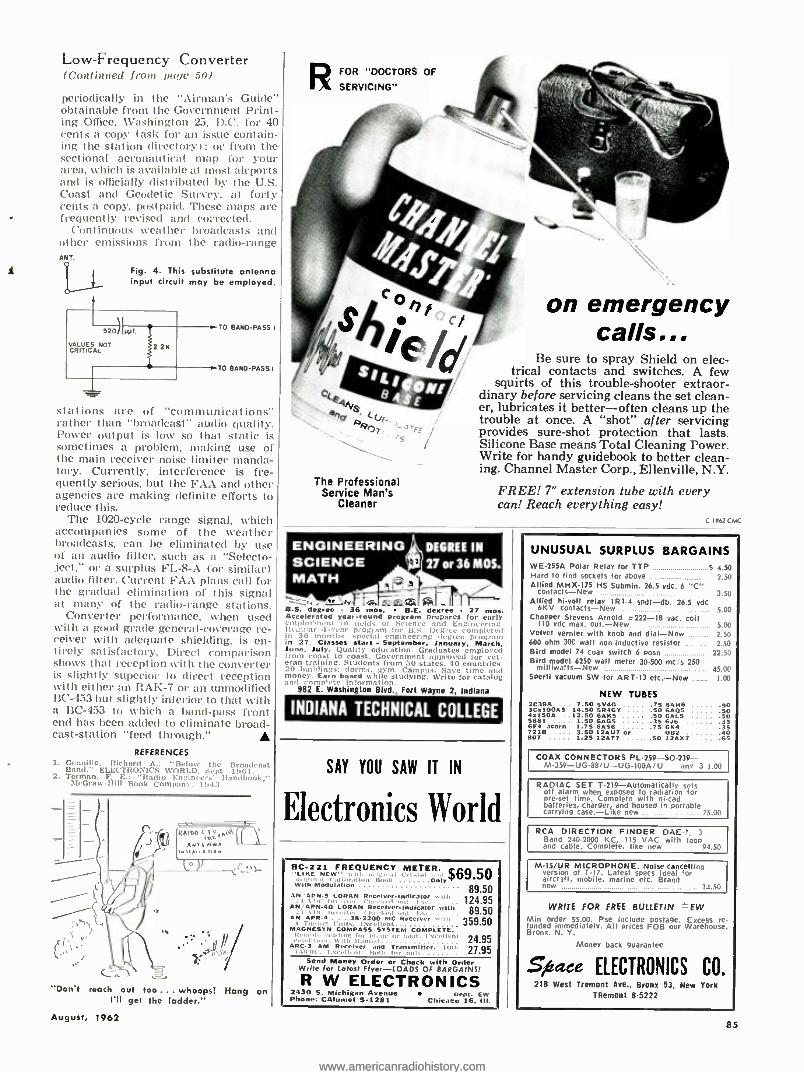
Low- Frequency Converter (Continued front page 50)
periodically in the "Airman's Guide" obtainable from the Government Print- ing Office, Washington 23, D.C. for 40 cents a copy (ask for an issue contain- ing the station directory); or from the sectional aeronautical map for your area, which is available at most airports and is officially distributed by the U.S. Coast and Geodetic Survey, at forty cents a copy. postpaid. These maps are frequently revised and corrected.
Continuous weather broadcasts and other emissions from the radio -range ANT.
O
t> Fig. 4. This substitute antenna input circuit may be employed.
VALUES NOT CRITICAL 22K
TO BANO-PASS I
TO BAND -PASST
stations are of "communications" rather than "broadcast" audio quality. Power output is low so that static is sometimes a problem, making use of the main receiver noise limiter manda- tory. Currently, interference is fre- quently serious, but the FAA and other agencies are making definite efforts to reduce this.
The 1020 -cycle range signal, which accompanies some of the weather broadcasts, can be eliminated by use of an audio filter, such as a "Selecto- ject," or a surplus FL -8 -A (or similar) audio filter. Current FAA plans call for the gradual elimination of this signal at many of the radio -range stations.
Converter performance. when used with a good grade general -coverage re- ceiver with adequate shielding, is en- tirely satisfactory. Direct comparison shows that reception tvith the converter is slightly superior to direct reception with either an RAK -7 or an unmodified BC -453 but slightly inferior to that with a BC -453 to which a band -pass front end has been added to eliminate broad- cast- station "feed through."
REFERENCES 1. Genuine. Richard A.: 'Below the Broads.: Band." ELECTRONICS WORLD. Sept. 1961. 2. Terman, F. E.: "Radio Engineers' Handbook,"
McCraw -Hill Book Company. 19.13.
/ / . I
"Don't reach out too ... whoops! Hang on I'll get the ladder."
August, 1962
RFOR "DOCTORS OF
SERVICING"
c4.F
°p v \ Rl
The Professional Service Man's
Cleaner
es
on emergency calls,,.
Be sure to spray Shield on elec- trical contacts and switches. A few
squirts of this trouble -shooter extraor- dinary before servicing cleans the set clean- er, lubricates it better -often cleans up the trouble at once. A "shot" after servicing provides sure -shot protection that lasts. Silicone Base means Total Cleaning Power. Write for handy guidebook to better clean- ing. Channel Master Corp., Ellenville, N.Y.
FREE! 7" extension tube with every can! Reach everything easy!
ENOINEERINGA DECREE IN
SCIENCE 27 or 36 MOS. MATH ti
ter.. 4_.*v r..^táfa 9.S. degree - 36 nias. B.E. degree 27 mos. Accelerated year -round program prepares for early employment in fields of Science and Engineering. Regular 4 -year program for B.S. Degree completed in 36 months. special engineering degree program in 27. CIass.s start September, J , March. Jun.. July. Quality education. Graduates employed front coast to coast. Government approved for vet- eran training. Students from 50 states. 90 countries. 20 buildings: dorms. gym. Campus. Save time and money. Earn board while studying. ))'rite for catalog .t. iii,orttlataan
n 1982 E. Washington Blvd., Fort Wayne 2, Indiana
INDIANA TECHNICAL COLLEGE
SAY YOU SAW IT IN
Electronics World
BC -22I FREQUENCY METER. QJS.Co -LIKE NEW ., i. -,n i
WIÌIMOOUialtloñllun U;,okl t' Only `9 JJ
89.50 AN'APN.9 LORAN ReeelverIndleator .., .
' Checked 124.95
AN /APN4BLORAN ReCelverIndleater with 89.50 n,rl In.Lea , ll. t..S,.
N APR 4 . 8.2200 MC Receiver wit. 359.50 .... Svry COMMPASS
SS SYSTEM COMPLETE.
iri g fey ne er hoot. rs,ru " "t 24.95 ve,a l qnt and Transmitter. Intl. 27.95
_r .,M u.u,l Roth rar .ml.
Send Money l Order or Check with Order Write for Lotest Oyer -LOADS OF BARGAINS!
R W ELECTRONICS 2430 S. Michigan Avenue W ent. L Phone: CAlurnet S -1281 Chicago 16. III.
C 1902Cti'C
funded
UNUSUAL SURPLUS BARGAINS WE-255A Polar Relay for TTP _ _. _.. S 4.50 Hard to find sockets for above 2.50 Allied MHX -175 HS Submin. 26.5 vdc. n "C"
contacts -New _. 3.50 Allied hi -volt relay IRI -4 spdt -db. 26.5 vdc
6KV contacts -New _ _ 5.00 Chopper Stevens Arnold .222 -18 vac. coil
110 vdc max. out. -New 5.00 Velvet vernier with knob and dial -New 2.50 600 ohm 300 watt non -inductive resistor 2.50 Bird model 74 coax switch 6 posn 22.50 Bird model 6250 watt meter 30 -500 me /s 250 milliwatts -New 45.00 Sperti vacuum SW for ART -13 etc. -New 1.00
NEW TUBES 2C39A .. 7.50 SV4G .75 SANE 90 3C5100A5 14.50 5R4GT .50 BAPS 50 451504 ..12.50 6A115 50 6AL5 50 5881 . ... 1.50 GAGS 35 6J6 35 6r4 acorn 1.75 EASE 75 654 35 7218 .... 3.50 12AU7 or OB2 40 807 1.25 124E7 .... .SO 12.157 .... .65
COAX CONNECTORS PL- 259- SO -239- M- 359- UG- 881U- UG -100A 7U . .any 3'1.00
RADIAC SET T- 219 -Automatically sets off alarm when exposed to radiation for pre -set time. Complete with ni -cad batteries, charger, and housed in portable carrying case.-Like new 75.00
RCA DIRECTION FINDER DAE -1. 3 Band 240 -2000 KC, 115 VAC with loop and cable. Complete, like new 94.50
M -15 /UR MICROPHONE. Noise -cancelling version of T -17. Latest specs Ideal for aircraft, mobile, marine etc. Brand new 14.50
WRITE FOR FREE BULLETIN =EW Min order $5.00. Pse include postage. Excess re-
immediately. All prices FOB our Warehouse, Bronx. N. Y.
Money back guarantee
Sfaace ELECTRONICS CO. 218 West Tremont Ave., Bronx 53, New York
TRemont 85222
85
www.americanradiohistory.comwww.americanradiohistory.com
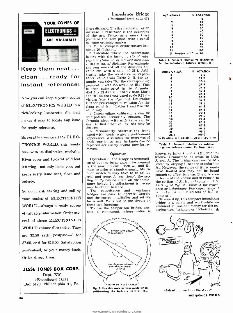
YOUR COPIES OF
ELECTRONICS 0. WOwLO
ARE VALUABLE!
Keep them neat ... clean . . . ready for instant reference!
Now you can keep a year's copies
of ELECTRONICS WORLD in a
rich -looking leatherette file that
makes it easy to locate any issue
for ready reference.
Specially designed for ELEC-
TRONICS WORLD, this handy
file -with its distinctive, washable
Kivar cover and 16 -carat gold leaf
lettering -not only looks good but
keeps every issue neat, clean and
orderly.
So don't risk tearing and soiling
your copies of ELECTRONICS
WORLD -always a ready source
of valuable information. Order sev-
eral of these ELECTRONICS
WORLD volume files today. They
are $2.50 each, postpaid -3 for
$7.00, or 6 for $13.00. Satisfaction
guaranteed, or your money back.
Order direct from:
JESSE JONES BOX CORP. Dept. EW
(Established 1843) Box 5120, Philadelphia 41, Pa.
86
impedance Bridge (Continued from page 47)
short distance. The first indication of an increase in resistance is the beginning of the arc. Temporarily mark these points on the front panel with a pencil or some erasable marker.
2. With a compass, divide this arc into about 20 divisions.
3. Calculate where the calibrations belong with the formula: (`ó of rota - tion) x (total no. of marked divisions) / 100 = no. of divisions. For example, say you marked off the divisions and came out with a total of 21.4. Arbi- trarily take the resistance or capaci- tance value from Table 2. If, for ex- ample, you take "9," the corresponding per -cent of rotation would be 45.4. This is then substituted in the formula: 45.4% x 21.4 / 100= 9.73 divisions. Mark the "9" on the front -panel scale 9.73 di- visions from the beginning. Determine further percentages of rotation for the front panel from Tables 1 and 2 in the same way.
4. Intermediate calibrations can be interpolated accurately enough. The formula given with each table can be used to find other values that may be desired.
5. Permanently calibrate the front panel with decals to give a professional appearance. Also mark the extremes of knob rotation so that the knobs can be replaced accurately should they be re- moved.
Operation Operation of the bridge is uncompli-
cated but the inductance measurement is the most difficult. Both R., and R.=
must be adjusted simultaneously. Multi- plier switch S. may have to be set by trial and error. As mentioned, the set- ting of R has no effect on the induc- tance bridge. Its adjustment is neces- sary to obtain balance.
The capacitance and resistance bridges are easy to operate. Merely find the correct multiplier and set R for a null. R is out of the circuit on these two functions.
To use the comparison bridge, con- nect a component, whose value is
o
00\
foR PURPOSE
DIVIDE INTO ABOUT 20 DIVISIONS
CALIBRATION POINTS FOR REPLACEMENT
OF KNOB
NO RESISTANCE CHANGE
Fig. 7. Use this scale as your guide when calibrating the balance control, R.,.
10's HENRYS ROTATION 1 o 2 10 3 20 4 30 5 40 6 50 7 60 8 70 9 80
10 90 11 100
Rotation = 10L - 10
Table 1. Per -cent rotation vs calibration for the inductance balance control, R.,.
OHMS OR µµf. 3 4 5
6 7
8
9
lo 11
12 13 14 16 18 20 22 25 30 35 36.1
Rotation
N. ROTATION 2.5
12.2 20.6 27.9 34.4 40.3 45.4 50.0 54.3 58.1 61.5 64.8 70.4 75.5 79.4 83.3 87.8 94.2 99.1
100.0 = (138 3R - 3831 / (10 + R)
Table 2. Per -cent rotation vs calibra- tion for balance control Rr. (cap., res.).
known, to jacks J and J. (E). The un- known is connected, as usual, to jacks J, and J.. The bridge can now be bal- anced by varying either the standard or R However, the range of R= is some- what limited and may not be broad enough to effect balance. The unknown in terms of the known and in respect to the setting of R_ is: unknown = .1 x (setting of R..) x (known) for resist- ance or inductance. For capacitance it is: unknown = 10 /(setting of R=1 x (known) .
To sum it up, this compact impedance bridge is a handy and worthwhile in- vestment in time and money for the ex- perimenter. designer, or technician.
"Solder! ... Iron! ... Pliers! .. ELECTRONICS WORLD
www.americanradiohistory.comwww.americanradiohistory.com
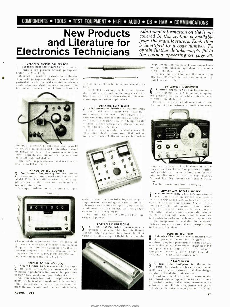
COMPONENTS TOOLS TEST EQUIPMENT HI -FI AUDIO CB HAM COMMUNICATIONS
New Products and Literature for
Electronics Technicians
Additional information on the items covered in this section is available from the manufacturers. Each item is identified by a code number. To obtain further details, simply fill in the coupon appearing on page 96.
VELOCITY PICKUP CALIBRATOR
1
ici. Inst rumen! Elect ronits Corp. is nunc tif. I lei ing a tea pot table velocity pickup tali. ',inn-. the \Lodi! 311.
I)rsigned in iul:uil, in rechttL Ihr u11i11.11í011 01 stut its pickup n.IO.du(tus. the nits unit i hart it calai usrlul ho field t het king 01 is lone a
quid I:IIIUla lors t 11441. 11o00110. nrrt.. :un . I læ nisi ornent operates lront 1 I -tote. 1060 r1).
suu'ces. It tali In airs pi0kups weighing op o 12 01111t4s seil h a at t Uran' of I'7 in eil hol se bull n
or hol iiunrd 01.00'.. I Io lids 01111111 is 1011. 01411i pot table. weighing ooh 2641 ; pounds. and has a sellunu.linrd shaker.
he precision pnlcnlinntrirr dial is t-.tlibtaied fruua 10 t1 130 mv. /in. /sec.
TRANSISTORIZED COUNTER 2 Northeastern Engineering. Inc. ha, nn l'lll
in11 ur«41 a 1,.n si.lnr i,ed I mt. I. the \l.nlel 11911. I lie Iull% n :ulilnl i,ed unit rue plop
`
\is I tbr. Inc 1)n .tnlaliou ui read inn ¡iiioaw:I I inn.
.\ simple push 'ninon sis init plu ides rapid
sell-1E1001 01 Ihr n111it.t la« ¡IìB4.; d«t dual point Illatl.it111 is A11100 1:11 il-. I- l'l'gtei«S I align' is Iluil 10 cps Ii I mt. .11141 Ihr masimlun period mows. 111'lIllt'lll 11',,!1«1x, s i. 11111 k, . 11:111113111 /111/)111 frequent i4. im lode. 1. 1110. In 11011. 11/11.111111. Anil I
ores 1 114 lint ui(astn. 12's 11"s I1 ",
SPECIAL SOLDERING TOOL
3 linger Electric Tools is m :nkrning a .pe- 0ial solde, ing iron designed lo inert Ille uttd.
ill inn irate 1)roducliou lint- assnbl, op,raliun. ill elcrlru11it. missile, and space i !Must l i4...
Feaint ing a new lita I-sink pa ion Mir o herein a double cushion of air. combined is it Inc heal transition surlaces. osrnl% di ip :ne. heal :titi keeps the iron h :nullc tool. the ilex, oeil is bring
August, 1962
..M11881116
NMI) Inis ides :I Illinilllllla Of 13 mnlinuuu. huur. 7R'I ul light aith ineuin ctluil:dtnl tI 1111a1 ul a
"dl-nail in( Antics, run hulb. I ho uew lunp
t`( igh. mils 7« z ltumlds :und
1114.0111,4 1114.0111,4 Is"VicI.II usc. a .land:nd I8" 13- ssatl Iluur4.sctvl n41lc.
011ere11 ill Itaslel 013414, 11 l'et1a144. u1ur:uut la- ligut..
1 he Y'.;lu Iu ean Ionglil4 heat ulruidg, re- dint. s,ai 41rn.its and i non r lungrl rl4tnital lilt.. I heir .u4 11 i1111 hfe:Id-un sul- dering its liar ,.uions aPpliutitins.
DYNAMIC BETA TESTER 4 It lnsn 11110111s 1)' is marketing
the \I,Iel I.,1. cis na beta power intul- si.Iur tust« I. a tnogl4.trl) 1 I:111si.lur ind ins!lia Il0l111 shit h mu- .Inns Ixla and leakage e il h at( u- 4an of 9' ;. It lea titres a pulse technique lot !he 41,1E11104 141.0 rest 46411 p111.« width ,uloinuau.lc sariahlr 11011 11.1 .I .1.111 111,41 .
hr 0n011 1IIIIt' 11 t.IU .tl.o 1«41 diodes. n'u«I di- stils.. tinting diode.. siliaou tin nil led Imiter,.. :nul phots ditnl.. (.01 1.11 null s011.1g, is 101111 1111
uusls sat is bic hon. 11 to 100 volts, is il h up lu '.11
:nip. ill rent. 11 :1,4 ripage is 01111 11110001, %AIi- able 1 10111 Il lu III null. ail h 110111 111 raps, i trill. \ 1011 t 1011 lists dal., I01 bila and l leakage lest.
un moor 16.111 I Val Ir alt.isltirs. I Ile Mill 11K0111es I S's 1 11 _'s I -IS
neigh. 1.i pounds. :ulti
PORTABLE FLUORESCENT L ITT Industrial Pronto, tc Disk' is in
pi nl lIt l ion on a pol 1.I boo, lung -lilt Iltures 11111 I:u11p 1,birh i, poictti lo urdinars flashlight bau net it,. I sing tine Is 1)e ill flashlight haulers. the
TV SERVICE INSTRUMENT 6 l'rriisinu \pP:ualus Cu.. Ise. has anuulnl4od
hi '.lil.uhilin 111 a cum bins 11un .n er1) .ig 11.11 gene. nut 3ní1 ,,I.1, Lei adder ,chit h is being ull«lyd a. Ihn \1oá41 1. -110.
U4signtd lie Ihr si.iCd alignn.en tit I \1 and 'I \- 11.465 -us. Ihr 111s1101r11 lilac, ides lot sirr!,
Inquests u, '
` ' iii line fundamentad °Minn
nuing4. Irow :1 lo 1_I:: nit. Swtr1) wi,ilh is conduit- Is sal iahle up t a 911 tit. \ built -in ( Iislal 0.61.
Ia1or u011im ,mato I1sed -h egt411n nisi Lrrs. Inertial blanking tunoila l X1115 «Iinliu. re. re- 1ta4r.
I he in.urnuncu li«:nn res 1 :1 "58c4, "s7".
LOW -POWER ROTARY SWITCH 1 Oak \Lmnfat luring Co. is nun mal Let ing a
2 iilt ll .Ilhulillial I -l' nun 1)11'«'1 uLnr .s, i lllil 11i 10..pet ial aP1.11c1lious in white u0n1)a1 .11,4 i. 111 pa aun11u11t i nlml cl m «. I hr si it, b is a lull II -posit iou nil' suet jai Iras urr. iw ludo long Dilo sited alln, moai ts. gold ra.hrd lo pi, veil i:1, uish: J11mnails a ipi _ 41rsi g 11. 1a 61 ici inn ail .lainl1.5.1«el :1,.d 11thoi Iloll ,011041101« 111.414'1 i.0 Is; 41111 abilils 14. eilh.l :lnl '.0 ten . l splan trsn.
I hi. - ponen . .0:10.1111r in mimeo., s0 in hiug (onlugural ions and can inuiporale 111)
11 hie sede 1. sat 000,
PLUG -IN RECTIFIERS 8 eidunsten. IIii tunni(1 t u' ow Ix, keting 45t
1 11111 111 ,i I ill,. Its iiterls des girti 1.0 1)t
nail duel i lolug ill ewer,' rplat emrt 111 silt 111 g ilia. et diet loht'.' \,.Iilahlt I Ian ings to -MOO sic], 1) . i . nd amps. mps. This ICI' srirs of re,li- hu p1innll, ihr
l
rltl.100 1,i 111 I11tr 151)4..31'1. r, \I..'I'_>. N.L. sut.v. :Ind m:ms uihcrs.
DRAFTING KIT
n ( : Thru Ruler Company is oiler ing its "l'ht)" kit in !licit has been designed espc-
.ialls tao e gMeet . draft II. and those design- ing «Ir« l l it ui and electronic tin oils.
I loosed in .I simulated tall skia li 1 1111 ii. the kit is Ilined 0411 rt.u1,pa t-ii pockets a hit ll held h,. toil id than ing .Ind dl.dli 1g i11.1111u04111s. In A10110011 lo an "II- íl.10 in, Ilan il :1111 .41:1011
pad. the set imclul«s :;11 yin du, t .nul I 911 de.
87
www.americanradiohistory.comwww.americanradiohistory.com

YOU SAVE MONEY!
RUSH US YOUR
LIST OF HI -FI COMPONENTS FOR A SPECIAL QUOTATION WRITE FOR FREE
AUDIO DISCOUNT
CATALOG A -15
New low prices on amplifiers, tun-
ers, tape recorders, speakers, etc.
KEY ELECTRONICS CO. 120 LIBERTY STREET NEW YORK 6, N.Y.
ELECTRONICS WORLD HAS
A BUYER FOR YOUR USED EQUIPMENT OR COMPONENTS!
The 200,000 purchasers of ELECTRONICS
WORLD are always in the market for good
used equipment or components. So if you have
something to sell, let EW readers know about
it through our classified columns. It costs very
little: just 60c a word, including name and ad-
dress. Minimum message: 10 words.
For further
information write:
Martin Lincoln ELECTRONICS WORLD One Park Avenue New York 16, N. Y.
WANTED M -3158 Hydrogen Generators
For Gibson Girl Radio Set
The Vets Distributing Company 3613 N. Western Parkway Louisville 12, Ky.
SPring 8 -8904
88
glee triangles, a Laminated protractor. a French curve, and a 12" calibrated 'l'- square with inch and millimeter scales. Olen, the kit tncasuras 19"x I31/2" while closed it is a compact 91/2"x
131/2".
10
PC TEST SYSTEM Lasoie Laloratcrries. Inc. Tels dos eloped a
complete rhrekuut ..tenu fur inbuilt- circuit "lids st hill lakes 213 11, i nri let :111,1 iusl1111(s all components and riven is al (''irrita l ions. the sxs-
trm is Capaldr of chalking aris sise a i1 cull boards
and ul, to till acres. points ils hit li wri he nndü- 111icd n, _"d)ll if the 11eeasinn tit minds, l'iris ¡ding :m over -all systems check a1 l'. :ut. Maas of btt- Ier. the system includes lire ditteient Glatit board fixtures.
HI -FI -AUDIO PRODUCTS
AUDIO DISTRIBUTION UNIT
11 jrrruld Iflr(tr ' .Cul pnraf' ha. rt-ciut inl nnlria r,1 a nunhll;11''r ss hiJl can n'pl.ue
an cirri,. audio disc ibulion .tol tar hoiels, motels. 01 insu il accusal rise.
I)tiguated the " \wliu -1 vol" \lode! VI.. . the unir pl osimes lot adding \ \I. f \I. background music. of public Ann ''11114 V1111'111', 10 :Ills I \ ditri- butiun ..seenn..1un ill plogl.uuuliug is piped tram
the hcad-cn,1 ul the i V distribution ssttcum u, ally 101011 in a Ili(II there is a I% iscritt i.. .
r .116. u ''il rail teed lise sella rate ha noels 111'
antics, estes inn :1 stmrhannrl I it :ilea, sinnt' the
t ire alas lets hero rnginccrcd o, persan nlots- uuulul:11ion helsreen adj.. cut l hauntls. Channel tons ciion it at flics c,1 bs !molding a trstlal anttsdlcd side. soviet and au I' \I sound tail icr.
FM ANTENNA KIT
12 TI-1 11161.11 \ppli :nui- (orlx,ratiun is mos. of- lr i
_ its I.:nk \d -.\ -kit" ishirll i. drigued
tnl n smut lug "nn :1 .xi.i ing l \ all, ('ll lia 11111.1 lu pi id(' Iht pn 1nm rtiIs ut a sip:11:11r l' \I :a'ss'ume
I hr kit tunas onldew w il h a 111 lu01 Ira,1 ill. st,, Itrrr,s. .Ind n,.nl -Ispc sIO11l1l.011s. I(asils a
sc11111 Ind. the ant 11111.1 tan br iris lolled in mi Ules. I hr uriil Is o11111 n itlil lia na I. 1110, ill ing rout, -
linl w i haut iol.mt ion. I- all divot HIM,. up to
25 'smiles Irmo the trausnlimrr. Ihr anienu.r is
gold anudücd and. a1 101 de 11lauulat-
turcr. cannot rust mur deb-1i6n:11r.
P.A. SYSTEMS
13 Il:u'ulaukardou. Inn, nunc marketing a
Ires stet im-s ill public add, rss :111,1 tuginrrrad snout ss .Inns under the "GaL ss ita,1eu.une.
Iur ludo,l in Iht' new' 'ci its :nr In. . :nid
I }rLw.ul anlplilirs. all S- ch:n11u'I p, eau's11lihct'.
11u1.i bt.ostil', and a ils ids mhuitr ill easily in-
stalled ineamplifier modules will' multiple in-
puts for est.'s tsp.: ul prugraut source. including facilities for pieradcotc and c pression olwra- I roll.
'I tie :mtplihars feat urn sur Lets for plug-in 1011.
impcdaucc Mil l llphunc I ranslarners. IR)I1l1an line transfurulrrs. and tape head or magnet it pl qualimis. %Isu iurluded :aa :sui lied bat'L microphone specth chers with front panel annul stsitches. monitor headset jack and mmnìinl sol. une com l.!.:unI pew iiun l'or an optional auoni tor loodli akei or su meter.
MULTIPLEX RECEIVER
14 KC 1 LW, 1 101 7 11111' Uis is' is 110W marf.cl- ing a lit, \I nnlItiplex sterco \\I
nrcisn-: nplilln. sshiah laalures a nrisisl11r F\I nnlrt..1t11tht NIX-7.
I ht nets insu ol io(ihide, I-\I n11111iplex.
a high- 11c1ln I \I Ilnu -l. \ \I tuner. and a n.nlrr- control 3trwail high lidrlilc sweet, :uupliticl. II fauuret a nets uulliplex donu,dulalinn ss stem.
n usisl or .1. amyl I 1 mown. a tandem:nulv.seusi- list lice tunrnl linliliug reailur. plus a wide r:ulga of pal a lis_ Inllt rots.
RECORDING TAPE 1SEastman kod.ik C. pan has iolrred the
J magnetic ntcnnlim_ lapa field I, ill' :1 -I and
16 nun sin, for :y,1!iumli''u in the minion pic lute, hrria,1cnl, :nIJ it-tooling ìnduslrias.
The reeurdiug tapa is sow as ail:111lr in :11 mulet
x 10110-hen nulls. In mol x 111111m -I ont and Ili x 12l0-beo loll. rod will onus Ils iner.' in 17 5
111111 will lis.
16
NEW SPEAKER SYSTEMS Kul khan ( urpoi atiriu is 11.11, n1.11krlì11g the urw sliu,hnill" alert ss 'snit orada- Its
G ormIriamu. bubonic. of i- mrglaud. I hest. models arc hit tl u,1t11 ill Il',- urss lìoc. all in .A.11111111.. ha11d-
cnbbad Ili led I' -n dim( sower cabinets. I hr \lu,l, 1 (. -I in, tuiles an S" drisar. 1 " eluvad
back nlithangt'.:;1 _" ts,t :mil a tralucnt rc-
sloas I In- 17.oau cps. I Ile Model G -2 has a
10" this rt. ti" closed -bark 0,í,h :nlgr. 31,2" tweeter and the smile Irequens n- sprtncC, he \Impel (:a intludas three S" dl isms but in all other rcptns is flit' sane as the oilier units.
11l nnrr mudls leatmr toned loot, crossoscr ncnsntk. and tii.uluo iwprd :uric.
LIGHTWEIGHT TURNTABLE
I
\Ct:a hct. lud ustric.s Di sision is now markct- I i11g i IigLns eight. l''srsilhuualc Iurnlablc. Ihr "Ss nnln''11mal ii ot.
N ,ighi ng juxt -.Is p ''und, and only two ruches high. chi. M.1,1166 111 uses two precision h,sta'esis ss ill Ii moss inn''i mounted on opposite silos of
ELECTRONICS WORLD
www.americanradiohistory.comwww.americanradiohistory.com

the deck. I htse ill Issu mull 1111161.1 1:1 Ille. turned wheels against the ;nids rim of the plat -
ter. proctoring rumble of olds du db. Other reaturcc iurlo11 slspuiou OR a nco
preux .ei.nnir pinta nl" lo pr's ids isnl:uion trout 11.110 1i11raliuus of r than 7,111 to I. accu - lacs within line 11 4,1111BM ill Lill minute, 611W
and Ida h r wider 11.111 pur -cell. It 11111 Ix. 111Itied in 1111 EC scrsionr: 111rul:lble :111111C. will, integrated
1 u. 11 . 11au1n11 arm. or tridi the firm's Inn' -tdy. ...nth n1.1ss !sir Lop.
18
ANTENNA FOR FM MULTIPLEX IIK6 \Iauulacturing CDnrp.rlrs hr, an- mooned tbc :sailability of a III torn: FM
antenna 11oigtird c.petialls for multiples stereo liliruirn..
I he " \lark ~burs. 7" \lodrl S.1711 is umuidi reclionai. It is Inninrnotlls molari/11 and not Alerted lis gnus ssirl's. I heir arc 1111 iusOlalrrs 10 ,s111 i111a1.' a1111 Iho :11mninOnl cicml(nt. 1151st
.SW.11iou. 1 hr anornna is :Hi' us !IIC. high.
.old -3'I _" deep. Il ('nus . rnlplcte with all lmrd- sswr fm mss 11:151 m'uuliug.
19
OMNIDIRECTIONAL MIKES 1':ht tr.-Vail, 1111. 111, 141,1111s hill (.11 ucu11
two lien 11,113111k' tak 14113111311rr lint genirnl. pea. aplrlitali11u.. I hr \lode!. Y:{:: and WO
are spet falls cuginceriol lin all n in 111 usas
wort bu are .unable 1111 paging %assn. ion.1-
lent. and geunal clnnlntnli,.0 ri11u.. s o
' a. %sell.
Ilmh model. h:ne an ¡ilium( litri ol-.r7 db and a II't'tlllt'l', response lit ill In IIIMilli ups. -I het' are asailable in t'ilhet high ironed: nut. or lil)-mini impedance scusi.nn, l 111'ir dnulne ¡u il high- in111ari plash moot lion makes the mikes suitable Imo indoor anni 011111110¡ use.
20
MULTIPLEX ADAPTER Paco ElcrIronic% C pans. Inc. i. olio111g a
uu ltiple\ adapter 1 \IXIUU) iu either kit or latlinv w'irr, tor
the MX11111 ha, been engineered lu be u.abie with practiellh all I \I inn( I. that hase shirr a rapt recul,nr ur molli pluX nul i bull. Soma lai inu is 28 di, and l u oll of s m.13'11u.r i. 17, lu 17.11111) rpm
I db. 1 hum :u3' deal hill iurmed:n)tr c:/lho11e.
Io110111r inputs. 11 11 selourd. fur 11i,r- hllllll 11131('1, :11111 one dur nation band limiers. l'.lsscr cunsunlpniun i. ;al natl. aril the 111 c :11111 es !I° 51 i" s 11 .
21
OFFICE INTERCOMS Ilogen ".rest° I)irisiun ha. urrein! hutln- duced a new .el iss of 1111113' 1111.1141111s 151r11
to ul:ntli als olhm riet n3'. I Inc ''Sul irr \'' 'mils are bonsai in gran loci tahi sui. which are neat and iuronspi( 111.11s.
the series iutludes \hale! \1'91 sind :uionl master ,ration. Model \'!'1l I21- sum ion l Its :Ir .I:Iünll, mild Ion 11111olt .1;11 iul1. 11,'. ig11t'r1 lo marl the lord. of laug(' u1' mall "1.4310 /Minor. I he
RXI remote station can initiate calls to one master .talion and the RX i remote um sein lites call ans une of three masters.
22
STEREO TAPE RECORDER Heath C pony is now tittering a four -«Pack stereo tape recorder in kit hoot. I he \l.xlcl
\1).22 proside.s four -track slur,. 1114.1141 record and piasbat k: MO su is pc 1eunl l mirs bat k me- wl.: two inputs ix:r channel with wising Con. trills: I;lst lorwartl and rewind: :'iligit trruuler:
1- YR.GUARANTEED RADIO & TV TUBES
NEW wit' OR /CE
Sensational OIi 1
TUBE CHECKERS "Sett Servws
s u'ory Used or Factory Second Tubes! TRU -VAC will replace FREE any FREE no°Alignment Plastie rube that becomes defective in within I year from date of purchase! Tool universal
t 99t 'f ALL TUBES INDIVIDUALLY BOXEO! CODE DATED & BRANDED "TRU -VAC" Y.luii) uh awry ornée
or 59.00 or more. Partial Listing Only ... Thousands More Tubes in Stockt SPECIAL! 6CBS 30c SCQ6 30c 054 364 6ÁC7 6ÁT6 6CF6 6J7 024 354 64FJ 6A116 6CG7 656G7 I A707 344 GAGS 6AU4GT °CGS 657 I user 41167* 6AHSGT6AUSGT 6CH8 6N7 IHSCT 4058 6ÁH6 6ÁU8 6CL6 6Q7 ILS ORZ] 66145 6AVSGT 6CM6 654 Ice 4C66 GALS GANG 6CM7 657 16567 54MS 6A418 SAWS 6C67 65067 1/15 SANS 64X8 66 X407 GSA? 155 SATE 6405 6AX5GT 6CR6 65C7 174 SAVE 6406 6BN5 6CS6 6513707 IU4 SAZ4 6407 68X7 6057 6SF5 Ills SORB GARS 68L76T 6CUS 65F7 I 5 SCCS SAUT SBN6 6CÚ6 6507
1%%2 5J6 608 60066T 6D6 65147 F4 554 6846 6BQ7 60E6 6527
20N4 578 SOCS SORB 6DG6GT 65147 2655 Sua SOCS 6858 60E6 65L7 345 SUB 6006 60556 6E5 65676T 3ALS SVSG 68E6 6826 Ses 6507 3ÁU6 5v601 GRFS 6027 6F6 SSR7 SUCS 5 48 61106E 6C4 666 674 SONG 'Y3 6116 6CÁ8 6J4 676 3026 646 6026 625 SUS acne 64114 SASS SCD6G 6J6 BUS
61/607 6W4GT
7F8 707
121146 1213Á7
121/6GT 126.667
6W6117 6 %4
7H7 7147
12806 128E6
12X4 1447 1287
6X56T 6X8
707 757
128F6 t2B117
1186 1407
6566 745 777167
120L6 12067
¡:4X 1704
746 7A7
754 724
12806 12057
19/11/407 196660
7A8 704
12A8 12A135
1aCA5 12CN5
19J6 ISIS
704 786
12A06 12.1E6
I2D 12F5
24A 252IGT
787 708
12AQ5 12Á16
12FE 1255
27 35A5
7CS 7C5
I2A77 124116
1257 12L6
3585 3 35C5 SUAS
7C6 7C7
12ÁU7 12ÁV6
1207 1205
35W4 SOBS 3525 SOCS
7ES 7E6
12ÁV7 12A5407
12547 12527
36 50L6 38 56
744 XXL 7E7
124X] 12427
125117 39' {{ 60 125N7CT 41 BS 624
717 1283 12507 42 11723 1 -YEAR GUARANTEED TV PICTURE TUBES. These tubes are made only from new parts and materials, except for the envelope which is re -used. Iisloss' Ll.ted huis-ci sta not
3'.1 Slid 4LI 1163' nd 21" uhr - ..I ..Iu.1 , :d.3' 3'111.1. SI. 3'.1 - KA.UIO extra. l'leluro Isles ''I.', 3'3' or 3',111 11., I and t.3' ...1.1 -F.3'í. 111,. rllarrl..,n11151.J. 1`
$3795 44 liable.w
a3'
lneir ocie
retad 1It11a pact'
fog Our
Warehouse
11
h
11rí1 :1.1 1'1 In.!!1 tl"l'1 23.95 tlSS'PS 111P 1 . 3' . . r . . ; 1 . 1 1 . r 1 - t1 . 1' ' -1 \\'l'1 2:1.113 21E1,1
11 l' 7, 11111.1 1 . .
7,11 I
13':.31' -1 I 711 1.1 _
13' 1.1.1 ATTENTION QUANTITY
7.31 USERS! lint !3'i
l'une l ' r i s : 3' 3' . . 1 : 3' 1 . 3' . r '' si llll ,il \I
Money Cheer(Ully Re/ginned Within Five TRU -VAC ' I1. PAYS YOUR POSTAGE --on
1 n l . 1
I .i3'rr.13' I .3'.I.í . on r .1n.a I:í11
I 1. 111.1.33 217.1.1 _ 11 1.1 17.1.5 21.%P.1
t 23.1.5 21\11,1 27.07i 2.111, \r3' ,1r'. ( counts 1:111 Orl \ " Write 1''
1 1
r ilr.l nnt: 11 'mart. \I.11. 151 Days. 11 not Completely Satlsllee!
of S5 or r 1'e In l.\ :1113'1 '1' rrt f"rel!n m!3'1.r..
113'ín1' r :3'.r le +. Ili r
- r.. -.rl The lnnselnT .tutern3'ut In oll tlli- aril 11r.3' 1,i r'\I Tmin' ,r.e11s'. or L'SI:1 tubes and nr. i.
Trau -vac Dept. EWS
Harrison Avenue Box 107 Harrison. N. 1. HUmboldt 4.9770
August, 1962 89
www.americanradiohistory.comwww.americanradiohistory.com

Send for NEW FREE CATALOG _ 962
with oscillator circuits
Citizen Band $295 Class "D" Crystals
CITIZEN BAND CLASS "D" CRYSTALS .l e .. m.:': tolerance a
mcci allrl Et,' eduireuunts. Ilernietwalle sealed Ilt-r : /l' (holder pin
.. pin.. t All tae p.r l crystal for sparing.
...
All 22 401yeie
frequencies in stack: , :5. 2. :.01í, rr L- 0:15 27 .55.
1
- - 7.10 ;.hers 27.125. 2:.I35. 27 I5:,. :7.105.
__.215. .a Hatched ysta l pe far AI.I, . I'. .,..1. Ser fy equipment make and nr'.1,l uurn heia 95.90 per set
RADIO CONTROL CRYSTALS in HC6, U HOLDERS -SIX FREQUENCIES
In I..I, I,. nnneli:lle d..lIst.ry tr1gneneie. Ii,red In
.0,0 pin tuler.u.ee .DU j^ pl t ging.
pin .ua,n,.lor. gat pins : mallahle. 111,1 ISe 1
26.995. 27.045, 27.095, 27.145, 27,195, 27.255 ......... ....... ,add SC per crystal Vor Postaue- handllnnl
ENGINEERING SAMPLES .. le at ,'ion., rhre..r. I
-erzne. IN ('lilt .tr.n. l'In.'l...C... o.. ,
IF YOUR PARTS DEALER DOESN'T STOCK Leta. 1 ry.Ull,. aisle, .Lege, aril s.1,I o- In- Lam.
RUSH YOUR ORDER NOW TO
t +TEXAS CRYSTALS
95 EACH
Imur
1000 Cr,.l -I Dr..., F "r, M,e.., Florida Dept. 11.82 Phone ís'1! 02tn,
I
FOR SHIPMENT VIA FIRST CLASS MAIL AT NO EXTRA I COST ATTACH THIS ADVT. TO YOUR ORDER!
GET
INTO ELECTRONICS
VALPARAISO
V.T.I. training leads to success PS technicians. meld engineers. specialists in communications. guided missiles. computers. radar and automation Basic & advanced courses in theory & laboratory. Electronic Engi- neering Technology an ECPD accredited Technical Institute curriculum. Assoc. degree in 29 mos. B.S. also obtainable. C.I. approved. Graduates in all branches of electronics with major companies. Start Sept.. Feb. Dorms, campus. high school graduate or equivalent. Write for catalog.
TECHNICAL INSTITUTE Dept. RD, Valparaiso, Indiana
TAPE RECORDERS HI -FI COMPONENTS SLEEP LEARN KITS
UNUSUAL VALUES MCRITAPE. tow Cost. FREE 1962 Ir oual ItY recarli,
tape. boxes DRESSNER
t 523RA aeriello Tatar N... Hyde PIrk. N.T.
r.).-$3 TO $5 AN HOUR REPAIRING ELECTRIC
APPLIANCES FREE Boor. tvlis dolor: it -right at hume! about profitable course trains >ou for
business. 900 MILLION top earnings. At no extra Appliances now in use. charge you get Appliance People need them fixed. Tester. Get FREE Book. YOU make good money FREE Sample Lesson!
NATIONAL RADIO INSTITUTE, Appliance Division I
Dept. EM2, Washington 16, D. C. I Send Free Boole, Free Appliance Repair Course I
Lesson.
Name I Address
City Zone.. State _t
90
four -pule 7.5 and :i. .
1 ips tape speeds; and pushglull bias oscillator .
The recorder is being offered in several Tor- sions, Hie Án22 is the complete unit while the AI)-12 (photo) is the mechanism milt without electronics. A sturdy luggage -lap carrying case is available at extra cost for housing the :\1/-22 for portable use.
NEEDLE -FORCE GAUGE Acoustic Research, Inc. is marketing a low. cost. easy -to -use needle -force gauge which
upetatcs on the principle of a balance. \\*eights of 1iá, I%. I. and 2 grams are provided fun making the tests. If stylus force is greater than :Pi grans. a (U.S. prni may be used as an acuir:ue -gl'aIll weight.
.An instruction sheet. with a photograph of the operation, is include) with the gauge.
AM -FM RADIO /INTERCOM 2A Fallon Electronic Industries, Inc. is now of. L feting its new \tadel 1100 home'olio -itner-
cum whit It combines \I-1. radio farililie, with IIp Im .line itiiiuIts Mid one in:itr inlet C0111
St it l imi. Sts led Ime 1111511 's .ill inslallaliun, the F \I r
is cquipp..I with .I.I, which pre,enls drill and an a.l... ,dl swillh tshich facilitates g weak or dist.,nt 51011 ulls.
25
PAGING SPEAKER Iiii. ersity Loudspeakers. Inc. hat let eloped ,onlpact and efficient p.a. speaker with It
Is Is keg marketed as the LIL -8. Frequmcs re. spouse is 300 to I0,001) cps: power rating is 11
w:uls: impedance is S ohms: and diprrsiom is
I In d1 '_ires. I)1 -,.., n.Ir dcig11ed for mnohlrmsitr ils! :lla -
li.,n ls. speaker mramrs I11í" X li;ít" and weighs II 2 pounds.
26
CB- HAM -COMMUNICATIONS
AUTOMATIC PHONE PATCH S r Elcttrunics has just introd11,rd an all. somatic piton, purls designed sprtihwlh lie
use still (:Ii II II slyisera. \Irasul ing 01114 ° "s
21."2"X 143". Ihr hail is lullt ant ilk. It o,III be
.lever I w tMLVaq/P!WV
1 nse.1I led hs tunnel 1612 I ro, lino,,- .peakte. mi Le. and 1,1ph.me. . \r,unling to the manuel, lmrl. moi :11111 loon air eliminated while 1,1. Lilly. prevent nett,.. L. \ qu.I lin :olio n.11isho mer permits hill hlqurn,s It'sp,nnc from the equip- nient ssilh e hill il is 115E11.
21
CB TRANSCEIVER I liiIu 1 irianitlir Lalora loties, Inc. is now 11.10 keling a tics,- (Al ft11lsceiseI. the \lode!
I1- 11110. I he Ir:11ures sis tesslal. Controlled receive and transmit ch: Is: tunable. no -drill peralian un all 2:1 th.lnnek: builtili "S" :old i.I.o current imam.. dune high.gain i.I. stages: push I1, -talk EvEd nn. pluie with eltnlonlic 5í.i11 hin',...11iuuI.l161i 5quthh and full 11015P liar ion: .nul 11115 i1ur lust nuise 1.1. Iront end.
28
NEW CB ANTENNAS Lafayette Radio Corporation is now offering three new (:11 antennas designed to meet
s.tosing coil to u n peat ions requirements. l he \lode! IIF.17\V is a 48" continuously loaded fiberglass whip designed for auto cowl or rear deck mounting. .\ special tinker support assures
8.point 1,' ling. It fits 15/16- to IIi-inch mounting holes and c s complete with Ilse feet of R(: ", &N' cable.
The FIF.Ii :\VX is a adinear ground plane fur receiving or tr. ' g. Over -Ill height is 211
feet and of hcasy wall. heal -treated almninuul tubing. The radials are 9 feel long with a ill' o.d. It comes c plete with nrmrhing stub. 1 h third unit 11F.- Ii4 \ \*X. is a teuilral three. element beam which develops a forts :ad gain of 9 di,. Franctuback ratio is 21 rib and frt,nt.to. side ratio is -111 db. OI All a l loniuunl cunsnvt I iuu, the boom is 8 feet lung will elements Ili!_ fret long.
29
NOISE ELIMINATOR Seto Electronics. Inc. is now offering a new electronic noise eliminator and cunlrullable
squelch as the `Signal Filter." Measuring only 11/4"x211 "x41,+ ". ihy tilt nit incorporates a dual
11101.11111 mode and thud ,liidr in an intelier circuit whith elettoolk tills chips nuise pulses out ul Ille signal.
\141011i1 Im 111k 1,l :Ma:II Llnrr. Ill(' unit trill eliminate igllllioll equipment inlrlïl 111(1. teep IA: telln1 "hash" and bacLglnuu,l anises as well .15 the nerd our rlalanale snap.10111 equipment till :111 t lllllll I isi' and mal illy l'llg irlo,..
I hr uuil is It .i gord Im be used with most CB 11 :useri tl'r5 using lobes .nul can be hooked up to sus \ \I sopethtl .sill' G. ur 12.cult ®.t. or tl.c.:wd I10.sult "B" poser supple or base sta. Him.
30
HAND -HELD CB UNIT Cadre Industries Corpora has added a
1.5 -watt portable tralcciver to ils line of Dansislorieed C(,lnnitmliral ions CO11pplllelll. 'I Ile "C -71" features plug. ill. printed l'i ro 11 it, IIIINt.ilar cansii IRI iron for ease ul m.linlc- nance. -I Ile unit will operate at hast `t
hours on tontpael re- chargeable han rl ir5 and has a nru.t h:uu1cl crystal -Conte u l Ir,l II':lllsnlil lrr and rt- reiser.
1 buihin m'o nt l' able antenna :Inc op thou! 5111,11 lutte Il.gl anitnna mid to the seratilils and range of the iusl rumen!- I he unit weighs less than three pounds including batteries.
9
31
SINGLE -CHANNEL CB UNIT heath Company i. ulleting :I low -test singlc- channel (:B transceiver kit, the t, W.12, for
tontineerial applications. The circuit features
ELECTRONICS WORLD
www.americanradiohistory.comwww.americanradiohistory.com

crsi il control of boil' transmitter and lecei(.r 1111 .tac ingir Ir( -dctel mi.rd I7eq.encs -I he cu-
perhrt rrtrisrr is pill\idr i os ills squr1cb and :min- ua111 nain lin iliI 11111(ions ..file a minimum
of operating cnnnuls pros ide for .simple. cas op- l'Ialinit.
I hr .l.c. 'mover supply is built -in and provision is 1oadr 1111 wing :nt at tesson Po"er ...Inds fur mnrral ion lin Ii or 12 trolls duc. in ntnbilr inswlla lion.. I hr kit 40111(.5 rougd(.le .Sidi microphone and crsials for one channel.
CB COMPRESSOR /AMPLIFIER
32 Con tnnticat' inc. is now "gel ing a u1a
L audio Moll. (55111 amplifier .111t11 has been .m11114.111, designed l'or mobile and base -station
,adio nana(is rrs. I tolen.ned the 'SpeakE:nv." the nia 111111
will :unplils Iha softer modulated sounds ishile allnssing the louder sounds to to tar 1 lnou gli at their uonual NAM. 1 hits total ;nu IoJula- lion and TAIL - noscrr is guealls n.nrd. card-
ing To Ihr ".1111,111, \ tno,l ui.0 111.0111 muri ,1l loss. proper uwdulaliou selling. to M. maintained lo the over :unr. \ less elaborate unit (muds.. a
IlKl'7 modulation indicating lamp.
FIELD -STRENGTH METER
33 Blonder Tongue Labs luir. is handling the l'.S. distribution of the new Banco \laded
I'SI' -9 fully tran.iaoriced field trengtl meter.
ighing nuls III pounds :.cul nuvuling l_.. I "S73/4", the FSI' -3 aecers the frequency slottrum front 52 -2211 mt. in one range amt has a
.(ni1 iii of 5 µs. minimum readable signal or 00 cis. lull cale ssith sunsitisitt control at maxi - mom.
lo1ol impedance is 75 Minn u.bal:.eced and 3110 ohms balanced: Irnnhs idth is 3 (lb at 11.5 nie. and mono -all actants i. - 2 ill, 1 4114 oser the ambient teugeranne I .Inge cil 11 lo 120 degrees F.
l'ru enrage mI \ \i mod11i:uion is inr:nut.iblc in cis,, :Ind 11.-,;
MANUFACTURERS' LITERATURE
POWER SUPPLIES
34 Sorensen has pubi .1 page brochure Scholl describes a toinld, n line of standard
tonnollyd poser nrodiuts Ior design tnginrrrs :lull in., b.nrt. of poosrr su p1lits. Scillagt legu- lann. lieu envy changers. high -4 ollagc testers, and inserters and cnerters.
I ht publication describes apptoximatel 5011
model.. including the molt. than 111 models added to the line since last year. In addition In product data. Ilse nest' catalogue also contains N pages of valuable bat Lguoon,l inhumation on definitions
and chararterilfcc Iet mP, used in Ibis field and interpretive data on parameters used to specify controlled power equipment hot standard items and cos equipment.
PRECISION RESISTORS Haven 1)iaision has published a completely
du Ilea catalogue and In for Ha costring its DA line of prcuision metal Idol it skims II Ill. I N,
d, and 12 'sa(l) 4si111 .1,4 i li, mime. and per- formance charm irrisi its: uns es. t 11.111s, and pho togia1hs explaining the 11 ilot /Lour of octal Eilat resistors: a lull dcsu 1111 ion of the company's ieliabilil ' a.. .ante proglaut: oldcling data: ap- plication information: and (uncut price list.
36
CATALOGUE FOLDERS 11111 F.lectnmi its. Inc. has issued five new two- odor catalogue -type folders picturing typical
c-s;unptec and some "11114äl inforut:uion on quatty crstals. frequents sources. cottage -con- trolled oscillators. Miniantrinvl low- frequency crystal filters. and LC filters made to custoui(.r spccificat ions.
P.A. PRODUCTS CATALOGUE
31 E 'nivrrsity L Islxakers. bet. has expanded its nuhl it address products catalogue to 12
nag(. to int'lude. besides detailed product descrip- tions. helpful information on applications in- soh ing dl iscra. trumpet. paging.lalkback sneak- ers. sound columns. and Iii -fi speakers for p.a. applications.
AEROSOL PRODUCTS
3 0 Fninn. Inc. has issued a Ili-page, htlbcolar o rataloile nidm'es :old describes the
lion'. line of arlmsol finishes, protective coatings, 'tenons. and I061 imam's for industry.
l)i.ignr.1 1m 1 -ist as a buying guide. a product refertme book. :.ml a technical catalogue. the booklet '''swots a wide variety of new products,
tenter .onion of the catalogue contains Ill color
WHY PAY MORE! RAD -TEL'S QUALITY
BRAND NEW TUBES
1 YEAR GUARANTEE TUBES FOR TV, RADIO, AND HI -FI
Q 1 -DAY ' SERVICE
OVER 500 TYPES IN
f1CC ` STOCK
SERVICEMEN:
COMPARE.100 "Good Movers"
. 1 5 "Best Movers"* THESE TUBES ARE A MUST FOR YOUR CADDY
Qty. Type Price Qty. Type Price Qty. Type Price _OR* .79 -6ÁS5 .60 -6X4 .39 -183* .79 _6AT6 .43 _6X8 .80 _1R5 .62 _6AU4 .82 _7AU7 .61 -1T4 .58 _6AU6* .52 _12A05 .60 _1U4 .57 _6AU8 .87 _12AT6 .41 _1U5 .50 _6AV6 .41 _12AT7 .76 ._1X2 .82 _6AW8 .90 _12ÁU6 .51 _ .2CY5 .70 -6AX4* .66 _12AU7* .60 _345 .42 _6BA6 .50 _12ÁV6 .41 _3AU6 .51 _6BC5 .61 _ 12AX4 .67 _3AV6 .41 _68E6 .55 _12AX7 .63 _3BC5 .54 -68G6 1.66 _12BA6 .50 _3BN6 .76 _6BK7 .85 _12BE6 .53 _3BZ6 .55 _68N6 .74 _12BH7 .77 _3C136 .54 _68Q6* 1.05 _12806 1.06 _3V4 .58 -6807* 1.00 _12817 37 _4807 1.01 -6BZ65 .55 _12L6 .58
4- BZ7 .96 _6BZ7 1.01 _12SA7 .92 _5AM8 .79 _6CA .43 _12SK7 .74 -5AN8 .86 _6C86* .55 -12S07 .78 ..5A05 .52 _6CD6 1.42 _12V6 .53 _5J6 .68 _6CG7* .61 _12W6 .69
5T8 .81 _6CS6 .57 _12X4 .38 _5U4* .60 _61)116 1.10 _25806 1.11 _5U8 .81 -616 .67 _25CD6 1.44 _5Y3 .46 _6K6 .63 _25L6 .57 - 6ÁB4 .46 _6S4 .51 _35C5 .51 - 6AC7 .96 _6SK7 .74 35W4* .42 _6AG5 .68 _6SN7* .65 _35Z5 .60 _6AF4 .97 _6T8 .85 _5085 .60 -6A15 .47 _6U8* .83 __5005* .53 _6AM8 .78 _6V6 .54 _5016 .61 - 6AN8 .93 _6W4 .60 _6A05 .53 _6W6 .71
RAD -TEL TUBE CO. NOT AFFILIATED WITH ANT
OTHER MAIL ORDER TUBE COMPANY
Manufacturers Suggested List Price
Send For New Tube L Parts Catalog a Trouble Shooting Guide
RAD -TEL TUBE CO TV, RADIO
AND HI -FI
CTID 55 CHAMBERS STREET. NEWARK S. NEW IERSEY
URNS ESn otoou1 must accompany an orden, talai. Coo a aeri Bean 55 eat SI
Panalieg omit plus pastase Maas men IS plus pos.'. Appal s euMi pet 1 II SetKtl to pup sae no COO s outwit aominenm RSA
August, 1962 91
www.americanradiohistory.comwww.americanradiohistory.com
chips of the company's standard tolu,. industrial colors, engine enamels. pr' r c0:u inga, and flu- orescent colors.
MICROLOGIC BROCHURE
39 Faint hill Semftug duuor has announced the as :ira hi lin of :I 12- page, Inll outil breit hure
which describes in : ino:rah o, mistumirriallui- catiug. i.e.. intgr;red luit tional building blocks called " \I k ndtcgit" elements.
The brut hure destt ibe' the manilla( tore of a
topical element 17u111 .ilium usslal glowing through to final test. \ sailablc units to rands in the lint. include a IIip IFp. gale. buffo. half -shift
gislcr. hall adder. and towuct adaplcr.
40
HAND TOOL LINE Attli le. Inc. has issued a 16 sate issu -color (.tnlogut (Meting its litt, ui pudusi0ual
hand tools lot. the industry. 1'how0aPhs. com- plete dest i ipt ions. and lull spas ilinu ions are giton lu a stcn c sits line of suwdritels. nut - Jfitcis. plie (utters. sti,el s. Ivens hen, krises, blades and handles.
41
MICROWAVE CONTROL DEVICES Microwasc Associates. Inc. is offering a 16- page loos boo a meeting nn iuun: se solid state
Iioitets, duplesels. phase shifters. and soltage satiable :utuualors Ion ;applications user the h'equencs range horn I Ills. to 13. }00 one. All des ius discussed in the booklet. "Semiconductor \Iicrossase Control Desires." utilize either vari- able reactance or variable conductance junction d ixles.
SOLDERS AND FLUXES
42 Alpha Metals. Inc. has :n nor need the avail - abilils of au all -new illustrated technical
catalogue coscring its solders. fluxes. preforms. special alloy s. lead and tin prosaism, and ultra- highpurity metals for use in various Semicum- ducur shines.
Bulktill 10.3 is a condensed product catalogue accompanied by technical data and charts on solder alloys and fluxes.
43
MOBILE RADIO EQUIPMENT C - at' C pant, Inc. is offering copies of its new four-page brat nitre contain.
jog descriptions, photographs. specifications, and line drawings of the firm's ntW 27,- and 7:s-watt high -band and :1 i- and 100 -Watts low band bile units.
44
TONE MULTIPLEX BROCHURE RC.t Microwave Department has issued a
16 -page brun hure describing its new C1. -12
solid -stains lone mmlliplcx rquipul(nl. l he hooklet contains detailed data un equipment applil allons. (topiaries. allocations. component diagrams, transmitter fitter :und rescuer option, uomplrtc sss-
tent specilìcuions. and other technic-al and op- cratiuu:ll lobo malign.
'I hr 111111 itc11 not be turd with existing micro. sane. satins. of st ire line uhanks to pros due ANI or Ircggrgn. shill data transmission. teletypes writer. telemeter iug. rentole control, and signal- ing lam litmus..
45
ELECTRONIC GAGING The \fillitsi ('. pant is disuniting a new specification blur hu n st hit If dcrribt.s ill de-
tail the adsantages of ils inn I..Isanr Dial" all -
d.c. cicclronic gaging ¡min. ol. Among the specifications iucluticd on the Mould
Ii58 arc selle ranges, probe pressure, range of probe lice Basel. probe . ul juslabilifs. sysltut ttt- curac. diuumsions. and pond..
46
TECHNICAL BULLETIN Oak \fanufact tiring Co. has just published a booklet " : \.C. Solenoid Operation" which
describes in detail a now. tompas t. lull -w:lye solid -stale rectifier for upetaliug .t. solenoids dinrtls hump :.c. sources.
the bouc hoot. prosides apldiratinn data. gen- eral rearms.. tlturical ratings. operating char- acter istics.:dung with mucleulical details on the unit.
PRECISION WIREWOUNDS
41 RC.L Elacl ' s, Inr. has announced pnb- piuniun tit .t oumpleteis usw tut cata-
logue tos Iring i, entire lins of precision wire. wounds and power resisol s.
The publication ins lodes complete technical data. chrts. :und illustatlons 011 subminiature axial -lead resistors, pr intvfcirc'uit resistors. axial - lead cntapsulatcd .types. heg -terminal apes in addition to a section on I to select the correct resistor for the job at hand
48
RECTIFIER -CAPACITOR DATA Faust col Metallurgical Corpsun: ' is now publishing a bi- munthh juurmd offering
technical information about realities's. capacitors. and semiconductors.
Titled "Re-Cap." the periodical is written for design and applic ation engineers in electronics. electric utilities. autumolisc. and electrical manu- facturing industries.
49
INSTRUMENT CAPABILITY General Electrfc C pang is offering a 16-
page booklet which describes the firm's In. sir cot Department engineering research and development, manufacturing, asscmhly and test. sales. surs i e. and product inns% :u ion e -:I pa nilil it's,
Each of the department's capabilities is ex- plained and illustratal. I he ptudmct section also includes a blit.f illustrated description of the ale -
parttutnt's line of indicting and recording in- st lmnWnts. insruntcntat ion ssslculs. laboratory
PIIIITO CREDITS Page Credit
12 (top) Electro -Sonic Labs 12 (bottom) Allied Radio Corp. 16 Fisher Radio Corp. 21 (top) Courtesy The New York Times 21 (color) United Press International
Photo Service 22, 24 Westrex Corp. 27 Tektronix, Inc. 28 (top) Electro Voice, Inc.
28 (bottom) . Bell Telephone Laboratories 28 (bottom right)
Sylvania Electric Products Inc. 29 (top) IBM 29 (center left) Nippon Electric Co. Ltd. 29 (Center right) Sperry Gyroscope Co. 29 (bottom) Radiation at Stanford 40, 41, 44, 28 (center) Radio Corp. of America 73 Eico Electronic Instrument Co.
92
Answer to Electronics Crosswords
(Appearing on page 771
P O T L A S E R
R H E O S T A T O E
A M P E R E T O N S X C I L E E R O
L T D Y N E N E O N
1 R U M U R A
C R A W L A A A T A R O L E T O T E
X L C O V E V E S R I F R E Q A S
A N O D E R U M I
Y N O R Y O U A F
and special testing equipment. and aircr;dt iu strunscuts.
SOLID -STATE STRAIN GAGES
50 Muro Systems Incorporated is offering a 14. page publication cm im cling its '' \l icro- Sensor"
solid -stale strain gages and temp- sensor solids t ate temperature gages.
The catalogue toadish, information on the firm's complete line of II solid -state units includ- ing a description of the done,. optimism usage. special applications. performance characteristics, and application guide lines.
DISPLAY RACKS
51 Vaal, Products C pans has issued two neu' color caudogoes %shish demonstrate in words
and pictures how products should be displayed for maximum exposure and greatest sales potcn- lial.
Cataluguc'I .li is entitled "Solderiess Terminal Displays than Sell" while the second publication c(Vel, the fi Inn's displacs for aura (It iyers. 1 he lest Spells ut net, h.fndising techniques and gives examples of elks rise tisplass.
52
"HIGH Q" REACTORS >lagnctic Nelals Company is offering a rom- prehensuve 24 -page bulletin cult it(ed "High Q
Reactors fur Low Frequencies" ss hich ou t lint's simple methods of designing and predicting the performances of F- lamination -constructed "high Q" reactors using nickel alloy materials for low audio and sub audio frequencies.
The booklet rt morns ehuire of lamination shape. basic design ralrular' . design permcabilil s. "O" calculations. uptimtun "O" curses. and re- actor design for optimum "n." I l i ust rat i'e gr:f elms
are plentiful. full -page. and easy to read.
SOLDERING IRONS
53 Ungar Electric Tools has announced the al ailabilitV of an 8-page catalogne which de-
scribes the "Imperial" soldering iron designt.d tu meet the mteds of intricate production line as-
sembly operations in the electronic. missile.:utd space industries.
'the four solar catalogue contains applicu' specifications. and user net priers on the cum ploc line of intruchangeable coin xmeuts.
54
INSTRUMENT RECTIFIERS Conant Laboratories has issued a series lei full -color data sheets covering an ex lionise
line of instrument rectifiers. The data sheets coyer specifications and prices
on standard types. nsiniatura metallic rectifiers. the Series 80 subminiature line. and the Series lilt -( copper -oxide instrument rectifiers.
55
COUNTER DATA The Rowan Controller Co. has an nulo rued publication of a 22 -page catalogue tshish de-
scribes its complete line of counters. "I be new catalogue corers twenty -two different nunlels di- sided into fisc rapes: eleclroiutpulse, plc- lets
mining. time. resolution. and ratchet en irks.. 7 he booklet provides plot inform:nion . u
technical capabilities. mounting dimensions. sche-
matics, and pictures.
56
TRANSISTORS AND DIODES General Insl rusent Semiconductor Risi.' has released copies of its Bulletin SR SIt!trt
describing a complete lint. of silicon plan:,' epi !axial and germanium transistors. silicon ;uul germanium diodes. silicon nano, ha slits, and sili- con zoner diode's.
Included arc technical data. dimensional di;r graina, and application inlonm.uion. 1 % pis al per forntanee specifications. circuits. and other nano- circuit design information are also sl n. .
Fill in coupon on page 96
for additional product data ELECTRONICS WORLD
www.americanradiohistory.comwww.americanradiohistory.com
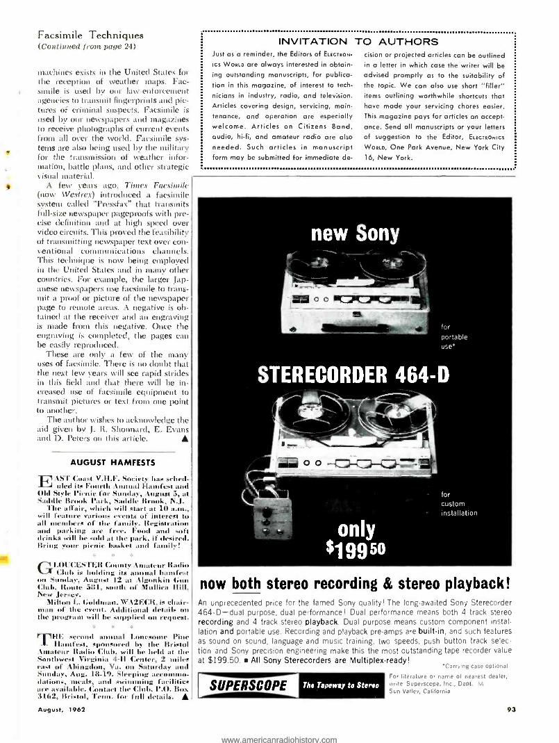
Facsimile Techniques (Continued from page 24)
machines exists in the United States for the reception of weather maps. Fac- simile is used by our law -enforcement agencies to transmit fingerprints and pic- tures of criminal suspects. Facsimile is used by our newspapers and magazines to receive photographs of current events from all over the world. Facsimile sys- tems are also being used by the military for the transmission of weather infor- mation, battle plans, and other strategic visual material.
A few years ago, Times Facsimile (now Westrex) introduced a facsimile system called "Pressfax" that transmits full -size newspaper pageproofs with pre- cise definition and at high speed over video circuits. This proved the feasibility of transmitting newspaper text over con- ventional communications channels. This technique is now being employed in the United States and in many other countries. For example, the larger Jap- anese newspapers use facsimile to trans- mit a proof or picture of the newspaper page to remote areas. A negative is ob- tained at the receiver and an engraving is macle from this negative. Once the engraving is completed, the pages can be easily reproduced.
These are only a few of the many uses of facsimile. There is no doubt that the next few years will see rapid strides in this field and that there will be in- creased use of facsimile equipment to transmit pictures or text from one point to another.
The author wishes to acknowledge the aid given by J. R. Shonnard, E. Evans and D. Pctcrs on this article.
AUGUST HAMFESTS
tSI Coat V.H.F. Sudety has sclted- J tiled its Fourth annual Harnfest and
Old Style Picnic for S lay, August 5, at Saddle Brook Park, Saddle Brook, N.J.
The affair, which will start at 10 a.nt., will feature var. s event. of crest to all members of the f 'h-. RegistrL and parking are free. F 1 and soft drinks will he sold at the park, if desired. Bring your picnic basket and fancily!
GLOUCESTER County Amateur Radio Club is holding its annual ha nufest
on S lay, august 12 at :Ugonkin Gun Club, Route 581, south of Mulliea Hill, New Jersey.
Milt I.. Gold Mall. WV.12ECR, is chair - man of the event. AJdit al details on the program will be supplied on request.
THE, sec 1 annual Lonesome Pine Hanfest, sponsored by the Bristol
.tmatcur Radio Club, will be held at the S hwest Virginia 1 -11 Center, 2 utiles east of Abingdon, Va. on Saturday and Sunday, Aug. 18 -19. Sleeping accommo- da s, meals, and swimming facilities are available. Contact the Club, P.O. Box 3162, Bristol, Tenn. for full details- A August, 1962
INVITATION TO AUTHORS Just as a reminder, the Editors of ELECTRON-
ICS WORLD are always interested in obtain- ing outstanding manuscripts, for publica- tion in this magazine, of interest to tech-
nicians in industry, radio, and television. Articles covering design, servicing, main- tenance, and operation are especially welcome. Articles on Citizens Band, audio, hi -fi, and amateur radio are also
needed. Such articles in manuscript form may be submitted for immediate de-
cision or projected articles can be outlined in a letter in which case the writer will be advised promptly as to the suitability of the topic. We can also use short "filler" items outlining worthwhile shortcuts that have made your servicing chores easier.
This magazine pays for articles on accept- ance. Send all manuscripts or your letters of suggestion to the Editor, ELECTRONICS
WORLD, One Park Avenue, New York City 16, New York.
now both stereo recording & stereo playback! An unprecedented price for the famed Sony quality! The long-awaited Sony Sterecorder 464 -D -dual purpose, dual performance! Dual performance means both 4 track stereo recording and 4 track stereo playback. Dual purpose means custom component instal. lation and portable use. Recording and playback pre-amps are built -in, and such features as sound on sound, language and music training, two speeds, push button track selec tion and Sony precision engineering make this the most outstanding tape recorder value at $199.50. All Sony Sterecorders are Multiplex-ready!
SUPERSCOPE The Tape way to Stereo
'Carrying case optional
For literature or name of nearest dealer, write Superscope, Inc., Dept. M Sun Valley, California
93
www.americanradiohistory.comwww.americanradiohistory.com
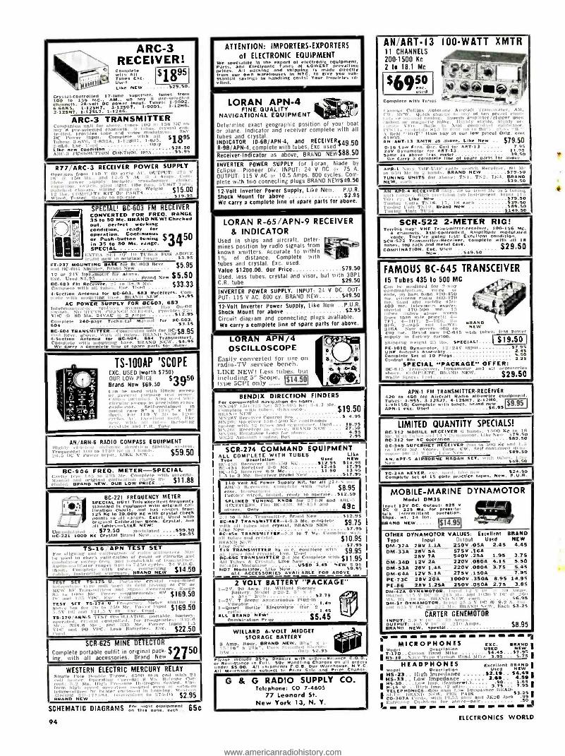
ARC -3 . RECEIVER! r-
Ñomplete with All " 1A Tubes
All Used
7 VX
X1111111 Like NEW $29.50
CryslalControlled 17 -tube superhet. tunes troll 100 to 156 MC.. AM., on any 8 pr"selected channels. .. Ì.125H . 3e1 150. input.
-9001 y' 1.12HS. 2.225N7. 1.12SL 7. 1.1246.
ARC -3 TRANSMITTER
p t 1 1 u h ,ii,. -A. 1.125117. 1.635
Lik new condition . ' $28.50 Lokie Alit 1 1l'.ilI0 1-í'0N CONTROL MIS $5.95 i
R77 'ARC-3 RECEIVER POWER SUPPLY
- $15.00
SPECIAL! BC -603 FM RECEIVER I.
CONVERTED FOR FREQ. RANGE 35 to SO Mc. BRAND NEW t Checked out, poled working áo dition, ready for
peration. Continuous or Push- button tuning in 35 to SO Mc. range. SPECIAL
0] I
V
EXTRA slïr 0I' In TL'U1.5 Full \.
:' In original brow. S3 in /11 new
FT.237 MOUNTING BASE Brand Newt'.802
Rcvr
(,$5.95 12 Orused ia'.22esmotor
for Above. Brand New $5s50
RC.683 FM Receiver. _- to SH.h Mc. $33.33 nnllete with all '... . Exc. U.cd 1Seetlen Antenna for BC903, 683 Receivers. Corn-
... . BRAN,/ NOW $4.95 AC POWER SUPPLY FOR 8C603, 683
50F N1: F1,1 :11. Provide,.
Th '1a 2 Amts $12.95 Completes 240. page\ Technical Manual for 11C.6
3. 604 BC -604 TRANSMIT ER- TT('orn P'snln suit for nce
'1 Ilexr. above. wlil, all tubes. BRAND NEW .F8.95 4- Section Antenna for BC.604. 694 Transmilt Complete with mounting base. BRAND N,W$4
carry co u One rd . .. n .ilow
q
.17J 11 ..st. i
D
V ':1 ;Lae
TS -100AP 'SCOPE EXC. USED (worth $750) OUR LOW PRICE 53950 Brand New ;69.50
AN ARN 6 RADIO COMPASS EQUIPMENT - airborne irr - rnn,ng
u :truth: V rimer 1750 Kr
NEW . $59.50
BC -908 FREQ. METER- SPECIAL 145 to 2:15 Me. Complete t ill, antenna. ulglnal calibration "
. $11.88 ",.ND NEW. OUR LOW PRICE
1/ /f
BC -221 FREQUENCY METER SPECIAL BUY! This r.eeient treuenCy I'.: tandard ì, equipped with or,ginIi
ICom pór.,tion c I Ns, ith r e 125 NC to 20.000 NC with crystal cheek
I points all ranges. Excel. Used with
Calibration Book. Crystal. and tattles all tab! -LIRE NEW! .aall
Un llimi,i l,n,..I ... $72.50 Nnd,ilateil 999.50 CC-221 1000 Kc Crystal IIe ri, i N, lv $8.95
TS -16 APN TEST SET For age i . 01,. alt.
i'Gl.ru -, i.ii .,'111
(.11001i l' f bandwidth f -,tt iii,
'u ili, S - 1 V .0 l'. connecting not.. twomlete with tubes.
.;
..J ,.. Iii.tru,tlon .0mn ,r1 BRAND NEW
.1,. r
Piled T t Porci ea e ld ..
I. $169.50
' $169.50 r 5 C P P P I I s . - 1 Al
n111,'Á, .frequeil.';. "'id 3:15 IMe. Inw',r i.e., naueries. r.,'. $22.50
SCR -625 MINE DETECTOR
Complete portable outfit in original pack- $275Q ing, with all accessories. Brand New L
WESTERN ELECTRIC MERCURY RELAY Single pole Ilonld, Throw. -
21
El,nl.. $2.95 BRAND NEW 9999
SCHEMATIC DIAGRAMS ;,7t47;1,,á'.p':;`;.n1 65c
94
ATTENTION: IMPORTERS -EXPORTERS
of ELECTRONIC EQUIPMENT We specialize in the export of electronic equipment. Parts. and Electronic Tubes at LOWEST prevailing
s All own
and shipping is made directly from ow war houses in NYC. to give you sub -
via teal savings in handling costs! Your Inquiries i
ted.
LORAN APN -4 FINE QUALITY ` CIR
NAVIGATIONAL EQUIPMENT 4
Determine exact geographic position of your boat or plane. Indicator and receiver complete with all tubes and crystal. INDICATOR ID- 6B /APN4, and RECEIVER ;49.50 R -98 /APN -4, complete with tubes. Exc. used
Receiver -Indicator as above, BRAND NEW$88.50
INVERTER POWER SUPPLY for loran. Made by
Eclipse- Pioneer Div. INPUT: 24 V DC l,r 75 A.
OUTPUT: 115 V AC t 10.5 Amps, 800 cycles. Com- plete with two connecting plugs BRAND NEW$49.50
12 -Volt Inverter Power Supply, Like New. P.U.R. Shock Mount for above $2.95 We carry a complete line of spare parts for above.
LORAN R- 65 !APN -9 RECEIVER
81 INDICATOR Used in ships and aircraft. Deter- mines position by radio signals from C aFl known xmitters. Accurate to within I
1% of distance. Complete with tubes and crystal. Exc. used. Value $1200.00. Our Price $.79.50
Used, less tubes. crystal and visor, but with 3BP1
C.R. tube $29.50
INVERTER POWER SUPPLY. INPUT: 24 V DC. OUT-
PUT: 115 V AC 800 cy. BRAND NEW $49.50
12.Volt Inverter Power Supply, Like New P.U.R. Shock Mount for above $2.95 Circuit diagram and connecting plugs available. We carry a complete line of spare parts for above.
LORAN AP111/4 OSCILLOSCOPE e
Easily converted for use on 6, radio -TV service bench. r+ LIKE NEW! Less tubes. but ° o-Q including 5' Scope. $14.50 type :CPI only
5
BENDU( DIRECTION N FINDERS
$19.50
SCR -274 COMMAND EQUIPMENT ALL
e COMPLETE WITH TUBES
Lima NEW Ill'.45'i Itecetr Ont.,. KC $12.95 514.95 15C -454 Receiver 3 -0 Mc 12.45 17.95 Ili' 455 uteceiver 8-9 Me 11.50 13.95 1.5 to 3 Mc. Receiver Brand New $17.95
110 Volt AC Power Supply Kit, for all 27.1 5 on Alit'.5 Itveyivers, C "l,g4ety with metal $8.95
Instructions ... .... rase. ory wired, le.ted, ready t oyerate..512.50
SLIN[D TUNING KNOB I
- and 1
RECEIVERS. Ells Of 1 " . I 4JÍ. others. Only - -
2.1 to :1 .sir. Tr:in.mitier, iIraml 5ev $12.95 SC -457 lTTER -4 -5.3 Mc. complete with all tubes and crystal. BRAND NEW..
elm Like New .............. .... ..57.95 SC 455 TRANSMITTER -e.:1 to 7 'Me. Complete will. ill tube, and try -1:11. $10.95 11114511 NI.M I.12t' New $7.95 719 TRANSMITTER 11'4 In., complete with $9.95 all 10 I '. I:. I.sed .
BC -695 TRANSMITTER 3-4 31c Complete with 11.95 5 w 2 - - '1 Like All T '
1117.1 50 Slo.110.1tor .. USED 3.5 NEW 5.95 MO7 Modulator. Ilk 5 .59.95
ALL ACCESSORIES AVAILABLE FOR ABOVE
2 VOLT BATTERY "PACKAGE" I -2\'. 20 Amp. Itr. Willard Storage
Battery. Model 220.2. 3" x 1" 51 .11
. higb ..............$3 79
1 -2VV 7 p Synchronous mug-In 1-Quart t n the Eleciroiyte ' ito; -2
1 49
ces. 1.45 ALL RAND NEW! $5.45 Combination P.iee
WILLARD 6 -VOLT MIDGET ' o: STORAGE BATTERY
Ir 3 Amp. Hour. BRAND NEW. gag.. g i. SI
vle I:I IO' x a l'.e. ,Iii
111,1 I.1 $2.95
',ease 2So'o Deposit th or der -Salante c or Remittance in Full. 50e Nandl.n9 Charges on all order. under SS.00. All shipments 5.0.11. Our Warehouse. N V C.
Ali Merchant,.. . Meet to Prior sale and Price Change
G & G RADIO SUPPLY CO. Tcicphone: CO 7 -4605
77 Leonard St. New York 13, N. Y.
AN ART-I3 100 -WATT 11 CHANNELS 200'1500 Kc
° N4'
2 to 18.1 Mc * ! -ail,
XMTR
1
,, oil;;
rs c, ANSART13 XMTR as above. Like New .. $79.50 0 -16 Low Freo. O. Coil for ART -13 7.95 24V Dynamotor for ART -13 11.95 Sant* as above
'plete line 01 snare parts Ill above complete
r' d.n' ., :,r h Re tlrer, .'.el.. BRAND NEW $79.50
vi
R I
0 NITS alias.. TN1. TN'!. TN:1, BRAND 539.50
..n ..Ili 1 only. Set to Loop Me in 5 tuning Iligl. 1'ecl.luq lab In%nl:nent. Input I1-i
r New 579.50 k T51,í. 17. 1N each 539.50
Brand New $9.50 11':. $149.50
SCR -522 2 -METER RIG! T err,h buy: VHF Transmitterreceiver. 100.156 Mc.
4 channels. XtaI. Controlled. Amplitude modulated Theyre going fast: Excellent condition.
SCR.522 Tr.,nsmi tterReCliver. complete with rl
all IS bones, top rack and metal Case. ie`9rpD COMBINATION. Exc. Used '_549.50 ,F Y
FAMOUS BC -645 TRANSCEIVER 15 Tubes 435 to 500 MC
iiiii Jane./ for 2-way t an
odenr pan ̀ bam i,and 420.450 o.g. ei d nsá edo, 100470 '.e and .hue 450. 10 m
e.teIevim.dt exper, , TI , 'mental 470.500 n 5
,he, qubes alone worth E:`. man ale price:, 4-
4 -7117, 2-7Er. by0. 2 -R55 +n.1 I -\st :
NEW :tins Now covers 5 .Intl c Brawl n w 1112.015 wpm tubes, less mover
..cooly in factory carton. Shipping Height 25 lbs SPECIAL!.... 519.50 PE101C Dynamotor. l2 _ I V Im,ut 67.95 UHF Antenna Assen,ely 2.45 Complete Set of 10 PIuts 5.50 Control Box 2.25
SPECIAL "PACKAGE" OFFER: 11C4115 Transceiver, Dynamotor and all ' shove. c,,.tl'l E.TE. BRAND NEW.
$29.50 While S'ek. last IF i V
APN -1 FM TRANSMITTER-RECEIVER 420 to 460 Mc Aircraft Radio altimeter equipment. Tubes: 4.955. 3.12527, 4.125.17. 2.12H6. ;9.95 1V150: Complete with tubes, brand new R APR,
LIMITED QUANTITY SPECIALS! 11C 112 MOBILE RECEIVER ,. h,,ndl.lke
'111.v ~ c 5 to 50 $89.50
h k III. t f. L I .1711.1.
AN .-.1.7--. In/1009E 17.707,11 Sf T. vim Ilk, 149.30
ToG -mp45 t
YER. f Co d.e
.' p rIalckti,. ce
n ta p.es, New, PU,.R
1
MOBILE- MARINE DYNAMOTOR Model DM35
ócul Lae DC. Output: Bas V
a 225 Ma. for proo.to- k inter ...tent tors.
ShOx. wt. 14 Ins al BRAND NEW $14.95
OTHER DYNAMOTOR VALUES: Excellent BRAND Type Input getout Used NEW DM.32A 28V 1.1A 250V .05A 2.45 4.45 DM 33A 28V 5A 575V .18A
28V 7A 540V .25A 1.95 3.75 DM -34D 12V 2A 220V .080A 4.15 5.50 DM 53A 28V 1.44 220V .080A 3.75 5.45 DM -64A 12V 5.1A 275V .150A 7.95 PE 73C 28V 20A 1000V .350A 8.95 14.95 PE86 28V 1.25* 250V .050A 2.75 3.85 DM`42A DYNAMO Ton.
11,1\\ DM37 DYH M Inc . \
oTO I'. t, Each 53.25
CARTER GENEMOTOR INPUT: 5.11 V lo
58.95 OUTPUT: 411: V I Snps. BRAND NEW. sp .Il
E
MICROPHONES EXC. BRAND 11.17 oescr. pt.on USED NEW
T- 1711 ..5arton Hand Mike .. ....$4.45...57.95 IRS-38 .Harr T1pe Carbon Wind M11ke 3.95... 5.75 '
HEADPHONES Exeetlent BRANO ' Model Deeeription Used NEW
IHS -33.. High Impedance $2.19.. $4.491 HS33.. LOw Impedance 2.49.. 4.89
1115.30....la,w Ion. ,teame,wt.l.
U .Ih :11 Imp..2 n s . 3.75... 7.95 T rI1 EPHONICS -olIl ohm I.pw Impels ice IIEAU-
IJ,AN11 NI.W. PC« PAIR $3.291 ' cr.. turn , . tl.. wpm 1'1.53 plug and 71.20 Jack .99 i ,i.hh,tte for aw,VL -pair 50
a - - -aw. = aM aM - - - - aBi ELECTRONICS WORLD
www.americanradiohistory.comwww.americanradiohistory.com

xix
ELECTRONICS MARKET PLACE
RATE, 60e per Minimum 10 words. September issue closes July 10th. Send order and remittance to: ELECTRONICS WORLD, One Park Ave., N. Y. C. 16, N. Y.
QUICKSILVER, Platinum, Silver, Gold. Ores Analyzed. Free Circular. Mercury Terminal, Norwood, Massa- chusetts.
ELECTRONICS ENGINEERING
AND INSTRUCTION USED Correspondence Courses and Books sold and rented. Money back guarantee. Catalog Free. (Courses Bought.) Lee Mountain, Pisgah, Alabama. ELECTRONICS! Associate degree -29 months. Techni- cians, field engineers, specialists in communications, missiles, computers, radar, automation. Start February, September. Valparaiso Technical Institute, Dept. N, Valparaiso, Indiana. NEW Trade? Electronic, Mechanical Drafting pays $150 week. Send S2 first lesson, complete home study course $25. Prior. Inc., 23-09 169 St., Whitestone 57, New York
FOR SALE TV Tuners -Rebuilt or Exchanged $9.95 complete - all types -fast, guaranteed service. Send tuner with all parts to: L. A. Tuner Exchange, 4611 West Jeffer- son Blvd.. Los Angeles 16. California. TUBES -TV, Radio, Transmitting And Industrial Types At Sensibly Low Prices. New. Guaranteed, 1st Qual- ity, Top Name Brands Only. Write For Free Catalog or Call WAlker 5 -7000, Barry Electronics Corp., 512 Broadway, New York 12N, N. Y.
DIAGRAMS for repairing radios $1.00. Television $2.00. Give make, model. Diagram Service, Box 672.E, Hart- ford 1. Conn. GOVERNMENT Surplus Receivers, Transmitters, Snoop - erscopes, Parabolic Reflectors, Picture Catalog 100. Meshna, Malden 48, Mass. PROFESSIONAL Electronic Projects- Organs, Timers, Computers, Industrial, etc. -$1 up. Catalog Free. Parks, Box 1665, Lake City, Seattle 55. Wash. BEFORE You Buy Receiving Tubes or Hi -Fi Components send now for your giant Free Zalytron current catalog - featuring nationally known Zalytron First Quality TV- Radio Tubes. Hi -Fi Stereo Systems. Kits. Parts. etc. All priced to Save You Plenty -Why Pay More? Zalytron Tube Corp., 220 W. 42nd St., NYC.
PRECISION Resistors, carbon-deposit. Guaranteed 1% accuracy. Millions in stock. 1/2 -watt, 8C. 1 -watt. 12e. 2 -watt, I5C. Leading manufacturer. Rock Distributing Co., 902 Corwin Rd., Rochester 10, N.Y.
SAVE dollars on radio, TV- tubes, parts at less than manufacturer's cost. 100% guaranteed! No rebrands, pulls. Request Bargain Bulletin. United Radio. 1000W, Newark, N.J.
"FREE- R.C.A., G.E. etc. tubes catalog. Discount to 75% from list. Picture tubes at 75C inch up. Parts, parts kits at 1,10 original cost. Needles. tube testers, silicons. seleniums 7" TV bench test tube- S6.99- and more." Arcturus Electronics Corp., E.W. 502 -22nd Street. Union City, New Jersey. TRANSFIRE TRANSISTOR Electronics ignition. Save gas, tune -ups. Improved starting, high and low-speed per- formance. Parts. Complete Kits. Conversions, from $34.95. Palmer Electronics, 2W, Carlisle- Massachu- setts. POCKET sized, low impedance, square -wave gener- ator. Variable frequency, 200 to 4000 cycles. Build it yourself for $9. Send $1 00 and stamped envelope for schematic to, Ace, 11500H NW 7th Ave., Miami 50, Florida. SCHEMATIC diagrams, exact replacement parts or- ders: Japanese transistor or tube radios, recorders. transceivers, electronics equipment. Give model and manufacturer. $1. Techservices, CPO 849, Tokyo, Japan. KELLISON sport cars, complete, semi -complete, bodies and frames. Send $1.00 for brochure. Kellison Car Co., Folsom, Calif. TELEVISION cameras, build one. Write: Spera Elec- tronics. 37 -10 33 St., L.I.C. 1, N.Y.
EXPERIMENTERS: Miniaturize equipment without printed circuits. Loading research lab technique illustrated instructions $1.00. Creativity, Inc.. 5883 Blackwelder St., Culver City, Calif. CONVERT any television to sensitive, big- screen oscil- loscope. Only minor changes required. No electronic experience necessary. Illustrated plans, $2.00. Relco. Dept. EW, Box 10563, Houston 18, Texas. TV Camera -low cost -easily built -complete sche- matics, instructions 50e. Denson Electronics, Rockville, Conn.
WANTED CASH Paid! Sell your surplus electronic tubes. Want unused, Clean radio and TV receiving, transmitting special purpose. Magnetrons, Klystrons, broadcast types. Want military and commercial lab test equip. ment such as G.R.H.P., AN UPM prefix. Also want commercial Ham Receivers and Transmitters. For a Fair Deal write: Barry Electronics Corp., 512 Broad- way. New York 12. N. Y. (Walker 5- 7000). TRIGGER -W91VJ We Buy Shortwave Equipment For Cash. 7361 North, River Forest. Ill. Phone PR 1 -8616. CASH or Ham Gear: For all types Military Surplus PRc- GRc. UPM and teletype. Philmar Electronics, Morrison - ville. New York.
CASH, or trade new amateur equipment for teletype, Kleinschmidt, or Collins equipment. Alltronics- Howard, Box 19, Boston I, Mass. (Richmond 2 -0048). PLATINUM electronic scrap bought. Noble Metals Co., Box One, Los Angeles 9, Calif.
TAPE AND RECORDERS TAPE Recorders, HI -FI Components. Sleep Learning Equipment, Tapes. Unusual Values. Free Catalog. Dress - ner, 1523 EW Jericho Turnpike, New Hyde Park, N.Y. RENT Stereo Tapes -over 2,500 Different -all major labels -free catalog. Stereo -Parti, 811 -G, Centinela Ave.. Inglewood 3, California. SELF -Hypnosis. New concept teaches you quickly by tape or LP- record. Free literature. McKinley Publishers, Dept. T6, Box 3038. San Bernardino, California. 4;TR Stereo Tapes -bought, sold, rented, traded! Free Catalog /bargain closeouts. (Columbia) 9651 Foxbury, Rivera, California. SAVE 30% Stereo music on tape. Free bargain catalog, blank tape /recorders /norelco speakers. Saxitone, 1776 Columbia Road, Washington, D.C.
DON'T buy Hi -Fi components until you get our low, low quotation. We guarantee "We Will Not Be Undersold." Easy- Pay -Plan. Send 100 for wholesale catalog and Best Buy Hi -Fi list. Hi- Fidelity Center, 220 -NC E. 23rd St., N.Y. 10, N.Y.
HIGH -FIDELITY
DISGUSTED with "Hi" Hi-Fi Prices? Unusual Dis- counts On Your High Fidelity Requirements. Write. Key Electronics, 120 Liberty St., New York 6, N. Y. Cloverdale 8-4288. RECORDERS. Components! Free wholesale catalogue! Carston. 125 -R, East 88, N.Y.C. 28. PRICES? The Best! Factory -sealed Hi -Fi Components' Yes! Send for free catalog. Audion, 1038R Northern Blvd., Roslyn, N.Y. MIRACLE Hi -Fi enclosure, construction drawings and assembly instructions, $2.00. Kits and assembled cab- inets also available. Gough & Company, Box 254, San Carlos, California.
PATENTS
PATENT Searches, $6.00. For free Invention Record. and "Information Inventor's Need," Write: Miss Hey- ward. 1C29 Vermont Avenue, N.W., Washington 5, D.C.
HELP WANTED
ELECTRONICS engineer. The research division of a major producer of synthetic fibers and dielectric materials has an attractive opening for a B.S. or M.S. in electrical engineering or physics with 2 -6 years experience to work in electronic instrument de- sign and development related to physical measure- ments in the field of polymer and fiber physics. Ex- perience with strain gauges. thermocouples, and other transducers desirable. Must have knowledge of tran- sistors as well as conventional vacuum tube circuitry. Pleasant working and living location near Asheville, N.C. Excellent benefit program: 5 day work week: moving expenses. Send complete resume, including salary requirements to Employment Manager, Enka, N.C. American Enka Corporation.
TECHNICIANS to $5.50 Hr. Tech Writers to $8.00 Hr. Designers & draftsmen to $6.50 Hr. Engineers to $12.00 Hr. Current rates paid by thousand engineer- ing firms, coast to coast. border to border. Per diem, Overtime on many. Who, Where with Vital Technical Deta in Job Shoppers Manual & Directory $2.00 Cash, Check, Money Order Electro- Press, Box 315, Pasadena, Cal.
GOVERNMENT SURPLUS
JEEPS $278. Airplanes $159, Boats $7.88, generators $2.68, typewriters $8.79, are typical government sur- plus sale prices. Buy 10.001 items wholesale, direct. Full details. 627 locations, procedure, only $1.00. Sur- plus, Box 789 -C97, Abbottstown, Penna.
Your classified ad in this space will be read by more than 200,000 buyers. It costs only 60C per word. For information. write: Martin Lincoln, Electronics World, One Park Avenue, New Yorh IS, N.Y.
SHOPPING GUIDE CLASSIFIED
A HANDY GUIDE TO PRODUCTS, NOT NECESSARILY ELECTRONIC, BUT OF WIDE GENERAL INTEREST.
PHOTOGRAPHY -FILM, EQUIPMENT, SERVICES
PHOTOGRAPHY For Pleasure or profit. Learn at home. Practical basic training. Long established school. Free booklet. American School of Photography, 835 Diversey Parkway, Dept. 253C, Chicago 14, Illinois.
SCIENCE Bargains- Request Free Giant Catalog "C1" -144 pages -Astronomical Telescopes, Microscopes, Lenses, Binoculars, Kits, Parts. War surplus bargains. Edmund Scientific Co., Barrington, New Jersey.
SEND Empty film box. Receive Surprise Gift. National Color Corporation, Atlanta 24, Georgia.
STAMPS AND COINS
GIGANTIC Collection Free! Includes triangles, early United States animals, commemoratives, British Colo- nies, high value pictorials, etc. Complete collection plus big illustrated magazine all free. Send 5C for postage. Gray Stamp Company, Dept. Z2, Toronto, Canada.
EDUCATIONAL OPPORTUNITIES
LEARN While Asleep, hypnotize with your recorder, phonograph. Astonishing details, sensational catalog free! Sleep- Learning Association, Box 24.1D, Olympia, Washington.
BUSINESS OPPORTUNITIES
SECOND Income From Oil Can End (our Toil! Free Book and Oilfield Maps! National Petroleum, Pan - American Bank Building -PP, Miami 32, Florida.
FREE Book "990 Successful, little -Known Businesses," Work home! Plymouth -555W, Brooklyn 4, New York.
I Made $40,000.00 Year by Mail Order! Helped others make money! Start with $10.00 -Free Proof. Torrey, Box 3566N, Oklahoma City 6, Oklahoma.
ASSEMBLE artificial lures at home for stores. Ma- terials supplied free. Profitable! Write: Lures, Ft. Walton Beach 1, Florida.
EXOTIC earrings! Details free. Pair $1.00. OHGA, ZD -365. Sigakenkusatu. Japan.
INVESTIGATE Accidents- -Earn $750 to $1.000 monthly. Men urgently needed. Car furnished. Business Expenses Paid. No Selling. No college education necessary. Pick own job location. Investigate full time. Or earn $6.44 hour spare time. Write for Free Literature. No obliga- tion. Universal, CZ -8, 6801 Bitterest. Dallas 5, Texas.
MISCELLANEOUS
2700 Novelties, Tricks, jokes, science, hobbies. World's biggest gadget catalog 10C. Johnson- Smith. D -528. Detroit 7.
INDEPENDENT Thinkers -investigate Humanism! Free literature. American Humanist Association, Dept. EW -1, Yellow Springs, Ohio.
HOMEBREWING! Beers. wines. Complete Instructions $1. Guaranteed. Crystalco 28 -BEW8, Millburn, New Jersey. AUTHORS! Learn how to have your book published, promoted, distributed. FREE booklet "ZD," Vantage, 120 West 31 St., New York 1.
HYPNOTIZE Unnoticed. quickly, effortlessly. or re- fund! Thousands satisfied! $2, Timner, Eox 244, Cedar - burg, Wisc. INVESTIGATORS, free brochure, latest subminiature electronic listening devices. Dept. -7B, 11500 NW 7th Ave., Miami 50. Florida. "HYPNOTIZE ... One word ... One fingersnap," on stage. Satisfaction -or refund. $2. Hypnomaster, Box 9309 -E8. Chicago 90. GIANT Arms." Dr. Young's. D.C. Revolutionary dis- covery. $2. Satisfaction or refund. Gaucho, Box 9309 - E8, Chicago 90.
WRITERS Send Your books, articles, stories, plays for free evaluation. screening and sale. Write today! Liter- ary Agent Mead, 915 Broadway. N.Y.C. 10.
www.americanradiohistory.comwww.americanradiohistory.com

ADVERTISERS' INDEX AUGUST, 1962
Advertisers listed below with code numbers have additional information available on their products in the form of catalogues
and bulletins. To obtain more detailed data, simply circle the proper code number in the coupon below and
mail it to the address indicated. We will direct your inquiry to the manufacturer for processing.
CODE NO. ADVERTISER PAGE CODE NO ADVERTISER PAGE CODE NO. ADVERTISER PAGE
100
101
102
103
104
105
106
107
108
109
110
111
112
113
114
115
Allied Radio 17.
Antenna Specialists Co.. The
Audion
B & K Manufacturing Co
Bell Telephone Laboratories
Capitol Radio Engineering Institute. The
Channel Master Corp
Cleveland Institute of Electronics
Columbia Electronics
Delco Radio
Don Bosco Electronics Inc
Dressner
EICO (Electronic Instr. Co. Inc.)
Electra- Voice, Inc
Electronic Chemical Corp
Electronics Book Service - A.S. Barnes & Co. Inc
Fair Radio Sales
G & G Radio Supply Co
Grantham School of Electronics
Greenlee Tool Co
18
8
72
9
19
5
85
7
72
2
77
90
20
58
16
67
60
94
13
62
116
117
118
119
120
121
122
123
124
125
126
127
128
Harman -Kardon 59
Heath Company 63
Indiana Technical Co:lege 85
Jensen Manufacturing Company 6
Key Electronics Co 88
Lafayette Radio 15
Lampkin Laboratories, Inc 60
Multicore Sales Corp 16
National Radio Institute SECOND COVER
National Radio Institute 90
Oelrich Publications 72
Peak Electronics Company 60
Quietrole Company 58
RCA Institutes. Inc 10, 11
R W Electronics 85
Rad -Tel Tube Co 91
Radio Corporation of America
FOURTH COVER
129
130
131
132
133
134
135
136
137
138
139
140
141
142
143
144
145
146
147
148
Radio Shack Corporation 78, 79. 80, 81
Rider Publisher Inc.. John F 4
Rohn Manufacturing Company 83
Sams & Co.. Inc., Howard W 65
Scott Inc.. H.N. 62
Sencore 73
Sonotone Corporation 14
Space Electronics Co 85
Sprague Products Company 57
Standard Kollsman Industries. Inc
THIRD COVER
Superscope, Inc 93
Texas Crystals 90
Transvision Electronics, Inc 71
Tri -State College 72
Tru -Vac 89
U.S. Crystals. Inc 64
University Loudspeakers. Inc 1
Valparaiso Technical Institute 90
Vets Distributing Company, The 88
Winegard 73
The coupon below can also be used to obtain, additional information on the new product items shown on pages 87 through 92 as well as on the ads listed ahoce.
VOID 8
AFTER
AUG. 31, 1962
NAME
STREET NO.
CITY ZONE STATE
ADVERTISED
PRODUCTS
(SEE INDEX ABOVE)
100
120
140
160
180
200
220
101
121
141
161
181
201
221
102
122
142
162
182
202
222
103
123
143
163
183
203
223
104
124
144
164
184
204
224
105
125
145
165
185
205
225
106
126
146
166
186
206
226
107
127
147
167
187
207
227
108
128
148
168
188
208
228
109
129
149
169
189
209
229
110
130
150
170
190
210
230
111
131
151
171
191
211
231
112
132
152
172
192
212
232
113
133
153
173
193
213
233
114
134
154
174
194
214
234
115
135
155
175
195
215
235
116
136
156
176
196
216
236
117
137
157
177
197
217
237
NEW PRODUCTS
& LITERATURE
1
21
41
2
22
42
3
23
43
4
24
44
5
25
45
6
26
46
7
27
47
8
28
48
9
29
49
10
30
50
11
31
51
12
32
52
13
33
53
14
34
54
15
35
55
16
36
56
17
37
57
18
38
58
MAIL To ELECTRONICS WORLD P.O. BOX 212
VILLAGE STATION NEW YORK 14, N.Y.
118 119
138 139
158 159
178 179
198 199
218 219
238 239
19 20
39 40
59 60
INDICATE NUMBER
OF ITEMS REQUESTED
96
toVIEMake sure that your
name and address are printed clearly.
ELECTRONICS
WORLD
READER
SERVICE
COUPON
ELECTRONICS WORLD
www.americanradiohistory.comwww.americanradiohistory.com

i
ml
f.o. the welds tong. ++..NO..ro.., of TV r...
CC.4, MS ULTRA -NEW
SPECIALLY FORMULATED
designed with the service man in mind
standard h.ollxman lndax/rlix
TACA RE
C
A SUPERIOR
LIQUID CONTACT
CLEANER
CoNrA0
Ultra -New coNraCARE KITE.
25
Cleans Almost Instantly with Minimum Rubbing After years of painstaking research, Standard Kollsman for the first time can honestly recommend a liquid contact cleaner. You'll find it in the new ContaCare Kit II. You'll also find a soft tough cloth - lint -free to avoid fouling ... and a tube of non -evaporating grease for permanent channel lubrication and contact protection. Instruc- tion sheet is clear, brief, and complete. Kit is compact and sturdy. Try it soon ... and save your elbow grease for jobs that need it.
INS /ST ON THE GENUINE CONTACARE KIT II
NO RESIDUE
NO SUBSEQUENT CORROSION
NON -FLAMMABLE
NON- CONDUCTIVE
standard kollsman® INDUSTRIES, INC. FORMERLY STANDARD COIL PRODUCTS CO.. INC., MELROSE PARK, ILLINOIS
WORLD'S L A R G E S T M A N U F A C T U R E R O F T E L E V I S I O N T U N E R S
www.americanradiohistory.comwww.americanradiohistory.com

Essential service data at your fingertips...
EI VINas PICTURE
yikNnMnp,.,W,, . ,.
RCA TECHNICAL PUBLICATIONS HELP YOU DO YOUR JOB
FASTER, BETTER, AND MORE PROFITABLY How many times each day do you have to refer to electronic
technical literature in order to do your job properly?
Of all major electronics manufacturers, RCA provides you with one of the most comprehensive, authoritative libraries of techni- cal service literature in your industry... all designed to put service facts you need at your fingertips. This literature is as important to your job as your soldering gun. RCA Receiving Tube Manual (RC -21) Essential data and basing diagrams for over 1000 receiving tubes. Treats tube theory, applications, circuits. RCA Receiving. Tube and Picture Tube Catalog (1275K) Classi- fication, application, and characteristics charts and basing dia- grams for over 1050 entertainment receiving and picture tubes.
TV Servicing (TVS -1030) Fully- illustrated, easy -to- follow guide to help you locate and diagnose TV troubles. TV Servicing, Supplement 1 (TVS -1031) Problems encountered in servicing hard -to- service sets.
RCA Color TV Pict -O -Guide Loose -leaf guide to help you recog- nize and repair color TV troubles. Illustrated, diagrammed, easy -to- follow. RCA Triple Pindex (PIN DEX 109) Lets you look at base diagrams of three different receiving tubes simultaneously. RCA Interchangeability Directory of Foreign vs. Domestic Re- ceiving Tubes (10E -197A) Shows which U.S. receiving tubes to use to replace those hard -to -get foreign types. RCA Service News Keeps you up to date on RCA's new products and promotions. ...And much more, including RCA technical data bulletins, tech- nical booklets and interchangeability directories on batteries, technical aids to more effective use of test equipment, etc. All are available from your Authorized RCA Electron Tube Distributor. Stop in to see him this week.
RCA ELECTRON TUBE DIVISION, HARRISON, N. J.
THE MOST TRUSTED NAME IN ELECTRONICS
www.americanradiohistory.comwww.americanradiohistory.com
Related Documents