Electronic Total Station R-300 SERIES R-315(N)/R-325(N)/R-335(N) R-322(N)/R-323(N)/R-326 R Instruction Manual

Welcome message from author
This document is posted to help you gain knowledge. Please leave a comment to let me know what you think about it! Share it to your friends and learn new things together.
Transcript

Electronic Total Station
R-300 SERIES
R-315(N)/R-325(N)/R-335(N)R-322(N)/R-323(N)/R-326
R
Instruction Manual
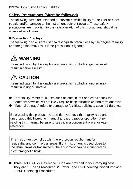
Safety Precautions (Must be followed)The following items are intended to prevent possible injury to the user or otherpeople and/or damage to the instrument before it occurs. These safetyprecautions are important to the safe operation of this product and should beobserved at all times.
■ Distinctive DisplaysThe following displays are used to distinguish precautions by the degree of injuryor damage that may result if the precaution is ignored.
WARNINGItems indicated by this display are precautions which if ignored wouldresult in serious injury.
CAUTIONItems indicated by this display are precautions which if ignored mayresult in injury or material.
● Here “injury” refers to injuries such as cuts, burns or electric shock thetreatment of which will not likely require hospitalization or long-term attention.
● “Material damage” refers to damage to facilities, buildings, acquired data, etc.
■ Three R-300 Quick Reference Guide are provided in your carrying case.They are 1. Basic Procedures, 2. Power Topo Lite Operating Procedures and 3. PSF Operating Procedures.
This instrument complies with the protection requirement forresidential and commercial areas. If this instrument is used close toindustrial areas or transmitters, the equipment can be influenced byelectromagnetic fields.
Before using this product, be sure that you have thoroughly read andunderstood this instruction manual to ensure proper operation. Afterreading this manual, be sure to keep it in a convenient place for easyreference.
PRECAUTIONS REGARDING SAFETY
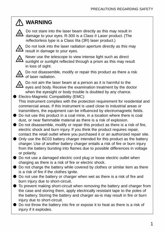
WARNING
Do not stare into the laser beam directly as this may result indamage to your eyes. R-300 is a Class II Laser product. (Thereflectorless type is a Class IIIa (3R) laser product.)
Do not look into the laser radiation aperture directly as this mayresult in damage to your eyes.
Never use the telescope to view intense light such as directsunlight or sunlight reflected through a prism as this may resultin loss of sight.
Do not disassemble, modify or repair this product as there a riskof laser radiation.
Do not aim the laser beam at a person as it is harmful to theeyes and body. Receive the examination treatment by the doctorwhen the eyesight or body trouble is doubted by any chance.
● Electro-Magnetic Compatibility (EMC):This instrument complies with the protection requirement for residential andcommercial areas. If this instrument is used close to industrial areas ortransmitters, the equipment can be influenced by electromagnetic fields.
● Do not use this product in a coal mine, in a location where there is coaldust, or near flammable material as there is a risk of explosion.
● Do not disassemble, modify or repair this product as there is a risk of fire,electric shock and burn injury. If you think the product requires repair,contact the retail outlet where you purchased it or an authorized repair site.
● Only use the BC03 battery charger intended for this product as the batterycharger. Use of another battery charger entails a risk of fire or burn injuryfrom the battery bursting into flames due to possible differences in voltageor polarity.
● Do not use a damaged electric cord plug or loose electric outlet whencharging as there is a risk of fire or electric shock.
● Do not charge the battery while covered by clothes or similar item as thereis a risk of fire if the clothes ignite.
● Do not use the battery or charger when wet as there is a risk of fire andburn injury due to short-circuit.
● To prevent making short-circuit when removing the battery and charger fromthe case and storing them, apply electrically resistant tape to the poles ofthe battery. Storing the battery and charger as-is may result in fire or burninjury due to short-circuit.
● Do not throw the battery into fire or expose it to heat as there is a risk ofinjury if it explodes.
1
PRECAUTIONS REGARDING SAFETY
2
PRECAUTIONS REGARDING SAFETY
The instrument contains a rechargeable battery and it is rechargeable.At the end of its useful life, it may be illegal to dispose of the battery.Check with your local solid waste officials for details for recycling.
Ni-MH
CAUTIONFor security, please do the opening inspection and inspectionevery a fixed period and adjustment.When the laser beam enters eyes, an unexpected accident mightbe caused by the blink of eyes. Establish the laser product toavoid the height of eyes of a driving person and walker.Establish an instrument so that laser beam does not hit areflection thing as a mirror and a glass window. The refectionbeam of the laser is also harmful to the human body.Besides the time when you measure the distance, cut off thepower supply or shade the beam of aperture with caps.Keep the laser product in the place where the person who doesnot have the product knowledge such as children does not touchby mistake.Destroy the power supply mechanism of the instrument so as notto emit the laser beam when throwing away it.
● Do not remove the handgrip without good reason. If it does come off, besure to attach it securely to the instrument with screws. If it is not fastenedsecurely, the instrument may fall when you grasp the handgrip, leading topossible injury.
● Do not short the poles of the battery or charger as there is a risk of injury or fire.● Do not touch any fluid which may leak from the battery as there is a risk of
chemical burn injury or reaction.● Do not insert or remove the electric plug with wet hands as there is a risk of
electric shock.● Do not use the case to stand on as it is slippery and unstable and may
cause you to fall, resulting in possible injury.● Be sure the tripod itself and the instrument on the tripod are both installed
securely as insecure installation may cause the tripod to fall over or theinstrument to drop, resulting in possible injury.
● Do not carry the tripod with the metal shoe pointing toward another personas the person may be injured if they strike him or her.
3
PRECAUTIONS REGARDING SAFETY
Usage PrecautionsSurveying instruments are high-precision instruments. In order to assure that theElectronic Total Station R-300 series product which you have purchased willprovide long-lasting maximum performance, the precautions in this manual mustbe followed. Be sure to follow these instructions and use this product properly atall times.
[Solar Observation]
WARNINGNever view the sun directly using the telescope as this may result in loss ofsight. Never point the objective lens directly at the sun as this may damageinternal components. When using the instrument for solar observation, be sureto attach the special solar filter (MU64) designed for this product to theobjective lens.
[Laser Beam]Do not stare into laser beam. R-300 is a class-II Laser product.(The reflectorless type is a Class IIIa (3R) laser product.)
[EDM axis]The R series EDM is the red visible laser beam and the beam diameter is verysmall. The beam is emitted from the objective center and the base plate centerhole. The EDM axis is designed to coincide with the telescope sight axis but bothaxes may not sometimes coincide slightly according to the intense temperaturechange and time lapse.
[Target Constant]Confirm the Target Constant of the instrument before measurement.If a different constant is to be used, use the correct constant of the target. Theconstant is stored in the instrument's memory when turned off.
[Reflectorless and Reflector sheet]● The measurement range is determined by the white side of the Kodak Gray
Card facing the instrument and by its surrounding brightness.There is a possibility that the range may vary when the target does not satisfythe conditions above at survey work.
● Pay attention to following in case of distance measurement by Reflectorless.In a situation resulting in low accuracy, perform the distance measurement byReflector sheet or Prism. (R-315N/R-325N/R-335N/R-322N/R-323N)
q There is a possibility that correct distance measurement may be impossible bydispersion or reduction of laser beam when the laser beam comes into thetarget from diagonal angle.
w There is a possibility that the instrument cannot calculate correctly whenreceiving reflected laser beam from forth and back directions in case ofmeasuring the target on the road.
4
PRECAUTIONS REGARDING SAFETY
e There is a possibility that synthesized values are calculated and the distancemay become longer or shorter than the actual one when the operatormeasure the target of slope or sphere or rugged shape.
r There is a possibility that the instrument cannot calculate correctly bycollecting the reflected laser beam from a man or a car that comes and goesin front of the target.
● When using Reflector sheet, set the Reflector sheet to have its surface beapprox. vertical to the aiming line. If it is positioned not to be approx. rightangle, there is a possibility that correct distance measurement may beimpossible by dispersion or reduction of laser beam.
[Battery & Charger]● Never use any battery charger other than the BC03 battery charger as this
may result in damage to the instrument.● If water should happen to splash on the instrument or the battery, wipe it off
immediately and allow it to dry in a dry location. Do not put the instrument inthe case until it is completely dry as this may result in damage to theinstrument.
● Turn off the power when removing the battery from the instrument asremoving the battery while the power is still on may result in damage to theinstrument.
● The battery mark displayed on the instrument is only an estimate of remainingbattery power and is not completely accurate. Replace the battery quicklywhen it is about to run down as the time a battery lasts on one charge differsdepending on conditions of ambient temperature, and the measurement modeof the instrument.
● Confirm the battery level remaining before operating.
[Auto focus]● The Auto focus mechanism is very precise but will not function under every
condition. Focusing depends on brightness, contrast, the shape and size ofthe target.In such a case, press the AF button and focus on the target by operating thePower focus key or the Focusing knob.
● The R-326 has no Auto focus function.
[LD POINT, Laser pointer]When you make a correct direction using the “LD POINT”, aim the laser beam atthe wall and mark the center and then confirm the discrepancy between thereticle center and the marked point beforehand.
5
PRECAUTIONS REGARDING SAFETY
[Storage and Operating Environment] ● To prevent making short-circuit when removing the battery and charger from
the case and storing them, apply electrically resistant tape to the poles of thebattery. Storing the battery and charger as is may result in fire or burn injurydue to short-circuit.
● Avoid storing the instrument in places subject to extreme high, low or radicallyfluctuating temperature. (Ambient temperature range during use: –20° C to+50° C)
● Distance measurements may take longer when atmospheric conditions arepoor such as when heat shimmer is present. When storing the instrument,always put it in its case and avoid storage in dusty location or location subjectto vibration or extreme heat or humidity.
● Whenever there is a sharp temperature difference between the instrument’sstorage and usage locations allow the instrument to adjust to the ambient foran hour or more before use. Be sure to protect the instrument from the sun ifthe location is subject to intense direct sunlight.
● During surveys for which the survey precision or atmospheric measurementmethod has been defined measure the atmospheric temperature andpressure separately and enter those values rather than using the AutomaticAtmospheric Correction function.
● The battery should be charged approximately once per month if theinstrument is to be stored for an extended period of time. The instrumentshould also be removed from its case occasionally and aired out.
● In addition to these precautions, be sure to handle the instrument properly atall times following the descriptions given in the various sections of this manualto assure safe and proper measurements.
[Transporting and Carrying the Instrument]● Be careful to protect this instrument from shock of impact and excessive
vibration which may result in damage during transportation and shipment.● When transporting the instrument, always put it in the case and wrap shock-
absorbing material around it and be sure it is handled as “FRAGILE”.
[Checks and Repairs] ● Always check the instrument before beginning work and check that the
instrument is maintaining the proper level of precision. Pentax bearsabsolutely no responsibility for damages due to survey results obtained fromsurveys conducted without an initial instrument check.
● Never disassemble the instrument, battery or charger even if you do detect anabnormality as there is a risk of fire or electric shock due to short-circuit. Ifyou think the product requires repair, contact the retail outlet where youpurchased it or an authorized repair site.
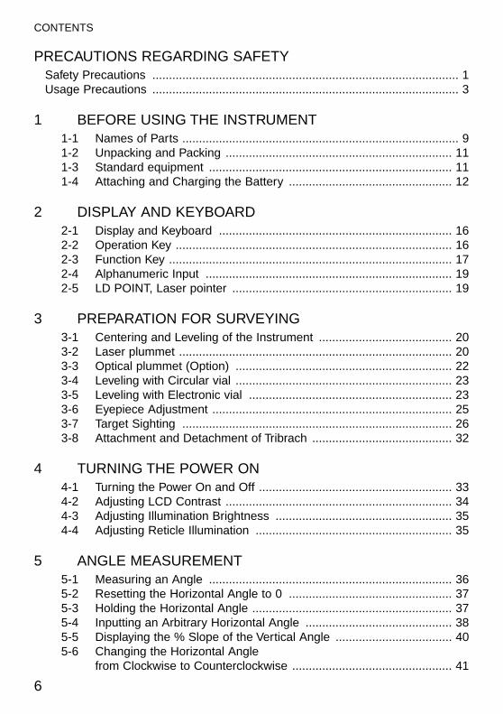
PRECAUTIONS REGARDING SAFETYSafety Precautions ............................................................................................ 1Usage Precautions ............................................................................................ 3
1 BEFORE USING THE INSTRUMENT 1-1 Names of Parts ................................................................................... 91-2 Unpacking and Packing .................................................................... 111-3 Standard equipment ......................................................................... 111-4 Attaching and Charging the Battery ................................................. 12
2 DISPLAY AND KEYBOARD2-1 Display and Keyboard ...................................................................... 162-2 Operation Key ................................................................................... 162-3 Function Key ..................................................................................... 172-4 Alphanumeric Input .......................................................................... 192-5 LD POINT, Laser pointer .................................................................. 19
3 PREPARATION FOR SURVEYING3-1 Centering and Leveling of the Instrument ........................................ 203-2 Laser plummet .................................................................................. 203-3 Optical plummet (Option) ................................................................. 223-4 Leveling with Circular vial ................................................................. 233-5 Leveling with Electronic vial ............................................................. 233-6 Eyepiece Adjustment ........................................................................ 253-7 Target Sighting ................................................................................. 263-8 Attachment and Detachment of Tribrach .......................................... 32
4 TURNING THE POWER ON4-1 Turning the Power On and Off .......................................................... 334-2 Adjusting LCD Contrast .................................................................... 34 4-3 Adjusting Illumination Brightness ..................................................... 354-4 Adjusting Reticle Illumination ........................................................... 35
5 ANGLE MEASUREMENT5-1 Measuring an Angle ......................................................................... 365-2 Resetting the Horizontal Angle to 0 ................................................. 375-3 Holding the Horizontal Angle ............................................................ 375-4 Inputting an Arbitrary Horizontal Angle ............................................ 385-5 Displaying the % Slope of the Vertical Angle ................................... 405-6 Changing the Horizontal Angle
from Clockwise to Counterclockwise ................................................ 41
6
CONTENTS
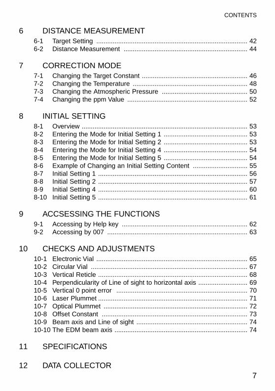
6 DISTANCE MEASUREMENT6-1 Target Setting ................................................................................... 426-2 Distance Measurement .................................................................... 44
7 CORRECTION MODE7-1 Changing the Target Constant .......................................................... 467-2 Changing the Temperature ............................................................... 487-3 Changing the Atmospheric Pressure ............................................... 507-4 Changing the ppm Value .................................................................. 52
8 INITIAL SETTING8-1 Overview ........................................................................................... 538-2 Entering the Mode for Initial Setting 1 .............................................. 538-3 Entering the Mode for Initial Setting 2 .............................................. 538-4 Entering the Mode for Initial Setting 4 .............................................. 548-5 Entering the Mode for Initial Setting 5 .............................................. 548-6 Example of Changing an Initial Setting Content .............................. 558-7 Initial Setting 1 .................................................................................. 568-8 Initial Setting 2 .................................................................................. 578-9 Initial Setting 4 .................................................................................. 608-10 Initial Setting 5 .................................................................................. 61
9 ACCSESSING THE FUNCTIONS9-1 Accessing by Help key ..................................................................... 629-2 Accessing by 007 ............................................................................. 63
10 CHECKS AND ADJUSTMENTS10-1 Electronic Vial ................................................................................... 6510-2 Circular Vial ...................................................................................... 6710-3 Vertical Reticle .................................................................................. 6810-4 Perpendicularity of Line of sight to horizontal axis ........................... 6910-5 Vertical 0 point error ........................................................................ 7010-6 Laser Plummet .................................................................................. 7110-7 Optical Plummet ............................................................................... 7210-8 Offset Constant ................................................................................ 7310-9 Beam axis and Line of sight ............................................................. 7410-10 The EDM beam axis ......................................................................... 74
11 SPECIFICATIONS
12 DATA COLLECTOR7
CONTENTS

13 APPENDIX13-1 Error Messages ................................................................................ 7913-2 Atmospheric Correction .................................................................... 8013-3 hPa and mmHg Conversion Tables .................................................. 8113-4 Error when no Atmospheric Correction is made .............................. 8213-5 Atmospheric Refraction and Earth Curvature Correction ................ 8313-6 Distance Range ................................................................................ 84
14 NOTICE TO THE USER OF THIS PRODUCT
8
CONTENTS
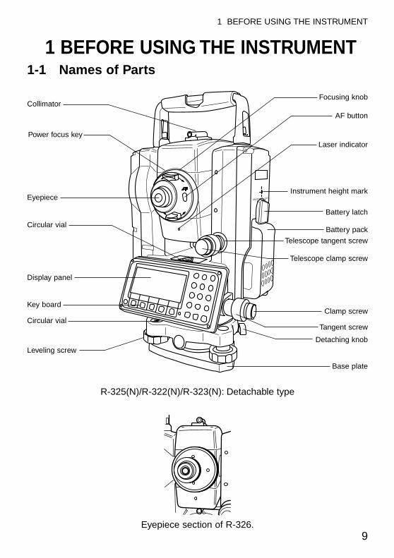
1 BEFORE USING THE INSTRUMENT1-1 Names of Parts
UNLOCK LOCK
9
1 BEFORE USING THE INSTRUMENT
Collimator
Power focus key
Eyepiece
Circular vial
Display panel
Key board
Circular vial
Leveling screw
Focusing knob
AF button
Laser indicator
Instrument height mark
Battery latch
Battery pack
Telescope tangent screw
Telescope clamp screw
Clamp screw
Tangent screw
Detaching knob
Base plate
Eyepiece section of R-326.
R-325(N)/R-322(N)/R-323(N): Detachable type
10
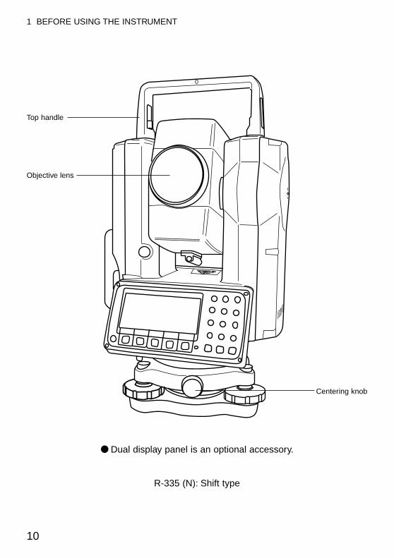
1 BEFORE USING THE INSTRUMENT
● Dual display panel is an optional accessory.
R-335 (N): Shift type
Top handle
Objective lens
Centering knob
1-2 Unpacking and PackingUnpacking the Instrument from the caseq Set the case down gently with the lid facing upwards.w Open the latches while pressing down on the lock (safety mechanism) and
open the lid of the case.e Remove the instrument from the case.
Packing the Instrument in the caseq Make sure the telescope is fairly level and lightly tighten the telescope clamp
screw.w Line up the housing marks (round yellow marks on the instrument) and tighten
the upper and lower clamp screws.e With the housing marks facing upward, set the instrument gently in the case
without forcing it.r Close the lid to the case and secure the latches.
1-3 Standard equipmentq Instrumentw Carrying casee BP02 batteryr BC03/AC01 chargert Plumb boby Hexagonal wrenchu Rain coveri Quick Reference Guide (Basic , PTL and PSF procedures)o CD-R (Basic operation & Special Functions manual)
11
1 BEFORE USING THE INSTRUMENT
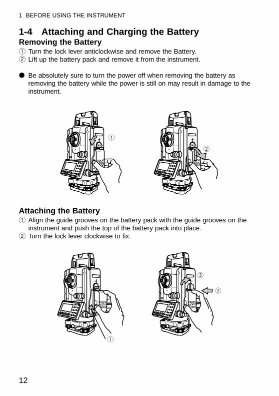
1-4 Attaching and Charging the BatteryRemoving the Batteryq Turn the lock lever anticlockwise and remove the Battery.w Lift up the battery pack and remove it from the instrument.
● Be absolutely sure to turn the power off when removing the battery asremoving the battery while the power is still on may result in damage to theinstrument.
Attaching the Batteryq Align the guide grooves on the battery pack with the guide grooves on the
instrument and push the top of the battery pack into place.w Turn the lock lever clockwise to fix.
q
w
e
q
w
12
1 BEFORE USING THE INSTRUMENT
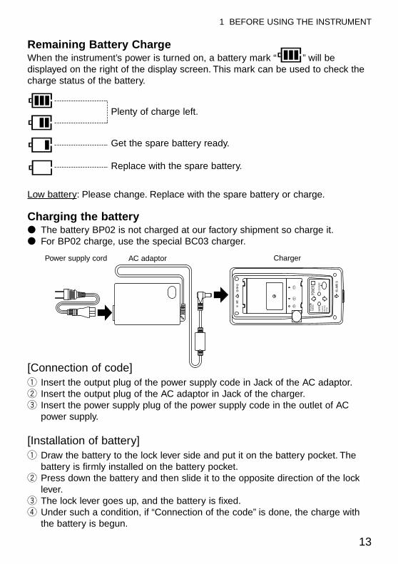
Remaining Battery ChargeWhen the instrument’s power is turned on, a battery mark “ ” will bedisplayed on the right of the display screen. This mark can be used to check thecharge status of the battery.
Plenty of charge left.
Get the spare battery ready.
Replace with the spare battery.
Low battery: Please change. Replace with the spare battery or charge.
Charging the battery● The battery BP02 is not charged at our factory shipment so charge it.● For BP02 charge, use the special BC03 charger.
[Connection of code]q Insert the output plug of the power supply code in Jack of the AC adaptor.w Insert the output plug of the AC adaptor in Jack of the charger.e Insert the power supply plug of the power supply code in the outlet of AC
power supply.
[Installation of battery]q Draw the battery to the lock lever side and put it on the battery pocket. The
battery is firmly installed on the battery pocket.w Press down the battery and then slide it to the opposite direction of the lock
lever.e The lock lever goes up, and the battery is fixed.r Under such a condition, if “Connection of the code” is done, the charge with
the battery is begun.
13
1 BEFORE USING THE INSTRUMENT
Power supply cord AC adaptor Charger
POWE
RCH
ARGE
Ni-MH
/Ni-C
dBa
ttery
Chag
erDis
chag
er
DISCH
ARGE
14
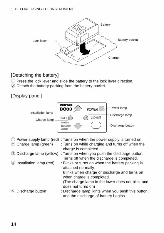
[Detaching the battery]q Press the lock lever and slide the battery to the lock lever direction.w Detach the battery packing from the battery pocket.
[Display panel]
q Power supply lamp (red) : Turns on when the power supply is turned on.w Charge lamp (green) : Turns on while charging and turns off when the
charge is completed.e Discharge lamp (yellow) : Turns on when you push the discharge button.
Turns off when the discharge is completed.r Installation lamp (red) : Blinks or turns on when the battery packing is
attached normally.Blinks when charge or discharge and turns onwhen charge is completed.(The charge lamp in the lower does not blink anddoes not turns on)
t Discharge button : Discharge lamp lights when you push this button,and the discharge of battery begins.
1 BEFORE USING THE INSTRUMENT
Lock lever
Battery
Battery pocket
Charger
CHARGENi-MH/Ni-CdBattery ChagerDischager
DISCHARGE
BC03 POWERInstallation lamp
Charge lamp
Power lamp
Discharge lamp
Discharge button
15
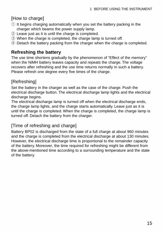
[How to charge]q It begins charging automatically when you set the battery packing in the
charger which beams the power supply lamp.w Leave just as it is until the charge is completed.e When the charge is completed, the charge lamp is turned off.r Detach the battery packing from the charger when the charge is completed.
Refreshing the battery The use time shortens gradually by the phenomenon of “Effect of the memory”when the NiMH battery leaves capacity and repeats the charge. The voltagerecovers after refreshing and the use time returns normally in such a battery.Please refresh one degree every five times of the charge.
[Refreshing]Set the battery in the charger as well as the case of the charge. Push theelectrical discharge button. The electrical discharge lamp lights and the electricaldischarge begins.The electrical discharge lamp is turned off when the electrical discharge ends,the charge lamp lights, and the charge starts automatically. Leave just as it isuntil the charge is completed. When the charge is completed, the charge lamp isturned off. Detach the battery from the charger.
[Time of refreshing and charge]Battery BP02 is discharged from the state of a full charge at about 960 minutesand the charge is completed from the electrical discharge at about 130 minutes.However, the electrical discharge time is proportional to the remainder capacityof the battery. Moreover, the time required for refreshing might be different fromthe above-mentioned time according to a surrounding temperature and the stateof the battery.
1 BEFORE USING THE INSTRUMENT
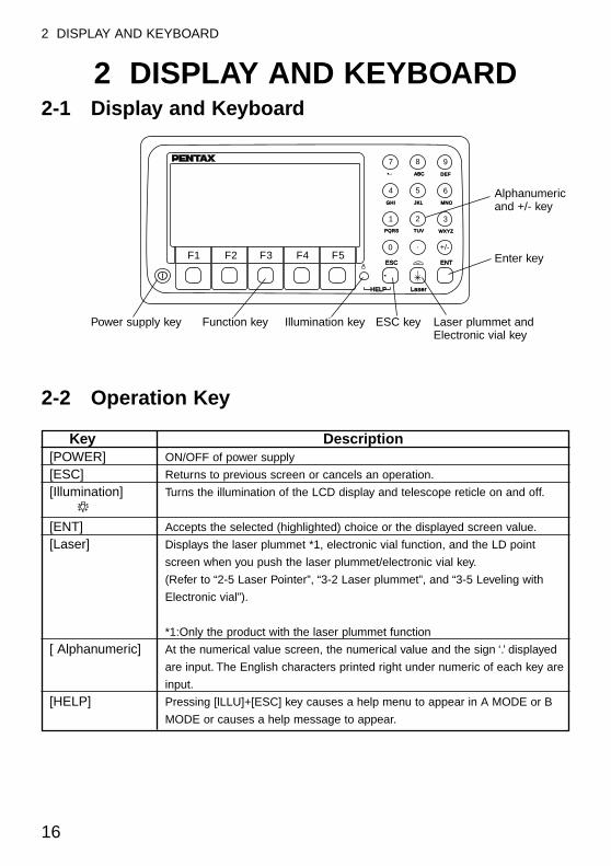
2 DISPLAY AND KEYBOARD2-1 Display and Keyboard
2-2 Operation Key
Key Description[POWER] ON/OFF of power supply
[ESC] Returns to previous screen or cancels an operation.
[Illumination] Turns the illumination of the LCD display and telescope reticle on and off.
[ENT] Accepts the selected (highlighted) choice or the displayed screen value.
[Laser] Displays the laser plummet *1, electronic vial function, and the LD point
screen when you push the laser plummet/electronic vial key.
(Refer to “2-5 Laser Pointer”, “3-2 Laser plummet”, and “3-5 Leveling with
Electronic vial”).
*1:Only the product with the laser plummet function
[ Alphanumeric] At the numerical value screen, the numerical value and the sign ‘.’ displayed
are input. The English characters printed right under numeric of each key are
input.
[HELP] Pressing [lLLU]+[ESC] key causes a help menu to appear in A MODE or B
MODE or causes a help message to appear.
7 8 9
4 5 6
1 2 3
0 . +/-
ABCABC DEFDEF
GHIGHI JKLJKL MNOMNO
PQRSPQRS TUVTUV WXYZWXYZ
ESCESC ENTENT
HELPHELP LaserLaser
F1 F2 F3 F4 F5
16
2 DISPLAY AND KEYBOARD
Alphanumericand +/- key
Laser plummet andElectronic vial key
ESC keyIllumination keyFunction keyPower supply key
Enter key
17
2 DISPLAY AND KEYBOARD
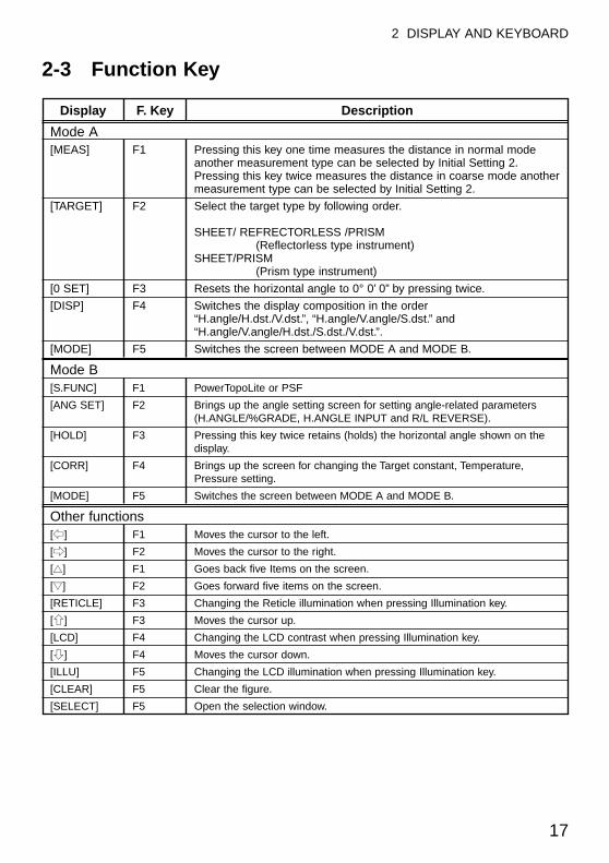
2-3 Function Key
Display F. Key Description
Mode A[MEAS] F1 Pressing this key one time measures the distance in normal mode
another measurement type can be selected by Initial Setting 2.Pressing this key twice measures the distance in coarse mode anothermeasurement type can be selected by Initial Setting 2.
[TARGET] F2 Select the target type by following order.
SHEET/ REFRECTORLESS /PRISM(Reflectorless type instrument)
SHEET/PRISM(Prism type instrument)
[0 SET] F3 Resets the horizontal angle to 0° 0’ 0” by pressing twice.
[DISP] F4 Switches the display composition in the order“H.angle/H.dst./V.dst.”, “H.angle/V.angle/S.dst.” and“H.angle/V.angle/H.dst./S.dst./V.dst.”.
[MODE] F5 Switches the screen between MODE A and MODE B.
Mode B[S.FUNC] F1 PowerTopoLite or PSF
[ANG SET] F2 Brings up the angle setting screen for setting angle-related parameters(H.ANGLE/%GRADE, H.ANGLE INPUT and R/L REVERSE).
[HOLD] F3 Pressing this key twice retains (holds) the horizontal angle shown on thedisplay.
[CORR] F4 Brings up the screen for changing the Target constant, Temperature,Pressure setting.
[MODE] F5 Switches the screen between MODE A and MODE B.
Other functions[f] F1 Moves the cursor to the left.
[e] F2 Moves the cursor to the right.
[▲▲] F1 Goes back five Items on the screen.
[▼▼] F2 Goes forward five items on the screen.
[RETICLE] F3 Changing the Reticle illumination when pressing Illumination key.
[g] F3 Moves the cursor up.
[LCD] F4 Changing the LCD contrast when pressing Illumination key.
[h] F4 Moves the cursor down.
[ILLU] F5 Changing the LCD illumination when pressing Illumination key.
[CLEAR] F5 Clear the figure.
[SELECT] F5 Open the selection window.
18
2 DISPLAY AND KEYBOARD
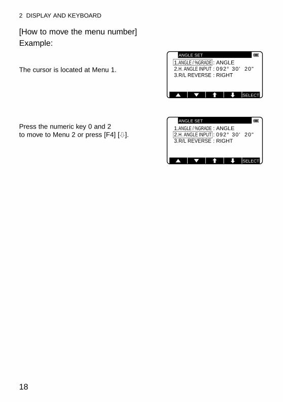
[How to move the menu number]Example:
The cursor is located at Menu 1.
Press the numeric key 0 and 2 to move to Menu 2 or press [F4] [h].
ANGLE SET
1.ANGLE / %GRADE : ANGLE2.H. ANGLE INPUT : 092° 30' 20"3.R/L REVERSE : RIGHT
SELECT
ANGLE SET
1.ANGLE / %GRADE : ANGLE2.H. ANGLE INPUT : 092° 30' 20"3.R/L REVERSE : RIGHT
SELECT
19
2 DISPLAY AND KEYBOARD
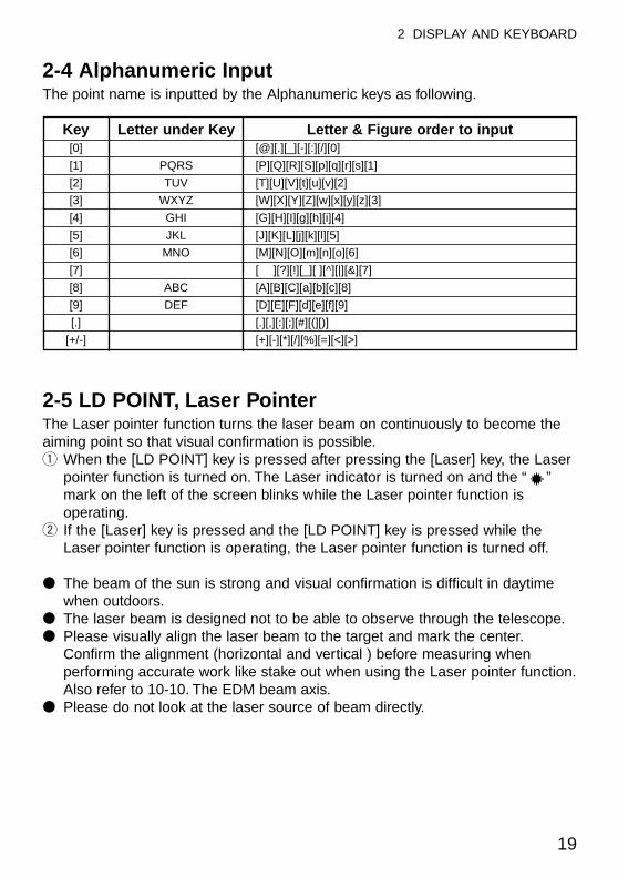
2-4 Alphanumeric InputThe point name is inputted by the Alphanumeric keys as following.
Key Letter under Key Letter & Figure order to input[0] [@][.][_][-][:][/][0]
[1] PQRS [P][Q][R][S][p][q][r][s][1]
[2] TUV [T][U][V][t][u][v][2]
[3] WXYZ [W][X][Y][Z][w][x][y][z][3]
[4] GHI [G][H][I][g][h][i][4]
[5] JKL [J][K][L][j][k][l][5]
[6] MNO [M][N][O][m][n][o][6]
[7] [ ][?][!][_][ ][^][|][&][7]
[8] ABC [A][B][C][a][b][c][8]
[9] DEF [D][E][F][d][e][f][9]
[.] [.][,][:][;][#][(][)]
[+/-] [+][-][*][/][%][=][<][>]
2-5 LD POINT, Laser Pointer The Laser pointer function turns the laser beam on continuously to become theaiming point so that visual confirmation is possible.q When the [LD POINT] key is pressed after pressing the [Laser] key, the Laser
pointer function is turned on. The Laser indicator is turned on and the “ ”mark on the left of the screen blinks while the Laser pointer function isoperating.
w If the [Laser] key is pressed and the [LD POINT] key is pressed while theLaser pointer function is operating, the Laser pointer function is turned off.
● The beam of the sun is strong and visual confirmation is difficult in daytimewhen outdoors.
● The laser beam is designed not to be able to observe through the telescope.● Please visually align the laser beam to the target and mark the center.
Confirm the alignment (horizontal and vertical ) before measuring whenperforming accurate work like stake out when using the Laser pointer function.Also refer to 10-10. The EDM beam axis.
● Please do not look at the laser source of beam directly.
20
3 PREPARATION FOR SURVEYING
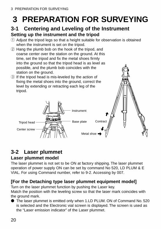
3 PREPARATION FOR SURVEYING3-1 Centering and Leveling of the InstrumentSetting up the instrument and the tripodq Adjust the tripod legs so that a height suitable for observation is obtained
when the instrument is set on the tripod.w Hang the plumb bob on the hook of the tripod, and
coarse center over the station on the ground. At thistime, set the tripod and fix the metal shoes firmlyinto the ground so that the tripod head is as level aspossible, and the plumb bob coincides with thestation on the ground.
e If the tripod head is mis-leveled by the action offixing the metal shoes into the ground, correct thelevel by extending or retracting each leg of thetripod.
3-2 Laser plummet Laser plummet modelThe laser plummet is not set to be ON at factory shipping. The laser plummetoperation of power supply ON can be set by command No 520, LD PLUM & EVIAL. For using Command number, refer to 9-2. Accessing by 007.
[For the Detaching type laser plummet equipment model]Turn on the laser plummet function by pushing the Laser key.Match the position with the leveling screw so that the laser mark coincides withthe ground mark.● The laser plummet is emitted only when 1.LD PLUM. ON of Command No. 520
is selected and the Electronic vial screen is displayed. The screen is used asthe “Laser emission indicator” of the Laser plummet.
Instrument
Base plateTripod head
Center screwMetal shoe
Contract
21
3 PREPARATION FOR SURVEYING
[For the Shift type laser plummet equipment model]● Turn on the laser plummet function by pushing the Laser key.● Match the position by the tripod so that the laser mark coincides with the
ground mark.● The centering knob is loosened, and the upper plate is pushed by the tip of a
finger, and a center mark is matched to the ground mark.● Tighten the centering knob.● Loosen the horizontal clamp screw, and rotate the instrument by 90°, and
confirm the vial of the circular vial is at the center at any position.Correct the vial with the leveling screw when the vial comes off from thecenter.
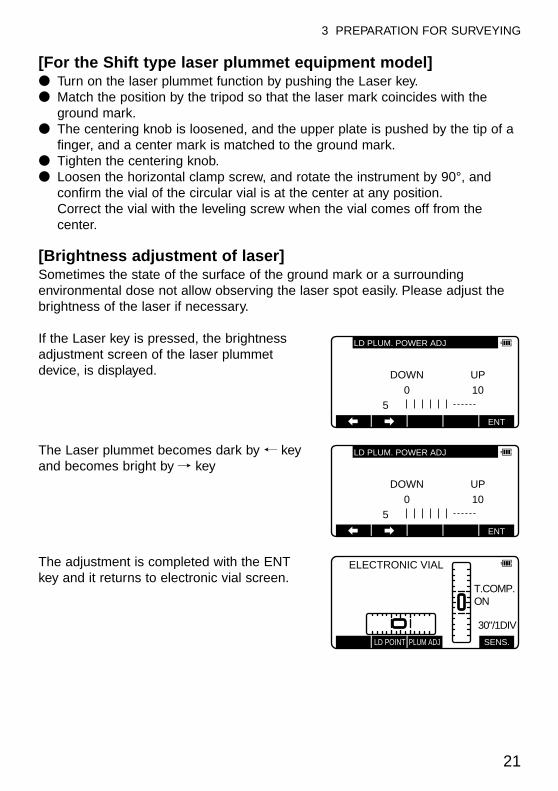
[Brightness adjustment of laser]Sometimes the state of the surface of the ground mark or a surroundingenvironmental dose not allow observing the laser spot easily. Please adjust thebrightness of the laser if necessary.
If the Laser key is pressed, the brightnessadjustment screen of the laser plummetdevice, is displayed.
The Laser plummet becomes dark by , keyand becomes bright by / key
The adjustment is completed with the ENTkey and it returns to electronic vial screen.
ENT
DOWN UP0
510
LD PLUM. POWER ADJ
ENT
DOWN UP0
510
LD PLUM. POWER ADJ
ELECTRONIC VIAL
T.COMP.ON
30"/1DIV
LD POINT PLUM ADJ SENS.
22
3 PREPARATION FOR SURVEYING
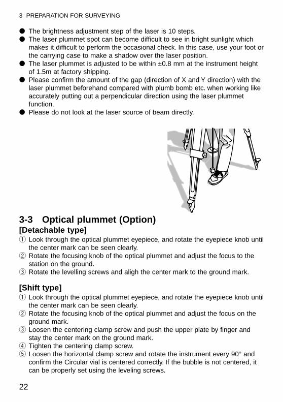
● The brightness adjustment step of the laser is 10 steps.● The laser plummet spot can become difficult to see in bright sunlight which
makes it difficult to perform the occasional check. In this case, use your foot orthe carrying case to make a shadow over the laser position.
● The laser plummet is adjusted to be within ±0.8 mm at the instrument heightof 1.5m at factory shipping.
● Please confirm the amount of the gap (direction of X and Y direction) with thelaser plummet beforehand compared with plumb bomb etc. when working likeaccurately putting out a perpendicular direction using the laser plummetfunction.
● Please do not look at the laser source of beam directly.
3-3 Optical plummet (Option)[Detachable type]q Look through the optical plummet eyepiece, and rotate the eyepiece knob until
the center mark can be seen clearly.w Rotate the focusing knob of the optical plummet and adjust the focus to the
station on the ground.e Rotate the levelling screws and aligh the center mark to the ground mark.
[Shift type]q Look through the optical plummet eyepiece, and rotate the eyepiece knob until
the center mark can be seen clearly.w Rotate the focusing knob of the optical plummet and adjust the focus on the
ground mark.e Loosen the centering clamp screw and push the upper plate by finger and
stay the center mark on the ground mark.r Tighten the centering clamp screw.t Loosen the horizontal clamp screw and rotate the instrument every 90° and
confirm the Circular vial is centered correctly. If the bubble is not centered, itcan be properly set using the leveling screws.
23
3 PREPARATION FOR SURVEYING
3-4 Leveling with Circular vial Tripod is adjusted according to the following points by extending or contractingthe legs so that the bubble of the Circular vial goes to the center of the circle.
● Shorten the leg at the side of the bubble or extend the leg opposite of thebubble to position the bubble in the center of the vial circle.
● All three legs are extended or contracted until the bubble is in the center.During this process, the foot is not placed on the tripod leg point and theposition of the tripod points do not change.
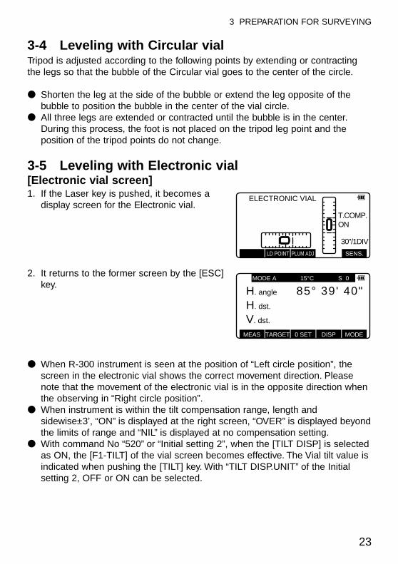
3-5 Leveling with Electronic vial [Electronic vial screen]1. If the Laser key is pushed, it becomes a
display screen for the Electronic vial.
2. It returns to the former screen by the [ESC]key.
● When R-300 instrument is seen at the position of “Left circle position”, thescreen in the electronic vial shows the correct movement direction. Pleasenote that the movement of the electronic vial is in the opposite direction whenthe observing in “Right circle position”.
● When instrument is within the tilt compensation range, length andsidewise±3’, “ON” is displayed at the right screen, “OVER” is displayed beyondthe limits of range and “NIL” is displayed at no compensation setting.
● With command No “520” or “Initial setting 2”, when the [TILT DISP] is selectedas ON, the [F1-TILT] of the vial screen becomes effective. The Vial tilt value isindicated when pushing the [TILT] key. With “TILT DISP.UNIT” of the Initialsetting 2, OFF or ON can be selected.
ELECTRONIC VIAL
T.COMP.ON
30"/1DIV
LD POINT PLUM ADJ SENS.
MEAS TARGET 0 SET DISP MODE
MODE A 15°C S 0
H. angle 40"39'85°H. dst. 0000000°V. dst. 000000°
3 PREPARATION FOR SURVEYING
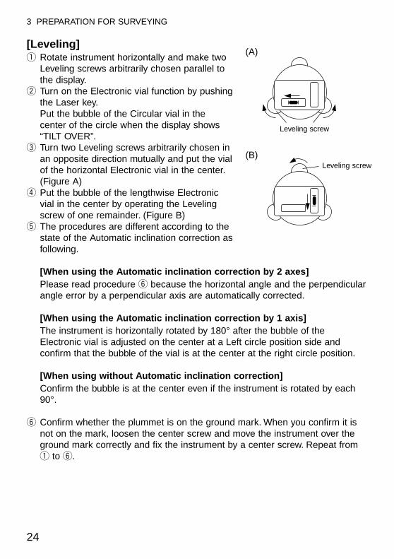
[Leveling]q Rotate instrument horizontally and make two
Leveling screws arbitrarily chosen parallel tothe display.
w Turn on the Electronic vial function by pushingthe Laser key.Put the bubble of the Circular vial in thecenter of the circle when the display shows“TILT OVER”.
e Turn two Leveling screws arbitrarily chosen inan opposite direction mutually and put the vialof the horizontal Electronic vial in the center.(Figure A)
r Put the bubble of the lengthwise Electronicvial in the center by operating the Levelingscrew of one remainder. (Figure B)
t The procedures are different according to thestate of the Automatic inclination correction asfollowing.
[When using the Automatic inclination correction by 2 axes]Please read procedure y because the horizontal angle and the perpendicularangle error by a perpendicular axis are automatically corrected.
[When using the Automatic inclination correction by 1 axis]The instrument is horizontally rotated by 180° after the bubble of theElectronic vial is adjusted on the center at a Left circle position side andconfirm that the bubble of the vial is at the center at the right circle position.
[When using without Automatic inclination correction]Confirm the bubble is at the center even if the instrument is rotated by each90°.
y Confirm whether the plummet is on the ground mark. When you confirm it isnot on the mark, loosen the center screw and move the instrument over theground mark correctly and fix the instrument by a center screw. Repeat fromq to y.
24
(A)
(B)
Leveling screw
Leveling screw
25
3 PREPARATION FOR SURVEYING
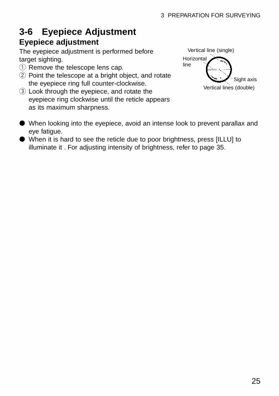
3-6 Eyepiece AdjustmentEyepiece adjustmentThe eyepiece adjustment is performed beforetarget sighting.q Remove the telescope lens cap.w Point the telescope at a bright object, and rotate
the eyepiece ring full counter-clockwise.e Look through the eyepiece, and rotate the
eyepiece ring clockwise until the reticle appearsas its maximum sharpness.
● When looking into the eyepiece, avoid an intense look to prevent parallax andeye fatigue.
● When it is hard to see the reticle due to poor brightness, press [ILLU] toilluminate it . For adjusting intensity of brightness, refer to page 35.
Sight axis
Vertical lines (double)
Vertical line (single)
Horizontalline
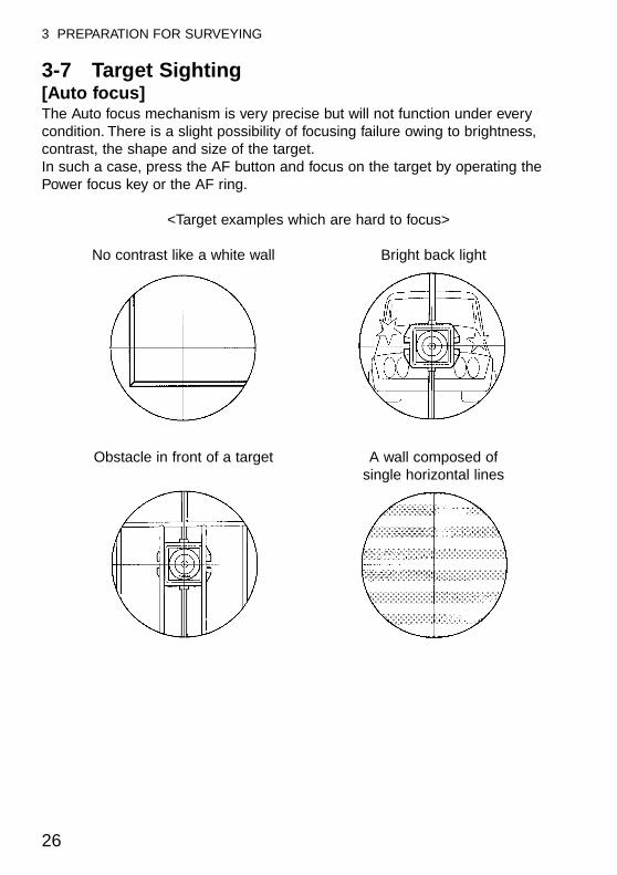
3-7 Target Sighting[Auto focus]The Auto focus mechanism is very precise but will not function under everycondition. There is a slight possibility of focusing failure owing to brightness,contrast, the shape and size of the target.In such a case, press the AF button and focus on the target by operating thePower focus key or the AF ring.
<Target examples which are hard to focus>
No contrast like a white wall Bright back light
Obstacle in front of a target A wall composed of single horizontal lines
26
3 PREPARATION FOR SURVEYING
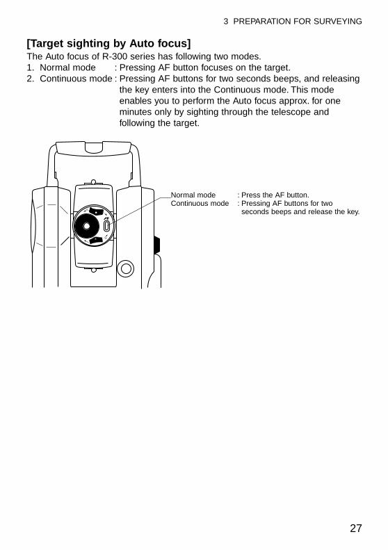
[Target sighting by Auto focus]The Auto focus of R-300 series has following two modes.1. Normal mode : Pressing AF button focuses on the target.2. Continuous mode : Pressing AF buttons for two seconds beeps, and releasing
the key enters into the Continuous mode. This modeenables you to perform the Auto focus approx. for oneminutes only by sighting through the telescope andfollowing the target.
27
3 PREPARATION FOR SURVEYING
Normal mode : Press the AF button.Continuous mode : Pressing AF buttons for two
seconds beeps and release the key.
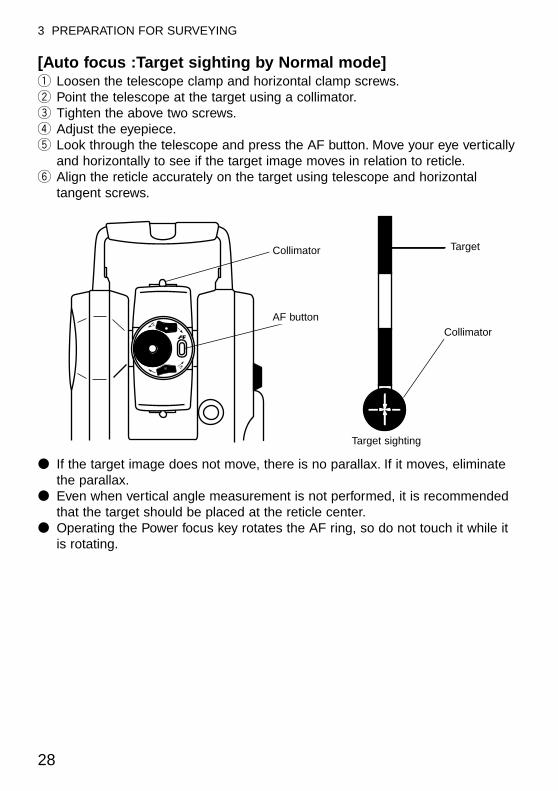
[Auto focus :Target sighting by Normal mode]q Loosen the telescope clamp and horizontal clamp screws.w Point the telescope at the target using a collimator.e Tighten the above two screws.r Adjust the eyepiece.t Look through the telescope and press the AF button. Move your eye vertically
and horizontally to see if the target image moves in relation to reticle.y Align the reticle accurately on the target using telescope and horizontal
tangent screws.
● If the target image does not move, there is no parallax. If it moves, eliminatethe parallax.
● Even when vertical angle measurement is not performed, it is recommendedthat the target should be placed at the reticle center.
● Operating the Power focus key rotates the AF ring, so do not touch it while itis rotating.
28
3 PREPARATION FOR SURVEYING
AF button
Collimator
Target sighting
Target
Collimator
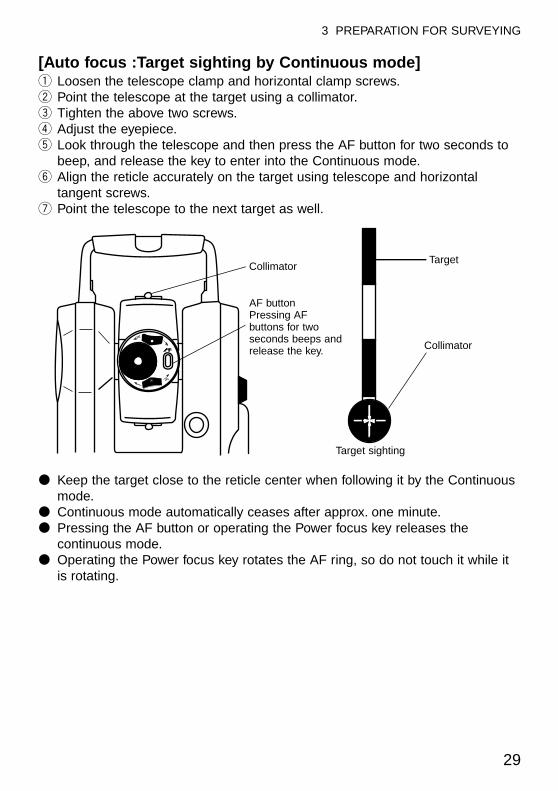
[Auto focus :Target sighting by Continuous mode]q Loosen the telescope clamp and horizontal clamp screws.w Point the telescope at the target using a collimator.e Tighten the above two screws.r Adjust the eyepiece.t Look through the telescope and then press the AF button for two seconds to
beep, and release the key to enter into the Continuous mode.y Align the reticle accurately on the target using telescope and horizontal
tangent screws.u Point the telescope to the next target as well.
● Keep the target close to the reticle center when following it by the Continuousmode.
● Continuous mode automatically ceases after approx. one minute.● Pressing the AF button or operating the Power focus key releases the
continuous mode.● Operating the Power focus key rotates the AF ring, so do not touch it while it
is rotating.
29
3 PREPARATION FOR SURVEYING
Collimator
AF buttonPressing AFbuttons for twoseconds beeps andrelease the key.
Target
Collimator
Target sighting
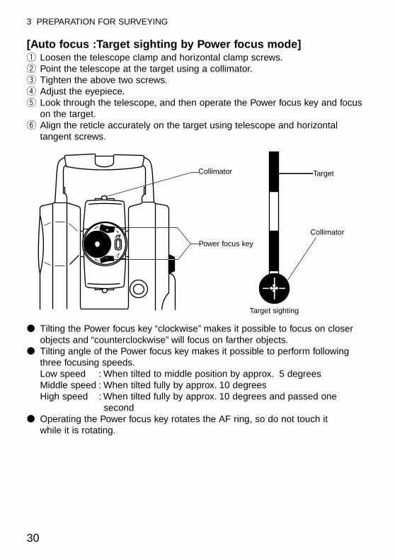
[Auto focus :Target sighting by Power focus mode]q Loosen the telescope clamp and horizontal clamp screws.w Point the telescope at the target using a collimator.e Tighten the above two screws.r Adjust the eyepiece.t Look through the telescope, and then operate the Power focus key and focus
on the target.y Align the reticle accurately on the target using telescope and horizontal
tangent screws.
● Tilting the Power focus key “clockwise” makes it possible to focus on closerobjects and “counterclockwise” will focus on farther objects.
● Tilting angle of the Power focus key makes it possible to perform followingthree focusing speeds.Low speed : When tilted to middle position by approx. 5 degreesMiddle speed : When tilted fully by approx. 10 degreesHigh speed : When tilted fully by approx. 10 degrees and passed one
second● Operating the Power focus key rotates the AF ring, so do not touch it
while it is rotating.
30
3 PREPARATION FOR SURVEYING
Collimator
Power focus key
Target
Collimator
Target sighting
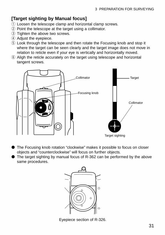
[Target sighting by Manual focus]q Loosen the telescope clamp and horizontal clamp screws.w Point the telescope at the target using a collimator.e Tighten the above two screws.r Adjust the eyepiece.t Look through the telescope and then rotate the Focusing knob and stop it
where the target can be seen clearly and the target image does not move inrelation to reticle even if your eye is vertically and horizontally moved.
y Aligh the reticle accurately on the target using telescope and horizontaltangent screws.
● The Focusing knob rotation “clockwise” makes it possible to focus on closerobjects and “counterclockwise” will focus on further objects.
● The target sighting by manual focus of R-362 can be performed by the abovesame procedures.
31
3 PREPARATION FOR SURVEYING
Collimator
Focusing knob
Target
Collimator
Target sighting
Eyepiece section of R-326.
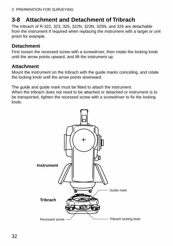
3-8 Attachment and Detachment of TribrachThe tribrach of R-322, 323, 325, 322N, 323N, 325N, and 326 are detachablefrom the instrument if required when replacing the instrument with a target or unitprism for example.
Detachment First loosen the recessed screw with a screwdriver, then rotate the locking knobuntil the arrow points upward, and lift the instrument up.
Attachment Mount the instrument on the tribrach with the guide marks coinciding, and rotatethe locking knob until the arrow points downward.
The guide and guide mark must be fitted to attach the instrument.When the tribrach does not need to be attached or detached or instrument is tobe transported, tighten the recessed screw with a screwdriver to fix the lockingknob.
32
3 PREPARATION FOR SURVEYING
Instrument
Tribrach
Recessed screw Tribrach locking lever
Guide mark
33
4 TURNING THE POWER ON
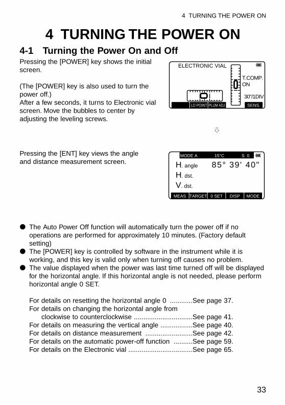
4 TURNING THE POWER ON4-1 Turning the Power On and OffPressing the [POWER] key shows the initialscreen.
(The [POWER] key is also used to turn thepower off.)After a few seconds, it turns to Electronic vialscreen. Move the bubbles to center byadjusting the leveling screws.
Pressing the [ENT] key views the angleand distance measurement screen.
● The Auto Power Off function will automatically turn the power off if nooperations are performed for approximately 10 minutes. (Factory defaultsetting)
● The [POWER] key is controlled by software in the instrument while it isworking, and this key is valid only when turning off causes no problem.
● The value displayed when the power was last time turned off will be displayedfor the horizontal angle. If this horizontal angle is not needed, please performhorizontal angle 0 SET.
For details on resetting the horizontal angle 0 ............See page 37.For details on changing the horizontal angle from
clockwise to counterclockwise ...............................See page 41.For details on measuring the vertical angle .................See page 40.For details on distance measurement .........................See page 42.For details on the automatic power-off function ..........See page 59.For details on the Electronic vial ..................................See page 65.
ELECTRONIC VIAL
T.COMP.ON
30"/1DIV
LD POINT PLUM ADJ SENS.
MEAS TARGET 0 SET DISP MODE
MODE A 15°C S 0
H. angle 40"39'85°H. dst. 0000000°V. dst. 000000°
h
4-2 Adjusting LCD Contrast
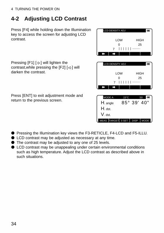
Press [F4] while holding down the Illuminationkey to access the screen for adjusting LCDcontrast.
Pressing [F1] [ ] will lighten thecontrast,while pressing the [F2] [ ] willdarken the contrast.
Press [ENT] to exit adjustment mode andreturn to the previous screen.
● Pressing the Illumination key views the F3-RETICLE, F4-LCD and F5-ILLU.● LCD contrast may be adjusted as necessary at any time.● The contrast may be adjusted to any one of 25 levels.● LCD contrast may be unappealing under certain environmental conditions
such as high temperature. Adjust the LCD contrast as described above insuch situations.
34
4 TURNING THE POWER ON
ENT
LOW HIGH0
725
LCD DENSITY ADJ
ENT
LOW HIGH0
725
LCD DENSITY ADJ
MEAS TARGET 0 SET DISP MODE
MODE A 15°C S0
H. angle 40"39'85°H. dst. 0000000°V. dst. 000000°
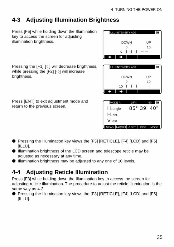
4-3 Adjusting Illumination Brightness
Press [F5] while holding down the Illuminationkey to access the screen for adjustingillumination brightness.
Pressing the [F1] [f] will decrease brightness,while pressing the [F2] [e] will increasebrightness.
Press [ENT] to exit adjustment mode andreturn to the previous screen.
● Pressing the Illumination key views the [F3] [RETICLE], [F4] [LCD] and [F5][ILLU].
● Illumination brightness of the LCD screen and telescope reticle may beadjusted as necessary at any time.
● Illumination brightness may be adjusted to any one of 10 levels.
4-4 Adjusting Reticle IlluminationPress [F3] while holding down the Illumination key to access the screen foradjusting reticle illumination. The procedure to adjust the reticle illumination is thesame way as 4-3.● Pressing the Illumination key views the [F3] [RETICLE], [F4] [LCD] and [F5]
[ILLU].
35
4 TURNING THE POWER ON
ENT
DOWN UP0
510
ILLU INTENSITY ADJ
ENT
DOWN UP0
1010
ILLU INTENSITY ADJ
MEAS TARGET 0 SET DISP MODE
MODE A 15°C S0
H. angle
H. dst. 00000°V. dst. 0000000°
40"39'85°
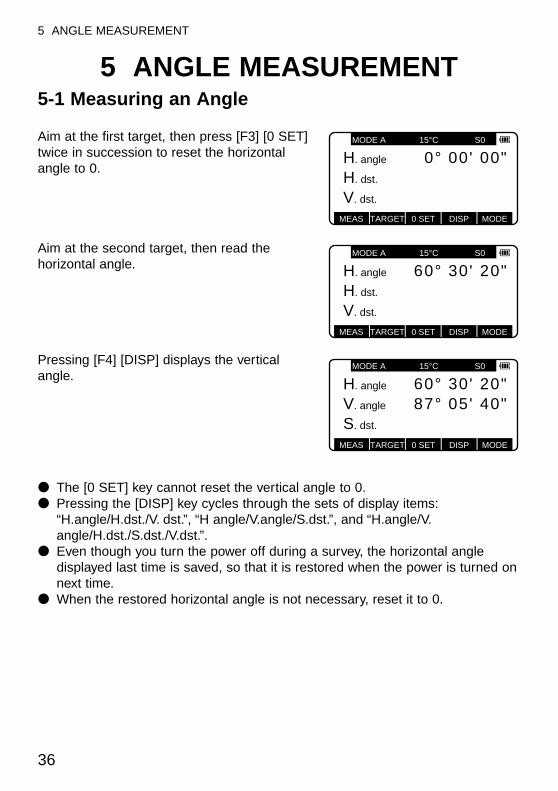
5 ANGLE MEASUREMENT5-1 Measuring an Angle
Aim at the first target, then press [F3] [0 SET]twice in succession to reset the horizontalangle to 0.
Aim at the second target, then read thehorizontal angle.
Pressing [F4] [DISP] displays the verticalangle.
● The [0 SET] key cannot reset the vertical angle to 0.● Pressing the [DISP] key cycles through the sets of display items:
“H.angle/H.dst./V. dst.”, “H angle/V.angle/S.dst.”, and “H.angle/V.angle/H.dst./S.dst./V.dst.”.
● Even though you turn the power off during a survey, the horizontal angledisplayed last time is saved, so that it is restored when the power is turned onnext time.
● When the restored horizontal angle is not necessary, reset it to 0.
36
5 ANGLE MEASUREMENT
MODE A 15°C S0
H. angle 00"00'0°H. dst.
V. dst.
MEAS TARGET 0 SET DISP MODE
MODE A 15°C S0
H. angle 20"30'60°H. dst.
V. dst.
MEAS TARGET 0 SET DISP MODE
MODE A 15°C S0
H. angle 20"30'60°V. angle 40"05'87°S. dst.
MEAS TARGET 0 SET DISP MODE
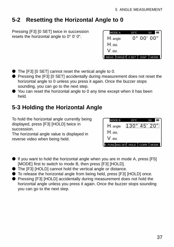
5-2 Resetting the Horizontal Angle to 0
Pressing [F3] [0 SET] twice in successionresets the horizontal angle to 0° 0' 0".
● The [F3] [0 SET] cannot reset the vertical angle to 0.● Pressing the [F3] [0 SET] accidentally during measurement does not reset the
horizontal angle to 0 unless you press it again. Once the buzzer stopssounding, you can go to the next step.
● You can reset the horizontal angle to 0 any time except when it has beenheld.
5-3 Holding the Horizontal Angle
To hold the horizontal angle currently beingdisplayed, press [F3] [HOLD] twice insuccession.The horizontal angle value is displayed inreverse video when being held.
● lf you want to hold the horizontal angle when you are in mode A, press [F5][MODE] first to switch to mode B, then press [F3] [HOLD].
● The [F3] [HOLD] cannot hold the vertical angle or distance.● To release the horizontal angle from being held, press [F3] [HOLD] once.● Pressing [F3] [HOLD] accidentally during measurement does not hold the
horizontal angle unless you press it again. Once the buzzer stops soundingyou can go to the next step.
37
5 ANGLE MEASUREMENT
MODE A 15°C S0
H. angle 00"00'0°H. dst.
V. dst.
MEAS TARGET 0 SET DISP MODE
S. FUNC ANG SET HOLD CORR MODE
MODE B 15°C S0
H. angle 20"45'130°H. dst.
V. dst.
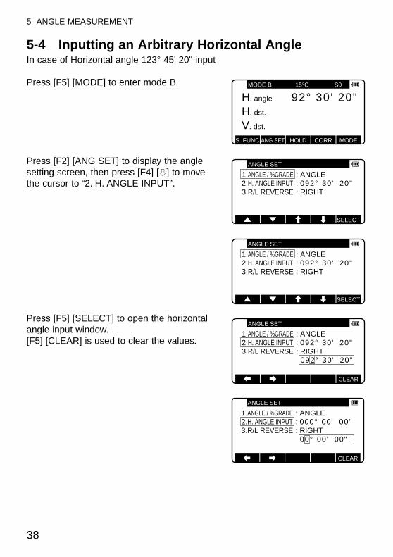
5-4 Inputting an Arbitrary Horizontal AngleIn case of Horizontal angle 123° 45' 20" input
Press [F5] [MODE] to enter mode B.
Press [F2] [ANG SET] to display the anglesetting screen, then press [F4] [h] to movethe cursor to “2. H. ANGLE INPUT”.
Press [F5] [SELECT] to open the horizontalangle input window.[F5] [CLEAR] is used to clear the values.
38
5 ANGLE MEASUREMENT
S. FUNC ANG SET HOLD CORR MODE
MODE B 15°C S0
H. angle 20"30'92°H. dst.
V. dst.
ANGLE SET
1.ANGLE / %GRADE : ANGLE2.H. ANGLE INPUT : 092° 30' 20"3.R/L REVERSE : RIGHT
SELECT
ANGLE SET
1.ANGLE / %GRADE : ANGLE2.H. ANGLE INPUT : 092° 30' 20"3.R/L REVERSE : RIGHT
SELECT
1.ANGLE / %GRADE : ANGLE2.H. ANGLE INPUT : 092° 30' 20"3.R/L REVERSE : RIGHT
092° 30' 20"
ANGLE SET
CLEAR
1.ANGLE / %GRADE : ANGLE2.H. ANGLE INPUT : 000° 00' 00"3.R/L REVERSE : RIGHT.
00° 00' 00"
ANGLE SET P-30
CLEAR
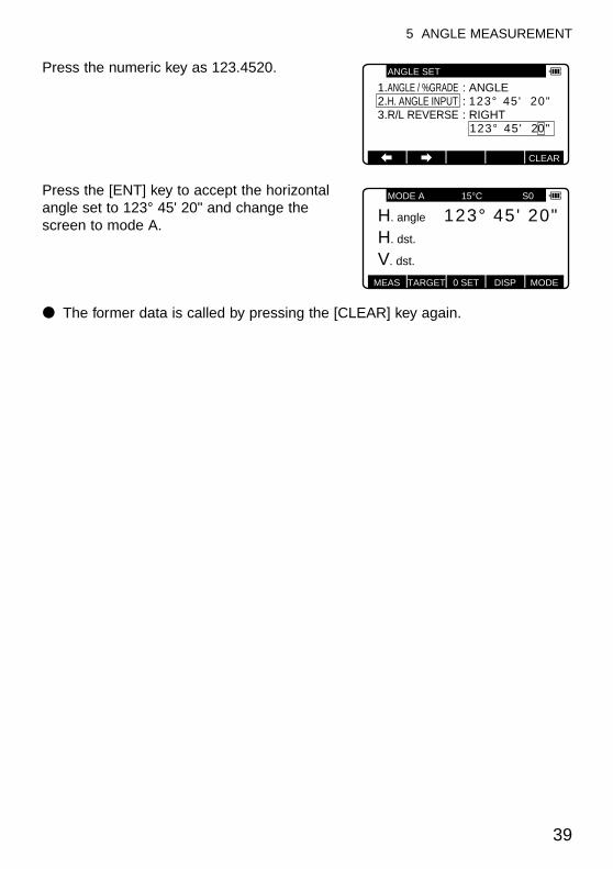
Press the numeric key as 123.4520.
Press the [ENT] key to accept the horizontalangle set to 123° 45' 20" and change thescreen to mode A.
● The former data is called by pressing the [CLEAR] key again.
39
5 ANGLE MEASUREMENT
1.ANGLE / %GRADE : ANGLE2.H. ANGLE INPUT : 123° 45' 20"3.R/L REVERSE : RIGHT
123° 45' 20"
ANGLE SET
CLEAR
MEAS TARGET 0 SET DISP MODE
MODE A 15°C S0
H. angle 20"45'123°H. dst.
V. dst.
5-5 Displaying the % Slope of the Vertical Angle
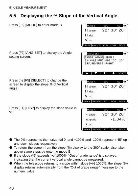
Press [F5] [MODE] to enter mode B.
Press [F2] [ANG SET] to display the Anglesetting screen.
Press the [F5] [SELECT] to change thescreen to display the slope % of Verticalangle.
Press [F4] [DISP] to display the slope value in%.
● The 0% represents the horizontal 0, and +100% and -100% represent 45° upand down slopes respectively.
● To return the screen from the slope (%) display to the 360° scale, also takeabove same steps by entering mode B.
● If the slope (%) exceeds [+/-]1000%, “Out of grade range” is displayed,indicating that the current vertical angle cannot be measured.
● When the telescope returns to a slope within slope [+/-] 1000%, the slope (%)display returns automatically from the “Out of grade range” message to thenumeric value.
40
5 ANGLE MEASUREMENT
S. FUNC ANG SET HOLD CORR MODE
MODE B 15°C S0
H. angle 20"30'92°H. dst.
V. dst.
ANGLE SET
1.ANGLE / %GRADE : ANGLE2.H. ANGLE INPUT : 092° 30' 20"3.R/L REVERSE : RIGHT
SELECT
MODE A 15°C S0
H. angle 20"30'92°H. dst.
V. dst.
MEAS TARGET 0 SET DISP MODE
MEAS TARGET 0 SET DISP MODE
MODE A 15°C S0
H. angle 20"30'92°%. grade -1.84%S. dst.
5-6 Changing the Horizontal Angle from Clockwiseto Counterclockwise
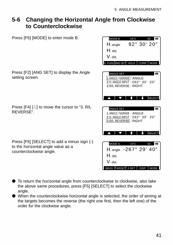
Press [F5] [MODE] to enter mode B.
Press [F2] [ANG SET] to display the Anglesetting screen.
Press [F4] [h] to move the cursor to “3. R/LREVERSE”.
Press [F5] [SELECT] to add a minus sign (-)to the horizontal angle value as acounterclockwise angle.
● To return the horizontal angle from counterclockwise to clockwise, also takethe above same procedures, press [F5] [SELECT] to select the clockwiseangle.
● When the counterclockwise horizontal angle is selected, the order of aiming atthe targets becomes the reverse (the right one first, then the left one) of theorder for the clockwise angle.
41
5 ANGLE MEASUREMENT
S. FUNC ANG SET HOLD CORR MODE
MODE B 15°C S0
H. angle 20"30'92°H. dst.
V. dst.
ANGLE SET
1.ANGLE / %GRADE : ANGLE2.H. ANGLE INPUT : 092° 30' 20"3.R/L REVERSE : RIGHT
SELECT
ANGLE SET
1.ANGLE / %GRADE : ANGLE2.H. ANGLE INPUT : 092° 30' 20"3.R/L REVERSE : RIGHT
SELECT
MEAS TARGET 0 SET DISP MODE
MODE A 15°C S0
H. angle 40"29'-267°H. dst.
V. dst.
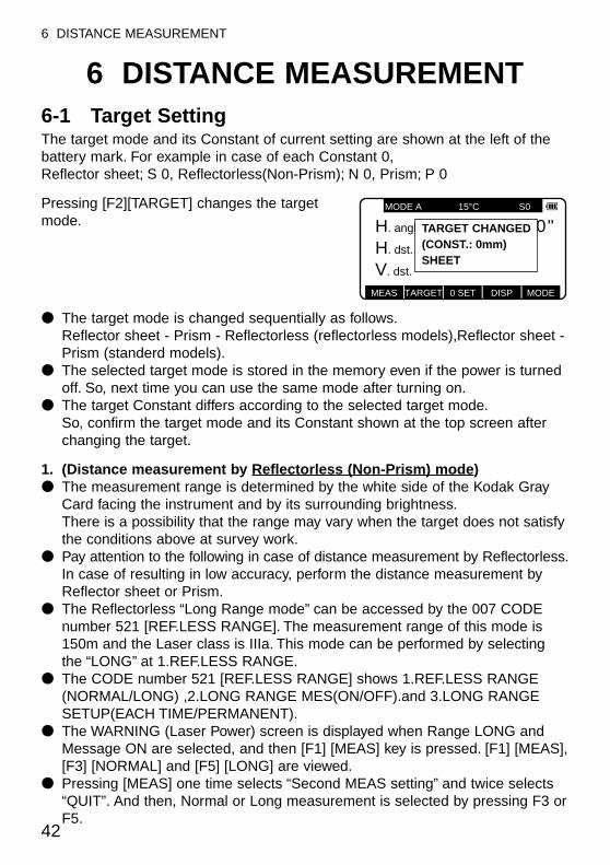
6 DISTANCE MEASUREMENT6-1 Target SettingThe target mode and its Constant of current setting are shown at the left of thebattery mark. For example in case of each Constant 0, Reflector sheet; S 0, Reflectorless(Non-Prism); N 0, Prism; P 0
Pressing [F2][TARGET] changes the targetmode.
● The target mode is changed sequentially as follows.Reflector sheet - Prism - Reflectorless (reflectorless models),Reflector sheet -Prism (standerd models).
● The selected target mode is stored in the memory even if the power is turnedoff. So, next time you can use the same mode after turning on.
● The target Constant differs according to the selected target mode.So, confirm the target mode and its Constant shown at the top screen afterchanging the target.
1. (Distance measurement by Reflectorless (Non-Prism) mode)● The measurement range is determined by the white side of the Kodak Gray
Card facing the instrument and by its surrounding brightness.There is a possibility that the range may vary when the target does not satisfythe conditions above at survey work.
● Pay attention to the following in case of distance measurement by Reflectorless.In case of resulting in low accuracy, perform the distance measurement byReflector sheet or Prism.
● The Reflectorless “Long Range mode” can be accessed by the 007 CODEnumber 521 [REF.LESS RANGE]. The measurement range of this mode is150m and the Laser class is IIIa. This mode can be performed by selectingthe “LONG” at 1.REF.LESS RANGE.
● The CODE number 521 [REF.LESS RANGE] shows 1.REF.LESS RANGE(NORMAL/LONG) ,2.LONG RANGE MES(ON/OFF).and 3.LONG RANGESETUP(EACH TIME/PERMANENT).
● The WARNING (Laser Power) screen is displayed when Range LONG andMessage ON are selected, and then [F1] [MEAS] key is pressed. [F1] [MEAS],[F3] [NORMAL] and [F5] [LONG] are viewed.
● Pressing [MEAS] one time selects “Second MEAS setting” and twice selects“QUIT”. And then, Normal or Long measurement is selected by pressing F3 orF5.
42
6 DISTANCE MEASUREMENT
MEAS TARGET 0 SET DISP MODE
MODE A 15°C S0
H. angle 20"30'92°H. dst.
V. dst. ( ( ( ) ) )
TARGET CHANGED(CONST.: 0mm)SHEET
q There is a possibility that correct distance measurement may be impossible bydispersion or reduction of laser beam when the laser beam comes into thetarget from diagonal angle.
w There is a possibility that the instrument cannot calculate correctly whenreceiving reflected laser beam from forth and back directions in case ofmeasuring the target on the road.
e There is a possibility that synthesized values are calculated and the distancemay become longer or shorter than the actual one when the operatormeasures the target of slope or sphere or rugged shape.
r There is a possibility that the instrument cannot calculate correctly collectingthe reflected laser beam from a man or a car that comes and goes in front ofthe target.
2. Distance measurement by Reflector sheet modePosition the Reflector sheet whose reflecting surface faces the aiming line to beapprox. right angle when the distance is measured by it. If it is positioned not tobe approx. right angle, there is a possibility that correct distance measurementmay be impossible by dispersion or reduction of laser beam.
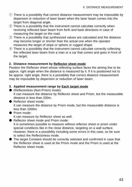
3. Applied measurement range by Each target mode● (Reflectorless (Non-Prism) mode):
It can measure the distance by Reflector sheet and Prism, but the measurabledistance is less than 200m.
● Reflector sheet mode:It can measure the distance by Prism mode, but the measurable distance isless than 1000m.
● Prism mode:It can measure by Reflector sheet as well.
● Reflector sheet mode and Prism mode:It is sometimes possible to measure without reflector sheet or prism underspecial conditions like in the close distance, targeting on a wall surface.However, there is a possibility including some errors in this case, so be sureto select the Reflectorless mode.
● The target Constant should be correctly selected and confirmed in case thatthe Reflector sheet is used at the Prism mode and the Prism is used at theReflector sheet mode.
43
6 DISTANCE MEASUREMENT
44
6 DISTANCE MEASUREMENT
6-2 Distance MeasurementThe R-300 series has two distance measurement modes of primary MEAS andsecond MEAS. Pressing the [F1][MEAS] one time goes to MEAS and twice goesto second MEAS.You can freely select and allocate your desired measurement mode in primaryMEAS and second MEAS by the Initial Setting 2. The “MEASURE SHOT” is setat primary MEAS and “TRACK CONT” is set at second MEAS as a Factorydefault setting.
● MEASURE SHOT means the Distance measurement by the Shot mode.● MEASURE CONT means the Distance measurement by the Continuous
mode.● TRACK SHOT means the Fast distance measurement by the Shot mode.● TRACK CONT means the Fast distance measurement by the Continuous
mode.Confirm the target Constant before beginning the distance measurement.
Example: “MEASURE SHOT” at primary MEAS (Factory default setting)
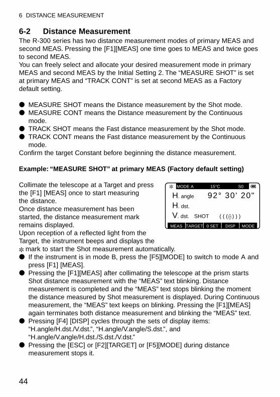
Collimate the telescope at a Target and pressthe [F1] [MEAS] once to start measuring the distance.Once distance measurement has beenstarted, the distance measurement markremains displayed.Upon reception of a reflected light from the Target, the instrument beeps and displays the ✽ mark to start the Shot measurement automatically.● If the instrument is in mode B, press the [F5][MODE] to switch to mode A and
press [F1] [MEAS].● Pressing the [F1][MEAS] after collimating the telescope at the prism starts
Shot distance measurement with the “MEAS” text blinking. Distancemeasurement is completed and the “MEAS” text stops blinking the momentthe distance measured by Shot measurement is displayed. During Continuousmeasurement, the “MEAS” text keeps on blinking. Pressing the [F1][MEAS]again terminates both distance measurement and blinking the “MEAS” text.
● Pressing [F4] [DISP] cycles through the sets of display items:“H.angle/H.dst./V.dst.”, “H.angle/V.angle/S.dst.”, and “H.angle/V.angle/H.dst./S.dst./V.dst.”
● Pressing the [ESC] or [F2][TARGET] or [F5][MODE] during distancemeasurement stops it.
MEAS TARGET 0 SET DISP MODE
MODE A 15°C S0
H. angle 20"30'92°H. dst.
V. dst. SHOT ( ( ( ) ) )
✽
● If the shot count for distance measurement has been set to 2 or more in“Initial Setting 2", the distance is measured for the specified number of timesto display the averaged value.
● If the Automatic Distance measurement : [AUTO MEAS] in “Initial Setting 2”has been set to “MEAS” the first measurement is started only by aiming atthe Target. Press [F1] [MEAS] for each measurement after the first one.
● If the Automatic Distance Signal : [MEAS SIGNAL] in “Initial Setting 2” hasbeen set to VALUE, a two-digit number representing the AIM value appearsas soon as measurement starts (The AIM value varies depending on thedistance and atmospheric conditions.)
● The minimum distance unit : [MEAN. MIN DISP] COARSE or FINE can beselected by the initial setting 2.
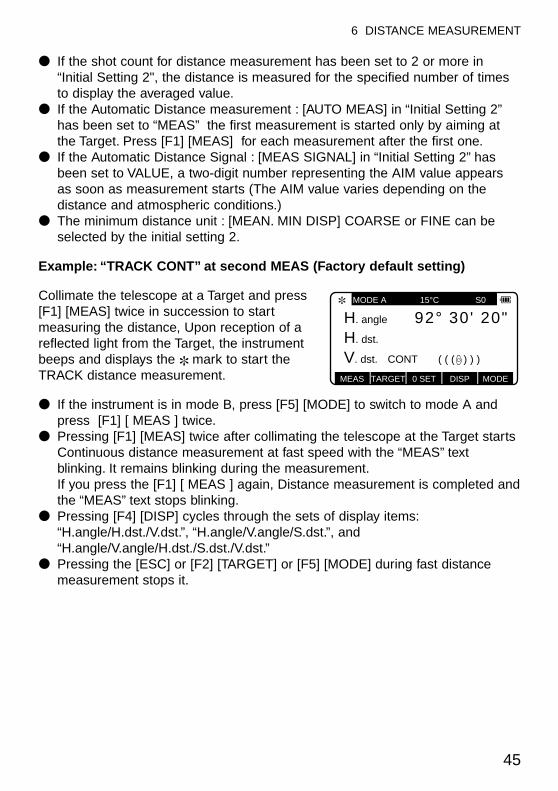
Example: “TRACK CONT” at second MEAS (Factory default setting)
Collimate the telescope at a Target and press[F1] [MEAS] twice in succession to startmeasuring the distance, Upon reception of areflected light from the Target, the instrumentbeeps and displays the ✽ mark to start theTRACK distance measurement.
● If the instrument is in mode B, press [F5] [MODE] to switch to mode A andpress [F1] [ MEAS ] twice.
● Pressing [F1] [MEAS] twice after collimating the telescope at the Target startsContinuous distance measurement at fast speed with the “MEAS” textblinking. It remains blinking during the measurement.If you press the [F1] [ MEAS ] again, Distance measurement is completed andthe “MEAS” text stops blinking.
● Pressing [F4] [DISP] cycles through the sets of display items:“H.angle/H.dst./V.dst.”, “H.angle/V.angle/S.dst.”, and “H.angle/V.angle/H.dst./S.dst./V.dst.”
● Pressing the [ESC] or [F2] [TARGET] or [F5] [MODE] during fast distancemeasurement stops it.
45
6 DISTANCE MEASUREMENT
MEAS TARGET 0 SET DISP MODE
MODE A 15°C S0
H. angle 20"30'92°H. dst.
V. dst. CONT ( ( ( ) ) )
✽
7 CORRECTION MODE
7-1 Changing the Target Constant
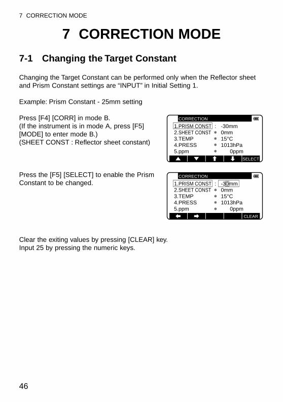
Changing the Target Constant can be performed only when the Reflector sheetand Prism Constant settings are “INPUT” in Initial Setting 1.
Example: Prism Constant - 25mm setting
Press [F4] [CORR] in mode B.(If the instrument is in mode A, press [F5][MODE] to enter mode B.)(SHEET CONST : Reflector sheet constant)
Press the [F5] [SELECT] to enable the PrismConstant to be changed.
Clear the exiting values by pressing [CLEAR] key.Input 25 by pressing the numeric keys.
46
7 CORRECTION MODE
SELECT
CORRECTION
1.PRISM CONST : -30mm2.SHEET CONST 0mm3.TEMP 15°C4.PRESS 1013hPa5.ppm 0ppm
CORRECTION
1.PRISM CONST : -30mm2.SHEET CONST 0mm3.TEMP 15°C4.PRESS 1013hPa5.ppm 0ppm
CLEAR
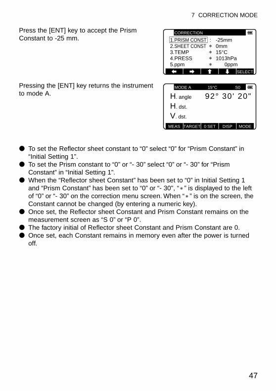
Press the [ENT] key to accept the PrismConstant to -25 mm.
Pressing the [ENT] key returns the instrumentto mode A.
● To set the Reflector sheet constant to “0” select “0” for “Prism Constant” in“Initial Setting 1”.
● To set the Prism constant to “0” or “- 30” select “0” or “- 30” for “PrismConstant” in “Initial Setting 1”.
● When the “Reflector sheet Constant” has been set to “0” in Initial Setting 1and “Prism Constant” has been set to “0” or “- 30", “ ” is displayed to the leftof “0” or “- 30” on the correction menu screen. When “ ” is on the screen, theConstant cannot be changed (by entering a numeric key).
● Once set, the Reflector sheet Constant and Prism Constant remains on themeasurement screen as “S 0” or “P 0”.
● The factory initial of Reflector sheet Constant and Prism Constant are 0.● Once set, each Constant remains in memory even after the power is turned
off.
47
7 CORRECTION MODE
CORRECTION
1.PRISM CONST : -25mm2.SHEET CONST 0mm3.TEMP 15°C4.PRESS 1013hPa5.ppm 0ppm
SELECT
MEAS TARGET 0 SET DISP MODE
MODE A 15°C S0
H. angle 20"30'92°H. dst.
V. dst.
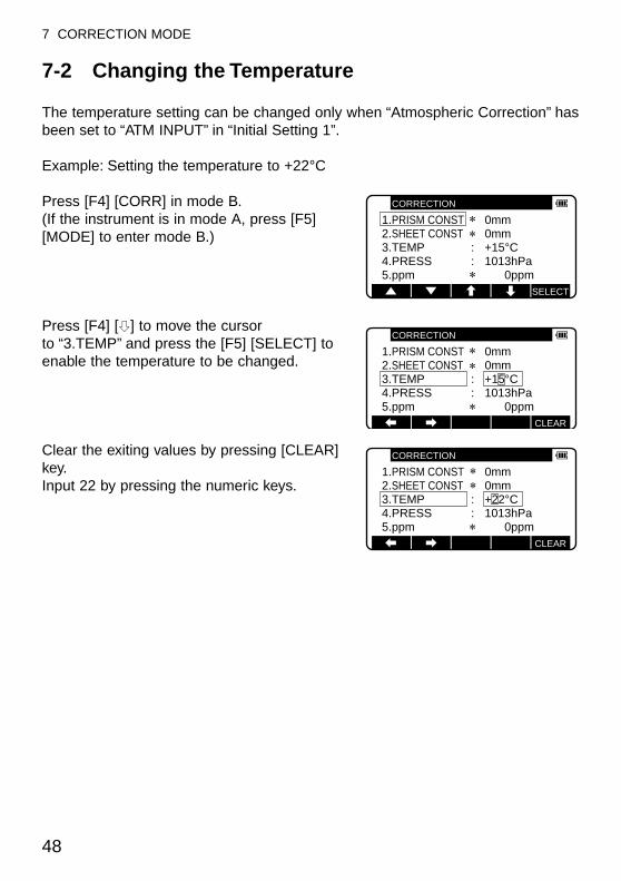
7-2 Changing the Temperature
The temperature setting can be changed only when “Atmospheric Correction” hasbeen set to “ATM INPUT” in “Initial Setting 1”.
Example: Setting the temperature to +22°C
Press [F4] [CORR] in mode B.(If the instrument is in mode A, press [F5][MODE] to enter mode B.)
Press [F4] [h] to move the cursor to “3.TEMP” and press the [F5] [SELECT] toenable the temperature to be changed.
Clear the exiting values by pressing [CLEAR]key.Input 22 by pressing the numeric keys.
48
7 CORRECTION MODE
SELECT
CORRECTION
1.PRISM CONST 0mm2.SHEET CONST 0mm3.TEMP : +15°C4.PRESS : 1013hPa5.ppm 0ppm
CORRECTION
1.PRISM CONST 0mm2.SHEET CONST 0mm3.TEMP : +15°C4.PRESS : 1013hPa5.ppm 0ppm
CLEAR
CORRECTION
1.PRISM CONST 0mm2.SHEET CONST 0mm3.TEMP : +22°C4.PRESS : 1013hPa5.ppm 0ppm
CLEAR

Press the [ENT] key to accept theTemperature to +22°C.
Pressing the [ENT] key returns the instrumentto mode A.
● The valid range of Temperatue input is from -30°C to +60°C.● When “Atmospheric Correction” in “Initial Setting 1” has been set to “1 . AUTO”
or “4. NIL”, “ ” is displayed to the left of the temperature value on thecorrection menu screen. When “ ” is on the screen, the temperature cannotbe changed. If “Atmospheric Correction” in “Initial Setting 1” has been set to“3. ppm INPUT”, no temperature is displayed on the correction menu screen.
● Once set, the temperature is displayed at the center of the top of themeasurement screen.
● The factory initial of temperature is “1. AUTO”.● Once set, the temperature remains in memory even after the power is turned
off.● Temperature correction is based on 15°C.
If this instrument is used without correcting the temperature, a distance errorper 100 m is about -0.1mm per +1°C as a temperature difference from 15°C.A distance error per 100 m is about 0.1 mm per -1°C as a temperaturedifference from 15°C. (For more accurate values, See page 82.)
49
7 CORRECTION MODE
SELECT
CORRECTION
1.PRISM CONST 0mm2.SHEET CONST 0mm3.TEMP : +22°C4.PRESS :1013hPa1013hPa
MEAS TARGET 0 SET DISP MODE
MODE A 15°C S0
H. angle 20"30'92°H. dst.
V. dst.
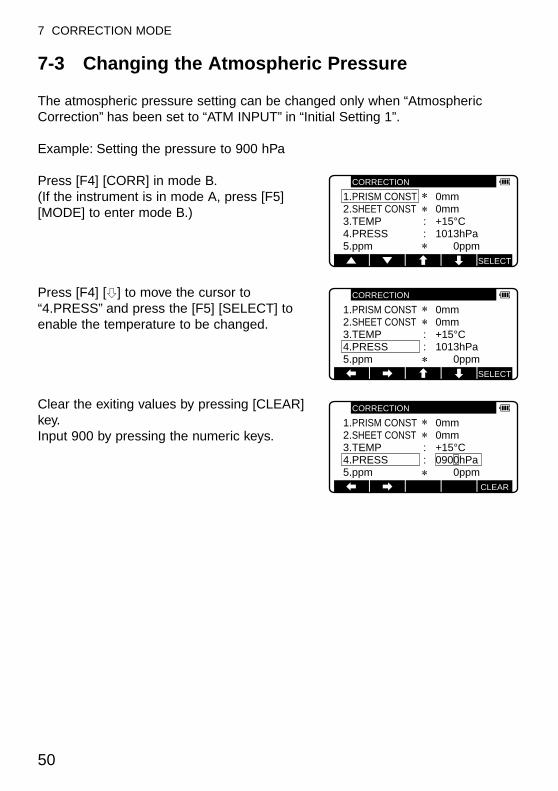
7-3 Changing the Atmospheric Pressure
The atmospheric pressure setting can be changed only when “AtmosphericCorrection” has been set to “ATM INPUT” in “Initial Setting 1”.
Example: Setting the pressure to 900 hPa
Press [F4] [CORR] in mode B.(If the instrument is in mode A, press [F5][MODE] to enter mode B.)
Press [F4] [h] to move the cursor to“4.PRESS” and press the [F5] [SELECT] toenable the temperature to be changed.
Clear the exiting values by pressing [CLEAR]key.Input 900 by pressing the numeric keys.
50
7 CORRECTION MODE
SELECT
CORRECTION
1.PRISM CONST 0mm2.SHEET CONST 0mm3.TEMP : +15°C4.PRESS : 1013hPa5.ppm 0ppm
CORRECTION
1.PRISM CONST 0mm2.SHEET CONST 0mm3.TEMP : +15°C4.PRESS : 1013hPa5.ppm 0ppm
SELECT
CORRECTION
1.PRISM CONST 0mm2.SHEET CONST 0mm3.TEMP : +15°C4.PRESS : 0900hPa5.ppm 0ppm
CLEAR

Press the [ENT] key to accept the PRESS to900 hPa.
Pressing the [ENT] key returns the instrumentto mode A.
● The valid range of Pressure input is from 600 to 1120 hPa. (420 - 840 mmHg) ● When “Atmospheric Correction” in “Initial Setting 1” has been set to “1. AUTO”
or “4. NIL”, “ ” is displayed to the left of the pressure value on the correctionmenu screen. When “ ” is on the screen, the pressure cannot be changed.If “Atmospheric Correction” in “Initial Setting 1” has been set to “3.ppmINPUT”, no pressure is displayed on the correction menu screen.
● Once set, the pressure is displayed at the center of the top of themeasurement screen.
● The factory initial of pressure is “1. AUTO”.● Once set, the pressure remains in memory even after the power is turned off.● Pressure correction is based on 1013 hectopascals (hPa).● If this instrument is used without correcting the pressure, a distance error per
100 m is about - 0.3 mm per -10 hPa as a pressure difference from 1013 hPa.(For more accurate values, see page 82.)
51
7 CORRECTION MODE
SELECT
CORRECTION
1.PRISM CONST 0mm2.SHEET CONST 0mm3.TEMP : +15°C4.PRESS : 0900hPa5.ppm 0ppm
MEAS TARGET 0 SET DISP MODE
MODE A 15°C S0
H. angle 20"30'92°H. dst.
V. dst.
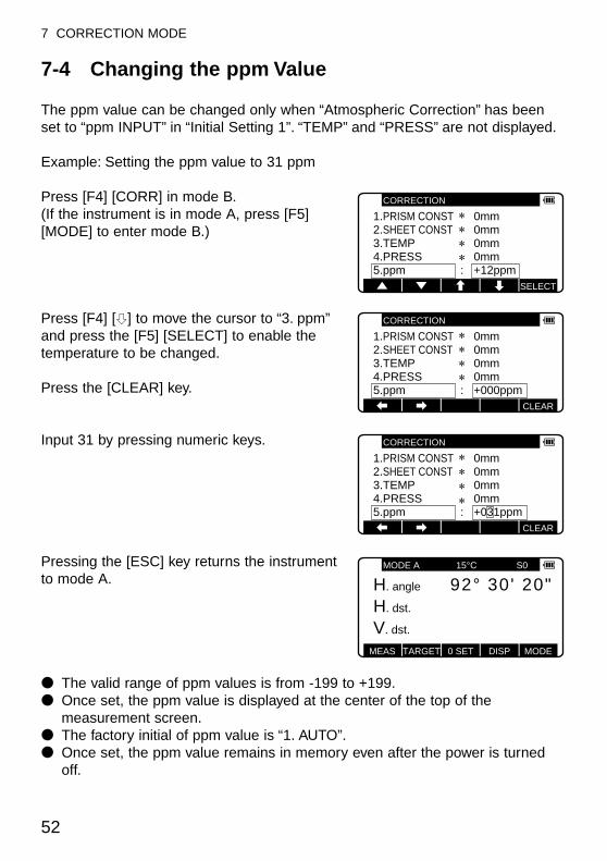
7-4 Changing the ppm Value
The ppm value can be changed only when “Atmospheric Correction” has beenset to “ppm INPUT” in “Initial Setting 1”. “TEMP” and “PRESS” are not displayed.
Example: Setting the ppm value to 31 ppm
Press [F4] [CORR] in mode B.(If the instrument is in mode A, press [F5][MODE] to enter mode B.)
Press [F4] [h] to move the cursor to “3. ppm”and press the [F5] [SELECT] to enable thetemperature to be changed.
Press the [CLEAR] key.
Input 31 by pressing numeric keys.
Pressing the [ESC] key returns the instrumentto mode A.
● The valid range of ppm values is from -199 to +199.● Once set, the ppm value is displayed at the center of the top of the
measurement screen.● The factory initial of ppm value is “1. AUTO”.● Once set, the ppm value remains in memory even after the power is turned
off.
52
7 CORRECTION MODE
CORRECTION
1.PRISM CONST 0mm2.SHEET CONST 0mm3.TEMP 0mm4.PRESS 0mm5.ppm : +12ppm
SELECT
1.PRISM CONST 0mm2.SHEET CONST 0mm3.TEMP 0mm4.PRESS 0mm5.ppm : +000ppm
CORRECTION
CLEAR
1.PRISM CONST 0mm2.SHEET CONST 0mm3.TEMP 0mm4.PRESS 0mm5.ppm : +031ppm
CORRECTION
CLEAR
MEAS TARGET 0 SET DISP MODE
MODE A 15°C S0
H. angle 20"30'92°H. dst.
V. dst.
53
8 INITIAL SETTING
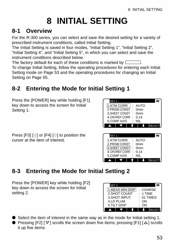
8 INITIAL SETTING8-1 OverviewFor the R-300 series, you can select and save the desired setting for a variety ofprescribed instrument conditions, called Initial Setting.The Initial Setting is saved in four modes, “Initial Setting 1”, “Initial Setting 2”,“Initial Setting 4”, and “Initial Setting 5”, in which you can select and save theinstrument conditions described below.The factory default for each of these conditions is marked by .To change Initial Setting, follow the operating procedures for entering each InitialSetting mode on Page 53 and the operating procedures for changing an InitialSetting on Page 55.
8-2 Entering the Mode for Initial Setting 1
Press the [POWER] key while holding [F1] key down to access the screen for InitialSetting 1.
Press [F3] [g] or [F4] [h] to position thecursor at the item of interest.
8-3 Entering the Mode for Initial Setting 2
Press the [POWER] key while holding [F2] key down to access the screen for Initialsetting 2.
● Select the item of interest in the same way as in the mode for Initial setting 1.● Pressing [F2] [ ] scrolls the screen down five items; pressing [F1] [ ] scrolls
it up five items.
SELECT
SET 1
1.ATM CORR : AUTO2.PRISM CONST : 0mm3.SHEET CONST : 0mm4.CRV/REF CORR : 0.145.COMP AXIS : NIL
SELECT
SET 1
1.ATM CORR : AUTO2.PRISM CONST : 0mm3.SHEET CONST : 0mm4.CRV/REF CORR : 0.145.COMP AXIS : NIL
SELECT
SET 2
1.MEAS MIN DISP : COARSE2.SHOT COUNT : 1 TIME3.SHOT INPUT : 01 TIMES4.LD PLUM : ON5.TILT DISP : ON
54
8 INITIAL SETTING
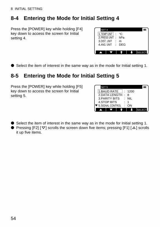
8-4 Entering the Mode for Initial Setting 4
Press the [POWER] key while holding [F4] key down to access the screen for Initialsetting 4.
● Select the item of interest in the same way as in the mode for Initial setting 1.
8-5 Entering the Mode for Initial Setting 5
Press the [POWER] key while holding [F5] key down to access the screen for Initialsetting 5.
● Select the item of interest in the same way as in the mode for Initial setting 1.● Pressing [F2] [ ] scrolls the screen down five items; pressing [F1] [ ] scrolls
it up five items.
SELECT
SET 4
1.TEMP UNIT : °C2.PRESS UNIT : hPa3.DIST. UNIT : m4.ANG. UNIT : DEG
SELECT
SET 5
1.BAUD RATE : 12002.DATA LENGTH : 83.PARITY BITS : NIL4.STOP BITS : 15.SIGNAL CONTROL : ON
55
8 INITIAL SETTING
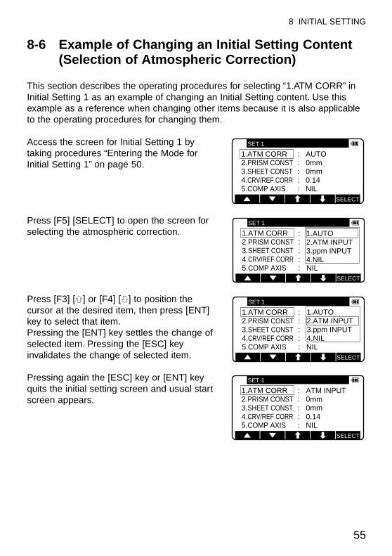
8-6 Example of Changing an Initial Setting Content(Selection of Atmospheric Correction)
This section describes the operating procedures for selecting “1.ATM CORR” inInitial Setting 1 as an example of changing an Initial Setting content. Use thisexample as a reference when changing other items because it is also applicableto the operating procedures for changing them.
Access the screen for Initial Setting 1 bytaking procedures “Entering the Mode forInitial Setting 1” on page 50.
Press [F5] [SELECT] to open the screen forselecting the atmospheric correction.
Press [F3] [g] or [F4] [h] to position thecursor at the desired item, then press [ENT]key to select that item.Pressing the [ENT] key settles the change ofselected item. Pressing the [ESC] keyinvalidates the change of selected item.
Pressing again the [ESC] key or [ENT] keyquits the initial setting screen and usual startscreen appears.
SELECT
SET 1
1.ATM CORR : AUTO2.PRISM CONST : 0mm3.SHEET CONST : 0mm4.CRV/REF CORR : 0.145.COMP AXIS : NIL
SELECT
SET 1
1.ATM CORR : AUTO2.PRISM CONST : 0mm3.SHEET CONST : 0mm4.CRV/REF CORR : 0.145.COMP AXIS : NIL
1.AUTO2.ATM INPUT3.ppm INPUT4.NIL
SELECT
SET 1
1.ATM CORR : AUTO2.PRISM CONST : 0mm3.SHEET CONST : 0mm4.CRV/REF CORR : 0.145.COMP AXIS : NIL
1.AUTO2.ATM INPUT3.ppm INPUT4.NIL
SELECT
SET 1
1.ATM CORR : ATM INPUT2.PRISM CONST : 0mm3.SHEET CONST : 0mm4.CRV/REF CORR : 0.145.COMP AXIS : NIL
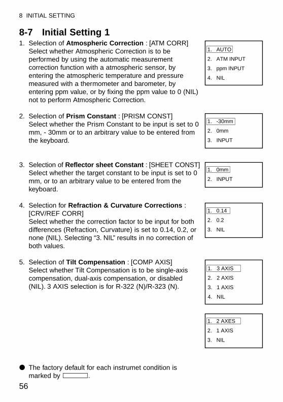
8-7 Initial Setting 11. Selection of Atmospheric Correction : [ATM CORR]
Select whether Atmospheric Correction is to beperformed by using the automatic measurementcorrection function with a atmospheric sensor, byentering the atmospheric temperature and pressuremeasured with a thermometer and barometer, byentering ppm value, or by fixing the ppm value to 0 (NIL)not to perform Atmospheric Correction.
2. Selection of Prism Constant : [PRISM CONST]Select whether the Prism Constant to be input is set to 0mm, - 30mm or to an arbitrary value to be entered fromthe keyboard.
3. Selection of Reflector sheet Constant : [SHEET CONST]Select whether the target constant to be input is set to 0mm, or to an arbitrary value to be entered from thekeyboard.
4. Selection for Refraction & Curvature Corrections :[CRV/REF CORR]Select whether the correction factor to be input for bothdifferences (Refraction, Curvature) is set to 0.14, 0.2, ornone (NIL). Selecting “3. NIL” results in no correction ofboth values.
5. Selection of Tilt Compensation : [COMP AXIS]Select whether Tilt Compensation is to be single-axiscompensation, dual-axis compensation, or disabled(NIL). 3 AXIS selection is for R-322 (N)/R-323 (N).
● The factory default for each instrumet condition ismarked by .
56
8 INITIAL SETTING
1. AUTO
2. ATM INPUT
3. ppm INPUT
4. NIL
1. 0mm
2. INPUT
1. -30mm
2. 0mm
3. INPUT
1. 0.14
2. 0.2
3. NIL
1. 2 AXES
2. 1 AXIS
3. NIL
1. 3 AXIS
2. 2 AXIS
3. 1 AXIS
4. NIL
57
8 INITIAL SETTING
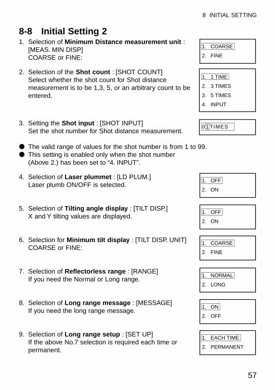
8-8 Initial Setting 21. Selection of Minimum Distance measurement unit :
[MEAS. MIN DISP]COARSE or FINE:
2. Selection of the Shot count : [SHOT COUNT]Select whether the shot count for Shot distancemeasurement is to be 1,3, 5, or an arbitrary count to beentered.
3. Setting the Shot input : [SHOT INPUT]Set the shot number for Shot distance measurement.
● The valid range of values for the shot number is from 1 to 99.● This setting is enabled only when the shot number
(Above 2.) has been set to “4. INPUT”.
4. Selection of Laser plummet : [LD PLUM.]Laser plumb ON/OFF is selected.
5. Selection of Tilting angle display : [TILT DISP.]X and Y tilting values are displayed.
6. Selection for Minimum tilt display : [TILT DISP. UNIT]COARSE or FINE:
7. Selection of Reflectorless range : [RANGE]If you need the Normal or Long range.
8. Selection of Long range message : [MESSAGE]If you need the long range message.
9. Selection of Long range setup : [SET UP]If the above No.7 selection is required each time orpermanent.
1. COARSE
2. FINE
1. NORMAL
2. LONG
1. ON
2. OFF
1. EACH TIME
2. PERMANENT
1. OFF
2. ON
1. OFF
2. ON
1. 1 TIME
2. 3 TIMES
3. 5 TIMES
4. INPUT
0 1 TIMES
1. COARSE
2. FINE
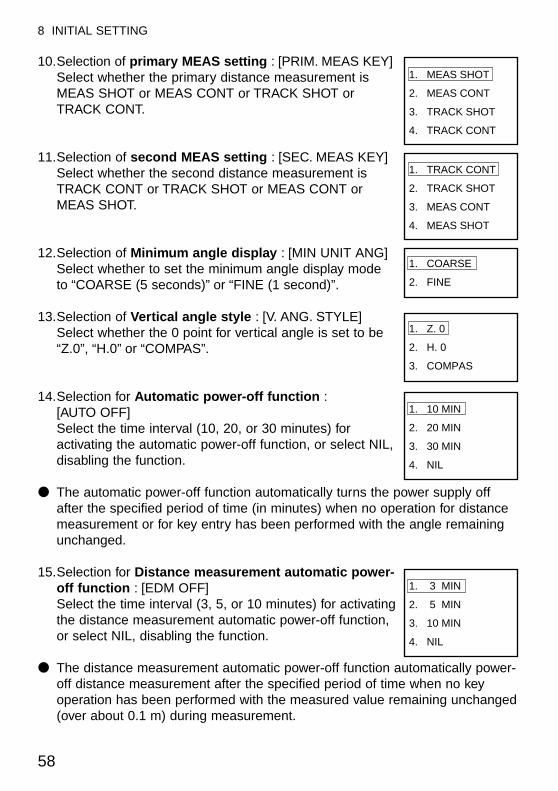
58
8 INITIAL SETTING
10.Selection of primary MEAS setting : [PRIM. MEAS KEY]Select whether the primary distance measurement isMEAS SHOT or MEAS CONT or TRACK SHOT orTRACK CONT.
11.Selection of second MEAS setting : [SEC. MEAS KEY]Select whether the second distance measurement isTRACK CONT or TRACK SHOT or MEAS CONT orMEAS SHOT.
12.Selection of Minimum angle display : [MIN UNIT ANG]Select whether to set the minimum angle display modeto “COARSE (5 seconds)” or “FINE (1 second)”.
13.Selection of Vertical angle style : [V. ANG. STYLE]Select whether the 0 point for vertical angle is set to be“Z.0”, “H.0” or “COMPAS”.
14.Selection for Automatic power-off function :[AUTO OFF]Select the time interval (10, 20, or 30 minutes) foractivating the automatic power-off function, or select NIL,disabling the function.
● The automatic power-off function automatically turns the power supply offafter the specified period of time (in minutes) when no operation for distancemeasurement or for key entry has been performed with the angle remainingunchanged.
15.Selection for Distance measurement automatic power-off function : [EDM OFF]Select the time interval (3, 5, or 10 minutes) for activatingthe distance measurement automatic power-off function,or select NIL, disabling the function.
● The distance measurement automatic power-off function automatically power-off distance measurement after the specified period of time when no keyoperation has been performed with the measured value remaining unchanged(over about 0.1 m) during measurement.
1. MEAS SHOT
2. MEAS CONT
3. TRACK SHOT
4. TRACK CONT
1. TRACK CONT
2. TRACK SHOT
3. MEAS CONT
4. MEAS SHOT
1. COARSE
2. FINE
1. Z. 0
2. H. 0
3. COMPAS
1. 10 MIN
2. 20 MIN
3. 30 MIN
4. NIL
1. 3 MIN
2. 5 MIN
3. 10 MIN
4. NIL
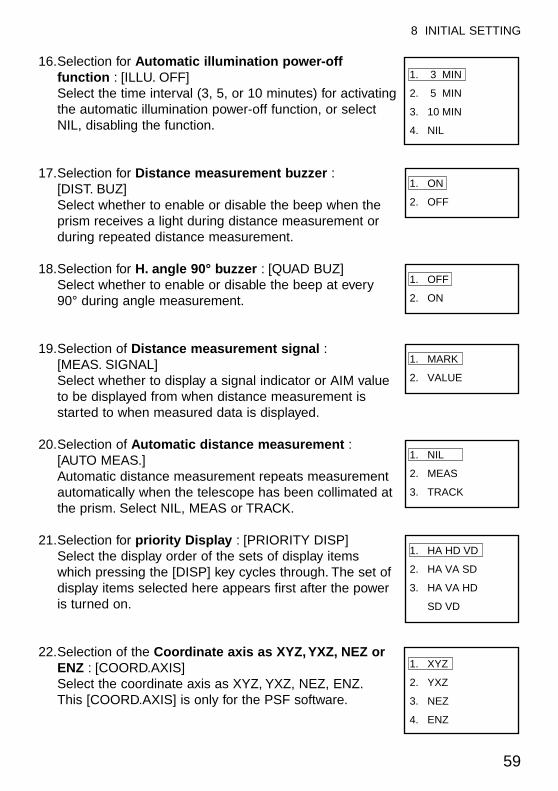
59
8 INITIAL SETTING
16.Selection for Automatic illumination power-offfunction : [ILLU. OFF]Select the time interval (3, 5, or 10 minutes) for activatingthe automatic illumination power-off function, or selectNIL, disabling the function.
17.Selection for Distance measurement buzzer :[DIST. BUZ]Select whether to enable or disable the beep when theprism receives a light during distance measurement orduring repeated distance measurement.
18.Selection for H. angle 90° buzzer : [QUAD BUZ]Select whether to enable or disable the beep at every90° during angle measurement.
19.Selection of Distance measurement signal :[MEAS. SIGNAL]Select whether to display a signal indicator or AIM valueto be displayed from when distance measurement isstarted to when measured data is displayed.
20.Selection of Automatic distance measurement :[AUTO MEAS.]Automatic distance measurement repeats measurementautomatically when the telescope has been collimated atthe prism. Select NIL, MEAS or TRACK.
21.Selection for priority Display : [PRIORITY DISP]Select the display order of the sets of display itemswhich pressing the [DISP] key cycles through. The set ofdisplay items selected here appears first after the poweris turned on.
22.Selection of the Coordinate axis as XYZ, YXZ, NEZ orENZ : [COORD.AXIS]Select the coordinate axis as XYZ, YXZ, NEZ, ENZ.This [COORD.AXIS] is only for the PSF software.
1. MARK
2. VALUE
1. NIL
2. MEAS
3. TRACK
1. HA HD VD
2. HA VA SD
3. HA VA HD
SD VD
1. 3 MIN
2. 5 MIN
3. 10 MIN
4. NIL
1. ON
2. OFF
1. OFF
2. ON
1. XYZ
2. YXZ
3. NEZ
4. ENZ
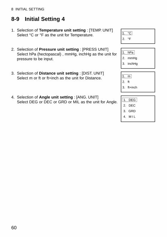
8-9 Initial Setting 4
1. Selection of Temperature unit setting : [TEMP. UNIT]Select °C or °F as the unit for Temperature.
2. Selection of Pressure unit setting : [PRESS UNIT]Select hPa (hectopascal) , mmHg, inchHg as the unit forpressure to be input.
3. Selection of Distance unit setting : [DIST. UNIT]Select m or ft or ft+inch as the unit for Distance.
4. Selection of Angle unit setting : [ANG. UNIT]Select DEG or DEC or GRD or MIL as the unit for Angle.
60
8 INITIAL SETTING
1. °C
2. °F
1. hPa
2. mmHg
3. inchHg
1. m
2. ft
3. ft+inch
1. DEG
2. DEC
3. GRD
4. M I L
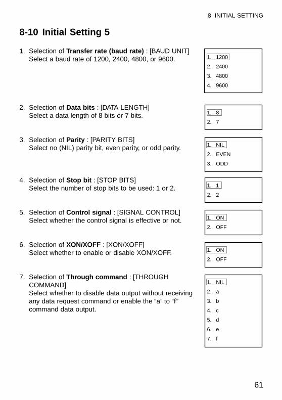
61
8 INITIAL SETTING
8-10 Initial Setting 5
1. Selection of Transfer rate (baud rate) : [BAUD UNIT]Select a baud rate of 1200, 2400, 4800, or 9600.
2. Selection of Data bits : [DATA LENGTH]Select a data length of 8 bits or 7 bits.
3. Selection of Parity : [PARITY BITS]Select no (NIL) parity bit, even parity, or odd parity.
4. Selection of Stop bit : [STOP BITS]Select the number of stop bits to be used: 1 or 2.
5. Selection of Control signal : [SIGNAL CONTROL]Select whether the control signal is effective or not.
6. Selection of XON/XOFF : [XON/XOFF]Select whether to enable or disable XON/XOFF.
7. Selection of Through command : [THROUGHCOMMAND]Select whether to disable data output without receivingany data request command or enable the “a” to “f”command data output.
1. 1200
2. 2400
3. 4800
4. 9600
1. 8
2. 7
1. NIL
2. EVEN
3. ODD
1. 1
2. 2
1. ON
2. OFF
1. ON
2. OFF
1. NIL
2. a
3. b
4. c
5. d
6. e
7. f
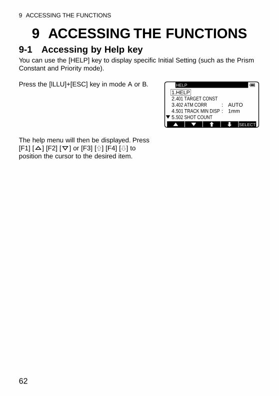
62
9 ACCESSING THE FUNCTIONS
9 ACCESSING THE FUNCTIONS9-1 Accessing by Help keyYou can use the [HELP] key to display specific Initial Setting (such as the PrismConstant and Priority mode).
Press the [lLLU]+[ESC] key in mode A or B.
The help menu will then be displayed. Press[F1] [ ] [F2] [ ] or [F3] [g] [F4] [h] toposition the cursor to the desired item.
SELECT
HELP
1.HELP2.401 TARGET CONST3.402 ATM CORR : AUTO4.501 TRACK MIN DISP : 1mm5.502 SHOT COUNT
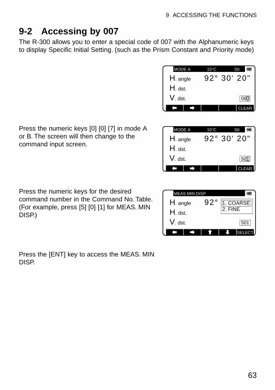
63
9 ACCESSING THE FUNCTIONS
9-2 Accessing by 007The R-300 allows you to enter a special code of 007 with the Alphanumeric keysto display Specific Initial Setting. (such as the Prism Constant and Priority mode)
Press the numeric keys [0] [0] [7] in mode Aor B. The screen will then change to thecommand input screen.
Press the numeric keys for the desiredcommand number in the Command No. Table.(For example, press [5] [0] [1] for MEAS. MINDISP.)
Press the [ENT] key to access the MEAS. MINDISP.
MODE A 15°C S0
000
CLEAR
H. angle 20"30'92°H. dst.
V. dst.
MODE A 15°C S0
501
CLEAR
H. angle 20"30'92°H. dst.
V. dst.
MEAS MIN DISP
501
H. angle 20"30'92°H. dst.
V. dst.
1. COARSE2. FINE
SELECT
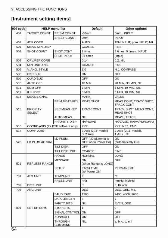
64
9 ACCESSING THE FUNCTIONS
[Instrument setting items]
007 code HELP menu list Default Other options401 TARGET CONST PRISM CONST -30mm 0mm, INPUT
SHEET CONST 0mm INPUT
402 ATM CORR AUTO ATM INPUT, ppm INPUT, NIL
501 MEAS. MIN DISP COARSE FINE
502 SHOT COUNT SHOT CONT 1 time 3 times, 5 times, INPUT
SHOT INPUT 01 times (input)
503 CRV/REF CORR 0.14 0.2, NIL
504 MIN UNIT ANG. COARSE FINE
505 V. ANG. STYLE Z.0 H.0, COMPASS
508 DIST.BUZ ON OFF
509 QUAD BUZ OFF ON
510 AUTO OFF 10 MIN 20 MIN, 30 MIN, NIL
511 EDM OFF 3 MIN 5 MIN, 10 MIN, NIL
512 ILLU.OFF 3 MIN 5 MIN, 10 MIN, NIL
514 MEAS.SIGNAL MARK VALUE
PRIM.MEAS KEY MEAS SHOT MEAS CONT, TRACK SHOT, TRACK CONT
515 PRIORITY SEC.MEAS KEY TRACK CONT TRACK SHOT, MEAS CONT, SELECT MEAS SHOT
AUTO MEAS. NIL MEAS., TRACK
PRIORITY DISP HA/HD/VD HA/VA/SD, HA/VA/HD/SD/VD
516 COORD.AXIS (for PSF software only) XYZ YXZ, NEZ, ENZ
517 COMP AXIS 3 Axis (2”/3” model) 2 Axis (2”/3” model), or 2 Axis 1 Axis , NIL
LD PLUM. OFF (LD plummet is ON 520 LD PLUM.&E.VIAL OFF when Power On) (automatically ON)
TILT DISP. OFF ON
TILT DISP.UNIT COARSE FINE
RANGE NORMAL LONG
MESSAGE ON OFF521 REF.LESS RANGE (when Range is LONG)
SETUP EACH TIME PERMANENT(w/ Power ON)
701 ATM UNIT TEMP.UNIT : °F
PRESS UNIT hPa mmHg, inchHg
702 DIST.UNIT m ft, ft+inch
703 ANG.UNIT DEG DEC, GRD, MIL
BAUD RATE 1200 2400, 4800, 9600
DATA LENGTH 8 7
PARITY BITS NIL EVEN, ODD
801 SET UP COM. STOP BITS 1 2
SIGNAL CONTROL ON OFF
XON/XOFF ON OFF
THROUGH NIL a, b, c, d, e, fCOMMAND
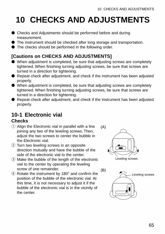
65
10 CHECKS AND ADJUSTMENTS
10 CHECKS AND ADJUSTMENTS● Checks and Adjustments should be performed before and during
measurement.● The instrument should be checked after long storage and transportation.● The checks should be performed in the following order.
[Cautions on CHECKS AND ADJUSTMENTS]● When adjustment is completed, be sure that adjusting screws are completely
tightened. When finishing turning adjusting screws, be sure that screws areturned in a direction for tightening.
● Repeat check after adjustment, and check if the instrument has been adjustedproperly.
● When adjustment is completed, be sure that adjusting screws are completelytightened. When finishing turning adjusting screws, be sure that screws areturned in a direction for tightening.
● Repeat check after adjustment, and check if the instrument has been adjustedproperly.
10-1 Electronic vialChecksq Align the Electronic vial in parallel with a line
joining any two of the leveling screws. Then,adjust the two screws to center the bubble inthe Electronic vial.
w Turn two leveling screws in an oppositedirection mutually and have the bubble of theside of the electronic vial to the center.
e Make the bubble of the length of the electronicvial to the center by operating the levelingscrew of one remainder.
r Rotate the instrument by 180° and confirm theposition of the bubble of the electronic vial. Atthis time, it is not necessary to adjust it if thebubble of the electronic vial is in the vicinity ofthe center.
(A)
(B)Leveling screws
Leveling screws
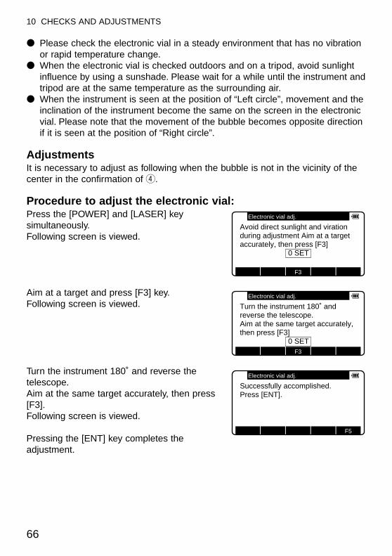
● Please check the electronic vial in a steady environment that has no vibrationor rapid temperature change.
● When the electronic vial is checked outdoors and on a tripod, avoid sunlightinfluence by using a sunshade. Please wait for a while until the instrument andtripod are at the same temperature as the surrounding air.
● When the instrument is seen at the position of “Left circle”, movement and theinclination of the instrument become the same on the screen in the electronicvial. Please note that the movement of the bubble becomes opposite directionif it is seen at the position of “Right circle”.
Adjustments It is necessary to adjust as following when the bubble is not in the vicinity of thecenter in the confirmation of r.
Procedure to adjust the electronic vial:Press the [POWER] and [LASER] keysimultaneously.Following screen is viewed.
Aim at a target and press [F3] key.Following screen is viewed.
Turn the instrument 180˚ and reverse thetelescope.Aim at the same target accurately, then press[F3].Following screen is viewed.
Pressing the [ENT] key completes theadjustment.
SELECTSELECTF3SELECTSELECT
Electronic vial adj.
Avoid direct sunlight and viration during adjustment Aim at a target accurately, then press [F3]
0 SET
SELECTSELECTF3SELECTSELECT
Electronic vial adj.
Turn the instrument 180˚ and reverse the telescope.Aim at the same target accurately, then press [F3]
0 SET
F5SELECTF3SELECTSELECT
Electronic vial adj.
Successfully accomplished.Press [ENT].
66
10 CHECKS AND ADJUSTMENTS
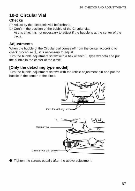
67
10 CHECKS AND ADJUSTMENTS
10-2 Circular VialChecksq Adjust by the electronic vial beforehand.w Confirm the position of the bubble of the Circular vial.
At this time, it is not necessary to adjust if the bubble is at the center of thecircle.
AdjustmentsWhen the bubble of the Circular vial comes off from the center according tocheck procedure w, it is necessary to adjust.Turn the bubble adjustment screw with a hex wrench (L type wrench) and put the bubble in the center of the circle.
[Only the detaching type model]Turn the bubble adjustment screws with the reticle adjustment pin and put thebubble in the center of the circle.
● Tighten the screws equally after the above adjustment.
Circular vial
Circular vial adj. screw
Circular vial adj. screw
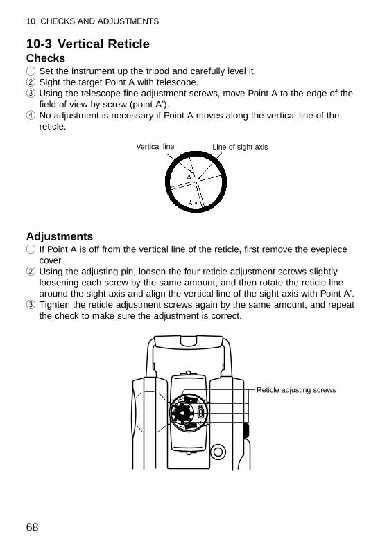
68
10 CHECKS AND ADJUSTMENTS
10-3 Vertical ReticleChecksq Set the instrument up the tripod and carefully level it.w Sight the target Point A with telescope.e Using the telescope fine adjustment screws, move Point A to the edge of the
field of view by screw (point A’).r No adjustment is necessary if Point A moves along the vertical line of the
reticle.
Adjustmentsq If Point A is off from the vertical line of the reticle, first remove the eyepiece
cover.w Using the adjusting pin, loosen the four reticle adjustment screws slightly
loosening each screw by the same amount, and then rotate the reticle linearound the sight axis and align the vertical line of the sight axis with Point A’.
e Tighten the reticle adjustment screws again by the same amount, and repeatthe check to make sure the adjustment is correct.
Vertical line Line of sight axis
Reticle adjusting screws
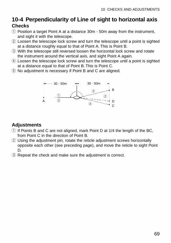
69
10 CHECKS AND ADJUSTMENTS
10-4 Perpendicularity of Line of sight to horizontal axisChecksq Position a target Point A at a distance 30m - 50m away from the instrument,
and sight it with the telescope.w Loosen the telescope lock screw and turn the telescope until a point is sighted
at a distance roughly equal to that of Point A. This is Point B.e With the telescope still reversed loosen the horizontal lock screw and rotate
the instrument around the vertical axis, and sight Point A again.r Loosen the telescope lock screw and turn the telescope until a point is sighted
at a distance equal to that of Point B. This is Point C.t No adjustment is necessary if Point B and C are aligned.
Adjustmentsq If Points B and C are not aligned, mark Point D at 1/4 the length of the BC,
from Point C in the direction of Point B.w Using the adjustment pin, rotate the reticle adjustment screws horizontally
opposite each other (see preceding page), and move the reticle to sight PointD.
e Repeat the check and make sure the adjustment is correct.
30 - 50m 30 - 50m
q
e
w
w
rA
B
DC
10-5 Vertical 0 point errorBe sure to follow check procedures mentioned below after making adjustmentson reticle and perpendicularity of line of sight to horizontal axis.
Checksq Set up the instrument and turn the power on.w Sight the telescope at any reference target A at Normale state. Read the
vertical angle ( γ ).e Turn the telescope and rotate the alidade. Sight the same target A again at
Back state and read the vertical angle R.r If γ+R = 360° , no further adjustment is necessary.
AdjustmentsIf the deviation d (γ+ R - 360° ) is wide, contact your local dealer.
70
10 CHECKS AND ADJUSTMENTS
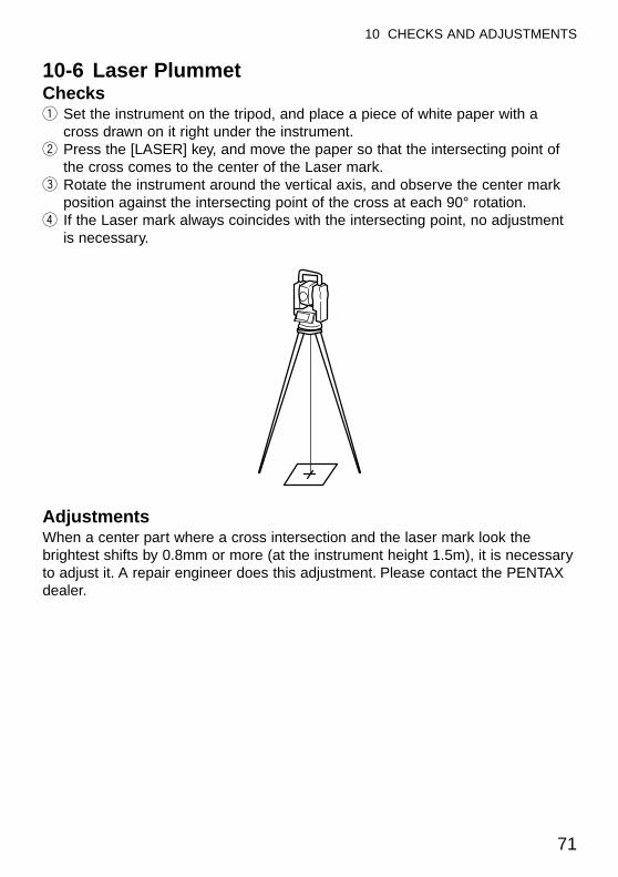
71
10 CHECKS AND ADJUSTMENTS
10-6 Laser PlummetChecksq Set the instrument on the tripod, and place a piece of white paper with a
cross drawn on it right under the instrument.w Press the [LASER] key, and move the paper so that the intersecting point of
the cross comes to the center of the Laser mark.e Rotate the instrument around the vertical axis, and observe the center mark
position against the intersecting point of the cross at each 90° rotation.r If the Laser mark always coincides with the intersecting point, no adjustment
is necessary.
AdjustmentsWhen a center part where a cross intersection and the laser mark look thebrightest shifts by 0.8mm or more (at the instrument height 1.5m), it is necessaryto adjust it. A repair engineer does this adjustment. Please contact the PENTAXdealer.
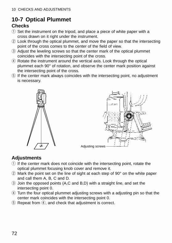
10-7 Optical PlummetChecksq Set the instrument on the tripod, and place a piece of white paper with a
cross drawn on it right under the instrument.w Look through the optical plummet, and move the paper so that the intersecting
point of the cross comes to the center of the field of view.e Adjust the leveling screws so that the center mark of the optical plummet
coincides with the intersecting point of the cross.r Rotate the instrument around the vertical axis. Look through the optical
plummet each 90° of rotation, and observe the center mark position againstthe intersecting point of the cross.
t If the center mark always coincides with the intersecting point, no adjustmentis necessary.
Adjustmentsq If the center mark does not coincide with the intersecting point, rotate the
optical plummet focusing knob cover and remove it.w Mark the point set on the line of sight at each step of 90° on the white paper
and call them A, B, C and D.e Join the opposed points (A,C and B,D) with a straight line, and set the
intersecting point 0.r Turn the four optical plummet adjusting screws with a adjusting pin so that the
center mark coincides with the intersecting point 0.t Repeat from r, and check that adjustment is correct.
72
10 CHECKS AND ADJUSTMENTS
Adjusting screws
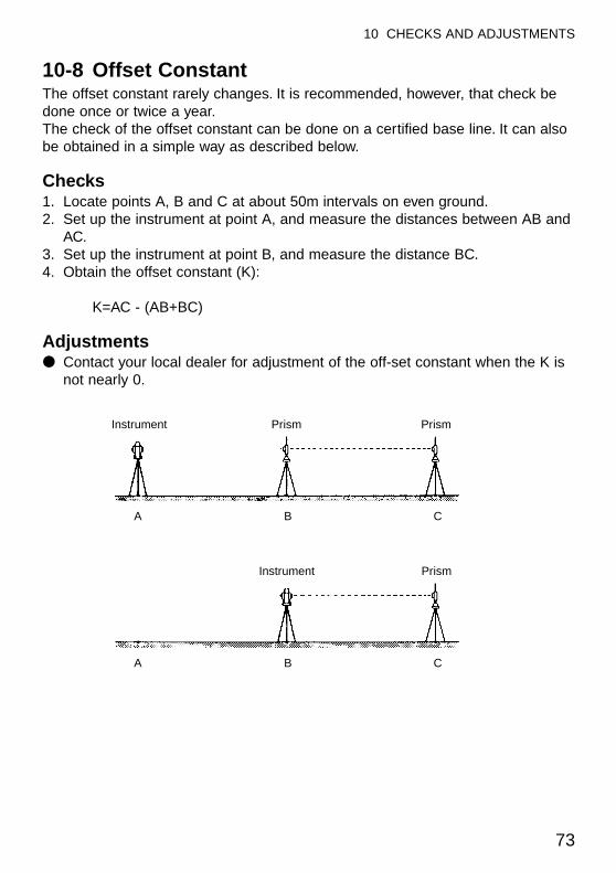
73
10 CHECKS AND ADJUSTMENTS
10-8 Offset ConstantThe offset constant rarely changes. It is recommended, however, that check bedone once or twice a year.The check of the offset constant can be done on a certified base line. It can alsobe obtained in a simple way as described below.
Checks1. Locate points A, B and C at about 50m intervals on even ground.2. Set up the instrument at point A, and measure the distances between AB and
AC.3. Set up the instrument at point B, and measure the distance BC.4. Obtain the offset constant (K):
K=AC - (AB+BC)
Adjustments● Contact your local dealer for adjustment of the off-set constant when the K is
not nearly 0.
Instrument Prism Prism
Instrument Prism
A B C
A B C
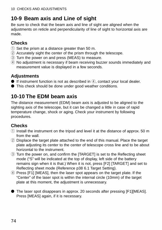
10-9 Beam axis and Line of sightBe sure to check that the beam axis and line of sight are aligned when theadjustments on reticle and perpendicularity of line of sight to horizontal axis aremade.
Checksq Set the prism at a distance greater than 50 m.w Accurately sight the center of the prism through the telescope.e Turn the power on and press (MEAS) to measure.r No adjustment is necessary if beam receiving buzzer sounds immediately and
measurement value is displayed in a few seconds.
Adjustments● If instrument function is not as described in r, contact your local dealer.● This check should be done under good weather conditions.
10-10 The EDM beam axisThe distance measurement (EDM) beam axis is adjusted to be aligned to thesighting axis of the telescope, but it can be changed a little in case of rapidtemperature change, shock or aging. Check your instrument by followingprocedures.
Checksq Install the instrument on the tripod and level it at the distance of approx. 50 m
from the wall.w Displace the target plate attached to the end of this manual. Place the target
plate adjusting its center to the center of telescope cross line and to be abouthorizontal to the instrument.
e Turn the power on, and confirm the [TARGET] is set to the Reflecting sheetmode (“S” will be indicated at the top of display, left side of the batteryremains sign when it is that.) When it is not, press [F2] [TARGET] and set toReflecting sheet mode (Reference p38 6.1 Target Setting).
r Press [F1] [MEAS], then the laser spot appears on the target plate. If the“Center” of the laser spot is within the internal circle (10mm) of the targetplate at this moment, the adjustment is unnecessary.
● The laser spot disappears in approx. 20 seconds after pressing [F1][MEAS].Press [MEAS] again, if it is necessary.
74
10 CHECKS AND ADJUSTMENTS
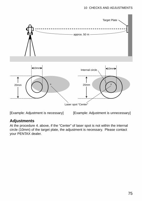
75
10 CHECKS AND ADJUSTMENTS
[Example: Adjustment is necessary] [Example: Adjustment is unnecessary]
AdjustmentsAt the procedure 4. above, if the “Center” of laser spot is not within the internalcircle (10mm) of the target plate, the adjustment is necessary. Please contactyour PENTAX dealer.
10mm
+ +20mm 20mm
10mm
Target Plate
approx. 50 m
Laser spot “Center”
Internal circle
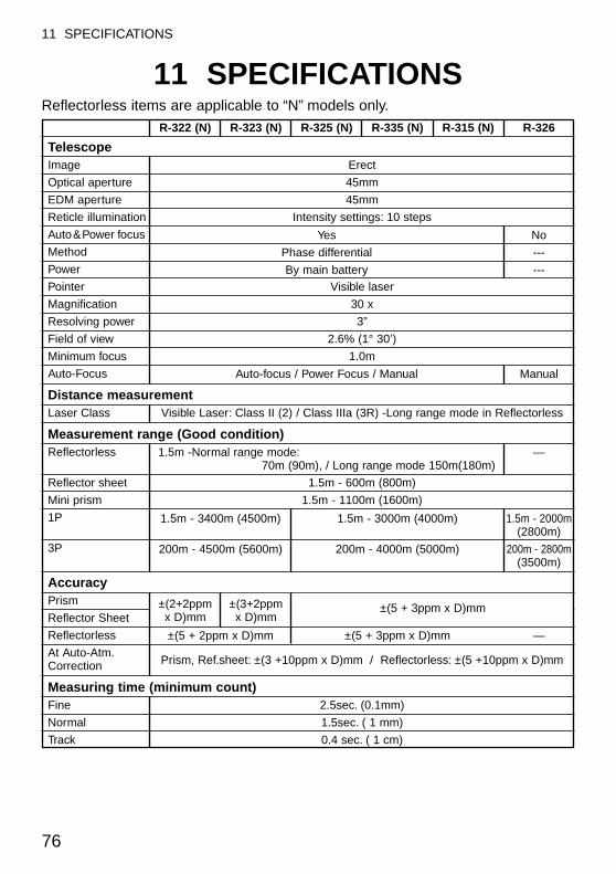
76
11 SPECIFICATIONS
11 SPECIFICATIONSReflectorless items are applicable to “N” models only.
TelescopeImage Erect
Optical aperture 45mm
EDM aperture 45mm
Reticle illumination Intensity settings: 10 steps
Auto&Power focus
Method
Power
Pointer Visible laser
Magnification 30 x
Resolving power 3”
Field of view 2.6% (1° 30’)
Minimum focus 1.0m
Auto-Focus
Distance measurementLaser Class Visible Laser: Class II (2) / Class IIIa (3R) -Long range mode in Reflectorless
Measurement range (Good condition)Reflectorless
Reflector sheet 1.5m - 600m (800m)
Mini prism 1.5m - 1100m (1600m)
1P
3P
AccuracyPrism
Reflector Sheet
Reflectorless
At Auto-Atm.Prism, Ref.sheet: ±(3 +10ppm x D)mm / Reflectorless: ±(5 +10ppm x D)mmCorrection
Measuring time (minimum count)Fine 2.5sec. (0.1mm)
Normal 1.5sec. ( 1 mm)
Track 0.4 sec. ( 1 cm)
Yes No
Phase differential ---
By main battery ---
Auto-focus / Power Focus / Manual Manual
1.5m -Normal range mode: —70m (90m), / Long range mode 150m(180m)
1.5m - 3400m (4500m) 1.5m - 3000m (4000m) 1.5m - 2000m(2800m)
200m - 4500m (5600m) 200m - 4000m (5000m) 200m - 2800m(3500m)
±(5 + 2ppm x D)mm ±(5 + 3ppm x D)mm —
R-322 (N) R-323 (N) R-325 (N) R-335 (N) R-315 (N) R-326
±(2+2ppm x D)mm
±(3+2ppm x D)mm
±(5 + 3ppm x D)mm
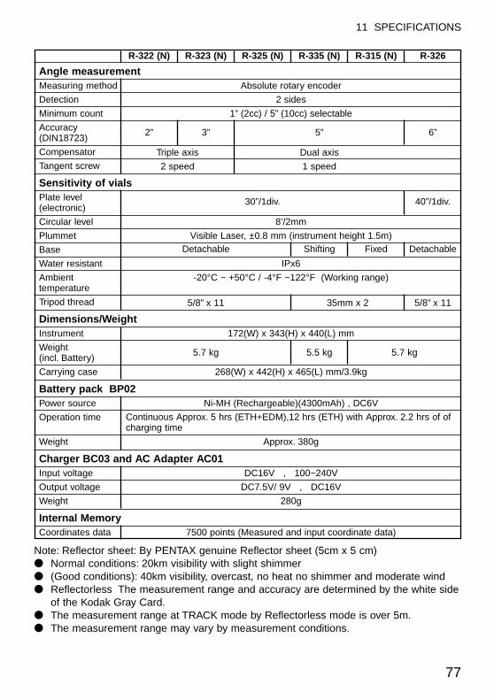
77
11 SPECIFICATIONS
Angle measurementMeasuring method Absolute rotary encoder
Detection 2 sides
Minimum count 1” (2cc) / 5” (10cc) selectable
Accuracy(DIN18723)
Compensator
Tangent screw
Sensitivity of vialsPlate level (electronic)
Circular level 8’/2mm
Plummet Visible Laser, ±0.8 mm (instrument height 1.5m)
Base
Water resistant IPx6
Ambient -20°C ~ +50°C / -4°F ~122°F (Working range)temperature
Tripod thread
Dimensions/WeightInstrument 172(W) x 343(H) x 440(L) mm
Weight (incl. Battery)
Carrying case 268(W) x 442(H) x 465(L) mm/3.9kg
Battery pack BP02Power source Ni-MH (Rechargeable)(4300mAh) , DC6V
Operation time
Weight Approx. 380g
Charger BC03 and AC Adapter AC01Input voltage DC16V , 100~240V
Output voltage DC7.5V/ 9V , DC16V
Weight 280g
Internal MemoryCoordinates data 7500 points (Measured and input coordinate data)
2” 3” 5” 6”
Triple axis Dual axis
2 speed 1 speed
30”/1div. 40”/1div.
Detachable
5/8” x 11 35mm x 2 5/8” x 11
5.7 kg 5.5 kg 5.7 kg
Shifting Fixed Detachable
R-322 (N) R-323 (N) R-325 (N) R-335 (N) R-315 (N) R-326
Continuous Approx. 5 hrs (ETH+EDM),12 hrs (ETH) with Approx. 2.2 hrs of ofcharging time
Note: Reflector sheet: By PENTAX genuine Reflector sheet (5cm x 5 cm)● Normal conditions: 20km visibility with slight shimmer● (Good conditions): 40km visibility, overcast, no heat no shimmer and moderate wind● Reflectorless The measurement range and accuracy are determined by the white side
of the Kodak Gray Card.● The measurement range at TRACK mode by Reflectorless mode is over 5m.● The measurement range may vary by measurement conditions.

78
12 DATA COLLECTOR
12 DATA COLLECTORThe instrument can communicate directly with a computer through the RS232Cinterface. By use of a data collector you can automate data entry from thecollection of survey data to the transfer of the data to a computer. This is useful insaving time and protecting data integrity.
● About connection with data collector and the handling, please refer to an“Instruction manual” of the data collector.
● Connecting a data collector to a computer is different with every system.Please contact your local dealer about them.
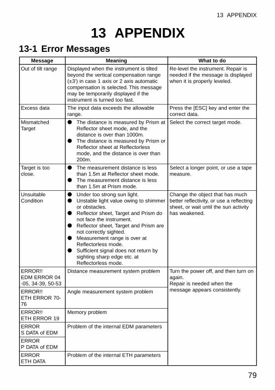
79
13 APPENDIX
13 APPENDIX13-1 Error Messages
Message
Out of tilt range
Excess data
MismatchedTarget
Target is tooclose.
UnsuitableCondition
ERROR!!EDM ERROR 04-05, 34-39, 50-53
ERROR!!ETH ERROR 70-76
ERROR!!ETH ERROR 19
ERRORS DATA of EDM
ERRORP DATA of EDM
ERRORETH DATA
Meaning
Displayed when the instrument is tiltedbeyond the vertical compensation range(±3') in case 1 axis or 2 axis automaticcompensation is selected. This messagemay be temporarily displayed if theinstrument is turned too fast.
The input data exceeds the allowablerange.
● The distance is measured by Prism atReflector sheet mode, and thedistance is over than 1000m.
● The distance is measured by Prism orReflector sheet at Reflectorlessmode, and the distance is over than200m.
● The measurement distance is lessthan 1.5m at Reflector sheet mode.
● The measurement distance is lessthan 1.5m at Prism mode.
● Under too strong sun light.● Unstable light value owing to shimmer
or obstacles.● Reflector sheet, Target and Prism do
not face the instrument.● Reflector sheet, Target and Prism are
not correctly sighted.● Measurement range is over at
Reflectorless mode.● Sufficient signal does not return by
sighting sharp edge etc. atReflectorless mode.
Distance measurement system problem
Angle measurement system problem
Memory problem
Problem of the internal EDM parameters
Problem of the internal ETH parameters
What to do
Re-level the instrument. Repair isneeded if the message is displayedwhen it is properly leveled.
Press the [ESC] key and enter thecorrect data.
Select the correct target mode.
Select a longer point, or use a tapemeasure.
Change the object that has muchbetter reflectivity, or use a reflectingsheet, or wait until the sun activityhas weakened.
Turn the power off, and then turn onagain.Repair is needed when themessage appears consistently.
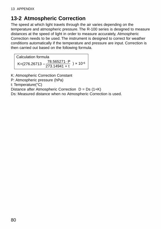
13-2 Atmospheric CorrectionThe speed at which light travels through the air varies depending on thetemperature and atmospheric pressure. The R-100 series is designed to measuredistances at the speed of light in order to measure accurately, AtmosphericCorrection needs to be used. The instrument is designed to correct for weatherconditions automatically if the temperature and pressure are input. Correction isthen carried out based on the following formula.
Calculation formula
K=(276.26713 –78.565271· P ) × 10-6
273.14941 + t
K: Atmospheric Correction Constant P: Atmospheric pressure (hPa) t: Temperature(°C) Distance after Atmospheric Correction D = Ds (1+K) Ds: Measured distance when no Atmospheric Correction is used.
80
13 APPENDIX
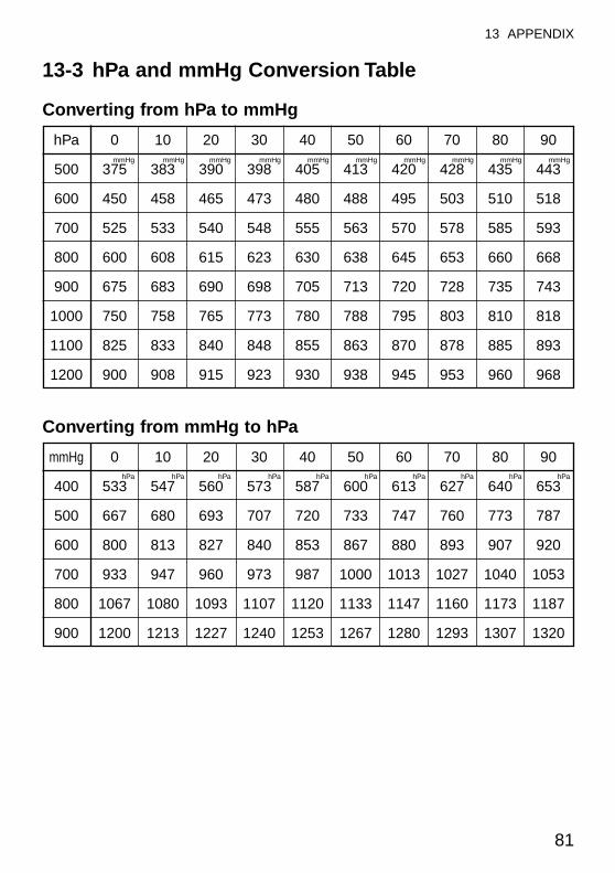
81
13 APPENDIX
13-3 hPa and mmHg Conversion Table
Converting from hPa to mmHg
hPa 0 10 20 30 40 50 60 70 80 90mmHg mmHg mmHg mmHg mmHg mmHg mmHg mmHg mmHg mmHg
500 375 383 390 398 405 413 420 428 435 443
600 450 458 465 473 480 488 495 503 510 518
700 525 533 540 548 555 563 570 578 585 593
800 600 608 615 623 630 638 645 653 660 668
900 675 683 690 698 705 713 720 728 735 743
1000 750 758 765 773 780 788 795 803 810 818
1100 825 833 840 848 855 863 870 878 885 893
1200 900 908 915 923 930 938 945 953 960 968
Converting from mmHg to hPa
mmHg 0 10 20 30 40 50 60 70 80 90hPa hPa hPa hPa hPa hPa hPa hPa hPa hPa
400 533 547 560 573 587 600 613 627 640 653
500 667 680 693 707 720 733 747 760 773 787
600 800 813 827 840 853 867 880 893 907 920
700 933 947 960 973 987 1000 1013 1027 1040 1053
800 1067 1080 1093 1107 1120 1133 1147 1160 1173 1187
900 1200 1213 1227 1240 1253 1267 1280 1293 1307 1320
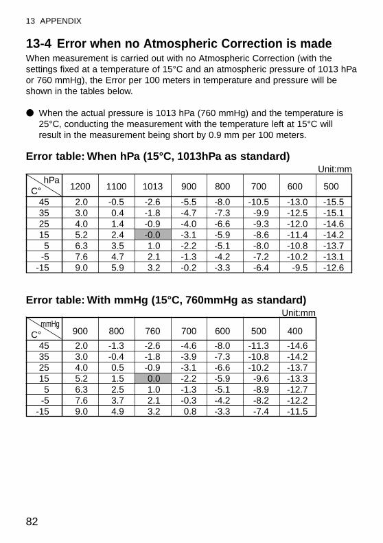
82
13 APPENDIX
13-4 Error when no Atmospheric Correction is madeWhen measurement is carried out with no Atmospheric Correction (with thesettings fixed at a temperature of 15°C and an atmospheric pressure of 1013 hPaor 760 mmHg), the Error per 100 meters in temperature and pressure will beshown in the tables below.
● When the actual pressure is 1013 hPa (760 mmHg) and the temperature is25°C, conducting the measurement with the temperature left at 15°C willresult in the measurement being short by 0.9 mm per 100 meters.
Error table: When hPa (15°C, 1013hPa as standard)Unit:mm
hPa1200 1100 1013 900 800 700 600 500C°
45 2.0 -0.5 -2.6 -5.5 -8.0 -10.5 -13.0 -15.535 3.0 0.4 -1.8 -4.7 -7.3 -9.9 -12.5 -15.1 25 4.0 1.4 -0.9 -4.0 -6.6 -9.3 -12.0 -14.6 15 5.2 2.4 -0.0 -3.1 -5.9 -8.6 -11.4 -14.2 5 6.3 3.5 1.0 -2.2 -5.1 -8.0 -10.8 -13.7
-5 7.6 4.7 2.1 -1.3 -4.2 -7.2 -10.2 -13.1 -15 9.0 5.9 3.2 -0.2 -3.3 -6.4 -9.5 -12.6
Error table: With mmHg (15°C, 760mmHg as standard)Unit:mm
mmHg900 800 760 700 600 500 400C°
45 2.0 -1.3 -2.6 -4.6 -8.0 -11.3 -14.635 3.0 -0.4 -1.8 -3.9 -7.3 -10.8 -14.225 4.0 0.5 -0.9 -3.1 -6.6 -10.2 -13.715 5.2 1.5 0.0 -2.2 -5.9 -9.6 -13.35 6.3 2.5 1.0 -1.3 -5.1 -8.9 -12.7
-5 7.6 3.7 2.1 -0.3 -4.2 -8.2 -12.2-15 9.0 4.9 3.2 0.8 -3.3 -7.4 -11.5
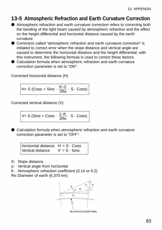
83
13 APPENDIX
13-5 Atmospheric Refraction and Earth Curvature Correction● Atmospheric refraction and earth curvature correction refers to correcting both
the bending of the light beam caused by atmospheric refraction and the effecton the height differential and horizontal distance caused by the earthcurvature.
● Correction called “atmospheric refraction and earth curvature correction” isinitiated to correct error when the slope distance and vertical angle arecaused to determine the horizontal distance and the height differential, withthis instrument, the following formula is used to correct these factors.
● Calculation formula when atmospheric refraction and earth curvaturecorrection parameter is set to “ON”:
Corrected horizontal distance (H)
Corrected vertical distance (V)
● Calculation formula when atmospheric refraction and earth curvaturecorrection parameter is set to “OFF”:
S: Slope distance α: Vertical angle from horizontal K: Atmospheric refraction coefficient (0.14 or 0.2) Re: Diameter of earth (6,370 km)
Horizontal distance H' = S · CosαVertical distance V' = S · Sinα
V= S (Sinα + Cosα · 1–K · S · Cosα)2Re
H= S (Cosα + Sinα · K–2
· S · Cosα)2Re
84
13 APPENDIX
84
13-6 Distance RangeGenerally speaking, the maximum range which can be measured variesconsiderably depending on the atmospheric conditions. For this reason, theSpecifications illustrate the values for both Good and Normal weather conditions.It is extremely difficult to judge when weather conditions are “Good” and whenthey are “Normal”. With this instrument, the conditions noted below are used todifferentiate between the two situations, (Good weather conditions for surveyingare different from Normal weather conditions, and in surveying situations, cloudyskies are considered more favorable than sunny skies.)
Weather conditions for measurement ranges are based on the following standardvalues:
Normal: Visibility of approximately 20 km, with slight shimmer and moderatewind.Good: Visibility of approximately 40 km, overcast, with no shimmer and
moderate wind.
85
14 NOTICE TO THE USER OF THIS PRODUCT
14 NOTICE TO THE USER OF THISPRODUCT
To assure compliance with the Safety standard 21 CFR, Chapter 1. Subchapter J.The U.S. bureau of Radiological Health requires the following information to beprovided to user.:
It can be dangerous to look into the beam with optical equipment such asbinoculars and telescopes.
1) Specifications of Laser RadiationA) The EDM module of the R-300 produces a visible light beam, which is
emitted from the telescope objective lens and the center hole of theinstrument base plate. The R-300 is designed and built to have a laserdiode radiating at 620-690 nm.
B) Radiant powerThe R-300 is designed and built to radiate a maximum average radiantpower of 4.75mw. (0.95mw for the model without “N”) from the telescope,and 0.95mw from the center hole of the base plate. The user may besubject to this radiation as a beam while operation until such time that theinstrument is turned off.
2) The following labels are affixed to and must remain attached to this laser product.A) The following Certification label is located near the Plate level.:
“This laser product is complied with the provisions of 21 CFR 1040. 10 and1040.11. For a Class II laser product.”Or for R-300 N models:“This laser product is complied with the provisions of 21 CFR 1040. 10 and1040.11. For a Class IIIa laser product.”
B) Caution label is located near the exit aperture :“AVOID EXPOSURE Laser radiation is emitted from this aperture.”
C) Warning logotype is located on the surface of the telescope:“CAUTION LASER RADIATION DO NOT STARE INTO BEAM”Or for R-300 N models:“DANGER LASER RADIATION AVOID DIRECT EYE EXPOSURE”
D) Warning label is Located near the exit aperture.3) Caution to maintain the safety in compliance with the standard
A) To maintain the safety standard, refrain from any operation, maintenance,or adjustment other than described in this instruction manual.
B) Operation, maintenance or adjustment other than those specified in thisinstruction manual may result in hazardous radiation exposure.
C) Maintenance and repair not covered in this manual must be done by anauthorized Pentax dealer.
D) The Laser beam emission by the Distance measurement can beterminated by pressing F1 MEAS key.
E) Pressing Laser key → F2 LD POINT key can terminate the laser beamemission by the laser pointer.
F) The Laser beam emission by the Laser plummet can be terminated bypressing Laser key.
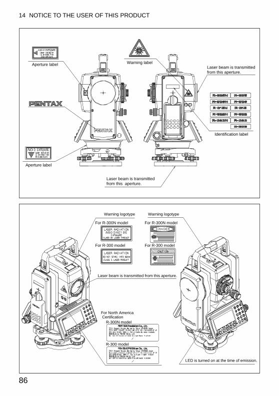
Laser beam is transmitted from this aperture.
Warning logotype
For R-300N model
For R-300 model
For R-300N model
For R-300 model
For North AmericaCertification
R-300N model
R-300 model
LED is turned on at the time of emission.
Warning logotype
86
14 NOTICE TO THE USER OF THIS PRODUCT
Laser beam is transmitted from this aperture.
Identification label
Warning labelAperture label
Aperture label
Laser beam is transmitted from this aperture.
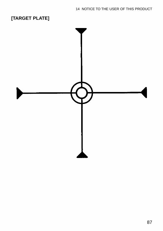
87
14 NOTICE TO THE USER OF THIS PRODUCT
[TARGET PLATE]


2-5-2, Higashi-Oizumi, Nerima-ku,Tokyo, 178-8555, Japan
Tel: +81-3-5905-1222Fax:+81-3-5905-1225
®
Member symbol of the Japan Surveying Instruments Manufacturers’ Association representing the high quality surveying products.
10.2002 First Edition02.2003 Second Edition
TS01101E
Related Documents