Electronic Throttle Control by Ivan Ng Heng Guan Dissertation submitted in partial fulfillment of the requirements for the Bachelor of Engineering (Hons) (Electrical & Electronics) JUNE2009 Universiti Teknologi PETRONAS Bandar Seri Iskandar 31750 Tronoh Perak Darul Ridzuan

Welcome message from author
This document is posted to help you gain knowledge. Please leave a comment to let me know what you think about it! Share it to your friends and learn new things together.
Transcript

Electronic Throttle Control
by
Ivan Ng Heng Guan
Dissertation submitted in partial fulfillment of
the requirements for the
Bachelor of Engineering (Hons)
(Electrical & Electronics)
JUNE2009
Universiti Teknologi PETRONAS
Bandar Seri Iskandar
31750 Tronoh
Perak Darul Ridzuan

Approved by,
CERTIFICATION OF APPROVAL
Electronic Throttle Control
by
Ivan Ng Heng Guan
A project dissertation submitted to the Electrical & Electronics Engineering Programme
Universiti Teknologi PETRONAS in partial fulfillment of the requirement for the
BACHELOR OF ENGINEERING (Hons) (ELECTRICAL & ELECTRONICS ENGINEERING)
(Assoc. of. Dr. Mohd Noh Bin Karsiti) Project Supervisor
UNIVERSITI TEKNOLOGI PETRONAS
TRONOH, PERAK
JUNE2009
11

CERTIFICATION OF ORIGINALITY
This is to certify that I am responsible for the work submitted in this project, that the
original work is my own except as specified in the references and acknowledgements,
and that the original work contained herein have not been undertaken or done by
unspecified sources or persons.
111

ABSTRACT
Electronic Throttle Control (ETC) is becoming an important part of automotive industry
today. Also known as the Drive-By-Wire technology, applied to our daily life, it can
result in an efficient throttle body controlling improving fuel efficiency, handling and
ride comfort in an automobile. The objective of the project is to understand where the
future of electronic control in the automotive industry is going due to advances in
technology. The main focus of the project is focused on controlling the position of the
throttle opening also known as the "butterfly". For this purpose, a remote controlled
(RC) servomotor was used for positioning, the "butterfly" opening. The RC servomotor
will be controlled by a PIC microcontroller with the fastest response it can achieve. For
error detection purpose, a feedback signal will be sent back to the microcontroller via a
throttle positioning sensor (TPS) to be analyzed. With existing feedback data, the
microcontroller would be able to correct the error significantly.
IV

ACKNOWLEDGEMENTS
Foremost, I would like to express my sincere gratitude to my project supervisor Assoc.
Prof. Dr. Mohd Noh Karsiti for the continuous support of my final year project, for his
patience, motivation, enthusiasm and immense knowledge. His guidance helped me in
all the time of research and writing of this thesis.
I also thank my fellow coursemates and technician in Universiti Teknologi PETRONAS
who helped me whenever they can. Without them, I would not been inspired doing my
work.
Last but not the least, I would like to thank my family and friends for giving me the
moral support, supporting me spiritually throughout my life.
v

TABLE OF CONTENTS
CERTIFICATION OF APPROVAL ............................................................................. ii
CERTIFICATION OF ORIGINALITY ....................................................................... iii
ABSTRACT ................................................................................................................. iv
ACKNOWLEDGEMENTS .......................................................................................... v
LIST OF FIGURE ...................................................................................................... viii
LIST OF TABLE .......................................................................................................... ix
LIST OF ABBREVIATIONS ....................................................................................... x
CHAPTER 1 .................................................................................................................. 1
1.1 Background of Study ......................................................................................... 1
1.2 Problem Statement ............................................................................................. 3
1.2.1 Problem Identification ................................................................................ 3
1.2.2 Significant of The Project ........................................................................... 3
1.3 Objective and Scope of Study ............................................................................ 4
1.3.1 Relevance of The Project.. .......................................................................... 4
1.3.2 Feasibility of The Project Within Scope and Time Frame ......................... 4
CHAPTER2 .................................................................................................................. 5
2.1 Theory ................................................................................................................ 5
2.2 Electronic Throttle Body ................................................................................... 6
2.3 Case Study on Vacuum Outlet from Throttle Bodies ........................................ 7
2.4 Open-Loop Control versus Close-Loop Control ............................................... 8
2.5 Throttle Position Sensor (fPS) .......................................................................... 9
2.6 RC Servo Motor ............................................................................................... 11
CHAPTER 3 ................................................................................................................ 13
3.1 Research Methodology .................................................................................... 13
3.2 MATLAB Simulink ......................................................................................... 15
3.3 Gear Set. ........................................................................................................... 15
3.4 PIC Microcontrollers ....................................................................................... 16
3.5 Project Activities .............................................................................................. 17
3.6 Tools ................................................................................................................ 18
VI

CHAPTER 4 ................................................................................................................ 19
4.1 Results .............................................................................................................. 19
4.1.1 MATLAB Simulink ................................................................................. 19
4.1.2 Gear ratio .................................................................................................. 23
4.1.3 Controller Circuit. ..................................................................................... 25
4.1.4 Programming the PIC controller ............................................................... 26
4.2 Throttle Position Sensor (TPS) ........................................................................ 27
4.3 Discussion ........................................................................................................ 28
CHAPTER 5 ................................................................................................................ 30
5.1 Conclusions and Recommendations ................................................................ 30
REFERENCES ............................................................................................................ 32
APPENDIX I : GANTT CHART ................................................................................ 35
APPENDIX II : PICTURES ........................................................................................ 37
APPENDIX III: SANWA SX-01 SERVO .................................................................. 38
APPENDIX IV: MATLAB THROTTLE MODEL .................................................... 39
APPENDIX V: PROGRAM CODE ............................................................................ 40
APPENDIX VI: PIC MICROPROCESSOR PINS & SPECIFICATION .................. 42
APPENDIX VII: SCHEMATIC DIAGRAM AND COMPONENT USED .............. 44
APPENDIX VIII: DATA SHEET FOR 74LS147 8-T0-3 LINE ENCODER ........... 45
APPENDIX IX: PICTURE OF THE PROTOTYPE MODEL ................................... 47
vii

LIST OF FIGURE
Figure 1: Electronic Throttle Body ................................................................................... 6
Figure 2: Electronic Throttle System ................................................................................ 7
Figure 3: Daihatsu Detomaso Vacuum outlets ................................................................. 8
Figure 4: Closed-Loop System ......................................................................................... 9
Figure 5: Open-Loop System ........................................................................................... 9
Figure 6 : Throttle Position Sensor Circuit... .................................................................. 10
Figure 7 : Graph of Resistance over time ....................................................................... 10
Figure 8: RC Servo Block Diagram ............................................................................... 11
Figure 9: RC servo functional block diagram ................................................................ 12
Figure 10: RC Servo control signal ................................................................................ 12
Figure 11: Process Flow Diagram .................................................................................. 13
Figure 12: Simple model ................................................................................................ 14
Figure 13: Gear Set. ........................................................................................................ 15
Figure 14: RC Servo Models .......................................................................................... 19
Figure 15: RC Servo Response without PID .................................................................. 20
Figure 16: RC Servo Response With PID ...................................................................... 21
Figure 17:ETC model with RC Servo ............................................................................ 21
Figure 18: Ideal Response of ETC ................................................................................. 22
Figure 19: Response of ETC with parameter set ............................................................ 23
Figure 20 : Controller Circuit Schematic ....................................................................... 25
Figure 21: Controller Flow Chart ................................................................................... 26
Figure 22: Gear set ......................................................................................................... 28
viii

LIST OF TABLE
Table 1: Physical condition of a throttle body ................................................................ 22
Table 2: Coding of the IPS corresponding to the angle ................................................ 27
ix

LIST OF ABBREVIATIONS
ETC Electronic Throttle Control
ECM Electronic Control Module
ECU Engine Control Unit
RC Remote Control
TPS Throttle Position Sensor
WOT Wide-Open Throttle
UTP Universiti Teknologi Petronas
EE Electrical & Electronics Engineering
PIC Programmable Interface Computer
ADC Analogue-to-Digital Converter
SPDT Single-Pole, Double-Throw
LED Light Emitting Diode
PWM Pulse-Width-Modulation
PPS Pedal Position Sensor
X

CHAPTER! INTRODUCTION
1.1 Background of Study
Electronic Throttle Control (ETC) has been around for the past 25 years. Also
known as the "Drive-By-Wire" system, it was first introduced by the British on their
military aircraft in the 60s called the "Fly-By-Wire" [1]. Nowadays, most high-end cars
use this system to enhance driver's experience which is to reduce fuel consumption by
controlling the amount of air-to-fuel ratio into the engine. Since there is also ruling in
emission gases nowadays, electronic throttle control is a way to ensure that harmful
exhaust emissions are kept to absolute minimum and drivability is maintained,
regardless of any circumstances [2].
Throttle control has been used widely not only in the automotive industry, but
also in industry like aviation, machinery and hobbyist product. In the automotive
industry, it is traditionally accomplished by a physical connection between the throttle
pedal and the throttle body which controls the engine airflow. This project is important
to understand where the future of electronic control is going due to advances in
technology and the need for all parts of the automobile to communicate with each other.
Electronic control in automotive allows engine, transmission, brakes, just to name a
few, to work together to achieve a much faster response to the driver's needs. With this
communication system, the electronic components could work closely with the
mechanical components to achieve a bright result.
I

In a drive-by-wire car, a microcontroller determines the correct throttle plate
position. If the driver needs sudden acceleration and steps on the accelerator pedal, the
sensor on the pedal transmits the driver's pressure on the pedal to the microcontroller,
which calculates and relays the correct throttle position to the motor, which moves the
butterfly opening accordingly. Electronic control of the butterfly opening offers
improved fuel economy and emissions by maintaining optimal throttle conditions at all
times, which is something human driver cannot do.
Since this project deals with throttle bodies, it is important to know about
throttle bodies and how they work. The functions of the vacuum connectors on throttle
bodies are also studied.
The idea of this project is to control a throttle electronically, therefore it is
important to know about engines and motors and how they actually works [3]. RC servo
was chosen due to its close-loop control system where feedback from the output can be
used for error detection. Compared to a stepper motor, it is very suitable for position
control where the control movements are much smoother [4]. Programmed to a
programming interface chip (PIC) with more than I 000 resolution control, the
servomotor should control the "butterfly" opening of the throttle precisely.
2

1.2 Problem Statement
1.2.1 Problem Identification
Since most of us demand for a car which is fuel efficient and meets gas emission
standards, car manufacturer had been finding ways to built them. There are many
attempts to solve this issue, for example, building smaller cars, hybrid cars or even
lighter cars. Through my experience, a car could also waste more energy depending on
the driver's driving lifestyle. Since it is difficult to change a driver's habit in driving,
Electronic Throttle Control (ETC) also known as Drive-by-Wire technology was
introduced. The concept of this is to control the "butterfly" opening on a throttle to
maximize the percentage of combustion in the engine. Since most car throttle
communicates with the Engine Control Unit (ECU), the angle of the "butterfly" opening
could be important information for the ECU for better efficiency and response.
1.2.2 Significant of The Project
In fuel injection systems, when the air-to-fuel ratio is poor, the amount of fuel
going into the engine will exceed the amount of air required for a complete combustion
[5]. When cases like this happen, incomplete combustion will occur causing wastage of
fuel supplied. This would not only effect the poor emission of the vehicle, but also
effect the poor fuel consumption and performance of the vehicle. Due to this weakness
in mechanical throttles, Electronic Throttle Control (ETC) is introduced to eliminate
such cases. With the flow controlled into the engine monitored precisely, the
consumption and performance of a vehicle could be monitored closely.
3

1.3 Objective and Scope of Study
1.3.1 Relevance of The Project
The main objective of this project is to build a functional Electronic Throttle
Control system and study its control element in the process. This will be accomplished
by building a prototype model of an ETC monitored with an aid of a throttle response
simulator built.
1.3.2 Feasibility of The Project Within Scope and Time Frame
The project work involves simulation and control. It has to be completed within
two final semesters, 28 weeks. The first semester covers mostly literature reviews of
written materials on the topic and a simulation. While in the second semester, a
prototype model is constructed. The allocated time frame is reasonable.
4

2.1 Theory
CHAPTER2 LITERATURE REVIEW & THEORY
Getting started with a project, it is important to conduct research to understand
about the project more. This project started by researching on the weaknesses faced by
mechanically driven throttles and what has been done to solve the issues. Knowing the
objective of this project, the throttle body of an engine was studied closely. With
condition which would affect a throttle's response, a simulator was modeled to study its
response towards its physical condition. This was important for us to build a throttle
which is responsive. Research was done on the throttle body on how it controls the air
intake into an engine at desired condition.
Since Electronic Throttle Control (ETC) has been around, research was also
done on it especially on why a DC servomotor is chosen over other motors. Due to this,
focus was moved to understanding how a motor works and how to control them. This
was important to determine the type of motor which is best used for this project. For
example, its torque rating or rotating speed which was important to obtain a quick and
stable response. Finalizing this, a control board will be designed to control the motor
which controls the opening of the throttle.
5
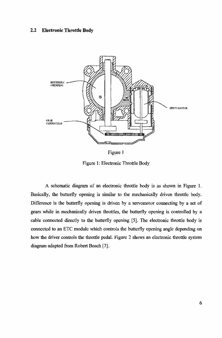
2.2 Electronic Throttle Body
BUTTERFLY OPE'NNmG
GEAR CONNECTION
Figure 1
Figure 1: Electronic Throttle Body
SER.YO IIIOTOR
A schematic diagram of an electronic throttle body is as shown in Figure 1.
Basically, the butterfly opening is similar to the mechanically driven throttle body.
Difference is the butterfly opening is driven by a servomotor connecting by a set of
gears while in mechanically driven throttles, the butterfly opening is controlled by a
cable connected directly to the butterfly opening [ 5]. The electronic throttle body is
connected to an ETC module which controls the butterfly opening angle depending on
how the driver controls the throttle pedal. Figure 2 shows an electronic throttle system
diagram adapted from Robert Bosch [7].
6

A<o'lt•o,IIOI ped~l
lliOdui~'
i lorolti<~ d<c' i<"
Figure 2: Electronic Throttle System
When a driver presses the throttle pedal, the throttle position sensor will send a
signal to the ETC module. The ETC module will control the opening angle of the
butterfly opening depending on the amount of pressure exerted on the throttle pedal.
The Throttle Position Sensor (IPS) will provide a feedback to the ETC module. This is
a feedback loop for error correction on the position of the butterfly opening.
2.3 Case Study on Vacuum Outlet from Throttle Bodies
A study was conducted on the vacuum outlet of throttle bodies to ensure any
modification done on a throttle body would not affect its output. Normally, the vacuum
outlet from a throttle body are connected to the power brakes, air-condition, wipers and
etc. For the Daihatsu Detomaso throttle body which was bought, the vacuum outlet are
connected to the power brakes, Electronic Control Unit (ECU) and air condition. The
vacuum outlets are as the figure 2.3.
7

Figure 3: Daihatsu Detomaso Vacuum outlets
2.4 Open-Loop Control versus Close-Loop Control
TO \lR 1•11NJHTIIII'I
Servomotors were chosen as a driver in Electronic Throttle Controls (ETC)
because it can be controlled in a closed loop function. A simple closed-loop and open
loop control system is as shown as below:
disturbance
mput output
sensor
8

Figure 4: Closed-Loop System
disturbance
/1 input ____, Input r-- Controller Process f-----+ output transducer ~ _,
Figure 5: Open-Loop System
Comparing the closed-loop and open-loop system above, the main problem with
open loop systems is its inability to detect error [4]. Looking at the close-loop control
system, the output signal is feed back into the input to eliminate any error that may
occur. Therefore, it is more stable to use a close-loop control system than a open-loop
control system because its feedback signal will corrects any error that may occur.
2.5 Throttle Position Sensor (TPS)
A throttle position sensor (TPS) is a sensor is used to monitor the position of the
throttle in an engine. The sensor is located on the butterfly spindle to directly monitor
the position of the throttle valve "butterfly".
The sensor usually consist of a potentiometer [11 ], as shown in figure 6, where it
provides a variable resistance dependent upon the position of the valve ("butterfly
position). It converts the throttle valve angle into an electric signal. As the throttle
opens, the signal voltage increases. A graph of resistance over time of a throttle position
sensor is as shown in figure 7.
9

ECU Sensot
Vss
Volt.lge Potentl.ll
Vdd
Vu (Po•111••l
Figure 6 : Throttle Position Sensor Circuit
t Voltage
(0.5V)
Closed ..... ,..f--_ __.~ Wide-Open
Figure 7 : Graph of Resistance over time
A typical TPS has 1000 ohm with the throttle in the idle position, and 4000ohm at
wide open throttle (WOT). The voltage signal from a typical TPS is 0.5 volts to 1 volt at
idle and 4.5 volts at WOT, and this signal informs the computer regarding the exact
throttle position.
The sensor signal is useful for the engine control unit (ECU) as an input to its
control system. The ignition timing and fuel injection timing are altered depending upon
the position of the throttle, and also depending on the rate of change of that position.
10

For example, in fuel injection engines, in order to avoid stalling, extra fuel may be
injected if the throttle is opened rapidly.
2.6 RC Servo Motor
Remote Controlled (RC) servo motor are designed to receive a position command
and move its motor shaft to the commanded position [8]. They are made from DC motor
with potentiometer and servo controller chip built to them to determine the angle of its
motor shaft and receive commanded position and drive the commanded position in a
feedback loop. A typical internal construction of the Sanwa servo with its component
list is as shown in APPENDIX m.
II. '· r-~--" II. l~~----,_ 1 "'..,... Coniroilltr DCilllolc-•
v .. ~ y v v
c:=::J
-<....._...:>" Aet'-"11 'fi'<aii:IOn (~t.r>t~ v,_..., .. I
Figure 8: RC Servo Block Diagram
An RC servo has limited motion, where it can only rotate between -90 to +90
degree. To protect it from over rotating, it has a mechanical stop to ensure the motion is
restricted. The figure below shows a servo consist of a DC motor with 2 gears
connected to a potential meter for feedback and some control circuitry.
11

'II' -#:-
• """"' C.oi!rltoner
I - -
Figure 9: RC servo functional block diagram
There are 3 inputs for a RC servo, one for power supply (SV), another for
ground, and the third for giving control signals. Usually, a l.Sms pulse width would
indicate 0-degree position (neutral) of the motor shaft. A pulse width of 1ms indicates -
90 degrees and a pnlse width of 2ms wonld indicate +90-degree [8). A sample of
motion is as shown in figure 9.
' . ..:::-=========:::' ~..-___ _., .. __ ~ ro- tr
1.5msec
,._
"'"""' Figure 10: RC Servo control signal
Odegre1.1&
v ca·-
12

3.1 Research Methodology
NO
YES
CHAPTER3 METHODOLOGY
START
END
NO
IDENTIFY MISSING PARTS
Figure II: Process Flow Diagram
HARDWARE AND SOFTWARE
13

During the first 14 weeks, final year project 1 course, research was conducted on
what Electronic Throttle Control (ETC) was all about. The main purpose of this is to
identify the problem statement of this project and solutions to overcome it. Knowing the
problem faced, research was done on DC motors especially which type of DC motor
which will be suitable for this project. Since throttle bodies contribute vacuum effects in
automotive technology, the effects were also eyed on. By the end of the semester, a
simulator was modeled for this project to simulate the response of the throttle under
certain physical conditions. There are 3 main mathematical model for the simulation,
ETC module, throttle and throttle position sensor. The model is as shown below,
Tbrottl• Position
ETC J.Vlod•d• Tbrotti•
'--- Tbrottl• Position Se-nsor
Figure 12: Simple model
During the second semester (final year project 2) a prototype of an Electronic
Throttle Control (ETC) was built. A pair of gear sets was first modeled linking the
servomotor and the throttle opening shaft. A controller was later built using a 16F84A
microprocessor controlled by a single-pole, double-throw (SPDT) switch. Since the
project requires a potentiometer as a control element to control the RC Servo, a 16F684
microcontroller was used replacing the 16F84 microcontroller. C Progranuning was the
programming language used to program the microcontroller. For error detection
purpose, the throttle position sensor (TPS) is used to provide a feedback to the
microcontroller.
14
3.2 MA TLAB Simulink
Due to its simulation capabilities, MA TLAB was chosen as the simulation
software to be used in this project. MA TLAB Simulink was used to model a simulator
to simulate the response of a throttle under certain conditions. For example for the
current mechanical throttle which was bought, the conditions are stiffness of the spring,
k, inertia movement of air-flow, J, and damping effect, c. Considering all this
conditions, the response of the throttle will be studied. A model of the throttle can be
seen in APPENDIX IV
With the optimal performance produced, the physical values of the throttle will
be applied when the prototype is built. This is to ensure a working throttle with great
efficiency can be built.
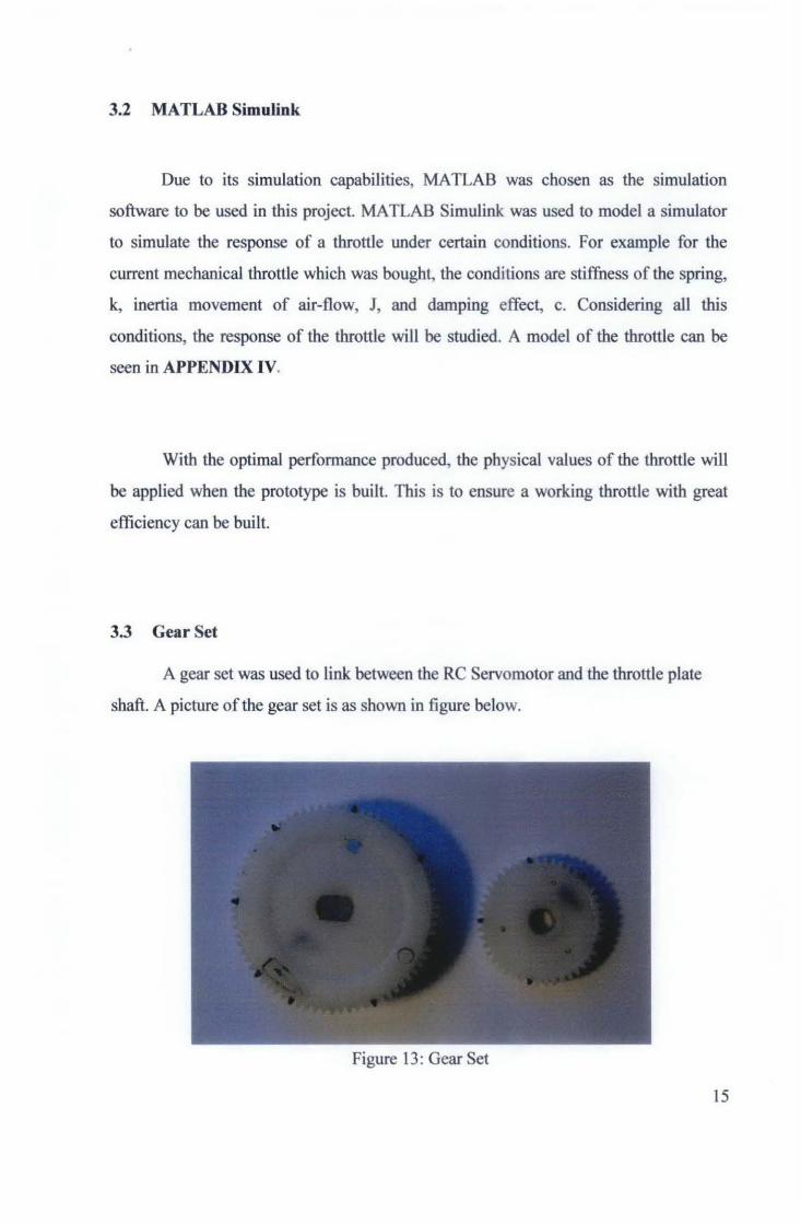
3.3 Gear Set
A gear set was used to link between the RC Servomotor and the throttle plate
shaft. A picture of the gear set is as shown in figure below.
Figure 13: Gear Set
15

Looking at figure 13, the gear on the left of the picture was built to be connected
to the throttle body shaft while the gear on the right is built to be connected to the RC
servomotor.
3.4 PIC Microcontrollers
Programmable Interface Computer (PIC) microcontroller is used in this project
due their flash based reprogram ability, and reasonable costs. Due its simple
architecture structure, it is easier to program. Since there are a lot of types of
microcontroller in the market, selection has to be made based on the specifications. For
this project, we would require a microcontroller which has an analogue-to-digital
converter (ADC) module. This was essential in order for us to control the "butterfly"
opening via a potentiometer.
At the beginning, I started using a PIC 16F84A microcontroller to control to
control the servo. After some attempts, I decided to switch to a PIC16F684
microcontroller. This was due to some functions which were needed for the servo
controller. The reasons for choosing this particular microcontroller are numerous. The
16F684 has a maximum of eleven 1/0 and we only need two. We need one analog input
to read the position of the potentiometer and one digital output to supply the control
signal to the servo. The 16F684 has an analog-to-digital converter (ADC) built into it. It
also has an internal oscillator capable of providing several oscillator frequencies from
31 kHz to 8 MHz which is very helpful. The 12F683 also has a built-in Pulse-Width
modulation (PWM) module which makes the programming a lot simpler.
16

The program was written inC and compiled using CCS, PCW compiler. The
program is grouped into four major sections: initialization of registers and I/0, reading
and averaging the value of the potentiometer, loading the value into the PWM registers,
and setting the internal oscillator frequency. A sample of the programming code is as
shown in APPENDIX V.
The program starts with a clock speed of 4 MHz and then reads timer 2 to
determine if the clock speed should be switched to 250kHz. We have to make sure that
the oscillator is not switched to 250 kHz before the output pulse goes low. If it does go
low, the width of the pulse would be stretched out and the servo would not function
properly.
3.5 Project Activities
During the first semester, research was done on a Remote Control (RC) servomotor
and throttles on how they actually work. A Daihatsu Detomaso 1.6cc fuel injection car
throttle body was purchased and recondition for the project. Research was also done on
why a servomotor was chosen for this project and on this, other alternatives were taken
into account. By the end of week 13, a simulation model was built in MATIAB.
Beginning of the second semester, a pair of gear set was bought for the motor and
moving shaft. Since the shape of the hole on the gears does not fit the motor and shaft,
they were molded to fit in it. Later, a controller was then built to control the RC
servomotor's direction. Initially, a SPDT switch type controller was used to control the
RC servo. Since the project requires a precision in control of the RC servo, the best
solution is to use a potentiometer to control the RC servo. The throttle position sensor
(TPS) which came along together with the throttle was then used for error detection.
17

3.6 Tools
At the beginning of this project, a Daihatsu Detomaso 1.6cc fuel injection throttle
body was purchased. ARC servomotor was also given to me by my supervisor for study
purpose. Pictures of some of the equipments available are shown in Appendix II.
Since a servomotor was feasible for the project, it was used to drive the throttle
shaft. I gear set, as shown previously in figure 13 was used to link them together. To
build a controller for the motor, the collection of electronic components, for e.g. PIC
rnicrocontrollers, breadboards and resistors was found in the university. Stamping of a
microcontroller is done in the microprocessor lab in the university.
For other components which are not available in the university, it was purchased
elsewhere.
18

4.1 Results
CHAPTER4 RESULTS & DISCUSSION
4.1.1 MATLAB Simulink
Since RC servos were chosen as the driver to drive the throttle plate in this
project, a simulated model was created in MATLAB Simulink to determine its
response. A model of the RC servo can be seen in Figure 14 below. The model is
connected to a 5V step-signal where its response versus its effect was studied. This is to
ensure that the close-loop system is stable and can be connected to the throttle.
Stop
Stop
~----~'+ ~------~ 950
s+40
Transfer Fen
PID Controller
950
s+40
Transfer Fen
Integrator
Integrator
Figure 14: RC Servo Models
Scope
Scope
19

As seen in Figure 14, a PID controller was connected to in second circuit. This
is to eliminate the overshoot which was not desirable when a 5V step signal is supplied
to the system. Figure 15 and 16 shows the difference when a PID controller was
implemented on the circuit.
6,-----.------.-----.-----,,-----.------.-----.-----.------.-----~
_/\ ____ ----:------------,-_ --------~----~----------------,---
2 .... -
I -I
Figure 15: RC Servo Response without PID
20

o,-~,-~-,~~,-~,-~-,~~,-~,-~-,~~,-~,
! I ! : I I : I
. ' ----- . ., ... · ....... -
l l ........... · '
I i i I o,~----7,-----+,----~,----~~----7,-----+,----~7----~.~----~,----~,,
Figure 16: RC Servo Response With PID
Next, the RC Servo model was linked to a throttle model as shown in Figure 14.
The subsystem model of the throttle is as show in APPENDIX IV.
1--------.!D
RCSewo
Throttle
Figure 17:ETC model with RC Servo
Throttle P(l:iition (De g)
'---+10 Tfuottle Po3ition (R.a:d)
21

1~~·r-----.---,-------.--~--~----.---,-------,--~-~
"~ ......... .
.,.~············ .
Figure 18: Ideal Response ofETC
Basically, an ideal response of the electronic throttle body should response as
Figure 18. The response manages to stabilize at 0.125s when a throttle signal of SV is
supplied.
Setting the throttle's parameter as the table below, we obtain a throttle response as
figure 19.
PARAMETERS VALUE
Inertia (J) 0.35
Damping(c) 11
Stiffness (k) 1.4
Table 1: Physical condition of a throttle body
22

100!:----,-.,:c-.)5.---::,:-, --~:.1:;-5 ---f,,:------;:',0_~~;-· --:;',,,,-----:O~.,;,------:,fc"---;:0-',.45---c},.5
Figure 19: Response of ETC with parameter set
4.1.2 Gear ratio
For this project, we will be using two spur gears. The larger gear with 7 4-teeth
will be linked to the throttle opening shaft while the smaller gear with 36-teeth will be
connected to the RC Servomotor. Therefore,
Gear Ratio= 46: 74
= 1 : 1.61
23

As we know, the desired maximum opening for a throttle is only 75 degrees;
therefore, the range to drive the throttle gear is:
75 X =
360 74
:. x = 15.5 teeth
The servomotor should be prograrmned to operate in the range of:
15.5 X --=-46 360
:. X= 121.3°
Therefore, the RC servomotor should operate in the range of oo « x « 121.3°
24
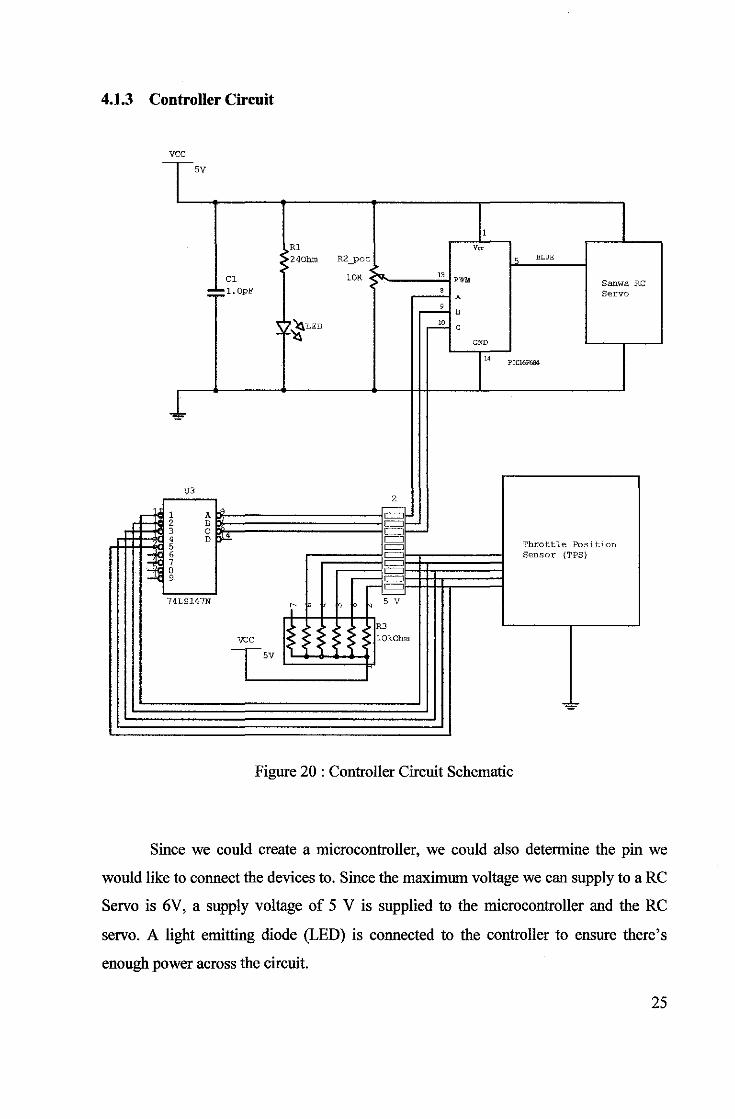
4.1.3 Controller Circuit
vee - -sv
1
Rl v" 240hm R2_pot lo "LUE
el lOK .... " PWM Sanwa RC : :1. OpF 8 Servo A
----2.. B
~ ~~LED ____!£. ' -
GND
" PICI6F684
J.
U3 2
F= 1 A _,
= 2 B §I-~ 3 c
' o>"'- = Throttle Position 5 = I= 6 = Sensor (TPS) 7 = 1- 8 = 9 -= r-= 74LS147N
~ ~'sv R3
vee lOkOhm Tsv ~~
Figure 20 : Controller Circuit Schematic
Since we could create a microcontroller, we could also determine the pin we
would like to connect the devices to. Since the maximum voltage we can supply to a RC
Servo is 6V, a supply voltage of 5 V is supplied to the microcontroller and the RC
servo. A light emitting diode (LED) is connected to the controller to ensure there's
enough power across the circuit.
25

4.1.4 Programming the PIC controller
A PIC 16F684 microcontroller was used to control the RC Servo position using
a potentiometer. The flowchart for the program is as shown in figure 21, and the C
programming code is in APPENDIX V.
ServoPWM
"'""''
Pedal Position
"'"""
ServoPWM output
Initialize CCP and Clock
Figure 21: Controller Flow Chart
As can be observed from figure 21, the controller reads a pedal position sensor
(PPS) via a potentiometer for positioning. In another way, we can conclude that the PPS
controls the PWM wave supplied to the RC servo.
26

4.2 Throttle Position Sensor (TPS)
For a throttle control it is important to create a feedback to the controller for error
detection and "butterfly" positioning correction. When the throttle was purchased, it
came along with a throttle switch. Throttle switch are a type of TPS which uses binary
bits to encode a certain angle. To determine the binary coding corresponding to the
throttle angle opening, an experiment was conducted and the results was as following:
Angle Coding Direct from TPS Coding after encoding
15°-30° 00001 100
30°-45° 00010 000
45°-60° 00100 111
60°-75° 01000 011
75°-90° 10000 101
Table 2: Coding of the TPS corresponding to the angle
Using a Motorola 74LS147 8-to-3 line encoder, the coding was reduced from a 5-
bit output to a 3-bit output as shown in table 2. By this way, feedback input to the
controller was reduced reducing the amount of data needed to be executed in a
microprocessor. By this way, the microcontroller can perform faster and the throttle
response could be improved.
27

4.3 Discussion
The MATLAB Simulink model was simulated to determine the response time of
the throttle considering the physical factor (inertia, stiffuess and damping) of the throttle
body. Throughout this project, a spring was not use to turn the throttle opening back to
its origin. Instate, a RC servo motor was used to control the "butterfly" opening freely
to open and close without any disturbance. Using this concept, the motor does not need
to counter against the back force of the throttle spring when it opens.
The only disturbance the RC servo motor will encounter is the vacuum effect
when the surrounding air flows into the engine via the throttle. Even with the existence
of this problem, the RC servo motor is capable of handling the load (3.5 kg/em at 6.0v)
exerted by the air flow due to its nature.
Referring to the gear set in figure 21, if a motor is driving the big gear via the
small gear, it will require a smaller torque compared to when it drives a small gear via a
big gear.
Figure 22: Gear set
28

In terms of response, it is better if the RC motor drives the throttle shaft (small
gear) via the bigger gear. The only disadvantage is the RC servo motor will require a
higher torque to counter the disturbance and the response will be slower. In this project,
the RC servomotor was linked to the throttle shaft (bigger gear) via a small gear.
The response time of the motor is very important in this project. In order to
achieve a fast response, it is important to supply a higher duty cycle frequency to the
motor. For a RC servomotor, the maximum duty cycle we can supply to the RC
servomotor is 60 hertz (Hz) [10]. Beyond 60Hz, the RC servo will experience humping
movements when rotating.
Besides controlling the frequency supplied to the RC Servo motor, it is also
important to reduce the amount of programming lines (if ,else) for fast response.
Normally, if there's a lot of programming lines in a program, the microprocessor will
take a longer time to execute it. Therefore, it is important to keep the program as simple
as possible and reduce the amount of programming lines.
29

CHAPTERS
CONCLUSIONS AND RECOMMENDATIONS
5.1 Conclusions and Recommendations
One of the limitations of the current RC servomotor is the operating speed
which affect the response time. When the throttle pedal is pushed instantly from 0 to
140 degree, there was a lag of about 0.5 seconds. To solve this problem, the current RC
servomotor can be replaced by high speed RC Servomotor. Doing this, the Jag of the
throttle can be reduced by more than half.
The prototype uses a throttle position sensor (TPS) to detect its "butterfly"
position error. Since there are 5 steps from the current throttle position sensor (TPS), the
TPS could only detect an error of more if it exceeds the 10 degree detection range. To
further improve the throttle position detection, the TPS can be replaced with a
potentiometer type of TPS. With the potentiometer type of TPS, the resolution of the
error detection of the throttle can be increased.
In an electronic throttle control (ETC), the pedal position sensor (PPS) plays an
important role especially ergonomically for the driver. Normally, a driver would exert a
certain pressure depending on its demand on the pedal to control a vehicle via the
throttle. For this project, focus was not put on designing a PPS which is ergonomically.
Therefore, for further studies on the project, a more desirable PPS can be improved for
the project.
30

Overall, a prototype of an electronic throttle control (ETC) was successfully
built using a Remote Controlled (RC) servomotor. For further research, a circuit board
could be built to read the data from the controller. The circuit board can then be
interfaced via a computer and the data from the controller could then be simulated. The
results from the simulation can then be studied and planed for further improvement.
31

REFERENCES
[1) Morris, James W. and Gavin, Jenney, Fly-by-Wire, A Historical and Design
Perspective, Warrendale, Pa, 1998.
[2] NZ Government, 29 July 08,
<http://www.beehive.govt.nz/release/exhaust+emissions+rule+improve
environment>
[3] Brain, Marshall, 29 July 08 <http://auto.howstuffworks.com/engine.htm>.
[4] Robbins & Myers/Electro-Craft, DC Motors Speed Controls Servo Systems, 4th
Ed, Minnesota, 1978.
[5] Don Knowles, Automotive Computer Systems, Delmar Publishers, Albany, 1996.
[6] NormanS. Nise, Control System Engineering, 4 Ed., Wiley & Sons Publication,
Massachusetts, 2004.
[7] Robert Bosch, Robert Bosch GmbH Staff, Gasoline-Engine Management, 3rd
Ed, Bentley Publishers, 2006.
[8] Kachroo, Pushkin and Mellodge, Patricia, Mobile Robotic Car Design, McGraw
Hill, New York, 2005.
[9] Sanwa RC Servo Specification, 291h Sept 2008
<http:/ /www.acehobby.co.nz/ossb2/root/OSSBEC l/showitem.asp?PID=54650>
[1 0] John Iovine, PIC Microcontroller Project Book, McGraw Hill, New York, 2004.
[11] Mark Schnubel, Today's Technician, Advance Engine Performance, Waterbury, CT, 2006.
32

[9] Lennon, Tony, 29th Sept 2008 <http://www.mathworks.com/matlabcentral/>
[10] Dabney, James B. and Harman, Thomas L., Mastering Simulink, McGraw Hill,
New York, 2004.
[11] Pico Technology, 1'1 Sept 2008
<http://www.picoauto.com/applications/electronic-throttle-control.html>
[12] Motorola 74LS147 8-to-3line encoder datasheet <www.datasheetcatalog.com>
33

APPENDIX I : GANTT CHART FINAL YEAR PROJECT I
NO. Detail/Work
1 Selecrion of proJect topic S.ubrn1sslon of jJroposa I
Apprm1al of proposal and .supervisor
2 Preliminary research/literature revi~>W Background ·itudy on ETC
Research on tl1rottJes & motors
3 Submission oi Preliminary
4 Semlnar
.5 Preliminary research/literature revi~>W ~·le-c:hanjs.m on ETCs. Contrcl:l!n,g motors
S-]mu1atlOt1 .so:tl!f.'are.s
6 Submission of Progress Repi>rl
7 Interim Reoprt Presentation Draft CCP'I' of rep,crt
Ana,lyze ali data gathered
8 Submission of Interim Report
9 Final Oral Presentation
1 2. 3
I I
I I
I
I I
I I I
4 5 6 1 8 9 10 11 12. 13 14
15/8 I I I I I I
I TBA. J I I
I I 117/!l I I i
I I I 115/10 I
I I I I I I I I TBA
35

Final Year Project II
NO. Detail/Work 15 16 17 1!1 19 20 21 22 23 24 25 26 27 2!1
1 Project Continues
I Gather equipments for prototype
Research on PLCs
2 Submission of Progress Report I I TBA I I .
3 Further Studies ofthe Project
Response Improvement
Timing Improvement
4 Submission of Progress Report I I TBA I I I I
s Seminar I I I
6 Poster Exhibition I I I I TBA I I I
7 Submission of Dissertation (soft bound) I I I I I I I I
8 Oral Presentation I I I I I I
9 Submission of Dissertation I I I I I --- ---- --
36

APPENDIX ll : PICTURES
Picture 1 :Remote Control Servomotor
Picture 2:Honda C70 Throttle Body
-Picture 3: Daihatsu Throttle Body
37

APPENDIX ill: SANWASX-01 SERVO
Specification [9]
Speed : 0.21 I 60degrees at 4.8V
: 0.19 I 60degrees at 6.0v
Torque : 3.2 kg/em at 4.8v
3.5 kg/em at 6.0v
Dimension : 39.0 x 20.0 x 36.0 mm
Weight : 45gm
TABLE 5.5 The Components In the Futaba Servo
01 l ppcr rn~r 0~ :\IJdctJP CRH~ ():{ Ht~ttom c;~~:-e
01 MH11l beann~: 0;) ~tl'lnl lx.-arin~
(}lj PottntiomHcr
07 Pot•·ntiomN<'r clnv•• plnm ~~~ :\If>! or
09 :\lt~tor piuinn II) ~kn" II IHt gc tr 1:! 2nd gem t:l 3nl g~>.tr 11 Fmnl gt·ar If> lut+·rnwdtlllf' -.hun 16 2nd h.tft
17 Sen:u hom I~ C:crew
HI Ctrcutt bonrcl :.!0 Connl"<'tornncl tnhlr
:.!I ('nhll' hu-.hmg
1l ~bun -.~!'mhh· .. rr•·" 21 Numcplatc
Futaba Servo internals (image copyright from Futaba Corporation)
38

APPENDIX IV: MATLAB THROTTLE MODEL
Torque Gair~
Damping Rela:.red Position
~-------------c·~------------~
Spring
Hard stops
rad-to-deg Idle controller
39

APPENDIX V: PROGRAM CODE
#include <16F684.h>
#fuses HS, XT, NOWDT, NOPROTECT, NOBROWNOUT, PUT,
#use delay( clock~ 4000000) II SET INITIAL CLOCK TO 4MHz
int8 CO~ 0; II FOR THE BUTTON ON PIN CO
int8 Cl ~ 0; II FOR THE BUTTON ON PIN Cl
int8 C2 ~ 0; II FOR THE BUTTON ON PIN C2
void setup( void) II SETUP THE A TO D, IIO AND CCP
{
setup_ adc _ports( 0 ); II ANi ANALOG INPUT setup_ adc( ADC _CLOCK_ DIV _ 8 ); II ADC CLOCK
set_ adc _channel( 0 ); II SELECT ADC CHANNEL 0
setup_ccpl( ccp_pwm ); II CONFIG CCPI AS PWM
setup_timer_2(T2_DIV_BY_16,255, I); /ISETUPCLOCKANDPERIOD
output_low(PIN _AI); II SET UNUSED I/0 TO OFF output_low(PIN _ A4);
output_low(PIN_ A5);
} void main()
{
int32 sum;
intl6 value, pwm;
int no_ acqs, t2 _value;
set_ tris _ C(Oxlll );
setup(); while ( TRUE )
{
value~ Read_ ADC();
sum= sum+ value; no_acqs ++; if( no_acqs > 127)
{ pwm ~sum I 128;
set_pwml_ duty( pwm + 256 ); sum =0;
II SET PIN CO,Cl AND C2 AS INPUT
II SETUP A TO D and PWM
II READ POTENTIOMETER VALUE II SUM THE VALUE
II INCREMENT AQUISITIONS
II AVERAGE THE POT READING II SET THE PWM% + lmS OFFSET
II CLEAR THE SUM no_acqs = 0; II CLEAR THE ACQUISITION COUNTER
}
t2 _value~ get_timer2();
if( t2_value > 140 && t2_value <205)
{
II GET THE V ALOE OF TIMER#
CHECK IF OSC SHOULD BE 250k or 4M
40

} }
setup_ oscillator( OSC _250KHZ ); II SET INTERNAL OSCILLATOR 250KHz
} else (
setup_ oscillator( OSC _ 4MHZ ); II SET INTERNAL OSCILLATOR4MHz
} if(input(PlN_CO=O && PlN_Cl=l && PIN_C2=1))
( get_timer2() > 140 && get_timer2() < 153;
}
else (
get _timer2();
} if(input(PIN_CO=l && PIN_CJ~~l && PIN_C2=1))
( get_timer2()> 153 && get_timer2()< 166;
} else (
get_timer2();
} if(input(PIN_CO=O &&PIN_Cl=l && PIN_C2=1))
( get_timer2()> 166 && get_ timer2()< 179;
}
else {
get_timer2();
} if(input(PIN_CO=O&& PIN_CJ=l &&PIN_C2=1))
( get_timer2()> 179 && get_timer2()< 192;
} else (
get_timer2();
} if(input(PIN_CO=O &&PIN_CJ=l &&PIN_C2=1))
( get_ timer2()> 192 && get_ timer2()< 205;
} else
( get_timer2();
}
41

APPENDIX VI: PIC MICROPROCESSOR PINS & SPECIFICATION
~ MICROCHIP PIC16F84A
18-pin Enhanced FLASH/EEPROJI 8-Bit I\licrocontrollt>r
High Performance RISC CPU Features:
: nly 55 single \"I'Cr'l:1 ins!nJcticns ~o s.rn • .:..1 in:structO"'iS single-:~"Cie l!:(cept ~Y prcgr.1•n
D:-.anctl~s 'tJhieh a~.:- Me-cycle
C periit'-"!9 s~·ee::i: !JC ~ 2D MHz dock input DC - 2~D ns :rstru::.tion c~·~le
~·:·.24 words of pn::gr.:;_,, memory e,: b;1Es of .Ja~i ~t..M
.:4 bi1es of Da~.a -=:::;~,:;:ort
7 4-bit \'idE- ins:tnJctio--: i.VVrt:ls • o-bit ,..;.,~ data byles
f 5 Special Functicn H.r.:r~J"are registers 2~ht-le-vel CE-ep haroware sta::k )irect ir:c ~:-~and relat ve a.::l::lressing ncdes Fcur ints'l"'..i!l=·'i: scur.:es: Ex~emal RBIJ.'INT pin -MRO tmer :r•erlow PORTB<7::4> ~':'1er"~Jp:-on-change Da:a ::::::~ROM writ<: o:mple:e
Peripheral Features:
7·-3 JO pins '.Vith in::liVC 1J-i dire;::to"l o:•ntrc High ::.u::e-~: -;inkis.ouro: for dirEct lEC dri..-e-• .25 rnA sink max_ p;E-: pin • 25 rot\ -source max. ;..;~ pin TMRO: 8.':-.-; "tin-ericount£~ with S-bit p"t•grarr·nable pre~::aler
Special Microcontroller Features:
iC,,tJCG era5e:.'•Nrite OJC~ Enh:m·~ed:=Lto.SH Fro~ran-. IT'~r1cri ~zr: .::al tC,OCC .. OOO tyc-.:::al erase.\\'.'"te ::.ydes ·.:cP~OM Jat;;. menc~:J i)<":::-i::-al EEPR::·'/1 .Ja:a -.~etE--"1ion >· 4•: :,-s:;:rs ln-Cir::.u 1-S-e,;·_:;. Prcgramrr "'S"r.il•: CSP-rw) -\liia iw::.pins ?o·,ver-c;r l:i!:eSE-t (i':t :R::1. Po~\'=; ... .,,:. ·-in-_.;_'" (?1:\~ q-:: G·scillatc~'" S!art--.,;p T ·ner !:OST) \"t.'iil•::hdog lrr-=-" ('NDT;1 wit'! its own On-C"' ;:· R.C G-scillatc ... lb-.. reliable oper.a:i::m Cede protectk1n Pmver s.;.ving SLEE::::~ r1cde-~ ele::.:able osci later opft·"! s
Pin Diagrams
PiliP. 501C
R~
R.~·TJ::::K' -
~....._ 4
:;;:<:.1"-;'!'
P.BtRe:-
SSOP
P.-'J.
R4.;.·TJCK:
\'.CLR---- 4
~=~~.t-.;-:-
P.B-1-
P.e;:--
-R."'.~
--- Fi."U --..os·::.t:-::.;__·-;u·,, -· e&::.::-::-·.·-;oJT
-Fi_3':"
-Fi_;:;s
-t=t"'.f
-I=!.~
--os-::-t.·-:._...;11-.. - os-::.::-:-·. -.;o.JT -·--[;[; .-fi_::;.
·-·Fi_;9S
P.Bl- -R.~ ..,_ __ __,-
CMOS Enhanced FLASH/EEPROM Tech11ology:
Lc::m pi.4'te:, high spe1:d e.::hnctcgy Fully s.ta~i:: des~."' ·~'\'ide -op~rat."~g- volt.age range - ::cmr1ercial: .2.1JV ~· 5.'5'! - lndiJ:S-tr a : 2.cv· to 5. 5'/ ":.!:!11 pcro~-e: o::r"~siJmpfc~:
{ 2 rr." o:ypica.l ·@ C.V. 4 M H:::: ·' 51'·" r,>pioal @ ~v. 3:< ~ ~< ( 1].5 ~LA ~)·;:.-cal s:andby ::· ..... .:nt@ ZV
42
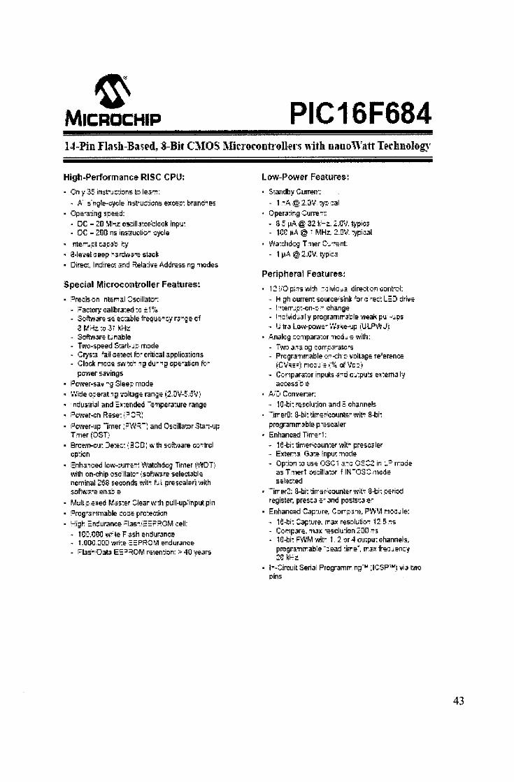
~ MICROCHIP PIC16F684 14-Pin fla~h-Ba.;Pd, 8-Bir C\IOS :\Hrrorontrollet·~ with nanoWatt T~rhnology
High-Performance RISC CPIJ:
On y 3-:- in:s.t"'J ::-:i::ms to le.Jm:
- A s·ngl~qcle nst~w:dons exo;:n branC:'1e5
Opo:.~•ing s.t=*d: • DC - 20 M;-z os.::iiL3~or.'clock inp'J: - DC - 200 ns ins'!ructio .. cycle
nte.7J_t·t ::-a_::·it:· i:y 3-le·.:el a eep : ... :;.r:fli'J"-i''"e stack Direc-:. ln::lireC! -3nd Rela:i'io: Addrsss ng ·nodes
Special Microcontroller F&atures:
':Jre.:is·:.n nte:mal ::-scillato'": :=a~or1 calibra:ed ~c ±1% Softo1.1ar>:: so: e:::-:able frequ>E-~::y r.rge cf 8 M:.f;::oJ7 kHz S•:.fl:t~.ll": t .. na.ble Two-speed S:art-·J.t· mode Cr1-s-:.:;_ ~ail ce-1ect f,y oriticai.J.pplic.i~icns Clock ncco:: s·~·~-~c.~ 19 d•J_ .. _~g cpe .. aticn ~Y pcwer 5.-.l'llings
i:Jc•Ner-saY "9 Sleep mode '.'.'ide cparat.1i;.l ·.·olbge range ~2-DV-!-.CV:• ndus:rri-.1! and =~:ended -;;,lper.l'!ure range
i:lc•Ner-cn Rs-se: •:.:JGrr: :::Jcwer-IJp lmer; :=\'\1~-: and Os.cilla~or Sb.•·•Jp T 11er (OST:· Brcwn-c•J~ J.eE::: •:3::::o·: wth sc·fttJ.lre- o:>"(trcl cp:ion
Snh-:r:·:ed low-:::•JI'N-"' Watchdcg Timer ( 1,>"~JDT:• with on-chip oscillato .. •:sofiw-lre -select.lble ncminal 268 seconds wit'! f J I pre-scale(t with s:mw-l ... e en-:1~- e
Mutt;:- -=~ed M-:7-s:er -:lear w ih pull-up.'input pin i:Jrcgrsr-1m:31ble ::cc::- pro:eC":~n
~igh i:'ndurance :=las .. ,·.;:E:;:-~OM cell·
tc•:·.OOO ~-rte F ssh endurance t.OOO.JDD wri:e ::PRe-~,., en::lur..Jnce :-1as~oOab E:::JROM re1en:ion: ::.40 ";"ears
Low-Power Feall.lres:
S::andby Curren':
- 1-A @ 2_D'J. cy<· ·:a I Opera:ing :::'Jrre"!r. - 8 -5 ~-"'@ 32 k·,...l:. 2.CV. typic1 - 1CC pA @ ~ MHz, 2.DV ':'JPi-::al Wa:::hdQ; T·ner C· .. """'=:nt:
- 1 ~A @ 2.GV. lj!pio•
Peripheral Featur&s:
1 ~ liO pi,s wi:h '"'·: fyic ,a dire--::tc•n contrc•l: H i;,lh curren~ "Source/sink ~or c ~e::-: L:D ::lri\1:-: I '!1Qrr J;:·::-cn-r:·"' change I ~-:::r ... id.i-5/y programrr--l_!:·le weak p•J --'-'P:i IJ tra Low-p:J•'IE:'' 0::-iOO:e""'JP 1:ULP•fo:J:1
Analcg ::o-:npara:or 11cd-.. : •Nith: T~".'O a.-r-i -og corr-.::<.3~atc-"S Prcgr-J11mable >:·-" -::h ::· 'lDit.Jge: re:ere-no= ~cv~:=) rtcc'.,; ·E- ·:~:~of \.'c:·) C•:·npara-:or inpllts .;; .. qj c·.-:pu~s: e:rtemal·~
;ac::e:s.s·::. &
,4:;) Ccm•er::er: - 10-bi: '"E-S.ChJiion and.:: channels -irrerD: 3-bi~ ~i~r.;r.'counts-" witn 8-bi; progrJmrr .. ible p:scaler
Enhance::! Tirr-s~1: 1e-bi: ':irr.er•coun:er wit"' presc.1ler Exter.'"!.i Ga:e lnpu~ :-node Op:ion :o use OSC 1 .rc (:.~:;:;:!'in -=· 1rode as T ·nert osdlla:or f IN·-os:::: mcde: s:le::.:ed
-irrer2: 8-bit ~ilr~r . .-counto:r •,•,•it" 8-bi;: -::-eriod register. pres::a -:~and posts::-a e.~
Enhanced Gap:ure, Corr;::·.;;pe, Pw~~1 r1o::.;le:
1e-bi: G:ap~ure. rr-a~ resolutk ... 12 5 _--:s CoMpare:. :'1l.1x ~-sclu:ion 2.DIJ ~-s 11]-bi: ;:::\'\'M wit'" t 2 or 4 cu;pu: channels, progr.~:nrrable ~-::-e;,d ~in-e-~. rr.-l~ fr';:.::·..;en::-y :21] ki~z.
1-.. -::ircuit Serial Programrr ng"N ;IC.SP1NJ ... ia two pins
43

APPENDIX VII: SCHEMATIC DIAGRAM AND COMPONENT USED
o I I I
A
" '
L40hm f..::::_po:;
1-
c
Q
UJ
F
f\c,
1--
G
t '' L::::~:::::=t~10(.0ltn
" ·-~ . ,---1. " r 0
I, ""
·~FI·
I"
'<LlTE
P!f.:l•-'F<S:4
' I
C:.otil"o'<l RC
S'Ocr:v:·
':'hr-:•t=l·~ F•:.oiuc-n 3;;,ns-~r i'I'PS!
I
c
D
1--
G
1-
~--~--J_I ____ _JI __ ~ __ _L ___ ~ __ LI _____ ~- I I J--~-----L-~--·~~L_--~
Controller Schematic Diagram
Controller Parts List
•!• Four 1.5V alkaline batteries
•!• Green LED
•!• I OK potentiometer
•!• 16F684 Microcontroller
•!• 0.01 ).tF Capacitor
•!• Miscellaneous: battery plug, eight pin DIP socket, female servo plug, breadboard, wires, socket connectors
44

APPENDIX VIII: DATA SHEET FOR 74LS147 8-T0-3 LINE ENCODER
® MOTOROLA
1 0-LINE-T0-4-LINE AND 8-LINE-T0-3-LINE PRIORITY ENCODERS
The SNM/7t:ILS147 and the SN5!1-174LS143 are Prior~ Encoders. Thev prwide priority decoding of the input: to ensure that onllf the highest order data line is: encoded. Both detioes have data inputs and outputs which are a dille atthe low logic level.
The l.S14l encodes nine data lines 1D four-line(S-42-1) BCD. The implied decimal zero condition does: not require an input condition because zero is: encoded when aU nine data lines are at a high logic level
The LS148 encodes eight data lines to three-line (42-1) binary( octaO. Bv providing cascading circuitry (Enable Input El and Enable Output EO) octal expansion G aiiMed without needing external circuitry.
The SN54174L.S74:1 is a proprietary Motorola part incorporating a built in deglilcl'ter netwolk which minimizes glitdles: on the GS output. The glitch occurs on 1he negaWe going transition ofthe El input when data input: 0-7 are at logical ones.
The onllfdcparameter differences beWeenthe LS148 andtheLS7~ are that(1) Pin 10(inputO)has: a fan-in of2 onthe LS7<(JSversus: a fan-in of 1 on the LS148; (2) Pins: 1,2,3,4, 11, 12and 13(inpul:s: 1.2. 3,4,5,6, 7) have a fan· in of3 on ihe LS748 versus a fan-in of2 on the LS14B.
The onllf ac dffference is: that1pHL from El to EO is changed from 4.) to 46 ns.
SN54174LS147 (TOP VIEW)
aJII'UI' ~-VQJ .. DitiiA
I
SN54174LS148 SN54174L S748
(TOP VIEW)
....... -~ .. • n 1
FAST !lND LS TTL DATA
5-245
SN54/74LS147 SN54/74LS148 SN54/74LS748
10-UNE-T0-4-LINE AND 8-UNE-T0-3-LINE PRIORITY ENCODERS
LOI'I POWER SCHOTTKY
• •• 1
• •• ··"'
J SUFFIX CERI'MIC
CP6 E 620-09
N SUFFIX PlASTIC
CASE648-0S
0 SUFFIX SOIC
CASE 751 e-ro
ORDERING INFORMATION
SN54LSXXXJ Cerarric SN74LSXXXN Plastic SN74LID<)()(0 SOIC
45

1 2 3
H H H
X X X X X X X X X X X X X X X X X X X X l X l H l H H
SN54/74LS147 • SN54/74LS148 • SN54/74LS748
SN54/74LS147 FUNCTION TABLE
INPUTS
4 5 6 7 8 • H H H H H H X X X X X l X X X X l H X X X l H H X X l H H H X l H H H H l H H H H H H H H H H H H H H H H H H H H H H H
OUTPUTS
D c a A
H H H H l H H l l H H H H l l l H l l H H l H l H l H H H H l l H H l H H H H l
El 0 1
H X X l H H l X X l X X l X X l X X l X X l X X l X l l l H
SN54/74LS148 SN54/74LS748
FUNCTION TABLE
INPUTS
2 3 4 5 6 7 A2
X X X X X X H H H H H H H H X X X X X l l X X X X l H l X X X l H H l X X l H H H l X l H H H H H l H H H H H H H H H H H H H H H H H H H H
-H- HIGH lo91c level, l LOW Log,e l.svel, X Irrelevant
FUNCTIONAL BLOCK DIAGRAMS
SN54/74LS147 SN54/74LS148
OUTPUTS
A1 AO GS EO
H H H H H H H l l l l H l H l H H l l H H H l H l l l H l H l H H l l H H H l H
46

APPENDIX IX: PICTURE OF THE PROTOTYPE MODEL
47
Related Documents


