Electronic Suspension Systems 23 © 2013 Pearson Higher Education, Inc. Pearson Prentice Hall - Upper Saddle River, NJ 07458 Advanced Automotive Electricity and Electronics James D. Halderman

Electronic Suspension Systems 23 © 2013 Pearson Higher Education, Inc. Pearson Prentice Hall - Upper Saddle River, NJ 07458 Advanced Automotive Electricity.
Jan 02, 2016
Welcome message from author
This document is posted to help you gain knowledge. Please leave a comment to let me know what you think about it! Share it to your friends and learn new things together.
Transcript

Electronic SuspensionSystems
23
© 2013 Pearson Higher Education, Inc.
Pearson Prentice Hall - Upper Saddle River, NJ 07458
Advanced Automotive Electricity and Electronics
James D. Halderman
23 Electronic Suspension Systems
Advanced Automotive Electricity and ElectronicsJames D. Halderman
© 2013 Pearson Higher Education, Inc.
Pearson Prentice Hall - Upper Saddle River, NJ 07458
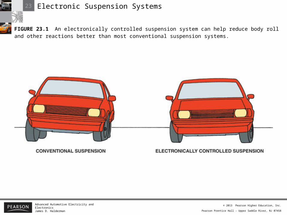
FIGURE 23.1 An electronically controlled suspension system can help reduce body roll and other reactions better than most conventional suspension systems.
23 Electronic Suspension Systems
Advanced Automotive Electricity and ElectronicsJames D. Halderman
© 2013 Pearson Higher Education, Inc.
Pearson Prentice Hall - Upper Saddle River, NJ 07458
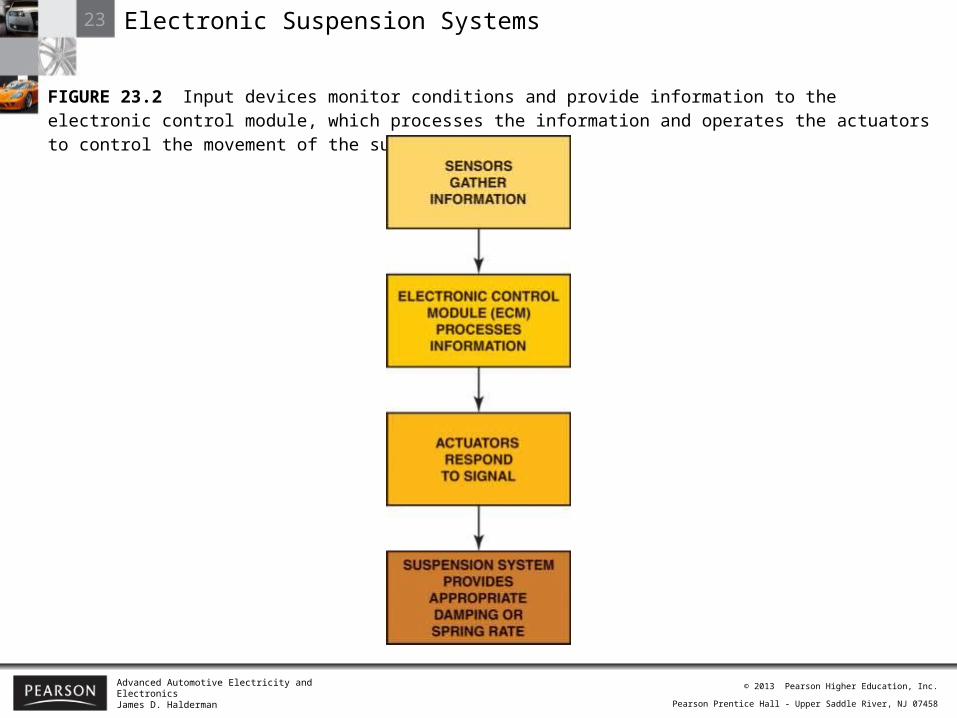
FIGURE 23.2 Input devices monitor conditions and provide information to the electronic control module, which processes the information and operates the actuators to control the movement of the suspension.
23 Electronic Suspension Systems
Advanced Automotive Electricity and ElectronicsJames D. Halderman
© 2013 Pearson Higher Education, Inc.
Pearson Prentice Hall - Upper Saddle River, NJ 07458
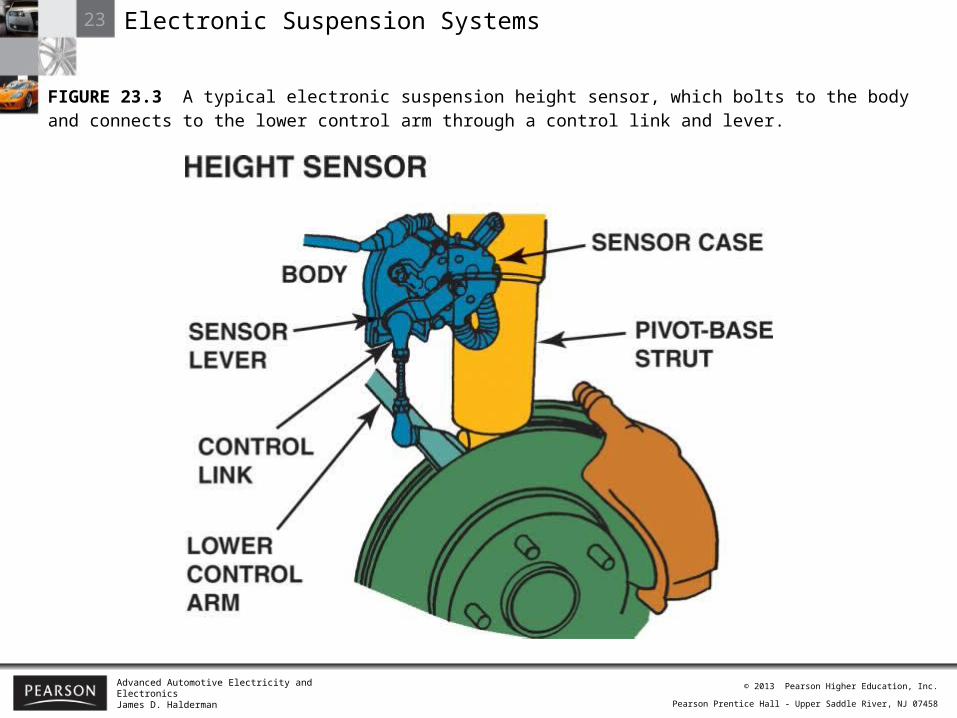
FIGURE 23.3 A typical electronic suspension height sensor, which bolts to the body and connects to the lower control arm through a control link and lever.
23 Electronic Suspension Systems
Advanced Automotive Electricity and ElectronicsJames D. Halderman
© 2013 Pearson Higher Education, Inc.
Pearson Prentice Hall - Upper Saddle River, NJ 07458
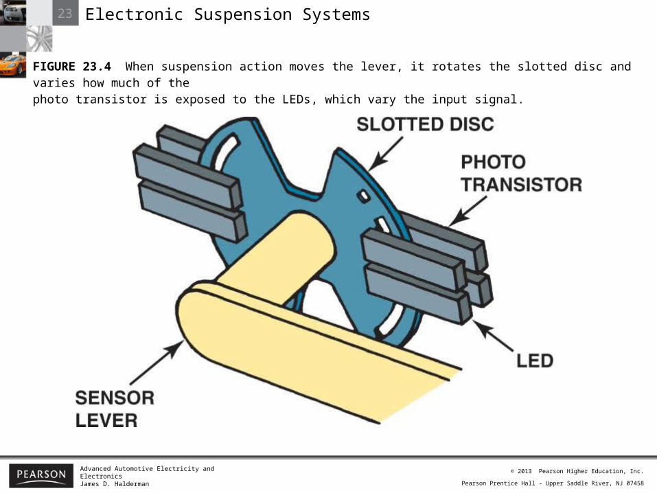
FIGURE 23.4 When suspension action moves the lever, it rotates the slotted disc and varies how much of thephoto transistor is exposed to the LEDs, which vary the input signal.
23 Electronic Suspension Systems
Advanced Automotive Electricity and ElectronicsJames D. Halderman
© 2013 Pearson Higher Education, Inc.
Pearson Prentice Hall - Upper Saddle River, NJ 07458
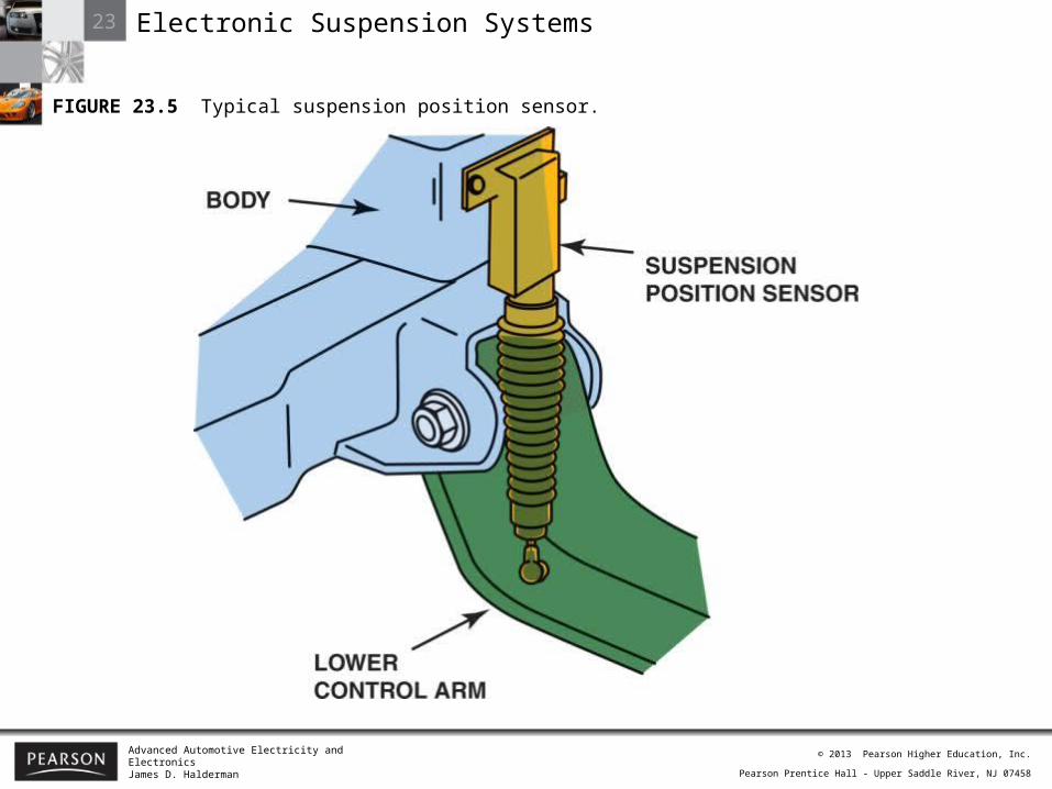
FIGURE 23.5 Typical suspension position sensor.
23 Electronic Suspension Systems
Advanced Automotive Electricity and ElectronicsJames D. Halderman
© 2013 Pearson Higher Education, Inc.
Pearson Prentice Hall - Upper Saddle River, NJ 07458
23 Electronic Suspension Systems
Advanced Automotive Electricity and ElectronicsJames D. Halderman
© 2013 Pearson Higher Education, Inc.
Pearson Prentice Hall - Upper Saddle River, NJ 07458
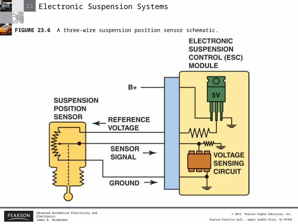
FIGURE 23.6 A three-wire suspension position sensor schematic.
23 Electronic Suspension Systems
Advanced Automotive Electricity and ElectronicsJames D. Halderman
© 2013 Pearson Higher Education, Inc.
Pearson Prentice Hall - Upper Saddle River, NJ 07458
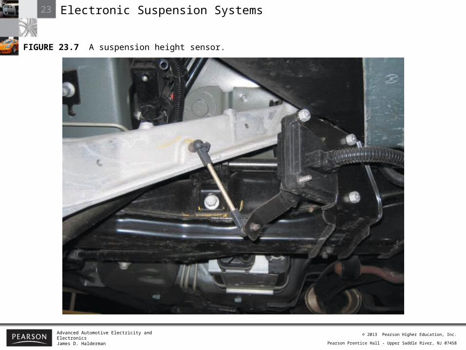
FIGURE 23.7 A suspension height sensor.

23 Electronic Suspension Systems
Advanced Automotive Electricity and ElectronicsJames D. Halderman
© 2013 Pearson Higher Education, Inc.
Pearson Prentice Hall - Upper Saddle River, NJ 07458
FIGURE 23.8 The steering wheel position (handwheel position) sensor wiring schematic and how the signal varieswith the direction that the steering wheel is turned.
23 Electronic Suspension Systems
Advanced Automotive Electricity and ElectronicsJames D. Halderman
© 2013 Pearson Higher Education, Inc.
Pearson Prentice Hall - Upper Saddle River, NJ 07458
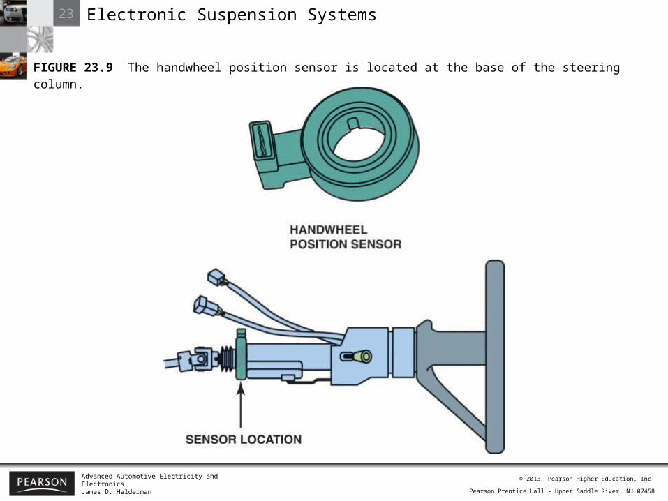
FIGURE 23.9 The handwheel position sensor is located at the base of the steering column.

23 Electronic Suspension Systems
Advanced Automotive Electricity and ElectronicsJames D. Halderman
© 2013 Pearson Higher Education, Inc.
Pearson Prentice Hall - Upper Saddle River, NJ 07458
FIGURE 23.10 Steering wheel (handwheel) position sensor schematic.
23 Electronic Suspension Systems
Advanced Automotive Electricity and ElectronicsJames D. Halderman
© 2013 Pearson Higher Education, Inc.
Pearson Prentice Hall - Upper Saddle River, NJ 07458
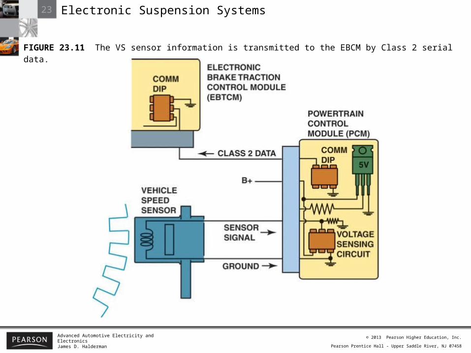
FIGURE 23.11 The VS sensor information is transmitted to the EBCM by Class 2 serial data.
23 Electronic Suspension Systems
Advanced Automotive Electricity and ElectronicsJames D. Halderman
© 2013 Pearson Higher Education, Inc.
Pearson Prentice Hall - Upper Saddle River, NJ 07458
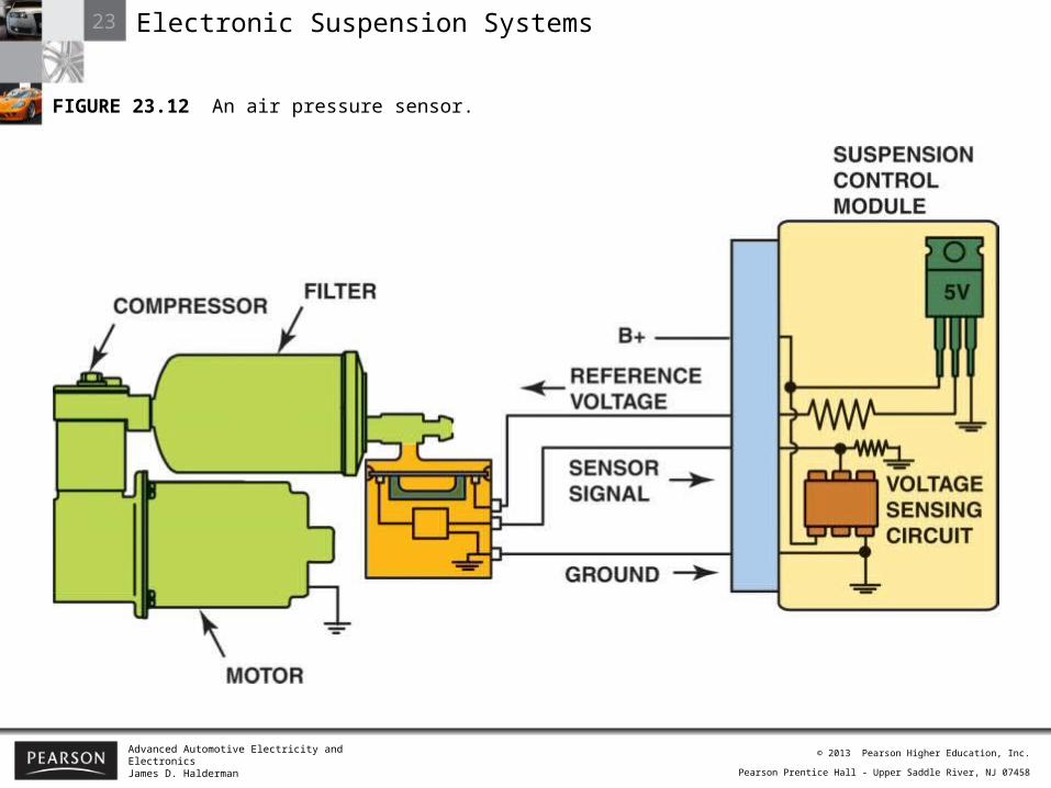
FIGURE 23.12 An air pressure sensor.
23 Electronic Suspension Systems
Advanced Automotive Electricity and ElectronicsJames D. Halderman
© 2013 Pearson Higher Education, Inc.
Pearson Prentice Hall - Upper Saddle River, NJ 07458
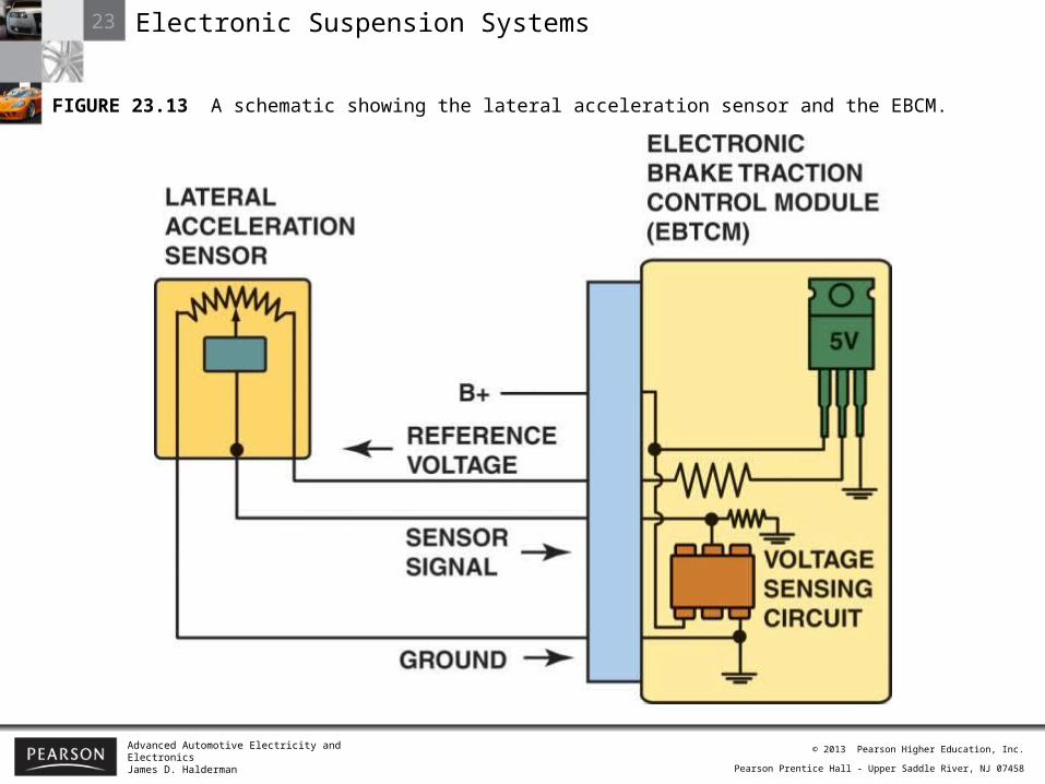
FIGURE 23.13 A schematic showing the lateral acceleration sensor and the EBCM.
23 Electronic Suspension Systems
Advanced Automotive Electricity and ElectronicsJames D. Halderman
© 2013 Pearson Higher Education, Inc.
Pearson Prentice Hall - Upper Saddle River, NJ 07458
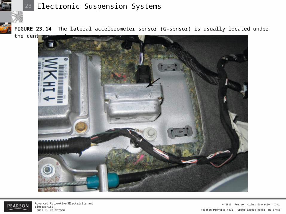
FIGURE 23.14 The lateral accelerometer sensor (G-sensor) is usually located under the center console.

23 Electronic Suspension Systems
Advanced Automotive Electricity and ElectronicsJames D. Halderman
© 2013 Pearson Higher Education, Inc.
Pearson Prentice Hall - Upper Saddle River, NJ 07458
23 Electronic Suspension Systems
Advanced Automotive Electricity and ElectronicsJames D. Halderman
© 2013 Pearson Higher Education, Inc.
Pearson Prentice Hall - Upper Saddle River, NJ 07458
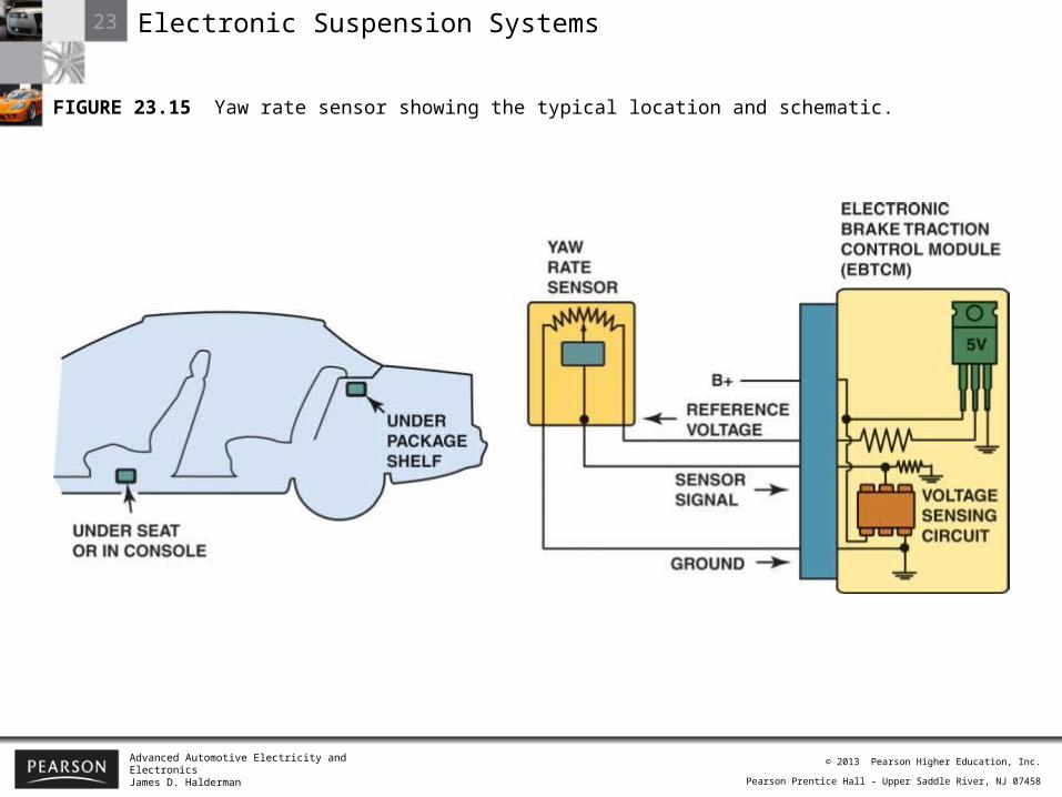
FIGURE 23.15 Yaw rate sensor showing the typical location and schematic.

23 Electronic Suspension Systems
Advanced Automotive Electricity and ElectronicsJames D. Halderman
© 2013 Pearson Higher Education, Inc.
Pearson Prentice Hall - Upper Saddle River, NJ 07458
FIGURE 23.16 A magnetic field is created whenever an electrical current flows through a coil of wire wrapped around an iron core.

23 Electronic Suspension Systems
Advanced Automotive Electricity and ElectronicsJames D. Halderman
© 2013 Pearson Higher Education, Inc.
Pearson Prentice Hall - Upper Saddle River, NJ 07458
FIGURE 23.17 When magnets are near each other, like poles repel and opposite poles attract.
23 Electronic Suspension Systems
Advanced Automotive Electricity and ElectronicsJames D. Halderman
© 2013 Pearson Higher Education, Inc.
Pearson Prentice Hall - Upper Saddle River, NJ 07458
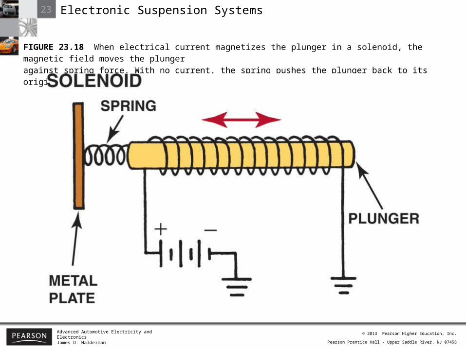
FIGURE 23.18 When electrical current magnetizes the plunger in a solenoid, the magnetic field moves the plungeragainst spring force. With no current, the spring pushes the plunger back to its original position.
23 Electronic Suspension Systems
Advanced Automotive Electricity and ElectronicsJames D. Halderman
© 2013 Pearson Higher Education, Inc.
Pearson Prentice Hall - Upper Saddle River, NJ 07458
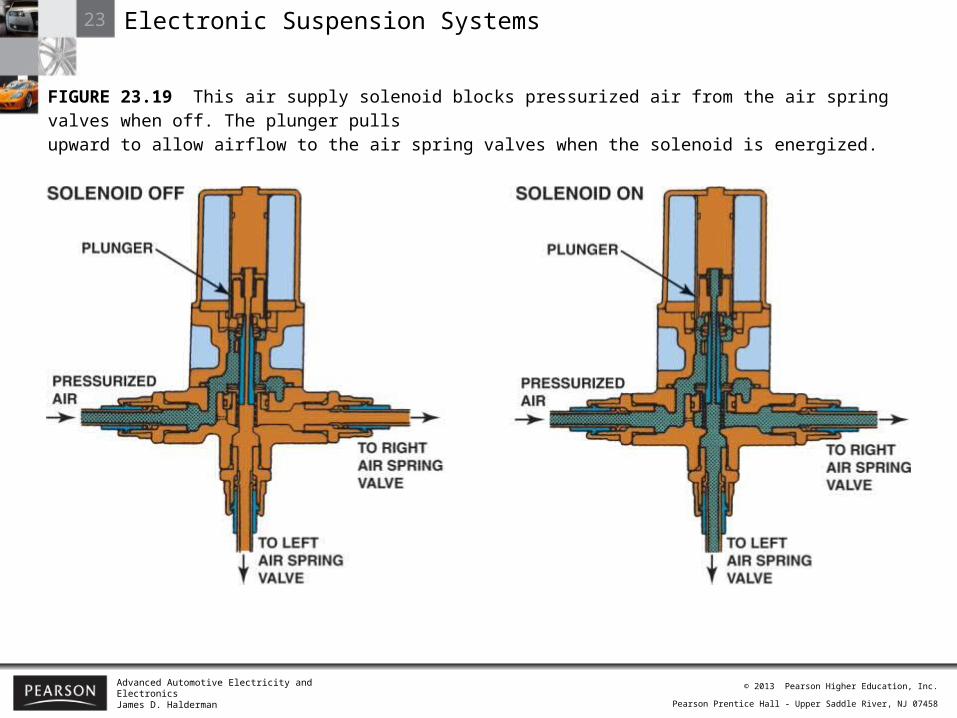
FIGURE 23.19 This air supply solenoid blocks pressurized air from the air spring valves when off. The plunger pullsupward to allow airflow to the air spring valves when the solenoid is energized.

23 Electronic Suspension Systems
Advanced Automotive Electricity and ElectronicsJames D. Halderman
© 2013 Pearson Higher Education, Inc.
Pearson Prentice Hall - Upper Saddle River, NJ 07458
FIGURE 23.20 An actuator motor uses a permanent magnet and four stator coils to drive the air spring control rod.

23 Electronic Suspension Systems
Advanced Automotive Electricity and ElectronicsJames D. Halderman
© 2013 Pearson Higher Education, Inc.
Pearson Prentice Hall - Upper Saddle River, NJ 07458
FIGURE 23.21 The stator coils of the actuator are energized in three ways to provide soft, medium, or firm ride from the air springs and shock absorbers.
23 Electronic Suspension Systems
Advanced Automotive Electricity and ElectronicsJames D. Halderman
© 2013 Pearson Higher Education, Inc.
Pearson Prentice Hall - Upper Saddle River, NJ 07458
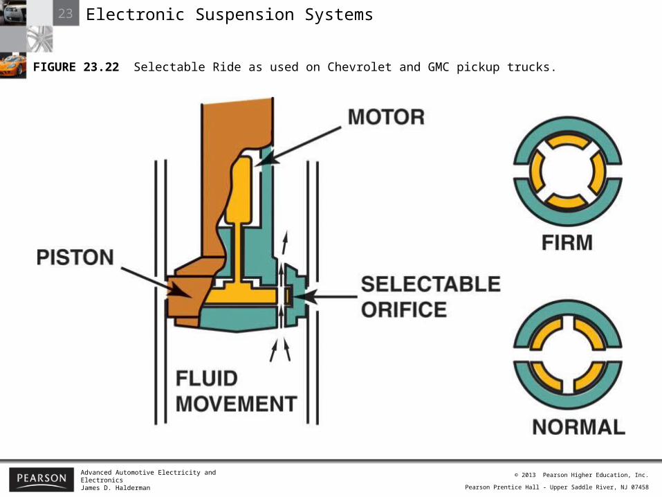
FIGURE 23.22 Selectable Ride as used on Chevrolet and GMC pickup trucks.

23 Electronic Suspension Systems
Advanced Automotive Electricity and ElectronicsJames D. Halderman
© 2013 Pearson Higher Education, Inc.
Pearson Prentice Hall - Upper Saddle River, NJ 07458
FIGURE 23.23 ALC maintains the same ride height either loaded or unloaded by increasing or decreasing the airpressure in the rear air shocks.

23 Electronic Suspension Systems
Advanced Automotive Electricity and ElectronicsJames D. Halderman
© 2013 Pearson Higher Education, Inc.
Pearson Prentice Hall - Upper Saddle River, NJ 07458
FIGURE 23.24 A typical schematic showing the air suspension compressor assembly and sensor.
23 Electronic Suspension Systems
Advanced Automotive Electricity and ElectronicsJames D. Halderman
© 2013 Pearson Higher Education, Inc.
Pearson Prentice Hall - Upper Saddle River, NJ 07458
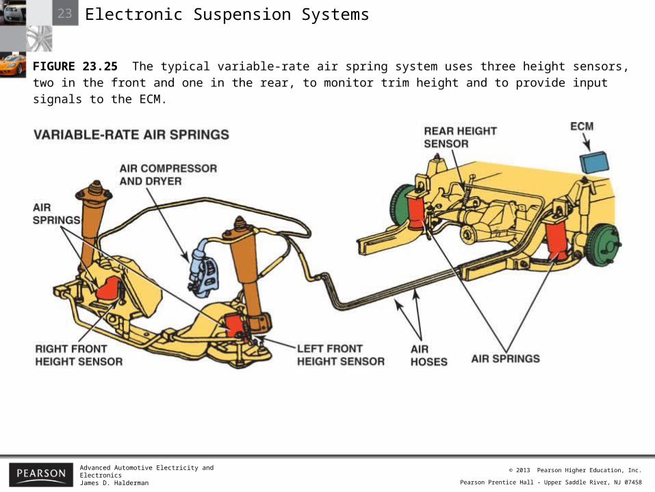
FIGURE 23.25 The typical variable-rate air spring system uses three height sensors, two in the front and one in the rear, to monitor trim height and to provide input signals to the ECM.
23 Electronic Suspension Systems
Advanced Automotive Electricity and ElectronicsJames D. Halderman
© 2013 Pearson Higher Education, Inc.
Pearson Prentice Hall - Upper Saddle River, NJ 07458
23 Electronic Suspension Systems
Advanced Automotive Electricity and ElectronicsJames D. Halderman
© 2013 Pearson Higher Education, Inc.
Pearson Prentice Hall - Upper Saddle River, NJ 07458
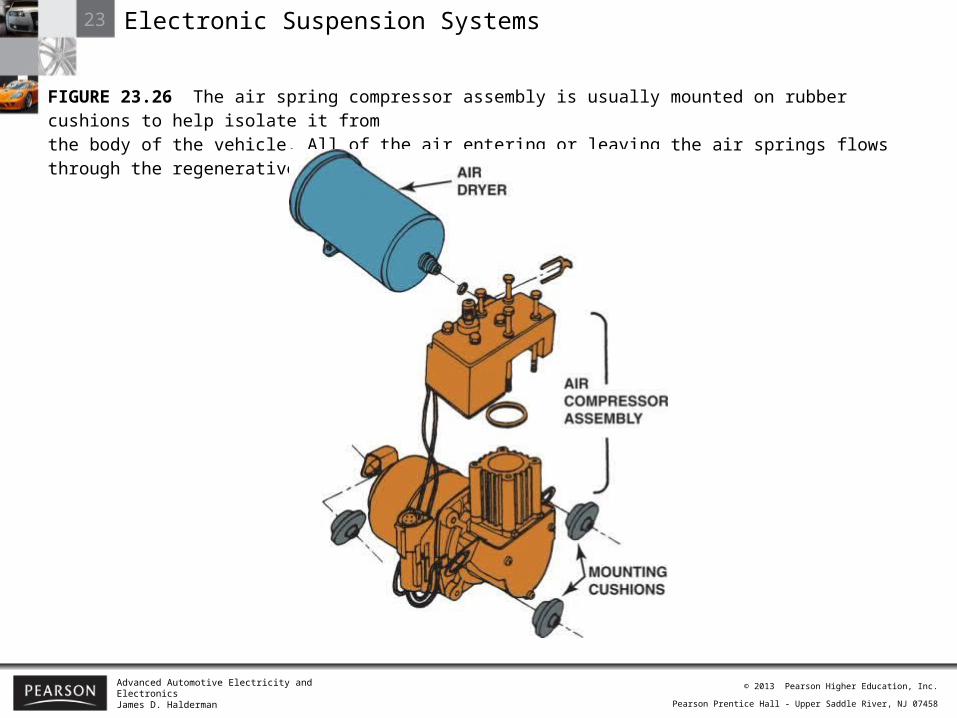
FIGURE 23.26 The air spring compressor assembly is usually mounted on rubber cushions to help isolate it fromthe body of the vehicle. All of the air entering or leaving the air springs flows through the regenerative air dryer.
23 Electronic Suspension Systems
Advanced Automotive Electricity and ElectronicsJames D. Halderman
© 2013 Pearson Higher Education, Inc.
Pearson Prentice Hall - Upper Saddle River, NJ 07458
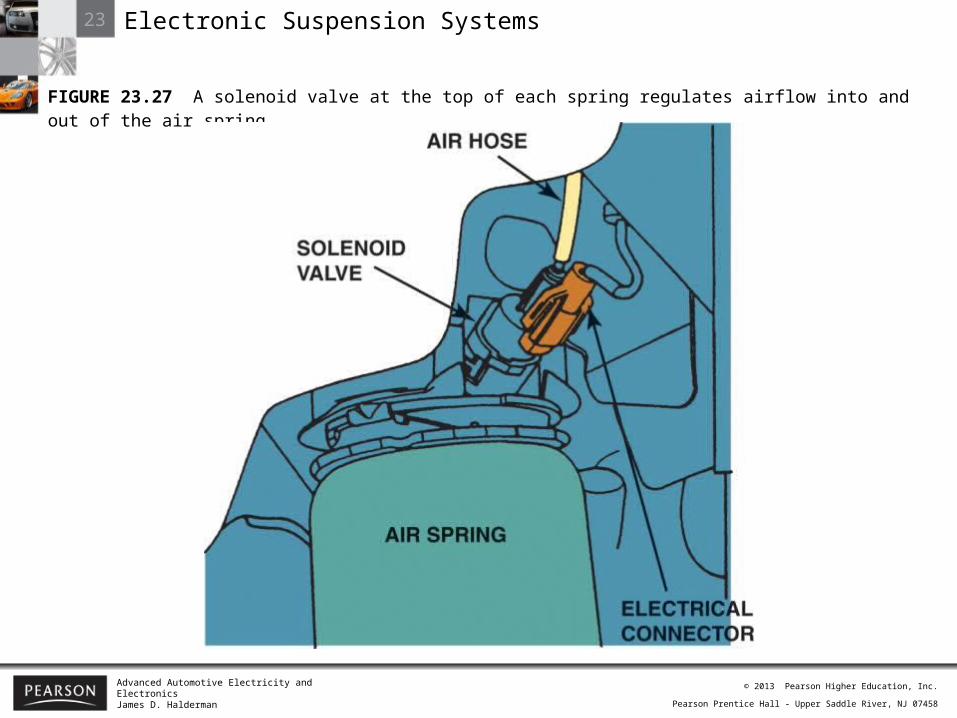
FIGURE 23.27 A solenoid valve at the top of each spring regulates airflow into and out of the air spring.

23 Electronic Suspension Systems
Advanced Automotive Electricity and ElectronicsJames D. Halderman
© 2013 Pearson Higher Education, Inc.
Pearson Prentice Hall - Upper Saddle River, NJ 07458
FIGURE 23.28 Schematic showing Computer Command Ride (CCR) system.

23 Electronic Suspension Systems
Advanced Automotive Electricity and ElectronicsJames D. Halderman
© 2013 Pearson Higher Education, Inc.
Pearson Prentice Hall - Upper Saddle River, NJ 07458
FIGURE 23.29 Schematic showing the shock control used in the RSS system.
23 Electronic Suspension Systems
Advanced Automotive Electricity and ElectronicsJames D. Halderman
© 2013 Pearson Higher Education, Inc.
Pearson Prentice Hall - Upper Saddle River, NJ 07458
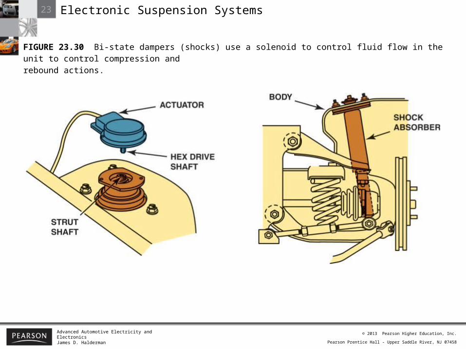
FIGURE 23.30 Bi-state dampers (shocks) use a solenoid to control fluid flow in the unit to control compression andrebound actions.
23 Electronic Suspension Systems
Advanced Automotive Electricity and ElectronicsJames D. Halderman
© 2013 Pearson Higher Education, Inc.
Pearson Prentice Hall - Upper Saddle River, NJ 07458
23 Electronic Suspension Systems
Advanced Automotive Electricity and ElectronicsJames D. Halderman
© 2013 Pearson Higher Education, Inc.
Pearson Prentice Hall - Upper Saddle River, NJ 07458
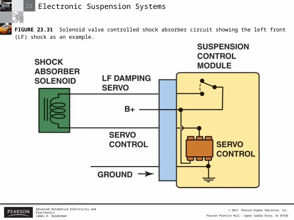
FIGURE 23.31 Solenoid valve controlled shock absorber circuit showing the left front (LF) shock as an example.
23 Electronic Suspension Systems
Advanced Automotive Electricity and ElectronicsJames D. Halderman
© 2013 Pearson Higher Education, Inc.
Pearson Prentice Hall - Upper Saddle River, NJ 07458
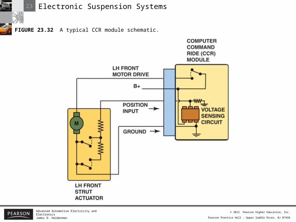
FIGURE 23.32 A typical CCR module schematic.
23 Electronic Suspension Systems
Advanced Automotive Electricity and ElectronicsJames D. Halderman
© 2013 Pearson Higher Education, Inc.
Pearson Prentice Hall - Upper Saddle River, NJ 07458
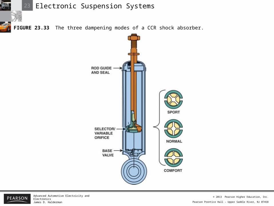
FIGURE 23.33 The three dampening modes of a CCR shock absorber.
23 Electronic Suspension Systems
Advanced Automotive Electricity and ElectronicsJames D. Halderman
© 2013 Pearson Higher Education, Inc.
Pearson Prentice Hall - Upper Saddle River, NJ 07458
23 Electronic Suspension Systems
Advanced Automotive Electricity and ElectronicsJames D. Halderman
© 2013 Pearson Higher Education, Inc.
Pearson Prentice Hall - Upper Saddle River, NJ 07458
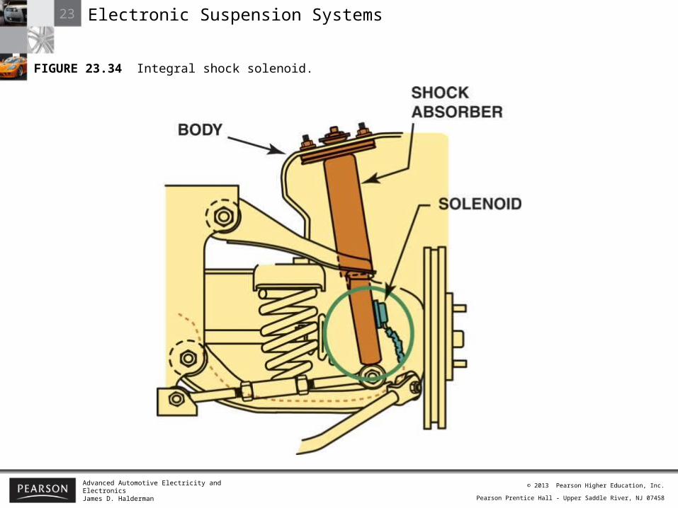
FIGURE 23.34 Integral shock solenoid.

23 Electronic Suspension Systems
Advanced Automotive Electricity and ElectronicsJames D. Halderman
© 2013 Pearson Higher Education, Inc.
Pearson Prentice Hall - Upper Saddle River, NJ 07458
23 Electronic Suspension Systems
Advanced Automotive Electricity and ElectronicsJames D. Halderman
© 2013 Pearson Higher Education, Inc.
Pearson Prentice Hall - Upper Saddle River, NJ 07458
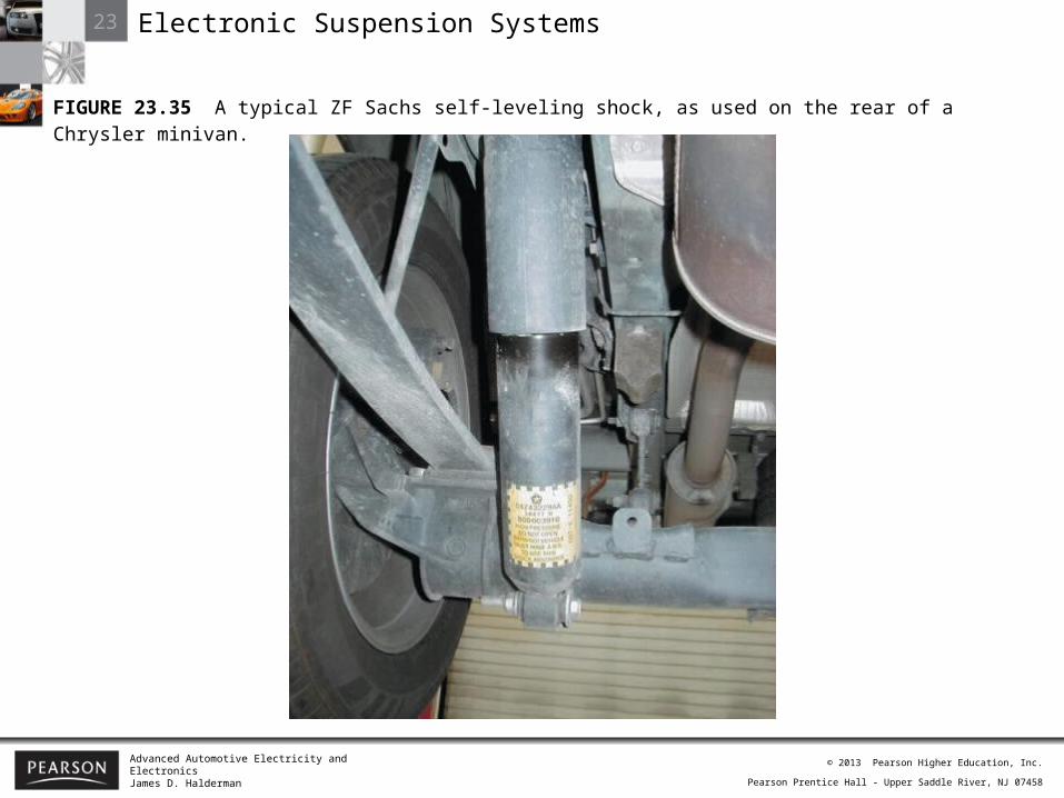
FIGURE 23.35 A typical ZF Sachs self-leveling shock, as used on the rear of a Chrysler minivan.
23 Electronic Suspension Systems
Advanced Automotive Electricity and ElectronicsJames D. Halderman
© 2013 Pearson Higher Education, Inc.
Pearson Prentice Hall - Upper Saddle River, NJ 07458
23 Electronic Suspension Systems
Advanced Automotive Electricity and ElectronicsJames D. Halderman
© 2013 Pearson Higher Education, Inc.
Pearson Prentice Hall - Upper Saddle River, NJ 07458
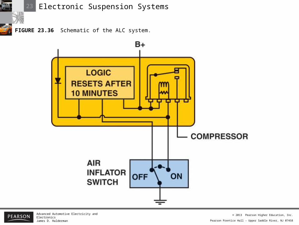
FIGURE 23.36 Schematic of the ALC system.

23 Electronic Suspension Systems
Advanced Automotive Electricity and ElectronicsJames D. Halderman
© 2013 Pearson Higher Education, Inc.
Pearson Prentice Hall - Upper Saddle River, NJ 07458
FIGURE 23.37 Air compressor assembly can be located at various locations depending on the vehicle.
23 Electronic Suspension Systems
Advanced Automotive Electricity and ElectronicsJames D. Halderman
© 2013 Pearson Higher Education, Inc.
Pearson Prentice Hall - Upper Saddle River, NJ 07458
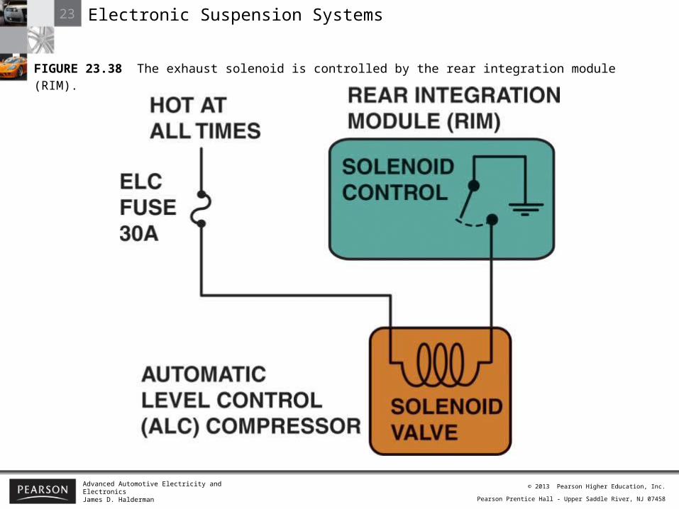
FIGURE 23.38 The exhaust solenoid is controlled by the rear integration module (RIM).
23 Electronic Suspension Systems
Advanced Automotive Electricity and ElectronicsJames D. Halderman
© 2013 Pearson Higher Education, Inc.
Pearson Prentice Hall - Upper Saddle River, NJ 07458
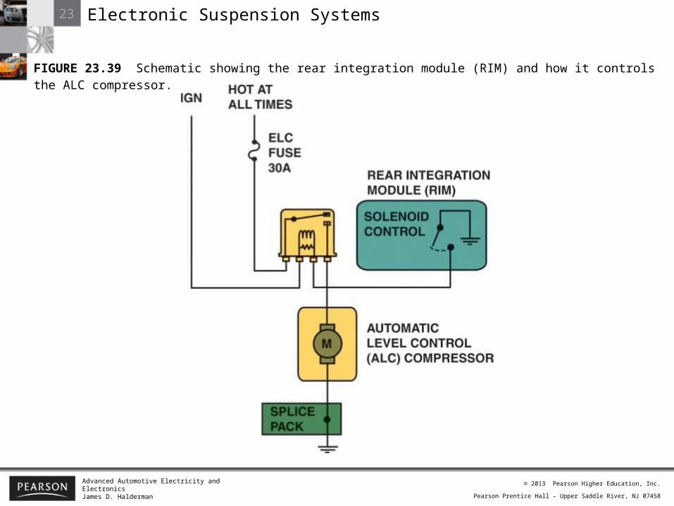
FIGURE 23.39 Schematic showing the rear integration module (RIM) and how it controls the ALC compressor.

23 Electronic Suspension Systems
Advanced Automotive Electricity and ElectronicsJames D. Halderman
© 2013 Pearson Higher Education, Inc.
Pearson Prentice Hall - Upper Saddle River, NJ 07458
FIGURE 23.40 Vehicles that use magneto-rheological shock absorbers have a sensor located near each wheel, as shown on this C6 Corvette.
23 Electronic Suspension Systems
Advanced Automotive Electricity and ElectronicsJames D. Halderman
© 2013 Pearson Higher Education, Inc.
Pearson Prentice Hall - Upper Saddle River, NJ 07458
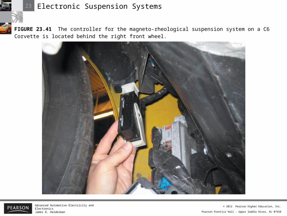
FIGURE 23.41 The controller for the magneto-rheological suspension system on a C6 Corvette is located behind the right front wheel.
23 Electronic Suspension Systems
Advanced Automotive Electricity and ElectronicsJames D. Halderman
© 2013 Pearson Higher Education, Inc.
Pearson Prentice Hall - Upper Saddle River, NJ 07458
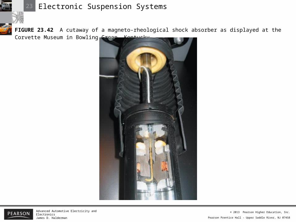
FIGURE 23.42 A cutaway of a magneto-rheological shock absorber as displayed at the Corvette Museum in Bowling Green, Kentucky.
23 Electronic Suspension Systems
Advanced Automotive Electricity and ElectronicsJames D. Halderman
© 2013 Pearson Higher Education, Inc.
Pearson Prentice Hall - Upper Saddle River, NJ 07458
23 Electronic Suspension Systems
Advanced Automotive Electricity and ElectronicsJames D. Halderman
© 2013 Pearson Higher Education, Inc.
Pearson Prentice Hall - Upper Saddle River, NJ 07458
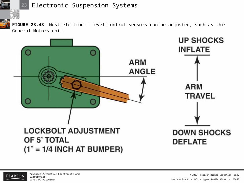
FIGURE 23.43 Most electronic level-control sensors can be adjusted, such as this General Motors unit.
Related Documents