Dublin Institute of Technology ARROW@DIT Articles Centre for Industrial and Engineering Optics 1-1-2004 Electronic Speckle Pattern Shearing Interferometer with a Photopolymer Holographyc Grating Emilia Mihaylova Dublin Institute of Technology, [email protected] Izabela Naydenova Dublin Institute of Technology, [email protected] Suzanne Martin Dublin Institute of Technology, [email protected] Vincent Toal Dublin Institute of Technology, [email protected] This Article is brought to you for free and open access by the Centre for Industrial and Engineering Optics at ARROW@DIT. It has been accepted for inclusion in Articles by an authorized administrator of ARROW@DIT. For more information, please contact [email protected]. Recommended Citation E. Mihaylova, I. Naydenova, S. Martin, V. Toal, Electronic spackle pattern shearing interferometer with a photopolymer holographic grating, Applied Optics, 43 (12), 2439, 2004

Welcome message from author
This document is posted to help you gain knowledge. Please leave a comment to let me know what you think about it! Share it to your friends and learn new things together.
Transcript

Dublin Institute of TechnologyARROW@DIT
Articles Centre for Industrial and Engineering Optics
1-1-2004
Electronic Speckle Pattern Shearing Interferometerwith a Photopolymer Holographyc GratingEmilia MihaylovaDublin Institute of Technology, [email protected]
Izabela NaydenovaDublin Institute of Technology, [email protected]
Suzanne MartinDublin Institute of Technology, [email protected]
Vincent ToalDublin Institute of Technology, [email protected]
This Article is brought to you for free and open access by the Centre forIndustrial and Engineering Optics at ARROW@DIT. It has been acceptedfor inclusion in Articles by an authorized administrator of [email protected] more information, please contact [email protected].
Recommended CitationE. Mihaylova, I. Naydenova, S. Martin, V. Toal, Electronic spackle pattern shearing interferometer with a photopolymer holographicgrating, Applied Optics, 43 (12), 2439, 2004

ELECTRONIC SPECKLE PATTERN SHEARING INTERFEROMETER
WITH A PHOTOPOLYMER HOLOGRAPHYC GRATING
Emilia Mihaylova, Izabela Naydenova, Suzanne Martin, Vincent Toal
Centre for Industrial and Engineering Optics
Dublin Institute of Technology, Kevin Street, Dublin 8, Ireland
Abstract
A photopolymer holographic grating is used to produce the two sheared images in an electronic
speckle pattern shearing interferometer. A ground glass screen following the grating serves the
purpose of eliminating unwanted diffraction orders and to remove the requirement for the CCD
camera to resolve the diffraction grating’s pitch. The sheared images on the ground glass are
further imaged onto the CCD camera. The fringe pattern contrast was estimated to be above 90%.
A validation of the system was done by comparing the theoretical phase difference distribution
with the experimental data from the three point bending test.
OCIS codes: 120.6160 Speckle interferometry; 090.7330 Volume holographic gratings.
1. INTRODUCTION
Electronic speckle pattern interferometry (ESPI) can only directly measure displacement.
Electronic speckle pattern shearing interferometry (ESPSI) enables direct measurements of
displacement derivatives to be made. ESPSI using a diffraction grating as a shearing element is

an attractive alternative to other shearographic systems1,2
using gratings as it provides
observation of real-time fringe formation and the possibility of phase-stepping analysis. The basic
restriction in the application of holographic gratings in ESPSI systems comes3 from the
requirement for the CCD camera to resolve the pitch of the diffraction grating (50 l/mm).
Joenathan & Bürkle suggested4 an introduction of a ground glass in the ESPSI system to
overcome the limitation for the grating frequency to be low. This idea is of interest for further
experimental development.
We suggest a new application of a photopolymer holographic grating in ESPSI. Self-processing
acrylamide based photopolymer5 is used as a recording medium for recording holographic
gratings. The optimized photopolymer material gives good diffraction efficiencies up to 94% for
an exposure of 80mJ/cm2
and it performs well in the transmission mode of hologram recording.
2. THEORY
2.1. Conventional shearography
When two light waves interfere, the following equation6 relates their relative phase Φ at a
location to their relative geometrical path length L:
βλ
π−=Φ nL
2 (1)
where λ is the wavelength of the laser light, n is the refractive index of the medium through
which the laser light is transmitted, and β is a constant phase. The change in the relative phase
∆=δΦ or phase change, which manifests as visible fringes, can be effected by an incremental
change in any of the three parameters λ, n, and L. Thus,
Ln
nLLn
LL
nn
δλ
πδ
λ
πδλ
λ
πδδδλ
λ
2222
++−=∂
Φ∂+
∂
Φ∂+
∂
Φ∂=∆ (2)
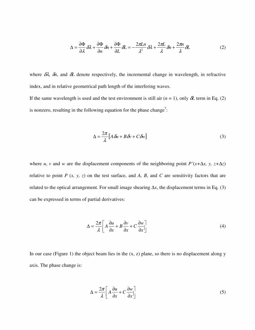
where δλ, δn, and δL denote respectively, the incremental change in wavelength, in refractive
index, and in relative geometrical path length of the interfering waves.
If the same wavelength is used and the test environment is still air (n = 1), only δL term in Eq. (2)
is nonzero, resulting in the following equation for the phase change7:
[ ]wCvBuA δδδλ
π++=∆
2 (3)
where u, v and w are the displacement components of the neighboring point P’(x+∆x, y, z+∆z)
relative to point P (x, y, z) on the test surface, and A, B, and C are sensitivity factors that are
related to the optical arrangement. For small image shearing ∆x, the displacement terms in Eq. (3)
can be expressed in terms of partial derivatives:
∂
∂+
∂
∂+
∂
∂=∆
x
wC
x
vB
x
uA
λ
π2 (4)
In our case (Figure 1) the object beam lies in the (x, z) plane, so there is no displacement along y
axis. The phase change is:
∂
∂+
∂
∂=∆
x
wC
x
uA
λ
π2 (5)

Consider the situation of an ESPSI system with one holographic grating in front of the CCD
camera and small image shear ∆x. The phase difference ∆ can be expressed as3
( ) xx
w
x
u∆
+
∂
∂+
∂
∂=∆ θθ
λ
πcos1sin
2 (6)
The dark fringes correspond to ∆ = 2nπ, where n is the fringe order. In this case:
( )x
n
x
w
x
u
∆=+
∂
∂+
∂
∂ λθθ cos1sin (7)
Fig.1. An optical set-up of the ESPSI system with a photopolymer grating
diode laser
CCD camera
object
imaging lens
photopolymer
holographic grating
ground glass
θθθθ
x
z
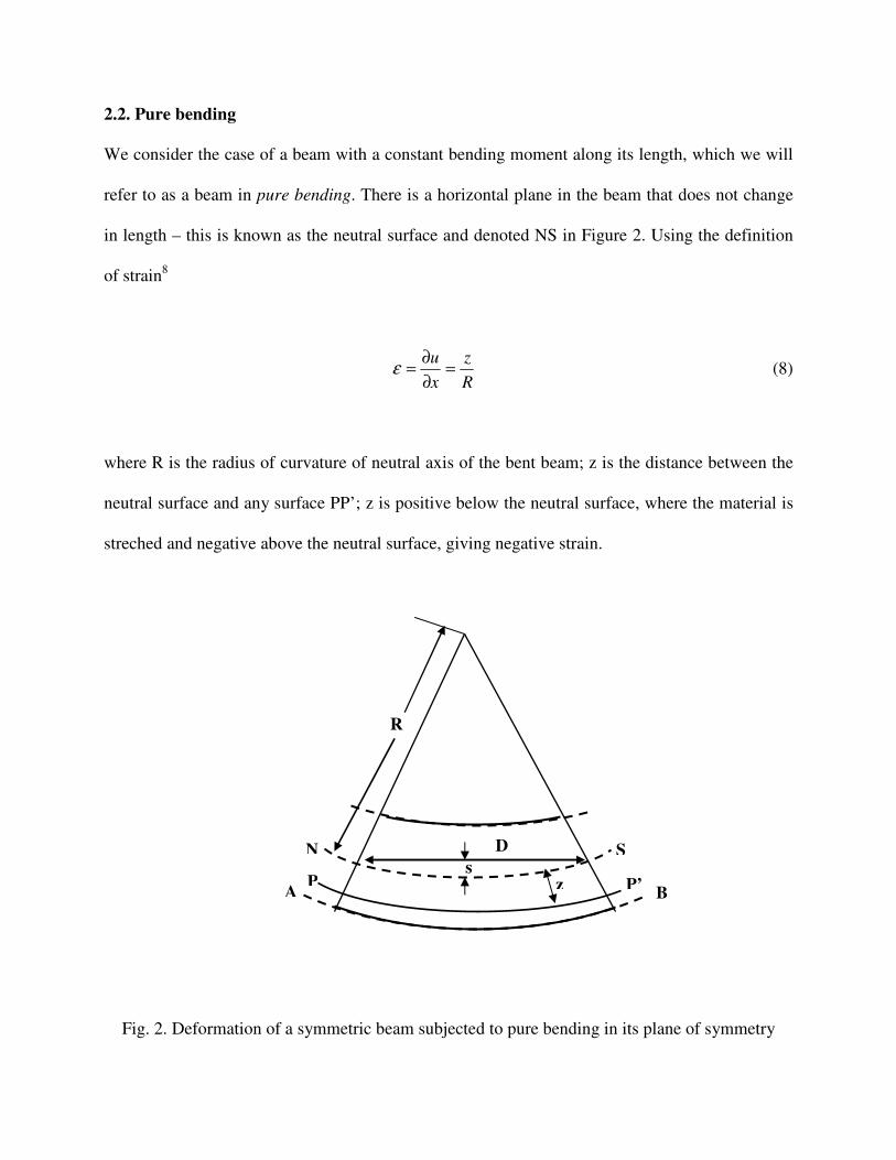
2.2. Pure bending
We consider the case of a beam with a constant bending moment along its length, which we will
refer to as a beam in pure bending. There is a horizontal plane in the beam that does not change
in length – this is known as the neutral surface and denoted NS in Figure 2. Using the definition
of strain8
R
z
x
u=
∂
∂=ε (8)
where R is the radius of curvature of neutral axis of the bent beam; z is the distance between the
neutral surface and any surface PP’; z is positive below the neutral surface, where the material is
streched and negative above the neutral surface, giving negative strain.
Fig. 2. Deformation of a symmetric beam subjected to pure bending in its plane of symmetry
A
N S
z P P’
R
s
D
B

The height of a curve measured from the chord (the sag formula) is:
2
2
2
−−=
DRRs (9)
where D is the diameter of the optical surface; we assume that the radius of the curvature of the
surface of interest is R as the degree of bending is of the order of microns (R>>z).
Using Eq. (8) and Eq. (9)
22 4
4
sD
ds
x
u
+=
∂
∂=ε (10)
where d is the thickness of the beam. As the ESPSI fringes are observed on the outer stretched
surface of the beam, 2
dz = .
For calibration of the system the well-known formulas8 for the slope (Eq. 11 and Eq. 12) have
been used:
( )EI
xLPx
x
w
16
4)(
22 −−=
∂
∂
20
Lx ≤≤ (11)
( )( )EI
LxxLPx
x
w
16
223)(
−−−=
∂
∂ Lx
L≤≤
2 (12)

where P is the constant uniform load per unit length, L is the length of the beam, EI is the
bending modulus.
3. EXPERIMENT
The arrangement of the electronic speckle pattern shearing interferometric system with a single
photopolymer holographic grating is presented schematically in Figure 2. A laser diode, with
wavelength 785 nm and a maximum output power of 50 mW, is used as the light source. A laser
beam illuminates the object at an angle θ = 30° to the normal to the object surface. A lens images
the object onto a ground glass. A holographic photopolymer diffraction grating is placed in front
of the ground glass, which acts as a diffusing screen. A holographic grating with spatial
frequency 500 lines per mm was recorded using the second harmonic of NdYAG laser -
λ=532nm. The diffraction efficiency of the grating is 60%. The intensities of the zero and the
first order of diffraction were equalized by rotation of the grating. The rotation of the grating
leads to slight off-Brag angle reading and decreases the intensity of the first order thus offering
the possibility for fine adjustment of both image and sheared image intensities.
4. RESULTS AND DISCUSSION
Figure 3 and Figure 4 show the results from the test of the ESPSI system using a photopolymer
holographic grating to introduce the shear. Fringe patterns presented on Figure 3 were recorded
during cooling of an aluminium tin filled with hot water. The fringe pattern characteristic of the
derivative of the displacement of the deformed object is displayed on the computer monitor. A
filter with a 3x3 window was used to remove the speckle noise in the images. The fringe pattern
contrast was estimated to be above 90%.

Fig. 3. ESPSI fringes in aluminium tin filled with hot water recorded during cooling:
a) at the beginning; b) after 3s; c) after 6s; d) after 9 s. The field of view is 20mm x 26mm
Fig. 4. ESPSI fringes on PVC during pure bending under deflection of:
a) 5 µm; b) 20µm. The field of view is 19 mm x 22 mm. The shear is ∆x = 6 mm.
a b c d

Fringe patterns presented in Figure 4 were recorded during pure bending of an polyvinylchloride
(PVC) beam with following dimensions: length - L = 130 mm; width – d = 6 mm and height – h
= 27 mm. The deflection was introduced using a vernier support and a step of 5 µm.
Fig. 5. Distribution of the phase difference vs. distance on the x-axis:
30 µm deflection - theory; 30 µm deflection - experiment;
35 µm deflection - theory; 35 µm deflection - experiment;
40 µm deflection - theory; 40 µm deflection - experiment;
-6.50E-04
-4.50E-04
-2.50E-04
-5.00E-05
1.50E-04
3.50E-04
5.50E-04
0.25 0.3 0.35 0.4 0.45 0.5 0.55 0.6 0.65 0.7 0.75
x/L
ph
ase d
iffe
ren
ce

Figure 5 presents the calibration curves of the ESPSI system with a single photopolymer
holographic grating and a ground glass. After substitution of the theoretical formulas for the
strain (10) and the slope (11) and (12) in the left part of Equation (7) we calculated the phase
difference distribution in x direction. From the experimental results for the position of the fringes
with order n = 0, 1, 2… we calculated the same phase difference distribution - right part of
Equation (7). The three different distributions (for deflections: 30 µm, 35 µm and 40µm) show a
good agreement between the theoretical prediction and the experimental data.
5. CONCLUSIONS
A new application of a photopolymer diffractive optical element in electronic speckle pattern
shearing interferometer (ESPSI) is presented. We improve the fringe pattern contrast in a simple
ESPSI scheme proposed by Jonathan & Bürkle4 utilising a photopolymer phase diffraction
grating as a shear-introducing element. The holographic grating is recorded using a self-
developing acrylamide based photopolymer material. The holographic grating is used to shear the
two images on a sheet of ground glass. The distance between the grating and the ground glass can
be used to control the amount of the shear. The sheared images on the ground glass are further
imaged onto a CCD camera. The introduction of the ground glass in the ESPSI system removes
the limitation for the grating spatial frequency to be low in order to be resolved by the CCD
camera.
A validation of the system was done by comparing the theoretical phase difference distribution
with the experimental data from the three point bending test.
The ESPSI system using a diffraction grating as a shearing element is compact, offers a simple
way to introduce discrete shear steps between two images by changing the distance between the
grating and the imaging plane. An additional advantage is the low cost of such a system.
ACKNOWLEDGMENTS
Acknowledgements are made to Technological Sector Research Programme Strand III supported
by the Irish Government. Emilia Mihaylova and Izabela Naydenova would like to thank Arnold
F. Graves Scholar Programme and FOCAS at Dublin Institute of Technology.
REFERENCES
1. Y. Iwahashi, K. Iwata, and R. Nagata, “Single-aperture speckle shearing interferometry with
a single grating”, Appl. Opt. 23 (2), 247-249 (1984).
2. C. Joenathan and R. S. Sirohi, “Holographic gratings in speckle shearing interferometry”,
Appl. Opt. 24 (17), 2750-2751 (1985).
3. H. Rabal, R. Henao, R. Torroba, “Digital speckle pattern shearing interferometry using
diffraction gratings”, Optics Comm. 126, 191-196 (1996).
4. C. Joenathan, L. Bürkle, “Elecktronic speckle pattern shearing interferometer using
holographic gratings”, Opt. Eng. 36 (9), 2473-2477 (1997).
5. S. Martin, P. Leclère, V. Toal, Y. Renotte and Y. Lion, “Characterisation of acrylamide-
based photopolymer holographic recording material”, Optical Engineering, 32 (12), 3942 –
3946 (1994).
6. C. M. Vest, Holographic Interferometry (John Wiley, New York 1979).
7. Y. Y. Hung and C. Y. Liang, “Image shearing camera for direct measurement of surface-
strains”, Appl. Opt. 10(7), 1046-1050 (1979).
8. T. J. Lardner and R. R. Archer, Mechanics of Solids (McGraw-Hill, Hightstown 1994).
E. Mihaylova, V. Toal, S. Martin, B. Bowe, “Mechanical characterization of polyvinilchloride
pipes using electronic speckle pattern interferometry”, in Opto-Ireland 2002 Optics and
Photonics Technologies and Applications, W. Blau, J. Donegan, A. Duke, B. MacCraith, J.
McLaughlin, N. McMillan, G. O’Connor, E. O’Mongain and V. Toal, eds., Proc. SPIE 4876, 994
– 1007 (2003).

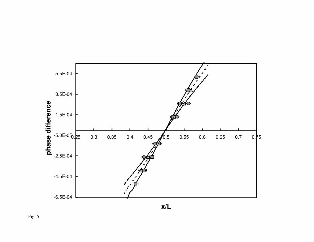
Fig. 5
-6.5E-04
-4.5E-04
-2.5E-04
-5.0E-05
1.5E-04
3.5E-04
5.5E-04
0.25 0.3 0.35 0.4 0.45 0.5 0.55 0.6 0.65 0.7 0.75
x/L
ph
ase d
iffe
ren
ce
Related Documents