JAYA ENGINEERING COLLEGE NAME : MICHAEL ANANDHARAJ.A EMAIL : [email protected] NAME : HARIHARAN.M EMAIL : [email protected] INTRODUCTION The invention of the transistor enabled the first radio telemetry capsules, which utilized simple circuits for in vivo telemetric studies of the gastro-intestinal tract. These units could only transmit from a single sensor channel, and were difficult to assemble due to the use of discrete components. The measurement parameters consisted of temperature, pH or pressure, and the first attempts of conducting real-time noninvasive physiological measurements suffered from poor reliability, low sensitivity, and short lifetimes of the devices. The first successful pH gut profiles were achieved in 1972, with subsequent improvements in sensitivity and lifetime. Single-channel raditelemetrycapsules have since been applied for the detection of disease and abnormalities in the GI tract where restricted access prevents the use of traditional endoscopy. MICROELECTRONIC PILLDESIGN AND FABRICATION ISFET This new line of pH meters and probes, based on ISFET (Ion Sensitive Field Effect Transistor) sensor technology, includes four pH meters and 10 pH probes. The pH meters are designed for ease-of-use and feature an interactive graphics LCD display with on-board Help and Auto-Read functions. All meters constantly monitor and display probe status and an estimation of its remaining life. The advanced meters have real-time clocks for time/date stamping, calibration alerts and high/low pH alarms.Titan Bench top pH meters operate on AC or battery power and offer a

Welcome message from author
This document is posted to help you gain knowledge. Please leave a comment to let me know what you think about it! Share it to your friends and learn new things together.
Transcript
JAYA ENGINEERING COLLEGE NAME : MICHAEL ANANDHARAJ.AEMAIL :[email protected] : HARIHARAN.MEMAIL : [email protected]
INTRODUCTION
The invention of the transistor
enabled the first radio
telemetry capsules, which
utilized simple circuits for in
vivo telemetric studies of the
gastro-intestinal tract. These
units could only transmit from
a single sensor channel, and
were difficult to assemble due
to the use of discrete
components. The measurement
parameters consisted of
temperature, pH or pressure,
and the first attempts of
conducting real-time
noninvasive physiological
measurements suffered from poor
reliability, low sensitivity,
and short lifetimes of the
devices. The first successful
pH gut profiles were achieved
in 1972, with subsequent
improvements in sensitivity and
lifetime. Single-channel
raditelemetrycapsules have
since been applied for the
detection of disease and
abnormalities in the GI tract
where restricted access
prevents the use of traditional
endoscopy.
MICROELECTRONIC PILLDESIGN
AND FABRICATION
ISFET
This new line of pH meters and
probes, based on ISFET (Ion
Sensitive Field Effect
Transistor) sensor technology,
includes four pH meters and 10
pH probes. The pH meters are
designed for ease-of-use and
feature an interactive graphics
LCD display with on-board Help
and Auto-Read functions. All
meters constantly monitor and
display probe status and an
estimation of its remaining
life. The advanced meters have
real-time clocks for time/date
stamping, calibration alerts
and high/low pH alarms.Titan
Bench top pH meters operate on
AC or battery power and offer a
host of sophisticated features,
including programmable user
alarms and data logging. Argus
Portable meters are rugged,
waterproof and operate on a
long-life rechargeable battery.
Each meter is available in
simple or advanced versions and
is supported by a variety of
probes covering almost
every application. The portable
Argususes an inductive
(contact-less) battery charging
system and IR data transfer
eliminating the need for
battery replacement or open
contact points. This design
ensures a completely watertight
(IP67) rating.
Three new series of ISFET
probes include the Red-Line
general purpose series for
routine applications, the Hot-
Line series for testing to
105°C and in aggressive
samples, and the Stream-Line
series that are temperature and
chemically resistant, and
employ a flow-type reference
junction to maximize
performance in difficult
samples.
pH value
pH is a measure of
the acidity or basicity of
an aqueous solution. Pure water
is said to be neutral, with a
pH close to 7.0 at
25 °C (77 °F). Solutions with a
pH less than 7 are said to
be acidic and solutions with a
pH greater than 7
are basic or alkaline.pH
measurements are in important
in medicine, biology,
chemistry, food science,
environmental science,
oceanography, civil engineering
and many other applications.
In a solution pH approximates
but is not equal to p[H], the
negative logarithm (base 10) of
the molarconcentration of
dissolved hydronium ions (H3O+);
a low pH indicates a high
concentration of hydronium
ions, while a high pH indicates
a low concentration. Crudely,

this negative of the logarithm
matches the number of places
behind the decimal point, so
for example
0.1 molar hydrochloric
acid should be near pH 1 and
0.0001 molar HCl should be near
pH 4 (the base 10 logarithms of
0.1 and 0.0001 being −1, and
−4, respectively). Pure (de-
ionized) water is neutral, and
can be considered either a very
weak acid or a very weak base
(center of the 0 to 14 pH
scale), giving it a pH of 7 (at
25 °C (77 °F)), or
0.0000001 M H+.[1] For
an aqueous solution to have a
higher pH, a base must be
dissolved in it, which binds
away many of these rare
hydrogen ions. Hydrogen ions in
water can be written simply as
H+ or as hydronium (H3O+) or
higher species (e.g. H9O4+) to
account forsolvation, but all
describe the same entity. Most
of the Earth's freshwater
surface bodies are slightly
acidic due to the abundance and
absorption of carbon dioxide;[2] in fact, for millennia in
the past most fresh water
bodies have long existed at a
slightly acidic pH level.
Sensors
The sensors were fabricated on
two silicon chips located at
the front end of the capsule.
Chip 1 comprises the silicon
diode temperature sensor, the
pH ISFET sensor and a two
electrode conductivity sensor.
Chip 2 comprises the oxygen
sensor and an optional nickel-
chromium (NiCr) resistance
thermometer. The silicon
platform of Chip 1was based on a
research product from
EcoleSuperieureD’In-genieurs en
Electro technique et
Electroniquewith predefined n-
channels in the p-type bulk
silicon forming the basis for
the diode and the ISFET. A
total of 542 of such de-vices
were batch fabricated onto a
single 4-in wafer. In contrast,
Chip 2was batch fabricated as a

9X9 array on a 380-m-
thicksingle crystalline
3nSilicon wafer with
<100>lattice orientation,
precoated with 300 nm Si3N4,
silicon nitride. One wafer
yielded 80,5X5 mm2 sensors (the
center of the wafer was used
for alignment markers)
Sensor Chip 1
An array of 4X2 combined
temperature and pH sensor
platforms were cut from the
wafer and attached on to a 100-
m-thick glass cover slip using
S1818 photo resist cured on a
hotplate. The cover slip acted
as temporary carrier to assist
handling of the device during
the first level of lithography
(Level 1) when the electric
connection tracks, the
electrodes and the bonding pads
were defined. The pattern was
defined in S1818 resist by
photolithography prior to
thermal evaporation of 200 nm
gold (including an adhesion
layer of 15 nm titanium and 15
nm palladium). An additional
layer of gold (40 nm) was
sputtered to improve the
adhesion of the electroplated
silver used in the reference
electrode. Liftoff in acetone
detached the chip array from
the cover slip. Individual
sensors were then diced prior
to their re-attachment in pairs
on a 100-m-thick cover slip by
epoxy resin. The left-hand-side
(LHS) unit comprised the diode,
while the right-hand-side (RHS)
unit comprised the ISFET.
The15X600 m (LXW) floating
gate of the ISFET was
precovered with a 50-nm-thick
proton sensitive layer of Si3N4
for pH detection. Photo curable
polyimide de-fined the 10-nL
electrolyte chamber for the pH
sensor (above the gate) and the
open reservoir above the
conductivity sensor (Level 2).
Photolithography
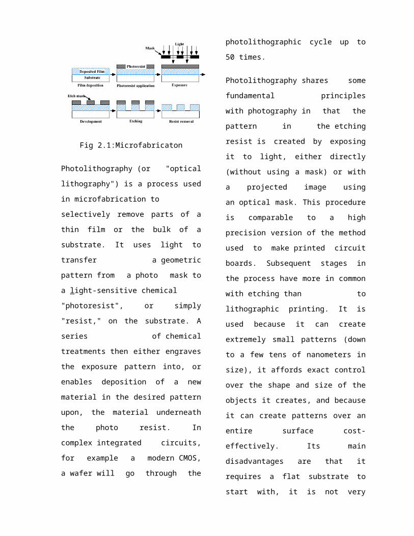
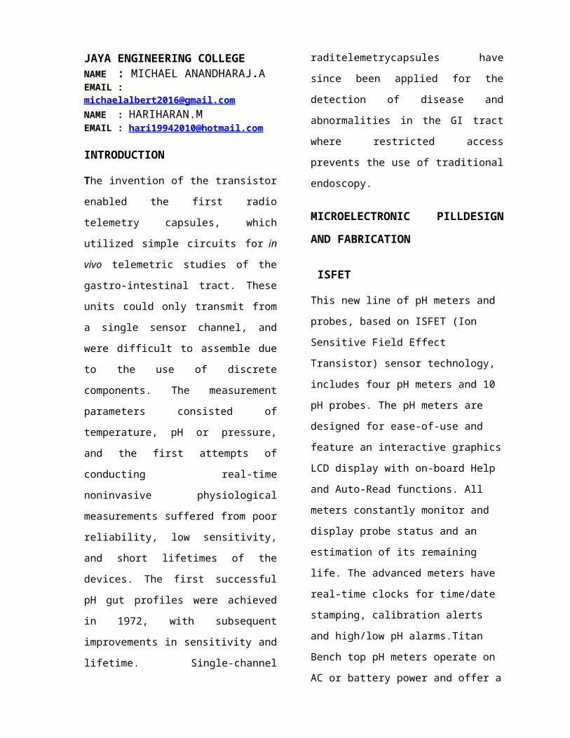
Fig 2.1:Microfabricaton
Photolithography (or "optical
lithography") is a process used
in microfabrication to
selectively remove parts of a
thin film or the bulk of a
substrate. It uses light to
transfer a geometric
pattern from a photo mask to
a light-sensitive chemical
"photoresist", or simply
"resist," on the substrate. A
series of chemical
treatments then either engraves
the exposure pattern into, or
enables deposition of a new
material in the desired pattern
upon, the material underneath
the photo resist. In
complex integrated circuits,
for example a modern CMOS,
a wafer will go through the
photolithographic cycle up to
50 times.
Photolithography shares some
fundamental principles
with photography in that the
pattern in the etching
resist is created by exposing
it to light, either directly
(without using a mask) or with
a projected image using
an optical mask. This procedure
is comparable to a high
precision version of the method
used to make printed circuit
boards. Subsequent stages in
the process have more in common
with etching than to
lithographic printing. It is
used because it can create
extremely small patterns (down
to a few tens of nanometers in
size), it affords exact control
over the shape and size of the
objects it creates, and because
it can create patterns over an
entire surface cost-
effectively. Its main
disadvantages are that it
requires a flat substrate to
start with, it is not very
effective at creating shapes
that are not flat, and it can
require extremely clean
operating conditions.
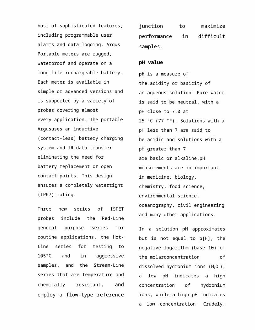
Fig. 2.2.The microelectronic sensors:
(a) schematic diagram of Chip
1,measuring4.75X5mm2, comprising the
pH (ISFET) sensor, the5X10mm2 dual
electrode conductivity sensor and the
silicon diode temperature sensor ;
(b) schematic diagram of Chip 2,
measuring 5X5mm2, comprising the
electrochemical oxygen sensor and a NiCr
resistance thermometer. Once integrated
in the pill, the area exposed to the
external environment is illustrated by the
3-mm-diameter circle;
(c) photomicrograph of sensor Chip 1 and
(d) sensorChip 2. The bonding pads, which
provide electrical contact to the external
electronic control circuit, are shown;
(e) close up of the pH sensor consisting of
the integrated 3x10⁻²mm2Ag|AgCl
reference electrode, a 500-m-diameter
and50–m-deep, 10-nL, electrolyte
chamber defined in polyimide, and the
15X600m floating gate of the ISFET
sensor;
(f) the oxygen sensor is likewise embedded
in an electrolyte chamber. The three-
electrode electrochemical cell comprises
the 1X10⁻¹ mm2 counter electrode, a
microelectrode array fX
diameter(4.5X10mm)working electrodes
(11) defined in500nmthick PECVD SiN, and
an integrated1.5X10mmAg|AgClreference
electrode.
The silver chloride reference
electrode (3x10⁻² mm2) was
fabricated during Levels 3 to5,
inclusive. The glass cover
slip, to which the chips were
attached, was cut down to the
size of the 4.75X5 mm2
footprint (still acting as a
supporting base)prior to
attachment on a custom-made
chip carrier used for
electroplating. Silver (m)
was deposited on the gold
electrode defined at by
chronopotentiometry (-300 nA,
600 s) after removing residual
polyimide in an O2 barrel asher
for 2 min. The electroplating
solution consisted of 0.2 M
AgNO3, 3 M KI and 0.5 M Na2SO4.
Changing the electrolyte
solution to 0.1 M KCl at Level
4 allowed for the electroplated
silver to be oxidized to AgCl
by chronopoteniometry (300 nA,
300 s). The chip was then
removed from the chip carrier
prior to injection of the
internal 1 M KCl reference
electrolyte required for the
Ag|AgCl reference electrode
(Level 5). The electrolyte was
retained in a 0.2% gel matrix
of calcium alginate.
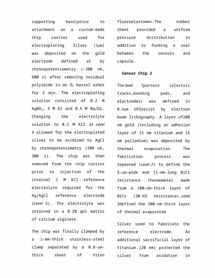
The chip was finally clamped by
a 1-mm-thick stainless-steel
clamp separated by a 0.8-m-
thick sheet of Viton
fluoroelastomer.The rubber
sheet provided a uniform
pressure distribution in
addition to forming a seal
between the sensors and
capsule.
Sensor Chip 2
The level 1pattern (electric
tracks,bonding pads, and
electrodes) was defined in
0.m UV3resist by electron
beam lithography. A layer of200
nm gold (including an adhesion
layer of 15 nm titanium and 15
nm palladium) was deposited by
thermal evaporation. The
fabrication process was
repeated (Level 2) to define the
5-m-wide and 11-mm-long NiCr
resistance thermometer made
from a 100-nm-thick layer of
NiCr (30-kΩ resistance).Level
3defined the 500-nm-thick layer
of thermal evaporated
Silver used to fabricate the
reference electrode. An
additional sacrificial layer of
titanium (20 nm) protected the
silver from oxidation in

subsequent fabrication levels.
The surface area of the
reference electrode was1.5x10-
2mm2, whereas thecounter
electrode made of gold had an
area of1.1x10-1mm2.Level 4defined
the microelectrode array of the
working electrode, comprising
57 circular gold electrodes,
each 10 m in diameter, with an
interelectrode spacing of 25m
and a combined area of4.5x10-
2mm2. Such an array promotes
electrode polarization and
reduces response time by
enhancing transportto the
electrode surface. The whole
wafer was covered with500 nm
plasma-enhanced chemical vapor
deposited (PECVD). The pads,
counter, reference, and the
microelectrode array of the
working electrode was exposed
using an etching mask of S1818
photo resist prior to dry
etching with C2f6. The chips
were then diced from the wafer
and attached to separate 100-
m-thick cover slips by epoxy
resin to assist handling. The
electrolyte chamber was defined
in 50-m-thick polyimide atLevel
5. Residual polyimide was
removed in an O2barrel asher(2
min), prior to removal of the
sacrificial titanium layer at
Level6 in a diluted HF solution
(HF to RO water, 1:26) for 15
s. Theshort exposure to HF
prevented damage to the PECVD
Si3N4Layer.Thermally evaporated
silver was oxidized to Ag|AgCl
(50%of film thickness) by
chronopotentiometry (120 nA,
300 s) atLevel 7in the presence
of KCl, prior to injection of
the internalreference
electrolyte at Level 8. A
5X5mm2sheet of oxygen
permeableteflon was cut out
from a 12.5-m-thick film and
attached to the chip at Level
9 with epoxy resin prior to
immobilization by the aid of a
stainless steel clamp.
Plasma-enhanced chemical
vapor deposition (PECVD)
It is a process used
to deposit thin films from

a gas state (vapor) to
a solid state on
a substrate. Chemical
reactions are involved in the
process, which occur after
creation of a plasma of the
reacting gases. The plasma is
generally created by RF (AC)
frequency or DC discharge
between two electrodes, the
space between which is filled
with the reacting gases.
Control Chip
The ASIC was a control unit
that connected together the
external components of the
micro system. It was fabricated
as a 22.5 mm2 silicon die using
a 3-V, 2-poly, 3-metal 0.6-m
CMOS process by Austria
Microsystems (AMS) via the
Euro-practice initiative. It is
a novel mixed signal design
that contains an analog signal
conditioning module operating
the sensors, an 10-bit analog-
to-digital (ADC) and digital-
to-analog(DAC) converters, and
a digital data processing
module. AnRCrelaxation
oscillator (OSC) provides the
clock signal.
The analog module was based on
the AMS OP05B operational
amplifier, which offered a
combination of both a power-
saving scheme (sleep mode) and
a compact integrated
circuitdesign. The temperature
circuitry biased the diode at
constantcurrent, so that a
change in temperature would
reflect a corresponding change
in the diode voltage. The pH
ISFET sensor was biased as a
simple source and drain
follower at constant current
with the drainsource voltage
changing with the threshold
voltage and pH. The
conductivity circuit operated
at direct current measuring the
resistance across the electrode
pair as an inverse function of
solution conductivity. An
incorporated potentiostat
circuit operated the
amperometric oxygen sensor with
a10-bit DAC controlling the
working electrode potential
with respect to the
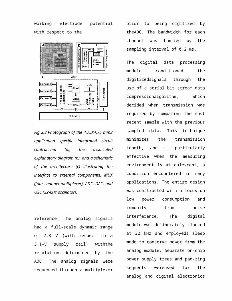
Fig 2.3.Photograph of the 4.75X4.75 mm2
application specific integrated circuit
control chip (a), the associated
explanatory diagram (b), and a schematic
of the architecture (c) illustrating the
interface to external components. MUX
(four-channel multiplexer), ADC, DAC, and
OSC (32-kHz oscillator).
reference. The analog signals
had a full-scale dynamic range
of 2.8 V (with respect to a
3.1-V supply rail) withthe
resolution determined by the
ADC. The analog signals were
sequenced through a multiplexer
prior to being digitized by
theADC. The bandwidth for each
channel was limited by the
sampling interval of 0.2 ms.
The digital data processing
module conditioned the
digitizedsignals through the
use of a serial bit stream data
compressionalgorithm, which
decided when transmission was
required by comparing the most
recent sample with the previous
sampled data. This technique
minimizes the transmission
length, and is particularly
effective when the measuring
environment is at quiescent, a
condition encountered in many
applications. The entire design
was constructed with a focus on
low power consumption and
immunity from noise
interference. The digital
module was deliberately clocked
at 32 kHz and employeda sleep
mode to conserve power from the
analog module. Separate on-chip
power supply trees and pad-ring
segments wereused for the
analog and digital electronics
sections in order todiscourage
noise propagation and
interference.
2.3.4. Radio Transmitter
The radio transmitter was
assembled prior to integration
in thecapsule using discrete
surface mount components on a
single-sided printed circuit
board (PCB). The footprint of
the standardtransmitter
measured 8X5X3mm including the
integratedcoil (magnetic)
antenna. It was designed to
operate at a trans-mission
frequency of 40.01 MHz at 20oC
generating a signalof 10 kHz
bandwidth. A second crystal
stabilized transmitterwas also
used. This second unit was
similar to the free running
standard transmitter, apart
from having a larger footprint
of10X5X3 mm, and a transmission
frequency limited to 20.08MHz
at 20oC, due to the crystal
used. Pills incorporating
thestandard transmitter were
denotedType I, whereas the pills
incorporating the crystal
stabilized unit were denotedType
II. Thetransmission range was
measured as being 1 meter and
the modulation scheme frequency
shift keying (FSK), with a data
rate of 1kbs-1.
1. Size of transmitter = 8
× 5 × 3 mm
2. Modulation Scheme =
Frequency Shift Keying
(FSK)
3. Data Transfer Rate = 1
kbps
4. Frequency = 40.01 MHz at
20 °C
5. Bandwidth of the signal
generated 10 KHz
6. It consumes 6.8 mW power
at 2.2 mA of current.
2.3.5. Capsule
The microelectronic pill
consisted of a machined
biocompatible (noncytotoxic),
chemically resistant
polyetherterketone (PEEK)
capsule and a PCB chip carrier
acting as a common platform for
attachment of the sensors,

ASIC, transmitter and the
batteries (Fig.2.3). The
fabricated sensorswere each
attached by wire bonding to a
custom made chip carrier made
from a 10-pin, 0.5-mm pitch
polyimide ribbon connector. The
ribbon connector was, in turn,
connected to an industrial
standard 10-pin flat cable plug
(FCP) socket attached to the
PCB chip carrier of the
microelectronic pill, to
facilitate rapid replacement of
the sensors whenrequired. The
PCB chip carrier was made from
two standard1.6-mm-thick fiber
glass boards attached back to
back by epoxyresin which
maximized the distance between
the two sensorchips. The sensor
chips were connected to both
sides of the PCBby separate FCP
sockets, with sensorChip
1 facing the top face, withChip
2 facing down. Thus, the oxygen
sensor onChip 2 hadto be
connected to the top face by
three 200-m copper leads
soldered on to the board. The
transmitter was integrated in
thePCB which also incorporated
the power supply rails, the
connection points to the
sensors, as well as the
transmitter and theASIC and the
supporting slots for the
capsule in which the
chipcarrier was located.
The ASIC was attached with
double-sided copper
conductingtape (Agar
Scientific, U.K.) prior to
wirebonding to the powersupply
rails, the sensor inputs, and
the transmitter (a processwhich
entailed the connection of 64
bonding pads). The unitwas
powered by two standard 1.55-V
SR44 silver oxide(Ag2O)cells
with a capacity of 175 mAh. The
batteries were serial connected
and attached to a custom made
3-pin, 1.27-mm pitch plugby
electrical conducting epoxy.
The connection to the matching
socket on the PCB carrier pro-
vided a three point power
supply to the circuit
comprising a negative supply
rail (-1.55 V), virtual ground
(0 V), and a positivesupply
rail (1.55 V). The battery pack
was easily replaced duringthe
experimental procedures.
The capsule was machined as two
separate screw-fitting
compartments. The PCB chip
carrier was attached to the
front section of the capsule.
The sensor chips were exposed
tothe ambient environment
through access ports and were
sealedby two sets of stainless
steel clamps incorporating a
0.8-m-thick sheet of Viton
fluoroelastomer seal. A 3-mm-
diameter access channel in the
center of each of the steel
clamps (incl. the seal),
exposed the sensing regions of
the chips. The rear section of
the capsule was attached to the
front section by a 13-mmscrew
connection incorporating a
Viton rubber O-ring. The seals
rendered the capsule water
proof, as well as making it
easy to maintain (e.g., during
sensor and battery
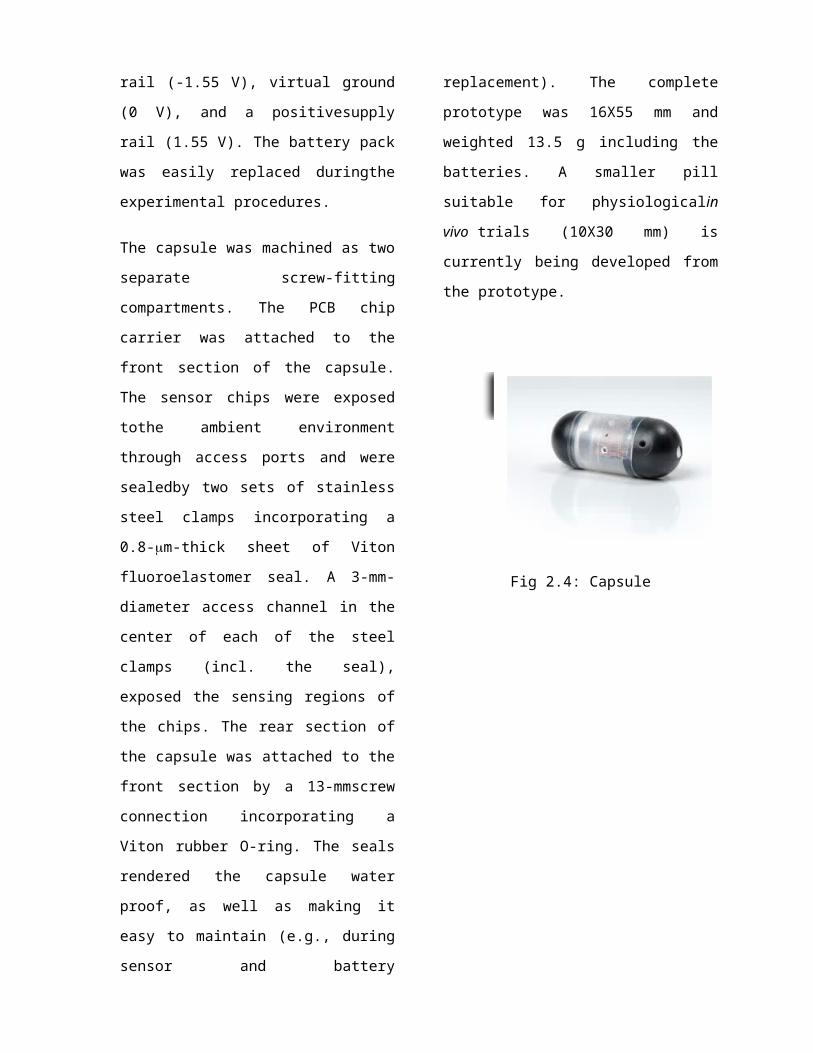
replacement). The complete
prototype was 16X55 mm and
weighted 13.5 g including the
batteries. A smaller pill
suitable for physiologicalin
vivo trials (10X30 mm) is
currently being developed from
the prototype.
Fig 2.4: Capsule
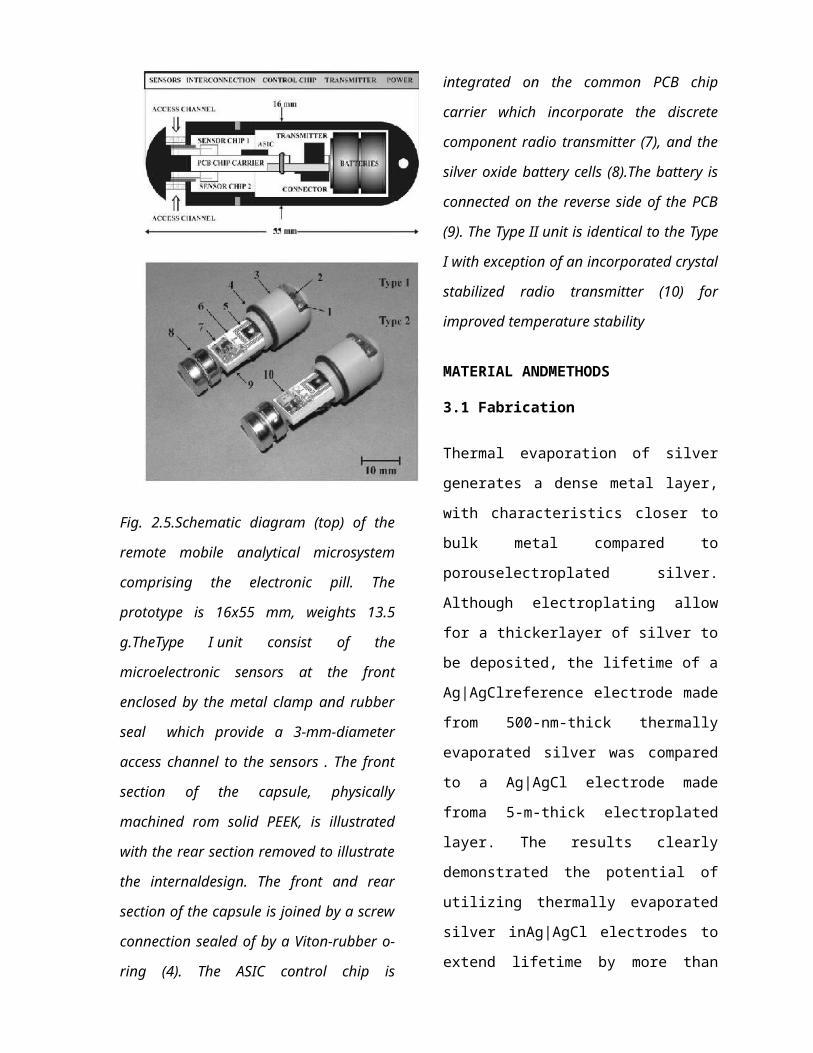
Fig. 2.5.Schematic diagram (top) of the
remote mobile analytical microsystem
comprising the electronic pill. The
prototype is 16x55 mm, weights 13.5
g.TheType I unit consist of the
microelectronic sensors at the front
enclosed by the metal clamp and rubber
seal which provide a 3-mm-diameter
access channel to the sensors . The front
section of the capsule, physically
machined rom solid PEEK, is illustrated
with the rear section removed to illustrate
the internaldesign. The front and rear
section of the capsule is joined by a screw
connection sealed of by a Viton-rubber o-
ring (4). The ASIC control chip is
integrated on the common PCB chip
carrier which incorporate the discrete
component radio transmitter (7), and the
silver oxide battery cells (8).The battery is
connected on the reverse side of the PCB
(9). The Type II unit is identical to the Type
I with exception of an incorporated crystal
stabilized radio transmitter (10) for
improved temperature stability
MATERIAL ANDMETHODS
3.1 Fabrication
Thermal evaporation of silver
generates a dense metal layer,
with characteristics closer to
bulk metal compared to
porouselectroplated silver.
Although electroplating allow
for a thickerlayer of silver to
be deposited, the lifetime of a
Ag|AgClreference electrode made
from 500-nm-thick thermally
evaporated silver was compared
to a Ag|AgCl electrode made
froma 5-m-thick electroplated
layer. The results clearly
demonstrated the potential of
utilizing thermally evaporated
silver inAg|AgCl electrodes to
extend lifetime by more than
100%.However, a protective
layer of 20 nm titanium was
required toprevent oxidation of
the silver in subsequent
fabrication levels,and which
had to be removed by immersion
in a HF solution. Since HF also
attacks, this procedure could
not be used inChip 1 to avoid
damage to the thin 50–nm layer
ofdefining the pH sensitive
membrane of the ISFET. In
contrast,the 500-nm-thick
PECVDdefining the
microelectrodearray of the
oxygen sensor, was tolerant to
HF exposure.
The sensor lifetime was further
extended through using athree-
electrode electrochemical cell
for the oxygen sensor, infavor
of a two-electrode device. A
two electrode unit utilizes
thereference electrode as a
combined counter and reference
unit tochannel all the current
from the reduction of oxygen.
However, a three-electrode
electrochemical cell bypasses
the current flowfrom the
working electrode by
incorporating a separate
counterelectrode subjecting the
reference electrode only to the
bias cur-rent of the input
transistor stage of the
operational amplifier, towhich
the sensor is connected. Thus,
the overall current channeled
through the reference was
reduced by at least three
ordersof magnitude. This effect
is important as it enables a
reductionin the electrode area
and improved long-term
stability.
3.2. General Experimental Setup
All the devices were powered by
batteries in order to
demonstrate the concept of
utilizing the microelectronic
pill in re-mote locations
(extending the range of
applications fromin vivosensing
to environmental or industrial
monitoring). The pill
wassubmerged in a 250-mL glass
bottle located within a 2000-
Mlbeaker to allow for a rapid
change of pH and temperature of
thesolution. A scanning
receiver captured the wireless
radio transmitted signal from
themicroelectronic pill by
using a coil antenna wrapped
around the2000-mL polypropylene
beaker in which the pill was
located. A portable Pentium III
computer controlled the data
acquisition unit (National
Instruments, Austin, TX) which
digitally acquired analog data
from the scanning receiver
prior to recording it on the
computer.
The solution volume used in all
experiments was 250 mL.The
beaker, pill, glass bottle, and
antenna were located withina
25X25 cm container of
polystyrene, reducing
temperaturefluctuations from
the ambient environment (as
might be expected within the GI
tract) and as required to
maintain a stabletransmission
frequency. The data was
acquired using Lab View and
processed using a MATLAB
routine.
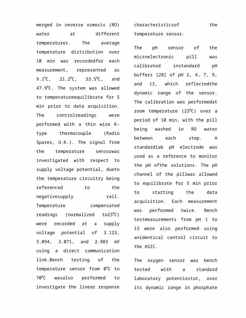
Fig 3.1
3.3. SensorCharacterization
The lifetime of the
incorporated Ag|AgCl reference
electrodes used in the pH and
oxygen sensors was measured
withan applied current of 1 pA
immersed in a 1.0 M KCl
electrolytesolution. The
current reflects the bias input
current of the operational
amplifier in the analog sensor
control circuitry to whichthe
electrodes were connected.
The temperature sensor was
calibrated with the pill sub-
merged in reverse osmosis (RO)
water at different
temperatures. The average
temperature distribution over
10 min was recordedfor each
measurement, represented as
9.10C, 21.20C, 33.50C, and
47.90C. The system was allowed
to temperatureequilibrate for 5
min prior to data acquisition.
The controlreadings were
performed with a thin wire K-
type thermocouple (Radio
Spares, U.K.). The signal from
the temperature sensorwas
investigated with respect to
supply voltage potential, dueto
the temperature circuitry being
referenced to the
negativesupply rail.
Temperature compensated
readings (normalized to230C)
were recorded at a supply
voltage potential of 3.123,
3.094, 3.071, and 2.983 mV
using a direct communication
link.Bench testing of the
temperature sensor from 00C to
700C wasalso performed to
investigate the linear response
characteristicsof the
temperature sensor.
The pH sensor of the
microelectronic pill was
calibrated instandard pH
buffers [28] of pH 2, 4, 7, 9,
and 13, which reflectedthe
dynamic range of the sensor.
The calibration was performedat
room temperature (230C) over a
period of 10 min, with the pill
being washed in RO water
between each step. A
standardlab pH electrode was
used as a reference to monitor
the pH ofthe solutions. The pH
channel of the pillwas allowed
to equilibrate for 5 min prior
to starting the data
acquisition. Each measurement
was performed twice. Bench
testmeasurements from pH 1 to
13 were also performed using
anidentical control circuit to
the ASIC.
The oxygen sensor was bench
tested with a standard
laboratory potentiostat, over
its dynamic range in phosphate
buffered saline (PBS) usinga
direct communication link at
23C. Cyclic voltammetry witha
sweep potential from 0.1 to
0.45 V (versus Ag|AgCl) was
per-formed in 1-mM ferroscene-
monocarboxylic acid (FMCA) as
amodel redox compound, to test
the performance of the micro-
electrode array. A three-point
calibration routine was
performedat oxygen
concentrations of 0 mg L-1(PBS
saturated with 2 M), 4 mg L-
1(PBS titration with 2 M) and
8.2mg L (oxygen saturated PBS
solution). The solution
saturatedwith dissolved oxygen
was equilibrated overnight
prior to use.The dissolved
oxygen was monitored using a
standard Clarkelectrode .The
reduction potential of water
was assessed in oxygen depleted
PBS, to avoid interference from
oxygen, at the same time
assessingthe lower potential
limit that could be used for
maximizing theefficiency of the
sensor. The voltage was then
fixed above thisreduction
potential to assess the dynamic
behavior of the sensorupon
injection of saturated Na2SO4in
oxygen saturated PBS.
3.4. Transmission
The pill’s transmission
frequency was measured with
respectto changes in
temperature. TheType I pill
(without crystal) wassubmerged
in RO water at temperatures of
10C, 110C,230 Cand 490C, whereas
theType II pill (with crystal)
was submergedin temperatures of
20C, 250C, and 450C. The change
in frequency was measured with
the scanning receiver, and the
resultsused to assess the
advantage of crystals
stabilized units at thecost of
a larger physical size of the
transmitter.
3.6. Sensor and Signal Drift
Long term static pH and
temperature measurements were
per-formed to assess signal
drift and sensor lifetime in
physiological electrolyte (0.9%
saline) solutions. A
temperature of 36.50Cwas
achieved using a water bath,
with the assay solutions
continuously stirred and re-
circulated using a peristaltic
pump. Thesensors were
transferred from solutions of
pH 4 to pH 7, within2 h of
commencing the experiment, and
from pH 7 to pH 10.5,after 4 h.
The total duration of the
experiment was 6 h. Each
experiment was repeated twice.
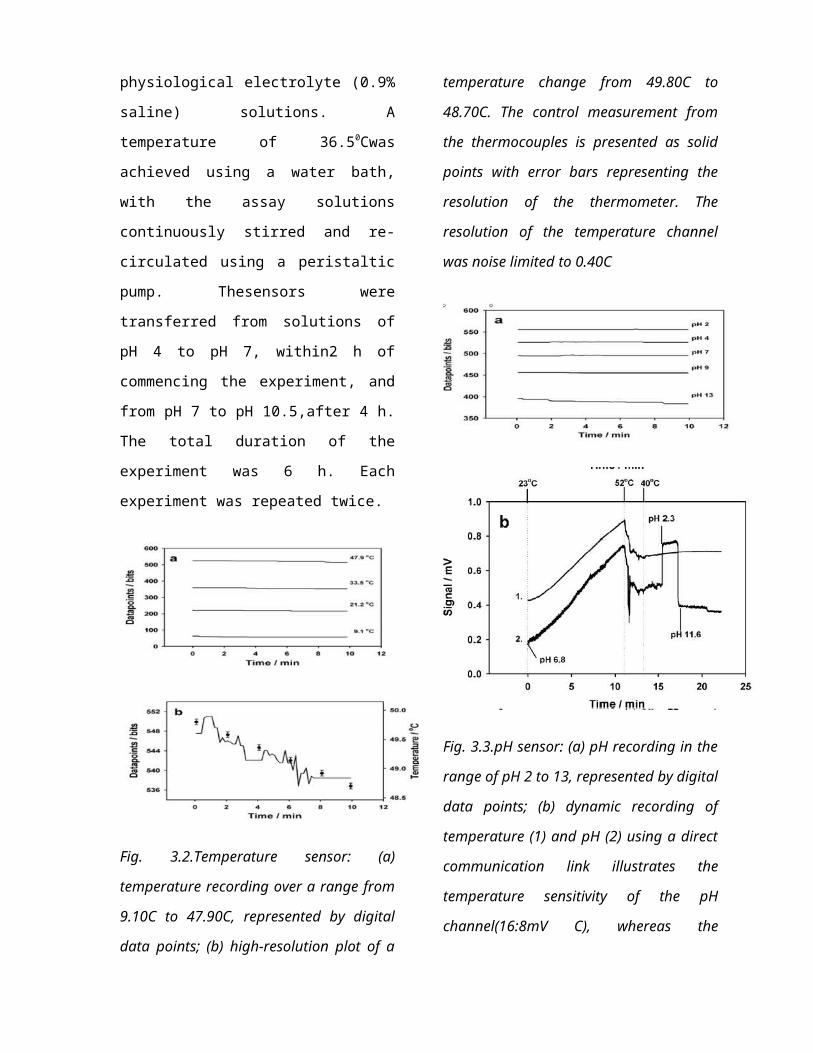
Fig. 3.2.Temperature sensor: (a)
temperature recording over a range from
9.10C to 47.90C, represented by digital
data points; (b) high-resolution plot of a
temperature change from 49.80C to
48.70C. The control measurement from
the thermocouples is presented as solid
points with error bars representing the
resolution of the thermometer. The
resolution of the temperature channel
was noise limited to 0.40C
Fig. 3.3.pH sensor: (a) pH recording in the
range of pH 2 to 13, represented by digital
data points; (b) dynamic recording of
temperature (1) and pH (2) using a direct
communication link illustrates the
temperature sensitivity of the pH
channel(16:8mV C), whereas the
temperature channel is insensitive to any
pH change
IMPORTANT OBSERVATIONS
The power consumption of the
microelectronic pill with the
transmitter, ASIC and the
sensors connected was
calculated to12.1 mW,
corresponding to the measured
current consumptionof 3.9 mA at
3.1-V supply voltage. The ASIC
and sensors consumed 5.3 mW,
corresponding to 1.7 mA of
current, whereasthe free
running radio transmitter (Type
I) consumed 6.8
mW(corresponding to 2.2 mA of
current) with the crystal
stabilized unit (Type II)
consuming 2.1 mA. Two SR44 Ag2O
batteries used provided an
operating time of more than 40
h for themicro system.
4.1. Temperature Channel
Performance
The linear sensitivity was
measured over a temperature
range from 00C to 700C and found
to be 15.4 mV0C-1. This
amplified signal response was
from the analog circuit, which
waslater implemented in the
ASIC. The sensor, once
integrated in the pill, gave a
linear regression of 11.9 bits-
C with a resolution limited by
the noise band of 0.40C. The
diodewas forward biased with a
constant current () with
then-channel clamped to ground,
while the p-channel was
floating.Since the bias current
supply circuit was clamped to
the negative voltage rail, any
change in the supply voltage
potential would cause the
temperature channel to drift.
Thus, bench test measurements
conducted on the temperature
sensor revealed thatthe output
signal changed by 1.45 mV per
mV change in supply voltage
expressed in millivolts,
corresponding to a drift of-
21mV h-1in the pill from a
supply voltage change of-
14.5m V - 1 .
4.2.pH Channel Performance
The linear characteristics from
pH 1 to 13 corresponded toa
sensitivity of-41.7mVpH-1unit at
230C, which is in agreement
with literature values although
the responsewas lower than the
Nernstian characteristics found
in standard glass pH electrodes
(-59.2mVunit). The pH
ISFETsensor operated in a
constant current mode (),
withthe drain voltage clamped
to the positive supply rail,
and thesource voltage floating
with the gate potential. The
Ag|AgClreference electrode,
representing the potential in
which thefloating gate was
referred to, was connected to
ground. Thesensor performance,
once integrated in the pill
[Fig. 3(a)], corresponded to
14.85 bitspH-1which gave a
resolution of 0.07pH per
datapoint. The calibrated
response from the pH
sensorconformed to a linear
regression, although the sensor
exhibited a larger
responsivityin alkaline
solutions. The sensor lifetime
of 20 h was limitedby the Ag|
AgCl reference electrode made
from electroplatedsilver. The
pH sensor exhibited a signal
drift of -6mVh-1(0.14 pH), of
which -2.5 mVh-1 was eliminated
to be due to the dissolution of
AgCl from the reference
electrode. The temperature
sensitivity of the pH-sensor
was measured as 16.8mVC-1.
Changing the Ph of the solution
at 400C from ph 6.8 to pH 2.3
and pH 11.6 demonstrated that
the two channels were
completely independent of each
other and that there was no
signal interference from the
temperature channel.
4.3.Oxygen sensor performance
The electrodes were first
characterized using the model
redox compound FMCA, showing
that the oxygen sensor behaved
with classic microelectrode
characteristics. The reduction
potential of water was
subsequently measured at -800
mV (versus the integrated Ag|
AgCl) by recording the steady-
state current in oxygen-
depleted PBS, thereby excluding
any interfering species.
In order to calibrate the
sensor, a three point
calibration was performed (at
saturated oxygen, and with
oxygen removed by the injection
of Na2SO3 to a final
concentration of 1 M). the
steady state signal from the
oxygen saturated solution was
recorded at a constant working
electrode potential of -700
mV(versus Ag|AgCl).which was
below the reduction potential
for water. This generated a
full-scale signal of 65 nA
corresponding 8.2 mg O2L-1. The
injection of Na2S03 into the PBS
after 90 s provided the zero
point calibration. This fall in
the reduction current provided
corroborative evidence that
dissolve oxygen was being
recorded, by returning the
signal back to the base line
level once all available oxygen
was consumed. A third,
intermediate point was
generated through the addition
of 0.01 M Na2SO3. The resulting
calibration graph form a linear
regression expressed in
nanoamperes. The sensitivity of
the sensor was 7.9 nA mg-1
O2,with the resolution of 0.4mg
L-1 limited by noise or
background drift. The lifetime
of the integrated Ag|AgCl
reference electrode, made from
thermal evaporated silver, was
found to be to 45 h,with an
averagevoltage drift of -1.3
mVh-1 due to he dissolution of
the AgCl during operation. Both
measurements of FMCA and oxygen
redox behavior indicated a
stable Ag|AgCl reference.
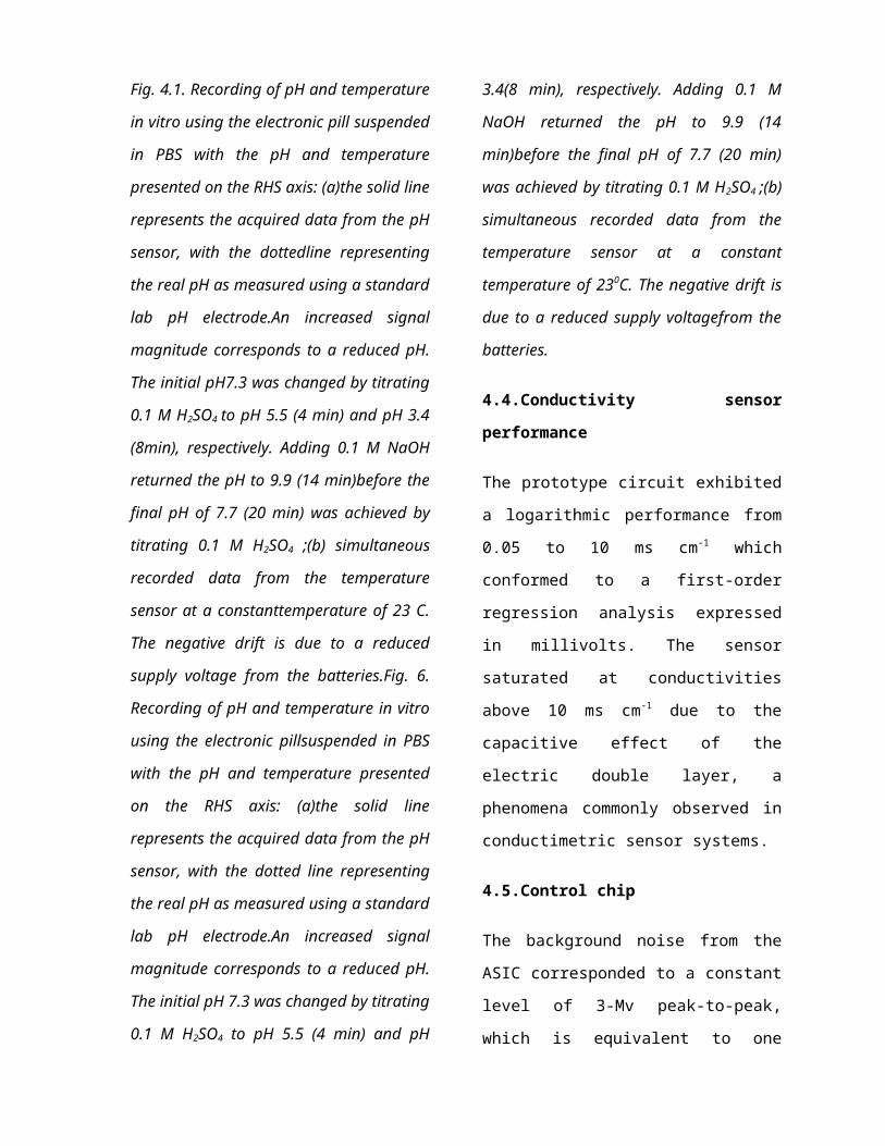
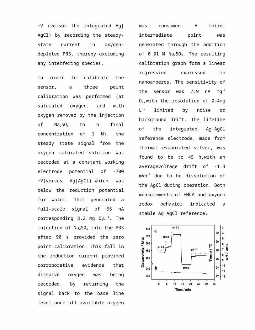
Fig. 4.1. Recording of pH and temperature
in vitro using the electronic pill suspended
in PBS with the pH and temperature
presented on the RHS axis: (a)the solid line
represents the acquired data from the pH
sensor, with the dottedline representing
the real pH as measured using a standard
lab pH electrode.An increased signal
magnitude corresponds to a reduced pH.
The initial pH7.3 was changed by titrating
0.1 M H2SO4 to pH 5.5 (4 min) and pH 3.4
(8min), respectively. Adding 0.1 M NaOH
returned the pH to 9.9 (14 min)before the
final pH of 7.7 (20 min) was achieved by
titrating 0.1 M H2SO4 ;(b) simultaneous
recorded data from the temperature
sensor at a constanttemperature of 23 C.
The negative drift is due to a reduced
supply voltage from the batteries.Fig. 6.
Recording of pH and temperature in vitro
using the electronic pillsuspended in PBS
with the pH and temperature presented
on the RHS axis: (a)the solid line
represents the acquired data from the pH
sensor, with the dotted line representing
the real pH as measured using a standard
lab pH electrode.An increased signal
magnitude corresponds to a reduced pH.
The initial pH 7.3 was changed by titrating
0.1 M H2SO4 to pH 5.5 (4 min) and pH
3.4(8 min), respectively. Adding 0.1 M
NaOH returned the pH to 9.9 (14
min)before the final pH of 7.7 (20 min)
was achieved by titrating 0.1 M H2SO4 ;(b)
simultaneous recorded data from the
temperature sensor at a constant
temperature of 230C. The negative drift is
due to a reduced supply voltagefrom the
batteries.
4.4.Conductivity sensor
performance
The prototype circuit exhibited
a logarithmic performance from
0.05 to 10 ms cm-1 which
conformed to a first-order
regression analysis expressed
in millivolts. The sensor
saturated at conductivities
above 10 ms cm-1 due to the
capacitive effect of the
electric double layer, a
phenomena commonly observed in
conductimetric sensor systems.
4.5.Control chip
The background noise from the
ASIC corresponded to a constant
level of 3-Mv peak-to-peak,
which is equivalent to one

least significant bit (LSB) of
the ADC. Since the second LSB
were required to provide an
adequate noise margin, the 10-
bit ADC was anticipated to have
an effective resolution of 8
bits.
4.6.Transmission frequency
Frequency stabilized units were
essential to prevent the
transmission drifting out of
range, particularly if the pill
was subject to a temperature
change during operation. The
standard type 1 transmitter
exhibited a negative linear
frequency change from 39.17 MHz
at 100C to 38.98 MHz at 490C,
corresponding to -4 kHz0C-1
expressed in hertz. The narrow
signal bandwidth of 10 kHz gave
a temperature tolerance of only
-+1.30C before the signal is
lost. In contrast, the type 2
transmitter exhibited a
positive linear frequency
change from 20.07 MHz at 20C to
20.11 MHz at 400C,
corresponding to 0.9 Khz0C-1.
Considering the identical
signal bandwidth of 10 KHz, the
temperature tolerance was
increased to -+5.50C. The
transmitter’s signal magnitude
was not affected with the pill
immersed in the different
electrolyte solutions or RO
water, compared to the pill
surrounded by air only. Tests
were also conducted with the
pill immersed in the large
polypropylene beaker filled
with 2000 mL of PBS without the
signal quality being
compromised. The
electromagnetic noise baseline
was measured to 78 dB of S/N in
the 20 MHz band of the crystal
stabilized transmitter.
4.7.Dual channel wireless
signal transmission
Dual channel wireless signal
transmission was recorded from
both the pH and temperature
channels at 230c, with the pill
immersed in a PBS solution of
changing pH. The calibration
graphs for the temperature and
pH channel were used to convert
the digital units from the
MATLAB calculated routine to
the corresponding temperature
and pH values.
The signal from the pH channel
exhibited an initial offset of
0.2 pH above the real value at
pH 7.3. In practice, the pH
sensor was found to exhibit a
positive pH offset as the
solution became more acidic,
and a negative pH offset as the
solution became more alkaline.
The temperature channel was
unaffected by the pH change,
confirming the absence of
crosstalk between the two
channels.
Fig. 4.2.Long term in vitro pH
measurements in response to a changing
pH from the initial pH 4 to pH 7 (2 h) and
pH 10.5 (4 h) at 36.50C: (a) solid line
represent the recorded data from the pH
sensor, with the dotted line representing
the real pH as measured using a standard
lab pH electrode. The average response
illustrates the long-term drift in the sensor
after 6 h. The error bars correspond to the
standard error of the mean (n=2); (b) the
drift from the temperature sensor is solely
based on the supply voltage potential,
resulting in a smaller error between
successive measurements(n=2).
DISCUSSION
All of the components of the
sensors and the capsule,
exposedto the local
environment, had to be able to

resist the corrosiveenvironment
in the digestive tract, and at
the same time be non-toxic
(biocompatible) to the
organism. If toxic materials
wereused (such as in batteries
and the Ag|AgCl reference
electrode), care would need to
be taken to prevent leakage
from the microsystem and into
the surrounding environment.
5.1. Sensor Performance
The temperature circuit was
sensitive to the supply
voltage. The n-channel of the
silicon diode was clamped to
ground, whereas the bias
current supply circuit was
clamped to the negative supply
rail. Thus, an increase of 7.25
mV h(froma total 14.5 mV hfrom
the positive and negative
supply rail) would reduce the
bias current by 0.5%, resulting
in adiode voltage change ofmV
h[20]. A potential
dividercircuit clamped between
ground and the positive supply
railwas used to create an
offset signal prior to the
amplificationstage. The change
in offset signal corresponds
tom V h , resulting in a total
signal change ofmV hprior
toamplification with a gain of
6.06, resulting in a total
change ofmV h. The theoretical
calculation conforms to
within40% of the experimental
result, which can be explained
byreal circuit device
tolerances (such as supply
voltage effect onthe
operational amplifiers) which
deviates from the
theoreticalpredictions.
The pH channel recordings from
the pill (Fig. 4.1)
deviatedfrom the true value
measured with the glass pH
electrode, bytransmitting
pHresponsivity below the
calibrated value. Inacidic
solutions, this resulted in a
pH response slightly abovethe
true value, whereas the
response in alkaline solutions
wasbelow the true value. In
neutral solutions, the pH
channel exhibited an offset of
0.2 units above the real value.
The resultsof the long-term
measurements conducted in Fig.
4.2 suggestedthat the recorded
values would match the real pH
of the solution if left to
equilibrate for 2 h. Thus, the
combined effect ofcalibration
offset and short equilibration
time to a changing pH, could
explain the signal offset
between the measured and realpH
presented in Fig. 6. The
discrepancy between the real
andrecorded value was possibly
due to an inherent memory
effect inthe pH
sensitivemembrane, where the
magnitude inresponse to a
changing pH depended on the
previous pH value.
Thedifference between the
initial pH measurement and the
solution value of pH 4 and 7
(Fig.4.2) was comparable to the
offsetmagnitudes seen in Fig.
4.1.
Considering Fig. 4.2, the
offset recorded for pH 10.5 was
dueto additional factors, such
as drift in the reference
electrode andsupply voltage.
The potential divider circuit,
which clamped thedrain
potential of the ISFET, was
connected between groundand the
positive supply rail. Thus, a
corresponding change inthe
positive supply rail ofmV
hwould result in adrain voltage
change ofmV hfrom the potential
divider circuit. The additional
drift from the Ag|AgCl
reference ofmV hbalanced the
remaining drift ofmV recorded.
The additional discrepancy
found at pH 10.5 was most
likely a result of long-term
signal drift from the inter-
action of proton reactive sites
in the bulk of themembrane,
with the drift becoming more
predominant in alkaline
solutions and at higher
temperatures.
Bench testing of the oxygen
sensor proved
satisfactoryoperation of the
electrochemical cell with a low
noise (1%of full signal
magnitude) and rapid response
time of 10 s.However, signal
resolution was limited to the
standard error ofmg L. The
signal discrepancy was caused
bycontamination or deposits on
the working electrode surface,
which reduced the sensitivity,
and by ambient temperature
variation, changing the amount
of dissolved oxygen by 2%C.
Cleaning the surface in abarrel
asher restored thefunction.
However, signal drift was also
caused by
electrolytepenetration of the
interface between the
PECVDlayerand the underlying
gold working electrode
comprising themicroelectrode
array. This represented a more
serious problem,since it
effectively increased the
combined surface area of
theworking electrode resulting
in an increase in signal
magnitudeat a constant
dissolved oxygen level.
The conductivity sensor is
currently being redesigned to
ex-tend the dynamic range. The
sensor will be an
interdigitatedgold planar
electrode using to prevent the
absorption of organic compounds
onto its surface.
Methods of digital signal
processing will be considered
afterdata acquisition to
improve the performance from
each sensorwith respect to
signal drift. In contrast,
analog signal algorithms
(artificial neural networks)
will be used in the sensor
electronicsto cancel out the
memory effect of the pH sensor,
and the reduction in
sensitivity caused by
contamination of the sensor
surface.
Observations on receiver
computer
1. 2 SR44 Ag2O batteries are
used.
2. Operating Time > 40
hours.
3. Power Consumption = 12.1
Mw
4. Corresponding current
consumption = 3.9mA
5. Supply Voltage = 3.1 V
5.4.Range
1. Temperature from 0 to
70 ° C
2. pH from 1 to 13
3. Dissolved Oxygen up
to 8.2 mg per liter
4. Conductivity
above 0.05 mScm-1
5. Full scale dynamic
Range analogue signal =
2.8 V
5.5.Accuracy
1. pH channel is around
0.2 unit the real value
2. Oxygen Sensor is
±0.4 mgL.
3. Temperature &
Conductivity is within
±1%.
6.Advantages
1. It is being beneficially
used for disease
detection & abnormalities
in human body. There fore
it is also called as
MAGIC PILL FOR HEALTH
CARE.
2. Adaptable for use in
corrosive & quiescent
environmentt
3. It can be used in
industries in evaluation
of water quality,
Pollution Detection,
fermentation process
control & inspection of
pipelines.
4. Micro Electronic Pill
utilizes a PROGRAMMABLE
STANDBY MODE, So Power
consumption is very
less.
5. It has very small size,
hence it is very easy for
practical usage’
6. High sensitivity, Good
reliability & Life times.
7. Very long life of the
cells(40 hours), Less
Power, Current & Voltage
requirement (12.1 mW, 3.9
mA, 3.1 V)
8. Less transmission length
& hence has zero noise
interference
6.2.Disadvantages
1. It cannot perform
ultrasound & impedance
tomography Tomography is
imaging by sections or
sectioning, through the
use of any kind of
penetrating wave.
2. Cannot detect radiation
abnormalities.
3. Cannot perform radiation
treatment associated with
cancer &
chronic inflammation.
4. Micro Electronic Pills
are expensive & are not
available in many
countries.
Still its size is not
digestible to small
babies.
CONCLUSION
We have developed an integrated
sensor array system which has
been incorporated in a mobile
remote analytical
microelectronic pill, designed
to perform real-time in
situ measurements of the GI
tract, providing the first in
vitro wireless transmitted
multichannel recordings of
analytical parameters. Further
work will focus on developing
photopatternable gel
electrolytes andoxygen and
cationselective membranes. The
microelectronic pill will be
miniaturized for medical and
veterinary applications by
incorporating the transmitter
on silicon and reducing
powerconsumption by improving
the data compression algorithm
andutilizing a programmable
standby power mode.
The generic nature of the
microelectronic pill makes
itadaptable for use in
corrosive environments related
to environ-mental and
industrial applications, such
as the evaluation ofwater
quality, pollution detection,
fermentation process controland
the inspection of pipelines.
The integration of
radiationsensors and the
application of indirect imaging
technologiessuch as ultrasound
and impedance tomography, will
improvethe detection of tissue
abnormalities and radiation
treatmentassociated with cancer
and chronic inflammation.
In the future, one objective
will be to produce a device,
analogous to a micro total
analysis system (TAS) or lab on
a chip sensorwhich is not only
capable of collecting and
processing data, but which can
transmit it from a remote
location. The overall concept
will be to produce an array of
sensor devices distributed
throughout the body or the
environment, capable off
transmitting high-quality
information in real-time.
Related Documents