E L E C T R O N I C G M B H Technical Manual TesiMod Operating Terminal BT15N Version 1.0 issued 26th November 1999 Sütron electronic GmbH Kurze Straße 29 70794 Filderstadt Tel.: ++49 7 11 / 77 09 80 Fax: ++49 7 11 / 77 09 86 0 Email: [email protected]

Welcome message from author
This document is posted to help you gain knowledge. Please leave a comment to let me know what you think about it! Share it to your friends and learn new things together.
Transcript

E L E C T R O N I C G M B H
Technical Manual
TesiMod Operating Terminal
BT15N
Version 1.0 issued 26th November 1999 Sütron electronic GmbHKurze Straße 2970794 FilderstadtTel.: ++49 7 11 / 77 09 80Fax: ++49 7 11 / 77 09 86 0Email: [email protected]

2
TesiMod BT15N
V1.0 15.06.1999 First edition

3
/001
-933
0/B
T15
N_g
rau_
eng_
V10
.300
000A
QK
0
TesiMod BT15N
Table of Contents
1 Explanation of Symbols .................................................. 5
2 The Operating Terminal BT15N ....................................... 5
2.1 Front View.............................................................................. 6
2.2 Keyboard ............................................................................... 72.2.1 Editing Keys ................................................................................... 72.2.2 Control Keys .................................................................................. 82.2.3 Special Keys .................................................................................. 92.2.4 Function Keys ............................................................................... 102.2.4.1 Function Key Arrangement ......................................................... 102.2.4.2 Slide-in Identification Strips for the Function Keys .......................... 11
2.3 Rear View ............................................................................ 122.3.1 Standard ..................................................................................... 122.3.2 InterBus ....................................................................................... 132.3.3 SUCOnet K .................................................................................. 142.3.4 PROFIBUS-DP ............................................................................... 152.3.5 CAN-Bus ..................................................................................... 162.3.6 InterBus Optical Fibre .................................................................... 17
2.4 Mounting the Terminal .......................................................... 182.4.1 Front Panel Dimensions .................................................................. 192.4.2 Side View, Mounting Depth............................................................ 202.4.3 Panel Cutout ................................................................................. 21
2.5 Pin Assignments ................................................................... 222.5.1 Pin Assignment X1 Supply Voltage .................................................. 232.5.2 Pin Assignment X2.1 / X2.2 InterBus ............................................... 242.5.3 Pin Assignment X2.1 / X2.2 SUCOnet K ......................................... 252.5.4 Pin Assignment X2 PROFIBUS-DP..................................................... 262.5.5 Pin Assignment X2.1 / X2.2 CAN-Bus ............................................. 272.5.6 Pin Assignment InterBus Optical Fibre .............................................. 282.5.7 Pin Assignment X3 SER1 TTY / 20 mA Current Loop.......................... 292.5.8 Pin Assignment X3 SER1 RS485 ..................................................... 302.5.9 Pin Assignment X3 SER1 RS232c .................................................... 312.5.10 Pin Assignment X3 SER2 RS232c .................................................... 312.5.11 Pin Assignment X4 Parallel Outputs ................................................. 32
2.6 Shielding .............................................................................. 32

4
TesiMod BT15N
2.7 Display ................................................................................. 332.7.1 Display Contrast Setting ................................................................. 342.7.2 Default Contrast Setting ................................................................. 342.7.3 Character Attributes ...................................................................... 342.7.4 Font Normal ................................................................................. 352.7.5 Font Zoom ................................................................................... 352.7.6 ASCII Character Set Table ............................................................. 36
2.8 User-Mode Switch................................................................. 37
2.9 Battery ................................................................................. 38
2.10 Fuse...................................................................................... 39
2.11 Application Memory ............................................................. 39
3 Technical Data .............................................................. 40
4 Declaration of Conformity ............................................. 43
5 Index ........................................................................... 45
A Appendix A ................................................................. A-1
A.1 Shielding of SubminD - Interconnections .............................. A-1

5
/001
-933
0/B
T15
N_g
rau_
eng_
V10
.300
000A
QK
0
TesiMod BT15N
This manual uses the following symbols to indicate notes and hazardous situations.
Notes for the User
General Danger
Specific Danger
1 Explanation of Symbols
2 The Operating Terminal BT15N
The operating terminal BT15N makes it easier for the operator to input and visualise process values.A comfortable operation is established by means of the TesiMod operating concept.
The BT15N is equipped with an extensive keyboard to input process values and to access severalfunctions. The LED backlit LCD module has a wide contrast and has full graphics capability. It supportscharacter oriented positioning of graphics, text elements and variables.
A built-in lithium battery buffers the data in the RAM and also supplies the real-time clock with power.The discharge state of the battery is monitored constantly by the system.
The communication with the BT15N is supported by standardized interfaces. The modularity of thesoftware allows a quick adjustment to different protocols.

6
TesiMod BT15N
2.1 Front View
1 Company Logo2 Operating Terminal Type Logo3 Front Panel4 Front Cover5 Filter Plate, Display Cutout6 Fastening Holes7 Status-LED Data Release8 Status LED Help9 Status LED Print10 Status-LED Acknowledge11 Special Key Data Release12 Editing Key Plus13 Editing Key Minus
14 Special Key Enter15 Special Key Clear16 Editing Key Dot17 Editing Keys 0 to 9, Alphabet18 Special Key Help19 Key Cursor Home20 Key Cursor Right, Left, Up, Down21 Special Key Acknowledge22 Special Key Print23 Control Key Page Down24 Control Key Page Up25 Function Keys F1 to F1626 Status-LED Function Keys

7
/001
-933
0/B
T15
N_g
rau_
eng_
V10
.300
000A
QK
0
TesiMod BT15N
2.2 Keyboard
Key: 0 and ( ) ° is used to edit data within the editor. If the system variable Shiftor ShiftCase is programmed, the characters ( and ) and ° can be entered.
Key: 1 and STU is used to edit data within the editor. If the system variable Shiftor ShiftCase is programmed, the characters S and T and U can be entered.
Key: 2 and VWX is used to edit data within the editor. If the system variable Shiftor ShiftCase is programmed, the characters V and W and X can be entered.
Key: 3 and YZ% is used to edit data within the editor. If the system variable Shiftor ShiftCase is programmed, the characters Y and Z and % can be entered.
Key: 4 and JKL is used to edit data within the editor. If the system variable Shiftor ShiftCase is programmed, the characters J and K and L can be entered.
Key: 5 and MNO is used to edit data within the editor. If the system variable Shiftor ShiftCase is programmed, the characters M and N and O can be entered.
Key: 6 and PQR is used to edit data within the editor. If the system variable Shiftor ShiftCase is programmed, the characters P and Q and R can be entered.
Key: 7 and ABC is used to edit data within the editor. If the system variable Shiftor ShiftCase is programmed, the characters A and B and C can be entered.
Key: 8 and DEF is used to edit data within the editor. If the system variable Shiftor ShiftCase is programmed, the characters D and E and F can be entered.
2.2.1 Editing Keys
The BT15N supports all important key functions in spite of the small measures. The keyboard consistsof membrane keys. The stroke distance is 0.3 mm and the key area is 16 x 16 mm. The key elementsare covered by an embossed polyester foil against environmental influences. This combination allowsa sensitive use of the keys. The Status LEDs illuminate green. The keyboard has a lifetime of 2 millswitching cycles.In transparent mode, the keys supply a fixed start and stop code. In standard mode, the function of thekeys is as defined by the user.
8
TesiMod BT15N
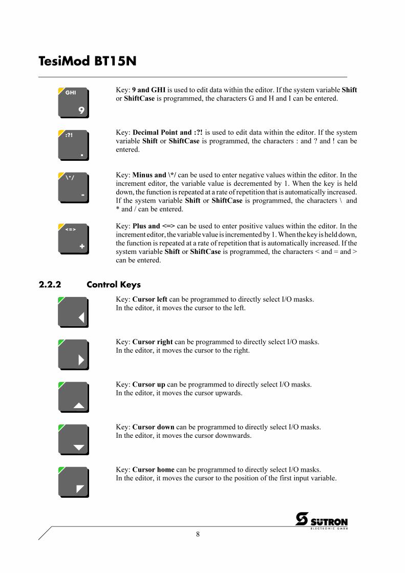
Key: 9 and GHI is used to edit data within the editor. If the system variable Shiftor ShiftCase is programmed, the characters G and H and I can be entered.
Key: Decimal Point and :?! is used to edit data within the editor. If the systemvariable Shift or ShiftCase is programmed, the characters : and ? and ! can beentered.
Key: Minus and \*/ can be used to enter negative values within the editor. In theincrement editor, the variable value is decremented by 1. When the key is helddown, the function is repeated at a rate of repetition that is automatically increased.If the system variable Shift or ShiftCase is programmed, the characters \ and* and / can be entered.
Key: Plus and <=> can be used to enter positive values within the editor. In theincrement editor, the variable value is incremented by 1. When the key is held down,the function is repeated at a rate of repetition that is automatically increased. If thesystem variable Shift or ShiftCase is programmed, the characters < and = and >can be entered.
2.2.2 Control Keys
Key: Cursor left can be programmed to directly select I/O masks.In the editor, it moves the cursor to the left.
Key: Cursor right can be programmed to directly select I/O masks.In the editor, it moves the cursor to the right.
Key: Cursor up can be programmed to directly select I/O masks.In the editor, it moves the cursor upwards.
Key: Cursor down can be programmed to directly select I/O masks.In the editor, it moves the cursor downwards.
Key: Cursor home can be programmed to directly select I/O masks.In the editor, it moves the cursor to the position of the first input variable.

9
/001
-933
0/B
T15
N_g
rau_
eng_
V10
.300
000A
QK
0
TesiMod BT15N
Key: Page up is used to page through tables, recipes and messages. The function-ality corresponds to the system variable �TabPgUp�. The key allows data contentstowards the top of the table to be viewed.
Key: Page down is used to page through tables, recipes and messages. Thefunctionality corresponds to the system variable �TabPgDn�. The key allows datacontents towards the bottom of the table to be viewed.
2.2.3 Special Keys
Key: Help key always displays the current help text (online help). When the status-LED help flashes, it signals that an error message is pending. The error or systemmessage is always displayed in plain-text.
Key: Data Release key is used to switch from a menu into the editor. The status-LED data release lights up when the editing mode is active. When the Data Releasekey is pressed within the editor, the editing mode is exited.
Key: Enter is used to conclude data entry. When pressed while in the startup mask,the key switches into the setup mask.
Key: Clear deletes the character beneath the cursor when it is used in an editor.Deletes the selected messages from the data memory.
Key: Acknowledge is used as an acknowledge key for the message system.
Key: Print can be used as a soft key to activate various print processes.

10
TesiMod BT15N
2.2.4.1 Function Key Arrangement
2.2.4 Function Keys
Funktion key F1 to F16 with integrated LEDs for functional feedback. The keyfunctions can be freely assigned to a softkey functionality, either as direct accesskeys for menu control or to activate a function in the controller.

11
/001
-933
0/B
T15
N_g
rau_
eng_
V10
.300
000A
QK
0
TesiMod BT15N
Labelled identification strips, standard
Blank identification strips
2.2.4.2 Slide-in Identification Strips for the Function Keys
The identification strips can be replaced after the terminal is dismounted. Inserting the strips from therear of the front panel does not affect the tightness specified for the unit.The unit is delivered with a set of identification strips.The set consists of:- two identification strips, labelled with F1 to F16- two blank identification strips.Various labelling methods are recommended, depending on the number of units involved.
Suitable labelling methods for:
Single units, prototypes: labelling with an indelible penSmall batch production: transparency with laser printingLarge batch production: custom specific printed identification strips
1 Position of identification strips
12
TesiMod BT15N
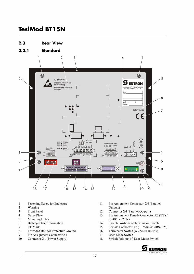
1 Fastening Screw for Enclosure2 Warning3 Front Panel4 Name Plate5 Mounting Holes6 Battery-related information7 CE Mark8 Threaded Bolt for Protective Ground9 Pin Assignment Connector X110 Connector X1 (Power Supply)
11 Pin Assignment Connector X4 (ParallelOutputs)
12 Connector X4 (Parallel Outputs)13 Pin Assignment Female Connector X3 (TTY/
RS485/RS232c)14 Switch Positions of Terminator Switch15 Female Connector X3 (TTY/RS485/RS232c)16 Terminator Switch (X3-SER1 RS485)17 User-Mode Switch18 Switch Poitions of User-Mode Switch
2.3 Rear View
2.3.1 Standard

13
/001
-933
0/B
T15
N_g
rau_
eng_
V10
.300
000A
QK
0
TesiMod BT15N
1 Fastening Screw for Enclosure2 Warning3 Front Panel4 Name Plate5 Mounting Hole6 Battery-related Information7 CE Mark8 Threaded Bolt for Protective Ground9 Pin Assignment Connector X110 Connector X1 (Power Supply)11 Pin Assignment Connector X4 (Parallel
Outputs)12 Connector X4 (Parallel Outputs)13 Pin Assignment X2.1 (Remotebus In)14 Male Connector X2.1 (Remotebus In)15 Pin Assignment X3 (SER2-RS232c)16 Female Connector X3 (SER2-RS232c)17 Pin Assignment X2.2 (Remotebus Out)18 Female Connector X2.2 (Remotebus Out)19 User-Mode Switch20 Switch Positions of User-Mode Switch21 Diagnosis LEDs
2.3.2 InterBus

14
TesiMod BT15N
1 Fastening Screw for Enclosure2 Warning3 Front Panel4 Name Plate5 Mounting Holes6 Battery-related Information7 CE Mark8 Threaded Bolt for Protective Ground9 Pin Assignment Connector X110 Connector X1 (Power Supply)11 Pin Assignment Connector X4 (Parallel
Outputs)
12 Connector X4 (Parallel Outputs)13 Pin Assignment X2.1 (SUCOnet K)14 Terminator Switch X2.1 (SUCOnet K)15 Female Connector X2.1 (SUCOnet K)16 Pin Assignment X3 (SER2-RS232c)17 Female Connector X3 (SER2-RS232c)18 Pin Assignment X2.2 (SUCOnet K)19 Female Connector X2.2 (SUCOnet K)20 User-Mode Switch21 Switch Positions of User-Mode Switch22 Diagnosis LED X2.1 / X2.2 (SUCOnet K)
2.3.3 SUCOnet K

15
/001
-933
0/B
T15
N_g
rau_
eng_
V10
.300
000A
QK
0
TesiMod BT15N
1 Fastening Screw for Enclosure2 Warning3 Front Panel4 Name Plate5 Montagebohrungen6 Battery-related Information7 CE Mark8 Threaded Bolt for Protective Ground9 Pin Assignment Connector X110 Connector X1 (Power Supply)
11 Pin Assignment Connector X4 (ParallelOutputs)
12 Connector X4 (Parallel Outputs)13 Pin Assignment X3 (SER2-RS232c)14 Female Connector X3 (SER2-RS232c)15 Pin Assignment X2 (PROFIBUS-DP)16 Female Connector X2 (PROFIBUS-DP)17 User-Mode Switch18 Switch Positions of User-Mode Switch19 Diagnosis LED
2.3.4 PROFIBUS-DP

16
TesiMod BT15N
1 Fastening Screw for Enclosure2 Warning3 Front Panel4 Name Plate5 Mounting Hole6 Battery-related Information7 CE Mark8 Threaded Bolt for Protective Ground9 Pin Assignment Connector X110 Connector X1 (Power Supply)11 Pin Assignment Connector X4 (Parallel
Outputs)12 Connector X4 (Parallel Outputs)13 Pin Assignment X2.1 (CAN-Bus)14 Male Connector X2.1 (CAN-Bus)15 Pin Assignment X3 (SER2-RS232c)16 Female Connector X3 (SER2-RS232c)17 Pin Assignment X2.2 (CAN-Bus)18 Female Connector X2.2 (CAN-Bus)19 User-Mode Switch20 Switch Positions of User-Mode Switch21 Diagnosis LEDs
2.3.5 CAN-Bus

17
/001
-933
0/B
T15
N_g
rau_
eng_
V10
.300
000A
QK
0
TesiMod BT15N
1 Fastening Screw for Enclosure2 Warning3 Front Panel4 Name Plate5 Mounting Hole6 Battery-related Information7 CE Mark8 Threaded Bolt for Protective Ground9 Pin Assignment Connector X110 Connector X1 (Power Supply)11 Pin Assignment Connector X4 (Parallel
Outputs)
12 Connector X4 (Parallel Outputs)13 Fibre Optical DO1 (Remotebus In)14 Fibre Optical DI1 (Remotebus In)15 Fibre Optical DI2 (Remotebus Out)16 Pin Assignment X3 (SER2-RS232c)17 Female Connector X3 (SER2-RS232c)18 Termintator Switch (InterBus)19 Fibre Optical DO2 (Remotebus Out)20 User-Mode Switch21 Switch Positions of User-Mode Switch22 Diagnosis LEDs
2.3.6 InterBus Optical Fibre

18
TesiMod BT15N
The front panel mounting is suitable for easy and sealed installation in places where the rear side of theunit is not accessible. The unit is particularly suitable for mounting in enclosures.
The front panel permits sealed installation of the unit in accordance with the IP65 degree of protection(at the front). At the rear side of the front panel a circumferential sealing is attached.All parts for mounting the unit are given with the spare parts set.
Special care needs to be taken during installation to maintain this high degree of protection. The unitis inserted from the front through the panel cutout and screwed to the mounting wall from the front. Theseal must be positioned evenly and the fastening elements tightened uniformly.
When installing the terminal, keep a minimum space of 30 mm around the terminal for adequate aircirculation.
The tightness between the front panel and the mounting surface depends on the care duringinstallation.
Front Panel Dimensions: 202.0 x 224.0 x 4.0 mm (H x W x D)Panel Cutout: 188 x 204 mm (H x W)
Mounting and maintenance may only be performed by qualified and authorizedpersonnel!
2.4 Mounting the Terminal

19
/001
-933
0/B
T15
N_g
rau_
eng_
V10
.300
000A
QK
0
TesiMod BT15N
2.4.1 Front Panel Dimensions

20
TesiMod BT15N
2.4.2 Side View, Mounting Depth
1 Cheese Head Screw M4 x 12 DIN79842 O-Ring 4.00 x 0.6 N70B3 Front Panel4 Circumferencial Sealing
5 Mounting Surface Thickness 1 to 10 mm6 Spring Lock Washer B4 DIN127 Form B7 Nut M4 DIN934

21
/001
-933
0/B
T15
N_g
rau_
eng_
V10
.300
000A
QK
0
TesiMod BT15N
2.4.3 Panel Cutout
1 4 Holes with a Diameter of 4.5 mm, alternatively Threads M4

22
TesiMod BT15N
The operating terminal is fitted as standard terminal or as bus terminal:
The connector X3 combines several interface standards within one physical connector. The connectoris divided into two channels. The channel for communication (SER1) is divided from the channel forupload/download/logging printer/scanner (SER2). The channels can operate independent of eachother.The channel of communication (SER1) can handle - specified by protocol - only one of the threeinterface standards.
Standard terminal:
Connector X1 24 VDC Supply VoltageConnector X3 SER1 TTY / 20 mA CommunicationConnector X3 SER1 RS232c CommunicationConnector X3 SER1 RS485 CommunicationConnector X3 SER2 RS232c Upload/Download/Logging Printer/ScannerConnector X4 Parallel Outputs Influencing Inputs of PLC
Bus terminal:
Connector X1 24 VDC Supply VoltageConnector X3 SER2 RS232c Upload/Download/Logging Printer/ScannerConnector X2.1 / X2.2 InterBus CommunicationConnector X2.1 / X2.2 SUCOnet K CommunicationConnector X2 PROFIBUS-DP CommunicationConnector X2.1 / X2.2 CAN-Bus CommunicationConnector DO1 / DI1 InterBusand DO2 / DI2 Optical Fibre CommunicationConnector X4 Parallel Outputs Influencing Inputs of PLC
The parallel outputs are suitable for direct access on inputs of PLCs.
2.5 Pin Assignments

23
/001
-933
0/B
T15
N_g
rau_
eng_
V10
.300
000A
QK
0
TesiMod BT15N
The supply voltage is connected via the connector X1.
The unit is equipped with a reverse voltage protection. If the poling is wrong, the unit doesn´t operate.
This unit confirms to the safety class I. For safe operation it is necessary to use safety extra-low voltage(SELV) in accordance with DIN EN 61131 for the supply voltage.
Connector in the terminal: 3-pin male connector strip Phoenix COMBICON MSTBV 2,5/3-GF
Pin Designation Function1 Signal Ground2 0 V Supply Voltage 0 V3 24 VDC Supply Voltage 24 VDC
The supply voltage is connected via a plug-in 3-pin female connector strip. The cable is secured in thefemale connector strip by means of screw terminals. Cables with fine wires with a cross-section of upto 2.5mm2 can be used. The female connector strip is secured in position by means of a screw-typelocking.The female connector strip of the type Phoenix COMBICON MSTB 2.5/3-STF is supplied.
2.5.1 Pin Assignment X1 Supply Voltage
Hazardous voltages can exist inside electrical installations that can pose a dangerto humans. Coming in contact with live parts may result in electric shock!
Please note with respect to pin assignment:If shielded connecting cables are used for the supply voltage, the shield should beconnected to pin 1.
Threaded bolt for protective grounding
A separate ground conductor must be provided for the ground screw in each case.The minimum cross-section of the ground conductor must be 1.5 mm2 and thelength as short as possible. Compliance with this information increases theoperational safety.

24
TesiMod BT15N
The unit can be fitted with the bus interfaces X2.1 and X2.2 for connection to the InterBus instead ofthe standard interfaces TTY / 20 mA and RS422 / RS485. The InterBus connection is certified underthe number 076. The connectors are of the 9-pin Submin D female and male connector strip type.
Connector in the terminal: 9-pin SubminD male connector strip for Remotebus In
Assignment:Pin Designation Function1 DO Data Out2 DI Data In3 GND Signal Ground4 nc not connected5 nc not connected6 /DO Data Out Reverse7 /DI Data In Reverse8 nc not connected9 nc not connected
Connector in the terminal: 9-pin SubminD female connector strip for Remotebus Out
Assignment:Pin Designation Function1 DO Data Out2 DI Data In3 GND Signal Ground4 nc not connected5 +5 V Power Supply +5 VDC6 /DO Data Out Reverse7 /DI Data In Reverse8 nc not connected9 RBST Remote Bus Status
A shielded cable with twisted pairs (Cable type LiYCY-TP) is used. The maximum cable lengthdepends on the usage within the InterBus topology.
2.5.2 Pin Assignment X2.1 / X2.2 InterBus

25
/001
-933
0/B
T15
N_g
rau_
eng_
V10
.300
000A
QK
0
TesiMod BT15N
To integrate the unit into a network topology of the SUCOnet K it can be equipped with the specialinterfaces for SUCOnet K instead of the standard interfaces TTY / 20 mA and RS422 / RS485. Theconnectors are 9-pin SubminD female and male connectors. The pinning of either connectors isidentical.
Termination:Activate the termination of the physically first (master) and last station in the network at all times.The termination of the stations located in between remains inactivated. To activate the termination, thetermination switch RD/TD must be set to ON.
Connector in the operating terminal: 9-pin SubminD female/male connector strip
Pin Designation Function1 nc not connected2 nc not connected3 TA/RA Transmit- / Receive Channel A4 GND Signal Ground5 nc not connected6 nc not connected7 TB/RB Transmit- / Receive Channel B8 GND Signal Ground9 nc not connected
A shielded cable with twisted pair wires (cable type LiYCY-TP) must be used.The maximum cable length depends on the data transmission rate that is used.For a transmission rate of 187.5 kbps the maximum cable length is 600 m, for a transmission rate of 375kbps a cable length of 300 m should not be exceeded. If longer cable length are required, repeaters mustbe used for signal conditioning. Self-controlled repeaters may be used for this process.
2.5.3 Pin Assignment X2.1 / X2.2 SUCOnet K

26
TesiMod BT15N
To integrate the unit into a network of the PROFIBUS-DP it can be equipped with the special interfacefor PROFIBUS-DP connection instead of the standard interfaces TTY / 20 mA and RS422 / RS485.A 9-pin SubminD female connector strip is used as a connector.
Connector on the operating terminal: 9-pin SubminD female connector strip
Assignment:Pin Designation Function1 nc not connected2 nc not connected3 TB/RB Transmit / Receive Data Plus4 RTS Request to Send5 GND Signal Ground6 +5 V Power Supply +5 VDC7 nc not connected8 TA/RA Transmit / Receive Data Minus9 nc not connected
Principally, all cable types specified in EN 50170 as cable type A can be used.This allows the following cable lengths (depending on the baud rate):
Baud Rate (bps) Cable Length (m)9 600 1200
19 200 120093 750 1200
187 500 1000500 000 400
1 500 000 20012 000 000 100
2.5.4 Pin Assignment X2 PROFIBUS-DP

27
/001
-933
0/B
T15
N_g
rau_
eng_
V10
.300
000A
QK
0
TesiMod BT15N
To integrate the unit into a network topology of the CAN bus it can be equipped with the specialinterfaces X2.1 and X2.2 for CAN Bus. The CAN bus is stated as a high-speed-bus according to ISO-DIS 11898.
Connector: 9-pin SubminD male connector strip X2.1
Pin Designation Function1 nc not connected2 CANL CAN_L bus line (dominant LOW)3 CAN_GND CAN Ground4 nc not connected5 nc not connected6 CAN_GND CAN Ground7 CANH CAN_H bus line (dominant HIGH)8 nc not connected9 nc not connected.
Connector: 9-pin SubminD female connector strip X2.2
Pin Bezeichnung Funktion1 nc not connected2 CANL CAN_L bus line (dominant LOW)3 CAN_GND CAN Ground4 nc not connected5 nc not connected6 CAN_GND CAN Ground7 CANH CAN_H bus line (dominant HIGH)8 nc not connected9 nc not connected
All signals of X2.1 to X2.2 are interconnected. The connecting cable has to be connected to all pinsincluding the reserved ones. The intention is, that there shall be no interruption of any of the wires inthe bus cable, assuming a possible future specification of the use of the reserved pins.
A shielded cable with twisted pair wires (cabe type LiYCY-TP) must be used. The CAN bus must beterminated with resistors on both ends of the cable structure.
2.5.5 Pin Assignment X2.1 / X2.2 CAN-Bus
28
TesiMod BT15N
To integrate the unit into a network topology of the InterBus optical fibre device net it can be equippedwith the special interfaces for InterBus Optical Fibre.The optical fibre interface is stated as F-SMA type 905.
The connectors for the optical fibres areDO1 and DI1 for Remotebus In andDO2 and DI2 for Remotebus Out.
The connection must conform to �Technical Guideline For Optical Transmission�.
For the optical transmission a dielectrical fibre with refractive index profile, likely a polymer fibre witha diameter of 980 µm of the core and 1000 µm of the coating. The connector of the type F-SMA isaccording to the specifications of IEC 874-2 respectively DIN 47258.The permitted distance between two subscribers of the optical fibre device bus is 1 through 5 m.
2.5.6 Pin Assignment InterBus Optical Fibre
The transmitter and receiver units may get unusable by dirt. For transportation,storage and when a unit is not in use, place caps on the plug terminals.
Infrared light can damage the retina of the eye! Never look into the open end ofthe optical fibre! Secure the open ends of the optical fibres and the plugs with caps!Always wear safety glasses!

29
/001
-933
0/B
T15
N_g
rau_
eng_
V10
.300
000A
QK
0
TesiMod BT15N
TTY / 20 mA current loop, passive
Pin Designation Channel Function10 T+ SER1 Transmit Data, Positive Polarity13 R+ SER1 Receive Data, Positive Polarity14 R- SER1 Receive Data, Negative Polarity19 T- SER1 Transmit Data, Negative Polarity
TTY / 20 mA current loop, active
Pin Designation Channel Function10 T+ SER1 Transmit Data, Positive Polarity12 S1+ SER1 Power Source 2, Positive Polarity13 R+ SER1 Receive Data, Positive Polarity14 R- SER1 Receive Data, Negative Polarity16 S2+ SER1 Power Source 1, Positive Polarity19 T- SER1 Transmit Data, Negative Polarity21 S1- SER1 Power Sink 1, Negative Polarity24 S2- SER1 Power Sink 2, Negative Polarity
Termination:When using the channel SER1 as current loop the terminator switches for RS485 must be switchedOFF!
The interface can be connected as either an active or passive current loop depending on the wiring. Thetransmit line and the receive line are provided with separate 20mA power sources. The compliancevoltage is approximately 24 VDC.The maximum baud rate is 19200Bd. The maximum cable length depends on the baud rate and rate oftransmission errors.For longer cable lengths, the 20mA power supply should be fed by the transmitting unit. This candecrease crosstalk on the signal lines considerably.In idle state (signal logical 1) a current loop of 20 mA can be measured on the cable.
Signal logical 1 - Current flow 20mASignal logical 0 - Current flow is interrupted
A shielded cable with twisted pair wires (cable type LiYCY-TP) and a minimum cross section of0.08 mm2 must be used. The maximum cable length is 100 m.
2.5.7 Pin Assignment X3 SER1 TTY / 20 mA Current Loop
Connect the cable shield to the metal hoods of the connectors over as large a surfaceas possible! Please refer to appendix A.
30
TesiMod BT15N
The interface RS485 is suitable for point-to-point connections and multipoint connections.
Termination for point-to-point connection:For operation with point-to-point connection the termination must always be activated.
Termination for multipoint connection:For operation with multipoint connections only the termination at the cable end must be activated.
The signals of the interface are electrically isolated.The configuration of the hardware can be adapted to different systems. The associated wires are markedwith �A� and �B�. Some descriptions refer to the pins with �+� and �-�, where the following applies:A = + and B = -. The voltage levels comply with the standards and are defined as follows:
Signal logical 1 - UA - UB <= -0.3 V i.e. (UA < UB)Signal logical 0 - UA - UB >= +0.3 V i.e. (UA > UB)
Pin Designation Channel Function8 T(A) SER1 Transmit Data Channel A9 T(B) SER1 Transmit Data Channel B11 SGND SER1 Signal Ground22 RD(A) SER1 Receive Data Channel A23 RD(B) SER1 Receive Data Channel B
A shielded cable with twisted pair wires (cable type LiYCY-TP) and a minimum cross section of0.34 mm2 (for 400 m) must be used. The maximum cable length is 400 m.
Connect the cable shield to the metal hoods of the connectors over as large a surfaceas possible! Please refer to appendix A.
2.5.8 Pin Assignment X3 SER1 RS485

31
/001
-933
0/B
T15
N_g
rau_
eng_
V10
.300
000A
QK
0
TesiMod BT15N
Interface for download, upload, logging printer and scanner.
Pin Designation Channel Function1 SER2 Low-noise Earth2 TD SER2 Transmit Data3 RD SER2 Receive Data4 RTS SER2 Request to Send5 CTS SER2 Clear To Send7 SGND SER2 Signal Ground20 DTR SER2 Data Terminal Ready
A shielded cable with stranding in layers (cable type LiYCY) and with a minimum cross-section of0.25 mm2 must be used. The maximum cable length is 15 m.
2.5.10 Pin Assignment X3 SER2 RS232c
Interface for communication with controller.
Pin Designation Channel Function6 TD SER1 Transmit Data15 CTS SER1 Clear To Send17 RTS SER1 Request To Send18 RD SER1 Receive Data25 SGND SER1 Signal Ground
A shielded cable with stranding in layers (cable type LiYCY) and with a minimum cross-section of0.25 mm2 must be used. The maximum cable length is 15 m.
2.5.9 Pin Assignment X3 SER1 RS232c
Connect the cable shield to the metal hoods of the connectors over as large a surfaceas possible! Please refer to appendix A.
Connect the cable shield to the metal hoods of the connectors over as large a surfaceas possible! Please refer to appendix A.

32
TesiMod BT15N
2.6 Shielding
The shield must be connected to the metal hoods of the connector housings at both ends and over aslarge a surface as possible. It should be noted that a potential equalization line with a minimum cross-section equal to 10 times that of the shield may be necessary as a result of the grounding on both sides.
2.5.11 Pin Assignment X4 Parallel Outputs
Open-collector-outputs, which switch the positive potential, are used as parallel outputs. These outputsare suitable for direct control of PLC inputs. The outputs can be activated by means of function keysor the controller. The assignment of these functions is carried out in the programming software. Theparallel outputs are designed for use in standard mode only.
Technical Data:Input voltage 15 through 30 VDCOutput Current max. 0.2 A for each outputDelay 30 to 50 ms
The outputs are short-circuit-proof!The voltage supply must be provided externally. Pins 9 through 13 for the negative potential areconnected internally.
Connector in the operating terminal: 15-pin SubminD male connector strip
Pin Designation Function1 A1 Output 12 A2 Output 23 A3 Output 34 A4 Output 45 A5 Output 56 A6 Output 67 A7 Output 78 A8 Output 89 0V Negative Potential10 0V Negative Potential11 0V Negative Potential12 0V Negative Potential13 0V Negative Potential14 nc Not Connected15 +24 V Positive Potential

33
/001
-933
0/B
T15
N_g
rau_
eng_
V10
.300
000A
QK
0
TesiMod BT15N
The display in the BT15N consists of a backlit LCD module with full graphics capability.The display is capable of simultaneously displaying up to 320 characters of the normal font. Thecharacters of the normal font are displayed by a matrix of 5 x 7 dots and with a height of 3.5 mm. Theformat allows 8 lines with 40 characters each to be displayed. The drift of contrast of the display iscompensated over the full temperature range. The operating terminal has an optimum viewing angleof approximately 90°.In the operating mode standard mode the default contrast can be adjusted at operating time by meansof a system variable.The display is capable of displaying either the extended ASCII character set (semi graphics) with thefont normal and zoom, and of displaying full graphics.
Overview of the Display of the BT15N:
Type: LCD ModuleResolution: 240 x 64 DotsBacklight: LEDLifetime LCD: 100000 hLifetime Backlight: 100000 h
Lines (Font Normal): 8Characters/Line (Font Normal): 40Dot Size: 0.49 mm x 0.49 mmGap Size: 0.04 mmDot Colour: BlackCharacter of Font Normal: 6 x 8 DotsCharacter of Font Zoom: 12 x 16 DotsBackground Colour: Yellow-GreenVisible Front Cutout (H x W): 40.4 mm x 134.0 mm
If the display is damaged, do not swallow or breathe in the liquids or gases beingemitted and avoid direct contact with skin.Danger of Poisoning! Could Result in Burns!
2.7 Display

34
TesiMod BT15N
The contrast for the display can be adjusted by means of the software. This requires the system variableLCDContrast to be set up in an I/O mask of the application. The value can then be modified using anyeditor that can handle integer numbers.The limit values for the brightness must be set to
Lower level: -40Upper level: +75
If this variable is not defined in the menus or the value is out of the range of values, the default setting(value 25) will be loaded when the system is initialized.The system variable can be stated in any I/O-mask of the application!
If the contrast of the display should be such that the masks are no longer legible, the default contrastsetting can be restored using the user mode switch.
Position of the switch to restore the contrast:
S1 ONS2 OFFS3 OFFS4 ON
This switch position coincides with �activating download by hardware�. The contrast will be resetbefore the warning is displayed. The warning will be displayed in a legible manner.How to setup the default contrast:- Switch off the operating terminal- Set the DIP-switches to the above decribed switch positions- Switch on the operating terminal- Upon display of a warning, switch off the operating terminal- Set the switch S4 to the OFF-position- Switch on the terminal again.The application description is not lost.
2.7.1 Display Contrast Setting
2.7.2 Default Contrast Setting
2.7.3 Character Attributes
By preselecting an attribute, any characters can be displayed as follows:- normal- flashing- underlined- inverseand in any combination.

35
/001
-933
0/B
T15
N_g
rau_
eng_
V10
.300
000A
QK
0
TesiMod BT15N
2.7.5 Font Zoom
2.7.4 Font Normal

36
TesiMod BT15N
2.7.6 ASCII Character Set Table

37
/001
-933
0/B
T15
N_g
rau_
eng_
V10
.300
000A
QK
0
TesiMod BT15N
The user-mode switch is placed at the rear side of the unit. The switch levers can be accessed by usinga pen or a small screwdriver.
The switches S5 to S8 can be used by the user as needed. The switch positions are stored at initializationtime and afterwards they can be overtaken to the controller.
Legend of above table:I = Switch position ON
- = Switch position OFFX = Switch position irrelevant
2.8 User-Mode Switch
S1 S2 S3 S4 S5 S6 S7 S8 Function
I X - - X X X X Standard-Mode with SPS (delivery state)
I X I - X X X X Standard-Mode without SPS
- I - - X X X X Transparent-Mode with start and stop code of the keys
- - - I X X X X Transparent-Mode without stop code of the keys
I - - I X X X X Activate download (deletes application memory)
und default contrast setting

38
TesiMod BT15N
A built-in lithium battery buffers the data in the CMOS-RAM and also supplies the real-time clock withpower. The battery provides a minimum life of 5 years, even under unfavourable operating conditions.If the battery is drained the system message �change battery� is generated.We recommend to replace the battery every 4 years while performing the regular maintenance.A new battery is supported by Sütron electronic or the sales representative of your country.If the system message �change battery� would not be recognized in due, eg the real time clock isinterrupted or displays a wrong time, a loss of data in the CMOS-RAM can be expected. In this caseyou must check all alterable data like passwords, parameters in the system variables, data sets of recipesand the entries of the message system after replacing the battery.
Replacing the battery:The battery can be replaced while the operating voltage is connected to ensure that the message dataand time setting are not lost. Mind the safety instructions!- Remove the mounting bolts of the connectors- Remove the fastening screws of the enclosure and remove the enclosure- Replace the cable fastener, which is used to hold the battery- Plug off the connector of the battery cable and replace the battery- Plug on the connector of the new battery- Place the new battery onto the plastic carrier on the printed circuit board and fasten it with a new
cable fastener- Place the enclosure on the rear side of the unit- At first fasten the bolts of the interface connectors and at last fasten the screws of the enclosure
properly
Changing the battery may only be performed by qualified and authorized personnel!
Sewage and refuse displosal:Dispose only drained batteries into the collection box of the community or of the local dealer. Thebattery is stated as drained when the message �change battery� appears on the display of the appliance.
To prevent short circuitry in the collection boxes insulate the poles of each battery with insulation tapeor put each single battery into a plastic bag.
2.9 Battery
Do not open lithium batteries. Danger of Poisoning!
Hazardous voltages can exist inside electrical installations that can pose a dangerto humans. Coming in contact with live parts may result in electric shock!
Electrostatic discharges can damage electronic components! ESD protective measuresmust be observed!
Do not put lithium batteries in fire or heat them above 100° C and do not rechargethem. Danger of Explosion!

39
/001
-933
0/B
T15
N_g
rau_
eng_
V10
.300
000A
QK
0
TesiMod BT15N
A semiconductor fuse is used to prevent damage to the operating terminal. Once the fuse has beenactivated, the device must be disconnected from the supply voltage to allow the semiconductor fuse toregenerate. With an ambient temperature of 20 °C, the regeneration takes about 20 seconds. The higherthe ambient temperature, the longer the regeneration period.The semiconductor fuse is not designed to be replaced.
2.10 Fuse
The unit is equipped with either a 256 KByte or 768 KByte flash memory an application memory.After switching on the unit the size of the application memory is displayed. This memory area isavailable to store the user application, the loadable protocol driver, the fonts and the recipe data.
2.11 Application Memory

40
TesiMod BT15N
3 Technical Data
Keyboard a Total of 42 Keys, Membrane Keys with Tactile Feedback, 2 MillionSwitch CyclesDivided into
7 Control Keys16 Function Keys with LED and Slide-in Identification Strips2 Special Key without LED4 Special Keys with LED13 Editing Keys
Display Backlit LCD Module with full Graphics Capability, 8 Lines with40 Characters Each, Character Size 3.5 mm,Display Area 40.4 x 134.0 mm (H x W)Lifetime LCD: 100000 hLifetime Backlight: 100000 h
Display Screen Glare Suppression for Increased Contrast
Interface X3 Variable Baud Rates and Data FormatsSER1 TTY/20 mA CommunicationSER1 RS485 CommunicationSER1 RS232c CommunicationSER2 RS232c, not galvanical isolated Download/Upload/Scanner/
Logging Printer
Interface X4 8 Parallel Outputs 24 VDC / 0.2 A, Short Circuit Proof
Options X2.1/X2.2 InterBus CommunicationX2.1/X2.2 SUCOnet K CommunicationX2 PROFIBUS-DP CommunicationX2.1/X2.2 CAN-Bus CommunicationDO1/DI1/ InterBusDO2/DI2 Optical Fibre Communication
ProtocollsStandard ABB CS31
ABB T200AEG KS-FunctionsAEG ModbusAllen BradleyBosch BUEP19/BUEP19EDIN-Meßbus Slave, DIN-Meßbus GatewayGE Fanuc SNPIDEC Micro3Jetter PASE / PCOM5Mitsubishi FX-Series and A-SeriesMoeller SUCOM 1 (PS306/316)Moeller SUCOM 1 (PS4-201)

41
/001
-933
0/B
T15
N_g
rau_
eng_
V10
.300
000A
QK
0
TesiMod BT15N
OMRON Host-LinkOMRON NT-LinkSiemens SINEC L1 Master LinkSiemens 3964R/RK512Siemens S5 PG (AS511)Siemens S7 PPISiemens S7 MPI (HMI-Host Adaptor)
ProtocollsField Bus CAN/CANopen
InterBusLONMoeller SUCOnet KPROFIBUS-DPSiemens S7 MPI
Central Unit TMPZ84C015, 10 MHz, Watchdog Timer, Real-Time Clock, Program-mable Interface Parameters, Temperature Compensation of the Display,Adjustment of Contrast, Battery Monitoring, User Mode Switch
Memory 256 / 768 KByte Flash Memory, Application Memory256 KByte Flash Memory, Firmware128 KByte stat. CMOS-RAM, Battery-Backed
Connection System Plug-in Type, via SubminD Female/Male Connector Strip
Supply Voltage 24 V Direct Voltage, Residual Ripple Max. 10%, SELVin accordance to DIN EN 61131Minimum Voltage 19.2 VMaximum Voltage 30.2 VTyp. Power Consumption <0.4 APeak Current (10 ms) <0.6 A
Connected Load ~10 W
Fuse Semiconductor Fuse
ReverseVoltage Protection Protection Diode

42
TesiMod BT15N
Noise Immunity EC Electromagnetic Compatibility Directive 89/336/EECEN 50081-1 Table A1EN 50082-2EN 55011 Limit Class BEN 55022EN 61000-4-2EN 61000-4-3EN 61000-4-4EN 61000-4-5EN 61000-4-6
Environmental Test Operating Temperature 0°C to 50°CStorage Temperature -25°C to 70°CRelative Humidity for:Operation max. 75% annual averageStorage max. 75% annual averageNon-condensing
Degrees of Protection EN 60529 Mechanical Degrees of ProtectionFront: IP65Rear: IP20
Front Panel Aluminium, Black Anodized with Affixed Polyester Cover, Circumferen-tial Rubber Sealing at Rear Side of Front Panel.202.0 x 224.0 x 4.0 mm (H x W x D)
Panel Cutout 188 x 204 mm (H x W)
Mounting Depth 50 mm without Connector (approx. 90 mm with connector)
Enclosure Zinc-Coated Steel Plate
Total Weight Approx. 1500 g

43
/001
-933
0/B
T15
N_g
rau_
eng_
V10
.300
000A
QK
0
TesiMod BT15N
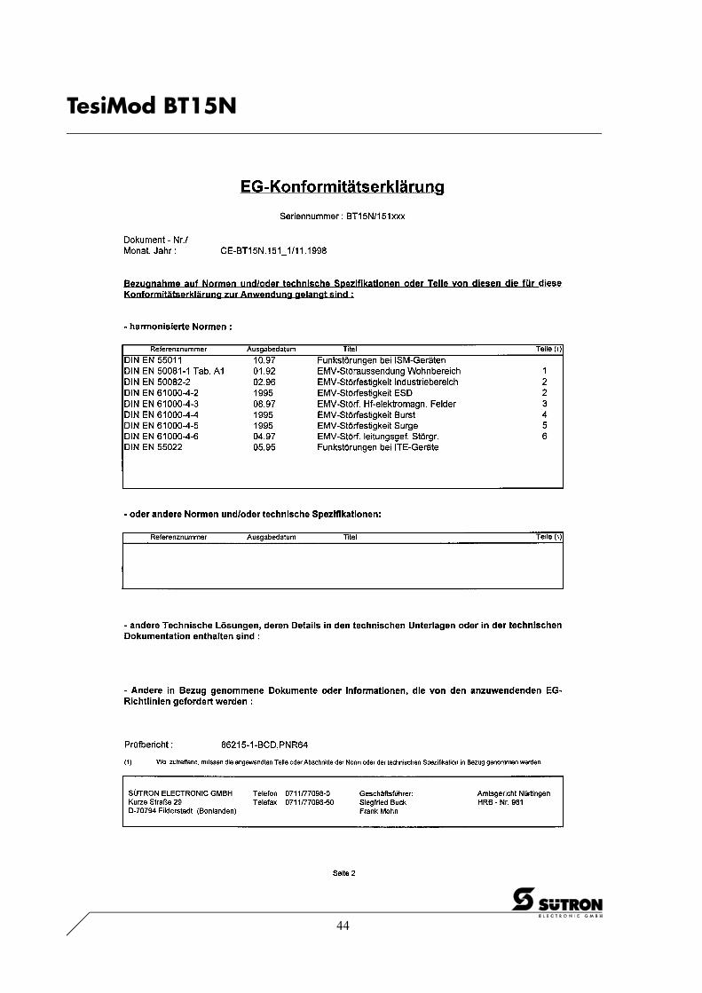
4 Declaration of Conformity
44
TesiMod BT15N

45
/001
-933
0/B
T15
N_g
rau_
eng_
V10
.300
000A
QK
0
TesiMod BT15N
5 Index
A
Application Memory 39ASCII Character Set Table 36
B
Battery 38
C
Character Attributes 34Control Keys 8
D
Declaration of Conformity 43Default Contrast Setting 34Display 33Display Contrast Setting 34
E
Editing Keys 7Explanation of Symbols 5
F
FontNormal 35Zoom 35
Front Panel Dimensions 19Front View 6Function Key Arrangement 10Function Keys 10Fuse 39
K
KeyAcknowledge 9Clear 9Cursor down 8Cursor home 8Cursor left 8Cursor right 8Cursor up 8Data Release 9Decimal Point 8Enter 9F1 to F16 10Help 9Minus 8Page down 9
Page up 9Plus 8Print 9
Keyboard 7
M
Mounting Depth 20Mounting the Terminal 18
P
Panel Cutout 21Pin Assignment
InterBus Optical Fibre 28X1 Supply Voltage 23X2 PROFIBUS-DP 26X2.1 / X2.2 CAN-Bus 27X2.1 / X2.2 InterBus 24X2.1 / X2.2 SUCOnet K 25X3 SER1 RS232c 31X3 SER1 RS485 30X3 SER1 TTY / 20 mA Current Loop 29X3 SER2 RS232c 31X4 Parallel Outputs 32
R
Rear ViewCAN-Bus 16InterBus 13InterBus Optical Fibre 17PROFIBUS-DP 15Standard 12SUCOnet K 14
S
Shielding 32Side View 20Slide-in Identification Strips 11Special Keys 9
T
Technical Data 40
U
User-Mode Switch 37

46
TesiMod BT15N

A-1
/000
-918
3/A
ppen
dix
A.3
0000
00Q
K0
Appendix A
A Appendix A
A.1 Shielding of SubminD - Interconnections
1 SubminD Connector2 Shield3 Cord Grip4 Cable
The shield must be pushed back tubularly.By fastening the cable with the cord grip you have to ensure an electrical contact of the shield to thehousing over an area as wide as possible and an appropriate strain relief.
Related Documents