Electronic Cornhole Final Design Report Design Team 11 Phillipp Gouin Lee Kirk Ashley Wilson Dr. Igor Tsukerman 11/29/2011

Welcome message from author
This document is posted to help you gain knowledge. Please leave a comment to let me know what you think about it! Share it to your friends and learn new things together.
Transcript

Electronic Cornhole
Final Design Report
Design Team 11
Phillipp Gouin
Lee Kirk
Ashley Wilson
Dr. Igor Tsukerman
11/29/2011

i
Table of Contents
List of Figures............................................................................................................iii-iv
List of Tables..............................................................................................................v
Abstract.....................................................................................................................1
1. Problem Statement................................................................................................1-5
Need..............................................................................................................1
Objective.......................................................................................................1
Background...................................................................................................1-5
Marketing Requirements...............................................................................5
Objective Tree...............................................................................................6
2. Design Requirements Specification......................................................................7-8
3. Accepted Technical Design..................................................................................8-37
Level 0 Block Diagram.................................................................................8
Level 0 FR Table..........................................................................................9
Level 1 Hardware Block Diagram................................................................9-10
Level 1 FR Table..........................................................................................10-11
Level 2 Hardware.........................................................................................11-15
Level 2 Cornhole Bag Block Diagram.............................................12
Level 2 Cornhole Bag FR.................................................................12-13
Level 2 Cornhole Board Block Diagram..........................................13
Level 2 Cornhole Board FR.............................................................13
Level 2 Cornhole PIC Block Diagram..............................................14
Level 2 Cornhole PIC FR.................................................................14-15
Hardware Calculation and Accepted Schematics............................................15-23
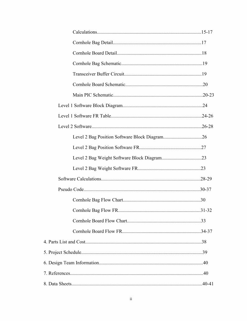
ii
Calculations......................................................................................15-17
Cornhole Bag Detail.........................................................................17
Cornhole Board Detail......................................................................18
Cornhole Bag Schematic...................................................................19
Transceiver Buffer Circuit................................................................19
Cornhole Board Schematic................................................................20
Main PIC Schematic..........................................................................20-23
Level 1 Software Block Diagram..................................................................24
Level 1 Software FR Table...........................................................................24-26
Level 2 Software...........................................................................................26-28
Level 2 Bag Position Software Block Diagram................................26
Level 2 Bag Position Software FR...................................................27
Level 2 Bag Weight Software Block Diagram.................................23
Level 2 Bag Weight Software FR....................................................23
Software Calculations..................................................................................28-29
Pseudo Code................................................................................................30-37
Cornhole Bag Flow Chart................................................................30
Cornhole Bag Flow FR....................................................................31-32
Cornhole Board Flow Chart.............................................................33
Cornhole Board Flow FR.................................................................34-37
4. Parts List and Cost................................................................................................38
5. Project Schedule....................................................................................................39
6. Design Team Information......................................................................................40
7. References..............................................................................................................40
8. Data Sheets............................................................................................................40-41
iii
List of Figures
Figure 1: Dimensions for Cornhole Board...............................................................1
Figure 2: Board Orientation on Cornhole Playing Field..........................................2
Figure 3: Sensor Directions......................................................................................3
Figure 4: Force Sensing Resistor.............................................................................4
Figure 5: Objective Tree...........................................................................................6
Figure 6: Level 0 Block Diagram.............................................................................8
Figure 7: Level 1 Hardware Block Diagram............................................................9
Figure 8: Level 2 Cornhole Bag Block Diagram.....................................................12
Figure 9: Level 2 Cornhole Board Block Diagram..................................................13
Figure 10: Level 2 Cornhole PIC Block Diagram....................................................14
Figure 11: Slope on Cornhole Board........................................................................16
Figure 12: Cornhole Bag Detail................................................................................17
Figure 13: Cornhole Board Detail.............................................................................18
Figure 14: Cornhole Bag Schematic..........................................................................19
Figure 15: Transceiver Buffer Circuit.......................................................................19
Figure 16: Board Schematic.......................................................................................20
Figure 17: Main PIC Schematic.................................................................................20
Figure 18: Part 1 of Main PIC Schematic..................................................................21
Figure 19: Part 2 of Main PIC Schematic..................................................................22
Figure 20: Part 3 of Main PIC Schematic..................................................................23
Figure 21: Level 1 Software Block Diagram...........................................................24
Figure 22: Level 2 Bag Position Software Block Diagram......................................25
Figure 23: Level 2 Bag Weight Software Block Diagram.......................................28

iv
Figure 24: Cornhole Bag Flow Chart.......................................................................30
Figure 25: Cornhole Board Flow Chart....................................................................33
v
List of Tables
Table 1: Design Requirements Specifications.........................................................7-8
Table 2: Level 0 FR.................................................................................................9
Table 3: Level 1 Hardware FR................................................................................10-11
Table 4: Level 2 Cornhole Bag FR.........................................................................12
Table 5: Level 2 Cornhole Board FR......................................................................13
Table 6: Level 2 Cornhole PIC FR..........................................................................14-15
Table 7: Level 1 Software FR..................................................................................24-26
Table 8: Level 2 Bag Position Software FR............................................................27
Table 9: Level 2 Bag Weight Software FR.............................................................28
Table 10: Cornhole Bag Flow FR...........................................................................31-32
Table 11: Cornhole Board Flow FR.......................................................................34-37
Table 12: Parts List.................................................................................................38
Table 13: Budget.....................................................................................................38
Table 14: Gantt Chart..............................................................................................39

1
Abstract Designer: AW
Cornhole is a very popular game that leads to hours of fun and family bonding; however, the scoring system of the game leads to much controversy. Currently the scoring system of the game is performed through all manual calculations which can be performed incorrectly. The goal of this project is to design an electronic cornhole scoring system by implementing various hardware and software platforms developed from research.
• Cornhole scoring calculated and maintained electronically
1. Problem Statement
Need Designer: PG
Have you ever had controversy over the score while playing cornhole? In today’s market there are no automatic “game incorporated” electronic cornhole score keeping devices. There have been many manual score-keeping devices where the user calculates the score and enters it into a device; however, mistakes can still be made. A system that calculates and displays the score for you is useful for ease of play.
Objective Designer: LK
The objective of this project is to design and prototype a system that will keep the score in a cornhole game electronically. The system will be able to keep score, be able to tell if a cornhole bag has been knocked off the board or into the cornhole, and say when someone has won the game. The user will be able to apply “house rules” for keeping score.
Background Designer: All
The game of cornhole is played with two teams of two people using two wooden boards spaced 27 feet apart measuring from the front of the boards. Figure 1 shows the dimension of the cornhole boards.
Figure 1: Dimensions for cornhole boards [1]

2
A player from each team stands in the pitcher's box across from their partner. Figure 2 shows the layout of the cornhole playing field.
Figure 2: Board orientation on cornhole playing field. [1]
The objective of the game is to land a 6 inch by 6 inch cloth bag filled with corn onto the board or into the hole located on the board. The players at a board will alternate throwing bags at the board across from them. Scoring is calculated in the following manner:
• 3 points for a bag in the hole • 1 point for a bag on the board • 0 points otherwise.
Only one team will score during a round because the score is calculated based upon the difference between the teams' scores in a round. For example, team A throws two bags on the hole and one bag on the board; their total points for the round is seven. Team B throws three bags on the board for a total of three points. The difference in points is four; therefore, team A would receive four points that round. The winning team can be determined by a number of different methods. A few methods to determine the winning team are
• Team reaching and/or exceeding 21 points, • Team scoring highest amount after a given number of rounds, • Team scoring highest amount after a given period of time.
The common practice is the winning team is determine by scoring exactly 21 points. If a team exceeds 21 points in a round, their score is reduced to a pre-determined score, normally 17 points, and play is continued.
The basic idea behind the design is to improve the scoring accuracy of the game which will also make the game easier to play. Currently, the standard of play is to calculated the score manually. Electronic scoreboards are available; however, the score is still entered manually in a fashion similar to basketball scoreboards. The intended design would implement accelerometers, force sensing resistors (FSR), PIC microcontrollers, and an
3
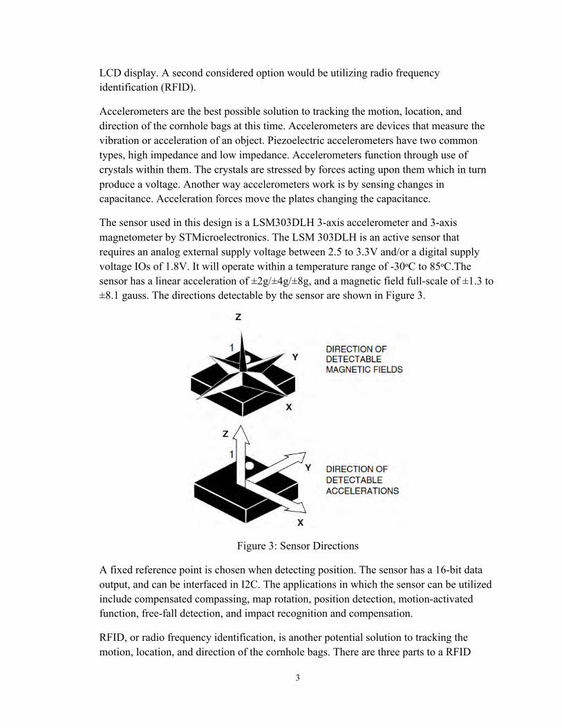
LCD display. A second considered option would be utilizing radio frequency identification (RFID).
Accelerometers are the best possible solution to tracking the motion, location, and direction of the cornhole bags at this time. Accelerometers are devices that measure the vibration or acceleration of an object. Piezoelectric accelerometers have two common types, high impedance and low impedance. Accelerometers function through use of crystals within them. The crystals are stressed by forces acting upon them which in turn produce a voltage. Another way accelerometers work is by sensing changes in capacitance. Acceleration forces move the plates changing the capacitance.
The sensor used in this design is a LSM303DLH 3-axis accelerometer and 3-axis magnetometer by STMicroelectronics. The LSM 303DLH is an active sensor that requires an analog external supply voltage between 2.5 to 3.3V and/or a digital supply voltage IOs of 1.8V. It will operate within a temperature range of -30ᶱC to 85ᶱC.The sensor has a linear acceleration of ±2g/±4g/±8g, and a magnetic field full-scale of ±1.3 to ±8.1 gauss. The directions detectable by the sensor are shown in Figure 3.
Figure 3: Sensor Directions
A fixed reference point is chosen when detecting position. The sensor has a 16-bit data output, and can be interfaced in I2C. The applications in which the sensor can be utilized include compensated compassing, map rotation, position detection, motion-activated function, free-fall detection, and impact recognition and compensation.
RFID, or radio frequency identification, is another potential solution to tracking the motion, location, and direction of the cornhole bags. There are three parts to a RFID
4
system: the RFID tags, the scanning antenna, and a transceiver. There are two types of RFID tags, passive and active. A passive tag receives its energy from the scanning antenna. The tag has no power or energy by itself. Depending on the antenna, passive tags usually need to be within a few inches of the antenna to activate. The active tag has its own power source. The scanning antenna also receives the stored information in the tags allowing communication between the transceiver and the tags.
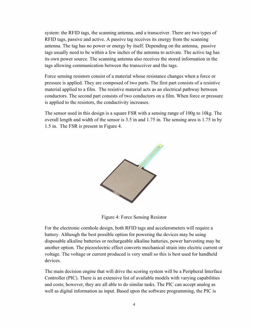
Force sensing resistors consist of a material whose resistance changes when a force or pressure is applied. They are composed of two parts. The first part consists of a resistive material applied to a film. The resistive material acts as an electrical pathway between conductors. The second part consists of two conductors on a film. When force or pressure is applied to the resistors, the conductivity increases.
The sensor used in this design is a square FSR with a sensing range of 100g to 10kg. The overall length and width of the sensor is 3.5 in and 1.75 in. The sensing area is 1.75 in by 1.5 in. The FSR is present in Figure 4.
Figure 4: Force Sensing Resistor
For the electronic cornhole design, both RFID tags and accelerometers will require a battery. Although the best possible option for powering the devices may be using disposable alkaline batteries or rechargeable alkaline batteries, power harvesting may be another option. The piezoelectric effect converts mechanical strain into electric current or voltage. The voltage or current produced is very small so this is best used for handheld devices.
The main decision engine that will drive the scoring system will be a Peripheral Interface Controller (PIC). There is an extensive list of available models with varying capabilities and costs; however, they are all able to do similar tasks. The PIC can accept analog as well as digital information as input. Based upon the software programming, the PIC is

5
able to output in either analog or digital as well as to any equipment that can accept an analog or digital signal. For the electronic cornhole design, a PIC is going to be used to compute the score, and output the score to an LCD display as well as trigger audio events. The LCD display will consist of two pair of seven segment displays which will satisfy the need to show the score of the game as well as maintain a low cost.
Two types PICs will be used in the design. A Microchip PIC18LF46K22-I/P will be used for the cornhole bags, and a Microchip PIC16LF1939-I/P will be used for the cornhole board and scoreboard. The PIC18LF4622-I/P is a high performance RISC CPU with a C Complier optimize architecture/instruction set. It has a 16-bit wide instruction and an 8-bit wide data path. It also has a 31-level software accessible hardware stack. The PIC18LF4622-I/P has extreme low-power management with a sleep mode, watchdog timer, and time oscillator. The PIC16LF1939-I/P is an enhanced mid-range core with 49 instruction and 16 stack levels. It also has a 96 LCD segment drive support. The PIC16LF1939-I/P is low power similar to the PIC18LF46K22-I/P.
Marketing Requirements Designer: PG, LK
• Detect bags on cornhole board • Distinguish between the different teams cornhole bags • Detect cornhole bags in the cornhole • Detect cornhole bags falling off the cornhole board • Keep appropriate score • Display score • Have preset scoring systems • Be portable • Be durable • Be easy to use • Output audio based on cornhole game events

6
Objective Tree Designer: AW
When developing the objective tree, the hierarchy of user needs is to be kept in mind. The marketing requirements are used to develop the objective tree. Figure 1 is the cornhole project objective tree.
Cornhole Scoring System
Keep Score Ease of Use Durable Portable
Detect Bags in the Hole
Detect Missing Bags
Display Score
Detect Bags on the Board
Distinguish between
Teams’ Bags
Auto-play Audio
ProgrammableScore
Withstand Repeated
Impacts from Bags
Fit in Most Vehicles
Figure 5: Objective Tree
7
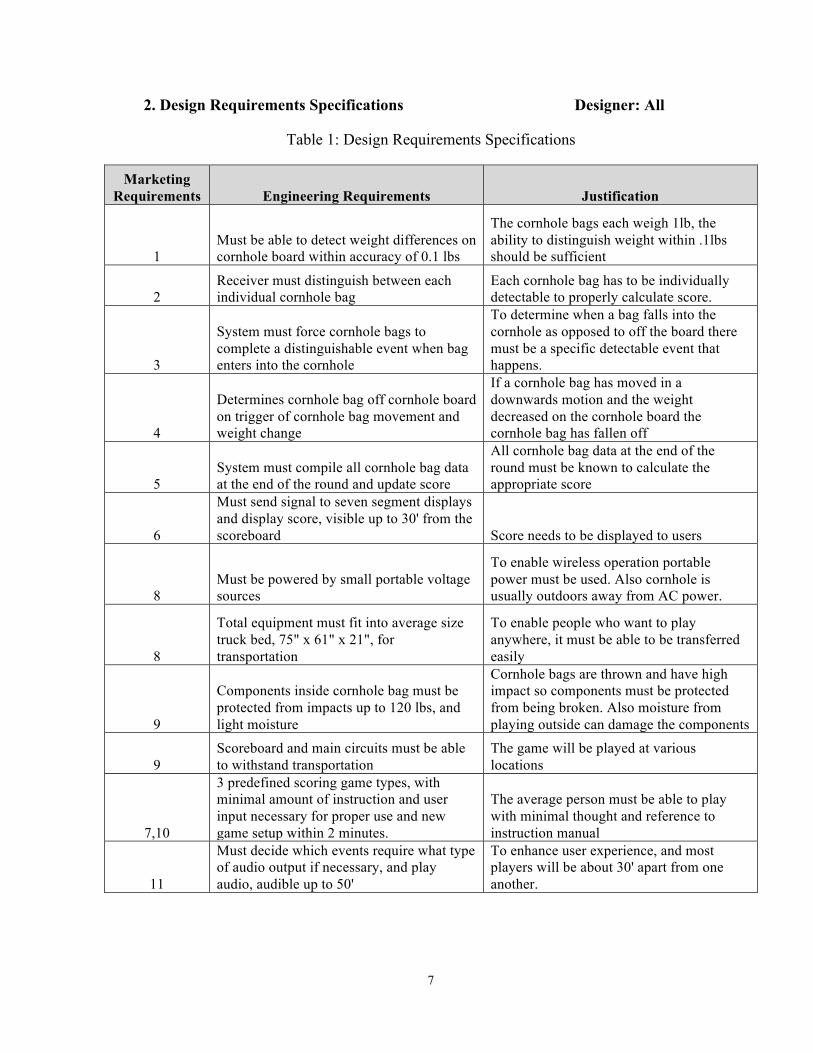
2. Design Requirements Specifications Designer: All
Table 1: Design Requirements Specifications
Marketing Requirements Engineering Requirements Justification
1 Must be able to detect weight differences on cornhole board within accuracy of 0.1 lbs
The cornhole bags each weigh 1lb, the ability to distinguish weight within .1lbs should be sufficient
2 Receiver must distinguish between each individual cornhole bag
Each cornhole bag has to be individually detectable to properly calculate score.
3
System must force cornhole bags to complete a distinguishable event when bag enters into the cornhole
To determine when a bag falls into the cornhole as opposed to off the board there must be a specific detectable event that happens.
4
Determines cornhole bag off cornhole board on trigger of cornhole bag movement and weight change
If a cornhole bag has moved in a downwards motion and the weight decreased on the cornhole board the cornhole bag has fallen off
5 System must compile all cornhole bag data at the end of the round and update score
All cornhole bag data at the end of the round must be known to calculate the appropriate score
6
Must send signal to seven segment displays and display score, visible up to 30' from the scoreboard Score needs to be displayed to users
8 Must be powered by small portable voltage sources
To enable wireless operation portable power must be used. Also cornhole is usually outdoors away from AC power.
8
Total equipment must fit into average size truck bed, 75" x 61" x 21", for transportation
To enable people who want to play anywhere, it must be able to be transferred easily
9
Components inside cornhole bag must be protected from impacts up to 120 lbs, and light moisture
Cornhole bags are thrown and have high impact so components must be protected from being broken. Also moisture from playing outside can damage the components
9 Scoreboard and main circuits must be able to withstand transportation
The game will be played at various locations
7,10
3 predefined scoring game types, with minimal amount of instruction and user input necessary for proper use and new game setup within 2 minutes.
The average person must be able to play with minimal thought and reference to instruction manual
11
Must decide which events require what type of audio output if necessary, and play audio, audible up to 50'
To enhance user experience, and most players will be about 30' apart from one another.
8
Marketing Requirements 1. Detect cornhole bags on cornhole board 2. Distinguish between the different teams cornhole bags 3. Detect cornhole bags in the cornhole 4. Detect cornhole bags falling off the cornhole board 5. Keep appropriate score 6. Display score 7. Preset scoring systems 8. Be portable 9. Be durable 10. Be easy to use 11. Output audio based on game events
3. Accepted Technical Design
Level 0 Block Diagram Designer: PG, LK
The Level 0 Block Diagram shows the general characteristics and operation of the system in a decomposed form. The diagram shows the inputs to the system on the right, and the outputs of the system on the left. The overall goal is to have the eight cornhole bags communicate wirelessly to the scoreboard. The scoreboard then processes the received information, and displays the score and plays corresponding audio. The Level 0 FR describes in detail the inputs and outputs of the block diagram. Figure 6 is the Level 0 Block Diagram, and Table 2 is the Level 0 FR Table.
Cornhole Scoreboard
8Power
BagsManual Set
Manual Reset
Display
Audio
Figure 6: Level 0 Block Diagram

9
Table 2: Level 0 FR
Module Cornhole Scoreboard Inputs Power: 6V Bags: Digital Information Manual set: digital input Manual reset: digital input Outputs Display: LED Audio:1 .5V Speaker output Functionality
Calculate and display proper score. Determine appropriate audio output based on bag input. New games start on manual set and reset.
Designer Phillipp Gouin
Level 1 Hardware Block Diagram Designer: PG
The Level 1 Hardware Block Diagram presents the basic design of the cornhole game in more detail than the Level 0. The Level 1 FR explains the inputs and outputs of each module within the system. The bags will be used to determine motion and direction which in turn will be deciphered using a PIC located inside the bag. The PIC transmits a signal to the board. The board also has weight sensors to determine how many bags are on the board. The main PIC will decipher the information from the bags and the board. Figure 7 is the Level 1 Hardware Block Diagram, and Table 3 is the Level 1 Hardware FR Table.

10
BOARDWeight Sensors
BAGSAccelerometer,RF Transmitter,
PIC3 V DC (Battery) RF Output
PICRF Receiver
Power Supply6 V DC Battery
Digital Weight Output
DisplayScore
Speaker
Audio Output
Weight
Figure 7: Level 1 Hardware Block Diagram
Table 3: Level 1 Hardware FR
Module Cornhole Bags Inputs Power: 3 V DC Acceleration: User implemented Outputs RF signal: 10 mA Weight: Weight of bag if on cornhole board Functionality Determine when the bag has been thrown
using the accelerometer and direction of motion. The information will process the data then transmit it using RF Transmission.
Designer Phillipp Gouin

11
Module Cornhole Board Inputs Power: 6 V DC Weight: Weight of bag if on cornhole board Outputs Digital Weight Output Functionality Determine the total number of bags on the
board by using weight sensors.
Designer Phillipp Gouin
Module PIC Board Inputs Power: 6 V DC RF signal: 10 mA Digital weight signal Outputs Audio Output: 0.5 V Peak Score Output Functionality Decipher inputs from bags and board, and
determine the proper score. Then send score to scoreboard and send appropriate audio to speaker according to current events.
Designer Phillipp Gouin
Module Speaker Inputs Audio Signal: 0.5 V Peak Outputs Audio Functionality Play audio sent from the PIC Designer Phillipp Gouin
Module Display Inputs Power: 6 V DC SCORE: ? Outputs Display Score Functionality Display Current score which is sent from
the PIC board.
Designer Phillipp Gouin
Level 2 Hardware Designer: PG
The Level 2 Hardware Block Diagrams decomposes each module of the Level 1 Hardware Block Diagram. Figures 8 and 9 are the Level 2 Hardware Block Diagrams, and Tables 4 and 5 are the Level 2 Hardware FR Tables.

12
3V DC (2 AA Batteries)
Accelerometer With Internal Compass and Inertia Switch
Radio Frequency Transmitter(868MHz)
RF OutputLoop Antenna
MicrocontrollerPIC18
Figure 8: Level 2 Cornhole Bag Block Diagram
Table 4: Level 2 Cornhole Bag FR
Module Accelerometer With Internal Compass and Inertia Switch Inputs Power: 3 V DC Outputs I^2C Data to Bag's PIC Functionality Accelerometer will detect acceleration of bag and direction
using internal compass. The internal inertia switch will save power and only turn the accelerometer on when it is moving.
Designer Phillipp Gouin
Module Radio Frequency Transmitter Inputs Power: 3 V DC Serial Data From Pic Outputs Serial RF output Functionality RF Transmitter will transmit the data from the Accelerometer
to the board's PIC VIA a loop antenna. Each bag will have its own unique frequency.
Designer Phillipp Gouin
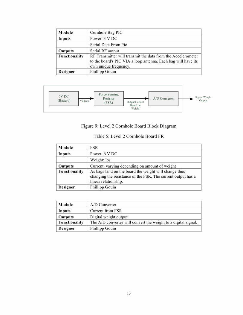
13
Module Cornhole Bag PIC Inputs Power: 3 V DC Serial Data From Pic Outputs Serial RF output Functionality RF Transmitter will transmit the data from the Accelerometer
to the board's PIC VIA a loop antenna. Each bag will have its own unique frequency.
Designer Phillipp Gouin
6V DC (Battery)
Force Sensing Resistor(FSR)Voltage Output Current
Based on Weight
A/D Converter Digital WeightOutput
Figure 9: Level 2 Cornhole Board Block Diagram
Table 5: Level 2 Cornhole Board FR
Module FSR Inputs Power: 6 V DC Weight: lbs Outputs Current: varying depending on amount of weight Functionality As bags land on the board the weight will change thus
changing the resistance of the FSR. The current output has a linear relationship.
Designer Phillipp Gouin
Module A/D Converter Inputs Current from FSR Outputs Digital weight output Functionality The A/D converter will convert the weight to a digital signal. Designer Phillipp Gouin
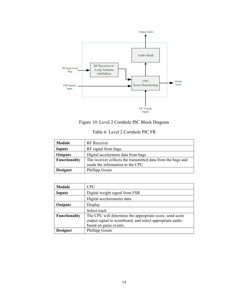
14
Audio Bank
RF Receiver w/ Loop Antenna
(868MHz)
FSR Digital Input
RF Input From Bag
OutputScore
CPUScore Determining
Output Audio
DC Voltage Supply
Figure 10: Level 2 Cornhole PIC Block Diagram
Table 6: Level 2 Cornhole PIC FR
Module RF Receiver Inputs RF signal from bags. Outputs Digital acceleration data from bags Functionality The receiver collects the transmitted data from the bags and
sends the information to the CPU Designer Phillipp Gouin
Module CPU Inputs Digital weight signal from FSR Digital accelerometer data Outputs Display Select track Functionality The CPU will determine the appropriate score, send score
output signal to scoreboard, and select appropriate audio based on game events.
Designer Phillipp Gouin

15
Module Audio Bank Inputs Select track Outputs Output Audio to speaker Select track Functionality This will be where audio tracks are stored then sent to speaker
when instructed. Designer Phillipp Gouin
Hardware Calculations and Accepted Layouts Designer: All
The design must take into account the force at which the bags impact the board. The velocity of the cornhole bag before impact can be found using
! = 2!ℎ, (1)
where V is the velocity of the bag before impact, g is gravity, and h is the height at which it is dropped. It is assumed that the object's trajectory is toward the ground. This equation can only be used for objects that have no external forces working upon them expect gravity. The worst case scenario would yield a velocity of 4 m/s. assuming the bag falls from a height of 3 m. The kinetic energy of the cornhole bag before impact can be found using
!" = !!!!!, (2)
where KE is the kinetic energy of the bag before impact, m is the mass of the cornhole bag, and V is the velocity of the bag before impact. When the mass is 0.5 kg, the worst case scenario would yield a kinetic energy value of 49J. In order to determine the force at impact, the distance the bag travels is assumed to be approximately 0.02m. If it was assumed the cornhole bag does not move upon impact, the force at impact would be infinite which is unreasonable. The force of the cornhole bag at impact can be found using
! = !"! , (3)
where F is the force of the cornhole bag upon impact, KE is the kinetic energy of the bag before impact, and d is distance the bad travels upon impact. Based upon the equation the force at impact is determined to be a maximum of 2450 N The force of impact will be essential to the design of the protective casing for the components within the cornhole bags.
In order to determine if a cornhole bag falls into the cornhole, the cornhole bag needs to slide backwards down a slope. If the game is executed properly, this is the only
16
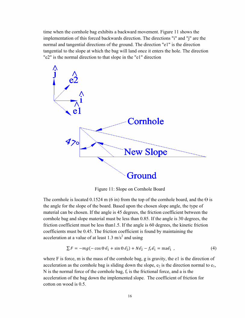
time when the cornhole bag exhibits a backward movement. Figure 11 shows the implementation of this forced backwards direction. The directions "i" and "j" are the normal and tangential directions of the ground. The direction "e1" is the direction tangential to the slope at which the bag will land once it enters the hole. The direction "e2" is the normal direction to that slope in the "e1" direction
Figure 11: Slope on Cornhole Board
The cornhole is located 0.1524 m (6 in) from the top of the cornhole board, and the Ө is the angle for the slope of the board. Based upon the chosen slope angle, the type of material can be chosen. If the angle is 45 degrees, the friction coefficient between the cornhole bag and slope material must be less than 0.85. If the angle is 30 degrees, the friction coefficient must be less than1.5. If the angle is 60 degrees, the kinetic friction coefficients must be 0.45. The friction coefficient is found by maintaining the acceleration at a value of at least 1.3 m/s2 and using
! = −!" − cosӨ e! + sinӨ !! + !!! − !!e! = mae! , (4)
where F is force, m is the mass of the cornhole bag, g is gravity, the e1 is the direction of acceleration as the cornhole bag is sliding down the slope, e2 is the direction normal to e1, N is the normal force of the cornhole bag, fr is the frictional force, and a is the acceleration of the bag down the implemented slope. The coefficient of friction for cotton on wood is 0.5.

17
The power consumption of the equipment inside the bag must be kept to a minimum. Two AA alkaline batteries will be used inside each bag. Each battery has a rating of 2400 milliamps per hours (mAh) which indicates that in 1 hour 2400mA can be drawn from each battery. The goal is to draw a maximum of 240mAh; therefore, two AA alkaline batteries would last through 40 hours of game play. The batteries must be contained within the bags either by means of a zipper on the bags or sewn into the bags. Figure 12 shows the physical design of the bag. The electronics within the bag will be protected using a padding such as bubble wrap. We plan on using a sort of padding such as bubble wrap to protect the inside electronics. The FSR layout on the cornhole board is shown in Figure 13.
Figure 12: Cornhole Bag Detail

18
Figure 13: Cornhole Board Detail
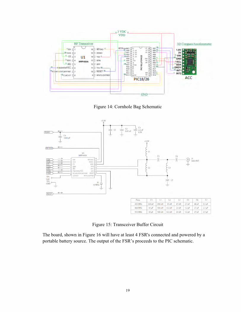
A variety of electrical components are present within each bag. The schematic for the internal electrical components is shown in Figure 14. This schematic contains the point-to-point connections of the internal electrical components of the bag. The RF transciever transmits information to the main PIC. In order for the antenna to transmit at the proper frequency, a buffer circuit is necessary. The buffer circuit is shown in Figure 15.
19
Figure 14: Cornhole Bag Schematic
Figure 15: Transceiver Buffer Circuit
The board, shown in Figure 16 will have at least 4 FSR's connected and powered by a portable battery source. The output of the FSR’s proceeds to the PIC schematic.

20
Figure 16: Board Schematic
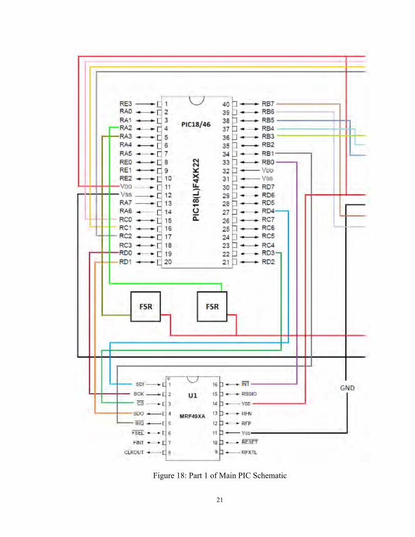
The main PIC circuit will be the main computing center of the system. It will process the bag data and output the score to the display. There will be three total PIC's, one for each team's data, and one for the scoreboard. Each PIC will have its own receiving antenna to capture each team's bag data. Figure 17 shows the entire main PIC schematic. Figure 18 through 20 show a zoomed in version of each portion of the main PIC schematic.
Figure 17: Main PIC Schematic
21
Figure 18: Part 1 of Main PIC Schematic

22
Figure 19: Part 2 of Main PIC Schematic

23
Figure 20: Part 3 of Main PIC Schematic

24
Level 1 Software Block Diagram Designer: LK
The Level 1 Software Block Diagram presents the basic design of the cornhole game in more detail than the Level 0. The Level 1 FR explains the inputs and outputs of each module within the system. GetBagPostion will be used to determine the position of each cornhole bag, and GetBoardWeight will be used to determine how many bags are on the cornhole board. ComputerScore calculates the score, sends it to the other two modules to display the score and play corresponding audio. Figure 21 is the Level 1 Software Block Diagram, and Table 3 is the Level 1 Hardware FR Table.
GetBagPosition
GetBoardWeight
ComputerScore
DisplayScore
PlayAudio
Figure 21: Level 1 Software Block Diagram
Table 7: Level 1 Software FR
Module GetBagPosition() Module Type Input and Output Inputs position[]: char[](array of chars values 0 to 255)
Outputs onBoard: boolean(0 or 1) inHole: boolean(0 or 1)
Functionality Read position data from the position[] array and determine proper values for output of Booleans
Modules Invoked None Designer Lee Kirk
25
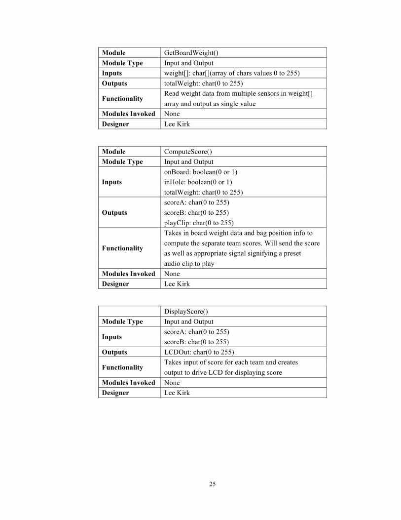
Module GetBoardWeight() Module Type Input and Output Inputs weight[]: char[](array of chars values 0 to 255) Outputs totalWeight: char(0 to 255)
Functionality Read weight data from multiple sensors in weight[] array and output as single value
Modules Invoked None Designer Lee Kirk
Module ComputeScore() Module Type Input and Output
Inputs onBoard: boolean(0 or 1) inHole: boolean(0 or 1) totalWeight: char(0 to 255)
Outputs scoreA: char(0 to 255) scoreB: char(0 to 255) playClip: char(0 to 255)
Functionality
Takes in board weight data and bag position info to compute the separate team scores. Will send the score as well as appropriate signal signifying a preset audio clip to play
Modules Invoked None Designer Lee Kirk
DisplayScore() Module Type Input and Output
Inputs scoreA: char(0 to 255) scoreB: char(0 to 255)
Outputs LCDOut: char(0 to 255)
Functionality Takes input of score for each team and creates output to drive LCD for displaying score
Modules Invoked None Designer Lee Kirk

26
Module PlayAudio() Module Type Input and Output Inputs clip: char(0 to 255) Outputs audio: char(0 to 255
Functionality Takes input integer to choose appropriate audio clip from a stored databank
Modules Invoked None Designer Lee Kirk
Level 2 Software Designer: LK
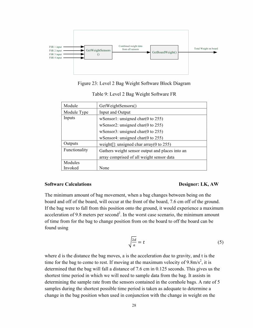
The Level 2 Software Block Diagrams decomposes each module of the Level 1 Software Block Diagram. Figures 22 and 23 are the Level 2 Software Block Diagrams, and Tables 8 and 9 are the Level 2 Software FR Tables.
GetAccelerometerData()
GetAccel()
GetMagField()
Acceleration x-directionAcceleration y-directionAcceleration z-direction
Magnetic field x-directionMagnetic field y-directionMagnetic field z-direction
Bag Frequency
Bag Frequency
Acceleration data for bag
Magnetic field data for bag
Bag Movement data
GetBagMovement()
Bags on board
Bags in hole
Figure 22: Level 2 Bag Position Software Block Diagram

27
Table 8: Level 2 Bag Position Software FR
Module GetAccelerometerData() Module Type Input and Output Inputs None Outputs movement[][]: signed integer array(-32768 to 32767) Functionality Compiles acceleration and magnetic field data into
an array pairing direction with acceleration in form of numerical value and sign for x and z direction
Modules Invoked GetAccel(), GetMagField()
Module GetAccel() Module Type Input and Output Inputs xAccelin: signed array(-32768 to 32767)
yAccelin: signed array(-32768 to 32767) zAccelin: signed array(-32768 to 32767) bagFreq: signed array(-32768 to 32767)
Outputs Accelout[]: signed integer array(-32768 to 32767) Functionality Gathers acceleration data from accelerometer and
outputs in standardized integer scale Modules Invoked None
Module GetMagField() Module Type Input and Output Inputs xMagin: signed array(-32768 to 32767)
yMagin: signed array(-32768 to 32767) zMagin: signed array(-32768 to 32767) bagFreq: signed array(-32768 to 32767)
Outputs Magout[]:signed integer array(-32768 to 32767) Functionality Gathers magnetic field data from accelerometer and
outputs in standardized integer scale Modules Invoked None
28
GetWeightSensors()
FSR 1 inputFSR 2 inputFSR 3 input
Combined weight data from all sensors
FSR 4 input
GetBoardWeight()Total Weight on board
Figure 23: Level 2 Bag Weight Software Block Diagram
Table 9: Level 2 Bag Weight Software FR
Module GetWeightSensors() Module Type Input and Output Inputs wSensor1: unsigned char(0 to 255)
wSensor2: unsigned char(0 to 255) wSensor3: unsigned char(0 to 255) wSensor4: unsigned char(0 to 255)
Outputs weight[]: unsigned char array(0 to 255) Functionality Gathers weight sensor output and places into an
array comprised of all weight sensor data Modules Invoked None
Software Calculations Designer: LK, AW
The minimum amount of bag movement, when a bag changes between being on the board and off of the board, will occur at the front of the board, 7.6 cm off of the ground. If the bag were to fall from this position onto the ground, it would experience a maximum acceleration of 9.8 meters per second2. In the worst case scenario, the minimum amount of time from for the bag to change position from on the board to off the board can be found using
!!!= ! (5)
where d is the distance the bag moves, a is the acceleration due to gravity, and t is the time for the bag to come to rest. If moving at the maximum velocity of 9.8m/s2, it is determined that the bag will fall a distance of 7.6 cm in 0.125 seconds. This gives us the shortest time period in which we will need to sample data from the bag. It assists in determining the sample rate from the sensors contained in the cornhole bags. A rate of 5 samples during the shortest possible time period is taken as adequate to determine a change in the bag position when used in conjunction with the change in weight on the

29
board from the FSR sensors. This means that within every 0.125 seconds, the bag's sensors need to be sampled 5 times. The sample rate frequency is found using
! ! = ! (6)
where s is the number of samples, t is the time interval, and f is the sampling frequency. From Equation 6, it's determined that the bags need to be sampled at a rate of 40 samples per second. If the sampling frequency was slower, it may not be possible to decipher the bags movement in the worst case scenario. Using this sampling rate, the bit rate necessary for transmission between our bag transmitter and the receiver connected to the PIC can be determined. Since there are 8 bits of acceleration data and 8 bits of magnetic field data each transmitting from the bag, a total of 16 bits of data per sample is needed. The minimum bit rate can be found using
!×! = !! (7)
where b is the number of bits, s is the number of samples, and br is the bit rate. If 16 bits (b) are sampled at a rate of 40 samples per second, the minimum bit rate is determined to be 640 bits per second.
There are two different communication protocols necessary to transmit the bag movement data to the PIC. The first method utilizes the accelerometer and in bag PIC to implement the I2C(Inter-Integrated Circuit) protocol. The 100 kbps (kilobits per second) transfer rate will satisfy the data bandwidth needs. The second method utilizes the in bag PIC to communicate with the RF transceiver via the SPI(Serial Peripheral Interface) protocol. This communication is performed at a programmable bit rate in the Mbps(megabits per second) range. This rate satisfies the data transfer needs. The third method utilizes the receiver data to connect to a PIC using an SPI interface. This is also satisfactory for the transmission needs.
The 6 FSR's are connected to analog input pins on the PIC connected to the board. The FSR's conductance changes linearly as force is applied to the face of them. With the board mounted on top, the conductance will change and be used to calculate the amount of weight on the board. This assists in determining if a bag is present on the board .The magnetic field information will assist in determining the bags orientation with respect to the position of the boards. Combined with the accelerometer data, which provides the physical movement and path of the bag, it can be determined if a bag has been thrown and its FSR input, if a bag has been thrown in the correct direction with regards to board orientation, and/or if the bag is on top of the board. The accelerometer will then be further employed to determine if the bag fell into the hole. If the movement signature shows the bag flying toward the board and then sliding down the inner slope (opposite of its normal motion), it can be assumed that the bad went into the hole.

30
Pseudo Code Designer: LK
initSPI()
initI2C()
initAccel()
readI2C()
writeSPI()
readSPI()
Bag Reset?No Yes
Figure 24: Cornhole Bag Flow Chart

31
Table 10: Cornhole Bag Flow FR
Module initI2C() Module Type Initialization Inputs None Outputs None Functionality Module to initialize the I2C communication
protocol between the PIC18 and Accelerometer Modules Invoked None
Designer Lee Kirk
Module initAccel() Module Type Initialization Inputs None Outputs None Functionality Module to initialize and calibrate the
Accelerometer Modules Invoked writeI2C(), readI2C() Designer Lee Kirk
Module initSPI() Module Type Initialization Inputs None Outputs None Functionality Module to initialize the SPI communication
protocol between the PICs and RF transceivers Modules Invoked None
Designer Lee Kirk
Module writeI2C() Module Type Input Inputs I2Cwrite: unsigned char(0 to 255) Outputs None Functionality Module to send data to the Accelerometer Modules Invoked None Designer Lee Kirk

32
Module readI2C() Module Type Output Inputs None Outputs I2Cread: unsigned char(0 to 255) Functionality Module to read data from the Accelerometer Modules Invoked None Designer Lee Kirk
Module writeSPI() Module Type Input Inputs SPIwrite: unsigned int(0 to 65535) Outputs None Functionality Module to write data to the RF Transceiver Modules Invoked convertI2CtoSPI() Designer Lee Kirk
Module readSPI() Module Type Output Inputs None Outputs SPIread: unsigned int(0 to 65535) Functionality Module to read data from the RF Transceiver Modules Invoked bagReset() Designer Lee Kirk
Module convertI2CtoSPI() Module Type Input and Output Inputs I2Cinput: unsigned char(0 to 255) Outputs SPIoutput: unsigned int(0 to 65535) Functionality Module to convert the data from I2C to SPI Modules Invoked None Designer Lee Kirk

33
initButtons()
initLCDMenu()
initFSR()
readSPI()
getFSR()
boardEvents()
initLCDBoard()
buttons()endRound()
Fix Score?
Yes
No
boardReset()
computeScore()
putLCDScore()
putLCDMenu()
playSound()
menu()
startRound()
fixScore()
Figure 25: Cornhole Board Flow Chart

34
Table 11: Cornhole Board Flow FR
Module initLCDScoreBoard() Module Type Initialization Inputs None Outputs None Functionality Module to initialize the PIC24 to LCD number
display Modules Invoked None Designer Lee Kirk
Module initLCDMenu() Module Type Initialization Inputs None Outputs None Functionality Module to initialize the PIC24 to the alphanumeric LCD display for menu options Modules Invoked None Designer Lee Kirk
Module initFSR() Module Type Initialization Inputs None Outputs None Functionality Module to initialize the FSR inputs and calibrate the "0" weight state Modules Invoked FSRADC() Designer Lee Kirk
Module initButtons() Module Type Initialization Inputs None Outputs None Functionality Module to initialize the PIC24 ports used to gather user input through push buttons Modules Invoked None Designer Lee Kirk

35
Module menu() Module Type Configuration Inputs None Outputs None Functionality Module to take user input from buttons to configure gameplay and perform score changes Modules Invoked putLCDMenu() Designer Lee Kirk
Module boardEvents() Module Type Configuration Inputs None Outputs None Functionality Module to decide based upon bag and FSR data if a bag is on the board, in the hole, or a miss Modules Invoked None Designer Lee Kirk
Module getFSR() Module Type Input and Output Inputs analogWeight: unsigned int(0 to 65535) Outputs digitalWeight: unsigned int(0 to 65535) Functionality Module to read the analog signal from the FSR sensor and output the digital version of it Modules Invoked FSRADC() Designer Lee Kirk
Module FSRADC() Module Type Input and Output Inputs analogWeight: unsigned int(0 to 65535) Outputs digitalWeight: unsigned int(0 to 65535) Functionality Module to perform analog to digital conversion of FSR signal Modules Invoked None Designer Lee Kirk
36
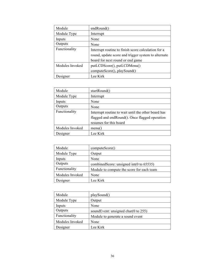
Module endRound() Module Type Interrupt Inputs None Outputs None Functionality Interrupt routine to finish score calculation for a round, update score and trigger system to alternate board for next round or end game Modules Invoked putLCDScore(), putLCDMenu() computeScore(), playSound() Designer Lee Kirk
Module startRound() Module Type Interrupt Inputs None Outputs None Functionality Interrupt routine to wait until the other board has flagged and endRound(). Once flagged operation resumes for this board Modules Invoked menu() Designer Lee Kirk
Module computeScore() Module Type Output Inputs None Outputs combinedScore: unsigned int(0 to 65535) Functionality Module to compute the score for each team Modules Invoked None Designer Lee Kirk
Module playSound() Module Type Output Inputs None Outputs soundEvent: unsigned char(0 to 255) Functionality Module to generate a sound event Modules Invoked None Designer Lee Kirk

37
Module putLCDScore() Module Type Input Inputs combinedScore: unsigned int(0 to 65535) Outputs None Functionality Module to send the score to the score board Modules Invoked computeScore() Designer Lee Kirk
Module boardReset() Module Type Interrupt Inputs None Outputs None Functionality Module to reset entire cornhole system if the reset button is pressed Modules Invoked writeSPI() Designer Lee Kirk
Module fixScore() Module Type Configuration Inputs None Outputs None Functionality Module to trigger score change if selected from user menu Modules Invoked menu() Designer Lee Kirk
Module buttons() Module Type Interrupt Inputs None Outputs None Functionality Module to trigger menu routine if arrow buttons have been pressed by user Modules Invoked menu() Designer Lee Kirk
38
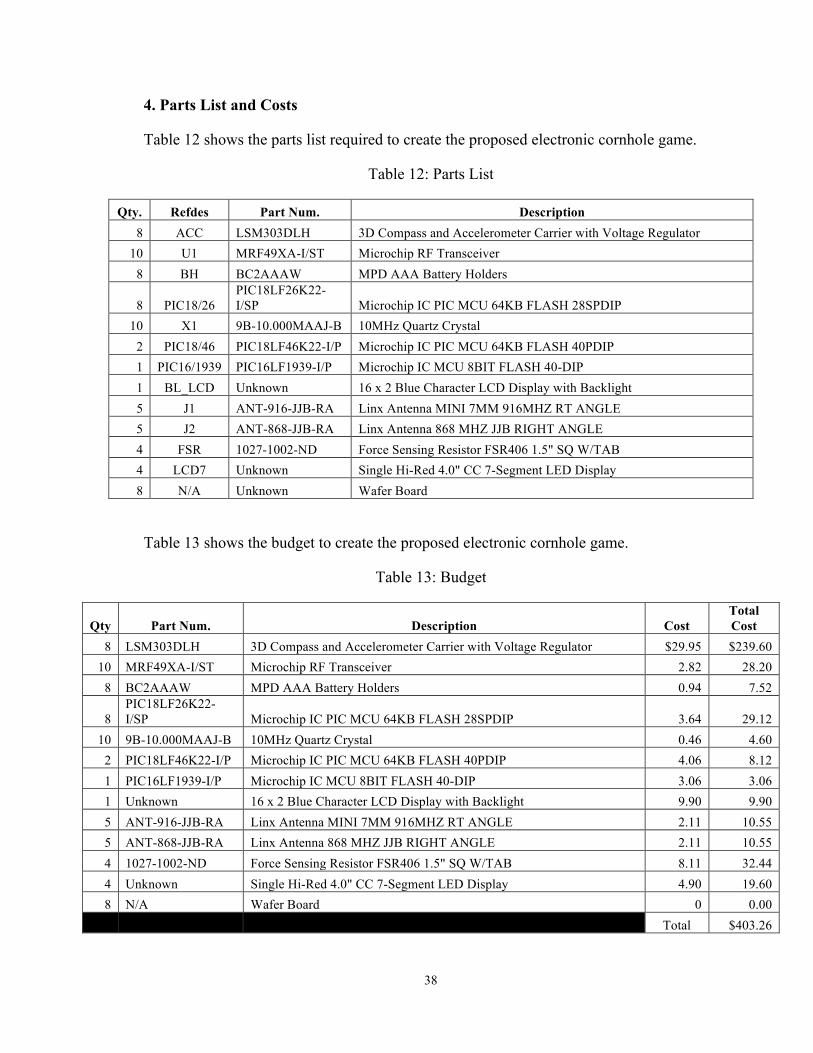
4. Parts List and Costs
Table 12 shows the parts list required to create the proposed electronic cornhole game.
Table 12: Parts List
Qty. Refdes Part Num. Description 8 ACC LSM303DLH 3D Compass and Accelerometer Carrier with Voltage Regulator
10 U1 MRF49XA-I/ST Microchip RF Transceiver 8 BH BC2AAAW MPD AAA Battery Holders
8 PIC18/26 PIC18LF26K22-I/SP Microchip IC PIC MCU 64KB FLASH 28SPDIP
10 X1 9B-10.000MAAJ-B 10MHz Quartz Crystal 2 PIC18/46 PIC18LF46K22-I/P Microchip IC PIC MCU 64KB FLASH 40PDIP 1 PIC16/1939 PIC16LF1939-I/P Microchip IC MCU 8BIT FLASH 40-DIP 1 BL_LCD Unknown 16 x 2 Blue Character LCD Display with Backlight 5 J1 ANT-916-JJB-RA Linx Antenna MINI 7MM 916MHZ RT ANGLE 5 J2 ANT-868-JJB-RA Linx Antenna 868 MHZ JJB RIGHT ANGLE 4 FSR 1027-1002-ND Force Sensing Resistor FSR406 1.5" SQ W/TAB 4 LCD7 Unknown Single Hi-Red 4.0" CC 7-Segment LED Display 8 N/A Unknown Wafer Board
Table 13 shows the budget to create the proposed electronic cornhole game.
Table 13: Budget
Qty Part Num. Description Cost Total Cost
8 LSM303DLH 3D Compass and Accelerometer Carrier with Voltage Regulator $29.95 $239.60 10 MRF49XA-I/ST Microchip RF Transceiver 2.82 28.20
8 BC2AAAW MPD AAA Battery Holders 0.94 7.52
8 PIC18LF26K22-I/SP Microchip IC PIC MCU 64KB FLASH 28SPDIP 3.64 29.12
10 9B-10.000MAAJ-B 10MHz Quartz Crystal 0.46 4.60 2 PIC18LF46K22-I/P Microchip IC PIC MCU 64KB FLASH 40PDIP 4.06 8.12 1 PIC16LF1939-I/P Microchip IC MCU 8BIT FLASH 40-DIP 3.06 3.06 1 Unknown 16 x 2 Blue Character LCD Display with Backlight 9.90 9.90 5 ANT-916-JJB-RA Linx Antenna MINI 7MM 916MHZ RT ANGLE 2.11 10.55 5 ANT-868-JJB-RA Linx Antenna 868 MHZ JJB RIGHT ANGLE 2.11 10.55 4 1027-1002-ND Force Sensing Resistor FSR406 1.5" SQ W/TAB 8.11 32.44 4 Unknown Single Hi-Red 4.0" CC 7-Segment LED Display 4.90 19.60 8 N/A Wafer Board 0 0.00
Total $403.26
39
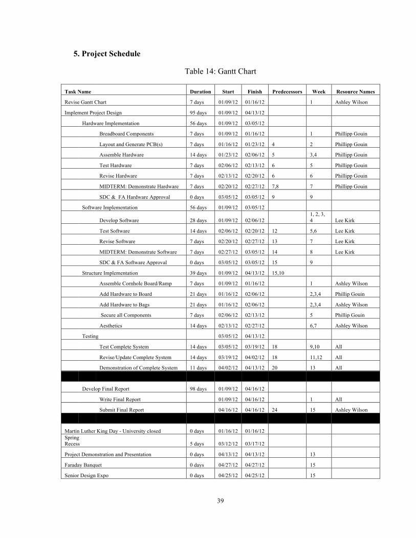
5. Project Schedule
Table 14: Gantt Chart
Task Name Duration Start Finish Predecessors Week Resource Names
Revise Gantt Chart 7 days 01/09/12 01/16/12 1 Ashley Wilson
Implement Project Design 95 days 01/09/12 04/13/12
Hardware Implementation 56 days 01/09/12 03/05/12
Breadboard Components 7 days 01/09/12 01/16/12 1 Phillipp Gouin
Layout and Generate PCB(s) 7 days 01/16/12 01/23/12 4 2 Phillipp Gouin
Assemble Hardware 14 days 01/23/12 02/06/12 5 3,4 Phillipp Gouin
Test Hardware 7 days 02/06/12 02/13/12 6 5 Phillipp Gouin
Revise Hardware 7 days 02/13/12 02/20/12 6 6 Phillipp Gouin
MIDTERM: Demonstrate Hardware 7 days 02/20/12 02/27/12 7,8 7 Phillipp Gouin
SDC & FA Hardware Approval 0 days 03/05/12 03/05/12 9 9
Software Implementation 56 days 01/09/12 03/05/12
Develop Software 28 days 01/09/12 02/06/12 1, 2, 3, 4 Lee Kirk
Test Software 14 days 02/06/12 02/20/12 12 5,6 Lee Kirk
Revise Software 7 days 02/20/12 02/27/12 13 7 Lee Kirk
MIDTERM: Demonstrate Software 7 days 02/27/12 03/05/12 14 8 Lee Kirk
SDC & FA Software Approval 0 days 03/05/12 03/05/12 15 9
Structure Implementation 39 days 01/09/12 04/13/12 15,10
Assemble Cornhole Board/Ramp 7 days 01/09/12 01/16/12 1 Ashley Wilson
Add Hardware to Board 21 days 01/16/12 02/06/12 2,3,4 Phillip Gouin
Add Hardware to Bags 21 days 01/16/12 02/06/12 2,3,4 Ashley Wilson
Secure all Components 7 days 02/06/12 02/13/12 5 Phillip Gouin
Aesthetics 14 days 02/13/12 02/27/12 6,7 Ashley Wilson
Testing 03/05/12 04/13/12
Test Complete System 14 days 03/05/12 03/19/12 18 9,10 All
Revise/Update Complete System 14 days 03/19/12 04/02/12 18 11,12 All
Demonstration of Complete System 11 days 04/02/12 04/13/12 20 13 All
Develop Final Report 98 days 01/09/12 04/16/12
Write Final Report 01/09/12 04/16/12 1 All
Submit Final Report 04/16/12 04/16/12 24 15 Ashley Wilson
Martin Luther King Day - University closed 0 days 01/16/12 01/16/12 Spring Recess 5 days 03/12/12 03/17/12
Project Demonstration and Presentation 0 days 04/13/12 04/13/12 13
Faraday Banquet 0 days 04/27/12 04/27/12 15
Senior Design Expo 0 days 04/25/12 04/25/12 15

40
6. Design Team Information Designer: AW
Hardware Manager: Phillipp Gouin, EE
Software Manager: Lee Kirk, CE
Project Leader and Archivist: Ashley Wilson, EE
8. References Designer: LK [1] American Cornhole Association, ACA Official Rules of Cornhole / Corn Toss http://www.playcornhole.org/rules.shtml Accessed October 10th, 20110
9. Data Sheets Designer: AW
1. Accelerometer: http://www.pololu.com/catalog/product/1250/specs 2. Transceiver: http://ww1.microchip.com/downloads/en/DeviceDoc/70590b.pdf 3. PIC18LF26K22-I/SP: http://ww1.microchip.com/downloads/en/DeviceDoc/41412D.pdf 4. Quartz Crystal: http://www.txccrystal.com/images/pdf/9b.pdf 5. PIC18LF46K22-I/P:
http://ww1.microchip.com/downloads/en/DeviceDoc/41412D.pdf
6. PIC16LF1939-I/P:
http://ww1.microchip.com/downloads/en/DeviceDoc/41364D.pdf
7. ANT-916-JJB-RA:
http://www.antennafactor.com/resources/data-guides/ant-916-jjb-xx.pdf
8. ANT-868-JJB-RA:
http://www.antennafactor.com/resources/data-guides/ant-868-jjb-xx.pdf

41
9. Force Sensing Resistor:
http://www.interlinkelectronics.com/sites/default/files/2010-10-26-DataSheet- FSR406-Layout2.pdf
Related Documents