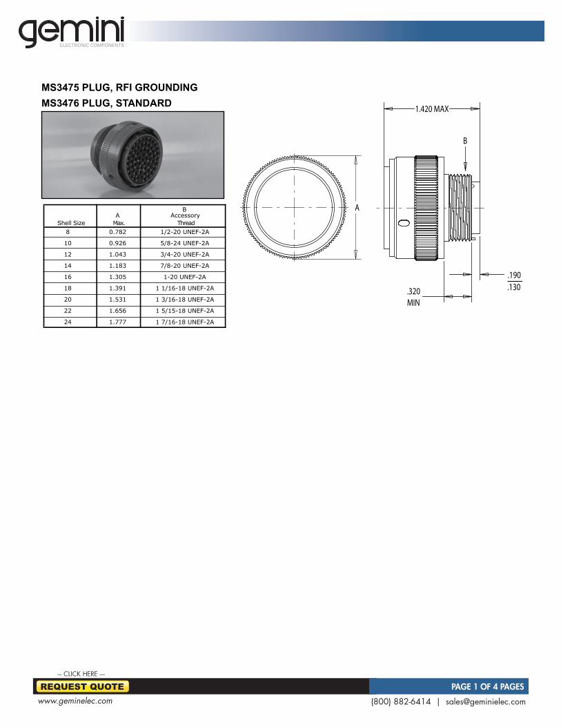
(800) 882-6414 | [email protected] www.geminelec.com REQUEST QUOTE PAGE 1 OF 4 PAGES --- CLICK HERE ---- ELECTRONIC COMPONENTS MS3475 PLUG, RFI GROUNDING MS3476 PLUG, STANDARD A B Max. Shell Size Accessory Thread 8 10 12 14 16 18 20 22 24 0.782 0.926 1.043 1.183 1.305 1.391 1.531 1.656 1.777 1/2-20 UNEF-2A 5/8-24 UNEF-2A 3/4-20 UNEF-2A 7/8-20 UNEF-2A 1-20 UNEF-2A 1 1/16-18 UNEF-2A 1 3/16-18 UNEF-2A 1 5/15-18 UNEF-2A 1 7/16-18 UNEF-2A A 1.420 MAX .320 MIN .190 .130 B

Welcome message from author
This document is posted to help you gain knowledge. Please leave a comment to let me know what you think about it! Share it to your friends and learn new things together.
Transcript
(800) 882-6414 | [email protected]
REQUEST QUOTE PAGE 1 OF 4 PAGES
--- CLICK HERE ----
ELECTRONIC COMPONENTS
Corsair Electrical Connectors
21
ms3475 PluG, rfi GrounDinGms3476 PluG, stanDarD
AB
Max.Shell SizeAccessory
Thread8
10
12
14
16
18
20
22
24
0.782
0.926
1.043
1.183
1.305
1.391
1.531
1.656
1.777
1/2-20 UNEF-2A
5/8-24 UNEF-2A
3/4-20 UNEF-2A
7/8-20 UNEF-2A
1-20 UNEF-2A
1 1/16-18 UNEF-2A
1 3/16-18 UNEF-2A
1 5/15-18 UNEF-2A
1 7/16-18 UNEF-2A
1.420 MAX
.320MIN
.190
.130
MIL-DTL-26482 SERIES 2
MS3475 PLUG, STANDARD
SHELL SIZE: 16
A
B
1.420 MAX
.320MIN
.190
.130
MIL-DTL-26482 SERIES 2
MS3475 PLUG, STANDARD
SHELL SIZE: 16
A
B
Crimp
Tool
M22520/1-01 M22520/1-02
or or
M22520/2-02 M22520/2-02PIN: 264-2001-009
M81969/14-01
Contact
Part Nmber
Insertion/Removal
ToolTurret
SOCKET: 244-2001-009
mil-Dtl-26482 series 2
mil-c-26482 tyPe rear release PluGs(corsair cj series intermateable with mil-c-26482 solder or Hermetic pin receptacles)
contact anD toolinG information
These three insert layouts, are not qualifiedto MIL-C-26482 Series 2. However, theyare rear release and meet all of the appropriateparameters of Series II, thus providing ahigher level of environmental capabilities.
Corsair Prefix cj09 76 W 08 02 P
Shell Configuration70 Receptacle, narrow flange71 Receptacle, cable connecting 72 Receptacle, wide flange74 Receptacle, jam nut75 Plug, RFI grounding76 Plug, straightClass (materials/finish)A Aluminum, black anodizedL Aluminum, electroless nickelW Aluminum, olive drab cadmium Over electroless nickel shell size08insert arrangement02, 03, 04contact typeP = Pin, S = Socket
orDerinG nomenclature
B A
0802
C
B
A
0803
A D
0804
B C
B A
0802
C
B
A
0803
A D
0804
B C
B A
0802
C
B
A
0803
A D
0804
B C
(800) 882-6414 | [email protected]
REQUEST QUOTE PAGE 2 OF 4 PAGES
--- CLICK HERE ----
ELECTRONIC COMPONENTS
Corsair Electrical Connectors
16
mil-Dtl-26482 series 2
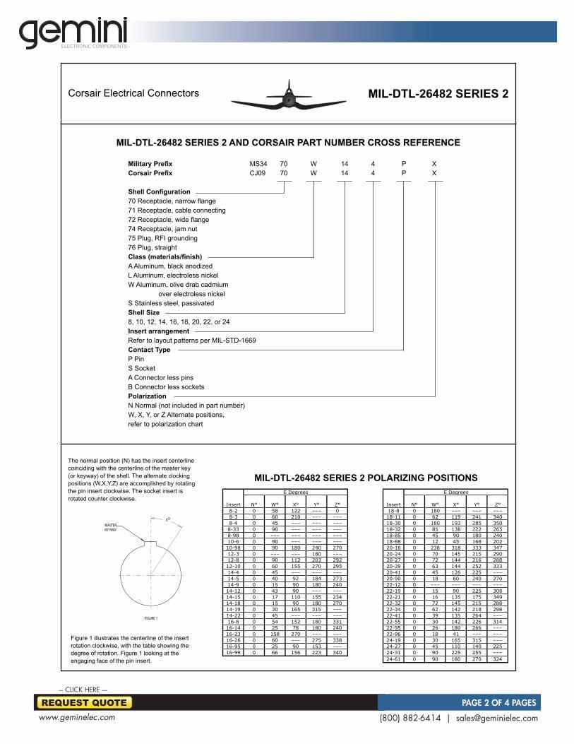
mil-Dtl-26482 series 2 anD corsair Part number cross reference
mil-Dtl-26482 series 2 PolariZinG Positions
N° W° X° Y° Z° N° W° X° Y° Z°
8-2 0 58 122 ––– 0 18-8 0 180 ––– ––– –––
8-3 0 60 210 ––– ––– 18-11 0 62 119 241 340
8-4 0 45 ––– ––– ––– 18-30 0 180 193 285 350
8-33 0 90 ––– ––– ––– 18-32 0 85 138 222 265
8-98 0 ––– ––– ––– ––– 18-85 0 45 90 180 240
10-6 0 90 ––– ––– ––– 18-88 0 12 45 168 202
10-98 0 90 180 240 270 20-16 0 238 318 333 347
12-3 0 ––– ––– 180 ––– 20-24 0 70 145 215 290
12-8 0 90 112 203 292 20-27 0 72 144 216 288
12-10 0 60 155 270 295 20-39 0 63 144 252 333
14-4 0 45 ––– ––– ––– 20-41 0 45 126 225 –––
14-5 0 40 92 184 273 20-90 0 18 60 240 270
14-9 0 15 90 180 240 22-12 0 ––– ––– ––– –––
14-12 0 43 90 ––– ––– 22-19 0 15 90 225 308
14-15 0 17 110 155 234 22-21 0 16 135 175 349
14-18 0 15 90 180 270 22-32 0 72 145 215 288
14-19 0 30 165 315 ––– 22-34 0 62 142 218 298
14-22 0 45 ––– ––– ––– 22-41 0 39 135 264 –––
16-8 0 54 152 180 331 22-55 0 30 142 226 314
16-14 0 25 78 180 240 22-95 0 26 180 266 –––
16-23 0 158 270 ––– ––– 22-96 0 19 41 ––– –––
16-26 0 60 ––– 275 338 24-19 0 30 165 315 –––
16-95 0 25 90 153 ––– 24-27 0 45 110 140 225
16-99 0 66 156 223 340 24-31 0 90 225 255 –––
24-61 0 90 180 270 324
E Degrees
Insert Insert
E Degrees
Military Prefix MS34 70 W 14 4 P XCorsair Prefix CJ09 70 W 14 4 P X
Shell Configuration70 Receptacle, narrow flange71 Receptacle, cable connecting 72 Receptacle, wide flange74 Receptacle, jam nut75 Plug, RFI grounding76 Plug, straightClass (materials/finish)A Aluminum, black anodizedL Aluminum, electroless nickelW Aluminum, olive drab cadmium over electroless nickel S Stainless steel, passivatedshell size8, 10, 12, 14, 16, 18, 20, 22, or 24insert arrangementRefer to layout patterns per MIL-STD-1669contact typeP PinS SocketA Connector less pinsB Connector less socketsPolarizationN Normal (not included in part number)W, X, Y, or Z Alternate positions, refer to polarization chart
E
FIGURE 1
MASTERKEYWAY
The normal position (N) has the insert centerline coinciding with the centerline of the master key (or keyway) of the shell. The alternate clocking positions (W,X,Y,Z) are accomplished by rotating the pin insert clockwise. The socket insert is rotated counter clockwise.
Figure 1 illustrates the centerline of the insert rotation clockwise, with the table showing the degree of rotation. Figure 1 looking at the engaging face of the pin insert.
(800) 882-6414 | [email protected]
REQUEST QUOTE PAGE 3 OF 4 PAGES
--- CLICK HERE ----
ELECTRONIC COMPONENTS
Corsair Electrical Connectors
17
mil-Dtl-26482 series 2
mil-Dtl-26482 series 2
Service Rating Service Rating Service Rating Wire Test
Condition I II Shielded Range Current
Sea Level 600 1000 500 volts, dc
70,000 ft. 300 450 –––
20
16
12
20
16
12
20
16
12
Military
Pat NumberGage
MIL-C-40029/4-110 PIN
MIL-C-39029/5-115 SOCKET
MIL-C-39029/4-111 PIN
MIL-C-39029/5-116 SOCKET
MIL-C-39029-4-113 PIN
Size
Military
Part Number
Gage
Military
Pat Number
MS27488-20
MS27488-16
MS27488-12
M81969/14-03
M81969/14-04
M81969/14-02
20-24
16-20
12-14
7.5 amps
13.0 amps
23 ampsMIL-C-39029-5-118 SOCKET
Wire Test
Range Current
20 20
16 16
12 12
MS27488-20
MS27488-16
MS27488-12
M81969/14-03
M81969/14-04
M81969/14-02
20-24
16-20
12-14
7.5 amps
13.0 amps
23 ampsM39029-5-118 SOCKET
Size
Military
Part Number
Gage
Military
Part Number
20
16
12
Military
Part NumberGage
M39029/4-110 PIN
M39029/5-115 SOCKET
M39029/4-111 PIN
M39029/5-116 SOCKET
M39029-4-113 PIN
MilitaryPart NumberMS27488-20-2MS27488-16-2MS27488-12-2
A
B
C
4 X O E
D DIA
MIL-DTL-26482 SERIES 2
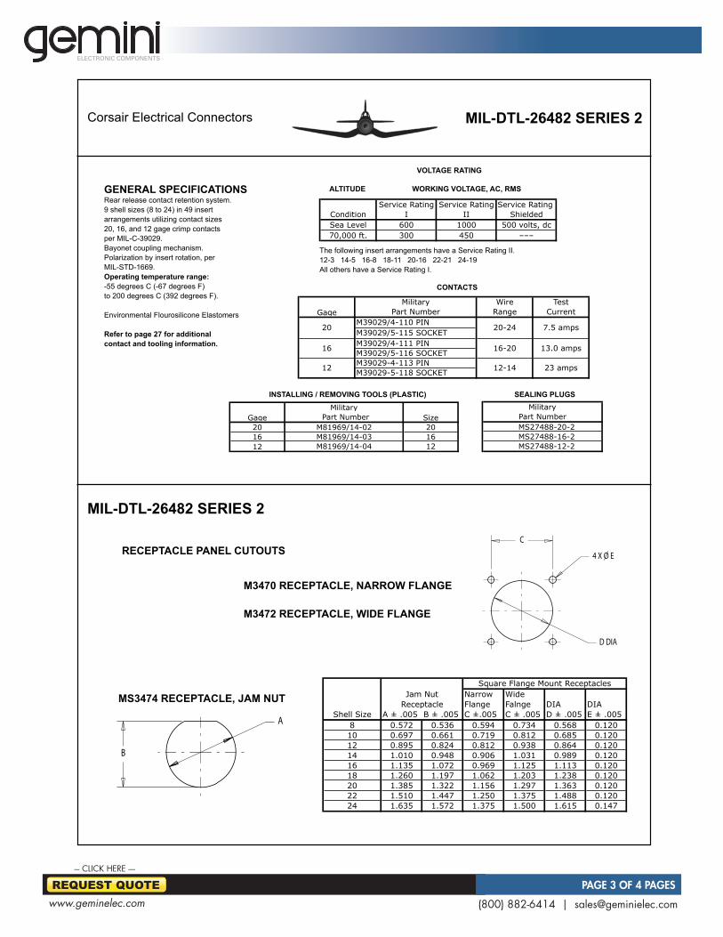
RECEPTACLE PANEL CUTOUTS
MS3474 RECEPTACLE, JAM NUT
MS3470 RECEPTACLE, NARROW FLANGE
MS3472 RECEPTACLE, WIDE FLANGE
A
B
C
4 X O E
D DIA
MIL-DTL-26482 SERIES 2
RECEPTACLE PANEL CUTOUTS
MS3474 RECEPTACLE, JAM NUT
MS3470 RECEPTACLE, NARROW FLANGE
MS3472 RECEPTACLE, WIDE FLANGE
Narrow Wide
Flange Falnge DIA DIA
Shell Size A ± .005 B ± .005 C ±.005 C ± .005 D ± .005 E ± .005
8 0.572 0.536 0.594 0.734 0.568 0.120
10 0.697 0.661 0.719 0.812 0.685 0.120
12 0.895 0.824 0.812 0.938 0.864 0.120
14 1.010 0.948 0.906 1.031 0.989 0.120
16 1.135 1.072 0.969 1.125 1.113 0.120
18 1.260 1.197 1.062 1.203 1.238 0.120
20 1.385 1.322 1.156 1.297 1.363 0.120
22 1.510 1.447 1.250 1.375 1.488 0.120
24 1.635 1.572 1.375 1.500 1.615 0.147
Square Flange Mount Receptacles
Jam Nut
Receptaclems3474 recePtacle, jam nut
recePtacle Panel cutouts
m3470 recePtacle, narroW flanGe
m3472 recePtacle, WiDe flanGe
General sPecificationsRear release contact retention system.9 shell sizes (8 to 24) in 49 insertarrangements utilizing contact sizes20, 16, and 12 gage crimp contactsper MIL-C-39029.Bayonet coupling mechanism.Polarization by insert rotation, perMIL-STD-1669.Operating temperature range:-55 degrees C (-67 degrees F)to 200 degrees C (392 degrees F).
Environmental Flourosilicone Elastomers
refer to page 27 for additionalcontact and tooling information.
VoltaGe ratinG
contacts
installinG / remoVinG tools (Plastic) sealinG PluGs
altituDe WorKinG VoltaGe, ac, rms
The following insert arrangements have a Service Rating II.12-3 14-5 16-8 18-11 20-16 22-21 24-19All others have a Service Rating I.
20 2016 1612 12M81969/14-04
GageMilitary
SizePart NumberM81969/14-02M81969/14-03

(800) 882-6414 | [email protected]
REQUEST QUOTE PAGE 4 OF 4 PAGES
--- CLICK HERE ----
ELECTRONIC COMPONENTS
Corsair Electrical Connectors
18
mil-Dtl-26482 series 2 insert Patterns Per mil-stD-1669caVity iDentification sHoWn for front face
of Pin anD rear face of socKet inserts
G
H
A
B
C
D
EF
M
J
L
K
14022–#12
18088–#12
204141–#20
241919–#12
243131–#16
246161–#20
225555–#20
221212–#12
222121–#16
183232–#20
201616–#16
202424–#20
1830
29– #20 1– #161811
11– #16
141818–#20
141919–#20
16088–#16
162626–#20
14044–#12
14055–#16
14095–#204–#12
16231–#1622–#20
16148–#206–#12
20392–#16
37–#20
224114–#1627–#20
22956–#12
26–#20
14124–#168–#20
14151–#1614–#20
08983–#20
08333–#20
10066–#20
12033–#16
12088–#20
121010–#20
MIL-DTL-5015 SERIES III INSERT PATTERNS PER MIL-STD-1651CAVITY IDENTIFICATION SHOWN FOR FRONT FACE
OF PIN AND REAR RACE OF SOCKET INSERTS
G
F
E
A
J
H
B
C
D
K
L
R
M
N
P
G
F
E
A
HB
C
D
G J
F E
A
K
H B
C
D
G
FE
A
J
H
B
C
D
L
M K
A
B
C
D
F
E
A
B
CD
E
A
B
C
D
A
BC
A
B
CA
B
C
A
J
H
G
B
C
DF
E
AB
A
J
K
L
H
G
M
U P
R
T
N B
C
D
F
S
E
A
J
K R
H G
L
M
S
P
T
N
B
C
D
U
F
V
E
A
B
C
D
H
G
F
E
AB
C
D
F
G
H
JP
K
LN
M
E
A
B
C
D
UV
W
S
T
G
F
E
H
X
J
L
M
N
K
P
R
ZY
AB
C
D
F
E
G
S
U
WX
Y
Z V
TP
N
HJK
b
L
M c
a
R
J
J
J
J
J
J
J
JJ
J
J
JJ
s
p
W
a
Rhf
K
K
KK
K
K
K
KK
KK
KK
A
AAAA
AAAA
AA
AA
B
BB
BB
BB
BB
BB
BB
C
C
C
C
C
C
C
CC
C
C
CC
D
D
D
D
D
D
D
DD
DD
DD
G
G
GG
G
GG
GG
GG
GG
F
F
FF
F
F
F
F
F
FF
FF
E
E
E
E
E
E
E
EE
EE
EE
H
HHH
H
HH
HH
HH
HH
L
L
LL
LL
LL
N
N
NN
N
N
N
N
N
NN
N
N
M
M
M
MM
M
L
L
L
L
L
M
MM
MM
MM
P
P
PP
P
P
P
P
P
PP
PP
R
R
RR
R
RR
R
R
R
RR
S
S
SS
S
S
S
SS
S
SS
T
TT
T
T
T
T
T
T
T
T
T
W
W
W
W
WW
X
W
WW
W
U
U
U
U
U
U
U
U
U
U
U
U
V
V
V
V
V
V
V
V
V
V
V
V
Z
Z
ZZ
ZZ
Z
Z
ZZ
c
c
c
c
ccc
c
c
b
b
b
b
b
bb
b
b
a
a
a
a
a
aa
a
a
X
X
X
X
XX
X
X
X
d
d
d
d
dd
d
d
d
e
e
e
e
e
ee
e
e
f f
ff
f
f
st
f
f
g
g
gg
g
gg
h
h
h
h
hhi
i
i
i
iij
j
j
jjk
k
kkkm
m
m
mm n
n
p
pn
nn p
pq
q
q
r
s
s
t
t
u
u
v
v
w
w
BBCC
CC
DD
DD
EE
EE
FF
FF
GG
GG
HHJJ
KKLL
MM
NNPP
BB
AA
AA
x
x
y
y
z
z
r
r
p
Y
Y
Y
YY
YY
Y
Y
Y
t
Q
X
r
r
S
gig
A
B
C
D
H
L
J
K
G
F
E
A
B
C
D
H
G
F
E
mil-Dtl-26482 series 2
Related Documents