Electronic band structure of magnetic bilayer graphene superlattices C. Huy Pham, 1,2 T. Thuong Nguyen, 1,2 and V. Lien Nguyen 1,3,a) 1 Theoretical and Computational Physics Department, Institute of Physics, VAST, 10 Dao Tan, Ba Dinh Distr., Hanoi 10000, Vietnam 2 SISSA/International School for Advanced Study, Via Bonomea 265, I-34136 Trieste, Italy 3 Institute for Bio-Medical Physics, 109A Pasteur, 1st Distr., Hochiminh City, Vietnam (Received 18 July 2014; accepted 15 September 2014; published online 25 September 2014) Electronic band structure of the bilayer graphene superlattices with d-function magnetic barriers and zero average magnetic flux is studied within the four-band continuum model, using the transfer matrix method. The periodic magnetic potential effects on the zero-energy touching point between the lowest conduction and the highest valence minibands of pristine bilayer graphene are exactly analyzed. Magnetic potential is shown also to generate the finite-energy touching points between higher minibands at the edges of Brillouin zone. The positions of these points and the related dis- persions are determined in the case of symmetric potentials. V C 2014 AIP Publishing LLC. [http://dx.doi.org/10.1063/1.4896530] I. INTRODUCTION As is well-known from semiconductor physics, the elec- tronic band structure of materials could be essentially modified by an external periodic potential, resulting in unusual transport and optical properties. 1 That is why the electronic band structure of graphene under a periodic potential (graphene superlattice) was extensively studied from the early days of graphene physics. For single layer graphene superlattices (SLGSLs), the electronic band structure has been in detail examined in a number of works for periodic potentials of different natures (electric 2–5 or magnetic 6–10 ) and different shapes (Kronig-Penney, 2, 5, 7, 10 co- sine, 3 or square 4 ). Interesting findings have been reported such as a strongly anisotropic renormalization of the carrier group ve- locity and an emergence of extra Dirac points (DPs) in the elec- tronic band structure of electric SLGSLs (Refs. 2–5) or an emergence of finite-energy DPs in the electronic band structure of magnetic ones. 8–10 Concerning the electronic band structure of bilayer gra- phene superlattices (BLGSLs), there are fewer works and they are all devoted to the case of electric potentials. 11–14 The most impressive feature observed in the electronic band structure of the electric BLGSLs studied (with different potential shapes: d-function, 11,14 rectangular, 12 or sine 13 ) is an emergence of a pair of new zero-energy touching points (TPs) or an opening of a direct band gap, depending on the potential parameters. 15 This unusual feature was not found in the electronic band structure of SLGSLs. It is also assumed to be common for all electric BLGSLs with any potential shape, providing the average potential to be zero. To our best knowledge, no works on the electronic band structure of BLGSLs with magnetic potentials have been reported. Note that while sharing with single layer graphene many properties important for electronics applications such as the excellent electric and thermal conductivities at room tem- perature or a possibility to control the electronic structure externally, bilayer graphene (BLG) exhibits the privileges, including the ability to open a band gap in the energy spectrum and to turn it flexibly by an external electric field. 16–18 Given the importance of BLG, it would be appropriate to study the electronic properties of various BLG-based structures. Graphene superlattices are of not only theoretical but also experimental and application interests. Experimentally, SLGSLs have been constructed for graphene on ruthenium 19 or iridium 20 surfaces. Other possible techniques that may be applied for creating SLGSLs as well as BLGSLs include the electron-beam induced deposition of adsorbates 21 and the use of periodically patterned gates. The very fact that the band structure of graphene superlattices may be finely engi- neered by using appropriate periodic potentials opens differ- ent ways to fabricate graphene-based electronic devices. The purpose of the present work is to study the electronic band structure of BLGSLs with periodic d-function magnetic barriers (magnetic BLGSLs—MBLGSLs). It is shown that the studied magnetic potential does not destroy the isotropically parabolic behavior of the band dispersion related to the origi- nal zero-energy TP, but makes the corresponding effective mass renormalized and might cause a shift of this point along the direction perpendicular to the superlattice direction in the wave-vector space. The magnetic potential is also shown to generate finite-energy TPs with linear and anisotropic disper- sions at the edges of Brillouin zone. These findings make the band structure of MBLGSLs cardinally different from that of electric BLGSLs examined. The paper is organized as follows. Section II describes the model of MBLGSLs under study and the calculating method. Section III presents calculating results which are in detail analyzed with an attention focused on the TPs identified at zero- as well as finite-energies. The paper is closed with an additional discussion and a brief summary in Sec. IV. II. MODEL AND CALCULATING METHOD We consider MBLGSLs arising from an infinitely flat Bernal-stacked BLG in a periodic magnetic field illustrated a) Electronic mail: [email protected] 0021-8979/2014/116(12)/123707/6/$30.00 V C 2014 AIP Publishing LLC 116, 123707-1 JOURNAL OF APPLIED PHYSICS 116, 123707 (2014) [This article is copyrighted as indicated in the article. Reuse of AIP content is subject to the terms at: http://scitation.aip.org/termsconditions. Downloaded to ] IP: 140.105.16.64 On: Thu, 02 Oct 2014 07:27:25

Welcome message from author
This document is posted to help you gain knowledge. Please leave a comment to let me know what you think about it! Share it to your friends and learn new things together.
Transcript
Electronic band structure of magnetic bilayer graphene superlattices
C. Huy Pham,1,2 T. Thuong Nguyen,1,2 and V. Lien Nguyen1,3,a)
1Theoretical and Computational Physics Department, Institute of Physics, VAST, 10 Dao Tan, Ba Dinh Distr.,Hanoi 10000, Vietnam2SISSA/International School for Advanced Study, Via Bonomea 265, I-34136 Trieste, Italy3Institute for Bio-Medical Physics, 109A Pasteur, 1st Distr., Hochiminh City, Vietnam
(Received 18 July 2014; accepted 15 September 2014; published online 25 September 2014)
Electronic band structure of the bilayer graphene superlattices with d-function magnetic barriers
and zero average magnetic flux is studied within the four-band continuum model, using the transfer
matrix method. The periodic magnetic potential effects on the zero-energy touching point between
the lowest conduction and the highest valence minibands of pristine bilayer graphene are exactly
analyzed. Magnetic potential is shown also to generate the finite-energy touching points between
higher minibands at the edges of Brillouin zone. The positions of these points and the related dis-
persions are determined in the case of symmetric potentials. VC 2014 AIP Publishing LLC.
[http://dx.doi.org/10.1063/1.4896530]
I. INTRODUCTION
As is well-known from semiconductor physics, the elec-
tronic band structure of materials could be essentially modified
by an external periodic potential, resulting in unusual transport
and optical properties.1 That is why the electronic band structure
of graphene under a periodic potential (graphene superlattice)
was extensively studied from the early days of graphene physics.
For single layer graphene superlattices (SLGSLs), the electronic
band structure has been in detail examined in a number of works
for periodic potentials of different natures (electric2–5 or
magnetic6–10) and different shapes (Kronig-Penney,2,5,7,10 co-
sine,3 or square4). Interesting findings have been reported such
as a strongly anisotropic renormalization of the carrier group ve-
locity and an emergence of extra Dirac points (DPs) in the elec-
tronic band structure of electric SLGSLs (Refs. 2–5) or an
emergence of finite-energy DPs in the electronic band structure
of magnetic ones.8–10
Concerning the electronic band structure of bilayer gra-
phene superlattices (BLGSLs), there are fewer works and
they are all devoted to the case of electric potentials.11–14
The most impressive feature observed in the electronic band
structure of the electric BLGSLs studied (with different
potential shapes: d-function,11,14 rectangular,12 or sine13) is
an emergence of a pair of new zero-energy touching points
(TPs) or an opening of a direct band gap, depending on the
potential parameters.15 This unusual feature was not found in
the electronic band structure of SLGSLs. It is also assumed
to be common for all electric BLGSLs with any potential
shape, providing the average potential to be zero.
To our best knowledge, no works on the electronic band
structure of BLGSLs with magnetic potentials have been
reported. Note that while sharing with single layer graphene
many properties important for electronics applications such as
the excellent electric and thermal conductivities at room tem-
perature or a possibility to control the electronic structure
externally, bilayer graphene (BLG) exhibits the privileges,
including the ability to open a band gap in the energy spectrum
and to turn it flexibly by an external electric field.16–18 Given
the importance of BLG, it would be appropriate to study the
electronic properties of various BLG-based structures.
Graphene superlattices are of not only theoretical but
also experimental and application interests. Experimentally,
SLGSLs have been constructed for graphene on ruthenium19
or iridium20 surfaces. Other possible techniques that may be
applied for creating SLGSLs as well as BLGSLs include
the electron-beam induced deposition of adsorbates21 and the
use of periodically patterned gates. The very fact that the
band structure of graphene superlattices may be finely engi-
neered by using appropriate periodic potentials opens differ-
ent ways to fabricate graphene-based electronic devices.
The purpose of the present work is to study the electronic
band structure of BLGSLs with periodic d-function magnetic
barriers (magnetic BLGSLs—MBLGSLs). It is shown that the
studied magnetic potential does not destroy the isotropically
parabolic behavior of the band dispersion related to the origi-
nal zero-energy TP, but makes the corresponding effective
mass renormalized and might cause a shift of this point along
the direction perpendicular to the superlattice direction in the
wave-vector space. The magnetic potential is also shown to
generate finite-energy TPs with linear and anisotropic disper-
sions at the edges of Brillouin zone. These findings make the
band structure of MBLGSLs cardinally different from that of
electric BLGSLs examined.
The paper is organized as follows. Section II describes
the model of MBLGSLs under study and the calculating
method. Section III presents calculating results which are
in detail analyzed with an attention focused on the TPs
identified at zero- as well as finite-energies. The paper is
closed with an additional discussion and a brief summary
in Sec. IV.
II. MODEL AND CALCULATING METHOD
We consider MBLGSLs arising from an infinitely flat
Bernal-stacked BLG in a periodic magnetic field illustrateda)Electronic mail: [email protected]
0021-8979/2014/116(12)/123707/6/$30.00 VC 2014 AIP Publishing LLC116, 123707-1
JOURNAL OF APPLIED PHYSICS 116, 123707 (2014)
[This article is copyrighted as indicated in the article. Reuse of AIP content is subject to the terms at: http://scitation.aip.org/termsconditions. Downloaded to ] IP:
140.105.16.64 On: Thu, 02 Oct 2014 07:27:25

schematically in Fig. 1(a). The magnetic field is assumed to
be uniform in the y-direction and staggered as periodic
d-function barriers of alternate signs in the x-direction, so for
a single lattice unit the field profile has the form
~B ¼ B0½dðxþ dB=2Þ � dðx� dB=2Þ�z; (1)
where B0 is the barrier strength and dB is the barrier width.
The corresponding vector potential ~A in the Landau gauge is
~AðxÞ ¼ ðB0lB=2Þ ½hðdB=2� jxjÞ � hðjxj � dB=2Þ�y; (2)
where h(x) is the Heaviside step function and lB ¼ffiffiffiffiffiffiffiffiffiffiffiffiffiffi�hc=eB0
pis the magnetic length.
Totally, as can be seen in Fig. 1(b), A(x) describes a
Kronig-Penney-type periodic potential along the x-direction
with dB is the barrier width, dW is the well width,
d¼ dBþ dW is the superlattice period, and A0�B0lB is the
potential strength.
In fact, the same periodic d-function magnetic barriers
of Eq. (1) have been before used to model magnetic
SLGSLs.6,7,10 Its advantage is a richness of fundamental
electronic properties, while a mathematical treatment is
rather simple. In practice, such the d-function model should
be hold as long as the de Broglie wavelength of quasi-
particles is much larger than the typical width of magnetic
barriers.6
To justify the consideration realized below, we will
ignore intervalley scattering assuming that the widths dB(W)
are much larger than the lattice constant in graphene. All
spin-related effects are also neglected. Besides, potentials
on both graphene layers are assumed to be the same at a
given (x, y)-point. Under these conditions, the low-energy
excitations near one original TP (say, K) in the energy band
structure can be generally described in the four-band con-
tinuum nearest-neighbor, tight-binding model with the
Hamiltonian22
H ¼
0 vFp t? 0
vFpþ 0 0 0
t? 0 0 vFpþ
0 0 vFp 0
0BBB@
1CCCA ; (3)
where p ¼ px þ ipy; vF ¼ffiffiffi3p
ta=ð2�hÞ � 106 m=s is the
Fermi velocity, t� 3 eV is the intralayer nearest-neighbor
hopping energy, a¼ 2.46 A is the lattice constant of gra-
phene, and t?� 0.39 eV is the interlayer nearest-neighbor
hopping energy. The magnetic field effect is here accounted
for by the momentum operator ~p ¼ ðpx; pyÞ � �i�h ~r þ e~A.
The Hamiltonian of Eq. (3) is limited to the case of symmet-
ric on-site energies. Also, other interlayer hopping parame-
ters are here neglected since they are much smaller than t?and may be effectively suppressed by disorder.17,18,23
Without the potential ~A, i.e., for pristine BLG, the
Hamiltonian of Eq. (3) yields the hyperbolic band dispersion
which interpolates between a linear dispersion at large mo-
mentum and a quadratic one in the vicinity of the TP.18 Such
a hyperbolic BLG band dispersion was experimentally
observed24,25 and, interestingly, it is still survived (with
renormalized parameters) even if the electron-electron inter-
action is taken into account.23,26 We are here interested in
the effects induced by the periodic magnetic potential ~A on
the BLG non-interacting band structure.
Due to a periodicity of the potential A (along the x-direc-
tion) the time-independent Schr€odinger equation HW¼EWfor the Hamiltonian H of Eq. (3) could be most conveniently
solved using the transfer matrix method.11,27 Actually, our
ultimate aim is to find the Eð~kÞ-relation that describes the
band structure of MBLGSLs under study. This could be
done in the way similar to that realized in Ref. 11 for electric
BLGSLs in the four band model.
Following the general idea of the T-matrix method,27 we
first consider the wave functions of the equation HW¼EWin the regions of constant potential, A(x)¼A0¼ constant.For H of Eq. (3) these wave functions can be generally writ-
ten in the form W ¼ QRðxÞ½A;B;C;D�T expðikyyÞ. They can
be then simplified by the linear transformation Q! T Qwith11
T ¼ 1
2
1 0 �1 0
0 1 0 �1
1 0 1 0
0 1 0 1
0BBBB@
1CCCCA:
So
Q! T Q ¼
1 1 0 0
k1=E �k1=E �ik0y=E �ik0y=E
0 0 1 1
�ik0y=E �ik0y=E k2=E �k2=E
0BBB@
1CCCA;
(4)
whereas the T -transformation does not change the matrix
R(x)
RðxÞ ¼ diag ½ eik1x; e�ik1x; eik2x; e�ik2x �; (5)
FIG. 1. Model of MBLGSLs under study: (a) Periodic d-function magnetic
barriers of alternate signs, ~B0 and �~B0 [red arrows] and (b) corresponding
1D periodic vector potential ~AðxÞ [blue curve] with A0 the potential strength,
dB is the barrier width, and dW is the well width [the period d¼ dBþ dW].
The dashed-line box in (a) describes the unit cell in T-matrix calculations.
123707-2 Pham, Nguyen, and Nguyen J. Appl. Phys. 116, 123707 (2014)
[This article is copyrighted as indicated in the article. Reuse of AIP content is subject to the terms at: http://scitation.aip.org/termsconditions. Downloaded to ] IP:
140.105.16.64 On: Thu, 02 Oct 2014 07:27:25
where k0y ¼ ky þ A0 and kn ¼ffiffiffiffiffiffiffiffiffiffiffiffiffiffiffiffiffiffiffiffiffiffiffiffiffiffiffiffiffiffiffiffiffiffiffiffiffiE2 � ð�1ÞnE� k02y
qwith
n¼ 1, 2.
Further, the amplitudes AI of the wave function before
an unit cell and those after it, AF, could be related to each
other by the T-matrix
AF ¼ TðF; IÞAI: (6)
On the other hand, the Bloch’s theorem states
QIRIðxÞAF ¼ expðikxdÞQIRIðx� dÞAI; (7)
where kx is the Bloch wave number and d is the potential
period.
Comparing Eq. (6) with Eq. (7) gives rise to the follow-
ing equation:
det ½ T � eikxdR�1I ðdÞ � ¼ 0: (8)
This is just the equation solutions of which give the desirable
Eð~kÞ-relation.
In reality, the transfer matrix Eq. (8) is very general
with matrices T� T(F, I) and RI defined by the Hamiltonian
examined. For the Hamiltonian under study, with the unit
cell described in Fig. 1(a), the T-matrix in Eq. (8) is defined
as
TðF; IÞ ¼ R�1W ðdBÞQ�1
W QBRBðdBÞQ�1B QW ;
where QW(B) and RW(B) are, respectively, defined in Eqs. (4)
and (5) for A0¼AW(B) and RI�RW.
In the case of SLGSLs, when the Hamiltonian H and,
therefore, T and RI are 2� 2 matrices, Eq. (8) can be analyti-
cally solved that gives straightaway a general expression for
the dispersion relation, Eð~kÞ.10 For MBLGSLs in the four-
band model of Eq. (3), Eq. (8) with (4� 4)-matrices T and RI
becomes too complicated. It cannot be in general solved ana-
lytically and, therefore, the dispersion relation cannot be
derived explicitly.
Note that for the periodic magnetic potential model of
interest the only way of breaking its symmetry is associated
with a difference between dB and dW. So the parameter
q¼ dW/dB is introduced to describe asymmetric effects. The
MBLGSLs with q¼ 1 (q 6¼ 1) will be then referred to as sym-
metric (asymmetric) MBLGSLs. Thus, the studied potential
model is entirely characterized by the three parameters, A0,
d, and q.
III. ELECTRONIC BAND STRUCTURES
In order to bring out the band structure of a MBLGSL,
we should numerically solve Eq. (8) for defined values of pa-
rameters A0, d, and q. Calculations have been performed for
different values of these parameters and typical results
obtained are presented in Figs. 2 and 3.
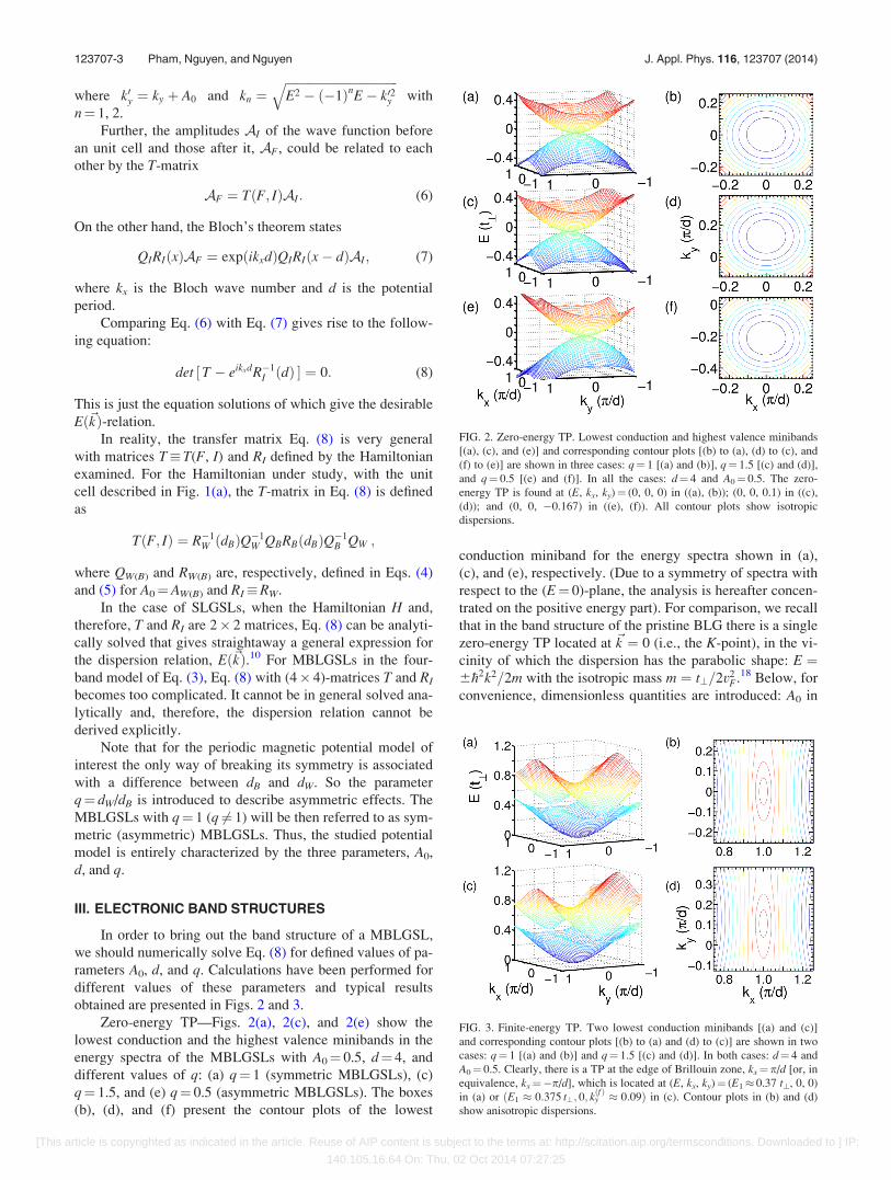
Zero-energy TP—Figs. 2(a), 2(c), and 2(e) show the
lowest conduction and the highest valence minibands in the
energy spectra of the MBLGSLs with A0¼ 0.5, d¼ 4, and
different values of q: (a) q¼ 1 (symmetric MBLGSLs), (c)
q¼ 1.5, and (e) q¼ 0.5 (asymmetric MBLGSLs). The boxes
(b), (d), and (f) present the contour plots of the lowest
conduction miniband for the energy spectra shown in (a),
(c), and (e), respectively. (Due to a symmetry of spectra with
respect to the (E¼ 0)-plane, the analysis is hereafter concen-
trated on the positive energy part). For comparison, we recall
that in the band structure of the pristine BLG there is a single
zero-energy TP located at ~k ¼ 0 (i.e., the K-point), in the vi-
cinity of which the dispersion has the parabolic shape: E ¼6�h2k2=2m with the isotropic mass m ¼ t?=2v2
F.18 Below, for
convenience, dimensionless quantities are introduced: A0 in
FIG. 2. Zero-energy TP. Lowest conduction and highest valence minibands
[(a), (c), and (e)] and corresponding contour plots [(b) to (a), (d) to (c), and
(f) to (e)] are shown in three cases: q¼ 1 [(a) and (b)], q¼ 1.5 [(c) and (d)],
and q¼ 0.5 [(e) and (f)]. In all the cases: d¼ 4 and A0¼ 0.5. The zero-
energy TP is found at (E, kx, ky)¼ (0, 0, 0) in ((a), (b)); (0, 0, 0.1) in ((c),
(d)); and (0, 0, �0.167) in ((e), (f)). All contour plots show isotropic
dispersions.
FIG. 3. Finite-energy TP. Two lowest conduction minibands [(a) and (c)]
and corresponding contour plots [(b) to (a) and (d) to (c)] are shown in two
cases: q¼ 1 [(a) and (b)] and q¼ 1.5 [(c) and (d)]. In both cases: d¼ 4 and
A0¼ 0.5. Clearly, there is a TP at the edge of Brillouin zone, kx¼p/d [or, in
equivalence, kx¼�p/d], which is located at (E, kx, ky)¼ (E1� 0.37 t?, 0, 0)
in (a) or ðE1 � 0:375 t?; 0; kðf Þy � 0:09Þ in (c). Contour plots in (b) and (d)
show anisotropic dispersions.
123707-3 Pham, Nguyen, and Nguyen J. Appl. Phys. 116, 123707 (2014)
[This article is copyrighted as indicated in the article. Reuse of AIP content is subject to the terms at: http://scitation.aip.org/termsconditions. Downloaded to ] IP:
140.105.16.64 On: Thu, 02 Oct 2014 07:27:25

units of t?/(evF), energies in units of t?, and x (or d) in
ð�hvF=t?Þ. For example, the value A0¼ 0.5 describes the field
of B0¼ 2.3 T or d¼ 4 means the period of 6.75 nm, given t?and vF as defined above.
In the case of q¼ 1 (symmetric MBLGSLs), Fig. 2(a)
shows a clear zero-energy TP between the two minibands at
ð~k ¼ 0Þ with an isotropic band dispersion [see contour plot
in (b)]. It seems that in this particular case of ky¼ 0, the mat-
rices in Eq. (8) become so simple that the energy spectrum
can be from this equation deduced in the form of the tran-
scendental equation
½ cosðkxdÞ � cosðk1dÞ�½cosðkxdÞ � cosðk2dÞ�
þð4A40=k2
1k22Þ sinðk1dWÞ sinðk1dBÞ sinðk2dWÞ sinðk2dBÞ
þð2A20=k1k2Þ½f1 þ f2 cosðkxdÞ � sinðk1dÞ sinðk2dÞ � ¼ 0;
(9)
where f1 ¼ sinðk1dWÞ sinðk2dWÞ þ sinðk1dBÞ sinðk2dBÞ; f2 ¼sin ðk1dWÞ sinðk2dBÞ þ sinðk1dBÞ sinðk2dWÞ, and k1ð2Þ ¼ffiffiffiffiffiffiffiffiffiffiffiffiffiffiffiffiffiffiffiffiffiffiffi
E26E� A20
p.
Next, expanding Eq. (8) to the lowest order in E, kx, and
ky we straightaway obtain the band dispersion in the vicinity
of the zero-energy TP examined
E ¼ 6�h2k2=2m� with m� ¼ mA0d
2 sinh A0d=2ð Þ : (10)
This dispersion has the same isotropically parabolic shape as
that for the pristine BLG, but the effective mass is renormal-
ized, depending on the product (A0d) as a single parameter.
Thus, impressively, the only effect a symmetrically peri-
odic magnetic potential [q¼ 1] can cause on the original
zero-energy TP is making the effective mass renormalized.
Equation (10) shows that m* is always less than m (for the
pristine BLG): ðm�=mÞ ! 1 at A0d� 1 and! 0 in the limit
of large A0d.
Now, we consider the more general case of asymmetric
MBLGSLs [q 6¼ 1]. In this case, as can be seen in Fig. 2, the
most noticeable feature is the magnetic potential induced
shift of the original zero-energy TP along the (kx¼ 0)-direc-
tion in either the positive [if q> 1, see Figs. 2(c) and 2(d)]
or the negative direction of ky [if q< 1, see Figs. 2(e) and
2(f)]. An intuitive estimation reveals that the magnetic
potential shifts the zero-energy TP from the original (E¼ 0,
kx¼ 0, ky¼ 0)-point to the ðE ¼ 0; kx ¼ 0; ky ¼ kðqÞy Þ-point
with kðqÞy depending on the potential parameters as
kðqÞy ¼ ½ðq� 1Þ=ðqþ 1Þ�A0. In Figs. 2(c) and 2(d) [q¼ 1.5]
or 2(e) and 2(f) [q¼ 0.5], the kðqÞy -coordinate is equal to 0.1
or ��0.167, respectively (given A0¼ 0.5). Note that kðqÞy
does not depend on the superlattice period d.
Further, as can be seen in Figs. 2(d) and 2(f), it seems
that even for asymmetric MBLGSLs, the band dispersion in
the vicinity of the zero-energy TP is still isotropic. This
statement could be justified in the way introduced in Refs. 5
and 14, writing Eq. (8) in the form f(E, kx, ky)¼ 0, then
expanding f to the lowest order in E, kx, and ky in the vicinity
of the TP examined, i.e., the ðE ¼ 0; kx ¼ 0; ky ¼ kðqÞy Þ-point.
In the result, we obtain the relation
E ¼ 6�h2
2m�q½ k2
x þ ðky � kqð Þ
y Þ2 � (11)
with the mass m�q depending on A0, d, and q as
m�q ¼ m2qA0d
qþ 1ð Þ2sinhð2qA0d= qþ 1ð Þ2Þ: (12)
These equations show that while moving the zero-energy TP
along the ky-direction from ky¼ 0 to ky ¼ kðqÞy , the asymmet-
rically periodic magnetic potentials keep the related band
dispersion isotropically parabolic and electron-hole symmet-
ric with an effective mass renormalized, depending on (A0d)
and q. Certainly, Eqs. (11) and (12) are reduced to Eq. (10)
in the case of q¼ 1.
Like m* in Eq. (10), the mass m�q in Eq. (12) is always
less than m (for the pristine BLG) and the ratio m�q=m monot-
onously decreases with increasing the product (A0d). Given
(A0d), the mass m�q varies with q, reaching a single minimum
at q¼ 1 (i.e., for symmetric potentials), where m�q ¼ mA0d=2sinhðA0d=2Þ.
Thus, a shift in ky-coordinate and a renormalization of
effective mass are the only two effects the periodic magnetic
potential studied can induce on the zero-energy TP in the
energy band structure of BLG.
Finite-energy TPs—Fig. 3 shows the two lowest con-
duction minibands [(a) and (c)] and the corresponding con-
tour plots [(b) to (a) and (d) to (c)] for just the two
MBLGSLs examined in Figs. 2((a) and (b)) and 2((c) and
(d)). In both the cases, q¼ 1 ((a) and (b)) and q¼ 1.5 ((c)
and (d)), it is clear that (i) there exist the finite energy TPs
between the two minibands at the edges of the Brillouin
zone, ðkx ¼ 6p=d; ky ¼ kðf Þy Þ, where k
ðf Þy depends on A0 and
q and equals to zero in the case of q¼ 1 (symmetric
MBLGSLs) [Figs. 3(a) and 3(b)] and (ii) the band disper-
sions related to these TPs are anisotropic [Figs. 3(b) and
3(d)]. Similar TPs between minibands are also existed at
higher energies (not shown). Describing quantitatively these
TPs is generally beyond our ability except the case of sym-
metric MBLGSLs, when kðf Þy ¼ 0. In this case, with zero ky-
coordinate, the energy location as well as the band dispersion
related to the finite energy TPs observed can be found from
Eq. (9) in the same way as that used above for the zero-
energy DP.
Indeed, for symmetric MBLGSLs, substituting the coor-
dinates kx¼6p/d and ky¼ 0 of the finite-energy TPs into
Eq. (9), we obtain the relation
cosðk1d=2Þcosðk2d=2Þ�ðA20=k1k2Þsinðk1d=2Þsinðk2d=2Þ¼0;
(13)
where k1ð2Þ ¼ffiffiffiffiffiffiffiffiffiffiffiffiffiffiffiffiffiffiffiffiffiffiffiE26E� A2
0
p. This equation yields the
energy-coordinates En of all finite-energy TPs generated at
the edges of the Brillouin zone in the energy spectra of the
symmetric MBLGSL, given A0 and d. So, these TPs are
located at (E¼En, kx¼6p/d, and ky¼ 0).
To find {En}, we numerically solved Eq. (13) for differ-
ent values of A0 and d. Some results obtained are presented,
123707-4 Pham, Nguyen, and Nguyen J. Appl. Phys. 116, 123707 (2014)
[This article is copyrighted as indicated in the article. Reuse of AIP content is subject to the terms at: http://scitation.aip.org/termsconditions. Downloaded to ] IP:
140.105.16.64 On: Thu, 02 Oct 2014 07:27:25

for example, in Fig. 4, where the three lowest energies En
(n¼ 1, 2, 3) are plotted as a function of A0 [Fig. 4(a) for
d¼ 4] or d [Fig. 4(b) for A0¼ 0.5]. Fig. 4(a) shows that while
the only position E1 of the lowest finite-energy touching
point is slightly descended, the positions of higher touching
points [E2,3 in the figure and higher En not shown] consider-
ably rise with increasing the potential strength A0. Fig. 4(b)
shows that all the energies En fall sharply at d 5 and then
smoothly decrease at larger period d. Particularly, in Fig.
3(a), the lowest finite energy TP is located at E1� 0.37 t?.
Next, to understand the anisotropic contour plots in Fig.
3(b), we have to find the dispersion relation, following the
same way as described above. Thus, by expanding Eq. (8) in
the vicinity of the (E¼En, kx¼p/d, and ky¼ 0)-point, we
arrive at the linear dispersion relation
E� En ¼ 6
ffiffiffiffiffiffiffiffiffiffiffiffiffiffiffiffiffiffiffiffiffiffiffiffiffiffiffiffiffiffiffiffiffiffiffiffiffiffiffiffiffiffiffiffiv2
nxðkx � p=dÞ2 þ v2nyk2
y
q; (14)
where vnx and vny are carrier group velocity components
depending on A0 and d. With the dispersions of Eq. (14), the
finite-energy TPs studied could be really referred to as the
finite-energy DPs.
Unfortunately, we are unable to derive analytical
expressions for the velocities vnx and vny. So, for instance,
we show in Fig. 4, the numerical values of v1x [solid line]
and v1y [dashed line] plotted against the potential strength A0
[Fig. 4(c)] or the period d [Fig. 4(d)] for the lowest (and
most important) finite-energy DP (n¼ 1). At small A0 and/or
d, a large difference between the two velocities, v1x v1y,
demonstrates a strongly anisotropic dispersion. Given d[Fig. 4(c)] (or A0 [Fig. 4(d)]), there exists a single value of
A0 ¼ AðcÞ0 (or d¼ d(c)), where v1x¼ v1y showing an isotropic
dispersion [AðcÞ0 � 1:5 in Fig. 4(c) and d(c)� 10.435 in Fig.
4(d)]. Beyond this point, an anisotropy in dispersion is
recovered, but it is much weaker than in the region of small
A0 and/or d. Returning to Figs. 3(a) and 3(b) for the symmet-
ric MBLGSL with A0¼ 0.5 and d¼ 4, we have v1x/v1y� 2.1.
This result explains a anisotropy in the contour plots in
Fig. 3(b). For higher finite-energy DPs (n¼ 2, 3,…), calcula-
tions show much more complicated A0- and d-dependences
of velocities (not shown) that demonstrate a strongly aniso-
tropic dispersion at small as well as large values of A0 and/or
d except a single point where vnx¼ vny.
In the opposite case of asymmetric MBLGSLs, q 6¼ 1
[Figs. 3(c) and 3(d)], we are able only to qualitatively
comment that the finite-energy TPs with linear dispersion
should be still generated at the edges of the Brillouin zone,
kx¼6p/d, but at non-zero ky ¼ kðf Þy and at energies which
depend on potential parameters in the way much more com-
plicated than Eq. (13) [in Figs. 3(c) and 3(d) kðf Þy � 0:09 and
E1� 0.375 t?].
Density of States—With the band structure determined
we can calculate its most important characteristics—the den-
sity of states (DOS). Calculations have been performed in
the same way as that suggested for SLGSLs in Ref. 7.
Fig. 5(a) shows as an example of the DOS for the
MBLGSL studied in Fig. 3(a) [red solid line] in comparison
to that for the pristine BLG [blue dashed line]. The arrow
indicates the energy-position of the lowest finite energy DP,
E1, calculated in Fig. 4(a). It should be first noted that the
step jump at jEj ! 0 in both the DOS-curves, solid for
MBLGSL as well as dashed for pristine BLG, are associated
with the parabolic shape of the band dispersion in the vicin-
ity of the neutral point. At larger jEj, clearly, the periodic
magnetic potential makes the solid line rather fluctuated,
comparing to the dashed one. A similar fluctuation has been
observed in the DOSs of SLGSLs4 and electric BLGSLs.14
Such a periodic potential induced fluctuation in the DOS
should be certainly manifested itself in transport properties
of the structure.
To understand the DOS-fluctuation observed, we present
in Fig. 5(b) the cut of the band structure along the (ky¼ 0)-
plan for the same MBLGSL with DOS shown in Fig. 5(a).
The dips at finite energies in the DOS solid curve in Fig. 5(a)
are clearly associated with the TPs seen in Fig. 5(b), whereas
FIG. 4. Three lowest from En determined in Eq. (13) are plotted versus A0
[(a) for d¼ 4] or d [(b) for A0¼ 0.5], n¼ 1, 2, and 3 (from bottom). In (c) or
(d) velocities v1x [red solid line] and v1y [blue dashed line] in Eq. (14) versus
A0 [(c) for d¼ 4] or d [(d) for A0¼ 0.5], respectively.
FIG. 5. (a) DOS for the MBLGSL with energy band structure presented in
Fig. 3(a) [red solid line] and that for the pristine BLG [blue dashed line] are
compared [arrow indicates the energy position E1 of the lowest finite energy
DPs]; (b) Cut along the (ky¼ 0)-plane of the band structure with the DOS
shown in (a).
123707-5 Pham, Nguyen, and Nguyen J. Appl. Phys. 116, 123707 (2014)
[This article is copyrighted as indicated in the article. Reuse of AIP content is subject to the terms at: http://scitation.aip.org/termsconditions. Downloaded to ] IP:
140.105.16.64 On: Thu, 02 Oct 2014 07:27:25

the peaks are located at the bending points between these
TPs. Note that Fig. 5(b) also shows the TPs other than those
studied above. These TPs are however generated only at
higher energies and, therefore, should be less important from
transport properties point of view.
IV. CONCLUSION
We have studied the effects of a periodic d-function
magnetic field with zero average flux (say, along the x-direc-
tion) on the electronic band structure of BLGs. The potential
is characterized by the three parameters: the strength A0, the
period d, and the asymmetric factor q (the ratio between the
well width and the barrier width). It was shown that the mag-
netic potential (i) may move the original zero-energy TP
between the lowest conduction and the highest valence mini-
bands along the ky-direction from ky¼ 0 to a ky-coordinate,
which depends on q and A0 and equals to zero for symmetric
potentials with q¼ 1; (ii) does not destroy the isotropically
parabolic shape of the band dispersion related to this TP, but
makes the effective mass renormalized, depending on the
potential parameters; and (iii) generates the finite-energy
TPs between minibands at the edges of the Brillouin zone,
the position of which and the related anisotropically linear
dispersion are exactly identified in the case of symmetric
potentials. These finite-energy DPs manifest themselves in
the fluctuation behavior of the density of states and, there-
fore, should cause some effect on the transport properties of
MBLGSLs.
For comparison, remind two related systems: electric
BLGSLs considered in Refs. 11–14 and magnetic SLGSLs
considered in Refs. 6, 7, and 10 for the potential with the
same shape of Eqs. (1) and (2). In the former systems, the
electric potential replaces the original zero-energy TP with
either a pair of new zero-energy TPs or a direct band gap,
depending on the potential parameters.11–14 It may also gen-
erate the finite-energy TPs with direction-dependent disper-
sions.14 In the latter, the magnetic potential leads to the
effects rather similar to those found in the present work,
including a potential induced shift of the zero-energy TP, an
isotropic renormalization of the group velocity related to this
point, and an emergence of finite energy DPs.10 We assume
that the findings shown above for MBLGSLs with d-function
magnetic barriers should robust against the changes in the
shape of magnetic barrier, providing the average flux to be
zero.
It should be finally noted that the MBLGSLs with
d-function magnetic barriers studied in the present work may
be realized using, for example, the narrow ferromagnetic
strips deposited on the top a BLG (see for a review28).
Recently, much attention is given to the substrate induced
graphene superlattices such as the graphene hexagonal boron
nitride moir�e superlattices (see Refs. 29 and 30 and referen-
ces therein).
ACKNOWLEDGMENTS
This work was financially supported by Vietnam
National Foundation for Science and Technology
Development under Grant No. 103.02-2013.17.
1L. Esaki and R. Tsu, IBM J. Res. Dev. 14, 61 (1970).2C.-H. Park, L. Yang, Y.-W. Son, M. L. Cohen, and S. G. Louie, Nat. Phys.
4, 213 (2008); Phys. Rev. Lett. 101, 126804 (2008); 103, 046808 (2009).3L. Brey and H. A Fertig, Phys. Rev. Lett. 103, 046809 (2009).4M. Barbier, P. Vasilopoulos, and F. M. Peeters, Phys. Rev. B 81, 075438
(2010).5C. H. Pham, H. C. Nguyen, and V. L. Nguyen, J. Phys.: Condens. Matter
22, 425501 (2010).6S. Ghosh and M. Sharma, J. Phys.: Condens. Matter 21, 292204 (2009).7M. R. Masir, P. Vasilopoulos, and F. M. Peeters, J. Phys.: Condens. Matter
22, 465302 (2010).8I. Snyman, Phys. Rev. B 80, 054303 (2009).9L. Dell’ Anna and A. De Martino, Phys. Rev. B 83, 155449 (2011).
10V. Q. Le, C. H. Pham, and V. L. Nguyen, J. Phys.: Condens. Matter 24,
345502 (2012).11M. Barbier, P. Vasilopoulos, and F. M. Peeters, Phys. Rev. B 82, 235408
(2010).12M. Killi, S. Wu, and A. Paramekanti, Phys. Rev. Lett. 107, 086801 (2011).13L. Z. Tan, C.-H. Park, and S. G. Louie, Nano Lett. 11, 2596 (2011).14C. H. Pham and V. L. Nguyen, “Touching points in the energy band struc-
ture of bilayer graphene superlattices,” J. Phys.: Condens. Matter (to be
published).15Though these TPs are somewhere called DPs,12,13 strictly, the band disper-
sion in the vicinity of a DP should be not only electron-hole symmetric but
also linear. The “touching point” terminology used here is more general
regardless of the dispersion shape as well as the energy position (zero or
finite).11,14
16E. V. Castro, K. S. Novoselov, S. V. Morozov, N. M. R. Peres, J. M. B.
Lopes dos Santos, J. Nilsson, F. Guinea, A. K. Geim, and A. H. Castro
Neto, J. Phys.: Condens. Matter 22, 175503 (2010).17S. Das Sarma, S. Adam, E. H. Hwang, and E. Rossi, Rev. Mod. Phys. 83,
407 (2011).18E. McCann and M. Koshino, Rep. Prog. Phys. 76, 056503 (2013).19S. Marchini, S. G€unther, and J. Wintterlin, Phys. Rev. B 76, 075429
(2007).20J. Coraux, A. T. N’Diaye, C. Busse, and T. Michely, Nano Lett. 8, 565
(2008).21J. C. Meyer, C. O. Girit, M. F. Crommie, and A. Zettl, Appl. Phys. Lett.
92, 123110 (2008).22It was shown that at least for the d-function potentials the two-band model
is not accurate enough for describing the energy band structure of
BLGSLs, so the four-band model should be applied.11
23S. V. Kusminskiy, D. K. Campbell, and A. H. Castro Neto, Europhys.
Lett. 85, 58005 (2009).24E. A. Henriksen, Z. Jiang, L.-C. Tung, M. E. Schwartz, M. Takita, Y.-J.
Wang, P. Kim, and H. L. Stormer, Phys. Rev. Lett. 100, 087403 (2008).25E. A. Henriksen and J. P. Eisenstein, Phys. Rev. B 82, 041412(R) (2010).26K. Zou, X. Hong, and J. Zhu, Phys. Rev. B 84, 085408 (2011).27H. C. Nguyen and V. L. Nguyen, J. Phys.: Condens. Matter 21, 045305
(2009).28A. Nagoret, J. Phys.: Condens. Matter 22, 253201 (2010).29M. Mucha-Kruczynski, J. R. Wallbank, and V. I. Fal’ko, Phys. Rev. B 88,
205418 (2013).30P. Moon and M. Koshino, e-print arXiv:1406.0668.
123707-6 Pham, Nguyen, and Nguyen J. Appl. Phys. 116, 123707 (2014)
[This article is copyrighted as indicated in the article. Reuse of AIP content is subject to the terms at: http://scitation.aip.org/termsconditions. Downloaded to ] IP:
140.105.16.64 On: Thu, 02 Oct 2014 07:27:25
Related Documents


![Theelectronicproperties of bilayer graphene · graphene [40], twisted graphene [41–46] or two graphene sheets separated by a dielectric with, possibly, electronic interactions between](https://static.cupdf.com/doc/110x72/5e69aa2b87c67d520529bd33/theelectronicproperties-of-bilayer-graphene-graphene-40-twisted-graphene-41a46.jpg)