Electronic Ballast for HID Lamps with High Frequency Square Waveform to Avoid Acoustic Resonances M. Ponce, A. Lbpez, J. Correa, J. Arau Centro Nacional de Investigacion y Desarrollo Tecnologico CENIDET Departamento de Electronica Cuemavaca, MJ~XICO. Fax: +52 (73) 12-24-34 E-mail: ponce@,cenidet.eclu.nzx P.O. BOX 5-164, C.P. 62050 Abstract.- This paper presents a driver for a HID lamp based on the application of a high frequency current square waveform through the lamp with the goal of avoiding acoustic resonances. The proposed ballast is fed from a 12V dc input voltage and is intended to be used in systems supplied from non-conventional sources, such as back-up batteries, photovoltaic generators and automotive applications. In order to initiate the discharge in the lamp an especially designed igniter supplied from the 12V dc voltage is used to apply high voltage ignition peaks to the lamp. Experimental results obtained from a laboratory prototype for a 70W Metal Halide lamp supplied at 30kHz are also shown to evaluate the possibilities of the proposed topology. I. INTRODUCTION Nowadays, the development of electronic ballast for low pressure mercury lamps (fluorescent lamps) is an area in expansion and well consolidated. Many research centers are dedicated to develop light, compact, efficient electronic ballasts with high power factor, and particularly with low cost. However, almost all these efforts have been focused to centered to high pressure lamps, such as metal halide lamps, high pressure mercury lamps and high pressure sodium lamps. This is mainly due to two reasons: firstly, the lower number of HID lamp appliances, and secondly, the more critical operation characteristics of this type of lamps. Similarly to fluorescent lamps, which introduced the tendency of substituting incandescent lamps in domestic appliances, HID lamps and particularly metal halide lamps, are a better option than halogen incandescent lamps in applications such as automobiles headlights, illumination of store window displays, stadiums, supermarkets, etc. These applications could be extended to remote zones where the main utility is not provided and energy is obtained from non- conventional generating systems such as windmills or solar energy generators. In this type of applications, the energy is stored in batteries and then distributed to domestic equipment and lighting. Under these conditions the supply of electric equipment from low voltage, for example 12 V, is needed. When comparing HID lamp and low pressure lamp operation at high frequencies two important issues should be considered: a greater starting voltage (from 1 kV to 5 kV for a cold lamp and from 20 kV to 40 kV for a hot lamp) and the low pressure lamps and until now not much work has been J. M. Alonso Universidad de Oviedo DIEECS - Tecnologia Electronica Campus de Viesques sln, Edificio 3 Gijon, 33204. SPAIN Fax: +34 (98) 518 21 38 E-mail: [email protected] 0-7803-6618-2/01/$10.00 0 2001 IEEE 658 presence of acoustic resonance. The starting problem can be solved using igniters that provide high voltage starting peaks to the lamp. On the other hand, the problem of avoiding acoustic resonance is more complex. The problem of acoustic resonances is characteristic of the HID lamps operating at frequencies greater than about 10 kHz and they appear when the modulation of the power in the lamp exceeds a threshold value [I]. Some of the problems that this phenomenon causes are [2]: fluctuation of the emitted light, variation of the color temperature, variation of lamp voltage and, in the worst case, rupture of the discharge tube. This phenomenon depends also on the gas pressure inside the discharge tube, the geometric characteristics of the discharge volume and the temperature of the filling gas [l]. As a consequence, the frequency range within which the acoustic resonances appear varies with the type of lamp. However, thanks to the advantages provided by electronic ballast for HID lamps, several solutions to the problem of acoustic resonances have been proposed. All of them are based in the same principle: to avoid that the lamp reaches a combination of power and frequency which would exceed the threshold value producing acoustic resonance. With this goal, the proposed solutions are based on achieving a broad distribution of the lamp power spectrum. Some of the proposed solutions are the following: 1. 2. 3. 4. 5. 6. Operation inside a frequency range free of acoustic resonances (22-28 kHz, 300-400 kHz and >I MHz) Supply the lamp with a current square waveform at low frequency [3] [4]. Modulation of the switching frequency [5][6]. Application of a non-sinusoidal voltage in the lamp [7]. Phase angle modulation [6]. Phase angle modulation with random noise generation [31[41. [61. All solutions, except number two and four, base its principle of operation in a distribution of the lamp power spectrum, with the objective of not exceeding the threshold value of power and frequency that might cause acoustic resonances. However, this threshold value also depends on

Welcome message from author
This document is posted to help you gain knowledge. Please leave a comment to let me know what you think about it! Share it to your friends and learn new things together.
Transcript
Electronic Ballast for HID Lamps with High Frequency Square Waveform to Avoid Acoustic Resonances
M. Ponce, A. Lbpez, J. Correa, J. Arau Centro Nacional de Investigacion y Desarrollo Tecnologico
CENIDET Departamento de Electronica
Cuemavaca, MJ~XICO. Fax: +52 (73) 12-24-34
E-mail: ponce@,cenidet.eclu.nzx
P.O. BOX 5-164, C.P. 62050
Abstract.- This paper presents a driver for a HID lamp based on the application of a high frequency current square waveform through the lamp with the goal of avoiding acoustic resonances. The proposed ballast is fed from a 12V dc input voltage and is intended to be used in systems supplied from non-conventional sources, such as back-up batteries, photovoltaic generators and automotive applications. In order to initiate the discharge in the lamp an especially designed igniter supplied from the 12V dc voltage is used to apply high voltage ignition peaks to the lamp. Experimental results obtained from a laboratory prototype for a 70W Metal Halide lamp supplied at 30kHz are also shown to evaluate the possibilities of the proposed topology.
I . INTRODUCTION
Nowadays, the development of electronic ballast for low pressure mercury lamps (fluorescent lamps) is an area in expansion and well consolidated. Many research centers are dedicated to develop light, compact, efficient electronic ballasts with high power factor, and particularly with low cost. However, almost all these efforts have been focused to
centered to high pressure lamps, such as metal halide lamps, high pressure mercury lamps and high pressure sodium lamps. This is mainly due to two reasons: firstly, the lower number of HID lamp appliances, and secondly, the more critical operation characteristics of this type of lamps.
Similarly to fluorescent lamps, which introduced the tendency of substituting incandescent lamps in domestic appliances, HID lamps and particularly metal halide lamps, are a better option than halogen incandescent lamps in applications such as automobiles headlights, illumination of store window displays, stadiums, supermarkets, etc. These applications could be extended to remote zones where the main utility is not provided and energy is obtained from non- conventional generating systems such as windmills or solar energy generators. In this type of applications, the energy is stored in batteries and then distributed to domestic equipment and lighting. Under these conditions the supply of electric equipment from low voltage, for example 12 V, is needed.
When comparing HID lamp and low pressure lamp operation at high frequencies two important issues should be considered: a greater starting voltage (from 1 kV to 5 kV for a cold lamp and from 20 kV to 40 kV for a hot lamp) and the
low pressure lamps and until now not much work has been
J. M. Alonso Universidad de Oviedo
DIEECS - Tecnologia Electronica Campus de Viesques sln, Edificio 3
Gijon, 33204. SPAIN Fax: +34 (98) 518 21 38
E-mail: [email protected]
0-7803-6618-2/01/$10.00 0 2001 IEEE 658
presence of acoustic resonance. The starting problem can be solved using igniters that provide high voltage starting peaks to the lamp. On the other hand, the problem of avoiding acoustic resonance is more complex.
The problem of acoustic resonances is characteristic of the HID lamps operating at frequencies greater than about 10 kHz and they appear when the modulation of the power in the lamp exceeds a threshold value [I]. Some of the problems that this phenomenon causes are [2]: fluctuation of the emitted light, variation of the color temperature, variation of lamp voltage and, in the worst case, rupture of the discharge tube. This phenomenon depends also on the gas pressure inside the discharge tube, the geometric characteristics of the discharge volume and the temperature of the filling gas [l]. As a consequence, the frequency range within which the acoustic resonances appear varies with the type of lamp.
However, thanks to the advantages provided by electronic ballast for HID lamps, several solutions to the problem of acoustic resonances have been proposed. All of them are based in the same principle: to avoid that the lamp reaches a combination of power and frequency which would exceed the threshold value producing acoustic resonance. With this goal, the proposed solutions are based on achieving a broad distribution of the lamp power spectrum. Some of the proposed solutions are the following:
1 .
2.
3. 4. 5. 6.
Operation inside a frequency range free of acoustic resonances (22-28 kHz, 300-400 kHz and > I MHz)
Supply the lamp with a current square waveform at low frequency [3] [4]. Modulation of the switching frequency [5][6]. Application of a non-sinusoidal voltage in the lamp [7]. Phase angle modulation [6]. Phase angle modulation with random noise generation
[31[41.
[61. All solutions, except number two and four, base its
principle of operation in a distribution of the lamp power spectrum, with the objective of not exceeding the threshold value of power and frequency that might cause acoustic resonances. However, this threshold value also depends on

the geometrical and physical characteristics of the lamp and therefore is not possible to determine in a generic form, which is the critical resonance frequency for an HID lamp.
In the case of the application of current square waveforms to the HID lamps, a noticeable difference with the previous solutions is observed. For sinusoidal waveforms without frequency modulation, the waveform of the instant lamp power can be observed in Fig. 1. As can be seen in this figure, the instant lamp power is variable and is modulated by double the frequency of voltage and current signals. A similar plot for perfectly square waveforms is shown in Fig. 2. As can be seen in this figure, the instant power delivery to the lamp is constant and similar to the power delivered by a DC source. Since in this last case, the power is not modulated by any frequency, the lamp is immune to the problem of the acoustic resonances and the switching frequency is not important. For this reason the application of a perfect square current waveform to the lamp represents a universal solution to the problem of acoustic resonances.
10 T .......... ........
Instantaneous power
a t n n 6
4
2
0
-2
-6
Degrees
-4 t Fig. 1 . Sinusoidal voltage and current waveforms applied to a discharge lamp
and instant power delivered to the lamp.
4
0
Fig. 2. Current and voltage square waveforms applied to a discharge lamp and the instant power delivered to the lamp.
However, it is practically impossible to attain a perfect square waveform. Therefore, there will exist always a ripple in the instant power waveform and zero crosses will be present due to the rise and fall time of the current square
waveform. In order to determine the effects of the instant power ripple in the production of acoustic resonances is possible to use the crest factor redefined for the instant power waveform. Thus, for the problem of acoustic resonances, the rms value in the definition of the crest factor will be substituted by the average value of the instant power, which represents the power delivered to the lamp. In this way, the power crest factor will be defined as follows:
p m Po
c =-
where: P, is the maximum instant power in the lamp and P, is the average power in the lamp.
If C, z 1 the probability of acoustic resonances appearance is minimum and this probability increases in accordance to C,. For this reason, in order to eliminate the problem of acoustic resonances C, must be almost one.
Another problems of the application of current square waveform to the HID lamps is the starting and stabilization of the lamp discharge. With square waveforms it is not possible to use a resonant tank to boost the voltage applied to the lamp and no impedance is present to stabilize the arc in the lamp. Furthermore, the current waveform must be nearly square to avoid acoustic resonances.
In this paper an inverter for HID lamps that provides a lamp current with quasi-square waveform at high frequency is presented. With this inverter, the instant power ripple applied to the lamp is lower than the ripple applied with sinusoidal waveforms and decreases the probability of rising acoustic resonances. To start the lamp discharge an especially designed igniter is used. This igniter provides pulses of high voltage to the lamp and is fed from 12V. A boost converter, also fed from 12 V, is added to the inverter to stabilize the lamp discharge and to provide the nominal power to the lamp. The resulting electronic ballast is used to supply a 70W metal halide lamp at 30 kHz without rising any acoustic resonance.
This paper is organized as follows. Section I1 presents a brief description of the proposed ballast. Detailed operation of the converter is presented in section 111. Section IV shows some experimental results obtained from the laboratory prototype. Finally, the conclusions of this work are presented in section V.
11. DESCRIPTION OF THE PROPOSED BALLAST
The proposed inverter is used to provide a current square waveform through the lamp. In order to avoid the presence of death time intervals in the current waveform the duty cycle should be equal to 50 percent. For this reason, the inverter can not both stabilize the current through the lamp and boost the input voltage. Therefore, a boost stabilize the lamp current and operate power.
converter is used to the lamp at nominal
659
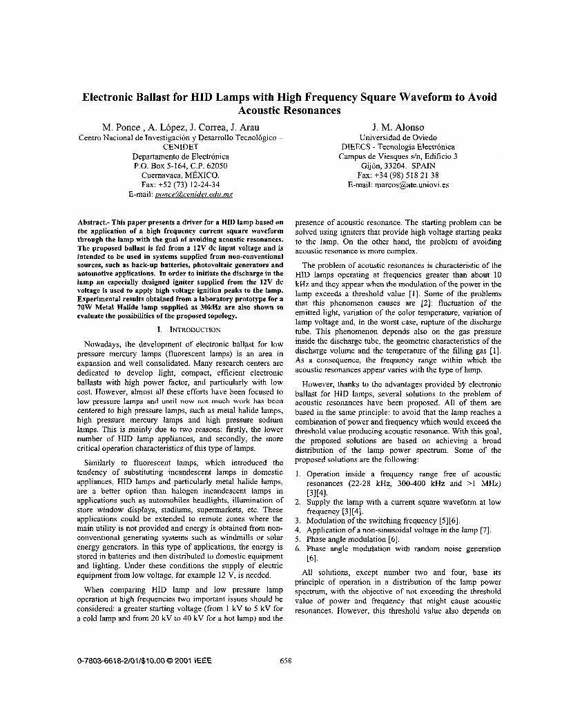
In order to obtain the high ignition voltage to initiate the discharge an especially igniter is used. The igniter is supplied from 12V and provides pulses of voltage high enough to start the discharge. The starting is performed with the lamp at ambient temperature a_nd the hot starting is not considered by now. The proposed circuit with the three stages is shown in Fig 3. This circuit consists of an igniter, a boost converter and the proposed inverter.
,'Jr,,ie, BmSt CO"YeIt8' ITi"R':Yi . . . . .. . . ,... .. ........ ..................... .,
L - "," 1;iy
?
n
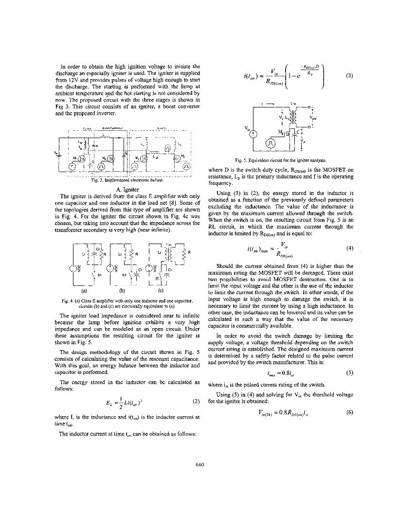
Fig. 5 . Equivalent circuit for the igniter analysis.
where D is the switch duty cycle, RDs(on) is the MOSFET on resistance, L, is the primary inductance and f is the operating frequency.
Using (3) in (2), the energy stored in the inductor is obtained as a function of the previously defined parameters excluding the inductance. The value of the inductance is given by the maximum current allowed through the switch. When the switch is on, the resulting circuit from Fig. 5 is an €U circuit, in which the maximum current through the inductor is limited by RDs(on) and is equal to:
Fig 3. Implemented electronic ballast
A. Igniter The igniter is derived from the class E amplifier with only
one capacitor and one inductor in the load net [8]. Some of the topologies derived from this type of amplifier are shown in Fig. 4. For the igniter the circuit shown in Fig. 4c was chosen, but taking into account that the impedance across the transformer secondary is very high (near infinite).
(a) (b) (4 Fig. 4. (a) Class E amplifier with only one inductor and one capacitor,
circuits (b) and (c) are electrically equivalent to (a).
The igniter load impedance is considered near to infinite because the lamp before ignition exhibits a very high impedance and can be modeled as an open circuit. Under these assumptions the resulting circuit for the igniter is shown in Fig. 5.
The design methodology of the circuit shown in Fig. 5 consists of calculating the value of the resonant capacitance. With this goal, an energy balance between the inductor and capacitor is performed.
The energy stored in the inductor can be calculated as follows:
1 . E , =-Lz(t,)' 2
where L is the inductance and i(ton) is the inductor current at time ton.
The inductor current at time to, can be obtained as follows:
Should the current obtained from (4) is higher than the maximum rating the MOSFET will be damaged. There exist two possibilities to avoid MOSFET destruction. One is to limit the input voltage and the other is the use of the inductor to limit the current through the switch. In other words, if the input voltage is high enough to damage the switch, it is necessary to limit the current by using a high inductance. In other case, the inductance can be lowered and its value can be calculated in such a way that the value of the necessary capacitor is commercially available.
In order to avoid the switch damage by limiting the supply voltage, a voltage threshold depending on the switch current rating is established. The designed maximum current is determined by a safety factor related to the pulse current and provided by the switch manufacturer. This is:
imx =O.Si,
where is, is the pulsed current rating of the switch.
for the igniter is obtained Using (5) in (4) and solving for Vi, the threshold voltage
660
When Vin < Vinm the value of L, can be selected for B. Inverter - - \ - - - ,
design convenience. However, if Vi* > is calculated as follows:
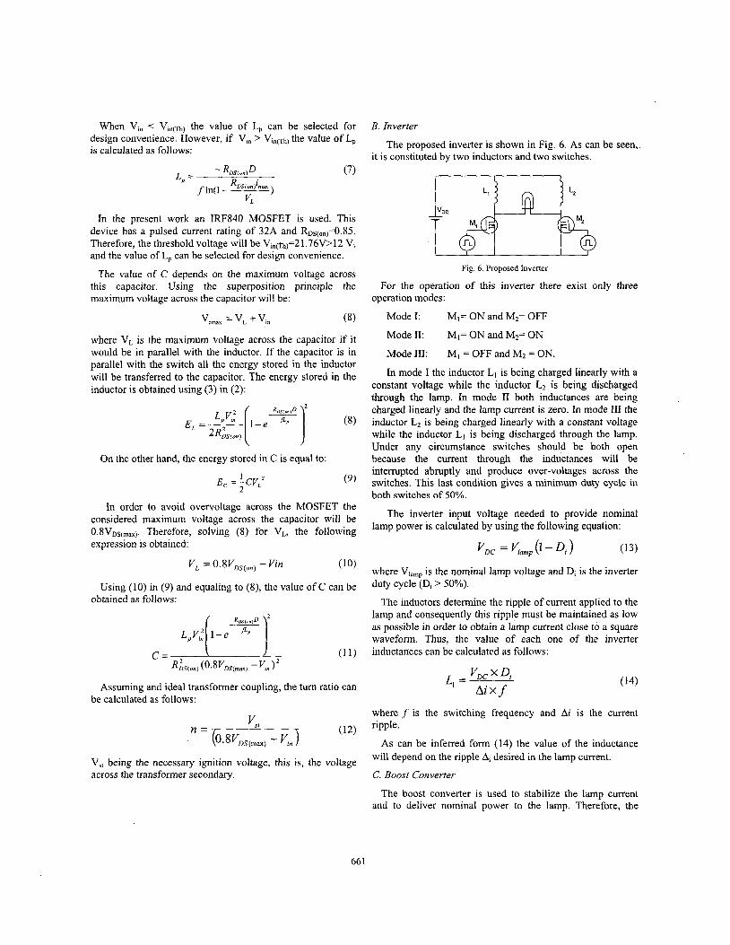
the value of L, The proposed inverter is shown in Fig. 6. As can be seen, it is constituted by two inductors and two switches.
- R,,(,,,D (7) L, = L n n
) f In( l R D s ( o n A m
V L
In the present work an IRF840 MOSFET is used. This device has a pulsed current rating of 32A and R~~,,,,=0.85. Therefore, the threshold voltage will be Vin(th)=2 1.76V>12 Vi and the value of L, can be selected for design convenience.
The value of C depends on the maximum voltage across this capacitor. Using the superposition principle the For the operation of this inverter there exist only three maximum voltage across the capacitor will be:
Fig. 6 . Proposed Inverter
operation modes:
(8) Mode I: MI= ON and M2= OFF Vcmax = VL + Vi,
where VL is the maximum voltage across the capacitor if it would be in parallel with the inductor. If the capacitor is in parallel with the switch all the energy stored in the inductor will be transferred to the capacitor. The energy stored in the inductor is obtained using (3) in (2):
On the other hand, the energy stored in C is equal to:
1 E , = -CVL' 2
(9 )
In order to avoid overvoltage across the MOSFET the considered maximum voltage across the capacitor will be 0.8VDs,,,,,. Therefore, solving (8) for VL, the following expression is obtained:
Using'( 10) in (9) and equaling to (8), the value of C can be obtained as follows:
Assuming and ideal transformer coupling, the tum ratio can be calculated as follows:
Mode 11: MI= ON and M2= ON
Mode 111: Mi = OFF and MZ = ON.
In mode I the inductor L, is being charged linearly with a constant voltage while the inductor L2 is being discharged through the lamp. In mode I1 both inductances are being charged linearly and the lamp current is zero. In mode I11 the inductor L2 is being charged linearly with a constant voltage while the inductor LI is being discharged through the lamp. Under any circumstance switches should be both open because the current through the inductances will be interrupted abruptly and produce over-voltages across the switches. This last condition gives a minimum duty cycle in both switches of 50%.
The inverter input voltage needed to provide nominal lamp power is calculated by using the following equation:
where Vlamp is the nominal lamp voltage and Di is the inverter duty cycle (D, > 50%).
The inductors determine the ripple of current applied to the lamp and consequently this ripple must be maintained as low as possible in order to obtain a lamp current close to a square waveform. Thus, the value of each one of the inverter inductances can be calculated as follows:
where f is the switching frequency and Ai is the current ripple.
As can be inferred form (14) the value of the inductance will depend on the ripple Ai desired in the lamp current.
C. Boost Converter V,, being the necessary ignition voltage, this is, the voltage across the transformer secondary.
The boost converter is used to stabilize the lamp current and to deliver nominal power to the lamp. Therefore, the
66 1
boost conver,ter must be designed to provide the necessary input voltage to the inverter and works in discontinuous operation mode. The design of this converter is based on the traditional methodology. Thus, the necessary duty cycle for a given output voltage is obtained from the following expression:
VGig
Vbwst
" DC The value of the inductor and capacitor are calculated as
follows:
I ,
50% i
n n n n n n h n n n n n 4
Kn2Db2 Lo =-
2 p L f b
vrelay
VaUX
3
and
I t
I I
(17) J b U v c
where fb is the operating frequency of the boost converter, Db is the duty cycle of the boost converter, Ilamp is the current through the lamp, PL is the power of the lamp and AVc is the voltage ripple in Co. In order to simplifjr the control circuit of the proposed ballast, the operating frequency fb is selected to be equal to double the operating frequency of the igniter and inverter.
111. OPERATION OF THE ELECTRONIC BALLAST
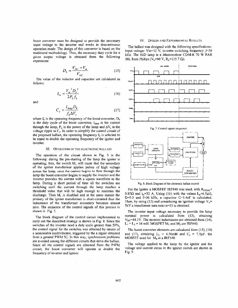
The operation of the circuit shown in Fig. 3 is the following: during the pre-starting of the lamp the igniter is operating; thus, the switch MI will cause that the secondary of the igniter transformer applies pulses of high voltage across the lamp, once the current begins to flow through the lamp the boost converter begins to supply the inverter and the inverter provides the current with a square waveform to the lamp. During a short period of time all the switches are switching until the current through the lamp reaches a threshold value that will be high enough to maintain the discharge. Then M, is disabled and at the same instant the primary of the igniter transformer is short-circuited thus the inductance of the transformer secondary becomes almost zero. The sequence of the control signals of this process is shown in Fig. 7.
The block diagram of the control circuit implemented to carry out the described strategy is shown in Fig. 8. Since the switches of the inverter need a duty cycle greater than 50%, the control signal for the switches was obtained by means of a monostable multivibrator, triggered by the a signal obtained from a general PWM IC. In this way, synchronism problems are avoided among the different circuits that drive the ballast. Since all the control signals are obtained from the PWM circuit, the boost converter will operate at double the frequency of inverter and igniter.
Iv . DESIGN AND EXPERIMENTAL RESULTS
The ballast was designed with the following specifications: Input voltage: Vin=12 V, inverter switching frequency: p 3 0 kHz. The HID lamp is a Mastercolour CDM-R 70 W PAR 30L from Philips (VL=90 V, RLzl15.7 Q).
vgrmv
VgPin"
I I
r-- 1 1 BOOST !
CONVERTER, I
Fig. 8. Block Diagram of the electronic ballast control
For the igniter a MOSFET IRF840 was used, with Ros(on)= 0.85R and i,,=32 A. Using (11) with the values LP=4.5pH, D=0.5 and f=30 kHz, a capacitor C=5.4nF is calculated. Then, by using (12) and considering an ignition voltage Vst= 5kV a transformer turn ratio n= 13 is obtained.
The inverter input voltage necessary to provide the lamp nominal power is calculated from . (13), obtaining VDc=44. 1V. The inverter inductances are obtained from (14), L, = L2 = 16 mH. MOSFET MI and M2 are IRF640.
The boost converter elements are calculated from (1 5) , (1 6) and (17), obtaining Lo = 4.56mH and CO = 7.5pF. the MOSFET used for MB is a IRF540.
The voltage applied to the lamp by the igniter and the voltage and current stress in the igniter switch are shown in Fig. 9.
662
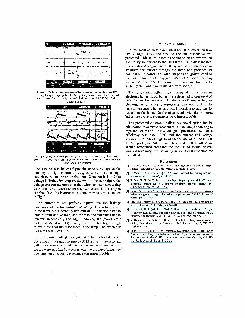
Figure 7. Voltage waveform across the igniter switch (upper trace, 200 V/DIV), Lamp voltage applied by the igniter (middle trace, 1 kV/DIV) and
current waveform in the igniter switch (lower trace, 10 A/DIV). Horiz. Scale: 5 ps/DIV).
Figure 9. Lamp current (upper trace, 1 A/DIV), lamp voltage (middle trace, 100 V/DIV) and instantaneous power in the lamp (lower trace, 50 VNDIV ).
Horiz. Scale: I O p/DIV).
As can be seen in this figure the applied voltage to the lamp by the igniter reaches VI,,=2.12 kV, what is high enough to initiate the arc in the lamp. Note that in Fig. 7 the voltage is limited by lamp breakdown. In the same figure the voltage and current stresses in the switch are shown, reaching 20 A and 198V. Once the arc has been establish, the lamp is supplied from the inverter with a square waveform as shown in Fig. 9.
The current is not perfectly square due the leakage inductance of the transformer secondary. The instant power in the lamp is not perfectly constant due to the ripple of the lamp current and voltage, and the rise and fall times in the inverter switches(M, and M2). However, the power crest factor calculated with (1) was C,=1.25, which is high enough to avoid the acoustic resonances in the lamp. The efficiency measured was about 70%.
The proposed ballast was compared to a resonant ballast operating at the same frequency (30 kHz). With the resonant ballast the phenomenon of acoustic resonances prevented that the arc were stabilized, whereas with the proposed ballast the- phenomenon of acoustic resonance was imperceptible.
V. CONCLUSIONS
In this work an electronic ballast for HID ballast fed from low voltage (12V) and free of acoustic resonances was presented. This ballast bases its operation on an inverter that applies square current to the HID lamp. The ballast includes two additional stages: one of them is a boost converter that stabilizes the current through the lamp and provides the nominal lamp power. The other stage is an igniter based on the class E amplifier that applies pulses of 2.2 kV to the lamp and is fed from 12V. Furthermore, the commutations in the switch of the igniter are realized at zero voltage.
The electronic ballast was compared to a resonant electronic ballast. Both ballast were designed to operate at 30 kHz. At this frequency and for the type of lamp tested, the phenomenon of acoustic resonances was observed in the resonant electronic ballast and was impossible to stabilize the current in the lamp. On the other hand, with the proposed ballast the acoustic resonances were imperceptible.
The presented electronic ballast is a novel option for the elimination of acoustic resonances in HID lamps operating at high frequency and for low voltage applications. The ballast efficiency was about 70% and the current and voltage stresses were low enough to allow the use of MOSFETs in TO220 packages. All the switches used in this ballast are ground referenced and therefore the use of special drivers was not necessary, thus attaining an extra cost reduction for the ballast.
References J . J. de Groat, J. A: I. M. van Vliet. “The high pressure sodium lamp”, Philips Technical Library, MacMillan Education, 0 1986. I. Zhou, L. Ma. And Z. Qian. “A novel method for testing acoustic resonance of HID lamps”, APEC’99. Richard Redl, Jon D. Paul. “a new high-frequency and high-efficiency electronic ballast for HID lamps: topology, analysis, design and experimental results”, APEC’99. Janos Melis, Oscar Vila-Masot. “Low frequency square wave electronic ballast for gas discharge”, United states patent No. 5,428,268, date of patent: jun, 27, 1995. Sam Ben-Yaakov, M. Gulko, A. Giter. “The simplest Electronic Ballast for HID Lamps”, APEC’96, pp. 634-640. L. Laskai, P. Enjeti, I. J: Pitel. “White noise modulation of high- frequency high-intensity discharge lamp ballasts”, IEEE Transactions on Industry Applications, Vol. 34, No. 3, May/June 1998, pp. 597-604. Y. Koshimura, N. Aoike, 0. Nomura. “Stable high frequency operation of high intensity discharge lamps and their ballast design.”, CIE 20* session’83, E36. Sokal, N. 0. “Class E High Efficiency Switching-Mode Tuned Power Amplifier with Only One Inductor and One Capacitor in Load Network- Approximate Analysis”. IEEE Joumal of Solid State Circuits, Vol. SC- 16, NO. 4, (Aug. 1981), pp. 380-384.
663
Related Documents