Electron-wall interactions and their consequences on transport Igor D. Kaganovich Princeton Plasma Physics Laboratory Princeton, NJ 08543 1

Welcome message from author
This document is posted to help you gain knowledge. Please leave a comment to let me know what you think about it! Share it to your friends and learn new things together.
Transcript
Electron-wall interactions and their consequences on transport
Igor D. Kaganovich
Princeton Plasma Physics Laboratory Princeton, NJ 08543
1
Outline
Part 1
– Non-Maxwellian EVDF
– Effects of emission on sheath
– Sheath Instability
– Near Wall Conductivity
– Emission from complex surfaces
– Revisiting Pierce Instability
2
Outline
Part 2
– Validating PIC codes
– 2-3D PPPL-modified LSP
– Anomalous Conductivity
– Spoke
3

Electron emission from the wall can increase the plasma heat flux to the wall many times
• Without SEE, sheath of space charge near the wall
reflects most electrons back to the plasma, thus
effectively insulating wall from the plasma (Left Figure)
• SEE reduces the wall potential and allows large
electron flux to the wall (Right Figure)
0
30
60
90
120
100 200 300 400 500 600 700 800
Discharge voltage, V
Ma
xim
um
ele
ctr
on
te
mp
era
ture
, e
V
High SEE BN channel
Low SEE segmented
w 6Te
e
i
Wall - Sheath - Plasma
w Te
e
i
see
Wall – Sheath - Plasma
Hall thruster experiments show
very different maximum electron
temperatures with high and low
SEE channel wall materials
Y. Raitses et al., Phys. Plasmas 2005 Y. Raitses et al., IEEE TPS 2011 4
5
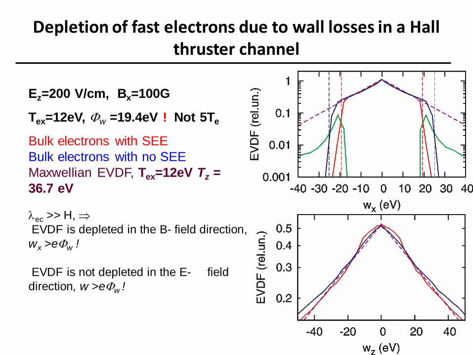
Depletion of fast electrons due to wall losses in a Hall thruster channel
Ez=200 V/cm, Bx=100G
Tex=12eV, Fw =19.4eV ! Not 5Te
Bulk electrons with SEE
Bulk electrons with no SEE
Maxwellian EVDF, Tex=12eV Tz =
36.7 eV
ec >> H,
EVDF is depleted in the B- field direction,
wx >eFw !
EVDF is not depleted in the E- field
direction, w >eFw !
6
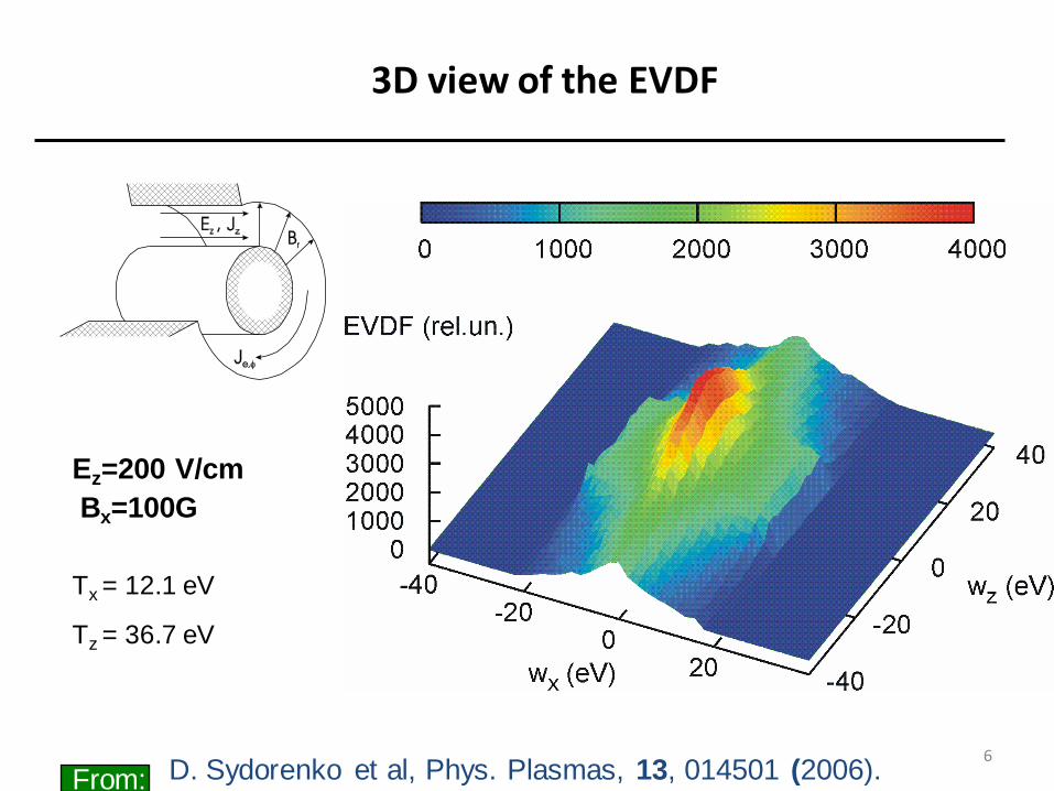
3D view of the EVDF
Ez=200 V/cm
Bx=100G
Tx = 12.1 eV
Tz = 36.7 eV
D. Sydorenko et al, Phys. Plasmas, 13, 014501 (2006). From:
7
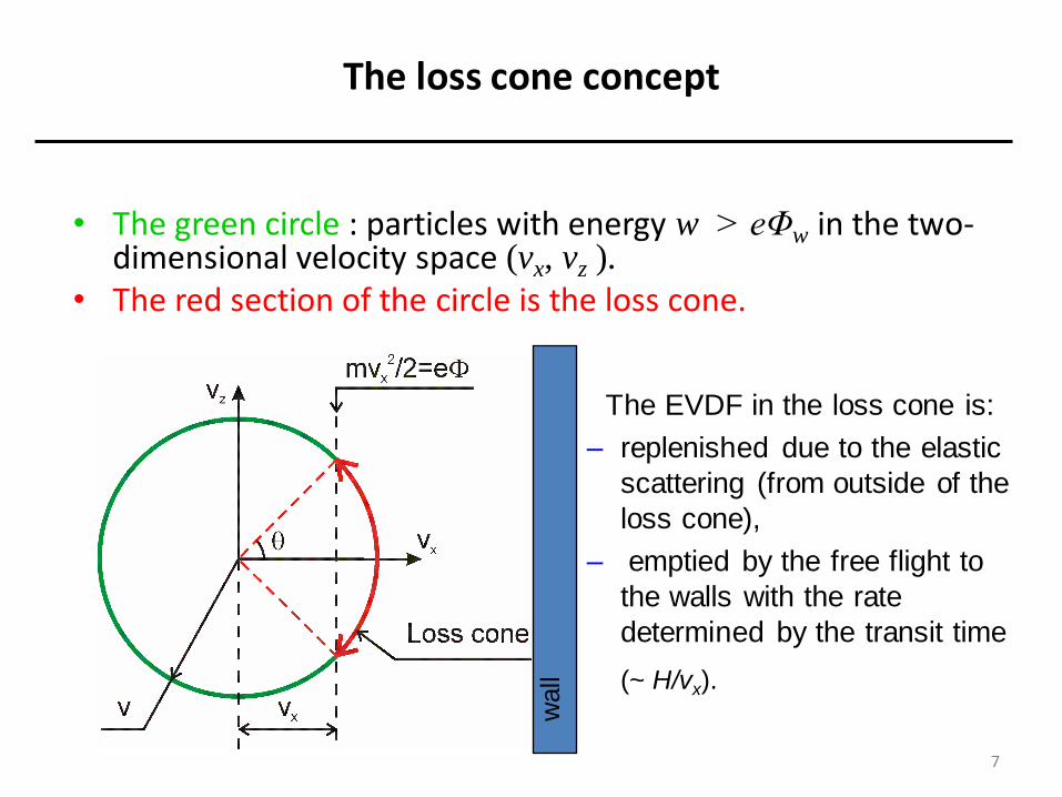
The loss cone concept
• The green circle : particles with energy w > eΦw in the two-dimensional velocity space (vx, vz ).
• The red section of the circle is the loss cone.
The EVDF in the loss cone is:
– replenished due to the elastic
scattering (from outside of the
loss cone),
– emptied by the free flight to
the walls with the rate
determined by the transit time
(~ H/vx).
wall
8
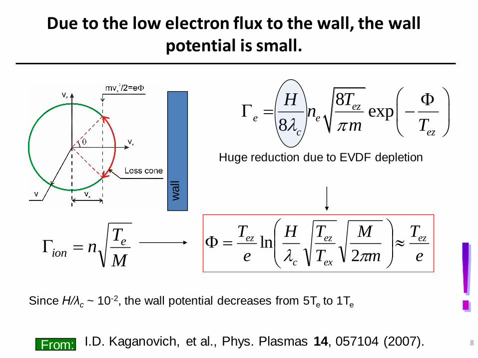
Due to the low electron flux to the wall, the wall potential is small.
e
T
m
M
T
TH
e
T ez
ex
ez
c
ez
F
2ln
8exp
8
eze e
c ez
THn
m T
F
M
Tn e
ion
Since H/λc ~ 10-2, the wall potential decreases from 5Te to 1Te
wall
I.D. Kaganovich, et al., Phys. Plasmas 14, 057104 (2007). From:
Huge reduction due to EVDF depletion
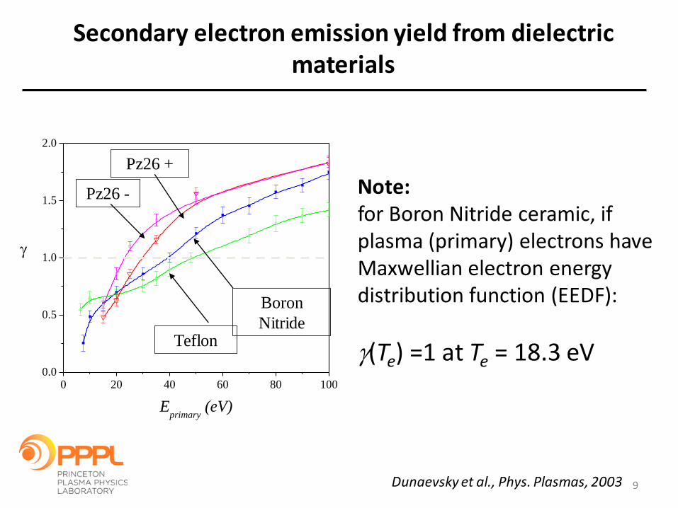
Secondary electron emission yield from dielectric materials
Note: for Boron Nitride ceramic, if plasma (primary) electrons have Maxwellian electron energy distribution function (EEDF):
(Te) =1 at Te = 18.3 eV
Dunaevsky et al., Phys. Plasmas, 2003
0 20 40 60 80 1000.0
0.5
1.0
1.5
2.0
Eprimary
(eV)
Teflon
Boron
Nitride
Pz26 -
Pz26 +
9
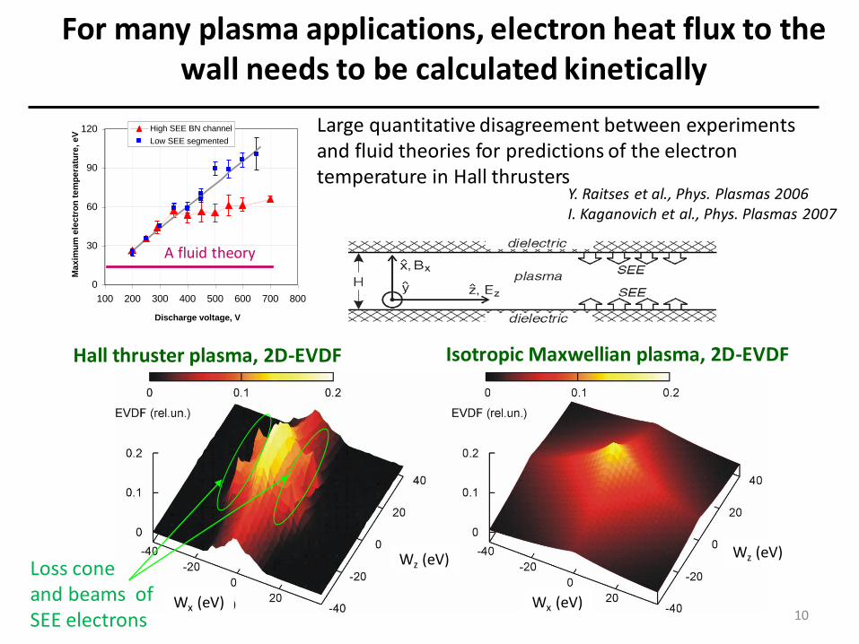
For many plasma applications, electron heat flux to the wall needs to be calculated kinetically
Hall thruster plasma, 2D-EVDF Isotropic Maxwellian plasma, 2D-EVDF
Depletion at high energy due to wall
losses and beams of SEE electrons Wz (eV) Wz (eV)
Wx (eV) Wx (eV)
Large quantitative disagreement between experiments and fluid theories for predictions of the electron temperature in Hall thrusters
0
30
60
90
120
100 200 300 400 500 600 700 800
Discharge voltage, V
Ma
xim
um
ele
ctr
on
te
mp
era
ture
, e
V
High SEE BN channel
Low SEE segmented
A fluid theory
Loss cone and beams of SEE electrons
Y. Raitses et al., Phys. Plasmas 2006 I. Kaganovich et al., Phys. Plasmas 2007
10

Electron fluxes have several components, including plasma bulk electrons, and counter-streaming beams of SEE
electrons from walls
(x) ions
SEE
beam SEE
plasma
ions
beam
plasma
Note: net > 1 if b>1 Net secondary electron emission net accounts for kinetic effects by separating SEE yield of plasma (p) and beam electrons (b)
1
Energy of incident electron, eV
11
SEE Yield as function of incident
electron energy
)(1 bp
p
net
Total
emission
coefficient:
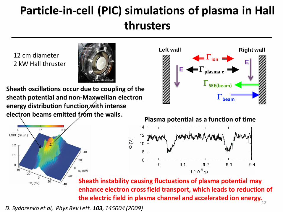
Particle-in-cell (PIC) simulations of plasma in Hall thrusters
Sheath oscillations occur due to coupling of the sheath potential and non-Maxwellian electron energy distribution function with intense electron beams emitted from the walls.
D. Sydorenko et al, Phys Rev Lett. 103, 145004 (2009)
Plasma potential as a function of time
Sheath instability causing fluctuations of plasma potential may enhance electron cross field transport, which leads to reduction of the electric field in plasma channel and accelerated ion energy.
12 cm diameter 2 kW Hall thruster
beam
SEE(beam)
ion
plasma e-
Left wall Right wall
E E
12
13
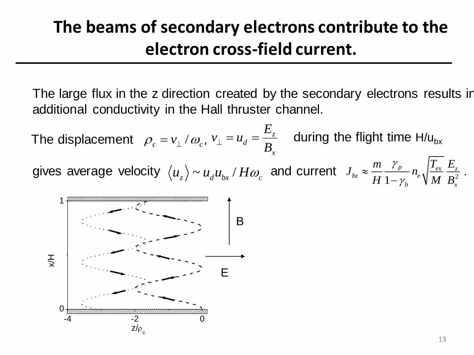
gives average velocity and current .
The beams of secondary electrons contribute to the electron cross-field current.
0
1
-4 -2 0
z/c
x/H
The large flux in the z direction created by the secondary electrons results in
additional conductivity in the Hall thruster channel.
/c cv z
d
x
Ev u
B
21
p ex zbz e
b x
T EmJ n
H M B
The displacement , during the flight time H/ubx
~ /z d bx cu u u H
E
B
14
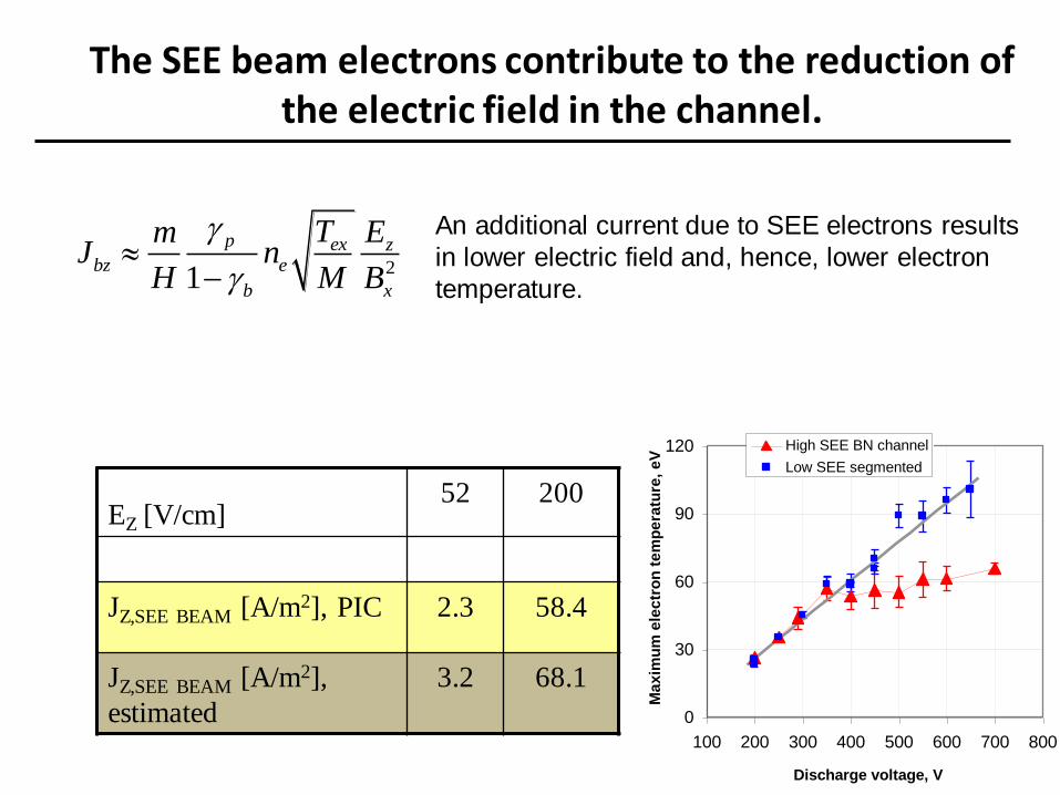
The SEE beam electrons contribute to the reduction of the electric field in the channel.
21
p ex zbz e
b x
T EmJ n
H M B
0
30
60
90
120
100 200 300 400 500 600 700 800
Discharge voltage, V
Ma
xim
um
ele
ctr
on
te
mp
era
ture
, e
V
High SEE BN channel
Low SEE segmented
EZ [V/cm] 52 200
JZ,SEE BEAM [A/m2], PIC 2.3 58.4
JZ,SEE BEAM [A/m2],
estimated
3.2 68.1
An additional current due to SEE electrons results
in lower electric field and, hence, lower electron
temperature.
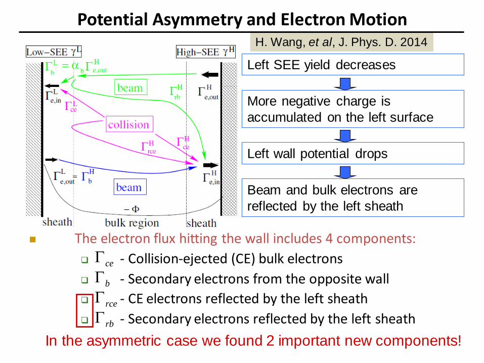
Potential Asymmetry and Electron Motion
The electron flux hitting the wall includes 4 components:
- Collision-ejected (CE) bulk electrons
- Secondary electrons from the opposite wall
- CE electrons reflected by the left sheath
- Secondary electrons reflected by the left sheath
Left SEE yield decreases
More negative charge is
accumulated on the left surface
Left wall potential drops
Beam and bulk electrons are
reflected by the left sheath
ce
b
rce
rb
In the asymmetric case we found 2 important new components!
H. Wang, et al, J. Phys. D. 2014
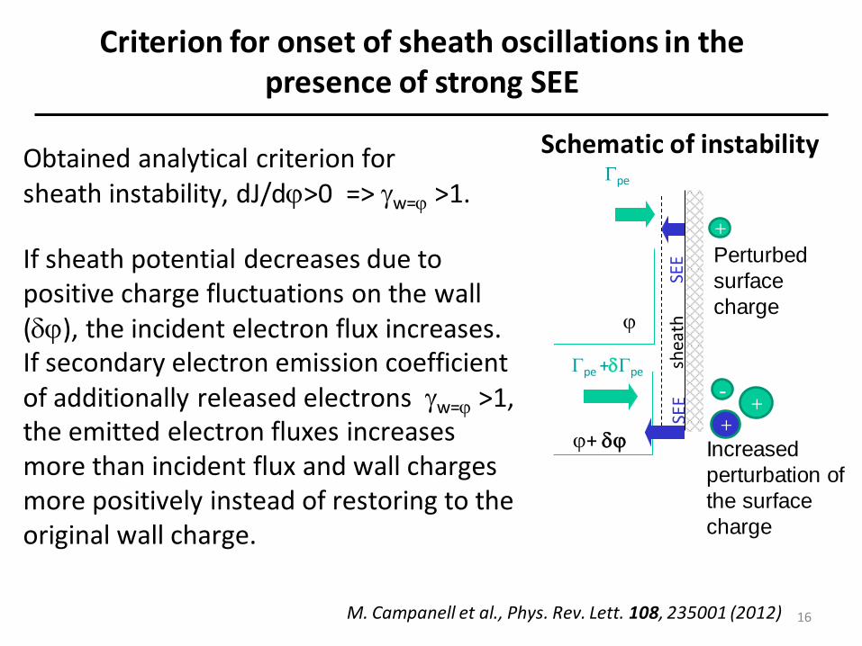
Criterion for onset of sheath oscillations in the presence of strong SEE
Obtained analytical criterion for sheath instability, dJ/d>0 => w= >1.
M. Campanell et al., Phys. Rev. Lett. 108, 235001 (2012)
Schematic of instability
If sheath potential decreases due to positive charge fluctuations on the wall (), the incident electron flux increases. If secondary electron emission coefficient of additionally released electrons w= >1, the emitted electron fluxes increases more than incident flux and wall charges more positively instead of restoring to the original wall charge.
pe
SEE
shea
th
+
-
+ +
pe +pe
SEE
+
16
Perturbed
surface
charge
Increased
perturbation of
the surface
charge
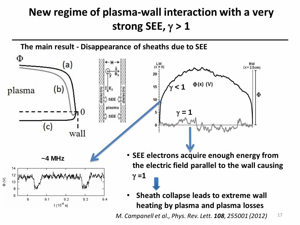
New regime of plasma-wall interaction with a very strong SEE, > 1
The main result - Disappearance of sheaths due to SEE
M. Campanell et al., Phys. Rev. Lett. 108, 255001 (2012)
= 1
< 1
~4 MHz • SEE electrons acquire enough energy from the electric field parallel to the wall causing =1
• Sheath collapse leads to extreme wall heating by plasma and plasma losses
17
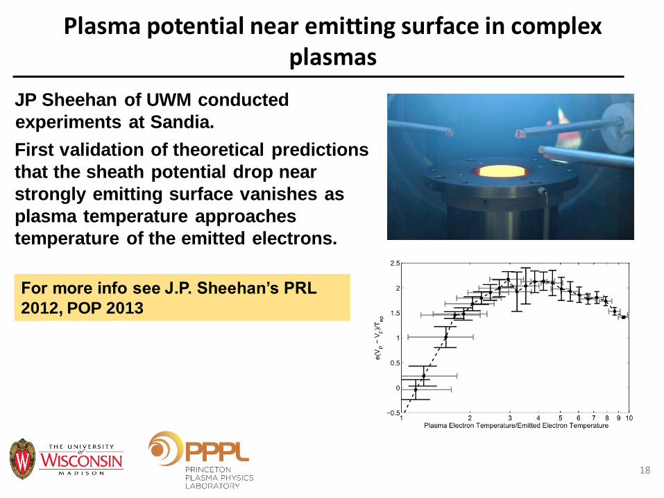
Plasma potential near emitting surface in complex plasmas
JP Sheehan of UWM conducted
experiments at Sandia.
First validation of theoretical predictions
that the sheath potential drop near
strongly emitting surface vanishes as
plasma temperature approaches
temperature of the emitted electrons.
For more info see J.P. Sheehan’s PRL
2012, POP 2013
18

Plasma properties can be changed by applying engineered materials to the surface
Application of carbon velvet to channel walls improves considerably thruster performance by reducing the electron cross-field current and by increasing nearly twice the maximum electric field in the channel compared with the conventional BN ceramic walls.
• Velvet suppresses SEE and reduces current at high voltages (good)
• Sharp tips can enhance field emission leading to arcing (bad)
• Need to engineer velvet morphology so that inter fiber gaps and protrusions are located well inside the sheath to avoid damage by arcing
Need to take into account spatial and temporal variations of sheath width due to plasma non-uniformity or instabilities
Carbon
velvet Protrusive
fibers > D
Channel wall
Velvet before plasma
Plasma burned out all protrusive fibers
Hall thruster
Carbon
velvet
To avoid field emission g, lp < Debye length
Plasma flow
Velvet Fibers
Wall
L
g
lp
19
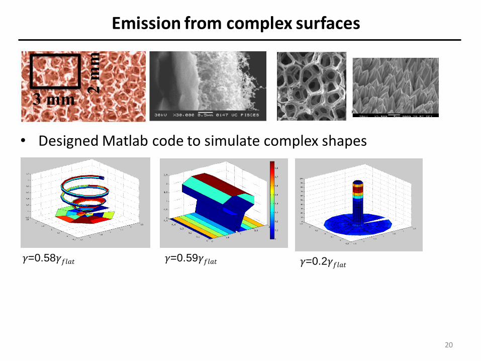
Emission from complex surfaces
• Designed Matlab code to simulate complex shapes
20
𝛾=0.59𝛾𝑓𝑙𝑎𝑡
𝛾=0.58𝛾𝑓𝑙𝑎𝑡
𝛾=0.2𝛾𝑓𝑙𝑎𝑡

Calculation of Effective Secondary Electron Emission Yield from Velvet-like structures
Fig.2. SEY vs angle of incidence for different values of aspect ration, A, and packing density, D.
21
Fig.1 Contributions to the
SEY emitted by the tops,
sides and the bottom
surface.
Exact analytic results vs approximate
numerical results for SEY
For more info see C. Swanson,
I.D. Kaganovich J. App. Phys.
2017

Effects of Boundaries -- Revisiting Pierce
Instability
Electron beam is injected into electron and ion background of equal
density.
Electrodes with fixed potential set potential at boundaries.
Instability is very different from textbook calculation for periodic b.c.
22
+ -
-
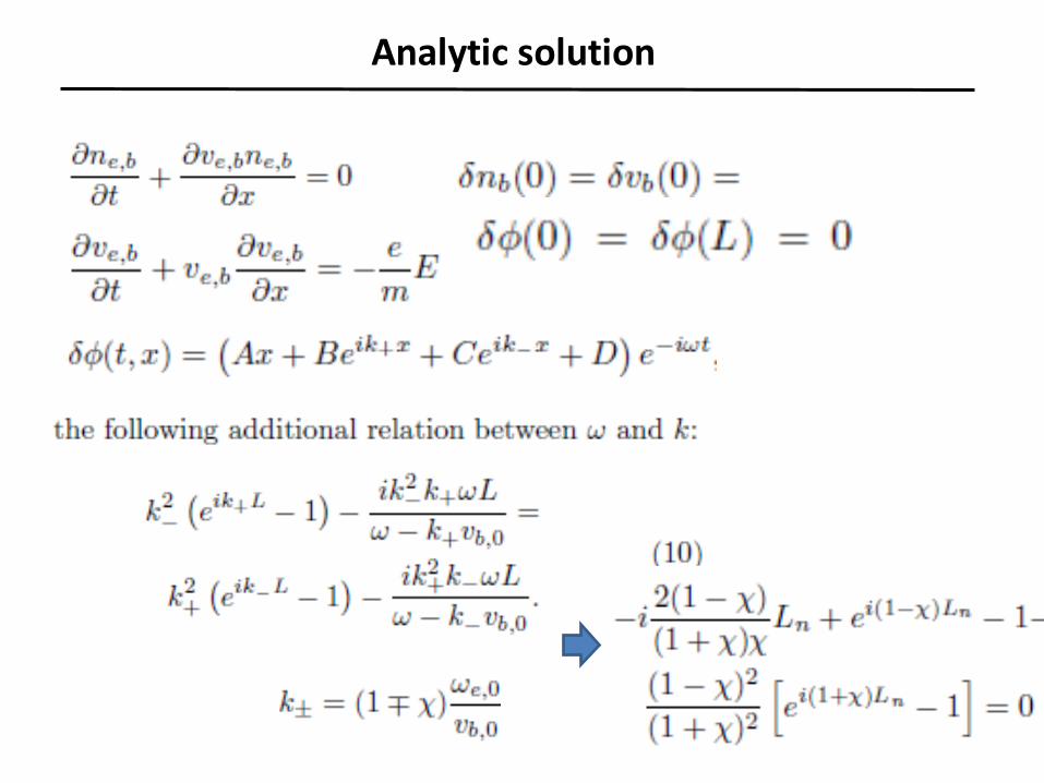
Analytic solution
23
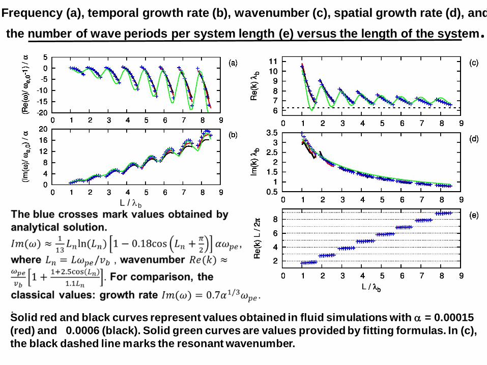
Frequency (a), temporal growth rate (b), wavenumber (c), spatial growth rate (d), and
the number of wave periods per system length (e) versus the length of the system.
Solid red and black curves represent values obtained in fluid simulations with a = 0.00015
(red) and 0.0006 (black). Solid green curves are values provided by fitting formulas. In (c),
the black dashed line marks the resonant wavenumber.
L / b
Conclusions
• SEE is important to take into account for many applications with Te>20eV
for dielectrics and >100eV for metals.
• SEE strongly affect sheath. Instability due to EVDF-sheath coupling,
inverse sheath
• Complex structures can reduce SEY. Theory was developed for optimal
parameters of velvet.
• SEE can create beams of electrons penetrating the plasma and causing
two-stream instability. We have studied the development of the two-stream
instability in a finite size plasma bounded by electrodes both analytically
and making use of fluid and particle-in-cell simulations. Its behavior is
very different from infinite plasma.
25
Developing Computational Capabilities for Thruster Simulations
J. Carlsson, A. Powis, I.D. Kaganovich, A.V. Khrabrov, Y.
Raitses
Princeton Plasma Physics Laboratory, NJ
26
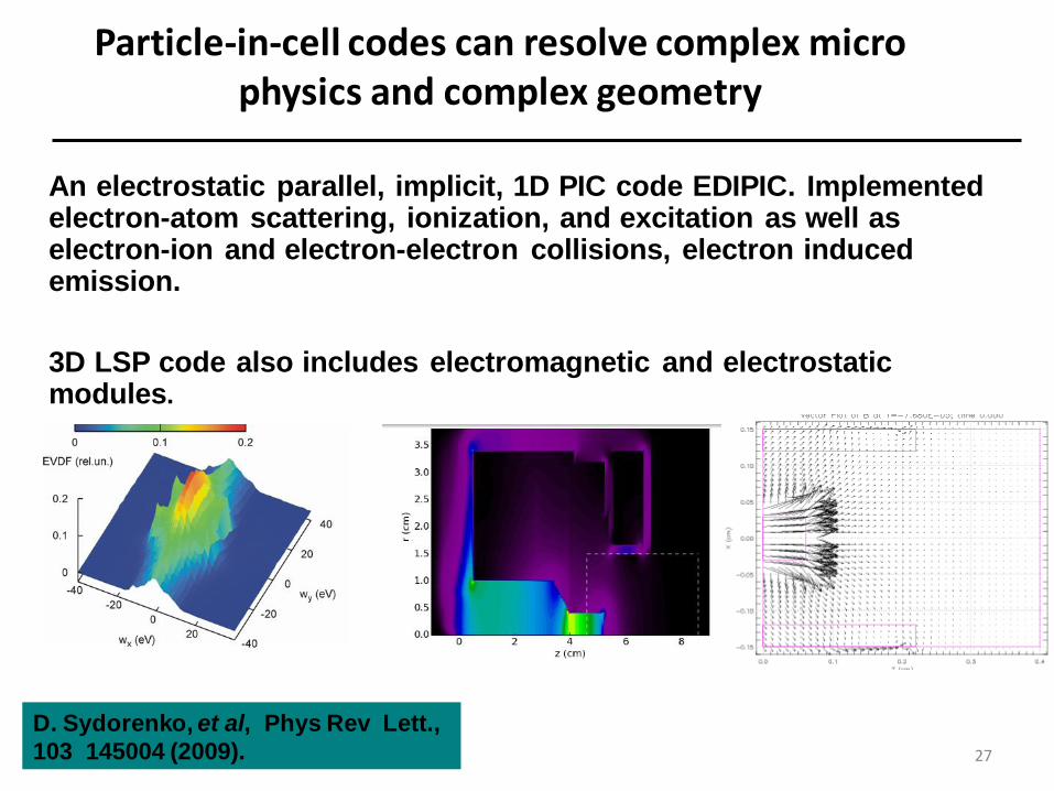
Particle-in-cell codes can resolve complex micro physics and complex geometry
An electrostatic parallel, implicit, 1D PIC code EDIPIC. Implemented electron-atom scattering, ionization, and excitation as well as electron-ion and electron-electron collisions, electron induced emission.
3D LSP code also includes electromagnetic and electrostatic modules.
D. Sydorenko, et al, Phys Rev Lett.,
103 145004 (2009). 27
Improvements in lsp code
28
• LSP code 3D - Electrostatic and Electromagnetic Particle-In-Cell
code includes:
• Implicit, Explicit Electrostatic and Electromagnetic solvers
• Full collision algorithm for isotropic elastic and inelastic
collisions.
• Improvements:
• New Electrostatic PETSc Solvers
• Anisotropic elastic and inelastic collisions
• External circuit

Benchmarking of codes
29
E. A. Den Hartog, D. A. Doughty, and J. E. Lawler, ”Laser optogalvanic and
fluorescence studies of the cathode region of a glow discharge”, Phys. Rev.
A 38, 2471 (1988).
Accurate and complete
measurements of the plasma
quantities: E(x), , J, U.
For more info see J. Carlsson,
PSST 2016
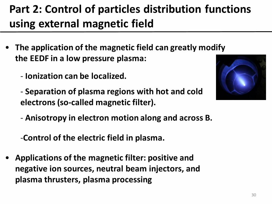
Part 2: Control of particles distribution functions using external magnetic field
• The application of the magnetic field can greatly modify the EEDF in a low pressure plasma:
- Ionization can be localized.
- Separation of plasma regions with hot and cold electrons (so-called magnetic filter).
- Anisotropy in electron motion along and across B.
-Control of the electric field in plasma.
• Applications of the magnetic filter: positive and negative ion sources, neutral beam injectors, and plasma thrusters, plasma processing
30
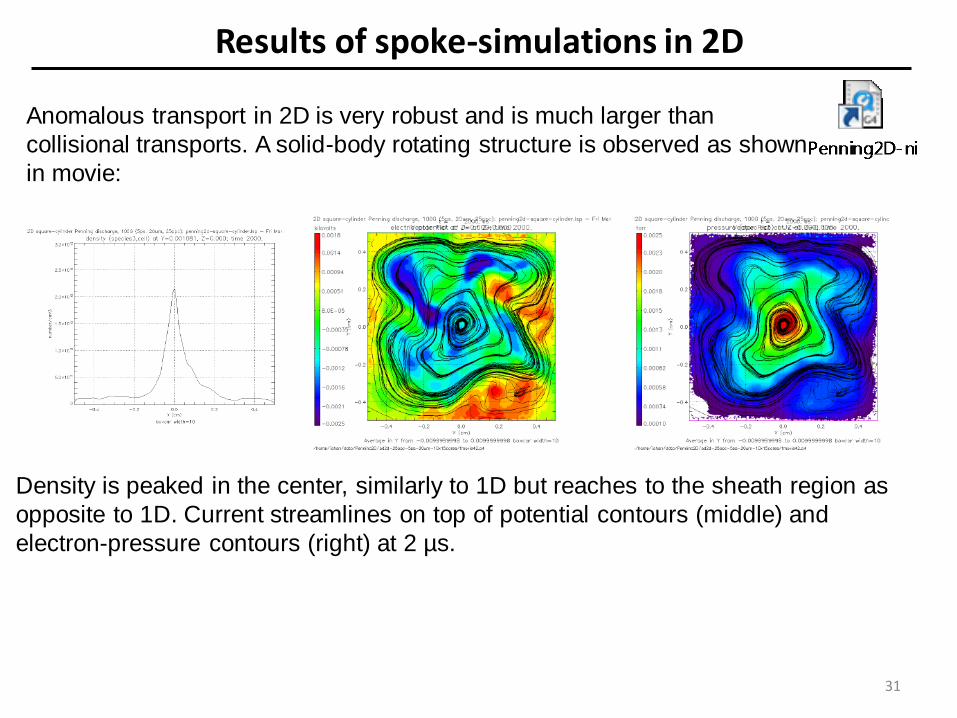
Results of spoke-simulations in 2D
Anomalous transport in 2D is very robust and is much larger than
collisional transports. A solid-body rotating structure is observed as shown
in movie:
Density is peaked in the center, similarly to 1D but reaches to the sheath region as
opposite to 1D. Current streamlines on top of potential contours (middle) and
electron-pressure contours (right) at 2 µs.
31
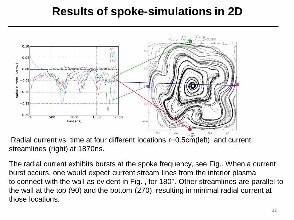
Results of spoke-simulations in 2D
Radial current vs. time at four different locations r=0.5cm(left) and current
streamlines (right) at 1870ns.
32
The radial current exhibits bursts at the spoke frequency, see Fig.. When a current
burst occurs, one would expect current stream lines from the interior plasma
to connect with the wall as evident in Fig. , for 180. Other streamlines are parallel to
the wall at the top (90) and the bottom (270), resulting in minimal radial current at
those locations.

33
34
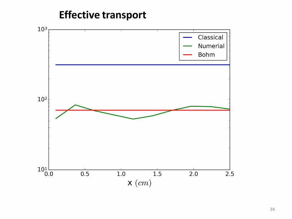
Effective transport

Summary of Part 2
We studied a number of low pressure E×B discharges with weakly
collisional quasi-neutral plasma, including plasma lens, Penning
discharge and Hall thrusters of different configurations.
All these plasma discharges are characterized by anomalously
high (not collisional) electron cross-field transport.
Anomalous transport is predicted to be due to small and large
scale instabilities.
An example of large scale instability is the E×B rotating spoke.
Recent PIC simulations predict small scale instabilities inside
the spoke.
Spoke can be controlled and suppressed with a feedback circuitry.
35

Effect of Surface Architecture on Secondary Electron Emission Properties of Materials
Yevgeny Raitses and Igor Kaganovich
BN
Graphite
Dendritic
Re/W, Re/Mo
Velvet
• Strong SEE effects on plasma-wall interaction occur
when SEE approaches 1 (top figure).
• For ceramic materials, SEE yield is higher and
approaches 1 at lower energies than for metals due
to a weaker scattering of SEE electrons on phonons
(for insulators), ~ 20 nm, than on electrons (for
metals,), ~ 1 nm.
• Surface-architectured materials can reduce the
effective SEE yield by trapping SEE electrons
between surface structural features.
• The SEE reduction is most significant for high aspect
ratio (1:103) velvets than for low aspect ratio (1:10)
dendritic coatings (top figure).
• Measurements demonstrate the existence of the
optimum aspect ratio and the density of the
architectural features (bottom left figure).
• New result: surface architecture affects the energy
distribution function of emitted electrons reducing
the fraction of backscattered electrons –important for
collisionless plasmas used in EP (bottom right
figure).
Carbon Velvet: Effect of
fiber length and packing
density on SEE for beam
electrons of 50 eV and
300 eV
1.5 mm
1.5 mm
3 mm
0.5 mm
Fractions of true and
back scattering SEE
electrons measured for
velvets (green) and
graphite (black)
True
Scat.
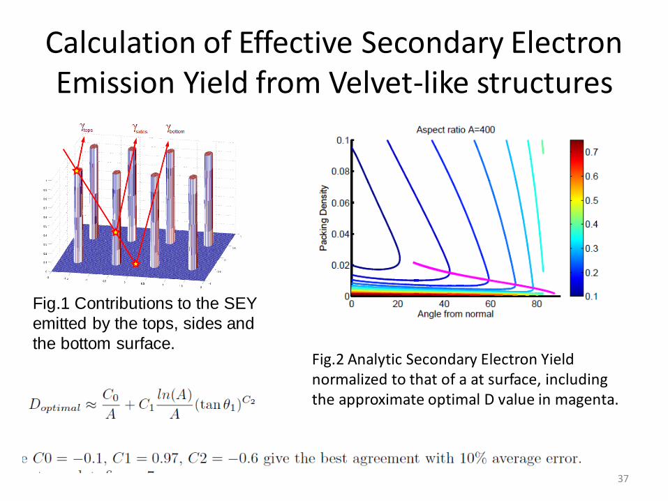
Calculation of Effective Secondary Electron Emission Yield from Velvet-like structures
Fig.2 Analytic Secondary Electron Yield normalized to that of a at surface, including the approximate optimal D value in magenta.
37
Fig.1 Contributions to the SEY
emitted by the tops, sides and
the bottom surface.
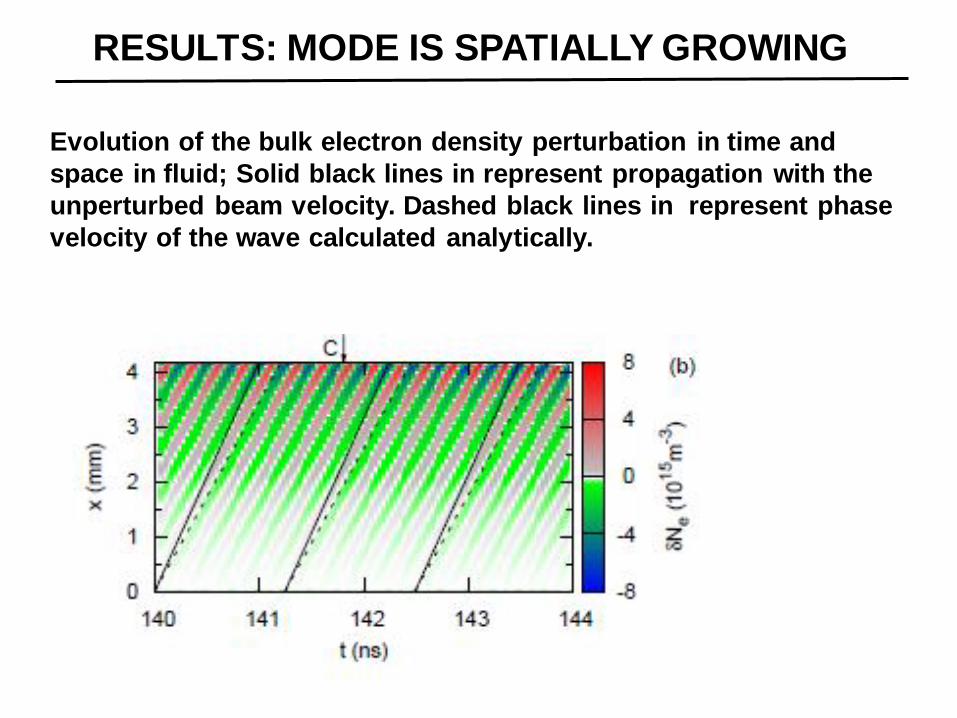
RESULTS: MODE IS SPATIALLY GROWING
Evolution of the bulk electron density perturbation in time and
space in fluid; Solid black lines in represent propagation with the
unperturbed beam velocity. Dashed black lines in represent phase
velocity of the wave calculated analytically.
EFFECT OF COLLISIONS ON THE TWO-STREAM INSTABILITY
IN A FINITE LENGTH PLASMA
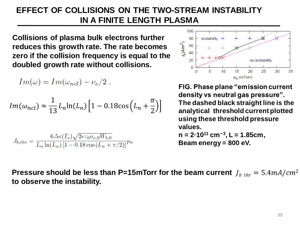
Collisions of plasma bulk electrons further
reduces this growth rate. The rate becomes
zero if the collision frequency is equal to the
doubled growth rate without collisions.
39
FIG. Phase plane “emission current
density vs neutral gas pressure”.
The dashed black straight line is the
analytical threshold current plotted
using these threshold pressure
values.
n = 2·1011 cm−3, L = 1.85cm,
Beam energy = 800 eV.
Pressure should be less than P=15mTorr for the beam current
to observe the instability.
IMPROVEMENTS IN EDIPIC CODE
40
• EDIPIC code - Electrostatic Direct Implicit Particle-In-Cell code
includes:
• Implicit Poisson solver
• Null collision algorithm for anisotropic elastic and inelastic
collisions, electron-electron collisions, EVDF diagnostics,
wave spectrum diagnostics, wall electron emissions
• Improvements:
• Magnetic field at an arbitrary angle to walls
• Full collision algorithm
• External circuit
PRELIMINARY RESULTS OF SPOKE-
DRIVING EXPERIMENTS
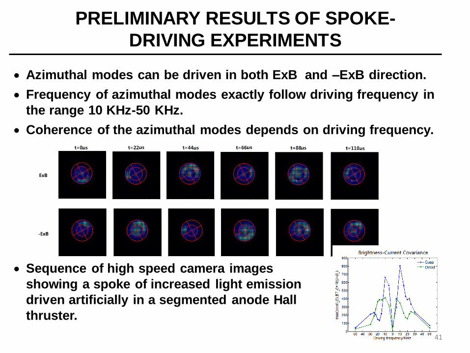
Azimuthal modes can be driven in both ExB and –ExB direction.
Frequency of azimuthal modes exactly follow driving frequency in
the range 10 KHz-50 KHz.
Coherence of the azimuthal modes depends on driving frequency.
Sequence of high speed camera images
showing a spoke of increased light emission
driven artificially in a segmented anode Hall
thruster.
41
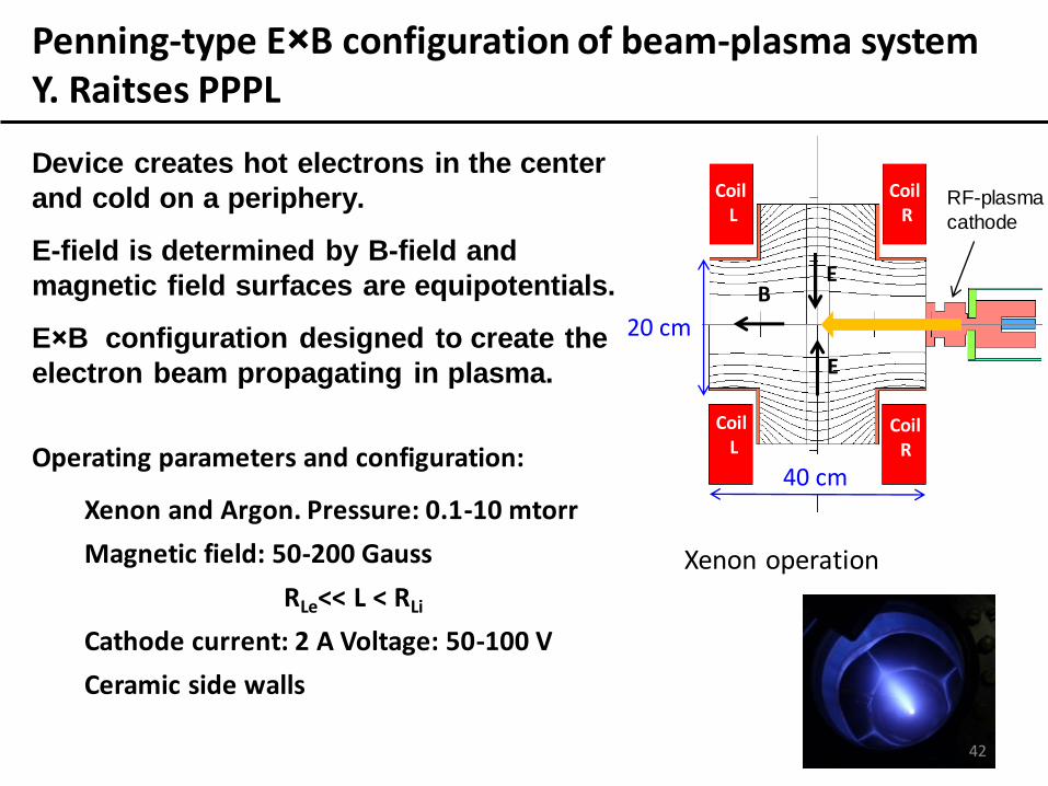
Operating parameters and configuration:
Xenon and Argon. Pressure: 0.1-10 mtorr
Magnetic field: 50-200 Gauss
RLe<< L < RLi
Cathode current: 2 A Voltage: 50-100 V
Ceramic side walls
Axis
RF-plasma
cathode
E
Coil L
Coil R
B
Axis
Coil L
Coil R
E
20 cm
40 cm
Xenon operation
42
Penning-type E×B configuration of beam-plasma system Y. Raitses PPPL
Device creates hot electrons in the center
and cold on a periphery.
E-field is determined by B-field and
magnetic field surfaces are equipotentials.
E×B configuration designed to create the
electron beam propagating in plasma.
Related Documents