materials Article Electromagnetic Wave Shielding Properties of Amorphous Metallic Fiber-Reinforced High-Strength Concrete Using Waveguides Sangkyu Lee 1 , Gyuyong Kim 1, * , Hongseop Kim 2 , Minjae Son 1 , Yaechan Lee 1 , Yoonseon Choi 3 , Jongmyung Woo 3 and Jeongsoo Nam 1 Citation: Lee, S.; Kim, G.; Kim, H.; Son, M.; Lee, Y.; Choi, Y.; Woo, J.; Nam, J. Electromagnetic Wave Shielding Properties of Amorphous Metallic Fiber-Reinforced High-Strength Concrete Using Waveguides. Materials 2021, 14, 7052. https://doi.org/10.3390/ma14227052 Academic Editor: Karim Benzarti Received: 19 October 2021 Accepted: 18 November 2021 Published: 20 November 2021 Publisher’s Note: MDPI stays neutral with regard to jurisdictional claims in published maps and institutional affil- iations. Copyright: © 2021 by the authors. Licensee MDPI, Basel, Switzerland. This article is an open access article distributed under the terms and conditions of the Creative Commons Attribution (CC BY) license (https:// creativecommons.org/licenses/by/ 4.0/). 1 Department of Architectural Engineering, Chungnam National University, 99 Daehak-ro, Yuseong-gu, Daejeon 34134, Korea; [email protected] (S.L.); [email protected] (M.S.); [email protected] (Y.L.); [email protected] (J.N.) 2 Building Safety Research Center, Department of Living and Built Environment Research, Korea Institute of Civil Engineering and Building Technology, 283, Goyang-daero, Ilsanseo-gu, Goyang-si 10223, Korea; [email protected] 3 Department of Radio and Information Communications Engineering, Chungnam National University, 99 Daehak-ro, Yuseong-gu, Daejeon 34134, Korea; [email protected] (Y.C.); [email protected] (J.W.) * Correspondence: [email protected]; Tel.: +82-42-821-5623 Abstract: In this study, high-strength concrete containing hooked-end steel or amorphous metallic fibers was fabricated, and the electrical conductivity and electromagnetic shielding effectiveness were evaluated after 28 and 208 days based on considerations of the influences of the moisture content. Amorphous metallic fibers, which have the same length and length/equivalent diameter ratio as hooked-end steel fibers, were favored for the formation of a conductive network because they can be added in large quantities owing to their low densities. These fibers have a large specific surface area as thin plates. The electromagnetic shielding effectiveness clearly improved as the electrical conductivity increased, and it can be expected that the shielding effectiveness will approach the saturation level when the fiber volume fraction of amorphous metallic fibers exceeds 0.5 vol.%. Meanwhile, it is necessary to reduce the amount of moisture to conservatively evaluate the electromagnetic shielding performance. In particular, when 0.5 vol.% of amorphous metallic fibers was added, a shielding effectiveness of >80 dB (based on a thickness of 300 mm) was achieved at a low moisture content after 208 days. Similar to the electrical conductivity, excellent shielding effectiveness can be expected from amorphous metallic fibers at low contents compared to that provided by hooked-end steel fibers. Keywords: electromagnetic wave; amorphous metallic fiber; shielding effectiveness; waveguide 1. Introduction The rapid development of information and communication technology has increased the use of electronic devices, thereby causing electromagnetic wave pollution [1–3]. In recent years, smart city infrastructure has been constructed worldwide based on various information and communication technologies. One of the key elements required for the operation of a smart city is platform operation via the integrated use and management of data. This implies that the scale of risks in smart cities may differ from that in the existing cities if electromagnetic interference disrupts the operations of various electronic and communication systems. Electromagnetic waves may cause the malfunction of electronic devices and can be used for network hacking or as military weapons (e.g., electromagnetic pulses (EMP)) to neutralize major networks of the enemy [4–7]. It was also reported that long-term exposure to electromagnetic waves can have a harmful impact on human health [8–10]. In this regard, research on construction materials with shielding performance is required. Materials 2021, 14, 7052. https://doi.org/10.3390/ma14227052 https://www.mdpi.com/journal/materials

Welcome message from author
This document is posted to help you gain knowledge. Please leave a comment to let me know what you think about it! Share it to your friends and learn new things together.
Transcript
materials
Article
Electromagnetic Wave Shielding Properties of AmorphousMetallic Fiber-Reinforced High-Strength ConcreteUsing Waveguides
Sangkyu Lee 1 , Gyuyong Kim 1,* , Hongseop Kim 2, Minjae Son 1, Yaechan Lee 1, Yoonseon Choi 3,Jongmyung Woo 3 and Jeongsoo Nam 1
Citation: Lee, S.; Kim, G.; Kim, H.;
Son, M.; Lee, Y.; Choi, Y.; Woo, J.;
Nam, J. Electromagnetic Wave
Shielding Properties of Amorphous
Metallic Fiber-Reinforced
High-Strength Concrete Using
Waveguides. Materials 2021, 14, 7052.
https://doi.org/10.3390/ma14227052
Academic Editor: Karim Benzarti
Received: 19 October 2021
Accepted: 18 November 2021
Published: 20 November 2021
Publisher’s Note: MDPI stays neutral
with regard to jurisdictional claims in
published maps and institutional affil-
iations.
Copyright: © 2021 by the authors.
Licensee MDPI, Basel, Switzerland.
This article is an open access article
distributed under the terms and
conditions of the Creative Commons
Attribution (CC BY) license (https://
creativecommons.org/licenses/by/
4.0/).
1 Department of Architectural Engineering, Chungnam National University, 99 Daehak-ro, Yuseong-gu,Daejeon 34134, Korea; [email protected] (S.L.); [email protected] (M.S.); [email protected] (Y.L.);[email protected] (J.N.)
2 Building Safety Research Center, Department of Living and Built Environment Research, Korea Institute ofCivil Engineering and Building Technology, 283, Goyang-daero, Ilsanseo-gu, Goyang-si 10223, Korea;[email protected]
3 Department of Radio and Information Communications Engineering, Chungnam National University, 99Daehak-ro, Yuseong-gu, Daejeon 34134, Korea; [email protected] (Y.C.); [email protected] (J.W.)
* Correspondence: [email protected]; Tel.: +82-42-821-5623
Abstract: In this study, high-strength concrete containing hooked-end steel or amorphous metallicfibers was fabricated, and the electrical conductivity and electromagnetic shielding effectiveness wereevaluated after 28 and 208 days based on considerations of the influences of the moisture content.Amorphous metallic fibers, which have the same length and length/equivalent diameter ratio ashooked-end steel fibers, were favored for the formation of a conductive network because they can beadded in large quantities owing to their low densities. These fibers have a large specific surface area asthin plates. The electromagnetic shielding effectiveness clearly improved as the electrical conductivityincreased, and it can be expected that the shielding effectiveness will approach the saturation levelwhen the fiber volume fraction of amorphous metallic fibers exceeds 0.5 vol.%. Meanwhile, it isnecessary to reduce the amount of moisture to conservatively evaluate the electromagnetic shieldingperformance. In particular, when 0.5 vol.% of amorphous metallic fibers was added, a shieldingeffectiveness of >80 dB (based on a thickness of 300 mm) was achieved at a low moisture content after208 days. Similar to the electrical conductivity, excellent shielding effectiveness can be expected fromamorphous metallic fibers at low contents compared to that provided by hooked-end steel fibers.
Keywords: electromagnetic wave; amorphous metallic fiber; shielding effectiveness; waveguide
1. Introduction
The rapid development of information and communication technology has increasedthe use of electronic devices, thereby causing electromagnetic wave pollution [1–3]. Inrecent years, smart city infrastructure has been constructed worldwide based on variousinformation and communication technologies. One of the key elements required for theoperation of a smart city is platform operation via the integrated use and managementof data. This implies that the scale of risks in smart cities may differ from that in theexisting cities if electromagnetic interference disrupts the operations of various electronicand communication systems.
Electromagnetic waves may cause the malfunction of electronic devices and can beused for network hacking or as military weapons (e.g., electromagnetic pulses (EMP)) toneutralize major networks of the enemy [4–7]. It was also reported that long-term exposureto electromagnetic waves can have a harmful impact on human health [8–10]. In this regard,research on construction materials with shielding performance is required.
Materials 2021, 14, 7052. https://doi.org/10.3390/ma14227052 https://www.mdpi.com/journal/materials
Materials 2021, 14, 7052 2 of 16
Cement-based composites, which are commonly used construction materials, havesome conductivity owing to ionic conduction [11], but it is difficult to expect sufficientshielding performance because their electrical conductivity is low. Therefore, the shield-ing effectiveness can be improved by increasing the electrical conductivity. This can beachieved by adding conductive materials that decrease the intensities of electromagneticwaves [3,11,12]. Accordingly, studies have been conducted to secure the electrical conduc-tivity and electromagnetic shielding effectiveness by adding various conductive materials,such as metal fibers, carbon fibers, and carbon nanotubes (CNTs), into concrete.
Many studies have been conducted on carbon-based materials, such as CNTs andgraphene, as mixing materials for electromagnetic wave shielding owing to their largespecific surface area, low density, and excellent mechanical and electrical properties, butthey have shortcomings, such as high production cost and low dispersibility [13–15]. Inthe case of metal materials, highly conductive silver, copper, nickel powder, and steel slagwere used in the early days of research, but had weaknesses, such as high price, corrosion,increased load, and decreased mechanical strength [2,11,16,17]. To address these problems,studies have been conducted to secure a conductive network using metal fibers with ahigh aspect ratio [11,18–20]. In the case of typical steel fibers, however, their heavy weightstill increases the self-weight of the structure, but their actual application is difficult owingto the corrosion problem [21,22]. Their small specific surface area and high density alsomake it difficult to construct continuous conduction paths, and the complex manufacturingprocesses, such as casting and hot and cold rolling, are not favorable in terms of carbondioxide emissions [23].
As described, carbon materials, such as CNTs and graphene, have been researched asmajor mixing materials for providing electromagnetic performance; despite their shortcom-ings, they exhibit excellent physical properties compared to the existing metal materials.However, only a few studies have been conducted on metal materials, such as steel fibers.Therefore, this study has focused on amorphous metallic fibers that can complement theshortcomings of typical steel fibers.
Given that amorphous metallic fibers have a lower density than typical steel fibers,they can be secured in larger quantities at the same content and have excellent corrosionresistance [24–26]. They can also be favorable for forming a conductive network becausethey have a large specific surface area as thin plates with a rough surface. In addition,amorphous metallic fibers can reduce carbon dioxide emissions by around 20% as theprocess used to produce them is simplified compared with typical steel fibers [23]. Previousstudies related to amorphous metallic fiber-reinforced concrete, however, were mostlyfocused on mechanical properties and durability [23–30]. Furthermore, there are fewstudies related to special physical impacts, such as electromagnetic properties.
Therefore, in this study, hooked-end steel fibers that have been extensively usedas construction materials were set as the comparison group so that the electromagneticshielding effectiveness of amorphous metallic fibers could be compared and evaluated.High-strength concrete containing hooked-end steel or amorphous metallic fibers wasthen fabricated, and the electrical conductivity and electromagnetic shielding effectivenesswere evaluated after 28 and 208 days based on considerations of the influences of moisturecontent. The electrical conductivity was measured using a digital multimeter, and theelectromagnetic shielding effectiveness was measured using waveguides. The effects of thecontent and specific surface area of fibers on the electrical conductivity and electromag-netic shielding effectiveness were examined, and the relationship between the electricalconductivity and electromagnetic shielding effectiveness was analyzed within the scope ofthis study.
2. Experimental Design and Method2.1. Materials
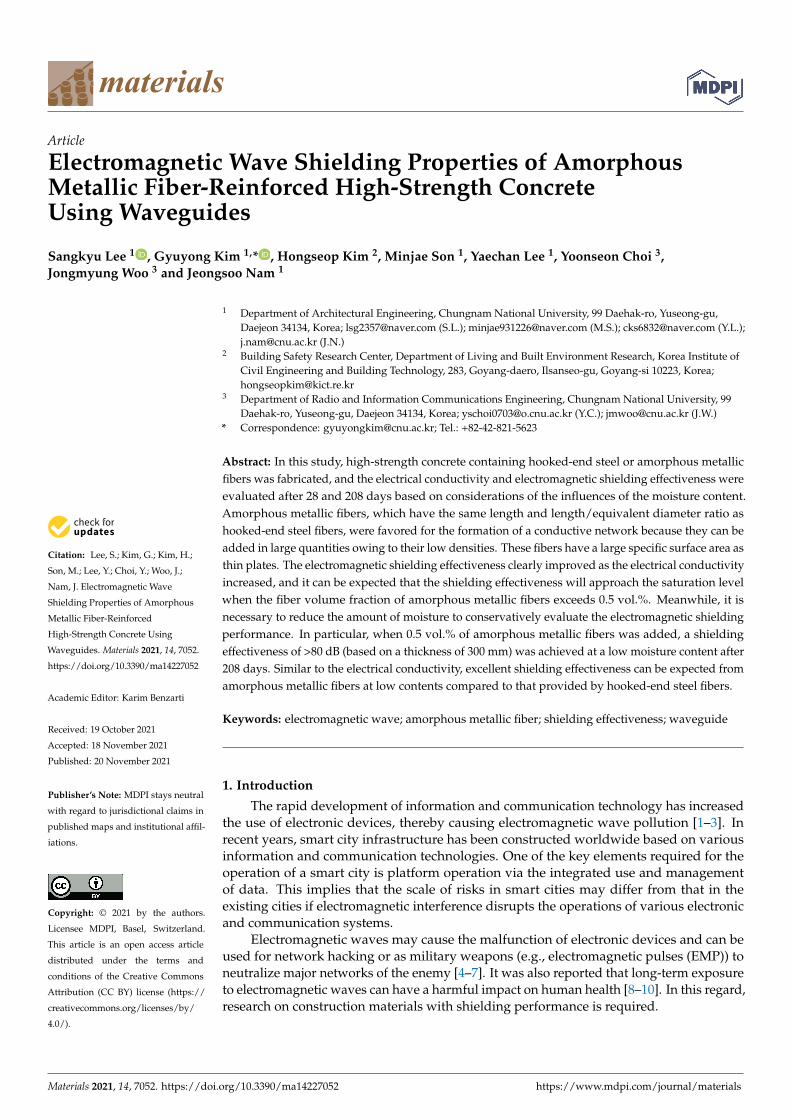
Table 1 and Figure 1 show the physical properties and geometry of the fibers used.Polypropylene fibers are cylindrical with a length of 15 mm, diameter of 20 µm, density of
Materials 2021, 14, 7052 3 of 16
0.91 g/cm3, and a melting point of 170 C. Amorphous metallic fibers have a thin plateshape with a rough surface and they have a length of 30 mm, width of 1.6 mm, thickness of29 µm, density of 7.2 g/cm3, tensile strength of 1400 MPa, and a specific surface area of9.6 m2/kg. Hooked-end steel fibers are cylindrical with both ends bent in the shape of ahook. They have a length of 30 mm, diameter of 0.25 mm, density of 7.85 g/cm3, tensilestrength of 1140 MPa, and a specific surface area of 1.0 m2/kg.
Table 1. Physical properties of the used fibers.
Mechanical Properties
Length: 15 mm, diameter: 20 µm, density: 0.91 g/cm3, melting point: 170 CLength: 30 mm, width: 1.6 mm, thickness: 29 µm, density: 7.2 g/cm3, tensile strength: 1400 MPa,specific surface area: 9.6 m2/kgLength: 30 mm, diameter: 0.25 mm, density: 7.85 g/cm3, tensile strength: 1140 MPa, specificsurface area: 1.0 m2/kg
Materials 2021, 14, x FOR PEER REVIEW 3 of 17
2. Experimental Design and Method 2.1. Materials
Table 1 and Figure 1 show the physical properties and geometry of the fibers used. Polypropylene fibers are cylindrical with a length of 15 mm, diameter of 20 µm, density of 0.91 g/cm3, and a melting point of 170 °C. Amorphous metallic fibers have a thin plate shape with a rough surface and they have a length of 30 mm, width of 1.6 mm, thickness of 29 µm, density of 7.2 g/cm3, tensile strength of 1400 MPa, and a specific surface area of 9.6 m2/kg. Hooked-end steel fibers are cylindrical with both ends bent in the shape of a hook. They have a length of 30 mm, diameter of 0.25 mm, density of 7.85 g/cm3, tensile strength of 1140 MPa, and a specific surface area of 1.0 m2/kg.
Table 2 shows the physical properties of the materials used. Cement (ordinary Port-land cement, density: 3150 kg/m3, fineness: 320 m2/kg), silica fume (density: 2500 kg/m3, fineness: 20,000 m2/kg), and ground granulated blast-furnace slag (density: 2500 kg/m3, fineness: 600 m2/kg) were used as a binder. Crushed granitic aggregate (maximum size: 20 mm, density: 2700 kg/m3, absorption: 0.9%) was used as coarse aggregate, and river sand (density: 2650 kg/m3, absorption: 1%, fineness modulus: 2.6) as fine aggregate. Poly-carboxylic acid-type superplasticizer was used as a water-reducing agent.
Table 1. Physical properties of the used fibers.
Mechanical Properties
Length: 15 mm, diameter: 20 µm, density: 0.91 g/cm3, melting point: 170 °C
Length: 30 mm, width: 1.6 mm, thickness: 29 µm, density: 7.2 g/cm3, tensile strength: 1400 MPa, specific surface area: 9.6 m2/kg
Length: 30 mm, diameter: 0.25 mm, density: 7.85 g/cm3, tensile strength: 1140 MPa, specific surface area: 1.0 m2/kg
(a) Polypropylene fiber (b) Amorphous metallic fiber (c) Hooked-end steel fiber
Figure 1. Types of used fibers.
Table 2. Physical properties of the materials used in this study.
Materials Mechanical Properties
Cement Ordinary Portland cement, density: 3150 kg/m3,
fineness: 320 m2/kg Silica fume Density: 2500 kg/m3, fineness: 20000 m2/kg
Ground granulated blast-fur-nace slag
Density: 2500 kg/m3, fineness: 600 m2/kg
Coarse aggregate Crushed granitic aggregate, maximum size: 20 mm, density: 2700 kg/m3, absorption: 0.9%
Fine aggregate River sand, density: 2650 kg/m3, absorption: 1%,
fineness modulus: 2.6
Figure 1. Types of used fibers.
Table 2 shows the physical properties of the materials used. Cement (ordinary Portlandcement, density: 3150 kg/m3, fineness: 320 m2/kg), silica fume (density: 2500 kg/m3,fineness: 20,000 m2/kg), and ground granulated blast-furnace slag (density: 2500 kg/m3,fineness: 600 m2/kg) were used as a binder. Crushed granitic aggregate (maximum size:20 mm, density: 2700 kg/m3, absorption: 0.9%) was used as coarse aggregate, and riversand (density: 2650 kg/m3, absorption: 1%, fineness modulus: 2.6) as fine aggregate.Polycarboxylic acid-type superplasticizer was used as a water-reducing agent.
Table 2. Physical properties of the materials used in this study.
Materials Mechanical Properties
Cement Ordinary Portland cement, density:3150 kg/m3, fineness: 320 m2/kg
Silica fume Density: 2500 kg/m3, fineness: 20,000 m2/kgGround granulated blast-furnace slag Density: 2500 kg/m3, fineness: 600 m2/kg
Coarse aggregate Crushed granitic aggregate, maximum size:20 mm, density: 2700 kg/m3, absorption: 0.9%
Fine aggregate River sand, density: 2650 kg/m3, absorption:1%, fineness modulus: 2.6
Super plasticizer Polycarboxylic acid type
2.2. Experimental Plan and Mixture Proportions
Table 3 shows the experimental plan. In previous studies, fire-resistance performancewas evaluated to utilize amorphous metallic fiber-reinforced concrete as a multifunctionalmaterial, and this property was linked with the specimen levels tested in this study [27,28].The specimens had six levels, and 0.15 vol.% of polypropylene fibers was added. Specifi-cally, 0.3 and 0.5 vol.% were added for hooked-end steel fibers and 0.1, 0.3, and 0.5 vol.%for amorphous metallic fibers. The compressive strength, flexural strength, electrical con-
Materials 2021, 14, 7052 4 of 16
ductivity, and electromagnetic shielding effectiveness were evaluated, and the results werecompared and analyzed according to the fiber type and content.
Table 3. Experimental plan.
Identity 1 Fiber Type and Volume FractionEvaluation ItemsPP HS AM
PP0.15
0.15
- -Compressive strength (MPa)
Flexural strength (MPa)Electrical conductivity (S/cm)
Electromagnetic shieldingeffectiveness (dB)
PP0.15HS0.3 0.3 -PP0.15HS0.5 0.5 -PP0.15AM0.1 - 0.1PP0.15AM0.3 - 0.3PP0.15AM0.5 - 0.5
1 PP: polypropylene fiber, AM: amorphous metallic fiber, HS: Hooked-end steel fiber PP0.15AM0.5: polypropylenefiber (0.15 vol.%) and amorphous metallic fiber (0.5 vol.%)-reinforced high-strength concrete.
Table 4 shows the mixed proportions of fiber-reinforced high-strength concrete. Wa-ter/Binder (W/B) was set to 0.19 and S/a to 0.45 to fabricate high-strength concrete with acompressive strength of approximately 100 MPa. All specimens satisfied the target slumpflow (650 ± 50 mm) and target air content (2 ± 1%).
Table 4. Mix proportions of the fiber-reinforced high-strength concrete.
W/B C/B SF/B GGBS/B S/aFibers (kg)
PolypropyleneFiber
AmorphousMetallic Fiber
Hooked-EndSteel Fiber
0.19 0.7 0.15 0.15 0.45 1.4(0.15 vol.%)
7.2(0.1 vol.%)
21.6(0.3 vol.%)
36.0(0.5 vol.%)
23.6(0.3 vol.%)
39.3(0.5 vol.%)
W: Water, B (C + SF + GGBS): Binder, C: Cement, SF: Silica fume, GGBS: Ground granulated blast-furnace slag, S:Fine aggregate, a (S + G (coarse aggregate)): Total amount of aggregate.
2.3. Preparation of Specimens
Fiber-reinforced high-strength concrete was prepared by adding water and the super-plasticizer after the dry mixing of the aggregates and binders. Fibers were then added andsufficiently mixed, and concrete was poured into specimen molds. The prepared specimenswere first cured in a water tank (20 ± 2C) for 28 days and then under constant temperatureand humidity conditions (temperature: 20 ± 2 C, relative humidity: 60 ± 5%) for 180 days.The moisture content of the specimens was calculated using Equation (1) based on thereport of RILEM committee TC 129 [31]. The results are listed in Table 5.
Wmoisture =Wbe f ore dry − Wa f ter dry
Wbe f ore dry× 100 (1)
where Wmoisture is the moisture content (%), Wbe f ore dry is the weight of the specimen beforedrying (g), and Wa f ter dry is the weight of the dried specimen (g).
Table 5. Moisture content of specimens.
CuringAge
(Days)
Moisture Content (%)
PP0.15 PP0.15HS0.3
PP0.15HS0.5
PP0.15AM0.1
PP0.15AM0.3
PP0.15AM0.5
28 6.0 5.8 5.9 5.9 5.8 5.8208 2.7 2.8 2.7 2.6 2.6 2.7
Materials 2021, 14, 7052 5 of 16
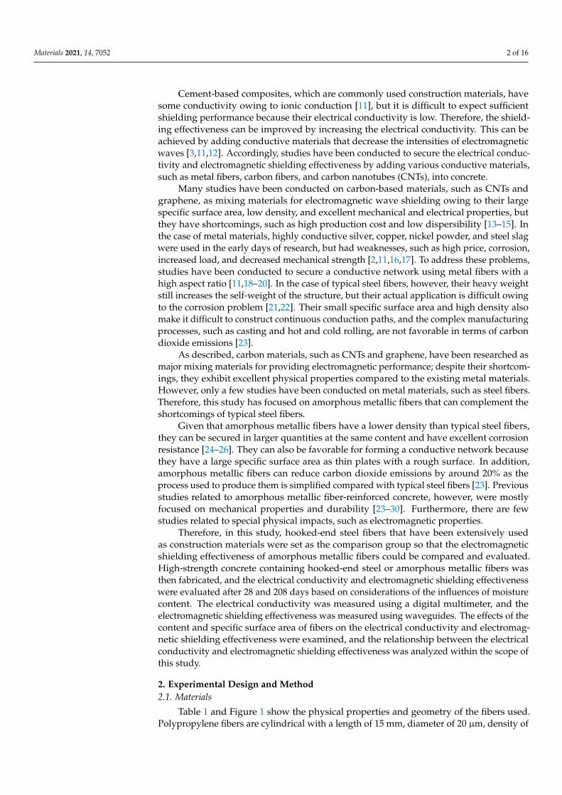
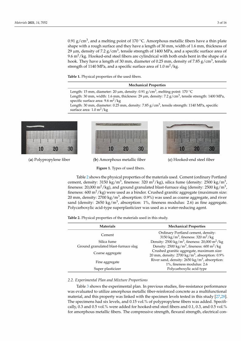
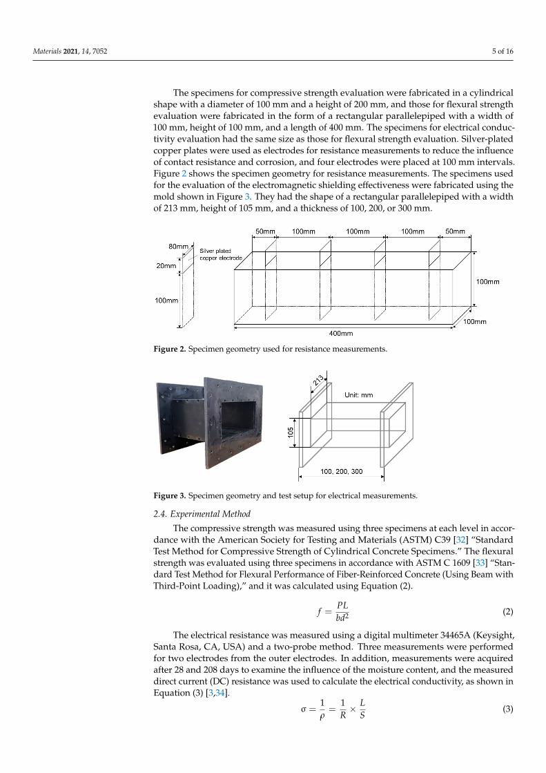
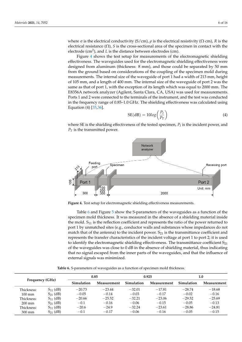
The specimens for compressive strength evaluation were fabricated in a cylindricalshape with a diameter of 100 mm and a height of 200 mm, and those for flexural strengthevaluation were fabricated in the form of a rectangular parallelepiped with a width of100 mm, height of 100 mm, and a length of 400 mm. The specimens for electrical conduc-tivity evaluation had the same size as those for flexural strength evaluation. Silver-platedcopper plates were used as electrodes for resistance measurements to reduce the influenceof contact resistance and corrosion, and four electrodes were placed at 100 mm intervals.Figure 2 shows the specimen geometry for resistance measurements. The specimens usedfor the evaluation of the electromagnetic shielding effectiveness were fabricated using themold shown in Figure 3. They had the shape of a rectangular parallelepiped with a widthof 213 mm, height of 105 mm, and a thickness of 100, 200, or 300 mm.
Materials 2021, 14, x FOR PEER REVIEW 5 of 17
𝑊 = 𝑊 𝑊 𝑊 × 100 (1)
where 𝑊 is the moisture content (%), 𝑊 is the weight of the specimen before drying (g), and 𝑊 is the weight of the dried specimen (g).
Table 5. Moisture content of specimens.
Curing Age
(Days)
Moisture Content (%)
PP0.15 PP0.15 HS0.3
PP0.15 HS0.5
PP0.15 AM0.1
PP0.15 AM0.3
PP0.15 AM0.5
28 6.0 5.8 5.9 5.9 5.8 5.8 208 2.7 2.8 2.7 2.6 2.6 2.7
The specimens for compressive strength evaluation were fabricated in a cylindrical shape with a diameter of 100 mm and a height of 200 mm, and those for flexural strength evaluation were fabricated in the form of a rectangular parallelepiped with a width of 100 mm, height of 100 mm, and a length of 400 mm. The specimens for electrical conductivity evaluation had the same size as those for flexural strength evaluation. Silver-plated cop-per plates were used as electrodes for resistance measurements to reduce the influence of contact resistance and corrosion, and four electrodes were placed at 100 mm intervals. Figure 2 shows the specimen geometry for resistance measurements. The specimens used for the evaluation of the electromagnetic shielding effectiveness were fabricated using the mold shown in Figure 3. They had the shape of a rectangular parallelepiped with a width of 213 mm, height of 105 mm, and a thickness of 100, 200, or 300 mm.
Figure 2. Specimen geometry used for resistance measurements.
Figure 3. Specimen geometry and test setup for electrical measurements.
2.4. Experimental Method
Figure 2. Specimen geometry used for resistance measurements.
Materials 2021, 14, x FOR PEER REVIEW 5 of 17
𝑊 = 𝑊 𝑊 𝑊 × 100 (1)
where 𝑊 is the moisture content (%), 𝑊 is the weight of the specimen before drying (g), and 𝑊 is the weight of the dried specimen (g).
Table 5. Moisture content of specimens.
Curing Age
(Days)
Moisture Content (%)
PP0.15 PP0.15 HS0.3
PP0.15 HS0.5
PP0.15 AM0.1
PP0.15 AM0.3
PP0.15 AM0.5
28 6.0 5.8 5.9 5.9 5.8 5.8 208 2.7 2.8 2.7 2.6 2.6 2.7
The specimens for compressive strength evaluation were fabricated in a cylindrical shape with a diameter of 100 mm and a height of 200 mm, and those for flexural strength evaluation were fabricated in the form of a rectangular parallelepiped with a width of 100 mm, height of 100 mm, and a length of 400 mm. The specimens for electrical conductivity evaluation had the same size as those for flexural strength evaluation. Silver-plated cop-per plates were used as electrodes for resistance measurements to reduce the influence of contact resistance and corrosion, and four electrodes were placed at 100 mm intervals. Figure 2 shows the specimen geometry for resistance measurements. The specimens used for the evaluation of the electromagnetic shielding effectiveness were fabricated using the mold shown in Figure 3. They had the shape of a rectangular parallelepiped with a width of 213 mm, height of 105 mm, and a thickness of 100, 200, or 300 mm.
Figure 2. Specimen geometry used for resistance measurements.
Figure 3. Specimen geometry and test setup for electrical measurements.
2.4. Experimental Method
Figure 3. Specimen geometry and test setup for electrical measurements.
2.4. Experimental Method
The compressive strength was measured using three specimens at each level in accor-dance with the American Society for Testing and Materials (ASTM) C39 [32] “StandardTest Method for Compressive Strength of Cylindrical Concrete Specimens.” The flexuralstrength was evaluated using three specimens in accordance with ASTM C 1609 [33] “Stan-dard Test Method for Flexural Performance of Fiber-Reinforced Concrete (Using Beam withThird-Point Loading),” and it was calculated using Equation (2).
f =PLbd2 (2)
The electrical resistance was measured using a digital multimeter 34465A (Keysight,Santa Rosa, CA, USA) and a two-probe method. Three measurements were performedfor two electrodes from the outer electrodes. In addition, measurements were acquiredafter 28 and 208 days to examine the influence of the moisture content, and the measureddirect current (DC) resistance was used to calculate the electrical conductivity, as shown inEquation (3) [3,34].
σ =1ρ=
1R× L
S(3)
Materials 2021, 14, 7052 6 of 16
where σ is the electrical conductivity (S/cm), ρ is the electrical resistivity (Ω·cm), R is theelectrical resistance (Ω), S is the cross-sectional area of the specimen in contact with theelectrode (cm2), and L is the distance between electrodes (cm).
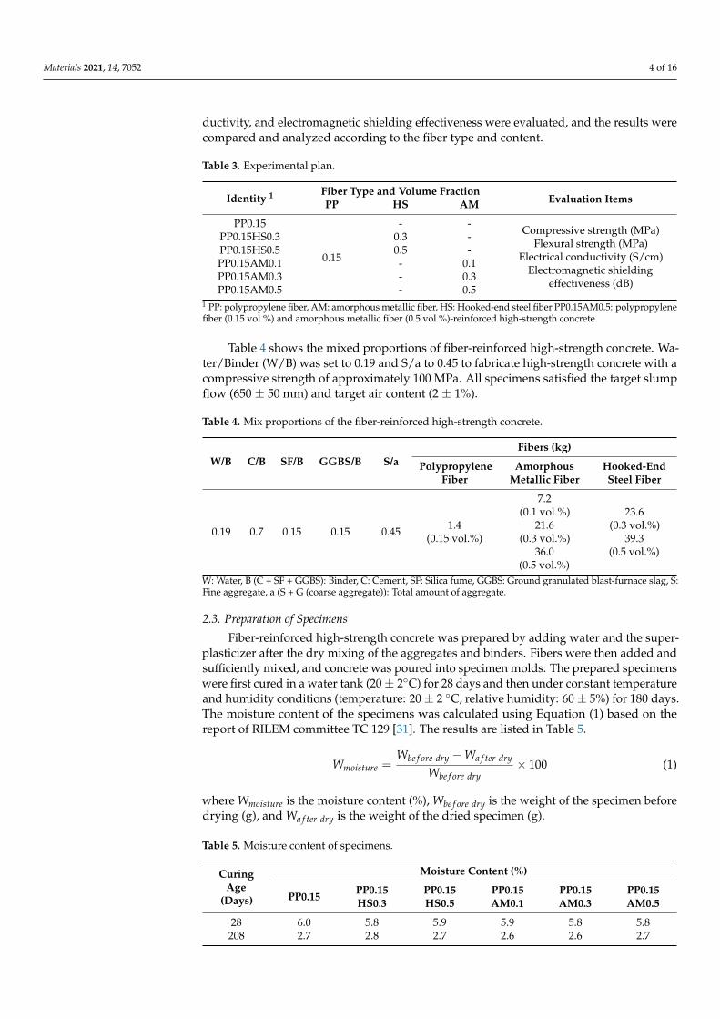
Figure 4 shows the test setup for measurements of the electromagnetic shieldingeffectiveness. The waveguides used for the electromagnetic shielding effectiveness weredesigned from aluminum (thickness: 8 mm), and those could be separated by 50 mmfrom the ground based on considerations of the coupling of the specimen mold duringmeasurements. The internal size of the waveguide of port 1 had a width of 213 mm, heightof 105 mm, and a length of 400 mm. The internal size of the waveguide of port 2 was thesame as that of port 1, with the exception of its length which was equal to 2000 mm. TheE8356A network analyzer (Agilent, Santa Clara, CA, USA) was used for measurements.Ports 1 and 2 were connected to the terminals of the instrument, and the test was conductedin the frequency range of 0.85–1.0 GHz. The shielding effectiveness was calculated usingEquation (4) [35,36].
SE(dB) = 10log(
PIPT
)(4)
where SE is the shielding effectiveness of the tested specimen, PI is the incident power, andPT is the transmitted power.
Materials 2021, 14, x FOR PEER REVIEW 7 of 17
Figure 4. Test setup for electromagnetic shielding effectiveness measurements.
Table 6. S-parameters of waveguides as a function of specimen mold thickness.
Frequency (GHz) 0.85 0.925 1.0
Simula-tion
Measure-ment
Simula-tion
Measure-ment
Simula-tion
Measure-ment
Thick-ness: 100
mm
S11 (dB) −20.73 −23.44 −32.01 −17.81 −28.74 −18.68
S21 (dB) −0.05 −0.14 −0.03 −0.17 −0.02 −0.16
Thick-ness: 200
mm
S11 (dB) −20.66 −25.52 −32.21 −23.06 −29.52 −25.69
S21 (dB) −0.1 −0.16 −0.06 −0.15 −0.05 −0.13
Thick-ness: 300
mm
S11 (dB) −20.6 −24.9 −32.24 −23.61 −28.86 −24.81
S21 (dB) −0.1 −0.17 −0.06 −0.16 −0.05 −0.15
(a) Thickness 100 mm
0.7 0.8 0.9 1.0 1.1 1.2-55-50-45-40-35-30-25-20-15-10-50
Simulation Measurement
S11 [
dB]
Frequency [GHz]0.7 0.8 0.9 1.0 1.1 1.2
-30
-25
-20
-15
-10
-5
0
Simulation Measurement
S21 [
dB]
Frequency [GHz]
Figure 4. Test setup for electromagnetic shielding effectiveness measurements.
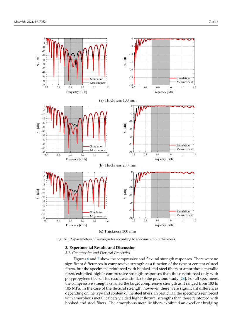
Table 6 and Figure 5 show the S-parameters of the waveguides as a function of thespecimen mold thickness. It was measured in the absence of a shielding material insidethe mold. S11 is the reflection coefficient and represents the ratio of the power returned toport 1 by unmatched sites (e.g., conductor walls and substances whose impedances do notmatch that of the antenna) to the incident power. S21 is the transmittance coefficient andrepresents the transfer characteristics of the incident voltage at port 1 to port 2; it is usedto identify the electromagnetic shielding effectiveness. The transmittance coefficient S21of the waveguides was close to 0 dB in the absence of shielding material, thus indicatingthat no signal escaped from the inner parts of the waveguides, and that the influence ofexternal signals was minimized.
Table 6. S-parameters of waveguides as a function of specimen mold thickness.
Frequency (GHz)0.85 0.925 1.0
Simulation Measurement Simulation Measurement Simulation Measurement
Thickness:100 mm
S11 (dB) −20.73 −23.44 −32.01 −17.81 −28.74 −18.68S21 (dB) −0.05 −0.14 −0.03 −0.17 −0.02 −0.16
Thickness:200 mm
S11 (dB) −20.66 −25.52 −32.21 −23.06 −29.52 −25.69S21 (dB) −0.1 −0.16 −0.06 −0.15 −0.05 −0.13
Thickness:300 mm
S11 (dB) −20.6 −24.9 −32.24 −23.61 −28.86 −24.81S21 (dB) −0.1 −0.17 −0.06 −0.16 −0.05 −0.15
Materials 2021, 14, 7052 7 of 16
Materials 2021, 14, x FOR PEER REVIEW 7 of 17
Figure 4. Test setup for electromagnetic shielding effectiveness measurements.
Table 6. S-parameters of waveguides as a function of specimen mold thickness.
Frequency (GHz) 0.85 0.925 1.0
Simula-tion
Measure-ment
Simula-tion
Measure-ment
Simula-tion
Measure-ment
Thick-ness: 100
mm
S11 (dB) −20.73 −23.44 −32.01 −17.81 −28.74 −18.68
S21 (dB) −0.05 −0.14 −0.03 −0.17 −0.02 −0.16
Thick-ness: 200
mm
S11 (dB) −20.66 −25.52 −32.21 −23.06 −29.52 −25.69
S21 (dB) −0.1 −0.16 −0.06 −0.15 −0.05 −0.13
Thick-ness: 300
mm
S11 (dB) −20.6 −24.9 −32.24 −23.61 −28.86 −24.81
S21 (dB) −0.1 −0.17 −0.06 −0.16 −0.05 −0.15
(a) Thickness 100 mm
0.7 0.8 0.9 1.0 1.1 1.2-55-50-45-40-35-30-25-20-15-10-50
Simulation Measurement
S11 [
dB]
Frequency [GHz]0.7 0.8 0.9 1.0 1.1 1.2
-30
-25
-20
-15
-10
-5
0
Simulation Measurement
S21 [
dB]
Frequency [GHz]Materials 2021, 14, x FOR PEER REVIEW 8 of 17
(b) Thickness 200 mm
(c) Thickness 300 mm
Figure 5. S-parameters of waveguides according to specimen mold thickness.
3. Experimental Results and Discussion 3.1. Compressive and Flexural Properties
Figures 6 and 7 show the compressive and flexural strength responses. There were no significant differences in compressive strength as a function of the type or content of steel fibers, but the specimens reinforced with hooked-end steel fibers or amorphous me-tallic fibers exhibited higher compressive strength responses than those reinforced only with polypropylene fibers. This result was similar to the previous study [28]. For all spec-imens, the compressive strength satisfied the target compressive strength as it ranged from 100 to 105 MPa. In the case of the flexural strength, however, there were significant differences depending on the type and content of the steel fibers. In particular, the speci-mens reinforced with amorphous metallic fibers yielded higher flexural strengths than those reinforced with hooked-end steel fibers. The amorphous metallic fibers exhibited an excellent bridging effect owing to the increased adhesion efficiency with the matrix be-cause they had a larger specific surface area than hooked-end steel fibers, and relatively more fibers were thus added at the same content. Previous studies also mentioned im-provements in flexural and tensile strengths owing to the special geometry and physical properties of amorphous metallic fibers [22,24], and a similar tendency was also observed in this study.
0.7 0.8 0.9 1.0 1.1 1.2-55-50-45-40-35-30-25-20-15-10-50
Simulation Measurement
S11 [
dB]
Frequency [GHz]0.7 0.8 0.9 1.0 1.1 1.2
-30
-25
-20
-15
-10
-5
0
Simulation Measurement
S21 [
dB]
Frequency [GHz]
0.7 0.8 0.9 1.0 1.1 1.2-55-50-45-40-35-30-25-20-15-10-50
Simulation Measurement
S11 [
dB]
Frequency [GHz]0.7 0.8 0.9 1.0 1.1 1.2
-30
-25
-20
-15
-10
-5
0
Simulation Measurement
S21 [
dB]
Frequency [GHz]
Figure 5. S-parameters of waveguides according to specimen mold thickness.
3. Experimental Results and Discussion3.1. Compressive and Flexural Properties
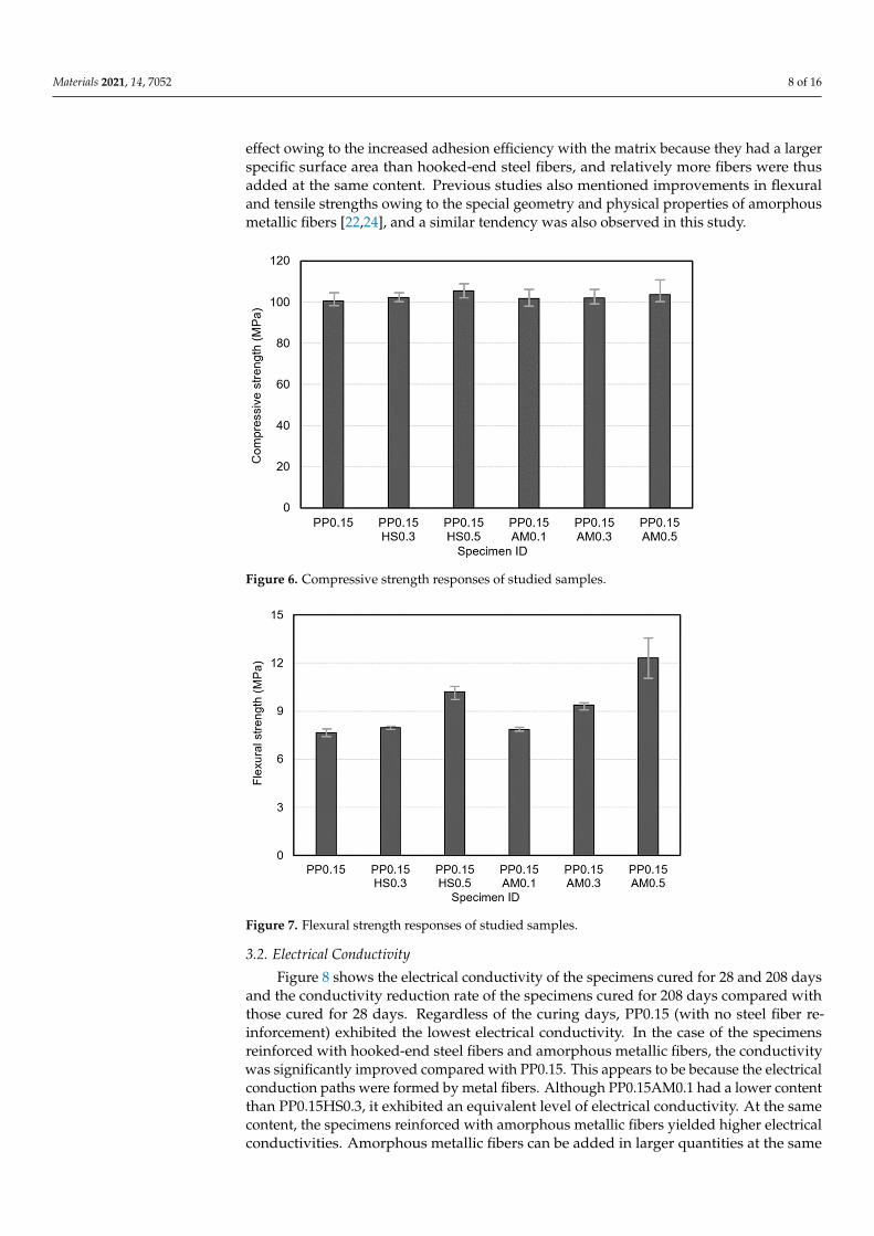
Figures 6 and 7 show the compressive and flexural strength responses. There were nosignificant differences in compressive strength as a function of the type or content of steelfibers, but the specimens reinforced with hooked-end steel fibers or amorphous metallicfibers exhibited higher compressive strength responses than those reinforced only withpolypropylene fibers. This result was similar to the previous study [28]. For all specimens,the compressive strength satisfied the target compressive strength as it ranged from 100 to105 MPa. In the case of the flexural strength, however, there were significant differencesdepending on the type and content of the steel fibers. In particular, the specimens reinforcedwith amorphous metallic fibers yielded higher flexural strengths than those reinforced withhooked-end steel fibers. The amorphous metallic fibers exhibited an excellent bridging
Materials 2021, 14, 7052 8 of 16
effect owing to the increased adhesion efficiency with the matrix because they had a largerspecific surface area than hooked-end steel fibers, and relatively more fibers were thusadded at the same content. Previous studies also mentioned improvements in flexuraland tensile strengths owing to the special geometry and physical properties of amorphousmetallic fibers [22,24], and a similar tendency was also observed in this study.
Materials 2021, 14, x FOR PEER REVIEW 9 of 17
Figure 6. Compressive strength responses of studied samples.
Figure 7. Flexural strength responses of studied samples.
3.2. Electrical Conductivity Figure 8 shows the electrical conductivity of the specimens cured for 28 and 208 days
and the conductivity reduction rate of the specimens cured for 208 days compared with those cured for 28 days. Regardless of the curing days, PP0.15 (with no steel fiber rein-forcement) exhibited the lowest electrical conductivity. In the case of the specimens rein-forced with hooked-end steel fibers and amorphous metallic fibers, the conductivity was significantly improved compared with PP0.15. This appears to be because the electrical conduction paths were formed by metal fibers. Although PP0.15AM0.1 had a lower con-tent than PP0.15HS0.3, it exhibited an equivalent level of electrical conductivity. At the same content, the specimens reinforced with amorphous metallic fibers yielded higher electrical conductivities. Amorphous metallic fibers can be added in larger quantities at the same content because they have thin-plate shapes with large specific surface areas and low densities, even though their lengths are the same as those of the hooked-end steel fibers. Thus, it appears that amorphous metallic fibers achieve an excellent conductive network by forming many current movement paths as they are randomly placed inside
Figure 6. Compressive strength responses of studied samples.
Materials 2021, 14, x FOR PEER REVIEW 9 of 17
Figure 6. Compressive strength responses of studied samples.
Figure 7. Flexural strength responses of studied samples.
3.2. Electrical Conductivity Figure 8 shows the electrical conductivity of the specimens cured for 28 and 208 days
and the conductivity reduction rate of the specimens cured for 208 days compared with those cured for 28 days. Regardless of the curing days, PP0.15 (with no steel fiber rein-forcement) exhibited the lowest electrical conductivity. In the case of the specimens rein-forced with hooked-end steel fibers and amorphous metallic fibers, the conductivity was significantly improved compared with PP0.15. This appears to be because the electrical conduction paths were formed by metal fibers. Although PP0.15AM0.1 had a lower con-tent than PP0.15HS0.3, it exhibited an equivalent level of electrical conductivity. At the same content, the specimens reinforced with amorphous metallic fibers yielded higher electrical conductivities. Amorphous metallic fibers can be added in larger quantities at the same content because they have thin-plate shapes with large specific surface areas and low densities, even though their lengths are the same as those of the hooked-end steel fibers. Thus, it appears that amorphous metallic fibers achieve an excellent conductive network by forming many current movement paths as they are randomly placed inside
Figure 7. Flexural strength responses of studied samples.
3.2. Electrical Conductivity
Figure 8 shows the electrical conductivity of the specimens cured for 28 and 208 daysand the conductivity reduction rate of the specimens cured for 208 days compared withthose cured for 28 days. Regardless of the curing days, PP0.15 (with no steel fiber re-inforcement) exhibited the lowest electrical conductivity. In the case of the specimensreinforced with hooked-end steel fibers and amorphous metallic fibers, the conductivitywas significantly improved compared with PP0.15. This appears to be because the electricalconduction paths were formed by metal fibers. Although PP0.15AM0.1 had a lower contentthan PP0.15HS0.3, it exhibited an equivalent level of electrical conductivity. At the samecontent, the specimens reinforced with amorphous metallic fibers yielded higher electricalconductivities. Amorphous metallic fibers can be added in larger quantities at the same
Materials 2021, 14, 7052 9 of 16
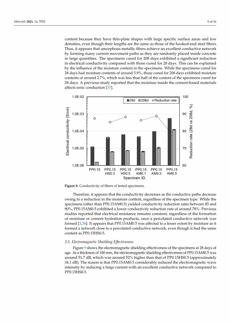
content because they have thin-plate shapes with large specific surface areas and lowdensities, even though their lengths are the same as those of the hooked-end steel fibers.Thus, it appears that amorphous metallic fibers achieve an excellent conductive networkby forming many current movement paths as they are randomly placed inside concretein large quantities. The specimens cured for 208 days exhibited a significant reductionin electrical conductivity compared with those cured for 28 days. This can be explainedby the influence of the moisture content in the specimens. While the specimens cured for28 days had moisture contents of around 5.9%, those cured for 208 days exhibited moisturecontents of around 2.7%, which was less than half of the content of the specimens cured for28 days. A previous study reported that the moisture inside the cement-based materialsaffects ionic conduction [37].
Materials 2021, 14, x FOR PEER REVIEW 10 of 17
concrete in large quantities. The specimens cured for 208 days exhibited a significant re-duction in electrical conductivity compared with those cured for 28 days. This can be ex-plained by the influence of the moisture content in the specimens. While the specimens cured for 28 days had moisture contents of around 5.9%, those cured for 208 days exhib-ited moisture contents of around 2.7%, which was less than half of the content of the spec-imens cured for 28 days. A previous study reported that the moisture inside the cement-based materials affects ionic conduction [37].
Figure 8. Conductivity of fibers of tested specimens.
Therefore, it appears that the conductivity decreases as the conductive paths decrease owing to a reduction in the moisture content, regardless of the specimen type. While the specimens (other than PP0.15AM0.5) yielded conductivity reduction rates between 85 and 90%, PP0.15AM0.5 exhibited a lower conductivity reduction rate of around 78%. Previous studies reported that electrical resistance remains constant, regardless of the formation of moisture or cement hydration products, once a percolated conductive network was formed [3,38]. It appears that PP0.15AM0.5 was affected to a lesser extent by moisture as it formed a network close to a percolated conductive network, even though it had the same content as PP0.15HS0.5.
3.3. Electromagnetic Shielding Effectiveness Figure 9 shows the electromagnetic shielding effectiveness of the specimens at 28
days of age. At a thickness of 100 mm, the electromagnetic shielding effectiveness of PP0.15AM0.5 was around 51.7 dB, which was around 52% higher than that of PP0.15HS0.5 (approximately 34.1 dB). The reason is that PP0.15AM0.5 considerably reduced the elec-tromagnetic wave intensity by inducing a large current with an excellent conductive net-work compared to PP0.15HS0.5.
At a thickness of 200 mm, the overall shielding effectiveness was significantly im-proved compared to that at 100 mm as the electromagnetic wave reflection and absorption losses were considerably increased owing to the increased thickness. The shielding effec-tiveness of PP0.15AM0.5 was around 46% higher than that of PP0.15HS0.5. PP0.15AM0.3 exhibited high shielding effectiveness of around 31%, even though it had a lower content than PP0.15HS0.5. PP0.15AM0.1 and PP0.15HSF0.3 yielded similar shielding effectiveness values equal to 46.1 and 46.6 dB, respectively. Meanwhile, PP0.15 yielded a shielding ef-fectiveness of around 9.2 dB, thus confirming that it is difficult to achieve the expected shielding effectiveness if conductive fibers are not added.
Figure 8. Conductivity of fibers of tested specimens.
Therefore, it appears that the conductivity decreases as the conductive paths decreaseowing to a reduction in the moisture content, regardless of the specimen type. While thespecimens (other than PP0.15AM0.5) yielded conductivity reduction rates between 85 and90%, PP0.15AM0.5 exhibited a lower conductivity reduction rate of around 78%. Previousstudies reported that electrical resistance remains constant, regardless of the formationof moisture or cement hydration products, once a percolated conductive network wasformed [3,38]. It appears that PP0.15AM0.5 was affected to a lesser extent by moisture as itformed a network close to a percolated conductive network, even though it had the samecontent as PP0.15HS0.5.
3.3. Electromagnetic Shielding Effectiveness
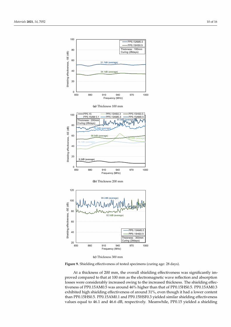
Figure 9 shows the electromagnetic shielding effectiveness of the specimens at 28 days ofage. At a thickness of 100 mm, the electromagnetic shielding effectiveness of PP0.15AM0.5 wasaround 51.7 dB, which was around 52% higher than that of PP0.15HS0.5 (approximately34.1 dB). The reason is that PP0.15AM0.5 considerably reduced the electromagnetic waveintensity by inducing a large current with an excellent conductive network compared toPP0.15HS0.5.
Materials 2021, 14, 7052 10 of 16Materials 2021, 14, x FOR PEER REVIEW 11 of 17
(a) Thickness 100 mm
(b) Thickness 200 mm
(c) Thickness 300 mm
Figure 9. Shielding effectiveness of tested specimens (curing age: 28 days).
Figure 9. Shielding effectiveness of tested specimens (curing age: 28 days).
At a thickness of 200 mm, the overall shielding effectiveness was significantly im-proved compared to that at 100 mm as the electromagnetic wave reflection and absorptionlosses were considerably increased owing to the increased thickness. The shielding effec-tiveness of PP0.15AM0.5 was around 46% higher than that of PP0.15HS0.5. PP0.15AM0.3exhibited high shielding effectiveness of around 31%, even though it had a lower contentthan PP0.15HS0.5. PP0.15AM0.1 and PP0.15HSF0.3 yielded similar shielding effectivenessvalues equal to 46.1 and 46.6 dB, respectively. Meanwhile, PP0.15 yielded a shielding
Materials 2021, 14, 7052 11 of 16
effectiveness of around 9.2 dB, thus confirming that it is difficult to achieve the expectedshielding effectiveness if conductive fibers are not added.
At a thickness of 300 mm, PP0.15AM0.5 exhibited around 21% higher shielding ef-fectiveness than PP0.15HS0.5. As the thickness increased, the difference in the shieldingeffectiveness demonstrated a tendency to decrease as a function of the electrical conduc-tivity difference. Since the specimen used in this study is a composite in which variousmaterials are mixed, resonance may occur at a specific frequency depending on the materialproperties and thickness of the specimen, and reflection may occur at a specific frequency.In particular, when the dB value of PP0.15AM0.5 is viewed as a linear value, it is a verysmall value of about −80dB, which is close to noise. Therefore, fluctuations seem to occurowing to the increase in sensitivity.
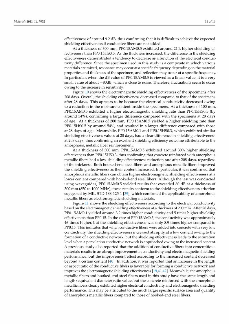
Figure 10 shows the electromagnetic shielding effectiveness of the specimens after208 days. Overall, the shielding effectiveness decreased compared to that of the specimensafter 28 days. This appears to be because the electrical conductivity decreased owingto a reduction in the moisture content inside the specimens. At a thickness of 100 mm,PP0.15AM0.5 exhibited a higher electromagnetic shielding rate than PP0.15HS0.5 (byaround 54%), confirming a larger difference compared with the specimens at 28 daysof age. At a thickness of 200 mm, PP0.15AM0.5 yielded a higher shielding rate thanPP0.15HS0.5 by around 54%, and resulted in a larger difference compared with thoseat 28 days of age. Meanwhile, PP0.15AM0.1 and PP0.15HS0.3, which exhibited similarshielding effectiveness values at 28 days, had a clear difference in shielding effectivenessat 208 days, thus confirming an excellent shielding efficiency outcome attributable to theamorphous, metallic fiber reinforcement.
At a thickness of 300 mm, PP0.15AM0.5 exhibited around 30% higher shieldingeffectiveness than PP0.15HS0.3, thus confirming that concrete reinforced with amorphousmetallic fibers had a low-shielding effectiveness reduction rate after 208 days, regardlessof the thickness. Both hooked-end steel fibers and amorphous metallic fibers improvedthe shielding effectiveness as their content increased. In particular, it was confirmed thatamorphous metallic fibers can obtain higher electromagnetic shielding effectiveness at alower content compared with hooked-end steel fibers. Although the test was conductedusing waveguides, PP0.15AM0.5 yielded results that exceeded 80 dB at a thickness of300 mm (850 to 1000 MHz); these results conform to the shielding effectiveness criterionsuggested by MIL-STD-188-125-1 [39], which confirmed the applicability of amorphousmetallic fibers as electromagnetic shielding materials.
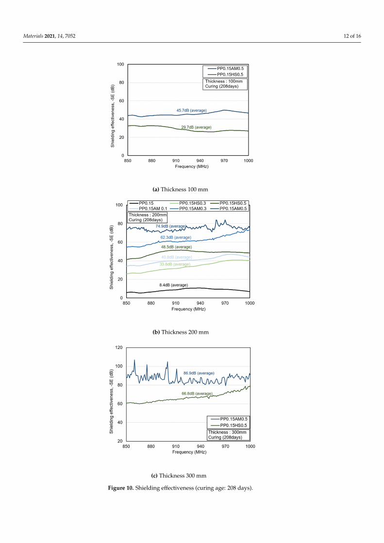
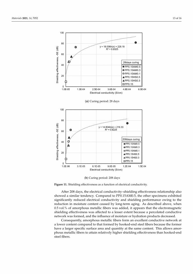
Figure 11 shows the shielding effectiveness according to the electrical conductivitybased on the electromagnetic shielding effectiveness at a thickness of 200 mm. After 28 days,PP0.15AM0.1 yielded around 3.2 times higher conductivity and 5 times higher shieldingeffectiveness than PP0.15. In the case of PP0.15AM0.5, the conductivity was approximately46 times higher, but the shielding effectiveness was only 8.9 times higher compared toPP0.15. This indicates that when conductive fibers were added into concrete with very lowconductivity, the shielding effectiveness increased abruptly at a low content owing to theformation of a conductive network, but the shielding effectiveness leads to the saturationlevel when a percolation conductive network is approached owing to the increased content.A previous study also reported that the addition of conductive fibers into cementitiousmaterials results in an abrupt improvement in conductivity and electromagnetic shieldingperformance, but the improvement effect according to the increased content decreasedbeyond a certain content [40]. In addition, it was reported that an increase in the lengthor aspect ratio of the conductive fibers is favorable for forming a conductive network andimproves the electromagnetic shielding effectiveness [19,41,42]. Meanwhile, the amorphousmetallic fibers and hooked-end steel fibers used in this study have the same length andlength/equivalent diameter ratio value, but the concrete reinforced with the amorphousmetallic fibers clearly exhibited higher electrical conductivity and electromagnetic shieldingperformance. This may be attributed to the much larger specific surface area and quantityof amorphous metallic fibers compared to those of hooked-end steel fibers.
Materials 2021, 14, 7052 12 of 16Materials 2021, 14, x FOR PEER REVIEW 13 of 17
(a) Thickness 100 mm
(b) Thickness 200 mm
(c) Thickness 300 mm
Figure 10. Shielding effectiveness (curing age: 208 days). Figure 10. Shielding effectiveness (curing age: 208 days).
Materials 2021, 14, 7052 13 of 16
Materials 2021, 14, x FOR PEER REVIEW 14 of 17
After 208 days, the electrical conductivity–shielding effectiveness relationship also showed a similar tendency. Compared to PP0.15AM0.5, the other specimens exhibited significantly reduced electrical conductivity and shielding performance owing to the re-duction in moisture content caused by long-term aging. As described above, when 0.5 vol.% of amorphous metallic fibers was added, it appears that the electromagnetic shield-ing effectiveness was affected to a lesser extent because a percolated conductive network was formed, and the influence of moisture or hydration products decreased.
Consequently, amorphous metallic fibers form an excellent conductive network at a lower content compared to that formed by hooked-end steel fibers because the former have a larger specific surface area and quantity at the same content. This allows amor-phous metallic fibers to attain relatively higher shielding effectiveness than hooked-end steel fibers.
(a) Curing period: 28 days
(b) Curing period: 208 days
Figure 11. Shielding effectiveness as a function of electrical conductivity.
4. Conclusions
Figure 11. Shielding effectiveness as a function of electrical conductivity.
After 208 days, the electrical conductivity–shielding effectiveness relationship alsoshowed a similar tendency. Compared to PP0.15AM0.5, the other specimens exhibitedsignificantly reduced electrical conductivity and shielding performance owing to thereduction in moisture content caused by long-term aging. As described above, when0.5 vol.% of amorphous metallic fibers was added, it appears that the electromagneticshielding effectiveness was affected to a lesser extent because a percolated conductivenetwork was formed, and the influence of moisture or hydration products decreased.
Consequently, amorphous metallic fibers form an excellent conductive network ata lower content compared to that formed by hooked-end steel fibers because the formerhave a larger specific surface area and quantity at the same content. This allows amor-phous metallic fibers to attain relatively higher shielding effectiveness than hooked-endsteel fibers.
Materials 2021, 14, 7052 14 of 16
4. Conclusions
In this study, the electromagnetic shielding effectiveness of amorphous metallic fiber-reinforced, high-strength concrete was evaluated using waveguides. The inferred conclu-sions were as follows:
1. Regardless of the reinforcing fibers, the flexural strength of fiber-reinforced, high-strength concrete was improved as the content of fibers increased owing to an im-provement in the bridging effect. In particular, amorphous metallic fibers significantlyimproved the flexural strength compared to hooked-end steel fibers owing to theimproved adhesion efficiency with the matrix. This was attributed to their largersurface area as thin plates and the fact that relatively more fibers were added at thesame content.
2. Amorphous metallic fibers are favorable for forming a conductive network becausethey can be added in large quantities owing to their low density, and have a largespecific surface area as thin plates, even though they have the same length andlength/equivalent diameter ratio value as hooked-end steel fibers. Therefore, it canbe said that amorphous metallic fibers form a percolation conductive network at alower content compared with hooked-end steel fibers.
3. The addition of metal fibers improved the electromagnetic shielding effectiveness(frequency range: 850–1000 Hz) owing to an improvement in electrical conductivity.Additionally, the shielding effectiveness of more than 80 dB (based on a thickness of300 mm) was observed at a low moisture content after 208 days when amorphousmetallic fibers (0.5 vol.%) were added. In addition, similar to the electrical conduc-tivity, the efficient shielding effectiveness can be expected from amorphous metallicfibers at a low content compared with hooked-end steel fibers.
4. Regardless of the age, the electromagnetic shielding effectiveness clearly improvedas the electrical conductivity increased, and it can be expected that the shieldingeffectiveness will approach the saturation level when the fiber volume fraction ofamorphous metallic fibers exceeds 0.5 vol.%. Meanwhile, given that the electricalconductivity and electromagnetic shielding effectiveness decrease owing to a reduc-tion in the moisture content of the specimen, it is necessary to reduce the amount ofmoisture to conservatively evaluate the electromagnetic shielding performance.
In future research, the effects of the addition of amorphous metallic fibers will be ana-lyzed in detail by identifying the percolation threshold of the electrical conductivity basedon the preparation of amorphous metallic fiber-reinforced cement composites with variouslengths and high contents, and by evaluating the electromagnetic shielding performanceusing a shielding room. In addition, it is necessary to analyze the electrical conductivityand electromagnetic shielding performance of steel fiber-reinforced cement composites byconstructing a database based on a large number of tests.
Author Contributions: Conceptualization, S.L., G.K. and J.N.; methodology, S.L., Y.L., Y.C. and J.W.;validation, S.L., G.K., J.N. and J.W.; formal analysis, S.L., H.K., M.S. and Y.C.; investigation, S.L., Y.L.and Y.C.; resources, S.L., G.K., J.N., J.W.; data curation, S.L., Y.L. and Y.C.; writing—original draftpreparation, S.L., G.K., J.N., Y.L., Y.C. and J.W.; writing—review and editing, S.L., G.K., J.N., J.W., M.S.and H.K.; visualization, S.L., Y.L. and Y.C.; supervision, G.K., J.N. and J.W.; project administration,G.K. and J.N.; funding acquisition, G.K., J.N. and J.W. All authors have read and agreed to thepublished version of the manuscript.
Funding: This work was supported by the Korea Agency for Infrastructure Technology Advancement(KAIA) grant funded by the Ministry of Land, Infrastructure and Transport (Grant 21SCIP-B146646-04).
Institutional Review Board Statement: Not applicable.
Informed Consent Statement: Not applicable.
Conflicts of Interest: The authors declare no conflict of interest.
Materials 2021, 14, 7052 15 of 16
References1. Das, N.C.; Khastgir, D.; Chaki, T.K.; Chakraborty, A. Electromagnetic interference shielding effectiveness of carbon black and
carbon fibre filled EVA and NR based composites. Compos. Part A 2000, 31, 1069–1081. [CrossRef]2. Kim, B.R.; Lee, H.K.; Park, S.H.; Kim, H.K. Electromagnetic interference shielding characteristics and shielding effectiveness of
polyaniline-coated films. Thin Solid Film 2011, 519, 3492–3496. [CrossRef]3. Yoon, H.N.; Jang, D.; Lee, H.K.; Nam, I.W. Influence of carbon fiber additions on the electromagnetic wave shielding characteristics
of CNT-cement composites. Constr. Build. Mater. 2021, 269, 121238. [CrossRef]4. Chung, D.D.L. Carbon materials for structural self-sensing, electromagnetic shielding and thermal interfacing. Carbon 2012, 50,
3342–3353. [CrossRef]5. Binggeli, C.; Rickli, H.; Ammann, P.; Brunckhorst, C.; Hufschmid, U.; Luechinger, R.; Duru, F. Induction ovens and electromagnetic
interference: What is the risk for patients with implantable cardioverter defibrillators? J. Cardiov. Electrophys. 2005, 16, 399–401.[CrossRef] [PubMed]
6. Radasky, W.A.; Baum, C.E.; Wik, M.W. Introduction to the special issue on high-power electromagnetics (HPEM) and intentionalelectromagnetic interference (IEMI). IEEE Trans. Electromagn. Compat. 2004, 46, 314–321. [CrossRef]
7. Lemer, E.J. Military electronics: Electromagnetic pulses: Potential crippler: Three bombs, exploded in space over the US, couldblack out the nation, wipe out communications, and make computers useless. IEEE Spectr. 1981, 18, 41–46. [CrossRef]
8. Beall, C.; Delzell, E.; Cole, P.; Brill, I. Brain tumors among electronics industry workers. Epidemiology 1996, 7, 125–130. [CrossRef]9. Grayson, J.K. Radiation exposure, socioeconomic status, and brain tumor risk in the US Air Force: A nested case-control study.
Am. J. Epidemiol. 1996, 143, 480–486. [CrossRef]10. Szmigielski, S. Cancer morbidity in subjects occupationally exposed to high frequency (radiofrequency and microwave) electro-
magnetic radiation. Sci. Total Environ. 1996, 180, 9–17. [CrossRef]11. Wen, S.; Chung, D.D.L. Electromagnetic interference shielding reaching 70 dB in steel fiber cement. Cem. Concr. Res. 2004, 34,
329–332. [CrossRef]12. Wanasinghe, D.; Aslani, F.; Ma, G.; Habibi, D. Advancements in electromagnetic interference shielding cementitious composites.
Const. Build. Mater. 2020, 231, 117116. [CrossRef]13. Li, Y.H.; Lue, J.T. Dielectric constants of single-wall carbon nanotubes at various frequencies. J. Nanosci. Nanotechnol. 2007, 7,
3185–3188. [CrossRef] [PubMed]14. Khushnood, R.A.; Ahmad, S.; Savi, P.; Tulliani, J.M.; Giorcelli, M.; Ferro, G.A. Improvement in electromagnetic interference
shielding effectiveness of cement composites using carbonaceous nano/micro inerts. Const. Build. Mater. 2015, 85, 208–216.[CrossRef]
15. Ma, P.C.; Siddiqui, N.A.; Marom, G.; Kim, J.K. Dispersion and functionalization of carbon nanotubes for polymer-basednanocomposites: A review. Compos. Part A Appl. Sci. Manuf. 2010, 41, 1345–1367. [CrossRef]
16. Guan, H.; Liu, S.; Duan, Y.; Cheng, J. Cement based electromagnetic shielding and absorbing building materials. Cem. Concr.Compos. 2006, 28, 468–474. [CrossRef]
17. Singh, A.P.; Gupta, B.K.; Mishra, M.; Chandra, A.; Mathur, R.B.; Dhawan, S.K. Multiwalled carbon nanotube/cement compositeswith exceptional electromagnetic interference shielding properties. Carbon 2013, 56, 86–96. [CrossRef]
18. Lee, N.; Kim, S.; Park, G. The effects of multi-walled carbon nanotubes and steel fibers on the AC impedance and electromagneticshielding effectiveness of high-performance, fiber-reinforced cementitious composites. Materials 2019, 12, 3591. [CrossRef]
19. Berrocal, C.G.; Hornbostel, K.; Geiker, M.R.; Löfgren, I.; Lundgren, K.; Bekas, D.G. Electrical resistivity measurements in steelfibre reinforced cementitious materials. Cem. Concr. Compos. 2018, 89, 216–229. [CrossRef]
20. Dehghanpour, H.; Yilmaz, K.; Afshari, F.; Ipek, M. Electrically conductive concrete: A laboratory-based investigation andnumerical analysis approach. Constr. Build. Mater. 2020, 260, 119948. [CrossRef]
21. Kim, H.; Kim, G.; Lee, S.; Son, M.; Choe, G.; Nam, J. Strain rate effects on the compressive and tensile behavior of bundle-typepolyamide fiber-reinforced cementitious composites. Compos. Part B: Eng. 2019, 160, 50–65. [CrossRef]
22. Kim, H.; Kim, G.; Gucunski, N.; Nam, J.; Jeon, J. Assessment of flexural toughness and impact resistance of bundle-type polyamidefiber-reinforced concrete. Compos. Part B Eng. 2015, 78, 431–446. [CrossRef]
23. Yang, J.M.; Shin, H.O.; Yoo, D.Y. Benefits of using amorphous metallic fibers in concrete pavement for long-term performance.Arch. Civ. Mech. Eng. 2017, 17, 750–760. [CrossRef]
24. Lee, S.; Kim, G.; Kim, H.; Son, M.; Choe, G.; Kobayashi, K.; Nam, J. Impact resistance, flexural and tensile properties of amorphousmetallic fiber-reinforced cementitious composites according to fiber length. Constr. Build. Mater. 2021, 271, 121872. [CrossRef]
25. Kim, H.; Kim, G.; Lee, S.; Choe, G.; Nam, J.; Noguchi, T.; Mechtcherine, V. Effects of strain rate on the tensile behavior ofcementitious composites made with amorphous metallic fiber. Cem. Concr. Compos. 2020, 108, 103519. [CrossRef]
26. Kim, H.; Kim, G.; Lee, S.; Choe, G.; Noguchi, T.; Nam, J. Direct tensile behavior of amorphous metallic fiber-reinforcedcementitious composites: Effect of fiber length, fiber volume fraction, and strain rate. Compos. Part B: Eng. 2019, 177, 107430.[CrossRef]
27. Choe, G.; Kim, G.; Kim, H.; Hwang, E.; Lee, S.; Nam, J. Effect of amorphous metallic fiber on mechanical properties ofhigh-strength concrete exposed to high-temperature. Constr. Build. Mater. 2019, 218, 448–456. [CrossRef]
28. Choe, G.; Kim, G.; Kim, H.; Hwang, E.; Lee, S.; Son, M.; Nam, J. Influence of amorphous metallic fibers on spalling properties ofhigh-strength concrete exposed to high temperature. Constr. Build. Mater. 2020, 263, 120711. [CrossRef]
Materials 2021, 14, 7052 16 of 16
29. Liao, J.; Yang, K.Y.; Zeng, J.J.; Quach, W.M.; Ye, Y.Y.; Zhang, L. Compressive behavior of FRP-confined ultra-high performanceconcrete (UHPC) in circular columns. Eng. Struct. 2021, 249, 113246. [CrossRef]
30. Ye, Y.Y.; Smith, S.T.; Zeng, J.J.; Zhuge, Y.; Quach, W.M. Novel ultra-high-performance concrete composite plates reinforced withFRP grid: Development and mechanical behaviour. Compos. Struct. 2021, 269, 114033. [CrossRef]
31. Schneider, U.; Schwesinger, P.; Debicki, G.; Diederichs, U.; Felicetti, R.; Franssen, J.M.; Jumppanen, U.M.; Khoury, G.A.; Millard,A.; Morris, W.A.; et al. RILEM Recommendations: Part 4: Tensile strength for service and accident conditions. Mater. Struct. 2000,33, 219–223.
32. American Society for Testing and Materials (ASTM). Standard Test Method for Compressive Strength of Cylindrical Concrete Specimens,ASTM C 39/39M; American Society for Testing and Materials: West Conshohocken, PA, USA, 2014; pp. 1–7.
33. American Society for Testing and Materials (ASTM). Standard Test Method for Flexural Performance of Fiber-Reinforced Concrete(Using Beam with Third-Point Loading), ASTM C1609/C1609M; ASTM International: West Conshohocken, PA, USA, 2012; pp. 1–9.
34. Nam, I.W.; Souri, H.; Lee, H.K. Percolation threshold and piezoresistive response of multi-wall carbon nanotube/cementcomposites. Smart Struct. Syst. 2016, 18, 217–231. [CrossRef]
35. Micheli, D.; Pastore, R.; Vricella, A.; Morles, R.B.; Marchetti, M.; Delfini, A.; Moglie, F.; Primiani, V.M. Electromagneticcharacterization and shielding effectiveness of concrete composite reinforced with carbon nanotubes in the mobile phonesfrequency band. Mater. Sci. Eng. B 2014, 188, 119–129. [CrossRef]
36. Micheli, D.; Vricella, A.; Pastore, R.; Delfini, A.; Morles, R.B.; Marchetti, M.; Donnini, J. Electromagnetic properties of carbonnanotube reinforced concrete composites for frequency selective shielding structures. Constr. Build. Mater. 2017, 131, 267–277.[CrossRef]
37. Gomis, J.; Galao, O.; Gomis, V.; Zornoza, E.; Garcés, P. Self-heating and deicing conductive cement. Experimental study andmodeling. Constr. Build. Mater. 2015, 75, 442–449. [CrossRef]
38. Xie, P.; Gu, P.; Beaudoin, J.J. Electrical percolation phenomena in cement composites containing conductive fibres. J. Mater. Sci.1996, 31, 4093–4097. [CrossRef]
39. Department of Defense. MIL-STD-188-125-1 High-Altitude Electromagnetic (HEMP) Protection for Ground Based C41 Facilities; USMilitary Specs/Standards/Handbooks; Department of Defense: Arlington, VA, USA, 2005; p. 106.
40. Wanasinghe, D.; Aslani, F.; Ma, G. Electromagnetic shielding properties of carbon fibre reinforced cementitious composites.Constr. Build. Mater. 2020, 260, 120439. [CrossRef]
41. Al-Saleh, M.H.; Sundararaj, U. Electromagnetic interference shielding mechanisms of CNT/polymer composites. Carbon 2009, 47,1738–1746. [CrossRef]
42. Jana, P.B.; Mallick, A.K.; De, S.K. Effects of sample thickness and fiber aspect ratio on EMI shielding effectiveness of carbon fiberfilled polychloroprene composites in the X-band frequency range. IEEE Trans. Electromagn. Compat. 1992, 34, 478–481. [CrossRef]
Related Documents