ELECTROMAGNETIC RADIATION CONCERNING HUMAN HEALTH AND ENVIRONMENTAL ISSUES EVELYN BLINDA AK KOPET Tesis Dikemukakan Kepada: Fakulti Kejuruteraan, Universiti Malaysia Sarawak Sebagai Memenuhi Sebahagian daripada Syarat Penganugerahan SaIjana Muda Kejuruteraan Dengan kepujian (Kejuruteraan Elektronik dan Telekomunikasi) 2002

Welcome message from author
This document is posted to help you gain knowledge. Please leave a comment to let me know what you think about it! Share it to your friends and learn new things together.
Transcript
ELECTROMAGNETIC RADIATION CONCERNING
HUMAN HEALTH AND ENVIRONMENTAL ISSUES
EVELYN BLINDA AK KOPET
Tesis Dikemukakan Kepada:
Fakulti Kejuruteraan, Universiti Malaysia Sarawak
Sebagai Memenuhi Sebahagian daripada Syarat
Penganugerahan SaIjana Muda Kejuruteraan
Dengan kepujian (Kejuruteraan Elektronik dan Telekomunikasi)
2002

....
To my beloved Father and Mother ...
And my dearly friends ...
ii

ACKNOWLEDGEMENT
First and foremost, I thank God for the ability He has given me to do my utmost in
my life. Next, I would like to thank my beloved family, especially my father and
mother for their support during my study in UNIMAS.
Heartiest thanks to my supervisor, Dr. Awangku Abd. Rahman bin Pgn. Hj. Yusof
who has given me encouragement and advice in completing this thesis. His
supervision on this project is very much appreciated. Not forgetting all the lecturers
and coordinators of the Faculty of Engineering, University Malaysia Sarawak
(UNIMAS).
Sincere appreciation to Dean, Dr. Mohamad Kadim Suaidi for his support in the
final year projects and his perfect leadership in the faculty. Also to Encik Wan Abu
Bakar and Encik Zakaria for their help in the Electronic and Telecommunication
(E.T) laboratory.
Finally, I would like to thank my friends especially Sylvia, Tina, Belinda and
Haro), and classmates ofE.T 1999/2002 for their help and support.
111

ABSTRACT
Reports about the possibility of adverse effects posed by electromagnetic
radiation on humans and environment are being discussed more often these days. In
conjunction with this, the main objective of this project focuses on the possible
electromagnetic (EM) radiation risks, based on some simple experiments conducted
in the laboratory. The scope of this study covers the fundamentals of Electromagnetic
field theory, issues regarding health hazard of electromagnetic radiation to humans
and environment, and some experiment the result and analysis carried out. The
experimental work carried out in this project aims to study the extent of different
types of materials such as wood, glass, polystyrene, plastic and cloth, to reducing of
electromagnetic field exposure to humans and the environment. The source of
electromagnetic wave used in this project is a microwave signal operating at a
frequency of 9.40 GHz.
IV
ABSTRAK
Laporan mengenai terdapatnya kebarangkalian bahaya daripada radiasi
elektromagnetik kepada manusia dan persekitaran seringkali dibincangkan sejak
kebelakangan ini. Sejajar dengan ini, objektif utama projek tertumpu kepada
kemungkinan bahayanya radiasi elektromagnetik (EM), berdasarkan eksperimen
yang mudah yang dijalankan di dalam makmal. Skop untuk kajian ini merangkumi
asas elektromagnetik, isu-isu berkaitan dengan risiko radiasi elektromagnetik
terhadap kesihatan manusia dan persekitaran serta keputusan dan analisis beberapa
eksperimen yang telah dijalankan. Eksperimen yang dijalankan dalam projek ini
bertujuan untuk mengkaji setahap mana beberapa jenis bahan seperti kayu, kaca,
polisterin, kertas, plastik dan kain dapat menghalang kadar dedahan gelombang
electromagnetik terhadap manUSla dan persekitaran. Sumber gelombang
elektromagnetik yang digunakan dalam eksperimen ini ialah gelombang mikro
dengan frekuansi 9.40 GHz.
v
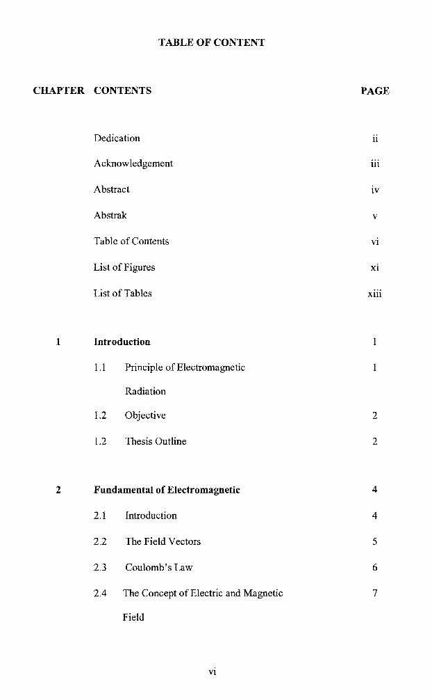
TABLE OF CONTENT
CHAPTER CONTENTS PAGE
Dedication ii
Acknowledgement 111
Abstract IV
Abstrak V
Table of Contents VI
List of Figures xi
List of Tables Xlll
1 Introduction
1.1 Principle of Electromagnetic
Radiation
1.2 Objective 2
1.2 Thesis Outline 2
2 Fundamental of Electromagnetic 4
2.l Introduction 4
2.2 The Field Vectors 5
2.3 Coulomb's Law 6
2.4 The Concept of Electric and Magnetic 7
Field
VI
I

10 2.5 The Laws of Ampere and Biot-Savart
2.6 The Lorentz Force 14
2.7 Maxwell's Equation 15
2.8 Magnetic Material 17
2.9 Summary of Equation for Static Fields 21
3 Radiation and Propagation of Waves 23
3.1 Introduction 23
3.2 Electromagnetic Radiation 23
3.2.1 Fundamental Of 24
Electromagnetic Waves
3.2.2 Waves in free space 25
3.2.3 Radiation and Reception 28
3.2.4 Polarization 28
3.2.5 Reception 29
3.2.6 Attenuation and Absorption 29
3.3 Effect of the Environment 30
3.3.1 Reflection of waves 30
3.3.2 Refraction 31
3.3.3 Interference of 32
Electromagnetic Waves
3.3.4 Diffraction of Radio Waves 33
3.4 Propagation Of Waves 33
3.4.1 Ground (Surface) Waves 36
Vll

36 3.4.2 Field Strength at a Distance
3.4.3 VLF Propagation 37
3.4.4 Sky-Wave Propagation 38
3.4.5 The Ionosphere and its Effects 38
3.4.6 Reflection Mechanism 38
4 Microwave 40
4.1 Introduction 40
4.2 Loss Tangent and Penetration Depth 42
4.2.1 Skin Effect 44
4.3 Microwave Properties of Water 46
4.4 Microwave Heating 49
4.5 Microwave Cooking 51
4.6 Microwave Safety Levels 52
4.7 Electromagnetic Compatibility 56
5 Antennas and Radiation 58
5.1 Introduction 58
5.2 Basic Principle of Antenna 59
5.2.1 Reciprocity 59
5.2.2 Field Region Surround 59
Antennas
5.2.3 Radiation Pattern 61
V111
64 5.2.4 Gain and Directivity
5.2.5 Efficiency of an Antenna 65
5.2.6 Polarization Properties 65
5.2.7 Impedance Properties 65
5.2.8 Frequency Characteristic 66
5.3 Electric Dipole Antenna (Hertz ian 67
Dipole)
6 Effect of Electromagnetic Radiation on 69
Human Health and Environment
6.1 Introduction 69
6.2 Electromagnetic Radiation a Threat to 70
Our Health
6.3 Electromagnetic Radiation a Threat to 73
Our Environment
6.4 Biological Effect of Electromagnetic 74
Radiation
6.5 The Above Average Exposure Safety 78
Guideline
7 Experiment Procedure and Results Analysis 81
7.1 Experiment Setup 82
7.1.1 The Basic Setup 82
7.1.2 Function of The Components 83
IX

84 7.1.3 Experiment Procedure
7.2 Experiment Result Analysis 85
7.2.1 Measurement on Different 85
Thickness of Materials
7.2.2 Measurement on All the 99
Materials at a Fix Thickness
7.3 Results Analysis 105
8 Conclusion and Recommendation 107
Reference 109
x
LIST OF FIGURE
Figure page
2.3.1 RepUlsion forces experienced by two point charges Ql and Q2 7
2.4.1 The electric field vector, E 7
2.4.2 Magnetic force between two parallel current element 9
2.5.1 Illustrating Ampere's Circuital Law 11
2.5.2 Geometry for deriving the electromagnetic potential 12
2.8.1 Representation ofmagnetic dipole 14
2.8.2 (a) Without applied magnetic field 19
(b) with applied magnetic field B alignment of 15
magnetic dipole moment occurs for those dipoles.
2.8.3 A space occupied by the magnetic material divided into cell 20
3.2.1.1 Transverse electromagnetic wave in free space 25
3.2.2.2 Spherical wavefronts. 30
3.3.1.1 Reflection of waves; image formation. 31
3.3.2.1 Refraction at a plane, sharply defined boundary 32
3.3.3.1 Interference of direct and ground-reflected 33
3.4.2 The electromagnetic spectrum 34
4.1.1 (a) Waves in loss less medium 41
(b) Waves in lossy medium 41
4.2.1 Penetration Depth (or skin depth) in conductor 44
4.3.1 Permittivity ofpure water in the microwave spectrum 47
4.3.2 Variation of Permittivity of water with temperature at 3 GHz 48
4.6.1 INIRC recommended safety levels 55
5.2.2.1 Field regions surrounding an antenna 60
Xl

61 5.2.3.1 Antenna patterns. (a) A three-dimensional pattern
(b) Two-dimensional cuts 61
5.2.3.2 E- and H- plane patterns for a hom antenna 62
5.2.3.3 An omnidirectional antenna patterns 63
5.3.1 The electric dipole antenna (the Hertzian dipole) 67
7.1.1 Typical Experiment Setup 82
7.2.1.1 Comparison Measurement for Different Thicknesses ofCloth 88
7.2.1.2 Comparison Measurement for Different Thicknesses of Glass 90
7.2.1.3 Comparison Measurement for Different Thicknesses of Paper 92
7.2.1.4 Comparison Measurement for Different Thicknesses of Plastic 94
7.2.1.5 Comparison Measurement for Different Thicknesses of Wood 96
7.2.1.6 Comparison Measurement for Different Thicknesses of Polystyrene 98
7.2.2.1 Measurement of 1 cm Thick for All the Materials 100
7.2.2.2 Measurement of2 cm Thick for All the Materials 102
7.2.2.3 Measurement of 3 cm Thick for All the Materials 104
xii
LIST OF TABLE
Table page
4.2.1 Loss tangent of Copper, Carbon and Bakelite at different frequencies 43
4.2.11 Skin Depth for some common material 45
6.5.1 Safety guidelines at frequencies used by cellular 79
andPCS
6.5.2 Standard for Mobile Base Station 80
7.2.1.1 Measurement from the Hom Antenna - without blockage 86
7.2.1.2 Measurement when blocked with Cloth at Different Thicknesses 87
7.2.1.3 Measurement when blocked with Glass at Different Thicknesses 89
7.2.1.4 Measurement when blocked with Paper at Different Thicknesses 91
7.2.1.5 Measurement when blocked with Plastic at Different Thicknesses 93
7.2.1.6 Measurement when blocked with Wood at Different Thicknesses 95
7.2.1.7 Measurement when blocked with Polystyrene at Different Thicknesses 97
7.2.2.1 Measurement of 1 cm Thick for all the Materials 99
7.2.2.2 Measurement of2cm Thick for all the Materials 101
7.2.2.3 Measurement of3 cm Thick for all the Materials 103
X111

CHAPTER 1
INTRODUCTION
1.1 Basic Principle of Electromagnetic Radiation
In this report, the concern is mainly on radiation phenomena associated with
electromagnetic fields and how it relates to human health and environment. Basically
the electromagnetic field deals with electric and magnetic fields. The fundamental
fields equation for electromagnetic fields can be represented by Maxwell's equation.
These are a set of partial differential equations, which describe the space and time
behavior of the electromagnetic field vectors.
When plane electromagnetic waves propagate through space it carry energy,
which is in the form of heat. For the creation of electromagnetic waves, specific
structures with time-varying charge and currents are needed. The process of
producing electromagnetic waves, which then propagate with no connection to the
source, is known as electromagnetic radiation.
Electromagnetic radiation in our environment influences the human body and
environment as a whole. It prohibits oxygen proper access to tissue and cells and
eliminates certain micro substances that are necessary in a healthy human body.
Some examples on the effect from exposure to electromagnetic radiation are cancer,
changes in behavior, memory loss, Parkinson's and Alzheimer's diseases, and many
others.

,..
1.2 Objectives
Therefore in this research, I have set a few objectives as guidelines in order to
complete this work.
1) To study on the possible danger posed by electromagnetic radiation on our
health and environment.
2) To find out the risk of electromagnetic waves and how significant association
between indicators of exposure to normal and above-average waves.
3) To do comparison on different types of materials such as wood, glass,
polystyrene, paper, cloth and plastic in order to determine which materials
has a potential to blocked electromagnetic radiation.
1.3 Thesis Outline
Chapter 1 briefly describes the project that being carried out. A short
introduction on the fundamental of electromagnetic field and radiation has been
explained in this section. It also stated the objective of this project.
In the Second Chapter, the basic principles related to electromagnetic
radiation such as electric and magnetic field vectors, Coulomb's Law, Maxwell's
Equation, Ampere's and Biot-Savart's Law, magnetic materials and many more are
introduced.
Chapter 3 introduces the nature and propagation of electromagnetic radiation
III order to get a better understanding of the theory of electromagnetic energy
radiation principle. In chapter 4 some properties of microwave in lossy media is
discussed. This chapter is important because it state how microwave can affect
human health.
2

Chapter 5 touched on the basic principle of antenna as it plays an important
role in transmitting and/or receiving electromagnetic waves thus producing the
electromagnetic radiation.
Chapter 6 focuses on the effects of electromagnetic radiation on human health
and our environment and some discussion on the normal and above-average doses of
radiation. Chapter 7 will include the experimental procedure and result. The
experiment is based on the manual book of CASSY (Computer Assisted Science
System) Directional Patterns. Therefore, the result is obtained using CASSY Pack-E
Directional Patterns software (sin: 524782).
The final chapter concludes the overall project and some recommendation
based on the problem faced in completing this project.
3

p
CHAPTER 2
FUNDAMENTALS OF ELECTROMAGNETIC
2.1 Introduction
Electromagnetism deals with the study of electric and magnetic fields. It is
useful to be familiarizing with the concept of field, and in particular with electric and
magnetic fields. These fields are vector quantities and their behavior is governed by a
set oflaws known as Maxwell's equation [1].
Limitations on the speed of modem computers, the range of validity of
electrical circuit theory, and the principles of signal transmission are just a few
examples of topics for which knowledge of electromagnetic is indispensable.
Electromagnetic devices are almost everywhere: in TV receivers, car ignition
systems, mobile phones and many others. Although it may sometimes be hard to see
the fundamental electromagnetic concepts on which their operation is based, these
devices certainly cannot be designed and how they work cannot be understood if we
don't know the basic electromagnetic principles.
There are also some equation and laws which concern with the study of
electromagnetism such as the Coulomb's Law where it showed the characteristic of
two charged bodies which are separated by r distance that can be consider as point
charges. Beside that, the Ampere's and Biot~Savart's Law, the Lorentz Force,
Maxwell's Equations, magnetic material and the summary of equation for static
fields will also be discussed.
4

2.2 The Field Vectors
In order to describe the electromagnetic field, 4 vectors are used [2]:
E = Electric field vector (stat volt/cm)
D Electric displacement vector or dielectric displacement vector or,
simply, displacement vector (stat volts/cm).
B = Magnetic displacement vector or magnetic field vector (gauss)*
H Magnetic field vector (oersted) *
E and B is the fundamental field vectors, and that D and H can be obtained
from these together with the properties of the medium in which the fields occur [2].
The mathematical relation that the field vectors satisfY cannot be derived, as
they must be obtained from experiment [2]. Thus the law of electromagnetism that is
valid for steady-state condition is discussed in the next section. The results of these
considerations may be summarized in Maxwell's equations, which seem to be true
and an accurate description of the behaviors of electromagnetic fields [2].
'" The unit oersted and gauss are identical, but historically oersted is applied to H and gauss to B. (Heald M. A., Marion J. B., 1980)
5
,.
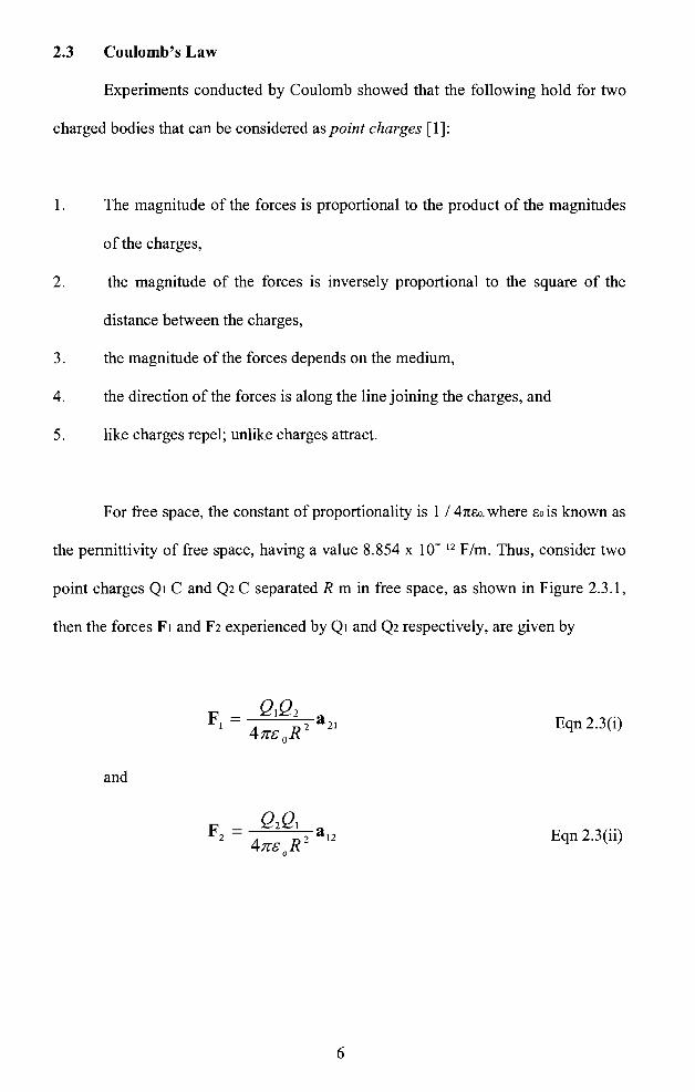
2.3 Coulomb's Law
Experiments conducted by Coulomb showed that the following hold for two
charged bodies that can be considered as point charges [1]:
1. The magnitude of the forces is proportional to the product of the magnitudes
of the charges,
2. the magnitude of the forces is inversely proportional to the square of the
distance between the charges,
3. the magnitude of the forces depends on the medium,
4. the direction of the forces is along the line joining the charges, and
5. like charges repel; unlike charges attract.
F or free space, the constant of proportionality is 1 I 41tEo. where £0 is known as
the permittivity of free space, having a value 8.854 x 10- 12 F/m. Thus, consider two
point charges QI C and Q2 C separated R m in free space, as shown in Figure 2.3.1,
then the forces FI and F2 experienced by QI and Q2 respectively, are given by
QIQ2 aF1 = Eqn 2.3(i) 4 R2 21:rc o
and
Q2QI aF2 = Eqn 2.3(ii) 4 R2 12:rc o
6

f
R -----...... - ......... al2'-............ F2 Q2
Figure 2.3.1: Repulsion forces experienced by two point charges QI and Q2
Where a21 and al2 are unit vectors along the line joining QI and Q2 as shown in
Figure 2.3.l.Therefore Eqn 2.3(i) and 2.3(ii) represent Coulomb's Law. Since the
unit of force is Newton, note that the eo has the units (coulomb) per (Newton2
meter2). These are commonly known as farads per meter (F/m), where a farad is
( coulomb) 2 per Newton-meter [1].
2.4 The concept of Electric and Magnetic Field
Assume that the position of the charge QI in Coulomb's law is known, and
several charges close to charge QI are of unknown magnitudes and signs and at
unknown locations (figure 2.4.1).
Figure 2.4.1: The electric field vector, E, is defined by the forces acting on a charged
particles
7

,...:
The force acting on Ql cannot be calculated using Coulomb's law, but from
Coulomb's law, and knowing that mechanical forces add as vectors, we predict that
there will be a force on Q 1 proportional to Q 1 itself given by [3]:
Fe=Q1E Eqn 2.4(i)
This is the definition of the electric field strength denote by E. It is a vector
equal to the force on a small charged body at a point in space, divided by the charge
of the body [3]. The unit of electric field strength is Newton per coulomb, or more
commonly volt per meter, where a volt is Newton-meter per coulomb. The test
charge should be so small that it does not alter the electric field in which it is placed
[1] .
Note that E generally differs from one point to another, and that it frequently
varies in time (for example, if we move the charges producing E). The domain of
space where there is a force on a charged body is called the electric field [3]. Thus
the electric field can be described by E, a vector function of space coordinates (and
possibly of time). Obviously, sources of electric field are electric charges and
currents. If source producing the field are not moving, the field can be calculated
from Coulomb's law. This kind offield is termed the electrostatic field, meaning 'the
field produced by electric charges that are not moving [3].
Another important property of the electric field is that it is linear. That is, the
principle of superposition applies and the field due to a number of charges is just the
vector sum of the individual fields. If it were not for this property, the analysis of
electromagnetic phenomena would be virtually impossible [2].
8

r !
Now consider the magnetic forces between two current elements for the case I, of two parallel short wire segments II and h with current II and h, shown in Figure
2.4.2 is given by:
Eqn 2.4(ii)
where km is a constant. The direction of the force in figure 2.4.2 (parallel elements
with current in the same direction) is attractive. It is repulsive if the currents in the
elements are in opposite directions [3].
Fm
hh
r
Figure 2.4.2: Magnetic force between two parallel current elements
Lets assume that there are several currents of unknown intensities, directions,
and are positioned closed to current element lilt. The resulting magnetic force will be
proportional to lllI. The current elements are nothing but small domains with moving
charges. Let the velocity of charges in the current element 1111 be v, and the charge of
individual charge carriers in the current element be Q. The force on the current
element is the result of forces on individual moving charges carriers, so that the
forces on a single charge carrier should be expected to be proportional to Qv [3].
Experimentally, the expression for this force is found to be of the form
9
Fm=QvxB Eqn 2.4(iii)
Where the sign "x" implies the vector, or cross, product of two vectors.
The vectors B is known as the magnetic induction vector or the magnetic flux
density vector [3]. If in a region of space a force of the form in Eqn 2.4(iii) exists on
a moving charge, the region is termed as magnetic field.
2.5 The Laws of Ampere and Biot-Savart
Next we will show that electric currents produce magnetic fields * [2]. If a
current I (stat amperes) flows in a wire, and if we map by some means the magnetic
field that is produced in free space and compute the line integral of B . dl along any
closed path that surrounds the wire, the result is proportional to 1, independent of the
details of the path figure 2.5.1. This fact is expressed by the Ampere' circuital law
[2]:
Eqn 2.5(i)
The constant of proportionality, 4n/c, is a consequence of using the Gaussian
units. The quantity c is the velocity of light in free space and the reason for its
appearance in Ampere's law will become apparent only after examining the wave
properties of the electromagnetic field. The differential expression of Ampere's law
is given by:
4ncurlB =-J (Total current) Eqn 2.5(ii)
c
• Discovered in 1820 by Hans Christian Oersted (1777 -1852)
10

I
J. D C
Figure 2.5.1: Illustrating Ampere's Circuital Law
The Biot-Savart law relates to the magnetic field produced by an element of a
circuit in which a current flows [2]. The differential statement is
I d I x edB Eqn 2.5(iii)
c r 2
where er unit vector
r = distance between two charges
c velocity of light
Portion of a circuit cannot be isolate and treat alone the effects of such an
element; a circuit must form a complete loop in order that a steady current may flow.
Therefore, by integrating Eqn 2.6(i) completely around the circuit, we obtain
I f dl x e rB=-c r2 Eqn 2.5(iv)
where the path of integration must correspond exactly with the circuit loop.
11
Related Documents