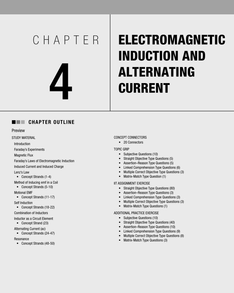
CHAPTER 4 ELECTROMAGNETIC INDUCTION AND ALTERNATING CURRENT n n n CHAPTER OUTLINE Preview STUDY MATERIAL Introduction Faraday’s Experiments Magnetic Flux Faraday’s Laws of Electromagnetic Induction Induced Current and Induced Charge Lenz’s Law • Concept Strands (1-4) Method of Inducing emf in a Coil • Concept Strands (5-10) Motional EMF • Concept Strands (11-17) Self Induction • Concept Strands (18-22) Combination of Inductors Inductor as a Circuit Element • Concept Strand (23) Alternating Current (ac) • Concept Strands (24-47) Resonance • Concept Strands (48-50) CONCEPT CONNECTORS • 20 Connectors TOPIC GRIP • Subjective Questions (10) • Straight Objective Type Questions (5) • Assertion–Reason Type Questions (5) • Linked Comprehension Type Questions (6) • Multiple Correct Objective Type Questions (3) • Matrix-Match Type Question (1) IIT ASSIGNMENT EXERCISE • Straight Objective Type Questions (80) • Assertion–Reason Type Questions (3) • Linked Comprehension Type Questions (3) • Multiple Correct Objective Type Questions (3) • Matrix-Match Type Questions (1) ADDITIONAL PRACTICE EXERCISE • Subjective Questions (10) • Straight Objective Type Questions (40) • Assertion–Reason Type Questions (10) • Linked Comprehension Type Questions (9) • Multiple Correct Objective Type Questions (8) • Matrix-Match Type Questions (3)

Welcome message from author
This document is posted to help you gain knowledge. Please leave a comment to let me know what you think about it! Share it to your friends and learn new things together.
Transcript
c h a p t e r
4ELECTROMAGNETIC INDUCTION AND ALTERNATING CURRENT
nnn Chapter Outline
Preview
sTUDY MATERIAL
Introduction
Faraday’s Experiments
Magnetic Flux
Faraday’s Laws of Electromagnetic Induction
Induced Current and Induced Charge
Lenz’s Law• Concept strands (1-4)
Method of Inducing emf in a Coil• Concept strands (5-10)
Motional EMF• Concept strands (11-17)
self Induction• Concept strands (18-22)
Combination of Inductors
Inductor as a Circuit Element• Concept strand (23)
Alternating Current (ac)• Concept strands (24-47)
Resonance• Concept strands (48-50)
ConCEPT ConnECToRs• 20 Connectors
ToPIC gRIP• subjective Questions (10)• straight objective Type Questions (5)• Assertion–Reason Type Questions (5)• Linked Comprehension Type Questions (6)• Multiple Correct objective Type Questions (3)• Matrix-Match Type Question (1)
IIT AssIgnMEnT ExERCIsE• straight objective Type Questions (80)• Assertion–Reason Type Questions (3)• Linked Comprehension Type Questions (3)• Multiple Correct objective Type Questions (3)• Matrix-Match Type Questions (1)
ADDITIonAL PRACTICE ExERCIsE• subjective Questions (10)• straight objective Type Questions (40)• Assertion–Reason Type Questions (10)• Linked Comprehension Type Questions (9)• Multiple Correct objective Type Questions (8)• Matrix-Match Type Questions (3)
4.2 Electromagnetic Induction and Alternating Current
In the year 1820, Oersted discovered that the current flowing through a conductor produces a magnetic field in the neighbourhood of the conductor. This phenomenon is due to the conversion of electrical energy to magnetic energy. So the reverse conversion process, i.e., the conver-sion of magnetic energy to electrical energy also should
be possible. Indeed, in 1831 Michael Faraday in UK and Joseph Henry in USA independently showed that electric current can be produced in a coil of wire with the help of a magnetic field. This conversion of magnet-ic energy to electrical energy is called electromagnetic induction.
intrOduCtiOn
Faraday’s experiments
Coil magnet experiment
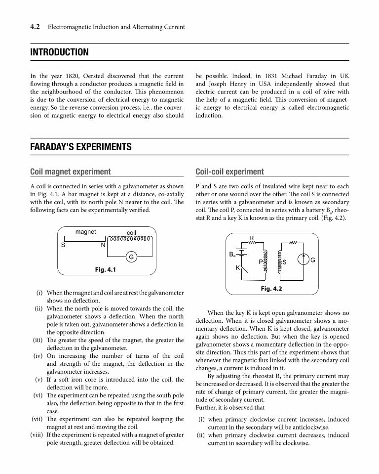
A coil is connected in series with a galvanometer as shown in Fig. 4.1. A bar magnet is kept at a distance, co-axially with the coil, with its north pole N nearer to the coil. The following facts can be experimentally verified.
Fig. 4.1
(i) When the magnet and coil are at rest the galvanometer shows no deflection.
(ii) When the north pole is moved towards the coil, the galvanometer shows a deflection. When the north pole is taken out, galvanometer shows a deflection in the opposite direction.
(iii) The greater the speed of the magnet, the greater the deflection in the galvanometer.
(iv) On increasing the number of turns of the coil and strength of the magnet, the deflection in the galvanometer increases.
(v) If a soft iron core is introduced into the coil, the deflection will be more.
(vi) The experiment can be repeated using the south pole also, the deflection being opposite to that in the first case.
(vii) The experiment can also be repeated keeping the magnet at rest and moving the coil.
(viii) If the experiment is repeated with a magnet of greater pole strength, greater deflection will be obtained.
Coil-coil experiment
P and S are two coils of insulated wire kept near to each other or one wound over the other. The coil S is connected in series with a galvanometer and is known as secondary coil. The coil P, connected in series with a battery Ba, rheo-stat R and a key K is known as the primary coil. (Fig. 4.2).
GS
R
KP
Ba
Fig. 4.2
When the key K is kept open galvanometer shows no deflection. When it is closed galvanometer shows a mo-mentary deflection. When K is kept closed, galvanometer again shows no deflection. But when the key is opened galvanometer shows a momentary deflection in the oppo-site direction. Thus this part of the experiment shows that whenever the magnetic flux linked with the secondary coil changes, a current is induced in it.
By adjusting the rheostat R, the primary current may be increased or decreased. It is observed that the greater the rate of change of primary current, the greater the magni-tude of secondary current. Further, it is observed that
(i) when primary clockwise current increases, induced current in the secondary will be anticlockwise.
(ii) when primary clockwise current decreases, induced current in secondary will be clockwise.
Electromagnetic Induction and Alternating Current 4.3
To interpret the results of Faraday’s experiments, it is necessary to understand a property of magnetic fields, called magnetic flux. Magnetic flux of a magnetic field passing through (or linking or threading) an area A isdefined as the surface integral of the magnetic induction passing through that area. It is represented by
f = B.ds∫where B is the magnetic induction and ds is an elemen-tal area. So B is also known as magnetic flux density. The scalar product definition is used because the area chosen can be at an angle to the direction of the magnetic field. The SI unit of magnetic flux is the weber (Wb) = J/A = V s = T m2. The CGS unit of flux is the maxwell (Mx) = 10-8 Wb. Its dimensional formula is ML2T-2 I-1
Take any surface, an open surface, a closed surface, or an irregular surface. The magnetic flux through that surface is given by f = B.ds∫ .
If B is uniform over the area, flux is B ds B A• = •∫Being the scalar product of field and area, the flux is
BA cos q, provided A is a simple plane area and B is uni-form. It could as well be -BA cos q. Whether positive or negative depends on how we define B and A. Conventional-ly, the plane of the paper is taken as the X-Y plane in a right
handed system, so that the magnetic field is represented by the sign ⊗ when it is in the –Z direction, (into the plane of the paper) and by the sign , if it is in the +Z direction (out of the plane of the paper). The direction of A is chosen as + Z direction when the boundary is traced anticlockwise
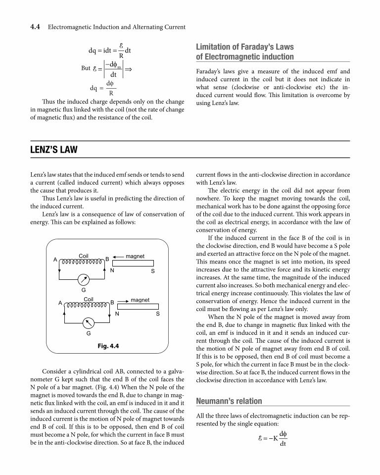
( )ˆA Ak= .Consider now a coil of area A with n turns kept in a
uniform magnetic field of flux density B, in such a way that the normal to plane of the coil makes an angle q with the direction of the magnetic field. (Fig. 4.3).
B
θ
Fig. 4.3
The flux linked with the coil is given by
f = n AB cosq
magnetiC Flux
Faraday’s laws OF eleCtrOmagnetiC induCtiOn
There are two laws of electromagnetic induction called Faraday’s I law and Faraday’s II law.
Faraday’s i law of electromagnetic induction
Whenever magnetic flux linked with a circuit changes, an instantaneous emf is induced in it. The induced emf per-sists as long as magnetic flux changes.
Faraday’s ii law of electromagnetic induction
The magnitude of induced emf is directly proportional to the rate of change of magnetic flux.
d .dtf∝E In SI, magnitude of E is given by d
dtf=E
induCed Current and induCed Charge
If R is the resistance of the coil (or the closed path) in which
an emf E is induced, then the electric current iR
= E is called the induced current in the coil.
The current which flows through the circuit is due to the flow of the induced charge dq.
dqi
dt=
4.4 Electromagnetic Induction and Alternating Current
dq idt dt
R= = E
But mddtf−
= ⇒E
dqdR
=φ
Thus the induced charge depends only on the change in magnetic flux linked with the coil (not the rate of change of magnetic flux) and the resistance of the coil.
limitation of Faraday’s laws of electromagnetic induction
Faraday’s laws give a measure of the induced emf and induced current in the coil but it does not indicate in what sense (clockwise or anti-clockwise etc) the in-duced current would flow. This limitation is overcome by using Lenz’s law.
lenz’s law
Lenz’s law states that the induced emf sends or tends to send a current (called induced current) which always opposes the cause that produces it.
Thus Lenz’s law is useful in predicting the direction of the induced current.
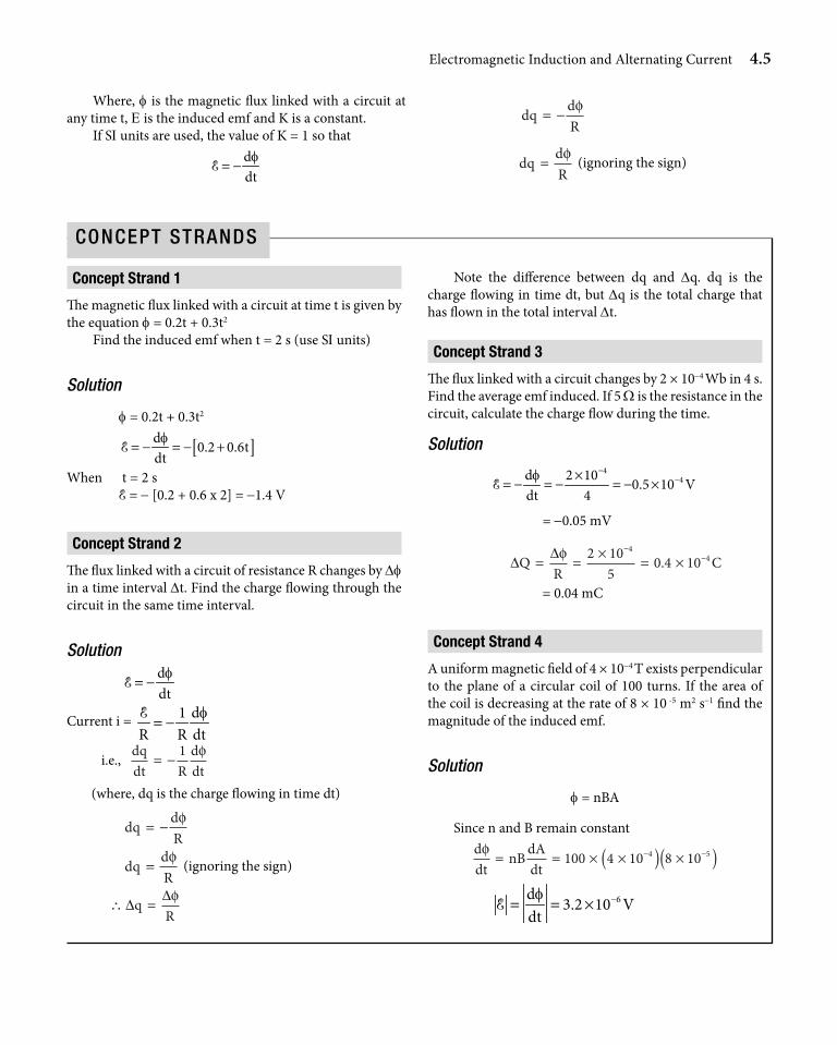
Lenz’s law is a consequence of law of conservation of energy. This can be explained as follows:
S
G
Coil
N
magnetA B
S
G
Coil
N
magnet A B
Fig. 4.4
Consider a cylindrical coil AB, connected to a galva-nometer G kept such that the end B of the coil faces the N pole of a bar magnet. (Fig. 4.4) When the N pole of the magnet is moved towards the end B, due to change in mag-netic flux linked with the coil, an emf is induced in it and it sends an induced current through the coil. The cause of the induced current is the motion of N pole of magnet towards end B of coil. If this is to be opposed, then end B of coil must become a N pole, for which the current in face B must be in the anti-clockwise direction. So at face B, the induced
current flows in the anti-clockwise direction in accordance with Lenz’s law.
The electric energy in the coil did not appear from nowhere. To keep the magnet moving towards the coil, mechanical work has to be done against the opposing force of the coil due to the induced current. This work appears in the coil as electrical energy, in accordance with the law of conservation of energy.
If the induced current in the face B of the coil is in the clockwise direction, end B would have become a S pole and exerted an attractive force on the N pole of the magnet. This means once the magnet is set into motion, its speed increases due to the attractive force and its kinetic energy increases. At the same time, the magnitude of the induced current also increases. So both mechanical energy and elec-trical energy increase continuously. This violates the law of conservation of energy. Hence the induced current in the coil must be flowing as per Lenz’s law only.
When the N pole of the magnet is moved away from the end B, due to change in magnetic flux linked with the coil, an emf is induced in it and it sends an induced cur-rent through the coil. The cause of the induced current is the motion of N pole of magnet away from end B of coil. If this is to be opposed, then end B of coil must become a S pole, for which the current in face B must be in the clock-wise direction. So at face B, the induced current flows in the clockwise direction in accordance with Lenz’s law.
neumann’s relation
All the three laws of electromagnetic induction can be rep-resented by the single equation:
dKdtf= −E
Electromagnetic Induction and Alternating Current 4.5
Where, f is the magnetic flux linked with a circuit at any time t, E is the induced emf and K is a constant.
If SI units are used, the value of K = 1 so thatddtf= −E
dq dR
= −φ
dq dR
=φ (ignoring the sign)
Concept strand 1
The magnetic flux linked with a circuit at time t is given by the equation f = 0.2t + 0.3t2
Find the induced emf when t = 2 s (use SI units)
Solution
f = 0.2t + 0.3t2
[ ]d 0.2 0.6t
dtf= − = − +E
When t = 2 s E = - [0.2 + 0.6 x 2] = -1.4 V
Concept strand 2
The flux linked with a circuit of resistance R changes by Df in a time interval Dt. Find the charge flowing through the circuit in the same time interval.
Solution
ddtf= −E
Current i = 1 dR R dt
f= −E
i.e., dqdt R
ddt
= −1 φ
(where, dq is the charge flowing in time dt)
dq d
R= −
φ
dq d
R=
φ (ignoring the sign)
∴ =∆∆qRφ
Note the difference between dq and Dq. dq is the charge flowing in time dt, but Dq is the total charge that has flown in the total interval Dt.
Concept strand 3
The flux linked with a circuit changes by 2 × 10⁻⁴ Wb in 4 s. Find the average emf induced. If 5 W is the resistance in the circuit, calculate the charge flow during the time.
Solution4
4d 2 10 0.5 10 Vdt 4f −
−×= − = − = − ×E
= -0.05 mV
∆
∆QR
C= =×
= ×−
−φ 2 105
0 4 104
4.
= 0.04 mC
Concept strand 4
A uniform magnetic field of 4 × 10⁻⁴ T exists perpendicular to the plane of a circular coil of 100 turns. If the area of the coil is decreasing at the rate of 8 × 10 -5 m2 s-1 find the magnitude of the induced emf.
Solution
f = nBA
Since n and B remain constantddt
nB dAdt
φ= = × ×( ) ×( )− −100 4 10 8 104 5
6d 3.2 10 Vdtf −= = ×E
ConCept StrandS
4.6 Electromagnetic Induction and Alternating Current
Consider a circular coil of radius r, having N turns, kept in a magnetic field B with the normal to the plane of coil making an angle q with the direction of the magnetic field.The magnetic flux linked with the coil is f = NBA cos q , where A = pR2 = area of cross-section of coil.
Since induced emf ddt
f−=E , by varying the magnetic
flux linked with the coil, we can produce an induced emf in the coil. The following are the possible methods of varying the magnetic flux linked with the coil.
(i) By changing only the angle qIf the coil is rotated inside the magnetic field with a constant angular velocity w such that q = wt, keeping N, B and A as constant, then
f = NBA coswt
⇒ ddt
NBA tφω ω= − sin
⇒ d NBAsin tdt
fw
−= =E
This method gives a sinusoidal induced emf (because sinwt can be positive or negative). This method is used in ac generators or alternators.
(ii) By changing only the number of turns (N)
ddt
BA dNdt
φθ= ( )cos
( )d dNBAcosdt dt
fq
−= = −E
This is not a method that can be practically realized easily.
(iii) By changing only the area A of the coil
( )d dANBcosdt dt
fε q
−= = −
When a coil moves into or moves out of a magnetic field with some velocity, the effective area of the coil in the magnetic field changes with time resulting in an induced emf in the coil.
methOd OF induCing emF in a COil
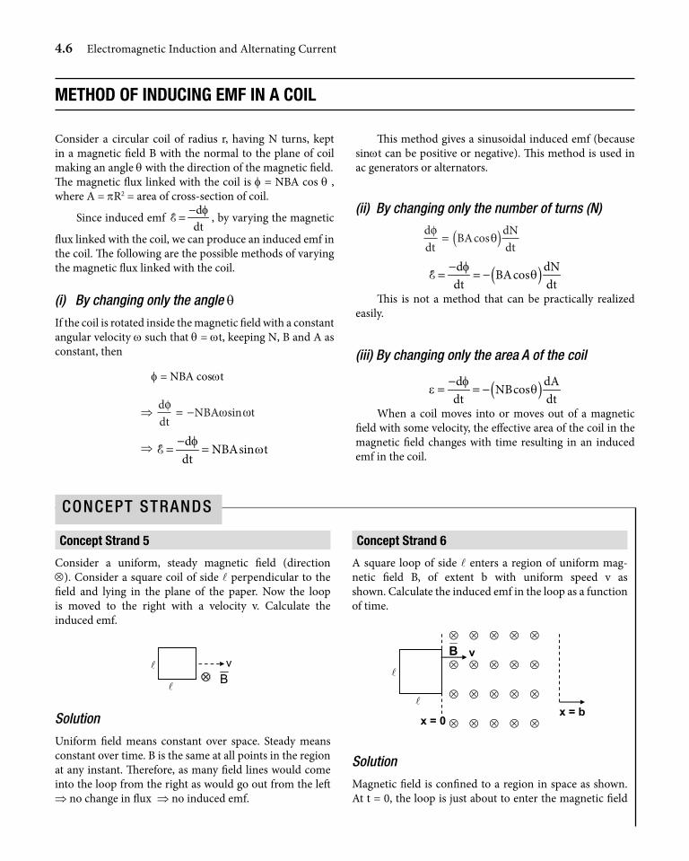
Concept strand 5
Consider a uniform, steady magnetic field (direction ⊗). Consider a square coil of side l perpendicular to the field and lying in the plane of the paper. Now the loop is moved to the right with a velocity v. Calculate the induced emf.
Solution
Uniform field means constant over space. Steady means constant over time. B is the same at all points in the region at any instant. Therefore, as many field lines would come into the loop from the right as would go out from the left ⇒ no change in flux ⇒ no induced emf.
Concept strand 6
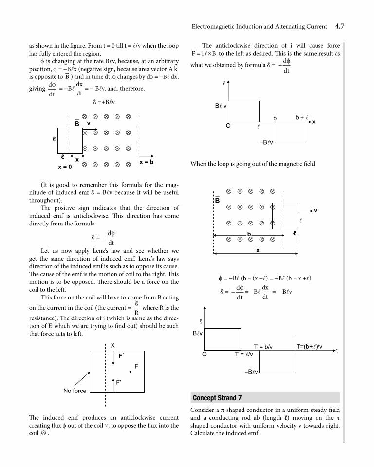
A square loop of side l enters a region of uniform mag-netic field B, of extent b with uniform speed v as shown. Calculate the induced emf in the loop as a function of time.
x = b
x = 0
⊗ ⊗ ⊗ ⊗ ⊗
⊗ ⊗ ⊗ ⊗ ⊗
⊗ ⊗ ⊗ ⊗ ⊗
⊗ ⊗ ⊗ ⊗ ⊗
B v
Solution
Magnetic field is confined to a region in space as shown. At t = 0, the loop is just about to enter the magnetic field
ConCept StrandS
Electromagnetic Induction and Alternating Current 4.7
as shown in the figure. From t = 0 till t = l/v when the loop has fully entered the region,
f is changing at the rate Blv, because, at an arbitrary position, f = -Blx (negative sign, because area vector A k is opposite to B ) and in time dt, f changes by df = -Bl dx,
giving ddtφ = -Bl
dxdt
= - Blv, and, therefore,
E =+Blv
x = b
ℓ
ℓx = 0
⊗ ⊗ ⊗ ⊗ ⊗
⊗ ⊗ ⊗ ⊗ ⊗
⊗ ⊗ ⊗ ⊗ ⊗
⊗ ⊗ ⊗ ⊗ ⊗
B v
x
(It is good to remember this formula for the mag-nitude of induced emf E = Blv because it will be useful throughout).
The positive sign indicates that the direction of induced emf is anticlockwise. This direction has come directly from the formula
E = −ddtφ
Let us now apply Lenz’s law and see whether we get the same direction of induced emf. Lenz’s law says direction of the induced emf is such as to oppose its cause. The cause of the emf is the motion of coil to the right. This motion is to be opposed. There should be a force on the coil to the left.
This force on the coil will have to come from B acting on the current in the coil (the current =
RE where R is the
resistance). The direction of i (which is same as the direc-tion of E which we are trying to find out) should be such that force acts to left.
F’
F’
F
X
No force
The induced emf produces an anticlockwise current creating flux f out of the coil ⊙, to oppose the flux into the coil ⊗ .
The anticlockwise direction of i will cause force F i B= ×l to the left as desired. This is the same result as
what we obtained by formula E = −ddtφ
O
B v
b b +
x
−Bv
E
When the loop is going out of the magnetic field
ℓ
⊗ ⊗ ⊗ ⊗ ⊗
⊗ ⊗ ⊗ ⊗ ⊗
⊗ ⊗ ⊗ ⊗ ⊗
⊗ ⊗ ⊗ ⊗
Bv
x
b⊗
f = -Bl (b – (x -l) = -Bl (b – x +l)
E = −ddtφ = -Bl
dxdt
= - Blv
O
Bv
T = /vT = b/v T=(b+)/v t
−Bv
E
Concept strand 7
Consider a p shaped conductor in a uniform steady field and a conducting rod ab (length ℓ) moving on the p shaped conductor with uniform velocity v towards right. Calculate the induced emf.
4.8 Electromagnetic Induction and Alternating Current
⊗ ⊗ ⊗ ⊗ ⊗ ⊗
⊗ ⊗ ⊗ ⊗ ⊗ ⊗
⊗ ⊗ ⊗ ⊗ ⊗ ⊗
⊗ ⊗ ⊗ ⊗ ⊗ ⊗
a
b
B
v
Solution
The induced emf is the same as in the previous example because the area enclosed increases at the rate v.
E = Blv and is positive and anticlockwise
Concept strand 8
A conducting rod moves on a parabolic conductor with uniform velocity v towards right as shown. Calculate the induced emf.
⊗ ⊗ ⊗ ⊗ ⊗ ⊗
⊗ ⊗ ⊗ ⊗ ⊗ ⊗
⊗ ⊗ ⊗ ⊗ ⊗ ⊗
a
b
Bv
y2 = 4ax
O x
Solution
At any x, effective length of conductor ab = 2 y = 2 4ax = 4 ax
In time dt, change in area of the loop dA = (2 y)dx = 2y v dt
df = -B dA = –B. 2 yv dt
E = - ddtf = + B 2 yv
⊗ ⊗ ⊗ ⊗ ⊗ ⊗
⊗ ⊗ ⊗ ⊗ ⊗ ⊗
⊗ ⊗ ⊗ ⊗ ⊗ ⊗
⊗ ⊗ ⊗ ⊗ ⊗ ⊗ dx
B
in an anticlockwise direction, to get E vs x:
E = B2 yv = Bv 4 ax = 4 Bv a x x⇒ ∝E
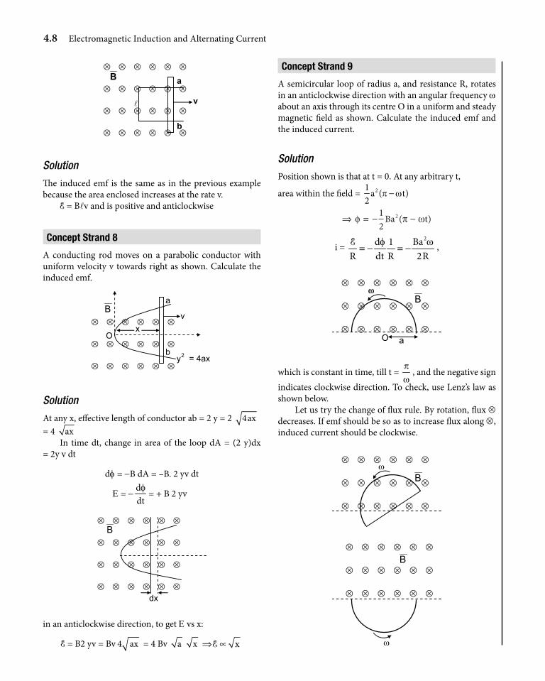
Concept strand 9
A semicircular loop of radius a, and resistance R, rotates in an anticlockwise direction with an angular frequency w about an axis through its centre O in a uniform and steady magnetic field as shown. Calculate the induced emf and the induced current.
Solution
Position shown is that at t = 0. At any arbitrary t,
area within the field = 21a ( t)
2p w−
⇒ = − −φ π ω12
2Ba t( )
i = 2d 1 Ba
R dt R 2Rf w= − = −E ,
O
⊗ ⊗ ⊗ ⊗ ⊗ ⊗
⊗ ⊗ ⊗ ⊗ ⊗ ⊗
⊗ ⊗ ⊗ ⊗ ⊗ ⊗
B
a
ω
which is constant in time, till t = pw
, and the negative sign indicates clockwise direction. To check, use Lenz’s law as shown below.
Let us try the change of flux rule. By rotation, flux ⊗ decreases. If emf should be so as to increase flux along ⊗, induced current should be clockwise.
⊗ ⊗ ⊗ ⊗ ⊗ ⊗
⊗ ⊗ ⊗ ⊗ ⊗ ⊗
⊗ ⊗ ⊗ ⊗ ⊗ ⊗
Bω
⊗ ⊗ ⊗ ⊗ ⊗ ⊗
⊗ ⊗ ⊗ ⊗ ⊗ ⊗
⊗ ⊗ ⊗ ⊗ ⊗ ⊗
B
ω
Electromagnetic Induction and Alternating Current 4.9
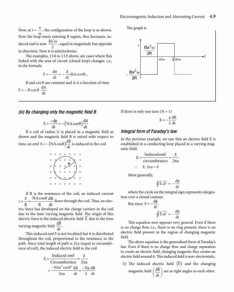
Now, at t = pw
, the configuration of the loop is as shown. Now the loop starts entering B region, flux Increases, in-
duced emf is now 2Ba
2w
, equal in magnitude but opposite
in direction. Now it is anticlockwise. The examples, 13.6 to 13.9 above, are cases where flux
linked with the area of circuit (closed loop) changes. i.e., in the formula
E = - ddt
ddt
BAφθ= − ( cos ) ,
B and cos q are constant and A is a function of time
E = - B cos q dAdt
The graph is
t
i
π/ω 2 π/ω
R2Ba2ω
−
R2Ba2ω
(iv) By changing only the magnetic field B
( )d dBNAcosdt dt
fq
−= = −E
If a coil of radius ‘a’ is placed in a magnetic field as shown and the magnetic field B is varied with respect to
time, an emf ( ) dBNAcos
dtq= −E is induced in the coil.
× × × × × × ×
× × × × × × ×
× × × × × × ×
× × × × × × ×
× × × × × × ×
× × × × × × ×
a
If R is the resistance of the coil, an induced current NAcos dBi
R R dtq
= =E flows through the coil. Thus, an elec-
tric force has developed on the charge carriers in the coil due to the time varying magnetic field. The origin of this electric force is the induced electric field E due to the time
varying magnetic field dBdt
.
This induced emf E is not localized but it is distributed throughout the coil, proportional to the resistance in the path. Since total length of path is 2pa (equal to circumfer-ence of coil), the induced electric field in the coil
Induced emfCircumference 2 ap
= = EE
2N a cos0 dB Na dB
2 a dt 2 dtp
p
− ° −= =
If there is only one turn (N = 1)a dB
E2 dt
= −
Integral form of Faraday’s law
In the previous example, we saw that an electric field E is established in a conducting loop placed in a varying mag-netic field.
InducedemfE
circumferance 2 ap= = E
\ E. 2pa = E
More generally,
E d ddt ∫ = −. φ
where the circle on the integral sign represents integra-tion over a closed contour.
But since d ,dtf= −E
E d ddt
. = −∫φ
This equation now appears very general. Even if there is no charge flow, i.e., there is no ring present, there is an electric field present in the region of changing magnetic field.
The above equation is the generalized form of Faraday’s law. Even if there is no charge flow and charge separation to create an electric field, changing magnetic flux creates an electric field around it. This induced field is non-electrostatic.
(i) The induced electric field ( )E and the changing
magnetic field dBdt
are at right angles to each other.
4.10 Electromagnetic Induction and Alternating Current
(ii) The induced electric field is non-conservative in nature. Hence potential and potential difference do not have any meaning in such fields.
(iii) The induced electric field lines are circular (closed lines)
The generalized form of Faraday’s law is the underlying principle of electromagnetic fields proposed later by Maxwell.
The principle of induced electric field due to time varying magnetic field is used in a device called ‘ Betatron’ which is used for accelerating electrons.
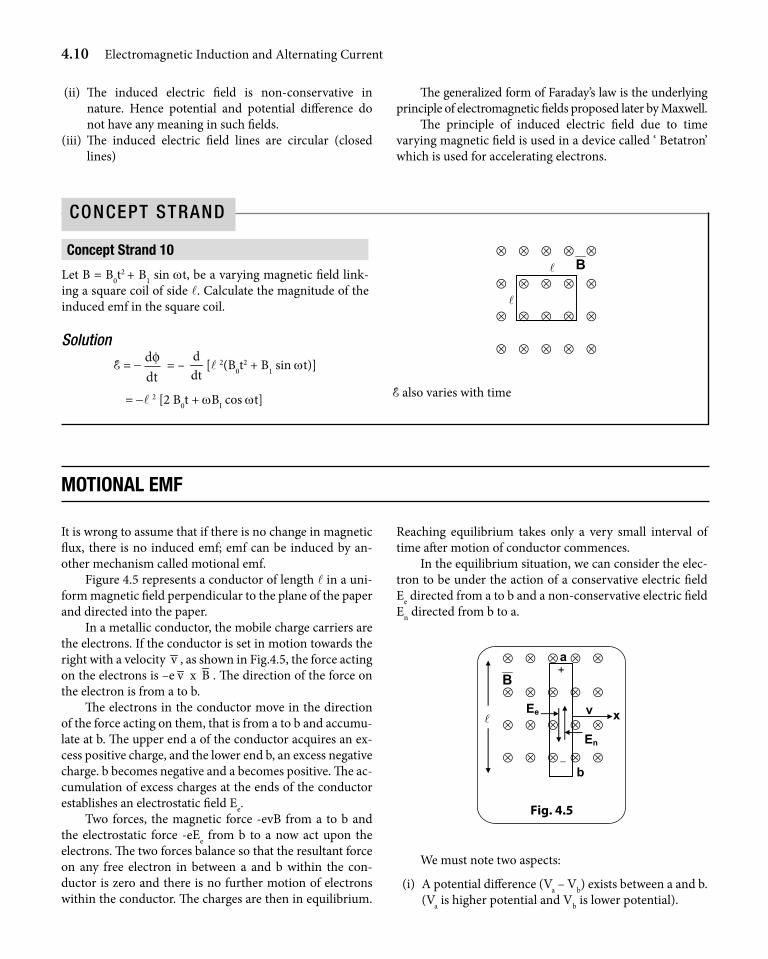
Concept strand 10
Let B = B0t2 + B1 sin wt, be a varying magnetic field link-
ing a square coil of side l. Calculate the magnitude of the induced emf in the square coil.
Solution
E = - ddtφ = –
ddt
[l 2(B0t2 + B1 sin wt)]
= -l 2 [2 B0t + wBI cos wt]
⊗ ⊗ ⊗ ⊗ ⊗
⊗ ⊗ ⊗ ⊗ ⊗
⊗ ⊗ ⊗ ⊗ ⊗
⊗ ⊗ ⊗ ⊗ ⊗
B
E also varies with time
ConCept Strand
mOtiOnal emF
It is wrong to assume that if there is no change in magnetic flux, there is no induced emf; emf can be induced by an-other mechanism called motional emf.
Figure 4.5 represents a conductor of length l in a uni-form magnetic field perpendicular to the plane of the paper and directed into the paper.
In a metallic conductor, the mobile charge carriers are the electrons. If the conductor is set in motion towards the right with a velocity v , as shown in Fig.4.5, the force acting on the electrons is –e v x B . The direction of the force on the electron is from a to b.
The electrons in the conductor move in the direction of the force acting on them, that is from a to b and accumu-late at b. The upper end a of the conductor acquires an ex-cess positive charge, and the lower end b, an excess negative charge. b becomes negative and a becomes positive. The ac-cumulation of excess charges at the ends of the conductor establishes an electrostatic field Ee.
Two forces, the magnetic force -evB from a to b and the electrostatic force -eEe from b to a now act upon the electrons. The two forces balance so that the resultant force on any free electron in between a and b within the con-ductor is zero and there is no further motion of electrons within the conductor. The charges are then in equilibrium.
Reaching equilibrium takes only a very small interval of time after motion of conductor commences.
In the equilibrium situation, we can consider the elec-tron to be under the action of a conservative electric field Ee directed from a to b and a non-conservative electric field En directed from b to a.
Fig. 4.5
x
a +
−
v
b
⊗ ⊗ ⊗ ⊗ ⊗
⊗ ⊗ ⊗ ⊗ ⊗
⊗ ⊗ ⊗ ⊗ ⊗
⊗ ⊗ ⊗ ⊗ ⊗
B
Ee
En
We must note two aspects:
(i) A potential difference (Va – Vb) exists between a and b. (Va is higher potential and Vb is lower potential).
Electromagnetic Induction and Alternating Current 4.11
(ii) The rod acts as a seat of electromotive force.
The potential difference Va – Vb is computed as per usual formula, -∫Ee.dl,
where Ee is the conservative electric field.The induced emf E is computed as per usual formula,
i.e., work done on a unit positive charge by the non conser-vative field to move it from negative to positive terminal
E = Enl where En is the nonconservative field.
At equilibrium, magnitudes
Ee = En and since En = Bl v
E = Va – Vb = Bl v as shown in Fig.4.6
a
b
Ee En
Fi g .4.6
E = Va − Vb
So, when a conducting rod moves perpendicular to B with speed v, the induced emf and the potential difference be-tween its ends = Bl v
But there is no current in the rod, because the circuit is not complete. It is an open circuit. The situation is similar to a cell not connected to any external circuit where En is the non- conservative field of chemical origin and Ee is the
Fig . 4.7
b
a
v ⊗
B
electrostatic field between positive and negative plates. The seat emf = E = work done in moving a unit positive charge
from b to a. So here the rod acts as a seat of emf. What hap-pens when the same rod is connected to an external circuit completing the loop as shown in Fig.4.7.
Let us assume that the lead wires and the outside cir-cuit do not lie within the region of the magnetic field. A current will be established in the circuit. If the conducting rod’s resistance is r and the outside circuit’s resistance is R,
then the current will be i = E
R rB vR r( ) ( )+
=+l
. The direction
of current will be positive to negative, from a to b in outer circuit and b to a within the rod. The directions of electric fields are shown in Fig.4.8.
b
a
v
+
−r
i
En
R
i = Bv/(R+r)
Ee
Fig. 4.8
As a result of the current, there is a reduction in the excess charges at the ends of the moving conductor, the electro-static field is weakened, and the magnetic force causes a further displacement of the free electrons within the con-ductor towards b. As long as the motion of the conductor is maintained, there is therefore, a continual current in the direction as shown.
The situation is similar to a battery circuit as shown in Fig.4.9.
i = E /(R+r) a
b
E +
Fig. 4.9
4.12 Electromagnetic Induction and Alternating Current
The resistance r of the moving rod is similar to internal resistance of the cell. If r = 0 (perfect conducting rod) then Va – Vb = Ee = En, otherwise Ee < En, Va – Vb < E, Va – Vb = E - ir.
Now if the external circuit lies within the B region there is no change from the last example since external part of the loop is stationary and there is no magnetic force on free electrons in them. Situation is the same as discussed above.
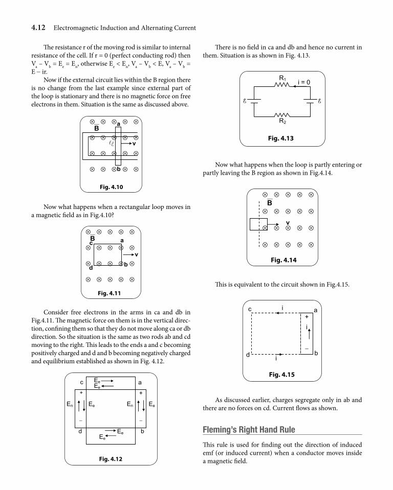
Fig. 4.10
b
a
v
⊗ ⊗ ⊗ ⊗ ⊗
⊗ ⊗ ⊗ ⊗ ⊗
⊗ ⊗ ⊗ ⊗ ⊗
⊗ ⊗ ⊗ ⊗
B
⊗
Now what happens when a rectangular loop moves in a magnetic field as in Fig.4.10?
Fig. 4.11
⊗ ⊗ ⊗ ⊗ ⊗
⊗ ⊗ ⊗ ⊗ ⊗
⊗ ⊗ ⊗ ⊗ ⊗
⊗ ⊗ ⊗ ⊗ ⊗
B a c
b d
v
Consider free electrons in the arms in ca and db in Fig.4.11. The magnetic force on them is in the vertical direc-tion, confining them so that they do not move along ca or db direction. So the situation is the same as two rods ab and cd moving to the right. This leads to the ends a and c becoming positively charged and d and b becoming negatively charged and equilibrium established as shown in Fig. 4.12.
ac
bd
+ +
− −
En En Ee Ee
Ee Ee
Ee Ee
Fig. 4.12
There is no field in ca and db and hence no current in them. Situation is as shown in Fig. 4.13.
R1
R2
i = 0
E E
Fig. 4.13
Now what happens when the loop is partly entering or partly leaving the B region as shown in Fig.4.14.
Fig. 4.14
v
⊗ ⊗ ⊗ ⊗ ⊗
⊗ ⊗ ⊗ ⊗ ⊗
⊗ ⊗ ⊗ ⊗ ⊗
⊗ ⊗ ⊗ ⊗ ⊗
B
This is equivalent to the circuit shown in Fig.4.15.
b
a+
−
i
i
i d
c
Fig. 4.15
As discussed earlier, charges segregate only in ab and there are no forces on cd. Current flows as shown.
Fleming’s right hand rule
This rule is used for finding out the direction of induced emf (or induced current) when a conductor moves inside a magnetic field.
Electromagnetic Induction and Alternating Current 4.13
According to this rule, if we stretch our thumb, in-dex finger and middle finger of the right hand in mutually perpendicular directions, with the thumb in the direction
of motion and index finger in the direction of the mag-netic field, then the direction in which the middle finger is stretched gives the direction of induced current.
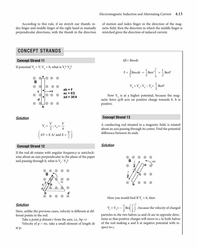
Concept strand 11
If potential Va = V, Vb = 0, what is Vc? Vd?
v c
d
ab = ℓ ac = ℓ/2 ad = 3ℓ/4
⊗ ⊗ ⊗ ⊗ ⊗
⊗ ⊗ ⊗ ⊗ ⊗
⊗ ⊗ ⊗ ⊗ ⊗
⊗ ⊗ ⊗ ⊗ ⊗
B
b
a
• •
Solution
Vc = V2
, vd = V4
VV E and ED D = =
ll
Concept strand 12
If the rod ab rotates with angular frequency w anticlock-wise about an axis perpendicular to the plane of the paper and passing through b, what is Va– Vb?
ω
a
b a’
p
⊗ ⊗ ⊗ ⊗ ⊗
⊗ ⊗ ⊗ ⊗ ⊗
⊗ ⊗ ⊗ ⊗
⊗ ⊗ ⊗ ⊗ ⊗
B
•r
SolutionHere, unlike the previous cases, velocity is different at dif-ferent points in the rod.
Take a point p distant r from the axis, i.e., bp =rVelocity of p = rw, take a small element of length dr
at p,
DE= Brwdr
E = 0
Br drw∫l
= 2
0
1B r
2w
l
= 12
Bwℓ2
Vb > Va ; Vb - Va= 12
Bwℓ2
Now Vb is at a higher potential, because the mag-netic force qvB acts on positive charge towards b. b is positive.
Concept strand 13
A conducting rod situated in a magnetic field, is rotated about an axis passing through its centre. Find the potential difference between its ends.
Solution
2
c
a ω
b
⊗ ⊗ ⊗ ⊗ ⊗
⊗ ⊗
⊗ ⊗
⊗ ⊗ ⊗ ⊗
B
2
Here you would find If Vc = 0, then
Va = Vb= - 21
B2 2
w l , because the velocity of charged
particles in the two halves ca and cb are in opposite direc-tions so that positive charges will move to c in both halves of the rod making a and b at negative potential with re-spect to c.
ConCept StrandS
4.14 Electromagnetic Induction and Alternating Current
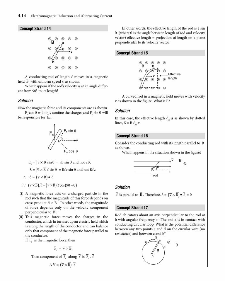
Concept strand 14
a
b
θ v
⊗ ⊗ ⊗ ⊗ ⊗
⊗ ⊗ ⊗ ⊗
⊗ ⊗ ⊗ ⊗ ⊗
⊗ ⊗ ⊗ ⊗ ⊗
B
A conducting rod of length l moves in a magnetic field B with uniform speed v, as shown.
What happens if the rod’s velocity is at an angle differ-ent from 90° to its length?
Solution
Now the magnetic force and its components are as shown.Fn cos q will only confine the charges and Fn sin q will
be responsible for nE .
vθ nF
Fn sin θ
Fn cos θ
En = v B× sin q = vB sin q and not vB;
E = v B× l sin q = Blv sin q and not Blv.
∴ E = ( )v B× • l
(Q ( ) ( ) ( )v B . v B . cos 90 q× = × −l l
(i) A magnetic force acts on a charged particle in the rod such that the magnitude of this force depends on cross product v B× . In other words, the magnitude of force depends only on the velocity component perpendicular to B .
(ii) This magnetic force moves the charges in the conductor, which in turn set up an electric field which is along the length of the conductor and can balance only that component of the magnetic force parallel to the conductor.
If nF is the magnetic force, then
nF = v B×
Then component of nF along l is nF . l
D V = ( )v B .× l
In other words, the effective length of the rod is ℓ sin q. (where q is the angle between length of rod and velocity vector) effective length = projection of length on a plane perpendicular to its velocity vector.
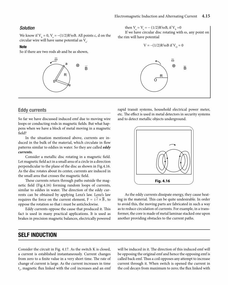
Concept strand 15
Effectivelength
v
X⊗ ⊗ ⊗ ⊗ ⊗
⊗ ⊗ ⊗ ⊗ ⊗
⊗ ⊗ ⊗ ⊗ ⊗
⊗ ⊗ ⊗ ⊗ ⊗
B
A curved rod in a magnetic field moves with velocity v as shown in the figure. What is E?
Solution
In this case, the effective length leff is as shown by dotted lines, E = B leff v
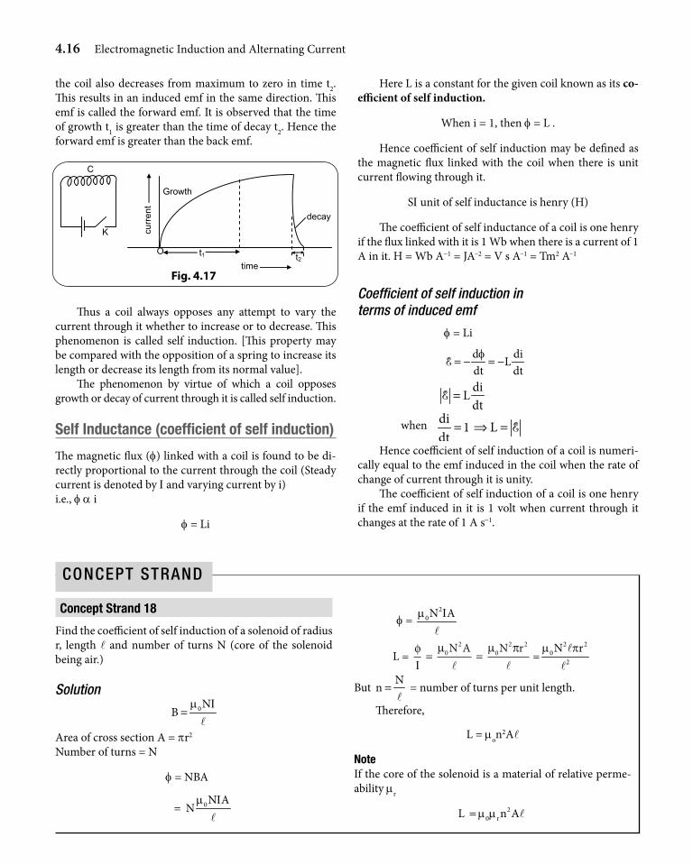
Concept strand 16
Consider the conducting rod with its length parallel to B as shown.
What happens in the situation shown in the figure?
B
rod
θ
v⊗
Solution
l is parallel to B . Therefore, E = ( )v B× • l = 0
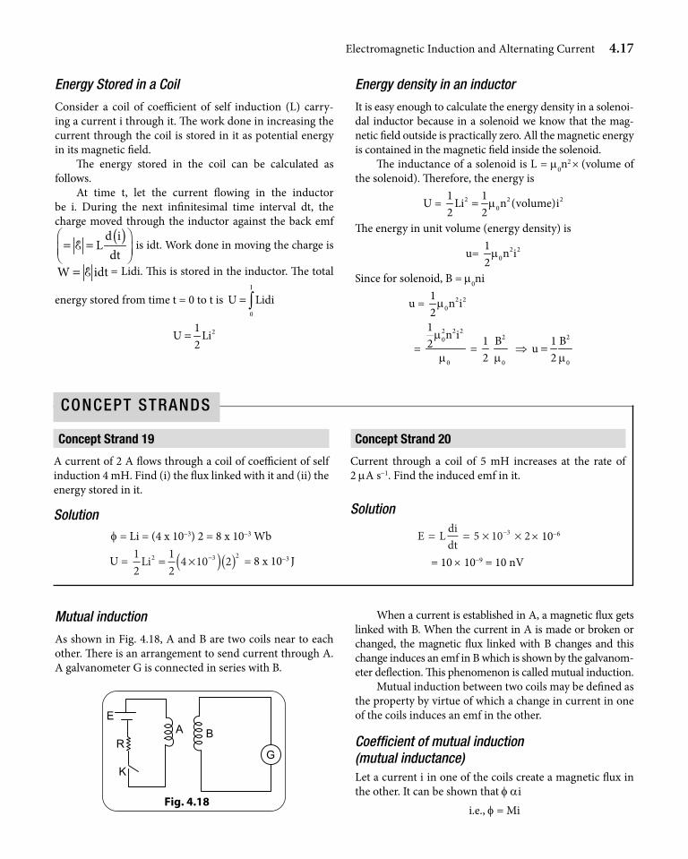
Concept strand 17
Rod ab rotates about an axis perpendicular to the rod at b with angular frequency w. The end a is in contact with conducting circular loop. What is the potential difference between any two points c and d on the circular wire (no resistance) and between c and b?
c
bR
d⊗
ω
Ba
Electromagnetic Induction and Alternating Current 4.15
Solution
We know if Vb = 0, Va = -(1/2)R2wB. All points c, d on the circular wire will have same potential as Va.
noteSo if there are two rods ab and be as shown,
b
R
e
⊗B
aω
then Va = Ve = - (1/2)R2wB, if Vb =0If we have circular disc rotating with w, any point on
the rim will have potential
V = -(1/2)R2wB if VO = 0
OR
⊗ω
B
eddy currents
So far we have discussed induced emf due to moving wire loops or conducting rods in magnetic fields. But what hap-pens when we have a block of metal moving in a magnetic field?
In the situation mentioned above, currents are in-duced in the bulk of the material, which circulate in flow patterns similar to eddies in water. So they are called eddy currents.
Consider a metallic disc rotating in a magnetic field. Let magnetic field act in a small area of a circle in a direction perpendicular to the plane of the disc as shown in Fig.4.16. As the disc rotates about its center, currents are induced in the small area that crosses the magnetic field.
These currents return through paths outside the mag-netic field (Fig.4.16) forming random loops of currents, similar to eddies in water. The direction of the eddy cur-rents can be obtained by applying Lenz’s law. Lenz’s law requires the force on the current element, F = i B×l , to oppose the rotation so that i must be anticlockwise.
Eddy currents oppose the cause that produced it. This fact is used in many practical applications. It is used as brakes in precision magnetic balances, electrically powered
rapid transit systems, household electrical power meter, etc. The effect is used in metal detectors in security systems and to detect metallic objects underground.
Fig. 4.16
As the eddy currents dissipate energy, they cause heat-ing in the material. This can be quite undesirable. In order to avoid this, the moving parts are fabricated in such a way as to reduce circulation of currents. For example, in a trans-former, the core is made of metal laminae stacked one upon another providing obstacles to the current paths.
selF induCtiOn
Consider the circuit in Fig. 4.17. As the switch K is closed, a current is established instantaneously. Current changes from zero to a finite value in a very short time. The rate of change of current is large. As the current increases in time t1, magnetic flux linked with the coil increases and an emf
will be induced in it. The direction of this induced emf will be opposing the original emf and hence the opposing emf is called back emf. Thus a coil opposes any attempt to increase current through it. When switch is opened the current in the coil decays from maximum to zero; the flux linked with
4.16 Electromagnetic Induction and Alternating Current
the coil also decreases from maximum to zero in time t2. This results in an induced emf in the same direction. This emf is called the forward emf. It is observed that the time of growth t1 is greater than the time of decay t2. Hence the forward emf is greater than the back emf.
K
C
t2time
t1O
curr
ent
decay
Growth
Fig. 4.17
Thus a coil always opposes any attempt to vary the current through it whether to increase or to decrease. This phenomenon is called self induction. [This property may be compared with the opposition of a spring to increase its length or decrease its length from its normal value].
The phenomenon by virtue of which a coil opposes growth or decay of current through it is called self induction.
self inductance (coefficient of self induction)
The magnetic flux (f) linked with a coil is found to be di-rectly proportional to the current through the coil (Steady current is denoted by I and varying current by i)i.e., f a i
f = Li
Here L is a constant for the given coil known as its co-efficient of self induction.
When i = 1, then f = L .
Hence coefficient of self induction may be defined as the magnetic flux linked with the coil when there is unit current flowing through it.
SI unit of self inductance is henry (H)
The coefficient of self inductance of a coil is one henry if the flux linked with it is 1 Wb when there is a current of 1 A in it. H = Wb A-1 = JA–2 = V s A–1 = Tm2 A–1
Coefficient of self induction in terms of induced emf
f = Li
d diLdt dtf= − = −E
diLdt
=E
when di 1 Ldt
= ⇒ = EHence coefficient of self induction of a coil is numeri-
cally equal to the emf induced in the coil when the rate of change of current through it is unity.
The coefficient of self induction of a coil is one henry if the emf induced in it is 1 volt when current through it changes at the rate of 1 A s-1.
Concept strand 18
Find the coefficient of self induction of a solenoid of radius r, length l and number of turns N (core of the solenoid being air.)
Solution0N
Bm I
=l
Area of cross section A = pr2
Number of turns = N
f = NBA
= 0N AN
m Il
f = 2
0N Am Il
L = φ µ µ πΙ= =0
20
2 2N A N rl l
=2 2
02
N rm pll
But N
n =l
= number of turns per unit length.
Therefore,
L = mon2Al
noteIf the core of the solenoid is a material of relative perme-ability mr
L 20 rn Am m= l
ConCept Strand
Electromagnetic Induction and Alternating Current 4.17
Energy Stored in a Coil
Consider a coil of coefficient of self induction (L) carry-ing a current i through it. The work done in increasing the current through the coil is stored in it as potential energy in its magnetic field.
The energy stored in the coil can be calculated as follows.
At time t, let the current flowing in the inductor be i. During the next infinitesimal time interval dt, the charge moved through the inductor against the back emf
( )d iL
dt = =
E is idt. Work done in moving the charge is
W idt= E = Lidi. This is stored in the inductor. The total
energy stored from time t = 0 to t is 0
U LidiI
= ∫21
U Li2
=
Energy density in an inductor
It is easy enough to calculate the energy density in a solenoi-dal inductor because in a solenoid we know that the mag-netic field outside is practically zero. All the magnetic energy is contained in the magnetic field inside the solenoid.
The inductance of a solenoid is L = m0n2 × (volume of
the solenoid). Therefore, the energy is
U = 2 2 20
1 1Li n (volume)i
2 2m=
The energy in unit volume (energy density) is
u= 2 20
1n i
2m
Since for solenoid, B = m0ni
u = 2 20
1n i
2m
= 2 2 20
0
1 n i2
m
m =
12
2
0
Bm
⇒ 2
0
1 Bu
2 m=
Concept strand 19
A current of 2 A flows through a coil of coefficient of self induction 4 mH. Find (i) the flux linked with it and (ii) the energy stored in it.
Solutionf = Li = (4 x 10⁻³) 2 = 8 x 10⁻³ Wb
U = 12
12
4 10 22 3 2Li = ×( )( )− = 8 x 10⁻³ J
Concept strand 20
Current through a coil of 5 mH increases at the rate of 2 mA s-1. Find the induced emf in it.
Solution
E L didt
= = × ×−5 10 23 × 10-6
= 10 × 10-9 = 10 nV
ConCept StrandS
Mutual induction
As shown in Fig. 4.18, A and B are two coils near to each other. There is an arrangement to send current through A. A galvanometer G is connected in series with B.
E
R
K
A
G
B
Fig. 4.18
When a current is established in A, a magnetic flux gets linked with B. When the current in A is made or broken or changed, the magnetic flux linked with B changes and this change induces an emf in B which is shown by the galvanom-eter deflection. This phenomenon is called mutual induction.
Mutual induction between two coils may be defined as the property by virtue of which a change in current in one of the coils induces an emf in the other.
Coefficient of mutual induction (mutual inductance)Let a current i in one of the coils create a magnetic flux in the other. It can be shown that f ai
i.e., f = Mi
4.18 Electromagnetic Induction and Alternating Current
Here M is a constant for the given alignment of the two coils and is known as coefficient of mutual induction.
Hence coefficient of mutual induction between two coils may be defined as the magnetic flux linked with one of the coils when a unit current is flowing through the other.
Now the emf induced in the second coil is
d diMdt dtf= − = −E
Using this equation also we can define coefficient of mutual induction.
Coefficient of mutual induction between two coils is the emf induced in one of the coils when the rate of change of current through the other is unity.
Unit of coefficient of mutual induction
Unit of M is henry (H). The coefficient of mutual induction between two coils is said to be one henry if the induced
emf in one coil is 1 V when the current through the other changes at the rate of 1 A s-1.
note: (i) Coefficient of mutual induction of coil A with respect
to another coil B is the same as that of B with respect to A i.e., MAB = MBA
(ii) If L1 and L2 are the coefficient of self induction of the two coils and M is coefficient of mutual induction between them.
M = K 1 2L L
where K is a constant known as the coefficient of coupling between the two coils. The value of K lies between 0 and +1.
K = 1 ⇒ perfect (tight) couplingK = 0 ⇒ loose coupling
(iii) Devices like Induction coil and transformer work on the principle of mutual induction.
Concept strand 21
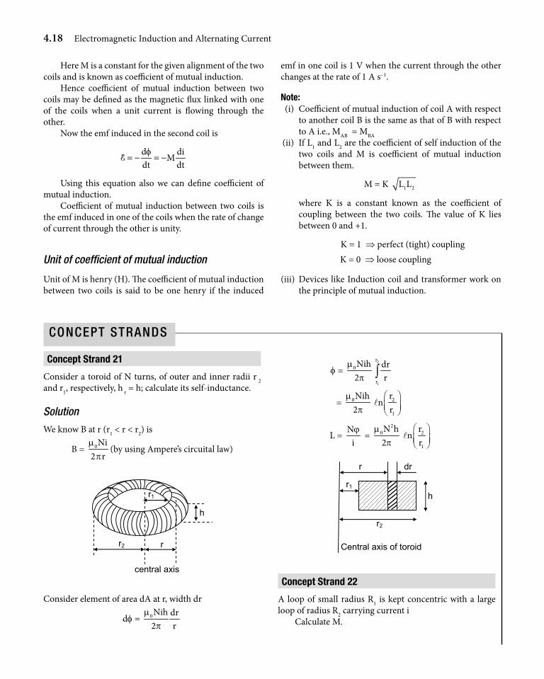
Consider a toroid of N turns, of outer and inner radii r 2 and r1, respectively, h r = h; calculate its self-inductance.
Solution
We know B at r (r1 < r < r2) is
B = 0Ni2 rm
p(by using Ampere’s circuital law)
h
r2
r1
r
central axis
Consider element of area dA at r, width dr
df = 0Nih dr2 r
mp
f = 0Nih2
mp
2
1
r
r
drr∫
= 0Nih2
mp
2
1
rn
r
l
L = N
iϕ
= 2
0N h2
mp
2
1
rn
r
l
dr r
r1
h
r2
Central axis of toroid
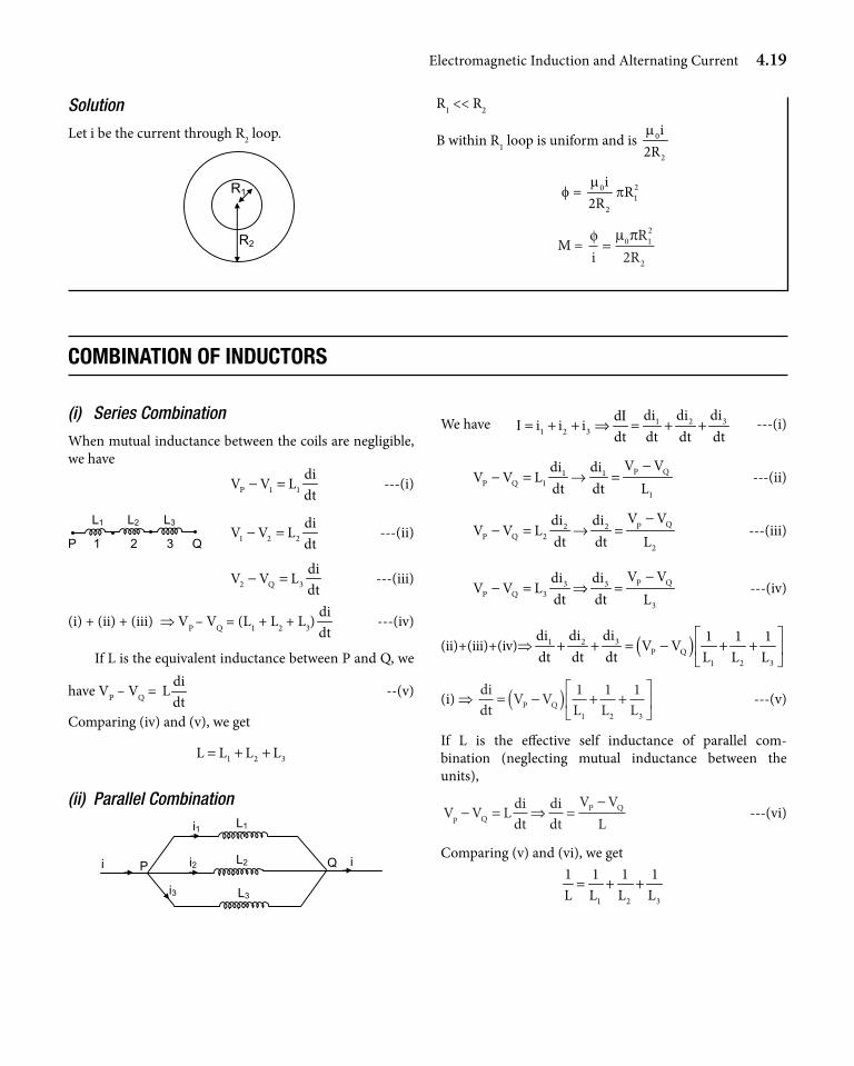
Concept strand 22
A loop of small radius R1 is kept concentric with a large loop of radius R2 carrying current i
Calculate M.
ConCept StrandS
Electromagnetic Induction and Alternating Current 4.19
(i) Series Combination
When mutual inductance between the coils are negligible, we have
P 1 1
diV V L
dt− = ---(i)
1 2 2
diV V L
dt− = ---(ii)
2 Q 3
diV V L
dt− = ---(iii)
(i) + (ii) + (iii) ⇒ VP – VQ = (L1 + L2 + L3)didt
---(iv)
If L is the equivalent inductance between P and Q, we
have VP – VQ = di
Ldt
--(v)
Comparing (iv) and (v), we get
1 2 3L L L L= + +
(ii) Parallel Combination
P Q
i1
i2
i3
L2
L3
ii
L1
We have 31 21 2 3
didi didi i i
dt dt dt dtI
I = + + ⇒ = + + ---(i)
P Q1 1P Q 1
1
V Vdi diV V L
dt dt L−
− = → = ---(ii)
p Q2 2P Q 2
2
V Vdi diV V L
dt dt L−
− = → = ---(iii)
P Q3 3P Q 3
3
V Vdi diV V L
dt dt L−
− = ⇒ = ---(iv)
(ii) + (iii) + (iv) ⇒ ( )31 2P Q
1 2 3
didi di 1 1 1V V
dt dt dt L L L
+ + = − + +
(i) ⇒ didt
V VL L LP Q= −( ) + +
1 1 11 2 3
---(v)
If L is the effective self inductance of parallel com- bination (neglecting mutual inductance between the units),
V V L didt
didt
V VLp Q
P Q− = ⇒ =−
---(vi)
Comparing (v) and (vi), we get
1 2 3
1 1 1 1L L L L= + +
Solution
Let i be the current through R2 loop.
R1
R2
R1 << R2
B within R1 loop is uniform and is 0
2
i2Rm
f = 201
2
iR
2Rm
p
M = φµ π
iR
R= 0 1
2
22
COmbinatiOn OF induCtOrs
4.20 Electromagnetic Induction and Alternating Current
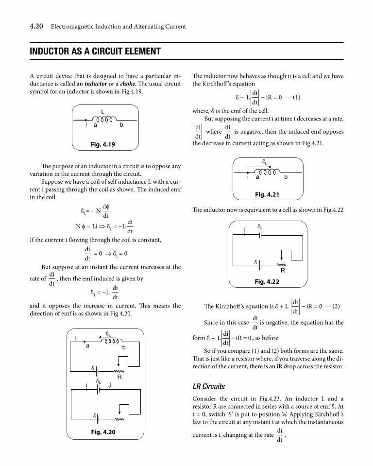
A circuit device that is designed to have a particular in-ductance is called an inductor or a choke. The usual circuit symbol for an inductor is shown in Fig.4.19.
i a
L
b
Fig. 4.19
The purpose of an inductor in a circuit is to oppose any variation in the current through the circuit.
Suppose we have a coil of self inductance L with a cur-rent i passing through the coil as shown. The induced emf in the coil
EL= - Nddtφ
N f = Li ⇒ EL = -Ldidt
If the current i flowing through the coil is constant, didt
= 0 ⇒ EL = 0
But suppose at an instant the current increases at the
rate of didt
, then the emf induced is given by
EL = -L didt
and it opposes the increase in current. This means the direction of emf is as shown in Fig.4.20.
EL
bai
ERELi ⇓
E
Fig. 4.20
The inductor now behaves as though it is a cell and we have the Kirchhoff ’s equation
E - di
L iR 0dt
− = — (1)
where, E is the emf of the cell.But supposing the current i at time t decreases at a rate,
didt
where didt
is negative, then the induced emf opposes
the decrease in current acting as shown in Fig.4.21.
i a
EL
b
Fig. 4.21
The inductor now is equivalent to a cell as shown in Fig.4.22
Fig. 4.22
R
i EL
E
The Kirchhoff ’s equation is E + L di
iR 0dt
− = — (2)
Since in this case didt
is negative, the equation has the
form E – di
L iR 0dt
− = , as before.
So if you compare (1) and (2) both forms are the same. That is just like a resistor where, if you traverse along the di-rection of the current, there is an iR drop across the resistor.
LR Circuits
Consider the circuit in Fig.4.23. An inductor L and a resistor R are connected in series with a source of emf E. At t = 0, switch ‘S’ is put to position ‘a’. Applying Kirchhoff ’s law to the circuit at any instant t at which the instantaneous
current is i, changing at the rate didt
,
induCtOr as a CirCuit element
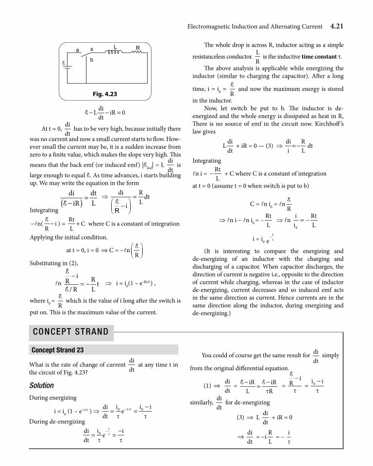
Electromagnetic Induction and Alternating Current 4.21
R L a s
b E
Fig. 4.23
diL iR 0dt
− − =E
At t = 0, didt
has to be very high, because initially there was no current and now a small current starts to flow. How-ever small the current may be, it is a sudden increase from zero to a finite value, which makes the slope very high. This means that the back emf (or induced emf) |Eind| = L
didt
is large enough to equal E. As time advances, i starts building up. We may write the equation in the form
( )di dt
iR L=
−E ⇒ di R dt
Li=
− ERIntegrating
-ln( iR−E ) =
RtC
L+ where C is a constant of integration
Applying the initial condition.
at t = 0, i = 0 ⇒ C = -lnR
E
Substituting in (2),
ln i RR t
/ R L
−= −
E
E ⇒ i = i0(1 – e-Rt/L) ,
where i0 = RE which is the value of i long after the switch is
put on. This is the maximum value of the current.
The whole drop is across R, inductor acting as a simple
resistanceless conductor. LR
is the inductive time constant t.
The above analysis is applicable while energizing the inductor (similar to charging the capacitor). After a long
time, i = i0 = RE and now the maximum energy is stored
in the inductor. Now, let switch be put to b. The inductor is de-
energized and the whole energy is dissipated as heat in R, There is no source of emf in the circuit now. Kirchhoff ’s law gives
diL
dt + iR = 0 — (3) ⇒
di Rdt
i L=−
Integrating
ln i = RtL
− + C where C is a constant of integration
at t = 0 (assume t = 0 when switch is put to b)
C = ln i0 = lnRE
⇒ ln i - ln i0 = –RtL
⇒ ln 0
i Rti L= −
i = i0
t
e t−
(It is interesting to compare the energizing and de-energizing of an inductor with the charging and discharging of a capacitor. When capacitor discharges, the direction of current is negative i.e., opposite to the direction of current while charging, whereas in the case of inductor de-energizing, current decreases and so induced emf acts in the same direction as current. Hence currents are in the same direction along the inductor, during energizing and de-energizing.)
Concept strand 23
What is the rate of change of current didt
at any time t in the circuit of Fig. 4.23?
Solution
During energizing
i = i0 (1 – e-t/t ) ⇒ t/0 0i i idie
dtt
t t− −
= =During de-energizing
t0idi i
edt
t
t t− −
= =
You could of course get the same result for didt
simply
from the original differential equation.
(1) ⇒ didt
= iR iRL Rt− −=E E =
iR
t
−E
= 0i it−
similarly, didt
for de-energizing
(3) ⇒ L didt
+ iR = 0
⇒didt
= -iRL
= - it
ConCept Strand
4.22 Electromagnetic Induction and Alternating Current
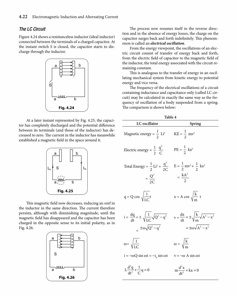
The LC Circuit
Figure 4.24 shows a resistanceless inductor (ideal inductor) connected between the terminals of a charged capacitor. At the instant switch S is closed, the capacitor starts to dis-charge through the inductor.
ba
a b
S
+++++
- - - - -
Fig. 4.24
At a later instant represented by Fig. 4.25, the capaci-tor has completely discharged and the potential difference between its terminals (and those of the inductor) has de-creased to zero. The current in the inductor has meanwhile established a magnetic field in the space around it.
ba
a b
SΙm Im
Fig. 4.25
This magnetic field now decreases, inducing an emf in the inductor in the same direction. The current therefore persists, although with diminishing magnitude, until the magnetic field has disappeared and the capacitor has been charged in the opposite sense to its initial polarity, as in Fig. 4.26.
ba
a b
S
+ + + + +
- - - - -
Fig. 4.26
The process now resumes itself in the reverse direc-tion and in the absence of energy losses, the charge on the capacitor surges back and forth indefinitely. This phenom-enon is called an electrical oscillation.
From the energy viewpoint, the oscillations of an elec-tric circuit consist of transfer of energy back and forth, from the electric field of capacitor to the magnetic field of the inductor, the total energy associated with the circuit re-maining constant.
This is analogous to the transfer of energy in an oscil-lating mechanical system from kinetic energy to potential energy and vice versa.
The frequency of the electrical oscillations of a circuit containing inductance and capacitance only (called LC cir-cuit) may be calculated in exactly the same way as the fre-quency of oscillation of a body suspended from a spring. The comparison is shown below:
Table 4LC oscillator Spring
Magnetic energy = 12
Li2 KE = 12
mv2
Electric energy = 12
2q
CPE =
12
kx2
Total Energy = 12
Li2 + 2q
2C
= 2Q
2C
E = 12
mv2 + 12
kx2
= 2kA
2
q = Q cos 1
tLC
x = A cos km
t
i = dqdt
= ± 2 21Q q
LC−
= 2 2Q qw± −
v = 2 2dx kA x
dt m= ± −
2 2A xw= ± −
w= 1
LC w =
km
i = -wQ sin wt = -i0 sin wt v = -w A sin wt
2
2
d q 1L q 0
Cdt+ =
2
2
d xm kx 0
dt+ =
Electromagnetic Induction and Alternating Current 4.23
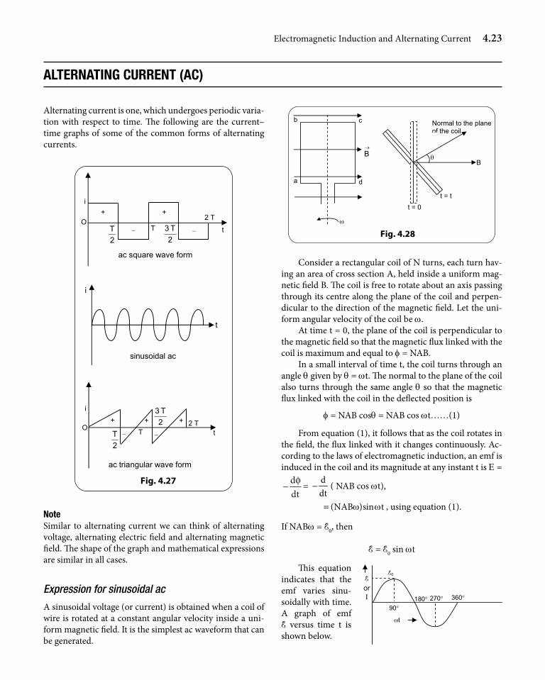
alternating Current (aC)
Alternating current is one, which undergoes periodic varia-tion with respect to time. The following are the current–time graphs of some of the common forms of alternating currents.
i
O +
2T
+
2T3
− − t T 2 T
ac square wave form
ac triangular wave form
i
O +
2T
2T3
t T 2 T +
−
+
−
t
i
sinusoidal ac
Fig. 4.27
noteSimilar to alternating current we can think of alternating voltage, alternating electric field and alternating magnetic field. The shape of the graph and mathematical expressions are similar in all cases.
Expression for sinusoidal ac
A sinusoidal voltage (or current) is obtained when a coil of wire is rotated at a constant angular velocity inside a uni-form magnetic field. It is the simplest ac waveform that can be generated.
a
b c
d
ω
→B θ
t = 0
t = t
B
Normal to the plane of the coil
Fig. 4.28
Consider a rectangular coil of N turns, each turn hav-ing an area of cross section A, held inside a uniform mag-netic field B. The coil is free to rotate about an axis passing through its centre along the plane of the coil and perpen-dicular to the direction of the magnetic field. Let the uni-form angular velocity of the coil be w.
At time t = 0, the plane of the coil is perpendicular to the magnetic field so that the magnetic flux linked with the coil is maximum and equal to f = NAB.
In a small interval of time t, the coil turns through an angle q given by q = wt. The normal to the plane of the coil also turns through the same angle q so that the magnetic flux linked with the coil in the deflected position is
f = NAB cosq = NAB cos wt……(1)
From equation (1), it follows that as the coil rotates in the field, the flux linked with it changes continuously. Ac-cording to the laws of electromagnetic induction, an emf is induced in the coil and its magnitude at any instant t is E =
−ddtφ =
ddt
− ( NAB cos wt),
(NAB )sin tw w= , using equation (1).
If NABw = E0, then
E = E0 sin wt
This equation indicates that the emf varies sinu-soidally with time. A graph of emf E versus time t is shown below.
E or Ι
90° 180° 270° 360°
ωt
E0
4.24 Electromagnetic Induction and Alternating Current
The maximum value of the induced emf in the coil is E0 = NABw and it occurs when wt = 90° or 270°.i.e when the plane of the coil is parallel to the magnetic field (normal to the coil and perpendicular to the magnetic field).
The induced emf in the coil is zero, when wt = 0° or 180°. i.e when the plane of the coil is perpendicular to the field.
If R is the resistance of the circuit to which the coil is connected, then the induced current i is given by the ex-pression (ac usually denoted by small letter i)
i = 00sin t i sin t
R Rw w= =
EE ,
where
00i R=
E is the maximum induced current.
0i i sin tw=
It is clear from the above equation that the current also varies sinusoidally with time.
Sinusoidal ac
ac is said to be sinusoidal if current-time graph is a sine curve. A sinusoidal ac can be mathematically represented as
i = io sin(wt + q) , where
i is the current at any time t; (i is also called the instan-taneous current)
i0 is the maximum numerical value of the current and is known as peak current.
(wt + q) is called the phase of alternating current at the time t, its SI unit being radian.
w is called the angular frequency of the ac. The unit of w is rad s-1.
q is the value of the phase when time t = 0 and is known as initial phase.
2T
pw
= is the period of sinusoidal variation and
1T 2
wυ
p= = is the frequency of ac.
The unit of period is second and the unit of frequency is hertz (Hz).
Average value of alternating current during a cycle (im) (Mean value)
Average value of alternating current during one complete cycle is zero since current in the positive half cycle and negative half cycle (being equal and opposite) cancel each other.
The average value fav of any quantity f (t) that varies with time, over a time interval from t1 to t2 is defined as
fav =
2
1
t
t
2 1
f (t)dt
(t t )−
∫
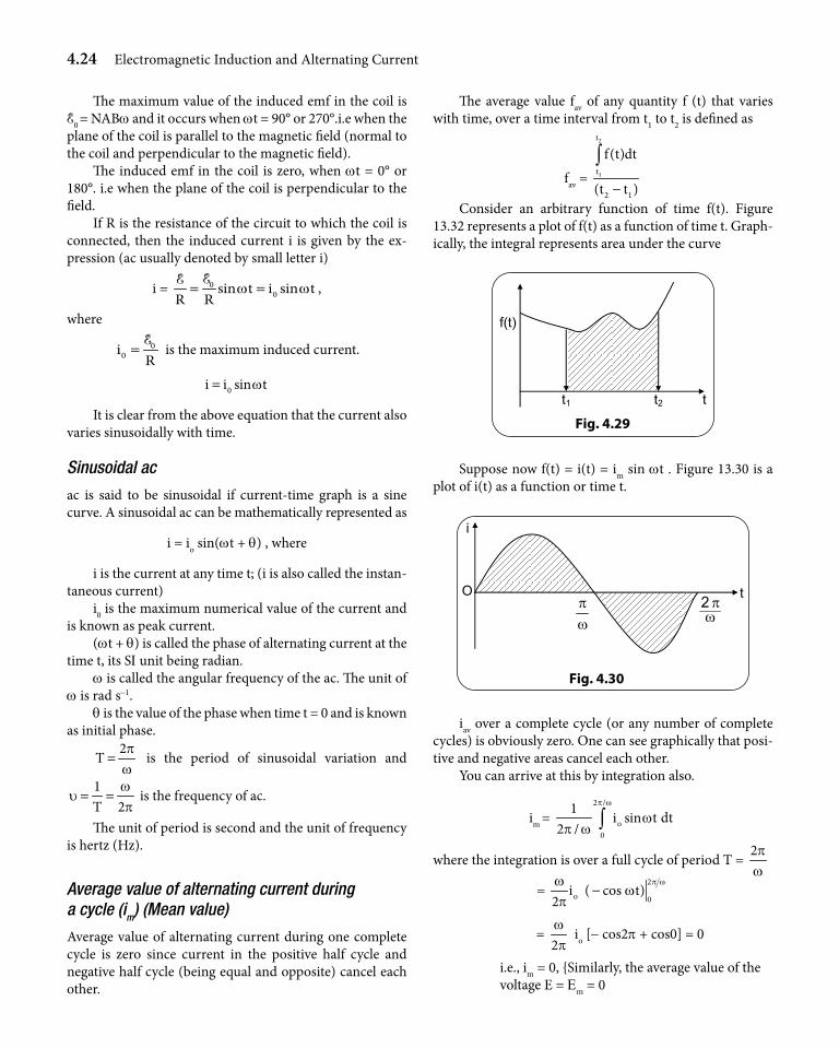
Consider an arbitrary function of time f(t). Figure 13.32 represents a plot of f(t) as a function of time t. Graph-ically, the integral represents area under the curve
f(t)
t t1 t2
Fig. 4.29
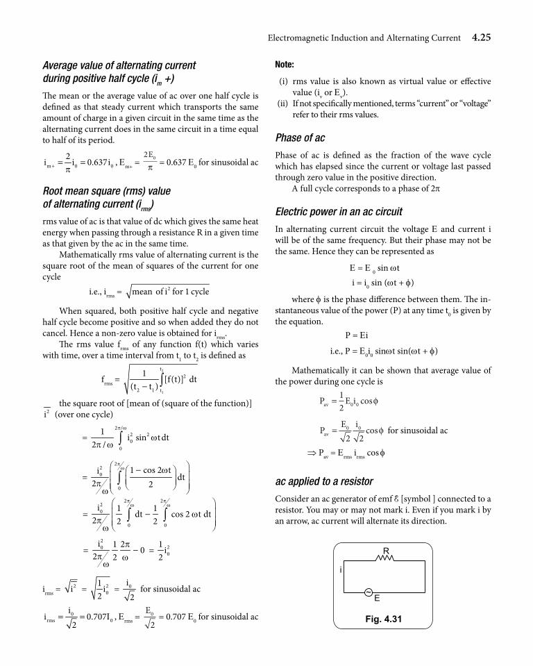
Suppose now f(t) = i(t) = im sin wt . Figure 13.30 is a plot of i(t) as a function or time t.
ωπ
ωπ2 tO
i
Fig. 4.30
iav over a complete cycle (or any number of complete cycles) is obviously zero. One can see graphically that posi-tive and negative areas cancel each other.
You can arrive at this by integration also.
im = 2 /
o0
1i sin t dt
2 /
p w
wp w ∫
where the integration is over a full cycle of period T = 2pw
= 2
o 0i ( cos t)
2p ww
wp
−
= 2wp
io [- cos2p + cos0] = 0
i.e., im = 0, Similarly, the average value of the voltage E = Em = 0
Electromagnetic Induction and Alternating Current 4.25
Average value of alternating current during positive half cycle (im +)
The mean or the average value of ac over one half cycle is defined as that steady current which transports the same amount of charge in a given circuit in the same time as the alternating current does in the same circuit in a time equal to half of its period.
m 0 02
i i 0.637ip+ = = , Em+ =
2 0Eπ = 0.637 E0 for sinusoidal ac
Root mean square (rms) value of alternating current (irms)
rms value of ac is that value of dc which gives the same heat energy when passing through a resistance R in a given time as that given by the ac in the same time.
Mathematically rms value of alternating current is the square root of the mean of squares of the current for one cycle
i.e., irms = 2mean of i for 1 cycle
When squared, both positive half cycle and negative half cycle become positive and so when added they do not cancel. Hence a non-zero value is obtained for irms.
The rms value frms of any function f(t) which varies with time, over a time interval from t1 to t2 is defined as
frms = 2
1
t2
2 1 t
1[f(t)] dt
(t t )− ∫the square root of [mean of (square of the function)]
2i (over one cycle)
= 2 /
2 20
0
1i sin tdt
2 /
p w
wp w ∫
= 2
20
0
1 cos 2 tidt
2 2
pw w
pw
− ∫
= 2 2
20
0 0
i 1 1dt cos 2 t dt
2 2 2
p pw w
wp
w
− ∫ ∫
= 20i 1 2
02 2
pp w
w− = 2
01
i2
irms = 2i = 20
1i
2 = 0i
2 for sinusoidal ac
0rms 0
ii 0.707
2I= = , Erms =
E0
2= 0.707 E0 for sinusoidal ac
note:
(i) rms value is also known as virtual value or effective value (iv or Ev).
(ii) If not specifically mentioned, terms “current” or “voltage” refer to their rms values.
Phase of ac
Phase of ac is defined as the fraction of the wave cycle which has elapsed since the current or voltage last passed through zero value in the positive direction.
A full cycle corresponds to a phase of 2p
Electric power in an ac circuit
In alternating current circuit the voltage E and current i will be of the same frequency. But their phase may not be the same. Hence they can be represented as
E = E 0 sin wt i = i0 sin (wt + f)
where f is the phase difference between them. The in-stantaneous value of the power (P) at any time t0 is given by the equation.
P = Ei
i.e., P = E0i0 sinwt sin(wt + f)
Mathematically it can be shown that average value of the power during one cycle is
P E iav =
12 0 0 cosφ
P E iav =
0 0
2 2cosφ for sinusoidal ac
⇒ Pav = Erms irms cos f
ac applied to a resistor
Consider an ac generator of emf E [symbol ] connected to a resistor. You may or may not mark i. Even if you mark i by an arrow, ac current will alternate its direction.
E
i
~
Fig. 4.31
R
4.26 Electromagnetic Induction and Alternating Current
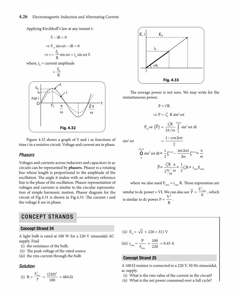
Applying Kirchhoff ’s law at any instant t:
E – iR = 0
⇒ E 0 sin wt – iR = 0
⇒ i = 0
RE
sin wt = i0 sin wt E
where, i0 = current amplitude
= 0
RE
E or i
Fig. 4.32
E
i
ωπ
ωπ2
t T1
E0
O
i0
Figure 4.32 shows a graph of E and i as functions of time t in a resistive circuit. Voltage and current are in phase.
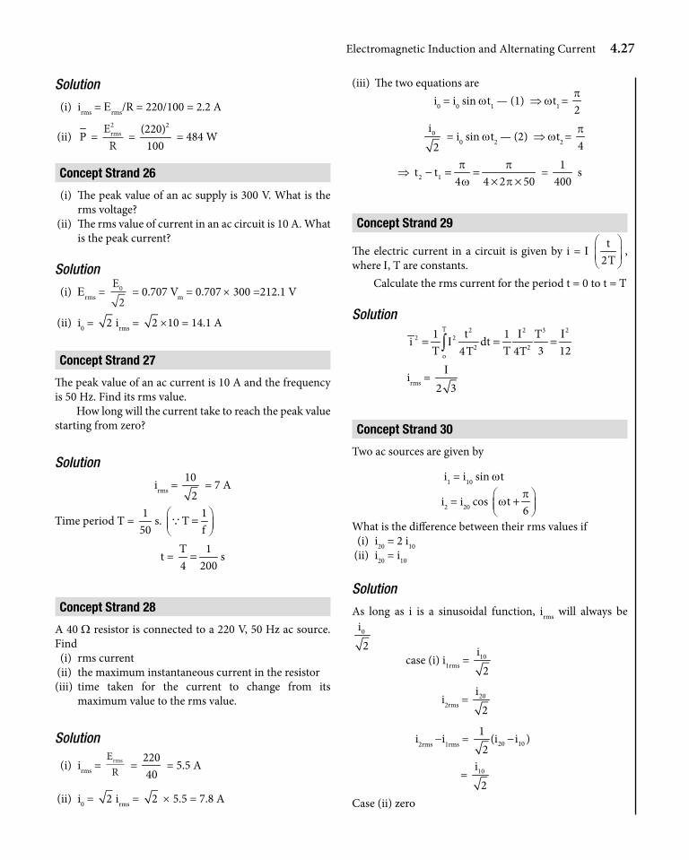
Phasors
Voltages and currents across inductors and capacitors in ac circuits can be represented by phasors. Phasor is a rotating line whose length is proportional to the amplitude of the oscillation. The angle it makes with an arbitrary reference line is the phase of the oscillation. Phasor representation of voltages and currents is similar to the circular representa-tion of simple harmonic motion. Phasor diagram for the circuit of Fig.4.31 is shown in Fig.4.33. The current i and the voltage E are in phase.
Fig. 4.33
Eo
io
ωt1
E, i
The average power is not zero. We may write for the instantaneous power,
P = i2R
⇒ P = 20i R sin2 wt
Pav or ( )P = 2 /2
20
0
i Rsin t dt
2 /
p w
wp w ∫
sin2 wt = 1 cos2 t
2w−
2 /2 2 / 2 /
0 00
t sin2 tsin t dt | |
2 2
p wp w p ww p
ww w
= - =ò
20 2
0 rms rms
i R 1P i R i E
22
pp w
w= = =
where we also used Erms = irms R. These expressions are
similar to dc power = VI. We can also see P = E
Rrms
2
, which
is similar to dc power P = 2V
R.
Concept strand 24
A light bulb is rated at 100 W for a 220 V sinusoidal AC supply. Find (i) the resistance of the bulb. (ii) The peak voltage of the rated source (iii) the rms current through the bulb
Solution
(i) R = E
Prms2
= 2(220)
100 = 484 W
(ii) E0 = 2 × 220 = 311 V
(iii) irms = rms
PE
= 100220
= 0.45 A
Concept strand 25
A 100 W resistor is connected to a 220 V, 50 Hz sinusoidal, ac supply. (i) What is the rms value of the current in the circuit? (ii) What is the net power consumed over a full cycle?
ConCept StrandS
Electromagnetic Induction and Alternating Current 4.27
Solution
(i) irms = Erms/R = 220/100 = 2.2 A
(ii) P = E
Rrms2
= 2(220)
100 = 484 W
Concept strand 26
(i) The peak value of an ac supply is 300 V. What is the rms voltage?
(ii) The rms value of current in an ac circuit is 10 A. What is the peak current?
Solution
(i) Erms = E0
2 = 0.707 Vm = 0.707 × 300 =212.1 V
(ii) i0 = 2 irms = 2 ×10 = 14.1 A
Concept strand 27
The peak value of an ac current is 10 A and the frequency is 50 Hz. Find its rms value.
How long will the current take to reach the peak value starting from zero?
Solution
irms = 10
2 = 7 A
Time period T = 1
50s.
1T
f = Q
t = T 14 200= s
Concept strand 28
A 40 W resistor is connected to a 220 V, 50 Hz ac source. Find (i) rms current (ii) the maximum instantaneous current in the resistor (iii) time taken for the current to change from its
maximum value to the rms value.
Solution
(i) irms = E
Rrms =
22040
= 5.5 A
(ii) i0 = 2 irms = 2 × 5.5 = 7.8 A
(iii) The two equations are i0 = i0 sin wt1 — (1) ⇒ wt1 =
2p
0i2
= i0 sin wt2 — (2) ⇒ wt2 = 4p
⇒ 2 1t t4 4 2 50p pw p
− = =× ×
= 1
400 s
Concept strand 29
The electric current in a circuit is given by i = I t
2T
, where I, T are constants.
Calculate the rms current for the period t = 0 to t = T
SolutionT 2 2 3 2
2 22 2
o
1 t 1 Ti dt
T T 3 124T 4TI I
I= = =∫
irms = 2 3
I
Concept strand 30
Two ac sources are given by
i1 = i10 sin wt
i2 = i20 cos t6p
w + What is the difference between their rms values if (i) i20 = 2 i10 (ii) i20 = i10
Solution
As long as i is a sinusoidal function, irms will always be0i2
case (i) i1rms = 10i2
i2rms = 20i2
i2rms -i1rms = 20 101
(i i )2
−
= 10i2
Case (ii) zero
4.28 Electromagnetic Induction and Alternating Current
Concept strand 31
(i) If a current i1 = 0i sin wt passes through a resistor R, what is the heat dissipated in one time period?
(ii) If the current is i2 = i0 sin (wt + p) what is the heat dissipated in two time periods?
(iii) If both i1 and i2 pass through R simultaneously, what is the heat dissipated in three time periods?
Solution
(i) P = 20
1i
2 R
Time period = 2pw
Heat dissipated in time 2pw
is 20i R
pw
(ii) P = 2 20i R
pw
(twice that of case (i)
(iii) i1 + i2 =0. Therefore P = 0
Concept strand 32
What is the rms value of an ac current whose instanta-neous value is i1sin wt + i2cos wt ?
Solution
Method 1:i = i1 sin wt + i2 cos wt i2 = i1
2 sin2 wt + i22 cos2 wt +i1i2 sin (2wt)
2i = 2 /
2
0
1i dt
2 /
p w
p w ∫The first term will give
12
i12 . Similarly, second term also is
12
i22 . The third term, we know, will give zero.
\ 2 1i
2= (i2
1 + i22)
irms = 2 21 2
1(i i )
2+
Method 2:i = i1 sin wt + i2 cos wtPut i1 = Ccos q, i2 = Csin qi = C sin (wt + q)
where C = 2 21 2i i+
irms = C2
= 2 21 2i i
2
+
Method 3: Phasor addition:The phasor diagram for i is as shown in the diagram
The two terms have phase difference 2p
.
i2
Amplitude
i1
Amplitude of i = 2 21 2i i+
irms = 2 21 2i i
2
+
Concept strand 33
If water in a kettle boils in 10 minute with a 220 V ac source, how long will it take if the source is 110 V dc? Consider that the circuit contains only a resistor.
Solution
220 V ac means rms value is 220 V. Let r be the resistance in the circuit.
Heat supplied = E
rt
rrms2 2220= × 600
= 2110
60yr
× ,
where y is time in minute.Solving, y = 40 min.
Concept strand 34
A 50 W resistor is connected to an ac source of 20 sin (100 p)t volt. Determine the heat dissipated during any 10 speriod.
Solution
P = E
Rrms2
= ( / )20 2
50
2
= 4 W
Heat = 4 × 10 = 40 J
Electromagnetic Induction and Alternating Current 4.29
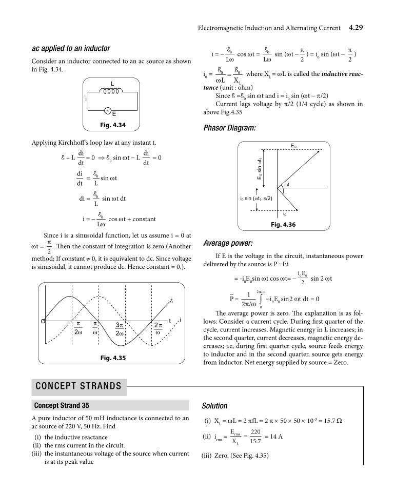
ac applied to an inductor
Consider an inductor connected to an ac source as shown in Fig. 4.34.
L
E
i
~
Fig. 4.34
Applying Kirchhoff ’s loop law at any instant t.
E – L didt
= 0 ⇒ E0 sin wt - L didt
= 0
didt
= 0
LE
sin wt
di = 0
LE
sin wt dt
i = - 0
LwE
cos wt + constant
Since i is a sinusoidal function, let us assume i = 0 at wt =
2p
. Then the constant of integration is zero (Another
method; If constant ≠ 0, it is equivalent to dc. Since voltage is sinusoidal, it cannot produce dc. Hence constant = 0.).
Fig. 4.35
O
E
i
ωπ
ωπ
23 t
ωπ
2 ωπ2
i = - 0
LwE
cos wt = 0
LwE
sin (wt -2p
) = i0 sin (wt - 2p
)
i0 = 0 0
LL Xw=
E E where XL = wL is called the inductive reac-
tance (unit : ohm)Since E =E0 sin wt and i = i0 sin (wt - p/2)Current lags voltage by p/2 (1/4 cycle) as shown in
above Fig.4.35
Phasor Diagram:
Fig. 4.36
E0
i0
ωt
E0 s
in ω
t 1
i0 sin (ωt1- π/2)
Average power:
If E is the voltage in the circuit, instantaneous power delivered by the source is P =Ei
= -i0E0sin wt cos wt= -i E0 0
2 sin 2 wt
P = 12
20 00
2
π ωω
π ω
/−∫ i E t dtsin
/
= 0
The average power is zero. The explanation is as fol-lows: Consider a current cycle. During first quarter of the cycle, current increases. Magnetic energy in L increases; in the second quarter, current decreases, magnetic energy de-creases; i.e, during first quarter cycle, source feeds energy to inductor and in the second quarter, source gets energy from inductor. Net energy supplied by source = Zero.
Concept strand 35
A pure inductor of 50 mH inductance is connected to an ac source of 220 V, 50 Hz. Find (i) the inductive reactance (ii) the rms current in the circuit. (iii) the instantaneous voltage of the source when current
is at its peak value
Solution
(i) XL = wL = 2 pfL = 2 p × 50 × 50 × 10-3 = 15.7 W
(ii) irms = EX
rms
L
=22015 7.
= 14 A
(iii) Zero. (See Fig. 4.35)
ConCept StrandS
4.30 Electromagnetic Induction and Alternating Current
Concept strand 36
If the magnetic energy of an inductor changes from maxi-mum value to minimum value in 10-2 s when connected to an ac source, calculate
(i) the frequency of the source (ii) the minimum value of the magnetic energy
Solution
(i) 14
Cycle = 10-2 s ⇒ T = 4 × 10⁻² s ⇒ f = 1/T = 25 Hz
(ii) Zero
Concept strand 37
A coil of inductance 10 mH and negligible resistance is connected to an oscillator giving output voltage 20 sin (100 t) volt. Determine the peak current in the circuit.
Solution
XL = wL = 100 ×10 × 10-3 = 1 W
i0 = EXL
0 = 201
= 20 A
Concept strand 38
Calculate the equivalent inductance of two inductances L1 and L2 connected in series.
L1 L2
a b
Solution
Let the equivalent be
L
ba
Connect ab across a source E = E0 sin wt.
i = E
Lt0
2ωω
πsin −
Now for the present case, Let E, E1, E2 be the instanta-neous voltages as shown.
baE1 E2
~ E
Then E = E1 + E2 where
E1 = i1 XL1 sin wt = E
LL t0
1ωω ωsin and similarly,
E2 = E
LL t0
2ωω ωsin
Then, E = E1 + E2 ⇒ L = L1 + L2
noteMutual inductance of coil is considered negligible here.
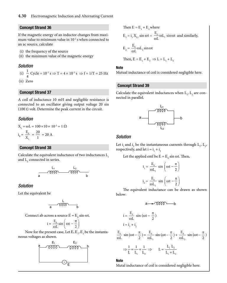
Concept strand 39
Calculate the equivalent inductances when L1, L2 are con-nected in parallel.
b a
L1
L2
Solution
Let i1 and i2 be the instantaneous currents through L1, L2, respectively, and let i = i1 + i2
Let the applied emf be E = E0 sin wt. Then,
i1 = EL0
1ω sin t
2p
w −
i2 = EL0
2ω sin t
2p
w − The equivalent inductance can be drawn as shown
below:
b
a
i = E
L0
ω sin (wt -
2p
)
i = i1 + i2
EL0
ω sin (wt -
2p
) = EL0
1ω sin (wt -
2p
) + EL0
2ω sin (wt -
2p
)
⇒1 2
1 1 1L L L= + ⇒ L = 1 2
1 2
L LL L+
noteMutal inductance of coil is considered negligible here.
Electromagnetic Induction and Alternating Current 4.31
ac applied to a capacitor
Applying Kirchhoff ’s loop rule at any instant t, for the cir-cuit shown in Figure 4.37,
C
i
~
Fig. 4.37
E
E - qC
= 0 ⇒ E0 sin wt -qC
= 0
q = E0C sin wt
dqi
dt= =wC E0 cos wt = wCE0 sin t
2p
w +
i0 = wC E0 = 0
cXE
Fig. 4.38
E
i
ωπ
ωπ
23
t 0
ωπ
2 ωπ2
E0 sin ωt1
π+ω
2tsini 10
where Xc = 1Cw
is known as capacitive reactance.
Since E = E0 sin wt and i = i0 sin t2p
w + , current leads
voltage by 2p (
14
cycle) as shown in the above figure.
Phasor diagram
Fig. 4.39
E
im
ωt E0 s
in ω
t 1
i 0 si
n ω
t 1 +π
/2
i
Average power
If E is the voltage in the circuit, instantaneous power deliv-ered by the source is
P = Ei
i0 E0 sin wt cos wt = i E0 0
2sin 2wt
P i E= ∫
12 2
0 0
0
2
π ω
π ω
/
/
sin 2 wt dt= zero
Physical significance of the above result is that the en-ergy stored in the capacitor in each quarter of the cycle is returned to the source in the next quarter.
Concept strand 40
A 30 m F capacitor is connected to a 220 V, 50 Hz source. Find
(i) the capacitive reactance, (ii) the rms current, (iii) the peak current and (iv) the current, when the frequency is doubled
Solution
(i) XC = 6
1 12 fC 2 (50)(30 10 )p p −=
×= 106 W
(ii) irms = EX
rms
C
=220106
= 2.08 A
(iii) i0 = 2 irms = 2.94 A (considering sinusoidal supply)
(iv) When f is doubled, XC is halved ⇒ i doubled ⇒ i = 4.16 A
ConCept StrandS
4.32 Electromagnetic Induction and Alternating Current
Concept strand 41
A 6 mF capacitor is connected to an ac source of frequency 100 Hz. The rms current in the circuit is 4 A. Find
(i) the rms voltage across the capacitor (ii) the average energy stored in the capacitor
Solution
(i) XL = 6
1 12 fC 2 (100)(6 10 )p p −=
×= 266 W
Erms = irms XL = 4 × 266 = 1064 V
(ii) 12
C (Erms)2 =
12
× 6 × 10-6 × (1064)2 = 3.4 J
Concept strand 42
The dielectric strength of air is 3.0 × 10⁶ V m–1 .A parallel plate air capacitor has plate area 10 cm2 and plate sepa-ration 0.05 mm. Find the maximum rms voltage of an ac source which can be safely connected to this capacitor.
Solution
maxmax max max
VE V E d
d= ⇒ =
= 3 × 106 ×0.05 × 10-3 = 150 V = E0
Erms = 150
2= 105 V
ac applied to a series LCR circuit
Consider circuit with L, C and R in series (Fig. 4.40). The instantaneous current i is the same through R, C and L. Let us assume
R L C
E
i
~
Fig. 4.40
i = i0 sin (wt + f)
where f is the phase difference by which i leads E. Let the instantaneous voltages be ER, EC, EL, E respectively across R, C, L and the source. We know that ER is parallel to i, EC lags by
2p
, EL leads i by 2p
.So phasors are represented
as shown in Fig.4.41.
ER
ωt + φ
i
EL
EC
Fig. 4.41
Now phasor addition of ER+ EC+ EL must be equal to E. so add them as shown in Fig. 4.42.
Fig. 4.42
ER
i
EC−EL
φ E
ωt
Magnitude wise
E E E ER C L02
02
0 02= + −( )
where ER0 = i0 R, EC0 = i0 XC,EL0 = i0 XL,
E02 = 2
0i [R2 + (XC – XL)2]
and tan f = E E
EX X
RC L
R
C L0 0
0
−=
−
i0 = E
R X X
EZ
C L
0
2 2
0
+ −=
( )
where Z is the impedance of the circuit which can be represented in the form of a triangle called the impedance triangle as shown in Fig. 4.43.
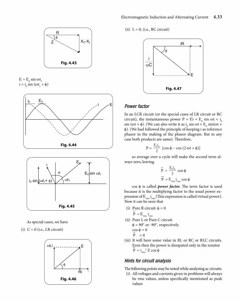
Electromagnetic Induction and Alternating Current 4.33
Fig. 4.43
ZφR
XC-XL
E = E0 sin wt1i = i0 sin (wt1 + f)
Fig. 4.44
i i0
EE0
ϕ
ωt1
E i
E0 sin ωt1
i0 sin (ωt1+ φ)
Fig. 4.45
As special cases, we have
(i) C = 0 (i.e., LR circuit)
Fig. 4.46
φ
E ωLi
Ri i
(ii) L = 0, (i.e., RC circuit)
Fig. 4.47
Ciω
E
φ iR
Power factor
In an LCR circuit (or the special cases of LR circuit or RC circuit), the instantaneous power P = Ei = E0 sin wt × i0 sin (wt + f). (We can also write it as i0 sin wt × E0 sin(wt + f). (We had followed the principle of keeping i as reference phasor in the making of the phasor diagram. But in any case both products are same). Therefore,
P = E i0 0
2 [cos f - cos (2 wt + f)]
so average over a cycle will make the second term al-ways zero, leaving
P = E i0 0
2 cos f
P = Erms irms cos f
cos f is called power factor. The term factor is used because it is the multiplying factor to the usual power ex-pression of Erms irms.(This expression is called virtual power).Now it can be seen that (i) Pure R circuit: f = 0 P = Erms irms
(ii) Pure L or Pure C circuit. f = 90° or -90°, respectively. cos f = 0 P = 0 (iii) It will have some value in RL or RC or RLC circuits.
Even then the power is dissipated only in the resistor P = irms
2 Z cos f
Hints for circuit analysis
The following points may be noted while analysing ac circuits: (i) All voltages and currents given in problems will always
be rms values, unless specifically mentioned as peak values
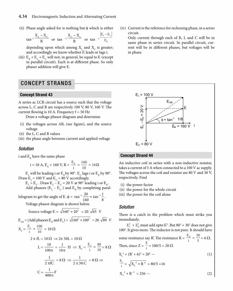
4.34 Electromagnetic Induction and Alternating Current
(ii) Phase angle asked for is nothing but f which is either
tan-1L CX X
R−
or tan -1C LX X
R−
or tan –1
E EE
L C
R
−
depending upon which among XL and XC is greater; and accordingly we know whether E leads or lags i.
(iii) ER + EL + EC will not, in general, be equal to E (except in parallel circuit). Each is at different phase. So only phaser addition will give E.
(iv) Current is the reference for reckoning phase, in a series circuit.
Only current through each of R, L and C will be in same phase in series circuit. In parallel circuit, cur- rent will be in different phases, but voltages will be in phase.
Concept strand 43
A series ac LCR circuit has a source such that the voltage across L, C and R are respectively 100 V, 80 V, 160 V. The current flowing is 10 A. Frequency f = 50 Hz
Draw a voltage phasor diagram and determine
(i) the voltages across AB, (see figure), and the source voltage
(ii) the L, C and R values (iii) the phase angle between current and applied voltage
Solution
i and ER have the same phase
i = 10 A, ER = 160 V, R = EiR = =
16010
16Ω
EL will be leading i or ER by 90°. EC lags i or ER by 90°. Draw EL = 100 V and EC = 80 V accordingly.
EL > EC . Draw EL – EC = 20 V at 90° leading i or ER.Add phasors (EL – EC ) and ER by completing paral-
lelogram to get the angle of E. f = 1 120 1tan tan
160 8− −= .
Voltage phasor diagram is shown below.
Source voltage E = 2 2160 20+ = 20 65 V
EAB = (Add phasors ER and EL) = 2 2160 100+ = 20 89 V
XL = EiL =
10010
= 10 W
2 p fL = 10 W ⇒ 2p 50L = 10 W
L = 10
100p =
110p
H ⇒ XC = EiC =
8010
= 8 W
12 fCp
= 8 W ⇒ 1
2 .50.Cp = 8 W ⇒
C = 1
F800p
E
i ER = 160 V
EC = 80 V
EL = 100 V
EL –
EC
= 2
0 V
φ = tan-1 1/8
EAB
Concept strand 44
An inductive coil in series with a non-inductive resistor, takes a current of 5 A when connected to a 100 V ac supply. The voltages across the coil and resistor are 80 V and 30 V, respectively. Find
(i) the power factor (ii) the power for the whole circuit (iii) the power for the coil alone
Solution
There is a catch in the problem which must strike you immediately.
E EL R2 2+ must add upto E2. But 802 + 302 does not give
1002. It gives more. The inductor is not pure. It should have
some resistance say R’. The resistance R = EiR =
305
= 6 W.
Then, since Z = Ei = 100/5 = 20 W
XL2 + (R’ + 6)2 = 202 — (1)
EiL = 2 2
LX R '+ = 80/5 =16
22LX R '+ = 256 — (2)
ConCept StrandS
Electromagnetic Induction and Alternating Current 4.35
Solving (1) and (2) we get
R’ = 9 W and XL = 5 7 W
Now,
(i) Power factor (for the circuit)
Cos f = R R '
Z+
= (6 + 9)/20 = 0.75
(ii) power for the circuit = Ei cos f
= 100 × 5 × 0.75 = 375 W
you can also get this by i2 (R + R’)
= 52 (6 + 9) = 375 W
(iii) Power for the coil alone = EL i cos f’ cos f’ = power factor for the coil alone
= 2 2L
R '(R ') X+
= 2 2
9 9169 (5 7)
=+
P for coil = 80 × 5 × 9/16 = 225 W You can get this easily by
i2 R’ = 52 × 9 = 225 W
Concept strand 45
A resistor of 200 W and a capacitor of 15 mF are connected in series to a 220 V, 50 Hz ac source. Calculate
(i) the current in the circuit. (ii) the rms voltage across the resistor and the capacitor.
Is the algebraic sum of these voltages more than the source voltage? If yes, resolve the paradox.
Solution
(i) Z = 2 2CR X+
Z2 = 2 6 2200 (2 .50.15 10 )p − −+ ×
Z = 2 2200 212+ = 291.5 W
irms = E
Zrms =
220291 5.
= 0.755 A
(ii) ER = irmsR = (0.755)(200) = 151 V
EC = irmsXC= (0.755) (212) = 160 VObviously they will not add upto 220 V. But phasor
addition, will give
2 2151 160+ = 220 V
Concept strand 46
A sinusoidal voltage of peak value 283 V and frequency 50 Hz is applied to a series LCR circuit, where R = 3 W, L = 25.48 mH, C = 796 mF. Find
(i) the impedance of the circuit. (ii) the phase difference between voltages across the
source and the current. (iii) the power dissipated in the circuit. (iv) the power factor.
Solution
(i) XL = 2 p fL = 2 × 3.14 × 50 × 25.48 × 10–3= 8 W
XC = 1
2 fCp = 6
12 3.14 50 796 10−× × × ×
= 4 W
Z = 2 2 2L CR (X X )+ − = ( )223 8 4 5W+ − =
(ii) Phase difference,
f = tan -1L CX X
R−
= tan -18 4
3−
= 53.1°
and take this as current lags. (If you stick to the phasor convention of treating current as reference, you must follow XL – XC. Since XL > XC, it is inductive in nature, i.e., current lags). Voltage leads the current by 53.1°
(iii) Power = irms2 R
irms = 0i2
= EZ
0 12
=
2835 2
= 40 A
P = 2rmsi R× = 402 × 3 = 4800 W
(iv) Power factor,
cos f = cos 53.1° = 0.6
Concept strand 47
A circuit containing a 80 mH inductor and a 60 mF capacitor in series is connected to a 230 V, 50 Hz supply.The resistance of the circuit is negligible. Determine
(i) rms current (ii) current amplitude (iii) rms potential drops across each element (iv) average power to inductor (v) average power to capacitor (vi) average power absorbed by circuit (vii) suppose the same circuit also has a resistance 15 W,
find the average power transferred to each element and the total power absorbed.
4.36 Electromagnetic Induction and Alternating Current
resOnanCe
Solution
XL = 2 p. 50.80 ×10-3 = 8p W XC = (2 p.50.60 × 10-6) -1 = 16.6p W (using p2 = 10)
(i) irms = E
X Xrms
C L−=
2308 6. π
= 8.5 A
(ii) i0 = 2 × 8.5 = 12 A
(iii) EL = irms XL = 8.5 × 8 p = 214 V
EC = irms XC = 8.5 × 16.6 p = 443 V
(iv) Zero (v) Zero (vi) Zero
(vii) Z = 2 2 2L CR (X X )+ −
= 2 215 (16.6 8 )p p+ − = 30.9 W
irms = 23030.9
= 7.44 A
Power to resistor = (7.44)2 × 15 = 830.3 WPower to L or C = 0Total power = 830.3 W
ac applied to series lCr circuit
In a series LCR ac circuit,
i0 = EZ
E
R X XC L
0 0
2 2=
+ −( ),
where, XC = 1Cw
, XL = wL. So, if w is varied, at a par-
ticular frequency w0, XC and XL will become equal, that is, XC – XL = 0. Therefore,
00
1L
Cw
w= ⇒ 0
1LC
w =
So, at this w0, i0 is maximum = ER
0 . w0 is called reso-
nant frequency – the frequency at which current amplitude is maximum. Note that resonance phenomenon occurs only if both L and C are present (the only possibility of EL cancelling EC, both being 180° out of phase). Typical graph of i0 as a function of w for given R, L and C values and E0 is as shown in Fig.4.48.
From a low value of w, the frequency w is increasedto w0. Low w means XL (i.e., wL) is lower compared to XC
(i.e.,1Cw
) . The circuit is more capacitive than inductive.
To the right of w0, w > w0. XC < XL ⇒ more inductive. At w0, XL = XC ⇒ purely resistive
Fig. 4.48
i
ωo ω
Quality factor, Q, is a measure of the “sharpness of reso-nance”. It is defined as follows:
2∆ω
ω1 ω2
i0
i0 / 2
i
ω ω0
Fig. 4.49
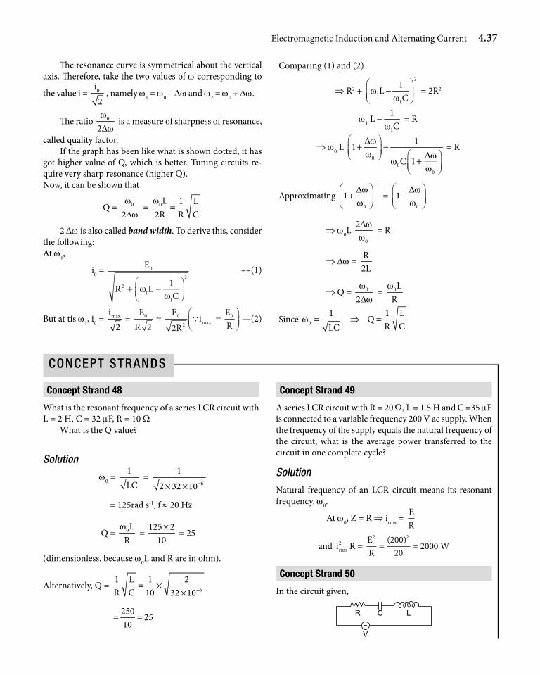
Electromagnetic Induction and Alternating Current 4.37
The resonance curve is symmetrical about the vertical axis. Therefore, take the two values of w corresponding to
the value i = 0i2
, namely w1 = w0 – Dw and w2 = w0 + Dw.
The ratio 0
2wDw
is a measure of sharpness of resonance,
called quality factor.If the graph has been like what is shown dotted, it has
got higher value of Q, which is better. Tuning circuits re-quire very sharp resonance (higher Q).Now, it can be shown that
Q = 0
2wDw
= 0L 1 L2R R Cw
=
2 Dw is also called band width. To derive this, consider the following:At w1,
i0 = E
R LC
0
21
1
21+ −
ωω
––(1)
But at tis w1, i0 = maxi2
= E
RE
Ri
ER
0 0
2
0
2 2= =
Q max —(2)
Comparing (1) and (2)
⇒ R2 + 2
11
1L
Cw
w
− = 2R2
w1 L -1
1Cw
= R
⇒ w0 L 0
00
11
C 1
Dww Dw
ww
+ −
+
= R
Approximating 1
0
1Dww
− +
= 0
1Dww
−
⇒ w0L 0
2Dww
= R
⇒ Dw = R2L
⇒ Q = 0
2wDw
= 0LR
w
Since 01LC
w = ⇒
1 LQ
R C=
Concept strand 48
What is the resonant frequency of a series LCR circuit with L = 2 H, C = 32 mF, R = 10 W
What is the Q value?
Solution
w0 = 1LC
= 6
1
2 32 10−× ×
= 125rad s-1, f ≈ 20 Hz
Q = 0LR
w =
125 210×
= 25
(dimensionless, because w0L and R are in ohm).
Alternatively, Q = 6
1 L 1 2R C 10 32 10−= ×
×
250
2510
= =
Concept strand 49
A series LCR circuit with R = 20 W, L = 1.5 H and C =35 mF is connected to a variable frequency 200 V ac supply. When the frequency of the supply equals the natural frequency of the circuit, what is the average power transferred to the circuit in one complete cycle?
Solution
Natural frequency of an LCR circuit means its resonant frequency, w0.
At w0, Z = R ⇒ irms = ER
and 2rmsi R =
ER
2 220020
=( )
= 2000 W
Concept strand 50
In the circuit given,
ConCept StrandS
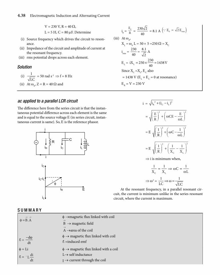
4.38 Electromagnetic Induction and Alternating Current
V = 230 V, R = 40 W, L = 5 H, C = 80 mF. Determine
(i) Source frequency which drives the circuit to reson- ance.
(ii) Impedance of the circuit and amplitude of current at the resonant frequency.
(iii) rms potential drops across each element.
Solution
(i) 1LC
= 50 rad s-1 ⇒ f = 8 Hz
(ii) At w0, Z = R = 40 W and
i0 = ER
0 = 230 2
40 = 8.1 A Q E Erms0 2=( )
(iii) At w0, XL = w0 L = 50 × 5 =250 W = XC
irms = 23040
= 8.1
2A
EL = L230
iX 250 1438V40
= × =
Since XC =XL, EC also
= 1438 V (EL + EC = 0 at resonance)
ER = V = 230 V
ac applied to a parallel LCR circuit
The difference here from the series circuit is that the instan-taneous potential difference across each element is the same and is equal to the source voltage E (in series circuit, instan-taneous current is same). So, E is the reference phasor.
i
i
iR
R C
L
iC iL
~
i φ
E iR
iL
iC
iC-iL
i = 2 2R C Li (i i )+ −
= ER
CE EL
+ −
2 2
ωω
= E 2 21 1
CR L
ww
+ −
= E 1 1 12 2
R X XC L
+ −
⇒ i is minimum when,
C L
1 1 1C
X X Lw
w= ⇒ =
⇒ w2 = 1 1
LC LCw⇒ =
At the resonant frequency, in a parallel resonant cir-cuit, the current is minimum unlike in the series resonant circuit, where the current is maximum.
S u m m a r y
φ =→ →B A.
f →magnetic flux linked with coil
B→
→ magnetic field
A→
→area of the coil
E = ddt
ϕ−
f → magnetic flux linked with coilE =induced emf
f = Li
E = −L didt
f → magnetic flux linked with a coil L→ self inductance
I → current through the coil
Electromagnetic Induction and Alternating Current 4.39
f = Mi
E = M didt
f → magnetic flux in secondary coili → current in primary coilM → Mutual inductance
M= 1 2K L L L1 and L2 → self inductances of the coilsM→ mutual inductance between the coils K → coefficient of coupling (for tight coupling K=1)
L = m0n2Al
20N A
Lm
=l
L → self inductance of a solenoidn → no:of turns/unit lengthN → total no:of turnsA → Area of the coill → length of the solenoid
20 rL n Am m= l
20 r N A
Lm m
=l
L →inductance of the solenoid when filled with material of relative permeability mr
n → no. of turns/unit lengthl → length of primaryA → Area of secondary, N = total number of turns
M= 0 1 2N N Aml
M → Mutual inductance between two solenoidsN1 → no:of turns in primary N2 → no :of turns in the secondary
E = B lv E → motional emf when a rod of length l is moving ⊥r to a magnetic field B with a velocity v(B⊥v⊥l)
E = 21B
2wl
E → motional emf when a rod of length l, a wheel of radus l or a disc of radius l is rotated ⊥r
to a magnetic field B w → angular frequency of rotaton
E = NABw sin wt Emax = NABw
E → induced emf in an ac generatorN → no:of turns of coilA → area of the coilB → magnetic field appliedw → angular frequency of rotation
i = NABR
w sin wt
i0 = NABR
w
i → induced currenti0 → peak currentR = resistance of coil
I = V E
R−
V → emf applied to dc motor R → resistance of coil E → back emfi → current flowing through the armature coil
L s= L1+L2 Inductance in series (No flux leakage)
P 1 2
1 1 1L L L
= + Inductance in parallel ( No flux leakage)
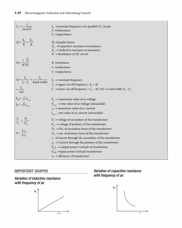
4.40 Electromagnetic Induction and Alternating Current
R1
f2 LCp
= fR →resonant frequency of a parallel LC circuitL→inductanceC→capacitance
CL XXQ
R R= =
Q→Quality factorXC →Capacitive reactance at resonanceXL → Inductive reactance at resonanceR → Resistance of AC circuit
1 LQ
R C=
R→resistanceL→inductanceC→capacitance
R R
2 1
f fQ
f f band width= =
−
0f2 fD
=
fR → resonant frequencyf2 → upper cut off frequency =f0 + Dff1 → lower cut off frequency = f0 – Df; 2Df = b and width (f2 –f1)
E0 = 2 Erms
i0 = rms2 i
E0 → maximum value of ac voltageErms → rms value of ac voltage (sinusoidal)i0 → maximum value of ac currentirms → rms value of ac current (sinusoidal)
EE
s
p = s
p
NN
h = E iE i
S S
P P
Es→ voltage of secondary of the transformerEP → voltage of primary of the transformerNs → No. of secondary turns of the transformerNP → no. of primary turns of the transformeris →Current through the secondary of the transformeriP → Current through the primary of the transformerESiS → output power (virtual) of transformerEPiP→input power (virtual) transformerh → efficiency of transformer
impOrtant graphs
Variation of inductive reactance with frequency of ac
Variation of capacitive reactance with frequency of ac
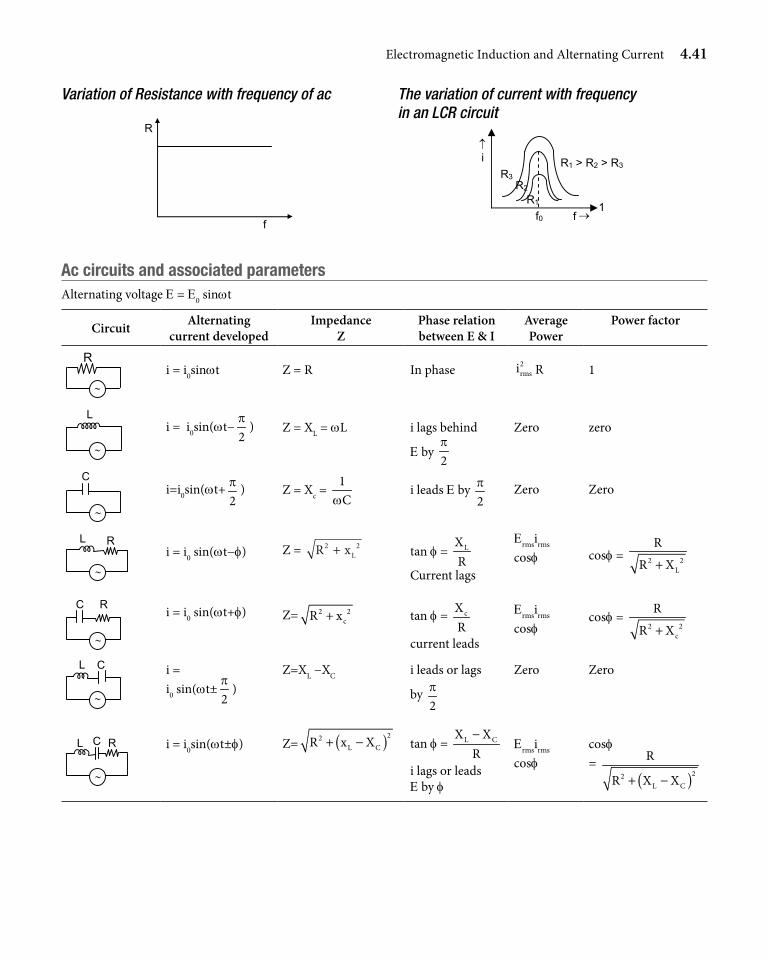
Electromagnetic Induction and Alternating Current 4.41
ac circuits and associated parametersAlternating voltage E = E0 sinwt
Circuit Alternating current developed
Impedance Z
Phase relation between E & I
Average Power
Power factor
R
∼ i = i0sinwt Z = R In phase 2
rmsi R 1
∼
L i = i0sin(wt−
2p
) Z = XL = wL i lags behind
E by 2p
Zero zero
∼
C i=i0sin(wt+
2p ) Z = Xc =
1Cw
i leads E by 2p Zero Zero
∼
L R i = i0 sin(wt−f) Z = R xL
2 2+ tan f = LXR
Current lags
Ermsirms
cosf cosf = 2 2L
R
R X+
∼
C R i = i0 sin(wt+f) Z= 2 2cR x+ tan f = cX
Rcurrent leads
Ermsirms
cosfcosf =
2 2c
R
R X+
∼
L C i = i0 sin(wt±
2p
)Z=XL −XC i leads or lags
by 2p
Zero Zero
∼
L C R i = i0sin(wt±f) Z= ( )22L CR x X+ − tan f = L CX X
R−
i lags or leads E by f
Ermsirms
cosfcosf =
( )22L C
R
R X X+ −
Variation of Resistance with frequency of ac The variation of current with frequency in an LCR circuit
↑ i
f→ 1
R1 > R2 > R3
R1
R2
R3
f0
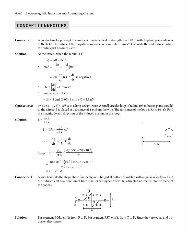
4.42 Electromagnetic Induction and Alternating Current
ConCept ConneCtorS
Connector 1: A conducting loop is kept in a uniform magnetic field of strength B = 0.02 T, with its plane perpendicular to the field. The radius of the loop decreases at a constant rate 1 mm s-1. Calculate the emf induced when the radius just becomes 2 cm.
Solution: At the instant when the radius is ‘r’
f = AB = pr2B.
\ emf = −
= − ( )ddt
ddt
r Bφπ 2
= 2pr.dr
.Bdt
(Qdrdt
is negative)
\ Here dr
1dt
= mm s-1
\ emf when r = 2 cm
= 2p×(2 cm) (0.02)(1 mm s-1) = 2.5 mV
Connector 2:. i = 3.36 (1 + 2 t) × 10-2 A in a long straight wire. A small circular loop of radius 10-3 m has its plane parallel to the wire and is placed at a distance of 1 m from the wire. The resistance of the loop is 8.4 × 10⁻⁴ W. Find the magnitude and direction of the induced current in the loop.
Solution: B = 0 i2 rm
p
1 m
f = BA = 0 i2 rm
ppx2.
E = – ddtφ = 20 di
x2r dtm
iinduced = ER
= 2
20 d(3.36(1 2t) 10 )x
2r R dtm −+ ×
= ( )27 3 2
4
4 10 10 3.36 2 10
2 1 8.4 10
p − − −
−
× × × × ×
× × × = 5 × 10–11 A
Connector 3: A wire bent into the shape shown in the figure is hinged at both ends rotated with angular velocity w. Find the induced emf as a function of time. (Uniform magnetic field B is directed normally into the plane of the paper).
ω
a
x
x x x x x
x x x x
x a
B
Solution: For segment PQR, emf is from P to R. For segment RST, emf is from T to R. Since they are equal and op-posite, they cancel
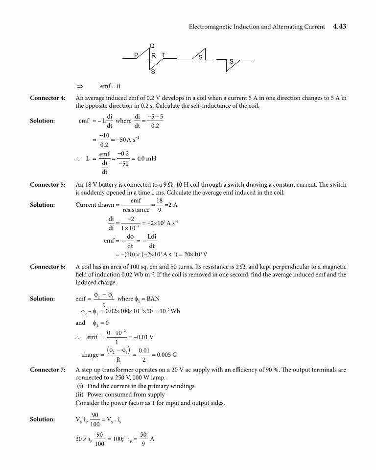
Electromagnetic Induction and Alternating Current 4.43
Q R
S
T P
S
S
⇒ emf = 0
Connector 4: An average induced emf of 0.2 V develops in a coil when a current 5 A in one direction changes to 5 A in the opposite direction in 0.2 s. Calculate the self-inductance of the coil.
Solution: emf = –di
Ldt
where di 5 5dt 0.2
− −=
= 11050A s
0.2−−
= −
\ L = 0.2emf
di 50dt
−=−
= 4.0 mH
Connector 5: An 18 V battery is connected to a 9 W, 10 H coil through a switch drawing a constant current. The switch is suddenly opened in a time 1 ms. Calculate the average emf induced in the coil.
Solution: Current drawn = emf 18
resis tance 9= =2 A
3
di 2dt 1 10−
−=
×= –2×10³ A s-1
emf = − = −ddt
Ldidt
φ
= –(10) × (–2×10³ A s-1) = 20×103 V
Connector 6: A coil has an area of 100 sq. cm and 50 turns. Its resistance is 2 W, and kept perpendicular to a magnetic field of induction 0.02 Wb m-2. If the coil is removed in one second, find the average induced emf and the induced charge.
Solution: emf = φ φ2 1−t
where f1 = BAN
f2 – f1 = 0.02×100×10–4×50 = 10–2 Wb
and f2 = 0
\ emf = 20 10
0.01 V1
−−= −
charge = φ φ2 1 0 01
2−( )
= =R
. 0.005 C
Connector 7: A step up transformer operates on a 20 V ac supply with an efficiency of 90 %. The output terminals are connected to a 250 V, 100 W lamp.
(i) Find the current in the primary windings (ii) Power consumed from supply Consider the power factor as 1 for input and output sides.
Solution: VP iP 90
100= VS . iS
20 × iP 90
100 = 100; iP =
509
A
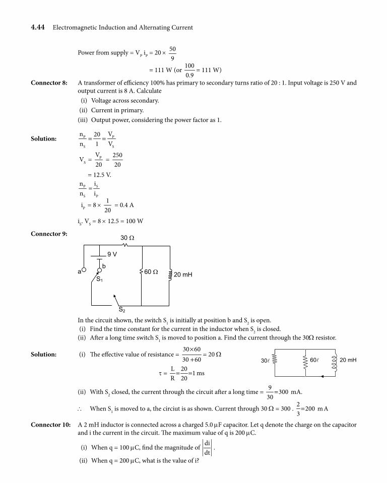
4.44 Electromagnetic Induction and Alternating Current
Power from supply = VP iP = 20 × 509
= 111 W (or 1000.9
= 111 W)
Connector 8: A transformer of efficiency 100% has primary to secondary turns ratio of 20 : 1. Input voltage is 250 V and output current is 8 A. Calculate
(i) Voltage across secondary. (ii) Current in primary. (iii) Output power, considering the power factor as 1.
Solution: P P
S S
n V20n 1 V
= =
VS = PV20
= 25020
= 12.5 V.
P
S
nn
= S
P
ii
iP = 8 × 1
20 = 0.4 A
iS. VS = 8 × 12.5 = 100 W
Connector 9: 30 Ω
60 Ω 20 mH S1
a b
S2
9 V
In the circuit shown, the switch S1 is initially at position b and S2 is open. (i) Find the time constant for the current in the inductor when S2 is closed. (ii) After a long time switch S1 is moved to position a. Find the current through the 30W resistor.
Solution: (i) The effective value of resistance = 30 6030 60
×+
= 20 W
t = L 20
1 msR 20= =
30l 60l 20 mH
(ii) With S2 closed, the current through the circuit after a long time = 9
300 mA.30
=
\ When S1 is moved to a, the circiut is as shown. Current through 30 W = 300 . 2
200 mA3=
Connector 10: A 2 mH inductor is connected across a charged 5.0 mF capacitor. Let q denote the charge on the capacitor and i the current in the circuit. The maximum value of q is 200 mC.
(i) When q = 100 mC, find the magnitude of didt
.
(ii) When q = 200 mC, what is the value of i?
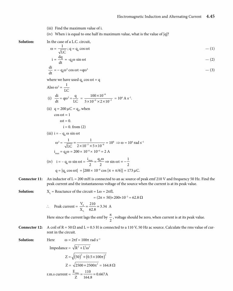
Electromagnetic Induction and Alternating Current 4.45
(iii) Find the maximum value of i. (iv) When i is equal to one half its maximum value, what is the value of |q|?
Solution: In the case of a L.C. circuit,
w = 1LC
; q = q0 cos wt — (1)
i = dqdt
= -q0w sin wt — (2)
didt
= - q0w2 cos wt =qw2 — (3)
where we have used q0 cos wt = q
Also w2 = 1
LC
(i) didt
= qw2 =q
LC =
6
6 3
100 105 10 2 10
−
− −
×× × ×
= 104 A s–1.
(ii) q = 200 mC = q0, when cos wt = 1 wt = 0. i = 0. from (2) (iii) i = – q0 w sin wt
w2 = 3 6
1 12 10 5 10LC − −=× × ×
= 108 ⇒ w = 104 rad s-1
imax = q0w = 200 × 10-6 × 10+4 = 2 A
(iv) i = – q0 w sin wt = max 0i q 1sin t
2 2 2w
w= ⇒ = −
q = |q0 cos wt| = |200 × 10-6 cos [p + p/6]| = 173 mC.
Connector 11: An inductor of L = 200 mH is connected to an ac source of peak emf 210 V and frequency 50 Hz. Find the peak current and the instantaneous voltage of the source when the current is at its peak value.
Solution: XL = Reactance of the circuit = Lw = 2pfL = (2p × 50)×200×10–3 = 62.8 W
\ Peak current = 0
L
V 2103.34
X 62.8= = A
Here since the current lags the emf by 2p
, voltage should be zero, when current is at its peak value.
Connector 12: A coil of R = 50 W and L = 0.5 H is connected to a 110 V, 50 Hz ac source. Calculate the rms value of cur-rent in the circuit.
Solution: Here w = 2pf = 100p rad s-1
Impedance = 2 2 2R L w+
Z = ( ) ( )2 250 0.5 100p+ ×
Z = 22500 2500p+ = 164.8 W
r.m.s current = rmsE 1100.667A
Z 164.8= =
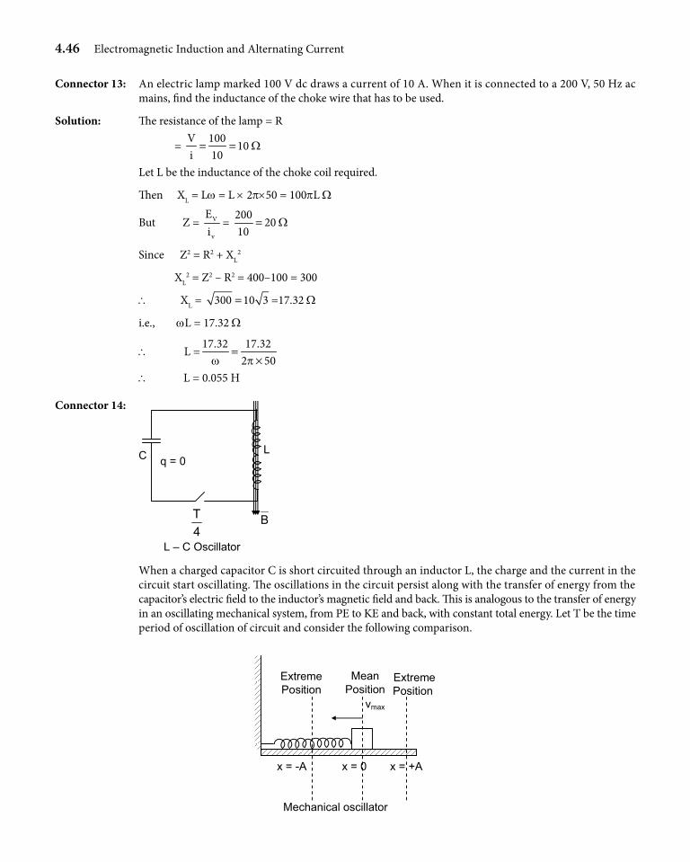
4.46 Electromagnetic Induction and Alternating Current
Connector 13: An electric lamp marked 100 V dc draws a current of 10 A. When it is connected to a 200 V, 50 Hz ac mains, find the inductance of the choke wire that has to be used.
Solution: The resistance of the lamp = R
= V 100
10i 10
W= =
Let L be the inductance of the choke coil required.
Then XL = Lw = L × 2p×50 = 100pL W
But Z = V
v
Ei
= 200
2010
W=
Since Z2 = R2 + XL2
XL2 = Z2 – R2 = 400–100 = 300
\ XL = 300 10 3= =17.32 W
i.e., wL = 17.32 W
\ L =17.32 17.32
2 50w p=
× \ L = 0.055 H
Connector 14:
L
B
C q = 0
4T
L – C Oscillator
When a charged capacitor C is short circuited through an inductor L, the charge and the current in the circuit start oscillating. The oscillations in the circuit persist along with the transfer of energy from the capacitor’s electric field to the inductor’s magnetic field and back. This is analogous to the transfer of energy in an oscillating mechanical system, from PE to KE and back, with constant total energy. Let T be the time period of oscillation of circuit and consider the following comparison.
vmax
ExtremePosition
MeanPosition
ExtremePosition
x = -A x = 0 x = +A
Mechanical oscillator
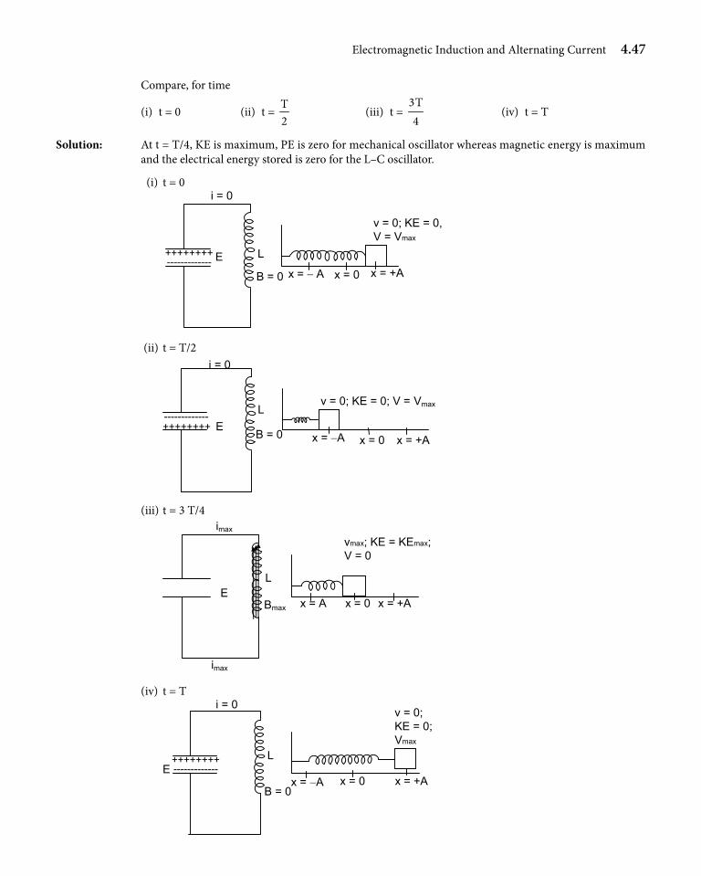
Electromagnetic Induction and Alternating Current 4.47
Compare, for time
(i) t = 0 (ii) t = T2
(iii) t = 3T4
(iv) t = T
Solution: At t = T/4, KE is maximum, PE is zero for mechanical oscillator whereas magnetic energy is maximum and the electrical energy stored is zero for the L–C oscillator.
(i) t = 0
x = − A x = 0 x = +A
v = 0; KE = 0,V = Vmax
i = 0
L
B = 0
E ++++++++ -------------
(ii) t = T/2
x = −A x = 0 x = +A
v = 0; KE = 0; V = Vmax
i = 0
L
B = 0E ++++++++
-------------
(iii) t = 3 T/4
x = A x = 0 x = +A
vmax; KE = KEmax;V = 0
imax
L
Bmax
E
imax
(iv) t = T
x = −A x = 0 x = +A
v = 0;KE = 0;Vmax
i = 0
L
B = 0
E ++++++++-------------
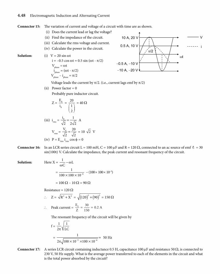
4.48 Electromagnetic Induction and Alternating Current
Connector 15: The variation of current and voltage of a circuit with time are as shown. (i) Does the current lead or lag the voltage? (ii) Find the impedance of the circuit. (iii) Calculate the rms voltage and current. (iv) Calculate the power in the circuit.
Solution: (i) V = 20 sin wt i = –0.5 cos wt = 0.5 sin (wt - p/2) Vphase = wt iphase = (wt - p/2) Vphase – iphase = p/2
Voltage leads the current by p/2. (i.e., current lags emf by p/2) (ii) Power factor = 0 Probably pure inductor circuit.
Z = 0
0
Ei
= 2012
= 40 W
(iii) irms = 0i 12 2 2= A
Vrms = 0V 202 2= = 10 2 V
(iv) P = Erms irms cos f = 0
Connector 16: In an LCR series circuit L = 100 mH, C = 100 mF and R = 120 W, connected to an ac source of emf E = 30 sin(100t) V. Calculate the impedance, the peak current and resonant frequency of the circuit.
Solution: Here X = 1
LC
ww
−
= 6
1100 100 10−× ×
- (100 × 100 × 10-3)
= 100 W – 10 W = 90 W
Resistance = 120 W
\ Z = 2 2R X+ = ( ) ( )2 2120 90+ = 150 W
\ Peak current = EZ
A0 30150
0 2= = .
The resonant frequency of the circuit will be given by
f = 1 1
2 LCp
= 3 6
1
2 100 10 100 10p − −=
× × × 50 Hz
Connector 17: A series LCR circuit containing inductance 0.5 H, capacitance 100 mF and resistance 50 W, is connected to 230 V, 50 Hz supply. What is the average power transferred to each of the elements in the circuit and what is the total power absorbed by the circuit?
10 A, 20 V
π/2ωt
0.5 A, 10 V
−0.5 A, −10 V
−10 A, −20 V
V
i
Electromagnetic Induction and Alternating Current 4.49
Solution: We have Z = 2
2 1R L
Cw
w + −
= ( ) ( )2
2
6
150 2 50 0.5
2 50 100 10p
p −
+ × × − × × × @ 135 W
irms = rmsE 230Z 135
= =1.7 A
\ Average power transferred to resistor
PR = irms2R = (1.7)2 × 50 ≈ 145 W
Average power transferred to inductor and capacitor is zero each
\ Total power absorbed by circuit = 145 W
Connector 18: Find the resonant frequency and Q-factor of a series LCR circuit with L = 2 H, C = 15 mF and R = 10 W.
Solution: L = 2 H, C = 15×10–6 F, R = 10 W
Resonant frequency,
f0 = 1
2 LCp=
6
1
2 2 15 10p −× ×@ 29.06 Hz
Q = 02 f L 2 29.06 2R 10
p p× × ×= = 36.51
Aliter
Q = 6
1 L 1 2R C 10 15 10−= ×
×= 36.51
Connector 19: In a series LCR circuit, L = 0.8 H, R = 300 W, C = 0.04 mF and the source has voltage amplitude 300 V and a frequency equal to the resonance frequency of the circuit.
(i) What is the power factor? (ii) What is the average power delivered by the source? (iii) The capacitor is replaced by one with C =0.08 mF and the source frequency is adjusted to the new
resonance value. What is then the average power delivered by the source?
Solution: As the circuit is set for resonance,
wL = 1Cw
, so Z =R
(i) Power factor = cos f = R/Z = 1
(ii) Prms = Erms .irms = 2
PE2
1R
= 2
300 1.
3002
= 150
(iii) There is no change in the impedance of the circuit as it continues to be in the resonance condition.
⇒ P = 2
rmsE150W
R=
Connector 20: When S is open, current leads emf by 60°. With S closed emf leads the current by a phase angle of 45°. Also the peak value of current in that case is 2 A. Determine the value of L, R, C.
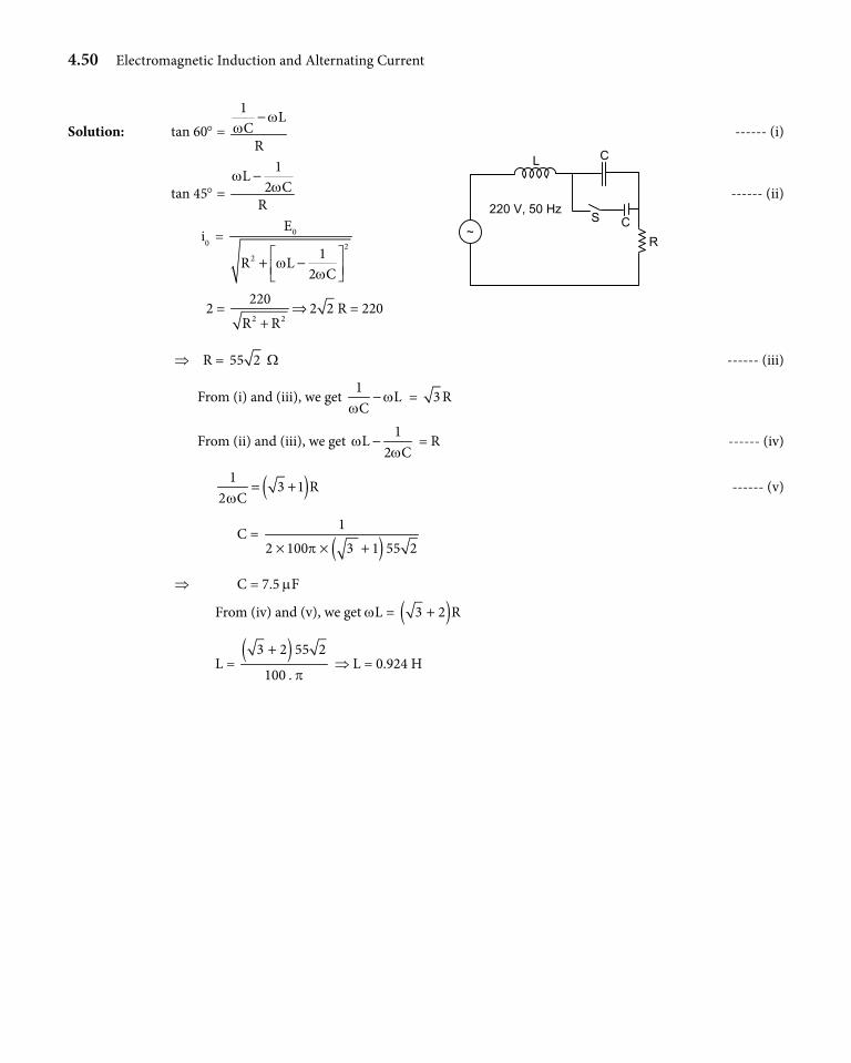
4.50 Electromagnetic Induction and Alternating Current
Solution: tan 60° = 1 LC
R
ww
− ------ (i)
tan 45° =
1L2 C
R
ww
− ------ (ii)
i0 = 0
22
E
1R L2 C
ww
+ −
C
C R
L
220 V, 50 Hz
~
S
2 = 2 2
2202 2
R R⇒
+R = 220
⇒ R = 55 2 W ------ (iii)
From (i) and (iii), we get 1
LC
ww
− = 3 R
From (ii) and (iii), we get 1
L2 C
ww
− = R ------ (iv)
( )13 1 R
2 Cw= + ------ (v)
C = ( )1
2 100 3 1 55 2p× × +
⇒ C = 7.5 mF
From (iv) and (v), we get wL = ( )3 2 R+
L = ( )3 2 55 2
100 . p
+ ⇒ L = 0.924 H
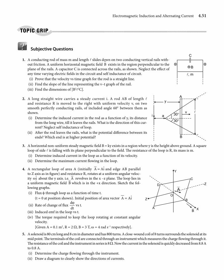
Electromagnetic Induction and Alternating Current 4.51
Subjective Questions
1. A conducting rod of mass m and length l slides down on two conducting vertical rails with-out friction. A uniform horizontal magnetic field B exists in the region perpendicular to the plane of the rails. A capacitor C is connected across the rails, as shown. Neglect the effect of any time varying electric fields in the circuit and self inductance of circuit.
(i) Prove that the velocity vs time graph for the rod is a straight line. (ii) Find the slope of the line representing the v–t graph of the rail. (iii) Find the dimensions of [B2l2C].
2. A long straight wire carries a steady current i. A rod AB of length l and resistance R is moved to the right with uniform velocity v, on two smooth perfectly conducting rails, of included angle 60° between them as shown.
(i) Determine the induced current in the rod as a function of y, its distance from the long wire, till it leaves the rails. What is the direction of this cur-rent? Neglect self inductance of loop.
(ii) After the rod leaves the rails, what is the potential difference between its ends? Which end is at higher potential?
3. A horizontal non-uniform steady magnetic field B = ky exists in a region where y is the height above ground. A square loop of side l is falling with its plane perpendicular to the field. The resistance of the loop is R, its mass is m.
(i) Determine induced current in the loop as a function of its velocity. (ii) Determine the maximum current flowing in the loop.
4. A rectangular loop of area A (initially ˆA Ai= and edge AB parallel to Z axis as in figure) and resistance R, rotates at a uniform angular veloc-ity jw about the y axis. i.e. A revolves in the x –z plane. The loop lies in a uniform magnetic field B which is in the +x direction. Sketch the fol-lowing graphs.
(i) Flux f through loop as a function of time t. (t = 0 at position shown). Initial position of area vector ˆA Ai=
(ii) Rate of change of flux ddtϕ
vs t.
(iii) Induced emf in the loop vs t. (iv) The torque required to keep the loop rotating at constant angular
velocity. [Given A = 0.1 m2, R = 2 W, B = 3 T, w = 4 rad s-1 respectively].
5. A solenoid is 80 cm long and 8 cm in diameter and has 800 turns. A close-wound coil of 8 turns surrounds the solenoid at its mid point. The terminals of the coil are connected through an instrument which measures the charge flowing through it. The resistance of the coil and the instrument in series is 8 W. Now the current in the solenoid is quickly decreased from 8.8 A to 0.8 A.
(i) Determine the charge flowing through the instrument. (ii) Draw a diagram to clearly show the directions of currents.
C
B ⊗
, m
⊗ ⊗
A y
a
B
i 30°
30°
v
D
C
B
A
O
A
X
Y
Z
–Z
B
TOpIC GRIp
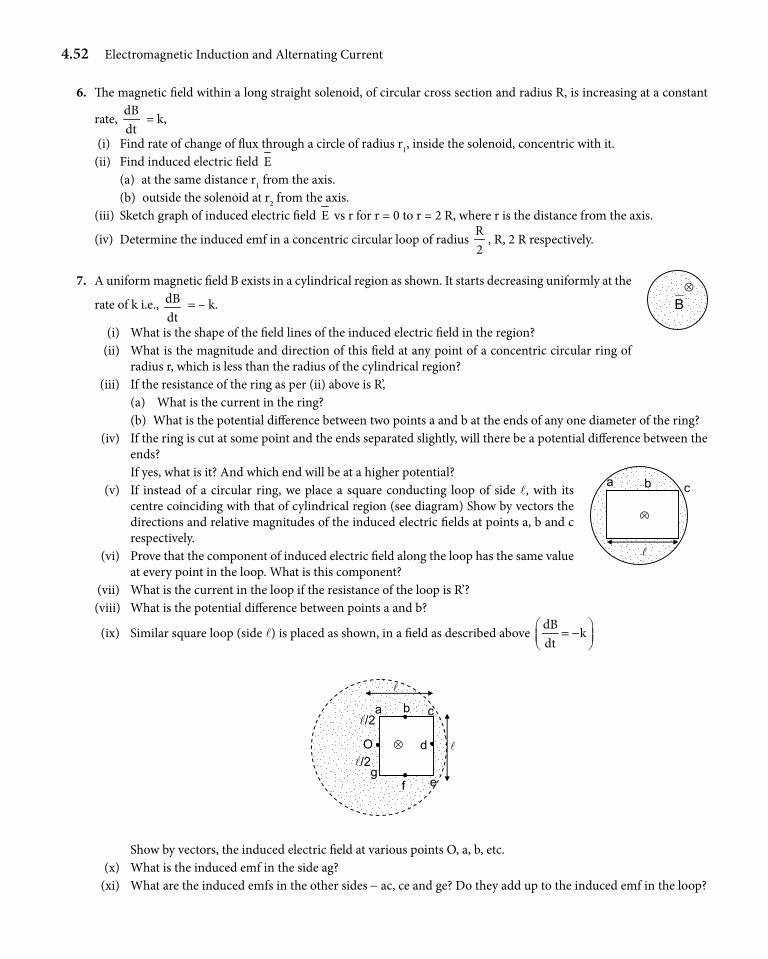
4.52 Electromagnetic Induction and Alternating Current
6. The magnetic field within a long straight solenoid, of circular cross section and radius R, is increasing at a constant
rate, dBdt
= k,
(i) Find rate of change of flux through a circle of radius r1, inside the solenoid, concentric with it. (ii) Find induced electric field E (a) at the same distance r1 from the axis. (b) outside the solenoid at r2 from the axis. (iii) Sketch graph of induced electric field E vs r for r = 0 to r = 2 R, where r is the distance from the axis.
(iv) Determine the induced emf in a concentric circular loop of radius R2
, R, 2 R respectively.
7. A uniform magnetic field B exists in a cylindrical region as shown. It starts decreasing uniformly at the
rate of k i.e., dBdt
= – k.
(i) What is the shape of the field lines of the induced electric field in the region? (ii) What is the magnitude and direction of this field at any point of a concentric circular ring of
radius r, which is less than the radius of the cylindrical region? (iii) If the resistance of the ring as per (ii) above is R’, (a) What is the current in the ring? (b) What is the potential difference between two points a and b at the ends of any one diameter of the ring? (iv) If the ring is cut at some point and the ends separated slightly, will there be a potential difference between the
ends? If yes, what is it? And which end will be at a higher potential? (v) If instead of a circular ring, we place a square conducting loop of side l, with its
centre coinciding with that of cylindrical region (see diagram) Show by vectors the directions and relative magnitudes of the induced electric fields at points a, b and c respectively.
(vi) Prove that the component of induced electric field along the loop has the same value at every point in the loop. What is this component?
(vii) What is the current in the loop if the resistance of the loop is R’? (viii) What is the potential difference between points a and b?
(ix) Similar square loop (side l) is placed as shown, in a field as described above dB
kdt
= −
a c
O
g f e
/2
⊗
/2
d
b
Show by vectors, the induced electric field at various points O, a, b, etc. (x) What is the induced emf in the side ag? (xi) What are the induced emfs in the other sides - ac, ce and ge? Do they add up to the induced emf in the loop?
B ⊗
a b c
⊗
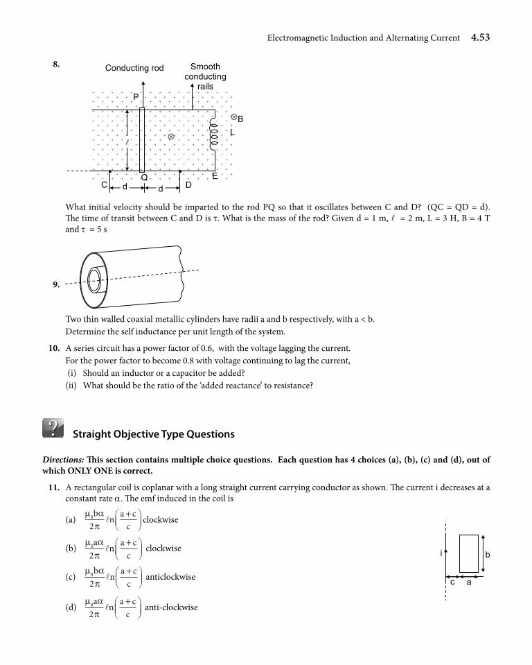
Electromagnetic Induction and Alternating Current 4.53
8.
L
Q
P
E
B
D C
Conducting rod Smooth conducting
rails
⊗
⊗
d d
What initial velocity should be imparted to the rod PQ so that it oscillates between C and D? (QC = QD = d). The time of transit between C and D is t. What is the mass of the rod? Given d = 1 m, l = 2 m, L = 3 H, B = 4 T and t = 5 s
9.
Two thin walled coaxial metallic cylinders have radii a and b respectively, with a < b. Determine the self inductance per unit length of the system.
10. A series circuit has a power factor of 0.6, with the voltage lagging the current. For the power factor to become 0.8 with voltage continuing to lag the current, (i) Should an inductor or a capacitor be added? (ii) What should be the ratio of the ‘added reactance’ to resistance?
Straight Objective Type Questions
Directions: This section contains multiple choice questions. Each question has 4 choices (a), (b), (c) and (d), out of which ONLY ONE is correct.
11. A rectangular coil is coplanar with a long straight current carrying conductor as shown. The current i decreases at a constant rate a. The emf induced in the coil is
(a) µ α
π0
2b n a c
cl
+
clockwise
i
a c
b (b)
µ απ
0
2a n a c
cl
+
clockwise
(c) µ α
π0
2b n a c
cl
+
anticlockwise
(d) µ α
π0
2a n a c
cl
+
anti-clockwise
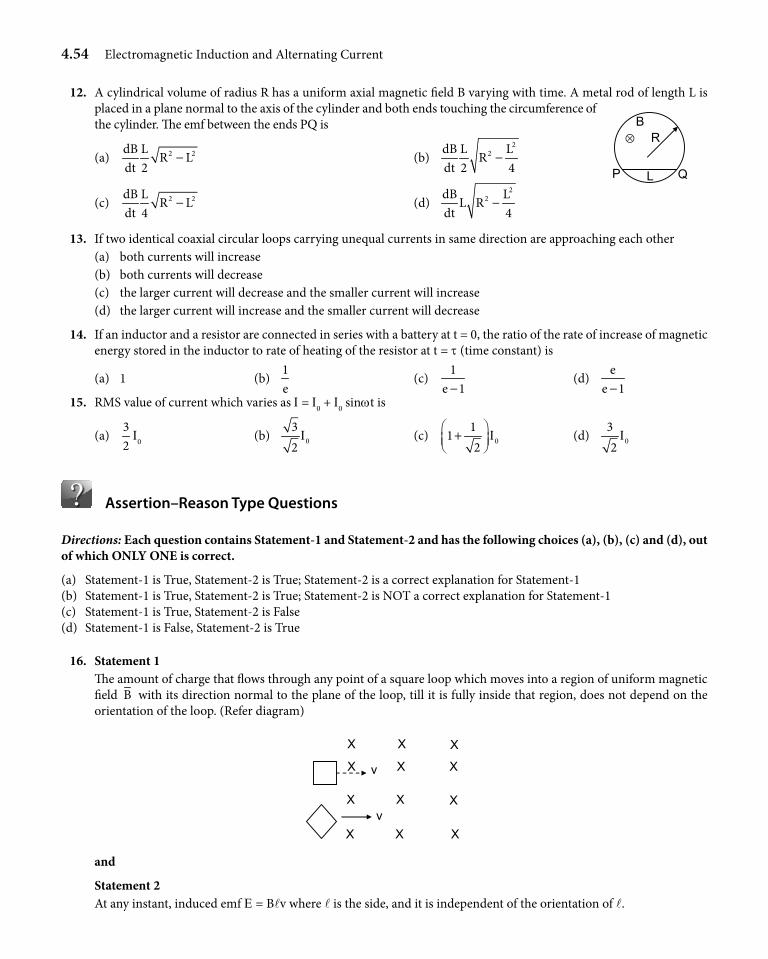
4.54 Electromagnetic Induction and Alternating Current
12. A cylindrical volume of radius R has a uniform axial magnetic field B varying with time. A metal rod of length L is placed in a plane normal to the axis of the cylinder and both ends touching the circumference of the cylinder. The emf between the ends PQ is
(a) 2 2dB LR L
dt 2− (b)
22dB L L
Rdt 2 4
−
(c) 2 2dB LR L
dt 4− (d)
22dB L
L Rdt 4
−
13. If two identical coaxial circular loops carrying unequal currents in same direction are approaching each other (a) both currents will increase (b) both currents will decrease (c) the larger current will decrease and the smaller current will increase (d) the larger current will increase and the smaller current will decrease
14. If an inductor and a resistor are connected in series with a battery at t = 0, the ratio of the rate of increase of magnetic energy stored in the inductor to rate of heating of the resistor at t = t (time constant) is
(a) 1 (b) 1e
(c) 1
e 1− (d)
ee 1−
15. RMS value of current which varies as I = I0 + I0 sinwt is
(a) 32
I0 (b) 032
I (c) 01
12
I +
(d) 032
I
Assertion–Reason Type Questions
Directions: Each question contains Statement-1 and Statement-2 and has the following choices (a), (b), (c) and (d), out of which ONLY ONE is correct.
(a) Statement-1 is True, Statement-2 is True; Statement-2 is a correct explanation for Statement-1(b) Statement-1 is True, Statement-2 is True; Statement-2 is NOT a correct explanation for Statement-1(c) Statement-1 is True, Statement-2 is False(d) Statement-1 is False, Statement-2 is True
16. Statement 1 The amount of charge that flows through any point of a square loop which moves into a region of uniform magnetic
field B with its direction normal to the plane of the loop, till it is fully inside that region, does not depend on the orientation of the loop. (Refer diagram)
X
X X X
X X
X X X
X X X v
v
and
Statement 2 At any instant, induced emf E = Blv where l is the side, and it is independent of the orientation of l.
R B
L P Q
⊗
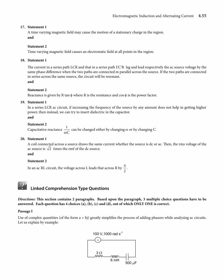
Electromagnetic Induction and Alternating Current 4.55
17. Statement 1 A time varying magnetic field may cause the motion of a stationary charge in the region. and
Statement 2 Time varying magnetic field causes an electrostatic field at all points in the region.
18. Statement 1
The current in a series path LCR and that in a series path L’C’R lag and lead respectively the ac source voltage by the same phase difference when the two paths are connected in parallel across the source. If the two paths are connected in series across the same source, the circuit will be resonant.
and
Statement 2 Reactance is given by R tan f where R is the resistance and cos f is the power factor.
19. Statement 1 In a series LCR ac circuit, if increasing the frequency of the source by any amount does not help in getting higher
power, then instead, we can try to insert dielectric in the capacitor. and
Statement 2 Capacitative reactance
1Cw
can be changed either by changing w or by changing C.
20. Statement 1 A coil connected across a source draws the same current whether the source is dc or ac. Then, the rms voltage of the
ac source is 2 times the emf of the dc source. and
Statement 2
In an ac RL circuit, the voltage across L leads that across R by 2p
.
Linked Comprehension Type Questions
Directions: This section contains 2 paragraphs. Based upon the paragraph, 3 multiple choice questions have to be answered. Each question has 4 choices (a), (b), (c) and (d), out of which ONLY ONE is correct.
Passage I
Use of complex quantities (of the form a + bj) greatly simplifies the process of adding phasors while analyzing ac circuits. Let us explain by example:
6 mH 500 µF
100 V,1000 rad s-1
~
3 Ω
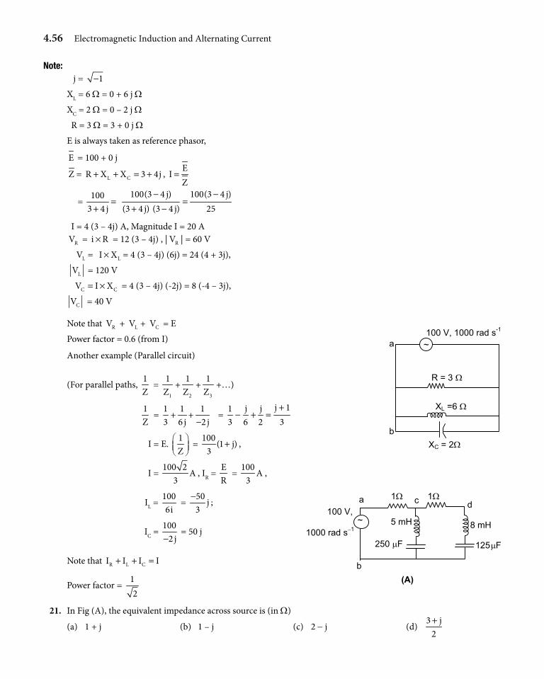
4.56 Electromagnetic Induction and Alternating Current
note: j = 1−
XL = 6 W = 0 + 6 j W
XC = 2 W = 0 – 2 j W
R = 3 W = 3 + 0 j W
E is always taken as reference phasor,
E = 100 + 0 j
Z = L CR X X 3 4j+ + = + , E
IZ
=
= 100
3 4 j=
+
100(3 4 j) 100(3 4 j)(3 4 j) (3 4 j) 25
− −=
+ −
I = 4 (3 – 4j) A, Magnitude I = 20 A
RV = i R× = 12 (3 – 4j) , | RV | = 60 V
LV = LI X× = 4 (3 – 4j) (6j) = 24 (4 + 3j),
LV = 120 V
C CV I X= × = 4 (3 – 4j) (-2j) = 8 (-4 – 3j),
CV = 40 V
Note that RV + LV + CV = E
R = 3 Ω
XL =6 Ω
XC = 2Ω
100 V, 1000 rad s-1
~
b
a Power factor = 0.6 (from I)
Another example (Parallel circuit)
(For parallel paths, 1Z
= 1
1Z
+2
1Z
+3
1Z
+…)
1Z
= 13
+16 j
+12 j−
= j 1j j1
3 6 2 3+
− + =
I = E. 1Z
= 100
(1 j)3
+ ,
I = 100 2
A3
, IR = ER
= 100
A3
,
IL = 1006i
= 50
j3−
; 100 V,
1000 rad s−1
1Ω 1Ω
8 mH5 mH
250 µF 125 µF
(A)
~
a c
b
d
IC = 100
2 j− = 50 j
Note that R L CI I I I+ + =
Power factor = 12
21. In Fig (A), the equivalent impedance across source is (in W)
(a) 1 + j (b) 1 – j (c) 2 - j (d) 3 j
2+
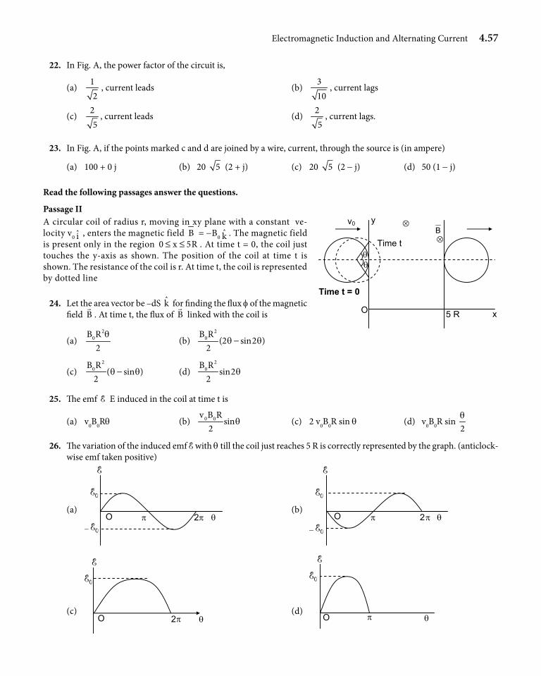
Electromagnetic Induction and Alternating Current 4.57
22. In Fig. A, the power factor of the circuit is,
(a) 12
, current leads (b) 310
, current lags
(c) 25
, current leads (d) 25
, current lags.
23. In Fig. A, if the points marked c and d are joined by a wire, current, through the source is (in ampere)
(a) 100 + 0 j (b) 20 5 (2 + j) (c) 20 5 (2 - j) (d) 50 (1 - j)
Read the following passages answer the questions.
Passage II A circular coil of radius r, moving in xy plane with a constant ve-locity v0 i , enters the magnetic field B = -B0 k . The magnetic field is present only in the region 0 x 5R≤ ≤ . At time t = 0, the coil just touches the y-axis as shown. The position of the coil at time t is shown. The resistance of the coil is r. At time t, the coil is represented by dotted line
24. Let the area vector be –dS k for finding the flux f of the magnetic field B
. At time t, the flux of B
linked with the coil is
(a) 2
0B R2
q (b)
20B R
(2 sin2 )2
q q−
(c) 2
0B R( sin )
2q q− (d)
20B R
sin22
q
25. The emf E E induced in the coil at time t is
(a) v0B0Rq (b) 0 0v B Rsin
2q (c) 2 v0B0R sin q (d) v0B0R sin
2q
26. The variation of the induced emf E with q till the coil just reaches 5 R is correctly represented by the graph. (anticlock- wise emf taken positive)
(a) O π 2π θ
E
0E
− 0E (b)
E
O π 2π θ
0E
− 0E
(c)
E
O 2π θ
0E
(d)
E
O π θ
0E
O 5 R
v0
Time tB
Time t = 0
y ⊗
x
θ θ
⊗
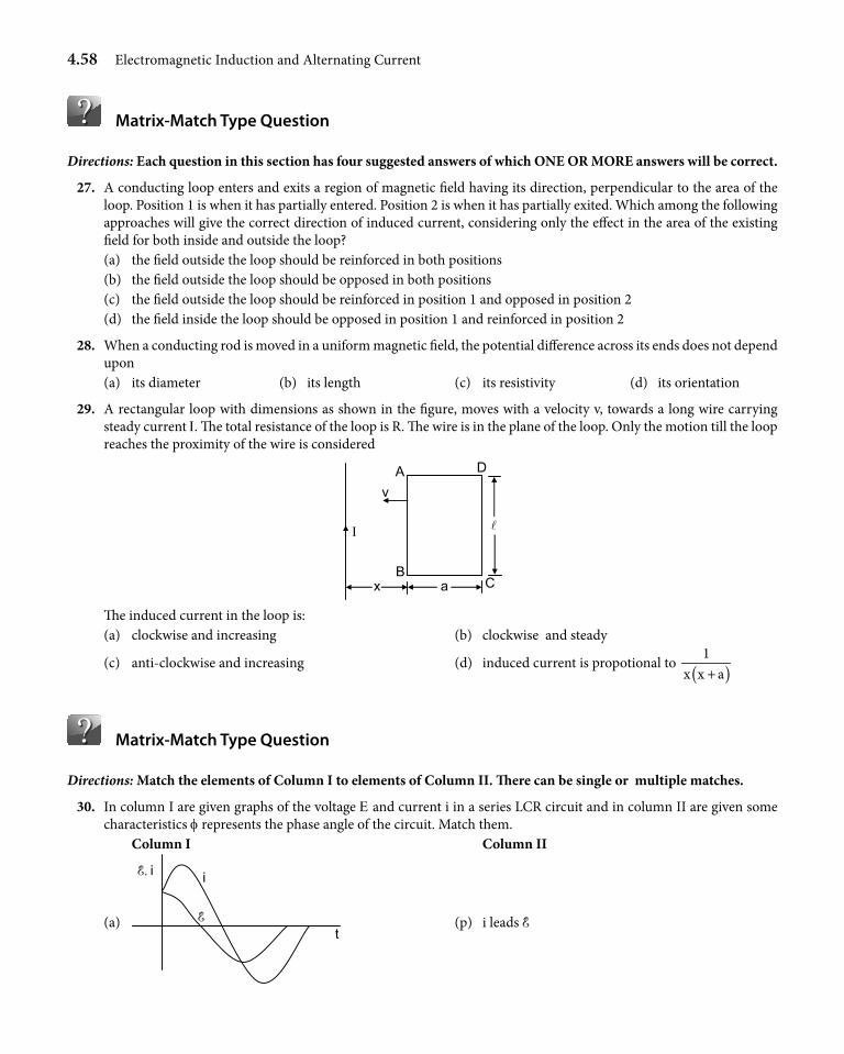
4.58 Electromagnetic Induction and Alternating Current
Matrix-Match Type Question
Directions: Each question in this section has four suggested answers of which ONE OR MORE answers will be correct.
27. A conducting loop enters and exits a region of magnetic field having its direction, perpendicular to the area of the loop. Position 1 is when it has partially entered. Position 2 is when it has partially exited. Which among the following approaches will give the correct direction of induced current, considering only the effect in the area of the existing field for both inside and outside the loop?
(a) the field outside the loop should be reinforced in both positions (b) the field outside the loop should be opposed in both positions (c) the field outside the loop should be reinforced in position 1 and opposed in position 2 (d) the field inside the loop should be opposed in position 1 and reinforced in position 2
28. When a conducting rod is moved in a uniform magnetic field, the potential difference across its ends does not depend upon
(a) its diameter (b) its length (c) its resistivity (d) its orientation
29. A rectangular loop with dimensions as shown in the figure, moves with a velocity v, towards a long wire carrying steady current I. The total resistance of the loop is R. The wire is in the plane of the loop. Only the motion till the loop reaches the proximity of the wire is considered
Ι
A D
B C
v
a x
The induced current in the loop is: (a) clockwise and increasing (b) clockwise and steady
(c) anti-clockwise and increasing (d) induced current is propotional to ( )1
x x a+
Matrix-Match Type Question
Directions: Match the elements of Column I to elements of Column II. There can be single or multiple matches.
30. In column I are given graphs of the voltage E and current i in a series LCR circuit and in column II are given some characteristics f represents the phase angle of the circuit. Match them.
Column I Column II
(a)
E, i
E
i
t (p) i leads E
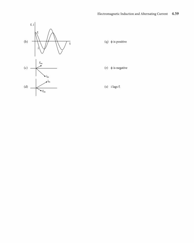
Electromagnetic Induction and Alternating Current 4.59
(b)
E
i t
E, i
(q) f is positive
(c) Em
im
(r) f is negative
(d) Em
im
(s) i lags E
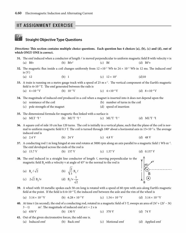
4.60 Electromagnetic Induction and Alternating Current
Straight Objective Type Questions
Directions: This section contains multiple choice questions. Each question has 4 choices (a), (b), (c) and (d), out of which ONLY ONE is correct.
31. The emf induced when a conductor of length l is moved perpendicular to uniform magnetic field B with velocity v is (a) Bℓv (b) Bℓv2 (c) Bℓ (d) Bℓ2v
32. The magnetic flux inside a coil changes uniformly from 12 ×10–3 Wb to 24 × 10–3 Wb in 12 ms. The induced emf is (V)
(a) 12 (b) 1 (c) 12 × 103 (d)10
33. A train is running on a metre gauge track with a speed of 25 m s-1. The vertical component of the Earth’s magnetic field is 4×10⁻⁵ T. The emf generated between the rails is
(a) 4 ×10⁻³ V (b) 10–3 V (c) 4 ×10⁻⁴ V (d) 8 ×10⁻⁴ V
34. The magnitude of induced emf produced in a coil when a magnet is inserted into it does not depend upon the (a) resistance of the coil (b) number of turns in the coil (c) pole strength of the magnet (d) speed of insertion
35. The dimensional formula for magnetic flux linked with a surface is (a) MLT –2I–1 (b) ML2T –1I–1 (c) ML2T –2I–1 (d) ML2T –2I
36. A square coil of side 10 cm has 120 turns. The coil is initially in a vertical plane, such that the plane of the coil is nor-mal to uniform magnetic field 0.3 T. The coil is turned through 180o about a horizontal axis in 15×10–2 s. The average induced emf is
(a) 2.4 V (b) 24 V (c) 4.8 V (d) 48 V
37. A conducting rod 1 m long hinged at one end rotates at 3000 rpm along an axis parallel to a magnetic field 1 Wb m-2. The emf developed across the ends of the rod is
(a) 15.7 V (b) 157 V (c) 1.57 V (d) 0.157 V
38. The emf induced in a straight line conductor of length l, moving perpendicular to the magnetic field B0 with a velocity v at angle of 45° to the normal to the rod is
(a) B0 l 2 (b) 23
B0 l
(c) 2 2 B0lv (d) B0lv12
39. A wheel with 10 metallic spokes each 50 cm long is rotated with a speed of 60 rpm with axis along Earth’s magnetic field at the point. If the field is 0.4×10⁻⁴ T, the induced emf between the axle and the rim of the wheel is
(a) 3.14 × 10⁻⁵ V (b) 6.28 × 10⁻⁵ V (c) 1.54 × 10⁻⁵ V (d) 3.14 × 10⁻⁴ V
40. At time t (in second), the end of a conducting rod, rotated in a magnetic field of 5 T, sweeps an area of (5t3 + (2t2 – 3t) 3 – t) m2. The magnitude of induced emf at t = 2 s is
(a) 650 V (b) 130 V (c) 370 V (d) 74 V
41. Out of the given electromotive forces, the odd one is. (a) Induced emf (b) Back emf (c) Motional emf (d) Applied emf
v 45°
A
B
B
i it aSSignment exerCiSe
Electromagnetic Induction and Alternating Current 4.61
42. A circular coil is placed in a uniform magnetic field. An induced emf can be produced in this coil by (a) moving the coil parallel to the field direction (b) moving the coil normal to the field direction (c) moving in any direction (d) rotating the coil
43. The production of electric current or emf in a coil when the magnetic flux linked with the coil is changed is called (a) Eddy current (b) Electromagnetic induction (c) Mutual induction (d) Lenz’s law
44. When a current i passes through an inductor of self-inductance L, the energy stored in it is
(a) Li2 (b) L2i2 (c) 12
L2i (d) 12
Li2
45. The number of turns per unit length of a solenoid is halved without any change in the length of the solenoid. Its self-inductance becomes
(a) half (b) one-fourth (c) double (d) 4 times
46. Which of the following is not true? (a) When an electric circuit with an inductor is switched off, due to the sudden circuit break, a large induced emf is
set up across the gap in the switch, due to which sparking takes place. (b) A lamp connected in parallel with large inductor glows brilliantly before going off when connected to an ac source (c) Inductance coils are made of copper (d) Eddy currents can be used for deep heat treatment, in medication etc.
47. An emf of 1 V is generated in a coil when the current through it changes from 0.1 A to 0.2 A in 500 ms, in the same direction. The self-inductance of the coil is
(a) 53
× 10–3 H (b) 5 × 10⁻³ H (c) 500 × 10–3 H (d) 53
× 10–6 H
48. Two pure inductors, of self inductance 50 mH and 150 mH respectively, are connected in parallel but are well separated from each other to avoid mutual inductance. The effective inductance is
(a) 200 mH (b) 37.5 mH (c) 75 mH (d) 175 mH
49. The self-inductance of a coil is 10 mH. A current of 1 mA flows through it. When switched off, the current reduces to 0 in 1 micro second. The induced emf in the coil is
(a) 10 × 10–1 V (b) 10 × 10–2 V (c) 10 V (d) 10 × 10-3 V
50. The current drawn by the primary coil of an ideal transformer, which steps down 400 V to 40 V to operate a device with resistance of 400 W, is
(a) 10 A (b) 0.01 A (c) 0.001 A (d) 1 A
51. The core of the transformer is laminated in order to (a) reduce the size (b) make the design handy (c) reduce the energy losses due to eddy currents (d) increase the size
52. In a step down transformer, the number of turns in the secondary is (a) less than in primary (b) more than in primary (c) equal to the number of turns in primary (d) can be less or equal
53. wL/R has the dimension (a) ML2T–1I–1 (b) I–1 (c) ML2I–1 (d) M0L0T0I0
54. The inductance of the coil, which is connected with a 0.3 pF capacitor to get an oscillating frequency of 1 MHz is (a) 1 H (b) 85 mH (c) 8.5 mH (d) 10 mH
4.62 Electromagnetic Induction and Alternating Current
55. A steady potential difference of 10 V produces heat at the rate of x in a resistor. The peak value of the alternating voltage, which will produce heat at the rate of
x2
in the same resistor, is (a) 10 2 V (b) 5 V (c) 10 V (d) 10 / 2 V
56. Unit of power factor is (a) ohm (b) henry (c) farad (d) it is unitless
57. A current of 20 mA flows through a 1.5 mH ideal inductor connected across a 220 V, 50 Hz supply. The power con-sumed by the coil is
(a) 0 (b) 30 mW (c) 3 W (d) 0.3 W
58. A generator produces a voltage given by 240 sin 12t volt, where t is in second. Frequency and rms voltage of the gen-erator are respectively
(a) 1.9 Hz, 170 V (b) 38 Hz, 170 V (c) 50 Hz, 170 V (d) 19 Hz, 240 V
59. The form factor of a sinusoidal alternating current is (a) 0.637 (b) 1.1 (c) 0.707 (d) 1
60. A 240 V ac generator is connected to an inductor and a 48 W resistor in series, through which a current of 3 A flows. The potential difference across the inductor is
(a) 90 V (b) 192 V (c) 100 V (d) 240 V
61. When no power is drawn in the secondary coil of an ideal transformer, the power factor of the primary coil of an ideal transformer is
(a)12
(b) 1 (c) 0 (d) ∞
62. The variation of XC with the frequency of the applied ac is
(a) (b) (c) (d)
63. The rate of heating in a resistor for 10 A ac is the same as the rate of heating in it for a direct current of
(a) 5 A (b) 10
A2
(c) 10 A (d) 10 2 A
64. At resonance, in an LCR series circuit, the impedance is equal to (a) Capacitance (b) Inductance (c) Resistance (d) LR / C
65. In an LCR series ac circuit, at resonance, the current (a) may lead or lag the generator voltage (b) always is in phase with generator voltage (c) always lags behind the generator voltage (d) always leads the generator voltage by p/4 rad
66. A coil of 500 turns and self-inductance of 10 mH, carries a current of 2 mA. The magnetic flux through the coil is (a) 2 ×10⁻⁵ Wb (b) 4 × 10⁻⁸ Wb (c) 10 × 10–3 Wb (d) 8 × 10⁻⁷ Wb
67. The equivalent inductance of a circuit containing coils of self-inductances L1, L2, and L3 in parallel is L. Assume no mutual inductance exists. Then
(a) L = 1 2 2 3 3 1
1 2 3
L L L L L LL L L+ ++ +
(b) L = L1 + L2 + L3
(c) 1L
= L1 + L2 + L3 (d) 1 2 3
1 1 1 1L L L L= + +
Electromagnetic Induction and Alternating Current 4.63
68. Two coils of self-inductance L1 and L2 with same area of cross section have a mutual inductance M. If n1 and n2 are the number of turns in each coil with a coefficient of coupling K, then relation between mutual inductance and self inductance is
(a) M = K 2
1
nn
L2 (b) M = K 1
2
nn
L1 (c) M = K2
2 11 2
1 2
n nL L
n n (d) M = K 1
2
nn
L2
69. Let f be the flux linked with a current carrying solenoid, which has an air core and cross sectional area (a1 × w1). The number of turns per unit length is n1. If B is the magnetic field, the length of the solenoid is equal to
(a) 1 1 1a w n
ϕ (b)
1nϕ
(c) 1 1Ba nϕ
(d) 1 1 1Ba w nϕ
70. Current i in an inductor L (2.3 mH) varies with time t, according to the equation i = (8t2 + 10t + 1) A. At t = 0.5 s, the magnitude of voltage across L is (a) 41.4 mV (b) 59.8 mV (c) 13.8 mV (d) 26 mV
71. The unit of self-inductance is (a) V s A–1 (b) Wb A (c) Wb C s-1 (d) V A-1 s-1
72. The self inductance of a solenoid depends on its length b, area of the wire a, the area of the cross section a1, number of turns per unit length n as
(a) n2ab (b) n2a1b (c) nab (d) na1b
73. Consider two inductors with self-inductances L1 and L2, in series, with mutual inductance M in between them. The equivalent inductance, if the current flows in opposite sense in the coils is
(a) L1 + L2 + 2M (b) L1 + L2 + M (c) L1 + L2 – 2M (d) L1 + L2 – M
74. Relation between mutual inductance M and self inductance L1 and L2 of two coils is
(a) 1 2M K L L= (b) 1
2
LM K
L= (c) 2
1
LM K
L= (d) ( )1 2 1 2M L L L L= +
75. If the number of turns in the two coils are 100 and 200 and the self inductance of the first coil is 4 mH, and K = 1, the mutual inductance between them is (The coils are physically identical)
(a) 16 mH (b) 8 mH (c) 2 mH (d) 4 mH
76. In two coupled coils L1 and L2, the current in L1 at time t (in second) is given by 1Li = (2t2 + 2(65t - 5t3) + 6t) A. When
t is 2 s, the flux in L2 (fL2) is 24 × 10-3 Wb. The mutual inductance between the coils is (a) 0.25 mH (b) 0.75 mH (c) 0.12 mH (d) 1 mH
77. Use of relatively thick copper wire for winding the transformer coil (a) Reduces the joule heat loss (b) Reduces the eddy current loss (c) Reduces the hysteresis loss (d) Increases the flux leakage
78. An rms voltage of 220 V is applied across a circuit of resistance 11 W and impedance 22 W. The power consumed by the circuit is
(a) 2200 W (b) 4400 W (c) 1100 W (d) 880 W
79. A normal domestic electric supply is an alternating current with peak value E0. The average value over a cycle is
(a) 0E3
(b) 0E2
(c) 0E
2p
(d) zero
80. The r.m.s. current in a sinusoidal 50 Hz ac circuit is 5 A. The instantaneous current at the instant 1
300second after the
instantaneous current is zero will be: (a) 6.1 A (b) 0.61 A (c) 3 A (d) 0.3 A
4.64 Electromagnetic Induction and Alternating Current
81. A circular loop has its normal along the unit vector ˆ ˆi j
n2+
= . It is in a region of uniform magnetic field ˆˆB 4j 5k= +
T and encloses an area of 100 cm2. The magnetic flux linked with the loop is (in Wb) (a) 2 × 10⁻² (b) 2 × 10⁻² (c) 2 2 × 10⁻² (d) 2 2 × 10⁻³
82. P
S
y = a
x = 0R
Q
v
x = 2 a
⊗
y
x O
An inward magnetic field B is bounded in a rectangular region given by x = 0, y = 0, x = 2a, y = a. A square loop of side a, initially with side QR coinciding with y axis, is moving along positive x axis with constant speed v. The varia-tion of flux f linked with the coil with position of QR is given by
(a)
Ba2
O a 2 a 3 a x
φ
(b)
Ba2
O x
φ
a 2 a 3 a
(c)
Ba2
a 2 a 3 a x
φ
O (d)
Ba2
O
φ
a 2 a 3 a
83. In the above problem the variation of induced emf e with position of QR is [Take clockwise as positive]
(a) a 2a 3a x
Bva
−Bva
O
e
(b) a 2 a 3 a x
Bva
−Bva
O e
(c) a 2 a 3 a x
Bva
−Bva
O e
(d) a 2 a 3 a
Bva
−Bva
O e
x
Electromagnetic Induction and Alternating Current 4.65
84.
R P S
T Q U
10 Ω 20 Ω⊗ B
In the arrangement shown metal rod PQ and rails RS and TU have zero resistance each and magnetic field B acts into the plane of the paper. Metal rod PQ is sliding from left to right parallel to RU. The ratio of power dissipated in the 10 W resistor to that in 20 W resistor is
(a) 2 : 1 (b) 1 : 2 (c) 4 : 1 (d) 1 : 4
85. Current i varies according to the relation i = 3.36 (1 + 2t) × 10-2A. A small circular loop of radius 10-3 m, with its plane parallel to the wire, is placed at a distance of 1 m from the wire. The mag-nitude of the induced current in the coil is (resistance of the coil is 8.4 × 10⁻⁴ W)
(a) 16 p × 10-12 A (b) 4 p × 10-12 A (c) 8 p × 10-12 A (d) 12 p × 10-12 A
86. On an inclined platform PQRS a metal rod is sliding down on two parallel metal rails PS and QR without friction. A resistance r is connected across ends P and Q. A uni-form magnetic field of induction B is always normal to the plane PQRS. The terminal velocity is
(Distance between rails is l)
(a) 0 (b) 2 2
mgr sinB
q
l
(c) 2 2
mgrB l
(d) mgr sin
Bq
l
87. PQRS is a horizontal board containing a small uniform inward magnetic field B. A copper rod of length = L is connected to a non conducting rigid wall of the board by means of a non conducting spring of force constant k. The spring is compressed by a length a and then released. The maximum emf induced in the rod is (the mass of the rod is m)
(a) BaL km
(b) BaL
(c) BaL mk
(d) BaL2
88. An L shaped conductor moves through a uniform magnetic field –B0 k with a uniform velocity v0 i . The emf induced across PQ is (negative end to positive end)
(a) 0 0v B a2
P to Q (b) 0 0v B a( 3 1)
2+ P to Q
(c) 0 0v B a( 3 1)
2− Q to P (d) 0 0v B a
( 3 1)2
+ Q to P
Q
i
1m
P
B P
Q
R
S
X
Y θ
r
QP
RSFree length of spring
a
⊗
90°
P a
X
Y
O 60°
v0
a Q
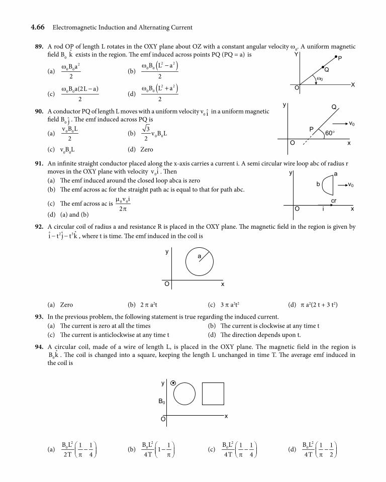
4.66 Electromagnetic Induction and Alternating Current
89. A rod OP of length L rotates in the OXY plane about OZ with a constant angular velocity w0. A uniform magnetic field B0 k exists in the region. The emf induced across points PQ (PQ = a) is
(a) 2
0 0B a2
w (b)
( )2 20 0B L a
2
w −
(c) 0 0B a(2L a)2
w − (d)
( )2 20 0B L a
2
w +
90. A conductor PQ of length L moves with a uniform velocity v0 i in a uniform magnetic field B0 j . The emf induced across PQ is
(a) 0 0v B L2
(b) 0 03
v B L2
(c) v0B0L (d) Zero
91. An infinite straight conductor placed along the x-axis carries a current i. A semi circular wire loop abc of radius r moves in the OXY plane with velocity 0
ˆv i . Then (a) The emf induced around the closed loop abca is zero (b) The emf across ac for the straight path ac is equal to that for path abc.
(c) The emf across ac is 0 0v i2
mp
(d) (a) and (b)
92. A circular coil of radius a and resistance R is placed in the OXY plane. The magnetic field in the region is given by 2 3 ˆˆ ˆi t j t k− − , where t is time. The emf induced in the coil is
x
y
O
a
(a) Zero (b) 2 p a2t (c) 3 p a2t2 (d) p a2(2 t + 3 t2)
93. In the previous problem, the following statement is true regarding the induced current. (a) The current is zero at all the times (b) The current is clockwise at any time t (c) The current is anticlockwise at any time t (d) The direction depends upon t.
94. A circular coil, made of a wire of length L, is placed in the OXY plane. The magnetic field in the region is 0ˆB k . The coil is changed into a square, keeping the length L unchanged in time T. The average emf induced in
the coil is
O
y
x
B0
(a) 2
0B L 1 12T 4p
− (b)
20B L 1
14T p
−
(c) 2
0B L 1 14T 4p
− (d)
20B L 1 1
4T 2p −
X
Y
O
Q
P
ω0
O x
y
P
Q
60°
v0
y a b
O x
v0
cr i
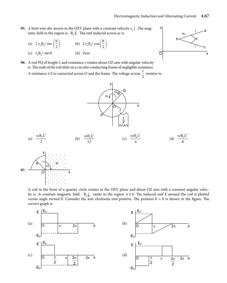
Electromagnetic Induction and Alternating Current 4.67
95. A bent wire abc moves in the OXY plane with a constant velocity v0 j . The mag-netic field in the region is –B0 k . The emf induced across ac is
(a) 2 v0B0l sin 2q
(b) 2 v0B0l cos2q
(c) v0B0l sin q (d) Zero
96. A rod PQ of length L and resistance r rotates about OZ axis with angular velocity w. The ends of the rod slide on a circular conducting frame of negligible resistance. A resistance r/2 is connected across O and the frame. The voltage across
r2
resistor is:
ω ⊗ Q
B
2r
O
P
x
y
(a) 2
0B L2
w (b)
20B L
12w
(c) 2
0B L4
w (d)
20B L
8w
97.
A coil in the form of a quarter circle rotates in the OXY plane and about OZ axis with a constant angular veloc-ity w. A constant magnetic field - B0 k exists in the region x ≥ 0. The induced emf E around the coil is plotted versus angle turned q. Consider the anti clockwise emf positive. The position q = 0 is shown in the figure. The correct graph is
(a) (b)
(c) (d)
O
y
x
b
a
c
v0
θ
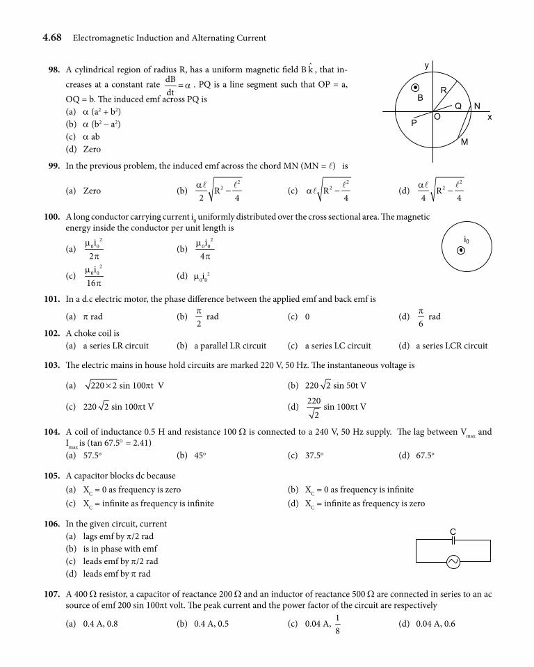
4.68 Electromagnetic Induction and Alternating Current
98. A cylindrical region of radius R, has a uniform magnetic field B k , that in-creases at a constant rate dB
dta= . PQ is a line segment such that OP = a,
OQ = b. The induced emf across PQ is (a) a (a2 + b2) (b) a (b2 - a2) (c) a ab (d) Zero
99. In the previous problem, the induced emf across the chord MN (MN = l) is
(a) Zero (b) 2
2R2 4
a−
l l (c)
22R
4a −
ll (d)
22R
4 4a
−l l
100. A long conductor carrying current i0 uniformly distributed over the cross sectional area. The magnetic energy inside the conductor per unit length is
(a) 2
0 0i2
mp
(b) 2
0 0i4
mp
(c) 2
0 0i16m
p (d) m0i0
2
101. In a d.c electric motor, the phase difference between the applied emf and back emf is
(a) p rad (b) 2p
rad (c) 0 (d) 6p
rad
102. A choke coil is (a) a series LR circuit (b) a parallel LR circuit (c) a series LC circuit (d) a series LCR circuit
103. The electric mains in house hold circuits are marked 220 V, 50 Hz. The instantaneous voltage is
(a) 220 2× sin 100pt V (b) 220 2 sin 50t V
(c) 220 2 sin 100pt V (d) 220
2sin 100pt V
104. A coil of inductance 0.5 H and resistance 100 W is connected to a 240 V, 50 Hz supply. The lag between Vmax and Imax is (tan 67.5° = 2.41)
(a) 57.5o (b) 45o (c) 37.5o (d) 67.5o
105. A capacitor blocks dc because (a) XC = 0 as frequency is zero (b) XC = 0 as frequency is infinite (c) XC = infinite as frequency is infinite (d) XC = infinite as frequency is zero
106. In the given circuit, current (a) lags emf by p/2 rad (b) is in phase with emf (c) leads emf by p/2 rad (d) leads emf by p rad
107. A 400 W resistor, a capacitor of reactance 200 W and an inductor of reactance 500 W are connected in series to an ac source of emf 200 sin 100pt volt. The peak current and the power factor of the circuit are respectively
(a) 0.4 A, 0.8 (b) 0.4 A, 0.5 (c) 0.04 A, 18
(d) 0.04 A, 0.6
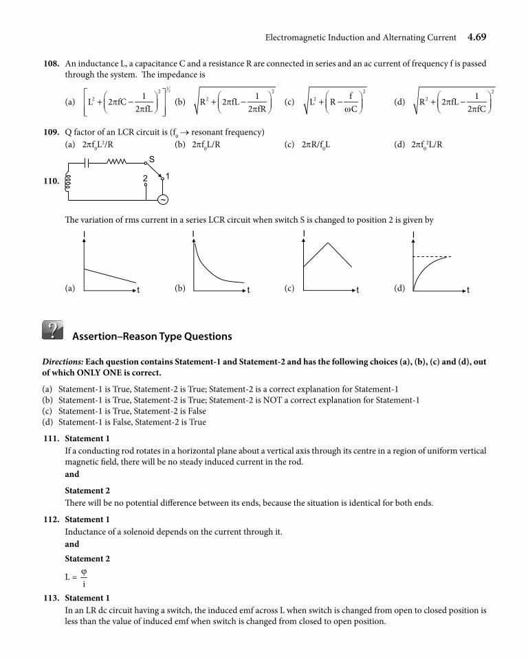
Electromagnetic Induction and Alternating Current 4.69
108. An inductance L, a capacitance C and a resistance R are connected in series and an ac current of frequency f is passed through the system. The impedance is
(a)
122
2 1L 2 fC
2 fLp
p
+ − (b)
22 1
R 2 fL2 fR
pp
+ − (c)
22 f
L RCw
+ − (d)
22 1
R 2 fL2 fC
pp
+ −
109. Q factor of an LCR circuit is (f0 → resonant frequency) (a) 2pf0L
2/R (b) 2pf0L/R (c) 2pR/f0L (d) 2pf02L/R
110. 2
~
1
S
The variation of rms current in a series LCR circuit when switch S is changed to position 2 is given by
(a) (b) (c) (d)
Assertion–Reason Type Questions
Directions: Each question contains Statement-1 and Statement-2 and has the following choices (a), (b), (c) and (d), out of which ONLY ONE is correct.
(a) Statement-1 is True, Statement-2 is True; Statement-2 is a correct explanation for Statement-1(b) Statement-1 is True, Statement-2 is True; Statement-2 is NOT a correct explanation for Statement-1(c) Statement-1 is True, Statement-2 is False(d) Statement-1 is False, Statement-2 is True
111. Statement 1 If a conducting rod rotates in a horizontal plane about a vertical axis through its centre in a region of uniform vertical
magnetic field, there will be no steady induced current in the rod. and
Statement 2 There will be no potential difference between its ends, because the situation is identical for both ends.
112. Statement 1 Inductance of a solenoid depends on the current through it. and Statement 2
L = iϕ
113. Statement 1 In an LR dc circuit having a switch, the induced emf across L when switch is changed from open to closed position is
less than the value of induced emf when switch is changed from closed to open position.
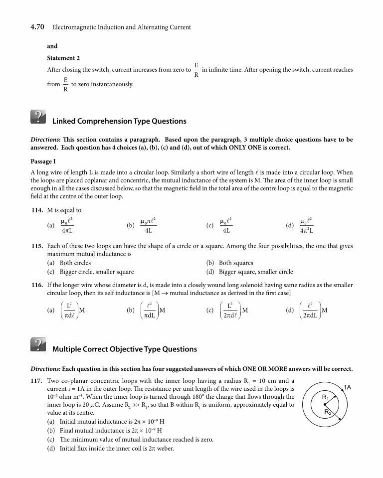
4.70 Electromagnetic Induction and Alternating Current
and
Statement 2
After closing the switch, current increases from zero to ER
in infinite time. After opening the switch, current reaches
from ER
to zero instantaneously.
Linked Comprehension Type Questions
Directions: This section contains a paragraph. Based upon the paragraph, 3 multiple choice questions have to be answered. Each question has 4 choices (a), (b), (c) and (d), out of which ONLY ONE is correct.
Passage I
A long wire of length L is made into a circular loop. Similarly a short wire of length l is made into a circular loop. When the loops are placed coplanar and concentric, the mutual inductance of the system is M. The area of the inner loop is small enough in all the cases discussed below, so that the magnetic field in the total area of the centre loop is equal to the magnetic field at the centre of the outer loop.
114. M is equal to
(a) 2
0
4 Lm
pl
(b) 2
0
4Lm pl
(c) 2
0
4Lm l
(d) 2
024 L
mpl
115. Each of these two loops can have the shape of a circle or a square. Among the four possibilities, the one that gives maximum mutual inductance is
(a) Both circles (b) Both squares (c) Bigger circle, smaller square (d) Bigger square, smaller circle
116. If the longer wire whose diameter is d, is made into a closely wound long solenoid having same radius as the smaller circular loop, then its self inductance is [M → mutual inductance as derived in the first case]
(a) 2L
Mdp
l
(b) 2
MdLp
l (c)
2L2 dp l
M (d) 2
M2 dLp
l
Multiple Correct Objective Type Questions
Directions: Each question in this section has four suggested answers of which ONE OR MORE answers will be correct.
117. Two co-planar concentric loops with the inner loop having a radius R1 = 10 cm and a current i = 1A in the outer loop. The resistance per unit length of the wire used in the loops is 10-3 ohm m-1. When the inner loop is turned through 180° the charge that flows through the inner loop is 20 mC. Assume R2 >> R1, so that B within R1 is uniform, approximately equal to value at its centre.
(a) Initial mutual inductance is 2p × 10-9 H (b) Final mutual inductance is 2p × 10-9 H (c) The minimum value of mutual inductance reached is zero. (d) Initial flux inside the inner coil is 2p weber.
R1 1A
R2
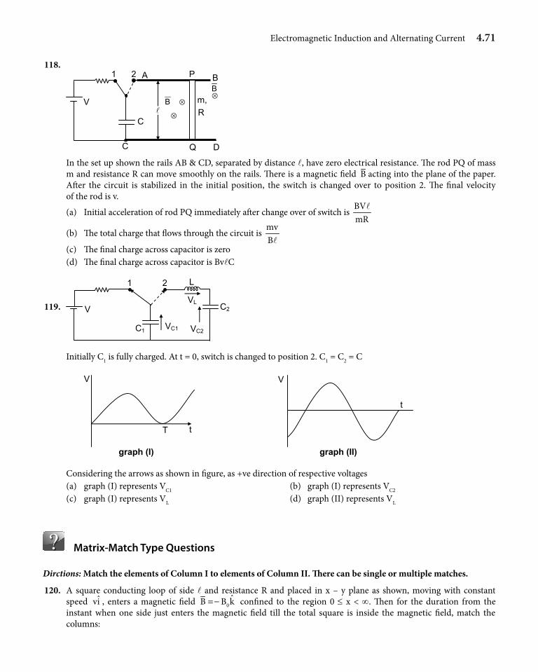
Electromagnetic Induction and Alternating Current 4.71
118. 1
C
V
Q D
m, R
B
⊗
⊗
2 A
B
C
P
⊗
B
In the set up shown the rails AB & CD, separated by distance l, have zero electrical resistance. The rod PQ of mass m and resistance R can move smoothly on the rails. There is a magnetic field B acting into the plane of the paper. After the circuit is stabilized in the initial position, the switch is changed over to position 2. The final velocity of the rod is v.
(a) Initial acceleration of rod PQ immediately after change over of switch is BVmR
l
(b) The total charge that flows through the circuit is mvBl
(c) The final charge across capacitor is zero (d) The final charge across capacitor is BvlC
119. V
C1 VC1 VC2
C2
L
VL
1 2
Initially C1 is fully charged. At t = 0, switch is changed to position 2. C1 = C2 = C
T t
V
graph (I)
V
t
graph (II)
Considering the arrows as shown in figure, as +ve direction of respective voltages (a) graph (I) represents VC1 (b) graph (I) represents VC2
(c) graph (I) represents VL (d) graph (II) represents VL
Matrix-Match Type Questions
Dirctions: Match the elements of Column I to elements of Column II. There can be single or multiple matches.
120. A square conducting loop of side l and resistance R and placed in x – y plane as shown, moving with constant speed ˆvi , enters a magnetic field 0
ˆB B k=− confined to the region 0 ≤ x < ∞. Then for the duration from the instant when one side just enters the magnetic field till the total square is inside the magnetic field, match the columns:
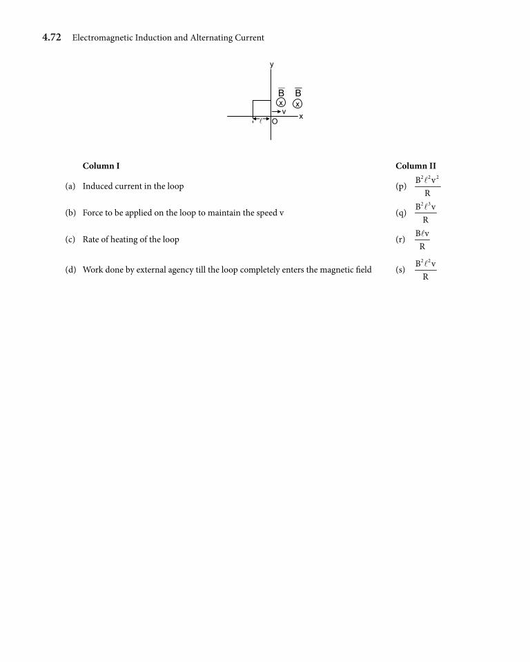
4.72 Electromagnetic Induction and Alternating Current
y
Oxv
B Bx x
Column I Column II
(a) Induced current in the loop (p) 2 2 2B vRl
(b) Force to be applied on the loop to maintain the speed v (q) 2 3B vRl
(c) Rate of heating of the loop (r) B vRl
(d) Work done by external agency till the loop completely enters the magnetic field (s) 2 2B vRl
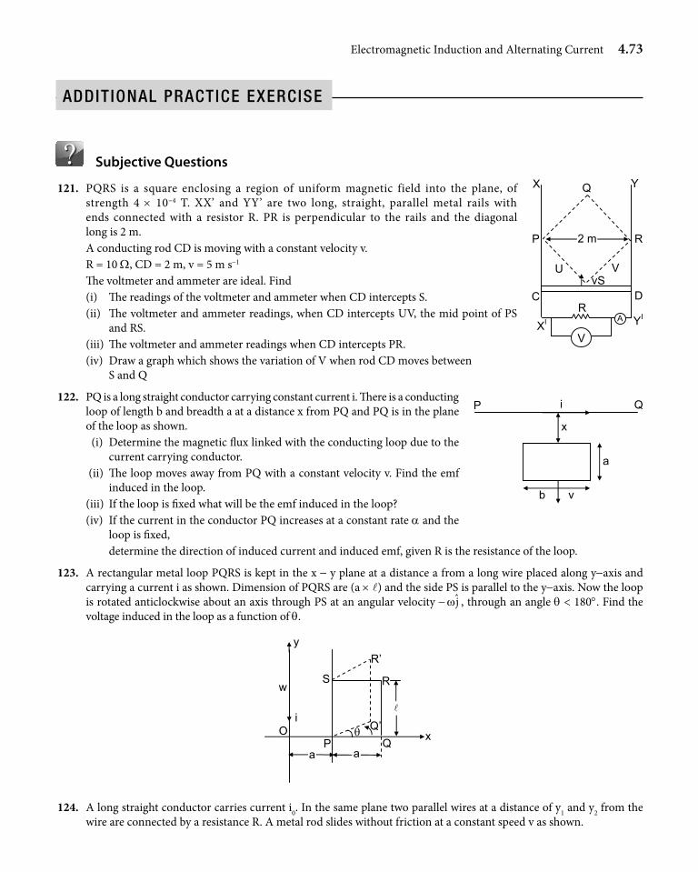
Electromagnetic Induction and Alternating Current 4.73
addit ional praCtiCe exerCiSe
Subjective Questions
121. PQRS is a square enclosing a region of uniform magnetic field into the plane, of strength 4 × 10⁻⁴ T. XX’ and YY’ are two long, straight, parallel metal rails with ends connected with a resistor R. PR is perpendicular to the rails and the diagonal long is 2 m.
A conducting rod CD is moving with a constant velocity v. R = 10 W, CD = 2 m, v = 5 m s-1
The voltmeter and ammeter are ideal. Find (i) The readings of the voltmeter and ammeter when CD intercepts S. (ii) The voltmeter and ammeter readings, when CD intercepts UV, the mid point of PS
and RS. (iii) The voltmeter and ammeter readings when CD intercepts PR. (iv) Draw a graph which shows the variation of V when rod CD moves between
S and Q
122. PQ is a long straight conductor carrying constant current i. There is a conducting loop of length b and breadth a at a distance x from PQ and PQ is in the plane of the loop as shown.
(i) Determine the magnetic flux linked with the conducting loop due to the current carrying conductor.
(ii) The loop moves away from PQ with a constant velocity v. Find the emf induced in the loop.
(iii) If the loop is fixed what will be the emf induced in the loop? (iv) If the current in the conductor PQ increases at a constant rate a and the
loop is fixed, determine the direction of induced current and induced emf, given R is the resistance of the loop.
123. A rectangular metal loop PQRS is kept in the x - y plane at a distance a from a long wire placed along y-axis and carrying a current i as shown. Dimension of PQRS are (a × l) and the side PS is parallel to the y-axis. Now the loop is rotated anticlockwise about an axis through PS at an angular velocity - jw , through an angle q < 180°. Find the voltage induced in the loop as a function of q.
w
Q P O
a
Q’
R
θ
S
R’
i
a
y
x
124. A long straight conductor carries current i0. In the same plane two parallel wires at a distance of y1 and y2 from the wire are connected by a resistance R. A metal rod slides without friction at a constant speed v as shown.
Q
P R
S V U
DCR
YI
YX
XI
V
v
A
V
2 m
QP i
x
a
b v
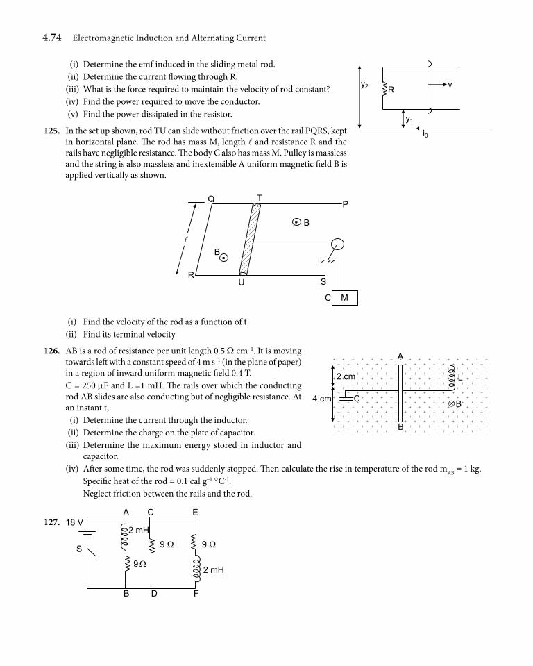
4.74 Electromagnetic Induction and Alternating Current
(i) Determine the emf induced in the sliding metal rod. (ii) Determine the current flowing through R. (iii) What is the force required to maintain the velocity of rod constant? (iv) Find the power required to move the conductor. (v) Find the power dissipated in the resistor.
125. In the set up shown, rod TU can slide without friction over the rail PQRS, kept in horizontal plane. The rod has mass M, length l and resistance R and the rails have negligible resistance. The body C also has mass M. Pulley is massless and the string is also massless and inextensible A uniform magnetic field B is applied vertically as shown.
C
P
M
S
T
B
Q
R
B
U
(i) Find the velocity of the rod as a function of t (ii) Find its terminal velocity
126. AB is a rod of resistance per unit length 0.5 W cm-1. It is moving towards left with a constant speed of 4 m s-1 (in the plane of paper) in a region of inward uniform magnetic field 0.4 T.
C = 250 mF and L =1 mH. The rails over which the conducting rod AB slides are also conducting but of negligible resistance. At an instant t,
(i) Determine the current through the inductor. (ii) Determine the charge on the plate of capacitor. (iii) Determine the maximum energy stored in inductor and
capacitor. (iv) After some time, the rod was suddenly stopped. Then calculate the rise in temperature of the rod mAB = 1 kg. Specific heat of the rod = 0.1 cal g-1 °C-1. Neglect friction between the rails and the rod.
127. E
S
18 V A
B
C
D F
2 mH
2 mH
9 Ω 9 Ω
9 Ω
vR y2
y1
i0
L
B
A
2 cm
4 cm C ⊗ B
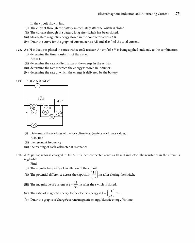
Electromagnetic Induction and Alternating Current 4.75
In the circuit shown, find (i) The current through the battery immediately after the switch is closed. (ii) The current through the battery long after switch has been closed. (iii) Steady state magnetic energy stored in the conductor across AB. (iv) Draw the curve for the graph of current across AB and also find the total current.
128. A 5 H inductor is placed in series with a 10 W resistor. An emf of 5 V is being applied suddenly to the combination. (i) determine the time constant t of the circuit. At t = t, (ii) determine the rate of dissipation of the energy in the resistor (iii) determine the rate at which the energy is stored in inductor (iv) determine the rate at which the energy is delivered by the battery
129.
300 1.8 H
4 µF
~
V4
V2 V5
V3 V1
V6
100 V, 500 rad s−1
(i) Determine the readings of the six voltmeters. (meters read r.m.s values) Also, find: (ii) the resonant frequency (iii) the reading of each voltmeter at resonance
130. A 25 mF capacitor is charged to 300 V. It is then connected across a 10 mH inductor. The resistance in the circuit is negligible.
Find (i) The angular frequency of oscillation of the circuit
(ii) The potential difference across the capacitor 1135
ms after closing the switch.
(iii) The magnitude of current at t = 1135
ms after the switch is closed.
(iv) The ratio of magnetic energy to the electric energy at t = 1135
ms.
(v) Draw the graphs of charge/current/magnetic energy/electric energy Vs time.
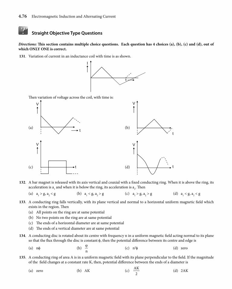
4.76 Electromagnetic Induction and Alternating Current
Straight Objective Type Questions
Directions: This section contains multiple choice questions. Each question has 4 choices (a), (b), (c) and (d), out of which ONLY ONE is correct.
131. Variation of current in an inductance coil with time is as shown.
Ι
t
Then variation of voltage across the coil, with time is:
(a)
V
t (b)
V
t
(c)
V
t (d)
V
t
132. A bar magnet is released with its axis vertical and coaxial with a fixed conducting ring. When it is above the ring, its acceleration is a1 and when it is below the ring, its acceleration is a2. Then
(a) a1 > g, a2 < g (b) a1 < g, a2 > g (c) a1 > g, a2 > g (d) a1 < g, a2 < g
133. A conducting ring falls vertically, with its plane vertical and normal to a horizontal uniform magnetic field which exists in the region. Then
(a) All points on the ring are at same potential (b) No two points on the ring are at same potential (c) The ends of a horizontal diameter are at same potential (d) The ends of a vertical diameter are at same potential
134. A conducting disc is rotated about its centre with frequency n in a uniform magnetic field acting normal to its plane so that the flux through the disc is constant f, then the potential difference between its centre and edge is
(a) nf (b) nϕ
(c) n2f (d) zero
135. A conducting ring of area A is in a uniform magnetic field with its plane perpendicular to the field. If the magnitude of the field changes at a constant rate K, then, potential difference between the ends of a diameter is
(a) zero (b) AK (c) AK2
(d) 2AK
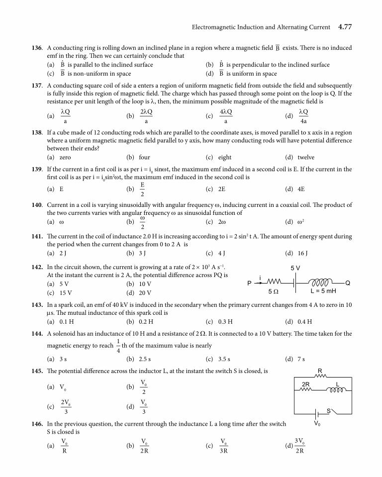
Electromagnetic Induction and Alternating Current 4.77
136. A conducting ring is rolling down an inclined plane in a region where a magnetic field B exists. There is no induced emf in the ring. Then we can certainly conclude that
(a) B is parallel to the inclined surface (b) B is perpendicular to the inclined surface (c) B is non-uniform in space (d) B is uniform in space
137. A conducting square coil of side a enters a region of uniform magnetic field from outside the field and subsequently is fully inside this region of magnetic field. The charge which has passed through some point on the loop is Q. If the resistance per unit length of the loop is l, then, the minimum possible magnitude of the magnetic field is
(a) Qa
l (b)
2 Qal
(c) 4 Q
al
(d) Q
4al
138. If a cube made of 12 conducting rods which are parallel to the coordinate axes, is moved parallel to x axis in a region where a uniform magnetic magnetic field parallel to y axis, how many conducting rods will have potential difference between their ends?
(a) zero (b) four (c) eight (d) twelve
139. If the current in a first coil is as per i = i0 sinwt, the maximum emf induced in a second coil is E. If the current in the first coil is as per i = i0sin2wt, the maximum emf induced in the second coil is
(a) E (b) E2
(c) 2E (d) 4E
140. Current in a coil is varying sinusoidally with angular frequency w, inducing current in a coaxial coil. The product of the two currents varies with angular frequency w as sinusoidal function of
(a) w (b) 2w
(c) 2w (d) w2
141. The current in the coil of inductance 2.0 H is increasing according to i = 2 sin2 t A. The amount of energy spent during the period when the current changes from 0 to 2 A is
(a) 2 J (b) 3 J (c) 4 J (d) 16 J
142. In the circuit shown, the current is growing at a rate of 2 × 10³ A s-1. At the instant the current is 2 A, the potential difference across PQ is
(a) 5 V (b) 10 V (c) 15 V (d) 20 V
143. In a spark coil, an emf of 40 kV is induced in the secondary when the primary current changes from 4 A to zero in 10 ms. The mutual inductance of this spark coil is
(a) 0.1 H (b) 0.2 H (c) 0.3 H (d) 0.4 H
144. A solenoid has an inductance of 10 H and a resistance of 2 W. It is connected to a 10 V battery. The time taken for the
magnetic energy to reach 14
th of the maximum value is nearly
(a) 3 s (b) 2.5 s (c) 3.5 s (d) 7 s
145. The potential difference across the inductor L, at the instant the switch S is closed, is
(a) V0 (b) 0V2
(c) 02V3
(d) 0V3
146. In the previous question, the current through the inductance L a long time after the switch S is closed is
(a) 0VR
(b) 0V2R
(c) 0V3R
(d) 03V2R
P
5 V
5 ΩQ
L = 5 mH
i
R
2R L
S
V0
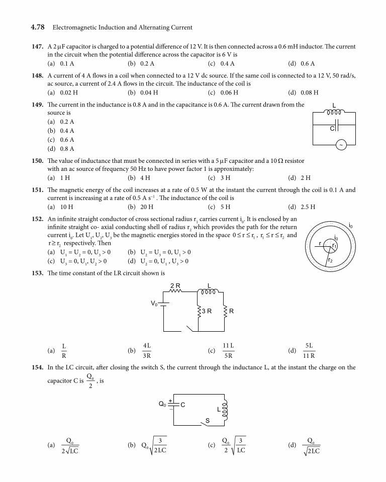
4.78 Electromagnetic Induction and Alternating Current
147. A 2 mF capacitor is charged to a potential difference of 12 V. It is then connected across a 0.6 mH inductor. The current in the circuit when the potential difference across the capacitor is 6 V is
(a) 0.1 A (b) 0.2 A (c) 0.4 A (d) 0.6 A
148. A current of 4 A flows in a coil when connected to a 12 V dc source. If the same coil is connected to a 12 V, 50 rad/s, ac source, a current of 2.4 A flows in the circuit. The inductance of the coil is
(a) 0.02 H (b) 0.04 H (c) 0.06 H (d) 0.08 H
149. The current in the inductance is 0.8 A and in the capacitance is 0.6 A. The current drawn from the source is
(a) 0.2 A (b) 0.4 A (c) 0.6 A (d) 0.8 A
150. The value of inductance that must be connected in series with a 5 mF capacitor and a 10 W resistor with an ac source of frequency 50 Hz to have power factor 1 is approximately:
(a) 1 H (b) 4 H (c) 3 H (d) 2 H
151. The magnetic energy of the coil increases at a rate of 0.5 W at the instant the current through the coil is 0.1 A and current is increasing at a rate of 0.5 A s-1 . The inductance of the coil is
(a) 10 H (b) 20 H (c) 5 H (d) 2.5 H
152. An infinite straight conductor of cross sectional radius r1 carries current i0. It is enclosed by an infinite straight co- axial conducting shell of radius r2 which provides the path for the return current i0. Let U1, U2, U3 be the magnetic energies stored in the space 10 r r≤ ≤ , 1 2r r r≤ ≤ and
2r r≥ respectively. Then (a) U1 = U2 = 0, U3 > 0 (b) U2 = U3 = 0, U1 > 0 (c) U3 = 0, U1, U2 > 0 (d) U2 = 0, U1 , U3 > 0
153. The time constant of the LR circuit shown is
2 R L
3 R R V0
(a) LR
(b) 4L3R
(c) 11 L5R
(d) 5L
11 R 154. In the LC circuit, after closing the switch S, the current through the inductance L, at the instant the charge on the
capacitor C is 0Q2
, is
L C
S
Q0− +
(a) 0Q2 LC
(b) 03
Q2LC
(c) 0Q 32 LC
(d) 0Q2LC
L
C
∼
r1
r2
r
i0
i0
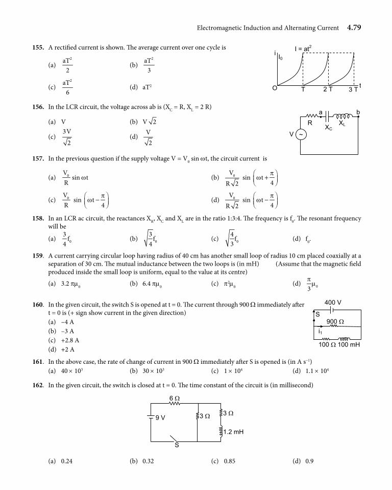
Electromagnetic Induction and Alternating Current 4.79
155. A rectified current is shown. The average current over one cycle is
(a) 2aT
2 (b)
2aT3
(c)
2aT6
(d) aT2
156. In the LCR circuit, the voltage across ab is (XC = R, XL = 2 R)
(a) V (b) V 2
(c) 3V
2 (d)
V2
157. In the previous question if the supply voltage V = V0 sin wt, the circuit current is
(a) 0VR
sin wt (b) 0VR 2
sin t4p
w +
(c) 0V
R sin t
4p
w − (d) 0V
R 2 sin t
4p
w −
158. In an LCR ac circuit, the reactances XR, XC and XL are in the ratio 1:3:4. The frequency is f0. The resonant frequency will be
(a) 03
f4
(b) 03
f4
(c) 04
f3
(d) f0.
159. A current carrying circular loop having radius of 40 cm has another small loop of radius 10 cm placed coaxially at a separation of 30 cm. The mutual inductance between the two loops is (in mH) (Assume that the magnetic field produced inside the small loop is uniform, equal to the value at its centre)
(a) 3.2 pm0 (b) 6.4 pm0 (c) p2m0 (d) 03p
m
160. In the given circuit, the switch S is opened at t = 0. The current through 900 W immediately after t = 0 is (+ sign show current in the given direction)
(a) –4 A (b) –3 A (c) +2.8 A (d) +2 A
161. In the above case, the rate of change of current in 900 W immediately after S is opened is (in A s–1) (a) 40 × 103 (b) 30 × 103 (c) 1 × 10⁴ (d) 1.1 × 10⁴
162. In the given circuit, the switch is closed at t = 0. The time constant of the circuit is (in millisecond)
6 Ω
9 V 3 Ω 3 Ω
1.2 mH
S
(a) 0.24 (b) 0.32 (c) 0.85 (d) 0.9
O T 2 T 3 T t
i I0
I = at2
R
a
XC XL
b
V ~
400 V
100 Ω 100 mH
S
i1 900 Ω
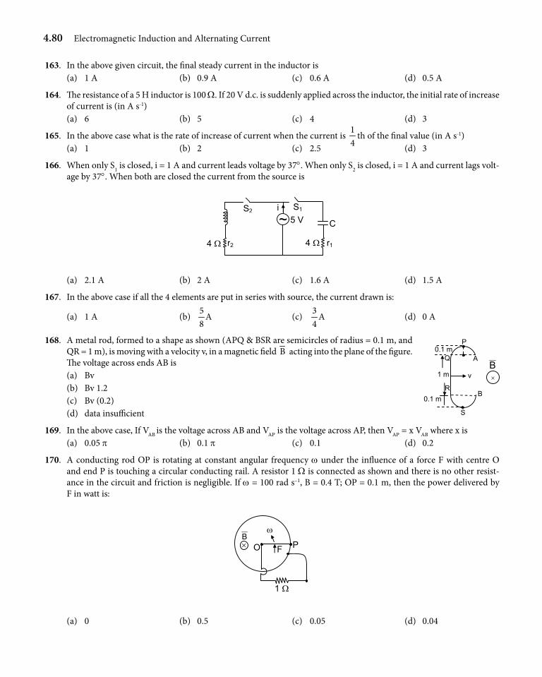
4.80 Electromagnetic Induction and Alternating Current
163. In the above given circuit, the final steady current in the inductor is (a) 1 A (b) 0.9 A (c) 0.6 A (d) 0.5 A
164. The resistance of a 5 H inductor is 100 W. If 20 V d.c. is suddenly applied across the inductor, the initial rate of increase of current is (in A s-1)
(a) 6 (b) 5 (c) 4 (d) 3
165. In the above case what is the rate of increase of current when the current is 14
th of the final value (in A s-1) (a) 1 (b) 2 (c) 2.5 (d) 3
166. When only S1 is closed, i = 1 A and current leads voltage by 37°. When only S2 is closed, i = 1 A and current lags volt-age by 37°. When both are closed the current from the source is
5 V
4 Ω
S2 S1
C
r14 Ω
~r2
i
(a) 2.1 A (b) 2 A (c) 1.6 A (d) 1.5 A
167. In the above case if all the 4 elements are put in series with source, the current drawn is:
(a) 1 A (b) 5
A8
(c) 3
A4
(d) 0 A
168. A metal rod, formed to a shape as shown (APQ & BSR are semicircles of radius = 0.1 m, and QR = 1 m), is moving with a velocity v, in a magnetic field B acting into the plane of the figure. The voltage across ends AB is
(a) Bv (b) Bv 1.2 (c) Bv (0.2) (d) data insufficient
169. In the above case, If VAB is the voltage across AB and VAP is the voltage across AP, then VAP = x VAB where x is (a) 0.05 p (b) 0.1 p (c) 0.1 (d) 0.2
170. A conducting rod OP is rotating at constant angular frequency w under the influence of a force F with centre O and end P is touching a circular conducting rail. A resistor 1 W is connected as shown and there is no other resist-ance in the circuit and friction is negligible. If w = 100 rad s–1, B = 0.4 T; OP = 0.1 m, then the power delivered by F in watt is:
ω
P
1 Ω
F B × O
(a) 0 (b) 0.5 (c) 0.05 (d) 0.04
Q
B
0.1 m
1 m v
A
×
B
P
S
0.1 m R
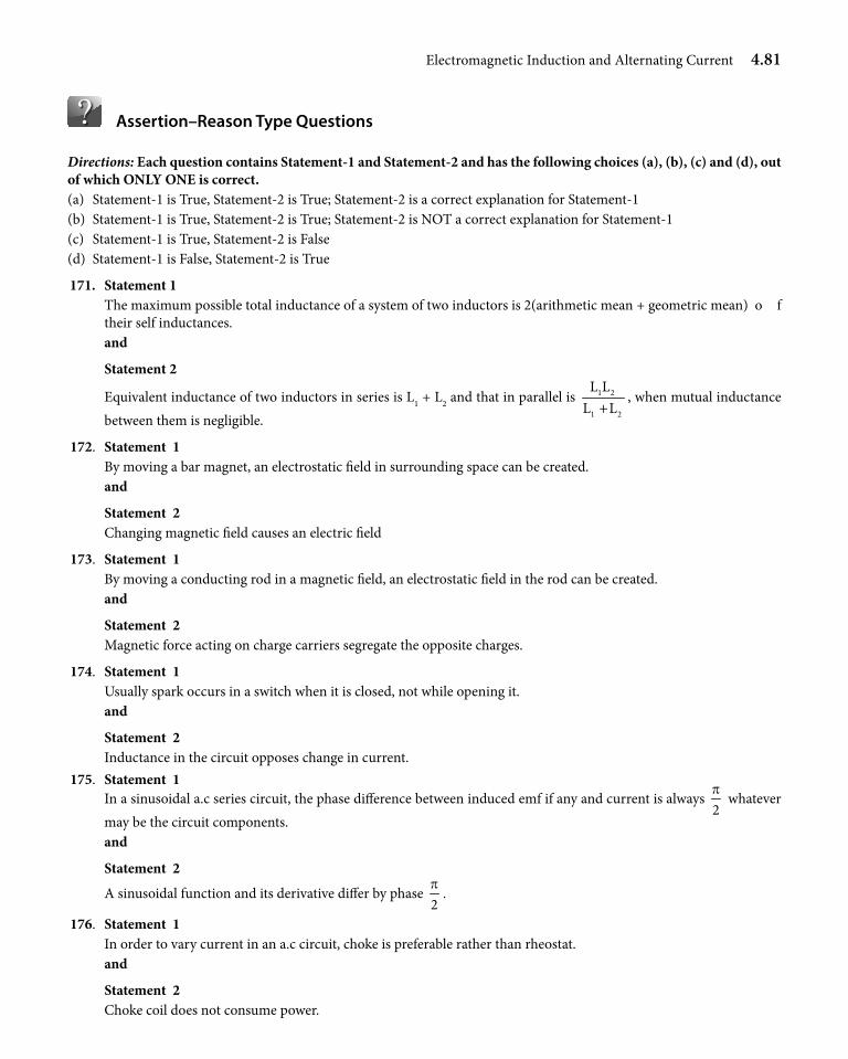
Electromagnetic Induction and Alternating Current 4.81
Assertion–Reason Type Questions
Directions: Each question contains Statement-1 and Statement-2 and has the following choices (a), (b), (c) and (d), out of which ONLY ONE is correct. (a) Statement-1 is True, Statement-2 is True; Statement-2 is a correct explanation for Statement-1(b) Statement-1 is True, Statement-2 is True; Statement-2 is NOT a correct explanation for Statement-1(c) Statement-1 is True, Statement-2 is False(d) Statement-1 is False, Statement-2 is True
171. Statement 1 The maximum possible total inductance of a system of two inductors is 2(arithmetic mean + geometric mean) o f
their self inductances. and
Statement 2
Equivalent inductance of two inductors in series is L1 + L2 and that in parallel is 1 2
1 2
L LL L+
, when mutual inductance between them is negligible.
172. Statement 1 By moving a bar magnet, an electrostatic field in surrounding space can be created. and
Statement 2 Changing magnetic field causes an electric field
173. Statement 1 By moving a conducting rod in a magnetic field, an electrostatic field in the rod can be created. and
Statement 2 Magnetic force acting on charge carriers segregate the opposite charges.
174. Statement 1 Usually spark occurs in a switch when it is closed, not while opening it. and
Statement 2 Inductance in the circuit opposes change in current. 175. Statement 1 In a sinusoidal a.c series circuit, the phase difference between induced emf if any and current is always
2p
whatever may be the circuit components.
and
Statement 2
A sinusoidal function and its derivative differ by phase 2p
.
176. Statement 1 In order to vary current in an a.c circuit, choke is preferable rather than rheostat. and
Statement 2 Choke coil does not consume power.
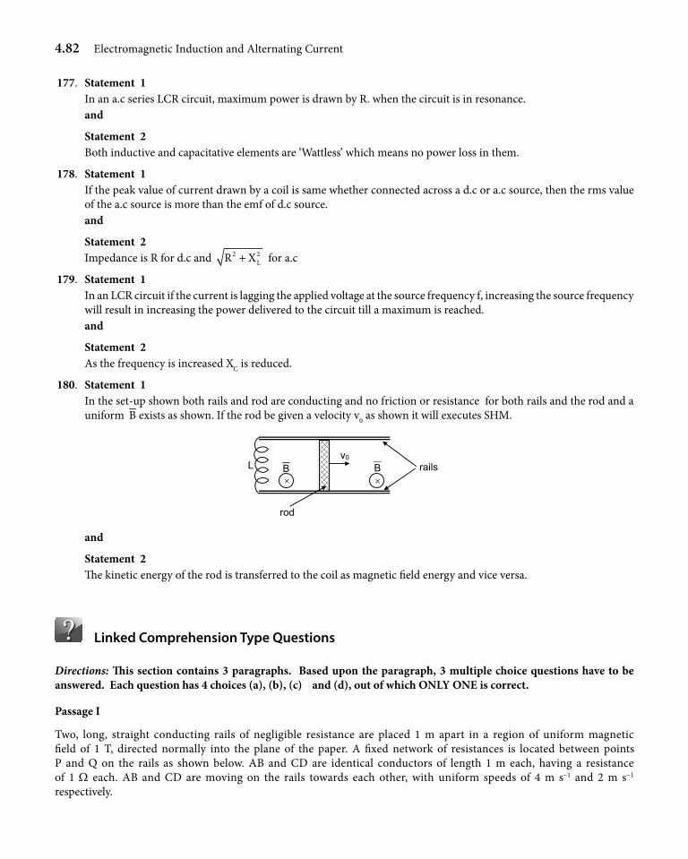
4.82 Electromagnetic Induction and Alternating Current
177. Statement 1 In an a.c series LCR circuit, maximum power is drawn by R. when the circuit is in resonance. and
Statement 2 Both inductive and capacitative elements are ‘Wattless’ which means no power loss in them.
178. Statement 1 If the peak value of current drawn by a coil is same whether connected across a d.c or a.c source, then the rms value
of the a.c source is more than the emf of d.c source. and
Statement 2 Impedance is R for d.c and 2 2
LR X+ for a.c
179. Statement 1 In an LCR circuit if the current is lagging the applied voltage at the source frequency f, increasing the source frequency
will result in increasing the power delivered to the circuit till a maximum is reached. and
Statement 2 As the frequency is increased XC is reduced.
180. Statement 1 In the set-up shown both rails and rod are conducting and no friction or resistance for both rails and the rod and a
uniform B exists as shown. If the rod be given a velocity v0 as shown it will executes SHM.
rod
BB rails L v0
× ×
and
Statement 2 The kinetic energy of the rod is transferred to the coil as magnetic field energy and vice versa.
Linked Comprehension Type Questions
Directions: This section contains 3 paragraphs. Based upon the paragraph, 3 multiple choice questions have to be answered. Each question has 4 choices (a), (b), (c) and (d), out of which ONLY ONE is correct.
Passage I
Two, long, straight conducting rails of negligible resistance are placed 1 m apart in a region of uniform magnetic field of 1 T, directed normally into the plane of the paper. A fixed network of resistances is located between points P and Q on the rails as shown below. AB and CD are identical conductors of length 1 m each, having a resistance of 1 W each. AB and CD are moving on the rails towards each other, with uniform speeds of 4 m s-1 and 2 m s-1 respectively.
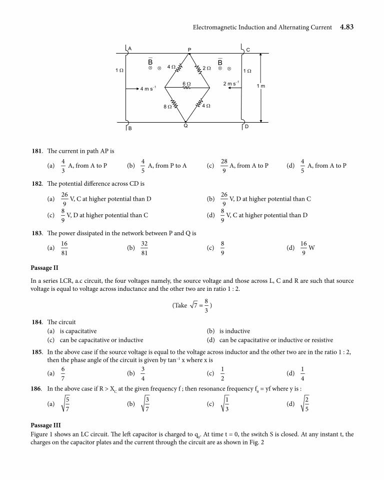
Electromagnetic Induction and Alternating Current 4.83
6 Ω
2 Ω 4 Ω
Q
P
8 Ω 4 Ω
•
•
4 m s−1
1 Ω
A
B D
C
1 m
1 Ω
2 m s−1
⊗ ⊗B
⊗ ⊗ B
181. The current in path AP is
(a) 43
A, from A to P (b) 45
A, from P to A (c) 289
A, from A to P (d) 45
A, from A to P
182. The potential difference across CD is
(a) 269
V, C at higher potential than D (b) 269
V, D at higher potential than C
(c) 89
V, D at higher potential than C (d) 89
V, C at higher potential than D
183. The power dissipated in the network between P and Q is
(a) 1681
(b) 3281
(c) 89
(d) 169
W
Passage II
In a series LCR, a.c circuit, the four voltages namely, the source voltage and those across L, C and R are such that source voltage is equal to voltage across inductance and the other two are in ratio 1 : 2.
(Take 8
73
= )
184. The circuit (a) is capacitative (b) is inductive (c) can be capacitative or inductive (d) can be capacitative or inductive or resistive
185. In the above case if the source voltage is equal to the voltage across inductor and the other two are in the ratio 1 : 2, then the phase angle of the circuit is given by tan–1 x where x is
(a) 67
(b) 34
(c) 12
(d) 14
186. In the above case if R > XC at the given frequency f ; then resonance frequency f0 = yf where y is :
(a) 57
(b) 37
(c) 13
(d) 25
Passage IIIFigure 1 shows an LC circuit. The left capacitor is charged to q0. At time t = 0, the switch S is closed. At any instant t, the charges on the capacitor plates and the current through the circuit are as shown in Fig. 2
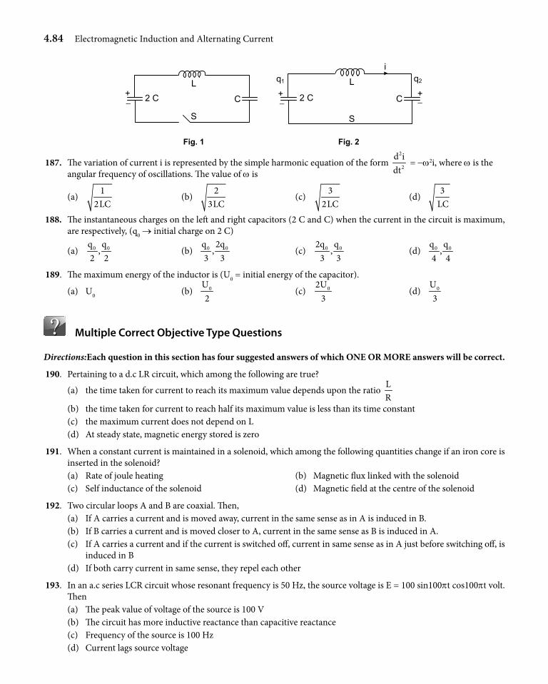
4.84 Electromagnetic Induction and Alternating Current
S
2 C C
L +
Fig. 1
−
S
2 C C
L
+ −
Fig. 2
+−
q1 q2
i
187. The variation of current i is represented by the simple harmonic equation of the form 2
2
d idt
= -w2i, where w is the angular frequency of oscillations. The value of w is
(a) 1
2LC (b)
23LC
(c) 3
2LC (d)
3LC
188. The instantaneous charges on the left and right capacitors (2 C and C) when the current in the circuit is maximum, are respectively, (q0 → initial charge on 2 C)
(a) 0 0q q,
2 2 (b) 0 0q 2q
,3 3
(c) 0 02q q,
3 3 (d) 0 0q q
,4 4
189. The maximum energy of the inductor is (U0 = initial energy of the capacitor).
(a) U0 (b) 0U2
(c) 02U3
(d) 0U3
Multiple Correct Objective Type Questions
Directions:Each question in this section has four suggested answers of which ONE OR MORE answers will be correct.
190. Pertaining to a d.c LR circuit, which among the following are true?
(a) the time taken for current to reach its maximum value depends upon the ratio LR
(b) the time taken for current to reach half its maximum value is less than its time constant (c) the maximum current does not depend on L (d) At steady state, magnetic energy stored is zero
191. When a constant current is maintained in a solenoid, which among the following quantities change if an iron core is inserted in the solenoid?
(a) Rate of joule heating (b) Magnetic flux linked with the solenoid (c) Self inductance of the solenoid (d) Magnetic field at the centre of the solenoid
192. Two circular loops A and B are coaxial. Then, (a) If A carries a current and is moved away, current in the same sense as in A is induced in B. (b) If B carries a current and is moved closer to A, current in the same sense as B is induced in A. (c) If A carries a current and if the current is switched off, current in same sense as in A just before switching off, is
induced in B (d) If both carry current in same sense, they repel each other
193. In an a.c series LCR circuit whose resonant frequency is 50 Hz, the source voltage is E = 100 sin100pt cos100pt volt. Then
(a) The peak value of voltage of the source is 100 V (b) The circuit has more inductive reactance than capacitive reactance (c) Frequency of the source is 100 Hz (d) Current lags source voltage
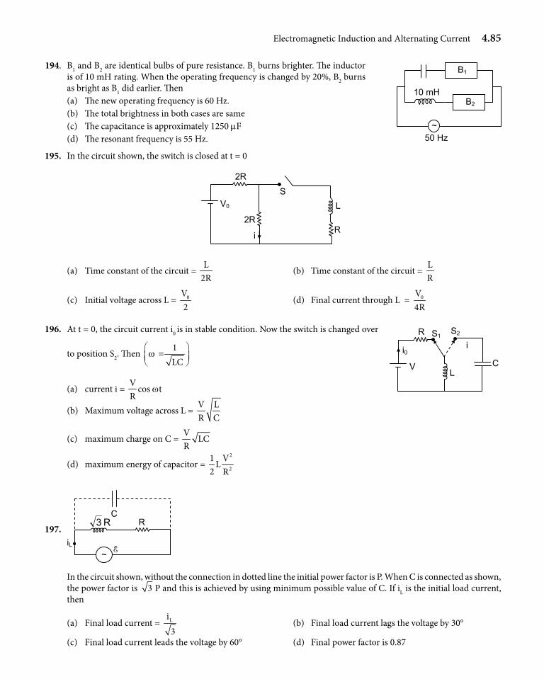
Electromagnetic Induction and Alternating Current 4.85
194. B1 and B2 are identical bulbs of pure resistance. B1 burns brighter. The inductor is of 10 mH rating. When the operating frequency is changed by 20%, B2 burns as bright as B1 did earlier. Then
(a) The new operating frequency is 60 Hz. (b) The total brightness in both cases are same (c) The capacitance is approximately 1250 mF (d) The resonant frequency is 55 Hz.
195. In the circuit shown, the switch is closed at t = 0
R
S L
i
2R
V0
2R
(a) Time constant of the circuit = L
2R (b) Time constant of the circuit =
LR
(c) Initial voltage across L = 0V2
(d) Final current through L = 0V4R
196. At t = 0, the circuit current i0 is in stable condition. Now the switch is changed over
to position S2. Then 1LC
w
=
(a) current i = V
cos tR
w
(b) Maximum voltage across L = V LR C
(c) maximum charge on C = V
LCR
(d) maximum energy of capacitor = 2
2
1 VL
2 R
197.
C R R3
~ iL E
In the circuit shown, without the connection in dotted line the initial power factor is P. When C is connected as shown, the power factor is 3 P and this is achieved by using minimum possible value of C. If iL is the initial load current, then
(a) Final load current = Li3
(b) Final load current lags the voltage by 30°
(c) Final load current leads the voltage by 60° (d) Final power factor is 0.87
B1
B2
~ 50 Hz
10 mH
R S1S2
i0
V L
C
i
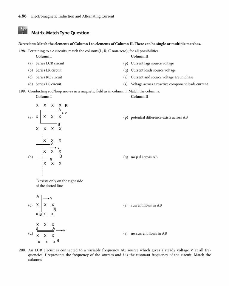
4.86 Electromagnetic Induction and Alternating Current
Matrix-Match Type Question
Directions: Match the elements of Column I to elements of Column II. There can be single or multiple matches.
198. Pertaining to a.c circuits, match the columns(L, R, C non-zero), for all possibilities. Column I Column II
(a) Series LCR circuit (p) Current lags source voltage
(b) Series LR circuit (q) Current leads source voltage
(c) Series RC circuit (r) Current and source voltage are in phase
(d) Series LC circuit (s) Voltage across a reactive component leads current
199. Conducting rod/loop moves in a magnetic field as in column I. Match the columns. Column I Column II
(a) X X X X
A
B
X X X X
X X X X
v
B
(p) potential difference exists across AB
(b) X X X
A X X X
X X X
v
BB
(q) no p.d across AB
B exists only on the right side of the dotted line
(c)
B X X X
X X X
A v
B (r) current flows in AB
(d) X X X
B
X X X
X X X A v
B
(s) no current flows in AB
200. An LCR circuit is connected to a variable frequency AC source which gives a steady voltage V at all fre-quencies. f represents the frequency of the sources and f is the resonant frequency of the circuit. Match the columns:
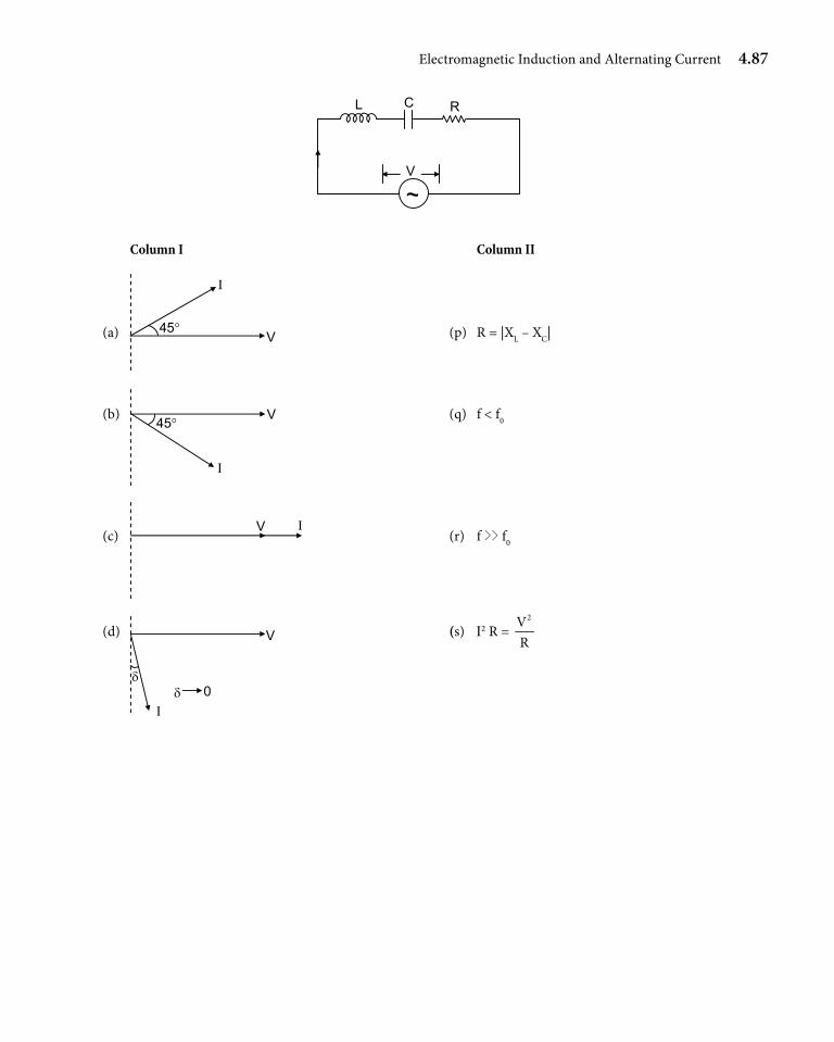
Electromagnetic Induction and Alternating Current 4.87
V
RCL
~
Column I Column II
(a) V
Ι
45° (p) R = |XL – XC|
(b) V
Ι
45° (q) f < f0
(c) Ι V
(r) f >> f0
(d) V
Ι δ 0
δ
(s) I2 R = 2V
R
4.88 Electromagnetic Induction and Alternating Current
Topic Grip
1. (i)
(ii) 2 2
mgm B C+ l
(iii) ML0T0
2. (i) 0ind
i vi
2 Rxmp
=l
from B to A
(ii) µ
π
0
2 32
i v
a
l
l+
3. (i) 2k v
iR
=l
(ii) i mgkmax = l2
4. (i) (ii) (iii) (iv) (0.09 - 0.09 cos 8 t) N m 5. (i) q = 50.5 mC (ii)
6. (i) 21r kp
(ii) (a) 1kr2
(b) 2
2
kR2r
(iii)
(iv) 2R
k2
p − ; –pR2k; –pR2k
7. (i) clockwise, concentric circles
(ii) kr2
, clockwise
(iii) (a) 2kr
R 'p
(b) zero
(iv) pkr2
(v) k2 2
l,
k k,
2 2 2 2l l
(vi) k2
× (perpendicular distance from centre)
(vii) ( )2k
clockwiseR 'l
(viii) zero (ix) (x) 0
(xi) E k E kac ce= =
l l2 2
4 2;
Eeg k= l2
4
8. m = 54 kg, u = 0.63 m s-1
9. 0 bn
2 amp
l
10. (i) Inductor
(ii) 7
12 11. (a) 12. (b) 13. (b) 14. (c) 15. (b) 16. (c) 17. (c) 18. (a) 19. (d) 20. (d) 21. (d) 22. (b) 23. (a) 24. (b) 25. (c) 26. (d) 27. (c), (d) 28. (a), (c) 29. (c), (d) 30. (a) → q, s (b) → p, r (c) → q, s (d) → p, r 31. (a) 32. (b) 33. (b) 34. (a) 35. (c) 36. (c) 37. (b) 38. (d) 39. (a) 40. (c) 41. (d) 42. (d) 43. (b) 44. (d) 45. (b) 46. (b) 47. (b) 48. (b) 49. (c) 50. (b) 51. (c) 52. (a) 53. (d) 54. (b) 55. (c) 56. (d) 57. (a) 58. (a) 59. (b) 60. (b) 61. (c) 62. (b) 63. (c) 64. (c) 65. (b) 66. (a) 67. (d) 68. (d) 69. (d) 70. (a) 71. (a) 72. (b)
73. (c) 74. (a) 75. (b) 76. (c) 77. (a) 78. (c) 79. (d) 80. (a) 81. (c) 82. (a) 83. (a) 84. (a) 85. (a) 86. (b) 87. (a) 88. (d) 89. (c) 90. (d) 91. (d) 92. (c) 93. (c) 94. (c) 95. (d) 96. (b) 97. (c) 98. (d) 99. (b) 100. (c) 101. (a) 102. (a) 103. (c) 104. (a) 105. (d) 106. (c) 107. (a) 108. (d) 109. (b) 110. (b) 111. (b) 112. (d) 113. (a) 114. (c) 115. (d) 116. (a) 117. (a), (b), (c) 118. (a), (b), d 119. (b), d 120. (a) → r (b) → s (c) → p (d) → q 121. (i) 0 (ii) 2 mV and 0.2 mA (iii) 4 mV and 0.4 mA (iv) Linear variation
122. (i) φµπ
= +
b i n ax
0
21l Wb
(ii) E ( )0iabv
V2 x x a
mp
=+
(iii) E = 0
(iv) E 0b an 1
2 xm a
p = − +
l V
(anticlockwise)
123. e = wil tan 2q
× 10–7 V
124. (i) E 0 20
1
yi v n V
2 ymp
= l
(ii) i = 0 0 2
1
i v yn A
2 R ym
pl
anSwerS KeyS
s O l u t i O n s
Electromagnetic Induction and Alternating Current 4.89
(iii) 2
0 20
1
y vF i n .
2 y Rmp
=
l N
(iv) 2
0 0 2
1
vi y 1Power n .
2 y Rm
p
=
l W
(v) 2
0 0 2
1
vi y 1n .
2 y Rm
p
l W
125. (i) 2 2B .t
2MR2 2
MgRv 1 e
B−
= −
l
lms-1
(ii) 1ter min al 2 2
MgRv ms
B−=
l
126. (i) I = 32 × 10–3 [1 – e-t × 1000] A
(ii) q = 16 3t
0.5 101 e Cm−
×
−
(iii) UL = UC = 0.512 × 10⁻⁶ J (iv) DT = 2.43 × 10⁻⁹ C 127. (i) i = 2 A (ii) i = 6 A (iii) Um = 4 × 10⁻³ J
(iv) 39t 10
2i 6 2e A − ×
= −
128. (i) 0.5 s (ii) 1 W (iii) 0.58 W (iv) 1.58 W
129. (i) V1 = 60 V V2 = 180 V V3 = 100 V V4 = 60 10 V V5 = 80 V V6 = 100 V
(ii) 11000 5rad s
6−
(iii) V1 = 100 V V2 = 100 5 V
V3 = 100 5 V
V4 = 100 6 V V5 = 0 V V6 = 100 V 130. (i) w = 2000 rad s-1
(ii) V = +240 V (iii) i = 9 A
(iv) 9
16 A
131. (c) 132. (d) 133. (d) 134. (a) 135. (a) 136. (d) 137. (c) 138. (b) 139. (a) 140. (c) 141. (c) 142. (c) 143. (a) 144. (c) 145. (a) 146. (b) 147. (d) 148. (d) 149. (a) 150. (d) 151. (a) 152. (c) 153. (d) 154. (c) 155. (b) 156. (d) 157. (d) 158. (b) 159. (b) 160. (a) 161. (a) 162. (a) 163. (c)
164. (c) 165. (d) 166. (c) 167. (b) 168. (a) 169. (c) 170. (d) 171. (b) 172. (d) 173. (a) 174. (d) 175. (a) 176. (a) 177. (b) 178. (d) 179. (d) 180. (b) 181. (c) 182. (d) 183. (a) 184. (c) 185. (b) 186. (d) 187. (c) 188. (c) 189. (d) 190. (b), (c) 191. (b), (c), (d) 192. (a), (c) 193. (b), (c), (d) 194. (b), (c) 195. (a), (c), (d) 196. (a), (b), (c), (d) 197. (a), (b), (d) 198. (a) → p, q, r, s (b) → p, s (c) → q (d) → p, q, r, s 199. (a) → p, s (b) → p, r (c) → p, s (d) → q, s 200. (a) → p, q (b) → p (c) → s (d) → r
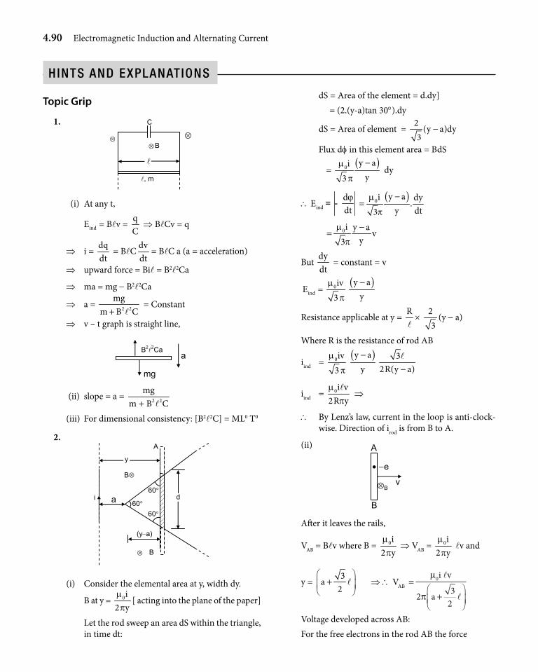
4.90 Electromagnetic Induction and Alternating Current
Topic Grip
1. C
B
, m
⊗ ⊗
⊗
(i) At any t,
indE = Blv = qC
⇒ BlCv = q
⇒ i = dqdt
= BlCdvdt
= BlC a (a = acceleration)
⇒ upward force = Bil = B2l2Ca
⇒ ma = mg - B2l2Ca
⇒ a = 2 2
mgm B C+ l
= Constant
⇒ v – t graph is straight line,
B22Ca
mg
a
(ii) slope = a = 2 2
mgm B C+ l
(iii) For dimensional consistency: [B2l2C] = ML0 T0
2.
⊗
A
y
a i 60°
60°
60°
B
(y−a)
B⊗
d
(i) Consider the elemental area at y, width dy.
B at y = 0i2 ymp
[ acting into the plane of the paper]
Let the rod sweep an area dS within the triangle, in time dt:
dS = Area of the element = d.dy] = (2.(y-a)tan 30°).dy
dS = Area of element = 2
(y a)dy3
−
Flux df in this element area = BdS
= ( )0 y ai
y3m
p
− dy
\ ind
dE
dtϕ
= -( )0 y ai dy
.y dt3
m
p
−=
0i y av
y3m
p
−=
But dydt
= constant = v
indE = 0iv3
m
p
( )y ay−
Resistance applicable at y = Rl
× 23
(y - a)
Where R is the resistance of rod AB
iind = 0iv3
m
p
( )y ay− 3
2R(y a)−l
iind = 0i v2R ym
pl
⇒
\ By Lenz’s law, current in the loop is anti-clock-wise. Direction of irod is from B to A.
(ii)
B
−e
⊗B v
A
•
After it leaves the rails,
VAB = Blv where B = 0i2 ymp
⇒ VAB = 0i2 ymp
lv and
y = 3
a2
+
l ⇒ \ VAB =+
µ
π
0
2 32
i v
a
l
l
Voltage developed across AB: For the free electrons in the rod AB the force
HintS and explanationS
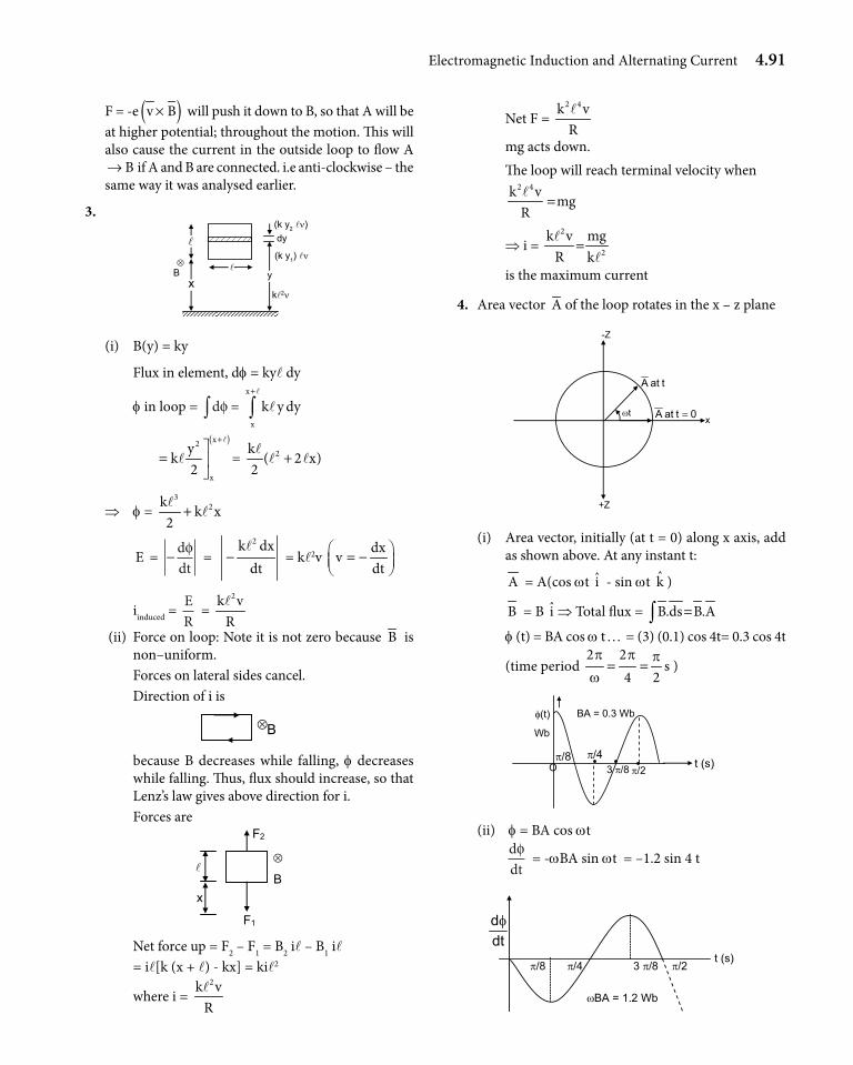
Electromagnetic Induction and Alternating Current 4.91
F = -e ( )v B× will push it down to B, so that A will be at higher potential; throughout the motion. This will also cause the current in the outside loop to flow A
B→ if A and B are connected. i.e anti-clockwise – the same way it was analysed earlier.
3.
dy (k y2 lν)
(k y1) lν
kl2νx
y⊗
B
(i) B(y) = ky
Flux in element, df = kyl dy
f in loop = dφ∫ = x
x
k y dy+
∫l
l
( )x2
x
yk
2
+
=
l
l = 2k( 2 x)
2+
ll l
⇒ f = 3
2kk x
2+
ll
E = − ddtφ =
2k dxdt
−l
= kl2v dx
vdt
= −
iinduced = ER
= 2k v
Rl
(ii) Force on loop: Note it is not zero because B is non–uniform.
Forces on lateral sides cancel. Direction of i is
B ⊗
because B decreases while falling, f decreases while falling. Thus, flux should increase, so that Lenz’s law gives above direction for i.
Forces are
B
F1
x
⊗
F2
Net force up = F2 – F1 = B2 il – B1 il = il[k (x + l) - kx] = kil2
where i = 2k v
Rl
Net F = 2 4k vRl
mg acts down. The loop will reach terminal velocity when
2 4k v
mgR
=l
⇒ i = 2
2
mgk vR k
=l
l is the maximum current
4. Area vector A of the loop rotates in the x – z plane
0tatA = ωt
tatA
-Z
+Z
x
(i) Area vector, initially (at t = 0) along x axis, add as shown above. At any instant t:
A = A(cos wt i - sin wt k )
B = B i ⇒ Total flux = B.ds B.A=∫ f (t) = BA cos w t … = (3) (0.1) cos 4t= 0.3 cos 4t
(time period 2 2
4 2p p p
w= = s )
O
φ(t)
π/8 π/4
BA = 0.3 Wb
3 π/8 π/2 t (s)
Wb
(ii) f = BA cos wt
ddtφ = -wBA sin wt = –1.2 sin 4 t
π/8 π/4 π/2 3 π/8 t (s)
dtdφ
ωBA = 1.2 Wb
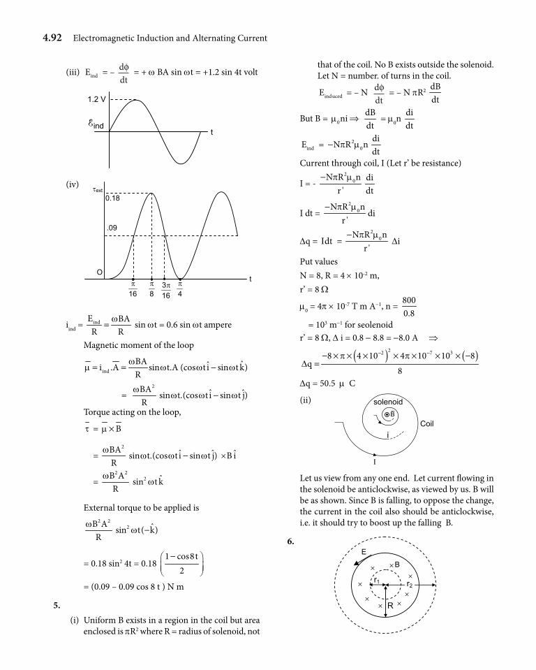
4.92 Electromagnetic Induction and Alternating Current
(iii) indE = – ddtφ = + w BA sin wt = +1.2 sin 4t volt
1.2 V
t indE
(iv)
t
163π
0.18
.09
O
8π
16π
4π
τext
iind = indE BAR R
w= sin wt = 0.6 sin wt ampere
Magnetic moment of the loop
indBA ˆˆi .A sin t.A (cos t i sin t k)R
wm w w w= = −
= 2BA
Rw ˆ ˆsin t.(cos t i sin t j)w w w−
Torque acting on the loop,
t = Bm ×
= 2BA
Rw ˆ ˆsin t.(cos t i sin t j)w w w− ×B i
= 2 2B A
Rw 2 ˆsin t kw
External torque to be applied is 2 2B A
Rw 2 ˆsin t( k)w −
= 0.18 sin2 4t = 0.18 1 cos8t
2−
= (0.09 – 0.09 cos 8 t ) N m
5. (i) Uniform B exists in a region in the coil but area
enclosed is pR2 where R = radius of solenoid, not
that of the coil. No B exists outside the solenoid. Let N = number. of turns in the coil.
inducedE = – N ddtφ = – N pR2
dBdt
But B = 0nim ⇒ dBdt
= m0n didt
indE = 20N R np m−
didt
Current through coil, I (Let r’ be resistance)
I = - 2
0N R nr '
p m− didt
I dt = 2
0N R nr '
p m−di
Dq = dtI = 2
0N R nr '
p m− Di
Put valuesN = 8, R = 4 × 10⁻² m, r’ = 8 W
m0 = 4p × 10-7 T m A-1, n = 8000.8
= 103 m-1 for seolenoidr’ = 8 W, D i = 0.8 - 8.8 = -8.0 A ⇒
( ) ( )22 7 38 4 10 4 10 10 8q
8
p pD
− −− × × × × × × × −=
Dq = 50.5 m C
(ii)
Ι
i
solenoid
Coil B
Let us view from any one end. Let current flowing in the solenoid be anticlockwise, as viewed by us. B will be as shown. Since B is falling, to oppose the change, the current in the coil also should be anticlockwise, i.e. it should try to boost up the falling B.
6.
r2 r1
× × ×
× × R
B
× ×
×
E
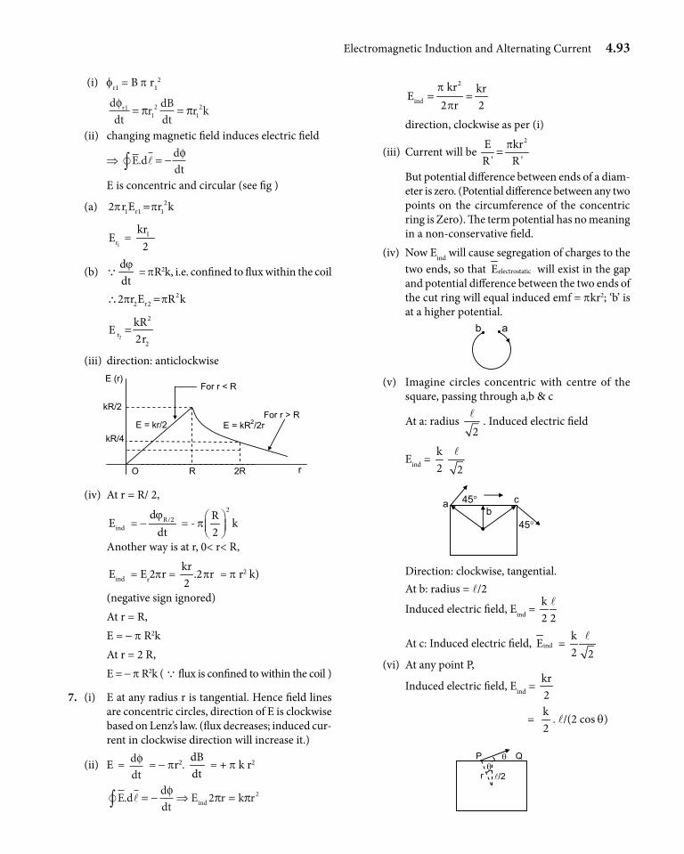
Electromagnetic Induction and Alternating Current 4.93
(i) fr1 = B p r12
ddt
r dBdt
r krφ π π11
21
2= =
(ii) changing magnetic field induces electric field
⇒ E d ddt
. = −∫φ
E is concentric and circular (see fig )
(a) 21 r1 12 r E r kp p=
1r
E = 1kr2
(b) Qddtϕ
= pR2k, i.e. confined to flux within the coil
2
2 r22 r E R kp p∴ =
2
2
r2
kRE
2r=
(iii) direction: anticlockwise
R R2 O r
kR/4
kR/2
E (r)
E = kr/2 E = kR2/2r
For r < R
For r > R
(iv) At r = R/ 2,
indE = - R/2ddtϕ
= -2R
k2
p
Another way is at r, 0< r< R,
indE = Er2pr = kr
.2 r2
p = p r2 k)
(negative sign ignored) At r = R, E = - p R2k At r = 2 R, E = - p R2k ( Q flux is confined to within the coil )
7. (i) E at any radius r is tangential. Hence field lines are concentric circles, direction of E is clockwise based on Lenz’s law. (flux decreases; induced cur-rent in clockwise direction will increase it.)
(ii) E = ddtφ = - pr2.
dBdt
= + p k r2
E d ddt
E r k rind. = − ⇒ =∫φ π π2 2
2
ind
kr krE
2 r 2p
p= =
direction, clockwise as per (i)
(iii) Current will be 2E kr
R ' R 'p=
But potential difference between ends of a diam-eter is zero. (Potential difference between any two points on the circumference of the concentric ring is Zero). The term potential has no meaning in a non-conservative field.
(iv) Now Eind will cause segregation of charges to the two ends, so that electrostaticE will exist in the gap and potential difference between the two ends of the cut ring will equal induced emf = pkr2; ‘b’ is at a higher potential.
b a
(v) Imagine circles concentric with centre of the square, passing through a,b & c
At a: radius 2l
. Induced electric field
Eind = k2 2
l
a b
c 45°
45°
Direction: clockwise, tangential. At b: radius = l/2
Induced electric field, Eind = k2 2
l
At c: Induced electric field, indE = k2 2
l
(vi) At any point P,
Induced electric field, Eind = kr2
= k2
. l/(2 cos q)
r /2
P Q θθ
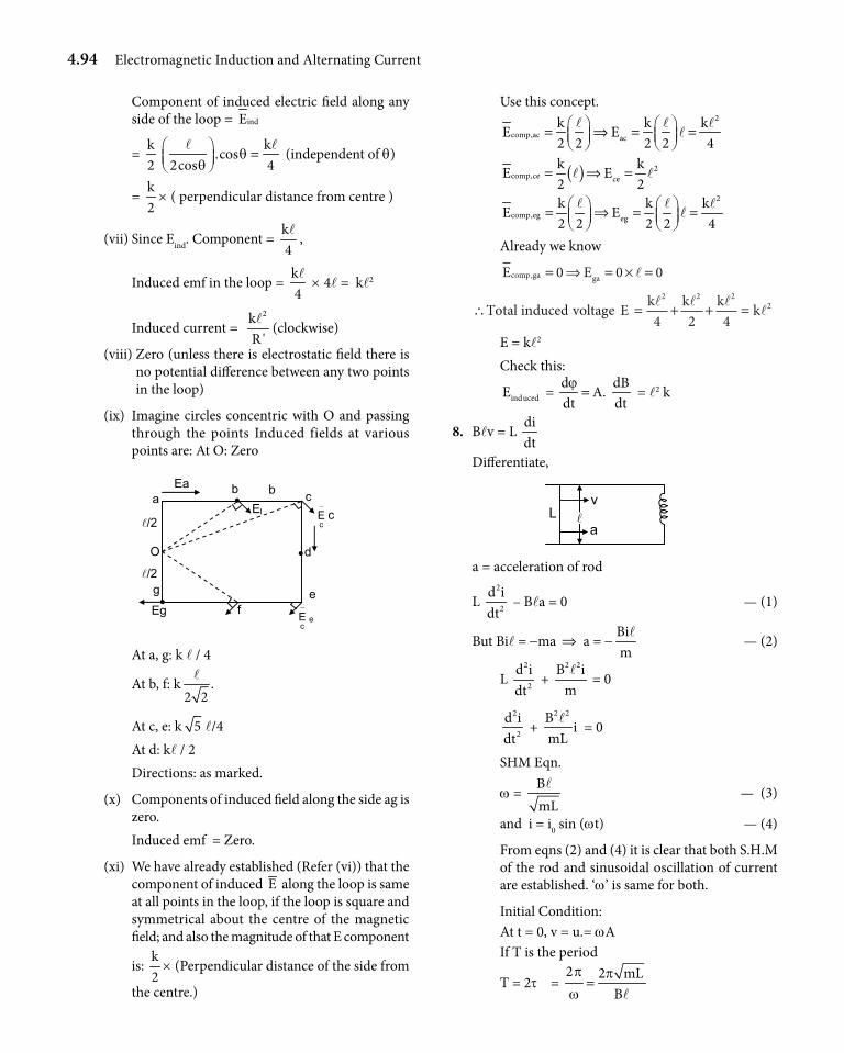
4.94 Electromagnetic Induction and Alternating Current
Component of induced electric field along any side of the loop = indE
= k2
k.cos
2cos 4q
q =
l l (independent of q)
= k2
× ( perpendicular distance from centre )
(vii) Since Eind. Component = k4l
,
Induced emf in the loop = k4l
× 4l = kl2
Induced current = 2k
R 'l
(clockwise)
(viii) Zero (unless there is electrostatic field there is no potential difference between any two points in the loop)
(ix) Imagine circles concentric with O and passing through the points Induced fields at various points are: At O: Zero
b
d
Eg e
c a
O
/2
/2
Ea
−
cE c
b •
•
• f −
cE e
El
g
At a, g: k l / 4
At b, f: k .2 2
l
At c, e: k 5 l/4 At d: kl / 2 Directions: as marked.
(x) Components of induced field along the side ag is zero.
Induced emf = Zero.
(xi) We have already established (Refer (vi)) that the component of induced E along the loop is same at all points in the loop, if the loop is square and symmetrical about the centre of the magnetic field; and also the magnitude of that E component
is: k2
× (Perpendicular distance of the side from
the centre.)
Use this concept.
2
comp,ac ack k kE E2 2 2 2 4
l l ll = ⇒ = =
( ) 2
comp,ce cek kE E2 2
l l= ⇒ =
2
comp,eg egk k kE E2 2 2 2 4
l l ll = ⇒ = =
Already we know
E Ecomp ga ga, = ⇒ = × =0 0 0l
∴ = + + =Total induced voltage E k k k kl l ll
2 2 22
4 2 4
E = kl2
Check this:
inducedE = ddtϕ= A.
dBdt
= l2 k
8. Blv = L didt
Differentiate,
L v
a
a = acceleration of rod
L 2
2
d idt
– Bla = 0 — (1)
But Bil = -ma ⇒ a = -Bim
l — (2)
L 2
2
d idt
+ 2 2B iml
= 0
2
2
d idt
+ 2 2B
imL
l = 0
SHM Eqn.
w = BmLl
— (3)
and i = i0 sin (wt) — (4)
From eqns (2) and (4) it is clear that both S.H.M of the rod and sinusoidal oscillation of current are established. ‘w’ is same for both.
Initial Condition: At t = 0, v = u.= wA If T is the period
T = 2t = 2 2 mL
Bp p
w=
l
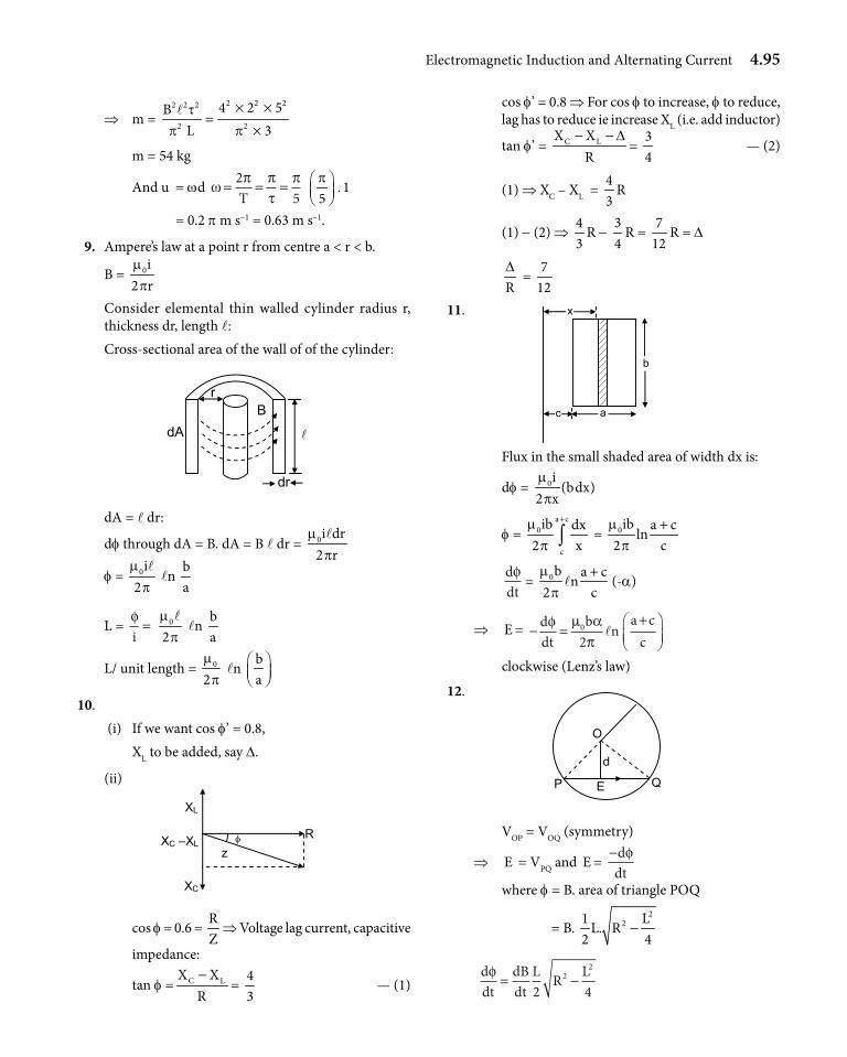
Electromagnetic Induction and Alternating Current 4.95
⇒ m = 2 2 22 2 2
2 2
4 2 5BL 3t
p p
× ×=
×l
m = 54 kg
And u = wd ω π πτ
π= = =25T
. 15p
= 0.2 p m s-1 = 0.63 m s-1.
9. Ampere’s law at a point r from centre a < r < b.
B = 0i2 rmp
Consider elemental thin walled cylinder radius r, thickness dr, length l: Cross-sectional area of the wall of of the cylinder:
dA
dr
B r
dA = l dr:
df through dA = B. dA = B l dr = 0i dr2 r
mpl
f = 0i2
mpl
ln
ba
L = φi= 0
2m
pl
ln ba
L/ unit length = 0
2m
p ln
ba
10. (i) If we want cos f’ = 0.8, XL to be added, say D.
(ii)
R XC –XL
XL
XC
z φ
cos f = 0.6 = RZ
⇒ Voltage lag current, capacitive
impedance:
tan f = C LX XR−
= 43
— (1)
cos f’ = 0.8 ⇒ For cos f to increase, f to reduce, lag has to reduce ie increase XL (i.e. add inductor)
tan f’ = C LX XR
D− −=
34
— (2)
(1) ⇒ XC – XL = 43
R
(1) - (2) ⇒ 43
R - 34
R = 7
12R = D
RD
= 7
12
11.
c a
b
x
Flux in the small shaded area of width dx is:
df = 0i (bdx)2 xmp
f = a c
0
c
ib dx2 x
mp
+
∫ = 0ib a cln
2 cm
p+
ddtφ
= 0b a cn
2 cm
p+
l (-a)
⇒ E = − =+
ddt
b na c
cφ µ α
π0
2l
clockwise (Lenz’s law)
12.
Q
O
P E
d
VOP = VOQ (symmetry)
⇒ E = VPQ and E = −ddtφ
where f = B. area of triangle POQ
= B. 2
21 LL. R
2 4−
ddt
dBdt
L R Lφ = −2 4
22
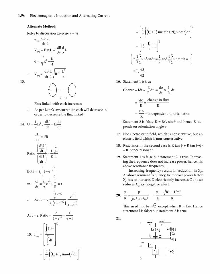
4.96 Electromagnetic Induction and Alternating Current
Alternate Method:
Refer to discussion exercise 7 - vi
E = dB ddt 2
VPQ = E × L = dB d
Ldt 2
d = 2
2 LR
4−
\ VPQ = 2
2dB L LR
dt 2 4−
13.
Flux linked with each increases\ As per Lenz’s law current in each will decrease in
order to decrease the flux linked
14. U = 21Li
2,
dU diLi
dt dt=
dHdt
= i2R
Ratio
dU diLdt dt
dH R idt
=
But i = t
0i 1 e t−
−
⇒ t
0idie
dtt
t−
= ; LR
t=
\ Ratio = t ( )
t
t
0
0
ie
i 1 e
t
t
t−
−−
t
t
e
1 e
t
t
−
−−
At t = t, Ratio = 1
1
e 1e 11 e
−
− =−−
15. Irms =
12T
2
0T
0
dt
dt
I
∫
∫
= ( )1
2T2
0 00
1sin t dt
TI I w
+
∫
= ( )1
2T2 2 2 20 0 0
0
1sin t 2 sin t dt
TI I w I w
+ +
∫
= 1
222 00 0
2I
I
+ +
T T
2
0 0
1 1 1sin tdt and sin tdt 0
T 2 Tw w
= = ∫ ∫Q
= I032
16. Statement 1 is true
Charge = Idt = E dtR
= ×ddt R
dtφ 1
= dR
change in fluxR
φ =
= BA
independentR
= of orientation
Statement 2 is false, E = Blv sin q and hence E de-pends on orientation angle q.
17. Not electrostatic field, which is conservative, but an electric field which is non-conservative
18. Reactance in the second case is R tan f + R tan (-f) = 0. hence resonant
19. Statement 1 is false but statement 2 is true. Increas-ing the frequency does not increase power, hence it is above resonance frequency. Increasing frequency results in reduction in XC. At above resonant frequency, to improve power factor XC has to increase. Dielectric only increases C and so reduces XC, i.e., negative effect.
20. 2 2 2
E E'R R L w=
+ ⇒
2 2 2R LE'E R
w+=
This need not be 2 except when R = Lw. Hence statement I is false; but statement 2 is true.
21.
8 j
−8 j
5 j
−4j
11
b
1
1+0j 1j a≡
L1 L2
C1C2
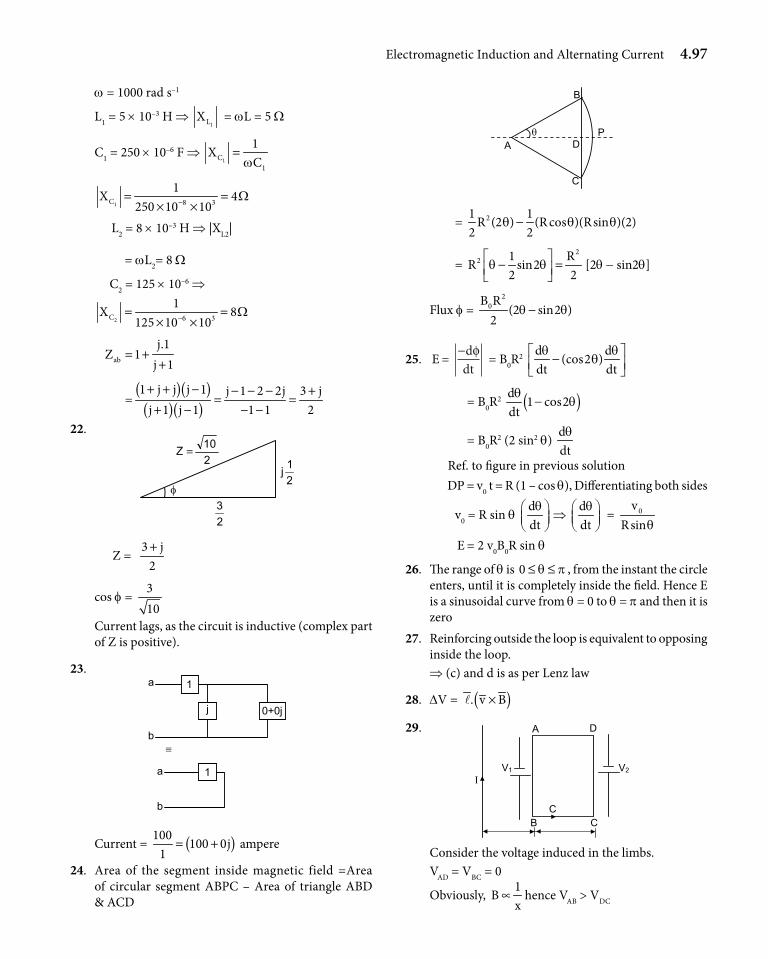
Electromagnetic Induction and Alternating Current 4.97
w = 1000 rad s–1
L1 = 5 × 10⁻³ H ⇒ 1LX = wL = 5 W
C1 = 250 × 10–6 F ⇒ 1C
1
1X
Cw=
1C 8 3
1X 4
250 10 10W−= =
× × L2 = 8 × 10⁻³ H ⇒ |XL2|
= wL2= 8 W
C2 = 125 × 10–6 ⇒
2C 6 3
1X 8
125 10 10W−= =
× ×
ab
j.1Z 1
j 1= +
+
=( )( )
( )( )1 j j j 1 j 1 2 2j 3 j
j 1 j 1 1 1 2+ + − − − − +
= =+ − − −
22.
23
φ
210Z =
21j
Z = 3 j
2+
cos f = 310
Current lags, as the circuit is inductive (complex part of Z is positive).
23.1
0+0jj
a
b
1 a
b
≡
Current = ( )100100 0j
1= + ampere
24. Area of the segment inside magnetic field =Area of circular segment ABPC – Area of triangle ABD & ACD
A
B
θ D
C
P
= 21 1R (2 ) (R cos )(Rsin )(2)
2 2q q q−
= 2
2 1 RR sin2
2 2q q − =
[2q - sin2q]
Flux f = 2
0B R(2 sin2 )
2q q−
25. E = −ddtφ = B0R
2 d d
(cos2 )dt dtq q
q −
= B0R2 ( )d
1 cos2dtq
q−
= B0R2 (2 sin2 q)
ddtq
Ref. to figure in previous solution DP = v0 t = R (1 – cos q), Differentiating both sides
v0 = R sin q ddtq
⇒
ddtq
= 0v
Rsinq E = 2 v0B0R sin q
26. The range of q is 0 q p≤ ≤ , from the instant the circle enters, until it is completely inside the field. Hence E is a sinusoidal curve from q = 0 to q = p and then it is zero
27. Reinforcing outside the loop is equivalent to opposing inside the loop.⇒ (c) and d is as per Lenz law
28. DV = ( ). v B×l
29.
Ι
A D
B C C
V2V1
Consider the voltage induced in the limbs. VAD = VBC = 0
Obviously, 1
Bx
∝ hence VAB > VDC
4.98 Electromagnetic Induction and Alternating Current
Current is anticlockwise.
Induced E = V1 – V2 = −+
µπ
µπ
0 0
2 2Ix
Ix a( )
= ⋅+
=+
µπ0
2I ax x a
kx x a( ) ( )
(k → constant)
30. Conceptual a → q, sb → p, rc → q, sd → p, rIf emf leads current, f is positive and if emf lags cur-rent, f is negative in a series LCR circuit.
IIT Assessment Exercise
31. ( )E . v Bl= × = Bvl
32. E ddt t
= − = = ××
−
−
φ φ∆∆
12 1012 10
3
3 = 1 V
33. E = Bℓv = 4 × 10-5 × 1 × 25 = 10-3 V
34. It is the induced current that depends on the resistance.
35. ddtφ
= [E] ⇒ [f]
= 2 3P ML T T
tI I
− = = ML2T-2I-1
36. Df = f2 – f1 = –nBA – nBA = –2nBA
E ≈ ∆∆φt
= 2nBA
tD
= 2
2 120 0.3 0.1 0.115 10−
× × × ××
= 4.8 V
37. E = 12
Bl2w = 21 2 30001 1
2 60p× × × ×
= 157 V
38.
δ’θ
v
( )Bv ×
B
A
B
δ
( )E v B • l= ×
From fig. d’ = d
l = AB
E vB cos vB sind ql l= =
1
vB . Note :End B of rod is ve2 + l
39. E = 12
Bl2w
w = 2 N
tp
⇒ E = 12
× 0.4 × 10-4 × 0.52 × 2 60
60p×
= 3.14 × 10⁻⁵ V
40. Induced emf = E = − ddtφ =
dBA dAB
dt dt=
A = 5t3 + (2t2 – 3t) 3 - tdAdt
= 15t2 + (4t – 3) 3 – 1 s At t = 2 s,
dAdt
= 15 × 4 + (4 × 2 – 3) 3 – 1 = 74
emf induced E = BdAdt
= 5 × 74 = 370 V
41. All others are produced due to electromagnetic induc-tion. Applied emf can be produced by other means.
42. f = B.A BA cosq=Translational motion will not change B, A or qRotational motion changes q → induced emf
43. Describes the process of electro-magnetic induction.
44. U = i
2
0
1E.di Li2
=∫
45. Number of turns per unit length (n) is halved.L m n2 ⇒ self inductance is one fourth.
x
~
46. Eddy currents can be used for deep heat treatment in medication. Lamp conected in paralled with a large induction and conceted to a.c. glows steadily (c) →
47. E = dI
Ldt
L = 6E t 1 500 10
I (0.2 0.1)D
D
−× ×=−
= 5 × 10⁻³ H
48. 1 2
1 2
L LL L+
= 50 15050 150
×+
= 37.5 mH
Electromagnetic Induction and Alternating Current 4.99
49. E = L dIdt
= 3
36
I 10L 10 10
t 1 10DD
−−
−= × ××
= 10 V
50. i2 = 40
400= 0.1 A ⇒ For ideal transformer, no power
loss ⇒ 400 i1 = 40 × 0.1
i1 = 0.1 . 40
400= 0.01 A
51. Smaller continuous volume ⇒ Smaller Eddy current
52. 2E L
= constant, L m n2
EE
nn
1
2
1
2
=
E1 > E2 ⇒ n1 > n2
53. reactance( )L
R resis tance( )WwW
= = no unit
Dimension = M0L0T0I0
54. f = 1
2 LCp
L = 2 2 2 12 12
1 14 f C 4 10 0.3 10p p −=
× × × × = 85 mH
55. 100 x 100
xR 2 2.R
= ⇒ = ⇒ Obviously (Vrms)2 to produce
x2
power is 100
2⇒ vrms =
102
peak
rms
VV
2
=
\ Vpeak = 10
. 2 10V2
=
56. Power factor = resis tance( )impedance ( )
W
W= no unit.
57. Power factor = 0 ⇒ Power = 0
58. 2pf = 12
f = 122p
= 1.9 Hz
Vrms = 240
120 22= = 170 V
59. Vrms = 0V2
Vav = 02Vp
⇒ Form factor = rms
av
VV
= 2 2
p = 1.1
60. 2 2 2 2L RV V V 240 144= − = −
(Q Vr = 48 × 3 = 144 V)
\ VL = 2 2 216 (15 9 )× − = 192 V
61. Input power = output power for ideal transformer ⇒ Input power = 0
⇒ Power factor = 0
62. XC = 1 1C 2 Cw pν=
⇒ Rectangular hyperbola
63. Pac = 2rmsI .R
Pdc = I2R ⇒ I = Irms = 10 A
64. XC = XL at resonance ⇒ Z = R.
65. At resonance, the circuit is purely resistive.
66. f = LI = 10 × 2 × 10-6 = 2 × 10⁻⁵ Wb
67. E = 321 2 3
dididiL L L
dt dt dt− = − = −
1 2 3
1 2 3
d(i i i )E E EL L L dt
+ ++ + = −
di Edt L− −=
1 2 3
1 1 1 1L L L L= + +
68. M = k 1 2L L
But 2
1 1
2 2
L nL n
=
⇒ M = 12
2
nK. L
n
69. The magnetic field linked with a coilf = BANwhere B is the magnetic field, A area of cross section and N the total number of turnsTherefore f = B A nl
As A = a1w1 and n = n1, then f = B a1w1 n1l
Therefore l = 1 1 1Ba w nϕ
70. Induced emf E = L didt
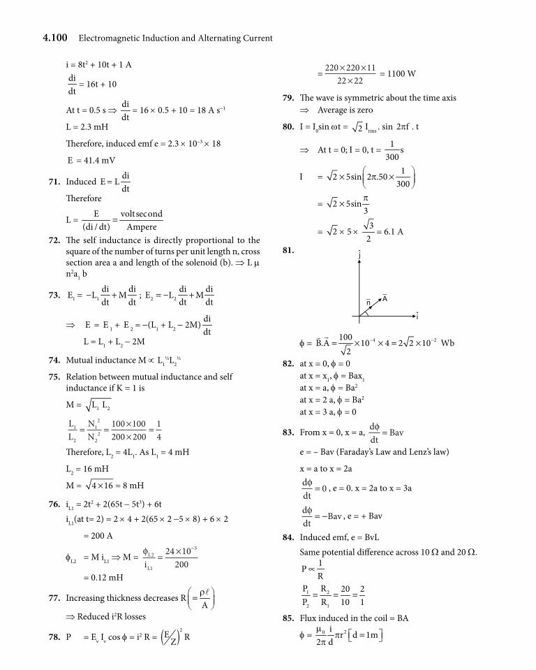
4.100 Electromagnetic Induction and Alternating Current
i = 8t2 + 10t + 1 Adidt
= 16t + 10
At t = 0.5 s ⇒ didt
= 16 × 0.5 + 10 = 18 A s-1
L = 2.3 mH
Therefore, induced emf e = 2.3 × 10–3 × 18
E = 41.4 mV
71. Induced E = Ldidt
Therefore
L = E voltsecond(di / dt) Ampere
=
72. The self inductance is directly proportional to the square of the number of turns per unit length n, cross section area a and length of the solenoid (b). ⇒ L m n2a1 b
73. 1E = 1di di
L Mdt dt
− + ; 2 2di diE L Mdt dt
= − +
⇒ E = E 1 + E 2 = -(L1 + L2 - 2M)didt
L = L1 + L2 - 2M
74. Mutual inductance M ∝ L1½L2
½
75. Relation between mutual inductance and self inductance if K = 1 is
M = 1 2L L
LL
NN
1
2
12
22
100 100200 200
14
= = ××
=
Therefore, L2 = 4L1. As L1 = 4 mH
L2 = 16 mH
M = 4 16× = 8 mH
76. iL1 = 2t2 + 2(65t - 5t3) + 6tiL1(at t= 2) = 2 × 4 + 2(65 × 2 -5 × 8) + 6 × 2
= 200 A
fL2 = M iL1 ⇒ M = φL
Li2
1
324 10200
= × −
= 0.12 mH
77. Increasing thickness decreases RAr = l
⇒ Reduced i2R losses
78. P = Ev Iv cos f = i2 R = ( )2E RZ
= 220 220 1122 22× ××
= 1100 W
79. The wave is symmetric about the time axis ⇒ Average is zero
80. I = I0sin wt = 2 Irms . sin 2 f . tp
⇒ At t = 0; I = 0, t = 1
s300
I = 1
2 5sin 2 .50300
p × ×
= 2 5sin3p
×
= 2 × 5 × 3
2= 6.1 A
81.
An
j
i
f = 4 2100B.A 10 4 2 2 10
2− −= × × = ×
Wb
82. at x = 0, f = 0at x = x1, f = Bax1
at x = a, f = Ba2
at x = 2 a, f = Ba2
at x = 3 a, f = 0
83. From x = 0, x = a, ddt
Bavφ =
e = – Bav (Faraday’s Law and Lenz’s law)
x = a to x = 2addtφ = 0 , e = 0. x = 2a to x = 3a
ddt
Bavφ = − , e = + Bav
84. Induced emf, e = BvLSame potential difference across 10 W and 20 W.
1P
R∝
1 2
2 1
P R 20 2P R 10 1
= = =
85. Flux induced in the coil = BA
f = 20 ir d 1m
2 dm
pp
=
Electromagnetic Induction and Alternating Current 4.101
e = ddt
rd
didt
φ µ=
0
2
2
= 2 p × 10-7 × 10-6 × 3.36 × 2 × 10-2
2di3.36 2 10
dt− = × ×
Q
= 13.44 × 10⁻¹⁵ × p V
\ i = 15
4
e 13.44 10R 8.4 10
p−
−
× ×=
× = 16 p × 10-12 A
86. Forces on the rod along path are weight and force due to the magnetic field. At any instant, net forceFnet = mg sin q - Bil
i → induced current
i = Bv
rl
v → instantaneous velocity of rod. At terminal ve-locity, say v’
mg sin q = Bil = 2 2B v '
rl
v’→ terminal velocity
v’ = 2 2
mgr sinB
q
l 87. When the rod crosses the mean position it will have
maximum velocity and hence emf induced will be maximum
2 21 1ka mv
2 2=
maxk
v am
=
Emax = B vmax L= B k
aLm
88.
P
S
Q
E2
E1
y
60°
60°30°
B ⊗ v0
x
1E = v0B0a sin 30°
2E = v0B0a sin 60°
emf across PQ = 0 0 0 0v B a v B a 32 2
+ Q to P.
89.
r
dr
a Q
O
P
• v
d E = vB0dr = w0B0r dr
PQE = w0B0
L
L a
r dr−∫ = 0 0B a(2L a)
2w −
90. emf = ( )v B d× • l = 0, as v , B and dl are co planar.
91. The flux f of magnetic field B due to i over the loop abca does not change with time as the loop moves, although B is non uniform.
abcaE = ddtφ= 0. Hence (a) is correct and (b) is also correct.
92. f = B . S
= 2 3 2 2 3ˆ ˆˆ ˆ(i t j t k)( a ).k a tp p− − = −
ddtφ = - 3 pa2t2
⇒ E ddt
= φ = 3pa2t2
93. As ddtφ < 0 . The induced current should oppose the
cause. Hence anti-clockwise.
94. Average emf = ∆∆φt
f1 = 2
0L
B2
pp
, f2 = 2
0L
B4
Eav =
φ φπ π
2 1 02
02
414
14
1 14
−= −
= −
T
B LT
B LT
95. a b c
Eab = v0B0l cos 2q
, a to b
Ebc = v0B0l cos 2q
, c to b
Eac = 0
96. E =
2
200
LBB L2
2 8
ww
=
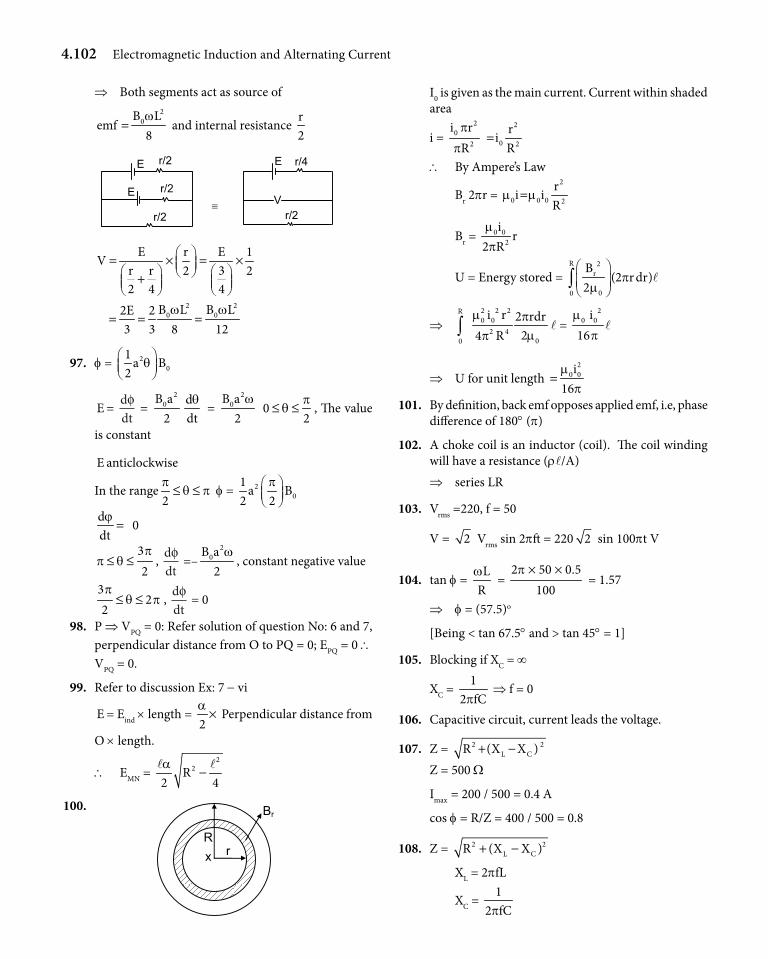
4.102 Electromagnetic Induction and Alternating Current
⇒ Both segments act as source of 2
0B Lemf
8w
= and internal resistance r2
E r/2
r/2 E
r/2
E r/4
r/2≡ V
E r E 1V
r r 32 22 4 4
= × = × +
2 2
0 0B L B L2E 23 3 8 12
w w= = =
97. f = 20
1a B
2q
E = ddtφ =
20B a2
ddtq
= 2
0B a2
w 0
2p
q≤ ≤ , The value
is constant
E anticlockwise
In the range2p
q p≤ ≤ f = 20
1a B
2 2p
ddtϕ= 0
32p
p q≤ ≤ , ddtφ =–
20B a2
w, constant negative value
32
2p
q p≤ ≤ , ddtφ = 0
98. P ⇒ VPQ = 0: Refer solution of question No: 6 and 7, perpendicular distance from O to PQ = 0; EPQ = 0 \ VPQ = 0.
99. Refer to discussion Ex: 7 - vi
E = Eind × length = 2a× Perpendicular distance from
O × length.
\ EMN = 2
2R2 4a
−l l
100.
R r x
Br
I0 is given as the main current. Current within shaded area
i = 2 2
002 2
i r ri
R Rp
p=
\ By Ampere’s Law
Br 2pr = 2
0 0 0 2
ri i
Rm m=
Br = 0 02
ir
2 Rmp
U = Energy stored = R 2
r
00
B(2 r dr)
2p
m
∫ l
⇒ 2 2 2R0 0
2 400
i r 2 rdr24 R
m pmp∫ l =
20 0i
16m
pl
⇒ U for unit length 2
0 0i16m
p=
101. By definition, back emf opposes applied emf, i.e, phase difference of 180° (p)
102. A choke coil is an inductor (coil). The coil winding will have a resistance (rl/A) ⇒ series LR
103. Vrms =220, f = 50
V = 2 Vrms sin 2pft = 220 2 sin 100pt V
104. tan f = L
Rw
= 2 50 0.5
100p × ×
= 1.57
⇒ f = (57.5)o
[Being < tan 67.5° and > tan 45° = 1]
105. Blocking if XC = ∞
XC = 1
2 fCp ⇒ f = 0
106. Capacitive circuit, current leads the voltage.
107. Z = 2 2L CR (X X )+ −
Z = 500 W
Imax = 200 / 500 = 0.4 A
cos f = R/Z = 400 / 500 = 0.8
108. Z = 2 2L CR (X X )+ −
XL = 2pfL
XC = 1
2 fCp
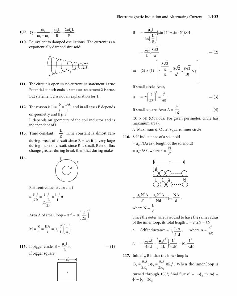
Electromagnetic Induction and Alternating Current 4.103
109. 0 0 0
2 1
L 2 f LQ
R Rw w p
w w= = =
− 110. Equivalent to damped oscillations: The current is an
exponentially damped sinusoid:
t
i
111. The circuit is open ⇒ no current ⇒ statement 1 truePotential at both ends is same ⇒ statement 2 is true. But statement 2 is not an explanation for 1.
112. The reason is L = φi
BAi
= and in all cases B depends
on geometry and B m i L depends on geometry of the coil inductor and is independent of i.
113. Time constant = LR
; Time constant is almost zero during break of circuit since R = ∞; it is very large during make of circuit, since R is small. Rate of flux change greater during break than that during make.
114.
r
R i
B at centre due to current i
= 0 0 0i i iL2R L2.
2
m m mp
p
= =
Area A of small loop = pr2 = 2
2p
p
l
M = φ µi
BAi L
= =
0
2 14
l
115. If bigger circle, B = 0i .L
mp — (1)
If bigger square,
4L
B = ( )0i sin45 sin45 4L48
m
p+ ×
= 0i 8 2.
Lm
p — (2)
⇒ (2) > (1) 2
8 28 2 8 2
~ 110
pp p
= >
Q
If small circle, Area,
A = 2 2
2 4p
p p =
l l — (3)
If small square, Area A = 2
16l
— (4)
(3) > (4) (Obvious: For given perimeter, circle has maximum area).\ Maximum f: Outer square, inner circle
116. Self-inductance of a solenoid = m0n
2(Area × length of the solenoid)
= m0n2Al’, where n =
N'l
d
’
1 2 3 N
= 2 2
0 00
N A N A NA' Nd d
m mm= =
l,
where N = Ll
Since the outer wire is wound to have the same radius of the inner loop, its total length L = 2prN = lN
\ Self inductance = m0L A
dl, where A =
2
4pl
\ = 2 2
0 0L L.
4 d 4L dm m
p p
=
l ll
= M.2L
dp l
117. Initially, B inside the inner loop is 20 0
0 0 12 2
i iB ; R
2R 2Rm m
ϕ p= = . When the inner loop is
turned through 180°; final flux f’ = -f0 ⇒ Df = f’ - f0 = 2f0
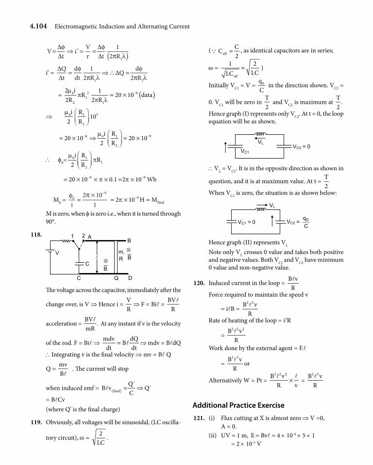
4.104 Electromagnetic Induction and Alternating Current
Vt
i Vr t R
= ⇒ = = ( )∆∆
∆∆
φ φπ λ
’ 12 1
i’ = ∆∆
∆Qt
ddt R
Q dR
= ⇒∴ =φπ λ
φπ λ
12 21 1
= ( )2 601
2 1
2 i 1R 20 10 data
2R 2 Rm
pp l
−= ×
⇒ 30 1
2
i R10
2 Rm
6 90 1
2
i R20 10 20 10
2 Rm− −
= × ⇒ = ×
\ f0=0 1
12
i RR
2 Rm
p
9 920 10 0.1 2 10 Wbp p− −= × × × = ×
M0 = φ π0
92 101i
=× −
9final2 10 H Mp −= × =
M is zero, when f is zero i.e., when it is turned through 90°.
118. 1
C
V
Q D
m, R
B
B⊗
⊗
2 A
C
B
The voltage across the capacitor, immediately after the
change over, is V ⇒ Hence i = VR
⇒ F = Bil = BV
Rl
acceleration = BV
.mR
l At any instant if v is the velocity
of the rod. F = Bil ⇒ mdv dQ
Bdt dt
= l ⇒ mdv = BldQ
\Integrating v is the final velocity ⇒ mv = Bl Q
Q = mvBl
. The current will stop
when induced emf = ( )final
Q'B v Q'
C= ⇒l
= BlCv(where Q’ is the final charge)
119. Obviously, all voltages will be sinusoidal, (LC oscilla-
tory circuit), w = 2
LC.
(eff
CC
2=Q , as identical capacitors are in series;
w = eff
1 2LCLC
= )
Initially VC1 = V = 0qC
in the direction shown. VC2 =
0. VC1 will be zero in T2
and VC2 is maximum at T
.2
Hence graph (I) represents only VC2. At t = 0, the loop equation will be as shown.
VC1
VLVC2 = 0
\VL = VC1. It is in the opposite direction as shown in
question, and it is at maximum value. At t = T2
When VC1 is zero, the situation is as shown below:
VC1 = 0
VL
VC2 = Cq0
Hence graph (II) represents VL
Note only VL crosses 0 value and takes both positive and negative values. Both VC1 and VC2 have minimum 0 value and non-negative value.
120. Induced current in the loop = B vRl
Force required to maintain the speed v
= ilB = 2 2B vRl
Rate of heating of the loop = i2R
= 2 2 2B vRl
Work done by the external agent = F.l
= 2 3B vRl
or
Alternatively W = Pt = 2 2 2B vR v
×l l
= 2 3B vRl
Additional Practice Exercise
121. (i) Flux cutting at X is almost zero ⇒ V =0, A = 0.(ii) UV = 1 m, E = Bvl = 4 × 10-4 × 5 × 1 = 2 × 10⁻³ V
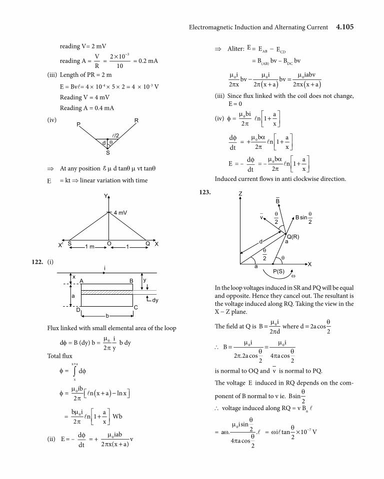
Electromagnetic Induction and Alternating Current 4.105
reading V= 2 mV
reading A = VR
= 32 10
10
−× = 0.2 mA
(iii) Length of PR = 2 m
E = Bvl= 4 × 10-4 × 5 × 2 = 4 × 10⁻³ V Reading V = 4 mV Reading A = 0.4 mA
(iv) R P
d θ /2
S
⇒ At any position E m d tanq m vt tanq
E = kt ⇒ linear variation with time
S XI Q X
Y
4 mV
O 1 m 1
122. (i)
y
dy
x
a
b
i
A
D
B
C
Flux linked with small elemental area of the loop
df = B (dy) b = 0 i2 ym
p b dy
Total flux
f = dx
x a
φ+
∫
f = ( )0ib n x a ln x2
mp + − l
= 0b i an 1
2 xmp
+ l Wb
(ii) E = – ddtφ = + 0iab
v2 x(x a)
mp +
⇒ Aliter: E = ABE - CDE
= B(AB) bv – BDC bv
( ) ( )0 0 0i i iabv
bv bv2 x 2 x a 2 x x am m mp p p
− =+ +
(iii) Since flux linked with the coil does not change, E = 0
(iv) f = 0bi2
mp
an 1
x +
l
ddtφ = 0b a
n 12 x
m ap
+ + l
E = – ddtφ = – 0b a
n 12 x
m ap
+ l
Induced current flows in anti clockwise direction.
123.
θ a X
v
a
Z
d
2θ
B
2sinB θ
2θ
P(S)ω
Q(R)
In the loop voltages induced in SR and PQ will be equal and opposite. Hence they cancel out. The resultant is the voltage induced along RQ. Taking the view in the X - Z plane.
The field at Q is 0iB where d 2a cos2 d 2m qp
= =
\ 0 0i iB
2 .2a cos 4 a cos2 2
m mq q
p p= =
is normal to OQ and v is normal to PQ.
The voltage E induced in RQ depends on the com-
ponent of B normal to v ie. Bsin2q
\ voltage induced along RQ = v Bn l
= 0isin
2a . .4 a cos
2
qm
wq
pl = 7i tan 10
2q
w −×l V
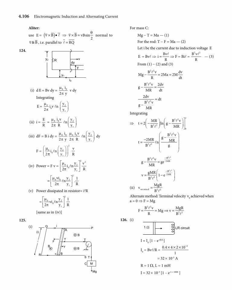
4.106 Electromagnetic Induction and Alternating Current
Aliter:
use E = ( )v B× • l ⇒ v B vBsin2q
× = normal to
v & B , i.e. parallel to RQ=l
124.
i0
vR
y1
y2
=---------y dy
(i) d E = Bv dy = 0 0i2 ym
p v dy
Integrating
E = 0
2m
pi0v ln 2
1
yy
(ii) i = ER
= 0 0i v2 Rm
p ln 2
1
yy
(iii) dF = B i dy = 0 0i2 ym
p0 0i v
2 Rm
p ln 2
1
yy
dy
F = µπ0
02
1
2
2i n y
yl
vR
(iv) Power = F v = 2 2
0 20
1
y vi n
2 y Rmp
l
2
0 0 2
1
vi y 1n .
2 y Rm
p
=
l
(v) Power dissipated in resistor= i2R
=2
0 20
1
y 1vi n
2 y Rmp
l
[same as in (iv)]
125. (i)
(i)
Mg
T
C
T
B
P
T
M
v
S
A
B
B
F
+
i
R
B
Q
For mass C:
Mg - T = Ma — (1) For the rod: T - F = Ma — (2) Let i be the current due to induction voltage E
E = Bvl ⇒ Bv
iR
=l
⇒ F = Bil = 2 2B vRl
— (3)
From (1) - (2) and (3)
2 2B v dv
Mg 2Ma 2MR dt
− = =l
2 2B v 2dv
gMR dt
− =l
2 2
2dvdt
B vgMR
=− l
Integrating
⇒ v2 2
2 20
MR B vt 2 ln g
MRB = − −
ll
2 2
2 2
B vg2MR MRt ngB
− −
=
l
ll
2 2tB2 2
2MRB vg ge
MR
−
− =ll
2 2tB
2MR2 2
gMRv 1 e
B
− = −
l
l
(ii) ter min al 2 2
MgRv
B=
lAlternate method: Terminal velocity v0 achieved when a = 0 ⇒ F = Mg
2 2
2 2
MgRB vF Mg v
R B= = ⇒ =
ll
126. (i)
1 Ω LR circuit
I = I0 [1 – e-tR/L]
I0 = Bvl/R = 20.4 4 2 10
1
−× × ×
= 32 × 10-3 A
R = 1 W, L = 1 mH
I = 32 × 10-3 [1 – e-t × 1000 ]
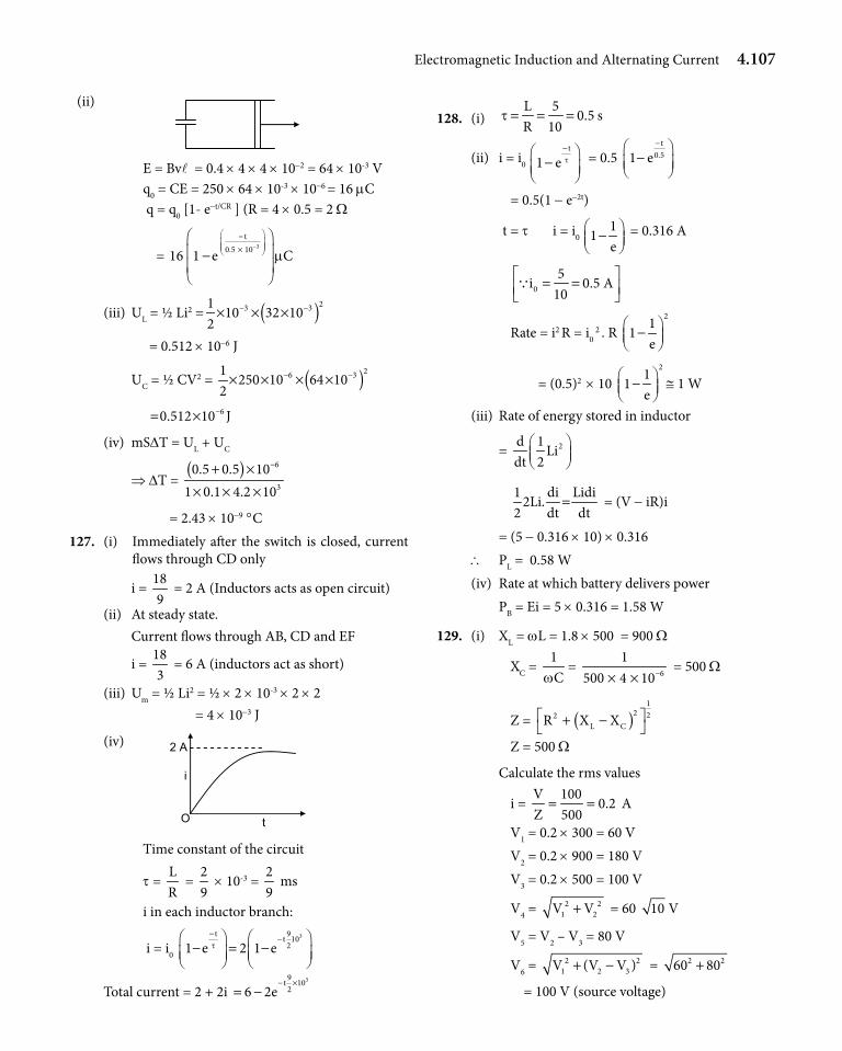
Electromagnetic Induction and Alternating Current 4.107
(ii)
E = Bvl = 0.4 × 4 × 4 × 10-2 = 64 × 10-3 V q0 = CE = 250 × 64 × 10-3 × 10-6 = 16 mC q = q0 [1- e-t/CR ] (R = 4 × 0.5 = 2 W
= 3
t0.5 1016 1 e Cm
−
− ×
−
(iii) UL = ½ Li2 = ( )23 3110 32 10
2− −× × ×
= 0.512 × 10⁻⁶ J
UC = ½ CV2 = ( )26 31250 10 64 10
2− −× × × ×
60.512 10 J−= ×
(iv) mSDT = UL + UC
⇒ DT = ( ) 6
3
0.5 0.5 101 0.1 4.2 10
−+ ×× × ×
= 2.43 × 10⁻⁹ °C 127. (i) Immediately after the switch is closed, current
flows through CD only
i = 189
= 2 A (Inductors acts as open circuit)
(ii) At steady state. Current flows through AB, CD and EF
i = 183
= 6 A (inductors act as short)
(iii) Um = ½ Li2 = ½ × 2 × 10-3 × 2 × 2 = 4 × 10⁻³ J
(iv)
O
i
2 A
t
Time constant of the circuit
t = LR
= 29
× 10-3 = 29
ms
i in each inductor branch:
i = i0 3t 9t 10
21 e 2 1 et−
− − = −
Total current = 2 + 2i 39t 10
26 2e− ×
= −
128. (i) L 5
0.5 sR 10
t = = =
(ii) i = i0
t
1 e t−
− = 0.5
t0.51 e−
−
= 0.5(1 - e-2t)
t = t i = i0 1
1e
− = 0.316 A
05
i 0.5 A10
= = Q
Rate = i2 R = i0 2 . R
211
e −
= (0.5)2 × 10 21
1e
− @ 1 W
(iii) Rate of energy stored in inductor
= 2d 1Li
dt 2
1 di Lidi
2Li.2 dt dt
= = (V - iR)i
= (5 - 0.316 × 10) × 0.316\ PL = 0.58 W(iv) Rate at which battery delivers power PB = Ei = 5 × 0.316 = 1.58 W
129. (i) XL = wL = 1.8 × 500 = 900 W
XC = 1Cw
= 6
1500 4 10−× ×
= 500 W
Z = ( )1
2 22L CR X X + −
Z = 500 W
Calculate the rms values
i = V 100
0.2Z 500= = A
V1 = 0.2 × 300 = 60 V V2 = 0.2 × 900 = 180 V V3 = 0.2 × 500 = 100 V
V4 = 2 21 2V V+ = 60 10 V
V5 = V2 – V3 = 80 V
V6 = 2 21 2 3V (V V )+ − = 2 260 80+
= 100 V (source voltage)
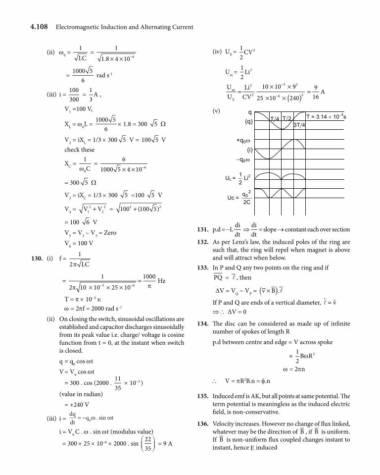
4.108 Electromagnetic Induction and Alternating Current
(ii) w0 = 1LC
= 6
1
1.8 4 10−× ×
= 1000 5
6 rad s-1
(iii) i = 100300
= 1
A3
,
V1 =100 V,
XL = w0L = 1000 5
6× 1.8 = 300 5 W
V2 = iXL = 1/3 × 300 5 V = 100 5 V check these
XC = 0
1Cw
= 6
61000 5 4 10−× ×
= 300 5 W
V3 = iXC = 1/3 × 300 5 =100 5 V
V4 = 2 21 2V V+ = 2 2100 (100 5)+
= 100 6 V V5 = V2 – V3 = Zero V6 = 100 V
130. (i) f = 12 LCp
= 3 6
1 1000
2 10 10 25 10 pp − −=
× × ×Hz
T = p × 10-3 s: w = 2pf = 2000 rad s–1
(ii) On closing the switch, sinusoidal oscillations are established and capacitor discharges sinusoidally from its peak value i.e. charge/ voltage is cosine function from t = 0, at the instant when switch is closed.
q = q0 cos wt V = V0 cos wt
= 300 . cos (2000 . 1135
× 10-3 )
(value in radian) = +240 V
(iii) i = dqdt
q t= − 0ω ω. sin
i = V0 C . w . sin wt (modulus value)
= 300 × 25 × 10-6 × 2000 . sin 2235
= 9 A
(iv) UE = 21CV
2
Um = 21Li
2
( )
3 22m
2 26E
10 10 9U Li 9U 16CV 25 10 240
−
−
× ×= =
× ×A
(v)
4T3 2T4T
q (q)
(i) −q0ω
UL = 21 Li2
Uc = C2
q 20
T = 3.14 × 10⁻⁴s
+q0ω
131. p.d = -Ldidt
⇒didt
= slope → constant each over section
132. As per Lenz’s law, the induced poles of the ring are such that, the ring will repel when magnet is above and will attract when below.
133. In P and Q any two points on the ring and if PQ = l , then
DV = VQ - VP = ( )v B .× l
If P and Q are ends of a vertical diameter, ˆ v=l⇒ \ DV = 0
134. The disc can be considered as made up of infinite number of spokes of length Rp.d between centre and edge = V across spoke
= 21B R
2w
w = 2pn
\ V = pR2B.n = f.n
135. Induced emf is AK, but all points at same potential. The term potential is meaningless as the induced electric field, is non-conservative.
136. Velocity increases. However no change of flux linked, whatever may be the direction of B , if B is uniform. If B is non-uniform flux coupled changes instant to instant, hence E induced
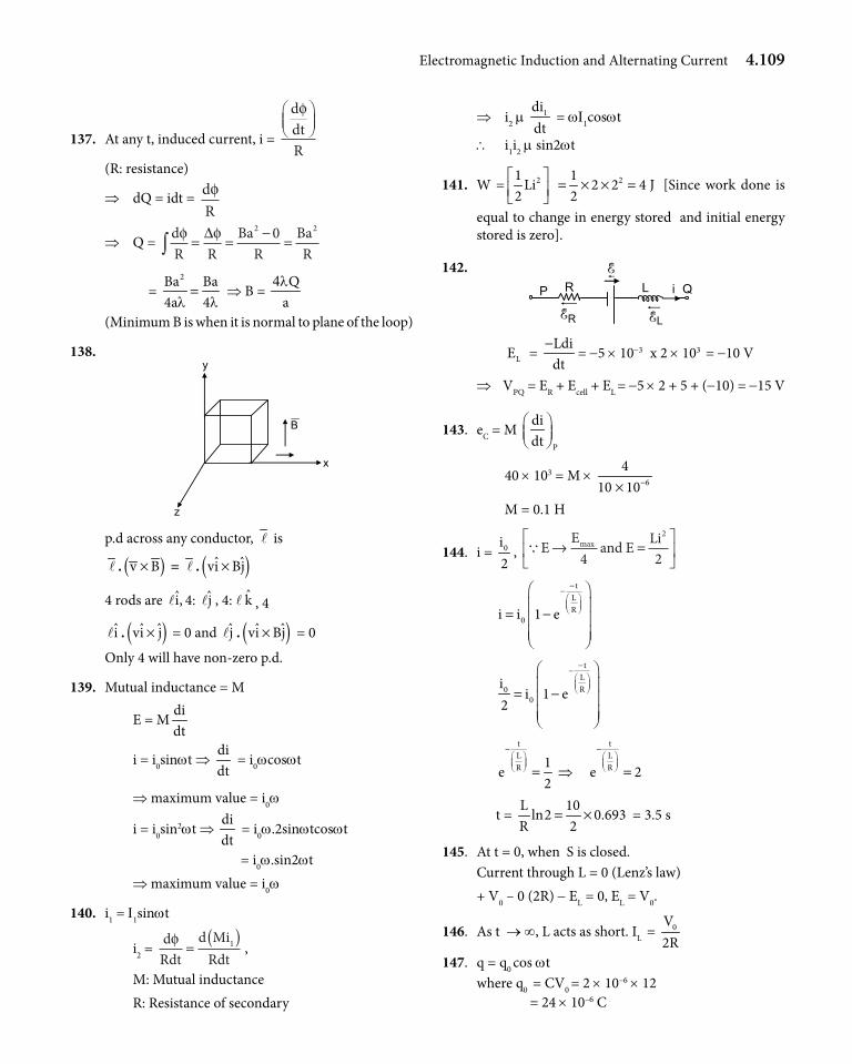
Electromagnetic Induction and Alternating Current 4.109
137. At any t, induced current, i =
ddtR
φ
(R: resistance)
⇒ dQ = idt = dRφ
⇒ Q = dR R
BaR
BaR
φ φ∫ = = − =∆ 2 20
= 2Ba Ba
4a 4l l= ⇒ B =
Qal4
(Minimum B is when it is normal to plane of the loop)
138.
x
y
z
B
p.d across any conductor, l is
l . ( )v B× = l . ( )ˆ ˆvi Bj×
4 rods are i,l 4: jl , 4: l k , 4
il . ( )ˆ ˆvi j× = 0 and jl . ( )ˆ ˆvi Bj× = 0
Only 4 will have non-zero p.d.
139. Mutual inductance = M
E = Mdidt
i = i0sinwt ⇒ didt
= i0wcoswt
⇒ maximum value = i0w
i = i0sin2wt ⇒ didt
= i0w.2sinwtcoswt
= i0w.sin2wt ⇒ maximum value = i0w
140. i1 = I1sinwt
i2 = dRdt
d MiRdt
φ =( )1 ,
M: Mutual inductance R: Resistance of secondary
⇒ i2 m 1didt
= wI1coswt
\ i1i2 m sin2wt
141. W = 2 21 1Li 2 2 4 J
2 2 = × × =
[Since work done is
equal to change in energy stored and initial energy stored is zero].
142.P R
RE LE
L i Q E
LE = Ldidt−
= -5 × 10-3 x 2 × 103 = -10 V
⇒ VPQ = ER + Ecell + EL = -5 × 2 + 5 + (-10) = -15 V
143. eC = M P
didt
40 × 103 = M × 6
410 10−×
M = 0.1 H
144. i = 0i2
, QE E and E Li→ =
max
4 2
2
tLR
0i i 1 e
−−
= −
tLR0
0
ii 1 e
2
−−
= −
tLR 1
e2
− = ⇒
tLRe 2
− =
t = L 10
ln2 0.693R 2
= × = 3.5 s
145. At t = 0, when S is closed.Current through L = 0 (Lenz’s law)+ V0 – 0 (2R) - EL = 0, EL = V0.
146. As t → ∞, L acts as short. IL = 0V2R
147. q = q0 cos wtwhere q0 = CV0 = 2 × 10–6 × 12 = 24 × 10–6 C
4.110 Electromagnetic Induction and Alternating Current
When V = 0 0V qq
2 2⇒ =
⇒ cos wt = 1 3
sin t2 2
w⇒ =
i = dqdt
= q0 . w . sin wt
6
6 4
1 324 10
22 10 6 10−
− −= × × ×
× × × = 0.6 A
Aliter:Conservation of energy requires
2 2 20
1 1 1CV CV Li
2 2 2= +
( )2612 10 12
2−× × ×
( ) ( )26 3 21 12 10 6 0.6 10 i
2 2− −= × × × + × ×
i = 0.6 A
148. R = 12
34
W=
Z = 12
52.4
W=
2 2 2LX Z R= − = 52 - 32 =16
XL = 4 WwL = 450 L = 4
L = 248 10 H
50−= × = 0.08 H
149. The phasor currents have a phase difference of 180°. I = IC - IL = 0.2 A
150. Power factor = 1
⇒ Resonance1
LC
ww
⇒ =
2 2 6
1 1L 2H
C 4 2500 5 10w p −⇒ = = ≈× × × ×
151. U = ½ Li2, dUdt
= Lididt
L = 0.5
10H0.1(0.5)
=
152. The magnetic field B = 0 for
2 3 1, 2r r ,U 0,U U 0≥ = >
153. Req = 3 2 11R R R
3 2 5×
+ =+
t = eq
5 LLR 11R
=
154. ( )2 2
02 0Q / 2 Q1 1 1Li
2 2 C 2 C+ =
⇒ 2
2 0Q1 1Li 1
2 2C 4 = −
22 0 03Q Q 3
i ; i4LC 2 LC
= =
155. Iav =
T
0
idt
T
∫ =
T2
0
at dt
T
∫ =
2aT3
156. Z = 2 2R (2R R) R 2+ − =
I = VZ
= V
R 2
Vab = I (XL – XC) = I (R) = V2
157. I0 = 0VR 2
, cos f = R R 1Z R 2 2= = ; f =
4p
As XL > XC. The circuit is inductive. The voltage V leads the current I by f.
I = 0VR 2
sin t4p
w −
158. L
C
X L1XC
w
w
=
= w2 (LC) = 43
⇒ 21 3LC 4
w= , wn = 1LC
wn = w 34
, fn = f0 34
159. Consider the two coils as shown. Field at the centre of A:
a
BA
b
x
iB
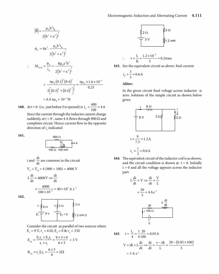
Electromagnetic Induction and Alternating Current 4.111
( )
20 B
32 2 2
b iB
2 b x
m=
+
φ πµ
ABa b i
b x=
+( )2 0
2
2 2322
.
\ Mi
a b
b xA B
A
B/ = =
+( )φ πµ0
2 2
2 2322
= ( ) ( )
( ) ( )
2 2 30 0
32 2 2
0.1 0.4 1.6 100.25
2 0.3 0.4
pm pm −× ×=
+
= 6.4 pm0 × 10–3 H
160. At t = 0– (i.e., just before S is opened) is L400
i 4A100
= =
Since the current through the inductor cannot change suddenly, at t = 0+, same 4 A flows through 900 W and completes circuit. Hence current flow in the opposite direction of i1 indicated
161. 900 Ω
100 Ω 100 mH
VL 4 A
i and didt
are common in the circuit
VL = VR = 4 (900 + 100) = 4000 V
di diL 4000V
dt dt= ⇒
3 13
400040 10 A s
100 10−
−= = ××
162.
3 Ω
1.2 mH Ω
6 Ω
9 V
3 Ω
E
r
2 = 0 E1
r1 2
Consider the circuit as parallel of two sources where E1 = 9 V, r1 = 6 W; E2 = 0 & r 2 = 3 W
1 2 2 1eq
1 2
E r E r 9 3 0E
r r 6 3+ × +
= =+ +
= 3 V
eq 1 26 3
R r || r 29
W×
= = =
3 Ω
1.2 mH
2 Ω
3 V
\ 3L 1.2 10
0.24msR 5
t−×
= = =
163. See the equivalent circuit as above: find current
03
i 0.6A5
= =
Aliter:
In the given circuit final voltage across inductor is zero. Solution of the simple circuit as shown below gives:
6 Ω
9 V 3 Ω 3 Ω2ii
9i 1.2A
7.5= =
L
ii 0.6A
2= =
164. The equivalent circuit of the inductor coil is as shown, and the circuit condition is shown at t = 0. Initially i = 0 and all the voltage appears across the inductor part
di di VL V
dt dt L= ⇒ =
1204As
5−= =
iR dtdiL
i
V
100 Ω
165. i = 0i 1 200.05A
4 4 100= =
( )20 0.05 100di di v iRV iR L
dt dt L 5− ×−
= + ⇒ = =
= 3 A s–1
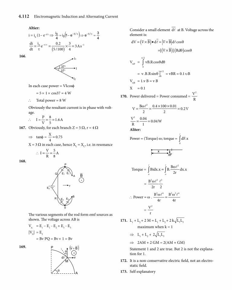
4.112 Electromagnetic Induction and Alternating Current
Altier:
i = i0 (1– e–t/t ⇒ ( )43ee1i
4i /t/t
00 =⇒-= t-t-
( )t/ 10idi 0.2 3
e 3Asdt 5 /100 4
t
t− −= = × =
166.
37°
Ι1
Ι
Ι2
37°
In each case power = VIcosf
= 5 × 1 × cos37 = 4 W
\ Total power = 8 W
Obviously the resultant current is in phase with volt-age.
\ I =P 8
1.6AV 5= =
167. Obviously, for each branch Z = 5 W, r = 4 W
⇒ tanf = X
0.754=
X = 3 W in each case, hence XL = XC, i.e. in resonance
\V 5
AR 8
I = =
168.
B
× B
v
E3 E3
E1 E1 A
Q
R
E2
S
P
The various segments of the rod form emf sources as shown. The voltage across AB is VA = E1 – E1 - E2 + E3 - E3
|VA| = E2
= Bv PQ = Bv × 1 = Bv
169.
v
θ A
P ×
( )Bv ×
M d
θ
Consider a small element dl at B. Voltage across the element is:
( )dV v B d v B d cosq= × • = ×l l
( ) ( )| v B | Rd cosq q= ×
VAP = /2
0
vB.R cos dp
q q∫
= /2
0v .B.Rsin
pq = vBR = 0.1 υB
VAB = 1.v B = v B
X = 0.1
170. Power delivered = Power consumed = 2V
R
2B 0.4 100 0.01V 0.2V
2 2w × ×
= = =l
2V 0.040.04W
R 1= =
Aliter:
Power = (Torque) w; torque = 0
dF.x∫l
Torque = 2
o o
BBidx.x B. dx.x
2rw
=∫ ∫l l l
= 2 2 2B2r 2wl l
\Power = w . 2 4 2 2 4B B4r 4rw w
=l l
= 2V
r
171. L1 + L2 + 2 M = L1 + L2
+ 2 1 2k L L maximum when k = 1
⇒ L1 + L2 + 1 22 L L
⇒ 2AM + 2 GM = 2(AM + GM)Statement 1 and 2 are true. But 2 is not the explana-tion for 1.
172. It is a non-conservative electric field, not an electro-static field.
173. Self explanatory
Electromagnetic Induction and Alternating Current 4.113
174. Sparking occurs while opening, because inductance tries to maintain current
175. Induced emf m didt
i m sinwt ⇒ didt
m coswt
176. Self explanatory
177. Wattless not only at resonance but at all frequencies. At resonance, impedance is minimum, current is
maximum, power is maximum P = 2E
R 178. Need not be
1 2E E 2R Z= ⇒ 1
2
E R2
E Z=
1
2
EE
= 1, depending on z <≥ 2 .R
179.
(XL – XC) × Ι φ
Ι × R
V
The circuit is already inductive. Increase in frequency, increases XL, reduces XC, (XL – XC) increases, power delivered reduces.
180. S.H.M. because restoring force is proportional to the displacement from initial position
( )Ldi dx
V L B . integratingdt dt
= = ⇒l
B xLi B x i
L= ⇒ =
ll
Restoring force |F| = Bil
= Bl2 2B x B
x. F xL L
= ⇒ ∝−l l
181. Motional emf of AB = 1E = Blv1
= 1 × 1 × 4 = 4 V
with A at higher potential (Fleming’s right hand rule).
Motional emf of CD = E2= Blv2
= 1 × 1 × 2 = 2 V,
with D at higher potential (Fleming’s right hand rule).
The network between P & Q is balanced Wheatstone’s
bridge 2 44 8
= and the equivalent resistance between
P and Q is
Req = ( )( )( )2 4 4 82 4 4 8+ ++ + +
= 4 W
Hence the equivalent circuit is as shown below.
i1 i2
4 Ω
(i1 − i2) 1 Ω
2E =2 V1 Ω
1E = 4 V
B
C
i1 i2 D
P
Q
A
Let the currents in the circuit be i1 and i2 as shown.Applying Kirchhoff ’s voltage law for path APQBA, we get-(i1 - i2) 4 - i1 × 1 + 4 = 0⇒ 4 i2 - 5 i1 + 4 = 0⇒ 5 i1 - 4 i2 = 4 ------ (i)
Applying Kirchhoff ’s voltage law for the loopAPCDQBA, we get
4 - i1 × 1 - i2 × 1 + 2 = 0
⇒ i1 + i2 = 6 ------ (ii)
On solving (i) and (ii), we get
i1 = 289
A (from A to P) and
i2 = 269
A (from C to D)
\ The current through PQ = i1 - i2
= 28 26 29 9 9− = A
182. The potential difference across CD = Potential difference across PQ = Potential difference across AB
= (i1 - i2) × Req = 2 8
A 4 V9 9
W× =
Aliter:VB - i1 × 1 + 4 = VA ⇒ (VA - VB)
= 4 - i1 = 4 - 28 89 9= V
Since the rails are without resistance, no potential drop across them. Hence VA – B = VC – D VP – Q
4.114 Electromagnetic Induction and Alternating Current
183. Power dissipated in PQ = i2 Req = (i1 - i2)2 Req
= 22
49 ×
= 1681
W
184. Clearly VL ≠ VC, as otherwise it will be resonance and VR will be equal to source voltage V, not in ratio 1: 2\ It can be capacitive or inductive, since
(XL - XC)2 = (XC - XL)2
185. (i)
Source voltage VR VL VC
1 x 1 2x
⇒ x2 + (1 - 2x)2 = 1
⇒ 5x2 - 4x = 0 ⇒ x = 45
⇒ tanf = C L
R
V VV−
=
8 1 354 45
−=
(ii)
Source voltage VR VL VC
1 2x 1 x
⇒ 4x2 + (1 - x)2 = 1
⇒ 5x2 - 2x = 0 ⇒ x = 25
tanf = L C
R
21V V 354V 45
−−= =
186. Since R > XC only case (ii) above is applicable
L
C
X 1 5X x 2
= = 2
x5
= Q
22L
2C 0
X LLC
1XC
w ww
ww
= = =
\ w0 = L
C
2.
5X 52X
w ww= = ⇒ y =
25
187. (i) + 1 2q qdiL
2C dt C− − = 0,
1 2di
q 2LC 2q 0dt
− − =
q1 – 2 q2 = 2 LC didt
------- (1)
As i flows, q1 decreases and q2 increases
⇒ i = 1 2dq dqdt dt
−=
Differentiating equation (1)
1dqdt
- 2 2dqdt
= 2 LC 2
2
d idt
,
2
2
d idt
= -3
i2LC
= - w2 i
⇒ The solution is i = i0 sin (wt + f)
w = 3
2LCAliter:
This is an LC circuit with
Ceff = ( )2
1 2
1 2
2CC C 2C
3C 3C C= =
+
w = eff
1 1 32LCLC 2L C
3
= =×
188.
q1
v1 v2
q2vL = 0 + C
+ 2C
When current is maximum; di di
0;L 0dt dt
= =
Hence circuit equation is as shown:
1 2
1 2
q qV V
2C C= ⇒ = Also q1 + q2 = q0
\ 0 2 20
q q qq
2C C−
= ⇒ = 3q2
⇒ q2 =0 0
1
q 2q& q
3 3=
189. The above case when i = maximum represent the maximum energy in the inductorEnergy in capacitor
2 2
0 02q q1 1 1 1. .
2 3 2C 2 3 C
= +
2 20 0q q2 1 1
.2C 9 9 2C 3
= + =
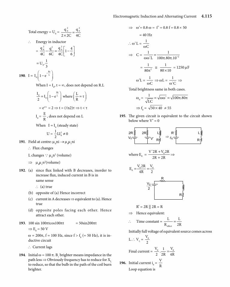
Electromagnetic Induction and Alternating Current 4.115
Total energy = U0 = 2 20 0q q
2 2C 4C=
×\ Energy in inductor
= 2 220 0q qq 4
14C 6C 4C 6
− = −
01
U .3
=
190. I = RtL
0 1 eI−
− When I = I0, t = ∞, does not depend on R.L
Rt
0 L0
L1 e where
2 RI
I t = − =
= et/t = 2 ⇒ t = (ln2)t ⇒ t < t
I0 = ER
, does not depend on L
When I = I0 (steady state)
U = 20
1L 0
2I ≠
191. Field at centre: m0ni → m0mrni\ Flux changes
L changes Q m0n2 (volume)
⇒ m0mrn2(volume)
192. (a) since flux linked with B decreases, inorder to increase flux, induced current in B is in
same sense \ (a) true(b) opposite of (a) Hence incorrect(c) current in A decreases ⇒ equivalent to (a). Hence
true(d) opposite poles facing each other. Hence attract each other.
193. 100 sin 100ptcos100pt = 50sin200pt⇒ E0 = 50 V
w = 200p, f = 100 Hz, since f > f0 (= 50 Hz), it is in-ductive circuit
\ Current lags
194. Initial w = 100 p. B1 brighter means impedance in the path less ⇒ Obviously frequency has to reduce for XL to reduce, so that the bulb in the path of the coil burn brighter.
⇒ w’= 0.8 w = f ’ = 0.8 f = 0.8 × 50
= 40 Hz
\w’ L = 1Cw
⇒ C = 2
1 1'L 100 .80 .10ww p p −=
= 2
180p
≅ 1
80 10× = 1250 mF
w’L = 1Cw
⇒ wL = 1'Cw
⇒
Total brightness same in both cases.
w0 = 1
' 100 .80LC
ww p p= =
⇒ f0 = 50 40× ≠ 55
195. The given circuit is equivalent to the circuit shown below where V’ = 0
2R V0
L 2R
V’
R’ E0
L ⇒
R R
where 00
V '2R V 2RE
2R 2R+
= ⇒+
0 00
V 2R VE
4R 2= =
R
2V0
R
R’ = 2R || 2R = R ⇒ Hence equivalent:
\ Time constant = effect
L LR 2R
=
Initially full voltage of equivalent source comes across
L. \VL = 0V2
Final current = 0 0V V1.
2 2R 4R=
196. Initial current i0 = VR
Loop equation is
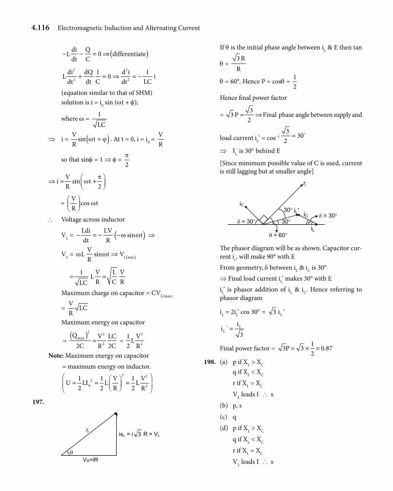
4.116 Electromagnetic Induction and Alternating Current
( )di QL 0 differentiate
dt C− − = ⇒
2 2
2 2
di dQ 1 d i 1L 0 i
dt C LCdt dt+ = ⇒ = −
(equation similar to that of SHM) solution is i = i0 sin (wt + f);
where w = 1LC
⇒ i = ( )Vsin t
Rw ϕ+ . At t = 0, i = i0 =
VR
so that sinf = 1 ⇒ f = 2p
Vi sin t
R 2p
w ⇒ = +
= V
cos tR
w
\ Voltage across inductor
VL = ( )Ldi LVsin t
dt Rw w− = − − ⇒
VL = ( )L max
VL sin t V
Rw w ⇒
1 V L V
LR C RLC
= =
Maximum charge on capacitor = CVL(max)
= V
LCR
Maximum energy on capacitor
= ( )2 2
max2
Q V LC2C 2CR
= = 2
2
1 VL
2 RNote: Maximum energy on capacitor = maximum energy on inductor.
2 2
20 2
1 1 V 1 VU L L L
2 2 R 2 RI
= = =
197.
θ
E ixL = i R3 = VL
VR=iR
If q is the initial phase angle between iL & E then tan
q = 3 RR
q = 60°. Hence P = cosq = 12
Hence final power factor
= 3
3 P Final phase2
= ⇒ angle between supply and
load current iL’ = cos-13
302
=
⇒ IL’ is 30° behind E
[Since minimum possible value of C is used, current is still lagging but at smaller angle]
δ = 30°
θ = 60°
30° δ δ = 30°
iL' 30°iC
E
iC
iL
The phasor diagram will be as shown. Capacitor cur-rent ic, will make 90° with E From geometry, d between iL & iC is 30° ⇒ Final load current iL’ makes 30° with EiL’ is phasor addition of iL & iC. Hence referring to phasor diagram
iL = 2iL’ cos 30° = L3 i '
LL
ii '
3=
Final power factor = 1
3P 3 0.872
= × =
198. (a) p if XL > XC
q if XL < XC
r if XL = XC
VL leads I \ s
(b) p, s
(c) q
(d) p if XL > XC
q if XL < XC
r if XL = XC
VL leads I \ s
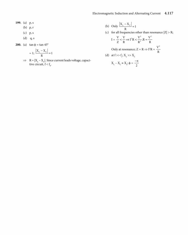
Electromagnetic Induction and Alternating Current 4.117
199. (a) p, s(b) p, r
(c) p, s
(d) q, s
200. (a) tan f = tan 45°
= 1; L CX X1
R−
=
⇒ R = |XL – XC|. Since current leads voltage, capaci-tive circuit, f < f0.
(b) Only L CX X1
R−
=
(c) for all frequencies other than resonance |Z| > R;
I = 2 2
22
V V V VR .R
Z R RRI< ⇒ < =
Only at resonance; Z = R ⇒ I2R = 2V
R(d) at f >> fc; XL >> XC
XL – XC ≈ XL; f = 2p−
Related Documents