BA049D/06/en/11.09 71105948 Valid as of version: V 2.03.XX (Device software) Description of Device Functions Proline Promag 50 Electromagnetic Flow Measuring System 6

Welcome message from author
This document is posted to help you gain knowledge. Please leave a comment to let me know what you think about it! Share it to your friends and learn new things together.
Transcript

BA049D/06/en/11.09
71105948
Valid as of version:
V 2.03.XX (Device software)
Description of Device Functions
Proline Promag 50Electromagnetic Flow Measuring System
6

Device functions Proline Promag 50
2 Endress+Hauser

Device functions Proline Promag 50 Contents
Endress+Hauser 3
Contents
1 Function matrix Promag 50 . . . . . . . . . . . . 5
1.1 The function matrix: layout and use . . . . . . . . . . . . . 5
1.2 Illustration of the function matrix . . . . . . . . . . . . . . 6
2 Group MEASURING VALUES . . . . . . . . . . 7
3 Group SYSTEM UNITS . . . . . . . . . . . . . . . . . 8
4 Group QUICK SETUP . . . . . . . . . . . . . . . . . 10
5 Group OPERATION . . . . . . . . . . . . . . . . . . . 11
6 Group USER INTERFACE . . . . . . . . . . . . . 13
7 Group TOTALIZER 1/2 . . . . . . . . . . . . . . . 16
8 Group HANDLING TOTALIZER . . . . . . 18
9 Group CURRENT OUTPUT . . . . . . . . . . . 19
10 Group PULSE/FREQUENCY OUTPUT 23
11 Group STATUS OUTPUT . . . . . . . . . . . . . . 34
11.1 Information on the response of the status output . . 37
11.2 Switching response of the status output . . . . . . . . . 38
12 Group STATUS INPUT . . . . . . . . . . . . . . . . 40
13 Group COMMUNICATION . . . . . . . . . . . 42
14 Group PROCESS PARAMETER . . . . . . . . 43
15 Group SYSTEM PARAMETERS . . . . . . . . 49
16 Group SENSOR DATA . . . . . . . . . . . . . . . . . 52
17 Group SUPERVISION . . . . . . . . . . . . . . . . . 54
18 Group SIMULATION SYSTEM . . . . . . . . 56
19 Group SENSOR VERSION . . . . . . . . . . . . . 57
20 Group AMPLIFIER VERSION . . . . . . . . . 57
21 Factory settings . . . . . . . . . . . . . . . . . . . . . . . 58
21.1 SI units (not for USA and Canada) . . . . . . . . . . . . . 58
21.2 US units (only for USA and Canada) . . . . . . . . . . . . 60
22 Index of key words . . . . . . . . . . . . . . . . . . . 61

Contents Device functions Proline Promag 50
4 Endress+Hauser
Registered trademarks
HART®
Registered trademark of the HART Communication Foundation, Austin, USA
HistoROM™, S-DAT®, FieldCare®
Registered trademarks of Endress+Hauser Flowtec AG, Reinach, CH

Device functions Proline Promag 50 1 Function matrix Promag 50
Endress+Hauser 5
1 Function matrix Promag 50
1.1 The function matrix: layout and use
The function matrix is a two-level construct: the groups form one level and the groups' functions
the other.
The groups are the highest-level grouping of the operating options for the measuring device.
A number of functions is assigned to each group.
You select a group in order to access the individual functions for operating and parameterizing the
measuring device.
An overview of all the groups available is provided in the table of contents on Page 3 and in the
graphical representation of the function matrix on Page 6.
An overview of all the functions available is provided on Page 6, complete with page references to
the detailed function descriptions.
The descriptions of the individual functions start on Page 7.
Example of how to parameterize a function (in this case changing the language for the UI):
1. Enter into the function matrix (F-key).
2. Select the OPERATION group.
3. Select the LANGUAGE function, change the setting from ENGLISH to DEUTSCH with OS
and save with F (all text on the display now appears in German).
4. Exit the function matrix (ESC > 3 seconds).
A0001142
>3s
- + E
Esc
E
E
E
E
E E E E E
–
+
+
Esc
–+
Esc
–
+
Esc
–
Em
n
o
p

1 Function matrix Promag 50 Device functions Proline Promag 50
6 Endress+Hauser
1.2 Illustration of the function matrix
SIM
UL. FR
EQ
.
(P.2
8)
EC
C C
LE
AN
. C
YC
L.
(P.4
8)
AC
TU
AL F
REQ
.
(P.2
7)
EC
C R
EC
OV
ER
Y T
IME
(P.4
8)
OPE
RA
T. H
RS.
(P.5
5)
DIS
PLA
Y T
EST
(P.1
5)
VA
LU
E S
IM.
CU
RR
EN
T (
P.2
2)
FA
ILSA
FE
VA
LU
E
(P.2
7)
VA
LU
E S
IM. P
ULSE
(P.3
3)
EC
C D
UR
AT
ION
(P.4
7)
PO
LA
RIT
Y E
CC
(P.5
3)
SYST
EM
RESET
(P.5
5)
BA
CK
LIG
HT
(P.1
5)
SIM
UL.
CU
RR
EN
T
(P.2
2)
FA
ILSA
FE
MO
DE
(P.2
7)
SIM
ULA
TIO
N P
ULSE
(P.3
2)
VA
L. SIM
. SW
IT. PT
.
(P.3
6)
DE
VIC
E R
EV
ISIO
N
(P.4
2)
EC
C
(P.4
7)
EP
D E
LE
CT
RO
DE
(P.5
3)
ALA
RM
DE
LA
Y
(P.5
5)
CO
NT
RA
ST
LC
D
(P.1
4)
RE
SE
T T
OT
ALIZ
.
(P.1
7)
AC
TU
AL C
UR
RE
NT
(P.2
1)
TIM
E C
ON
ST
AN
T
(P.2
7)
FA
ILSA
FE
MO
DE
(P.3
2)
SIM
. SW
ITC
H P
OIN
T
(P.3
5)
DEV
ICE
ID
(P.4
2)
EPD
/O
ED
RE
S.T
IME
(P.4
7)
OV
ER
VLT
G T
IME
(P.5
3)
ER
RO
R C
AT
EG
.
(P.5
5)
AC
CE
SS C
OD
E
CO
UN
TE
R (
P.1
2)
DIS
PL. D
AM
PIN
G
(P.1
4)
TO
TA
LIZ
ER
MO
DE
(P.1
7)
FA
ILSA
FE
MO
DE
(P.2
1)
OU
TPU
T S
IGN
AL
(P.2
5)
OU
TPU
T S
IGN
AL
(P.3
0)
AC
TU
AL S
TA
TU
S
(P.3
5)
VA
LU
E S
IM. ST
AT
US
(P.4
1)
MA
NU
FA
CT
. ID
(P.4
2)
EPD
/O
ED
AD
J.
(P.4
6)
INT
EG
RA
T. T
IME
(P.5
1)
MEA
S.
PE
RIO
D
(P.5
3)
ASSIG
N P
RO
C. E
RR
.
(P.5
4)
SW
REV
. I/
O M
OD
.
(P.5
7)
FO
RM
AT
DA
TE
/T
IME
(P.
9)
ST
AT
US A
CC
ESS
(P.
12
)
FO
RM
AT
(P.
14
)
UN
IT T
OT
ALIZ
ER
(P.
16
)
TIM
E C
ON
ST
AN
T
(P.
21
)
VA
LU
E-f
HIG
H
(P.
24
)
PU
LSE
WID
TH
(P.
29
)
TIM
E C
ON
ST
AN
T
(P.
35
)
SIM
. ST
AT
US I
NP.
(P.
40
)
HA
RT
PR
OT
OC
OL
(P.
42
)
EM
PT
Y P
IPE
DE
T.
(P.
44
)
SY
ST
EM
DA
MPIN
G
(P.
51
)
NO
M. D
IAM
ET
ER
(P.
52
)
ER
RO
R C
AT
EG
.
(P.
54
)
SW
REV
. N
O. S-D
AT
(P.
57
)
I/O
MO
DU
LE
TYP
E
(P.
57
)
UN
IT LE
NG
TH
(P.9)
PR
IVA
TE
CO
DE
(P.12)
10
0%
VA
LU
E
(P.13)
OV
ER
FLO
W
(P.16)
VA
LU
E 2
0 m
A
(P.21)
EN
D V
ALU
E F
REQ
.
(P.23)
PU
LSE V
ALU
E
(P.29)
OFF-V
ALU
E
(P.35)
MIN
. PU
LSE
WID
TH
(P.40)
BU
S A
DD
RE
SS
(P.42)
OFF-V
ALU
E
(P.43)
PO
S. ZE
RO
RE
TU
RN
(P.50)
ZER
O P
OIN
T
(P.52)
ASSIG
N S
YS. E
RR
.
(P.54)
VA
L.S
IM.M
EA
S.V
AR
.
(P.56)
HW
RE
V. SE
NS.
(P.57)
LA
NG
UA
GE
GR
OU
P
(P.57)
UN
IT V
OLU
ME
(P.
8)
AC
CE
SS C
OD
E
(P.12)
ASSIG
N L
INE
2
(P.13)
SU
M
(P.16)
FA
ILSA
FE M
OD
E
(P.18)
CU
RR
EN
T S
PA
N
(P.20)
ASSIG
N F
RE
Q.
(P.23)
ASSIG
N P
ULSE
(P.28)
ON
-VA
LU
E
(P.34)
AC
TIV
E L
EV
EL
(P.40)
TA
G D
ESC
R.
(P.42)
ON
-VA
LU
E
(P.43)
ME
ASU
RIN
G M
OD
E
(P.49)
K-F
AC
TO
R
(P.52)
PR
EV
. SY
S. C
ON
D.
(P.54)
SIM
. M
EA
S.
VA
RIA
B.
(P.56)
SEN
SO
R T
YP
E
(P.57)
SW
RE
V. A
MP
L.
(P.57)
Fu
ncti
on
s →
VO
LU
ME
FLO
W
(P.
7)
UN
IT V
OL.
FLO
W
(P.
8)
QU
ICK
SE
TU
P
CO
MM
ISSIO
N (
P.
10)
LA
NG
UA
GE
(P.
11
)
ASSIG
N L
INE
1
(P.
13
)
ASSIG
N T
OT
ALIZ
ER
(P.
16
)
RE
SE
T A
LL T
OT
AL.
(P.
18
)
ASSIG
N C
UR
RE
NT
OU
TP
. (P
.1
9)
OPE
RA
TIO
N M
OD
E
(P.
23
)
VA
LU
E S
IM. FR
EQ
.
(P.
28
)
ASSIG
N S
TA
TU
S
(P.
34
)
ASSIG
N S
TA
TU
S
(P.
40
)
TA
G N
AM
E
(P.
42
)
ASSIG
N L
F C
UT
OFF
(P.
43
)
INST
ALL. D
IRE
CT
.
(P.
49
)
CA
LIB
RA
TIO
N D
AT
E
(P.
52
)
CU
RR
. SY
S. C
ON
D.
(P.
54
)
SIM
. FA
ILS. M
OD
E
(P.
56
)
SE
RIA
L N
UM
BE
R
(P.
57
)
DE
VIC
E S
OFT
WA
RE
(P.
57
)
▼ ▼ ▼ ▼ ▼ ▼ ▼ ▼ ▼ ▼ ▼ ▼ ▼ ▼ ▼ ▼ ▼ ▼ ▼
Fu
ncti
on
gro
up
s
ME
ASU
RIN
G V
ALU
ES
(P.7)
SY
ST
EM
UN
ITS
(P.8)
QU
ICK
SE
TU
P
(P.1
0)
OPE
RA
TIO
N
(P.1
1)
USER
IN
TE
RFA
CE
(P.1
3)
TO
TA
LIZ
ER
1/2
(P.1
6)
HA
ND
LIN
G T
OT
ALIZ
.
(P.1
8)
CU
RR
EN
T O
UT
PU
T
(P.1
9)
PU
LSE
/FR
EQ
. O
UT
P.
(P.2
3)
ST
AT
US O
UT
PU
T
(P.3
4)
ST
AT
US I
NP
UT
(P.4
0)
CO
MM
UN
ICA
TIO
N
(P.4
2)
PR
OC
ESS P
AR
AM
.
(P.4
3)
SYST
EM
PA
RA
M.
(P.4
9)
SE
NSO
R D
AT
A
(P.5
2)
SU
PE
RV
ISIO
N
(P.5
4)
SIM
ULA
T.
SY
ST
EM
(P.5
6)
SE
NSO
R V
ER
SIO
N
(P.5
7)
AM
PLIF
IER
VE
RS.
(P.5
7)

Device functions Proline Promag 50 2 Group MEASURING VALUES
Endress+Hauser 7
2 Group MEASURING VALUES
Function description MEASURING VALUES
! Note!
• The engineering unit of the measured variable displayed here can be set in the SYSTEM UNITS group, (see Page 8).
• If the fluid in the pipe flows backwards, a negative sign prefixes the flow reading on the display.
VOLUME FLOW The volume flow currently measured appears on the display.
User interface:
5-digit floating-point number, including unit and sign
(e.g. 5.5445 dm3/min; 1.4359 m3/h; –731.63 gal/d; etc.)

3 Group SYSTEM UNITS Device functions Proline Promag 50
8 Endress+Hauser
3 Group SYSTEM UNITS
Function description SYSTEM UNITS
Use this function group to select the unit for the measured variable.
UNIT VOLUME FLOW Use this function to select the unit for displaying the volume flow.
The unit you select here is also valid for:
• Current output
• Frequency output
• Switch points (limit value for volume flow, flow direction)
• Low flow
Options:
Metric:
Cubic centimeter → cm3/s; cm3/min; cm3/h; cm3/day
Cubic decimeter → dm3/s; dm3/min; dm3/h; dm3/day
Cubic meter → m3/s; m3/min; m3/h; m3/day
Milliliter → ml/s; ml/min; ml/h; ml/day
Liter → l/s; l/min; l/h; l/day
Hectoliter → hl/s; hl/min; hl/h; hl/day
Megaliter → Ml/s; Ml/min; Ml/h; Ml/day
US:
Cubic centimeter → cc/s; cc/min; cc/h; cc/day
Acre foot → af/s; af/min; af/h; af/day
Cubic foot → ft3/s; ft3/min; ft3/h; ft3/day
Fluid ounce → oz f/s; oz f/min; oz f/h; oz f/day
Gallon → gal/s; gal/min; gal/h; gal/day
Kilo gallon → Kgal/s; Kgal/min; Kgal/h; Kgal/day
Million gallon → Mgal/s; Mgal/min; Mgal/h; Mgal/day
Barrel (normal fluids: 31.5 gal/bbl) → bbl/s; bbl/min; bbl/h; bbl/day
Barrel (beer: 31.0 gal/bbl) → bbl/s; bbl/min; bbl/h; bbl/day
Barrel (petrochemicals: 42.0 gal/bbl) → bbl/s; bbl/min; bbl/h; bbl/day
Barrel (filling tanks: 55.0 gal/bbl) → bbl/s; bbl/min; bbl/h; bbl/day
Imperial:
Gallon → gal/s; gal/min; gal/h; gal/day
Mega gallon → Mgal/s; Mgal/min; Mgal/h; Mgal/day
Barrel (beer: 36.0 gal/bbl) → bbl/s; bbl/min; bbl/h; bbl/day
Barrel (petrochemicals: 34.97 gal/bbl) → bbl/s; bbl/min; bbl/h; bbl/day
Factory setting:
Depends on nominal diameter and country (see Page 58 ff.).
UNIT VOLUME Use this function to select the unit for displaying the volume.
The unit you select here is also valid for:
• Pulse weighting (e.g. m3/p)
Options:
Metric → cm3; dm3; m3; ml; l; hl; Ml Mega
US → cc; af; ft3; oz f; gal; Kgal; Mgal; bbl (normal fluids); bbl (beer);
bbl (petrochemicals) → bbl (filling tanks)
Imperial → gal; Mgal; bbl (beer); bbl (petrochemicals)
Factory setting:
Depends on nominal diameter and country (see Page 58 ff.).
! Note!
The unit of the totalizers is independent of your choice here. The unit for each totalizer is
selected separately for the totalizer in question.

Device functions Proline Promag 50 3 Group SYSTEM UNITS
Endress+Hauser 9
UNIT LENGTH Use this function to select the unit for displaying the length of the nominal diameter.
The unit you select here is also valid for:
• Nominal diameter of sensor (see function NOMINAL DIAMETER on Page 48)
Options:
MILLIMETER
INCH
Factory setting:
MILLIMETER (SI units: not for USA and Canada)
INCH (US units: only for USA and Canada)
FORMAT DATE/TIME Use this function to select the format for the date and the time.
The unit you select here is also valid for:
Displaying the current calibration date (function CALIBRATION DATE on Seite 52)
Options:
DD.MM.YY 24H
MM/DD/YY 12H A/P
DD.MM.YY 12H A/P
MM/DD/YY 24H
Factory setting:
DD.MM.YY 24H (SI units)
MM/DD/YY 12H A/P (US units)
Function description SYSTEM UNITS

4 Group QUICK SETUP Device functions Proline Promag 50
10 Endress+Hauser
4 Group QUICK SETUP
! Note!
The display returns to the QUICK SETUP COMMISSION cell if you press the ESC key combination
during interrogation.
a0005413-en
Function description QUICK SETUP
QUICK SETUP
COMMISSION
Use this function to start the Quick Setup menu for commissioning.
Options:
YES
NO
Factory setting:
NO
++ +E EEsc
E+-
XXX.XXX.XX
HOME-POSITION
QSCommission
Language
Defaults
Quick Setup
UnitVolume flow
MeasuringMode
Frequency Pulse
Current Output Freq.-/ Pulse Output Quit
AssignCurrent
AssignFrequency
AssignPulse
CurrentSpan
Value20 mA
TimeConstant
TimeConstant
FailsafeMode
FailsafeMode
FailsafeMode
OperationMode
End ValueFreq.
Valuef max
PulseValue
PulseWidth
OutputSignal
OutputSignal
Automatic parameterizationof the display
Quit Quick Setup

Device functions Proline Promag 50 5 Group OPERATION
Endress+Hauser 11
5 Group OPERATION
Function description OPERATION
LANGUAGE Use this function to select the language for all texts, parameters and messages shown on
the local display.
! Note!
The displayed options depend on the available language group shown in the LANGUAGE
GROUP function.
Options:
Language group WEST EU / USA:
ENGLISH
DEUTSCH
FRANCAIS
ESPANOL
ITALIANO
NEDERLANDS
PORTUGUESE
Language group EAST EU / SCAND:
ENGLISH
NORSK
SVENSKA
SUOMI
POLISH
RUSSIAN
CZECH
Language group ASIA:
ENGLISH
BAHASA INDONESIA
JAPANESE (Silbenschrift)
Factory setting:
Country-dependent (see Page 58 ff.)
! Note!
• If you press the OS keys simultaneously at startup, the language defaults to
"ENGLISH".
• You can change the language group via the configuration program FieldCare. Please
do not hesitate to contact your Endress+Hauser sales office if you have any questions.

5 Group OPERATION Device functions Proline Promag 50
12 Endress+Hauser
ACCESS CODE All data of the measuring system are protected against inadvertent change. Programming
is disabled and the settings cannot be changed until a code is entered in this function. If
you press the OS keys in any function, the measuring system automatically goes to this
function and the prompt to enter the code appears on the display (when programming is
disabled).
You can enable programming by entering your personal code,
(factory setting = 50, see function PRIVATE CODE on Page 12)
User input:
max. 4-digit number: 0...9999
! Note!
• The programming levels are disabled if you do not press a key within 60 seconds
following automatic return to the HOME position.
• You can also disable programming in this function by entering any number (other than
the defined private code).
• The Endress+Hauser service organization can be of assistance if you mislay your
personal code.
PRIVATE CODE Use this function to enter a personal code number for enabling programming.
User input:
0...9999 (max. 4-digit number)
Factory setting:
50
! Note!
• Programming is always enabled with the code "0".
• Programming has to be enabled before this code can be changed.
When programming is disabled this function is not available, thus preventing others
from accessing your personal code.
STATUS ACCESS Use this function to check the access status for the function matrix.
User interface:
ACCESS CUSTOMER (parameterization possible)
LOCKED (parameterization disabled)
ACCESS CODE
COUNTER
Displays how often the customer code, service code or the digit "0" (code-free) has been
entered to gain access to the function matrix.
Display:
max. 7-digit number: 0...9999999
Factory setting:
0
Function description OPERATION

Device functions Proline Promag 50 6 Group USER INTERFACE
Endress+Hauser 13
6 Group USER INTERFACE
Function description USER INTERFACE
ASSIGN LINE 1 Use this function to define which display value is assigned to the main line (top line of
the local display) for display during normal measuring operation.
Options:
OFF
VOLUME FLOW
VOLUME FLOW IN %
TOTALIZER 1
TOTALIZER 2
Factory setting:
VOLUME FLOW
ASSIGN LINE 2 Use this function to define which display value is assigned to the additional line
(bottom line of the local display) for display during normal measuring operation.
Options:
OFF
VOLUME FLOW
VOLUME FLOW IN %
VOLUME FLOW BARGRAPH IN %
TOTALIZER 1
TAG NAME
OPERATING/SYSTEM CONDITION
FLOW DIRECTION
TOTALIZER 2
Factory setting:
TOTALIZER 1
100% VALUE! Note!
This function is only available if VOLUME FLOW IN % or VOLUME FLOW BARGRAPH
IN % was selected in the function ASSIGN LINE 1 or ASSIGN LINE 2.
Use this function to define the flow value to be shown on the display as the 100% value.
User input:
5-digit floating-point number
Factory setting:
Depends on nominal diameter and country (see Page 58 ff.).

6 Group USER INTERFACE Device functions Proline Promag 50
14 Endress+Hauser
FORMAT Use this function to define the maximum number of places after the decimal point
displayed for the reading in the main line.
Options:
XXXXX. – XXXX.X – XXX.XX – XX.XXX – X.XXXX
Factory setting:
X.XXXX
! Note!
• Note that this setting only affects the reading as it appears on the display, it has no
influence on the accuracy of the system's calculations.
• The places after the decimal point as computed by the measuring device cannot
always be displayed, depending on this setting and the engineering unit. In such
instances an arrow appears on the display between the measuring value and the engi-
neering unit (e.g. 1.2 → l/h), indicating that the measuring system is computing with
more decimal places than can be shown on the display.
DISPLAY DAMPING Use this function to enter a time constant defining how the display reacts to severely
fluctuating flow variables, either very quickly (enter a low time constant) or with dam-
ping (enter a high time constant).
User input:
0...100 seconds
Factory setting:
3 s
! Note!
Setting the time constant to zero seconds switches off damping.
CONTRAST LCD Use this function to optimize display contrast to suit local operating conditions.
User input:
10...100%
Factory setting:
50%
Function description USER INTERFACE

Device functions Proline Promag 50 6 Group USER INTERFACE
Endress+Hauser 15
BACKLIGHT Use this function to optimize the backlight to suit local operating conditions.
User input:
0...100%
! Note!
Entering the value "0" means that the backlight is "switched off". The display then no
longer emits any light, i.e. the display texts can no longer be read in the dark.
Factory setting:
50%
DISPLAY TEST Use this function to test the operability of the local display and its pixels.
Options:
OFF
ON
Factory setting:
OFF
Test sequence:
1. Start the test by selecting ON.
2. All pixels of the main line and additional line are darkened for at least 0.75 seconds.
3. The main line and additional line show an "8" in each field for at least 0.75 seconds.
4. The main line and additional line show a "0" in each field for at least 0.75 seconds.
5. The main line and additional line show nothing (blank display) for at least 0.75
seconds.
When the test completes the local display returns to its initial state and the setting
changes to OFF.
Function description USER INTERFACE

7 Group TOTALIZER 1/2 Device functions Proline Promag 50
16 Endress+Hauser
7 Group TOTALIZER 1/2
Function description TOTALIZER 1/2
ASSIGN TOTALIZER Use this function to assign a measured variable (volume flow) to the totalizer.
Options:
OFF
VOLUME FLOW
Factory setting:
VOLUME FLOW
! Note!
The totalizer is reset to "0" as soon as the selection is changed.
SUM Use this function to view the total for the totalizer measured variable aggregated since
measuring commenced. The value can be positive or negative.
User interface:
max. 7-digit floating-point number, including sign and unit (e.g. 896,845.7 dm3)
! Note!
The totalizer response to faults is defined in the FAILSAFE MODE function
(see Page 18).
OVERFLOW Use this function to view the overflow for the totalizer aggregated since measuring
commenced.
Total flow quantity is represented by a floating decimal point number consisting of max.
7 digits. You can use this function to view higher numerical values (>9 999 999) as over-
flows. The effective quantity is thus the total of OVERFLOW plus the value returned by
the SUM function.
Example:
Reading for 2 overflows: 2 E7 kg (= 2 000 000 dm3)
The value returned by the SUM function = 896,845.7 dm3
Effective total quantity = 2,896,845.7 dm3
Display shows:
Integer with exponent, including sign and unit, e.g. 2 E7 dm3
UNIT TOTALIZER Use this function to define the unit for the totalizer.
Options:
Metric → cm3; dm3; m3; ml; l; hl; Ml Mega
US → cc; af; ft3; oz f; gal; Kgal; Mgal; bbl (normal fluids); bbl (beer);
bbl (petrochemicals); bbl (filling tanks)
Imperial → gal; Mgal; bbl (beer); bbl (petrochemicals)
Factory setting:
Depends on nominal diameter and country (see Page 58 ff.).

Device functions Proline Promag 50 7 Group TOTALIZER 1/2
Endress+Hauser 17
TOTALIZER MODE Use this function to define how the flow components are to be totalised.
Options:
BALANCE
Positive and negative flow components. The positive and negative flow components are
balanced. In other words, net flow in the flow direction is registered.
FORWARD
Positive flow components only
REVERSE
Negative flow components only
Factory setting:
Totalizer 1 = BALANCE
Totalizer 2 = FORWARD
RESET TOTALIZER Use this function to reset the sum and the overflow of the totalizer to "zero" (= RESET).
Options:
NO
YES
Factory setting:
NO
! Note!
If the device is equipped with a status input and if it is appropriately configured, totalizer
resetting can also be triggered by a pulse.
Function description TOTALIZER 1/2

8 Group HANDLING TOTALIZER Device functions Proline Promag 50
18 Endress+Hauser
8 Group HANDLING TOTALIZER
Function description HANDLING TOTALIZER
RESET ALL
TOTALIZERS
Use this function to reset the totals (including all overflows) of the totalizers (1...2) to
"zero".
Options:
NO
YES
Factory setting:
NO
! Note!
If the device has a status input and if it is appropriately configured, a reset for the totalizer
(1...2) can also be triggered by a pulse (see the ASSIGN STATUS INPUT function on
Page 31).
FAILSAFE MODE Use this function to define the totalizer response in case of fault.
Options:
STOP
The totalizer is paused until the fault is rectified.
ACTUAL VALUE
The totalizer continues to count on the basis of the current flow measuring value. The
fault is ignored.
HOLD VALUE
The totalizer continues to count the flow that is based on the last valid flow measuring
value (before the fault occurred).
Factory setting:
STOP

Device functions Proline Promag 50 9 Group CURRENT OUTPUT
Endress+Hauser 19
9 Group CURRENT OUTPUT
Function description CURRENT OUTPUT
ASSIGN CURRENT OUT-
PUT
Use this function to assign a measured variable to the current output.
Options:
OFF
VOLUME FLOW
Factory setting:
VOLUME FLOW
! Note!
If you select OFF, the only function shown in this group is the function
(ASSIGN CURRENT OUTPUT).

9 Group CURRENT OUTPUT Device functions Proline Promag 50
20 Endress+Hauser
CURRENT SPAN Use this function to define the current span. The selection specifies the operational range
and the lower and upper signal on alarm. For the current output the option HART can be
defined additionally.
Options:
0–20 mA
4–20 mA
4–20 mA HART
4–20 mA NAMUR
4–20 mA HART NAMUR
4–20 mA US
4–20 mA HART US
0–20 mA (25 mA)
4–20 mA (25 mA)
4–20 mA (25 mA) HART
Factory setting:
4–20 mA HART NAMUR
Current span, operational range and signal on alarm level
A0001222
a = Current span
1 = Operational range (measuring information)
2 = Lower signal on alarm level
3 = Upper signal on alarm level
! Note!
• When switching the hardware from an active (factory setting) to a passive output
signal select a current span of 4–20 mA.
• If the measured value exceeds the measuring range a notice message is generated
(#351...354, current span).
• In case of a fault the behaviour of the current output is according to the selected
option in the function FAILSAFE MODE (see Page 21). Change the error category in
the function ASSIGN SYSTEM ERROR (see Page 54) to generate a fault message
instead of a notice message.
Function description CURRENT OUTPUT
12 3
I[mA]
a 1 2 3
0-20 mA
4-20 mA
4-20 mA NAMUR
4-20 mA US
0-20 mA (25 mA)
4-20 mA (25 mA)
0 - 20.5 mA 0 22
4 - 20.5 mA 2 22
3.8 - 20.5 mA 3.5 22.6
3.9 - 20.8 mA 3.75 22.6
0 - 24 mA 0 25
4 - 24 mA 2 25
4-20 mA HART 4 - 20.5 mA 2 22
4-20 mA HART NAMUR 3.8 - 20.5 mA 3.5 22.6
4-20 mA HART US 3.9 - 20.8 mA 3.75 22.6
4-20 mA (25 mA) HART 4 - 24 mA 2 25

Device functions Proline Promag 50 9 Group CURRENT OUTPUT
Endress+Hauser 21
VALUE 20 mA Use this function to assign the 20 mA current a full scale value.
Positive and negative values are permissible. The required measuring range is defined by
defining the VALUE 20 mA.
In the SYMMETRY measuring mode, (see Page 45), the value assigned applies to both
flow directions; in the STANDARD measuring mode it applies only to the flow direction
selected.
User input:
5-digit floating-point number, with sign
Factory setting:
Depends on nominal diameter and country (see Page 58 ff.).
! Note!
• The appropriate unit is taken from the group SYSTEM UNITS, (see Page 8).
• The value for 0 or 4 mA always corresponds to the zero flow (0 [unit]). This value is
fixed and cannot be edited.
TIME CONSTANT Use this function to enter a time constant defining how the current output signal reacts
to severely fluctuating measured variables, either very quickly (enter a low time constant)
or with damping (enter a high time constant).
User input:
fixed-point number 0.01...100.00 s
Factory setting:
3.00 s
FAILSAFE MODE For safety reasons it is advisable to ensure that the current output assumes a predefined
state in the event of a fault. The setting you select here affects only the current output.
The failsafe mode of other outputs and the totalizers is defined in the corresponding
function groups.
Options:
MIN. CURRENT
The current output adopts the value of the lower signal on alarm level (as defined in the
function CURRENT SPAN).
MAX. CURRENT
The current output adopts the value of the upper signal on alarm level (as defined in the
function CURRENT SPAN).
HOLD VALUE (not recommended)
Measuring value output is based on the last measuring value saved before the error
occurred .
ACTUAL VALUE
Measured value output is based on the current flow measurement.
The fault is ignored .
Factory setting:
MIN. CURRENT
ACTUAL CURRENT Use this function to view the computed actual value of the output current.
User interface:
0.00...25.00 mA
Function description CURRENT OUTPUT

9 Group CURRENT OUTPUT Device functions Proline Promag 50
22 Endress+Hauser
SIMULATION CURRENT Use this function to activate simulation of the current output.
Options:
OFF
ON
Factory setting:
OFF
! Note!
• The "SIMULATION CURRENT OUTPUT" notice message indicates that simulation is
active.
• The measuring device continues to measure while simulation is in progress,
i.e. the current measuring values are output correctly via the other outputs.
" Caution!
The setting is not saved if the power supply fails.
VALUE SIMULATION
CURRENT ! Note!
This function is not available unless the function SIMULATION CURRENT is active
(= ON).
Use this function to define a selectable value (e.g. 12 mA) to be output at the current
output. This value is used to test downstream devices and the measuring device itself.
User input:
Floating-point number: 0.00...25.00 mA
Factory setting:
0.00 mA
" Caution!
The setting is not saved if the power supply fails.
Function description CURRENT OUTPUT

Device functions Proline Promag 50 10 Group PULSE/FREQUENCY OUTPUT
Endress+Hauser 23
10 Group PULSE/FREQUENCY OUTPUT
Function description PULSE/FREQUENCY OUTPUT
This group is not available unless the measuring device is equipped with a pulse/frequency output.
OPERATION MODE Use this function to configure the output as a pulse output or frequency output. The
functions available in this function group vary, depending on which option you select
here.
Options:
PULSE
FREQUENCY
Factory setting:
PULSE
ASSIGN FREQUENCY! Note!
This function is not available unless the FREQUENCY setting was selected in the
function OPERATION MODE.
Use this function to assign a measured variable to the frequency output.
Options:
OFF
VOLUME FLOW
Factory setting:
VOLUME FLOW
! Note!
If you select OFF, the only functions shown in this function group are the functions
ASSIGN FREQUENCY and OPERATION MODE.
END VALUE FREQ.! Note!
This function is not available unless the FREQUENCY setting was selected in the
function OPERATION MODE.
Use this function to define a full scale frequency for the frequency output.
You define the associated measured value of the measuring range in the function
VALUE-f HIGH on Page 24.
User input:
4-digit fixed-point number 2...1250 Hz
Factory setting:
1000 Hz
Example:
• VALUE-f HIGH = 1000 l/h, end frequency = 1000 Hz: i.e. at a flow of
1000 l/h, a frequency of 1000 Hz is output.
• VALUE-f HIGH = 3600 l/h, end frequency = 1000 Hz: i.e. at a flow of
3600 l/h, a frequency of 1000 Hz is output.
! Note!
• In the FREQUENCY operating mode the output signal is symmetrical
(on/off ratio = 1:1). At low frequencies the pulse duration is limited to a maximum of
2 seconds, i.e. the on/off ratio is no longer symmetrical.
• The initial frequency is always 0 Hz. This value is fixed and cannot be edited.

10 Group PULSE/FREQUENCY OUTPUT Device functions Proline Promag 50
24 Endress+Hauser
VALUE-f HIGH! Note!
This function is not available unless the FREQUENCY setting was selected in the
function OPERATION MODE.
Use this function to assign a value to the end value frequency.
Positive and negative values are permissible. The required measuring range is defined by
defining the VALUE-f HIGH. In the SYMMETRY measuring mode, (see Page 45), the
value assigned applies to both flow directions; in the STANDARD measuring mode it
applies only to the flow direction selected.
User input:
5-digit floating-point number
Factory setting:
Depends on nominal diameter and country, [value] / [dm3...m3 or US-gal...US-Mgal]
corresponds to the factory setting for the final value (see Page 58 ff.)
.
A0001279
➀ = Value-f min.
➁ = Value-f high
! Note!
• The appropriate unit is taken from the group SYSTEM UNITS, (see Page 8).
• The value-f min. for the initial frequency always corresponds to the zero flow
(0 [unit]). This value is fixed and cannot be edited.
Function description PULSE/FREQUENCY OUTPUT
Q
125
100
0
Freq.
➀ ➁

Device functions Proline Promag 50 10 Group PULSE/FREQUENCY OUTPUT
Endress+Hauser 25
OUTPUT SIGNAL! Note!
Function is not available unless the FREQUENCY setting was selected in the
OPERATION MODE function.
For selecting the output configuration of the frequency output.
Options:
PASSIVE - POSITIVE
PASSIVE - NEGATIVE
Factory setting: PASSIVE - POSITIVE
Explanation
• PASSIVE = power is supplied to the frequency output by means of an external power
supply.
Configuring the output signal level (POSITIVE or NEGATIVE) determines the quiescent
behaviour (at zero flow) of the frequency output.
The internal transistor is activated as follows:
• If POSITIVE is selected, the internal transistor is activated with a positive signal level.
• If NEGATIVE is selected, the internal transistor is activated with a negative signal
level (0 V).
! Note!
With the passive output configuration, the output signal levels of the frequency output
depend on the external circuit (see examples).
Example for passive output circuit (PASSIVE)
If PASSIVE is selected, the frequency output is configured as an open collector.
A0001225
m = Open collector
n = External power supply
! Note!
For continuous currents up to 25 mA (Imax = 250 mA / 20 ms).
Example for output configuration PASSIVE-POSITIVE:
Output configuration with an external pull-up resistance.
In the quiescent state (at zero flow), the output signal level at the terminals is 0 V.
A0004687
m = Open collector
n = Pull-up resistance
o = Transistor activation in "POSITIVE" quiescent state (at zero flow)
p = Output signal level in quiescent state (at zero flow)
In the operating status (flow present), the output signal level changes from 0 V to a posi-
tive voltage level.
A0001975
(continued on next page)
Function description PULSE/FREQUENCY OUTPUT
1 5 8 37+
-
=U = 30 V DC
max
m
n
U = 30 V DCmax
+
U (V)
t
U (V)
to p
mn
U (V)
t

10 Group PULSE/FREQUENCY OUTPUT Device functions Proline Promag 50
26 Endress+Hauser
OUTPUT SIGNAL
(continued)
Example for output configuration PASSIVE-POSITIVE:
Output configuration with an external pull-down resistance.
In the quiescent state (at zero flow), a positive voltage level is measured via the
pull-down resistance.
A0004689
m = Open collector
n = Pull-down resistance
o = Transistor activation in "POSITIVE" quiescent state (at zero flow)
p = Output signal level in quiescent state (at zero flow)
In the operating status (flow present), the output signal level changes from a positive
voltage level to 0 V.
A0001981
Example for output configuration PASSIVE-NEGATIVE:
Output configuration with an external pull-up resistance.
In the quiescent state (at zero flow), the output signal level at the terminals is at a posi-
tive voltage level.
A0004690
m = Open collector
n = Pull-up resistance
o = Transistor activation in "NEGATIVE" quiescent state (at zero flow)
p = Output signal level in quiescent state (at zero flow)
In the operating status (flow present), the output signal level changes from a positive
voltage level to 0 V.
A0001981
Function description PULSE/FREQUENCY OUTPUT
U = 30 V DCmax
o p
+
U (V)
t
U (V)
t
m
n
U (V)
t
U = 30 V DCmax
+
U (V)
t
U (V)
to p
mn
U (V)
t

Device functions Proline Promag 50 10 Group PULSE/FREQUENCY OUTPUT
Endress+Hauser 27
TIME CONSTANT! Note!
This function is not available unless the FREQUENCY setting was selected in the
function OPERATION MODE.
Use this function to enter a time constant defining how the frequency output signal
reacts to severely fluctuating measured variables, either very quickly (enter a low time
constant) or with damping (enter a high time constant).
User input:
Floating-point number 0.00...100.00 s
Factory setting:
0.00 s
FAILSAFE MODE! Note!
This function is not available unless the FREQUENCY setting was selected in the
function OPERATION MODE.
For safety reasons it is advisable to ensure that the frequency output assumes a predefi-
ned state in the event of a fault. Use this function to define this state. The setting you
select here affects only the frequency output. It has no effect on other outputs and the
display (e.g. totalizers).
Options:
FALLBACK VALUE
Output is 0 Hz.
FAILSAFE LEVEL
Output is the frequency specified in the FAILSAFE VALUE function.
HOLD VALUE
Measuring value output is based on the last measuring value saved before the error
occurred.
ACTUAL VALUE
Measuring value output is based on the current flow measurement.
The fault is ignored.
Factory setting:
FALLBACK VALUE
FAILSAFE VALUE! Note!
This function is not available unless FREQUENCY was selected in the OPERATION
MODE function and FAILSAFE LEVEL was selected in the function FAILSAFE MODE.
Use this function to define the frequency that the measuring device should output in the
event of a fault.
User input:
max. 4-digit number: 0...1250 Hz
Factory setting:
1250 Hz
ACTUAL FREQUENCY! Note!
This function is not available unless the FREQUENCY setting was selected in the
function OPERATION MODE.
Use this function to view the computed value of the output frequency.
User interface:
0...1250 Hz
Function description PULSE/FREQUENCY OUTPUT

10 Group PULSE/FREQUENCY OUTPUT Device functions Proline Promag 50
28 Endress+Hauser
SIMULATION
FREQUENCY ! Note!
This function is not available unless the FREQUENCY setting was selected in the
function OPERATION MODE.
Use this function to activate simulation of the frequency output.
Options:
OFF
ON
Factory setting:
OFF
! Note!
• The "SIMULATION FREQUENCY OUTPUT" notice message indicates that simulation
is active.
• The measuring device continues to measure while simulation is in progress, i.e. the
current measuring values are output correctly via the other outputs.
" Caution!
The setting is not saved if the power supply fails.
VALUE SIMULATION
FREQUENCY ! Note!
This function is not available unless FREQUENCY was selected in the OPERATION
MODE function and the function VALUE SIMULATION FREQUENCY is active (= ON).
Use this function to define a selectable frequency value (e.g. 500 Hz) to be output at the
frequency output. This value is used to test downstream devices and the measuring
device itself.
User input:
0...1250 Hz
Factory setting:
0 Hz
" Caution!
The setting is not saved if the power supply fails.
ASSIGN PULSE! Note!
This function is not available unless the PULSE setting was selected in the OPERATION
MODE function.
Use this function to assign a measured variable to the pulse output.
Options:
OFF
VOLUME FLOW
Factory setting:
VOLUME FLOW
! Note!
If you select OFF, the only functions shown in this function group are the functions
ASSIGN PULSE and OPERATION MODE.
Function description PULSE/FREQUENCY OUTPUT

Device functions Proline Promag 50 10 Group PULSE/FREQUENCY OUTPUT
Endress+Hauser 29
PULSE VALUE! Note!
This function is not available unless the PULSE setting was selected in the OPERATION
MODE function.
Use this function to define the flow at which a pulse is triggered.
These pulses can be totalled by an external totalizer and in this way the total flow since
measuring commenced can be registered.
User input:
5-digit floating-point number, [unit]
Factory setting:
Depends on nominal diameter and country (see Page 58 ff.).
! Note!
The appropriate unit is taken from the group SYSTEM UNITS (see Page 8).
PULSE WIDTH! Note!
This function is not available unless the PULSE setting was selected in the OPERATION
MODE function.
Use this function to enter the maximum pulse width of the output pulses.
User input:
0.5...2000 ms
Factory setting:
100 ms
Pulse output is always with the pulse width (B) entered in this function. The intervals
(P) between the individual pulses are automatically configured. However, they must at
least correspond to the pulse width (B = P).
A0001233-en
B = Pulse width entered (the illustration applies to positive pulses)
P= Intervals between the individual pulses
! Note!
When entering the pulse width, select a value that can still be processed by an external
totalizer (e.g. mechanical totalizer, PLC, etc.).
" Caution!
If the pulse number or frequency resulting from the pulse value entered, (see function
PULSE VALUE on Page 27), and from the current flowis too large to maintain the pulse
width selected (interval P is smaller than the pulse width B entered), a system error mes-
sage (pulse memory) is generated after buffering/balancing time.
Function description PULSE/FREQUENCY OUTPUT
B=PB
PP
B B< P
t t
transistor transistor
conducting
nonconducting
conducting
nonconducting

10 Group PULSE/FREQUENCY OUTPUT Device functions Proline Promag 50
30 Endress+Hauser
OUTPUT SIGNAL! Note!
Function is not available unless the PULSE setting was selected in the OPERATION
MODE function.
For selecting the output configuration of the pulse output.
Options:
PASSIVE - POSITIVE
PASSIVE - NEGATIVE
Factory setting: PASSIVE - POSITIVE
Explanation
• PASSIVE = power is supplied to the pulse output by means of an external power
supply.
Configuring the output signal level (POSITIVE or NEGATIVE) determines the quiescent
behaviour (at zero flow) of the pulse output.
The internal transistor is activated as follows:
• If POSITIVE is selected, the internal transistor is activated with a positive signal level.
• If NEGATIVE is selected, the internal transistor is activated with a negative signal
level (0 V).
! Note!
With the passive output configuration, the output signal levels of the pulse output
depend on the external circuit (see examples).
Example for passive output circuit (PASSIVE)
If PASSIVE is selected, the pulse output is configured as an open collector.
A0001225
➀ = Open Collector
➁ = External power supply
! Note!
For continuous currents up to 25 mA (Imax = 250 mA / 20 ms).
Example for output configuration PASSIVE-POSITIVE:
Output configuration with an external pull-up resistance.
In the quiescent state (at zero flow), the output signal level at the terminals is 0 V.
A0004687
➀ = Open Collector
➁ = Pull-Up-Resistance
➂ = Transistor activation in "POSITIVE" quiescent state (at zero flow)
➃ = Output signal level in quiescent state (at zero flow)
In the operating status (flow present), the output signal level changes from 0 V to a
positive voltage level.
A0001975
(continued on next page)
Function description PULSE/FREQUENCY OUTPUT
1 5 8 37+
-
=U = 30 V DC
max
m
n
U = 30 V DCmax
+
U (V)
t
U (V)
to p
mn
U (V)
t

Device functions Proline Promag 50 10 Group PULSE/FREQUENCY OUTPUT
Endress+Hauser 31
OUTPUT SIGNAL
(continued)
Example for output configuration PASSIVE-POSITIVE:
Output configuration with an external pull-down resistance. In the quiescent state (at
zero flow), a positive voltage level is measured via the pull-down resistance.
A0004689
➀ = Open Collector
➁ = Pull-Down-Resistance
➂ = Transistor activation in "POSITIVE" quiescent state (at zero flow)
➃ = Output signal level in quiescent state (at zero flow)
In the operating status (flow present), the output signal level changes from a positive
voltage level to 0 V.
A0001981
Example for output configuration PASSIVE-NEGATIVE:
Output configuration with an external pull-up resistance. In the quiescent state (at zero
flow), the output signal level at the terminals is at a positive voltage level.
A0004690
➀ = Open Collector
➁ = Pull-Up-Resistance
➂ = Transistor activation in "NEGATIVE" quiescent state (at zero flow)
➃ = Output signal level in quiescent state (at zero flow)
In the operating status (flow present), the output signal level changes from a positive
voltage level to 0 V.
A0001981
Function description PULSE/FREQUENCY OUTPUT
U = 30 V DCmax
o p
+
U (V)
t
U (V)
t
m
n
U (V)
t
U = 30 V DCmax
+
U (V)
t
U (V)
to p
mn
U (V)
t

10 Group PULSE/FREQUENCY OUTPUT Device functions Proline Promag 50
32 Endress+Hauser
FAILSAFE MODE! Note!
This function is not available unless the PULSE setting was selected in the function
OPERATION MODE.
For safety reasons it is advisable to ensure that the pulse output assumes a predefined
state in the event of a fault. Use this function to define this state. The setting you select
here affects only the pulse output. It has no effect on other outputs and the display
(e.g. totalizers).
Options:
FALLBACK VALUE
Output is 0 pulse.
ACTUAL VALUE
Measuring value output is based on the current flow measurement. The fault is ignored.
Factory setting:
FALLBACK VALUE
SIMULATION PULSE! Note!
This function is not available unless the PULSE option was selected in the OPERATION
MODE function.
Use this function to activate simulation of the pulse output.
Options:
OFF
COUNTDOWN
The pulses specified in the VALUE SIMULATION PULSE function are output.
CONTINUOUSLY
Pulses are continuously output with the pulse width specified in the PULSE WIDTH
function. Simulation is started once the CONTINUOUSLY option is confirmed with the
F key.
! Note!
Simulation is started by confirming the CONTINUOUSLY option with the F key.
The simulation can be switched off again via the SIMULATION PULSE function.
Factory setting:
OFF
! Note!
• The notice message #631 "SIM. PULSE" indicates that simulation is active.
• The on/off ratio is 1:1 for both types of simulation.
• The measuring device continues to measure while simulation is in progress, i.e. the
current measured values are output correctly via the other outputs.
" Caution!
The setting is not saved if the power supply fails.
Function description PULSE/FREQUENCY OUTPUT

Device functions Proline Promag 50 10 Group PULSE/FREQUENCY OUTPUT
Endress+Hauser 33
VALUE SIMULATION
PULSE ! Note!
This function is not available unless the COUNTDOWN option was selected in the
SIMULATION PULSE function.
Use this function to specify the number of pulses (e.g. 50) which are output during the
simulation. This value is used to test downstream devices and the measuring device
itself. The pulses are output with the pulse width specified in the PULSE WIDTH func-
tion. The on/off ratio is 1:1.
Simulation is started once the specified value is confirmed with the F key. The display
remains at "0" if the specified pulses have been output.
User input:
0...10000
Factory setting:
0
! Note!
Simulation is started by confirming the simulation value with the F key.
The simulation can be switched off again via the SIMULATION PULSE function.
" Caution!
The setting is not saved if the power supply fails.
Function description PULSE/FREQUENCY OUTPUT

11 Group STATUS OUTPUT Device functions Proline Promag 50
34 Endress+Hauser
11 Group STATUS OUTPUT
Function description STATUS OUTPUT
This group is not available unless the measuring device is equipped with a status output.
ASSIGN STATUS
OUTPUT
Use this function to assign a switching function to the status output.
Options:
OFF
ON (operation)
FAULT MESSAGE
NOTICE MESSAGE
FAULT MESSAGE or NOTICE MESSAGE
EPD or OED (Empty Pipe Detection / Open Electrode Detection, only if active)
FLOW DIRECTION
VOLUME FLOW LIMIT VALUE
Factory setting:
FAULT MESSAGE
! Note!
• The behaviour of the status output is a normally closed behaviour, in other words the
output is closed (transistor conductive) when normal, error-free measuring is in
progress.
• It is very important to read and comply with the information on the switching charac-
teristics of the status output, (see Page 34).
• If you select OFF, the only function shown in this function group is the function
ASSIGN STATUS OUTPUT.
ON-VALUE! Note!
This function is not available unless LIMIT VALUE or FLOW DIRECTION was selected
in the function ASSIGN STATUS OUTPUT.
Use this function to assign a value to the switch-on point (status output pulls up). The
value can be equal to, greater than or less than the switch-off point. Positive and negative
values are permissible.
User input:
5-digit floating-point number, [unit]
Factory setting:
0 [unit]
! Note!
• The appropriate unit is taken from the group SYSTEM UNITS, (see Page 8).
• Only the switch-on point is available for flow direction output (no switch-off point). If
you enter a value not equal to the zero flow (e.g. 5 ), the difference between the zero
flow and the value entered corresponds to half the switchover hysteresis.

Device functions Proline Promag 50 11 Group STATUS OUTPUT
Endress+Hauser 35
OFF-VALUE! Note!
This function is not available unless LIMIT VALUE was selected in the function ASSIGN
STATUS OUTPUT.
Use this function to assign a value to the switch-off point (status output drops out). The
value can be equal to, greater than or less than the switch-on point. Positive and negative
values are permissible.
User input:
5-digit floating-point number, [unit]
Factory setting:
0 [unit]
! Note!
• The appropriate unit is taken from the group SYSTEM UNITS, (see Page 8).
• If SYMMETRY is selected in the function MEASURING MODE (Page 45) and values
with different signs are entered for the switch-on and switch-off points, the notice
message "INPUT RANGE EXCEEDED" appears.
TIME CONSTANT Use this function to enter a time constant defining how the measuring signal reacts to
severely fluctuating measured variables, either very quickly (enter a low time constant)
or with damping (enter a high time constant).
The purpose of damping, therefore, is to prevent the status output changing state conti-
nuously in response to fluctuations in flow.
User input:
fixed-point number 0.00...100.00 s
Factory setting:
0.00 s
ACTUAL STATUS
OUTPUT
Use this function to check the current status of the status output.
User interface:
NOT CONDUCTIVE
CONDUCTIVE
SIMULATION SWITCH
POINT
Use this function to activate simulation of the status output.
Options:
OFF
ON
Factory setting:
OFF
! Note!
• The "SIMULATION STATUS OUTPUT" message indicates that simulation is active.
• The measuring device continues to measure while simulation is in progress, i.e. the
current measuring values are output correctly via the other outputs.
" Caution!
The setting is not saved if the power supply fails.
Function description STATUS OUTPUT

11 Group STATUS OUTPUT Device functions Proline Promag 50
36 Endress+Hauser
VALUE SIMULATION
SWITCH POINT ! Note!
This function is not available unless the function SIMULATION SWITCH POINT is
active (= ON).
Use this function to define the switching response of the status output during the simula-
tion. This value is used to test downstream devices and the measuring device itself.
Options:
NOT CONDUCTIVE
CONDUCTIVE
Factory setting:
NOT CONDUCTIVE
" Caution!
The setting is not saved if the power supply fails.
Function description STATUS OUTPUT

Device functions Proline Promag 50 11 Group STATUS OUTPUT
Endress+Hauser 37
11.1 Information on the response of the status output
General
If you have configured the status output for "LIMIT VALUE" or "FLOW DIRECTION", you can
configure the requisite switch points in the functions ON-VALUE and OFF-VALUE. When the
measured variable in question reaches these predefined values, the status output switches as shown
in the illustrations below.
Status output configured for limit value
The status output switches as soon as the measured variable undershoots or overshoots a defined
switch point. Application: Monitoring flow or process-related boundary conditions.
Measured variable
A0001235
A = Maximum safety → ➀ SWITCH-OFF POINT > ➁ SWITCH-ON POINT
B = Maximum safety → ➀ SWITCH-OFF POINT < ➁ SWITCH-ON POINT
C = Maximum safety → ➀ SWITCH-OFF POINT = ➁ SWITCH-ON POINT (this configuration is to avoid)
➂ = Status output switched off (not conductive)
Status output configured for flow direction
The value entered in the function SWITCH-ON POINT defines the switch point for the positive and
negative directions of flow. If, for example, the switch point entered is = 1 m3/h, the status output
switches off at –1 m3/h (not conductive) and switches on again at +1 m3/h (conductive).
Set the switch point to 0 if your process calls for direct switchover (no switching hysteresis). If low
flow cut off is used, it is advisable to set hysteresis to a value greater than or equal to the low flow
rate.
Switch-off point / Switch-on point
A0001236
a = Status output conductive
b = Status output not conductive
t
o o
nnm
o
nm
A B C
m
-1 0 +1 a
b
-Q Q

11 Group STATUS OUTPUT Device functions Proline Promag 50
38 Endress+Hauser
11.2 Switching response of the status output
Function StatusOpen collector response
(transistor)
ON (operation) System in measuring mode
A0001052
conduc-
tive
A0001237
System not in measuring mode
(power supply failed)
A0001291
not
conduc-
tive
A0001238
Fault message System OK
A0001052
conduc-
tive
A0001237
(System or process error)
Fault → Error response of
outputs/Inputs and totalizer
A0001291
not
conduc-
tive
A0001238
Notice message System OK
A0001052
conduc-
tive
A0001237
(System or process error)
Fault → Continuation of
measuring
A0001291
not
conduc-
tive
A0001238
Fault message
or
notice message
System OK
A0001052
conduc-
tive
A0001237
(System or process error)
Fault → Response to error
or
Note → Continuation of
measuring
A0001291
not
conduc-
tive
A0001238
Empty pipe detec-
tion (EPD) /
Open electrode
detection (OED)
Measuring tube full
A0001292
conduc-
tive
A0001237
Measuring tube partially filled /
empty measuring tube
A0001293
not
conduc-
tive
A0001238
Esc
E+-
XXX.XXX.XX
Esc
E+-
XXX.XXX.XX
Esc
E+-
XXX.XXX.XX
Esc
E+-
XXX.XXX.XX
Esc
E+-
XXX.XXX.XX
Esc
E+-
XXX.XXX.XX
Esc
E+-
XXX.XXX.XX
Esc
E+-
XXX.XXX.XX

Device functions Proline Promag 50 11 Group STATUS OUTPUT
Endress+Hauser 39
Flow
direction
Forward
A0001241
conduc-
tive
A0001237
Reverse
A0001242
not
conduc-
tive
A0001238
Limit value
Volume flow
Limit value not overshot or
undershot
A0001243
conduc-
tive
A0001237
Limit value overshot or
undershot
A0001244
not
conduc-
tive
A0001238
Function StatusOpen collector response
(transistor)

12 Group STATUS INPUT Device functions Proline Promag 50
40 Endress+Hauser
12 Group STATUS INPUT
Function description STATUS INPUT
This group is not available unless the measuring device is equipped with a status input.
ASSIGN STATUS INPUT Use this function to assign a switching function to the status input.
Options:
OFF
RESET TOTALIZER 1
POSITIVE ZERO RETURN
RESET TOTALIZER 2
RESET ALL TOTALIZERS
Factory setting:
OFF
! Note!
Positive zero return is active as long as the active level is available at the status input
(continuous signal). All other assignments react to a change in level (pulse) at the status
input.
ACTIVE LEVEL Use this function to define whether the assigned switch function, (see function ASSIGN
STATUS INPUT) is released or sustained when the level is present (HIGH) or not present
(LOW).
Options:
HIGH
LOW
Factory setting:
HIGH
MINIMUM PULSE
WIDTH
Use this function to define a minimum pulse width which the input pulse must achieve
in order to trigger the selected switching function.
User input:
20...100 ms
Factory setting:
50 ms
SIMULATION STATUS
INPUT
Use this function to activate simulation of the status input, i.e. to trigger the function
assigned to the status input, (see function ASSIGN STATUS INPUT on Page 31).
Options:
OFF
ON
Factory setting:
OFF
! Note!
• The "SIMULATION STATUS INPUT" notice message indicates that simulation is
active.
• The measuring device continues to measure while simulation is in progress, i.e. the
current measuring values are output correctly via the outputs.
" Caution!
The setting is not saved if the power supply fails.

Device functions Proline Promag 50 12 Group STATUS INPUT
Endress+Hauser 41
VALUE SIMULATION
STATUS INPUT ! Note!
This function is not available unless the function SIMULATION STATUS INPUT is active
(= ON).
Use this function to select the level to be simulated at the status input.
Options:
HIGH
LOW
Factory setting:
LOW
" Caution!
The setting is not saved if the power supply fails.
Function description STATUS INPUT

13 Group COMMUNICATION Device functions Proline Promag 50
42 Endress+Hauser
13 Group COMMUNICATION
Function description COMMUNICATION
TAG NAME Use this function to enter a tag name for the measuring device. You can edit and read this
tag name at the local display or via the HART protocol.
User input:
max. 8-character text, permitted characters are: A–Z, 0–9, +, –, punctuation marks
Factory setting:
"_ _ _ _ _ _ _ _" (no text)
TAG DESCRIPTION Use this function to enter a tag description for the measuring device. You can edit and
read this tag description at the local display or via the HART protocol.
User input:
max. 16-character text, permitted characters are: A–Z, 0–9, +, –, punctuation marks
Factory setting:
"_ _ _ _ _ _ _ _ _ _ _ _ _ _ _ _" (No text)
BUS ADDRESS Use this function to define the address for the exchange of data with the HART protocol.
User input:
0...15
Factory setting:
0
! Note!
Addresses 1...15: a constant 4 mA current is applied.
HART PROTOCOL Use this function to display if the HART protocol is active.
User interface:
OFF = HART protocol not active
ON = HART protocol active
! Note!
The HART protocol is activated by selecting 4–20 mA HART or 4–20 mA (25 mA) HART
in the function CURRENT SPAN (see Page 20).
MANUFACTURER ID Use this function to view the manufacturer.
User interface:
– Endress+Hauser
– 17 (≅ 11 hex) for Endress+Hauser
DEVICE ID Use this function to view the device ID in hexadecimal numerical format.
User interface:
41 (≅ 65 dez) for Promag 50
DEVICE REVISION Use this function to view the device-specific revision of the HART command interface.
User interface:
E.g.: 5

Device functions Proline Promag 50 14 Group PROCESS PARAMETER
Endress+Hauser 43
14 Group PROCESS PARAMETER
Function description PROCESS PARAMETER
ASSIGN LOW FLOW CUT
OFF
Use this function to assign the switch point for low flow cut off.
Options:
OFF
VOLUME FLOW
Factory setting:
VOLUME FLOW
ON-VALUE LOW FLOW
CUT OFF
Use this function to enter the switch-on point for low flow cut off.
Low flow cut off is active if the value entered is not equal to 0. The sign of the flow value
is highlighted on the display to indicate that low flow cut off is active.
User input:
5-digit floating-point number, [unit]
Factory setting:
Depends on nominal diameter and country (see Page 58 ff.).
! Note!
The appropriate unit is taken from the group SYSTEM UNITS (see Page 8).
OFF-VALUE LOW FLOW
CUT OFF
Use this function to enter the switch-off point for low flow cut off.
Enter the switch-off point as a positive hysteresis value from the switch-on point.
User input:
Integer 0...100%
Factory setting:
50%
A0003882
m = switch-on point , n = switch-off point
a = Low flow cut off is switched on
b = Low flow cut off is switched off (a + a ⋅ H)
H = Hysteresis value: 0 to 100%
■ = Low flow cut off active
Q = Flow
t
H
Q
m
nb
a

14 Group PROCESS PARAMETER Device functions Proline Promag 50
44 Endress+Hauser
EMPTY PIPE
DETECTION (EPD)
Flow cannot be measured correctly unless the measuring tube is full. This status can be
monitored at all times with the Empty Pipe Detection function. Use this function to
activate Empty Pipe Detection (EPD) or Open Electrode Detection (OED).
• EPD = Empty Pipe Detection (with the help of an EPD electrode)
• OED = Open Electrode Detection (empty pipe detection with the help of the measu-
ring electrodes, if the sensor is not equipped with an EPD electrode or the orientation
is not suitable for using EPD).
Options:
OFF – ON SPECIAL – OED – ON STANDARD
OFF (neither EPD nor OED are active)
ON SPECIAL (only for DN <400):
Switching on the Empty Pipe Detection (EPD) for devices in remote version (transmitter
and sensor are installed separately).
OED:
Switching on the Open Electrode Detection (OED).
ON STANDARD:
Switching on the Empty Pipe Detection (EPD) for:
– Devices in compact version (transmitter and sensor form a single mechanical unit).
– Applications where a facing and coating of the fluid on the measuring tube line and
measuring electrode accrues.
Factory setting:
OFF
! Note!
• The options ON STANDARD and ON SPECIAL are not available unless the sensor is
equipped with an EPD electrode.
• The default setting for the EPD/OED functions when the device is delivered is OFF.
The functions must be activated as required.
• The devices are calibrated at the factory with water (approx. 500 μS/cm). If the con-
ductivity of certain fluids deviates from this reference, empty pipe/full pipe adjustment
must be performed again on site (see function EPD/OED ADJUSTMENT on page 46).
• The adjustment coefficients must be valid before you can switch on the EPD or OED.
If these coefficients are not available, the function EPD/OED ADJUSTMENT is dis-
played (see Page 44).
• If there are problems with the adjustment, the following error messages appear on the
screen:
– ADJUSTMENT FULL = EMPTY:
The adjustment values for empty pipe and full pipe are identical. In such instances,
empty pipe adjustment/full pipe adjustment must be carried out again.
– ADJUSTMENT NOT OK:
Adjustment is not possible as the fluid conductivity values are outside the permitted
range.
(continued on next page)
Function description PROCESS PARAMETER

Device functions Proline Promag 50 14 Group PROCESS PARAMETER
Endress+Hauser 45
EMPTY PIPE
DETECTION (EPD)
(continued)
Notes on empty pipe detection (EPD and OED)
• Flow cannot be measured correctly unless the measuring pipe is completely full. This
status can be monitored at all times by means of the EPD/OED.
• An empty or partially filled pipe is a process error. A default factory setting defines that
a fault message is issued and that this process error has an effect on the outputs.
• The EPD/OED process error can be output via the configurable status output.
• Use the function ASSIGN PROCESS ERROR to define whether a notice or fault mes-
sage should be triggered (see Page 54).
• A plausibility check of the adjustment values will only be executed by activating the
empty pipe detection. If an empty or full pipe adjustment is performed during the
empty pipe detection is active, the empty pipe detection has to be de- and again acti-
vated, after finishing the adjustment, to start the plausibility check.
Response to partially filled pipes
If the EPD/OED is switched on and responds to a partially filled or empty pipe, the fault
message "EMPTY PIPE" appears on the display. If the pipe is partially empty and the
EPD/OED is not switched on, the response can vary in identically configured systems:
• Flow reading fluctuates
• Zero flow
• Excessively high flow values
Notes on Open Electrode Detection (OED)
Open Electrode Detection (OED) functions like the Empty Pipe Detection (EPD).
In contrast to the EPD where the measuring device must be equipped with a separate
(optional) electrode, the OED detects partial filling by means of the two measuring elec-
trodes which are present as standard (fluid no longer covers the measuring electrodes).
Open electrode detection can also be used if:
• the sensor is not installed in the optimal position for using EPD (optimal = installed
horizontally).
• the sensor is not equipped with an additional (optional) EPD electrode.
! Note!
• Cable connection length:
When mounting a remote version, please observe the maximum permissible cable
length of 15 metres in order to keep the OED function.
• OED empty pipe adjustment:
To achieve the best results for the open electrode detection, it is important to have the
electrodes surface as dry as possible (no liquid film) while the empty-pipe adjustment
is being made.
Even during normal operation, the OED function is only secured if there is no longer
any liquid film present on the electrodes when the measuring pipe is empty.
Function description PROCESS PARAMETER

14 Group PROCESS PARAMETER Device functions Proline Promag 50
46 Endress+Hauser
EPD/OED ADJUSTMENT Use this function to activate the EPD/OED adjustment for an empty or full measuring
tube.
! Note!
A detailed description and other helpful hints for the empty-pipe/full-pipe adjustment
procedure can be found on Page 44.
Options:
OFF
FULL PIPE ADJUST
EMPTY PIPE ADJUST
OED FULL ADJUST
OED EMPTY ADJUST
Factory setting:
OFF
Procedure for EPD or OED empty-pipe / full-pipe adjustment
1. Empty the piping. In case of an EPD adjustment, the wall of the measuring tube
should be wetted with fluid for the adjustment procedure but this is not the case with
an OED adjustment!
2. Start empty-pipe adjustment: Select "EMPTY PIPE ADJUST" or "OED EMPTY
ADJUST" and press F to confirm.
3. After empty-pipe adjustment, fill the piping with fluid.
4. Start full-pipe adjustment: Select "FULL PIPE ADJUST" or "OED FULL ADJUST" and
press F to confirm.
5. Having completed the adjustment, select the setting "OFF" and exit the function by
pressing F .
6. Now select the "EMPTY PIPE DETECTION" function. Switch on Empty Pipe
Detection by selecting the following settings:
– EPD → Select ON STANDARD or ON SPECIAL and press F to confirm.
– OED → Select OED and confirm with F .
" Caution!
The adjustment coefficients must be valid before you can activate the EPD/OED func-
tion. If adjustment is incorrect the following messages might appear on the display:
– FULL = EMPTY
The adjustment values for empty pipe and full pipe are identical. In cases of this nature
you must repeat empty-pipe or full-pipe adjustment again!
– ADJUSTMENT NOT OK
Adjustment is not possible because the fluid’s conductivity is out of range.
Function description PROCESS PARAMETER

Device functions Proline Promag 50 14 Group PROCESS PARAMETER
Endress+Hauser 47
EPD/OED RESPONSE
TIME ! Note!
This function is not available unless ON STANDARD, ON SPECIAL or OED was selected
in the EMPTY PIPE DETECTION function.
Use this function to enter the time span for which the criteria for an "empty" pipe have to
be satisfied without interruption before a notice message or fault message is generated.
The setting defined here is used by the active empty pipe detection (EPD) or open elec-
trode detection (OED).
User input:
fixed-point number 1.0...100 s
Factory setting:
1.0 s
! Note!
OED detection time:
The recognition of open electrodes is, in contrast to the empty pipe detection (EPD), very
slow reacting (delay at least 25 seconds) and is only activated after an aditional delay
from the programmed response time!
We recommend in most applications to use the empty pipe detection (EPD) which is an
optimal solution for detecting partly filled measuring tubes.
ECC! Note!
This function is not available unless the measuring device is equipped with the optional
electrode cleaning function (ECC).
Use this function to activate cyclical electrode cleaning.
Options:
OFF
ON
Factory setting:
ON (only if the optional electrode cleaning function ECC is available)
Notes on electrode cleaning (ECC)
Conductive deposits on the electrodes and on the walls of the measuring tube (e.g. mag-
netite) can falsify measurement values. The Electrode Cleaning Circuitry (ECC) was
developed to prevent such conductive deposits accreting in the vicinity of the electrodes.
ECC functions as described above for all available electrode materials except tantalum. If
tantalum is used as the electrode material, the ECC protects the electrode surface only
against oxidation.
" Caution!
If the ECC is switched off for a prolonged period in applications with conductive depo-
sits, a layer forms inside the measuring tube and this can falsify measurement values. If
the layer is allowed to accrete beyond a certain level, it might no longer be possible to
remove it by switching on the ECC. If this happens the measuring tube must be cleaned
and the layer removed.
ECC DURATION! Note!
This function is not available unless the measuring device is equipped with the optional
electrode cleaning function (ECC).
Use this function to specify the electrode cleaning duration.
User input:
fixed-point number 0.01...30.0 s
Factory setting:
2.0 s
Function description PROCESS PARAMETER

14 Group PROCESS PARAMETER Device functions Proline Promag 50
48 Endress+Hauser
ECC RECOVERY TIME! Note!
This function is not available unless the measuring device is equipped with the optional
electrode cleaning function (ECC).
Use this function to specify the recovery time for which the last flow value measured
prior to cleaning is retained. A recovery time is necessary as the signal outputs can fluctu-
ate after electrode cleaning on account of electrochemical interference voltages.
User input:
max. 3-digit number: 1... 600 s
Factory setting:
5 s
" Caution!
The last value measured prior to cleaning is output for the duration of the recovery time
(max. 600 s). This in turn means that the measuring system does not register changes in
flow, e.g. stoppage, during this time span.
ECC CLEANING CYCLE! Note!
This function is not available unless the measuring device is equipped with the optional
electrode cleaning function (ECC).
Use this function to specify the cleaning cycle for electrode cleaning.
User input:
Integer: 30...10080 min
Factory setting:
40 min
Function description PROCESS PARAMETER

Device functions Proline Promag 50 15 Group SYSTEM PARAMETERS
Endress+Hauser 49
15 Group SYSTEM PARAMETERS
Function description SYSTEM PARAMETERS
INSTALLATION
DIRECTION SENSOR
Use this function to reverse the sign of the flow quantity, if necessary.
Options:
NORMAL (flow as indicated by the arrow)
INVERSE (flow opposite to direction indicated by the arrow)
Factory setting:
NORMAL
! Note!
Ascertain the actual direction of fluid flow with reference to the direction indicated by
the arrow on the sensor (nameplate).
MEASURING MODE Use this function to select the measuring mode for all outputs.
Options:
STANDARD
SYMMETRY
Factory setting:
STANDARD
The responses of the individual outputs in each of the measuring modes are described in
detail on the following pages:
Current output and frequency output
STANDARD
Only the flow components for the selected flow direction are totalled, (positive or nega-
tive full scale value ➁ = flow direction). Flow components in the opposite direction are
not taken into account (suppression).
Example for current output:
A0001248
SYMMETRY
The output signals of the current and frequency outputs are independent of the direction
of flow (absolute amount of the measured variable).
The "VALUE 20 mA" or "VALUE-f HIGH" ➂ (e.g. backflow) corresponds to the mirrored
VALUE 20 mA or VALUE-f HIGH ➁ (e.g. flow).
Positive and negative flow components are taken into account.
Example for current output:
A0001249
! Note!
The direction of flow can be output via the configurable status output.
(continued on next page)
Q
20
4
0
mA
➀ ➁
Q
20
0
mA
4
➂ ➀ ➁

15 Group SYSTEM PARAMETERS Device functions Proline Promag 50
50 Endress+Hauser
MEASURING MODE
(continued)
Pulse output
STANDARD
Only positive flow components are totalled. Negative components are not taken into
account.
SYMMETRY
Positive and negative flow components are taken into account.
! Note!
The direction of flow can be output via the configurable status output.
Status output
! Note!
The information is only applicable if LIMIT VALUE was selected in the function ASSIGN
STATUS OUTPUT.
STANDARD
The status output signal switches at the defined switch points.
SYMMETRY
The status output signal switches at the defined switch points, irrespective of the sign. In
other words, if you define a switch point with a positive sign, the status output signal
switches as soon as the value is reached in the negative direction (negative sign), (see
illustration).
Example for the SYMMETRY measuring mode:
Switch-on point: Q = 4
Switch-off point: Q = 10
➀ = Status output switched on (conductive)
➁ = Status output switched off (not conductive)
A0001247
POSITIVE ZERO RETURN Use this function to interrupt evaluation of measured variables.
This is necessary when a piping system is being cleaned, for example.
This setting acts on all function and outputs of the measuring device.
Options:
OFF
ON → Signal output is set to the "ZERO FLOW" value.
Factory setting:
OFF
Function description SYSTEM PARAMETERS
0
- 4
- 10
4
10
Q
t
➀➀ ➁ ➀ ➁ ➀

Device functions Proline Promag 50 15 Group SYSTEM PARAMETERS
Endress+Hauser 51
SYSTEM DAMPING Use this function to set the filter depth of the digital filter.
This reduces the sensitivity of the measuring signal to interference peaks (e.g. high solids
content, gas bubbles in the fluid, etc.). The system reaction time decreases with an
increasing filter setting.
User input:
0...15
Factory setting:
9
! Note!
The system damping acts on all functions and outputs of the measuring device.
INTEGRATION TIME Use this function to set the integration time.
Under normal circumstances it is not necessary to change the factory settings.
User input:
3.3...65 ms
Factory setting:
20 ms at 50 Hz → mains frequency (e.g. Europe)
16.7 ms at 60 Hz → mains frequency (e.g. USA)
" Caution!
The integration time must not be selected with a greater value than the measuring period
(see Page 53).
! Note!
The integration time defines the duration of internal totaling of the induced voltage in the
fluid (measured by the measuring electrode), i.e. the time in which the measuring device
records the true flow (afterwards the magnetic field for the next integration is created
from the opposite pole).
Function description SYSTEM PARAMETERS
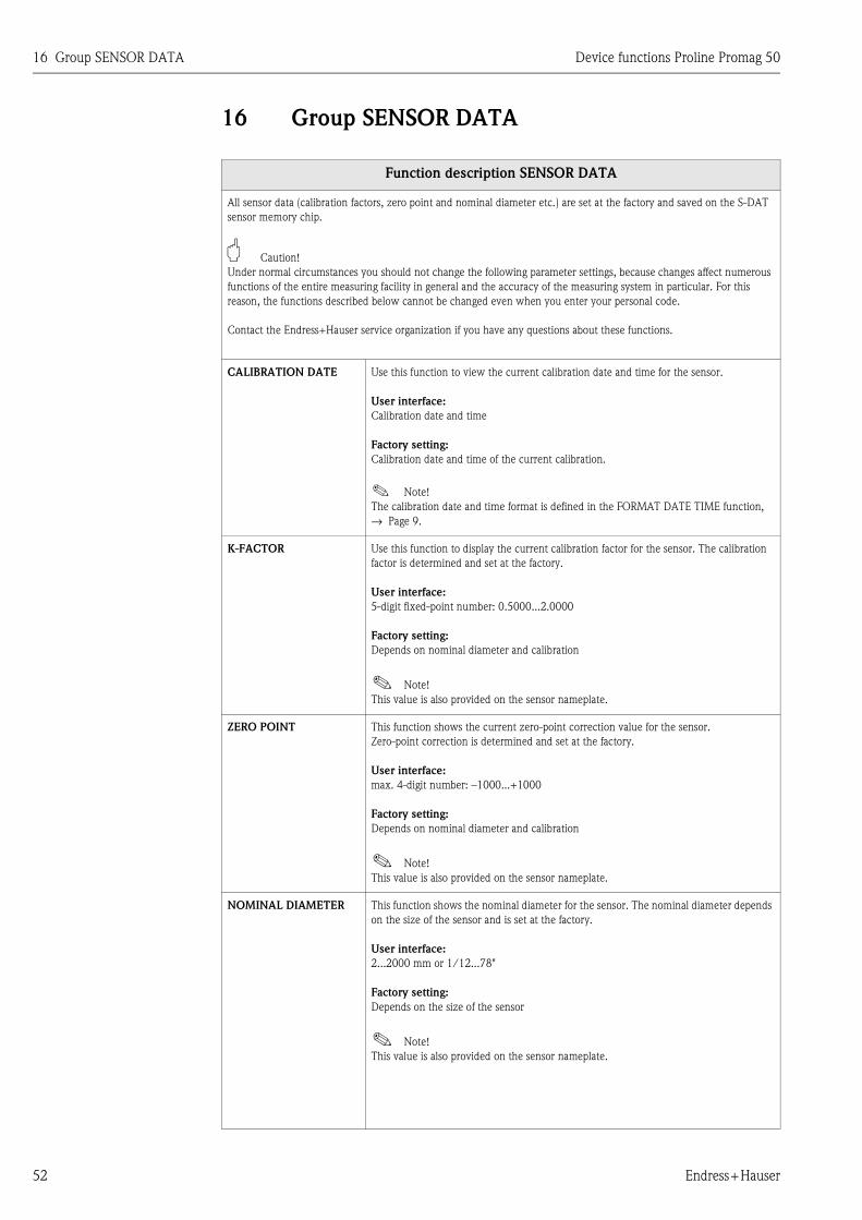
16 Group SENSOR DATA Device functions Proline Promag 50
52 Endress+Hauser
16 Group SENSOR DATA
Function description SENSOR DATA
All sensor data (calibration factors, zero point and nominal diameter etc.) are set at the factory and saved on the S-DAT
sensor memory chip.
" Caution!
Under normal circumstances you should not change the following parameter settings, because changes affect numerous
functions of the entire measuring facility in general and the accuracy of the measuring system in particular. For this
reason, the functions described below cannot be changed even when you enter your personal code.
Contact the Endress+Hauser service organization if you have any questions about these functions.
CALIBRATION DATE Use this function to view the current calibration date and time for the sensor.
User interface:
Calibration date and time
Factory setting:
Calibration date and time of the current calibration.
! Note!
The calibration date and time format is defined in the FORMAT DATE TIME function, → Page 9.
K-FACTOR Use this function to display the current calibration factor for the sensor. The calibration
factor is determined and set at the factory.
User interface:
5-digit fixed-point number: 0.5000...2.0000
Factory setting:
Depends on nominal diameter and calibration
! Note!
This value is also provided on the sensor nameplate.
ZERO POINT This function shows the current zero-point correction value for the sensor.
Zero-point correction is determined and set at the factory.
User interface:
max. 4-digit number: –1000...+1000
Factory setting:
Depends on nominal diameter and calibration
! Note!
This value is also provided on the sensor nameplate.
NOMINAL DIAMETER This function shows the nominal diameter for the sensor. The nominal diameter depends
on the size of the sensor and is set at the factory.
User interface:
2...2000 mm or 1/12...78"
Factory setting:
Depends on the size of the sensor
! Note!
This value is also provided on the sensor nameplate.

Device functions Proline Promag 50 16 Group SENSOR DATA
Endress+Hauser 53
MEASURING PERIOD Use this function to set the time for a full measuring period.
The duration of the measuring period is calculated from the rise time of the magnetic
field, the brief recovery time, the integration time (which can be set) and the empty pipe
detection time.
User input:
0.0...1000 ms
Factory setting:
Depends on nominal diameter
! Note!
The system checks the time entered and sets the measuring period which is actually used
internally to a plausible value. If you enter 0 ms, the system automatically computes the
shortest time.
OVERVOLTAGE TIME Use this function to specify the time in which overvoltage is applied to the coil circuit in
order to build up the magnetic field as fast as possible.
The overvoltage time is adjusted automatically while measuring is in progress. The
overvoltage time depends on the sensor type and the nominal diameter and is set at the
factory.
User interface:
4-digit floating-point number: 0.0...100.0 ms
Factory setting:
Depends on nominal diameter
EPD ELECTRODE Use this function to check whether the sensor is equipped with an EPD electrode.
User interface:
YES
NO
Factory setting:
YES → Electrode fitted as standard
POLARITY ECC Use this function to display the actual current polarity for optional electrode cleaning
(ECC). Electrode cleaning uses either a positive or negative current, depending on the
electrode material.
The measuring device automatically selects the correct polarity on the basis of the
electrode-material data stored in the S-DAT.
User interface:
POSITIVE → for electrodes made of: 1.4435, Hastelloy C, platinum, titanium
NEGATIVE → for electrodes made of: tantalum
" Caution!
If the incorrect current is applied to the electrodes, the electrode material is destroyed.
Function description SENSOR DATA

17 Group SUPERVISION Device functions Proline Promag 50
54 Endress+Hauser
17 Group SUPERVISION
Function description SUPERVISION
CURRENT SYSTEM
CONDITION
Use this function to check the present system status.
User interface:
"SYSTEM OK" or the fault / notice message with the highest priority.
PREVIOUS SYSTEM
CONDITIONS
Use this function to view the fifteen most recent fault and notice messages since
measuring last started.
User interface:
The last 15 fault/notice messages appear on the display
ASSIGN SYSTEM ERROR Use this function to view all system errors and the associated error categories (fault
message or notice message). By selecting a certain system error, its error category can be
changed in the subsequent function ERROR CATEGORY.
Options:
CANCEL
List of system errors
! Note!
• You can exit this function as follows: select "CANCEL" and confirm with F .
• A list of possible system errors is provided in the Operating Instructions Promag 50,
BA 046D/06/en
ERROR CATEGORY! Note!
This function is only available if a system error has been selected in the function ASSIGN
SYSTEM ERROR.
Use this function to define whether a system error triggers a notice message or a fault
message. If you select FAULT MESSAGES, all outputs respond to an error in accordance
with their defined error response patterns.
Options:
NOTICE MESSAGES (display only)
FAULT MESSAGES (outputs and display)
! Note!
Press the F key twice to call up the ASSIGN SYSTEM ERROR function.
ASSIGN PROCESS
ERROR
Use this function to view all process errors and the associated error categories (fault mes-
sage or notice message). By selecting an individual process error, its error category can be
changed in the subsequent function ERROR CATEGORY.
Options:
CANCEL
List of process errors
! Note!
• You can exit this function as follows: select "CANCEL" and confirm with F .
• A list of possible process errors is provided in the Operating Instructions Promag 50,
BA 046D/06/en

Device functions Proline Promag 50 17 Group SUPERVISION
Endress+Hauser 55
ERROR CATEGORY! Note!
This function is only available if a process error has been selected in the function ASSIGN
PROCESS ERROR.
Use this function to define whether a process error triggers a notice message or a fault
message. If you select FAULT MESSAGES, all outputs respond to an error in accordance
with their defined error response patterns.
Options:
NOTICE MESSAGES (display only)
FAULT MESSAGES (outputs and display)
! Note!
Press the F key twice to call up the ASSIGN PROCESS ERROR function.
ALARM DELAY Use this function to define a time span in which the criteria for an error have to be
satisfied without interruption before an error or notice message is generated.
Depending on the setting and the type of error, this suppression acts on:
• Display
• Status output
• Current output
• Frequency output
User input:
0...100 s (in steps of one second)
Factory setting:
0 s
" Caution!
If this function is activated error and notice messages are delayed by the time correspon-
ding to the setting before being forwarded to the higher-order controller (process control-
ler, etc.). It is therefore imperative to check in advance in order to make sure whether a
delay of this nature could affect the safety requirements of the process.
If error and notice messages cannot be suppressed, a value of 0 seconds must be entered
here.
SYSTEM RESET Use this function to perform a reset of the measuring system.
Options:
NO
RESTART SYSTEM (restart without interrupting power supply)
Factory setting:
NO
OPERATION HOURS The hours of operation of the device appear on the display.
Display:
Depends on the number of hours of operation elapsed:
Hours of operation < 10 hours → display format = 0:00:00 (hr:min:sec)
Hours of operation 10...10,000 hours → display format = 0000:00 (hr:min)
Hours of operation > 10,000 hours → display format = 000000 (hr)
PERMANENT STORAGE This function indicates whether permanent storage of all parameters in the EEPROM has
been switched on or off.
Display:
0 = OFF
1 = ON
Factory setting:
ON
Function description SUPERVISION
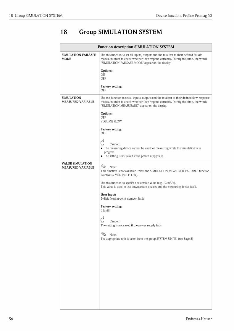
18 Group SIMULATION SYSTEM Device functions Proline Promag 50
56 Endress+Hauser
18 Group SIMULATION SYSTEM
Function description SIMULATION SYSTEM
SIMULATION FAILSAFE
MODE
Use this function to set all inputs, outputs and the totalizer to their defined failsafe
modes, in order to check whether they respond correctly. During this time, the words
"SIMULATION FAILSAFE MODE" appear on the display.
Options:
ON
OFF
Factory setting:
OFF
SIMULATION
MEASURED VARIABLE
Use this function to set all inputs, outputs and the totalizer to their defined flow-response
modes, in order to check whether they respond correctly. During this time, the words
"SIMULATION MEASURAND" appear on the display.
Options:
OFF
VOLUME FLOW
Factory setting:
OFF
" Caution!
• The measuring device cannot be used for measuring while this simulation is in
progress.
• The setting is not saved if the power supply fails.
VALUE SIMULATION
MEASURED VARIABLE ! Note!
This function is not available unless the SIMULATION MEASURED VARIABLE function
is active (= VOLUME FLOW).
Use this function to specify a selectable value (e.g. 12 m3/s).
This value is used to test downstream devices and the measuring device itself.
User input:
5-digit floating-point number, [unit]
Factory setting:
0 [unit]
" Caution!
The setting is not saved if the power supply fails.
! Note!
The appropriate unit is taken from the group SYSTEM UNITS, (see Page 8)

Device functions Proline Promag 50 19 Group SENSOR VERSION
Endress+Hauser 57
19 Group SENSOR VERSION
20 Group AMPLIFIER VERSION
Function description SENSOR VERSION
SERIAL NUMBER Use this function to view the serial number of the sensor.
SENSOR TYPE Use this function to view the sensor type.
HARDWARE REVISION
NUMBER SENSOR
Use this function to view the hardware revision number of the sensor.
SOFTWARE REVISION
NUMBER
S-DAT
Use this function to view the software revision number of the software used to create the
content of the S-DAT
Function description AMPLIFIER VERSION
DEVICE SOFTWARE Displays the current device software version.
SOFTWARE
REVISION NUMBER
AMPLIFIER
Use this function to view the software revision number of the amplifier.
LANGUAGE GROUP Use this function to view the language group.
The following language groups can be ordered: WEST EU / USA, EAST EU / SCAND.,
ASIA.
Display:
available language group
! Note!
• The language options of the available language group are displayed in the LANGUAGE
function.
• You can change the language group via the configuration software FieldCare. Please
do not hesitate to contact your Endress+Hauser sales office if you have any questions.
I/O MODULE TYPE Use this function to view the configuration of the I/O module complete with terminal
numbers.
SOFTWARE
REVISION NUMBER
I/O MODULE
Use this function to view the software revision number of the I/O module.

21 Factory settings Device functions Proline Promag 50
58 Endress+Hauser
21 Factory settings
21.1 SI units (not for USA and Canada)
Low flow, full scale value, pulse value, totalizer
Nominal diameter Low flow Full scale value Pulse value Totalizer
[mm] [inch] (approx. v = 0.04 m/s) (approx. v = 2.5 m/s)(approx. 2 pulses/s at v =
2.5 m/s)
2 1/12" 0.01 dm3/min 0.5 dm3/min 0.005 dm3 dm3
4 5/32" 0.05 dm3/min 2 dm3/min 0.025 dm3 dm3
8 5/16" 0.1 dm3/min 8 dm3/min 0.10 dm3 dm3
15 1/2" 0.5 dm3/min 25 dm3/min 0.20 dm3 dm3
25 1" 1 dm3/min 75 dm3/min 0.50 dm3 dm3
32 1 1/4" 2 dm3/min 125 dm3/min 1.00 dm3 dm3
40 1 1/2" 3 dm3/min 200 dm3/min 1.50 dm3 dm3
50 2" 5 dm3/min 300 dm3/min 2.50 dm3 dm3
65 2 1/2" 8 dm3/min 500 dm3/min 5.00 dm3 dm3
80 3" 12 dm3/min 750 dm3/min 5.00 dm3 dm3
100 4" 20 dm3/min 1200 dm3/min 10.00 dm3 dm3
125 5" 30 dm3/min 1850 dm3/min 15.00 dm3 dm3
150 6" 2.5 m3/h 150 m3/h 0.025 m3 m3
200 8" 5.0 m3/h 300 m3/h 0.05 m3 m3
250 10" 7.5 m3/h 500 m3/h 0.05 m3 m3
300 12" 10 m3/h 750 m3/h 0.10 m3 m3
350 14" 15 m3/h 1000 m3/h 0.10 m3 m3
400 16" 20 m3/h 1200 m3/h 0.15 m3 m3
450 18" 25 m3/h 1500 m3/h 0.25 m3 m3
500 20" 30 m3/h 2000 m3/h 0.25 m3 m3
600 24" 40 m3/h 2500 m3/h 0.30 m3 m3
700 28" 50 m3/h 3500 m3/h 0.50 m3 m3
– 30" 60 m3/h 4000 m3/h 0.50 m3 m3
800 32" 75 m3/h 4500 m3/h 0.75 m3 m3
900 36" 100 m3/h 6000 m3/h 0.75 m3 m3
1000 40" 125 m3/h 7000 m3/h 1.00 m3 m3
– 42" 125 m3/h 8000 m3/h 1.00 m3 m3
1200 48" 150 m3/h 10000 m3/h 1.50 m3 m3
– 54" 200 m3/h 13000 m3/h 1.50 m3 m3
1400 – 225 m3/h 14000 m3/h 2.00 m3 m3
– 60" 250 m3/h 16000 m3/h 2.00 m3 m3
1600 – 300 m3/h 18000 m3/h 2.50 m3 m3
– 66" 325 m3/h 20500 m3/h 2.50 m3 m3
1800 72" 350 m3/h 23000 m3/h 3.00 m3 m3
– 78" 450 m3/h 28500 m3/h 3.50 m3 m3
2000 – 450 m3/h 28500 m3/h 3.50 m3 m3

Device functions Proline Promag 50 21 Factory settings
Endress+Hauser 59
Language
Length
Country Language
Australia English
Austria Deutsch
Belgium English
Czech Republic Czech
Denmark English
England English
Finland Suomi
France Francais
Germany Deutsch
Hong Kong English
Hungary English
India English
Indonesia Bahasa Indonesia
Instruments International English
Italy Italiano
Japan Japanese
Malaysia English
Netherlands Nederlands
Norway Norsk
Poland Polish
Portugal Portuguese
Russia Russian
Singapore English
South Africa English
Spain Espanol
Sweden Svenska
Switzerland Deutsch
Thailand English
Unit
Length mm

21 Factory settings Device functions Proline Promag 50
60 Endress+Hauser
21.2 US units (only for USA and Canada)
Low flow, full scale value, pulse value, totalizer
Language, length
Nominal diameter Low flow Full scale value Pulse value Totalizer
[inch] [mm] (approx. v = 0.04 m/s) (approx. v = 2.5 m/s)(approx. 2 pulses/s
at v = 2.5 m/s)
1/12" 2 0.002 gal/min 0.1 gal/min 0.001 gal gal
5/32" 4 0.008 gal/min 0.5 gal/min 0.005 gal gal
5/16" 8 0.025 gal/min 2 gal/min 0.02 gal gal
1/2" 15 0.10 gal/min 6 gal/min 0.05 gal gal
1" 25 0.25 gal/min 18 gal/min 0.20 gal gal
1 1/4" 32 0.50 gal/min 30 gal/min 0.20 gal gal
1 1/2" 40 0.75 gal/min 50 gal/min 0.50 gal gal
2" 50 1.25 gal/min 75 gal/min 0.50 gal gal
2 1/2" 65 2.0 gal/min 130 gal/min 1 gal gal
3" 80 2.5 gal/min 200 gal/min 2 gal gal
4" 100 4.0 gal/min 300 gal/min 2 gal gal
5" 125 7.0 gal/min 450 gal/min 5 gal gal
6" 150 12 gal/min 600 gal/min 5 gal gal
8" 200 15 gal/min 1200 gal/min 10 gal gal
10" 250 30 gal/min 1500 gal/min 15 gal gal
12" 300 45 gal/min 2400 gal/min 25 gal gal
14" 350 60 gal/min 3600 gal/min 30 gal gal
16" 400 60 gal/min 4800 gal/min 50 gal gal
18" 450 90 gal/min 6000 gal/min 50 gal gal
20" 500 120 gal/min 7500 gal/min 75 gal gal
24" 600 180 gal/min 10500 gal/min 100 gal gal
28" 700 210 gal/min 13500 gal/min 125 gal gal
30" – 270 gal/min 16500 gal/min 150 gal gal
32" 800 300 gal/min 19500 gal/min 200 gal gal
36" 900 360 gal/min 24000 gal/min 225 gal gal
40" 1000 480 gal/min 30000 gal/min 250 gal gal
42" – 600 gal/min 33000 gal/min 250 gal gal
48" 1200 600 gal/min 42000 gal/min 400 gal gal
54" – 1.3 Mgal/d 75 Mgal/d 0.0005 Mgal Mgal
– 1400 1.3 Mgal/d 85 Mgal/d 0.0005 Mgal Mgal
60" – 1.3 Mgal/d 95 Mgal/d 0.0005 Mgal Mgal
– 1600 1.7 Mgal/d 110 Mgal/d 0.0008 Mgal Mgal
66" – 2.2 Mgal/d 120 Mgal/d 0.0008 Mgal Mgal
72" 1800 2.6 Mgal/d 140 Mgal/d 0.0008 Mgal Mgal
78" – 3.0 Mgal/d 175 Mgal/d 0.001 Mgal Mgal
– 2000 3.0 Mgal/d 175 Mgal/d 0.001 Mgal Mgal
Unit
Language English
Length inch

Device functions Proline Promag 50 22 Index of key words
Endress+Hauser 61
22 Index of key words
Numerics100% Value . . . . . . . . . . . . . . . . . . . . . . . . . . . . . . . . . . . 13
AAccess code . . . . . . . . . . . . . . . . . . . . . . . . . . . . . . . . . . . 12
Active level (status input) . . . . . . . . . . . . . . . . . . . . . . . . . 40
Actual
Current . . . . . . . . . . . . . . . . . . . . . . . . . . . . . . . . . . . 21
Frequency . . . . . . . . . . . . . . . . . . . . . . . . . . . . . . . . . 27
Status output . . . . . . . . . . . . . . . . . . . . . . . . . . . . . . . 35
Alarm delay (notice or fault messages) . . . . . . . . . . . . . . . 55
Assign
Current output . . . . . . . . . . . . . . . . . . . . . . . . . . . . . . 19
Display line 1 . . . . . . . . . . . . . . . . . . . . . . . . . . . . . . . 13
Display line 2 . . . . . . . . . . . . . . . . . . . . . . . . . . . . . . . 13
Frequency . . . . . . . . . . . . . . . . . . . . . . . . . . . . . . . . . 23
Low flow cut off . . . . . . . . . . . . . . . . . . . . . . . . . . . . . 43
Process error . . . . . . . . . . . . . . . . . . . . . . . . . . . . . . . . 54
Pulse . . . . . . . . . . . . . . . . . . . . . . . . . . . . . . . . . . . . . 28
Status input . . . . . . . . . . . . . . . . . . . . . . . . . . . . . . . . 40
Status output . . . . . . . . . . . . . . . . . . . . . . . . . . . . . . . 34
System error . . . . . . . . . . . . . . . . . . . . . . . . . . . . . . . . 54
Totalizer . . . . . . . . . . . . . . . . . . . . . . . . . . . . . . . . . . . 16
BBus address . . . . . . . . . . . . . . . . . . . . . . . . . . . . . . . . . . . 42
CCode
Access code . . . . . . . . . . . . . . . . . . . . . . . . . . . . . . . . 12
Counter (Unlocking) . . . . . . . . . . . . . . . . . . . . . . . . . . 12
Private code . . . . . . . . . . . . . . . . . . . . . . . . . . . . . . . . 12
Commissioning Quick Setup . . . . . . . . . . . . . . . . . . . . . . . 10
Contrast LCD . . . . . . . . . . . . . . . . . . . . . . . . . . . . . . . . . . 14
Current span . . . . . . . . . . . . . . . . . . . . . . . . . . . . . . . . . . 20
DDevice ID . . . . . . . . . . . . . . . . . . . . . . . . . . . . . . . . . . . . . 42
Device Revision . . . . . . . . . . . . . . . . . . . . . . . . . . . . . . . . 42
Device software . . . . . . . . . . . . . . . . . . . . . . . . . . . . . . . . 57
Display
Backlight . . . . . . . . . . . . . . . . . . . . . . . . . . . . . . . . . . 15
Contrast LCD . . . . . . . . . . . . . . . . . . . . . . . . . . . . . . . 14
Damping . . . . . . . . . . . . . . . . . . . . . . . . . . . . . . . . . . 14
Format . . . . . . . . . . . . . . . . . . . . . . . . . . . . . . . . . . . . 14
Test . . . . . . . . . . . . . . . . . . . . . . . . . . . . . . . . . . . . . . 15
EECC (electrode cleaning) . . . . . . . . . . . . . . . . . . . . . . . . . 47
Cleaning cycle . . . . . . . . . . . . . . . . . . . . . . . . . . . . . . 48
Duration . . . . . . . . . . . . . . . . . . . . . . . . . . . . . . . . . . . 47
Polarity . . . . . . . . . . . . . . . . . . . . . . . . . . . . . . . . . . . . 53
Recovery time . . . . . . . . . . . . . . . . . . . . . . . . . . . . . . . 48
Empty Pipe Detection (EPD/OED)
EPD electrode . . . . . . . . . . . . . . . . . . . . . . . . . . . . . . . 53
EPD/OED adjustment . . . . . . . . . . . . . . . . . . . . . . . . 46
General information . . . . . . . . . . . . . . . . . . . . . . . . . . 44
Response time . . . . . . . . . . . . . . . . . . . . . . . . . . . . . . . 47
Switching on/off EPD/OED . . . . . . . . . . . . . . . . . . . . 44
End value frequency . . . . . . . . . . . . . . . . . . . . . . . . . . . . . 23
Error category
Process error . . . . . . . . . . . . . . . . . . . . . . . . . . . . . . . . 55
System error . . . . . . . . . . . . . . . . . . . . . . . . . . . . . . . . 54
FFactory settings . . . . . . . . . . . . . . . . . . . . . . . . . . . . . . . . . 58
Failsafe mode
Current output . . . . . . . . . . . . . . . . . . . . . . . . . . . . . . 21
Frequency output . . . . . . . . . . . . . . . . . . . . . . . . . . . . 27
Pulse output . . . . . . . . . . . . . . . . . . . . . . . . . . . . . . . . 32
Totalizer . . . . . . . . . . . . . . . . . . . . . . . . . . . . . . . . . . . 18
Flow damping (system damping) . . . . . . . . . . . . . . . . . . . . 51
Format (display) . . . . . . . . . . . . . . . . . . . . . . . . . . . . . . . . 14
Frequency (High value) . . . . . . . . . . . . . . . . . . . . . . . . . . . 24
Function matrix
Layout and use . . . . . . . . . . . . . . . . . . . . . . . . . . . . . . . 5
Overview . . . . . . . . . . . . . . . . . . . . . . . . . . . . . . . . . . . 6
GGroup
Amplifier version . . . . . . . . . . . . . . . . . . . . . . . . . . . . . 57
Communication . . . . . . . . . . . . . . . . . . . . . . . . . . . . . 42
Current output . . . . . . . . . . . . . . . . . . . . . . . . . . . . . . 19
Handling totalizer . . . . . . . . . . . . . . . . . . . . . . . . . . . . 18
Measuring values . . . . . . . . . . . . . . . . . . . . . . . . . . . . . 7
Operation . . . . . . . . . . . . . . . . . . . . . . . . . . . . . . . . . . 11
Process parameter . . . . . . . . . . . . . . . . . . . . . . . . . . . . 43
Pulse/frequency output . . . . . . . . . . . . . . . . . . . . . . . . 23
Quick Setup . . . . . . . . . . . . . . . . . . . . . . . . . . . . . . . . 10
Sensor data . . . . . . . . . . . . . . . . . . . . . . . . . . . . . . . . . 52
Sensor version . . . . . . . . . . . . . . . . . . . . . . . . . . . . . . . 57
Simulation system . . . . . . . . . . . . . . . . . . . . . . . . . . . . 56
Status input . . . . . . . . . . . . . . . . . . . . . . . . . . . . . . . . . 40
Status output . . . . . . . . . . . . . . . . . . . . . . . . . . . . . . . . 34
Supervision . . . . . . . . . . . . . . . . . . . . . . . . . . . . . . . . . 54
System parameters . . . . . . . . . . . . . . . . . . . . . . . . . . . 49
System units . . . . . . . . . . . . . . . . . . . . . . . . . . . . . . . . . 8
Totalizer . . . . . . . . . . . . . . . . . . . . . . . . . . . . . . . . . . . 16
User interface . . . . . . . . . . . . . . . . . . . . . . . . . . . . . . . 13
HHardware revision number (sensor) . . . . . . . . . . . . . . . . . . 57
HART Protocol . . . . . . . . . . . . . . . . . . . . . . . . . . . . . . . . . 42
II/O module type (input/output type) . . . . . . . . . . . . . . . . 57
Installation direction sensor . . . . . . . . . . . . . . . . . . . . . . . 49
Integration time . . . . . . . . . . . . . . . . . . . . . . . . . . . . . . . . 51
KK-Factor . . . . . . . . . . . . . . . . . . . . . . . . . . . . . . . . . . . . . . 52
LLanguage
Factory settings . . . . . . . . . . . . . . . . . . . . . . . . . . 59, 60
Language group (display) . . . . . . . . . . . . . . . . . . . . . . . 57
Selection . . . . . . . . . . . . . . . . . . . . . . . . . . . . . . . . . . . 11

22 Index of key words Device functions Proline Promag 50
62 Endress+Hauser
Low flow cut off
Off value . . . . . . . . . . . . . . . . . . . . . . . . . . . . . . . . . . 43
On value . . . . . . . . . . . . . . . . . . . . . . . . . . . . . . . . . . 43
MManufacturer ID . . . . . . . . . . . . . . . . . . . . . . . . . . . . . . . 42
Measuring mode . . . . . . . . . . . . . . . . . . . . . . . . . . . . . . . 49
Measuring period . . . . . . . . . . . . . . . . . . . . . . . . . . . . . . 53
Minimum pulse width . . . . . . . . . . . . . . . . . . . . . . . . . . . 40
NNominal diameter . . . . . . . . . . . . . . . . . . . . . . . . . . . . . . 52
OOED (Open electrode detection)
see Empty Pipe Detection . . . . . . . . . . . . . . . . . . . . . . 44
Off value
Low flow cut off . . . . . . . . . . . . . . . . . . . . . . . . . . . . 43
Status output . . . . . . . . . . . . . . . . . . . . . . . . . . . . . . . 35
On value
Low flow cut off . . . . . . . . . . . . . . . . . . . . . . . . . . . . 43
Status output . . . . . . . . . . . . . . . . . . . . . . . . . . . . . . . 34
Operation hours . . . . . . . . . . . . . . . . . . . . . . . . . . . . . . . 55
Operation mode (pulse/frequency output) . . . . . . . . . . . . 23
Output signal
Frequency output . . . . . . . . . . . . . . . . . . . . . . . . . 25, 26
Pulse . . . . . . . . . . . . . . . . . . . . . . . . . . . . . . . . . . 30, 31
Overflow (totalizer) . . . . . . . . . . . . . . . . . . . . . . . . . . . . . 16
Overvoltage time . . . . . . . . . . . . . . . . . . . . . . . . . . . . . . . 53
PPermanent storage . . . . . . . . . . . . . . . . . . . . . . . . . . . . . . 55
Polarity ECC . . . . . . . . . . . . . . . . . . . . . . . . . . . . . . . . . . 53
Positive zero return . . . . . . . . . . . . . . . . . . . . . . . . . . . . . 50
Previous system conditions . . . . . . . . . . . . . . . . . . . . . . . 54
Pulse value . . . . . . . . . . . . . . . . . . . . . . . . . . . . . . . . . . . 29
Pulse width . . . . . . . . . . . . . . . . . . . . . . . . . . . . . . . . . . . 29
QQuick Setup commissioning . . . . . . . . . . . . . . . . . . . . . . . 10
RReset
All totalizers . . . . . . . . . . . . . . . . . . . . . . . . . . . . . . . 18
System . . . . . . . . . . . . . . . . . . . . . . . . . . . . . . . . . . . . 55
Totalizer . . . . . . . . . . . . . . . . . . . . . . . . . . . . . . . . . . 17
SSensor
Installation direction . . . . . . . . . . . . . . . . . . . . . . . . . 49
K-Factor . . . . . . . . . . . . . . . . . . . . . . . . . . . . . . . . . . 52
Measuring period . . . . . . . . . . . . . . . . . . . . . . . . . . . . 53
Overvoltage time . . . . . . . . . . . . . . . . . . . . . . . . . . . . 53
Sensor type . . . . . . . . . . . . . . . . . . . . . . . . . . . . . . . . 57
Serial number . . . . . . . . . . . . . . . . . . . . . . . . . . . . . . 57
Zero point . . . . . . . . . . . . . . . . . . . . . . . . . . . . . . . . . 52
Simulation
Current . . . . . . . . . . . . . . . . . . . . . . . . . . . . . . . . . . . 22
Failsafe mode . . . . . . . . . . . . . . . . . . . . . . . . . . . . . . . 56
Frequency . . . . . . . . . . . . . . . . . . . . . . . . . . . . . . . . . 28
Measured variable . . . . . . . . . . . . . . . . . . . . . . . . . . . 56
Pulses . . . . . . . . . . . . . . . . . . . . . . . . . . . . . . . . . . . . 32
Status input . . . . . . . . . . . . . . . . . . . . . . . . . . . . . . . . 40
Switch point . . . . . . . . . . . . . . . . . . . . . . . . . . . . . . . . 35
Software revision number
Amplifier . . . . . . . . . . . . . . . . . . . . . . . . . . . . . . . . . . 57
Device Software . . . . . . . . . . . . . . . . . . . . . . . . . . . . . 57
I/O Module . . . . . . . . . . . . . . . . . . . . . . . . . . . . . . . . 57
S-DAT . . . . . . . . . . . . . . . . . . . . . . . . . . . . . . . . . . . . 57
Status access . . . . . . . . . . . . . . . . . . . . . . . . . . . . . . . . . . 12
Status output
Flow direction . . . . . . . . . . . . . . . . . . . . . . . . . . . . . . 37
General . . . . . . . . . . . . . . . . . . . . . . . . . . . . . . . . . . . 37
Limit value . . . . . . . . . . . . . . . . . . . . . . . . . . . . . . . . . 37
Switching response . . . . . . . . . . . . . . . . . . . . . . . . . . . 38
Storage
permanent . . . . . . . . . . . . . . . . . . . . . . . . . . . . . . . . . 55
Sum (totalizer) . . . . . . . . . . . . . . . . . . . . . . . . . . . . . . . . . 16
System
Current conditions . . . . . . . . . . . . . . . . . . . . . . . . . . . 54
Damping (flow damping) . . . . . . . . . . . . . . . . . . . . . . 51
Operation hours . . . . . . . . . . . . . . . . . . . . . . . . . . . . . 55
Previous conditions . . . . . . . . . . . . . . . . . . . . . . . . . . 54
Reset . . . . . . . . . . . . . . . . . . . . . . . . . . . . . . . . . . . . . 55
TTag
Description . . . . . . . . . . . . . . . . . . . . . . . . . . . . . . . . 42
Name . . . . . . . . . . . . . . . . . . . . . . . . . . . . . . . . . . . . . 42
Test display . . . . . . . . . . . . . . . . . . . . . . . . . . . . . . . . . . . 15
Time constant
Current output . . . . . . . . . . . . . . . . . . . . . . . . . . . . . . 21
Frequency output . . . . . . . . . . . . . . . . . . . . . . . . . . . . 27
Status output . . . . . . . . . . . . . . . . . . . . . . . . . . . . . . . 35
Totalizer . . . . . . . . . . . . . . . . . . . . . . . . . . . . . . . . . . . . . 16
Assign . . . . . . . . . . . . . . . . . . . . . . . . . . . . . . . . . . . . 16
Failsafe mode . . . . . . . . . . . . . . . . . . . . . . . . . . . . . . . 18
Mode . . . . . . . . . . . . . . . . . . . . . . . . . . . . . . . . . . . . . 17
Overflow . . . . . . . . . . . . . . . . . . . . . . . . . . . . . . . . . . 16
Reset . . . . . . . . . . . . . . . . . . . . . . . . . . . . . . . . . . . . . 17
Reset all totalizers . . . . . . . . . . . . . . . . . . . . . . . . . . . 18
Unit selection . . . . . . . . . . . . . . . . . . . . . . . . . . . . . . . 16
UUnit
Length . . . . . . . . . . . . . . . . . . . . . . . . . . . . . . . . . . . . . 9
Totalizer . . . . . . . . . . . . . . . . . . . . . . . . . . . . . . . . . . 16
Volume . . . . . . . . . . . . . . . . . . . . . . . . . . . . . . . . . . . . 8
Volume flow . . . . . . . . . . . . . . . . . . . . . . . . . . . . . . . . 8
VValue
20 mA . . . . . . . . . . . . . . . . . . . . . . . . . . . . . . . . . . . . 21
f high . . . . . . . . . . . . . . . . . . . . . . . . . . . . . . . . . . . . . 24
Failsafe level . . . . . . . . . . . . . . . . . . . . . . . . . . . . . . . . 27
Value simulation
Current . . . . . . . . . . . . . . . . . . . . . . . . . . . . . . . . . . . 22
Frequency . . . . . . . . . . . . . . . . . . . . . . . . . . . . . . . . . 28
Measured variable . . . . . . . . . . . . . . . . . . . . . . . . . . . 56
Pulse . . . . . . . . . . . . . . . . . . . . . . . . . . . . . . . . . . . . . 33

Device functions Proline Promag 50 22 Index of key words
Endress+Hauser 63
Status input . . . . . . . . . . . . . . . . . . . . . . . . . . . . . . . . 41
Switch point . . . . . . . . . . . . . . . . . . . . . . . . . . . . . . . . 36
Volume flow (display) . . . . . . . . . . . . . . . . . . . . . . . . . . . . . 7
ZZero point . . . . . . . . . . . . . . . . . . . . . . . . . . . . . . . . . . . . 52

22 Index of key words Device functions Proline Promag 50
64 Endress+Hauser

Device functions Proline Promag 50 22 Index of key words
Endress+Hauser 65

22 Index of key words Device functions Proline Promag 50
66 Endress+Hauser

Device Functions Proline Promag 50
Endress+Hauser 67

www.endress.com/worldwide
BA049D/06/en/11.09
71105948
FM+SGML6.0
Related Documents


