1998 Jan 29 24 Philips Components Electrolytic capacitors General introduction TRANSLATION OF TECHNICAL TERMS SOME IMPORTANT TERMS DES TERMES IMPORTANTES EINIGE WICHTIGE BEGRIFFE Ambient temperature (T amb ) température ambiante Umgebungstemperatur Assessment level niveau d'assurance Gütebestätigungsstufe Axial terminations sorties axiales axiale Anschlußdrähte Capacitance capacité Kapazität Charge charge laden Climatic category catégorie climatique Klimakategorie Dimensions dimensions Maße Discharge décharge entladen Dissipation factor (tan δ) tangente de l`angle de pertes Verlustfaktor Endurance endurance Dauerspannungsprüfung Equivalent series resistance (ESR) résistance série équivalente äquivalenter Serienwiderstand Equivalent series inductance (ESL) inductance série équivalente äquivalente Serieninduktivität Failure rate taux de fiabilité Ausfallrate Frequency (f) fréquence Frequenz General purpose grade usage général allgemeine Anforderungen Impedance (Z) impédance Scheinwiderstand, Impedanz Leadless sans fils unbedrahtet Leakage current (I l ) courant de fuite Reststrom Long life grade longue durée de vie erhöhte Anforderungen Method méthode Verfahren Mounting montage Montage No visible damage aucun dommage keine sichtbaren Schäden Open circuit circuit ouvert Unterbrechung Mounting hole diagram dessin de montage Bohrungsraster Rated capacitance (C R ) capacité nominale Nennkapazitat Rated voltage (U R ) tension nominale Nennspannung Recovery reprise Nachbehandlung Forming voltage (U F ) tension de formation Formierspannung Requirements exigences Anforderungen Reverse voltage (U rev ) tension inverse Umpolspannung Ripple current (I R ) courant ondulé überlagerter Wechselstrom Short circuit court-circuit Kurzschluß Surface mounting device (SMD) composant pour montage en surface oberflächenmontierbares Bauelement Surge voltage (U S ) surtension Spitzenspannung Terminal pitch distance entre les connections Rastermaß Terminations sorties Anschlüsse Useful life durée de vie Brauchbarkeitsdauer Visual examination examen visuel Sichtkontrolle

Welcome message from author
This document is posted to help you gain knowledge. Please leave a comment to let me know what you think about it! Share it to your friends and learn new things together.
Transcript
1998 Jan 29 24
Philips Components
Electrolytic capacitors General introduction
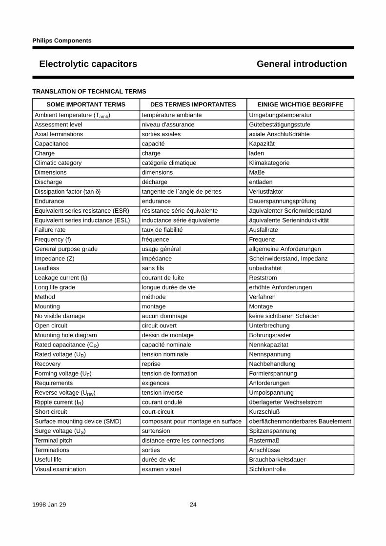
TRANSLATION OF TECHNICAL TERMS
SOME IMPORTANT TERMS DES TERMES IMPORTANTES EINIGE WICHTIGE BEGRIFFE
Ambient temperature (Tamb) température ambiante Umgebungstemperatur
Assessment level niveau d'assurance Gütebestätigungsstufe
Axial terminations sorties axiales axiale Anschlußdrähte
Capacitance capacité Kapazität
Charge charge laden
Climatic category catégorie climatique Klimakategorie
Dimensions dimensions Maße
Discharge décharge entladen
Dissipation factor (tan δ) tangente de l`angle de pertes Verlustfaktor
Endurance endurance Dauerspannungsprüfung
Equivalent series resistance (ESR) résistance série équivalente äquivalenter Serienwiderstand
Equivalent series inductance (ESL) inductance série équivalente äquivalente Serieninduktivität
Failure rate taux de fiabilité Ausfallrate
Frequency (f) fréquence Frequenz
General purpose grade usage général allgemeine Anforderungen
Impedance (Z) impédance Scheinwiderstand, Impedanz
Leadless sans fils unbedrahtet
Leakage current (Il) courant de fuite Reststrom
Long life grade longue durée de vie erhöhte Anforderungen
Method méthode Verfahren
Mounting montage Montage
No visible damage aucun dommage keine sichtbaren Schäden
Open circuit circuit ouvert Unterbrechung
Mounting hole diagram dessin de montage Bohrungsraster
Rated capacitance (CR) capacité nominale Nennkapazitat
Rated voltage (UR) tension nominale Nennspannung
Recovery reprise Nachbehandlung
Forming voltage (UF) tension de formation Formierspannung
Requirements exigences Anforderungen
Reverse voltage (Urev) tension inverse Umpolspannung
Ripple current (IR) courant ondulé überlagerter Wechselstrom
Short circuit court-circuit Kurzschluß
Surface mounting device (SMD) composant pour montage en surface oberflächenmontierbares Bauelement
Surge voltage (US) surtension Spitzenspannung
Terminal pitch distance entre les connections Rastermaß
Terminations sorties Anschlüsse
Useful life durée de vie Brauchbarkeitsdauer
Visual examination examen visuel Sichtkontrolle

1998 Jan 29 25
Philips Components
Electrolytic capacitors General introduction
CAPACITOR PRINCIPLES
The essential property of a capacitor is to store electricalcharge. The amount of electrical charge (Q) in thecapacitor (C) is proportional to the applied voltage (U).The relationship of these parameters is:
Q = C × U
where:
Q = charge in coulombs (C)
C = capacitance in farads (F)
U = voltage in volts (V).
The value of capacitance is directly proportional to the(anode) surface area and inversely proportional to thethickness of the dieletric layer, thus:
where:
εO = absolute permittivity (8.85 × 10⁻¹² F/m)
εr = relative dielectric constant (dimensionless)
A = surface area (m2)
d = thickness of the dielectric (oxide layer in electrolyticcapacitors) (m).
C εO εrAd----××=
Energy content of a capacitor
The energy content of a capacitor is given by:
WE12--- C U
2××=
handbook, halfpage
MBC552
A
cathode
dielectric
dε r
C
anode
Fig.1 Equivalent circuit of an ideal capacitor.
NON-POLAR
handbook, full pagewidth dielectric layercathode
electrolytecurrent supply
aluminium foil
anode
aluminium foil(highly etched)
electrolyte absorbing paper(spacer)
Al2O3 Al2O3
CCA422
Fig.2 Equivalent circuit of an electrolytic capacitor.
dbook, halfpage
C
MBC551
R ins
ESRR ESLL
POLAR
Anode electrode: valve effect metal: aluminium.
Dielectric: Al2O3
Cathode electrode, solid or non-solid electrolyte depending on technology:
non-solid: wet electrolyte, spacer and aluminium foil
solid: solid electrolyte (e.g. manganese dioxide), graphite and silver epoxy.

1998 Jan 29 26
Philips Components
Electrolytic capacitors General introduction
ELECTRICAL BEHAVIOUR
CHARACTERISTICS OF ELECTROLYTIC CAPACITORS VARY WITH TEMPERATURE, TIME AND APPLIEDVOLTAGE.
Fig.3 Typical variation of electrical parameters as a function of frequency, ambient temperature, voltage and time.
handbook, full pagewidth
MBC545 - 1
frequency
C
frequency
Tan δ
frequency
Z
ESR
temperature
leakagecurrent
load time
leakagecurrent
voltage
leakagecurrent
temperature
failurerate
% rated voltage
failurerate
temperature
ripplecurrent
capability
Z
ESR
temperature
ESR
C
25 Co
C/C0Z/Z0
ESR/ESR0
Z
life time
C
Tan δESR
Z Tan δESR/Z
C
frequency
ripplecurrent
capability

1998 Jan 29 27
Philips Components
Electrolytic capacitors General introduction
CONSTRUCTION
Examples
th Aluminium can
Rubber sealing
Aluminiumconnection part
Insulatingsleeve
Anode and cathode lead,tin plated
Wound cell, consisting of:
- Aluminium foil anode with aluminium oxide dielectric
- Paper spacer impreg- nated with electrolyte
- Aluminium foil cathode
MSB819
Fig.4 Radial Aluminium.
Fig.5 Axial Aluminium.
handbook, full pagewidth
Anode leadAluminium foil anodewith aluminium oxide dielectric
Cathode tab foilwelded to the bottom
of the canAluminium foil cathode
Blue insulating sleeve
Cathode lead
Aluminium can
Sealing disc
Paper spacerimpregnated
with electrolyte
CCA419

1998 Jan 29 28
Philips Components
Electrolytic capacitors General introduction
Fig.6 Large Aluminium, snap-in.
handbook, full pagewidth
Snap-in connections for fast assembly
Non-porous, teflon-coatedhard paper disc and rubberinsert for optimum seal
Wound cell:
Aluminium foil anode withaluminium oxide dielectric
Paper space impregnatedwith electrolyte
Aluminium foil cathode
Aluminium can
Solvent-resistant shrinksleeve gives high
insulation resistance
High-quality low-resistancelaser weld between
connections and anode/cathode.This means low ESR and ESL
Special design so that insertionforces on the connections
do not stress thewindings mechanically
CCA420
handbook, full pagewidth
Epoxy resinCone-shaped flange
Anode leadEtched aluminiumcovered with Al2O3
(dielectric)
Cathode connection:Silver epoxy on graphite and manganese dioxide
Cathode lead
CCA421
Fig.7 Solid Aluminium (SAL), radial.

1998 Jan 29 29
Philips Components
Electrolytic capacitors General introduction
Fig.8 Large Aluminium, screw terminal.
handbook, full pagewidth Synthetic disc sealedby rubber gasket
Multi-welded low ESR connections
Solvent resistantinsulating sleeve
Winding of high purityetched aluminium and
electrolyte impregnatedpaper spacer
Pressure relief
Terminals withuniversal screws
Bolt for mounting(optional) CCB093

1998 Jan 29 30
Philips Components
Electrolytic capacitors General introduction
DEFINITIONS OF ELECTRICAL PARAMETERS
Sequence of measurement for tests are in accordancewith “IEC 384-4” :
1. Leakage current (IL)2. Capacitance (CR)3. Dissipation factor (tan δ or ESR)4. Impedance (Z).
Capacitance
AC CAPACITANCE OF AN ELECTROLYTIC CAPACITOR
The capacitance of an equivalent circuit, havingcapacitance, resistance and inductance in series,measured with alternating current of approximatelysinusoidal waveform at a specified frequency; refer toFig.9.
Standard measuring frequencies for electrolytic capacitorsare 100 or 120 Hz.
DC CAPACITANCE OF AN ELECTROLYTIC CAPACITOR
(FOR TIMING CIRCUITS)
DC capacitance is given by the amount of charge which isstored in the capacitor at the rated voltage (UR).DC capacitance is measured by a single discharge of thecapacitor under defined conditions. Measuring proceduresare described in “DIN 41328, sheet 4” (withdrawn).
At any given time, the DC capacitance is higher than theAC capacitance.
handbook, halfpageVAC
C ESR ESL
MBC549
Fig.9 AC equivalent circuit of an electrolytic capacitor.
Fig.10 DC equivalent circuit of an electrolytic capacitor.
handbook, halfpage
MBC578
CDC
R leak
ESR
RATED CAPACITANCE (CR)
The capacitance value for which the capacitor has beendesigned and which is usually indicated upon it.
Preferred values of rated capacitance and their decimalmultiples are preferably chosen from the E3 series of“IEC Publication 63”.
TOLERANCE ON RATED CAPACITANCE
Preferred values of tolerances on rated capacitance
These values depend on the relevant series.
Voltage
RATED VOLTAGE (UR)
The maximum direct voltage, or peak value of pulsevoltage which may be applied continuously to a capacitorat any temperature between the lower categorytemperature and the rated temperature.
CATEGORY VOLTAGE (UC)
The maximum voltage which may be applied continuouslyto a capacitor at its upper category temperature.
TEMPERATURE DERATED VOLTAGE
The temperature derated voltage is the maximum voltagethat may be applied continuously to a capacitor, for anytemperature between the rated temperature and the uppercategory temperature.
RIPPLE VOLTAGE (URPL)
An alternating voltage may be applied, provided that thepeak voltage resulting from the alternating voltage, whensuperimposed on the direct voltage, does not exceed thevalue of rated direct voltage or fall under 0 V and that theripple current is not exceeded.
REVERSE VOLTAGE (UREV)
The maximum voltage applied in the reverse polaritydirection to the capacitor terminations.
SURGE VOLTAGE (US)
The maximum instantaneous voltage which may beapplied to the terminations of the capacitor for a specifiedtime at any temperature within the category temperaturerange.
−20/+20% −10/+50% −10/+30% −10/+10%M T Q K

1998 Jan 29 31
Philips Components
Electrolytic capacitors General introduction
Temperature
CATEGORY TEMPERATURE RANGE
The range of ambient temperatures for which the capacitorhas been designed to operate continuously: this is definedby the temperature limits of the appropriate category.
RATED TEMPERATURE
The maximum ambient temperature at which the ratedvoltage may be continuously applied.
MINIMUM STORAGE TEMPERATURE
The minimum permissible ambient temperature which thecapacitor shall withstand in the non-operating condition,without damage.
Resistance/Reactance
EQUIVALENT SERIES RESISTANCE (ESR)
The ESR of an equivalent circuit having capacitance,inductance and resistance in series measured withalternating current of approximately sinusoidal waveformat a specified frequency; refer to Fig.9.
EQUIVALENT SERIES INDUCTANCE (ESL)
The ESL of an equivalent circuit having capacitance,resistance and inductance in series measured withalternating current of approximately sinusoidal waveformat a specified frequency; refer to Fig.9.
DISSIPATION FACTOR (TANGENT OF LOSS ANGLE; tan δ)
The power loss of the capacitor divided by the reactivepower of the capacitor at a sinusoidal voltage of specifiedfrequency:
tan δ = ESR × 2 πfC (approximation formula)
IMPEDANCE (Z)
The impedance (Ζ) of an electrolytic capacitor is given bycapacitance, ESR and ESL in accordance with thefollowing equation (see Fig.11):
Z ESR2
2πfESL 12πfC--------------–
+2
=
Current
LEAKAGE CURRENT (IL)
Leakage current flows through a capacitor when aDC voltage is applied in correct polarity. It is dependent onvoltage, temperature and time.
Leakage current for acceptance test (IL5)
In accordance with international standards (“IEC 384-4”and “CECC 30300”) the leakage current (IL5) after5 minutes application of rated voltage at 20 °C, isconsidered as an acceptance requirement.
The leakage current requirements for the majority ofPhilips electrolytic capacitors, are lower than specified in“IEC 384-4” or “CECC 30300”.
If, for example, after prolonged storage and/or storage atexcessive temperature (>40 °C), the leakage current at thefirst measurement does not meet the requirements,pre-conditioning shall be carried out in accordance with“CECC 30300 subclause 4.1”.
Leakage current at delivery (IL1 or IL2)
In addition to IL5, the leakage current after 1 minuteapplication of rated voltage (IL1) is specified in most of thedetail specifications.
For some series this value is specified after2 minutes (IL2).
Operational leakage current (IOP)
After continuous operation (1 hour or longer) the leakagecurrent will normally decrease to less than 20% of the5 minute value (IL5).
The operational leakage current depends on appliedvoltage and ambient temperature; see Tables 1 and 2.
Leakage current after storage with no voltage applied(shelf life)
If non-solid electrolytic capacitors are stored above roomtemperature for long periods of time, the oxide layer mayreact with the electrolyte, causing increased leakagecurrent when switched on for the first time after storage.

1998 Jan 29 32
Philips Components
Electrolytic capacitors General introduction
Table 1 Typical multiplier of operational leakage current as a function of ambient temperature(as far as allowed for the corresponding series)
Table 2 Typical multiplier of operational leakage current as a function of applied voltage
SYMBOL MULTIPLIER
Tamb (°C) −55 −40 −25 0 20 45 65 85 105 125
IOP/IL <0.5 0.5 0.6 0.8 1 1.5 2.5 4 7 10
SYMBOL MULTIPLIER
U/UR <0.2 0.3 0.4 0.5 0.6 0.7 0.8 0.9 1.0
IOP/IL 0.1 0.15 0.2 0.3 0.4 0.5 0.65 0.8 1
Ripple current (I R)
Any pulsating voltage (or ripple voltage superimposed onDC bias) across a capacitor results in an alternatingcurrent through the capacitor.
Because of ohmic and dielectric losses in the capacitor,this alternating current produces an increase oftemperature in the capacitor cell.
The heat generation depends on frequency and waveformof the alternating current.
The maximum RMS value of this alternating current, whichis permitted to pass through the capacitor during its entirespecified useful life (at defined frequency and definedambient temperature), is called rated ripple current (IR).
The rated ripple current is specified in the relevant detailspecifications at 100 or 120 Hz (in special cases at100 kHz) and at upper category temperature.
Usually the rated ripple current will cause a temperatureincrease of the capacitor's surface of approximately 3 or5 K (dependent on series) compared with ambienttemperature. A further temperature increase of 3 or 5 Kwill be found in the core of the capacitor.
Fig.11 Vector diagram showing the AC parametersof a capacitor.
handbook, halfpage
CCB112
δZ
ESR
12 π f C
2 π f ESL
This temperature rise is the result of the balance betweenheat generated by electric losses:
P = IR2 ESR
and the heat carried off by radiation, convection andconduction:
P = ∆T × A × β;
IR can be determined by the equation:
where:
∆Τ = difference of temperature between ambient andcase surface
A = geometric surface area of the capacitor
β = specific heat conductivity, dependent on the size ofthe capacitor.
The heat, generated by ripple current, is an importantfactor of influence for non-solid electrolytic capacitors forcalculating the useful life under certain circumstances.
In the detail specifications this factor is considered in theso-called ‘life-time nomograms’ (‘Multiplier of useful life’graph) as a ratio between actual ripple current (IA) andrated ripple current (IR), drawn on the vertical axis.
Care should be taken to ensure that the actual ripplecurrent remains inside the graph at any time of the entireuseful life. If this cannot be realized, it is more appropriateto choose a capacitor with a higher rated voltage or highercapacitance, than originally required by the application.
The internal losses and the resultant ripple currentcapability of electrolytic capacitors are frequencydependent. Therefore, a relevant frequency conversiontable (‘Multiplier of ripple current as a function offrequency’) is stated in the detail specifications.
IR∆T A β××
ESR---------------------------=
IR∆T A β××
ESR---------------------------=

1998 Jan 29 33
Philips Components
Electrolytic capacitors General introduction
CALCULATION OF THE APPLICABLE RMS RIPPLE CURRENT
Non-sinusoidal ripple currents (if not accessible by directmeasurement) have to be analyzed into a number ofsinusoidal ripple currents by means of Fourier-analysis;the vectorial sum of the currents thus found may notexceed the applicable ripple current.
For some frequently occurring waveforms, approximationformulae are stated in Fig.12 for calculating thecorresponding RMS value.
Fig.12 Approximation formulae for RMS valuesof non-sinusoidal ripple currents.
handbook, halfpage
CCA416
A
t 2t 1
T
t 2 t
A
t 2t 1
T
t
t 0
T
A
t
t
A
t 0
T
WAVE FORM RMS VALUE
A
3 t 1 2 t 2
3 T
t 0
2 TA
t 0
TA
3 TA
t 1 t 2
STORAGE
No pre-condition will be necessary for Philips electrolyticcapacitors, when stored under standard atmosphericconditions (“IEC 68-1, clause 5.3.1”) for the followingperiods of time:
3 years for non-solid 85 °C types
4 years for non-solid 105 °C types
10 years for non-solid 125 °C types
20 years for solid types.
After these periods, the leakage current for acceptancetest shall not exceed twice the specified IL5 requirement.
To ensure good solderability and quality of taping, for alltypes and prior to mounting, the storage time shall notexceed 3 years. This means for example: 2 years storagetime between manufacture and arrival at the customer,plus 1 year in customer storage.
OPERATIONAL CONDITIONS
Charge-discharge proof
This term means the capability of capacitors to withstandfrequent switching operations without significant change ofcapacitance.
Philips Al-electrolytic capacitors are charge-dischargeproof in accordance with “IEC 384-4” and“CECC 30300 subclause 4.20”: unless otherwisespecified, 106 switching operations (RC = 0.1 s) shall notcause a capacitance change of more than 10%.
Non-frequent charging and discharging, without a seriesresistor, will not damage the capacitor.
If a capacitor is charged and discharged continuouslyseveral times per minute, the charge and dischargecurrents have to be considered as ripple currents flowingthrough the capacitor. The RMS value of these currentsshould be determined and the resultant value must notexceed the applicable limit.
Endurance test
In “IEC 384-4” or “CECC 30300” the criteria for theacceptable drift of electrical parameters after theendurance test at UR and upper category temperature aredefined.
Test duration and conditions per series are stated in therelevant detail specification.
The endurance test does not provide information about theuseful life of a capacitor, as no failure percentage isdefined for this investigation.

1998 Jan 29 34
Philips Components
Electrolytic capacitors General introduction
Useful life
Useful life (other names: load life, life time or typical lifetime) is that period of time, during which a given failurepercentage may occur, under well defined conditions andrequirements. Useful life data are usually calculated with aconfidence level of 60%.
High quality of materials and controlled manufacturingprocesses provided, the useful life of non-solid electrolyticcapacitors is solely determined by evaporation ofelectrolyte through the sealing.
Figure 13 shows the principal electrical consequences ofthis electrolyte loss: increasing impedance and decreasingcapacitance at the end of useful life, for different non-solidtypes.
Due to the fact that no liquid electrolyte is used in solidaluminium electrolytic capacitors, the associated failuremechanism does not occur.
The influence of temperature on useful life is indicated bythe so-called ‘10 K-rule’ under the horizontal axis of thegraph. The ‘10 K-rule’ means approximately, that doublethe life time can be expected per 10 K temperaturedecrease; this principle is derived from the well known lawof Arrhenius about acceleration of reaction processes.
The exact temperature dependence of useful life for aparticular range is given in the corresponding detailspecification in the ‘life-time nomogram’ (‘Multiplier ofuseful life’ graph in the detail specifications). Detailedperformance requirements, on which the definition ‘usefullife’ is based, are also stated in the relevant detailspecifications.
Exceeding those requirements shall not necessarilyinduce a malfunction of the equipment involved. Theperformance requirements offer advice on the choice ofcomponents and design of the circuitry.
Fig.13 Principal trend of electrical parameters during useful life of different electrolytic capacitors.
C0 = initial value of capacitance.
ZD = specified limit of impedance.
handbook, full pagewidth CCA417
life time at specified ambient temperature
100
90
80
70
60
50
40
100
Z/ZD
(%)
400
300
200
2000 h/85 °C4000 h/75 °C8000 h/65 °C
>5 years/40 °C
10 K-rule 8000 h/85 °C16000 h/75 °C32000 h/65 °C
>20 years/40 °C
30000 h/85 °C60000 h/75 °C
120000 h/65 °C
>50 years/40 °C
SAL-capacitors
typ. useful life ofextra long life types
SAL-capacitors
typ. useful lifeof standard types
typ. useful lifeof long life types
extra long lifelong lifestandard
∆C0C
(%)

1998 Jan 29 35
Philips Components
Electrolytic capacitors General introduction
CALCULATION OF USEFUL LIFE BY MEANS OF
‘LIFE-TIME NOMOGRAMS’
Based on the Arrhenius law and on experience for somedecades, a nomogram is specified in the detailspecification for each range, where the influence ofambient temperature and ripple current on the expecteduseful life is shown. Ripple currents at other frequenciesthan specified must be corrected using the frequencyconversion tables in the relevant detail specification.
The ratio of ripple current (IA/IR) is plotted on the verticalaxis and the ambient temperature (Tamb) on the horizontal.
At the intersection of these two operational conditions theappropriate multiplier (correction factor) for useful life canbe read. The useful life under certain conditions shall becalculated by multiplying (or dividing respectively) thespecified useful life, with the resultant correction factor.
The useful life determined by this procedure is normallyvalid for applications without forced cooling. Under certainconditions and with additional cooling, the useful life maybe considerably extended.
Fig.14 Typical example of a life-time nomogram: useful life as a function of ambient temperatureand ripple current load.
handbook, full pagewidth3.3
3.2
3.0
2.8
2.6
2.4
2.2
2.0
1.8
1.6
1.4
1.2
1.00.80.50.0
3.1
40 50 60 70 80 90 100Tamb ( C)o
MBC579
lifetime multiplier
Axial and radial 85 C - types.I = actual ripple current at specified conditions.I = rated ripple current, multiplied with the frequency correction factor (see relevant tables in the detail specifications).
AR
o
7050
20
6.04.0
2.01.5
1.0
30
1510
3.0
IA
RI
Axial and radial 85 °C types.
1998 Jan 29 36
Philips Components
Electrolytic capacitors General introduction
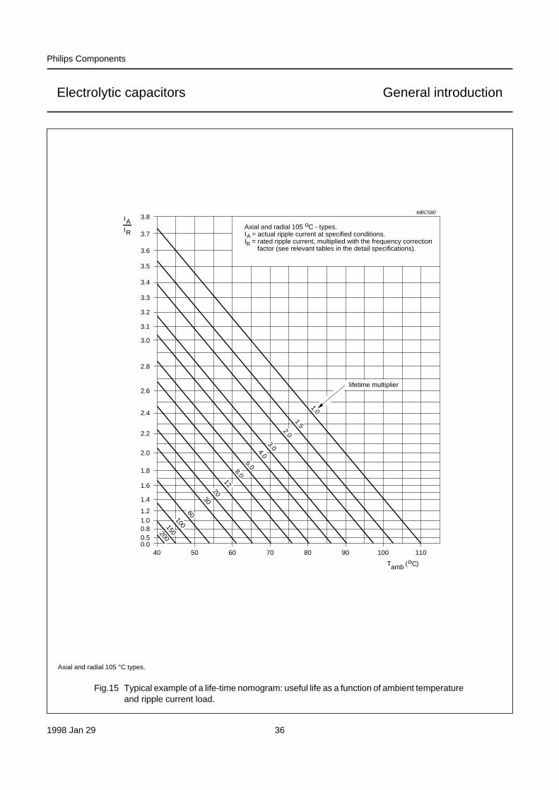
Fig.15 Typical example of a life-time nomogram: useful life as a function of ambient temperatureand ripple current load.
handbook, full pagewidth3.8
3.7
3.6
3.5
3.4
3.3
3.2
3.0
2.8
2.6
2.4
2.2
2.0
1.8
1.6
1.4
1.21.00.80.50.0
3.1
40 50 60 70 80 90 100 110
MBC580
lifetime multiplier
Tamb ( C)o
Axial and radial 105 C - types.I = actual ripple current at specified conditions.I = rated ripple current, multiplied with the frequency correction factor (see relevant tables in the detail specifications).
AR
o
200
10060
20
6.04.0
2.01.5
1.0
30
128.0
150
3.0
IA
RI
Axial and radial 105 °C types.

1998 Jan 29 37
Philips Components
Electrolytic capacitors General introduction
EXAMPLES FOR THE USE OF ‘LIFE-TIME NOMOGRAMS’
Example 1
Temperature in (operating) equipment is 45 °C.
Ripple current load is exactly the rated value (thus:IA/IR = 1).
Which useful life can be expected (without pause andstorage times):
1. for a capacitor with a specified useful life of2000 hours at 85 °C?
2. for a capacitor with a specified useful life of2000 hours at 105 °C?
Solution:
The corresponding life-time multiplier may be found at theintersection between the vertical ‘45 °C’-line and thehorizontal ‘1’-line. For the 85 °C type this is ‘30’ (seeFig.14) and for the 105 °C type it is ‘90’ (see Fig.15).
Resulting useful life is thus:
1. for 85 °C type: 30 × 2000 hours = 60000 hours orabout 7 years
2. for 105 °C type: 90 × 2000 hours = 180000 hours orabout 20 years.
Example 2
Which life time requirement has to be fulfilled by thecapacitors, if the equipment life shall be 10 years(approx. 100000 hours), consisting of 1000 hours at75 °C + 9000 hours at 65 °C + 90000 hours at 40 °C?No ripple current applied (thus: IA/IR = 0).
Solution:
The mentioned life-times shall be converted to specified85 °C or 105 °C life-times, i.e. they have to be dividedthrough the correction factors found at the intersection ofthe respective operational conditions (see Table 4).
The required life-time can be fulfilled by types with aspecified useful life of:
1. >2970 hours at 85 °C i.e. a 3000 hours/85 °C type, or
2. >935 hours at 105 °C i.e. a 1000 hours/105 °C type.
Example 3
Which internal temperature may occur in the equipment,if the actual ripple current at 10 kHz is 3 times higher thanspecified for a 16 V-type and the load limit may not beexceeded?
Solution:
The ripple current must first be converted from 10 kHz to100 Hz by using the conversion table (see typicalexample, Table 3). This shows that the conversion factorfor a 16 V-type is 1.2.
IA/IR = 3 at 10 kHz and must be divided by 1.2, resulting inIA/IR = 2.5 at 100 Hz.
The load limit is defined by the diagonal line ‘multiplier 1’ inthe relevant nomogram.
This means here: the vertical line on the intersection ofIA/IR = 2.5 and the multiplier 1-line shows the maximumpermitted internal temperature:
1. for 85 °C types this is max. 59 °C2. for 105 °C types this is max. 79 °C.
The corresponding life-time in this case is equal to thespecified useful life.
Table 3 Typical example of a frequency conversion table (IR/IRO) as a function of frequency;IRO = ripple current at 100 Hz
FREQUENCY(Hz)
IR MULTIPLIER
UR = 6.3 to 25 V UR = 35 and 40 V UR = 50 and 63 V
50 0.95 0.85 0.80
100 1.00 1.00 1.00
300 1.07 1.20 1.25
1000 1.12 1.30 1.40
3000 1.15 1.35 1.50
≥10000 1.20 1.40 1.60

1998 Jan 29 38
Philips Components
Electrolytic capacitors General introduction
Table 4 Life-time calculation in “Example 2”
LIFE CONDITIONS 85 °C TYPES (see Fig.14) 105 °C TYPES (see Fig.15)
1000 hours at 75 °C 1000/2.9 = 345 hours 1000/8 = 125 hours
9000 hours at 65 °C 9000/6 = 1500 hours 9000/20 = 450 hours
90000 hours at 40 °C 90000/80 = 1125 hours 90000/250 = 360 hours
sum for 85 °C = 2970 hours sum for 105 °C = 935 hours
FAILURE RATE (λ)
The failure rate is defined by the number of componentsfailing within a unit of time, related to the total quantity ofcomponents observed:
or
λ number of failures (statistical upper limit 60%)total number of components duration×-------------------------------------------------------------------------------------------------------------------------=
λ failure percentage (%)100 duration×-----------------------------------------------------------=
however, for an individual component it is not
longer than the specified useful life.
The failure rate (λ) is generally expressed in so-called ‘fit’(failure in time) = 10−9/hours with an upper confidencelevel (UCL) of 60%. It is calculated from results ofperiodical tests in the quality laboratories or derived fromfield observations respectively.
Usually the failure rate during time shows the well known‘bathtub’ curve (see Fig.16).
MTBF 1λ---
=
Fig.16 Failure rate (λ) as a function of time (‘bathtub’ curve).
a) Initial failure period (‘infant mortality’).
b) Random failure period (= useful life period).
c) Wear-out failure period.
handbook, full pagewidth
MBC547
factory customerfailurerate(λ)
(a) (b) (c)
time (t)

1998 Jan 29 39
Philips Components
Electrolytic capacitors General introduction
There are 3 periods in a typical capacitor life cycle:
1. Initial failure period, showing a rapidly decreasingfailure rate. During production of Philips electrolyticcapacitors, initial failures are removed after re-forming(which is a short burn-in); all capacitors shipped, havepassed burn-in.
2. Random failure period, showing a low and constantfailure rate. This period is identical with ‘useful life’.The sum total of all (drift and accident) failures duringthis period, related to the total number of observedcapacitors, is called ‘failure percentage’. Both arespecified in the detail specification of the relevantseries.
3. Wear-out failure period, showing an increasing failurerate due to gradual deterioration.
Since the failure rate mainly depends on two stress factors(temperature and applied voltage), it is usually specifiedunder reference conditions, which are: Tamb = 40 °C andU = 0.5 UR.
For other operational conditions, λ has to be convertedcorrespondingly with the aid of Figs 17 and 18, failurerates as a function of stress factors (T and U/UR) fornon-solid and SAL electrolytic capacitors.
CLIMATIC CATEGORY
For each capacitor range the climatic category inaccordance with “IEC 68-1” is stated in the relevant detailspecification. The climatic category consists of three digitgroups; example given in Table 5.
Fig.17 Conversion factors for failure rate (λ) as a function of ambient temperature (Tamb) andvoltage ratio (U/UR) for non-solid electrolytic capacitors.
handbook, 4 columns
0 20
CCA418
100
Tamb (°C)
10
1
failure ratemultiplying
factor
40 60 8010−1
102
4.102
120 140
U/UR =
0.90.8
0.70.60.50.40.3
1
0.2/0.1

1998 Jan 29 40
Philips Components
Electrolytic capacitors General introduction
Table 5 Example of climatic categories
Example: 40 / 085 / 56
40 lower category temperature (here: −40 °C)
085 upper category temperature (here: +85 °C)
56 duration of test ‘damp heat, steady state’ (here: 56 days)
Fig.18 Conversion factors for failure rate (λ) as a function of ambient temperature (Tamb) andvoltage ratio (U/UR) for SAL electrolytic capacitors.
handbook, full pagewidth
1500 50
CCA425
100
1
failure ratemultiplying
factor
0.9
0.8
0.7
0.6
0.5
0.4
0.30.2/0.1
1
102
10
10−1
U/UR =
Tamb (°C)
1998 Jan 29 41
Philips Components
Electrolytic capacitors General introduction
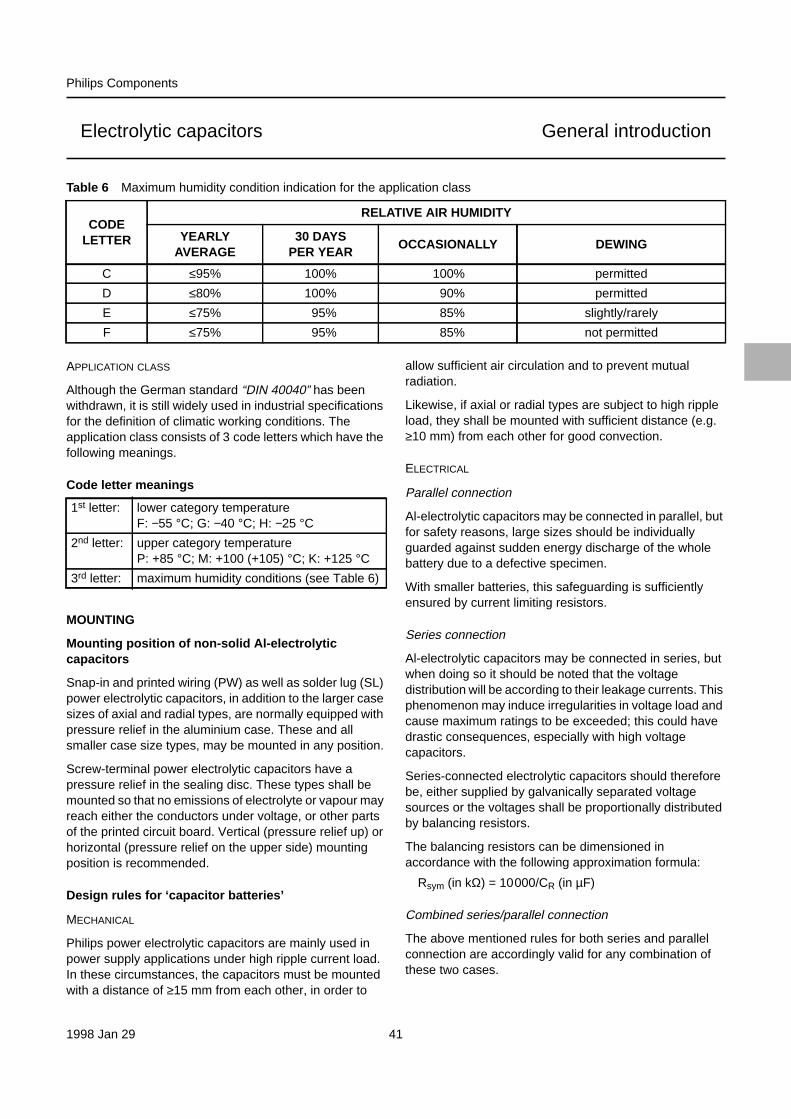
Table 6 Maximum humidity condition indication for the application class
CODELETTER
RELATIVE AIR HUMIDITY
YEARLYAVERAGE
30 DAYSPER YEAR
OCCASIONALLY DEWING
C ≤95% 100% 100% permitted
D ≤80% 100% 90% permitted
E ≤75% 95% 85% slightly/rarely
F ≤75% 95% 85% not permitted
APPLICATION CLASS
Although the German standard “DIN 40040” has beenwithdrawn, it is still widely used in industrial specificationsfor the definition of climatic working conditions. Theapplication class consists of 3 code letters which have thefollowing meanings.
Code letter meanings
MOUNTING
Mounting position of non-solid Al-electrolyticcapacitors
Snap-in and printed wiring (PW) as well as solder lug (SL)power electrolytic capacitors, in addition to the larger casesizes of axial and radial types, are normally equipped withpressure relief in the aluminium case. These and allsmaller case size types, may be mounted in any position.
Screw-terminal power electrolytic capacitors have apressure relief in the sealing disc. These types shall bemounted so that no emissions of electrolyte or vapour mayreach either the conductors under voltage, or other partsof the printed circuit board. Vertical (pressure relief up) orhorizontal (pressure relief on the upper side) mountingposition is recommended.
Design rules for ‘capacitor batteries’
MECHANICAL
Philips power electrolytic capacitors are mainly used inpower supply applications under high ripple current load.In these circumstances, the capacitors must be mountedwith a distance of ≥15 mm from each other, in order to
1st letter: lower category temperatureF: −55 °C; G: −40 °C; H: −25 °C
2nd letter: upper category temperatureP: +85 °C; M: +100 (+105) °C; K: +125 °C
3rd letter: maximum humidity conditions (see Table 6)
allow sufficient air circulation and to prevent mutualradiation.
Likewise, if axial or radial types are subject to high rippleload, they shall be mounted with sufficient distance (e.g.≥10 mm) from each other for good convection.
ELECTRICAL
Parallel connection
Al-electrolytic capacitors may be connected in parallel, butfor safety reasons, large sizes should be individuallyguarded against sudden energy discharge of the wholebattery due to a defective specimen.
With smaller batteries, this safeguarding is sufficientlyensured by current limiting resistors.
Series connection
Al-electrolytic capacitors may be connected in series, butwhen doing so it should be noted that the voltagedistribution will be according to their leakage currents. Thisphenomenon may induce irregularities in voltage load andcause maximum ratings to be exceeded; this could havedrastic consequences, especially with high voltagecapacitors.
Series-connected electrolytic capacitors should thereforebe, either supplied by galvanically separated voltagesources or the voltages shall be proportionally distributedby balancing resistors.
The balancing resistors can be dimensioned inaccordance with the following approximation formula:
Rsym (in kΩ) = 10000/CR (in µF)
Combined series/parallel connection
The above mentioned rules for both series and parallelconnection are accordingly valid for any combination ofthese two cases.

1998 Jan 29 42
Philips Components
Electrolytic capacitors General introduction
MARKINGPhilips electrolytic capacitors are identified in accordance with “IEC” rules. When sufficient space is available,capacitors are marked with the following details:
Rated capacitance in µF (the ‘µ’ sign represents the position of the decimal point)
Rated voltage in V
Tolerance on rated capacitance if necessary, as a letter code in accordance with “IEC 62”, e.g.
T for −10/+50%
M for ±20%
K for ±10%
Q for −10/+30%
A for tolerance according to detail specification
Group number 3-digit part of the catalogue number, e.g. 036 for RSP series
Name of manufacturer PHILIPS or PH or P
Date code abbreviation in 2 digits (“IEC 62”), e.g.
1st digit 2nd digit
D = 1993 1 = January
E = 1994 2 = February
F = 1995 ...
H = 1996 9 = September
J = 1997 O = October
K = 1998 N = November
L = 1999 D = December
example:
F5 = produced in 1995, May
production date may also be stated as year/week code
example: 9525 = produced in 1995, 25th week
Date code may also be stamped in the case.
Factory code indicating the factory of origin
Polarity identification strip, band or negative symbol (‘−’ sign) to indicate the negative terminal and/or a‘+’ sign to identify the positive terminal.
Related Documents