ELECTROCHEMISTRY Principles, Methods, and Applications CHRISTOPHER M. A. BRETT and ANA MARIA OLIVEIRA BRETT Departamento de Quimica, Universidade de Coimbra, Portugal Oxford New York Tokyo OXFORD UNIVERSITY PRESS

Welcome message from author
This document is posted to help you gain knowledge. Please leave a comment to let me know what you think about it! Share it to your friends and learn new things together.
Transcript

ELECTROCHEMISTRYPrinciples, Methods, and Applications
CHRISTOPHER M. A. BRETTand
ANA MARIA OLIVEIRA BRETTDepartamento de Quimica,Universidade de Coimbra,
Portugal
Oxford New York Tokyo
OXFORD UNIVERSITY PRESS

Oxford University Press, Walton Street, Oxford OX2 6DPOxford New York
Athens Auckland Bangkok BombayCalcutta Cape Town Dar es Salaam Delhi
Florence Hong Kong Istanbul KarachiKuala Lumpur Madras Madrid Melbourne
Mexico City Nairobi Paris SingaporeTaipei Tokyo Toronto
and associated companies inBerlin Ibadan
Oxford is a trade mark of Oxford University Press
Published in the United Statesby Oxford University Press Inc., New York
© Christopher M. A. Brett and Ana Maria Oliveira Brett, 1993First published 1993
Reprinted 1994
All rights reserved. No part of this publication may bereproduced, stored in a retrieval system, or transmitted, in any
form or by any means, without the prior permission in writing of OxfordUniversity Press. Within the UK, exceptions are allowed in respect of anyfair dealing for the purpose of research or private study, or criticism or
review, as permitted under the Copyright, Designs and Patents Act, 1988, orin the case of reprographic reproduction in accordance with the terms oflicences issued by the Copyright Licensing Agency. Enquiries concerningreproduction outside those terms and in other countries should be sent tothe Rights Department, Oxford University Press, at the address above.
This book is sold subject to the condition that it shall not,by way of trade or otherwise, be lent, re-sold, hired out, or otherwisecirculated without the publisher's prior consent in any form of bindingor cover other than that in which it is published and without a similar
condition including this condition being imposedon the subsequent purchaser.
A catalogue record for this book is available from the British Library
Library of Congress Cataloging in Publication DataBrett, Christopher M. A.
Electrochemistry: principles, methods, and applications/Christopher M. A. Brett and Ana Maria Oliveira Brett.
Includes bibliographical references.1. Electrochemistry. I. Brett, Ana Maria Oliveira. II. Title.
QD553.B74 1993 541.3'7-dc20 92-29087ISBN 0 19 855389 7 (Hbk)ISBN 0 19 855388 9 (Pbk)
Printed in Great Britainby Bookcraft (Bath) Ltd.,Midsomer Norton, Avon

PREFACE
Electrochemistry has undergone significant transformations in the lastfew decades. It is not now the province of academics interested only inmeasuring thermodynamic properties of solutions or of industrialistsusing electrolysis or manufacturing batteries, with a huge gulf betweenthem. It has become clear that these two, apparently distinct subjects,and others, have a common ground and they have grown towards eachother, particularly as a result of research into the rates of electrochemicalprocesses. Such an evolution is due to a number of factors, butprincipally the possibility of carrying out reproducible, dynamic experi-ments under an ever-increasing variety of conditions with reliable andsensitive instrumentation. This has enabled many studies of a fundamen-tal and applied nature to be carried out.
The reasons for this book are twofold. First to show the all-pervasiveand interdisciplinary nature of electrochemistry, and particularly ofelectrode reactions, through a description of modern electrochemistry.Secondly to show to the student and the non-specialist that this subject isnot separated from the rest of chemistry, and how he or she can use it.Unfortunately, these necessities are, in our view, despite efforts overrecent years, still very real.
The book has been organized into three parts, after Chapter 1 asgeneral introduction. We have begun at a non-specialized, undergraduatelevel and progressed through to a relatively specialized level in eachtopic. Our objective is to transmit the essence of electrochemistry andresearch therein. It is intended that the chapters should be as independ-ent of one another as possible. The sections are: Chapters 2-6 on thethermodynamics and kinetics of electrode reactions, Chapters 7-12 onexperimental strategy and methods, and Chapters 13-17 on applications.Also included are several appendices to explain the mathematical basis inmore detail. It is no accident that at least 80 per cent of the book dealswith current-volt age relations, and not with equilibrium. The essence ofany chemical process is change, and reality reflects this.
We have not filled the text with lots of details which can be found inthe references given, and, where appropriate, we make ample referenceto recent research literature. This is designed to kindle the enthusiasmand interest of the reader in recent, often exciting, advances in the topicsdescribed.
A major preoccupation was with notation, given the traditionallydifferent type of language that electrochemists have used in relation to
viii Preface
other branches of chemistry, such as exchange current which measuresrate constants, and given differences in usage of symbols betweendifferent branches of electrochemistry. Differences in sign conventionsare another way of confusing the unwary beginner. We have decidedbroadly to follow IUPAC recommendations.
Finally some words of thanks to those who have helped and influencedus throughout our life as electrochemists. First to Professor W. J. AlberyFRS, who introduced us to the wonders of electrochemistry and to eachother. Secondly to our many colleagues and students who, over the years,with their comments and questions, have aided us in deepening ourunderstanding of electrochemistry and seeing it with different eyes.Thirdly to anonymous referees, who made useful comments based on adetailed outline for the book. And last, but not least, to OxfordUniversity Press for its interest in our project and enabling us to bring itto fruition.
Coimbra C.M.A.B.May 1992 A.M.O.B.
ACKNOWLEDGEMENTS
Full bibliographical references to all material reproduced are to be foundat the ends of the respective chapters.
Figure 3.4 is reprinted with permission from D. C. Grahame, Chem.Rev.y 1947, 41, 441. Copyright 1947 American Chemical Society; Fig 7.1is reprinted with permission from G. M. Jenkins and K. Kawamura,Nature, 1971, 231, 175. Copyright 1971 Macmillan Magazines Ltd; Fig.8.2c is reprinted by permission of the publisher, The ElectrochemicalSociety Inc., Fig. 9.10a is reprinted with permission from R. S. Nicholsonand I. Shain, Anal. Chem., 1964, 36, 706. Copyright 1964 AmericanChemical Society; Fig. 12.3 is reprinted by permission of John Wiley &Sons Inc. from J. D. E. Macintyre, Advances in electrochemistry andelectrochemical engineering, 1973, Vol. 9, ed. R. H. Muller, p. 122.Copyright © 1973 by John Wiley & Sons, Inc.; Fig. 12.15a is reprintedwith permission by VCH Publishers © 1991; Fig. 12.15b is reprinted withpermission from R. Yang, K. Naoz, D. F. Evans, W. H. Smyrl and W.A. Hendrickson, Langmuir, 1991, 7, 556. Copyright 1991 AmericanChemical Society; Fig. 15.9 is reproduced from J. P. Hoare and M. L.LaBoda, Comprehensive treatise of electrochemistry, 1981, Vol. 2, ed. J.O'M. Bockris et al., p. 448, by permission of the publisher, PlenumPublishing Corporation; Fig. 16.7 is reproduced by kind permission of thecopyright holder, National Association of Corrosion Engineers; Fig. 17.3is reproduced from S. Ohki, Comprehensive treatise of electrochemistry,1985, Vol. 10, ed. S. Srinivasan et al, p. 94, by permission of thepublisher, Plenum Publishing Corporation; Fig. 17.6 is reproduced fromR. Pethig, Modern bioelectrochemistry, ed. F. Gutmann and H. Keyser,1986, p. 201, by permission of the publisher, Plenum PublishingCorporation; Fig. 17.7 is reprinted with permission from M. J. Eddowesand H. A. O. Hill, /. Am. Chem. Soc, 1979, 101, 4461. Copyright 1979American Chemical Society; Fig. 17.9 is reproduced from M. Tarasevich,Comprehensive treatise of electrochemistry, 1985, Vol. 10, ed. S. Sriniva-san et al., p. 260, by permission of the publisher, Plenum PublishingCorporation; Fig. 17.11 is reproduced with the kind permission of theInstitute of Measurement and Control; Table 2.2 is reproduced by kindpermission of Butterworth-Heinemann Ltd; Table 7.1 is reprinted fromR. L. McCreery, Electroanalytical chemistry, 1991, Vol. 17, ed. A. J.Bard, p. 243, by courtesy of Marcel Dekker Inc.; Table 7.3 is reprintedby permission of John Wiley & Sons Inc. from D. T. Sawyer and J. L.Roberts, Experimental electrochemistry for chemists, 1974, Copyright ©

x Acknowledgements
191A by John Wiley & Sons, Inc.; Tables 9.1 and 9.2 are reprinted withpermission from R. S. Nicholson and I. Shain, Anal. Chem., 1964, 36,706. Copyright 1964 American Chemical Society; Table 9.3 is reprintedwith permission from R. S. Nicholson, Anal. Chem.y 1965, 37, 1351,copyright 1965 American Chemical Society, and from S. P. Perone, Anal.Chem.y 1966, 38, 1158, copyright 1966 American Chemical Society;Table 15.2 is reprinted by permission of the publisher, The Electrochem-ical Society Inc.; Table 17.1 is reproduced from H. Berg, Comprehensivetreatise of electrochemistry, 1985, Vol. 10, ed. S. Srinivasan et al., p. 192,by permission of the publisher, Plenum Publishing Corporation; Table17.2 is reproduced from S. Srinivasan, Comprehensive treatise ofelectrochemistry, 1985, Vol. 10, ed. S. Srinivasan et al.y p. 476, bypermission of the publisher, Plenum Publishing Corporation.
The following are also thanked for permission to reproduce or reprintcopyright material: Bioanalytical Systems Inc. for Fig. 14.8; ElsevierScience Publishers BV for Figs 8.3, 8.4, 8.6, 8.7, 11.7, Tables 8.1 and 8.2;Elsevier Sequoia SA for Figs 9.11, 9.12, 9.15, 12.4, 12.8, 12.20, and 14.3;Journal of Chemical Education for Fig. 9.13a; Kluwer Academic Publ-ishers for Fig. 3.10; R. Kotz for Fig. 12.1; Oxford University Press forFigs 2.11, 2.12, and 17.10; Royal Society of Chemistry for Table 14.2.
Although every effort has been made to trace and contact copyrightholders, in a few instances this has not been possible. If notified thepublishers will be pleased to rectify any omission in future editions.
CONTENTS
Notation and Units xxiMain Symbols xxiiSubscripts xxviAbbreviations xxviiFundamental physical constants xxixMathematical constants xxixUseful relations at 25°C (298.15 K) involving fundamentalconstants xxix
1 I N T R O D U C T I O N 11.1 The scope of electrochemistry 11.2 The nature of electrode reactions 11.3 Thermodynamics and kinetics 21.4 Methods for studying electrode reactions 51.5 Applications of electrochemistry 51.6 Structure of the book 61.7 Electrochemical literature 7
PART I Principles
2 ELECTROCHEMICAL CELLS:THERMODYNAMIC PROPERTIES ANDELECTRODE POTENTIALS 132.1 Introduction 132.2 The cell potential of an electrochemical cell 142.3 Calculation of cell potential: activities or
concentrations? 162.4 Calculation of cell potential: electrochemical potential . 182.5 Galvanic and electrolytic cells 202.6 Electrode classification 212.7 Reference electrodes 222.8 Movement of ions in solution: diffusion and migration . 252.9 Conductivity and mobility 262.10 Liquid junction potentials 322.11 Liquid junction potentials, ion-selective electrodes, and
biomembranes 332.12 Electrode potentials and oxidation state diagrams . . . 34
References 38

xii Contents
3 T H E I N T E R F A C I A L R E G I O N 393.1 Introduction 393.2 The electrolyte double layer: surface tension, charge
density, and capacity 393.3 Double layer models 44
the first models: Helmholtz, Gouy-Chapman, Stern,and Grahame 45Bockris, Devanathan, and Muller model 51'chemical' models 52
3.4 Specific adsorption 543.5 The solid metallic electrode: some remarks 563.6 The semiconductor electrode: the space-charge region . 583.7 Electrokinetic phenomena and colloids: the zeta
potential 64electrophoresis 66sedimentation potential 67electroosmosis 67streaming potential 68limitations in the calculation of the zeta potential . . 68
References 68
4 F U N D A M E N T A L S O F K I N E T I C S A N DM E C H A N I S M O F E L E C T R O D ER E A C T I O N S 704.1 Introduction 704.2 The mechanism of electron transfer at an electrode . . 704.3 The mechanism of electron transfer in homogeneous
solution 714.4 An expression for the rate of electrode reactions . . . 724.5 The relation between current and reaction rate: the
exchange current 764.6 Microscopic interpretation of electron transfer . . . . 77
References 81
5 MASS T R A N S P O R T 825.1 Introduction 825.2 Diffusion control 835.3 Diffusion-limited current: planar and spherical
electrodes 855.4 Constant current: planar electrodes 905.5 Microelectrodes 925.6 Diffusion layer 94

Contents xiii
5 . 7 C o n v e c t i o n a n d d i f fus ion : h y d r o d y n a m i c s y s t e m s . . . 955 .8 H y d r o d y n a m i c s y s t e m s : s o m e u s e f u l p a r a m e t e r s . . . . 9 75.9 A n e x a m p l e o f a c o n v e c t i v e - d i f f u s i o n s y s t e m : t h e
r o t a t i n g d i s c e l e c t r o d e 9 8R e f e r e n c e s 102
KINETICS AND TRANSPORT INE L E C T R O D E REACTIONS 1036.1 Introduction 1036.2 The global electrode process: kinetics and transport . . 1036.3 Reversible reactions 1066.4 Irreversible reactions 1096.5 The general case I l l6.6 TheTafellaw 1136.7 The Tafel law corrected for transport 1156.8 Kinetic treatment based on exchange current 1156.9 The effect of the electrolyte double layer on electrode
kinetics 1166.10 Electrode processes involving multiple electron transfer 1196.11 Electrode processes involving coupled homogeneous
reactions 122References 126
PART II Methods
E L E C T R O C H E M I C A L E X P E R I M E N T S . . . . 1297.1 Introduction 1297.2 Electrode materials for voltammetry 129
metals 130carbon 130other solid materials 133mercury 133
7.3 The working electrode: preparation and cleaning . . . 1347.4 The cell: measurements at equilibrium 1367.5 The cell: measurements away from equilibrium . . . . 137
electrodes 137supporting electrolyte 138removal of oxygen 140
7.6 Calibration of electrodes and cells 1427.7 Instrumentation: general 142
xiv Contents
7.8 Analogue instrumentation 143potentiostat 146galvanostat 147compensation of cell solution resistance 148
7.9 Digital instrumentation 148References 149
8 H Y D R O D Y N A M I C E L E C T R O D E S 151
8.1 Introduction 1518.2 Limiting currents at hydrodynamic electrodes 1558.3 A special electrode: the dropping mercury electrode . . 1578.4 Hydrodynamic electrodes in the study of electrode
processes 163reversible reaction 163the general case 164
8.5 Double hydrodynamic electrodes 1658.6 Multiple electron transfer: the use of the RRDE . . . 167
consecutive reactions 168parallel reactions 168consecutive and parallel reactions 169
8.7 Hydrodynamic electrodes in the investigation of coupledhomogeneous reactions 169
8.8 Hydrodynamic electrodes and non-stationary techniques 171References 172
9 CYCLIC VOLTAMMETRY AND LINEARSWEEP TECHNIQUES 1749.1 Introduction 1749.2 Experimental basis 1759.3 Cyclic voltammetry at planar electrodes 176
reversible system 177irreversible system 181quasi-reversible system 183adsorbed species 185
9.4 Spherical electrodes 1879.5 Microelectrodes 1889.6 Systems containing more than one component 1889.7 Systems involving coupled homogeneous reactions . . . 1899.8 Convolution linear sweep voltammetry 1919.9 Linear potential sweep with hydrodynamic electrodes . 1939.10 Linear potential sweep in thin-layer cells 194
References 197
Contents xv
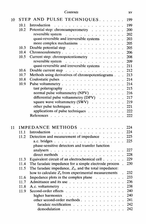
10 S T E P A N D P U L S E T E C H N I Q U E S 19910.1 Introduction 19910.2 Potential step: chronoamperometry 200
reversible system 202quasi-reversible and irreversible systems 203more complex mechanisms 205
10.3 Double potential step 20510.4 Chronocoulometry 20610.5 Current step: chronopotentiometry 208
reversible system 209quasi-reversible and irreversible systems 211
10.6 Double current step 21210.7 Methods using derivatives of chronopotentiograms . . . 21310.8 Coulostatic pulses 21410.9 Pulse voltammetry 214
tast polarography 215normal pulse voltammetry (NPV) 216differential pulse voltammetry (DPV) 217square wave voltammetry (SWV) 219other pulse techniques 221applications of pulse techniques 222
References 222
11 IMPEDANCE METHODS 22411.1 Introduction 22411.2 Detection and measurement of impedance 225
a.c. bridges 225phase-sensitive detectors and transfer functionanalysers 227direct methods 228
11.3 Equivalent circuit of an electrochemical cell 22911.4 The faradaic impedance for a simple electrode process . 23011.5 The faradaic impedance, Zf, and the total impedance:
how to calculate Zf from experimental measurements . 23211.6 Impedance plots in the complex plane 23311.7 Admittance and its use 23611.8 A.c. voltammetry 23811.9 Second-order effects 240
higher harmonics 240other second-order methods 241
faradaic rectification 242demodulation 242

xvi Contents
11.10 More complex systems, porous electrodes, and fractals . 24411.11 Нуdrodynamic electrodes and impedance 24811.12 Transforms and impedance 249
References 251
12 N O N - E L E C T R O C H E M I C A L P R O B E S OFE L E C T R O D E S A N D E L E C T R O D EP R O C E S S E S 253
12.1 Introduction 25312.2 In situ spectroscopic techniques 254
transmission 254reflectance, electroreflectance and ellipsometry . . . 255internal reflection 258Raman spectroscopy 259electron spin resonance (ESR) spectroscopy . . . . 260X-ray absorption spectroscopy 261second harmonic generation (SHG) 263
12.3 Ex situ spectroscopic techniques 263photoelectron spectroscopy (XPS) 263Auger electron spectroscopy (AES) 264electron energy loss spectroscopy (EELS) 266electrochemical mass spectrometry (ECMS)
and secondary ion mass spectrometry (SIMS) . . . 266low-energy and reflection high-energy electron
diffraction (LEED and RHEED) 26712.4 In situ microscopic techniques 268
scanning tunnelling microscopy (STM) 269atomic force microscopy (AFM) 270scanning electrochemical microscopy (SECM) . . . . 272scanning ion conductance microscopy (SICM) . . . . 273
12.5 Ex situ microscopic techniques: electron microscopy . . 27312.6 Other in situ techniques 276
measurement of mass change: the quartz crystalmicrobalance (QCM) 276measurement of absorbed radiation: thermal changes 277
12.7 Photoelectrochemistry 27812.8 Electrochemiluminescence 282
References 282
PART III Applications
13 P O T E N T I O M E T R I C S E N S O R S 289
13.1 Introduction 289

Contents xvii
13.2 Potentiometric titrations 29013.3 Functioning of ion-selective electrodes 29413.4 Glass electrodes and pH sensors 29513.5 Electrodes with solid state membranes 29713.6 Ion-exchange membrane and neutral carrier membrane
electrodes 30113.7 Sensors selective to dissolved gases 30313.8 Enzyme-selective electrodes 30313.9 Some practical aspects 30413.10 Recent developments: miniaturization 305
ISFETs 305coated wire electrodes 306hybrid sensors 307
13.11 Potentiometric sensors in flow systems 30713.12 Electroanalysis with potentiometric sensors 308
References 309
14 A M P E R O M E T R I C A N D V O L T A M M E T R I CS E N S O R S 310
14.1 Introduction 31014.2 Amperometric titrations 311
simple amperometric titrations 311biamperometric titrations 312amperometric titrations with double hydrodynamicelectrodes 313
14.3 Membrane and membrane-covered electrodes 31414.4 Modified electrodes . 3 1 614.5 Increase of sensitivity: pre-concentration techniques . . 31814.6 Amperometric and voltammetric electroanalysis . . . . 322
References 324
15 E L E C T R O C H E M I S T R Y IN I N D U S T R Y . . . . 326
15.1 Introduction 32615.2 Electrolysis: fundamental considerations 32715.3 Electrochemical reactors 32815.4 Porous and packed-bed electrodes 33115.5 Examples of industrial electrolysis and electrosynthesis . 332
the chlor-alkali industry 332metal extraction: aluminium 336water electrolysis 338organic electrosynthesis: the Monsanto process . . . 339
15.6 Electrodeposition and metal finishing 34115.7 Metal processing 345

xvjjj Contents
15.8 Batteries 34615.9 Fuel cells 34915.10 Electrochemistry in water and effluent treatment . . . 350
References 351
16 C O R R O S I O N 35316.1 Introduction 35316.2 Fundamentals 353
thermodynamic aspects 354kinetic aspects 354
16.3 Types of metallic corrosion 36116.4 Electrochemical methods of avoiding corrosion . . . . 363
electrochemically produced protective barriers . . . 364sacrificial anodes 364methods of impressed current/potential 365corrosion inhibitors 365
References 366
17 B I O E L E C T R O C H E M I S T R Y 36717.1 Introduction 36717.2 The electrochemical interface between biomolecules:
cellular membranes, transmembrane potentials, bilayerlipid membranes, electroporation 368
17.3 Nerve impulse and cardiovascular electrochemistry . . 373the nerve impulse 374cardiovascular problems 376
17.4 Oxidative phosphorylation 37817.5 Bioenergetics 37917.6 Bioelectrocatalysis 38117.7 Bioelectroanalysis 38717.8 Future perspectives 391
References 391
Appendices
Al USEFUL M A T H E M A T I C A L RELATIONS . . 395Al.l The Laplace transform 395
introduction 395the transform 395important properties 397
A1.2 The Fourier transform 398

Contents xix
A1.3 Other useful functions and mathematical expressions . 399the Airy function 399the gamma function 399the error function 400Taylor and Maclaurin series 401hyperbolic functions 403
Reference 404
A2 P R I N C I P L E S OF A . C . C I R C U I T S 405
A2.1 Introduction 405A2.2 Resistance 406A2.3 Capacitance 406A2.4 Representation in the complex plane 406A2.5 Resistance and capacitance in series 407A2.6 Resistance and capacitance in parallel 408A2.7 Impedances in series and in parallel 410A2.8 Admittance 410A2.9 The Kramers-Kronig relations 410
References 411
A3 D I G I T A L S I M U L A T I O N 412
A3.1 Introduction 412A3.2 Simulation models 412A3.3 Implicit methods 414
References 414
A4 S T A N D A R D E L E C T R O D E P O T E N T I A L S . . 416
INDEX 419

Notation and Units
As far as possible without straying too far from common usage, theguidelines of IUPAC have been followed, described in Quantities, unitsand symbols in physical chemistry (Blackwell, Oxford, 1988). Other,more detailed information has been taken from the following sources inthe IUPAC journal, Pure and Applied Chemistry:
'Electrode reaction orders, transfer coefficients and rate constants.Amplification of definitions and recommendations for publication ofparameters', 1979, 52, 233.Tnterphases in systems of conducting phases', 1986, 58, 454.'Electrochemical corrosion nomenclature', 1989, 61, 19.Terminology in semiconductor electrochemistry and photo-electrochemical energy conversion', 1991, 63, 569.'Nomenclature, symbols, definitions and measurements for electrifiedinterfaces in aqueous dispersions of solids', 1991, 63, 896.
The units quoted are those recommended. In practice, in electrochem-istry, much use is made of sub-multiples: for example, cm instead of mand JUA or mA instead of A, for obvious reasons. The text tends to usethe commonly employed units.
In the list of symbols, those used at only one specific point in the textare mostly omitted, in order to try and reduce the length of the list,since explanation of their meaning can be found next to the relevantequation. We have also provided a list of frequently used subscripts, alist of abbreviations, and values of important constants and relationsderived from these.
Following recommended usage, loge is written as In and log10 iswritten as lg.

Notation: main symbols
UnitsаааААЬс
С
DеЕЕ
Ес
Eg
Еу
EF
L-* rcdox
f
activitynozzle diameter of impinging jetradius of colloidal particlearea'constant'Tafel slopeconcentration
c() concentration at electrode surfaceCoo bulk concentration
capacityCd differential capacity of double layerC; integral capacity of double layerCs capacity in RC series combinationCsc capacity of semiconductor space-charge
layerdiffusion coefficientelectron chargeelectric field strengthelectrode potential
Z?"0" standard electrode potentialE^r formal potential£cel, cell potential (electromotive force)Ecor corrosion potentialEV2 half-wave potential£j liquid junction potentialEm membrane potentialEp peak potentialEz potential of zero chargeEx inversion potential in cyclic voltammetry
lowest energy of semiconductor conduction bandbandgap energy in semiconductorhighest energy of semiconductor valence bandFermi energyenergy of redox couplefrequency
—mmm2
variesV"1
mol m~3
F
m2s - 1
СVm"1
V
eVeVeVeVeVHz

Notation: main symbols xxiii
/DL
FggGhHI
IjJ
к
КImmt
mnn'
и,P
PiPPe
Qr
Frumkin double layer correctionforceacceleration due to gravityconstant in Temkin and Frumkin isothermsGibbs free energyheightenthalpy at constant pressureelectric current
/ c capacitative current/f faradaic current/L diffusion limited current/p peak current
ionic strengthelectric current densityvolume fluxrate constant: homogeneous first orderrate constant: heterogeneous
ka rate constant for oxidation at electrodekc rate constant for reduction at electrodekd mass transfer coefficient
potentiometric selectivity coefficientequilibrium constantlength of electrodemassmass flux of liquidmolalitynumber of electrons transferrednumber of electrons transferred in rate determiningstepnumber density of species i(DO/DR)S where s = 1/2 (stationary electrodes andDMEs), s = 2/3 (hydrodynamic electrodes), s = 1(microelectrodes)partial pressure of ipressure (total)Peclet number (Pe = vl/D)electric chargeradial variable
—Nm s " 2
—J m o P 1
mJ m o P 1
A
molm~Am" 2
s"1
ms" 1
——m
kgkgs"1
kgm-3
m~3
—PaPa—Сm
r 0 radius of (hemi-)spherical e l e c t r o d erx radius of disc e lectroder2 inner radius of ring e lect roder3 o u t e r radius of ring e lect roderc capillary radius

xxiv Notation: main symbols
R resistance QRct charge transfer resistanceRs resistance in RC series combinationJRQ cell solution resistance
R radius of tube mRe Reynolds number (Re = vl/v) —S entropy J т о Г l K"1
Sc Schmidt number (5c = v/D) —Sh Sherwood number (Sh = kJ/D) —t time sti transport number of species / —T temperature Кщ mobility of species i m2 V" l s~l
ue electrophoretic mobilityU potential (same meaning as E, used in photo- and
semiconductor electrochemistry) VUfb flat-band potential
v velocity m s " 1
v potential scan rate V s"1
V voltage (in operational amplifiers, etc.) VV volume m 3
V{ volume flow rate m 3 s~l
W rotation speed Hzx distance mX reactance QV admittance Sz ion charge —Z impedance Q
Z s impedance of R C series combinationZ ' real part of impedanceZ " imaginary part of impedanceZ f Faradaic impedanceZ w Warburg impedance
oc electrochemical charge transfer coefficient —a& anodicac cathodic
a electrode roughness parameter —a double hydrodynamic electrode geometric constant —/3 double hydrodynamic electrode geometric constant —P Esin-Markov coefficient —/3 energetic proportionality coefficient —

Notation: main symbols xxv
УУУ
г
€
ч
ввкА
Л
£V
V
V
р
ааатФ00
\р(0
(0
activity coefficientsurface tensiondimensionless concentration variablesurface excess concentrationdiffusion layer thicknesshydrodynamic boundary layer thicknessmolar absorption coefficientpermittivitypermittivity of vacuumrelative permittivityporosity of materialzeta (electrokinetic) potential(nF/RT)(E-E1/2)overpotentialviscositycontact anglefractional surface coverageexp [(nF/RT)(E - E^)]conductivityvalue of t where sweep is inverted in cyclicvoltammetrymolar conductivitychemical potentialelectrochemical potentialfrequency of electromagnetic radiationstoichiometric numberkinematic viscosityresistivitydensitysurface charge densityv(nF/RT)mass-transport dependent expression (Table 8.2)characteristic time in experimentelectrostatic potentialinner electric potentialphase anglesurface electric potentialouter electric potentialangular velocity, rotation speedcircular frequency
—N m " 1
—mol m~2
mmn^mol"1
Fin"1
Fm"1
——V—VPas
——Sm"1
sS m2 molJmol"1
Jmol"1
s"1
—m2s"x
Q m
kgm"3
Cm"2
s"1
sVV
VVrads"1
rads"1
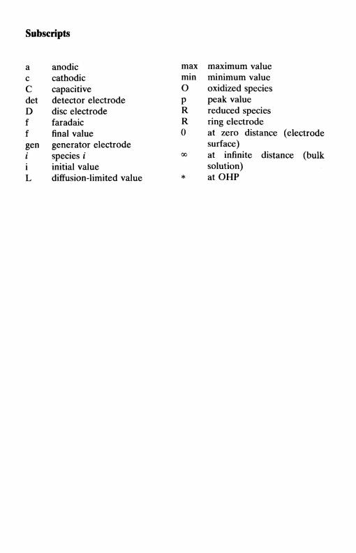
Subscripts
a anodicс cathodicС capacitivedet detector electrodeD disc electrodef faradaicf final valuegen generator electrodei species ii initial valueL diffusion-limited value
max maximum valuemin minimum valueО oxidized speciesp peak valueR reduced speciesR ring electrode0 at zero distance (electrode
surface)<*> at infinite distance (bulk
solution)* at OHP

Abbreviations
AES Auger electron spectroscopyAFM atomic force microscopyASV anodic stripping voltammetryAdSV adsorptive stripping voltammetryBLM bilayer lipid membraneCDE channel double electrodeCE electrode process involving chemical followed by
electrochemical stepC'E catalytic electrode process involving chemical followed by
electrochemical stepCV cyclic voltammetryDDPV differential double pulse voltammetryDISP electrode process involving electrochemical followed by
chemical, followed by disproportionation step to regeneratereagent
DME dropping mercury electrodeDNPV differential normal pulse voltammetryDPV differential pulse voltammetryDSA dimensionally stable anodeEC electrode process involving electrochemical followed by
chemical stepECE electrode process involving electrochemical followed by
chemical, followed by electrochemical stepECL electrochemiluminescenceECMS electrochemical mass spectroscopyEELS electron energy loss spectroscopyEMIRS electrochemically modulated infrared spectroscopyEQCM electrochemical quartz crystal microbalanceESR electron spin resonanceEXAFS extended X-ray absorption fine structureFFT fast Fourier transformGC glassy carbonHMDE hanging mercury drop electrodeHOPG highly oriented pyrolytic graphiteHPLC high-performance liquid chromatographyIHP inner Helmholtz plane

XXV111 Abbreviations
IRRAS infrared reflection absorption spectroscopyISE ion-selective electrodeISFET ion-selective field effect transistorISM ion-selective membraneLEED low-energy electron diffractionLSV linear sweep voltammetryMCFC molten carbonate fuel cellMS mass spectrometryNHE normal hydrogen electrodeNPV normal pulse voltammetryOA operational amplifierOHP outer Helmholtz planeOTE optically transparent electrodeOTTLE optically transparent thin-layer electrodePAFC phosphoric acid fuel cellPAS photoacoustic spectroscopyPSA potentiometric stripping analysisQCM quartz crystal microbalanceRDE rotating disc electrodeRHEED reflection high-energy electron diffractionRRDE rotating ring-disc electrodeSCC stress corrosion crackingSCE saturated calomel electrodeSCM surface compartment modelSECM scanning electrochemical microscopySEM scanning electron microscopySHG second harmonic generationSICM scanning ion conductance microscopySIMS secondary ion mass spectroscopySMDE static mercury drop electrodeSNIFTRS subtractively normalized interfacial Fourier transi
infrared spectroscopySOFC solid oxide fuel cellSTM scanning tunnelling microscopySWV square wave voltammetryTDE tube double electrodeТЕМ transmission electron microscopyWJRDE wall-jet ring-disc electrodeXANES X-ray absorption near edge structureXPS X-ray photoelectron spectroscopy

Fundamental physical constants
с speed of light in vacuume unit of electron chargeF Faraday constantkB Boltzmann constantR gas constanth Planck constantNA Avogadro constante0 permittivity of vacuumg acceleration due to gravity
2.99792458 x l O ^ s " 1
1.602177 х Н Г 1 9 С9.6485 xlO 4 С т о Г 1
1.38066 x l ( T 2 3 J К" 1
8.31451 J КГ1 т о Г 1
6.62608 x ИГ 3 4 Js6.02214 х К Р т о Г 1
8.85419 x 10~12 Г 1 С2 т " 1
9.80665 ms~ 2
Mathematical constants
eIn 10
3.141592653592.718281828462.302585
Useful relations at 25°C (298.15 K) involving fundamentalconstants
RT/F(RTУ F) In 10kBT
25.693 mV59.160 mV25.7 meV (4.12 xlO~ 2 1J)

INTRODUCTION
1.1 The scope of electrochemistry1.2 The nature of electrode reactions1.3 Thermodynamics and kinetics1.4 Methods for studying electrode reactions1.5 Applications of electrochemistry1.6 Structure of the book1.7 Electrochemical literature
1.1 The scope of electrochemistry
Electrochemistry involves chemical phenomena associated with chargeseparation. Often this charge separation leads to charge transfer, whichcan occur homogeneously in solution, or heterogeneously on electrodesurfaces. In reality, to assure electroneutrality, two or more chargetransfer half-reactions take place, in opposing directions. Except in thecase of homogeneous redox reactions, these are separated in space,usually occurring at different electrodes immersed in solution in a cell.These electrodes are linked by conducting paths both in solution (viaionic transport) and externally (via electric wires etc.) so that charge canbe transported. If the cell configuration permits, the products of the twoelectrode reactions can be separated. When the sum of the free energychanges at both electrodes is negative the electrical energy released canbe harnessed (batteries). If it is positive, external electrical energy can besupplied to oblige electrode reactions to take place and convert chemicalsubstances (electrolysis).
In this chapter, a brief overview of electrochemistry, and particularlyof electrode reactions, is given in order to show the interdisciplinarynature and versatility of electrochemistry and to introduce a few of theimportant fundamental concepts. Before discussing these it is worthlooking briefly at the nature of electrode reactions.
1.2 The nature of electrode reactions
Electrode reactions are heterogeneous and take place in the interfacialregion between electrode and solution, the region where charge distribu-

2 Introduction
tion differs from that of the bulk phases. The electrode process is affectedby the structure of this region. However, we first assume that there is noeffect apart from charge separation. At each electrode, charge separationcan be represented by a capacitance and the difficulty of charge transferby a resistance. For the rest of this and the ensuing sections we consideronly one of the electrodes.
The electrode can act as only a source (for reduction) or a sink (foroxidation) of electrons transferred to or from species in solution, as in
where О and R are the oxidized and reduced species, respectively.Alternatively, it can take part in the electrode reaction, as in dissolutionof a metal M:
М-н>М"+ + ие-In order for electron transfer to occur, there must be a correspondence
between the energies of the electron orbitals where transfer takes place inthe donor and acceptor. In the electrode this level is the highest filledorbital, which in a metal is the Fermi energy level, EF. In soluble speciesit is simply the orbital of the valence electron to be given or received.Thus:
• for a reduction, there is a minimum energy that the transferableelectrons from the electrode must have before transfer can occur, whichcorresponds to a sufficiently negative potential (in volts)
• for an oxidation, there is a maximum energy that the lowestunoccupied level in the electrode can have in order to receive electronsfrom species in solution, corresponding to a sufficiently positive potential(in volts).The values of the potentials can be controlled externally. In this way wecan control which way an electrode reaction occurs and to what extent.
The thermodynamics and kinetics of electrode processes are sum-marized in the following section. However, before this we return to thestructure of the interfacial region. The change in charge distribution fromthe bulk in this region means that the relevant energy levels in reactingspecies and in the electrode are not the same as in the bulk phases, andsoluble species need to adjust their conformation for electron transfer tooccur. These effects should be corrected for in a treatment of kinetics ofelectrode processes—the thinner the interfacial region the better, and thiscan be achieved by addition of a large concentration of inert electrolyte.
1.3 Thermodynamics and kinetics
Electrode reactions are half-reactions and are, by convention, expressedas reductions. Each has associated with it a standard electrode potential,
1.3 Thermodynamics and kinetics 3
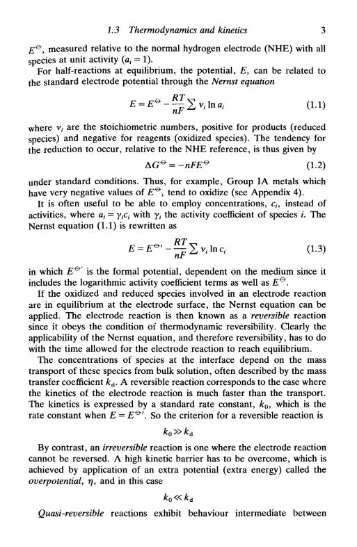
E&
y measured relative to the normal hydrogen electrode (NHE) with allspecies at unit activity (я, = 1).
For half-reactions at equilibrium, the potential, E, can be related tothe standard electrode potential through the Nernst equation
^ (1.1)
where v, are the stoichiometric numbers, positive for products (reducedspecies) and negative for reagents (oxidized species). The tendency forthe reduction to occur, relative to the NHE reference, is thus given by
AG^=-nFE^ (1.2)
under standard conditions. Thus, for example, Group IA metals whichhave very negative values of £ ° , tend to oxidize (see Appendix 4).
It is often useful to be able to employ concentrations, ch instead ofactivities, where at = у{с{ with y, the activity coefficient of species i. TheNernst equation (1.1) is rewritten as
RT£ = £ ^ ' - — E v / l n c , (1.3)
in which £ ° is the formal potential, dependent on the medium since itincludes the logarithmic activity coefficient terms as well as £ ° .
If the oxidized and reduced species involved in an electrode reactionare in equilibrium at the electrode surface, the Nernst equation can beapplied. The electrode reaction is then known as a reversible reactionsince it obeys the condition of thermodynamic reversibility. Clearly theapplicability of the Nernst equation, and therefore reversibility, has to dowith the time allowed for the electrode reaction to reach equilibrium.
The concentrations of species at the interface depend on the masstransport of these species from bulk solution, often described by the masstransfer coefficient kd. A reversible reaction corresponds to the case wherethe kinetics of the electrode reaction is much faster than the transport.The kinetics is expressed by a standard rate constant, k0, which is therate constant when E = E^'. So the criterion for a reversible reaction is
ko»kd
By contrast, an irreversible reaction is one where the electrode reactioncannot be reversed. A high kinetic barrier has to be overcome, which isachieved by application of an extra potential (extra energy) called theoverpotentialy r\y and in this case
ko«kd
Quasi-reversible reactions exhibit behaviour intermediate between
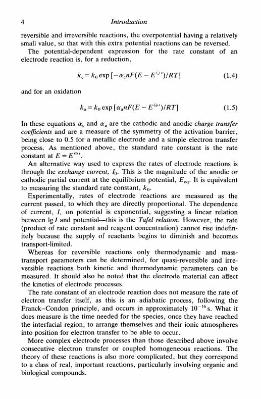
4 Introduction
reversible and irreversible reactions, the overpotential having a relativelysmall value, so that with this extra potential reactions can be reversed.
The potential-dependent expression for the rate constant of anelectrode reaction is, for a reduction,
kc = k0 exp [-acnF(E - E^')/RT] (1.4)
and for an oxidation
k.A = k0 exp [aanF(E - E^')/RT] (1.5)
In these equations occ and ara are the cathodic and anodic charge transfercoefficients and are a measure of the symmetry of the activation barrier,being close to 0.5 for a metallic electrode and a simple electron transferprocess. As mentioned above, the standard rate constant is the rateconstant at E = E^f.
An alternative way used to express the rates of electrode reactions isthrough the exchange current, /0. This is the magnitude of the anodic orcathodic partial current at the equilibrium potential, Eeq. It is equivalentto measuring the standard rate constant, kQ.
Experimentally, rates of electrode reactions are measured as thecurrent passed, to which they are directly proportional. The dependenceof current, /, on potential is exponential, suggesting a linear relationbetween lg / and potential—this is the Tafel relation. However, the rate(product of rate constant and reagent concentration) cannot rise indefin-itely because the supply of reactants begins to diminish and becomestransport-limited.
Whereas for reversible reactions only thermodynamic and mass-transport parameters can be determined, for quasi-reversible and irre-versible reactions both kinetic and thermodynamic parameters can bemeasured. It should also be noted that the electrode material can affectthe kinetics of electrode processes.
The rate constant of an electrode reaction does not measure the rate ofelectron transfer itself, as this is an adiabatic process, following theFranck-Condon principle, and occurs in approximately 10~16s. What itdoes measure is the time needed for the species, once they have reachedthe interfacial region, to arrange themselves and their ionic atmospheresinto position for electron transfer to be able to occur.
More complex electrode processes than those described above involveconsecutive electron transfer or coupled homogeneous reactions. Thetheory of these reactions is also more complicated, but they correspondto a class of real, important reactions, particularly involving organic andbiological compounds.

1.5 Applications of electrochemistry 5
1.4 Methods for studying electrode reactions
In order to study electrode reactions, reproducible experimental condi-tions must be created which enable minimization of all unwanted factorsthat can contribute to the measurements and diminish their accuracy.Normally we wish to suppress migration effects, confine the interfacialregion as close as possible to the electrode, and minimize solutionresistance. These objectives are usually achieved by addition of a largequantity of inert electrolyte (around lmoldm" 3), the electroactivespecies being at a concentration of 5 т м or less.
A complete study of an electrode process requires measurement ofkinetic as well as thermodynamic parameters. This means that conditionsin which the system is not reversible must be used. Since the standardrate constant, k0, cannot be changed, then the mass transfer coefficient,kd, may have to be increased until the reaction becomes at leastquasi-reversible. This can be done in various ways in various types ofexperiment:
• steady state methods: hydrodynamic electrodes, increasing convec-tion; microelectrodes, decreasing size
• linear sweep methods: increasing sweep rate
• step and pulse techniques: increasing amplitude and/or frequency
• impedance methods: increasing perturbation frequency, registeringhigher harmonics, etc.
The type of technique chosen will depend very much on the timescale ofthe electrode reaction.
Non-electrochemical methods can and should be used for studyingelectrode surfaces and the interfacial region structure, particularly in situin real time where this is possible.
1.5 Applications of electrochemistry
Once electrode reactions and electrode processes are understood, thisknowledge can be used for:
• tailoring electrode reactions so as to enhance required and inhibitunwanted electrode reactions, perhaps by changing electrode material ordeveloping new electrode materials
• studying complex systems in which many electrode reactions occursimultaneously or consecutively, as in bioelectrochemistry

6 Introduction
• measuring concentrations of electroactive species, making use of theselectivity of the potential and of the electrode material at or outsideequilibrium (as in potentiometric, amperometric, voltammetric, andenzyme sensors).
Thus the range of applications is vast. Electroanalysis, potentiometricand voltammetric; industrial electrolysis, electroplating, batteries, fuelcells, electrochemical machining, and many other related applications,including minimization of corrosion; biosensors and bioelectrochemistry.
1.6 Structure of the book
This book is organized into three main sections, as its subtitle suggests.In the first part, Chapters 2-6, some fundamentals of electrode
processes and of electrochemical and charge transfer phenomena aredescribed. Thermodynamics of electrochemical cells and ion transportthrough solution and through membrane phases are discussed in Chapter2. In Chapter 3 the thermodynamics and properties of the interfacialregion at electrodes are addressed, together with electrical properties ofcolloids. Chapters 4-6 treat the rates of electrode processes, Chapter 4looking at fundamentals of kinetics, Chapter 5 at mass transport insolution, and Chapter 6 at their combined effect in leading to theobserved rate of electrode processes.
The second part of the book discusses ways in which informationconcerning electrode processes can be obtained experimentally, and theanalysis of these results. Chapter 7 presents some of the importantrequirements in setting up electrochemical experiments. In Chapters8-11, the theory and practice of different types of technique arepresented: hydrodynamic electrodes, using forced convection to increasemass transport and increase reproducibility; linear sweep, step and pulse,and impedance methods respectively. Finally in Chapter 12, we give anidea of the vast range of surface analysis techniques that can be employedto aid in investigating electrode processes, some of which can be used insitu, together with photochemical effects on electrode reactions—photoelectrochemistry.
In the third part of the book areas in which there are importantapplications of electrochemistry are described. Chapters 13 and 14 lookat potentiometric and amperometric/voltammetric sensors respectively,focusing particularly on recent developments such as new electrodematerials and miniaturization. Electrochemistry in industry, which prod-uces many materials used directly or indirectly in everyday life, as well asbatteries, is described in Chapter 15. The electrochemical phenomenon
1.7 Electrochemical literature 7
of corrosion, economically prejudicial, is described in Chapter 16.Finally, since many biochemical processes involve charge transfer reac-tions, in Chapter 17 the many possibilities that arise from their study byelectrochemical methods, bioelectrochemistry, are presented.
1.7 Electrochemical literature
The electrochemical literature is very widespread. Some indication of itsbreadth is given below. The references at the end of each chaptercomplement this list.
General books
Many books on electrochemistry have been published in recent decades.Mostly the more general ones are not cited throughout the text, but thisdoes not reflect on their quality. A list of them is given below, inchronological order.
P. Delahay, New instrumental methods in electrochemistry, Interscience,New York, 1954.
K. J. Vetter, Electrochemical kinetics. Academic Press, New York, 1967.R. N. Adams, Electrochemistry at solid electrodes, Dekker, New York,
1969.J. O'M. Bockris and A. N. Reddy, Modern electrochemistry, Plenum,
New York, 1970.J. Newman, Electrochemical systems, Prentice Hall, Englewood Cliffs,
NJ, 1973.D. T. Sawyer and J. L. Roberts, Experimental electrochemistry for
chemists, Wiley, New York, 1974.E. Gileadi, E. Kirowna-Eisner, and J. Penciner, Interfacial electrochem-
istry. An experimental approach, Addison-Wesley, Reading, MA,1975.
W. J. Albery, Electrode kinetics, Clarendon Press, Oxford, 1975.A. J. Bard and L. R. Faulkner, Electrochemical methods, fundamentals
and applications, Wiley, New York, 1980.A. M. Bond, Modern polarographic methods in analytical chemistry,
Dekker, New York, 1980.Southampton Electrochemistry Group, New instrumental methods in
electrochemistry, Ellis Horwood, Chichester, 1985.J. Goodisman, Electrochemistry: theoretical foundations, Wiley-
Interscience, New York, 1987.

8 Introduction
J. Koryta, Principles of electrochemistry, Wiley, Chichester, 1987.P. H. Rieger, Electrochemistry, Prentice-Hall International, EnglewoodCliffs, NJ, 1987.D. R. Crow, Principles and applications of electrochemistry, 3rd edn,Chapman and Hall, London, 1988.P. W. Atkins, Physical chemistry, 4th edn., Oxford University Press,1990, Chapters 10, 25, and 30.D. Pletcher, A first course in electrode processes. The ElectrochemicalConsultancy, Romsey, UK, 1991.J. Koryta, Ionsy electrodes, and membranes, Wiley, Chichester, 1991.
Series
A number of series of volumes dealing with electrochemistry have beenpublished. Those recently issued or currently being published are listedbelow.
Advances in electrochemistry and electrochemical engineering, Wiley,New York. Volumes 1-9, ed. P. Delahay and C. W. Tobias; Volumes10-13, ed. H. Gerischer and C. W. Tobias.
Advances in electrochemical science and engineering, ed. H. Gerischerand С W. Tobias, VCH, Weinheim (continuation of Adv. Electro-chem. Electrochem. Eng.\ 1 volume until end 1991).
Comprehensive treatise of electrochemistry, ed. J. O'M. Bockris, В. Е.Conway, E. Yeager et al., Plenum, New York, Volumes 1-10.
Comprehensive chemical kinetics, section 10; electrode kinetics, ed. R. G.Compton et al., Elsevier, Amsterdam, Volumes 26-29.
Electroanalytical chemistry: a series of advances, ed. A. J. Bard, Dekker,New York (17 volumes until end 1991).
Modern aspects of electrochemistry, ed. J. O'M. Bockris, В. Е. Conwayet al, Plenum, New York (21 volumes until end 1991).
International journals devoted to electrochemistry
There are a number of international journals devoted primarily toelectrochemistry:
Bioelectrochemistry and Bioenergetics (an independent section of/. Electroanal. Chem.)
CorrosionCorrosion ScienceElectroanalysisElectrochimica Acta

1.7 Electrochemical literature 9
Elektrokhimiya {Soviet Electrochemistry)Journal of Applied ElectrochemistryJournal of Electroanalytical and Interfacial ElectrochemistryJournal of the Electrochemical SocietySelective Electrode Reviews (formerly Ion Selective Electrode Reviews,until 1988)
Articles with electrochemical themes also regularly appear in a largenumber of other journals.

PART I
Principles

ELECTROCHEMICAL CELLS:THERMODYNAMIC PROPERTIESAND ELECTRODE POTENTIALS
2.1 Introduction2.2 The cell potential of an electrochemical cell2.3 Calculation of cell potential: activities or concentrations?2.4 Calculation of cell potential: electrochemical potential2.5 Galvanic and electrolytic cells2.6 Electrode classification2.7 Reference electrodes2.8 The movement of ions in solution: diffusion and migration2.9 Conductivity and mobility2.10 Liquid junction potentials2.11 Liquid junction potentials, ion-selective electrodes and biomembranes2.12 Electrode potentials and oxidation state diagrams
2.1 Introduction
An understanding of thermodynamic properties associated with electrodeprocesses is fundamental in order to answer questions such as:
• Why is it that half-reactions in electrochemical cells proceed spon-taneously in one direction and furnish current?
• What is the effect of the salt bridge?• What is the effect of ion migration?
In this chapter we attempt to reply to these and to other relatedquestions. To treat the topic in a concrete way, we consider twoelectrochemical cells:
Zn|Zn2+(aq)|Cu2+(aq)|Cu
and
Hg | Hg2Cl2 | Cl-(aq) ji Zn2+(aq) | Zn
where we represent only the species of interest. In these cells the symbol

14 Electrochemical cells
| denotes a phase boundary, | a junction between miscible liquids, and jj asalt bridge (liquid junction) whose function is to provide an electricallyconducting link between two spatially separated components of the cell inthe liquid phase. It should be stressed that, according to the internation-ally accepted IUPAC convention, the half-reactions are considered in theway the cell is depicted on paper, that is oxidation in the left half-cell (theelectrode is the anode) and reduction in the right half-cell (the electrodeis the cathode)1.
2.2 The cell potential of an electrochemical cell
The cell potential of an electrochemical cell is calculated from theelectrode potentials (reduction potentials) of the respective half-reactions1. Given that, by convention, the half-reaction on the left isconsidered to be an oxidation and that on the right a reduction we have
^cell = bright ~ ^left (2-1)
where £right and £left are the potentials of each half-cell, obtained fromthe Nernst equation.
The Nernst equation relates the activities of the species involved withthe electrode potential, Ey of the half-reaction and its standard electrodepotential, E"0", which is the value of the potential relative to the standardhydrogen electrode when the activities of all species are unity. For thegeneric half-reaction
where n is the stoichiometric number of electrons transferred for eachspecies, the Nernst equation is
£ = £^-^2>,1па,. (2.2)nt
in which V/ has positive values for products (reduced species) andnegative values for reagents (oxidized species). This can be written as
nF Пай,
For example, for
MnO2 + 4H+ + 2e~ -* Mn2 + + H2O

2.2 The cell potential of an electrochemical cell 15
the logarithmic term is
RT\nIFIF а М п 2 + йн 2 о
ан2о i s approximately constant and is neglected in the Nernst equationexcept in the case of a mixture with another solvent or in veryconcentrated solutions.
The cell potential tells us the maximum work (maximum energy) thatthe cell can supply2. This value is
AG = -nFEcell (2.4)
It is evident that on removing energy (in the form of current or convertedchemical substances) the amount of unconverted substances remaining isdiminished, reflecting the changes in the concentrations of the species inthe liquid phase. In the solid phase, however, there is no alteration ofactivity, which is normally accepted as being unity.
We now calculate the cell potential for the two cases mentioned above.
Case 1
Zn|Zn 2 + (aq)iCu 2 + (aq) |Cu
which means we consider the cell reaction as
Zn + Cu 2 + -*Zn 2 + + Cu
The half-reactions are represented by
right: Cu2 + 2e~ -• Cu £ ° = +0.34 V
left: Zn2+ + 2e" -> Zn £ ° = -0.76 V
If the aqueous species have unit activity, then E^ values may be usedand
E£n = +0.34 - (-0.76) = +1.10 V
The corresponding A G 0 value is
° = -2.20F = -212 kJ mol"1
which is negative. This result shows that the reaction proceeds spon-taneously as written.
The equivalent of the Nernst equation for the whole cell is
(2.5)

16 Electrochemical cells
It can be seen that if the ratio (acu2+/aZn2+) is sufficiently small, Ecell
becomes negative and the direction of spontaneous reaction is changed.
Case 2
Hg | Hg2Cl2 | СГ(аЧ) jj Zn2+(aq) | Zn
The stoichiometric cell reaction to consider is
2Hg + 2СГ + Zn 2 + -• Hg2Cl2 + Zn
and the half-reactions are represented by
right: Zn2 + + 2e"-> Zn £ e = -0.76 V
left: Hg2Cl2 + 2e~ -> 2Hg 4- 2СГ £ e = +0.27 V
For unit activities,
Etn = -0.76 - 0.27 = -1.03 V
and
AG°=+199kJmor 1
The negative value of E^n (and positive AG°) means that at unitactivities the cell functions spontaneously in the direction opposite to thatwritten above. Thus the spontaneous cell reaction is
Hg2Cl2 + Zn2+ -> 2Hg 4- Zn2+ + 2СГ
The half-cell on the left is an example of a reference electrode (Section2.7) so called since, as Hg2Cl2 is a sparingly soluble salt, the activities ofHg and Hg2Cl2 can be taken as unity. The potential of the half-cell isaltered solely by the chloride ion activity according to the expression
RTЯсен = £ £ „ - —In a a - (2-6)
This electrode is known as the calomel electrode.
2.3 Calculation of cell potential: activities or concentrations?
Although the use of activities in the Nernst equation is undoubtedlycorrect, it is worth considering whether it is necessary and what is thedifference between activities and concentrations in general.
In the context of this book, a detailed discussion of activities andconcentrations is not justified. However, it is clear that in relativelyconcentrated solutions there will be interionic interactions that do not

2. 3 Calculation of cell potential: activities or concentrations ? 17
occur in very dilute solutions because of the large interionic distances inthe latter. Consequently the velocity of ion migration (i.e. the momen-tum of each ion) will be altered, and this can reduce, or possibly increase,ionic activity. Thus we write the relations
a = Ymm (2.1a)
a = ycc (2.1b)
where ym is the activity coefficient for concentrations in relation tomolality (molkg"1), and yc in relation to molarity (moldm"3). Thus,these coefficients are proportionality factors between activity and con-centration, whose values vary with concentration.
It is often useful to employ concentrations instead of activities inelectrochemical experiments: for example, in preparing solutions we usemasses and volumes, that is we determine the concentration of a solution.Thus, the Nernst equation, instead of being written as
(2.3)
can be formulated as
In this last equation, E^' is the formal potential. It is related to thestandard electrode potential, E^y by
^ ' = ̂ + ̂ 1 1 1 ^ (2.9)nF П Ус,'к,
Experimentally we measure the formal potential, ZT0"', relative to areference electrode (Section 2.7). However, by performing measure-ments at different concentrations and extrapolating to zero concentration,values of E^~ can be obtained. Another factor that can enter into thevalues of /Г0"' is perturbations caused by other reactions, normally due tocomplexation.
An example of the difference between values of IT0"' and E^ is thevalues obtained in the potentiometric titration of Fe 2 + with Ce4 + in0 . 5 M H 2 S O 4 . These are, relative to the normal hydrogen electrode(NHE):
Standard electrode „ . . .^ A. t Formal potential
potential r
E^/V £ ° 7 V
Fe3+ | Fe2+ +0.77 +0.68Ce4+ Ce3+ +1.61 +1.44
18 Electrochemical cells
The differences reflect not only the activities of the ions involved in thehalf-reactions but also the fact that 0 . 5 M H 2 S O 4 does not have pHO (infact the second ionization is only partially effected).
2.4 Calculation of cell potential: electrochemical potential
Although the calculation of EceU in the previous section appears satisfac-tory, it is not very rigorous. In this section we show how a rigorousthermodynamic argument4 leads to the same result. For this we need theconcept of the electrochemical potential Д, that obeys the same criteria atequilibrium as the chemical potential \i. Its definition for component / inphase oc is
ji?= tf + zfQ" (2.10)
= JU°" + RT In ui + ztF<t>a (2.11)
which is the sum of a term due to the chemical potential and another thatrepresents the contribution from charged species described by theelectrostatic potential ф in phase oc. Since
" f = ( fr ) (2Л2)
\drii/ ТгРгП.ф.
then
/*r=(ff) (2-13)where G is the electrochemical free energy. G is analogous to the freeenergy, G, but contains the electrical effects of the environment. In thecase of a species without charge,
ДГ=МГ (2.14)
Various deductions are possible from these expressions:
• For a pure phase that has unit activity,
A? =**?'" (2.15)
where [л®'а is the standard chemical potential in phase oc.
• For a metal, activity effects can be neglected. The electrochemicalpotential is the electronic energy of the highest occupied level (Fermilevel, EF)
K=^-F0e (2.16)
2 4 Calculation of cell potential: electrochemical potential 19
• For species i in equilibrium between two phases a and j8,
£f = £f (2.17)
We now apply these concepts to specific cases.As a first example, consider the sparingly soluble salt silver chloride in
equilibrium with its ions:
AgCl(s)^Ag+(aq) + Cr(aq)We have
ififfi = A £f?' + ££,gC1 = Д ^ + + Да- (2.18)
given that silver chloride is neutral and has unit activity. The standardfree energy change, A G e , for dissolution is given, using (2.11), by
lfO,aq р т | n /„aq _aq \ /9 in\
[AQ\-——1\.1 1П V#Ag+^Cl~/ V~'-*-"/
thus obtaining the well-known result
AG^=-RT\nKsp (2.20)
As a second example we return to the first cell of Section 2.1:
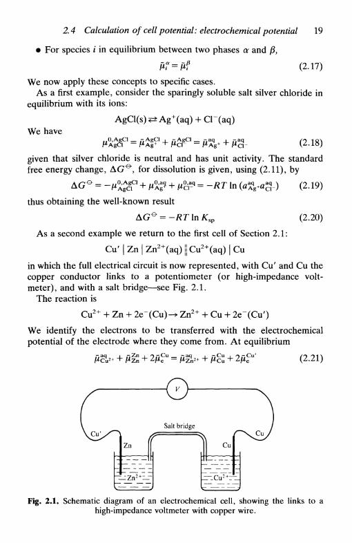
Cu' | Zn | Zn2+(aq) ji Cu2+(aq) | Cuin which the full electrical circuit is now represented, with Cu' and Cu thecopper conductor links to a potentiometer (or high-impedance volt-meter), and with a salt bridge—see Fig. 2.1.
The reaction is
Cu2+ + Zn + 2e~(Cu)-+ Zn2 + + Cu + 2e~(Cu')
We identify the electrons to be transferred with the electrochemicalpotential of the electrode where they come from. At equilibrium
(2.21)- a q .-• Zn -aq
Fig. 2.1. Schematic diagram of an electrochemical cell, showing the links to ahigh-impedance voltmeter with copper wire.
20 Electrochemical cells
We know that
2(£cCu' - №) = -2F(tf>Cu' - фс") = 2FEcell (2.22)
therefore (2.21) can be written
2FEcen = ji&& + RT In лЙ2+ + 2 F 0 ^ + ^z 'n
Z n
- RT In a z V ~ 2 F 0 ^ - №u (2.23)
n + Д ^ In («C u 2 +/aZ n 2 +) (2.24)
= 2FE£n + ЛГ In («Cu2+/«Zn2+) (2.25)
which is the Nernst equation for the whole cell:
ell - ^cell + ir^ I" I ) (2.5)Lt \#Zn2+/
This type of reasoning is applicable to any cell and always leads to thecorresponding Nernst equation.
2.5 Galvanic and electrolytic cells
So far the spontaneous functioning of an electrochemical cell has beendescribed, which corresponds to the transformation of energy obtained ina chemical reaction into electron movement, that is electrical energy.This type of cell is a galvanic cell.
By supplying electrical energy from an external voltage source, i.e.applying a potential, we supply electrons of the corresponding energy,allowing the direction of the electrode reactions to be altered. We areable to convert electrical into chemical energy. Here we have anelectrolytic cell which is much used in electrode reaction studies, and isused industrially in brine electrolysis, in the extraction and refining ofmetals, in electrosynthesis, etc.
Let us consider the charges on the electrodes in the two cases. At theanode in a galvanic cell, since the oxidation is spontaneous, there is anexcess of electrons at the electrode. On the other hand, in an electrolyticcell where oxidation is forced to occur, there is a shortage of electronsand a positive charge. The two situations are:
galvanic cellelectrolytic cell
anode-
+
cathode+—
Some electrochemical cells can function as galvanic or electrolytic cells.A well-known example is the lead-acid car battery. Under discharge

2. 6 Electrode classification 21
(supplying current) it is a galvanic cell whose electrode reactions are
anode (-ve):
Pb 4- S O ^ -> PbSO4 + 2e"
cathode (4-ve):
PbO2 + 4H+ + S O ^ + 2e" -> 2H2O + PbSO4 EceU = 2.05 V
On recharging the battery these half-reactions are inverted, and electricalenergy has to be supplied.
2.6 Electrode classification
There are many electrode materials, with a great diversity of behaviour.The historical classification5'6 is a first approach, and as it is still referredto it will be described here. Electrode materials, together with thesolutions with which they contact, are divided into four categories:
1. An electrode in contact with a solution of its ions. This can besubdivided into two cases:
(a) A metal in contact with its cations, e.g. Си | Cu2 +, where
DT
E = E^ + — \naMn, (2.26)
and the half-reaction is
(b) A non-metal in contact with its ions, e.g. H 2 | H+ or Cl2 | Cl~ on
the surface of an inert conducting substance such as platinum. For thefirst of these,
PT n1/2
E = E^ + — l n ^ (2.27)F aH+
where pHl is the partial pressure of hydrogen gas.In this type of electrode the potential arises from electron transferbetween the neutral species and the ion.
2. A metallic electrode in contact with a solution containing anionsthat form a sparingly soluble salt with the metal's ions, e.g.Hg | Hg2Cl2 | СГ, the calomel electrode (see Fig. 2.3). The salt activity,being almost entirely in the solid phase, can be regarded as unity. Thusthe potential is a function only of the anion activity. For the calomelelectrode,
E = E^-^\nacl- (2.6)г

22 Electrochemical cells
These systems are much used as reference electrodes since, because ofthe low solubility product of the salt, the potential is very stable. Otherexamples are Ag | AgCl | Cl~ and, for alkaline solution, Hg | HgO | ОНГ.
3. This type of electrode is a source or sink of electrons, permittingelectron transfer without itself entering into the reaction, as is the casefor the first or second type of electrodes. For this reason they are calledredox or inert electrodes. In reality the concept of an inert electrode isidealistic, given that the surface of an electrode has to exert an influenceon the electrode reaction (perhaps small) and can form bonds withspecies in solution (formation of oxides, adsorption, etc.). Such processesgive rise to non-faradaic currents (faradaic currents are due to interfacialelectron transfer). This topic will be developed further in subsequentchapters.
The first 'redox' electrode materials to be used were the noble metals,namely gold and platinum, and also mercury. At present this designationincludes many types of material such as glassy carbon, different types ofgraphite, and semiconductor oxides, so long as a zone of potential isemployed where surface reactions involving the electrode material do notoccur.
4. Electrodes that cannot be grouped into the above categories, e.g.modified electrodes (see Chapter 14).
This classification is useful mainly for electrodes of the first and secondtypes. The great majority of electrodes are, however, of the third orfourth types.
2.7 Reference electrodes
Reference electrodes, as their name suggests, are used to give a value ofpotential to which other potentials can be referred in terms of a potentialdifference—potentials can only be registered as differences with respectto a chosen reference value. Thus, a good reference electrode3'6 needs tohave a potential that is stable with time and with temperature and whichis not altered by small perturbations to the system—that is, by thepassage of a small current. There are three types of reference electrode:
• Type 1: e.g. the hydrogen electrode
• Type 2: e.g. the calomel electrode
• Others: e.g. glass electrodes, Type 3 electrodes, etc.
The standard (or normal) hydrogen electrode is the most importantreference electrode because it is the one used to define the standard
2.7 Reference electrodes 23
—
\
Mi
ll
Solution
" ^ Platinized Pt
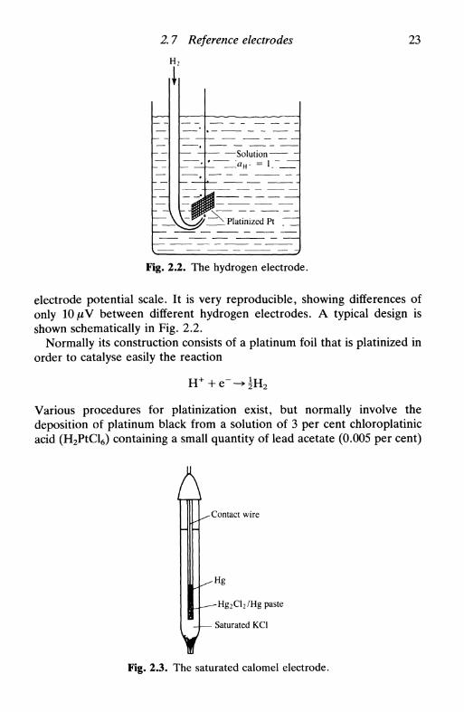
1 — — -jFig. 2.2. The hydrogen electrode.
electrode potential scale. It is very reproducible, showing differences ofonly IOJUV between different hydrogen electrodes. A typical design isshown schematically in Fig. 2.2.
Normally its construction consists of a platinum foil that is platinized inorder to catalyse easily the reaction
Various procedures for platinization exist, but normally involve thedeposition of platinum black from a solution of 3 per cent chloroplatinicacid (H2PtCl6) containing a small quantity of lead acetate (0.005 per cent)
A^Contact wire
-Hg
-Hg2Cl2/Hg paste
- Saturated KC1
Fig. 2.3. The saturated calomel electrode.

24 Electrochemical cells
to prolong electrode life. Hydrogen is bubbled in a solution of theelectrolyte that is to be used before this is introduced into the cell.
Electrodes of Type 2 are good reference electrodes, as stated inSection 2.6. In Fig. 2.3 a schematic view of a saturated calomel electrodethat can be easily introduced into any solution is shown.
Some general precautions need to be taken with reference electrodes,especially when there is a possibility of the formation of complexesinvolving the sparingly soluble salt. This is the case for many metallichydroxides which have very low solubility products, suggesting their usein alkaline solution—they often form hydroxy complexes at high hydro-xide concentration, which limits their use. Mercury oxide does not havethis disadvantage and so is used preferentially—however, care should betaken with the anion concentration in the electrolyte.
Table 2.1 lists half-reactions for electrodes of the second type and theirpotential for unit activities. These electrodes have, in the majority ofcases, their own electrolyte associated with them. So, to calculate thepotential of a cell in relation to the standard hydrogen electrode it isnecessary to take the liquid junction potential between the twoelectrolytes into account (Section 2.10).
These electrodes were developed principally for aqueous solution.However, they normally have a porous plug that links the electrolytewithin the reference electrode to the solution in the cell (referenceelectrodes of this kind are rarely used nowadays to carry current, butonly to control potentials). Since ion transport through the plug is verysmall, they can be used for short periods in non-aqueous solvents. Thereare reference electrodes that have been developed specifically for use innon-aqueous solvents, for example, Li+ | Li in dimethylsulfoxide.
Quasi-reference electrodes such as platinum or silver wires or mercurypools are sometimes used in voltammetric experiments, particularlytransient experiments. The advantage is low electrical resistance, but
Table 2.1. Half-reactions for reference elec-trodes based on sparingly soluble salts in water
solvent
AgBr + e -^Ag + Br" 0.071AgCl + e" -> Ag 4- СГ 0.222
Hg2Cl2 + 2e" -» 2Hg + 2СГ 0.268HgO + H2O + 2e" -» Hg + 2OH~ 0.098
Hg2SO4 + 2e~ -» 2Hg + SO4" 0.613T1C1 + e" -> Tl(Hg) 4- СГ -0.557

2.8 The movement of ions in solution: diffusion and migration 25
their potential may vary up to 10 or 20 mV. They are described further inChapter 7.
2.8 The movement of ions in solution: diffusion and migration
It is important to consider the movement of ions in electrolyte solutionsbetween anode and cathode, and thence some of the properties ofelectrolyte solutions in general. Solvated ions move at different velocities,according to their size and charge. Diffusion is due to a concentrationgradient, and migration to electric field effects. Thus, whilst diffusionoccurs for all species, migration affects only charged species (effectively,owing to the existence of dipoles, or induced dipoles in neutral species, asmall electric field effect is observed).
Diffusion (Fig. 2.4) is described by Fick's first law:
(2.28)
where Jt is the flux of species / of concentration ct in direction x, anddel Эх is the concentration gradient. Д is the proportionality factorbetween flux and concentration gradient, known as the diffusioncoefficient. The negative sign arises because the flux of species tends toannul the concentration gradient.
In the presence of an applied electric field of strength E = дф/дх,
(2.29)
where the second term on the right-hand side represents migration. Thisterm clearly shows the importance of charge of the species and of thevalue of d0/djc (electric field gradient). Opposing this electric force thereare three retarding forces:
• A frictional force that depends on the size of the solvated ion
c\(x) + AJC)
/ x
Fig. 2.4. Diffusion in one dimension. The net flux is proportional to — cf AJC, dueto the concentration gradient.
26 Electrochemical cells
0 © е> <э
(а) (Ь)
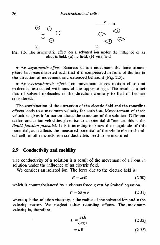
Fig. 2.5. The asymmetric effect on a solvated ion under the influence of anelectric field: (a) no field; (b) with field.
• An asymmetric effect. Because of ion movement the ionic atmos-phere becomes distorted such that it is compressed in front of the ion inthe direction of movement and extended behind it (Fig. 2.5).
• An electrophoretic effect. Ion movement causes motion of solventmolecules associated with ions of the opposite sign. The result is a netflux of solvent molecules in the direction contrary to that of the ionconsidered.
The combination of the attraction of the electric field and the retardingeffects leads to a maximum velocity for each ion. Measurement of thesevelocities gives information about the structure of the solution. Differentcation and anion velocities give rise to a potential difference: this is theliquid junction potential. It is interesting to know the magnitude of thispotential, as it affects the measured potential of the whole electrochemi-cal cell; in other words, ion conductivities need to be measured.
2.9 Conductivity and mobility
The conductivity of a solution is a result of the movement of all ions insolution under the influence of an electric field.
We consider an isolated ion. The force due to the electric field is
F = zeE (2.30)
which is counterbalanced by a viscous force given by Stokes' equation
F = 6nr]rv (2.31)
where ц is the solution viscosity, r the radius of the solvated ion and v thevelocity vector. We neglect other retarding effects. The maximumvelocity is, therefore
v=-T^- ( 2 - 3 2 )
= uE (2.33)

2. 9 Conductivity and mobility 27
where и is the ion mobility, and is the proportionality coefficient betweenthe velocity and electric field strength.
How are conductivity and mobility related? The flux of charge, j, is
j = zevcNA (2.34)
where ze is the charge of each ion, v its velocity, and cNA the numericalion density. Writing eNA = F (one mole of electrons) and substituting
j = zvcF (2.35)
= zcuFE (2.36)
The current, /, that passes between two parallel electrodes of area A isrelated to the flux of charge j, and to the potential difference betweenthem, Аф, by
/ =jA = K^J^= KEA (2.37)
where к is the conductivity and / the distance between the electrodes thatapply the electric field of strength E = Аф/l. One immediately concludes,by combining (2.36) and (2.37), that for each ion
Ki = zgciuiF (2.38)
Therefore, for the solution (which contains various ions) the measuredconductivity, ку is given by
K = FENW (2.39)
The molar conductivity of an ion, ki9 is
AI- = - = zI-a,.F (2.40)Ci
and the electrolyte molar conductivity, A, is
Л = 2А, = 2 - (2.41)i Ci
As can be seen, the measurement of the conductivity of an electrolytesolution is not species selective. Individual ionic conductivities can becalculated only if the conductivity (or mobility) of one ion is known: thisin the case of a simple salt solution containing one cation and one anion.If various ions are present, calculation is correspondingly more difficult.Additionally, individual ionic conductivities can vary with solutioncomposition and concentration.
28 Electrochemical cells
If the electric field is of high intensity (of the order of lOOkVcm"1)then the conductivity increases with field strength. For strong electrolytes(first Wien effect) this is due to the fact that the ions begin to movewithout their solvent sheath, since the relaxation time for the ionicatmosphere becomes too large—eventually a limiting conductivity valueis reached as the field strength increases. For weak electrolytes (secondWien effect) the electric field interacts with the dipoles of the undis-sociated molecule, for example a weak acid, increasing its dissociationconstant.
We next consider the relation between mobility and diffusioncoefficient. This arises because a concentration gradient is also a chemicalpotential gradient. For a sufficiently dilute solute, i,
ic, (2.42)
and differentiating with respect to distance
(f) =^(f*) (2.43)\dx/P>T Ci \dx/PfT
The diffusive force experienced by a particle i is thus
r-m p-44»
The number flux of ions /, Jh is, from (2.36),
Ji = — = ciuiE (2.46)zte
and substituting from (2.30) for the electric field intensity, E,
>,-** (2.47)
Combining (2.45) and (2.47) leads to
*--*£(£) (2.48)ztF \dx/PrT
Comparison with Fick's first law of diffusion, (2.28), shows that

2 9 Conductivity and mobility 29
This is the Einstein relation, and shows the direct proportionality betweendiffusion coefficient and mobility.
The relation between conductivity and diffusion coefficient, theNernst-Einstein relation, is easily derived from (2.40) and (2.49):
This permits the estimation of diffusion coefficients from measurementsof conductivity.
Another useful expression concerns the relation between the diffusioncoefficient and the viscous drag. From (2.33), one can write
^ (2.51)6nrjr
Substituting in the Einstein relation, (2.49), we obtain
(2.52)
This is known as the Stokes-Einstein relation and is independent of thecharge of the species. Using this expression, diffusion coefficients can beestimated from viscosity measurements, so long as Stokes' Law isapplicable. It is used particularly for macromolecules.
Sometimes it is useful to know what fraction of the current istransported by each ion. This is its transport number, and is given by
It is evident that
2 4 = 1 (2-54)
The transport number of an ion varies with the ionic constitution of thesolution, and is another way of expressing conductivities or mobilities.There are two important methods for measuring transport numbers: theHittorf method and the moving boundary method5.
Hittorf method (Fig. 2.6)
An electrolytic cell is divided into three compartments, and a current / ispassed. After time ty It/z+F cations have reached the cathode itself, butonly t+(It/z+F) cations have reached the cathode compartment. Thus,

30 Electrochemical cells
Cathode Anode
Z-F
Fig. 2.6. The Hittorf method for determining transport numbers. In the diagramthe passage of a current / for time t is shown. It is assumed that t+ +1_ = 1. The
electrolytic cell is divided into three compartments.
there is a change in the ionic concentration of the cathode compartmentof
F) = -t_(Itlz+F) (2.55)
In the anode compartment the change is —t+(It/z_F). Thus, themeasurement of this change in composition of the anode and cathodecompartments leads directly to values of t+ and t_.
Moving boundary method (Fig. 2.7)
This method is used to determine the transport number of M in salt MX.A solution of higher density than MX, NX (where uN > wM), is put in a
MX
NX
Initially
MX
NX
After time /
D
Fig. 2.7. The moving boundary method for determining transport numbers. Л Вand CD represent the frontiers between MX and NX at the beginning of the
experiment and after time t respectively.
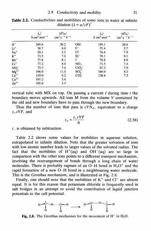
2.9 Conductivity and mobility 31
Table 2.2. Conductivities and mobilities of some ions in water at infinitedilution (A = u/zF)7
н+
y +
Na+
K+
Rb+
Cs+
NHJMg2 +
Ca2+
Cu2+
Zn2 +
VScm2mol l
349.638.750.173.577.877.273.5
106.0119.0107.2105.6
10 Vcm^V-1
36.24.05.27.68.18.07.6
11.06.25.65.5
O H "F "
crBr~
r
CIO4
soj-co2-
hlS cm2 mol"1
199.155.476.478.176.871.567.3
160.0138.6
10 Vcm 2 s" 1 V- 1
20.65.77.98.18.07.47.08.37.5
vertical tube with MX on top. On passing a current / during time t theboundary moves upwards. All ions M from the volume V contained bythe old and new boundary have to pass through the new boundary.
Thus the number of ions that pass is cVNA, equivalent to a chargez+cVF, and
f_ is obtained by subtraction.
Table 2.2 shows some values for mobilities in aqueous solution,extrapolated to infinite dilution. Note that the greater solvation of ionswith low atomic number leads to larger values of the solvated radius. Thefact that the mobilities of H+(aq) and OH"(aq) are so large incomparison with the other ions points to a different transport mechanism,involving the rearrangement of bonds through a long chain of watermolecules. There is probably rupture of an O-H bond in H 3 O + and therapid formation of a new O-H bond in a neighbouring water molecule.This is the Grotthus mechanism, and is illustrated in Fig. 2.8.
Finally, one should note that the mobilities of K+ and Cl~ are almostequal. It is for this reason that potassium chloride is frequently used insalt bridges in an attempt to avoid the contribution of liquid junctionpotentials to the cell potential.
H^?^-H—-о—н н-^?~"'н^о—н
Fig. 2.8. The Grotthus mechanism for the movement of H+ in H2O.

32 Electrochemical cells
2.10 Liquid junction potentials
Liquid junction potentials are the result of different cation and anionmobilities under the influence of an electric field. The potential manifestsitself in the interface between two different solutions separated by aporous separator or by a membrane. These junctions can be classifiedinto three distinct types:
• Two solutions of the same electrolyte but with different concentra-tions. The typical case is a concentration cell with transport, e.g.
H2, Pt | HClfaO | НС1(л2) | Pt, H 2
with the partial pressures of hydrogen equal on the two sides. There is aliquid junction between the solutions of hydrochloric acid.
• Two solutions of the same concentration of one of the ions, but theother ion differs.
• Other cases.
The total cell potential is
^cell = ^Nernst + ^ j
where E} is the liquid junction potential. We now consider examples ofthe first two cases cited above for the calculation of Er
Case 1
Consider the liquid junction of the concentration cell given above. Thereare two phases a and j3, which contain hydrochloric acid at differentactivities. The transport of ions at equilibrium is expressed by
Г+ДЙ+ + f_£g,- = t+fL^+ + *_Д&- (2.57)
or, removing the terms that are equal on the two sides,
l (2.58)
If we write
and
we easily reach
-'-)?lnTi (2-59)

2.11 Liquid junction potentials 33
Evidently this argument is not very rigorous, in that the interfacial regionis not considered. However, if we assume a linear change in concentra-tion and invariant transport numbers in the interfacial region we arrive atthe result of (2.59) corresponding to a symmetric variation of interfacialpotential.
Case 2.
Here it is not very correct to assume that the concentration gradients varylinearly through the junction, especially because the concentrationprofiles depend on the technique of junction formation. Assuming thatactivities are equal to concentrations and that there is, in fact, a lineartransition, we obtain the Henderson equation
S ——'- [ct(P) - Ci(a)] E \zt\ щс^ос)
£ j = - — — In- (2.60)
2 \zt\ щ[с№ - ct(a)] E \zt\ uiCi(P)i i
For a 1:1 electrolyte this reduces to
l n ^ (2.61)г Л л
which is the Lewis-Sargent relation, the positive sign corresponding to acommon cation and the negative sign to a common anion.
Minimization of the liquid junction potential is commonly carried outusing a salt bridge in which the ions have almost equal mobilities. Oneexample is potassium chloride (£+ = 0.49 and £_=0.51) and another ispotassium nitrate (£+ = 0.51 and £_=0.49). If a large concentration ofelectrolyte is used in the salt bridge this dominates the ion transportthrough the junctions such that the two values of E} have the samemagnitude but opposing polarities. The result is that they annul eachother. In this way values of E-} can be reduced to 1-2 mV.
2.11 Liquid junction potentials, ion-selective electrodes, andbiomembranes
We consider again (2.59):
Е- = (фр-ф") = « - O —In— (259)j F ap

34 Electrochemical cells
If it were possible to have an interface permeable to only one ion, thenthe transport number of that ion would be unity and
E> = Tlnff (2.62)
or, in general, for an ion of charge z,,
(2-63)
Em, the corresponding liquid junction potential, is called the membranepotential or Donnan potential. Ideally Em changes in a Nernstian fashionwith the activity of the ion in one of the phases, the activity in the otherphase being held constant. This is the basis of the functioning ofion-selective electrodes (Chapter 13) and, to a good approximation, ofbiomembranes (Chapter 17).
2.12 Electrode potentials and oxidation state diagrams
In calculating the cell potential of an electrochemical cell and to calculatethe maximum possible energy produced one uses the expression
AG = -nFE (2.64)
In fact, each electron transfer half-reaction involves a free energy changefollowing this formula. To reach the total variation in ЛG we sum thecontributions of the two half-reactions, remembering that one is areduction and the other an oxidation. For example, for the dissolution ofsilver chloride under standard conditions
AgCl + e~^> Ag + СГ £ ° = 4-0.22 V AGf = -0.22 FAg+ + e~^Ag £ ° = + 0 . 8 0 V AGf =-0.80 F
Thus, for
we have AGgt = AGf - AGf = +0.58 F. From the relation
AG^=-RTlnK (2.65)
we can calculate that
К = exp (-AG^JRT) = exp (-0.58 F/RT) = 1.55 x 10~10.
This value of К can be identified with the solubility product—thedifferences that arise in relation to tabulated values of Ksp are due todifferences in the solution conditions. In the same way we can calculatestability constants of complexes.
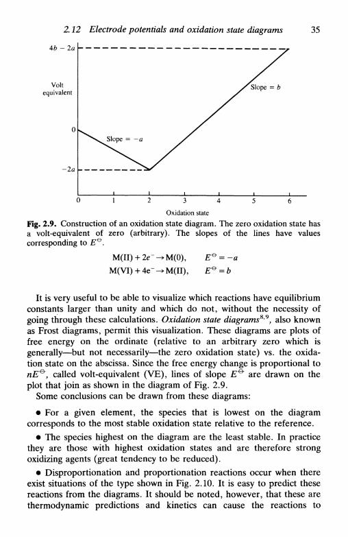
2.12 Electrode potentials and oxidation state diagrams 35
4b - 2a
Voltequivalent
-2a
Slope = b
Oxidation state
Fig. 2.9. Construction of an oxidation state diagram. The zero oxidation state hasa volt-equivalent of zero (arbitrary). The slopes of the lines have valuescorresponding to E^.
M(VI) + 4e"
It is very useful to be able to visualize which reactions have equilibriumconstants larger than unity and which do not, without the necessity ofgoing through these calculations. Oxidation state diagrams8'9, also knownas Frost diagrams, permit this visualization. These diagrams are plots offree energy on the ordinate (relative to an arbitrary zero which isgenerally—but not necessarily—the zero oxidation state) vs. the oxida-tion state on the abscissa. Since the free energy change is proportional tonE^y called volt-equivalent (VE), lines of slope E^ are drawn on theplot that join as shown in the diagram of Fig. 2.9.
Some conclusions can be drawn from these diagrams:
• For a given element, the species that is lowest on the diagramcorresponds to the most stable oxidation state relative to the reference.
• The species highest on the diagram are the least stable. In practicethey are those with highest oxidation states and are therefore strongoxidizing agents (great tendency to be reduced).
• Disproportionation and proportionation reactions occur when thereexist situations of the type shown in Fig. 2.10. It is easy to predict thesereactions from the diagrams. It should be noted, however, that these arethermodynamic predictions and kinetics can cause the reactions to
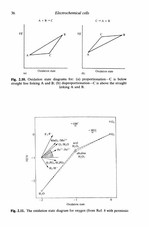
36 Electrochemical cells
A + B - * C С - А + В
VE В VE
(a)Oxidation state
(b)Oxidation state
Fig. 2.10. Oxidation state diagrams for: (a) proportionation—С is belowstraight line linking A and B; (b) disproportionation—С is above the straight
linking A and B.
0
- 1
_2
F 2 / F -
/мпО4/Мп2
/ у^О 2 /Н/ /s С̂ »3 + /Г
ХН^РОл/НяРОл/\ 3 *̂* 4 3 "̂̂ 3
н̂2/н- /
/
Н 2 0
2О
е
/
-ОН*о
acid
/Talkaline
^ н 2 о 2
- н о 2о
^ ^
оо3
- 2 - 1
Oxidation state
Fig. 2.11. The oxidation state diagram for oxygen (from Ref. 8 with permissio

2.12 Electrode potentials and oxidation state diagrams 37
+6
+4
+ 2
I
- 2
- 4
HMnO4
0 +1 +3 +4 +5 +6 + 7
Oxidation state
Fig. 2.12. The oxidation state diagram for transition metals of the first series(from Ref. 9 with permission).
proceed only very slowly at room temperature, as for example thedisproportionation
The diagrams are normally constructed in relation to the hydrogenelectrode with aH+ = 1 as reference, which would be a horizontal straightline. However, they can be modified for the reference to be another pHor another half-reaction. If we choose as reference the reduction ofoxygen to water under standard conditions, for example, which hasE^= +1.23V, the modification corresponds to a clockwise rotation ofthe diagram.
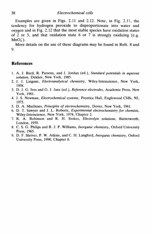
38 Electrochemical cells
Examples are given in Figs. 2.11 and 2.12. Note, in Fig. 2.11, thetendency for hydrogen peroxide to disproportionate into water andoxygen and in Fig. 2.12 that the most stable species have oxidation statesof 2 or 3, and that oxidation state 6 or 7 is strongly oxidizing (e.g.
More details on the use of these diagrams may be found in Refs. 8 and9.
References
1. A. J. Bard, R. Parsons, and J. Jordan (ed.), Standard potentials in aqueoussolution, Dekker, New York, 1985.
2. J. J. Lingane, Electroanalytical chemistry, Wiley-Interscience, New York,1958.
3. D. J. G. Ives and G. J. Janz (ed.), Reference electrodes. Academic Press, NewYork, 1961.
4. J. S. Newman, Electrochemical systems, Prentice Hall, Englewood Cliffs, NJ,1973.
5. D. A. Maclnnes, Principles of electrochemistry, Dover, New York, 1961.6. D. T. Sawyer and J. L. Roberts, Experimental electrochemistry for chemists,
Wiley-Interscience, New York, 1974, Chapter 2.7. R. A. Robinson and R. H. Stokes, Electrolyte solutions, Butterworth,
London, 1959.8. С S. G. Philips and R. J. P. Williams, Inorganic chemistry, Oxford University
Press, 1965.9. D. F. Shriver, P. W. Atkins, and С. Н. Langford, Inorganic chemistry, Oxford
University Press, 1990, Chapter 8.
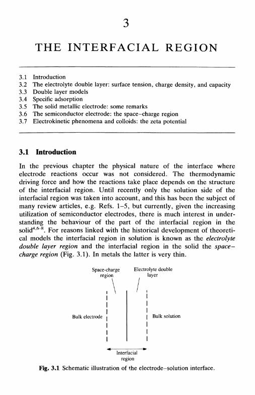
THE INTERFACIAL REGION
3.1 Introduction3.2 The electrolyte double layer: surface tension, charge density, and capacity3.3 Double layer models3.4 Specific adsorption3.5 The solid metallic electrode: some remarks3.6 The semiconductor electrode: the space-charge region3.7 Electrokinetic phenomena and colloids: the zeta potential
3.1 Introduction
In the previous chapter the physical nature of the interface whereelectrode reactions occur was not considered. The thermodynamicdriving force and how the reactions take place depends on the structureof the interfacial region. Until recently only the solution side of theinterfacial region was taken into account, and this has been the subject ofmany review articles, e.g. Refs. 1-5, but currently, given the increasingutilization of semiconductor electrodes, there is much interest in under-standing the behaviour of the part of the interfacial region in thesolid4'6"8. For reasons linked with the historical development of theoreti-cal models the interfacial region in solution is known as the electrolytedouble layer region and the interfacial region in the solid the space-charge region (Fig. 3.1). In metals the latter is very thin.
Space-chargeregion
Electrolyte doublelayer
Bulk electrode Bulk solution
Interfacialregion
Fig. 3.1 Schematic illustration of the electrode-solution interface.
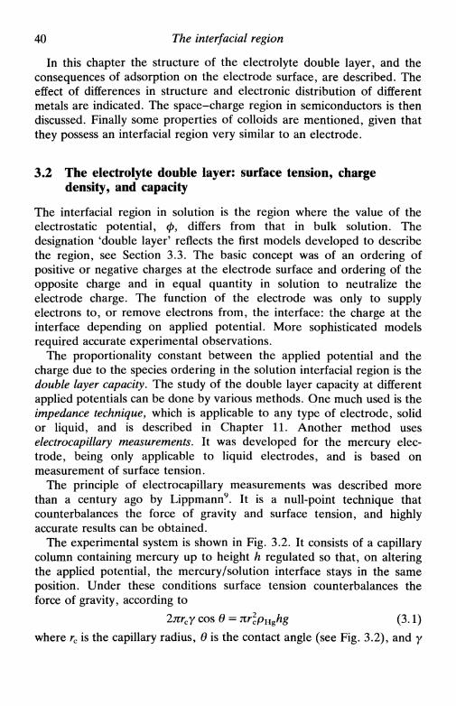
40 The interfacial region
In this chapter the structure of the electrolyte double layer, and theconsequences of adsorption on the electrode surface, are described. Theeffect of differences in structure and electronic distribution of differentmetals are indicated. The space-charge region in semiconductors is thendiscussed. Finally some properties of colloids are mentioned, given thatthey possess an interfacial region very similar to an electrode.
3.2 The electrolyte double layer: surface tension, chargedensity, and capacity
The interfacial region in solution is the region where the value of theelectrostatic potential, ф, differs from that in bulk solution. Thedesignation 'double layer' reflects the first models developed to describethe region, see Section 3.3. The basic concept was of an ordering ofpositive or negative charges at the electrode surface and ordering of theopposite charge and in equal quantity in solution to neutralize theelectrode charge. The function of the electrode was only to supplyelectrons to, or remove electrons from, the interface: the charge at theinterface depending on applied potential. More sophisticated modelsrequired accurate experimental observations.
The proportionality constant between the applied potential and thecharge due to the species ordering in the solution interfacial region is thedouble layer capacity. The study of the double layer capacity at differentapplied potentials can be done by various methods. One much used is theimpedance technique, which is applicable to any type of electrode, solidor liquid, and is described in Chapter 11. Another method useselectrocapillary measurements. It was developed for the mercury elec-trode, being only applicable to liquid electrodes, and is based onmeasurement of surface tension.
The principle of electrocapillary measurements was described morethan a century ago by Lippmann9. It is a null-point technique thatcounterbalances the force of gravity and surface tension, and highlyaccurate results can be obtained.
The experimental system is shown in Fig. 3.2. It consists of a capillarycolumn containing mercury up to height h regulated so that, on alteringthe applied potential, the mercury/solution interface stays in the sameposition. Under these conditions surface tension counterbalances theforce of gravity, according to
2ягсу cos в = nrlpHghg (3.1)
where rc is the capillary radius, в is the contact angle (see Fig. 3.2), and у
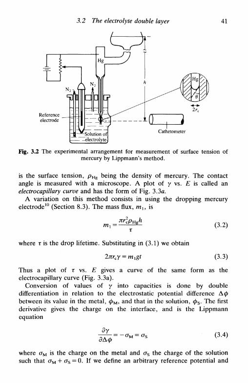
3.2 The electrolyte double layer
I
41
Referenceelectrode
Cathetometer
Fig. 3.2 The experimental arrangement for measurement of surface tension ofmercury by Lippmann's method.
is the surface tension, p H g being the density of mercury. The contactangle is measured with a microscope. A plot of у vs. E is called anelectrocapillary curve and has the form of Fig. 3.3a.
A variation on this method consists in using the dropping mercuryelectrode10 (Section 8.3). The mass flux, rab is
(3.2)
where r is the drop lifetime. Substituting in (3.1) we obtain
(3.3)
Thus a plot of т vs. E gives a curve of the same form as theelectrocapillary curve (Fig. 3.3a).
Conversion of values of у into capacities is done by doubledifferentiation in relation to the electrostatic potential difference Афbetween its value in the metal, фм, and that in the solution, фБ. The firstderivative gives the charge on the interface, and is the Lippmannequation
дАф'(3.4)
where oM is the charge on the metal and as the charge of the solutionsuch that oM + a s = 0. If we define an arbitrary reference potential and

42 The interfacial region
(a)
(c)
Fig. 3.3 Schematic plots of the double layer region, (a) ElectrocapiUary curve(surface tension, y, vs. potential); (b) Charge density on the electrode, aM, vs.potential; (c) Differential capacity, Cd, vs. potential. Curve (b) is obtained bydifferentiating curve (a), and (c) by differentiation of (b), Ez is the point of zero
charge.
the potential in relation to that reference is EA then д(Аср) ~ <5(£д) and
ByТЕГ"— ~°м (y-b)otL д
The fact that the Lippmann equation is the derivative of the electroca-piUary equation shows that the charge oM is zero when the slope of theelectrocapiUary curve is zero. The potential where this occurs is called thepoint of zero charge, Ez, and occurs at the maximum in the electroca-piUary curve, see Fig. 3.3.
A second differentiation of the electrocapiUary curve gives the value ofthe interfacial capacity. There are, however, two definitions of this:
• The differential capacity Cd. This is the derivative of the curve of aM
vs. E (Fig. 3.3c), whose minimum value occurs for E = Ez:

3.2 The electrolyte double layer 43
420
380
340
300
260
KOH
/11 NaCl/ ,
jKCNSfi
_Ca(NO3)2
-
f \NaBr/ \
KI \
\
i i i
0.5
(a)
0 -0.5
(E- E7)/V-1.0
3 2 -
24
16
0
1 M
0.8
(b)
0 -0.8
(E- E7)/V
- 1 . 6
Fig. 3.4 (a) Electrocapillary curves for mercury in contact with various elec-trolytes (Ez is the value for sodium fluoride); (b) Variation of the differentialcapacity of sodium fluoride at mercury with potential. (From Ref. 11 with
permission.)
• The integral capacity, Cx. Measuring a M for two reasonably differentpotentials, the value of the calculated capacity is the average value in thatzone, assuming that C d varies with E. This is the integral capacity that iszero at E = Ez, the point of zero charge
Е-Ех
(3.7)
44 The interfacial region
CddEE 7 - E (3.8)
I dEEz
Figure 3.4 gives examples of real electrocapillary curves anddifferential capacity curves. Double layer models have to explain theshape of these curves.
The impedance technique gives values of Cd directly. It consists of theapplication of a small sinuisoidal perturbation superimposed on a fixedapplied potential. The component of the resulting current that is out ofphase with the applied signal leads to calculation of the differentialcapacity of the interface. More details are given in Chapter 11. Thus,values of aM and у are obtained by integration. Besides making the useof solid, and not only liquid, electrodes possible, another advantage isthat integration tends to reduce the errors in the experimental measure-ments, whereas differentiation increases them.
3.3 Double layer models
Any double layer model has to explain experimental results, for examplein Fig. 3.4 for sodium fluoride at a mercury electrode. Until the 1960smeasurements were made almost exclusively at mercury electrodes andmodels were developed for this electrode. The fact that mercury is anideally polarizable liquid in the zone negative to the hydrogen electrodemeans that its behaviour is often different from solid electrodes (mono-crystalline and polycrystalline). These models are, therefore, of apredominantly electrostatic nature.
Nevertheless, an important application of electrostatic models is to theinterface between two immiscible electrolyte solutions. This can beviewed as two electrolyte double layers arranged back to back. In reality,however, total immiscibility never occurs and the degree of miscibilityincreases with the presence of electrolyte, so that corrections to themodels need to be introduced.
It was only after making measurements with solid electrodes that theconcept of the energy associated with the electrode's electronic distribu-tion in the interfacial region was introduced. This distribution depends onthe electrode material as well as on its crystalline structure and exposedcrystallographic face. However, it is interesting to see the historicalevolution of the models, given that successively more factors that reflectthe structure have been introduced.
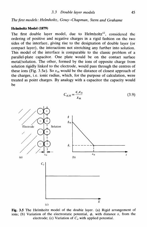
3.3 Double layer models
The first models: Helmholtz, Gouy -Chapman, Stern and Grahame
45
Helmholtz Model (1879)
The first double layer model, due to Helmholtz12, considered theordering of positive and negative charges in a rigid fashion on the twosides of the interface, giving rise to the designation of double layer (orcompact layer), the interactions not stretching any further into solution.This model of the interface is comparable to the classic problem of aparallel-plate capacitor. One plate would be on the contact surfacemetal/solution. The other, formed by the ions of opposite charge fromsolution rigidly linked to the electrode, would pass through the centres ofthese ions (Fig. 3.5я). So xu would be the distance of closest approach ofthe charges, i.e. ionic radius, which, for the purpose of calculation, weretreated as point charges. By analogy with a capacitor the capacity wouldbe
d,H 'xH
(3.9)
Solution
(b)
(c)
Fig. 3.5 The Helmholtz model of the double layer, (a) Rigid arrangement ofions; (b) Variation of the electrostatic potential, ф, with distance x, from the
electrode; (c) Variation of Cd with applied potential.
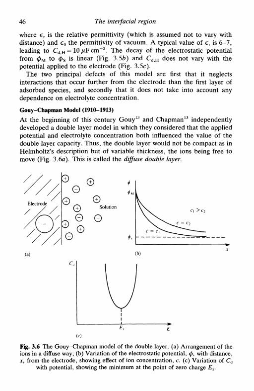
46 The interfacial region
where er is the relative permittivity (which is assumed not to vary withdistance) and e0 the permittivity of vacuum. A typical value of er is 6-7,leading to C d H = lOjuFcm"2. The decay of the electrostatic potentialfrom ф м to ф$ is linear (Fig. 3.5b) and Cd H does not vary with thepotential applied to the electrode (Fig. 3.5c).
The two principal defects of this model are first that it neglectsinteractions that occur further from the electrode than the first layer ofadsorbed species, and secondly that it does not take into account anydependence on electrolyte concentration.
Gouy-Chapman Model (1910-1913)
At the beginning of this century Gouy13 and Chapman13 independentlydeveloped a double layer model in which they considered that the appliedpotential and electrolyte concentration both influenced the value of thedouble layer capacity. Thus, the double layer would not be compact as inHelmholtz's description but of variable thickness, the ions being free tomove (Fig. 3.6a). This is called the diffuse double layer.
Solution
0
0 0©
с, >c2
(a) (b)
(с)
Fig. 3.6 The Gouy-Chapman model of the double layer, (a) Arrangement of theions in a diffuse way; (b) Variation of the electrostatic potential, ф, with distance,xy from the electrode, showing effect of ion concentration, с. (с) Variation of Cd
with potential, showing the minimum at the point of zero charge Ez.
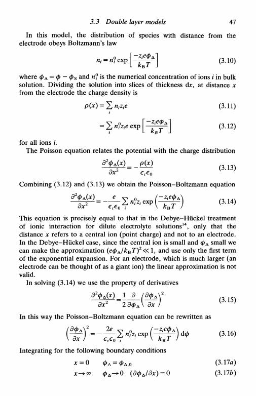
3.3 Double layer models 47
In this model, the distribution of species with distance from theelectrode obeys Boltzmann's law
where 0 Д = ф — ф3 and n° is the numerical concentration of ions i in bulksolution. Dividing the solution into slices of thickness djc, at distance xfrom the electrode the charge density is
PW = S W (З.П)
? [ ^ ] (зл2)
for all ions i.The Poisson equation relates the potential with the charge distribution
Combining (3.12) and (3.13) we obtain the Poisson-Boltzmann equation
' n*i2i e x p
This equation is precisely equal to that in the Debye-Hiickel treatmentof ionic interaction for dilute electrolyte solutions14, only that thedistance x refers to a central ion (point charge) and not to an electrode.In the Debye-Hiickel case, since the central ion is small and фА small wecan make the approximation (ефА/квТ)2« 1, and use only the first termof the exponential expansion. For an electrode, which is much larger (anelectrode can be thought of as a giant ion) the linear approximation is notvalid.
In solving (3.14) we use the property of derivatives
э2ф^х)_\ э /дфл2
Эх2 2ЭфА\ Эх I K ' '
In this way the Poisson-Boltzmann equation can be rewritten asa 2c v 0
Z, пъ expIntegrating for the following boundary conditions
(3.17a)
0 (3.176)

48 The interfacial region
we get
'Эф ч 2
Эх
For a z : z electrolyte
Эх \ ехе
This equation can be integrated, if written in the form
ГФА
(3.20,
The result is
2kBT Г tanh (zect>J4kBT)n
We can write
Г tanh(ze0A/4A:Br) 1= exP - ^ M (3.22)
in which JCD L is a distance characteristic of the diffuse layer thickness
For water (e r = 78) at 298 K, * D L = 3.04 x 10~8z~l c" 1 / 2 cm. Note that thedrop in potential with distance is faster for higher concentrations and thatx D L « r 1 / 2 reflecting the thermal energy of the ions (equation (3.23)). IfCoo = 1.0 M and z = l then, from (3.23), x D L = 0.3nm. The decay ofpotential is shown in Fig. 3.6b.
The value of C d is easily obtained from (3.19). The charge density ofthe diffuse layer is
(3.24)л:=0
(3.25)
Differentiating,
Эаы (2г2е2€т€ф(1= ( T - = cosh (3.26)
^ kBT I \2kBT/

3.3 Double layer models 49
The cosh term gives rise to the variation in capacity with potential shownin Fig. 3.6c. The minimum in the curve is identifiable with the point ofzero charge, Ez, and the curve is symmetric around Ez.
For dilute aqueous solutions at 298 K,
C d , G C = 228zcl/2 cosh (19.5z0A t O) ]UF cm" 2
This model is better than a parallel-plate capacitor for simulatingcurves such as in Fig. 3.46, but only close to Ez: in reality, far from E z ,Cd is, to a first approximation, independent of potential. We rememberthe approximation that ions are considered as point charges and that,consequently, there is no maximum concentration of ions close to theelectrode surface!
Stern Model (1924)
Stern15 combined the Helmholtz model for values of potential far from Ez
with the Gouy-Chapman model for values close to Ez (Fig. Ъ.1ауЬ). Неconsidered that the double layer was formed by a compact layer of ions
Solution
0(a)
(c)
Fig. 3.7 The Stern model of the double layer, (a) Arrangement of the ions in acompact and a diffuse layer; (b) Variation of the electrostatic potential, ф, with
distance, x, from the electrode; (c) Variation of Cd with potential.

50 The interfacial region
next to the electrode followed by a diffuse layer extending into bulksolution. The physical explanation of the experimental measurements isthat, far from Ez, the electrode exerts a strong attraction towards the ionsthat are therefore attached rigidly to the surface, all the potential dropbeing restricted to within the distance corresponding to the first layer ofions (compact layer). Close to Ez there is a diffuse distribution of ions(diffuse layer).
In mathematical terms this is equivalent to two capacitors in series,with capacities CH representing the rigid compact layer and CGC
representing the diffuse layer. The smaller of the two capacities deter-mines the observed behaviour:
^=r+r~ (3-27)
(2eTe0z2e2nykBT)mcosh(ze<t>At0/2kBT) K' }
Fig. 3.7c shows the variation of the total capacity with potential. Thereare two extreme cases:
• close to Ez, CH » CGC and so Cd ~ CGC
• far from £z , CH « CGC and Cd ~ CH
which satisfies the assumptions of the model.As in the Gouy-Chapman model, the more concentrated the elec-
trolyte the less the importance of the thickness of the diffuse layer andthe more rapid the potential drop. At distance xH there is the transitionfrom the compact to the diffuse layer. The separation plane between thetwo zones is called the outer Helmholtz plane (OHP): the origin of theinner Helmholtz plane will be discussed below.
Comparison between Figs 3.7c and ЪЛЪ shows that this model is thebest of the three so far, but does not yet explain all the facets of thecurves. Indeed, as already mentioned, mercury, as a liquid, is a specialcase. Results with other electrolytes and with solid electrodes show amore complicated behaviour.
Grahame Model (1947)
In spite of the fact that Stern had already distinguished between ionsadsorbed on the electrode surface and those in the diffuse layer, it wasGrahame11 who developed a model that is constituted by three regions(Fig. 3.8). The difference between this and the Stern model is theexistence of specific adsorption (Section 3.4): a specifically adsorbed ionloses its solvation, approaching closer to the electrode surface—besidesthis it can have the same charge as the electrode or the opposite charge,
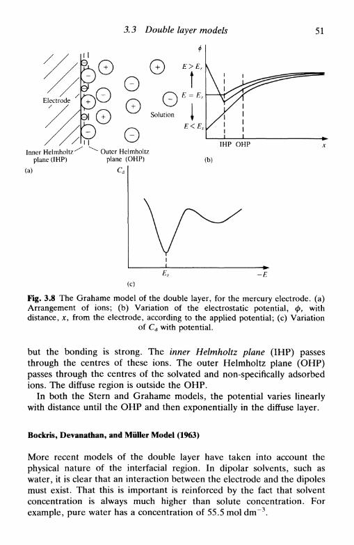
3.3 Double layer models 51
E<E7
IHP OHPInner Helmholtz
plane (IHP)
(a)
• Outer Helmholtzplane (OHP) (b)
-E(c)
Fig. 3.8 The Grahame model of the double layer, for the mercury electrode, (a)Arrangement of ions; (b) Variation of the electrostatic potential, ф, withdistance, x, from the electrode, according to the applied potential; (c) Variation
of Cd with potential.
but the bonding is strong. The inner Helmholtz plane (IHP) passesthrough the centres of these ions. The outer Helmholtz plane (OHP)passes through the centres of the solvated and non-specifically adsorbedions. The diffuse region is outside the OHP.
In both the Stern and Grahame models, the potential varies linearlywith distance until the OHP and then exponentially in the diffuse layer.
Bockris, Devanathan, and Muller Model (1963)
More recent models of the double layer have taken into account thephysical nature of the interfacial region. In dipolar solvents, such aswater, it is clear that an interaction between the electrode and the dipolesmust exist. That this is important is reinforced by the fact that solventconcentration is always much higher than solute concentration. Forexample, pure water has a concentration of 55.5 mol dm~3.

52 The interfacial region
0
E>E7
E<E7i i
IHP OHP
(a) (b)
Fig. 3.9 The model of Bockris et al. of the double layer, (a) Arrangement of ionsand solvent molecules; ® represents a water molecule; (b) Variation of the
electrostatic potential, ф, with distance, x, from the electrode.
The Bockris, Devanathan, and Miiller model16 recognizes this situationand shows the predominance of solvent molecules near the interface (Fig.3.9). The solvent dipoles are oriented according to the electrode chargewhere they form a layer together with the specifically adsorbed ions.
Regarding the electrode as a giant ion, the solvent molecules form itsfirst solvation layer; the IHP is the plane that passes through the centre ofthese dipoles and specifically adsorbed ions. In a similar fashion, OHPrefers to adsorption of solvated ions that could be identified with asecond solvation layer. Outside this comes the diffuse layer. Note that theactual profile of electrostatic potential variation with distance (Fig. 3.9b)is the same in qualitative terms as in the Grahame model (Fig. 3.8b).
These authors also defined a shear plane, not necessarily coincidentwith the outer Helmhoitz plane, which is extremely important inelectrokinetic effects (Section 3.7). The shear plane limits the zone wherethe rigid holding of ions owing to the electrode charge ceases to operate.The potential of this plane is called the zeta or electrokinetic potential, f.
'Chemical' models
The concept of double layer structure is far from being well establishedand evaluated. The models presented above give emphasis to electros-tatic considerations. 'Chemical' models have been developed that con-sider the electronic distribution of the atoms in the electrode, which isrelated to their work function. This was only possible after experimental
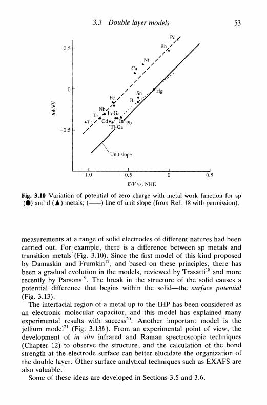
3.3 Double layer models 53
0.5
0
-0.5
-
NiA /
Ca /A /
/ Sn VFe / n. • ./
Nb Л /T a Vln-Ga .-\/^
ATi / Cdv**In^>b
/ "Tl-Ga
Unit slope
I i
/
i i
-1.0 -0.5 0E/Vvs. NHE
0.5
Fig. 3.10 Variation of potential of zero charge with metal work function for sp(•) and d (A) metals; ( ) line of unit slope (from Ref. 18 with permission).
measurements at a range of solid electrodes of different natures had beencarried out. For example, there is a difference between sp metals andtransition metals (Fig. 3.10). Since the first model of this kind proposedby Damaskin and Frumkin17, and based on these principles, there hasbeen a gradual evolution in the models, reviewed by Trasatti18 and morerecently by Parsons19. The break in the structure of the solid causes apotential difference that begins within the solid—the surface potential(Fig. 3.13).
The interfacial region of a metal up to the IHP has been considered asan electronic molecular capacitor, and this model has explained manyexperimental results with success20. Another important model is thejellium model21 (Fig. 3.13fo). From an experimental point of view, thedevelopment of in situ infrared and Raman spectroscopic techniques(Chapter 12) to observe the structure, and the calculation of the bondstrength at the electrode surface can better elucidate the organization ofthe double layer. Other surface analytical techniques such as EXAFS arealso valuable.
Some of these ideas are developed in Sections 3.5 and 3.6.

54 The interfacial region
3.4 Specific adsorption
As explained in the description of the Grahame model for the doublelayer, specific adsorption is the adsorption of ions at the electrode surfaceafter losing their solvation partially or completely. These ions can havethe same charge or the opposite charge to the electrode. Bonds formedwith the electrode in this way are stronger than for solvated ions.
The idea of the existence of specific adsorption appeared as anexplanation for the fact that electrocapillary curves at mercury electrodesare different for different electrolytes at the same concentration (Fig.ЪЛа). For sodium and potassium halides in water the differences arise atpotentials positive of Ez, which suggests an interaction with the anions.As the effect is larger the smaller the ionic radius of the anion, the idea ofspecific adsorption with partial or total loss of hydration arose.
The degree of specific adsorption should vary with electrolyte con-centration, just as there should be a change in the point of zero chargedue to specific adsorption of charges. This is the Esin-Markov effect,expressed by the Esin-Markov coefficient, /3:
1 (d(eEz)\ (d(6Ez)\
^т-^)=\-^г) (3-29)
This derivative is equal to zero in the absence of specific adsorption. Foranion adsorption, and constant charge density, the point of zero chargemoves in the negative direction in order to counterbalance adsorption.For cations, Ez moves in the positive direction, assuming constant chargedensity. In aqueous solution, specific adsorption only occurs close to Ez;far from £z, solvent molecules are attracted so strongly that it is difficultto push them out of the way.
Experimentally it is observed that specific adsorption occurs more withanions than with cations. This is in agreement with chemical models ofthe interfacial region. Since, according to the free electron model, ametallic lattice can be considered as a cation lattice in a sea of electronsin free movement, it is logical to expect a greater attraction for anions insolution.
The degree of adsorption depends on electrolyte concentration. Thedegree of coverage of a surface by specific adsorption of ions can bedescribed by monolayer adsorption isotherms (Fig. 3.11). Three types ofisotherm are generally considered:
• Langmuir isotherm (Fig. 3.11л). It is assumed that there is nointeraction between adsorbed species, that the surface is smooth, andthat eventually surface saturation occurs. Thus, if в is the fraction of

3.4 Specific adsorption 55
оp p p
(a) (b) (c)
Fig. 3.11 Adsorption isotherms: (a) Langmuir; (b) Temkin; (c) Frumkin.
coverage
1-е(3.30)
where Д is the energetic coefficient of proportionality and aix the activityof species i in bulk solution.
• Temkin isotherm (Fig. 3.116). This considers that the adsorptionenergy is a function of the degree of coverage according to
Г, = (3.31)
where Г, is the excess of species i, and g a parameter that treats theinteraction energy between the adsorbed species, varying with coverage.
• Frumkin isotherm (Fig. 3.11c). This considers interactions in adifferent way:
(3.32a)
or
Г - ГX S L I
D'T'
Г, = — In (fta,,») In
RT
(3-326)
F s being the maximum surface excess. A positive value of g impliesattractive interaction and negative g repulsive interaction. When g = 0and putting i y r s = 0, the Langmuir isotherm is obtained from (3.32a).Additionally, comparison of (3.31) and (3.32) shows that the Temkinisotherm is a special case of the Frumkin isotherm when Г,/Г8 = 0.5.
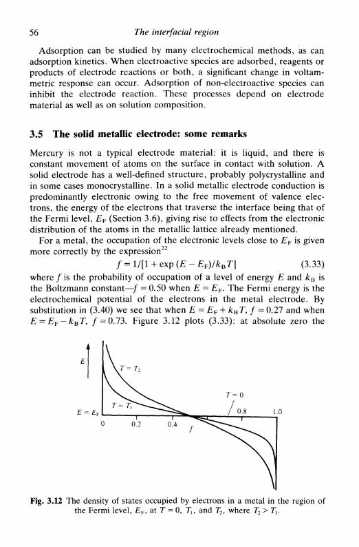
56 The interfacial region
Adsorption can be studied by many electrochemical methods, as canadsorption kinetics. When electroactive species are adsorbed, reagents orproducts of electrode reactions or both, a significant change in voltam-metric response can occur. Adsorption of non-electroactive species caninhibit the electrode reaction. These processes depend on electrodematerial as well as on solution composition.
3.5 The solid metallic electrode: some remarks
Mercury is not a typical electrode material: it is liquid, and there isconstant movement of atoms on the surface in contact with solution. Asolid electrode has a well-defined structure, probably polycrystalline andin some cases monocrystalline. In a solid metallic electrode conduction ispredominantly electronic owing to the free movement of valence elec-trons, the energy of the electrons that traverse the interface being that ofthe Fermi level, EF (Section 3.6), giving rise to effects from the electronicdistribution of the atoms in the metallic lattice already mentioned.
For a metal, the occupation of the electronic levels close to EF is givenmore correctly by the expression22
/ = 1/[1 + exp (E - EF)/kBT] (3.33)where / is the probability of occupation of a level of energy E and kB isthe Boltzmann constant—/ = 0.50 when E = EF. The Fermi energy is theelectrochemical potential of the electrons in the metal electrode. Bysubstitution in (3.40) we see that when E = £ F 4- kBT, f = 0.27 and whenE = EF-kBT, / = 0.73. Figure 3.12 plots (3.33): at absolute zero the
Fig. 3.12 The density of states occupied by electrons in a metal in the region ofthe Fermi level, £F, at T = 0, Tx, and T2, where T2>TX.

3.5 The solid metallic electrode: some remarks 57
cut-off is sharp, the probability of occupation becoming more smearedout as the temperature increases.
By convention, for a metal, it is said that only electrons with energieswithin kBT of EF can be transferred. (In the case of semiconductors(3.33) cannot be applied and larger energy intervals have to beconsidered.)
The interfacial structure of a solid electrode depends on variousfactors. The interatomic distance varies with the exposed crystallographicface and with the interaction energy; between the crystallites in apolycrystalline material there are breaks in the structure and one-dimensional and two-dimensional defects, such as screw dislocations, etc.Adsorption of species can be facilitated or made more difficult, and at themacroscopic level we observe the average behaviour.
Recently the structure of the double layer associated with the interfaceof gold and platinum monocrystals with solution has been investigated23.A clear difference between crystallographic faces is noted, manifested inthe values of differential capacity and in evidence of adsorption involtammograms. Cyclic voltammograms suggest that there is a reor-ganization on the metal surface to give the equivalent of a surface layerof low Miller index, the identity of this face depending on the appliedpotential24. These studies are still in their early stages and concreteconclusions concerning a possible restructuring cannot yet be stated.
Electrode
(a)
Electrode
(b)
Fig. 3.13 Variation of the electrostatic potentials with distance from a metallicelectrode, (a) Classical representation; (b) The 'jellium' model.
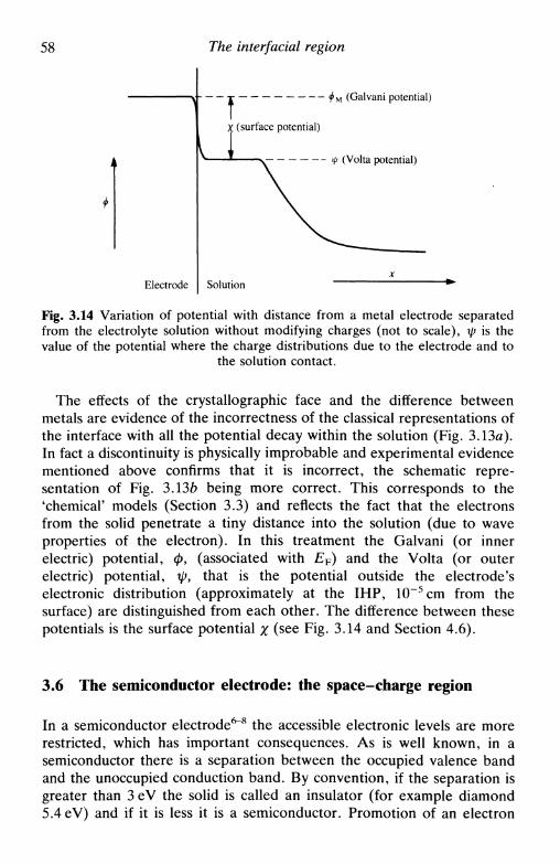
58 The interfacial region
(Galvani potential)
V (Volta potential)
Electrode
Fig. 3.14 Variation of potential with distance from a metal electrode separatedfrom the electrolyte solution without modifying charges (not to scale), ip is thevalue of the potential where the charge distributions due to the electrode and to
the solution contact.
The effects of the crystallographic face and the difference betweenmetals are evidence of the incorrectness of the classical representations ofthe interface with all the potential decay within the solution (Fig. 3.13fl).In fact a discontinuity is physically improbable and experimental evidencementioned above confirms that it is incorrect, the schematic repre-sentation of Fig. 3.136 being more correct. This corresponds to the'chemical' models (Section 3.3) and reflects the fact that the electronsfrom the solid penetrate a tiny distance into the solution (due to waveproperties of the electron). In this treatment the Galvani (or innerelectric) potential, ф, (associated with EF) and the Volta (or outerelectric) potential, \py that is the potential outside the electrode'selectronic distribution (approximately at the IHP, 10~5cm from thesurface) are distinguished from each other. The difference between thesepotentials is the surface potential % (see Fig. 3.14 and Section 4.6).
3.6 The semiconductor electrode: the space-charge region
In a semiconductor electrode6"8 the accessible electronic levels are morerestricted, which has important consequences. As is well known, in asemiconductor there is a separation between the occupied valence bandand the unoccupied conduction band. By convention, if the separation isgreater than 3 eV the solid is called an insulator (for example diamond5.4 eV) and if it is less it is a semiconductor. Promotion of an electron
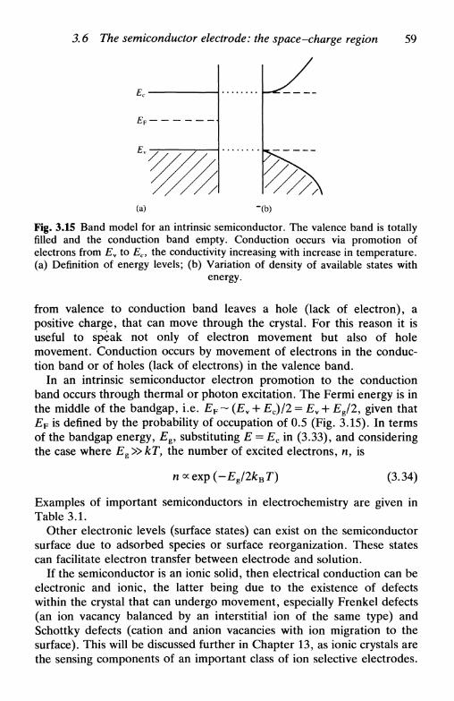
3.6 The semiconductor electrode: the space-charge region 59
(a) "(b)
Fig. 3.15 Band model for an intrinsic semiconductor. The valence band is totallyfilled and the conduction band empty. Conduction occurs via promotion ofelectrons from Ev to Ec, the conductivity increasing with increase in temperature,(a) Definition of energy levels; (b) Variation of density of available states with
energy.
from valence to conduction band leaves a hole (lack of electron), apositive charge, that can move through the crystal. For this reason it isuseful to speak not only of electron movement but also of holemovement. Conduction occurs by movement of electrons in the conduc-tion band or of holes (lack of electrons) in the valence band.
In an intrinsic semiconductor electron promotion to the conductionband occurs through thermal or photon excitation. The Fermi energy is inthe middle of the bandgap, i.e. EF~ (Ev + Ec)/2 = Ev + £g/2, given thatEF is defined by the probability of occupation of 0.5 (Fig. 3.15). In termsof the bandgap energy, Eg, substituting E = Ec in (3.33), and consideringthe case where Eg»kT, the number of excited electrons, n, is
n oc PYn ( I* 10k T\ C\ \&\
Examples of important semiconductors in electrochemistry are given inTable 3.1.
Other electronic levels (surface states) can exist on the semiconductorsurface due to adsorbed species or surface reorganization. These statescan facilitate electron transfer between electrode and solution.
If the semiconductor is an ionic solid, then electrical conduction can beelectronic and ionic, the latter being due to the existence of defectswithin the crystal that can undergo movement, especially Frenkel defects(an ion vacancy balanced by an interstitial ion of the same type) andSchottky defects (cation and anion vacancies with ion migration to thesurface). This will be discussed further in Chapter 13, as ionic crystals arethe sensing components of an important class of ion selective electrodes.

60 The interfacial region
Table 3.1. Bandgap energy, Eg, and cor-responding wavelength Abg (important forphoto-excitation) of some semiconductorsof electrochemical interest25. Zone of vis-
ible light (300-*950nm)
Semiconductor
SnO2
ZnOSrTiO3
TiO2
CdSGaPFe2O3
CdSeCdTeGaAsInPSi
EJzV
3.53.23.23.02.42.32.11.71.41.41.31.1
Abg/nm
350390390410520540590730890890950
1130
However, to simplify the discussion that follows and since at present themajority of semiconductors of electrochemical interest are not ioniccrystals, we consider only electronic conduction.
Owing to difficulties in electron movement in semiconductors, when asteady state has been achieved almost all the applied potential appearswithin the semiconductor, creating a region of potential variation close tothe surface called the space-charge region (Fig. 3.16).
In fact intrinsic semiconductors, which are necessarily pure crystals, are
Space-changeregion
Solution
Surface
Fig. 3.16 The space-charge region in an intrinsic semiconductor.

3.6 The semiconductor electrode: the space-charge region 61
little used. It is more common to use doped semiconductors, the dopingnormally being introduced externally. In an n-type semiconductor dopingis obtained by introducing an atom into the lattice that has approximatelythe same size as the substrate atoms but with more electrons, e.g. silicondoped with phosphorus or arsenic, or non-stoichiometric III-V com-pounds; they will occupy lattice positions and supply electrons that canmove through the crystal. The energy of these electrons is slightly lessthan Ec; electronic conduction can be by thermal excitation from theimpurity band to the conduction band (Fig. 3.11a). In a p-typesemiconductor the doped atoms have a deficiency of electrons in relationto substrate atoms leading to an unoccupied band a little above £v; holeconduction in the valence band occurs via electron promotion from Ey tothe unoccupied band (Fig. 3.17b). By doping it is possible to change asolid that under normal conditions would be an insulator, owing to thelarger bandgap, into a semiconductor. However, in electrochemistry, thedoping is done principally to fix £ F close to Ec (n-type) or close to Ew
(p-type).In a semiconductor electrode, almost all the potential variation in the
interfacial region occurs in the space-charge region. This is due to thefact that the values for the space-charge capacity, Csc, are from0.001-1 ]UF cm"2, whilst those for Cd are from 10-100 JUF cm"2, so thatCsc dominates. The theory of the space-charge region was developed bySchottky26, Mott27, Davydov28, and more completely by Brittain andGarrett29.
We now describe the effect of applied potential to an n-type semicon-ductor in its space-charge region. As there is an excess of electrons, theelectron is the majority carrier; as there is also movement of a muchsmaller number of holes (electron deficiencies), the hole is the minority
Full
Empty
Ev / / / / / / / / / / / / / / / / / / / / v̂
(a) (b)
Fig. 3.17 Semiconductors: (a) n-type; (b) p-type. The mode of electron conduc-tion is indicated by the arrows.
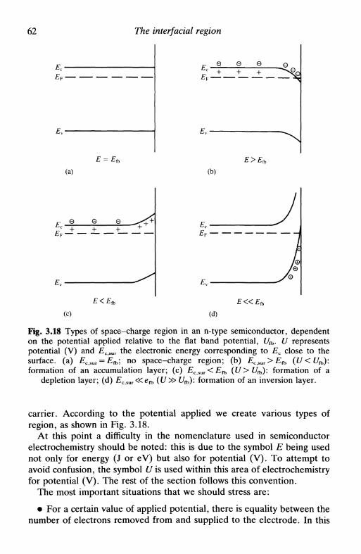
62 The interfacial region
Q Q Q
(a) (b)
(c) (d)
Fig. 3.18 Types of space-charge region in an n-type semiconductor, dependenton the potential applied relative to the flat band potential, U^. U representspotential (V) and ECSUT the electronic energy corresponding to Ec close to thesurface, (a) £c,sur = E^; no space-charge region; (b) ECt%UT> E^ ((/<f/fb):formation of an accumulation layer; (c) ECSUT<Efb (UXJa,): formation of a
depletion layer; (d) £c,sur«efb (U>> Ufb): formation of an inversion layer.
carrier. According to the potential applied we create various types ofregion, as shown in Fig. 3.18.
At this point a difficulty in the nomenclature used in semiconductorelectrochemistry should be noted: this is due to the symbol E being usednot only for energy (J or eV) but also for potential (V). To attempt toavoid confusion, the symbol U is used within this area of electrochemistryfor potential (V). The rest of the section follows this convention.
The most important situations that we should stress are:
• For a certain value of applied potential, there is equality between thenumber of electrons removed from and supplied to the electrode. In this

3.6 The semiconductor electrode: the space-charge region 63
situation there will be no space-charge region and the potential is calledthe flat-band potential, 1/л.
• Electrons accumulate in the space-charge layer by injection, givingrise to an accumulation layer.
• Electrons are removed from the space-charge layer, creating adepletion layer.
• The force to extract electrons from the electrode is so great that theyare extracted not only from the conduction band but also from thevalence band (equivalent to hole injection). An inversion layer is formed,so called because the n-type semiconductor is converted into a p-typesemiconductor at the surface. Adsorbates can facilitate this process.
To have passage of current it is necessary that EF is within theconduction or within the valence band in the space-charge region, i.e.accumulation layer in an n-type semiconductor (reduction) or holeaccumulation layer in a p-type semiconductor (oxidation).
There is an analogy with the Schottky diode. When Ecsur>E^(negative voltage bias), and possibly for E slightly negative in relation toЕъ, there will be a large current flux, assuming that there are electroniclevels in solution to accept the electrons from the electrode. WhenEc,sur<Efb the current will be almost zero.
Another important aspect refers to adsorbates. These have their ownassociated energy levels, known as surface states, and can aid electrontransfer if there is superposition of the conduction band and thatcorresponding to the surface state (Fig. 3.19). A better understanding ofthe energy distributions of the solution species in Fig. 3.19 is possible onreferring to Section 4.6.
y-j^ Surface state
Fig. 3.19 Conjugation of an accumulation layer in an n-type semiconductor witha surface state to facilitate the reduction of О to R. In the absence of the surface
state, there would be no reaction.

64 The interfacial region
For a p-type semiconductor the arguments are analogous; in this casethe majority carrier is the hole.
Due to the great extension of the space-charge region, almost all thepotential drop occurs across it. So we can measure its capacity, Csc, andcalculate E^ from the Mott-Schottky relation
where Nu is the density of donor atoms. A plot of C~c
2 vs. U is a straightline if all other voltage drops are unaffected by the applied potential—wecalculate f/fb from the intercept and iVD from the slope. The presence ofadsorbates modifies C sc and is manifested in the non-linearity of theplots. Once Efb is known, we can calculate Ew and Ec from the relations
Ey = -Еъ + kBTin —p (p-type semiconductor) (3.36л)
Ec = En, + kB T In —~ (n-type semiconductor) (3.366)
where Nv and Nc are the effective density of states in the valence andconduction bands respectively for p- and п-type semiconductors, dataobtained from solid state measurements. Knowing the values of thebandgap energy, Eg (Table 3.1), we can then calculate Ec for p-type andEw for n-type semiconductors respectively.
Semiconductors are extremely important in photoelectrochemistry,where the energy necessary to jump from the valence to the conductionband is supplied by visible light. These aspects are developed in Chapter12.
3.7 Electrokinetic phenomena and colloids: the zeta potential
A colloidal system consists of a disperse phase suspended in a dispersionmedium, which does not separate with time3a"32. All combinations ofgases, liquids, and solids are possible except for a gas dispersed in a gas.Normally when speaking of colloids one is referring to a solid suspendedin a liquid, the solid particles having diameters between 10~7cm and10~5 cm. The solid particles are charged, which causes repulsion betweenthe particles and gives temporal stability to the colloidal system. Recentlythere has been increasing interest in colloids because of their possible useas electrodes for electrolysis, each particle acting as anode and cathode atthe same time. Their particular advantage is the large surface areaexposed to solution in relation to their solid volume. Since the particles
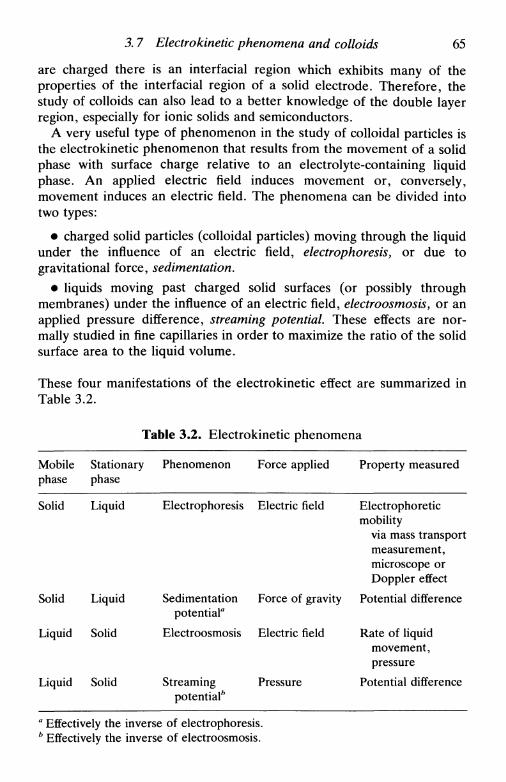
3. 7 Electrokinetic phenomena and colloids 65
are charged there is an interfacial region which exhibits many of theproperties of the interfacial region of a solid electrode. Therefore, thestudy of colloids can also lead to a better knowledge of the double layerregion, especially for ionic solids and semiconductors.
A very useful type of phenomenon in the study of colloidal particles isthe electrokinetic phenomenon that results from the movement of a solidphase with surface charge relative to an electrolyte-containing liquidphase. An applied electric field induces movement or, conversely,movement induces an electric field. The phenomena can be divided intotwo types:
• charged solid particles (colloidal particles) moving through the liquidunder the influence of an electric field, electrophoresis, or due togravitational force, sedimentation.
• liquids moving past charged solid surfaces (or possibly throughmembranes) under the influence of an electric field, electroosmosis, or anapplied pressure difference, streaming potential. These effects are nor-mally studied in fine capillaries in order to maximize the ratio of the solidsurface area to the liquid volume.
These four manifestations of the electrokinetic effect are summarized inTable 3.2.
Table 3.2. Electrokinetic phenomena
Mobilephase
Solid
Solid
Liquid
Liquid
Stationaryphase
Liquid
Liquid
Solid
Solid
Phenomenon
Electrophoresis
Sedimentationpotential"
Electroosmosis
Streamingpotential*
Force applied
Electric field
Force of gravity
Electric field
Pressure
Property measured
Electrophoreticmobility
via mass transportmeasurement,microscope orDoppler effect
Potential difference
Rate of liquidmovement,pressure
Potential difference
a Effectively the inverse of electrophoresis.b Effectively the inverse of electroosmosis.

66 The interfacial region
The size of the particles that is calculated from these experimentscorresponds to particle dimensions plus the double layer thickness, in thiscase defined by the shear plane inside which the adsorbed species arerigidly held, and outside of which there is free movement. The shearplane can therefore be associated roughly with the outer Helmholtzplane, an approximation often made. The value of the electrostaticpotential at the shear plane with respect to the value in bulk solution iscalled the electrokinetic or zeta potential, £33 (see Section 3.3).
In the presence of a large quantity of inert electrolyte, all the potentialdrop is confined to within the compact layer and £ is zero. By applicationof an appropriate potential at an electrode we can also arrange for£ = 0 - this value of the potential is called the isoelectric point. This is, ingeneral, not equal to the point of zero charge, as the value of the latter isaffected by the presence of specifically adsorbed species (Section 3.4).
We now consider briefly the four effects that are described in Table 3.2and how to deduce values of the zeta potential, £, from experimentalinformation.
Electrophoresis
In electrophoresis the solid moves in a liquid phase due to the applicationof an electric field. The forces acting on the particles are similar to thosethat act on solvated ions:
• Force of the electric field on the particle
• Frictional forces
• Forces due to the action of the electric field on ions of the oppositecharge to that of the particle within the double layer {relaxation effect)
• Induction forces in the double layer caused by the electric field(electrophoretic retardation)
The electrophoretic mobility, ме, is calculated by solving the Poissonequation with the appropriate boundary conditions. The final relation isof the type
l3 г)(3.37)
where e is the permittivity, rj the absolute viscosity, E the electric fieldstrength, and/(fl/xDL) a numerical factor, where a is the particle radiusand JCDL the double layer thickness, that varies according to which of theforces indicated above have to be considered. This depends on particlesize and double layer thickness. For every small particles in dilutesolution, the double layer is thick and/(a/xD L) —» 1 (negligible relaxation

3.7 Electrokinetic phenomena and colloids 67
effect). For large particles in concentrated solutions, where the doublelayer is thin, f(a/xDL)^> 1.5 (negligible electrophoretic retardation). Allother situations lead to intermediate numerical factors. Measurements ofelectrophoretic mobility, using (3.37) with the appropriate numericalfactor, lead to values for the zeta potential.
As can be inferred, electrophoretic mobility depends on solution ionicstrength since double layer thickness decreases with increasing electrolyteconcentration. It also depends on the surface charge of the particles. Ifthis charge varies in colloidal particles of similar dimensions thenelectrophoresis provides a basis for their separation. An example of thisis in proteins, where the surface charge varies with pH in a different wayaccording to the protein identity.
Sedimentation potential
Colloidal particles are affected by the force of gravity, either natural orthrough centrifugation. Sedimentation of the particles often gives rise toan electric field. This occurs because the particles move, whilst leavingsome of their ionic atmosphere behind. These potentials are usuallydifficult to measure, and are an unwanted side effect in ultracentrifuga-tion, where they are minimized by adding a large concentration of inertelectrolyte.
Electroosmosis
In electroosmosis, the stationary and mobile phases are exchanged inrelation to electrophoresis. As measurement of the rate of movement of aliquid through a capillary is difficult, the force that it exerts is measured,i.e. the electroosmotic pressure, or, alternatively, the volume of liquidtransported through a capillary in a given time interval. The electroos-motic velocity, veo, is
Vco = — (3.38)
which is of the same form as (3.37) for electrophoresis, putting/(fl/jcDL) = 1.5, since the capillary radius is much larger than the doublelayer thickness.
The volume flow of liquid, Vf, is veoAy where A is the cross-sectionalarea of the capillary. A current will flow of magnitude / = АкЕ, in whichк is the solution conductivity, and thus the electroosmotic flow, flux perunit electric current at zero pressure difference, is given by
Vf_ veoA _ eg(3.39)
KTj
68 The interfacial region
Streaming potential
If a pressure difference, AP, is applied between the extremes of acapillary, then a potential difference is created, called the streamingpotential:
Аф= — АР (3.40)КГ]
By comparing this with (3.39) the close relationship between streamingpotential and electroosmotic flow can be seen.
Limitations in the calculation of the zeta potential
Quantitative measurements of electrokinetic phenomena permit thecalculation of the zeta potential by use of the appropriate equations.However, in the deduction of the equations approximations are made:this is because in the interfacial region physical properties such asconcentration, viscosity, conductivity, and dielectric constant differ fromtheir values in bulk solution, which is not taken into account. Correctionsto compensate for these approximations have been introduced, as well asconsideration of non-spherical particles and particles of dimensionscomparable to the diffuse layer thickness. This should be consulted in thespecialized literature.
References
1. D. C. Grahame, Ann. Rev. Phys. Chem., 1955, 6, 337.2. R. Parsons, Modern aspects of chemistry, Butterworths, London, Vol. 1,
1954, ed. J. O'M. Bockris and В. Е. Conway, pp. 103-179.3. R. Parsons, Advances in Electrochemistry and Electrochemical Engineering,
ed. P. Delahay and C. W. Tobias, Wiley, New York, Vol. 1, 1961, pp. 1-64.4. A. F. Silva ed., Trends in interfacial electrochemistry, Proceedings of NATO
ASI (1984), Reidel, Dordrecht, 1985.5. S. Trasatti, Modern aspects of electrochemistry, Plenum, New York, Vol. 13,
1979, ed. B. E. Conway and J. O'M, Bockris, pp. 81-206.6. S. R. Morrison, Electrochemistry at semiconductor and oxidised metal
electrodes. Plenum, New York, 1980.7. K. Uosaki and H. Kita, Modern aspects of electrochemistry, Plenum, New
York, Vol. 18, 1986, ed. R. E. White, J.O'M. Bockris, and В. Е. Conway,pp. 1-60.
8. A. Hamnett, in Comprehensive chemical kinetics, ed. R. G. Compton,Elsevier, Amsterdam, Vol. 27, 1987, Chapter 2.

References 69
9. G. Lippmann, CompL Rend., 1873, 76, 1407.10. J. Heyrovsky, Chem. Listy, 1922, 16, 246.11. D. C. Grahame, Chem. Rev., 1947, 41, 441.12. H. L. F. von Helmholtz, Ann. Physik, 1853, 89, 211; 1879, 7, 337.13. G. Gouy, Compt. Rend., 1910, 149, 654; D. L. Chapman, Phil. Mag., 1913,
25, 475.14. D. Maclnnes, Principles of electrochemistry, Dover, New York, 1962,
Chapter 7.15. O. Stern, Z. Elektrochem., 1924, 30, 508.16. J. O'M. Bockris, M. A. Devanathan, and K. Muller, Proc. R. Soc, 1963,
A274, 55.17. В. В. Damaskin and A. N. Frumkin, Electrochim, Acta, 1974, 19, 173;
B. B. Damaskin, U. V. Palm, and M. A. Salve, Elektrokhimiya, 1976, 12,232; В. В. Damaskin, /. Electroanal. Chem., 1977, 75, 359.
18. S. Trasatti, in Ref. 4, 25-48.19. R. Parsons, Chem. Rev., 1990, 90, 813.20. G. A. Martynov and R. R. Salem, Electrical double layer at a metal-dilute
electrolyte solution interface, Lecture Notes in Chemistry 33, Springer-Verlag,Berlin, 1983.
21. J. Goodisman, Electrochemistry: theoretical foundations, Wiley-Interscience,New York, 1987, pp. 232-239.
22. Ref. 6, p. 5.23. A. Hamelin, Modern aspects of electrochemistry, Plenum, New York, Vol.
16, 1985, ed. B. E. Conway, R. E. White, and J. O'M, Bockris, pp. 1-101.24. R. M. Cervino, W. E. Triaca, and A. J. Arvia, /. Electroanal. Chem., 1985,
182, 51.25. H. O. Finklea, /. Chem. Ed., 1983, 60, 325.26. W. Schottky, Zeit, fur Physik, 1939, 113, 367.27. N. F. Mott, Proc. Roy. Soc, 1939, A171, 27.28. B. Davydov, /. Physics USSR, 1939, 1, 169.29. W. H. Brattain and С G. B. Garrett, Phys. Rev., 1955, 99, 376.30. R. J. Hunter, Foundations of colloid science, Oxford University Press, New
York, 1987.31. D. H. Everett, Basic principles of colloid science, Royal Society of
Chemistry, London, 1988.32. A. Kitahara and A. Watanabe, Electrical phenomena at interfaces, Dekker,
New York, 1984.33. R. J. Hunter, Zeta potential in colloid science, Academic Press, New York,
1981.
FUNDAMENTALS OF KINETICSAND MECHANISM OF
ELECTRODE REACTIONS
4.1 Introduction4.2 The mechanism of electron transfer at an electrode4.3 The mechanism of electron transfer in homogeneous solution4.4 An expression for the rate of electrode reactions4.5 The relation between current and reaction rate: the exchange current4.6 Microscopic interpretation of electron transfer
4.1 Introduction
In this chapter the mechanisms of electrode reactions are explained forthe most simple case of an electron transfer without chemical transforma-tion, i.e. without formation or breaking chemical bonds. Other morecomplex cases are also referred to. Comparison with electron transferreactions in homogeneous solution are made.
In a system involving reagents and products at equilibrium, the rates ofthe reactions in each direction are equal. Equilibrium can thus be seen asa limiting case, and any kinetic model must give the correct equilibriumexpression. For reactions at an electrode, half-reactions y the equilibriumexpression is the Nernst equation.
4.2 The mechanism of electron transfer at an electrode
We consider the case of an oxidation of reduction at an electrode withoutchemical transformation, an example being
Fe3+(aq) 4- e~(electrode) *± Fe2+(aq)
The mechanism consists of the steps shown in Fig. 4.11'2.
• 1. Diffusion of the species to where the reaction occurs (describedby a mass transfer coefficient kd - see Chapter 5).
• 2. Rearrangement of the ionic atmosphere (10~8s).

4.3 The mechanism of electron transfer 71
Diffusion (step 1)
Electrontransfer(step 5)
*c
R*
Diffusion
Fig. 4.1 Scheme of electron transfer at an electrode.
• 3. Reorientation of the solvent dipoles (10~n s).
• 4. Alterations in the distances between the central ion and theligands(HT14s).
• 5. Electron transfer (HT1 6s).
• 6. Relaxation in the inverse sense.
Steps 2-5 are included in the charge transfer rate constant, ка or kc, andinclude adsorption of the reagent on the electrode surface, which in thecase of a soluble product will afterwards de-adsorb. Steps 2-4 can beseen as a type of pre-equilibrium before the electron transfer. During theelectron transfer itself all positions of the atoms are frozen, obeying theFranck-Condon principle (adiabatic process).
4.3 The mechanism of electron transfer in homogeneoussolution
The mechanism described above is also correct for electron transfer inhomogeneous solution except that, instead of the reaction site being anelectrode, it is the point where the two ions meet in the interior of thesolution. In the equations for energy changes a factor of 2 relative toelectrode reactions appears, since whole reactions rather than half-reactions are being considered. Theoretical and experimental com-parisons between electrode reactions and redox reactions in solution havebeen made with satisfactory results3.
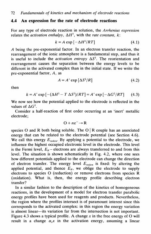
72 Fundamentals of kinetics and mechanism of electrode reactions
4.4 An expression for the rate of electrode reactions
For any type of electrode reaction in solution, the Arrhenius expressionrelates the activation enthalpy, AH*, with the rate constant, k:
k=Aexp[-AHVRT] (4.1)
A being the pre-exponential factor. In an electron transfer reaction, therearrangement of the ionic atmosphere is a fundamental step, and thus itis useful to include the activation entropy AS*. The reorientation andrearrangement causes the separation between the energy levels to bedifferent in the activated complex than in the initial state. If we write thepre-exponential factor, Л, as
A=A' exp[AS*/#] (4.2)
then
к = A' exp [-(AH* - T AS*)/RT] = A' exp [-AGVRT] (4.3)
We now see how the potential applied to the electrode is reflected in thevalues of AG*.
Consider a half-reaction of first order occurring at an 'inert' metallicelectrode;
species О and R both being soluble. The О | R couple has an associatedenergy that can be related to the electrode potential (see Section 4.6).We call this energy £redox- By applying a potential to the electrode, weinfluence the highest occupied electronic level in the electrode. This levelis the Fermi level, EF - electrons are always transferred to and from thislevel. The situation is shown schematically in Fig. 4.2, where one seeshow different potentials applied to the electrode can change the directionof electron transfer. The energy level £redox is fixed: by altering theapplied potential, and thence EF, we oblige the electrode to supplyelectrons to species О (reduction) or remove electrons from species R(oxidation). What is, then, the energy profile describing electrontransfer?
In a similar fashion to the description of the kinetics of homogeneousreactions, in the development of a model for electron transfer parabolicenergy profiles have been used for reagents and products. Nevertheless,the region where the profiles intersect is of paramount interest since thiscorresponds to the activated complex: in this region the energy variationis almost linear—its variation far from the intersection is not important.Figure 4.3 shows a typical profile. A change x in the free energy of О willresult in a change acx in the activation energy, assuming a linear

4.4 An expression for the rate of electrode reactions
Reduction
('negative' electrode potential)
Oxidation
('positive' electrode potential)
(a) (b)
Fig. 4.2 Electron transfer at an inert metallic electrode. The potential applied tothe electrode alters the highest occupied electronic energy level, EF, facilitating
(a) reduction or (b) oxidation.
intersection. So for a reduction we can write
In a similar way, for an oxidation
AG* = AG*,o - ocjiFE
(4.4a)
(4.46)
E = E (negative)
о
Reaction coordinate
Fig. 4.3 Effect of a change in applied electrode potential on the reduction of О toR (R considered absent in bulk solution and in the electrode material).

74 Fundamentals of kinetics and mechanism of electrode reactions
where E is the potential applied to the electrode and or is a measure ofthe slope of the energy profiles in the transition state zone and, therefore,of barrier symmetry. Values of aa and ac can vary between 0 and 1, butfor metals are around 0.5. A value of 0.5 means that the activatedcomplex is exactly halfway between reagents and products on thereaction coordinate, its structure reflecting reagent and product equally.In this simple case of a one-step transfer of n electrons between О and R,it is easily deduced that (аа + ac) = 1.
We now substitute the expressions for AG* from (4.4a) and (4.46). Weobtain for a reduction
kc = A' exp [-AGiJRT] exp [-acnFE/RT] (4.5a)
and for an oxidation
ka = A' exp [-AGlo/RT] exp [aanFE/RT] (4.5b)
These equations can be rewritten in the form
К = kc,o exp [-acnFE/RT] (4.6a)
and
ka = kOt0 exp [<xanFE/RT] (4.6b)
As the reaction is first order, at equilibrium
kc[O]* = ka[R]* (4.7)
where [O]* and [R]* are the concentrations of О and R next to theelectrode. If [O]* = [R]*, the potential is E^', the formal potential, and
kc = ka = k0 (4.8)
this last constant being the standard rate constant. Substituting (4.8) in(4.6a) (4.6b)f
kc = k0 exp [-acnF(E - E^')/RT] (4.9a)
ka = k0 exp [aanF(E - E^')/RT] (4.9b)
This is the formulation of electrode kinetics first derived by Butler andVolmer4. The observed current for kinetic control of the electrodereaction is proportional to the difference between the rate of theoxidation and reduction reactions at the electrode surface and is given by
I = nFA(ka[R]*-kc[O]*) (4.10)
where A is the electrode area.

4.4 An expression for the rate of electrode reactions 75
We can draw some conclusions:
• 1. On changing the potential applied to the electrode, we influenceka and kc in an exponential fashion. The electrode is thus a powerfulcatalyst. Nevertheless, it should be noted that /:C[O]* and &a[R]* do notgrow indefinitely, being limited by the transport of species to theelectrode. When all the species that reach it are oxidized or reduced thecurrent cannot increase further. If there are no effects from migration,diffusion limits the transport of electroactive species close to theelectrode; the maximum current is known as the diffusion-limited current(Section 5.3). Whatever the value of the standard rate constant, k0, if theapplied potential is sufficiently positive (oxidation) or sufficiently negative(reduction) the maximum current will always be reached.
• 2. As indicated, for metals the activation barrier (Fig. 4.3) ishalfway between reagents and products and oc~\ (that is ara or ac). Incertain less usual cases the activated complex has predominantly thestructure of the oxidized or the reduced species, giving rise to values ofar~0 and a r~ l respectively (Fig. 4.4). These situations occur withsemiconductor electrodes, since the externally applied voltage appears asa potential difference almost totally across the semiconductor spacecharge layer.
In many cases electrode processes involving the transfer of more thanone electron take place in consecutive steps. The symmetry of theactivation barrier referred to above relates to the rate-determining step.For example, a two-electron transfer involving a pre-equilibrium for thefirst electron transfer and the second electron transfer as the rate-determining step leads to (an) — 1 + 0.5 = 1.5. From this we mightcalculate a = 0.75, which is not a reflection of the position of theactivated complex on the reaction coordinate. Thus extreme care must be
Reactioncoordinate
Reactioncoordinate
Reactioncoordinate
(a) (b) (c)
Fig. 4.4 Energy profiles for the cases (a) arc~0; (b) occ~\\ (c) arc~ 1.
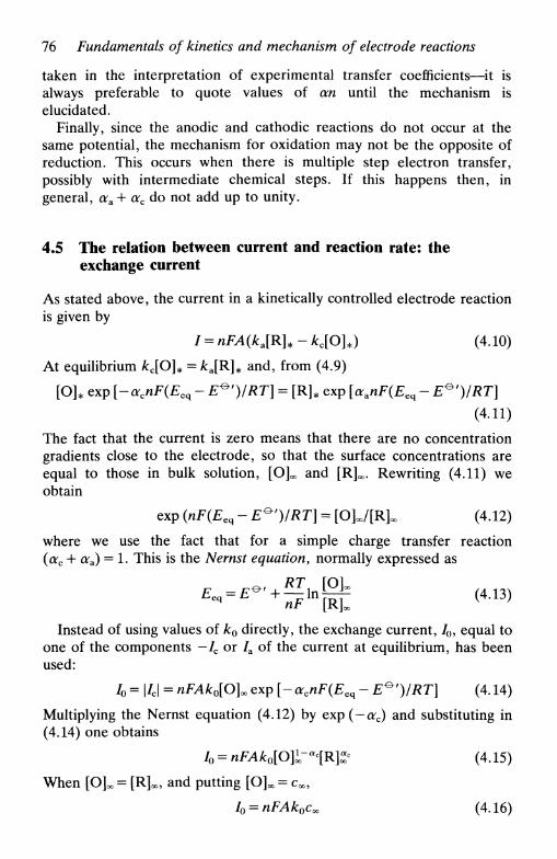
76 Fundamentals of kinetics and mechanism of electrode reactions
taken in the interpretation of experimental transfer coefficients—it isalways preferable to quote values of an until the mechanism iselucidated.
Finally, since the anodic and cathodic reactions do not occur at thesame potential, the mechanism for oxidation may not be the opposite ofreduction. This occurs when there is multiple step electron transfer,possibly with intermediate chemical steps. If this happens then, ingeneral, аа + ас do not add up to unity.
4.5 The relation between current and reaction rate: theexchange current
As stated above, the current in a kinetically controlled electrode reactionis given by
I = nFA(kJR]*-kc[O]*) (4.10)
At equilibrium A:C[O]* = /:a[R]* and, from (4.9)
[О]„ exp [-acnF(Eeq - E^')/RT] = [R]* exp [aanF(Eeq - E^')/RT]
(4.11)
The fact that the current is zero means that there are no concentrationgradients close to the electrode, so that the surface concentrations areequal to those in bulk solution, [О]^ and [R]^. Rewriting (4.11) weobtain
exp (nF(Eeq - E*')/RT] = [OJ./fR]. (4.12)
where we use the fact that for a simple charge transfer reaction(ac + ora) = 1. This is the Nernst equation, normally expressed as
Instead of using values of k0 directly, the exchange current, /0, equal toone of the components —/c or /a of the current at equilibrium, has beenused:
I0=\Ic\ = nFAk0[O]O0Qxp[-acnF(Eeq-E^r)/RT] (4.14)
Multiplying the Nernst equation (4.12) by exp (— ac) and substituting in(4.14) one obtains
I0 = nFAk0[O]l-aiR]Z< (4.15)
When [OJoo = [R]oc, and putting [O]^ = c^,
I0 = nFAk0coo (4.16)
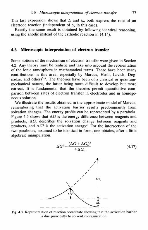
4.6 Microscopic interpretation of electron transfer 77
This last expression shows that /0 and k0 both express the rate of anelectrode reaction (independent of ac in this case).
Exactly the same result is obtained by following identical reasoning,using the anodic instead of the cathodic reaction in (4.14).
4.6 Microscopic interpretation of electron transfer
Some notions of the mechanism of electron transfer were given in Section4.2. Any theory must be realistic and take into account the reorientationof the ionic atmosphere in mathematical terms. There have been manycontributions in this area, especially by Marcus, Hush, Levich, Dog-nadze, and others5"9. The theories have been of a classical or quantum-mechanical nature, the latter being more difficult to develop but morecorrect. It is fundamental that the theories permit quantitative com-parison between rates of electron transfer in electrodes and in homoge-neous solution.
We illustrate the results obtained in the approximate model of Marcus,remembering that the activation barrier results predominantly fromsolvation changes. The energy profile can be represented by a parabola.Figure 4.5 shows that AG is the energy difference between reagents andproducts, AGS describes the solvation change between reagents andproducts, and AG* is the activation energy2. For the intersection of thetwo parabolas, assumed to be identical in form, one obtains, after a littlealgebraic manipulation,
(4.17)
Fig. 4.5 Representation of reaction coordinate showing that the activation barrieris due principally to solvent reorganization.

78 Fundamentals of kinetics and mechanism of electrode reactions
So, what is the variation of the rate constant with potential? The chargetransfer coefficient, a, anodic or cathodic, is given by
(4Л8)RTF
dinkЭЕ BE
This is a form of the Tafel relation (Section 6.6) so long as the current isproportional to the rate constant. It is an example of a linear free energyrelationship (a kinetic parameter, In A:, varies linearly with a thermo-dynamic parameter, E). Substituting AG* we get
(4.19)
(4-20)
We can isolate some limiting cases:
• AG S » AG: the kinetics is slow and oc~\ (this is the case for manyreactions)
• AGS small (fast reactions),
AG S -AG, * - > l (Fig. 4.4a);
AGS« - AG, or-* 0 (Fig. 4.4c).
So, for very fast reactions, the theory predicts a variation of a withpotential. There is some evidence that this occurs, but given the multistepnature of any electrode reaction no definitive conclusions can be taken,and mechanisms can be elaborated which have constant charge transfercoefficients. Indeed the fact that the enthalpic and entropic parts of thecoefficients have different temperature dependences leads to the questionas to what is the real significance of the charge transfer coefficient, a topiccurrently under discussion9.
Another aspect affecting electron transfer that has become moreimportant with the increasing use of semiconductor electrodes10"13 in, forexample, solar energy conversion, but is also valid for metal electrodes,should be mentioned. Electron transfer occurs between the highestoccupied energy level in the electrode (the Fermi level EF) and theenergy level of the redox pair in solution, £redox. The occupation of theelectronic levels close to EF is given more correctly by the expression14
/ = 1/[1 + exp (E - EF)/kBT] (4.21)
where / is the probability of occupation of a level of energy E, and kB is
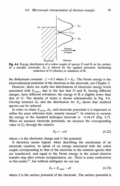
4.6 Microscopic interpretation of electron transfer 79
' Electrode Solution
Fig. 4.6 Energy distribution of a redox couple of species О and R on the surfaceof a metallic electrode; EF is altered by the applied potential, facilitating
reduction of О (shown) or oxidation of R.
the Boltzmann constant - / = 0.5 when E = EF. The Fermi energy is theelectrochemical potential of the electrons in the electrode, see Chapter 3.
However, there are really two distributions of electronic energy levelsassociated with ETedox, due to the fact that О and R, having differentcharges, have different solvations; the energy of R is slightly lower thanthat of O. The density of states is shown schematically in Fig. 4.6.Overlap between EF and the distribution for Eo shows that oxidizedspecies can be reduced.
In order to relate Eredox, EF, and electrode potentials it is important toutilize the same reference state, namely vacuum14. In relation to vacuumthe energy of the standard hydrogen electrode is —4.44eV (Fig. 4.7).When we measure electrode potentials, we measure the correspondingvalue of EF through the relation
EF=-eU (4.22)
where e is the electronic charge and U the potential.It therefore seems logical, when describing the mechanism of an
electrode reaction, to speak of an energy associated with the redoxcouple corresponding to that of the electrons in the solution species thatare transferred, and equal to the Fermi energy in the actual electrontransfer step after solvent reorganization, etc. There is some controversyin this matter15, but without ambiguity we can say
EF = Eredox-eX (4.23)
where X is the surface potential of the electrode. The surface potential is

80 Fundamentals of kinetics and mechanism of electrode reactions
Energy £/eVElectrode
potential U/V
-AM-
Standard hydrogenelectrode
Standard oxygenelectrode + 1.23 -
- 3 -
- - 2
- 2 -
- - 3
- 1 -
- - 4
- - 5
- - 6
-0 Vacuum: electronsat rest
• -4 .44
•-5.67
Fig. 4.7 The relation between electrode potentials, their corresponding energies,and vacuum.
the potential difference between the interface (of potential tyy the Voltapotential) and the interior of the electrode (of potential фу the Galvanipotential). Thus, at equilibrium and with unit activities, £redox isequivalent to the energy of the Volta potential, whereas EF is associatedwith the Galvani potential. X reflects the break in the structure of thesolid and consequent variations in electronic distribution (Fig. 4.8 andChapter 3).
Energy correspondingto Volta potential
Solution
Fig. 4.8 The relation between the Galvani potential, ф м , the Volta potential,and the 'surface potential, x> shown schematically.

References 81
If X ~ 0 then
EF = Eredox (4.24)
Thus EF is associated with the electrode potential and £redox with theredox potential of the species: since in general ХФ0, we cannot assumetheir equivalence. A measurement of potential gives values of electrodepotentials and never redox potentials.
The crucial point is that the difference of potential available to effectelectrode reactions and surmount activation barriers is not simply thedifference between the Galvani potential (i.e. the Fermi energy) and thepotential in solution. On the side of the solid it is the Volta potential andon the side of the solution it is the potential at the inner Helmholtz plane,where species have to reach to in order for electron transfer to bepossible. Corrections to rate constants for the latter are commonlycarried out using the Gouy-Chapman model of the electrolyte doublelayer and will be described in Section 6.9.
References
1. K. J. Vetter, Electrochemical kinetics, Academic Press, New York, 1967.2. W. J. Albery, Electrode kinetics, Clarendon Press, Oxford, 1975.3. R. A. Marcus, J. Phys. Chem., 1963, 67, 853.4. J. A. V. Butler, Trans. Faraday Soc, 1924, 19, 729 and 734; T. Erdey-Gruz
and M. Volmer, Z. Physik. Chem., 1930, 150A, 203.5. R. Marcus, Ann. Rev. Phys. Chem., 1964, 15, 155 and references therein.6. V. G. Levich, Advances in electrochemistry and electrochemical engineering,
ed. P. Delahay and C. W. Tobias, Wiley, New York, Vol. 4, 1966, pp.249-371.
7. R. R. Dogonadze, Reactions of molecules at electrodes, ed. N. H. Hush,Wiley-Interscience, New York, 1971, Chapter 3.
8. A. M. Kuznetsov, Faraday Disc. Chem. Soc, 1982, 74, 49.9. В. Е. Conway, Modern aspects of electrochemistry, Plenum, New York, Vol.
16, 1985, ed. B. E. Conway, R. E. White, and J. O'M. Bockris, pp. 103-188.10. P. J. Holmes ed., The electrochemistry of semiconductors, Academic Press,
London, 1962.11. S. R. Morrison, Electrochemistry at semiconductor and oxidised metal
electrodes, Plenum, New York, 1980.12. K. Uosaki and H. Kita, Modern aspects of electrochemistry, Plenum, New
York, Vol. 18, 1986, ed. R. E. White, J. O'M. Bockris, and В. Е. Conway,pp. 1-60.
13. A. Hamnett, Comprehensive chemical kinetics, Elsevier, Amsterdam, Vol.27, 1987, ed. R. G. Compton, Chapter 2.
14. Ref. 11 p. 5.15. H. Reiss, /. Phys. Chem., 1985, 89, 3873; S. U. M. Khan, R. С Kainthla,
and J. O'M. Bockris, /. Phys. Chem., 1987, 91, 5974; H. Reiss, /.Electrochem. Soc, 1988, 135, 247C.
MASS TRANSPORT
5.1 Introduction5.2 Diffusion control5.3 Diffusion-limited current: planar and spherical electrodes5.4 Constant current: planar electrodes5.5 Microelectrodes5.6 Diffusion layer5.7 Convection and diffusion: hydrodynamic systems5.8 Hydrodynamic systems: some useful parameters5.9 An example of a convective-diffusion system: the rotating disc electrode
5.1 Introduction
In the last chapter it became clear that in the expression for the rate of anelectrode reaction
the values of ka and kc (electrode kinetics) and of [O]* and [R]* are bothof extreme importance. These, in turn, are affected not only by theelectrode reaction itself but also by the transport of species to and frombulk solution. This transport can occur by diffusion, convection, ormigration (Section 2.8). Normally, conditions are chosen in whichmigration effects can be neglected, this is the effects of the electrode'selectric field are limited to very small distances from the electrode, asdescribed in Chapter 3. These conditions correspond to the presence of alarge quantity (>0.1м) of an inert electrolyte (supporting electrolyte),which does not interfere in the electrode reaction. Using a highconcentration of inert electrolyte, and concentrations of 10~3 м or less ofelectroactive species, the electrolyte also transports almost all the currentin the cell, removing problems of solution resistance and contributions tothe total cell potential—an exception to this is ultramicroelectrodes,where the currents are so low that higher solution resistances can betolerated. In these conditions we need to consider only diffusion andconvection.
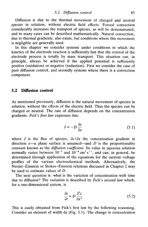
5.2 Diffusion control 83
Diffusion is due to the thermal movement of charged and neutralspecies in solution, without electric field effects. Forced convectionconsiderably increases the transport of species, as will be demonstrated,and in many cases can be described mathematically. Natural convection,due to thermal gradients, also exists, but conditions where this movementis negligible are generally used.
In this chapter we consider systems under conditions in which thekinetics of the electrode reaction is sufficiently fast that the control of theelectrode process is totally by mass transport. This situation can, inprinciple, always be achieved if the applied potential is sufficientlypositive (oxidation) or negative (reduction). First we consider the case ofpure diffusion control, and secondly systems where there is a convectioncomponent.
5.2 Diffusion control
As mentioned previously, diffusion is the natural movement of species insolution, without the effects of the electric field. Thus the species can becharged or neutral. The rate of diffusion depends on the concentrationgradients. Fick's first law expresses this:
(5..,
where / is the flux of species, дс/дх the concentration gradient indirection x—a plane surface is assumed—and D is the proportionalityconstant known as the diffusion coefficient. Its value in aqueous solutionnormally varies between 10~5 and 10~6cm2s~1, and can, in general, bedetermined through application of the equations for the current-voltageprofiles of the various electrochemical methods. Alternatively, theNernst-Einstein or Stokes-Einstein relations discussed in Chapter 2 maybe used to estimate values of D.
The next question is: what is the variation of concentration with timedue to diffusion? The variation is described by Fick's second law which,for a one-dimensional system, is
дс д2с
тг°и? <5-2)
This is easily obtained from Fick's first law by the following reasoning.Consider an element of width djc (Fig. 5.1). The change in concentration
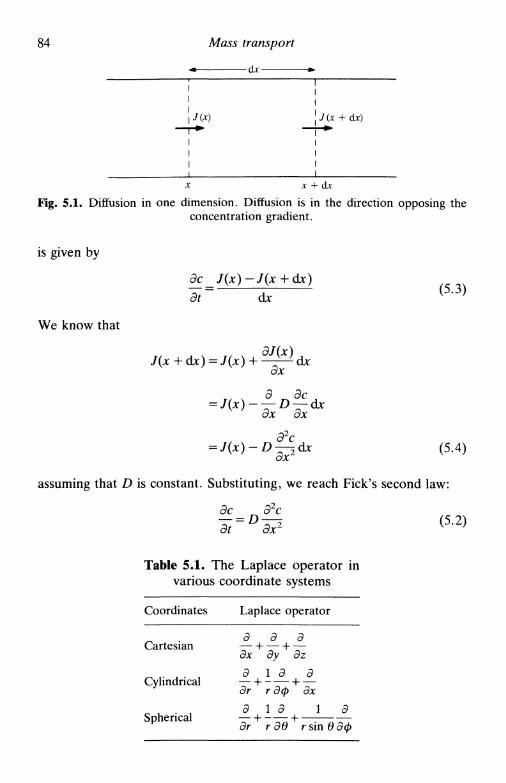
84 Mass transport
- d j c -
\J(x) J(x + dx)
x + dx
Fig. 5.1. Diffusion in one dimension. Diffusion is in the direction opposing theconcentration gradient.
is given by
We know that
dc_J(x)-J(x
dt~ dx(5.3)
ax
= J(x)~D—2dx (5.4)
assuming that D is constant. Substituting, we reach Fick's second law:
Эс Э2с(5.2)
Table 5.1. The Laplace operator invarious coordinate systems
Coordinates Laplace operator
Cartesian
Cylindrical
Spherical
д~дх~
д
ддг
д
1 д
1 д
гдв
д
' dzд
* дх
1
г sin
д
вдф
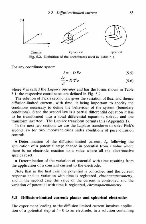
5.3 Diffusion -limited current 85
Cartesian Cylindrical Spherical
Fig. 5.2. Definition of the coordinates used in Table 5.1.
For any coordinate system
J=-DVc
dt
(5.5)
(5.6)
where V is called the Laplace operator and has the forms shown in Table5.1; the respective coordinates are defined in Fig. 5.2.
The solution of Fick's second law gives the variation of flux, and thencediffusion-limited current, with time, it being important to specify theconditions necessary to define the behaviour of the system (boundaryconditions). Since the second law is a partial differential equation it hasto be transformed into a total differential equation, solved, and thetransform inverted1. The Laplace transform permits this (Appendix 1).
In the next two sections we use the Laplace transform to solve Fick'ssecond law for two important cases under conditions of pure diffusioncontrol:
• Determination of the diffusion-limited current, /d, following theapplication of a potential step: change in potential from a value wherethere is no electrode reaction to a value where all the electroactivespecies react.
• Determination of the variation of potential with time resulting fromthe application of a constant current to the electrode.
Note that in the first case the potential is controlled and the currentresponse and its variation with time is registered, chronoamperometry,and in the second case the value of the current is controlled and thevariation of potential with time is registered, chronopotentiometry.
5.3 Diffusion-limited current: planar and spherical electrodes
The experiment leading to the diffusion-limited current involves applica-tion of a potential step at / = 0 to an electrode, in a solution containing

86 Mass transport
\E\
No reaction
Reaction of all speciesreaching the electrode
/ = О
Fig. 5.3. Potential step to obtain a diffusion-limited current of the electroactivespecies.
either oxidized or reduced species, from a value where there is noelectrode reaction to the value where all electroactive species that reachthe electrode react, as shown in Fig. 5.3. This gives rise to a diffusion-limited current whose value varies with time. For a planar electrode,which is uniformly accessible, this is called semi-infinite linear diffusion,and the current is
I = nFAD(^) (5.7)\&t/o
where / = nFAJ, x is the distance from the electrode, and we consider,for simplicity, an oxidation (anodic current) with c = [R]. If it were areduction a minus sign would be introduced into (5.7).
We solve Fick's second law
— = £>—4 (5.8)
with the boundary conditions corresponding to our experiment, which are
t = 0, c0 = Coo (no electrode reaction) (5.9a)
155 0 lim с = Coo (bulk solution) (5.96)
>0 1\ co = 0 (diffusion-limited current,/d) (5.9c)
t>0
x
in which c() represents the concentration at the electrode and c^ theconcentration in bulk solution.
The mathematical solution to this problem is facilitated by using adimensionless concentration
y = ̂ - ^ (5.10)
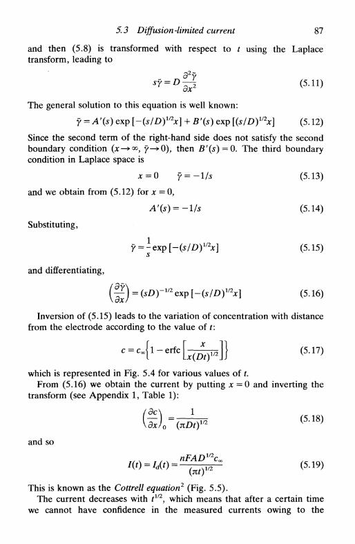
5.3 Diffusion-limited current 87
and then (5.8) is transformed with respect to t using the Laplacetransform, leading to
*y = £ > 0 (5.11)
The general solution to this equation is well known:
Y = A'(s) exp [-(s/D)mx] + B'(s) exp [(s/D)1/2x] (5.12)
Since the second term of the right-hand side does not satisfy the secondboundary condition (*-><», y->0), then B'(s) = 0. The third boundarycondition in Laplace space is
x = 0 f=-l/s (5.13)
and we obtain from (5.12) for x = 0,
A'(s) = -l/s (5.14)
Substituting,
х] (5.15)
and differentiating,
( |£) = (*£>Г1/2ехр [-(s/D)V2x] (5.16)
Inversion of (5.15) leads to the variation of concentration with distancefrom the electrode according to the value of t:
( 5 Л 7 )
which is represented in Fig. 5.4 for various values of t.From (5.16) we obtain the current by putting x = 0 and inverting the
transform (see Appendix 1, Table 1):
кдх/о i
and so
w , ч nFADv\
Ш (5-18)
(5Л9)— {ntf12
This is known as the Cottrell equation2 (Fig. 5.5).The current decreases with tll2
y which means that after a certain timewe cannot have confidence in the measured currents owing to the
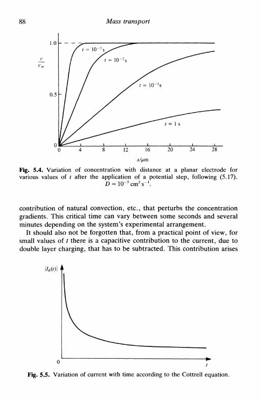
Mass transport
х/цтFig. 5.4. Variation of concentration with distance at a planar electrode forvarious values of t after the application of a potential step, following (5.17).
contribution of natural convection, etc., that perturbs the concentrationgradients. This critical time can vary between some seconds and severalminutes depending on the system's experimental arrangement.
It should also not be forgotten that, from a practical point of view, forsmall values of t there is a capacitive contribution to the current, due todouble layer charging, that has to be subtracted. This contribution arises
Fig. 5.5. Variation of current with time according to the Cottrell equation.
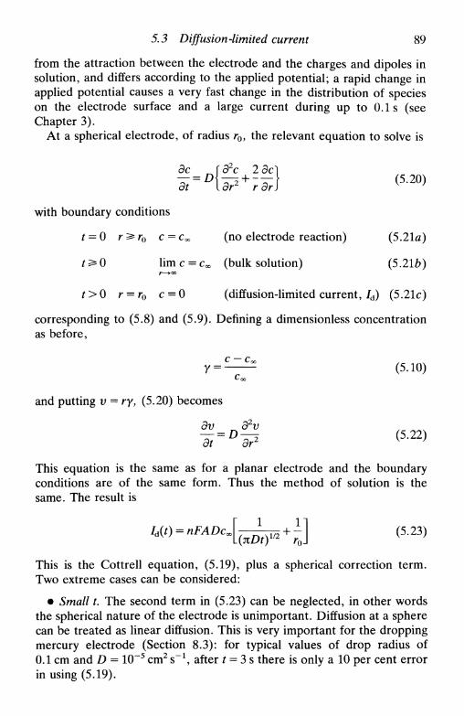
5.3 Diffusion-limited current 89
from the attraction between the electrode and the charges and dipoles insolution, and differs according to the applied potential; a rapid change inapplied potential causes a very fast change in the distribution of specieson the electrode surface and a large current during up to 0.1s (seeChapter 3).
At a spherical electrode, of radius r0, the relevant equation to solve is
э2с 2+
with boundary conditions
t = 0 r^r0 с— Co, (no electrode reaction) (5.21a)
t ^ 0 lim с = Coo (bulk solution) (5.21ft)Г—>°o
t>0 r = r0 c = 0 (diffusion-limited current, /d) (5.21c)
corresponding to (5.8) and (5.9). Defining a dimensionless concentrationas before,
C ^ (5.10)Coo
and putting v = ry, (5.20) becomes
dv 32v(5-22)
This equation is the same as for a planar electrode and the boundaryconditions are of the same form. Thus the method of solution is thesame. The result is
< 5 2 з >
This is the Cottrell equation, (5.19), plus a spherical correction term.Two extreme cases can be considered:
• Small t. The second term in (5.23) can be neglected, in other wordsthe spherical nature of the electrode is unimportant. Diffusion at a spherecan be treated as linear diffusion. This is very important for the droppingmercury electrode (Section 8.3): for typical values of drop radius of0.1 cm and D = 10~5 cm2 s"1, after t = 3 s there is only a 10 per cent errorin using (5.19).

90 Mass transport
Table 5.2. Diffusion currents for planar and spherical electrodes:assuming Do = DR. ro = sphere radius; в = [О
Oxidation orreduction
Oxidation andreduction (closeto equilibrium
potential)
Type of electrode
Planar
Spherical
Planar
Spherical
Equation
nFADiac(*0 1 / 2
nFADl/2c^("0"2 '
nFADV2cx
(1 + в)(М)1'2
nFADl/2cx
(1 + в){м)ш
nFADcx
nFADcx
(l + 0)ro
Comments
Cottrell equation (5.19)
Cottrell equation plusspherical correction (5.23)
• Large t. The spherical term dominates, which represents a steady-state current. However, due to the effects of natural convection thissteady state is never reached at conventionally-sized electrodes. Thesmaller the electrode radius, the faster the steady state is achieved. It ispossible to achieve a steady state at microelectrodes. These are describedfurther in Section 5.5.
The equations for the diffusion-limited current at planar and sphericalelectrodes are shown in Table 5.2 together with the expressions for thediffusion currents when the potential is not far from the equilibriumpotential so that oxidation and reduction occur at the same time.
5.4 Constant current: planar electrodes
Starting at t = 0 a constant current is applied to the electrode in order tocause oxidation or reduction of electroactive species, and the variation ofthe potential of the electrode with time is measured (chronopoten-tiometry). Fick's second law is solved using the Laplace transform as inthe previous section; the first two boundary conditions are the same, butthe third is different:
t = 0 c0 = Coo (no electrode reaction) (5.9a)
t^O lim с = сх (bulk solution) (5.9b)Jt—»QO
t>0 x = 0 I = nFAD(dc/dx)0 (5.24)
The third condition expresses the fact that a concentration gradient isbeing imposed at the electrode surface.
As in the last section, and following the same arguments, we reach
Y=A'(s) exp [-(s/D)1/2x] (5.25)
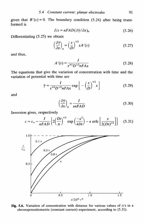
5.4 Constant current: planar electrodes 91
given that Bf(s) = O. The boundary condition (5.24) after being trans-formed is
I/s = nFAD(df/dx)0
Differentiating (5.25) we obtain
and thus,
A'(s) =sy2DmnFAx
(5.26)
(5.27)
(5.28)
The equations that give the variation of concentration with time and thevariation of potential with time are
1/2
and
\dx/o snF;snFAD
Inversion gives, respectively
(5.30)
1.0
0.5
0 . 1 т
0.5 1.0
x/2Dxh Th
1.5
Fig. 5.6. Variation of concentration with distance for various values of t/r in achronopotentiometric (constant current) experiment, according to (5.31).

92 Mass transport
0.5Г/т
1.0
Fig. 5.7. Variation of potential with time (chronopotentiogram) in a systemcontrolled by diffusion and with application of a constant current, т is the
transition time. ET/4 is the potential when t = т/4 (Section 10.5).
and
2ft1
— Coo ~~nFADV2nm (5.32)
When c0 = 0, all species in the zone of the electrode have beenconsumed, as shown in Fig. 5.6. The corresponding value of t is called thetransition time, т.
From (5.32) and putting c0 = 0 and t = r
lTm__nFADmnm
which is known as the equation3. If (1т1/2/сж) is not constant forseveral experiments with the same solution then the electrode process isnot a simple electron transfer, but involves other steps. Figure 5.7represents the theoretical variation of potential with time for this type ofexperiment.
It should be noted that the equation for the transition time at aspherical electrode is equal to that for a plane electrode. This result,perhaps unexpected, shows that it is only the current density thatdetermines the transition time and not the curvature of the electrodesurface.
5,5 Microelectrodes
Microelectrodes4'5, or ultramicroelectrodes, are denned as electrodeswhich have at least one dimension that is a function of its size, which in

5.5 Microelectrodes 93
practice means between 0.1 and 50jUm. Common geometries includespherical, hemispherical, disc, ring, and line. Their applications aremany, and will be referred to throughout the book. They exhibit highcurrent densities, but low total currents, so that the percentage electroly-sis is small, and permit the attainment of steady states in situations, suchas in the absence of added electrolyte, not possible with larger electrodes.
The diffusion-limited current at spherical and hemispherical microelec-trodes follows directly from (5.23). We consider a hemispherical elec-trode as shown in Fig. 5.8. After a certain time, depending on theelectrode size, a steady-state is reached, and the current is
c^ (5.34)0
This can be rewritten in terms of the surface length, d> where d = jtr0, as
I = 2nFdDcOD (5.35)
For a hemispherical electrode of diameter 1 jum, 95 per cent of thesteady-state response is reached 0.1 s after application of a potential step.Additionally, and in general, as a result of the high rate of diffusion thecurrent density is sufficiently high that interference from natural, andeven forced, convection is negligible.
Finally, we consider the case of a plane disc microelectrode. In this
11 \k/Planar electrode of Hemisphericalinfinite dimension electrode
Y/AMicroelectrode
Fig. 5.8. Schematic diagram showing the uniform current density for planar andspherical/hemispherical electrodes, and the non-uniform accessibility of the disc
microelectrode.
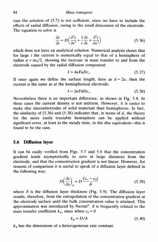
94 Mass transport
case the solution of (5.7) is not sufficient, since we have to include theeffects of radial diffusion, owing to the small dimension of the electrode.The equation to solve is
dc /d2c \dc S2c\— = D - ^ + - — + - ^ (5.36)dt \ дг г дг Эх /
which does not have an analytical solution. Numerical analysis shows thatfor large / the current is numerically equal to that of a hemisphere ofradius a = Jtro/2, showing the increase in mass transfer to and from theelectrode caused by the radial diffusion component:
I = 4nFaDcO0 (5.37)
If once again we define the surface length, here as d = 2a, then thecurrent is the same as at the hemispherical electrode:
I = 2nFdDcO0 (5.38)
Nevertheless there is an important difference, as shown in Fig. 5.8. Inthese cases the current density is not uniform. However, it is easier tomake disc microelectrodes of solid materials than hemispheres. In fact,the similarity of (5.36) and (5.38) indicates that, in terms of d, the theoryfor the more easily tractable hemisphere can be applied withoutsignificant error, at least in the steady state, to the disc equivalent—this isfound to be the case.
5.6 Diffusion layer
It can be easily verified from Figs. 5.5 and 5.6 that the concentrationgradient tends asymptotically to zero at large distances from theelectrode, and that the concentration gradient is not linear. However, forreasons of comparison it is useful to speak of a diffusion layer defined inthe following way:
= Dv °° °' (5.39)О
where <5 is the diffusion layer thickness (Fig. 5.9). The diffusion layerresults, therefore, from the extrapolation of the concentration gradient atthe electrode surface until the bulk concentration value is attained. Thisapproximation was introduced by Nernst6. 6 is frequently related to themass transfer coefficient kdy since when c0 = 0
kd = D/6 (5.40)
kd has the dimensions of a heterogeneous rate constant.

5.7 Convection and diffusion: hydrodynamic systems 95
i-6-
/ /Electrode
Solution
Fig. 5.9. The definition of the diffusion layer <5; (дс/дх)0 is the concentrationgradient at the electrode surface.
Applying (5.39) to the Cottrell equation (5.19), we can deduce theexpression for the diffusion layer thickness as
6 = (nDt)l/2 (5.41)
The thickness increases with tm, hence the problems of natural convec-tion, etc. at large t. The mass transfer coefficient is (compare with (5.40))for c0 = 0
kd=(D/nt)m (5.42)
At a hemispherical microelectrode
(5.43)
The smaller д the larger the concentration gradient at the electrodesurface, leading to higher currents. It is also useful in certain investi-gations that <5 is independent of t. Both these conditions can be satisfiedby microelectrodes. They can also be obtained by imposition of forcedconvection at larger electrodes—hydrodynamic systems.
5.7 Convection and diffusion: hydrodynamic systems
In a fluid where there is both convection and diffusion—a hydrodynamicsystem—the flux is given by
J = cv-DVc (5.44)
which is a modification of Fick's first law. The expression correspondingto Fick's second law is
дс_ 2
— - - v (5.45)
The forms of this equation in the three coordinate systems can be foundin Table 5.3.
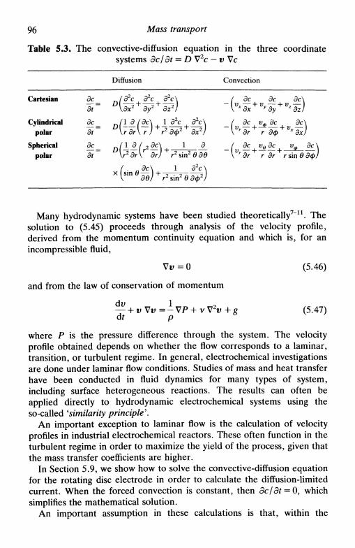
96 Mass transport
Table 5.3. The convective-diffusion equation in the three coordinatesystems dc/dt = D V2c — v Vc
Diffusion Convection
Cartesian
Cylindrical
polar
Spherical
polar
dcdt
dc
dt
dc
dt
U 2 + dy2 + dzV
Э2с
. dc dc dc— \Vr H IL h i ) ,
dx y dy dz
dc Уф дс dc
dr r dф x dx
Jt
= D{?dr{r dr)+r4n-/ dc ve dc Уф dc \
\ r dr r dr r sin в dф)
^ +Эв) ' г2 sin2 в Эф
Many hydrodynamic systems have been studied theoretically7 n . Thesolution to (5.45) proceeds through analysis of the velocity profile,derived from the momentum continuity equation and which is, for anincompressible fluid,
Vu=0
and from the law of conservation of momentum
-p
2v + g
(5.46)
(5.47)
where P is the pressure difference through the system. The velocityprofile obtained depends on whether the flow corresponds to a laminar,transition, or turbulent regime. In general, electrochemical investigationsare done under laminar flow conditions. Studies of mass and heat transferhave been conducted in fluid dynamics for many types of system,including surface heterogeneous reactions. The results can often beapplied directly to hydrodynamic electrochemical systems using theso-called 'similarity principle'.
An important exception to laminar flow is the calculation of velocityprofiles in industrial electrochemical reactors. These often function in theturbulent regime in order to maximize the yield of the process, given thatthe mass transfer coefficients are higher.
In Section 5.9, we show how to solve the convective-diffusion equationfor the rotating disc electrode in order to calculate the diffusion-limitedcurrent. When the forced convection is constant, then dc/dt = 0, whichsimplifies the mathematical solution.
An important assumption in these calculations is that, within the
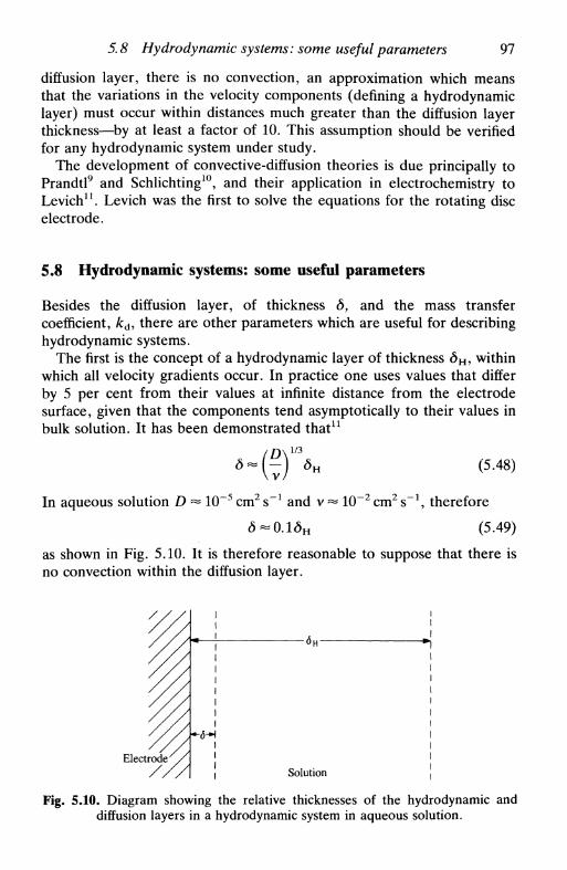
5.8 Hydrodynamic systems: some useful parameters 97
diffusion layer, there is no convection, an approximation which meansthat the variations in the velocity components (defining a hydrodynamiclayer) must occur within distances much greater than the diffusion layerthickness—by at least a factor of 10. This assumption should be verifiedfor any hydrodynamic system under study.
The development of convective-diffusion theories is due principally toPrandtl9 and Schlichting10, and their application in electrochemistry toLevich11. Levich was the first to solve the equations for the rotating discelectrode.
5.8 Hydrodynamic systems: some useful parameters
Besides the diffusion layer, of thickness <5, and the mass transfercoefficient, /cd, there are other parameters which are useful for describinghydrodynamic systems.
The first is the concept of a hydrodynamic layer of thickness <5H> withinwhich all velocity gradients occur. In practice one uses values that differby 5 per cent from their values at infinite distance from the electrodesurface, given that the components tend asymptotically to their values inbulk solution. It has been demonstrated that11
o ~ — <5H (5.48)
In aqueous solution D ~ 10~5 cm2 s"1 and v ~ 10~2 cm2 s"1, therefore
<5-0.1<5H (5.49)
as shown in Fig. 5.10. It is therefore reasonable to suppose that there isno convection within the diffusion layer.
Electrode /
-6-H
-<5H-
Solution
Fig. 5.10. Diagram showing the relative thicknesses of the hydrodynamic anddiffusion layers in a hydrodynamic system in aqueous solution.

98 Mass transport
We now define various dimensionless groups that are useful in masstransport problems:
1. The Reynolds number, Re
Re=- (5.50)
where v is a characteristic velocity, / a characteristic length, and v thekinematic viscosity. Below a certain critical value of Re, Recriu the flow islaminar; above it is turbulent with a transition regime around ReCTli.
2. The Schmidt number, Sc
Sc=^ (5.51)
is a characteristic of the medium, v being a characteristic primarily of thesolvent and D of the electrochemical species. 5c is, therefore, determinedpurely by the physical properties of the solution. For aqueous solution,5c -10 3 .
3. The Peclet number, Pe
vlPe=- = Re.Sc (5.52)
represents the relative contributions of transport by convection and bydiffusion. In aqueous solution outside the diffusion layer Pe » 1, even forsmall Re.
4. The Sherwood number, Sh
where / is a characteristic length of the system. Sh is proportional to themass transfer coefficient kd.
5.9 An example of a convective-diffusion system: the rotatingdisc electrode
A rotating disc electrode1213 consists of a disc electrode embedded in themiddle of a plane surface (theoretically of infinite extent) that rotatesaround its axis in a fluid, the disc being centred on the axis. In practicethe electrode bodies usually have the form of a cylinder, with the sheatharound the disc significantly larger than it is, so as to approximate asurface of infinite dimension (Fig. 8.2). We assume in these calculations

5.9 An example of a convective-diffusion system 99
that there are no convection effects caused by the walls of the cell wherethe experiment is carried out, nor effects resulting from the finitedimensions of the electrode body etc.—generically known as edge effects.
The first step consists in deducing the velocity profile. This fluiddynamics problem was solved by von Karman14 and Cochran15 and givesthe velocity components:
radial vr = rcoF(y)
angular уф = rcoG(y)
perpendicular yx = —((ov)l/2H(y)
where у is the dimensionless distance from the disc
1/2
y= -
(5.54a)
(5.54b)
(5.54c)
(5.55)
In these expressions CD is the disc rotation rate (rads l) and v thekinematic viscosity. The coordinates are shown in Fig. 5.2. Figure 5.11shows the variation of the functions F, G, and H with distance from thedisc and Fig. 5.12 the corresponding streamlines. As a result of rotation,solution is sucked towards the disc and spread out sideways.
Levich10 introduced the approximation that, close to the electrode,
СГХ
0
— Cx
(5.56a)
(5.56b)
(5.56c)
Fig. 5.11 The functions F, G, and H and their variation with dimensionlessdistance from a rotating disc.
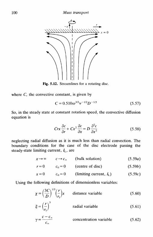
100 Mass transport
-*р -̂
Fig. 5.12. Streamlines for a rotating disc.
where C, the convective constant, is given by
C = 0.510(o3/2v-mD-m (5.57)
So, in the steady state at constant rotation speed, the convective diffusionequation is
Эх Эх(5.58)
neglecting radial diffusion as it is much less than radial convection. Theboundary conditions for the case of the disc electrode passing thesteady-state limiting current, /L, are
x-^oo c^Coo (bulk solution) (5.59л)
r = о c0 = 0 (centre of disc) (5.59b)
x = 0 c0 = 0 (limiting current, /L) (5.59c)
Using the following definitions of dimensionless variables:
- x
7 =с —
distance variable
radial variable
concentration variable
(5.60)
(5.61)
(5.62)
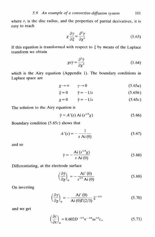
5.9 An example of a convective-diffusion system 101
where гл is the disc radius, and the properties of partial derivatives, it iseasy to reach
d2y
< 5 6 3 )
If this equation is transformed with respect to § by means of the Laplacetransform we obtain
Х*У = ~Л (5.64)
which is the Airy equation (Appendix 1). The boundary conditions inLaplace space are
x ^ o o y - * 0 (5.65*)
§ = 0 у =-1/5 (5.656)
£ = 0 у =-1/5 (5.65с)
The solution to the Airy equation is
y = A'(s)A\(sl/3x) (5.66)
Boundary condition (5.65c) shows that
A'(S) = ~7^W) (5-67)
and so
_ = _Ai(su'x) ( 5 _ 6 g )
Differentiating, at the electrode surface
Ai' (0)
s 2 / 3 Ai(0)
On inverting
Ai' (0) ^
(5.69)
(5.70)
and we get
1/2с„ (5.71))dxJ0
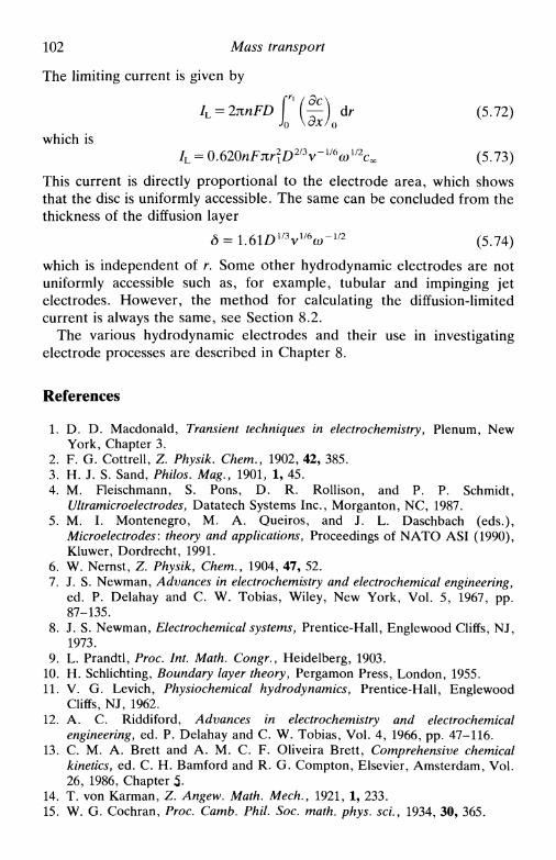
102 Mass transport
The limiting current is given by
P(^) dr (5.72)o \dx/0
which is/L = <д.620пРш\О21Ъу-тюшсх (5.73)
This current is directly proportional to the electrode area, which showsthat the disc is uniformly accessible. The same can be concluded from thethickness of the diffusion layer
6 = 1.61D l /V / 6w 4 / 2 (5.74)
which is independent of r. Some other hydrodynamic electrodes are notuniformly accessible such as, for example, tubular and impinging jetelectrodes. However, the method for calculating the diffusion-limitedcurrent is always the same, see Section 8.2.
The various hydrodynamic electrodes and their use in investigatingelectrode processes are described in Chapter 8.
References
1. D. D. Macdonald, Transient techniques in electrochemistry, Plenum, NewYork, Chapter 3.
2. F. G. Cottrell, Z. Physik. Chem., 1902, 42, 385.3. H. J. S. Sand, Philos. Mag., 1901, 1, 45.4. M. Fleischmann, S. Pons, D. R. Rollison, and P. P. Schmidt,
Ultramicroelectrodes, Datatech Systems Inc., Morganton, NC, 1987.5. M. I. Montenegro, M. A. Queiros, and J. L. Daschbach (eds.),
Microelectrodes: theory and applications, Proceedings of NATO ASI (1990),Kluwer, Dordrecht, 1991.
6. W. Nernst, Z. Physik, Chem., 1904, 47, 52.7. J. S. Newman, Advances in electrochemistry and electrochemical engineering,
ed. P. Delahay and С W. Tobias, Wiley, New York, Vol. 5, 1967, pp.87-135.
8. J. S. Newman, Electrochemical systems, Prentice-Hall, Englewood Cliffs, NJ,1973.
9. L. Prandtl, Proc. Int. Math. Congr., Heidelberg, 1903.10. H. Schlichting, Boundary layer theory, Pergamon Press, London, 1955.11. V. G. Levich, Physiochemical hydrodynamics, Prentice-Hall, Englewood
Cliffs, NJ, 1962.12. A. C. Riddiford, Advances in electrochemistry and electrochemical
engineering, ed. P. Delahay and С W. Tobias, Vol. 4, 1966, pp. 47-116.13. С M. A. Brett and A. M. C. F. Oliveira Brett, Comprehensive chemical
kinetics, ed. С H. Bamford and R. G. Compton, Elsevier, Amsterdam, Vol.26, 1986, Chapter 5-
14. T. von Karman, Z. Angew. Math. Mech., 1921, 1, 233.15. W. G. Cochran, Proc. Camb. Phil. Soc. math. phys. sci., 1934, 30, 365.
KINETICS AND TRANSPORT INELECTRODE REACTIONS
6.1 Introduction6.2 The global electrode process: kinetics and transport6.3 Reversible reactions6.4 Irreversible reactions6.5 The general case6.6 The Tafel law6.7 The Tafel law corrected for transport6.8 Kinetic treatment based on exchange current6.9 The effect of the electrolyte double layer on electrode kinetics6.10 Electrode processes involving multiple electron transfer6.11 Electrode processes involving coupled homogeneous reactions
6.1 Introduction
In the last two chapters the kinetics of electrode processes and masstransport to an electrode were discussed. In this chapter these two partsof the electrode process are combined and we see how the relative ratesof the kinetics and transport cause the behaviour of electrochemicalsystems to vary14.
6.2 The global electrode process: kinetics and transport
Transport to the electrode surface as described in Chapter 5 assumes thatthis occurs solely and always by diffusion. In hydrodynamic systems,forced convection increases the flux of species that reach a pointcorresponding to the thickness of the diffusion layer from the electrode.The mass transfer coefficient kd describes the rate of diffusion within thediffusion layer and kc and k.a are the rate constants of the electrodereaction for reduction and oxidation respectively. Thus for the simpleelectrode reaction O + /ie~—>R, without complications from adsorption,
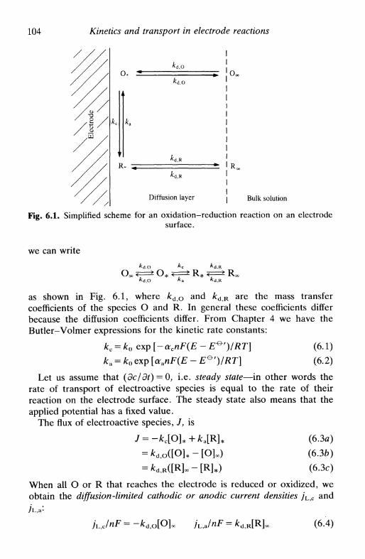
104 Kinetics and transport in electrode reactions
Diffusion layer Bulk solution
Fig. 6.1. Simplified scheme for an oxidation-reduction reaction on an electrodesurface.
we can write
кс
~к~7 Roc
as shown in Fig. 6.1, where kdO and A:dR are the mass transfercoefficients of the species О and R. In general these coefficients differbecause the diffusion coefficients differ. From Chapter 4 we have theButler-Volmer expressions for the kinetic rate constants:
kc = k0 exp [- acnF(E - E^')/RT) (6.1)
k.a = k0 exp [aanF(E - E^')/RT] (6.2)
Let us assume that (dc/dt) = O, i.e. steady state—in other words therate of transport of electroactive species is equal to the rate of theirreaction on the electrode surface. The steady state also means that theapplied potential has a fixed value.
The flux of electroactive species, /, is
J = -*c[O]*+*aP4* (63a)
= *d,o([0]*-[0]oo) (6.36)
= *d,R([R]«-[R]*) (63c)
When all О or R that reaches the electrode is reduced or oxidized, weobtain the diffusion-limited cathodic or anodic current densities yL c and
JuJnF = - = * d , R [R]o (6.4)

6.2 The global electrode process: kinetics and transport 105
Since kd = D/д (equation (5.40)), we can write
kd,o/kd,R=p = (Do/DKy (6.5)
Making the appropriate substitutions, the concentrations can be removedfrom (6.3) leading to
kcjUc+pkJUa
( 6 ' 6 )
We can point out two extreme cases for this expression:
1. Only О present in solution: /L a = 0 and ka — 0. Thus
i = lTTk (6-7)
that is
l = ^ S L + T L (6.8)
kinetics transport
This result shows that the total flux is due to a transport and a kineticterm. When kc»kdo then
-r^lo)- <610)
and the flux is determined by the transport. On the other hand, when/Vc %4 lvd о
-± = - ^ — (6.11)j nF/cc[O]oo
and the kinetics determines the flux.
2. Only R present in solution: /L c = 0 and kc = 0. From (6.6) we reach
j. fca/L,a ( 6 1 2 )
Rearranging,
1 1 1
kinetics transport
106 Kinetics and transport in electrode reactions
The form of the expression is the same as that obtained in Case 1 withonly О present in solution, and so the same comments are valid.
We now consider the factors that affect the variation of kc (or ka) andkd. The kinetic rate constants depend on the applied potential and on thevalue of the standard rate constant, k0. As was seen in Chapter 5, kd isinfluenced by the thickness of the diffusion layer, which we can controlthrough the type of experiment and experimental conditions, such asvarying the forced convection. By altering kc (or k.a) and kd we can obtainkinetic information as will be described below. At the moment we notethat there are two extremes of comparison between k0 and kd:
• kQ » kd reversible system
• k0 « kd irreversible system
The word reversible signifies that the system is at equilibrium at theelectrode surface and it is possible to apply the Nernst equation at anypotential.
The calculation of the current requires the relation between the fluxand current:
/ = d> j dA = nF d> J cL4 (6.14)
Normally, such as at stationary planar electrodes and at uniformlyaccessible hydrodynamic electrodes, for example the rotating disc, theflux over the electrode surface is constant: in this case we have the simplerelation
l = Aj = nFAJ (6.15)
6.3 Reversible reactions
Reversible reactions are those where
ko»kd
and, at any potential, there is always equilibrium at the electrode surface.The current is determined only by the electronic energy differencesbetween the electrode and the donor or acceptor species in solution andtheir rate of supply. Applying the Nernst equation
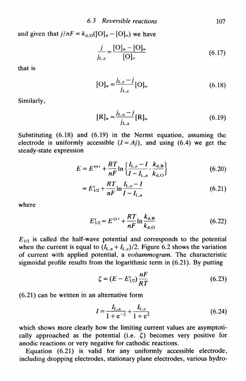
6.3 Reversible reactions 107
and given that j/nF = kd,0([0]* - [O]oc) we have
j \Oh - [OL/ = ГО1 ( 6 Л 7 )
7L,C L^JOC
that is
[O^^iZijok (6.18)
Similarly,
[R]*=^—^[Rjoc (6.19)
Substituting (6.18) and (6.19) in the Nernst equation, assuming theelectrode is uniformly accessible (I = Aj), and using (6.4) we get thesteady-state expression
(6.20)
= £r1/2 + ̂ l n ^ f ^ (6.21)
where
/rr „ — F&' _i i n d-R (f. oo\
Ei/2 is called the half-wave potential and corresponds to the potentialwhen the current is equal to (/L a + /L,c)/2. Figure 6.2 shows the variationof current with applied potential, a voltammogram. The characteristicsigmoidal profile results from the logarithmic term in (6.21). By putting
t; = {E-E\l2)^- (6.23)
(6.21) can be written in an alternative form
/ = Г + ^ + 1+& ( 6*2 4 )
which shows more clearly how the limiting current values are asymptoti-cally approached as the potential (i.e. £) becomes very positive foranodic reactions or very negative for cathodic reactions.
Equation (6.21) is valid for any uniformly accessible electrode,including dropping electrodes, stationary plane electrodes, various hydro-

108 Kinetics and transport in electrode reactions
IA Oxidation
Reduction
Fig. 6.2. Voltammogram for a reversible system where the solution contains Оand R. Example: a mixture of Fe(II) and Fe(III) at a platinum rotating disc
electrode.
dynamic systems, and hemispherical microelectrodes. In fact, the sameexpression is reached for non-uniformly accessible electrodes, but thereasoning is a little more complex.
In all cases
(6.25)
where s = \ (dropping or stationary electrode), s = § (hydrodynamicelectrodes) or s = 1 (microelectrodes). Even if DR = 1.5DO, for 5 = 1,we get E\,2 — E^' = 10.5 mV, which would be an extreme case. So, innearly all cases, we can identify E\/2 with £ ° ' without introducing a largeerror.
Assuming that DR = Do we can conclude, from (6.20), that theequilibrium potential £eq, where the current is zero, is
When [O]« = [R]oo then £eq = E\/2 = E*'.From the expressions obtained above, we can write a diagnostic of
reversibility:
• E\/2 independent of [O]oo and [R^

6,4 Irreversible reactions 109
/L,c ~ /
/ " /L,a
E = E\
EN
Fig. 6.3. Plot of lg [(/ L c — /)/(/ —/L a)] vs. E for a reversible reaction; inverse' slope is (0.05916/л) V at 298 K.
• The form of the current-potential curve is independent of thediffusion layer thickness.
• A plot of lg [(/L, c- /)/(/ - /L a)] vs. E—equation (6.21)—will give astraight line of slope 0.05916/n V at 298K and an intercept of Er
l/2, seeFig. 6.3.
6.4 Irreversible reactions
For irreversible reactions, ko«kd. Kinetics has an important role,especially for potentials close to Eeq. It is necessary to apply a higherpotential than for a reversible reaction in order to overcome theactivation barrier and allow reaction to occur—this extra potential iscalled the overpotential, rj. Because of the overpotential only reductionor only oxidation occurs and the voltammogram, or voltammetric curve,is divided into two parts. At the same time it should be stressed that theretarding effect of the kinetics causes a lower slope in the voltammogramsthan for the reversible case. Figure 6.4 shows, schematically, the curveobtained, which is explained in greater detail below.
The expressions (6.9) and (6.13) are valid for this situation. Thetransport term has to appear, since only at the beginning of anirreversible voltammogram can the effects of transport be neglected. Thisis because kc or ka increases on increasing the potential negatively orpositively so that we finally reach the limiting current plateaux in Fig. 6.4.

по Kinetics and transport in electrode reactions
tJ
с
: "
(/L,a)/2
! / ^
/
/ \/ 1
, ^У !£ i r r
'/г.а
h1.
\
-,a
E
Fig. 6.4. Schematic voltammogram for an irreversible electrode reaction. Ex-ample: a mixture of anthraquinone and anthraquinol at a platinum rotating disc
electrode.
The half-wave potential for reduction or oxidation varies with kd, sincethere is not equilibrium on the electrode surface. For cathodic and anodicprocesses respectively we may write
(6.27)
(6.28)
where a is the charge transfer coefficient that appears in (6.1) and (6.2).E\r/2 is not constant, but varies with the rate of transport of species to theelectrode. Once more, similarly to the reversible case in Fig. 6.2, thelogarithmic term in (6.27) and (6.28) explains the sigmoidal form of thecurves obtained. The appearance of the factors ac or <xa with 0 < а < 1causes the curves to have a lower slope than for a reversible reaction.Plots of the type shown in Fig. 6.3 can be done using (6.27) and (6.28),and (<xan) or (<xcn) calculated from the slopes of these plots.
For a uniformly accessible electrode (I=jA), (6.9) or (6.13) can bewritten in the form
(6.29)
in which /k is the kinetic current and /L the limiting current. A plot of / l
vs. k^1 (proportional to /L) is a straight line from which one obtains /k

6.5 The general case 111
Slope -> values of D
Fig. 6.5. Plot of / l vs. /L ' at a uniformly accessible electrode for an irreversiblereaction.
from the intercept and the diffusion coefficient D from the slope (Fig.6.5). For example, for the rotating disc electrode one constructs a plot of7"1 vs. W~V2
y where W is the rotation speed of the electrode in Hz, since/L is proportional to Wm, as demonstrated in Section 5.9.
6.5 The general case
We now consider the general case and show how reversible andirreversible systems are limiting cases of the general behaviour. Forsimplicity, we assume that Do = DK(p = 1). Thus (6.6) becomes
; = • (6.30)
Using again the Butler-Volmer formulation of electrode kinetics,
kc = k0 exp [- acnF(E - E^')/RT] (6.1)
ka = k0 exp [aanF(E - E^')/RT] (6.2)
and, in order to reduce the number of symbols, writing
/ =RT
and substituting (6.1) and (6.2) in (6.30) we obtain
, = j U c exp (-acnf) + yL,a exp (aanf)
kjko + exp (-acnf) + exp (aanf)
(6.31)
(6.32)

112 Kinetics and transport in electrode reactions
We consider three limiting cases of (6.32)
1. A:0»A:d: reversible system. Multiplying through by exp(acnf) andsince we are considering a simple electrode reaction where (ara + ac) = 1,expression (6.32) becomes
(6.33)exp(/i/)
or, rearranging,
exp (nf) = expRT /-7L,a
For a uniformly accessible electrode,
E = E ' H—— In w T ,
(6.34)
(6.35)
which is the equation for the voltammetric curve, equation (6.21), withD o = DR.
2. / large i.e. E very positive (oxidation) or very negative (reduction)in relation to £ 0 ' . Whatever the relative values of k0 and kd, we shouldobtain the limiting current. From (6.32):
• / large and positive, exp (—acnf) —» 0, and we obtain
/ =7ь,а i.e. limiting anodic current (6.36)
J n (a) (b)
(c)/
= E - Ещ
Fig. 6.6, The effect of the value of ac on the current density, j . (a) ac = 0.25:oxidation favoured; (b) arc = 0.50: symmetric; (c) arc = 0.75: reduction favoured.

6.6 The Tafel law 113
j ь
Fig. 6.7. The effect of the value of k0 on the current density close to Eeq; (a) k0
large; (b) k0 smaller.
• /large and negative, exp (aanf) —»0, and we obtain
j =jLc i.e. limiting cathodic current (6.37)
3 . / close to zero, that is E~E^'. In these conditions we canapproximate the exponentials by the first term in the Maclaurin expan-sion (Appendix 1). We obtain
. = /L,c + 7L,a - JUc^nf + JubOCJlf
kjko + 2In this relation j is directly proportional to E via / (see (6.31)). Theproportionality constant is highly dependent on the value of ac (andthence also on ara), Fig. 6.6, and on the ratio kjko, Fig. 6.7.
6.6 The Tafel law
Between the limiting current plateaux of a voltammogram and the linearregion close to Eeq described by (6.38) there is a region of potential forirreversible reactions where / depends exponentially on potential. This isthe Tafel region. Considering a system where there is only О in bulksolution, that is there is only reduction, from the equation
kc = k0 exp [- acnF(E - E^')/RT] (6.1)
it is obvious that
In kc = constant! —acnFE
RT(6.39)

114
Since
we have
Kinetics and transport in electrode reactions
jc/nF=-kc[O]*
—lnyc = constant2 —acnFE
RT
In a similar fashion for an oxidation,
ln/a = constant3aanFE
RT
(6.40)
(6.41)
(6.42)
These last two expressions are forms of the Tafel law. They are anexample of a linear free energy relationship (linear relation between akinetic and a thermodynamic parameter) the parameters in this casebeing the flux (or the current) and the potential.
Constructing plots of In |y | vs. E we obtain Fig. 6.8. The slopes of thelines are -ac(nF/RT) and aa(nF/RT); the intercept at E = Eeq gives theexchange current /0 = j0A and thence the standard rate constant from theexpression deduced in Section 4.5:
lJnFA =jJnF = (6.43)
Note that close to £eq, since reaction occurs in both directions there aredeviations from a straight line, and far from Eeq transport limitationsprovoke alterations in concentrations, also causing deviations.
Slope-acnF \
RT >^
In [/I '
v4 T/7
>/ Slope
aanF
RT
Fig. 6.8. Plot of In |y | vs. E showing how to measure y0 and a from the slopes ofthe lines.

6.8 Kinetic treatment based on exchange current 115
6.7 The Tafel law corrected for transport
The Tafel law can be corrected for transport effects, enlarging the regionof the voltammetric curve that can be utilized in Tafel plots.
For a reduction, from (6.9)
"e"/)
j /L,c nFke[OU nFkJLO]» K° }
that is
-In I - - — 1 = - acnf + In k0 + In (nF[O]x) (6.45)
One does a plot of lg (j~l —jz!c) vs. E. For an oxidation, analogously,
-In I T - — 1 = aanf + In k0 + In (fiF[R]oo) (6.46)
The intersection of the two lines given by (6.41) and (6.42) is when
<xanf + ocjxj = In (nF[O]oo) - In (nF[R]oo) (6.47)
Since in the electrode reaction considered, (ara 4- ac) = 1, then
n/ = ln([O]ee/[R]00) (6.48)
or
Щ: (6>49)
As this is the Nernst equation, the value of E can be identified with theequilibrium potential Eeq. Knowing [O]oc and [R]^ we can determine k0
from the intersection of the two straight lines, in the same way asdemonstrated in Fig. 6.8.
6.8 Kinetic treatment based on exchange current
All the equations deduced above can be formulated in terms of theexchange current /0 (Section 4.5). In this way we have the advantage ofobtaining the current as a function of the difference in applied potentialand equilibrium potential, i.e. the overpotential, rj; the disadvantage isthat it is not directly related to the rate constants, which is important forcomparison with other branches of kinetics.

116 Kinetics and transport in electrode reactions
As shown in Chapter 4, the exchange current density is equal to theanodic or cathodic component of the current density at equilibrium(/a=-/c=/o) that is
/o = -/c = nFk0[O]* exp [-acnF(Ecq - E^')/RT] (6.50)
On substituting the Nernst equation written as
exp [nF(Eeq - E^')/RT] = [O]OC/[R]OC (6.51)
we get
/0 = nFkQ[O]l-aiR]£ = nFk0[O]ZiR]Zc (6.43)
From equations (6.18), (6.19), (6.31), and (6.50) it is relatively easy toreach
Г [O]* , ч [Rl*j = 7o| - TQT exp (-acnfrj) + — - exp (aanfrj)
where r\= E — Eeq is the overpotential. In the case of [О]* ~ [O]oo (<10per cent of the limiting current)
/ =/()[exp (aanfrj) - exp (-acnfr])] (6.53)
In the linear region close to Ecq (exp (x) ~JC), and writing ara = 1 — ac
j=jonfrj (6.54)
For an irreversible reaction and for overpotentials corresponding to theexponential region, the Tafel law is
In/ = ln/0 — acnfrj (reduction) (6.55)
In/ = ln/o + <*aAz/r7 (oxidation) (6.56)
Other information, particularly useful for multistep reactions, can beobtained from the following relations deduced from (6.43):
9 In j 0 din j 0
^! rrvi = a^ ^ rr̂ i = a* (6.57)
Changing [O]oc or [R]oo, the value of /() varies and we can determine thevalue of aa or arc, without needing to know the value of n in therate-determining step.
6.9 The efifect of the electrolyte double layer on electrodekinetics
The electrolyte double layer affects the kinetics of electrode reactions6.For charge transfer to occur, electroactive species have to reach at least

6.9 The effect of the electrolyte double layer 111
HZ R*
(a)
Fig. 6.9. (a) Schematic representation of the path followed by an electrodereaction. The effect of the electrode's electric field begins at the outside of thedouble layer, but for there to be reaction the species has to reach xu from theelectrode; (b) Variation of ф with distance, showing that the potential difference
to cause electrode reaction is ( ф м — фФ).
to the outer Helmholtz plane (distance xH in Fig. 3.9). Hence, thepotential difference available to cause reaction is ( ф м — ф$) (see Fig. 6.9)and not ( ф м — ф$). Only when фх ~ ф8 can we say that the double layerdoes not affect the electrode kinetics. Additionally, the concentration ofelectroactive species will be, in general, less at distance JCH from theelectrode than outside the double layer in bulk solution. These assump-tions can be treated quantitatively.
For a reduction a convenient representation is
pre-equilibriumO±
outside the double layer outer Helmholtz plane

118 Kinetics and transport in electrode reactions
Following the Gouy-Chapman model of the diffuse layer,
(6.58)
From the Butler-Volmer expressions, the true rate constant is then
kc = /co,t exp 1̂ — J (6.59)
where kOt represents the true standard rate constant of the electrodereaction. The reaction rate is
kc[O]t = кол exp [ " C ' " ^ M ™ ] Ы О ] . (6.60)
where
/DL = exp 1̂— ^r1 -J (6.61)
Clearly /D L is also given by
the ratio between the apparent standard rate constant, k0, and the truestandard rate constant, k0 t, known as the Frumkin correction, /D L. Thepractical consequence is variation of k0 with potential. A more rigorousdeduction from the expression for /D L is obtained through the use ofelectrochemical potentials.
To apply the correction it is necessary to know the value of фх. Thisvalue has been calculated for the mercury electrode from electrocapillarycurves, calculating aM and thence ф% using the Stern model. As thismodel does not include specific adsorption, the calculated values of фф
are either too positive (cations) or too negative (anions) besidesdifferences caused by the blocking effect of the ions.
As is perhaps to be expected, the double layer can also affect thevalues of the measured, i.e. apparent, charge transfer coefficientsmanifested in the slopes of the Tafel plots (Section 6.6). It is possible toshow that, for the Stern model, and considering a cathodic transfercoefficient as example,
<xc = *c,t + —,—72 — (6.63)
where occ is the observed coefficient and act the true coefficient. There
6.10 Electrode processes involving multiple electron transfer 119
are two extreme cases:
• [ze((j)%- ф$)12къТ] large, implying that ac~ <хсл. This situationcorresponds to potentials far from Ez.
• [ге{фх — ф5)/2/:вГ] small, corresponding to potentials close to Ez.
*c~ttc,t+ *г"Уг (6.64)
If, for example, C G C = CH, arc,t= 0.5 and z — 1 we obtain arc = —0.25. As
can be seen, the apparent value of occ can be positive or negative. Thisexample shows the extreme importance in correcting values of ac and aa
for double layer effects.We can ask how effects of the double layer on electrode kinetics can be
minimized and if the necessity of correcting values of a and of rateconstants can be avoided? In order for this to be possible, we have toarrange for фг ~ 0S, that is all the potential drop between electrodesurface and bulk solution is confined to within the compact layer, for anyvalue of applied potential. This can be achieved by addition of a largequantity of inert electrolyte (—1.0 м), the concentration of electroactivespecies being much lower (<5тм). As stated elsewhere, other ad-vantages of inert electrolyte addition are reduction of solution resistanceand minimization of migration effects given that the inert electrolyteconducts almost all the current. In the case of microelectrodes (Section5.6) the addition of inert electrolyte is not necessary for many types ofexperiment as the currents are so small.
6.10 Electrode processes involving multiple electron transfer
In many reduction or oxidation half-reactions, the oxidation statechanges by a value greater than 1. Examples for metallic cations areT1(III)-^T1(I), Cu(II)^Cu(0), and examples of other species O2->H2O2 (2e~) or O2—»H2O (4e~), these also involving other species in thehalf-reactions. In this section we consider metal ions given that, at leastapparently, there are no other species involved, except for molecules ofsolvation etc. If the reactions are irreversible we can investigate theirkinetics.
For a two-electron reduction (Fig. 6.10), we have generically
B + e ~

120 Kinetics and transport in electrode reactions
в + e" -*2.0
1.0
(a)
A + e~ —В
-E
2 . 0 -
1.0-
Г/ // // ///
Л 1
Л 1
1е-~ -*• Г
W
(b)-E
2.0
1.0
(c)
• A + 2e~
A + e - — В
-E
Fig. 6.10. Voltammograms for the reduction of species A following A + e —>B + e~—>C according to the relative rates of the two steps. /L = /L(A—»B).(a) Second step much more difficult than the first; (b) First step rate-determining;
second step fast; (c) First step pre-equilibrium; second step rate-determining.
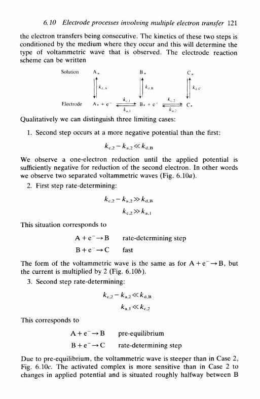
6.10 Electrode processes involving multiple electron transfer 121
the electron transfers being consecutive. The kinetics of these two steps isconditioned by the medium where they occur and this will determine thetype of voltammetric wave that is observed. The electrode reactionscheme can be written
Solution A^ Bx C,,
A'd.c
Electrode A* + e~ ч " ' > В* + е~ < > c** a . l * a . 2
Qualitatively we can distinguish three limiting cases:
1. Second step occurs at a more negative potential than the first:
We observe a one-electron reduction until the applied potential issufficiently negative for reduction of the second electron. In other wordswe observe two separated voltammetric waves (Fig. 6.10a).
2. First step rate-determining:
This situation corresponds to
A 4- e~ —> В rate-determining step
B + e ~ ^ C fast
The form of the voltammetric wave is the same as for A + e~—>B, butthe current is multiplied by 2 (Fig. 6.10b).
3. Second step rate-determining:
This corresponds to
A 4- e~ —» В pre-equilibrium
В + e~ —»С rate-determining step
Due to pre-equilibrium, the voltammetric wave is steeper than in Case 2,Fig. 6.10c. The activated complex is more sensitive than in Case 2 tochanges in applied potential and is situated roughly halfway between В

122 Kinetics and transport in electrode reactions
and С on the reaction coordinate. This means that ocji — 1.5 (but doesnot mean that arc
%0.75). In actual fact, arc —0.5 as n — 1 in therate-determining step.
It is also of interest to consider the reverse reaction, oxidation of С toA. Supposing the reduction follows path 2:
A + e~ —» В rate-determining step
B + e~-*C fast
it is quite possible that the oxidation is not the inverse, but is
С + e~ —» В rate-determining step
B + e~-^A fast
This change in mechanism is due to the different potentials (i.e. differentelectronic energies) at which the reactions occur. We cannot ever assumea priori that the reverse of a multistep reaction with known mechanismwill be the inverse.
It is also fairly evident that for certain combinations of rate constantswe can change mechanisms by changing the applied potential.
The application of these concepts to the electroreduction of oxygen,important for fuel cells, with hydrodynamic electrodes is described inChapter 8.
Finally in this section, we remember that multiple electron transfer hasto follow the reaction coordinate and has consecutive steps, even if thefirst step is rate determining. The possibility of multiple electron transferreactions without intermediate chemical steps has been questioned, withexperimental evidence from, for example, the supposedly relativelysimple reduction of Cd(II) and similar ions at mercury electrodes6. This isbecause solvation and interaction with the environment, adsorption, etc.are different for each oxidation state.
6.11 Electrode processes involving coupled homogeneousreactions
Interesting reactions occur when the charge transfer at the electrode isassociated with homogeneous reactions in solution that can precede orfollow the electron transfer reaction at the electrode. A selection ofpossible schemes is shown in Table 6.1. Note the presence of manyorganic compounds: the reduction or oxidation of these compoundsinvolves, in many cases, the addition or removal of hydrogen, which
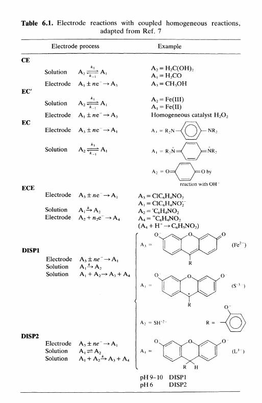
Table 6.1. Electrode reactions with coupled homogeneous reactions,
adapted from Ref. 7
Electrode process Example
СЕ
E C
EC
Solution A2
Electrode Aj
Solution A2
Electrode A t
Electrode A3
Solution A2
•A3
A 2 = H 2 C(OH) 2
A, = H 2 COA 3 = СНзОН
A 2 = Fe(III)A, = Fe(II)Homogeneous catalyst H 2 O 2
A., = R 2 N — \ C j ) — N R 2
/———л
A, = R2N=/ \=NR2
\ /
A2 = O
ECEreaction with OH
Electrode A 3 ± ле
Solution A!-^>A2
Electrode A 2 + n2e~
A 3 = C1C6H4NO2
AT = C1C6H4NO2-A 2 = C 6 H 4 NO 2
A 4 = " C 6 H 4 N O 2
DISP1Electrode A3±ne -^A}
Solution A,-^A2
Solution A! + A2—> A3 + A4
DISP2Electrode A3 ± ne —> A^Solution A,^±A2
Solution A, + A2 -^ A3 + A4
A 4 =
R H
pH9-10 DISP1pH 6 DISP2

124 Kinetics and transport in electrode reactions
proceeds via electron plus proton transfer. Such mechanisms are com-monly summarized in the scheme of squares, shown below for twoelectron transfers and two protonation steps.
AH +
-н +
-н +
CH-
CH,
A typical example is quinone/hydroquinone systems.
We consider three simple schemes, shown in Fig. 6.11, and examine
the effect of homogeneous coupled reactions on the current at the
electrode: they are C E , E C , and E C , where E represents an electroche-
mical step (at the electrode) and С a chemical step (in solution). T h e
equations to calculate the rate constants from experimental measure-
ments for the various types of electrode can be found in the specialized
literature. In most studies the electrochemical step has been considered
reversible—thus, in the following, the rate constant for the electrode
reaction is not indicated.
CE process
Solution A 2 < > Ax
Electrode Ax ± ne~ -+ A3
The concentration of Ax is less than in the absence of the chemical step,and is dependent on the value of K. Measurement of the diminution incurrent allows the determination of the values of kx and &_j. The positionof the voltammetric curve on the potential axis is not affected by thehomogeneous step (Fig. 6.11a).
EC process
Electrode A3±ne~-+Ax
Solution A i <=* A2
The chemical step reduces the quantity of A x at the electrode surface and
consequently causes a shift of the voltammetric wave to more positive

6.11 Electrode processes 125
(a)
/
(b)
П
(с) Е
Fig. 6.11. The effect of coupled homogeneous reactions on electrode reactionsillustrated for an oxidation. Mechanisms (a) CE (b) EC (c) E C . Absence of
homogeneous reaction ( ); presence ( ).
potentials (oxidation) or more negative (reduction) (Fig. 6.11b). Thisshift can be directly related to the kinetics of the homogeneous reaction.
EC process
Solution A2 ^ ^ ^ Axk-\
Electrode А)±пе~-±А2

126 Kinetics and transport in electrode reactions
This is a catalytic process, the homogeneous reaction regenerating thereagent of the electrode reaction. The concentration of Ax will be largerthan expected and the current bigger than in the absence of thehomogeneous reaction (Fig. 6.11c). Altering kd (through the diffusionlayer thickness) permits the determination of the kinetics of the homoge-neous reaction.
In all these schemes for coupled homogeneous reactions, it is useful toconsider in the deduction of the equations the concept of a reaction layerassociated with the homogeneous reaction; all the homogeneous reactionoccurs within a distance equal to the thickness of the reaction layer fromthe electrode. When the thickness of the layer is significantly smaller(<10 per cent) than the thickness of the diffusion layer the two layers canbe considered as being independent, which simplifies the mathematicaltreatment. The thickness of the reaction layer depends on the values ofthe homogeneous rate constants kx and k_x.
Other more complex mechanistic schemes are studied by a variety oftechniques. Double hydrodynamic electrodes are particularly useful forinvestigating schemes involving two electron transfer steps, such as ECEand DISP schemes. Some of the applications of the different electroche-mical techniques in the elucidation of these reactions are described in thefollowing chapters.
References
1. W. J. Albery, Electrode kinetics, Clarendon Press, Oxford, 1975.2. H. R. Thirsk and J. A. Harrison, A guide to the study of electrode kinetics,
Academic Press, New York, 1972.3. K. J. Vetter, Electrochemical kinetics, Academic Press, New York, 1967.4. J. Koryta, Principles of electrochemistry} Wiley, London, 1987.5. P. Delahay, Double layer and electrode kinetics, Wiley-Interscience, New
York, 1965.6. W. H. Reinmuth, /. Electroanal. Chem., 1972, 34, 297; С P. M. Bongenaar,
A. G. Remijnse, M. Sluyters-Rehbach, and J. H. Sluyters, J. ElectroanalChem., 1980, 111, 155.
7. С. М. A. Brett, Port. Electrochim. Acta, 1985, 3, 355.

PART II
Methods

7
ELECTROCHEMICALEXPERIMENTS
7.1 Introduction7.2 Electrode materials for voltammetry7.3 The working electrode: preparation and cleaning7.4 The cell: measurements at equilibrium7.5 The cell: measurements away from equilibrium7.6 Calibration of electrodes and cells7.7 Instrumentation: general7.8 Analogue instrumentation7.9 Digital instrumentation
7.1 Introduction
The experimental aspects to be discussed in this chapter include celldesign, electrode materials, construction and cleaning of electrodes,solution composition, and control instrumentation. Electrode materialsspecially designed for potentiometric measurements, which rely on thematerial selectivity, are discussed in Chapter 13.
We shall not give many practical details, but only those of greatestinterest in the planning and design of electrochemical experiments.However, it is hoped that the discussion in this chapter will prove an aidto consulting more detailed expositions in this area, for example Refs.1-6.
1.2 Electrode materials for voltammetry
The choice of an electrode material depends to a great extent on theuseful potential range of the electrode in the particular solvent employedand the qualities and purity of the material. The usable potential range islimited by one or more of the following factors:
• solvent decomposition

130 Electrochemical experiments
• decomposition of the supporting electrolyte (Section 7.5)
• electrode dissolution or formation of a layer of aninsulating/semiconducting substance on its surface.
Additionally, solid electrodes can be adversely affected by poisoningthrough contact with solutions containing contaminants. We now con-sider some frequently used materials and look at their properties aselectrodes in more detail.
Metals
Much has been written about solid metal electrodes, which have nowlargely displaced liquid mercury. Those most often used as redox ('inert')electrodes for studying electron transfer kinetics and mechanism, anddetermining thermodynamic parameters are platinum, gold, and silver.However, it should be remembered that their inertness is relative: atcertain values of applied potential bonds are formed between the metaland oxygen or hydrogen in aqueous and some non-aqueous solutions.Platinum also exhibits catalytic properties.
A general advantage of metal electrodes is that their high conductivityresults in low (usually negligible) background currents. It is usually fairlyeasy to increase sensitivity and reproducibility at solid electrodes byforced convection. Their surfaces can be modified by electrodeposition orchemical modification, although the latter is more common with carbonelectrodes (see below). Another advantage of the use of metal electrodesis the ease of construction of the electrode assembly, and ease ofpolishing.
Electrodes of many metals can undergo corrosion or passivation—formation of a salt film on the surface—and other reactions, dependingon the medium and experimental conditions. Electrochemical techniquescan be used to investigate the mechanisms of these processes.
Carbon
Carbon7 exists in various conducting forms. Electrochemical reactions arenormally slower at carbon than at metallic electrodes, electron transferkinetics being dependent on structure and surface preparation8.
Carbon has a high surface activity, which explains its susceptibility topoisoning by organic compounds. Bonds with hydrogen, hydroxyl andcarboxyl groups, and sometimes quinones, can be formed at the carbonsurface. The presence of these groups signifies that the behaviour of theseelectrodes can be very pH-sensitive. The presence of functional groupshas also been purposely used to modify the electrode surface (modified
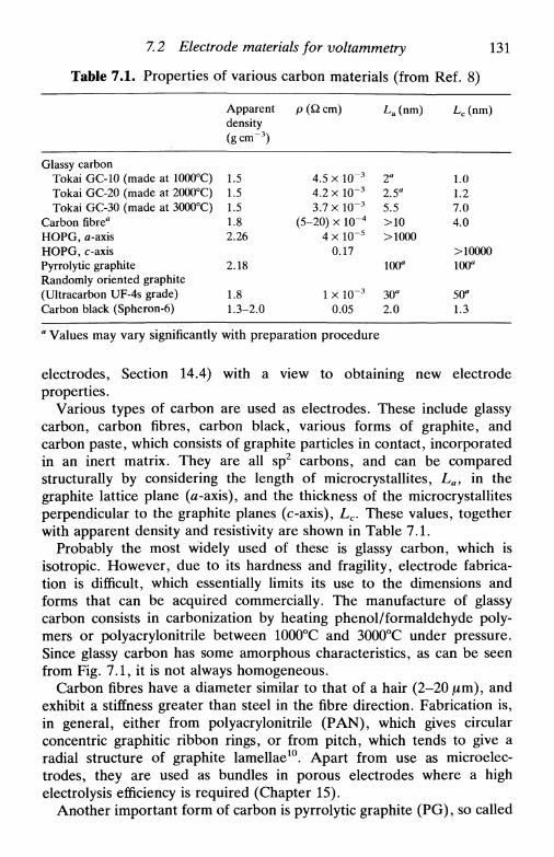
Apparentdensity(gem-3)
1.51.51.51.82.26
2.18
1.81.3-2.0
p (Q cm)
4.5 x 1(T3
4.2 x l O " 3
3.7xl(T 3
(5-20) x 1(Г4
4 x 10~5
0.17
1 x 1(Г3
0.05
La (nm)
2a
2.5"5.5>10>1000
100°
30я
2.0
Lc (nm)
1.01.27.04.0
>10000100я
50°1.3
7.2 Electrode materials for voltammetry 131
Table 7.1. Properties of various carbon materials (from Ref. 8)
Glassy carbonTokai GC-10 (made at 1000°C)Tokai GC-20 (made at 2000°C)Tokai GC-30 (made at 3000°C)
Carbon fibre"HOPG, д-axisHOPG, c-axisPyrrolytic graphiteRandomly oriented graphite(Ultracarbon UF-4s grade)Carbon black (Spheron-6)
a Values may vary significantly with preparation procedure
electrodes, Section 14.4) with a view to obtaining new electrodeproperties.
Various types of carbon are used as electrodes. These include glassycarbon, carbon fibres, carbon black, various forms of graphite, andcarbon paste, which consists of graphite particles in contact, incorporatedin an inert matrix. They are all sp2 carbons, and can be comparedstructurally by considering the length of microcrystallites, La, in thegraphite lattice plane (a-axis), and the thickness of the microcrystallitesperpendicular to the graphite planes (c-axis), Lc. These values, togetherwith apparent density and resistivity are shown in Table 7.1.
Probably the most widely used of these is glassy carbon, which isisotropic. However, due to its hardness and fragility, electrode fabrica-tion is difficult, which essentially limits its use to the dimensions andforms that can be acquired commercially. The manufacture of glassycarbon consists in carbonization by heating phenol/formaldehyde poly-mers or polyacrylonitrile between 1000°C and 3000°C under pressure.Since glassy carbon has some amorphous characteristics, as can be seenfrom Fig. 7.1, it is not always homogeneous.
Carbon fibres have a diameter similar to that of a hair (2-20 jum), andexhibit a stiffness greater than steel in the fibre direction. Fabrication is,in general, either from polyacrylonitrile (PAN), which gives circularconcentric graphitic ribbon rings, or from pitch, which tends to give aradial structure of graphite lamellae10. Apart from use as microelec-trodes, they are used as bundles in porous electrodes where a highelectrolysis efficiency is required (Chapter 15).
Another important form of carbon is pyrrolytic graphite (PG), so called

132 Electrochemical experiments
Strong confluence
Weak confluence
Fig. 7.1. Representation of the structure of glassy carbon, showing La and Lc(from Ref. 9 with permission).
because it is prepared by high-temperature decomposition of gaseoushydrocarbons on to a hot surface, which is anisotropic and has a slightlyhigher density than natural graphite. If this is pressure annealed at hightemperature it turns into highly ordered pyrrolytic graphite (HOPG),which is highly anisotropic as shown in Table 7.1, and is very re-producible. In graphite (Fig. 7.2) the choice of basal or edge plane altersthe electrochemical response owing to the different structure of theexposed surface. Pores arising in graphite are sometimes impregnatedwith ceresin or paraffin under vacuum in order to impede the entry ofsolution into the electrode.
0.335 nm
0.1415 nm
Fig. 7.2. The structure of graphite.
7.2 Electrode materials for voltammetry 133
Electrodes made with carbon or graphite paste mixed with a hydro-phobic diluent such as Nujol, paraffin, silicone rubber, epoxy resin,Teflon, or Kel-F, have also been used. Comparative studies between thevarious types of carbon paste electrode have been carried out11.
Other solid materials
Other solid electrode materials used are semiconductors, for examplemetal oxides1213, and conducting organic salts14. These last are of muchinterest at present for the immobilization of organic compounds such asenzymes, given their compatibility with these macromolecules (Chapter17).
For spectroelectrochemical and photoelectrochemical studies, opticallysemi-transparent electrodes have been fabricated by vapour depositiontechniques on glass or quartz substrates (Chapter 12). Tin and indiumoxides, platinum, and gold have been used.
Mercury
For many years, mercury was the most used electrode material in thelaboratory in the dropping mercury and hanging mercury drop elec-trodes, and more recently in the static mercury drop electrode. Itpossesses a very high negative overpotential for hydrogen evolution inaqueous solution, permitting a negative range of potential larger than forany other material (about -2.0 V vs. SCE instead of -1.0 V negativelimit); conversely, for potentials more positive than +0.2 V vs. SCEmercury oxidation begins. Thus it is used almost always to studyreduction processes, as oxidations of soluble species occurring at negativepotentials are uncommon.
Mercury purity is very important, since on the one hand we have toensure that no other element is dissolved in or amalgamated with themercury, and on the other hand impure mercury used in a droppingmercury electrode would block the capillary.
Mercury purification processes can be summarized in four steps:
• Removal of oxides and dirt on the mercury surface by filteringthrough a filter paper with a pinhole (Whatman No. 40).
• Removal of dissolved basic metals (zinc and cadmium) by agitationin 2 м HNO3 for 1-3 days using a vacuum aspirator. The appearance ofbubbles of mercury on the surface means that this step is finished.
• Distillation to remove noble metals (platinum, gold, silver, etc.).There are various types of distillation apparatus; care must be taken thatthis does not become a reservoir of impurities.
• Washing with water, drying, filtering, and distilling twice more.

134 Electrochemical experiments
There are two useful and easy methods for testing mercury purity. Ifbasic metals are present then the mercury leaves a thin film on the wall ofa glass vessel. The other method consists of placing a small quantity ofmercury in a corked bottle with approximately three times its volume ofdistilled water and agitating: if the mercury is pure then foam will beformed, lasting for 5-15 s.
After use in an electrochemical experiment, mercury should beredistilled. It is highly toxic, especially as vapour, so care should beexercised: any drops that escape should be caught in a tray placedunderneath the cells, and the laboratory must have good ventilation.
Instead of drops, liquid mercury can be used as thin films electrodepo-sited on some solid electrodes in order to increase the useable negativepotential range of these electrodes. For example, on glassy carbonsubstrates the deposition can be done from a solution of 1СГ5 м Hg(II) in0.1 M H N O 3 , applying a convenient potential (—1.0 V vs. SCE) during afew minutes, and stirring the solution. Alternatively a mercury film canbe formed on other substrates, such as copper, by simple immersion inliquid mercury. The special properties of these thin film electrodes aredescribed in Section 9.10.
7.3 The working electrode: preparation and cleaning
Working electrodes are normally solid. The mercury electrode is the onlyliquid electrode at room temperature (with the rare exceptions of galliumand amalgam electrodes) and has been most used as a droppingelectrode.
For reasons of ease of manufacture, the majority of solid electrodeshave a circular or rectangular form. External links are through aconducting epoxy resin either to a wire or to a solid rod of a metal suchas brass, and the whole assembly is introduced by mechanical pressureinto an insulating plastic sheath (Kel-F, Teflon, Delrin, perspex, etc.) orcovered with epoxy resin. It is very important to ensure that there are nocrevices between electrode and sheath where solution can enter andcause corrosion. Examples of electrodes constructed by this process willbe shown in Chapter 8.
Unfortunately, expansion coefficients of plastics and metals can bequite different. For this reason it is suggested that electrodes are kept inclosed glass tubes in a thermostat bath when not in use, at thetemperature at which they will be employed. If this is not done, there is a
7.3 The working electrode: preparation and cleaning 135
risk that the surfaces of the electrode and sheath will not be coplanarafter a period of time. This means total repolishing, entailing con-siderable costs in time and electrode material.
Once the electrode is constructed, it has to be polished to obtain asmooth, brilliant surface which is free of physical defects. The polishingsubstance used depends on electrode material hardness, and can be usedon polishing tables or with special polishing cloths. Diamond, paste orspray, and alumina powder, available containing particles of varioussizes, are widely used. The process begins with large particles (perhaps25 /im diameter), using successively smaller particles until at least 1 jum isreached, verifying the absence of scratches, etc. It is unlikely, except forvery soft electrode materials, that the surface can be improved by usingparticles of size less than 0.3 /лт diameter. During a series of experimentsit is possible that the last steps of polishing have to be repeated betweeneach experiment owing to electrode poisoning, corrosion, etc.
When carbon paste is used as electrode material an electrode body ismade with a shallow hole where the paste is inserted. This electrodecannot be polished; when necessary the electrode is renewed. If it is amixture of carbon paste with a plastic then careful polishing or surfacecutting can be done.
Finally, it should be emphasized that the surface of a solid electrode isnot truly clean after polishing. Particles of abrasive will be stuck in thepores of the electrode, and so on. In some experiments this can make alot of difference. For this reason it is necessary to resort to methods suchas ultrasound or electrochemical cleaning: the latter consists of applyingdifferent potentials or currents during predetermined periods of time tooxidize or reduce the impurities so that they leave the surface (see Ref.15). At the same time there may be changes in surface properties(Section 3.5).
A dropping mercury electrode (DME) is constructed by linking areservoir containing mercury of high purity through a tube of a plasticsuch as Tygon to a very fine glass capillary (internal diameter —0.05 mm).Drops of mercury are formed at the bottom of the capillary and whichfall when they reach a certain size due to the action of gravity; a newdrop then begins to grow. The experimental arrangement is illustrated inFig. 8.7. By modifying the supply of mercury to the capillary it is possibleto have a hanging drop (HMDE). A different modification that forms ahanging drop and that assures good reproducibility in drop size has beendeveloped—the static drop (SMDE). This can be used in a hanging or ina quasi-dropping mode. In the latter case the drop attains its final sizevery rapidly, after which its surface area is constant. Electrical contact tomercury electrodes is normally made via a platinum wire inserted into theliquid mercury just above the capillary.
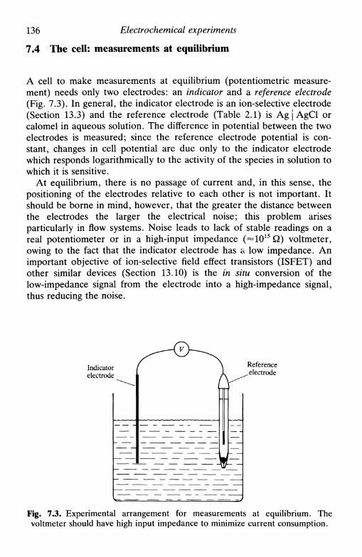
136 Electrochemical experiments
7.4 The cell: measurements at equilibrium
A cell to make measurements at equilibrium (potentiometric measure-ment) needs only two electrodes: an indicator and a reference electrode(Fig. 7.3). In general, the indicator electrode is an ion-selective electrode(Section 13.3) and the reference electrode (Table 2.1) is Ag j AgCl orcalomel in aqueous solution. The difference in potential between the twoelectrodes is measured; since the reference electrode potential is con-stant, changes in cell potential are due only to the indicator electrodewhich responds logarithmically to the activity of the species in solution towhich it is sensitive.
At equilibrium, there is no passage of current and, in this sense, thepositioning of the electrodes relative to each other is not important. Itshould be borne in mind, however, that the greater the distance betweenthe electrodes the larger the electrical noise; this problem arisesparticularly in flow systems. Noise leads to lack of stable readings on areal potentiometer or in a high-input impedance (~1015 Q) voltmeter,owing to the fact that the indicator electrode has a low impedance. Animportant objective of ion-selective field effect transistors (ISFET) andother similar devices (Section 13.10) is the in situ conversion of thelow-impedance signal from the electrode into a high-impedance signal,thus reducing the noise.
Indicatorelectrode
Referenceelectrode
Fig. 7.3. Experimental arrangement for measurements at equilibrium. Thevoltmeter should have high input impedance to minimize current consumption.

7.5 The cell: measurements away from equilibrium 137
7.5 The cell: measurements away from equilibrium
Electrodes
Outside equilibrium there is passage of current between two electrodes,as in galvanic cells or electrolytic cells. In laboratory research we areusually interested in investigating the electrode process at one of theelectrodes, the indicator or working electrode, through control of itspotential (potentiostatic control) or the current it passes (galvanostaticcontrol), the other, auxiliary, electrode being used to complete theelectrical circuit. In the past, in controlled potential experiments, theauxiliary electrode was also the reference electrode, which thus had thedouble function of passing current and acting as a reference potential forcontrolling the potential of the working electrode. Sometimes thisbrought problems of potential stability—on passing current, the activitiesof the species would be slightly altered in the vicinity of the referenceelectrode, causing a variation of its potential. For this reason three-electrode systems were developed where the current passes from theworking electrode to an auxiliary electrode (of larger area than theworking electrode), the separate reference electrode serving purely as areference potential and not passing current.
In electrochemical research, auxiliary electrodes are frequently madeof platinum foil or gauze, sometimes placed in a compartment separatedfrom the rest of the solution by a porous frit, so as to avoidcontamination arising from the reaction occurring at the auxiliaryelectrode. This is an oxidation if reduction is occurring at the workingelectrode and vice versa, but the identity of the auxiliary electrodereaction is not important in this type of experiment.
Exceptions to the three-electrode system in the laboratory are now fewbut important. A pool of mercury at the bottom of a cell in contact withan electrolyte solution containing chloride or bromide can serve asauxiliary and reference electrodes simultaneously owing to the very largesurface area exposed. Another exception is experiments with microel-ectrodes: the current that passes is so small that the effect on thereference/auxiliary electrode potential is negligible.
In order to control the working electrode potential accurately, it isnecessary that the resistance between working and reference electrodes isas small as possible. This means close positioning, that is often notpossible. In these cases a Luggin capillary is used, a piece of glass intowhich the reference electrode is inserted and whose finely drawn-outpoint is placed close to the working electrode. The optimal positiondepends on the geometry of the indicator electrode and on theelectrochemical technique being employed.

138 Electrochemical experiments
Referenceelectrode
Lid
Workingelectrode
Luggincapillary
Auxiliaryelectrode
Thermostattedwater
Fig. 7.4. Electrochemical cell for measurements in a three-electrode scheme at aplanar electrode.
Figure 7.4 shows an electrochemical cell containing a stationary planarworking electrode, a reference electrode with Luggin capillary, and anauxiliary electrode. Some other types of more specialized cells aredescribed in subsequent chapters.
Quasi-reference electrodes can be employed in situations where thehigh reproducibility of potential is not necessary, such as in manyvoltammetric analysis experiments. Mercury pools (referred to above) orsilver wires in aqueous halide media are examples. Platinum wires canalso be used. The advantage of wires, apart from their small size, is inreducing the uncompensated resistance in resistive media, relative toconventional reference electrodes.
Supporting electrolyte
Normally electrode reactions take place in solutions, or sometimes inmolten salts (e.g. aluminium extraction). In order to minimize thephenomenon of migration of the electroactive ions caused by the electricfield (Chapter 2) and to confine the interfacial potential difference to thedistance of closest approach of solvated ions to the electrode (Chapter 3),the addition of a solution containing a high concentration of inertelectrolyte, called supporting electrolyte, is necessary. This has a con-centration at least 100 times that of the electroactive species and is theprincipal source of electrically conducting ionic species. The concentra-tion of supporting electrolyte varies normally between 0.01 м and 1.0 м,the concentration of electroactive species being 5 т м or less. The

7.5 The cell: measurements away from equilibrium 139
Table 7.2. Some supporting electrolytes and their approximate potentialranges in water and other solvents for platinum, mercury, and carbon
EN vs. SCE- 3 0 +3
I i | | , , I
U M H 2 S O 4 1I 1 1 м NaOH j
I 1 1 M H 2 S O 4 ЛWater , I ,1 1 м КС1 \ Hg
I 1 1 M NaOH J
I 1 1 M HC1O4 1 c
I I0.1MKC1 f
Non-aqueous I 1 0.1 M TBAP/DMF(Pt)
I 10.1 м TBABF4/ACN
TBAP = tetrabutylammonium perchlorateDMF = dimethylformamide
TBABF4 = tetrabutylammonium tetrafluoroborateACN = acetonitrile
supporting electrolyte should be chosen, as well as its concentration, sothat the transport numbers of the electroactive species are practicallyzero: it can be an inorganic or organic salt, an acid or a base, or a buffersolution such as citrate, phosphate, or acetate. The choice also has to bemade in relation to the properties of the solvent employed. A descriptionof the properties of non-aqueous solvents and usable electrolytes can befound in Ref. 16.
Table 7.2 shows some useful supporting electrolytes in aqueous andnon-aqueous media. The usable potential range is limited by solventand/or supporting electrolyte decomposition and, to a certain extent, byelectrode material. Sometimes samples for laboratory analysis alreadycontain supporting electrolyte, as is the case for sea water (0.7 м NaCl);in others acid is added during preparation by digestion, etc., that canserve simultaneously as supporting electrolyte. In Table 7.1 it shouldbe noted that there are useful organic salts (tetraalkylammonium-)that are soluble in non-aqueous solvents: in these cases there is lessconfidence that the supporting electrolyte does not interfere in theelectrode reactions17.
All care must be taken to ensure that the supporting electrolyte is truly

140 Electrochemical experiments
inert in the potential range of the experiment, not reacting with theelectrode or with the products of the electrode reaction (except whendesired). This also shows the importance of reagent purity for preparingan electrolyte solution of the best quality, of purification of commercialreagents if necessary, of drying and distilling pure organic solvents underthe appropriate conditions, and of careful distillation of water to removeinorganic and organic impurities, these latter by photolytic degradationor reaction with permanganate.
In the case of microelectrodes where currents are sufficiently small sothat the reference electrode can serve simultaneously as auxiliaryelectrode (see above) the solution ohmic potential drop (product ofcurrent and solution resistance) is also small. This means that measure-ments can be made in highly resistive media without the addition ofsupporting electrolyte, a fact that can be very useful.
Removal of oxygen
The atmosphere contains about 20 per cent oxygen, which is slightlyheavier than air, and is dissolved appreciably (^10~4 м) in solutions opento the atmosphere. Oxygen is reduced at electrodes in two separatetwo-electron steps or in one four-electron step at potentials that varybetween 0.05 V and -0.9 V vs. SCE, depending on pH and on electrodematerial. In acid solution
and in alkaline solution
O2 + 2H2O + 2e" -> 2OH" + H 2O 2
H 2O 2 + 2e --> 2OH~
the four-electron reduction being obtained by addition of the twotwo-electron steps. These half-reactions contribute to the current meas-ured at the electrode and oxygen can oxidise the electrode surface.Besides this, oxygen, radicals such as HO 2, and hydrogen peroxide canreact with the reagents and/or products of the electrode reaction beingstudied. Thus removal of oxygen from the solution is, in general, of greatimportance, especially for studies done at negative potentials, unless theelectroreduction of oxygen itself is being investigated.
Removal of oxygen can be done chemically by the addition of the exactquantity of a compound such as hydrazine, according to the reaction
N 2H 4 + O 2 -»N 2 + 2H2O
This procedure is used industrially to minimize corrosion.
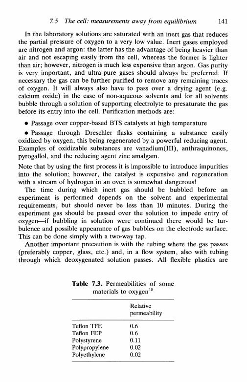
7.5 The cell: measurements away from equilibrium 141
In the laboratory solutions are saturated with an inert gas that reducesthe partial pressure of oxygen to a very low value. Inert gases employedare nitrogen and argon: the latter has the advantage of being heavier thanair and not escaping easily from the cell, whereas the former is lighterthan air; however, nitrogen is much less expensive than argon. Gas purityis very important, and ultra-pure gases should always be preferred. Ifnecessary the gas can be further purified to remove any remaining tracesof oxygen. It will always also have to pass over a drying agent (e.g.calcium oxide) in the case of non-aqueous solvents and for all solventsbubble through a solution of supporting electrolyte to presaturate the gasbefore its entry into the cell. Purification methods are:
• Passage over copper-based BTS catalysts at high temperature• Passage through Dreschler flasks containing a substance easily
oxidized by oxygen, this being regenerated by a powerful reducing agent.Examples of oxidizable substances are vanadium(III), anthraquinones,pyrogallol, and the reducing agent zinc amalgam.
Note that by using the first process it is impossible to introduce impuritiesinto the solution; however, the catalyst is expensive and regenerationwith a stream of hydrogen in an oven is somewhat dangerous!
The time during which inert gas should be bubbled before anexperiment is performed depends on the solvent and experimentalrequirements, but should never be less than 10 minutes. During theexperiment gas should be passed over the solution to impede entry ofoxygen—if bubbling in solution were continued there would be tur-bulence and possible appearance of gas bubbles on the electrode surface.This can be done simply with a two-way tap.
Another important precaution is with the tubing where the gas passes(preferably copper, glass, etc.) and, in a flow system, also with tubingthrough which deoxygenated solution passes. All flexible plastics are
Table 7.3. Permeabilities of somematerials to oxygen18
Teflon TFETeflon FEPPolystyrenePolypropylenePolyethylene
Relativepermeability
0.60.60.110.020.02

142 Electrochemical experiments
permeable to oxygen—some permeability values are given in Table 7.3.Lengths of plastic tubes should therefore be minimized.
7.6 Calibration of electrodes and cells
In investigating electrode processes it is extremely important to knowwhether the assumptions of the theory that is being applied are valid.Calibration of the working electrode and of the cell is thus a fundamentalrequirement. Since electrode response varies with time, calibration mayhave to be repeated fairly often.
In voltammetric experiments a normal type of calibration is therecording of voltammetric curves for a known system, constructing plotssuch as variation of limiting current with the transport parameter, or ofcurrent with concentration. In potentiometric experiments the equivalentwould be the variation of potential with concentration. These curves areespecially important in electroanalytical experiments: working curvespermit the immediate conversion of a measured current or potential intoa concentration.
Another useful electroanalytical procedure is the standard additionmethod: successive quantities of a standard solution are added to theunknown solution, the concentration of species in the unknown solutionbeing determined from the intercept of the plot of response vs. quantityadded. Note that the use of graphical methods without comparison withtheoretical equations and known systems does not prove the accuracy ofthe experiments, but only their precision.
Finally, the detection limit of a technique, which is determined by theimpossibility of separating signal from noise (blank), should be con-sidered. In potentiometric experiments the detection limit results from adiminution down to zero variation in measured potential with concentra-tion decrease, as discussed in Chapter 13. It is clear that reproducibilityhas an important effect on detection limit, and detection limits aresometimes quoted on this basis, such as three times the standarddeviation. Unfortunately in the electroanalytical literature, as in manyother areas, there is sometimes an incorrect use of statistical techniquesthat favours the authors' results or hides the degree of non-reproducibility!
7.7 Instrumentation: general
Instrumentation for electrochemical experiments has undergone rapiddevelopment, allowing much greater precision and accuracy in control
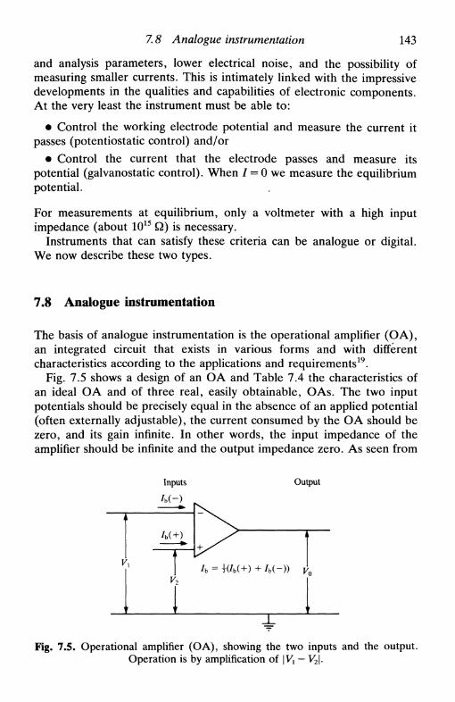
7.8 Analogue instrumentation 143
and analysis parameters, lower electrical noise, and the possibility ofmeasuring smaller currents. This is intimately linked with the impressivedevelopments in the qualities and capabilities of electronic components.At the very least the instrument must be able to:
• Control the working electrode potential and measure the current itpasses (potentiostatic control) and/or
• Control the current that the electrode passes and measure itspotential (galvanostatic control). When / = 0 we measure the equilibriumpotential.
For measurements at equilibrium, only a voltmeter with a high inputimpedance (about 1015 Q) is necessary.
Instruments that can satisfy these criteria can be analogue or digital.We now describe these two types.
7.8 Analogue instrumentation
The basis of analogue instrumentation is the operational amplifier (OA),an integrated circuit that exists in various forms and with differentcharacteristics according to the applications and requirements19.
Fig. 7.5 shows a design of an OA and Table 7.4 the characteristics ofan ideal О A and of three real, easily obtainable, О As. The two inputpotentials should be precisely equal in the absence of an applied potential(often externally adjustable), the current consumed by the О A should bezero, and its gain infinite. In other words, the input impedance of theamplifier should be infinite and the output impedance zero. As seen from
Inputs
/b(-)
Output
= Ш+) + /b(-)) Vo
Fig. 7.5. Operational amplifier (OA), showing the two inputs and the output.Operation is by amplification of |V, — V2\.

144 Electrochemical experiments
Table 7.4. Characteristics of operational amplifiers
Maximum output currentMaximum output voltageOpen circuit gainInput impedanceMaximum offset voltage
(\Vi-V2\)Input currentInput bias current
741
~5 mA±15 V106 dB2MQl m V
80 n A20 n A
LM11
~5 mA±15 V109 dB10 n Q0.2 mV
40 p Al p A
FET
~5 mA±15V106 dB1012Q3mV
30 p A10 pA
Ideal
InfiniteInfiniteInfiniteInfiniteZero
ZeroZero
Table 7.4 input impedances in real OAs vary from 106 upwards, thecurrents consumed from nA to less than pA and the gain between 104 and108.
Other factors to take into account are:
• The amplifiers work from voltage sources of ±9V to ±18 V; theoutput potential can never exceed these values;
• For high frequency there is a decline in amplifier gain and in the rateof change in output voltage to an instantaneous change in input voltage(slew rate)—generally IV/JUS at low frequency;
• The circuits need some time to stabilize at the new voltages after avoltage step, perhaps as much as 100 /is. This limitation is especiallyimportant in transient techniques (Chapters 9-11).
By choosing adequate amplifiers and using the feedback principle it ispossible to construct circuits, making use of Ohm's and Kirchoff's laws torelate input voltage, Vh with output voltage, Vo. Some of the circuitcomponents are illustrated in Fig. 7.6 with the respective relationsindicated. The gain of these components must always be less than thegain of the О A at open circuit.
For a measurement at equilibrium, it is sufficient to use a voltagefollower made from a high quality OA at the voltmeter inputs for each ofthe two electrodes. Modern good-quality pH and ion-selective electrodemeters already come with these requirements satisfied.
We now need to know how to combine the circuit components of Fig.7.6 in order to form a potentiostat or a galvanostat. Current and/orvoltage boosters can be incorporated in the schemes shown below whenhigher currents or voltage ranges are required.

V) Vo = V{ + IR
Voltage follower Inverting Current follower
Vx —ww-V2 s/WVV—
у ъ Д
Л/WW—i
vo=vl- v2
у —Ww\r
1RC
\V{dt Vo = - d/
Subtracting Summing inverting Integrating Differentiating
Fig. 7.6. Components of electrical circuits constructed from operational amplifiers using the feedback principle.

146
Potentiostat
Electrochemical experiments
A potentiostat controls the potential applied to the working electrode,and permits the measurement of the current it passes. Combination ofsome of the components in Fig. 7.6 gives the potentiostat of Fig. 7.7. In
Electrodes:
Working
ED(2) y/WV-1
Г
71-AuxiliaryReference
-H
Fig. 7.7. Potentiostat circuit for control of working electrode potential. Allresistances are equal, except /?D which is variable.
the circuit illustrated it is possible to apply two signals simultaneouslythat are added before reaching the working electrode—an example wouldbe a voltage ramp and a sinusoidal signal. We have
Ew-Ere{=V1 + Vz (7.1)
where £w and Eref are the working and reference electrode potentialsrespectively, and
V — I R (1 0\
I УЛЛЛ/V—[уУ^
Electrodes:
t> Generator (disc)
О Detector (ring)
Auxiliary
Reference
Fig. 7.8. Bipotentiostat circuit for control of the potential of two workingelectrodes. All resistances are equal, except Rn and RK which are variable.
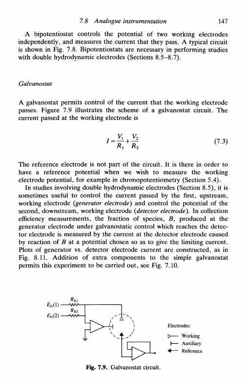
7.8 Analogue instrumentation 147
A bipotentiostat controls the potential of two working electrodesindependently, and measures the current that they pass. A typical circuitis shown in Fig. 7.8. Bipotentiostats are necessary in performing studieswith double hydrodynamic electrodes (Sections 8.5-8.7).
Galvanostat
A galvanostat permits control of the current that the working electrodepasses. Figure 7.9 illustrates the scheme of a galvanostat circuit. Thecurrent passed at the working electrode is
(7.3)
The reference electrode is not part of the circuit. It is there in order tohave a reference potential when we wish to measure the workingelectrode potential, for example in chronopotentiometry (Section 5.4).
In studies involving double hydrodynamic electrodes (Section 8.5), it issometimes useful to control the current passed by the first, upstream,working electrode {generator electrode) and control the potential of thesecond, downstream, working electrode {detector electrode). In collectionefficiency measurements, the fraction of species, B, produced at thegenerator electrode under galvanostatic control which reaches the detec-tor electrode is measured by the current at the detector electrode causedby reaction of В at a potential chosen so as to give the limiting current.Plots of generator vs. detector electrode current are constructed, as inFig. 8.11. Addition of extra components to the simple galvanostatpermits this experiment to be carried out, see Fig. 7.10.
Electrodes:
Working
Auxiliary
Reference
Fig. 7.9. Galvanostat circuit.

148 Electrochemical experiments
ED(2)
_ ^ " ^ ^ l w w кElectrodes:
Generator (disc)Detector (ring)AuxiliaryReference
Fig. 7.10. Circuit for measuring collection efficiencies at double hydrodynamicelectrodes. All resistances are equal except Rlt R2, and RR, which are variable.
Compensation of cell solution resistance
With a Luggin capillary (Section 7.3), one can never reduce the effects ofsolution resistance to zero. In certain experiments where compensation isnecessary in order to increase sensitivity in the response signal, compen-sation can be done electronically. However, compensation can never beexact—if it is, then the electrical system becomes unstable and starts tooscillate. More details may be found in Ref. 20.
7.9 Digital instrumentation
In the past decade there has been an increasing use of digitalinstrumentation21'22; this involves controlling experiments with amicroprocessor inside the instrument or by an external microcomputer.These can also be used for direct analysis of the data obtained.
Since a digital instrument functions at fixed points, that is discon-tinuously, any direct microprocessor control of an experiment has to bein steps. For example, a linear sweep appears as a staircase instead of acontinuous ramp. To minimize these effects there are two possibilities:
• Transform the digital signal into an analogue signal using a DACwith appropriate filtering, doing the inverse with the response through anADC;
• Use a sufficiently powerful microprocessor so that the differencesbetween the fixed points are so small that there is no visible difference (intheoretical and practical terms) between the signal applied digitally oranalogically.

References 149
The second of these options, although involving fewer steps, is only nowbecoming important with the advent of 16-bit and 32-bit microprocessorsand microcomputers at reasonably accessible prices.
Digital instrumentation is especially useful where it is necessary toapply pulses of potential to the working electrode, i.e. a succession ofsteps, with current sampling (the microprocessor's internal clock is used).There has recently been a lot of progress in this area of pulsevoltammetry (Section 10.9).
Finally, we remember that, due to its nature, digital instrumentationhas a tendency to increase signal noise (there is damping on analoguesignals). The only way to solve this problem is repeat the measurementsseveral times and take the average values, or use other strategiessuch as higher-quality electronic components or improved instrumentshielding23.
References
1. D. T. Sawyer and J. L. Roberts, Experimental electrochemistry for chemists,Wiley, New York, 1974.
2. P. T. Kissinger and W. R. Heinemann (ed.), Laboratory techniques inelectroanalytical chemistry, Dekker, New York, 1984.
3. D. J. G. Ives and G. J. Janz (ed.), Reference electrodes, Academic Press,New York, 1961.
4. L. Meites, Polarographic techniques, Interscience, New York, 1965.5. J. Heyrovsky and P. Zuman, Practical polarography, Academic Press, New
York, 1968.6. E. Gileadi, E. Kirowa-Eisner, and J. Penciner, Interfacial electrochemistry:
an experimental approach, Addison-Wesley, Reading, MA, 1975.7. K. Kinoshita, Carbon, electrochemical and physicochemical properties,
Wiley, New York, 1988.8. R. L. McCreery, Electroanalytical chemistry, ed. A. J. Bard, Dekker, New
York, Vol. 17, 1991, pp. 221-374.9. G. M. Jenkins and K. Kawamura, Nature, 1971, 231, 175.
10. I. L. Kalnin and H. Jaeger in Carbon fibres and their composites, ed. E.Fitzer, Springer-Verlag, Berlin, 1985.
11. J. Lindquist, /. ElectroanaL Chem., 1974, 52, 37.12. L. D. Burke and M. F. G. Lyons, Modern aspects of electrochemistry,
Plenum, New York, Vol. 18, 1986, ed. R. E. White, J. O'M. Bockris, and B.E. Conway, pp. 169-248.
13. E. J. M. O'Sullivan and E. J. Calvo, Comprehensive chemical kinetics,Elsevier, Amsterdam, Vol. 27, 1987, ed. R. G. Compton, Chapter 3.
14. e.g. W. J. Albery and P. N. Bartlett, /. Chem. Soc. Chem. Commun., 1984,234.
15. e.g. Ref. 6, pp. 311-312.

150 Electrochemical experiments
16. С. К. Mann, Electroanalytical chemistry, ed. A. J. Bard, Dekker, New York,Vol. 3, 1969, pp. 57-134.
17. C. M. A. Brett and A. M. Oliveira Brett, /. Electroanal. Chem., 1988, 255,199.
18. Ref. 1, p. 130.19. R. Kalvoda, Operational amplifiers in chemical instrumentation, Ellis Hor-
wood, Chichester, 1975.20. Ref. 1, Chapter 5.21. K. Schwabe, H. D. Suschke, and G. Wachler, Electrochim. Acta, 1980, 25,
59.22. P. He, J. P. Avery, and L. R. Faulkner, Anal. Chem., 1982, 54, 1313A.23. S. G. Weber and J. T. Long, Anal. Chem., 1988, 60, 903A.
8
HYDRODYNAMIC ELECTRODES
8.1 Introduction8.2 Limiting currents at hydrodynamic electrodes8.3 A special electrode: the dropping mercury electrode8.4 Hydrodynamic electrodes in the study of electrode processes8.5 Double hydrodynamic electrodes8.6 Multiple electron transfer: the use of the RRDE8.7 Hydrodynamic electrodes in the investigation of coupled homogeneous
reactions8.8 Hydrodynamic electrodes and non-stationary techniques
8.1 Introduction
Hydrodynamic electrodes1 are electrodes which function in a regime offorced convection. The advantage of these electrodes is increasedtransport of electroactive species to the electrode, leading to highercurrents and thence a greater sensitivity and reproducibility. Most of theapplications of these electrodes are in steady-state conditions, i.e.constant forced convection and constant applied potential or current. Inthis case dc/dt = 0, which simplifies the solution of the convectivediffusion equation (Section 5.6)
— = DV2c-vVc (8.1)
Even when дс/дгФО, i.e. in applications of these electrodes in combina-tion with transient techniques, forced convection is useful at the veryleast for improving the reproducibility of the results, owing to the weakdependence of the electrode response on the physical properties of thesolution, such as viscosity (Section 8.8).
The method of resolution of (8.1) was indicated in Sections 5.7-5.9,showing as an example the calculation of the limiting current at therotating disc electrode. In this chapter we discuss this and otherhydrodynamic electrodes used in the study of electrode processes. Therotating disc electrode has probably been the hydrodynamic electrode

152 Hydro dynamic electrodes
most used for investigating the kinetics and mechanism of electrochemi-cal reactions2"8. The characteristics of the dropping mercury electrode(DME) are also discussed9; its operation is cyclic and, as a firstapproximation, at the same point in successive cycles we can invoke thesteady-state. Voltammetric studies at the DME are, for historicalreasons, referred to as polarography.
In Table 8.1 all the hydrodynamic electrodes in common use are listed.
Table 8.1. Limiting currents, /L, at hydrodynamic electrodes underlaminar flow conditions". Adapted from Ref. 1
A. Uniformly accessible electrodes6
Flow
Rotating discRotating hemisphere
Rotating core
Wall-tubeStationary disc in
uniformly laminar flow
parameter (/)
CO
CO
CO
Vf/(0.5a)U/lr,
B. Dropping mercury electrode'
Flow parameter (/)
m,
C. Non-uniformly accessible electrodesFlow
TubeChannelWall-jet6
Stationary disc inuniformly rotating fluid6''
Stationary disc in fluidrotating due to a rotating
parameter
vfvf
со'
со"
к0.6200.433^0.474
O.62(sin0)-1/2
0.610.753 or 0.780
к709607
Expression for
5.43nFc0OD2/3r0.925nFCoDD2/3il^nFc^D^v0J61nFCooD
2/3
OAHnFc^D213
Comments
Experimentallyк = 0.451
в is angle betweenrotation axis andelectrode surface
Experimental deviationsof ±4 per cent
Comments
Av. current (/L)
limiting current2/3 у 1/3
[h2d)~ l/3wx2/3Vf
l/3
-5/12fl-l/2r3/4y3/4
у~1/6лг2со
a For coordinates see Fig. 8.1.b The expression for /L at the ring electrode is obtained by putting (rln/2 - rln/2)2/3 instead of
c This is the Ilkovic equation which assumes uniform accessibility.d These electrodes are not uniformly accessible, despite appearances, since the convectiveflow is towards and not from the centre of the disc.
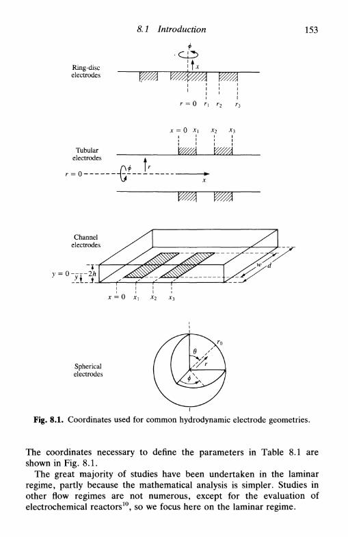
8.1 Introduction 153
Ring-discelectrodes v/ЩУМ
г = О г, г2
x = 0 xx x3
Tubularelectrodes
- o- - • # •
V////A
X
\У///Л
Channelelectrodes
Sphericalelectrodes
Fig. 8.1. Coordinates used for common hydrodynamic electrode geometries.
The coordinates necessary to define the parameters in Table 8.1 areshown in Fig. 8.1.
The great majority of studies have been undertaken in the laminarregime, partly because the mathematical analysis is simpler. Studies inother flow regimes are not numerous, except for the evaluation ofelectrochemical reactors10, so we focus here on the laminar regime.

154 Hydrodynamic electrodes
x = 0
Fig. 8.2л. Schematic streamlines at a rotating disc.
2R
V///////
Fig. 8.2Л. Establishment of Poiseuille flow and diffusion layer in a tube orchannel of infinite width.
^ ^ ^ ^ ^ ^ ^ ^Fig. 8.2c. Mass transfer at an impinging jet electrode. I, central core potentialregion; II, established flow region; III, stagnation region ('wall-tube' region);
IV, wall-jet region (from Ref. 13 with permission).

8.2 Limiting currents at hydrodynamic electrodes
8.2 Limiting currents at hydrodynamic electrodes
155
As described in Chapter 5, forced convection leads to a thin layer ofsolution next to the electrode, within which it is assumed that onlydiffusion occurs (i.e. it is assumed that all concentration gradients occurwithin this layer)—the diffusion layer of thickness <5. At a particular pointon a hydrodynamic electrode and for constant convection, 6 is constant.If the value of <5 is constant over the whole electrode surface then theelectrode is uniformly accessible to electroactive species that arrive frombulk solution.
If the potential applied to the electrode is sufficiently negative(reduction) or positive (oxidation), all the electroactive species that reachthe electrode will react and we obtain the limiting current, /L, whateverthe value of the standard rate constant, k0. The relation between thelimiting current and the diffusion layer thickness, <5, is
Thus, at a uniformly accessible electrode, /L is directly proportional toelectrode area.
The expressions for the limiting currents at commonly used hydrodyn-amic electrodes are presented in Table 8.1. Nearly all of these havecylindrical symmetry, and the electrodes are embedded in surfaces ofinfinite extension. As explained in Chapter 5, calculation of /L beginswith the velocity profile in solution1112. Thence, one obtains expressionsfor the velocity components close to the electrode surface and calculates/L. Streamlines and schematic profiles of solution movement for someconfigurations are shown in Fig. 8.2. The following points should be
Fig. 8.2d. The wall-jet electrode: schematic streamlines.
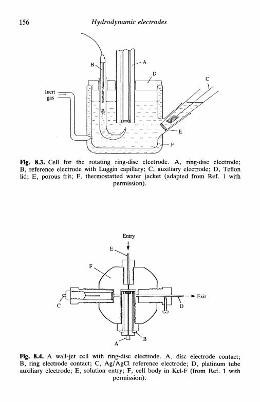
156 Hydrodynamic electrodes
Fig. 8.3. Cell for the rotating ring-disc electrode. A, ring-disc electrode;B, reference electrode with Luggin capillary; C, auxiliary electrode; D, Teflonlid; E, porous frit; F, thermostatted water jacket (adapted from Ref. 1 with
permission).
Exit
Fig. 8.4. A wall-jet cell with ring-disc electrode. A, disc electrode contact;B, ring electrode contact; C, Ag/AgCl reference electrode; D, platinum tubeauxiliary electrode; E, solution entry; F, cell body in Kel-F (from Ref. 1 with
permission).
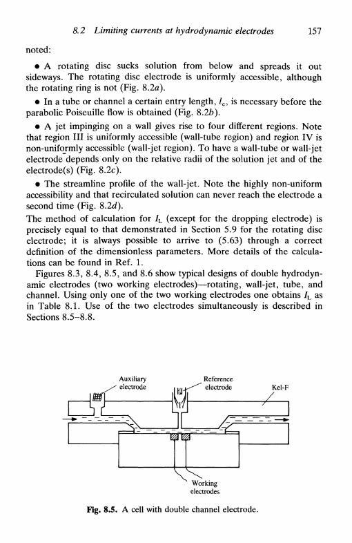
8.2 Limiting currents at hydrodynamic electrodes 157
noted:
• A rotating disc sucks solution from below and spreads it outsideways. The rotating disc electrode is uniformly accessible, althoughthe rotating ring is not (Fig. 8.2я).
• In a tube or channel a certain entry length, /e, is necessary before theparabolic Poiseuille flow is obtained (Fig. 8.2b).
• A jet impinging on a wall gives rise to four different regions. Notethat region III is uniformly accessible (wall-tube region) and region IV isnon-uniformly accessible (wall-jet region). To have a wall-tube or wall-jetelectrode depends only on the relative radii of the solution jet and of theelectrode(s) (Fig. 8.2c).
• The streamline profile of the wall-jet. Note the highly non-uniformaccessibility and that recirculated solution can never reach the electrode asecond time (Fig. 8.2d).The method of calculation for /L (except for the dropping electrode) isprecisely equal to that demonstrated in Section 5.9 for the rotating discelectrode; it is always possible to arrive to (5.63) through a correctdefinition of the dimensionless parameters. More details of the calcula-tions can be found in Ref. 1.
Figures 8.3, 8.4, 8.5, and 8.6 show typical designs of double hydrodyn-amic electrodes (two working electrodes)—rotating, wall-jet, tube, andchannel. Using only one of the two working electrodes one obtains /L asin Table 8.1. Use of the two electrodes simultaneously is described inSections 8.5-8.8.
Auxiliaryelectrode
Referenceelectrode Kel-F
Workingelectrodes
Fig. 8.5. A cell with double channel electrode.

158 Hydrodynamic electrodes
Fig. 8.6. Construction of typical tubular electrodes, (a) Integral construction:A, generator electrode; B, detector electrode; C, reference electrode; D,auxiliary electrode; E, porous frits; F, joints; G, epoxy resin, (b) Demountableconstruction: A, generator electrode; B, detector electrode; C, Teflon parts; D,reference electrode; E, cell body in Teflon; F, brass thread (from Ref. 1 withpermission).
8.3 A special electrode: the dropping mercury electrode
The derivation of the equation for the diffusion-limited current at thedropping mercury electrode differs from that of the other electrodesdescribed above owing to its cyclic operation. Mercury flowing downthrough a fine capillary forms a drop at the bottom end of the capillary.This drop, the electrode, increases in size until it falls by the force ofgravity; the electrode is then renewed by formation of another drop.There are thus virtually no problems of electrode poisoning. The mode of

8.3 Л special electrode: the dropping mercury electrode 159
Inert,gas
Fig. 8.7. A cell for the dropping mercury electrode. A, mercury reservoir;B, Tygon tube; C, link to mercury by platinum wire; D, capillary; E, reference
electrode; F, auxiliary electrode (from Ref. 1 with permission).
operation is shown in Fig. 8.7.One of the first to study the dropping mercury electrode mathemati-
cally was Ilkovic14. Following his derivation of /L, we start from theCottrell equation (Section 5.3) for a planar electrode
r , ч nFADy2
Coo / ч
Remembering that the surface area of the electrode (supposed spherical)

160 Hydrodynamic electrodes
Fig. 8.8. Variation of /L with t at the dropping electrode: (-( ) practical.
-) theoretical and
is increasing, its radius, r0, is given by
ro = \4яр/(8.4)
where mx is the mass flux of liquid, given normally in mgs"1, and p itsdensity. Substituting expression (8.4) in (8.3), we obtain
(8.5)
Drop growth causes an increase in the concentration gradient whichresults in a multiplicative factor of V(7/3). The final equation for thelimiting current (Ilkovic equation), with сж measured in molcm""3 and Din cm2s 1, is
1/2 Д/6 (8.6)
Integrating over the lifetime of the drop, т, the variation of /L with timeduring drop life being shown in Fig. 8.8, we obtain the average value,IL(t) which is
/L(0 = 607ncooD1/2m?/3T1/6 (8.7)
The Ilkovic equation is experimentally verified with some rigour in theform of (8.7), but not as (8.6). The current at the beginning of drop life isless than predicted and later on it is larger. Possible reasons are:
• neglect of electrode curvature
• neglect of the shielding effect of the capillary where the drop isformed, especially at the beginning of drop life

8.3 A special electrode: the dropping mercury electrode 161
• neglect of the fact that the part of the drop linked to the capillarydoes not contact with the solution.
Various treatments introducting corrective terms have appeared, but fewinclude the curvature of the electrode explicitly in the formulation of theproblem. The majority of the expressions have the form
where the constant A varies between 17 and 39, the corrective termcorresponding to spherical diffusion (see Table 5.3).
Another important factor linked with drop growth is the appearance ofcapacitive currents, /c, manifested as a background current, see Fig. 8.9.We can write
(8.9)
where Ez is the point of zero charge and Cx the integral capacity of thedouble layer (Section 3.2). From (8.4), and since for liquid mercuryp = 13.4 g cm"3, we have
Thus
А Л
— = 5.7xlO"3mfr1/3
/c = 5.7 X 10⁻³Ci(£: - Е2)тГгуз
Ic = 8.6 x 10⁻³Q(E - Ez)mTr~m
(8.10)
(8.11)
(8.12)
-/л
L'A -E
Fig. 8.9. Determination of /L at a dropping electrode by subtraction of thebackground current.

162 Hydrodynamic electrodes
So Ic^t m whilst Ibxt1/e, that is / c diminishes with time whereas /L
increases. This is one of the reasons for sampling the current almost atthe end of drop life in many polarographic techniques, in the hope that / c
is almost zero and can be neglected. It should also be noted that if C{ andт do not vary with potential, then the background current varies linearlywith potential, which is useful for calculating the height of polarographicpeaks.
It can be shown that х^Нъ
у where h is the height of the mercurycolumn, by considering the force of gravity and liquid flow in a capillary.So Ic<xh and IL<xhm. This means that there is a minimum detectionlimit; with current sampling this is around 10~7м (see Chapter 10 onpulse techniques). It is therefore important not to have too high a columnof mercury.
Another important phenomenon that occurs at the dropping mercuryelectrode is the polarographic maximum15, which occurs when, onreaching the limiting current plateau, the observed current exceeds /L
(Fig. 8.10). The causes are mass transport within the electrode andsurface adsorption. Three types of maximum have been identified:
1. Variations of mercury surface tension cause movement within themercury. Owing to the different velocity distibutions close to and faraway from the capillary, there is a non-uniform current distribution.Maxima are tall and narrow.
2. Due to high flows of mercury (rapid dropping), giving small,rounded maxima.
3. Some surfactants adsorbed on the electrode surface with a compactmolecular structure, i.e. liquid crystals, lead to condensed two-
Fig. 8.10. Schematic polarographic maximum.

8.4 Hydrodynamic electrodes 163
dimensional layers on the drop surface. This phenomenon causesturbulence. Examples are camphor and adamantol.
Maxima can be reduced to zero in many cases by addition of smallquantities of certain surfactants (for example Triton-X-100 or gelatine)given the effect these have on surface tension. Another possibilityconsists in using very short drop lifetimes with mechanical control of dropfall. It is now realized that this is only possible for certain types ofexperiment; it is equivalent to the use of a microelectrode (Chapter 5).
8.4 Hydrodynamic electrodes in the study of electrodeprocesses
In Sections 6.3-6.5 expressions for the analysis of the voltammogramscorresponding to the simple electron transfer process О + ле~—»R,obtained for uniformly accessible electrodes such as the rotating discelectrode, were presented. In this section these expressions will beapplied to hydrodynamic electrodes in general.
Reversible reaction
In this case non-uniform accessibility has no influence. The equation forthe voltammogram is then
where
E\l2 = E^' 4- — In (—-\ (8.14)
and s = § for all hydrodynamic electrodes except the dropping electrodewhere s = \. The shape of the voltammogram is shown in Fig. 6.2. Analternative way of describing the voltammetric curve, in order to separatethe anodic and cathodic components, is by substituting
Z = {E-E'm)(nFlRT) (8.15)
to obtain

164 Hydrodynamic electrodes
The general case
In the general case for a uniformly accessible electrode (/L a electrodearea)
where Ik = nFAka[R]x (or — nFAkc[O]oc), assuming a first-order electrodereaction. So, exemplifying for a rotating disc electrode, a plot of 7"1 vs.W~m (see Table 8.1) gives k0 from the intercept and D from the slope.
It has been demonstrated by Matsuda and co-workers in a series ofpapers16 that is is possible to use, for first-order reactions, approximateexpressions for the voltammetric curves of the form
+exp{-C} l + exp{£}
x (А:0/Р2 />[ехр {-аЛ} + ехр }]
Л}]
for many hydrodynamic electrodes, including some that are slightlynon-uniformly accessible. In these equations
r£ (8.15)
D = Dg-D|c (8.19)
with о an expression dependent on mass transport and A a number,constant for a uniformly accessible electrode and in other cases depend-ent on electrode geometry, being calculated numerically. Whilst foruniform accessibility the expression is exact, when it is non-uniform thereis an error involved, the magnitude of the error increasing with thedegree of non-uniform accessibility. For example, for the wall-jet discelectrode which is highly non-uniformly accessible, (8.18) cannot beapplied.
When
A « (ko/D2/3)a[cxp {-ac£} + exp {a£}} (8.20)
corresponding to fast electrode reactions, (8.18) reduces to the reversiblecase, (8.16).
Values of о and A for various hydrodynamic electrodes are shown inTable 8.2. For these electrodes, graphical analysis of experimental resultscan follow (8.17), since expressions (8.17) and (8.18) have the sameform.
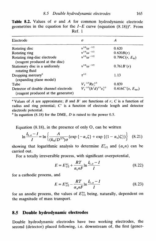
8.5 Double hydrodynamic electrodes 165
Table 8.2. Values of о and A for common hydrodynamic electrodegeometries in the equation for the 1-Е curve (equation (8.18))a. From
Ref. 1
Electrode
Rotating discRotating ringRotating ring-disc electrode
(reagent produced at the disc)Stationary disc in a uniformly
rotating fluidDropping mercury*
(expanding plane model)TubeDetector of double channel electrode
(reagent produced at the generator)
о
УШО)-Ш
УШ(О~Ш
vveo)~1/2
vV6(o~m
тш
V7mRx\'3
Vim(h2d)y3xl2
A
0.6200.620Б(г)0.799C(r, ER)
0.16lB'(r)
1.13
0.839? 0.616C'(JC, Edet)
a Values of A are approximate; В and B' are functions of г; С is a function ofradius and ring potential; С is a function of electrode length and detectorelectrode potential.b In equation (8.18) for the DME, D is raised to the power 0.5.
Equation (8.18), in the presence of only O, can be written
a c £ } + e x p { ( l - O S } ) f (8.21)/ " Ч ( £ 0 / Д 2 / >
showing that logarithmic analysis to determine E\/2 and (acn) can becarried out.
For a totally irreversible process, with significant overpotential,
oc
for a cathodic process, and
(8.22)
^ n 1 ^ (8.23)aanF I
for an anodic process, the values of Ely2 being, naturally, dependent onthe magnitude of mass transport.
8.5 Double hydrodynamic electrodes
Double hydrodynamic electrodes have two working electrodes, thesecond (detector) placed following, i.e. downstream of, the first (gener-
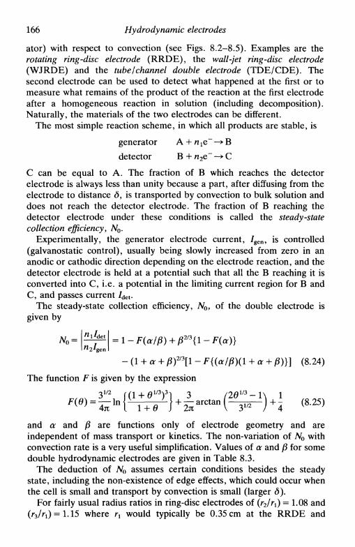
166 Hydrodynamic electrodes
ator) with respect to convection (see Figs. 8.2-8.5). Examples are therotating ring-disc electrode (RRDE), the wall-jet ring-disc electrode(WJRDE) and the tube I channel double electrode (TDE/CDE). Thesecond electrode can be used to detect what happened at the first or tomeasure what remains of the product of the reaction at the first electrodeafter a homogeneous reaction in solution (including decomposition).Naturally, the materials of the two electrodes can be different.
The most simple reaction scheme, in which all products are stable, is
generator A + пге~ —> В
detector В + л2е~ -> С
С can be equal to A. The fraction of В which reaches the detectorelectrode is always less than unity because a part, after diffusing from theelectrode to distance d, is transported by convection to bulk solution anddoes not reach the detector electrode. The fraction of В reaching thedetector electrode under these conditions is called the steady-statecollection efficiency f No.
Experimentally, the generator electrode current, / g e n, is controlled(galvanostatic control), usually being slowly increased from zero in ananodic or cathodic direction depending on the electrode reaction, and thedetector electrode is held at a potential such that all the В reaching it isconverted into C, i.e. a potential in the limiting current region for В andC, and passes current /d e t.
The steady-state collection efficiency, No, of the double electrode isgiven by
- (1 + a + РГ3[1 - F{(a/P)(l + <x + P)}] (8.24)
The function F is given by the expression
and a and /J are functions only of electrode geometry and areindependent of mass transport or kinetics. The non-variation of No withconvection rate is a very useful simplification. Values of a and /J for somedouble hydrodynamic electrodes are given in Table 8.3.
The deduction of No assumes certain conditions besides the steadystate, including the non-existence of edge effects, which could occur whenthe cell is small and transport by convection is small (larger <5).
For fairly usual radius ratios in ring-disc electrodes of (r2lrx) = 1.08 and(r3/r1) = 1.15 where rx would typically be 0.35 cm at the RRDE and

& 6 Multiple electron transfer: the use of the RRDE 167
Table 8.3. Values of a and /3 for some double hydrodynamic electrodes
Electrode
Rotating ring-disc electrode (RRDE) /r2\3 /r3\
3 /r2\3
Wall-tube ring-disc electrode (WTRDE) \7j W " W
Wall-jet ring-disc electrode (WJRDE) /r2\9 / 8 /r3\
9 / 8 /r2\9
W ~ W "WTube double electrode (TDE) /1Л /1Л //2\
Channel double electrode (CDE) \J~J ~ \J~J ~~ \TJ
0.18 cm at the WJRDE, we obtain values of around 0.18 and 0.11 for No
respectively. For tubular and channel electrodes, the ratios (12/1\) = 1.08and (/3//O = 1.15 lead to NQ « 0.10.
Another useful double electrode parameter, when the potential of bothelectrodes is controlled, is the reduction in the detector electrode currentwhen the generator electrode is passing current, if the potential appliedboth electrodes is equal, these being of the same material. By inspectionof Tables 8.1 and 8.3 it can be seen that the relation between generatorlimiting current, /L,gen> and detector limiting current with the generatordisconnected, /^det, is
К^Р'Х,^ (8.26)The limiting current at the detector electrode with the generatorelectrode connected, /L,det, is then
/L,det = /£,det - Wo/L,gen = /« ,d c t( l - N^~2'3) (8.27)
In fact (N0p~2/3) < 1 and the term in brackets, the shielding factor, isalways positive. The shielding factor is the maximum reduction in thedetector electrode current that can be caused by the generator electrode:its use is to remove an unwanted electroactive species from solution thatinterferes with the reaction under study. To maximize the reduction incurrent (minimize the shielding factor) we want an electrode geometrysuch that (TVo/S"273)̂ " 1, which corresponds to a very small interelectrodegap, (r2 — fi), and a thin detector electrode.
We now exemplify some of the uses of these electrodes in theelucidation of various types of electrode processes.
8.6 Multiple electron transfer: the use of the RRDE
The rotating ring-disc electrode has been much used in the study ofelectron transfer in consecutive and parallel reactions or a mixture ofboth. Each of these situations is now examined in detail.

168 Hydrodynamic electrodes
Consecutive reactions
Consider the scheme
Disc Аж > A* — - — > В —:—•• С*
kx к2
Ring В* W R C > D
where the mass transfer coefficient is
kd = 0.620D2/3v-1/6a)m (8.28)
and where we assume that the diffusion coefficients of all species insolution are equal. Applying the stationary state approximation to theconcentrations of the various species, i.e. dA/dt = dB/dt = 0, we obtain
nRN0
2(8.29)
dandp = L + (n, + n2)£-2l (n, + n2)^ (8.30)
L KXA Ki
From the first expression we conclude that for the two extremes when:
• k2»kd, /R = 0: A voltammetric wave is obtained at the disccorresponding to (nx-\-n2) electrons. Diffusion to the ring can beneglected.
• k2«kd, |/R//D | = (nRN0//*i): Reaction of В at the disc can beneglected relative to its diffusion to the ring electrode.
For the general case we construct plots of
• ^D/^R VS- CO~1/2 (expression 8.29), obtaining nx from the interceptand k2 from the slope.
• (^L,D — Лэ)/Л* v s - co~m (expression 8.30), obtaining kx from the slopeand n2 from the intercept.
Parallel reactions
The scheme is „ lC
k\Disc A ^ > A*
— £ — • B*

8.7 Hydrodynamic electrodes 169
where only В is electroactive at the ring. The expressions for this case are
nxkx + n2k2nRN0
/R к•2
(8.31)
= (я1-и 2 ) + -г- 2 (8-32)
Consecutive and parallel reactions
This type of reaction is often called the branched mechanism andcorresponds to many real systems such as, for example, the electroreduc-tion of oxygen. At platinum electrodes, a mechanism that explains theexperimental data is17 *,
Ring H 2 O < H 2 O 2
The calculated expressions are
i - • - , , i • и (8.33)*R
-=1 + ̂ - 2 (8.34)
A plot of /D//R VS, со ш will give straight lines of different slopesdepending on the applied potential (which affects the ratio kx/k2 and k3).At the same time there are extreme cases such as
kx = 0, intercept (8.34) = 1
kx = 0, k3 = 0 slope (8.33) = 1.
A summary of the various mechanisms considered for the electroreduc-tion of oxygen at platinum electrodes can be found in Ref. 17.
8.7 Hydrodynamic electrodes in the investigation of coupledhomogeneous reactions
In Section 6.9 the schemes of some mechanisms involving coupledhomogeneous reactions, namely EC, CE, and C'E, were shown. Hydro-dynamic electrodes are useful in the study of these mechanisms owing to
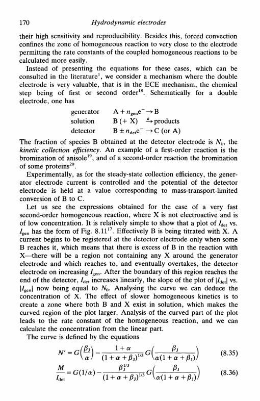
170 Hydrodynamic electrodes
their high sensitivity and reproducibility. Besides this, forced convectionconfines the zone of homogeneous reaction to very close to the electrodepermitting the rate constants of the coupled homogeneous reactions to becalculated more easily.
Instead of presenting the equations for these cases, which can beconsulted in the literature1, we consider a mechanism where the doubleelectrode is very valuable, that is in the ECE mechanism, the chemicalstep being of first or second order18. Schematically for a doubleelectrode, one has
generatorsolution
detector
A + n g e ne -»
В (+ X) ±>В ± nd e te~ -»
Вproducts
С (or A)
The fraction of species В obtained at the detector electrode is Nk, thekinetic collection efficiency. An example of a first-order reaction is thebromination of anisole19, and of a second-order reaction the brominationof some proteins20.
Experimentally, as for the steady-state collection efficiency, the gener-ator electrode current is controlled and the potential of the detectorelectrode is held at a value corresponding to mass-transport-limitedconversion of В to С.
Let us see the expressions obtained for the case of a very fastsecond-order homogeneous reaction, where X is not electroactive and isof low concentration. It is relatively simple to show that a plot of /d e t vs./gen has the form of Fig. 8. I I 1 7 . Effectively В is being titrated with X. Acurrent begins to be registered at the detector electrode only when someВ reaches it, which means that there is excess of В in the reaction withX—there will be a region not containing any X around the generatorelectrode and which reaches to, and eventually overtakes, the detectorelectrode on increasing / g e n. After the boundary of this region reaches theend of the detector, /d e t increases linearly, the slope of the plot of |/d e t | vs.|/ g e n | now being equal to No. Analysing the curve we can deduce theconcentration of X. The effect of slower homogeneous kinetics is tocreate a zone where both В and X exist in solution, which makes thecurved region of the plot larger. Analysis of the curved part of the plotleads to the rate constant of the homogeneous reaction, and we cancalculate the concentration from the linear part.
The curve is defined by the equations
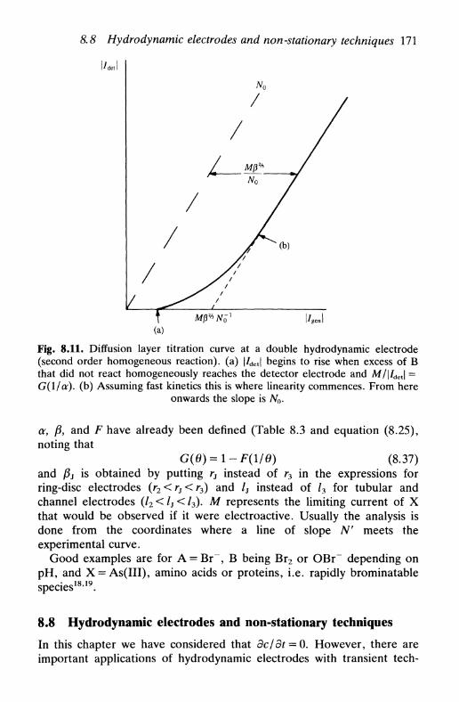
8.8 Hydrodynamic electrodes and non-stationary techniques 171
l/detl
Fig. 8.11. Diffusion layer titration curve at a double hydrodynamic electrode(second order homogeneous reaction), (a) |/det| begins to rise when excess of Вthat did not react homogeneously reaches the detector electrode and M/|/det| =G(l/ar). (b) Assuming fast kinetics this is where linearity commences. From here
onwards the slope is No.
a, /3, and F have already been defined (Table 8.3 and equation (8.25),noting that
G(0) = l - F ( l / 0 ) (8.37)and /3j is obtained by putting rs instead of r3 in the expressions forring-disc electrodes (г2<г}<гъ) and /j instead of /3 for tubular andchannel electrodes (/2 < /j < /3). M represents the limiting current of Xthat would be observed if it were electroactive. Usually the analysis isdone from the coordinates where a line of slope N' meets theexperimental curve.
Good examples are for A = Br~, В being Br2 or OBr~ depending onpH, and X = As(III), amino acids or proteins, i.e. rapidly brominatablespecies1819.
8.8 Hydrodynamic electrodes and non-stationary techniques
In this chapter we have considered that dc/dt = 0. However, there areimportant applications of hydrodynamic electrodes with transient tech-
172 Hydrodynamic electrodes
niques, their preferential use being based on the high reproducibility ofresults that this type of electrode confers and the weak dependence onthe physical properties of the solutions relative to stationary electrodes.These applications will be described in the chapters that follow.
Nevertheless, it is important to refer here to the fact that forcedconvection alters the electrode response only in the case of this being at atimescale that is long in comparison with the electrode process. For shorttimescales the (fast) perturbation will be confined to a very short distancefrom the electrode surface: the electrode reaction parameters are notaffected by the convection, this being simply a way of achieving goodreproducibility.
References
1. C. M. A. Brett and A. M. C. F. Oliveira Brett, Comprehensive chemicalkinetics, Elsevier, Amsterdam, Vol. 26, 1986, ed. С. Н. Bamford and R. G.Compton, Chapter 5.
2. A. C. Riddiford, Advances in electrochemistry and electrochemicalengineering, ed. P. Delahay and C. W. Tobias, Wiley, New York, Vol. 4,1966, pp. 47-116.
3. Yu. V. Pleskov and V. Yu. Filinovskii, The rotating disc electrode,Consultants Bureau, New York, 1976.
4. W. J. Albery and M. L. Hitchman, Ring disc electrodes, Clarendon Press,Oxford, 1971.
5. F. Opekar and P. Beran, /. Electroanal. Chem., 1976, 69, 1.6. S. Bruckenstein and B. Miller, Ace. Chem. Res., 1977, 10, 54.7. V. Yu. Filinovskii and Yu. V. Pleskov, Comprehensive treatise of
electrochemistry, Plenum, New York, Vol. 9, 1984, ed. E. Yeager, J. O'M.Bockris, В. Е. Con way, and S. Sarangapani, pp. 293-352.
8. R. G. Compton, M. E. Laing, D. Mason, R. J. Northing, and P. R. Unwin,Proc. R. Soc. bond., 1988, A418, 113.
9. J. Heyrovsky, Chem. Listy, 1922, 16, 256.10. F. Bare, C. Bernstein and W. Vielstich, Advances in electrochemistry and
electrochemical engineering, ed. H. Gerischer and C. W. Tobias, Wiley, NewYork, Vol. 13, 1984, pp. 261-353.
11. V. G. Levich, Physicochemical hydrodynamics, Prentice-Hall, EnglewoodCliffs, NJ, 1962.
12. J. S. Newman, Electrochemical systems, Prentice-Hall, Englewood Cliffs, NJ,1973.
13. D. T. Chin and С. Н. Tsang, /. Electrochem. Soc, 1978, 125, 1461.14. D. Ilkovic, Collect. Czech. Chem. Commun., 1934, 6, 498.15. H. H. Bauer, Elecroanalytical chemistry, ed. A. J. Bard, Dekker, New York,
Vol. 8, 1975, pp. 169-279.

References 173
16. H. Matsuda et al., Bull. Chem. Soc. Japan, 1955, 28, 422; /. Electroanal.Chem., 1967, 15, 325; 1972, 35, 77; 1972, 38, 159; 1973, 44, 199; 1974, 52,421.
17. K. L. Hsueh, D. T. Chin, and S. Srinivasan, J. Electroanal. Chem., 1983,153, 79 and references therein.
18. Ref. 4, Chapters 7, 8, 9.19. Ref. 4, p. 127.20. W. J. Albery, L. R. Svanberg, and P. Wood, /. Electroanal. Chem., 1984,
162, 29.

CYCLIC VOLTAMMETRY ANDLINEAR SWEEP TECHNIQUES
9.1 Introduction9.2 Experimental basis9.3 Cyclic voltammetry at planar electrodes9.4 Spherical electrodes9.5 Microelectrodes9.6 Systems containing more than one component9.7 Systems involving coupled homogeneous reactions9.8 Convolution linear sweep voltammetry9.9 Linear potential sweep with hydrodynamic electrodes9.10 Linear potential sweep in thin-layer cells
9.1 Introduction
Of all the methods available for studying electrode processes, potentialsweep methods are probably the most widely used, particularly bynon-electrochemists. They consist in the application of a continuouslytime-varying potential to the working electrode. This results in theoccurrence of oxidation or reduction reactions of electroactive species insolution (faradaic reactions), possibly adsorption of species according tothe potential, and a capacitive current due to double layer charging. Theobserved current is therefore different from that in the steady state(дс/dt = 0). The potential sweep technique is normally used at stationaryelectrodes but can also be used at hydrodynamic electrodes. Its principaluse has been to diagnose mechanisms of electrochemical reactions, forthe identification of species present in solution and for the semi-quantitative analysis of reaction rates1"3. Until recently it was difficult todetermine kinetic parameters accurately from these experimental results,but new methods for the analysis and simulation of these voltammetriccurves now permit much greater accuracy in the determination of rateconstants.
For the cyclic voltammetry specialist, many details of the application ofcyclic voltammetry to a huge variety of electrochemical systems can befound in Ref. 4.
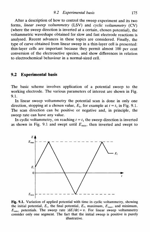
9.2 Experimental basis 175
After a description of how to control the sweep experiment and its twoforms, linear sweep voltammetry (LSV) and cyclic voltammetry (CV)(where the sweep direction is inverted at a certain, chosen potential), thevoltammetric waveshape obtained for slow and fast electrode reactions isanalysed. Recent advances in these topics are considered. Finally, thetype of curve obtained from linear sweep in a thin-layer cell is presented:thin-layer cells are important because they permit almost 100 per centconversion of the electroactive species, and show differences in relationto electrochemical behaviour in a normal-sized cell.
9.2 Experimental basis
The basic scheme involves application of a potential sweep to theworking electrode. The various parameters of interest are shown in Fig.9.1.
In linear sweep voltammetry the potential scan is done in only onedirection, stopping at a chosen value, Eu for example at t = tx in Fig. 9.1.The scan direction can be positive or negative and, in principle, thesweep rate can have any value.
In cyclic voltammetry, on reaching t = t1 the sweep direction is invertedas shown in Fig. 9.1 and swept until £min, then inverted and swept to
Fig. 9.1. Variation of applied potential with time in cyclic voltammetry, showingthe initial potential, Ei9 the final potential, Ef, maximum, Emax, and minimum,Emin, potentials. The sweep rate \dE/dt\ = v. For linear sweep voltammetryconsider only one segment. The fact that the initial sweep is positive is purely
illustrative.

176 Cyclic voltammetry and linear sweep techniques
£max, etc. The important parameters are
• the initial potential, Ex
• the initial sweep direction
• the sweep rate, v
• the maximum potential, Emax
• the minimum potential, Emin
• the final potential, Ef
It is not common, but can sometimes be convenient, to change the valuesof Emax and Emin between successive cycles.
A faradaic current, /f, due to the electrode reaction, is registered in therelevant zone of applied potential where electrode reaction occurs. Thereis also a capacitive contribution: on sweeping the potential the doublelayer charge changes; this contribution increases with increasing sweeprate. The total current is
dE/ = / c + / f = C d — + / f =uC d + /f (9.1)
Thus Ic<xv and, as will be demonstrated in the following sections,Ifocym: this means that for very high sweep rates the capacitive currentmust be subtracted in order to obtain accurate values of rate constants.
In the following section we consider the equations obtained for theshape and position of the voltammetric waves according to the rate of theelectrode reaction. On increasing the sweep rate there is less time toreach equilibrium at the electrode surface; reactions which appear asreversible at slow sweep rates can be quasi-reversible at high sweep rates.
9.3 Cyclic voltammetry at planar electrodes
In this section we deduce the expressions for simple electron transferO + ne~—>R, with only О initially present in solution. The initial sweepdirection is therefore negative. The observed faradaic current depends onthe kinetics and transport by diffusion of the electroactive species. It isthus necessary to solve the equations
Э2[О]h1 <9-2>
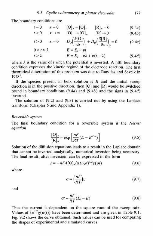
9.3 Cyclic voltammetry at planar electrodes 111
The boundary conditions are
t = 0 x = o [O]* = [0]oo [R]* = 0 (9.4л)
t>0 x-+™ [O] -^[Ok [R]-^0 (9.46)
f>0 x = 0 ОО(^Щ +DJ^P) =0 (9.4c)V Эх /о V Эх ' v J
t>k E = E{-vk + v{t-k)
where Я is the value of t when the potential is inverted. A fifth boundarycondition expresses the kinetic regime of the electrode reaction. The firsttheoretical description of this problem was due to Randies and Sevcik in19485.
If the species present in bulk solution is R and the initial sweepdirection is in the positive direction, then [O] and [R] would be switchedround in boundary conditions (9.4a) and (9.46) and the signs in (9.4d)inverted.
The solution of (9.2) and (9.3) is carried out by using the Laplacetransform (Chapter 5 and Appendix 1).
Reversible system
The final boundary condition for a reversible system is the Nernstequation
Solution of the diffusion equations leads to a result in the Laplace domainthat cannot be inverted analytically, numerical inversion being necessary.The final result, after inversion, can be expressed in the form
/ = -nFA[OUnD0o)m
X(ot) (9.6)
where
and
?;-£) (9.8)
Thus the current is dependent on the square root of the sweep rate.Values of {n>l/2x(°(t)} have been determined and are given in Table 9.1;Fig. 9.2 shows the curve obtained. Such values can be used for comparingthe shapes of experimental and simulated curves.
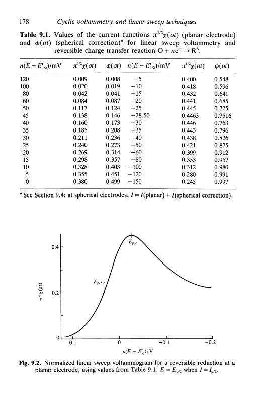
178 Cyclic voltammetry and linear sweep techniques
Table 9.1. Values of the current functions n1/2x(ot) (planar electrode)and ф((Л) (spherical correction)* for linear sweep voltammetry and
reversible charge transfer reaction О + ne~—> R6.
n(E-E\/2)/mV
120100806050454035302520151050
*mX(ot)
0.0090.0200.0420.0840.1170.1380.1600.1850.2110.2400.2690.2980.3280.3550.380
0.0080.0190.0410.0870.1240.1460.1730.2080.2360.2730.3140.3570.4030.4510.499
n(E - E\l2)lmV
-5-10-15-20-25-28.50-30-35-40-50-60-80
-100-120-150
^X(ot)
0.4000.4180.4320.4410.4450.44630.4460.4430.4380.4210.3990.3530.3120.2800.245
Ф(")
0.5480.5960.6410.6850.7250.75160.7630.7960.8260.8750.9120.9570.9800.9910.997
1 See Section 9.4: at spherical electrodes, / = /(planar) + /(spherical correction).
0.4
0.2
0.1 0 -0.1
n(E-E\/2)/V
-0.2
Fig. 9.2. Normalized linear sweep voltammogram for a reversible reduction at aplanar electrode, using values from Table 9.1. E = Ep/2 when / = /p/2.

9.3 Cyclic voltammetry at planar electrodes 179
The shape of the curve can be understood in the following way. Onreaching a potential where the electrode reaction begins, the current risesas in a steady-state voltammogram. However, the creation of a concentra-tion gradient and consumption of electroactive species means that,continuing to sweep the potential, from a certain value just before themaximum value of the current, the peak current, the supply of electroac-tive species begins to fall. Owing to depletion, the current then begins todecay, following a profile proportional to Гш, similar to that afterapplication of a potential step.
We now indicate some quantitative parameters in the curve, which canbe deduced from data in Table 9.1. First, the current function, nll2x(oi),passes through a maximum value of 0.4463 at a reduction peak potential
£p,c Of
R T ID \1/2
E E * ' l
= E\/2 - 0.0285/л (9.10)
Secondly, the peak current in amperes is
/p c = -2.69 x Wn3'2ADl£[O]^vm (9.11)
with A measured in cm2, Do in cm^"1 , [O]oo in mol cm"3 and v in Vs"1 ,substituting T — 298 К in (9.6) and (9.7)—an equation first obtained byRandies and Sevcik5. Thirdly, the difference in potential between thepotential at half height of the peak, £p/2,c (/ = JP,c/2), and Epc is given by
|£Pc-£p/2cl=2.2 — = — - mV at298K (9.12)nF n
If the scan direction is inverted after passing the peak for a reductionreaction, then a cyclic voltammogram, as shown schematically in Fig. 9.3,is obtained. It has been shown that, if the inversion potential, Ek, is atleast 35/n mV after EPtC, then
£p,a = E\/2 + 0.0285/n + - (9.13)
in which x = 0 for Ek «£pc and is 3 mV for | £ p c - Ek\ = 80/n mV. Inthis case
|/p.a//p,cl = 1 (9-14)
The shape of the anodic curve is always the same, independent of Ek, butthe value of Ek alters the position of the anodic curve in relation to thecurrent axis. For this reason / p a should be measured from a baseline thatis a continuation of the cathodic curve, as shown in Fig. 9.3.

180 Cyclic voltammetry and linear sweep techniques
i
0.4
^ 0.2
Q
^ 8
о о
i- 0 . 2
-
A ^ >
i
J ''
\a /
1/
' P , c
/ i
0.2 0.1 0 -0.1 -0.2n(E- EV2)N
Fig. 9.3. Cyclic voltammogram for a reversible system.
We can summarize all the information in a diagnostic for linear sweepand cyclic voltammograms of reversible reactions:
• /росИ2
• Ep independent of v
• \Ep - Ep/2\ = 56.61 n mV
and for cyclic voltammetry alone
• |/p,a//p,cl =
x «Epc от Ек»Ера)
As is clear from (9.6), / р « Г ш : so, if experiments are conducted attemperatures other than 298 K, the correction in /p is easy to do.
Sometimes, and this is one of the disadvantages of conventionalanalysis of cyclic voltammograms, it is not possible to measure thebaseline with sufficient precision in order to measure /p a. However, it is agood approximation to apply the following expression in terms of thepeak current measured from the current axis (/pa)o and the current at theinversion potential (/л)0 (see Fig. 9.2)
p,c(9.15)
The capacitive contribution to the total current as given in (9.1) shouldalso be taken into account. Writing If = Ipc we have, from (9.1) and

9.3 Cyclic voltammetry at planar electrodes 181
(9.11),
h Cdvll210l/2in-5
(9.16)
Substituting typical values (Cd = 20juFcm 2, D o = 1 0 5 cm 2 s \ and[О]^ = 10~7 mol cm"3 (1(Г4 м), and n = 1) we obtain
с = 0.24u1/2 (9.17)
This ratio is 0.1 for u=0.18Vs l\ if [OJoo is an order of magnitudehigher, i.e. 10~3 м, then the ratio is only 0.01. This shows the advantageof using concentrations as high as possible, millimolar concentrationsrepresenting the upper limit.
Another practical factor mentioned in Chapter 7 is the solutionresistance between working and reference electrodes. This resistanceleads to a shift in the potential of the working electrode of IpR& where# Q is the resistance (uncompensated) of the solution. A broadening ofthe peaks is observed, greater separation between Epa and £ p c thanpredicted theoretically, and the peak currents are lower. Since the peakcurrent increases with sweep rate, this factor becomes more important forlarge values of v.
Irreversible system
In the case of an irreversible reaction of the type О + я е - ^ R , linearsweep and cyclic voltammetry lead to the same voltammetric profile,since no inverse peak appears on inversing the scan direction.
To solve (9.2) and (9.3), a fifth boundary condition to add to boundaryconditions (9.4) is
D o - 1 = kc[O]* = К ехр {bt}[OU (9.18)
for a reduction, where
К = k0ехр [(-<xcn'FIRT)(E.x - E*')] (9.19)
and
b = acn'Fv/RT (9.20)
n' being the number of electrons transferred in the rate-determining step.As for the reversible case, the mathematical solution in the Laplace
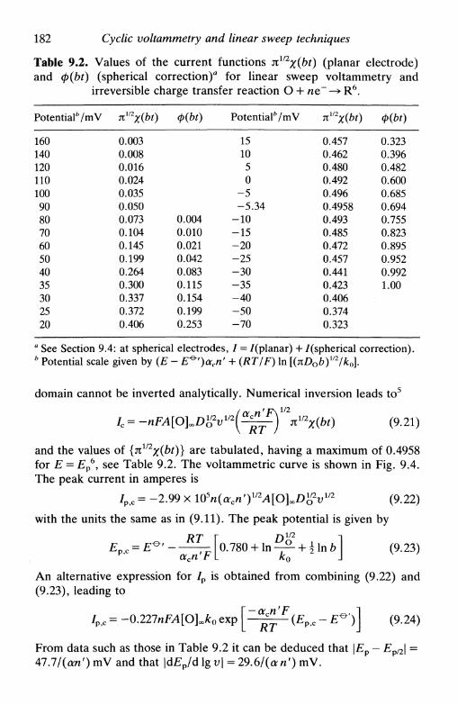
182 Cyclic voltammetry and linear sweep techniques
Table 9.2. Values of the current functions nll2x{bt) (planar electrode)and ф(Ы) (spherical correction)0 for linear sweep voltammetry and
irreversible charge transfer reaction О + ие~—>R6.
Potential6 / m V
160
140
120
110
100
90
80
70
60
50
40
35
30
25
20
TCV2
X(bt)
0.003
0.008
0.016
0.024
0.035
0.050
0.073
0.104
0.145
0.199
0.264
0.300
0.337
0.372
0.406
ф(Ы)
0.004
0.010
0.021
0.042
0.083
0.115
0.154
0.199
0.253
Potential V m V
15
10
5
0
-5
-5.34
-10
-15
-20
-25
-30
-35
-40
-50
-70
nV2X(bt)
0.457
0.462
0.480
0.492
0.496
0.4958
0.493
0.485
0.472
0.457
0.441
0.423
0.406
0.374
0.323
ф(Ы)
0.323
0.396
0.482
0.600
0.685
0.694
0.755
0.823
0.895
0.952
0.992
1.00
a See Section 9.4: at spherical electrodes, / = /(planar) + /(spherical correction).b Potential scale given by (E - E^')acn' + (RT/F) In [(nDob)mj'k0].
domain cannot be inverted analytically. Numerical inversion leads to5
/c = -nFA[O^D^v^(^fj'\^x{bt) (9.21)
and the values of {nl/2x(bt)} a r e tabulated, having a maximum of 0.4958for E = Ep
6, see Table 9.2. The voltammetric curve is shown in Fig. 9.4.The peak current in amperes is
/p c = -2.99 x 10⁵n(acn')1/2^[O]ooD^2u1/2 (9.22)
with the units the same as in (9.11). The peak potential is given by
( 9 - 2 3 )
An alternative expression for /p is obtained from combining (9.22) and(9.23), leading to
/p,c = -0.227nFA[O]o.*0 exp [ Z i ~ №P,c - O ] (9-24)
From data such as those in Table 9.2 it can be deduced that \EP — Ep/2\ =47.7/(on')mV and that |d£p /dlgv| = 29.6/(o-n')mV.

9.3 Cyclic voltammetry at planar electrodes 183
X
-0.1
n(E - Ep)/V
Fig. 9.4. Linear sweep voltammogram for an irreversible system (O + ne~-*R).In cyclic voltammetry, on inverting the sweep direction, one obtains only the
continuation of current decay ( ).
With respect to reversible systems the waves are shifted to morenegative potentials (reduction), Ep depending on sweep rate. The peaksare broader and lower.
Quasi-reversible systems
For quasi-reversible systems7 the kinetics of the oxidation and reductionreactions have to be considered simultaneously. The mathematicalsolution is, therefore, more complex, but there are numerical theoreticalsolutions.
As a general conclusion, the extent of irreversibility increases withincrease in sweep rate, while at the same time there is a decrease in thepeak current relative to the reversible case and an increasing separationbetween anodic and cathodic peaks, shown in Fig. 9.5.
Peak shape and associated parameters are conveniently expressed by aparameter, Л, which is a quantitative measure of reversibility, beingeffectively the ratio kinetics/transport,
Л = vl/2
When DR = DO =
(9.25)
(9.26)
showing that small Л corresponds to large v (i.e. large a).The following ranges were suggested for the different types of system
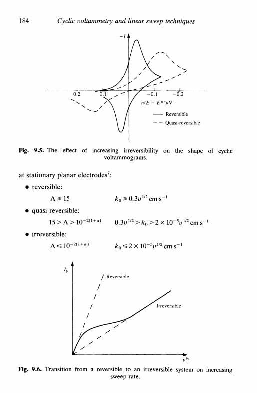
184 Cyclic voltammetry and linear sweep techniques
0.2 0
N /
11
у.1 ^ **
X\ /V
A/ \ /V
/ \
/ >v
, ' / ^
/ -o.i/ n(E - E*
\\
>»»
-0.2
>')/V
Reversible
Quasi-reversible
Fig. 9.5. The effect of increasing irreversibility on the shape of cyclicvoltammograms.
at stationary planar electrodes7:
• reversible:
Л 2*15 ko^0.3vmcms-1
• quasi-reversible:
15>Л>1(Г 2 ( 1 + а ) 0.3u1 / 2>/to>2xl0-5u1 / 2cms-1
• irreversible:
Reversible
Irreversible
Fig. 9.6. Transition from a reversible to an irreversible system on increasingsweep rate.

9.3 Cyclic voltammetry at planar electrodes 185
Table 9.3. Variation of the difference between anodic andcathodic peak potentials with the degree of reversibility, ex-pressed as гр ( = Л я " 1 / 2 , see equation 9.25)8, assuming a = 0.5
Ц n(£p,a-£p,c)/mV
207653210.910.800.750.610.540.50
6163646568728486899296104105
0.380.350.260.250.160.140.120.110.100.0770.0740.048
117121140141176188200204212240244290
The transition between these zones is shown schematically in Fig. 9.6.In the case of cyclic voltammograms and for 0.3 < oc < 0.7 (a is ac or
ara), Ep is almost exclusively dependent on Л and hardly varies with a.This can be useful for the calculation of k0 using Table 9.3, or byinterpolation from a working curve drawn using these data.
Adsorbed species
If the reagent or product of an electrode reaction is adsorbed strongly orweakly on the electrode, the form of the voltammetric wave is modified9.There are two types of situation:
• the rate of reaction of adsorbed species is much greater than ofspecies in solution
• it is necessary to consider the reactions of both adsorbed species andof those in solution.
From a mathematical point of view the first of these is the simpler. Anadsorption isotherm has to be chosen or, alternatively, one has to assumethat there is adsorption equilibrium before the experiment begins.
The details of the calculation of the voltammetric profiles can beconsulted in the specialized literature8. Here we give the expression for areversible reaction in which only the adsorbed species О and Rcontribute to the total current. The reason for this is to enable acomparison between the expressions for this situation and for thin-layer

186 Cyclic voltammetry and linear sweep techniques
cells (Section 9.10), since they are analogous—in neither case is there anylimitation from diffusion of electroactive species.
The current-potential curve for О initially adsorbed and for fastelectrode kinetics is given by
-nFoATOj(bo/bK)e
[1 + (bo/bR)ef(9.27)
where Fo,i is the surface concentration of adsorbed O, before theexperiment begins, on an electrode of area А, о = (nF/RT)v, bo and bR
express the adsorption energy of О and R respectively, and
(9.28)
The peak current for reduction, /p c, is obtained when (bo/bK)6 = 1, thatis
-n2F2vATOt
ART(9.29)
0.25
Fig. 9.7. Cyclic voltammogram for a reversible system of species adsorbed on theelectrode. If О and R are adsorbed with the same strength, Ep = £ ° ' .

9.4 Spherical electrodes 187
having the same magnitude for an oxidation. The peak potential is then
The value of Ep is the same for oxidation and for reduction.If the adsorption isotherm is of Langmuir type and (bo/bK) = 1, then
the voltammetric profile is described by the function 0(1 + 6)~2. Fromthis it can be calculated that the peak width at half height is 90.6/n mV.This is all shown schematically in Fig. 9.7.
9.4 Spherical electrodes
It was demonstrated in Chapter 5 (see Table 5.2) that for a potential stepthe expression for the current at a spherical electrode is that of a planarelectrode with a spherical correction. The same is true for potentialsweep.
Considering first potential sweep for a reversible system one obtains
(9.3.)ro
for a reduction, in which r0 is the electrode radius and <t>(ot) a currentfunction different from x(at)- The peak current is
/p,c = /Р,р,а„аГ - 0.725 X 105 " A D ° [ O ] " (9.32)
where r0 is in cm and the other units are as in (9.11) for a planarelectrode. Since the spherical correction does not depend on scan rate wecan consider spherical electrodes as if they were planar, plus a sphericalcorrection. The current function for the spherical correction, <t>(ot), isshown in Table 9.1; as can be seen it follows a sigmoidal 1-Е profile.
For irreversible systems the corresponding expressions are
nFADo[Q]^bt)lp — Vplanar (У.ЭЭ)
/р,с = /р,р1апаГ- 0-670 X 10s я Л Р ° [ О ] ~ (9.34)ro
where r0 is in cm and the other units are as in (9.22) for a planarelectrode, the spherical correction being, once more, independent of scanrate. Values of the current function for the spherical correction, ф(Ы)>are given in Table 9.2. As for reversible systems, the spherical correctionby itself corresponds to a sigmoidal 1-Е profile, though of lower slope.

188 Cyclic voltammetry and linear sweep techniques
(a) (b)
Fig. 9.8. Cyclic voltammograms at a microelectrode. (a) Low scan rate(~0.1 Vs"1); (b) High scan rate (>10 Vs"1). Note the similarity with hydrodyna-
mic electrodes.
9.5 Microelectrodes
The particular advantages of microelectrodes were discussed in Section5.5. The current density at a microelectrode is larger than that at aspherical or planar electrode of larger dimensions owing to radial andperpendicular diffusion. Mass transport is greater, and we observedifferences in the experimental results obtained by the various electro-chemical techniques relative to macroelectrodes.
In cyclic voltammetry we obtain the current due to perpendiculardiffusion superimposed on a radial diffusion contribution, this latter beingindependent of scan rate. In particular, the spherical term in (9.31) and(9.33) of the previous section can easily dominate at low scan rates. Thusfor small v (0.1 Vs"1) we observe a steady-state, scan-rate-independent,voltammogram (Fig. 9.8я); for large v (>10Vs"1) we observe a cyclicvoltammogram of the conventional type (Fig. 9.8ft). Reversibility is lessthan that at a macroelectrode, owing to the higher mass transport: thisimplies that higher rate constants for electron transfer or coupledhomogeneous reactions can be determined.
High-speed cyclic voltammetry10 can easily be done at microelectrodes,increasing the range of rate constants accessible by the technique. This isbecause of the reduced capacitive contribution at microelectrodes—sweep rates of up to 106Vs~1 at microelectrodes have been reported.Nevertheless capacitive current subtraction is essential at these rates andinstrumental artefacts can appear, which must be taken into account.
9.6 Systems containing more than one component
In solutions containing more than one electroactive species, variousvoltammetric waves appear. The same can happen if there is a second

9.7 Systems involving coupled homogeneous reactions 189
II
Inversion at E^ toidentify couple I
Inversion at £д2 toidentify couple II
Fig. 9.9. Cyclic voltammetry in the investigation of systems of more than onecomponent, showing the importance of the inversion potential in the identifica-
tion of the peaks on the inverse scan.
step (or indeed more steps) in the electrode reaction: one or two waveswill appear depending on whether the second step is easier or moredifficult than the first. The formation of various species in the vicinity ofthe electrode permits their posterior inverse reaction on inverting thesweep direction. By choosing different inversion potentials, after the firstwave and before the second, it is possible to see which waves appear onthe inverse scan and which correspond to the initial sweep (Fig. 9.9). Thisprocedure permits the identification of the species present in solution anddeductions with respect to the mechanism3.
9.7 Systems involving coupled homogeneous reactions
Cyclic voltammetry is a powerful tool for investigating electrode proc-esses involving coupled homogeneous reactions. We exemplify with theEC mechanism:
electrode A3 ± nt~ —» A2 ,K-tsolution Ax <=± A2
presented in Section 6.9, and consider the electrode reaction reversible.If the homogeneous step is very fast there is no current peak on invertingthe sweep direction. On the other hand, increasing the sweep rate, v,

190 Cyclic voltammetry and linear sweep techniques
1.0
0.8
- 0.6
-^ 0.4
0.2
(a)
sf
-20
-40
(b)
-2.0 -1.0
-1.0 1.0
Fig. 9.10. EC mechanism in cyclic voltammetry (reversible electrode reaction andirreversible homogeneous reaction), (a) Plot of the ratio |/p,a//p,c| with \g{k_xx)where vr = \El/2- EK\ (from Ref. 6 with permission), (b) Variation of cathodic
peak potential, Ep>c, as a function of \g(k_Ja).
reduces the time between the appearance of the peak in the initial sweepand where it would appear on the inverse scan, giving less time for thehomogeneous reaction to occur—the reverse peak therefore increases insize with increasing v until all the species produced initially react. Thesituation is represented schematically in Fig. 9.10a for a reversibleelectrode reaction and with k = k_b kt = 0 (irreversible homogeneousreaction). Analysis of the results and fitting to working curves allows k_x
to be determined.An alternative strategy consists in analysing the variation of peak

9.8 Convolution linear sweep voltammetry 191
potential, EPtC, as a function of scan rate (Fig. 9.106). The horizontalregion corresponds to negligible effect from the following reaction (highscan rate or low homogeneous reaction rate constant, k_x).
Analysis of other mechanisms with coupled homogeneous reactionsleads to plots of the same kind and which can be used for thedetermination of the relevant kinetic parameters. Details are given in theliterature, for example Refs. 1,2, and 4.
9.8 Convolution linear sweep voltammetry
Almost all the analysis of cyclic and linear sweep voltammograms hasbeen done through peak currents and peak potentials. Unless digitalsimulation and curve-fitting by parameter adjustment is carried out, allthe information contained in the rest of the wave is ignored; this bringsproblems of accuracy and precision. Besides this, a kinetic model has tobe proposed before the results can be analysed.
An answer to this lies in the transformation of the linear sweepresponse into a form which is readily analysable, i.e. the form of asteady-state voltammetric wave. Two independent methods of achievingthis goal have been described: the convolution technique by Saveant andco-workers1112, and semi-integration by Oldham13. In this section wedescribe the convolution technique, and demonstrate the equivalence ofthe two approaches at the end.
Convolution involves calculating integrals of the type
=[{'(»»)('- ] / / 2 (9-35)
and defining a current function
ф = -iemlnFA[O\BD^ (9.36)
where в is a fixed value of time. Using a dimensionless potential variable,
Z = {nFIRT){E-Em) (9.37)
solution of the diffusion equation, for a reversible reduction is
I(ip) = (1 + e*)"1 (9.38)
that can be expressed in the form
£ = £>/2 + ̂ l n ~ (9.39)nF I
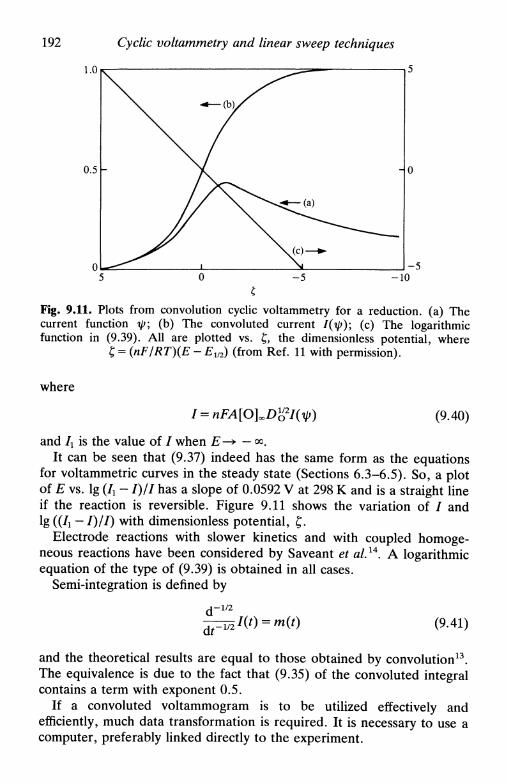
192 Cyclic voltammetry and linear sweep techniques
- 5 -10
Fig. 9.11. Plots from convolution cyclic voltammetry for a reduction, (a) Thecurrent function ip; (b) The convoluted current 1(гр); (c) The logarithmicfunction in (9.39). All are plotted vs. £, the dimensionless potential, where
£ = (nF/RT)(E - EV2) (from Ref. 11 with permission).
where
(9.40)
and Ix is the value of / when £—» — oo.It can be seen that (9.37) indeed has the same form as the equations
for voltammetric curves in the steady state (Sections 6.3-6.5). So, a plotof E vs. lg (Л - /)// has a slope of 0.0592 V at 298 К and is a straight lineif the reaction is reversible. Figure 9.11 shows the variation of / andlg ((/x — /)//) with dimensionless potential, £.
Electrode reactions with slower kinetics and with coupled homoge-neous reactions have been considered by Saveant et al.14. A logarithmicequation of the type of (9.39) is obtained in all cases.
Semi-integration is defined by
- l / 2
(9.41)
and the theoretical results are equal to those obtained by convolution13.The equivalence is due to the fact that (9.35) of the convoluted integralcontains a term with exponent 0.5.
If a convoluted voltammogram is to be utilized effectively andefficiently, much data transformation is required. It is necessary to use acomputer, preferably linked directly to the experiment.

9.9 Linear potential sweep with hydrodynamic electrodes
9.9 Linear potential sweep with hydrodynamic electrodes
193
Linear potential sweep at a hydrodynamic electrode can lead to twoextreme situations:
• Small v: convection contributes much more than the sweep, nocurrent peak appearing
• Large v: the sweep dominates, convection not affecting the electroderesponse, except to assure reproducibility. There are current peaks andthe equations for stationary electrodes are applicable in the region of thepeak potential.Between the two extremes the current peak begins to appear. Figure 9.12shows schematically the form of the voltammetric waves for differentvalues of v.
The forms of the cyclic voltammograms have been deduced theoreti-cally for the rotating disc1516, tubular17, and wall-jet disc18 electrodes,normally by numerical calculation. There is good agreement betweentheory and experiment.
Advantages of using hydrodynamic electrodes in linear sweep voltam-metry are: weak dependence on the physical properties of the electrolyte,suppression of natural convection, and the possibility of obtaining valuesof /p and /L in only one experiment.
2.0 г
1.0
-0.1 0.1
n{E-
0.2 0.3
Fig. 9.12. Linear sweep voltammograms at a rotating-disc electrode for differentsweep rates and for the same rotation speed—reversible reaction (from Ref. 15
with permission).
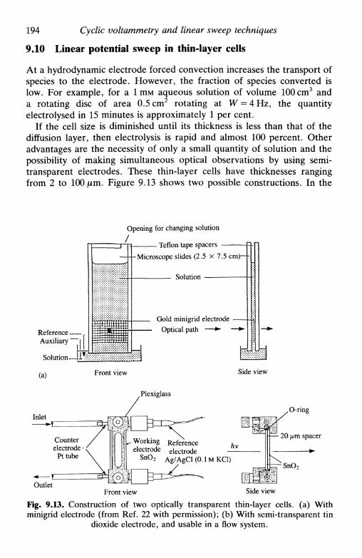
194 Cyclic voltammetry and linear sweep techniques
9.10 Linear potential sweep in thin-layer cells
At a hydrodynamic electrode forced convection increases the transport ofspecies to the electrode. However, the fraction of species converted islow. For example, for a 1 т м aqueous solution of volume 100 cm3 anda rotating disc of area 0.5 cm2 rotating at W = 4 Hz, the quantityelectrolysed in 15 minutes is approximately 1 per cent.
If the cell size is diminished until its thickness is less than that of thediffusion layer, then electrolysis is rapid and almost 100 percent. Otheradvantages are the necessity of only a small quantity of solution and thepossibility of making simultaneous optical observations by using semi-transparent electrodes. These thin-layer cells have thicknesses rangingfrom 2 to 100 jum. Figure 9.13 shows two possible constructions. In the
ReferenceAuxiliary
Solution
(a)
Inlet
Opening for changing solution/
- Teflon tape spacers -
-Microscope slides (2.5 x 7.5 cm)— -
Solution
Gold minigrid electrode
Optical path — •
Front view Side view
Plexiglass
Working Referenceelectrode electrode
SnO2 Ag/AgCl(0.lMKCl)
Outlet
O-ring
• — 20 цт spacer
SnO2
Front view Side view
Fig. 9.13. Construction of two optically transparent thin-layer cells, (a) Withminigrid electrode (from Ref. 22 with permission); (b) With semi-transparent tin
dioxide electrode, and usable in a flow system.
9.10 Linear potential sweep in thin-layer cells 195
case of minigrid electrodes, the mesh must be sufficiently fine toapproximate a planar electrode in order to apply the equations which willbe derived below. The auxiliary and reference electrodes have to beplaced outside the thin-layer zone—this can lead to a non-uniformcurrent distribution at the working electrode, which has somewhatlimited the application of this type of cell to kinetic studies.
Thin-layer cells have been used with linear sweep, in coulometry and inchronopotentiometry. Here we limit the discussion to linear sweep—descriptions of this and other techniques can be found in Refs. 19-21.
The fact that there is total electrolysis is one of the conditions in thesolution of the equation for a reduction
I=-nFV^2k ( 9 4 2 )
for a simple charge transfer, where V is the cell volume, and we assumethat the concentrations of О and R are uniform throughout the cell. Ifonly О is present initially in solution (concentration [O]i), then at time t
[O], + [R], = [O]S (9.43)
Substituting this relation in the Nernst equation for a reversible reaction
we get
[O], = [Olijl - [l + exp ( ^ ( £ - E^'))] '} (9-45)
= [O],{l-[l + 0]-1} (9.46)
where
0 = exp[^|(£-/^')] (9.28)
Calculating the differential d[O]*/dt from (9.46) and substituting in(9.42), remembering that v = —(dE/dt) we obtain
^ - ^ 2 (9.47)
= -nFoV[0\Z(ot) (9.48)
where o = (nF/RT)v, and Z(oi) = 0/(1 + 0)2 is the current function. Itis easy to show by differentiating Z{ot) that the current maximum occursfor 0 = 1. This result means that Ep = E^' and that
p
(9-49)

196 Cyclic voltammetry and linear sweep techniques
Z{ot)
Fig. 9.14. Shape of the cyclic voltammogram obtained in a thin-layer cell for areversible system, from (9.48).
Identical considerations are valid for an oxidation. The voltammetriccurve in Fig. 9.14 shows the results obtained. Three important pointsshould be noted in contrast with reversible reactions in normal cells:
• peak current is proportional to v, and not to vm
• there is no separation between anodic and cathodic peaks
• the curve is totally symmetric round Ep
Figure 9.14 should be compared with Fig. 9.5 for adsorbed species, and(9.47) and (9.49) with (9.27) and (9.29). The form is exactly the same inthe two cases and is due to the non-existence of limitations to theelectrode reaction imposed by mass transfer.
For electrode reactions with slower kinetics, the first two points aboveare no longer valid (Fig. 9.15); however, /p is still proportional to v. Theexpressions for Ep and /p in an irreversible reduction are
ART>" • (9.50,
nacn'F2vV[O}{
e~RT(9.51)
Finally, we note that the mercury thin-film electrode has many of the

References 197
-0.4
Fig. 9.15. Voltammograms for irreversible reactions in a thin-layer cell, forvarious rate constant values (from Ref. 23 with permission).
characteristics of a thin-layer cell. Anodic stripping voltammetry ofmetals previously deposited and present within the thin film givepotential-current curves for linear sweep dissolution very similar to thoseof Fig. 9.15 (Section 14.4).
References
1. D. D. Macdonald, Transient techniques in electrochemistry, Plenum, NewYork, 1977, Chapter 6.
2. V. D. Parker, Comprehensive chemical kinetics, Elsevier, Amsterdam, Vol.26, 1986, ed. C. H. Bamford and R. G. Compton, Chapter 2.
3. P. T. Kissinger and W. R. Heinemann, J. Chem. Ed., 1983, 60, 702.4. M. Noel and K. I. Vasu, Cyclic voltammetry and the frontiers of
electrochemistry, Aspect Publications, London, 1990.5. J. E. B. Randies, Trans. Faraday Soc, 1948, 44, 327; A. Sevcik, Collect.
Czech. Chem. Commun., 1948, 13, 349.6. R. S. Nicholson and I. Shain, Anal. Chem., 1964, 36, 706.7. H. Matsuda and Y. Ayabe, Z. Elektrochem., 1955, 59, 494.8. R. S. Nicholson, Anal. Chem., 1965, 37, 1351; S. P. Perone, Anal. Chem.,
1966, 38, 1158.9. E. Laviron, Electroanalytical chemistry, ed. A. J. Bard, Dekker, New York,
Vol. 12, 1982, pp. 53-157.10. R. M. Wightman and D. O. Wipf, Ace. Chem. Res., 1990, 23, 64.11. J. С Imbeaux and J. M. Saveant, /. Electroanal. Chem., 1973, 44, 169.12. L. Nadjo and J. M. Saveant, /. Electroanal. Chem., 1973, 48, 113.13. К. В. Oldham, Anal. Chem., 1972, 44, 196; 1973, 45, 39.

198 Cyclic voltammetry and linear sweep techniques
14. Ref. 1 p. 227.15. M. Lovric and J. Osteryoung, /. Electroanal. Chem., 1986, 197, 63.16. P. C. Andricacos and H. Y. Cheh, 7. Electrochem. Soc, 1980, 127, 2153,
2385, /. Electroanal. Chem., 1981, 124, 95; G. С Quintana, P. СAndricacos, and H. Y. Cheh, J. Electroanal. Chem., 1983, 144, 77; 1985,182, 259.
17. J. Dutt and T. Singh, /. Electroanal. Chem., 1985, 190, 65; 1985, 196, 35;1986, 207, 41; R. G. Compton and P. R. Unwin, J. Electroanal. Chem.,1986, 206, 57.
18. R. G. Compton, A. C. Fisher, M. H. Latham, С M. A. Brett, and A. M.Oliveira Brett, J. Phys. Chem., 1992, 96, 8363.
19. A. T. Hubbard and F. C. Anson, Electroanalytical Chemistry, ed. A. J.Bard, Dekker, New York, Vol. 4, 1970, 129-214.
20. A. T. Hubbard, CRC Crit. Rev. Anal. Chem., 1973, 3, 201.21. F. E. Woodward and C. N. Reilley, Comprehensive treatise of
electrochemistry, Plenum, New York, Vol. 9, 1984, ed. E. Yeager, J. O'M.Bockris, В. Е. Conway, and S. Sarangapani, pp. 353-392.
22. T. P. DeAngelis and W. R. Heinemann, /. Chem. Ed., 1976, 53, 594.23. A. T. Hubbard, /. Electroanal. Chem., 1969, 22, 165.

10
STEP AND PULSE TECHNIQUES
10.1 Introduction10.2 Potential step: chronoamperometry10.3 Double potential step10.4 Chronocoulometry10.5 Current step: chronopotentiometry10.6 Double current step10.7 Methods using derivatives of chronopotentiograms10.8 Coulostatic pulses10.9 Pulse voltammetry
10.1 Introduction
A step in applied potential or current1"3 represents an instantaneousalteration to the electrochemical system. Analysis of the evolution of thesystem after this perturbation permits deductions about electrode reac-tions and their rates to be made. The equivalent in homogeneous kineticswould be a temperature or pressure jump. Potential and current step givecomplementary information because, whereas in the first case thepotential change causes a brief capacitive current peak, in the secondcase a part of the applied current, the value of which probably varies withtime, is always used to charge the double layer as the potential changes.Another important point is the effect of natural convection at macro-scopic electrodes that begins to be felt from 20 s to 300 s after starting theexperiment, depending on the care taken with the experimentalarrangement.
The equations for potential and current steps in reversible systems,neglecting capacitive contributions were derived in Chapter 5. In thepresent chapter we show the possibilities of using these methods toelucidate electrode processes. We also consider successions of steps, thatis pulses, especially with sampling of the response, which in the case ofpotential control has wide analytical application.

200 Step and pulse techniques
10.2 Potential step: chronoamperometry
The study of the variation of the current response with time underpotentiostatic control is chronoamperometry. In Section 5.4 the currentresulting from a potential step from a value of the potential where thereis no electrode reaction to one corresponding to the mass-transport-limited current was calculated for the simple system О + ne~—»R, whereonly О or only R is initially present. This current is the faradaic current,/f, since it is due only to a faradaic electrode process (only electrontransfer). For a planar electrode it is expressed by the Cottrell equation4
However, when the potential is changed, the double layer has to becharged, giving rise to a capacitive current, / c . The resulting I-t curve(chronoamperogram) is shown schematically in Fig. 10.1. Using poten-tiostats with good-quality components, / c decays to zero in less than50 JUS, and so it can be neglected for longer times.
When a rapid electrode process is being studied and 50 jus is too long atimescale, the use of a microelectrode is recommended for the followingreason. For a step in potential, AE, applied to an RC series element weobtain
AE= —ехр(-*/ДС)к
(10.2)
In an electrochemical cell, R is the solution resistance, Ra> independentof electrode area, and С is the double layer capacity, Cd, directly
n
/focr
Fig. 10.1. Evolution of current with time on applying a potential step at astationary electrode. /f is the faradaic current and /c the capacitive current.
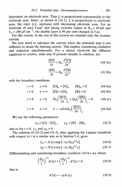
10.2 Potential step: chronoamperometry 201
dependent on electrode area. Thus / c is proportional exponentially to theelectrode area. Since, as shown in (10.1), /f is proportional to electrodearea, the ratio / f//c increases with decreasing electrode area. For anelectrode of area 4 |Um2 and taking extreme values of Ra = 10 kQ andCd = 100 fj,F cm"2, the double layer is 99 per cent charged in 3 /is.
For this reason, in the rest of this section we consider only the faradaiccurrent.
We now need to calculate the current when the potential step is notsufficient to attain the limiting current. This implies considering oxidationand reduction simultaneously. For a planar electrode the diffusionequations to resolve, with only О present initially in solution, are
(10.3a)
with the boundary conditions
f > 0
t>0 x=0
t>0
3[O]
dt °
3[R]dt R
S
[o]* =
[O]->[
d\O]dx2
Э2[Щ
Эх2
[OU ] * = o[Rl
Щox
= 0
(10.3b)
(10.4a)
(10.46)
(10.4c)
(10. Ad)
We use the following parameters
Го = [О] - [O]«, yR = [R] - [R]. (Ю.5)
and so for t = 0, 7o and yR = 0.The solution of (10.2) and (10.3), after applying the Laplace transform
with respect to fin a similar way as in Section 5.4, gives
?o = A'(s) exp [~(s/Do)l/2x] (10.6)
yR = A"(s) exp [-(s/DR)1/2x] (10.7)
Differentiating and considering boundary condition (10.4c) we obtain
( Л
that is
A"(s) = -pA'(s)
(10.8)
(10.9)
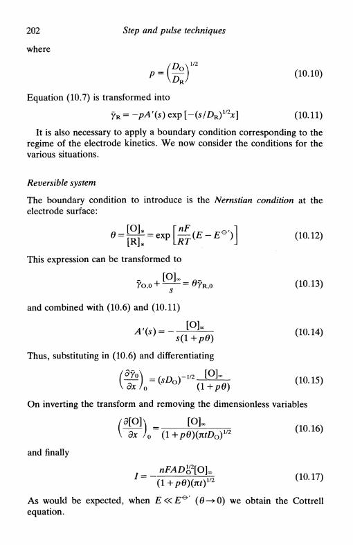
202 Step and pulse techniques
where
p = (7^) (IO.IO)
Equation (10.7) is transformed into
yR = -pA'(s) exp [-(s/DR)mx] (10.11)
It is also necessary to apply a boundary condition corresponding to theregime of the electrode kinetics. We now consider the conditions for thevarious situations.
Reversible system
The boundary condition to introduce is the Nernstian condition at theelectrode surface:
This expression can be transformed to
s
and combined with (10.6) and (10.11)
(10.13)
Thus, substituting in (10.6) and differentiating
On inverting the transform and removing the dimensionless variables
(ЭЩ [Q]~
ГагАга+рвхлдо) 1 * ( 1 0 Л 6 )
and finally
As would be expected, when E«E^ (0-^0) we obtain the Cottrellequation.
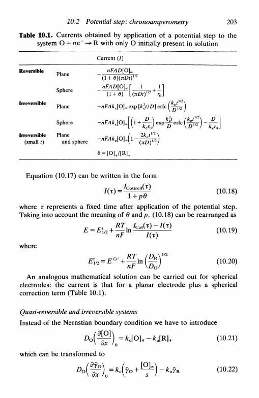
10.2 Potential step: chronoamperometry 203
Table 10.1. Currents obtained by application of a potential step to thesystem О 4- ne~~—»R with only О initially present in solution
Reversible
Irreversible
Irreversible(small t)
Plane
Sphere
Plane
Sphere
Planeand sphere
Current (/)
nFADlO]^(1 + e){xDt)m
nFAD[O]^ 1(1 + 0) l(KDt)l/:
-nFAkJLO^explklt/ Г)1 л г Ь 1 c 1
Л /2 ч
) -
Equation (10.17) can be written in the form
where т represents a fixed time after application of the potential step.Taking into account the meaning of в and p> (10.18) can be rearranged as
/cot(T)-/(r)• — In-
nF /(т)
where
(10.19)
(10.20)
An analogous mathematical solution can be carried out for sphericalelectrodes: the current is that for a planar electrode plus a sphericalcorrection term (Table 10.1).
Quasi-reversible and irreversible systems
Instead of the Nernstian boundary condition we have to introduce
(10.21)
which can be transformed to

204 Step and pulse techniques
By differentiation of (10.6) we know that
(10.23)
Introducing (10.22) and (10.23) into (10.6) and (10.11) we obtain finally
A'(s) = £_— 1/2 (10.24)
where
H = —^ + —^ (10.25)
Therefore
Inversion of the transform gives
7(0 = -лД4*с[0]оо exp ( # 2 0 erfc (Htm) (10.27)
If both О and R are present initially,
7(0 = nFA(K[R\x - кс[О]ж) exp (Я 2 0 erfc (Htm) (10.28)
In the case of a totally irreversible reaction (consider a reduction), theexpression is simplified, since
Н = щ2 (10.29)
and so
7(0 = -nFAkc[O]x exp [k2jDot] erfc (kctm/D%2) (10.30)
These expressions are quite complex and can be found, together withthe corresponding expressions for spherical electrodes, in Table 10.1.
A very useful simplification in the calculation of kinetic parameters isthe application of a small step at the foot of the voltammetric wave. SinceHtm is small we can linearize according to
exp (x2) erfc (*) « 1 - n £ (10.31)л
Equation (10.27), for example, is simplified to
( 2Ht1/2\1 i^-) (10.32)
я /The value of kc is obtained from the intercept of the plot of 7(0 vs. t1/2.

10.3 Double potential step
More complex mechanisms
205
The current response to a potential step always reflects the mechanism ofthe electrode reaction and, in principle, can be used to distinguishmechanisms involving coupled homogeneous reactions, etc. However,sometimes the modification to the response is so small that it isimpossible to differentiate it with confidence from experimental error.Recently the use of hydrodynamic electrodes, especially the rotating discelectrode, has been investigated with this aim in mind: higher transportpermits easier distinction between mechanisms, besides annulling theeffects of natural convection for large t. This technique has had somesuccess5.
10.3 Double potential step
The potential is altered between two values, perhaps repeatedly (Fig.10.2). The second step inverts the electrode reaction. We consider aninitial step from a potential where there is no electrode reaction to avalue corresponding to the limiting reduction current (only О initiallypresent in solution); at t= т the potential reverts to its initial value andthere is oxidation of R that was produced. The equations for a planar
Fig. 10.2. Double potential step, (a) Variation of E with t; (b) Schematicvariation of / with t.
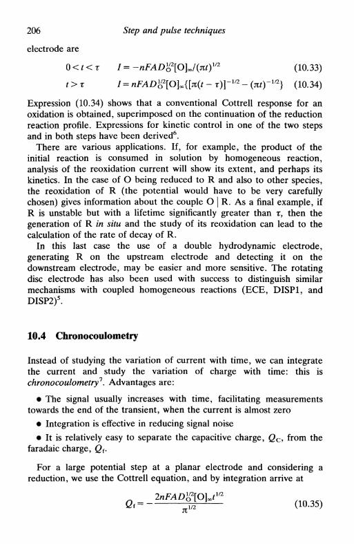
206 Step and pulse techniques
electrode are
0 < % < т 1= -nFAD"2[O]J(m)1/2 (10.33)
t > r 1= nFAD}?[O]»{[n(t - r)]-m - (jtO~1/2} (10.34)
Expression (10.34) shows that a conventional Cottrell response for anoxidation is obtained, superimposed on the continuation of the reductionreaction profile. Expressions for kinetic control in one of the two stepsand in both steps have been derived6.
There are various applications. If, for example, the product of theinitial reaction is consumed in solution by homogeneous reaction,analysis of the reoxidation current will show its extent, and perhaps itskinetics. In the case of О being reduced to R and also to other species,the reoxidation of R (the potential would have to be very carefullychosen) gives information about the couple О | R. As a final example, ifR is unstable but with a lifetime significantly greater than т, then thegeneration of R in situ and the study of its reoxidation can lead to thecalculation of the rate of decay of R.
In this last case the use of a double hydrodynamic electrode,generating R on the upstream electrode and detecting it on thedownstream electrode, may be easier and more sensitive. The rotatingdisc electrode has also been used with success to distinguish similarmechanisms with coupled homogeneous reactions (ECE, DISP1, andDISP2)5.
10.4 Chronocoulometry
Instead of studying the variation of current with time, we can integratethe current and study the variation of charge with time: this ischronocoulometry7. Advantages are:
• The signal usually increases with time, facilitating measurementstowards the end of the transient, when the current is almost zero
• Integration is effective in reducing signal noise
• It is relatively easy to separate the capacitive charge, Q c from the
faradaic charge, Qf.
For a large potential step at a planar electrode and considering areduction, we use the Cottrell equation, and by integration arrive at
2nFAD%2[OUm
Qt= ^H— (Ю.35)JX
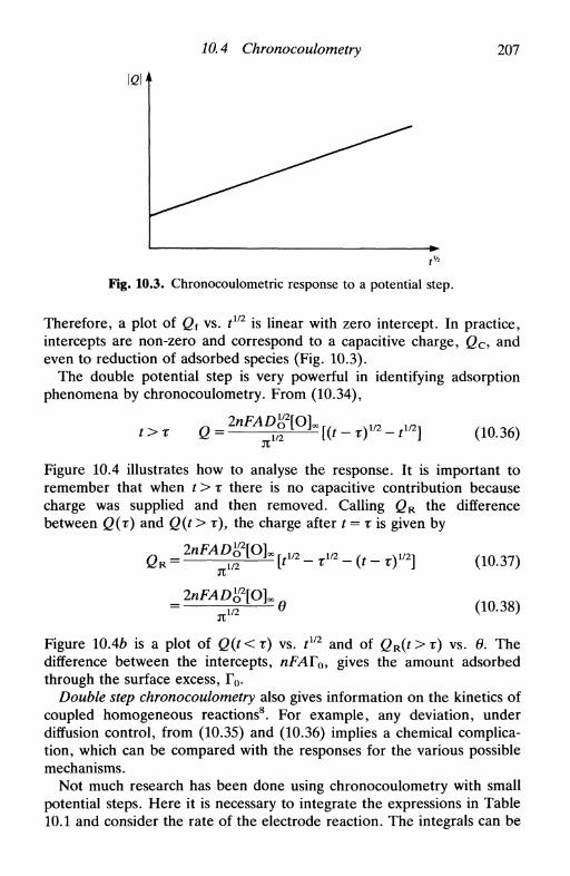
10.4 Chronocoulometry 207
lei
Fig. 10.3. Chronocoulometric response to a potential step.
Therefore, a plot of Q{ vs. tm is linear with zero intercept. In practice,intercepts are non-zero and correspond to a capacitive charge, <2C, andeven to reduction of adsorbed species (Fig. 10.3).
The double potential step is very powerful in identifying adsorptionphenomena by chronocoulometry. From (10.34),
t>x Q =2nFAD%2[O]a
[(t-r)m-t1/2] (10.36)
Figure 10.4 illustrates how to analyse the response. It is important toremember that when t > r there is no capacitive contribution becausecharge was supplied and then removed. Calling QR the differencebetween Q(r) and Q(t > т), the charge after t = r is given by
(10.37)к
1/2
в (10.38)
Figure 10.46 is a plot of Q(t<r) vs. tm and of QR(t>r) vs. в. Thedifference between the intercepts, nFATQy gives the amount adsorbedthrough the surface excess, Го.
Double step chronocoulometry also gives information on the kinetics ofcoupled homogeneous reactions8. For example, any deviation, underdiffusion control, from (10.35) and (10.36) implies a chemical complica-tion, which can be compared with the responses for the various possiblemechanisms.
Not much research has been done using chronocoulometry with smallpotential steps. Here it is necessary to integrate the expressions in Table10.1 and consider the rate of the electrode reaction. The integrals can be

208 Step and pulse techniques
<2(т) -
(a)
nFAr0]
(b)
Fig. 10.4. (a) Chronocoulometric response to a(b) Corresponding plots.
double potential step;
obtained directly, or in the Laplace domain before inversion throughsimple division by the Laplace variable. However, the possibilities forfuture use of the technique are many, because the signal measurement ona longer timescale is more accurate than in chronoamperometry, wheremeasurements are more limited by current decay.
10.5 Current step: chronopotentiometry
A current step applied to an electrode provokes a change in its potential.The flux of electrons is used first to charge the double layer, and then forthe faradaic reactions. The study of the variation of the potential with

10.5 Current step: chronopotentiometry 209
time is chronopotentiometry2. In Section 5.4 it was shown that, neglectingthe capacitive current, the potential at a planar electrode is approxi-mately constant until the end of the transition time, т, which correspondsto the total consumption of the electroactive species in the neighbour-hood of the electrode. The Sand equation9 describes the transition time,r, according to
I T 1 1 2 nFAD"2Km
[5Г Г " ( 1 0 3 9 )
for a simple system O + ne~—»R with only О initially present. Thetransition time is independent of the rate of charge transfer. Usinghydrodynamic electrodes it is possible that r-*oo due to the hightransport of electroactive species to the electrode.
We now consider the form of the chronopotentiogram according to thekinetics of the electrode process. We take as negligible the contributionof the capacitive current; its contribution is larger at the beginning and atthe end of the chronopotentiogram owing to the greater variation ofpotential in those regions.
The equations for a planar electrode with only О present initially arethe same as for the potential step, (10.3), as well as boundary conditions(10.4). The differences reside in the choice of the last boundarycondition. To this end we need to know the concentrations of О and Ron the electrode surface, [O]* and [R]* respectively.
The concentrations of О and R are given by
y o = A'(s) exp [-(5/D O ) 1 / 2 JC] (10.6)
yR = A»(s) exp [-(s/DK)1/2x] (10.7)
Differentiating, and taking account of boundary conditions (10.4c) and(10.4d), after inversion we arrive at
1°1--'°1»-;^1ЕЬ < i a 4 0 >
2Itm
Reversible system
The final boundary condition is expressed by the Nernst equation.Substituting the Sand equation (10.39), together with (10.40) and (10.41)into the Nernst equation
^ & (10.42)[R]
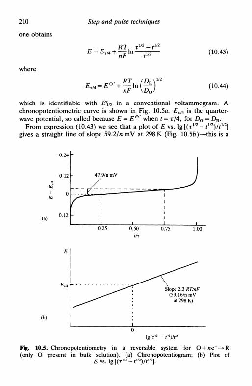
210
one obtains
where
Step and pulse techniques
r r RTA rm-tm
E = £T/4 + — In угnF t1'2
(10.43)
(10.44)
which is identifiable with E\/2 in a conventional voltammogram. Achronopotentiometric curve is shown in Fig. 10.5a. ExtA is the quarter-wave potential, so called because E = £ ° ' when t = т/4, for Do = DR.
From expression (10.43) we see that a plot of E vs. lg [(т1/2 - tV2)/tin]gives a straight line of slope 59.2/n mV at 298 К (Fig. 10.56)—this is a
(a)
-0.24
-0.12
0
0.12
»-
47.9/n mV
- ^ ^ • • •
i i
J1
1
i
i
0.25 0.50
tfr0.75 1.00
(b)
Slope 2.3 RT/nF(59.16/nmV
at 298 K)
Fig. 10.5. Chronopotentiometry in a reversible system for O + ne~-»R(only О present in bulk solution), (a) Chronopotentiogram; (b) Plot of
£vs. 1 / 2 l / 2 1 / 2
10.5 Current step: chronopotentiometry 111
diagnostic of a reversible system. On the other hand, \E3r/4- Et/4\ =47.9/rtmVat298K.
For an oxidation (10.43) also applies, but with a negative sign in placeof the positive sign.
Quasi-reversible and irreversible systems
The final boundary condition, for only О initially present, is
) = * c [ O ] . - * J R ] , (10.45)
substituting for [O]* and [R]* in (10.40) and (10.41) we get
/ = nFA{kaPRtm - ke([O]« + Pot112)} (10.46)
where
P
nFA(DRn)m ° nFA{Don)1
(10.47)
Except for potentials close to £eq, where it is necessary to consider thereaction in both directions, we have
/ = nFAkc{Potш - [О]»} (10.48)
Substituting in the Sand equation for /, we obtain
nmDK2
*c = ̂ i ^ (10.49)
This expression allows the calculation of k0> and, since only О ispresent in bulk solution, is equal to the expression for an irreversiblesystem. Using
kc = k0 exp [-acnF(E - E^')/RT] (10.50)
the result is
^ Ь ] <Щ51)
Therefore, for a totally irreversible wave \E3v/4 — ET/4\ = 33.8/an' mV at298 K. Figure 10.6 illustrates the variation of potential with timeschematically.

212 Step and pulse techniques
0.25 0.50 0.75 1.0
tfr
Fig. 10.6. Chronopotentiogram for an irreversible system: О + ne —> R.
10.6 Double current step
In the last section the capacitive contribution was neglected. However,for some galvanostatic experiments this procedure is not possible.Various theoretical treatments have been developed to analyse chrono-potentiograms, but always with approximations that are difficult tojustify, such as, for example, / c constant!
A better alternative is to modify the experiment. The use of a doublecurrent step10, as demonstrated in Fig. 10.7, can reduce the problem. Thefirst step has sufficient length to charge the double layer; the current isthen reduced to a lower value at which there is not capacitive component.
о
Fig. 10.7. The double current step. The first pulse is to charge the double layer.f,«l(r 6s.
10. 7 Methods using derivatives of chronopotentiograms 213
In principle, compensation of capacitive effects can be 100 per cent. Theoptimal pulse duration seems to be about 1 ̂ s.
A theoretical description of this experiment has to take into accountthe existence of a faradaic current during the first pulse. For small valuesof t, one obtains, for only О or R present, the equation
RT ( 1 47V .„}
МП (Щ52)
where r? is the overpotential. A plot of ц (when t = f,) vs. tx gives k0 fromthe intercept. Knowing k0, and that the current is purely capacitive whent = 0,
RTA j£)"Double current steps, where the second step reverts to the initial value
of the applied current, have been used in mechanistic studies11.
10.7 Methods using derivatives of chronopotentiograms
If we consider reversible and irreversible systems, the derivatives dE/dtare easily obtained and are
тг^Щ ( 1 0 - 5 4 )
/ 2 (T 1 / 2 - tl/2)]~l (10.55)
respectively. The positive signs refer to oxidation and the negative signsto reduction. The minimum values of the derivatives are related to thetransition times according to
f = (4T/9) (10.56)4 ш y r,min ° n r l
and
d£\ 2RT ,— = ± f=r/4 (10.57)d^/irr,min ocnFx
By measuring dE/dt we can calculate the transition time, r. Theusefulness of these expressions is that they permit the determination of гin a region where the capacitive contribution is small (in fact at itsminimum).

214 Step and pulse techniques
10.8 Coulostatic pulses
In the coulostatic pulse technique, a charge step is applied during 1 JUS,the potential of the electrode being followed afterwards in open circuit12.Conditions are chosen such that only the double layer is charged, andeven a fast reaction proceeds only to a very small extent. After the pulsethe electrode relaxes to its initial state, releasing the charge. Theresultant flux of electrons can be used to cause faradaic reactions. Theadvantage is that the solution where the measurements are made canhave a high resistance so long as the measurements are done in opencircuit; supporting electrolyte is not necessary.
The generic equations are
/ f = - / c = " C d ^ (10.58)
and
\ (10.59)— \ /fdr
We consider two special cases:
1. Small step and without creating significant concentration gradients:Equation (10.59) gives
rj(t) = rj(t = O)cxp(-) (10.60)
where
* £ (10.61)
2. Large step, sufficient to reach the plateau of the voltammetric waveand with Cd independent of potential:
AE = \E(t) - E(t = 0)| = ̂ „ £ (Ю.62)
.1/2from substitution of the Cottrell equation in (10.59). The plot of E vs. tis linear, with slope proportional to concentration.
10.9 Pulse voltammetry
The potential step is the basis of pulse voltammetry1314. Pulse techniqueswere initially developed for the dropping mercury electrode15 (Section
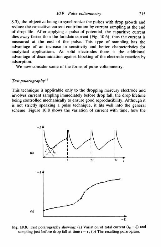
10.9 Pulse voltammetry 215
8.3), the objective being to synchronize the pulses with drop growth andreduce the capacitive current contribution by current sampling at the endof drop life. After applying a pulse of potential, the capacitive currentdies away faster than the faradaic current (Fig. 10.6); thus the current ismeasured at the end of the pulse. This type of sampling has theadvantage of an increase in sensitivity and better characteristics foranalytical applications. At solid electrodes there is the additionaladvantage of discrimination against blocking of the electrode reaction byadsorption.
We now consider some of the forms of pulse voltammetry.
Tast polarography16
This technique is applicable only to the dropping mercury electrode andinvolves current sampling immediately before drop fall, the drop lifetimebeing controlled mechanically to ensure good reproducibility. Although itis not strictly speaking a pulse technique, it fits well into the generalscheme. Figure 10.8 shows the variation of current with time, how the
(a)
-I
(b)
-E
Fig. 10.8. Tast polarography showing: (a) Variation of total current (/c + /f) andsampling just before drop fall at time t = т; (b) The resulting polarogram.

216 Step and pulse techniques
sampling is done, and the polarogram, without the oscillations in currentof a conventional polarogram (see Fig. 8.9). Detection limits of the orderof 10~6м are possible.
Normal pulse voltammetry (NPV)15'16
In normal pulse voltammetry a base value of potential, Eb.ASG, is chosen,normally where there is no faradaic reaction, and this is applied to theelectrode. From this value short pulses of increasing amplitude areapplied, the amplitude increment always being equal. The current ismeasured at the end of each pulse, the duration of which varies normallybetween 5 and 100 ms; the interval between pulses is 2-4 s. Figure 10.9shows the scheme of operation and response.
(a)
i k
(b)
Fig. 10.9. Normal pulse voltammetry. (a) Scheme of pulse application starting at£base- The current is measured at the end of the pulses and it is assumed that / at£basc is zero, т = 2-4 s and (т — г') 5-100 ms. At the DME the end of the pulse is
synchronized with drop fall; (b) Schematic 1-Е profile.

10.9 Pulse voltammetry 217
In relation to tast polarography, normal pulse polarography has theadvantage that there is faradaic reaction only during the pulses, leadingto larger currents, given that there is lower consumption of electroactivespecies close to the electrode. In the case of solid electrodes, problems ofsurface blocking by the product of the electrode reaction are reducedthrough the use of pulses.
The form of the response is a succession of points following the sameprofile as a conventional voltammogram. However, since a pulse causesgreater mass transport than a steady-state technique (hydrodynamicelectrode), a reaction that appears reversible in the steady state canappear quasi-reversible with this technique. On the other hand, given theshort timescale, effects due to coupled homogeneous reactions may notbe observed.
Differential pulse voltammetry (DPV)1516
This technique is similar to NPV but with two important differences:
• The base potential is incremented between pulses, these incrementsbeing equal.
• The current is measured immediately before pulse application and atthe end of the pulse: the difference between the two currents isregistered.
The potential-time waveform is represented in Fig. 10.10. Pulsessuperimposed on a potential ramp have also been employed; formicroprocessor control the staircase waveform is clearly simpler to putinto operation.
Since DPV is a differential technique, the response is similar to the firstderivative of a conventional voltammogram, that is a peak. The peakpotential, Ep, can be approximately identified with El/2. With increasingirreversibility Ep moves away from El/2 (reversible system), at the sametime as peak width increases and its height diminishes. The degree ofreversibility of an electrode reaction is similar to that observed in NPV,since the timescale is the same.
Quantitative treatments for reversible systems demonstrated that, withonly R (positive sign) or only О (negative sign) initially present,
AEEmax = Em±— (10.63)
where AE is the pulse amplitude. The peak current is

218 Step and pulse techniques
10//TmVf "I i*~rr T I
JLJLJLJb50/n mV
T ~ 0 . 5 - * 5 S
(T - T')~5-*50ms
(a)
A/
A/ = /(2) - /(1)
(b)
Fig. 10.10. Differential pulse voltammetry. (a) Scheme of application of poten-tials (sometimes superimposed on a ramp rather than a staircase); (b) Schematic
1-Е profile.
r and r ' are described in Fig. 10.10 and a is given by
/ nF AE\a = e x p f e T J (10.65)
The term (1 - <J)/(1 + o) describes the effect of AE on (<5/)max. This termincreases as \AE\ increases, attaining a value of unity for very large |A£| .In fact the use of |A£| values larger than about 100 mV is not viable, asthe peak width at half height, W1/2, also increases, leading to a loss of
10.9 Pulse voltammetry 219
resolution. At the limit, when A£—»0
Wl/2 = 3.52RT/nF (10.66)
The maximum value of the current obtained for large values of AEcorresponds to that obtained in NPV under identical conditions. For anelectrode process without complications, DPV should be no better thanNPV.
At the dropping mercury electrode the fact that DPV is better thanNPV is due to the residual capacitive current contribution, which issubtracted out in the differential technique. It is relatively easy todemonstrate that the diminution factor, f, is given by
Ж=Ё ( 1 0 6 7 )
where Ez is the potential of zero charge (Chapter 8, equation (8.9)). Ingeneral, / has a value less than 0.1. It should also be noted that with'static electrodes' (a succession of suspended electrodes of identical, fixedarea) the capacitive contribution described by equation (10.67) shouldalso be reduced to zero.
At solid electrodes the better response from DPV than from NPV isclear in many cases, especially involving organic compounds. As theseoften lead to adsorption on the electrode, it is possible that a differentialtechnique discriminates against effects that are moreless constant beforeand after pulse application.
Square-wave voltammetry (SWV)I7
Square-wave voltammetry was invented in 1952 by Barker18, but waslittle used at the time owing to difficulties with the controlling electronics.With advances in instrumentation it has now become an importantanalytical technique. The waveform is shown in Fig. 10.11, and consistsof a square wave superimposed on a staircase, a full square wave cyclecorresponding to the duration of one step in the staircase waveform.
Whereas NPV and DPV function with effective sweep rates of1-10 mVs"1, SWV can reach lVs" 1 . There are advantages: greaterspeed in analysis, lower consumption of electroactive species in relationto DPV, and reduced problems with blocking of the electrode surface.Since the current is sampled in both the positive- and the negative-goingpulses, peaks corresponding to the oxidation or reduction of theelectroactive species at the electrode surface can be obtained in the sameexperiment, and by subtraction their difference. Subtraction also meansthat the difference current is zero for a species at a potential correspond-ing to the region of mass-transport limited current. In analysis, this can

220 Step and pulse techniques
2mV{
1 —>\
2 1 н
\1
\
\
\
•
t
(a)
A/ = /(1) - /(2)
(b)
Fig. 10.11. Square wave voltammetry. (a) Scheme of application of potentials:sum of a staircase and a square wave; (b) Typical response: £ s t~2mV;
rmin = 2 ms. Note the similarity to DPV.
be very useful, particularly for removing the current due to reduction ofdissolved oxygen.
The rapidity means that full square-wave voltammograms can beregistered in quick succession, chronovoltammograms, an importantapplication being in electrochemical detection of eluents from high-pressure liquid chromatography columns.
In the particular case of the static mercury drop electrode, given thatthe experiment can be done in 2 s, a full analysis is possible during thelifetime of one drop.

10.9 Pulse voltammetry 221
E i
-и—ц
Fig. 10.12. Scheme of reverse pulse voltammetry (RPV). £base corresponds toelectrolysis of the electroactive species in solution.
Other pulse techniques
There are other pulse combinations, developed with particular aimsbesides the reduction of capacitive and adsorptive contributions. Someare described below.
Reverse Pulse Voltammetry (RPY)This originated from a similar idea to that of the double potential step. Abase potential at which all the electroactive species is electrolysed isapplied, and the reverse reaction is carried out by normal pulse (Fig.10.12). A good reason for using this technique is to diminish theproblems caused by parallel electrode reactions of the initial species.
Differential Normal Pulse Voltammetry (DNPV)This is a hybrid of DPV and NPV. Instead of applying a succession ofpulses from a base potential, as in NPV, each pulse contains two pulsesseparated by ДЕ, giving rise to a differential measurement. With thescheme in Fig. 10.13, it is possible to register the current relative toreduction or oxidation by considering pairs of alternate pulses, or, by
Ek
•ff-
Fig. 10.13. Scheme of differential normal pulse voltammetry (DNPV). It ispossible to register (72 - / t), (74 - /3), or {(/2 - /,) - (74 - /3)}-

222 Step and pulse techniques
4*-
Fig. 10.14. Scheme for double differential pulse voltammetry (DDPV). (/2-/i)at potential (Ex + E2)/2 is registered. Pulse width —50 ms.
using all pairs of pulses, the difference between them. Besides this, thereduction in the time spent at potentials where there is electrodereaction, in comparison with DPV, offers clear advantages in relation toadsorption problems.
Double Differential Pulse Voltammetry (DDPV)
The aim of this technique is precisely the same as DPV; Fig. 10.14 showsthe pulse application scheme. The form of the voltammograms (peaks)was deduced theoretically19. As in DNPV, the great advantage is thereduction in time during which electrolysis occurs.
Applications of pulse techniques
Applications of pulse techniques in electrochemistry have been pre-dominantly in the area of analysis, relying on the linear dependence ofpeak height on potential, although recently their use in mechanisticstudies, particularly square-wave voltammetry, has begun to be ex-ploited. The reason for their use in analysis is intimately linked with thelow detection limits that are attainable, particularly in combination withpre-concentration techniques, as will be seen in Chapter 14. Finally, sincenowadays the pulse sequences are generally controlled and responsesanalysed using microprocessors, the development of new waveforms forparticular situations is now a much easier task than it was even a decadeago.
References
1. D. D. Macdonald, Transient techniques in electrochemistry, Plenum, NewYork, 1977, Chapter 4.
References 223
2. D. D. Macdonald, Transient techniques in electrochemistry, Plenum, NewYork, 1977, Chapter 5.
3. Z. Nagy, Modern aspects of electrochemistry, Plenum, New York, Vol. 21,1990, ed. R. E. White, J. O'M. Bockris, and В. Е. Conway, pp. 237-292.
4. F. G. Cottrell, Z. Physik. Chem., 1902, 42, 385.5. R. G. Compton, M. E. Laing, R. J. Northing, and P. R. Unwin, Proc. R.
Soc. bond., 1988, A418, 113.6. N. M. Smit and M. D. Wijnen, Rec. Trav. Chim., 1960, 79, 5; F. Kimmerle
and J. Chevalet, /. Electroanal. Chem., 1969, 21, 237.7. F. С Anson, Anal. Chem., 1966, 38, 54.8. Ref. 1, pp. 93-95.9. H. J. S. Sand, Philos. Mag., 1901, 1, 45.
10. H. Gerischer and M. Krause, Z. Physik. Chem., 1957,10, 264; 1958,14, 184.11. Ref. 2, pp. 158-176.12. H. P. van Leeuwen, Electroanalytical chemistry, ed. A. J. Bard, Dekker,
New York, Vol. 12, 1982, pp. 159-238.13. P. He, J. P. Avery and L. R. Faulkner, Anal. Chem., 1982, 54, 1313A.14. S. Borman, Anal. Chem., 1982, 54, 698A.15. A. M. Bond, Modern polarographic methods in analytical chemistry, Dekker,
New York, 1980.16. J. Osteryoung and M. M. Schreiner, CRC Crit. Rev. Anal. Chem., 1988, 19,
SI.17. J. Osteryoung and J. O'Dea, Electroanalytical chemistry, ed. A. J. Bard,
Dekker, New York, Vol. 14, 1986, pp. 209-308.18. G. С Barker and I. L. Jenkins, Analyst, 1952, 77, 685.19. W. J. Albery, T. W. Beck, W. N. Brooks, and M. Fillenz, J. Electroanal.
Chem., 1981, 125, 205.

11
IMPEDANCE METHODS
11.1 Introduction11.2 Detection and measurement of impedance11.3 Equivalent circuit of an electrochemical cell11.4 The faradaic impedance for a simple electrode process11.5 The faradaic impedance, Zf, and the total impedance: how to calculate Zf
from experimental measurements11.6 Impedance plots in the complex plane11.7 Admittance and its use11.8 A.c. voltammetry11.9 Second-order effects11.10 More complex systems, porous electrodes, and fractals11.11 Hydrodynamic electrodes and impedance11.12 Transforms and impedance
11.1 Introduction
Electrochemical systems can be studied with methods based on im-pedance measurements. These methods involve the application of a smallperturbation, whereas in the methods based on linear sweep or potentialstep the system is perturbed far from equilibrium. This small imposedperturbation can be of applied potential, of applied current or, withhydrodynamic electrodes, of convection rate. The fact that the perturba-tion is small brings advantages in terms of the solution of the relevantmathematical equations, since it is possible to use limiting forms of theseequations, which are normally linear (e.g. the first term in the expansionof exponentials).
The response to the applied perturbation, which is generally sinusoidal,can differ in phase and amplitude from the applied signal. Measurementof the phase difference and the amplitude (i.e. the impedance) permitsanalysis of the electrode process in relation to contributions fromdiffusion, kinetics, double layer, coupled homogeneous reactions, etc.There are important applications in studies of corrosion, membranes,ionic solids, solid electrolytes, conducting polymers, and liquid/liquidinterfaces.

11.2 Detection and measurement of impedance 225
Comparison is usually made between the electrochemical cell and anequivalent electrical circuit that contains combinations of resistances andcapacitances (inductances are only important for very high perturbationfrequencies, > 100 kHz). The combinations normally used for faradaicreactions are considered in Section 11.3; there is a component repre-senting transport by diffusion, a component representing kinetics (purelyresistive), and another representing the double layer capacity, this for asimple electrode process. Another strategy is to choose a model for thereaction mechanism and kinetic parameters, derive the impedanceexpression, and compare with experiment. Given that impedance meas-urements at different frequencies can, in principle, furnish all theinformation about the electrochemical system (if we are capable ofunderstanding all the contributions) there has been much interest indeveloping impedance techniques in electrochemistry1"12.
In this chapter, after a description of specialized methods for im-pedance measurement, the procedure for deducing the kinetics andmechanism from the impedance spectra is demonstrated.
The principles of a.c. circuits necessary for the comprehension of someof the ideas and concepts presented here are given in Appendix 2. Theimpedance is the proportionality factor between potential and current; ifthese have different phases then we can divide the impedance into aresistive part, Ry where the voltage and current are in phase, and areactive part, Xc = l/(oC, where the phase difference between currentand voltage is 90°. As shown in Appendix 2, it is often easier forposterior calculation and analysis to display the impedance vectorially incomplex-plane diagrams.
11.2 Detection and measurement of impedance
There are three types of technique for the detection and measurement ofimpedance613.
Alternating current bridge
These bridges, as shown in Fig. 11.1, use the principle of balancebetween the electrochemical cell under study and a variable impedance,Zs, which in research on electrode processes normally consists of aresistance Rs in series with a capacitance Cs. Given that
Zs = Rs-i/coCs (11.1)
and that
Zcell/R1 = ZJR2 (11.2)

226 Impedance methods
Fig. 11.1. A.c. bridge for the measurement of the impedance of electrochemicalcells. The bridge is balanced when the current is zero: in this case ZCCJRX =
ZJR2 where Zs = Rs - i/coCs.
we have
that is
and
- i(Ri/a)CsR2) (11.3)(11.4)
(11.5)
CceXX = CsR2lRx (11.6)
The capacitance is due only to the working electrode, whilst theresistance includes the resistive components of the electrode process, ofthe solution, etc. In some cases a combination of resistance andcapacitance in parallel has also been used. In these conditions theanalysis is more easily carried out in terms of admittance Y = 1/Z: seeAppendix 2.
When it is necessary to apply a d.c. potential to the cell in addition tothe a.c. perturbation, it is more convenient to use a potentiostat, whichsimultaneously applies the d.c. potential and does the detection, ratherthan the conventional detector. This arrangement is called a potentiostaticbridge, and in this way very good stability in the applied potential and

11.2 Detection and measurement of impedance 227
accuracy for a wide range of frequencies is possible, limited only by thecharacteristics of the electronic components of the potentiostat.
For very high frequencies the accuracy of bridges depends very muchon cell design, and Debye-Falkenhagen effects begin to appear14. Theseoccur usually above 10 MHz, and are due to the ions moving faster thanthe time needed for rearrangement of the ionic atmosphere: theytherefore tend to leave it behind and the cell resistance drops. Fornormal frequencies the technique is very exact, but also very time-consuming.
A disadvantage of this type of technique is that the impedance of thewhole cell is measured, whereas in the investigation of electrodeprocesses one is interested in the properties of one of the electrodes. It ispossible to reduce the contribution of the unwanted components by usingan auxiliary electrode with an area large relative to that of the electrodebeing studied, and extrapolating the cell impedance to infinite frequencyin order to remove contributions such as cell resistance.
Phase-sensitive detectors and transfer function analysers
These detectors compare the signal applied to the system with theresponse, giving the phase difference and the ratio of the amplitudes (i.e.impedance) (Fig. 11.2). The signal is applied by a potentiostat orgalvanostat: it is necessary to subtract the resistance between the workingand reference electrodes, and this can be done electronically. It is easy toregister the response in terms of the alternating current as a function ofapplied potential, or as phase difference vs. applied potential, both thesepieces of information being important in a.c. voltammetry.
Generator
Phase-sensitivedetector
Cell
Response
Difference in phaseand amplitude
Fig. 11.2. Principle of functioning of a phase-sensitive detector.

228 Impedance methods
Transfer function analysers and network analysers, both digital, haveprinciples of electronic operation different from the conventional ana-logue phase-sensitive detector. However, the information obtained issimilar, and for a wider range of frequencies (10~4—> 106Hz). Theinstruments are microprocessor controlled, permitting automatic analysis,appropriate signal processing to improve signal/noise ratios, etc. It mustbe remembered that the processing of digital signals is complicated, andif not correctly carried out it can lead to strange and erroneous results.
In spectroscopy it is current practice to apply all frequencies at thesame time through the Fourier transform. In electrochemical systems it ispossible to do the same, but it is not yet clear if this is advantageousgiven that quite a large signal accumulation time is necessary for signalaveraging; stepping through the various frequencies automatically takesmore or less the same time (Section 11.12) and the results are of similaraccuracy and precision.
Direct methods
If the applied signal is transmitted to a recorder (frequency <5 Hz) or anoscilloscope (frequency <5 kHz) and registered against the responsesignal, a Lissajous figure appears. The shape of this figure leads to theimpedance. With a perturbing signal of
E(t) = AE sin cot (11.7)
/ (0 i i
Fig. 11.3. Lissajous figure for impedance measurement (see text).

11.3 Equivalent circuit of an electrochemical cell 229
the response is
AEДО = 7^7sin (cor+ 0) (11.8)
As shown in Fig. 11.3, the values of the important variables can be takendirectly from the Lissajous figure.
11.3 Equivalent circuit of an electrochemical cell
Any electrochemical cell can be represented in terms of an equivalentelectrical circuit that comprises a combination of resistances and capacit-ances (inductances only for very high frequencies). This circuit shouldcontain at the very least components to represent:
• the double layer: a pure capacitor of capacity Cd
• the impedance of the faradaic process Z f
• the un-compensated resistance, Ra, which is, usually, the solutionresistance between working and reference electrodes.
The combination of these elements is shown in Fig. 11.4, with Z f and Cd
in parallel. The impedance Z f can be subdivided in two equivalent ways:
1. Subdivision into a resistance, Rs, in series with a pseudo-capacitance, Cs, according to the scheme
*s c s
s/WW If—
which was described in Section 11.2 on a.c. bridges.
2. Subdivision into a resistance measuring the resistance to chargetransfer, RcU and an impedance that measures the difficulty of masstransport of the electroactive species, called the Warburg impedance, Z w :
Thus, for kinetically favoured reactions #ct—»0 and Z w predominates,and for difficult reactions Rct^><x> and Rct predominates. This is called theRandies circuit15.

230 Impedance methods
WWWVWA/f + /c
Fig. 11.4. Equivalent electrical circuit of an electrochemical cell for a simpleelectrode process. /?Q is the solution resistance, of the contacts and electrodematerials, Z f the impedance of the electrode process, and Cd the double layer
capacity.
When other steps are involved in the electrode process, homogeneousor heterogeneous, more complicated circuits have to be utilized, asindicated in Section 11.10.
11.4 The faradaic impedance for a simple electrode process
Consider the charge transfer reaction
at a planar electrode (semi-infinite linear diffusion), and for a sinusoidalperturbation of
/ = /0 sin Ш
with со the perturbation frequency (rads - 1).For a series RC circuit we have
and by differentiation
d£ d/ 1_df Sd* + C.
= RJco cos Ш + — sin cot
(11.9)
(11.10)
(11.11)
(11.12)
The general relation reflecting the charge transfer process, that is£ = / ( / , [O]*,[R]*), leads to
dEdEdl ЭЕ d[O]* ЭЕ d[R]*dt ~ Э1 dt+ Э[О]* df + a[R]* d(
(11.13)

11.4 The faradaic impedance for a simple electrode process 231
The three partial derivatives describe the kinetics of the reaction and(ЭЕ/dI) is the charge transfer resistance, Rct. It can be shown, usingLaplace transformation, that
d[O]* / / со \1/2 .Я ^ Щ («*<"+ «.«*) (11.14a)
d[R]* - / / соAt nFA
со \ m
T T (sin cot + cos wt) (11.14b)ZL>R/
Since the a.c. perturbation is small, the linearized relation betweencurrent and overpotential, r\ (equation (6.50)), considering aa = arc = 0.5,may be used, that is
n i L i w j Q o i x x j o o IQJ (11-15)
Thus
SF RT(11.16)
(11.17)
where /0 is the exchange current, and
ЭЕ RT ЭЕ -RT
Equation (11.13) then becomes
— = \Rct + -^mjla) cos cot + loco m sin o>f (11.18)
where
RT / 1 1 \
^ " ^ F M V ^ V D ^ O I O O ^ D ^ R I J ^ ' ^
By comparison of (11.12) and (11.18) we verify that
Rs = Rct + oa)-1/2 (11.20)
and that
l/Cs=oa>l/2 (11.21)
In this way, from (11.14), we can identify the Warburg impedance, Z w ,of the Randies circuit as consisting of a resistance and a capacitance inseries and where the components in phase Z w and out of phase ZJV, withZ = Z' + iZ", are given by
Z w = Rw = <яо"1/2 (11.22a)
Z w = -(wCw)"1 = -aw" 1 / 2 (11.226)
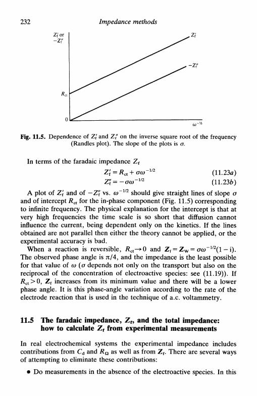
232 Impedance methods
Fig. 11.5. Dependence of Z\ and Z" on the inverse square root of the frequency(Randies plot). The slope of the plots is o.
In terms of the faradaic impedance Z f
Z'f=Rct+oa)-y2 (11.23a)
Z'i=-oa)-m (11.236)
A plot of Zf and of —Z" vs. co~1/2 should give straight lines of slope оand of intercept Rct for the in-phase component (Fig. 11.5) correspondingto infinite frequency. The physical explanation for the intercept is that atvery high frequencies the time scale is so short that diffusion cannotinfluence the current, being dependent only on the kinetics. If the linesobtained are not parallel then either the theory cannot be applied, or theexperimental accuracy is bad.
When a reaction is reversible, i?ct—»0 and Z f = Z W = oa)~l/2(l — i).The observed phase angle is л/4, and the impedance is the least possiblefor that value of со (a depends not only on the transport but also on thereciprocal of the concentration of electroactive species: see (11.19)). IfRct > 0, Z f increases from its minimum value and there will be a lowerphase angle. It is this phase-angle variation according to the rate of theelectrode reaction that is used in the technique of a.c. voltammetry.
11.5 The faradaic impedance, Z f, and the total impedance:how to calculate Z f from experimental measurements
In real electrochemical systems the experimental impedance includescontributions from Cd and Rn as well as from Z f. There are several waysof attempting to eliminate these contributions:
• Do measurements in the absence of the electroactive species. In this
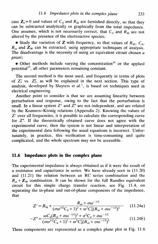
11.6 Impedance plots in the complex plane 233
case Zf = 0 and values of Cd and i?Q are furnished directly, so that theycan be subtracted analytically or graphically from the total impedance.One assumes, which is not necessarily correct, that Cd and i?Q are notaltered by the presence of the electroactive species;
• Study the variation of Z with frequency, so that values of Rn, Cd,Rct and Z w can be extracted, using appropriate techniques of analysis.The disadvantage is the necessity of using an equivalent circuit chosen apriori;
• Other methods include varying the concentration16 or the appliedpotential17, all other parameters remaining constant.
The second method is the most used, and frequently in terms of plotsof Zf vs. Z", as will be explained in the next section. This type ofanalysis, developed by Sluyters et al.1, is based on techniques used inelectrical engineering.
Another point to consider is that we are assuming linearity betweenperturbation and response, owing to the fact that the perturbation issmall. In a linear system Z' and Z" are not independent, and are relatedby the Kramers-Kronig relations (Appendix 2). Knowing the values ofZ' over all frequencies, it is possible to calculate the corresponding curvefor Z". If the theoretically obtained curve does not agree with theexperimental curve, then the system is not linear and interpretation ofthe experimental data following the usual equations is incorrect. Unfor-tunately, in practice, this verification is time-consuming and quitecomplicated, and the whole spectrum may not be accessible.
11.6 Impedance plots in the complex plane
The experimental impedance is always obtained as if it were the result ofa resistance and capacitance in series. We have already seen in (11.20)and (11.21) the relation between an RC series combination and the/?ct + Z w combination. It can be shown for the full Randies equivalentcircuit for this simple charge transfer reaction, see Fig. 11.4, onseparating the in-phase and out-of-phase components of the impedance,that
Rct+oa) -l/2
(oo)V2Cd + I)2 + co2C2d(Rct + oo)'112)2
„ _ (oCd(Rct + ocQ-y2)2 + o2Cd + go;"172
These components are represented as a complex plane plot in Fig. 11.6

234 Impedance methods
- Z " i i
Kinetic control
+ - y - 2a2Cd
Z'
Fig. 11.6. Plot of impedance in the complex plane of a simple electrochemicalsystem: О + ле~—»R.
(Sluyters or Cole-Cole plot), in a form similar to the representation ofcomplex numbers (Argand diagram).
It is interesting to consider two limiting forms of these equations:
(11.25а)
(11.25ft)
This low-frequency limit is a straight line of unit slope, whichextrapolated to the real axis gives an intercept of ( # n + # c t - 2 a 2 C d ) .The line corresponds to a reaction controlled solely by diffusion, and theimpedance is the Warburg impedance, the phase angle being я/4, seeFig. 11.6.
2. ct>—»°o. At the high-frequency limit the control is purely kinetic,and / ? c t » Z w . The electrical analogy is an RC parallel combination.Thus (11.24) become
Rct
Z " = -coCdR
2
ct
+ co2C2R2
ct
(11.26a)
(11.26b)
Simplifying we obtain
(11.27)

11.6 Impedance plots in the complex plane 235
This last expression is the equation of a circle of radius RJ2 withintercepts on the Z' axis of R& (co-> <») and of /?Q + Rct (eo—> 0), see Fig.11.6.
It is important to understand the physical reasons for the existence ofthis semi-circle. For very high frequency Z" ( = -l/o)Cd) is very small,but rises as the frequency diminishes. For very low frequency, Cs gives ahigh reactance but the current passes predominantly through Rcu
increasing Z' and diminishing Z".
Figure 11.6 shows the semi-circle, the straight line and a transitionzone between the two. For different systems it can happen that, due tothe relative values of the components Rct, Z w and Cd, only thesemi-circle or only the straight line are observed.
When an electrode process involves several steps, sometimes asuccession of semi-circles side by side is obtained, corresponding to RCparallel combinations in series and with different RC time constants,from which it is possible to deduce the corresponding parameters.
It is interesting to represent the impedance in three dimensions, thethird axis being lg/. The impedance is represented as Z, or if its valuevaries a lot, as lg Z. This procedure is recommended by Macdonald18 as itpermits an excellent visualization of the electrode process and makes thedetection of anomalies easier. Figure 11.7 shows an example.
In general, the form of complex plane plots of the type shown in Fig.11.6 alters on changing the concentration of the electroactive species16. Ithas been shown for the various kinetic regimes that the variation of Z"with concentration has the form in Fig. 11.8. The equation of this curve
- Z "
cdRct
Z w
= lOfi= 1 pF= 1 Ш= 0
Scale:Z — units of 200 fi
lg/— units of 1(origin -2)
Fig. 11.7. Impedance plot in three dimensions (from Ref. 18 with permission).

236 Impedance methods
Fig. 11.8. Variation of impedance with concentration for reactions of variablekinetics: 1—reversible, /?ct—»0; 2—quasi-reversible, RCJOCL>~1/2~1; 3—ir-
reversible, /?ct—»o°.
can be obtained from (11.24), and is
r D _l_— i\r> '
2a)Cd(Rjo(o~1 1
4co2C2
d
which is a circle centred on [flQ - (2coCd)~1(Rct/a(w~1/2 + I)"1] on the Z'axis and on -{2cc>Cd)~l on the Z" axis. A segment of the circle is tracedfrom (Z' = /?Q, Z" = -l/coCd) at zero concentration to (Z' = /?Q, Z" = 0)at infinite concentration. The curvature diminishes from irreversible toreversible reactions. The centre of the circle traced by the experimentalpoints linked to the points for ^ = 0 and Coo = o° gives the phase angle:я/4 for a reversible reaction (see Fig. 11.8) and zero for a totallyirreversible reaction. These plots furnish the same information ascomplex plane plots and are an alternative to these in the interpretationof the results of impedance measurements.
11.7 Admittance and its use
Admittance is the inverse of impedance, and is represented by thesymbol F. In certain circumstances, admittance is very useful since
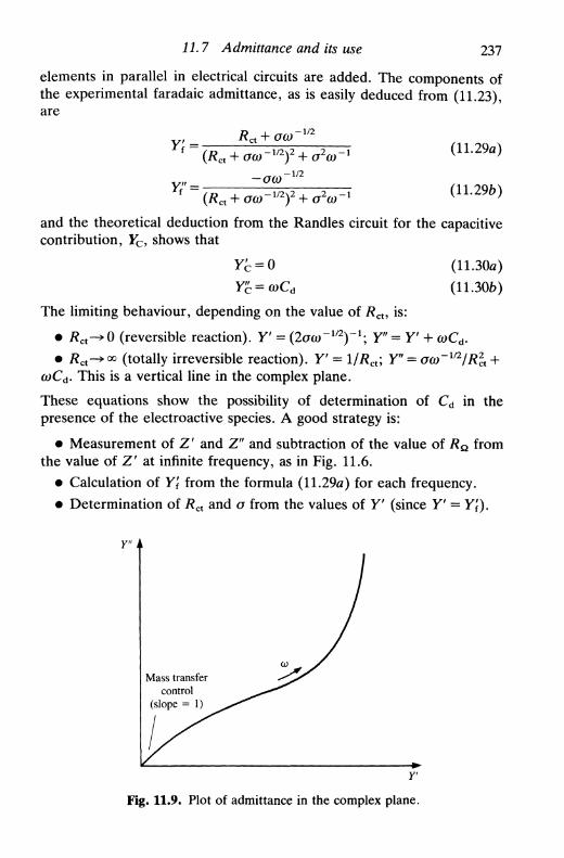
11.7 Admittance and its use 237
elements in parallel in electrical circuits are added. The components ofthe experimental faradaic admittance, as is easily deduced from (11.23),are
Rcx + oo)-m
f ~~ n? _u ^ . i - i / 2 4 2 -L ^ . , - 1 (11.29a)
F f " = (R + oo)-1/2)2 + o2o)-1 (11.296)
and the theoretical deduction from the Randies circuit for the capacitivecontribution, F c , shows that
Y'c = 0 (11.30а)
Y'^ = a)Cd (11.306)
The limiting behaviour, depending on the value of RcU is:
• # c t -»0 (reversible reaction). У = (2айГ1/2)~1; Y"=Y' + wCd.
• Rct^°° (totally irreversible reaction). У = 1/Rct; Y" = oo)~ll2IR2
cX +a)Cd. This is a vertical line in the complex plane.
These equations show the possibility of determination of Cd in thepresence of the electroactive species. A good strategy is:
• Measurement of Z ' and Z" and subtraction of the value of R& fromthe value of Z' at infinite frequency, as in Fig. 11.6.
• Calculation of Y[ from the formula (11.29a) for each frequency.
• Determination of Rct and a from the values of У (since У = Y[).
Y" i
Mass transfercontrol
(slope = 1)
Fig. 11.9. Plot of admittance in the complex plane.
238 Impedance methods
• Insertion of the values for Rct and о in the expression for Y",obtaining the value of Cd directly.
One assumes that the double layer admittance is that of a pure capacitor.Thus its value should be independent of frequency. The graphicalvariation of Y' with Y" is shown schematically in Fig. 11.9. More detailsmay be found in Ref. 9.
As a final point we call attention to the fact that a plot of Y' vs. E hasthe same form as an a.c. voltammogram, i.e. it comprises a peak centredon the half-wave potential—this because the measured current is in-versely proportional to Rct.
11.8 A.c. voltammetry
If a fixed frequency sinusoidal perturbation is applied at a succession offixed d.c. potentials, we can register the resulting alternating current andits phase angle vs. the d.c. potential. The form of the curves obtainedgives information about the kinetics, and can also be used for analyticalpurposes519"21.
The theoretical treatment is simplified when the perturbation fre-quency is sufficiently high that the contributions of Eac and Edc can beseparated, owing to the diffusion layer derived from the d.c. potentialbeing much larger than that derived from the a.c. perturbation. As inother techniques involving measurements for various potentials, the d.c.potential can be swept slowly. The use of hydrodynamic electrodes,including the dropping mercury electrode (a.c. polarography) allows agreater reproducibility and sensitivity in the results obtained.
Here we only consider a reversible system; treatments for other kineticregimes and more complicated electrode processes can be found in Refs.5 and 6. For a reversible system we know, from Section 11.6, that thephase angle is JT/4. Theoretical considerations show that, for thereduction of O,
4RTcosh2(p/2)
where p = (DO/DR)1/2 and A£ is the r.m.s. amplitude of the potentialperturbation. The peak current is
lp ART ( 1 1 3 2 )
at a potential Edc = EV2. From (11.31) and (11.32) it is easy to show that

11.8 Л.с. voltammetry 239
- 0 . 1 -НОЛ
п(Е -
Fig. 11.10. Shape of a peak in a.c. voltammetry for a reversible system.
Table 11.1. Parameters for reversible and quasi-reversible a.c. voltam-mograms with О initially present (reversible d.c. behaviour)
Reversiblecot ф 1
4cosh 2(^/2)
Quasi-reversible
cot ф
\I\
I'pl
1 +
= (Do/DR) E(t) = Edc - AE sin (e
240 Impedance methods
the voltammogram shape is described by
2RT [/L\m /L-Ixm
as shown in Fig. 11.10. At a dropping mercury electrode without currentsampling the characteristic variation of current with drop size is superim-posed on this curve.
The equations for reversible and quasi-reversible systems are given inTable 11.1. The table shows, as mentioned in Section 11.4, that the phaseangle is lower the slower the electrode reaction.
11.9 Second-order effects
Higher harmonics
A musician learns that on playing a note at a frequency of x Hz, soundsof reduced intensity at frequencies 2x, 3x, etc. appear. In fact, anyperiodic excitation leads to the same type of behaviour.
In an electrochemical system, Taylor's expansion shows that
+ ' * ' (И.34)
ЕоЛ
Until now we have used conditions for which the second and followingterms are (or are supposed to be) negligible, in other words / is linear inE; this corresponds to small sinusoidal perturbations. The terms in theTaylor expansion are called first harmonic or fundamental, secondharmonic, third harmonic, etc. If we look at the form of a normalvoltammogram (Fig. 6.2) the approximation of a linear system is validclose to Em much more than in other parts of the voltammogram wherethe curvature of the 1-Е profile is more pronounced.
If we register the second harmonic current vs. d.c. potential, this willhave the same form as the second derivative of the voltammetric curve,as Fig. 11.11 shows. One of the advantages of the use of the secondharmonic is that, since the double layer capacity is essentially linear, itcontributes much less to the second harmonic than to the fundamentalfrequency and the calculation of accurate kinetic parameters is muchfacilitated.

11.9 Second-order effects 241
дЕ
д2!дЕ2
Е EV2 E
Fig. 11.11. Forms of the derivatives of a normal voltammogram. (dl/dE) and(d2I/dE2) have the forms of the a.c. voltammograms of the fundamental and
second harmonic respectively.
Other second-order methods
Apart from the second harmonic there are other second-order effects,which are developed in the techniques of faradaic rectification anddemodulation. Both these techniques are utilized to study systems withvery fast kinetics.
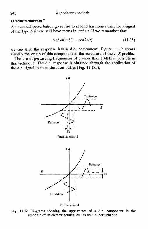
242 Impedance methods
Faradaic rectification22
A sinusoidal perturbation gives rise to second harmonics that, for a signalof the type /0 sin cot, will have terms in sin2 cot. If we remember that
sinL2 COt = • cos 2 cor) (11.35)
we see that the response has a d.c. component. Figure 11.12 showsvisually the origin of this component in the curvature of the 1-Е profile.
The use of perturbing frequencies of greater than 1 MHz is possible inthis technique. The d.c. response is obtained through the application ofthe a.c. signal in short duration pulses (Fig. 11.13a).
Excitation
Д ^LV__..
Response >
Potential control
Current control
Fig. 11.12. Diagrams showing the appearance of a d.c. component in theresponse of an electrochemical cell to an a.c. perturbation.
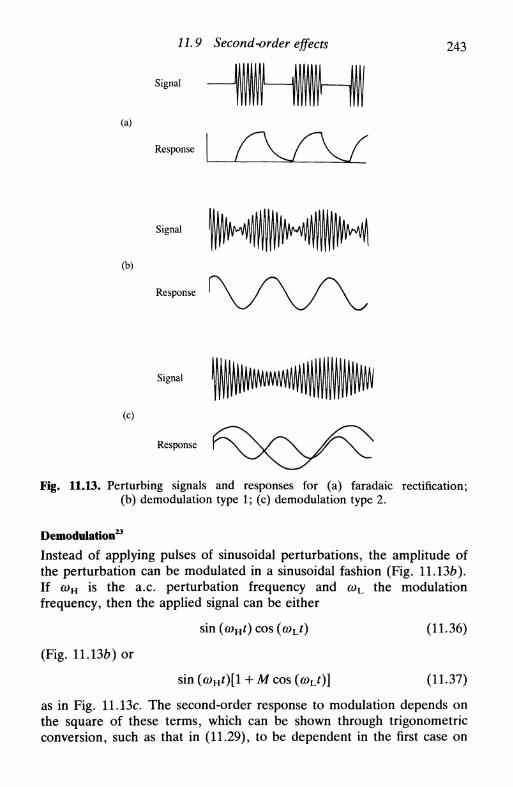
11.9 Second-order effects 243
(a)
Signal
Response
(b)
Signal
Response
(c)
Signal
Response
Fig. 11.13. Perturbing signals and responses for (a) faradaic rectification;(b) demodulation type 1; (c) demodulation type 2.
Demodulation23
Instead of applying pulses of sinusoidal perturbations, the amplitude ofthe perturbation can be modulated in a sinusoidal fashion (Fig. 11.136).If CDH is the a.c. perturbation frequency and <yL the modulationfrequency, then the applied signal can be either
(Fig. 11.13b) or
sin (o)Ht) cos (coLt)
sin (a)Ht)[l + M cos
(11.36)
(11.37)
as in Fig. 11.13c. The second-order response to modulation depends onthe square of these terms, which can be shown through trigonometricconversion, such as that in (11.29), to be dependent in the first case on

244 Impedance methods
frequencies wL and 2a>L and in the second case only on 2(ob. The reasonfor the use of this technique is, once more, to reduce the relativecontribution to the measurements of linear components such as Cd, thusimproving the accuracy.
11.10 More complex systems, porous electrodes, and fractals
Many electrode processes are more complex than those discussed above.Besides this, the impedance of an interface is dependent on its micro-scopic structure which, in the case of a solid electrode, can have animportant influence. Impedance measurements can be used to studycomplicated corrosion phenomena (Chapter 16), blocked interfaces (i.e.where there is no redox process nor adsorption/desorption), theliquid/liquid interface24'25, transport through membranes26, theelectrode/solid electrolyte interface etc. Experimental measurementsalways furnish values of Z' and Z" or their equivalents У and Y", or ofthe complex permittivities e' and e" (e = Y/iwCc, Cc being the capacit-ance of the empty cell). In this section we attempt to show how to
No AgreementJ with \У
experiment
System characterization
Fig. 11.14. Flow diagram for evaluating experimental impedance results.

11.10 More complex systems, porous electrodes, and fractals 245
Rb Ra + /?ь
-WWV\A—
|—АЛЛЛЛ/ '
4 '•• (*)> 41+«Fig. 11.15. Two circuits with the same impedance at all frequencies.
interpret the results in terms of a physical model, which should alwaysfollow reasoning such as that examplified in Fig. 11.14. The importanceof the physical model is shown in Fig. 11.15, whose two circuits giveprecisely equal impedance values at all frequencies. Some help can behad from altering experimental conditions (concentration for example)and obtaining various series of measurements.
Two types of electrical analogy model for the interpretation ofimpedance data can be used: based on combinations of resistances andcapacitances, or based on transmission lines. These possibilities are nowdescribed.
For consecutive or parallel electrode reactions it is logical to constructcircuits based on the Randies circuit, but with more components.Figure 11.16 shows a simulation of a two-step electrode reaction, withstrongly adsorbed intermediate, in the absence of mass transport control.When the combinations are more complex it is indispensable to resort todigital simulation so that the values of the components in the simulationcan be optimized, generally using a non-linear least squares method(complex non-linear least squares fitting).
Transmission lines have been much used recently to simulate inter-faces, especially where the solid is rough. We consider, to illustrate, asimple transmission line (Fig. 11.17).
Rct
•лллл/w—
I W W W 1
Fig. 11.16. An equivalent circuit for a two-step electrode reaction with stronglyadsorbed intermediate.

246 Impedance methods
r. dx
с dx
Fig. 11.17. A resistive-capacitive transmission line that describes a semi-infinitelinear diffusion process.
Elementary considerations show that
/ = -dvi
dv _dt ~
Эх г
dll
Эхе
32V 1
Эх тс
(11.38)
(11.39)
(11.40)
where r — Rlx is the resistance per unit length of the transmission lineand с = C/x is the capacitance per unit length. Expression (11.40) is ofthe same type as Fick's second law, thence its application to electrochem-istry. The impedance is
z =1/2
(11.41)
which is a line of slope я/4 in the complex plane, that is the Warburgimpedance for semi-infinite diffusion (Fig. 11.18a). If the transmissionline is finite there can be two situations:
1. Termination in an open circuit (corresponding to reflection) as inconducting polymers and porous electrodes, such as porous carbon inacid media (Fig. 11.186).
2. Termination in a large resistance, i.e. a blocked interface such as ametal totally covered with oxide or a highly resistive membrane used inion exchange selective electrodes (Section 13.6) (Fig. 11.18c). This issometimes referred to as the finite Warburg impedance.
Rugosity and porosity give rise to the so-called constant phase element(CPE), which can be described by groups of parallel or branchedtransmission lines. The CPE is manifested in real systems by animpedance spectrum altered from the expected shape, especially in the

11.10 More complex systems, porous electrodes, and fractals 247
-Z" -Z" -Z"
Z'(a) (b) (c)
Fig. 11.18. Variation of impedance for diffusive systems: (a) Semi-infinitediffusion; (b) Reflective finite diffusion; (c) Transmissive finite diffusion.
diffusive part, where an angle of less than я/4 relative to the real axis isobtained. In the case of a blocked interface the element can be describedby
YCPB = b(ia)C)« (11.42)
where b is a proportionality constant. Using a transmission line model, deLevie27'28 showed, for porous electrodes, that or = 0.5 whereas for asmooth electrode ar=l . In this case the impedance diagrams can becorrected by calculating values of |Z | 2 and multiplying the phase angle by2, as demonstrated in Fig. 11.19.
It is recognized, however, that many interfaces are rough but do notcorrespond to porous electrodes. This suggests that values of a between0.5 and 1 should be considered. It has been observed that the largemajority of interfaces contain the same or similar features at different
—z" -Z'
Z' Z'
Fig. 11.19. Conversion of the impedance spectrum of a porous electrode to theequivalent smooth electrode.
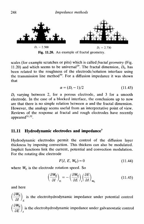
248 Impedance methods
D{ = 2.500 Df = 2.730
Fig. 11.20. An example of fractal geometry.
scales (for example scratches or pits) which is called fractal geometry (Fig.11.20) and which seems to be universal29. The fractal dimension, D f, hasbeen related to the roughness of the electrode/solution interface usingthe transmission line method30. For a diffusion impedance it was shownthat
a=(Df-l)/2 (11.43)
Df varying between 2, for a porous electrode, and 3 for a smoothelectrode. In the case of a blocked interface, the conclusions up to noware that there is no simple relation between a and the fractal dimension.However, the analogy seems useful from an interpretative point of view.Reviews of the response at fractal and rough electrodes have recentlyappeared31'32.
11.11 Hydrodynamic electrodes and impedance7
Hydrodynamic electrodes permit the control of the diffusion layerthickness by imposing convection. This thickess can also be modulated.Implicit functions link the current, potential and convection modulation.For the rotating disc electrode
F(I,E,WE) = 0 (11.44)
where WE is the electrode rotation speed. So
VOIW/XCJ/H, ( 1 L 4 5 )
and here
is the electrohydrodynamic impedance under potential control\ Э1
( ——) is the electrohydrodynamic impedance under galvanostatic control\ oE 11

11.11 Transforms and impedance 249
ЭЕ\— ) is the electrochemical impedance at fixed rotation speedol / wE
The last of these is the impedance which has been considered throughoutthis chapter. We now consider forced convection. For low frequencies thediffusion layer thickness due to the a.c. perturbation is similar to that ofthe d.c. diffusion layer: in these cases convection effects will be apparentin the impedance expressions. For the rotating disc electrode thesefrequencies are lower than 40 Hz33. For higher frequencies where the twodiffusion layers are of quite different thicknesses, the advantage ofhydrodynamic electrodes is that transport is well defined with time, asoccurs with linear sweep voltammetry.
Applications of double hydrodynamic electrodes are particularly inter-esting because the change of phase in the current measured at thedownstream electrode permits discrimination between the electron flowand the flux of electroactive species produced at the upstreamelectrode34.
Modulation of the convective flux, originally proposed byBruckenstein35, leads to the electrohydrodynamic impedance. It has beenused for determining kinetic parameters and diffusion parameters inNewtonian and Ostwaldian fluids, and in corrosion.
11.11 Transforms and impedance
The determination of the characteristics of an electrochemical system bya.c. techniques requires measuring the impedance at various frequencies,to give a frequency spectrum. Instead of applying each frequencysuccessively the application of all the frequencies simultaneously has beensuggested, using a transform to analyse the response36. This procedurecan be particularly advantageous at a dropping electrode, where it wouldpermit the recording of a full spectrum during the lifetime of one drop.Possible excitation signals vary from a group of sinusoidal signals to whitenoise. Comparisons have been made, but owing to the time necessary toobtain a reasonable signal/noise ratio in the response in the frequencydomain, it is not clear if this method is faster than the automaticsweeping of the frequency spectrum.
Whatever the excitation, the transformation of the response from thefrequency to the time domain (Fig. 11.21) is done with the inverseFourier transform, normally as the FFT (fast Fourier transform) algo-rithm, just as for spectra of electromagnetic radiation. Remembering thatthe Fourier transform is a special case of the Laplace transform with

250 Impedance methods
Frequency(a)
(b)Frequency
Fig. 11.21. The Fourier transform: the link between the time and frequencydomain, (a) A simple sinusoidal signal; (b) The first two components of a square
wave (Fig. Al.l).
s = i(o (Appendix 1) this type of method can be applied to any techniqueinvolving change in potential or current, given that any waveform can besynthesized by superposition of sinusoidal waves of variable frequencyand amplitude (Fourier synthesis). The response can then be analysed interms of the resultant impedances. Unfortunately, from an experimentalpoint of view it is not realistic to proceed in this way, but it is importantto attempt to unify the various methods at a theoretical level which are,effectively, probing different aspects of the same problem.

References 251
References
1. M. Sluyters-Rehbach and J. H. Sluyters, Electroanalytical chemistry, ed. A.J. Bard, Dekker, New York, Vol. 4, 1970, pp. 1-128.
2. R. D. Armstrong, M. F. Bell, and A. A. Metcalfe, Chem. Soc. Spec. Per.Reports, Electrochemistry, 1978, 6, 98-127.
3. W. I. Archer and R. D. Armstrong, Chem. Soc. Spec. Per. Reports,Electrochemistry, 1980, 7, 157-202.
4. I. Epelboin, Comprehensive treatise of electrochemistry, Plenum, New York,Vol. 4, 1981, ed. J. O'M. Bockris, B. E. Conway, E. Yeager, and R. E.White, Chapter 3.
5. D. D. Macdonald, Transient techniques in electrochemistry, Plenum, NewYork, 1977, Chapter 7.
6. D. D. Macdonald and M. С. Н. McKubre, Modern aspects ofelectrochemistry, Plenum, New York, Vol. 14, 1982, ed. J. O'M. Bockris, B.E. Conway, and R. E. White, pp. 61-150.
7. C. Gabrielli, The identification of electrochemical processes by frequencyresponse analysis, Solartron Instruments, UK, 1980.
8. M. Sluyters-Rehbach and J. H. Sluyters, Comprehensive treatise ofelectrochemistry, Plenum, New York, Vol. 9, 1984, ed. E. Yeager, J. O'M.Bockris, В. Е. Conway, and S. Sarangapani, pp. 177-292.
9. M. Sluyters-Rehbach and J. H. Sluyters, Comprehensive chemical kinetics,Elsevier, Amsterdam, Vol. 26, 1986, ed. С. Н. Bamford and R. G.Compton, Chapter 4.
10. J. R. Macdonald (ed.), Impedance spectroscopy, Wiley, New York, 1987.11. C. Gabrielli, Use and applications of electrochemical impedance spectroscopy,
Schlumberger Instruments, UK, 1990.12. C. Gabrielli (ed.), Proceedings of the first international symposium on
electrochemical impedance spectroscopy, Electrochim. Acta, 1990, 35, No. 10.13. Ref. 10, Chapter 3.14. P. Debye and H. Falkenhagen, Phys. Z., 1928, 29, 121 and 401.15. J. E. B. Randies, Disc. Faraday soc, 1947, 1, 11.16. Ref. 1, pp. 37-38.17. Ref. 1, pp. 38-41.18. J. R. Macdonald, J. Schoonman, and A. P. Lehnen, Solid state ionics, 1981,
5, 137.19. D. E. Smith, Electroanalytical chemistry, ed. A. J. Bard, Dekker, New York,
Vol. 1, 1966, pp. 1-155.20. B. Breyer and H. H. Bauer, A.c. polarography and tensammetry, Wiley,
New York 1963.21. D. E. Smith, Crit. Rev. Anal. Chem., 1971, 2, 247.22. H. P. Argawal, Modern aspects of electrochemistry, Plenum, New York, Vol.
20, 1989, ed. J. O'M. Bockris, R. E. White, and В. Е. Conway, pp. 177-263.23. Ref. 9, pp. 252-3.24. J. Koryta and P. Vanysek, Advances in electrochemistry and electrochemical
engineering, ed. H. Gerischer and С W. Tobias, Wiley, New York, Vol. 12,1981, pp. 113-176.
25. P. Vanysek, Electrochemistry on liquid I liquid interfaces, Lecture Notes inChemistry Vol. 39, Springer-Verlag, Berlin, 1985.
252 Impedance methods
26. e.g. R. P. Buck, /. Electroanal Chem., 1986, 210, 1.27. R. de Levie, Electrochim. Acta, 1964, 9, 1231.28. R. de Levie, Advances in electrochemistry and electrochemical engineering,
ed. P. Delahay and C. W. Tobias, Wiley, New York, Vol. 6, 1967, pp.329-397.
29. В. В. Mandelbrot, The fractal geometry of nature, Freeman, San Francisco,1982.
30. A. Le Mehaute and G. Crepy, Solid state ionics, 1983, 9/10, 17; S. Liu, Phys.Rev. Lett., 1985, 55, 529; L. Nyikos and T. Pajkossy, Electrochim. Acta,1985, 30, 1533, 1986, 31, 1347; M. Keddam and H. Takenouti, Electrochim.Acta, 1988, 33, 445; T. Pajkossy and L. Nyikos, Electrochim. Acta, 1989, 34,171, 181.
31. R. de Levie, J. Electroanal. Chem., 1990, 281, 1.32. T. Pajkossy,/. Electroanal. Chem., 1991, 300, 1.33. K. Tokuda and H. Matsuda, /. Electroanal. Chem., 1977, 82, 157; 1978, 90,
149; 1979, 95, 147.34. W. J. Albery et al., /. Chem. Soc. Faraday Trans. 1, 1971, 67, 2414; 1978,
74, 1007; 1979, 75, 1623.35. S. Bruckenstein, M. I. Bellavance, and B. Miller,/. Electrochem. Soc, 1973,
120, 1351.36. D. E. Smith, Anal. Chem., 1976, 48, 221A and 517A.
12
NON-ELECTROCHEMICALPROBES OF ELECTRODES AND
ELECTRODE PROCESSES
12.1 Introduction12.2 In situ spectroscopic techniques12.3 Ex situ spectroscopic techniques12.4 In situ microscopic techniques12.5 Ex situ microscopic techniques: electron microscopy12.6 Other in situ techniques12.7 Photoelectrochemistry12.8 Electrochemiluminescence
12.1 Introduction
There is a great variety of electrochemical experiments that can be doneto elucidate electrode processes, as has become clear. However, theinformation obtained is often complex and interpretation may beambiguous. Aditionally, there is no direct insight into what is happeningat a microscopic or molecular level on the electrode surface. For thesereasons, one has recourse to spectroscopic and microscopic techniques,many of which are used in surface science. Some of these can beemployed in conjunction with the electrochemical experiment in real timeas in situ probes. They are not electrochemical, so they give a differenttype of information that complements the electrochemical information.This field is expanding so rapidly that the survey in this chapter cannot beexhaustive in its description of techniques: it would become dispropor-tionately long if this were attempted. References 1-5 give a good andmore complete survey of the immense progress achieved in recent years.
Spectroscopic techniques can be carried out in situ (low-energy photon,etc.) and ex situ or in vacuo (high-energy photon and electron tech-niques). Ex situ microscopic techniques have been employed for manyyears to examine surfaces, and are now widely used tools. However, insitu microscopic techniques with resolution approaching the atomic scale
254 Non-electrochemical probes of electrodes and electrode processes
are very recent: scanning tunnelling microscopy and atomic forcemicroscopy are invaluable in imaging the surface structure. A particularlyinteresting variant of using in situ probes with direct electrochemicalcontrol is scanning electrochemical microscopy.
Electromagnetic radiation, besides being a probe of surface structure,can excite electrons in the species in solution (especially in organiccompounds) or in the electrode itself (especially in semiconductorelectrodes). This photon excitation can lead to electron transfer betweenelectrode and solution. The study of these phenomena isphotoelectrochemistry and can be very important in conversion of solarenergy into electricity in order to convert substances (photoelectrolysis).
A slightly different application is where species produced electrochem-ically lead to photon emission in the visible spectrum, via the formationof organic radicals by homogeneous reaction from electrochemicallygenerated precursors. The electrode controls the quantity of precursor,enabling quantitative parameters of the homogeneous reaction to beelucidated. This is known as electrogenerated chemiluminescence orelectrochemiluminescence (ECL).
12.2 In situ spectroscopic techniques
In these techniques a beam of photons is directed to the electrode suchthat it is transmitted or reflected. The majority of the techniques arereflective, since transmission is limited to transparent or semi-transparentelectrode materials.
Transmission**1
Since the electrode has to be transparent, the electrode material islimited to thin films of metals or semiconductors deposited on atransparent substrate (for example a thin film of tin(IV) oxide orplatinum on quartz) or to very fine grids of the electrode material, asshown in Fig. 9.13. The first of these two options is preferable, since thetransmission coefficient is uniform and the electrode can be truly planar,and as such can be used as a hydrodynamic electrode, for example. Thechange in absorbance with time due to one of the reagents or products ofthe electrode reaction characterizes the mechanism.
This type of cell and electrode can be used to photochemically activatean electrochemical system, the electrode reaction being used to detect orelectrolyse the species produced (e.g. photoelectrolysis of water, Section12.5).

12.2 In situ spectroscopic techniques 255
E
Direction ofpropagation
Fig. 12.1. Propagation of electromagnetic radiation: the magnetic, H, andelectric, E, vectors. A beam of ordinary light contains the vectors in randomized
directions. \H\ = \E\.
Reflectancef electroreflectance, and ellipsometry8
These techniques depend on the fact that electromagnetic radiationcomprises two perpendicular vectors mutually perpendicular to thedirection of photon transmission—the magnetic vector H and the electricvector E, Fig. 12.1. In normal non-polarized radiation, the directions ofthese vectors are not aligned, their sum being zero. In linearly polarizedradiation the vectors are all aligned in the same direction; in partiallypolarized radiation the alignment is partial.
Reflection at a surface of a beam of linearly polarized photons altersthe direction and amplitude of the electric and magnetic vectors. It isthese differences between incident and reflected beams that give informa-tion concerning surface structure, as they depend on the interaction ofthe beam with the electronic distribution and with the associated localelectric and magnetic fields on the surface. The phase and amplitudechange for the vectors is different for the component parallel to the planeof incidence than for the component perpendicular to it. The result is avector that follows a spiral during its propagation, and is referred to aselliptically polarized, Fig. 12.2. A deeper treatment of these opticalproperties can be found in Ref. 9. Such measurements are referred to asspecular reflectance.
In these experiments cells are designed that have a thin electrolytelayer over the working electrode covered by a window that is transparentto the incident radiation. Refraction of the beam by the window has to betaken into account in the calculations.
The reflectance, R, is the ratio between the intensities of the reflectedand incident beams. Experimentally only the intensity of the reflectedbeam, /R, is measured and changes in /R caused by:
• Modulation of photon intensity (reflectance): The equation for this is
^ = ̂ (12.1)R R У '

256 Non-electrochemical probes of electrodes and electrode processes
(a)
(b)
- • EP
Plane of incidence
Plane of incidence
(c)
Fig. 12.2 Conversion of linearly polarized electromagnetic radiation into ellipti-cally polarized radiation by reflection. Consideration of the electric vector,(a) Decomposition of E in components perpendicular and parallel to the planeof incidence; (b) Example after reflection: the vector moves anticlockwise;
(c) Representation in three dimensions.

«ч I ^
—«I О
12.2 In situ spectroscopic techniques
10
Parallel component
Perpendicular component
257
N
2 6
2.5 3.0 3.5 4.0
/zv/eV
4.5 5.0
Fig. 12.3. Typical electroreflectance results: Ag in 1.0MNaClO4; £ ldc=~0.5V
vs. SCE (from Ref. 10 with permission).
• Modulation of potential {electroreflectance)1011: The equation is
1 AR A/R
R AE /R AE (12.2)
Potential modulation causes alterations in the electrode surface that,measured as a function of incident light frequency, permits conclusions tobe taken in relation to electronic structure, adsorption, film formation,etc. The type of curve obtained is shown in Fig. 12.3.
Whereas electroreflectance is conventionally used in the UV/visibleregion, in the 1980s Bewick et al.12~u developed the technique in the IRregion. Since IR radiation interacts with the vibrations of chemicalbonds, important information regarding bonds with adsorbed species hasbeen obtained15, especially useful for research into electrocatalysts. Newdevelopments in signal processing, such as the Fourier transform (FT-IR), have veen very valuable.
There are three types of infrared experiment that can be conducted:
1. Electrochemically modulated infrared spectroscopy (EMIRS), involv-ing potential modulation. Modulation frequencies from 1-100 Hz areemployed and phase-sensitive detection used to calculate AR.
2. Subtractively normalized interfacial Fourier transform infrared spec-troscopy (SNIFTRS). Using an FTIR spectrometer, multifrequency

258 Non-electrochemical probes of electrodes and electrode processes
determinations are possible, but instrumental limitations with respect tospeed of data collection put too low an upper limit on the potentialmodulation frequency. Spectra are therefore recorded at two differentpotentials and subtracted.
3. Infrared reflection-absorption spectroscopy (IRRAS) is done at fixedpotential. Electric vectors in the incident beam parallel to the metalsurface do not interact with adsorbed molecules, whereas those perpen-dicular to the surface do. The light beam is switched successively betweenthe two directions and the results subtracted.
We can measure the phase change of the intensities of the perpendicu-lar and parallel components of the electric vector after reflection: this isellipsometry916r~18. In the most accurate instruments the reflected beam isadjusted successively by a group of polarizers until the beam is totallyextinguished. The results are conveniently represented in a plot ofparallel vs. perpendicular intensity in relation to the incident beam.Applications are especially to the study of film growth on electrodesurfaces (Fig. 12.4).
30Internal reflection
An electrode (or any other transparent material such as an optical fibre),reflects radiation internally if the angle of incidence is larger than thecritical angle. Prisms are used to let the radiation enter and leave (Fig.
-60
-61
-62
-63
35
35.0
34.7
200 400 200 400t/s r/s
Fig. 12.4. Ellipsometry trace for polymerization of thionine on platinum, showingeffect of coating between t = 50 s and t = 450 s, using light of Я = 450 nm (solution
40 /iM thionine in 0.05 м H2SO4) (from Ref. 19 with permission).
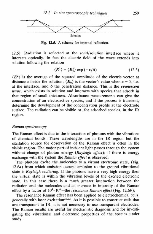
12.2 In situ spectroscopic techniques 259
Solution
Fig. 12.5. A scheme for internal reflection.
12.5). Radiation is reflected at the solid/solution interface where itinteracts optically. In fact the electric field of the wave extends intosolution following the relation
(E2) = (E2)cxp(-x/S) (12.3)
(E2) is the average of the squared amplitude of the electric vector atdistance x inside the solution, (Eo) is the vector's value when x = 0, i.e.at the interface, and 6 the penetration distance. This is the evanescentwave, which exists in solution and interacts with species that adsorb inthat region of small thickness. Absorbance measurements can give theconcentration of an electroactive species, and if the process is transient,determine the development of the concentration profile at the electrodesurface. The radiation can be visible or, for adsorbed species, in the IRregion.
Raman spectroscopy
The Raman effect is due to the interaction of photons with the vibrationsof chemical bonds. These wavelengths are in the IR region but theexcitation source for observation of the Raman effect is often in thevisible region. The major part of incident light passes through the systemwithout change of photon energy (Rayleigh effect); if there is energyexchange with the system the Raman effect is observed.
The photons excite the molecules to a virtual electronic state, (Fig.12.6я) from which emission occurs; emission to the ground vibrationalstate is Rayleigh scattering. If the photons have a very high energy thenthe virtual state is within the vibration levels of the excited electronicstate. In this case there is a much greater interaction between theradiation and the molecules and an increase in intensity of the Ramaneffect by a factor of 104-106—the resonance Raman effect (Fig. 12.6ft).
The resonance Raman effect has been applied to electrochemical cells,generally with laser excitation21'22. As it is possible to construct cells thatare transparent to IR, it is not necessary to use transparent electrodes.The Raman results are useful for mechanistic diagnosis and for investi-gating the vibrational and electronic properties of the species understudy.
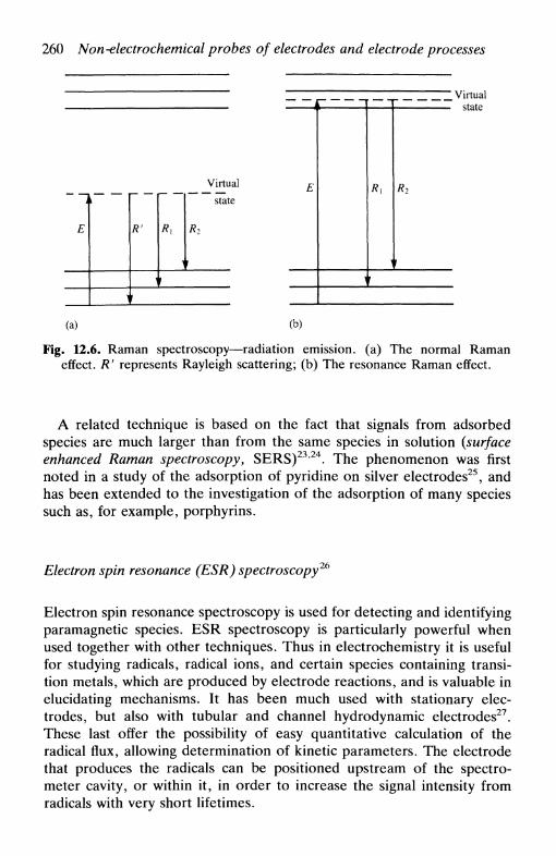
260 Non-electrochemical probes of electrodes and electrode processes
R'
Virtual
stateE R2
Virtualstate
(a) (b)
Fig. 12.6. Raman spectroscopy—radiation emission, (a) The normal Ramaneffect. R' represents Rayleigh scattering; (b) The resonance Raman effect.
A related technique is based on the fact that signals from adsorbedspecies are much larger than from the same species in solution (surfaceenhanced Raman spectroscopy, SERS)23'24. The phenomenon was firstnoted in a study of the adsorption of pyridine on silver electrodes25, andhas been extended to the investigation of the adsorption of many speciessuch as, for example, porphyrins.
Electron spin resonance (ESR) spectroscopy 26
Electron spin resonance spectroscopy is used for detecting and identifyingparamagnetic species. ESR spectroscopy is particularly powerful whenused together with other techniques. Thus in electrochemistry it is usefulfor studying radicals, radical ions, and certain species containing transi-tion metals, which are produced by electrode reactions, and is valuable inelucidating mechanisms. It has been much used with stationary elec-trodes, but also with tubular and channel hydrodynamic electrodes27.These last offer the possibility of easy quantitative calculation of theradical flux, allowing determination of kinetic parameters. The electrodethat produces the radicals can be positioned upstream of the spectro-meter cavity, or within it, in order to increase the signal intensity fromradicals with very short lifetimes.

12.2 In situ spectroscopic techniques 261
X-ray absorption spectroscopy2^30
The absorption coefficient, \i> of atoms for X-rays with increasing X-rayenergy (frequency) decreases until threshold values corresponding tophotoionization of core electrons are reached. There is then a rapidincrease in \i, called an absorption edge. Atoms give rise to severalabsorption edges due to the different core electron shells: К (one edge),L (three edges), and M (five edges). For an isolated atom, after anabsorption edge is reached there is a steady decrease in \i until the nextedge. However, for atoms surrounded by other atoms there is interactionof the emitted photoelectron with these leading to backscattering (Fig.12.7a). This in turn leads to oscillations in the absorption coefficient (Fig.12.76). These oscillations are a probe of short-range atomic order.
Beyond the absorption edge the variation in absorption coefficient canbe divided into two regions. If the photoelectron energy is sufficientlyhigh (40-1000 eV above the absorption edge) then we can approximatethat the frequency of oscillation of the absorption coefficient depends onthe distance between the central absorber and its neighbour, whereas thesignal amplitude depends on this and the identity and concentration ofneighbours. This is the region of extended X-ray absorption fine structure(EXAFS). Information on bond distances, coordination numbers, andatom identification can be obtained.
For lower photoelectron energies, interaction with the electronicenvironment of the absorber atom is much greater and each electroncannot be considered singly. The fine structure is richer and givesinformation such as spin state and local symmetry, but theoretical
X-ray
(a)
А В С D A. Pre-edge\ , / / B. Edge
C. Near edgeD. EXAFS
(b) Energy
Fig. 12.7. X-ray absorption spectroscopy. (a) Interaction of a photoelectronproduced by X-ray absorption with neighbouring atoms, showing backscattering;
(b) Typical absorption spectrum, showing the various regions.

262 Non-electrochemical probes of electrodes and electrode processes
modelling is more difficult. This is referred to as the X-ray absorptionnear edge structure (XANES) region.
For EXAFS and particularly for XANES, data analysis is complex.The oscillation frequency/bond distance dependence means that exten-sive use is made of Fourier transform analysis. Most applications to datehave been in the EXAFS region. In order to acquire sufficiently strongsignals in a reasonable time, use has to be made of high-intensity photonfluxes, which are available at synchrotron facilities. These provide abroad-band tuneable source of high-intensity radiation, but the reducednumber of facilities limits widespread dissemination of the technique.Reflection (fluorescent detection) mode is usually preferred to transmis-sion. Experiments can be conducted in any phase, and the probing ofelectrode surfaces in situ is an important application.
Types of electrode/solution interface studied include oxide films onmetals, monolayer deposits obtained by underpotential deposition, ad-sorption, and spectroelectrochemistry in thin-layer cells.
A useful illustrative example is shown in Fig. 12.8 of iron passivated bychromate and nitrite. Fourier transform of the EXAFS data to givedistance-dependent signals shows the similarities and differences betweenthe two passivation methods.
Fe 3O 4
U
(a)
Chromate treated
Energy
N i t r i t e t r e a t e d
Nitrite passivatedChromate passivated
0.1 0.2 0.3 0.4 0.5 0.6
r/nm
(c)
к. i t i
(b)Energy
Fig. 12.8. Passivation of iron by chromate and nitrite. Raw X-ray absorption dataof (a) Fe and Fe3O4 and (b) Fe films after treatment; (c) EXAFS data after
Fourier transform (adapted from Ref. 31 with permission).
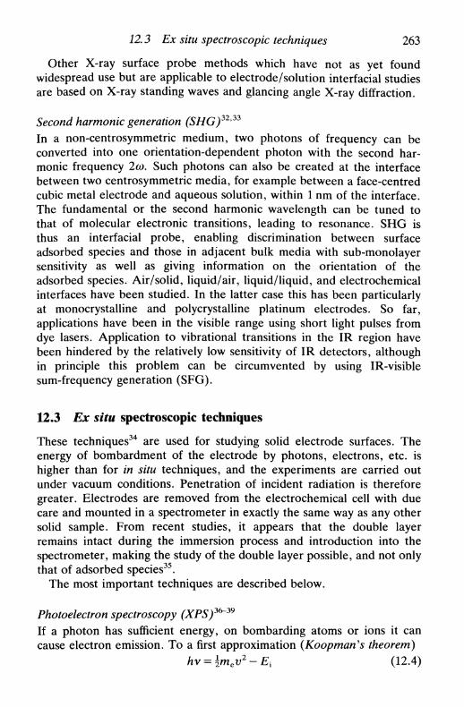
12.3 Ex situ spectroscopic techniques 263
Other X-ray surface probe methods which have not as yet foundwidespread use but are applicable to electrode/solution interfacial studiesare based on X-ray standing waves and glancing angle X-ray diffraction.
Second harmonic generation (SHG)32'33
In a non-centrosymmetric medium, two photons of frequency can beconverted into one orientation-dependent photon with the second har-monic frequency 2co. Such photons can also be created at the interfacebetween two centrosymmetric media, for example between a face-centredcubic metal electrode and aqueous solution, within 1 nm of the interface.The fundamental or the second harmonic wavelength can be tuned tothat of molecular electronic transitions, leading to resonance. SHG isthus an interfacial probe, enabling discrimination between surfaceadsorbed species and those in adjacent bulk media with sub-monolayersensitivity as well as giving information on the orientation of theadsorbed species. Air/solid, liquid/air, liquid/liquid, and electrochemicalinterfaces have been studied. In the latter case this has been particularlyat monocrystalline and polycrystalline platinum electrodes. So far,applications have been in the visible range using short light pulses fromdye lasers. Application to vibrational transitions in the IR region havebeen hindered by the relatively low sensitivity of IR detectors, althoughin principle this problem can be circumvented by using IR-visiblesum-frequency generation (SFG).
12.3 Ex situ spectroscopic techniques
These techniques34 are used for studying solid electrode surfaces. Theenergy of bombardment of the electrode by photons, electrons, etc. ishigher than for in situ techniques, and the experiments are carried outunder vacuum conditions. Penetration of incident radiation is thereforegreater. Electrodes are removed from the electrochemical cell with duecare and mounted in a spectrometer in exactly the same way as any othersolid sample. From recent studies, it appears that the double layerremains intact during the immersion process and introduction into thespectrometer, making the study of the double layer possible, and not onlythat of adsorbed species35.
The most important techniques are described below.
Photoelectron spectroscopy (XPS)3&~39
If a photon has sufficient energy, on bombarding atoms or ions it cancause electron emission. To a first approximation (Koopman's theorem)
hv = \mcv2 - Ex (12.4)
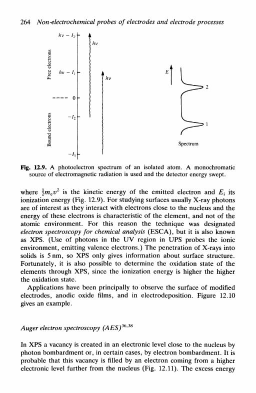
264 Non-electrochemical probes of electrodes and electrode processes
hv - U
hv - L
hv
hv
Spectrum
Fig. 12.9. A photoelectron spectrum of an isolated atom. A monochromaticsource of electromagnetic radiation is used and the detector energy swept.
where \mev2 is the kinetic energy of the emitted electron and Ex its
ionization energy (Fig. 12.9). For studying surfaces usually X-ray photonsare of interest as they interact with electrons close to the nucleus and theenergy of these electrons is characteristic of the element, and not of theatomic environment. For this reason the technique was designatedelectron spectroscopy for chemical analysis (ESCA), but it is also knownas XPS. (Use of photons in the UV region in UPS probes the ionicenvironment, emitting valence electrons.) The penetration of X-rays intosolids is 5nm, so XPS only gives information about surface structure.Fortunately, it is also possible to determine the oxidation state of theelements through XPS, since the ionization energy is higher the higherthe oxidation state.
Applications have been principally to observe the surface of modifiedelectrodes, anodic oxide films, and in electrodeposition. Figure 12.10gives an example.
Auger electron spectroscopy (AES)36'38
In XPS a vacancy is created in an electronic level close to the nucleus byphoton bombardment or, in certain cases, by electron bombardment. It isprobable that this vacancy is filled by an electron coming from a higherelectronic level further from the nucleus (Fig. 12.11). The excess energy

12.3 Ex situ spectroscopic techniques
I i . , , r-
265
TiC0.5 M H2SO4
С (Is)
1.25 Vsce
Carboxylic
- Carbide1—Graphite
290 280Binding energy
Fig. 12.10. C(l s) photoelectron spectrum of a reactively sputtered TiC electrodeon a glass substrate, (a) As prepared; (b) After 5min at +1.25 V vs. SCE
(passive region) in 0.5 м H2SO4 (from Ref. 39 with permission).
is then dissipated by
• photon emission in the X-ray region {fluorescence) and/or
• emission of a secondary electron {Auger electron).
As in XPS, Auger electrons are characteristic of the emitting species.In AES applied to electrochemical studies, normally electron bom-
bardment is employed as it furnishes higher intensities of incidentradiation, increasing the number of Auger electrons and facilitating their
Vacuum
(2P./2)
и(2S,/2)
К
(a) (b) (с)
Fig. 12.11. Diagram of Auger electron production, (a) Emission of primaryelectron; (b) Decay of an electron from Lr—>/C; (c) Emission of Auger electron.
Sometimes photons are emitted instead of electrons (X-ray fluorescence).

266 Non-electrochemical probes of electrodes and electrode processes
detection. It should be noted, however, that electrons have a moredestructive effect than photons on surface structure. It is not a techniquefor studying the double layer.
AES is much used to make depth profiles of solid structure. Theprocedure consists in recording an Auger spectrum, bombarding thesurface with high-energy ions (e.g. Ar+) to remove a few atomic layers,taking another Auger spectrum, etc. This scheme is particularly useful inthe investigation of porous and non-porous films formed anodically onmetals such as nickel or aluminium.
Electron energy loss spectroscopy (EELS)
Electrons that bombard a surface are usually inelastically scattered. Theenergy can be transferred, in the same way as for photon bombardment,to cause secondary electron emission (Auger electrons) or to causephoton emission (X-ray fluorescence), which gives information onelemental composition as described above. Electron energy loss spectro-scopy (EELS) consists of detecting the reflected or transmitted incidentelectron beam, which gives information on energy loss and momentumtransfer, and can be related to elemental composition. Its particular use isin detecting light elements undetectable by X-ray fluorescence due totheir low X-ray cross-sections. Thus the two techniques arecomplementary.
EELs is usually employed at high electron kinetic energies (up to105 eV) with thin samples in the transmission mode. For the electrochem-ist, low kinetic energies (<1 eV) in the reflection mode are of greatestinterest as they can be used to study the vibrational spectra ofadsorbates40.
Electrochemical mass spectrometry (ECMS)41 and secondary ion massspectrometry (SIMS)42*43
Mass spectrometry (MS) is a gas-phase technique in which atoms ormolecules present in the spectrometer chamber are ionized, and follow atrajectory through applied electric and magnetic fields which separatesthem according to their mass/charge ratio. A number of procedures havebeen developed to enable MS to be used for analysing species in theliquid and solid phases, and are based on species extraction into the gasphase. These include plasma desorption, ion bombardment, thermosprayand electrospray ionization, and laser desorption. In this section weconcentrate on techniques useful to electrochemistry.
To complement electrochemical studies two types of interface between
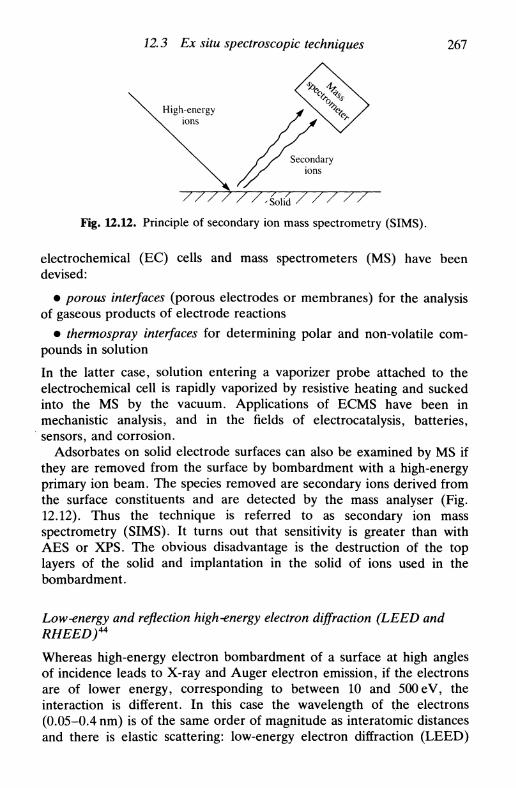
12.3 Ex situ spectroscopic techniques 267
-Solid/ / / / /
Fig. 12.12. Principle of secondary ion mass spectrometry (SIMS).
electrochemical (EC) cells and mass spectrometers (MS) have beendevised:
• porous interfaces (porous electrodes or membranes) for the analysisof gaseous products of electrode reactions
• thermospray interfaces for determining polar and non-volatile com-pounds in solution
In the latter case, solution entering a vaporizer probe attached to theelectrochemical cell is rapidly vaporized by resistive heating and suckedinto the MS by the vacuum. Applications of ECMS have been inmechanistic analysis, and in the fields of electrocatalysis, batteries,sensors, and corrosion.
Adsorbates on solid electrode surfaces can also be examined by MS ifthey are removed from the surface by bombardment with a high-energyprimary ion beam. The species removed are secondary ions derived fromthe surface constituents and are detected by the mass analyser (Fig.12.12). Thus the technique is referred to as secondary ion massspectrometry (SIMS). It turns out that sensitivity is greater than withAES or XPS. The obvious disadvantage is the destruction of the toplayers of the solid and implantation in the solid of ions used in thebombardment.
Low-energy and reflection high-energy electron diffraction (LEED andRHEED)44
Whereas high-energy electron bombardment of a surface at high anglesof incidence leads to X-ray and Auger electron emission, if the electronsare of lower energy, corresponding to between 10 and 500 eV, theinteraction is different. In this case the wavelength of the electrons(0.05-0.4 nm) is of the same order of magnitude as interatomic distancesand there is elastic scattering: low-energy electron diffraction (LEED)
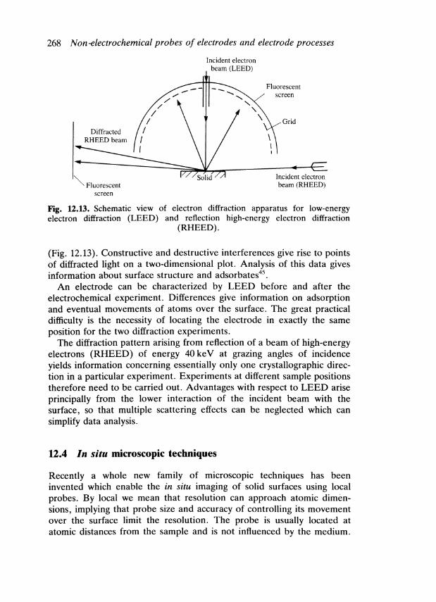
268 N on-electrochemical probes of electrodes and electrode processes
Incident electronbeam (LEED)
Fluorescentscreen
Grid
Incident electronbeam (RHEED)
Fig. 12.13. Schematic view of electron diffraction apparatus for low-energyelectron diffraction (LEED) and reflection high-energy electron diffraction
(RHEED).
(Fig. 12.13). Constructive and destructive interferences give rise to pointsof diffracted light on a two-dimensional plot. Analysis of this data givesinformation about surface structure and adsorbates45.
An electrode can be characterized by LEED before and after theelectrochemical experiment. Differences give information on adsorptionand eventual movements of atoms over the surface. The great practicaldifficulty is the necessity of locating the electrode in exactly the sameposition for the two diffraction experiments.
The diffraction pattern arising from reflection of a beam of high-energyelectrons (RHEED) of energy 40keV at grazing angles of incidenceyields information concerning essentially only one crystallographic direc-tion in a particular experiment. Experiments at different sample positionstherefore need to be carried out. Advantages with respect to LEED ariseprincipally from the lower interaction of the incident beam with thesurface, so that multiple scattering effects can be neglected which cansimplify data analysis.
12.4 In situ microscopic techniques
Recently a whole new family of microscopic techniques has beeninvented which enable the in situ imaging of solid surfaces using localprobes. By local we mean that resolution can approach atomic dimen-sions, implying that probe size and accuracy of controlling its movementover the surface limit the resolution. The probe is usually located atatomic distances from the sample and is not influenced by the medium.

12.4 In situ microscopic techniques 269
Fig. 12.14. Scheme of operation of piezoelectric drives for scanning local probemicroscopy.
Not only can experiments be performed in situ, but also the timeevolution of surface topography can be monitored. Accurate scanning ofthe surface is accomplished by means of piezoelectric drives—the size ofa piezoelectric crystal changes linearly with the applied potentialdifference. Drives are applied in x> у and z directions as shownschematically in Fig. 12.14. Generally, successive scans are applied in thex direction incrementing у between scans, so that a series of x-z profilesare recorded. These can be converted by computer software intogray-scale or coloured images if desired.
From a practical point of view, adequate vibration-free experimentalconditions must be assured given the resolution in question. Vibration-free tables are available, but in many cases suspending a concrete blockon which the working part of the instrument is located from the ceilingwith elastic cords is perfectly adequate.
The most important of these techniques is scanning tunnelling micros-copy (STM), the invention of Binning and Rohrer45, for which they wonthe Nobel Prize in Physics in 1986, followed by atomic force microscopy(AFM)47, and which are described in this section, indicating theirapplication to the study of electrode processes.
Other local probe techniques to be discussed, of an electrochemicalnature, which rely on much of the same instrumental technology, arescanning electrochemical microscopy (SECM) and scanning ion conduc-tance microscopy (SICM).
Scanning tunnelling microscopy46'*8'49
This local probe technique relies on a tunnelling current being passedbetween tip and substrate. For electron tunnelling to be possible thedistance between tip and substrate must be less than about 2 nm, and the

270 Non-electrochemical probes of electrodes and electrode processes
magnitude of the current increases markedly as the tip is brought closer.The tip itself must therefore also be of atomic dimensions. Materials usedfor the tips, which are usually etched, are tungsten andplatinum/rhodium or platinum/iridium alloys. The phenomenon occursessentially because of overlap between the electron clouds of substrateand tip. Strictly speaking, therefore, it is the electron density of thesubstrate that is mapped by scanning and not the atomic topography.
In general, a constant tunnelling current is imposed and the height ofthe tip adjusted accordingly, which leads to the topographic image. Thetip/substrate voltage bias can be altered and topography registered foreach bias. Since it is electron density that is recorded, changes withvarying positive or negative voltage bias can give spectroscopic informa-tion. This is known as current imaging tunnelling spectroscopy (CITS)50,although it has, as yet, been little explored.
Much of the initial work was done in vacuum and with semiconductorand metal monocrystals. These experiments showed evidence of surfacereconstruction, and the presence of substances that adsorb on thesesubstrates.
Studies can also be carried out in electrolyte solution, with thesubstrate acting as the working electrode. Thus real-time records can bemade of nucleation and new phase formation, for example in under-potential deposition, surface corrosion, and adsorption in a generalsense. The only limitation is that the substrate must be a conductor or agood semiconductor, such as silicon or germanium. Two examples ofscanning tunnelling micrographs are shown in Fig. 12.15.
Atomic force microscopy (AFM)47y53
The principal limitation of STM is that it cannot be used with insulatingsubstrates. However, at the sort of distances where tunnelling currentsoccur, there is an attractive or repulsive force between atoms in the tipand the substrate, which is independent of the conducting or non-conducting nature of the substrate. In order to measure this, the tip ismounted on the end of a soft cantilever spring, the deflection of which ismonitored optically by interferometry or beam deflection. These can-tilever springs are microfabricated photolithographically from silicon,silica, or silicon nitride and have lateral dimensions of around 100 дотand thickness of 1 дот, to which tiny diamond tips are attached.
Resolution is generally not quite so high as with STM. However,applications to some forms of polymerization, protein adsorption oninsulating surfaces, and corrosion of anodic oxide films are made possibleby this arrangement.

12.4 In situ microscopic techniques 271
Fig. 12.15. Examples of scanning tunnelling micrographs, (a) Copper electrode-posited from Cu(NO3)2 solution on highly ordered pyrrolytic graphite and imagedat -0.5 V vs. Ag | AgCl (tip bias potential +0.6 V) (from Ref. 51 withpermission); (b) Electropolymerized polypyrrole with poly(4-styrenesulphonate)
anion on graphite substrate (from Ref. 52 with permission).

272 Non-electrochemical probes of electrodes and electrode processes
Scanning electrochemical microscopy (SECM)54
Scanning electrochemical microscopy seeks to overcome the lack ofsensitivity and selectivity of the probe tip in STM and AFM to thesubstrate identity and chemical composition. It does this by using both tipand substrate as independent working electrodes in an electrochemicalcell, which therefore also includes auxiliary and reference electrodes. Thetip is a metal microelectrode with only the tip active (usually a metal wirein a glass sheath). At large distances from the substrate, in an electrolytesolution containing an electroactive species the mass-transport-limitedcurrent is therefore
I = 4nFaDcx (12.5)
as discussed in Section 5.5. As the tip is brought close to the substratemodifications in the current appear, as shown in Fig. 12.16. If thesubstrate is an insulator then diffusion of electroactive species from bulksolution is hindered and the current falls. If it is a conductor and held at apotential such that the electrode reaction occurring at the tip is reversed,then the current is enhanced—this may be due to the 'natural' potentialof the substrate arising from open circuit charge transfer processes orthrough applied potential. The response is obviously distance dependent.Besides topographical imaging using constant current mode, chemicaland electrochemical information can be obtained depending on electro-lyte conditions, and potentials applied to tip and substrate.
There are two types of application of this microscopic technique:
• To monitor substances and electrode surfaces, from thin films tobiological or polymer.
• To fabricate structures by electrochemical etching of metallic andsemiconductor electrodes with high precision and accuracy.
/ / / / / /' / Insulating
/ substrate/
/ / /Conducting/
substrate
Fig. 12.16. Schematic effect of substrate type on microelectrode tip response:(a) insulating—current reduction; (b) conducting—current enhancement by
feedback.

12.5 Ex situ microscopic techniques: electron microscopy 273
The resolution of the technique is limited by the size of the micro-electrode tip, at present 200 nm. In the future, reduction of tip size totens of nanometres by use of novel microelectrode fabrication proceduresshould increase the applicability of SECM.
Scanning ion conductance microscopy (SICM)55
This technique is also done in electrolyte solution, but shows someimportant differences from the other in situ microscopic techniques. Thetip is a tiny glass micropipette contained within which is a smallelectrode, whose function is to measure ion currents. A potentialdifference is applied between tip and substrate. The current which isregistered diminishes as the tip approaches the substrate surface,disappearing altogether when they contact since the micropipette openingis blocked. Thus surface topography under constant current mode can beregistered. However, the most exciting potential application is to detection channels in biomembranes, and determine what stimuli cause them toopen and close, particularly useful if the technique can be madeion-specific. At present, resolution is about 200 nm.
12.5 Ex situ microscopic techniques: electron microscopy
Electron microscopy56, most commonly employed as scanning electronmicroscopy (SEM), is now a widely used tool in examining themorphology of surfaces under vacuum conditions, and so in an electro-chemical context electrode surfaces and corroded surfaces. Instrumentsalso permit chemical microanalysis to be carried out.
One of the reasons as to why we should use electron microscopy ratherthan optical microscopy to obtain topographical images is shown in Fig.12.17: the resolution obtainable can reach almost atomic dimensions. The
SEM
HREM Optical microscopy
ТЕМ
0.1 nm 1.0 nm 10 nm 100 nm 1 \xm 10 ^m 100 \лт lmm
Resolution
Fig. 12.17. Usual working ranges of various electron microscopy techniques:SEM, scanning electron microscopy; ТЕМ, transmission electron microscopy;
HREM, high-resolution electron microscopy.
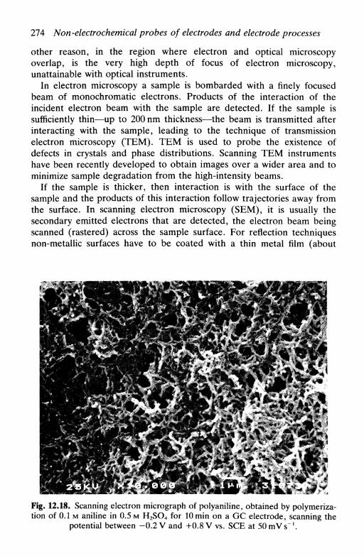
274 Non-electrochemical probes of electrodes and electrode processes
other reason, in the region where electron and optical microscopyoverlap, is the very high depth of focus of electron microscopy,unattainable with optical instruments.
In electron microscopy a sample is bombarded with a finely focusedbeam of monochromatic electrons. Products of the interaction of theincident electron beam with the sample are detected. If the sample issufficiently thin—up to 200 nm thickness—the beam is transmitted afterinteracting with the sample, leading to the technique of transmissionelectron microscopy (ТЕМ). ТЕМ is used to probe the existence ofdefects in crystals and phase distributions. Scanning ТЕМ instrumentshave been recently developed to obtain images over a wider area and tominimize sample degradation from the high-intensity beams.
If the sample is thicker, then interaction is with the surface of thesample and the products of this interaction follow trajectories away fromthe surface. In scanning electron microscopy (SEM), it is usually thesecondary emitted electrons that are detected, the electron beam beingscanned (rastered) across the sample surface. For reflection techniquesnon-metallic surfaces have to be coated with a thin metal film (about
Fig. 12.18. Scanning electron micrograph of polyaniline, obtained by polymeriza-tion of 0.1 м aniline in 0.5 м H2SO4 for 10 min on a GC electrode, scanning the
potential between -0.2 V and +0.8 V vs. SCE at 1

12.5 Ex situ microscopic techniques: electron microscopy 275
10 nm), for example by sputtering with gold, to prevent build-up ofcharge on the surface of the sample. An example of a scanning electronmicrograph is shown in Fig. 12.18.
From the discussion of ex situ spectroscopic techniques earlier in thechapter it is clear that other products of the interaction between incidentbeam and the surface can be detected. One of these is backscatteredelectrons (BSE) which give an image in which heavy elements lead tohigh backscattering (white areas) and light elements lead to lowbackscattering (black areas). Thus a very qualitative form of elementalanalysis can be performed by BSE detection.
Electron microprobes permit chemical microanalysis as well as SEMand BSE detection, often referred to as analytical electron microscopy(AEM), or electron probe microanalysis (EPMA)56'57. This is becauseanother product of the surface interaction with an incident electron beamis X-ray photons which have wavelengths and energies dependent onelement identity and on the electron shell causing the emission. Analysisof these photons can give a local chemical analysis of the surface.Resolution of 1 //m is attainable. Two types of X-ray spectrometer can beemployed:
• Wavelength dispersive spectrometer (WDS) in which the wavelengthis scanned, and the wavelengths corresponding to the ejected photonsdetermined, by using diffraction from crystals mounted in the spectro-meter and manipulating the angle between the crystal surface and thephoton beam.
• Energy dispersive spectrometer (EDS), in which a multichannelanalyser gives the photon energy spectrum.
In both cases peaks can be assigned to particular elements and their areasto the percentage of the element present. WDS has a much betterresolution than EDS, although until recently the former was applicable tosignificantly fewer elements. However, with state-of-the-art instrumentsand anticontamination devices for light elements, elements from carbonupwards can be quantitatively analysed by WDS.
ТЕМ instruments can also perform microanalysis, EDS being the mostused detection technique at present, together with EELS (see Section12.3) for light elements.
One of the interesting applications is that, by fixing the wavelength (orenergy) corresponding to a particular element, an image of the solidsurface (for SEM) or solid sample (for STEM) showing the distributionof the element can be obtained. This can give very useful information oncorrosion phenomena and on surface, in particular electrode surface,composition.

276 Non-electrochemical probes of electrodes and electrode processes
Complementary information to that obtainable by EPMA, particularlyregarding in situ identification of adsorbed species may be by thenewly-developed technique of scanning infra-red microscopy (SIRM).
12.6 Other in situ techniques
There are non-electrochemical techniques that are being used to charac-terize the electrode/electrolyte interface and that cannot be grouped intothe categories of the previous sections. These are based on measurementsof mass and heat change.
Measurement of mass change: the quartz crystal microbalance (QCM)5H'59
Quartz crystals have a characteristic oscillation frequency which variesaccording to their mass. Although crystal wafers have been used as masssensors in vacuum and gas-phase experiments for many years, it is onlyrecently that they have been employed in contact with liquids orsolutions. Quartz crystal wafers can be used as electrodes by depositing athin film of electrode material on the exposed surface, and interfacialmass changes can then be monitored. It is then known as the electrochem-ical QCM or EQCM. It is a direct, but non-selective, probe of masstransport.
The design of the assembly is shown in Fig. 12.19. The quartz wafer issandwiched between two electrodes that apply an oscillating electric field,resulting in a standing wave within the wafer and in mechanicaloscillation at resonant frequencies, generally in the range from 2 MHz to20 MHz. A wafer of thickness 320 /im oscillates at around 5 MHz. At this
Electrolyte solutionand electroactive species"
. •' Quartzwafer .*
Electrode (oscillation circuit)
Electrode (oscillation" circuit) andelectrochemical cellworking electrode
Fig. 12.19. Design of the quartz crystal microbalance for electrochemistry,showing the applied electric field and external contact.

12.6 Other in situ techniques 277
о 0.8 1.2
/7109molcm-2
Fig. 12.20. Electrosorption of Br~ and I" on polycrystalline gold. Plot of chargepassed vs. coverage determined by EQCM. Slope is the electrosorption valency
(from Ref. 60 with permission).
frequency a mass change of 18 ng cm"2 of an electrode causes a frequencychange of 1 Hz, a resolution attainable with good frequency counters.
Examples have been in measuring monolayers obtained by under-potential deposition and sub-monolayer by electrosorption. The measu-rement of mass changes in thin films such as redox and conductingpolymers has been studied, particularly when accompanying redoxprocesses: QCM measurements can give information on both counter-ionand solvent incorporation. Figure 12.20 shows a plot of charge passed foradsorption of Br~ and I" on polycrystalline gold electrodes vs. thecoverage as measured by EQCM. Charge transfer from adsorbed speciesto the electrode reduces their ionic character—the charge transferred iscalled the electrosorption valency. The plot shows direct evidence ofpartial charge transfer from adsorbed bromide ion to the electrode(electrosorption valency —0.4), but total transfer in the case of iodide(electrosorption valency —1.0).
Measurement of absorbed radiation: thermal changes
If an electrode has an irregular surface, it is sometimes more profitable todetect absorbed radiation rather than transmitted or reflected radiation.Radiation absorption causes an increase in electrode temperature thatcan be detected directly with a thermocouple or thermistor (photother-mal spectroscopy61).
Alternatively, a sharp change in temperature induced by an intermit-tent light beam of high intensity causes pressure fluctuations in thevicinity of the electrode. Detection of this pressure change is known as

278 Non-electrochemical probes of electrodes and electrode processes
photoacoustic spectroscopy62. Detectors are conventionally piezoelectricor microphones. However, since the temperature change alters therefractive index of the fluid close to the electrode, the light beam (usuallyfrom a laser) is deflected from its original path—detection of this beam isknown as photothermal deflection or mirage effect detection. At thesolid/liquid interface this detection mode has been shown to be twoorders of magnitude more sensitive than the other types of detector.
Electrochemical applications up the present have been few, but wideruse can be predicted in the future.
12.7 Photoelectrochemistry
Photoelectrochemical reactions are those where incidence of photons onan electrode excites an electron within the electrode or excites a speciesin solution so that an electrochemical reaction occurs at the electrode. Inboth cases a current flows if the conditions are appropriate.
The first of these is particularly pertinent for semiconductorelectrodes63 (Section 3.7). This is because the energy of visible light is1-3 eV, which corresponds to the energy bandgap in a number ofsemiconductors. These photochemical reactions are of extreme interestowing to possible technological applications using solar energy64'65.
The mode of operation is as follows. Excitation of an electron in asemiconductor leaves a hole. Depending on the correspondence ofenergy levels, a species in solution could receive the excited electron orfill the hole with one of its own electrons, so that there are two possibletypes of reaction. Additionally electron-hole recombination can occur,the energy excess being released as thermal energy; this recombinationoften proceeds through surface states and it is desirable to avoid it.Measurement of the photocurrent gives information on semiconductorproperties in the space-charge region66.
Figure 12.21 shows the effect in an n-type semiconductor of promotionof electrons by incident photons and subsequent electrode reactions. Thisfigure should be compared with Fig. 6.9 for an n-type semiconductorwithout incident radiation. Irradiation facilitates oxidation, a significantoverpotential being unnecessary. Figure 12.22 compares schematicallywhat is obtained at semiconductor electrodes with and without incidentlight. As is to be expected there is no photoeffect (except in rare cases)for potentials more negative than U^.
For a p-type semiconductor, there is no anodic photoeffect andirradiation promotes reduction and passage of a cathodic current.

12.7 Photoelectrochemistry 279
Ее-
hv IEo
hv
Anodic currentR + h ^ O No current
Ec-
hv
U < Ufb No current
Fig. 12.21. The effect of incident light on an n-type semiconductor and onelectron transfer. Electron-hole separation is promoted only in the space-chargeregion. The energy of the redox couple, £redox, determines if there is oxidation or
reduction.
Ik
U
Fig. 12.22. Oxidation at an n-type semiconductor. Curve 1: no light; Curve 2:with light.
280 Non-electrochemical probes of electrodes and electrode processes
There are three types of photoelectrochemical cell. The cell, besidesthe semiconductor electrode, contains auxiliary and reference electrodesthat are not light sensitive:
1. Photovoltaic cells. As the name suggests, these involve directconversion of light into electric current. The reaction at the auxiliaryelectrode is the inverse of that at the semiconductor electrode. Inprinciple, there is no change in electrolyte composition with time. Anexample would be
n-TiO2 | NaOH, O2 | Pt
with oxidation of OH" at n-TiO2 and reduction of oxygen at the platinumelectrode.
2. Photocatalytic cells. As in (1) above the reaction functions in thesense AG < 0 but the photons are used to overcome the activation energybarrier. These cells are used in converting substances. Probable applica-tions are exemplified by the decomposition of acetic acid into ethane,carbon dioxide and hydrogen:
n-TiO2 | CH3COOH I Pt
3. Photoelectrolytic and photogalvanic cells. These cells involve theconversion of radiant energy in chemical energy for converting substancesbut unlike the situation in (2), AG >0. The potential applied to theelectrode helps the conversion.
• Photoelectrolytic cells. Chemical compounds are converted irrevers-ibly. Relevant examples of possible industrial importance are thedecomposition of water or hydrogen sulphide into hydrogen and oxygenor hydrogen and sulphur respectively.
• Photogalvanic cells61. The conversion of substances is used as a wayof storing photon energy. On connecting the external circuit the cellsupplies current regenerating the initial chemical compounds: it is thussimilar to a battery. Substances used are generally sulphonated dyes suchas thionine. Unfortunately the efficiency is low, and thus their commer-cial application is unlikely.
The semiconductor electrode most studied in photoelectrolytic cells hasbeen n-TiO2, and in photogalvanic cells n-SnO2. Because the bandgapenergies are 3.0 eV and 3.5 eV respectively, they are not optimumsemiconductors as they only make use of about 5 per cent of the solarenergy. For this reason there has been research into other semiconduc-tors, for example cadmium sulphide. In all cases the efficiency is fairlylow.

Stepl
12.7 Photoelectrochemistry
Step 2
281
Step3
hvr O
Semiconductor Dye
Fig. 12.23. Mediation of electron transfer at a semiconductor electrode by dyesensitization.
As a result of these difficulties the possibility of using light-sensitivemediators (i.e. dyes) that aid the semiconductor in using a largerpercentage of incident light have been explored66'69. We illustrate thisidea with n-TiO2 covered by a thin film of a dye such as methylviologen.The dye, D (donor), is excited (sensitized) and injects an electron intothe conduction band of the semiconductor, being transformed into D+ ;following this D+ reacts with R in solution regenerating D. This processis useful if the wavelength of the light necessary to excite the dye issufficiently long. The process is shown in Fig. 12.23.
In recent years there has been interest in using semiconductordispersions in the form of colloidal particles instead of macroscopicelectrodes70. The area/volume ratio is clearly larger, which gives in-creased yields. Colloidal semiconductors investigated are principallyn-TiO2 and cadmium sulphide with adatoms (surface states) of platinum.The particles have to function simultaneously as cathode and anode.Figure 12.24 shows their mode of operation schematically for reductionof A, aided by oxidation of a dye, D.
Fig. 12.24. Use of semiconductor particles for photoelectrolysis of A. D is a dye,for example methylviologen.

282 Non-electrochemical probes of electrodes and electrode processes
Recently a low-cost, high efficiency (about 12 per cent in diffusedaylight) photovoltaic cell based on dye-sensitized colloidal titaniumoxide films with a conducting glass auxiliary electrode was described71.
12.8 Electrochemiluminescence72'73
The study of the fate of radicals produced by electrode reactions isimportant in the investigation of species arising in the decomposition orhomogeneous reaction of organic compounds. Sometimes radicals, onundergoing homogeneous reactions in solution, emit light. The study ofthis luminescence is called electrochemically generated chemilumines-cence or electrochemiluminescence (ECL).
Whenever there is light emission we can register a spectrum, which isvery useful in the identification of the light-emitting species.
We exemplify with rubrene (R) and Л^УУ,ЛГ,,/У',ге1гатегпу1-/?-phenlydiamine (TMPD) in acetonitrile. Rubrene can give cation or anionradicals, but TMPD gives only cation radicals. At a rotating ring-discelectrode, R~~ is generated on the disc and TMPD+ on the ring. If thereaction between the two radicals is fast then a very fine band of lightcoincident with the internal radius of the ring will appear; if it is slowerthan the band will be wider and shifted radially. These considerationshave been quantified74.
References
1. R. J. Gale (ed.), Spectroelectrochemistry, theory and practice, Plenum, NewYork, 1988.
2. R. G. Compton and A. Hamnett (ed.), Comprehensive chemical kinetics,Elsevier, Amsterdam, 1989, Vol. 29.
3. G. Gutierrez and C. Melendres (ed.), Spectroscopic and diffraction tech-niques in interfacial electrochemistry, Proceedings of NATO ASI 1988,Kluwer, Dordrecht, 1990.
4. R. Varma and J. R. Selman (ed.), Techniques for characterization ofelectrodes and electrochemical processes, Wiley, New York, 1991.
5. H. D. Abruna (ed.), Electrochemical interfaces: modern techniques for in-situinterface characterization, VCH, New York, 1991.
6. T. Kuwana and N. Winograd, Electroanalytical chemistry, ed. A. J. Bard,Dekker, New York, Vol. 7, 1974, pp. 1-78; W. H. Heinemann, F. M.Hawkridge, and H. N. Blount, Vol. 13, 1984, pp. 1-113.
7. T. Kuwana and W. R. Heinemann, Ace. Chem. Res., 1976, 9, 241.8. R. H. Muller (ed.), Advances in electrochemistry and electrochemical
engineering, Wiley, New York, 1973, Vol. 9.9. R. H. Muller, in Ref. 8, pp. 167-226.
References 283
10. J. D. E. Mclntyre, in Ref. 8, pp. 61-166.11. D. M. Kolb, in Ref. 1, Chapter 4.12. A. Bewick, Trends in inter]acial electrochemistry, ed. A. F. Silva, Proceed-
ings of NATO ASI, 1984, Riedel, Dordrecht, 1985, pp. 331-358.13. A. Bewick and S. Pons, Advances in infrared and Raman spectroscopy, ed.
R. J. H. Clark and R. E. Hester, Wiley, Chichester, Vol. 12, 1985, pp. 1-63.14. J. K. Foley, С Korzeniewski, J. L. Daschbach, and S. Pons,
Electroanalytical chemistry, ed. A. J. Bard, Dekker, New York, Vol. 14,1986, pp. 309-440.
15. P. A. Christensen and A. Hamnett in Ref. 2, pp. 1-77.16. J. Kruger, in Ref. 8, pp. 227-280.17. R. Greef, in Ref. 2, pp. 427-452.18. R. W. Collins and Y.-T. Kim, Anal Chem., 1990, 62, 887A.19. A. Hamnett and A. R. Hillman, /. Electroanal. Chem., 1987, 233, 125.20. W. N. Hansen, in Ref. 8, pp. 1-60.21. R. L. McCreery and R. T. Packard, Anal Chem., 1989, 61, 775A.22. R. P. Cooney, M. R. Mahoney, and J. R. McQuillan, Advances in infrared
Raman spectroscopy, ed. R. J. H. Clark and R. E. Hester, Wiley,Chichester, Vol. 9, 1982, pp. 188-281.
23. R. E. Hester, in Ref. 2, pp. 79-104.24. R. L. Garrell, Anal Chem., 1989, 61, 410A.25. M. Fleischmann, P. J. Hendra, and A. J. McQuillan, /. Chem. Soc. Chem.
Commun., 1973, 80.26. Т. М. McKinney, Electroanalytical chemistry, ed. A. J. Bard, Dekker, New
York, Vol. 10, 1977, pp. 97-278.27. A. M. Waller and R. G. Compton, in Ref. 2, pp. 297-352.28. M. J. Fay, A. Proctor, D. P. Hoffmann, and D. M. Hercules, Anal. Chem.,
1988, 60, 1225A.29. H. D. Abruiia, Modern aspects of electrochemistry, Plenum, New York, Vol.
20, 1989, ed. J. O'M. Bockris, R. E. White, and В. Е. Conway, pp. 265-326.30. H. D. Dewald, Electroanalysis, 1991, 3, 145.31. G. G. Long, J. Kruger, D. R. Black, and M. Kuriyama, J. Electroanal
Chem., 1983, 150, 603.32. R. M. Corn, Anal. Chem., 1991, 63, 285A.33. G. L. Richmond, Electroanalytical chemistry, ed. A. J. Bard, Vol. 17, 1991,
pp. 87-180.34. R. Parsons in Ref. 2, pp. 105-127.35. D. M. Kolb, Z. Phys. Chem. Neue Folge, 1987, 154, 179.36. J. Augustynski and L. Balsenc, Modern aspects of electrochemistry, Plenum,
New York, Vol. 13, 1979, ed. В. Е. Conway and J. O'M. Bockris, pp.251-360.
37. P. M. A. Sherwood, Chem. Soc. Rev., 1985, 14, 1.38. K. W. Nebesny, B. L. Maschhoff, and N. R. Armstrong, Anal. Chem., 1989,
61, 469A.39. R. Kotz, Advances in electrochemical science and engineering, ed. H.
Gerischer and С W. Tobias, VCH, Weinheim, Vol. 1, 1990, pp. 75-126.40. M. A. Chesters and N. Sheppard, Advances in infrared and Raman
spectroscopy, ed. R. J. H. Clark and R. E. Hester, Wiley, Chichester, Vol.16, 1988, pp. 377-412.

284 Non-electrochemical probes of electrodes and electrode processes
41. B. Bittins Cattaneo, E. Cattaneo, P. Konigshoven, and W. Vielstich,Electroanalytical chemistry, ed. A. J. Bard, Vol. 17, 1991, pp. 181-220.
42. С A. Evans Jr., Anal. Chem., 1975, 47, 818A, 855A.43. J. C. Vickerman, A. E. Brown, and N. M. Reed, Secondary ion mass
spectrometry: principles and applications, Oxford University Press, 1990.44. G. Ertl and J. Kuppers, Low energy electrons and surface chemistry, VCH,
Weinheim, 1985.45. P. N. Ross and F. T. Wagner, Advances in electrochemistry and electrochemi-
cal engineering, ed. H. Gerischer and C. W. Tobias, Vol. 13, 1983, pp.69-112.
46. G. Binning, H. Rohrer, С Gerber, and E. Weibel, Phys. Rev. Lett., 1983,50, 120.
47. G. Binnig, C. F. Quate, and C. Gerber, Phys. Rev. Lett., 1986, 56, 930.48. T. R. I. Cataldi, I. G. Blackham, A. D. Briggs, J. B. Pethica, and H. A. O.
Hill,/. Electroanal. Chem., 1990, 290, 1.49. R. Sonnenfeld, J. Schneir, and P. K. Hansma, Modern aspects of
electrochemistry, Plenum, New York, Vol. 21, 1990, ed. R. E. White, J.O'M. Bockris, and В. Е. Conway, pp. 1-28.
50. R. J. Hamers, Annu. Rev. Phys. Chem., 1989, 40, 531.51. D. R. Yaniv and L. D. McCormick, Electroanalysis, 1991, 3, 103.52. R. Yang, K. Naoz, D. F. Evans, W. H. Smyrl, and W. A. Hendrickson,
Langmuir, 1991, 7, 556.53. D. Rugar and P. Hansma, Physics today, Oct. 1990, 23.54. A. J. Bard, G. Denuault, C. Lee, D. Mandler, and D. O. Wipf, Ace. Chem.
Res., 1990,23,357.55. P. K. Hansma, B. Drake, O. Marti, S. A. C. Gould, and С. В. Prater,
Science, 1989, 243, 641.56. J. P. Eberhardt, Structural and chemical analysis of materials, Wiley,
Chichester, 1991, Part 5.57. D. E. Newbury, С E. Fiori, R. B. Marinenko, R. L. Myklebust, C. R. Swyt,
and D. S. Bright, Anal. Chem., 1990, 62, 1159A, 1245A.58. M. R. Deakin and D. A. Buttry, Anal. Chem., 1989, 61, 1147A.59. D. A. Buttry, Electroanalytical chemistry, ed. A. J. Bard, Vol. 17, 1991, pp.
1-86.60. M. Deakin, T. Li, and O. Melroy, /. Electroanal. Chem., 1988, 243, 343.61. G. H. Brlmyer, A. Fujishima, K. S. V. Santhanam, and A. J. Bard, Anal.
Chem., 1977,49,2057.62. D. S. Ballantine Jr. and H. Wohltjen, Anal. Chem., 1989, 61, 704A.63. Yu. V. Pleskov and Yu. Ya. Farevich, Semiconductor photoelectrochemistry,
Plenum, New York, 1986.64. S. U. M. Khan and J. O'M. Bockris, Modern aspects of electrochemistry,
Plenum, New York, Vol. 14, 1982, ed. J. O'M. Bockris, В. Е. Conway, andR. E. White, pp. 151-193.
65. Yu. V. Pleskov, Solar energy conversion. A photoelectrochemical approach,Springer-Verlag, Berlin, 1990.
66. L. Peter, in Ref. 2, pp. 353-383.67. W. J. Albery, Ace. Chem. Res., 1982, 15, 142.68. M. Gratzel, Ace. Chem. Res., 1981, 14, 376.

References 285
69. M. Gratzel (ed.), Energy resources through photochemistry and catalysis,Academic Press, New York, 1983.
70. M. Gratzel, Modern aspects of electrochemistry, Plenum, New York, Vol. 15,1983, ed. R. E. White, J. O'M. Bockris, and В. Е. Conway, pp. 83-165.
71. B. O'Regan and M. Gratzel, Nature, 1991, 353, 737.72. L. R. Faulkner and A. J. Bard, Electroanalytical chemistry, ed. A. J. Bard,
Dekker, New York, Vol. 10, 1977, pp. 1-95.73. J. G. Velasco, Electroanalysis, 1991, 3, 261.74. L. R. Faulkner, Meth. EnzymoL, 1978, 57, 494.

PART III
Applications

13
POTENTIOMETRIC SENSORS
13.1 Introduction13.2 Potentiometric titrations13.3 Functioning of ion-selective electrodes13.4 Glass electrodes and pH sensors13.5 Electrodes with solid state membranes13.6 Ion-exchange membrane and neutral carrier membrane electrodes13.7 Sensors selective to dissolved gases13.8 Enzyme-selective electrodes13.9 Some practical aspects13.10 Recent developments: miniaturization13.11 Potentiometric sensors in flow systems13.12 Electroanalysis with potentiometric sensors
13*1 Introduction
Electrochemical measurements for analytical purposes can be carried outunder conditions of equilibrium (zero current) with potentiometricsensors or outside equilibrium (passage of current) with amperometric orvoltammetric sensors. In this chapter potentiometric sensors currently inuse will be described. The cell arrangement, with indicator and referenceelectrodes in solution and linked to a potentiometer, or high-impedancevoltmeter, has already been described in Section 7.4. In principle anyelectrode can be used for a potentiometric measurement. The equi-librium potential, Eeq, results from the sum of the partial anodic andcathodic currents due to the various electrode reactions being equal tozero. In order to make the value of Eeq useful for quantitativeinterpretation, it is necessary to create conditions where secondaryreactions can be neglected in relation to the reaction being studied.Selective electrodes were developed with this objective, selectivity beingprovided by the electrode material. The mode of operation variesaccording to the type of electrode material—glass, ionic salt, etc.—andits operation is different to that of a metal or semiconductor electrode.
After a description of the simple, but important, technique of

290 Potentiometric sensors
potentiometric titrations, the rest of the chapter is devoted to the use andoperation of potentiometric selective electrodes.
13.2 Potentiometric titrations1
Any titration involves the progressive change of the activities (orconcentrations) of the titrated and titrating species and, in principle, canbe done potentiometrically. However, for an accurate determination it isnecessary that there is a fairly rapid variation in equilibrium potential inthe region of the equivalence point. Useful applications are redox,complexation, precipitation, acid-base titrations, etc. From the titrationcurve it is possible to calculate values of the formal potentials of thetitrated and titrating species, as explained below.
An important question is whether we can use any indicator electrode.A 'redox' electrode, i.e. inert in the range of potential where measure-ments are being done, is a possibility, especially for redox titrations. Inother cases, the use of electrodes selective to the ion being titrated isbetter, such as pH electrodes in acid-base titrations. The method ofanalysis of the data obtained is, naturally, the same in all cases andindependent of electrode material.
We illustrate with the general case of a simple redox titration:
titrated titrant
corresponding to the half-reactions
O2 + л2е~ <=* R2
An example is O! = Ce(IV) and R2 = Fe(II). The appropriate Nernstequations are
Before the equivalence point the couple C^/R! is in excess anddetermines the potential, and after the equivalence point the couple inexcess is O2/R2 and this determines the potential. Therefore, by use ofexpressions (13.1) and (13.2) it is possible to construct the theoreticaltitration curve if the values of Ef'' and Ef are known (Fig. 13.1).

13.2 Potentiometric titrations 291
•^equiv
Volume, V, of titrant R2
Fig. 13.1. Potentiometric titration between Ox (titrated) and R2 (titrant). Vequivthe volume of titrant added at the equivalence point at potential £equiv.
is
At the equivalence point the potential, Eequiy (= Ex = E2), can beexpressed as the sum of (13.1) and (13.2) after multiplying by nx and n2
respectively:
(13.3)•n2ET+ — In
Since, at the equivalence point, [O^ = [R2] and [O2] = [Ri], (13.3)reduces to
•'-'«niiiv
-е-'(13.4)
Ef~' is the potential when half of the volume necessary to reach theequivalence point has been added—see (13.1); ZvP is the potential whentwice the titrant volume needed to reach £equiv has been added—it canalso be calculated from (13.4), given a knowledge of Eequiv and Ef~'.
As can be seen, an accurate determination of the formal potentials andconcentration of the species being titrated depends heavily on a correctmeasurement of the equivalence point. For this reason the following plotsof various functions of the titration curve are often done (Fig. 13.2):
• The first derivative (Fig. 13.2a). The equivalence point correspondsto the top of the peak.

292 Potentiometric sensors
• The second derivative (Fig. 13.26). The equivalence point is wherethe curve crosses the V-axis.
• The Gran plot (Fig. 13.2c2). This method consists of the mathemati-cal transformation of the titration curve into straight lines via rearrangedNernst equations. Using a selective electrode that responds only to a
Fig. 13.2. Methods for determining the equivalence point of a potentiometrictitration curve (including acid-base titrations). (a) First derivative; (b) Secondderivative; (c) Gran plot for titration of a strong acid with a strong base; Vx is the
initial volume of acid and V the volume of base added.

13.2 Potentiometric titrations 293
cation A we have
where E' is the sum of the constant terms in the measured potential andS = 2.3RT/F. Thus
[A] = К x юпЕ/0059 = Kx 10£AS (13.6)
Taking into account the volume change during the titration, we candeduce that a plot of (Ц + У)10£:/5 vs. V is linear and should be zero atV = Veqlliv After the equivalence point another redox couple is in excessand a different line is obtained with slope of opposite sign, as shown inFig. 13.2c. Using this type of plot, points on the curve throughout thetitration can be employed, thus reducing the error in determining Vequiv
which can be measured by extrapolation. The equivalence point is theminimum where the two straight lines intersect.
The accuracy of any one of these methods depends on the size of theincrements of titrant volume: the smaller these are the better. Calcula-tions with few experimental points and assuming a linear variationbetween them, i.e. calculating AE/AV, leads to obviously incorrectresults.
More complex redox titrations show a dependence on solution pH, theexpression for £equiv being slightly more complicated, for example thereduction of MnOj to Mn2+ in acid medium:
+ 8H+ + 5e~-> Mn2+ + 4H2O
with Nernst equation
5F [Mn2+]
In acid-base titrations of weak acids or bases the expressions are alsomore complicated. Nevertheless, the introduction of concentration de-pendence as a function of the composition of the medium in the Nernstequations always leads to the correct result.
Bipotentiometric titrations, that is potentiometric titrations with aconstant imposed passage of current of the order of 5-10 //A, usuallybetween two platinum electrodes, should also be mentioned here. Theseare not strictly speaking potentiometric titrations, since 1Ф0, but theyinvolve a reading of potential. The current flow provokes the occurrenceof a half-reaction. Where there is a dominant redox couple before andafter the endpoint, the potential difference registered is more or lessconstant, but in the zone of the equivalence point there is generally a

294 Potentiometric sensors
sharp change in the potential difference, AE, which can be monitored.The form of the plot of potential difference/titrant volume depends to agreat extent on the species involved. In the case of the Fe(II)/Ce(IV)titration, before and after the equivalence point where the iron andcerium redox couples dominate respectively, AE is small, and near theequivalence point there is a sudden increase in AE. The technique isrestricted to polarizable electrodes, i.e. those that can pass current easily,since nearly all selective electrodes, such as the pH electrode, are unableto pass current. Its most popular application is in the determination ofwater by the Karl-Fischer method3.
13.3 Functioning of ion-selective electrodes
The functioning of an ion-selective electrode (ISE)4"6 is based on theselectivity of passage of charged species from one phase to anotherleading to the creation of a potential difference. The fundamentaltheoretical formulation is the same as that developed for liquid junctionpotentials (Section 2.11). In the case of ISEs one phase is the solutionand the other a membrane (solid or liquid in a support matrix). Themembrane potential, Em, for an ion, i, of charge zt is
where a and j8 are the two phases: oc is the solution and ]8 the membrane.If af remains constant then Em varies in a Nernstian fashion with theactivity of species / in solution. We can write
Em = constant + — In a? (13.9)ztF
which shows a variation of 59In mV per decade of variation in activity at298 K. Real electrodes do not exhibit exactly this value, but the readingshould be close—the range of activities that it is possible to measure isusually from lO^-lO"1.
There are interferences to this simple functioning of the ISE accordingto (13.9). These are due to the fact that membranes are not perfectlyselective and respond to some extent to species other than the desiredion. If we consider a linear concentration gradient within the membranethen the Henderson equation (equation (2.60)) can be applied, writing itin the form
E = constant + — In (a, + 2 kffaZi/zn (13.10)ZjT \ j /
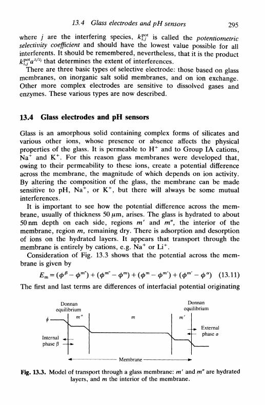
13.4 Glass electrodes and pH sensors 295
where / are the interfering species, kff is called the potentiometricselectivity coefficient and should have the lowest value possible for allinterferents. It should be remembered, nevertheless, that it is the productkfjlaZi/Zj that determines the extent of interferences.
There are three basic types of selective electrode: those based on glassmembranes, on inorganic salt solid membranes, and on ion exchange.Other more complex electrodes are sensitive to dissolved gases andenzymes. These various types are now described.
13.4 Glass electrodes and pH sensors
Glass is an amorphous solid containing complex forms of silicates andvarious other ions, whose presence or absence affects the physicalproperties of the glass. It is permeable to H + and to Group IA cations,Na+ and K+. For this reason glass membranes were developed that,owing to their permeability to these ions, create a potential differenceacross the membrane, the magnitude of which depends on ion activity.By altering the composition of the glass, the membrane can be madesensitive to pH, Na+, or K+, but there will always be some mutualinterferences.
It is important to see how the potential difference across the mem-brane, usually of thickness 50 jum, arises. The glass is hydrated to about50nm depth on each side, regions m' and ra", the interior of themembrane, region m, remaining dry. There is adsorption and desorptionof ions on the hydrated layers. It appears that transport through themembrane is entirely by cations, e.g. Na+ or Li+.
Consideration of Fig. 13.3 shows that the potential across the mem-brane is given by
~ Фт") + (Фт" ~ Фт) - Фт') + (Фт' - Фа) (13.11)
The first and last terms are differences of interfacial potential originating
Donnanequilibrium
m"
Internalphase p
Membrane -
Donnanequilibrium
Externalphase a
Fig. 13.3. Model of transport through a glass membrane: m' and m" are hydratedlayers, and m the interior of the membrane.
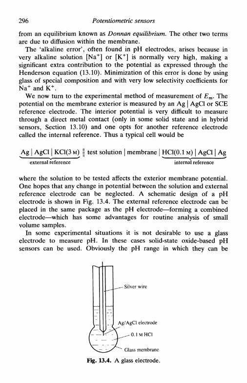
296 Potentiometric sensors
from an equilibrium known as Donnan equilibrium. The other two termsare due to diffusion within the membrane.
The 'alkaline error', often found in pH electrodes, arises because invery alkaline solution [Na+] or [K+] is normally very high, making asignificant extra contribution to the potential as expressed through theHenderson equation (13.10). Minimization of this error is done by usingglass of special composition and with very low selectivity coefficients forNa+ and K+.
We now turn to the experimental method of measurement of Em. Thepotential on the membrane exterior is measured by an Ag | AgCl or SCEreference electrode. The interior potential is very difficult to measurethrough a direct metal contact (only in some solid state and in hybridsensors, Section 13.10) and one opts for another reference electrodecalled the internal reference. Thus a typical cell would be
Ag | AgCl | KC1(3 M) II test solution | membrane | НС1(0.1 м) | AgCl | Ag
external reference internal reference
where the solution to be tested affects the exterior membrane potential.One hopes that any change in potential between the solution and externalreference electrode can be neglected. A schematic design of a pHelectrode is shown in Fig. 13.4. The external reference electrode can beplaced in the same package as the pH electrode—forming a combinedelectrode—which has some advantages for routine analysis of smallvolume samples.
In some experimental situations it is not desirable to use a glasselectrode to measure pH. In these cases solid-state oxide-based pHsensors can be used. Obviously the pH range in which they can be
- Silver wire
Ag/AgCl electrode
0.1MHC1
Glass membrane
Fig. 13.4. A glass electrode.
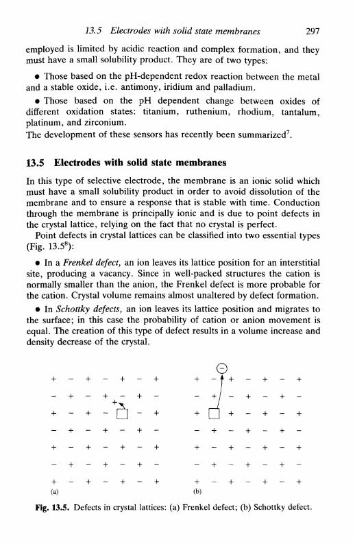
13.5 Electrodes with solid state membranes 297
employed is limited by acidic reaction and complex formation, and theymust have a small solubility product. They are of two types:
• Those based on the pH-dependent redox reaction between the metaland a stable oxide, i.e. antimony, iridium and palladium.
• Those based on the pH dependent change between oxides ofdifferent oxidation states: titanium, ruthenium, rhodium, tantalum,platinum, and zirconium.The development of these sensors has recently been summarized7.
13.5 Electrodes with solid state membranes
In this type of selective electrode, the membrane is an ionic solid whichmust have a small solubility product in order to avoid dissolution of themembrane and to ensure a response that is stable with time. Conductionthrough the membrane is principally ionic and is due to point defects inthe crystal lattice, relying on the fact that no crystal is perfect.
Point defects in crystal lattices can be classified into two essential types(Fig. 13.58):
• In a Frenkel defect, an ion leaves its lattice position for an interstitialsite, producing a vacancy. Since in well-packed structures the cation isnormally smaller than the anion, the Frenkel defect is more probable forthe cation. Crystal volume remains almost unaltered by defect formation.
• In Schottky defects, an ion leaves its lattice position and migrates tothe surface; in this case the probability of cation or anion movement isequal. The creation of this type of defect results in a volume increase anddensity decrease of the crystal.
- + - + - + - - + - + - + -
+ - + - + - + + - + - + - +(a) (b)
Fig. 13.5. Defects in crystal lattices: (a) Frenkel defect; (b) Schottky defect.
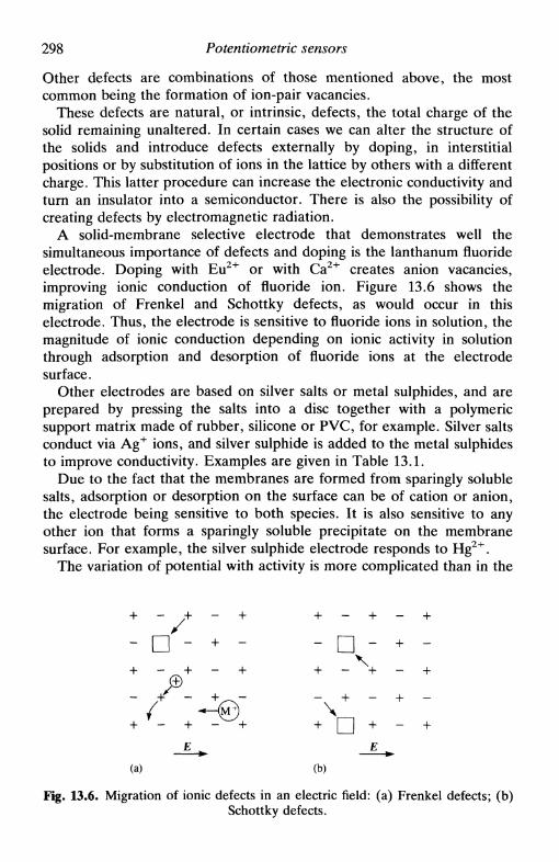
298 Potentiometric sensors
Other defects are combinations of those mentioned above, the mostcommon being the formation of ion-pair vacancies.
These defects are natural, or intrinsic, defects, the total charge of thesolid remaining unaltered. In certain cases we can alter the structure ofthe solids and introduce defects externally by doping, in interstitialpositions or by substitution of ions in the lattice by others with a differentcharge. This latter procedure can increase the electronic conductivity andturn an insulator into a semiconductor. There is also the possibility ofcreating defects by electromagnetic radiation.
A solid-membrane selective electrode that demonstrates well thesimultaneous importance of defects and doping is the lanthanum fluorideelectrode. Doping with Eu2 + or with Ca2+ creates anion vacancies,improving ionic conduction of fluoride ion. Figure 13.6 shows themigration of Frenkel and Schottky defects, as would occur in thiselectrode. Thus, the electrode is sensitive to fluoride ions in solution, themagnitude of ionic conduction depending on ionic activity in solutionthrough adsorption and desorption of fluoride ions at the electrodesurface.
Other electrodes are based on silver salts or metal sulphides, and areprepared by pressing the salts into a disc together with a polymericsupport matrix made of rubber, silicone or PVC, for example. Silver saltsconduct via Ag+ ions, and silver sulphide is added to the metal sulphidesto improve conductivity. Examples are given in Table 13.1.
Due to the fact that the membranes are formed from sparingly solublesalts, adsorption or desorption on the surface can be of cation or anion,the electrode being sensitive to both species. It is also sensitive to anyother ion that forms a sparingly soluble precipitate on the membranesurface. For example, the silver sulphide electrode responds to Hg2 +.
The variation of potential with activity is more complicated than in the
. X \ - - Л + ./ /—N \
+ - + * ^ + + п + - +
Е ^ Е ^
(а) (Ь)
Fig. 13.6. Migration of ionic defects in an electric field: (a) Frenkel defects; (b)Schottky defects.

13.5 Electrodes with solid state membranes 299
Table 13.1. Examples of electrodes with solid state membranes
Ion
s2-Ag+
Pb 2 +
Cd 2 +
Cu 2 +
Material
Ag2SAg2SPbS(A g 2S)CdS(Ag2S)CuS(Ag2S)
Detection limit
10"6
10"7
10"7
10"7
10"8
Ion
F"
crBr"Г
Material
LaF 3
AgClAgBr
Agl
Detection limit
10"7
io~5
10~6
10"8
case of the glass electrode, as the electrode responds to both cations andanions. We exemplify with a silver halide membrane, AgX, where theinternal contact can be an internal reference electrode, as in glasselectrodes, but a metallic contact is more common, often called ohmiccontact (Fig. 13.7). (In the case of ohmic contact the migration of ionsthrough the contact should strictly speaking be considered—normally thiscontribution to the total potential is neglected). The cell can beschematized as
Ag | AgCl | KCl(0.1 M) jj test solution containing | AgX membrane | AgAg+ but not X- |
ohmiccontact
The cell potential is given by
RT— l n a A g + - .
(13.12)
(13.13)
Screening
Internalreferenceelectrode
Internalsolution
Referenceelectrode
Liquid junction
(b)
Membrane
Fig. 13.7, Forms of ion-selective electrodes with solid state membranes: (a) withinternal reference electrode; (b) with ohmic contact; (c) with ohmic contact and
combined reference electrode.

300 Potentiometric sensors
or £ISE is given by
^ RT(13.14)
RT RT= £?g+/Ag + - ^ l n # s p — - l n e x - (13.15)
Г Г
We can also write
RTЕ1*Е = Е%р<-- — 1пах- (13.16)
As demonstrated in (13.15) the detection limit (Section 13.9) isaffected by the solubility product of the membrane. Following simpleequilibrium reasoning (flAg+)tot is always equal to the sum of a term dueto membrane dissolution and one due to Ag+ activity in solution, so\aAg+,that is
(«Ag+)tot = sol«Ag+ + 7 ^ — (13.17)V^AgVtot
Substituting in (13.14),
F-F*> , ^^ 1 n [ so^Ar + [sola2
Ag+ + 4/Csp]1/2l
E - £Ag+/Ag + -у in I j (13.18)
If s o l a A g + » ( 4 /Csp)1/2, there will be Nernstian response. Rigorously, the
activity of Ag+ from lattice defects should also be considered: if this ismuch larger than (4А^р)
1/2 then the detection limit is given by theconcentration of lattice defects.
It is not difficult to show that the equation corresponding to (13.18) forthe anion X~ is
g { - + tf+ 4 KJ"} (13.19)
The detection limit for a silver chloride electrode is shown in Fig. 13.8,which is far above the theoretical limit predicted from the solubilityproduct. It has been shown in solutions of buffered silver ion activity thatthe limit can be reached. Note that the sensitivity is linked to resolutionof the potential measurement and not with the detection limit.
The presence of complexing agents alters membrane solubility, and thedetection limit is also affected. Additionally, there is a shift in potentialto more negative values owing to the lower concentration of free cations.

13.6 Ion-exchange membranes 301
-0 .20
-0.25
-0 .30
- 7 - 6 - 5
lg flAgCl
- 4 - 3
Fig. 13.8 Detection limit for an AgCl ion-selective electrode (Ksp~ 10~10),following the equation E = Ec + (RT/2F) In Ksp for the horizontal straight line
(see (13.18)).
As seen in Table 13.1 and already stated, silver sulphide is added toelectrodes based on sulphides of copper, cadmium, or lead to improveconductivity. In fact the functioning is not altered as the solubilityproduct of silver sulphide is significantly lower than that of the othersulphides. The expression for the potential is
' - E%VAg + -^ InKsp(Ag2S) t RT
Ksp(MS) IF+ — In aM2 (13.20)
which describes the behaviour fairly accurately.
13.6 Ion-exchange membranes and neutral carrier membraneelectrodes
Instead of using membranes for selective electrodes that are permeable toions via adsorption, porous membranes can be employed, where thespecies to be measured traverses from one side of the membrane to theother. These are of two types: ion exchange9 and neutral carrier10.Examples are given in Fig. 13.9 and Table 13.2. These membranes have apolymeric matrix of PVC, of silicone rubber, etc., and contain a solventand chelating agents which are selective to the species of interest. Theagents are usually macrocyclic and transport is by exchange of the speciesbetween adjacent macrocycles.
The most important electrode of the ion-exchange type is the calciumelectrode. A water-immiscible hydrophobic solvent is used—for example
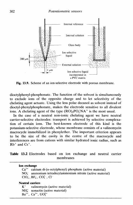
302 Potentiometric sensors
200 \xm
1 \xm
Internal reference
Internal solution
Glass body
Ion-selectiveliquid '.
External solution -
Ion selective liquidincoфorated ina PVC matrix
Fig. 13.9. Scheme of an ion-selective electrode with porous membrane.
dioctylphenyl-phosphonate. The function of the solvent is simultaneouslyto exclude ions of the opposite charge and to let selectivity of thechelating agent actuate. Using the less polar decanol as solvent instead ofdioctyl-phenylphosphonate, makes the electrode sensitive to all divalentions. A chelating agent of the type (RO)2PO^"NA+ is the most usual.
In the case of a neutral non-ionic chelating agent we have neutralcarrier-selective electrodes: transport is achieved by selective complexa-tion of certain ions. The best-known electrode of this kind is thepotassium-selective electrode, whose membrane consists of a valinomycinmacrocycle immobilized in phenylether. The important criterion appearsto be the size of the cavity in the centre of the macrocycle andinterferences are from cations with similar hydrated ionic radius, such asRb+ and Cs+.
Table 13.2 Electrodes based on ion exchange and neutral carriermembranes
Ion exchangeCa2+ calcium di-(n-octylphenyl) phosphate (active material)NO^ ammonium tetradecylammonium nitrate (active material)ClO^BF^COfT, СГ
Neutral carriersK+ valinomycin (active material)NH4 nonactin (active material)Ba2+, Ca2+, UO 2 +

13.8 Enzyme-selective electrodes 303
Table 13.3 Potentiometric sensorsselective to dissolved gases
Gas
NH3
CO2
NOX
SO2
H2S
ISE
pH
рнpHрнs2-
13.7 Sensors selective to dissolved gases11
The principle of these electrodes is a little different, and is normallybased on the measurement of the pH of a solution of electrolyte placedbetween a membrane and a glass electrode, the membrane being porousto the species it is desired to determine (Table 13.3). The dissolved gasconditions the pH of the solution behind the membrane. Membranes canbe microporous (for example PTFE) or homogeneous (for examplesilicone rubber).
It should be noted that some gas-sensitive sensors are amperometric, asin the Clark electrode for oxygen (Section 14.3).
Another type of sensor is a high-temperature solid-state potentiometricsensor for oxygen (>400°C) in industrial processes. These are based onthe measurement of the potential of a concentration cell of the type
O2 (test), M' | zirconia solid electrolyte (ZrO2) | M", O2 (ref.)
where M' and M" are metallic contacts12.
13.8 Enzyme-selective electrodes
Enzymes are substances that react very selectively with a substrate in avery specific reaction. Their immobilization on a membrane which is thenplaced over an electrode in a solution together with the substrate to bedetermined leads to reaction products that can be detected at theelectrode covered by the membrane. An example is the degradation ofurea by urease with an internal sensor element (i.e. ion-selectiveelectrode) sensitive to ammonium ion:
CO(NH2)2 + H2O ̂ ^ CO2,"
In other cases the enzyme reaction alters the pH, and the internal sensorelement is a glass electrode.
These electrodes are described in Chapter 17.

304 Potentiometric sensors
13.9 Some practical aspects
On opting to use potentiometric sensors there are aspects of a practicalnature that have to be taken into account:
1. What is the detection limit? Given that the variation of potentialwith activity is not linear below a certain activity, eventually becomingconstant, it is important to define parameters for determining the limit.The present criterion for the detection limit, according to IUPAC, isshown in Fig. 13.10. Other criteria are based on the precision of potentialreadings and their resolution at specified confidence levels.
2. During how long does the electrode response remain Nernstian—often even with a new electrode the response is sub- or supra-Nernstian(i.e. slopes of potential vs. activity are less or greater than 59In mV at298 K)? Or, at the very least, does the electrode give a variation ofpotential with activity that is stable and reproducible? This condition isrelated to the electrode lifetime and varies with the type of utilization(contact with which solutions and for how long) of the selectiveelectrode. In the case of solid-state membrane electrodes the potentialand its reproducibility depend on the preconditioning—polishing withabrasive etc.—since, by polishing, a fresh electrode surface is producedeach time.
3. What is the response time of the electrode, that is how long does ittake to reach equilibrium after dipping the electrode in solution, or afterchanging the concentration of solution (an activity step)? Clearly thismust be as short as possible: optimized times would be of the order of
Detectionlimit
Fig. 13.10. Determination of the detection limit of an ion-selective electrode,following IUPAC13.

13.10 Recent developments: miniaturization 305
30 s. How should this be defined14?
4. What is the electrode selectivity in relation to other species insolution? Remember that this is given by (fcP°V//z') and not only by theselectivity coefficient к?°\
All these factors have to be considered. The effect of the variation ofpotential with temperature and alteration of the slope of the potential vs.activity profile can be minimized by periodic calibration. This perioddepends on the type of analysis being carried out, but calibration cannotbe dispensed with.
13.10 Recent developments: miniaturization
There has been wide application of ion-selective electrodes. Some ofthese applications require small electrodes, for example measurements invivo. Miniaturization of glass electrodes in the form of micropipettes hasgone some way to enabling electrophysiological measurements to becarried out. Other applications require good reproducibility at low cost.Two types of ISE have been developed with both these criteria in mind:ISFETs and coated wire electrodes, besides so-called hybrid sensors. Thefirst of these has the extra advantage that signal processing is done in situ,resulting in a low impedance signal (a conventional electrode gives a highimpedance signal) that improves the signal/noise ratio.
ISFETs
The field-effect transistor (FET) that is ion selective (ISFET) wasdeveloped in the 1970s and 1980s1516. It was developed bearing in mindthat miniaturizing a conventional configuration ISE would give a fairlybad signal/noise ratio, affecting detection limit and sensitivity. In anISFET, signal amplification is done directly in the membrane in contactwith the solution, instead of in the measuring instrument at the end of acable which is susceptible to the electric and magnetic fields of the localenvironment.
A diagram of a typical ISFET is shown in Fig. 13.11. Instead of using ametallic gate as in a normal FET, a thin film of a material sensitive to anion is used (ISM). The difference in potential between the ISM and thesolution is a function of ion activity. The potential developed alters theconcentration of carriers in the region marked 'channel' which in turnalters the I-V characteristics between source and drain. The current is alow-impedance signal that can be related directly to the activity of theions in solution.

306 Potentiometric sensors
Encapsulation
Type n drain [- Channel _j Type n source |Gate insulator
Si3N4
Fig. 13.11. An ion-selective field effect transistor (ISFET).
This sensor is extremely small. The construction of many ISFETs onthe same chip is possible, either identical or sensitive to different ions. Achip of 1 x 2 mm can have five or six ISFETs.
One of the important applications possible with these sensors is for invivo studies17.
Coated wire electrodes1*
A thin film of a membrane-forming material is deposited on a metal wire(silver, platinum, nickel, etc.) or on carbon, the membrane being, forexample, a liquid exchanger immobilized in PVC (Fig. 13.12). Thiselectrode is thus similar to an ion-exchange selective electrode, butwithout solution and without internal reference. The detailed mechanismof its operation is not clear but it is certain, and logical, that the interface
- Platinum wire
- Insulating film
-Sensor film(PVC matrix with ion exchanger)
Fig. 13.12. Schematic diagram of a coated wire electrode.

13.11 Potentiometric sensors in flow systems 307
between membrane and wire is not totally blocked (the wire is not totallycovered) so that effectively there is an internal reference electrode. If thiswere not the case there could be no passage of current to establishequilibrium.
The great advantage of these sensors is that they are cheap anddisposable; the disadvantage is their poor reproducibility. However,there have been many applications, especially in the quantitative detec-tion of drugs of abuse.
Hybrid sensors
In these sensors the technology developed for ISFET construction is usedin conventional electrodes. Links between the membrane and internalreference are metallic (ohmic contact), by deposition of the metal on themembrane (solid state membranes), or by deposition of an ion-selectivemembrane on a metal. This latter is an integrated sensor.
Solution
Glass film to Encapsulation
• Outputmeasure pH '
Inert substrate
Fig. 13.13. A hybrid sensor.
An example being researched for possible use is a pH electrode (Fig.13.13): a metal contact is deposited on an inert substrate followed by aglass film (in an oven) that totally encapsulates the electrical contact19.This would be a considerably more robust pH electrode than thosepresently used, and easier to maintain.
13.11 Potentiometric sensors in flow systems
Flow methods20 permit the placing of electrochemical sensors at essentialcontrol points. Normally a branching of the principal flow is aranged thatpasses by the sensors any reagents, etc., being added after branching andbefore the sensor. An on-line response can be extremely important forefficient control.
Any potentiometric sensor or combination of potentiometric sensorscan, in principle, be used in a flow system. Certain precautions have to be

308 Potentiometric sensors
taken, some particularly important owing to solution movement:1. Positioning of the external reference electrode. The signal can be
affected by local electric fields between indicator and external referenceelectrodes, an effect that is increased by solution flow, making itimportant to reduce the distance between the electrodes as much aspossible.
2. The electrode response time is increased relative to stationarysolution.
3. Solution movement has the tendency to remove species from themembrane surface, i.e. membrane deterioration is faster than in station-ary solution, and there is a consequent shortening of electrode lifetime.Periodic calibration becomes extremely important.
4. Removal of solid residues by filtering, and the adjusting of solutionconditions to optimize the response, e.g. control of pH, ionic strength,elimination of ionic interferences, should be done frequently.
13.12 Electroanalysis with potentiometric sensors
Owing to their specificity, sensitivity, and range of measurable con-centrations, potentiometric sensors based on ionic or enzymatic selec-tivity have wide application in analytical determinations. Other poten-tiometric sensors using electrodes of the first kind (Mn+ | M), used inprecipation titrations, are not easy to manipulate and redox electrodeshave a reduced application owing to their lack of selectivity, reacting toany oxidizable or reducible species.
Since ISEs can be used in continuous flow systems or in flow systemswith sample injection (flow injection analysis, FIA)21 their application iswide, not limited to discrete samples. Analysis time becomes shorter,with faster recycling. Additionally, in flow systems the experimentalassembly and data analysis can be controlled automatically by microcom-puter, including periodic calibration. Another development is the use ofsensors for the detection of eluents of chromatographic columns inhigh-pressure liquid chromatography (HPLC). Miniaturization has per-mitted an increase in the use of sensors in foods, biological tissues, andclinical analyses in general.
It remains an objective to develop potentiometric sensors with longerlifetimes, greater reproducibility and greater stability. The importance ofan appropriate statistical treatment of the results in order to determinetheir precision is stressed. Frequent calibration is necessary, at least atthe beginning of each measurement session and in a medium as similar aspossible to that where the sensors are to be employed, in order to ensurethe accuracy of the analytical determinations.

References 309
References
1. D. Т. Sawyer and J. L. Roberts, Experimental electrochemistry for chemists,Wiley, New York, 1974, Chapter 9.
2. M. Mascini, Ion Selective Electrode Rev., 1980, 2, 17.3. S. K. Macieod, Anal Chem., 1991, 63, 557A.4. P. L. Bailey, Analysis with ion selective electrodes, Heyden, London, 1976.5. J. Koryta and K. Stulik, Ion selective electrodes, Cambridge University Press,
1983.6. H. Freiser (ed.), Ion selective electrodes in analytical chemistry, Plenum, New
York, 1981, 2 vols.7. S. Glab, A. Hulanicki, G. Edwall, and F. Ingrun, CRC Crit. Rev. Anal.
Chem., 1989,21,29.8. N. N. Greenwood, Ionic crystals, lattice defects and non-stoichiometry,
Butterworth, London, 1968.9. G. J. Moody, B. B. Saad, and J. D. R. Thomas, Ion Selective Electrode
Rev., 1988, 10,71.10. D. Amman, W. E. Morf, P. C. Meier, E. Pretsch, and W. Simon, Ion
Selective Electrode Rev., 1983, 5, 3.11. S. Bruckenstein and J. S. Symanski, J. Chem. Soc. Faraday Trans, I, 1986,
82, 1105.12. J. Fouletier and E. Siebert, Ion Selective Electrode Rev., 1986, 8, 133.13. PureAppl. Chem., 1976, 48, 127.14. E. Lindner, K. Toth, and E. Pungor, Pure Appl. Chem., 1986, 58, 469.15. J. Janata, Chem. Rev., 1990, 90, 691.16. P. Bergveld, IEEE Trans., 1970, ВМЕ-Г7, 70; 1972, BME-19, 342.17. B. A. McKinley, B. A. Houtchens, and J. Janata, Ion Selective Electrode
Rev., 1984,6, 173.18. R. W. Cattrall and I. C. Hamilton, Ion Selective Electrode Rev., 1984, 6, 125.19. R. G. Kelly and A. E. Owen, /. Chem. Soc. Faraday Trans, I, 1986, 82,
1195.20. K. Stulik and V. Pacakova, Electroanalytical measurements inflowing liquids,
Ellis Horwood, Chichester, 1987.21. J. Ruzicka and E. H. Hansen, Flow injection analysis, 2nd edn, Wiley, New
York, 1988.

14
AMPEROMETRIC ANDVOLTAMMETRIC SENSORS
14.1 Introduction14.2 Amperometric titrations14.3 Membrane and membrane-covered electrodes14.4 Modified electrodes14.5 Increase of sensitivity: pre-concentration techniques14.6 Amperometric and voltammetric electroanalysis
14.1 Introduction
An amperometric sensor measures a current at a fixed applied potential,that is at one point on the current-voltage curve. A voltammetric sensorrecords a number of points on, or a chosen region of, the current-voltageprofile. Thus an amperometric sensor is a fixed-potential voltammetricsensor.
The larger part of this book has been devoted to studies related toelectrochemical measurements away from equilibrium. As demonstrated,these permit the determination of kinetic and thermodynamic parametersof the electrode processes, whereas measurements at equilibrium furnishonly thermodynamic data. So, whilst potentiometric analysis is a power-ful tool in the determination of activities or concentrations, the specificityarising from the electrode material, amperometric or voltammetricanalysis permits other parameters besides these to be obtined.
The most important selectivity parameter of electrodes for voltam-metric sensors is the applied potential. Ideally, the electrode potentials ofthe redox couples would be sufficiently far apart for there to be nointerference between different species. Unfortunately this is not the case,and it is necessary to look for greater selectivity. We can discriminatebetter between the different species present in solution through a correctchoice of conditions for the study of the electrode reaction: electrodematerial (Chapter 7) in some cases through surface modification; use ofhydrodynamic electrodes (Chapter 8); application of potential sweep

14.2 Amperometric titrations 311
(Chapter 9) or potential pulses (Chapter 10); alternating current voltam-metry (Chapter 11) and so on. Additionally, kinetic and mechanisticinformation can sometimes be obtained from the same set ofexperiments.
Recent developments in amperometric and voltammetric sensors havebeen in improving selectivity, increasing sensitivity, and lowering detec-tion limits. Hydrodynamic electrodes, besides permitting greater sen-sitivity, also bring greater reproducibility and the possibility of use in flowsystems for process control, quality control, and as chromatographicdetectors. The widespread use of pulse techniques, particularlydifferential pulse voltammetry and more recently square wavevoltammetry, has enabled lower detection limits to be reached. At thesame time, there has been much progress in the automation of thesesensors, not only to control experiments but also to analyse the dataobtained.
In this chapter, after describing the useful technique of amperometrictitrations, recent developments in amperometric and voltammetric sen-sors are summarized. Their application as biosensors to the study ofbiological compounds and in vivo, is described in Chapter 17.
14.2 Amperometric titrations
Not all redox titrations have a well-defined equivalence point, andamperometric titrations1, in which a potential corresponding normally tothat necessary to attain the mass-transport-limited current is applied tothe working (indicator) electrode, permit the calculation of the titrationendpoint through measurements done far from the equivalence point.Titrations can be done in flow systems, and in this sense it is possible toalter the quantity of added titrant so as to obtain greater accuracy in thedetermination of the equivalence point2.
Simple amperometric titrations
The electrical circuit consists of two electrodes: a redox indicatorelectrode and a reference electrode that also passes current. A fixedpotential difference is applied and the equivalence point is calculatedfrom the intersection of the two straight lines that show the variation ofcurrent before and after the endpoint in a plot of current as a function ofadded titrant volume. The plots can have various forms, depending onwhether the titrated species or titrant are or are not electroactive. Figure14.1 shows the four possible cases. Sometimes the potential differenceapplied is less than that necessary to reach the mass-transport-limitedcurrent, but sufficient to give good results.

312 Amperometric and voltammetric sensors
I
" equiv V * e q u i v V
Fig. 14.1 Forms of amperometric titration.
As this is an indirect method of determining the equivalence point ithas some advantages. Dilute solutions can be titrated, allowing titrationof sparingly soluble precipitates with no interference from supportingelectrolyte. Non-electroactive compounds can be titrated so long as thetitrant is electroactive, or vice versa. Titrations are fast, only three pointsbefore and three points after the equivalent point being necessary.
Some examples are titration of Pb2+ with CrOj", Ni2+ with diacetyl-dioxime, and barbituric acids with Hg2(ClO4)2.
Biamperometric titrations
Biamperometric titrations involve the use of two redox electrodes insolution, and are applicable only to titrations where there is a reversiblesystem before or after the endpoint; there is no reference electrode. Theapplication of a potential difference causes one electrode to be anode andthe other cathode. A current passes due to oxidation or reduction,respectively, of a species present in solution, decreasing to / = 0 at theequivalence point; alternatively it may be that / = 0 until the equivalence

14.2 Amperometric titrations 313
0\/R\ reversibleO2/R2 reversible
CVR! irreversibleO2/R2 reversible
Oi/Rt reversibleO2/R2 irreversible
V V V V lr equiv т У equiv v I
Fig. 14.2 Forms of curve obtained in biamperometric titrations.
O 2 .titrant
&E~ 0.1-*0.2 V
point and that the current begins to rise after this. Since / = 0 in all casesat the equivalence point, this method is sometimes called the dead-stopendpoint method. The forms of the curves that can be obtained areshown in Fig. 14.2. Applications of this technique are in titrations ofiodine, bromine, titanium(III) and cerium(IV) and in the determinationof water in non-aqueous solvents with the Karl-Fischer reagent.
Amperometric titrations with double hydrodynamic electrodes
Titrations of non-electroactive compounds can be carried out by homo-geneous reaction with titrants electrogenerated in situ. This can be doneusing double hydrodynamic electrodes in the diffusion layer microtitra-tion technique described in Section 8.7.
In this technique the upstream electrode (generator) is galv^nostati-cally controlled to generate a species that reacts with species X insolution in a second-order homogeneous reaction, the detector electrodebeing used to quantify the fraction of the electrogenerated species thatdid not react:
generator
solution
detector
A±#B+O
В±к
i^ -»B
i —> products
ье~ ̂ С (or A)
Figure 8.11 shows the type of curve that is obtained, which allows thedetermination of the concentration of X. The rotating ring-disc electrode3
and the wall-jet ring-disc electrode in continuous flow4 (Fig. 14.3) andwith sample injection into potassium bromide solution5 have beenused—this last procedure reduces the amount of sample necessary and

314 Amperometric and voltammetric sensors
N' = 0.035
20 40 60 80
Fig. 14.3 Diffusion-layer microtitration curves at the wall-jet ring disc electrodefor titration of As(III) (X) with bromine (B) generated at the disc electrode frombromide. Solution 10~2 м KBr -Ь 0.5 м H2SO4. Analysis of the curve leads to [X]
(from Ref. 4 with permission).
makes quantification faster. An important application is in the quantita-tive determination of amino-acids and proteins by reaction with Br2 orOBr~ electrogenerated from Br~, which has been automated6.
14.3 Membrane and membrane-covered electrodes
In order to make an electrode more selective we can arrange for onlycertain species to reach its surface, with the additional advantage ofreducing electrode poisoning. This can be done by modifying theelectrode surface (see next section), by a porous membrane touching theelectrode or separated from it by a thin film of electrolyte, or by using ametallized membrane as indicator electrode.
Direct coverage of electrodes with porous membranes7 can diminishpoisoning problems, avoiding reduction in response with time. This is aparticularly pertinent problem in solutions containing reasonable amountsof organic compounds. An example is the successful use of celluloseacetate to impede the irreversible adsorption of proteins on glassy carbonelectrodes8.
The best-known example of a membrane-covered electrode is theClark electrode for determination of dissolved oxygen (Fig. 14.4910). Amembrane (usually PTFE) with pores of a size that lets only oxygendiffuse through is placed over a thin film of electrolyte on top of aplatinum or gold electrode, the potential of this being controlled so as toreduce oxygen. The anode is usually a silver disc that acts simultaneouslyas reference electrode. It can be used for oxygen determination in gas orliquid phases.

14.3 Membrane and membrane<overed electrodes 315
Connectors
C a t h o f Anode
\
Anode (Ag) -
Film of electrolyte -
Cathode(Au, Pt, Ag)
Insulatingmaterial
Anode (Ag)
Electrolyte reservoir
Membrane
Fig. 14.4 The Clark electrode for determination of dissolved oxygen.
Other electrodes functioning in a similar way have been developed forother dissolved gases, with important clinical applications (Table 14.1).Since the porous membrane does not let past species that can poison theelectrode, these electrodes are ideal for measurements in biologicalfluids.
Metallized membrane electrodes11 have the inner, non-exposed surfaceof the membrane metallized: this is the indicator electrode, and contactswith an internal electrolyte solution. Typical metals are gold andplatinum and typical membrane materials PTFE and polyethylene;ion-exchange membranes such as Nafion can be used to improveselectivity; membranes can be porous or non-porous—in the latter casetransport through the membrane is by activated diffusion. The externalmedium can be liquid or gas phase and so this type of detector can beused in gas chromatography. Gases such as oxygen, carbon monoxide,hydrogen, chlorine and nitrous oxide can be determined, and also anions
Table 14.1. Amperometric sensors for dissolvedgases
Gases dissolved in aqueous phaseO2, NO, halothane, CO2
Gas phaseH2S, HCN, CO, NO, NO2, Cl2
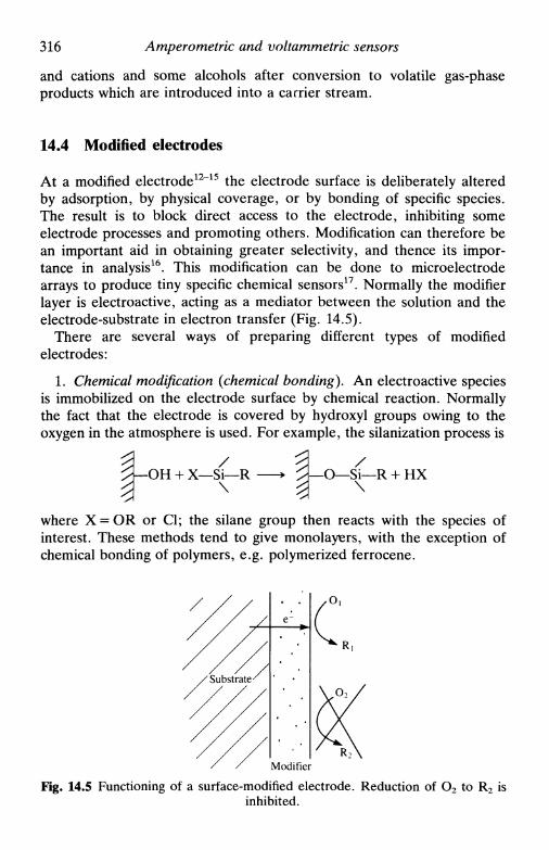
316 Amperometric and voltammetric sensors
and cations and some alcohols after conversion to volatile gas-phaseproducts which are introduced into a carrier stream.
14.4 Modified electrodes
At a modified electrode12"15 the electrode surface is deliberately alteredby adsorption, by physical coverage, or by bonding of specific species.The result is to block direct access to the electrode, inhibiting someelectrode processes and promoting others. Modification can therefore bean important aid in obtaining greater selectivity, and thence its impor-tance in analysis16. This modification can be done to microelectrodearrays to produce tiny specific chemical sensors17. Normally the modifierlayer is electroactive, acting as a mediator between the solution and theelectrode-substrate in electron transfer (Fig. 14.5).
There are several ways of preparing different types of modifiedelectrodes:
1. Chemical modification {chemical bonding). An electroactive speciesis immobilized on the electrode surface by chemical reaction. Normallythe fact that the electrode is covered by hydroxyl groups owing to theoxygen in the atmosphere is used. For example, the silanization process is
-ОН + X—Si—R\
У\—O—Si—R + HX
where X = OR or Cl; the silane group then reacts with the species ofinterest. These methods tend to give monolayers, with the exception ofchemical bonding of polymers, e.g. polymerized ferrocene.
Modifier
Fig. 14.5 Functioning of a surface-modified electrode. Reduction of O2 to R2 isinhibited.
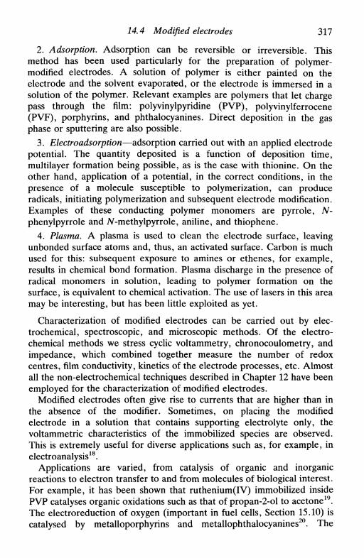
14.4 Modified electrodes 317
2. Adsorption. Adsorption can be reversible or irreversible. Thismethod has been used particularly for the preparation of polymer-modified electrodes. A solution of polymer is either painted on theelectrode and the solvent evaporated, or the electrode is immersed in asolution of the polymer. Relevant examples are polymers that let chargepass through the film: polyvinylpyridine (PVP), polyvinylferrocene(PVF), porphyrins, and phthalocyanines. Direct deposition in the gasphase or sputtering are also possible.
3. Electroadsorption—adsorption carried out with an applied electrodepotential. The quantity deposited is a function of deposition time,multilayer formation being possible, as is the case with thionine. On theother hand, application of a potential, in the correct conditions, in thepresence of a molecule susceptible to polymerization, can produceradicals, initiating polymerization and subsequent electrode modification.Examples of these conducting polymer monomers are pyrrole, N-phenylpyrrole and ЛГ-methylpyrrole, aniline, and thiophene.
4. Plasma. A plasma is used to clean the electrode surface, leavingunbonded surface atoms and, thus, an activated surface. Carbon is muchused for this: subsequent exposure to amines or ethenes, for example,results in chemical bond formation. Plasma discharge in the presence ofradical monomers in solution, leading to polymer formation on thesurface, is equivalent to chemical activation. The use of lasers in this areamay be interesting, but has been little exploited as yet.
Characterization of modified electrodes can be carried out by elec-trochemical, spectroscopic, and microscopic methods. Of the electro-chemical methods we stress cyclic voltammetry, chronocoulometry, andimpedance, which combined together measure the number of redoxcentres, film conductivity, kinetics of the electrode processes, etc. Almostall the non-electrochemical techniques described in Chapter 12 have beenemployed for the characterization of modified electrodes.
Modified electrodes often give rise to currents that are higher than inthe absence of the modifier. Sometimes, on placing the modifiedelectrode in a solution that contains supporting electrolyte only, thevoltammetric characteristics of the immobilized species are observed.This is extremely useful for diverse applications such as, for example, inelectroanalysis18.
Applications are varied, from catalysis of organic and inorganicreactions to electron transfer to and from molecules of biological interest.For example, it has been shown that ruthenium(IV) immobilized insidePVP catalyses organic oxidations such as that of propan-2-ol to acetone19.The electroreduction of oxygen (important in fuel cells, Section 15.10) iscatalysed by metalloporphyrins and metallophthalocyanines20. The

318 Amperometric and voltammetric sensors
development of the electrochemistry of proteins and enzymes was hinderedby the strong attraction of these compounds to the electrode surfacecausing poisoning, and, additionally in the case of enzymes, theirdegradation by the electrode material. A mediator facilitates electrontransfer and minimizes attraction and repulsion effects between thebiological molecule and the electrode. However, a careful choice ofsubstrate may lead to the development of methods that do not needmediator and allow direct immobilization (see Chapter 17).
In technology, conducting polymers will probably have an importantrole, as they can be successively oxidized or reduced21'22
insulating polymer <=± oxidized polymerneutral conducting
by alteration of applied potential in a switching action; often this isaccompanied by a colour change. For this reason conducting polymersare being investigated for electrochromic displays, energy stores, etc. Asthey are conducting they are also being considered as protective coatingsof metal surfaces against corrosion, especially to protect againstphotocorrosion.
In specific cases, electrode bulk as opposed to surface modification canbe employed, as with carbon paste electrodes23. The modifier, asubstance that reacts preferentially in some way with a species to bedetermined, is mixed directly with the carbon paste. The mode of actionis either by catalyzing the analyte reaction or pre-concentrating theanalyte on the surface before determination.
14.5 Increase in sensitivity: pre-concentration techniques
A sensitivity increase and lower detection limit can be achieved in variousways with the use of voltammetric detectors rather than amperometry atfixed potential or with slow sweep. The principle of some of thesemethods was already mentioned: application of a pulse waveform(Chapter 10) and a.c. voltammetry (Chapter 11). There is, nevertheless,another possibility—the utilization of a pre-concentration step thataccumulates the electroactive species on the electrode surface before itsquantitative determination, a determination that can be carried out bycontrol of applied current, of applied potential or at open circuit. Thesepre-concentration (or stripping) techniques24"26 have been used forcations and some anions and complexing neutral species, the detectionlimit being of the order of 10~10 м. They are thus excellent techniques forthe determination of chemical species at trace levels, and also forspeciation studies. At these levels the purity of the water and of the
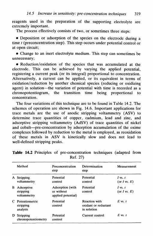
14.5 Increase in sensitivity: pre-concentration techniques 319
reagents used in the preparation of the supporting electrolyte areextremely important.
The process effectively consists of two, or sometimes three steps:
• Deposition or adsorption of the species on the electrode during atime t (preconcentration step). This step occurs under potential control orat open circuit;
• Change to an inert electrolyte medium. This step can sometimes beunnecessary;
• Reduction/oxidation of the species that was accumulated at theelectrode. This can be achieved by varying the applied potential,registering a current peak (or its integral) proportional to concentration.Alternatively, a current can be applied, or its equivalent in terms ofoxidation/reduction by another chemical species (reducing or oxidizingagent) in solution—the variation of potential with time is recorded as achronopotentiogram, the transition time being proportional toconcentration.
The four variations of this technique are to be found in Table 14.2. Theschemes of operation are shown in Fig. 14.6. Important applications fortrace metals are the use of anodic stripping voltammetry (ASV) todetermine trace quantities of copper, cadmium, lead and zinc, andadsorptive stripping voltammetry (AdSV) of trace quantities of nickeland cobalt—pre-concentration by adsorption accumulation of the oximecomplexes followed by reduction to the metal is employed, as reoxidationof these metals in ASV is kinetically slow and does not lead towell-defined stripping peaks.
Table 14.2 Principles of pre-concentration techniques (adapted fromRef. 27)
A
В
С
D
Method
Strippingvoltammetry
Adsorptivestrippingvoltammetry
Potentiometricstrippinganalysis
Strippingchronopotentiometry
Preconcentrationstep
Potentialcontrol
Adsorption (withor withoutapplied potential)
Potentialcontrol
Potentialcontrol
Determinationstep
Potentialcontrol
Potentialcontrol
Reaction withoxidant or reductantin solution
Current control
Measurement
/vs. /(or / vs. E)
/vs. /(or / vs. E)
£vs . /
£vs . /
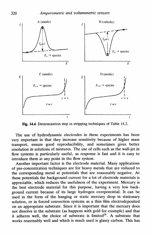
320 Amperometric and voltammetric sensors
A (anodic) В (cathodic)
£p -> species£p -*• species
D (anodic)
Fig. 14.6 Determination step in stripping techniques of Table 14.2.
The use of hydrodynamic electrodes in these experiments has beenvery important in that they increase sensitivity because of higher masstransport, ensure good reproducibility, and sometimes gives betterresolution in solutions of mixtures. The use of cells such as the wall-jet inflow systems is particularly useful, as response is fast and it is easy tointroduce them at any point in the flow system.
Another important factor is the electrode material. Many applicationsof pre-concentration techniques are for heavy metals that are reduced tothe corresponding metal at potentials that are reasonably negative. Atthese potentials the background current for a lot of electrode materials isappreciable, which reduces the usefulness of the experiment. Mercury isthe best electrode material for this purpose, having a very low back-ground current because of its large hydrogen overpotential. It can beused in the form of the hanging or static mercury drop in stationarysolution, or in forced convection systems as a thin film electrodepositedon an appropriate substrate. Since it is important that the mercury doesnot dissolve in the substrate (as happens with gold for example) and thatit adheres well, the choice of substrate is limited28. A substrate thatworks reasonably well and which is much used is glassy carbon. This has

14.5 Increase in sensitivity: pre-concentration techniques 321
the additional advantage that in the zone of positive potentials glassycarbon itself can be used as electrode for anion determinations, etc. Awide range of potentials is thus possible. It has been suggested thatmercury is electrodeposited on glassy carbon at — 1.0 V vs. SCE so thatthe tendency of mercury to form small droplets on the surface isminimized. Other substrates suggested are iridium and silver.
In anodic stripping voltammetry the mercury film and the metal ion tobe determined are often co-deposited (called in situ mercury deposition).The thin mercury film has characteristics similar to a thin-layer cell,described in Section 9.10. Additionally, it can be easily used inhydrodynamic systems29.
Use of mercury as electrode material resolves the problem of thenegative potential zone being too small but brings others, as it is a liquid.When a metal ion is reduced on the mercury surface to the metal, thiscan diffuse to within the mercury film, forming Hg-M bonds, or, if thereis more than one dissolved metal, intermetallic compounds can be formedwithin the mercury, as is the case of Cu-Zn. Reoxidation of intermetallic
Fig, 14.7 Stripping voltammetry with collection at a double hydrodynamicelectrode, with preconcentration at the generator electrode: (a) Potential step att = *deP at the generator electrode to remove the deposit; (b) Chronoamperogramat the generator electrode with faradaic (1) and capacitive (2) components;(c) Chronoamperogram at the detector electrode with only faradaic component(potential unaltered throughout the experiment); (d) Integral of the curve in (c),the height being proportional to the concentration of species to determine
Qdet = -No/gen,dep'dep.
322 Amperometric and voltammetric sensors
compounds occurs at a potential different from the individual metals,which can cause difficulties in the resolution of adjacent peaks. Naturally,there are ways of reducing this problem, and there is even the possibilityof using other pre-concentration techniques. The study of the formationand properties of Cu-Zn is very important, because in nature thepresence of one of these elements implies the presence of the other.
Figure 14.7 shows the technique of anodic stripping voltammetry withcollection at a double hydrodynamic electrode30. The fact that it ispossible to control the potentials of generator and detector electrodesindependently is used to increase sensitivity. This procedure has beenused with success at rotating and wall-jet electrodes4'27
14.6 Amperometric and voltammetric electroanalysis
The great possibilities of amperometric and voltammetric electroanalysisboth in stationary solution and in continuous flow are evident from theprevious sections. However, the choice of which technique and ex-perimental protocol to use depends on various factors, such as:
• The concentration range of the species to be determined• Possible interferences to its exact determination, i.e. matrix
composition• The accuracy and precision necessary• The quantity of sample• The required speed with which an answer is required
In the case of trace quantities, or any determination close to detectionlimits, accuracy is much more important than precision, as the former isthe primary consideration as to whether a given trace level is acceptableor not. Theoretical detection limits are often defined in the literature asthree times the standard deviation of the measurements, but practicaldetection limits are usually higher and are determined by levels ofcontamination that can be introduced through reagent and samplemanipulation.
It is probable that there will be much development in new solidelectrode detectors for flow systems in the near future which, owing totheir hydrodynamic character, give fast on-line voltammetric responses31"33.When the amount of sample is small, a flow injection system34 isindicated; applications of stripping analysis35 and modified electrodes36 inthis mode have been reviewed. Chromatographic detection is similar inmany ways to flow injection, and there are many applications of

14.6 Amperometric and voltammetric electroanalysis 323
Referencelelectrode
LC column
Working electrode
Fig. 14.8 A thin-layer cell for use as a high pressure liquid chromatographyelectrochemical detector (courtesy of Bioanalytical Systems).
electrochemical detectors36'37 as there are in capillary electrophoresis38. Athin-layer cell for coupling to an HPLC column is shown in Fig. 14.8.
The use of pulse techniques for electroanalytical determinations hasbeen much publicized, and is applicable to both solid electrodes and theHMDE/SMDE. The development in recent years of square wavevoltammetry (SWV)39 widens the possibilities beause of its rapidity(Section 10.9); it is especially useful because the time necessary to do anexperiment is only 2 s, which means that a SMDE drop in the droppingmode can also be used for micromolar determinations. Progress obtainedwith pulse techniques40'41 has meant that applications of a.c. voltammetryhave been few, but there is no theoretical reason for this. The very lowdetection limits achieved in stripping voltammetry result not only fromthe pre-concentration step but also from the use of pulse waveforms inthe determination step.
Another important future direction is in the use of microelectrodes andmicroelectrode arrays. They are often easier to manipulate by theinexperienced, and instrumentation is simpler. They can be used in highlyresistive 'dirty' media where conventional electrodes may be unuseableand are able to probe localized concentrations. Composite electrodes42,of which carbon paste is an example, if conveniently prepared, can act asmicroelectrode assemblies. In a more general sense, lithographic and

324 Amperometric and voltammetric sensors
screen-printing processes can be used to fabricate microelectrode as-semblies, which either all do the same determination to increase theanalytical signal, or are independently controlled to determine differentspecies.
Finally, the possibilities of automation of amperometric and voltam-metric electroanalysis should be stressed, as well as the use of solventsother than water43. Pulse techniques are semi-automated by nature; theresponses can be transmitted directly to a microcomputer for immediateanalysis. Fast on-line analysis in flow systems with automated calibrationis one of the great advantages, which will be much exploited in thefuture.
References
1. D. T. Sawyer and J. L. Roberts, Experimental electrochemistry for chemists,Wiley, New York, 1974, Chapter 9.
2. K. Toth, G. Nagy, Zs, Feher, G. Horvai, and E. Pungor, Anal. Chim. Acta,1980, 114, 45.
3. W. J. Albery, S. Bruckenstein, and D. C. Johnson, Trans. Faraday Soc,1966, 62, 1938.
4. W. J. Albery and С M. A. Brett, /. Electroanal. Chem., 1983, 144, 211.5. A. M. Oliveira Brett and L. Santos, unpublished results.6. W. J. Albery, L. R. Svanberg and P. Wood, J. Electroanal. Chem., 1984,
162, 45.7. K. Doblhofer and R. D. Armstrong, Electrochim. Acta, 1988, 33, 453.8. J. Wang, Electroanalysis, 1991, 3, 255.9. L. С Clark Jr., Trans. Am. Soc. Artif. Intern. Organs, 1956, 2, 41.
10. M. L. Hitchman, Measurement of dissolved oxygen, Wiley-Interscience, NewYork, 1978.
11. F. Opekar, Electroanalysis, 1989, 1, 287.12. R. W. Murray, Electroanalytical chemistry, ed. A. J. Bard, Dekker, New
York, Vol. 13, 1984, pp. 191-368.13. W. J. Albery and A. R. Hillman, Ann. Rep. Prog. Chem. Sect. C, 1981, 78,
377.14. A. J. Bard, /. Chem. Ed., 1983, 60, 302.15. M. Kaneko and D. Wohrle, Adv. Polymer. ScL, 1988, 84, 143.16. S. Dong and Y. Wang, Electroanalysis, 1989, 1, 99.17. M. J. Natan and M. S. Wrighton, Progress in inorganic chemistry, ed. S. J.
Lippard, Wiley-Interscience, New York, Vol. 37, 1990, pp. 391-494.18. R. Guadalupe and H. D. Abruna, Anal. Chem., 1985, 57, 142.19. B. A. Moyer, M. S. Thompson and T. J. Meyer, /. Am. Chem. Soc, 1980,
102, 2310.20. e.g. J. P. Collman, P. Denisevich, Y. Jonai, M. Marrocco, C. Koval, and F.
С Anson, /. Am. Chem. Soc, 1980, 102, 6027.21. G. K. Chandler and D. Pletcher, RSC Spec Per. Reports, Electrochemisty,
Vol. 10, 1984, p. 117.
References 325
22. A. F. Diaz, J. F. Rubinson, and H. B. Mark Jr., Adv. Polymer ScL, 1988,84, 113.
23. K. Kalcher, Electroanalysis, 1990, 2, 419.24. V. Vydra, K. Stulik, and E. Julakova, Electrochemical stripping analysis,
Ellis Horwood, Chichester, 1976.25. J. Wang, Stripping analysis. Principles, instrumentation and applications,
VCH Publishers, Deerfield Beach, Florida, 1985.26. J. Wang, Electroanalytical chemistry, ed. A. J. Bard, Dekker, New York,
Vol. 16, 1989, pp. 1-87.27. С M. A. Brett and M. M. P. M. Neto, /. Chem. Soc. Faraday Trans. 1,
1986, 82, 1071.28. S. P. Kounaves and J. Buffle, /. Electroanal. Chem,, 1987, 216, 53.29. С M. A. Brett and A. M. С F. Oliveira Brett' /. Electroanal. Chem., 1989,
262, 83.30. D. С Johnson and R. E. Allen, Talanta, 1973, 20, 305.31. K. Stulik and V. Pacakova, Electroanalytical measurements inflowing liquids,
Ellis Horwood, Chichester, 1987.32. H. Gunasingham and B. Fleet, Electroanalytical chemistry, ed. A. J. Bard,
Dekker, New York, Vol. 16, 1989, pp. 89-179.33. С M. A. Brett and A. M. С F. Oliveira Brett, Port. Electrochim. Acta,
1989, 7, 657.34. J. Ruzicka and E. H. Hansen, Flow injection analysis, Wiley, New York,
1988.35. M. D. Luque de Castro and A. Izquierdo, Electroanalysis, 1991, 3, 457.36. E. Wang, H. Ji and W. Hou, Electroanalysis, 1991, 3, 1.37. G. Horvai and E. Pungor, CRC Crit. Rev. Anal. Chem., 1989, 21, 1.38. P. D. Curry Jr., C. E. Engstrom-Silverman, and A. G. Ewing,
Electroanalysis, 1991, 3, 587.39. J. G. Osteryoung and J. J. O'Dea, Electroanalytical chemistry, ed. A. J.
Bard, Dekker, New York, Vol. 14, 1986, pp. 209-308.40. J. G. Osteryoung and M. M. Schreiner, CRC Crit. Rev. Anal. Chem., 1988,
19, 81.41. G. N. Eccles, CRC Crit. Rev. Anal. Chem., 1991, 22, 345.42. D. E. Tallman and S. L. Petersen, Electroanalysis, 1990, 2, 499.43. E. A. M. F. Dahmen, Electroanalysis: theory and applications in aqueous and
non-aqueous media and in automated chemical control, Elsevier, Amsterdam,1986.

15
ELECTROCHEMISTRY ININDUSTRY
15.1 Introduction15.2 Electrolysis: fundamental considerations15.3 Electrochemical reactors15.4 Porous and packed-bed electrodes15.5 Examples of industrial electrolysis and electrosynthesis15.6 Electrodeposition and metal finishing15.7 Metal processing15.8 Batteries15.9 Fuel cells15.10 Electrochemistry in water and effluent treatment
15.1 Introduction
Electrochemistry has a very important role in industry in various types ofapplication including electrolysis (conversion of substances), metal pro-cessing and finishing, batteries and fuel cells, and water and effluenttreatment1"3. Extensive, often fairly specialized, books on various aspectsexist in the literature. Reference 1 provides a modern, up-to-date,general view with many examples. In this chapter a brief survey of theseapplications is provided. At industrial level primary considerations arenaturally economic, the product or process yield in space and in time andthe energy consumption being very important. In the case of batteriesand fuel cells their efficiency, lifetime, stability, the current supplied areall of importance. Corrosion, unwanted in all but a very few cases such aselectrochemical machining, but important because of its economic andsocial consequences, is discussed in the next chapter.
The use of electrochemistry in industry is affected by the price ofelectricity and its ease of supply, principally in cases where there is analternative production method. For this reason large-scale energy-intensive electrolysis processes such as metal extraction have developedwhere electricity can be generated at low cost. This criterion is more

15.2 Electrolysis: fundamental considerations 327
important than the cost of transporting the ores, owing to the hugethermal losses in transmission of electrical energy. Now that supercon-ductors with critical temperatures significantly higher than the boilingpoint of liquid nitrogen are being discovered and developed, thetransmission of electricity along superconductor cables without energylosses could and probably will become reality within the next fewdecades, a development that will very much benefit the electrochemicalindustry.
15.2 Electrolysis: fundamental considerations
Electrolysis is the conversion of electrical energy into chemical energy inorder to convert substances by oxidation or reduction, so that productsare formed as the element or an appropriate compund. Also included isthe generation of charged intermediates that link to other species, as inelectrosynthesis. The design of the cells where these reactions take place,together with associated operations, is electrochemical engineering*.
As has been explained throughout this book, electrochemists haveunder their control parameters such as the solvent, supporting elec-trolyte, concentration of electroactive species, solution movement, shapeand material of the electrodes, the electrochemical cell, applied potentialor current, and temperature. All these factors affect the kinetics andmechanism of electrode processes, and the electrochemical engineer mustbe aware of all of them. In industry one attempts to increase the rate ofthe required mechanism whilst minimizing the rate of any other mechan-ism or parallel process that can occur simultaneously, in order tomaximize the yield in space and time. To achieve a good yield it isnecessary to maximize the contact between electrode and electrolyte andsometimes to apply fairly large overpotentials to overcome solutionresistance. In order to optimize these factors, a good knowledge of thefundamental principles of electrochemisty is required. In the past this wasoften achieved by trial and error, but at present there is a lot of efforttowards optimizing industrial processes through scientific research intoprocess development.
In certain cases of metal extraction, electrolysis has to be employed ofnecessity. Metals are, with rare exceptions such as gold, found in naturein positive oxidation states. In principle, reduction to the metal can becarried out by a chemical reducing agent. Chemical reducing agents thatare used on a large scale are hydrogen, carbon, carbon monoxide, ormixtures of these. However, for the very electropositive metals, thereducing power of these compounds is not sufficient to extract the metalexcept under very extreme conditions of high temperature and pressure,
328 Electrochemistry in industry
so that electrolysis has to be employed. Examples are the elements ofGroup IA, magnesium, and aluminium.
In other cases electrochemistry is used because of the control of theselectivity of the reaction that is achieved through applied potential,when an ore or other sample contains various species with similarchemical but different electrochemical characteristics. The substancesconverted are obtained with a high degree of purity, but often at highenergy cost.
Cell voltages for industrial electrochemical cells are expressed in thefollowing way:
where Ec and Ea are the thermodynamic potentials for cathodic andanodic reactions respectively, ц are the overpotentials, and (//?сец) is thecontribution from the resistance of electrolyte and electrodes, dependenton cell design. Thus electrolysis cell voltages are always negative. It iseasy to see that the cell's energy efficiency is given by
(Ec — ЕЛpercentage energy efficiency = — — x 100
15.3 Electrochemical reactors
There are various types of electrochemical reactor5'6; the classification issimilar to that used for other chemical processes. The three basic types ofelectrochemical reactor are shown in Fig. 15.1:
1. Batch reactor. The process requires total conversion of the reagents,and therefore includes a time for discharging and recharging. It is noteasily adaptable to industrial situations, because of:
• low conversion rate towards the end of the electrolysis step
• time lost with discharging and recharging.This reactor is best for laboratory use in investigations of electrolysiskinetics and mechanism.
2. Plug-flow reactor. Reagents are continuously introduced and theelectrolyte (reagent + product) continuously removed. In general, con-version is less than 100 per cent but there are not the disadvantages of thebatch reactor. Use of porous electrodes or electrodes with smallanode-cathode spacing significantly improves the yield. Because of this ithas much industrial application.

15.3 Electrochemical reactors 329
(a)
EntryReactor
Exit
(b)Distance
Entry — •
(c)
C>K3-- • Exit
Г о
WithinE n t r y reactor
Reagents
Exit
Reagents Reagents
Products Producis
Distance
Fig. 15.1. Types of electrochemical reactor; (a) Batch reactor; (b) Plug flowreactor; (c) Backmix flow reactor.

330 Electrochemistry in industry
3. Backmix flow reactor or continuously stirred tank reactor. Theconversion rate is lower than for plug-flow reactors because the reagent isimmediately diluted on being introduced into the reactor. Many flowreactors, e.g. tubular reactors, and especially in the turbulent regime arein this class.
Plug-flow and backmix flow reactors can be used as single-pass, withrecirculation or in cascade, leading to many possible configurations, butalways with the aim of optimizing product yield in space and time.
In practice, there exist much more complex reactors. An extremelyimportant factor is the flow regime. Reactor design has to be such thatthe current density is uniform at all the electrodes (except in rare cases)and, preferably, high.
It is possible to design reactors so that the anode and cathode arepositioned close to each other and with the cells containing more thanone pair of electrodes. In this way conversion can be almost 100 per cent(compare with thin-layer cells, Section 9.10).
JL
- +
T
4- -
T
+ - - +
T
-0
(a) - 0
eel!
e(b)
e
Fig. 15.2. Scheme of multielectrode cells: (a) Monopolar; (b) Bipolar.
15.4 Porous and packed-bed electrodes 331
There are two types of multielectrode reactor: monopolar and bipolarcells, as shown in Fig. 15.2. The bipolar configuration has the advantagethat the electrical circuit has only to be linked at the ends of the electrodepile; the disadvantage is limitation to certain electrode materials: whenthe anode and cathode are of the same material or when they can beeasily glued to each other.
Another way to obtain high degrees of conversion, besides the closepositioning of anode and cathode, is through the use of porous andpacked bed electrodes. Since these electrodes have great importance inthe laboratory as well as at an industrial level, they are describedseparately.
15.4 Porous and packed-bed electrodes
Porous electrodes are fabricated from a piece of material, such asreticulated vitreous carbon (RVC), that contains interlinked pores whichlet solution pass through. Packed-bed electrodes consist of small contact-ing conducting particles which fill the volume of a reactor leaving holesbetween the particles for solution to pass: they can be of, for example,metal fragments or carbon fibres. There are also fluidized-bed electrodesin which the reactor is not completely filled with particles and solutionpasses vertically from the bottom to the top, forcing movement of theparticles and consequent fluid behaviour. Whilst in the porous andpacked-bed electrodes there is a large resistance to solution movement,in fluidized-bed systems high flow rates are possible. With all these typesof electrode, potential gradients along the electrode assembly arecreated. The disadvantage of the fluidized-bed electrode is that there isless control over the potential of the particles, and for this reason itsfuture application is not clear. Porous-bed and packed-bed electrodes willnow be described in greater detail, for which, because of their structuralsimilarities there exists, with some approximations, a common theoreticaldescription7'8.
It is possible to show that, if the size and distribution of the pores isuniform, then the fraction, R, of species electrolysed is
R = 1 - exp (bUa-lsL) (15.1)
where U is the linear flow velocity, b is a proportionality factor defined
by
kd = bUa (15.2)
with kd the mass transfer coefficient and a- is a constant that has a valuebetween 0.33 and 0.50 for laminar flow, and between 0.50 and 1.00 for

332 Electrochemistry in industry
turbulent flow, s is the specific area of the electrode:
where Л is the transverse section of the electrode, L its length, and a theinternal electrode area, taking in the sum of the areas of all the pores. Ascan be seen, R = 1 when
bU°-lsL»0 (15.4)
and as a< 1, (15.4) predicts that efficiency decreases with increase in Uy
as would be expected. The maximum possible value of U for totalconversion is
2LDe LDs2
Uc = ~r^ = ~2T ( 1 5 * 5 )
where r is the average pore radius and e the material porosity (97 percent for RVC).
These expressions assume mass transport control; kinetic limitationscomplicate the analysis. However, it is reasonable to assume that apotential corresponding to the mass-transport-limited current can almostalways be chosen.
Principal applications are in electrosynthesis, metal recovery and,sometimes, electroanalysis.
15.5 Examples of industrial electrolysis and electrosynthesis
In this section some examples of electrolysis and electrosynthesis of greatindustrial relevance will be described. Nevertheless, it should be madeclear that there are many other important processes which are notdescribed here. A summary is given in Table 15.1.
The chlor-alkali industry^12
This is one of the largest electrochemical industries in the world. Itconsists in the electrolysis of sodium chloride as brine to give chlorineand caustic soda. Chlorine is used in the preparation of vinyl chloride forPVC, as a bleaching agent for paper and paper pulp, as a disinfectant,besides other chloration applications. Caustic soda is important inmineral processing, and in the paper, textile, and glass industries. Table15.2 shows recent data for industrial consumption of chlorine and causticsoda in the USA.
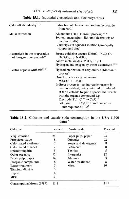
15.5 Examples of industrial electrolysis 333
Table 15.1. Industrial electrolysis and electrosynthesis
Chlor-alkali industry913
Metal extraction
Electrolysis in the preparationof inorganic compounds17
Electro-organic synthesis2
Extraction of chlorine and sodium hydroxidefrom NaCl
Aluminium (Hall-Heroult process)14"16
Sodium, magnesium, lithium (electrolysis ofthe fused salts)
Electrolysis in aqueous solution (principallycopper and zinc)
Strong oxidizing agents: KMnO4, K2Cr2O7,Na2S2O8, F2, NaClO3.
Active metal oxides: MnO2, Cu2OHydrogen and oxygen by water electrolysis18"20
Hydrodimerization of acrylonitrile (Monsantoprocess)
Direct processes e.g. reductionМе2СО-м-РЮН
Indirect processes—an inorganic reagent isused as catalyst, being oxidized or reducedat the electrode to give a species that reactswith the organic compound e.g.Electrode(Pb): Cr3 +-+Cr2O2
Solution: Cr2O2~ + anthracene —>
anthraquinone + Cr3+
Table 15.2. Chlorine and caustic soda consumption in the USA (1990data)25
Chlorine
Vinyl chloridePropylene oxideChlorinated methanesChlorinated ethanesEpichlorohydrinOther organicsPaper pulp, paperInorganic compoundsWater treatmentTitanium dioxideExportMisc.
Consumption/Mtons (1989)
Per cent
248775
121485343
11.1
Caustic soda
Paper pulp, paperOrganicsSoaps and detergentsPetroleumTextilesInorganicsAluminaWater treatmentMisc.
Per cent
2422
885
1238
10
11.2
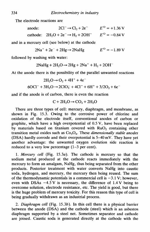
334 Electrochemistry in industry
The electrode reactions are
anode: 2СГ -» Cl2 + 2e" E ° = +1.36 V
cathode: 2H2O + 2e~ -> H2 + 2OH" £ ° = -0.84 V
and in a mercury cell (see below) at the cathode
2Na+ + 2e" + 2Hg-^ 2NaHg £ ° = -1.89 V
followed by washing with water:
2NaHg + 2H2O - • 2Hg + 2Na+ + H2 + 2OH~
At the anode there is the possibility of the parallel unwanted reactions
6ОСГ + 3H2O^> 2C1O^ + 4СГ + 6H+ + 3/2O2 + 6e"
and if the anode is of carbon, there is even the reaction
C + 2H2O-»CO2 + 2H2O
There are three types of cell: mercury, diaphragm, and membrane, asshown in Fig. 15.3. Owing to the corrosive power of chlorine andoxidation of the electrode itself, conventional anodes of carbon orgraphite, which have a high overpotential of 0.5 V, have been replacedby materials based on titanium covered with RuO2 containing othertransition metal oxides such as Co3O4. These dimensionally stable anodes(DSA) hardly corrode and their overpotential is 5-40 mV. They have yetanother advantage: the unwanted oxygen evolution side reaction isreduced to a very low percentage (1-3 per cent).
1. Mercury cell (Fig. 15.3a). The cathode is mercury so that thesodium metal produced at the cathode reacts immediately with themercury to form an amalgam, NaHg, thus being separated from the otherproducts. Posterior treatment with water converts NaHg into causticsoda, hydrogen, and mercury, the mercury then being reused. The sumof the thermodynamic potentials in a commercial cell is -3.1 V; however,even with DSAs -4.5 V is necessary, the difference of 1.4 V being toovercome solution, electrode resistance, etc. The yield is good, but thereis the huge problem of mercury toxicity. For this reason this type of cell isbeing gradually withdrawn as an industrial process.
2. Diaphragm cell (Fig. 15.3ft). In this cell there is a physical barrierbetween the anode (DSA) and the cathode (steel) which is an asbestosdiaphragm supported by a steel net. Sometimes separator and cathodeare joined. Caustic soda is generated directly at the cathode with the

15.5 Examples of industrial electrolysis 335
Saturated NaCl**-
©
Spent NaClHg
' NaHg -0NaHg
(a)
Saturated NaCl
(b)
Saturated NaCl
TDiaphragm
Dilute NaOH +
Dilute NaCl
— — ' — aq. NaOH
Selective membrane(c)
15.3. The chlor-alkali industry. Types of cell (schematic): (a) Mercury cell;(b) Diaphragm cell; (c) Membrane cell.
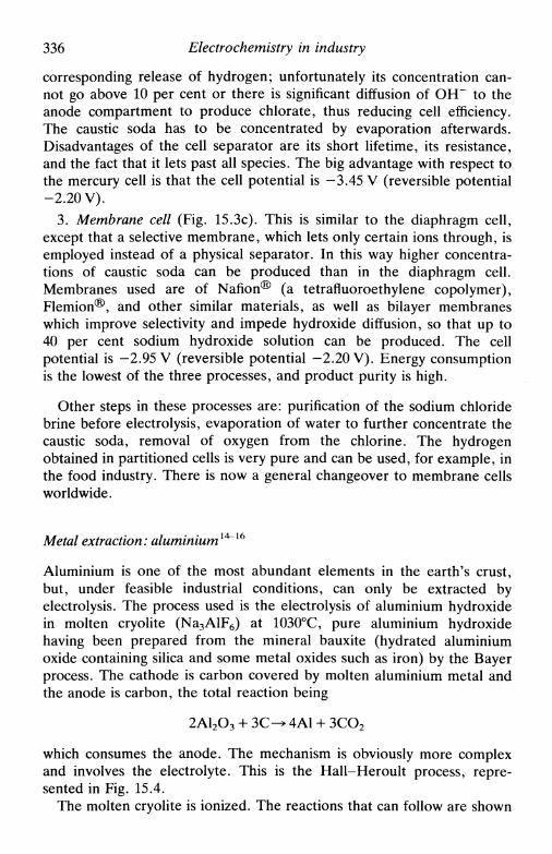
336 Electrochemistry in industry
corresponding release of hydrogen; unfortunately its concentration can-not go above 10 per cent or there is significant diffusion of OH~ to theanode compartment to produce chlorate, thus reducing cell efficiency.The caustic soda has to be concentrated by evaporation afterwards.Disadvantages of the cell separator are its short lifetime, its resistance,and the fact that it lets past all species. The big advantage with respect tothe mercury cell is that the cell potential is -3.45 V (reversible potential-2.20 V).
3. Membrane cell (Fig. 15.3c). This is similar to the diaphragm cell,except that a selective membrane, which lets only certain ions through, isemployed instead of a physical separator. In this way higher concentra-tions of caustic soda can be produced than in the diaphragm cell.Membranes used are of Nafion® (a tetrafluoroethylene copolymer),Flemion®, and other similar materials, as well as bilayer membraneswhich improve selectivity and impede hydroxide diffusion, so that up to40 per cent sodium hydroxide solution can be produced. The cellpotential is -2.95 V (reversible potential -2.20 V). Energy consumptionis the lowest of the three processes, and product purity is high.
Other steps in these processes are: purification of the sodium chloridebrine before electrolysis, evaporation of water to further concentrate thecaustic soda, removal of oxygen from the chlorine. The hydrogenobtained in partitioned cells is very pure and can be used, for example, inthe food industry. There is now a general changeover to membrane cellsworldwide.
Metal extraction: aluminium1^16
Aluminium is one of the most abundant elements in the earth's crust,but, under feasible industrial conditions, can only be extracted byelectrolysis. The process used is the electrolysis of aluminium hydroxidein molten cryolite (Na3AlF6) at 1030°C, pure aluminium hydroxidehaving been prepared from the mineral bauxite (hydrated aluminiumoxide containing silica and some metal oxides such as iron) by the Bayerprocess. The cathode is carbon covered by molten aluminium metal andthe anode is carbon, the total reaction being
2A12O3 + ЗС-^ 4А1 + 3CO2
which consumes the anode. The mechanism is obviously more complexand involves the electrolyte. This is the Hall-Heroult process, repre-sented in Fig. 15.4.
The molten cryolite is ionized. The reactions that can follow are shown

15.5 Examples of industrial electrolysis 337
Lid
Graphitized anthracitein bitumen
Carbon cathode1 current collectnr<>/^i V/f/S//////S/V/y/S7/s/<'///SA\ —
Fig. 15.4. Scheme of a cell for aluminium extraction by the Hall-Heroultprocess.
below, and involve complex ion formation:
24+2F"
4A1F2" + A1 2 O 3 ^ 3Al2OFi" + 6F~
2AlFg" + 2A12O3-^ 3Al2O2Fi"
At the cathode, there is evidence that the complex ions AlF^" anddismute, then following reduction of Al3+ to Al,
AIF4
Na+ is not reduced and F~ produced by the cathode reactions neutralizesthe charge of the sodium ions.
At the anode the electrode reactions involve the aluminium oxyfluoridecomplex ion:
2AlOFii"2AlFg-
2A1F§"
4A1F4T + CO2 + 4e
+ CO2 + 4e

338 Electrochemistry in industry
Finally we need to know the cell potential. Under typical conditions itis
reversible potentialanode overpotentialIR drops: at electrodes
in electrolyte
-1.2-0.5-1.1-1.5
VVVV
-4.3 V
Thus only 30 per cent of the total potential is used for the electrodereactions. It would clearly be very advantageous if there were anothermore energy-efficient process, preferably at a lower temperature.
The only reasonably successful advance in this sense is the Alcoaprocess, based on the electrolysis of aluminium trichloride in a 2-15 percent concentration at 700°C in a 3:2 mixture of molten sodium chlorideand potassium chloride using carbon electrodes. Aluminium oxide ispreviously converted into aluminium chloride using chlorine from elec-trolysis. The reactions are thus
2A12O3 + 3C + 6 C 1 2 ^ 4A1C13 + 3CO2
Energy efficiency is stated to be about 10 per cent better than theHall-Heroult process.
1719Water electrolysis
Hydrogen gas is very important for hydrogenation of inorganic mole-cules, in semiconductor fabrication and in ammonia synthesis. It isnormally produced by separating carbon monoxide and hydrogen result-ing from high-temperature gasification of coal, or from petroleumproducts. However, this hydrogen is not very pure.
High-purity hydrogen is necessary in the food industry to producemargarines etc. Pure oxygen, generated in situ, is important in lifesupport systems in submarines, space vehicles, and so on. Electrolysisgenerally leads to high-purity products, and only water electrolysispermits hydrogen and oxygen to be obtained with sufficient purity for theapplications described. (It should be noted however, that the hydrogenproduced in the electrolysis of sodium chloride in diaphragm or mem-brane cells is also of high purity—see above.)
The basic configuration of a cell for water electrolysis is fairly simple(Fig. 15.5). Anode and cathode are separated by a physical barrier,usually asbestos. The electrodes can be of various materials, such ascarbon, and are often doped with an electrocatalytic material so as to

15.5 Examples of industrial electrolysis
o 2 н2 o 2 н 2 o,
339
ft ft
0
1 Electrodes
-KOH(aq)
Separators
Fig. 15.5. Scheme of a cell for water electrolysis. Note the separators betweenthe H2 and O2 produced. The electrical link is monopolar (but in other designs
can be bipolar).
reduce the energy consumption. The electrolyte is potassium or sodiumhydroxide, as corrosion problems are less in alkaline media. High-pressure electrolysers are often used, since they are more compact thanthose operating at atmospheric pressure, but cell engineering can bedifficult.
Conventional high-pressure electrolysers are being gradually replacedby solid polymer electrolysers which are light and compact and operateon a different principle. Only the anode is exposed to water, whereoxidation of water gives oxygen and H+(aq), the latter diffusing througha solid electrolyte membrane to the cathode where gaseous hydrogen isevolved. An important advantage is that pure water, as opposed tocorrosive electrolyte, can be used and product gases are separated.
There has recently been interest in the photoelectrolysis of water(Section 12.4). In this process a large part of the energy necessary forelectrolysis is provided photochemically by solar radiation, promoting thereactions by exciting the valence electrons in semiconductor electrodes.This electronic energy is then transferred to the water molecules, helpingto break the O-H bonds. Efficiencies achieved so far are still not high,and it is not clear at present what future this will have.
23Organic electrosynthesis: the Monsanto process
The industrial organic electrosynthesis reaction of greatest impact mustbe the Monsanto process for the hydrodimerization of acrylonitrile to

340 Electrochemistry in industry
adiponitrile, one of the steps in the fabrication of nylon 66. Chemicalsynthesis routes, such as gas-phase catalysis of butene, exist and are usedbut feedstocks are more expensive than for the electrochemical route.
The electrode reactions are:
anode: 2 H 2 O ^ O2 + 4H+ + 4e
cathode: 2CH2=CHCN + 2H2O +
via [CH 2 =CHCNp
CHCH2CN| +2ОНГ|
CHCH2CN
At the cathode, other reactions are possible such as reaction ofacrylonitrile with OH~ or direct protonation of the radical anion[CH2—CHCN]'~ to give propionitrile. The existence of several possiblepathways is general in the synthesis of organic compounds, and optimizedexperimental conditions, such as choice of electrode potentials thatminimize unwanted lateral reactions, must be sought. In this particularcase pH control is also of obvious importance in minimizing theunwanted reactions.
The present process is shown schematically in Fig. 15.6. The 'solution'is an emulsion of acrylonitrile and 10-15 per cent disodium hydrogen-phosphate in water containing a quaternary ammonium salt,hexamethylene-bis(ethyldibutylammonium) phosphate, to conduct thecurrent. The anode is carbon steel and the cathode is cadmium (a sheetfixed on to the anode); this cell is a good example of the use of bipolarelectrodes (Section 15.3). EDTA and borax are added in small quantities
Cd Cd Cd cathode
TCarbon steel
anodesElectrolyte
Fig. 15.6. The Monsanto process for the hydrodimerization of acetonitrile. Thecell has bipolar electrodes.

15.6 Electrodeposition and metal finishing 341
to minimize anode corrosion. The cell potential is -3 .8V and theselectivity is 88 per cent.
15.6 Electrodeposition and metal finishing
Metals are used for many purposes, but they are often susceptible tocorrosion (Chapter 16). Protection against corrosion26 brings hugeeconomic benefits. Often protection is done by electrodeposition of alayer of another metal, more inert (and more expensive) on thesubstrate27, for example on iron and steels. Because of the importance ofefficient protection there has been much laboratory investigation intoelectrodeposition mechanisms, but there are still empirical factors to beexplained satisfactorily.
The mechanism of electrodeposition or electrocrystallization28'29 in-volves, as a first step, the reduction of a cation on the substrate surface(aided by an applied potential or current) to form an adatom, and itsmigration over the surface to an energetically favourable site. Otheratoms of the electrodeposit aggregate with the first, forming the nucleusof a new phase. The nucleus grows parallel and/or perpendicular to thesurface. Clearly, a number of nuclei can form and grow on the surface.When all the electrode surface is covered with at least a monolayer,deposition is on the same metal rather than on a different metalsubstrate. As is to be expected, the formation of the first layersdetermines the structure and adhesion of the electrodeposit.
Qualitatively the process is very similar to the formation of aprecipitate in homogeneous solution. The difference is in the structure ofthe precipitate30, as well as its formation, in homogeneous solution beingaffected by the degree of supersaturation and in electrodeposition by theoverpotential.
We now consider briefly how nucleus formation on an electrodesurface, electrocrystallization, can be studied. Nucleation normallyfollows a first-order rate law
N = N0(l-exp(-At)) (15.6)
where No is the number of nucleation sites and A the nucleation constant.There are two limiting cases of (15.6):
• instantaneous nucleation: N = No, At» I, which is probable onapplying a high overpotential;
• continuous nucleation: N = ANot, At«\.
We are assuming an equal nucleation energy for all nucleation sites. Inreality, the energy is less where there are breaks in structure such as grainboundaries, dislocations, etc.

342 Electrochemistry in industry
In the growth phase, the nucleus can grow parallel to and/orperpendicular to the surface. If the growth probability is equal in all threedirections hemispheres are formed of surface area 2яг2, where r is theradius of the sphere.
For a kinetically controlled process the current per nucleus is
2) (15.7)
2nnFM2k3
2
= -2 ? (1.5.8)
where we introduce the dependence of r on t; M is the molecular mass ofthe electrodeposit, p its density, and к the rate constant. When there aremany nuclei then, for instaneous nucleation,
— t2 (15.9)
and for progressive nucleation,
i = 2nnFA^AN^t3 ( i 5 i o )
If the process is diffusion controlled then, for small t,
nnF(2Dcx)3/2MV2N0 1/2
P
for instantaneous nucleation, and
(15 J
З р ш
for progressive nucleation. The dependence of / on t for the four cases issummarized in Table 15.3.
Table 15.3 Dependence of current with time forthe growth of hemispherical nuclei: values of n
where l<*tn
Diffusion controlKinetic control
Nucleation
Instantaneous
1/22
Progressive
3/23
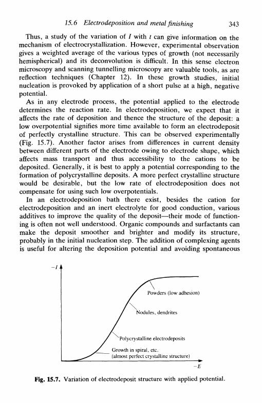
15.6 Electrodeposition and metal finishing 343
Thus, a study of the variation of / with t can give information on themechanism of electrocrystallization. However, experimental observationgives a weighted average of the various types of growth (not necessarilyhemispherical) and its deconvolution is difficult. In this sense electronmicroscopy and scanning tunnelling microscopy are valuable tools, as arereflection techniques (Chapter 12). In these growth studies, initialnucleation is provoked by application of a short pulse at a high, negativepotential.
As in any electrode process, the potential applied to the electrodedetermines the reaction rate. In electrodeposition, we expect that itaffects the rate of deposition and thence the structure of the deposit: alow overpotential signifies more time available to form an electrodepositof perfectly crystalline structure. This can be observed experimentally(Fig. 15.7). Another factor arises from differences in current densitybetween different parts of the electrode owing to electrode shape, whichaffects mass transport and thus accessibility to the cations to bedeposited. Generally, it is best to apply a potential corresponding to theformation of poly crystalline deposits. A more perfect crystalline structurewould be desirable, but the low rate of electrodeposition does notcompensate for using such low overpotentials.
In an electrodeposition bath there exist, besides the cation forelectrodeposition and an inert electrolyte for good conduction, variousadditives to improve the quality of the deposit—their mode of function-ing is often not well understood. Organic compounds and surfactants canmake the deposit smoother and brighter and modify its structure,probably in the initial nucleation step. The addition of complexing agentsis useful for altering the deposition potential and avoiding spontaneous
Powders (low adhesion)
Nodules, dendrites
Polycrystalline electrodeposits
Growth in spiral, etc.(almost perfect crystalline structure)
-E
Fig. 15.7. Variation of electrodeposit structure with applied potential.
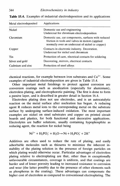
344 Electrochemistry in industry
Table 15.4. Examples of industrial electrodeposition and its applications
Metal electrodeposited Applications
Nickel Domestic use and engineeringUndercoat for chromium electrodeposition
Chromium Domestic use, car components, surfaces with reducedfriction in tools and valves in motors (appliednormally over an undercoat of nickel or copper)
Copper Contacts in electronic industry. Decoration.Undercoat for nickel and chromium
Tin Protection of cans, electrical contacts for solderingSilver and gold Decorating, mirrors, electrical contactsCadmium and zinc Protection of steel alloys
chemical reactions, for example between iron substrates and Cu2+. Someexamples of industrial electrodeposition are given in Table 15.4.
Other important metal finishings to protect against corrosion areconversion coatings such as anodization (especially for aluminium),electroless plating, and electrophoretic painting. The first is done to forma passive layer, and is described in greater detail in Section 16.4.
Electroless plating does not use electrodes, and is an autocatalyticreaction on the metal surface after nucleation has begun. A reducingagent R reduces metal ions to the corresponding metal on the substratesurface by undergoing surface-induced oxidation. The most importantexamples are nickel on steel substrates and copper on printed circuitboards and plastics, for both functional and decorative applications.Electrolytes are buffer solutions, usually containing hypophosphite asreducing agent, the reaction for nickel being
Ni2+ + H2PO^ + H2O-> Ni + H2PO^ + 2H+
Additives are often used to reduce the rate of plating, and easilyadsorbable molecules such as thiourea to minimize the inherent in-stability of the plating solution in the presence of foreign particles onwhich plating would otherwise occur. Particular advantages of electrolessplating relative to electroplating are that, other than in exceptionallyunfavourable circumstances, coverage is uniform, and that coatings areharder and of lower porosity leading to increased resistance to corrosionand wear (the latter possibly due to the presence of other elements suchas phosphorus in the coating). These advantages can compensate thehigher cost of electroless as compared to conventional electroplating. The

15.7 Metal processing 345
harder coatings do lead to lower ductility and higher residual stress, sothat the type of application must be carefully studied.
Electrophoretic painting31 is much used in the automobile industry. Itconsists of the electrodeposition of a polymeric film on a metal from apolymer solution, which totally covers and protects it. The word'electrophoretic' is not very correct in describing the process, andrecently the term 'electrodeposited paint' has been used. The polymercontains acidic or basic groups which form micelles; the solution alsocontains pigments and other organic solids in suspension. The mechanisminvolves migration of the micelles to the electrode, neutralization of theircharge, precipitation of the neutralized polymer with occlusion ofpigment molecules, and, finally, removal of the water solvent from thepolymer layer by electroosmosis. The advantage in using water is clear;the coating is very good, even within crevices. It is a pity that it is onlypossible to apply one coat since, after the surface is coated, it no longerconducts. An important application is in the priming of steel car bodiesafter phosphate conversion coating (see Chapter 16).
15.7 Metal processing
Electrodeposition and electrodissolution of metals has an important rolein the fabrication of metal articles with shapes that are difficult to makeby conventional methods32, We exemplify with two types of processing:electroformation and electrochemical machining.
In electroformation, a metal is electrodeposited in the shape and formof the desired object on top of a substrate (the mould) that is afterwardsremoved. An example is the manufacture of foils for electrical shavers:the mould (cathode) is a cylinder with a design containing insulated partswhere there is no electrodeposition and that turns slowly; the anode isalso cylindrical and concentric with the cathode, and the foil is separatedfrom the mould with a knife (Fig. 15.8). The most commonly used metals
О Foil
Anode
Fig. 15.8. Electroformation of foils.

346 Electrochemistry in industry
Feed direction
Anode .Flow indirection
Cathode_L Flow in* Flow out
r, _, CathodeFeed | , ^ Flow in
Insulation
/ FixtureFlow out housing
(a) External shaping (b) Cavity sinking (c) Plunge cutting
Flow in
Cathode Flow in
Flow out
Feeddirection
'Rotation of anode
(d) Turning
_|_ Nk. Flow out
(e) Trepanning (f) Internal grooving
Fig. 15.9. Electrochemical machining: principle of operation for various types ofshaping (from Ref. 32 with permission).
are nickel and copper, for economic reasons. Apart from foils, bulkmaterials of complex shape can be formed, such as tools and forms forplastics, high-frequency waveguides, and so on.
Metal objects with complex shapes can be formed by electrochemicalmachining (electroerosion), especially important when mechanical mach-ining is not possible. The object is the anode, where dissolution occurs,and the tool is the cathode, having the form of a mould for the object.The cathode has small holes from which jets of electrolyte exit so thatthere is a layer of electrolyte between anode and cathode (Fig. 15.9). Anextremely important example is the manufacture of components such asblades for turbines.
15.8 Batteries
Batteries are stores of chemical energy which, on applying an externalload, can convert this energy into electrical energy. Besides economicfactors, there are certain requirements for a battery to be useful:
• its voltage should be constant and with a minimum overpotential
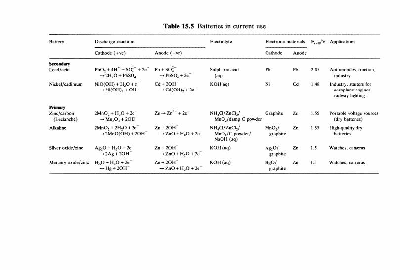
Table 15.5 Batteries in current use
Battery
SecondaryLead/acid
Nickel/cadimum
PrimaryZinc/carbon
(Leclanche)
Alkaline
Silver oxide/zinc
Mercury oxide/zinc
Discharge reactions
Cathode (+ve)
PbO2 + 4H + +SO 4 ~+2e~
NiO(OH) + H2O + e~^Ni(OH) 2 + OH~
2MnO2+H2O + 2e~
2MnO2 + 2H2O + 2e~->2MnO(OH) + 2OH~
Ag2O + H2O + 2e~->2Ag + 2OH~
HgO + H2O + 2e~
Anode (—ve)
Pb + SO4~
C d ^ C d ( O H ) 2 + 2e~
Zn + 2OH"-> ZnO + H2O + 2e
Zn + 2OH~-* ZnO + H2O + 2e~
Zn + 2OH~-* ZnO + H2O + 2e~
Electrolyte
Sulphuric acid(aq)
KOH(aq)
NH4Cl/ZnCl2/MnO2/damp С powder
NH4Cl/ZnCl2/MnO2/C powder/NaOH (aq)
KOH (aq)
KOH (aq)
Electrode
Cathode
Pb
Ni
Graphite
MnO2/graphite
Ag2O/graphite
HgO/graphite
materials
Anode
Pb
Cd
Zn
Zn
Zn
Zn
EM |,A
2.05
1.48
1.55
1.55
1.5
1.5
т Applications
Automobiles, traction,industry
Industry, starters foraeroplane engines,railway lighting
Portable voltage sources(dry batteries)
High-quality drybatteries
Watches, cameras
Watches, cameras

348 Electrochemistry in industry
• on discharging the battery, the voltage remains constant• it has a sufficient, normally high, capacity to supply current• storage without self-discharge
Real batteries satisfy these criteria up to the point judged necessary forthe application in mind. Batteries are classified into two types:
• primary, which discharge only once, e.g. dry batteries;• secondary, which are rechargeable, e.g. lead-acid accumulators.
Another criterion to consider in this category is the number of possiblerecharge cycles.
Some commonly used batteries are shown in Table 15.5, and two aredrawn schematically in Fig. 15.10. From these it can be seen thatimportant components are the container, the anode/cathode compart-ment separators, current collectors to transport current from theelectrode material (usually a porous, particulate paste), the electrodematerial itself, and the electrolyte. It should be noted that the electrodereactions can be significantly more complex than those indicated in Table15.5, and there will probably be parallel reactions. By stacking thebatteries in series, any multiple of the cell potential can be obtained.
Because of the great utility of batteries, the search for systems thatoffer higher energy densities and voltages than present systemscontinues33'34. Lithium batteries in non-aqueous media, which are now
Carbon cylinder
(a)
- Washer
- Separator
] — Zinc anode
<— Plastic
- Metalcovering
-Washer
Zinc Hdanode \
\ L_Y/7/////A
Rubberwasher
Metal case
(b)
\Ag2Opaste
Absorbentcloth
Fig. 15.10. Two batteries in common use: (a) The cylindrical Leclanche battery;(b) The silver oxide/zinc button cell.
15.9 Fuel cells 349
reaching the market for medical and consumer purposes, have lithiumnegative electrodes and can in principle exhibit very high batteryvoltages, because of the very negative electrode potential of the Li+/Licouple, high storage density and high discharge current density—they areusually primary batteries. Use of reduction of organic polymers, such as•fCF)-,,, or of oxidized conducting polymers such as poly acetylene,polyaniline, or polypyrrole, is being investigated as positive electrodereaction. The high chemical reactivity of lithium metal causes difficultiesin battery design.
Amongst other new systems under study are the sodium/sulphurbattery with sodium /?-alumina solid electrolyte operating at 300-375°Cand Li-FeS batteries operating at about 450°C. Long-term batteryresearch is directed towards batteries that can operate at room tempera-ture with aqueous electrolyte, such as zinc-halogen, aluminium-air, andiron-air.
15.9 Fuel cells
Fuel cells33'34 are, in effect, batteries in which the reactants are fedexternally. A fuel undergoes oxidation through controlled half-reactions,in order to convert chemical energy into electrical energy. Directelectrochemical oxidation of fuels appears very difficult to achieve in thecase of hydrocarbons. For example, methane would follow the half-reactions
anode CH4 + 2H2O -* CO2 + 8H+ + 8e~
cathode O2 + 4H+ + 4e~ -> 2H2O
It seems to be necessary to convert the primary fuel into hydrogen orcarbon monoxide first; after this the cell functions well. The best-knownapplication is in the combustion of hydrogen in aqueous potassiumhydroxide electrolyte with nickel electrodes at 200°C, as used in theApollo series space flights.
Present research is mainly into four types of cell:
1. Phosphoric acid (PAFC). The electrolyte is concentrated H3PO4
absorbed on to a solid matrix, and operates at 200°C. The electrodes arecarbon loaded with platinum particles; the anode fuel is hydrogen and thecathode fuel is air. The cell voltage is usually around 0.67 V. This type ofcell has been tested commercially, producing 4.8 MW for several monthsat 40 per cent efficiency.
2. Molten carbonate (MCFC). The cell operates at 650°C and useshydrogen or carbon monoxide as anode fuel, which reacts with carbonate

350 Electrochemistry in industry
in the electrolyte (40 per cent LiAlO2, 28 per cent K2CO3, 32 per centLi2CO3) to give carbon dioxide, whilst oxygen is reduced at the cathodeby carbon dioxide to carbonate. Cell voltages are around 0.9 V. Problemsin functioning can arise with contamination by sulphur or chlorine.
3. Solid oxide (SOFC). The electrolyte is a ceramic oxide and operatesat 1000°C and can consume hydrogen or hydrogen/carbon monoxidemixtures. A high electrical efficiency of over 50 per cent is reported.
4. Alkaline. Fuels are hydrogen and oxygen in a concentrated solutionof potassium hydroxide at room temperature. The possible advantage isthe use of non-platinum catalysts such as Raney nickel and silver oncarbon supports. This is at an earlier stage of development than the othercells.
Possible future applications, besides small-scale power generation atremote sites such as in space, are large-scale power generation, vehicletraction, and burning side-products such as hydrogen from industrialchemical processes in order to recover electrical energy. Other reasonsfor continuing investigations are:
• the possibility of obtaining an efficiency of electrical energy produc-tion greater than that possible by classical combustion (which is about 35per cent), thus saving natural fuel resources
• the amount of carbon dioxide released into the atmosphere is lessper MW of electricity than in other electricity generation processes,which is very important for environmental reasons.
15.10 Electrochemistry in water and effluent treatment
Electrochemistry can be used for a number of purposes linked to waterand effluent treatment. The most obvious of these involve the removal ofionic components from waters by application of an appropriate potential.This is employed to remove metal ions from process streams and oftenleads to recovery of the metal, which can be reused. Clearly, cell designswhich favour high electrode surface area/catholyte volume ratios are tobe recommended.
Cleaning of organic contamination in effluents and in sewage can beaided by electrochemistry in the following ways:
• Electrochemically in situ generated oxidants: hydrogen peroxide,ozone, and hypochlorite or chlorine
• Generating gas bubbles electrolytically at the base of tanks throughwhich the effluent enters slowly at one end at the top and is continuously

References 351
removed from the bottom at the other end. The gas bubbles take
suspended matter with them to the surface from where it is scraped off
{electroflotation). A flocculating agent can be added by controlled
electrochemical anode dissolution, using anodes such as aluminium or
iron, the process then being known as electroflocculation.
Ionic species in waters can be concentrated, and the water purified at
the same time, by electrodialysis. Ion-exchange membranes are employed
with an applied electric field in order to force ionic salts to pass from
dilute into concentrated solutions. Examples of the use of electrodialysis
are in the concentrating of Ni2 + in used nickel plating solutions for
recirculation, and in desalination plants in the purification of sea water or
well water to acceptable levels to make it fit for drinking.
References
1. D. Pletcher and F. C. Walsh, Industrial electrochemistry, 2nd edn., Chapmanand Hall, London, 1990.
2. A. T. Kuhn (ed.), Industrial electrochemistry, Elsevier, Amsterdam, 1971.3. J. O'M. Bockris, B. E. Conway, E. Yeager, and R. E. White (ed.),
Comprehensive treatise of electrochemistry, Plenum, New York, Vol. 2, 1981.4. E. Heitz and G. Kreysa, Principles of electrochemical engineering, VCH,
Weinheim, 1986.5. R. С Alkire, /. Chem. Ed., 1983, 60, 274.6. M. I. Ismail (ed.), Electrochemical reactors; their science and technology,
Elsevier, Amsterdam, 1989.7. R. E. Sioda, Electrochim. Acta, 1970, 15, 783;/. Appl. Electrochem., 1975,
5,221; 1978,8,297.8. J. Newman and W. Tiedemann, Advances in electrochemistry and electroche-
mical engineering, ed. H. Gerischer and C. W. Tobias, Wiley, New York,Vol. 11, 1978.
9. D. L. Caldwell, in Ref. 3, pp. 105-166.10. D. M. Novak, B. V. Tilak, and В. Е. Conway, Modern aspects of
electrochemistry, Plenum, New York, Vol. 14, 1982, ed. В. Е. Conway and J.O'M. Bockris, pp. 195-318.
11. W. N. Brooks, Chem. Brit, 1986, 22, 1095.12. S. Venkatesh and B. V. Tilak, J. Chem. Ed., 1983, 60, 276.13. F. Hine, B. V. Tilak, and K. Viswanathan, Modern aspects of
electrochemistry, Vol. 18, 1986, ed. R. E. White, J. O'M, Bockris, and В. Е.Conway, pp. 249-302.
14. W. E. Haupin and W. B. Frank, in Ref. 3, pp. 301-325.15. W. E. Haupin, /. Chem. Ed., 1983, 60, 279.16. A. R. Burkin (ed.), Production of aluminum and alumina, critical reports on
applied chemistry, Wiley, Chichester, Vol. 20, 1987.17. N. Ibl and H. Vogt, in Ref. 3, pp. 167-250.

352 Electrochemistry in industry
18. B. V. Tilak, P. W. T. Lu, J. E. Colman, and S. Srinivasan, in Ref. 3, pp.1-104.
19. F. Gutmann and O. J. Murphy, Modern aspects of electrochemistry, Plenum,New York, Vol. 15, 1983, ed. R. E. White, J. O'M. Bockris, and В. Е.Conway, pp. 1-82.
20. M. Gratzel, Modern aspects of electrochemistry, Plenum, New York, Vol. 15,1983, ed. R. E. White, J. O'M. Bockris, and В. Е. Conway, pp. 83-165.
21. K. Koster and H. Wendt, in Ref. 3, pp. 251-299.22. J. H. Wagenknecht, /. Chem. Ed., 1983, 60, 271.23. M. M. Baizer (ed.), Organic electrochemistry, Dekker, New York, 1973.24. D. K. Kyriacou and D. A. Jannakoudakis, Electrocatalysis for organic
synthesis, Wiley-Interscience, New York, 1986.25. H. S. Burney and J. B. Talbot, J. Electrochem. Soc, 1991, 138, 3140.26. A. T. Kuhn (ed.), Techniques in electrochemistry, corrosion and metal
finishing—a handbook, Wiley, London, 1987.27. C. J. Rands, in Ref. 3, pp. 381-397.28. E. D. Budevski, Comprehensive treatise of electrochemistry, Plenum, New
York, Vol. 7, 1983, ed. B. E. Conway, J. O'M. Bockris, E. Yeager, and R.E. White, pp. 399-450.
29. M. Sluyters-Rehbach, J. H. O. G. Wigenberg, E. Bosco, and J. H. Sluyters,/. ElectroanaL Chem., 1987, 236, 1.
30. A. R. Despic, Comprehensive treatise of electrochemistry, Plenum, NewYork, Vol. 7, 1983, ed. B. E. Conway, J. O'M. Bockris, E. Yeager, and R.E. White, pp. 451-528.
31. F. Beck, in Ref. 3, pp. 537-569.32. J. P. Hoare and M. L. LaBoda, in Ref. 3, pp. 399-520.33. A. F. Sammells, J. Chem. Ed., 1983, 60, 320.34. M. Hayes, Chem. Brit., 1986, 22, 1101.

16
CORROSION
16.1 Introduction16.2 Fundamentals16.3 Types of metallic corrosion16.4 Electrochemical methods of avoiding corrosion
16.1 Introduction
Corrosion refers to the loss or conversion into another insolublecompound of the surface layers of a solid in contact with a fluid. Thesolid is normally a metal, but the term corrosion is also used to refer tothe dissolution of ionic crystals or semiconductors. In the majority ofcases the fluid is water, but an important exception is the reaction ofmetallic surfaces with air at high temperature, leading to oxide forma-tion, or, in industrial environments, to sulphides, etc. In the context ofthis book, corrosion of metals or semiconductors in contact with aqueoussolution or humid air at normal temperatures is of predominant interest.
Owing to the tremendous economic damage it can cause, corrosion hasand continues to be the subject of extensive study especially with a viewto its minimization at acceptable expense—economic and environmental.We attempt to give an idea of the forms of corrosion, how to investigateit by electrochemistry, and how it can be minimized, or at least reducedand controlled. As will be seen, given the complexity of corrosionprocesses, the mechanism of which can alter significantly depending onthe local environment, the more specialized literature should be con-sulted for details on specific cases, for example Refs. 1-6.
16.2 Fundamentals
The corrosion of a metal in contact with an aqueous solution can berepresented by the generic half-reactions
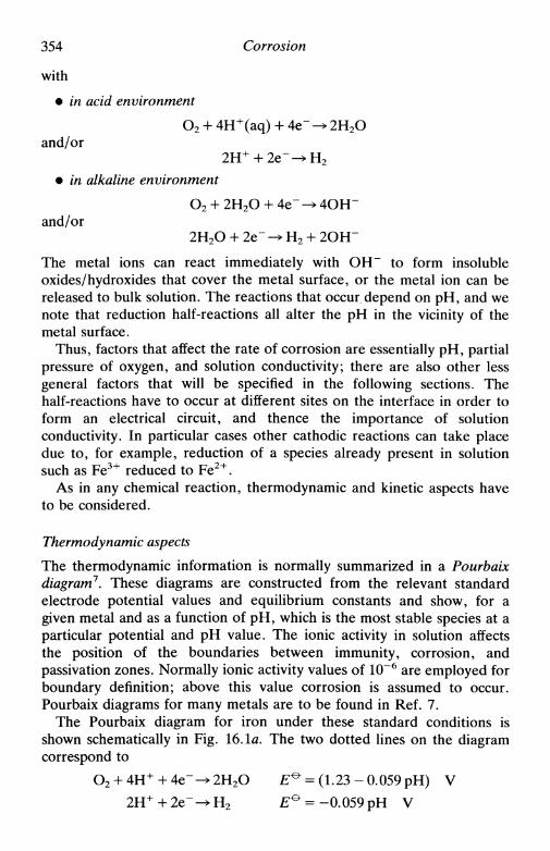
354 Corrosion
with
• in acid environment
O2 + 4H+(aq) + 4 e ~ ^ 2H2Oand/or
2H+ + 2 e " ^ H 2
• in alkaline environment
O2 + 2H2O + 4e" -» 4OH"and/or
2H2O + 2e" -+ H2 + 2OH"
The metal ions can react immediately with OH" to form insolubleoxides/hydroxides that cover the metal surface, or the metal ion can bereleased to bulk solution. The reactions that occur depend on pH, and wenote that reduction half-reactions all alter the pH in the vicinity of themetal surface.
Thus, factors that affect the rate of corrosion are essentially pH, partialpressure of oxygen, and solution conductivity; there are also other lessgeneral factors that will be specified in the following sections. Thehalf-reactions have to occur at different sites on the interface in order toform an electrical circuit, and thence the importance of solutionconductivity. In particular cases other cathodic reactions can take placedue to, for example, reduction of a species already present in solutionsuch as Fe3+ reduced to Fe2+.
As in any chemical reaction, thermodynamic and kinetic aspects haveto be considered.
Thermodynamic aspects
The thermodynamic information is normally summarized in a Pourbaixdiagram7. These diagrams are constructed from the relevant standardelectrode potential values and equilibrium constants and show, for agiven metal and as a function of pH, which is the most stable species at aparticular potential and pH value. The ionic activity in solution affectsthe position of the boundaries between immunity, corrosion, andpassivation zones. Normally ionic activity values of 10~6 are employed forboundary definition; above this value corrosion is assumed to occur.Pourbaix diagrams for many metals are to be found in Ref. 7.
The Pourbaix diagram for iron under these standard conditions isshown schematically in Fig. 16.1a. The two dotted lines on the diagramcorrespond to
O2 + 4H+ + 4e ^ 2H2O £ ° = (1.23 - 0.059 pH) V
2H+ + 2 e " ^ H 2 E ° = -0.059 pH V
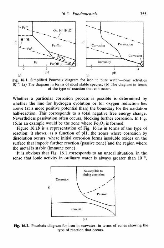
16.2 Fundamentals 355
-*. F e 3 +
H + /H 2
^ F e ^
l
Ч\
Fe
O, H + /H 0
4 Fe2O3
, F e ( O H ) ? ^ ^
ECorrosion Passivation
Corrosion
Immunity
7
PH14 7
PH(a) (b)
Fig. 16.1. Simplified Pourbaix diagram for iron in pure water—ionic activities1(T6: (a) The diagram in terms of most stable species; (b) The diagram in terms
of the type of reaction that can occur.
Whether a particular corrosion process is possible is determined bywhether the line for hydrogen evolution or for oxygen reduction liesabove (at a more positive potential than) the boundary for the oxidationhalf-reaction. This corresponds to a total negative free energy change.Nevertheless passivation often occurs, blocking further corrosion. In Fig.16.1a an example would be the zone where Fe2O3 is formed.
Figure 16.16 is a representation of Fig. 16.1a in terms of the type ofreaction: it shows, as a function of pH, the zones where corrosion bydissolution occurs, where initial corrosion forms insoluble oxides on thesurface that impede further reaction (passive zone) and the region wherethe metal is stable (immune zone).
It is obvious that Fig. 16.1 corresponds to an unreal situation, in thesense that ionic activity in ordinary water is always greater than 10~6,
Corrosion
Susceptible topitting corrosion
Immune
PH
Fig. 16.2. Pourbaix diagram for iron in seawater, in terms of zones showing thetype of reaction that occurs.

356 Corrosion
there may be foreign ions present and the local pH at the surface or atparts of the surface may differ from the bulk. A real situation is thecorrosion of iron in seawater ([СГ] = 0.7 м; рН ~ 7.5) which is shown inFig. 16.2. The zone where pitting corrosion, caused by Cl~, occurs shouldbe noted; this involves rupture of the passive hydroxide film.
Kinetic aspects
Fortunately, kinetics makes corrosion more difficult, so that it is muchless prejudicial than predicted thermodynamically. In the electrochem-istry laboratory corrosion can be studied by voltammetry and kineticparameters can be predicted from Tafel plots and from impedance data.
An important measurement is the corrosion potential, ECOT. This is theopen circuit potential, whose value can change with time. ECOT is a mixedpotential, since the anodic and cathodic reactions are different. Thepartial anodic or cathodic current that flows at this potential is called thecorrosion current, /cor, and is directly related to the rate constant of theelectrode reaction.
A representation of E vs. / is called the Evans diagram (Fig. 16.3), adiagram much used by metallurgists. This diagram is useful for takingqualitative conclusions, especially when the kinetics of H + reduction isstrongly dependent on the metal. For quantitative conclusions, it is clearto the electrochemist that a Tafel plot of E vs. lg |/| contains the sameinformation and gives the possibility of determining /cor with greateraccuracy, as in Fig. 16.4. Besides this, it is possible to correct the data in
2H+ + 2e" ^
Fig. 16.3. Evans diagram for metallic corrosion in acid medium. The concentra-tions are adjusted for £eq to be equal for the three metals.

-Е
16.2 Fundamentals
М = Pb-
357
-2Н+ + 2е" - Н - ,
Fig. 16.4. A Tafel plot for the situation represented in Fig. 16.3 (in normalrepresentation rotated 90° anticlockwise).
a Tafel plot for transport effects. Note that it is lg |/| (current) and notlg I/I (current density) that is plotted, owing to differences of geometricarea where anodic and cathodic reactions occur.
The Tafel plot permits the calculation of the rate constants of thereactions from the intersections, and the charge transfer coefficient fromthe slope. Corrosion researchers use the parameter b (the inverse of theslope of the Tafel plot) extensively in their studies, the reason being therepresentation of the Tafel plot in the way illustrated in Fig. 16.4. In fact,
L 23RT , -2.3RTья = — — - ьс = •aan'F acn'F
(16.1)
where nf is the number of electrons in the rate-determining step.For potentials close to ECOT, we can obtain a relation that allows us to
calculate the corrosion current. Considering the anodic half-reaction weknow that
4),a
= /o,a exp (16.3)
where Eeq>a is the equilibrium potential for the redox couple of the anodichalf-reaction and /0?a the respective exchange current. In a similar way fora cathodic half-reaction,
/cor = /o,c (16.4)

358 Corrosion
in which £eq,c and /0,c have the corresponding meaning for the cathodicreaction. Therefore, for an applied potential different from ECOT, we have
/ = Ц е х р [ J - exp [ J j (16.5)
If (E — ECOT) = A£ is small, leading to a current A/, then we can makethe approximation exp (x) = l+x and obtain
(16.6)
On rearranging,
- ' » • • ! » • ' * ' ( 1 6 . 7 )
which is the Stern-Geary relation8. In this expression Д//АЕ is called thepolarization conductance, KCOT, and its inverse AE/A/ the polarizationresistance, RP. The utility of this relation is because, knowing /Ccor or RP
and Z?a and fcc, we can determine /cor.There are two basic methods for determining RP in the laboratory:
1. Through an impedance experiment
Ap = Zfju-^Q ^ш_>оо (16.8)
2. With small-amplitude cyclic voltammetry9, at a sufficiently slow scanrate (about O.lmVs"1) and with an amplitude of £co r±10mV. Astraight line of slope 1/RF should be obtained.
Of these two methods, the second is the safer, owing to difficulties in thedetermination of ZW^O J it often being necessary to use frequencies lessthan 10~3 Hz.
Alternatively, for fieldwork, but less exactly, a two-electrode probeplaced on the specimen with a 20 mV potential difference applied willsettle around Ecor, the current flow can be measured and RP calculated.
Another aspect to consider is the presence or absence of oxygen insolution. The effect of its presence in acidic solution is demonstrated inFig. 16.5, the result being greater corrosion. Sometimes it catalysescorrosion by oxidizing ionic species in solution, for example
4Fe2+ + O2 + 4H+ > 4Fe3+ + 2H2O
2Fe

16.2 Fundamentals 359
lg / c o r (with 0 2 )
lg / c o r (without O 2 )
М-*М"+ + пе~
/ c o r (with O 2 ) >
/cor (without O 2 )
Fig. 16.5. Tafel plot in acidic medium for metallic corrosion in the absence and inthe presence of oxygen.
Solution flow affects the reaction rate, given that it removes or suppliesspecies in contact with the metal, such as oxygen.
The formation of passive films of metal oxides was already mentioned,the metal becoming immune to corrosion, even when corrosion isthermodynamically very favourable. On sweeping the potential in thepositive direction, we first observe active corrosion, but after reaching acertain value of applied potential (the Flade potential) there is passiva-tion. Passivation is due to two factors: the solubility product of ahydroxide is reached or there is a structural change in a hydroxide filmwhich already exists in a porous form and which changes to a non-porousform. Eventually, for very high positive potentials, there is film ruptureand release of oxygen. Figure 16.6 shows a typical voltammetric profilefor this type of metal, e.g. nickel. It should be noted that the presence ofions that cause pitting can make the passive region non-existent.
Utilization of impedance methods and simulation of the spectraobtained from analogue electrical circuits or transmission lines (Chapter11) can lead to a better comprehension of the complex corrosion processand its inhibition1011. It can also be used as a practical diagnostic ofcorrosion. An example of an impedance spectrum in the complex planeformat and also in the Bode format (the modulus impedance and phaseangle vs. lg (//Hz)), which is extensively employed in impedance studiesof corrosion, is shown in Fig. 16.7. The advantage of the Bode plot is thatit shows high-frequency features which are hidden in the complex planeplot because in the latter the high-frequency points are very closetogether.

360 Corrosion
Active
Flade potential
Evolution of O2and destructionof passive film
- Reduction ofO2 or H2O
Passive region
Fig. 16.6. Voltammetric curve for a metal that forms a passive film, e.g. nickel
30 гResults
A MeasuredCalculated
(a)0 10 20 30 40 50 60
Z'/kfi cm2
N
105
104
103
102
101
10°
(b) 10-10"2 10-1 10° Ю1 102
//Hz
100
80
60
40
20
0
I
103 104
Fig. 16.7. Impedance of AISI316 stainless steel in 3 per cent (wt) NaOH at 80°C(a) Complex plane plot; (b) Bode plot (from Ref. 10 with permission).

16.3 Types of metallic corrosion
16.3 Types of metallic corrosion361
There are many forms of corrosion: this section summarizes the varioustypes. Besides this, knowing the corrosion rate (with or withoutprotection against corrosion) and how it occurs, the engineer can orientcalculations in the design of tubing, walls, etc. so that they have sufficientthickness to minimize rupture. In many of these cases where materialshave reached their final form through application of mechanical forces(stress) or are subjected to mechanical forces periodically (resulting infatigue), corrosion can be accelerated owing to the weakening of thematerial in certain places where cracks appear.
Uniform attack on a metal results in uniform corrosion. This isexploited in the processing and finishing of metals (Chapter 15).However, metallic structures are rarely homogeneous and surfaces arerough: corrosion occurs, preferentially within fissures in the surface(crevice corrosion), making corrosion faster.
In general, metals or alloys that are used are covered with oxide orhydroxide films. Formation of cracks and fissures can destroy thepassivation. The depth of crevices increases rapidly because it is onlythere that the metal is not covered with a protective layer ofoxide/hydroxide (see Fig. 16.8). The result is an increase in surfaceroughness and possible problems due to reduction in mechanicalstrength.
In the case of scratches in paint films that cover the metal the principleis the same (Fig. 16.9). There is oxide formation at the scratch site, thecorrosion continuing, therefore, in a direction parallel to the metalsurface.
Many other types of corrosion can occur. An important example isbimetallic corrosion which occurs at the junction between two different
Air
, _ Solution
Oxide
Fig. 16.8. Scheme of crevice corrosion.
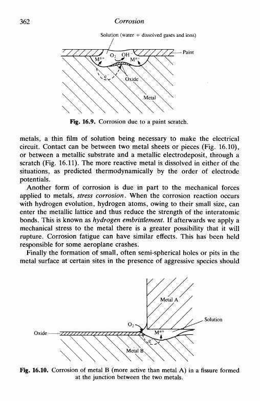
362 Corrosion
Solution (water + dissolved gases and ions)
\-K/////**-— Paint
Fig. 16.9. Corrosion due to a paint scratch.
metals, a thin film of solution being necessary to make the electricalcircuit. Contact can be between two metal sheets or pieces (Fig. 16.10),or between a metallic substrate and a metallic electrodeposit, through ascratch (Fig. 16.11). The more reactive metal is dissolved in either of thesituations, as predicted thermodynamically by the order of electrodepotentials.
Another form of corrosion is due in part to the mechanical forcesapplied to metals, stress corrosion. When the corrosion reaction occurswith hydrogen evolution, hydrogen atoms, owing to their small size, canenter the metallic lattice and thus reduce the strength of the interatomicbonds. This is known as hydrogen embrittlement. If afterwards we apply amechanical stress to the metal there is a greater possibility that it willrupture. Corrosion fatigue can have similar effects. This has been heldresponsible for some aeroplane crashes.
Finally the formation of small, often semi-spherical holes or pits in themetal surface at certain sites in the presence of aggressive species should
Oxide
Solution
Fig. 16.10. Corrosion of metal В (more active than metal A) in a fissure formedat the junction between the two metals.
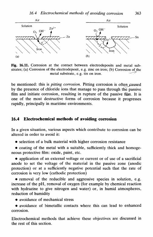
16.4 Electrochemical methods of avoiding corrosion 363
Air Air
Solution Solution
-Sn
Fig. 16.11. Corrosion at the contact between electrodeposits and metal sub-strates; (a) Corrosion of the electrodeposit, e.g. zinc on iron; (b) Corrosion of the
metal substrate, e.g. tin on iron. — ^
be mentioned: this is pitting corrosion. Pitting corrosion is often^ausedby the presence of chloride ions that manage to pass through the passivefilm and initiate corrosion, resulting in rupture of the passive film. It isone of the most destructive forms of corrosion because it progressesrapidly, principally in maritime environments.
16.4 Electrochemical methods of avoiding corrosion
In a given situation, various aspects which contribute to corrosion can bealtered in order to avoid it:
• selection of a bulk material with higher corrosion resistance• coating of the metal with a suitable, sufficiently thick and homoge-
neous protective film: oxide, paint, etc.• application of an external voltage or current or of use of a sacrificial
anode to set the voltage of the material in the passive zone (anodicprotection) or at a sufficiently negative potential such that the rate ofcorrosion is very low (cathodic protection)
• removal of the reducible and aggressive species in solution, e.g.increase of the pH, removal of oxygen (for example by chemical reactionwith hydrazine to give nitrogen and water) or, in humid atmospheres,reduction of humidity
• avoidance of mechanical stress• avoidance of bimetallic contacts where this can lead to enhanced
corrosion.
Electrochemical methods that achieve these objectives are discussed inthe rest of this section.

364 Corrosion
Electrochemically produced protective barriers
Much of metal electrodeposition is carried out with the aim of minimizingcorrosion, the most common electrodeposits being tin, zinc, nickel andchromium on a cheaper metal substrate, such as iron. Since there ischemical bonding between substrate and electrodeposit, this is betterthan covering with paint (except electrophoretic painting, see Chapter15) and additionally the surface generally becomes harder, as it does innickel electroless plating.
Another process of physical protection is the formation of an oxidelayer that makes the metal passive. This procedure is used for aluminium.Aluminium is normally anodized in 10 per cent sulphuric acid with steelor copper cathodes until an oxide thickness of 10-100 /лп is obtained. Asthe more superficial part of the oxide layer has a fairly open structure it ispossible to deposit metals (cobalt, nickel, etc.) or organic pigments in thepores and seal with boiling water or with an alkaline solution. Thecolours after metallic deposition are due to interference effects. Chromicand oxalic acids are also used significantly as electrolyte.
Anodization is also important for titanium, copper, and steel and in thefabrication of electrolytic and non-electrolytic capacitors from alumi-nium, niobium, and tantalum.
Phosphating provides a corrosion-resistant undercoat for paint finisheson steel (particularly automotive bodies), and to a lesser extent on zincand aluminium. The usual process consists of immersion in a bathcontaining phosphoric acid, a metal phosphate (usually iron or zinc), andan accelerator, the pH varying between 1.8 and 3.2, at 60-90°C.
The disadvantage of physically protective barriers is the rapid andlocalized corrosion that occurs when the protective layer is scratched orremoved locally (Figs. 16.10 and 16.11). Thus, in many cases, theutilization of methods involving continuous electrochemical protection isnecessary.
Sacrificial anodes
Electrochemical protection can be achieved by forming an electrolyticcell in which the anode material is more easily corroded than the metal itis desired to protect. This is the case of zinc in contact with iron (Fig.16.11): in this example there is a sort of cathodic protection. Protectionof ship hulls, of subterranean pipeline tubings, of oil rigs, etc. is oftendone using sacrificial anodes that are substituted as necessary. Therequisites for a good sacrificial anode are, besides its preferentialcorrosion, slow corrosion kinetics and non-passivation. Sacrificial anodesin use are, for this reason, normally of zinc, magnesium, or aluminium

16.4 Electrochemical methods of avoiding corrosion 365
alloys, their surfaces partially active and partially passivated, so thatcorrosion is not very fast. A problem that can arise is a decrease in thedegree of protection far from the anodes.
Methods of impressed current/potential
In this type of protection the potential of the metal surface is maintainedconstant by application of an appropriate potential or current (this latteris electrically easier) in a zone where the oxidation current is very low.Referring to Fig. 16.6 one sees that there are two possibilities:
1. Cathodic protection in the negative potential zone where reductionof oxygen or water commences, and where the rate of metal oxidation islow. In this case there has to be an inert auxiliary electrode close to thesurface to be protected. The protection process consumes current, thequantity depending on solution resistance between the surface to beprotected and the anode. This protection can be expensive in terms ofenergy consumption, and even more if there is hydrogen release and,consequently, hydrogen embrittlement.
2. Anodic protectiony normally done potentiostatically, by applicationof a potential within the passive region. Given the form of Fig. 16.6, it isnot so easy to control the potential by impressed current. The advantagesare that there is no release of hydrogen and that often the current, andthus the energy consumed, is low.
Examples of cathodic protection with impressed current are, at thepresent time, protection of steel pipelines in maritime environments or insubsoil. An important example of anodic protection is in the storage ofacids in steel tanks—the anodic current passivates the steel (see Fig.16.1a).
Corrosion inhibitors
Corrosion inhibitors are organic or inorganic species added to thesolution in low concentration and that reduce the rate of corrosion.Inhibition can function in three different ways:
1. A reagent that promotes the appearance of a precipitate on themetal surface, possibly catalysing the formation of a passive layer, forexample hydroxyl ion, phosphate, carbonate, and silicate.
2. Oxidants such as nitrite and chromate which function by shifting thethe surface potential of the metal in the positive direction until thepassive zone in Fig. 16.6 (note that if these components are present ininsufficient quantity the metal stays in the active zone, with potentiallydisastrous consequences).

366 Corrosion
3. A reagent that is adsorbed on the metal surface, diminishing eithermetal dissolution or the reduction of H2O/O2/H+. In either of thesecases, corrosion is reduced. Substances that inhibit metallic dissolutionare organic and include aromatic and aliphatic amines, sulphur com-pounds, and those containing carbonyl groups; the release of hydrogen isinhibited by compounds containing phosphorus, arsenic, and antimony.
The great impact of the social and economic consequences of corro-sion, with many tons of materials being corroded each day, and also froma safety point of view, means that research into these electrode processesand the search for new methods to reduce and control corrosion mustcontinue.
References
1. U. R. Evans, The corrosion and oxidation of metals, Arnold, London, 1960.2. A. T. Kuhn (ed.), Techniques in electrochemistry, corrosion and metal
finishing, Wiley, London, 1987.3. J. M. West, Basic corrosion and oxidation, 2nd edn, Ellis Horwood,
Chichester, 1986.4. A. J. B. Cutler, С D. S. Tuck, S. P. Tyfield, and D. E. Williams, Chem.
Brit, 1986,22, 1109.5. D. Pletcher and F. C. Walsh, Industrial electrochemistry, 2nd edn., Chapman
and Hall, London, 1989, Chapter 10.6. N. Sato, Corrosion, 1989, 45, 354.7. M. Pourbaix, Atlas of electrochemical equilibria in aqueous solutions,
Pergamon Press, Oxford, 1966.8. M. Stern and A. L. Geary, /. Electrochem. Soc, 1957, 104, 56.9. D. D. Macdonald, /. Electrochem. Soc, 1978, 125, 1443.
10. D. C. Silverman and J. E. Carrico, Corrosion, 1988, 44, 280.11. K. Jtittner, Electrochim. Acta, 1990, 35, 1501; F. Mansfeld, Electrochim.
Ada, 1990, 35, 1533; R. Oltra and M. Keddam, Electrochim. Acta, 1990, 35,1619.

17
BIOELECTROCHEMISTRY
17.1 Introduction17.2 The electrochemical interface between biomolecules: cellular membranes,
transmembrane potentials, bilayer lipid membranes, electroporation17.3 Nerve impulse and cardiovascular electrochemistry17.4 Oxidative phosphorylation17.5 Bioenergetics17.6 Bioelectrocatalysis17.7 Bioelectroanalysis17.8 Future perspectives
17.1 Introduction
Faraday, Galvani and others showed in their experiments, many yearsago, the existence of processes occurring in biological systems, which wenow know have an electrochemical foundation. Despite the lack ofresearch in this area during the past century, nobody today doubts thegreat importance of studying this kind of reactions for clarifying andcomprehending the more relevant biological processes15. This is theobjective of a relatively new branch of interdisciplinary research,bioelectrochemistry.
Electron transfer occurs in various ways in the biological sphere. Newtheories suggest that molecular electron transfer is crucial in thebiological regulation of organisms' defence as well as in the growth ofcancerous cells6. It has been proposed that many enzymatic reactions areof an electrochemical nature7, the enzymes being not only catalysts butalso conductors between active sites. Other processes linked withelectrochemical reactions are photosynthesis, nerve excitation, bloodcoagulation, vision, smell, functioning of the thyroid gland, the origin ofthe biological electric potential, etc.
The complexity of biological systems means that it is very importantthat their study should be based on firm foundations. Many pieces in thebiological puzzle are still missing, but each piece represents a valuablecontribution towards attaining the goal.

368 Bioelectrochemistry
At the present time, with the development of new electrochemicalmethods and new electrode materials, a large amount of research hasbeen carried out in the electrochemistry of proteins, enzymes, andcellular components. Nevertheless, much remains to be done. Electro-chemical experiments, in conjunction with other techniques, such asspectroscopy, may give a better answer to these questions.
In this chapter the intention is to give a view of present developmentsand research in bioelectrochemistry. It is not possible to describe theelectrochemical aspects of all the kinds of biological events and processesoccurring in living systems, but some examples will be presented anddiscussed to give an idea of the extent of bioelectrochemistry.
17.2 The electrochemical interface between biomolecules:cellular membranes, transmembrane potentials, bilayerlipid membranes, electroporation
A large fraction of biological molecules has dissociable groups inaqueous solution, giving rise to H+(aq) or other cations or anions, theextent of ionization depending on pH.
Examples of these molecules are amino acids, which exist in thezwitterionic form in acid solution, and in which the molecule contains anequal quantity of positively and negatively charged groups. Thus,zwitterionic molecules are dipolar ions that can have a total positive ornegative charge or be neutral, according to solution pH.
Membrane lipids are amphiphatic molecules: they contain both ahydrophilic and a hydrophobic moiety. Molecules of this kind can lead tovarious types of interface. A natural example is the cellular membrane, abilayer arrangement of such molecules, that marks the frontier betweencells. The principal constituents of this membrane are lipids and proteins(Fig. 17.1).
Lipids are characterized by a predominantly hydrocarbon structure, arevery soluble in organic solvents and sparingly soluble in water, and havephysical properties that are in agreement with their hydrophobicity.Lipids are divided into several classes or families, some having a polarpart; they have important biological functions besides being essentialmembrane components. Links with other molecules are via covalentbonding or van der Waals forces.
Proteins are made of a large number of L-amino acids united bypeptide links (—CONH—), formed from the carboxyl group of oneamino acid and an amine group of another with release of a watermolecule. The name protein comes from a Greek word Jtpcoreivrjmeaning 'of the first importance'. Proteins are constituents of the cell and
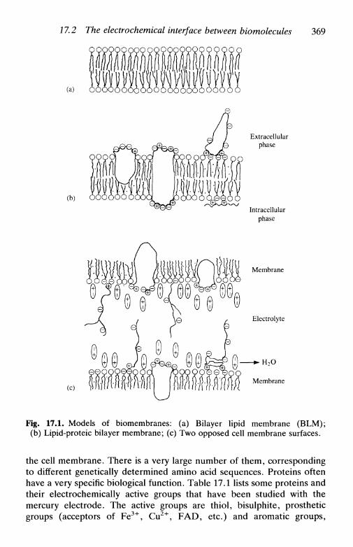
17.2 The electrochemical interface between biomolecules 369
(a)
(b)
Extracellularphase
Intracellularphase
(c)
Membrane
Electrolyte
- • H 2 O
Membrane
Fig. 17.1. Models of biomembranes: (a) Bilayer lipid membrane (BLM);(b) Lipid-proteic bilayer membrane; (c) Two opposed cell membrane surfaces.
the cell membrane. There is a very large number of them, correspondingto different genetically determined amino acid sequences. Proteins oftenhave a very specific biological function. Table 17.1 lists some proteins andtheir electrochemically active groups that have been studied with themercury electrode. The active groups are thiol, bisulphite, prostheticgroups (acceptors of Fe3+, Cu2+, FAD, etc.) and aromatic groups,
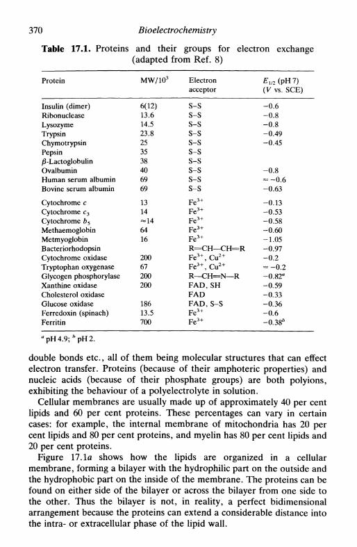
370 Bioelectrochemistry
Table 17.1. Proteins and their groups for electron exchange(adapted from Ref. 8)
Protein
Insulin (dimer)RibonucleaseLysozymeTrypsinChymotrypsinPepsin/8-LactoglobulinOvalbuminHuman serum albuminBovine serum albumin
Cytochrome сCytochrome c 3
Cytochrome b5
MethaemoglobinMetmyoglobinBacteriorhodopsinCytochrome oxidaseTryptophan oxygenaseGlycogen phosphorylaseXanthine oxidaseCholesterol oxidaseGlucose oxidaseFerredoxin (spinach)Ferritin
MW/103
6(12)13.614.523.8253538406969
1314
6416
20067200200
18613.5700
Electronacceptor
S-SS-SS-SS-SS-SS-SS-SS-SS-SS-S
Fe 3 +
Fe 3 +
Fe 3 +
Fe 3 +
Fe 3 +
R = C H — C H = RFe 3 + , Cu2 +
F e 3 + , C u 2 +
R—CH=N—RFAD, SHFADFAD, S-SFe 3 +
Fe 3 +
£ 1 / 2 (pH7)(V vs. SCE)
-0 .6-0 .8-0 .8-0.49-0.45
-0 .8- - 0 . 6-0.63
-0.13-0.53-0.58-0.60-1.05-0.97- 0 . 2- - 0 . 2-0.82"-0.59-0.33-0.36-0 .6-0.38*
flpH4.9;*pH2.
double bonds etc., all of them being molecular structures that can effectelectron transfer. Proteins (because of their amphoteric properties) andnucleic acids (because of their phosphate groups) are both polyions,exhibiting the behaviour of a polyelectrolyte in solution.
Cellular membranes are usually made up of approximately 40 per centlipids and 60 per cent proteins. These percentages can vary in certaincases: for example, the internal membrane of mitochondria has 20 percent lipids and 80 per cent proteins, and myelin has 80 per cent lipids and20 per cent proteins.
Figure 17.1a shows how the lipids are organized in a cellularmembrane, forming a bilayer with the hydrophilic part on the outside andthe hydrophobic part on the inside of the membrane. The proteins can befound on either side of the bilayer or across the bilayer from one side tothe other. Thus the bilayer is not, in reality, a perfect bidimensionalarrangement because the proteins can extend a considerable distance intothe intra- or extracellular phase of the lipid wall.

17,2 The electrochemical interface between biomolecules 371
An electric potential difference is created between the intra- andextracellular layers of the membrane (Fig. 17.1c), called the surfacepotential, Es. This is due to the ionization of the amine and carboxylgroups, or others such as thio groups of proteins, on the surface of themembrane, which are oriented according to an asymmetric distribution.An electrical double layer is thus formed.
The variation of the surface potential is given by
Es — ED (17.1)
in which ED is the potential difference due to the dipoles and £ D L is thepotential difference due to the double layer, obtained from the Poisson-Boltzmann equation of a diffuse layer (Chapter 3).
Experimentally it is the transmembrane potential difference that isobserved by the use of potential-sensitive fluorescent dyes. Two of thecomponents of the transmembrane potential difference are the intra- andextracellular potential differences (Fig. 17.2). If фх is the potential in theinterior of the cell and фо the exterior potential, then the transmembranepotential, Em, is given, in the case of a symmetric membrane where Eu
for the two sides cancels, by
Ет=ф{-фо = £ i , D L - £O,DL + £Diff (17.2)
in which £i,DL a n d £O ,DL are the internal and external surface potentials,respectively, and EDiff expresses the diffusion of ionic species through thesymmetric membrane (Em = EDm when Ei = Eo). When there is a
Interior Membrane Exterior
Fig. 17.2 Schematic representation of transmembrane potential profile. Em,transmembrane potential difference; EO>DL, exterior diffuse double layer potentialdifference; £i,DL, interior diffuse double layer potential difference; Eu potentialdifference due to membrane molecular dipoles; EDi = EUo, symmetric membrane
potential; £Diff diffusion potential difference.
372 Bioelectrochemistry
sufficiently large charge density on the membrane surfaces, the trans-membrane potential is determined solely by the difference in surfacepotentials, the diffusion potential being negligible. Supposing that theintra- and extracellular electrolyte is the same, the only difference beingits concentration, then for a univalent ion
^ ^ (17.3)г Сх
which has the same form as the Nernst equation. co is the concentrationoutside and cx the concentration inside the cell.
At equilibrium, Em is called the resting potential, and is affected by thetransport of all ions that can pass through the membrane, which ispermeable to almost all ions. In fact, the important ions are normallylimited to sodium and potassium and resting potentials vary in value fromtens to hundreds of millivolts.
It is therefore clear that the Donnan potential for equilibriumpotentials (Section 2.11) cannot be used in (17.3), except in specialcircumstances, since there are various components in the total trans-membrane potential. Donnan himself predicted that the phenomenonwould be more complicated for ion transfer processes between living cellsor tissue and the liquids that surround them9. This transmembranepotential is not, however, the only one that can occur in the membrane10.
The fact that the majority of in vivo processes occur on the surface ofor within the membrane and that electrical phenomena are veryimportant in membranes such as those found in the chloroplast, musclefibres, nerve fibres, mitochondria, etc., has recently led to intensive studyof the electrical properties of bilayer lipid membranes (BLM) in anattempt to reproduce a model of the cell membrane. Membranes of5-10 nm thickness have been studied, the membranes consisting of twoparallel sheets of lipids with a hydrophobic environment in the interior ofthe membrane and the hydrophilic groups directed to the exterioraqueous medium.
Artificial bilayer lipid membranes (BLM) have an electrical conduc-tivity of к = 10"14-10"12 S cm"1, less than cell membranes by a factor of106. The conductivity is increased to physiological levels with theintroduction of electron acceptors or proteins in the artificial membranesthat form charge transfer complexes with the lipids, as for solid statelipids11.
The similarities between experimental results from lipids in the solidstate and in the membrane can be considered as experimental evidencefor a mechanism for the two states identical to that of semiconductors12.
Natural membranes have two interfaces with aqueous solutions, andinterfacial properties, such as surface potential, concentration, and

17.3 Nerve impulse and cardiovascular electrochemistry 373
capacitance should affect ion transfer processes. The interaction ofcharged groups on the surface with counter-ions in solution formselectrical double layers13.
The surface compartment model (SCM)1415, which is a theory of iontransport focused on ionic process in electrical double layers at mem-brane protein surfaces, can explain these phenomena. The steady statephysical properties of the discrete surface compartments are calculatedfrom electrical double layer theory.
Artificial transmembrane material release and uptake can be achievedby electroporation16. The electroporation technique, dating from 1982, isa very efficient way of manipulating biological cells and cell tissue,through transient permeabilization of membranes by electrical pulses.Pulse characteristics are field strength of 0.1-30 kV cm"1 and 0.01-30 mspulse duration. Another consequence of electroporation is that electro-porated membranes are more likely to undergo fusion if two cells arebrought into contact (cell electrofusion) as well as to undergo insertion offoreign glycoproteins and DNA (electroinsertion or electrotransfection).
Although the mechanisms of electroporation, electrofusion, and elec-troinsertion are not known, biophysical data suggest that the primaryfield pulse effect is interfacial polarization by ion accumulation at themembrane surfaces. The resulting transmembrane electric field causesrearrangements of the lipids such that pores are formed1718. Electroporesanneal slowly (over a period of minutes) when the pulse is switched off.
The direct electroporative transfer of genes, i.e. DNA (electrotrans-fection), to transform cells is of great interest for molecular biology,genetic engineering, therapy, and biotechnology. Other nucleic acids andproteins can also be efficiently transferred to recipient cells, microorgan-isms, and tissue. The main advantage of electroporative gene transfer isthat intact, chemically untreated cell material can be transferred withhigh efficiency. In particular, the stable electrotransformation of intactbacteria, yeast, and plant cells is an important biological and biotech-nological challenge.
17.3 Nerve impulse and cardiovascular electrochemistry
The importance of transmembrane potentials in cells has been dem-onstrated. Since the cells are totally enclosed by a membrane theynaturally form an electrochemical cell. The cellular fluids containsufficient concentrations of sodium, potassium, and chloride ions to be agood electrolyte, and potential differences originate in the intra- andextracellular membrane surfaces. We now discuss what happens when

374 Bioelectrochemistry
there is an external depolarizing or hyperpolarizing stimulus in the casesof the nerve impulse and cardiovascular problems. The action potential isthe response to the stimulus which puts the biological electrochemical celloutside equilibrium.
The nerve impulse
The nerve cell membrane separates the external from the internal cellfluid, as does any cell membrane. As is true of virtually all cells, theintra- and extracellular fluids are electrolytic solutions of almost equalconductivity, but their chemical composition is very different. The ionspresent in largest quantities are sodium and potassium. The species in theexternal fluid are made up of more than 90 per cent sodium and chlorideions: in the cell interior there are principally potassium and organic ionsthat cannot pass through the membrane, only 10 per cent of the ionsbeing sodium and chloride.
The nerve impulse is called the action potential, and consists principallyof two events that occur consecutively: an influx of positive charge
50
>
I- 5 0
Erest
-100
Outward
J с 03
(a)
50
Thresholdpotential —50
Relatively high
I 1« 1
0
^ Threshold current
• . i i i ^
1 2 3 4 5
HighWK Relatively high Як
High gN
Low gN a
Time/ms(b)
Time/ms
Fig. 17.3. (a) An action potential produced by a nerve-cell membrane inresponse to a depolarization (above the threshold) stimulus, (b) Sketch oftime-dependent conductivity change of a nerve axon membrane (from Ref. 22
with permission).

17.3 Nerve impulse and cardiovascular electrochemistry 375
through the membrane due mostly to the movement of sodium ions intothe cell, followed by the efflux of positive charge, mainly due topotassium ions. The interpretation of this phenomenon by Hodgkin andHuxley19 is that these movements reflect a transient opening of themembrane to sodium ions and then to potassium ions. Propagation of thisimpulse along the nerve is based on different kinds of transfer of theexcitation: ion movement through the aqueous phase in and around thenerves, conduction by non-electrolytic carrier molecules, (for exampleacetylcholine at synapses), sometimes of a solid-state semiconductor type(Szent-Gyorgyi mechanism20), etc. Propagation of the impulse is thebasis for communication through the nervous system.
The mathematical equations describing the ionic currents are empiri-cal, but there is now proof for the existence of membrane-spanningproteins that act as channels for sodium and potassium ions and that openand close in response to changes in membrane polarization.
The nerve impulse, or action potential, may or may not be linked to anelectric potential difference but has propagative characteristics21. Theaction potential is caused by the opening of the membrane to the entry ofsodium ions. After the passage of the nerve impulse, the membrane tendsto recover (Fig. 17.3), returning to its initial state. This occurs through anactive transport mechanism of sodium from the interior to the exterior ofthe cell that involves a membrane-spanning enzyme, Na,K-ATPase. Foreach ATP molecule split by the enzyme, three sodium ions leave thenerve and two potassium ions enter, causing a net movement of chargethrough the membrane, which contributes to the transmembrane poten-tial difference. This process is called the electrogenic sodium pump (Fig.17.4). This pump is responsible for maintaining the transmembrane
Cell interior
ATP
Pi + ADP
Cell exterior
2K +
Fig. 17.4. Electrogenic sodium ion pump.

376 Bioelectrochemistry
Action potential / \
.. Sarcoplasmic reticulum
Myosin
~)
D
ЛСа
Сс
Actin
n n rj n n f~j n
tTransverse tubule
Fig. 17.5. Model for the release of calcium ions during muscular contraction.
resting potential, as it keeps the potassium concentration gradientconstant.
Muscular contraction involves a similar process, since it is stimulatedby the nerve impulse, and an action potential along the musclemembrane carries the impulse to the actin and myosin fibres. The muscleaction potential causes the release of calcium ions from stores in thesarcoplasmic reticulum, and the interaction of actin and myosin provokesmuscle contraction.
Figure 17.5 shows a scheme for excitation-contraction coupling of askeletal muscle.
Cardiovascular problems
The mechanism leading to the formation of a blood clot has been muchstudied. It comprises a reaction sequence whose kinetics is not very clear,but there is no doubt that the initial step is an increase in the potential ofthe blood vessel walls, which are negatively charged in the normal state.
Investigation of coagulation is more easily carried out in vitro.Although the two processes are similar, it is necessary to be cautious incomparing in vivo and in vitro mechanisms. The clot formed in a testtube is different from that formed in the vascular system. Coagulation invitro consists of a fibrin net in which there exist white and red cells and asmall number of platelets. In vivo, the clots consist of large amorphousmasses of platelets surrounded by white cells and very few red cells.
Blood coagulation factors are responsible for the coagulation phenom-

17.3 Nerve impulse and cardiovascular electrochemistry 377
Table 17.2. Dependence of thrombus deposition at metal electrodes onposition of metals in the electrochemical series (adapted from Ref. 23
with permission)
Metal
MgAlCdCuNiAuPt
M"+/M standardelectrode potential(vs. NHE)
-2.375-1.670-0.402+0.346-0.230+ 1.420+ 1.200
Rest potentialat metal-bloodinterface(vs. NHE)
-1.360-0.750-0.050+0.025+0.029+0.120+0.125
Occurrence (/) ornon-occurrence (x)of thrombusdeposition
X
X
X
УУУУ
enon that occurs in a reaction sequence, sometimes called the cascadesystem. Cyclic voltammograms of fibrinogen, thrombin, and prothrombinat platinum electrodes in ionic and pH conditions similar to blood showedthe influence of oxygen and of adsorption phenomena occurring at thesame time as electron transfer23.
Experiments showed that coagulation increases for applied potentialdifferences greater than +0.2 V vs. NHE; below this value, clot forma-tion is very small. The rest potential of various materials used forvascular prostheses and cardiac valves was determined. In Table 17.2some of the materials tested are mentioned. It was concluded thatmetallic electrodes with a negative potential vs. NHE in the blood areanticoagulant while those with positive potential are coagulant. Unfortu-nately, the metals most useful for prostheses are the most easilycorroded: those of platinum and gold, not corroded, are unsuitablebecause of their positive rest potentials. Attempts to resolve the problemhave utilized prostheses of plastic materials compatible in terms of theirqualities of physical resistance, durability, etc. with their end use.
In the same way, the mechanism of action of drugs and coagulant andanticoagulant medication takes place through the variation of surfacecharge in the blood vessels.
The mechanism of blood coagulation is very complex, and has been theobject of scientific and clinical investigation for more than a century24'25.The study of the mechanisms of the electrochemical reactions involved incardiovascular processes and the selection of anticoagulant drugs andthrombogenic prosthesis materials, to be successful, needs to be carriedout simultaneously through haematological and electrochemical research.

378 Bioelectrochemistry
17.4 Oxidative phosphorylation
The electron transfer processes that occur within the membrane, such asfor example, phosphorylation (Fig. 17.6), are well known, but theirmechanisms remain unexplained. These electron transfer processes are ofprimary importance in two types of membrane; chloroplasts in photo-synthesis, and mitochondria in respiration.
As an example we use mitochondria (Fig. 17.6). These are smallcorpuscles that exist in large quantities within cells. They possess anexterior and an interior membrane where the enzymes cytochrome b, c,с ъ a and a3, ATPase, and NADH are located. The interior membrane,of non-repetitive structure, contains 80 per cent protein and 20 per centlipid. The Gibbs free energy variation of the conjugated redox pairs isgiven by the formal potential, according to
AG° ' = -nF AE••e-/ (17.4)
In the respiratory chain we start from the system NAD/NADH2
{E^' = -0.32 V) and reach the system O2/H2O ( £ O / = +0.82 V). Thefree energy change is thus — 220kJmol~1, but this tells us nothing aboutthe mechanism of action of the mitochondria.
Some of the steps of the electron transfer mechanism in biologicalmembranes are known, as they are for the associated proton transfer
Host cellcytoplasm
Mitochondria
Oxygen
Cristae
Membrane
Intermembrane medium
Fig. 17.6. The vectorial pumping of calcium ions and protons across themitochondrion membranes. A schematic enlargement of the inner (cristae)membrane is shown to indicate the existence of protein-based electron (e~) and
proton (H+) conduction pathways (from Ref. 26 with permission).

17.5 Bioenergetics 379
mechanism. This proton flux, which accompanies the electron transfer,creates a proton gradient through the membrane and a potentialdifference given by
9 ^RTAEH+ = Аф- - ^ — ApH (17.5)
leading to the so-called proton pump.The energy released by electron transfer can be used in the transport of
protons through the membrane. One of the proton conduction mechan-isms in proteins is through a chain of hydrogen bonds in the protein, i.e.a Grotthus mechanism (Section 2.9), similar to the mechanism of protonmovement in ice. Protons are injected and removed by the variousoxidation/reduction reactions which occur in the cell: there is no excessof protons or electrons in the final balance, and the reaction cycle isself-sustaining.
17.5 Bioenergetics
Bioenergetics is the study of energy flow in living organisms. In recentyears new electrochemical techniques have been developed and existingones perfected in order to allow the study of these processes27. Despitethe importance of thermodynamic data in understanding the reactions,there is increasing interest in the investigation of the kinetics andmechanism, through the use of voltammetric techniques, especially usingmediators.
The mechanisms of mediator action may be as follows:
1. The mediator is generated electrochemically and reacts with abiological molecule by homogeneous electron transfer;
2. The mediator is linked to the electrode surface, forming a surface-modified electrode, and the biological molecule links itself to themediator layer by heterogeneous electron transfer.
In studying the kinetics of heterogeneous electron transfer in biomole-cules, it is very important to take into account the solution conditions andelectrode material. Mercury and platinum were the most used electrodesuntil 1970. After that, work done with glassy carbon, metallic oxidesemiconductors and chemically modified electrodes began to appear.Proteins such as cytochromes c, c3, c7, b3, and P450, myoglobin,haemoglobin, ferridoxin, peroxidase, and catalase are some of the moststudied compounds28'29 A cyclic voltammogram of ferricytochrome с at agold electrode is shown in Fig. 17.7.

380 Bioelectrochemistry
(с)
1/iA
-0.2 V +0.2 V
Fig. 17.7. D.c. cyclic voltammograms of horse heart ferricytochrome с(5 mg cm"3) in NaClO4 (0.1 м), phosphate buffer (0.02 м) at pH 7 in the presenceof 4,4'-bipyridyl (0.01 м). Sweep rate (rnVs"1): (a) 20; (b) 50; (c) 100 (from Ref.
30 with permission).
There are groups of natural compounds that have a special position inthe study of energy flow through living organisms, for example in thesequential exergonic oxidation of food. Lavoisier in the eighteenthcentury defined in a simplistic way the food metabolism of livingorganisms as being essentially combustion: food and oxygen are ingested,and carbon dioxide and water are ejected—the same total reaction as ifthe food was burnt. The correct elucidation of the mechanisms by whichenergy is stored in molecules such as carbohydrates, fats, and proteins, isa difficult challenge, as is how this energy is released to produce work in acontrolled fashion.
In an intact cell, not all the energy release that occurs with thedegradation of some compounds (catabolism) can be utilized in thesynthesis (anabolism) of other cell components. This is a consequence ofthe dissipation function31, which expresses the rate of loss of free energyin the thermodynamic coupling of two non-reversible processes, with onereleasing and the other requiring energy. Since not all the energyreleased can be used, external energy from for example, photosynthesis,is necessary. There is also the possibility of energy retention in somechemical systems, which can be used in a controlled and efficient way
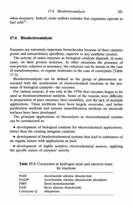
17.6 Bioelectrocatalysis 381
when necessary. Indeed, some authors consider that organisms operate asfuel cells32.
17.6 Bioelectrocatalysis
Enzymes are extremely important biomolecules because of their catalyticpower and extraordinary specificity, superior to any synthetic catalyst.
The activity of redox enzymes as biological catalysts depends, in somecases, on their protein structure. In other situations the presence ofnon-proteic cofactors is necessary; the cofactors can be metals in the caseof metalloenzymes, or organic molecules in the case of coenzymes (Table17.3).
Bioelectrocatalysis can be defined as the group of phenomena as-sociated with the acceleration of electrochemical reactions in the pre-sence of biological catalysts—the enzymes.
For various reasons, it was only in the 1970s that enzymes began to beused as bioelectrochemical catalysts. Some of the reasons were difficultyin preparation of pure enzymes, their instability, and the lack of multipleapplications. These problems have been largely overcome, and betterpurification methods and enzyme immobilization methods on electrodesurfaces have been developed.
The principal applications of biocatalysts in electrochemical systemscan be summarized as:
• development of biological catalysts for electrochemical applications,better than the existing inorganic catalysts
• development of bioelectrochemical systems that lead to substances ofan organic nature with applications as fuels
• development of highly sensitive electrochemical sensors, applyingthe specific nature of enzymes' activity.
Table 17.3 Coenzymes in hydrogen atom and electron trans-fer reactions
NAD nicotinamide adenine dinucleotideNADP nicotinamide adenine dinucleotide phosphateFMN flavin mononucleotideFAD flavin adenine dinucleotideCoenzyme О ubiquinone
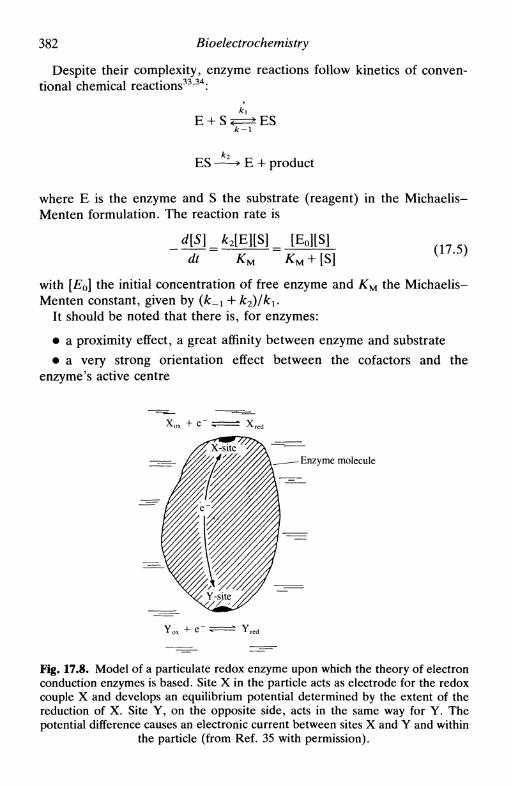
382 Bioelectrochemistry
Despite their complexity, enzyme reactions follow kinetics of conven-tional chemical reactions33'34:
E + S £± ESk-\
ES — -̂> E + product
where E is the enzyme and S the substrate (reagent) in the Michaelis-Menten formulation. The reaction rate is
dt KM
with [Eo] the initial concentration of free enzyme and KM the Michaelis-Menten constant, given by {k_x + k2)/k1.
It should be noted that there is, for enzymes:
• a proximity effect, a great affinity between enzyme and substrate• a very strong orientation effect between the cofactors and the
enzyme's active centre
Enzyme molecule
Fig. 17.8. Model of a particulate redox enzyme upon which the theory of electronconduction enzymes is based. Site X in the particle acts as electrode for the redoxcouple X and develops an equilibrium potential determined by the extent of thereduction of X. Site Y, on the opposite side, acts in the same way for Y. Thepotential difference causes an electronic current between sites X and Y and within
the particle (from Ref. 35 with permission).
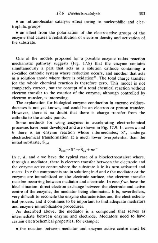
17.6 Bioelectrocatalysis 383
• an intramolecular catalysis effect owing to nucleophilic and elec-trophilic groups
• an effect from the polarization of the electroactive groups of theenzyme that causes a redistribution of electron density and activation ofthe substrate.
One of the models proposed for a possible enzyme redox reactionmechanistic pathway suggests (Fig. 17.8) that the enzyme containssimultaneously a part that acts as a solution cathode containing aso-called cathodic system where reduction occurs, and another that actsas a solution anode where there is oxidation35. The total charge transferfor the whole chemical reaction is therefore zero. This model is notcompletely correct, but the concept of a total chemical reaction withoutelectron transfer to the exterior of the enzyme, although controlled byelectron transfer, is interesting.
The explanation for biological enzyme conduction in enzyme oxidore-ductases is not yet known, and could be an electron or proton transfer.However, there is no doubt that there is charge transfer from thecathodic to the anodic points.
Some methods for using enzymes in accelerating electrochemicalprocesses have been developed and are shown in Fig. 17.9. In cases a andb there is an enzyme reaction whose intermediates, S*, undergoelectrochemical transformation at a much lower overpotential than theinitial substrate, Sred
In c, d, and e we have the typical case of a bioelectrocatalyst where,through a mediator, there is electron transfer between the electrode andthe enzyme active centre where the substrate is in its turn activated andreacts. In с the components are in solution; in d and e the mediator or theenzyme are immobilized on the electrode surface, the electron transferreaction occurring between mediator and electrode. In case/we have theideal situation: direct electron exchange between the electrode and activecentre of the enzyme, the mediator being eliminated. It is, nevertheless,very difficult to reconcile the enzyme characteristics and the electrochem-ical process, and it continues to be important to find adequate mediatorsand enzyme immobilization procedures.
As described above, the mediator is a compound that serves asintermediate between enzyme and electrode. Mediators need to havecertain electrochemical properties, for example:
• the reaction between mediator and enzyme active centre must be
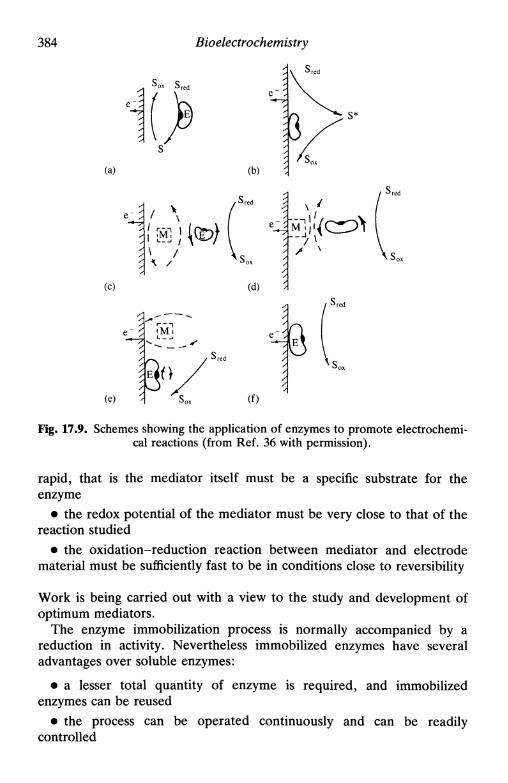
384 Bioelectrochemistry
Sox S r e (
(a) (b)
(C) (d)
(e)
С^ ^ r e c
С (f)
Fig. 17.9. Schemes showing the application of enzymes to promote electrochemi-cal reactions (from Ref. 36 with permission).
rapid, that is the mediator itself must be a specific substrate for theenzyme
• the redox potential of the mediator must be very close to that of thereaction studied
• the oxidation-reduction reaction between mediator and electrodematerial must be sufficiently fast to be in conditions close to reversibility
Work is being carried out with a view to the study and development ofoptimum mediators.
The enzyme immobilization process is normally accompanied by areduction in activity. Nevertheless immobilized enzymes have severaladvantages over soluble enzymes:
• a lesser total quantity of enzyme is required, and immobilizedenzymes can be reused
• the process can be operated continuously and can be readilycontrolled
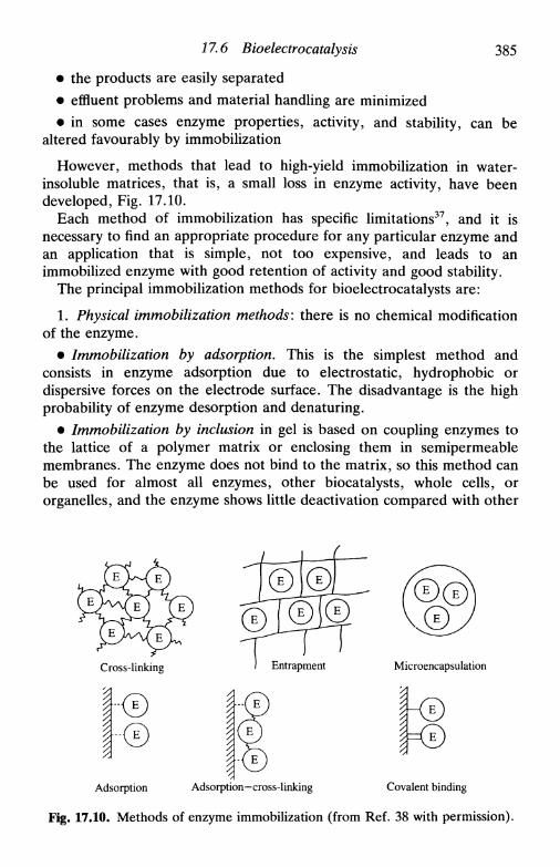
17.6 Bioelectrocatalysis 385
• the products are easily separated• effluent problems and material handling are minimized• in some cases enzyme properties, activity, and stability, can be
altered favourably by immobilization
However, methods that lead to high-yield immobilization in water-insoluble matrices, that is, a small loss in enzyme activity, have beendeveloped, Fig. 17.10.
Each method of immobilization has specific limitations37, and it isnecessary to find an appropriate procedure for any particular enzyme andan application that is simple, not too expensive, and leads to animmobilized enzyme with good retention of activity and good stability.
The principal immobilization methods for bioelectrocatalysts are:
1. Physical immobilization methods: there is no chemical modificationof the enzyme.
• Immobilization by adsorption. This is the simplest method andconsists in enzyme adsorption due to electrostatic, hydrophobic ordispersive forces on the electrode surface. The disadvantage is the highprobability of enzyme desorption and denaturing.
• Immobilization by inclusion in gel is based on coupling enzymes tothe lattice of a polymer matrix or enclosing them in semipermeablemembranes. The enzyme does not bind to the matrix, so this method canbe used for almost all enzymes, other biocatalysts, whole cells, ororganelles, and the enzyme shows little deactivation compared with other
Cross-linking
•-©
Entrapment Microencapsulation
Adsorption Adsorption-cross-linking Covalent binding
Fig. 17.10. Methods of enzyme immobilization (from Ref. 38 with permission).

386 Bioelectrochemistry
Table 17.4. Classification of immobilization methods for insolubleenzymes
Immobilization methods for insoluble enzymes
Binding Entrapment
Cross-linking
Supportbinding
— Gel— Fibre— Microencapsulation
— Physical adsorption— Ionic binding— Metal binding—Covalent binding
immobilization methods. Disadvantages are the possibility of enzymeleaving the gel net and the non-conducting properties of the gel.
2. Chemical immobilization methods. These can be accomplished viathe formation of an array between the enzyme and surface active groupsor via covalently linked transporters. The advantage is that the enzymecannot escape to solution; the disadvantage is that partial or total enzymedeactivation can occur during immobilization owing to the formation ofadditional chemical links.
Research into new enzyme immobilization methods directly on theelectrode surface is in progress.
Table 17.4 gives a classification of immobilization methods for in-soluble enzymes that combines the nature of interaction responsible forimmobilization and the nature of the support.
The mechanism and theory of bioelectrocatalysis is still under develop-ment. Electron transfer and variation of potential in the electrode-enzyme-electrolyte system has therefore to be investigated. Whether theenzyme is soluble and the electron transfer process occurs through amediator, or whether there is direct enzyme immobilization on theelectrode surface, the homogeneous process in the enzyme active centrehas to be described by the laws of enzyme catalysis, and the heteroge-neous processes on the electrode surface by the laws of electrochemicalkinetics. Besides this there are other aspects outside electrochemistry or

17.7 Bioelectroanalysis 387
enzymology. Fundamental research in this dominion will elucidate themechanisms of action of bioelectrocatalysts and develop the scientificbasis for the appearance of optimized bioelectrochemical catalysts.
17.7 Bioelectroanalysis
Bioelectroanalysis is a new area in rapid development withinelectroanalysis39. The use of biological components: enzymes, antibodies,etc., to detect specific compounds has led to the development ofbiosensors4'40.
A large part of analytical chemistry is linked to the qualitative andquantitative analysis of relatively simple species in complex matriceswhere various types of interferences occur. Bioelectroanalytical sensorspermit the analysis of species with great specificity very rapidly, beingsensitive, highly selective and, in principle, cheap. They can be used inclinical analysis, in on-line control processes for industry or environment,or even in vivo41'42.
Bioelectrochemical sensors can be divided into two groups: poten-tiometric and amperometric. Since the description by Clark43 of the firstelectrochemical biosensor based on the oxygen electrode, many poten-tiometric and amperometric sensors using enzymes44 and other materialshave been designed and applied.
In potentiometric sensors a membrane or surface sensitive to a speciesgenerates a potential proportional to the logarithm of the concentrationof the active species, measured relative to a reference electrode (Chapter13). The use of potentiometric electrodes in clinical analysis began at thebeginning of the century with the pH glass electrode. Other electrodesfor measurement in blood, such as ion-selective electrodes for sodium,potassium, lithium, and fluorine followed45. An important developmentwas the appearance of the potassium electrode using valinomycin asneutral charge carrier.
The recently developed field-effect transistors (FETs)41 have also beenused as biosensors. The ion-selective field-effect transistor (ISFET) usesion-selective membranes, identical to those used in ion-selective elec-trodes, over the gate.
Enzyme-selective electrodes (Fig. 17.11) have been made as a mem-brane containing immobilized enzymes placed over a pH electrode orover a gas electrode such as an ammonia electrode for potentiometricdetection, or over an oxygen electrode for amperometric detection. Theproducts of the reaction of enzyme with substrate are detected by theelectrode.

388 Bioelectrochemistry
pH electrode
H +
~~'_z~_r~ Membrane withj m ^ ^ s L ^ z J biocatalytic component
Substrate4
Product
Platinumcathode
Substratereduced
(с)
Membrane withbiocatalytic component
°2 Substrateoxidized
pH electrode
CO,, NH3 Gas-permeable- membrane- Air layer
Membrane withbiocatalytic component
^ — - ^ Membrane withbiocatalytic component
Substratereduced
(d)
Fig. 17.11. (a) Potentiometric biosensor based on pH electrode; (b) Poten-tiometric biosensor based on gas electrode; (c) Oxygen electrode: determinationof oxygen; (d) Oxygen electrode: determination of hydrogen peroxide (from Ref.
42 with permission).
Amperometric sensors measure the current produced by chemicalreaction of an electroactive species at a constant applied voltage, which isrelated to the concentration of the species in solution (Chapter 14). Mostbiologically relevant compounds, such as glucose, urea, cholesterol, etc.are not electroactive and it is necessary to create an adequate combina-tion of reactions to produce an electroactive species. Moreover, in manycases the selectivity given by a constant applied potential is not sufficientto discriminate between various electroactive species, and extra selec-tivity is required. Enzymes can provide this selectivity and sensitivity.Unfortunately, the ideal solution of direct immobilization of enzymes onelectrodes (Section 17.6) tends to result in a significant loss of enzymeactivity. Thus, the following two methods have been developed: one isplacing membranes containing an immobilized enzyme over the electrodeand the other is attaching mediators followed by the enzyme to theelectrode surface (Fig. 17.12). Great care has to be taken in choosingmediators for a given enzyme reaction46.
Conducting organic salt electrodes directly coupled to oxidases havebeen described such as, for example, N-methylphenazinium (NMP+)cation and tetracyanoquinodimethane (TCNQ~) anion as an electrodematerial for facilitating electron transfer of glucose oxidase47. Resultswith other salt cations, such as tetrathiafulvalene (TTF+) and quinoline(Q+), have been reported48.
Electrochemical biosensors have the great advantage of being more

17.7 Bioelectroanalysis 389
11
Substrate
Products
Fig. 17.12. General model for modified electrode, showing mediation of electrontransfer. Eo , Mo and ER, MR are the oxidized and reduced forms of enzyme (E)
and mediator (M) respectively.
economic than other methods and with rapid response and possibility ofautomation enabling a high sample throughput. The determination ofabout 80 different substances including substrates, cofactors, prostheticgroups, enzymes, antibodies, inhibitors, and activators using electroche-mical biosensors has been proposed42.
The use of biosensors for industrial and environmental analysis is veryimportant for the control of food manufacturing processes, for theevaluation of food quality, for the control of fermentation processes andfor monitoring of organic pollutants.
In environmental analysis biosensors have been developed for threemajor applications:
• the assay of environmental inorganic compounds such as nitrate,phosphate, and organic compounds such as methane, NT A, mono-methylsulfate or dimethylformamide;
• monitoring of parameters such as biologically dissolved oxygen;• the determination of toxic or mutagenic materials.
Biosensors have great advantages over spectrophotometric methods inthe relatively little time consumed, ease of operation, and relatively lowcost. Sensors using immobilized microorganisms instead of enzymes arebeing developed for environmental analysis.
Microbial sensors49 are based on the contact between an electrode andimmobilized living cells. The electrode converts the biochemical signalfrom the microorganism into an electric potential, for example therelease of oxygen is registered as a current at constant potential at theClark electrode. There are some advantages in the use of microbial sensorsin relation to other enzymes for electroanalysis: there is no necessity topurify the microbial cells, the sensor is regenerated by immersion in anutrient solution of the microbial culture (it is an in vivo sensor), there isno cof actor regeneration, and the cells fully catalyse metabolic transfor-
390 Bioelectrochemistry
mations, which is not possible with just one enzyme. But there are alsomajor disadvantages: the response time is long and the selectivity is low.
Microelectrodes50 have been finding many possible applications due totheir miniaturized geometry and possibility of in vivo applications,although biocompatibility of the materials used, the need for sterileconditions in implantation of the electrodes, and the risk of immunereactions or thrombosis are still major difficulties for any practicalapplication of in vivo techniques.
The problems that occur with in vivo experiments are not completelysolved. The points where the implanted electrodes cause tissue damageare rapidly regenerated and covered by conjunctive tissue or even byantibodies from electrode rejection. The formation and growth ofconjunctive tissue is influenced by the form and nature of the electrodematerial. A material's biocompatibility is defined as its ability to performwith an appropriate host response in a specific application51. Therefore itis important to develop biomaterials for in vivo sensor applications, sinceneither the conjunctive tissue nor the antibody layer on the electrode isconducting, and a large decrease in electrode response after implantationis observed.
Electrochemical detectors have been used after high-performanceliquid chromatography separation for the determination of catecholam-ines and similar metabolites. Catecholamines constitute a group ofcompounds of great biological interest, some being normally present inthe chemical neurotransmission processes, others being neurotoxins52
that can be responsible for schizophrenia, depression, and some mentalperturbations, like Alzheimer's disease. There have been attempts tostudy their mechanism of action in vivo53'54. Nevertheless, the simul-taneous appearance of ascorbic acid has made these investigations moredifficult.
Microelectrodes are also used in electrophysiology as sensors ofpotential in intra- and extracellular measurements to study ion transportat the molecular level and to obtain measurements of the current passingthrough a single ion channel, as in the patch-clamp technique55. Analysisof electroencephalograms, electromyograms, and electrocardiograms, allmeasuring electrical signals generated in the human body, has been ofgreat importance in the detection and treatment of the respectiveperturbations. The measurements are made through thin wires orelectrodes of Ag | AgCl placed on the surface or in the interior of theorgan that is to be analysed. For safety reasons the electrical signals fromthe body are converted into optical signals, then reconverted intoelectrical signals, using opto-isolators, to isolate the body electricallyfrom the signal-processing instrument.

References 391
17.8 Future perspectives
Much remains to be done in the field of bioelectrochemistry, although ithas already demonstrated great possibilities in elucidating biologicalreactions. The topics described can be consulted in greater depth in therecommended literature.
Our objective in this chapter has been to call attention to a fascinatingand stimulating branch of electrochemistry in rapid development but stillin its infancy. It will certainly contribute a great deal to the understandingof the kinetics and mechanisms of biological phenomena such asselectivity in ionic transport, excitability of membranes, nerve impulseconduction, muscle contraction, photosynthesis, energy conversion andstorage, effects of hormones and drugs, clotting of blood, and manyothers.
References
1. S. Srinivasan, Yu. A. Chizmadzhev, J. O'M. Bockris, В. Е. Conway, and E.Yeager (ed.), Comprehensive treatise of electrochemistry, Plenum, NewYork, Vol. 10, 1985.
2. G. Milazzo (ed.), Topics in bioelectrochemistry and bioenergetics, Wiley,1978, 5 volumes.
3. F. Gutmann and H. Keyser (ed.), Modern bioelectrochemistry, Plenum, NewYork, 1986.
4. A. P. F. Turner, I. Karube, and G. S. Wilson (ed.), Biosensors, fundamen-tals and applications, Oxford University Press, 1987.
5. G. Milazzo etal, Experientia, 1980, 36, 1243.6. A. Szent-Gyorgyi, Science, 1968, 161, 988.7. F. W. Cope, Bull. Math. Biophysics, 1969, 31, 519.8. H. Berg, in Ref. 1, p. 192.9. F. G. Donnan, Chem. Rev., 1924, 1, 73.
10. H. Coster and J. R. Smith, in Ref. 2, Vol. 2, pp. 53-88.11. Cr. Simionescu, Sv. Dumitrescu, and V. Percec in Ref. 2, Vol. 2, pp.
151-204.12. B. Rosenberg, Disc. Faraday Soc, 1971, 51, 1.13. M. J. Sparnaay, The electrical double layer, 1972, Pergamon Press, Oxford,
pp. 1-19.14. M. Blank, Biochim. Biophys. Acta, 1987, 906, 277.15. M. Blank, Bioelectrochemistry II, Vol. 32, Physical Series, Plenum, New
York, 1988.16. E. Neumann, A. E. Sowers, and С A. Jordan (ed.), Electroporation and
electrofusion in cell biology, Plenum, New York, 1989.17. I. P. Sugar and E. Neumann, Biophys. Chem., 1984, 19, 211.18. E. Neumann and K. Rosenheck, J. Membrane BioL, 1972, 10, 279.19. A. L. Hodgkin and A. F. Huxley, /. Physiol., 1952, 117, 500.20. A. Szent-Gyorgyi, Nature, 1941, 148, 157.21. P. K. J. Kinnunen and J. A. Virtanen, in Ref. 3, pp. 457-479.

392 Bioelectrochemistry
22. S. Ohki, in Ref. 1, p. 94.23. S. Srinivasan, in Ref. 1, p. 476.24. R. C. Tolman and A. E. Stearn, /. Am. Chem. Soc, 1918, 40, 264.25. E. J. Warburg, Biochem. J., 1922, 16, 153.26. R. Pethig, in Ref. 3, p. 201.27. E. F. Bowden, F. M. Hawkridge, and H. N. Blount, Ref. 1, pp. 297-346.28. W. J. Albery, M. J. Eddowes, H. A. O. Hill, and A. R. Hillman, J. Am.
Chem. Soc, 1981, 103,3904.29. K. Niki, Y. Kawasaki, N. Nishimura, Y. Higuchi, N. Yasuoka, and M.
Kakudo, /. Electroanal. Chem., 1984, 168, 275.30. M. J. Eddowes and H. A. O. Hill, J. Am. Chem. Soc, 1979, 101, 4461.31. D. Walz, Biochim. Biophys. Ada, 1990, 1019, 171.32. J. O'M. Bockris and S. Srinivasan, Nature, 1967, 215, 197.33. G. Lehninger, Biochemistry, Worth Publishers, New York, 1975, Chapter 8.34. L. Stryer, Biochemistry, Freeman, San Francisco, 1981.35. F. W. Cope, Bull. Math. Biophysics, 1965, 27, 237.36. M. Tarasevich, in Ref. 1, p. 260.37. J. F. Kennedy and J. M. S. Cabral in Biotechnology, VCH, Weinheim, 1987,
Vol. 7a, Chapter 7.38. S. A. Barker, in Ref. 4, p. 92.39. J. P. Hart, Electroanalysis of biologically important compounds, Ellis
Horwood, Chichester, 1990.40. A. E. G. Cass (ed.), Biosensors: a practical approach, IRL Press, Oxford,
1990.41. I. Karube, in Biotechnology, VCH, Weinheim, 1987, Vol. 7a, Chapter 13.42. R. D. Schmid and I. Karube, in Biotechnology, VCH, Weinheim, 1987, Vol.
6b, Chapter 11.43. L. C. Clark Jr. and C. Lyons, Ann. N.Y. Acad. Sci., 1962, 102, 29.44. G. Nagy and E. Pungor, Bioelectrochem. Bioenerget., 1988, 20, 1.45. J. Koryta, Ions, electrodes and membranes, 2nd edn, Wiley, Chichester,
1991.46. P. N. Bartlett, P. Tebbutt, and R. G. Whitaker, Prog. Reaction Kinetics,
1991, 16, 55.47. J. J. Kulys, A. S. Samalius, and G. J. S. Svirmickas, FEBS Letters, 1980,
114, 7.48. W. J. Albery, P. N. Bartlett, and D. H. Craston, /. Electroanal. Chem.,
1985, 194, 223.49. K. Riedel, R. Renneberg, and P. Liebs, Bioelectrochem. Bioenerget., 1988,
19, 137.50. R. M. Wightman in Ultramicroelectrodes, ed. M. Fleischmann, S. Pons, D.
R. Rolison, and P. P. Schmidt, Datatech Systems, USA, 1987.51. Biomaterials Society definition.52. G. Dryhurst, Chem. Rev., 1990, 90, 758.53. R. D. O'Neill, M. Fillenz, W. J. Albery, and N. J. Goddard, Neuroscience,
1983, 9, 87.54. R. M. Wightman, L. J. May, and A. C. Michael, Anal. Chem., 1988, 60,
769A.55. E. Neher and B. Sakmann, Nature, 1976, 260, 799.

Appendices

APPENDIX 1
USEFUL MATHEMATICALRELATIONS
Al.l The Laplace transformA 1.2 The Fourier transformA1.3 Other useful functions and mathematical expressions
A l . l The Laplace transform
Introduction
The Laplace transform is essential in order to transform a partialdifferential equation into a total differential equation. After solving theequation the transform is inverted in order to obtain the solution to themathematical problem in real time and space.
The occurrence of partial differential equations in electrochemistry isdue to the variation of concentration with distance and with time, whichare two independent variables, and are expressed in Fick's second law orin the convective-diffusion equation, possibly with the addition of kineticterms. As in the resolution of any differential equation, it is necessary tospecify the conditions for its solution, otherwise there are many possiblesolutions. Examples of these boundary conditions and the utilization ofthe Laplace transform in resolving mass transport problems may be foundin Chapter 5.
The transform
The definition of the Laplace transform/(s), for a function F{t), is
f{s) = <£{F{t)} = fexp (st)F(t) dt (Al.l)
where s is a number sufficiently large for the integral to converge; SErepresents the transform. A simple example is
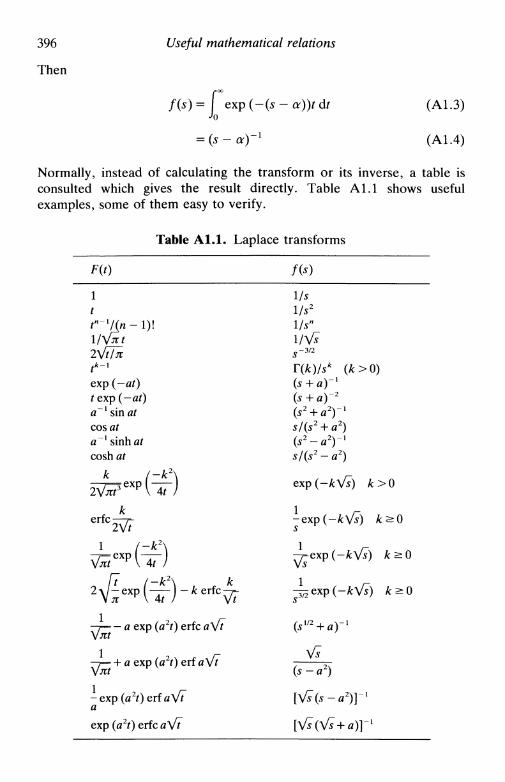
396 Useful mathematical relations
Then
f(s)=i exp(-(s-a))tdt (A1.3)
= (s -a)-1 (A1.4)
Normally, instead of calculating the transform or its inverse, a table isconsulted which gives the result directly. Table A 1.1 shows usefulexamples, some of them easy to verify.
Table Al.l. Laplace transforms
по1t
l/\/jtt
, * - i
exp (-at)Гехр (—at)a~l sin atcos ata~l sinh atcosh at
к ^ /-k2\
ке Г C2\ft
1 ^ /-£2\
/7 /-A:2\ A:
-y— - a exp (я2*) erfc «\ft
—i— + « e x P (я 2 0 e r f я V^
- e x p ( a 2 0 e r f a V ^
exp (a2t) erfc л V^
Us1/s2
l/s"I/VJ
(5 + a ) " 1
(5 2 + fl2)
s/(s2 + a(s2 - a2)s/(s2-a
exp (-k
1
1
1
(*'« + «)
( 5 - a 2 )
[V«(s-
[Vf(Vf
2)2)/—
. - 1
a2)}
+ a)
> 0 )
Л > 0
Л/*J -
- l

А 1.1 The Laplace transform 397
Important properties
The Laplace transform has some properties which are extremely useful inaiding in the resolution of equations in electrochemistry and otherbranches of science.
1. The transform is linear:
2{aF(t) + bG{t)} = af(s) + bg(s)
2. The transform of a derivative is
{^} (A1.6)
If F(t) is redefined such that F(0) = 0, then F(0) disappears. An examplewould be a dimensionless concentration variable
giving
dt
Note that the bar over the symbol у represents the fact that thedimensionless concentration was transformed. All variables not subjectedto direct transformation remain as they were before applying thetransform.
3. The transform of an integral is
which involves, in the Laplace domain, simple division by the Laplacevariable.
4. Inversion, when not corresponding to a tabulated expression, canoften be made possible by separation of the solution in the Laplacedomain into two parts which are tabulated, by means of the convolutionintegral
fV ) dr (A1.10)
In other cases functions have to be written as their series expansions; thisprocess can lead to errors, especially in expansions which contain termsalternately positive and negative.

398 Useful mathematical relations
Al.l The Fourier transform
If, in the Laplace transform, we write
s = ico (Al.ll)we obtain
f(s)=\ exp(-ia)t)F(t)dt (A1.12)
which is the Fourier transform. This is, therefore, a special case of theLaplace transform, and corresponds to a transformation from real time tothe frequency domain. Its importance is principally for the registering offrequency spectra, as in impedance studies (Section 11.12). It is particu-larly useful when low frequencies are being applied to a system and theresponse contains high-frequency noise—the noise is rejected by thetransform, equivalent to filtering.
Any waveform can be described by a Fourier series y(t), involving thesummation of sinusoidal waves of different frequencies, phases andamplitudes:
cc
y(t) = Ao + 2^ An sin (co0nt + фп) (А1.13)
where An is the amplitude of component n with frequency ncoo/2n Hz andphase angle фп. Numerical algorithms for synthesizing the waveformexist: generally the fast Fourier transform (FFT) is employed, which alsoperforms the inversion, greater rapidity being given by computer control.An example of the approximate superposition of sinusoidal waves to givea square wave is shown schematically in Fig. Al.l .
- 4
\
!—\ ЛЛJ W XT'
Fig. Al.l. Formation of a square wave by superposition of the components,showing the two most important components.
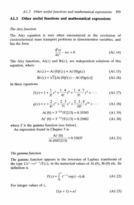
А 1.3 Other useful functions and mathematical expressions 399
A1.3 Other useful functions and mathematical expressions
The Airy function
The Airy equation is very often encountered in the resolution ofelectrochemical mass transport problems in dimensionless variables, andhas the form
d2o>- ^ - c o z = 0 (А1.14)
The Airy functions, Ai(z) and Bi(z), are independent solutions of thisequation, where
Ai (z) = Ai (0)/(z) + Ai'(0)g(z) (А1.15)
Bi (z) = V3 [Ai (0)/(z) - Ai'(0)g(z)] (А1.16)
In these equations
z +
Ai (0) = 3-2/3/Г(2/3) = 0.35503 (A1.19)
Ai' (0) = 3-Ш/Г(1/3) = 0.25882 (A1.20)
where Г is the gamma function (see below).An expression found in Chapter 5 is
A l ^ =0.53837 (A1.21)Ai(0)r(2/3)
The gamma function
The gamma function appears in the inversion of Laplace transforms ofthe type 1/s2—> tz~llT(z)y in the numerical values of Ai (0), Bi (0) etc. Itsdefinition is
T(z) = J f^expf-Odf (A1.22)
For integer values of z,
Г(п + 1) = п! (А1.23)

400 Useful mathematical relations
Table A1.2. Values of thegamma function F(z) for impor-
tant fractions
z
1/41/31/22/33/41
T(z)
3.6256102.6789391.7724541.3541181.2254161.000000
and, in general,
= zF(z) (A1.24)
From tables listing values of Г between 0 and 1 it is possible to calculateF(z) for any positive value. Some values for fractional z are given inTable A 1.2, and the variation of the gamma function with z is shown inFig. A1.2.
The error function
The definition of the error function, erf (z), is
(A1.25)
r(z)
00 1 2 3 4
Fig. A1.2. Graphical representation of the gamma function, F(z), for z >0.
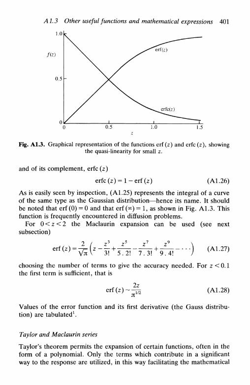
Л 1.3 Other useful functions and mathematical expressions 401
1.0 к
f(z)
0.5
0.5 1.0 1.5
Fig. A1.3. Graphical representation of the functions erf (z) and erfc (z), showingthe quasi-linearity for small z.
and of its complement, erfc (z)
erfc(z) = l - e r f ( z ) (A1.26)
As is easily seen by inspection, (A 1.25) represents the integral of a curveof the same type as the Gaussian distribution—hence its name. It shouldbe noted that erf (0) = 0 and that erf (°°) = 1, as shown in Fig. A1.3. Thisfunction is frequently encountered in diffusion problems.
For 0 < z < 2 the Maclaurin expansion can be used (see nextsubsection)
(A1.27)
choosing the number of terms to give the accuracy needed. For z<0.1the first term is sufficient, that is
erf(z)2z
j t1/2 (A1.28)
Values of the error function and its first derivative (the Gauss distribu-tion) are tabulated1.
Taylor and Maclaurin series
Taylor's theorem permits the expansion of certain functions, often in theform of a polynomial. Only the terms which contribute in a significantway to the response are utilized, in this way facilitating the mathematical
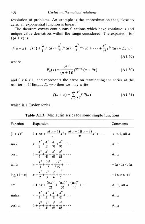
402 Useful mathematical relations
resolution of problems. An example is the approximation that, close tozero, an exponential function is linear.
The theorem covers continuous functions which have continuous andunique value derivatives within the range considered. The expansion forf(a + x) is
f(a+x) =/(«) +^/'(«) + ^ Г ( « ) + ^ / » + • * * + ^ / ( n ) ( * ) + En(*)
(A1.29)
where
En(x) = 7—TTTJ (a + вх) (А1.30)
and 0 < в < 1, and represents the error on terminating the series at thenth term. If Нтп_»оо En-+0 then we may write
which is a Taylor series.
Table A1.3. Maclaurin series for some simple functions
Function
(l+x)"
sin*
c o s л :
t a n *
l o g e ( l + * )
e
s i n h x
c o s h x
E x p a n s i o n
1 + ax
x3
* " 3 ! H
1 " 2 ! H
л:3
ar(a-l) 2 a(a-l)(a-2) 3
' 2! A ' 3! A '
x 5 x 7 x 9
h 5 ! 7 ! + 9 !x 4 x 6 x 8
" 4 ! 6 ! + 8 !
2 x 5 1 7 x 7
I I - Lh 1 5 + 3 1 5 +
x2 x3 x4 x5
-v -I- -L.X 2 + 3 4 + 5
1 + ax
x3
1 + X 2 i H
(ax)2 (ax)3 (ax)4
' 2 ! ' 3 ! ' 4 ! 'JC5 x7 x9
h 5 ! + 7 ! + 9 ! + ' "x4 x6 xs
C o m m e n t s
| * | < 1 , a l l o r
A l l *
A l l *
— \л <x < \K
A l l J C , a l l a
A l l *
A l l *

Л 1.3 Other useful functions and mathematical expressions 403
In the special case of a = 0, (A1.29) transforms into
f(x) =f(0) + */'(0) +^/"(0) + • • • + ^ / ( n ) ( 0 ) + En(x) (A1.32)
with
En(x)=-^-— f(n+1\6x) (A1.33)
and for lim.j^oo En —» 0ОС Г
/(*) = E"^/( r)(0) (A1.34)
which is the Maclaurin series.Exemplifying with the use of a Maclaurin series for exp (x) one obtains
x2 x3
exp (x) = l + x + - + - + . . . (A1.35)
= 2 ^ (A1.36)
Other examples are to be found in Table A 1.3.
Hyperbolic functions
Hyperbolic functions are combinations of exponentials. They are given inTable A1.4, and these functions are plotted in Fig. A1.4. Since they arecontinuous functions, with continuous derivatives obtained in the sameway as normal trigonometric functions, that is
d d— (sinh z) = cosh z — (cosh z) = sinh z (A 1.37)dz dz
the appropriate Maclaurin series may be used (Table A1.3 givesexamples).
Table A1.4. Hyperbolic functions
sinhx Ke'-e"*)coshx {(ex + e~x)
sinh x e* —tanhx
cosh x e* + ecschx (sinhx)"1
sechx (coshjc)"1
cothx (tanhjc)"1

404 Useful mathematical relations
\\ cosh x\\\\\\
sech x
f(x)
- 4 - 3 - 2 _ - 1 4 x
- - 1
- - 2
- - 3
sinhxcoshjc
tanh*
csch*
sech x
coth x
Fig. A1.4. Graphical representation of hyperbolic functions.
Hyperbolic functions frequently appear in electrochemical problems,for instance in the inversion of Laplace transforms. An importantexample of the use of the cosh function is in the expression for thedifferential capacity of the electrolyte double layer following the Gouy-Chapman model (Chapter 3) which has a minimum value and issymmetric around this minimum—compare Fig. 3.6 with the coshfunction in Fig. A1.4.
Reference
1. M. Abramowitz and L A . Stegun (ed.), Handbook of mathematical functions,Dover, New York, 1965.

APPENDIX 2
PRINCIPLES OF a.c. CIRCUITS
A2.1 IntroductionA2.2 ResistanceA2.3 CapacitanceA2.4 Representation in the complex planeA2.5 Resistance and capacitance in seriesA2.6 Resistance and capacitance in parallelA2.7 Impedances in series and in parallelA2.8 AdmittanceA2.9 The Kramers-Kronig relations
A2.1 Introduction
The electrochemical response to an a.c. perturbation is very important inimpedance techniques (Chapter 11). This response cannot be understoodwithout a knowledge of the fundamental principles of a.c. circuits1, whichis presented in this appendix.
We consider the application of a sinusoidal voltage
V = Vosino)t (A2.1)
where Vo is the maximum amplitude and со the frequency (rads"1) to anelectrical circuit that contains combinations of resistances and capacit-ances which, it is hoped, will adequately represent the electrochemicalcell. The response is a current, given by
I = I0 sin (cot + ф) (А2.2)
where ф is the phase angle between perturbation and response. Theproportionality factor between V and / is the impedance, Z. Impedancesconsist of resistances, reactances (derived from capacitive elements) andinductances. Inductances will not be considered here, as for electrochem-ical cells, they only arise at very high frequencies (>1 MHz).
The problem of application of a sinusoidal current and response as amodulated potential obeys analogous mathematical considerations andwill not be discussed.

406 Principles of a. c. circuits
A2.2 Resistance
In the case of a pure resistance, R, Ohm's law V = IR leads to
(A2.3)
and ф = 0. There is no phase difference between potential and current.
/ = —̂ sin cotR
A2.3 Capacitance
For a pure capacitor
dt
Substituting for dV/dt, using (A2.1), one obtains
/ = a)CVosm((Qt + -
= ТГ sin 4- -
(A2.4)
(A2.5)
(A2.6)
By comparing with (A2.2), we see that ф = я/2, that is the current lagsbehind the potential by я/2. Хс = (coC)~l is known as the reactance(measured in ohms).
A2.4 Representation in the complex plane
Given the different phase angles of resistances and reactances describedabove, representation in two dimensions is useful. On the x-axis the
Fig. A2.1. Representation in the complex plane of an impedance containingresistive and capacitive components.

А2.5 Resistance and capacitance in series 407
phase angle is zero; on rotating anticlockwise about the origin the phaseangle increases; pure reactances are represented on the у -axis. Thedistance from the origin corresponds to the amplitude. This is preciselywhat is done with complex numbers as represented vectorially in thecomplex plane: here the real axis is for resistances and the imaginary axisfor reactances. By convention, the current is always on the real axis.Thus it becomes necessary to multiply reactances by —i (V—1) (Fig.A2.1).
А2.5 Resistance and capacitance in series
We exemplify the use of vectors in the complex plane with a resistanceand capacitance in series (Fig. А2.2я). The total potential difference isthe sum of the potential differences across the two elements. FromKirchhoff's law the currents have to be equal, that is
/ = /R = /C (A2.7)
The differences in potential are proportional to R and Xc respectively.Their representation as vectors in the complex plane is shown in Fig.A2.1. The vectorial sum of — iXc and of R gives the impedance Z. As a
IC =
(a)
Z'
(b)
Fig. A2.2. Resistance and capacitance in series: (a) Electrical circuit; (b)Complex plane impedance plot.

408 Principles of а. с. circuits
vector, the impedance is
Z = R-iXc (A2.8)
The magnitude of the impedance is
\Z\ = (R2 + X2
c)m (A2.9)
and the phase angle
^ ^ (А2.10)
Often the in-phase component of the impedance is referred to as Z 'and the out-of-phase component, i.e. at я/2, is called Z", that isZ = Z' + iZ". Thus for this case
Z'=R, Z"=-Xc (A2.ll)
This is a vertical line in the complex plane impedance plot, since Z' isconstant but Z" varies with frequency, as shown in Fig. A2.2b.
A2.6 Resistance and capacitance in parallel
The circuit is shown in Fig. А2.3я. The total current, / t o t, is the sum ofthe two parts, the potential difference across the two components beingequal:
/tot = ̂ sin Ш + у- sin (e»f + ̂ ) (A2.12)
We need to calculate the vectorial sum of the currents shown in Fig.A2.36. Thus
|/totl = (/2
R + /c)1 / 2 (A2.13)
The magnitude of the impedance is
and the phase angle
/ c 1ф = arctan — = arctan (A2.16)
which is equal to the RC series combination (equation (A2.10)).
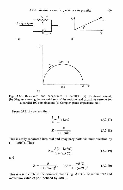
А2.6 Resistance and capacitance in parallel 409
/ = /R +
/ R — -VVWW\/—|
R
(a) (b)
- Z "
(c)
tf/2
Fig. A2.3. Resistance and capacitance in parallel: (a) Electrical circuit;(b) Diagram showing the vectorial sum of the resistive and capacitive currents for
a parallel RC combination; (c) Complex-plane impedance plot.
From (A2.12) we see that
(A2.17)
Z =R
1 4- icoRC(A2.18)
This is easily separated into real and imaginary parts via multiplication by(1 - icoRC). Thus
and
Z' =
z =
R
R(l-ia)RC)
1 + (coRC)2
1 + (wRCfZ' =
-R2C1 + {(oRCf
(A2.19)
(A2.20)
This is a semicircle in the complex plane (Fig. A2.3c), of radius R/2 andmaximum value of \Z"\ defined by coRC = 1.

410 Principles of а. с. circuits
A2.7 Impedance in series and in parallel
Impedances can be combined in the same way as resistances:
in series: Z = ZX + Z2 (A2.21)
in parallel: 1/Z = l/Zl + 1/Z2 (A2.22)
A2.8 Admittance
Admittance is the inverse of impedance, that is
Y=l/Z (A2.23)
It is represented by the symbol F, and can be especially useful in theanalysis of parallel circuits, since admittances for elements in parallel aresummed directly in the same way as one sums impedances for elements inseries (and vice versa).
If the components of the impedance and admittance in phase arerepresented by Z' and У respectively and the components with phaseangle of я/2 represented by Z" and Y", then
_1 Z - \Z"
Z Z' + iZ"~(Z')2 + (Z"):
Thus
y = — = — = Y' 4-iY" f A? 94^
Y' = ,^2Z\^2 = GP (A2.25)
and- Z "
(Z)2 + (Z")
where Gp is the conductance and Bp the susceptance.
У " = Т^ГТТ^г- = ВР= соСр (А2.26)
A2.9 The Kramers-Kronig relations
An electrical system with linear properties does not generate harmonicsin response to the perturbation signal, and the response to two or moresuperimposed excitation signals is equal to the sum of the two responsesobtained by excitation independently. With electrochemical systems thislinearity is possible to a good approximation for perturbations rather lessthan the thermal potential (kBT/e) = 25 mV at 298 K.
References 411
Since almost all equations used in impedance methods are derivedassuming linearity, it is important to have some means of verifying thissupposition. The Kramers-Kronig relations2 link Z' with Z" and allowthe calculation of values for Z" at any frequency from a knowledge of thefull frequency spectrum of Z', and vice versa.
The relations are
r̂̂ -f̂ (A2.27,
(А2.28)
Я Jo X - (OZ
Jt Jo LJC J x — со
x — со(А2.30)
Although these have been applied to electrical systems for over 40 years,only recently have they been applied to electrochemical systems3.
References
1. G. Lancaster, Dc and ac circuits, Oxford Physics Series, Oxford UniversityPress, 1973.
2. H. W. Bode, Network and feedback amplifier design, van Nostrand, NewYork, 1945, Chapter 4.
3. D. D. Macdonald and M. Urquidi-Macdonald, J. Electrochem. Soc, 1985,132, 2316.
APPENDIX 3
DIGITAL SIMULATION
A3.1 IntroductionA3.2 Simulation modelsA3.3 Implicit methods
A3.1 Introduction
The theoretical solution to the equations for electrode processes nearlyalways has to involve approximations, not only for numerical but also foranalytical solutions—such as, for example, the assumption that there isno convection within the diffusion layer of hydrodynamic electrodes. Inother cases, of complex mechanism, it is not even possible to resolve theequations algebraically. There is another possibility for theoreticalanalysis, which is to simulate the electrode process digitally.
Digital simulation has two aims:
• to compare solutions obtained analytically and numerically andexamine the agreement between the two methods
• to solve equations when algebraic solution is not possible.The accuracy of the result obtained by simulation depends on the
increments used in the variables (distance, time, concentration, etc.), andthence the computation time. Care must be taken not to introduceapparently small errors which can be propagated and grow along thesimulation. Also, it should always be remembered that the experiment iscorrect; what may be wrong is our interpretation of the results, that is thesimulation model.
Only an introduction to digital simulation will be given in thisappendix. Extensive treatments exist, such as those in Refs. 1-4. In orderto implement digital simulation FORTRAN has usually been employed.
A3.2 Simulation models
The method normally used in simulation is the finite difference method.The solution is divided into small volume elements within whichconcentrations are assumed to be uniform. Time is also incremented.

Л 3.2 Simulation models 413
Fig. A3.1. Concentration elements for digital simulation.
The example to be given is semi-infinite linear diffusion to a planarelectrode—concentration variation is only perpendicular to the electrode.Fick's second law is
дс Э2с(A3.1)
Three successive volume elements have concentrations ct-lf c, and c/+1,(Fig. A3.1), and the time increment is At. It is not difficult to show, byTaylor series expansion, that (A3.1) transforms into
At^=D-
- (c, - Ci_
Ax(A3.2)
= D-(Ax)2
(A3.3)
where ct is the concentration in element i at time (t + At). To do thecomputations boundary conditions have to be introduced, and particu-larly the initial conditions. It is also necessary to decide whether thestarting point is the electrode surface or bulk solution.
The calculation can be done in two distinct ways:
1. Consider the elements as boxes—but should the electrode surfacebe in the middle of a box (these coordinates always have to be used inorder to define the position of the box) or at the interface between twoboxes? In the past the electrode surface has been put in the middle of abox, but this procedure has been criticized as not corresponding tophysical reality.
2. Use as coordinates the points halfway between the interface ofadjacent elements, calculating the variation of concentration with time atthese points. In this case there is no problem with the positioning of theelectrode surface, as it is at the edge of a box. The simulation formulaeare the same. This method can be particularly advantageous fornon-planar electrodes as it is not necessary to decide on the three-dimensional shape of the elements; only the position of the pointsmatters.
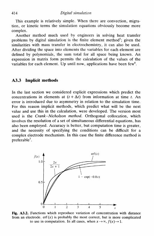
414 Digital simulation
This example is relatively simple. When there are convection, migra-tion, or kinetic terms the simulation equations obviously become morecomplex.
Another method much used by engineers in solving heat transferproblems by digital simulation is the finite element method5; given thesimilarities with mass transfer in electrochemistry, it can also be used.After dividing the space into elements the variables for each element aredefined by polynomials, the sum total for all space being known. Anexpression in matrix form permits the calculation of the values of thevariables for each element. Up until now, applications have been few6.
A3.3 Implicit methods
In the last section we considered explicit expressions which predict theconcentrations in elements at (t + At) from information at time t. Anerror is introduced due to asymmetry in relation to the simulation time.For this reason implicit methods, which predict what will be the nextvalue and use this in the calculation, were developed. The version mostused is the Crank-Nicholson method. Orthogonal collocation, whichinvolves the resolution of a set of simultaneous differential equations, hasalso been employed. Accuracy is better, but computation time is greater,and the necessity of specifying the conditions can be difficult for acomplex electrode mechanism. In this case the finite difference method ispreferable7.
erf(jc)
Fig. A3.2. Functions which reproduce variation of concentration with distancefrom an electrode, erf (*) is probably the most correct, but is more complicated
to use in computation. In all cases, when x^<^, /(*)—» 1.

References 415
As implicit methods need much computation time it is important tominimize the number of elements as much as possible. Far from theelectrode the variation in concentration is relatively small in comparisonwith the variation close to the electrode and, consequently, elements canbe larger; this leads to elements of non-equal size or to non-equalintervals. It is useful to employ functions that reproduce the variationwithin the intervals to a good approximation. Some examples are shownin Fig. A3.2.
References
1. S. W. Feldberg, Electroanalytical chemistry, ed. A. J. Bard, Dekker, NewYork, Vol. 3, 1969, pp. 199-296.
2. D. Britz, Digital simulation in electrochemistry, Springer-Verlag, Berlin, 1981.3. S. Pons, Electroanalytical chemistry, ed. A. J. Bard, Dekker, New York, Vol.
13, 1984, pp. 115-190.4. J. Maloy, Laboratory techniques in electroanalytical chemistry, ed. P. T.
Kissinger and W. R. Heinemann, Dekker, New York, 1984, Chapter 16.5. S. S. Rao, The finite element method in engineering, Pergamon Press, New
York, 1982.6. J. Kwak and A. J. Bard, Anal. Chem., 1989, 61, 1221.7. R. G. Compton, M. E. Laing, D. Mason, R. J. Northing, and P. R. Unwin,
Proc. R. Soc. bond., 1988, A418, 113.

APPENDIX 4
STANDARD ELECTRODEPOTENTIALS
The following is a list of standard electrode potentials of commonhalf-reactions in aqueous solution, that is measured relative to thestandard hydrogen electrode at 25°C (298.15 K) with all species at unitactivity. Most of these values were taken from Standard potentials inaqueous solution, ed. A. J. Bard, R. Parsons, and J. Jordan, Dekker,New York, 1985, in which values for many other half-reactions may alsobe found.
Ag+ + e " ^ A g +0.80Ag2+ + e~-^Ag+ +1.98AgBr + e~ -* Ag + Br" +0.07AgCl + e~-> Ag + СГ +0.22Agl + e ' ^ A g + r -0.15А13+ + Зе"-»А1 -1.68As + 3H+ + 3e" -> AsH3 -0.23As(OH)3 + 3H+ + 3e --> As + 3H2O +0.24AsO(OH)3 + 2H+ + 2e" -> As(OH)3 + H2O +0.56Au+ + e~-^Au +1.83Au3+ + 3e"->Au +1.52Ba2+ + 2e~^Ba -2.92Be2+ + 2e"->Be -1.97Br2(l) + 2e"^2Br" +1.06Br2(aq) + 2e" -> 2Br~ +1.09BrO" + H2O + 2e~ -» Br" + 2ОНГ +0.762HOBr + 2H+ + 2 e " ^ Br2 + 2H2O +1.602ВЮз- + 12H+ + 10e"-> Br2 + 6H2O +1.48BrO4" + 2H+ + 2e -^ ВгОз" + H2O +1.85CO2 + 2H+ + 2e -^CO + H2O -0.11

СО2 + 2Н+ + 2е"2СО2 + 2Н+ + 2е"Са2 + + 2е~-*СаCd(OH)2 + 2e"-H>Cd2 + + 2е~—>CdСе 3 + + Зе~-^СеСе 4 + + е~—>Се3+
С12 + 2е~->2СГСЮ" + Н2О + 2е
Appendix 4
-* HCOOH^ H 2 C 2 O 4
Cd + 2OH"
--»СГ + 2ОН"2НОС1 + 2Н+ + 2е" -» С12 + 2Н2ОНСЮ2 + 2Н+ + 2(СЮз" + ЗН + + 2еС1Оз" + 2Н+ + е-СЮ4" + 2Н+ + 2еСо 2 + + 2е"->СоСо 3 + + е"->Со 2 +
Co(NH3)6+ + e " -Co(phen)i+ + e~-Со(С2О4)
3~ + е~-Сг2+ + 2е~-^СгСг2О?~ + 14Н+ +Сг3+ + Зе"-^СгCs+ + e"-^CsQU+ + e ~-^CuCu2 + + 2e"->CuCu2 + + e"^^Cu +
СиС1 + е~^^Си +Cu(NH3)5+ + 2e"-F 2 + 2e~-^2F~Fe 2 + + 2e~ -> FeFe 3 + + 3e"-*Fepe3+ + e -^,p e 2+
Fe(phen)3+ + e~-Fe(CN)i" + e " ^Fe(CN)^~ + 2 e " -2H+ + 2e"-^H 2
^"-^HOC1 + H2O->HC1O2 + H2O
-^C1O2 + H2O-^C1O3" + H2O
»Co(NH3)2 +
-» Co(phen)i+
-> Co(C2O4)3~
6e ^ 2 C r 3 + + 7H2O
• С Г
^ C u + 4NH3
^Fe(phen)2 +
Fe(CN)4">Fe + 6CN"
E^/V-0.20-0.48-2.84-0.82-0.40-2.34+ 1.72+ 1.36+0.89+ 1.63+ 1.68+ 1.18+ 1.17+ 1.20-0.28+ 1.92+0.06+0.33+0.57-0.90+ 1.38-0.74-2.92+0.52+0.34+0.16+0.12-0.00+2.87-0.44-0.04+0.77+ 1.13+0.36-1.160 (by definition)
417
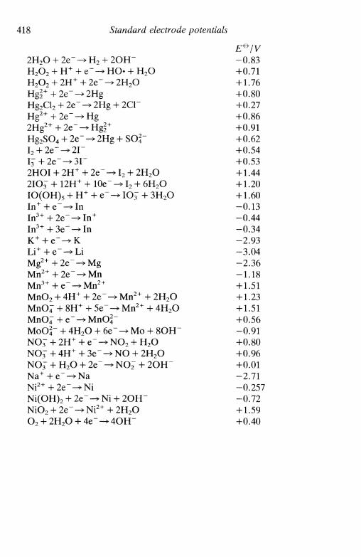
Hg2SO4 + 2e--
2HOI + 2H+ +2IOJ + 12H+ 4Ю(ОН), + Н+
+ 2Hg
2е~->•10е~-
+ е~-
+ sor
12 + 2Н2О-> 12 + 6Н2О* Ю J + ЗН2О
418 Standard electrode potentials
E^/V2Н2О + 2е" -* Н2 + 2ОН~ -0.83Н2О2 + Н + + е~ -> НО- + Н2О +0.71Н2О2 + 2Н+ + 2е~ -> 2Н2О +1.76Hgi+ + 2e"-^2Hg +0.80Hg2Cl2 + 2е" -^ 2Hg + 2СГ +0.27Hg2+ + 2e"-^Hg +0.86
+0.91+0.62+0.54+0.53+ 1.44+ 1.20+ 1.60-0.13-0.44-0.34-2.93-3.04-2.36-1.18+ 1.51
MnO2 + 4Н+ + 2е" -> Мп2+ + 2Н2О +1.23- 8Н+ + 5 е " ^ Мп2+ + 4Н2О +1.51е ' ^ М п О 2 . " +0.56
f 4Н2О + бе" -> Мо + 8ОН~ -0.91NOJ + 2Н+ + е~ -> NO2 + Н2О +0.80
• + 4Н+ + Зе~ -^ NO + 2Н2О +0.96: + Н2О + 2е~ -^ NO2~ + 2OH" +0.01
Na+ + e~-^Na —2.71Ni2+ + 2е" -> Ni -0.257Ni(OH)2 + 2e" -» Ni + 2OH" -0.72NiO2 + 2e" -> Ni2 + + 2H2O +1.59O2 + 2H2O + 4e" -» 4OH~ +0.40

О2 + 4Н+ + 4 е - ^О2 + е~-^О2~О2 + Н2О + 2е"-^О2 + Н + + е - - ^ НО2 + 2Н+ + 2 е ~ ^Р + ЗН+ + Зе~-»РНРО(ОН)2 + ЗН+
НРО(ОН)2 + 2Н+
РО(ОН)3 + 2Н+ +РЬ2 + + 2 е " ^ Р ЬРЬО2 + 4Н+ + 2е"PbSO4 + 2е~ -> РЬPt2 + + 2e"-»Pt
S + 2e~-->S2~2SO2(aq) + 2H+ +SO2(aq) + 4H+ + 4S4Ol~ + 2e~-»2S2
SO^~ + H2O + 2e~2SO^" + 4H+ + 2e"S2Ol~ + 2e~-^2SCSn2+ + 2e~-^SnSn4+ + 2e~-»Sn2+
Sr2+ + 2e"->SrTi2 + + 2e"-^TiTi3 + + e~-^Ti2 +
TiO2 + + e~-*Ti3 +
Tl+ + e"-^TlV2+ + 2e"-^ V
VO2 + + 2H+ + 2e~VOj + 2H+ + e - -Zn 2 + +2e~-»ZnZn(OH)2r + 2e~-
2H2O
HO2" +
H 2O 2
+ 3e~-+ 2e~-2e"->]
^ P b 2 +
+ SO4~
4e~->5e~-*S
->S2C
-_» y 3 +
^VO 2 +
Appendix 4
OH
* P + 3H2O> H2PO(OH) + H2OHPO(OH)2 + H2O
+ 2H2O
j2ol" + н 2 о+ 2H2O
" + 2OH"\\- + 2H2O
+ H2O+ H2O
> Zn + 4OH"
+ 1.23-0.33-0.08-0.13+0.70-0.06-0.50-0.50-0.28-0.13+ 1.70-0.36+ 1.19-2.93-0.48-0.40+0.50+0.08-0.94-0.25+ 1.96-0.14+0.15-2.89-1.63-0.37+0.10-0.34-1.13-0.26+0.34+ 1.00-0.76-1.29
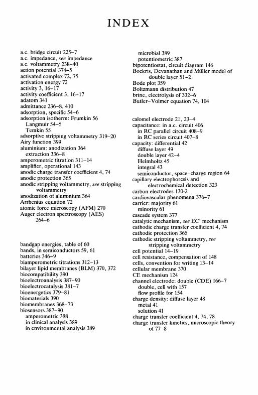
INDEX
a.c. bridge circuit 225-7a.c. impedance, see impedancea.c. voltammetry 238-40action potential 374-5activated complex 72, 75activation energy 72activity 3, 16-17activity coefficient 3, 16-17adatom 341admittance 236-8, 410adsorption, specific 54-6adsorption isotherm: Frumkin 56
Langmuir 54-5Temkin 55
adsorptive stripping voltammetry 319-20Airy function 399aluminium: anodization 364
extraction 336-8amperometric titration 311-14amplifier, operational 143anodic charge transfer coefficient 4, 74anodic protection 365anodic stripping voltammetry, see stripping
voltammetryanodization of aluminium 364Arrhenius equation 72atomic force microscopy (AFM) 270Auger electron spectroscopy (AES)
264-6
bandgap energies, table of 60bands, in semiconductors 59, 61batteries 346-9biamperometric titrations 312-13bilayer lipid membranes (BLM) 370, 372biocompatibility 390bioelectroanalysis 387-90bioelectrocatalysis 381-7bioenergetics 379-81biomaterials 390biomembranes 368-73biosensors 387-90
amperometric 388in clinical analysis 389in environmental analysis 389
microbial 389potentiometric 387
bipotentiostat, circuit diagram 146Bockris, Devanathan and Miiller model of
double layer 51-2Bode plot 359Boltzmann distribution 47brine, electrolysis of 332-6Butler-Volmer equation 74, 104
calomel electrode 21, 23-4capacitance: in a.c. circuit 406
in RC parallel circuit 408-9in RC series circuit 407-8
capacity: differential 42diffuse layer 49double layer 42-4Helmholtz 45integral 43semiconductor, space-charge region 64
capillary electrophoresis andelectrochemical detection 323
carbon electrodes 130-2cardiovascular phenomena 376-7carrier: majority 61
minority 61cascade system 377catalytic mechanism, see EC mechanismcathodic charge transfer coefficient 4, 74cathodic protection 365cathodic stripping voltammetry, see
stripping voltammetrycell potential 14-19cell resistance, compensation of 148cells, convention for writing 13-14cellular membrane 370CE mechanism 124channel electrode: double (CDE) 166-7
double, cell with 157flow profile for 154
charge density: diffuse layer 48metal 41solution 41
charge transfer coefficient 4, 74, 78charge transfer kinetics, microscopic theory
of 77-8
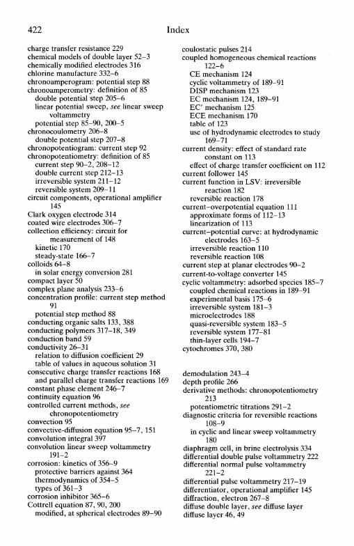
422 Index
charge transfer resistance 229chemical models of double layer 52-3chemically modified electrodes 316chlorine manufacture 332-6chronoamperogram: potential step 88chronoamperometry: definition of 85
double potential step 205-6linear potential sweep, see linear sweep
voltammetrypotential step 85-90, 200-5
chronocoulometry 206-8double potential step 207-8
chronopotentiogram: current step 92chronopotentiometry: definition of 85
current step 90-2, 208-12double current step 212-13irreversible system 211-12reversible system 209-11
circuit components, operational amplifier145
Clark oxygen electrode 314coated wire electrodes 306-7collection efficiency: circuit for
measurement of 148kinetic 170steady-state 166-7
colloids 64-8in solar energy conversion 281
compact layer 50complex plane analysis 233-6concentration profile: current step method
91potential step method 88
conducting organic salts 133, 388conducting polymers 317-18, 349conduction band 59conductivity 26-31
relation to diffusion coefficient 29table of values in aqueous solution 31
consecutive charge transfer reactions 168and parallel charge transfer reactions 169
constant phase element 246-7continuity equation 96controlled current methods, see
chronopotentiometryconvection 95convective-diffusion equation 95-7, 151convolution integral 397convolution linear sweep voltammetry
191-2corrosion: kinetics of 356-9
protective barriers against 364thermodynamics of 354-5types of 361-3
corrosion inhibitor 365-6Cottrell equation 87, 90, 200
modified, at spherical electrodes 89-90
coulostatic pulses 214coupled homogeneous chemical reactions
122-6CE mechanism 124cyclic voltammetry of 189-91DISP mechanism 123EC mechanism 124, 189-91EC mechanism 125ECE mechanism 170table of 123use of hydrodynamic electrodes to study
169-71current density: effect of standard rate
constant on 113effect of charge transfer coefficient on 112
current follower 145current function in LSV: irreversible
reaction 182reversible reaction 178
current-overpotential equation 111approximate forms of 112-13linearization of 113
current-potential curve: at hydrodynamicelectrodes 163-5
irreversible reaction 110reversible reaction 108
current step at planar electrodes 90-2current-to-voltage converter 145cyclic voltammetry: adsorbed species 185-7
coupled chemical reactions in 189-91experimental basis 175-6irreversible system 181-3microelectrodes 188quasi-reversible system 183-5reversible system 177-81thin-layer cells 194-7
cytochromes 370, 380
demodulation 243-4depth profile 266derivative methods: chronopotentiometry
213potentiometric titrations 291-2
diagnostic criteria for reversible reactions108-9
in cyclic and linear sweep voltammetry180
diaphragm cell, in brine electrolysis 334differential double pulse voltammetry 222differential normal pulse voltammetry
221-2differential pulse voltammetry 217-19differentiator, operational amplifier 145diffraction, electron 267-8diffuse double layer, see diffuse layerdiffuse layer 46, 49

Index 423
diffusion 25-6, 83-5Fick's laws of 25,83-5
diffusion coefficient 25, 83and conductivity (Nernst-Einstein
relation) 29and mobility (Einstein relation) 29and viscosity (Stokes-Einstein relation)
29diffusion layer 94-5, 155diffusion-limited current, planar and
spherical electrodes 85-90digital instrumentation 148-9digital simulation 412-15dimensionally stable anodes 334DISP1 and DISP2 mechanisms 123dissipation function 380Donnan equilibrium 295Donnan potential 34double current step 212-13double hydrodynamic electrodes 165-7
stripping voltammetry at 321double layer correction 116-19double layer models: Bockris et al. 51-2
'chemical' 52-3Gouy-Chapman 46-9Grahame 50-1Helmholtz 45-6Stern 49-50
double potential step 205-6drop time at DME 160dropping mercury electrode (DME) 135,
158-63capacitive current at 161cell for 159diffusion limited current at 159-61
EC mechanism 124cyclic voltammetry and 189-91
E C mechanism 125ECE mechanism 170effluent treatment 350-1Einstein relation 28electrocapillary curve 42electrocapillary equation 40electrocapillary measurements 40-1electrochemical free energy 18electrochemical machining 346electrochemical mass spectrometry (ECMS)
266-7electrochemical potential 18electrochemical reactors 328-31electrochemiluminescence (ECL) 282electrocrystallization 341-3electrode: auxiliary 137
enzyme-selective 303gas-sensing 303
glass 295indicator 136membrane-covered 314-15mercury film 197, 321metallized membrane 315optically transparent 194reference 136-7working 137
electrode kinetics, Butler-Volmerformulation of 74, 104
effect of double layer on 116-19electrode materials: carbon 130-3
conducting organic salt 133, 388conducting polymer 318, 349mercury 133-4metals 130semiconductors 133
electrode potentials, relation to vacuum 80electrode reaction rate: Butler-Volmer
formulation 74, 104electrodeposition 343-4electrode-solution interface 39electrodialysis 351electroflocculation 351electroflotation 351electroformation 345electrogenic sodium pump 375electrokinetic phenomena 64-8electroless plating 344electrolysis, fundamentals of 327-8
table of industrial processes 333electrolyte, supporting 138-40electrolytic cell 20electron diffraction 267-8electron energy loss spectroscopy (EELS)
266electron microscopy 273-6electron probe microanalysis (EPMA) 275electron spectroscopy for chemical analysis,
see XPSelectron spin resonance (ESR) spectroscopy
260electron transfer: mechanism of 70-1
microscopic interpretation of 77-81electroosmosis 67electropainting, see electrophoretic paintingelectrophoresis 66-7electrophoretic painting 345electroplating 343electroporation 373electroreflectance 257electrosorption valency 297electrosynthesis, the Monsanto process
339-41ellipsometry 258energy level, and electrode potential 79-80
Fermi 56-7
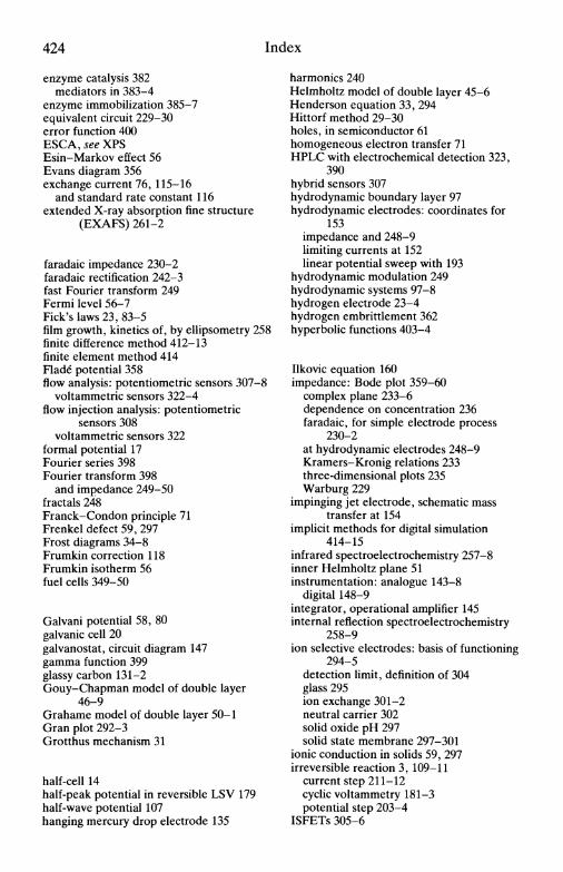
424 Index
enzyme catalysis 382mediators in 383-4
enzyme immobilization 385-7equivalent circuit 229-30error function 400ESCA, see XPSEsin-Markov effect 56Evans diagram 356exchange current 76, 115-16
and standard rate constant 116extended X-ray absorption fine structure
(EXAFS) 261-2
faradaic impedance 230-2faradaic rectification 242-3fast Fourier transform 249Fermi level 56-7Fick's laws 23, 83-5film growth, kinetics of, by ellipsometry 258finite difference method 412-13finite element method 414Flade potential 358flow analysis: potentiometric sensors 307-8
voltammetric sensors 322-4flow injection analysis: potentiometric
sensors 308voltammetric sensors 322
formal potential 17Fourier series 398Fourier transform 398
and impedance 249-50fractals 248Franck-Condon principle 71Frenkel defect 59, 297Frost diagrams 34-8Frumkin correction 118Frumkin isotherm 56fuel cells 349-50
Galvani potential 58, 80galvanic cell 20galvanostat, circuit diagram 147gamma function 399glassy carbon 131-2Gouy-Chapman model of double layer
46-9Grahame model of double layer 50-1Gran plot 292-3Grotthus mechanism 31
half-cell 14half-peak potential in reversible LSV 179half-wave potential 107hanging mercury drop electrode 135
harmonics 240Helmholtz model of double layer 45-6Henderson equation 33, 294Hittorf method 29-30holes, in semiconductor 61homogeneous electron transfer 71HPLC with electrochemical detection 323,
390hybrid sensors 307hydrodynamic boundary layer 97hydrodynamic electrodes: coordinates for
153impedance and 248-9limiting currents at 152linear potential sweep with 193
hydrodynamic modulation 249hydrodynamic systems 97-8hydrogen electrode 23-4hydrogen embrittlement 362hyperbolic functions 403-4
Ilkovic equation 160impedance: Bode plot 359-60
complex plane 233-6dependence on concentration 236faradaic, for simple electrode process
230-2at hydrodynamic electrodes 248-9Kramers-Kronig relations 233three-dimensional plots 235Warburg 229
impinging jet electrode, schematic masstransfer at 154
implicit methods for digital simulation414-15
infrared spectroelectrochemistry 257-8inner Helmholtz plane 51instrumentation: analogue 143-8
digital 148-9integrator, operational amplifier 145internal reflection spectroelectrochemistry
258-9ion selective electrodes: basis of functioning
294-5detection limit, definition of 304glass 295ion exchange 301-2neutral carrier 302solid oxide pH 297solid state membrane 297-301
ionic conduction in solids 59, 297irreversible reaction 3, 109-11
current step 211-12cyclic voltammetry 181-3potential step 203-4
ISFETs 305-6
Index 425
isoelectric point 66isotherm, adsorption, see adsorption
isotherm
kinetics, electrode reaction 74, 104Kramers-Kronig relations 410-11
laminar flow 96Langmuir isotherm 54-5Laplace operator 84Laplace transform 395-7LEED 267-8Levich equation 102Lewis-Sargent relation 33limiting currents at hydrodynamic
electrodes, table of 152linear sweep voltammetry: convolution
191-2experimental basis 175at hydrodynamic electrodes 193irreversible system 182reversible system 178thin-layer cells 194-7
Lippmann equation 41liquid junction potential 26, 32-4liquid-liquid interface 244Lissajous figures 228lock-in amplifier 227-8low energy electron diffraction 267-8Luggin capillary 137
Maclaurin series 402-3Marcus theory 77-8mass spectrometry 266mass transport, types of 82-3mass transfer coefficient 98, 103maxima, polarographic 162-3maxima suppressors 163mediators 318, 383-4membrane cells in brine electrolysis 336membrane potential 34, 371membrane surface potential 371mercury cells in brine electrolysis 334mercury electrode: advantages of, in
analysis 321mercury thin-film electrode 197, 321metallized membrane electrodes 315Michaelis-Menten kinetics 382microelectrodes 92-3
in cyclic voltammetry 188diffusion-limited current 93-4in vivo 390in voltammetric analysis 323
microscopy ex situ: electron microscopy273-6
microscopy in situ: AFM 270general 268-9SECM 272SICM 273STM 269-70
migration 25-6minigrid electrode, in thin-layer cell 194mitochondria 378mobility 26-31modified electrodes 316-18Monsanto process 339-41Mott-Schottky relation 64moving boundary method 30-1multicomponent systems, cyclic
voltammetry of 188-9multielectrode cells 330-1multiple electron transfer 119-22multistep reactions 119-22
Nernst diffusion layer 94-5Nernst-Einstein relation 29Nernst equation 3, 14nerve impulses 374-6neurotransmission 390normal pulse voltammetry 216-17nucleation 341-3
ohmic drop, see uncompensated resistanceoperational amplifier 143
characteristics of 144optically transparent electrode 194outer Helmholtz plane 50overpotential 111-13oxidation state diagrams 34-8oxidative phosphorylation 378-9oxygen, removal of 140-2oxygen reduction, use of RRDE to study
169
packed-bed electrodes 331-2parallel charge transfer reactions 168-9passivation 355, 365peak current in cyclic voltammetry:
adsorbed species 186irreversible reaction 182reversible reaction 179thin-layer cells 196
peak potential in cyclic voltammetry:adsorbed species 187
irreversible reaction 182reversible reaction 179thin-layer cells 196
426 Index
Peclet number 98phase angle: a.c. voltammetry 239
in RC circuits 408Warburg impedance 234
phase sensitive detectors 227-8phosphorylation 378-9photoacoustic spectroscopy 297-8photocatalytic cell 280photocurrent 278photoelectrolytic cell 280photoelectron spectroscopy 263-4photogalvanic cells 280photothermal deflection 278photovoltaic cells 280pitting corrosion 363point of zero charge 42Poisson-Boltzmann equation 47Poisson equation 47polarization resistance 358polarogram 161polarographic maximum 162-3polarography 158-63porous electrodes: for electrolysis 331-2
impedance spectra of 247-8potential step: diffusion limited current due
to 85-90irreversible reaction 203-4reversible reaction 202-3
potential sweep, see linear sweeppotentiometric selectivity coefficient 295potentiometric stripping analysis 319-20potentiometric titrations 290-4potentiostat, circuit diagram of 146Pourbaix diagram 355preceding reaction, see CE reactionpreconcentration techniques 318-22proteins 368-70proton pump 379pseudocapacitance 229pulse voltammetry 214-22
differential normal pulse 221-2differential pulse 217-19double differential pulse 222normal pulse 216-17reverse pulse 221square wave 219-20
quartz crystal microbalance 276-7quasi-reference electrodes 24-5, 138quasi-reversible reactions, cyclic
voltammetry 183-5
Raman effect 259Raman spectroscopy 259-60Randies circuit 229
rate constant 72Butler-Volmer expression for 74
rate-determining step, in multistep reaction121
RC circuits 407-9RDE, see rotating disc electrodereaction layer 126redox potential 81reference electrodes 22-5reflectance 255resistance: in a.c. circuit 406
in RC parallel circuit 408-9in RC series circuit 407-8
resonance Raman effect 259reverse pulse voltammetry 221reversible reaction 3, 106-9
current step 209-11cyclic voltammetry 177-81diagnostic of: cyclic voltammetry 180
steady-state voltammetry 108-9potential step 202-3
Reynolds number 98rotating disc electrode: derivation of
limiting current at 98-102schematic streamlines 154
rotating ring-disc electrode 166-7cell for 156in study of multiple electron transfer
167-9RRDE, see rotating ring-disc electrode
sacrificial anodes 364-5salt bridge 19sampled-current voltammetry, see pulse
voltammetrySand equation 92, 209scanning electrochemical microscopy
(SECM) 272scanning electron microscopy (SEM) 273-6scanning ion conductance microscopy
(SICM) 273scanning tunnelling microscopy (STM)
269-70Schmidt number 98Schottky defect 59, 207second harmonic generation (SHG) 263secondary ion mass spectroscopy (SIMS)
266-7sedimentation potential 67semiconductor: bandgap values, table of 60
doped 61flat-band potential 62-3intrinsic 59surface states 63
semi-integration 192

Index 427
sensors in electroanalysis: amperometric322-4, 388
in FIA 308, 322in flow systems 307, 322potentiometric 307-8, 387voltammetric 322-4
Sherwood number 98shielding factor 167similarity principle 96sodium hydroxide, manufacture 332-6solar energy conversion 281-2space-charge region 58-64specific adsorption 54-6spectroelectrochemical cell 194square wave voltammetry 219-20standard electrode potentials 14-17
table of 416-19standard rate constant 3, 74static mercury drop electrode 135Stern-Geary relation 358Stern model of double layer 49-50Stokes-Einstein relation 29Stokes law 26streaming potential 68stress corrosion 362stripping chronopotentiometry 319-20stripping voltammetry 318-22subtracter, operational amplifier 145surface coatings: for corrosion inhibition
364analysis by XPS 265
surface compartment model (SCM) 373surface enhanced Raman spectroscopy
(SERS) 260surface excess 55surface potential 58, 80surface states in semiconductor 63surface tension 40-1
Tafel equation 114Tafel law 113-14
corrected for transport 115Tafel plot 114
for corrosion 357, 359Tast polarography 215-16Taylor series 401-2Temkin isotherm 55thin-film electrodes 197, 321
thin-layer cells 194, 323titration: amperometric 311-12
biamperometric 312-13diffusion layer 170-1, 313-14potentiometric 290-4
transfer coefficient 4, 74transfer function analysers 227-8transition time 92transmembrane potential difference 371transmission line 245-6transmission spectroelectrochemistry 254-8transport number 29
measurement by Hittorf method 29-30measurement by moving boundary
method 30-1tubular electrode: construction of 158
double (TDE) 166-7flow profile at 158
uncompensated resistance 148UV/visible spectroscopy 257
valence band 59Volta potential 58, 80voltage follower 145voltage inverter 145
wall-jet electrode: cell for 156schematic streamlines 155
wall-jet ring-disc electrode (WJRDE) 166-7Warburg impedance 229
finite 246water electrolysis 338-9water treatment 350-1Wien effects 28work function, and potential of zero charge
53
XPS 263-4X-ray absorption near edge structure
(XANES) 261-2X-ray absorption spectroscopy 261-3
zeta potential 66, 68
Related Documents