Page 1 The 11 th International Forum On Electrolysis In The Chemical Industry: Electrochemical Processing Technologies Sheraton Sand Key, Clearwater Beach, FL November 2-6, 1997 Electrochemical Process Development at Olin Based On Advances in Electrodes, Cell Designs, and Chemical Feedstocks Jerry J. Kaczur, Leonard L. Scott, Ronald L. Dotson Olin Corporation Charleston Technology Center Chlor Alkali products Division P.O. Box 248 Charleston, TN 37310 INTRODUCTION The commercial development of various new electrochemical processes at Olin over the last 15 years has been critically dependent on new electrodes, cell designs, and special chemical feedstocks to meet the technical and economic requirements of each individual process. This paper will detail some of these processes and provide insight in some of the new technical developments made in developing these electrochemical processes. ECHO SODIUM HYDROSULFITE PROCESS 1.0 Introduction Development of the ECHO process for the direct electrosynthesis of sodium hydrosulfite was initiated in 1985. The first commercial system began operation in 1990 in Charleston, TN. Operations have since then expanded in Charleston, an Olin manufacturing facility in Brazil, and to an Olin licensee - Vulcan Chemicals in Port Edwards, WI. Sodium hydrosulfite (Na 2 S 2 O 4 ), also known as sodium dithionite, is a powerful reducing agent used in the pulp and paper, textile and clay industries. Currently, the pulp and paper industry consumes about 55% of the total U.S. demand for sodium hydrosulfite. Textile dyeing accounts for nearly 30% and clay bleaching accounts for about 18% of hydrosulfite demand. Pulp & Paper Hydrosulfite consumption in the pulp and paper industry is generally in mechanical pulp brightening, mainly in the Chemical Thermal-Mechanical Pulp (CTMP) process and the Thermo-Mechanical Pulping (TMP) process in making paper having good print quality such as newspapers. The reductive bleaching with hydrosulfite typically achieves brightness gains of about 1 to 8 points. Hydrosulfite brightening in these processes does little damage to the pulp fibers compared to other brightening processes. Clay Processing Hydrosulfite is used for bleaching of clays used as fillers and coatings in the paper industry as well as fine china. Typically, iron is the most common contaminate in raw clays. This iron contaminate colors the clay and detracts from its use as a filler for

Welcome message from author
This document is posted to help you gain knowledge. Please leave a comment to let me know what you think about it! Share it to your friends and learn new things together.
Transcript
Page 1
The 11th International Forum On Electrolysis In The Chemical Industry: Electrochemical Processing Technologies Sheraton Sand Key, Clearwater Beach, FL November 2-6, 1997
Electrochemical Process Development at Olin Based On Advances
in Electrodes, Cell Designs, and Chemical Feedstocks
Jerry J. Kaczur, Leonard L. Scott, Ronald L. Dotson
Olin Corporation Charleston Technology Center Chlor Alkali products Division
P.O. Box 248 Charleston, TN 37310
INTRODUCTION The commercial development of various new electrochemical processes at Olin over the last 15 years has been critically dependent on new electrodes, cell designs, and special chemical feedstocks to meet the technical and economic requirements of each individual process. This paper will detail some of these processes and provide insight in some of the new technical developments made in developing these electrochemical processes. ECHO SODIUM HYDROSULFITE PROCESS 1.0 Introduction Development of the ECHO process for the direct electrosynthesis of sodium hydrosulfite was initiated in 1985. The first commercial system began operation in 1990 in Charleston, TN. Operations have since then expanded in Charleston, an Olin manufacturing facility in Brazil, and to an Olin licensee - Vulcan Chemicals in Port Edwards, WI. Sodium hydrosulfite (Na2S2O4), also known as sodium dithionite, is a powerful reducing agent used in the pulp and paper, textile and clay industries. Currently, the pulp and paper industry consumes about 55% of the total U.S. demand for sodium hydrosulfite. Textile dyeing accounts for nearly 30% and clay bleaching accounts for about 18% of hydrosulfite demand.
Pulp & Paper Hydrosulfite consumption in the pulp and paper industry is generally in mechanical pulp brightening, mainly in the Chemical Thermal-Mechanical Pulp (CTMP) process and the Thermo-Mechanical Pulping (TMP) process in making paper having good print quality such as newspapers. The reductive bleaching with hydrosulfite typically achieves brightness gains of about 1 to 8 points. Hydrosulfite brightening in these processes does little damage to the pulp fibers compared to other brightening processes. Clay Processing Hydrosulfite is used for bleaching of clays used as fillers and coatings in the paper industry as well as fine china. Typically, iron is the most common contaminate in raw clays. This iron contaminate colors the clay and detracts from its use as a filler for
Page 2
opacity in papers and as a finisher. Paper applications require a high brightness in clays used as fillers to increase overall paper brightness. Textile Dyeing Sodium hydrosulfite is used as a vatting agent in the textile industry. Organic dyes are solubilized into the aqueous dyeing solution by reduction with hydrosulfite. Indigo dyeing of textile fibers is a common process that utilizes hydrosulfite to make the dye soluble by converting it into a leuco acid form. The dye absorbed in the textile fibers is then converted into the insoluble dye form by air oxidation.
2.0 Olin ECHO Hydrosulfite Process Slide 5 gives an overview of the ECHO hydrosulfite process. The ECHO process uses a novel two-compartment membrane cell design utilizing a multilayer porous stainless steel fiber based cathode (slide 7), nickel anode, and cation ion exchange membrane. The process uses a modular multi-element bipolar electrolyzer system. 3.0 ECHO Process Electrolysis Chemistry Slide 9 summarizes the ECHO process electrolysis chemistry, showing a detailed cross section of the solution flow through the cell.
Anolyte Chemistry The anode reaction on nickel anodes in an NaOH anolyte is the electrolysis of water, with the formation of oxygen and sodium ions which are transported across the cation ion exchange membrane into the catholyte compartment:
4NaOH O2 + 2H2O + 4e- + 4Na+ (1) The back migration of anionic sulfur species through the cation membrane from the catholyte such as bisulfite, hydrosulfite, and thiosulfate are oxidized in the anolyte compartment to sulfate:
HSO3- , S2O4
2- , S2O32- SO4
2- (2) Catholyte Chemistry The key cathodic reaction in the process is the reduction of two bisulfite ions to form one hydrosulfite ion, consuming two hydrogen ions per hydrosulfite formed:
2HSO3- + 2H+ + 2e- S2O4
2- + 2H2O (3) The cathode side reactions include formation of hydrogen and hydroxide ions through water reduction,
2H2O + 2e- H2 + 2OH- (4) as well as the formation of thiosulfate either from the cathodic reduction of sulfite
2SO32- + 4e- + 3H2O S2O3
2- + 6OH- (5) or from the cathodic reduction of hydrosulfite:
Page 3
S2O42- + 2H+ + 2e- S2O3
2- + H2O (6) Hydrosulfite is also consumed in a disproportionation reaction at neutral to low pH yielding thiosulfate and bisulfite,
2S2O42- + H2O S2O3
2- + 2HSO3- (7)
or at high pH conditions yielding sulfide, sulfite, and sulfate:
2S2O42- + 4OH- S2- + 2SO3
2- + SO4- + 2H2O (8)
Hydrosulfite is readily oxidized by exposure to air and the decomposition is accelerated with decreasing solution pH.
4.0 Keys To ECHO Hydrosulfite Process Development Successful commercialization of the ECHO process required new developments in cell design, electrodes, and process control. These process development highlights are summarized below.
Multilayer Flow-Through Cathode The key to the ECHO process is the multilayer flow-through cathode, shown in Slide 7. The cathode employs a top surface layer consisting of small diameter metal fibers, providing a high surface area for the cathode reaction. This high surface area layer reduces the voltage potential at the metal fiber reaction surfaces and allows electrolyzer operation at high current densities while minimizing the competing side reactions that form thiosulfate and hydrogen. The metal fiber layers under the high surface area layer are used to provide a uniform aqueous liquid flow distribution through the entire face of the cathode. Bipolar Flow-Through Cell Design Development A unique bipolar flow-through cell design was developed for the process. The design consists of a cathode side system having a two pass flow through per cathode element. This design helps provide more uniform flow distribution through the cathodes, allows operating at higher volumetric flow rates through the cathode to increase mass transfer at the cathode reaction surfaces, and provides a method of maintaining a small cell gap between the cathode and membrane to lower the operating cell voltage. Slide 8 shows a schematic of the ECHO process bipolar electrolyzer components and a photo of an ECHO electrolyzer module shown in slide 10. Process Control A PC control system using a robust real time operating system (RTOS) was developed by Olin for this process - OMNX® Direct control software. The process software controls cell operation and shutdowns and allows for reliable, unattended operation with process data logging. The PC control system is less expensive than distributed control systems (DCS) and can easily be configured. Several of the PC controlled systems have run as long as 3 years without a computer reboot, demonstrating the robustness of the operating system and hardware.
Page 4
HIGH PURITY HYDROXYLAMMONIUM NITRATE ELECTROLYTIC PROCESS 1.0 Introduction A process for the direct electrosynthesis of hydroxylammonium nitrate (HAN) from nitric acid has been under development at Olin since 1984. The project progressed from an initial feasibility study, jointly sponsored by Olin and the U.S. Army Ballistics Research Laboratory, through proof of concept studies of the electrolysis process, to the completion in 1991 of a full scale electrolyzer and continuous process for the production of concentrated high purity HAN. The programs have been funded by the U.S. Army to provide the Department of Defense (DoD) with a process for the production of high quality concentrated HAN that meets the stringent requirements necessary for the formulation of liquid gun propellants. Liquid gun propellants (LP) containing HAN have been under study by the DoD since the early 1950's, initially at the Naval Ordnance Station, Indian Head, Md. Today's HAN-based propellant is formulated to balance fuel and oxidizer at stoichiometric ratios that produce only carbon dioxide, nitrogen, and water as reaction products. The successful development of a 155 mm regenerative liquid propellant gun now operated by General Dynamics forms the basis of the tank gun program currently under development by the U.S. Army. A number of different methods can be employed to produce HAN; however, only a limited number offer practical methods for preparation to the quality and quantities necessary for LP formulation and stability. Methods to produce HAN reported in the literature are:
Reduction of nitrite with bisulfite Hydrolysis of primary nitroparaffins Cation exchange conversion of hydroxylammonium Hydroxylammonium sulfate (HAS) to HAN Catalytic hydrogenation of nitric acid Electrodialysis and water splitting Electrochemical reduction of organic nitrates Electrolytic reduction of nitrates
The reduction of nitrate at a cathode was first reported by Schevbakov and Libina in 1932 for the production of hydroxylamine. The best results were obtained when an amalgamated lead cathode was used in a 50% solution of sulfuric acid to which nitric acid was added slowly, producing current efficiencies of 60-70%. Process scale-up at Olin involved a 30-fold increase from bench scale to a commercial size 6 m2 electrolyzer operating at a current density of 3 - 3.5 kA/m2 with an 85% cathode current efficiency. The full-sized electrolyzer is capable of continuously producing about 70,000 kg/yr of 13 molar concentrated HAN. The 13 molar HAN is blended with triethanolamine nitrate, TEAN, under carefully controlled conditions to form LP XM46. Product applications for HAN and HAN based propellants and formulations, both old and new, include:
Smart type automobile air bag inflator systems Strippers for electronic semiconductor chips and circuit boards Hybrid rocket motors Torpedo propellants
Page 5
Combustion catapults Nuclear fuel reprocessing
2.0 HAN Continuous Electrolytic Process Slide 13 gives an overview of the HAN process. Slide 15 gives a summary of the HAN process electrolysis chemistry. The HAN electrolysis cell design is a horizontal two compartment membrane cell that uses a platinum clad niobium anode and a high hydrogen overvoltage cathode, liquid mercury. A photo of the 6 m2 HAN process electrolyzer is shown in slide 17.
Anolyte Chemistry The cell anolyte is made up of a concentrated nitric acid solution capable of supplying protons to the catholyte. The anodic oxidation of water occurs at a platinum anode surface into hydrogen ions (protons) and oxygen as follows:
3H2O 6H+ + 6e- + 3/2O2 (9) The protons generated in this step is subsequently transported from anolyte to catholyte through a horizontal perfluorinated sulfonic acid membrane. The cell cathode is liquid mercury that rests on a flat current collector plate made of a Hastelloy alloy. The catholyte solution flows in slots between the membrane and the cathode surface. Nitric acid at 70 wt% is added to the catholyte through a circulation loop which flows through and is cooled by a heat exchanger. The formation of HAN directly from nitric acid on a mercury cathode requires six protons and six electrons, as well as two moles of nitric acid per mole of HAN produced. The final step is acidification of the free amine with nitric acid to form the hydroxylammonium nitrate salt:
HNO3 + 6H+ + 6e- NH2OH + 2H2O (10)
NH2OH + HNO3 (NH3OH)NO3 (11) with the overall cathodic reaction for HAN being:
2HNO3 + 6H+ + 6e- (NH3OH)NO3 + 2H2O (12)
Cathodic HAN Formation Mechanism A proposed mechanism for the reactions taking place on a mercury cathode is that it proceeds through a Millon’s base, (Hg2NOH), however this has not been unequivocally confirmed experimentally. The first step is thought to be electrolytic reduction of acid,
2e- + 2H+ 2H (13) followed by the oxidation of mercury at the cathode,
2HNO3 + 2Hg 2Hg+ + 2H + 2NO3- (14)
Page 6
and then reduction of nitric acid to nitrite in the form of nitrous acid:
2H + HNO3 H3NO3 HNO2 + H2O (15)
The nitrous acid is reduced to the nitroxyl moiety, the monomer of hyponitrous acid,
2H + HNO2 H3NO2 HNO + H2O (16) which reacts with the mercurous ion to produce the Millon's base:
2Hg+ + HNO + 2e- Hg2NOH (17) The Million's base releases hydroxylamine as a free base after its reduction from hyponitrous acid in two steps as follows:
Hg2NOH + H H2N2O2 + 2H H4N2O2 (18)
H4N2O2 + 2H H6N2O2 2NH2OH (19) The final step is acidification of the free amine with nitric acid to form hydroxylammonium nitrate:
NH2OH + HNO3 (NH3OH)NO3 (11) Chemical Side Reactions While the equations indicate that stoichiometric amounts of nitric acid are required to produce HAN, in reality an excess of nitric acid is required to reduce undesired side reactions and to prevent formation of hydrogen, nitrous oxide, ammonia and nitrogen. These various side reactions are described below. The formation of significant amounts of hydrogen from the electrolysis of water,
2H2O + 2e- H2 + 2OH- (20) is not desirable. However, limited amounts of byproducts resulting in concentrations
within the flammability limits of the three component system; hydrogen, nitrous oxide, and nitrogen can be tolerated. The decomposition of HAN is initiated by disproportionation which results in creation of the unstable intermediate dihydroxylamine, NH(OH)2, ammonium nitrate, and nitric acid:
2(NH3OH)NO3 NH(OH)2 + NH4NO3 + HNO3 (21) In the acid catholyte, the dihydroxylamine decomposes producing nitrous oxide and water:
4NH(OH)2 N2O + 3H2O (22)
Page 7
A secondary reaction can also occur involving the disproportionation of dihydroxylamine to HAN and nitrous acid in several steps.
2NH(OH)2 NH2OH + HNO2 + H2O (23) The nitrous acid is able to react with HAN and ammonium nitrate:
(NH3OH)NO3 + HNO2 N2O + 2H2O + HNO3 (24)
NH4NO3 + HNO2 N2 + 2H2O + HNO3 (25) The decomposition of HAN is initiated by disproportionation resulting in the unstable intermediate, dihydroxylamine, NH(OH)2, ammonium nitrate, and nitric acid. Low levels of ammonium nitrate and metals in the final HAN product are required. HAN Decomposition By Trace Metals The formation of dihydroxylamine is known to be encouraged by the presence of specific metal ions at low levels. The long term stability of HAN and LP is fundamentally controlled by presence of these metals, and sub-ppm levels of these metals are required for long shelf life. Metallic ions that can catalyze the decomposition of hydroxylamine are listed in their order of descending activity:
Cu>Co(II)>Fe(II)>Mn>Zn (26) The formation of dihydroxylamine is known to be catalyzed by the presence of specific metal ions such as iron and copper. These metal ions are easily capable of undergoing cyclic valency changes, for example:
(NH3OH)NO3 + 2Fe(NO3)3 + H2O NH(OH)2 + 3HNO3 + 2Fe(NO3)2 (27) The reduced metal ions are, in turn, oxidized by oxidizing agents such as nitric acid
3Fe+2 + NO3- + 4H+ 3Fe+3 + NO + 2H2O (28)
thereby recreating the species that oxidizes HAN,
2Fe(NO3)2 + (NH3OH)NO3 + 2HNO3 NH4NO3 + 2Fe(NO3)3 + H2O (29) The long term stability of HAN in LP is fundamentally controlled by these metal ions. Sub-ppm levels are necessary for long shelf life of the products.
3.0 HAN Neutralization The next step in this three step process following electrolysis is neutralization. The excess free nitric acid in the HAN produced in the electrolyzer is removed using an ion exchange resin having a pKa equal to that of hydroxylamine. Strong-base resins readily decompose HAN. The ion exchange resin employed in the process is a weak-base, gel type polyacrylate based anion exchange resin.
Page 8
The neutralization control system is designed such that the resin is only exposed to neutral HAN. The tertiary amine functional group on the resin, R-NR’2, first protonates and then adsorbs the nitrate ion, leaving the free hydroxylamine, NH2OH, in the effluent and the resin in the neutralized state, R-NR’2 HNO3. Free hydroxylamine leaving the column is mixed with HAN from the electrolyzer containing excess nitric acid to reform HAN in the solution again. Control of the excess nitric acid in the neutralized product is maintained by pH control to within 0.024 pH units of the set point which is 2.0. 4.0 Concentration Of HAN The neutralized HAN is then concentrated by low temperature single stage vacuum evaporation to produce a 25 wt% to 82 wt% HAN final solution product. Forced circulation through a heat exchanger, operating on a tempered water system, provides uniform, safe, controlled thermal input for concentration. Product purity is maintained by using corrosion resistant materials. 5.0 HAN Product Quality The quality of the HAN product manufactured by this process is shown in slide 16. Mercury in the HAN product is typically less than 10 ppb to background levels. Improved metals reduction in the HAN product has been demonstrated using ion exchange resins to achieve levels of Fe, Ni, Cr, and Ca of less than 10 ppb. 6.0 Keys To HAN Process Development The development of a successful commercial HAN process depended on novel cell design, electrodes, and process control. All of these were critical items that had to be developed. The development highlights on these critical areas are summarized below.
Process Cathode Selection The key to the HAN successful process is the mercury cathode. In the laboratory process evaluation program, mercury cathodes provided the highest process efficiencies in producing HAN as well as the least byproduct formation and highest product purity. Evaluations of graphite and other cathode materials were not successful. Olin is still has an interest in other types of suitable cathodes that can be used for this process. Anode Development Special anodes were fabricated from pure niobium and designed to support a large differential pressure against the membrane of 2 psig without deflection. Niobium was chosen as the substrate because of its inertness to nitric acid. The anode material chosen was a platinum clad niobium wire screen because platinum has little or no decomposition effects in HAN and the platinum clad wire would provide a long lifetime service in the process. Cell Design Development A special leak-free horizontal electrolyzer was designed for the process that could handle a mercury cathode. The electrolysis system design keeps mercury inside the electrolyzer, achieving mercury levels of less than 10 ppb in the final product. Mercury is prevented from dissolving into the catholyte during a shutdown by using a cathodic protection during shutdown. The design also provided special sealing of the membrane while providing a smooth transition of catholyte fluid into and out of the cell circulation piping. A special gasket design for the fluoropolymer coated stainless steel anode and cathode compartments and membrane was also used. Fluoropolymer coated components were utilized for the wetted parts of the electrolyzer. The electrolyzer was
Page 9
sloped to compensate for the movement of the liquid metal cathode due to the shear forces caused by the catholyte fluid flow. Process Control A PC control system using a real time operating system (RTOS) developed by Olin - OMNX® Direct control software, was used for the process. Early bench scale operation conducted with manual control indicated that sophisticated process control using on-line analyzers would be necessary to maintain proper nitric acid levels in the catholyte. The process control systems provide necessary control of temperature, excess nitric acid, anolyte concentration, and recirculation flows over a load range of 6 - 18 kA, temperature of 5 - 25C, and acid concentration range of 0.4 - 1M. By proving the process control instrumentation and computer control software at the bench scale, this contributed to a successful commercial plant start-up. the continuous pilot plant Process operations have achieved production requirements and surpassed product quality goals established for the process. Reliability of the process has been high and flexibility of supply demonstrated through product supplied to the military. The OMNX® control system provides for precise control of the process anolyte and product catholyte concentrations. Neutralization The development of a suitable neutralization system for the removal of the free excess nitric acid from the HAN leaving the electrolyzer was also critically important in the commercial process.
Page 10
DCD™ ELECTROCHEMICAL CHLORINE DIOXIDE TECHNOLOGY 1.0 Introduction Olin has developed a patented electrochemical technology base with the capability of directly producing chlorine-free chlorine dioxide solutions on demand from a sodium chlorite feedstock. Since its original conception in 1988, the technology has been refined and demonstrated for production rates in the 1 to 20 lb/day ClO2 range for small scale applications and 60 to 100 lb/day ClO2 range per square meter of electrolyzer for larger scale applications. The key to this technology was the development of high surface area anode materials and a zero gap cell design to achieve high conversions of chlorite to chlorine dioxide in a single pass through the electrolyzer. 2.0 Typical Chlorine Dioxide Generation Chemistry Chlorine dioxide (ClO2) is a powerful oxidizing agent. It has a selective reactivity that makes it useful in many applications such as in municipal and waste water treatment as a disinfection and sanitization agent, pulp and textile bleaching, oil field applications for sulfate reducing bacteria control, and as a chemical oxidation agent where chlorine or other oxidizing agents are unsuitable. Chlorine dioxide is an extremely effective bactericide which is equal to or superior to chlorine on a mass dosage basis. Unlike chlorine, chlorine dioxide does not hydrolyze in water and therefore its germicidal activity is relatively constant over a broad pH range. The reactions of chlorine dioxide with organics also differentiates it from chlorine. Chlorine dioxide reacts by oxidation and does not predominantly yield chlorinated organics as is the case with chlorine or hypochlorite reactions with organics. These advantages have led to a significant growth in chlorine dioxide applications in the last 10 years. Chlorine dioxide is a yellow-green to reddish gas depending on its concentration. The concentrated gas is sensitive to pressure, light, and temperature and cannot be shipped or stored safely. Instead, the chlorine dioxide gas is generated and dissolved in water to form a dilute aqueous solutions. These aqueous solutions are used on-site and can be stored at appropriate concentrations if required. In most applications, the solution production rate can be adjusted to match the process consumption rate. Chlorine dioxide can be efficiently generated in typical chemical generator based systems by oxidizing sodium chlorite with an oxidant, such as chlorine or sodium hypochlorite, under acidic conditions:
2NaClO2 + Cl2 2ClO2 + 2NaCl (30)
2NaClO2 + NaOCl + H2SO4 2ClO2 + NaCl + Na2SO4 + H2O (31) These chemical oxidation methods have a theoretical molar conversion efficiency of chlorite to chlorine dioxide of 100%. The other common method of generating chlorine dioxide is by the acid activation of chlorite,
5NaClO2 + 4HCl 4ClO2 + 5NaCl + 2H2O (32)
Page 11
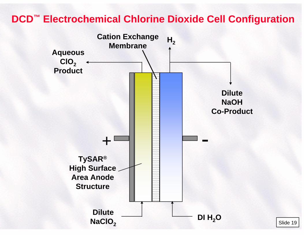
where the maximum theoretical molar conversion of chlorite to chlorine dioxide for the acid activation method is 80%. The preferred generation of chlorine dioxide from chlorite utilizes an oxidizer because of the 20% lower molar conversion by the acid activation route, and significantly reducing sodium chlorite consumption costs. 3.0 DCD™ Process Electrolysis Chemistry The electrochemical oxidation of sodium chlorite has been known since the 1930's, but many of the processes developed had to remove the chlorine dioxide produced by air or vacuum stripping in order to obtain sufficiently high conversion yields of chlorite to chlorine dioxide. A direct electrochemical process route was selected for development by Olin. The key to the conceptual process was to find or fabricate a stable high surface area anode structure(s) that could directly oxidize chlorite to chlorine dioxide at both a high current efficiencies as well as high conversion efficiency, and preferably in a single pass through the electrolyzer unit. The Olin DCD™ electrolyzer design, as shown in slide 19, is a two compartment zero gap cell having a perfluorinated sulfonic acid cation ion exchange membrane separator between the anode and cathode compartments. The overall DCD™ process chemistry/reaction is:
NaClO2 + H2O ClO2 + NaOH + 1/2H2 (33)
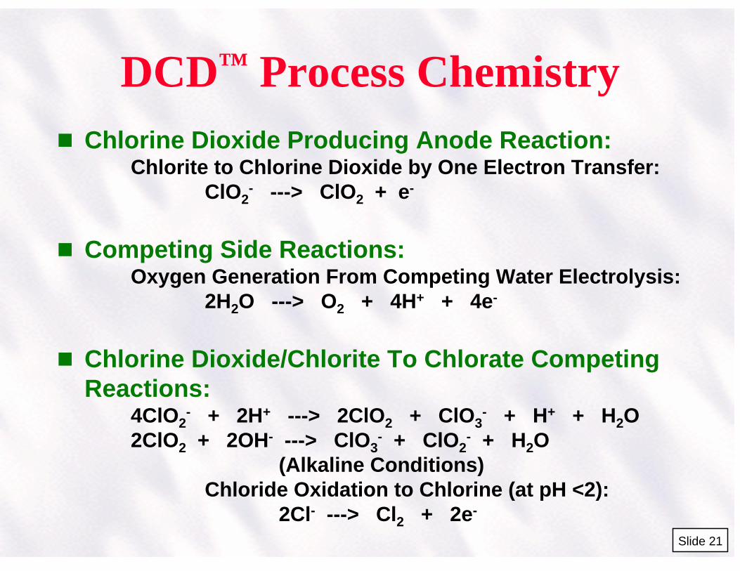
Anolyte Chemistry The major anodic reaction in the DCD™ process is the one electron transfer oxidation of the chlorite ion on the high surface area anode structure:
ClO2- ClO2 + e- (34)
Sodium ions from the sodium chlorite pass through the cation ion exchange membrane into the cathode compartment. The major competing anodic side reaction is the electrolysis of water to form oxygen gas and hydrogen ions which acidifies the bulk chlorite solution in the anolyte:
2H2O O2 + 4H+ + 4e- (35) Under acidic conditions, a portion of the chlorite can be converted chemically in the bulk solution by an acid activation reaction,
5ClO2- + 4H+ 4ClO2 + 5Cl- + 2H2O (36)
as well as in a competing acid activation disproportionation reaction forming chlorine dioxide and byproduct chlorate:
4ClO2- + 2H+ 2ClO2 + ClO3
- + Cl- + H2O (37) The other bulk solution phase side reaction is chlorate ion formation from the hydrolysis of chlorine dioxide under alkaline conditions, forming chlorite and chlorate:
Page 12
2ClO2 + 2OH- ClO3- + ClO2
- + H2O (38) which may occur at the membrane interface or in the initial input region of the cell with an alkaline sodium chlorite feedstock. In addition, chloride ion present in the sodium chlorite feedstock can be anodically oxidized to chlorine under acidic conditions:
2Cl- Cl2 + 2e- (39) which further disproportionates to form hydrochloric acid and hypochlorous acid under acidic conditions:
Cl2 + H2O HOCl + HCl (40) Any chlorine formed will chemically oxidize any available chlorite ions to chlorine dioxide:
2ClO2- + HOCl + H+ 2ClO2 + Cl- + H2O (41)
If there is no residual chlorite in the anolyte solution, then chlorine as HOCl will be present in the final chlorine dioxide product solution. Catholyte Reactions The catholyte reaction produces hydroxide ions and hydrogen from the reduction of water,
2H2O 2OH- + H2 (42) and the hydroxide ions combine with the sodium ions from the anolyte compartment to produce NaOH.
2Na+ + 2OH- NaOH (43)
4.0 Keys To DCD™ Process Development The DCD™ process required new developments in electrodes, cell design, and chemical feedstock. These process development highlights are summarized below.
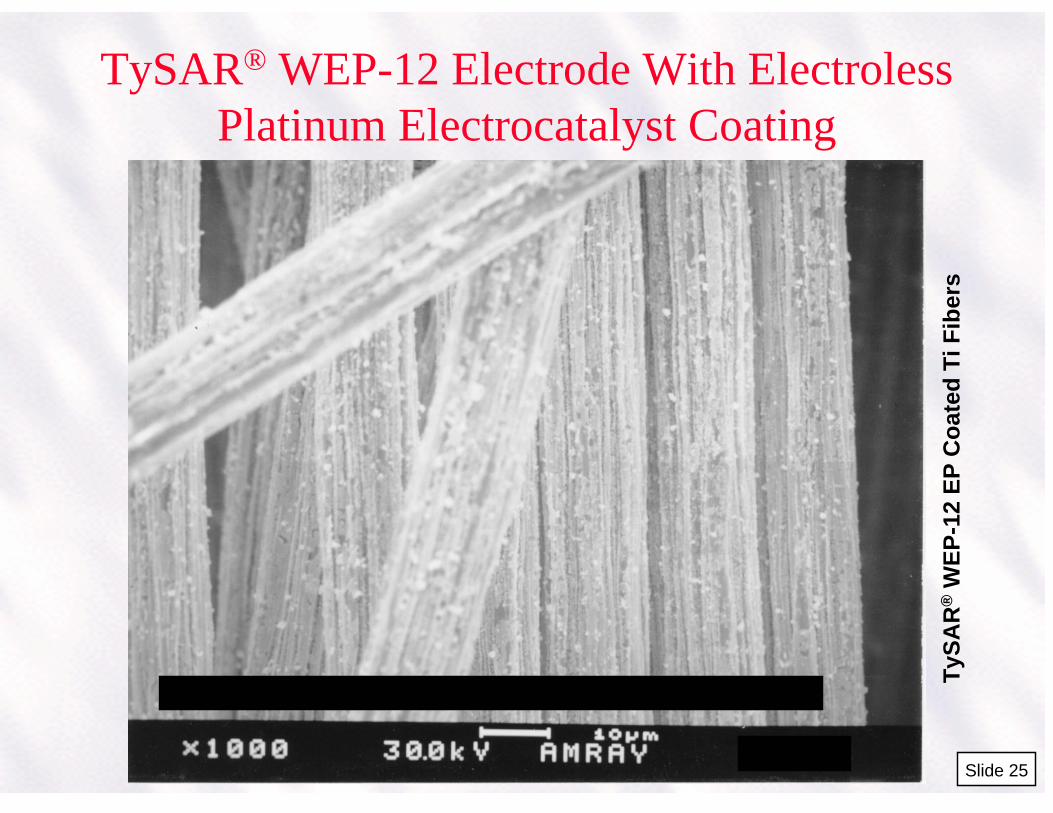
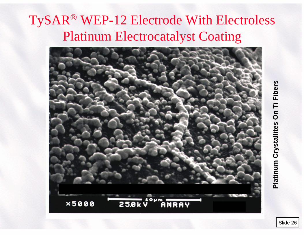
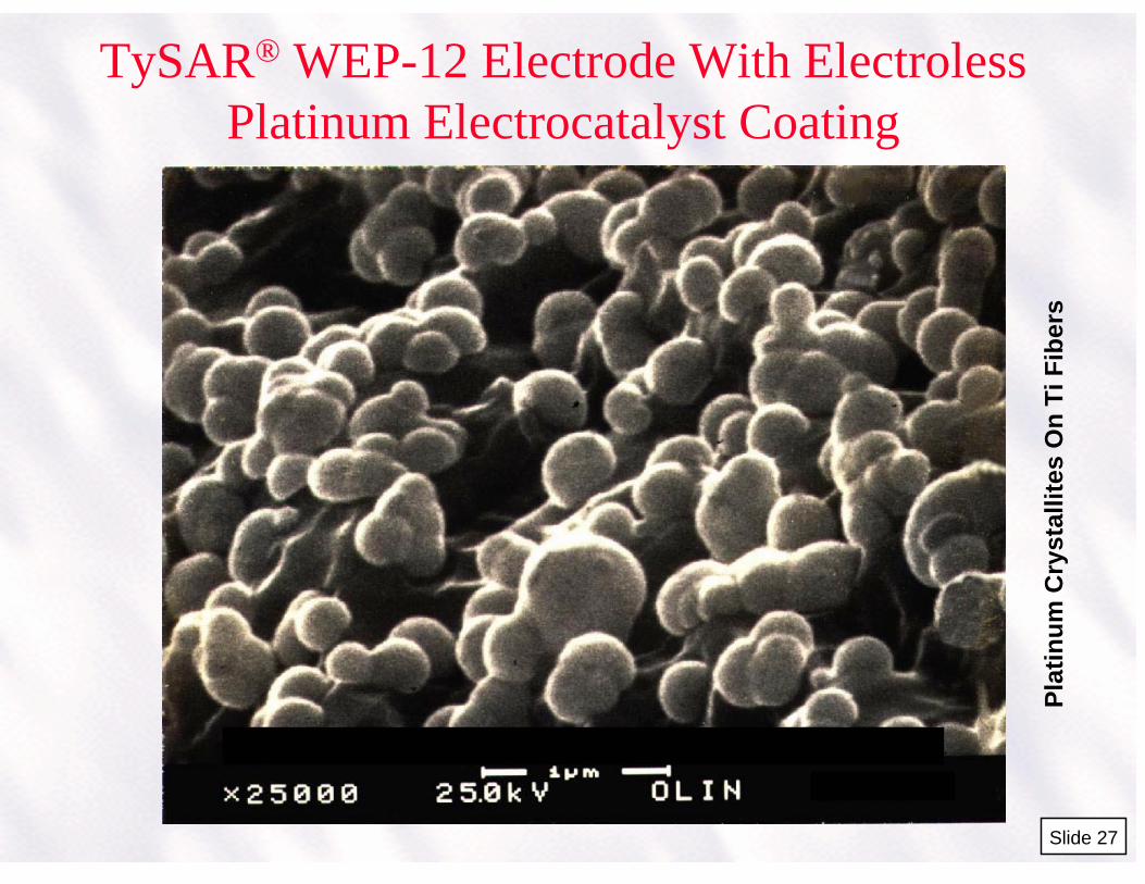
TySAR® High Surface Area Electrodes The key to the DCD™ process is the new Olin TySAR® WEP-12 high surface area electrode. This non-sintered felt or web type electrode is made from 12 micron titanium filaments with an applied electroless platinum coating on the fiber surfaces. Slide 25 is an electron microscope (EM) micrograph which shows an 1000X magnification of some of the WEP-12 platinum plated electrode fibers. Slide 26 shows an EM micrograph with a 5,000X magnification showing more detail of spherically shaped platinum crystallites on the titanium surfaces, and Slide 27 shows a 25,000X magnification. The successful development of these electrodes required developing a patented electroless process for evenly plating all of the surfaces of the high surface area fibers with electrocatalyst, in this case platinum.
Page 13
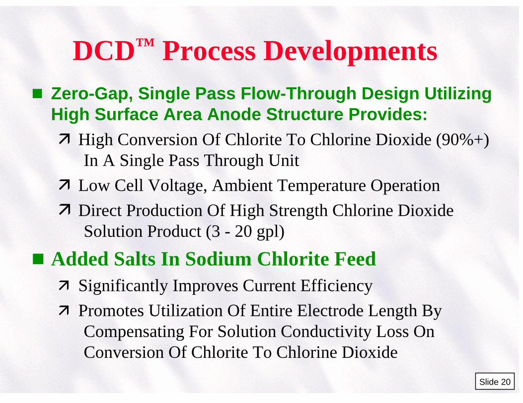
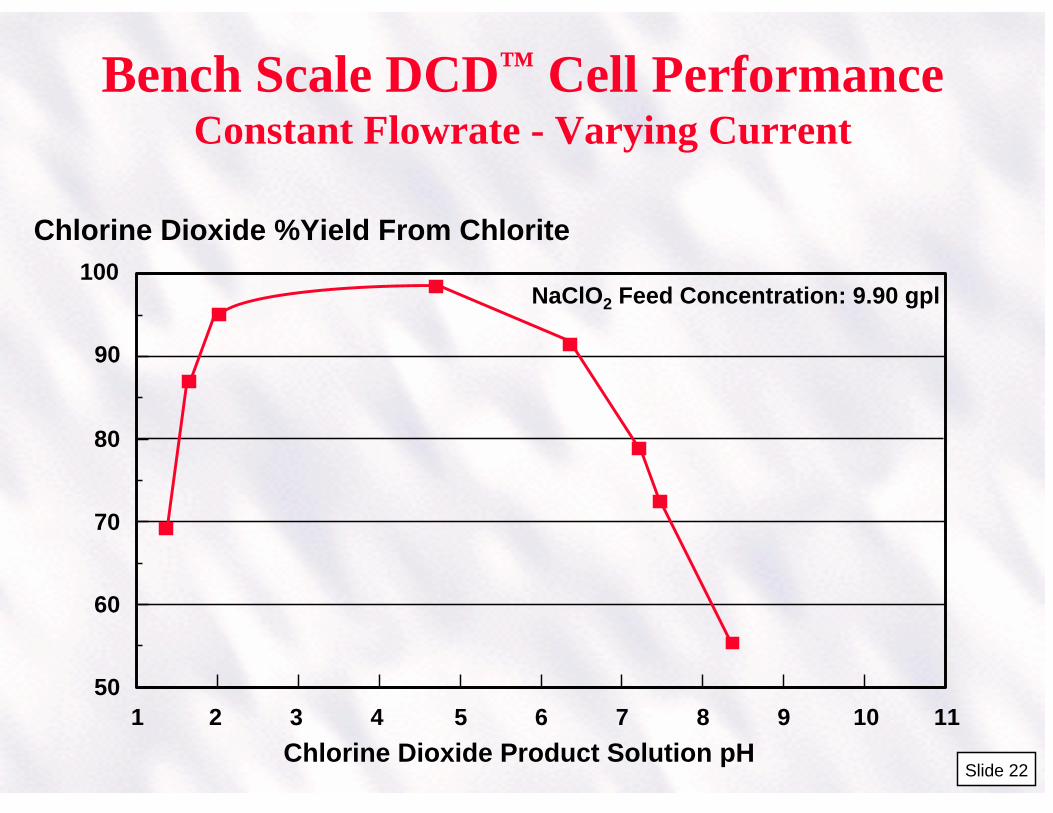
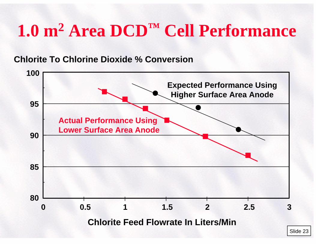
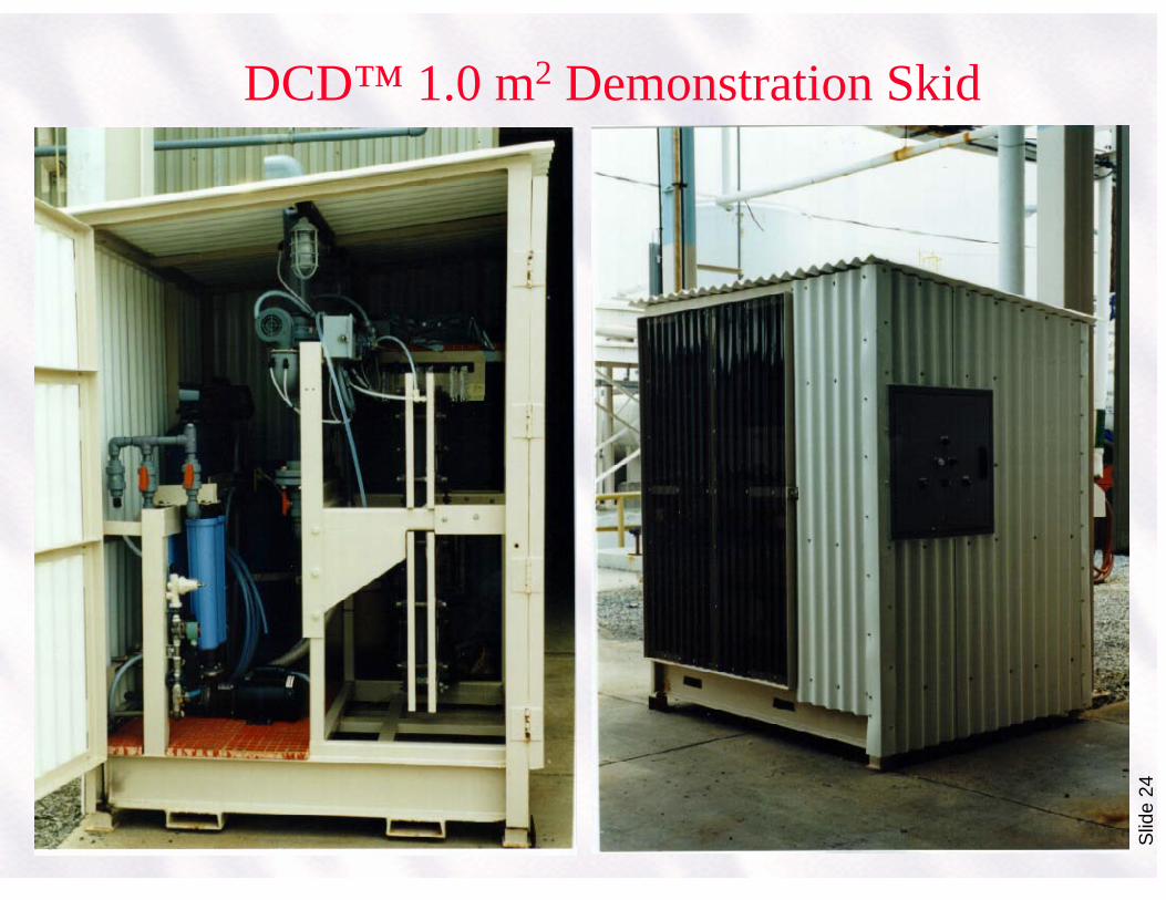
The use of a high surface area anode structure in the process reduces the operating voltage potential at the reaction anode surfaces, thus reducing the side reactions previously discussed that form byproduct oxygen, hydrogen ions, as well as chlorate. In addition, the high surface area anode allows for high conversion efficiencies of chlorite ion to chlorine dioxide in a single pass through the electrolyzer with conversions up to 95%+. Slide 22 shows a typical performance, in this case, of a bench scale DCD™ unit. The graph shows that at a constant chlorite feed input flowrate and varying the current to the cell, the chlorine dioxide product solution pH can be used to indicate the best region for maintaining maximum conversion performance. The maximum conversion of chlorite to chlorine dioxide is obtained by controlling the anolyte chlorine dioxide solution product pH in a range of about 3 - 5. Optimum electrolyzer conversion performance is obtained using pH in a feedback loop to control the applied cell current. Slide 23 shows performance data for a 1.0 m2 DCD™ cell using a lower surface area TySAR® electroless plated platinum electrode showing the chlorite conversion percentage performance as a function of input flowrate, with the cell current adjusted to an optimum pH of 3.2 in the chlorine dioxide product output. The expected performance using the higher surface area TySAR® WEP-12 is shown. Slide 24 shows a photo of the 1.0 m2 DCD™ demonstration skid used in the process scale-up. The use of platinum metal as the anode electrocatalyst surface coating has provided the highest performance for this process. Platinum has a high oxygen overvoltage potential so that the water oxidation reaction will occur at a higher anode potential. This means that the competing water oxidation reaction producing oxygen will occur in significant amounts only at higher current densities on the anode surfaces. The oxidation reaction of chlorite ion is the predominant oxidation reaction in this process using a high surface area anode structure. Zero Gap Cell Design Development A unique zero gap flow-by type cell design was developed for the process. The cell design is shown in slide 22. The design utilizes a bulky yet easily compressible high surface area electrode which completely fills the anolyte compartment with the solution flow upward through the cross sectional thickness of the electrode. A current collector is used to distribute current into the high surface anode structure. The anode is directly in contact with the cation ion exchange membrane. The cathode is also positioned directly against the membrane. This direct membrane contact reduces the cell operating voltage so that it no longer depends on the catholyte solution conductivity because the membrane itself becomes the direct conductive medium. This allows the use of deionized or softened water as the feed to the catholyte in a single pass flow producing a weak or strong NaOH co-product as required. The cell operating voltage is low, operating between 2.5 - 4.0 volts depending on the operating current density. The cell design can operate up to about 4 kA/m2 or higher, depending on the electrochemical process or reactions being done in the cell. The simple plastic cell frame components provides a very inexpensive cell for suitable processes. Sodium Chlorite Feedstock The utilization of a conductive electrolyte additives in the sodium chlorite anolyte feed was found to be critical in obtaining high chlorite to chlorine dioxide conversions. The high surface area electrode requires a some amount of conductive electrolyte to achieve
Page 14
high conversion because the anolyte solution conductivity decreases with vertical distance upward within the anode structure. This is because the conductive chlorite ion concentration is depleted to the non-conductive chlorine dioxide product, and the upper section of the anode structure does not work operate efficiently. The use of added salts, such as NaCl or sodium sulfate, to the chlorite feed significantly increases the conversion performance from about 70% to a significantly higher 90 - 95%.
NEW TECHNOLOGY APPLICATIONS/OFFSHOOTS The technology developments described in this paper have potential applications in various other electrochemical processes that can utilize these enhancements. Slides 28 and 29 summarize some of the technology enhancements described in this paper. These technology enhancements include:
High Surface Area Electrodes Cell Designs Process Control
___________________________________________ 1997 Olin Corporation File: 17637-1.doc
Page 15
REFERENCES ECHO Hydrosulfite Process 1. Cawlfield, D. W., “Multilayer Electrode Electrolytic Cell”, U.S. Patent 4,740,287. 2. Cawlfield, D. W., Ford, J. M. and Woodard, K. E. Jr., ”Electrolytic Cell for Alkali Metal
Hydrosulfite Solutions”, U.S. Patent 4,743,350. 3. Cawlfield, D. W., “Multilayer Electrode”, U.S. Patent 4,761,216. 4. Cawlfield, D. W. and French, J. M., ”Electrolytic Cell Apparatus”, U.S. Patent
4,770,756. 5. Cawlfield, D. W., “Process for Treatment of Separator for Sodium Hydrosulfite
Membrane Cell”, U.S. Patent 4,784,875. 6. Bolick, R. E. II, Cawlfield, D. W. and French, J. M., “Electrochemical Process for
Producing Hydrosulfite Solutions”, U.S. Patent 4,793,906. 7. Cawlfield, D. W., “Sodium Hydrosulfite Electrolytic Cell Process Control System”, U.S.
Patent 4,836,903. 8. Cawlfield, D. W., “Sodium Hydrosulfite Electrolytic Cell Process Control System”, U.S.
Patent 4,857,158. 9. Bolick, R. E. II, Cawlfield, D. W. and Woodard, K. E. Jr., “Modular Electrolytic Cell and
Processing Apparatus”, U.S. Patent 4,892,636. 10. Bolick, R. E. II, Cawlfield, D. W. and French, J. M., “Electrochemical Process for
Producing Hydrosulfite Solutions”, U.S. Patent 4,992,147. High Purity Hydroxylamine Ammonium Nitrate Electrolytic Process 1. Klein, N. “Liquid Propellants for use in Guns, - A Review,” BRL-TR-2641, Ballistic
Research Laboratory, Aberdeen, MD, [JPL 8], 1985, p 18. 2. Klein, N., “The Molecular Structure of HAN-Based Liquid Propellants,” BRL-TR-3139,
Ballistic Research Laboratory (Aberdeen Proving Ground, MD), [JPL LP 330], 1990, pp. 11-13.
3. Klein, N., "Liquid Propellants for Use in Guns", pp. 573-496, in Gun Propulsion Tech; L. Stiefel ed., Vol. 189, AIAA Progress Series, 1988, Chap. 14.
4. Schevbackov, I.G. and Libina, D.M., Z. Elektrochem, 35, 977 (1932) 5. Development of a Production Process for High Purity HAN, Contract #DAAA15-89-C-
0011. 6. Production of LP XM46, Contract #DAAA21-92-C-0009. 7. Woodard, K. E., Jr., Moore, S. H., Muse, E. K., Cawlfield, D. W., Dotson, R. L.,
“Continuous Process for the Production of High-Purity Hydroxylamine Nitrate,” Industrial Electrolysis & Electrochemical Engineering Division Proceedings, Vol. 93-14, The Electrochemical Society, pp. 38-55.
8. Electrosynthesis of Hydroxylammonium Nitrate, A High Energy Oxidizer for Military Liquid Propellants," Fourth International Gun Propellant and Propulsion Symposium, ARDEC. Nov., 1988.
9. Brooker, R. T., "Electrolytically Produced HAN/LP, Chemically Produced HAN/LP", AFAS/FARV Technology Days for Industry, April 20-23, 1993
10. Dotson, R. L., and Hernandez, D. Y., “Direct Electrochemical Reduction of Nitric Acid to Hydroxylamine Nitrate”, U.S. Patent 4,849,073.
11. Brooker, R. T., and Dotson, R. L., “Process for Concentrating Aqueous Solutions of Hydroxylammonium Salts”, U.S. Patent 4,851,125.
12. Dotson, R. L., Hernandez, D. Y., and Sasse, R. A., “Method of Reducing Excess Nitric Acid in Aqueous Hydroxylamine Nitrate Solutions; Neutralization or Ion Exchange”, U.S. Patent 4,968,394.
Page 16
13. Dotson, R. L., and Moore, S. H., “Process for Decomposing Solutions of Hydroxylammonium Salts With Hypohalite”, U.S. Patent 5,062,966.
14. Ford, J. M., Cawlfield, D. W., and Woodard, K. E., Jr., “Liquid Metal Cathode Electrochemical Cell and Cathode Frame”, U.S. Patent 5,185,069.
15. Cawlfield, D. W., Ford, J. M., and Woodard, K. E., Jr., “Liquid Metal Cathode Electrochemical Cell”, U.S. Patent 5,186,804.
16. Cawlfield, D. W., Ford, J. M., and Moore, S. H., “Baseplate for Electrolytic Cell With A Liquid Metal Cathode”, U.S. Patent 5,209,836.
17. Cawlfield, D. W., “Process For The Production Of High Purity Hydroxylammonium Nitrate”, U.S. Patent 5,213,784.
18. Cawlfield, D. W., and Ford, J. M., “Direct Electrochemical Reduction of Catholyte At A Liquid Metal Cathode”, U.S. Patent 5,258,104.
19. Burger, C. O., Casteel, J. D., Dotson, R. L., Mellor, R. E., Moore, S. H., Pickering, J. F., and Reed, P. J., “Process for Removal of Mercury From Hydroxyl-Ammonium Nitrate Solutions”, U.S. Patent 5,294,417.
20. Cawlfield, D. W., Loftis, D. B., Moore, S. H., and Walter, E. K., “Process For Treating Aqueous Solutions of Hydroxylamine Salts Containing Excess Acid”, U.S. Patent 5,318,762.
21. Kaczur, J. J., Woodard, K. E., Jr., Cawlfield, D. W., and Muse, E. K., “Electrochemical Process For The Removal Of Residual Nitric Acid From Aqueous Hydroxylammonium Nitrate”, U.S. Patent 5,391,268.
22. Schmidt, E. W. and Gavin, D. F., “Catalytic Decomposition Of Hydroxylammonium Nitrate-Based Monopropellants”, U.S. Patent 5,485,722.
23. Cawlfield, D. W., Dotson, R. L., Loftis, H. J., Moore, S. H., Brooker, R. T., and Stirrat, J. S., “Hydroxylammonium Nitrate Free Of Ammonium Nitrate”, U.S. Patent 5,510,097.
DCD™ Electrochemical Chlorine Dioxide Technology 1. Cawlfield, D. W. and Kaczur, J. J. "Electrochemical Method For Producing
Chlorine Dioxide”, U.S. Patent 5,041,196. 2. Kaczur, J. J. and Cawlfield, D. W., "Electrolytic Process For Producing Chlorine
Dioxide", U.S. Patent 5,084,149. 3. Kaczur, J. J. and Cawlfield, D. W., "Electrochemical Process For Producing
Chlorine Dioxide Solutions From Chlorites, U.S. Patent 5,092,970. 4. Kaczur, J. J. and Cawlfield, D. W., "Electrochemical Process For Producing
Chlorine Dioxide Solutions From Chlorites”, U.S. Patent 5,106,465. 5. Cawlfield, D. W. and Kaczur, J. J., "Electrochemical Chlorine Dioxide
Generator", U.S. Patent 5,158,658. 6. Kaczur, J. J. and Cawlfield, D. W., "High Surface Area Electrode Structures For
Electrochemical Processes”, U.S. Patent 5,294,319. 7. Kaczur, J. J., Cawlfield, D. W., and Watson, J. F., "Process For Producing an
Electrode By Electroless Deposition”, U.S. Patent 5,298,280.
Electrochemical Process Development at Olin Based On Advances in Electrodes, Cell
Designs, and Chemical Feedstocks
Jerry J. Kaczur, Leonard L. Scott, Ronald L. Dotson
Olin Corporation
Charleston Technology Center
Chlor-Alkali products Division
P.O. Box 248
Charleston, TN 37310
The 11th International Forum On Electrolysis In The Chemical Industry:
Electrochemical Processing Technologies
Sheraton Sand Key, Clearwater Beach, FL November 2-6, 1997
Slide 1©1997 Olin Corporation
Electrochemical Process DevelopmentAt Olin
New Electrochemical Process Development
Success Required Developing And Using Advances In New Materials and Process Designs
Key Development Areas
Electrodes - Anodes, Cathodes
Cell Designs - Bipolar, Zero-Gap
Process Feedstocks - Purity, New Chemicals
Olin Process Examples
ECHO Sodium Hydrosulfite Process
HAN - Hydroxylammonium Nitrate Process
DCD™ Electrochemical Chlorine Dioxide Process
Slide 2
ECHO Sodium Hydrosulfite Process
Slide 3
Sodium Hydrosulfite Applications
Pulp & Paper
Mechanical Pulp Brightening For Newsprint,etc.
• Chemical Thermal-Mechanical Pulping (CTMP)
• Thermo-Mechanical Pulping (TMP)
Clay Bleaching
Bleaching Clays Used In:
• Pulp & Paper As Fillers, Opacity And Brightness Agents
• Manufacturing Fine China
Textile Dyeing
Vatting Agent in Solubilizing Dyes Such As Indigo
Slide 4
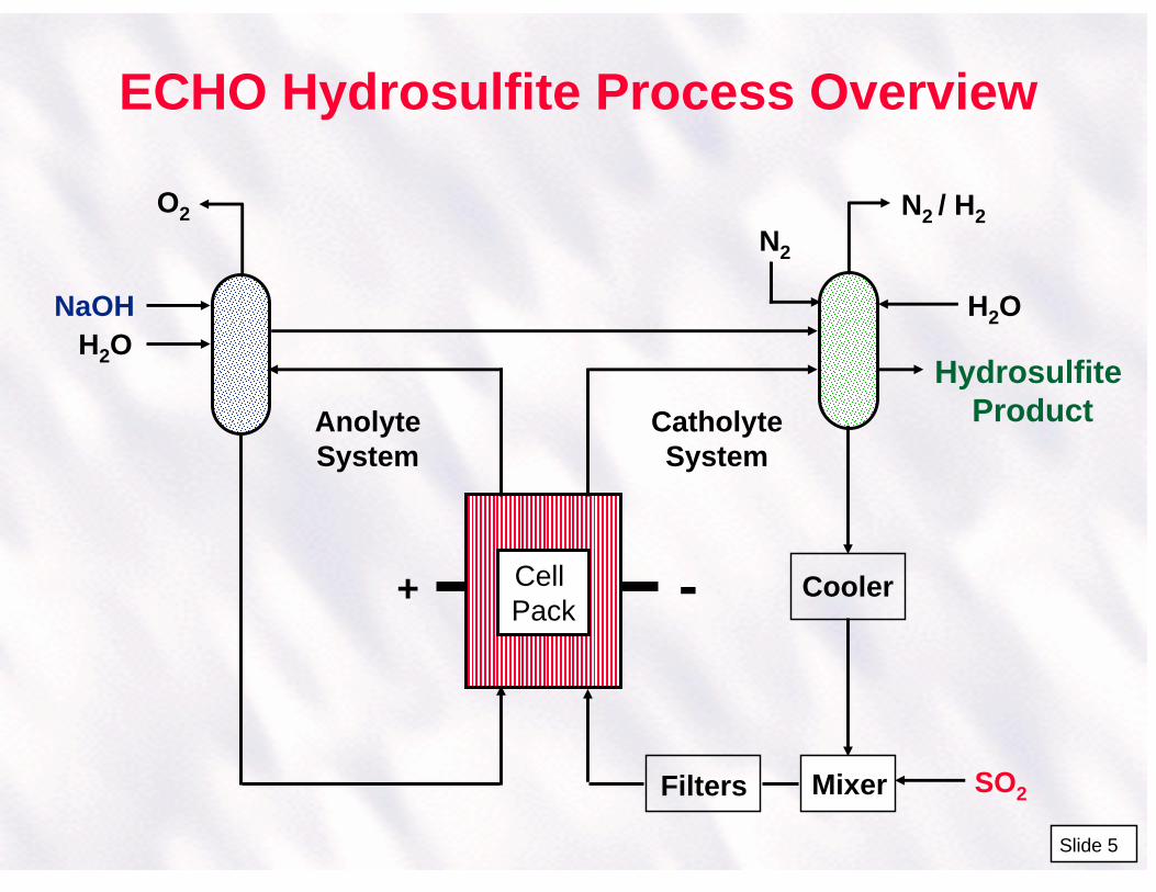
ECHO Hydrosulfite Process Overview
Cell Pack
SO2
CatholyteSystem
AnolyteSystem
H2ONaOH
O2
N2
N2 / H2
H2O
HydrosulfiteProduct
-+
Filters Mixer
Cooler
Slide 5
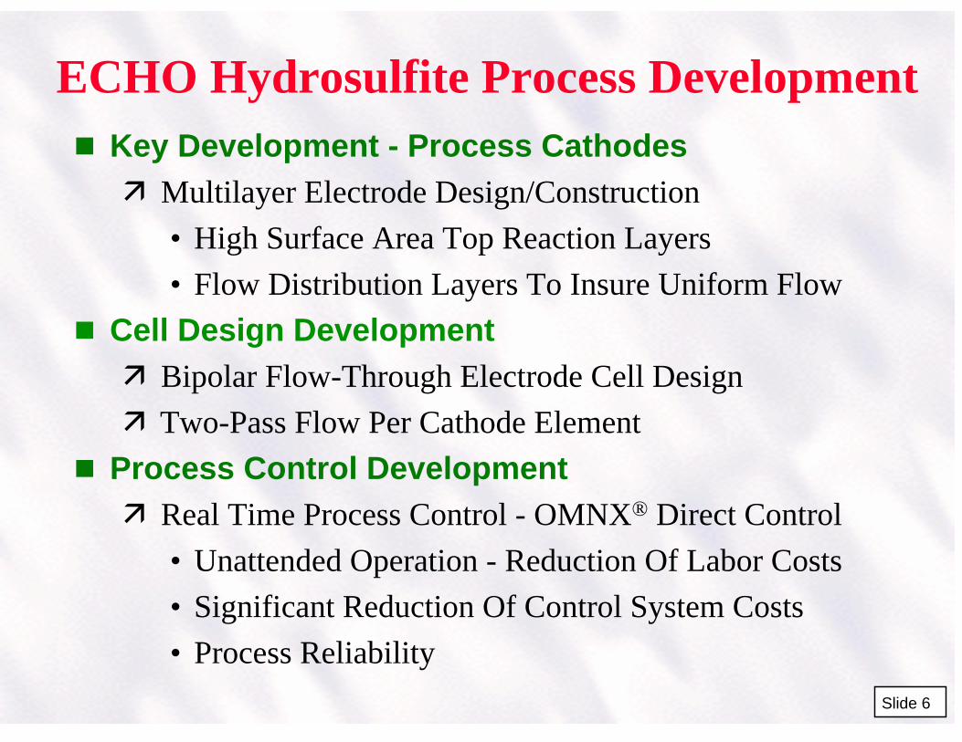
ECHO Hydrosulfite Process Development Key Development - Process Cathodes
Multilayer Electrode Design/Construction
• High Surface Area Top Reaction Layers
• Flow Distribution Layers To Insure Uniform Flow
Cell Design Development
Bipolar Flow-Through Electrode Cell Design
Two-Pass Flow Per Cathode Element
Process Control Development
Real Time Process Control - OMNX® Direct Control
• Unattended Operation - Reduction Of Labor Costs
• Significant Reduction Of Control System Costs
• Process Reliability
Slide 6
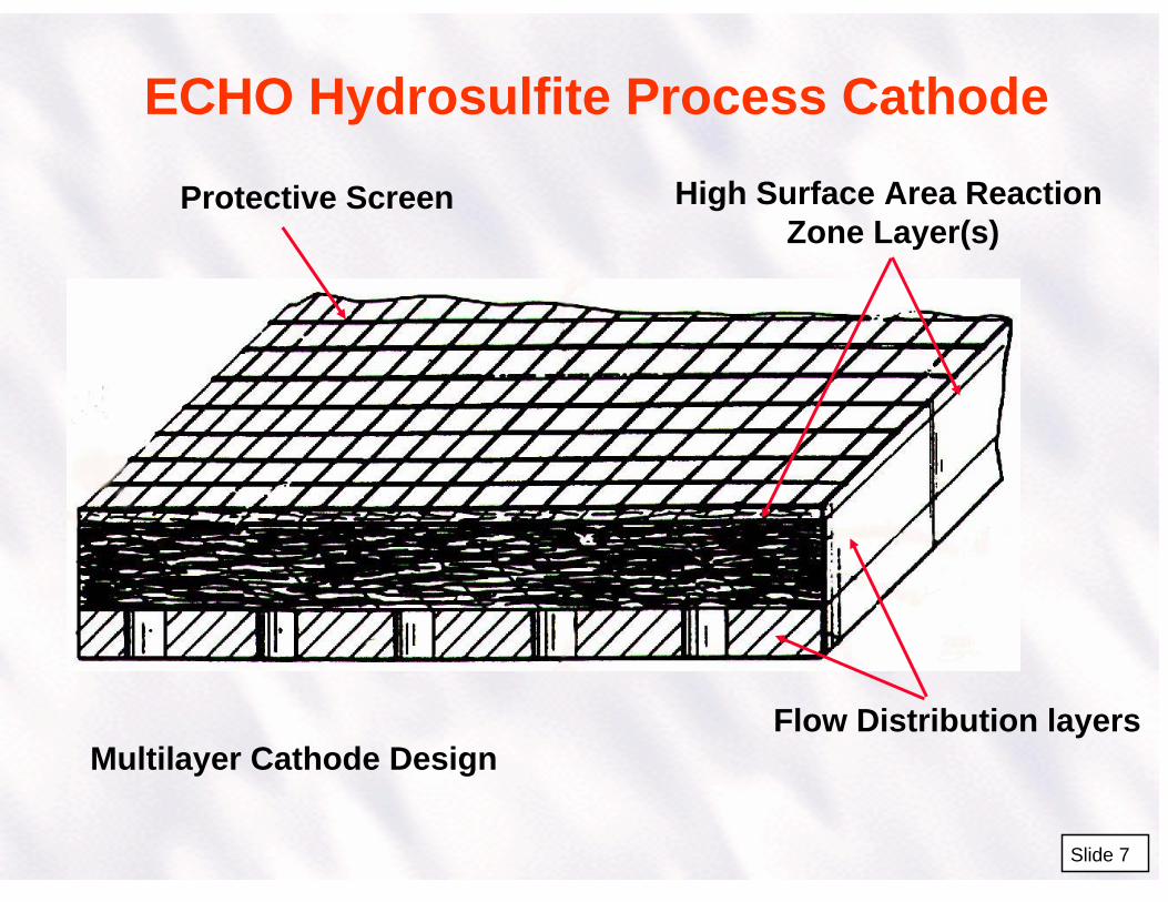
ECHO Hydrosulfite Process Cathode
Slide 7
Multilayer Cathode DesignFlow Distribution layers
High Surface Area ReactionZone Layer(s)
Protective Screen
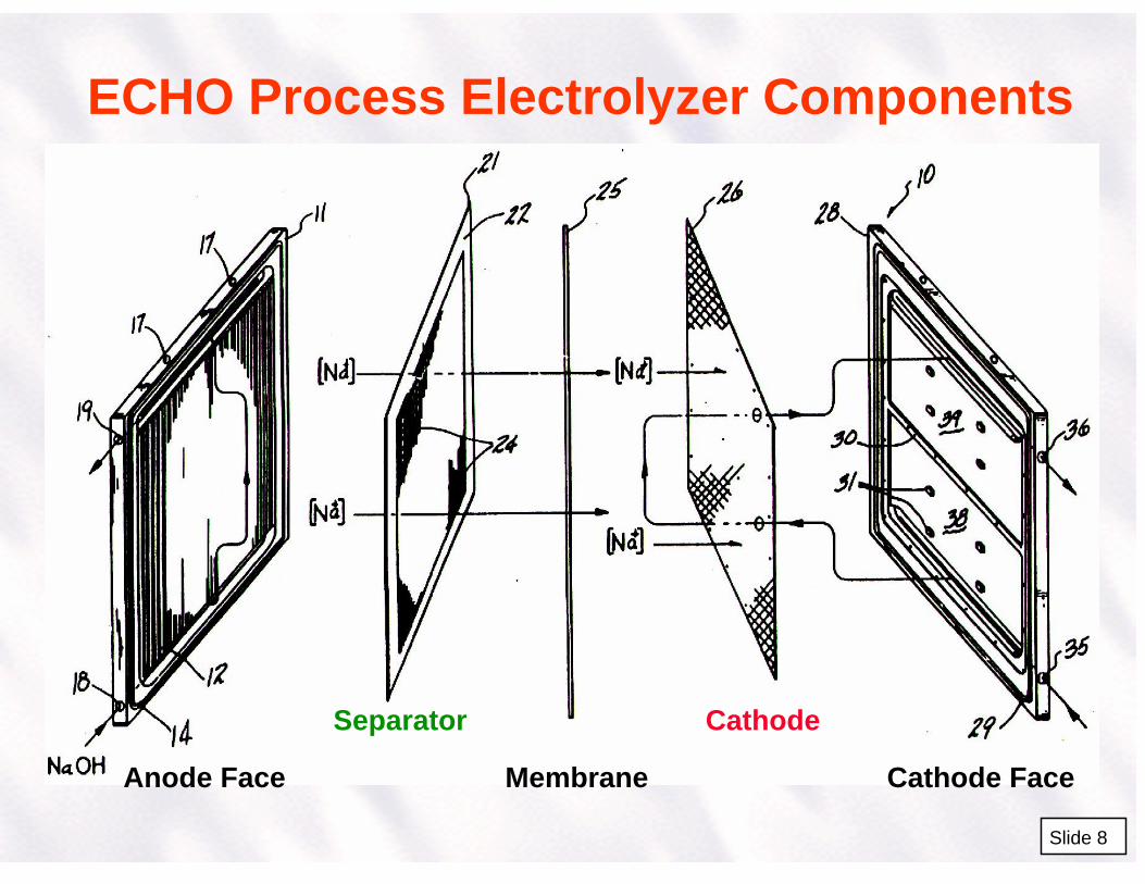
ECHO Process Electrolyzer Components
Slide 8
Membrane
Separator Cathode
Anode Face Cathode Face
ECHO Process Electrolysis Chemistry
Anode Reactions:
4NaOH ====> O2 + 2H2O + 4e- + 4Na+
HSO3- , S2O4
2- , S2O32- ====> SO4
2-
-
Slide 9
+
Separator
Anode
Cathode
HSO3-NaOH
Cation Membrane
O2 , NaOH S2O42-
Cathode Reaction:
2HSO3- + 2e- + 2H+ ====> S2O4
2- + 2H2O
Cathode Side Reactions:
2H+ + 2e- ====> H2
S2O42- + 2e- +2H+ ====> S2O3
2- + H2O
2SO32- + 4e- + 3H2O ====> S2O3
2- + 6OH-
Na+

Olin ECHO Sodium HydrosulfiteProcess Electrolyzer Module
Slide 10
HAN -Hydroxylammonium
Nitrate Process
Slide 11
Routes To HAN & Product Applications Process Routes To HAN
• Reduction of nitrite with bisulfite
• Hydrolysis of primary nitroparaffins
• Cation exchange conversion of Hydroxylammonium
• Hydroxylammonium sulfate (HAS) to HAN
• Catalytic hydrogenation of nitric acid
• Electrodialysis and water splitting
• Electrochemical reduction of organic nitrates
• Electrolytic reduction of nitrates
Recent HAN Applications• Tank gun propellant
• Smart type automobile air bag inflator systems
• Strippers for electronic semiconductor chips & circuit boards
• Hybrid rocket motors
• Torpedo propellants
• Combustion catapults
• Nuclear fuel reprocessingSlide 12
HAN Process Overview
Nitric AcidElectronic Grade
Power
DI WaterNanopure Grade
Electrolysis Neutralization
Waste Treatment
Concentrator
HAN Product< 0.1 wt.% HNO3< 1.0 wt.% Total Impurities< 5.0 ppm First Transition
Metals Series Plus Hg
Slide 13
HAN Process Development Process Cathode Developments
Hg Cathode Provided Highest Efficiency, Least By-Product Formation, and Highest Product Purity
Still Interested In Alternate Cathodes!
Anode Development
Pt-Clad Niobium Chosen as Anode Material
• Long Operating Life
• Low Impurity Contamination Of HAN Product
Other Important Process Factors
Feedstock Purity, Ion Exchange Neutralization
Real Time Process Control - OMNX® Direct Control
Slide 14
HAN Process Electrolysis Chemistry
+H2O
HNO3
CationMembrane
Anode
H2O H+
2HNO3 + 6H+ + 6e- -----> (NH3OH)NO3 + 2H20
H2O
O2N2
Hg
N2OH2O2N2
(NH3OH) NO3
3H2O ----> 3/2 O2 + 6H+ + 6e-
Side Reactions: 2H2O + 2e- -----> H2 + 2OH-
OH- + (NH2OH)HNO3 -----> NH2OH + H2O + NO3-
4NH2OH -----> N2O + 2NH3 + 3H2ONH3 + HNO3 -----> NH4NO3
-
Slide 15
HAN Product Quality
Slide 16
Method of Analysis - ICP/MS
Metals Standard Typical Analysisppb
Demonstrated Technology(If Required)
ppb
Mg <30Ca <300 <10Ti <5.0V <4.0Cr <130 <10Mn <10Fe <300 <10Co <5.0Ni <160 <10Cu <40Zn <40Hg <10 <10
HAN - Hydroxylammmonium Nitrate Process6.0 m2 Electrolyzer
Slid
e 17
DCD™ Electrochemical Chlorine Dioxide Process
Slide 18
DI H2O
DiluteNaOH
Co-Product
DiluteNaClO2
+
H2
-
AqueousClO2
Product
TySAR®
High SurfaceArea Anode
Structure
Cation ExchangeMembrane
DCD™ Electrochemical Chlorine Dioxide Cell Configuration
Slide 19
DCD™ Process Developments Zero-Gap, Single Pass Flow-Through Design Utilizing
High Surface Area Anode Structure Provides:
High Conversion Of Chlorite To Chlorine Dioxide (90%+)In A Single Pass Through Unit
Low Cell Voltage, Ambient Temperature Operation
Direct Production Of High Strength Chlorine DioxideSolution Product (3 - 20 gpl)
Added Salts In Sodium Chlorite Feed Significantly Improves Current Efficiency
Promotes Utilization Of Entire Electrode Length ByCompensating For Solution Conductivity Loss OnConversion Of Chlorite To Chlorine Dioxide
Slide 20
DCD™ Process Chemistry Chlorine Dioxide Producing Anode Reaction:
Chlorite to Chlorine Dioxide by One Electron Transfer: ClO2
- ---> ClO2 + e-
Competing Side Reactions:Oxygen Generation From Competing Water Electrolysis:
2H2O ---> O2 + 4H+ + 4e-
Chlorine Dioxide/Chlorite To Chlorate Competing Reactions:
4ClO2- + 2H+ ---> 2ClO2 + ClO3
- + H+ + H2O2ClO2 + 2OH- ---> ClO3
- + ClO2- + H2O
(Alkaline Conditions)Chloride Oxidation to Chlorine (at pH <2):
2Cl- ---> Cl2 + 2e-
Slide 21
Bench Scale DCD™ Cell PerformanceConstant Flowrate - Varying Current
Chlorine Dioxide %Yield From Chlorite
Chlorine Dioxide Product Solution pH
NaClO2 Feed Concentration: 9.90 gpl
1 2 3 4 5 6 7 8 9 10 1150
60
70
80
90
100
Slide 22
1.0 m2 Area DCD™ Cell Performance
0 0.5 1 1.5 2 2.5 380
85
90
95
100
Chlorite Feed Flowrate In Liters/Min
Chlorite To Chlorine Dioxide % Conversion
Actual Performance Using Lower Surface Area Anode
Expected Performance UsingHigher Surface Area Anode
Slide 23
DCD™ 1.0 m2 Demonstration Skid
Slid
e 24
TySAR® WEP-12 Electrode With Electroless Platinum Electrocatalyst Coating
Slide 25
TyS
AR
®W
EP
-12
EP
Co
ated
Ti F
iber
s
TySAR® WEP-12 Electrode With Electroless Platinum Electrocatalyst Coating
Slide 26
Pla
tin
um
Cry
stal
lite
s O
n T
i Fib
ers
TySAR® WEP-12 Electrode With Electroless Platinum Electrocatalyst Coating
Slide 27
Pla
tin
um
Cry
stal
lite
s O
n T
i Fib
ers

New Technology Applications/Offshoots
Slide 28
New Technology Applications/Offshoots
High Surface Area Electrode Materials
Applications Requiring Requiring High Selectivity, HighChemical Conversion
• Various Inorganic and Organic Processes
Custom Electrode Constructions To Match Processes
• Sintered And Non-Sintered Electrode Forms
Other Electrode Materials
• Stainless Steel, Nickel, Etc. For Cathode/Anode Applications
New Electrocatalyst Coating Developments
• TySAR® EP, IM - Electroless Platinum, Intermetallics, Au, RuO2, IrO2, etc.
Slide 29
New Technology Applications/Offshoots Cell Designs
New Bipolar Cell Configurations
• Application To Other Processes For Cathode or Anode Specific Reactions
Zero-Gap Type Cell Design
• Inexpensive Plastic Construction
• Processes Requiring High or Low Product Conversions
Process Control
Direct PC Controlled Processes
• Olin OMNX® Direct Control Software Commercially Available
• Lower Cost Than DCS Systems
• Easily Configurable To Customer Applications Slide 30

Electrochemical Process Development at Olin Based On Advances in Electrodes, Cell
Designs, and Chemical Feedstocks
Jerry J. Kaczur, Leonard L. Scott, Ronald L. Dotson
Olin CorporationCharleston Technology CenterChlor-Alkali products Division
P.O. Box 248Charleston, TN 37310
The 11th International Forum On Electrolysis In The Chemical Industry:Electrochemical Processing TechnologiesSheraton Sand Key, Clearwater Beach, FL November 2-6, 1997
Slide 1©1997 Olin Corporation

Electrochemical Process DevelopmentAt Olin
New Electrochemical Process Development Success Required Developing And Using Advances In
New Materials and Process Designs Key Development Areas Electrodes - Anodes, Cathodes Cell Designs - Bipolar, Zero-Gap Process Feedstocks - Purity, New Chemicals
Olin Process Examples ECHO Sodium Hydrosulfite Process HAN - Hydroxylammonium Nitrate Process DCD™ Electrochemical Chlorine Dioxide Process
Slide 2

ECHO Sodium Hydrosulfite Process
Slide 3

Sodium Hydrosulfite Applications
Pulp & Paper Mechanical Pulp Brightening For Newsprint,etc.
• Chemical Thermal-Mechanical Pulping (CTMP)• Thermo-Mechanical Pulping (TMP)
Clay Bleaching Bleaching Clays Used In:
• Pulp & Paper As Fillers, Opacity And Brightness Agents
• Manufacturing Fine China Textile Dyeing Vatting Agent in Solubilizing Dyes Such As Indigo
Slide 4

ECHO Hydrosulfite Process Overview
Cell Pack
SO2
CatholyteSystem
AnolyteSystem
H2ONaOH
O2N2
N2 / H2
H2O
HydrosulfiteProduct
-+
Filters Mixer
Cooler
Slide 5

ECHO Hydrosulfite Process Development Key Development - Process Cathodes Multilayer Electrode Design/Construction
• High Surface Area Top Reaction Layers• Flow Distribution Layers To Insure Uniform Flow
Cell Design Development Bipolar Flow-Through Electrode Cell Design Two-Pass Flow Per Cathode Element
Process Control Development Real Time Process Control - OMNX® Direct Control
• Unattended Operation - Reduction Of Labor Costs• Significant Reduction Of Control System Costs• Process Reliability
Slide 6

ECHO Hydrosulfite Process Cathode
Slide 7
Multilayer Cathode DesignFlow Distribution layers
High Surface Area ReactionZone Layer(s)
Protective Screen

ECHO Process Electrolyzer Components
Slide 8
Membrane
Separator Cathode
Anode Face Cathode Face

ECHO Process Electrolysis Chemistry
Anode Reactions:
4NaOH ====> O2 + 2H2O + 4e- + 4Na+
HSO3- , S2O4
2- , S2O32- ====> SO4
2-
-
Slide 9
+
Separator
Anode
Cathode
HSO3-NaOH
Cation Membrane
O2 , NaOH S2O42-
Cathode Reaction:
2HSO3- + 2e- + 2H+ ====> S2O4
2- + 2H2O
Cathode Side Reactions:
2H+ + 2e- ====> H2
S2O42- + 2e- +2H+ ====> S2O3
2- + H2O
2SO32- + 4e- + 3H2O ====> S2O3
2- + 6OH-
Na+

Olin ECHO Sodium HydrosulfiteProcess Electrolyzer Module
Slide 10

HAN -Hydroxylammonium
Nitrate Process
Slide 11

Routes To HAN & Product Applications Process Routes To HAN
• Reduction of nitrite with bisulfite• Hydrolysis of primary nitroparaffins• Cation exchange conversion of Hydroxylammonium• Hydroxylammonium sulfate (HAS) to HAN• Catalytic hydrogenation of nitric acid• Electrodialysis and water splitting• Electrochemical reduction of organic nitrates• Electrolytic reduction of nitrates
Recent HAN Applications• Tank gun propellant• Smart type automobile air bag inflator systems• Strippers for electronic semiconductor chips & circuit boards• Hybrid rocket motors• Torpedo propellants• Combustion catapults• Nuclear fuel reprocessing
Slide 12

HAN Process Overview
Nitric AcidElectronic Grade
Power
DI WaterNanopure Grade
Electrolysis Neutralization
Waste Treatment
Concentrator
HAN Product< 0.1 wt.% HNO3< 1.0 wt.% Total Impurities< 5.0 ppm First Transition
Metals Series Plus Hg
Slide 13

HAN Process Development Process Cathode Developments Hg Cathode Provided Highest Efficiency, Least
By-Product Formation, and Highest Product Purity Still Interested In Alternate Cathodes!
Anode Development Pt-Clad Niobium Chosen as Anode Material
• Long Operating Life• Low Impurity Contamination Of HAN Product
Other Important Process Factors Feedstock Purity, Ion Exchange Neutralization Real Time Process Control - OMNX® Direct Control
Slide 14

HAN Process Electrolysis Chemistry
+H2O
HNO3
CationMembrane
Anode
H2O H+
2HNO3 + 6H+ + 6e- -----> (NH3OH)NO3 + 2H20
H2O
O2N2
Hg
N2OH2O2N2
(NH3OH) NO3
3H2O ----> 3/2 O2 + 6H+ + 6e-
Side Reactions: 2H2O + 2e- -----> H2 + 2OH-
OH- + (NH2OH)HNO3 -----> NH2OH + H2O + NO3-
4NH2OH -----> N2O + 2NH3 + 3H2ONH3 + HNO3 -----> NH4NO3
-
Slide 15

HAN Product Quality
Slide 16
Method of Analysis - ICP/MS
Metals Standard Typical Analysisppb
Demonstrated Technology(If Required)
ppb
Mg <30Ca <300 <10Ti <5.0V <4.0Cr <130 <10Mn <10Fe <300 <10Co <5.0Ni <160 <10Cu <40Zn <40Hg <10 <10

HAN - Hydroxylammmonium Nitrate Process6.0 m2 Electrolyzer
Slid
e 17

DCD™ Electrochemical Chlorine Dioxide Process
Slide 18

DI H2O
DiluteNaOH
Co-Product
DiluteNaClO2
+
H2
-
AqueousClO2
Product
TySAR®
High SurfaceArea Anode
Structure
Cation ExchangeMembrane
DCD™ Electrochemical Chlorine Dioxide Cell Configuration
Slide 19

DCD™ Process Developments Zero-Gap, Single Pass Flow-Through Design Utilizing
High Surface Area Anode Structure Provides: High Conversion Of Chlorite To Chlorine Dioxide (90%+)
In A Single Pass Through Unit Low Cell Voltage, Ambient Temperature Operation Direct Production Of High Strength Chlorine Dioxide
Solution Product (3 - 20 gpl)
Added Salts In Sodium Chlorite Feed Significantly Improves Current Efficiency Promotes Utilization Of Entire Electrode Length By
Compensating For Solution Conductivity Loss OnConversion Of Chlorite To Chlorine Dioxide
Slide 20

DCD™ Process Chemistry Chlorine Dioxide Producing Anode Reaction:
Chlorite to Chlorine Dioxide by One Electron Transfer: ClO2
- ---> ClO2 + e-
Competing Side Reactions:Oxygen Generation From Competing Water Electrolysis:
2H2O ---> O2 + 4H+ + 4e-
Chlorine Dioxide/Chlorite To Chlorate Competing Reactions:
4ClO2- + 2H+ ---> 2ClO2 + ClO3
- + H+ + H2O2ClO2 + 2OH- ---> ClO3
- + ClO2- + H2O
(Alkaline Conditions)Chloride Oxidation to Chlorine (at pH <2):
2Cl- ---> Cl2 + 2e-
Slide 21

Bench Scale DCD™ Cell PerformanceConstant Flowrate - Varying Current
Chlorine Dioxide %Yield From Chlorite
Chlorine Dioxide Product Solution pH
NaClO2 Feed Concentration: 9.90 gpl
1 2 3 4 5 6 7 8 9 10 1150
60
70
80
90
100
Slide 22

1.0 m2 Area DCD™ Cell Performance
0 0.5 1 1.5 2 2.5 380
85
90
95
100
Chlorite Feed Flowrate In Liters/Min
Chlorite To Chlorine Dioxide % Conversion
Actual Performance Using Lower Surface Area Anode
Expected Performance UsingHigher Surface Area Anode
Slide 23

DCD™ 1.0 m2 Demonstration Skid
Slid
e 24

TySAR® WEP-12 Electrode With Electroless Platinum Electrocatalyst Coating
Slide 25
TySA
R®
WEP
-12
EP C
oate
d Ti
Fib
ers

TySAR® WEP-12 Electrode With Electroless Platinum Electrocatalyst Coating
Slide 26
Plat
inum
Cry
stal
lites
On
Ti F
iber
s

TySAR® WEP-12 Electrode With Electroless Platinum Electrocatalyst Coating
Slide 27
Plat
inum
Cry
stal
lites
On
Ti F
iber
s

New Technology Applications/Offshoots
Slide 28

New Technology Applications/Offshoots
High Surface Area Electrode Materials Applications Requiring Requiring High Selectivity, High
Chemical Conversion• Various Inorganic and Organic Processes
Custom Electrode Constructions To Match Processes• Sintered And Non-Sintered Electrode Forms
Other Electrode Materials• Stainless Steel, Nickel, Etc. For Cathode/Anode
Applications New Electrocatalyst Coating Developments
• TySAR® EP, IM - Electroless Platinum, Intermetallics, Au, RuO2, IrO2, etc.
Slide 29

New Technology Applications/Offshoots Cell Designs New Bipolar Cell Configurations
• Application To Other Processes For Cathode or Anode Specific Reactions
Zero-Gap Type Cell Design• Inexpensive Plastic Construction• Processes Requiring High or Low Product Conversions
Process Control Direct PC Controlled Processes
• Olin OMNX® Direct Control Software Commercially Available
• Lower Cost Than DCS Systems• Easily Configurable To Customer Applications
Slide 30
Related Documents