236 ISSN 1392–1320 MATERIALS SCIENCE (MEDŽIAGOTYRA). Vol. 17, No. 3. 2011 Electrochemical Deposition of Porous Cobalt Oxide Films on AISI 304 Type Steel Ieva KELPŠAITĖ 1 , Jonas BALTRUŠAITIS 2 , Eugenijus VALATKA 1 ∗ 1 Department of Physical Chemistry, Kaunas University of Technology, Radvilėnų pl. 19, LT-50254 Kaunas, Lithuania 2 Department of Chemistry and Central Microscopy Research Facility, 76 EMRB, University of Iowa, Iowa City IA 52242, USA Received 10 November 2010; accepted 25 May 2011 Cobalt hydroxide films on AISI 304 stainless steel were prepared using the electrochemical deposition from neutral cobalt acetate solutions under galvanostatic conditions. The obtained films were characterized using X-ray diffraction, X-ray photoelectron spectroscopy, scanning electron microscopy and thermal analysis. It was established that as- deposited films consisted of α-modification with intercalated CH 3 COO – ions. The lamellar morphology of cobalt hydroxide film was retained in Co 3 O 4 films obtained after the initial cobalt hydroxide film thermal treatment at 673 K. Electrochemical oxidation of as-deposited hydroxide films led to the formation of black oxohydroxide film, CoO(OH). Keywords: cobalt hydroxides, electrochemical deposition, oxide electrodes. 1. INTRODUCTION ∗ Hydroxides and oxides of cobalt constitute an important class of materials characterized by good electro- chemical, catalytic and optical properties. It is known [1] that cobalt hydroxide mainly exists in two polymorphic modifications, designated as α- and β-Co(OH) 2 . Both forms have a hexagonal layered structure. α-Co(OH) 2 is isostructural with hydrotalcite-like compounds while β-Co(OH) 2 is brucite-like and consists of hydroxy groups with Co(II) ions occupying octahedral sites. The α-modification has hydroxy group deficiency and consists of positively charged layers with intercalated anions (e. g. NO 3 – , Cl – , CO 3 2– , etc.) and water molecules in the interlayer space to maintain charge neutrality [2]. The α-hydroxides have a larger interlayer spacing (>7.0 Ǻ, depending on the intercalated anions) when compared to the β-form (4.6 Ǻ) [3 – 11]. However, the hydrotalcite-like form is metastable and easily transforms to more stable brucite-like form. It has been shown in numerous papers that both hydroxides are very promising materials for various important technological applications, for example, supercapacitors [12 – 17], electrocatalysts [18 – 21], electrochromic electrodes [22]. Cobalt hydroxide-based materials are widely used as precursors for the synthesis of various mixed oxide catalysts and adsorbents, activity of which is highly dependent on structure, morphology, composition and treatment method of the hydroxide precursor [23]. Upon thermal treatment above 300 °C cobalt hydroxide usually transforms to black tricobalt tetraoxide Co 3 O 4 [24, 25]. A mixed-valence Co 3 O 4 has the spinel structure with cobalt(II) in tetrahedral sites and cobalt(III) in octahedral sites. Cobalt oxide is p-type semiconductor exhibiting high catalytic activity in oxidation reactions [26]. Black cobalt oxide is a selective coating material for high-temperature solar collectors [27, 28]. The cobalt oxide coatings are ∗ Corresponding author. Tel.: +370-37-300153; fax: +370-37-300152. E-mail address: [email protected] (E. Valatka) superior to the black chrome coatings often used. The function of cobalt oxide as a coating intended to operate up to 1000 °C is to concentrate the solar radiation on the collector surface. For this purpose, a high solar absorbance with low infrared emittance is required. Moreover, Co 3 O 4 has attracted increased attention to its application in rechargeable Li-ion batteries [29, 30]. Co 3 O 4 is stable up to 800 °C and decomposes to cobalt oxide CoO above 900 °C. CoO is an antiferromagnetic material, which finds applications in electroanalysis [31, 32]. Cobalt oxyhydrox- ide, CoO(OH), has a hexagonal structure, in which the divalent metal cation is located in the octahedral site coordinated by six hydroxy groups. CoO(OH) is a promising material for fuel cells [33] and capacitors [34]. Generally, cobalt oxides materials can be deposited using several techniques, such as precipitation, sputtering, pulsed laser deposition, spray pyrolysis, chemical bath deposition, sol-gel, hydrothermal synthesis, electrochemi- cal deposition. Electrochemical deposition presents several advantages when compared to other methods [35, 36]: low cost, possibility of large-scale deposition, low temperature processing and direct control of film thickness. Very thin layers with specific composition, morphology and good adhesion between the deposited film and the substrate can be prepared using the electrochemical techniques. The final morphology and texture of the electrodeposited material depend on the electrolyte composition, temperature, electrode potential or current density, duration of electrodeposition process and nature of the electrode substrate. Conventional baths for the electrodeposition of cobalt oxides typically contain CoCl 2 [9, 15, 18, 19, 21, 34], CoSO 4 [28, 41] or Co(NO 3 ) 2 [8, 10, 13, 14, 17, 20, 32, 33, 37 – 40]. The presence of various organic molecules (e. g. glucose, fructose, citric acid, tartrate, polyelectrolytes, etc.) in the electrodeposition bath was shown to highly influence the structure, morphology and properties of cobalt (hydr)oxide films [42 – 45]. To the best of our knowledge, there is no data concerning electrochemical deposition of cobalt hydroxide on stainless steel substrate from acetate solutions.

Welcome message from author
This document is posted to help you gain knowledge. Please leave a comment to let me know what you think about it! Share it to your friends and learn new things together.
Transcript

236
ISSN 1392–1320 MATERIALS SCIENCE (MEDŽIAGOTYRA). Vol. 17, No. 3. 2011
Electrochemical Deposition of Porous Cobalt Oxide Films on AISI 304 Type Steel
Ieva KELPŠAITĖ 1, Jonas BALTRUŠAITIS 2, Eugenijus VALATKA 1 ∗
1 Department of Physical Chemistry, Kaunas University of Technology, Radvilėnų pl. 19, LT-50254 Kaunas, Lithuania 2 Department of Chemistry and Central Microscopy Research Facility, 76 EMRB, University of Iowa,
Iowa City IA 52242, USA
Received 10 November 2010; accepted 25 May 2011
Cobalt hydroxide films on AISI 304 stainless steel were prepared using the electrochemical deposition from neutral
cobalt acetate solutions under galvanostatic conditions. The obtained films were characterized using X-ray diffraction,
X-ray photoelectron spectroscopy, scanning electron microscopy and thermal analysis. It was established that as-
deposited films consisted of α-modification with intercalated CH3COO– ions. The lamellar morphology of cobalt
hydroxide film was retained in Co3O4 films obtained after the initial cobalt hydroxide film thermal treatment at 673 K.
Electrochemical oxidation of as-deposited hydroxide films led to the formation of black oxohydroxide film, CoO(OH).
Keywords: cobalt hydroxides, electrochemical deposition, oxide electrodes.
1. INTRODUCTION∗
Hydroxides and oxides of cobalt constitute an important class of materials characterized by good electro-chemical, catalytic and optical properties. It is known [1] that cobalt hydroxide mainly exists in two polymorphic modifications, designated as α- and β-Co(OH)2. Both forms have a hexagonal layered structure. α-Co(OH)2 is isostructural with hydrotalcite-like compounds while β-Co(OH)2 is brucite-like and consists of hydroxy groups with Co(II) ions occupying octahedral sites. The α-modification has hydroxy group deficiency and consists of positively charged layers with intercalated anions (e. g. NO3
–, Cl–, CO3
2–, etc.) and water molecules in the interlayer space to maintain charge neutrality [2]. The α-hydroxides have a larger interlayer spacing (>7.0 Ǻ, depending on the intercalated anions) when compared to the β-form (4.6 Ǻ) [3 – 11]. However, the hydrotalcite-like form is metastable and easily transforms to more stable brucite-like form. It has been shown in numerous papers that both hydroxides are very promising materials for various important technological applications, for example, supercapacitors [12 – 17], electrocatalysts [18 – 21], electrochromic electrodes [22]. Cobalt hydroxide-based materials are widely used as precursors for the synthesis of various mixed oxide catalysts and adsorbents, activity of which is highly dependent on structure, morphology, composition and treatment method of the hydroxide precursor [23]. Upon thermal treatment above 300 °C cobalt hydroxide usually transforms to black tricobalt tetraoxide Co3O4 [24, 25].
A mixed-valence Co3O4 has the spinel structure with cobalt(II) in tetrahedral sites and cobalt(III) in octahedral sites. Cobalt oxide is p-type semiconductor exhibiting high catalytic activity in oxidation reactions [26]. Black cobalt oxide is a selective coating material for high-temperature solar collectors [27, 28]. The cobalt oxide coatings are
∗Corresponding author. Tel.: +370-37-300153; fax: +370-37-300152.
E-mail address: [email protected] (E. Valatka)
superior to the black chrome coatings often used. The function of cobalt oxide as a coating intended to operate up to 1000 °C is to concentrate the solar radiation on the collector surface. For this purpose, a high solar absorbance with low infrared emittance is required. Moreover, Co3O4 has attracted increased attention to its application in rechargeable Li-ion batteries [29, 30]. Co3O4 is stable up to 800 °C and decomposes to cobalt oxide CoO above 900 °C. CoO is an antiferromagnetic material, which finds applications in electroanalysis [31, 32]. Cobalt oxyhydrox-ide, CoO(OH), has a hexagonal structure, in which the divalent metal cation is located in the octahedral site coordinated by six hydroxy groups. CoO(OH) is a promising material for fuel cells [33] and capacitors [34].
Generally, cobalt oxides materials can be deposited using several techniques, such as precipitation, sputtering, pulsed laser deposition, spray pyrolysis, chemical bath deposition, sol-gel, hydrothermal synthesis, electrochemi-cal deposition. Electrochemical deposition presents several advantages when compared to other methods [35, 36]: low cost, possibility of large-scale deposition, low temperature processing and direct control of film thickness. Very thin layers with specific composition, morphology and good adhesion between the deposited film and the substrate can be prepared using the electrochemical techniques. The final morphology and texture of the electrodeposited material depend on the electrolyte composition, temperature, electrode potential or current density, duration of electrodeposition process and nature of the electrode substrate. Conventional baths for the electrodeposition of cobalt oxides typically contain CoCl2 [9, 15, 18, 19, 21, 34], CoSO4 [28, 41] or Co(NO3)2 [8, 10, 13, 14, 17, 20, 32, 33, 37 – 40]. The presence of various organic molecules (e. g. glucose, fructose, citric acid, tartrate, polyelectrolytes, etc.) in the electrodeposition bath was shown to highly influence the structure, morphology and properties of cobalt (hydr)oxide films [42 – 45]. To the best of our knowledge, there is no data concerning electrochemical deposition of cobalt hydroxide on stainless steel substrate from acetate solutions.

237
Therefore, in the present study we report the electrochemical deposition of cobalt hydroxide films from the aqueous solution of cobalt acetate as a cobalt source in combination with KNO3 as a supporting electrolyte. Our interest in metal oxide film deposition stems from the search for the new functional materials suitable for the realization of various photocatalytic redox processes in water and air, such as organic compound degradation and CO2 photoreduction.
2. EXPERIMENTAL METHODS
2.1. Synthesis of cobalt hydroxide
Cobalt hydroxide films on stainless steel were prepared by electrochemical deposition using a standard three electrode cell (volume 100 mL). AISI 304 stainless steel plates 0.5 mm thick were used as support. All solutions were prepared using doubly distilled water and analytical grade reagents. Cobalt acetate (Co(CH3COO)2, >97 % purity) and potassium nitrate (KNO3, purity >99 %) were obtained from Reachim (Russia) and used as received. Only freshly prepared solutions (initial pH 7.05) were used for the measurements. All solutions were not deaerated during the experimental runs. The electrochemi-cal synthesis was carried out at 291 K ±1 K. The as-deposited samples were thoroughly washed with distilled water and dried to constant weight at room temperature. The electrodeposition process was carried out under galvanostatic conditions. The obtained results showed that the most stable films were obtained at 0.5 mA cm–2 with the electrolysis duration of 30 min. Under these conditions, the amount of the electrodeposited cobalt hydroxide was (0.5 ±0.02) mg cm–2, as determined by gravimetric method.
2.2. Analytical techniques
The electrochemical measurements were performed by computer-controlled Autolab PGSTAT12 (Ecochemie, The Netherlands) potentiostat/galvanostat. The GPES® 4.9 software was used for the collection and treatment of the experimental data. The anodic compartment contained the stainless steel working electrode and Ag, AgCl ⎜KCl(sat) reference electrode. Throughout the paper all potentials are referred to this electrode. The cathodic compartment housed a platinum wire (geometric area about 15 cm2) as a counter electrode. 0.1 M KNO3 (purity >99 %, Reachim, Russia) solution was used as a supporting electrolyte.
The X-ray powder diffraction (XRD) data were collected with DRON-6 (Bourevestnik Inc., Russia) powder diffractometer with Bragg-Brentano geometry using Ni-filtered CuKα radiation and graphite monochro-mator. The crystallite size Dhkl was calculated from the line broadening using the Scherrer’s equation [46]:
ΘB
kD
hkl
hklcos⋅
⋅
=
λ ,
where λ is the wavelength of the CuKα radiation (1.54056 × 10⁻¹⁰ m), θ the Bragg diffraction angle, Bhkl the full width at the half maximum intensity of the characteris-tic reflection peak (2θ = 36.86°) and k a constant (the value used in this study was 0.94).
A custom-designed Kratos Axis Ultra X-ray photoelectron spectroscopy (XPS) system was used to determine the elemental composition of as-deposited and annealed at 673 K films. The experimental set-up for reactions and analysis has been described in detail before [47]. Briefly, the surface analysis chamber is equipped with monochromatic radiation at 1486.6 eV from an aluminum Kα source using a 500 mm Rowland circle silicon single crystal monochromator. The X-ray gun was operated using a 15 mA emission current at an accelerating voltage of 15 kV. Low energy electrons were used for charge compensation to neutralize the sample. Survey scans were collected using the following instrument parameters: energy scan range of 1200 eV to –5 eV; pass energy of 160 eV; step size of 1 eV; dwell time of 200 ms and an X-ray spot size of 700 μm × 300 μm. High resolution spectra were acquired in the region of interest using the following experimental parameters: 20 eV to 40 eV energy window; pass energy of 20 eV; step size of 0.1 eV and dwell time of 1000 ms. One sweep was used to acquire all the regions. The absolute energy scale was calibrated to the Cu 2p2/3 peak binding energy of 932.6 eV using an etched copper plate. All spectra were calibrated using carbon C1s peak at 285.0 eV. A Shirley-type background was subtracted from each spectrum to account for inelastically scattered electrons that contribute to the broad background. CasaXPS software was used to process the XPS data [48]. Transmission corrected relative sensitivity factor (RSF) values from the Kratos library were used for elemental quantification. An error of ±0.2 eV is reported for all the peak binding energies.
All scanning electron microscopy (SEM) images were acquired using the Hitachi S-4800 scanning electron microscope operating at 2 kV accelerating voltage. Samples were imaged without any conductive coating.
Differential scanning calorimetry and thermogravim-etry (DSC–TG) analysis was performed on a Netzsch STA 409 PC Luxx (Netzsch GmbH, Germany) simultaneous thermal analyzer. The heating was carried out in air, the rate of temperature increase was 15 K min–1 and the temperature range from 303 K to 1073 K was used.
FTIR spectra were measured in the range of 400 cm–1
– 4000 cm–1 on a Perkin Elmer FT-IR System infrared spectrometer using KBr pellets (1 mg of the substance was mixed with 200 mg KBr and these pellets was pressed in vacuum atmosphere).
3. RESULTS AND DISCUSSION
3.1. Voltammetric behavior of stainless steel in
cobalt(II) acetate electrolyte
The voltammetric behavior of AISI 304 type stainless steel electrode in 0.05 M Co(CH3COO)2 with 0.1 M KNO3 electrolyte is shown in Fig. 1. Sweeping negatively from an initial potential of –0.2 V, two reductive peaks (labeled C1 and C2) are observed. The first increase in cathodic current was observed at negative potential of –0.35 V. This peak can be related to the reduction of nitrate ions and formation of hydroxy groups [35, 38]:
−−−−
+→++ 2OHNO2eOHNO223
; (1)
238
−+−−+→++ 10OHNH8eO7HNO
423. (2)
A further increase in current observed at –0.9 V can be mainly associated with water decomposition releasing molecular hydrogen and hydroxy groups:
−−
+→+ 2OH(g)H2eO2H22
. (3)
Due to these processes, the pH of the electrolyte close to the electrode increases. Hydroxy groups formed via electrochemical reduction are expected to react with Co(II) ions present in electrolyte. As a result, cobalt hydroxide is deposited on the electrodes according to the reaction (4):
(s)Co(OH)2OHCo2
2→+
−+ . (4)
Consequently, cobalt hydroxide electrodeposition in nitrate bath follows an EC (electrochemical reaction followed by an irreversible chemical reaction) mechanism. As it is pointed out in [35] the relative importance of (1) and (2) reactions in electrogeneration of base is not well-established. Some experimental evidences show that hydrogen evolution reactions are as important as nitrate reduction in the electrodeposition of hydroxides.
-6
-4
-2
0
2
4
6
-1.2 -0.7 -0.2 0.3 0.8 1.3
E, V
j, m
A c
m-2
Fig. 1. Voltammetric behavior of AISI 304 type steel in 0.05 M
Co(CH3COO)2 + 0.1 M KNO3 electrolyte. Potential scan
rate ν = 50 mV s–1
When the potential was reversed at –1.0 V and scanned towards the positive values, a distinctive anodic peak was observed at the potentials above 0.7 V. It can be mainly associated with the oxidation of electrodeposited compounds. The increase of anodic current at the poten-tials above 0.9 V can be related to the evolution of oxygen and the oxidation of the stainless steel substrate. It has been shown [49] that in this potential range the transpas-sive dissolution of stainless steel occurs due to the release of soluble Cr(VI) and Fe(III) species into the electrolyte.
Additionally, it was also found (Fig. 2) that the peak around +0.8 V appears only if the electrode potential is swept to the negative potential of –0.85 V. At more positive potentials the presence of this anodic peak was not observed. This can be explained by proposing that under these conditions cobalt hydroxide layer on the steel surface is not formed. Such assumption is supported by electroly-sis experiments under potentiostatic conditions. During these experimental runs stainless steel electrode potential was kept constant (–0.5, –0.6, –0.7, –0.8 or –0.9 V) for
20 min. No formation of cobalt hydroxide residues was observed at potentials from positive to –0.9 V.
The rate of electrodeposition is increased by the electrolyte temperature in the range of 293 K – 373 K, as it is evidenced in inset of Fig. 2.
-1.2
-0.8
-0.4
0
0.4
-0.9 -0.5 -0.1 0.3 0.7
E, V
j, m
A c
m-2
-10
0
10
20
-0.2 0.3 0.8
E, V
j, m
A c
m-2 353 K
333 K
313 K
293 K
Fig. 2. Cyclic voltammograms of AISI 304 type steel in 0.05 M
Co(CH3COO)2 + 0.1 M KNO3 electrolyte at different
negative sweep values. Potential scan rate ν = 50 mV s–1.
Inset: dependence of anodic peak height on electrolysis
temperature
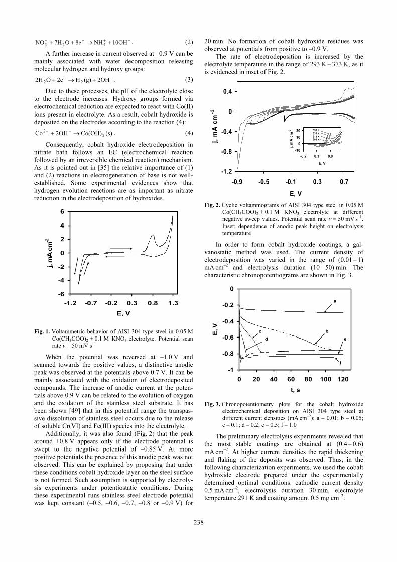
In order to form cobalt hydroxide coatings, a gal-vanostatic method was used. The current density of electrodeposition was varied in the range of (0.01 – 1) mA cm–2 and electrolysis duration (10 – 50) min. The characteristic chronopotentiograms are shown in Fig. 3.
-1
-0.8
-0.6
-0.4
-0.2
0
0 20 40 60 80 100 120
t, s
E, V
a
bc
d e
f
Fig. 3. Chronopotentiometry plots for the cobalt hydroxide
electrochemical deposition on AISI 304 type steel at
different current densities (mA cm–2): a – 0.01; b – 0.05;
c – 0.1; d – 0.2; e – 0.5; f – 1.0
The preliminary electrolysis experiments revealed that the most stable coatings are obtained at (0.4 – 0.6)
mA cm–2. At higher current densities the rapid thickening and flaking of the deposits was observed. Thus, in the following characterization experiments, we used the cobalt hydroxide electrode prepared under the experimentally determined optimal conditions: cathodic current density 0.5 mA cm–2, electrolysis duration 30 min, electrolyte temperature 291 K and coating amount 0.5 mg cm–2.

239
3.2. Structural characterization of cobalt
hydroxide coatings Fig. 4 shows thermogravimetric (TG) and differential
scanning calorimetry (DSC) analysis results of as-prepared cobalt hydroxide sample. DSC curve reveals three endo-thermic effects in the temperature range of 323 K – 620 K. They are accompanied by the weight loss of about 43 %. The first endothermic effect at 323 K – 433 K is due to the evaporation of physically adsorbed and interlayer water molecules. The endothermic effect at 470 K – 535 K can be associated with the decomposition of the hydrotalcite-like structure of cobalt hydroxide. The third endothermic peak observed at 606 K can be related to the decomposition of intercalated CH3COO– groups. These results are consistent with the TG data reported in the literature [3, 5].
40
50
60
70
80
90
100
30 180 330 480 630 780
Ma
ss,
%
-1.6
-1.4
-1.2
-1
-0.8
-0.6
-0.4
-0.2
0
0.2
0.4
0.6
Temperature, o
C
Endo
Exo
Hea
t fl
ow
, µ
V/m
g
Fig. 4. TG–DSC patterns of as-deposited cobalt hydroxide
The X-ray diffractograms of as-prepared and annealed at 673 K cobalt hydroxide samples are presented in Fig. 5. XRD curve of as-prepared sample reveals diffraction peaks at 9.76, 19.66, 33.16 and 59.28° corresponding to cobalt hydroxide. Small number of reflection peaks is an indication of poorly ordered samples. Based on the obtained results it can be assumed that the hydroxide synthesized here is of a mixed phase showing reflections characteristic of both α- and β-modifications. The strong low-angle reflection peak at 2θ = 9.76° can be found with d-spacing of 9.05 Å. This can be associated with acetate groups intercalated into hydrotalcite-like α-cobalt hydroxide structure. This value is intermediate as compared to those reported in literature for acetate intercalated α-cobalt hydroxide: 8.36 Å in [3] and 12.65 Å in [5]. The structure of α-cobalt hydroxides is highly dependent on the nature of inserted anion species leading to increased interlayer spacing compared to β-cobalt hydroxide. Both inorganic and organic groups have been incorporated into cobalt hydroxide layers [3 – 11]. In a case of NH3, NO3
–, CO3
2– and SO4
2– ions, the interlayer spacing was found to be in the range of 7.35 Å – 10.1 Å. Kurmoo showed [6] that the basal spacing increases with the length of the organic species in the following order: dicyanamide 11.5 Å, suberate 16.2 Å, caprylate 22.8 Å and dodecyl
sulfate 25.0 Å. Similar results were obtained by Yarger et al. [7]. They determined that cobalt hydroxide with significantly increased basal spacing (≥25.0 Å) can be produced by incorporating sodium dodecyl sulfate or 1-hexadecanesulfonate via electrochemical deposition.
0 10 20 30 40 50 60 70 80 90
2θ, degreesIn
ten
sit
y, a
.u.
(a)
(b)
Fig. 5. XRD pattern of (a) as-deposited and (b) annealed at 673 K
films
The presence of a reflection peak at 2θ = 19.66° in Fig. 5, a, can be related to the formation of β-modification. The reflection peaks at 2θ = 33.16° and 2θ = 59.28° exhibit an asymmetry on the higher angle side. This feature indicates the presence of turbostratic materials in which the stacked layers are randomly oriented about the principal crystallographic axis [14]. These diffraction peaks can be associated with α-cobalt hydroxide, according to the results reported in the literature [3].
The corresponding XRD pattern of thermally treated samples (Fig. 5, b) reveals diffraction peaks which can be readily attributed to the cubic phase of Co3O4. According to the Scherrer’s equation, the average Co3O4 crystallite size was calculated to be 29.2 nm.
The incorporation of acetate ions in as-prepared cobalt hydroxide films was confirmed using infrared absorption analysis (Fig. 6). It can be seen that there are IR absorptions not only in the high (3600 cm–1
– 3700 cm–1) and the low (600 cm–1
– 400 cm–1) wavenumber regions as it would be expected for β-Co(OH)2 modification [9], but also in the intermediate (1600 cm–1
– 800 cm–1) wavenum-ber region due to the vibrations of intercalated ions. The large absorption band centered at 3431 cm–1 can be assigned to the stretches of hydroxy groups. The peaks at 1578 cm–1 and 1385 cm–1 can be attributed to the stretching COO vibrations of the free acetate ion. The absorption band at 666 cm–11 can be ascribed to Co–OH vibrations. Other peaks at 1474, 1020 and 458 cm–1 show the presence of CH3 groups.
The FTIR spectrum of annealed cobalt hydroxide is shown in Fig. 7. Two distinctive bands can be seen characteristic for cobalt oxide Co3O4 [50]. The first band at 565 cm–1 is associated with the Co(III) ions in octahedral position. The second band at 659 cm–1 is attributed to the Co(II) ions in tetrahedral position.

240
400100016002200280034004000
Wavenumbers, cm-1
Tra
nsm
itta
nce, a.u
.
Fig. 6. FTIR spectrum of as-deposited cobalt hydroxide
400100016002200280034004000
Wavenumbers, cm-1
Tra
nsm
itta
nce, a.u
.
400500600700800
Fig. 7. FTIR spectrum of cobalt hydroxide annealed at 673 K
Chemical composition of the cobalt hydroxide and oxide films was characterized using XPS. High resolution Co2p and O1s spectra were obtained for both films and are shown in Fig. 8. The quantification was performed in terms of O1s/Co2p ratio and was found to be 1.56 for as-deposited sample and 1.35 for annealed sample. Latter value was very close to the theoretical value of 1.33 for Co3O4. Co2p region had doublets with Co2p3/2 peak at 781.2 eV and 780.1 eV for as-deposited and annealed samples, respectively. Co2p3/2 peak at 779.5 eV – 780.1 eV has previously been attributed to Co3O4 phase of cobalt oxide [51, 52], albeit close in value for CoO phase [53]. Co2p3/2 peak at 780.7 eV, on the other hand, has previously been attributed to Co(OH)2 [10].
Satellite peaks are also present in Co2p spectra for both samples, but of much lower intensity in annealed sample than in as-deposited. The suppression of shake up satellite peaks was observed for Co3O4 phase as opposed to CoO phase [54], thus corroborating previous assignment of Co3O4 for annealed sample. Satellite peaks have also been observed to be more prominent in Co3O4 as opposed to Co(OH)2 samples [10].
a
b
Fig. 8. High resolution XPS spectra of Co2p and O1s regions of
(a) as-deposited and (b) annealed at 673 K films.
Satellites in Co2p spectrum are denoted with asterisks
O1s spectra shown for both samples are comprised of several components. Namely, peaks at 530.1, 531.3 and 533.2 eV can be observed. These can be attributed to oxygen atoms in Co-O, Co(OH)2 and adsorbed water [10]. Peak due to the cobalt-hydroxy bonds is the main peak in as-deposited sample, whereas in annealed sample it constitutes roughly to 34 % of all O1s region. This, as well as XPS spectral analysis of Co2p region discussed above, unambiguously shows that as-deposited sample is cobalt hydroxide, whereas annealed sample is Co3O4 with some hydroxy groups adsorbed on the surface.
SEM images at various maginifications of as-deposited and annealed cobalt hydroxide films are shown in Fig. 9. Both films shown have the same surface morphology, e. g. the cobalt oxide film retains the same porous morphology as that of the precursor hydroxide. Both films showed very distinct clustering behavior at lower magnification, while at higher magnification lamelar structure can be seen. The morphology reported in this
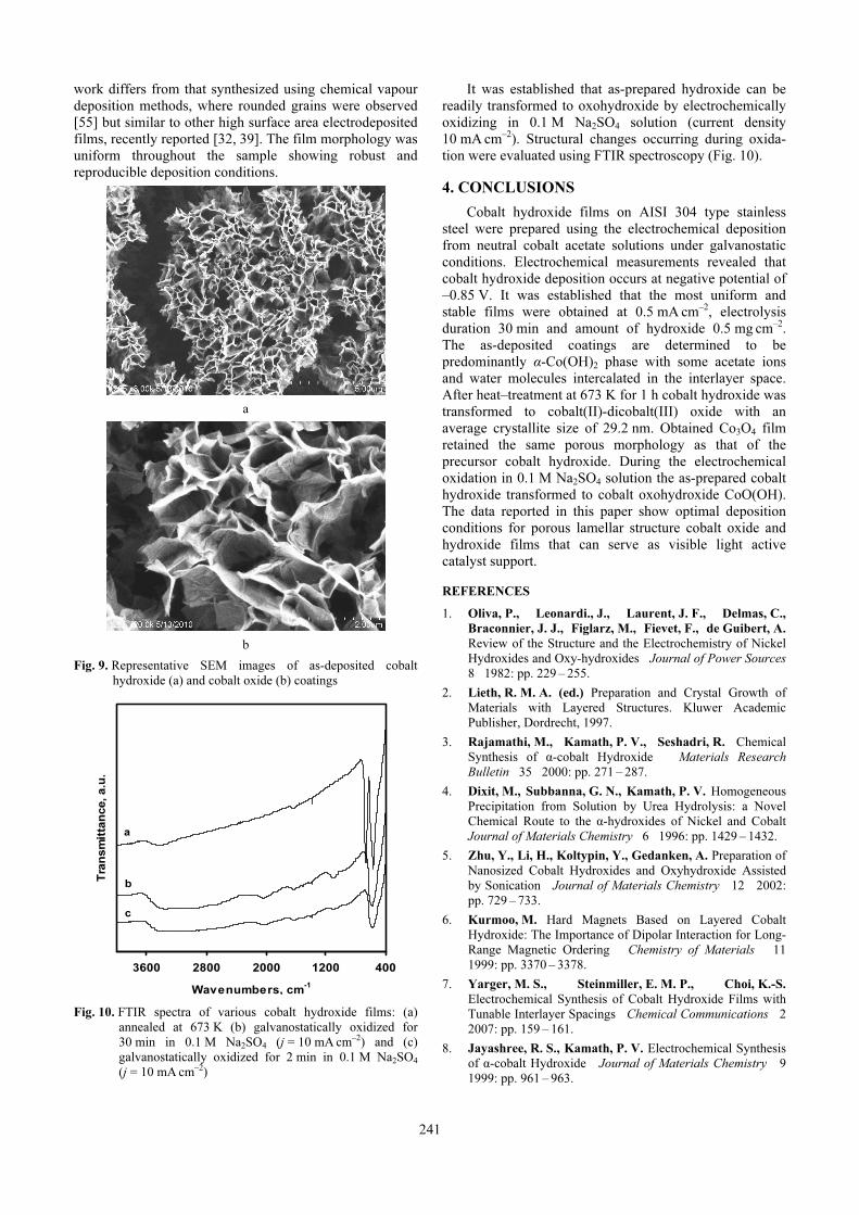
241
work differs from that synthesized using chemical vapour deposition methods, where rounded grains were observed [55] but similar to other high surface area electrodeposited films, recently reported [32, 39]. The film morphology was uniform throughout the sample showing robust and reproducible deposition conditions.
a
b
Fig. 9. Representative SEM images of as-deposited cobalt
hydroxide (a) and cobalt oxide (b) coatings
4001200200028003600
Wavenumbers, cm-1
Tra
nsm
itta
nce, a.u
.
a
b
c
Fig. 10. FTIR spectra of various cobalt hydroxide films: (a)
annealed at 673 K (b) galvanostatically oxidized for
30 min in 0.1 M Na2SO4 (j = 10 mA cm–2) and (c)
galvanostatically oxidized for 2 min in 0.1 M Na2SO4
(j = 10 mA cm–2)
It was established that as-prepared hydroxide can be readily transformed to oxohydroxide by electrochemically oxidizing in 0.1 M Na2SO4 solution (current density 10 mA cm–2). Structural changes occurring during oxida-tion were evaluated using FTIR spectroscopy (Fig. 10).
4. CONCLUSIONS
Cobalt hydroxide films on AISI 304 type stainless steel were prepared using the electrochemical deposition from neutral cobalt acetate solutions under galvanostatic conditions. Electrochemical measurements revealed that cobalt hydroxide deposition occurs at negative potential of –0.85 V. It was established that the most uniform and stable films were obtained at 0.5 mA cm–2, electrolysis duration 30 min and amount of hydroxide 0.5 mg cm–2. The as-deposited coatings are determined to be predominantly α-Co(OH)2 phase with some acetate ions and water molecules intercalated in the interlayer space. After heat–treatment at 673 K for 1 h cobalt hydroxide was transformed to cobalt(II)-dicobalt(III) oxide with an average crystallite size of 29.2 nm. Obtained Co3O4 film retained the same porous morphology as that of the precursor cobalt hydroxide. During the electrochemical oxidation in 0.1 M Na2SO4 solution the as-prepared cobalt hydroxide transformed to cobalt oxohydroxide CoO(OH). The data reported in this paper show optimal deposition conditions for porous lamellar structure cobalt oxide and hydroxide films that can serve as visible light active catalyst support.
REFERENCES
1. Oliva, P., Leonardi., J., Laurent, J. F., Delmas, C.,
Braconnier, J. J., Figlarz, M., Fievet, F., de Guibert, A.
Review of the Structure and the Electrochemistry of Nickel
Hydroxides and Oxy-hydroxides Journal of Power Sources
8 1982: pp. 229 – 255.
2. Lieth, R. M. A. (ed.) Preparation and Crystal Growth of
Materials with Layered Structures. Kluwer Academic
Publisher, Dordrecht, 1997.
3. Rajamathi, M., Kamath, P. V., Seshadri, R. Chemical
Synthesis of α-cobalt Hydroxide Materials Research
Bulletin 35 2000: pp. 271 – 287.
4. Dixit, M., Subbanna, G. N., Kamath, P. V. Homogeneous
Precipitation from Solution by Urea Hydrolysis: a Novel
Chemical Route to the α-hydroxides of Nickel and Cobalt
Journal of Materials Chemistry 6 1996: pp. 1429 – 1432.
5. Zhu, Y., Li, H., Koltypin, Y., Gedanken, A. Preparation of
Nanosized Cobalt Hydroxides and Oxyhydroxide Assisted
by Sonication Journal of Materials Chemistry 12 2002:
pp. 729 – 733.
6. Kurmoo, M. Hard Magnets Based on Layered Cobalt
Hydroxide: The Importance of Dipolar Interaction for Long-
Range Magnetic Ordering Chemistry of Materials 11
1999: pp. 3370 – 3378.
7. Yarger, M. S., Steinmiller, E. M. P., Choi, K.-S.
Electrochemical Synthesis of Cobalt Hydroxide Films with
Tunable Interlayer Spacings Chemical Communications 2
2007: pp. 159 – 161.
8. Jayashree, R. S., Kamath, P. V. Electrochemical Synthesis
of α-cobalt Hydroxide Journal of Materials Chemistry 9
1999: pp. 961 – 963.

242
9. Liu, Z., Ma, R., Osada, M., Takada, K., Sasaki, T.
Selective and Controlled Synthesis of α- and β-cobalt
Hydroxides in Highly Developed Hexagonal Plateles
Journal of the American Chemical Society 127 (40) 2005:
pp. 13869 – 13874.
10. Yang, J., Liu, H., Martens, W. N., Frost, R. L. Synthesis
and Characterization of Cobalt Hydroxide, Cobalt
Oxyhydroxide, and Cobalt Oxide Nanodiscs Journal of
Physical Chemistry C 114 (1) 2010: pp. 111 – 119.
11. Jeevanandam, P., Koltypin, Yu., Gedanken, A., Mastai,
Y. Synthesis of α-cobalt(II) Hydroxide Using Ultrasound
Radiation Journal of Materials Chemistry 10 2000:
pp. 511 – 514.
12. Chou, S.-L., Wang, J.-Z., Liu, H.-K., Dou, S.-X.
Electrochemical Deposition of Porous Co(OH)2 Nanoflake
Films on Stainless Steel Mesh for Flexible Supercapacitors
Journal of the Electrochemical Society 155 2008:
pp. A926 – A929.
13. Zhou, W.-J., Xu, M.-W., Zhao, D.-D., Xu, C.-L., Li, H.-
L. Electrodeposition and Characterization of Ordered
Mesoporous Cobalt Hydroxide Films on Different
Substrates for Supercapacitors Microporous and
Mesoporous Materials 117 2009: pp. 55 – 60.
14. Gupta, V., Kusahara, T., Toyama, H., Gupta, S., Miura,
N. Potentiostatically Deposited Nanostructured α-Co(OH)2:
a High Performance Electrode Material for Redox-capacitors
Electrochemistry Communications 9 2007: pp. 2315 –
2319.
15. Kandalkara, S. G., Gunjakara, J. L., Lokhande, C. D.
Preparation of Cobalt Oxide Thin Films and its Use in
Supercapacitor Application Applied Surface Science 254
2008: pp. 5540 – 5544.
16. Chang, J.-K., Wu, C.-M., Sun, I.-W. Nano-architectured
Co(OH)2 Electrodes Constructed Using an Easily-
manipulated Electrochemical Protocol for High-performance
Energy Storage Applications Journal of Materials
Chemistry 20 2010: pp. 3729 – 3735.
17. Zhou, W.-J., Zhao, D.-D., Xu, M.-W., Xu, C.-L., Li, H.-
L. Effects of the Electrodeposition Potential and
Temperature on the Electrochemical Capacitance Behavior
of Ordered Mesoporous Cobalt Hydroxide Films
Electrochimica Acta 53 2008: pp. 7210 – 7219.
18. Fan, L. F., Wu, X. Q., Guo, M. D., Gao, Y. T. Cobalt
Hydroxide Film Deposited on Glassy Carbon Electrode for
Electrocatalytic Oxidation of Hydroquinone Electrochimica
Acta 52 2007: pp. 3654 – 3659.
19. Dasa, D., Das, K. Cobalt Hydroxide Film on Pt as Co-
catalyst for Oxidation of Polyhydric Alcohols in Alkaline
Medium Materials Chemistry and Physics 123 2010:
pp. 719 – 722.
20. Dinamani, M., Kamath, P. V. Electrocatalysis of Oxygen
Evolution at Stainless Steel Anodes by Electrosynthesized
Cobalt Hydroxide Coatings Journal of Applied
Electrochemistry 30 2010: pp. 1157 – 1161.
21. Yi Wang, Dun Zhang, Huaiqun Liu. A Study of the
Catalysis of Cobalt Hydroxide Towards the Oxygen
Reduction in Alkaline Media Journal of Power Sources
195 2010: pp. 3135 – 3139.
22. Vidotti, M., van Greco, C., Ponzio, E. A., Córdoba de
Torresi, S. I. Sonochemically Synthesized Ni(OH)2 and
Co(OH)2 Nanoparticles and Their Application in Electro-
chromic Electrodes Electrochemistry Communications 8
2006: pp. 554 – 560.
23. Zhang, F., Xiang, X., Li, F., Duan, X. Layered Double
Hydroxides as Catalytic Materials: Recent Development
Catalysis Surveys from Asia 12 2008: pp. 253 – 265.
24. Tang, C.-W., Wang, C.-B., Chien, S.-H. Characterization
of Cobalt Oxides Studied by FT-IR, Raman, TPR and TG-
MS Thermochimica Acta 473 2008: pp. 68 – 73.
25. Liu, X., Yi, R., Zhang, N., Shi, R., Li, X., Qiu, G. Cobalt
Hydroxide Nanosheets and Their Thermal Decomposition to
Cobalt Oxide Nanorings Chemistry – An Asian Journal 3
2008: pp. 732 – 738.
26. Klissurski, D., Rives, V. High-temperature Superconduc-
tors in Catalysis Applied Catalysis A: General 109
1994: pp. 1 – 44.
27. Barrera, E., González, I. A New Cobalt Oxide
Electrodeposit Bath for Solar Absorbers Solar Energy
Materials and Solar Cells 51 1998: pp. 69 – 82.
28. Abdel Hamid, Z., Abdel Aal, A., Schmuki, P.
Nanostructured Black Cobalt Coatings for Solar Absorbers
Surface and Interface Analysis 40 2008: pp. 1493 – 1499.
29. Li, W. Y., Xu, L. N., Chen, J. Co3O4 Nanomaterials in
Lithium-Ion Batteries and Gas Sensors Advanced
Functional Materials 15 2005: pp. 851 – 857.
30. Gao, Y., Chen, S., Cao, D., Wang, G., Yin, J.
Electrochemical Capacitance of Co3O4 Nanowire Arrays
Supported on Nickel Foam Journal of Power Sources 195
2010: pp. 1757 – 1760.
31. Koshizaki, N., Yasumoto, K., Sasaki, T. Mechanism of
Optical Transmittance Change by NOx in CoO/SiO2
Nanocomposites Films Sensors and Actuators B:
Chemical 66 2000: pp. 122 – 124.
32. Heli, H., Yadegari, H. Nanoflakes of the Cobaltous Oxide,
CoO: Synthesis and Characterization Electrochimica Acta
55 2010: pp. 2139 – 2148.
33. Mansour, C., Pauporté, T., Ringuedé, A., Albin, V.,
Cassir, M. Protective Coating for MCFC Cathode: Low
Temperature Potentiostatic Deposition of CoOOH on Nickel
in Aqueous Media Containing Glycine Journal of Power
Sources 156 2006: pp. 23 – 27.
34. Zheng, H., Tang, F., Lim, M., Rufford, T., Mukherji, A.,
Wang, L., Lu, G. Electrochemical Behavior of Carbon
Nanotube/Cobalt Oxyhydroxide Nanoflake Multilayer Films
Journal of Power Sources 193 2009: pp. 930 – 934.
35. Therese, G. H. A., Kamath, P. V. Electrochemical
Synthesis of Metal Oxides and Hydroxides Chemistry of
Materials 12 (5) 2000: pp. 1195 – 1204.
36. Boccaccini, A. R., Zhitomirsky, I. Application of
Electrophoretic and Electrolytic Deposition Techniques in
Ceramics Processing Current Opinion in Solid State and
Materials Science 6 2002: pp. 251 – 260.
37. Brownson, J. R. S., Lévy-Clément, C. Electrodeposition of
α- and β-cobalt Hydroxide Thin Films Via Dilute Nitrate
Solution Reduction Physica Status Solidi (b) 245 2008:
pp. 1785 – 1791.
38. Brownson, J. R. S., Lévy-Clément, C. Nanostructured α-
and β-cobalt Hydroxide Thin Films Electrochimica Acta
54 2009: pp. 6637 – 6644.
39. Prasad, B. E., Kamath, P. V., Upadhya, S. Electrochemi-
cal Synthesis of Macroporous Oxide Coatings on Stainless-
Steel Substrates Journal of the American Ceramic Society
91 2008: pp. 3870 – 3874.
40. Mendoza, L., Albin, V., Cassir, M., Galtayries, A.
Electrochemical Deposition of Co3O4 Thin Layers in Order
to Protect the Nickel-based Molten Carbonate Fuel Cell

243
Cathode Journal of Electroanalytical Chemistry 548
2003: pp. 95 – 107.
41. Ivanova, N. D., Boldyrev, E. I., Ivanov, S. V., Makeeva,
I. S. Electrochemical Synthesis of Black Cobalt Russian
Journal of Applied Chemistry 76 2003: pp. 1589 – 1592.
42. Casella, I. G., Gatta, M. Study of the Electrochemical
Deposition and Properties of Cobalt Oxide Species in Citrate
Alkaline Solutions Journal of Electroanalytical Chemistry
534 2002: pp. 31 – 38.
43. Casella, I. G. Electrodeposition of Cobalt Oxide Films from
Carbonate Solutions Containing Co(II)–tartrate Complexes
Journal of Electroanalytical Chemistry 520 2002:
pp. 119 – 125.
44. Ismail, J., Ahmed, M. F., Kamath, P. V., Subbanna,
G. N., Uma, S., Gopalakrishnan, J. Organic Additive-
mediated Synthesis of Novel Cobalt(II) Hydroxides
Journal of Solid State Chemistry 114 1995: pp. 550 – 555.
45. McNally, E. A., Zhitomirsky, I., Wilkinson, D. S.
Cathodic Electrodeposition of Cobalt Oxide Films Using
Polyelectrolytes Materials Chemistry and Physics 91
2005: pp. 391 – 398.
46. Azaroff, L. V. Elements of X-ray Crystallography. McGraw
Hill Book Co, New York, 1968.
47. Baltrusaitis, J., Usher, C. R., Grassian, V. H. Reactions of
Sulfur Dioxide on Calcium Carbonate Single Crystal and
Particle Surfaces at the Adsorbed Water Carbonate Interface
Physical Chemistry Chemical Physics 9 2007:
pp. 3011 – 3024.
48. Fairley, N. (1999 – 2009) CasaXPS Version 2.3.14,
www.casaxps.com
49. Betova, I., Bojinov, M., Laitinen, T., Mäkelä, K.,
Pohjanne, P., Saario, T. The Transpassive Dissolution
Mechanism of Highly Alloyed Stainless Steels: I.
Experimental Results and Modelling Procedure Corrosion
Science 44 2002: pp. 2675 – 2697.
50. Christoskova, St. G., Stoyanova, M., Georgieva, M.,
Mehandjiev, D. Preparation and Characterization of a
Higher Cobalt Oxide Materials Chemistry and Physics 60
1999: pp. 39 – 43.
51. Oku, M., Sato, Y. In-situ X-ray Photoelectron
Spectroscopic Study of the Reversible Phase Transition
between CoO and Co3O4 in Oxygen of 10−3 Pa Applied
Surface Science 55 1992: pp. 37 – 41.
52. Patil, D., Patil, P., Subramanian, V., Joy, P. A., Potdar,
H. S. Highly Sensitive and Fast Responding CO Sensor
Based on Co3O4 Nanorods Talanta 81 2010: pp. 37 – 43.
53. Nefedov, V. I., Firsov, M. N., Shaplygin, I. S. Electronic
Structures of MRhO2, MRh2O4, RhMO4 and Rh2MO6 on the
Basis of X-ray Spectroscopy and ESCA Data Journal of
Electron Spectroscopy and Related Phenomena 26 1982:
pp. 65 – 78.
54. Vaz, C. A. F., Wang, H.-Q., Ahn, C. H., Henrich, V. E.,
Bakara, M. Z., Schwendemann, T. C., Pilet, N., Atbers,
B. J., Schwarz, U. D., Zhang, L. H., Zhu, Y., Wang, J.,
Altman, E. I. Interface and Electronic Characterization of
Thin Epitaxial Co3O4 Films Surface Science 603 2009:
pp. 291 – 297.
55. Barreca, D., Massignan, C., Daolio, S., Fabrizio, M.,
Piccirillo, C., Armelao, L., Tondello, E. Composition and
Microstructure of Cobalt Oxide Thin Films Obtained from a
Novel Cobalt(II) Precursor by Chemical Vapor Deposition
Chemistry of Materials 13 (2) 2001: pp. 588 – 593.
56. Wei, G., Luo, L. US Patent No 5984982, 1999.
Related Documents