Montana Tech Library Digital Commons @ Montana Tech Bachelors eses and Reports, 1928 - 1970 Student Scholarship 5-15-1947 Electro-Deposition of Iron from a Chloride Bath Charles W. Noon Follow this and additional works at: hp://digitalcommons.mtech.edu/bach_theses Part of the Ceramic Materials Commons , Environmental Engineering Commons , Geology Commons , Geophysics and Seismology Commons , Metallurgy Commons , Other Engineering Commons , and the Other Materials Science and Engineering Commons is Bachelors esis is brought to you for free and open access by the Student Scholarship at Digital Commons @ Montana Tech. It has been accepted for inclusion in Bachelors eses and Reports, 1928 - 1970 by an authorized administrator of Digital Commons @ Montana Tech. For more information, please contact [email protected]. Recommended Citation Noon, Charles W., "Electro-Deposition of Iron from a Chloride Bath" (1947). Bachelors eses and Reports, 1928 - 1970. 227. hp://digitalcommons.mtech.edu/bach_theses/227

Welcome message from author
This document is posted to help you gain knowledge. Please leave a comment to let me know what you think about it! Share it to your friends and learn new things together.
Transcript
Montana Tech LibraryDigital Commons @ Montana Tech
Bachelors Theses and Reports, 1928 - 1970 Student Scholarship
5-15-1947
Electro-Deposition of Iron from a Chloride BathCharles W. Noon
Follow this and additional works at: http://digitalcommons.mtech.edu/bach_theses
Part of the Ceramic Materials Commons, Environmental Engineering Commons, GeologyCommons, Geophysics and Seismology Commons, Metallurgy Commons, Other EngineeringCommons, and the Other Materials Science and Engineering Commons
This Bachelors Thesis is brought to you for free and open access by the Student Scholarship at Digital Commons @ Montana Tech. It has been acceptedfor inclusion in Bachelors Theses and Reports, 1928 - 1970 by an authorized administrator of Digital Commons @ Montana Tech. For moreinformation, please contact [email protected].
Recommended CitationNoon, Charles W., "Electro-Deposition of Iron from a Chloride Bath" (1947). Bachelors Theses and Reports, 1928 - 1970. 227.http://digitalcommons.mtech.edu/bach_theses/227
ELECTRO-DEPOSITION OF IRON
FROM A CHLORIDE BATH
by
Charles W. Noon
M01ITANA SCHOOL OF MINES LmBAB1'BUTTE
A ThesisSubmitted to the Department of Metallurgy
in Partial Fulfillment ofthe Requirements for the Degree of
Bachelor of Science in Metallurgical Engineering
Montana School of Mines
Butte, MontanaMay 15, 1947
ELECTRO-DEPOSTTION OF IRON
FROMA CHLORIDE BATH
by
Charles W. Noon
A Thesis
Submitted to the Department of Metallu.rgy
in Partial -Fulfillmemt of
the Requir~ms:Ht$l!o.t" 'fh'l Degree of
Bachelor of ~~ience in Metallurgical Engineering
Montana School of Mines
Butte, Montana
May 15, 1947
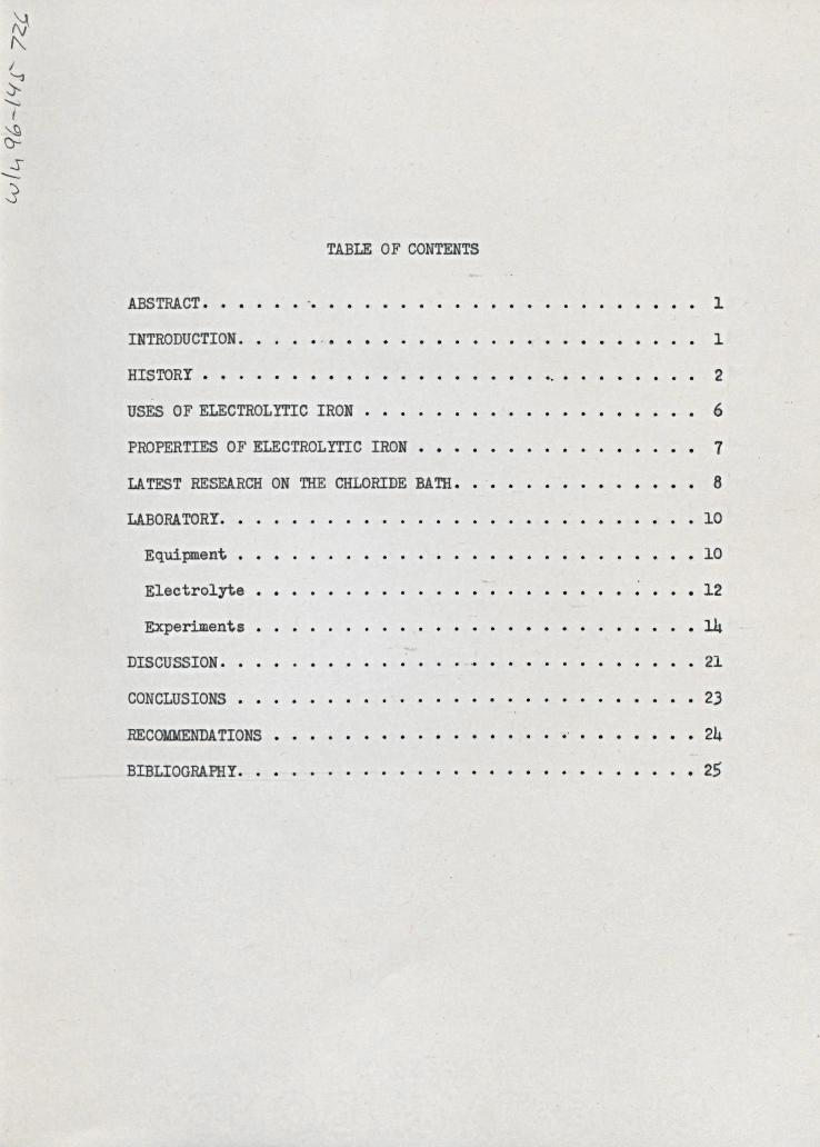
TABLE 0F CONTENTS
ABSTRACT. ..INTRODUCTION.HISTORY •USES OF ELECTROLYTIC IRON •PROPERTIES OF ELECTROLYTIC IRON •LATEST RESEARCH ON THE CHLORIDE BATH.LABOR! TORY.
Equipment.Electrolyte •Experiments •
DISCUSSION.CONCLUSIONS •RECOl41dENDATIONSBIBLIOGRAPHY.
1
1
e , • 2
6
• 7
8
• 10
• 10
• 12.14• 21
• 2324
• 25
ABSTRACT
Iron was electro-deposited from a ferrous chloride bath. Studieswere made of deposits formed when current density was varied, and fin-ally when both current density and temperature were changed. An attemptwas made to lay the ground work for a long range study of the chloridebath, and to deter.mine the most simple conditions possible for obtaininga smooth, even, and thick deposit; particularly,. one free from cracksaad pits. other deposits were made from the sulfate bath, such that acomparison of the quality of the two could be made. A review of the his-tory of electrolyte iron, its uses and properties, and the latest infor-mation on research in the chloride bath were also included. The labora-tory equipment, and the electrolyte employed in this work were described.
INTRODUCTION
Although electrolytic iron has been known for almost one hundredyears, it has always remained one of minor importance in the plating world.Many factors influence this obscurity, but the two prominent ones are suf-ficient to explain it. The first lies in the fact that electro-deposition,as a means of obtaining iron as such, has been continually pushed into theimpractical by other well established and cheaper methods. The other liesin the fact that electrolytic iron, with properties which make it desir-able for specific uses, has been ever replaced by other metals. Thesemetals can be produced at a low cost, are abundant, and have special prop-erties that make them better than electrolytic iron. Though its historyis one primarily of laboratory interest, with a few brief flurries of com-mercial interest, and though the above conditions have prevented its be-Coming of importance up to the present time, research on electrolytic iron
-1-
is being continually carried foreward.
HISTORY
The first recorded work on electrolytic iron was produced by Botteger,a German chemist, in 1846, in which he showed the results of various lab-oratory experiments on the subject. A 11:1.11followed in which interestcentered mainly in the laboratory, with the.gathering'of information andeXamining results for possible commercial value. In 1868, Klien, Jacobiand Maximowi tsch found it useful for plating copper engravings that wereused fer printing Russian bank notes. It was employed in this manner formany years since it provided a hard and durable coating, with the addedadvantage that printing could go on until the copper began to show through,whereupon the engraving could be replated. Finally, however, nickle re-placed it for this use. Except for this particular item, electrolyticiron remained in obscurity until 1904. At this time Burgess and Hambuchen,in America, produced a deposit which created the first flurry of commercialinterest. Their method, modified by Watts, was the basis for the construc-tion of the electrolytic refining plant of the ~estern Electric Company atHawthorne, Illinois. A ferrous and ammonium sulfate s'olutionwas employedwith a current denSity of 6-10 amps/sq. foot, an emf. of less than onevolt, a temperature of 300C, and anodes of wrought iron. Ammonium oxalatewas used as an addition agent. The low production of 1000 pounds of ironper week, together with the high cost, soon forced the plant out of exist-ence. The same year found an English chemist, Cowper-eoles, developing amethod employing a 20% solution of Sulfo-Cresylic acid charged with suspen-ded iron oxide, a c.d. of 100 amps/sq. ft., a temperature of 700C, and arotating cathode. No production of commercial importance arose from thisdevelopment, although it was later claimed that the plant at Grenoble,
-2-
France, was based on his idea.In 1908, the Fischer-Langbien Pfanhausen, a German concern, developed
an electrolyte of ferrous and calcium chlorides, from which a good, puredeposit was obtained. The current <!iensityranged up to 200 amps/sq. foot,and the temperature was 900C. Hughes, of Englantil,stu.died this and tOQkout British patents on the same.
From a commercial standpoint, 1910 seemed to be the year that the highpoint in electrolytic iron was reached. Bou.cher and Bouchayer, French chem-ists, developed a solution which seemed promising, and later Bouchayer formedthe company, Societe "Le FertJ, and eensbructed a plant, wb.ich was quite com-plete. The process consisted of the refining of cast iron to form a fin-ished tube. The electrolyte was ferrous chloride, made up of sorap ironand HCL, with a specific gravity of 1.5; of which, none was discarded. Itwas kept at 70-75°c, but temperature control was difficult. The electrolytewas circulated rapidly, and before returning to the cell was passed overiron filings to insure neutrality. The iron filings also acted as a filter.The company claimed that the noxious effect· of the H2 liberated at the ca-thode was overcome by the oxychloride of iron which the solution carried.At first the oxychloride was made by areating the solution in the scraptanks, but was later accomplished by a slight electrolytic oxidation of thesolution using an insoluble anode. The plant employed two rows of cells,and each row was a separate circuit. The anodes were two L-shaped castings,and during the process were about 80% dissolved. The cathode was a rotatingmandrel, 85-160 mm. in diameter and 4 meters long, mounted on wooden bear-ings. The mandrels were rotated at various speeds depending on the diameter,the 160 mm. diameter cathode being run at 180-220 RPM. If the bearings werenot worn the iron deposited smoothly as a thin tube on the mandrel; if ro-tation was not even the deposit was irregular and of uneven thickness. The
-3-
thinnest tube was 2 mm. thick, and the thickest was 5 mm., and it was atthis point that the company claimed the efficiency of their system. Inthe formation of tubing by drawing, dies are needed for each reduction insize, and the resulting tube had to be treated to eliminate undesirableproperties produced by the drawing process. The electrolytic formation,on the other hand, could be controlled in the one operation, obtaining thedesired thickness, and a finished tube. This, the company claimed, resultedin large savings, particularly in labor.
The power supplied was 1000 amps and 100-130 volts, giving a eurrentdenSity of 10 amps/sq. ft. and a voltage per cell of 3-4 volts. After de-pOSition, the mandrel was placed in a slowly revolving lathe which oarrieda traveling, double gas jet. This removed enough hydrogen so that the tubecould be removed without cracking. The tube was removed by compressing thedeposit by means of three traveling rolls which were hydraulically forcedagainst the deposit. The pressure-was sufficient to expand the iron circum-ferentially so that the tube came entirely loose from the mandrel. It wasthen removed and given a full anneal in an open flame, continuous furnace.
Before the mandrels could be used again they were scoured and polished,and placed as the cathode in a bath of lead perchlorate. Insoluble anodeswere used, and a light coating of lead was plated on these mandrels. Thelead acted as a rust preventative, so that stripping of the tube would befaoilitated by the presence of this soft, easily fusible layer between thesteel mandrel and the iron deposit. Total production was about 2 tons perday. The product was used in special radiator work requiring tubes of highductility. Their advantage lay in that they could easily be drawn into com-plicated shapes, and easily welded. The plant operated some fifteen ortwenty years before economic reasons forced it to close.
In 1911, Fischer developed a chloride bath, but no information on it
-4-
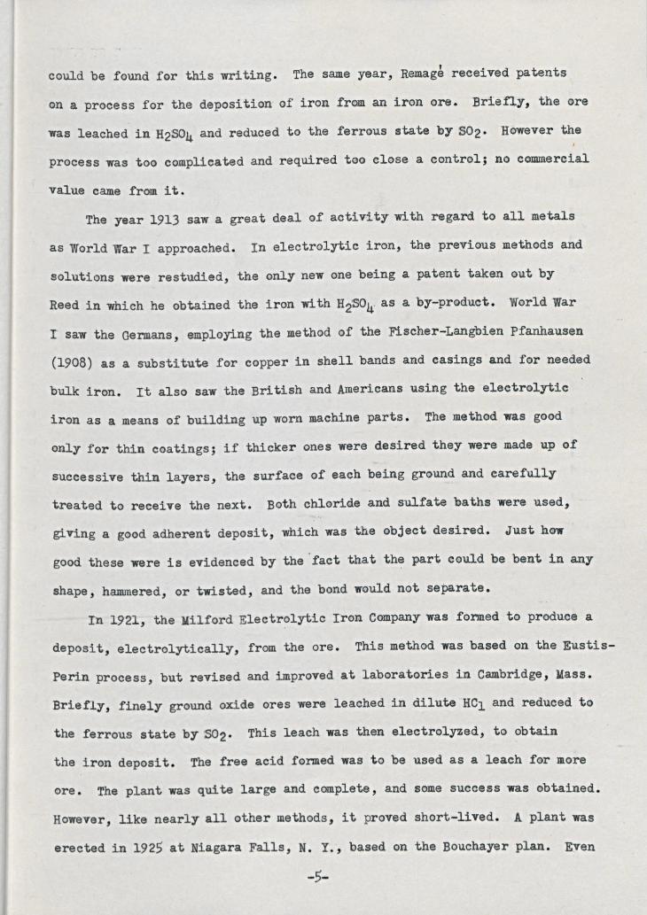
could be found for this writing. The same year, Remag$ received patentson a process for the deposition of iron from an iran ore. Briefly, the orewas leached in H2S04 and reduced to the ferrous state by 502' However theprocess was too complicated and required too close a control; no commercial
value came from it.The year 1913 saw a great deal of activity with regard to all metals
as World War I approached. In electrolytic iron, the previous methods andsolutions were restudied, the only new one being a patent taken out byReed in which he obtained the iron with H2S04 as a by-product. World WarI saw the Germans, employing the method of the Fischer-Langbien Pfanhausen(1908) as a substitute for copper in shell bands and casings and for neededbulk iron. It also saw the British and Amerioans using the electrolyticiron as a means of building up worn machine parts. The method was goodonly for thin coatings; if thicker ones were desirea they were made up ofsuccessive thin layers, the surface of each being ground and carefullytreated to receive the next. Both ohloride and sulfate baths were used,giVing a good adherent deposit, which was the object desired. Just hawgood these were is evidenced by the "fact that the part could be bent in anyshape, hammered, or twisted, and the bond would not separate.
In 1921, the Milford Electrolytic Tran Company was formed to produce adeposit, electrolytically, from the ore. This method was based on the Eustis-Perin process, but revised and improved at laboratories in Cambridge, Mass.Briefly, finely ground oxide ores were leached in diluteHCl and reduced tothe ferrous state by S02' This leach was then electrolyzed, to obtainthe iron deposit. The free acid formed was to be used as a leach for moreore. The plant was quite large and complete, and some success was obtained.However, like nearly all other methods, it proved short-lived. A plant waserected in 1925 at Niagara Falls, N. Y., based on the Bouchayer plan. Even
-5-
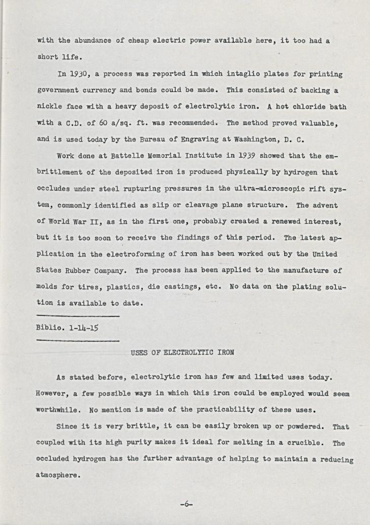
with the abundance of cheap electric power available here, it too had ashort life.
In 1930, a process was reported in which intaglio plates for printinggovernment currency and bonds could be made. This consisted of backing anickle face with a heavy deposit of electrolytic iron. A hot chloride bathwith a C.D. of 60 a/sq. ft. was recommended. The method proved valuable,and is used today by the Bureau of Engraving at Washington, D. C.
Work done at Battelle Memorial Institute in 1939 showed that the em-brittlement of the deposited iron is produced physically by hydrogen thatoccludes under steel rupturing pressures in the ultra~microscopic rift sys-tem, commonly identified as slip or cleavage plane structure. The adventof World War II, as in the first one, probably created a renewed interest,but it is too soon to receive the findings of this period. The latest ap-plication in the electroforming of iron has been worked out by the Unitedstates Rubber Company. The process has been applied to the manufacture ofmolds for tires, plastics, die castings, etc. No data on the plating solu-tion is available to date.
Biblio. 1-14-1$
USES OF ELECTROLYTIC IRON
As stated before, electrolytic iron has few and limited uses today.However, a few possible ways in which this iron could be employed would seemworthwhile. No mention is made of the practicability of these uses.
Since it is very brittle, it can be easily broken up or powdered. Thatcoupled with its high purity makes it ideal for melting in a crucible. Theoccluded hydrogen has the further advantage of helping to maintain a reducingatmosphere.
-6-
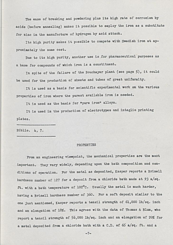
The ease of breaking and powaering plus its high rate of corrosion byacids (before annealing) makes it possible to employ the iron as a substitutefor ziDC in the manufacture of hydrogen by acid attack.
Its high purity makes it possible to cempe te with Swedish iron at ap-
proximately the same cost.Due to its high purity, another use is for pharmaceutical purposes as
a base for compounds of which iron is a constituent.Tn spite of the failure of the Bouchayer plant (see page 5), it could
be used for the production of sheets and tubes of great uniformity.It is used as a basis for scientific experime~tal work on the various
properties of iron where the purest available iron is needed.Tt is used as the basis for "pure iron" alloys.It is used in the production of electrotypes and intaglio printing
plates.
Biblio. 4, 7.
PROPERTIES
From an engineering viewpoint, the mechanical properties are the mostimportant. They vary widely, depending upon the bath oomposition and con-ditions of operation. For the metal as deposited, Kasper reports a Brinellhardness number of 127 for a deposit from a chloride bath made at 93 a/sq.ft. with a bath temperature of 102oC. Usually the metal is much harder,having a Brinell hardness number of 360. For a soft deposit similar to theone just mentioned, Kasper reports a tensil strength of 61,000 Ib/sq. inchand an elongation of 18%. This agrees with the data of Thomas & Blum, whoreport a tensil strength of 56,000 Ib/sq. inch and an elongation of 20% fora metal deposited from a chloride bath with a C.D. of 65 a/sq. ft. and a
-7-
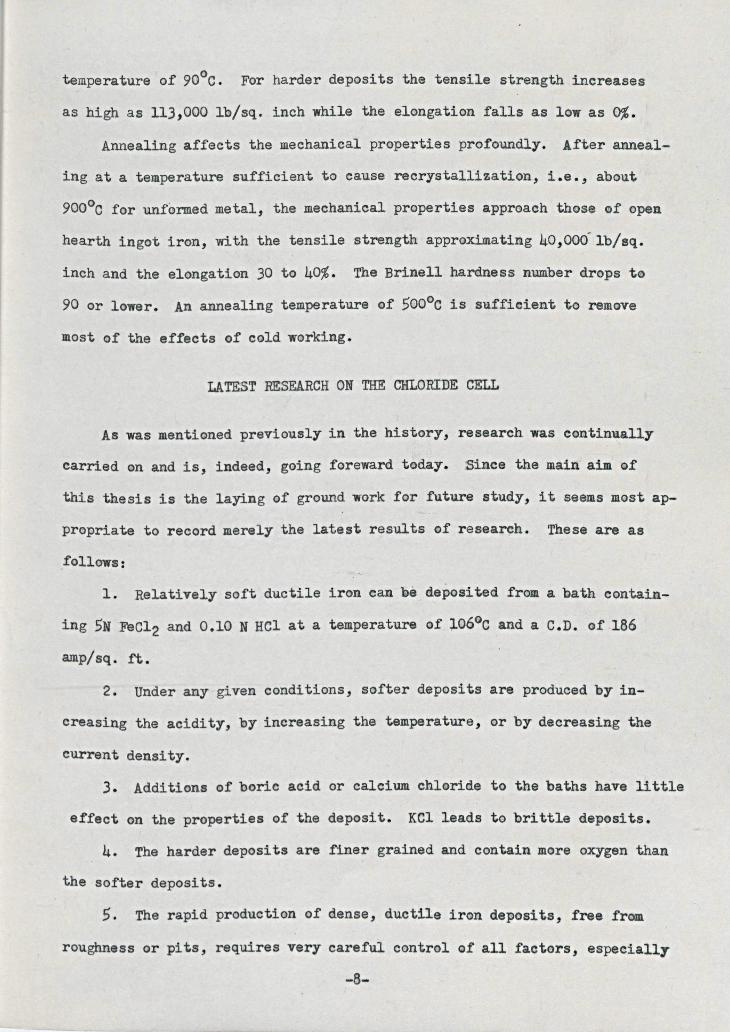
temperature of 90oC. For harder deposits the tensile strength increasesas high as 113,000 la/sq. inch while the elongation falls as low as 0%.
Annealing affects the mechanical properties prof-oundly. After anneal-ing at a temperature sufficient to cause recrystallization, i.e., about9000C for unformed metal, the mechanical properties approaoh these of openhearth ingot iron, with the tensile strength approximating 40,OOO~lb/sq.inch and the elongation 30 to 40%. The Brinel1 hardness number drops to90 or lower. An annealing temperature of 500Gc is sufficient to removemost of the effects of cold working.
LATEST RESEARCH ON THE CHLORIBE CELL
As was mentioned previously in the history, research was continuallycarried on and is, indeed, going foreward today. Since the main aim ofthis thesis is the laying of ground work for future study, it seems most ap-propriate to record merely the latest results of research. These are as.follows:
1. Relatively soft ductile iron can be deposited from a bath contain-ing 5N FeC12 and 0.10 N RCl at a temperature of l06°c and a C.D. of 186amp/sq. ft.
2. Under any given conditions, softer deposits are produced by in-creasing the acidity, by increasing the temperature, or by decreasing thecurrent density.
3. Additions of boric acid or calcium chloride to the baths have littleeffect on the properti~s of the deposit. KCl leads to brittle deposits.
4. The harder deposits are finer grained and contain more oxygen thanthe softer deposits.
5. The rapid production of dense, ductile iron deposits, free framroughness or pits, requires very careful control of all faotors, especially
-8-
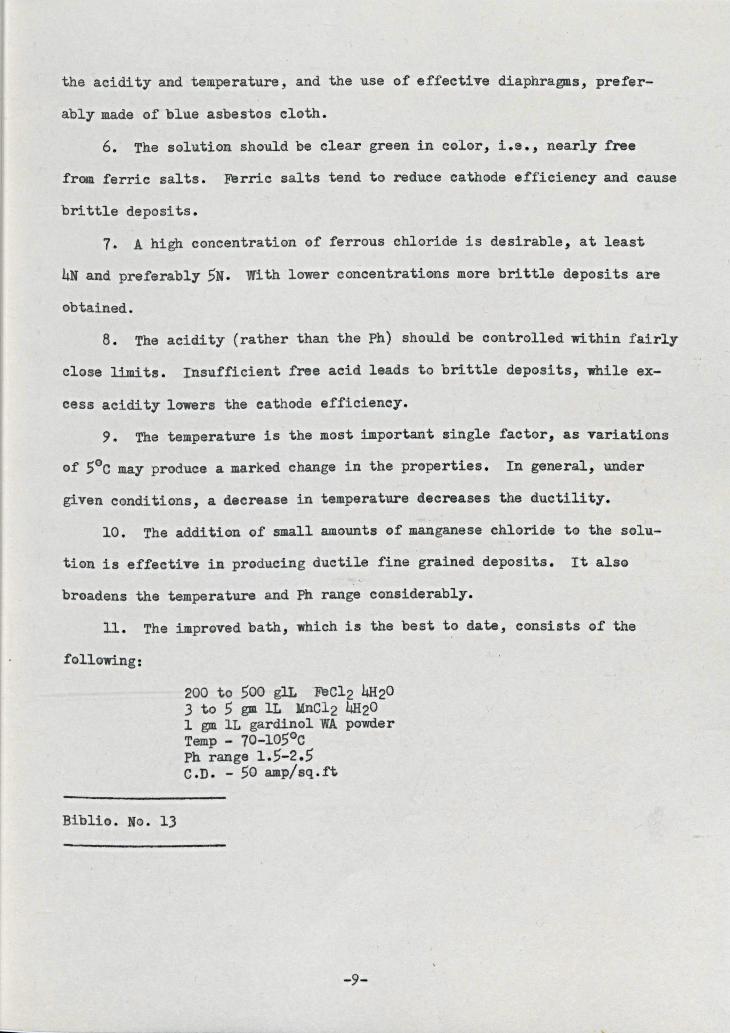
the acidity and temperature, and the use of effective diaphragms, prefer-ably made of blue asbestos cloth.
6. The solution should be clea~ green in color, i.e., nearly freefrom ferric salts. Ferric salts tend to reduce cathode efficiency and causebrittle deposits.
7. A high concentration of ferrous chloride is desirable, at least4N and preferably 5N. With lower concentrations more brittle deposits areobtained.
8. The acidity (rather than the Ph) should be controlled within fairlyclose limits. Insufficient free acid leads to brittle deposits, while ex-cess acidity lowers the cathode efficiency.
9. The temperature is the most important single factor, as variationsof SoC may produce a marked change in the properties. In general, undergiven conditions, a decrease in temperature decreases the ductility.
10. The addition of small amounts of manganese chloride to the solu-tion is effective in producing ductile fine grained deposits. It alsobroadens the temperature and Ph range considerably.
11. The improved bath, which is the best to date, consists of thefollowing:
200 to 500 glL 'FeC12 4H203 to 5 gm 1L MnC12 4H201 gm 1L gardinol WA powderTemp - 70-105°cPh range 1.5-2.5C.D. - 50 amp/sq.ft
Biblio. No. 13
-9-
LABOR! TORY WORK
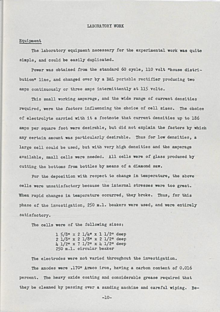
EquipmeatThe laboratory equipment necessary for the experimental work was quite
simple, and CQuld be easily duplicated.Power was obtained from the standard 60 cycle, 110 volt nhouse distri-
bution" line, and changed aver by a B&L portable rectifier producing twoamps contiBuously or three amps intermittently at 115 volts.
This small working amperage, and the wide range of current densitiesrequired, were the factors influencing the choice of cell sizes. The choiceof electrolyte carried with it a footnote that current densities up to 186amps per square foot were desirable, but did not explain the factors by whichany certain amount was particularly desirable. ThllSfor low densities, alarge cell could be used, but with very high densities and the amperageavailable, small cells were needed. All cells were of glass produced bycutting the bottoms from bottles by means of a diamond saw.
For the deposition with respect to change in temperature, the abovecells were unsatisfactory because the internal stresses were too great.When rapid changes in temperature occurred, they broke. Thus, for thisphase (j)fthe investigation, 250 m.l. beakers were used',and were entirelysatisfactory.
The cells were of the following sizes:1 5/811 X 2 1/4" x 1 1/2'" deep2 1/8" x 2 l/Bn x 2 1/2" deep4 1/2" x 7 1/2" x 4 1/2ft <deep250 m.l. circular beaker
The electrodes were not varied throughout the investigation.The anodes were .170" Armco iron, having a carbon content of 0.016
percent. The heavy oxide coating and considerable grease required thatthey be cleaned by passing over a sanding machine and careful wiping. Be-
-10-
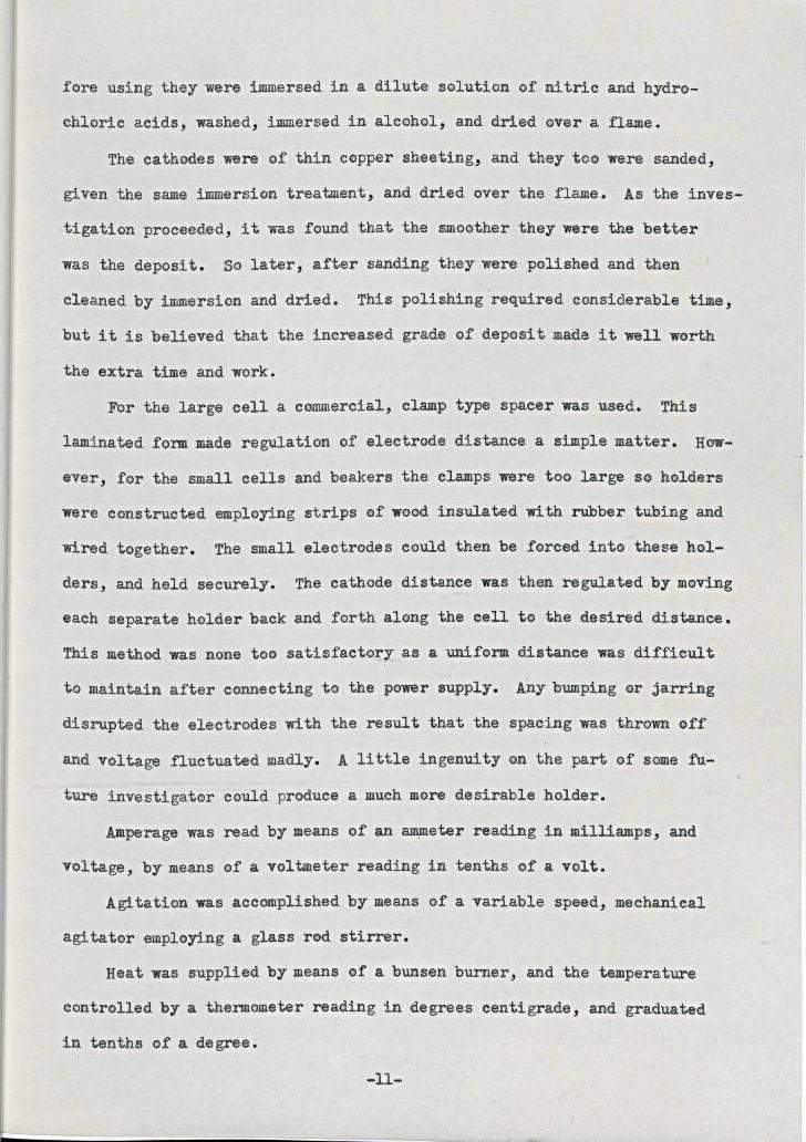
fore using they were immersed in a dilute solution of nitric and hydro-chloric acids, washed, immersed in alcohol, and dried over a flame.
The cathodes were of thin copper sheeting, and they too were sanded,given the same immersion treatment, and dried over the flame. As the inves-tigation proceeded, it was found that the smoother they were the betterwas the deposit. So later, after sanding they were polished and thencleaned by immersion and dried. This polishing required considerable time,but it is believed that the increased grade of deposit made it well worththe extra time and work.
For the large cell a commercial, clamp type spacer was used. Thislaminated fo~ made regulation of electrode distance a simple matter. How-ever, for the small cells and beakers the clamps were too large so holderswere constructed employing strips of wood insulated with rubber tubing andwired together. The small electrodes could then be forced into these hol-ders, and held securely. The cathode distance was then regulated by movingeach separate holder back and forth along the cell to the desired distance.This method was none too satisfactory as a uniform distance was difficultto maintain after connecting to the power supply. Any bumping or jarringdisrupted the electrodes with the result that the spacing was thrown offand voltage fluctuated madly. A little ingenuity on the part of some fu-ture investigator could produce a much more desirable holder.
Amperage was read by means of an ammeter reading in milliamps, andvoltage, by means of a voltmeter reading in tenths of a volt.
Agitation was accomplished by means of a variable speed, mechanicalagitator employing a glass rod stirrer.
Heat was supplied by means of a bunsen burner, and the temperaturecontrolled by a thermometer reading in degrees centigrade, and graduatedin tenths of a degree.
-11-
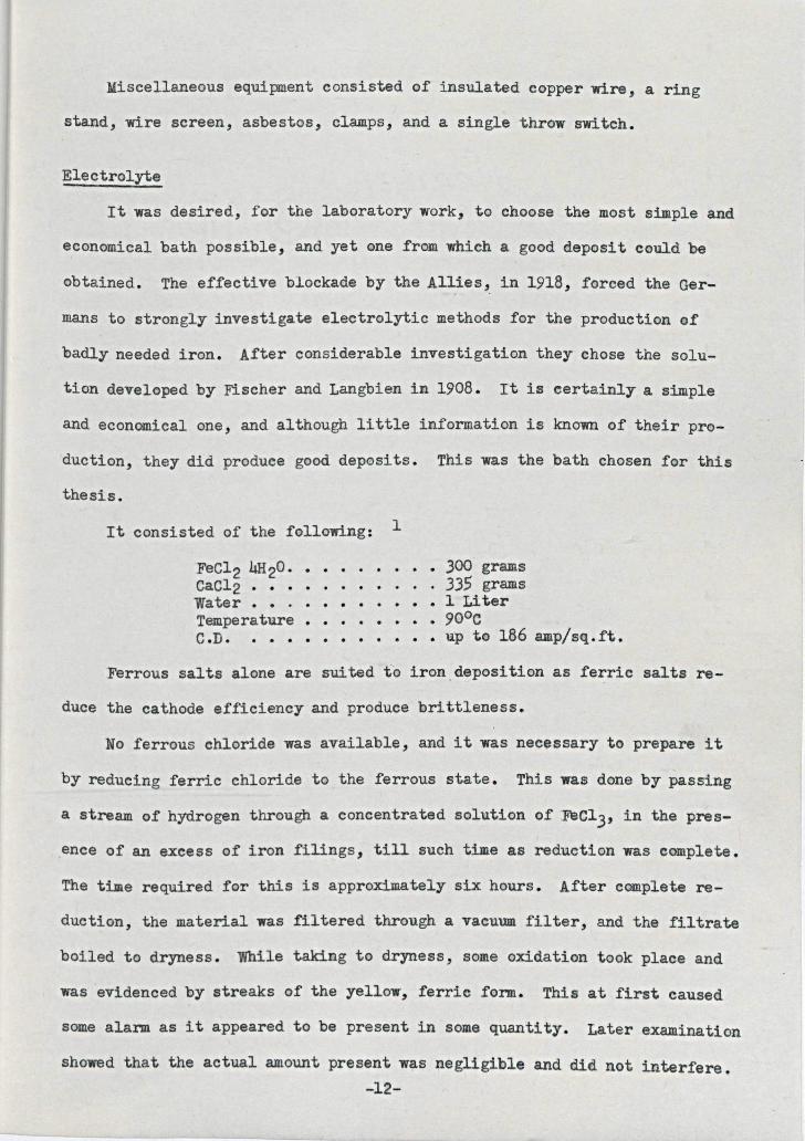
Miscellaneous equipment consisted of insulated copper wire, a ringstand, wire screen, asbestos, clamps, and a single throw switch.
ElectrolyteIt was desired, for the laboratory work, to choose the most simple and
economical bath possible, and yet one from which a good deposit could beobtained. The effective blockade by the Allies, in 1918, forced the Ger-mans to strongly investigate electrolytic methods for the production ofbadly needed iron. After considerable investigation they ehose the solu-tion developed by Fischer and Langbien in 1908. rt is certainly a simpleand economical one, and although little information is known of their pr0-duction, they aid produce good depesits. This was the bath chosen for this
It consisted of the following: 1
thesis.
FeC12 4H20 •••CaC12 • • • • .water • • . • •••Temperature • • •C.D. • ••.
. . • • 300 grams. 335 grams
• • 1 Liter9000
• •• up to 186 amp/sq. ft.Ferrous salts alone are suited to iron ,deposition as ferric salts re-
duce the cathode efficiency and produce brittleness.No ferrous chloride was available, and it was necessary to prepare it
by reduCing ferric chloride to the ferrous state. This was done by passinga stream of hydrogen through a concentrated solution of 'FeC13' in the pres-ence of an excess of iron filings, till such time as reduction was complete.The time required fOT this is approximately six hours. After complete re-duction, the material was filtered through a vacuum filter, and the filtrateboiled to dryness. While taking to dryness, some oxidation took place andwas evidenced by streaks of the yellow, ferric form. This at first causedsome alann as it appeared to be present in some quantity. Later examinationshowed that the actual amount present was negligible and did not interfere.
-12-
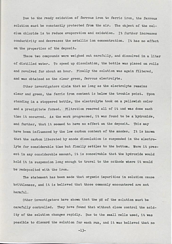
Due to the ready oxidation of ferrous iron to ferric iron, the ferroussolution must be constantly protected from the air. The object of the cal-cium chloride is to reduce evaporation and oxidation. It further increasesconductivity and decreases the metallic ion concentration. It has no effecton the properties of the deposit.
These two compounds were weighed out carefully, and dissolved in a literof distilled water. To speed ap dissolution, the bottle was placed on rollsand revolved for about an hour. Finally the solution was again filtered,and was obtained as the clear green, ferrous electrolyte.
Other investigators claim that as long as the electrolyte remainsclear and green, the ferric iron content is below the trouble point. Uponstanding in a stoppered bottle, the electrolyte took on a yellowish colorand a precipitate formed. Filtration removed all of it and was done eachtime it occurred. As the work progressed, it was found to be a hydroxide,and further, that it seemed to have no effect on the deposit. This mayhave been influenced by the low carbon content of the anodes. It is knownthat the carbon liberated by anode dissolution is suspended in the electro-lyte for considerable time but finally setties to the bottom. Were it pres-ent in any considerable amount, it is conceivable that the hydroxide wouldhold it in suspension long enough to travel to the cathode where it wouldbe redeposited with the iron.
The statement has been made that organic impurities in solution causebrittleness, and it is believed that those commonly encountered are notharmful.
Other investigators have shown that the pH of the solution must becarefully controlled. They have found that without close control the acid-ity of the solution changes rapidly. Due to the small cells used, it waspossible to discard the solution for each run, aad it was believed that no
-13-
trouble arose from pH control as the time of deposition was too shortfor much oxidation. The pH of the solution was 4.9 immediately after prep-aration, but soon settled down to 1.8. Here it remained for the rest ofthe examination. Evans 4 stated that high acidity wastes current throughevolution of hydrogen, and further causes excessive pitting. He alsoclaimed that lowering of the acidity increases current efficiency. Blumand Hogaboam believe a pH of 1.8 is ideal.2
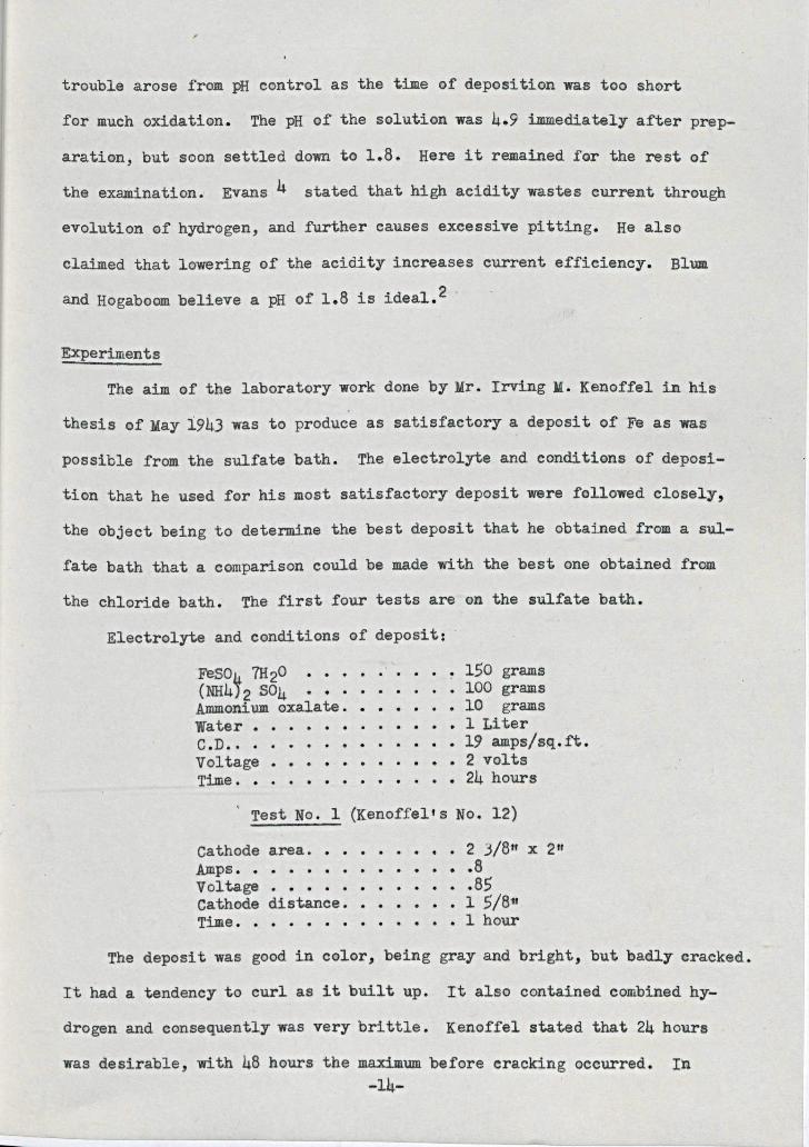
ExperimentsThe aim of the laboratory work done by Mr. rrving M. Kenoffel in his
thesis of May i943 was to produce as satisfactory a deposit of Fe as waspossible from the sulfate bath. The electrolyte and conditions of deposi-
.Electrolyte and conditions of deposit:
tion that he used for his most satisfactory deposit were followed closely,the object being to determine the best deposit that he obtained from a sul-fate bath that a comparison could be made with the best one obtained fromthe chloride bath. The first four tests are on the sulfate bath •
C.D.. . . · . .
1.50grams100 grams10 grams1 Liter
. •••• 19 amps/s~.ft.2 volts
• • • • 24 hours
FeS0}J7H20(NH4) 2 S04 • • • • • • •Ammonium oxalate .••••water • • ••Voltage.Time.
· . · . .Test No.1 (Kenoffel's No. 12)
Cathode area. · · 2 3/8" x 2"Amps. . . · . · · .8voltage . · . · . . . . · .8.5Cathode distance. 1 .5/811
Time. . · 1 hourThe deposit was good in color, being gray and bright, but badly cracked.
rt had a tendency to curl as it built up. It also contained combined hy-drogen and consequently was very brittle. Kenoffel stated that 24 hourswas desirable, with 48 hours the maximum before cracking occurred. In
-14-
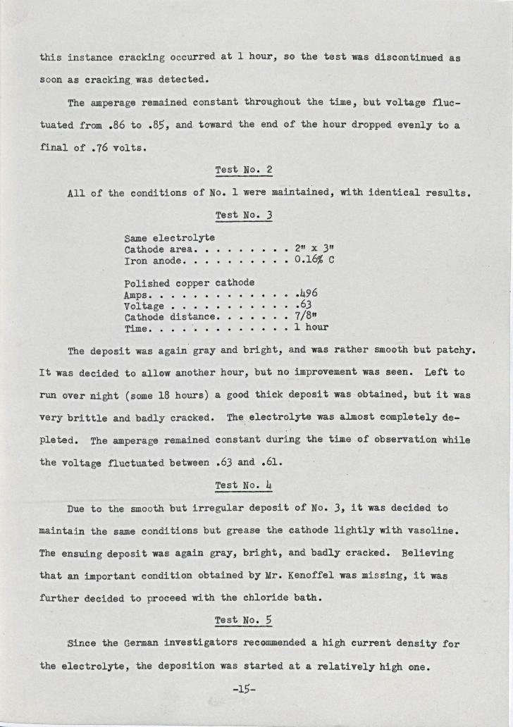
this instance cracking occurred at 1 hour, so the test was discontinued assoon as cracking,was detected.
The amperage remained constant throughout the time, but voltage fluc-tuated from .86 to .85, and toward the end of the hour dropped evenly to afinal of .76 volts.
Test No.2
All of the conditions of No.1 were maintained, with identical results,Test No.3
Same electrolyteCathode area. • • •Iron anode •••
• • • • • 211 X 3"• 0.16% C
Polished copper cathodeAmps. . . . . . . . . . . . . .496Voltage • . • • • • • • • • . .63Cathode distance. • •••.• 1/8"Time. • • . • • • • • • 1 hour
The deposit was again gray and bright, and was rather smooth but patchy.It was decided to allow another hour, but no improvement was seen. Left torun over night (some 18 hours) a good thick deposit was obtained, but it wasvery brittle and badly cracked. The ,electrolyte was almost completely de-pl~ted. The amperage remained constant during the time of observation whilethe voltage fluctuated between .63 and .61-
Test No.4Due to the smooth but irregular deposit of No.3, it was decided to
maintain the same conditions but grease the cathode lightly with vasoline.The ensuing deposit was again gray, bright, and badly cracked. Believingthat an important condition obtained by Mr. Kenoffel was missing, it was
Test No.5further decided to proceed with the chloride bath.
Since the German investigators recommended a high current density forthe electrolyte, the deposition was started at a relatively high one.
-15-
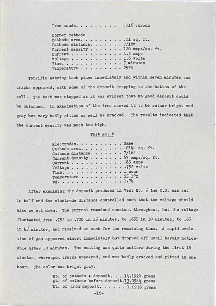
Iron anode. • • . . . . . . .016 carbonCopper cathodeCathode area. • .01 sq. ft.Cathode distance. • • • • 7/16"Current density • • 120 amps/sq. ft.current ••••• 1.2 ampsVoltage ••••••••••• 1.6 voltsTime. • • • • • • • • 1 minutesTemperature • • 25°c
Terrific gassing took place immediately and within seven minutes badcracks appearea, with some of the deposit dropping to the bottom of thecell. The test was stopped as it was evident that no good deposit couldbe obtained. An examination of the iron showed it to be rather bright andgray but very badly pitted as well as oracked. The results indioated thatthe current denSity was much too high.
Electrodes •••Cathode area. • •Cathode distance ••Current density ••Current •VoltageTime ••Temperature •pH ••
• • 'Same• .0144 sq. ft.
• • • 1/16fl• .'. . • 59 amps/sq. ft.• • • • • .85 amps• ••••• 752 volts
• • • • • ..1 hour• • 25.1oC
• • • • ~ 1.74
Test No.6
After examining the deposit produced in Test No.5 the C.D. was cutin half and the electrode distance controlled such that the voltage shouldalso Qe out down. The current remained constant throughout, but the'voltagefluctuated from .152 to .100 in 15 minutes, to .655 in 30 minutes, to .65in 45 minutes, and remained as such for the remaining time. A rapid evolu-tion of gas appeared almost immediately but dropped off until barely notice-able after 30 minutes. The coating was quite uniform during the first 15minutes, whereupon cracks appeared, and was 'badly cracked and pitted in onehour. The color was bright gray.
wt. of cathode + deposit. • • 14.1920 gramswt. of cathode before deposit.1).0984 gramswt. of iron deposi t. • • • . • l.0936 grams
-16-
x 55.852
.85 x 60 x 6096500 = .886
1.0936 • 123% eff ••886
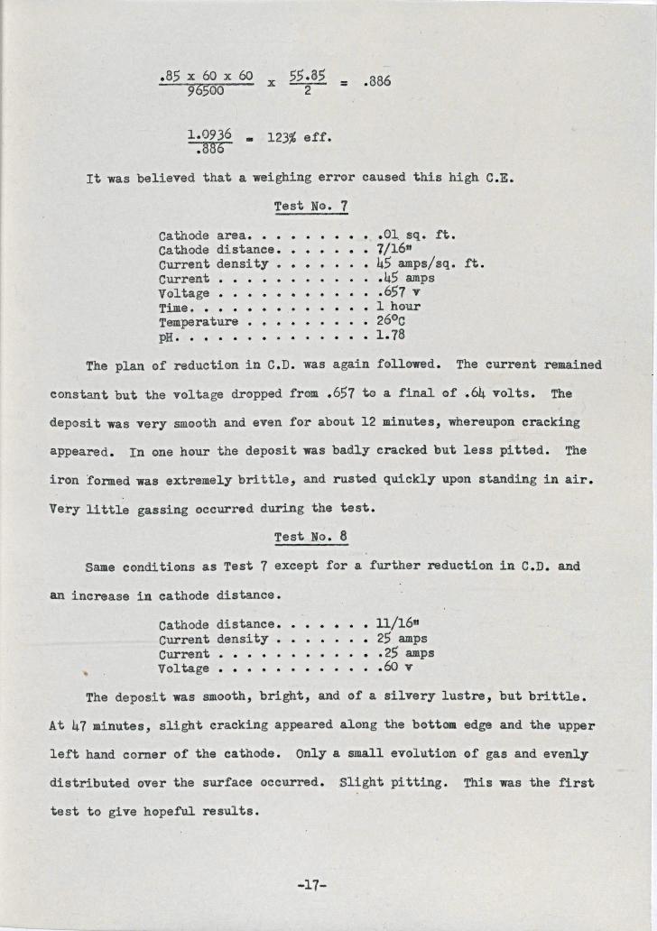
It was believed that a weighing error caused this high C.E.Test No.7
Cathode area. • • • • • ...01, sq. ft .Cathode distance ••••••• 1/16"Current density. 45 amps/sq. ft.Current • • • .45 ampsVoltage • • • •• 657 vTime. • • • • • • • • • • • • 1 hourTemperature • • • 26°cpH..•.•.•.•.•••• 1.78
The plan of reduction in C.D. was again followed. The current remainedconstant but the voltage dropped frem .657 to a final of .64 volts. Thedeposit was very smooth and even for about 12 minutes, whereupon crackingappeared. In one hour the deposit was badly cracked but less pitted. Theiron f<lmnedwas extremely brittle, and rusted quickly upen standing in air.Very little gassing occurred during the test.
Test No.8Same conditions as Test 7 except for a further reduction in C.D. and
an increase in cathode distance.Cathode distance ••••••• 11/16"Current density • • • • • • • 25 ampsCurrent • • • • • • • • • • • •25 ampsVoltage • • • • .60 v
The deposit was smooth, bright, and of a silvery lustre, but brittle.At 47 minutes, slight cracking appeared along the bottom edge and the upperleft hand corner of the cathode. Only a small.eVGlution of gas and evenlydistributed over the surface occurred. Slight pitting. This was the firsttest to give hopeful results.
-17-
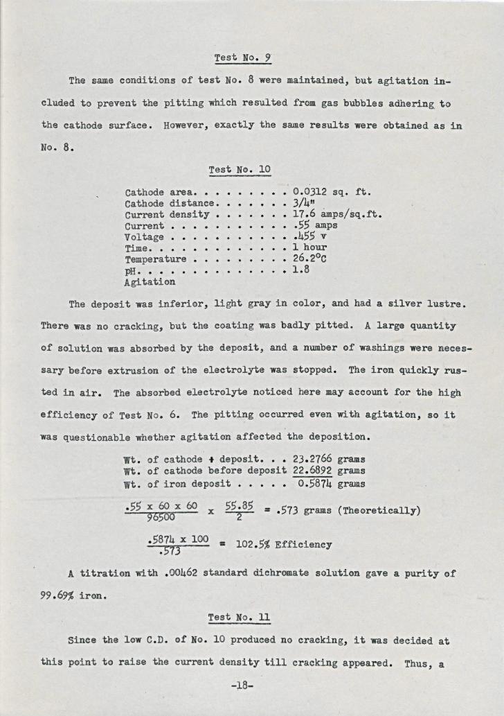
Test No.9The same conditions of test No. 8 were maintained, but agitation in-
cluded to prevent the pitting which resulted from gas bubbles adhering. tothe cathode surface. However, exactly the same results were obtained as inNo.6.
Test No. 10Cathode area. • • • • 0.0312 sq. ft.Cathode distance. • • • • • • 3/4'"Current density. • • 17.6 amps/sq.ft.Current ••• .55 ampsVol tage • • • • • • • • .455 vTime. • . . • . . . . • 1 hourTemperature • • • •• . • 26.20CpH. • • . . . . . . • 1.6Agitation
The deposit was inferior, light gray in color, and had a silver lustre.There was no cracking, but the coating was badly pitted. A large quantityof solution was absorbed by the deposit, and a number of washings were neces-sary before extrusion of the electrolyte was stopped. The iron quickly rus-ted in air. The absorbed electrolyte noticed here may acoount for the highefficienoy of Test No.6. The pitting occurred even with agitation, so itwas questionable whether agitation affeoted the deposition.
wt. of cathode + deposit ••• 23.2766 gramswt. of cathode before deposit 22.6892 gramswt. of iron deposit • • 0.5874 grams
.55 x 60 x 60 x 55.85 = .573 grams (Theoretically)96500 2
.5~~~3x100 • 102.5% Efficiency
A titration with .00462 standard diohromate solation gave a purity of99.69% iron.
Test No. 11Since the low C.D. of No. 10 produced no cracking, it was decided at
this point to raise the current density till craoking appeared. Thus, a-;1.8-
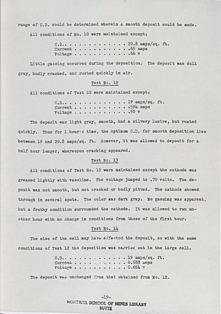
range of C.D. could be determined wherein a smooth deposit could be made.All conditions of No. 10 were maintained except:
C.D.. • . . • •Current • • • • • •VQltage • • • •
20.8 amps/sq. ft.••• 65 amps•• 66 v
Little gassing occurred during the deposition. The deposit was dullgray, badly cracked, and rusted quickly in air.
Test No. 12All conditions of Test 10 were maintained except:
C.D ••, •Current.Voltage •
. . . . •• 19 amps/sq. ft.. • • .594 amps
.50 v· . . . .· . . . . .
The deposit was light gray, smooth, had a silvery lustre, but rustedquickly. Thus for 1hour's time, the optimum C.D. for smooth deposition liesbetween 19 and 20.8 ~ps/Sq. ft. However, it was allowed to deposit for ahalf hour longer, whereupon cracking appeared.
Test No. 13All conditions of Test No. 12 were maintained exeept the cathode was
greased lightly with vasoline. The v~ltage jump~d to .10 volts. The de-posit was not smooth, but not cracked or badly pitted. The eathode showed
conditions of Test 12 ~ha ~eposition was eell •
through in several spots. The color was dark gray. No gassing was apparent,but a frothy condition surrounded the eathode. It was allowed to run an-other hour with no change in conditions from those of the first hour.
, Test No. 14
The size of the.cell may na7e ~ffe~tcd the deposit, so with the same
C.D.. • •Current.Voltage •
• 0 •••••• 19 amps/sq. ft.• •• c ~ • • • • • 0.588 amps• • • • • 0.654 'V'
The deposit W~~ unchanged from that obtained f~Qm No. 12.
-19-l\'IONTlUU~SCHOOL OF NINES I..IB.RAa'
BUTT~~------------~----~--
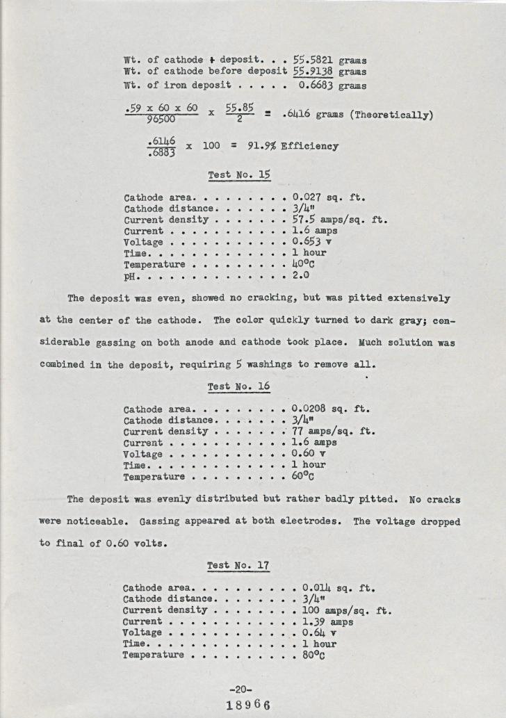
wt. of cathode • deposit ••• 55.5821 gramswt. of cathode before deposit 55.9138 gramswt. of iron deposit . • 0.6683 grams
.59 x 60 x 60 x 55285 :96500
.6146 100 = 91.9% Efficiency.6883 x
.6416 grams (Theoretically)
Test No. 15
Time .•••••Temperature • • • •pH. • • ••
· .••• 0.027 sq. ft.• 3/4"57.5 amps/sq.
• 1.6 amps• • • • • • 0.G53 v. • 1hour
• 40°C• • • 2.()
ft.Cathode area. • • •Cathode distance ••Current density •Current •••Voltage •••
· .
• •
The deposit was even, showed no cracking, but was ,itted extensivelyat the center of the cathode. The color quickly turned to dark gray; COD-
siderable gassing on both anode and cathode took place. Much solution wascombined in the deposit, requiring 5 washings to remove all.
Test No. 16Cathode area. • • • • • • 0.0208 sq. ft.Cathode distance.. ••• 3/4"Current density. • •• 71 amps/sq. ft.Current •• • • • • • • • 1.6 ampsVoltage ••••••••••• 0.60 vT~..... • ••••• l~urTemperature • • • 6000
The deposit was evenly distributed but rather badly pitted. No crackswere noticeable. Gassing appeared at both electrodes. The voltage droppedto final of 0.60 volts.
Test No. 17Cathode area. • • • • 0.014 sq. ft.Cathode distance. • . • • • • • 3/41J
Current density •••••••• 100 amps/sq. ft.Current ••• • • • 1.39 ampsVoltage •••••••••••• 0.64 vTime. • • • • • •• • 1hourTemperature • • 800C
-20-18966
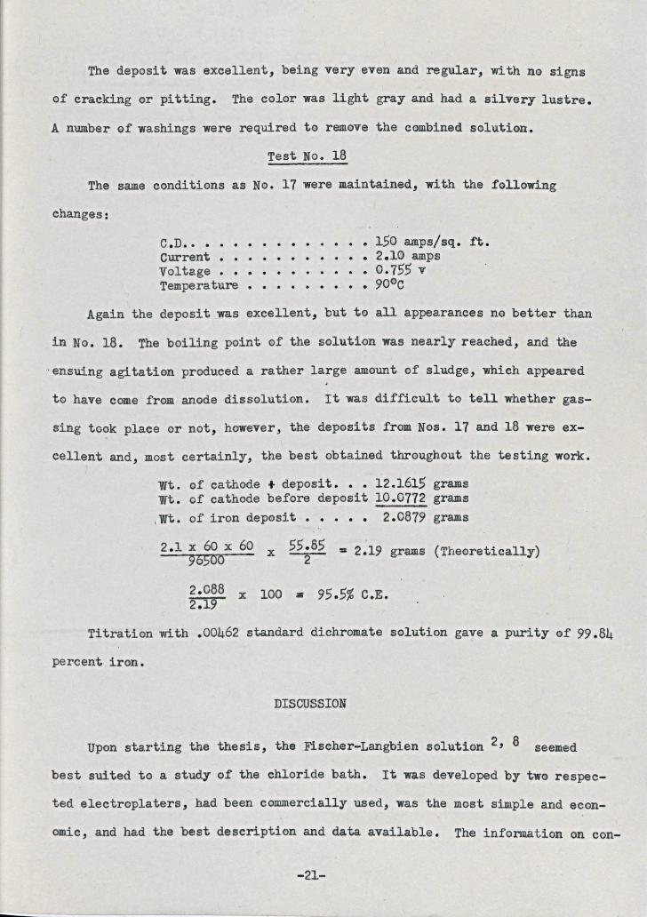
The deposit was excellent, being very even and regular, with no signsof cracking or pitting. The color was light gray and had a silvery lustre.A number of washings were required te remove the combined solutiQn.
Test No. 18The Bame conditions as No. 11 were maintained, with the following
changes:C.D.. • . • •Current •••Voltage •••Tempera ture •
• • •••••• 150 amps/sq. ft.• • • • • • 2.10 amps
• •••• 0.155 v• • 900c
Again the deposit was excellent, but to all appearances no better thanin No. 18. The boiling point of the selution was nearly reached, and the.ensuing agitation produced a rather large amount of sludge, which appearedto have come from anode dissolution. It was difficult to tell whether gas-sing took place or not, however, the deposits from Nos. 11 and 18 were ex-ce11ent and, most certainly, the best obtained throughout the testing work.
wt. of cathode + deposit ••• 12.1615wt. of cathode before deposit. 10.0112
2.0819. . .gramsgramsgrams,wt. of iron deposit ••
2.1 x 60 x 6096500 x
55.85 = 2.19 grams (Theoretically)2
2.088 x 100 • 95.5% C.E.2.19Titration with .00462 standard dichromate solution gave a purity of 99.84
percent iron.
DISCUSSION
Upon starting the thesis, the Fischer-Langbien solution 2, 8 seemedbest suited to a study of the chloride bath. It was developed by two respec-ted electroplaters, had been commercially used, was the most simple and econ-omic, and had the best description and data available. The information on con-
-21-
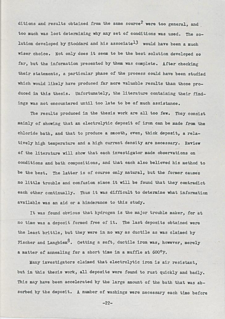
ditions and results obtained from the same source2 were too geReral:, andtoo much was lost determining why any set of conditions was used. The so-lution developed by Stoddard and his associate13 would have been a muchwiser choice. Not only does it seem to be the best solution developed sofar, but the information presented by them was complete. After checkingtheir statements, a particular phase of the proeess could have been studiedwhich would likely have produced far more valuable results than those pro-duced in this thesis. Unfortunately, the literature containing their find-ings was not encountered until too late to be of much assistance.
The results produced in the thesis work are all too few. They consistmainly of showing that an electrolytic deposit of iron can be made from thechloride bath, and that to produce a smooth, even, thick deposit, a rela-tively high temperature and a high current density are necessary. Reviewof the literature will show that each investigator made observations onconditions and bath compositions, and that each also believed his method tobe the best. The latter is of course only natural, but the former causesno little trouble and confusion amee. it will be found that they contradicteach other continually. Thus it was difficult to determine what informatioRavailable was an aid or a hinderance to this study.
It was found obvious that hydrogen is the major trouble maker, for atno time was a deposit formed free of it. The last deposits obtained werethe least brittle, but they were in no way as ductile as was claimed byFischer and Langb1en8• Getting a soft, ductile iron was, however, merelya matter of annealing for a short time in a muffle at 6000'F.
Many investigators claimed that electrolytic iron is air resistant,but in this thesis work, all deposits were found to rust quickly and badly.This may have been accelerated by the large amount of the bath that was ab-sorbed by the deposit. A number of washings were necessary each time before
-22-
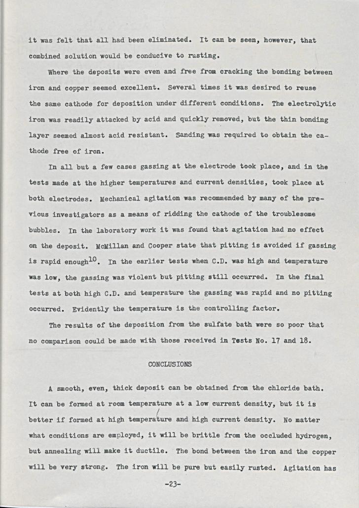
it was felt that all had been eliminated. It can be seen, however, thatcombined solution would be conducive to rusting.
Where the deposits were even and free from cracking the bonding betweeniron and copper seemed excellent. Several times it was desired to reusethe same cathode for deposition under different conditions. The electrolyticiron was readily attacked by acid and quickly removed, but the thin bondinglayer seemed almost acid resistant. Sanding was required to obtain the ca-thode free of iron.
In all but a few cases gassing at the electrode took place, and in thetests made at the higher temperatures and current densities, took place atboth electrodes. Mechanical agitation was recommended by many of the pre-Vious investigators as a means of ridding the cathode of the troublesomebubbles. In the laboratory work it was found that agitation had no effecton the deposit. McMillan and Cooper state that pitting is avoided if gassingis rapid enoughlO• In the earlier tests when C.D. was high and temperaturewas low, the gassing was violent but pitting. still occurred. In the finaltests at both high C.D. and temperature the gassing was rapid and no pittingoccurred. Evidently the temperature is the controlling factor.
The results of the deposition from the sulfate bath were so poor thatno comparison could be made with those received in Tests No. 11 and 18.
CONCLUSIONS
A smooth, even, thick deposit can be obtained from the chloride bath.
-23-
It can be formed at room temperature at a low current density, but it isbetter if formed at high tempera(ure and high current density. No matterwhat conditions are employed, it will be brittle from the occluded hydrogen,but annealing will make it ductile •. The bond between the iron and the copperwill be very strong. The iron will be pure but easily rusted. Agitation has
no effect on the deposit, nor has the hydroxicle of iron formed in the solu-
tion.
RECOMMENDATIONS
I would like to recommend a lORg range study of electrolytic iroR in
all of its phases. The three baths (sulfate, chloride, and sulfate-chloride)
could be investigated with the idea of determining which is actually best
for all around deposition. When enough- information has been gathered from
all three, an intensive study could then be made toward the electrO-winning
of iron from its ores.
There is much to be known of the chloride bath, and r- would recommend
further study of it to some future student. This thesis attempted to deter-
mine the conditions at which the best deposit could be obtained, and r be-
lieve that it is conclusively shown that the high temperatures and current
densities are necessary. Beginning at this point, then, the student could
make an examination which would eventually show how hydrogen embrittlement
can be avoided.I would recommend the solution developed by Stoddard and his associatel)
rather than the one I employed.
r would further recommend the recording of all data, no matter how
trivial, so that the results obtained may be duplicated.
-24-
BIBLIOGRAPHY
1. Belcher, D; Progress in Electrolytie Iron: TAECS, Vol. 45, Pg. 455 (1924)2. Blum and Hogaboam; Iron Deposition: Principles of Electroplating and
Electroforming; Second Edition, pg 282 (1930)3. Bradley and stoughton; Electrolytic Iron: The Metallurgy of Iron and
Steel, Third Edition, pgs. 3, 200, 330 (1923)4. Evans, U. R.; Uses of Electrolytic Iron,: Metals and Metal Compounds,
Vol. 3 pg. 105 (1923)5. Glasstone, s.; The Determination of pH Values by Electrometric Methods:
Fundamentals of Electro-Chemistry and Electro-deposi-tion, Chap. VIII, pg. 30, (1943)
6. Hogabocm, G. B.; Some Unsolved Problems in Electro-platingJ TAECS; Vol.19, pg. 53 (1911)
7. Kenoffel, I. M.; Electrolytic Deposition of Iron: Undergraduate Thesis,at M.S.M. (1943)
-25-
8. Langbien, G.; Deposition of Iron: Electro-deposition of Metals, 7th Edi-tion, pg. 415 (1913)
9. Magorien, P.D.: Electro-deposition of Iron: Undergraduate Thesis, atM.S.M. (1944)
10. McMillan & Cooper; The Electro-deposition of Iron: ElectrO-Metallurgy,3rd Edition, p. 230 (1910)
11. Mantell, C. L.; Iron: Industrial Electro-Chemistry, Second Edition, pg.283 (1940)
12. Simmons, E.; The Leach~ng and Electro-deposition of Iron: UndergraduateThesis, at M.'S.M. (1933)
13. Stoddard, W. B.; Iron Plating: TAECS; Vol. 84, p. 305 (1943)14. story, O. W.; Review of Some Recent Progress in Electrolytic IrOl!l: TAECS,
Vol. 29, p. 351 (1916)15. Thomas, C. T.; Iron Deposition: TAECS, Vol. 80, p. 499 (1941)
ACKNOWLEDGMENT
The writer wishes to express his appreciation to Professors
Spielman and Graverson for their patience, suggestions, and as-
sistance.
Related Documents


![Electro‐Optic Modulation in Hybrid Metal Halide Perovskites · nonlinear crystals relies on costly and complicated bonding or deposition processes (heterogeneous integration).[4,5]](https://static.cupdf.com/doc/110x72/5f3860b78cb5b531b06e28f0/electroaoptic-modulation-in-hybrid-metal-halide-perovskites-nonlinear-crystals.jpg)