Citation: Meloni, E.; Iervolino, G.; Ruocco, C.; Renda, S.; Festa, G.; Martino, M.; Palma, V. Electrified Hydrogen Production from Methane for PEM Fuel Cells Feeding: A Review. Energies 2022, 15, 3588. https://doi.org/10.3390/en15103588 Academic Editor: George Avgouropoulos Received: 26 April 2022 Accepted: 12 May 2022 Published: 13 May 2022 Publisher’s Note: MDPI stays neutral with regard to jurisdictional claims in published maps and institutional affil- iations. Copyright: © 2022 by the authors. Licensee MDPI, Basel, Switzerland. This article is an open access article distributed under the terms and conditions of the Creative Commons Attribution (CC BY) license (https:// creativecommons.org/licenses/by/ 4.0/). energies Review Electrified Hydrogen Production from Methane for PEM Fuel Cells Feeding: A Review Eugenio Meloni * , Giuseppina Iervolino, Concetta Ruocco , Simona Renda , Giovanni Festa , Marco Martino and Vincenzo Palma Department of Industrial Engineering, University of Salerno, Via Giovanni Paolo II 132, 84084 Fisciano, Italy; [email protected] (G.I.); [email protected] (C.R.); [email protected] (S.R.); [email protected] (G.F.); [email protected] (M.M.); [email protected] (V.P.) * Correspondence: [email protected] Abstract: The greatest challenge of our times is to identify low cost and environmentally friendly alternative energy sources to fossil fuels. From this point of view, the decarbonization of industrial chemical processes is fundamental and the use of hydrogen as an energy vector, usable by fuel cells, is strategic. It is possible to tackle the decarbonization of industrial chemical processes with the electrification of systems. The purpose of this review is to provide an overview of the latest research on the electrification of endothermic industrial chemical processes aimed at the production of H 2 from methane and its use for energy production through proton exchange membrane fuel cells (PEMFC). In particular, two main electrification methods are examined, microwave heating (MW) and resistive heating (Joule), aimed at transferring heat directly on the surface of the catalyst. For cases, the catalyst formulation and reactor configuration were analyzed and compared. The key aspects of the use of H 2 through PEM were also analyzed, highlighting the most used catalysts and their performance. With the information contained in this review, we want to give scientists and researchers the opportunity to compare, both in terms of reactor and energy efficiency, the different solutions proposed for the electrification of chemical processes available in the recent literature. In particular, through this review it is possible to identify the solutions that allow a possible scale-up of the electrified chemical process, imagining a distributed production of hydrogen and its consequent use with PEMs. As for PEMs, in the review it is possible to find interesting alternative solutions to platinum with the PGM (Platinum Group Metal) free-based catalysts, proposing the use of Fe or Co for PEM application. Keywords: microwaves; process intensification; joule heating; PEM fuel cells; hydrogen 1. Introduction It is clear that we need a new formula for the production of chemicals: the chemical processes still depend heavily on the intense heat generated by fossil fuels. Curbing car- bon emissions, while maintaining quality of life, is a global challenge for manufacturing processes that will require process innovation. The decarbonization of energy-intensive manufacturing industries represents one of the most pressing technological challenges of the coming decades. Among these industries, the chemical sector (including refineries) is by far the most significant energy consumer [1]. One solution is to replace the energy pro- duced by burning carbon-based fuels with energy from “green” sources such as electricity produced from renewable sources. From scientific literature it is possible to consider that, very often, the use of electricity is limited to the initial stages of the process such as the electrocatalytic conversion of water, CO 2 and/or nitrogen into hydrogen, carbon monoxide, syngas, formic acid, methanol or ammonia [2–5]. The subsequent reaction steps are usually carried out in the conventional way, therefore, by using the classical thermochemical path through the use of fossil fuels, especially in the case of endothermic reactions. However, if Energies 2022, 15, 3588. https://doi.org/10.3390/en15103588 https://www.mdpi.com/journal/energies

Welcome message from author
This document is posted to help you gain knowledge. Please leave a comment to let me know what you think about it! Share it to your friends and learn new things together.
Transcript
Citation: Meloni, E.; Iervolino, G.;
Ruocco, C.; Renda, S.; Festa, G.;
Martino, M.; Palma, V. Electrified
Hydrogen Production from Methane
for PEM Fuel Cells Feeding: A
Review. Energies 2022, 15, 3588.
https://doi.org/10.3390/en15103588
Academic Editor: George
Avgouropoulos
Received: 26 April 2022
Accepted: 12 May 2022
Published: 13 May 2022
Publisher’s Note: MDPI stays neutral
with regard to jurisdictional claims in
published maps and institutional affil-
iations.
Copyright: © 2022 by the authors.
Licensee MDPI, Basel, Switzerland.
This article is an open access article
distributed under the terms and
conditions of the Creative Commons
Attribution (CC BY) license (https://
creativecommons.org/licenses/by/
4.0/).
energies
Review
Electrified Hydrogen Production from Methane for PEM FuelCells Feeding: A ReviewEugenio Meloni * , Giuseppina Iervolino, Concetta Ruocco , Simona Renda , Giovanni Festa ,Marco Martino and Vincenzo Palma
Department of Industrial Engineering, University of Salerno, Via Giovanni Paolo II 132, 84084 Fisciano, Italy;[email protected] (G.I.); [email protected] (C.R.); [email protected] (S.R.); [email protected] (G.F.);[email protected] (M.M.); [email protected] (V.P.)* Correspondence: [email protected]
Abstract: The greatest challenge of our times is to identify low cost and environmentally friendlyalternative energy sources to fossil fuels. From this point of view, the decarbonization of industrialchemical processes is fundamental and the use of hydrogen as an energy vector, usable by fuelcells, is strategic. It is possible to tackle the decarbonization of industrial chemical processes withthe electrification of systems. The purpose of this review is to provide an overview of the latestresearch on the electrification of endothermic industrial chemical processes aimed at the productionof H2 from methane and its use for energy production through proton exchange membrane fuel cells(PEMFC). In particular, two main electrification methods are examined, microwave heating (MW)and resistive heating (Joule), aimed at transferring heat directly on the surface of the catalyst. Forcases, the catalyst formulation and reactor configuration were analyzed and compared. The keyaspects of the use of H2 through PEM were also analyzed, highlighting the most used catalysts andtheir performance. With the information contained in this review, we want to give scientists andresearchers the opportunity to compare, both in terms of reactor and energy efficiency, the differentsolutions proposed for the electrification of chemical processes available in the recent literature. Inparticular, through this review it is possible to identify the solutions that allow a possible scale-up ofthe electrified chemical process, imagining a distributed production of hydrogen and its consequentuse with PEMs. As for PEMs, in the review it is possible to find interesting alternative solutions toplatinum with the PGM (Platinum Group Metal) free-based catalysts, proposing the use of Fe or Cofor PEM application.
Keywords: microwaves; process intensification; joule heating; PEM fuel cells; hydrogen
1. Introduction
It is clear that we need a new formula for the production of chemicals: the chemicalprocesses still depend heavily on the intense heat generated by fossil fuels. Curbing car-bon emissions, while maintaining quality of life, is a global challenge for manufacturingprocesses that will require process innovation. The decarbonization of energy-intensivemanufacturing industries represents one of the most pressing technological challenges ofthe coming decades. Among these industries, the chemical sector (including refineries) isby far the most significant energy consumer [1]. One solution is to replace the energy pro-duced by burning carbon-based fuels with energy from “green” sources such as electricityproduced from renewable sources. From scientific literature it is possible to consider that,very often, the use of electricity is limited to the initial stages of the process such as theelectrocatalytic conversion of water, CO2 and/or nitrogen into hydrogen, carbon monoxide,syngas, formic acid, methanol or ammonia [2–5]. The subsequent reaction steps are usuallycarried out in the conventional way, therefore, by using the classical thermochemical paththrough the use of fossil fuels, especially in the case of endothermic reactions. However, if
Energies 2022, 15, 3588. https://doi.org/10.3390/en15103588 https://www.mdpi.com/journal/energies
Energies 2022, 15, 3588 2 of 34
the electrocatalytic production of fuels from water is certainly of fundamental importance todecarbonize the chemical sector, it is equally important to address the possible applicationsof electricity in subsequent reactions, which ultimately lead to thousands of products onthe market today. Therefore, it is necessary to understand the role of electricity in chemicalreactors and catalysts in order to identify the limits and advantages of this new technology.Electrification of conventionally fired chemical reactors has the potential to reduce CO2emissions and provide flexible and compact heat generation.
So, what are the possible approaches reported in the literature on the use of electricityfor the development of chemical processes? Several techniques are possible: electrocatalyticor photoelectrochemical processes in which the direct supply of electric current (DC) to theelectrodes results in the transfer of charge across the interface between the electrode and thetreated liquid [6–8]; plasma reactors [9–11], in which highly reactive ionized gases (plasma)are generated through electricity, so resulting in large numbers of chemically active species,including electrons, ions, atoms and radicals [1]. Moreover, the transfer of thermal energyin electrified reactors can be achieved in various ways, such as: microwave-assisted heating,in which heat is generated through the displacement of dipolar molecules or ions in liquidscaused by the rapidly alternating electric field of the microwaves; ohmic or Joule heating,in which heat is generated by an electric current passing through a resistive conductor;induction heating, in which heat is generated by eddy currents, resulting in the conductivematerials by the rapidly alternating magnetic field, so resulting in the Joule heating of thosematerials [1]. The comparison among the different electrification methods is summarizedin the following Table 1.
The role of electricity in chemical processes seems to be of particular importance forall those processes that we can define as endothermic, which require a supply of heat todevelop the reaction and reach favorable thermodynamic equilibrium conditions to obtainthe desired conversion and yield. In particular, electricity can be useful for providing heatto catalytic systems in a uniform way, avoiding thermal hot spots or large temperaturegradients from the heat source towards the catalyst.
This is the case, for example, of processes such as reforming for the production ofsyngas, endothermic processes that require a constant supply of heat to the catalytic sites.
Industrial-scale reformers consist of hundreds of tubular reactors that need to beheated. Traditionally, heating occurs through the combustion of fossil fuels and the mainmechanism of heat transfer is radiation. For this reason, to ensure the right amount of heatto the catalyst, combustion takes place at temperatures much higher than the actual reactiontemperature. Energy losses are very high, as are fossil CO2 emissions into the atmosphere.
Conventional reforming presents three main drawbacks [12]:
• Inefficient heat transfer. The heat for the reaction must first be transferred by radiationfrom the burning fuel to the outer walls of the reactor tube. Then, from the externalwall, it must reach the inside of the pipe by conduction and finally reach the surface ofthe catalyst. Furthermore, generally the supports used for the catalysts are made ofalumina, and therefore are poor thermal conductors.
• The maintenance costs of the reactor are relatively high. The high temperaturesrequired stress the materials of which the pipes are made. Typically, a tube replacementis required after an average of 5 years of operation. Additionally, the costs for theseinterventions are very high, and can reach millions of dollars [12].
• Large quantities of methane (natural gas) are consumed in providing the heat energyfor the reforming reaction. For example, a typical 1100 ton d−1 ammonia plant requiresapproximately 400,000 m3 d−1 of natural gas only for the heating stage. While naturalgas is a relatively cheap fuel today, it is a nonrenewable resource and may not remaincheap in the future.
• To supply thermal energy to the reforming reaction, it is necessary to burn largequantities of methane gas. Even though it is a relatively cheap fuel, it is nonetheless afossil fuel and therefore not renewable.
Energies 2022, 15, 3588 3 of 34
Table 1. Comparison of different alternatives for the electrification of chemical reactors.
Mechanism Principle Pro Cons
Ohmic or Joule
electric current passing througha resistive conductor producesheat ð, a conductive structuredsupport (foam, monolith) isused on which the catalyst isdeposited as thin film
- with respect to fired reactors andwith electrically heated furnaces (inwhich the catalytic tubes are inserted),there is a minimization of transferresistance and a solid–solid heattransfer (higher rate and efficiency)
- catalysts have a shape different fromconventional fixed/fluid/mobile bedapplications, and should beoptimized for the applications
- avoidance also of mass transferlimitations, possible gradientsbetween the catalyst and the gasphase (at lower T, beneficial to reduceside reactions)
- problems of adhesionand stability of thecatalytic film over thestructured support mustbe still solved
- necessity for a specificredesign to optimizecatalyst performance
- possible side negativeeffect of structuredsubstrate
- examples of industrialdevelopment in the areaare not available
Inductionheating
rapidly alternating magneticfield either generates eddycurrents in conductingmaterials, resulting in the Jouleheating of those materials, orgenerates heat inferro-/ferrimagnetic materialsby the magnetichysteresis losses
- studied in literature, known for over70 years, but scarcely applied tocatalytic reactors
- used in some industrial applications(fast preheating of petroleumfractions
- simple design, possible inductionoscillations
- localized heating at the catalyst,creation of thermal gradients with theflowing gas phase (rapid quench)
- technology available industrially forother applications
- need to add acomponent which can beheated by induction
- possible alternations instability, selectivity,potential decreaseproductivity
- possible interferenceswith integrated Pdmembrane
Microwave/RFheating
rapidly alternating electric fieldof the microwave generates heatby moving dipolar molecules orions in liquids, or by gettingabsorbed in the so-called“dielectric lossy” solidnonmagnetic materials
industrial experience for fine chemicalsproductionrelatively simple technology
effective with liquids, lesswith gas reactions; mainchallenge with heterogeneouscatalysts to achieve uniformheating; proposed solutionsdifficult to scale-up
In the literature, there are several research studies aimed at improving the energyefficiency of these processes that promote their sustainability. The catalysts currently usedin the industrial sector consist of alumina pellets which, having a low coefficient of thermalconductivity, offer considerable resistance to the passage of heat [13]. From the studies,it emerged that the choice of structured catalysts prepared, starting from carriers withhigh thermal conductivity, such as silicon carbide, either in monolithic form [14] or inthe configuration of heating element [15], or conductive foams in which the pores arefilled with the catalyst [16], allows to optimize the system from a thermal point of view,ensuring a more homogeneous radial thermal profile and, therefore, a reduction of hotspotsphenomena [17].
With a view to intensifying chemical processes, different electrification technologiesare being developed. Thanks to the use of renewable sources, they will be able to supportthe environmental cause and also to improve the efficiency of the process itself, such as thethermal transfer.
For this purpose, there are several systems aimed at supplying thermal energy, startingfrom electrified solutions, which are proposed in the following paragraphs.
Energies 2022, 15, 3588 4 of 34
In particular, this review was focused on the electrification of the methane reformingprocesses, in which the heating was obtained by microwave irradiation and the Joule effect.The produced streams, after further purification stages (not in the scope of the review), forexample, by means of a membrane for obtaining H2 with the desired purity, may be usedfor feeding fuel cells for more sustainable and in situ energy production. Among the others,the PEM fuel cells have been chosen for this review.
2. Microwaves
Microwaves, which can be produced from the electricity obtained from renewableenergy sources, can be effectively used for heating chemical reactors, which are currentlyconducted by using the burning of fossil fuels, thus helping in the chemical industry’selectrification [18]. Apart from its peculiar characteristics (rapid, volumetric and selective),the microwave heating can result in a huge process intensification, since it may allow animprovement in at least one of the main process parameters, such as yield, selectivity,capital or operating cost, as well as may reduce the environmental impact of a process.In recent years, microwave heating has successfully been applied in commercial fields,including food processing, physical and chemical treatments of wood, plastic, rubber andceramics [19]. Regarding the application of microwave heating to chemical engineeringprocesses, some main issues must be further investigated [20]. In the last decade, severalresearch efforts have been focused in this direction, with several groups investigatingthe possibility to intensify some chemical processes, such as ammonia production atlow pressure [21] and methane and biomass valorization [22,23], through the use of theMW heating. These recent studies evidenced interesting results and pose the basis forfurther research. One of the main features of most industrial chemical reactors is thatthey have (i) a fixed bed, (ii) a fluidized bed, (iii) slurry or (iv) a monolithic configuration,thus being multiphase. The MW heating, being selective (microwaves may preferentiallyheat a phase or material with respect to others), may have a fundamental importancein multiphase reactors. For example, in a silicon carbide (SiC) monolith, the selectiveheating realized, since only the solid absorbs microwaves (so heating itself), may causea temperature difference between the hot solid and the cold gas present in its channels,therefore influencing the homogeneous and heterogeneous reactions inside the reactor.This behavior is peculiar for the microwave heating of multiphase reactors and cannot beobtained in conventional heating [24]. Selective heating can also result in highly localizedheating or hot spot formation [25], sometimes related to arcing or plasma [26], which canoccur in the case of the concentration of the electric field in a small gap between microwaveabsorbers, such as activated carbon and silicon carbide [27,28]. So, arcing or plasma occurswhen the electric field strength becomes higher than the dielectric strength of the continuumphase (~3 MV/m for air) [29]. Sharp edges and other surface irregularities, allowing theaccumulation of free charges with a consequent increase in the charge density and theresulting electric field, may help arc formation [28,29]. The occurrence of hot spots inmultiphase reactors can be productive [30,31] or deleterious [32]. In fact, hot spots caneither reduce the catalyst activity by promoting, for example, the crystallization of the metalnanoparticles dispersed on it [33,34], or the localized higher temperature may result inenhanced reaction performance by obtaining (i) higher temperatures for the heterogeneousreactions to occur [35,36] or (ii) the desorption of the products from the catalyst surface at ahigher rate [37]. In the past decade, several research groups have focused their attentionon microwave multiphase reactors, such as monoliths [23,37–41], fixed beds [42–45] andslurry reactors [33–35]. Applications of these studies include polymerization [46], biomassvalorization [47,48], epoxidation [49,50], methane nonoxidative coupling [23], methanesteam reforming [39], MW-assisted CO2 desorption from zeolites 13X [45] and propanedehydrogenation [41]. The studies evidenced the effective process intensification obtainedthrough MW heating, since higher yields and selectivity, as well as lower processing time,have been shown. One of the main issues still remaining is the accurate measurement ofthe temperature in MW-assisted processes; in this sense, only in few cases [23,38,40] have
Energies 2022, 15, 3588 5 of 34
the temperatures of the different phases been reported with sufficient spatial resolution.Some reviews have been published in the recent past, either dealing with specific areas ofchemical engineering [51] or providing a broad overview of the applications of microwaveheating in chemical engineering processes [52,53].
In this review, reactions have been chosen as an example of chemical processes in-tensified by applying MWs. In the following subsections, the most recent advances inMW-assisted catalytic methane reforming reactions are shown, by also focusing on thereactor design.
2.1. MW-Assisted Reforming
Three different routes for methane reforming are widely known:
1. Steam reforming of methane, SRM, Equation (1), developed for the first time bySabatier and Senderens in 1902 [51];
2. Dry reforming of methane, DRM, Equation (2), which was studied for the first time byFischer and Tropsch in 1928 over cobalt and nickel catalysts [54], and then optimizedin 1948 by Reitmeier et al. [55], in whose studies the presence of steam into DRMfeeding stream resulted in suppressing coke formation;
3. Partial oxidation of methane, POM, Equation (3), studied for the first time in 1949by Lewis et al. [56], whose studies were performed by reforming methane throughoxidizing it with oxygen using supported copper oxide catalyst.
SRM: CH4 + H2O 3H2 + CO ∆H0298K = +206.1 kJ mol−1 (1)
DRM: CH4 + CO2 2H2 + 2CO ∆H0298K = +247 kJ mol−1 (2)
POM: CH4 + 1/2 O2 2H2 + CO ∆H0298K = −36 kJ mol−1 (3)
As evident from the above reported equations, SRM and DRM are highly endothermicreactions, while POM is a slightly exothermic one [57]. Each of the three mentionedreforming processes has its peculiarities, resulting in pros and cons in the adoption of aprocess with respect to the others. In fact, for example, the Fischer–Tropsch (FT) process canbe used for the synthesis of oxygen-containing chemicals by using the syngas with a H2:COratio higher than two produced by SRM [58], while the use of the syngas with a H2:COratio near to one produced by DRM increases the selectivity of long chain hydrocarbonsduring the same FT process [59]. In addition, the reduced energy input needed for POM,due to its exothermicity, could probably make it more attractive, even if it requires highpurity oxygen feed, with a consequent need for safety control auxiliaries and high operatingcost. SRM and DRM are generally performed at temperatures higher than 800 ◦C by usingheterogeneous catalysts to achieve high methane conversion [60,61]. Different studiespresent in the literature have shown that DRM and SRM processes can be performedat temperatures in the range 400–500 ◦C over highly active Ni-based catalysts [62–64],but a methane conversion lower than 20% has been reported. Several studies have alsoproposed the combination of different reforming processes aimed at eliminating/reducingthe drawback of a particular reforming process. For example, the combination of anexothermic and an endothermic reaction can result in a decreased high purity oxygenrequirement in the reactor, as well as in enhanced thermal efficiency by exchanging heatfrom the different reactions [18]. On the other hand, the combination of DRM and SRMcan allow the presence of the gasification reaction between coke and water on the catalystsurface (Equation (4)), which can (i) help in reducing the coke formation and depositionissue and (ii) increasing the H2:CO ratio [65].
C + H2O CO + H2, ∆H0298K = −131 kJ mol−1 (4)
In the three mentioned reforming reactions performed by using conventional heating,four steps, below summarized, have been reported in the presence of a heterogeneouscatalyst [66]:

Energies 2022, 15, 3588 6 of 34
(i) The first step, considered as the rate-determining one, is the methane activation. Theenergy needed for the rupture of C-Hx or CHx-Hx bonds is governed by the surfaceproperties. Each partially dissociated CHx species is adsorbed on the catalyst surface,which sees also the presence of active carbonaceous species, C*.
(ii) The second step is the activation of coreactants (H2O, CO2, or O2), whose absorptionand dissociation on the catalyst surface or metal–support interface results in theformation of active oxygen species.
(iii) The third step is the formation of the O-H group: the reaction between COx and Hradicals or surface O and H radicals allows the formation of surface hydroxyl (OH-)groups. The interaction of the adsorbed CHx species and the O-H groups results inthe formation of CHxO intermediates, which then decompose to CO and H2. Thecatalyst–support interface normally serves as an active site for CHxO formation.
(iv) The fourth step is the oxidation and desorption of intermediates: the oxygen specieson the metal catalyst surface may react with a surface group (CHx group, CHxO orCOsurface). Consequently, the formation of CO through the dissociation of CHxOand COsurface or the Boudouard reaction (Equation (5)) may be obtained. Other sidereactions affecting the overall reforming performance and product selectivity mayoccur, including reverse water gas shift (Equation (6)), and CH4 decomposition shift(Equation (7)) [66].
CO2 + C* 2CO, ∆H0298K = +172 kJ mol−1 (5)
CO2 + H2 COsurface + H2O, ∆H0298K = +41 kJ mol−1 (6)
CH4 C* + H2, ∆H0298K = +75 kJ mol−1 (7)
Our literature review evidenced that the reaction routes occurring in catalytic MW-assisted methane reforming seems to be like the ones of conventional methane reforming,with enhanced performance in the former case, mainly due to two peculiar effects: (i) ther-mal and (ii) specific or nonthermal. These two effects are briefly summarized in thefollowing lines.
Thermal effects due to MW irradiation are generally associated with the hot spotformation and selective heating, considered, as previously mentioned, the main responsiblein the increased reactant conversion and product selectivity in the gas phase reaction. Infact, in the case of reforming reactions, the localized higher temperatures may result in aneasy activation of adsorbed CH4 and coreactants (O2, CO2, or H2O), with the consequentformation of syngas [39,65]. As a rule, the thermal effects are mainly related to the abilityof the catalyst to absorb the MW irradiation.
In contrast, the nonthermal effects are due to physical interaction between gaseousmolecules and MWs, but this point is still under debate from the scientific community, inwhich conflicting opinions from several theoretical and experimental studies are present.Regarding this aspect, several review papers discussing on this subject are available, whichcan be consulted by interested readers [66,67]. In general, in some studies the hypothesisthat the coupling of MW energy and gaseous molecules may occur, so resulting in thepopulation of the quantum vibration state, which is defined as the rotational excited stateto promote gaseous molecules’ dissociation. Following such a mechanism, the reduction ofthe Arrhenius activation energy for the dissociation of gaseous molecules can be obtained,as demonstrated by some recent studies in which the catalytic MW-assisted decompositionof NO to N2 and O2 has been investigated [68,69]. In addition, some recent studies havebeen able to attribute the enhanced performance in MW-assisted reactions to nonthermaleffects, through the use of advanced measurement techniques such as in the real timeRaman spectroscopy measurement equipped with fiber optic thermometer [70–72]. Moredeep discussions on the nonthermal effects of MWs are present in the works of Stuergaand Gaillard [73,74]. Other studies are present which use fixed bed reactors and that haveargued that the nonthermal effects resulted in the reduction of the activation energy ofthe studied reactions [75–77]. In any case, in these studies, differently from the previously
Energies 2022, 15, 3588 7 of 34
mentioned ones, the temperature of the systems was measured through infrared pyrometeror thermocouples, and therefore with a nonaccurate spatial resolution: so, definitiveevidence is difficult to find.
2.2. MW Reactors
One of the main challenges in the development of microwave heating-based technolo-gies is the proper design of the microwave cavity, in particular with the aim to scale-upa MW-assisted reactor. In fact, the sensitive nature of the standing wave pattern of theelectric and magnetic fields and the ineffective heating of the reactor due to the penetrationdepth becoming smaller than the reactor size make this step very difficult. Therefore, thesedrawbacks must be overcome for a widespread application of MW heating in chemicalprocesses. In this sense, the fast progress in computational resources and the availability ofuser-friendly multiphysics commercial software could be helpful, for example, in providingthe exact distribution of the 3D temperature and electromagnetic field in a microwave cavityand reactor [78]. However, progress in CFD goes on slowly with respect to the advancesin experimental tests. In fact, the presence of different aspects which must be consideredmakes the modeling of microwave multiphase reactors very challenging, aspects which arerelated to the peculiar nature of the reactors, simultaneously being multiphase (they arecharacterized by the presence of more than one phase, such as gas and solid or gas andliquid), multiphysics (they are characterized by the presence of different physics, such aselectromagnetism, transport processes and chemical reactions) and multiscale (they arecharacterized by a variable length scale, from a single catalyst particle to the microwavecavity). Due to these difficulties, few comparative studies are present in which the sim-ulation results are validated with experimental tests [79–83]. In any case, the majority ofthese studies have been performed considering only single-phase systems, such as themicrowave heating of liquids in a glass vial [79,80,83]. In the case of multiphase systems,several simplifications are needed to effectively manage the complexity of the systemand obtain the results in a reduced computational cost. For example, some studies areavailable in which a multiphase fixed bed reactor, constituted by uniformly arranged largeparticles [43], biphasic solid hydride [84] and zeolites [45,85], was considered a continuum,and in the simulations the experimentally measured effective permittivity of the samplewas employed. However, these simplifications should be carefully chosen, since they canintroduce large uncertainties in the model predictions, which can result in uncertainties forthe reactor design.
In this review, the attention was focused on multiphase reactors, which in general canbe classified as fluid–fluid (which in turn are divided into dispersed and biphasic) andfluid–solid (which in turn are divided into slurry, fixed bed and structured bed), dependingon the phases involved. In the following subsections, more details are reported regardingthe recent studies on the MW-assisted heating of multiphase reactors, also giving an outlookon the challenges and opportunities in achieving an effective process intensification drivenby microwaves.
2.2.1. Fluid–Fluid Systems
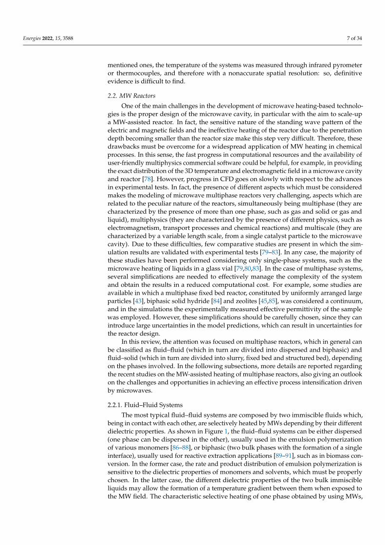
The most typical fluid–fluid systems are composed by two immiscible fluids which,being in contact with each other, are selectively heated by MWs depending by their differentdielectric properties. As shown in Figure 1, the fluid–fluid systems can be either dispersed(one phase can be dispersed in the other), usually used in the emulsion polymerizationof various monomers [86–88], or biphasic (two bulk phases with the formation of a singleinterface), usually used for reactive extraction applications [89–91], such as in biomass con-version. In the former case, the rate and product distribution of emulsion polymerization issensitive to the dielectric properties of monomers and solvents, which must be properlychosen. In the latter case, the different dielectric properties of the two bulk immiscibleliquids may allow the formation of a temperature gradient between them when exposed tothe MW field. The characteristic selective heating of one phase obtained by using MWs,
Energies 2022, 15, 3588 8 of 34
coupled to the solubility of the solute depending on temperature, can play a crucial role inreactive extraction.
Energies 2022, 15, x FOR PEER REVIEW 8 of 35
bulk immiscible liquids may allow the formation of a temperature gradient between them when exposed to the MW field. The characteristic selective heating of one phase obtained by using MWs, coupled to the solubility of the solute depending on temperature, can play a crucial role in reactive extraction.
Figure 1. Schematic of the two extreme mixing cases of fluid–fluid systems. (a) Dispersed system; (b) Biphasic system. Reprinted from [18].
2.2.2. Fluid–Solid Systems The fluid–solid systems represent the main part of the applications of microwave
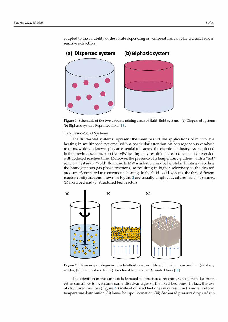
heating in multiphase systems, with a particular attention on heterogeneous catalytic re-actors, which, as known, play an essential role across the chemical industry. As mentioned in the previous section, selective MW heating may result in increased reactant conversion with reduced reaction time. Moreover, the presence of a temperature gradient with a “hot” solid catalyst and a “cold” fluid due to MW irradiation may be helpful in limit-ing/avoiding the homogeneous gas phase reactions, so resulting in higher selectivity to the desired products if compared to conventional heating. In the fluid–solid systems, the three different reactor configurations shown in Figure 2 are usually employed, addressed as (a) slurry, (b) fixed bed and (c) structured bed reactors.
Figure 2. Three major categories of solid–fluid reactors utilized in microwave heating: (a) Slurry reactor; (b) Fixed bed reactor; (c) Structured bed reactor. Reprinted from [18].
The attention of the authors is focused to structured reactors, whose peculiar prop-erties can allow to overcome some disadvantages of the fixed bed ones. In fact, the use of structured reactors (Figure 2c) instead of fixed bed ones may result in (i) more uniform
Figure 1. Schematic of the two extreme mixing cases of fluid–fluid systems. (a) Dispersed system;(b) Biphasic system. Reprinted from [18].
2.2.2. Fluid–Solid Systems
The fluid–solid systems represent the main part of the applications of microwaveheating in multiphase systems, with a particular attention on heterogeneous catalyticreactors, which, as known, play an essential role across the chemical industry. As mentionedin the previous section, selective MW heating may result in increased reactant conversionwith reduced reaction time. Moreover, the presence of a temperature gradient with a “hot”solid catalyst and a “cold” fluid due to MW irradiation may be helpful in limiting/avoidingthe homogeneous gas phase reactions, so resulting in higher selectivity to the desiredproducts if compared to conventional heating. In the fluid–solid systems, the three differentreactor configurations shown in Figure 2 are usually employed, addressed as (a) slurry,(b) fixed bed and (c) structured bed reactors.
Energies 2022, 15, x FOR PEER REVIEW 8 of 35
bulk immiscible liquids may allow the formation of a temperature gradient between them when exposed to the MW field. The characteristic selective heating of one phase obtained by using MWs, coupled to the solubility of the solute depending on temperature, can play a crucial role in reactive extraction.
Figure 1. Schematic of the two extreme mixing cases of fluid–fluid systems. (a) Dispersed system; (b) Biphasic system. Reprinted from [18].
2.2.2. Fluid–Solid Systems The fluid–solid systems represent the main part of the applications of microwave
heating in multiphase systems, with a particular attention on heterogeneous catalytic re-actors, which, as known, play an essential role across the chemical industry. As mentioned in the previous section, selective MW heating may result in increased reactant conversion with reduced reaction time. Moreover, the presence of a temperature gradient with a “hot” solid catalyst and a “cold” fluid due to MW irradiation may be helpful in limit-ing/avoiding the homogeneous gas phase reactions, so resulting in higher selectivity to the desired products if compared to conventional heating. In the fluid–solid systems, the three different reactor configurations shown in Figure 2 are usually employed, addressed as (a) slurry, (b) fixed bed and (c) structured bed reactors.
Figure 2. Three major categories of solid–fluid reactors utilized in microwave heating: (a) Slurry reactor; (b) Fixed bed reactor; (c) Structured bed reactor. Reprinted from [18].
The attention of the authors is focused to structured reactors, whose peculiar prop-erties can allow to overcome some disadvantages of the fixed bed ones. In fact, the use of structured reactors (Figure 2c) instead of fixed bed ones may result in (i) more uniform
Figure 2. Three major categories of solid–fluid reactors utilized in microwave heating: (a) Slurryreactor; (b) Fixed bed reactor; (c) Structured bed reactor. Reprinted from [18].
The attention of the authors is focused to structured reactors, whose peculiar prop-erties can allow to overcome some disadvantages of the fixed bed ones. In fact, the useof structured reactors (Figure 2c) instead of fixed bed ones may result in (i) more uniformtemperature distribution, (ii) lower hot spot formation, (iii) decreased pressure drop and (iv)
Energies 2022, 15, 3588 9 of 34
better heat and mass transfer rates [92] due to their higher heat conduction properties com-pared to fixed beds [93]. In the MW-assisted reactions, the most used structured catalysts arein the monolith and open-cell foam configuration, made of silicon carbide or cordierite. Theformer material has a well-known high thermal conductivity (up to 400 W m−1 K−1) and isa very good microwave absorber (εr = 9.72 − 2.01j); in contrast, the latter material has botha low thermal conductivity and MW susceptivity (up to 3 W m−1 K−1 and εr = 1.5 − 0.007j,respectively). For these reasons, the use of a structured catalyst prepared on a cordieritesupport in a MW-assisted reaction strongly depends on the dielectric properties of thecatalyst coating. For example, the increase in the loss tangent of a cordierite monolith from0.004 to 0.020 may be obtained after coating it with a silver–copper oxide (tan δe = 1.029)catalyst [94]. In addition, the uniformity of the catalyst coating is mandatory for a success-ful MW-assisted process when using cordierite: in fact, the presence of a thicker catalystcoating results in hot spot formation due to preferential heating. In this way, a boost ofreactivity is obtained, with a consequent inhomogeneous accumulation of side products,such as coke (its presence is detrimental for the microwave field leading to microwavedecoupling). In the case of SiC monoliths, a more uniform temperature profile can beobtained even with an irregular catalyst coating [95].
In recent years, different experimental investigations have been performed aimed atdemonstrating that an effective process intensification in terms of selectivity to the desiredproduct and production rate may be possible by using MW-heated structured reactors.In these studies, the selective heating of the solid with respect to the gas phase led toa clear temperature difference between the two phases, with the solid having a highervalue. Therefore, a higher catalytic reaction rate and the suppression of the gas-phase sidereactions were obtained, so resulting in a significant intensification of yield and selectivity.At present, SiC-based monoliths are ideal material for developing structured reactors.However, the research of new and innovative materials with nonconventional geometriescould be helpful in increase the availability of structured reactors. Their peculiar propertiesmake the structured reactors usable in different MW-assisted processes, not only chemicaltransformations, including also, for example, hydrogen release from metal hydrides [96].
Most of the studies in the literature focused on fluid–solid systems in which the fluid isa gas. Some examples are also present in which liquids are fed to structured reactors, suchas in the case of the MW-assisted degradation of malachite green (an organic pollutant), byusing CoFe2O4/SiC foam [97].
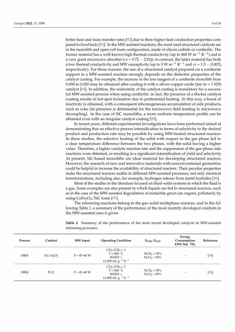
The reforming reactions belong to the gas–solid multiphase reactors, and in the fol-lowing Table 2, a summary of the performance of the most recently developed catalysts inthe MW-assisted ones is given.
Table 2. Summary of the performance of the most recent developed catalysts in MW-assistedreforming processes.
Process Catalyst MW Input Operating Condition XCH4; XCO2
EnergyConsumptionkWh Nm−3H2
Reference
DRM Ni/Al2O3 P = 45–60 W
CO2/CH4 = 1T = 800 ◦CWHSV =
11,000 mL g−1 h−1
XCH4 = 90%XCO2 = 90% - [58]
DRM Pt/C P = 45–60 W
CO2/CH4 = 1T = 800 ◦CWHSV =
11,000 mL g−1 h−1
XCH4 = 90%XCO2 = 90% - [58]
Energies 2022, 15, 3588 10 of 34
Table 2. Cont.
Process Catalyst MW Input Operating Condition XCH4; XCO2
EnergyConsumptionkWh Nm−3H2
Reference
DRM Ni/Al2O3-SiC P = 45–60 W
CO2/CH4 = 1T = 800 ◦CWHSV =
11,000 mL g−1 h−1
XCH4 = 90%XCO2 = 90% - [58]
DRM Ni/SiC P = 45–60 W
CO2/CH4 = 1T = 800 ◦CWHSV =
11,000 mL g−1 h−1
XCH4 = 90%XCO2 = 90% - [58]
DRM 7Ru/SrTiO3 P = 36.99 kW CO2/CH4 = 1T = 940 ◦C.
XCH4 = 99.5%XCO2 = 94% 18.58 [98]
DRM Fe/HZSM-5 P = 700 W CO2/CH4 = 1WHSV = 2.4 L h−1 g−1
XCH4 = 63.03%XCO2 = 91.27% - [24]
DRM LaxSr2−xCoO4-Mn P = 140 W CO2/CH4 = 1WHSV = 10 L h−1 g−1
XCH4 = 80%XCO2 = 80% 3.98 [99]
DRM Co-Mo/TiO2 P = 100 W CO2/CH4 = 1WHSV = 10 L h−1 g−1
XCH4 = 81%XCO2 = 86% - [100]
DRM Cu-Mo/TiO2 P = 100 W CO2/CH4 = 1WHSV = 10 L h−1 g−1
XCH4 = 76%XCO2 = 62% - [100]
DRM Ni-Co/ZrO2-CaO+ SiC -
CO2/CH4 = 1WHSV = 10 L h−1 g−1
T = 800 ◦C
XCH4 = 97.1%XCO2 = 99.2% - [101]
DRM 10Ni/AC -CO2/CH4 = 1
WHSV = 33 L h−1 g−1
T = 650 ◦C
XCH4 = 48%XCO2 = 51% - [102]
DRM Ni/MgO/AC -CO2/CH4 = 1
WHSV = 33 L h−1 g−1
T = 650 ◦C
XCH4 = 82%XCO2 = 85% - [102]
SRM15%Ni/CeO2-
Al2O3on a SiC monolith
P = 800 W @GHSV = 3300 h−1
P = 1000 W @GHSV = 5000 h−1
GHSV = 3300 and5000 h−1
T = 550–950 ◦CP = 1 barS/C = 3
CH4 equilibriumconversion
T = 800 ◦C—GHSV =3300 h−1
T = 850 ◦C—GHSV =5000 h−1
3.8 [39]
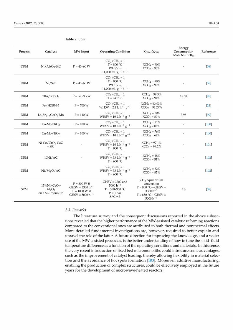
2.3. Remarks
The literature survey and the consequent discussions reported in the above subsec-tions revealed that the higher performance of the MW-assisted catalytic reforming reactionscompared to the conventional ones are attributed to both thermal and nonthermal effects.More detailed fundamental investigations are, however, required to better explain andunravel the role of the latter. A future direction for improving the knowledge, and a wideruse of the MW-assisted processes, is the better understanding of how to tune the solid–fluidtemperature difference as a function of the operating conditions and materials. In this sense,the very recent introduction of fixed bed micromonoliths could introduce some advantages,such as the improvement of catalyst loading, thereby allowing flexibility in material selec-tion and the avoidance of hot spots formation [103]. Moreover, additive manufacturing,enabling the production of complex structures, could be effectively employed in the futureyears for the development of microwave-heated reactors.
Energies 2022, 15, 3588 11 of 34
3. Electrical Resistive (Joule) Heating
Another technology for the supply of heat through electricity is ohmic or Joule heating,using those called “Resistance-heated reactors” [1]. In this regard, an interesting conceptwas presented in a recent article by Wismann et al., which proposed a new electric reactorheated by the Joule effect for the steam reforming of methane [104].
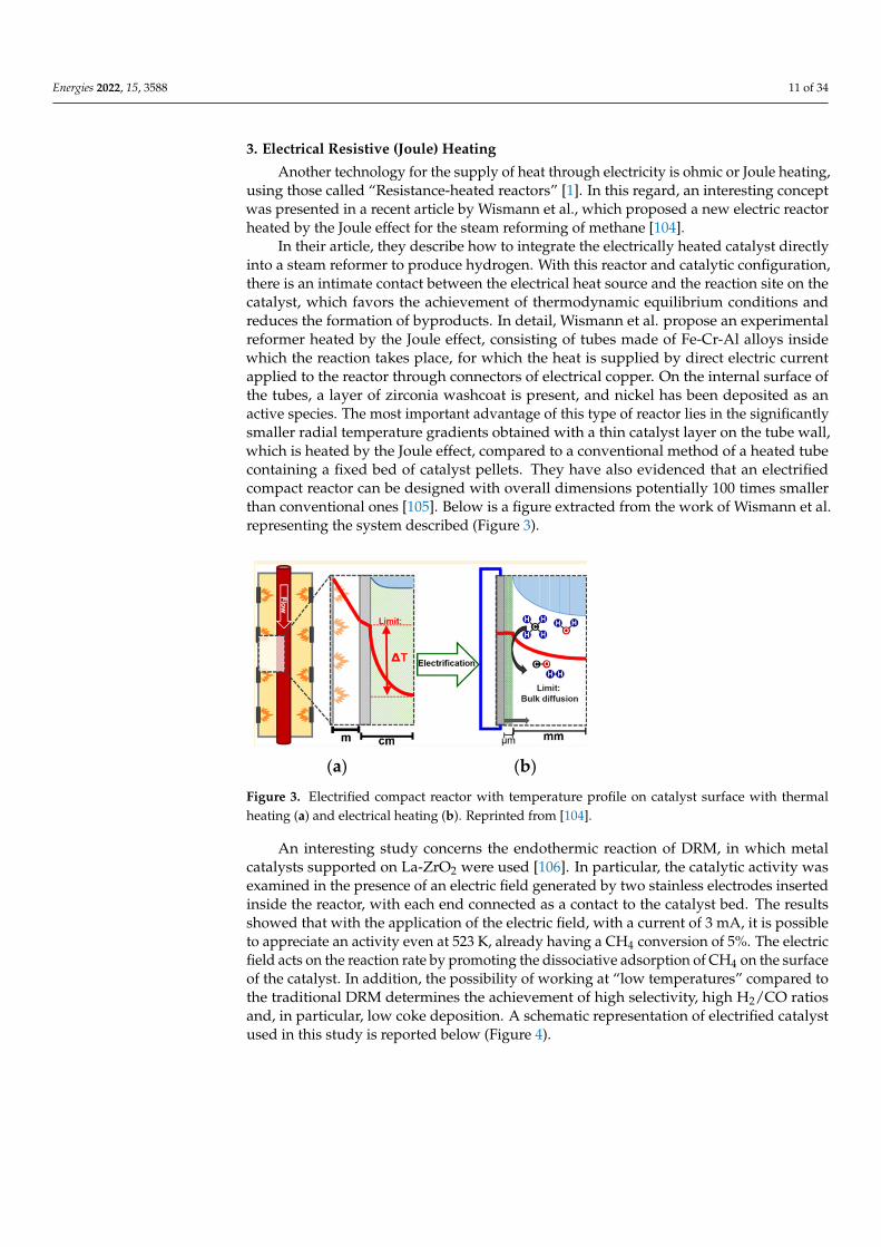
In their article, they describe how to integrate the electrically heated catalyst directlyinto a steam reformer to produce hydrogen. With this reactor and catalytic configuration,there is an intimate contact between the electrical heat source and the reaction site on thecatalyst, which favors the achievement of thermodynamic equilibrium conditions andreduces the formation of byproducts. In detail, Wismann et al. propose an experimentalreformer heated by the Joule effect, consisting of tubes made of Fe-Cr-Al alloys insidewhich the reaction takes place, for which the heat is supplied by direct electric currentapplied to the reactor through connectors of electrical copper. On the internal surface ofthe tubes, a layer of zirconia washcoat is present, and nickel has been deposited as anactive species. The most important advantage of this type of reactor lies in the significantlysmaller radial temperature gradients obtained with a thin catalyst layer on the tube wall,which is heated by the Joule effect, compared to a conventional method of a heated tubecontaining a fixed bed of catalyst pellets. They have also evidenced that an electrifiedcompact reactor can be designed with overall dimensions potentially 100 times smallerthan conventional ones [105]. Below is a figure extracted from the work of Wismann et al.representing the system described (Figure 3).
Energies 2022, 15, x FOR PEER REVIEW 11 of 35
The most important advantage of this type of reactor lies in the significantly smaller radial temperature gradients obtained with a thin catalyst layer on the tube wall, which is heated by the Joule effect, compared to a conventional method of a heated tube containing a fixed bed of catalyst pellets. They have also evidenced that an electrified compact reactor can be designed with overall dimensions potentially 100 times smaller than conventional ones [105]. Below is a figure extracted from the work of Wismann et al. representing the system described (Figure 3).
(a) (b)
Figure 3. Electrified compact reactor with temperature profile on catalyst surface with thermal heat-ing (a) and electrical heating (b). Reprinted from [104].
An interesting study concerns the endothermic reaction of DRM, in which metal cat-alysts supported on La-ZrO2 were used [106]. In particular, the catalytic activity was ex-amined in the presence of an electric field generated by two stainless electrodes inserted inside the reactor, with each end connected as a contact to the catalyst bed. The results showed that with the application of the electric field, with a current of 3 mA, it is possible to appreciate an activity even at 523 K, already having a CH4 conversion of 5%. The electric field acts on the reaction rate by promoting the dissociative adsorption of CH4 on the sur-face of the catalyst. In addition, the possibility of working at “low temperatures” com-pared to the traditional DRM determines the achievement of high selectivity, high H2/CO ratios and, in particular, low coke deposition. A schematic representation of electrified catalyst used in this study is reported below (Figure 4).
Figure 3. Electrified compact reactor with temperature profile on catalyst surface with thermalheating (a) and electrical heating (b). Reprinted from [104].
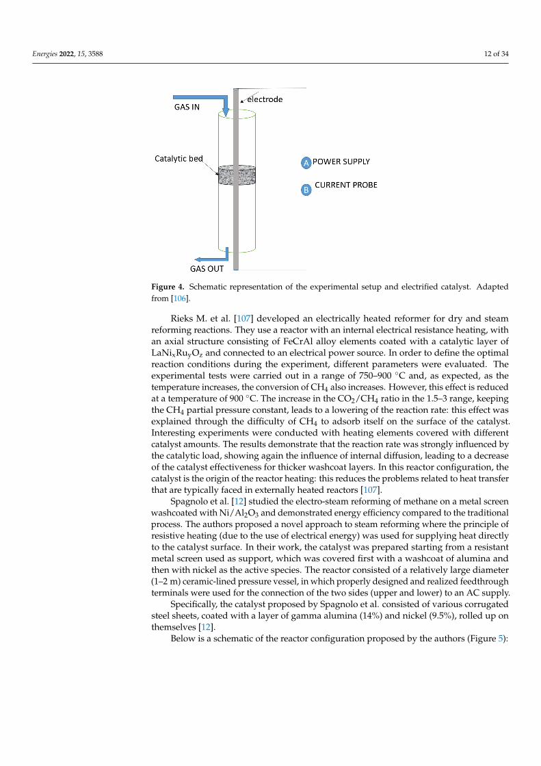
An interesting study concerns the endothermic reaction of DRM, in which metalcatalysts supported on La-ZrO2 were used [106]. In particular, the catalytic activity wasexamined in the presence of an electric field generated by two stainless electrodes insertedinside the reactor, with each end connected as a contact to the catalyst bed. The resultsshowed that with the application of the electric field, with a current of 3 mA, it is possibleto appreciate an activity even at 523 K, already having a CH4 conversion of 5%. The electricfield acts on the reaction rate by promoting the dissociative adsorption of CH4 on the surfaceof the catalyst. In addition, the possibility of working at “low temperatures” compared tothe traditional DRM determines the achievement of high selectivity, high H2/CO ratiosand, in particular, low coke deposition. A schematic representation of electrified catalystused in this study is reported below (Figure 4).
Energies 2022, 15, 3588 12 of 34Energies 2022, 15, x FOR PEER REVIEW 12 of 35
Figure 4. Schematic representation of the experimental setup and electrified catalyst. Adapted from [106].
Rieks M. et al. [107] developed an electrically heated reformer for dry and steam re-forming reactions. They use a reactor with an internal electrical resistance heating, with an axial structure consisting of FeCrAl alloy elements coated with a catalytic layer of LaNixRuyOz and connected to an electrical power source. In order to define the optimal reaction conditions during the experiment, different parameters were evaluated. The ex-perimental tests were carried out in a range of 750–900 °C and, as expected, as the tem-perature increases, the conversion of CH4 also increases. However, this effect is reduced at a temperature of 900 °C. The increase in the CO2/CH4 ratio in the 1.5–3 range, keeping the CH4 partial pressure constant, leads to a lowering of the reaction rate: this effect was explained through the difficulty of CH4 to adsorb itself on the surface of the catalyst. In-teresting experiments were conducted with heating elements covered with different cata-lyst amounts. The results demonstrate that the reaction rate was strongly influenced by the catalytic load, showing again the influence of internal diffusion, leading to a decrease of the catalyst effectiveness for thicker washcoat layers. In this reactor configuration, the catalyst is the origin of the reactor heating: this reduces the problems related to heat trans-fer that are typically faced in externally heated reactors [107].
Spagnolo et al. [12] studied the electro-steam reforming of methane on a metal screen washcoated with Ni/Al2O3 and demonstrated energy efficiency compared to the tradi-tional process. The authors proposed a novel approach to steam reforming where the prin-ciple of resistive heating (due to the use of electrical energy) was used for supplying heat directly to the catalyst surface. In their work, the catalyst was prepared starting from a resistant metal screen used as support, which was covered first with a washcoat of alu-mina and then with nickel as the active species. The reactor consisted of a relatively large diameter (1–2 m) ceramic-lined pressure vessel, in which properly designed and realized feedthrough terminals were used for the connection of the two sides (upper and lower) to an AC supply.
Specifically, the catalyst proposed by Spagnolo et al. consisted of various corrugated steel sheets, coated with a layer of gamma alumina (14%) and nickel (9.5%), rolled up on themselves [12].
Below is a schematic of the reactor configuration proposed by the authors (Figure 5):
Figure 4. Schematic representation of the experimental setup and electrified catalyst. Adaptedfrom [106].
Rieks M. et al. [107] developed an electrically heated reformer for dry and steamreforming reactions. They use a reactor with an internal electrical resistance heating, withan axial structure consisting of FeCrAl alloy elements coated with a catalytic layer ofLaNixRuyOz and connected to an electrical power source. In order to define the optimalreaction conditions during the experiment, different parameters were evaluated. Theexperimental tests were carried out in a range of 750–900 ◦C and, as expected, as thetemperature increases, the conversion of CH4 also increases. However, this effect is reducedat a temperature of 900 ◦C. The increase in the CO2/CH4 ratio in the 1.5–3 range, keepingthe CH4 partial pressure constant, leads to a lowering of the reaction rate: this effect wasexplained through the difficulty of CH4 to adsorb itself on the surface of the catalyst.Interesting experiments were conducted with heating elements covered with differentcatalyst amounts. The results demonstrate that the reaction rate was strongly influenced bythe catalytic load, showing again the influence of internal diffusion, leading to a decreaseof the catalyst effectiveness for thicker washcoat layers. In this reactor configuration, thecatalyst is the origin of the reactor heating: this reduces the problems related to heat transferthat are typically faced in externally heated reactors [107].
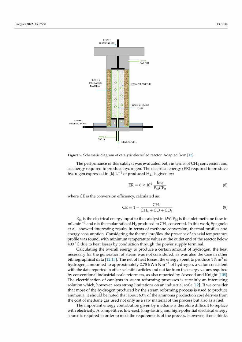
Spagnolo et al. [12] studied the electro-steam reforming of methane on a metal screenwashcoated with Ni/Al2O3 and demonstrated energy efficiency compared to the traditionalprocess. The authors proposed a novel approach to steam reforming where the principle ofresistive heating (due to the use of electrical energy) was used for supplying heat directlyto the catalyst surface. In their work, the catalyst was prepared starting from a resistantmetal screen used as support, which was covered first with a washcoat of alumina andthen with nickel as the active species. The reactor consisted of a relatively large diameter(1–2 m) ceramic-lined pressure vessel, in which properly designed and realized feedthroughterminals were used for the connection of the two sides (upper and lower) to an AC supply.
Specifically, the catalyst proposed by Spagnolo et al. consisted of various corrugatedsteel sheets, coated with a layer of gamma alumina (14%) and nickel (9.5%), rolled up onthemselves [12].
Below is a schematic of the reactor configuration proposed by the authors (Figure 5):
Energies 2022, 15, 3588 13 of 34Energies 2022, 15, x FOR PEER REVIEW 13 of 35
Figure 5. Schematic diagram of catalytic electrified reactor. Adapted from [12].
The performance of this catalyst was evaluated both in terms of CH4 conversion and as energy required to produce hydrogen. The electrical energy (ER) required to produce hydrogen expressed in [kJ L−1 of produced H2] is given by: ER = 6 × 10 (8)
where CE is the conversion efficiency, calculated as: CE = 1 − (9)
Ein is the electrical energy input to the catalyst in kW, FM is the inlet methane flow in mL min−1 and n is the molar ratio of H2 produced to CH4 converted. In this work, Spagnolo et al. showed interesting results in terms of methane conversion, thermal profiles and en-ergy consumption. Considering the thermal profiles, the presence of an axial temperature profile was found, with minimum temperature values at the outlet end of the reactor be-low 400 °C due to heat losses by conduction through the power supply terminal.
Calculating the overall energy to produce a certain amount of hydrogen, the heat necessary for the generation of steam was not considered, as was also the case in other bibliographical data [12,15]. The net of heat losses, the energy spent to produce 1 Nm3 of hydrogen, amounted to approximately 2.78 kWh Nm−3 of hydrogen, a value consistent with the data reported in other scientific articles and not far from the energy values re-quired by conventional industrial-scale reformers, as also reported by Atwood and Knight [108]. The electrification of catalysts in steam reforming processes is certainly an interest-ing solution which, however, sees strong limitations on an industrial scale [12]. If we con-sider that most of the hydrogen produced by the steam reforming process is used to pro-duce ammonia, it should be noted that about 60% of the ammonia production cost derives from the cost of methane gas used not only as a raw material of the process but also as a fuel.
The important energy contribution given by methane is therefore difficult to replace with electricity. A competitive, low-cost, long-lasting and high-potential electrical energy source is required in order to meet the requirements of the process. However, if one thinks
Figure 5. Schematic diagram of catalytic electrified reactor. Adapted from [12].
The performance of this catalyst was evaluated both in terms of CH4 conversion andas energy required to produce hydrogen. The electrical energy (ER) required to producehydrogen expressed in [kJ L−1 of produced H2] is given by:
ER = 6× 10⁴ EIN
FMCEn(8)
where CE is the conversion efficiency, calculated as:
CE = 1− CH4
CH4 + CO + CO2(9)
Ein is the electrical energy input to the catalyst in kW, FM is the inlet methane flow inmL min−1 and n is the molar ratio of H2 produced to CH4 converted. In this work, Spagnoloet al. showed interesting results in terms of methane conversion, thermal profiles andenergy consumption. Considering the thermal profiles, the presence of an axial temperatureprofile was found, with minimum temperature values at the outlet end of the reactor below400 ◦C due to heat losses by conduction through the power supply terminal.
Calculating the overall energy to produce a certain amount of hydrogen, the heatnecessary for the generation of steam was not considered, as was also the case in otherbibliographical data [12,15]. The net of heat losses, the energy spent to produce 1 Nm3 ofhydrogen, amounted to approximately 2.78 kWh Nm−3 of hydrogen, a value consistentwith the data reported in other scientific articles and not far from the energy values requiredby conventional industrial-scale reformers, as also reported by Atwood and Knight [108].The electrification of catalysts in steam reforming processes is certainly an interestingsolution which, however, sees strong limitations on an industrial scale [12]. If we considerthat most of the hydrogen produced by the steam reforming process is used to produceammonia, it should be noted that about 60% of the ammonia production cost derives fromthe cost of methane gas used not only as a raw material of the process but also as a fuel.
The important energy contribution given by methane is therefore difficult to replacewith electricity. A competitive, low-cost, long-lasting and high-potential electrical energysource is required in order to meet the requirements of the process. However, if one thinks
Energies 2022, 15, 3588 14 of 34
of an electrified reformer, one should not necessarily think of large industrial scales, but,on the contrary, these reformers lend themselves well to the concept of compact, small anddistributed hydrogen modules. Traditional reformers cannot be downsized. Furthermore,another interesting advantage of electrified reformers lies in the maintenance cost: sincethe material does not have to reach high temperatures on the surface of the tube, it doesnot undergo severe thermal stress and damage.
Renda et al. studied the electrification of a structured catalyst consisting of a SiCresistance covered with a washcoat based on a silica–mullite composite covered with Ni forthe dry and steam reforming reactions. The catalyst was heated by the Joule effect. In thisway, it was possible to supply heat to the catalyst directly from the inside, thus reducing theresistance to heat transport. From the data obtained in terms of hydrogen production andenergy consumption, it can be seen that, as expected, the energy consumption of the systemis strictly linked to the H2 productivity [10,15]. As also reported by Spagnolo et al. [12], thehigher energy consumption was observed at lower space velocity values. This behaviorcan be explained considering that, with the laboratory scale, the effects of heat dissipationin the reactor have a big role with respect to the low gas flow rate fed to the reactor.
Sekine et al. conducted a catalytic reforming experiment at low temperatures(423 K) [109]. The experimental setup used for this work was a fixed bed reactor con-nected to two stainless steel bars used as electrodes. In the feed ratio used, S/C wasequal to 2, and 200 mg of catalyst was used. Initially, the experiments were conducted toevaluate the effect of an electric field for catalytic reforming on metal catalysts (Pt-, Pd-,Rh-, Ni-) supported on CeO2. Steam reforming on these catalysts was carried out withand without the electric field, and performed at low temperatures in a range from 423 Kto 773 K. It was noted that at low temperature, conventional reforming gave almost zeroconversion; subsequently, with the application of the electric field, conversion increasedexponentially, especially for the Rh/CeO2 catalyst. In this study, the authors evaluatedthe effect of the doping of these catalysts with zirconia in different amounts. It was notedthat the conversion of methane increased with the increase of the zirconium content. Itwas therefore possible to observe that the metal catalysts supported on CexZr1−xO2 are thebest among those observed, since they showed a higher activity; in fact, the conversion ofmethane for electro-reforming increased as the Ce/Zr ratio decreased [109].
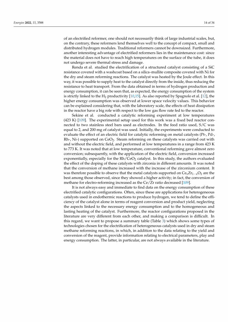
It is not always easy and immediate to find data on the energy consumption of theseelectrified catalytic configurations. Often, since these are applications for heterogeneouscatalysts used in endothermic reactions to produce hydrogen, we tend to define the effi-ciency of the catalyst alone in terms of reagent conversion and product yield, neglectingthe aspects linked to the necessary energy consumption and to the homogeneous andlasting heating of the catalyst. Furthermore, the reactor configurations proposed in theliterature are very different from each other, and making a comparison is difficult. Inthis regard, we want to propose a summary table (Table 3) which shows some types oftechnologies chosen for the electrification of heterogeneous catalysts used in dry and steammethane reforming reactions, in which, in addition to the data relating to the yield andconversion of the reagent, provide information relating to electrical parameters, play andenergy consumption. The latter, in particular, are not always available in the literature.
Energies 2022, 15, 3588 15 of 34
Table 3. Energy consumption among the electrified-structured catalyst proposed in literature forelectrified reforming processes and their operating condition.
Process HeatingElement Catalyst Electric
ParametersOperatingCondition XCH4; YH2
EnergyConsumptionkWh Nm−3H2
Reference
DRMSiC heating
element (JouleEffect)
Ni/Al2O3 P = 218 W CO2/CH4 = 1T = 790 ◦C.
XCH4 = 85%YH2 = 82% 5.1 [15]
SRMSiC heating
element (JouleEffect)
Ni/Al2O3 P = 220 W CH4/H2O = 3T = 790 ◦C.
XCH4 = 80%YH2 = 80% 4.8 [15]
DRMStainlesselectrode
(Joule Effect)Ni/La-ZrO2
I = 12 mAV = 0.4 kV
P = 5 W
T = 576 KCH4/CO2 = 1
XCH430.2%
YH2 = -18 [106]
SRMStainless
electrode rode(Joule Effect)
Ni/CeZrO2Ce/Zr = 3
I = 3 mAEPC = 1.29 W
T = 190 ◦CH2O/CH4 = 2
XCH412%
YH2 = -3.98 [109]
SRMStainless
electrode rode(Joule Effect)
Ni/CeZrO2Ce/Zr = 1
I = 3 mAEPC = 1.53 W 3.21 [109]
SRMStainless
electrode rode(Joule Effect)
Ni/CeZrO2Ce/Zr = 0.3
I = 3 mAEPC = 2.54 W 3.75 [109]
3.1. Reactor Configuration for Resistive (Joule) Heating
Considering the current reactor configurations proposed for endothermic processes,they typically include the internal flow of the reactants through a tube configurationin which the heat is supplied from the outside by burning a fossil fuel [110] Therefore,the heating efficiency in these configurations is compromised due to multiple thermalresistances. On the contrary, thinking about the application of resistances for heating thecatalysts, they generate heat distributed evenly in the catalyst in direct contact with thefluid. For this purpose, it is interesting to observe which are some of the possible simplereactor configurations that satisfy this requirement. The solutions proposed concern, almostalways, schemes of modular reactors with heating by electrical resistance designed forapplications in endothermic reactions. The idea of using modular configurations is justifiedby the energy requirement, and by the difficult scalability of the system thus proposed. Inparticular, the following two reactor schemes proposed in the literature can be considered,as they represent the configurations more easily applicable even with any changes [105].
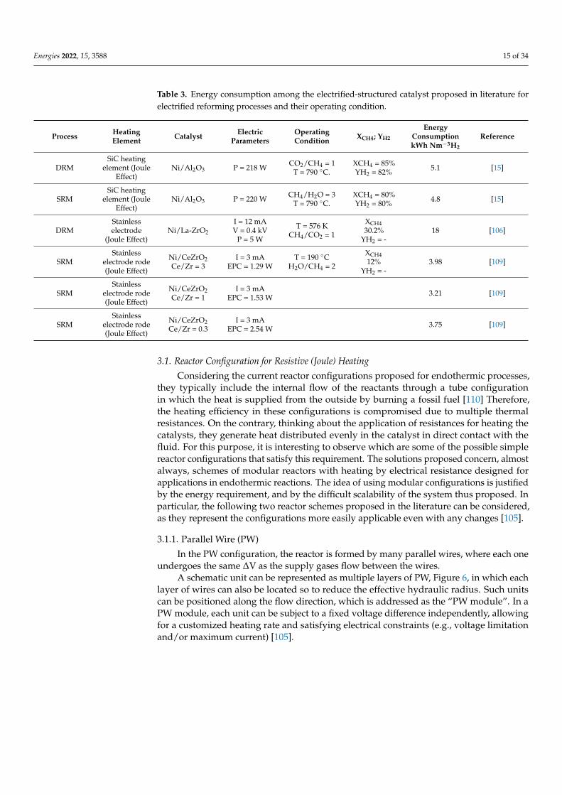
3.1.1. Parallel Wire (PW)
In the PW configuration, the reactor is formed by many parallel wires, where each oneundergoes the same ∆V as the supply gases flow between the wires.
A schematic unit can be represented as multiple layers of PW, Figure 6, in which eachlayer of wires can also be located so to reduce the effective hydraulic radius. Such unitscan be positioned along the flow direction, which is addressed as the “PW module”. In aPW module, each unit can be subject to a fixed voltage difference independently, allowingfor a customized heating rate and satisfying electrical constraints (e.g., voltage limitationand/or maximum current) [105].
Energies 2022, 15, 3588 16 of 34Energies 2022, 15, x FOR PEER REVIEW 16 of 35
Figure 6. Parallel wires unit reactor configuration. Adapted from [105].
3.1.2. Parallel Tube Reactor (PTR) This configuration is like the traditional configuration used in endothermic processes
(e.g., steam reforming), except that the heating is provided by electricity and by the com-bustion section. In the PTR, the stacked parallel tubes, each passed through the feed gases, are maintained separate from each other and undergo the same ΔV between inlet and outlet (Figure 7).
In this arrangement, the fluid flows internally and has the same direction of the elec-tric current flow. Conversely, in the PW configuration, the fluid flows externally and its direction is perpendicular to the electric current flow. We note that the practical imple-mentation of these reactor configurations can only be achieved if they can be expanded and adapted to the discontinuous nature of renewable energy.
It should be noted that, when covering a wire or tube with a catalytic layer of average thickness between 20–100 µm, the feed gases flow over the electrically heated wires or tubes where the catalytic reaction and the local composition and temperature are strictly linked. In fact, the temperature of the gas phase next to the floss may cause reforming or other reactions in the gas phase (homogeneous reactions). To identify the materials with the desired catalytic and electrical properties, and to be able to correctly interpret the ex-perimental results in the hypothesis of a scale-up of the process, the understanding of homogeneous–heterogeneous chemistry coupled to local flow conditions and velocity is fundamental. The analysis of this system always requires the characterization of the cata-lytic properties, in particular of the washcoat, as well as a deep understanding of the transport phenomena [105,111,112].
Figure 6. Parallel wires unit reactor configuration. Adapted from [105].
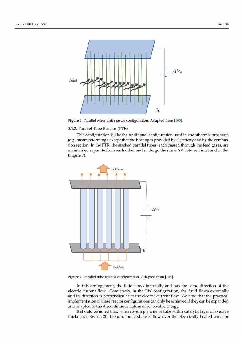
3.1.2. Parallel Tube Reactor (PTR)
This configuration is like the traditional configuration used in endothermic processes(e.g., steam reforming), except that the heating is provided by electricity and by the combus-tion section. In the PTR, the stacked parallel tubes, each passed through the feed gases, aremaintained separate from each other and undergo the same ∆V between inlet and outlet(Figure 7).
Energies 2022, 15, x FOR PEER REVIEW 17 of 35
Figure 7. Parallel tube reactor configuration. Adapted from [105].
The factors in terms of both design and operating parameters affecting the conversion of the limiting reactant may be evaluated through small-order models, in which the fluid flow, heat and mass transport are simultaneously coupled in micro–mesoscale. In this sense, different parameters may be considered, including wire properties, the density of catalytic sites, the spacing between wires/tubes, the heating rate, the feed composition, the inlet temperature and the flow rate. For example, in Wismann’s work, the evaluation of the functionality of the electrified catalyst was based on a model in which the heat flow was studied on a single heating element consisting of an iron of Fe-Cr-Al characterized by very small temperature gradients [104].
In order to evaluate the possibility that the SiC element, if connected to the electrical grid, can act as heating medium by means of the Joule effect, Renda et al. propose the modeling of the heating element (SiC) and the simulation, which allowed them to evaluate the variation of the electric potential V along the SiC element length and the heat transfer in the solids. The results confirm that, if connected to the electric grid, the SiC element can heat itself by means of the Joule effect, so allowing its use as a support for a catalyst and, consequently, its use in process intensification as a contemporary heating medium and catalyst support [15].
An important and peculiar aspect of these reactor configurations with electrified cat-alysts is their flexibility and modularity. In fact, it is possible to adjust the number of wires or pipes in the base unit according to the current–voltage and/or power constraints, to-gether with the conversion level to be achieved and the heating requirements. One more important advantage of the modular design of an electrified reactor is that both the shorter start-up and shut-down operations (in the order of magnitude of seconds) may be ob-tained compared to the several hours or days needed by large traditional fossil fuel reac-tors. This allows to quickly adapt the number of operating units based on the available power supply [58,105,110].
The idea of electrifying the catalyst, studying in particular the effect of the washcoat, of the interaction between the gas and the electrified catalytic surface, will certainly have
Figure 7. Parallel tube reactor configuration. Adapted from [105].
In this arrangement, the fluid flows internally and has the same direction of theelectric current flow. Conversely, in the PW configuration, the fluid flows externallyand its direction is perpendicular to the electric current flow. We note that the practicalimplementation of these reactor configurations can only be achieved if they can be expandedand adapted to the discontinuous nature of renewable energy.
It should be noted that, when covering a wire or tube with a catalytic layer of averagethickness between 20–100 µm, the feed gases flow over the electrically heated wires or
Energies 2022, 15, 3588 17 of 34
tubes where the catalytic reaction and the local composition and temperature are strictlylinked. In fact, the temperature of the gas phase next to the floss may cause reformingor other reactions in the gas phase (homogeneous reactions). To identify the materialswith the desired catalytic and electrical properties, and to be able to correctly interpretthe experimental results in the hypothesis of a scale-up of the process, the understandingof homogeneous–heterogeneous chemistry coupled to local flow conditions and velocityis fundamental. The analysis of this system always requires the characterization of thecatalytic properties, in particular of the washcoat, as well as a deep understanding of thetransport phenomena [105,111,112].
The factors in terms of both design and operating parameters affecting the conversionof the limiting reactant may be evaluated through small-order models, in which the fluidflow, heat and mass transport are simultaneously coupled in micro–mesoscale. In thissense, different parameters may be considered, including wire properties, the density ofcatalytic sites, the spacing between wires/tubes, the heating rate, the feed composition, theinlet temperature and the flow rate. For example, in Wismann’s work, the evaluation of thefunctionality of the electrified catalyst was based on a model in which the heat flow wasstudied on a single heating element consisting of an iron of Fe-Cr-Al characterized by verysmall temperature gradients [104].
In order to evaluate the possibility that the SiC element, if connected to the electricalgrid, can act as heating medium by means of the Joule effect, Renda et al. propose themodeling of the heating element (SiC) and the simulation, which allowed them to evaluatethe variation of the electric potential V along the SiC element length and the heat transferin the solids. The results confirm that, if connected to the electric grid, the SiC elementcan heat itself by means of the Joule effect, so allowing its use as a support for a catalystand, consequently, its use in process intensification as a contemporary heating mediumand catalyst support [15].
An important and peculiar aspect of these reactor configurations with electrifiedcatalysts is their flexibility and modularity. In fact, it is possible to adjust the number ofwires or pipes in the base unit according to the current–voltage and/or power constraints,together with the conversion level to be achieved and the heating requirements. One moreimportant advantage of the modular design of an electrified reactor is that both the shorterstart-up and shut-down operations (in the order of magnitude of seconds) may be obtainedcompared to the several hours or days needed by large traditional fossil fuel reactors.This allows to quickly adapt the number of operating units based on the available powersupply [58,105,110].
The idea of electrifying the catalyst, studying in particular the effect of the washcoat,of the interaction between the gas and the electrified catalytic surface, will certainly havefurther developments, as it is an approach that has interesting characteristics, especially forendothermic reactions.
In fact, with the electrification of the catalyst, heated by the Joule effect, we noticethat the heat is generated on the catalytic surface where it is required, thus making theheat transfer much more efficient. Furthermore, the maximum temperature occurs insidethe catalytic structure, and no longer in correspondence with the containment walls. Thismeans that the materials of the reactor will also have a greater resistance over time. Itis important to underline that, in the proposed configurations, the reactor walls are notsubjected to excessively high temperatures, therefore the operating temperature for thereforming processes can be reduced (it is no longer necessary to reach values of 1000 ◦Cto obtain values of 850 ◦C on the catalyst, and there is no risk of thermal hot spots thatcan damage the reactor walls). To heat the catalyst, it is possible to use electricity fromrenewable sources: this saves nonrenewable natural gas, thus reducing CO2 emissions.
3.2. Remarks
The most interesting aspects of the solutions proposed in the literature for the electrifi-cation of reactions for the hydrogen production concern the aspects relating to the transient
Energies 2022, 15, 3588 18 of 34
time, which, in these cases, is of the order of seconds compared to traditional reactors thattake from several hours to a day, and the modularity of the rectors. Perhaps the latter is themost interesting feature of electrified solutions for reforming reactors, already highlightedby some studies in the literature [15,105]. Indeed, it is possible to design the reactor basedon the local energy availability of the proposed projects and their modularity, flexibilityand ease of scalability. The reactor configurations that provide resistive heating (due tothe Joule effect), proposed in various bibliographic studies, can be sized according to theavailability of local (renewable) energy. Therefore, a strong interest in this solution emergesfrom the literature. The researchers carried out their studies both by performing modelingand simulations to understand the behavior of the heat flow along the heating element,and in other cases also trying to validate the data obtained experimentally. The resultsobtained so far are interesting and certainly need further confirmation and further studies,such as more detailed analyses of flow models, pilot-scale experiments and evaluation ofthe stability of the catalyst.
4. PEM Fuel Cells
In recent years, many countries and companies have invested heavily in researchingand developing new alternative energy sources such as solar, wind, biomass and geothermalenergy [113,114]. Hydrogen fuel cells are considered among the most interesting and mostsuitable energy sources to overcome the problems related to greenhouse gases, climatechange and energy shortages [115].
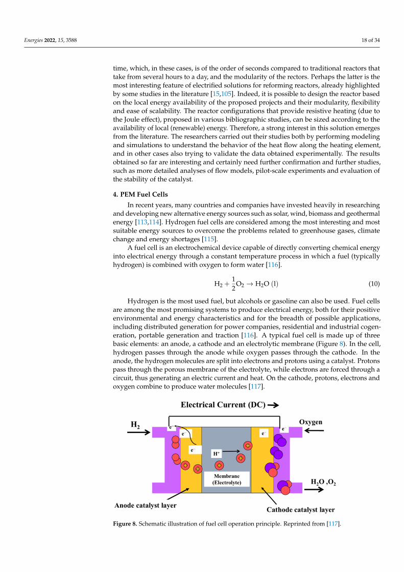
A fuel cell is an electrochemical device capable of directly converting chemical energyinto electrical energy through a constant temperature process in which a fuel (typicallyhydrogen) is combined with oxygen to form water [116].
H2 +12
O2 → H2O (l) (10)
Hydrogen is the most used fuel, but alcohols or gasoline can also be used. Fuel cellsare among the most promising systems to produce electrical energy, both for their positiveenvironmental and energy characteristics and for the breadth of possible applications,including distributed generation for power companies, residential and industrial cogen-eration, portable generation and traction [116]. A typical fuel cell is made up of threebasic elements: an anode, a cathode and an electrolytic membrane (Figure 8). In the cell,hydrogen passes through the anode while oxygen passes through the cathode. In theanode, the hydrogen molecules are split into electrons and protons using a catalyst. Protonspass through the porous membrane of the electrolyte, while electrons are forced through acircuit, thus generating an electric current and heat. On the cathode, protons, electrons andoxygen combine to produce water molecules [117].
Energies 2022, 15, x FOR PEER REVIEW 19 of 35
circuit, thus generating an electric current and heat. On the cathode, protons, electrons and oxygen combine to produce water molecules [117].
Figure 8. Schematic illustration of fuel cell operation principle. Reprinted from [117].
Fuel cells are receiving considerable attention in scientific research, as they appear to be a very promising alternative for generating clean energy using highly efficient renew-able electrolytic hydrogen. Furthermore, fuel cells have the advantage of producing elec-tricity if a fuel source is supplied, thus not needing to be recharged periodically like bat-teries [117].
4.1. Proton Exchange Membrane Fuel Cells There are various types of fuel cells which differ in the operating temperature and
the type of electrolyte used. Proton exchange membrane fuel cells (PEMFC) are among the most interesting, as they appear to be the most reliable and ready for use in larger scale applications, including the automobile industry and portable devices [118]. In the PEMFCs there is a polymeric electrolytic membrane for the proton conduction. Hydrogen ions, generated by the hydrogen oxidation at the anode, are recombined at the cathode through the polymeric electrolyte membrane with migrating electrons and oxygen, pro-ducing water, while electrical energy is generated by electrons in an external circuit con-nected to a load [119].
The chemical half reactions for the PEMFC are as follows: Hydrogen Oxidation Reaction (HOR), on the anode [120]: H → 2H + 2e (11)
Oxygen Reduction Reaction (ORR), on the cathode [120]: O + 2H + 2e → H O (12)
In PEMFCs (Figure 9), hydrogen, lower alcohols (like methanol and ethanol) and ac-ids (like formic acid) can be used as fuels [121]. However, hydrogen is the most used and recommended since, compared to other usable fuels, its weight-based energy density is the largest and is the easiest to oxidize under the near conditions of room temperature and atmospheric pressure. Furthermore, since oxygen (in air) is used as a comburent, the only products obtainable are electricity, heat and water, thus making it a zero-emission process (greenhouse gas and pollution free) [121]. PEMFCs have significant advantages over other types of fuel cells, including high power densities, low operating temperatures, quick start-up times and easy stacking [118]. In this paragraph, some research progress of platinum-based catalysts and platinum group metal (PGM)-free-based catalysts for PEMFC applications achieved in recent years will be described.
Figure 8. Schematic illustration of fuel cell operation principle. Reprinted from [117].
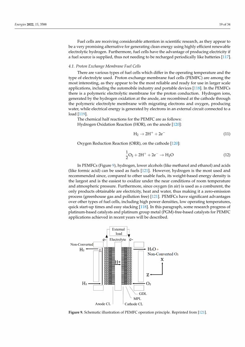
Energies 2022, 15, 3588 19 of 34
Fuel cells are receiving considerable attention in scientific research, as they appear tobe a very promising alternative for generating clean energy using highly efficient renewableelectrolytic hydrogen. Furthermore, fuel cells have the advantage of producing electricity ifa fuel source is supplied, thus not needing to be recharged periodically like batteries [117].
4.1. Proton Exchange Membrane Fuel Cells
There are various types of fuel cells which differ in the operating temperature and thetype of electrolyte used. Proton exchange membrane fuel cells (PEMFC) are among themost interesting, as they appear to be the most reliable and ready for use in larger scaleapplications, including the automobile industry and portable devices [118]. In the PEMFCsthere is a polymeric electrolytic membrane for the proton conduction. Hydrogen ions,generated by the hydrogen oxidation at the anode, are recombined at the cathode throughthe polymeric electrolyte membrane with migrating electrons and oxygen, producingwater, while electrical energy is generated by electrons in an external circuit connected to aload [119].
The chemical half reactions for the PEMFC are as follows:Hydrogen Oxidation Reaction (HOR), on the anode [120]:
H2 → 2H+ + 2e− (11)
Oxygen Reduction Reaction (ORR), on the cathode [120]:
12
O2 + 2H+ + 2e− → H2O (12)
In PEMFCs (Figure 9), hydrogen, lower alcohols (like methanol and ethanol) and acids(like formic acid) can be used as fuels [121]. However, hydrogen is the most used andrecommended since, compared to other usable fuels, its weight-based energy density isthe largest and is the easiest to oxidize under the near conditions of room temperatureand atmospheric pressure. Furthermore, since oxygen (in air) is used as a comburent, theonly products obtainable are electricity, heat and water, thus making it a zero-emissionprocess (greenhouse gas and pollution free) [121]. PEMFCs have significant advantagesover other types of fuel cells, including high power densities, low operating temperatures,quick start-up times and easy stacking [118]. In this paragraph, some research progress ofplatinum-based catalysts and platinum group metal (PGM)-free-based catalysts for PEMFCapplications achieved in recent years will be described.
Energies 2022, 15, x FOR PEER REVIEW 20 of 35
Figure 9. Schematic illustration of PEMFC operation principle. Reprinted from [121].
4.1.1. Pt-Based Platinum-based catalysts are the choice to realize the optimal adsorption of oxygen-
ate produced in the oxygen reduction reaction (ORR) [122]. Due to the sluggish ORR ki-netics at the cathode, and the not particularly high stability of commercial platinum-based catalysts, research is focusing on the development of a catalytic formulations capable of meeting the performance and durability requirements for any applications, and in partic-ular for the automotive one [123]. In this section, the results of some articles focused on the use of platinum-based catalyst in PEMFC applications are briefly argued. A summary table (Table 4) is provided at the end of the section to highlight the results in terms of peak power density (P), mass activity (MA), specific activity (SA) and electrochemical active surface areas (ECSA).
Dmitry D. Spasov et al. [124] synthesized a platinum-based catalyst supported on SnO2-modified carbon for PEMFC applications. The influence of the SnO2 load, varied be-tween 5% and 40% by weight, was evaluated. The authors demonstrated that the for-mation of Pt-SnO2 clusters significantly affects the catalyst structure and performance. The increase of the SnO2 load promotes the uniformity in the Pt-SnO2 clusters distribution on the carbon support surface, resulting in improved performance. However, an excessive load of SnO2 favors particle agglomeration and negatively affects the uniformity of the SnO2 particle distribution, decreasing the catalyst performance.
Meenakshi Seshadhri Garapati et al. [125] tested a new cathode catalyst for single-cell measurements of PEMFCs, consisting of partially exfoliated carbon nanotubes (PECNTs) on which nanoparticles of the Pt3Sc alloy have been deposited as an active phase. This catalyst has shown very interesting performances, both in terms of ORR ac-tivity and durability, above all thanks to the Pt3Sc alloy nanoparticles which, due to the excellent interaction with the partially exfoliated carbon nanotubes, allow adsorbing the oxygen molecules with a lower binding energy than Pt.
Reza Alipour MoghadamEsfahani et al. [126] tested a platinum-based catalyst on a NbO combined with multiwalled carbon nanotubes support. The obtained catalyst showed interesting performances for PEMFC applications, as the presence of NbO im-proved the metal–support interactions and gave the catalyst a high resistance to corrosion.
Padmini Basumatary et al. [127] have developed, for a PEMFCs application, a new catalyst supported by three-dimensional nanoflower-like structures of MoS2 deposited on graphene sheets, while PtScNi nanoparticles have been grafted on the support as active phases. They also studied the effect of the different doping ratios of Sc, which had a posi-tive effect on the electrocatalytic properties, increasing the activity surface area and the
Figure 9. Schematic illustration of PEMFC operation principle. Reprinted from [121].

Energies 2022, 15, 3588 20 of 34
4.1.1. Pt-Based
Platinum-based catalysts are the choice to realize the optimal adsorption of oxygenateproduced in the oxygen reduction reaction (ORR) [122]. Due to the sluggish ORR kinetics atthe cathode, and the not particularly high stability of commercial platinum-based catalysts,research is focusing on the development of a catalytic formulations capable of meetingthe performance and durability requirements for any applications, and in particular forthe automotive one [123]. In this section, the results of some articles focused on the useof platinum-based catalyst in PEMFC applications are briefly argued. A summary table(Table 4) is provided at the end of the section to highlight the results in terms of peak powerdensity (P), mass activity (MA), specific activity (SA) and electrochemical active surfaceareas (ECSA).
Table 4. Platinum-based catalyst for fuel cells application: Peak power density (P), mass activity(MA), specific activity (SA) and electrochemical active surface areas for selected catalyst for eacharticle (ECSA).
Catalyst P[W cmPt−2]
MA[A mgPt−1]
SA[mA cmPt−2]
ECSA[m2 gPt−1] Ref
Pt/10wt%SnO2/C 0.25 (40 ◦C) - - 57 [124]Pt3Sc/PECNTs 0.76 (60 ◦C) 0.0803 - 102.1 [125]Pt/NbO/CNTs 0.772 (80 ◦C) 0.057 - 81.62 [126]
PtSc0.5Ni/MoS2@graphene 0.0517 (50 ◦C) 3.579 4.1 86.27 [127]Pt-Ni-Ir/C
Pt:Ni:Ir = 2:2:1 0.4 (80 ◦C) 0.0004 - 85 [128]
Pt/VC 0.9 (80 ◦C) 0.096 56.4 [129]Pt/rGO - - 10.5 0.51 [130]
Pt/Ti3O5Mo0.2Si0.4 0.97 (80 ◦C) - 2.35 89.6 [131]Pt/CNT-Ti3C2Tx (1:1) 0.175 (60 ◦C) 0.163 0.26 63 [132]Pt NWs/Ti3C2Tx-CNT 0.182 (180 ◦C) 0.32 0.21 63.59 [133]
Pt/TiN–TiO2 0.392 (70 ◦C) - - 73 [134]Pt/GCNT 0.38 (160 ◦C) - - 59 [135]Pt-YOx/C - 0.108 0.204 52.82 [136]PtxMg/C 1.275 (80 ◦C) 1.09 2.67 40 [137]
Au−Pt−Co/C-0.015 - 0.386 0.535 72.2 [138]Pt-Co/3D rHPGO - 0.167 0.31 53.1 [139]
Pt/rEGO2-CB3 0.537 (60 ◦C) 0.006416 4.682 41.73 [140]Pt/CB-SiO220%, - 0.26 0.933 29.27 [141]
Pt/CA-200 0.642 (80 ◦C) - - 187.9 [142]Pt-PBI/MWCNT 0.047 (180 ◦C) - - 43 [143]
Dmitry D. Spasov et al. [124] synthesized a platinum-based catalyst supported onSnO2-modified carbon for PEMFC applications. The influence of the SnO2 load, variedbetween 5% and 40% by weight, was evaluated. The authors demonstrated that theformation of Pt-SnO2 clusters significantly affects the catalyst structure and performance.The increase of the SnO2 load promotes the uniformity in the Pt-SnO2 clusters distributionon the carbon support surface, resulting in improved performance. However, an excessiveload of SnO2 favors particle agglomeration and negatively affects the uniformity of theSnO2 particle distribution, decreasing the catalyst performance.
Meenakshi Seshadhri Garapati et al. [125] tested a new cathode catalyst for single-cellmeasurements of PEMFCs, consisting of partially exfoliated carbon nanotubes (PECNTs) onwhich nanoparticles of the Pt3Sc alloy have been deposited as an active phase. This catalysthas shown very interesting performances, both in terms of ORR activity and durability,above all thanks to the Pt3Sc alloy nanoparticles which, due to the excellent interactionwith the partially exfoliated carbon nanotubes, allow adsorbing the oxygen molecules witha lower binding energy than Pt.
Energies 2022, 15, 3588 21 of 34
Reza Alipour MoghadamEsfahani et al. [126] tested a platinum-based catalyst on aNbO combined with multiwalled carbon nanotubes support. The obtained catalyst showedinteresting performances for PEMFC applications, as the presence of NbO improved themetal–support interactions and gave the catalyst a high resistance to corrosion.
Padmini Basumatary et al. [127] have developed, for a PEMFCs application, a newcatalyst supported by three-dimensional nanoflower-like structures of MoS2 deposited ongraphene sheets, while PtScNi nanoparticles have been grafted on the support as activephases. They also studied the effect of the different doping ratios of Sc, which had apositive effect on the electrocatalytic properties, increasing the activity surface area and thedensity of the active sites, thus favoring the ensemble effect and the interactions betweenthe nanoparticles of the active phases and the support.
Rui Lin et al. [128] evaluated the performance of a Pt-Ni-Ir ternary alloy used as theactive phase of a C-based catalyst for PEMFC applications. The catalyst achieved goodperformance, both in terms of activity and durability, as the combined presence of Ni andIr increases the active surface area and improves the uniformity of the Pt distribution.
Fengjuan Zhu et al. [129] reported a synthesis strategy for the realization of a Pt/C-based catalyst, in which citric acid and acetic acid solutions were used to allow pH regu-lation and facilitate the Pt NPs distribution and the metal active sites generation. Thanksto the synergic effect of these two acids, a catalyst with a high Pt content and a fine anduniform Pt NPs distribution was obtained. The authors believe that these factors haveallowed a decrease in the local oxygen transport resistance of the catalyst, thereby providingattractive performance for PEMFC applications.
Jemin Kim et al. [130] carried out a study on the catalytic performance of oxygenreduction catalysts for PEMFCs. Platinum nanoparticles were synthesized on grapheneoxide in three reduction states: unreduced, partially reduced and reduced. The resultsshowed that a low concentration of oxygen containing functional group can positivelyaffect the ORR, improving the performance of the catalyst both in terms of activity anddurability. Therefore, the catalyst supported by reduced graphene oxide showed the bestperformance, as it had the lowest concentration of oxygen containing functional groupamong the tested catalysts.
Reza Alipour Moghadam Esfahani et al. [131] tested the durability of a platinum-based catalyst supported on dual-doped titanium suboxide Ti3O5Mo0.2Si0.4 for PEMFCapplications. This catalyst showed considerable durability during the performed testsdue to the ability of the support to stabilize the platinum nanoparticles, thus increasingthe resistance to nanoparticles segregation and, consequently, increasing the resistance todeactivation. Furthermore, the presence of Si as a dopant improved both the conductivityof the support and its resistance to corrosion.
Chenxi Xu et al. [132] reported the use of a hybrid material MXene (Ti3C2Tx)–carbonnanotube (CNT) used as a support for a Pt NPs-based catalyst in PEMFC applications.This hybrid support was prepared by self-assembly of negatively charged Ti3C2Tx flakesand positively charged CNTs. This catalyst showed superior performance compared to acommercial Pt/C catalyst, mainly due to the synergic effect of the hybrid support materials.
Ranran Wang et al. [133] evaluated the performance of a catalyst for HT-PEMFCapplications consisting of Pt nanowires loaded on a Ti3C2Tx–CNT hybrid support. Withthe same support, the Pt nanowire-based catalyst showed superior performance comparedto the Pt nanoparticle-based catalyst, both in terms of ORR activity and thermal stability,thanks to the better Pt nanowires electron transport capacity.
Lai Wei et al. [134] evaluated the performance of a Pt-based catalyst in which a TiN-TiO2 hybrid material was used as a support. This material was obtained starting from TiNtreated with alkali to transform a part of it into TiO2 in order to combine the TiN highconductivity and the TiO2 high corrosion resistance. Thanks to the combined effect ofthe two materials and the highly specific surface area of the hybrid support, this catalystachieved superior performance compared to a commercial Pt/C catalyst, both in terms ofORR activity and stability, making it an interesting catalyst for PEMFCs application.
Energies 2022, 15, 3588 22 of 34
Yilser Devrim et al. [135] studied the effect of graphitization on multiwalled carbonnanotubes used as a catalytic support in PEMFCs. The carbon nanotubes graphitizationassured an improved durability to the final catalyst, enhancing the interactions betweenthe platinum nanoparticles and the support, and thus making the catalyst more resistant toparticle sintering.
Tiankuo Chu et al. [136] investigated the influence of yttrium oxides on Pt/C catalystsfor PEMFC applications. The yttrium oxides can be easily adsorbed on the Pt crystalsurface, thus allowing an increase in the ORR activity and limiting the Pt nanoparticlesagglomeration.
Emmanuel Batsa Tetteh et al. [137] studied the performance for PEMFC applications ofa carbon-based catalyst in which a platinum–magnesium alloy was used as an active species.This catalyst showed very good catalytic performances, mainly due to the high chargestransfer that occurs from Mg to Pt due to the large difference in electronegativity betweenthe two metals. This phenomenon allows the Pt to remain constantly in an electrons-richstate, minimizing its oxidation.
Feng Wang et al. [138] evaluated the performance of an Au-doped Pt-Co/C catalystfor PEMFC applications. The presence of Au allows to obtain a catalyst with a high Ptload already at lower temperatures (≈150 ◦C) than the typical heat treatments adopted.Furthermore, Au plays a key role in preventing the metal elements leaching during theprocess. These factors have allowed the catalyst to achieve superior performance, both interms of ORR activity and stability, compared to a commercial Pt/C catalyst.
Rui Lin et al. [139] used a honeycombed graphene 3D hierarchical porous structure(3D HPG) as a support for a Pt-Co NPs-based catalyst for PEMFC applications. The supportwas modified with an addition of oxygen groups to allow a better Pt-Co NPs dispersion.The presence of the honeycomb structure protects the Pt-Co NPs from the direct impactof the electrolyte on the catalytic interface, while the presence of the oxygen groups limitsthe Pt-Co NPs agglomeration, with consequent improved performance compared to acommercial Pt/C catalyst, both in terms of ORR activity and durability.
Zhahoqi Ji et al. [140] have prepared a new hybrid material to be used as a support forplatinum-based catalysts in hydrogen fuel cells by combining, in different ratios, reducedelectrochemically exfoliated graphene oxide (rEGO) with carbon black (CB). This catalyst,especially in the case of the ratio rEGO:CB = 2:3, showed excellent catalytic performance:the presence of functional groups -NH2 and graphitic N improved the ORR activity whilethe structure of the hybrid support hindered the catalyst agglomeration and coarsening.
Jahowa Islam et al. [141] studied the effect of silica coating on the carbon black supportin Pt/C-based catalysts for PEMFC applications. The silica-coated carbon-supportedcatalyst showed better durability than a commercial Pt/C catalyst, as the presence ofthe silica layer allowed to block the contact between the carbon and the oxygen species,improving catalyst corrosion resistance, and to mitigate the direct contact between Pt andcarbon, improving catalyst metal dissolution resistance.
Kevin Gu et al. [142] have developed a Pt-based catalyst supported by a porosity-tunable carbon aerogel (CA) as an alternative to the carbon black (CB) support. Due tothe high accessibility of its pores and its higher BET surface area and ECSA compared tothe CB-based catalyst, the CA-based catalyst has shown very interesting performance forPEMFC applications.
Enis Oguzhan Eren et al. [143] prepared a platinum-based catalyst using polybenzimi-dazole (PBI) wrapped carbon nanotubes (MWCNTs) as a support and tested it for possibleapplications in high-temperature PEMFCs. From the tests carried out, the catalyst proves tobe very interesting, especially from the durability point of view. However, the performanceof this catalyst in the fuel cell is lower than the commercial Pt/C catalyst, probably due tothe polybenzimidazole film over the nanotubes, which can make some of the framework’scatalytic areas inaccessible during the single-cell operations.
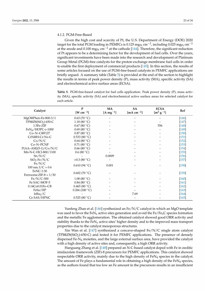
Energies 2022, 15, 3588 23 of 34
4.1.2. PGM-Free-Based
Given the high cost and scarcity of Pt, the U.S. Department of Energy (DOE) 2020target for the total PGM loading in PEMFCs is 0.125 mgPt cm−2, including 0.025 mgPt cm−2
at the anode and 0.100 mgPt cm−2 at the cathode [144]. Therefore, the significant reductionof Pt appears to be a determining factor for the development of fuel cells. Over the years,significant investments have been made into the research and development of PlatinumGroup Metal (PGM)-free catalysts for the proton exchange membrane fuel cells in orderto enable the first deployment of commercial products [145]. In this section, the results ofsome articles focused on the use of PGM-free-based catalysts in PEMFC applications arebriefly argued. A summary table (Table 5) is provided at the end of the section to highlightthe results in terms of peak power density (P), mass activity (MA), specific activity (SA)and electrochemical active surface areas (ECSA).
Table 5. PGM-free-based catalyst for fuel cells application: Peak power density (P), mass activ-ity (MA), specific activity (SA) and electrochemical active surface areas for selected catalyst foreach article.
Catalyst P[W cm−2]
MA[A mg−1]
SA[mA cm−2]
ECSA[m2 g−1] Ref
MgO@Phen-Fe-800-3/1 0.63 (70 ◦C) - - - [146]TPI@Z8(SiO2)-650-C 1.18 (80 ◦C) - - - [147]
1.5Fe-ZIF 0.67 (80 ◦C) - - 556 [148]FeN4/HOPC-c-1000 0.69 (80 ◦C) - - - [149]
Co–N–C@F127 0.87 (80 ◦C) - - - [150]CrN@H-Cr-Nx-C 0.533 (80 ◦C) - - - [151]
Co/N/C 0.64 (80 ◦C) - - - [152]Co–N–PCNF 0.71 (80 ◦C) - - - [153]
P(AA–AM)(5-1)/Co/N/C 0.66 (80 ◦C) - - - [154]Mn-N-C-HCl-800/1100 0.6 (80 ◦C) - - - [155]
Sn/N/C - 0.0009 - - [156]SiO2-Fe/N/C >0.3 (80 ◦C) - - - [157]
Fe/N/C100 nm; I/C = 0.6 0.610 (94 ◦C) 0.001 - - [158]
FeNC-1:30Ferrocene:ZIF-8 = 1/30 0.602 (70 ◦C) - - - [159]
Fe/N/C-300 1.08 (80 ◦C) - - - [160]Fe SAC-MOF-5 0.84 (80 ◦C) - - - [161]
0.14Co0.01Fe–CB 0.465 (80 ◦C) - - - [162]FeSa/HP 0.266 (240 ◦C) - - - [163]IrRu2/C - - 7.69 - [164]
Ce SAS/HPNC 0.525 (80 ◦C) - - - [165]
Yunfeng Zhan et al. [146] synthesized an Fe/N/C catalyst in which an MgO templatewas used to favor the FeNx active sites generation and avoid the Fe/Fe3C species formationand the metallic Fe agglomeration. The obtained catalyst showed good ORR activity andstability thanks to the FeNx active sites’ higher density and to the improved mass transportproperties due to the catalyst mesoporous structures.
Xin Wan et al. [147] synthesized a concave-shaped Fe/N/C single atom catalyst(TPI@Z8(SiO2)-650-C) and tested it for PEMFC applications. The presence of denselydispersed Fe-N4 moieties, and the large external surface area, have provided the catalystwith a high density of active sites and, consequently, a high ORR activity.
Hanguang Zhang et al. [148] prepared an N-C-based catalyst doped with Fe in zeoliticimidazolate framework (ZIF)-8 precursors for PEMFC applications. This catalyst showedrespectable ORR activity, mainly due to the high density of FeN4 species in the catalyst.The amount of Fe plays a fundamental role in obtaining a high density of the FeN4 species,as the authors found that too low an Fe amount in the precursors results in an insufficient
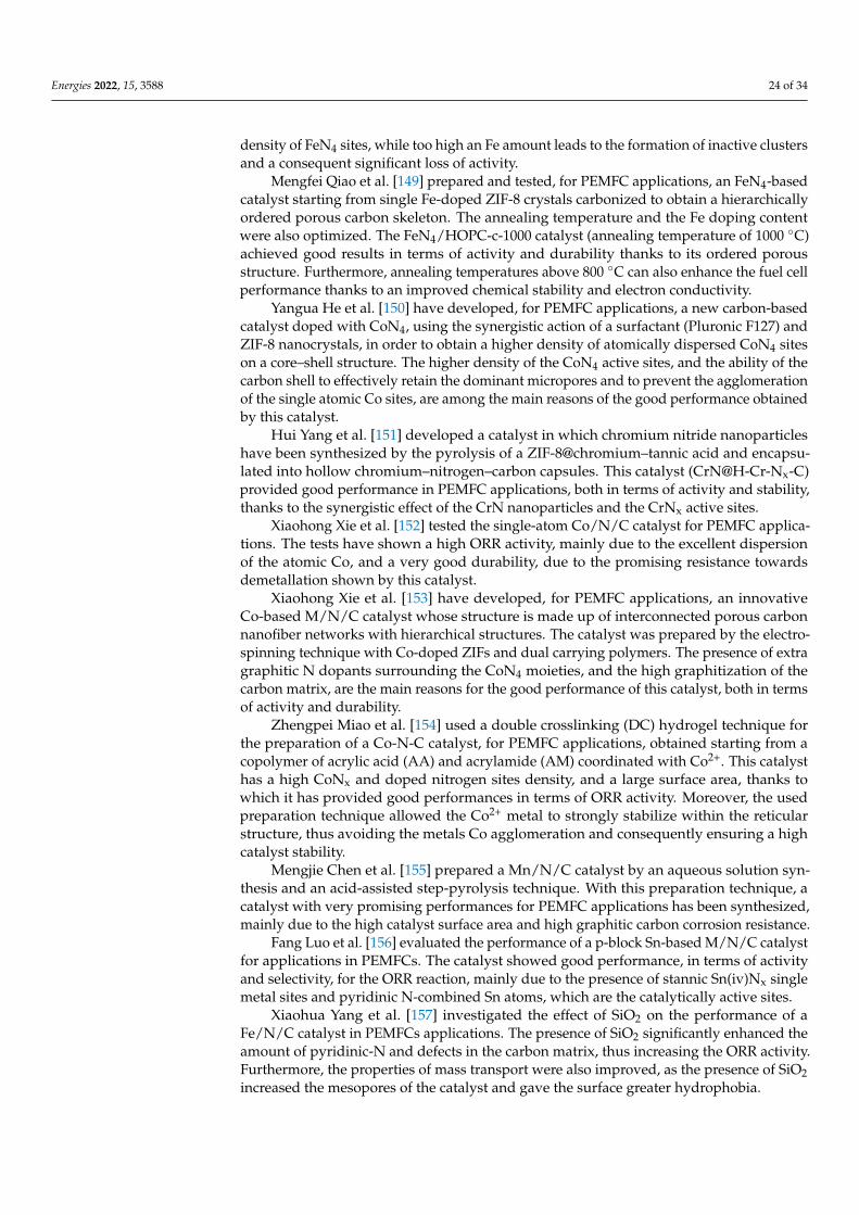
Energies 2022, 15, 3588 24 of 34
density of FeN4 sites, while too high an Fe amount leads to the formation of inactive clustersand a consequent significant loss of activity.
Mengfei Qiao et al. [149] prepared and tested, for PEMFC applications, an FeN4-basedcatalyst starting from single Fe-doped ZIF-8 crystals carbonized to obtain a hierarchicallyordered porous carbon skeleton. The annealing temperature and the Fe doping contentwere also optimized. The FeN4/HOPC-c-1000 catalyst (annealing temperature of 1000 ◦C)achieved good results in terms of activity and durability thanks to its ordered porousstructure. Furthermore, annealing temperatures above 800 ◦C can also enhance the fuel cellperformance thanks to an improved chemical stability and electron conductivity.
Yangua He et al. [150] have developed, for PEMFC applications, a new carbon-basedcatalyst doped with CoN4, using the synergistic action of a surfactant (Pluronic F127) andZIF-8 nanocrystals, in order to obtain a higher density of atomically dispersed CoN4 siteson a core–shell structure. The higher density of the CoN4 active sites, and the ability of thecarbon shell to effectively retain the dominant micropores and to prevent the agglomerationof the single atomic Co sites, are among the main reasons of the good performance obtainedby this catalyst.
Hui Yang et al. [151] developed a catalyst in which chromium nitride nanoparticleshave been synthesized by the pyrolysis of a ZIF-8@chromium–tannic acid and encapsu-lated into hollow chromium–nitrogen–carbon capsules. This catalyst (CrN@H-Cr-Nx-C)provided good performance in PEMFC applications, both in terms of activity and stability,thanks to the synergistic effect of the CrN nanoparticles and the CrNx active sites.
Xiaohong Xie et al. [152] tested the single-atom Co/N/C catalyst for PEMFC applica-tions. The tests have shown a high ORR activity, mainly due to the excellent dispersionof the atomic Co, and a very good durability, due to the promising resistance towardsdemetallation shown by this catalyst.
Xiaohong Xie et al. [153] have developed, for PEMFC applications, an innovativeCo-based M/N/C catalyst whose structure is made up of interconnected porous carbonnanofiber networks with hierarchical structures. The catalyst was prepared by the electro-spinning technique with Co-doped ZIFs and dual carrying polymers. The presence of extragraphitic N dopants surrounding the CoN4 moieties, and the high graphitization of thecarbon matrix, are the main reasons for the good performance of this catalyst, both in termsof activity and durability.
Zhengpei Miao et al. [154] used a double crosslinking (DC) hydrogel technique forthe preparation of a Co-N-C catalyst, for PEMFC applications, obtained starting from acopolymer of acrylic acid (AA) and acrylamide (AM) coordinated with Co2+. This catalysthas a high CoNx and doped nitrogen sites density, and a large surface area, thanks towhich it has provided good performances in terms of ORR activity. Moreover, the usedpreparation technique allowed the Co2+ metal to strongly stabilize within the reticularstructure, thus avoiding the metals Co agglomeration and consequently ensuring a highcatalyst stability.
Mengjie Chen et al. [155] prepared a Mn/N/C catalyst by an aqueous solution syn-thesis and an acid-assisted step-pyrolysis technique. With this preparation technique, acatalyst with very promising performances for PEMFC applications has been synthesized,mainly due to the high catalyst surface area and high graphitic carbon corrosion resistance.
Fang Luo et al. [156] evaluated the performance of a p-block Sn-based M/N/C catalystfor applications in PEMFCs. The catalyst showed good performance, in terms of activityand selectivity, for the ORR reaction, mainly due to the presence of stannic Sn(iv)Nx singlemetal sites and pyridinic N-combined Sn atoms, which are the catalytically active sites.
Xiaohua Yang et al. [157] investigated the effect of SiO2 on the performance of aFe/N/C catalyst in PEMFCs applications. The presence of SiO2 significantly enhanced theamount of pyridinic-N and defects in the carbon matrix, thus increasing the ORR activity.Furthermore, the properties of mass transport were also improved, as the presence of SiO2increased the mesopores of the catalyst and gave the surface greater hydrophobia.
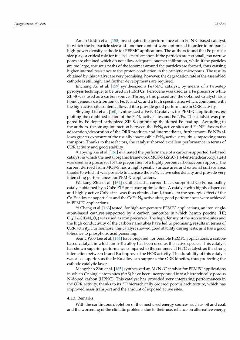
Energies 2022, 15, 3588 25 of 34
Aman Uddin et al. [158] investigated the performance of an Fe-N-C-based catalyst,in which the Fe particle size and ionomer content were optimized in order to prepare ahigh-power density cathode for PEFMC applications. The authors found that Fe particlesize plays a critical role for fuel cells performance. If the particles are too small, too narrowpores are obtained which do not allow adequate ionomer infiltration, while, if the particlesare too large, tortuous paths of the ionomer around the particles are formed, thus causinghigher internal resistance to the proton conduction in the catalytic micropores. The resultsobtained by this catalyst are very promising; however, the degradation rate of the assembledcathode is still high, and further developments are required.
Jinchang Xu et al. [159] synthesized a Fe/N/C catalyst, by means of a two-steppyrolysis technique, to be used in PEMFCs. Ferrocene was used as a Fe precursor whileZIF-8 was used as a carbon source. Through this procedure, the obtained catalyst has ahomogeneous distribution of Fe, N and C, and a high specific area which, combined withthe high active site content, allowed it to provide good performance in ORR activity.
Shiyang Liu et al. [160] synthesized a Fe-N-C catalyst, for PEMFC applications, ex-ploiting the combined action of the FeNx active sites and Fe NPs. The catalyst was pre-pared by Fe-doped carbonized ZIF-8, optimizing the doped Fe loading. According tothe authors, the strong interaction between the FeNx active sites and Fe NPs favors theadsorption/desorption of the ORR products and intermediates; furthermore, Fe NPs al-lows greater exposure of the usually inaccessible FeNx active sites, thus improving masstransport. Thanks to these factors, the catalyst showed excellent performance in terms ofORR activity and good stability.
Xiaoying Xie et al. [161] evaluated the performance of a carbon-supported Fe-basedcatalyst in which the metal organic framework MOF-5 (Zn4O(1,4-benzenedicarboxylate)3)was used as a precursor for the preparation of a highly porous carbonaceous support. Thecarbon derived from MOF-5 has a high specific surface area and external surface area,thanks to which it was possible to increase the FeNx active sites density and provide veryinteresting performances for PEMFC applications.
Weikang Zhu et al. [162] synthesized a carbon black-supported Co-Fe nanoalloycatalyst obtained by a CoFe-ZIF precursor optimization. A catalyst with highly dispersedand highly active CoFe sites was thus obtained and, thanks to the synergic effect of theCo-Fe alloy nanoparticles and the CoFe-Nx active sites, good performances were achievedin PEMFC applications.
Yi Cheng et al. [163] tested, for high-temperature PEMFC applications, an iron single-atom-based catalyst supported by a carbon nanotube in which hemin porcine (HP,C34H32ClFeN4O4) was used as iron precursor. The high density of the iron active sites andthe high conductivity of the carbon nanotubes have led to promising results in terms ofORR activity. Furthermore, this catalyst showed good stability during tests, as it has a goodtolerance to phosphoric acid poisoning.
Seung Woo Lee et al. [164] have prepared, for possible PEMFC applications, a carbon-based catalyst in which an Ir-Ru alloy has been used as the active species. This catalysthas shown superior performance compared to the commercial Pt/C catalyst, as the stronginteraction between Ir and Ru improves the HOR activity. The durability of this catalystwas also superior, as the Ir-Ru alloy can suppress the ORR kinetics, thus protecting thecathode catalytic layer.
Mengzhao Zhu et al. [165] synthesized an M/N/C catalyst for PEMFC applicationsin which Ce single atom sites (SAS) have been incorporated into a hierarchically porousN-doped carbon (HPNC). This catalyst has provided very interesting performances inthe ORR activity, thanks to its 3D hierarchically ordered porous architecture, which hasimproved mass transport and the amount of exposed active sites.
4.1.3. Remarks
With the continuous depletion of the most used energy sources, such as oil and coal,and the worsening of the climatic problems due to their use, reliance on alternative energy
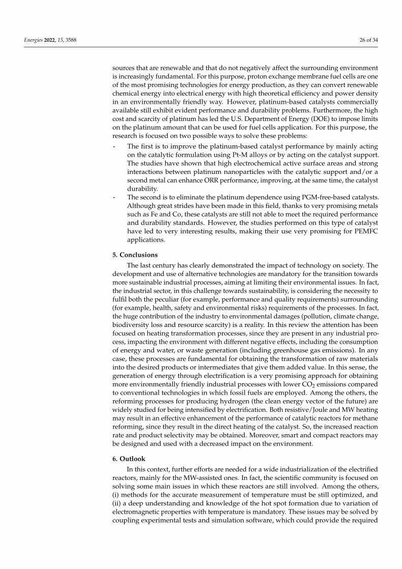
Energies 2022, 15, 3588 26 of 34
sources that are renewable and that do not negatively affect the surrounding environmentis increasingly fundamental. For this purpose, proton exchange membrane fuel cells are oneof the most promising technologies for energy production, as they can convert renewablechemical energy into electrical energy with high theoretical efficiency and power densityin an environmentally friendly way. However, platinum-based catalysts commerciallyavailable still exhibit evident performance and durability problems. Furthermore, the highcost and scarcity of platinum has led the U.S. Department of Energy (DOE) to impose limitson the platinum amount that can be used for fuel cells application. For this purpose, theresearch is focused on two possible ways to solve these problems:
- The first is to improve the platinum-based catalyst performance by mainly actingon the catalytic formulation using Pt-M alloys or by acting on the catalyst support.The studies have shown that high electrochemical active surface areas and stronginteractions between platinum nanoparticles with the catalytic support and/or asecond metal can enhance ORR performance, improving, at the same time, the catalystdurability.
- The second is to eliminate the platinum dependence using PGM-free-based catalysts.Although great strides have been made in this field, thanks to very promising metalssuch as Fe and Co, these catalysts are still not able to meet the required performanceand durability standards. However, the studies performed on this type of catalysthave led to very interesting results, making their use very promising for PEMFCapplications.
5. Conclusions
The last century has clearly demonstrated the impact of technology on society. Thedevelopment and use of alternative technologies are mandatory for the transition towardsmore sustainable industrial processes, aiming at limiting their environmental issues. In fact,the industrial sector, in this challenge towards sustainability, is considering the necessity tofulfil both the peculiar (for example, performance and quality requirements) surrounding(for example, health, safety and environmental risks) requirements of the processes. In fact,the huge contribution of the industry to environmental damages (pollution, climate change,biodiversity loss and resource scarcity) is a reality. In this review the attention has beenfocused on heating transformation processes, since they are present in any industrial pro-cess, impacting the environment with different negative effects, including the consumptionof energy and water, or waste generation (including greenhouse gas emissions). In anycase, these processes are fundamental for obtaining the transformation of raw materialsinto the desired products or intermediates that give them added value. In this sense, thegeneration of energy through electrification is a very promising approach for obtainingmore environmentally friendly industrial processes with lower CO2 emissions comparedto conventional technologies in which fossil fuels are employed. Among the others, thereforming processes for producing hydrogen (the clean energy vector of the future) arewidely studied for being intensified by electrification. Both resistive/Joule and MW heatingmay result in an effective enhancement of the performance of catalytic reactors for methanereforming, since they result in the direct heating of the catalyst. So, the increased reactionrate and product selectivity may be obtained. Moreover, smart and compact reactors maybe designed and used with a decreased impact on the environment.
6. Outlook
In this context, further efforts are needed for a wide industrialization of the electrifiedreactors, mainly for the MW-assisted ones. In fact, the scientific community is focused onsolving some main issues in which these reactors are still involved. Among the others,(i) methods for the accurate measurement of temperature must be still optimized, and(ii) a deep understanding and knowledge of the hot spot formation due to variation ofelectromagnetic properties with temperature is mandatory. These issues may be solved bycoupling experimental tests and simulation software, which could provide the required
Energies 2022, 15, 3588 27 of 34
information for low-cost process intensification, but the modeling tools must be furtheroptimized, too, in order to give more precise predictions of the electrified catalytic systems.
Among fuel cells, proton exchange membrane fuel cells can be considered a ma-ture technology for large-scale applications, including for the automotive industry andportable devices. However, further efforts are needed to design efficient and low-costcatalytic systems.
The integration of the different reviewed systems in the way, for example, of a dis-tributed hydrogen production is possible, but only if some main engineering challengesare solved. In fact, (i) the integration of the electrified methane reforming unit with thePEMFC to maximize the energy efficiency may be obtained only if H2 is effectively sep-arated from the stream exiting the electrified reactor (for example, by using a water–gasshift stage after the reaction step, or a membrane for the H2 separation) in order to feedhigh-purity hydrogen, and (ii) more robust and high performing catalysts with a longlifetime are necessary.
Thus, as an important contribution to a sustainable future, the industry and its prod-ucts can be adapted to a circular economy—a system aimed at eliminating waste, circulatingand recycling products, and saving resources and the environment.
Author Contributions: Conceptualization, E.M., M.M., G.I., C.R., S.R., G.F. and V.P.; methodology,E.M., M.M., G.I., C.R., S.R., G.F. and V.P.; software, E.M., M.M., G.I., C.R., S.R., G.F. and V.P.; validation,E.M., M.M., G.I., C.R., S.R., G.F. and V.P.; formal analysis, E.M., M.M., G.I., C.R., S.R., G.F. and V.P.;investigation, E.M., M.M., G.I., C.R., S.R., G.F. and V.P.; resources, E.M., M.M., G.I., C.R., S.R., G.F.and V.P.; data curation, E.M., M.M., G.I., C.R., S.R., G.F. and V.P.; writing—original draft preparation,E.M., M.M., G.I., C.R., S.R., G.F. and V.P.; writing—review and editing, E.M., M.M., G.I., C.R., S.R.,G.F. and V.P.; visualization, E.M., M.M., G.I., C.R., S.R., G.F. and V.P.; supervision, E.M., M.M., G.I.,C.R., S.R., G.F. and V.P.; project administration, E.M., M.M., G.I., C.R., S.R., G.F. and V.P. All authorshave read and agreed to the published version of the manuscript.
Funding: This research was funded by PRIN (Progetti di ricerca di Rilevante Interesse Nazionale)—Bando 2020 Prot. 2020N38E75 “Process for Low-carbon blUe & green hydrogen Generation viaIntensified electrified reforming of Natural gas/biogas (PLUG-IN)”.
Institutional Review Board Statement: Not applicable.
Informed Consent Statement: Not applicable.
Data Availability Statement: Not applicable.
Acknowledgments: The authors would like to thank PRIN (Progetti di ricerca di Rilevante Inter-esse Nazionale)—Bando 2020 Prot. 2020N38E75 “Process for Low-carbon blUe & green hydrogenGeneration via Intensified electrified reforming of Natural gas/biogas (PLUG-IN)”.
Conflicts of Interest: The authors declare no conflict of interest.
Nomenclature
CA Carbon aerogelCB Carbon blackCE Conversion efficiencyDC Direct currentDOE Department of EnergyDRM Dry reforming of methaneEin Electrical energy input to the catalyst in kWECSA Electrochemical active surface areas
Energies 2022, 15, 3588 28 of 34
ER Electrical energyFM Inlet methane flow in mL min−1
HOPC Hierarchically ordered porous carbonHOR Hydrogen oxidation reactionHPNC Hierarchically porous N-doped carbonMA Mass activityMOF Metal organic frameworkMW MicrowaveN Molar ratio of H2 produced to CH4 convertedORR Oxygen reduction reactionP Peak power densityPECNTs Partially exfoliated carbon nanotubesPEMFCs Proton Exchange Membrane Fuel CellsPGM Platinum group metalPOM Partial oxidation of methanePTR Parallel tube reactorPW Parallel wirerEGO Reduced electrochemically exfoliated graphene oxideSA Surface activitySAS Single atom sitesSiC Silicon carbideSRM Steam reforming of methaneZIF Zeolitic imidazolate framework
References1. Stankiewicz, A.I.; Nigar, H. Beyond electrolysis: Old challenges and new concepts of electricity-driven chemical reactors. React.
Chem. Eng. 2020, 5, 1005–1016. [CrossRef]2. Sapountzi, F.; Tsampas, M.; Fredriksson, H.; Gracia, J.; Niemantsverdriet, H. Hydrogen from electrochemical reforming of C1–C3
alcohols using proton conducting membranes. Int. J. Hydrogen Energy 2017, 42, 10762–10774. [CrossRef]3. Mahmood, N.; Yao, Y.; Zhang, J.-W.; Pan, L.; Zhang, X.; Zou, J.-J. Electrocatalysts for Hydrogen Evolution in Alkaline Electrolytes:
Mechanisms, Challenges, and Prospective Solutions. Adv. Sci. 2017, 5, 1700464. [CrossRef] [PubMed]4. Jhong, H.-R.; Ma, S.; Kenis, P.J. Electrochemical conversion of CO2 to useful chemicals: Current status, remaining challenges, and
future opportunities. Curr. Opin. Chem. Eng. 2013, 2, 191–199. [CrossRef]5. Sequeira, C.A.C.; Santos, D.M.F. Electrochemical routes for industrial synthesis. J. Braz. Chem. Soc. 2009, 20, 387–406. [CrossRef]6. Ding, Q.; Song, B.; Xu, P.; Jin, S. Efficient Electrocatalytic and Photoelectrochemical Hydrogen Generation Using MoS2 and
Related Compounds. Chem 2016, 1, 699–726. [CrossRef]7. Iervolino, G.; Tantis, I.; Sygellou, L.; Vaiano, V.; Sannino, D.; Lianos, P. Photocurrent increase by metal modification of Fe2O3
photoanodes and its effect on photoelectrocatalytic hydrogen production by degradation of organic substances. Appl. Surf. Sci.2017, 400, 176–183. [CrossRef]
8. Iervolino, G.; Vaiano, V.; Rizzo, L. Visible light active Fe-doped TiO2 for the oxidation of arsenite to arsenate in drinking water.Chem. Eng. Trans. 2018, 70, 1573–1578.
9. Iervolino, G.; Vaiano, V.; Pepe, G.; Campiglia, P.; Palma, V. Degradation of Acid Orange 7 Azo Dye in Aqueous Solution by aCatalytic-Assisted, Non-Thermal Plasma Process. Catalysts 2020, 10, 888. [CrossRef]
10. Palma, V.; Cortese, M.; Renda, S.; Ruocco, C.; Martino, M.; Meloni, E. A Review about the Recent Advances in SelectedNonThermal Plasma Assisted Solid–Gas Phase Chemical Processes. Nanomaterials 2020, 10, 1596. [CrossRef]
11. Zhou, D.; Zhou, R.; Zhou, R.; Liu, B.; Zhang, T.; Xian, Y.; Cullen, P.J.; Lu, X.; Ostrikov, K. Sustainable ammonia production bynon-thermal plasmas: Status, mechanisms, and opportunities. Chem. Eng. J. 2021, 421, 129544. [CrossRef]
12. Spagnolo, D.; Cornett, L.; Chuang, K. Direct electro-steam reforming: A novel catalytic approach. Int. J. Hydrogen Energy 1992, 17,839–846. [CrossRef]
13. López, E.; Divins, N.J.; Anzola, A.; Schbib, S.; Borio, D.; Llorca, J. Ethanol steam reforming for hydrogen generation overstructured catalysts. Int. J. Hydrogen Energy 2013, 38, 4418–4428. [CrossRef]
14. Ricca, A.; Palma, V.; Martino, M.; Meloni, E. Innovative catalyst design for methane steam reforming intensification. Fuel 2017,198, 175–182. [CrossRef]
15. Renda, S.; Cortese, M.; Iervolino, G.; Martino, M.; Meloni, E.; Palma, V. Electrically driven SiC-based structured catalysts forintensified reforming processes. Catal. Today 2022, 383, 31–43. [CrossRef]
16. Balzarotti, R.; Ambrosetti, M.; Beretta, A.; Groppi, G.; Tronconi, E. Investigation of packed conductive foams as a novel reactorconfiguration for methane steam reforming. Chem. Eng. J. 2019, 391, 123494. [CrossRef]
17. Sanz, O.; Velasco, I.; Reyero, I.; Legorburu, I.; Arzamendi, G.; Gandía, L.M.; Montes, M. Effect of the thermal conductivity ofmetallic monoliths on methanol steam reforming. Catal. Today 2016, 273, 131–139. [CrossRef]
Energies 2022, 15, 3588 29 of 34
18. Goyal, H.; Chen, T.-Y.; Chen, W.; Vlachos, D.G. A review of microwave-assisted process intensified multiphase reactors. Chem.Eng. J. 2021, 430, 133183. [CrossRef]
19. Newman, J.; Bonino, C.A.; Trainham, J.A. The energy future. Ann. Rev. Chem. Biomol. Eng. 2018, 9, 153–174. [CrossRef]20. Jones, D.A.; Lelyveld, T.P.; Mavrofidis, S.W.; Kingman, S.W.; Miles, N.J. Microwave heating applications in environmental
engineering—A review. Resour. Conserv. Recycl. 2001, 34, 75–90. [CrossRef]21. Hu, J.; Wildfire, C.; Stiegman, A.E.; Dagle, R.A.; Shekhawat, D.; Abdelsayed, V.; Bai, X.; Tian, H.; Bogle, M.B.; Hsu, C.; et al.
Microwave-driven heterogeneous catalysis for activation of dinitrogen to ammonia under atmospheric pressure. Chem. Eng. J.2020, 397, 125388. [CrossRef]
22. Luque, R.; Menendez, J.A.; Arenillas, A.; Cot, J. Microwave-assisted pyrolysis of biomass feedstocks: The way forward? EnergyEnviron. Sci. 2012, 5, 5481–5488. [CrossRef]
23. Julian, I.; Ramirez, H.; Hueso, J.L.; Mallada, R.; Santamaria, J. Non-oxidative methane conversion in microwave-assistedstructured reactors. Chem. Eng. J. 2019, 377, 119764. [CrossRef]
24. Zhang, F.; Zhang, X.; Song, Z.; Chen, H.; Zhao, X.; Sun, J.; Mao, Y.; Wang, X.; Wang, W. Fe/HZSM-5 synergizes with biomasspyrolysis carbon to reform CH4–CO2 to syngas in microwave field. Int. J. Hydrogen Energy 2022, 47, 11153–11163. [CrossRef]
25. De Bruyn, M.; Budarin, V.L.; Sturm, G.S.J.; Stefanidis, G.D.; Radoiu, M.; Stankiewicz, A.; Macquarrie, D.J. Subtle Microwave-Induced Overheating Effects in an Industrial Demethylation Reaction and Their Direct Use in the Development of an InnovativeMicrowave Reactor. J. Am. Chem. Soc. 2017, 139, 5431–5436. [CrossRef] [PubMed]
26. Horikoshi, S.; Osawa, A.; Sakamoto, S.; Serpone, N. Control of microwave-generated hot spots. Part V. Mechanisms of hot-spotgeneration and aggregation of catalyst in a microwave-assisted reaction in toluene catalyzed by Pd-loaded AC particulates. Appl.Catal. A Gen. 2013, 460–461, 52–60. [CrossRef]
27. Musho, T.; Wildfire, C.; Houlihan, N.M.; Sabolsky, E.M.; Shekhawat, D. Study of Cu2O particle morphology on microwave fieldenhancement. Mater. Chem. Phys. 2018, 216, 278–284. [CrossRef]
28. Chen, W.; Gutmann, B.; Kappe, C.O. Characterization of Microwave-Induced Electric Discharge Phenomena in Metal-SolventMixtures. ChemistryOpen 2012, 1, 39–48. [CrossRef]
29. Horikoshi, S.; Osawa, A.; Abe, M.; Serpone, N. On the Generation of Hot-Spots by Microwave Electric and Magnetic Fields andTheir Impact on a Microwave-Assisted Heterogeneous Reaction in the Presence of Metallic Pd Nanoparticles on an ActivatedCarbon Support. J. Phys. Chem. C 2011, 115, 23030–23035. [CrossRef]
30. Horikoshi, S.; Suttisawat, Y.; Osawa, A.; Takayama, C.; Chen, X.; Yang, S.; Sakai, H.; Abe, M.; Serpone, N. Organic synthesesby microwave selective heating of novel metal/CMC catalysts–The Suzuki-Miyaura coupling reaction in toluene and thedehydrogenation of tetralin in solvent-free media. J. Catal. 2012, 289, 266–271. [CrossRef]
31. Horikoshi, S.; Osawa, A.; Sakamoto, S.; Serpone, N. Control of microwave generated hot spots. Part IV. Control of hot spots on aheterogeneous microwaveabsorber catalyst surface by a hybrid internal/external heating method. Chem. Eng. Process. ProcessIntensif. 2013, 69, 52–56. [CrossRef]
32. Zhang, X.; Hayward, D.O.; Mingos, D.M.P. Apparent equilibrium shifts and hot-spot formation for catalytic reactions induced bymicrowave dielectric heating. Chem. Commun. 1999, 11, 975–976. [CrossRef]
33. Horikoshi, S.; Kamata, M.; Mitani, T.; Serpone, N. Control of Microwave-Generated Hot Spots. 6. Generation of Hot Spots inDispersed Catalyst Particulates and Factors That Affect Catalyzed Organic Syntheses in Heterogeneous Media. Ind. Eng. Chem.Res. 2014, 53, 14941–14947. [CrossRef]
34. Suttisawat, Y.; Horikoshi, S.; Sakai, H.; Abe, M. Hydrogen production from tetralin over microwave-accelerated Pt-supportedactivated carbon. Int. J. Hydrogen Energy 2010, 35, 6179–6183. [CrossRef]
35. Suttisawat, Y.; Horikoshi, S.; Sakai, H.; Rangsunvigit, P.; Abe, M. Enhanced conversion of tetralin dehydrogenation undermicrowave heating: Effects of temperature variation. Fuel Process. Technol. 2011, 95, 27–32. [CrossRef]
36. Horikoshi, S.; Kamata, M.; Sumi, T.; Serpone, N. Selective heating of Pd/AC catalyst in heterogeneous systems for the microwave-assisted continuous hydrogen evolution from organic hydrides: Temperature distribution in the fixed-bed reactor. Int. J. HydrogenEnergy 2016, 41, 12029–12037. [CrossRef]
37. Manno, R.; Sebastian, V.; Mallada, R.; Santamaria, J.S. 110th Anniversary: Nucleation of Ag Nanoparticles in Helical MicrofluidicReactor. Comparison between Microwave and Conventional Heating. Ind. Eng. Chem. Res. 2019, 58, 12702–12711. [CrossRef]
38. Ramirez, A.; Hueso, J.L.; Abian, M.; Alzueta, M.U.; Mallada, R.; Santamaria, J. Escaping undesired gas-phase chemistry:Microwave-driven selectivity enhancement in heterogeneous catalytic reactors. Sci. Adv. 2019, 5, eaau9000. [CrossRef]
39. Meloni, E.; Martino, M.; Ricca, A.; Palma, V. Ultracompact methane steam reforming reactor based on microwaves susceptiblestructured catalysts for distributed hydrogen production. Int. J. Hydrogen Energy 2020, 46, 13729–13747. [CrossRef]
40. Ramirez, A.; Hueso, J.L.; Mallada, R.; Santamaria, J. In situ temperature measurements in microwave-heated gas-solid catalyticsystems. Detection of hot spots and solid-fluid temperature gradients in the ethylene epoxidation reaction. Chem. Eng. J. 2017,316, 50–60. [CrossRef]
41. Ramirez, A.; Hueso, J.L.; Mallada, R.; Santamaria, J. Microwave-activated structured reactors to maximize propylene selectivity inthe oxidative dehydrogenation of propane. Chem. Eng. J. 2020, 393, 124746. [CrossRef]
42. Suttisawat, Y.; Sakai, H.; Abe, M.; Rangsunvigit, P.; Horikoshi, S. Microwave effect in the dehydrogenation of tetralin and decalinwith a fixed-bed reactor. Int. J. Hydrogen Energy 2012, 37, 3242–3250. [CrossRef]
Energies 2022, 15, 3588 30 of 34
43. Haneishi, N.; Tsubaki, S.; Abe, E.; Maitani, M.M.; Suzuki, E.-I.; Fujii, S.; Fukushima, J.; Takizawa, H.; Wada, Y. Enhancement ofFixed-bed Flow Reactions under Microwave Irradiation by Local Heating at the Vicinal Contact Points of Catalyst Particles. Sci.Rep. 2019, 9, 222. [CrossRef] [PubMed]
44. Durka, T.; Stefanidis, G.D.; Van Gerven, T.; Stankiewicz, A.I. Microwave-activated methanol steam reforming for hydrogenproduction. Int. J. Hydrogen Energy 2011, 36, 12843–12852. [CrossRef]
45. Meloni, E.; Martino, M.; Pullumbi, P.; Brandani, F.; Palma, V. Intensification of TSA processes using a microwave-assistedregeneration step. Chem. Eng. Process. Process Intensif. 2020, 160, 108291. [CrossRef]
46. Ergan, B.T.; Bayramoglu, M.; Özcan, S. Emulsion polymerization of styrene under continuous microwave irradiation. Eur. Polym.J. 2015, 69, 374–384. [CrossRef]
47. Ricciardi, L.; Verboom, W.; Lange, J.; Huskens, J. Reactive Extraction Enhanced by Synergic Microwave Heating: Furfural YieldBoost in Biphasic Systems. ChemSusChem 2020, 13, 3589–3593. [CrossRef]
48. Motasemi, F.; Gerber, A.G. Multicomponent conjugate heat and mass transfer in biomass materials during microwave pyrolysisfor biofuel production. Fuel 2018, 211, 649–660. [CrossRef]
49. Aguilera, A.F.; Tolvanen, P.; Eränen, K.; Wärnå, J.; Leveneur, S.; Marchant, T.; Salmi, T. Kinetic modelling of Prileschajewepoxidation of oleic acid under conventional heating and microwave irradiation. Chem. Eng. Sci. 2019, 199, 426–438. [CrossRef]
50. Aguilera, A.F.; Tolvanen, P.; Wärnå, J.; Leveneur, S.; Salmi, T. Kinetics and reactor modelling of fatty acid epoxidation in thepresence of heterogeneous catalyst. Chem. Eng. J. 2019, 375, 121936. [CrossRef]
51. Li, H.; Zhao, Z.; Xiouras, C.; Stefanidis, G.D.; Li, X.; Gao, X. Fundamentals and applications of microwave heating to chemicalsseparation processes. Renew. Sustain. Energy Rev. 2019, 114, 109316. [CrossRef]
52. Palma, V.; Barba, D.; Cortese, M.; Martino, M.; Renda, S.; Meloni, E. Microwaves and Heterogeneous Catalysis: A Review onSelected Catalytic Processes. Catalysts 2020, 10, 246. [CrossRef]
53. Enger, B.C.; Lødeng, R.; Holmen, A. A review of catalytic partial oxidation of methane to synthesis gas with emphasis on reactionmechanisms over transition metal catalysts. Appl. Catal. A Gen. 2008, 346, 1–27. [CrossRef]
54. Fisher, F.; Tropsch, H. Conversion of methane into hydrogen and carbon monoxide. Brennst.-Chem. 1928, 9, 39–46.55. Reitmeier, R.E.; Atwood, K.; Bennett, H.; Baugh, H. Production of synthetic gas-reaction of light hydrocarbons with steam and
carbon dioxide. Ind. Eng. Chem. 1948, 40, 620–626. [CrossRef]56. Lewis, W.K.; Gilliland, E.R.; Reed, W.A. Reaction of methane with copper oxide in a fluidized bed. Ind. Eng. Chem. 1949, 41,
1227–1237. [CrossRef]57. Li, F.; Ao, M.; Pham, G.H.; Jin, Y.; Nguyen, M.H.; Alawi, N.M.; Tade, M.O.; Liu, S. A novel UiO-66 encapsulated 12-silicotungstic
acid catalyst for dimethyl ether synthesis from syngas. Catal. Today 2020, 355, 3–9. [CrossRef]58. de García, I.D.; Stankiewicz, A.; Nigar, H. Syngas production via microwave-assisted dry reforming of methane. Catal. Today
2020, 362, 72–80. [CrossRef]59. Pakhare, D.; Spivey, J. A review of dry (CO2) reforming of methane over noble metal catalysts. Chem. Soc. Rev. 2014, 43, 7813–7837.
[CrossRef]60. Meloni, E.; Martino, M.; Palma, V. A Short Review on Ni Based Catalysts and Related Engineering Issues for Methane Steam
Reforming. Catalysts 2020, 10, 352. [CrossRef]61. Etminan, A.; Sadrnezhaad, S.K. A two step Microwave-assisted coke resistant mesoporous Ni-Co catalyst for methane steam
reforming. Fuel 2022, 317, 122411. [CrossRef]62. Sokolov, S.; Kondratenko, E.V.; Pohl, M.-M.; Barkschat, A.; Rodemerck, U. Stable low-temperature dry reforming of methane over
mesoporous La2O3-ZrO2 supported Ni catalyst. Appl. Catal. B Environ. 2012, 113, 19–30. [CrossRef]63. Baudouin, D.; Rodemerck, U.; Krumeich, F.; Mallmann, A.D.; Szeto, K.C.; Ménard, H.; Veyre, L.; Candy, J.-P.; Webb, P.B.; Thieuleux,
C.; et al. Particle size effect in the low temperature reforming of methane by carbon dioxide on silica-supported Ni nanoparticles.J. Catal. 2013, 297, 27–34. [CrossRef]
64. Matsumura, Y.; Nakamori, T. Steam reforming of methane over nickel catalysts at low reaction temperature. Appl. Catal. A Gen.2004, 258, 107–114. [CrossRef]
65. An, Y.; Dou, J.; Tian, L.; Zhao, X.; Yu, J. Role of microwave during microwave-assisted catalytic reforming of guaiacol, syringolbio-oil as model compounds. J. Anal. Appl. Pyrolysis 2021, 158, 105290. [CrossRef]
66. Nguyen, H.M.; Sunarso, J.; Li, C.; Pham, G.H.; Phan, C.; Liu, S. Microwave-assisted catalytic methane reforming: A review. Appl.Catal. A Gen. 2020, 599, 117620. [CrossRef]
67. Díaz-Ortiz, Á.; Prieto, P.; de la Hoz, A. A critical overview on the effect of microwave irradiation in organic synthesis. Chem. Rec.2019, 19, 85–97. [CrossRef]
68. Xu, W.; Zhou, J.; Ou, Y.; Luo, Y.; You, Z. Microwave selective effect: A new approach towards oxygen inhibition removal forhighly-effective NO decomposition by Microwave catalysis over BaMnxMg1−xO3 mixed oxides at low temperature under excessoxygen. Chem. Commun. 2015, 51, 4073–4076. [CrossRef]
69. Xu, W.; Wang, Q.; Peng, K.; Chen, F.; Han, X.; Wang, X.; Zhou, J. Development of MgCo2O4–BaCO3 composites as microwavecatalysts for the highly effective direct decomposition of NO under excess O2 at a low temperature. Catal. Sci. Technol. 2019, 9,4276–4285. [CrossRef]
70. Garcia-Costa, A.L.; Zazo, J.A.; Casas, J.A. Microwave-assisted catalytic wet peroxide oxidation: Energy optimization. Sep. Purif.Technol. 2019, 215, 62–69. [CrossRef]
Energies 2022, 15, 3588 31 of 34
71. Nozariasbmarz, A.; Dsouza, K.; Vashaee, D. Field induced decrystallization of silicon: Evidence of a microwave non-thermaleffect. Appl. Phys. Lett. 2018, 112, 093103. [CrossRef]
72. Einaga, H.; Nasu, Y.; Oda, M.; Saito, H. Catalytic performances of perovskite oxides for CO oxidation under microwave irradiation.Chem. Eng. J. 2016, 283, 97–104. [CrossRef]
73. Stuerga, D.A.C.; Gaillard, P. Microwave Athermal Effects in Chemistry: A Myth’s Autopsy: Part II: Orienting effects andthermodynamic consequences of electric field. J. Microw. Power Electromagn. Energy 1996, 31, 101–113. [CrossRef]
74. Stuerga, D.A.C.; Gaillard, P. Microwave Athermal Effects in Chemistry: A Myth’s Autopsy: Part I: Historical background andfundamentals of wave-matter interaction. J. Microw. Power Electromagn. Energy 1996, 31, 87–100. [CrossRef]
75. Xu, W.; Zhou, J.; Su, Z.; Ou, Y.; You, Z. Microwave catalytic effect: A new exact reason for microwave-driven heterogeneousgas-phase catalytic reactions. Catal. Sci. Technol. 2015, 6, 698–702. [CrossRef]
76. Bai, X.; Robinson, B.; Killmer, C.; Wang, Y.; Li, L.; Hu, J. Microwave catalytic reactor for upgrading stranded shale gas to aromatics.Fuel 2019, 243, 485–492. [CrossRef]
77. Hunt, J.; Ferrari, A.; Lita, A.; Crosswhite, M.; Ashley, B.; Stiegman, A.E. Microwave-Specific Enhancement of the Carbon–CarbonDioxide (Boudouard) Reaction. J. Phys. Chem. C 2013, 117, 26871–26880. [CrossRef]
78. Bai, X.; Muley, P.D.; Musho, T.; Abdelsayed, V.; Robinson, B.; Caiola, A.; Shekhawat, D.; Jiang, C.; Hu, J. A combined experimentaland modeling study of Microwave-assisted methane dehydroaromatization process. Chem. Eng. J. 2022, 433, 134445. [CrossRef]
79. Goyal, H.; Mehdad, A.; Lobo, R.F.; Stefanidis, G.; Vlachos, D.G. Scaleup of a Single-Mode Microwave Reactor. Ind. Eng. Chem.Res. 2019, 59, 2516–2523. [CrossRef]
80. Sturm, G.S.J.; Verweij, M.D.; Van Gerven, T.; Stankiewicz, A.I.; Stefanidis, G. On the effect of resonant microwave fields ontemperature distribution in time and space. Int. J. Heat Mass Transf. 2012, 55, 3800–3811. [CrossRef]
81. Chen, T.-Y.; Baker-Fales, M.; Vlachos, D.G. Operation and Optimization of Microwave-Heated Continuous-Flow Microfluidics.Ind. Eng. Chem. Res. 2020, 59, 10418–10427. [CrossRef]
82. Malhotra, A.; Chen, W.; Goyal, H.; Plaza-Gonzalez, P.J.; Julian, I.; Catala-Civera, J.M.; Vlachos, D.G. Temperature Homogeneityunder Selective and Localized Microwave Heating in Structured Flow Reactors. Ind. Eng. Chem. Res. 2021, 60, 6835–6847.[CrossRef]
83. Robinson, J.; Kingman, S.; Irvine, D.; Licence, P.; Smith, A.; Dimitrakis, G.; Obermayer, D.; Kappe, C.O. Electromagneticsimulations of microwave heating experiments using reaction vessels made out of silicon carbide. Phys. Chem. Chem. Phys. 2010,12, 10793–10800. [CrossRef] [PubMed]
84. Sanz-Moral, L.M.; Navarrete, A.; Sturm, G.; Link, G.; Rueda, M.; Stefanidis, G.; Martín, Á. Release of hydrogen from nanoconfinedhydrides by application of microwaves. J. Power Sources 2017, 353, 131–137. [CrossRef]
85. Nigar, H.; Sturm, G.S.J.; Garcia-Baños, B.; Peñaranda-Foix, F.L.; Catalá-Civera, J.M.; Mallada, R.; Stankiewicz, A.; Santamaría, J.Numerical analysis of microwave heating cavity: Combining electromagnetic energy, heat transfer and fluid dynamics for a NaYzeolite fixed-bed. Appl. Therm. Eng. 2019, 155, 226–238. [CrossRef]
86. Zhang, C.; Liao, L.; Gong, S.S. Recent developments in microwave-assisted polymerization with a focus on ring-openingpolymerization. Green Chem. 2007, 9, 303–314. [CrossRef]
87. Ebner, C.; Bodner, T.; Stelzer, F.; Wiesbrock, F. One Decade of Microwave-Assisted Polymerizations: Quo vadis? Macromol. RapidCommun. 2011, 32, 254–288. [CrossRef]
88. Hoogenboom, R.; Schubert, U.S. Microwave-Assisted Polymer Synthesis: Recent Developments in a Rapidly Expanding Field ofResearch. Macromol. Rapid Commun. 2007, 28, 368–386. [CrossRef]
89. Van Putten, R.-J.; Van Der Waal, J.C.; De Jong, E.; Rasrendra, C.B.; Heeres, H.J.; De Vries, J.G. Hydroxymethylfurfural, A VersatilePlatform Chemical Made from Renewable Resources. Chem. Rev. 2013, 113, 1499–1597. [CrossRef]
90. Caratzoulas, S.; Davis, M.E.; Gorte, R.J.; Gounder, R.; Lobo, R.F.; Nikolakis, V.; Sandler, S.I.; Snyder, M.A.; Tsapatsis, M.; Vlachos,D.G. Challenges of and Insights into Acid-Catalyzed Transformations of Sugars. J. Phys. Chem. C 2014, 118, 22815–22833.[CrossRef]
91. Chen, T.-Y.; Cheng, Z.; Desir, P.; Saha, B.; Vlachos, D.G. Fast microflow kinetics and acid catalyst deactivation in glucoseconversion to 5-hydroxymethylfurfural. React. Chem. Eng. 2020, 6, 152–164. [CrossRef]
92. Palma, V.; Martino, M.; Meloni, E.; Ricca, A. Novel structured catalysts configuration for intensification of steam reforming ofmethane. Int. J. Hydrogen Energy 2017, 42, 1629–1638. [CrossRef]
93. Bianchi, E.; Heidig, T.; Visconti, C.G.; Groppi, G.; Freund, H.; Tronconi, E. An appraisal of the heat transfer properties of metallicopen-cell foams for strongly exo-/endo-thermic catalytic processes in tubular reactors. Chem. Eng. J. 2012, 198–199, 512–528.[CrossRef]
94. Ramírez, A.; Hueso, J.L.; Mallada, R.; Santamaría, J. Ethylene epoxidation in microwave heated structured reactors. Catal. Today2016, 273, 99–105. [CrossRef]
95. Palma, V.; Ricca, A.; Martino, M.; Meloni, E. Innovative structured catalytic systems for methane steam reforming intensification.Chem. Eng. Process. Process Intensif. 2017, 120, 207–215. [CrossRef]
96. Zhang, H.; Geerlings, H.; Lin, J.; Chin, W.S. Rapid microwave hydrogen release from MgH2 and other hydrides. Int. J. HydrogenEnergy 2011, 36, 7580–7586. [CrossRef]
97. Mao, Y.; Yang, S.; Xue, C.; Zhang, M.; Wang, W.; Song, Z.; Zhao, X.; Sun, J. Rapid degradation of malachite green by CoFe2O4–SiCfoam under microwave radiation. R. Soc. Open Sci. 2018, 5, 180085. [CrossRef]

Energies 2022, 15, 3588 32 of 34
98. Gangurde, L.S.; Sturm, G.S.J.; Valero-Romero, M.J.; Mallada, R.; Santamaria, J.; Stankiewicza, A.I.; Stefanidis, G.D. Synthesis,characterization, and application of ruthenium-doped SrTiO3 perovskite catalysts for microwave-assisted methane dry reforming.Chem. Eng. Process. Process Intensif. 2018, 127, 178–190. [CrossRef]
99. Marin, C.M.; Popczun, E.J.; Nguyen-Phan, T.-D.; De Tafen, N.; Alfonso, D.; Waluyo, I.; Hunt, A.; Kauffman, D.R. Designingperovskite catalysts for controlled active-site exsolution in the microwave dry reforming of methane. Appl. Catal. B Environ. 2020,284, 119711. [CrossRef]
100. Nguyen, H.M.; Pham, G.H.; Tade, M.; Phan, C.; Vagnoni, R.; Liu, S. Microwave-Assisted Dry and Bi-reforming of Methane overM–Mo/TiO2 (M = Co, Cu) Bimetallic Catalysts. Energy Fuels 2020, 34, 7284–7294. [CrossRef]
101. Li, R.; Xu, W.; Deng, J.; Zhou, J. Coke-Resistant Ni−Co/ZrO2−CaO-Based Microwave Catalyst for Highly Effective DryReforming of Methane by Microwave Catalysis. Ind. Eng. Chem. Res. 2021, 60, 17458–17468. [CrossRef]
102. Sharifvaghefi, S.; Shirani, B.; Eic, M.; Zheng, Y. Application of Microwave in Hydrogen Production from Methane Dry Reforming:Comparison between the Conventional and Microwave-Assisted Catalytic Reforming on Improving the Energy Efficiency.Catalysts 2019, 9, 618. [CrossRef]
103. Chen, W.; Malhotra, A.; Yu, K.; Zheng, W.; Plaza-Gonzalez, P.J.; Catala-Civera, J.M.; Santamaria, J.; Vlachos, D.G. Intensifiedmicrowave-assisted heterogeneous catalytic reactors for sustainable chemical manufacturing. Chem. Eng. J. 2021, 420, 130476.[CrossRef]
104. Wismann, S.T.; Engbæk, J.S.; Vendelbo, S.B.; Eriksen, W.L.; Frandsen, C.; Mortensen, P.M.; Chorkendorff, I. Electrified MethaneReforming: Understanding the Dynamic Interplay. Ind. Eng. Chem. Res. 2019, 58, 23380–23388. [CrossRef]
105. Balakotaiah, V.; Ratnakar, R.R. Modular reactors with electrical resistance heating for hydrocarbon cracking and other endothermicreactions. AIChE J. 2021, 68, e17542. [CrossRef]
106. Yabe, T.; Mitarai, K.; Oshima, K.; Ogo, S.; Sekine, Y. Low-temperature dry reforming of methane to produce syngas in an electricfield over La-doped Ni/ZrO2 catalysts. Fuel Process. Technol. 2017, 158, 96–103. [CrossRef]
107. Rieks, M.; Bellinghausen, R.; Kockmann, N.; Mleczko, L. Experimental study of methane dry reforming in an electrically heatedreactor. Int. J. Hydrogen Energy 2015, 40, 15940–15951. [CrossRef]
108. Atwood, K.; Knight, C.B. Relbrming kinetics and catalysis. In Fertilizer Science and Technology; Slack, A.V., James, G.R., Eds.;Marcel Dekker: New York, NY, USA, 1973; Volume 2.
109. Sekine, Y.; Haraguchi, M.; Matsukata, M.; Kikuchi, E. Low temperature steam reforming of methane over metal catalyst supportedon CexZr1−xO2 in an electric field. Catal. Today 2011, 171, 116–125. [CrossRef]
110. Froment, G.; Bischoff, K.; Wilde, J. Transport Processes with Reactions Catalyzed by Solids. In Chemical Reactor Analysis andDesign, 2nd ed.; John Wiley & Sons: New York, NY, USA, 1990; pp. 148–149.
111. Ratnakar, R.R.; Dadi, R.K.; Balakotaiah, V. Multi-scale reduced order models for transient simulation of multi-layered monolithreactors. Chem. Eng. J. 2018, 352, 293–305. [CrossRef]
112. Sarkar, B.; Ratnakar, R.R.; Balakotaiah, V. Multi-scale coarse-grained continuum models for bifurcation and transient analysis ofcoupled homogeneous-catalytic reactions in monoliths. Chem. Eng. J. 2020, 407, 126500. [CrossRef]
113. Olabi, A.; Wilberforce, T.; Abdelkareem, M.A. Fuel cell application in the automotive industry and future perspective. Energy2020, 214, 118955. [CrossRef]
114. Fan, L.; Tu, Z.; Chan, S.H. Recent development of hydrogen and fuel cell technologies: A review. Energy Rep. 2021, 7, 8421–8446.[CrossRef]
115. Song, Y.; Zhang, C.; Ling, C.-Y.; Han, M.; Yong, R.-Y.; Sun, D.; Chen, J. Review on current research of materials, fabrication andapplication for bipolar plate in proton exchange membrane fuel cell. Int. J. Hydrogen Energy 2019, 45, 29832–29847. [CrossRef]
116. Treccani, Il Portale Del Sapere. Available online: https://www.treccani.it/enciclopedia/celle-a-combustibile_%28Enciclopedia-della-Scienza-e-della-Tecnica%29/ (accessed on 16 December 2021).
117. Alashkar, A.; Al-Othman, A.; Tawalbeh, M.; Qasim, M. A Critical Review on the Use of Ionic Liquids in Proton ExchangeMembrane Fuel Cells. Membranes 2022, 12, 178. [CrossRef] [PubMed]
118. Tzelepis, S.; Kavadias, K.A.; Marnellos, G.E.; Xydis, G. A review study on proton exchange membrane fuel cell electrochemicalperformance focusing on anode and cathode catalyst layer modelling at macroscopic level. Renew. Sustain. Energy Rev. 2021, 151,111543. [CrossRef]
119. Ren, X.; Wang, Y.; Liu, A.; Zhang, Z.; Lv, Q.; Liu, B. Current progress and performance improvement of Pt/C catalysts for fuelcells. J. Mater. Chem. A 2020, 8, 24284–24306. [CrossRef]
120. Manoharan, Y.; Hosseini, S.E.; Butler, B.; Alzhahrani, H.; Senior, B.T.F.; Ashuri, T.; Krohn, J. Hydrogen Fuel Cell Vehicles; CurrentStatus and Future Prospect. Appl. Sci. 2019, 9, 2296. [CrossRef]
121. Pourrahmani, H.; Shakeri, H.; Van Herle, J. Thermoelectric Generator as the Waste Heat Recovery Unit of Proton ExchangeMembrane Fuel Cell: A Numerical Study. Energies 2022, 15, 3018. [CrossRef]
122. Huang, L.; Zaman, S.; Tian, X.; Wang, Z.; Fang, W.; Xia, B.Y. Advanced Platinum-Based Oxygen Reduction Electrocatalysts forFuel Cells. Accounts Chem. Res. 2021, 54, 311–322. [CrossRef]
123. Wang, X.X.; Swihart, M.T.; Wu, G. Achievements, challenges and perspectives on cathode catalysts in proton exchange membranefuel cells for transportation. Nat. Catal. 2019, 2, 578–589. [CrossRef]
Energies 2022, 15, 3588 33 of 34
124. Spasov, D.D.; Ivanova, N.A.; Pushkarev, A.S.; Pushkareva, I.V.; Presnyakova, N.N.; Chumakov, R.G.; Presnyakov, M.Y.; Grigoriev,S.A.; Fateev, V.N. On the Influence of Composition and Structure of Carbon-Supported Pt-SnO2 Hetero-Clusters onto TheirElectrocatalytic Activity and Durability in PEMFC. Catalysts 2019, 9, 803. [CrossRef]
125. Garapati, M.S.; Sundara, R. Highly efficient and ORR active platinum-scandium alloy-partially exfoliated carbon nanotubeselectrocatalyst for Proton Exchange Membrane Fuel Cell. Int. J. Hydrogen Energy 2019, 44, 10951–10963. [CrossRef]
126. MoghadamEsfahani, R.A.; Vankova, S.K.; Easton, E.B.; Ebralidze, I.; Specchia, S. A hybrid Pt/NbO/CNTs catalyst with highactivity and durability for oxygen reduction reaction in PEMFC. Renew. Energy 2020, 154, 913–924. [CrossRef]
127. Basumatarya, P.; Konwarb, D.; Yoon, Y.S. Conductivity-tailored PtNi/MoS2 3D nanoflower catalyst via Sc doping as a hybridanode for a variety of hydrocarbon fuels in proton exchange membrane fuel cells. Appl. Catal. B Environ. 2020, 267, 118724.[CrossRef]
128. Lin, R.; Che, L.; Shen, D.; Cai, X. High durability of Pt-Ni-Ir/C ternary catalyst of PEMFC by stepwise reduction synthesis.Electrochim. Acta 2019, 330, 135251. [CrossRef]
129. Zhu, F.; Luo, L.; Wu, A.; Wang, C.; Cheng, X.; Shen, S.; Ke, C.; Yang, H.; Zhang, J. Improving the High-Current-DensityPerformance of PEMFC through Much Enhanced Utilization of Platinum Electrocatalysts on Carbon. ACS Appl. Mater. Interfaces2020, 12, 26076–26083. [CrossRef] [PubMed]
130. Kim, J.; Kim, S.-I.; Jo, S.G.; Hong, N.E.; Ye, B.; Lee, S.; Dow, H.S.; Lee, D.H.; Lee, J.W. Enhanced activity and durability of Ptnanoparticles supported on reduced graphene oxide for oxygen reduction catalysts of proton exchange membrane fuel cells.Catal. Today 2019, 352, 10–17. [CrossRef]
131. Esfahani, R.A.M.; Easton, E.B. Exceptionally durable Pt/TOMS catalysts for fuel cells. Appl. Catal. B Environ. 2020, 268, 118743.[CrossRef]
132. Xu, C.; Fan, C.; Zhang, X.; Chen, H.; Liu, X.; Fu, Z.; Wang, R.; Hong, T.; Cheng, J. MXene (Ti3C2Tx) and Carbon NanotubeHybrid-Supported Platinum Catalysts for the High-Performance Oxygen Reduction Reaction in PEMFC. ACS Appl. Mater.Interfaces 2020, 12, 19539–19546. [CrossRef]
133. Wang, R.; Chang, Z.; Fang, Z.; Xiao, T.; Zhu, Z.; Ye, B.; Xu, C.; Cheng, J. Pt nanowire/Ti3C2Tx-CNT hybrids catalysts for the highperformance oxygen reduction reaction for high temperature PEMFC. Int. J. Hydrogen Energy 2020, 45, 28190–28195. [CrossRef]
134. Wei, L.; Shi, J.; Cheng, G.; Lu, L.; Xu, H.; Li, Y. Pt/TiN–TiO2 catalyst preparation and its performance in oxygen reduction reaction.J. Power Sources 2020, 454, 227934. [CrossRef]
135. Devrim, Y.; Arıca, E.D. Investigation of the effect of graphitized carbon nanotube catalyst support for high temperature PEM fuelcells. Int. J. Hydrogen Energy 2019, 45, 3609–3617. [CrossRef]
136. Chu, T.; Xie, M.; Yang, D.; Ming, P.; Li, B.; Zhang, C. Highly active and durable carbon support Pt-rare earth catalyst for protonexchange membrane fuel cell. Int. J. Hydrogen Energy 2020, 45, 27291–27298. [CrossRef]
137. Tetteh, E.B.; Lee, H.-Y.; Shin, C.-H.; Kim, S.-H.; Ham, H.C.; Tran, T.-N.; Jang, J.-H.; Yoo, S.J.; Yu, J.-S. New PtMg Alloy with DurableElectrocatalytic Performance for Oxygen Reduction Reaction in Proton Exchange Membrane Fuel Cell. ACS Energy Lett. 2020, 5,1601–1609. [CrossRef]
138. Wang, F.; Zhang, Q.; Rui, Z.; Li, J.; Liu, J. High-Loading Pt–Co/C Catalyst with Enhanced Durability toward the OxygenReduction Reaction through Surface Au Modification. ACS Appl. Mater. Interfaces 2020, 12, 30381–30389. [CrossRef]
139. Lin, R.; Zheng, T.; Chen, L.; Wang, H.; Cai, X.; Sun, Y.; Hao, Z. Anchored Pt-Co Nanoparticles on Honeycombed Graphene asHighly Durable Catalysts for the Oxygen Reduction Reaction. ACS Appl. Mater. Interfaces 2021, 13, 34397–34409. [CrossRef][PubMed]
140. Ji, Z.; Perez-Page, M.; Chen, J.; Rodriguez, R.G.; Cai, R.; Haigh, S.J.; Holmes, S.M. A structured catalyst support combiningelectrochemically exfoliated graphene oxide and carbon black for enhanced performance and durability in low-temperaturehydrogen fuel cells. Energy 2021, 226, 120318. [CrossRef]
141. Islam, J.; Kim, S.-K.; Kim, K.-H.; Lee, E.; Park, G.-G. Enhanced durability of Pt/C catalyst by coating carbon black with silica foroxygen reduction reaction. Int. J. Hydrogen Energy 2020, 46, 1133–1143. [CrossRef]
142. Gu, K.; Kim, E.J.; Sharma, S.; Sharma, P.R.; Bliznakov, S.; Hsiao, B.S.; Rafailovich, M.H. Mesoporous carbon aerogel with tunableporosity as the catalyst support for enhanced proton-exchange membrane fuel cell performance. Mater. Today Energy 2020, 19,100560. [CrossRef]
143. Eren, E.O.; Ozkan, N.; Devrim, Y. Polybenzimidazole-modified carbon nanotubes as a support material for platinum-basedhigh-temperature proton exchange membrane fuel cell electrocatalysts. Int. J. Hydrogen Energy 2020, 46, 29556–29567. [CrossRef]
144. Yang, X.; Zhang, G.; Du, L.; Zhang, J.; Chiang, F.-K.; Wen, Y.; Wang, X.; Wu, Y.; Chen, N.; Sun, S. PGM-Free Fe/N/C and UltralowLoading Pt/C Hybrid Cathode Catalysts with Enhanced Stability and Activity in PEM Fuel Cells. ACS Appl. Mater. Interfaces2020, 12, 13739–13749. [CrossRef] [PubMed]
145. Osmieri, L.; Park, J.; Cullen, D.A.; Zelenay, P.; Myers, D.J.; Neyerlin, K.C. Status and challenges for the application of platinumgroup metal-free catalysts in proton-exchange membrane fuel cells. Curr. Opin. Electrochem. 2021, 25, 100627. [CrossRef]
146. Zhan, Y.; Zeng, H.; Xie, F.; Zhang, H.; Zhang, W.; Jin, Y.; Zhang, Y.; Chen, J.; Meng, H. Templated growth of Fe/N/C catalyst onhierarchically porous carbon for oxygen reduction reaction in proton exchange membrane fuel cells. J. Power Sources 2019, 431,31–39. [CrossRef]
147. Wan, X.; Liu, X.; Li, Y.; Yu, R.; Zheng, L.; Yan, W.; Wang, H.; Xu, M.; Shui, J. Fe–N–C electrocatalyst with dense active sites andefficient mass transport for high-performance proton exchange membrane fuel cells. Nat. Catal. 2019, 2, 259–268. [CrossRef]
Energies 2022, 15, 3588 34 of 34
148. Zhang, H.; Chung, H.T.; Cullen, D.A.; Wagner, S.; Kramm, U.I.; More, K.L.; Zelenay, P.; Wu, G. High-performance fuel cellcathodes exclusively containing atomically dispersed iron active sites. Energy Environ. Sci. 2019, 12, 2548–2558. [CrossRef]
149. Qiao, M.; Wang, Y.; Wang, Q.; Hu, G.; Mamat, X.; Zhang, S.; Wang, S. Hierarchically Ordered Porous Carbon with AtomicallyDispersed FeN 4 for Ultraefficient Oxygen Reduction Reaction in Proton-Exchange Membrane Fuel Cells. Angew. Chem. 2019,132, 2710–2716. [CrossRef]
150. He, Y.; Hwang, S.; Cullen, D.A.; Uddin, M.A.; Langhorst, L.; Li, B.; Karakalos, S.; Kropf, A.J.; Wegener, E.C.; Sokolowski, J.;et al. Highly active atomically dispersed CoN4 fuel cell cathode catalysts derived from surfactant-assisted MOFs: Carbon-shellconfinement strategy. Energy Environ. Sci. 2018, 12, 250–260. [CrossRef]
151. Yang, H.; Wang, X.; Zheng, T.; Cuello, N.C.; Goenaga, G.; Zawodzinski, T.A.; Tian, H.; Wright, J.T.; Meulenberg, R.W.; Wang, X.;et al. CrN-Encapsulated Hollow Cr-N-C Capsules Boosting Oxygen Reduction Catalysis in PEMFC. CCS Chem. 2021, 3, 208–218.[CrossRef]
152. Xie, X.; He, C.; Li, B.; He, Y.; Cullen, D.A.; Wegener, E.C.; Kropf, A.J.; Martinez, U.; Cheng, Y.; Engelhard, M.H.; et al. Performanceenhancement and degradation mechanism identification of a single-atom Co–N–C catalyst for proton exchange membrane fuelcells. Nat. Catal. 2020, 3, 1044–1054. [CrossRef]
153. He, Y.; Guo, H.; Hwang, S.; Yang, X.; He, Z.; Braaten, J.; Karakalos, S.; Shan, W.; Wang, M.; Zhou, H.; et al. Single Cobalt SitesDispersed in Hierarchically Porous Nanofiber Networks for Durable and High-Power PGM-Free Cathodes in Fuel Cells. Adv.Mater. 2020, 32, 2003577. [CrossRef]
154. Miao, Z.; Xia, Y.; Liang, J.; Xie, L.; Chen, S.; Li, S.; Wang, H.; Hu, S.; Han, J.; Li, Q. Constructing Co–N–C Catalyst via a DoubleCrosslinking Hydrogel Strategy for Enhanced Oxygen Reduction Catalysis in Fuel Cells. Small 2021, 17, 2100735. [CrossRef][PubMed]
155. Chen, M.; Li, X.; Yang, F.; Li, B.; Stracensky, T.; Karakalos, S.; Mukerjee, S.; Jia, Q.; Su, D.; Wang, G.; et al. Atomically DispersedMnN4 Catalysts via Environmentally Benign Aqueous Synthesis for Oxygen Reduction: Mechanistic Understanding of Activityand Stability Improvements. ACS Catal. 2020, 10, 10523–10534. [CrossRef]
156. Luo, F.; Roy, A.; Silvioli, L.; Cullen, D.A.; Zitolo, A.; Sougrati, M.T.; Oguz, I.C.; Mineva, T.; Teschner, D.; Wagner, S.; et al.P-block single-metal-site tin/nitrogen-doped carbon fuel cell cathode catalyst for oxygen reduction reaction. Nat. Mater. 2020, 19,1215–1223. [CrossRef]
157. Yang, X.; Wang, Y.; Zhang, G.; Du, L.; Yang, L.; Markiewicz, M.; Choi, J.-Y.; Chenitz, R.; Sun, S. SiO2-Fe/N/C catalyst withenhanced mass transport in PEM fuel cells. Appl. Catal. B Environ. 2019, 264, 118523. [CrossRef]
158. Uddin, A.; Dunsmore, L.; Zhang, H.; Hu, L.; Wu, G.; Litster, S. High Power Density Platinum Group Metal-free Cathodes forPolymer Electrolyte Fuel Cells. ACS Appl. Mater. Interfaces 2019, 12, 2216–2224. [CrossRef]
159. Xu, J.; Liang, G.; Chen, D.; Li, Z.; Zhang, H.; Chen, J.; Xie, F.; Jin, Y.; Wang, N.; Meng, H. Iron and nitrogen doped carbon derivedfrom ferrocene and ZIF-8 as proton exchange membrane fuel cell cathode catalyst. Appl. Surf. Sci. 2021, 573, 151607. [CrossRef]
160. Liu, S.; Meyer, Q.; Li, Y.; Zhao, T.; Su, Z.; Ching, K.; Zhao, C. Fe–N–C/Fe nanoparticle composite catalysts for the oxygenreduction reaction in proton exchange membrane fuel cells. Chem. Commun. 2022, 58, 2323–2326. [CrossRef]
161. Xie, X.; Shang, L.; Xiong, X.; Shi, R.; Zhang, T. Fe Single-Atom Catalysts on MOF-5 Derived Carbon for Efficient Oxygen ReductionReaction in Proton Exchange Membrane Fuel Cells. Adv. Energy Mater. 2021, 12, 2102688. [CrossRef]
162. Zhu, W.; Pei, Y.; Douglin, J.C.; Zhang, J.; Zhao, H.; Xue, J.; Wang, Q.; Li, R.; Qin, Y.; Yin, Y.; et al. Multi-scale study on bifunctionalCo/Fe–N–C cathode catalyst layers with high active site density for the oxygen reduction reaction. Appl. Catal. B Environ. 2021,299, 120656. [CrossRef]
163. Cheng, Y.; Zhang, J.; Wu, X.; Tang, C.; Yang, S.-Z.; Su, P.; Thomsen, L.; Zhao, F.; Lu, S.; Liu, J.; et al. A template-free method tosynthesis high density iron single atoms anchored on carbon nanotubes for high temperature polymer electrolyte membrane fuelcells. Nano Energy 2020, 80, 105534. [CrossRef]
164. Lee, S.W.; Lee, B.; Baik, C.; Kim, T.-Y.; Pak, C. Multifunctional Ir–Ru alloy catalysts for reversal-tolerant anodes of polymerelectrolyte membrane fuel cells. J. Mater. Sci. Technol. 2020, 60, 105–112. [CrossRef]
165. Zhu, M.; Zhao, C.; Liu, X.; Wang, X.; Zhou, F.; Wang, J.; Hu, Y.; Zhao, Y.; Yao, T.; Yang, L.-M.; et al. Single Atomic Cerium Siteswith a High Coordination Number for Efficient Oxygen Reduction in Proton-Exchange Membrane Fuel Cells. ACS Catal. 2021, 11,3923–3929. [CrossRef]
Related Documents