ATPL GROUND TRAINING SERIES ELECTRICS AND ELECTRONICS + + - +

Welcome message from author
This document is posted to help you gain knowledge. Please leave a comment to let me know what you think about it! Share it to your friends and learn new things together.
Transcript

ATPL GROUND TRAINING SERIESELECTRICS AND ELECTRONICS
++
-
+

IntroductionI
ii
IIntroduction
© CAE Oxford Aviation Academy (UK) Limited 2014
All Rights Reserved
This text book is to be used only for the purpose of private study by individuals and may not be reproduced in any form or medium, copied, stored in a retrieval system, lent, hired, rented, transmitted or adapted in whole or in part without the prior written consent of CAE Oxford Aviation Academy.
Copyright in all documents and materials bound within these covers or attached hereto, excluding that material which is reproduced by the kind permission of third parties and acknowledged as such, belongs exclusively to CAE Oxford Aviation Academy.
Certain copyright material is reproduced with the permission of the International Civil Aviation Organisation, the United Kingdom Civil Aviation Authority and the European Aviation Safety Agency (EASA).
This text book has been written and published as a reference work to assist students enrolled on an approved EASA Air Transport Pilot Licence (ATPL) course to prepare themselves for the EASA ATPL theoretical knowledge examinations. Nothing in the content of this book is to be interpreted as constituting instruction or advice relating to practical flying.
Whilst every effort has been made to ensure the accuracy of the information contained within this book, neither CAE Oxford Aviation Academy nor the distributor gives any warranty as to its accuracy or otherwise. Students preparing for the EASA ATPL (A) theoretical knowledge examinations should not regard this book as a substitute for the EASA ATPL (A) theoretical knowledge training syllabus published in the current edition of ‘Part-FCL 1’ (the Syllabus). The Syllabus constitutes the sole authoritative definition of the subject matter to be studied in an EASA ATPL (A) theoretical knowledge training programme. No student should prepare for, or is currently entitled to enter himself/herself for the EASA ATPL (A) theoretical knowledge examinations without first being enrolled in a training school which has been granted approval by an EASA authorised national aviation authority to deliver EASA ATPL (A) training.
CAE Oxford Aviation Academy excludes all liability for any loss or damage incurred or suffered as a result of any reliance on all or part of this book except for any liability for death or personal injury resulting from CAE Oxford Aviation Academy’s negligence or any other liability which may not legally be excluded.
Printed in Singapore by KHL Printing Co. Pte Ltd

Introduction I
iii
Int
rodu
ctio
nITextbook Series
Book Title Subject
1 010 Air Law
2 020 Aircraft General Knowledge 1 Airframes & Systems
Fuselage, Wings & Stabilizing SurfacesLanding GearFlight ControlsHydraulicsAir Systems & Air ConditioningAnti-icing & De-icingFuel SystemsEmergency Equipment
3 020 Aircraft General Knowledge 2 Electrics – Electronics
Direct CurrentAlternating Current
4 020 Aircraft General Knowledge 3 Powerplant
Piston EnginesGas Turbines
5 020 Aircraft General Knowledge 4 Instrumentation
Flight InstrumentsWarning & RecordingAutomatic Flight ControlPower Plant & System Monitoring Instruments
6 030 Flight Performance & Planning 1 Mass & BalancePerformance
7 030 Flight Performance & Planning 2 Flight Planning & Monitoring
8 040 Human Performance & Limitations
9 050 Meteorology
10 060 Navigation 1 General Navigation
11 060 Navigation 2 Radio Navigation
12 070 Operational Procedures
13 080 Principles of Flight
14 090 Communications VFR CommunicationsIFR Communications

IntroductionI
iv
IIntroduction

Introduction I
v
Int
rodu
ctio
nI
DC Electrics
1. DC Electrics - Basic Principles. . . . . . . . . . . . . . . . . . . . . . . . . . . . . . . . . . . . 1
2. DC Electrics - Switches . . . . . . . . . . . . . . . . . . . . . . . . . . . . . . . . . . . . . . 27
3. DC Electrics - Circuit Protection and Capacitors . . . . . . . . . . . . . . . . . . . . . . . . 35
4. DC Electrics - Batteries . . . . . . . . . . . . . . . . . . . . . . . . . . . . . . . . . . . . . . 51
5. DC Electrics - Magnetism. . . . . . . . . . . . . . . . . . . . . . . . . . . . . . . . . . . . . 69
6. DC Electrics - Generators and Alternators . . . . . . . . . . . . . . . . . . . . . . . . . . . 81
7. DC Electrics - DC Motors . . . . . . . . . . . . . . . . . . . . . . . . . . . . . . . . . . . . .103
8. DC Electrics - Aircraft Electrical Power Systems . . . . . . . . . . . . . . . . . . . . . . . . .119
9. DC Electrics - Bonding and Screening . . . . . . . . . . . . . . . . . . . . . . . . . . . . . .143
10. DC Electrics - Specimen Questions . . . . . . . . . . . . . . . . . . . . . . . . . . . . . . .149
AC Electrics
11. AC Electrics - Introduction to AC . . . . . . . . . . . . . . . . . . . . . . . . . . . . . . . .159
12. AC Electrics - Alternators . . . . . . . . . . . . . . . . . . . . . . . . . . . . . . . . . . . .185
13. AC Electrics - Practical Aircraft Systems . . . . . . . . . . . . . . . . . . . . . . . . . . . .219
14. AC Electrics - Transformers . . . . . . . . . . . . . . . . . . . . . . . . . . . . . . . . . . .229
15. AC Electrics - AC Motors . . . . . . . . . . . . . . . . . . . . . . . . . . . . . . . . . . . .239
16. AC Electrics - Semiconductors . . . . . . . . . . . . . . . . . . . . . . . . . . . . . . . . .249
17. AC Electrics - Logic Gates . . . . . . . . . . . . . . . . . . . . . . . . . . . . . . . . . . . .261
18. Index. . . . . . . . . . . . . . . . . . . . . . . . . . . . . . . . . . . . . . . . . . . . . . .275
Contents
ATPL Book 3 Electrics and Electronics

IntroductionI
vi
IIntroduction

1
1Chapter
DC Electrics - Basic Principles
Introduction . . . . . . . . . . . . . . . . . . . . . . . . . . . . . . . . . . . . . . . . . . . . . . 3
Electromotive Force (EMF) . . . . . . . . . . . . . . . . . . . . . . . . . . . . . . . . . . . . . . 4
Current. . . . . . . . . . . . . . . . . . . . . . . . . . . . . . . . . . . . . . . . . . . . . . . . . 5
Resistance . . . . . . . . . . . . . . . . . . . . . . . . . . . . . . . . . . . . . . . . . . . . . . . 6
Factors Affecting the Resistance . . . . . . . . . . . . . . . . . . . . . . . . . . . . . . . . . . . 6
Units of Resistance . . . . . . . . . . . . . . . . . . . . . . . . . . . . . . . . . . . . . . . . . . 6
Resistors . . . . . . . . . . . . . . . . . . . . . . . . . . . . . . . . . . . . . . . . . . . . . . . . 7
Ohm’s Law. . . . . . . . . . . . . . . . . . . . . . . . . . . . . . . . . . . . . . . . . . . . . . . 7
Power . . . . . . . . . . . . . . . . . . . . . . . . . . . . . . . . . . . . . . . . . . . . . . . . . 7
Series and Parallel Circuits . . . . . . . . . . . . . . . . . . . . . . . . . . . . . . . . . . . . . . 8
Kirchoff’s Laws . . . . . . . . . . . . . . . . . . . . . . . . . . . . . . . . . . . . . . . . . . . 11
Questions - Theory . . . . . . . . . . . . . . . . . . . . . . . . . . . . . . . . . . . . . . . . . 14
Questions - Units 1 . . . . . . . . . . . . . . . . . . . . . . . . . . . . . . . . . . . . . . . . . 16
Questions - Units 2 . . . . . . . . . . . . . . . . . . . . . . . . . . . . . . . . . . . . . . . . . 18
Questions - General . . . . . . . . . . . . . . . . . . . . . . . . . . . . . . . . . . . . . . . . . 20
Annex A . . . . . . . . . . . . . . . . . . . . . . . . . . . . . . . . . . . . . . . . . . . . . . . 24
Answers - Theory . . . . . . . . . . . . . . . . . . . . . . . . . . . . . . . . . . . . . . . . . . 26
Answers - Units 1 . . . . . . . . . . . . . . . . . . . . . . . . . . . . . . . . . . . . . . . . . . 26
Answers - Units 2 . . . . . . . . . . . . . . . . . . . . . . . . . . . . . . . . . . . . . . . . . . 26
Answers - General . . . . . . . . . . . . . . . . . . . . . . . . . . . . . . . . . . . . . . . . . . 26

DC Electrics - Basic Principles1
2
1D
C Electrics - Basic Principles

1
3
D
C E
lect
rics
- Ba
sic
Prin
cipl
es1
DC Electrics - Basic Principles
Introduction
An electric current is created when electrons are caused to move through a conductor. Moving electrons can explain most electrical effects.
All materials consist of tiny particles called atoms. Atoms are made up of a nucleus and electrons. Atoms of different materials have different numbers of electrons. The electrons orbit the nucleus like the sun with planets spinning around it.
The electrons have a negative charge and the nucleus has an equal number of positive charges (protons) making the atom electrically neutral. The negative electron is held in its orbit by its attraction to the positive nucleus. Electrons in outer orbits are not so strongly attracted to the positive nucleus and may easily fly off and attach themselves to a neighbouring atom in the material. These are called free electrons.
Figure 1.1
Electron(negativelycharged)
Nucleus comprising of protons (+ve
charge) and neutrons
An atom that has lost an electron becomes more positive and is called a positive ion, an atom that has gained an electron becomes more negative and is called a negative ion. If the free electrons can be made to move in a particular direction through the material, an electric current has been created.
Materials which have free electrons are called conductors, e.g. copper, silver and aluminium. Materials which have very few free electrons are called insulators, e.g. wood, rubber, glass and plastics.
Electrons are caused to move along a piece of wire by applying a positive charge from some source at one end and a negative charge at the other. The positive charge attracts the free electrons and the negative charge repels them so there is a flow of electrons in one direction through the wire from the negative terminal to the positive terminal.
To maintain the current flow, the force which caused the electrons to flow in the first place must be maintained otherwise the electrons will all collect at the positive terminal and the current flow will cease. To keep the current flowing, the source of the force which caused the

DC Electrics - Basic Principles1
4
1D
C Electrics - Basic Principles
electrons to move must be capable of absorbing the electrons from the positive terminal and transferring them through itself back to the negative terminal.
In this way the current can be maintained as long as there is a complete circuit.
Electricity had been in use before electrons were discovered and it had been assumed that electricity was the flow of something from positive to negative and all the laws of electricity were based on this idea. This is known as conventional flow. Flow from negative to positive is known as electron flow.
Figure 1.2Figure 1.2
There are six basic means to provide the force which causes electrons to flow:
• Friction - static electricity• Chemical Action - cells and batteries (primary and secondary cells)• Magnetism - generators and alternators• Heat - thermocouples (junction of two dissimilar metals)• Light - photo electric cell• Pressure - piezoelectric crystals
Of the six basic methods, only Chemical Action (batteries) and Magnetism (generators) produce electrical power in sufficient quantities for normal daily needs.
Electromotive Force (EMF)
For electric current to flow there must be a force behind it. In the same way that water needs a force (pressure) to make it flow, electricity needs pressure, Electromotive Force (EMF), to make it flow. In a water tank if pressure decreases, flow decreases. In electrics if the EMF decreases, the flow of electrons decreases.
EMF is measured in units of Voltage. The number of volts is a measure of the EMF or Potential Difference (pd) (the difference in electrical potential between the positive and negative terminal). Voltage is given the symbol V or E.
By increasing the voltage the flow of electrons increases past any point in a circuit, and decreasing the voltage decreases the flow. To maintain the correct flow it is normal to keep a constant voltage in a circuit.

1
5
D
C E
lect
rics
- Ba
sic
Prin
cipl
es1
DC Electrics - Basic Principles
Figure 1.3 Comparison between voltage and water pressure
The source of the voltage can be a battery or a generator. Batteries become discharged as their voltage is used so are limited in their use. Generators are used to maintain a constant voltage.
For high and low voltages the following prefixes are used:
One Microvolt - one millionth of a volt (1 µV)
One Millivolt - one thousandth of a volt (1 mV)
One Kilovolt - one thousand volts (1 kV)
To measure voltage a voltmeter is used. It is connected across the two points between which the voltage is to be measured without disconnecting the circuit.
Current
The current (symbol I) in a conductor is the number of electrons passing any point in the conductor in one second and is measured in amperes or amps (symbol A).
Current can be measured by an instrument called an ammeter which is connected into the circuit so that the current in the circuit passes through the ammeter.
Small values of current are given the following prefixes:
One Microamp - one millionth of an ampere (1 µA)
One Milliamp - one thousandth of an ampere (1 mA)
Effects of an electric current:
• Heating Effect. When a current flows through a conductor it always causes the conductor to become hot - electric fires, irons, light bulbs and fuses.
• Magnetic Effect. A magnetic field is always produced around the conductor when a current flows through it - motors, generators and transformers.
• Chemical Effect. When a current flows through certain liquids (electrolytes) a chemical change occurs in the liquid and any metals immersed in it - battery charging and electroplating.

DC Electrics - Basic Principles1
6
1D
C Electrics - Basic Principles
Resistance
For a current to flow there must be a complete path or circuit. The fewer obstructions in the circuit the greater will be the current flow. The higher the voltage the greater will be the current flow.
The obstruction in the circuit which opposes the current flow is called resistance. Different materials have different numbers of free electrons those with more free electrons will have a lower resistance than those with few free electrons, so those with more free electrons are better conductors of electricity.
For a fixed voltage the smaller the resistance the larger will be the current flow and the larger the resistance the smaller will be the current flow. The current in the circuit can therefore be adjusted by altering the resistance.
Factors Affecting the Resistance
• Type of material. e.g. silver is a better conductor than copper
• Length. The longer the wire the greater the resistance
• Cross sectional area. The thicker the wire the smaller the resistance
• Temperature. The symbol for temperature coefficient is α (alpha). If resistance increases with an increase of temperature, the resistor is said to have a Positive Temperature Coefficient (PTC). If resistance decreases with an increase of temperature, the resistor is said to have a Negative Temperature Coefficient (NTC). Resistors having these characteristics are used in aircraft systems for temperature measurement.
Units of Resistance
The unit of resistance is the ohm (symbol Ω). A material has a resistance of one ohm if an applied voltage of one volt produces a current flow of one ampere.
For larger and smaller values:
One millionth of an ohm = one microhm (1 µΩ)
One thousandth of an ohm = one milliohm (1 mΩ)
One thousand ohms = one kilohm (1 kΩ)
One million ohms = one megohm (1 MΩ)
1
7
D
C E
lect
rics
- Ba
sic
Prin
cipl
es1
DC Electrics - Basic Principles
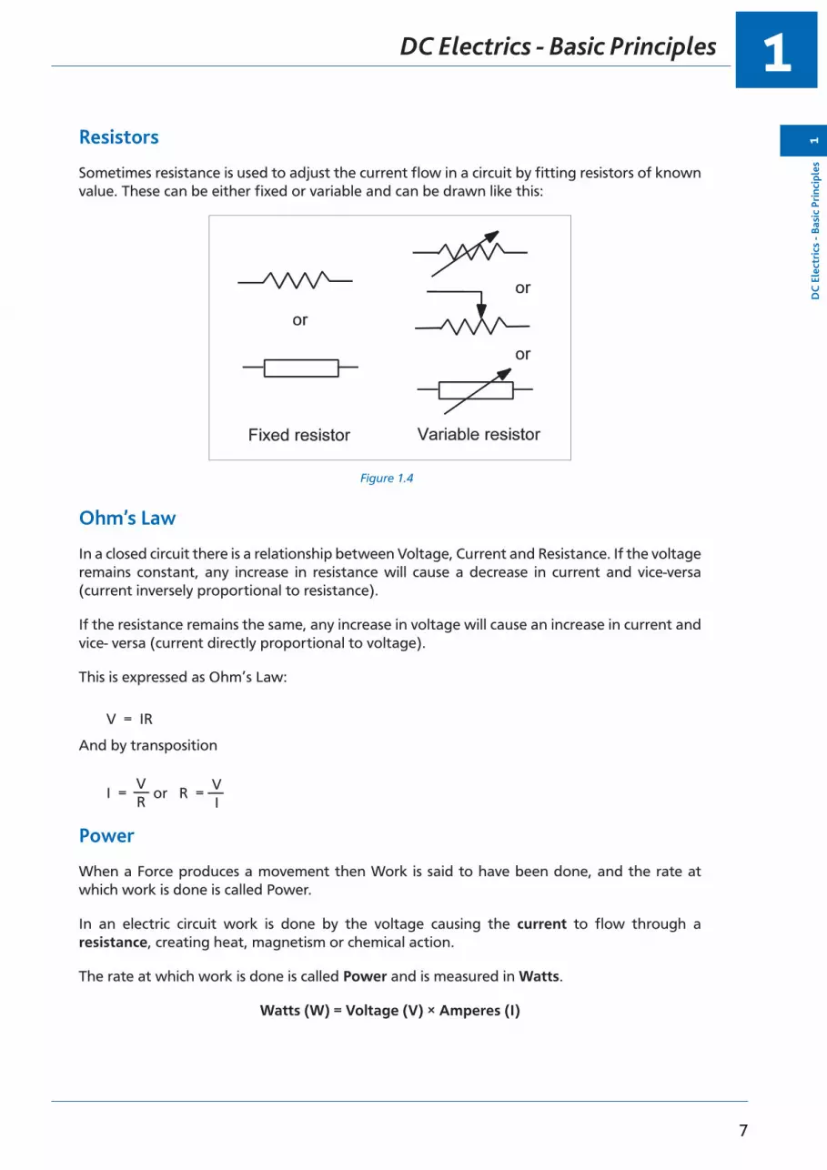
Resistors
Sometimes resistance is used to adjust the current flow in a circuit by fitting resistors of known value. These can be either fixed or variable and can be drawn like this:
Figure 1.4
Ohm’s Law
In a closed circuit there is a relationship between Voltage, Current and Resistance. If the voltage remains constant, any increase in resistance will cause a decrease in current and vice-versa (current inversely proportional to resistance).
If the resistance remains the same, any increase in voltage will cause an increase in current and vice- versa (current directly proportional to voltage).
This is expressed as Ohm’s Law:
V = IR
And by transposition
I = or R = VR
VI
Power
When a Force produces a movement then Work is said to have been done, and the rate at which work is done is called Power.
In an electric circuit work is done by the voltage causing the current to flow through a resistance, creating heat, magnetism or chemical action.
The rate at which work is done is called Power and is measured in Watts.
Watts (W) = Voltage (V) × Amperes (I)

DC Electrics - Basic Principles1
8
1D
C Electrics - Basic Principles
Three formulae for calculating power can be derived from the two basic formulae V=IR and W=V×I
• Voltage unknown W = I2 R
• Resistance unknown W = V × I
• Current unknown V2
RW =
When a current passes through a resistor it becomes hot and will eventually melt if the current becomes excessive.
The amount of heat developed by a current (I) in a resistor (R) is I2R watts, therefore it can be seen that the heating effect is proportional to the square of the current. So a small increase in current can cause a significant increase in heating effect.
Each electrical component will be given a Power Rating (maximum wattage) which, if exceeded, will cause the component to overheat, e.g. 60 watt light bulb.
Each electrical circuit in an aircraft will be protected by a fuse or circuit breaker which will prevent the maximum power rating of a component to be exceeded by breaking the circuit if the current increases.
Series and Parallel Circuits
More than one resistance can be connected in any one circuit and they may be connected in Series - one after the other, or in Parallel - alongside each other.
• Series
Figure 1.5
Series connection reduces current flow and therefore power consumption, but can be impractical because individual loads (resistances) cannot be individually controlled. Also the failure of one resistance would mean failure of the rest of the circuit.
The total circuit resistance can be calculated by summing the individual resistances.
RT = R1 + R2 + R3
i.e. RT = 4 + 6 + 10
RT = 20 ohms
V = IR so current = = 0.6 amps
12 20
1
9
D
C E
lect
rics
- Ba
sic
Prin
cipl
es1
DC Electrics - Basic Principles
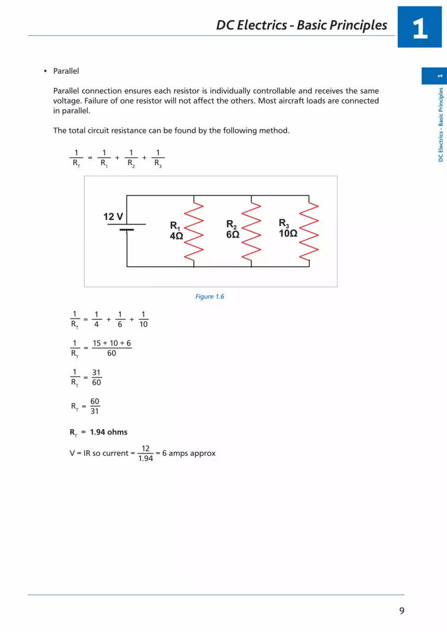
• Parallel
Parallel connection ensures each resistor is individually controllable and receives the same voltage. Failure of one resistor will not affect the others. Most aircraft loads are connected in parallel.
The total circuit resistance can be found by the following method.
1 RT
1 R1
1 R2
1 R3
= + +
Figure 1.6
1 RT
1 4
1 6
1 10= + +
1 RT
15 + 10 + 6 60
=
1 RT
31 60=
RT
60 31=
RT = 1.94 ohms
V = IR so current = = 6 amps approx12
1.94
DC Electrics - Basic Principles1
10
1D
C Electrics - Basic Principles
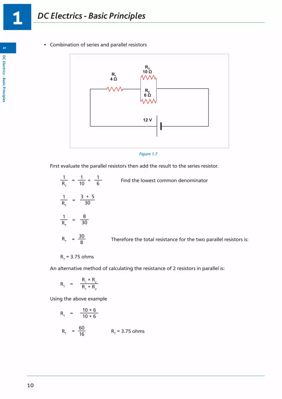
• Combination of series and parallel resistors
Figure 1.7
First evaluate the parallel resistors then add the result to the series resistor.
1 RT
1 10
1 6
Find the lowest common denominator= +
1 RT
3 + 5 30=
1 RT
8 30=
RT
30 8 Therefore the total resistance for the two parallel resistors is:=
RT = 3.75 ohms
An alternative method of calculating the resistance of 2 resistors in parallel is:
R1 × R2 R1 + R2
RT =
Using the above example
10 × 6 10 + 6RT =
RT
60 16 RT = 3.75 ohms=

1
11
D
C E
lect
rics
- Ba
sic
Prin
cipl
es1
DC Electrics - Basic Principles
Note: The total resistance of resistors in parallel is always less than the value of the lowest resistor e.g. 3.75 ohms is less than 6 ohms.
Total circuit resistance is 3.75 ohms plus 4 ohms = 7. 75 ohms
Kirchoff’s Laws
• First law
The total current flow into a point on a circuit is equal to the current flow out of that point e.g.
Figure 1.8
• Second law
If all the voltage drops in a closed circuit are added together, their sum always equals the voltage applied to that closed circuit.
Figure 1.9
2 V 4 V
12 V
2 ohms 4 ohms 6 ohms
6 V
To prove Kirchoff’s 2nd Law, first we must calculate the current and therefore the total resistance:
RT = R1 + R2 + R3 RT = 2 + 4 + 6 RT = 12 ohms

DC Electrics - Basic Principles1
12
1D
C Electrics - Basic Principles
From Ohm’s Law
VR
V = IR » I =
1212
I =
I = 1 amp
We can now calculate the voltage drops throughout the circuit. At present all we know is there is 12 volts before the 2 ohm resistor and zero volts after the 6 ohm resistor.
Using Ohm’s Law V= IR. To calculate the voltage drop across the 2 ohm resistor:
V = 1 amp × 2 ohms = 2 volts
Therefore, the voltage drop is 2 volts i.e. 12 volts enters the 2 ohm resistor and 10 volts exits. Using the same approach for the 4 ohm resistor:
V = 1 amp × 4 ohms = 4 volts i.e. 10 volts enters the 4 ohm resistor and 6 volts exits.
Finally, calculating the voltage drop across the 6 ohm resistor:
V = 1 amp × 6 ohms = 6 volts i.e. 6 volts enters the 6 ohm resistor and zero volts exit.
Therefore, the voltage drop in the closed circuit is 2 volts + 4 volts + 6 volts = 12 volts which equals the voltage applied.
1
13
D
C E
lect
rics
- Ba
sic
Prin
cipl
es1
DC Electrics - Basic Principles

Questions1
14
1Q
uestions
Questions - Theory
1. All effects of electricity take place because of the existence of a tiny particle called the:
a. electricb. proton c. neutron d. electron
2. The nucleus of an atom is:
a. positively charged b. negatively charged c. statically charged d. of zero potential
3. An atom is electrically balanced when:
a. its protons and electrons balance each other b. the protons outnumber the electronsc. the electrons outnumber the protonsd. the electric and static charges are balanced
4. The electrons of an atom are:
a. positively charged b. neutralc. negatively charged d. of zero potential
5. A material with a deficiency of electrons becomes:
a. positively charged b. negatively chargedc. isolatedd. overheated
6. A material with a surplus of electrons becomes:
a. positively charged b. negatively charged c. over chargedd. saturated
7. Heat produces an electric charge when:
a. like poles are joinedb. a hard and soft glass is heatedc. the junction of two unlike metals is heatedd. hard and soft material are rubbed together
1
15
Que
stio
ns1
Questions
8. Friction causes:
a. mobile electricity b. basic electricity c. static electricity d. wild electricity
9. Chemical action produces electricity in:
a. a light meter b. a generatorc. a primary celld. starter generator
10. A photo electric cell produces electricity when:
a. two metals are heatedb. exposed to a light sourcec. a light source is removedd. exposed to the heat of the sun

Questions1
16
1Q
uestions
Questions - Units 1
1. The difference in electric potential is measured in:
a. kVARs b. wattsc. ampsd. volts
2. Electrical power is measured in:
a. wattsb. amperes c. ohmsd. volts
3. The unit measurement of electrical resistance is:
a. the volt b. the watt c. the ohmd. the ampere
4. An ammeter measures:
a. currentb. power dissipationc. differences of electrical potential d. heat energy
5. Materials containing ‘free electrons’ are called:
a. insulators b. resistors c. collectorsd. conductors
6. The unit used for measuring the EMF of electricity is:
a. the ohmb. the amperec. the voltd. the watt
7. The unit used for measuring:
a. current - is the voltb. resistance - is the ohmc. electric power - is the capacitor d. EMF - is the amp

1
17
Que
stio
ns1
Questions
8. Three resistors of 60 ohms each in parallel give a total resistance of:
a. 180 ohms b. 40 ohms c. 30 ohms d. 20 ohms
9. A voltmeter measures:
a. electromotive forceb. the heat loss in a series circuit c. the current flow in a circuitd. the resistance provided by the trimming devices
10. Watts =
a. resistance squared × amps b. volts × ohmsc. ohms × amps d. volts × amps
Questions1
18
1Q
uestions
Questions - Units 2
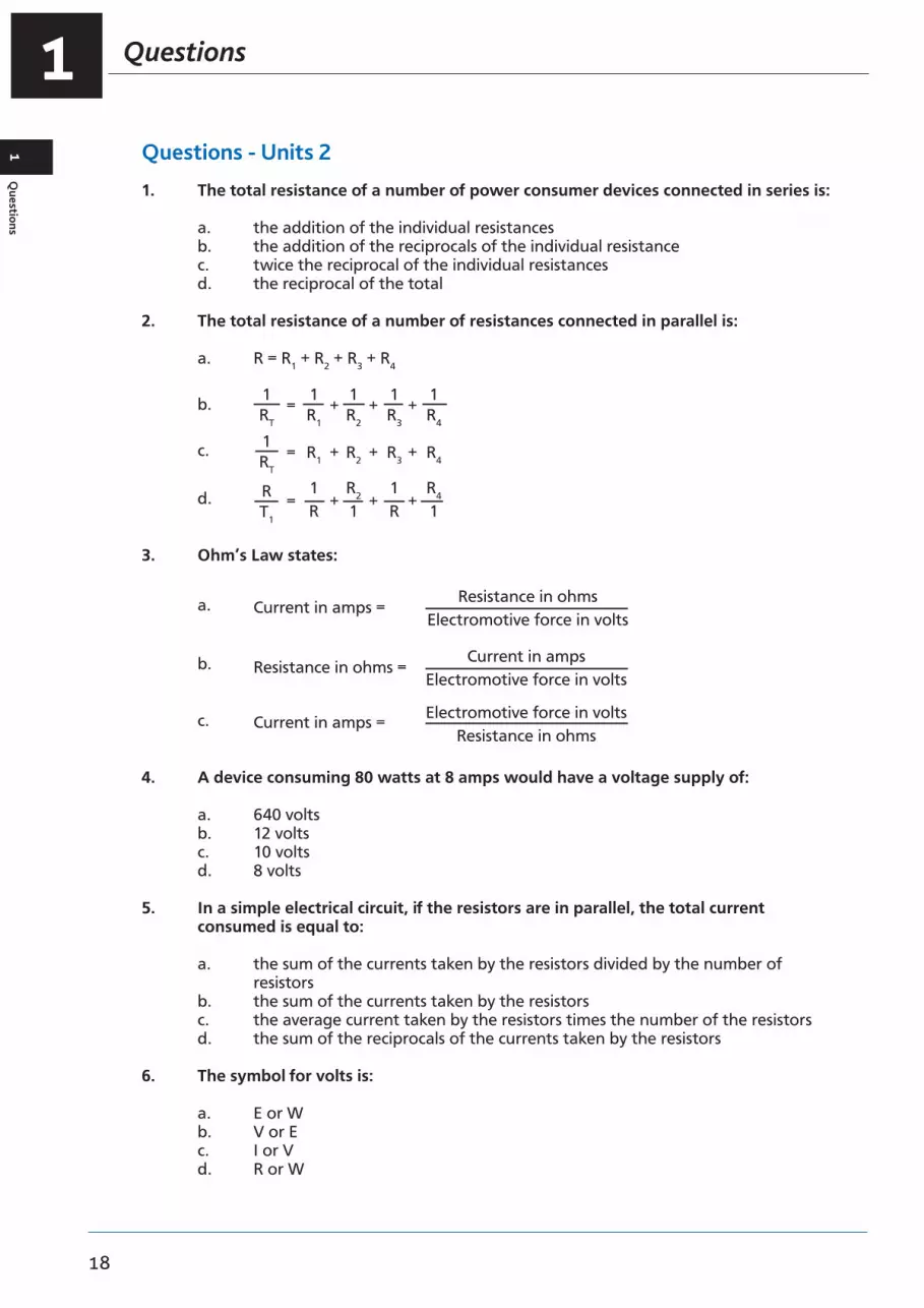
1. The total resistance of a number of power consumer devices connected in series is:
a. the addition of the individual resistancesb. the addition of the reciprocals of the individual resistance c. twice the reciprocal of the individual resistancesd. the reciprocal of the total
2. The total resistance of a number of resistances connected in parallel is:
a. R = R1 + R2 + R3 + R4
b. 1 R2
1 R1
= + + +1 RT
1 R3
1 R4
c. = + + +1 RT
R1 R3R2 R4
d. = + + +R T1
1 R
1 R
R2 1
R4 1
3. Ohm’s Law states:
a. Resistance in ohms Electromotive force in volts
Current in amps =
b. Current in amps Electromotive force in volts
Resistance in ohms =
c. Electromotive force in volts Resistance in ohms
Current in amps =
4. A device consuming 80 watts at 8 amps would have a voltage supply of:
a. 640 volts b. 12 volts c. 10 volts d. 8 volts
5. In a simple electrical circuit, if the resistors are in parallel, the total current consumed is equal to:
a. the sum of the currents taken by the resistors divided by the number of resistors
b. the sum of the currents taken by the resistorsc. the average current taken by the resistors times the number of the resistors d. the sum of the reciprocals of the currents taken by the resistors
6. The symbol for volts is:
a. E or W b. V or Ec. I or V d. R or W

1
19
Que
stio
ns1
Questions
7. Electrical potential is measured in:
a. watts b. bars c. volts d. ohms
8. If a number of electrical consuming devices were connected in parallel, the reciprocal of the total resistance would be:
a. the sum of the currentsb. the sum of the reciprocals of the individual resistances c. the sum of their resistancesd. volts divided by the sum of the resistances
9. The current flowing in an electrical circuit is measured in:
a. volts b. ohmsc. inductance d. amps
10. Electromotive force is measured in:
a. amps × volts b. wattsc. ohms d. volts

Questions1
20
1Q
uestions
Questions - General
1. Ohm’s Law is given by the formula:
a. RV
I =
b. RI
V =
c. VR
I =
d. R = V × I
2. The current flowing in a circuit is:
a. directly proportional to resistance, indirectly proportional to voltageb. directly proportional to temperature, inversely proportional to resistance c. inversely proportional to resistance, directly proportional to voltaged. inversely proportional to applied voltage, directly proportional to temperature
3. The unit of EMF is the:
a. ampere b. volc. wattd. ohm
4. Potential difference is measured in:
a. amps b. volts c. watts d. ohms
5. The unit of current is the:
a. ampere b. voltc. wattd. ohm
6. The unit of resistance is the:
a. ampere b. voltc. watt d. ohm
7. Electrical power is measured in:
a. amperes b. voltsc. watts d. ohms

1
21
Que
stio
ns1
Questions
8. 1250 ohms may also be expressed as:
a. 1250 k ohms b. 1.25 k ohms c. 1.25 M ohmsd. 0.125 k ohms
9. 1.5 M ohms may also be expressed as:
a. 15 000 ohms b. 1500 ohmsc. 150 000 ohms d. 1500 k ohms
10. 550 k ohms may also be expressed as:
a. 550 000 M ohms b. 0.55 M ohmsc. 55000 ohms d. 0.55 ohms
11. If the voltage applied to a simple resistor increases:
a. current will decrease but power consumed remains constant b. resistance and power decreasec. current flow will increase and power consumed will increase d. current flow increases and power consumed decreases
12. What is the total resistance in this circuit:
a. 11.5 ohmsb. 11 500 k ohmsc. 11.5 k ohmsd. 11.5 M ohms
LOOK AT THE CIRCUIT AT ANNEX A AND ANSWER THE FOLLOWING QUESTIONS
13. The total resistance of the circuit is:
a. 14 ohms b. 39.6 ohms c. 25.6 ohmsd. varies with the applied voltage
14. The current flow indication on ammeter ‘A’ would be:
a. 2 amps b. 2 voltsc. 2.5 ampsd. 2.5 volts

Questions1
22
1Q
uestions
15. The total power consumed in the circuit will be:
a. 14 kilowatts b. 56 kilowatts c. 56 wattsd. 14 watts
16. The power consumed by R5 alone is:
a. 14 watts b. 28 watts c. 112 wattsd. 28 kilowatts
17. The indication on voltmeter V1 will be:
a. 2.3 volts b. 28 volts c. 9.2 volts d. 92 volts
18. The indication on voltmeter V3 will be:
a. 28 volts b. 14 volts c. 14 amps d. 3.5 volts
19. The indication on voltmeter V2 will be:
a. 28 volts b. 4.8 volts c. 9.6 volts d. 14 volts
20. The current flowing through R2 is:
a. 0.04 amps b. 0.4 amps c. 4 ampsd. 40 milliamps
21. The current flowing through R3 is:
a. 0.04 amps b. 0.4 amps c. 4 ampsd. 40 milliamps
22. The current flowing through R4 is:
a. 120 milliamps b. 1.2 ampsc. 19.2 ampsd. 1.92 milliamps

1
23
Que
stio
ns1
Questions
23. The power consumed by R2 alone is:
a. 1.92 kilowatts watts b. 1.92 wattsc. 65.3 wattsd. 65.3 kilowatts
24. The power consumed by R3 alone is:
a. 1.92 kilowatts watts b. 1.92 wattsc. 65.3 wattsd. 65.3 kilowatts
25. The power consumed by R4 alone is:
a. 5.76 kilowatts b. 5.76 voltsc. 5.76 wattsd. 3.33 watts
26. The power consumed by R1 alone is:
a. 18.4 kilowatts b. 42.32 wattsc. 18.4 wattsd. 4.232 kilowatts

Questions1
24
1Q
uestions
Annex A
28 V DC
R1 R3 R5
R4
R2

1
25
Que
stio
ns1
Questions

Answers1
26
1A
nswers
Answers - Theory
1 2 3 4 5 6 7 8 9 10
d a a c a b c c c b
Answers - Units 1
1 2 3 4 5 6 7 8 9 10
d a c a d c b d a d
Answers - Units 2
1 2 3 4 5 6 7 8 9 10
a b c c b b c b d d
Answers - General
1 2 3 4 5 6 7 8 9 10 11 12
c c b b a d c b d b c c
13
a
Total circuit resistance, evaluate the total resistance of the three resistors in parallel first
1 RT
1 R1
1 R2
1 R3
= + +
1 RT
1 12
1 12
1 4
= + +
1 RT
1 + 1 + 3 12
=
1 RT
5 12
=
12 5
RT = = 2.4 Ω
Then add the resistances in series
4.6 + 2.4 + 7 = 14 Ω
14
aI = = 2 ampsV
R
15 16 17 18 19 20 21 22 23 24 25 26
c b c b b b b b b b c c

27
2Chapter
DC Electrics - Switches
Switches . . . . . . . . . . . . . . . . . . . . . . . . . . . . . . . . . . . . . . . . . . . . . . . 29
Proximity Detectors . . . . . . . . . . . . . . . . . . . . . . . . . . . . . . . . . . . . . . . . . 30
Time Switches . . . . . . . . . . . . . . . . . . . . . . . . . . . . . . . . . . . . . . . . . . . 33
Centrifugal Switches . . . . . . . . . . . . . . . . . . . . . . . . . . . . . . . . . . . . . . . . 33

DC Electrics - Switches2
28
2D
C Electrics - Sw
itches

2
29
DC
Ele
ctri
cs -
Swit
ches
2
DC Electrics - Switches
Switches
The initiation and control of aircraft circuits is achieved by switches and relays. Some typical switches are described here.
Toggle SwitchA general purpose switch common in older aircraft having a number of isolating contacts inside. It can be a two position switch (on or off) or a multi-position switch sprung biased to the centre or off position and then pressed and held to select in the desired direction.
Figure 2.1 Figure 2.1
Switch LightSwitch lights have largely replaced toggle switches in modern aircraft and combine the functions of a switch with a push action and an indicator light for the associated function.
There are two basic types
• Momentary action press and hold to activate, release to deactivate.
• Alternate action press and release to activate, press and release a second time to deactivate.
The indicator in the lens confirms the selected position or provides a warning which requires the switch to be selected.
Figure 2.2

DC Electrics - Switches2
30
2D
C Electrics - Sw
itches
Guarded SwitchesToggle switches or switch lights can be guarded to prevent inadvertent operation, e.g. generator disconnects the fuel dump master. (See previous diagram)
MicroswitchMicroswitches are still used in modern aircraft to detect the position of a particular device e.g. door opened or closed.
The name Microswitch describes the small movement between the ‘make and break’ position. Microswitches can activate indications on the flight deck or control relays for a sequenced operation. They are largely replaced by proximity detectors on modern aircraft.
Figure 2.3 Microswitch Figure 2.3
Bimetallic Switch (Thermal Switch)Bimetallic switches are temperature sensitive switches and are activated when a certain value of temperature is reached to provide an indication to the pilot or to activate / deactivate a circuit, e.g. fire detection circuits, battery overheat switch, oil temperature warning light.
Proximity Detectors
Proximity detectors are electrical or electronic sensors that respond to the presence of a material. The electrical or electronic response is used to activate a switch, relay or transistor. There are many types of proximity detectors, the major types being inductive, capacitive and magnetic. The inductive and magnetic sensors need the monitored material to be metal, but the capacitive type can monitor either metal or non-metal materials.
Inductive TypeThis type of sensor has an inductance coil whose inductance changes when a ferromagnetic material (target) is brought into close proximity with it.

2
31
DC
Ele
ctri
cs -
Swit
ches
2
DC Electrics - Switches
Figure 2.4 Figure 2.4
This type of sensor is used in undercarriage systems in place of microswitches. A typical undercarriage system is described below. Each proximity switch consists of three components:
• A printed circuit card located in what is called the landing gear accessory unit.• A sensor located on appropriate landing gear structure.• An actuator (or target) for each sensor, located adjacent to its sensor.
The proximity sensor is a hermetically sealed unit, and is actuated by the presence of the actuator or target, i.e. it is not touched by it. As a result, the proximity switch is unaffected by atmospheric conditions, and is highly reliable.
Capacitive TypeIn this type of sensor detection is made by a capacitor undergoing a capacitance change owing to the proximity of material.
The capacitive proximity detector is an extremely versatile device in that it is capable of detecting all materials, liquid and solid. As well as detecting the presence of a ferrous or non- ferrous target, it can be used to detect high or low liquid levels in a hydraulic or fuel system.
Magnetic TypeA coil situated in a magnetic field will have an electromotive force (EMF) induced in it if the magnetic flux changes. The magnitude of the induced EMF will depend on the rate at which the flux is changed. These are the basic principles on which the magnetic proximity detectors operate.
In its simplest form, a coil is wound around a bar magnet and one pole of the magnet is then located close to a ferrous object. If the ferrous object moves, the flux in the magnet changes and an EMF is induced in the coil. If a number of ferrous objects move past the magnet, a train of pulses is induced in the coil.

DC Electrics - Switches2
32
2D
C Electrics - Sw
itches
Magnetic detectors are most commonly used in conjunction with mild steel gear wheels, each tooth in the wheel being, in effect, a ferrous object. The detector is located radially and close to the periphery of the wheel and provides an output having a frequency equal to the frequency of passage of the teeth past the detector.
Figure 2.5 Figure 2.5
Figure 2.6
Figure 2.6 Landing Gear Position Sensors

2
33
DC
Ele
ctri
cs -
Swit
ches
2
DC Electrics - Switches
Time Switches
Time switches or relays can be initiated electrically or mechanically to activate a circuit after a specific time interval has occurred, e.g. auxiliary power unit air intake door closes 30 seconds after APU has shut down.
Centrifugal Switches
These can be set to activate or de-activate a circuit as the RPM of a device increases or decreases, e.g. starter motor cut-out switch.

DC Electrics - Switches2
34
2D
C Electrics - Sw
itches

35
3Chapter
DC Electrics - Circuit Protection and Capacitors
Electrical Faults . . . . . . . . . . . . . . . . . . . . . . . . . . . . . . . . . . . . . . . . . . . 37
Circuit Protection Devices. . . . . . . . . . . . . . . . . . . . . . . . . . . . . . . . . . . . . . 37
Fuses . . . . . . . . . . . . . . . . . . . . . . . . . . . . . . . . . . . . . . . . . . . . . . . . . 37
The Cartridge Fuse . . . . . . . . . . . . . . . . . . . . . . . . . . . . . . . . . . . . . . . . . 37
Spare Fuses . . . . . . . . . . . . . . . . . . . . . . . . . . . . . . . . . . . . . . . . . . . . . 38
High Rupture Capacity (HRC) Fuses . . . . . . . . . . . . . . . . . . . . . . . . . . . . . . . . 39
Dummy Fuses . . . . . . . . . . . . . . . . . . . . . . . . . . . . . . . . . . . . . . . . . . . . 39
Current Limiters . . . . . . . . . . . . . . . . . . . . . . . . . . . . . . . . . . . . . . . . . . . 39
Circuit Breakers . . . . . . . . . . . . . . . . . . . . . . . . . . . . . . . . . . . . . . . . . . . 40
Reverse Current Circuit Breakers . . . . . . . . . . . . . . . . . . . . . . . . . . . . . . . . . . 41
Capacitors . . . . . . . . . . . . . . . . . . . . . . . . . . . . . . . . . . . . . . . . . . . . . . 41
Capacitance . . . . . . . . . . . . . . . . . . . . . . . . . . . . . . . . . . . . . . . . . . . . . 42
Capacitor in a DC Circuit . . . . . . . . . . . . . . . . . . . . . . . . . . . . . . . . . . . . . . 42
Capacitor in an AC Circuit . . . . . . . . . . . . . . . . . . . . . . . . . . . . . . . . . . . . . 43
Capacitors in Parallel . . . . . . . . . . . . . . . . . . . . . . . . . . . . . . . . . . . . . . . . 44
Capacitors in Series . . . . . . . . . . . . . . . . . . . . . . . . . . . . . . . . . . . . . . . . . 44
Questions - Circuit Breakers . . . . . . . . . . . . . . . . . . . . . . . . . . . . . . . . . . . . 45
Questions - Fuses . . . . . . . . . . . . . . . . . . . . . . . . . . . . . . . . . . . . . . . . . . 47
Answers - Circuit Breakers . . . . . . . . . . . . . . . . . . . . . . . . . . . . . . . . . . . . . 50
Answers - Fuses . . . . . . . . . . . . . . . . . . . . . . . . . . . . . . . . . . . . . . . . . . . 50

DC Electrics - Circuit Protection and Capacitors3
36
3D
C Electrics - C
ircuit Protection and Capacitors
3
37
D
C E
lect
rics
- C
ircui
t Pr
otec
tion
and
Cap
acit
ors
3
DC Electrics - Circuit Protection and Capacitors
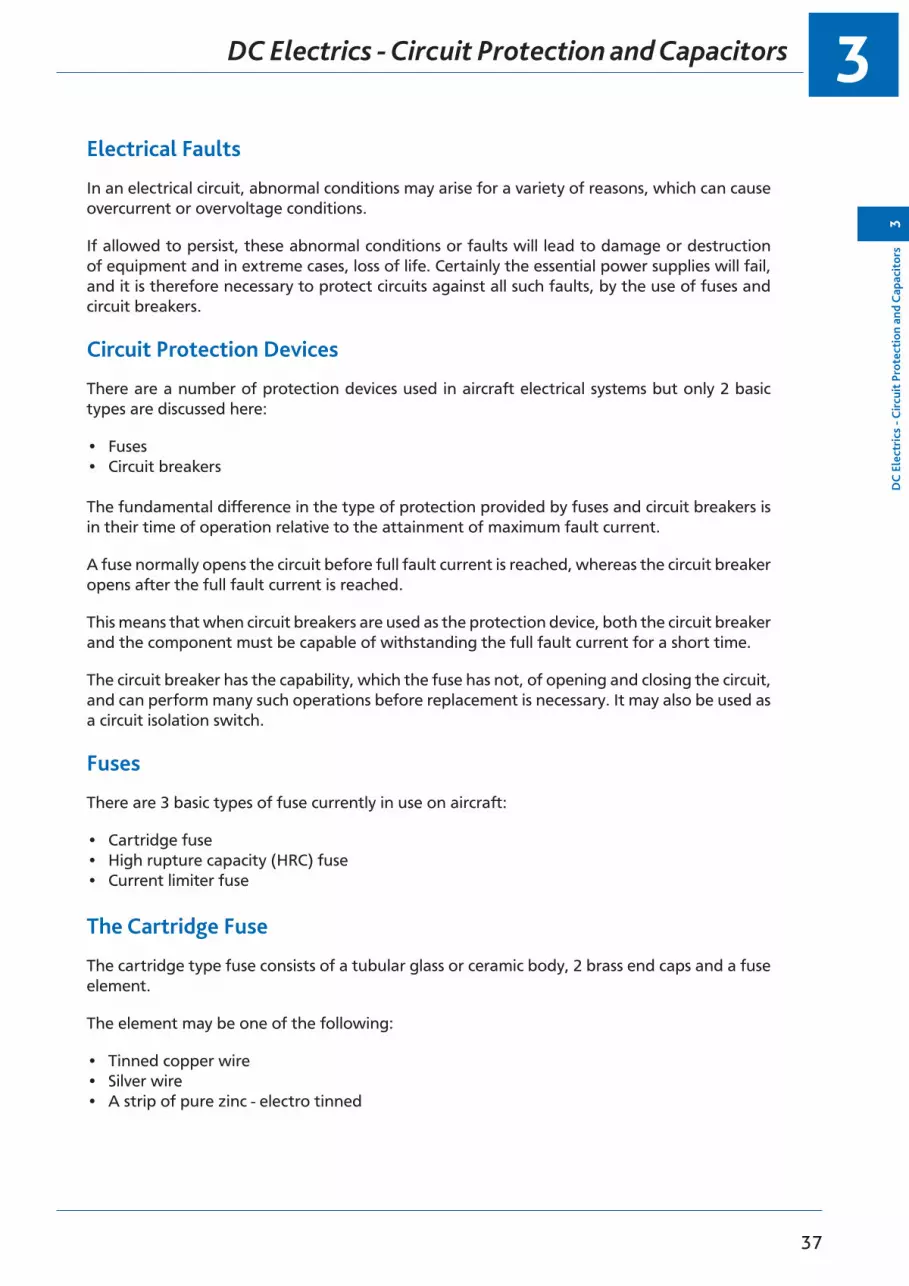
Electrical Faults
In an electrical circuit, abnormal conditions may arise for a variety of reasons, which can cause overcurrent or overvoltage conditions.
If allowed to persist, these abnormal conditions or faults will lead to damage or destruction of equipment and in extreme cases, loss of life. Certainly the essential power supplies will fail, and it is therefore necessary to protect circuits against all such faults, by the use of fuses and circuit breakers.
Circuit Protection Devices
There are a number of protection devices used in aircraft electrical systems but only 2 basic types are discussed here:
• Fuses• Circuit breakers
The fundamental difference in the type of protection provided by fuses and circuit breakers is in their time of operation relative to the attainment of maximum fault current.
A fuse normally opens the circuit before full fault current is reached, whereas the circuit breaker opens after the full fault current is reached.
This means that when circuit breakers are used as the protection device, both the circuit breaker and the component must be capable of withstanding the full fault current for a short time.
The circuit breaker has the capability, which the fuse has not, of opening and closing the circuit, and can perform many such operations before replacement is necessary. It may also be used as a circuit isolation switch.
Fuses
There are 3 basic types of fuse currently in use on aircraft:
• Cartridge fuse• High rupture capacity (HRC) fuse• Current limiter fuse
The Cartridge Fuse
The cartridge type fuse consists of a tubular glass or ceramic body, 2 brass end caps and a fuse element.
The element may be one of the following:
• Tinned copper wire• Silver wire• A strip of pure zinc - electro tinned

DC Electrics - Circuit Protection and Capacitors3
38
3D
C Electrics - C
ircuit Protection and Capacitors
Figure 3.1. Typical Fuses, (a) A Light Duty Circuit Fuse. (b) A High RapturingCapacity Fuse.
Figure 3.1 Typical fuses a. A light duty circuit fuse b. A high rupturing capacity fuse
The latter type element is generally used in heavy duty circuits, the zinc strip being cut to a specified width.
A fuse operates when the current flowing through it is sufficient to melt the wire or strip element, the time taken varying inversely with the current.
All fuses are rated at a specific current value, i.e. the rating indicates the current they will carry continuously or intermittently without unduly heating up or deteriorating.
The rating of a fuse for a particular circuit is such that it is not less than the normal current flowing in the circuit, but that it operates (‘blows’) at a current level below the safety limit of the equipment or cable used.
For this reason only the specified fuse should be used in a particular circuit. The diagram shows typical aircraft fuses; the ratings can vary between 0 .5 and 500 amps, the higher ratings being limited to the HRC or current limiter types.
Fuses are made of a type of wire which has a low melting point, and when it is placed in series with the electrical load it will melt, blow or rupture when a current of higher value than its ampere rating is placed upon it.
Fuses are rated in ‘amps’.
A blown fuse may be replaced with another of the correct rating once only. If it blows again when switching on, there is a defect in the system and the fuse must not be changed again until the circuit has been investigated.
Spare Fuses
The carriage of spare fuses is mandatory, the quantity of spares being at least 10% of the number of each rating installed, with a minimum of 3 of each.
3
39
D
C E
lect
rics
- C
ircui
t Pr
otec
tion
and
Cap
acit
ors
3
DC Electrics - Circuit Protection and Capacitors
High Rupture Capacity (HRC) Fuses
The high rupture capacity (HRC) fuse is an improvement on the cartridge type fuse. It is used mainly for high current rated circuits.
The body is a ceramic material of robust construction and has one or more element holes. The element holes are filled with powdered marble or clean quartz sand. The end caps are of plated brass or copper.
The HRC has the following advantages over the normal glass cartridge type:
• more accurate operation• operates without flame• does not deteriorate with age• is more robust• operates rapidly• is not affected by ambient temperature
Dummy Fuses
Aircraft electrical circuits which are not in use will have dummy fuses fitted. If it is necessary to isolate a particular circuit by the removal of the fuse in order that the system be made ‘safe’ or for work to be carried out, a dummy fuse or fuse holder should replace the fuse which has been removed.
To distinguish the dummy fuse, a red streamer is attached to it.
Dummy fuse links are manufactured to standard fuse dimensions from red plastic, the centre portion being square in section with corrugated sides to facilitate identification.
Services protected by circuit breakers are made safe in a similar manner, a warning flag or plate is clipped to the tripped circuit breaker, indicating that the service has been rendered safe for servicing.
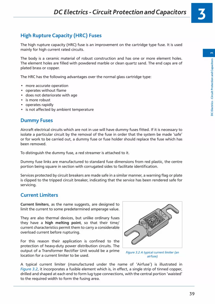
Current Limiters
Current limiters, as the name suggests, are designed to limit the current to some predetermined amperage value.
They are also thermal devices, but unlike ordinary fuses they have a high melting point, so that their time/current characteristics permit them to carry a considerable overload current before rupturing.
For this reason their application is confined to the protection of heavy-duty power distribution circuits. The output of a Transformer Rectifier Unit would be a prime location for a current limiter to be used.
A typical current limiter (manufactured under the name of ‘Airfuse’) is illustrated in Figure 3.2, it incorporates a fusible element which is, in effect, a single strip of tinned copper, drilled and shaped at each end to form lug type connections, with the central portion ‘waisted’ to the required width to form the fusing area.
Figure 3.2 A typical current limiter (an airfuse)

DC Electrics - Circuit Protection and Capacitors3
40
3D
C Electrics - C
ircuit Protection and Capacitors
The central portion is enclosed by a rectangular ceramic housing, one side of which is furnished with an inspection window which, depending on the type, may be glass or mica.
Circuit Breakers
Circuit breakers combine the function of fuse and switch and can be used for switching circuits on and off in certain circumstances.
They are fitted to protect equipment from damage resulting from overload, or fault conditions. The design and construction of CBs is wide and varied.
Generally, the CB incorporates an automatic thermo-sensitive tripping device and a manually or electrically operated switch.
Some electrically operated CBs may also include electromagnetic and reverse current tripping devices.
The smaller type single button CBs, shown in Figure 3.3, range from 5 amps to 45 amps, whereas the larger reverse current CBs can be rated up to 600 amps.
The diagram shows two typical CBs, the single push pull button type has a white marker band to assist in identifying a ‘tripped’ circuit breaker amongst a panel of many.
The CB at (b) is fitted with a “manual trip” button and is more usually associated with a heavy duty circuit.
Figure 3.3 Circuit breakersFigure 3.3 Circuit Breakers.
CBs are common on the flight deck of modern aircraft and can be categorized as either:
• a Non-trip Free Circuit Breaker, or• a Trip Free Circuit Breaker.
The non-trip free circuit breaker may be held in under fault conditions and the circuit will be made, this is clearly dangerous.

3
41
D
C E
lect
rics
- C
ircui
t Pr
otec
tion
and
Cap
acit
ors
3
DC Electrics - Circuit Protection and Capacitors
The trip free circuit breaker if held in under the same circumstances, the circuit can not be made.
Pressing the re-set button will reset either CB if the fault has been cleared.
Reverse Current Circuit Breakers
These CBs are designed to protect power supply systems and associated circuits against fault currents reversing against the normal current direction of flow of a magnitude greater than those at which cut-outs normally operate.
They are furthermore designed to remain in a “locked-out” condition to ensure complete isolation of a circuit until a fault has been cleared.
Capacitors
Introduction:A capacitor can perform three basic functions:
• Stores an electrical charge by creating an electrical field between the plates.• Will act as if it passes Alternating Current• Blocks Direct Current flow
Construction:In its simplest form a capacitor consists of two metal plates separated by an insulator called a dielectric. Wires connected to the plates allow the capacitor to be connected into the circuit.
Figure 3.4 The construction of a simple capacitor

DC Electrics - Circuit Protection and Capacitors3
42
3D
C Electrics - C
ircuit Protection and Capacitors
Symbols:Figure 3.5 shows the electrical circuit symbols for various capacitors. With the polarized capacitor it is important to connect the positive terminal to the positive supply. Non-polarized types can be connected either way round.
Figure 3.5 Capacitor symbols
FIXED (Non-polarized)
VARIABLE PRESET
FIXED (Polarized)
Capacitance
The capacitance (C) of a capacitor measures its ability to store an electrical charge. The unit of capacitance is the FARAD (F). The farad is subdivided into smaller, more convenient units.
1 microfarad (1 µF) = 1 millionth of a farad = 10-6 F
1 nanofarad (1 nF) = 1 thousand millionth of a farad = 10-9 F
1 picofarad (1 pF) = 1 millionth millionth of a farad = 10-12 F
Factors Affecting Capacitance:• Area of the plates - a large area gives a large capacitance
• Distance between the plates - a small distance gives a large capacitance
• Material of the dielectric - different materials have different values of capacitance, for example paper, mica, air and fuel. The value of the dielectric is referred to as the dielectric constant (k). For example, waxed paper has a k value of about 3, whereas air has a k of 1. So a capacitor having waxed paper as its dielectric would have 3 times the capacitance of the same capacitor having air as its dielectric.
Working Voltage:This is the largest voltage DC or Peak AC which can be applied across the capacitor. It is often marked on the case of the capacitor and if it is exceeded, the dielectric may break down and permanent damage result.
Capacitor in a DC Circuit
Figure 3.6 shows a capacitor in series with a battery and a switch. If the switch is closed, electrons are pushed by the battery on to plate Y building up a negative charge. This charge exerts a repelling force across the dielectric which causes electrons to leave the plate X and be attracted to the positive plate of the battery. While this charging action is taking place electrons are passing through the connecting wires but no current flows through the dielectric.

3
43
D
C E
lect
rics
- C
ircui
t Pr
otec
tion
and
Cap
acit
ors
3
DC Electrics - Circuit Protection and Capacitors
Figure 3.6
Figure 3.6
12 V12 V
After a short time the difference in charge between the plates results in a potential difference existing between the plates. The flow of electrons will reduce and stop when the potential difference between the plates is equal to the supply voltage. The capacitor is now fully charged, current has stopped flowing, the plates are said to be charged and there exists an electric field between the plates. The capacitor is now blocking DC flow.
If the switch is opened and the capacitor is disconnected from the battery, it holds its charge: a capacitor stores electrical energy by the formation of an electric field between the plates. The capacitor will only discharge if it is now connected to an external circuit.
Capacitor in an AC Circuit
Figure 3.7 shows the battery replaced with an Alternating Current Supply. A light bulb is placed in series with the supply and the capacitor.
As the terminals X and Y are now changing from positive to negative at a rate depending on the frequency of the supply, current is first flowing in one direction, reversing and flowing in the opposite direction. The capacitor is charging in one direction, discharging and then charging in the opposite direction. This process continues until the supply is disconnected. The bulb will be continuously ON. Current flows in the wires but no current flows through the dielectric.
Therefore: A capacitor appears to pass AC
Figure 3.7
X
Y
X
Y

DC Electrics - Circuit Protection and Capacitors3
44
3D
C Electrics - C
ircuit Protection and Capacitors
Capacitors in Parallel
Capacitors connected in parallel are effectively increasing the area of the plates. The total capacitance CT can be found by adding the individual capacitances:
CT = C1 + C2 etc
Figure 3.8
Figure 3.8
V C1 C2
Capacitors in Series
Capacitors in series have effectively increased the distance between the plates and therefore the total capacitance has decreased. The total capacitance is found by using the formula for resistances in parallel:
1 CT
1 C1
1 C2
= + etc
Figure 3.9
C1 C2
3
45
Que
stio
ns3
Questions
Questions - Circuit Breakers
1. In a circuit fitted with a non-trip free circuit breaker if a fault occurs and persists:
a. if the reset button is depressed and held in, the circuit will be made b. the trip button may be pressed to reset, but not permanentlyc. a non-trip free circuit breaker can never be bypassedd. the reset button may be pressed to make the circuit permanent
2. A trip free circuit breaker that has tripped due to overload:
a. can be reset and held in during rectification b. can never be resetc. can be reset after overhauld. may be reset manually after fault has been cleared
3. Circuit breakers and fuses:
a. are used in DC circuits only b. are used in AC or DC circuits c. are used in AC circuits onlyd. are used in low current circuits only
4. A trip free circuit breaker is one which:
a. cannot be reset by holding the lever in while the fault persists b. can be reset by holding the lever in while the fault persistsc. must be held in during checks to find faults d. can be bypassed
5. If the reset button is pressed in the trip free circuit breaker, the contacts with the fault cleared will:
a. be made and kept madeb. only be made if there is a fuse in the circuit c. reset itself only after a delay of 20 secondsd. not be made and the reset will remain inoperative
6. A circuit breaker is a device for:
a. controlling rotor movement only b. isolating the service on overloadc. isolating the battery when using the ground batteries d. earthing the magnetos when switching off
7. A non-trip free circuit breaker is:
a. one which can make a circuit in flight by pushing a button b. a wire placed in a conductor which melts under overload c. another type of voltage regulatord. an on-off type tumbler switch

Questions3
46
3Q
uestions
8. A non-trip free circuit breaker that has tripped due to overload:
a. can never be resetb. can only be reset on the ground by a maintenance engineer c. can be reset and held in if necessaryd. cannot be reset while the fault is still there
9. A thermal circuit breaker works on the principle of:
a. differential expansion of metals b. differential thickness of metals c. differential density of metalsd. differential pressure of metals
10. Circuit breakers are fitted in:
a. series with the load b. parallel with the load c. across the loadd. shunt with the load

3
47
Que
stio
ns3
Questions
Questions - Fuses
1. A fuse is said to have blown when:
a. an excess current has burst the outer cover and disconnected the circuit from the supply
b. the circuit is reconnectedc. a current of a higher value than the fuse rating has melted the conductor and
disconnected the circuit from the supplyd. the amperage has been sufficiently high to cause the fuse to trip out of its
holder and has therefore, disconnected the circuit from the supply
2. In a fused circuit the fuse is:
a. in parallel with the load b. in series with the loadc. in the conductor between generator and regulator d. only fitted when loads are in series
3. Overloading an electrical circuit causes the fuse to ‘Blow’. This:
a. increases the weight of the insulation b. fractures the fuse casec. disconnects the fuse from its holder d. melts the fuse wire
4. What must be checked before replacing a fuse?
a. The ohms of the circuitb. The amps being used in the circuitc. The amps capacity of the consuming device in the circuit d. The correct fuse volt or watts rating
5. The size of fuse required for an electrical circuit whose power is 72 watts and whose voltage is 24 volts is:
a. 24 amps b. 10 amps c. 5 amps d. 15 amps
6. When selecting a fuse for an aircraft circuit the governing factor is:
a. the voltage of the circuit b. cable cross-sectional area c. resistance of the circuitd. power requirements of the circuit
7. A fuse in an electrical circuit is ‘blown’ by:
a. cooler airb. the breaking of the glass tubec. excess voltage breaking the fuse wire d. excess current rupturing the fuse wire

Questions3
48
3Q
uestions
8. A fuse is used to protect an electrical circuit, it is:
a. of low melting point b. of high capacityc. of high melting point d. of low resistance
9. Fuses:
a. protect the load b. protect the cablec. protect the generatord. protect both the circuit cable and load
10. A current limiter:
a. is a fuse with a low melting point b. is a circuit breakerc. is a fuse with a high melting pointd. is a fuse enclosed in a quartz or sand

3
49
Que
stio
ns3
Questions
Answers3
50
3A
nswers
Answers - Circuit Breakers
1 2 3 4 5 6 7 8 9 10
a d b a a b a d a a
Answers - Fuses
1 2 3 4 5 6 7 8 9 10
c b d c c d d a d c

51
4Chapter
DC Electrics - Batteries
Batteries . . . . . . . . . . . . . . . . . . . . . . . . . . . . . . . . . . . . . . . . . . . . . . . 53
Secondary Cells . . . . . . . . . . . . . . . . . . . . . . . . . . . . . . . . . . . . . . . . . . . 54
Lead Acid Battery . . . . . . . . . . . . . . . . . . . . . . . . . . . . . . . . . . . . . . . . . . 55
Alkaline Battery (Nickel Cadmium, NiCad) . . . . . . . . . . . . . . . . . . . . . . . . . . . . 58
Battery Checks. . . . . . . . . . . . . . . . . . . . . . . . . . . . . . . . . . . . . . . . . . . . 59
Battery Charging . . . . . . . . . . . . . . . . . . . . . . . . . . . . . . . . . . . . . . . . . . 60
Secondary Batteries Summary . . . . . . . . . . . . . . . . . . . . . . . . . . . . . . . . . . . 60
Questions - Batteries 1 . . . . . . . . . . . . . . . . . . . . . . . . . . . . . . . . . . . . . . . 61
Questions - Batteries 2 . . . . . . . . . . . . . . . . . . . . . . . . . . . . . . . . . . . . . . . 63
Questions - Batteries 3 . . . . . . . . . . . . . . . . . . . . . . . . . . . . . . . . . . . . . . . 65
Answers - Batteries 1 . . . . . . . . . . . . . . . . . . . . . . . . . . . . . . . . . . . . . . . . 68
Answers - Batteries 2 . . . . . . . . . . . . . . . . . . . . . . . . . . . . . . . . . . . . . . . . 68
Answers - Batteries 3 . . . . . . . . . . . . . . . . . . . . . . . . . . . . . . . . . . . . . . . . 68
DC Electrics - Batteries4
52
4D
C Electrics - Batteries
4
53
DC
Ele
ctri
cs -
Batt
erie
s4
DC Electrics - Batteries
Batteries
The purpose of a battery in an aircraft is to provide an emergency source of power when the generator is not running and to provide power to start the engine.
A battery is made up of a number of cells which convert chemical energy into electrical energy by a transfer of electrons from one material to another causing a potential difference between them. During the transfer of electrons the chemical composition of the two materials changes.
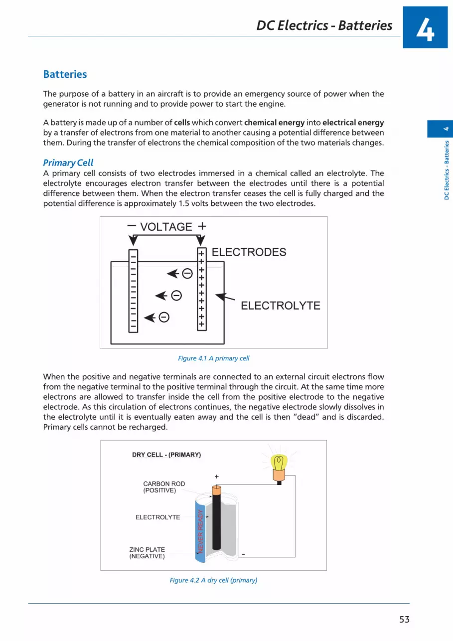
Primary CellA primary cell consists of two electrodes immersed in a chemical called an electrolyte. The electrolyte encourages electron transfer between the electrodes until there is a potential difference between them. When the electron transfer ceases the cell is fully charged and the potential difference is approximately 1.5 volts between the two electrodes.
Figure 4.1 A primary cellFigure 4.1. A Primary Cell
When the positive and negative terminals are connected to an external circuit electrons flow from the negative terminal to the positive terminal through the circuit. At the same time more electrons are allowed to transfer inside the cell from the positive electrode to the negative electrode. As this circulation of electrons continues, the negative electrode slowly dissolves in the electrolyte until it is eventually eaten away and the cell is then “dead” and is discarded. Primary cells cannot be recharged.
Figure 4.2 A dry cell (primary)
DC Electrics - Batteries4
54
4D
C Electrics - Batteries
Secondary Cells
Secondary cells work on the same principle as primary cells but the chemical energy in the cell can be restored when the cell has been discharged by passing a “charging current” through the cell in the reverse direction to that of the discharge current. In this way the secondary cell can be discharged and recharged many times over a long period of time
During recharging electrical energy is converted into chemical energy which is retained until the cell is discharged again.
The Capacity of a cell is a measure of how much current a cell can provide in a certain time. Capacity is measured in Ampere hours (Ah) and is determined by the area of the plates; the bigger the cell the greater its capacity.
A cell with a capacity of 80 Ah should provide a current of 8 A for 10 hours, or 80 A for 1 hr. Theoretically that should be true but in practice the capacity will reduce as the rate of discharge is increased. Capacity is normally measured at the 1 hour rate.
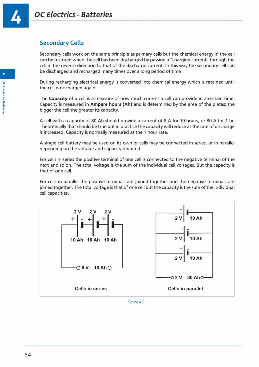
A single cell battery may be used on its own or cells may be connected in series, or in parallel depending on the voltage and capacity required
For cells in series the positive terminal of one cell is connected to the negative terminal of the next and so on. The total voltage is the sum of the individual cell voltages. But the capacity is that of one cell.
For cells in parallel the positive terminals are joined together and the negative terminals are joined together. The total voltage is that of one cell but the capacity is the sum of the individual cell capacities.
Figure 4.3
2 V2 V
2 V
2 V
2 V
6 V
Cells in series Cells in parallel
2 V 2 V
10 Ah 10 Ah 10 Ah
10 Ah
10 Ah
10 Ah
30 Ah
10 Ah

4
55
DC
Ele
ctri
cs -
Batt
erie
s4
DC Electrics - Batteries
Lead Acid Battery
Figure 4.4
One of the most common types of secondary cell is the Lead Acid cell.
The active material of the positive plate is lead peroxide and the negative plate is spongy lead, both plates are immersed in an electrolyte solution of water and sulphuric acid. The container is glass or hard plastic with a filler cap to allow replenishment of distilled water, which is lost through evaporation during use. A vent hole in the cap allows the escape of hydrogen gas, which is produced when the cell is working
The state of charge of a lead acid cell can be determined by measuring the strength of the electrolyte solution. This is done with a hydrometer which measures the specific gravity (SG). A fully charged cell will have a SG of 1.27, a discharged cell will have a SG of 1.17.
When the cell is connected to an external circuit and current is flowing, lead sulphate is formed at both plates and the specific gravity will fall as the acid becomes weaker. When the SG has fallen to 1.17 and the voltage to 1.8 volts the cell should be recharged.
To charge a cell it is connected to a battery charger which applies a slightly higher voltage to the cell and causes current to flow in the reverse direction through the cell. While this is happening the lead sulphate which had been deposited on the plates is removed and the SG of the electrolyte rises to 1.27. The voltage ‘on load’ should have returned to just above 2 volts.
When charging a lead acid battery it is important that the rate of charge is controlled. Charging too quickly can cause ‘gassing’ and evaporation to occur which may lead to boiling the battery dry and causing damage to the plates.

DC Electrics - Batteries4
56
4D
C Electrics - Batteries
Figure 4.5 A lead acid secondary cell
The SG of the electrolyte is an indication of the battery’s state of charge or serviceability. The value of the SG is checked using a hydrometer. The level of the electrolyte is maintained just above the top of the plates by topping up with distilled water. Loss of water is caused by gassing at the plates when fully charged.
The on load/nominal voltage of each cell of a lead acid battery is 2 volts.
The off load voltage of each cell of a lead acid battery is 2.2 volts.
Electrolytes are highly corrosive and if spilled in aircraft can cause extensive damage.
The neutralizing agent to be used for an acid electrolyte is a sodium bicarbonate solution. The performance of a battery is affected by temperature. In low temperatures the rate of discharge is decreased because of higher internal resistance. In warm temperatures the battery rate of discharge will increase. In general the battery performs better in warm temperatures (just like a car battery). As a lead acid battery discharges the SG of the electrolyte reduces. In freezing temperatures with a discharged battery there is a risk of the electrolyte freezing. It is therefore important to maintain the battery in a fully charged state during winter operations.
Figure 4.6 shows a free liquid type of lead acid battery where the electrolyte is in liquid form. Figure 4.7 shows an absorbed liquid type of lead acid battery where the electrolyte is absorbed into the active materials in the plates making it less prone to spillage.

4
57
DC
Ele
ctri
cs -
Batt
erie
s4
DC Electrics - Batteries
Figure 4.6 Lead acid battery (free liquid type)
Figure 4.7 Lead acid battery (absorbed liquid type)

DC Electrics - Batteries4
58
4D
C Electrics - Batteries
Alkaline Battery (Nickel Cadmium, NiCad)
Lead acid batteries are still used in some smaller aircraft but have been largely replaced by Nickel Cadmium (alkaline type) batteries. These use different materials for their plates and electrolyte. The plates are nickel oxide and cadmium and the electrolyte is potassium hydroxide. The SG of the electrolyte is 1.24 - 1.30.
The on-load voltage of one cell is about 1.2 volts.
Unlike the lead acid battery, the relative SG of the nickel-cadmium battery electrolyte does not change and the voltage variation from “fully charged” to “fully discharged,” is very slight. The only way to determine the state of charge is to carry out a measured discharge test i.e. a capacity test.
The terminal voltage remains substantially constant at 1.2 volts throughout most of the discharge. Due to its low internal resistance it is also capable of supplying high current during its discharge cycle and low current during recharging without violent fluctuations of terminal voltage.
NiCad batteries have a low thermal capacity; the heat generated in certain conditions is faster than it can dissipate, so causing a rapid increase in temperature.
This has the effect of lowering the effective internal resistance thus allowing an ever increasing charging current, which, unless checked, leads to the total destruction of the battery.
This condition is known as a thermal runaway, and can cause so much heat that the battery may explode. For this reason the charging of the battery must be closely monitored and includes some safety features.
A built-in thermal switch monitors the temperature and operates on a preset value of temperature. This effectively isolates the battery from the charging source until a reduction in temperature reverts the switch back to its normal position. Associated with the temperature switch may be an indicator light on the flight deck to alert the pilot.
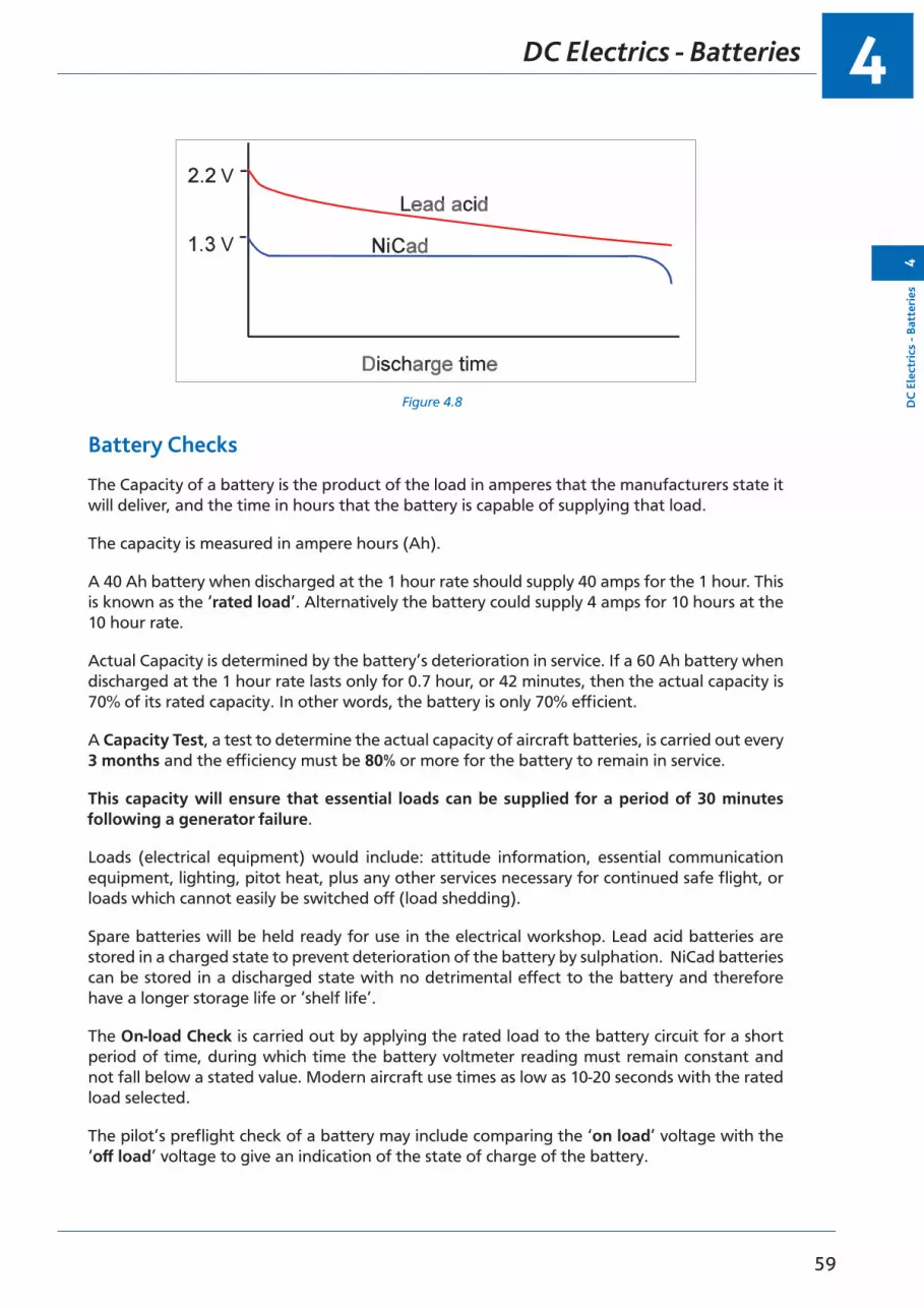
The nickel cadmium battery, however, is more robust and can hold a constant terminal voltage much better during the discharge cycle. It is therefore much preferred in large modern aircraft because in the event of a total failure of the aircraft generators the NiCad battery will provide a much more stable voltage.
Figure 4.8 is a graphical representation of a comparison of the discharge voltage of a lead acid against a NiCad during discharge.
4
59
DC
Ele
ctri
cs -
Batt
erie
s4
DC Electrics - Batteries
Figure 4.8 Figure 4.8
V
V
Battery Checks
The Capacity of a battery is the product of the load in amperes that the manufacturers state it will deliver, and the time in hours that the battery is capable of supplying that load.
The capacity is measured in ampere hours (Ah).
A 40 Ah battery when discharged at the 1 hour rate should supply 40 amps for the 1 hour. This is known as the ‘rated load’. Alternatively the battery could supply 4 amps for 10 hours at the 10 hour rate.
Actual Capacity is determined by the battery’s deterioration in service. If a 60 Ah battery when discharged at the 1 hour rate lasts only for 0.7 hour, or 42 minutes, then the actual capacity is 70% of its rated capacity. In other words, the battery is only 70% efficient.
A Capacity Test, a test to determine the actual capacity of aircraft batteries, is carried out every 3 months and the efficiency must be 80% or more for the battery to remain in service.
This capacity will ensure that essential loads can be supplied for a period of 30 minutes following a generator failure.
Loads (electrical equipment) would include: attitude information, essential communication equipment, lighting, pitot heat, plus any other services necessary for continued safe flight, or loads which cannot easily be switched off (load shedding).
Spare batteries will be held ready for use in the electrical workshop. Lead acid batteries are stored in a charged state to prevent deterioration of the battery by sulphation. NiCad batteries can be stored in a discharged state with no detrimental effect to the battery and therefore have a longer storage life or ‘shelf life’.
The On-load Check is carried out by applying the rated load to the battery circuit for a short period of time, during which time the battery voltmeter reading must remain constant and not fall below a stated value. Modern aircraft use times as low as 10-20 seconds with the rated load selected.
The pilot’s preflight check of a battery may include comparing the ‘on load’ voltage with the ‘off load’ voltage to give an indication of the state of charge of the battery.

DC Electrics - Batteries4
60
4D
C Electrics - Batteries
If the battery is not supplying any load then it is likely to show its nominal voltage (off load voltage). If the battery is then loaded up by switching on selective loads (e.g. pitot heater, landing lights, blower motors) and the voltage is maintained then the battery is in a good state of charge. If the voltage falls below a stated value within a time limit determined by the manual then the battery is in a low state of charge and should be replaced.
Battery Charging
A Constant Voltage Charging system is employed with most lead acid batteries to maintain the battery in a fully charged condition during flight. With this system the output voltage of the generator is maintained constant at 14 volts for a 12 volt battery and 28 volts for a 24 volt battery.
The generator voltage exceeds the battery voltage by 2 volts for every 12 volts of battery potential.
With alkaline batteries which are susceptible to thermal runaway it may be that a constant current charging system is employed by a dedicated battery charger which monitors battery temperature and voltage. Some charging systems use a method known as pulse charging and once the battery is up to 85% capacity, the battery charger delivers short pulses of charging current.
NOTE: After starting an engine using the aircraft’s battery, whether it is a lead acid battery or an alkaline battery, the generator, when it is on line, recharges that battery.
This is indicated by the high initial reading on the generator’s ammeter (load ammeter) or the battery ammeter (centre zero). This reading should quickly reduce as the battery is recharged, but if the charge rate increases, or remains high, it could be an indication of a faulty battery.
A high charge rate could result in a battery overheating and subsequent damage.
Secondary Batteries Summary
Figure 4.9
1.170
1.240 -1.300
1.270
SGSPILLAGE
Sodiumbicarbonate+ water
Boric acid
potassiumhydroxide /distilled waterpotassiumhydroxide /distilled water
cadmiumhydroxide
nickelhydroxide
nickeloxide
leadperoxide
spongylead
sulphuricacid
weaksulphuricacid
leadsulphate
leadsulphate
cadmium
ELECTROLYTENEGATIVEPOSITIVE
LEAD ACID
Summary.Secondary batteries: CHARGED DISCHARGED
ALKALINE

4
61
Que
stio
ns4
Questions
Questions - Batteries 1
1. Battery voltage is tested with:
a. a megometerb. a voltmeter on rated loadc. an ammeter with a rated voltage d. a hygrometer
2. Two 12 V 40 Ah batteries connected in series will produce:
a. 12 V 80 Ah b. 12 V 20 Ah c. 24 V 80 Ah d. 24 V 40 Ah
3. Two 12 V 40 Ah batteries connected in parallel will produce:
a. 12 V 80 Ahb. 24 V 80 Ah c. 12 V 20 Ah d. 24 V 40 Ah
4. A battery capacity test is carried out:
a. 6 monthly b. 2 monthly c. 3 monthlyd. every minor check
5. An aircraft has three batteries each of 12 volts with 40 Ah capacity connected in series. The resultant unit has:
a. a voltage of 36 and a capacity of 120 Ah b. a capacity of 120 Ah and a voltage of 12 c. a capacity of 36 Ah and 120 wattsd. a voltage of 36 and a capacity of 40 Ah
6. An aircraft has a battery with a capacity of 40 Ah. Assuming that it will provide its normal capacity and is discharged at the 10 hour rate:
a. it will pass 40 amps for 10 hrs b. it will pass 10 amps for 4 hrs c. it will pass 4 amps for 10 hrs d. it will pass 40 amps for 1 hr
7. Battery capacity percentage efficiency must always be:
a. 10% above saturation level b. above 70%c. 80% or mored. above 90%

Questions4
62
4Q
uestions
8. The method of ascertaining the voltage of a standard aircraft lead acid battery is by checking:
a. the voltage on open circuitb. the current flow with a rated voltage charge c. the voltage off loadd. the voltage with rated load switched ON
9. A battery is checked for serviceability by:
a. using an ammeterb. measuring the specific gravity of the electrolyte c. a boric acid solutiond. using an ohmmeter
10. In an AC circuit:
a. the battery is connected in seriesb. a battery cannot be used because the wire is too thick c. a battery cannot be used because it is DCd. only NiCad batteries can be used

4
63
Que
stio
ns4
Questions
Questions - Batteries 2
1. The specific gravity of a fully charged lead acid cell is:
a. 1.270 b. 1.090 c. 1.120 d. 0.1270
2. The nominal voltage of the lead acid cell is:
a. 1.2 volts b. 1.5 volts c. 1.8 volts d. 2.0 volts
3. A lead acid battery voltage should be checked:
a. on open circuitb. using a trimmer circuit c. with an ammeterd. on load
4. In an aircraft having a battery of 24 volts nominal off load and fully charged the voltmeter would read:
a. 22 volts b. 24 volts c. 26 volts d. 28 volts
5. The system used to maintain aircraft batteries in a high state of charge is the:
a. constant current system b. constant load systemc. constant resistance system d. constant voltage system
6. If you connect two identical batteries in series it will:
a. double the volts and halve the capacity b. reduce the voltage by 50%c. double the volts and leave the capacity the samed. double the volts and double the amps flowing in a circuit with twice the
resistance
7. The nominal voltage of an alkaline cell is:
a. 2.2 volts b. 1.8 volts c. 1.2 volts d. 0.12 volts

Questions4
64
4Q
uestions
8. The specific gravity of a fully charged alkaline cell is:
a. 0.120 - 0.130b. 1.160c. 1.240 - 1.30d. 1.800
9. The electrolyte used in the lead acid cell is diluted:
a. hydrochloric acid b. sulphuric acidc. boric acidd. potassium hydroxide
10. The electrolyte used in an alkaline battery is diluted:
a. saline solution b. sulphuric acidc. cadmium and distilled water d. potassium hydroxide solution

4
65
Que
stio
ns4
Questions
Questions - Batteries 3
1. The number of lead acid cells required to make up a twelve volt battery is:
a. 8 b. 12 c. 6 d. 10
2. A voltmeter across the terminals of a battery with all services off will indicate:
a. electromotive force b. resistancec. a flat batteryd. residual voltage
3. The voltage of a secondary cell is:
a. determined by the number of plates b. determined by the area of the platesc. determined by the diameter of the main terminals d. determined by the active materials on the plates
4. The level of the electrolyte must be maintained:
a. just below the top plateb. above the plates level with the filler cap c. one inch below the top of the platesd. just above the top of the plates
5. To top up the electrolyte add:
a. sulphuric acid b. distilled waterc. sulphuric acid diluted with distilled water d. boric acid
6. Non-spill vents are used on aircraft batteries to:
a. prevent spillage of electrolyte during violent manoeuvres b. stop spillage of the water onlyc. prevent the escape of gasesd. prevent spillage during topping-up
7. The capacity of a lead acid battery is:
a. determined by the area of the platesb. determined by the active materials on the plates c. determined by the size of the series coupling bars d. determined by the number of separators
8. Acid spillage in an aircraft can be neutralized by using:
a. caustic sodab. soap and waterc. soda and waterd. bicarbonate of soda and water

Questions4
66
4Q
uestions
9. When the battery master switch is switched off in flight:
a. the generators are disconnected from the bus bar b. the ammeter reads maximumc. the battery is isolated from the bus bard. the battery is discharged through the bonding circuit diodes
10. When the generator is on line the battery is:
a. in parallel with the other loads b. in series with the generatorc. in series when the generator is on line and is relayed when the generator is off
line d. load sharing

4
67
Que
stio
ns4
Questions

Answers4
68
4A
nswers
Answers - Batteries 1
1 2 3 4 5 6 7 8 9 10
b d a c d c c d b c
Answers - Batteries 2
1 2 3 4 5 6 7 8 9 10
a d d c d c c c b d
Answers - Batteries 3
1 2 3 4 5 6 7 8 9 10
c a d d b a a d c a

69
5Chapter
DC Electrics - Magnetism
Magnetism . . . . . . . . . . . . . . . . . . . . . . . . . . . . . . . . . . . . . . . . . . . . . 71
Temporary Magnets . . . . . . . . . . . . . . . . . . . . . . . . . . . . . . . . . . . . . . . . 72
Permanent Magnets . . . . . . . . . . . . . . . . . . . . . . . . . . . . . . . . . . . . . . . . 72
Permeability . . . . . . . . . . . . . . . . . . . . . . . . . . . . . . . . . . . . . . . . . . . . . 73
Magnetism . . . . . . . . . . . . . . . . . . . . . . . . . . . . . . . . . . . . . . . . . . . . . 73
The Molecular Structure of Magnets . . . . . . . . . . . . . . . . . . . . . . . . . . . . . . . 73
The Magnetic Effect of a Current . . . . . . . . . . . . . . . . . . . . . . . . . . . . . . . . . 74
The Corkscrew Rule . . . . . . . . . . . . . . . . . . . . . . . . . . . . . . . . . . . . . . . . . 74
The Magnetic Field of a Solenoid . . . . . . . . . . . . . . . . . . . . . . . . . . . . . . . . . 76
The Right Hand Grasp Rule. . . . . . . . . . . . . . . . . . . . . . . . . . . . . . . . . . . . . 76
The Strength of the Field of a Solenoid . . . . . . . . . . . . . . . . . . . . . . . . . . . . . . 76
Solenoid and Relay . . . . . . . . . . . . . . . . . . . . . . . . . . . . . . . . . . . . . . . . . 76
The Forces on a Conductor Which is Carrying a Current . . . . . . . . . . . . . . . . . . . . . 77
Questions . . . . . . . . . . . . . . . . . . . . . . . . . . . . . . . . . . . . . . . . . . . . . . 78
Answers . . . . . . . . . . . . . . . . . . . . . . . . . . . . . . . . . . . . . . . . . . . . . . . 80

DC Electrics - Magnetism5
70
5D
C Electrics - M
agnetism

5
71
DC
Ele
ctri
cs -
Mag
neti
sm5
DC Electrics - Magnetism
Magnetism
A magnet has the following properties:
• It will attract and pick up bits of iron and steel.• If freely suspended, it will come to rest pointing in a N-S direction.• A magnetic field (a region surrounding a magnet in which its magnetic effects can be
detected).
If iron filings are sprinkled on to a sheet of paper which is placed over a magnet, the filings arrange themselves into a distinctive pattern. They trace out invisible lines of influence in the magnetic field. These lines are called lines of flux or lines of force.
We can give direction to the lines of flux by putting arrowheads on them in the direction a compass needle would point if placed in the magnetic field.
Lines of flux of a magnet emerge from the N pole and re-enter at the S pole.
Although, in diagrams, some lines of flux are shown incomplete they are in fact always continuous.
Lines of flux never cross
When two magnets are brought close together their resultant field is modified by the fact that lines of flux cannot cross. Where lines of flux from the two magnets are in the same direction they reinforce one another and the flux density is increased.
When lines of flux from the two magnets oppose one another they tend to cancel each other out. Magnetic effects are most powerful at two points, usually near the ends of the magnet, called the poles of the magnet.
When a magnet is freely suspended and comes to rest, the end nearest to the earth’s magnetic north pole is called the ‘north seeking’ or North (N) pole of the magnet. The other is the South (S) pole. If the N pole of a magnet is brought near the N pole of another magnet, the two poles repel each other. Similarly two S poles repel each other.
Attraction occurs between a N and a S pole.
LIKE POLES REPEL
UNLIKE POLES ATTRACT
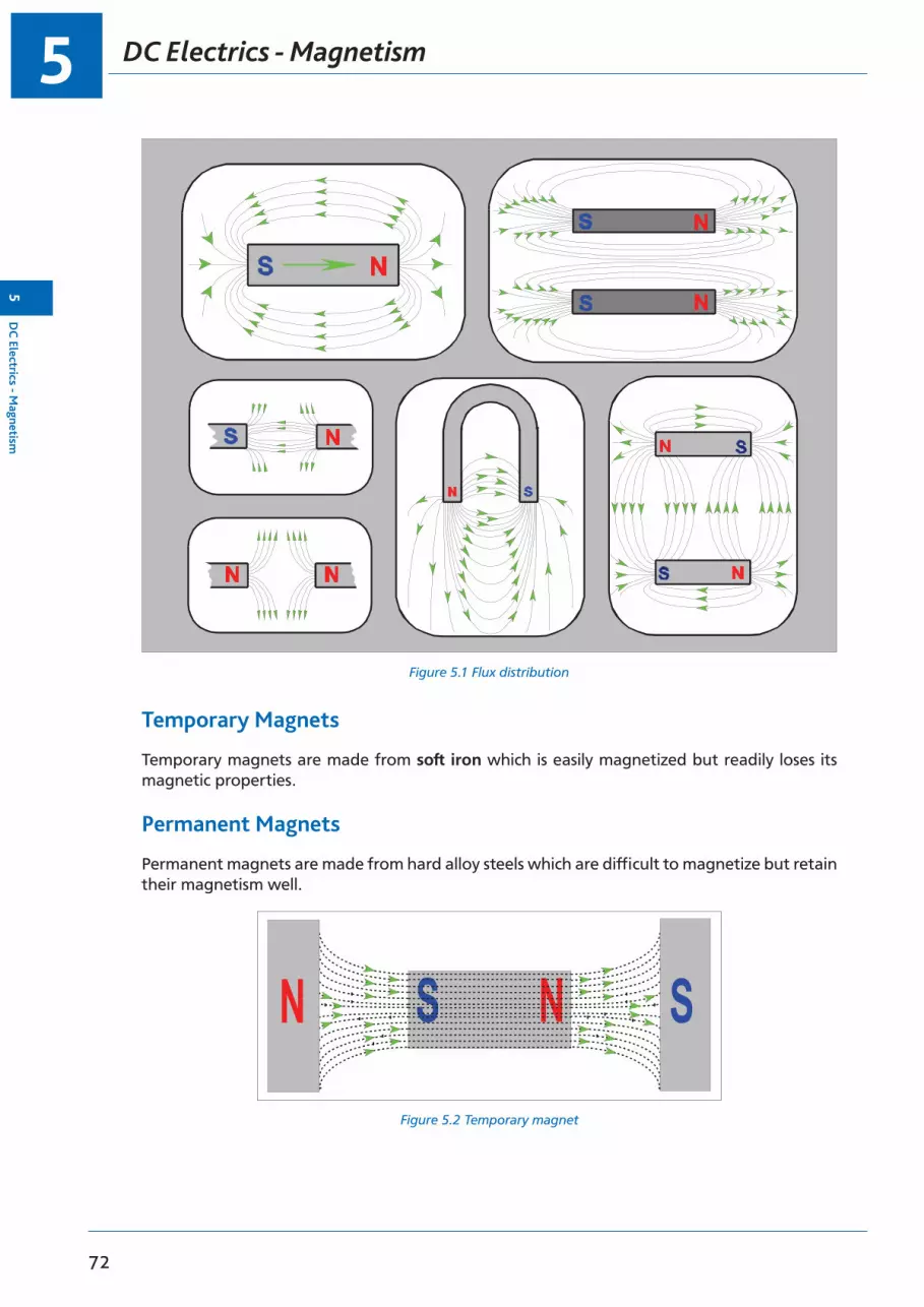
DC Electrics - Magnetism5
72
5D
C Electrics - M
agnetism
Figure 5.1 Flux distribution
Temporary Magnets
Temporary magnets are made from soft iron which is easily magnetized but readily loses its magnetic properties.
Permanent Magnets
Permanent magnets are made from hard alloy steels which are difficult to magnetize but retain their magnetism well.
Figure 5.2 Temporary magnetFigure 5.2. Temporary Magnet

5
73
DC
Ele
ctri
cs -
Mag
neti
sm5
DC Electrics - Magnetism
Permeability
If an unmagnetized piece of soft iron is placed in a magnetic field, the lines of flux concentrate to flow through the iron. The iron itself becomes magnetized and produces additional lines of flux.
This property of increasing the flux density is called permeability.
If it is removed from the magnetic field, the soft iron loses most of its magnetism. Soft iron is said to have low magnetic retentivity. The little magnetism which remains is called its residual magnetism.
Magnetism
Magnetism may be destroyed by:
• Heating the material.• Hammering the material.• Placing the material inside a solenoid which is supplied with an alternating current.
The Molecular Structure of Magnets
In an unmagnetized piece of soft iron, the molecules tend to form closed chains. When the iron is magnetized, the magnetized molecules tend to line up with invisible lines of influence in the magnetic field which are called the lines of flux. When all the molecules line up, the magnet is said to be saturated and it cannot be magnetized further.
Figure 5.3 Molecular distribution
N S
N
N S
N S
S N S N S N
N SN SN SS
S N S N S N
NN SN SS
S N S N S N S
NN SN SS
N S N SN S
MAGNETIZEDUNMAGNETIZED
SATURATED
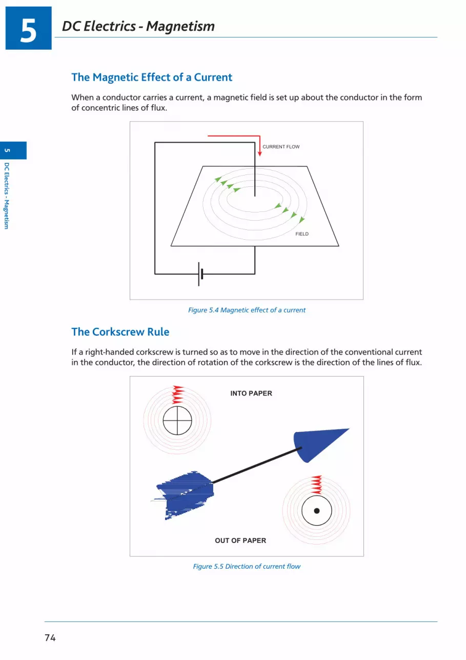
DC Electrics - Magnetism5
74
5D
C Electrics - M
agnetism
The Magnetic Effect of a Current
When a conductor carries a current, a magnetic field is set up about the conductor in the form of concentric lines of flux.
Figure 5.4 Magnetic effect of a current
CURRENT FLOW
FIELD
The Corkscrew Rule
If a right-handed corkscrew is turned so as to move in the direction of the conventional current in the conductor, the direction of rotation of the corkscrew is the direction of the lines of flux.
Figure 5.5 Direction of current flow
INTO PAPER
OUT OF PAPER

5
75
DC
Ele
ctri
cs -
Mag
neti
sm5
DC Electrics - Magnetism
Figure 5.6 Combined magnetic fieldsFigure 5.6. Combined Magnetic Fields
Figure 5.7 Magnetic field in a coil
S
Figure 5.7. Magnetic Field in a Coil

DC Electrics - Magnetism5
76
5D
C Electrics - M
agnetism
The Magnetic Field of a Solenoid
A solenoid (electromagnet) is a coil of a large number of turns of insulated wire. Between the coils the flux cancels out. The field pattern is similar to that of a bar magnet. The polarity of a solenoid may be found by the Right Hand Grasp Rule. Electromagnets and the principle of electromagnetism play a vital part in the operation and control of many aircraft electrical circuits.
The Right Hand Grasp Rule
If a solenoid is held in the right hand so that the fingers are curled round it pointing in the direction of the conventional current, the outstretched thumb points to the North pole of the solenoid.
The Strength of the Field of a Solenoid
The strength of the field of a solenoid can be increased by:
• increasing the number of turns on the coil.• increasing the current.• using a soft iron core.
When the current is switched off the magnetic field collapses leaving a little residual magnetism in the soft iron core.
Solenoid and Relay
Solenoids and relays are nothing more than remotely controlled switches. By switching a small current from the flight deck a large current can be switched at the solenoid or relay, e.g. the starter solenoid in the starting circuit for a piston engine.
The solenoid has a moving core whereas the relay has a stationary core and an attracted armature.
The wires that form the coil of the solenoid or relay are insulated and have no physical or electrical contact with the circuit which is controlled by the contacts.
Figure 5.8 Solenoid and relay

5
77
DC
Ele
ctri
cs -
Mag
neti
sm5
DC Electrics - Magnetism
The Forces on a Conductor Which is Carrying a Current
If a current carrying conductor is placed between two magnets, the interaction of the two magnetic fields will produce a strong magnetic field on one side of the conductor and a weak magnetic field on the other. The resultant stronger force will cause the conductor to move.
This is the basic motor principle and the direction of movement can be deduced by using Fleming’s Left Hand Rule. This will be explained in the section dealing with motors.
Figure 5.9 Interaction between two magnetic fields
S
S
FIELDSTRENGTHENED
FIELD WEAKENEDCONDUCTOR MOVESIN DIRECTION OFARROW
Figure 5.9. Interaction Between Two Magnetic Fields
The motion caused by the effects of current through a conductor suspended in a magnetic field is known as Lorentz force.

Questions5
78
5Q
uestions
Questions
1. The area of force around a magnet is termed:
a. conductance b. stablec. magnetic resistance d. magnetic field
2. When a magnet is unable to accept any further magnetism it is termed:
a. reluctance b. saturation c. actived. reactance
3. Permanent magnets are manufactured from:
a. steel b. plastic c. liquid d. glass
4. Magnetic lines of force flow externally from:
a. one main line station to another b. the master stationc. the north to the south pole d. in a random direction
5. Which of the two poles has the greatest strength?
a. North seeking pole b. South seeking polec. Both poles have the same strength d. The saturated pole
6. Electromagnetism is a product of:
a. voltage b. currentc. resistanced. engine resistance
7. To increase electromagnetic force one would:
a. increase coil resistance b. reduce current flowc. lower EMFd. increase current flow
8. If you bring two magnets together:
a. like poles will attractb. unlike poles will attract c. over heating will occurd. their magnetic fields will adjust to avoid overcrowding

5
79
Que
stio
ns5
Questions
9. A soft iron core in an electromagnet:
a. increases flux density b. decreases flux density c. reduces arcingd. increases the lines of strength

Answers5
80
5A
nswers
Answers
1 2 3 4 5 6 7 8 9
d b a c c b d b a
81
6Chapter
DC Electrics - Generators and Alternators
Electromagnetic Induction . . . . . . . . . . . . . . . . . . . . . . . . . . . . . . . . . . . . . 83
Fleming’s Right Hand Rule . . . . . . . . . . . . . . . . . . . . . . . . . . . . . . . . . . . . . 84
Faraday’s Law . . . . . . . . . . . . . . . . . . . . . . . . . . . . . . . . . . . . . . . . . . . . 85
Lenz’s Law. . . . . . . . . . . . . . . . . . . . . . . . . . . . . . . . . . . . . . . . . . . . . . 85
Simple Generator . . . . . . . . . . . . . . . . . . . . . . . . . . . . . . . . . . . . . . . . . . 85
Simple DC Generator . . . . . . . . . . . . . . . . . . . . . . . . . . . . . . . . . . . . . . . . 87
Characteristics of the Series Wound DC Generator . . . . . . . . . . . . . . . . . . . . . . . . 88
Commutator Ripple . . . . . . . . . . . . . . . . . . . . . . . . . . . . . . . . . . . . . . . . . 88
Characteristics of the Shunt Wound DC Generator . . . . . . . . . . . . . . . . . . . . . . . . 89
A Compound Wound DC Generator. . . . . . . . . . . . . . . . . . . . . . . . . . . . . . . . 90
Flashing the Generator Field . . . . . . . . . . . . . . . . . . . . . . . . . . . . . . . . . . . . 90
Alternators . . . . . . . . . . . . . . . . . . . . . . . . . . . . . . . . . . . . . . . . . . . . . 91
Voltage Control . . . . . . . . . . . . . . . . . . . . . . . . . . . . . . . . . . . . . . . . . . . 92
Voltage Regulator Operation . . . . . . . . . . . . . . . . . . . . . . . . . . . . . . . . . . . 93
Layout of a Generator System . . . . . . . . . . . . . . . . . . . . . . . . . . . . . . . . . . . 95
Load Sharing Circuits . . . . . . . . . . . . . . . . . . . . . . . . . . . . . . . . . . . . . . . . 95
Operation of Load Sharing Circuit . . . . . . . . . . . . . . . . . . . . . . . . . . . . . . . . . 96
Questions - Generator Theory . . . . . . . . . . . . . . . . . . . . . . . . . . . . . . . . . . . 98
Questions - Generator Control . . . . . . . . . . . . . . . . . . . . . . . . . . . . . . . . . . .100
Answers - Generator Theory . . . . . . . . . . . . . . . . . . . . . . . . . . . . . . . . . . . .102
Answers - Generator Control . . . . . . . . . . . . . . . . . . . . . . . . . . . . . . . . . . . .102
DC Electrics - Generators and Alternators6
82
6D
C Electrics - G
enerators and Alternators

6
83
DC
Ele
ctri
cs -
Gen
erat
ors
and
Alt
erna
tors
6
DC Electrics - Generators and Alternators
Electromagnetic Induction
Batteries are a good source of DC electricity by conversion of chemical energy, but they are not inexhaustible and will go flat after a period of time and need recharging. The primary source of electricity in an aircraft is always the generator or alternator.
Magnetism can be used to generate electricity by converting mechanical energy to electrical energy by Electromagnetic Induction.
If a conductor is moved in a magnetic field, the conductor will ‘cut through’ the invisible lines of flux. When this happens an Electromotive Force EMF (voltage) is induced into the conductor as long as the conductor keeps moving. If the conductor stops, the induced EMF ceases. It does not matter if the conductor or the magnetic field is moved as long as there is relative movement between the two.
If the conductor is connected to a complete circuit then a current will flow in the circuit in proportion to the induced EMF.
Figure 6.1 The situation with relative motion between the magnet and the coil
Figure 6.2 The situation with the magnet at rest
0
N
S
0
S
Figure 6.3 The direction of the relative motion determining the direction of current flow

DC Electrics - Generators and Alternators6
84
6D
C Electrics - G
enerators and Alternators
Fleming’s Right Hand Rule
The direction of the current can be determined by Fleming’s Right Hand Rule (Figure 6.4). To do so, align the first finger with the field from the North Pole to the South Pole. Point the thumb in the direction of rotation and the second finger will show the current direction.
For example, in Figure 6.4 the first finger is aligned with the field and the thumb is pointing upward in the direction of rotation of the red half of the armature. The second finger shows the current coming out of the red (negative) half of the armature. The blue half of the armature is moving downward therefore, with the first finger still aligned with the field, if the hand is rotated through 180 degrees, the second finger will show the current going into the armature.
If the direction of rotation or the field polarity is reversed, then so will be the direction of the current. However, if both are reversed the direction of current remains unchanged.
Figure 6.4 Fleming’s right hand rule
ThuMbMotion
FirstFingerField
SeCondFingerCurrent
Figure 6.4 Fleming’s Right Hand Rule
The magnitude of the induced voltage can be affected in three ways:
• The rate of cutting of lines of force. (Speed)• The strength of the magnetic field. (Flux density)• The number of turns of wire. (Larger coil)
Figure 6.5 Factors which determine the strength of the induced EMF
THREE WAYS OF INCREASING THE STRENGTHOF THE INDUCED EMF
1. 2. 3.INCREASE THE SPEED AT WHICH THE CONDUCTOR MOVES THROUGH THE MAGNETICFIELD
INCREASE THE STRENGTH OF THE MAGNETIC FIELD
INCREASE THE NUMBER OF TURNS ON THE COIL
6
85
DC
Ele
ctri
cs -
Gen
erat
ors
and
Alt
erna
tors
6
DC Electrics - Generators and Alternators
Faraday’s Law
Faraday’s law states:
When the magnetic flux through a coil is made to vary, a voltage is set up. The magnitude of this induced voltage is proportional to the rate of change of flux.
Lenz’s Law
Lenz’s law states:
A change of flux through a closed circuit induces a voltage and sets up a current. The direction of this current is such that its magnetic field tends to oppose the change in flux.
This action produces a back EMF. (See next chapter on Motors).
Simple Generator
The simplest form of a generator is a single loop of wire turning in a fixed magnetic field produced by a permanent magnet (Figure 6.6). The closed circuit is made by attaching rotating slip rings to both ends of the loop which are in contact with stationary carbon brushes. Continuous contact between the slip rings and the brushes is maintained by spring pressure. The brushes are attached to cables which form a closed circuit.
• The rotating loop is known as the armature.• The magnetic field is termed the field.• In a simple generator the armature rotates in the field.• An EMF is induced in the armature by electromagnetic induction.• The slip rings, brushes and cables complete the closed circuit and current will flow.
This type of generator produces an AC voltage in the armature and therefore an Alternating Current in the external circuit (first flowing one way, then changing direction and flowing the opposite way).
Figure 6.6 and Figure 6.7 show the layout of a simple AC generator and the voltage output rising then falling then changing direction as the armature sides reverse their direction through the magnetic field. The graphical view shows how a sine wave output of AC is generated. The maximum voltage is induced when there is maximum cutting of lines of flux. The position where no voltage is induced (position 1, 3 and 5 Figure 6.7), when the armature is moving parallel to the lines of flux, is known as the neutral plane.
A coil of wire can be wrapped around the two poles of the magnet. Passing a current through this coil will allow the magnetic field strength to be increased and so increase the voltage output of the generator. This is termed the field coil and is used to control the voltage to a fixed value irrespective of the generator speed.

DC Electrics - Generators and Alternators6
86
6D
C Electrics - G
enerators and Alternators
Figure 6.6 A simple AC generator
Figure 6.7 AC generator voltage output
S
N
1 2 3 4 5
N N N N
S S S S
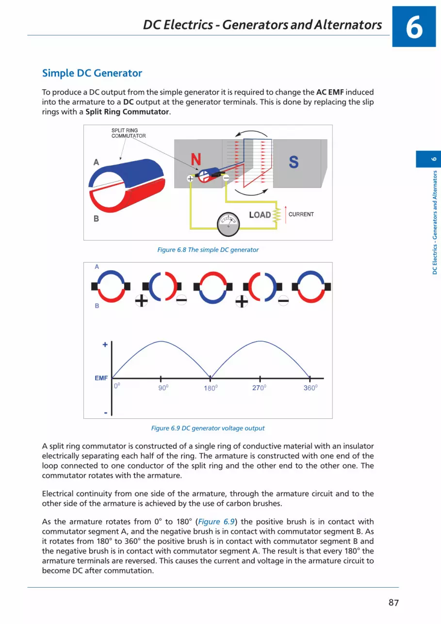
6
87
DC
Ele
ctri
cs -
Gen
erat
ors
and
Alt
erna
tors
6
DC Electrics - Generators and Alternators
Simple DC Generator
To produce a DC output from the simple generator it is required to change the AC EMF induced into the armature to a DC output at the generator terminals. This is done by replacing the slip rings with a Split Ring Commutator.
Figure 6.8 The simple DC generatorFigure 6.8 The Simple DC Generator
Figure 6.9 DC Generator Voltage OutputFigure 6.9 DC generator voltage output
A split ring commutator is constructed of a single ring of conductive material with an insulator electrically separating each half of the ring. The armature is constructed with one end of the loop connected to one conductor of the split ring and the other end to the other one. The commutator rotates with the armature.
Electrical continuity from one side of the armature, through the armature circuit and to the other side of the armature is achieved by the use of carbon brushes.
As the armature rotates from 0° to 180° (Figure 6.9) the positive brush is in contact with commutator segment A, and the negative brush is in contact with commutator segment B. As it rotates from 180° to 360° the positive brush is in contact with commutator segment B and the negative brush is in contact with commutator segment A. The result is that every 180° the armature terminals are reversed. This causes the current and voltage in the armature circuit to become DC after commutation.
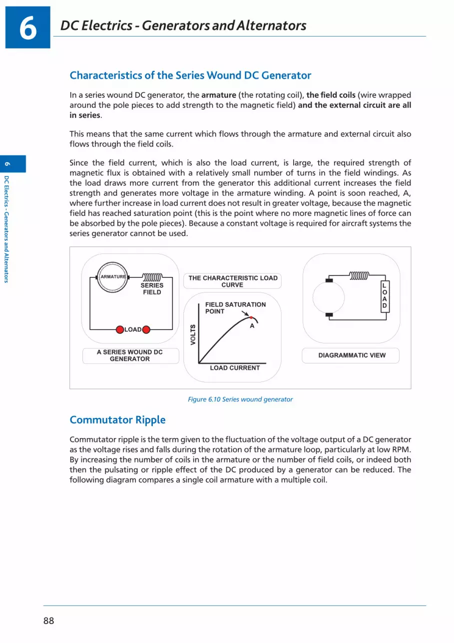
DC Electrics - Generators and Alternators6
88
6D
C Electrics - G
enerators and Alternators
Characteristics of the Series Wound DC Generator
In a series wound DC generator, the armature (the rotating coil), the field coils (wire wrapped around the pole pieces to add strength to the magnetic field) and the external circuit are all in series.
This means that the same current which flows through the armature and external circuit also flows through the field coils.
Since the field current, which is also the load current, is large, the required strength of magnetic flux is obtained with a relatively small number of turns in the field windings. As the load draws more current from the generator this additional current increases the field strength and generates more voltage in the armature winding. A point is soon reached, A, where further increase in load current does not result in greater voltage, because the magnetic field has reached saturation point (this is the point where no more magnetic lines of force can be absorbed by the pole pieces). Because a constant voltage is required for aircraft systems the series generator cannot be used.
Figure 6.10 Series wound generator
LOAD
DIAGRAMMATIC VIEW
LOAD
SERIESFIELD
ARMATURE
LOAD CURRENT
A SERIES WOUND DCGENERATOR
THE CHARACTERISTIC LOADCURVE
FIELD SATURATIONPOINT
A
Figure 6.11 Series Wound Generator
Commutator Ripple
Commutator ripple is the term given to the fluctuation of the voltage output of a DC generator as the voltage rises and falls during the rotation of the armature loop, particularly at low RPM. By increasing the number of coils in the armature or the number of field coils, or indeed both then the pulsating or ripple effect of the DC produced by a generator can be reduced. The following diagram compares a single coil armature with a multiple coil.
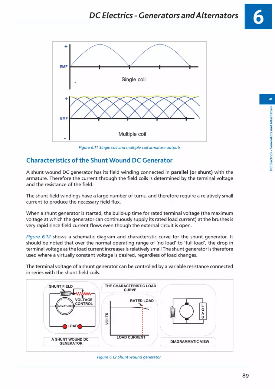
6
89
DC
Ele
ctri
cs -
Gen
erat
ors
and
Alt
erna
tors
6
DC Electrics - Generators and Alternators
Figure 6.11 Single coil and multiple coil armature outputs
Characteristics of the Shunt Wound DC Generator
A shunt wound DC generator has its field winding connected in parallel (or shunt) with the armature. Therefore the current through the field coils is determined by the terminal voltage and the resistance of the field.
The shunt field windings have a large number of turns, and therefore require a relatively small current to produce the necessary field flux.
When a shunt generator is started, the build-up time for rated terminal voltage (the maximum voltage at which the generator can continuously supply its rated load current) at the brushes is very rapid since field current flows even though the external circuit is open.
Figure 6.12 shows a schematic diagram and characteristic curve for the shunt generator. It should be noted that over the normal operating range of ‘no load’ to ‘full load’, the drop in terminal voltage as the load current increases is relatively small The shunt generator is therefore used where a virtually constant voltage is desired, regardless of load changes.
The terminal voltage of a shunt generator can be controlled by a variable resistance connected in series with the shunt field coils.
Figure 6.12 Shunt wound generator
LOAD
LOAD CURRENTA SHUNT WOUND DCGENERATOR
THE CHARACTERISTIC LOADCURVE
RATED LOAD
SHUNT FIELD
VOLTAGECONTROL
ARMATURE LOAD
DIAGRAMMATIC VIEW

DC Electrics - Generators and Alternators6
90
6D
C Electrics - G
enerators and Alternators
A Compound Wound DC Generator
A compound wound generator is a generator with combined series and shunt windings. There are two sets of field coils, one in series with the armature, and one in parallel with the armature. One shunt coil and one series coil are always mounted on a common pole piece and are sometimes enclosed in a common covering.
Compound wound generators were designed to overcome the drop in terminal voltage which occurs in a shunt wound generator when the load is increased. This voltage drop is undesirable where constant voltage loads are used. By adding the series field, which increases the strength of the total magnetic field when the load current is increased, the voltage drop caused by the increased load current flowing through the resistance of the armature is overcome, and it is possible to obtain an almost constant voltage output.
Figure 6.13 Compound wound generator
THE CHARACTERISTIC LOADCURVE
DIAGRAMMATIC VIEWCOMPOUND WOUND DCGENERATOR
Flashing the Generator Field
The DC generator is normally self-excited due to the residual magnetism which remains in the field pole pieces when the machine is inactive or static. Self-excited means that because of the residual magnetism as soon as the generator is rotated there will be a voltage produced. Some of this voltage can be applied to the field coil to increase the magnetism and cause the voltage to increase further until it reaches its controlled value. An externally excited generator is one which has no residual magnetism and requires a battery to supply the field coil with current to start the generating process.
It will have been noted that magnetism can be lost, destroyed or reversed due to the passage of time, the effects of heat, exposure to an AC field, hammering or shock, and the application of a reversal of polarity. The loss of residual magnetism in a DC generator, which will prevent any build up in output voltage, can be corrected by momentarily passing a current through the field in the normal direction.
This procedure is known as “flashing the field”. In practice some aircraft might have a button or switch to allow this procedure to be carried out from the cockpit.

6
91
DC
Ele
ctri
cs -
Gen
erat
ors
and
Alt
erna
tors
6
DC Electrics - Generators and Alternators
Alternators
Most modern light aircraft use an alternator rather than a DC generator to provide constant voltage electricity for its electrical system because of the advantages an alternator has.
The alternator has a much better power to weight ratio, will produce a stable output at low RPM and does not suffer with the problems of a commutator as it uses a rectifier to convert AC to DC. The following table and diagram identify the constructional differences between the DC generator and the alternator.
DC GENERATOR ALTERNATOR
Rotating Armature Stationary Armature
Stationary Field Rotating Field
Converts AC to DC by means of a commutator
Converts AC to DC by means of a rectifier
Suffers from arcing and sparking at the commutator as the high load current has to flow through the commutator and brushes
High load current taken from stationary armature eliminates arcing and sparking. Small field current only flows through slip rings.
Figure 6.14 Construction of a generator and alternator
LOAD
LOAD

DC Electrics - Generators and Alternators6
92
6D
C Electrics - G
enerators and Alternators
Voltage Control
The output voltage of a generator or alternator is dependent upon:
• The speed of rotation of the armature or field.• The strength of the magnetic field.• The number of turns in the armature.• The size and shape of the turns in the armature.
Most light aircraft DC electrical systems operate at 14 volts and so all the equipment is designed to operate correctly when supplied with 14 volts. It is therefore necessary for the output of the generator or alternator to be controlled or regulated, to ensure that at all times it supplies 14 volts.
As can be seen from the points above, there are four factors which influence the output voltage of a generator or alternator.
The number and size and shape of the turns is a design factor and therefore the operator cannot alter them.
The generator or alternator is driven by a drive belt or an engine accessory gearbox and therefore the speed of rotation of the armature or field is linked to the speed of rotation of the engine. Controlling the output voltage by controlling the speed of the engine is not a practical solution.
Remember back to basic magnetism, the strength of the magnetic field produced by a coil of wire is proportional to the current flowing through the coil (an electromagnet).
The only practical method of controlling the output voltage of a generator is to control the strength of the magnetic field by controlling the current flow in a coil wound around the magnetic pole pieces (field coil or field winding). Control of the current flow is achieved by a voltage regulator.
A voltage regulator consists of:
• A variable resistance in series with the field coil. In older voltage regulators the variable resistance was achieved using a Carbon Pile. In modern voltage regulators it is achieved by employing an electronic solid state system of transistors, diodes and resistors. The net result is the same whichever is used.
• A control coil in parallel with the field coil and the armature. This is used to sense the generator output voltage and vary the resistance to control the current through the field coil, therefore controlling the voltage.
The voltage regulator senses the output voltage of the generator or alternator and adjusts the field current to maintain the correct output voltage irrespective of generator speed or electrical load

6
93
DC
Ele
ctri
cs -
Gen
erat
ors
and
Alt
erna
tors
6
DC Electrics - Generators and Alternators
Voltage Regulator Operation
A carbon pile voltage regulator uses the carbon pile as a variable resistor. The carbon pile is a stack of carbon discs whose overall resistance is proportional to the amount of compression of the stack. The more the stack is compressed, the lower the resistance.
Figure 6.15 Carbon pile voltage regulator
In Figure 6.15 the control coil, which is in parallel with the generator armature, has the generator output supplied across it. Because the control coil has a fixed resistance and Ohm’s Law states that V = I R, the current through the control coil will vary in direct proportion to the generator output voltage. As the current varies so will the strength of the magnetic field produced by the coil.
The strength of the magnetic field produced by the control coil affects the value of the variable resistance, (the compression of the carbon pile) which is in series with the field coil. As the resistance in the variable resistor varies, because V = I R, so the current in the field coil varies. As the current through the field coil varies so does the strength of the magnetic field it produces, and therefore the EMF induced into the armature, and the output voltage of the generator is controlled automatically.
In Figure 6.15 the field coil is shown outside of the generator for clarity, in fact it is an integral part of the generator construction.
The vibrating contact voltage regulator (Figure 6.16) controls the voltage output in a similar fashion but instead of varying a resistance it rapidly switches in and out a fixed resistance.
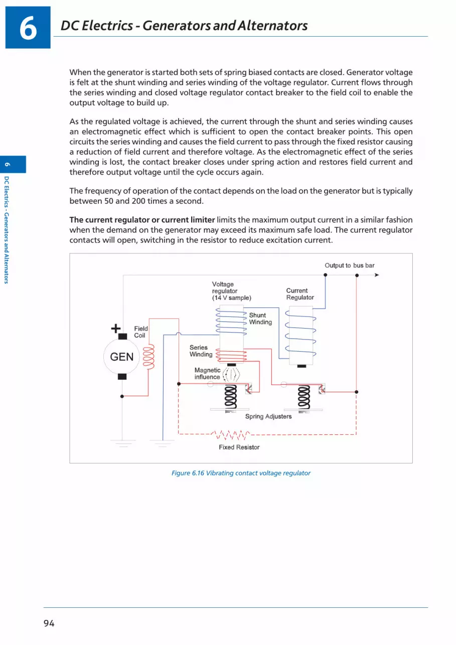
DC Electrics - Generators and Alternators6
94
6D
C Electrics - G
enerators and Alternators
When the generator is started both sets of spring biased contacts are closed. Generator voltage is felt at the shunt winding and series winding of the voltage regulator. Current flows through the series winding and closed voltage regulator contact breaker to the field coil to enable the output voltage to build up.
As the regulated voltage is achieved, the current through the shunt and series winding causes an electromagnetic effect which is sufficient to open the contact breaker points. This open circuits the series winding and causes the field current to pass through the fixed resistor causing a reduction of field current and therefore voltage. As the electromagnetic effect of the series winding is lost, the contact breaker closes under spring action and restores field current and therefore output voltage until the cycle occurs again.
The frequency of operation of the contact depends on the load on the generator but is typically between 50 and 200 times a second.
The current regulator or current limiter limits the maximum output current in a similar fashion when the demand on the generator may exceed its maximum safe load. The current regulator contacts will open, switching in the resistor to reduce excitation current.
Figure 6.16 Vibrating contact voltage regulator

6
95
DC
Ele
ctri
cs -
Gen
erat
ors
and
Alt
erna
tors
6
DC Electrics - Generators and Alternators
Layout of a Generator System
In an aircraft system the generator, load and battery are all in parallel with each other. The bus bar is a distribution point. The generator output voltage is maintained slightly higher than battery voltage to maintain the battery charged.
Figure 6.17 Diagram of a generator system
Bus bar
LOAD
Load Sharing Circuits
When the aircraft electrical system has two generators feeding one bus bar it is known as PARALLELING GENERATORS. The advantage of operating generators in parallel is much the same of having two batteries in parallel - double the capacity. It also allows the generators to share the total load of the aircraft and enables power to be maintained in the event of a generator failure.
When paralleling generators it is necessary for each generator to supply half of the total current demanded by the loads on the bus bar. This is known as LOAD SHARING.
To achieve load sharing the output voltage of both generators must be exactly the same. If there is any potential difference between the generator outputs then current will flow from the higher potential generator to the lower potential generator. This is known as recirculating current.
If this is the case then generator with the higher voltage output will be supplying all the current demanded by the bus bar loads and whatever current is demanded by the potential difference between the generator outputs. The generator with the lower voltage output will be supplying no current to the bus bar. There will be no load sharing, and the current flowing to the low output generator will be attempting to turn the generator into a motor. The direction of rotation of the motor will be in opposition to the direction of rotation of the engine. Flow of current to the low output generator is undesirable and parallel systems will have reverse current relays fitted to protect against this fault in the event of a failure of the load sharing circuit.
The load sharing circuit consists of equalizing coils in the voltage regulators which finely adjusts each generator field current to ensure the output voltages of the paralleled generators are equal.
In each voltage regulator the equalizing coil is positioned such that it affects the magnetic field produced by the control coil, which affects the value of the variable resistance, which in turn affects the current through the shunt field coil and so regulates the output voltage of the generator. The direction of flow of current through the equalizing coil will determine whether the voltage output of the generator is increased or decreased.

DC Electrics - Generators and Alternators6
96
6D
C Electrics - G
enerators and Alternators
Operation of Load Sharing Circuit
(See Figure 6.18)
• With both generators “off line” there is no output from either generator and both Equalizing Relays and Line Contactors are open. (The line contactor is a large solenoid operated contact which enables the output line of the generator to be connected to the bus bar when the output voltage of the generator has been checked and found to be acceptable. It may be closed automatically or manually from the cockpit.)
• When No. 1 generator is brought “on line”, No. 1 generator line contactor closes and its output, regulated by its voltage regulator, is supplied to the aircraft bus bar. No. 1 Equalizing Relay, which is part of the generator line contactor, is closed.
• When No. 2 generator is brought “on line”, No. 2 generator line contactor is closed and its output, regulated by its voltage regulator, is supplied to the aircraft bus bar.
• No. 2 Equalizing Relay is also closed. This now connects both generator voltage regulators into the Equalizing circuit.
• If there is any potential difference between the output of generator 1 and 2, there will be a current flow through the equalizing coils which will apply correcting values to each voltage regulator increasing the voltage of the lower voltage generator and reducing the voltage of the higher generator until they are the same, equally sharing the total aircraft load.

6
97
DC
Ele
ctri
cs -
Gen
erat
ors
and
Alt
erna
tors
6
DC Electrics - Generators and Alternators
Figure 6.18 Load sharing
14 V
EqualizingCoil
Voltage ControlCoil
Field Coil
GEN1 GEN2
14 V
LineContactors
EqualizingContactsVariable
Resistor
Current to aircraft loads
Figure 6.20 Load Sharing

Questions6
98
6Q
uestions
Questions - Generator Theory
1. An EMF is induced in a conductor rotating in a magnetic field by:
a. capacitive reactionb. the reverse current relay c. electro transmissiond. electromagnetic induction
2. Magnetic field strength is controlled by:
a. battery bus bar current b. current in the field coil c. current in the armatured. current flow to the battery
3. If a conductor is placed in a magnetic field:
a. an EMF is induced in the conductorb. an EMF is induced in the conductor only when the conductor rotates c. the applied resistance assists the back EMFd. an EMF is induced in the conductor only when the conductor is stationary
4. The output of a basic generator before commutation is:
a. ACb. DC and after commutation is AC c. DCd. synchronized AC and DC
5. An internally excited generator is one where:
a. the field is produced within the distribution b. the field is initiated by a HT and LT coilc. the field is initiated by the batteryd. the field is initiated within the generator
6. A DC generator has a commutator whose purpose is to:
a. change AC to give a generator output of DC b. change DC to ACc. transmit the generator output to the electrical circuit and to cool the
generator d. maintain a constant resistance
7. Another name for a number of conductors rotating in a magnetic field is:
a. a capacitor b. an armature c. a condenserd. a commutator
6
99
Que
stio
ns6
Questions
8. A generator is governed so that:
a. the EMF is constant and the rate of flow varies b. the rate of flow is constant and the EMF variesc. the generator voltage reduces generator temperature d. back EMF is equal and opposite to the applied EMF
9. The voltage regulator:
a. senses cut-out pressure and adjusts field currentb. senses generator output pressure and adjusts field currentc. senses generator output current and adjusts the field voltage d. senses back EMF
10. The generator master switch is normally:
a. fitted with a mechanical safety catchb. in the field circuit which is connected in parallel with the generator output c. in the field circuit which is in parallel with the voltage regulatord. fitted in series with the commutator

Questions6
100
6Q
uestions
Questions - Generator Control
1. The voltage regulator:
a. provides a constant current flow from the generator with changes of generator speed
b. senses current outputc. maintains a steady generator voltage with changes of generator speedd. regulates the amount of current supplied by the battery to operate the
generator
2. Voltage is controlled in a generator by:
a. a reverse current relay b. moving the brushesc. a voltage regulator d. it is uncontrollable
3. On aircraft, generator voltage is regulated by:
a. varying the generator field strength b. increasing and decreasing the loadc. changing the generator speed d. changing generator load
4. In an aircraft having a battery with a nominal voltage of 24 V, generator output would be:
a. 24 volts b. 28 amps c. 28 volts d. 24 amps
5. In DC electrical generating systems, the voltage regulator controls the system voltage within prescribed limits:
a. regardless of varying engine RPM and electrical load, by varying the current in the generator field windings
b. by means of a relay which closes contacts in the output line when a certain RPM is reached
c. by temperatured. by a variable resistance which limits the voltage given by the batteries
6. A voltage regulator is fitted to:
a. prevent high circulating currents b. prevent backlashc. to ensure correct voltage output to battery d. to prevent battery feedback to the generator
7. If an aircraft electrical system is quoted as 24 volts DC, the output of the generator is:
a. 12 volts with the generators connected in series b. 28 volts with the generators connected in parallelc. 36 volts with the generators connected in series/parallel d. 42 volts
6
101
Que
stio
ns6
Questions
8. If a circuit is designed for 12 volts, the generator will:
a. give paralleled output only b. give controlled 14 voltsc. 14 volts wild DCd. give controlled 12 volts
9. The aircraft electrical generator output is controlled in flight by:
a. sensing the generator output pressure b. ram airc. a resistance in the generator output circuit d. the resistance of the armature circuit
10. In a generator control circuit the strength of the magnetic field is controlled by:
a. the commutatorb. the voltage regulatorc. the reverse current contactor d. the output CB

Answers6
102
6A
nswers
Answers - Generator Theory
1 2 3 4 5 6 7 8 9 10
d b b a d a b a b b
Answers - Generator Control
1 2 3 4 5 6 7 8 9 10
c c a c a c b b a b

103
7Chapter
DC Electrics - DC Motors
Electric Motors . . . . . . . . . . . . . . . . . . . . . . . . . . . . . . . . . . . . . . . . . . .105
Fleming’s Left Hand Rule . . . . . . . . . . . . . . . . . . . . . . . . . . . . . . . . . . . . . .105
Practical DC Motor . . . . . . . . . . . . . . . . . . . . . . . . . . . . . . . . . . . . . . . . .106
Back EMF . . . . . . . . . . . . . . . . . . . . . . . . . . . . . . . . . . . . . . . . . . . . . .107
Slow Start Resistor . . . . . . . . . . . . . . . . . . . . . . . . . . . . . . . . . . . . . . . . .107
Commutation . . . . . . . . . . . . . . . . . . . . . . . . . . . . . . . . . . . . . . . . . . . .107
Series Wound Motors . . . . . . . . . . . . . . . . . . . . . . . . . . . . . . . . . . . . . . . .108
Shunt Wound Motors. . . . . . . . . . . . . . . . . . . . . . . . . . . . . . . . . . . . . . . .108
Starter-generator Systems . . . . . . . . . . . . . . . . . . . . . . . . . . . . . . . . . . . . .109
Actuators . . . . . . . . . . . . . . . . . . . . . . . . . . . . . . . . . . . . . . . . . . . . . .110
Solenoid Actuators . . . . . . . . . . . . . . . . . . . . . . . . . . . . . . . . . . . . . . . . .110
Motor Actuator Construction . . . . . . . . . . . . . . . . . . . . . . . . . . . . . . . . . . .110
The Split Field Series Actuator . . . . . . . . . . . . . . . . . . . . . . . . . . . . . . . . . . .111
The Split Field Series Actuator Operation . . . . . . . . . . . . . . . . . . . . . . . . . . . . .111
Motor Actuators . . . . . . . . . . . . . . . . . . . . . . . . . . . . . . . . . . . . . . . . . .112
Rotary Actuators . . . . . . . . . . . . . . . . . . . . . . . . . . . . . . . . . . . . . . . . . .112
Linear Actuators . . . . . . . . . . . . . . . . . . . . . . . . . . . . . . . . . . . . . . . . . .113
Actuator Brakes . . . . . . . . . . . . . . . . . . . . . . . . . . . . . . . . . . . . . . . . . . .114
Actuator Clutches . . . . . . . . . . . . . . . . . . . . . . . . . . . . . . . . . . . . . . . . . .114
Visual Indicators Used with Linear Actuators . . . . . . . . . . . . . . . . . . . . . . . . . . .114
Visual Indicators Used with Rotary Actuators . . . . . . . . . . . . . . . . . . . . . . . . . . .114
Indicator Lights . . . . . . . . . . . . . . . . . . . . . . . . . . . . . . . . . . . . . . . . . . .114
Electromagnetic Indicators . . . . . . . . . . . . . . . . . . . . . . . . . . . . . . . . . . . . .115
Questions . . . . . . . . . . . . . . . . . . . . . . . . . . . . . . . . . . . . . . . . . . . . . .116
Answers . . . . . . . . . . . . . . . . . . . . . . . . . . . . . . . . . . . . . . . . . . . . . . .118
DC Electrics - DC Motors7
104
7D
C Electrics - D
C M
otors

7
105
DC
Ele
ctri
cs -
DC
Mot
ors
7
DC Electrics - DC Motors
Electric Motors
An electric motor is a machine for converting electrical energy into mechanical energy. Its function is, therefore, the reverse of that of a generator. There is little difference between the construction of DC motors and DC generators; both have essentially the same parts and they look alike. In fact, in many cases, a DC machine can be used either as a motor or a generator.
Remember back to magnetic principles, a current flowing through a wire placed in a magnetic field causes the wire to move due to a force acting on the wire; a motor works on this principle.
Fleming’s Left Hand Rule
The direction of rotation of a motor can be determined by Fleming’s Left Hand Rule (Figure 7.1). To do this, align the first finger with the field from the North Pole to the South Pole. Point the second finger in the direction of the current flowing into or out of the armature and the thumb will indicate the direction of motion.
For example in Figure 7.1 the first finger is aligned with the field and the second finger is pointing in the direction of the current coming out of the red (negative) half of the armature. The thumb is pointing upward indicating that the motion is upwards and therefore anticlockwise. In the blue (positive) half of the armature the current is flowing into the armature. Therefore, with the first finger still aligned with the field if the hand rotated through 180 degrees, the thumb will now be pointing downward confirming anticlockwise rotation of the armature.
If the current or the field polarity is reversed, then so will be the direction of rotation of the motor. However, if both are reversed the direction of rotation of the motor remains unchanged.
Figure 7.1 Fleming’s left hand rule for motors
ThuMbMotion
FirstFingerField
SeCondFingerCurrent
Figure 6.21 Fleming’s Left Hand Rule For Motors

DC Electrics - DC Motors7
106
7D
C Electrics - D
C M
otors
Practical DC Motor
The simple DC generator shown earlier and the DC motor below are not practical and can be improved by adding further armature/s and improving the shape of the pole pieces. (Figure 7.2b.) Generator voltage output and motor speed can be controlled by the addition of field windings which enable the field strength to be adjusted. Figure 7.3 shows a sectional view of a practical DC generator which is similar to a DC motor.
Figure 7.2 a: Simple DC motor b: Improved DC motor
Figure 7.3 Sectional view of DC rotating armature generator

7
107
DC
Ele
ctri
cs -
DC
Mot
ors
7
DC Electrics - DC Motors
Back EMF
The movement of the conductor in the magnetic field induces in it an electromotive force (EMF) which we know from Lenz’s law will oppose the rate of change of magnetic flux producing it. So an EMF is induced into the rotating part of the motor which tends to oppose the rotation of the motor. That is to say, the induced voltage will oppose the supply voltage. It is therefore called the back EMF.
The back EMF is proportional to motor speed and can never be as great as the supply input voltage. The difference between the applied EMF and the back EMF is always such that current can flow in the conductor and produce motion.
Slow Start Resistor
Some motors may have a slow start resistor in the circuit which is switched in series with the armature when the motor is first started to reduce the initial starting current before a back EMF has been established. The resistor is then bypassed by a centrifugal or time switch when the motor is turning to apply full current to the armature.
Figure 7.4 Slow start resistor circuit
Commutation
The simplest form of motor has a single loop of wire able to rotate freely between the poles of a permanent magnet. A connection is made from the DC supply source (a battery) to the loop by brushes on a commutator; the 2 segments of which are connected to opposite ends of the loop. An example of this type of motor is shown (Figure 7.2a).
A single loop DC motor would not be able to turn heavy loads. To obtain a large mechanical output, with smooth running, the same improvements are made as in the case of the DC generator. That is a laminated iron core carrying a number of armature coils is used, and a corresponding number of commutator segments. The magnetic field is produced by an electro-

DC Electrics - DC Motors7
108
7D
C Electrics - D
C M
otors
magnet and its field coils and the spacing between the armature and pole pieces is kept as small as possible.
Series Wound Motors
The series wound motor has its field connected in series with the armature. The field coil consists of a few turns of heavy wire, and since the entire armature current flows through it, the field strength varies with the armature current. If the load on the motor increases, it slows down and the back EMF decreases, which allows the armature and field current to increase and so provide the heavier torque needed.
Figure 7.5 Series wound motor
Series motors run slowly with heavy loads and very rapidly with light loads. If the load is completely removed, the motor can dangerously over speed and possibly disintegrate.
The reason for this is that the current required to rotate the motor with only a light load is very small, and consequently the series wound field coils produce only a weak magnetic field. This means that the motor cannot turn fast enough to generate the amount of back EMF needed to restore the balance. Series wound motors are variable speed motors and their speed changes with the applied load, for this reason they are not used either when a constant speed condition is needed, or where the load is intermittent. The series wound motor has a high starting torque and because of this it must never be started off load. Use of the series wound motor is mainly confined to electric actuators, starter motors and landing gear actuation.
Shunt Wound Motors
In a shunt wound motor, the field is connected directly across the voltage source, and is therefore independent of variation in load and armature current. The field coil consists of many turns of fine wire. The torque developed varies directly with the armature current.
If the load on the motor increases, the motor slows down, reducing the back EMF (which depends upon speed as well as on the constant field strength).
The reduced back EMF allows the armature current to increase, thereby furnishing the heavier torque needed to drive the increased load.

7
109
DC
Ele
ctri
cs -
DC
Mot
ors
7
DC Electrics - DC Motors
If the load is decreased, the motor speeds up, increasing the back EMF and thereby decreasing the armature current and the torque developed whereupon the motor slows down. In a shunt wound motor, the variation of speed from ‘no-load’ to normal or ‘full’ load is only 10 % of the ‘no-load’ speed. Shunt wound motors are therefore considered constant speed motors.
Shunt wound motors are normally used where constant speeds under varying loads are required and tasks where it is possible for the motor to start under light or no-load conditions, such as fans, centrifugal pumps and motor generator units.
Figure 7.6 Shunt wound motor
A SHUNT WOUND DC MOTOR
SHUNT FIELD
ARMATURE
DIAGRAMMATIC VIEW
Starter-generator Systems
Several types of turbine-powered aircraft are equipped with starter systems which use a starter generator having the dual function of engine starting and of supplying DC power to the aircraft’s electrical system.
Starter-generator units are basically compound-wound machines with two sets of field windings, one armature winding and a commutator. They are permanently coupled with the appropriate engine via a drive shaft and gear train.
For starting purposes, the unit functions as a fully compounded motor, the shunt field winding being supplied with current via a field changeover relay.
When the engine is running and the starter motor circuit is isolated from the power supply, the changeover relay is also automatically de-energized and its contacts connect the shunt field winding to a voltage regulator. The changeover relay contacts also permit DC to flow through the shunt winding to provide initial excitation of the field.
The machine thereafter functions as a conventional DC generator, its output being connected to the bus bar when it reaches the regulated level.

DC Electrics - DC Motors7
110
7D
C Electrics - D
C M
otors
Generator
Shunt field
Series field
Engine
Drive shaft
Voltage regulator
Generator mode
Motor
Shunt field
Series field
Engine
Drive shaft
Voltage regulator
Motor mode
Figure 7.7 Compound wound motor generator
The advantage of the starter-generator is that only one device provides both functions, thereby saving weight and complexity. The disadvantage is its inability to maintain full output at low RPM hence their use is typical on turbine engines which maintain a high engine RPM. A typical starter generator supplies 300 amps at 28 volts.
Actuators
Equipment and components which are installed in the modern aircraft are generally inaccessible for manual operation by the pilot or crew. Remote control of such items is achieved by the use of electrical actuators.
These actuators may be divided into two main groups:
• Solenoid actuators• Motor actuators
Solenoid Actuators
Solenoid actuators are used to control hydraulic and pneumatic system selectors. Application of electrical power to a solenoid results in a valve opening under magnetic attraction.
Motor Actuator Construction
The actuator motor is a high speed reversible motor and it is widely used for the electrical operation of fuel valves, cooler shutters, trimming tabs, etc.
A wide ratio gear train is used to transmit the power and the actuator can be either rotary or linear in movement.

7
111
DC
Ele
ctri
cs -
DC
Mot
ors
7
DC Electrics - DC Motors
The Split Field Series Actuator
This type of actuator has two differentially wound series field windings, each producing a flux in the opposite direction. Only one winding can be energized at any one time, and the direction of rotation depends on which winding is energized.
Limit switches which are operated by the mechanical load are normally fitted in series with the field windings, these stop the motor automatically when the load reaches the limits of its travel.
Figure 7.8 The Split Field Series ActuatorFigure 6.31
The Split Field Series Actuator Operation
With an OPEN selection, a supply is fed to the armature via the limit switch, the open field and brake coils. Energizing the brake coils releases the brake (if fitted, allowing the motor to operate.
On completion of the actuator travel the limit switches are tripped as follows:
• Open Limit Switch. This breaks the supply to the motor on completion of travel and makes the circuit to the ‘open’ position indicator.
• Close Limit Switch. This sets up the ‘close’ circuit ready for completion when a selection of ‘close’ is made on the control switch.
Note: The brake solenoid operates immediately the supply is broken thus preventing over-runs or creep.
A slipping clutch may also be fitted between the armature shaft and gearing to prevent damage which could be caused by mechanical overload.

DC Electrics - DC Motors7
112
7D
C Electrics - D
C M
otors
Motor Actuators
There are two types of motor actuators in use:
• Rotary actuators• Linear actuators
Rotary Actuators
Rotary actuators are operated by small reversible motors which rotate an output shaft through a gearbox.
They are used for the operation of fuel valves and air/oil shut-off valves.
Control is by means of an ON/OFF or OPEN/SHUT selector switch. Two limit microswitches control the extent and direction of travel and also operate the visual indicators in the cockpit. One limit switch is always closed, allowing current from the selector switch to the actuator. The limit switches change over at the end of travel.
SELECTOR SWITCH
28 V DC
CLOSE LIMITSWITCH
OPEN LIMITSWITCH
OPEN CLOSE
REDUCTIONGEAR
OUTPUTDRIVE
MOTOR
OPENCLOSE
BRAKE COILS
CLUTCH
OPEN
‘DOLL’S EYE’POSITION
INDICATOR
Figure 6.28 Rotary ActuatorFigure 7.9 Rotary actuator

7
113
DC
Ele
ctri
cs -
DC
Mot
ors
7
DC Electrics - DC Motors
Linear Actuators
Linear actuators have small reversible motors which are coupled through a reduction gear to a screw jack which extends or retracts a ram or plunger.
They are used for any operation which requires a push/pull action, e.g. flaps, undercarriage, trim tabs, and also as inching controls for oil cooler shutters.
Operation is by means of selector switches when used for full up/down operation, but for small movements, such as those required with trimming controls, a spring-loaded self-centring ‘OFF’ switch is used, movement of the switch one way or the other away from centre supplying power to the actuator motor, which will then operate in the selected sense.
Two limit switches control the extent of travel and direction, and also operate visual indicators. The respective switch opens to stop the motor at full travel.
With an inching actuator, both limit switches will be closed at any time the actuator is not at a full travel position, this will facilitate motor reversal by means of the inching control switch.
Figure 7.10 A linear actuator.
DC Electrics - DC Motors7
114
7D
C Electrics - D
C M
otors
Actuator Brakes
Many actuators are fitted with electromagnetic brakes to prevent over-travel when the motor is switched off.
The design of brake systems vary with the type and size of the actuator, but in all cases the brakes are spring-loaded to the ‘on’ condition when the motor is de-energized, and the operating solenoids are connected in series with the armature so that the brakes are withdrawn immediately power is applied.
Actuator Clutches
Friction clutches are incorporated in the transmission systems of actuators to protect them against the effects of mechanical over-loading.
Visual Indicators Used with Linear Actuators
Press-to-test lights or magnetic indicators are used where no intermediate stopping positions between actuator limits are required.
Position indicators with a graduated scale are fitted in situations where movement either side of a datum, or between open or closed, is to be shown.
Visual Indicators Used with Rotary Actuators
These indicate to the pilot the position of the actuated equipment which would typically be fuel or oil valves. These are only ever in the ‘OPEN’ or ‘SHUT’ position.
In both cases an indication of either Loss of Power supply, or that the actuator is travelling between selected positions, will be required.
Indicator Lights
Indicator lights are usually of the ‘press-to-test’ type. Application of finger pressure on the front glass of the lamp unit enables the filament to be tested without operating the control switches of the actuator.
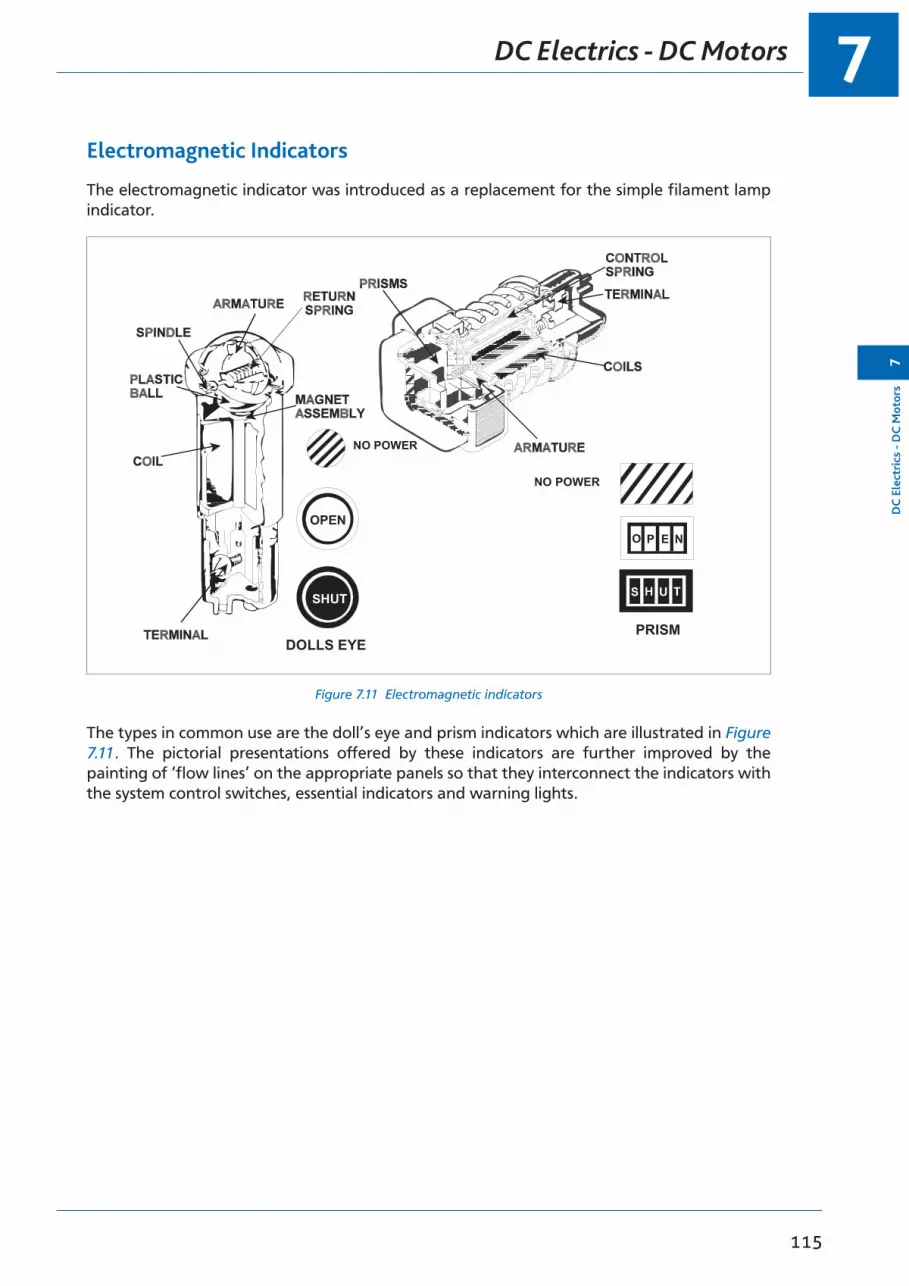
7
115
DC
Ele
ctri
cs -
DC
Mot
ors
7
DC Electrics - DC Motors
Electromagnetic Indicators
The electromagnetic indicator was introduced as a replacement for the simple filament lamp indicator.
O P E N
PRISM
OPEN
NO POWER
DOLLS EYE
NO POWER
Figure 6.30 Electro-Magnetic IndicatorsFigure 7.11 Electromagnetic indicators
The types in common use are the doll’s eye and prism indicators which are illustrated in Figure 7.11. The pictorial presentations offered by these indicators are further improved by the painting of ‘flow lines’ on the appropriate panels so that they interconnect the indicators with the system control switches, essential indicators and warning lights.

Questions7
116
7Q
uestions
Questions
1. Rotary actuators are used for:
a. undercarriage retractionb. centre of gravity assessment c. operation of fuel cocksd. movement of control surfaces
2. Actuator normal travel is controlled by:
a. a clutchb. limit microswitches c. mechanical indicators d. mechanical stops
3. On a twin engined DC aircraft having two DC generators load sharing is achieved by:
a. equalizing engine RPMsb. an equalizing circuit to sense the difference and equalize the voltages of the
two generatorsc. synchronizing relays and voltage coil tunersd. an equalizing circuit to sense the difference and equalize the field currents of
the two generators
4. Pilots are informed of rotary actuator positions by:
a. non-return valvesb. lights or doll’s eye indicators c. travel indicatorsd. veger counters
5. Press-to-test lights are used:
a. to indicate to the pilot that the circuit has power and is complete b. to control the movement of a rotary actuatorc. to indicate to the pilot that the circuit has operatedd. only to indicate to the pilot that the equipment has malfunctioned
6. A device for changing AC to DC is:
a. an inverterb. a rotary transformer c. a rectifierd. an alternator
7. An inching control is used in conjunction with:
a. a linear actuator b. a rotary actuatorc. a combination of linear and rotary actuator d. a rectifier

7
117
Que
stio
ns7
Questions
8. Friction clutches are fitted to actuators for:
a. protection against mechanical overload b. protection against brake on loadsc. protection against non-return valve failure d. protection against supply failures
Answers7
118
7A
nswers
Answers
1 2 3 4 5 6 7 8
c b b b a c a a
119
8Chapter
DC Electrics - Aircraft Electrical Power Systems
Aircraft Electrical Power Systems. . . . . . . . . . . . . . . . . . . . . . . . . . . . . . . . . .121
Dipole or Two Wire System. . . . . . . . . . . . . . . . . . . . . . . . . . . . . . . . . . . . .121
Single Pole (Unipole or Earth Return) System. . . . . . . . . . . . . . . . . . . . . . . . . . .122
Generators and Alternators . . . . . . . . . . . . . . . . . . . . . . . . . . . . . . . . . . . .122
Voltage Regulators . . . . . . . . . . . . . . . . . . . . . . . . . . . . . . . . . . . . . . . . .122
Overvoltage Protection Unit . . . . . . . . . . . . . . . . . . . . . . . . . . . . . . . . . . . .123
Generator Cut-out or Reverse Current Relay . . . . . . . . . . . . . . . . . . . . . . . . . . .123
Rectifiers. . . . . . . . . . . . . . . . . . . . . . . . . . . . . . . . . . . . . . . . . . . . . . .124
Inverters . . . . . . . . . . . . . . . . . . . . . . . . . . . . . . . . . . . . . . . . . . . . . . .124
The Generator Differential Cut-out . . . . . . . . . . . . . . . . . . . . . . . . . . . . . . . .124
Generator (or Alternator) Warning Light . . . . . . . . . . . . . . . . . . . . . . . . . . . . .124
Generator (or Alternator) Master Switch . . . . . . . . . . . . . . . . . . . . . . . . . . . . .124
Monitoring Instruments . . . . . . . . . . . . . . . . . . . . . . . . . . . . . . . . . . . . . .125
Ammeters and Voltmeters . . . . . . . . . . . . . . . . . . . . . . . . . . . . . . . . . . . . .125
The Battery . . . . . . . . . . . . . . . . . . . . . . . . . . . . . . . . . . . . . . . . . . . . .127
Bus Bars . . . . . . . . . . . . . . . . . . . . . . . . . . . . . . . . . . . . . . . . . . . . . . .128
Bus Bar Systems . . . . . . . . . . . . . . . . . . . . . . . . . . . . . . . . . . . . . . . . . . .129
Parallel Bus Bar System . . . . . . . . . . . . . . . . . . . . . . . . . . . . . . . . . . . . . . .130
Load Shedding . . . . . . . . . . . . . . . . . . . . . . . . . . . . . . . . . . . . . . . . . . .131
Generator or Alternator Failure . . . . . . . . . . . . . . . . . . . . . . . . . . . . . . . . . .132
Questions - Generator Cut-out . . . . . . . . . . . . . . . . . . . . . . . . . . . . . . . . . . .133
Questions - Generator Circuit 1 . . . . . . . . . . . . . . . . . . . . . . . . . . . . . . . . . .135
Questions - Generator Circuit 2 . . . . . . . . . . . . . . . . . . . . . . . . . . . . . . . . . .137
Questions - Distribution . . . . . . . . . . . . . . . . . . . . . . . . . . . . . . . . . . . . . .139
Answers - Generator Cut-out . . . . . . . . . . . . . . . . . . . . . . . . . . . . . . . . . . . .142
Answers - Generator Circuit 1 . . . . . . . . . . . . . . . . . . . . . . . . . . . . . . . . . . .142
Answers - Generator Circuit 2 . . . . . . . . . . . . . . . . . . . . . . . . . . . . . . . . . . .142
Answers - Distribution . . . . . . . . . . . . . . . . . . . . . . . . . . . . . . . . . . . . . . .142

DC Electrics - Aircraft Electrical Power Systems8
120
8D
C Electrics - A
ircraft Electrical Power System
s

8
121
DC
Ele
ctri
cs -
Airc
raft
Ele
ctri
cal P
ower
Sys
tem
s8
DC Electrics - Aircraft Electrical Power Systems
Aircraft Electrical Power Systems
The power system for a single-engine aircraft consists of a generator or alternator with the control and indication equipment necessary to supply all the electrical power once the system is on line.
The term on line means that the generator or alternator has been switched into the electrical system and is actually supplying power to the system.
With multi-engine aircraft two or more generators or alternators are installed in parallel. The ampere capacity of an aircraft electrical system is determined by the number of power-consuming devices fitted.
Dipole or Two Wire System
Figure 8.1 Dipole system
A dipole or two wire system is required where an aircraft is made of a non-conductive material. The current needs a complete circuit to flow and therefore needs a negative wire to connect the load to the negative side of the generator as well as a positive or ‘live wire’ to connect from the bus bar (distribution point) to the load.

DC Electrics - Aircraft Electrical Power Systems8
122
8D
C Electrics - A
ircraft Electrical Power System
s
Single Pole (Unipole or Earth Return) System
Figure 8.2 Unipole system
This is the most common type of system on an aircraft with metal construction. The metal airframe is used as the negative conductor completing the circuit for the current flow. The negative side of the generator is connected to an ‘airframe earth’ as is the negative side of each load.
Generators and Alternators
Generators or Alternators are used to convert mechanical energy to electrical energy.
A generator produces direct current, DC, by using a rotating armature, stationary field and a commutator as described in the previous chapter whereas an alternator produces alternating current, AC, by using a rotating field and a stationary armature. If it is required to convert the AC output of an alternator to DC, a diode rectifier is used, fitted in the end frame of the alternator.
Most modern light aircraft have a direct current system which is powered by an alternator. The full power output of a generator is closely related to the RPM of the engine and is usually attained with the engine running at half speed whereas the full power output of an alternator can be attained at slow running, one obvious advantage that an alternator has over a generator. The generator is driven at a speed which is approximately three times that of the engine.
Voltage Regulators
The Voltage Regulator maintains the output voltage of the generator or alternator at a constant value, irrespective of the engine RPM or electrical loads. This is achieved by controlling either the current flow in the field coils of a generator, or the current flow in the exciter field of an alternator.
The basic voltage regulator setting controls the generator output to maintain 14 volts for a 14 volt system with a 12 volt battery and 28 volts for a 28 volt system with a 24 volt battery.

8
123
DC
Ele
ctri
cs -
Airc
raft
Ele
ctri
cal P
ower
Sys
tem
s8
DC Electrics - Aircraft Electrical Power Systems
Overvoltage Protection Unit
An overvoltage protection unit is fitted to protect against the output voltage of the generator rising dangerously high and causing damage to aircraft circuits due to overheating (W=I²R). It protects against voltage regulator failure.
The overvoltage protection circuit will automatically disconnect the field circuit if the voltage rises to typically 16.5 volts in a 14 volt system, thereby reducing the generator output to zero and safeguarding the system.
It may also open the generator cut-out to prevent reverse current flow.
Generator Cut-out or Reverse Current Relay
The generator cut-out permits the generator voltage to build up to a preset figure before its contacts close and put the generator on line. It will open to prevent the battery feeding current back into the generator when the generator voltage is below that of the battery voltage.
The contacts of a cut-out are closed by rising voltage and opened by reverse current. A cut-out is not fitted in an alternator system as the Rectifiers provide reverse current protection.
The reverse current cut-out relay shown below would be used with a DC generator. It may be an integral part of the voltage regulator or it may be a separate unit. Before the generator is started, the spring holds the contacts open. As the generator builds up voltage, that voltage is applied to the shunt (voltage) coil which has many turns of thin wire and is connected in parallel with the generator output. When the voltage has built up above the battery voltage the current through the voltage coil causes a magnetic influence to close the contacts and connect the generator to the bus bar. The current flows through the current coil, which has a few turns of thick wire, and through the contacts to the bus bar and the aircraft loads. The current flow through the current coil increases the magnetic effect and helps to keep the contacts closed against the spring.
Figure 8.3 Reverse current cut-out relayFigure 7.3 Reverse Current Cut-Out Relay

DC Electrics - Aircraft Electrical Power Systems8
124
8D
C Electrics - A
ircraft Electrical Power System
s
When the output voltage of the generator falls below battery voltage then current flow is reversed and current flows back toward the generator. The falling voltage of the generator causes the magnetic influence of the voltage coil to reduce and as the current flow through the current coil is reversed, it reverses the magnetic field produced by the current coil. This opposes the field produced by the voltage coil and allows the contacts to open by the spring, disconnecting the generator from the bus bar and preventing reverse current into the generator.
Rectifiers
The rectifiers in the alternator end frame convert AC to DC and permit the current to flow out from the alternator but not into it from the battery. They have a low resistance in the direction of current flow and a high resistance in the other direction.
Inverters
Static InverterStatic inverters are solid state devices which covert DC to constant frequency AC. A typical input to a static inverter would be 18 - 30 volts DC and the output would be 115 volts AC at 400 hertz frequency. The internal circuitry of a static inverter contains standard electrical and electronic components such as oscillators, diodes, transistors, capacitors and transformers.
Rotary InverterRotary inverters convert DC to AC by using a constant speed DC motor to drive an alternator thereby producing constant frequency AC.
The Generator Differential Cut-out
The generator differential cut-out is fitted in a multi-engine aircraft to prevent circulating currents between a generator which is already on line and one which is coming on line.
The on-coming generator cannot switch on line until its output voltage is 2% above the output voltage of the generator which is already on line. The 2% difference in potential is between the on-coming generator output and the battery bus bar.
Generator (or Alternator) Warning Light
The generator or alternator warning light indicates to the pilot that the generator or alternator voltage has fallen below battery voltage. Illumination of the light is usually associated with the generator cut-out position or a reverse current detector.
Generator (or Alternator) Master Switch
The master switch enables the pilot to electrically isolate the generator or alternator. Opening the master switch breaks the generator field circuit or the alternator exciter circuit and the electrical output falls to its residual level which is virtually zero.

8
125
DC
Ele
ctri
cs -
Airc
raft
Ele
ctri
cal P
ower
Sys
tem
s8
DC Electrics - Aircraft Electrical Power Systems
Monitoring Instruments
Instruments and warning lights must be provided for the pilot to monitor the aircraft DC or AC electrical system. The AC system is covered in the AC chapter, here we will examine typical meters and show their use in a DC system.
Ammeters and Voltmeters
Ammeters and voltmeters are provided in AC and DC systems and in most cases are of the moving coil type of instrument shown in the following diagram. The instrument consists of a permanent magnet with a soft iron core between the poles, inside which fits a former on a spindle which is free to rotate inside the magnetic field. A coil of wire is wound around the former and current is allowed to flow around the coil. Two hairsprings are fitted to restrain the movement of the coil; as the coil rotates one spring is wound up, the other unwound. The hairsprings allow the current to be fed into and out of the coil. The coil and former carry a pointer which is arranged to move over a scale as the coil rotates.
When current flows through the coil a magnetic field is created which interacts with the main field and causes the coil to rotate moving the indicator pointer across the scale until the torque is balanced by the hairspring. The greater the current flow through the coil, the greater will be the movement of the pointer. When the current flow reduces, the pointer will be returned to its ‘zero’ mark by the hairspring. So the deflection of the pointer is proportional to the current flowing through the coil, giving rise to an evenly divided scale.
The meter is likely to be housed inside a case made of soft iron to prevent stray magnetism affecting the indication.
To enable the range of the instrument to be extended a shunt (resistor of low resistance value) can be fitted in conjunction with this type of meter when used as an ammeter. When used as a voltmeter, a multiplier (resistor of high resistance value) is fitted. A shunt or multiplier will allow only a proportion of the total current to be allowed through the instrument therefore protecting the delicate mechanism but still allowing it to measure large values.
Figure 8.4 A moving coil instrumentFigure 7.4 A Moving Coil Instrument

DC Electrics - Aircraft Electrical Power Systems8
126
8D
C Electrics - A
ircraft Electrical Power System
s
The number of indicating devices required and the types employed depends on the type of aircraft and the overall nature of its electrical installation.
One ammeter (or load meter) is normally provided for each possible source of power, and a single voltmeter with multiple selections for each DC system.
There are basically two types of ammeter:-
• The charge/discharge ammeter (or ‘centre zero’ ammeter) see Figure 8.5.• The generator ammeter or load meter (‘left zero’ ammeter) see Figure 8.5.
The charge/discharge or centre zero type ammeter displays information about current flow into or out of the battery.
If the needle is to the right of zero, the alternator is working and supplying power to the electrical system and charging the battery.
If the needle is to the left of zero, then the battery is discharging, indicating that the alternator is not supplying power to the electrical system.
The load meter or left zero type of ammeter displays actual current draw (system demand) from the alternator.
If the load meter reads zero, then the alternator is not supplying power to the system, leaving the battery as the sole source of power in a single-engine system.
Figure 8.5 Simple ammeters
If an alternator fails in flight, all operating electrical equipment begins to deplete the battery. The pilot must therefore immediately assess the situation to determine what equipment is absolutely essential to the safety of flight at that moment and turn off everything else to conserve battery power.
This procedure is known as load shedding.

8
127
DC
Ele
ctri
cs -
Airc
raft
Ele
ctri
cal P
ower
Sys
tem
s8
DC Electrics - Aircraft Electrical Power Systems
Figure 8.6 shows both how current is measured with an ammeter placed in the current flow so that it measures the current flowing through it and how EMF and pd are measured with a voltmeter connected to the two points between which the potential difference is to be measured.
Voltmeters have a high internal resistance and are connected in parallel to measure the voltage between two points. It may have a multiplier fitted in series with the meter to increase the indicating range of the instrument.
Ammeters have a low internal resistance and are placed in series to measure current through the load. An ammeter may have a shunt fitted in parallel with the meter to increase the indicating range of the instrument.
Figure 8.6 Ammeter and voltmeter connections
The Battery
The battery would normally be a 12 or 24 volt lead acid or alkaline and can be used to start the engines, or to supply electrical power in the event of generator or alternator failure.
Figure 8.7 Lead Acid Battery (Absorbed Liquid Type)
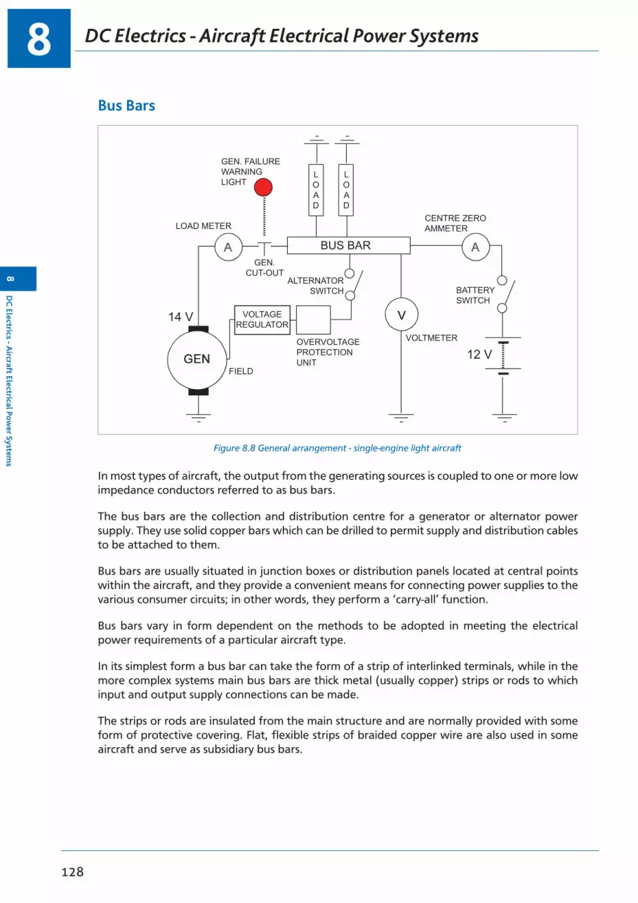
DC Electrics - Aircraft Electrical Power Systems8
128
8D
C Electrics - A
ircraft Electrical Power System
s
Bus Bars
BUS BARGEN.
CUT-OUT
GEN. FAILUREWARNINGLIGHT
VOLTAGEREGULATOR
14 V
12 VOVERVOLTAGEPROTECTIONUNIT
FIELD
ALTERNATORSWITCH
CENTRE ZEROAMMETER
BATTERYSWITCH
VOLTMETER
LOAD METER
LOAD
LOAD
Figure 8.8 General arrangement - single-engine light aircraft
In most types of aircraft, the output from the generating sources is coupled to one or more low impedance conductors referred to as bus bars.
The bus bars are the collection and distribution centre for a generator or alternator power supply. They use solid copper bars which can be drilled to permit supply and distribution cables to be attached to them.
Bus bars are usually situated in junction boxes or distribution panels located at central points within the aircraft, and they provide a convenient means for connecting power supplies to the various consumer circuits; in other words, they perform a ‘carry-all’ function.
Bus bars vary in form dependent on the methods to be adopted in meeting the electrical power requirements of a particular aircraft type.
In its simplest form a bus bar can take the form of a strip of interlinked terminals, while in the more complex systems main bus bars are thick metal (usually copper) strips or rods to which input and output supply connections can be made.
The strips or rods are insulated from the main structure and are normally provided with some form of protective covering. Flat, flexible strips of braided copper wire are also used in some aircraft and serve as subsidiary bus bars.
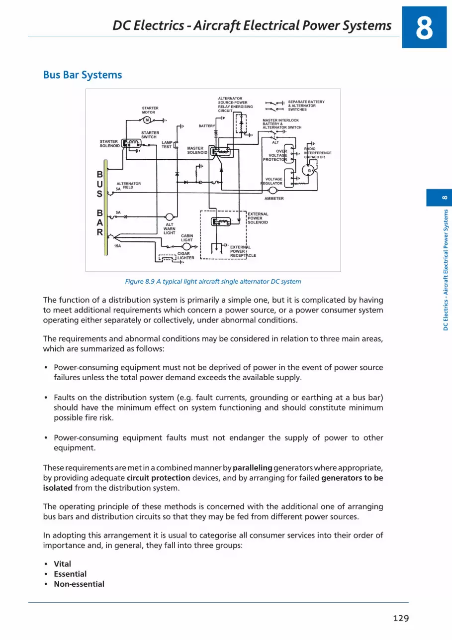
8
129
DC
Ele
ctri
cs -
Airc
raft
Ele
ctri
cal P
ower
Sys
tem
s8
DC Electrics - Aircraft Electrical Power Systems
Bus Bar Systems
STARTERSOLENOID
STARTERMOTOR
STARTERSWITCH
LAMPTEST
5A
5A
15A
ALTWARNLIGHT
CABINLIGHT
CIGARLIGHTER
EXTERNALPOWERRECEPTACLE
EXTERNALPOWERSOLENOID
MASTERSOLENOID
VOLTAGEREGULATOR
OVERVOLTAGE
PROTECTOR
G
RADIOINTERFERENCECAPACITOR
ALT
BATTERYMASTER INTERLOCKBATTERY &ALTERNATOR SWITCH
ALTERNATORFIELD
ALTERNATORSOURCE-POWERRELAY ENERGISINGCIRCUIT
SEPARATE BATTERY& ALTERNATORSWITCHES
BUS
BAR
M
AMMETER
Figure 8.9 A typical light aircraft single alternator DC system
The function of a distribution system is primarily a simple one, but it is complicated by having to meet additional requirements which concern a power source, or a power consumer system operating either separately or collectively, under abnormal conditions.
The requirements and abnormal conditions may be considered in relation to three main areas, which are summarized as follows:
• Power-consuming equipment must not be deprived of power in the event of power source failures unless the total power demand exceeds the available supply.
• Faults on the distribution system (e.g. fault currents, grounding or earthing at a bus bar) should have the minimum effect on system functioning and should constitute minimum possible fire risk.
• Power-consuming equipment faults must not endanger the supply of power to other equipment.
These requirements are met in a combined manner by paralleling generators where appropriate, by providing adequate circuit protection devices, and by arranging for failed generators to be isolated from the distribution system.
The operating principle of these methods is concerned with the additional one of arranging bus bars and distribution circuits so that they may be fed from different power sources.
In adopting this arrangement it is usual to categorise all consumer services into their order of importance and, in general, they fall into three groups:
• Vital• Essential• Non-essential

DC Electrics - Aircraft Electrical Power Systems8
130
8D
C Electrics - A
ircraft Electrical Power System
s
Vital services are those which would be required after an emergency wheels-up landing, e.g. emergency lighting and crash switch operation of fire extinguishers. These services are connected directly to the battery.
Essential services are those required to ensure safe flight in an in-flight emergency situation. They are connected to DC and AC bus bars, as appropriate, and in such a way that they can always be supplied from a generator or from batteries.
Non-essential services are those which can be isolated in an in-flight emergency for load shedding purposes (see below), and are connected to DC and AC bus bars, as appropriate, and are supplied from a generator.
Figure 8.10 illustrates, in a very simplified form, the principle of dividing categorized consumer services between individual bus bars; this is an example of a parallel bus bar system.
In this example, the power distribution system is one in which the power supplies are 28 volts DC, from engine-driven generators operating in parallel, 115 volts 400 Hz AC from inverters, and 24 volts DC from batteries.
Parallel Bus Bar System
Figure 8.10 shows that each generator has its own bus bar to which are connected the non-essential consumer services.
Both bus bars are in turn connected to a single bus bar which supplies power to the essential services. Thus, with both generators operating, all consumers requiring DC power are supplied.
The essential services bus bar is also connected to the battery bus bar so ensuring that the batteries are maintained in the charged condition.
The battery bus bar may be referred to as a ‘hot bus’ or ‘hot battery bus’ because it is always connected to the battery.
In the event that one generator should fail it is automatically isolated from its respective bus bar and all bus bar loads are then taken over by the operating generator. In the event of a generator failure the pilot will commence “LOAD SHEDDING” (page 131).
Should both generators fail, however, non-essential consumers can no longer be supplied, but the batteries will automatically supply power to the essential services and keep them operating for a predetermined period calculated on the basis of consumer load requirements and battery state of charge. (Normally a minimum of 30 minutes).
In the case of the system represented in Figure 8.10, the DC supply to power the inverters is taken from bus bars appropriate to the importance of the AC operated consumers.
Thus, essential AC consumers are operated by the No. 3 inverter and so it is supplied with DC from the essential services bus bar.
No. 1 and No. 2 inverters supply AC to non-essential services and so they are powered by DC from the No. 1 and No. 2 bus bars.

8
131
DC
Ele
ctri
cs -
Airc
raft
Ele
ctri
cal P
ower
Sys
tem
s8
DC Electrics - Aircraft Electrical Power Systems
Figure 8.10 Multi DC generator system block diagram
INV2INV1
NON ESS ACCONSUMERS
ESSENTIAL DCCONSUMERS
ESSENTIALACCENTRE BUS BAR
No.2 BUSNo.1 BUS
BATTERY BUS (HOT BUS)
VITALCONSUMERS
EXT. PWR.
No.1 GEN28 V
No.2 GEN28 V
BATTERY SWITCH
GENERATORCIRCUIT BREAKER
GENERATORCIRCUIT BREAKER
BATTERIES
NON ESS DCCONSUMERS
NON ESS DCCONSUMERS
INV3
24 V24 V
Load Shedding
Load shedding is the overall reduction of the electrical loads on the power supply system in the event that the generators cannot supply all of the load demanded. In some aircraft it can be automatically achieved, in other aircraft the pilot must monitor the electrical load by use of the ammeters or load meters and maintaining the total load within the rated value of the generator or alternator. After generator failure some non-essential loads would be switched off to prevent overloading the remaining generator or battery. This will result in a decrease in current demand from the bus bar and enable the essential loads to be supplied.

DC Electrics - Aircraft Electrical Power Systems8
132
8D
C Electrics - A
ircraft Electrical Power System
s
Generator or Alternator Failure
The indications of a generator or alternator failure would consist of a generator or alternator warning light illuminating and the ammeter or load meter showing either zero, or a discharge if it was the centre reading type. Typical actions to be carried out in the event of a generator or alternator failure are as follows:
• Switch off all unnecessary electrical loads. Details are given in the aircraft handling notes of the items to be the subject of load shedding.
• Isolate the generator or alternator electrically by turning the master switch or alternator switch “off”. This will break the field circuit and the output voltage will fall to zero or a residual value, making the failed system ‘safe’.
• In most cases a failure of the generator will cause the reverse current relay to operate, isolating the generator output from the bus bar.

8
133
Que
stio
ns8
Questions
Questions - Generator Cut-out
1. In an electrical circuit the reverse current cut-out relay will open:
a. when battery voltage exceeds generator voltageb. when circuit voltage is less than generator voltage c. when the main output CB is resetd. when the batteries are flat
2. A generator cut-out is provided:
a. to prevent the battery over heatingb. to prevent the battery from being overcharged c. to allow the generator to be isolated in a crashd. to prevent discharge of the battery through the generator
3. A generator cut-out will open when:
a. circuit loads equal the battery voltage b. the air temperature reaches 45°Cc. circuit loads equal the generator voltaged. generator voltage falls below battery voltage
4. A generator cut-out is fitted to prevent:
a. the battery discharging through the generator windings b. the generator overcharging the batteryc. fire in the event of overloading the system d. out of phasing
5. In the event of the cut-out points sticking in the closed position, the most probable results, when the engine stopped would be:
a. gain of engine power b. a burnt out generatorc. loss of residual magnetism d. no apparent reaction
6. To prevent circulating currents when more than one generator is being connected to the same bus bar:
a. reverse current relays are fittedb. the generators are connected in seriesc. rectifiers are fittedd. differential cut-outs are used
7. A generator cut-out is fitted:
a. in series with the generator output b. in the diode circuitc. in parallel with the generator output d. in the field circuit

Questions8
134
8Q
uestions
8. On a 28 volt system with a 24 volt battery the cut-out contacts close at approximately:
a. 36 volts b. 24 volts c. 28 volts d. 26 volts
9. A component whose job is similar to a generator cut-out is:
a. a rectifier.b. a converter c. an inverterd. a reverse current relay
10. If the cut-out is open, the battery is feeding the loads which are:
a. in series with the battery b. in parallel with the batteryc. in sequence with the cut-out d. cross coupled
8
135
Que
stio
ns8
Questions
Questions - Generator Circuit 1
1. In a two-engine aircraft with two generators, there would be:
a. one ammeter for each generator and one voltmeter switchable to indicate either generator voltage or battery voltage
b. one voltmeter for each generator. and one ammeter switchable to indicate either generator current or battery current
c. one ammeter showing the total output and one switchable voltmeterd. one ammeter and one voltmeter each showing the average current and
voltage output
2. A generator converts mechanical energy to electrical by:
a. electromagnetic spring action b. electromagnetic inductionc. electrostatic inductiond. electrodynamic induction
3. In an aircraft electrical system which incorporates a voltmeter, the voltmeter indicates:
a. the flow in the electrical system before the battery cut-out contacts close b. the rate of flow at all timesc. the pressure in the electrical system before and after the cut-out contacts close d. the flow in the electrical system after the battery cut-out contacts close
4. If the generator warning light comes on in flight it indicates that:
a. the generator is feeding the battery bus barb. the generator is not feeding the battery bus bar c. the battery has failedd. a rectifier is faulty
5. A generator failure is usually indicated by:
a. the ammeter reading decreasing or showing a discharge and a red warning lamp lighting
b. the voltmeter reading increasing, the ammeter reading showing discharge and a red lamp lighting
c. the current consuming devices failing to operate d. the motor speed increasing
6. A generator warning light will be illuminated:
a. when the battery voltage exceeds that of the generator and the cut-out has opened
b. at night onlyc. when the generator is supplying current to a fully charged battery, and no
electrical loads are switched ond. when the battery charge current is lower than required to maintain its fully
charged state

Questions8
136
8Q
uestions
7. If a generator fails in flight:
a. the voltmeter will read maximum b. the ammeter reading will decrease c. load sharing circuits will operated. the watt metre will show an increase
8. If one generator fails you should:
a. switch off the good generatorb. stop and feather the engine concernedc. switch off the failed generator and continue normal use of the electrical
systemd. switch off the failed generator, and cut down on the electrical services being
used
9. A generator is brought ‘on line’ when it is:
a. connected in series with other generatorsb. switched into the electrical circuit in parallel with the other generators c. connected with the ground batteries for startingd. connected to a phase reducer
10. In a twin-engine aircraft, fitted with two generators, if one should fail:
a. the failed generator must be isolatedb. cut down the air supply to reduce five risks c. the failed generator must be stoppedd. both generators must be switched off
8
137
Que
stio
ns8
Questions
Questions - Generator Circuit 2
1. A generator is brought ‘on line’ via the cut-out by an increase in:
a. the battery voltageb. the radio bypass switch c. the generator voltaged. the generator field voltage
2. Generator failure is indicated by:
a. load sharing circuits connectingb. a decrease or discharge in ammeter readings and generator warning light onc. an increase in voltmeter readings, a discharge in ammeter reading and
generator warning light ond. failure of electrically driven instruments
3. In a twin-engine aircraft, with a generator fitted to both engines, the starboard generator fails. Then:
a. the starboard engine cuts b. the port engine cutsc. both engines run normallyd. the engine with the failed generator will automatically feather
4. Loads on a bus bar are:
a. in series with the generator so that the voltage can be reduced b. in parallel so the voltage can be variedc. in parallel so the current can be reducedd. determined by the cross-sectional area of the lead cable
5. When the battery master switch is switched off in flight:
a. the generators are disconnected from the bus bar b. the battery is isolated from the bus barc. the battery is discharged through the bonding circuit diodes d. the battery may overheat
6. A generator is taken ‘off’ line by:
a. the battery switchb. closing of the field switch c. opening of the cut-outd. removing all loads
7. If the ammeter reads plus 5 amp after engine shut down:
a. some switches have been left ‘on’ b. the battery is chargingc. the generator field switch is ‘on’ d. the ammeter is defective
Questions8
138
8Q
uestions
8. If the ammeter shows ‘no’ charge, yet the battery remains charged, you would look for:
a. loose battery connections b. a defective voltage regulator c. a defective CBd. a defective ammeter
9. A field switch in the generator circuit is:
a. kept in the ‘on’ positionb. connected in the armature circuit c. to ‘shut off’ the generator fieldd. to disconnect the battery
10. During flight a malfunction of the generator cut-out would be indicated by:
a. overheating of the battery b. the ammeterc. lights going outd. the current limiter
8
139
Que
stio
ns8
Questions
Questions - Distribution
1. A short circuit in a “single pole” electrical circuit would be caused:
a. by a broken conductor between the source of supply and an item of equipment
b. by an open circuit between loads in parallelc. when wiring between the source of supply and an item of equipment goes
down to earth d. by an open circuit between an item of equipment and earth
2. In a “2 pole” electrical circuit, a short of the conductors would result in:
a. an item of equipment operating automatically without switches b. the component not workingc. an increase in voltaged. an item of equipment burning out because of a large current flow
3. The indicating range of an ammeter can be increased by fitting:
a. a shunt fitted in parallel with the instrument b. a shunt fitted in parallel with the loadc. a shunt fitted in series with the instrumentd. a multiplier fitted in parallel with the instrument
4. An electrical system which uses the aircraft structure as a return path for current is known as:
a. a diode pole circuitb. an earth return circuit c. a single phase circuit d. a dipole circuit
5. On a single pole circuit, if the positive conductor is shorted to the aircraft structure:
a. the electrical component will operate b. the fuse will blowc. the circuit will be under loadedd. the load will only operate at half speed
6. In a double pole circuit:
a. the systems polarity will changeb. the current is supplied by one wire and the current is returned through the
aircraft bonding systemc. the current passes out through one wire and is returned through a second
wired. the current passes out through one wire and is returned via the aircraft’s
immune circuit
7. In an earth return circuit if the conductor is open circuited:
a. the fuse will blowb. the bus bars will overheat c. the load will not operated. the generator will burn out

Questions8
140
8Q
uestions
8. A ‘hot bus’ is:
a. the bus bar always connected to the battery b. the bus bar that supplies the galley power c. the bus bar that supplies the essential loadsd. the bus bar that supplies the non-essential loads
9. A dipole circuit is one where:
a. diode valves are usedb. three conductors are usedc. the aircraft structure is used for the earth return d. two conductor wires are used

8
141
Que
stio
ns8
Questions

Answers8
142
8A
nswers
Answers - Generator Cut-out
1 2 3 4 5 6 7 8 9 10
a d d a b d a d d b
Answers - Generator Circuit 1
1 2 3 4 5 6 7 8 9 10
a b c b a a b d b a
Answers - Generator Circuit 2
1 2 3 4 5 6 7 8 9 10
c b c c b c d d c b
Answers - Distribution
1 2 3 4 5 6 7 8 9
c b a b b c c a d

143
9Chapter
DC Electrics - Bonding and Screening
Bonding . . . . . . . . . . . . . . . . . . . . . . . . . . . . . . . . . . . . . . . . . . . . . . .145
The Static Discharge System or Static Wicks. . . . . . . . . . . . . . . . . . . . . . . . . . . .145
Discharge of Static on Touchdown. . . . . . . . . . . . . . . . . . . . . . . . . . . . . . . . .145
Screening . . . . . . . . . . . . . . . . . . . . . . . . . . . . . . . . . . . . . . . . . . . . . .145
Questions . . . . . . . . . . . . . . . . . . . . . . . . . . . . . . . . . . . . . . . . . . . . . .146
Answers . . . . . . . . . . . . . . . . . . . . . . . . . . . . . . . . . . . . . . . . . . . . . . .148

DC Electrics -Bonding and Screening9
144
9D
C Electrics - Bonding and Screening
9
145
DC
Ele
ctri
cs -
Bond
ing
and
Scre
enin
g9
DC Electrics - Bonding and Screening
BondingAn aircraft in flight will pick up, or become charged with, static electricity from the atmosphere. Bonding will prevent any part of the aircraft from building up a potential so great that it will create a spark and generate a fire risk.
Each piece of the metal structure of the aircraft, and each component on the aircraft, is joined to the other by flexible wire strips. All strips must be clean and free from any insulating coatings such as anodizing, paint, grease and oxides to prevent electrolytic corrosion occurring which would introduce resistance.
This process is called bonding, and it provides an easy path for the electrons from one part of the aircraft to another.
Bonding can also act as part of the earth return system in a unipole circuit and will also help to prevent radio interference due to static discharges.
The Static Discharge System or Static WicksThe static discharge systems, or static wicks, are fitted to reduce static build-up on the airframe. They were originally made of cotton of about the thickness of a cigarette.
They are fitted to the trailing edge of the aircraft control surfaces, and the tips of wings, or stabilizers. Static electricity is dispersed from them into the atmosphere.
The free end of the wick becomes ‘teased’ (spread out) and a brush discharge action takes place. Modern wicks are like miniature barbed antenna, small wire brushes, or alternatively are straight metal wicks.
Discharge of Static on TouchdownTo ensure that no static electrical charge, with its possible fire risk, remains on the aircraft after landing, the main bond must be brought into instantaneous contact with the ground as the aircraft touches down.
This is achieved by fitting nose, tail or main wheel tyres which contain a high proportion of carbon in the rubber.
The tyre is in contact with the main bond via the wheel bearing and any static charge is dissipated to earth on touchdown.
ScreeningScreening is designed to prevent radio interference by absorbing electrical energy.
Static electrical charges, produced by the operation of certain electrical equipment, create interference on radio circuits.
This interference is overcome by fitting interference suppressors in the cables connected to the source of interference, and by total enclosure of the cables in a continuous metal sheath.
Screening is required for ignition systems, DC generators and motors (commutator machines), slip ring machines operating at over 200 RPM and also for any electrical equipment operating by making and breaking a circuit at a frequency greater than 10 Hz.

Questions9
146
9Q
uestions
Questions
1. Why are static wick dischargers fitted to aircraft?
a. To smooth the generator outputb. To prevent tyres bursting on landingc. To minimize radio interferenced. To act as an earth return in a single pole electrical system
2. Bonding is used to protect the aircraft against fire from arcing of static electricity by:
a. providing an earth returnb. shortening the negative stripsc. maintaining different electrical potential throughout the structure d. ensuring the same electrical potential of all metal components
3. Static electricity constitutes a fire hazard because:
a. metal components become very hot and ignite inflammable gases and materials
b. sparks occur due to differences of potential and could ignite inflammable gases and materials
c. of colour charged electronsd. aircraft tyres become heavily charged and may burst on landing
4. Static electrical charges and currents in an aircraft structure are evened out by:
a. hardening b. screening c. bonding d. anodizing
5. The electrical components of aircraft systems are screened to:
a. bond the circuit to reduce risk of fire b. prevent them dischargingc. prevent short circuits in radio equipmentd. prevent them interfering with the function of radio equipment
6. Bonding is a method of:
a. heat screeningb. providing a positive reactionc. ensuring that the different parts of the aircraft are maintained at a different
potentiald. ensuring that the different parts of the aircraft are maintained at the same
potential
7. The purpose of electrical bonding on an aircraft is:
a. to prevent compass malfunctioning and accumulation of local static charges b. to reduce the anodizing effectc. to isolate all components electrically and therefore make static potential
constantd. to provide a low resistance path for earth return circuits and safely dissipate
local static charges and lightning strikes

9
147
Que
stio
ns9
Questions

Answers9
148
9A
nswers
Answers
1 2 3 4 5 6 7
c d b c d d d

149
10Chapter
DC Electrics - Specimen Questions
Questions – General 1 . . . . . . . . . . . . . . . . . . . . . . . . . . . . . . . . . . . . . . .151
Questions – General 2 . . . . . . . . . . . . . . . . . . . . . . . . . . . . . . . . . . . . . . .154
Answers – General 1 . . . . . . . . . . . . . . . . . . . . . . . . . . . . . . . . . . . . . . . .156
Answers – General 2 . . . . . . . . . . . . . . . . . . . . . . . . . . . . . . . . . . . . . . . .156

Questions10
150
10Q
uestions

10
151
Que
stio
ns10
Questions
Questions – General 1
1. Spare fuses are carried:
a. at the operators’s discretion b. for generators onlyc. by law with a stated minimum number required d. by the first officer
2. When selecting a fuse for a circuit the governing factor is:
a. the voltage of the circuitb. the fuse length and diameter c. the resistance of the circuitd. the power requirement of the circuit
3. Differential cut-outs close when a differential voltage exists between the:
a. generator bus and battery bus barb. generator bus bar and earthc. batteriesd. battery bus bar and earth
4. Circulating current is the term used to describe:
a. back EMFb. current necessary to excite the generatorc. current passing between two paralleled generators of differing voltaged. current passing between AC and DC systems
5. A megohm is:
a. 10 000 ohmsb. 1000 ohmsc. 1 000 000 ohmsd. 1 000 000 000 ohms
6. Load shedding is:
a. transferring the loads between generatorsb. reducing the load voltagec. overall reduction of electrical load on the systemd. overall reduction of generator voltages
7. When a generator is on line and its associated ammeter reads 10 amps, this is an indication of:
a. BTBs being energizedb. battery charge ratec. battery discharge rated. generator load

Questions10
152
10Q
uestions
8. The formula for calculating power is:
a. V2
Ror I2 × R or I × V
b. V2
Ror I × R or I × V
c. V
R2or I2 × R or I2 × V
d. V
R2or I × R2 or I × V
9. Assuming a 5 amp circuit has failed during flight and investigation has shown that the fuse is open circuit, the action to be taken is to:
a. switch the circuit off immediatelyb. switch off, replace the fuse with another of the correct rating for the circuit
and repeat this action as often as necessaryc. leave the switch on, replace the failed fuse with one of increased ratingd. switch off, replace the failed fuse with one of the correct rating once only
10. If the voltage in a circuit is doubled, the current will:
a. doubleb. increase only if the battery is in circuitc. remain the samed. decrease
11. A simple electrical circuit has a current flow of 4 amperes and its resistance is 5 ohms. How much power (watts) is used?
a. 20 wattsb. 45 wattsc. 80 wattsd. 100 watts
12. Check a lead acid battery voltage:
a. only if a fault is suspectedb. on load with a voltmeterc. on no load with a voltmeterd. on open circuit with a voltmeter
13. Connecting two batteries in series will:
a. increase the voltage and capacityb. have no effectc. decrease the voltage and the capacityd. increase the voltage, the capacity will remain the same

10
153
Que
stio
ns10
Questions
14. An aircraft has a battery with a capacity of 60 Ah. Assuming that it will provide its nominal capacity and is discharged at the 10 hour rate:
a. it will pass 60 amperes for 10 hoursb. it will pass 10 amperes for 6 hoursc. it will pass 6 amperes for 10 hoursd. it will pass 60 amperes for 1 hour
15. A NiCad battery shows a high temperature after engine start, this could be an indication of:
a. thermal runawayb. it is not connected to the battery bus barc. normal temperature during chargingd. depends upon the outside air temperature
16. When generators are connected in parallel their output voltage must be:
a. divided by the circuit resistanceb. the samec. added togetherd. controlled by one generator
Questions10
154
10Q
uestions
Questions – General 2
1. In a direct current generating system the voltage regulator controls the system voltage within prescribed limits:
a. regardless of varying engine RPM and electrical load by inserting a variable resistance in the generator field winding
b. by means of a relay which closes contacts in the output circuit when a prescribed voltage is reached
c. of the generator rotor speedd. by a variable resistance which limits the voltage given by the battery
2. A generator cut-out is fitted:
a. to isolate the battery on touchdownb. to prevent the battery from being overchargedc. to allow the generator to be isolated in a crashd. to prevent the battery feeding back into the generator when its voltage is
above the generator voltage
3. A generator cut-out contacts will close:
a. with an increase in battery voltageb. with an increase in generator voltagec. at flight idle onlyd. with an increase in generator current
4. Failure of an aircraft generator is indicated by:
a. a red warning light lighting and the ammeter showing zero or dischargeb. a red warning light going out and the ammeter showing a dischargec. a current limiter trippingd. a circuit fuse blowing
5. On a twin-engine aircraft with a generator fitted to each engine, if the starboard generator fails,:
a. the fuel cross feed cocks closeb. the starboard engine cuts (stops)c. the port engine will cutd. both engines will run normally
6. On an earth return aircraft wiring circuit:
a. the negative pole is connected to the aircraft structureb. the positive pole is connected to the aircraft structurec. the negative pole is connected to the positive poled. two fuses are needed
7. In a dipole aircraft wiring circuit if the conductors are bridged:
a. an item of electrical equipment would be burned outb. no immediate action is necessaryc. the item of electrical equipment would operate normallyd. the fuse or circuit breaker in that circuit will blow

10
155
Que
stio
ns10
Questions
8. A circuit breaker that has tripped due to overload:
a. cannot be reset unless the circuit has returned to normalb. will not be able to be reset in the airc. will reset itself when the circuit returns to normald. must be replaced
9. When changing a blown fuse:
a. it is changed with one of a lower ratingb. the press to reset button is operatedc. leave circuit switched ond. it is changed with one of the correct rating
10. As the speed of an electric motor increases the back EMF will:
a. remain the sameb. fluctuatec. increased. decrease
11. The output of a shunt wound generator:
a. will rise gradually as load is appliedb. will remain constant as load is appliedc. will vary with generator speedd. will fall gradually as load is applied
12. Load shedding is:
a. increasing circuit resistanceb. transferring the loads between generatorsc. reducing the load voltaged. overall reductions of the loads on the system
13. An inertia switch on an aircraft will operate:
a. when selected by the pilot or flight engineerb. automatically in flightc. during an emergency or crash landingd. in flight only
14. The purpose of electrical bonding on aircraft is:
a. to directly earth the positive leadb. to prevent compass malfunctioning and to gather local static chargesc. to isolate all components electrically and therefore make the static potential
constantd. to provide a low resistance path for earth return circuits and safely dissipate
local static charges and lightning strikes
15. Electrical components of aircraft systems are screened to:
a. bond the circuit to reduce risk of fireb. prevent them interfering with the function of radio equipmentc. prevent short circuits interfering with aircraft equipmentd. prevent engine malfunctions

Answers10
156
10A
nswers
Answers – General 1
1 2 3 4 5 6 7 8 9 10 11 12
c d a c c c d a d a c b
13 14 15 16
d c a b
Answers – General 2
1 2 3 4 5 6 7 8 9 10 11 12
a d b a d a d a d c b d
13 14 15
c d b

ATPL GROUND TRAINING SERIESAC ELECTRICS
++
-
+

AC Electrics -Introduction to AC11
158
11A
C Electrics - Introduction to A
C
159
11Chapter
AC Electrics - Introduction to AC
Introduction . . . . . . . . . . . . . . . . . . . . . . . . . . . . . . . . . . . . . . . . . . . . .161
The Nature of Alternating Current. . . . . . . . . . . . . . . . . . . . . . . . . . . . . . . . .161
Terms. . . . . . . . . . . . . . . . . . . . . . . . . . . . . . . . . . . . . . . . . . . . . . . . .163
The Relationship of Current and Voltage in an AC Circuit . . . . . . . . . . . . . . . . . . . .165
Resistance in AC Circuits . . . . . . . . . . . . . . . . . . . . . . . . . . . . . . . . . . . . . .165
Inductance in AC Circuits . . . . . . . . . . . . . . . . . . . . . . . . . . . . . . . . . . . . . .166
Inductive Reactance . . . . . . . . . . . . . . . . . . . . . . . . . . . . . . . . . . . . . . . .169
Capacitance in AC Circuits . . . . . . . . . . . . . . . . . . . . . . . . . . . . . . . . . . . . .169
Capacitive Reactance . . . . . . . . . . . . . . . . . . . . . . . . . . . . . . . . . . . . . . . .171
Impedance. . . . . . . . . . . . . . . . . . . . . . . . . . . . . . . . . . . . . . . . . . . . . .172
Resonant Circuits . . . . . . . . . . . . . . . . . . . . . . . . . . . . . . . . . . . . . . . . . .172
Summary. . . . . . . . . . . . . . . . . . . . . . . . . . . . . . . . . . . . . . . . . . . . . . .173
Power in AC Circuits. . . . . . . . . . . . . . . . . . . . . . . . . . . . . . . . . . . . . . . . .173
Power in a Purely Resistive Circuit . . . . . . . . . . . . . . . . . . . . . . . . . . . . . . . . .174
Power in a Purely Inductive Circuit. . . . . . . . . . . . . . . . . . . . . . . . . . . . . . . . .174
Power in a Capacitive Circuit . . . . . . . . . . . . . . . . . . . . . . . . . . . . . . . . . . . .175
Power in a Practical AC Circuit . . . . . . . . . . . . . . . . . . . . . . . . . . . . . . . . . . .176
Power Factor . . . . . . . . . . . . . . . . . . . . . . . . . . . . . . . . . . . . . . . . . . . .177
Power Factor Resume. . . . . . . . . . . . . . . . . . . . . . . . . . . . . . . . . . . . . . . .177
Questions . . . . . . . . . . . . . . . . . . . . . . . . . . . . . . . . . . . . . . . . . . . . . .178
Answers . . . . . . . . . . . . . . . . . . . . . . . . . . . . . . . . . . . . . . . . . . . . . . .184

AC Electrics -Introduction to AC11
160
11A
C Electrics - Introduction to A
C

11
161
AC
Ele
ctri
cs -
Intr
oduc
tion
to A
C11
AC Electrics - Introduction to AC
Introduction
Alternating current (AC) is used in most large modern transport aircraft because of the following advantages that it holds over direct current (DC) supplies:
• AC generators are simpler and more robust in construction than DC machines.
• The power to weight ratio of AC machines is better than comparable DC machines.
• The supply voltage can be converted to a higher or lower value with almost 100% efficiency using transformers.
• Any required DC voltage can be obtained simply and efficiently using transformer rectifier units. (TRUs).
• Three phase AC motors which are simpler, more robust and more efficient than DC motors, can be operated from a constant frequency source, (AC generators).
• AC machines do not suffer from the commutation problems associated with DC machines and consequently are more reliable, especially at high altitude.
• High voltage AC systems require less cable weight than comparable power low voltage DC systems.
The Nature of Alternating Current
If the electrons flowing in a circuit move backwards and forwards about a mean position then the current produced is known as alternating current, AC. The simple AC generator shown in Figure 11.1 shows that a loop of wire (armature) rotated in a magnetic field experiences a continuously changing flux through it so that a voltage will be induced as long as rotation continues.
Figure 11.1 Simple AC generatorFigure 1.1 Simple AC Generator

AC Electrics -Introduction to AC11
162
11A
C Electrics - Introduction to A
C
The magnitude of the voltage depends on the speed of rotation and the field strength (i.e. rate of change of flux).
When an armature is connected to a load (resistor) in a closed circuit through slip rings and carbon brushes a current will flow around the circuit in proportion to the induced voltage.
If this armature is rotated as in Figure 11.2 then the flux is constantly changing. In positions 1, 3 and 5 the two sides of the loop are moving parallel to the field and so there is no voltage induced as there is no rate of change of flux. In positions 2 and 4 the two sides of the armature are moving at right angles to the field and the maximum voltage is induced as there is maximum rate of change of flux. In between these positions the induced voltage is between maximum and zero.
The polarity of the induced voltage changes as it passes through zero because the direction that each side of the armature moves through the field is reversed. If the polarity reverses then so must the current through the external circuit, and current flowing backwards and forwards about a mean position is alternating current. The direction of current flow through each side of the armature at any point can be determined by using Fleming’s Right Hand Rule for generators.
Figure 11.2 shows one complete revolution of the generator armature and the associated rise and fall of induced voltage.
Figure 11.2 Production of AC
Figure 11.3 illustrates the production of AC. The blue vector arrow OP represents one half of the coil of the generator, pivoted at O and rotating in an anti-clockwise direction. The EMF induced in the coil is proportional to the ordinate ON, or can be calculated by multiplying the max value by the sine of the Phase Angle at that point.
Successive ordinates plotted to a time scale corresponding to the rate of rotation of OP produce a sine wave which represents an alternating current or voltage.

11
163
AC
Ele
ctri
cs -
Intr
oduc
tion
to A
C11
AC Electrics - Introduction to AC
Figure 11.3 Production of a sine wave
Terms
Several terms are used to describe alternating current, illustrated in Figure 11.3 and some of these terms are explained below:
Figure 11.4 Frequency comparison
• Cycle. A cycle is one complete series of values, e.g. the graph of Figure 11.3
• Phase. A sine wave can be given an angular notation called phase. One cycle represents from 0° - 360° of phase.

AC Electrics -Introduction to AC11
164
11A
C Electrics - Introduction to A
C
• Frequency. The number of cycles occurring each second is the frequency of the supply. The frequency is measured in hertz (Hz). One cycle per second is equal to one hertz. Constant frequency AC supply systems usually have a frequency of 400 Hz. Frequency is dependent upon the number of times a North and a South pole pass the armature in a given time period.
To determine the frequency of a generator output, the following formula can be used:
Number of Poles 2
RPM 60 (seconds)
× = Frequency in hertz
The number of poles is the total of North and South poles making up the field of the generator and the RPM is the speed of rotation in revolutions per minute.
For example, an 8 pole generator rotating at 6000 RPM will have an output frequency of:
8 2
6000 60
× = 400 hertz
• Period. The period is the time it takes for one cycle to occur. It is the reciprocal of the frequency:
Period (T) = seconds1 f
• Amplitude or Peak Value. The amplitude of a sine wave is the maximum value it attains in one cycle, see Figure 11.5.
• Root Mean Square Value (RMS). The effective value of an alternating current is calculated by comparing it with Direct Current. The comparison is based on the amount of heat produced by each current under identical conditions.
A DC current of 1 amp will make a resistor hotter than AC with peak value of 1 amp. So to make the resistor as hot with an AC current its peak value must be higher so that its effective value can be 1 amp.
The effective value is termed the Root Mean Square, which is found by taking a number of instantaneous values of voltage or current, whichever is required, during a half cycle. These values are squared and their mean (average) value determined. Obtaining the square root of the mean value gives the Root of the Mean of the Squares, the RMS value.
Another way of looking at it is that the voltage (or current) rises from zero to maximum in 90° of phase angle, the average value must occur at the midway point of 45°. As the values follow a sine curve as previously described then the value at 45° is a product of the peak value multiplied by the sine of 45 (0.707).
Therefore the RMS value of alternating current (or voltage) is related to its amplitude or peak value.
For a sine wave, the relationship is given by the formula:
RMS = PEAK VALUE
√2Or RMS = 0.707 × PEAK VALUE
Most AC supply values are given in RMS terms. In general terms, ammeters and voltmeters are calibrated in RMS values also.

11
165
AC
Ele
ctri
cs -
Intr
oduc
tion
to A
C11
AC Electrics - Introduction to AC
Figure 11.5 AC terminology
The Relationship of Current and Voltage in an AC Circuit
Current and voltage in an AC circuit have the same frequency and the wave form (the shape of the cycle) is similar, e.g. if the voltage waveform is sinusoidal then the current waveform is also sinusoidal.
In a DC circuit the current flow was directly affected by the applied voltage and circuit resistance in the relationship formulated by OHM’s Law (V = IR). I.e. the current is directly proportional to the voltage and inversely proportional to the resistance.
There are very few AC circuits in which the current is affected solely by the applied voltage and resistance such that both the current and the voltage pass through zero and reach their peaks in the same direction simultaneously. In such circuits voltage and current are said to be in phase and the circuit is said to be resistive.
In most circuits, however, because of the ever changing values of voltage and current, the current flow is influenced by the magnetic and electrostatic effects of inductance and capacitance respectively, which cause the current and voltage to be out of phase. This means that although they are at the same frequency, the voltage and current do not pass through zero at the same time. The difference between corresponding points on the waveforms is known as phase difference or phase angle. Inductive and capacitive circuits will be studied later in this text.

AC Electrics -Introduction to AC11
166
11A
C Electrics - Introduction to A
C
Resistance in AC Circuits
There is no such thing as a ‘pure resistance’ when considering an AC circuit. All resistors, even a piece of wire, have ’inductance’ as well as resistance, but for the purpose of studying AC theory in this chapter we have to assume that we can build separate circuits having only resistance, inductance or capacitance.
In the resistive circuit, then, we are assuming ‘pure resistance’
The voltage and current waveforms when AC is applied across a pure resistive circuit are sine waves. Both waveforms are in phase as shown in Figure 11.6, and Ohm’s Law applies as in DC circuits, remembering that values quoted will be RMS values.
Figure 11.6 The phase relationship in a purely resistive circuitFigure 1.6. The Phase Relationship in A Purely Resistive Circuit
Inductance in AC Circuits
In a simple generator, a change of flux through a conductor induced a voltage in that conductor, by rotating the conductor relative to the magnetic field. A different kind of generator uses a rotating magnetic field and a stationary conductor. Both rely on the physical movement of conductor or field.
A change of flux in a coil can be achieved without physical motion, by varying a current flow, thereby changing the magnetic field relative to a coil. Figure 11.7 shows how voltages can be induced in this manner.
Figure 11.7a shows a DC circuit containing a coil, controlled by a switch. This is the primary circuit, and with no current flow there is no magnetic field created in the coil. Alongside the primary circuit is another circuit containing a coil and an ammeter, this is the secondary circuit. As there is no current flow in the primary circuit there will be nothing happening.
In Figure 11.7b the switch has been made and a magnetic field is produced by the current flow through the coil which expands while the current is increasing. This magnetic field ‘cuts’ the coil in the secondary circuit as it is expanding, thereby inducing a voltage and current flow which will show by a deflection of the ammeter. When the current is stable at its maximum the magnetic field will be stable and there will be no induced voltage. Therefore the meter in the circuit will kick sharply as the switch is closed and return to zero when the magnetic field becomes static.

11
167
AC
Ele
ctri
cs -
Intr
oduc
tion
to A
C11
AC Electrics - Introduction to AC
In Figure 11.7c the switch has been opened and there is a rapid collapse of the magnetic field because the current flow has ceased, inducing a voltage in the secondary circuit. The meter will kick in the opposite direction as the field collapses to zero.
Figure 11.7d and e show an AC circuit. With an ever changing and alternating current flow in the circuit, the magnetic field will be constantly changing; therefore, there will be a continually induced voltage and current flow proportional to the AC waveform. This will be indicated by the ammeter needle swinging alternately left and right. The greatest voltage will be induced when the current is changing at its greatest rate, i.e. when it is changing polarity.
This is called mutual induction and is the principle of operation of transformers. The magnitude of the induced voltage is dependent on the rate of change of the magnetic field which is proportional to the frequency of the supply.
Figure 11.7 Inductance
Figure 11.8 Self-induction

AC Electrics -Introduction to AC11
168
11A
C Electrics - Introduction to A
C
Referring to Figure 11.8, the secondary circuit has been removed, but the AC supply still generates an ever changing magnetic field which has the effect of inducing a voltage in the coil itself. This is called self-induction and according to Lenz’s law the voltage induced will oppose any change of current in the circuit. This self-induced voltage is often referred to as the Back EMF.
The amount of inductance in any circuit can be measured by the size of the induced voltage. A number of factors affect induced voltage.
• The number of turns in the coil (stronger magnetic field).• The addition of a soft iron core in the coil (stronger magnetic field).• An increase in the rate of change of current (increase in frequency).
The first two items refer to the construction of the coil itself and determine the value of the self-inductance for a given frequency. This is referred to as the Inductance of the coil and is a measure of its ability to produce a Back EMF. A coil with a high value of inductance will produce a greater Back EMF than one with a small value for the same supply frequency.
Any device having inductance can be referred to as an inductor. The unit of inductance (L) is the henry (H). Inductance is usually expressed in millihenries or microhenries as the henry is too large a unit for practical use. A circuit has an inductance of one henry if a current change of one ampere per second induces a back EMF of one volt.
The effect of inductance in an AC circuit is to cause the voltage and current to be out of phase; because of the opposition to the current flow, the rise in current is held back behind the rise in voltage i.e. current lags voltage.
In a circuit having only inductance the current lags the voltage by 90°. This is illustrated in Figure 11.9.
Figure 11.9 The phase relationship in a purely inductive circuit

11
169
AC
Ele
ctri
cs -
Intr
oduc
tion
to A
C11
AC Electrics - Introduction to AC
Inductive Reactance
The opposition to current flow in this circuit is called the Inductive Reactance.
It is called reactance rather than resistance because the effects of inductance depend on the frequency of the supply as well as the value of the inductance.
Inductive reactance is measured in ohms and is given the symbol XL.
To determine inductive reactance the following formula can be used.
XL = 2 π f L
where π is a constant, f is the frequency, L is the inductance
From this formula it can be seen that as frequency increases, the value of inductive reactance increases so the circuit current would decrease. Conversely, and more importantly, as the circuit frequency decreases, the inductive reactance decreases and the circuit current increases.
Capacitance in AC Circuits
Capacitance is the ability of a circuit to store an electrical charge. A device used to introduce capacitance into a circuit is known as a Capacitor. A capacitor consists of two plates separated by a dielectric, see Figure 11.10. Dielectrics can be, amongst other things, air, mica or waxed paper.
Three factors affect the amount of charge a capacitor can hold.
They are:
• The area of the plates.• The distance between the plates.• The material used to separate the plates, the dielectric.
The capacitor will store an electric charge, much like a hydraulic accumulator stores fluid under pressure, but first it needs to be charged.
When connected to the battery as shown in Figure 11.10 electrons will be removed from the plate connected to the positive terminal of the battery and added to the plate connected to the negative terminal, conventional current flow will be from positive to negative. This process will continue until the plates become saturated and no more current will flow.

AC Electrics -Introduction to AC11
170
11A
C Electrics - Introduction to A
C
Figure 11.10 A capacitor in a DC circuit
The potential difference between the plates is at its maximum and the capacitor is now fully charged, its voltage being equal to the battery voltage.
If the switch is now moved to a mid position, the charging circuit is disconnected and the capacitor will hold its charge indefinitely, in a similar fashion to an accumulator. (In practice there will be some leakage which allows the capacitor to discharge over a period of time).
Using the switch to connect the capacitor to the external circuit will allow the capacitor to discharge and current will flow around the circuit in the opposite direction until the potential difference across the plates has become equal. Notice that the capacitor has discharged in the opposite direction to which it was charged. Note also that electrons do not pass between the plates through the dielectric
Figure 11.11 Capacitor in an AC circuit.Figure 1.11 Capacitor in An AC Circuit

11
171
AC
Ele
ctri
cs -
Intr
oduc
tion
to A
C11
AC Electrics - Introduction to AC
When fitted in an AC circuit as shown in Figure 11.11 the capacitor will be constantly charging and discharging as the applied voltage and current flow are constantly reversing polarity and direction. As the applied voltage falls, the capacitor discharges current back into the circuit in the opposite direction and its voltage falls.
This has the effect of shifting the voltage out of phase with the current, and in a purely capacitive circuit the current will lead the voltage by 90°. See Figure 11.12.
The unit of capacitance is the farad, and a capacitor is given the symbol C. If a current of 1 ampere flowing for 1 second creates a potential difference of 1 volt between the plates of a capacitor then it is a 1 farad capacitor. Because of the values involved, a 1 farad capacitor is not a practical size and a more common unit is the microfarad or picofarad.
Figure 11.12 Phase relationship in a purely capacitive circuit
Capacitive Reactance
The opposition to current flow in this circuit is called Capacitive Reactance. As in the inductive circuit, the amount of reactance is dependent upon frequency and the value of the capacitor in farads. Capacitive reactance is measured in ohms and is given the symbol XC. It can be calculated by using the following formula:
1 2 π f C
XC =
From this formula it can be seen that as frequency increases, the value of capacitive reactance decreases so the circuit current will increase. Conversely if frequency decreases, capacitive reactance increases and circuit current will decrease.

AC Electrics -Introduction to AC11
172
11A
C Electrics - Introduction to A
C
Impedance
The total opposition to current flow in an AC circuit is a combination of resistance, inductive reactance and capacitive reactance. But because in each circuit there is a different phase relationship between the voltage and current, they cannot simply be added together.
Inductive reactance can be thought of as having the opposite effect to capacitive reactance as in one circuit the current lags the voltage by 90° and in the other the current leads the voltage by 90°, so they are 180° apart and the total reactance can be found by subtracting one from the other. Impedance is the vector sum of the resistance and total reactance and represents the total opposition to current flow measured in ohms and given the symbol Z.
Figure 11.13
Pictorially this can be shown as vectors in an impedance triangle, from which it can be seen that resistance is out of phase with reactance by 90°:
Mathematically the vector sum of the two can be expressed using Pythagoras’ Theorem.
Resonant Circuits
Changes of supply frequency in a circuit will have the opposite effect on capacitance and inductance. An increase of supply frequency will increase the inductive reactance (XL) and decrease the capacitive reactance (XC). Increasing XL will cause the current in the circuit to decrease and decreasing XC will cause the current to increase.
The manner in which the inductance and capacitance react in an opposite way to changes of supply frequency means that there will be one specific frequency for each circuit at which their values will be equal.
When the Capacitive Reactance and the Inductive Reactance in a circuit are equal the circuit is said to be Resonant.
If a capacitor and an inductance are placed in series with each other, at the resonant frequency the current flowing in the circuit will be maximum. If, on the other hand, the capacitor and inductance are placed in parallel with each other, the current flowing in the circuit at resonant frequency will be at a minimum.

11
173
AC
Ele
ctri
cs -
Intr
oduc
tion
to A
C11
AC Electrics - Introduction to AC
Summary
• The Voltage and Current phase relationship in reactive circuits can be remembered using the following mnemonic:
C I V I L
In a Capacitive circuit, I current leads Voltage leads I current in an L inductive circuit.
• The effect of frequency variation on inductive and capacitive reactance is shown in the following graph.
Figure 11.14
Power in AC Circuits
The power absorbed in a DC circuit, according to Ohm’s Law, is the product of the Voltage and the Current. So it is in AC circuits. However, due to the change in phase relationship between voltage and current in reactive circuits, the actual power absorbed is not necessarily the same as the power apparently supplied.
Once again the Resistive, Inductive and Capacitive circuits need to be examined separately and then a practical circuit having a combination of all three is considered.

AC Electrics -Introduction to AC11
174
11A
C Electrics - Introduction to A
C
Power in a Purely Resistive Circuit
The power in a resistive circuit is the average value of all of the instantaneous values of power for a complete cycle. The instantaneous power value is found by multiplying the instantaneous values of current and voltage. If this process is carried out over a full cycle, it will give the power curve shown in Figure 11.15.
Figure 11.15 Power in a purely resistive circuit
Average power(True power)RMS Volts ×RMS AmpsWatts or kW
VoltageCurrentPower
6
5
4
3
2
1
0
-1
-2
-3
-4
-5
-6
Voltage and Current‘in phase’ = Real power
Notice that the power curve is always positive because the voltage and current are in phase and its frequency is twice that of the voltage and current.
This positive power is known as the True Power, Real Power or Wattfull Power and its value is the product of the RMS current and the RMS voltage. It is measured in watts or kilowatts (kW).
The average power over a complete cycle is the average value of the power curve and can be represented by a line drawn halfway between the minimum and maximum values.
Power in a Purely Inductive Circuit
Figure 11.16 shows a purely inductive circuit where the current ‘lags ‘the voltage by 90°. It can be seen that by plotting instantaneous values of current × voltage we can obtain the waveform of instantaneous power.
The axis of that power waveform is the same as that of the voltage and current but its frequency is double.
If the axis of all the waveforms is the same, then the positive power is equal to the negative power. The positive cycle represents power given to the circuit to generate the magnetic field, and the negative cycle is power given back by the circuit in generating the Back EMF.
Thus in a circuit that contains only inductance, the true power is zero and only the power required that is necessary to overcome the inductive reactance is absorbed. This called reactive power and is the product of the voltage and current that is 90° out of phase. It is measured as Volts × Amps Reactive VAR or kVAR.

11
175
AC
Ele
ctri
cs -
Intr
oduc
tion
to A
C11
AC Electrics - Introduction to AC
The product of the RMS voltage and the RMS current in this circuit is known as the apparent power and is measured in VA or KVA.
Figure 11.16 Power in a purely inductive circuit
Power = Volts × AmpsReactive. VAR or kVAR(No real power generatedwhen current 90° out of phase with voltage)
Phase angle 90°current lagsvoltage
Positive power
Negative power
True power = 0
Power in a Capacitive Circuit
Power in a purely capacitive circuit is very similar to the inductive circuit, because the current is also out of phase with the voltage, but this time leading. Refer to Figure 11.17, once again the positive power is equal to the negative power thus no real power is absorbed. The power required is only overcoming the capacitive reactance. When the voltage and current are 90° out of phase the power required is all reactive power (VAR or kVAR).
As before the RMS volts × RMS amps is apparent power (VA or kVA)
Power = Volts × AmpsReactive. VAR or kVAR(No real power developedwhen current 90° out of phase with voltage)
Positive power
Truepower = 0
Negative power
Phase angle 90°current leadsvoltage
Figure 11.17 Power in a purely capacitive circuit

AC Electrics -Introduction to AC11
176
11A
C Electrics - Introduction to A
C
Power in a Practical AC Circuit
A practical AC circuit will always have some resistance and some inductance, and the amounts of each will depend on the construction of that circuit. An AC circuit may also have capacitance if capacitors are fitted.
Calculating power, therefore, depends on the ratio of resistance in a circuit to the inductance or capacitance (remember that inductance has the opposite effect to capacitance so if both are present in a circuit, the effects of one will cancel out some of the other leaving the circuit more inductive or capacitive depending on which one is more dominant, the resistance will always be there).
Figure 11.18 shows a circuit having equal resistance and inductance; notice the phase angle is 45° and that the amounts of positive power and negative power are not equal.
A line dividing the power curve into two equal areas would show the average power consumed in that circuit. The “average power” in a circuit with both resistance and inductance is the true power (kW) consumed in that circuit.
The apparent power (kVA) is the RMS volts × amps and the reactive power (kVAR) is the amount of power required to overcome the inductive reactance.
Figure 11.18 Power in a circuit having equal amounts of resistance and inductance
More positive powerthan negative power.True power axis nowabove the zero axis.
Positive power
Negative power
Truepower(kW)
true power (kW)apparent power (kVA)Power factor =
Phase angle of 45°current ‘lags’ voltage

11
177
AC
Ele
ctri
cs -
Intr
oduc
tion
to A
C11
AC Electrics - Introduction to AC
Power Factor
There is a definite relationship between the apparent power and the true power; the value of each will change with the ratio of resistance to inductance (or capacitance) and therefore with the phase angle.
The greater the phase angle, the greater will be the apparent power compared with the true power, and vice versa. This relationship is called the power factor and can be calculated as the ratio between true power and apparent power.
TRUE POWER APPARENT POWER
= POWER FACTOR (PF)
In a purely inductive (or capacitive) circuit the true power would be zero and the phase angle will be 90° so from the formula we can deduce that the power factor must also be zero, its minimum value.
Decreasing the phase angle increases the true power and increases the power factor.
In a purely resistive circuit the phase angle will be zero and the true power will equal the apparent power so the power factor will be its maximum or 1.
The power factor can also be calculated as the cosine of the phase angle.
NOTE: cos 0° = 1 , cos 90° = 0
Power Factor Resume
Below is a list of facts relating to the power factor. It may be of use when revising the subject so far.
• Apparent Power = the product of RMS voltage and current in one half cycle.
• Apparent Power can also be called the Theoretical Power or Rated Power. It is measured in VA or kVA.
• True Power = Apparent Power, but only if the voltage and the current are in phase.
• True Power = Zero, but only if the voltage and the current are 90° out of phase.
• True Power can also be called the Real Power, the Effective Power, the Wattful Power or the Working Power consumed in the circuit.
• True Power is measured in watts or kilowatts.
• Real Power = the voltage × the current × the power factor.
• Reactive Power is measured in kVAR.
• TRUE POWER (kW) APPARENT POWER (kVA)
= POWER FACTOR

Questions11
178
11Q
uestions
Questions
1. The impedance of a circuit:
a. is the AC inductive loadb. is the DC inductive loadc. is the total resistance in an AC circuitd. is the highest resistance of a rectifier
2. The ratio of true power to apparent power is known as:
a. ohmsb. the power factorc. kVAsd. the RMS value
3. In a constant frequency AC supply system, the frequency is determined by:
a. the generator drive speed and the number of polesb. engine drive speed and the power factorc. the capacitive reactanced. the impedance
4. The amount of electrical power output for a given generator weight is:
a. dependent on the aircrafts power requirementsb. greater for a DC generatorc. greater for an AC generatord. determined by the size of the aircraft
5. The frequency of a supply is quoted in:
a. cycles or hertzb. wattsc. megacyclesd. cycles / minute
6. One advantage that AC has over DC is:
a. that TRUs are not requiredb. that the generators require less coolingc. that the cables require less insulationd. the ease with which the voltage can be stepped up or down with almost 100%
efficiency
7. The voltage output of an AC generator will rise to a maximum value:
a. in one direction, fall to zero and rise in the same directionb. in one direction and remain therec. in one direction, fall to zero and rise to a maximum value in the opposite
directiond. in one direction only

11
179
Que
stio
ns11
Questions
8. If the frequency in an inductive circuit is less than it was designed for, then current consumption will:
a. decreaseb. remain the samec. fluctuated. increase
9. In a capacitive circuit, if the frequency increases:
a. current decreasesb. current increasesc. current flow is unaffected by frequency changed. the voltage fluctuates
10. The line voltage of a typical aircraft constant frequency paralleled AC system is:
a. 115 b. 208 c. 200 d. 400
11. A 400 Hz supply has:
a. an output capacity of 400 000 wattsb. an impedance of 400 ohmsc. a frequency of 400 cycles per secondd. a frequency of 400 cycles per minute
12. In an AC circuit which is mainly inductive:
a. current will lead voltageb. current and voltage will be in phasec. current will lag voltaged. the power factor will be negative
13. If the frequency is increased in an inductive circuit:
a. reactance will increaseb. reactance will decreasec. impedance will remain constantd. the heating effect will increase
14. The RMS value of alternating current is:
a. the mean current value for one half cycleb. 1.73 times the peak valuec. equal to the square root of the peak valued. .707 times the peak value
15. The number of separate stator windings in an AC generator determines:
a. the output voltage of the supplyb. the output frequency of the supplyc. the power factord. the number of phases present in the supply

Questions11
180
11Q
uestions
16. kVAR is a measure of:
a. the resistive load on the alternatorb. the reactive load on the alternatorc. the total load on the alternatord. the total circuit impedance
17. The output of an alternator is rated in:
a. kVAb. kVARc. kWd. kW/kVAR
18. Instruments measuring AC are calibrated in:
a. RMS valuesb. average valuesc. peak valuesd. mean values
19. Impedance is the:
a. vector sum of the resistance and the reactanceb. sum of the resistance and capacitive reactancec. sum of the capacitive reactance and the inductive reactanced. sum of the resistance, inductive reactance and the capacitive reactance
20. If an alternator is run at below normal frequency, then:
a. electric motors will stopb. inductive devices will overheatc. lights will become dimd. lights will become brighter
21. The power factor is:
a. kVA kW
b. kW kVAR
c. kW kVA
d. kVAR kW

11
181
Que
stio
ns11
Questions
22. When reactance is present in a circuit:
a. the power factor will be unityb. the power factor will be negativec. the power factor will be greater than unityd. the power factor will be less than one
23. Generator output frequency is decreased by decreasing the:
a. generator field rotation speedb. generator field voltagec. generator field currentd. generator field impedance
24. The RMS value of AC is:
a. 1.73 times the peak valueb. the peak value times the power factorc. the peak value which would provide the same heating effect as DCd. the value of DC which would provide the same heating effect
25. In a reactive circuit:
a. the voltage and current will be out of phaseb. the voltage and current will be in phase opposition c. the voltage will always be led by the currentd. the voltage and current will be in phase
26. A capacitor consists of two metal plates:
a. separated by a diabeticb. which have current flowing between themc. which will not allow a potential difference between them d. separated by waxed paper or mica
27. In a DC circuit, an inductance:
a. never has any effect on the voltageb. only affects the voltage upon switching onc. offers opposition to the flow while switching on and offd. will always increase the voltage
28. The basic unit of inductance is:
a. the henry b. the ohmc. the faradd. the coulomb
29. In an inductive circuit:
a. current leads the voltage b. current lags the voltagec. the voltage is in phase with the currentd. only the RMS values vary

Questions11
182
11Q
uestions
30. In a capacitive circuit, if the frequency increases then:
a. current flow is unaffectedb. the voltage variesc. current flow decreases d. current flow increases
31. The power factor is:
a. WATTFUL POWER REAL POWER
b. RATED POWER APPARENT POWER
c. APPARENT POWER TRUE POWER
d. REAL POWER
APPARENT POWER
32. Transferring electrical energy by means of a magnetic field is called:
a. electrostatic inductionb. electromolecular inductionc. electromagnetic inductiond. electromolecular amplification

11
183
Que
stio
ns11
Questions

Answers11
184
11A
nswers
Answers
1 2 3 4 5 6 7 8 9 10 11 12
c b a c a d c d b c c c
13 14 15 16 17 18 19 20 21 22 23 24
a d d b a a a b c d a d
25 26 27 28 29 30 31 32
a d c a b d d c

185
12Chapter
AC Electrics - Alternators
Introduction to Aircraft Power Supplies . . . . . . . . . . . . . . . . . . . . . . . . . . . . . .187
Generators / Alternators . . . . . . . . . . . . . . . . . . . . . . . . . . . . . . . . . . . . . .187
Rotating Armature Alternator . . . . . . . . . . . . . . . . . . . . . . . . . . . . . . . . . . .187
Rotating Field Alternator . . . . . . . . . . . . . . . . . . . . . . . . . . . . . . . . . . . . . .188
Alternator Output Rating . . . . . . . . . . . . . . . . . . . . . . . . . . . . . . . . . . . . .188
A Single Phase Alternator . . . . . . . . . . . . . . . . . . . . . . . . . . . . . . . . . . . . .188
Polyphase Circuits . . . . . . . . . . . . . . . . . . . . . . . . . . . . . . . . . . . . . . . . . .189
Three Phase Alternator Connections . . . . . . . . . . . . . . . . . . . . . . . . . . . . . . .190
The Four Wire Star Connection . . . . . . . . . . . . . . . . . . . . . . . . . . . . . . . . . .191
Delta Connected Alternator . . . . . . . . . . . . . . . . . . . . . . . . . . . . . . . . . . . .192
Practical AC Generators. . . . . . . . . . . . . . . . . . . . . . . . . . . . . . . . . . . . . . .192
Brushed Alternators. . . . . . . . . . . . . . . . . . . . . . . . . . . . . . . . . . . . . . . . .193
Brushless Alternators . . . . . . . . . . . . . . . . . . . . . . . . . . . . . . . . . . . . . . . .194
Frequency Wild Alternators . . . . . . . . . . . . . . . . . . . . . . . . . . . . . . . . . . . .194
Obtaining a Constant Frequency Supply from a Frequency Wild System . . . . . . . . . . . .195
Constant Frequency Alternators . . . . . . . . . . . . . . . . . . . . . . . . . . . . . . . . . .195
Constant Speed Generator Drive Systems . . . . . . . . . . . . . . . . . . . . . . . . . . . . .195
CSDU Fault Indications in the Cockpit . . . . . . . . . . . . . . . . . . . . . . . . . . . . . . .195
The Drive Disconnect Unit (Dog Clutch Disconnect) . . . . . . . . . . . . . . . . . . . . . . .196
Variable Speed Constant Frequency Power Systems (VSCF) . . . . . . . . . . . . . . . . . . .196
Self-excited Generators . . . . . . . . . . . . . . . . . . . . . . . . . . . . . . . . . . . . . . .197
Load Sharing or Paralleling of Constant Frequency Alternators . . . . . . . . . . . . . . . . .197
Real Load . . . . . . . . . . . . . . . . . . . . . . . . . . . . . . . . . . . . . . . . . . . . . .197
Reactive Load . . . . . . . . . . . . . . . . . . . . . . . . . . . . . . . . . . . . . . . . . . . .197
Parallel Connection . . . . . . . . . . . . . . . . . . . . . . . . . . . . . . . . . . . . . . . . .198
Before Connecting in Parallel . . . . . . . . . . . . . . . . . . . . . . . . . . . . . . . . . . .198
Layout of a Paralleled System . . . . . . . . . . . . . . . . . . . . . . . . . . . . . . . . . . .199
Real Load Sharing . . . . . . . . . . . . . . . . . . . . . . . . . . . . . . . . . . . . . . . . . .199
Continued Overleaf

AC Electrics -Alternators12
186
12A
C Electrics - A
lternators
Reactive Load Sharing . . . . . . . . . . . . . . . . . . . . . . . . . . . . . . . . . . . . . .200
Load Sharing General . . . . . . . . . . . . . . . . . . . . . . . . . . . . . . . . . . . . . . .201
Alternator Cooling . . . . . . . . . . . . . . . . . . . . . . . . . . . . . . . . . . . . . . . .201
Generator Fault Protection . . . . . . . . . . . . . . . . . . . . . . . . . . . . . . . . . . . .202
Bus Tie Breakers (BTBs) . . . . . . . . . . . . . . . . . . . . . . . . . . . . . . . . . . . . . .202
Discriminatory Circuits . . . . . . . . . . . . . . . . . . . . . . . . . . . . . . . . . . . . . .202
Differential Fault Protection . . . . . . . . . . . . . . . . . . . . . . . . . . . . . . . . . . .202
Synchronizing Units . . . . . . . . . . . . . . . . . . . . . . . . . . . . . . . . . . . . . . . .203
Generator Failure Warning Light. . . . . . . . . . . . . . . . . . . . . . . . . . . . . . . . .203
Load Meters . . . . . . . . . . . . . . . . . . . . . . . . . . . . . . . . . . . . . . . . . . . .203
Voltage and Frequency Meters . . . . . . . . . . . . . . . . . . . . . . . . . . . . . . . . .203
Generator Control Unit (GCU) . . . . . . . . . . . . . . . . . . . . . . . . . . . . . . . . . .204
Emergency Supplies. . . . . . . . . . . . . . . . . . . . . . . . . . . . . . . . . . . . . . . .204
The Ram Air Turbine (RAT) . . . . . . . . . . . . . . . . . . . . . . . . . . . . . . . . . . . .204
The Auxiliary Power Unit (APU) . . . . . . . . . . . . . . . . . . . . . . . . . . . . . . . . .204
The Static Inverter. . . . . . . . . . . . . . . . . . . . . . . . . . . . . . . . . . . . . . . . .205
Ground Power Constant Frequency Supply System. . . . . . . . . . . . . . . . . . . . . . .205
Typical Controls and Indications . . . . . . . . . . . . . . . . . . . . . . . . . . . . . . . . .206
Questions . . . . . . . . . . . . . . . . . . . . . . . . . . . . . . . . . . . . . . . . . . . . .208
Answers . . . . . . . . . . . . . . . . . . . . . . . . . . . . . . . . . . . . . . . . . . . . . .218

12
187
AC
Ele
ctri
cs -
Alt
erna
tors
12
AC Electrics - Alternators
Introduction to Aircraft Power Supplies
The requirement for more power to operate larger pieces of electrical equipment as passenger aircraft grew in size now means that most large commercial aircraft use alternating current distribution systems.
The industry standard that has evolved for constant frequency aircraft is: 115 V/ 200 V/ 400 Hz / 3 phase
And the requirement for DC is satisfied by converting AC to 28 V DC using transformer rectifier units (TRUs), while retaining the battery for emergency use.
The distribution system is laid out in a similar fashion to the DC aircraft using a system of bus bars having a distinct hierarchy, the emphasis being placed on the ability of the system to cope with failure with the minimum loss of electrical services.
As in a DC system, the AC generators can be operated in parallel if the designer requires.
This chapter will explain different types of AC generator, their operation, control and protection and some typical aircraft AC systems.
Generators / Alternators
In a DC generator the rotating part is always the armature. In an AC generator this is not generally true.
Another name for an AC generator is Alternator.
There are two types of alternator
• Rotating Armature.• Rotating Field.
Rotating Armature Alternator
The rotating armature alternator is similar in construction to a DC generator in that the armature rotates in a stationary magnetic field. As it does so, an EMF is induced into it, and this EMF, rather than being converted to DC as it is in the commutator of a DC machine, is taken out as AC through Slip Rings.
The rotating armature is only used in very small output alternators and is not generally used for supplying AC systems.

AC Electrics -Alternators12
188
12A
C Electrics - A
lternators
Rotating Field Alternator
Most practical alternators are designed with a rotating field and a stationary armature so that the rotor, the moving part, carries the field windings. The field can either be energized by a permanent magnet or by DC from a separate source.
Figure 12.1 Rotating field alternator
NOTE: The field MUST be energized by DC to keep the correct polarity in the rotor.
One advantage of a rotating field alternator is that only a low current is fed through slip rings to the field windings.
The output is taken from the stationary armature windings, which means that problems associated with arcing from the brush gear are greatly reduced. Figure 12.1 illustrates a simple rotating field alternator.
Alternator Output Rating
The maximum output current from an alternator depends on the amount of heat loss which can be sustained in the armature. This power loss heats up the conductors and can, in extreme cases, destroy the insulation of the windings. Alternators are rated in terms of this armature current as well as by their voltage output. Thus every alternator is rated in Volt Amperes (VA) or Kilovolt Amperes (kVA), the Apparent Power.
A Single Phase Alternator
A single phase alternator has its stator windings connected in series to supply the output. The stator windings (coils) are connected so as to be series-aiding, so that the induced voltages in them are in phase. The rotor consists of two poles of opposite polarity. This is illustrated in Figure 12.2.

12
189
AC
Ele
ctri
cs -
Alt
erna
tors
12
AC Electrics - Alternators
Figure 12.2 Single phase alternator
The output of this type of machine will rise to a maximum in one direction, then fall to zero, rise to a maximum in the other direction and then fall to zero again.
Polyphase Circuits
Polyphase or “multi-phase” alternators have two or more single phase windings symmetrically spaced around the stator.
The number of separate stator windings determines the number of phases present in the supply. The currents and voltages generated in this type of machine will have the same frequency but be out of phase with each other.
Corresponding values of voltage or current will be separated by an equal number of degrees. The most common polyphase alternator is the three phase alternator which has become the standard AC distribution system for aircraft. This is illustrated in Figure 12.3.
Note that the phase windings are mechanically arranged to be at 120° to each other in the sequence A, B, C so that the outputs are electrically separated by 120° as shown in the diagram. It can be seen that “A” phase reaches a peak going positive before “B” phase reaches a peak going positive before “C” phase reaches a peak going positive. This is the phase sequence ABC.
The peak values of the voltages induced in the three single phase windings of the three phase alternator shown in Figure 12.3 are 120° displaced from each other. The three phases are independent of each other.
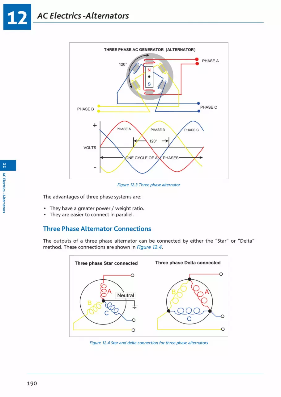
AC Electrics -Alternators12
190
12A
C Electrics - A
lternators
Figure 12.3 Three phase alternator
The advantages of three phase systems are:
• They have a greater power / weight ratio.• They are easier to connect in parallel.
Three Phase Alternator Connections
The outputs of a three phase alternator can be connected by either the “Star” or “Delta” method. These connections are shown in Figure 12.4.
Figure 12.4 Star and delta connection for three phase alternators

12
191
AC
Ele
ctri
cs -
Alt
erna
tors
12
AC Electrics - Alternators
The Four Wire Star Connection
A star connected three phase alternator has the three phases joined at one end to form a fourth connection known as the neutral point. Refer to Figure 12.5.
Figure 12.5 Star connected alternator
The neutral point is normally grounded and used as the earth return in modern aircraft. The neutral line will carry any out of balance current. This means that if there is an earth fault on one phase, the neutral will carry an exceptionally high load.
This is the type of alternator that will be fitted to a typical aircraft distribution system because it can cope with different loads on each bus bar, the delta connection can not.
The connection at the opposite end of the phase from the neutral is called the line connection. A voltmeter measuring the potential difference between the neutral and the line lead would read phase voltage. A voltmeter measuring the potential difference between two line connections would read line voltage.
In this type of alternator the phase voltage and line voltage are different because phase voltage is measured across one phase whereas line voltage is measures across two phases and is the vector sum of the two.
Given one or the other of these values, the following formula will enable the student to establish the missing criterion:
Line Voltage = 1.73 × Phase VoltageNote: (1.73 = √3)
The line voltage of a typical aircraft supply system would be 200 volts, and from the formula above it can be seen that the phase voltage would be:
200 1.73
or 115 volts
To be more specific, a modern aircraft power supply would be 115 V/ 200 V/ 400 Hz/ 3 phase.

AC Electrics -Alternators12
192
12A
C Electrics - A
lternators
While the voltages of line and phase differ in the star connected system, because the windings form only one path for current flow between phases:
LINE CURRENT = PHASE CURRENT
Figure 12.6 Delta connected alternator
Delta Connected Alternator
As can be seen from Figure 12.6, in this system the ends of the phases are joined together to form a closed mesh and the loads are connected in a similar fashion.
Logically, because the potential measured across the phase is measured between two lines, then:
LINE VOLTAGE IS PHASE VOLTAGE
BUT
LINE CURRENT = PHASE CURRENT × √3
This type of connection will not be used in a practical distribution system because it cannot cope with unbalanced loads as there is no neutral point. However, they may be used for specific purposes e.g. speed sensors or tacho generators.
Practical AC Generators
Rotating Armature alternators suffer from various disadvantages:
• The rotating coils are heavy and centrifugal forces are high.• Efficient insulation of the rotating coils is difficult.• The resistance across the brushes to the slip rings is high.• The rotating coils are difficult to cool.• They have a poor power to weight ratio.

12
193
AC
Ele
ctri
cs -
Alt
erna
tors
12
AC Electrics - Alternators
Rotating Field alternators make up the majority in use. From the previous sections it will be seen that in this type of alternator the field is in the rotor and the phase windings form the stator.
There are two types of rotating field alternator in use on aircraft:
• Brushed alternators.• Brushless alternators.
Brushed Alternators
The current supply for the excitation of the rotor field can be provided initially from the aircraft DC bus bar (battery) and then subsequently by rectified AC. The DC current is directed through brushes and slip rings to the rotating field.
Control of the excitation current is by the voltage regulator which samples the alternator output (115 V AC) and adjusts the excitation current to maintain the correct voltage irrespective of the alternator speed and loads.
The voltage regulator in its simplest form is a variable resistance connected in series with the field coil (the principle of the carbon pile regulator in Chapter 6, page 93 ).
Figure 12.7 Brushed alternator
115 V AC BUS
TRU
28 V DC BUS BAR

AC Electrics -Alternators12
194
12A
C Electrics - A
lternators
Brushless Alternators
Figure 12.8 Brushless alternator
115 V AC BUS
TRU
28 V DC BUS BAR
A brushless alternator incorporates an exciter generator mounted on the same shaft as the main generator. The purpose of the exciter generator is to provide a current for the main generator rotating field. The rotating rectifier converts the AC produced in the exciter armature to DC required for the main rotor field supply.
Voltage regulation is effected by controlling the exciter field strength and thereby the current strength at the main rotor field coil.
Brushless alternators have some advantages over brushed alternators:
• They are very reliable• There are no brush wear problems• They have a high power to weight ratio
Modern brushless alternators may have a third generator on the same shaft called a Permanent Magnet Generator (PMG) which provides excitation current for its exciter generator. Alternator output is usually 115 V/200 V/400 Hz/3 phase.
There are two basic types of brushless alternator:
• Externally excited. (No residual magnetism in the exciter)• Self-excited. (Some residual magnetism in the exciter)
Frequency Wild Alternators
If an alternator is driven directly from the engine gearbox then its speed, and therefore the frequency of its output, will vary directly with engine speed. An output from such a generator is said to be Frequency Wild.
NOTE: The connection of two frequency wild generators in parallel is not possible.

12
195
AC
Ele
ctri
cs -
Alt
erna
tors
12
AC Electrics - Alternators
Frequency wild alternators are usually used on aircraft to power the electrical de-icing systems, where the resistances that make up the heater mats are not affected by changing frequencies.
Obtaining a Constant Frequency Supply from a Frequency Wild System
Inverters can be used to give a constant frequency output from a frequency wild supply. The frequency wild AC is rectified to DC which is used to power a Static Inverter which then converts DC to constant frequency AC.
Constant Frequency Alternators
If an alternator can be driven at a constant speed, then the output frequency will be constant. Driving the engine at a constant speed is not a practical proposition so a device is required to keep the speed of the alternator constant irrespective of the engine speed.
Constant Speed Generator Drive Systems
The Constant Speed Drive Unit (CSDU) consists of an engine driven hydraulic pump, the output of which drives a hydraulic motor which itself in turn drives the alternator.
The oil which forms the fluid, through which the mechanism operates and also facilitates lubrication and cooling, is contained within a reservoir, entirely separate from the engine oil system. The output of the hydraulic pump, and therefore the speed of the hydraulic motor, depends on the angle of a swash plate within the pump. The angle of the swash plate is controlled by a device called a speed governor. The speed governor is controlled by the load controller which senses the output frequency of the alternator and is responsible for increasing or decreasing the torque output of the CSDU to the alternator drive.
Most CSDUs are capable of maintaining the alternator output frequency within 5% of 400 Hz (380 - 420 Hz).
In the event of a mechanical failure in the alternator, the CSDU is protected by a Quill Drive; this is the equivalent of a weak link which will break before any major damage can be caused.
The CSDU operates in one of three modes: overdrive, straight through drive or underdrive.
• Overdrive = engine speed less than generator speed• Straight through drive = engine speed same as generator speed • Underdrive = engine speed greater than generator speed
Some constant frequency generators have their CSDU and generator combined in one unit called an Integrated Drive Unit (IDU) or Integrated Drive Generator (IDG).
CSDU Fault Indications in the Cockpit
There are several indications in the cockpit associated with the Constant Speed Drive Unit and the problems which might occur with it. The two main ones are:
• Low Oil Pressure Warning Lights. These will illuminate when the oil pressure drops below a predetermined minimum value.
• High Oil Temperature warning. This allows the CSDU oil outlet temperature to be monitored.
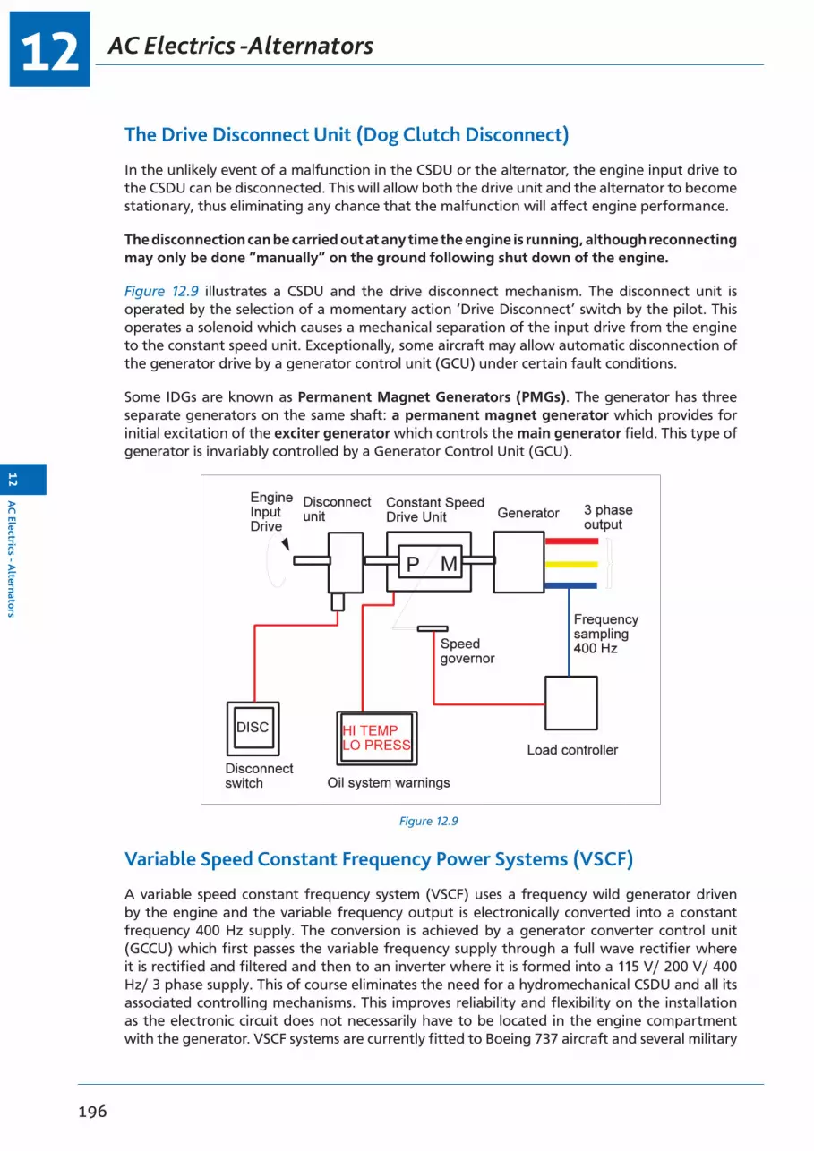
AC Electrics -Alternators12
196
12A
C Electrics - A
lternators
The Drive Disconnect Unit (Dog Clutch Disconnect)
In the unlikely event of a malfunction in the CSDU or the alternator, the engine input drive to the CSDU can be disconnected. This will allow both the drive unit and the alternator to become stationary, thus eliminating any chance that the malfunction will affect engine performance.
The disconnection can be carried out at any time the engine is running, although reconnecting may only be done “manually” on the ground following shut down of the engine.
Figure 12.9 illustrates a CSDU and the drive disconnect mechanism. The disconnect unit is operated by the selection of a momentary action ‘Drive Disconnect’ switch by the pilot. This operates a solenoid which causes a mechanical separation of the input drive from the engine to the constant speed unit. Exceptionally, some aircraft may allow automatic disconnection of the generator drive by a generator control unit (GCU) under certain fault conditions.
Some IDGs are known as Permanent Magnet Generators (PMGs). The generator has three separate generators on the same shaft: a permanent magnet generator which provides for initial excitation of the exciter generator which controls the main generator field. This type of generator is invariably controlled by a Generator Control Unit (GCU).
Figure 12.9
Variable Speed Constant Frequency Power Systems (VSCF)
A variable speed constant frequency system (VSCF) uses a frequency wild generator driven by the engine and the variable frequency output is electronically converted into a constant frequency 400 Hz supply. The conversion is achieved by a generator converter control unit (GCCU) which first passes the variable frequency supply through a full wave rectifier where it is rectified and filtered and then to an inverter where it is formed into a 115 V/ 200 V/ 400 Hz/ 3 phase supply. This of course eliminates the need for a hydromechanical CSDU and all its associated controlling mechanisms. This improves reliability and flexibility on the installation as the electronic circuit does not necessarily have to be located in the engine compartment with the generator. VSCF systems are currently fitted to Boeing 737 aircraft and several military

12
197
AC
Ele
ctri
cs -
Alt
erna
tors
12
AC Electrics - Alternators
aircraft. The VSCF also incorporates a built-in test facility which can provide fault isolation information to the ground engineer.
Self-excited Generators
A self-excited generator is one which has some permanent magnetism in its exciter generator. On initial rotation, the flux from these Stationary Permanent Magnets causes an induced AC voltage and therefore current to flow in its rotor. The rotor output is then fed directly to a rotating rectifier which in turn supplies the rotating field coils of the main generator with a DC supply.
The output of the main generator stator is tapped to provide a regulated supply to the exciter field so enabling the voltage to be controlled.
Load Sharing or Paralleling of Constant Frequency Alternators
When running two or more constant frequency alternators in parallel they must be controlled in order that each one takes a fair and equal share of the load.
This “load sharing” or “paralleling” requires that two parameters are regulated:
• Real Load.• Reactive Load.
Real Load
Real Load is the actual working load output available for supplying the various electrical services and it is measured in kilowatts (real power or true power).
Real Load is directly related to the mechanical power or torque which is being supplied to the alternator drive by its prime mover, i.e. the engine or CSDU.
Real Load Sharing is achieved by controlling the Constant Speed Drive Unit (CSDU) and adjusting the torque at its output shaft so that if the torque of the two or more CSDUs is equal then the real load taken by each generator is the same.
Reactive Load
Reactive Load is the so-called Wattless Load which is the vector sum of inductive and capacitive currents and voltages expressed in kVAR (Kilovolt-Amperes Reactive). Reactive Load Sharing is achieved by controlling the Voltage Output (Exciter Field Current) of each generator that is connected in parallel. If their voltages are identical then the reactive load on each generator will be the same.

AC Electrics -Alternators12
198
12A
C Electrics - A
lternators
Parallel Connection
To control the real and reactive load when two or more generators are paralleled there are two separate load sharing circuits, one to detect and control real load and one to detect and control reactive load.
N.B. It must be stressed that until a generator is connected in parallel with one or more generators it will not be connected into the load sharing circuits. While constant frequency alternators are operating as individual units, such as at engine start when only one alternator may be on line, their real load and reactive load sharing circuits are not connected.
Before Connecting in Parallel
AC generators, or alternators, are synchronous machines which will lock frequencies when they are operated in parallel. The system frequency thus becomes that of the alternator with the highest load.
However, if the two alternators are at different frequencies before they are connected in parallel then damage can occur as one generator tries to slow down and the other tries to speed up, so they must be at the same frequency before paralleling.
As well as being at the same frequency they must also be of the same phase sequence, i.e. at any point in time, phase A, B and C on the first generator must be identical to phase A, B and C on the second generator. The voltage of each generator being paralleled must also be the same.
Figure 12.10 Conditions required before parallelingFigure 2.10 Conditions Required Before Parallelling

12
199
AC
Ele
ctri
cs -
Alt
erna
tors
12
AC Electrics - Alternators
Layout of a Paralleled System
Figure 12.11 shows a diagram of the layout of a three generator paralleled system. Notice that for each of the three phases of the output there is a separate bus bar, for example the No. 1 generator bus bar (Gen Bus 1) is made up of three separate bus bars A, B and C for phases A, B and C. The generator is connected to its own bus bar through a 3 phase circuit breaker called the Generator Circuit Breaker (GCB), operated automatically or controlled from the flight deck. All the electrical loads of the aircraft are shared between the three generator bus bars.
To operate the generators in parallel they are connected through their respective generator bus bars to a synchronizing bus bar via a Bus Tie Breaker (BTB). A Bus Tie Breaker is a 3 phase circuit breaker controlled automatically or manually from the flight deck.
The synchronizing bus bar takes no electrical loads at all, it is only there to allow the engine driven generators to be operated in parallel. Ground power or power from the APU generator can be connected into the synchronizing bus and from there can be fed to the load bus bars through the BTBs when the engine generators are not operating and the GCBs are open.
Figure 12.11 Three generator paralleled system
GENERATORCIRCUITBREAKER NO.1
SYNCHRONIZING BUS
BUS TIEBREAKER NO.1
GROUNDPOWER ORAPU
BTBNO.2
BTBNO.3
GCBNO.2
GCBNO.3
Real Load Sharing
The Load Controller controls the basic frequency of the AC generator (400 Hz).
After paralleling, the load controllers work together to evenly share the real load by increasing the torque input to the lower speeding alternators drive and decreasing the torque input to the higher speeding alternators to ensure each alternator takes an equal share of the load.
Current transformers sense the Real Load distribution at the output of each of the paralleled alternators.

AC Electrics -Alternators12
200
12A
C Electrics - A
lternators
When current flows through these transformers, voltage is induced in them and a current will flow in the Load Sharing Loop. Each of the current transformers, which are connected in series with each other in the loop, has an Error Detector wired in parallel with it.
If it is assumed initially in Figure 12.12 that conditions of balanced load have been attained, then the current output of each current transformer can also be assumed to be 5 amperes and no current will flow through the error detectors.
Figure 12.12 Real load sharing circuit
GEN1 GEN2 GEN3
TO SPEED GOVERNOR NO. 1 TO SPEED GOVERNOR NO. 2 TO SPEED GOVERNOR NO. 3
5 A
5 A5 A 4 A 4 A
1 A1 A2 A
7 A
Now imagine that the drive unit of the No 1 alternator increases its torque output, it will take a bigger share of the load than the other two alternators which will decrease by a proportional amount.
The output of the No. 1 alternator current transformer has increased to 7 amperes so this will mean that the output of the No. 2 and 3 transformers will decrease to 4 amperes so that the average current flowing in the circuit is still 5 amperes.
According to Kirchoff’s first law the difference between each current transformer and the average current will be pushed through the error detectors in opposite directions. This signal, when amplified, will be sent to the speed governors to tell the CSDU for the No. 1 Gen to reduce torque (speed) and the CSDUs for the No. 2 and 3 Gen to increase torque (speed) until the current in each transformer is once again equal and the real load is once again balanced.
Real load sharing is controlled by matching CSDU speed (torque)
Reactive Load Sharing
The reactive load sharing circuit shown below looks very similar to the real load sharing circuit. It works in a similar fashion but it is a completely separate circuit.
The sensing of out of balance loads by the current transformers is the same but this time the error detector needs to know the difference between the reactive loads carried by each generator.

12
201
AC
Ele
ctri
cs -
Alt
erna
tors
12
AC Electrics - Alternators
The mutual reactor is a phase shifting transformer which ensures that the error detector only detects that part of the current which is 90° out of phase with the voltage (reactive load). The error signal is then amplified and correcting signals are sent to the generator field circuit to increase the voltage on the low voltage generator and reduce the voltage of the higher voltage generator to balance the reactive load.
Reactive load sharing is controlled by the Voltage Regulators matching voltage outputs (field excitation).
Figure 12.13 Reactive load sharing circuit
GEN1 GEN2 GEN3
5 A
5 A 4 A
1 A2 A 1 A
4 A7 A 5 A
Load Sharing General
It is typical to run three and four generator systems in parallel but most modern twin engine aircraft with two generators run the generators in isolation (Split Bus System).
In those three and four generator systems the load sharing circuits operate as shown above but are extended to cater for the required number of generators.
If any generator in a parallel system is not connected in parallel then it will not be connected to the load sharing circuits either.
REMEMBER: Real load sharing - speed, frequency, torque (CSDU) Reactive load sharing - excitation current, field current (Voltage Regulator)
Alternator Cooling
The heat generated in the alternator stator windings due to the current flow through them means that some form of cooling system is required. Those systems with frequency wild generators or constant frequency generators with separate CSDUs typically use ram air cooling in flight and some means to induce an airflow on the ground. IDGs or IDUs use their oil to cool the stators which is then cooled in its own oil cooler.

AC Electrics -Alternators12
202
12A
C Electrics - A
lternators
Generator Fault Protection
When constant frequency alternators are paralleled, then the requirement for other Control and Protection devices become apparent.
There follows a non-exhaustive list of some of those devices:
• Bus Tie Breakers (BTBs).• Discriminatory circuits.• Differential Fault Protection circuits.• Synchronizing Units.• Failure Warning systems.• Load meters.• Voltage and Frequency meters.• Generator Control Units (GCUs).
Bus Tie Breakers (BTBs)
A bus tie breaker connects two bus bars together. In a paralleled system it connects an alternator to the synchronizing bus bar. The synchronizing bus bar allows two or more alternators to be connected in parallel with each other while the BTBs are closed. Control of the BTB can be automatic or manual dependent on the type of aircraft. Correct signals from a Synchronizing Unit (monitoring phase frequency and voltage) must be available before the BTB will close and put the alternator in parallel with another. In a paralleled system the BTBs are normally closed. In a Split Bus system (non paralleled) the BTB is normally open.
Visual indication of the position of the BTBs is given by indicators on the electrical control panel or the electronic display panel.
Discriminatory Circuits
When alternators are paralleled, Discrimination Circuitry is required to ensure that in the event of a fault only the faulty system is disconnected from the appropriate bus bar. This is achieved by selective switching of the GCBs and BTBs.
Differential Fault Protection
Control and protection devices must be included within the power supply circuits. These will monitor system performance and appropriately operate the relevant circuit breakers, GCBs BTBs etc. This may be achieved by a component known as a bus power control unit (BPCU) which monitors the system by current transformers placed at each generator and at each bus bar. It will isolate a defective generator or faulty bus bar and reconfigure the electrical system to maintain the maximum usage.
Protection is provided for:
• Over / Under Voltage• Over / Under Frequency• Over / Under Excitation.• Differential Current Faults, (short circuits between bus bars or bus bar to ground, or open
circuit faults unbalancing phase outputs).
12
203
AC
Ele
ctri
cs -
Alt
erna
tors
12
AC Electrics - Alternators
Synchronizing Units
Before the alternator can be connected to a bus bar which is common to another alternator its voltages, frequency and phase sequence must be within very strict limits and in the same order. The Synchronizing Unit ensures that these values are within limits before it will allow connection to a common bus bar. There are two methods in use:
• Automatic Control• Manual (Dark Lamp) Method
Automatic control will not allow the BTB or GCB to close and parallel the generators until the voltage, frequency and phase sequence of the oncoming generator is within limits. This may be achieved by circuitry within a bus bar protection control unit or in the Generator Control Units (GCUs) of a modern IDG system.
The Manual (Dark Lamp) method is a much older method but remains in use on a few aircraft. Synchronizing Lights on the alternator control panel will show when there are differences between phases of two supplies. Synchronization is indicated when the lamps are “dark” and then the BTB, or GCB, can be closed by means of the manual switch.
Generator Failure Warning Light
A Generator Failure Warning Light will illuminate when its associated GCB is tripped. The Centralized Warning System will operate simultaneously with the Generator Warning Light and in some aircraft Aural Warnings are generated.
Aircraft with electronic systems management display units will show the failure and the associated schematic display.
Load Meters
kW / kVAR Meters are used in paralleled alternator systems to indicate the Real Power (kW) or the Reactive Power (kVAR) output. Only one meter may be used to indicate both parameters, selection of a switch will determine which of the two is shown. Typically the switch is selected so that the kW output is normally displayed.
The Real Load is the part of the alternator output which is available to do work at the bus bar. The Reactive Load is the part of the alternator output which is used to create electromagnetic and electrostatic effects in the circuits. It is the so-called Wattless Load which is the vector sum of the inductive and capacitive currents and voltages.
Load meters on modern electronic display units may only show a percentage of the maximum power being taken.
Voltage and Frequency Meters
Voltage and frequency indications are also provided for each generator. Typically only one voltmeter and one frequency meter is provided in systems with several alternators in circuit. The voltage or frequency of any alternator can be selected by a Multi-position Switch. The switch can usually be positioned to show not only the supply frequency and voltage of the engine driven alternators, but also that of the auxiliary power unit, the ground power unit or the Emergency Ram Air Turbine, if provided.
AC Electrics -Alternators12
204
12A
C Electrics - A
lternators
Generator Control Unit (GCU)
In a modern generator control system a Generator Control Unit (GCU) houses circuitry to provide many functions of power control and protection. A typical GCU will monitor generator output and provide voltage regulation by controlling the exciter field current. Protection circuitry will monitor for overvoltage and overcurrent, frequency, phase sequence and differential current protection. A GCU will be provided for each generator and they may work as a team with the BPCU in controlling fault isolation switching.
The GCU may also house an Exciter Control Relay otherwise known as a Generator Control Relay or Generator Field Relay. The exciter control relay controls the exciter field current supply to the generator field. In the event of a dangerous fault occurring (over excitation or overvoltage) the fault protection circuit will open the exciter control relay which will cause the generator output to fall to a residual value making it safe. The GCU will also open the generator circuit breaker (GCB) to disconnect the generator from its bus bar. (In a paralleled system power would be maintained to the generator bus bar from the other generators through the BTB).
Emergency Supplies
In the unlikely event of some, or the entire engine driven AC power generation systems on the aircraft failing, alternative methods of supply must be made available. Some alternative means of providing AC are listed below:
• Ram Air Turbine (RAT)• Auxiliary Power Unit (APU)• Static Inverter.• Hydraulic Motor driven generator.
The Ram Air Turbine (RAT)
The Ram Air Turbine (RAT or ELRAT), when lowered into the slipstream of an aircraft in flight, will produce an emergency source of AC power. The output is controlled at a nominal 115 V/ 200 V/ 400 Hz/ 3 phase; it will give limited operation only of Flight Instrument and Radio services in the event of total alternator failure. (RATs driving an electrical generator have been largely replaced by RATs driving a hydraulic pump, as modern aircraft are more dependent on hydraulic power to power the primary flying controls in an emergency).
The Auxiliary Power Unit (APU)
The Auxiliary Power Unit (APU) is usually a small gas turbine engine mounted in the aircraft tailcone. This engine runs at a constant speed and has its own protection devices in the event of a fire, low oil pressure, high oil temperature, overspeed or overheat.
It can be used, among other things, to drive a 115 V/ 200 V/ 400 Hz/ 3 phase alternator for ground servicing supplies, or, in some aircraft, for emergency supplies in the air.
The APU alternator cannot be paralleled with the engine driven alternators, and will only supply power to the bus bars when no other source is feeding them.

12
205
AC
Ele
ctri
cs -
Alt
erna
tors
12
AC Electrics - Alternators
The Static Inverter
A Static Inverter is a Solid State Device capable of supplying the aircraft with 115 V/ 200 V/ 400 Hz/ 3 phase for the limited operation of instrument and radio services.
It is powered by the aircraft batteries or from an essential DC bus bar.
Ground Power Constant Frequency Supply System
The standard modern Ground Power Unit output is 115 V/ 200 V/ 400 Hz/ 3 phase.
When plugged into the aircraft it can be used to supply all the aircraft electrical services.
The ground power unit circuitry must include automatic protection systems which will ensure that ground power:
• Cannot be connected to the aircraft distribution system if the system is already being supplied by its own alternators.
• Cannot be connected if the phase sequence of the supply is incorrect.
• Will be rejected and switched off at source if overvoltage occurs.

AC Electrics -Alternators12
206
12A
C Electrics - A
lternators
Typical Controls and Indications
Figure 12.14 shows typical controls and indications for a three-engine paralleled system. This type of panel uses “switch lights”. These are a combination switch and indicator, either having a momentary or alternate action e.g. push once to activate (generator disconnect switch) or push once to switch “on”, then push a second time to switch “off” (galley power on/off). The indicator shows switch position or system status.
Each engine drives a constant frequency generator (Integrated Drive Generator or IDG). Oil temp indications are shown along with overheat and low pressure warning lamps in the disconnect switch. The disconnect switch is guarded to prevent inadvertent operation.
Figure 12.14 Control and indications for a three-engine parallel system

12
207
AC
Ele
ctri
cs -
Alt
erna
tors
12
AC Electrics - Alternators
The APU also drives a generator but this one does not need a constant speed unit because the APU runs at a constant speed.
The generator field switch lights control the field excitation circuit (exciter control relay). The “flow bar” in the “close” switch light illuminates to indicate the generator field is complete and the voltage and frequency can be checked by selecting the required generator on the rotary switch and reading off the voltmeter and frequency meter in the upper right corner of the panel. The “trip” switch light opens the field circuit to reduce the generator voltage to zero.
The Generator Circuit Breaker (GCB) is controlled by the GCB switch lights (close/trip) which connect or disconnect the generator to its own AC bus bar or the APU to the AC Tie Bus. The load on each generator can be monitored by the Real/Reactive load indicator showing kW or kVAR. The meter normally shows kW but kVAR can be shown by pressing and holding the kVAR button to the left of the gauges.
The BTBs are controlled in the same manner to connect the generator busses to the AC tie bus for parallel operation. All three generators are normally connected in parallel to share the total aircraft electrical load.
Each AC bus feeds a TRU which converts 115 V/ 200 V/ 400 Hz/ 3 phase AC to 28v DC to power the individual DC busses. These too are normally paralleled through tie breakers which are all controlled by the DC Bus Isolation switch.
The DC part of the system can also be checked for voltage and current by use of the other rotary selector and meters for DC Volts and Amps
The Standby bus bars can be fed from the normal electrical supply (AC and DC) or from the battery in the event of a total supply failure. The red fail lights indicate no voltage on the Essential or Standby bus bars.
Questions12
208
12Q
uestions
Questions
1. An alternator is:
a. a reversing input switchb. an AC generatorc. a DC generatord. a static inverter
2. To prevent high circulating currents between paralleled alternators, the following conditions should be met:
a. their voltage and frequency must be the sameb. their frequencies must be identical and their phase sequence must be the
samec. their voltage, frequency, phase and phase sequence must all be the samed. their inductive and capacitive reactances must match exactly
3. The output of an AC generator is taken from:
a. the exciter windingsb. the field coilsc. the stator windingsd. the rotor coils
4. The moving part of an alternator is:
a. the rotorb. the megacyclec. the statord. the frequency
5. A frequency wild alternator must be:
a. paralleledb. a rotating magnet typec. self-excitingd. unparalleled
6. In a 3 phase AC generator circuit, the phase voltage is:
a. greater than line voltageb. 10% higher than line voltagec. less than line voltaged. equal to line voltage
7. If an alternator output is frequency wild, it would normally be used for:
a. flight instrumentsb. charging a batteryc. all AC equipmentd. prop and engine de-icing systems

12
209
Que
stio
ns12
Questions
8. The generator output voltage is increased by:
a. putting more load on itb. the frequency controllerc. decreasing the generator field voltaged. increasing the generator field current
9. A constant frequency AC supply in an aircraft with only frequency wild generators is provided by:
a. an inverterb. a diodec. an autotransformerd. a rectifier
10. An alternator normally used to supply an aircraft’s power system would be:
a. single phaseb. three phasec. two phased. frequency wild
11. A permanent magnet in a rotating field generator:
a. provides for initial excitation of the fieldb. controls the amount of excitation in the stator windingsc. provides the initial excitation in the voltage regulatord. can be flashed by the application of alternating current
12. Voltage control of an alternator output is achieved by varying the:
a. excitation of the rotating commutatorb. load currentc. excitation of the rotating fieldd. power factor
13. Frequency wild AC is produced when:
a. a transformer winding open circuitsb. the voltage regulator is malfunctioningc. the rotational speed of the generator variesd. the alternator becomes angry
14. In a star connected supply system:
a. line and phase current are equalb. line current is greater than phase currentc. line current is less than phase currentd. phase current is 0.707 times line current
15. In a 3 phase supply system, line voltage would be sensed between the:
a. phases onlyb. phase and earthc. phase and neutrald. phases and earth

Questions12
210
12Q
uestions
16. One advantage of three phase generation over single phase generation is that:
a. most aircraft services require a three phase supplyb. it can be more easily transformed into DCc. it gives more compact generators and allows lower cable weightsd. the power factor is much lower
17. In a typical aircraft constant frequency supply system, the phase voltage is:
a. 200b. 115c. 208d. 400
18. An alternator with its output taken from its stationary armature, has:
a. a stationary fieldb. its field excitation fed directly to the armaturec. AC excitationd. a rotating field
19. The phase voltage in a star wound three phase system is measured between:
a. phase and neutralb. two phasesc. two linesd. neutral and earth
20. If one phase of a star wound three phase system becomes earthed, it will:
a. earth all three phasesb. cause a large current to flow in the neutralc. have no effect on the other phasesd. cause a reduction in the frequency of the supply
21. The alternators fitted in an aircraft’s main power supply system would normally be:
a. brushed self-excited machinesb. frequency wildc. self-excitedd. externally excited
22. A voltage regulator works by:
a. sensing the battery voltageb. assessing the impedance of the circuitc. varying the circuit voltaged. varying the rotating field strength
23. To ensure correct load sharing on paralleled alternators:
a. both real and reactive loads should be balancedb. actual loads should be the samec. reactive loads should be the samed. the load impedance should be constant
12
211
Que
stio
ns12
Questions
24. Reactive load sharing is achieved by:
a. altering the loads on the bus barsb. varying the generator rotational speedc. varying the generator field currentd. altering the CSDU output torque
25. Real load sharing is achieved by:
a. varying the alternator rotational speedb. varying the generator field currentc. altering the loads on the bus bard. the voltage regulator
26. The phase relationship of paralleled generators should be:
a. unimportantb. 180° apartc. synchronousd. 120° apart
27. In a constant speed parallel operation alternator system:
a. each alternator has its own constant speed drive unitb. all engines are run at the same speedc. all alternators are driven by the same engined. engine speed is governed by the constant speed drive unit
28. An aircraft’s constant frequency supply is maintained at:
a. between 350 - 450 Hzb. between 380 - 420 Hzc. between 115 - 200 Hz d. between 395 - 495 Hz
29. For a modern aircraft powered by an AC system, the ground power unit must supply:
a. 28 volts AC onlyb. 200 voltsc. 115 volts, three phased. 115/200 volts, three phase, 400 Hz
30. Oil for the operation of a CSDU is:
a. supplied from the engine oil systemb. a separate self-contained supplyc. drawn from a common tank for all CSDUsd. only required for lubrication purposes
31. Malfunction of a CSDU requires:
a. automatic electrical disconnection of the drive at any time in flightb. that the input drive will shear on the ground onlyc. operation of the drive disconnect switch at any time in flightd. operation of the drive disconnect switch on the ground only

Questions12
212
12Q
uestions
32. Before two constant frequency AC generators can be connected in parallel:
a. their frequency, phase, phase sequence and voltage must match, and a means of automatic real and reactive load sharing must be available
b. real and reactive loads must match. Frequency, phase and voltage must be within limits
c. the synchronization lights on the alternator control panel must be fully brightd. suitable control arrangements must exist for the sharing of real and reactive
loads. These will correct any phase or frequency error existing at the time of connection
33. The generator control relay (GCR) is:
a. in the excitation circuitb. between the alternator and its load bus barc. in the stator circuitd. between the load bus bar and the synchronous bus bar
34. The running excitation current for an alternator is:
a. ACb. DC from the aircraft batteriesc. DC from the static inverterd. DC which is rectified AC and could be from a separate excitation generator on
the main rotor shaft
35. If each phase of a three phase star wound system has a phase voltage of 115 volts, the voltage obtained by bridging two phase would be:
a. 200 volts ACb. 173 volts DC c. 28 volts DCd. 173 volts AC
36. Protection from ‘earth’ faults and ‘line to line’ faults is given by:
a. a negative earth detectorb. a fault protection system including a differential protection monitorc. the synchronization unitd. reactive load sharing circuits
37. Warnings of CSDU oil overheat are given in the cockpit by:
a. audio warningb. an ‘oil overheat’ warning lightc. a ‘low oil pressure’ warning lightd. a temperature gauge
38. One disadvantage of parallel operation is that:
a. faults can propagate, and any error in supply can affect all servicesb. the system is less flexible due to the need for additional control and protection
circuitsc. the greater load on the CSDUs means that their power / weight ratio is much
reducedd. there is a considerable increase in complexity compared with a non-paralleled
system, due to the need for CSDUs and load sharing circuits
12
213
Que
stio
ns12
Questions
39. Alternators in parallel operation require the maintenance of constant frequency and phase synchronization to:
a. balance the battery voltage when more than one battery is being usedb. prevent recirculating currentsc. control their voltaged. reduce their magnetic fields
40. The APU generator can only be used when:
a. another generator is on lineb. the aircraft is on the groundc. the bus bars are being fed from another sourced. when no other power source is feeding the bus bar
41. The purpose of the differential protection circuit in a three phase AC system is:
a. to compare alternator output current to bus bar currentb. to compare on and off load currentsc. to compare the alternators reactive load to its real loadd. to compare the CSDU efficiency ratings
42. An alternator driven by a CSDU
a. can never be paralleledb. will require a voltage controllerc. will require a lubrication system separated from its drive oil systemd. will not require a voltage controller
43. In the event of a mechanical malfunction of the alternator:
a. the drive disconnect unit will automatically separate the CSDU from the alternator
b. the real load will be adjusted to compensatec. the quill drive will fractured. the CSDU oil temperature will decrease
44. The load meter, upon selection to “kVAR” would indicate:
a. total power availableb. reactive loadsc. active loadsd. only DC resistive loads
45. Disconnection of the CSDU in flight would be advisable if:
a. the frequency meter indicated a discrepancy of greater than 5 Hz between alternators
b. there was an over or under voltagec. the oil temperature was high or the oil pressure was lowd. the engine failed
Questions12
214
12Q
uestions
46. To increase the real load taken by a paralleled AC generator, the:
a. generator drive torque is increasedb. generator excitation is increasedc. generator drive torque and field excitation are increasedd. generator voltage regulator adjusts the generator rotor torque
47. Load sharing circuits are necessary whenever:
a. generators are operating in seriesb. generators are operating independentlyc. the ground power and the APU are serving the bus bars togetherd. generators are operating in parallel
48. Paralleled alternators will have:
a. one load meter which measures total system loadb. one voltmeter for each alternatorc. one load meter for each alternatord. one meter which indicates both voltage and frequency
49. Frequency controlled generators are:
a. always paralleledb. not always paralleledc. never paralleledd. paralleled only when the DC is paralleled
50. If the CSDU drive disconnect unit has been used, the drive can:
a. only be reconnected when the aircraft is on the groundb. be reinstated in flight from the electrical supply departmentc. be reinstated in flight from the flight deckd. be reinstated when necessary by using the Ram Air Turbine
51. When selected to ‘kW’, the alternator load meter will indicate the:
a. total circuit loadb. real loadc. reactive loadd. current flowing in the field
52. An AC generator’s IDU oil system:
a. is self-containedb. is common with the engine oil systemc. is used only for coolingd. is used only for lubrication
53. An alternator driven by a non-integrated constant speed drive unit, has windings that are cooled by:
a. waterb. oilc. oil and waterd. air

12
215
Que
stio
ns12
Questions
54. The load in a paralleled AC system is measured in:
a. kW & kVAb. kW & kVc. kV & kVARd. kW & kVAR
55. Paralleled generators must share real and reactive loads:
a. to prevent large current flows through the TRUsb. to prevent out of balance forces being fed through the CSDUs to the enginesc. to prevent large flows of current from one generator to anotherd. to prevent harmonic frequencies being created in the synchronous bus bars
56. One advantage of running alternators in parallel is that:
a. the supply to all circuits is in phaseb. a large capacity is available to absorb heavy transient loads when switching of
heavy currents occursc. the risk of overloading the system is reducedd. there is only a requirement for one CSDU
57. When an external AC supply is feeding the bus bars:
a. the internal bus bars are disconnectedb. the aircraft generators are run in parallel with the external supplyc. the aircraft generators are taken off lined. the synchronizing unit will ensure that no frequency difference exists between
the aircraft generators and the external supply
58. A three phase AC system can be used to supply:
a. both one or three phase equipmentb. only three phase equipmentc. only single phase equipmentd. only inductive or capacitive loads
59. In a frequency wild generation system:
a. generators can be run in parallel only when all engine RPMs matchb. generators can never be run in parallel and there can be no duplication of
supplyc. generators can never be run in parallel, but after rectification, the DC can be
fed to a common bus bar to provide a redundancy of supplyd. capacitive and inductive loads can be fed with no problems of overheating
60. A fault on one phase of a three phase AC star connected system would:
a. have no effectb. affect only the phase concernedc. cause inductive loads to overheatd. affect all three phases
Questions12
216
12Q
uestions
61. The purpose of an inverter is:
a. to change AC into DCb. to change the frequency of the AC supplyc. to act as a back up for the alternatord. to change DC into AC
62. A low reactive load on one generator is compensated for by:
a. altering the excitation current flowing in its field circuitb. increasing the rotor speedc. increasing the real load on the other generatorsd. overall load reduction
63. I n the event of a mechanical failure occurring in the generator, the CSDU is protected by:
a. a hydraulic clutchb. a universal jointc. a quill drived. a feather drive
64. To increase the real load which is being taken by a paralleled alternator:
a. the voltage regulator adjusts the generator rotor torqueb. both its drive torque and its excitation are increasedc. only its excitation is increasedd. its drive torque is increased
65. An earth fault on a bus bar of a parallel generator system:
a. would require that the appropriate GCB should openb. would require that the appropriate BTB should openc. would require that both the appropriate GCB and BTB should opend. would require that all alternators should operate independently

12
217
Que
stio
ns12
Questions

Answers12
218
12A
nswers
Answers
1 2 3 4 5 6 7 8 9 10 11 12
b c c a d c d d a b a c
13 14 15 16 17 18 19 20 21 22 23 24
c a a c b d a b c d a c
25 26 27 28 29 30 31 32 33 34 35 36
a c a b d b c a a d a b
37 38 39 40 41 42 43 44 45 46 47 48
b d b d a b c b c a d c
49 50 51 52 53 54 55 56 57 58 59 60
b a b a d d c b c a c d
61 62 63 64 65
d a c d c

219
13Chapter
AC Electrics - Practical Aircraft Systems
Power Distribution . . . . . . . . . . . . . . . . . . . . . . . . . . . . . . . . . . . . . . . . .221
The Split Bus System . . . . . . . . . . . . . . . . . . . . . . . . . . . . . . . . . . . . . . . .221
Parallel Bus Bar System . . . . . . . . . . . . . . . . . . . . . . . . . . . . . . . . . . . . . . .224
Questions . . . . . . . . . . . . . . . . . . . . . . . . . . . . . . . . . . . . . . . . . . . . . .226
Answers . . . . . . . . . . . . . . . . . . . . . . . . . . . . . . . . . . . . . . . . . . . . . . .228

AC Electrics -Practical Aircraft Systems13
220
13A
C Electrics - Practical A
ircraft Systems
Figu
re 1
3.1
Gen
erat
or F
eede
r Li
nes
Flig
ht
dec
k C
Bp
anel Lin
e C
urr
ent
Tran
sfor
mer
s
Eng
ine/
Win
gD
isco
nn
ect
CSD
Gen
erat
or
2
Fro
m A
PU
Gen
erat
or
To lo
adB
us
bars
Gen
erat
or
Bre
aker
1
Gen
erat
or
Bre
aker
2
APU
Gen
erat
or
Bre
aker
CSD
Gen
erat
or
1
Eng
ine/
Win
gD
isco
nn
ect

13
221
AC
Ele
ctri
cs -
Prac
tica
l Airc
raft
Sys
tem
s13
AC Electrics - Practical Aircraft Systems
Power Distribution
In a very basic form, Figure 13.1 shows the general layout of an electrical distribution system for a twin jet aircraft. One generator is driven by and mounted on each engine and one generator is mounted on the APU (not shown). The feeder cables from each generator are routed through the aircraft wings and fuselage to meet at a central distribution compartment usually beneath the flight deck or cabin floor. This distribution compartment will house many of the components already described: GCBs, BTBs GCUs or voltage regulators, current transformers, main bus bars and bus bar protection circuitry, battery and battery charger. Bus bars and bus bar extensions may be found on the flight deck behind the rear, side and overhead circuit breaker panels.
A schematic diagram for this type of system is shown at Figure 13.2.
The Split Bus System
The Split Bus Bar System uses 115 V/ 200 V/ 400 Hz/ 3 phase constant frequency alternators as the primary power source. They are not designed to run in parallel and therefore do not require complex paralleling and load sharing circuits. A 28 V DC supply is provided by two Transformer Rectifier Units (TRUs) which convert 115 V AC to 28 V DC from the two separate AC bus bars. A battery is provided which will provide power to start the APU and limited emergency power to the essential bus bars, or to supply air and electrics on the ground when the engine driven generators are off line.
If, in the circuit shown in Figure 13.2, either alternator should fail, then the main bus bars are automatically connected by the Bus Tie Breaker and they will now serve as one bus bar. Power supplies to all the bus bars are thereby maintained. The APU may then be started in flight and its generator can be used to restore full power by connecting to AC bus 1 or bus 2. While each alternator separately supplies its own AC non-essential services and the associated TRU, the essential AC loads are supplied from only the No. 1 main bus bar via a changeover relay. In particular, note that the main AC bus bars are normally isolated from one another, i.e. the alternators are not paralleled
If both alternators should fail, then the AC non-essential services, which are normally supplied from the main AC bus bars, are isolated.
The changeover relay between the No. 1 main bus bar and the essential AC bus bar will automatically switch over. This causes the essential AC bus bar to be connected to an Emergency Static Inverter, which should, if the batteries are in a fully charged state, supply the essential AC bus bars for 30 minutes.

AC Electrics -Practical Aircraft Systems13
222
13A
C Electrics - Practical A
ircraft Systems
Figure 13.2 Split bus system
No. 1 No. 2APU
Under normal conditions, the DC supply in Figure 13.2 is obtained from the two independent TRUs and the batteries.
The No. 1 TRU supplies essential DC loads and the No. 2 TRU supplies non-essential DC loads.
In normal operation the two bus bars supplying the essential and non-essential DC loads are connected together by the Isolation Relay. The batteries are connected directly to the Battery Bus Bar, and through the Battery Relay they will feed the essential DC bus bar.
If, one alternator fails then both TRUs are still supplied through the now closed contacts of the bus tie breaker, and will still supply all of the DC consumers.
If, however, both alternators fail, the DC Isolation Relay will open and separate the essential and non-essential bus bars.
Non-essential loads will now no longer be powered, but the AC and DC essential loads will be fed from the battery bus bar (the AC loads from the static inverter).
External power or supplies from the APU can be used to feed all electrical services in the aircraft on the ground, but the APU generator may only be capable of supplying one bus bar in flight.

13
223
AC
Ele
ctri
cs -
Prac
tica
l Airc
raft
Sys
tem
s13
AC Electrics - Practical Aircraft Systems
Figure 13.3 A320 split bus control panel
Figure 13.4 A320 ECAM display
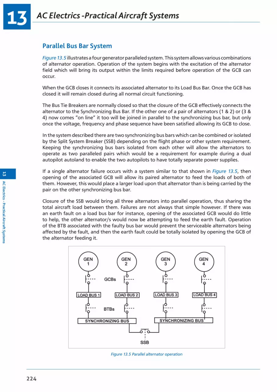
AC Electrics -Practical Aircraft Systems13
224
13A
C Electrics - Practical A
ircraft Systems
Parallel Bus Bar System
Figure 13.5 illustrates a four generator paralleled system. This system allows various combinations of alternator operation. Operation of the system begins with the excitation of the alternator field which will bring its output within the limits required before operation of the GCB can occur.
When the GCB closes it connects its associated alternator to its Load Bus Bar. Once the GCB has closed it will remain closed during all normal circuit functioning.
The Bus Tie Breakers are normally closed so that the closure of the GCB effectively connects the alternator to the Synchronizing Bus Bar. If the other one of a pair of alternators (1 & 2) or (3 & 4) now comes “on line” it too will be joined in parallel to the synchronizing bus bar, but only once the voltage, frequency and phase sequence have been satisfied allowing its GCB to close.
In the system described there are two synchronizing bus bars which can be combined or isolated by the Split System Breaker (SSB) depending on the flight phase or other system requirement. Keeping the synchronizing bus bars isolated from each other will allow the alternators to operate as two paralleled pairs which would be a requirement for example during a dual autopilot autoland to enable the two autopilots to have totally separate power supplies.
If a single alternator failure occurs with a system similar to that shown in Figure 13.5, then opening of the associated GCB will allow its paired alternator to feed the loads of both of them. However, this would place a larger load upon that alternator than is being carried by the pair on the other synchronizing bus bar.
Closure of the SSB would bring all three alternators into parallel operation, thus sharing the total aircraft load between them. Failures are not always that simple however. If there was an earth fault on a load bus bar for instance, opening of the associated GCB would do little to help, the other alternator/s would now be attempting to feed the earth fault. Operation of the BTB associated with the faulty bus bar would prevent the serviceable alternators being affected by the fault, and then the earth fault could be totally isolated by opening the GCB of the alternator feeding it.
Figure 13.5 Parallel alternator operation
SYNCHRONIZING BUS SYNCHRONIZING BUS

13
225
AC
Ele
ctri
cs -
Prac
tica
l Airc
raft
Sys
tem
s13
AC Electrics - Practical Aircraft Systems
An example of an aircraft with this type of paralleled system is the Boeing 747 - 400. Shown below in Figure 13.6 and Figure 13.7 are the control panel and the EICAS display for the electrical system.
Figure 13.6 747 - 400 electrical control panel
Figure 13.7 747 - 400 EICAS electrical display

Questions13
226
13Q
uestions
Questions
1. The purpose of a synchronizing bus bar is to:
a. enable interconnections to be made between generator bus barsb. supply essential servicesc. monitor on load currentsd. interconnect DC bus bars
2. Fuses and circuit breakers are fitted:
a. in DC circuits onlyb. in both AC and DC circuitsc. in AC circuits onlyd. only to protect the wiring
3. Where the aircraft’s main electrical supply is AC, DC requirements are met by:
a. batteriesb. TRUsc. invertersd. a static inverter
4. In a split bus system using non-paralleled constant frequency alternators as the primary power source:
a. essential AC loads are supplied directly from No. 1 AC bus barb. essential AC loads are supplied directly from No. 2 AC bus barc. only non-essential AC loads are supplied from the AC bus barsd. essential AC loads are normally supplied from No. 1 AC bus bar via the
changeover relay
5. In a split bus system using non-paralleled constant frequency alternators as the primary power source, if both alternators fail:
a. all non-essential services are lostb. all non-essential services will be supplied direct from the battery bus barc. all non-essential services will be supplied from the static inverterd. essential DC consumers only will be supplied from the No. 1 TRU, all other DC
services will be lost
6. In normal operation, the split bus bar AC system takes its DC supply from:
a. two TRUs which are always isolatedb. a battery which is supplied from No. 1 TRU onlyc. two TRUs which are connected together by the isolation relayd. the static inverter
7. The static inverter in the split bus system supplies:
a. the essential DC consumersb. the essential AC consumersc. both essential and non-essential consumersd. the batteries

13
227
Que
stio
ns13
Questions
8. In the split bus system, the AC bus bars:
a. are automatically connected via the isolation relay if one alternator failsb. are automatically connected via the bus tie breaker if one alternator failsc. can be connected together by switch selection if one alternator failsd. can never be connected together because there is no load sharing circuit
9. With parallel generator operation:
a. there are two synchronizing bus bars which are normally kept isolatedb. the GCBs connect the generators to the synchronizing bus barc. the BTBs connect the synchronizing bus bars togetherd. the GCRs connect the generators to their load bus bars
10. In a parallel alternator operation, should one alternator fail, then:
a. the other alternators can be selected to supply its loadb. the failed alternator’s loads will not be suppliedc. the GCB of the failed alternator will remain closed to allow its loads to be
supplied by the remaining alternatorsd. the SSB will close allowing the three remaining alternators to share all of the
load
11. If external power is plugged into an aircraft which utilizes the split bus system of power distribution, then:
a. it will automatically parallel itself with any alternators already on lineb. it will only supply non-essential AC consumersc. it will supply all the aircraft servicesd. essential AC consumers will be supplied from the static inverter

Answers13
228
13A
nswers
Answers
1 2 3 4 5 6 7 8 9 10 11
a b b d a c b b a d c
229
14Chapter
AC Electrics - Transformers
Transformers . . . . . . . . . . . . . . . . . . . . . . . . . . . . . . . . . . . . . . . . . . . .231
Transformation Ratio . . . . . . . . . . . . . . . . . . . . . . . . . . . . . . . . . . . . . . . .231
Power in a Transformer . . . . . . . . . . . . . . . . . . . . . . . . . . . . . . . . . . . . . . .232
Three Phase Transformers . . . . . . . . . . . . . . . . . . . . . . . . . . . . . . . . . . . . .232
Autotransformers . . . . . . . . . . . . . . . . . . . . . . . . . . . . . . . . . . . . . . . . . .232
Rectification of Alternating Current . . . . . . . . . . . . . . . . . . . . . . . . . . . . . . . .233
Half Wave Rectification. . . . . . . . . . . . . . . . . . . . . . . . . . . . . . . . . . . . . . .233
Full Wave Rectification . . . . . . . . . . . . . . . . . . . . . . . . . . . . . . . . . . . . . . .234
Three Phase Rectifiers . . . . . . . . . . . . . . . . . . . . . . . . . . . . . . . . . . . . . . .234
Transformer Rectifier Units (TRUs) . . . . . . . . . . . . . . . . . . . . . . . . . . . . . . . .236
Inverters . . . . . . . . . . . . . . . . . . . . . . . . . . . . . . . . . . . . . . . . . . . . . . .236
Questions . . . . . . . . . . . . . . . . . . . . . . . . . . . . . . . . . . . . . . . . . . . . . .237
Answers . . . . . . . . . . . . . . . . . . . . . . . . . . . . . . . . . . . . . . . . . . . . . . .238

AC Electrics -Transformers14
230
14A
C Electrics - Transform
ers
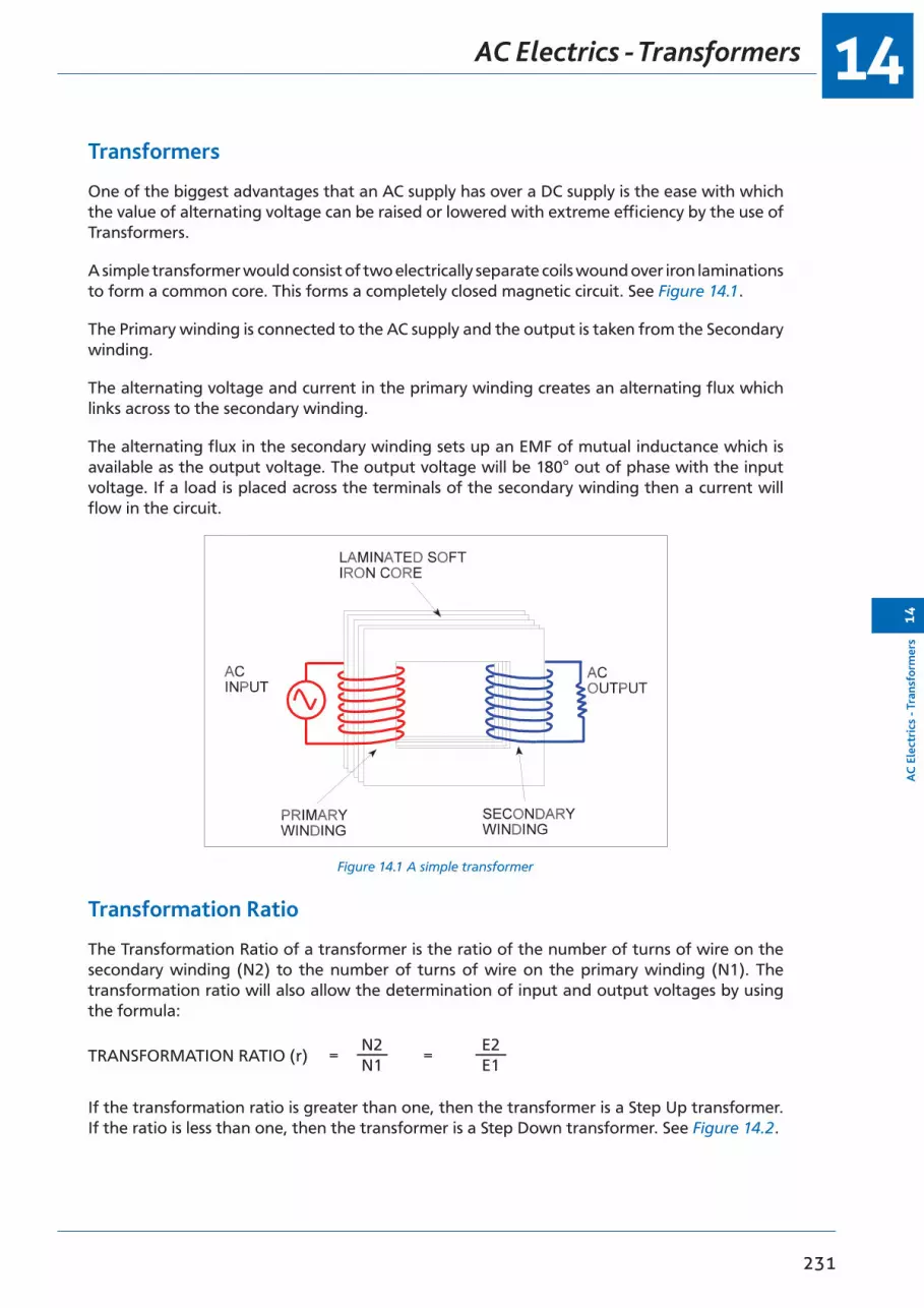
14
231
AC
Ele
ctri
cs -
Tran
sfor
mer
s14
AC Electrics - Transformers
Transformers
One of the biggest advantages that an AC supply has over a DC supply is the ease with which the value of alternating voltage can be raised or lowered with extreme efficiency by the use of Transformers.
A simple transformer would consist of two electrically separate coils wound over iron laminations to form a common core. This forms a completely closed magnetic circuit. See Figure 14.1.
The Primary winding is connected to the AC supply and the output is taken from the Secondary winding.
The alternating voltage and current in the primary winding creates an alternating flux which links across to the secondary winding.
The alternating flux in the secondary winding sets up an EMF of mutual inductance which is available as the output voltage. The output voltage will be 180° out of phase with the input voltage. If a load is placed across the terminals of the secondary winding then a current will flow in the circuit.
Figure 14.1 A simple transformer
Transformation Ratio
The Transformation Ratio of a transformer is the ratio of the number of turns of wire on the secondary winding (N2) to the number of turns of wire on the primary winding (N1). The transformation ratio will also allow the determination of input and output voltages by using the formula:
N2 N1
E2 E1TRANSFORMATION RATIO (r) = =
If the transformation ratio is greater than one, then the transformer is a Step Up transformer. If the ratio is less than one, then the transformer is a Step Down transformer. See Figure 14.2.

AC Electrics -Transformers14
232
14A
C Electrics - Transform
ers
Figure 14.2 Step up and step down transformers
Power in a Transformer
If we ignore the very small losses that do occur in a transformer, then we can say that the power that goes into a transformer equals the power that comes out of it. The power in either the primary winding or the secondary winding is equal to the product of the voltage times the current in either winding.
Three Phase Transformers
The output of a three phase alternator can be transformed by either:
• 3 SINGLE PHASE TRANSFORMERS
or
• 1 THREE PHASE TRANSFORMER
A three phase transformer consists of the primary and secondary windings of each phase wound on one of three laminated iron limbs.
Autotransformers
Where AC is required for the operation of instruments on the aircraft, an Autotransformer can be used to either step down, or sometimes even step up, the source supply; the supply usually required for instruments is 26 volts AC.
An autotransformer is a single winding on a laminated core to form a closed magnetic circuit. Figure 14.3 illustrates the relationship between the primary and secondary windings in an autotransformer.
It should be noted that part of the winding carries both the primary and secondary current because it is common to both windings.

14
233
AC
Ele
ctri
cs -
Tran
sfor
mer
s14
AC Electrics - Transformers
Figure 14.3 Autotransformers
Autotransformers are less expensive than two coil transformers because they use less wire; however, they do not electrically isolate the primary and secondary windings and so cannot be used in many circuits for this reason.
Rectification of Alternating Current
A Rectifier is a device which will convert AC into DC. The operation of the Diode Rectifier is described in the Semiconductor chapter, and is a very common device in modern aircraft solid state circuits. It can be used to convert AC to DC or as a “Blocking Diode” (electrical non-return valve) to prevent reverse current flow in a DC system. Some rectifiers are designed to conduct at a predetermined voltage; these rectifiers are called Zener Diodes.
A diode has a high resistance in one direction and a low resistance in the other. The accepted symbol for a diode rectifier and the direction of conventional current flow is shown in Figure 14.4.
Half Wave Rectification
A diode inserted in the secondary circuit of a transformer will allow current to flow through the load in one direction only. This is termed Half Wave Rectification. The bottom half of the AC waveform is blocked and the frequency of the output is the same as the input, as shown in Figure 14.4.
Figure 14.4 Single phase half wave rectification

AC Electrics -Transformers14
234
14A
C Electrics - Transform
ers
Full Wave Rectification
To fill in the gaps between pulses that have been left from half wave rectification a Bridge Rectifier can be used. As can be seen from Figure 14.5 when one half of the bridge circuit is presenting a high resistance to current flow, the other half is allowing it to flow relatively easily. This arrangement is specifically designed to allow the output of the bridge to be of a single polarity. The output can be smoothed to some extent by the addition of a capacitor placed across it.
Figure 14.5 Single phase full wave rectifier
Three Phase Rectifiers
The rectification of a three phase supply can be effected by using a formation of six rectifiers in a bridge circuit.
This is shown in Figure 14.6. The output of a Three Phase Rectifier is essentially a steady output.
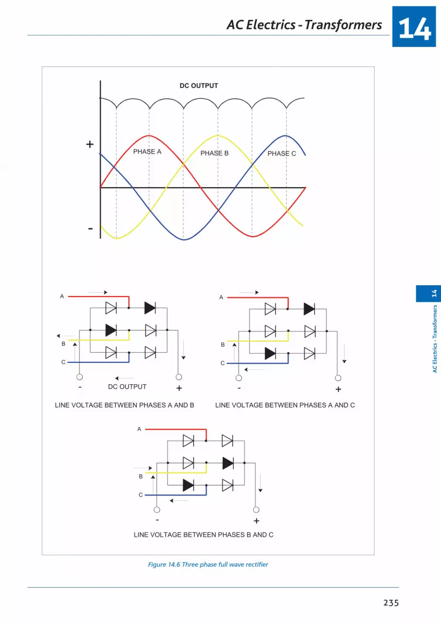
14
235
AC
Ele
ctri
cs -
Tran
sfor
mer
s14
AC Electrics - Transformers
Figure 14.6 Three phase full wave rectifier
PHASE A PHASE B PHASE C+
-
+-
A
B
C
LINE VOLTAGE BETWEEN PHASES A AND B
DC OUTPUT
+-
A
B
C
LINE VOLTAGE BETWEEN PHASES B AND C
+-
A
B
C
LINE VOLTAGE BETWEEN PHASES A AND C
DC OUTPUT
AC Electrics -Transformers14
236
14A
C Electrics - Transform
ers
Transformer Rectifier Units (TRUs)
TRUs convert AC at one voltage to DC at another voltage by combining the transformer and rectifier in one unit (usually 115 V/ 200 V/ 400 Hz/ 3 phase to 28 V DC) to supply the DC needs of an AC distribution system.
TRUs are invariably multi-phase units to achieve a smooth DC output. Indications of TRU output (amps) can be shown on the main electrical panel on the flight deck.
Cooling is achieved by drawing air through the unit which may be monitored for temperature with an overheat warning supplied.
Inverters
An inverter converts DC to AC.
The inverter in a constant frequency AC equipped aircraft is used as a source of emergency supply if the AC generators fail; then, the inverter is powered by the battery.
Inverters are usually “solid state” static inverters, transistorized in modern aircraft, providing constant frequency AC for operation of flight instruments and other essential AC consumers. Rotary and Static inverters are described in the DC section and are not generally used in modern aircraft.
Aircraft which have a frequency wild distribution system (British Aerospace ATP, ATR 42) use inverters to supply their normal constant frequency requirements. This is done by transforming and rectifying the frequency wild into DC, and then supplying the DC to the inverter (static) to give a controlled AC output.
Inverter output can be monitored for voltage and frequency in the same manner as the main generators.
Cooling is accomplished in the same manner as the TRU.

14
237
Que
stio
ns14
Questions
Questions
1. Instrument transformers normally:
a. convert 14 volts DC to 26 volts ACb. reduce the AC supply to 26 volts for some instrumentsc. change 115 volts to 200 volts for engine instrumentsd. convert 28 volts DC to 28 volts AC
2. An autotransformer:
a. varies its turns ratio automatically to maintain a constant output voltage with varying input voltage
b. has only one coil which is used as both primary and secondaryc. will maintain a constant output frequency with a varying supply frequencyd. requires an inductive supply
3. A step up transformer is one in which the number of turns on the secondary winding is:
a. the same as the primary if the cable diameter is the same b. greater than that on the primaryc. less than on the primaryd. always the same as on the primary
4. A transformer which halves the voltage will have:
a. twice as many turns on the secondary as on the primary b. half as many turns on the secondary as on the primaryc. half as much current flowing in the secondary as in the primary d. four times as many turns on the secondary as on the primary
5. The power output of a transformer is:
a. in proportion to the transformation ratiob. in inverse proportion to the transformation ratio c. the same as the power inputd. increased in a step up transformer
6. With no load across the output terminals of a transformer:
a. the current flow will be maximumb. the current flow will be negligiblec. the current will be in phase with the voltaged. the voltage in the primary will be always greater than the secondary
7. If the voltage induced in the secondary windings is greater than that in the primary then the transformer is:
a. an autotransformer b. a step upc. a step downd. a magnetic amplifier

Answers14
238
14A
nswers
Answers
1 2 3 4 5 6 7
b b b b c b b

239
15Chapter
AC Electrics - AC Motors
Alternating Current Motors . . . . . . . . . . . . . . . . . . . . . . . . . . . . . . . . . . . .241
The Principle of Operation of AC Motors . . . . . . . . . . . . . . . . . . . . . . . . . . . . .241
The Synchronous Motor . . . . . . . . . . . . . . . . . . . . . . . . . . . . . . . . . . . . . .241
The Induction Motor . . . . . . . . . . . . . . . . . . . . . . . . . . . . . . . . . . . . . . . .243
The Squirrel Cage Rotor . . . . . . . . . . . . . . . . . . . . . . . . . . . . . . . . . . . . . .243
The Induction Motor Stator . . . . . . . . . . . . . . . . . . . . . . . . . . . . . . . . . . . .243
Slip Speed . . . . . . . . . . . . . . . . . . . . . . . . . . . . . . . . . . . . . . . . . . . . . .244
Starting Single Phase Induction Motors . . . . . . . . . . . . . . . . . . . . . . . . . . . . . .244
Fault Operation . . . . . . . . . . . . . . . . . . . . . . . . . . . . . . . . . . . . . . . . . . .244
Questions . . . . . . . . . . . . . . . . . . . . . . . . . . . . . . . . . . . . . . . . . . . . . .245
Answers . . . . . . . . . . . . . . . . . . . . . . . . . . . . . . . . . . . . . . . . . . . . . . .248

AC Electrics -AC Motors15
240
15A
C Electrics - A
C M
otors
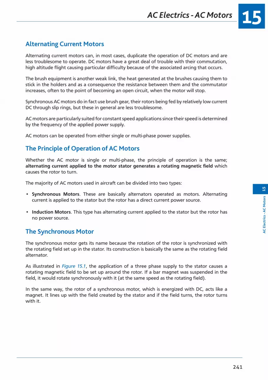
15
241
AC
Ele
ctri
cs -
AC
Mot
ors
15
AC Electrics - AC Motors
Alternating Current Motors
Alternating current motors can, in most cases, duplicate the operation of DC motors and are less troublesome to operate. DC motors have a great deal of trouble with their commutation, high altitude flight causing particular difficulty because of the associated arcing that occurs.
The brush equipment is another weak link, the heat generated at the brushes causing them to stick in the holders and as a consequence the resistance between them and the commutator increases, often to the point of becoming an open circuit, when the motor will stop.
Synchronous AC motors do in fact use brush gear, their rotors being fed by relatively low current DC through slip rings, but these in general are less troublesome.
AC motors are particularly suited for constant speed applications since their speed is determined by the frequency of the applied power supply.
AC motors can be operated from either single or multi-phase power supplies.
The Principle of Operation of AC Motors
Whether the AC motor is single or multi-phase, the principle of operation is the same; alternating current applied to the motor stator generates a rotating magnetic field which causes the rotor to turn.
The majority of AC motors used in aircraft can be divided into two types:
• Synchronous Motors. These are basically alternators operated as motors. Alternating current is applied to the stator but the rotor has a direct current power source.
• Induction Motors. This type has alternating current applied to the stator but the rotor has no power source.
The Synchronous Motor
The synchronous motor gets its name because the rotation of the rotor is synchronized with the rotating field set up in the stator. Its construction is basically the same as the rotating field alternator.
As illustrated in Figure 15.1, the application of a three phase supply to the stator causes a rotating magnetic field to be set up around the rotor. If a bar magnet was suspended in the field, it would rotate synchronously with it (at the same speed as the rotating field).
In the same way, the rotor of a synchronous motor, which is energized with DC, acts like a magnet. It lines up with the field created by the stator and if the field turns, the rotor turns with it.
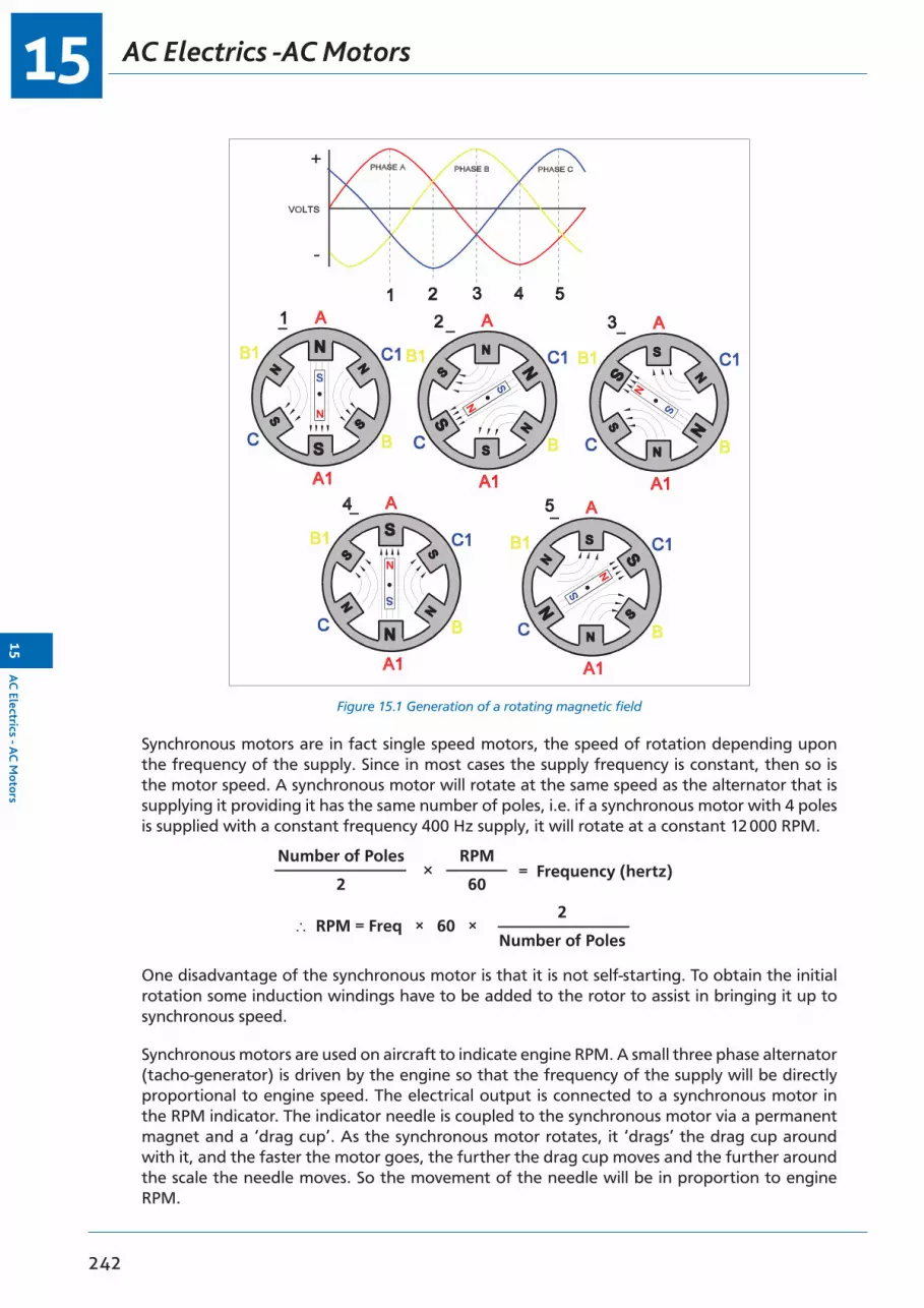
AC Electrics -AC Motors15
242
15A
C Electrics - A
C M
otors
Figure 15.1 Generation of a rotating magnetic field
Synchronous motors are in fact single speed motors, the speed of rotation depending upon the frequency of the supply. Since in most cases the supply frequency is constant, then so is the motor speed. A synchronous motor will rotate at the same speed as the alternator that is supplying it providing it has the same number of poles, i.e. if a synchronous motor with 4 poles is supplied with a constant frequency 400 Hz supply, it will rotate at a constant 12 000 RPM.
Number of Poles
2
2
Number of Poles
= Frequency (hertz)
∴ RPM = Freq × 60 ×
RPM
60×
One disadvantage of the synchronous motor is that it is not self-starting. To obtain the initial rotation some induction windings have to be added to the rotor to assist in bringing it up to synchronous speed.
Synchronous motors are used on aircraft to indicate engine RPM. A small three phase alternator (tacho-generator) is driven by the engine so that the frequency of the supply will be directly proportional to engine speed. The electrical output is connected to a synchronous motor in the RPM indicator. The indicator needle is coupled to the synchronous motor via a permanent magnet and a ‘drag cup’. As the synchronous motor rotates, it ‘drags’ the drag cup around with it, and the faster the motor goes, the further the drag cup moves and the further around the scale the needle moves. So the movement of the needle will be in proportion to engine RPM.

15
243
AC
Ele
ctri
cs -
AC
Mot
ors
15
AC Electrics - AC Motors
The Induction Motor
The induction motor gets its name from the fact that an alternating current is induced in the rotor by the rotating magnetic field in the stator.
It is the most commonly used because of its simplicity, its robustness and because it is relatively cheap to produce.
This relative cheapness is mainly because of the fact that the rotor is a self-contained unit and not connected to the supply.
Figure 15.2 Squirrel cage induction motor
The Squirrel Cage Rotor
The rotor consists of a cylindrical laminated iron core which has a number of longitudinal bars of copper evenly spaced around the circumference. These bars are joined at either end by rings of the same material to form a composite structure called a Squirrel Cage. The rotor bars are of very low resistance material so that a large current can flow through them.
The Induction Motor Stator
The stator consists of windings, the number of which is related to the number of poles and also to the number of phases of the power supply. The rotating magnetic field produced in the stator cuts through the bars of the rotor which is basically a closed circuit of low resistance.
The resultant induced voltage creates a relatively large current flow in the squirrel cage. This current flow sets up its own magnetic field which interacts with the rotating field of the stator to produce a torque. If a three phase motor has two phases of its supply reversed, then its direction of rotation will be reversed also.

AC Electrics -AC Motors15
244
15A
C Electrics - A
C M
otors
Slip Speed
The speed of the motor is determined by the frequency of the supply and the load on the motor. The rotor never quite reaches true synchronous speed, if it did then the squirrel cage bars would not be cut by any lines of force and thus would not produce the induced voltage. The difference between synchronous speed and rotor speed is called the slip speed or rotor slip. A typical value of slip would be 5%. Because of the difference in speed between the stator field and rotor, the induction motor is sometimes referred to as being asynchronous.
Starting Single Phase Induction Motors
Single phase induction motors are not self-starting. Different methods are used to assist in making them self-starting. The most common method is the use of what is called a Split Phase Winding.
If the current in the split phase winding can be made to lead or lag the current in the main winding by 90° then a rotating field can be produced.
The lead or lag can be produced by the following methods:
• Resistance starting• Inductance starting• Resistance / inductance starting• Capacitance starting
The application of each method depends on the power output of the motor, e.g. capacitance started motors are usually of less than 2 HP output.
Fault Operation
Occasionally the failure of one phase of the supply to a three phase induction motor does happen. If the motor is lightly loaded then it will probably continue to run at about half of its normal speed. This will create a humming noise in the motor which, because of the usually remote locations in which the motors are mounted, will probably not make itself apparent. The fault usually becomes apparent the next time an attempt is made to run the motor, when it will not start.

15
245
Que
stio
ns15
Questions
Questions
1. Synchronous motors are usually supplied by:
a. three phase ACb. single phase ACc. DC to the statord. DC to the stator and AC to the rotor
2. Reversing two phases to a three phase motor will:
a. blow the phase fusesb. cause the motor to run in reversec. overheat the stator windingsd. stall the motor
3. A synchronous motor runs at a speed that depends upon the supply:
a. voltageb. currentc. reactanced. frequency
4. If one phase of the supply to a three phase motor fails, then:
a. the motor will continue to run at the same speedb. will slow down and stopc. will stop immediatelyd. will run at about half speed but will not start on its next selection
5. The basic principle of operation of a 3 phase induction motor is:
a. a rotating field created in the rotorb. a rotating field created in the statorc. a stationary field created in the statord. a stationary field created in the rotor
6. In an induction motor:
a. the rotor is star connectedb. magnetic fields blend evenly with one anotherc. AC is induced in the rotord. a DC supply produces DC in the rotor
7. In a synchronous motor, the rotor is:
a. energized by DC and it lines up with the magnetic field in the statorb. wave woundc. both AC and DC energizedd. impeded by the AC induced into it
Questions15
246
15Q
uestions
8. An induction motor has:
a. slip rings and brushesb. a commutatorc. no slip ring or brushesd. slip rings but no brushes
9. A squirrel cage rotor:
a. is not connected to the supplyb. is expensive to producec. rotates at exactly synchronous speedd. is a closed circuit of high resistance
10. A starting circuit for a powerful single phase induction motor might be:
a. a capacitance starterb. a resistance / inductance starterc. a cartridge starterd. a bump starter

15
247
Que
stio
ns15
Questions
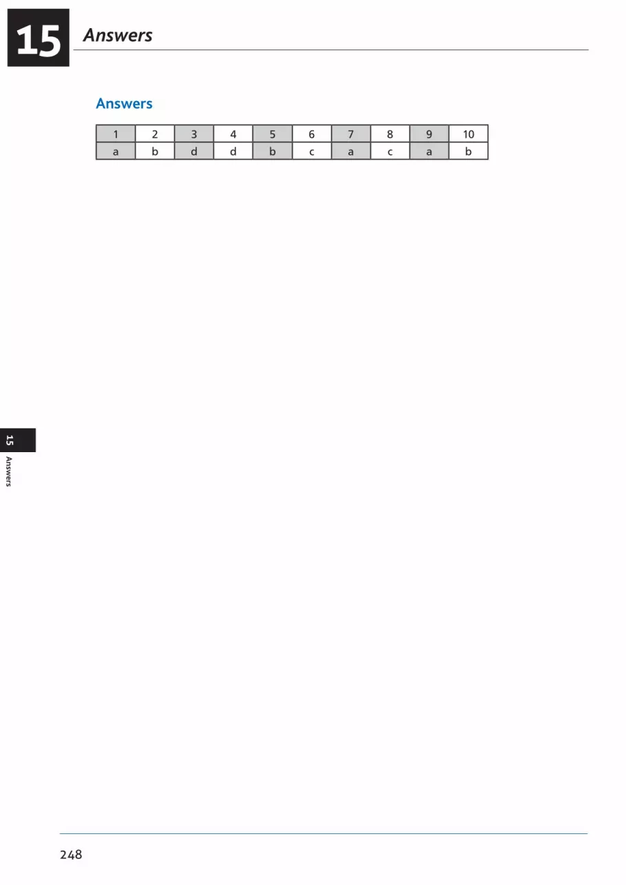
Answers15
248
15A
nswers
Answers
1 2 3 4 5 6 7 8 9 10
a b d d b c a c a b
249
16Chapter
AC Electrics - Semiconductors
An Introduction to Semiconductors . . . . . . . . . . . . . . . . . . . . . . . . . . . . . . . .251
Conductors and Insulators . . . . . . . . . . . . . . . . . . . . . . . . . . . . . . . . . . . . .251
Semiconductors . . . . . . . . . . . . . . . . . . . . . . . . . . . . . . . . . . . . . . . . . . .252
N-Type Material . . . . . . . . . . . . . . . . . . . . . . . . . . . . . . . . . . . . . . . . . . .253
P-Type Material . . . . . . . . . . . . . . . . . . . . . . . . . . . . . . . . . . . . . . . . . . .254
Current Flow. . . . . . . . . . . . . . . . . . . . . . . . . . . . . . . . . . . . . . . . . . . . .255
The P-N Junction . . . . . . . . . . . . . . . . . . . . . . . . . . . . . . . . . . . . . . . . . .255
Reverse Bias . . . . . . . . . . . . . . . . . . . . . . . . . . . . . . . . . . . . . . . . . . . . .256
Forward Bias. . . . . . . . . . . . . . . . . . . . . . . . . . . . . . . . . . . . . . . . . . . . .256
The Junction Diode . . . . . . . . . . . . . . . . . . . . . . . . . . . . . . . . . . . . . . . . .256
The Bipolar or Junction Transistor . . . . . . . . . . . . . . . . . . . . . . . . . . . . . . . . .257
Summary. . . . . . . . . . . . . . . . . . . . . . . . . . . . . . . . . . . . . . . . . . . . . . .259

AC Electrics -Semiconductors16
250
16A
C Electrics - Sem
iconductors
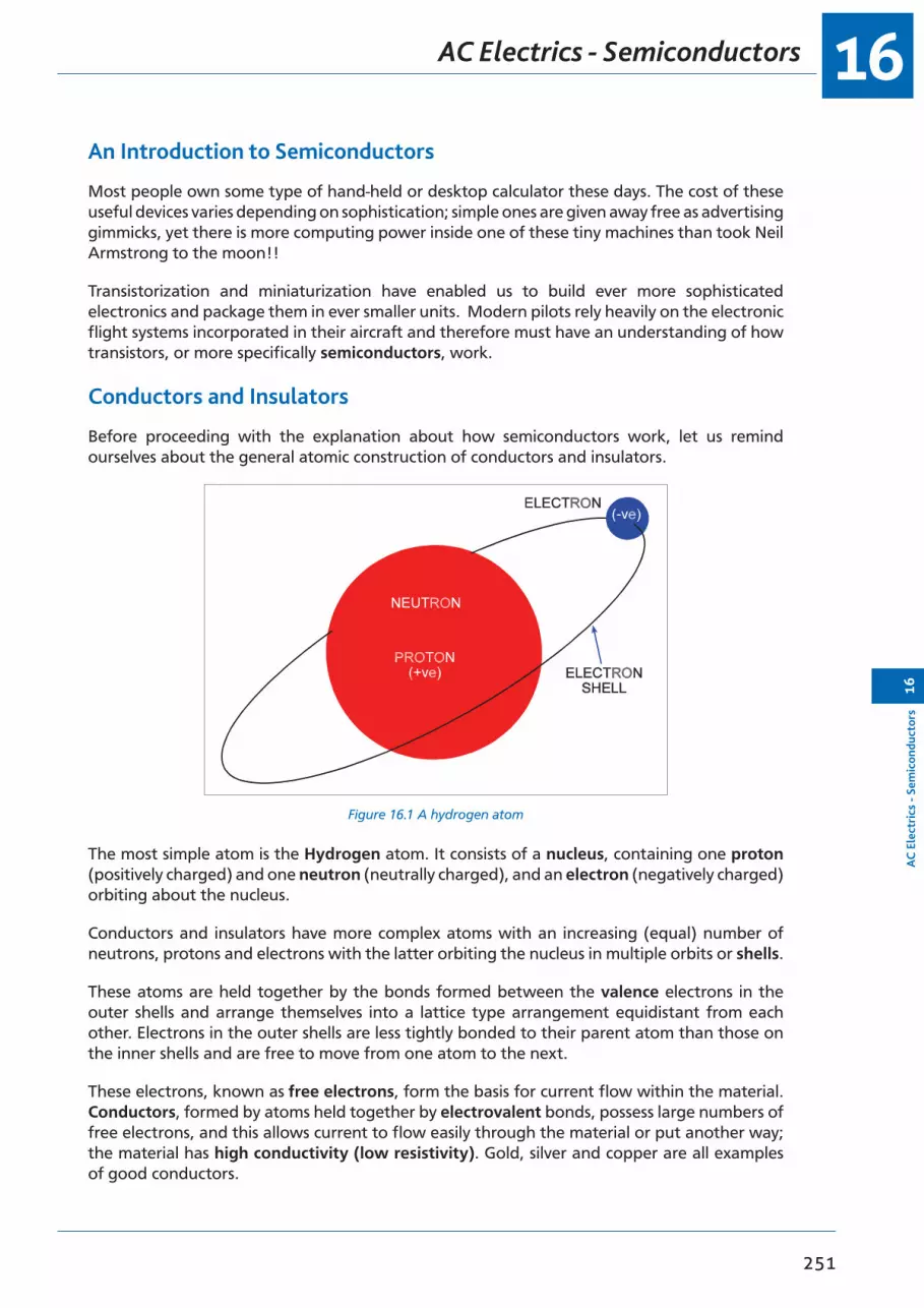
16
251
AC
Ele
ctri
cs -
Sem
icon
duct
ors
16
AC Electrics - Semiconductors
An Introduction to Semiconductors
Most people own some type of hand-held or desktop calculator these days. The cost of these useful devices varies depending on sophistication; simple ones are given away free as advertising gimmicks, yet there is more computing power inside one of these tiny machines than took Neil Armstrong to the moon!!
Transistorization and miniaturization have enabled us to build ever more sophisticated electronics and package them in ever smaller units. Modern pilots rely heavily on the electronic flight systems incorporated in their aircraft and therefore must have an understanding of how transistors, or more specifically semiconductors, work.
Conductors and Insulators
Before proceeding with the explanation about how semiconductors work, let us remind ourselves about the general atomic construction of conductors and insulators.
Figure 16.1 A hydrogen atom
The most simple atom is the Hydrogen atom. It consists of a nucleus, containing one proton (positively charged) and one neutron (neutrally charged), and an electron (negatively charged) orbiting about the nucleus.
Conductors and insulators have more complex atoms with an increasing (equal) number of neutrons, protons and electrons with the latter orbiting the nucleus in multiple orbits or shells.
These atoms are held together by the bonds formed between the valence electrons in the outer shells and arrange themselves into a lattice type arrangement equidistant from each other. Electrons in the outer shells are less tightly bonded to their parent atom than those on the inner shells and are free to move from one atom to the next.
These electrons, known as free electrons, form the basis for current flow within the material. Conductors, formed by atoms held together by electrovalent bonds, possess large numbers of free electrons, and this allows current to flow easily through the material or put another way; the material has high conductivity (low resistivity). Gold, silver and copper are all examples of good conductors.

AC Electrics -Semiconductors16
252
16A
C Electrics - Sem
iconductors
Insulators, on the other hand, are formed by atoms held together by covalent bonds and possess few free electrons. This means that current flow is difficult; the material has low conductivity (high resistivity). Mica is one example of a good insulator.
Semiconductors
Semiconductors, as their name would imply, fall somewhere between a conductor and an insulator. Silicon and germanium are examples of semiconductors.
Both materials are formed by atoms with covalent bonds. Though each possesses some free electrons at normal temperatures, they are closer to being insulators than conductors. Thus an EMF applied across the material would give rise to an intermediate current flow, higher than that in an insulator, but less than that in a conductor.
Conductivity can be improved by the controlled addition of impurities into the silicon or germanium material using a process known as doping.
Figure 16.2 A typical atomic lattice structure

16
253
AC
Ele
ctri
cs -
Sem
icon
duct
ors
16
AC Electrics - Semiconductors
N-Type Material
By doping the silicon or germanium with arsenic or antimony, atoms which have 5 valance electrons in their outer shell are introduced into the lattice structure. The ratio of impurity atoms to original atoms (doping ratio) is in the order of 1:108.
Figure 16.3 N-type material
Four of the five electrons form covalent bonds with the surrounding atoms, the 5th electron, having no such ties, becomes a free electron. Conductivity through the material is thus increased.
We call this type of material N-type because of the surfeit of free electrons which are, of course, negatively charged. However, it should be noted that the material remains electrically neutral; for each free electron there is a fixed positive ion within the material.

AC Electrics -Semiconductors16
254
16A
C Electrics - Sem
iconductors
P-Type Material
By doping with impurities such as aluminium or indium, again in the same doping ratio as above, atoms with only three valence electrons in their outer shell are introduced.
Figure 16.4 P-type material
This time there are only 3 electrons to form the covalent bonds, one is missing. In other words there is a hole in the valent structure.
Electrons from adjacent atoms tend to move into these holes thus creating holes around the donor atoms which in turn ‘steal’ electrons from their neighbours moving the hole on further.
This apparent movement of holes increases the conductivity of the material.
Because of the shortage of electrons the material is classified as P-type.
Again, it should be noted, it possesses no electrical charge, there being an equal number of holes and fixed negative ions.

16
255
AC
Ele
ctri
cs -
Sem
icon
duct
ors
16
AC Electrics - Semiconductors
Current Flow
Applying an EMF across a piece of N-type material would cause the free electrons to migrate towards the positive terminal.
Any electrons leaving the material at the positive terminal are replaced by electrons entering at the negative terminal, thus the overall balance between free electrons and fixed positive ions is maintained.
In P-type material the situation is more complex, but in general, electrons are attracted into the positive terminal creating holes in this region.
The holes ‘migrate’ towards the negative terminal and are ultimately filled by an electron entering at that point.
Hence in P-type semiconductor material we can consider current flow as the drift of holes in the conventional direction, namely from the positive to the negative terminal. Again, overall balance is maintained between electrons and fixed negative ions.
The P-N Junction
If we fuse two small pieces of N and P-type materials together, by a process similar to welding, some free electrons from the N-type material migrate across the boundary into the P-type and similarly, holes migrate the other way.
This migration produces a charged region known as the Depletion Layer and creates a Barrier Potential restricting further electron/hole movement. This barrier potential may be represented as an imaginary battery, though it should be remembered, the regions of increased positive and negative charge exist only across the junction. The material as a whole possesses no electrical charge.
Figure 16.5 The P-N junction
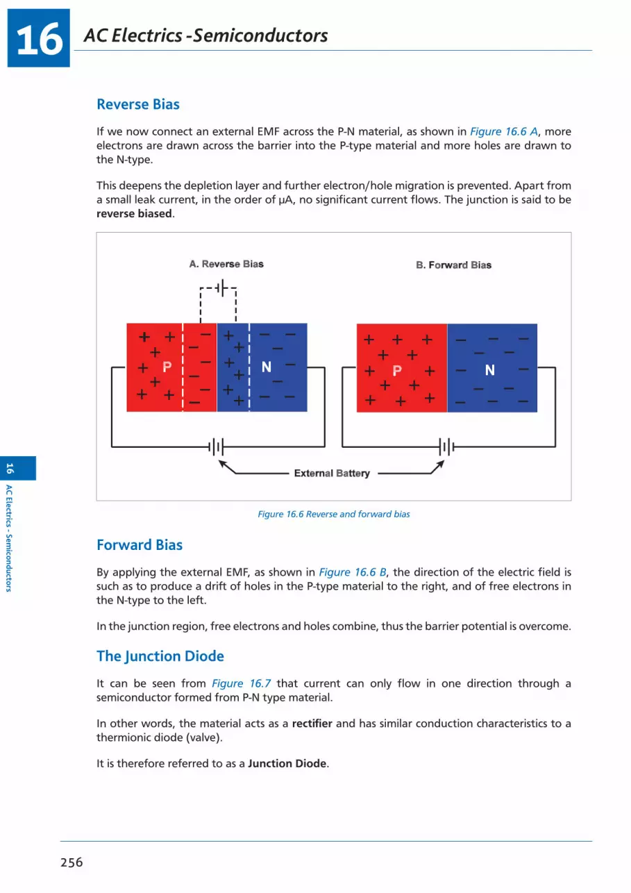
AC Electrics -Semiconductors16
256
16A
C Electrics - Sem
iconductors
Reverse Bias
If we now connect an external EMF across the P-N material, as shown in Figure 16.6 A, more electrons are drawn across the barrier into the P-type material and more holes are drawn to the N-type.
This deepens the depletion layer and further electron/hole migration is prevented. Apart from a small leak current, in the order of µA, no significant current flows. The junction is said to be reverse biased.
Figure 16.6 Reverse and forward bias
Forward Bias
By applying the external EMF, as shown in Figure 16.6 B, the direction of the electric field is such as to produce a drift of holes in the P-type material to the right, and of free electrons in the N-type to the left.
In the junction region, free electrons and holes combine, thus the barrier potential is overcome.
The Junction Diode
It can be seen from Figure 16.7 that current can only flow in one direction through a semiconductor formed from P-N type material.
In other words, the material acts as a rectifier and has similar conduction characteristics to a thermionic diode (valve).
It is therefore referred to as a Junction Diode.

16
257
AC
Ele
ctri
cs -
Sem
icon
duct
ors
16
AC Electrics - Semiconductors
Figure 16.7 The junction diode and its circuit symbolFigure 7.7. The Junction Diode and its Circuit Symbol.
The Bipolar or Junction Transistor
Construction: This is a combination of two junction diodes and consists of either a thin layer (typically 25 µm) of P-type semiconductor sandwiched between two N-type semiconductors (as shown in Figure 16.8 left) which is referred to as an N-P-N transistor, or a thin layer of N-type semiconductor sandwiched between two P-type semiconductors (as shown in Figure 16.8 right), which is referred to as a P-N-P transistor.
Figure 16.8 The bipolar transistor
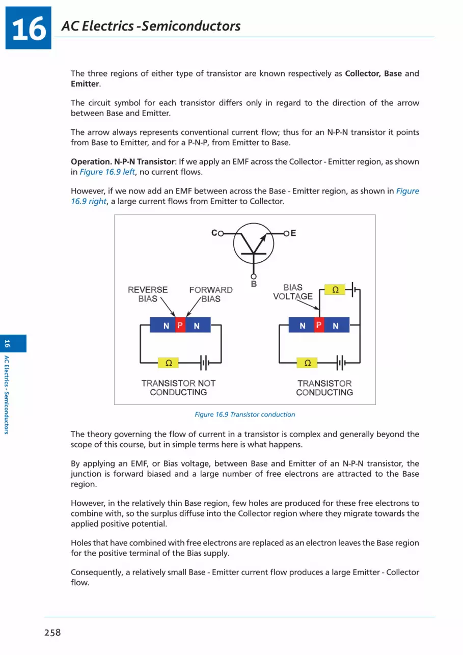
AC Electrics -Semiconductors16
258
16A
C Electrics - Sem
iconductors
The three regions of either type of transistor are known respectively as Collector, Base and Emitter.
The circuit symbol for each transistor differs only in regard to the direction of the arrow between Base and Emitter.
The arrow always represents conventional current flow; thus for an N-P-N transistor it points from Base to Emitter, and for a P-N-P, from Emitter to Base.
Operation. N-P-N Transistor: If we apply an EMF across the Collector - Emitter region, as shown in Figure 16.9 left, no current flows.
However, if we now add an EMF between across the Base - Emitter region, as shown in Figure 16.9 right, a large current flows from Emitter to Collector.
Figure 16.9 Transistor conduction
The theory governing the flow of current in a transistor is complex and generally beyond the scope of this course, but in simple terms here is what happens.
By applying an EMF, or Bias voltage, between Base and Emitter of an N-P-N transistor, the junction is forward biased and a large number of free electrons are attracted to the Base region.
However, in the relatively thin Base region, few holes are produced for these free electrons to combine with, so the surplus diffuse into the Collector region where they migrate towards the applied positive potential.
Holes that have combined with free electrons are replaced as an electron leaves the Base region for the positive terminal of the Bias supply.
Consequently, a relatively small Base - Emitter current flow produces a large Emitter - Collector flow.

16
259
AC
Ele
ctri
cs -
Sem
icon
duct
ors
16
AC Electrics - Semiconductors
Operation. P-N-P Transistor: A P-N-P transistor’s operation is similar in all respects to that of an N-P-N transistor except that the applied EMFs are reversed.
Summary
The ability of a transistor to control a large Emitter - Collector current by means of a small Base - Emitter current means it can act as a switch or amplifier: as a switch by turning the Base - Emitter current on and off, or as an amplifier by superimposing a small alternating current signal on the Bias voltage. In conjunction with the Junction Diode and other electronic components, such as resistors, capacitors and inductors, the applications for the transistor are almost limitless.
Furthermore, the ability to control precisely those areas to which doping is applied, using photo-etching techniques, means that all of the above components can be incorporated into a highly sophisticated and complex circuit within a single, small piece of silicon. The ubiquitous computer chip is one such example.
For the future, as production techniques improve, faster, more powerful circuits will be contained in ever smaller packages, leading in turn to more sophisticated technology being incorporated in the modern airliner.

AC Electrics -Semiconductors16
260
16A
C Electrics - Sem
iconductors

261
17Chapter
AC Electrics - Logic Gates
An Introduction to Logic Gates . . . . . . . . . . . . . . . . . . . . . . . . . . . . . . . . . .263
Binary Logic . . . . . . . . . . . . . . . . . . . . . . . . . . . . . . . . . . . . . . . . . . . . .263
Truth Tables . . . . . . . . . . . . . . . . . . . . . . . . . . . . . . . . . . . . . . . . . . . . .263
Gate Symbols . . . . . . . . . . . . . . . . . . . . . . . . . . . . . . . . . . . . . . . . . . . .263
Positive and Negative Logic . . . . . . . . . . . . . . . . . . . . . . . . . . . . . . . . . . . .263
The ‘AND’ Gate . . . . . . . . . . . . . . . . . . . . . . . . . . . . . . . . . . . . . . . . . . .264
The ‘OR’ Gate . . . . . . . . . . . . . . . . . . . . . . . . . . . . . . . . . . . . . . . . . . . .265
The ‘INVERT’ or ‘NOT’ Gate . . . . . . . . . . . . . . . . . . . . . . . . . . . . . . . . . . . .266
The ‘NAND’ Gate . . . . . . . . . . . . . . . . . . . . . . . . . . . . . . . . . . . . . . . . . .267
The ‘NOR’ Gate . . . . . . . . . . . . . . . . . . . . . . . . . . . . . . . . . . . . . . . . . . .268
The ‘EXCLUSIVE OR’ Gate . . . . . . . . . . . . . . . . . . . . . . . . . . . . . . . . . . . . .269
Questions . . . . . . . . . . . . . . . . . . . . . . . . . . . . . . . . . . . . . . . . . . . . . .270
Answers . . . . . . . . . . . . . . . . . . . . . . . . . . . . . . . . . . . . . . . . . . . . . . .274

AC Electrics -Logic Gates17
262
17A
C Electrics - Logic G
ates

17
263
AC
Ele
ctri
cs -
Logi
c G
ates
17
AC Electrics - Logic Gates
An Introduction to Logic Gates
Logic gates, or gates, are a type of fundamental function performed by computers and related equipment. A single integrated circuit (IC) within a computer contains several gate circuits. Each gate may have several inputs and must have only one output.
There are six commonly used logic gates: the ‘AND’, the ‘OR’, the ‘INVERT’, the ‘NOR’, the ‘NAND’ and the ‘EXCLUSIVE OR’. The name of each gate represents the function it performs.
Binary Logic
Logic gates are of a binary nature, i.e. the inputs and the outputs are in one of two states expressed by the digital notation ‘1’ or ‘0’. Other corresponding expressions are also frequently used, they are:
• ‘1’ - on; true; high (H); closed; engaged• ‘0’ - off; false; low (L); open; disengaged
Truth Tables
Truth Tables are a systematic means of displaying binary data. Truth tables illustrate the relationship between a logic gate’s inputs and outputs. This type of data display can be used to describe the operation of a gate. For troubleshooting purposes, the truth table data is often reviewed in order to determine the correct output signal for a given set of inputs.
Gate Symbols
Each logic gate has a symbol of a specific shape. The symbols are designated to “point” in a given direction, that is, the inputs are always listed on the left of the symbol and the outputs on the right.
Since logic gates operate using digital data, all input and output signals will be made up of ‘1’s or ‘0’s. Typically the symbol ‘1’ represents ‘ON’ or voltage positive, and the symbol ‘0’ represents ‘OFF’, or voltage negative. Voltage negative is often referred to as zero voltage or the circuit’s ground.
Positive and Negative Logic
As stated earlier, logic circuit input and output signals consist of two distinct levels. These levels are often referred to as ‘binary 1’ and ‘binary 0’. The actual voltage levels required to achieve a ‘binary 1’ or ‘binary 0’ may vary between circuits.
• If positive logic is used in the digital circuit, a ‘binary 1’ equals a high voltage level and a ‘binary 0’ equals a low voltage level. The actual voltage values may be either both positive or both negative, or one positive and one negative. The only stipulation for positive logic is that a ‘binary 1’ is created by a greater positive voltage than a ‘binary 0’ . Each signal represents the greater positive voltage value as a ‘binary 1’, and therefore the following examples employ the positive logic concept. Most digital systems employ positive logic throughout the entire computer and related component circuitry.

AC Electrics -Logic Gates17
264
17A
C Electrics - Logic G
ates
• The negative logic concept defines ‘binary 1’ as the lower voltage value and ‘binary 0’ as the higher voltage value (more positive). Although less popular, negative logic is used in some systems in order to meet certain design parameters.
The ‘AND’ Gate
The ‘AND’ gate is used to represent a situation where all inputs to the gate must be ‘1’ (on) to produce a ‘1’ (on) output. To be an ‘AND’ gate, input No. 1 and input No. 2 and input No. 3 etc, must be ‘1’ to produce a ‘1’ output. If any input is a ‘0’ (off), the output will be ‘0’ (off). The symbol and the truth table for a two-input AND gate are illustrated in Figure 17.1.
Figure 17.1 The symbol and truth table for an ‘AND’ gateFigure 7.10. The Symbol and Truth Table for an 'AND' Gate.
A simple ‘AND’ circuit may also be represented by two switches in series used to turn on a light as shown in Figure 17.1. If both switches (inputs) are ‘1’ (on), the light will turn ‘1’ (on). If either switch is ‘0’ (off), the light will be ‘0’ (off).
The ‘AND’ gate is sometimes called an ‘ALL or NOTHING’ gate.

17
265
AC
Ele
ctri
cs -
Logi
c G
ates
17
AC Electrics - Logic Gates
The ‘OR’ Gate
The ‘OR’ gate is used to represent a situation where any input being ‘1’ (on) will produce a ‘1’ (on) output. To be an ‘OR’ gate, input No. 1 or input No. 2 or input No. 3, etc, must be ‘1’ to produce a ‘1’ output.
Only if all inputs become ‘0’ will the ‘OR’ gate produce a ‘0’ output. If any input is a ‘1’, regardless of the other input values, the ‘OR’ gate will produce a ‘1’ output.
A two-input ‘OR’ gate symbol and corresponding truth table are illustrated in Figure 17.2.
A simple ‘OR’ circuit may be made up of two switches in parallel controlling one light. If either switch is ‘1’ (on), the light will turn ‘1’ (on).
The OR gate may be called an “ANY or ALL“ gate.
Figure 17.2 Representation of the ‘OR’ gate
A
B
A
CC
B
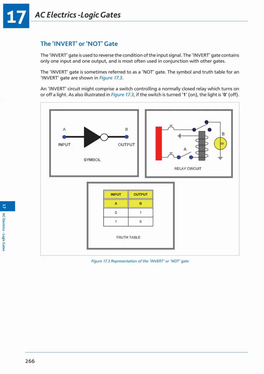
AC Electrics -Logic Gates17
266
17A
C Electrics - Logic G
ates
The ‘INVERT’ or ‘NOT’ Gate
The ‘INVERT’ gate is used to reverse the condition of the input signal. The ‘INVERT’ gate contains only one input and one output, and is most often used in conjunction with other gates.
The ‘INVERT’ gate is sometimes referred to as a ‘NOT’ gate. The symbol and truth table for an ‘INVERT’ gate are shown in Figure 17.3.
An ‘INVERT’ circuit might comprise a switch controlling a normally closed relay which turns on or off a light. As also illustrated in Figure 17.3, if the switch is turned ‘1’ (on), the light is ‘0’ (off).
Figure 17.3 Representation of the ‘INVERT’ or ‘NOT’ gateFigure 7.12. Representation of the 'INVERT' or 'NOT' Gate.
A
B

17
267
AC
Ele
ctri
cs -
Logi
c G
ates
17
AC Electrics - Logic Gates
The ‘NAND’ Gate
The ‘NAND’ gate is an ‘AND’ gate with an inverted output. The output of this gate will be ‘1’ if any input is ‘0’. This is the exact opposite of an ‘AND’ gate. The representations of a ‘NAND’ gate are shown in Figure 17.4.
The ‘NAND’ gate circuit illustrated in Figure 17.4 shows if either switch is closed, there will be no output.
Figure 17.4 The representation of the ‘NAND’ gateFigure 7.13. The Representations of the 'NAND' Gate.
A B
C

AC Electrics -Logic Gates17
268
17A
C Electrics - Logic G
ates
The ‘NOR’ Gate
The ‘NOR’ gate is an ‘OR’ gate with an inverted output. This results in a gate where any input being ‘1’ will create a ‘0’ output. The ‘NOR’ symbol, the truth table and the relay circuit which represent a ‘NOR’ gate are all illustrated in Figure 17.5.
Figure 17.5 Representations of the ‘NOR’ gateFigure 7.14. Representations of the 'NOR' Gate.
A
B
C

17
269
AC
Ele
ctri
cs -
Logi
c G
ates
17
AC Electrics - Logic Gates
The ‘EXCLUSIVE OR’ Gate
The ’EXCLUSIVE OR’ gate is designed to produce a ‘1’ output whenever its input signals are dissimilar.
An illustration of the representations of the ‘EXCLUSIVE OR’ gate is shown in Figure 17.6. This gate compares a maximum of two input signals to determine its output.
As shown in the truth table within Figure 17.6, if the input signals have like values, the output will be ‘0’, if the input signals have unlike values, the output will be ‘1’
Figure 17.6 Representations of the ‘EXCLUSIVE OR’ gateFigure 7.15. Representations of the 'EXCLUSIVE OR' Gate.
A
B
C

Questions17
270
17Q
uestions
Questions
1. The logic function of the circuit shown is:
a. ‘AND’b. ‘OR’ c. ‘NOR’ d. ‘NOT’
2. The circuit shown here represents:
a. an ‘AND’ gate b. a ‘NOR’ gate c. an ‘OR’ gated. an ‘EXCLUSIVE OR’ gate
3. The diagram is the equivalent of which of the accompanying symbols:
4. The gate symbols shown are:
a. ‘AND’ and ‘NAND’b. ‘EXCLUSIVE OR’ and ‘EXCLUSIVE NOR’c. ‘OR’ and ‘NOR’d. ‘OR’ and ‘EXCLUSIVE OR’
5. A gate which requires that all inputs must be HIGH to obtain an output would be:
a. a ‘NOR’ gateb. an ‘OR’ gatec. an ‘AND’ gated. a ‘NOT’ gate

17
271
Que
stio
ns17
Questions
6. This diagram represents:
a. an inverterb. an ‘AND’ gatec. an ‘EXCLUSIVE NOR’ gated. an ‘OR’ gate
7. To obtain logic ‘0’ at output ‘Z’ there must be:
a. logic ‘1’ at ‘X’ and logic ‘0’ at ‘Y’b. logic ‘0’ at ‘X’ and logic ‘1’ at ‘Y’c. logic ‘1’ at ‘X’ and logic ‘1’ at ‘Y’d. logic ‘0’ at ‘X’ and logic ‘0’ at ‘Y’
8. A transistor:
a. can only be used as an amplifierb. can be used as a demi-conductor to act as an automatic switch or an amplifierc. is an inverted silicon controlled rectifierd. can be used as a semiconductor to act as an automatic switch or an amplifier
9. A transistor:
a. is made up of crystals in the arrangement of emitter, base and collectorb. is made up of crystals in the arrangement of emitter, collector and basec. is made up of crystals in the arrangement of collector, emitter and based. requires a current of ten amps through the base to transmit
10. A gate with only one input and one output:
a. cannot be a ‘double’ gateb. is a ‘NOT’ gatec. can only be a ‘semi-gate’d. cannot be a ‘NOT’ gate
11. The two most commonly used gates are:
a. ‘NOT’ and ‘NOR’b. ‘OR’ and ‘EXCLUSIVE AND’c. ‘AND’ and ‘OR’d. ‘AND’ and ‘NAND’
12. Truth tables illustrate the relationship between:
a. inputs and outputsb. integrated gates for trouble shootingc. the sequence of operation of the gatesd. electronic and electrical circuits
28 V

Questions17
272
17Q
uestions
13. The output expression for this type of gate is:
a. ‘AND’b. ‘EXCLUSIVE NOR’c. ‘EXCLUSIVE OR’d. ‘EXCLUSIVE NOT’
14. In order to energize the relay shown in this circuit, the logic state at the inputs must be:
a. logic ‘0’ at points ‘A’ and ‘B’b. logic ‘0’ at point ‘A’ and logic ‘1’ at point ‘B’c. logic ‘1’ at points ‘A’ and ‘B’d. always identical at points ‘A’ and ‘B’
15. The type of logic gate represented by this diagram is:
a. ‘OR’b. ‘NAND’c. ‘AND’d. ‘NOT’

17
273
Que
stio
ns17
Questions

Answers17
274
17A
nswers
Answers
1 2 3 4 5 6 7 8 9 10 11 12
b a c a c d c d a b c a
13 14 15
c c d

275
18Index
Chapter

Index18
276
18Index
AActuators . . . . . . . . . . . . . . . . . . . . . . . . . 110Alkaline Battery . . . . . . . . . . . . . . . . . . . . . 58ALL or NOTHING Gate . . . . . . . . . . . . . . . 264Alternate Action . . . . . . . . . . . . . . . . . . . . . 29Alternator Cooling . . . . . . . . . . . . . . . . . . 201Alternators . . . . . . . . . . . . . . . . . . . . . . . . . 91Aluminium . . . . . . . . . . . . . . . . . . . . . . . . 254Ammeter . . . . . . . . . . . . . . . . . . . . . . . . . . . . 5Ampere Hours (Ah) . . . . . . . . . . . . . . . . . . 54Amperes . . . . . . . . . . . . . . . . . . . . . . . . . . . . 5Amps . . . . . . . . . . . . . . . . . . . . . . . . . . . . . . . 5AND Gate . . . . . . . . . . . . . . . . . . . . . . . . . 264Antimony . . . . . . . . . . . . . . . . . . . . . . . . . 253ANY or ALL Gate . . . . . . . . . . . . . . . . . . . 265Apparent Power (VA or kVA) . . . . . . . . . 175Armature . . . . . . . . . . . . . . . . . . . . . . . . . . 85Arsenic . . . . . . . . . . . . . . . . . . . . . . . . . . . 253Autotransformers . . . . . . . . . . . . . . . . . . . 232Auxiliary Power Unit . . . . . . . . . . . . . . . . 204
BBack EMF . . . . . . . . . . . . . . . . . . . . . . . . . . 85Back EMF . . . . . . . . . . . . . . . . . . . . . . . . . 107Base . . . . . . . . . . . . . . . . . . . . . . . . . . . . . . 258Batteries . . . . . . . . . . . . . . . . . . . . . . . . . . . 53Bimetallic Switch . . . . . . . . . . . . . . . . . . . . 30Binary Logic . . . . . . . . . . . . . . . . . . . . . . . 263Bipolar . . . . . . . . . . . . . . . . . . . . . . . . . . . . 257Bonding . . . . . . . . . . . . . . . . . . . . . . . . . . 145Brushed Alternators . . . . . . . . . . . . . . . . . 193Brushless Alternators . . . . . . . . . . . . . . . . 194Bus Bar . . . . . . . . . . . . . . . . . . . . . . . . . . . . 95Bus Bars. . . . . . . . . . . . . . . . . . . . . . . . . . . 128Bus Tie Breaker (BTB) . . . . . . . . . . . . . . . . 199
CCapacitance . . . . . . . . . . . . . . . . . . . . . . . 165Capacitance . . . . . . . . . . . . . . . . . . . . 42, 169Capacitive Reactance . . . . . . . . . . . . . . . . 171Capacitors . . . . . . . . . . . . . . . . . . . . . . . . . . 41Carbon Pile . . . . . . . . . . . . . . . . . . . . . . . . . 93Cartridge Fuse . . . . . . . . . . . . . . . . . . . . . . 37Centre Zero Ammeter . . . . . . . . . . . . . . . 126Centrifugal Switches . . . . . . . . . . . . . . . . . 33Changeover Relay . . . . . . . . . . . . . . . . . . 221Charging Current . . . . . . . . . . . . . . . . . . . . 54Chemical Energy . . . . . . . . . . . . . . . . . . . . . 53Circuit Breakers. . . . . . . . . . . . . . . . . . . . . . 40Circuit Protection Devices . . . . . . . . . . . . . 37
CIVIL . . . . . . . . . . . . . . . . . . . . . . . . . . . . . 173Collector . . . . . . . . . . . . . . . . . . . . . . . . . . 258Commutator Ripple . . . . . . . . . . . . . . . . . . 88Conductors . . . . . . . . . . . . . . . . . . . . . . . . . . 3Constant Speed Drive Unit (CSDU) . . . . . 195Conventional Flow . . . . . . . . . . . . . . . . . . . . 4Corkscrew Rule . . . . . . . . . . . . . . . . . . . . . . 74Current . . . . . . . . . . . . . . . . . . . . . . . . . . . . . 5Current Limiters . . . . . . . . . . . . . . . . . . . . . 39Cycle . . . . . . . . . . . . . . . . . . . . . . . . . . . . . 163
DDelta . . . . . . . . . . . . . . . . . . . . . . . . . 190, 192Dielectric . . . . . . . . . . . . . . . . . . . . . . . . . . . 41Differential Fault . . . . . . . . . . . . . . . . . . . 202Dipole . . . . . . . . . . . . . . . . . . . . . . . . . . . . 121Dog Clutch . . . . . . . . . . . . . . . . . . . . . . . . 196Doping . . . . . . . . . . . . . . . . . . . . . . . . . . . 252Drive Disconnect Unit . . . . . . . . . . . . . . . 196Dummy Fuses . . . . . . . . . . . . . . . . . . . . . . . 39
EEarth Return . . . . . . . . . . . . . . . . . . . . . . . 122Electric Motors . . . . . . . . . . . . . . . . . . . . . 105Electrodes . . . . . . . . . . . . . . . . . . . . . . . . . . 53Electrolyte . . . . . . . . . . . . . . . . . . . . . . . . . . 53Electromagnetic Indicators . . . . . . . . . . . 115Electromagnetic Induction . . . . . . . . . . . . 83Electromotive Force (EMF) . . . . . . . . . . . . . 4Electron Flow . . . . . . . . . . . . . . . . . . . . . . . . 4Electrons . . . . . . . . . . . . . . . . . . . . . . . . . . . . 3Electrostatic . . . . . . . . . . . . . . . . . . . . . . . 165Emitter . . . . . . . . . . . . . . . . . . . . . . . . . . . 258Essential . . . . . . . . . . . . . . . . . . . . . . . . . . 129Exciter Control Relay . . . . . . . . . . . . . . . . 204EXCLUSIVE OR Gate . . . . . . . . . . . . . . . . . 269
FFARAD . . . . . . . . . . . . . . . . . . . . . . . . . . . . . 42Faraday’s Law . . . . . . . . . . . . . . . . . . . . . . . 85Field . . . . . . . . . . . . . . . . . . . . . . . . . . . . . . . 85Flashing the field . . . . . . . . . . . . . . . . . . . . 90Fleming’s Left Hand Rule . . . . . . . . . . . . . 105Fleming’s Right Hand Rule . . . . . . . . . . . . 84Flux . . . . . . . . . . . . . . . . . . . . . . . . . . . . . . . 71Four Wire Star . . . . . . . . . . . . . . . . . . . . . 191Frequency . . . . . . . . . . . . . . . . . . . . . . . . . 164Frequency Wild . . . . . . . . . . . . . . . . . . . . . 194Full Wave Rectification . . . . . . . . . . . . . . 234Fuses . . . . . . . . . . . . . . . . . . . . . . . . . . . . . . 37
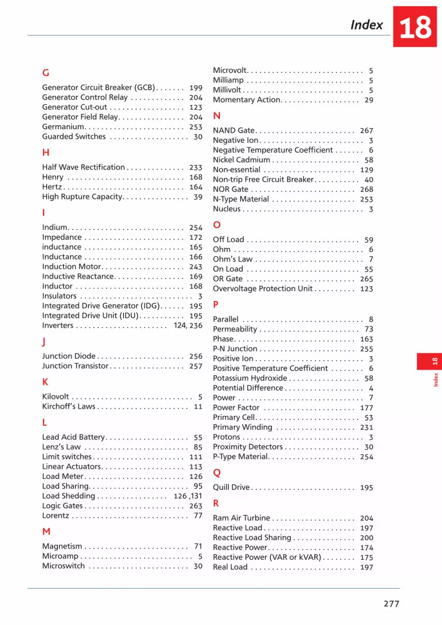
18
277
Inde
x18
Index
GGenerator Circuit Breaker (GCB) . . . . . . . 199Generator Control Relay . . . . . . . . . . . . . 204Generator Cut-out . . . . . . . . . . . . . . . . . . 123Generator Field Relay . . . . . . . . . . . . . . . . 204Germanium . . . . . . . . . . . . . . . . . . . . . . . . 253Guarded Switches . . . . . . . . . . . . . . . . . . . 30
HHalf Wave Rectification . . . . . . . . . . . . . . 233Henry . . . . . . . . . . . . . . . . . . . . . . . . . . . . 168Hertz . . . . . . . . . . . . . . . . . . . . . . . . . . . . . 164High Rupture Capacity . . . . . . . . . . . . . . . . 39
IIndium . . . . . . . . . . . . . . . . . . . . . . . . . . . . 254Impedance . . . . . . . . . . . . . . . . . . . . . . . . 172inductance . . . . . . . . . . . . . . . . . . . . . . . . 165Inductance . . . . . . . . . . . . . . . . . . . . . . . . 166Induction Motor . . . . . . . . . . . . . . . . . . . . 243Inductive Reactance . . . . . . . . . . . . . . . . . 169Inductor . . . . . . . . . . . . . . . . . . . . . . . . . . 168Insulators . . . . . . . . . . . . . . . . . . . . . . . . . . . 3Integrated Drive Generator (IDG) . . . . . . 195Integrated Drive Unit (IDU) . . . . . . . . . . . 195Inverters . . . . . . . . . . . . . . . . . . . . . . 124, 236
JJunction Diode . . . . . . . . . . . . . . . . . . . . . 256Junction Transistor . . . . . . . . . . . . . . . . . . 257
KKilovolt . . . . . . . . . . . . . . . . . . . . . . . . . . . . . 5Kirchoff’s Laws . . . . . . . . . . . . . . . . . . . . . . 11
LLead Acid Battery . . . . . . . . . . . . . . . . . . . . 55Lenz’s Law . . . . . . . . . . . . . . . . . . . . . . . . . 85Limit switches . . . . . . . . . . . . . . . . . . . . . . 111Linear Actuators . . . . . . . . . . . . . . . . . . . . 113Load Meter . . . . . . . . . . . . . . . . . . . . . . . . 126Load Sharing. . . . . . . . . . . . . . . . . . . . . . . . 95Load Shedding . . . . . . . . . . . . . . . . . 126 ,131Logic Gates . . . . . . . . . . . . . . . . . . . . . . . . 263Lorentz . . . . . . . . . . . . . . . . . . . . . . . . . . . . 77
MMagnetism . . . . . . . . . . . . . . . . . . . . . . . . . 71Microamp . . . . . . . . . . . . . . . . . . . . . . . . . . . 5Microswitch . . . . . . . . . . . . . . . . . . . . . . . . 30
Microvolt . . . . . . . . . . . . . . . . . . . . . . . . . . . . 5Milliamp . . . . . . . . . . . . . . . . . . . . . . . . . . . . 5Millivolt . . . . . . . . . . . . . . . . . . . . . . . . . . . . . 5Momentary Action . . . . . . . . . . . . . . . . . . . 29
NNAND Gate . . . . . . . . . . . . . . . . . . . . . . . . 267Negative Ion . . . . . . . . . . . . . . . . . . . . . . . . . 3Negative Temperature Coefficient . . . . . . . 6Nickel Cadmium . . . . . . . . . . . . . . . . . . . . . 58Non-essential . . . . . . . . . . . . . . . . . . . . . . 129Non-trip Free Circuit Breaker . . . . . . . . . . . 40NOR Gate . . . . . . . . . . . . . . . . . . . . . . . . . 268N-Type Material . . . . . . . . . . . . . . . . . . . . 253Nucleus . . . . . . . . . . . . . . . . . . . . . . . . . . . . . 3
OOff Load . . . . . . . . . . . . . . . . . . . . . . . . . . . 59Ohm . . . . . . . . . . . . . . . . . . . . . . . . . . . . . . . 6Ohm’s Law . . . . . . . . . . . . . . . . . . . . . . . . . . 7On Load . . . . . . . . . . . . . . . . . . . . . . . . . . . 55OR Gate . . . . . . . . . . . . . . . . . . . . . . . . . . 265Overvoltage Protection Unit . . . . . . . . . . 123
PParallel . . . . . . . . . . . . . . . . . . . . . . . . . . . . . 8Permeability . . . . . . . . . . . . . . . . . . . . . . . . 73Phase . . . . . . . . . . . . . . . . . . . . . . . . . . . . . 163P-N Junction . . . . . . . . . . . . . . . . . . . . . . . 255Positive Ion . . . . . . . . . . . . . . . . . . . . . . . . . . 3Positive Temperature Coefficient . . . . . . . . 6Potassium Hydroxide . . . . . . . . . . . . . . . . . 58Potential Difference . . . . . . . . . . . . . . . . . . . 4Power . . . . . . . . . . . . . . . . . . . . . . . . . . . . . . 7Power Factor . . . . . . . . . . . . . . . . . . . . . . 177Primary Cell . . . . . . . . . . . . . . . . . . . . . . . . . 53Primary Winding . . . . . . . . . . . . . . . . . . . 231Protons . . . . . . . . . . . . . . . . . . . . . . . . . . . . . 3Proximity Detectors . . . . . . . . . . . . . . . . . . 30P-Type Material . . . . . . . . . . . . . . . . . . . . . 254
QQuill Drive . . . . . . . . . . . . . . . . . . . . . . . . . 195
RRam Air Turbine . . . . . . . . . . . . . . . . . . . . 204Reactive Load . . . . . . . . . . . . . . . . . . . . . . 197Reactive Load Sharing . . . . . . . . . . . . . . . 200Reactive Power . . . . . . . . . . . . . . . . . . . . . 174Reactive Power (VAR or kVAR) . . . . . . . . 175Real Load . . . . . . . . . . . . . . . . . . . . . . . . . 197
Index18
278
18Index
Real Load Sharing . . . . . . . . . . . . . . . . . . 199Real Power . . . . . . . . . . . . . . . . . . . . . . . . 174Recirculating Current . . . . . . . . . . . . . . . . . 95Rectifier . . . . . . . . . . . . . . . . . . . . . . . . . . . . 91Rectifiers . . . . . . . . . . . . . . . . . . . . . . . . . . 124Relay . . . . . . . . . . . . . . . . . . . . . . . . . . . . . . 76Resistance . . . . . . . . . . . . . . . . . . . . . . . . . . . 6Resonant . . . . . . . . . . . . . . . . . . . . . . . . . . 172Reverse Current Circuit Breakers . . . . . . . . 41Reverse Current Relay . . . . . . . . . . . . . . . 123Root Mean Square . . . . . . . . . . . . . . . . . . 164Rotary Actuators . . . . . . . . . . . . . . . . . . . 112Rotating Armature . . . . . . . . . . . . . . . . . . 187Rotating Field . . . . . . . . . . . . . . . . . . . . . . 188
SScreening . . . . . . . . . . . . . . . . . . . . . . . . . 145Secondary Cells . . . . . . . . . . . . . . . . . . . . . . 54Secondary winding . . . . . . . . . . . . . . . . . 231Self-excited . . . . . . . . . . . . . . . . . . . . . . . . . 90Self-induction . . . . . . . . . . . . . . . . . . . . . . 168Semiconductors . . . . . . . . . . . . . . . . . . . . 252Series . . . . . . . . . . . . . . . . . . . . . . . . . . . . . . . 8Series Wound DC Generator . . . . . . . . . . . 88Series Wound Motors . . . . . . . . . . . . . . . 108Shunt . . . . . . . . . . . . . . . . . . . . . . . . . . . . . . 89Shunt Wound DC Generator . . . . . . . . . . . 89Shunt Wound Motors . . . . . . . . . . . . . . . 108Silicon . . . . . . . . . . . . . . . . . . . . . . . . . . . . 253Single Pole . . . . . . . . . . . . . . . . . . . . . . . . 122Slip Rings . . . . . . . . . . . . . . . . . . . . . . . . . . . 85Slip Speed . . . . . . . . . . . . . . . . . . . . . . . . . 244Solenoid . . . . . . . . . . . . . . . . . . . . . . . . . . . 76Spare Fuses . . . . . . . . . . . . . . . . . . . . . . . . . 38Specific Gravity (SG) . . . . . . . . . . . . . . . . . . 55Split Bus System . . . . . . . . . . . . . . . . . . . . 221Split Field . . . . . . . . . . . . . . . . . . . . . . . . . 111Split Ring Commutator . . . . . . . . . . . . . . . 87Squirrel Cage Rotor . . . . . . . . . . . . . . . . . 243Star . . . . . . . . . . . . . . . . . . . . . . . . . . . . . . 190Static Discharge . . . . . . . . . . . . . . . . . . . . 145Static Inverter . . . . . . . . . . . . . . . . . . . . . . 205Static Wicks . . . . . . . . . . . . . . . . . . . . . . . . 145Step Down transformer . . . . . . . . . . . . . . 231Step Up transformer . . . . . . . . . . . . . . . . 231Switches . . . . . . . . . . . . . . . . . . . . . . . . . . . 29Switch Light . . . . . . . . . . . . . . . . . . . . . . . . 29Synchronizing Bus Bar . . . . . . . . . . . . . . . 202Synchronous Motor . . . . . . . . . . . . . . . . . 241
TThermal Runaway . . . . . . . . . . . . . . . . . . . 58Three Phase Alternator . . . . . . . . . . . . . . 190Time Switches . . . . . . . . . . . . . . . . . . . . . . . 33Toggle Switch . . . . . . . . . . . . . . . . . . . . . . . 29Transformation Ratio . . . . . . . . . . . . . . . . 231Transformer Rectifier Units (TRUs) . 187, 236Transformers . . . . . . . . . . . . . . . . . . . . . . . 231Trip Free Circuit Breaker . . . . . . . . . . . . . . . 41True Power . . . . . . . . . . . . . . . . . . . . . . . . 174Truth Tables . . . . . . . . . . . . . . . . . . . . . . . 263
UUnipole . . . . . . . . . . . . . . . . . . . . . . . . . . . 122
Vvibrating contact . . . . . . . . . . . . . . . . . . . . 93Vital . . . . . . . . . . . . . . . . . . . . . . . . . . . . . . 129Voltage . . . . . . . . . . . . . . . . . . . . . . . . . . . . . 4Voltage Regulator . . . . . . . . . . . . . . . . . . . 93voltmeter . . . . . . . . . . . . . . . . . . . . . . . . . . . 5
WWattfull Power . . . . . . . . . . . . . . . . . . . . . 174Watts . . . . . . . . . . . . . . . . . . . . . . . . . . . . . . . 7
ZZener Diodes . . . . . . . . . . . . . . . . . . . . . . 233
Related Documents