Welcome message from author
This document is posted to help you gain knowledge. Please leave a comment to let me know what you think about it! Share it to your friends and learn new things together.
Transcript

JTJT,
V#
C?7


ELECTRICITY
TREATED EXPERIMENTALLY.


o,
ELECTRICITY
TREATED EXPERIMENTALLY
FOR THE USE OF SCHOOLS AND STUDENTS
BY
LINNAEUS CUMMING, M.A.
LATE SCHOLAR OF TRINITY COLLEGE, CAMBRIDGE
ASSISTANT MASTER IN RUGBY SCHOOL
D. VAN NOSTRAND23 MURRAY & 27 WARREN STREETS
NEW YORK1887


PREFACEThe author has endeavoured in this work to give the
substance of experimental lectures delivered to some of
the senior boys in Rugby School.
The course lasts for one school year, consisting of about
seventy lessons, each of one hour. Of these about ten
are devoted to testing the progress of the boys.
These lessons are educational, not technical ; accord-
ingly, ample explanation and numerous experiments are
devoted to the principles of the science, while many appli-
cations claim but the briefest notice.*
In every part of the subject quantitative measurement-
has been kept in view, and attention has been directed
to the absolute system of measurement.
To understand certain instruments it is necessary to
assume results obtained from theory. Articles in which
such assumptions are made are marked with an asterisk (*),
and may be passed over at the teacher's discretion. It is
probably wiser, where possible, to defer them till the
learner has gained some acquaintance with the theory,
such as is afforded by the present author's Introduction
to the Theory of Electricity.
It is assumed that, in teaching the subject, the appa-
ratus is before the student, and not a mere diagram.

vi Preface.
Articles referring to a few rather expensive pieces of
apparatus have been marked with an asterisk, to suggest
that they may be passed over in the absence of the
apparatus.
Every experiment described has been performed by the
author before his class with the apparatus shown, except
in cases where reference is made to an historical experi-
ment, not suited for class demonstration, or requiring
instruments of higher power than those commonly in
use.
The author wishes to record his thanks to his wife, and
to G. C. Eichards, Esq., of Balliol College, Oxford, who
have made drawings, from the apparatus actually in use,
for the woodcuts. His thanks are also due to his col-
league, Gr. Stallard, Esq., who has read the whole of the
proof-sheets and the mss. of the portions referring to
Chemical Science, making many valuable corrections and
suggestions.
The numerical data are chiefly taken from S. Lupton's
Numerical Talks and Constants, a most valuable small
work of reference.
L. CUMMING.
Rugby, 1886.
CONTENTS
BOOK L—MAGNETISM.CHAPTER I.—MAGNETS.
[Pages 1-12.]
Definition of Magnetism—Magnet Poles—North and South Poles of a
Magnet—Action of Magnetic Poles on each other—Magnetism in-
duced in Soft Iron—Induction by Induced Magnetism—Steel
under Induction—Hypothesis of Magnetized Molecules—Magnetic
Substance.—(Sect. 1 to 9.)
CHAPTER II.—FIELD OF MAGNETIC FORCE.
[Pages 13-32.]
Definition of a Field of Magnetic Force—Magnetic Force on a Pole at
a Point—Lines of Force—Strength of Magnetic Field of a Single
Pole, by Coulomb's Balance—Strength of Field by the Method of
Oscillations—Strength of Magnetic Field by Method of Devia-
tions—Comparison of Strength of two Magnet Poles—^Meaning of
an Absolute System of Measurement—*Absolute Unit of Magnetism
—Theories suggested by Experiment.
—
(Sect. 10 to 19.)
CHAPTER III.—METHODS OF MAGNETIZATION.
[Pages 33-37.]
Quality and Temper of Steel—Method of Single Touch—Method of
Divided Touch—Method of Double Touch—Magnetic Battery
—
Magnetic Saturation—Retention of Magnetism.
—
(Sect. 20 to 26.)

viii Contents.
CHAPTER IV.—TERRESTRIAL MAGNETISM.
[Pages 38-65.]
Field of Terrestrial Magnetic Force—Magnetic Elements of a Place
—
The Declinometer—The Dipping Needle—The Intensity—*Gauss'
Method for Finding Intensity—^Magnetic Moment of a Magnet
in Absolute Measure—Magnetic Elements of Greenwich—Changes
in Elements— Variations in "Declination— Relation to Aurora
Borealis and to Solar Phenomena—Other Variations—Magnetic
Charts—Isoclinal Chart—Isodynamic Chart— Isogonic Chart-
Hypotheses of one or two Magnets—The Mariner's Compass—Effect
of iron masses in Ships—Semicircular Variation— Quadrantal
Varaition—Magnetism of Steel-plated Ships—Questions on Book I.
—(Sect. 27 to 48.)
BOOK II.—FKICTIONAL ELECTEICITY.
CHAPTER I.—ELECTRIFICATION.
[Pages 67-80.]
Definition of Electricity—Means of detecting Electricity—Action of
Electrified Bodies on each other—Vitreous and Resinous Elec-
tricity—Conductors and Non-Conductors—Effect of Damp or Dry
Atmosphere— Gold-Leaf Electroscope—Development of the two
Electricities, simultaneous and in equal quantities—The Electrical
Series—Electrification by Pressure and Cleavage— Pyro-Elec-
tricity.—(Sect. 49 to 59.)
CHAPTER II.—THE FIELD OF ELECTRIC FORCE.
[Pages 81-97.]
The Electric Field—Coulomb's Torsion Balance—Law of Action at
different Distances—Law of Action with different Quantities
—
*Absolute Measure of Electricity—Use of Proof-Plane—No Elec-
tricity within a hollow Conductor—Electrical Density—Electrical

Contents. ix
Potential—Capacity of a Conductor— Potential Experiments with
the Gold-Leaf Electroscope—Electrical Force requires varying
Potential.—(Sect. 60 to 71.)
CHAPTER III.—ELECTRICAL INDUCTION.
[Pages 98-121.]
Electrification induced on an Insulated Conductor—Induction on
a Body connected with the Earth— Electroscope charged by
Induction—Faraday's Ice-pail Experiment—The Earth our Zero
of Potential—*Potential in Absolute Measure—*Absolute Measure
of Potential at a Point in the Field—*Equipotential Surfaces
—
*Application to a Sphere—Electrification of two Parallel Plates,
one initially charged— The Leyden Jar—Volta's Condensing
Electroscope—^Discharge by Alternate Contacts—Specific Induc-
tive Capacity—Condition of the Dielectric in a Leyden Jar
—
Faraday's Theory of Induction.
—
(Sect. 72 to 87.)
CHAPTER IV.—ELECTRICAL MACHINES.
[Pages 122-149.]
The Cylinder Machine—The Plate Machine—The Electrophorus
—
The Voss Machine—*The Holtz Machine—Experiments with the
Electrical Machine—Experiments with a Leyden Jar Battery
—
Chemical Decompositions by the Machine discharge.
—
(Sect. 88
to 95.)
CHAPTER V.—ABSOLUTE MEASURE OF ELECTRICITY.
[Pages 150-169.]
The Unit Jar, and Experiments with it—*Theory of Thomson's Elec-
trometers—*The Absolute Electrometer—*The Portable Electro-
meter—*The Quadrant Electrometer—*The Gauge—*The Replen-
isher—*Uses of Quadrant Electrometer—Questions on Book II.
—(Sect. 96 to 103).

Contents.
BOOK III.—VOLTAIC ELECTEICITY.
CHAPTER I.—THE BATTERY.
[Pages 171-189.]
Electrical Conditions of a Zinc-Copper Couple—Chemical Conditions of
the Cell—Thermal Condition of the Cell—Source of Energy of the
Current—Local Action—Action of Evolved Hydrogen—Smee's
Cell—The Bichromate Cell—Daniell's Cell—Grove's and Bunsen's
Cells—Leclanch^'s Cell—Marie Davy's Cell—Becquerel's Cell
—
Electromotive Force—Battery arranged in Simple Circuit
—
Battery arranged in Compound Circuit—Frictional Electricity
obtained from a Battery—Comparison of Frictional with Voltaic
Electricity—Dry Piles.—(Sect. 104 to 122.)
CHAPTER II.—ELECTROLYSIS.
[Pages 190-214.]
Phenomena of the Current—Direction of the Current—Electrolysis of
PotassiumIodide—Electrolysis ofWater—Electrolysis of Hydrogen
Chloride—Secondary action in Decomposition of Sulphates, etc.
—
Potassium set free by Electrolysis—Faraday's Terminology forElec-
trolysis—Quantity of Ions separated by the same current—Electro-
Chemical Equivalents—Battery obeys the Laws of Electrolysis
—
E.M.F. necessary for Electrolysis—*E.M.F. measured thermally
—
Hypothesis of Molecular Electrification—Grotthtis' Hypothesis
—
Polarisation of Electrodes—Grove's Gas Battery, and Ritter's
Secondary Pile—Polarisation the test of an Electrolyte—Plante's
and Faure's Cells—Electro-metallurgy—Nobili's Rings—The Lead
sTree.—(Sect. 123 to 144.)
CHAPTER III.—OHM'S LAW.
[Pages 215-250.]
Ohm's Law—Measurement of Resistance—*Potential Gradient
—
Oersted's Experiment : Galvanometers—The Tangent Galvano-
meter—Sine Galvanometer—Astatic Galvanometer—The Mirror
Contents, xi
Galvanometer— Magnetic action of a Current in a Liquid—Units
employed in Voltaic Electricity—Illustrations of Ohm's Law
—
Experimental Determination of Battery Resistance—Resistance of
the Galvanometer—To find the Resistance of a given Wire Coil
—
Relation of Resistance to Dimensions of Conductor : Specific
Resistance—Application of Ohm's Law to Simple Circuit
—
Application of Ohm's Law to a Compound Circuit—Application
of Ohm's Law to a Mixed Circuit—*Arrangement of Battery for
the Greatest Current—Method of changing rapidly the Battery
arrangement—Measurement of E.M.F. by Galvanometer—Laws
of Divided Currents—Galvanometer Shunts—Thermal Effects of a
Current in the Conductor—^Measure of Heating Effect.
—
(Sect.
145 to 169.)
CHAPTER IV—WHEATSTONE'S BRIDGE.
[Pages 251-258.]
*Theory of the Bridge—*Use of the Bridge to find the Resistance of a
Coil—*Method of Finding Galvanometer Resistance—*Method of
Finding Battery Resistance—*Method of Comparing the E.M.F. of
Cells.—(Sect. 170 to 174.)
CHAPTER V.—ELECTRO-MAGNETISM AND ELECTRO-DYNAMICS.
[Pages 259-318.]
Bertins' Commutator—Magnetic Field of a Straight Current—Rotation
of a Magnet Pole round a Current—Rotation of a Current round
a Magnet Pole — Movement of Current in a Magnetic Field
—
Methods of Suspending Currents—Effects of Terrestrial Mag-netism on Moveable Currents—Magnetic Properties of a Closed
Circuit carrying a Current—
"^Distinction between a Voltaic Circuit
and a Magnetic Shell—*Absolute Electro-magnetic Units—Attrac-
tions and Repulsions of Parallel and Inclined Currents (Electro-
Dynamics)—Action of an Infinite Current on another wholly on
one side—Equivalence of a Sinuous and Straight Current—*The

xii Contents,
Magnetic Field inside a Solenoid—Electro-Magnets—Paramagnetic
and Diamagnetic Substances—Electro-magnetic Toys—Electro-
motors—The Electric Bell—The Electric Telegraph—The Line for
Land or Marine Telegraph—The Battery—The Single Needle
Telegraph Communicator—The Single Needle Indicator—Arrange-
ment of Apparatus at Telegraph Station—Codes of Telegraph
Signals—*The Morse Key—*The Morse Indicator—*The Morse
Relay—*The Morse Sounder—^Electrostatic Induction in Cables
—
*Thomson's Marine Galvanometer—*Thomson's Syphon Recorder
—*Step by Step, or ABC Telegraph—*Ampere's Theory of Magnetism—The Magnetic Tick.—(Sect. 175 to 210.)
CHAPTER VI.-CURRENT INDUCTION.
[Pages 319-365.]
Work done in the Electro-magnetic Field at Expense of the Current
—
^Theoretical Explanation of foregoing Experiment—Induced Cur-
rents—Current induced in a Coil by a Moving Pole—Reversal of
Barlow's Wheel—Currents induced by Terrestrial Magnetism
—
Current induced by Moving Parallel Conductors—Currents in-
duced by Changes in Strength of the Magnetic Field—Currents
induced in Electromotors—The extra Current, or Galvanic
Spark— Lenz's Law— Currents induced in Solid Conductors
moved in the Magnetic Field—Clark's Magneto-electric Machine
or Dynamo—Siemens' Armature—The Gramme Machine—The
Incandescent Electric Lamp—The Arc Lamp—Source of the
Voltaic Arc—Arrangement of Arc Lamps—JablokofF Candle
—
Induction Coils—Experiments with the Induction Coil—Discharge
through Rarefied Gas—Graham Bell's Telephone—The Micro-
phone—Questions on Book III.
—
(Sect. 211 to 235.)
BOOK IV.—THEKMO-ELECTKI0ITY.
[Pages 367-379.]
Definition of Thermo-Electricity — Elementary Experiments— The
Thermopile—Thermo-electric Power and Diagram—E.M.F. of

Contents. xiii
Thermo-electric Currents—Thermo-electric Diagrams for Higher
Temperatures—Thermo-electric Currents in Circuits of one Metal—*The Peltier Effect—*Theoretical Measure of the E.M.F. of a
Thermo-electric Couple—*The Thomson Effect—Thermo-electric
Batteries—Questions on Book IV.
—
(Sect. 236 to 246.)
APPENDIX I.—ABSOLUTE UNITS IN C.S.G.
SYSTEM.
[Pages 381-388.]
Units and Measures—Fundamental Units—Mechanical Units.
—
(Sect.
247 to 249.)
APPENDIX II.
[Page 389.]
Table of Natural Sines and Tangents of Angles for each Degree.


ELECTRICITY
TREATED EXPERIMENTALLY

BOOK I.
MAGNETISM.
CHAPTER L
MAGNETS.
I. Definition of Magnetism.—Magnetism is defined
as the property of attracting small masses of iron, possessed
by various compounds of iron which are called Magnets.
The ancients were acquainted with this property in a certain
iron ore obtained from Magnesia, in Asia Minor, whence the
name Magnetism is derived. This magnetic iron ore, or
Magnetite (denoted by the chemical formula Fe3 4), occurs
very widely disseminated through the earth, and in various
parts, as in Sweden, forms massive beds, which are a very
valuable source of iron. Though always acted on powerfully
by other magnets, it does not itself always possess magnetic
power. The most powerful native magnets are obtained from
Siberia and from the Hartz Mountains. These magnets are
usually called natural, to distinguish them from artificial mag-
nets, which are made of tempered steel, magnetised either by
rubbing with a natural magnet, or by one of a variety of
methods described hereafter. These are in the form of
straight, rectangular or lozenge-shaped bars, or else of bars
bent into a horse-shoe form.
A

Electricity, [Book I.
2. Magnet Poles.—If a natural magnet be sprinkled
with iron filings, the filings are observed to cling more abun-
dantly on two opposite faces than elsewhere. In the case
of a bar magnet, as in the figure, the iron filings remain
clinging only to the ends, and to parts very near to the ends.
The ends of the bar, in which the magnetic power seems
to be concentrated, are spoken of as the poles of the magnet.
The straight line drawn from pole to pole is the axis of the
magnet, and the plane which bisects the axis at right angles
is its equatorial plane, or equator.
3. North and South Poles of a Magnet.—If either
a natural or artificial magnet be poised on a point, or sus-
pended by a silk fibre in a paper stirrup (Fig. 2), so as to
be free to move in a horizontal
plane, it will be observed always
to come to rest with its axis in a
certain definite direction. 1 Except
in very high latitudes, one (and
always the same) pole will point
more or less towards the north, and
the other towards the south. This
property leads us to a convenient
mode of distinguishing the two poles
of a magnet, calling that which is
directed towards the north the north (or better, the north-
1 This direction is called the Magnetic Meridian.
tj
Fig. 2.

chap, ij Magnets. 3
seeking) pole and the opposite, the south or south-seeking
pole. They are also sometimes distinguished as blue and
red poles, or as positive and negative poles. This con-
stancy of direction in a freely-suspended magnet has led to
its use in Europe since the twelfth century, and from muchearlier times by the Chinese, for directing the course in navi-
gation. On this account the magnet is called the loadstone
(more correctly spelt lodestone), from an Anglo-Saxon word
denoting to lead. The poles in bar magnets are distinguished
by engraving either a line or the letter "N" near the north
pole (Fig. 3). — Q g \I. : ! ,
....)
Fig. 3.
4. Action of Magnetic Poles on each other.—Wehave seen that the poles of a magnet differ from each other
in their behaviour under the action of the earth. We now
naturally inquire what is the action of the poles of two dif-
ferent magnets on each other. Suspend one magnet freely,
having marked its poles ; approach towards its poles (Fig. 4)
in succession one (say the north) pole of another magnet.
When the north pole is presented towards the north pole of
the suspended magnet it will be repelled, and if presented
towards the south pole it will be attracted. If, on the other
hand, the south pole be presented to the north pole of the
suspended magnet it will be attracted, and if the south pole
be presented to the south pole it will be repelled. Hence we

Electricity. [Book I.
learn that while both poles have the same power of attracting
soft iron, they behave in opposite ways towards the poles of
another magnet—like poles repelling, but unlike poles attract-
Fig. 4.
ing each other. This property affords a delicate means of
detecting feeble magnetization. A long light magnet, sup-
ported in a paper stirrup and suspended by a few fibres of
cocoon silk (see Fig. 2), is easily deflected from its normal
direction. If on presenting the same part of a body to the
alternate ends we find one pole attracted and the other re-
pelled, we may conclude that the body is magnetized, the
magnet's behaviour towards it showing the name of the pole
used.
5. Magnetism induced in Soft Iron.—If we take a
bar of annealed or soft iron and present it to the pole of a
MajTiel nSoft iron
Fig. 5.
magnet, the magnet, if sufficiently powerful, will pick it up
and support its weight, If while one end adheres to a pole
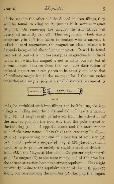
chap, i.] Magnets. 5
of the magnet the other end be dipped in iron filings, they
will be found to cling to it, just as if it were a magnet
(Fig. 5). On removing the magnet the iron filings will
nearly all instantly fall off. This magnetism, which exists
temporarily in soft iron when in contact with a magnet, is
called induced magnetism, the magnet on whose influence it
depends being called the inducing magnet. It will be found
that actual contact is not necessary, as magnetism is induced
in the iron when the magnet is not in actual contact, but at
a considerable distance from the bar. The distribution of
induced magnetism is easily seen to be exactly similar to that
of ordinary magnetism in the magnet ; for if the iron under
induction of a magnet pole, at a small distance from one of its
SOFT IRON
Fig. 6.
ends, be sprinkled with iron filings and be lifted up, the iron
filings will cling near the ends and fall off near the middle
(Fig. 6). It might easily be inferred from the attraction of
the magnet pole for the iron bar, that the pole nearest to
the inducing pole is of opposite name and the more remote
pole of the same name. That this is the case may be shown
(Fig. 7) by presenting one end of a long bar of soft iron (A)
to the north pole of a suspended magnet (B), placed at such a
distance as to produce merely a slight attractive deflection
from MM', the Magnetic Meridian. On presenting the north
pole of a magnet (C) to the more remote end of the iron bar,
the former attraction becomes a strong repulsion. This might
apparently be due to the repulsive action of the north pole (C)
itself, but on removing the iron bar (A), keeping the magnet

Electricity. [Book I,
(0) in position, the suspended magnet will fall back almost
into its normal position. The large magnet (D) is placed to
steady the movements of the suspended needle in the experi-
ment. These two experiments prove that, under induction
of a magnet pole, the part of a soft iron bar nearest to the
inducing pole acquires polarity of opposite name, while the
part farthest away acquires polarity of the same name. This
Fig. 7.
can be illustrated by observing the behaviour, under induc-
tion, of pieces of iron of various shapes, with one or more
magnet poles variously disposed round them. If, for ex-
ample, a north magnet pole be presented to the middle of
a bar, the central part becomes a south pole, and each of
the ends a north pole (Fig. 8). If presented to the base of a
piece of iron shaped like the letter Y, the extremities of the

Chap. I.] Magnets. 7
fork become north poles. If presented to the centre of a star-
shaped piece of metal (Fig. 9), each point becomes a north
pole. The disposition of the poles is at once seen on dipping
SOFT IROMf
Fig. 8. Fig. 9.
the body under induction into iron filings and lifting it out,
when the filings will be found clinging at each of the various
poles.
6. Induction by Induced Magnetism.—It is easy to
show that induced magnetic poles have the power of inducing
magnetism in other iron bars brought under their influence.
If a series of iron bars be arranged end to end, in contact or
with space between them (Fig. 10), and a strong magnet pole
ft*mimi
Fig. 10.
be brought near one end, the opposite end will be found to
be magnetic, having the power of picking up iron filings, and
of exerting attraction or repulsion on other poles. If a
magnet be drawn slowly through a number of short pieces of
iron wire or carpenter's brads (Fig. 11), they will be found
to arrange themselves in strings, end to end, each in turn
being a magnet, and inducing magnetism in the brad im-
mediately next to it. Of course the length of the string of
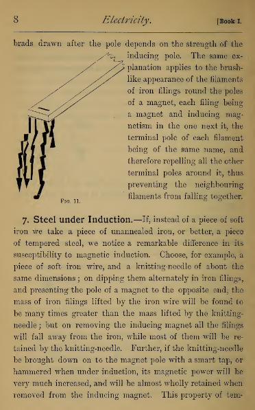
Electricity. [Book I.
brads drawn after the pole depends on the strength of the
inducing pole. The same ex-
planation applies to the brush-
like appearance of the filaments
of iron filings round the poles
of a magnet, each filing being
a magnet and inducing mag-
netism in the one next it, the
terminal pole of each filament
being of the same name, and
therefore repelling all the other
terminal poles around it, thus
preventing the neighbouring
filaments from falling together.Fig. 11. ° °
7. Steel under Induction.—If, instead of a piece of soft
iron we take a piece of unannealed iron, or better, a piece
of tempered steel, we notice a remarkable difference in its
susceptibility to magnetic induction. Choose, for example, a
piece of soft iron wire, and a knitting-needle of about the
same dimensions ; on dipping them alternately in iron filings,
and presenting the pole of a magnet to the opposite end, the
mass of iron filings lifted by the iron wire will be found to
be many times greater than the mass lifted by the knitting-
needle ; but on removing the inducing magnet all the filings
will fall away from the iron, while most of them will be re-
tained by the knitting-needle. Further, if the knitting-needle
be brought down on to the magnet pole with a smart tap, or
hammered when under induction, its magnetic power will be
very much increased, and will be almost wholly retained when
removed from the inducing magnet. This property of tern-

chap, i.] Magnets. 9
pered steel is usually expressed by saying that steel possesses
a coercive force which is absent in soft iron, in virtue of which
steel cannot at once take up the magnetic condition when
placed under magnetic induction, but having once taken it up
retains it for ever. Soft iron on the other hand, owing to the
absence of coercive force, takes up the magnetic condition
at once, and loses it as rapidly when the inducing magnet is
removed. It should be borne in mind that there is no such
thing in natural or artificial products as soft iron or hard steel
which strictly obeys the laws as stated above, all the varieties
of iron and steel being intermediate in their behaviour be-
tween those two ideal limits—all soft iron retaining a fraction
of the magnetism induced in it, and all hard steel being to
some extent susceptible of temporary magnetization under
induction.
This explains the observation that the pole of a strong
magnet attracts either pole of a weak magnet when brought
sufficiently near to it. The strong magnet here acts by in-
duction on the weak, and the induced magnetism of opposite
name to the inducing pole overpowers the like permanent
magnetism, and converts repulsion into attraction. Hence in
experiments on weak magnetism, it is necessary to observe
the first movement of the suspended magnet, as the feeble pole
approaches it. The same explanation applies to the use of
armatures or keepers, that is bars of soft iron which are made
to lie across between opposite poles when magnets are packed
away (Fig. 12). Each armature becomes by induction a
magnet, and acts back by induction on the magnet poles to
which it owes its magnetic character, tending to prevent
their magnetism from dissipating under accidental jars or the
induction of neighbouring magnets. It is even possible to
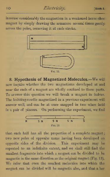
IO Electricity. [Book I.
increase considerably the magnetism in a weakened horse-shoe
magnet by simply drawing the armature several times gently
across the poles, removing it at each stroke.
Fig. 12.
8. Hypothesis of Magnetized Molecules.—We will
now inquire whether the two magnetisms developed at and
near the ends of a magnet are wholly confined to those parts.
To answer this question we will break a magnet in halves.
The knitting-needle magnetized in a previous experiment will
answer well, and can be at once snapped in two when held
in a pair of pincers. On performing the experiment, we find
S N S N
Fig. 13.
S N
that each half has all the properties of a complete magnet
;
two new poles of opposite name having been developed on
opposite sides of the division. This experiment may be
repeated to an indefinite extent, and we shall still find the
smallest fragments into which a magnet can be divided to be
magnetic in the same direction as the original magnet (Fig. 13).
We infer that even the smallest molecules into which the
magnet can be divided will be magnetic also, and that a bar

chap, i.] Magnets. 1
1
magnet is an assemblage of such molecules, each of which is
a magnet endowed with its opposite poles ; the poles of the
molecular magnet being arranged as in Fig 14, and the
magnetic properties of the magnet being due to the resultant
of such a system of magnetic forces.
£ = === = = = = =£)<N3 NSNS NS NS /V S MS /VS Af 5 US NS
Fig. 14.
If we have two altogether equal magnets, and place their
opposite poles in contact, such an arrangement is exactly
equivalent to a magnet of double the length of either magnet;
the two opposite poles when placed in contact each neutra-
lising the other's effect on all external magnetism. If we
apply this principle to the molecular magnets of Fig. 14, all of
which we suppose for a moment, of exactly equal magnetic
strength, we shall have equal and opposite poles in contact
along the whole length of the magnet mutually neutralising
each other, and free magnetism confined to the ends of the
magnet.
*
If we next assume that the magnetic strength of the suc-
cessive molecules falls off as we get near the ends of the
magnet, wre have the free magnetism distributed along the
magnet to some distance from the ends ; and that appears
to be at any rate a fair mental picture of the actual distribu-
tion of magnetism in a magnet. If we would form a picture of
the state of the magnet before magnetization, we may assume
either that the molecules are without magnetism till brought
under induction, or that the molecules already magnetized
1 Byfree, we mean magnetism not neutralised by opposite magnetismin adjacent molecules, and therefore free to act on other magnetismat a distance from it.

1
2
Electricity. [Book i.
have their magnetic axes directed in all sorts of directions
(see Fig. 15), so as to neutralise each other's action. The
\/\-\//^^/\— /^ N»^/N/'^/.X/,^^ \ - \ \ / -/
Fig. 15.
process of magnetization then consists in giving the molecules
a twist, which brings all their magnetic axes into the same
direction, namely that of magnetization. In the case of soft
iron this magnetic twist is brought about at once on applying
the Inducing Magnet; but in the case of steel there is a
greater molecular rigidity, which can only be overcome by
the magnetic force when the molecules are in a state of
vibration among themselves. This may be illustrated by a
glass tube containing iron or steel filings. If the pole of a
magnet be drawn along the tube always in the same direction,
several times, it will be found to have become a magnet,
showing polarity like a feeble bar magnet. On shaking up
the filings all trace of magnetism disappears.
These considerations however, belong to hypotheses in-
capable of direct verification by experiment, whose further
consideration had better be deferred till the student has
gained a more complete knowledge of experimental details.
9. Magnetic Substance.—It has been shown by Fara-
day, with the help of very powerful magnets, that almost all
substances are susceptible of magnetic influence, but the only
substances besides the various compounds of iron, which show
magnetic properties under the action of our ordinary magnets,
are the metals nickel and cobalt

CHAPTER II
FIELD OF MAGNETIC FORCE.
io. Definition of a Field of Magnetic Force.—Wehave seen that any body possessing induced or permanent
magnetism, when brought into the neighbourhood of a bar
magnet or any distribution of magnets, experiences mechanical
force. It is usual therefore to refer to the space surrounding
any distribution of magnetism as a Field of Magnetic Force.
We have also seen that every magnet has two kinds of
magnetism developed, each nearly concentrated in a pole.
The forces experienced by any magnetized body (suppose for
simplicity a thin bar magnet) will therefore usually consist
of two forces acting at its two ends, which may be combined
into a single resultant force and couple, on ordinary mechanical
principles. Before we can find this resultant we must know
the action on each pole, at its own place in the magnetic field.
To do this might seem impossible, as we cannot separate the
north pole from the south, and experiment with each sepa-
rately. We are able in effect to do exactly this, owing to the
fact that the force falls off rapidly as the distance increases,
so as to become almost or quite insensible at very moderate
distances. If then we choose a long magnet for exploring
the field, we can place its more remote pole in such a position
that the whole observed force is sensibly, though not accu-
rately, that due to the nearer pole. For we cannot observe
with absolute accuracy, and we can easily make the error
13

14 Electricity. [Booki.
produced by the distant pole less than that inseparable from
our rough methods of observation.
ii. Magnetic Force on a Pole at a Point.—Guided
by this principle, we proceed now to consider the force
experienced by a magnetic pole placed in a given position
in a magnetic field. To define a force we require to know
three things—the point of application, the direction of action,
and the magnitude.
1. The Point of Application.—Since in any actual magnet
the free magnetism is distributed over a finite portion of the
magnet, it might seem that there was no point of application
of the magnetic force. If, however, we choose a thin and
evenly magnetized needle, there will be a certain centre of
magnetism very near to the actual end of the magnet, such
that the action of the field on the total magnetism is appreci-
ably the same as if it were all concentrated at that point.
This centre of magnetism should of course be defined as the
physical pole of the magnet. It is scarcely necessary to point
out its analogy to the centre of gravity of a material body.
We shall in future consider the force on a pole as acting on
the total quantity of magnetism concentrated in the pole.
2. The Direction.—At each point in the field there will be a
certain direction in which a pole will be urged when placed
there, the directions being exactly opposite for a north and
south pole. These directions are spoken of as the Line of
Force through the point in the field, and we may conceive the
field mapped out into lines of force, the direction of the line
at each point showing the direction in which a magnet pole,
if placed at that point, would be urged. It is also clear that
two of these lines of force can never intersect (except in a
Chap, ii.] Field of Magnetic Force. 1
5
pole), since we should have in that case two directions in
which the force would urge the pole, and this we know to be
mechanically impossible. We may further define the positive
direction of a line of force as that in which a north (or +)pole would be urged, and the negative direction as that in
which a south (or - )pole would be urged.
3. The Magnitude.—To determine this we must measure
the force with which a certain pole, which we choose as our
standard, is urged along the line of force. This may of
course be measured, like a statical force in pounds, grains or
grams, according to the system of weights and measures we
choose to employ. This force, when measured in suitable units,
is generally called the strength of the field at the given point.
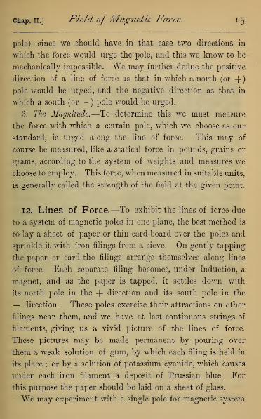
12. Lines of Force.—To exhibit the lines of force due
to a system of magnetic poles in one plane, the best method is
to lay a sheet of paper or thin card-board over the poles and
sprinkle it with iron filings from a sieve. On gently tapping
the paper or card the filings arrange themselves along lines
of force. Each separate filing becomes, under induction, a
magnet, and as the paper is tapped, it settles down with
its north pole in the + direction and its south pole in the
— direction. These poles exercise their attractions on other
filings near them, and we have at last continuous strings of
filaments, giving us a vivid picture of the lines of force.
These pictures may be made permanent by pouring over
them a weak solution of gum, by which each filing is held in
its place ; or by a solution of potassium cyanide, which causes
under each iron filament a deposit of Prussian blue. For
this purpose the paper should be laid on a sheet of glass.
We may experiment with a single pole for magnetic system

i6 Electricity. [Book I.
by placing a long magnet vertical, using only its upper pole.
We then notice that the lines of force are in the form of
straight lines radiating from a point (Fig. 16).
Fig. 16.
In an ordinary bar magnet, laid horizontally under the paper,
the lines of force emanate chiefly from the poles (Fig. 17),
forming oval curves between them. Theoretically, in a simple
bar magnet we should expect all the lines of force to go
from one pole to the other, but in an ordinary magnet the free
magnetism along the edges causes some of the lines not to pro-
ceed directly from the poles, but always from north-polar to
south-polar magnetism, as may be seen on examining the figure.

chap. ii. ] Field of Magnetic Force. 1
7
In the system consisting of two poles of like name, the
lines emanate from each pole but do not intersect, all ap-
proaching towards the equatorial plane of the system without
meeting it—this plane being, in mathematical language, an
asymptote to the system of lines.
Fig. 17.
In like manner can also be shown the polarity of an iron
bar under induction of two opposite or like poles near its ends.
Fig. 19 showrs the lines of force in a system consisting of two
opposite magnet poles and a bar of iron between them.
If, as sometimes happens in a magnet, intermediate poles

i8 Electricity. [Book I.
by intention or accident have been developed, these are at
once shown by the behaviour of the iron filings.
It is instructive to notice that in all these cases the direc-
tion of the line of force is the direction of the resultant of a
system of forces acting from each pole of the system. Thus
Fig. 18.
in a single bar magnet. AB in Fig. 20, the line of force PF at
P will be found by compounding forces in the directions APand PB, directed respectively from the north and towards
the south poles.
13. Strength of Magnetic Field of a Single Pole,
by Coulomb's Balance.—We are now in a position to

chap, ii.] Field of Magnetic Force. 19
compare the strength of the magnetic field at different points
in it. This was originally done by Coulomb for a single pole,
AGS J2Dj3
Fig. 20.
by means of the Torsion Balance (Fig. 21). It consists essen-
tially of three parts—(1.) A long thin magnetic needle, -4,

20 Electricity. [Book I,
evenly magnetized and suspended, so as to swing in a hori-
zontal plane by a fine silver wire, which is attached above to a
Torsion Circle, B. A square of card is put on one end of the
magnet, the resistance of which against the air when swinging
tends to bring the needle rapidly to rest. (2.) The torsion
Fig. 21.
circle (shown enlarged on the right of Fig. 21) carries the
upper end of the wire coiled on the horizontal arm CD,
supported on the frame E, which can be twisted round the
vertical axis, the graduated limb FQ measuring the twist put
on to the wire in performing an experiment. (3.) The needle
swings in a glass case (HK), graduated on its surface, so as
to show the angular movements of the needle. The case

chap, ii.] Field of Magnetic Force. 2
1
is perforated above, so as to allow of the introduction of a
magnetic needle (L) in a vertical position, whose lower pole
creates the magnetic field, whose strength is measured by
the pole of the moving needle. The effects of the more dis-
tant poles of L and A are neglected.
We assume at the outset that both the graduated torsion
circle (FG) has its pointer to zero, and that the needle points
to its zero of graduation on the case (UK), when the needle
is in the magnetic meridian, and the wire has no torsion :
also that the magnet pole is introduced immediately opposite
the zero of graduation, so as to deflect the needle by its re-
pulsive action, the opposing poles being of like sign. This
adjustment is secured in practice by marking the magnetic
meridian by means of an independent magnet, and turning
the case until the 0° and 180° of graduation are in a line with
it ; then, replacing the magnetic needle by a copper needle of
equal weight, twist the whole torsion circle until the copper
needle hangs in the magnetic meridian. On replacing the
magnetic needle, it will hang in the magnetic meridian, and
the wire will be free from torsion.
On introducing the vertical magnet there will be repulsion,
and the needle will take up a position out of the magnetic
meridian, in which the repulsion between the two magnet
poles is balanced by the combined effect of the earth's direc-
tive force on the magnet and the torsion put on to the wire
by the deflection of the needle.
The latter of these is simply proportional to the angle
through which the wire is twisted, or to the deflection of the
needle ; and the earth's directive action can also be measured
in terms of the twist in the wire. The forces acting on the
needle, PP\ in Fig. 22, when deflected from the meridian

22 Electricity. [Book I.
MM will be two equal and opposite forces, whose magni-
tude we will call F, acting parallel to MM. The effect of
such a pair of forces in twisting the magnet round C, back
again towards the meridian, will be measured by their
moment, or 2.Fx CG. When the angle of deflection is small,
CG is very nearly equal to AP, the arc described by the pole
Fig. 22. Fig. 23.
A in its deflection, and this is proportional simply to the angle
of deflection. 1
To find the action of the earth in terms of the torsion of
the wire, we must first find through how many degrees the
circle must be turned to give 1° deflection to the needle before
the magnet L is introduced. Take a plan of the instrument
1 The moment is really proportional to the sine of the angle of
deflection, and the sine for small angles is known to be proportional
to the angle.

tive action of the earth for any moderate deflection is found
T-A
chap, il] Field of Magnetic Force. 23
(Fig. 23) in which the smaller circle represents the torsion
circle, and the larger the graduated glass case. Suppose the
torsion circle turned from the magnetic meridian, MM\through the angle BCA (= ?
70
), and the needle through the
angle PCA (=A°), the torsion on the wire is (T—A)°, and
this balances the deflection, A°. Hence the torsion per degree
—j—
), and we may assume that the direc-
tive action of the earth for any i
by multiplying the deflection by
We can now express the force between the magnet poles in
any position in terms of the torsion of the wire alone, and
this is simply proportional to the angle of torsion in all ex-
periments with the same instrument.
We will now proceed to work out a particular numerical
experiment, in which we endeavour to compare the force
exerted on the moving by the fixed magnet pole, at two dis-
tances whose ratio is as 2 : 1.
(1.) Before introducing the second pole, twist the torsion
circle through 35° ; the needle is seen to deflect 5°: and
therefore 30° of torsion balances the directive action of the
earth through 5° ; or the earth's directive action is measured
by 6° of torsion per degree of deflection.
(2.) Introduce the magnet pole which deflects the needle
40°. Refer to the plan of the instrument (Fig. 24), in which
D represents the fixed pole, E the repulsive force which acts
in direction DP : the effect in twisting the needle is measured
by the moment of B about C, or CK x R. When the angle
of deflection is small, CK is nearly equal to CP ; and we shall
therefore assume that the moment is measured by R, the
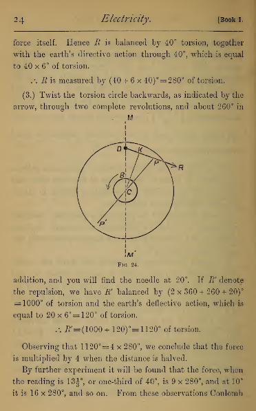
24 Electricity. [Book I.
force itself. Hence B is balanced by 40° torsion, together
with the earth's directive action through 40°, which is equal
to 40 x 6° of torsion.
. \ B is measured by (40 + 6x 40)°= 280° of torsion.
(3.) Twist the torsion circle backwards, as indicated by the
arrow, through two complete revolutions, and about 260° in
M
addition, and you will find the needle at 20°. If B' denote
the repulsion, we have R' balanced by (2 x 360 + 260 + 20)°
= 1000° of torsion and the earth's deflective action, which is
equal to 20 x 6°= 120° of torsion.
.-. #=(1000 + 120)°= 1120° of torsion.
Observing that 11 20°= 4 x 280°, we conclude that the force
is multiplied by 4 when the distance is halved.
By further experiment it will be found that the force, when
the reading is 13^°, or one-third of 40°, is 9 x 280°, and at 10°
it is 16 x 280°, and so on. From these observations Coulomb

chap, n.] Field of Magnetic Force. 25
deduced the important law that where the distances of two
poles are made in succession proportional to
1, 2, 3, 4,
the forces at these distances are proportional to
iiiiwhich is usually expressed by saying that the forces are in-
versely as the squares of the distances between the poles.
14. Strength of Field by the Method of Oscilla-
tions.—The strength of the field may also be investigated by
means of the method of Oscillations. This depends on the
well-known dynamical law that a pendulum, when oscillating
through a small arc about its position of equilibrium, makes
isochronous oscillations
—
i.e. oscillations whose time is indepen-
dent of the arc (supposed small) through which the pendulum
swings—and that the force which is always drawing it back to
its position of rest is proportional to the square of the number
of oscillations made in a given time.
Now, a magnet, when freely suspended, is a double pen-
dulum, and, when disturbed, oscillates under the same laws
as a pendulum ; and, since it will continue to oscillate for five
or ten minutes, the number of oscillations in that time can be
counted within a fraction of a single oscillation. 1
If we place the south pole of another magnet in the
meridian, at a measured distance to the north of the suspended
magnet, it will increase the magnetic force on the needle, and
make the oscillations more rapid. If the suspended needle
be very short, compared with the distance of the magnet pole,
the forces on the two poles will be appreciably equal and
1 For rough experiments, the number of oscillations made in 30seconds is sufficient.
26 Electricity. [Booki.
opposite, and we have the oscillating magnet behaving as a
pendulum under the combined action of the earth and magnet
pole, whose effects are simply added together.
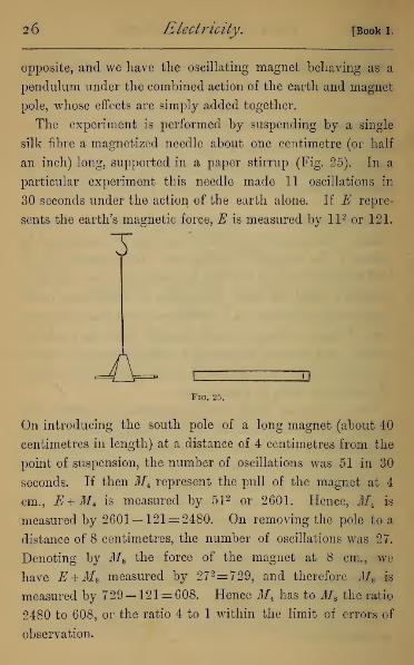
The experiment is performed by suspending by a single
silk fibre a magnetized needle about one centimetre (or half
an inch) long, supported in a paper stirrup (Fig. 25). In a
particular experiment this needle made 11 oscillations in
30 seconds under the action of the earth alone. If E repre-
sents the earth's magnetic force, E is measured by ll 2 or 121.
T
J\-Fig. 25.
On introducing the south pole of a long magnet (about 40
centimetres in length) at a distance of 4 centimetres from the
point of suspension, the number of oscillations was 51 in 30
seconds. If then iff4 represent the pull of the magnet at 4
cm., E + Mt is measured by 51 2 or 2601. Hence, M± is
measured by 2601— 121 = 2480. On removing the pole to a
distance of 8 centimetres, the number of oscillations was 27.
Denoting by M8 the force of the magnet at 8 cm., we
have E +M8 measured by 27 2= 729, and therefore M8 is
measured by 729— 121 = 608. Hence Jf4 has to M8 the ratio
2480 to 608, or the ratio 4 to 1 within the limit of errors of
observation.
Chap. II.] Field of Magnetic Force. 27
The same method employed at other distances will confirm
the law of inverse squares, just as in Coulomb's method.
It should be noticed, in this and the following experiments,
that it must be the pole as defined in Art. 11, and not the
mere end of the magnet, which is to be placed at the given
distances from the suspended magnet. A few experiments
enable the experimenter to arrive at the true position of the
magnet pole, which in an ordinary bar magnet is about \ in.
from the end.
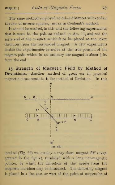
15. Strength of Magnetic Field by Method of
Deviations.—Another method of great use in practical
magnetic measurements, is the method of Deviation. In this
M1
• xc •
method (Fig. 26) we employ a very short magnet PP (exag-
gerated in the figure), furnished with a long non-magnetic
pointer, by which the deflection of the needle from the
magnetic meridian may be measured. The deflecting magnet
is placed in a line east or west of the point of suspension of
28 Electricity. [Booki.
the needle as at M or N. Kemembering that the magnet is
very short, and considering only one deflecting pole, the forces
acting on each pole will be a force along the magnetic meridian
(E) due to the earth's action, and a force at right angles to it
(F), due to the action of the deflecting pole. The magnet takes
up its position along the resultant of these two forces. Let
GCG' be a horizontal scale graduated both ways from C; also,
let KCK' be a graduated scale placed in a vertical plane, both
being east and west of the meridian. If the line CP be pro-
duced, either by a pointer or by sights attached to the magnet,
and moving with it, so that the distance Qyat which the axis of
the magnet cuts the vertical scale is known, the principle of
the parallelogram of forces will apply, and we shall have
p Tin— =—^ . But BC and E are fixed quantities for all obser-
vations, and hence we see that F is measured in each ex-
periment by the distance BQ. If we choose distances for Mproportional to 1, 2, 3, . . .we shall find the distances BQrespectively proportional to 1, \, ±, . . . , thus giving another
proof of the law of inverse squares.
BOThe ratio —^ depends on the angle BCP, and is in fact
BCsimply the tangent of that angle. If C be in the centre of a
graduated card, the same result may be obtained by observing
the angle of deflection, and extracting its tangent from the
table given in Appendix II. In performing the experiment,
the magnet and its suspension should be placed under a glass
case, as otherwise currents of air prevent its remaining at rest
in the position of magnetic equilibrium.
16. Comparison of Strength of two Magnet Poles.
—To compare two magnetic poles is simply to compare the

chap, ii.] Field of Magnetic Force. 29
forces they respectively exert on the same pole when placed at
the same distance from it.
This comparison may be made by either of the above
methods, simply changing the one pole for the other of two
magnets to be tested, keeping the distance from the testing
magnet the same, or applying the law of inverse squares to
reduce the observations to a constant distance. A better
method is to place the two poles as at M and A7", on opposite
sides of the short suspended needle of the last experiment, and
move one of them backwards and forwards till the suspended
needle remains in the meridian. The strengths of field at
due to M and to N must then be equal, and we shall have
strength of pole M at distance CM equal to that of the pole
N at distance CN. Hence their strengths at the same dis-
tance would be in the ratio CM2 to CN2.
If now m, m! be the strengths of the poles
—
i.e. the forces
with which they urge a certain standard pole at unit distance
7YI—the strength of the field of m at distance r will be -g. Assum-

30 Electricity. [Book I.
ing this, we can easily correct the last result for the action of
the more distant pair of magnet poles. For if we assume MM
'
and NN' (Fig. 27) to be the two magnets, the strength of field
at C due to the magnet MM' will be found by subtracting
the strength due to M from that due to M, which gives
jroi and that due to JS/Jy will be n*r<>— nAvo ; andCM2 CM'**11U tllctu uue tu iyiy win uo CA72 CAT2
we have therefore, if the magnet remains undisturbed,
m[CM* CM'V- m \CN'2 CN'V
from which the ratio m : m' is at once determined.
* 17. Meaning of an Absolute System of Measure-
ment.—In speaking of magnet poles we have frequently
referred to a standard pole, but have used in place of it the
pole of any needle convenient for the particular experiment
we had in hand. No magnet pole can be made to retain its
magnetism without change for any length of time ; and it is
therefore useless to attempt, by means of a single magnet, to
compare the strengths of a field or of another pole at any
great interval of time.
To enable us to do this we make an absolute system of
units in which the strength of our pole must be determined,
absolutely at the time of each experiment.
For an account of the absolute system of units employed,
the student is referred to Appendix I. We only note here
that with three fundamental units (that of length being called
the centimetre ; of time, the second of our ordinary mean-time
clocks ; and of mass, the gram) we are able to express every
other unit required in physical investigation independently of

chap, ii.] Field of Magnetic Force. 3 r
any new physical quantity. Premising that the absolute
unit of force is the dyne, we proceed to explain the absolute
units used in magnetism.
* 18. Absolute Unit of Magnetism.—We know by our
experiments that two magnet poles of the same kind repel
each other with a force which may be measured in dynes or
absolute units of force. We can therefore conceive two equal
magnet poles which when a centimetre apart exert a force
of exactly one dyne on each other. These two would then
be called unit magnet poles, and the quantity of magnetism
in each of them a unit of magnetism. We make no assump-
tion here as to the nature of magnetism, referring only to its
action in the magnetic field. We should define the strength
of any other magnetic pole by the number of units of mag-
netism it contains, or by the force exerted on a unit pole
placed at unit distance. We should also define the strength
at any point in a magnetic field, as the force with which a
unit of magnetism condensed in a point and placed there would
be urged along the line of force.
It follows from this definition, combined with the law of
inverse squares of the distance, that if we have a pole of
strength Mtthe strength of the field at a distance D cm. from it
will be — : and the force urging a pole of strength M r
placed
MM'at distance D cm., will be "
^ , both expressed in absolute
measure.
19. Theories Suggested by Experiment.—It will
naturally strike the student that by all our methods of
experiment, acknowledged everywhere, to be rough and ap-

3 2 Electricity. [Book i.
proximate only, we have given an altogether inadequate
proof of a law of such precision and generality. We must
remind him however that he has in this been only following
in the track of the discoverers, both of this and of every other
physical law. Such laws have been discovered by something
like a happy guess from very rough observations, while the
confirmation of the guess depends on methods of greater
refinement, which generally depend altogether on a know-
ledge of the law itself they are intended to prove. As an
illustration, we may notice that by help of the law just
enunciated we can determine the form of the magnetic curves
for a given distribution of poles, and can in many cases trace
the theoretical magnetic curves by graphical means, and so
compare the curves yielded by theory with those given by
experiment.

CHAPTER III
METHODS OF MAGNETIZATION.
20. Quality and Temper of Steel.—To secure good
permanent magnets it is, first of all, necessary to have bars of
the best steel evenly tempered. The temper which gives the
best results is obtained by cooling the bars when brought to a
cherry-red—the same temper as that for the best cutlery.
There are various processes of magnetization, but all depend
on overcoming the coercive force of the steel by vibrating its
molecules when under powerful external magnetic induction.
21. Method of Single Touch. — The first method,
known as Single Touch, consists merely in rubbing the bai
to be magnetized several times lengthwise, and always in
the same direction, across the pole of
a strong magnet. In this, as in all
cases, the end of the bar at which
the magnet pole leaves it becomes of
opposite name to the inducing pole.
This process is repeated five or six
times on both sides of the bar to be /v
magnetized, and gives a fairly strong
magnetism to a short thin bar, such as a piece of watch-spring
or small compass needle. The arrow shows the direction in
which the bar is rubbed across the pole to communicate the
poles shown by the letters N, S.
C
Fig. 28.
34 Electricity. [Book I.
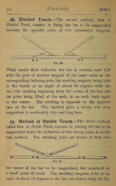
22. Divided Touch.—The second method, that of
Divided Touch, consists in fixing the bar to be magnetized
between the opposite poles of two permanent magnets.
N SPig. 20.
N S
While under their induction the bar is stroked, each half
with the pole of another magnet of the same name as the
corresponding inducing pole, the stroking magnets being held
in the hands at an angle of about 30 degrees with the
bar ; the stroking beginning from the centre of the bar, and
the poles being lifted at the ends, in an arch, back again
to the centre. The stroking is repeated on the opposite
face of the bar. This method gives a strong and even
magnetism to moderately thin and long bars.
23. Method of Double Touch.—The third method,
called that of Double Touch, consists in placing the bar to be
magnetized under the induction of two strong poles, as in the
last method. The stroking poles are placed at first over
Fig. 30.
the centre of the bar to be magnetized, but separated by
a small piece of wood. The stroking magnets, held at an
angle of about 15 degrees to the bar, are drawn along the bar

Cbap. hi.] Methods of Magnetization. 35
steadily from the centre to the end, and back again to the
other end, several times, being taken off finally at the centre,
after each half has been passed over the same number of
times. The bar is turned over, and the same process repeated
on the opposite face. This is found to give a strong mag-
netism to thick bars, but is apt to develop consequent poles,
unless the rubbing be performed very steadily.
Some experimentalists prefer the use of a strong horse-shoe
magnet, whose two poles are placed on the bar at its centre,
Fig. 31.
and rubbed backwards and forwards, as in the last-named
method. When several bars require to be magnetized at
once, they are placed with their ends in contact, so as to
form a closed circuit, the angular spaces between their ends
being filled in with soft iron. The horse-shoe magnet is put
down at any part, and simply made to slide round the circuit,
always in the same direction, several times, by means of
which all the bars are magnetized strongly. Each bar is
magnetized in the same direction as the inducing magnet,
and the consecutive ends, acquiring opposite magnetism,
increase each other's power by mutual induction.
24. Magnetic Battery.—It has been found that thin
bars can be magnetized much more strongly than thick ones
36 Electricity. [Book I.
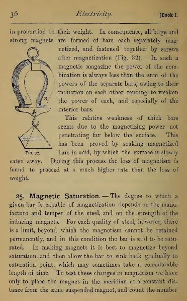
in proportion to their weight. In consequence, all large and
strong magnets are formed of bars each separately mag-
netized, and fastened together by screws
after magnetization (Fig. 32). In such a
magnetic magazine the power of the com-
bination is always less than the sum of the
powers of the separate bars, owing to their
induction on each other tending to weaken
the power of each, and especially of the
interior bars.
This relative weakness of thick bars
seems due to the magnetizing power not
penetrating far below the surface. This
has been proved by soaking magnetized
Fig. 32. bars in acid, by which the surface is slowly
eaten away. During this process the loss of magnetism is
found to proceed at a much higher rate than the loss of
weight.
25. Magnetic Saturation.— The degree to which a
given bar is capable of magnetization depends on the manu-
facture and temper of the steel, and on the strength of the
inducing magnets. For each quality of steel, however, there
is a limit, beyond which the magnetism cannot be retained
permanently, and in this condition the bar is said to be satu-
rated. In making magnets it is best to magnetize beyond
saturation, and then allow the bar to sink back gradually to
saturation point, which may sometimes take a considerable
length of time. To test these changes in magnetism we have
only to place the magnet in the meridian at a constant dis-
tance from the same suspended magnet, and count the number
chap, in.] Methods of Magnetization, 37
of oscillations in a given time. As long as these decrease in
number the power of the magnet is diminishing. Another
method commonly employed to test the power of a horse-shoe
magnet consists in suspending to the armature (Fig. 32) of a
fixed magnet a scale-pan, into which weights can be put, and
so determine its portative power. The amount the magnet
can support can be increased by adding small weights at
successive intervals, never allowing the weight to be sufficient
to separate the armature from the magnet.
The production of permanent magnets of small size, but
great magnetic power, is now a matter of great importance,
especially in telephone work, and great improvements have
been made in the manufacture of steel for this purpose. In
the Paris Exhibition of 1882 there was a magnet which could
support seventy-six times its own weight ; and the small
ordinary magnets now used in Gower-Bell telephones hold
up from fifteen to twenty-five times their own weight. (Mr.
W. H. Preece, F.R.S., in Report 0} Institute of Mech. Engineers,
Jan. 1883.)
26. Retention of Magnetism. — After a magnet has
been made, great care must be taken to preserve it from
accidental jars, by which the mass is set in vibration, the
effect of which, in the absence of strong external induction,
is to relax the molecular rigidity on which the magnetism of
steel depends. The same effect will be produced by heating
the magnet—a red heat not only destroying all traces of mag-
netism, but making the metal quite indifferent to magnetism.
CHAPTER IV.
TERRESTRIAL MAGNETISM.
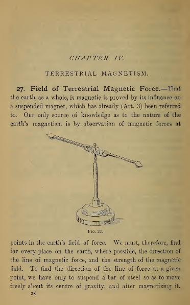
27. Field of Terrestrial Magnetic Force.—That
the earth, as a whole, is magnetic is proved by its influence on
a suspended magnet, which has already (Art. 3) been referred
to. Our only source of knowledge as to the nature of the
earth's magnetism is by observation of magnetic forces at
Fig. 33.
points in the earth's field of force. We must, therefore, find
for every place on the earth, where possible, the direction of
the line of magnetic force, and the strength of the magnetic
field. To find the direction of the line of force at a given
point, we have only to suspend a bar of steel so as to move
freely about its centre of gravity, and after magnetizing it,
38

chap, iv.] Terrestrial Magnetism, 39
observe the position it assumes. This may be nearly fulfilled by
such a suspension as that of Fig. 33, in which the axis of a
needle swinging in a vertical plane is mounted on a pivot,
about which it can turn horizontally. Such a needle in Eng-
land at the present time will always come to rest in a plane
inclined 18° to 20° to the west of the astronomical meridian,
and will rest in that plane at an angle of 67° to 69° to the
horizon. This shows that within any very limited space the
lines of force are sensibly a series of straight lines parallel to
one another.
That these lines of force should remain straight lines to
considerable distances from the earth is very unlikely ; but
the linear dimensions of the earth are so great, compared
with any distances above it at which we can take observa-
tions, that we are not likely ever to be able to discover what
their true shape is. Their sensible parallelism for moderate
distances confirms us in our assumption (Art. 13) that the
earth's action on a needle consists of two equal and opposite
forces, since we cannot employ a needle so long that the field
of force at the two ends of it shows any sensible difference in
direction or intensity. This is all that is meant when the
earth's action on a needle is said to be directive only ; the
effect of a couple in mechanics being to twist a body round
without altering the position of its centre of gravity, until the
two forces constituting the couple are in the same straight
line. The needle in our experiment then takes up that
position in which the earth's pull consists of two equal and
opposite forces on its two ends, directed along it, and therefore
maintaining it in equilibrium.
This has been shown experimentally by supporting a
magnet on a cork float. In any vessel conveniently small

4-0 Electricity. [Book i.
the surface tension of the water will draw the cork to the
side, but at a point depending on the position on the surface
in which the float is placed, and in no way depending on
the direction of the earth's magnetism.
28. Magnetic Elements of a Place.—The definitions
of the direction of the line of force and of the strength of the
earth's magnetic pull constitute what are called the magnetic
elements of the place. They are three in number.
1. Declination—is the angle which the vertical plane through
the magnetic axis of a freely suspended needle makes with
the astronomical meridian of the place. This plane is com-
monly called the magnetic meridian of the place (see Art. 23),
and is the vertical plane which passes through the axis of an
ordinary horizontally suspended needle. The declination is
counted E. or W. as the north pole of the needle points to the
E. or W. of the astronomical meridian or vertical plane which
passes due north and south of the place of observation.
2. Inclination or Dip—is the angle which the magnetic axis
of a magnet, freely suspended about its centre of gravity,
makes with the horizon of the place. This may be either
north or south according as the north or south end of the
needle dips below the horizontal plane.
3. Intensity—is the force, expressed in absolute measure,
with which the earth's magnetism urges a unit magnet pole
at the place.
29. The Declinometer.—To determine each of these
elements at any place requires a special piece of apparatus.
That for determining the declination is called a Declinometer.
This consists (Fig. 34) of a mounted telescope A, swinging on
two Y pieces B, B, the axis being levelled by the hanging
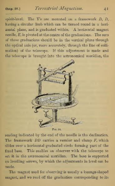
Chap. IV.] Terrestrial Magnetism. 4i
spirit-level. The Y's are mounted on a framework D, D,
having a circular limb which can be turned round in a hori-
zontal plane, and is graduated within. A horizontal magnet
needle, F, is pivoted at the centre of the graduations. The zero
of these graduations should be in the vertical plane through
the optical axis (or, more accurately, through the line of colli-
mation) of the telescope. If this adjustment is made and
the telescope is brought into the astronomical meridian, the
Fig. 34.
reading indicated by the end of the needle is the declination.
The framework DD carries a vernier and clamp F, which
slides over a horizontal graduated circle forming part of the
fixed base. This enables an observer with the telescope to
set it in the astronomical meridian. The base is supported
on levelling screws, by which the adjustments in level can be
made.
The magnet used for observing is usually a lozenge-shaped
magnet, and we read off the graduation corresponding to its
42 Electricity. [Book i.
pointed extremity. If the poles are not in the geometrical
axis of the magnet, this reading will be either too small or
too great. To correct this, the faces of the needle are usually
reversed, and the reading repeated, since then the declination,
which was before too small, will become too great, or vice
versd; the mean of the two readings correcting the error.
There may be also an error of centering the needle, by which
the pivot is thrown out of the centre of the graduations. This
is corrected by reading each time both ends of the needle.
The mean of the four readings so obtained will give the
true declination.
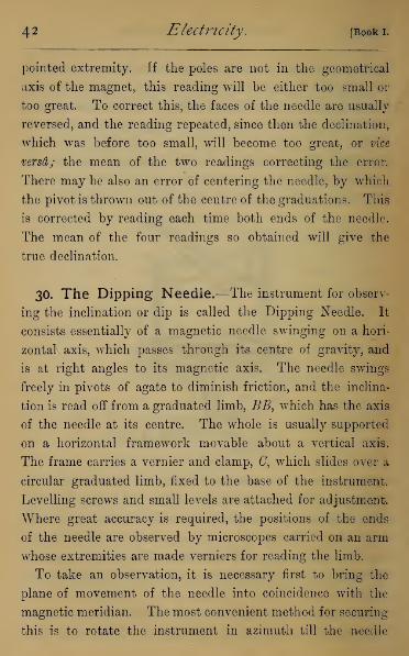
30. The Dipping Needle.—The instrument for observ-
ing the inclination or dip is called the Dipping Needle. It
consists essentially of a magnetic needle swinging on a hori-
zontal axis, which passes through its centre of gravity, and
is at right angles to its magnetic axis. The needle swings
freely in pivots of agate to diminish friction, and the inclina-
tion is read off from a graduated limb, BB, which has the axis
of the needle at its centre. The whole is usually supported
on a horizontal framework movable about a vertical axis.
The frame carries a vernier and clamp, 0, which slides over a
circular graduated limb, fixed to the base of the instrument.
Levelling screws and small levels are attached for adjustment.
Where great accuracy is required, the positions of the ends
of the needle are observed by microscopes carried on an arm
whose extremities are made verniers for reading the limb.
To take an observation, it is necessary first to bring the
plane of movement of the needle into coincidence with the
magnetic meridian. The most convenient method for securing
this is to rotate the instrument in azimuth till the needle

Chap. IV.] Terrestrial Magnetism, 43
shows an inclination of 90°, i.e. stands vertical. The needle
must then be in the plane at right angles to the meridian, for
in this position the horizontal component of the earth's pull is
balanced by an increased pressure on the south and diminished
pressure on the north bearing of the needle, while the vertical
component acting alone keeps the needle in a vertical position.
To eliminate the errors of centering, and of want of coinci-
dence between the geometrical and magnetic axes, the hori-
Fio. 35.
zontal circle is read, when each end of the needle points to
90°, and also when the faces of the needle have been reversed,
either by turning the instrument through half a revolution
or by lifting the needle from its supports and reversing the
bearings. The mean of the four readings so obtained,
diminished by 90°, will give the plane of the meridian.
When the needle is in the plane of the meridian, it is made
to vibrate slightly by bringing a magnet for a moment near to
it, and allowed to take up its position of rest after the magnet's

44 Electricity. [Booki.
removal, when both ends of the needle are read. As it seldom
comes to rest twice over in exactly the same position, this
method is repeated about ten times.
As before, the faces of the needle are reversed, and the
same set of observations repeated.
There is a further error which occurs in the indications of
a dipping needle, due to the axis of rotation of the needle
not passing through its centre of gravity. If the centre of
gravity were ever so little towards the north end of the needle,
the weight acting through it would pull down the north end
and increase the dip, supposed north. If it were towards the
south end, it would pull down the south end, and therefore
diminish the dip. This error is neutralised by lifting out the
needle and reversing its magnetism, and again repeating the
two sets of observations on each end described above. The
mean of the eight means so obtained will give the true dip.
We have entered into details of the methods employed in
taking observations with the dipping needle, as an illustration
of the use of well-directed multiplied observations in using
physical instruments, and not because it is likely that such
methods could be usefully applied to the rough instruments
placed in a student's hands or used in a lecture experiment.
The need of such refinements only becomes apparent in instru-
ments brought to the highest perfection in construction, and
they would be as much out of place in a rough instrument
as a micrometer reading to thousands of an inch on a roughly
divided carpenter's rule, or a rider reading thousands of an
ounce on the beam of a grocer's balance.
31. The Intensity.—To compare the magnetic intensity
at various places; we have apparently only to observe the
Chap. IV.] Terrestrial Magnetism, 45
number of small oscillations made by the same dipping needle
in a given time about its position of equilibrium, the intensity
being simply proportional to the square of the number of
oscillations observed. This method would of course only
give us the intensity, referred to an arbitrary standard—say
the intensity at some one place—and not in absolute measure.
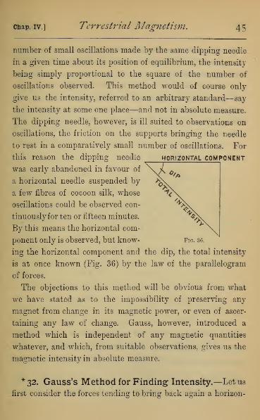
The dipping needle, however, is ill suited to observations on
oscillations, the friction on the supports bringing the needle
to rest in a comparatively small number of oscillations. For
this reason the dipping needle horizontal component
was early abandoned in favour of
a horizontal needle suspended by
a iew fibres of cocoon silk, whose
oscillations could be observed con-
tinuously for ten or fifteen minutes.
By this means the horizontal com-
ponent only is observed, but know- fig. 36.
ing the horizontal component and the dip, the total intensity
is at once known (Fig. 36) by the law of the parallelogram
of forces.
The objections to this method will be obvious from what
we have stated as to the impossibility of preserving any
magnet from change in its magnetic power, or even of ascer-
taining any law of change. Gauss, however, introduced a
method which is independent of any magnetic quantities
whatever, and which, from suitable observations, gives us the
magnetic intensity in absolute measure,
*32. Gauss's Method for Finding Intensity.—Let us
first consider the forces tending to bring back again a horizon-

46 Electricity. [Book I.
tally suspended magnetic needle displaced from the meridian.
Using absolute units, assume m to be the magnetic strength of
each pole of the magnet, and H the horizontal component
of the earth's magnetic intensity. The definition ofH is the
pull on a unit of magnetism, and since at P there are by
supposition m units, the pull at P and P' will be two forces
Hm equal and oppositely directed. The moment of this
couple, tending to twist the magnet back to its position of
rest, is 2Hm x PM where PM is the arm of either force. This
maybe written Hm.PP' x~ when _- depends only on the
angle PGM, through which the magnet is deflected. The
quantity mxPP' is usually called the Magnetic Moment of
Chap. IV.] Terrestrial Magnetism. 47
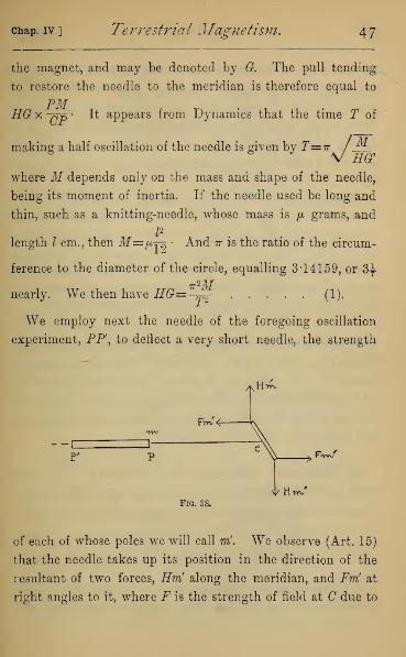
the magnet, and may be denoted by G. The pull tending
to restore the needle to the meridian is therefore equal to
PMHG x yn5 • It appears from Dynamics that the time T of
making a half oscillation of the needle is given by T=7r / ffi6 * *\/ Hff
where M depends only on the mass and shape of the needle,
being its moment of inertia. If the needle used be long and
thin, such as a knitting-needle, whose mass is /x grams, and
I2
length I cm., then M=fxj^ And it is the ratio of the circum-
ference to the diameter of the circle, equalling 3*14159, or 3^-
nearly. We then have HG=-T2 (1).
We employ next the needle of the foregoing oscillation
experiment, PF, to deflect a very short needle, the strength
H^
Bn?4-
- -C n—E' ,Rw/
vl/ HiFig. 38.
of each of whose poles we will call mf. We observe (Art. 15)
that the needle takes up its position in the direction of the
resultant of two forces, Hm! along the meridian, and Fm! at
right angles to it, where F is the strength of field at C due to

48 Electricity. [Book 1.
m at P, and -mat F. Whence if 6 be the deflection of the
Fneedle from the meridian, -^= tan 8 \ also
_m_ _m___(CF-CP).(CP + CP)
CP2 CF2~~m"
CP2. CF2
np> , np= G
' CPKCP 2 'Since G=m
(CF- GP)'
We thus have -^ -
cp2 cp2= tan 0,
H GF + GP .:M /0
.
Multiplying together equations (1) and (2) we obtain H2 in
terms of magnitudes obtained by weighing and measuring
only, and independent of any magnetic quantity whatever.
*33. Magnetic Moment of a Magnet in Absolute
Measure.—The method just described may be also used to
obtain G. For dividing, in place of multiplying, we have
G2 in absolute measure. Hence the same method enables us
to express the magnetic moment, and hence the strength of
any magnet pole in absolute measure.
34. Magnetic Elements of Greenwich.—The mag-
netic elements found for Greenwich in January 1884, were :
—
Declination, . 18° 10' West.
Dip, ... 67° 30',
Intensity, . . -472.
35. Changes in Elements.—No sooner had instru-
ments of moderate accuracy been applied to determine these
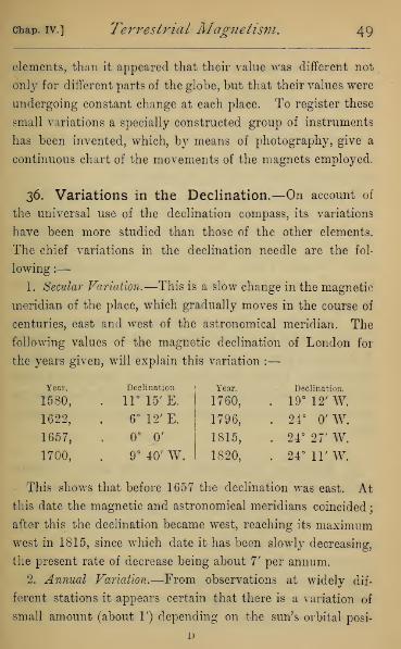
chap, iv.] Terrestrial Magnetism. 49
elements, than it appeared that their value was different not
only for different parts of the globe, but that their values were
undergoing constant change at each place. To register these
small variations a specially constructed group of instruments
has been invented, which, by means of photography, give a
continuous chart of the movements of the magnets employed.
36. Variations in the Declination.—On account of
the universal use of the declination compass, its variations
have been more studied than those of the other elements.
The chief variations in the declination needle are the fol-
lowing :
—
1. Secular Variation.—This is a slow change in the magnetic
meridian of the place, which gradually moves in the course of
centuries, east and west of the astronomical meridian. The
following values of the magnetic declination of London for
the years given, will explain this variation :
—
Year. Declination Year. Declination.
1580, . 11° 15' E. 1760, . 19° 12' W.
1622, 6°12'E. 1796, . 24° 0' W.
1657, 0° 0' 1815, . 24° 27' W.
1700, 9° 40' W. 1820, . 24°11'W.
This shows that before 1657 the declination was east. At
this date the magnetic and astronomical meridians coincided
;
after this the declination became west, reaching its maximumwest in 1815, since which date it has been slowly decreasing,
the present rate of decrease being about 7' per annum.
2. Annual Variation.—From observations at widely dif-
ferent stations it appears certain that there is a variation of
small amount (about 1') depending on the sun's orbital posi-
D

5o Electricity. [Booki.
tion \ the north end of the needle pointing to the east of the
mean position when the sun is north, and to the west when
the sun is south of the equator.
3. Diurnal Variation.—The comparison of a series of hourly
observations of the declination at Kew, extending over several
years, shows that there is a variation in the declination, de-
pending on the sun's position in its daily path.
The needle occupies its mean position when the sun is
on the magnetic meridian about 10.30 A.M. Its maximum
easterly variation, amounting to 4', occurs three hours earlier,
and its maximum westerly, amounting to 6', about three hours
later. It again reaches the magnetic meridian about 6.30
P.M., and remains 1' or 2' east of it during the night, moving
eastwards again early in the morning.
4. Perturbations.—These are irregular movements of the
needle, by which its regular advance is broken up into a series
of zigzags of greater or less amount. At some periods these
perturbations become comparatively very large, the needle
continuing to swing rapidly through several minutes of arc on
either side of its mean position. These are called Magnetic
Storms.
37. Relation to Aurora Borealis and to Solar
Phenomena.—That these perturbations are not local dis-
turbances is proved by their occurring simultaneously at
stations very widely separated, and it is probable that they
have a common cause with the aurora borealis, brilliant displays
of which most frequently occur at the same time with the
magnetic storms. There is also evidence of a remarkable con-
nection between these magnetic perturbations and changes
in the sun's atmosphere. On 1st September 1859 Mr. Car-

chap, iv.] Terrestrial Magnetism. 5
1
rington, the astronomer, was taking observations on the sun's
spots in his Observatory at Redhill, when suddenly, within the
area of the largest group of spots, there broke out two patches
of intensely bright and white light, which, after increasing for
some seconds, gradually died away, the whole duration of the
phenomenon being not more than five minutes, during which
time the two patches traversed a space on the sun's disc of no
less than 35,000 miles. On visiting, a few days afterwards, the
magnetic Observatory at Kew, he learned that at the instant
he observed this phenomenon the three magnetic elements
were disturbed, the declination needle making a movement of
13-2' to the west.
A further connection between the earth's magnetism and
the sun is shown by the apparent coincidence of the periods
of greatest frequency of sun-spots with a periodic maximum
disturbance of the magnetic needle. It seems pretty well
established, by observations extending over 150 years, that
there exists a periodic frequency of sun-spots, whose period
is from ten to eleven years. Accurate information on mag-
netic variation extends over a very much shorter period, but
there seems to be, at stations widely separated, a marked co
incidence between the periods of frequency of sun-spots, of
magnetic storms, and of a marked increase in the range of the
diurnal variation. These can hardly point to anything else
but a very marked influence exercised by the sun on the mag-
netism of the earth.
38. Other Variations.—Such are the chief perturbations
in the magnetic elements, their character and amount changing
at different places on the earth. That others exist is highly
probable, and perturbations with a half-yearly period, and
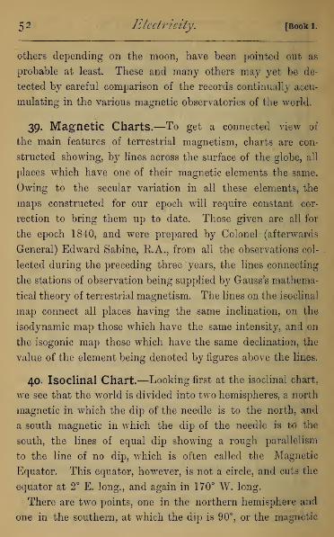
5 2 Electricity. [Book i.
others depending on the moon, have been pointed out as
probable at least. These and many others may yet be de-
tected by careful comparison of the records continually accu-
mulating in the various magnetic observatories of the world.
39. Magnetic Charts.—To get a connected view of
the main features of terrestrial magnetism, charts are con-
structed showing, by lines across the surface of the globe, all
places which have one of their magnetic elements the same.
Owing to the secular variation in all these elements, the
maps constructed for our epoch will require constant cor-
rection to bring them up to date. Those given are all for
the epoch 1840, and were prepared by Colonel (afterwards
General) Edward Sabine, K.A., from all the observations col-
lected during the preceding three years, the lines connecting
the stations of observation being supplied by Gauss's mathema-
tical theory of terrestrial magnetism. The lines on the isoclinal
map connect all places having the same inclination, on the
isodynamic map those which have the same intensity, and on
the isogonic map those which have the same declination, the
value of the element being denoted by figures above the lines.
40. Isoclinal Chart.—Looking first at the isoclinal chart,
we see that the world is divided into two hemispheres, a north
magnetic in which the dip of the needle is to the north, and
a south magnetic in which the dip of the needle is to the
south, the lines of equal dip showing a rough parallelism
to the line of no dip, which is often called the Magnetic
Equator. This equator, however, is not a circle, and cuts the
equator at 2° E. long., and again in 170° W. long.
There are two points, one in the northern hemisphere and
one in the southern, at which the dip is 90°, or the magnetic

o o o o ot. <o in * k> S 9 o o o o ,> o o c
o -J sl-ai": W!«*
1
o
o
on
oCD
O
«:
Jc
oi
in
oCO
oLi
i
O '
aj
t-:
c
3ov.?
o
O
oto
en J ^"9 .ST
5\ as.
m
-;-"'-
-5Vt;
ato
o
oOJ
1
osi
i
£oo(»
ul
Co
o
o
05
O<0
oto
o
-.CE.-::%»N«e» —
,
"'•'•:'^;J3
<3
t-Ic c
o .-:$.:
:vji|vj^
.
\2
at- \
fl fiZ^f
f>ch
:?£
N
iiiB
WA&M~i^ x::-" y
1
5-Ez wee
14 5 -Jl 1
.-
Z:'.-£ «/c1
/ * s
1
|c ^-j4|^j
<0«J T
o 5 /
o2j /f )
< Mr|m ^ 3/
OD
PtO c
/
"41<-
s
s5 ^
^ .<rrsjft?
1£
J-'-
J
fcv '/I":f:
:.i
';:/•;< f.
taj
BBR
-oo >E <o<-•' ".•''.':•':':':'
*p';;.v
" *J"
si *?ST*S o-.
1 pi 7";
00
if l^ *A
s&y
*>3
\c, s\j?v»
K)1
««^m r ^ ta fgfjj SA «
sl S S?SS2°2SSga & K
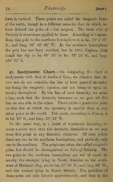
54 Electricity. [Booki.
force is vertical. These points are called the Magnetic Poles
of the earth, though in a different sense to that in which we
have defined the poles of a bar magnet. The term Pole of
Verticity is sometimes applied to them. According to Captain
Ross, this pole in the northern hemisphere is in lat. 70° 5' 17"
N., and long. 96° 45' 48" W. In the southern hemisphere
the pole has not been reached, but in 1841 Captain Ross
found the dip to be 88° 35' in lat. 76° 20' S., and long.
165° 32' E.
41. Isodynamic Chart.—On comparing the chart of
isodynamic with that of isoclinal lines, we observe that the
two sets do not coincide, the line of least general intensity
not being the magnetic equator, and not being of equal in-
tensity throughout. By the line of least intensity, we mean
a line, such that the intensity increases as we pass off this
line on one side or the other. There exists a particular point
on this line at which the intensity is smaller than at any
other point in the world. This point, according to Erman, is
in lat. 20° S., and long. 35° 12' W.
In the same way, by a point of maximum intensity, we
mean a point such that the intensity diminishes as we pass
from that point in any direction whatever. Of such points
there are two in the northern hemisphere, and probably only
one in the southern. The points are often also called magnetic
poles, but should be distinguished as Poles of Intensity. The
two poles in the northern hemisphere are not of equal in-
tensity, the stronger lying in North America to the south-
west of Hudson's Bay, about lat. 52° 19' N., and long. 92° W.,
and the weaker lying in North Siberia. The positions of
these poles are only known approximately, and that in the


5 6 Electricity. [Book i.
southern hemisphere with still less exactness, the point of
highest recorded intensity, according to the observations of
Captain Eoss, being in lat. 60° 19' S., and long. 131° 20' E.;
but he had certainly not reached the actual point of greatest
intensity, and was prevented by insuperable obstacles from
proceeding further towards it.
These remarks are sufficient to show that the poles of ver-
ticity and intensity do not coincide in the northern hemisphere,
and although their position is less certainly determined in the
southern hemisphere, enough is known to say that they are
not coincident.
42. Isogonic Chart.—Referring lastly to the declination
chart, or chart of isogonic lines, we see that the line of 0°
declination is not a great circle, but an irregular line passing
through the poles of verticity and astronomical poles in both
hemispheres. The lines of small declination follow its general
direction, but the lines of higher declination form a series of
loops in each hemisphere, connecting the pole of verticity with
the corresponding astronomical pole.
There is to be noticed a remarkable oval patch extending
over parts of North-East Siberia, China, and Japan, along the
margin of which the declination sinks to 0°, and within it
becomes westerly, though surrounded by a region of easterly
declination.
There is also an area similar to this over the Pacific, in
which the declination shows a curious decrease, but does not
reach 0°.
43. Hypotheses of one or two Magnets.—The first
attempt to explain physically the phenomena of terrestrial
magnetism was the hypothesis of Bond (published in 1676),

K <p «o *- k> cm — — cu 8 S ^ § ^
/St$^' } <, ZWffi']^r
j^/1 J s?
Q cOr_ T£"fc __ | ?
^322pp£
•J—-aJ
1'
3$y^pHjf ^
3*- P Wrdy--?''^} ^r*-iq Sic
•
a; ytv :::•:
4hk\Hia*3k?\ Y$ 7 7
i Jj9£-rc^«
od. :S *i*^
—
1 j \ '-
\ j ^^ (- c
>, \l i 1
/ t ^^ j !c
3
^io ggll
•eft Jjai^H
| UI SBl
j
33
C
3
jj
3
|
3-
§£> lip
<*: fBlfe
^5-_
D
" ^^Jj|lj|
i ill* 1 " "N^„_j 1 ^
KP^S '0 / / / If [V l*. ft--/, c
5
!
3
r~^{j»^-,^P^r
1^%^^^^ I// 1 ^ ? : V '
5
f3
M1q/ T
37/( ^ 1
lI
§i
P
Efir-ltep rl1
tt15-
•i
—
H'
3
S g '"ofc1 a> rf>W
if00 *
ililliii
3\ts£7: :'.<':::<
fc->^V
,""i35,
31—
Li 1
D
s _£_—?_£—cjLJ3 t3 C
L^-"
? S <;5,C3 O

58 Electricity [Booki.
which assumed two magnet poles, one in the northern and the
other in the southern hemisphere, but not coincident with the
terrestrial poles. Of these poles the magnetic south was in
the northern, and the magnetic north pole in the southern
hemisphere. This hypothesis explained the general observa-
tion that in the northern hemisphere the north end of a
needle dips down, and in the southern hemisphere the south
end. It would require, however, the poles of verticity and
intensity to coincide, and the lines both of equal dip and of
equal intensity to be small circles round this common pole as
their centre. We have already seen that neither of these is
the case, and have no choice but to reject the hypothesis.
The existence of two poles of intensity in the northern
hemisphere, inferred by Halley from his map of isogonic lines,
led him to the hypothesis (published in 1683) of two magnets,
of different strength, having their four poles at certain points
in the two hemispheres. This hypothesis (developed mathe-
matically by Hansteen in his Magnetismus der Erde> published
in 1819) was found to correspond with observation much more
nearly than that of a single magnet, but the discrepancies were
too great to allow of its being accepted as a full explanation
of the facts.
We are then at present able only to say that the earth, as
a whole, is magnetic, the northern hemisphere having a
preponderance of south polar magnetism, and the southern
hemisphere an equal excess of north polar magnetism. Of
the distribution of this magnetism, over and through the
earth, we know only what observation teaches us. Whether
it is permanent or the result of cosmical induction or partly
both, we know not; except that observation justifies us in
saying that some variations in terrestrial magnetism, which
depend on the position of the sun in his daily and yearly

Chap. IV.] Terrestrial Magnetism. 59
course, are likely to be due to solar induction or to some less
direct solar influence (such perhaps as changes of tempera-
ture) j while some remarkable perturbations seem to be asso-
ciated with outbursts taking place in the solar atmosphere.
44. The Mariner's Compass.—The practical interest
of terrestrial magnetism as applied -to navigation is obvious.
The only element with which the mariner is directly concerned
Fig. 39.
in steering his vessel is the declination, and in parts of the
world where it is well known the course is directed by the
compass alone in all weathers; astronomical observations
being used only to correct, from time to time, the calculated
position, derived from the rate and magnetic bearing. The
compass usually employed consists of a flat circular card, on
the under surface of which are secured four to eight light
magnetic needles. The card swings in a compass-box on a
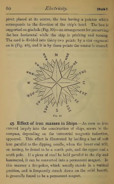
6o Electricity. [Book I.
pivot placed at its centre, the box having a pointer which
corresponds to the direction of the ship's head. The box is
supported on gimbals (Fig. 39)—an arrangement for preserving
the box horizontal while the ship is pitching and tossing.
The card is divided into thirty-two points by a star engraved
on it (Fig. 40), and it is by these points the course is steered.
Fig. 40.
45. Effect of iron masses in Ships.—As soon as iron
entered largely into the construction of ships, errors in the
compass, depending on the terrestrial magnetic induction,
appeared. This effect is illustrated by holding a bar of soft
iron parallel to the dipping needle, when the lower end will,
on testing, be found to be a north pole, and the upper end a
south pole. If a piece of steel be held parallel to the dip and
hammered, it can be converted into a permanent magnet. In
this manner a fire-poker, which usually stands in a vertical
position, and is frequently struck down on the solid hearth,
is generally found to be a permanent magnet.
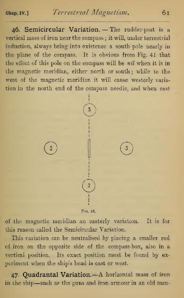
Chap. IV.] Terrestrial Magnetism. 61
46. Semicircular Variation.— The rudder-post is a
vertical mass of iron near the compass ; it will, under terrestrial
induction, always bring into existence a south pole nearly in
the plane of the compass. It is obvious from Fig. 41 that
the effect of this pole on the compass will be nil when it is in
the magnetic meridian, either north or south ; while to the
west of the magnetic meridian it will cause westerly varia-
tion in the north end of the compass needle, and when east
©
©
©
Fig. 41.
of the magnetic meridian an easterly variation. It is for
this reason called the Semicircular Variation.
This variation can be neutralised by placing a smaller rod
of iron on the opposite side of the compass-box, also in a
vertical position. Its exact position must be found by ex-
periment when the ship's head is east or west.
47. Quadrantal Variation.—A horizontal mass of iron
in the ship—such as the guns and iron armour in an old man-

62 Electricity. [Book I.
of-war, or even a cargo of iron and steel—produce by their
transient magnetism another variation in the compass. Each
mass of iron becomes a magnet, always having its magnetic
axis parallel to the meridian. The effect is seen on inspect-
ing Fig. 42. In the four positions, A,B, C, D, of the mass
—
/v
fJ
©
©Fig. 42.
i.e. at the four cardinal points of the compass—the variation
vanishes. When the magnetic mass is between^ and B—i.e.
in the north-west quadrant—the influence of the induced south
pole on the north pole of the needle preponderates, and the
variation of the north pole is west. Between B and C the
north polar influence preponderates, and the variation is east.
Between G and D, in the south-east quadrant, it is again
west, and between D and A, or in the north-east quadrant, it
chap, iv.] Terrestrial Magnetism. 63
is east. This variation, from changing its direction at each
quadrant, is called quadrant al variation. It follows that two
masses of soft iron fixed in the ship on opposite sides of the
compass always increase each other's disturbance of the needle,
but if placed so that the lines joining them to the compass
subtend a right angle, they tend to neutralise each other's
effect. To correct this variation a mass of soft iron must be
fixed near the compass in a direction at right angles to that
of the centre of the resultant disturbing mass.
48. Magnetism of Steel-plated Ships.—As soon as
ships were constructed of iron plates riveted together, it was
found that the hammering of the plates during construction
converted them into permanent magnets, the total effect of
which on the ship's compass was very large and very irregular
;
so much so that in one ship the compass varied 50° east in one
position of the ship's head, and 50° west in another. It was
found by theory, and confirmed by experiment, that the total
permanent magnetism could always be resolved into two
magnets, one along the ship's length, and the other trans-
verse to the ship. Each of these was separately corrected
by a permanent magnet fastened on the deck of the vessel.
After the first few voyages of an iron ship a considerable
amount of the magnetism obtained during construction is
lost, probably by beating about with the waves, and it is in
consequence necessary, while the ship is young, to make a
new correction for magnetism after each voyage. Very soon,
however, the ship acquires a permanent magnetic condition,
after which no further readjustment is needed.
The magnetism lost during the first few voyages is called
sub-permanent, and that retained always permanent magnetism.

QUESTIONS ON BOOK I.
1. Draw a rough sketch of the lines of force for three equal and
similar magnet poles placed at the angles of an equilateral triangle.
2. Draw the lines of force for two magnet poles of the same sign,
but one stronger than the other.
3. On twisting the torsion circle in Coulomb's balance, through 40°,
the needle is deflected from the meridian 5°. Find the torsion equi-
valent of the earth's directive action on the magnet.
Ans.—7°.
4. The earth's directive action being measured by 5° of torsion,
how far must the torsion circle be twisted round to bring the needle
to 10° ?
Ans.—60°.
5. The influence of the earth in Coulomb's balance being neutralised
by external magnets, so that the needle is under torsion only; whenthe magnet pole is introduced the needle deflects 40°. How muchtorsion must be applied to bring the needle to 20° and to 10° ?
Ans.— 140° and 630° respectively.
6. The directive action of the earth being 5°, the introduction of
the magnet causes a deflection of 40°. How much torsion must be
put on to bring the reading to 20° ?
Ans.—940°.
7. A short magnet needle suspended horizontally, and oscillating
under the earth's action only makes 21 oscillations in a minute ; whenanother magnet pole is distant 4 inches it makes 27 oscillations in the
same time. Calculate the number of oscillations it will make whenthe second pole is distant 2 inches.
Ans.—40 per ]/ nearly.
8. A short suspended magnet, oscillating under the earth's force,
makes 35 oscillations in a minute ; when a south pole is placed in the
meridian to the north of it, it makes 45 oscillations in the same time.
How many oscillations per minute will it make if the pole be placed
at the same distance to the south of it?
Ans.—21 per 1/ nearly,
64
Questions on Magnetism. 65
9. A needle makes 29 oscillations per V when a south magnet pole
is 8 inches to the south of it, and 50 oscillations when the same pole is
4 inches to the north of it. Find how many oscillations the needle will
make when under the earth's influence only.
A>rs.—34 oscillations per 1' nearly.
10. Two magnet needles of equal size and weight, freely suspended,
under the earth's action, make 40 and 36 oscillations respectively in
the same time. Compare their magnetic strength.
Ans.—Ratio of 1 to -81.
11. Two magnets 14 and 16 centimetres long, placed east and west
of a suspended needle, with their nearer poles 7 and 8 centimetres
respectively from the point of suspension, just balance each other.
Compare the strengths of their poles.
Ans.—49 to 64.
12. Two equal magnet poles, placed 3 centimetres apart, exert on each
other an attraction of 4 units. Find the strength of the poles in
absolute measure.
Ans.—Each of strength 6.
13. Two magnet poles, whose strengths are in the ratio 3 to 2 whenplaced 10 centimetres apart, exert a force of 24 units. Find the
strength of each pole in absolute measure.
Ans.—60 and 40.
14. Two magnets, the strengths of whose poles are 8 and 12, are
placed in the same straight line, with opposite poles facing each other,
at a distance of 4 centimetres. If the magnets are respectively 12
and 16 centimetres long, find the magnetic attraction between them.
Ans.—5*5 units nearly.
15. The same magnet needle, suspended horizontally under the
earth's action, makes at two places 101 and 103 oscillations in the
same time. Compare the horizontal component of the earth's mag-netism at those places.
Ans.— 1 to 1*04 nearly.
16. A short magnet, suspended horizontally, makes 29 oscillatious
in a minute ; when a south pole is placed 4 centimetres from it on the
north side, it makes 39 oscillations in the same time. Compare thestrength of this pole with the horizontal component of the earth's
magnetism. Explain fully what is meant by this comparison.
Ans.—12 9 to 1 nearly.
E

BOOK II.
FRICTIONAL ELECTRICITY.
CHAPTER L
ELECTRIFICATION.
49. Definition of Electricity.—There are certain bodies
which, when warm and dry, acquire by friction the property
of attracting feathers, filaments of silk, or indeed any light
bodies towards them. This property is called Electricity,
and bodies which possess it are said to be electrified. The
ancients were acquainted with it only in amber, the Greek
name for which (rjXeKrpov) is the origin of the term Electricity.
Dr. Gilbert, physician to Queen Elizabeth, seems to have been
the first who noticed the same property in other bodies, and
we shall see reason to believe that any two bodies whatever
of different structure, when rubbed together, develop elec-
tricity to a greater or smaller extent
To exhibit this property all the apparatus employed must
be kept warm and dry : With this precaution, absolutely
necessary in all experiments on the present subject, it is easy
to exhibit electricity in a very great variety of bodies. Glass
rubbed with silk, sealing-wax rubbed with flannel, vulcanite
or ebonite rubbed with any woollen material, or with silk,
67

68 Electricity. [Book II.
common writing-paper well warmed and rubbed with a bristle
clothes-brush—all manifest electricity by picking up feathers,
scraps of paper, silk fibre, or other light materials.
50. Means of detecting Electricity.—If we present
an electrified body to a pith-ball pendulum—that is, a pith
ball suspended by a silk thread—it is
first drawn towards the excited body,
and, immediately after contact, repelled,
for a reason which we shall see pre-
sently. A skeleton-ball pendulum (Fig.
43) made of narrow strips of gilt paper,
will answer equally well. A light lath
(Fig. 44), about a metre long, poised
on the convex surface of an egg or a
watch-glass, will follow the movements
of the excited body round a complete
circle. These and other arrangements
described later for detecting the presence of electricity are
called Electroscopes.
If the body electrified be very light, it will cling to other
bodies to which it is presented. The paper excited by a
clothes-brush will be found to cling with some force to the
table on which it was laid while being excited by brushing;
on removal it clings to the hands of the operator, and may
be made to cling to the walls of a room, or any other flat
surface.
51. Action of Electrified Bodies on each other.—To investigate the action of electricity on other electricity, we
will excite by friction a rod of sealing-wax, and either poise it
on a convex surface, like the lath electroscope, or suspend it
Fig. 43.
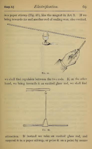
Chap. I.] Electrification. 69
in a paper stirrup (Fig. 45), like the magnet in Art. 3. If we
bring towards its end another rod of sealing-wax, also excited,
Fig. 44.
we shall find repulsion between the two rods. If, on the other
hand, we bring towards it an excited glass rod, we shall find
AFig. 45.
attraction. If instead we take an excited glass rod, and
suspend it in a paper stirrup, or poise it on a point by means

7o Electricity. [Book II.
of a dimple blown in its surface (Fig. 46), we shall find it
attracted by excited sealing-wax, but repelled by excited
glass.
52. Vitreous and Resinous Electricity. — This
teaches us that there are two different kinds of electricity
:
Fig. 46.
one developed in glass when excited by silk, called Vitreous
or Positive electricity (written + E.) ; another developed in
sealing-wax when excited by flannel, which is called
Eesinous or Negative electricity (written — K). The experi-
ments also show that like electricities repel, but unlike
electricities attract, each other.
The suspended glass and sealing-wax rods when excited
may be used to detect the kinds of other electrifications ; for
a body, if unelectrified, will attract both rods when presented
to them in turn, but an electrified body will attract one and
repel the other, as its electricity is of the opposite or of the
same name. Thus paper electrified by rubbing with india-

Chap. I.] Electrification . 71
rubber will be found to have a charge of vitreous electricity,
and the india-rubber will have a charge of resinous electricity.
If a silk ribbon (Fig. 47), a foot or a foot and a half long,
after being rubbed several times over a glass rod, is folded
in the middle, the two halves repel each other, being similarly
excited by the glass, and, if suspended,^^
remain for some time divergent. This~~
\
may be used as an electroscope, for on
bringing near from below a negatively-
electrified body (an excited rod of sealing-
wax, for instance), the ribbons diverge
further, they being negatively electrified
;
and, conversely, on bringing near a
positively electrified body they collapse.Fig. 47.
In the same manner, if a sheet of paper, before it is excited, be
cut up into narrow strips, only held together along one edge,
after excitement the strips show a violent repulsion, curling
up away from one another.
53. Conductors and Non-Conductors or Insulators.
--There is a class of bodies, of which the metals are the best
Fig. 48.
examples, which do not show any sign of electrification when
excited by friction. This is the case with a brass rod held in
7 2 Electricity. [Book n.
the hand, and rubbed with a cat's fur or a silk handkerchief.
If, however, the brass rod be supported on a handle of glass
(Fig. 48) or ebonite, we shall find that, holding it by its handle,
and rubbing it, it is immediately excited, and on testing is
found to be charged with negative electricity. On touching
the excited brass with the finger, or with another metal body
in connection with the earth, all signs of electricity instan-
taneously disappear. We see therefore that the metal is
capable of excitement like the other bodies we have con-
sidered ; but the reason we do not observe it when held in
the hand and excited is, that the electricity is drawn away by
the hand as fast as it is generated. Bodies such as these are
called Conductors ; while other bodies, such as glass and seal-
ing-wax, which do not carry away the electricity as fast as it
is generated, are called Non-conductors or Insulators. These
latter, which can be excited when held in the hand, used to
be called Electrics, and those like the metals, which were not
so excited, were called Non-electrics. These terms, however,
are now misleading, and had better be abandoned.
Different bodies have very different powers of conducting
electricity, all being intermediate between an ideal perfect
conductor and perfect non-conductor. The best conductors
are the metals, and the best solid non-conductor is said to be
gum-lac. For our present purpose it will be sufficient to notice
that such bodies as the following are, next to metals, the best
conductors : Charcoal, graphite, water, mineral and vegetable
substances (chiefly owing to the large amount of water they
contain), and linen and cotton fibres. The best non-conduc-
tors or insulators after gum-lac are sealing-wax, glass, resin,
sulphur, silk, paper, and caoutchouc. These are roughly in
order of their powers of conduction and insulation respec-
chap, i.] Electrification. 73
tively. It is doubtful how far air and gases are conductors
in the proper sense of the word, but it is important to notice
that dry air acts as an insulator of ordinary charges, while
damp air allows the charge to pass away, though this effect is
probably clue to the film of moisture formed on the surface of
the insulating supports of electrified bodies, and this liquid
film is certainly an excellent conductor. In the case of liquids
also we have mercury and the fused metals, which conduct
well, and, just like the metals ; aqueous solutions of acids and
salts are fair conductors; pure water, alcohol, ether, are
semi-conductors ; while carbon bisulphide is a good non-con-
ductor, though in these, excepting the metals, it is doubtful
how far conduction is separated from another action (electro-
lysis), which we shall discuss later on.
Conduction in bodies is also affected by temperature. Some
bodies which are insulators when cold become conductors when
heated to fusion, or even considerably below fusing-point.
This is the case with glass.
54. Effect of Damp or Dry Atmosphere.—We can
now understand the necessity for drying and warming our
apparatus, insisted upon above. Warming the air of a room in
which experiments are performed dries the air, by removing
it further from its dew-point, while warming the apparatus
above the temperature of the air prevents the formation of
the film of water on the insulating supports. Paper, being
very hygroscopic, must be thoroughly dried by holding it
before the fire for a minute or so, in order to drive out the
moisture before it can be electrified.
55. Gold-leaf Electroscope.—The instrument most

74 Electricity. [Book II.
covered with
commonly used for investigations in electricity is the Gold-
leaf Electroscope. This consists of a brass
rod (A) fastened to the centre of a brass
circular cap (JB), and having at its other end
two strips of gold leaf (CC), which, when
the instrument is unelectrified, hang down
parallel to each other. This apparatus is in-
sulated by supporting the cap on a glass
tube (Z>), well varnished, which surrounds
the brass rod. The tube is cemented into
the top of a glass bell-jar (E). Two strips of
tinfoil (FF) usually run from the base of
the glass bell up to the level of the gold
leaves. The base is of wood, sometimes
tinfoil, and usually supports a cup of
sulphuric acid, or calcium chloride, to maintain dryness in
the air.
On touching the cap of the electroscope with excited glass
or sealing-wax, we communicate a charge which causes the
gold leaves to diverge exactly like the excited silk ribbons in
Art. 52. Otherwise a negative charge can be communicated
by simply flapping the cap slightly with a silk handkerchief,
affording another illustration of the electrification of an insu-
lated conductor by friction. Further, when we have charged
the electroscope, say with positive electricity, on bringing an-
other positively electrified body near to its cap, we observe
that the leaves diverge further : this is because the positive
electricity tends to repel like electricity from the cap into
the leaves, causing in this manner further divergence. In
the same manner, on bringing a negatively electrified body
the leaves are observed partly to collapse. In thisnear,
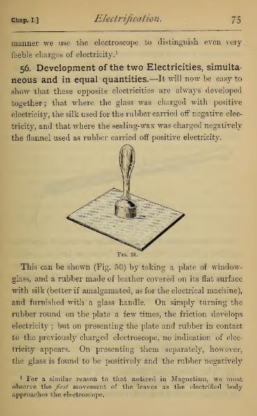
Chap, i.] Electrification. 75
manner we use the electroscope to distinguish even very-
feeble charges of electricity. 1
56. Development of the two Electricities, simulta-
neous and in equal quantities.—It will now be easy to
show that these opposite electricities are always developed
together; that where the glass was charged with positive
electricity, the silk used for the rubber carried off negative elec-
tricity, and that where the sealing-wax was charged negatively
the flannel used as rubber carried off positive electricity.
Fig. 50.
This can be shown (Fig. 50) by taking a plate of window-
glass, and a rubber made of leather covered on its flat surface
with silk (better if amalgamated, as for the electrical machine),
and furnished with a glass handle. On simply turning the
rubber round on the plate a few times, the friction develops
electricity ; but on presenting the plate and rubber in contact
to the previously charged electroscope, no indication of elec-
tricity appears. On presenting them separately, however,
the glass is found to be positively and the rubber negatively
1 For a similar reason to that noticed in Magnetism, we mustobserve the first movement of the leaves as the electrified bodyapproaches the electroscope.
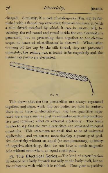
76 Electricity. [Book II.
cliarged. Similarly, if a rod of sealing-wax (Fig. 51) be fur-
nished with a flannel cap extending three inches down it (with
a silk thread attached by which it can be drawn off), by
twisting the rod round and round inside the cap electricity is
generated ; but on presenting them together to the electro-
scope, no trace of electrification is observed. When, after
drawing off the cap by the silk thread, they are presented
separately, the sealing-wax is found to be negatively and the
flannel cap positively electrified.
Fig. 51.
This shows that tlie two electricities are always separated
together, and since, while the two bodies are held in contact,
there is no trace of electrification, the two quantities sepa-
rated are always such as just to neutralise each other's attrac-
tive and repulsive effect on external electricity. This leads
us also to say that the two electricities are separated in equal
quantities. This statement we shall find to be of universal
application ; and we can no more develop a quantity of posi-
tive electricity without an equal (or complementary) quantity
of negative electricity, than we can have a north magnetic
pole without somewhere an equal south pole.
57. The Electrical Series.—The kind of electrification
developed on a body depends not only on the body itself, but on
the substance with which it is rubbed. Thus glass is positive

chap, i.] Electrification. 77
when rubbed with silk, and negative when rubbed with the
fur of the living cat. Minute differences in the surface texture
of the substances rubbed leads to an electrical separation on
rubbing. Thus white and black silk, when rubbed together,
show a separation of electricity\probably due to a difference
in surface caused by the dye ; rough and smooth glass, when
rubbed together, leave the smooth positively and the rough
negatively electrified ; and even two pieces of ribbon cut from
the same piece, if drawn over each other, the length of one
across the breadth of the other, will show a separation of
electricities. The fur of the living cat, and, according to
Clerk-Maxwell, that of the living dog, is found to be positive
to a dressed cat's fur.
If we have any three substances (A, B, C), and find by
experiment that A carries away positive electricity when
rubbed with B, and B positive electricity when rubbed with
C, we shall always find A positive to C when they are rubbed
together. In performing the experiment care should be taken
that all the bodies are neutral, to begin with. Suppose, for
instance, that A, on being rubbed by B, left B with a high
charge of negative electricity, the effect of rubbing B and Cmight then be only to divide B's charge between B and C,
which would then both be found negative.
On this ground it is possible to arrange any given sub-
stances in an electric series, such that each member of the
series is positive to all that come after it, but negative to all
that go before it. From what we have just said, it will be
clear that the order of the series will not be the same for all
samples of nominally the same substance, and thus irregu-
larities occur. Thus it is generally stated that cat's fur stands
at the head of this series, but the present writer has found
78 Electricity, [Book 11.
certain cleavage planes in calcite to be positive to the fur
of at least one living cat, and has found specimens of glass
positive to some dressed furs. The series given by different
authors consequently differ a good deal ; that which we
supply here must therefore be understood as only true in a
general way, with such limitations as we have noticed. It
is that obtained with the substances generally used by the
present writer.
+Catskin. Metal.
Smooth Glass.
The Hand.
( Caoutchouc.
t Planed Dealboard
Paper.
Flannel.
Silk.
Roughened Glass.
Cork.
Ebonite.
Sealing-wax.
Sulphur.
Vulcanised India-
rubber.
58. Electrification by Pressure and Cleavage.—
There are other methods besides friction of causing electrical
separation. We do not at present refer to electricity de-
veloped by contact in metals, or by chemical decomposition,
or by heating the junction of two metals. If two non-con-
ductors be simply pressed together, and suddenly separated,
they will be found to be electrified. This is easily shown by
pressing a cork supported on a glass handle down on to a
piece of indiarubber, or even on to a piece of orange-peel.
Many minerals show an electrical separation on cleavage.
If a block of mica be held by two insulating handles, and
separated along cleavage planes, the flakes will be found to be

chap, l] Electrification. 79
electrified. The same thing appears on breaking up roll-
sulphur. If the sulphur be supported on an insulating pad,
a piece of india-rubber for instance, and be broken over an
electroscope by smart taps of a hammer, the fragments which
fall on the cap will generally make the leaves diverge. For
the same reason, lump sugar, when broken in the dark, often
shows a phosphorescence, due to the reuniting of the electri-
cities separated by the fracture.
59. Pyro-Electricity.—There is also another mode in
which electricity is developed, namely, when certain badly
conducting minerals are heated or cooled. This is termed
pyro-electricity. It is most strongly shown in tourmaline
Fig. 52.
crystals which have the facets at the opposite ends of the
crystal differently arranged (Fig. 52). The specimen should
be suspended in a stirrup of fine wire over a metal plate
warmed by a spirit lamp. Very soon one end will show
positive, and the opposite negative, electricity, and this will
continue as long as the temperature rises, till it reaches a
temperature of about 350° C, when all trace of electricity
ceases. On removing the plate, and passing the lamp flame
over the crystal to discharge its electricity, and then allowing
it to cool, that end which was positive when being heated
becomes negative while being cooled, and vice versa. The end
80 Electricity. [Book n.
which is positive while being heated is called the analogue,
and the opposite the antilogue, pole of the crystal. Suitable
crystals are rare, but specimens in the form of long needles
may be met with, which show pyro-electricity faintly, and
especially while cooling, when observation can be more easily
made. In Fig. 52 the left-hand drawing showing the terminal
with fewest facets is the analogue, and the right-hand draw-
ing is the antilogue pole.
No physical theory has yet been propounded to account for
the electrical separations we have noticed. We may, per-
haps, point out that they all seem dependent on a molecular
strain in the molecules of different bodies when brought into
very close contact by friction or pressure. The electrification
by cleavage or heating in crystals may be referred to a similar
cause, if we remember that in many crystals the arrangement
of the molecules is such that their expansion by heating and
all physical properties are different in different directions.
In these, either cleavage or heating may establish a state
of molecular strain which is accompanied by a separation of
electricity. If the crystal is a conductor, the separated
electricities of course immediately unite again, and the phe-
nomenon cannot be observed.
We have, as in Magnetism, purposely avoided all reference
to the various one and two fluid hypotheses, which were useful
only in the infancy of those sciences.
CHAPTER II.
THE FIELD OF ELECTRIC FORCE.
60. The Electric Field.—We must now proceed to
consider the laws of attraction and repulsion of electrified
bodies, just as we did in Magnetism. We have seen that if we
have a distribution of electricity, and an electrified body be
brought near it, this latter will experience mechanical force.
Just, then, as the air space round a magnet showed us a field
of magnetic force, so the air space round an electrified body
shows us a field of electrical force. To the air or other
medium across which electrical forces are displayed, Faraday
gave the name dielectric. It will simplify matters if we
use for exploring the field of force a very small sphere,
carrying always the same charge of electricity, and we may
then assume that the action on this sphere is the same as if
all the electricity were collected at some point within it,
probably near its centre. We will suppose this an unit charge,
and assuming the electrification positive, we will call it a
plus unit (written + unit). At every point in the field of
force there will be a certain definite direction in which the
+ unit put there will be urged, and this direction is called
the line of force through that point. The whole field may
therefore be mapped out into lines of force, which, as in
Magnetism, cannot intersect each other. There will also be
a certain force with which the + unit is urged along the line
of force at each point in the field, and this force is called the
F
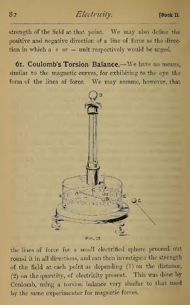
82 Electricity. [Book II.
strength of the field at that point. We may also define the
positive and negative direction of a line of force as the direc-
tion in which a + or — unit respectively would be urged.
61. Coulomb's Torsion Balance.—We have no means,
similar to the magnetic curves, for exhibiting to the eye the
form of the lines of force. We may assume, however, that
the lines of force for a small electrified sphere proceed out
round it in all directions, and can then investigate the strength
of the field at each point as depending (1) on the distance,
(2) on the quantity, of electricity present. This was done by
Coulomb, using a torsion balance very similar to that used
by the same experimenter for magnetic forces.

cmap. il] The Field of Elective Force. 83
The torsion balance (Fig. 53) consists of a glass needle (A)
carrying at one end a gilt ball (j5), and at the other a counter-
poise, suspended by a fine wire (C), which is often a single
capillary fibre of glass, attached to a torsion circle (D) above,
the circle having a graduated rim by which the twist put on
to the wire may be measured. The needle moves in a glass case
(E), whose surface is graduated, the suspension of the needle
being in the centre of graduations : by its means the movement
of the needle may be read. In the upper part of the case there
is a hole through which an insulated gilt ball (F) (the carrier
ball), of the same size as the needle ball, may be introduced
and placed in contact with the needle ball. Another in-
sulated gilt ball (G) (the divided-charge ball), equal to the
carrier and needle balls, and supported on an insulating stem,
is required in the course of the experiment. The base is
supported on levelling screws, by which the suspension of the
needle is brought to the centre of the graduations on the case.
Within the case is placed a vessel with drying material as in
the gold-leaf electroscope.
When the whole system is unelectrified, the needle ball
rests in the place which the carrier ball will occupy when in
position ; the wire being without torsion, and the needle and
pointer each at its zero of graduation.
62. Law of Action at different Distances.—Onelectrifying the carrier ball, and introducing it, there is at
first attraction, but after contact repulsion, of the needle ball.
We will suppose it to be repelled, and to come to rest at 72°.
The torsion on the wire is also 72°. To bring the needle back
to 36°, it will be found necessary to turn the torsion circle
backwards through about 250°. The repulsion at 36° will
84 Electricity. [Book n.
then be 250° + 36°= 286°, which we notice to be very nearly
4 x 72°. Thus we learn that the repulsion at 36° is four times
that at 72°. To bring the needle to 24°, we must still turn
the torsion circle backwards through one complete revolution,
and 260° additional. The total torsion is then 360° + 260° +
24°= 644°, which is nearly 9 x 72°.
This will be sufficient to suggest the law of inverse squares,
as that holding between two small electrified spheres placed
at different distances from each other. In most instruments
the torsion, when the needle and carrier balls are within 20°
of each other, becomes less than this theory requires, the
reason being that the electricities on the two balls mutually
repel each other towards the more remote sides of the balls,
and they in consequence act on each other at a distance some-
what greater than the distance of their centres.
We may infer that the strength of the electrical field, due
to a quantity of electricity condensed in a point, is inversely as
the square of the distance from the electrified particle, i.e. if
distances be taken respectively as 1, 2, 3, . . . etc., the forces
at those distances will be as 1, J, -§-, . . . etc,
63. Law of Action with different Quantities.—Wehave seen nothing at present enabling us to measure quantities
of electricity, but if we have two equal spheres, one charged
with electricity, and the other insulated and neutral, we
may assume that on bringing them into contact the charge
will be divided equally between them. Thus, in the above
experiment, when the carrier ball touched the needle ball
the charge was equally divided between them, and we
were therefore investigating the force between two equal
charges. After turning back the torsion circle to its 0°, let us

chap, il] The Field of Electric Force. 85
remove the carrier ball, and halve its charge by simple contact
with the equal divided-charge ball. Keintroduce it into the
instrument, carefully avoiding contact with the needle ball
(this may be done by turning the torsion circle through
about a quarter of a revolution), and regulate the torsion
circle till the needle again stands at 72°. It will be found
that the torsion circle stands at 36°, and the torsion on the
wire is (72°— 36°)= 36°. Hence we see that the repulsive
force is halved on halving the charge in the carrier ball.
If we halve again the charge in the carrier ball, the torsion
circle must be twisted through 54°, and the torsion is there-
fore (72° -54°)= 18°, which is one fourth of its first value
—
when the charge of one of the balls is divided by four. Lastly,
take out the carrier ball, and discharge by contact with the
finger. On reintroducing it, the needle ball is attracted, and
divides its charge with the carrier ball, so that each ball has
half of its original charge. We shall then find that the torsion
necessary to keep the balls at 72° is 18°, or Jx^of that
when each charge was unity.
From these experiments we may infer that the force at
equal distances between two charges of electricity condensed
in points is proportional to the product of the quantities, and
that the strength of the field at a given distance from a charge
condensed in a point is proportional to the charge.
*64. Absolute Measure of Electricity.—We may nowexplain how electrical quantities may, like magnetic, be
measured in terms of the absolute system of units, explained
in Appendix I. Thus we shall assume one absolute unit of
electricity to be such a quantity that, when condensed in a
point, it exerts unit force on another equal quantity placed at

86 Electricity. [Bookii.
unit distance. We can then express the force between two
quantities q and q' condensed in points at distance D cm. apart
t>y 2^> an(l the strength of field at a distance Dfrom a quan-
tity q condensed in a point by -2-.
Coulomb, by vertical stops which prevented the needle
swinging back to zero, showed identically the same laws to
hold for the attraction between two quantities of electricity
of opposite sign.
65. Use of the Proof-Plane.—Returning to our funda-
mental experiment of the attraction and subsequent repulsion
by an electrified body of any light conducting body, we can
^ggg^ggg^ggg*^^
Fig. 54.
see that if we insulate by a glass handle a small gilt ball or
paper disc, and apply it to the surface of an electrified body,
it will, on removal, carry away some of its electricity, which
may be tested by a charged electroscope at a distance. Wemay, in this manner, test the electrification of a body too
feebly electrified to show directly attractions and repulsions.
Such an instrument was called a Proof-Plane by Coulomb, and
has since his time been widely used in testing electrification.
It may be noticed that what we test by the proof-plane is
really the strength of the electric field close to the point on
the conductor at which it is applied, for this, and this only,
determines the quantity of electricity which shall be repelled
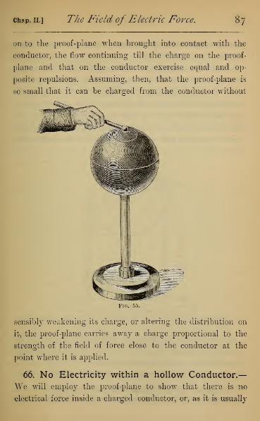
chap, ii.] The Field of Electric Force. 87
on to the proof-plane when brought into contact with the
conductor, the flow continuing till the charge on the proof-
plane and that on the conductor exercise equal and op-
posite repulsions. Assuming, then, that the proof-plane is
so small that it can be charged from the conductor without
Fig. 55.
sensibly weakening its charge, or altering the distribution on
it, the proof-plane carries away a charge proportional to the
strength of the field of force close to the conductor at the
point where it is applied.
66. No Electricity within a hollow Conductor,—We will employ the proof-plane to show that there is no
electrical force inside a charged conductor, or, as it is usually

88 Electricity. [Book II.
expressed, that electricity resides only on the outside of a con-
ductor.
Let us take an insulated hollow sphere (Fig. 55), or con-
ductor of any shape, with a small circular aperture, through
which the proof-plane may be easily introduced. Charge the
conductor, 1 and charge with the same kind of electricity a
gold-leaf electroscope at a distance. On testing with the
proof-plane we find indications of a charge, on any external
point, but on any part of the interior surface no charge what-
ever.
Fig. 56.
Otherwise take an insulated sphere (A), having two in-
sulated hemispheres (BC), which envelop A, but are separated
from it by an air-space (shown in section in Fig. 56) Let Abe charged, and the hemispheres adjusted carefully without
1 In this and the following experiments the charging of the con-
ductors, but not of the electroscope, is done from an electropliorus.

chap, ii.] The Field ofElectric Force. 89
contact with A ; then lift by its silk thread the metal wire D,
and drop it through the aperture E in JB, until it just rests on
A, and then remove it again. On removing B and (7, A will
be found to be completely discharged, the charge having been
by contact transferred to the external hemispheres.
Again, if we test the outside and inside of a hollow electri-
fied cylinder, we shall find the inside charge insensible every-
where except very near to the edge. This will be true even
if the cylinder be made of wire gauze with very large meshes.
Faraday used an insulated cotton gauze bag, similar to a
Fig. 57.
butterfly-net, fitted to a wire rim for support, and fastened on
to a glass stem, the end of the bag being furnished with a
silk thread passing through both sides, by which the bag
could be turned inside out at pleasure. After charging he
showed by the proof-plane that there was no sensible electri-
fication on the inside. He then by the silk thread turned
the bag inside out, showing again that there was no trace of
electrification on the inside surface.

go Electricity, [Book II.
Faraday also constructed a cubical chamber, twelve feet
wide, formed of a slight wooden framework, with copper wires
passing along and across it in various directions, and then
covered it with paper in close proximity to the conducting
wires, and pasted bands of tinfoil over it in every direction.
This chamber was insulated, and put in connection with a
Fig. 58.
powerful electrical machine, which was worked for some time.
He then says :—"I went into the cube and lived in it, and
using lighted candles, electrometers, and all other tests of
electrical states, I could not find the least influence upon them,
or indication of anything particular given by them, though all

chap, ii.] The Field of Electric Force. 9
1
the time the outside of the cube was powerfully charged, and
large sparks and brushes were darting off from every part of
its outer surface."
We may imitate this experiment by placing a metal wire
cage over a gold-leaf electroscope supported on a metal plate,
which is insulated with a pad of india-rubber (Fig. 58). Wemay either leave the electroscope free or connect its cap by a
wire with the outside surface of the cage ; but on electrifying
the cage, the leaves of the electroscope will not diverge, as we
have seen they always do when the instrument is placed in a
field of electric force.
67, Electrical Density, — These experiments show us
that the field of force only exists in the dielectric surrounding-
electrified conductors, and does not extend inside them.
They show not only that there is no electricity within the
conductor, but also that the external electrification is so dis-
tributed that the resultant force at every internal point
vanishes. The older theorists, assuming that electricity was
of the nature of a material but weightless film investing the
conductor, set themselves to discover the law of density of
such a film that the condition thus stated might be true, and
there came into use the term Electrical Density at a point on
a conductor. We may use the term to denote the quantity
of electrification per unit area on a charged conductor, and this
implies no material idea of electricity, while our definition of
quantity implies none. The term, moreover, is convenient,
since we can clearly have the same quantity of electricity on
a sphere of one inch or of one foot radius, and the densities
of the distributions must thus be inversely as the surfaces of
the spheres, or as 144 to 1. It follows, too, theoretically, as a

92 Electricity. [Book II.
consequence of the general law of distribution stated above,
that the force close to any point on an electrified conductor is
proportional only to the density of the electrification at that
point. 1 Hence for our purpose it matters little whether we
speak of the force near a point on an electrified conductor, or
the density of the electrification at the point.
Although we cannot lay down the law of density of distri-
bution on a conductor, we can by the proof-plane show some
Fig. 59.
of its more general properties. To obtain numerical results
we must employ the Torsion Balance, charging independ-
ently the needle ball • after touching with the carrier ball a
certain part of the conductor, introduce it into the balance,
as before carefully avoiding contact, and observe the torsion
necessary to give a certain fixed deflection. This torsion
1 Cumming's Introduction to the Theory of Electricity, Art. 62.

chap, ii.] The Field of Electric Force. 93
measures the quantity on the carrier ball, and is therefore a
measure of the electrical density, which can be compared at
as many points as we please.
It is, however, sufficient to show the more general laws by
the proof-plane and gold-leaf electroscope. If we test a sphere,
we shall find that its electrification has the same density at
every point, 1 as might have been expected from its shape.
For other conductors it will be found that the density at points
and angles is very high ; that at the flatter portions small
;
while within hollows and cavities it almost wholly disappears.
If for the density we substitute depth of a liquid film
supposed homogeneous, we may represent to the eye the
depth of the imaginary electric stratum by the diagram (Fig.
59), which show it approximately for a sphere, a cone, and a
hollow hemisphere.
68. Electrical Potential. — Let us next connect the
proof-plane by a long wire with a gold-leaf electroscope at a
distance (Fig. 60), and touch in succession various parts of any
of the conductors we have been experimenting upon. Weshall observe that for every point on or within each of these
conductors there is a certain fixed divergence of the leaves
which never alters, whether the proof-plane be applied to
places of high or low density. This divergence depends on
the electrification of the conductor as a whole, and we will for
the present define it as the potential of the conductor, the ex-
periment showing that all points on the conductor are at the
same potential. This indication is of course the potential of
1 Cavendish pointed out, more than a hundred years ago, that a dis-
tribution of electricity of uniform density over a sphere would give
no force on an electrified particle placed within it, if the law of elec-
trical action were that of the inverse square of the distance, and on noother law of action whatever. This must be regarded as the mostrigorous proof we possess of this law.

94 Electricity. [Book II.
the cap and leaves of the electroscope, and although this
instrument is not adapted to give numerical measures, we can
speak of a higher and lower potential according as the diverg-
ence of the leaves is greater or less. When the leaves diverge
with negative electricity we have negative potential, which
may have a greater or less value.
69. Capacity of a Conductor.—Take the hollow sphere
having an aperture in its surface, and connect it with the
distant electroscope. If we bring successive charges by means
Fig. 60.
of a small insulated sphere or proof-plane, and introduce them
through the aperture, on touching the inner surface the charge
is given up to the sphere, and the proof-plane can be with-
drawn uncharged. We now observe that the potential shown
by the divergence in the gold leaves goes on rising with the

chap, ii.] The Field of Electric Force. 95
charge, and we shall assume that the potential is proportional
to the charge, so that for each conductor there is a fixed ratio
between the charge and the potential, which fixed ratio is
called the Capacity of the Conductor. If, then, we are able
to obtain a numerical measure of the potential in terms of a
suitable unit; for any given conductor, if Q represent the
charge, V the potential, and C the capacity, we shall have
The capacity, so far as a conductor insulated in a large
room is concerned, depends only on the shape and size of the
conductor, but we shall learn presently that it depends also
on the neighbourhood of other conductors. That the capa-
city depends on the form, and not only on the size of the
conductor, may be shown by choosing two conductors of the
same surface and very different forms ; a sphere composed of
two separable hemispheres (see Fig. 56), and one of the
separate hemispheres answers well, since in the hemisphere
both the outer and inner hemispheres become external.
Charge one hemisphere and test its potential by connecting
it with a distant electroscope. Then bring up the second
hemisphere, and fit the two together without discharging,
and you have the same quantity of electricity as before dis-
tributed over the same surface, the inner surface now not
being electrified. It will be found, nevertheless, that the
gold leaves have collapsed somewhat, proving that for equal
charges the potential of the sphere is lower than the hemi-
sphere, or that the capacity of the sphere is greater than that
of a hemisphere of the same total area.
70. Potential Experiments with the Gold-Leaf
Electroscope.— TTe can now examine more fully the

96 Electricity. [Book II.
action of the Gold-leaf Electroscope, especially with re-
ference to the function of the tinfoil strips, which are
attached to the glass case opposite to the gold leaves. Wewill at present assume that the whole base is covered with tin-
foil in contact with strips, and that it extends outside the
glass case by passing under it, as shown in section, in Fig. 61.
We will now insulate the electroscope, and connect the cap
with the base by strips of tinfoil outside the case (Fig. 62).
c
r
Fig. 61. Fig. 62.
We shall now find, however highly we electrify the cap, there
is no divergence of the gold leaves. The effect of joining, by
the conducting tinfoil, the base and the cap is to bring them
all to the same potential. We learn, therefore, that the leaves
ivill not diverge unless the base and cap are at different potentials.
To illustrate this further, remove the connecting strips, and
charge, say with + electricity the base, leaving the cap un-
charged ; the leaves now diverge with — electricity. Next
give a charge to the cap, and if it be of the right strength, the
leaves collapse, since the base and cap are brought to the
same potential. If the last charge be too strong the leaves
chap. II.] The Field of Electric Force. 97
diverge with + electricity. By giving alternate charges to
the base and cap we shall find that the leaves may diverge
with + or — electricity, though both cap and base are charged
positively, just as the potential of the cap is higher or lower
than that of the base.
71. Electrical Force requires varying Potential.—
These experiments teach us that we can only have electrical
force exhibited in a region in which the potential changes
as we go from one part to another. In the last experiment
the mechanical force which caused the leaves to diverge was
exerted because a positive electrification tends to move from
places of higher towards places of lower potential ; and vice
versa, negative electricity tends from places of lower towards
places of higher potential. Every field of force therefore is a
region of varying potential, but the space inside an electrified
conductor, in which, as we have already seen (Art. 66), no
divergence in the leaves of an unelectrified electroscope takes
place, must be a region of uniform potential.
We may point out two useful analogies which these experi-
ments suggest. First, that of temperature, in which a flow of
heat takes place from hotter to colder bodies, i.e. from bodies
at higher towards those at lower temperature. In this case
heat is analogous to electricity, and temperature to potential,
no exchange being apparent if the bodies are at equal tem-
peratures. Secondly, that of level in gravitation—a liquid
(water, for example) always tends to flow when a channel is
opened from places of higher towards places of lower level, in
which case level is analogous to potential, and water to elec-
tricity, there being no flow of water between two reservoirs
at the same level.
G

CHAPTER III
ELECTRICAL INDUCTION
72. Electrification induced on an Insulated Con-
ductor.—If we introduce an insulated unelectrified body into
a field of force, we find a separation of electricities by induc-
tion similar in general character to magnetic induction.
Fig. 63.
Thus if A (Fig. 63) be a body electrified, say positively,
and BG an insulated unelectrified body, we shall find on testing
BG with a proof-plane that there is a charge of negative
electricity at B and of positive electricity at G. If we pass
from B or (7, testing with the proof-plane at each step, we
shall easily see that the density diminishes continually,
until at an intermediate point it vanishes. Such points of

Chap. III.] Electrical Induction. 99
neutral electrification form a neutral line round BC. We thus
see that the electrification of A acts on the conductor BC,
separating its electricities, drawing electricity of opposite name
towards i>, and repelling electricity of like name towards G.
We infer that every electrical charge tends to separate
electricity in all surrounding conductors, drawing to the parts
nearest to it electricity of opposite name to its own, and
repelling to the most remote part electricity of like name.
+ + +„-H-4-4--J- + + + + 4-
Fig. 64.
It is easy to see that these induced charges are able to
cause fresh separations by induction in other bodies, as may
be seen if we bring BE (Fig. 64) near to (7, when we shall
find negative electricity towards D and positive towards E.
If BC be divisible into two parts by a plane through its
middle (Fig. 65), enabling us to separate B and (7, while
keeping them insulated, we shall find that B carries away a
negative charge and C a positive charge.
We thus see that from a given electrical separation we can
by induction make fresh separations in other conductors
without limit, and this principle is used in many machines

lOO Electricity. [Book II.
for generating electricity. It might at first sight appear
that in obtaining an unlimited amount of electrical sepa-
ration from a small initial separation we have a breach of
the general law of conservation of energy. Such is not the
case, however, since, in separating B and C in the foregoing
illustration, just as much energy is expended as would have
produced in any other way the separation in question.
Fig. 65.
If, while BG is under induction, we test in the manner of
Art. 68 its potential, we shall find it to be the same through-
out, just as for a charged body. This potential is found to
be lower than that of the charged body A, but nearer to Athe nearer BO is brought to A. The function of the induced
negative charge at B is to keep down the potential where it
would be too high, and that of the + charge at C to keep up
the potential where it would be too low.
We can now see that the attraction of light bodies in our
earliest experiments was itself a consequence of induction.
These bodies had a charge developed, in them by induction
opposite to that of the inducing body on the side next
chap. in.
]
Electrical Induction. io i
to it. The attraction between the opposite electricities
caused the first attraction of the bodies. By contact the
induced charge was neutralised, and the original charge dis-
tributed over both bodies, and then repulsion between the
like electricities caused the observed repulsion between the
bodies.
In the same way, in every case in which an electrical dis-
charge takes place, that charge is preceded by induction, and
may be regarded as a consequence of the increased inductive
action as the bodies approach more and more near.
73. Induction on a Body connected with the Earth.
—If BG be touched for an instant with the finger, the leaves
of an electroscope attached to it collapse. The reason is, that
the human body, the floor, walls, and furniture of the room,
are on the whole conductors, and through them the cap and
base of the electroscope are brought into conducting contact,
and, as we have seen, the leaves in that case collapse. The
conductor BC, however, is not discharged, but retains an
induced negative charge, which can be either tested by the
proof-plane, or becomes sensible to the attached electroscope
on the removal of A, the inducing body.
74. Electroscope charged by Induction.—We can
in this manner charge a body by induction with a charge
opposite to that of the inducing body. This method is fre-
quently employed for charging a gold-leaf electroscope (Fig,
66). Present to it an excited glass rod, charged + (Fig. 66a),
and the leaves will diverge, owing to the inductive separa-
tion of electricities, + E. going to the leaves, and — E. to the
cap, the potential of the leaves and cap, owing to the induc-
tion, being higher than the earth. Touch the cap with the

102 Electricity. [Book II.
finger (Fig. 66&), thus bringing the cap and leaves to earth
potential, or the potential of the tinfoil strips,—the leaves
will collapse, the cap and leaves retaining a bound negative
charge. Eemove first the finger, and next the inducing
body (Fig. 66c), and the electroscope leaves diverge with
their negative charge now set free.
75. Faraday's Ice-pail Experiment.—To find the total
amount of inductive action of which an electrified body is
capable, Faraday adopted the following method, which is
generally called the Ice-pail Experiment, from the use of an
ice pail in the original experiment. Take a metal pail (A),
closed at bottom, and open at the top, and support it on an
insulating stand (Fig. 67). Connect its outside with an electro-
scope (B) at a distance. Electrify a brass ball ((7), suspended
by a silk thread, and lower it into the pail. The leaves
will of course immediately diverge by induction, but after
the ball has been lowered a third of the depth, no further
divergence is perceptible as it is lowered further. And even
after contact with the base of the pail, the leaves still retain

Chap. III.] Electrical Indttction. 103
the same divergence. On removing the ball by its silk thread,
it is of course found to be completely discharged.
/TTtfS I'-
'-*©
*\
mFig. 67.
We see by this experiment that the brass ball, as soon as
it was pretty well under cover of the pail, induced on the
pail a certain definite quantity of electricity, negative on
the inside, and of course an equal quantity of positive on the
outside. By contact with the base of the pail, the ball was
discharged, just neutralising the induced negative charge
on the inside, leaving the positive charge on the outside quite
unaltered. Thus we see the original induction on the surface
of the pail was equal to the body's own charge, and this
must be the expression of a universal law of induction.
Faraday repeated the experiment with a series of ice pails,
one inside the other, but separated by insulating pads (Fig.
68). The result was precisely the same. When he lowered
the electrified ball into the innermost pail (No. 1), the same
effects were observed as before in the outermost (No. 4). Onconnecting 1 and 2 together by an insulated wire, there was
still no change in the electroscope. On now removing No. 1

io4 Electricity. [Book II.
by silk threads there was still no change perceptible, every
experiment only tending to confirm the preceding conclu-
cT
O_1
C |, --v
Fig. 68.
sion of the equality under all conditions of the charge, and
the induced charge developed on surrounding conductors.
76. The Earth our Zero of Potential.—If we make
electrical separations in an ordinary room, the foregoing ex-
periments show us that the complementary distributions are
bound across the air of the room to the distributions on the
insulated conductors within. Outside the room there will be
no electrical force due to the separation made inside. The
earth, being a conductor, is at the same potential throughout,
that potential being independent of any electrical separations
made in cavities within it. This makes the earth a very con-
venient standard as a zero of potential. This zero of po-
tential is as arbitrary as the zero of a thermometer scale.
Whether the earth's potential is high or low we cannot tell
;

chap, in.] Electrical Induction, 105
but since all potentials we observe are ultimately compared
with it, and its own potential can never be altered by any
electrical separations we make within it, we choose it as our
most convenient standard of reference, or our zero.
*77. Potential in Absolute Measure.—We have at
present only referred to potential as the electroscope indica-
tion. We have proved by experiment these laws :—(1) The
potential at every point of a charged conductor is the same\
(2) The potential of a conductor rises with its charge; (3)
Electrical force requires a region of varying potential; (4)
Positive electricity tends to fly from places of higher towards
places of lower potential. We may choose as our measure
of potential any physical quantity which satisfies these four
conditions. Now it is proved in works on the Theory of
Electricity that these are all satisfied by measuring potential
by the work done against electrical forces in carrying a -f unit
from the earth up to the point at which potential is measured.
For it is shown (1) the work done in carrying a -f unit up
to any point on or within a charged conductor is the same
;
(2) the work done is proportional to the charge, thus con-
firming our assumption that there exists a constant ratio
between the charge and the potential, which ratio we defined
to be the capacity of the conductor; (3) the electrical force
urging a + unit in any direction whatever is measured by the
rate of change of the potential in that direction, thus showing
that electrical forces exist only in a region of varying poten-
tial; (4) that the + unit is urged by the forces acting in the
electric field from places of higher towards places of lower
potential, since work is done when the -f unit is carried
in the opposite direction.
106 Electricity. [Bookii.
This shows that we may measure the potential of a con-
ductor absolutely by the work done on a + unit in carrying
it from the earth to the conductor. Should work be done in
carrying the -f- unit from the conductor to the earth, the
potential of the conductor is negative.
*7& Absolute Measure of Potential at a Point in
the Field.—We can clearly take, for the absolute measure
of the potential at a given point in the field, the work done
on a + unit brought up from the earth to the given point,
and it can be proved that this is quite independent of the
path pursued in carrying up the + unit. The difference of
potential between any two points in the field thus becomes
measured by the work done in carrying the + unit from one
point to the other, that being at higher potential to which
the + unit is carried. This work done between the two
points is also independent of the path pursued. Thus each
point in the field has its own potential.
To connect this with our electrometer indication, we may con-
ceive a very small insulated conductor placed at the point, and
connected with an electroscope so charged that no electricity
passes between the electroscope and the conductor to alter its
charge. The electroscope indication would then give the
potential at that point in the air. Otherwise assume a
burning match placed at the point, and connected with the
electroscope. Unless the match and electroscope are at the
same potential as the point in the air, electricity tends to be
thrown off, and the smoke and products of combustion fly off
with their own charges of electricity until equilibrium is
established. The electroscope indication is then the poten-
tial at the point.
chap, in.] Electrical Induction. 107
*79. Equipotential Surfaces.—There is no force on a
-f unit, and therefore no change of potential, if it is carried
along a line which cuts lines of force at right angles. There-
fore any surface drawn cutting all lines of force at right
angles has the same potential throughout, and is called an
equipotential surface. One such surface passes through every
point in the field between the conductor and the walls of the
room, both of which are also equipotential surfaces.
Again, there is no force inside a charged conductor. This
shows that the whole space within the conductor is equi-
potential, and not merely the surface. We pointed this out
experimentally (Art. 66) when we saw that a gold-leaf electro-
scope did not show divergence when placed in a wire cage
highly charged. There was, at least, no difference of potential
between the cap and base of the instrument, however placed,
and therefore presumably no change of potential anywhere
within the conductor.
*8o. Application to a Sphere.— It is a useful exercise
to consider the case of an electrified sphere supposed to be
suspended in a large room. The lines of force emanate from
it at right angles, and we will assume that they are straight
lines (the room being very large), and that the equipotential
surfaces are spheres concentric with the conductor (Fig. 69).
Since the electrification has uniform density, the force exerted
by the charge on the sphere can be proved the same as if it
were condensed in its centre. Thus, if the charge be Q, and
the radius B, the force on a + unit at a distance D from the
centre is ™, and that just outside the surface is -™- The
density is 17—=-:—™, which shows that the den-J area of surface IttIi*
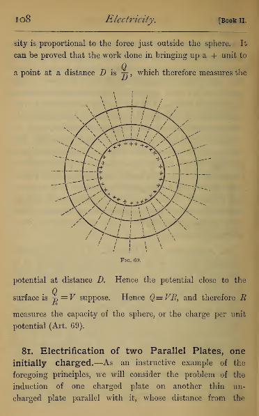
io8 Electricity, [Book II.
sity is proportional to the force just outside the sphere. It
can be proved that the work done in bringing up a + unit to
a point at a distance D is j? , which therefore measures the
Fig. 69.
potential at distance D. Hence the potential close to the
surface is v^V suppose. Hence Q=FB, and therefore R
measures the capacity of the sphere, or the charge per unit
potential (Art. 69).
81. Electrification of two Parallel Plates, one
initially charged.—As an instructive example of the
foregoing principles, we will consider the problem of the
induction of one charged plate on another thin un-
charged plate parallel with it, whose distance from the

Chap. III.] Electrical Induction. 109
first plate can be varied at pleasure. The arrangement is
shown in Fig. 70
Fig. 70
(1) Let the charged plate (A) (Fig. 71) be connected with
A.
X —
+ —4. —
*>A
fiV
li
Fig. 71.
A~i
the cap, and the insulated but uncharged plate (B) with the

no Electricity. [Book II.
base of the same electroscope. When B is brought up very
near to A, but without actual contact, the leaves collapse,
showing that the unelectrified plate is sensibly at the same
potential as the electrified plate, but on moving it further away,
the difference of potential goes on increasing, A of course being
at higher potential than B. The potential at any point in
B will be due to the three distributions, namely the + on A,
and the + and — distributions on opposite sides of B. The
two latter, from their symmetry, will neutralise each other's
potential everywhere within B, and the potential of B will be
that due only to A. When B is close to A, its potential will
therefore be the same as that in air close to Ayand as it
retreats from A its potential will decrease just as the potential
in air decreases.
A
/\ B
T f Z}
•f T — T
J. ± — 7
J. X - i
T A - T
Ot T
\ AFig. 72.
(2) Let us now test the potential of A and B relatively to
the earth, connectingA with the cap of one electroscope, and Bwith that of another (Fig. 72). When they are close together,
the two electroscopes indicate the same potential. As we
separate them, we find that the potential of B constantly de-
creases, that of A remaining unaltered. The explanation is,

Chap. III.] Electrical Induction. in
that the equal and opposite induced charges on B are so
nearly at the same distance from every point on A, that
their inductive effects on A are equal and opposite, and their
potentials at every point of A are equal and opposite, and
therefore do not affect the potential of A, which is still that
due to its own charge.
rC,r^>
r^v>
AFig. 73.
(3) Replace B by a thick plate (Fig. 73)—a hollow plate
with two opposite flat metallic surfaces will do. We shall
now find that the potential of A diminishes as B is moved up
to A. Here the opposite charges called up by induction are
not at the same distance from A, the negative charge being
the nearer, and in consequence the potential of A is lowered.
(4) Eeplace the thin plate and touch it with the finger
(Fig. 74). The potential of A at once falls, and the nearer
B is to A the greater the fall in A's potential. This is due
to the large negative charge induced by A, which, from its
nearness to A, lowers A's potential. In other words, on
bringing up the + unit to A, the work is almost nil, for B's
attraction nearly equals A's repulsion.

112 Electricity. [Book II.
(5) Place B at a certain distance from A, touch B, and
connect it with an electroscope. The leaves of course
collapse. On separating the plates further, however, the
leaves of J3's electroscope are seen to diverge with — E., but
on bringing them nearer together they diverge with -|- E,
AFig. 74.
^Earth
These are obviously the effects of increased and diminished
induction, owing to the change in i?'s position. It shows also
that a body having a — charge may have a 4- potential,
owing to the presence of + E. near to it.
82. The Leyden Jar.—These experiments show us that
the capacity of a charged body depends not onlyon the geometry
of the body considered, but also on the presence of other con-
ductors. Since the potential of the charged body in the pre-
ceding experiment was lowered by bringing near to it a body
connected with the earth, it follows that the capacity of the
conductor was raised in the same proportion. This principle is
used in the Leyden jar. This consists of a glass jar (Fig. 75),
coated outside to about two-thirds of its height with tinfoil, and
the inside is either coated with tinfoil or filled with sulphuric
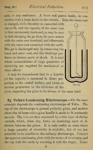
Chap. III.] Electrical Induction. "3
o
acid, or any conductor. A brass rod passes inside, in con-
nection with a brass knob on the outside. Here the inner coat
is charged, while the outer is connected with
the earth, and the capacity of the inner coat
is thus enormously increased, as may be seen
by first charging the jar from the same source
with the outer coat insulated, and afterwards
with the outer coat connected with the earth.
The jar is discharged only by connecting the
inner and outer coat, and the discharge pro-
duces an intense spark or shock. It is used
where accumulations of large quantities of
electricity are required for mechanical or
other effects.
It may be remembered that in a Leyden
jar the capacity is increased in direct pro-
portion to the coated surface, and varies in
inverse proportion to the thickness of the
glass, supposing the glass to be always of the same kind.
Fig. 75.
83. Volta's Condensing Electroscope.—On the same
principle depends the condensing electroscope of Volta. The
cap of the electroscope is ground perfectly plane, and another
plane disc of brass with a glass handle is made to fit accurately
on to it. The two are then separated by a thin layer of shellac
varnish, which, when dry, forms an insulating layer of di-
electric between the plates. It is only useful in cases where
a large quantity of electricity is available, but of too low
potential to be sensible to the ordinary electroscope. Connect
the upper or condensing plate with the source of electricity, and
the cap with the earth by touching it with the finger. There
H
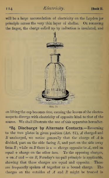
ii4 Electricity. [Book n.
will be a large accumulation of electricity on the Leyden jar
principle across the very thin layer of shellac. On removing
the finger, the charge called up by induction is insulated, and
Fig. 76.
on lifting the cap becomes free, causing the leaves ofthe electro-
scope to diverge with electricity of opposite kind to that of the
source. We shall illustrate the use of this apparatus hereafter.
*84. Discharge by Alternate Contacts.—Returning
to the two plates in given position (Art. 81), ^4 charged and
B uncharged, we notice generally that the charge of A is
divided, part on the side facing B, and part on the side away
fromjB; while onB there is a — charge opposite to A, and an
equal + charge on the other face. To the opposing charges,
+ onA and — on B, Faraday's ice-pail principle is applicable,
showing that these charges are equal and opposite. These
are frequently spoken of together as a bound charge. The
charges on the outsides of A and B might be treated in

chap, in.] Electrical Indtictton. 11
5
the same way, they being bound to equal and opposite
charges on surrounding conductors, only we assume surround-
ing conductors to be so distant that their effect on the distribu-
tion is inappreciable, and these charges are spoken of as the
free charges of A and B respectively. Each of these systems
will have its own capacity—that for the bound charge de-
pending on the shape, size, and nearness of the plates, and
that for the free charge only on the form of the external
surfaces. If we call these C and C respectively, every
charge communicated to A will be divided between the free
and bound charges in ratio of C to C. If the whole charge on
CA be Q, the free charge will be q,q> • Q = nQ suppose,
Cand the bound charge „ „. * Q = mQ suppose; where of
course m + n=l.y = FREE CHARGE
£
B
+ m q
- TO Q= BOUND CHARCS
l-m2 q
= BOUND CHARCE
= free charce
Fig. 77.
(1) At first charging, the charges will be, as in the first
diagram of Fig. 77,
on A, free charge=nQ; bound charge=mQ;and on B, bound charge= -mQ.
(2) Insulate B, and touch A, thus bringing its potential to
zero. The bound charge on B is now divided in ratio 0': C,
and we have, as in the second diagram,
on B, free charge= —mnQ ; bound charge= —m?Q;
and on A, bound charge= +m2Q.

u6 Electricity. [Book II.
(3) Insulate A, and touch B ; the bound charge on A will
now be divided in same ratio, and we have
on A, free charge=?im2Q, and bound charge=m3
Q;
and on B, bound charge= —mzQ.
(4) By similar reasoning we see that after p contacts with
the alternate plates the free charge will be
dznmF^Q, and the bound charge zizmpQ
Fig. 7S
Since mis a fraction near to unity, mp will be a consider-
able fraction when p is a large number, and hence in the dis-
charge by alternate contacts the charge is dissipated very slowly
indeed. This is illustrated in various ways, as by attaching
d bell to the knob of the Leyden jar (Fig. 78), and placing
another in connection with the earth in such a position that a
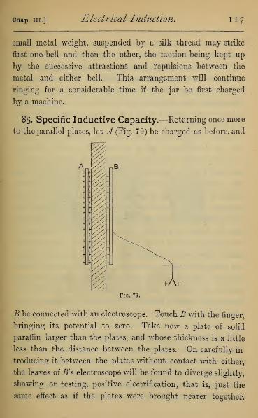
Chap. III.] Electrical Induction. 117
small metal weight, suspended by a silk thread may strike
first one bell and then the other, the motion being kept up
by the successive attractions and repulsions between the
metal and either bell. This arrangement will continue
ringing for a considerable time if the jar be first charged
by a machine.
85. Specific Inductive Capacity.—Eeturning once more
to the parallel plates, let A (Fig. 79) be charged as before, and
Fig. 79.
B be connected with an electroscope. Touch B with the finger,
bringing its potential to zero. Take now a plate of solid
paraffin larger than the plates, and whose thickness is a little
less than the distance between the plates. On carefully in
troducing it between the plates without contact with either,
the leaves of B's electroscope will be found to diverge slightly,
showing, on testing, positive electrification, that is, just the
same effect as if the plates were brought nearer together.
1 1
8
Electricity. [Book n.
(Great care is necessary to prevent the electrification of the
paraffin, by accidental friction with the hands or clothes, in
which case the resulting divergence would be negative, since
the paraffin becomes negative by friction.) This shows that
induction depends on the nature of the dielectric. This
phenomenon was discovered by Faraday, who experimented
by constructing exactly equal Leyden jars, in one of which air
was the dielectric, and in the other a substance like sulphur
or shellac. On charging one, and then dividing the charge
with the other jar, he found in the case of shellac that the
jar having shellac retained two thirds of the divided charge,
and that with air only one third. Since they were at the
same potential, he inferred that the capacity of the jar with
shellac as dielectric was just double that with air. This he
expressed by saying that the inductive capacity of shellac was
double that of air. He found dry air a convenient standard,
since he found no sensible difference on either rarefying or
compressing it, or on substituting for it any of the permanent
gases. There were few solid substances in which the insula-
tion was good enough to admit of Faraday's method of ex-
periment. The only ones with which he expresses himself
satisfied are sulphur and flint glass, in both of which he
showed the specific inductive capacity to be greater than
double that of air,
86. Condition of the Dielectric in a Leyden Jar.
—
That all electrical actions belong to the dielectric, and not to
the conductor, is also shown by the Leyden jar with moveable
coatings (Fig. 80). Charge this jar in the usual way, and place
it on an insulator. Lift out the inner coat, and this will be
found to carry away only a small fraction of the charge. Lift

Chap. III.] Electrical Induction. 119
the jar out of the outer coat, which will also retain hardly a
trace of the charge. The glass can now be handled inside and
out, a slight discharge being perceptible when the outside
and inside are touched at the same time ; but on fitting up
the jar again, and discharging in the usual way, there will be
nearly as strong a spark as if the discharge had immediately
followed the charge.
Fig. SO.
This shows that every electrification is not one of con-
ductors in the field, but rather one of the field itself, the
function of the conductor being only to determine the limits
of the field.
Another illustration is given by the residual charge in a
Leyden jar. Of whatever dielectric the condenser be made,
except it be a gas, a short time after the first discharge has
passed, another feeble discharge can be obtained, and this may
be repeated several times in succession. This appears due to a
want of homogeneity in the dielectric, and a partial conduction
through it, causing a storing up of electricity within the sub-
stance of the dielectric, which begins to be conducted back
again only after the primary discharge has passed.

1 20 Electricity. [Book n.
87. Faraday's Theory of Induction.—Faraday has
laid down a theory of induction agreeable to this conception,
and this was the first step towards a true physical conception
of electrical actions. He satisfied himself that induction was
not due to action at a distance between the electrified body
and the body under induction, and he substituted for it an
action through the dielectric from molecule to molecule only.
He assumes that every dielectric consists of molecules, each
©e eg e © ee®e> 22® © ©^©eeaee
<^ oiffr«
Fig. 81.
of which acts as a conductor, but which are separated from
each other by a non-conducting medium, or, at least, non-con-
ducting up to a certain limiting strain among the molecules.
The electrification of the surface bounding the field (or of
the conductor, if we choose still to speak of it) separates the
electricities in the layer of molecules next to it. These act
on the next layer, and so on through the field. The lines of
force define the direction in which the separation takes place,

Chap, in.] Electrical Induction. 1 2
1
the quantity separated being always equal to that in the
proximate layer of molecules. Thus the electrification will
consist of a flow of electricity equal to the original charge
across each equipotential surface \ but instead of being a flow
through a finite space, it is only a flow across the molecules
which lie in that surface. This may be represented in a dia-
grammatic way, as in Fig. 81, supposing shaded parts to re-
present positive electricity.
Of a higher order is the theory of Faraday developed by
Clerk-Maxwell, in which he regards the electrification as a
state of molecular strain in the dielectric. In support of that
theory is the observation of Sir William Thomson, that on
charging and discharging a large condenser a peculiar noise
is emitted, just as might be expected in a medium taking
up or losing suddenly a strained condition. The same applies
to the noise said sometimes to be heard at the instant of a
flash of lightning.

CHAPTER IV
ELECTRICAL MACHINES.
88. The Cylinder Machine.—There are two classes of
electrical machines; that is, machines by which large quantities
of electricity at high potential may be rapidly obtained, one
depending on simple friction, and the other on an initial
electrification by friction, from which an indefinite amount
of electricity may be developed by inductiou.
Fig. 82.
The simplest form of friction machine is that known as the
cylinder machine (Fig. 82). It consists of a cylinder of glass
(jB) fitted in a frame which allows it to rotate about a spindle
running along its axis. The extremity of one horizontal
122

chap, iv.] Electrical Machines. 123
diameter is pressed by a leather pad (A) coated with silk, on
which is smeared an amalgam of mercury and tin, the pressure
being increased by a spring controlled by a screw. The pad
is usually insulated and furnished with a brass knob, from
which negative electricity can be collected. Towards the
opposite side of the cylinder points a comb, consisting of a row
of very sharp brass points (C) attached to a large brass globe
or cylinder (D), called the Prime Conductor, on which the
positive electricity collects. This is always insulated by being
supported on glass legs. A flap of silk attached at one edge
to the rubber passes nearly over the upper half of the cylinder,
and prevents the deposit of dust on the cylinder, by which
the electricity would be dissipated.
On turning round the cylinder, the friction with the rubber
separates electricity, the positive on the glass and the negative
on the rubber. The glass with its positive charge is carried
onwards till it is opposite the brass comb on the opposite side.
Here it acts inductively on the points, and — E. is drawn
off, neutralising the + E. on the cylinder, and causing a charge
of free + E. on the conductor. On turning the handle round
this process constantly goes on, till the difference of potential
between the prime ( + ) and negative (— ) conductors is equal
to that which can be obtained by the friction between glass
and amalgamated silk. Sparks of positive or negative elec-
tricity can be obtained from the respective conductors. The
difference of potential actually attained will always be less
than the limit indicated, because of dust and moisture in the
air, and also because of the want of perfect insulation in the
glass supports. The advantage of a warm and dry state in
the atmosphere is obvious.
In the ordinary working of the machine it is usual to con-

124 Electricity. [Book II.
nect the negative conductor with the earth by a metal chain.
If the insulation of the rubber were perfect, we should, on
drawing sparks from the prime conductor, at last reach a
stage at which the potential of the negative conductor would
be below the potential of the earth by the whole available
potential difference, and then the prime conductor would be at
zero potential, and no sparks could be obtained from it. The
machine would apparently cease to work.
Again, the body which draws sparks from the machine is
generally at the potential of the earth, and therefore the poten-O tial difference available for giving
sparks is that between the earth and
the prime conductor. But if the
negative conductor be at a negative
potential, this available difference is
not the full potential difference of
the machine, or the machine is prac-
b tically not working to its full power.
On connecting the negative conductor
with the ground the potential of the
positive conductor at once rises. The
same effect may be gained by simply
connecting the negative conductor
with the apparatus by which sparks
In a fairly insulated
Fig. 83.
are to be drawn, keeping all insulated,
machine the difference is well seen (1) by drawing a succession
of sparks from the prime conductor while the rubber is insu-
lated ; (2) by drawing sparks, while standing on an insulating
stool, and touching with one hand the negative conductor
;
(3) by drawing sparks, standing on the ground with the
rubber to earth.

Chap. IV.] Electrical Machines. 125
The prime conductor is frequently furnished with an elec-
trometer, consisting of a vertical metal rod, from which is
suspended, by a thin wire or linen thread, a pith ball (Fig. 83).
The divergence is shown by a small graduated quadrant
attached, which indicates the degree to which the machine is
working. This is called Henley's Quadrant Electrometer—
an unfortunate term, as the Quadrant Electrometer is an
instrument of Sir William Thomson's, described hereafter.
89. The Plate Machine.—The Plate Machine (Fig. 84) is
a circular vertical plate (A) of glass or ebonite, which is turned
Fig. 84.
by a spindle through its centre. Two rubbers {BE) are
attached at opposite extremities of the vertical diameter, each
made double, and pressed by a screw clamp on opposite

126 Electricity. [Book II.
sides of the plate. Along a horizontal diameter are two
combs (CO), each formed in shape of the letter U, so as to
act on the two surfaces of the plate. These are connected by-
metal rods with the prime conductor, which is well insu-
lated on a glass support. Flaps of silk (EE) extend over the
quadrants from the rubbers nearly to the combs.
The action is identical with that of the cylinder machine.
Its advantages are rather greater compactness, and the possi-
bility of substituting ebonite for glass. The ebonite is as
good in its electrical properties, but is less hygroscopic, and
therefore the action is not quite so dependent on weather.
Also the double action on opposite sides of the plate increases
the rate at which electricity can be obtained.
90. The Electrophorus.—Of instruments depending on
induction the simplest is the electrophorus (Fig. 85). It consists
(1)
-M- -I- -I- -h -'- -h -I- -H -I- -I- -I- -I-
/•v-I- -I- -I- -I- H- -I- I- -I- -I- -4- -I- -h -I- -I-
(ii)r
-1
,+. -i- _|_ .|_ _|_ _,_ _|_ _|. -1- -!- -|. -|_ -|_ -|.
B
Dearth
1....C
_,- -1- -|. _,- -j. -1- -[_ -1- -|- -|- -j_ -i-
-1- -1- -1- -1- -+- -1- -1- -1- -1- -1- -1- -1- -1-
-I- -1- -i- -I- -1- -Vj -f- -I- -f--1- -1- -hH I 3
-I- -I- -I- -I- -1- -I- -H -I- -i-+ + -l-
Fig. 85.
of a cake (A) resting on a metal form or sole (B), and of a
chap, iv,] Electrical Machines. 127
cover (0). The cake used to consist of a resinous compound
melted and poured into the form, but is now more com-
monly a plate of ebonite, with a sheet of tinfoil on its
under surface forming the sole. The cover is a flat metal
plate, having attached to it a glass handle, by which it can
be raised and lowered. The charging of the electrophorus is
done by rubbing or flapping the ebonite plate with a cat's fur
(Fig. 85, i), by which a charge of — E. is developed on its
upper surface. This acts inductively through the cake, and
binds by induction a charge of + E. on the sole. By this
means the potential of the charge on the cake is lowered, and
the tendency of the electricity to escape into the air diminished.
On putting the plate down on the cake there is only contact
at very few points, and everywhere else a thin plate of air be-
tween the cake and cover. There will therefore be developed
(Fig. 85, ii) a charge of + E. on the under surface of the
cover very nearly equal to the whole — E. on the cake, while
there is an equal free charge of — E. on the upper surface.
On touching the plate with the finger (Fig. 85, iii), the com-
plementary — E. is driven to earth. The induction will now
be almost wholly between the cake and cover, owing to the
much greater nearness of the cover. On lifting up the cover
it has a strong charge of -h E., which can be used for charging
other conductors. The induction between the cake and sole
is again restored, the cake returning to the state shown in
Fig. 85 (i), and the charge is so well preserved that in a dry
atmosphere the electrophorus may be used with only one
charging for an hour or more together.
91. The Voss Machine.—A great variety of machines
have been invented, in which the induction of a small initial
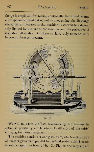
128 Electricity. [Book II.
charge is employed for raising continually the initial charge
in compound interest ratio, and also for giving the discharge
whose power increases as the machine is worked to a degree
only limited by the size of the machine and the perfection of
insulation attainable. Of these we have only room to refer
to two of the most modern.
Fig. 86.
We will take first the Voss machine (Fig. 86), because its
action is peculiarly simple when the difficulty of the initial
charging has been overcome.
The machine consists of one glass plate, which is fixed, andof another glass plate parallel to the fixed plate, which is madeto rotate rapidly in front of it. In Fig. 86 the larger plate

chap, iv.] Electrical Machines. 129
is fixed, and the smaller rotates in front of it, admitting of our
seeing the arrangement of the fixed plate through it. The
fixed plate has two sheets of paper (AA), with tinfoil under-
neath it, pasted on to the glass, and called the armatures.
From each of these proceeds a metal arm (BB) bent three
times at right angles, and carrying on its end a metal
brush, which sweeps over certain metal buttons as they pass
by it.
The moveable plate has cemented to its front eight of these
metal buttons (a a . . .), which come in contact with the suc-
cessive brushes.
Fig. S7.
In front of the moveable plate, and facing it, are two brass
combs ((7(7) which face the plate, and are cut away opposite
to the buttons (Fig. 87), allowing them to pass without con-
tact. These are connected by metal rods with the moveable
conductors (DD), between which the spark passes.
Fig. 88.
In addition there is a diagonal conductor (E) furnished at
each end with a brass comb, of which the central tooth is
replaced by a brush of metal wires which sweeps over the
buttons as they pass under it (Fig. 88). The combs all extend
the full width of the paper armature.
I

1 30 Electricity. [Book 11.
The knobs (DD) are in connection with the inner coats of
two Leyden jars (FF) whose outer coats are to earth.
The peculiarity of this apparatus is that no special priming
(that is, initial charging of the armatures) is required. It
appears that from accidental surface inequalities a slight
difference of potential is established by friction between the
brushes and buttons, and the construction of the machine is
such as to accumulate the initial charge, however small, on
compound interest principle. In working the machine the plate
is rotated in the direction of the arrows shown in Fig. 86.
We assume initially a small potential difference between the
armatures A, A, and will show how this difference is in-
creased. Omitting the conductor CO, which takes no part
in the initial stages of charging, each button passes during
a revolution four brushes—two belonging to the armatures,
and two to the diagonal conductor. Fig. 89 either shows one
button in four consecutive positions, or four buttons simul-
taneously, remembering that pairs of buttons always occur at
ends of a diameter.
Consider first the pair of buttons in position (i) and (iii)
in Fig. 89, in which (i) represents a portion of the positive
armature, and (iii) a portion of the negative armature. At (i)
the positive armature induces a charge of — E. on the button,
while at (iii), which is connected with (i) by the diagonal
conductor, the negative armature induces a charge of + E.
The button therefore leaves (i) with a negative charge bound
across the air space, and leaves (iii) with a positive charge.
The button, on passing from (i) to (ii), will give up its strong
bound negative charge to the negative armature, retaining only
a small free charge. Similarly, the button on passing from (iii)
to (iv) will give up its bound positive charge, retaining only a

Chap. IV.] Electrical Machines. 131
1
(i)
CO
very small free charge. We see therefore that each button
which passes from (i) to (ii), or from (iii) to (iv), will
enforce the charge of these respective
armatures; and since at each point
there is actual metallic contact, the
electricity not having to break across
an air space, the action will go on,
however small the initial difference.
When the charges are high enough
to act inductively across the air spaces
between the plate and the combs (CC),
the neutralisation which usually takes
place in E will take place across the
air space (DD), giving rise to the spark.
As soon as this is the case, not only
the metal buttons, but the whole glass
surface between the combs and the
armature, help to enforce the action.
After turning for a very short time,
if the atmosphere be moderately dry
and the machine warm, sparks four or
five inches long may be easily obtained
from a comparatively small machine
(16-inch plates).
The use of the Leyden jars (FF) is to concentrate the
spark. If they be removed, the discharge takes place by what
is called the brush discharge, consisting of very fine branches,
giving a slight pricking sensation if received on the hand, and
making but very slight noise. If the Leyden jars be present,
the first effect of the electricity developed in the conductors
D, D, is to charge these jars, one with its inner coat positive,
I(ivj
Fig. 89.
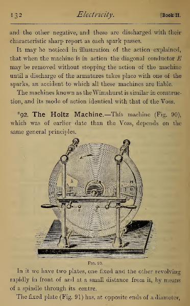
Electricity. [Book II.
and the other negative, and these are discharged with their
characteristic sharp report as each spark passes.
It may be noticed in illustration of the action explained,
that when the machine is in action the diagonal conductor Emay be removed without stopping the action of the machine
until a discharge of the armatures takes place with one of the
sparks, an accident to which all these machines are liable.
The machines known as theWimshurst is similar in construc-
tion, and its mode of action identical with that of the Voss.
*92. The Holtz Machine.—This machine (Fig. 90),
which was of earlier date than the Voss, depends on the
same general principles.
Fig. 90.
In it we have two plates, one fixed and the other revolving
rapidly in front of and at a small distance from it, by means
of a spindle through its centre.
The fixed plate (Fig. 91) has, at opposite ends of a diameter,

Chap. IV.] Electrical Machines. 133
two apertures or windows cut in the form of truncated sectors
of a circle. Below one and above the other are two sheets
of paper (BB\ the armatures, glued to the glass, with two
tongues or pointed strips, also of paper, projecting from them
into their respective windows. In the centre is a circular
hole through which passes the spindle of the moving plate.
Fig. 91.
The moving plate is an entire circle with a hole in the
centre for fixing the spindle, and, for mechanical reasons,
having a diameter slightly less than that of the fixed plate.
The plate is fixed with the two armatures at opposite ex-
tremities of a horizontal diameter. Opposite to them, but on
the remote side of the moving plate, are two brass combs
(Fig. 90), as near as possible to the moving plate without actual
contact with it. These combs are well insulated, and connected
with two brass knobs (EE), whose distance apart may be
adjusted by the insulating handles. These knobs are the
positive and negative conductors. The relative position of

134 Electricity. [Book II.
the parts near one end of a horizontal diameter is seen in
section in Fig. 92. In the section, A is the window, B the
armature, C the tongue, and D one tooth of the brass comb,
Before working the machine, it must be primed. The brass
knobs are brought into contact, and a piece of ebonite rubbed
with flannel is held between the plates in contact with one
armature, by which this armature receives a weak charge of
negative electricity. Sometimes a small ebonite machine is
fixed to the base in such a position that the electrified ebonite
plate acts inductively on one tongue.
o>
Fig. 92. Fig. 93 (i).
The further action can best be understood if we consider
the electrical actions which occur in six successive positions
of a portion of the revolving plate in the course of a single
revolution, just as we did in the Voss machine. The plate
revolves in such a direction as to meet the tongues of the
armature, as shown by the arrows in Fig. 90.
1st Position,—Opposite the window of the fixed plate which
contains the tongue of the negative armature, Fig. 93 (i).

Chap. IV.] Electrical Machines, 135
The tongue, being pointed, reduces the inner surface of the
glass plate to its own potential, giving it a negative charge.
This charge acts inductively through the glass, binding on the
opposite surface a positive charge, and leaving a negative
charge free. This action through a dielectric, though an
obvious consequence of Faraday's law of induction, was first
pointed out by Eeiss, and is often called Reiss's action.
2d Position.—Between the negative armature and the brass
comb, as in Fig. 93 (ii).
/
M-f *-
•H-
j-i-
if-
* -
**
FiG. 93 (ii). Fig. 93 (iii).
The brass points of the comb neutralise the free negative
charge on the outer surface of the glass, and a redistribution
of the induced charges takes place. The negative charge on
the armature acts by induction both across the air and the
glass, calling up a positive charge across the air space, leaving
the negative charge bound to the positive charge on the
outside surface of the glass.
3d Position.—After passing the armature, as in Fig. 93 (iii).
In this position the induction of the negative charge of the
armature is removed, and in consequence a positive charge is
set free on both sides of the moving plate. These charges of
course act inductively on the glass of the fixed plate, as shown
in the diagram.
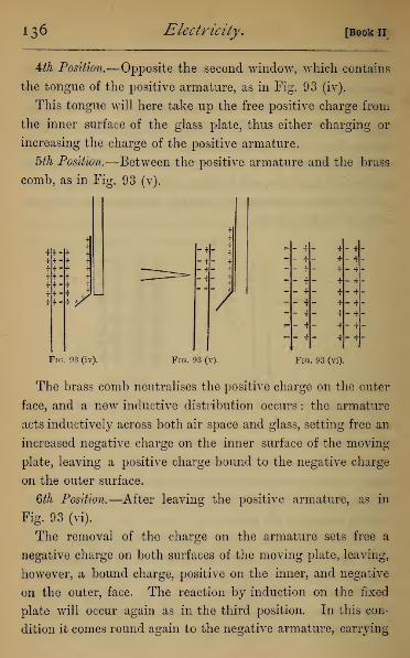
136 Electricity. [Book n
Uh Position.—Opposite the second window, which contains
the tongue of the positive armature, as in Fig. 93 (iv).
This tongue will here take up the free positive charge from
the inner surface of the glass plate, thus either charging or
increasing the charge of the positive armature.
5th Position.—Between the positive armature and the brass
comb, as in Fig. 93 (v).
1/ 7
Fro. 93 (iv). Fig. 93 (v).
- f - + - +_ i + - *- t _. j. - T
" f + - "f
- + + - +- T + " 4- T — T -T- 4 + " *
- -f •f_ J.
Fig . 93 (vi)
The brass comb neutralises the positive charge on the outer
face, and a new inductive distribution occurs : the armature
acts inductively across both air space and glass, setting free an
increased negative charge on the inner surface of the moving
plate, leaving a positive charge bound to the negative charge
on the outer surface.
6th Position.—After leaving the positive armature, as in
Fig. 93 (vi).
The removal of the charge on the armature sets free a
negative charge on both surfaces of the moving plate, leaving,
however, a bound charge, positive on the inner, and negative
on the outer, face. The reaction by induction on the fixed
plate will occur again as in the third position. In this con-
dition it comes round again to the negative armature, carrying
chap. iv. ] Electrical Machines. 137
a charge which will reinforce its electrification, after which
the whole process goes on over again.
The action of the machine may be briefly described thus,
—
each portion of the moving plate as it passes from the induc-
tion of the negative armature has a positive charge on both
faces, that on the inner face after half a revolution enforces
the charge on the positive armature, and that on the outer
face is taken up by the comb, and makes the spark. The
same will be the case, changing signs with each portion of the
plate as it leaves the positive armature.
For the neutralisation of the opposite electricities de-
veloped by the action of the machine on the combs and con-
ductors, the knobs should be kept together till the charging
has risen sufficiently for sparks to strike across, by which the
neutralisation (only partial, of course) takes place during the
whole time the machine is at work.
As in the Voss machine, two Leyden jars (not shown in
the figure), having their outer coats connected by a brass band,
are usually hung from the brass rods in connection with the
conductors E, E. They are, of course charged, one positively
and the other negatively, and their function is to store up
the electricity developed, allowing, when they are charged,
one strong spark to pass in place of a large number of sparks
of much smaller quantity, which form a brush discharge.
Occasionally the power of the machine is increased by having
four plates instead of two, in which case the fixed plates are
back to back, and the revolving plates outside ; the brass comb
being on the inside of a U-shaped rod to collect the electricity
from both plates at once.
From a Holtz machine, with plates 2 feet in diameter, a bril-
liant discharge of sparks 6 to 8 inches long can be obtained.

138 Electricity. [Book 11.
93. Experiments with the Electrical Machine.—Almost an infinite variety of experiments, both instructive
and amusing, can be exhibited by means of the electrical
machine. We briefly indicate a few under general head-
ings :
—
1. Subdivision of the Spark—This is done by means of
small discs of tinfoil pasted on the surface of glass, leaving
a very small interval between each two successive discs. In
this way any pattern that can be traced by one continuous line
can be formed, and when placed in the line of discharge of a
machine, each interval is lighted up by a spark. The pattern
traced by bright sparks can be seen in a darkened room.
2. Attractions arid Repulsions.—A head is cut in wood, with
long hair fastened on by a metal screw, which is in connection
with a metal rod, by which the head is supported on the prime
conductor: when the machine is worked, the hairs stand
out, owing to mutual repulsion, and can be swayed about
inductively in various directions by presenting the hand or
any flat conductor near them.
The Electrical Chimes consist of bells, of which alternate
ones are connected with the prime conductor and the earth.
Between them hang by silk threads small masses of metal,
which are attracted and repelled by the electrified bells in
succession, keeping up a ringing while the machine is worked.
Electrical Hail consists of a number of pith balls placed in a
glass cylinder, in the upper part of which is a moveable brass
plate connected with the prime conductor, and the base is
coated with tinfoil connected with the earth. On turning the
machine, the pith balls fly about between the plate and base.
The same thing can be shown by figures cut in pith
and placed between two brass plates, one of which hangs

Chap, iv.] Electrical Machines. 139
from the prime conductor, and the other is to earth. On
working the machine, the figures continue dancing between
the two plates.
3. Conduction of the Human Body.—By standing on an in-
sulating stool, and holding the prime conductor of an
electrical machine in the hand, a considerable charge may-
be imparted, of which the recipient is quite unconscious,
unless it be by the standing out of the hair or of loose parts
of the clothing by electrical repulsion. A spark can be taken
from any part of the body of the person charged, just as
from any other conductor, when a pricking sensation is felt
just where the spark is drawn. Sparks drawn in this way
are harmless, and almost painless.
With this experiment should be compared one in which the
human body is in the line of discharge, and offers resistance to
the passage of electricity. This may be done in a perfectly
harmless manner by charging a Leyden jar with two or three
turns of an electrical machine. A large class, on joining hands
all round, the first holding the outer coat and the last touching
the knob, will receive the discharge through the muscles of
the arms and chest, and will receive a shock, most felt in
the elbow joints, where the muscle is discontinuous. The
arms and chest here act as a bad conductor, the right and
left hands being brought to a slight difference of potential
before the discharge takes place.
We have already noticed that conductors and non-con-
ductors are only relative terms, and we have here two
experiments in which the same body acts first as a con-
ductor, and next as a dielectric.
5. The Disruptive Discharge in Air.—There are three ways
in which an electrical discharge may be shown to take place.

140 Electricity. [Book 11.
The first is by the ordinary disruptive discharge. This
occurs when the air becomes strongly strained by the
potential difference, and, suddenly yielding, allows the dis-
charge to pass, not freely as through a conductor, but by a
violent disturbance of the molecules of air along the path,
which become strongly heuted, and make the visible spark.
This spark is often spoken of very inaccurately as the electric
fluid. The spark will be observed to take a zigzag and
forked path. This seems due to the discharge passing along
the line of least resistance, which, owing to conducting
motes in the air, is not the straight line. The snap which
accompanies the discharge has never been fully explained,
but is no doubt due to the disturbance in the air caused by
the passage of the discharge.
6. The Glow Discharge.—This takes place on sharp points,
either in connection with the machine or on pointed con-
ductors connected with the earth presented towards the
machine. It may be seen in the dark as a faint purplish
glow on the brass combs connected with the various forms of
machine. If a pointed rod be placed on the prime conductor,
the glow will immediately appear, and it will be found im-
possible to draw a spark from the machine, the electricity
being discharged silently from the point. If the hand be
placed near the point a strong current of air will be found
setting from the point.
A method of discharge, similar to that from points, is
afforded by a flame, which we have already noticed (see
Art. 78), and by any form of water-dripping apparatus, in
which the water dropping away from an insulated vessel
carries off a charge until it brings the nozzle from
which the water drips to the same potential as the air in

CHap. IV.] Electrical Machines. 141
contact with it. The electrical watering-pot depends on
this principle. A metal vessel, having a capillary outlet
by a syphon, is suspended from the prime conductor.
Before electrification the water drips only one drop at a
time, but on turning the machine the water flows out in
a continuous stream, owing to the repulsion between the
electrified vessel and the similarly electrified water which is
leaking away from it.
Fig. 94.
It appears from the current of air which proceeds from the
points that the particles of the air themselves become charged
at the point, and are then repelled, carrying their charge with
them, and discharging as they come against the walls of the
room or other conductors. This current of air is accompanied
by a recoil if the pointed conductor is free to move. It is
employed as a source of motion in the electrical whirl
(Fig. 94) and electrical orrery, in both of which points are so
142 Electricity. [Book II.
placed that the recoil sets the apparatus of which they are parts
spinning, the direction of rotation being against the points.
7. The Brush Discharge.—This is best seen between the
conductors of a Voss or Holtz machine after the Leyden jars
in the interior have been removed. It seems intermediate in
character between the spark and glow discharges. It some-
times rises out from wooden knobs or conductors about the
machine like the stem of a tree, and spreads out in the air
like its branches.
The connection of these forms of discharge with the pheno-
mena of lightning cannot be overlooked. The spark discharge
is identical in character with the flash of forked lightning,
the forking and zigzag path being often seen in the spark from
the machine.
The glow discharge is known as St. Elmo's Fire, which is
frequently seen on the tops of the lightning-rods connected
with the masts of ships, and also upon other pointed objects
—
even on the tops of umbrellas or walking-sticks—when the
atmosphere is much disturbed electrically.
The brush discharge may occur in some varieties of summer
lightning, though what is most commonly called so is only the
lighting up of the edges of cloud-masses by electric discharges
taking place behind them, or at points below the horizon of
the place of observation * the discharge being too distant for
thunder to be audible. Thunder, for the volume of its sound,
is audible for an exceedingly short distance—very much less
than the report of a cannon.
The only other form of discharge, that known as the fire-ball,
has not yet been explained or imitated experimentally. It
appears of the nature of a Leyden jar very powerfully charged,
which may move about through rooms, playing about the
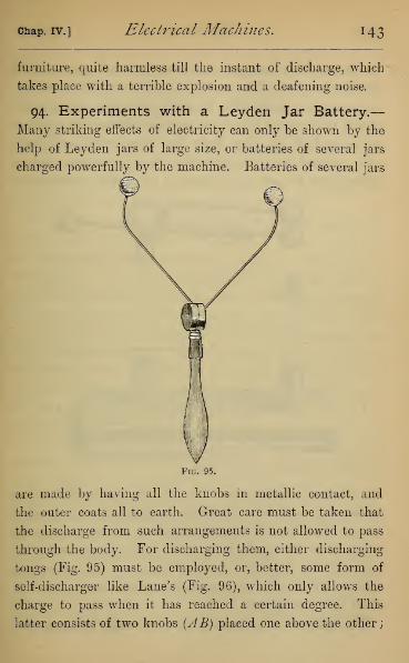
Chap. IV.] Electrical Machines. H3
furniture, quite harmless till the instant of discharge, which
takes place with a terrible explosion and a deafening noise.
94. Experiments with a Leyden Jar Battery.—
Many striking effects of electricity can only be shown by the
help of Leyden jars of large size, or batteries of several jars
charged powerfully by the machine. Batteries of several jars
Fig. 95.
are made by having all the knobs in metallic contact, and
the outer coats all to earth. Great care must be taken that
the discharge from such arrangements is not allowed to pass
through the body. For discharging them, either discharging
tongs (Fig. 95) must be employed, or, better, some form of
self-discharger like Lane's (Fig. 96), which only allows the
charge to pass when it has reached a certain degree. This
latter consists of two knobs (AB) placed one above the other;

144 Electricity, [Book II.
the lower (B) is insulated, and connected with the knobs of
the Leyden jars. The upper (A), which is also insulated,
moves about a pivot within the hollow ball (0). It is counter-
poised by a weight (D) on the opposite side of the pivot, so
as to be held up, away from the lower knob, in contact
with a fixed knob E, until the knob B reaches such a
charge that its pull on A draws A and B into contact, and
Fig. 96.
the discharge takes place between them. On the lever
between A and C is a small sliding weight (F), which can be
shifted along so as to alter the degree of charge necessary to
bring down the upper knob. The experiments here given
can easily be done by a Leyden battery of four quart jars
charged by a Holtz or good plate machine, and several of
them with a single jar.
The ignition of coal-gas is seen by simply bringing the

chap, iv.] Electrical Machines. 145
knob of a single charged jar into contact with a gas burner
from which gas is issuing, the outer coat being connected
by a chain with the gas pipes. It may also be shown by
corking up in a metal tube a mixture of coal-gas and air.
The tube is furnished with an arrangement by which the
spark passes through the mixed gas within the tube. On
passing the spark an explosion takes place by which the
eork is driven out.
The explosion of gunpowder is not effected by passing the
spark in the ordinary way. It appears to be too rapid, and
in consequence the gunpowder is scattered about without
being ignited. On introducing a piece of wet string, which is
only a semi-conductor, in some part of the line of discharge,
the spark is retarded, and the powder then explodes. The
accompanying diagram (Fig. 97) shows an arrangement by
which this and several following experiments can be performed,
using Lane's discharger, already described, and Henley's dis-
charging table for supporting the apparatus through which
the discharge takes place. The Henley's table consists of a
table {A) supported on an adjustable stem, having a strip of
ivory or some bad conductor across its top. On opposite
sides are two insulated arms (BC), passing through a ball and
socket which has universal motion. These arms can be
adjusted with their lower ends at any position on the table.
The Leyden battery (D) has its knob connected simply with
the lower knob of the Lane's discharger (E), and wires con-
nect the upper knob (F), through the Henley's discharger,
with the outer coat of the jars. For exploding gunpowder,
the gunpowder is laid on the discharging table, the points of
the arms being placed in it, and the wet string replaces part
of one of the wires.
K

146 Electricity, [Book II.

chap, iv.] Electrical Machines, 147
The powder may be put in a small ivory mortar, with an
ivory bullet fitting into its mouth. If the discharge be made
across two wires which enter the mortar from opposite sides,
the bullet will be expelled with some force.
Ether may be ignited by simply putting it in a metal cup
connected with the earth. If the knob of the Leyden jar
whose outer coat is also to earth be approached towards the
ether the discharge passes and ignites the liquid.
If the charge from several jars be passed through gold leaf
or very fine wire, the metal offers resistance, and the charge
in passing may completely deflagrate the metal. This can
easily be shown with gold leaf. The gold leaf should be
gummed on a piece of cardboard, tinfoil being also gummed
on to the card in contact with the gold leaf, and projecting
from the ends. The card must then be put in a screw-press,
which replaces the top of the table on Henley's discharger,
and the arms must be brought into contact with the projecting
tinfoil. After the explosion has passed, the gold will, in part
or whole, be deflagrated, leaving a purplish stain on the card
where the discharge has passed. To show the mechanical
effects, such as splitting wood and puncturing glass, more
powerful Leyden batteries are required. An interesting ex-
periment, which can be shown with one or two jars, is that of
passing the discharge through a card held in the screw-press,
with the arms just on opposite sides. By the discharge a
hole is pierced through the card, and a burr is left round its
edges on the negative side, as if a material body, such as
a needle, had been pushed through from the positive to the
negative side.
An instructive experiment is that known as the Thunder
House, illustrating the effect of a discontinuous conducting

148 Electricity. [Book 11.
line for a powerful discharge (Fig. 98). A conducting wire
passes down the end of a wooden model of a house gable,
except about half an inch where the discharge has to pass
across a piece of wood (A) fitted loosely into the wall. Ondischarging a Leyden jar through it, the loose piece of wood,
which occurs in the line of discharge, is frequently projected
several yards. If the wood be turned round, making the con-
ducting wire continuous, as at B, the discharge passes quietly
through it without dislodging the wood.
In a similar way, a pyramid built of
loose bricks may be thrown over by a
discharge, if the conducting line is
broken near the base.
This illustrates the effect of lightning
when the conductor does not terminate
in "good earth"—that is, earth con-
stantly damp, and continuous with the
conducting body of the earth. The light-
ning rod under these conditions becomes
itself a source of danger to the building
it is intended to protect, since the light-
ning no longer passes to earth by the
rod, but flies from it across walls and
other bad conductors, rending them in pieces, in its passage
to the gas or water supply pipes of the house, which are
certain to be in " good earth." Similar accidents may happen
through not connecting by metal bands the lightning rod
with all external masses of metal, such as gutters, spouts,
and lead on the roof.
Fig. 98.
95. Chemical Decompositions by the Machine dis-

chap, iv.] Electrical Machines. 149
charge.—The power of the machine discharge to perform
chemical decompositions was originally shown by Faraday,
and can be repeated easily by the discharge of a Voss or
Holtz machine. In the case of iodide of potash it is only
necessary to place, on a piece of platinum foil, a few thick-
nesses of bibulous paper soaked in the solution. Then bring
a platinum wire from the positive terminal of the machine
on to the folds of moist paper, and connect the foil with the
opposite terminal. On turning the machine, a brown spot,
due to iodine, soon appears round the platinum point, proving
the decomposition of the salt.
For the decomposition of copper sulphate we have only to
bring two platinum wires, in connection with the terminals
of the machine, into a large drop of the solution on a plate of
glass. After turning the machine, the platinum wire in con-
nection with the negative conductor will be found coated with
copper.

CHAPTER V.
ABSOLUTE MEASURE OF ELECTRICITY.
96. The Unit Jar, and Experiments with it.—Wehave in previous articles referred to changes and differences
of potential, and have explained how they theoretically
might be measured, but have not described any instru-
ments by means of which these measurements could be re-
duced to practice. The instruments we have used have been
essentially electroscopes—means of detecting the presence
of a difference of potential; and not electrometers—means
of actually measuring the difference. All instruments for
measuring differences of potential we owe to Sir William
Thomson, but, before referring to them, there is an earlier
instrument invented by Snow Harris, called the Unit Jar, by
means of which the quantity of electricity communicated to
a given conductor can be measured, and some of the laws of
electrification can be verified.
This (Fig. 99) consists of a small Leyden jar, placed on
an insulating stem, whose inner coat is connected with the
electrical machine, and outer coat with the body to be charged.
It is furnished with two balls, whose distance apart can be
adjusted, one connected with the inner, and the other with the
outer coat. When the jar reaches a certain definite charge,
a discharge takes place between the balls. The positive elec-
tricity from the outer coat, instead of going to earth, goes to
150

Chap, v.] Absolute Measure of Electricity. 1 5
1
charge a conductor connected with it, and therefore at each
discharge of the unit jar a certain definite amount of electricity
has left the outer coat and gone to the conductor, this amount
being unaffected by the discharge of the bound charges of the
jar. We may take this amount as our provisional unit, and
so charge conductors with a certain number of units measured
by the number of sparks which pass between the coats of the
unit jar. As long as the conductor is the same, the rise in
charge is of course proportional to the rise in potential.
Fig. 99.
The inventor of the unit jar investigated several laws of
electrical action by its means, of which we will take two as
illustrations, the one referring to the striking distance, and
the other to the capacity of a Leyden battery or jar.
The striking distance really depends on the form and size
of the conductors between which the spark passes, but for two
nearly equal spheres it is approximately proportional to the
difference of potential. This may be shown by help of the

i52 Electricity. [Book II.
unit jar. We must arrange on the knob of the jar to be ex-
perimented with a self-discharging arrangement, such as Fig.
100, where the distance between the knobs A and B connected
with the inner and outer coats can be varied and measured by
the sliding rod, which is graduated. If now, by the arrange-
ment of Fig. 99, we charge the Leyden jar, we can count how
many units leave the unit jar by the number of sparks which
pass in it, before the Leyden jar has received a charge which
will strike across any given measured air space. If we double
Fig. 100.
the air space, we shall find that we have to double the num-
ber of units admitted before discharge takes place, and so on.
In making the experiment, the Leyden jar must be completely
discharged after each experiment, as the passage of a spark
across a considerable air space by no means produces com-
plete discharge.
We may also easily show that the capacity of a battery is
proportional to the quantity of coated surface, assuming
that we have three or four jars of nearly equal coated surface
and thickness of glass. Set the discharging electroscope at a
chap, v.] Absolute Measure of Electricity. 153
certain distance on the knob of a single jar, and observe the
number of units required to produce discharge, that is, to
produce a certain definite potential difference between the
inner and outer coat. This number will be a measure of the
capacity. Connect another equal jar with the first mentioned
jar, in a battery of two jars. It will be found to require twice
as many units to produce a discharge. With a third jar it
will require three times as many, and so on.
*97. Theory of Thomson's Electrometers.—It is
proved in works on the theory of electricity, that if we
have two plates parallel to each other, one insulated and
electrified and the other to earth, the lines of force proceed
from the plate at higher to that at lower potential in parallel
lines at right angles to either plate, if wre exclude a portion
round the edge of each plate, which is subject to the induc-
tion of surrounding bodies. If, then, we take two spaces,
each of area S, opposite to each other and near the middle of
two parallel plates, it appears that the capacity of the system
Sformed by the two surfaces is j—. , where t is the distance
22between the plates, and it as before very nearly equal to -^-.
All the measures are of course referred to the absolute
system.
It also appears that the attractive force between the por-
V'2Stions indicated of the two plates is given by 0—72, measured
in dynes or absolute units of force.
In applying this theory, Thomson has two parallel plates,
which are brought to the potentials whose difference is to be
measured. In one of these he makes an aperture, into which

154 Electricity. [Book II.
a moveable disc almost exactly fits, and he then measures the
force exerted on this disc alone ; taking care that when the
reading is taken, the disc is at the same potential and in the
same plane with the annulus or " guard ring" surrounding it.
This position is often called the "fiducial position."
*98. The Absolute Electrometer. — Sir William
Thomson divides his electrometers into two classes, Idiostatic,
in which the electrification to be measured is the only one
employed, and Heterostatic, in which the electrification is
measured by means of an independent electrification, made in
the electrometer. In one of his earliest forms of absolute
electrometer (Fig. 101), the moveable disc (A) was suspended
Fig. 101.
by three metal wires from one end of a long metallic lever, and
counterpoised by a weight (B) at the other end. The fulcrum
consists of a wire stretched between two metal supports ((7(7),
to which a certain amount of torsion is given, so as to keep

Chap, v.] Absohtte Measure of Electricity, 155
the metal disc, when unelectrified, above its fiducial position.
Its register is made by the fine hair which joins the ends of
the arms (D) projecting from the lever, and moving with its
motion over the surface of an upright enamelled rod, on which
are two black dots separated by about a hair's-breadth. The
hair and dots are viewed simultaneously through a strong con-
vex lens, and the fiducial position is registered when the hair
bisects the distance between the centres of the two black dots.
All the parts of the instrument we have described, as
well as the guard ring, are in communication with the earth.
The lower disc, whose potential is required to be measured,
is insulated on a glass stem, and has its distance from the
first plate adjusted by a micrometer screw.
Before using the instrument the guard ring is placed in
metallic connection with the lower disc, so that there is no
electrical attraction. The disc or trap-door is above its fiducial
position, owing to the torsion of the wire. By means of
weights placed on the moveable disc, and a light wire rider
on the arm, the disc can be brought to its fiducial mark. The
force acting on the disc when in fiducial position will then
always equal the weights which had been used in this experi-
ment. In making a measure of potential the lower disc is
connected with the body whose potential is required, and
by turning the micrometer screw the distance between
the discs is adjusted till the register is brought to its
fiducial mark. Then, knowing the attraction F by the
weights previously used, 1 the distance t by the micrometer
screw, and the area S of the moveable disc, the difference of
1 Fy
the weight in grams, must be multiplied by the absolute
measure of gravity to reduce it to absolute units of force. Thismay be assumed 98 J.

156 Electricity. [Book II.
potential becomes known in absolute measure by the formula
8irP~' K/¥v ~s
In the drawing we have omitted the external case, the
mechanical arrangement of the micrometer screw below, and
the vessel containing pumice-stone moistened with sulphuric
acid for securing dryness.
*99. The Portable Electrometer-—Where small
potential differences have to be measured, the absolute
Fig. 102.
electrometer is not sensitive enough. In these cases
heterostatic instruments have to be employed. Fig. 102
chap, v.] Absolute Measure of Electricity. 157
represents the Portable Electrometer, constructed specially
for observations on atmospheric electricity. The attracted
disc (A) consists of a very thin sheet of aluminium held below
its fiducial position by the torsion of a wire which supports
it. The movements of the disc are registered by a long arm
(AA), also of aluminium, whose end is divided into two arms
crossed by a hair, which moves over an enamel plate, as in
the absolute electrometer. The case containing the instru-
ment is a Leyden jar, and all the parts we have named are in
connection with its inner coat (C). This is charged inde-
pendently by an electrophorus. The plate (D) is supported on
a glass stem, and its movements registered by a micrometer
screw (E). It is connected by a spiral wire with a terminal
which passes through the case, but is insulated from it (Fig.
103). This terminal is connected with the body of which the
potential is to be measured, ^represents pumice-stone mois-
tened with sulphuric acid to secure dryness in the instrument.
Fig. 103 gives a sketch of the brass umbrella, which, by
sliding on the terminal in connection with D, either, when
raised, insulates it from the earth, or, when lowered, puts it
in connection with the earth. The importance of this will be
seen in taking an observation.
Supposing the Leyden jar charged, we first determine the
earth reading. This is done by depressing the brass umbrella,
thus bringing the plate D to earth. On turning the micro-
meter screw we can bring the disc to its fiducial mark, and
read off its exact position by means of the micrometer screw.
Now raise the umbrella, and put D in connection with the
body whose potential is to be found. Turn round the
micrometer screw until the disc is in fiducial position, and
again read the micrometer screw.

158 Electricity. [Book II
The difference between the two readings is a measure
of the potential difference between the body and the earth,
independent of the charge given to the Leyden jar.
To prove this, let U be the unknown potential of the
charge in the Leyden jar. Connect the moveable plate with
Fig. 103.
the earth, and suppose that the observed distance between
the plates is t . Then we have (Art. 97)
U=t &7fF
s(1).
Next let V be the potential required to be found, and let t be
the second reading of the micrometer. Then
(2V

chap, v.] Absolute Measttre of Electricity, 1 59
showing that the measure obtained is altogether independent
—--can
be found once for all by comparison with an absolute electro-
meter, and the readings reduced to absolute measure ever
afterwards.
This instrument is most frequently used for finding the
difference of potential at a point in the air and at the earth's
surface. For this purpose a wire is attached to the terminal
which carries on its further end a burning slow match, the
effect of which is to reduce the conductor (D) to the potential
at the point in the air at which the products of combustion
are escaping.
100. The Quadrant Electrometer.—To the same
class belongs Sir William Thomson's earliest electrometer,
the Quadrant Electrometer, which is adapted to detect
and measure very minute potential differences. The prin-
ciple of the instrument is, that when one conductor is under
the cover of another, so that the induction on external
bodies may be neglected, the force between them, what-
ever their forms, is proportional to the square of their
potential difference. Thus if U be the potential of the
internal body, which we will suppose at the higher potential,
and V the potential of the external body, the force between
them is C(U— V) 2, where C depends only on the geometry of
the two bodies. Next let the body of potential U be placed
symmetrically between two bodies alike in all respects whose
potentials are V and V. It will be urged in opposite direc-
tions by the forces C(V-Vf and C(U-V'y, and therefore
will be urged towards the body of lower potential by the force

1 60 Electricity. [Book 11.
c(u-vy-c{u-v'f
=2C(V'-V)(u--^~).
If £7 be very large compared with both Fand V,' then the force
=2CU(r-v).
This theory is carried into practice by making the external
conductors in form of four quadrants cut from a shallow
circular closed box of brass (Fig. 104), the opposite pairs
Fig. 104.
being joined by wires. These are separately insulated, and
within them hangs horizontally a light needle made of
aluminium, maintained at a high potential by being con-
nected with the inner coating of a Leyden jar. Whenthe four quadrants are at the same potential, the needle
is kept either by a magnet attached to it or by a bifilar
suspension symmetrically over one of the planes of division.
If the pairs of quadrants AA are at different potentials
from BB, the needle will be urged at both ends in the same
direction of rotation, with a force proportional to the
product of the potential of the needle and the difference of
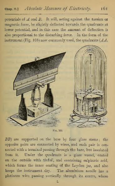
chap, v.] Absolute Measure of Electricity. 161
potentials of A and B. It will, acting against the torsion or
magnetic force, be slightly deflected towards the quadrants at
lower potential, and in this case the amount of deflection is
also proportional to the disturbing force. In the form of the
instrument (Fig. 105) now commonly used, the quadrants (AA,
Fig. 105.
BE) are supported on the base by four glass stems; the
opposite pairs are connected by wires, and each pair is con-
nected with a terminal passing through the base, but insulated
from it. Under the quadrants is a glass vessel, coated
on the outside with tinfoil, and containing sulphuric acid,
which forms the inner coating of the Leyden jar, and also
keeps the instrument dry. The aluminium needle has a
platinum wire passing vertically through its centre, whose
L

l62 Electricity. [Book II.
lower end dips in the sulphuric acid, and whose upper end is
formed in a T, to the top of which the bifilar suspension (D)
is attached. To register the movements of the needle a light
concave mirror (E) is cemented to the wire immediately
under the head of the T. The whole is enclosed under a
bell-glass, and supported on levelling screws. By means of
a lens (F) the light from a narrow slit in front of the flame
of an oil lamp (G) is thrown on the mirror, reflected from
it, and focussed on a graduated screen (H) placed above
the slit. As the distance between the slit and the mirror is
about 18 inches, the smallest movement of the mirror causes
a considerable movement in the image of the slit on the
graduated screen.
*IOI. The Gauge.—In Sir William Thomson's original
form the bell-glass itself formed the Leyden jar, and the parts
Fig, 106.
SulphuricAcid
of the apparatus were suspended from a metal plate which
closed it at the top. This form is still adopted where there
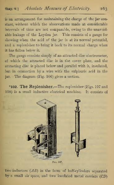
Chap, v.] Absolute Measure of Electricity. 163
is an arrangement for maintaining the charge of the jar con-
stant, without which the observations made at considerable
intervals of time are not comparable, owing to the unavoid-
able leakage of the Leyden jar. This consists of a gauge for
showing when the acid of the jar is at its normal potential,
and a replenisher to bring it back to its normal charge when
it has fallen below it.
The gauge consists simply of an attracted disc electrometer,
of which the attracted disc is in the cover plate, and the
attracting disc is placed below and parallel with it, insulated,
but in connection by a wire with the sulphuric acid in the
jar. The diagram (Fig. 106) gives a section.
*I02. The Replenisher.—The replenisher (Figs. 107 and
108) is a small inductive electrical machine. It consists of
Fig. 107.
two inductors (AB) in the form of half-cylinders separated
by a small air space, and two insulated metal carriers (CD)
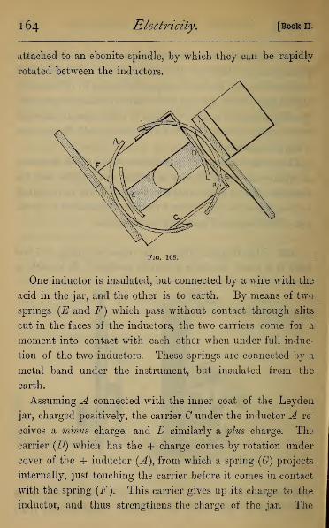
1 64 Electricity. [Book II.
attached to an ebonite spindle, by which they can be rapidly
rotated between the inductors.
Fig. 108.
One inductor is insulated, but connected by a wire with the
acid in the jar, and the other is to earth. By means of two
springs (E and F) which pass without contact through slits
cut in the faces of the inductors, the two carriers come for a
moment into contact with each other when under full induc-
tion of the two inductors. These springs are connected by a
metal band under the instrument, but insulated from the
earth.
Assuming A connected with the inner coat of the Leyden
jar, charged positively, the carrier C under the inductor A re-
ceives a minus charge, and D similarly a plus charge. The
carrier (D) which has the + charge comes by rotation under
cover of the + inductor (A), from which a spring (Gf) projects
internally, just touching the carrier before it comes in contact
with the spring (F). This carrier gives up its charge to the
inductor, and thus strengthens the charge of the jar. The

chap, v.] Absolute Measure of Electricity, 165
opposite carrier at the same time gives up its charge by a
spring to the opposite inductor, by which it passes to earth.
A few turns of the milled head at the top of the ebonite
spindle will then bring up the charge if it be too low ; and it
can easily be seen that turning the head in the opposite
direction will bring down the charge should it be too high.
*I03- Uses of Quadrant Electrometer,—By the
Quadrant Electrometer differences of potential can be shown
and measured which are quite insensible to the gold-leaf elec-
troscope. The pyro-electricity of tourmaline can be shown by
it in very short broken crystals. It is only necessary to bind a
platinum wire round each end of the crystal, connecting the
opposite ends with the electrometer terminals. By placiug the
crystal without contact over a metal plate, under which a
lamp is lighted, the needle will soon deflect, showing the
presence of the pyro-electricity. Its chief use, however, is in
investigating differences of potential on which current elec-
tricity depends, and which form the subject of our next
Book.
QUESTIONS ON BOOK II.
1. A sheet of paper well dried and rubbed with a brush will adhere
to the wall of a room, but it will remain longer adherent the drier the
air of the room. Explain this.
2. Two gold-leaf electroscopes, charged with opposite electricities,
are approached towards each other till the caps nearly touch. Explain
the effect observed on the leaves.
3. A gold-leaf electroscope is taken from a colder room and at once
placed on the table of a warmer room ; a charged body is brought in
contact with the cap. Describe the effect on the electroscope.

1 66 Questions on Book II.
4. A crystal of tourmaline is suspended by a silk fibre between two
bodies, one positively and the other negatively electrified ; the whole
system is enclosed in an oven, which is gradually heated from outside.
Describe the behaviour of the tourmaline crystal daring heating, and
also during cooling.
5. Explain why, after heating a tourmaline crystal, it is usual to
draw the flame of a lamp across it before observing the phenomena on
cooling. Explain the effect on the observed phenomena, consequent
on neglect of this precaution.
6. A piece of glass rubbed with cat's fur is pivoted freely, and
approached by another piece of glass rubbed with silk. Describe the
action between them.
7. A silk glove is drawn off the hand. What will be the electrical
condition of the glove ?
8. A gold-leaf electroscope is charged by flapping it with a silk
handkerchief, and a piece of roll-sulphur, rubbed with cork, is ap-
proached towards its cap. Describe the observed effect.
9. In Coulomb's Balance, when the carrier ball is introduced, the
needle ball, after contact, shows a deflection of 30°. Explain how the
torsion circle must be treated to bring the balls 15° apart, and also to
bring them 60° apart.
Ans.—105° in the negative direction, i.e. opposite to the deflection ;
52° 30' in the positive direction.
10. If the balls in the balance had been at first 30° apart, and 260°
of torsion had been put on in a negative direction (i.e. opposite to the
deflection of the needle), find the position of the needle.
Ans.—At 10°.
11. If the balls in the balance show at first charging a deflection of
a°, and torsion /3° in the negative direction is applied, write down an
equation for finding the position of the needle.
Ans.—If x° be the position required, x3 + /3cc2= a3
.
12. A fixed charge is given to the needle ball, and the carrier ball
introduced without contact, carrying charges from successive con-
ductors, show that the charges can be compared by turning the torsion
circle till the balls are at a constant distance apart, and observing the
torsion on the wire. These charges will then be simply proportional
to the torsion in each case.

Questions on Book II 167
13. If the balance be discharged completely before each observation,
and the carrier ball introduced several times successively with different
charges, show that the charge in each case will be proportional to the
square root of the cube of the observed deflections.
14. The charge on the carrier ball of the balance, which at first
shows a deflection of 36°, is halved, and the ball introduced again
without contact with the needle ball. Find the reading of the torsion
circle when the balls again diverge 36°.
15. The needle ball of a balance is electrified, and charges are
carried from three selected points on a conductor by the carrier ball,
which is introduced each time into the balance without contact. The
readings of the torsion circle corresponding to the three charges are
respectively — 35°, + 3°, and + 20°, the deflection of the needle being
in all cases 45°. Compare the electrical density at the three points.
16. A sheet of tinfoil, of which two opposite edges are held by in-
sulating handles is charged, and has a gold-leaf electroscope connected
with its surface. What change in the indication of the electroscope
would be noticed, supposing the sheet rolled up like a wall map ?
.17. A gold-leaf electroscope has its base to earth, and an electrified
wire cage is lowered over its cap, just avoiding contact with the base.
Describe the changes in the electroscope as it is lowered.
18. A gold-leaf electroscope has a sharp point attached to its cap,
and a glass rod, charged by friction with silk, is held over the point
for a short time, and then removed. Describe all the indications of
the electroscope.
19. A person on an insulating stool draws a silk glove off his hand,
and, holding the glove in the opposite hand, presents the ungloved
hand to the cap of an uncharged electroscope. What indications will
be obtained ? If he now drop the glove on the floor what change will
there be ?
20. A glass funnel with a narrow tube is filled with copper filings,
which gradually flow out on to the cap of a gold-leaf electroscope;
a rod of sealing-wax rubbed with flannel is held over the funnel as
the copper filings are discharged. Show that the electroscope acquires
a permanent charge.
21. A platinum dish is placed on the cap, and over it a glass
funnel with a capillary tube, filled with acidulated water. Show that

1 68 Questions on Book II
on holding an excited sealing-wax rod over the funnel the liquid will
flow through the capillary tube into the platinum dish, and will com-
municate a permanent charge to the electroscope. What is its sign ?
22. A sphere whose radius is 5 cm. has a charge of 10 absolute
units communicated to it. Find its potential and the density of its
electrification in absolute measure.
23. A sphere whose radius is 10 cm. is brought to potential 5 in
absolute measure. Find its charge.
24. Spheres whose radii are 5 and 6 cm. are connected by a long
wire (whose capacity is nil). Find how a charge communicated to
the system is divided between them.
25. Spheres whose radii are 1, 2, and 3 cm., are charged to poten-
tials 1, 2, 3 in absolute measure, and are then suddenly connected by
a long wire. Find the potential of them all after contact.
Ans.—J.
26. The radii of two spheres are as 2:3, and the density of their
electrification as 9 : 8. Compare their potentials.
Ans.—3 : 4.
27. An electrophorus cake excited by friction is dropped face
downwards on a metal plate connected with the earth. What is the
electrical condition of the sole ?
28. One of two insulated hollow vessels has a weak charge of elec-
tricity. A carrier ball, supported on a silk fibre, is brought near the
outside of the charged vessel, touched by the finger, and then dropped
into the second vessel. It is lifted out, approached to the outside of
this vessel, when near it touched by the finger, and then dropped into
the first vessel. The whole process is repeated over and over again.
Show that the potential difference of the two vessels rises in compound
interest ratio.
29. If one thousand spherical mist particles, all at the same elec-
trical potential, fall together into a single rain-drop, the potential of
the rain-drop is one hundred times that of each mist particle.
30. Compare potential in a battery of 6 jars charged by 12 turns of
a machine, with that of a battery of 12 jars of equal area charged
with 36 turns of the same machine working at the same power.
Ans.— As 2 to 3.

Questions on Book II 169
31. Compare the quantity in a fully-charged battery of 8 jars with
that in another battery of 12 jars, the quantity of coated surface in
each jar of the latter being double that in each of the former, and the
thickness of the glass one half.
Ans.—As 1 to 6.
32. In a certain trap-door electrometer the trap-door was brought
to its fiducial position by a weight of -0133 grams, the whole being
unelectrified. The disc is a square whose side is *8 cm., and in a
certain experiment the trap-door was brought to its fiducial markwhen the moveable disc was distant *5 cm. Find the potential differ-
ence in absolute measure.
Ans.—11 3 nearly.
33. The replenisher in a quadrant electrometer is a modified Voss
machine. Trace out the corresponding parts of the apparatus in the
two instruments.
34. Point out the exact source of danger in holding a piece of metal
in the hand during a thunderstorm.
35. Show, on the general principles of induction, that a person maybe killed at the instant of a lightning discharge without the dis-
charge passing through his body (the return shock).
36. When the electrification of the earth is resinous, what would
be the electrical condition of rain falling to the earth, and of smoke
rising from the earth ?
37. Show that a knight of the middle ages in a coat of mail could
not be injured by lightning.
38. Why should you not in a thunderstorm take refuge under a
tree?
39. Would you in a thunderstorm feel yourself secure in a house
built of sheet-iron ?
40. Show why a house in which a gas or water supply exists is
more liable to damage from lightning than one without them.


BOOK III.
VOLTAIC ELECTRICITY.
CHAPTER L
THE BATTERY.
104. Electrical Conditions of a Zinc-Copper Couple.—Voltaic Electricity may be defined as the electrical condi-
tions developed in metals and liquids when in contact. As anillustration (Fig. 109) we take a strip
of zinc (amalgamated by dipping it ^^^k ^e^^^in dilute sulphuric acid, and rubbing
it over with mercury) and a strip of
copper of the same size. Dip them,
without contact between them, in a
vessel of water, slightly acidulated
with a few drops of sulphuric acid.
If we now connect the plates with
the terminals of a quadrant electro-
meter, or with the plates of a con-
densing electroscope, it will be found
that the copper is positive to the
zinc. It can be shown that in this,
as in other cases, there is not a
development of one kind of electricity only, for on insu-
171
Fig. 109.

r 7 2 Electricity. [Book m.
lating the vessel it will be found that the copper is positive
to the earth, and the zinc negative to the earth.
If we now connect the copper and zinc by a thick wire, all
trace of electrification disappears, but on separating them
again the difference of potential instantaneously reappears.
On substituting a very thin wire for the thick wire, we find
that the difference of potential is diminished but does not
disappear, but can be made less and less by shortening or
thickening the conducting wire. This shows that there is in
this case not a single discharge of electricity, as in a Leyden
jar, but a continuous discharge depending in some way on the
connecting arc.
105. Chemical Conditions of the Cell.—If we
next examine the fluid in the vessel, we shall notice that
while the zinc and copper are in contact, bubbles of gas
stream up from the copper plate. This gas can be collected
and proved to be hydrogen. On separating the plates the
stream of hydrogen bubbles ceases. After the contact has
lasted for some time, on taking out a few drops of the liquid
and evaporating it, we shall find that it leaves a white residue
of sulphate of zinc, and on removing the zinc plate, washing,
and drying it, we shall find that it has lost in weight.
If, for comparison, we leave the zinc and copper in the
liquid without contact for the same length of time, we shall
find no hydrogen evolved, no deposit of zinc sulphate on
evaporating the liquid, and no loss of weight in the zinc.
We have thus shown that when zinc and copper are dipped
in acidulated water they assume different potentials, without
any sensible chemical action taking place; but as soon as
they are in contact with each other, the potential difference

chap, l] The Battery. i J$
is diminished, and as long as contact continues, chemical
action takes place in the liquid; zinc, being dissolved, forming
zinc sulphate in the liquid, and hydrogen being evolved at
the copper plate.
If the weighed amalgamated zinc and copper plates be
placed under an inverted glass jar in a pneumatic trough,
and there brought into contact, the hydrogen can be collected
and its weight computed. If the loss in the weight of zinc be
also determined, these two weights will have a constant ratio
—hydrogen to zinc—of 2 to 65, which is the ratio of their
chemical equivalents. We see, therefore, that the action in
the cell is purely the chemical action of the fluid on the metallic
zinc, although the action on the zinc takes place at the zinc
plate, and the hydrogen is given off at the copper plate.
106. Thermal Condition of the Cell.—While the
zinc and copper are in contact, we shall find that the
temperature both of the liquid and the solid conductors
has risen, and by performing the experiment in a calorimeter
it can be shown that the total heat evolved is exactly equal
to that which would be evolved on dissolving the same weight
of ordinary granulated zinc in dilute acid. This further con-
firms the conclusion that the action in the cell is a purely
chemical one.
107. Source of Energy of the Current—From the
experiments on the simple zinc-copper cell, we see that,
although we may have difference of potential, we cannot
have a flow of electricity maintained in the conductor, with-
out a sensible amount of chemical action in the cell. This
might have been in a measure anticipated, by considering
that the current in the conductor is a form of energy

1 74 Electricity. [Book m.
(developing heat, and capable of doing work in a variety of
ways), and can therefore only be maintained by an expendi-
diture of energy. This source of energy is found in the
energy of chemical combination in the battery. For the
maintenance of the current it therefore appears necessary
that we should have at least one fluid capable of decomposi-
tion, and of forming compounds with some other body with
which it is in contact. Thus we might in the cell have sub-
stituted, for sulphuric acid, hydrochloric or nitric acid, or even
pure water, and the action would, initially at least, have been
much the same. We might also have varied the metals, pro-
vided we still had one of them capable of being dissolved by
the liquid. Thus if we had used copper and platinum, we
should have had the copper attacked by the acid, taking the
place of the zinc in the typical cell ; but if we had used gold
and platinum, neither of which is acted upon by sulphuric
acid, we should have had no current. We should also find,
in all changes of the metals, that that which is acted on by
the acid is always at the lower potential.
For convenience of reference, the plates in the liquid are
called electrodes, that which is consumed by the acid being
called the zincode, and the opposite plate the platinode, from
their analogy to the zinc and platinum in a typical zinc-
platinum cell.
108. Local Action.—In all the older forms of cell some
modification of the zinc-copper cell of Volta was used, in
which zinc was the metal dissolved, and dilute sulphuric acid
the liquid.
When only commercial zinc is used in making the cells, a
rapid evolution of gas takes place from the zinc plate, accom-

chap, i.] The Battery, 1 75
panied by the corrosion of this plate when the zinc and copper
are not in contact, thus causing a waste of zinc, a weaken-
ing of the current, and obliging the use of a very weak acid
solution in the cells. This is called local action, and can be
avoided by rubbing the zinc plate—first dipped in dilute
acid, to remove oxide—with liquid mercury. In this way an
amalgam of zinc and mercury is formed on the surface of the
zinc. The cause of this local action, as it is called, in the
zinc plate, seems to be the existence of other metals as im-
purities in the zinc. These with the zinc and the acid set
up small voltaic couples, by which the zinc is consumed and
hydrogen evolved. The presence of the mercury seems to
keep a uniform amalgam of zinc and mercury always in
contact with the acid, and prevents these local circuits. Whenthe battery is in action the zinc alone is consumed, the mer-
cury amalgam being constantly replenished from the solid
zinc behind. This allows a much stronger acid to be used
for charging the battery.
109. Action of Evolved Hydrogen.—In every battery
in which there is employed one fluid and two metals, a
further defect consists in the deposit of the hydrogen gas on
the platinode, forming a layer of hydrogen instead of metal.
This, in the first place, acts as a non-conductor to the elec-
tricity, so weakening the current; in the second place, its
contact with the copper plate lessens its potential, so that,
after the battery has been working for a short time, the
potential difference between the terminals is much lessened.
It also decomposes the zinc sulphate in the liquid, causing a
deposit of zinc on the copper plate.
110, Smee's Cell.—These effects are somewhat obviated
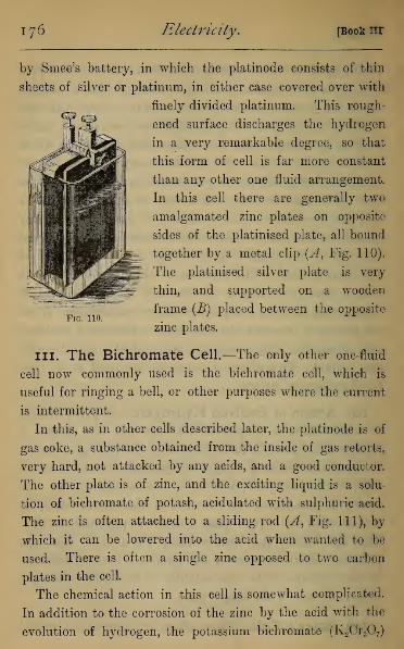
176 Electricity. [Book nr
by Smee's battery, in which the platinode consists of thin
sheets of silver or platinum, in either case covered over with
finely divided platinum. This rough-
ened surface discharges the hydrogen
in a very remarkable degree, so that
this form of cell is far more constant
than any other one fluid arrangement.
In this cell there are generally two
amalgamated zinc plates on opposite
sides of the platinised plate, all bound
together by a metal clip (A, Fig. 110).
The platinised silver plate is very
thin, and supported on a wooden
frame (B) placed between the opposite
zinc plates.Fig. 110.
III. The Bichromate Cell.—The only other one-fluid
cell now commonly used is the bichromate cell, which is
useful for ringing a bell, or other purposes where the current
is intermittent.
In this, as in other cells described later, the platinode is of
gas coke, a substance obtained from the inside of gas retorts,
very hard, not attacked by any acids, and a good conductor.
The other plate is of zinc, and the exciting liquid is a solu-
tion of bichromate of potash, acidulated with sulphuric acid.
The zinc is often attached to a sliding rod (A, Fig. Ill), by
which it can be lowered into the acid when wanted to be
used. There is often a single zinc opposed to two carbon
plates in the cell.
The chemical action in this cell is somewhat complicated.
In addition to the corrosion of the zinc by the acid with the
evolution of hydrogen, the potassium bichromate (K2Cr2 7)

Chap. L] The Battery, 177
parts with some of its oxygen to the zinc, forming zinc oxide
3(ZnO), three atoms of zinc entering into the action, and the
salt, in doing so, is decomposed into po-
tassium oxide (K20) and chromium ses-
quioxide (Cr2 3).Each of these oxides,
in the presence of free sulphuric acid,
forms a sulphate, the ultimate products
being zinc sulphate and a compound
sulphate of potassium and chromium
(KCr2S04) called chrome alum, which
gives a green colour to the liquid after
the cell has been in action for some
time.
112. Danieirs Cell.—In two fluid
and two metal batteries the hydrogen
evolved acts chemically on some other
substance, and causes a solid or liquid
to be formed at the platinode which
has no injurious effect.
A great variety of such cells are
in existence for various purposes, of
which we shall describe those most commonly used.
Daniell's Cell is constructed in a great variety of forms,
but consists essentially of a zinc rod immersed in dilute
acid, separated by porous earthenware, or some material
gradually permeable by liquids, from sulphate of copper in
which a copper rod is immersed. In this case the hydrogen
set free by the action of the acid on the zinc attacks the
copper sulphate, forming sulphuric acid, and causing a
deposit of metallic copper on the copper plate.
This cell continues working apparently at the expense only
M
Fig, 111.

178 Electricity. [Book in.
of the zinc and the copper sulphate, the latter of which can
be replaced by packing crystals of copper sulphate round the
copper plate, and in this case the working of the cell continues
till the zinc is consumed. The formation of zinc sulphate in
the zinc cell appears not to be injurious till a deposit of
crystals occurs, as the cell is found to work equally well
when the zinc cell is filled with a concentrated solution of
zinc sulphate instead of acid. In this latter case the zinc
sulphate has no direct action on the metallic zinc, except when
the terminals are joined. The chemical action originating the
current in this case is the tendency, in the presence of free
zinc, to replace copper sulphate by the more stable compound
zinc sulphate,—an action which can only take place in the
pores of the material separating the zinc sulphate from the
copper sulphate.
The form given to this cell may be an outer glazed porce-
lain cell containing the zinc plate and acid, with an inner
vessel of porous porcelain filled with copper sulphate with the
copper rod immersed, shown in section in Fig. 112. Another
form is to have the outer vessel entirely copper, containing the
copper sulphate, and an inner porous vessel with the zinc rod
immersed in acid (Fig. 113).
On the same principle are constructed specific-gravity
batteries, of which one form is shown in section in Fig. 114.
It depends on the difference in specific gravity of zinc sulphate
and copper sulphate. At the bottom of the vessel lies a copper
plate embedded in crystals of copper sulphate, and a saturated
solution of the salt is poured over it to about half fill the
vessel. A copper wire is fastened to the plate, and, passing
through the liquid (insulated by a coating of gutta-percha), is
connected with a terminal outside. On the top of the copper

Chap. I.] The Battery. 179
•
=n ':Wk
Fiq. 112. Fiq 113
-Cu/
Fig. Hi.

i8o Electricity. [Book III.
sulphate is carefully poured a solution of zinc sulphate or
dilute acid, which, being specifically lighter, rests upon it
without mixing. In contact with this is suspended a zinc
plate. Menotti's battery differs from this only in placing a
layer of sawdust or sand over the copper sulphate crystals,
which takes the place of the porous cell.
113. Grove's and Bunsen's Cells.—In Grove's Cell
(Fig. 115) the outer porcelain or glass vessel contains the
Fig. 115.
zinc plate immersed in dilute acid, and the porous vessel con-
tains a sheet of platinum immersed in strong nitric acid.
In this the hydrogen set free by the corrosion of the zinc
attacks the nitric acid, reducing it to water and one or
more compounds of nitrogen and oxygen, which are soluble
m the water and nitric acid to a large extent; but the
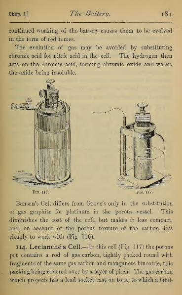
Chap. I.] The Battery. 181
continued working of the battery causes them to be evolved
in the form of red fumes.
The evolution of gas may be avoided by substituting
chromic acid for nitric acid in the cell. The hydrogen then
acts on the chromic acid, forming chromic oxide and water,
the oxide being insoluble.
Fig. 116. Fig. 117.
Bunsen's Cell differs from Grove's only in the substitution
of gas graphite for platinum in the porous vessel. This
diminishes the cost of the cell, but makes it less compact,
and, on account of the porous texture of the carbon, less
cleanly to work with (Fig. 116).
114. Leclanche's Cell.—In this cell (Fig. 117) the porous
pot contains a rod of gas carbon, tightly packed round with
fragments of the same gas carbon and manganese binoxide, this
packing being covered over by a layer of pitch. The gas carbon
which projects has a lead socket cast on to it, to which a bind-

182 Electricity. [Book III.
ing screw is attached. The outer cell contains a zinc rod
immersed in a solution of sal-ammoniac. The sal-ammoniac or
ammonium chloride (H3NHC1) attacks the zinc, forming zinc
chloride (ZnCl2), which combines with the ammonia (H3N) to
form a compound (2H3NZnCl2), and liberating hydrogen. The
hydrogen reduces the manganese binoxide (Mn02) in the porous
vessel to a lower oxide (Mn2 3) and water. This cell continues
working till the whole of the manganese binoxide has been re-
duced, if occasionally filled up with the sal-ammoniac solution.
115. Marie Davy's Cell.—In this the porous vessel con-
tains a paste of mercury sulphate, in which the carbon rod is
immersed; the outer vessel contains a zinc rod immersed
in brine. In this cell zinc chloride is formed, and the sodium
set free attacks the sulphate of mercury, forming sodium
sulphate, and liberating mercury, which is found in a metallic
form at the bottom of the cell. This can easily be recon-
verted into sulphate, and used over again without any loss.
116. Becquerers Cell.—This, called by its inventor the
Fig. 118.
" oxygen battery," is of rather theoretical than practical im-
portance, being constructed without the use of two metals. It
chap, l] The Battery. 183
consists (Fig. 118) of an outer vessel containing nitric acid,
and a porous vessel containing caustic potash, platinum plates
dipping into each vessel to form the terminals. On joining
the terminals a current flows from the platinum in the acid
to that in the alkali, nitrate of potash being formed in the
pores of the diaphragm.
117. Electromotive Force.—In dealing with voltaic
cells, a very important element in their working is the differ-
ence of potential of their terminals when separate. This is
commonly called the Electromotive Force (written E.M.F.)
—though of course not a Mechanical Force.
The unit used for E.M.F. is not the ordinary unit of
potential which we used in Electrostatics, but a unit obtained
in a theoretical manner, and called a Volt. For the present
there will be no appreciable error if we take it as the E.M.F.
of a DanielFs cell formed of an amalgamated zinc rod in satu-
rated zinc sulphate, and a copper rod in semi-saturated copper
sulphate. The actual value of this E.M.F. is found to be
1-07 Volt.
In terms of this unit we can express the E.M.F. of different
cells by simply connecting their terminals with those of
a quadrant electrometer and observing the deflections, which
are directly proportional to the E.M.F.s of the different cells
experimented with1 By this means the following values maybe approximately verified (slight differences being unavoidable
owing to variation in the metal and fluids) :
—
Volta (zinc, acid, copper), . . . about 1
Smee (zinc, acid, platinised silver), . . „ 1
Bichromate (zinc, potas. bichromate, carbon
when freshly prepared), . . . „ 2
1 It is preferable to xeverse the terminals in each experiment, thedifference of the readings being then proportional to double the E.M.F.

1 84 Electricity. [Book in.
Daniell (zinc, acid, copper sulphate, copper), about
Grove (zinc, acid, nitric acid, platinum), . „
Bunsen (zinc, acid, nitric acid, carbon), . „Leclanche' (zinc, sal-ammoniac, manganese
dioxide, carbon), . . . „Marie Davy (zinc, acid, mercurous sulphate,
carbon), . ... . „
1 to 1*14
1-94 to 1*97
1-75 to 1*96
1-41
1*2
118. Battery arranged in Simple Circuit.—According
to the purpose for which a battery is to be used, the cells are
grouped either in simple or compound circuit, or in a manner
compounded of the two.
Fig. 119.
In a simple circuit arrangement, called also multiple arc,
all the cells have their zincs connected to a common terminal,
and all the coppers connected to another (Fig. 119). Since
the zincs are all connected together, as also the coppers, they
are respectively at the same potentials, and the battery is
equivalent to a single cell with the size of the plates in-
creased in proportion to the number of cells. The E.M.F.
of the battery will be found to be the same as for a single
cell, since it is independent of the size of the plates.
119. Battery arranged in Compound Circuit.—In
this arrangement (Fig. 120) the copper of the first cell is con-
nected to the zinc of the next, the copper of that to the zinc
of the third, and so on. The cells arranged in this manner are
often said to be in series.
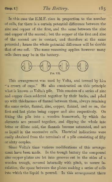
chap, i.] The Battery.
In this case the E.M.F. rises in proportion to the number
of cells, for there is a certain potential difference between the
zinc and copper of the first, and the same between the zinc
and copper of the second \ but the copper of the first and zinc
of the second are in contact, and therefore at the same
potential ; hence the whole potential difference will be double
that of one cell. The same reasoning applies however many
cells there may be in the battery.
Fig. 120.
This arrangement was used by Volta, and termed by him" a crown of cups." He also constructed on this principle
what is known as Volta's pile. This consists of a series of zinc
and copper discs soldered together by their backs, and piled
up with thicknesses of flannel between them, always retaining
the same order, flannel, zinc, copper, flannel, and so on, the
first and last plates being copper and zinc respectively. On
fitting the pile into a wooden framework, by which the
elements are pressed together, and dipping the whole into
brine or dilute acid, the flannels become saturated, and act
as liquid in the successive cells. Electrical indications were
easily obtained from the terminals of a pile consisting of fifty
or sixty couples.
Since Volta's time various modifications of this arrange-
ment have been made. In the trough battery the compound
zinc copper plates are let into grooves cut in the sides of a
wooden trough, covered internally with pitch, to secure in-
sulation, the space between the plates making a series of cells
into which the liquid is poured. In this arrangement there
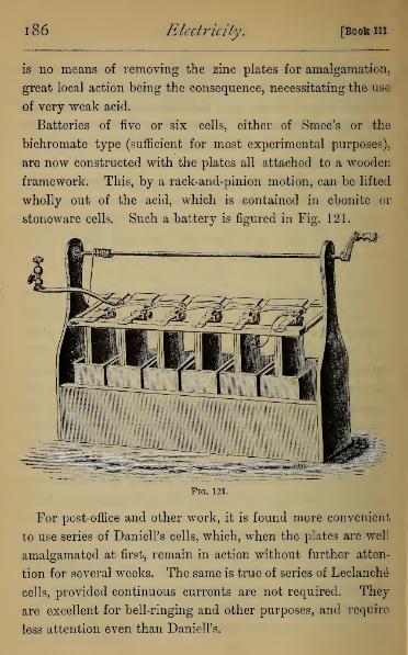
1 86 Electricity. [Boot III.
is no means of removing the zinc plates for amalgamation,
great local action being the consequence, necessitating the use
of very weak acid.
Batteries of five or six cells, either of Smee's or the
bichromate type (sufficient for most experimental purposes),
are now constructed with the plates all attached to a wooden
framework. This, by a rack-and-pinion motion, can be lifted
wholly out of the acid, which is contained in ebonite or
stoneware cells. Such a battery is figured in Fig. 121.
Fig. 121.
For post-office and other work, it is found more convenient
to use series of DanielPs cells, which, when the plates are well
amalgamated at first, remain in action without further atten-
tion for several weeks. The same is true of series of Leclanch6
cells, provided continuous currents are not required. They
are excellent for bell-ringing and other purposes, and require
less attention even than Daniell's.

chap, i.] The Battery. 187
120. Frictional Electricity obtained from a Battery.
—M. Gassiot, and since him other experimenters, have con-
structed many thousand cells, carefully insulated and arranged
in compound circuit. By this means the E.M.F. is vastly
increased, so much that sparks can be obtained, electro-
scopes and Leyden jars charged, and all the phenomena
characteristic of frictional electricity demonstrated.
To compare the effects of frictional with those of voltaic
electricity, it may be instructive to give the results obtained
by Messrs. De La Rue and Miiller, working with silver
chloride cells, whose potential difference is about the same as
that of the zinc copper cell we are using. They found that
1,000 cells in series gives a striking distance of *0205 cm.
5,000 „ „ „ -1176 „
10,000 „ „ „ -2863 „
15,000 „ „ „ -4882 „
These confirm what was said above, that the striking distance
is not strictly proportional to the potential difference when
that difference is very small.
121. Comparison of Frictional with Voltaic Elec-
tricity.—Faraday has, on the other hand, compared the
quantities derived from frictional and voltaic electricity both
by their magnetic and chemical effects. He found that "two
wires, one of platina 1 and one of zinc, each one-eighteenth of
an inch in diameter, placed five-sixteenths of an inch apart,
and immersed to the depth of five-eighths of an inch in acid
consisting of one drop of oil of vitriol and four ounces of
distilled water at a temperature of about 60° (Fah.), and
connected at the other extremities by a copper wire eighteen
1 Called by modern chemists Platinum.

1 88 Electricity. [Book m.
feet long and one-eighteenth of an inch thick . . . yield as
much electricity in . . . Tfo-ths of a second as . . . thirty
turns of the large electrical machine in excellent order."
"The electrical machine," he says, "is fifty inches in
diameter; it has two sets of rubbers; its prime conductor
consists of two brass cylinders connected by a third, the
whole length being twelve feet, and the surface in contact
with air about 1422 square inches. When in good excitation
one revolution of the plate will give ten or twelve sparks, each
an inch in length. Sparks or flashes from ten to fourteen
inches in length may easily be drawn fro? the conductors." 1
From these two results we learn that ij frictional elec-
tricity the potential differences are very high, but the
quantity of electricity concerned is very minute, while in
voltaic electricity the differences of potential are very small,
but the quantity enormously great. Eeturning to our hydro-
static analogy, we may say that the machine discharge is as
the tiniest rill falling down a very steep hill ; the voltaic
current is like a vast river flowing through a nearly level
valley.
122. Dry Piles.—On the principle of the compound
series are constructed certain modifications of Volta's pile,
called Dry Piles. In these the liquid is replaced by paper,
which, unless specially dried, contains a large quantity of
water. The only one now used is Zamboni's. This consists
of paper coated on one side with tinfoil and rubbed over on
the opposite side with manganese dioxide slightly moistened.
The sheets are then cut out with a punch and piled together
in the order, tinfoil, paper, binoxide of manganese. With
1 Faraday, Experimental Researches, Series in., Jan. 1833.

chap, l] The Battery. 189
several thousand sheets a high electromotive force is obtained,
though the current is insignificant. The most remarkable
thing about them is their permanence of action. By affixing
suitable terminals the pile can be discharged by alternate con-
tacts, giving motion to a light pendulum or see-saw, which
under suitable conditions has been known to keep up its
motion for several years. This pile is also used in Bohnen-
berger's electroscope, in which a single gold leaf is suspended
between two parallel plates near together, which are connected
with the terminals of a dry pile. The gold leaf then shows
electrification by diverging to one side or the other.
This, however, as well as every other form of electroscope,
is superseded by Thomson's Quadrant Electrometer, which
can be made to measure the hundredth part of the E.M.F.
of a single Daniell's cell.

CHAPTER II
ELECTROLYSIS.
123. Phenomena of the Current.—We now proceed to
consider some of the actions belonging to the electricity in
motion as they are presented in the wire joining the termi-
nals of a battery. These are the peculiar phenomena which
form the subject of voltaic electricity. The properties of
the current may be classed as Chemical, Magnetic, and
Thermal. In the present chapter we consider the Chemical
phenomena.
124. Direction of the Current.—As the phenomena
of the current all depend on certain directions, it is con-
venient to have conventional rules by which these directions
can be remembered. We have seen that in a zinc-copper cell
the copper is at a higher potential than the zinc, and conse-
quently when they are joined by a conductor, a neutralisation
of electricity takes place along the conductor. This can best
be represented by a movement of + E. from the copper to
the zinc, and an equal movement of — E. from the zinc
to the copper. The motion of the + E. may be called
the positive current, and we fix our attention on this, and
speak of it as the direction of the current. This is only a
convention or memoria technica to represent to our mind the
neutralisation of unequal potential, and does not imply any
theory as to the nature of the current.
190

Chap. II.] Electrolysis. 191
If we always had a flow of + E. to the zinc plate, and
— E. to the copper, without any compensating flow in the
opposite direction, the potential of the zinc
would constantly rise, and that of the
copper constantly sink. Hence we infer
that there is a flow of electricity through
the liquid of the cell equal in amount and
opposite in direction to that in the conduc-
tor. That is to say, the current will flow
in the liquid from zinc to copper, and in
the external conductor from copper to zinc,
making a complete circuit (Fig. 122). This
assumption of the current in the liquid
will be confirmed through all our experiments, since we
shall find that the liquid obeys exactly the same laws as
the solid conductor while the current is passing.
In every battery, then, we shall assume that the current in
the liquid is from the zincode to the platinode, and in the
external conductor from the platinode to the zincode.
U
Fig. 122.
125. Electrolysis of Potassium Iodide.—Let us now
place the terminals of a zinc-copper or other cell on opposite
sides of a piece of blotting or other kind of bibulous paper
moistened with potassium iodide. Near the end of the wire in
connection with the copper will appear a brown discoloration
owing to the liberation of iodine. If the bibulous paper be
first soaked in a solution of starch, the discoloration becomes
blue owing to the action of the liberated iodine on the starch.
To actions of which this is the type Faraday gave the general
name of Electrolysis, and to him we owe the very full in-
vestigation of the general laws on which the action depends.
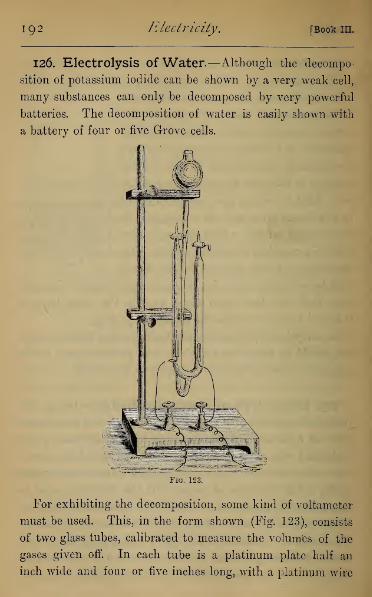
192 Electricity. [Book III.
126. Electrolysis of Water.—Although the decompo-
sition of potassium iodide can be shown by a very weak cell,
many substances can only be decomposed by very powerful
batteries. The decomposition of water is easily shown with
a battery of four or five Grove cells.
Fig. 123.
For exhibiting the decomposition, some kind of voltameter
must be used. This, in the form shown (Fig. 123), consists
of two glass tubes, calibrated to measure the volumes of the
gases given off. In each tube is a platinum plate half an
inch wide and four or five inches long, with a platinum wire

chap, ii.] Electrolysis. 193
welded to it, which is fused through the glass tube, and enables
communication to be made with the battery. These tubes
communicate either by being parts of the same U-shaped
tube (Fig. 123), or by being inverted over water in an inde-
pendent vessel. The apparatus must be at first filled with
water, slightly acidulated with sulphuric acid, for which the
third upright tube is provided. On passing the current, the
gases are rapidly evolved, hydrogen bubbling up from the
platinum plate connected with the zincode of the battery,
and oxygen from the plate connected with the platinode.
If we measure the volumes of the hydrogen and oxygen
evolved, after reducing them to the same pressure, we shall
find that the hydrogen occupies exactly double the volume
of the oxygen, and if we compute their weight, we shall find
the weight of the oxygen to be exactly eight times that of
the hydrogen. In practice it will be impossible to collect the
whole of the gases, .since the oxygen is to some extent soluble
in the water.
127. Electrolysis of Hydrogen Chloride.—Hydrogen
chloride or hydrochloric acid may be decomposed by a similar
arrangement, but the terminals must be made of carbon, since
platinum is attacked by the " nascent " chlorine (i.e. chlorine
at the instant of its separation from hydrogen). Moreover,
the chlorine is soluble in water, but its solubility is diminished
by saturating the water with common salt. After allowing
the current to pass for several hours, to saturate the liquid
with chlorine, it will be found that very nearly equal volumes
of hydrogen and chlorine are given off, the hydrogen as be-
fore collecting on the terminal connected with the zincode, and
chlorine on that connected with the platinode of the battery.
N

1 94 Electricity. [Book in.
In both these cases we see that the substance is decomposed
into its elements in exactly the proportions in which chemistry
teaches they enter into the substances, and which are indi-
cated by the form of their chemical formulae, H2 for water,
and HC1 for hydrogen chloride.
128. Secondary action in the Decomposition of
Sulphates, etc.—In many cases the electrical decomposition
is accompanied by a secondary action which may be purely
chemical. Thus if by means of two platinum plates we pass
the current through copper sulphate (CuS0 4 ), we shall find
pure copper deposited on the plate next to the zincode, and
oxygen only given off from the plate next to the platinode.
In this case the copper sulphate appears to be electrically
decomposed into copper, and the radical S0 4 , which is un-
stable, and cannot exist alone. It consequently attacks the
water of the solution, taking up hydrogen from it, and
forming H 2S0 4 , liberating only the oxygen. The presence of
the free sulphuric acid around the plate can easily be shown
by performing the decomposition in a V-tube. In the case
of the sulphates of the metals, potassium and sodium, which
cannot exist as metals in the presence of either water or air,
we have a double decomposition. If, for instance, sulphate
of sodium (Na2S04) solution be decomposed, only oxygen
and hydrogen will make their appearance at the plates. In
this case it appears that sodium is set free by electrolysis at
the plate next the platinode, but immediately attacks the
water, forming soda (NaHO) and liberating hydrogen. At
the same time S04 is set free at the opposite plate ; it, too,
cannot remain free, but attacks the water, forming with it
sulphuric acid (H2S04) and liberating oxygen. We thus
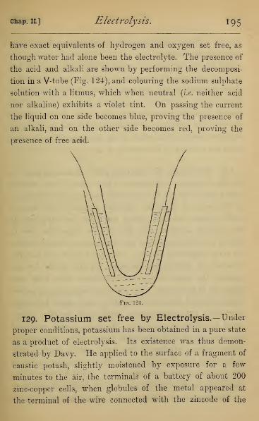
Chap. II] Electrolysis. 195
have exact equivalents of hydrogen and oxygen set free, as
though water had alone been the electrolyte. The presence of
the acid and alkali are shown by performing the decomposi-
tion in a V-tube (Fig. 124), and colouring the sodium sulphate
solution with a litmus, which when neutral (i.e. neither acid
nor alkaline) exhibits a violet tint. On passing the current
the liquid on one side becomes blue, proving the presence of
an alkali, and on the other side becomes red, proving the
presence of free acid.
Fig. 124.
129. Potassium set free by Electrolysis.—Under
proper conditions, potassium has been obtained in a pure state
as a product of electrolysis. Its existence was thus demon-
strated by Davy. He applied to the surface of a fragment of
caustic potash, slightly moistened by exposure for a few
minutes to the air, the terminals of a battery of about 200
zinc-copper cells, when globules of the metal appeared at
the terminal of the wire connected with the zincode of the

196 Electricity. [Bookin.
battery. These were preserved by performing the decom-
position under naphtha.
The experiment may be repeated with a battery of five
or six Grove cells, by making a hollow in the surface of a
block of caustic potash, and putting in it a globule of mercury.
If the block be rested on a platinum plate, and the current
passed from the platinum plate to a wire dipping in the
mercury, the potassium is liberated and forms an amalgam
with the mercury, from which it can be separated by distilling
away the mercury in the absence of air.
130. Faraday's Terminology for Electrolysis.—In
all the foregoing experiments it can hardly have escaped
notice that hydrogen and the metals have appeared uniformly
at the terminal connected with the zincode of the battery,
while oxygen, chlorine, iodine, and acids have appeared at
the opposite terminal, and this will be found the case in
almost every decomposition into which these substances enter.
To avoid confusion, Faraday, with the help of the late Dr.
Whewell of Cambridge, invented certain terms for ex-
pressing the observed facts of electrolysis apart from any
theory as to their cause. The process of separating by voltaic
action chemical compounds into their constituents he termed
electrolysis, 1 and any substance which could be thus decom-
posed he called an electrolyte. We have already employed
the term electrode,2 by which he means "that substance, or
rather surface, whether of air, water, metal, or any other
body, which bounds the extent of the decomposing matter in
the direction of the electric current." It will be noticed that
our use of the term for the plates of the battery is strictly in
1 rjXeKrpou and Xuco, to set free. 2 rjXeKrpov and odos, a way,

Chap. II.] Electrolysis. 197
accordance with this use. "The surface at which the cur-
rent," according to our present notion, enters "the electrolyte
is called the anode 1:" it is the negative extremity of the decom-
posing body, is where oxygen, chlorine, acids, etc., are
evolved, and is against or opposite the positive electrode
(platinode)." "The cathode 2 is that surface at which the
current leaves the decomposing body, and is its positive
extremity; the combustible bodies, metals, alkalies, and
bases, are evolved there, and it is in contact with the negative
electrode " (zincode).
Fig. 125.
For the purpose of distinguishing the substances which are
set free at the electrodes, Faraday continues, " I propose to
distinguish such bodies by calling those anions 3 which go to
the anode of the decomposing body, and those passing to the
cathode, cations,4, and when I have occasion to speak of these
together I shall call them ions." 5
Thus in the decomposition of water hydrogen and oxygen
1 aw, upwards, and obos.2 Kara, downwards, and 686s.
3 avicov, that which goes up. 4 Karicov, that which goes down.5 Faraday, Experimental Researches, Series vn., vol. i. p. 195.
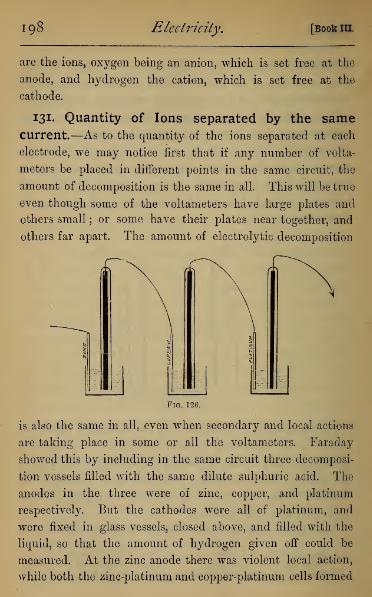
198 Electricity. [Book III.
are the ions, oxygen being an anion, which is set free at the
anode, and hydrogen the cation, which is set free at the
cathode.
131. Quantity of Ions separated by the samecurrent.—As to the quantity of the ions separated at each
electrode, we may notice first that if any number of volta-
meters be placed in different points in the same circuit, the
amount of decomposition is the same in all. This will be true
even though some of the voltameters have large plates and
others small ; or some have their plates near together, and
others far apart. The amount of electrolytic decomposition
Fig. 126.
is also the same in all, even when secondary and local actions
are taking place in some or all the voltameters. Faraday
showed this by including in the same circuit three decomposi-
tion vessels filled with the same dilute sulphuric acid. The
anodes in the three were of zinc, copper, and platinum
respectively. But the cathodes were all of platinum, and
were fixed in glass vessels, closed above, and filled with the
liquid, so that the amount of hydrogen given off could be
measured. At the zinc anode there was violent local action,
while both the zinc-platinum and copper-platinum cells formed

chap, il] Electrolysis. 199
voltaic couples, zinc sulphate forming at the zinc, and copper
sulphate at the copper anode. In the cell with both anode
and cathode of platinum there was of course no chemical
action beyond the direct decomposition of the liquid. After
passing the current through this compound arrangement till
a measureable amount of gas was collected at the three
cathodes, it was found that the amount of hydrogen in all
three was absolutely the same.
From these and numerous experiments, on nearly all the
electrolytes with which he was acquainted, and including
experiments both with frictional and voltaic electricity,
Faraday was enabled to lay down the principle that the
quantity of any given element separated in a given time by
electrolytic decomposition is simply proportional to the
strength of the current. Having established this, he used a
voltameter in the circuit as the measure of current strength
in many experiments with strong currents.
Further than this, if the current were passed through a
series of cells, some of which contained acidulated water, and
others contained hydrochloric acid, the quantity of hydrogen
collected at the cathodes of all the cells was found to be the
same.
Or again, if we take a series of cells containing different
electrolytes, e.g. (1) acidulated water, (2) copper sulphate,
(3) fused chloride of tin, (4) hydrochloric acid, when proper
precautions are taken for collecting the whole of the products
of decomposition, it will be found that the hydrogen collected
at the cathodes of (1) and (4), the chlorine at the anodes of
(3) and (4), the copper at the cathode of (2), and the tin at
the cathode of (3), will have certain definite ratios to each
other which will be absolutely invariable wherever any of

200 Electricity. [Book m.
these substances form the ions in any electrolytic decom-
position.
132. Electro - Chemical Equivalents.—Having seen,
then, that (1) the quantity of any given electrolyte decom-
posed in different cells in the same circuit is always the same,
(2) that the amount of any ion set free from different com-
pounds is the same for the same current, (3) that the
different ions are set free in quantities which bear a certain
definite relation to each other in respect of quantity when
liberated by the same current, we conclude that passing
unit current for unit time causes the separation of a certain
definite amount of each elementary substance which forms an
ion. This amount may be expressed in grains or grams, and
is independent of everything but the kind of ion and the
arbitrary unit of current we choose to adopt. This amount
of each ion is called its electro-chemical equivalent.
We have assumed in the above statement, as Faraday did,
that only one compound of each pair of ions is an electrolyte,
being generally that in which, according to the chemical
notation of his time, one atom of each ion entered. Later
researches have shown that in many cases two compounds of
the same ions (e.g. cupric and cuprous chloride) are both
electrolytes, thus giving rise to two or more electro-chemical
equivalents.
When these electro-chemical equivalents are calculated,
they are found to have the same ratio as the ordinary
chemical equivalents ; but while these latter are only the
ratios in which certain substances enter into chemical com-
binations, the former are perfectly definite masses of the sub-
stances. Thus it is found that for every 65 grams of zinc con-

chap, ii.] Electrolysis. 201
sumed in each cell of the battery, there will be set free in a
voltameter 2 grams of hydrogen, and 16 grams of oxygen, and
in a series of decomposition cells included in the circuit, and
containing solutions of metallic salts such as Faraday contem-
plated, there will be set free 254 grams of iodine, 71 of
chlorine, 63*3 of copper, 207 of lead, 200 of mercury, 78 of
potassium, 216 of silver, 118 of tin, etc. The equivalents
obtained from other salts will be simple multiples or sub-
multiples of these numbers, generally either double or one
half.
133. The Battery obeys the Laws of Electrolysis.
—The same laws which hold in the decomposition cell also
hold in each cell of the battery. Thus for each electro-
chemical equivalent of zinc consumed in each cell of the
battery, without local action, there will be an equivalent of
each ion separated in every cell through which the battery
current passes. This can easily be demonstrated by allowing
a Daniell cell to decompose copper sulphate, making both elec-
trodes in the decomposition cell of copper. Taking the pre-
caution that all the copper plates, both of the battery and the
decomposition cell, are cleaned and weighed before the action
begins, it will be found, after the current has passed for any
length of time, that the increase of weight of the battery plate
and of the plate forming the cathode are exactly the same.
134. E.M.F. necessary for Electrolysis.—It is now
easy to understand, on the ordinary principles of energy, why
we require a high E.M.F. to decompose certain compounds in
which chemical affinity is strong. If the decomposition, say
in a water voltameter, is effected at all, we must have an
equivalent of water separated for each equivalent of zinc

202 Electricity. [Book in.
consumed in the battery cell. If the cell be a simple zinc-
copper couple, the total thermal energy due to the consump-
tion of an equivalent of zinc in the battery is simply the
number of thermal units evolved during the conversion of
that weight of zinc into zinc sulphate. This is a superior
limit to the amount of energy available in the circuit, since in
every circuit some energy is expended in heat developed in
its solid and liquid parts.
Again, the combustion of an equivalent of hydrogen in
an equivalent of oxygen evolves a certain definite amount of
heat which may be measured in thermal units, and this
number of thermal units must be expended in decomposing
the equivalent of water into its elements. If then the energy
(measured thermally) required for the decomposition of an
equivalent of any substance be greater than the thermal
energy developed per equivalent of zinc in the battery, that
decomposition cannot take place.
*I35. E.M.F. measured thermally. — Again, the
E.M.R of the battery cell may be measured by the thermal
energy developed by the decomposition of an equivalent of
zinc in each cell. For the E.M.F. is by definition measured
by the work done in bringing a unit of electricity from the
negative to the positive pole, and is therefore measured by
the energy developed in the passage of the same quantity of
electricity from the positive to the negative pole. If the
unit of electricity be that which passes in our arbitrary unit
current in unit time, the thermal energy developed by the
passage of unit current for unit time through the battery will
be a measure of the E.M.F. of the battery.
Hence, if we are able to express in thermal units the

Chap, ii.] Electrolysis. 203
amount of all the chemical actions which takes place in
any battery cell, we have a thermal measure of its E,M.F.
This Sir William Thomson has done for a Daniel cell (Phil.
Mag., May 1851). In this cell there is (Art, 11 2) a zinc plate
in zinc sulphate, and a copper plate in copper sulphate. The
chemical actions may be represented thus
—
(1) Zinc decomposes the water, and forms zinc oxide.
(2) Zinc oxide combines with sulphuric acid, and forms zinc
sulphate.
(3) Copper oxide is separated from the copper sulphate.
(4) Copper is separated from the copper oxide, the oxygen
recombining with the hydrogen liberated in (1).
In (1) water is decomposed, and in (4) the elements of water
recombine. These may be neglected, since they are equal
and opposite in their thermal relations, the same amount of
heat being evolved when the elements recombine, as was
absorbed in their separation. Again, the action in (1) and
(2) is of the nature of a running down of energy, and there-
fore accompanied by an evolution of heat ; while (3) and (4)
are of the nature of a building up of (potential) energy, and
therefore are accompanied by an absorption of heat.
The following data are supplied by experiment :
—
(1) The heat evolved in the combustion of one gram of
zinc in oxygen to produce 1 246 grams, of oxide
= 1301 thermal units.
(2) The heat evolved by 1'246 grms. of zinc oxide in
combining with sulphuric acid=369 units.
(3) Heat evolved by combustion of an equivalent of copper
(=-9727grm.) in oxygen to form 1*221 grms. of
copper oxide= 588*6 units.

204 Electricity. [Book m.
(4) Heat evolved by the combination of 1*221 grms. of
copper oxide with dilute sulphuric acid= 293 units.
Therefore, for each gram of zinc consumed in a cell we
have 1301 + 369-(588'6 + 293)= 788'4 thermal units avail-
able for external work. •
The decomposition of an equivalent weight of water
(*277 grm.) will require about 1060 thermal units for its
decomposition. Hence a Daniell cell cannot decompose
water; but a Grove cell, whose E.M.F. is about 1-9 of a
Daniell, can perform the decomposition of water, as also can
a battery of two DanielFs cells in series.
136. Hypothesis of Molecular Electrification.
—
Seeing that in every electrolytic decomposition we have two
ions, and for every electro-chemical equivalent of one ion which
collects at the cathode a certain definite quantity of positive
electricity has passed to the cathode, and for every equivalent
of the other ion the same definite amount of negative electricity
has passed to the anode, it is impossible not to think of the
charges of electricity as bound up in the molecules of the two
ions, and bound up with them in definite proportions, so that
the same absolute quantity of electricity is associated with the
electro-chemical equivalent of every ion, this charge being
positive for a cation and negative for an anion. In this
way electrolysis may be compared to an electrical convection
in which each molecule of each ion with its own specific charge
of electricity is constantly being transferred from and towards
the opposite electrodes.
That this hypothesis is not an ultimate molecular law may
be seen by noticing numerous exceptions to the rules cited
above. Thus iodine in some compounds is an anion and in

Chap. II.] Electrolysis. 205
others a cation, and, as we have noticed, two chlorides of
copper (Cu2Cl2 and CuCl2) may be decomposed by electro-
lysis, the same amount of chlorine being yielded by both,
but twice as much copper by the former as by the latter.
137. Grotthiis' Hypothesis.—The appearance of the
separate ions at the electrodes without their appearance in a
free state in the intervening liquid is generally explained by
GrottrnV hypothesis.
This assumes that throughout the liquid there is a series of
decompositions, and recompositions in the direction determined
by the E.M.F. active at the electrodes.
Thus in the decomposition of water each element (hydrogen
and oxygen) in the compound molecule retains its electrical
affinity. The hydrogen being + is turned in each molecule
towards the cathode, and the oxygen towards the anode.
The series of polarised molecules may be represented thus
(a, Fig. 127) :-
r-
-I 1- — .,- _ .j- «. -!- _ -1- _ -1 -J-— -1 ->
[o)(@(i^(^ —3
-&
Fig. 127.
The discharge consists in the neutralisation of the electricity
in each H2 with the of the next molecule at the same instant
that these two elements unite to make a new water molecule.
Thus, after discharge, the arrangement is represented by &.

206 Electricity. [Book III.
After discharge the polarised state is instantly restored, and
the series of polarisations and discharges succeed each other
so rapidly that they present to our means of observation the
appearance of a continuous current.
Exactly the same series of decompositions and recomposi-
tions takes place in the battery itself, the only difference
being that the oxygen set free attacks the zinc, forming with
it zinc oxide. We assume here that in the typical cell water
is the electrolyte ; but since sulphuric acid is always present,
there is some doubt whether this is not really the electrolyte,
the oxygen being a product of secondary action, as in every
sulphate. It is at least remarkable that the quantity of acid
present does not affect the E.M.F. of the cell.
Fig. 128.
In the case of the two fluid cells it will easily be understood
that a similar series of decompositions and recompositions
takes place. Thus, in a Daniell cell, we should have the
series of polarised molecules shown in Fig. 128 (a), and, after
discharge, the series of Fig. 128 (J).
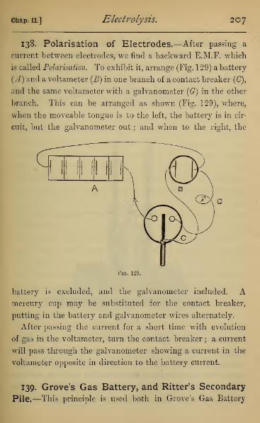
Chap. II.] Electrolysis. 207
138. Polarisation of Electrodes.—After passing a
current between electrodes, we find a backward E.M.F. which
is called Polarisation. To exhibit it, arrange (Fig. 129) a battery
(A) and a voltameter (B) in one branch of a contact breaker (C),
and the same voltameter with a galvanometer (G) in the other
branch. This can be arranged as shown (Fig. 129), where,
when the moveable tongue is to the left, the battery is in cir-
cuit, but the galvanometer out ; and when to the right, the
Fig. 129.
battery is excluded, and the galvanometer included. Amercury cup may be substituted for the contact breaker,
putting in the battery and galvanometer wires alternately.
After passing the current for a short time with evolution
of gas in the voltameter, turn the contact breaker ; a current
will pass through the galvanometer showing a current in the
voltameter opposite in direction to the battery current.
139. Grove's Gas Battery, and Ritter's Secondary
Pile.—This principle is used both in Grove's Gas Battery

208 Electricity. [Book III.
and Bitter's Secondary Pile. In Grove's Gas Battery (Fig.
130) the cell consists of two tubes, each containing a plati-
num plate, to which platinum wires are attached, which are
fused through the glass tube, and terminate in binding screws
or mercury cups. On passing the battery current, oxygen
and hydrogen are liberated and collected. If the process be
Fig. 130.
stopped, a current will be found to flow from the plate in the
hydrogen to that in the oxygen, decomposing water, and
setting free oxygen against the hydrogen plate, and hydrogen
against the oxygen plate ; these combine with the occluded
hydrogen and oxygen to form water again. The E.M.F. of this
battery is low, four cells being required to decompose water.

chap, ii.] Electrolysis, 209
In Bitter's Secondary Pile, the plates of platinum are large,
and it has been used as a condenser for storing large quantities
of electricity.
140. Polarisation the test of an Electrolyte.—Clerk-
Maxwell has pointed out that the existence of the polarisation
current is the best test whether a given substance is an
electrolyte, and may be applied where the quantities of the
products of decomposition are too small to be detected by
chemical means. Faraday has laid down the general law that
no solid is ever an electrolyte, but it can be easily proved
that glass, even at a temperature below 100° C, and while
perfectly hard, is an electrolyte. Put mercury in a test-tube,
and sink the test-tube in another vessel (a larger test-tube will
do) containing mercury, and surrounded by a steam bath.
Dip two wires in the mercury, one inside and the other
outside the inner tube, and connect with a battery and gal-
vanometer. As the temperature rises, a current begins to
pass before the mercury is at 100° C, and on detaching
the battery, and leaving the galvanometer alone in circuit, a
polarisation current is seen to pass in the opposite direction,
proving that the glass has been decomposed by the current.
141. Plante's and Faure's Cells.—In the practical use
of electricity, it is probable that storage batteries on the
principle of the Secondary Pile will play an important part.
The form to which attention has most been directed was in-
vented by Plants, and improved by Faure and others. Plant's
idea was to immerse two lead plates in dilute sulphuric acid,
and by a series of actions, partly electrolytic and partly
chemical, to obtain a deposit of lead peroxide (Pb02) on the
anode, and pure lead in a spongy condition on the cathode.

210 Electricity. [Bookin.
In the cell, while discharge is taking place, the spongy lead
acts as the zincode, and the lead coated with lead peroxide
as the platinode. The preparation of Plant6's plates requires
a long time, as the current has to be sent through the cell
several times with long periods of rest between. These in-
tervals of rest are necessary, as during them both chemical
and local actions take place between the lead and the products
of electrolytic decomposition. When the plates are once
brought to a proper condition, a single passage of the current
for a few hours is sufficient to restore the cell after each dis-
charge. The ultimate product of the discharge seems to be
a deposit of sulphate of lead on both plates, and this is re-
moved by electrolysis on repassing the current, that on the
zincode (which in electrolysis is the cathode) being con-
verted into spongy lead, and that on the platinode (or anode)
into lead peroxide. The improvement introduced by Faure
was designed to hasten the preparation of the lead plates.
He coats both the plates at first with minium or red-lead
(Pb 3 4 ), which, after chemical and electrolytic action, in a
relatively short time gives the plates the same condition as
in Plant6's cell. The E.M.F. of the cell, when in good con-
dition, is about two volts.
142. Electro-metallurgy.—A very important application
of electrolysis in the arts is the deposit of metals (especially
copper, gold, and silver) from the solution of their salts, called
electrotyping or electroplating.
The deposit of copper is very easily accomplished by using
a cell containing a concentrated solution of copper sulphate,
a strip of copper being suspended in it as the anode, and the
body to be coated with copper as the cathode, with a single

chap, ii.] Electrolysis, 2 1
1
Daniell's cell, or, for large plates, three or four Darnell's cells,
as battery. The body to be coated with copper is often an im-
press or cast taken from a seal, coin, or other object, in wax,
plaster, or gutta-percha. These moulds are non-conductors,
but on being evenly coated with plumbago or black-lead they
become conductors. The prepared mould is suspended by a
copper wire in the electrolytic cell. An even coat of copper
is thus deposited upon it, and after it has acquired a suitable
thickness it can be removed from the wax mould, and will be
found to give an exact copy of the engraved marks or stamp
on the original seal or medal.
In some arrangements the conducting mould is made to
take the place of the copper plate in the Daniell's cell
itself.
Flowers and leaves can be coated with copper and after-
wards silver-plated by making their surfaces conducting. The
best method of accomplishing this is by immersing the object
in a weak solution of phosphorus in carbon disulphide, and
then allowing the solvent to evaporate, leaving a thin deposit
of phosphorus. On immersing the object in a bath of silver
nitrate, the silver becomes reduced as a thin superficial film.
This is sufficient to make the surface conducting, and it can
be coated with copper in the manner described above.
Copies of engraved copper plates can be made by immersing
the original in the copper sulphate bath (having first rubbed
its back over with a varnish, to prevent a deposit taking place
on it). The deposit of copper will adhere to the surface, but
after a sufficiently thick deposit has been made, it can be easily
separated and will give a reverse of the engraving. On
repeating this process with the reverse any number of copies
of the original engraving can be obtained. It is now more
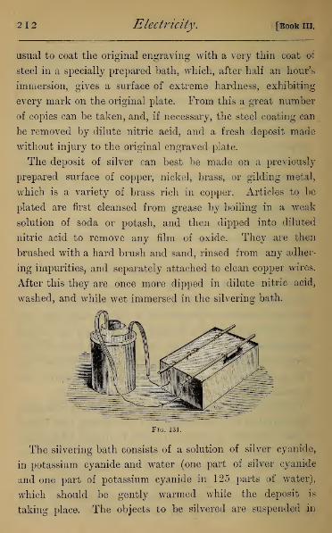
2 1
2
Electricity. [Book in.
usual to coat the original engraving with a very thin coat of
steel in a specially prepared bath, which, after half an hour's
immersion, gives a surface of extreme hardness, exhibiting
every mark on the original plate. From this a great number
of copies can be taken, and, if necessary, the steel coating can
be removed by dilute nitric acid, and a fresh deposit made
without injury to the original engraved plate.
The deposit of silver can best be made on a previously
prepared surface of copper, nickel, brass, or gilding metal,
which is a variety of brass rich in copper. Articles to be
plated are first cleansed from grease by boiling in a weak
solution of soda or potash, and then dipped into diluted
nitric acid to remove any film of oxide. They are then
brushed with a hard brush and sand, rinsed from any adher-
ing impurities, and separately attached to clean copper wires.
After this they are once more dipped in dilute nitric acid,
washed, and while wet immersed in the silvering bath.
Fig. 131.
The silvering bath consists of a solution of silver cyanide,
in potassium cyanide and water (one part of silver cyanide
and one part of potassium cyanide in 125 parts of water),
which should be gently warmed while the deposit is
taking place. The objects to be silvered are suspended in
chap, ii.] Electrolysis. 21
3
the bath from copper rods and form the cathode of the
cell, the anode being formed by a strip of silver also sus-
pended in the liquid to prevent the solution from becoming
weakened. The battery may be either Daniell's, Bunsen's, or
Smee'sj the number of cells employed depending on the
size and number of objects to be plated. The diagram
(Fig. 131) shows the arrangement for silvering with one
Bunsen's cell.
The process of electro-gilding is very similar, except that
the objects are first " pickled " in a bath of mixed dilute nitric
and sulphuric acids. The gilding bath is usually a solution of
potassio-gold cyanide, but many other baths can be employed
with success.
143. Nobili's Rings.—These are obtained very easily by
placing a drop of copper sulphate on a silver or platinum
plate, and touching the plate with one end of a bent strip of
zinc, whose other end dips into the copper sulphate. These
form together a minute voltaic cell, and copper is deposited
from the solution on to the platinum plate. The film of copper
is thickest immediately under the zinc point, and diminishes
pretty regularly, giving rings of varied colours. By using
a solution of lead oxide in potash, and connecting the sup-
porting plate with the platinode of a battery of several Grove
cells, while the zincode is connected with a platinum wire
which dips in the liquid, a deposit of lead peroxide is made,
which exhibits very bright iridescent colours.
144. The Lead Tree.—To Electrolysis (partially, at
any rate) we may refer the formation of the lead and silver
trees. If we place a zinc and a copper rod in contact with

214 Electricity. [Book in
each other in a flask which contains a solution of lead
acetate, the zinc replaces the lead in the salt, forming zinc
acetate, and the lead becomes deposited on the copper. Under
these conditions the lead appears in bright branching crystals
growing out from the copper, to which the name Lead Tree,
or Arbor Saturni, has been given. The replacement of the
lead by the more oxidisable zinc is a chemical action, but the
peculiar form which the ramifications of the lead take is due
to the electrolytic deposit.

CHAPTER III
OHM'S LAW.
145. Ohm's Law.—This most important law, discovered
by Ohm, states that with any given conductor, of which
two parts are kept at different potentials, there is a con-
stant ratio between the numerical measure of the poten-
tial difference, and of the strength of the current which
traverses the conductor. This constant ratio depends only
on the form, material, and temperature of the conductor, and
is usually called its Resistance. Different conductors may
be compared numerically, in respect of resistance, just as
in respect of mass, capacity for heat, or any other physical
property. By choosing suitable units of potential difference,
current strength, and resistance, we may express Ohm's
law numerically thus : Let V be the potential difference, /
the current strength, and B the resistance of the conductor,
all measured in these units, then -j=B, or F=IB.
In the case of a battery cell, V will denote the difference of
potential between the terminals when open, and B will be
the total resistance made up of the internal resistance of
the liquid part of the cell, and the external resistance of
conductors, solid or liquid, outside the cell. If we denote
the former of these by r and the latter by B, and if E denote
the E.M.F. of the cell, we shall have E=I (B + r),
t E
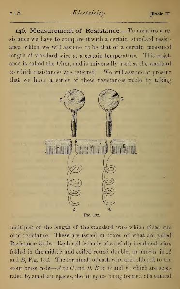
2l6 Electricity, [Book III.
146. Measurement of Resistance.—To measure a re-
sistance we have to compare it with a certain standard resist-
ance, which we will assume to be that of a certain measured
length of standard wire at a certain temperature. This resist-
ance is called the Ohm, and is universally used as the standard
to which resistances are referred. We will assume at present
that we have a series of these resistances made by taking
Fig. 132.
multiples of the length of the standard wire which gives one
ohm resistance. These are issued in boxes of what are called
Resistance Coils. Each coil is made of carefully insulated wire,
folded in the middle and coiled round double, as shown in Aand B, Fig. 132. The terminals of each wire are soldered to the
stout brass rods
—
A to and D, B to D and E, which are sepa-
rated by small air spaces, the air space being formed of a conical

Chap. III.] Ohms Law. 217
hole, into which brass plugs (F. G) fit. When the plugs are in
position, the current passes across the plug; but when the
plug is withdrawn, the current goes through the correspond-
ing wire. The coils are fitted up in boxes (Fig. 133), the
numbers of ohms in successive coils being 1, 2, 3, 4, from
which, by means of addition, all numbers up to 10 can be
obtained. Then follow 10, 20, 30, 40, taking us up to 100;
and then 100, 200, 300, 400, taking us up to 1000, and so
on to any required extent.
Fig. 133.
We may observe that the ohm is about equal to the resist-
ance of a yard of fine galvanometer copper wire (B. W. G.
No. 40).
*I47. Potential Gradient.—Our first illustration of
Ohm's law consists of the construction of potential
gradients. Take a battery of three or four Darnell's cells
(.4, Fig. 134), and introduce a set of resistances, of 100,
200, 300, 400 ohms respectively between the terminals
BF. Also connect B with one terminal of a quadrant
electrometer, the other terminal being connected with a

2l8 Electricity. [Book III.
loose wire, which can be applied to either of the brass pieces
C, D, E, RThe deflection of the electrometer shows the difference of
potential between B and C, B and D, B and E, and B and Frespectively.
c QUADRANT ELECTROMETER
400 OHMS
Fig. 134.
Taking a particular experiment, the number of scale
degrees read off from the screen were
—
For^andC .. 9 scale divisions.
„ B and D . • 28
„ B and E . . 52
„ jBandi^ .. . 87
The numbers 9, 28, 52, 87 are sufficiently nearly in the
ratios of 100, 300, 600, 1000 to suggest to us the rule that
the fall in potential is simply proportional to the resistance.
If now we set off on a horizontal line distances propor-
tional to the resistance, so that (Fig. 135) BC, CD, BE, EF

Chap. II.] Ohm's Law. 219
represent on any scale the resistance in the previous figure
(Fig. 134), and set up at C, D, E, F, ordinates or perpendiculars
Fig. 135.
proportional to the observed potential differences, the extremi-
ties of these ordinates will be in a straight line, and that
straight line may be taken as giving graphically the potential
gradient in the conductor. The potential at any point may be
found by simply drawing a perpendicular to meet the gradient
line from the corresponding part of the line of resistances.
We may notice that this, in connection with the law of
Ohm, gives us an independent proof of the constancy of the
current in all parts of a circuit; the ratio between the
potential difference and the resistance being the measure of
the current strength. This measure is, in fact, the tangent
of the angle at j5, or of the inclination of the potential
gradient.
When any amount of resistance is introduced between the
terminals of the cell, the difference of potential becomes less
than the total E.M.F. observed when the circuit is open.
Assuming the current to consist of a series of polarisations
and discharges, the chemical affinities or contacts must call up
the difference of potential representing the whole E.M.F.
after each discharge. The remaining part of the E.M.F. is
really present in the liquid of the cell, which offers resistance
to the current, and in it the potential follows exactly the same
laws as in the solid part of the circuit. To illustrate this, let

220 Electricity. [Book I1L
us take a single cell, and complete the diagram by setting off
a horizontal line ABC, in whichAB represents the resistance of
the cell, BC the resistance of the connecting arc, and AD a
vertical line representing the E.M.F. Then the line DC will
give us the potential at every point in the circuit.
D
Fig. 136.
If there are several cells in compound circuit, AB represents
the total resistance, and AD the total E.M.F. of the battery.
The line of potential will not then be DC, but a broken line
which rises at each cell. Thus, supposing we have three
cells, the line of potential will be given by E, F, G, H, K, C,
D
K
Fig. 137.
The potential gradient gives us only potential differences,
and not the absolute potential at any point, If the cell and
circuit be all insulated, the potential at some parts will be -f
,
and at other parts — , depending on the capacity of the
various parts of the circuit. If we connect the circuit with

chap, in.] Ohms Law. 221
earth at any one point, we have only to draw a line parallel to
the base line through the corresponding point on the gradient,
and perpendiculars to this line will then give the absolute
potential, positive when above and negative when below this
line. The figures drawn would represent the potential, sup-
posing the zinc plate brought to earth.
148. Oersted's Experiment— Galvanometers. —Oersted, a Danish philosopher, was the first who discovered
the action of a conductor carrying a current on a magnet
placed near to it. It can be shown by a stout wire bent in
the form of Fig. 138, with a freely-pivoted magnet needle
A BC
within the circuit. ABO are three mercury cups for the
purpose of introducing the battery wires. After placing the
coil in the magnetic meridian, so that the wires are parallel to
the magnet when no current is passing, and the north pole
suppose towards B, place the battery terminals in A and B, so
that the current passes under the magnet from A to B, and the

222 Electricity. [Book IIL
north pole will be seen to deflect towards the east ; on passing
it from B to A it will deflect in the opposite direction ; hence
the direction in which the magnet deflects is reversed with the
current. Next place the original ^-terminal in (7, so that the
current passes above the- magnet from A to C; the deflection
will be to the west, or opposite to that which was seen when
the current passed under the magnet from A to B. Hence we
see that the deflection is in contrary directions, according as
the current passes above or below the magnet. Lastly, put
one terminal in B and the other in C, so that the current
passes from B to A under the magnet, and from A to B above
the magnet; these two parts of the current
will conspire to deflect the north pole west-
wards.
The following rule for the direction of motion
of the magnet given by Ampere was : If a little
figure swim in the current (which enters by his
heels and leaves byhis head),and look towards the
magnet, the north pole will be driven to his left.
A rule identical with Ampere's, which will be
greatly used afterwards, is : The direction of
motion of the north pole is related to the
direction of the current, as the direction of
propulsion of any right-handed screw is re-
lated to the direction of the twist in the
muscles of the wrist in driving it in. These
two directions are said to be related in right-
handed cyclical order. In Fig. 139 they are
shown, the direction of the straight arrow being that in
which a corkscrew is pushed in, and the arrows on the spiral
being the direction of motion of the spiral or of the twist in
Fig. 139.

chap. in.] Ohms Law. 223
the muscles of the wrist when driving it in. The central
arrow then shows the direction in which a free north pole
would be urged by a current in the direction of the arrow
circulating in the screw. Otherwise, if the current circulate
with the hands of a watch, a north magnetic pole will be
driven from the front towards the back of the watch.
A variety of instruments have been constructed on the
principle of Oersted's phenomenon for detecting and measur-
ing currents. To detect very weak currents, the effect on
the magnet may be increased to a great extent by simply
increasing the number of circuits round the magnet by
winding the wire in a continuous coil, each coil producing
its own effect on the magnet, and the sum of the effects of
all the coils being added together Such an arrangement is
often called a current multiplier.
149. The Tangent Galvanometer.—Where currents
of considerable strength have to be measured, the most con-
venient instrument is that known as the Tangent Galvanometer
(Fig. 140). It consists of one or several coils of stout wire
on the edge of a narrow circular hoop (A), whose terminals are
attached to the base, In the centre is pivoted a very short
magnet (B) furnished with a pointer of aluminium, glass, or
any non-magnetic substance. Under the needle is a graduated
card for observing the deflection of the needle. The zero of
the graduations is in the plane of the wire coil, and the in-
strument is capable of being turned on its base about a central
axis to allow of the zero of graduation, and therefore the
plane of the coils, being brought into the magnetic meridian
before taking an observation.
Since a conductor carrying a current exerts force on a magnet
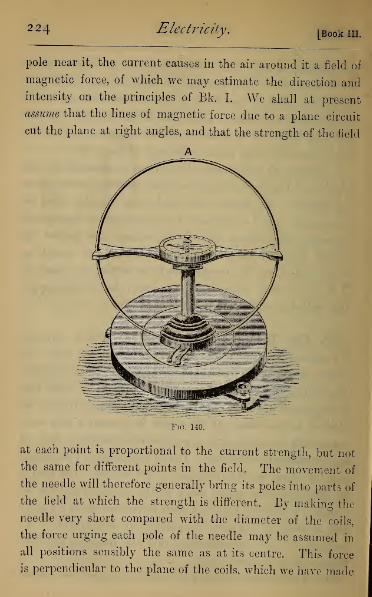
224 Electricity. [Book III.
pole near it, the current causes in the air around it a field of
magnetic force, of which we may estimate the direction andintensity on the principles of Bk. I. We shall at present
assume that the lines of magnetic force due to a plane circuit
cut the plane at right angles, and that the strength of the field
A
Fio. 140.
at each point is proportional to the current strength, but not
the same for different points in the field. The movement of
the needle will therefore generally bring its poles into parts of
the field at which the strength is different. By making the
needle very short compared with the diameter of the coils,
the force urging each pole of the needle may be assumed in
all positions sensibly the same as at its centre. This force
is perpendicular to the plane of the coils, which we have made

Chap. III.] Ohms Law. 225
the plane of the meridian, and is proportional to the current
strength. The method and construction of Art. 15 shows that
the needle will rest at an inclination to the meridian, and that
the force at right angles to the meridian is proportional to the
tangent of the deflection. Thus, with
the same instrument, the strength of
the current traversing the coils will
always be proportional to the tangent
of the angle of deflection of the needle,
and when we do not require currents
in absolute measure it is sufficient to
use the tangent of the angle as the
measure of the current. A table of
tangents for this purpose is given in
Appendix II.
It is an improvement in con-
struction to have two parallel coils
(Fig. 141), with the current traversing them in the same
direction, the magnet being suspended in the centre of the
line joining their centres. By this arrangement, due to Helm-
holtz, the field round the magnet becomes much more nearly
of uniform strength.
Fig. 141.
150. Sine Galvanometer.—In this galvanometer the
reading is taken with the magnet poles always in the same
position relatively to the coils, and the strength of the field
therefore is strictly proportional to the current strength.
The tangent galvanometer can be used as a sine galvano-
meter by having a graduated circle attached to its base, and
a pointer to the moveable framework which carries the coils.
First bring the coils into the magnetic meridian, and observe
P

226 Electricity. [Book in.
the reading of the pointer on the fixed scale. On passing the
current the magnet will deflect, but the coils can now be
turned round so as to follow its deflection until (supposing
the current not too strong) the magnet remains at rest in the
plane of the coils. The fixed circle is again read, and the
difference of the readings gives the angle through which the
coils have been turned from the magnetic meridian. In this
case the current strength is proportional to the sine of the
angle of deflection, and for use with this form of galvanometer
a table of sines is given in Appendix II.
The sine galvanometer can be made without any loss of
accuracy in a portable form by making the coil long and flat,
with a long needle suspended in its centre.
151. Astatic Galvanometer.—When we have to detect
or to measure very weak currents, either the astatic galvano-
Fig. 142.
meter or Sir W. Thomson's mirror galvanometer may be used.
The astatic galvanometer is named from the employmentof an astatic needle. This consists of two exactly equal

Chap. III.] Ohm's Law. 22'
magnetic needles attached to a common axis, with their poles
in opposite directions. Such a system will set equally in all
directions under the action of the earth's magnetism—that
is, it will be astatic. The magnets are very light, and the
whole system is suspended by a single fibre of unspun silk.
If a coil of wire carrying a current pass between the two
magnets, and entirely surround the lower one, as in Fig. 142,
Ampere's principle shows that the parts of the coil above and
below the lower magnet conspire to deflect this magnet in the
same direction; also that the part of the coil between the
magnets, by its action on the upper magnet, tends to turn
the magnetic system still in the same direction; while the
lower part of the coil, by its action on the upper magnet
alone, tends in the contrary direction. This effect will be
much smaller than either of the
other actions, owing to the greater
distance between the magnet and
the current. If the magnetic sys-
tem were absolutely astatic, any
current, however weak, would be
shown by the magnets at once
setting at right angles to the
coils. In practice there is never
an absolutely astatic system, but
the earth's power is so much|
weakened that the very weak cur-
rent becomes sensible by a deflec-
tion of the needle. In the best
instruments the set of the magnets is at right angles to the
meridian. The general arrangement of the instrument is
shown in Fig. 143. The upper needle moves over a graclu-
FiG. 143.
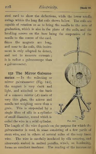
228 Electricity. [Book III.
ated card to show the deflections, while the lower needle
swings within the long flat coils shown below. The coils are
capable of rotation so as to bring the needle to the zero of
graduation, which is also in the plane of the coils, and the
levelling screws on the base bring the suspension of the
needle to the centre of the card.
Since the magnets are long,
and near to the coils, this instru-
ment is only adapted to detect,
and not to measure currents;
it is rather a galvanoscope than
a galvanometer.
152. The Mirror Galvano-
meter. — In the reflecting or
mirror galvanometer (Fig. 144),
the magnet is very short and
light, and attached to the back
of a concave mirror (A) made of
very thin glass, the mirror and
needle not weighing more than a
grain. This is suspended by a
single fibre of silk in a cylinder
of small diameter, round which is
coiled the wire in a solid cylinder.
The length of the wire depends on the purpose for which the
galvanometer is used, in some consisting of a few yards of
stout wire, and in others of several miles of the very finest
wire. The wire is carefully insulated by silk covering, and
afterwards soaked in melted paraffin, which, on hardening,
forms an excellent insulator. The reading of the instrument
Fig. 144.
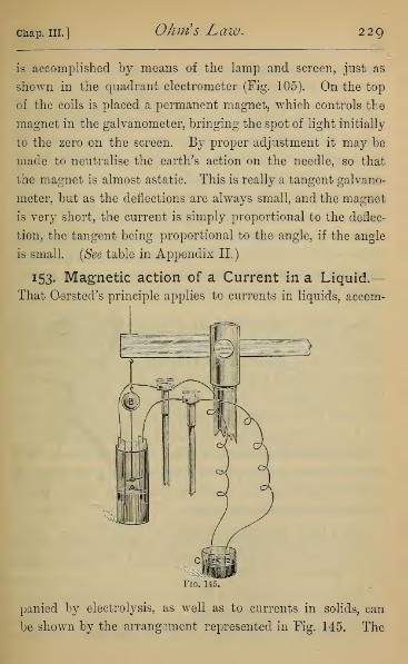
Chap. III.] Ohm's Law. 229
is accomplished by means of the lamp and screen, just as
shown in the quadrant electrometer (Fig. 105). On the top
of the coils is placed a permanent magnet, which controls the
magnet in the galvanometer, bringing the spot of light initially
to the zero on the screen. By proper adjustment it may be
made to neutralise the earth's action on the needle, so that
the magnet is almost astatic. This is really a tangent galvano-
meter, but as the deflections are always small, and the magnet
is very short, the current is simply proportional to the deflec-
tion, the tangent being proportional to the angle, if the angle
is small. (See table in Appendix II.)
153. Magnetic action of a Current in a Liquid.—That Oersted's principle applies to currents in liquids, accom-
Fiq. 145.
panied by electrolysis, as well as to currents in solids, can
be shown by the arrangement represented in Fig. 145. The

230 Electricity. [Bookin.
magnet (A) is suspended at right angles to the parallel zinc
and copper plates of a simple unclosed zinc-copper couple, and
immediately over the liquid. It is supported by a wire fixed
to it, on which is cemented a mirror, and the whole is sus-
pended by a single fibre of unspun silk. The movements of
the needle are registered by the lamp and screen, as in a
mirror galvanometer. On closing the circuit by means of
the mercury-cup (G) the spot of light moves so as to indicate
a current in the liquid from the zinc to the copper.
The deflection is much greater if, for the zinc and copper
plates, we substitute two platinum plates, and send a current
through the liquid (supposed to be acidulated water) from a
battery of four or five Grove cells.
154. Units employed in Voltaic Electricity.—In
every voltaic circuit there are three physical quantities con-
cerned, E.M.F., Eesistance, and Current Strength, connected
together by Ohm's law. We have now described instruments
by help of which these may be measured : E.M.F. by the
Quadrant Electrometer, Resistance by a box of resistance coils,
and Current Strength by a Voltameter or Galvanometer.
Before illustrating their use, it may be convenient to notice
the units actually employed in practice, as they are different
from those referred to in Frictional Electricity. These, called
absolute Electrostatic units, are
:
For E.M.F. , the theoretical unit of potential, which is the
potential of a sphere of unit radius charged with unit
quantity (Art. 80).
For Current Strength, a current in which a unit of elec-
tricity passes per second.
For Resistance (by Ohm's law), the resistance of a con-
chap, in.] Ohms Law. 231
ductor in which unit of potential difference would cause
a unit of electricity to pass per second.
In Voltaic Electricity it has already been pointed out that
these units are very inconvenient, since every E.M.F. would
be represented by a very small fraction, and every current
strength by a very large number. We consequently adopt a
new and more convenient system, which will be fully explained
later. For the present our units will be :
For E.M.F., the E.M.F. of a Daniell's cell of given con-
struction (see Art. 124). This is called a Volt.
For Eesistance, the resistance of a certain length of a
certain wire at a given temperature. This is called
an Ohm.
For Current Strength, that in a circuit in which the
E.M.F. is one volt and the resistance is one ohm.
This current strength is called an Amphre.
The quantity of electricity which flows per second in a
current of one Ampere is called a Coulomb. It is
our new unit of Electrical Quantity.
To connect these units with our units in electro-chemistry,
the most natural assumption seems to be that the electro-
chemical equivalents shall be the masses of the respective
ions which appear to be associated with one coulomb of
electricity. The results obtained by various experimenters
seem to show that one coulomb of electricity sets free nearly
0000105 gm. of hydrogen {Numerical Tables and Constants, by
S. Lupton).
155. Illustrations of Ohm's Law.—The law as
stated by Ohm can be illustrated by showing that in a
232 Electricity. [Book in.
battery (1) the E.M.F. is proportional to the current when
the resistance is constant; (2) the E.M.F. is proportional to
the resistance when the current is constant. It then follows
on ordinary algebraical principles that the E.M.F. is pro-
portional to the product .of current strength and resistance
where both vary.
(1) To prove that the E.M.F. is proportional to current
strength with a constant resistance, use a series of Daniell's
cells, all of equal E.M.F. If we interpose a very large resist-
ance (5000 ohms say), the difference of potential at the ter-
minals will be practically the whole E.M.F., the resistance of
the battery being insensible compared with this large resist-
ance. The current will then be so small that we must
employ a Thomson's mirror galvanometer to detect it.
Fitting up the galvanometer and resistance with one cell,
we get a certain deflection, 12*5 scale-degrees, suppose; with
two cells the deflection becomes 24'6 divisions; with three
cells, 37 divisions, and so on; hence proving the constancy
of the ratio between the difference of potential and the
current strength.
(2) To prove that the E.M.F. is proportional to the
resistance when the current is constant.
Although we do not know the internal resistance of a cell
of the battery, we may assume that when the battery is in
compound circuit and the current passes through all the cells
in succession, the total resistance is the sum of the resistances
of each cell.
Fit up the battery and a set of resistance coils with a
tangent galvanometer of no sensible resistance (or, at any
rate, very low resistance compared to one cell). If we use
one cell only, and introduce 10 ohms' additional resistance, the

chap. in.] Ohms Law. 233
galvanometer will give a certain reading, say 20°. Next, use
two cells and introduce 20 ohms' resistance, and the galvano-
meter reading is sensibly the same. And this reading will
not alter if we introduce 3 cells and 30 ohms, or 4 cells and
40 ohms, and so on. Now in these cases the E.M.F.s have
been in proportion of the numbers 1, 2, 3, 4, and so have the
resistances, for if r be the resistance of one battery cell, the
resistances have actually been r+10, 2r+20, 3r+30, 4r+40.
Of course these two illustrations can only be taken as
suggesting the soundness of the law. Like every great
induction of science, its proof rests on an infinite series of
observations which are constantly in progress. We can only
add here that Ohm's law has borne the most rigorous tests
of absolute accuracy that have been applied to it.
156. Experimental Determination of Battery Re-
sistance.—On account of the importance of Ohm's law we
shall now, with a set of resistance coils, use it to determine
certain resistances. These determinations are not susceptible
of very great accuracy, and are not such as would be employed
in practice. More accurate practical methods will form the
subject of the next chapter.
To find the resistance of a cell or battery, fit it up with
resistance coils (R) and a galvanometer (G) of small resistance
(Fig. 146). Observe the deflection, and take the measure of
the current from the table of tangents. Halve this measure
and find the deflection which corresponds to half current.
By introducing resistance, the current can be brought down
to this reading. The resistance introduced will now be equal
to the internal resistance. For if we halve the current, wedouble the resistance in the circuit, and since at first the only

234 Electricity, [Book III.
resistance was internal, the external resistance introduced
must be equal to it. As an example, take the battery of four
Daniell's cells used before, which, when fitted up with a
galvanometer of small resistance, gives 73° deflection. Nowtan 73° = 3-270, therefore \ tan 73° = l-635=tan 58° 30'
nearly. On introducing 24 ohms' resistance, the deflection
of the galvanometer falls to 58|°. We infer that the resist-
ance of the four cells and of the galvanometer equals 24 ohms,
or that the resistance of each cell is 6 ohms, neglecting the
galvanometer resistance.
Fig. 146.
157. Resistance of the Galvanometer.—Fit up the
galvanometer, whose resistance is supposed to be consider-
able, with resistance coils in the circuit of a battery or cell
of known resistance, as in Fig. 146. Observe the reading
with only the resistance of the battery and galvanometer
(r + G say). As before, introduce resistance till the current
is halved, and then the introduced resistance will also equal
r + G; whence r being known, G}the galvanometer resist-
ance, becomes known. If necessary, resistance may be intro-

Chap. III.] Ohms Law. 235
duced at first to bring the galvanometer reading down if
too high, since the reading should not be taken with a
deflection above 75°, the change in the tangent becoming
very large for each degree at higher angles.
158. To find the Resistance of a given Wire Coil.
—This can be done either by balancing the unknown against
a known resistance, or by calculation.
(1) By balancing.—Fit up as in Fig. 147 a circuit consisting
of a battery (A), a galvanometer (ff), a box of resistance coils
(E), and the unknown resistance (X), whose terminals are
connected with the mercury cups (B, G). When the battery
wire (P) dips into B, and the coil (X) is included, read the
galvanometer. Next lift the wire (P) from B into C, thus
excluding the coil. Introduce resistance in B till the galvano-
meter regains its former reading. The resistance introduced
will then equal that of X, the unknown resistance.
Fig. 147.
(2) By calculation.—Let E be the E.M.F., and r the internal
resistance of the battery, g the galvanometer resistance, and
x the unknown resistance.

2 $6 Electricity . [Book in
.
Take out all resistance except that of the battery and
galvanometer (when the battery is said to be short-circuited),
and let the observed current be Iv Then by Ohm's law
a=-4- a)-r + g.
Introduce the unknown resistance x, and let the current be
h
Introduce a known resistance n ohms, and let the current
beig
(3).r + g + n
DividiiQg equations (2) and (1)
h r + g
Dividing equations (3) and (1)
h r + g
Hence we have, by eliminating r + g,
x J-i—
J- 2 J-i
Since in this result only ratios of current strengths enter
we may for the current strengths Il9 72 , IZ} write the tangents
of the observed deflections of the galvanometer, assuming it
to be of the tangent form.
As a particular example, using the same battery of four
Darnell's cells, and the galvanometer of small resistance, we
find on short-circuiting the battery a deflection of 73°\ on
introducing the coil whose resistance is unknown, the deflec-
chap. m.
]
Ohm's Law. 237
tion sinks to 37°, and on introducing 20 ohms, external re-
sistance, the deflection is 61°.
We have from the tables (Appendix II.)
tan 73°= 3*271, tan 37°= *756, and tan 61° = l-784.
Hence 3'271=— : -756=-r + g r + g + x
E1*784= -
+ # + 20
3-271 x x _ 2-515'"' "^756" r+ g
''' r+g" -756
, 3-271 _ 120 20 _ 1-487
al-784~
1+f+^ •'• r + #""l-784
1-784' r+ ^=ri87
x20
2-515 1-784 OA QA , ,
"'" X==~^756
Xri87
X = mS D6ar J '
The same equations give r + g, which, on working out, is
found to be 24 ohms nearly.
159. Relation of Resistance to Dimension of a
Conductor: Specific Resistance.—We have seen that
the resistance of a wire or of the liquid of a battery is pro-
portional to the length which the current has to traverse ) we
may next inquire how it is related to the sectional area of the
wire. The easiest way to do this is to take two equal lengths,
cut from the same wire, and place them breast to breast
(Fig. 148) as a single conductor, when we find the resistance
to be exactly half that of either wire taken separately.
Since the two wires are equal in all respects, they will
behave exactly as if they were lying side by side, or in
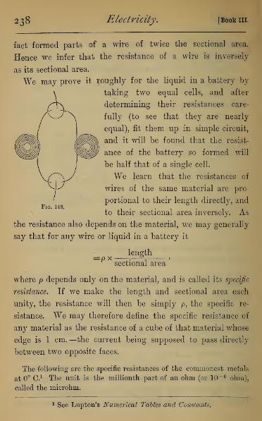
238 Electricity. [Book III.
fact formed parts of a wire of twice the sectional area.
Hence we infer that the resistance of a wire is inversely
as its sectional area.
We may prove it roughly for the liquid in a battery by
taking two equal cells, and after
determining their resistances care-
fully (to see that they are nearly
equal), fit them up in simple circuit,
and it will be found that the resist-
ance of the battery so formed will
be half that of a single cell.
We learn that the resistances of
wires of the same material are pro-
portional to their length directly, and
to their sectional area inversely. As
the resistance also depends on the material, we may generally
say that for any wire or liquid in a battery it
=px length
sectional area
where p depends only on the material, and is called its specific
resistance. If we make the length and sectional area each
unity, the resistance will then be simply p, the specific re-
sistance. We may therefore define the specific resistance of
any material as the resistance of a cube of that material whose
edge is 1 cm. —the current being supposed to pass directly
between two opposite faces.
The following are the specific resistances of the commonest metals
at 0° O. 1 The unit is the millionth part of an ohm (or 10" 6 ohm),
called the microhm.
1 See Lupton's Numerical Tables and Constants.

chap, in.] Ohm's Law. 239
Silver, annealed, . • . . 1-521
Copper, hard drawn, . 1-642
Platinum, annealed, 9-158
Iron, soft, . o 9-827
Mercury, • 96-146
Bismuth, . . , , . 132-65
German Silver, . . 21-17
Brass, .... 5*8
The specific resistances of liquids most commonly used are, accord-
ing to the best determinations, in ohms,
Water at 4° C, 91 x 106
„ at 11° C, 3'4 xlO5
Dilute hydrogen sulphate (5% acid) at 18° C, 4 '88
„ (20% acid) „ 1-562
„ (30% acid) „ 1*38
„ (40% acid) „ 1-5
Hydrogen nitrate, at 18° C., . . . 1*61
Copper sulphate sat. solution at 10° C, . 29*3
Zinc sulphate sat. solution at 14° C, . 21*5
Sodium chloride sat. solution at 13° C, . 5 3
In all cases the resistance diminishes rapidly as temperature rises.
The specific resistances of the commonest insulators measured in
megohms or 10e ohms.
Glass (crystal) below 40° C, . . . infinite.
at 46° 0.,
„ „ at 105° C,
Paraffin, at 46° C, .
Ebonite, at 46° C, .
6-182 x 109
1-16 xlO7
3-4 x 10¹⁰
2-8 x 10¹⁰
160. Application of Ohm's Law to a Simple Circuit.
—We can now compute the current obtained from a battery
in simple circuit. The E.M.F. we have seen to be the same

240 Electricity. [Book 111.
as for a single cell, and if we have n cells, each of resistance
r, the total inter:
formula becomes
Tr, the total internal resistance becomes — , and hence Ohm's
E nET
~— +R r + nR
When ^=0, or the external resistance vanishes, the current
sx— or n times the current from one cell. If the externalr
resistance becomes large, so that r vanishes in comparison
with nR, the current becomes :r#= t>, or the same as for a
single cell. This can be proved experimentally by introducing
a resistance of say 10,000 ohms, and showing that the current
is the same as for a single cell.
161. Application of Ohm's Law to a CompoundCircuit.—In the compound series of n cells, the E.M.F. be-
comes nE and the internal resistance of the battery nr. Hence
r nE~ nr +R
When R is very large compared to nr, the current is -^,
and therefore proportional simply to the number of cells.
If R, on the other hand, be very small compared to r, the
nE E . . ,
current becomes —=— , or the same as trom a single cell.nr r ' °
162. Application of Ohm's Law to a Mixed Circuit.
—We have seen that with a simple circuit, and small external
resistance, the current is directly proportional to the number

Chap. III.] Ohms Law, 241
of cells, while with a compound circuit and small resistance
it is the same as for one cell. When the resistance is moder-
Fig. 149.
ately large, a better arrangement of the battery can be
obtained by what is termed Mixed Circuit. In this a number
of cells are compound-circuited, and placed in a row with
other equal rows also compound-circuited abreast of them.
Each row of q cells (each having E.M.F. = E, and resistance
= r) will be equivalent to a single cell whose E.M.F. is qJE,
and resistance qr.
If we have p rows then we have p such cells in simple
circuit, and we have for the current strength
qr+ fi qr+pB
If we have n cells, then pq = 71, and
T_ 11E
~~qr+pB
*i63. Arrangement of a Battery for the greatest
Current.—This is to find the values of p and q which make
/ the greatest possible. In the last expression we may write
nE1=
( V^r-
Q
242 Electricity. [Book 111.
This will be the greatest possible when the denominator is
the least possible, and that is when the square it contains
vanishes.
•*• V<??— Vpi2= 0>
P
which gives the condition that the external and internal
resistances shall be equal.
If the cells are in simple circuit the external resistance is
—5 and for this, or for any less external resistance, the simplen
circuit is the best. If the cells are in compound circuit, the in-
ternal resistance is nr, and for this, or any greater external re-
sistance, the compound circuit is best. For intermediate values
of R the best arrangement is found by solving the equations
for^ and q. For example, to find the best arrangement of 48
cells, each of resistance *5 ohms to be used with an external
resistance of 6 ohms. Here
pq=i8, and 6=— x -5
or -2=12P
22= 576
q = 24
.*. best arrangement is 2 rows each of 24 cells.
If the external resistance had been 1 ohm, we should have
had ~- = 2 and pq= 48
,
.'. q is between 9 and 10.
Neither 9 nor 10 is a submultiple of 48; wre must therefore

Chap. III.] Oh7fis Law. 243
give to q either the value 8 or 12, and find which will give
the greater current.
4:SE 48Substituting q= 8, gives /= -g
—
*5j.6=T0^ (A-vt. ^^
,0 • r 48-# 48^and 2=12,gives/=
12x .6 + 4=
TQ^
or the currents are equal, and the best arrangement is either
six rows each of eight cells, or four rows of twelve cells.
164. Method of changing rapidly the Battery
arrangement.—For verifying these deductions from Ohm's
law, it will be found useful to fit up a battery of six Daniell's
cells, so that they can easily be changed from one arrange-
ment to another. This can be done by placing the battery on
a frame, one wire from each plate passing to a binding-screw or
mercury cup on the framework—all the zincodes being in one
straight line and all the platinodes in another, so placed that the
Fig. 150.
terminals form a series of equilateral triangles. By brass or
copper strips placed across the terminals, either screwed down
by tightening the binding-screws or dipping in the mercury
244 Electricity, [Bookin.
cups, we can put the battery in simple circuit (a, Fig. 150), or
in compound circuit (6, Fig. 150), or in any mixed circuit.
Also, by a binding-screw which can be attached to any one
brass strip, we can include as many cells as we please.
A caution must be here given against the use of the ordi-
nary resistance coils with batteries of several cells, unless the
resistance introduced be great, since strong currents are apt
to heat and injure the resistance coils.
165. Measurement of E.M.F. by Galvanometer.—E
Ohm's law gives us /= p ,. in which if r. the internal resist-° B + r>
'
ance, be made small compared with B (which can be made a
large constant resistance), the current strength with different
cells is in each simply proportional to its E.M.F. By using
a sensitive mirror galvanometer and a very large external
resistance (5000 ohms suppose), we may treat the total resist-
ance as a constant with any battery we employ. The in-
dications given by different cells or batteries are- therefore
proportional to their respective E.M.F.
Eesults obtained by this means may be compared with
those obtained (Art. 117) by the quadrant electrometer, and
will accord well for constant batteries, being smaller for all
one-fluid cells owing to polarisation.
Instruments depending on this principle are called Potentio-
meters.
166, Laws of Divided Currents.—We may here in-
vestigate experimentally some of the laws of divided currents.
Suppose there are two conductors joining two points, the
conductors being of different resistance, we shall find that the
current in either branch is inversely as the resistance of that
branch.
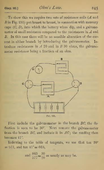
Chap. III.] Ohms Law. 245
To show this we require two sets of resistance coils (A and
B in Fig. 151) put breast to breast, in connection with mercury
cups (C, D), into which the battery wires dip, and a galvano-
meter of small resistance compared to the resistances in A and
B. In this case there will be no sensible alteration of the cur-
rent in either branch by introducing the galvanometer. In-
troduce resistances in A 20 and in B 30 ohms, the galvano-
meter resistance being a fraction of an ohm.
Fig. 151.
First include the galvanometer in the branch BC, the de-
flection is seen to be 30°. Next remove the galvanometer
from the branch BC, and include it in AC; the reading then
becomes 41°.
Referring to the table of tangents, we see that tan 30°
= •577, and tan 41°= -86 5,
t865 30
n,
and ——=— as nearly as may be.
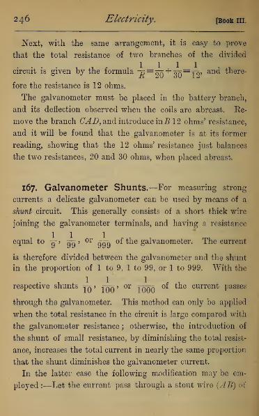
246 Electricity. [Book in.
Next, with the same arrangement, it is easy to prove
that the total resistance of two branches of the divided
. ... ,-,-• ,1111circuit is given by the formula 7?
=<m"*" qT^Toj an(* ™ere"
fore the resistance is 12 ohms.
The galvanometer must be placed in the battery branch,
and its deflection observed when the coils are abreast. Ee-
move the branch CAD, and introduce inB 12 ohms' resistance,
and it will be found that the galvanometer is at its former
reading, showing that the 12 ohms' resistance just balances
the two resistances, 20 and 30 ohms, when placed abreast.
167. Galvanometer Shunts.—For measuring strong
currents a delicate galvanometer can be used by means of a
shunt circuit. This generally consists of a short thick wire
joining the galvanometer terminals, and having a resistance
equal t° 9" > 99 'or
999 °f ^e galvanometer. The current
is therefore divided between the galvanometer and the shunt
in the proportion of 1 to 9, 1 to 99, or 1 to 999. With the
respective shunts yn > ^qq > or Tqoo °f ^e current passes
through the galvanometer. This method can only be applied
when the total resistance in the circuit is large compared with
the galvanometer resistance; otherwise, the introduction of
the shunt of small resistance, by diminishing the total resist-
ance, increases the total current in nearly the same proportion
that the shunt diminishes the galvanometer current.
In the latter case the following modification may be em-
ployed :—Let the current pass through a stout wire (AB) of
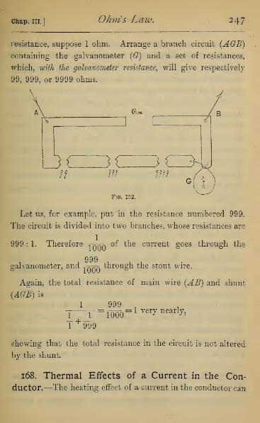
Chap. III.] Ohm's Law. 247
resistance, suppose 1 ohm. Arrange a branch circuit {AGB)
containing the galvanometer (G) and a set of resistances,
which, with the galvanometer resistance, will give respectively
99, 999, or 9999 ohms.
Fig. 152.
Let us, for example, put in the resistance numbered 999.
The circuit is divided into two branches, whose resistances are
999 : 1. Therefore tqaa of the current goes through the
999galvanometer, and -tkk^ through the stout wire.
Again, the total resistance of main wire (AB) and shunt
(AGB) is
1—
r
=iWo
=1 yery nearly'
T +999
showing that the total resistance in the circuit is not altered
by the shunt.
168. Thermal Effects of a Current in the Con-
ductor.—The heating effect of a current in the conductor can

248 Electricity. [Book in,
be shown by connecting the terminals of a battery of five or
six Grove cells with platinum wires of various sections. The
thicker the wire the smaller will be the rise in temperature
;
but with a very thin wire, such as is used for blowpipe experi-
ments, 4 or 5 inches may be kept glowing at red heat. The
shorter the wire, the more intensely it will glow, owing to the
decrease in resistance, and therefore increase of current where
the wire is shortened. It has been shown by experiment that
the current which will keep an inch of wire at a given tempera-
ture would maintain a mile of the same wire at an equal
temperature, but practically increasing the length of a con-
ductor of considerable resistance diminishes the current, and
fresh battery power must be supplied to maintain the same
current.
The heating effect is closely analogous to the heating caused
by passing a current of liquid through narrow tubes. The
more rapidly the liquid flows, and the narrower the tube,
the greater will be the frictional resistance.
The heating effect also depends on the nature of the
material, being greater the greater its specific resistance.
This is shown by having a chain, whose alternate links are of
platinum and silver wires of about the same gauge. If the
chain be placed between the terminals of the battery, the
platinum will be found to glow with a red heat, while the
silver remains dark and cold, though of course the current in
all is the same. This is owing to the specific resistance of the
platinum being about six times that of the silver.
*i69. Measure of Heating Effect.—If we have a con-
ductor whose extremities are at potential difference V, and a
current T passes through it, that current represents a loss of

chap, in.] Ohm's Law. 249
energy represented by VI units of energy per second (Art. 143).
Unless work is being done externally, that energy must be con-
verted into heat in the conductor itself. Hence the heat given
out per second will be the thermal equivalent of VI units of
energy. If H be the number of thermal units given out, and
J be Joule's mechanical equivalent of heat, we have
JH=VI=PB where R is the resistance, since V=IRby Ohm's law.
Let now m be the mass, c the specific heat, and 6 the rise in
temperature, then H=mc9. Also let I be the length, a the
sectional area, p the specific resistance, and D the density
;
then m=hD and i?=— • Substituting, we havea °'
JlaDc6=P^' a
e= pp !
JDc
This will represent the rise in temperature per second, sup-
posing no heat lost by radiation or otherwise.
This confirms our rule that the rise in temperature is
independent of the length when the current is constant, and
shows that the heating is inversely as the square of the
section, or as the fourth power of the diameter when the
section varies. This explains the enormous heat developed
in a thin wire forming part of a circuit as in the incandescent
lamp or fuze in mining.
The same general laws apply to the heating of the liquid
parts of a circuit, the heat being simply proportional to the
resistance in each section of the circuit. Thus on short-cir-
cuiting a battery, the cells are rapidly heated, and the stout

250 Electricity. [Book in.
wire remains cool. Here the energy of the current is wholly
converted into heat in the battery itself. When a large
resistance is interposed, the current is smaller, and only a
small fraction of that heats the battery, the greater part
heating the larger external resistance.
The formula JH~PRt for the amount of heat given out
in t seconds gives the result in gram-degrees, if we give J"
the value 4*2 xlO7 ergs, and measure / and R in absolute
units of either the electrostatic or electromagnetic system.
It can be proved (Art. 184) that if I he measured in amperes
and R in ohms, the right-hand side must be multiplied by
107, which reduces the formula for the number of gram-
degrees given off to
w- Imt•

CHAPTER IV.
WHEATSTONE'S BRIDGE.
*I70. Theory of the Bridge.—The measurements de-
tailed in the last chapter depend on the use of a tangent
galvanometer, an instrument which gives a good rough
measure of a strong current, but is not very sensitive to small
changes in current, nor capable of being read to a very great
nicety. All the most accurate measurements are therefore
made by extremely sensitive galvanometers of the astatic or
mirror type, the adjustment of the apparatus requiring that
the current through the galvanometer shall vanish.
The chief instrument used for measuring all resistances
is Wheatstone's Bridge. The principle of this instrument
is a divided circuit whose terminals are by a battery kept
at a certain potential difference. Let the resistance be
represented by the lines AB, AC in one plane, and the
potential difference between A and B or C by a line ADperpendicular to the plane. The lines DB and DC will
(Art. 147) give the potential-gradient. If two points B, Fbetaken in AB and AC respectively, so that AB : BB :: AF: FC
251

252 Electricity. [Book III.
and EG, FH be drawn parallel to AD, then EG=FH for
EG BE , .F.ff <7i?
AD~AB and AD"AG' which shows i? and i*7
to be at the
same potential. Hence a galvanometer placed in EF would be
unaffected. This was put in practice by Wheatstone, who
arranged a parallelogram into the sides of which resistances
could be introduced. Let AE BF be the parallelogram, the
Fig. 154.
gaps in the sides being left for the resistances. In the diagonal
AB is placed a battery, and in the other diagonal EF the gal-
vanometer. Into one side he introduced the resistance to be
measured, and into the others he put known resistances,
which he varied till the galvanometer remained at zero.
The unknown resistance was then given by the formula
—
Resistance in AE __ Resistance in AFResistance in EB~~~ Resistance in FB
*i7i, Use of the Bridge to find the Resistance of a
Coil.—In modern instruments the form is altered, the fixed
portions consisting of stout copper strips of no appreciable re-
sistance (Fig. 155), the gaps in AE and EB being for the in-
troduction of the unknown resistance, and a certain measured
resistance. The branches AF and BF are formed by a single

Chap. IV.] Wheatstone s Bridge. 253
stout German silver wire, a metre in length, along which slides
a key (F), by pressing down which contact can be made with
the wire at any point. The key runs along a raised wooden
Fig. 155.
rod, whose upper surface is graduated carefully in millimetres,
and read from both ends ; so that the length of the two parts
of the wire canl)e at once read off. This key is slid along the
wire till the galvanometer remains at rest, whether the key is
up or down, and in this position the reading is taken. If,
then, p be the unknown resistance in AE, and q the knownresistance in EB> and %, a the distances of F measured along the
wire from A and B respectively, we have —=— , or <n=— •r " a q 1 a
In performing experiments it is often convenient to have
two galvanometers—one a rough one, for getting an approxi-
mate adjustment, and finally a very sensitive one for getting
an accurate adjustment.
Fig. 156 shows the arrangement actually made in finding
the resistance of a coil of wire. Its terminals are placed in
two mercury cups used for securing better contact, these
being connected with the binding-screws by wide copper
strips. The resistance-coils are connected with the other
corresponding terminals. The battery consisting of a single

254 Electricity. [Book III.
Daniell cell, and the galvanometer are in the two diagonal
branches.

chap, iv.] Wheatstone s Bridge. 255
*i72. Method of finding Galvanometer Resistance.
—The bridge may be used for finding the resistance of the
galvanometer actually in use. The galvanometer is included
in the branch AE (Fig. 155). Now it is clear that if E and Fare at the same potential, the mere joining them by a wire will
not alter the current in any branch. Hence if we put a contact
breaker in the branch EF, and move the key till the galvano-
meter reading is not altered by depressing it, we may find the
galvanometer resistance exactly as in the preceding case.
With a very sensitive galvanometer the current is often so
strong as to deflect the needle through very nearly 90°, in
which case the reading cannot be taken. To reduce the read-
ing we must either introduce a very large resistance into the
galvanometer branch EF, which can afterwards be subtracted
from the final result, or we can, better, introduce a large resist-
ance into the battery branch AB, so reducing the current in
all parts of the bridge.
This method is due to Sir W. Thomson, and was suggested
to him by Mance's method for finding internal resistance
which follows.
*I73- Method of finding Battery Resistance.—To
understand Mance's method, we must notice a further exten-
sion of the principle of the bridge, which appears from theory,
namely, that so long as the relation —= ^- holds between the
resistances, whatever electromotive forces be introduced in
the branches, the current in the branch circuit EF (Fig. 157)
is independent of any E.M.F. or resistance in the branch
circuit AB, while the current in AB is independent of E.M.F.
and resistance in EF Hence if we include the battery of
unknown resistance in the branch AE. a galvanometer in AB,

256 Electricity. [Book III.
and a contact breaker in EF9we must shift the key till rais-
ing or lowering its button makes no difference in the galvano-
meter reading.
Fig. 157
As in the last case if the current be too strong for the
galvanometer, we can increase the resistance in the galvano-
meter branch.
*174- Method of comparing the E.M.F. of Cells.—
We conclude this chapter with a method of comparing the
E.M.F. of two constant cells by a method analogous to that
of the Wheatstone Bridge.
Place the cell, whose E.M.F. we will denote by E, and a set
of resistance-coils (A ) in an open circuit which terminates in
two mercury cups (CD). Also place the second cell, whose
E.M.F. is E f
, with another set of resistance-coils (B) with its
terminals in the same mercury cups, so placing the cells that
they would send the current in opposite directions through
a branch joining CD, and introduce a galvanometer in the
branch CD (Fig. 158).
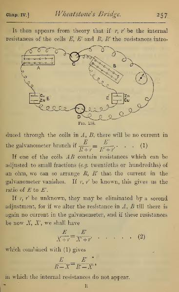
Chap. IV.] Wheatstone s Bridge. 257
It then appears from theory that if r, r' be the internal
resistances of the cells E, E' and B, R' the resistances intro-
Fig. 155.
duced through the coils in A, B, there will be no current in
— = -^—. . . (1)B + r R' + r'
V'
the galvanometer branch if
If one of the coils AB contain resistances which can be
adjusted to small fractions (e.g. twentieths or hundredths) of
an ohm, we can so arrange R, R' that the current in the
galvanometer vanishes. If r, r' be known, this gives us the
ratio of E to E '.
If r, / be unknown, they may be eliminated by a second
adjustment, for if we alter the resistance in A, B till there is
again no current in the galvanometer, and if these resistances
be now X, X, we shall have
E E'
X+r-X + f
which combined with (1) gives
E E'*
R-X~R'-X"in which the internal resistances do not appear.
(2)

258 Electricity. [Book in.
As a particular example we give the numbers obtained on
comparing a Daniell and Leclanch6 cell. On taking out
40 ohms resistance in the Leclanch6 branch, and 31*5 in
the Daniell branch, the galvanometer was at zero. Secondly,
altering the resistance in the Leclanch6 branch to 70 ohms,
that in the Daniell had to be adjusted to 54.
This gives
Leclanche : Daniell :: 70-40 :: 54-31*5
: : 30 : 22*5
Or Leclanche == 1*3 Daniell in respect of E.M.F.

CHAPTER V.
ELECTRO-MAGNETISM AND ELECTRO-DYNAMICS.
175, Bertins' Commutator.—In many of the experi-
ments which form the subject of this chapter we require a
convenient and rapid means of changing the direction of the
current. This is done by a commutator, of which there
Fig. 159.
are many forms. That known as Bertins' is perhaps the
simplest, as mere inspection of the instrument shows the
direction in which the current is passing. On a fixed ebonite
base (Fig. 159) are four binding-screws, two (AB) connected
259

260 Electricity. [Bookin
with the battery terminals, and two (CD) with the apparatus in
use. On this base is a disc of ebonite carrying a brass horse-
shoe, and a brass tongue within the horse-shoe, but insulated
from it. These are separately connected with the battery
terminals by metal strips and sliding contacts underneath.
The other two binding-screws have metal springs attached to
them, so that either end of the horse-shoe and the tongue may
be simultaneously in contact with them. By turning the
ebonite through a small angle, the tongue and horse-shoe
come into contact with the springs in the reverse order, and
so reverse the direction of the current. The diagrams show
the commutator in the two positions, the direction of the
current being shown by arrows.
176. Magnetic Field of a Straight Current—Oersted's experiment has taught us that a magnet pole
placed near a current experiences force. Since this is the
test of a magnetic field, it follows that a current of electricity
possesses the properties of a distribution of magnetism in that
it is surrounded by a magnetic field. To investigate this
magnetic field we will take a straight wire, and place it so
that it passes at right angles through a sheet of paper, on
which we can sprinkle iron filings. On passing the current
from five Grove cells in simple circuit, and tapping the paper,
it will be seen that the iron filings arrange themselves in con-
centric circles round the wire. These are therefore the lines
of force ; and from Oersted's experiment, or by the use of a
small magnet, we see that the direction of the lines of force is
related to the direction of the current in right-handed cyclical
order, as indicated by the arrows (Fig. 160). That is to say, if
the direction of the current be the direction in which a cork-

chap, v.] Electro- Magnetism and Dynamics. 261
screw, or other right-handed screw, is propelled through the
cork, the direction of the line of force is represented by the
twist in the muscles of the wrist, by which it is driven in.
Fig. 160.
i77 % Rotation of a Magnet Pole round a Current.
We infer from the last experiment that a magnet pole free
to move will rotate round a current. The experiment was
originally performed by Faraday by bringing the current
to bear only on one half of the magnet, carrying it away again
as soon as it reaches the centre. It is convenient to bend the
magnet, so that it may be pivoted on its middle point, the
current being brought to a mercury cup supported upon the
revolving magnet, and carried away by a bent wire which dips
into an annular cup of mercury, with which the battery wire
is connected. On passing a strong current, the magnet pole
rotates steadily, and on reversing the direction of the current,
the direction of rotation is reversed (Fig. 161).

262 Electricity. [Book in.
178. Rotation of a Current round a Magnet Pole.
—The third law of motion shows that whatever force a
Fig 161.
current exerts on a pole, the pole must exert an exactly
equal and opposite force on the current. Thus the system of
forces between a magnet pole and a current consists of a couple,
and the current, if free to move, will spin round the pole,
having the same direction of rotation relatively to the pole
that the pole has relatively to the current. These directions
of rotation are shown by the dotted lines in Fig. 162.
The rotation of a current round a pole can be shown
experimentally by pivoting a wire bent in the form of
an inverted letter U on the top of a vertical magnet, the
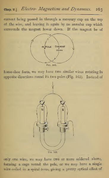
chap, v.] Electro- Magnetism and Dynamics. 263
current being passed in through a mercury cup on the top
of the wire, and leaving it again by an annular cup which
surrounds the magnet lower down. If the magnet be of
n'pole Current i
c c ^1 DOWN v
Fig. 162.
horse-shoe form, we may have two similar wires rotating in
opposite directions round its two poles (Fig. 163). Instead of
Fig. 163.
only one wire, we may have two or more soldered above,
forming a cage round the pole, or we may have a single
wire coiled in a spiral form, giving a pretty optical effect of

264 Electricity. [Book III.
continually screwing up or down; or we may vary the
experiment by passing the current into one annular cup and
out by the other, causing the wires to rotate in the same
direction round the opposite poles.
179. Movement of Current in a Magnetic Field.—
A little reflection will show that the motion of the current
cannot depend on the mere magnet pole, but does depend
on the field of force immediately around the current. The
observed motion must, in fact, be the expression of a tendency
on the part of any moveable current to cut lines of magnetic
force at right angles, the direction of motion being reversed
when either the direction of the lines of force or of the
current is reversed.
Fig. 164.
This is easily shown if we pass a current through a wire
freely suspended above and dipping in a cup of mercury. If
the poles of a strong horse-shoe magnet be brought near the
wire, so that the wire lies between them, or in any way cuts

chap, v.] Electro- Magnetism and Dynamics. 265
the lines of force, the wire moves through the mercury until
contact is broken, falls back again, and so keeps up a vibrating
movement (Fig. 164). The direction of motion can be altered
by reversing the poles or the direction of the current. If the
two poles be placed parallel to the wire, no effect is pro-
duced.
This principle is further illustrated by Barlow's wheel.
The wheel consists of a brass wheel cut into a star with
eight or ten points. The points, when they come in succes-
sion to their lowest position, dip into a mercury cup, and
a current is sent from the axis down the vertical radius to the
mercury, whence it returns to the battery. If now the poles
of a magnet be placed on opposite sides of the wheel, the
wheel begins to rotate, and by bringing the points successively
into the mercury cup, keeps up a continuous rotation as
long as the battery current continues. On reversing either
the poles or the current, the direction of rotation is re-
versed (Fig. 165).
Fig. 165.
By means of this apparatus it is easy to study the direction
of motion of a conductor in a magnetic field. The movement

266 Electricity. [Book in.
of the conductor is affected only by the lines of force which
cut through it, and the direction in which it tends to move
is at right angles to the plane containing the current and the
lines of magnetic force which cut it. The effect is greatest
when the current is placed so as to cut the lines of force at
right angles. The following is a convenient memoria technica
for remembering the relations of the three directions—current,
lines of force, and movement of conductor :
—
A figure swim-
ming in the current, and looking along the lines offorce, is carried
to his left For example, a person standing erect carrying a
current which flows from his heels to his head, and looking
magnetic northwards, i.e. along the lines of the earth's hori-
zontal force, is carried towards the west by the earth's
horizontal magnetic field.
180, Methods of Suspending Currents.—To con-
struct a circuit which shall be perfectly free to move, and yet
be in connection with the terminals of a battery, presents a
mechanical problem of some difficulty. Ampere overcame it
by the invention of a stand which goes by his name, and
some modification of which is still used. After many trials,
the present writer has adopted the following method, which
will give satisfactory results in all the experiments described
with five Grove cells arranged for simple circuit, as in Art. 164.
The axis of the central stem consists of a wire connected with
one binding-screw, and terminating in a mercury cup. It is
insulated by an ebonite cylinder from the outside, which con-
sists of a brass tube, connected with the second binding-screw.
On the brass tube slides an annular cup of mercury (Fig. 166).
The wire frames of various forms are pivoted in the central
mercury cup, and the other terminal dips slightly into

chap, v.] Electro- Magnetism and Dynamics. 267
the mercury in the annular cup. The wires are so bent
that the centre of gravity is brought below the cup. To
diminish friction on the cup, the wire frame is also sus-
pended by a few fibres of unspun silk, by which nearly
its whole weight is borne (see Fig. 173), and the wire
framework is left with remarkable freedom of motion. [The
central stem is usually sold with a rather cumbrous arrange-
ment for supporting the wire frames, whose movements are
then very sluggish.]
Fig. 166.
181. Effects of Terrestrial Magnetism on Move-able Currents.—By means of the double rectangle of
Fig. 166, if the rectangles be made large enough (each not
less than 10 in. by 8 in.), it will be found, on passing a cur-
rent, that the framework sets as a magnet would, but with its
plane at right angles to the magnetic meridian, the current
ascending on the west and descending on the east side in
each rectangle.
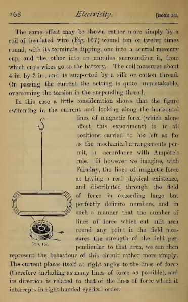
268 Electricity. [Book III.
?
The same effect may be shown rather more simply by a
coil of insulated wire (Fig. 167) wound ten or twelve times
round, with its terminals dipping, one into a central mercury
cup, and the other into an annulus surrounding it, from
which cups wires go to the battery. The coil measures about
4 in. by 3 in., and is supported by a silk or cotton thread.
On passing the current the setting is quite unmistakable,
overcoming the torsion in the suspending thread.
In this case a little consideration shows that the figure
swimming in the current and looking along the horizontal
lines of magnetic force (which alone
affect this experiment) is in all
positions carried to his left as far
as the mechanical arrangements per-
mit, in accordance with Ampere's
rule. If however we imagine, with
Faraday, the lines of magnetic force
as having a real physical existence,
and distributed through the field
of force in exceeding large but
perfectly definite numbers, and in
such a manner that the number of
lines of force which cut unit area
round any point in the field mea-
sures the strength of the field per-
pendicular to that area, we can then
represent the behaviour of this circuit rather more simply.
The current places itself at right angles to the lines of force
(therefore including as many lines of force as possible), and
its direction is related to that of the lines of force which it
intercepts in right-handed cyclical order.
Fig. 167

chap, v.] Electro- Magnetism and Dynamics. 269
By supporting a wire framework, free to rotate about a
horizontal axis at right angles to the magnetic meridian, and
passing a strong current, it has been shown that it sets at
right angles to the dipping needle.
By supporting a horizontal wire pivoted at one end, and
with its other end just dipping into a mercury basin, on which
it is supported by a cork float, it has been shown that on
passing a current through the wire it rotates under the
action of the vertical component of the earth's magnetism in
accordance with Ampere's rule.
182. Magnetic Properties of a Closed Current.—If
we take a wire bent in the form of Fig. 168, in which the
current passes round the two equal rectangles (AB) in opposite
directions—roundA in a direction with the hands of a watch,
and round B in the contrary direction—the whole system will
be astatic with reference to the earth.
Fig. 163.
If we now take a magnet, and present its north pole to A,
it will be found that A is attracted by it, and if we present
the same pole to B it will be repelled. If we next present
the north pole to the back of A it will be repelled, and the
back of B will be attracted. If the south pole of the magnet
be used, these attractions and repulsions will again be reversed.
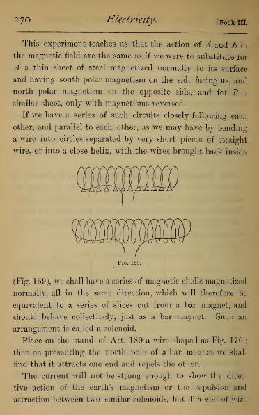
2 jo Electricity.[Book IIL
This experiment teaches us that the action of A and B in
the magnetic field are the same as if we were to substitute for
A a thin sheet of steel magnetized normally to its surface
and having south polar magnetism on the side facing us, and
north polar magnetism on the opposite side, and for B a
similar sheet, only with magnetisms reversed.
If we have a series of such circuits closely following each
other, and parallel to each other, as we may have by bending
a wire into circles separated by very short pieces of straight
wire, or into a close helix, with the wires brought back inside
Fig. 169.
(Fig. 169), we shall have a series of magnetic shells magnetized
normally, all in the same direction, which will therefore be
equivalent to a series of slices cut from a bar magnet, and
should behave collectively, just as a bar magnet. Such an
arrangement is called a solenoid.
Place on the stand of Art. 180 a wire shaped as Fig. 170
;
then on presenting the north pole of a bar magnet we shall
find that it attracts one end and repels the other.
The current will not be strong enough to show the direc-
tive action of the earth's magnetism or the repulsion and
attraction between two similar solenoids, but if a coil of wire

Chap, v.] Electro- Magnetism and Dynamics. 271
be formed by closely coiling stout insulated wire from end
to end of a cylinder 6 inches long, and bringing the wire
through the cylinder, and again repeating the close coiling
till four or five layers have been obtained, this will be found
to act precisely as a weak magnet when presented to the ends
of the solenoid, the pairs of poles attracting and repelling just
as they would for two bar magnets.
Fig. 170
The rules for the north and south poles of the solenoid will
be in accordance with what we said before ; that will be the
south pole in which the current, to an observer looking down
upon it, goes with the hands of a watch, and a north pole
in which the current goes against the hands of a watch (see
Fig. 171).
tii s
jmywmFig. 171.
The behaviour of currents under magnetic force is some-
times illustrated by the floating battery of De La Rive.
This is a simple zinc-copper couple, connected by several turns
of insulated copper wire. The plates are mounted on the
under-side of a cork float, and put on a vessel of acidulated

272 Electricity. [Book III.
water, which acts as the liquid of the cell (Fig. 172). By this
means the behaviour of a closed circuit under a magnet can
easily be exhibited.
Fig. 172.
By experiments, of which the above may be taken as types,
and others depending on quantitative measures, Ampere was
able to lay down as an experimental law that every closed
voltaic circuit carrying a current is identical in its behaviour
with a magnetic shell, magnetized normally, the current fol-
lowing the direction of the hands of a watch to an observer
looking down on the south polar face. The strength of the
equivalent current is directly proportional to the strength of
the magnetic shell, or to its magnetic moment per unit area.
*i83. Distinction between a Voltaic Circuit and a
Magnetic Shell.—There is a very important difference
between the shell and the circuit. For if P, Q be two points
on the north and south side of a magnetized shell, a north
pole placed at P will be repelled by the action of the shell,
and carried round the edge to Q, where it will stop by impact
against the shell. If a small aperture were made in the shell,

chap, v.] Electro- Magnetism and Dynamics. 273
though too small to affect the force on a pole at any external
point, still in passing through this aperture the magnet pole
would experience a retarding force, against which the work
done by the pole between Q and P would just balance the
work done on it by the accelerating force it had experienced
up to Q, and it would reach P again with neither gain nor loss
of energy. This is no more than the assumption that mag-
netic forces among fixed magnets obey the law of conserva-
tion of energy. If, on the other hand, we have a voltaic
circuit, and P, Q be the corresponding points on opposite
sides of its plane, the pole passes freely from Q to P without
experiencing any retarding force, and reaches P again with
an increase of energy. This energy is of course derived, as
we shall see presently, from the current energy which has
its source in the chemical energy of the battery.
*i84. Absolute Electro-magnetic Units.—This ex-
periment of Ampere is the key to the absolute electro-
magnetic system of measurement alluded to in Art. 154.
We define in this system the unit current of electricity, as
that current which, traversing any closed circuit, gives rise
to an electro-magnetic field identical in all respects with the
magnetic field due to a magnetic shell of unit strength, whose
edge coincides with the circuit. This is called the absolute
unit of current strength.
The absolute unit of quantity is the quantity of electricity
which passes per second in a current of unit strength.
The absolute unit of E.M.F. or potential difference is the
potential difference between two points such that unit work
is done in carrying the absolute unit of quantity from one
point to the other.
S

2 74 Electricity. [Book in.
The absolute unit of capacity is the capacity of a conductor
which, when charged with unit quantity of electricity, is at
unit potential.
The absolute unit of resistance is the resistance in a circuit
in which the E.M.F. is the absolute unit of potential and the
current is the absolute unit of current.
These are not the units referred to above in Art. 154,
as some would be inconveniently large, and others incon-
veniently small.
The Coulomb, or practical unit of quantity, is y1^ of the
absolute unit.
The Volt, or unit of potential, is equal to 108, or one
hundred million absolute units of potential.
The Amphre, or practical unit of current, is -^ of the abso-
lute unit.
The Ohm, or unit of resistance, is 109, or one thousand
million absolute units.
The Farad, or unit of capacity, is 10~9, or one thousand-
millionth of the absolute unit. The micro-farad, more com-
monly employed, is the millionth part of the farad, and there-
fore 10~15, or one thousand-billionth of the absolute unit.
185. Attractions and Repulsions of Parallel and
Inclined Currents (Electro-Dynamics).—To investi-
gate the action of one current upon another, the best form
of apparatus is that of Fig. 173, in which the current in
the two rectangles is astatic under the earth's magnetism.
If the battery wires be parallel and very near to the ex-
treme vertical currents, it will be found that the moveable
wire shows attraction where the currents run in the same
direction, but repulsion when in opposite directions. These

chap, v.] Electro- Magnetism and Dynamics. 275
actions will be made more visible if, instead of a single wire,
we use a current multiplier, or a coil of several circuits, each
rectangular in form, shown in Fig. 167. On presenting the
opposite sides of the multiplier, in which the currents are in
opposite directions, to one of the vertical wires on the stand,
the attraction and repulsion are more strongly marked.
Fig. 173.
By the same arrangement it can be shown that when
two finite currents are inclined to each other without cross-
ing, they attract when both run towards or both run away

276 Electricity. [Book III.
from the common apex, but repel when one runs towards
and the other away from the apex.
The attraction and repulsion of parallel currents are
admirably shown by the arrangement of Fig. 174, which
consists of two flat spirals, each suspended by two wires,
through which the current is carried. On the base is a
Fig. 174.
simple form of contact breaker and commutator. On causing
the spirals to hang in parallel planes a short distance apart,
and passing the current so that it shall run in parallel direc-
tions round both spirals, they are attracted towards each
other. On hanging the spirals initially in contact, or nearly

cnap.v.] Electro- Magnetism and Dynamics. 277
so, and passing the current so as to traverse them in opposite
directions, there will be a very marked repulsion.
The attraction of parallel currents is well illustrated by the
vibrating spiral. This consists of a spiral of moderately thin
copper wire suspended at its upper end and dipping at its lower
end into a basin of mercury (Fig. 175). On passing a current,
the successive turns of the spiral attract each other, draw the
point out of the mercury, and break the contact ; when the
lower end of the spiral falls back again into the mercury cup.
A vibratory motion is thus kept up as long as the battery
connection lasts.
These actions are easily explained in accordance with the
principles we have laid down, by regarding the parallel
Fig. 175.
currents as edges of two magnetic shells which face each other.
When the currents are in the same direction, the surfaces
oppositely magnetized will be directly opposed, and therefore
attraction ensues. If the currents are in opposite directions,

2j& Electricity. [Book in.
the surfaces similarly magnetized will oppose, and therefore
repel each other.
The same result will be arrived at also by considering
either current in the field of force due to the other. For
ifA be a current, its lines of force will be more or less nearly
circles round it, and those circles will rise out of the paper
on one side and sink into it on the opposite (Fig. 176). If
another wire carrying a current be placed on the paper below
A, the figure swimming in the current and looking downwards
will be carried to his left, i.e. towards A ; and if the other
current be above A, the figure swimming in the current and
looking upwards will be carried to his left, that is, towards Aalso. Thus on both sides, A will attract a current running
parallel to itself and in the same direction.
Lines of Force upwards.
A >Lines of Force downwards.
Fig. 176.
The laws of inclined currents can be explained by taking
the equivalent magnetic shells, or by considering the resolved
part of the field of force of one current perpendicular to the
other.
186. Action of an Infinite Current on another
wholly on one side.—If ABC represent a current, and
DE another at right angles to it (Fig. 177), then, apply-
ing the principle of inclined currents, we see that the current
in AB runs towards the apex, and that in DE runs away
from it, and therefore AB and DE repel each other ; while
those in BO and DE both run away from the apex, and
therefore attract each other. Hence, on the whole, DE, if
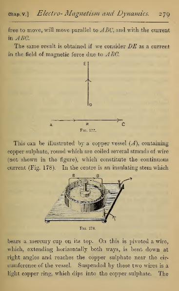
chap, v.] Electro- Magnetism and Dynamics. 2 79
free to move, will move parallel to ABC, and with the current
in ABC.
The same result is obtained if we consider DE as a current
in the field of magnetic force due to ABC.
y^
B
Fig. 177.
nThis can be illustrated by a copper vessel (A), containing
copper sulphate, round which are coiled several strands of wire
(not shown in the figure), which constitute the continuous
current (Fig. 178). In the centre is an insulating stem which
b ^ w B
Fig. 178.
bears a mercury cup on its top. On this is pivoted a wire,
which, extending horizontally both ways, is bent down at
right angles and reaches the copper sulphate near the cir-
cumference of the vessel. Suspended by these two wires is a
light copper ring, which dips into the copper sulphate. The

280 Electricity. [Book in.
current, after traversing the coil round the copper vessel,
passes up the centre to the mercury cup, divides and descends
by the two wires to the copper sulphate, whence it returns
to the battery. The action of the continuous current on
both the horizontal and vertical parts of the current in the
poised wire causes it to rotate steadily, carrying with it the
copper ring which steadies the motion.
187. Equivalence of a Sinuous and Straight
Current.—Ampere laid down the rule that a sinuous cur-
rent is equivalent to a straight current passing through it.
This can be shown by making a compound solenoid in which
the wire, coiled outside a tube in a helix, is carried through
the tube in a straight line, and this is done four or five
times, as described in Art. 182. We thus have an exterior
sinuous current of about 24 yards, and an internal straight
current in the opposite direction, whose length is about half a
yard. On placing this arrangement parallel to one of the
vertical wires in the suspended rectangle of Art. 185, and
passing the current through them both, we shall find they
are quite neutral to each other, the straight part just balanc-
ing the effect of the sinuous part.
If, on the other hand, the compound coil be approached
endwise to the current, its action is seen to be similar to
that of a bar magnet.
*i88. The Magnetic Field inside a Solenoid.—One
of the most remarkable things about a solenoid carrying a
current is the great strength of the magnetic field inside it.
To explain this, we may notice that the lines of force due to a
straight current are circles, having their centre in the axis of
the current. If we have a large number of straight currents

cuap. v.] Electro- Magnetism and Dynamics. 281
parallel to each other in a plane, to find the strength of field
at any given point, we must compound, according to the
parallelogram law, the strength of field due to each current
separately. This requires a mathematical investigation, but
we can easily see the general effect. Let the line of dots AB(Fig. 179) denote the section of the paper by the currents
which pass down perpendicularly through the paper, and
extend indefinitely right and left. Let P be a point at
which we want to construct the line of force. The force
due to the current at A will be at right angles to AP,
and right-handed to the current; we denote it by F. Wecan generally choose a current (B) such that PA=PB, and B
Fig. 179.
will give at P a force at right angles to BP equal to the force
due to A ; we denote it by F\ Now F, F 1 are equal, and
equally inclined to AB, and will therefore have a resultant
parallel to AB. The same will be true of each pair of currents
equally distant from P. The line of force at P will therefore be
parallel to AB, and the strength of field will be somewhat in-
creased by each single current. Of course, practically, the re-
mote currents will produce little effect, and if the currents be
finite with P near the middle, we may assume that the lines of
force are parallel to AB, that is to say, in the system we have
assumed the lines of force will cross the currents at right angles.
Suppose, now, one of the wires bent into a circle or closed figure.

282 Electricity. [Book III.
The lines of force will no longer be circles, but will be closed
curves, being crowded together in the closed curve, and spread
out outside it, somewhat as in the drawing (Fig. 180), in which
we represent the curves obtained when we pass a current down
one and up the other of two parallel wires near together.
<->^
Fig. 180.
Now, suppose each of the circles forming the band of cur-
rents we considered just now to be bent into a circle, and we
have the solenoidal arrangement. The lines of force must
now be a series of closed curves linked with the cylinder,
formed of the solenoid, entering by its south and leaving by
its north polar end. Externally the lines will be the same as
for a bar magnet (Art. 12), and the reasoning we used above
shows that all the circles conspire to give at all internal points,
except near the ends, a field whose lines of force are parallel
to the axis of the cylinder. These lines, moreover, are very
crowded, since all the lines pass through the cylinder, but

chap, v.] Electro- Magnetism and Dynamics. 283
are spread through the whole field outside it. The crowding
together of the lines explains on Faraday's hypothesis (Art,
181) the great relative strength of the field within the sole-
noid. In Fig. 181 a diagram of the lines of force is shown,
the two rows of circles being the section by the paper of the
solenoid wire.
Fig. 181.
This explains why a soft iron wire placed outside will be
magnetized very feebly and in the opposite direction to the
magnetization of the solenoid, while a wire inside will be very
strongly magnetized in the same direction.
189. Electro-Magnets.—Temporary magnets of great
power are made by placing soft iron bars within helices
of wire, through which a current is transmitted. The soft
iron, while the current is passing, becomes a very strong
magnet, but instantly loses its magnetism when the circuit is
broken. This is easily seen by putting a stout soft iron wire

284 Electricity. [Book III.
through a helix of insulated copper wire, when, on passing
the current through the helix, the iron wire will acquire the
power of picking up large quantities of brads or iron frag-
ments, dropping them again the moment that contact with
the battery is broken.
Fig. 182.
If a horse-shoe is made in soft iron, and a few dozen
strands of wire are coiled in opposite directions round the
two ends, on passing a current through the wire, a very-
powerful electro-magnet is made, capable of supporting very
heavy weights when suspended from a soft iron armature
joining its poles (Fig. 182).

chap, v.] Electro- Magnetism and Dynamics. 285
If a bar of steel be placed within the helix, the magnetism
induced is less strong than for an iron bar of the same size,
but is largely retained after the current is broken. Small bars
can be easily magnetized to saturation by placing them in a
helix and giving smart blows with a hammer while the cur-
rent is passing.
By the method just indicated temporary magnets can be
made of vast power compared even with the strongest per-
manent magnets. To obtain the best effects very nice adjust-
ments have to be made between the dimensions of the soft
iron core and the coils of wire which surround it. If the core
be too thick, only the outer parts are magnetized, while the
inner part contributes nothing to the strength of the pole.
There is again great difficulty in obtaining thick iron rods
which are well annealed throughout, without which the iron
is not soft. The core is therefore often made of a number of
thin rods of soft iron. By these means, with proper pre-
cautions, magnets of vast power have been made.
190. Paramagnetic and Diamagnetic Substances.
—By means of the powerful electro-magnet possessed by the
Royal Institution, Faraday showed that almost all substances
were more or less susceptible to magnetic influence. He also
discovered two classes of substances very different in their
behaviour when under magnetic influence. The first class he
called paramagnetics, which in their properties are similar to
iron, nickel, and cobalt, so that when a bar of one of these
substances is suspended in the strong magnetic field between
the poles of the magnet, the bar sets with its length along the
lines of force, or, as he termed it, axially. The other class
he called diamagnetics, of which bismuth is a type. When a
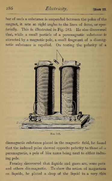
286 Electricity. [Book III.
bar of such a substance is suspended between the poles of the
magnet, it sets at right angles to the lines of force, or equa-
tonally. This is illustrated in Fig. 183. He also discovered
that, while a small particle of a paramagnetic substance is
attracted by a magnetic pole, a small fragment of a diamag-
netic substance is repelled. On testing the polarity of a
Fig. 183.
diamagnetic substance placed in the magnetic field, he found
that the induced poles showed opposite polarity to those of a
paramagnetic, a pole of like name being next to either induc-
ing pole.
Faraday discovered that liquids and gases are, some para-
and others dia-magnetic. To show the action of magnetism
on liquids, he placed a drop of the liquid in a very thin

chap, v.] Electro- Magnetism and Dynamics. 287
watch-glass supported between the poles of the electro-
magnet. On making contact with the battery, the shape of
the drop was altered. If a paramagnetic, the drop was
flattened, being drawn along the lines of force • if a diamag-
netic, the drop was heaped up by the repulsion of the poles
and made more convex (see Fig. 184).
PARA MACNETIC LIQUID.
( ^S^ )
DIAMACNETIC LIQUID.
Fig. 184.
To test the magnetism of a gas, he allowed it to escape
from a fine circular orifice between the magnetic poles, and
found that if paramagnetic it spread out like a fish-tail burner
along the lines of force, and if diamagnetic it spread out
across them.
A simple wa}~ of explaining the behaviour of diamagnetic
bodies depends on the magnetism of the air surrounding them.
Oxygen, at any rate, is a moderately strong paramagnetic, and
any substance less strongly paramagnetic than oxygen, when
immersed in it, would behave as a diamagnetic. For under
the induction of the magnetic field we should have, at say the
nominally north pole, a separation of north-polar magnetism
on the solid, and at the same time a separation of south-polar
magnetism in the oxygen in contact with it. If, then, the
paramagnetism of the oxygen be the stronger, the south pole
induced in the oxygen would overpower the north pole in-
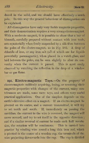
288 Electricity. [Book in.
duced in the solid, and we should have effectively a south
pole. In this way the general behaviour of diamagnetics can
be explained.
All diamagnetics have only very feeble magnetic properties,
and their demonstration requires a very strong electro-magnet.
With a moderate magnet, it is possible to show that a bar of
bismuth, carefully prepared without contact with iron tools,
sets equatorially when freely suspended by a silk fibre between
the poles of the electro-magnet, as in Fig. 183. A drop of
chloride of iron, or any iron salt (all of which are for liquids
powerfully paramagnetic), when placed in a watch-glass, and
laid between the poles, can be seen slightly to alter its con-
vexity when the current is passed. This is most easily
observed by watching the reflection in the drop of a window
bar or gas flame.
191. Electro-magnetic Toys.—On the property of
electro-magnets suddenly acquiring, losing, or reversing their
magnetic properties with changes of the current, many con-
trivances are made, some mere toys, and others very useful
practical applications. One of the simplest depends on the
earth's directive effect on a magnet. If an electro-magnet be
pivoted on its centre, and a current transmitted, it will try
to set north and south. If, immediately on passing the
meridian, the current in the wire is reversed, the magnet will
move onward, and try to set itself in the opposite direction
;
and if a similar reversal of current be made each half revolu-
tion, the rotation will be continuous. This is carried into
practice by winding wire round a long thin iron rod, which
is pivoted in the centre of a wooden cup, the terminals of the
wire projecting downwards into the cup. The cup is divided
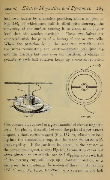
chap, v.] Electro- Magnetism and Dynamics. 289
into two halves by a wooden partition, shown in plan in
Fig. 186, of which each half is filled with mercury, the
convexity of the surface causing it to stand at a higher
level than the wooden partition. These two halves are
connected with the poles of a battery of one or two cells.
When the partition is in the magnetic meridian, and
the wires terminating the electro-magnetic coil, just dip
into the mercury but pass over the partition, its change of
polarity at each half rotation keeps up a constant rotation.
Fig. 186.
This commutator is used in a great number of electro-magnetic
toys. On placing it axially between the poles of a permanent
magnet, a short electro-magnet (Fig. 187, a), whose terminals
dip into the commutator cup, can be made to rotate with
great rapidity. If the partition be placed in the equator of
the permanent magnet, a cage (Fig. 187, b) consisting of vertical
wires pivoted on its middle, one half dipping into each half
of the mercury cup, will keep up a constant rotation, as is
easily seen by considering the motion of the conductor in the
field of magnetic force, traversed by a current in one half
T
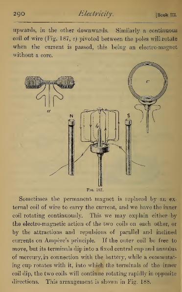
290 Electricity, [Book III.
upwards, in the other downwards. Similarly a continuous
coil of wire (Fig. 187, c) pivoted between the poles will rotate
when the current is passed, this being an electro-magnet
without a core.
Fig. 187.
Sometimes the permanent magnet is replaced by an ex-
ternal coil of wire to carry the current, and we have the inner
coil rotating continuously. This we may explain either by
the electro-magnetic action of the two coils on each other, or
by the attractions and repulsions of parallel and inclined
currents on Ampere's principle. If the outer coil be free to
move, but its terminals dip into a fixed central cup and annulus
of mercury, in connection with the battery, while a commutat-
ing cup rotates with it, into which the terminals of the inner
coil dip, the two coils will continue rotating rapidly in opposite
directions. This arrangement is shown in Fig. 188.

chap, v.] Electro- Magnetism and Dynamics. 291
192. Electromotors.—On similar principles have been
constructed a great number of electromotors, intended by their
HflR^
Fig. 188.
inventors to replace steam by electricity as prime motive
power. None of them have as yet come into more than
limited use, owing chiefly to their great expensiveness com-
pared with steam-engines. Thus, weight for weight, zinc is
fifty times as expensive as coal, and it appears that only about
as much work can be obtained from a pound of zinc used
through the medium of an electro-magnetic engine, as from a
pound of coal used in a steam-engine. When electricity is
generated by steam power, and either distributed by wires or
stored in secondary batteries, it is probable that electromotors
will be employed much more widely for a variety of domestic
purposes, as well as for driving locomotives in underground

292 Electricity. [Book m
railways, and doing work in places where the products of com-
bustion of coal render the use of steam-engines unsuitable.
The first-made electromotors were obviously derived from
the action of the piston in a steam-engine, masses of soft
iron being attracted by electro-magnets, which were destroyed
at the end of the stroke by automatic contact breakers ; and
the backwards and forwards motion so produced was con-
verted into circular motion by the ordinary beam-and-crank
arrangement. The short distance through which an electro-
magnet exerts its power necessitated a very short stroke,
introducing mechanical difficulties. Models on this principle
are common.
Another form consists of masses of soft iron arranged on the
circumference of a wheel, round which are arranged a number
of fixed electro-magnets, having their poles very near its
circumference. These electro-magnets are made when the
piece of soft iron is approaching the magnet, and unmade
when immediately opposite to it. Thus each mass of soft
iron, when within about twenty degrees of an electro-magnet,
and approaching it, receives a pull which is sufficient to
send it on to within twenty degrees of the next magnet.
To this class belongs Froment's engine, of which the sketch
(Fig. 189) represents a model. The arrangement for throwing
the magnets alternately in and out of circuit consists of a
wheel of eight projecting teeth revolving with the rotating
wheel. Each projecting tooth, on coming in contact with a
spring, makes contact in the battery circuit, and so makes the
two electro-magnets.
Griscomb's Motor is a modern form of motor, weighing only
two or three pounds, and capable, when worked with four or
five Grove cells, of turning a sewing-machine, or a small saw.

chap, v.] Electro- Magnetism and Dynamics. 293
Its principle is that of a moveable coil rotating within a fixed
coil. The wires of each coil are wound on an iron frame-
work, making a Ions: narrow coil like Siemens' armature, the
Ftg. 1
two opposite edges of the iron being north and south polar
when the current is passing. The inner coil is furnished
with a commutator, which reverses the current as soon as
Fig. 190.
opposite poles of the inner and outer coils are opposed. The
general appearance of the machine is shown (Fig. 190), in
which A represents the outer coil of wires, B one pole of the

294 Electricity. [Book III.
fixed electro-magnet made by them, and C the commutating
arrangement by which the inner coil has the current reversed
each half revolution. Fig. 191 (i) shows the inner coil (D),
whose terminals are attached to the two halves of the spindle
(E), which are carefully insulated from each other. In
Fig. 191.
Fig. 191 (ii) the commutator is shown in plan, the current
being transmitted to the inner coil through the springs F and
G, which carry the friction rollers, working on the commu-
tator E.
The battery current enters at H, passes by F to E, through
the inner coil back to the upper half of E, on by G to K, from

chap, v.] Electro- Magnetism and Dynamics. 295
Z" through the outer coils to L, and from L back by a bind
ing-screw to the battery.
193. The Electric Bell.—The next useful application
of electro-magnetism is shown in the electric bell, now widely
used for domestic and other purposes. The construction and
working of the bell is easily understood from the diagram (Fig.
192). The bell is an ordinary metal dome-shaped bell (A), and
Pio. 192.
the clapper (J?) is moved by the electro-magnet (0). The clapper
is held by a spring, which has a piece of soft iron (D) attached
to it, this piece of soft iron acting as the armature of the
electro-magnet. 1 As soon as the current passes (in the direc-
tion shown by the arrows), the electro-magnet is made, and
attracts the armature, which carries with it the clapper, caus-
ing it to strike the bell ; the elasticity of the spring causes
a recoil of the clapper and prevents a dead sound. The
instant, however, that the armature is drawn forward, it
ceases to press the spring (E), and contact is by that means1 In the instrument D is brought very near to the poles of the magnet.

296 Electricity. [Book in.
broken, the magnet is unmade, and the elasticity of the
spring carries the armature away from the magnet again, re-
making contact with the battery, and setting up a vibratory
motion in the clapper, which causes the bell to continue ringing.
The battery usually consists of two or three Leclanch6
cells, and contact is made at a distance by pushing a small
button by which contact is made between two metal plates in
the frame-work of the button.
194. The Electric Telegraph,—The most important
application of these principles of electro-magnetism is found
in the Electric Telegraph, which we must now briefly de
scribe.
The earliest attempts at telegraphy consisted in organising
a code of signals by the discharge of a Leyden jar through
a circuit, which would cause a spark or series of sparks
to be seen at the distant station. This was abandoned,
because it was found impossible to secure insulation in the
circuit in all weathers for electricity of high potential. Soon
after Oersted's discovery of the deflection of a magnet by
a current, it was seen that, by passing a current through a
circuit, a magnet at a distant station might be deflected.
At first it was proposed to use twenty-six wires and twenty-
six magnets, each representing one letter of the alphabet. It
was soon seen that by a properly arranged code of signals two
wires and two magnets were sufficient—one to show deflec-
tions to the right, and another deflections to the left ; and,
still later, it was found that one needle, by reversing the
current, was sufficient to supply all signals required.
Formerly each magnet used required two wires to make
a complete circuit for the transmission of the current be-
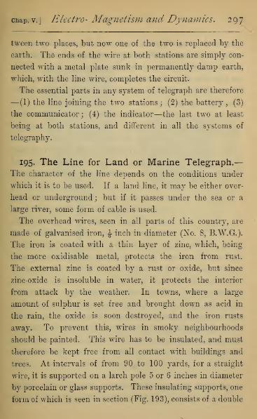
chap, v.j Electro- Magnetism and Dynamics. 297
tween two places, but now one of the two is replaced by the
earth. The ends of the wire at both stations are simply con-
nected with a metal plate sunk in permanently damp earth,
which, with the line wire, completes the circuit.
The essential parts in any system of telegraph are therefore
—(1) the line joining the two stations; (2) the battery, (3)
the communicator; (4) the indicator—the last two at least
being at both stations, and different in all the systems of
telegraphy.
195. The Line for Land or Marine Telegraph,
—
The character of the line depends on the conditions under
which it is to be used. If a land line, it may be either over-
head or underground; but if it passes under the sea or a
large river, some form of cable is used.
The overhead wires, seen in all parts of this country, are
made of galvanised iron, ± inch in diameter (No. 8, B.W.G.).
The iron is coated with a thin layer of zinc, which, being
the more oxidisable metal, protects the iron from rust.
The external zinc is coated by a rust or oxide, but since
zinc-oxide is insoluble in water, it protects the interior
from attack by the weather. In towns, where a large
amount of sulphur is set free and brought down as acid in
the rain, the oxide is soon destroyed, and the iron rusts
away. To prevent this, wires in smoky neighbourhoods
should be painted. This wire has to be insulated, and must
therefore be kept free from all contact with buildings and
trees. At intervals of from 90 to 100 yards, for a straight
wire, it is supported on a larch pole 5 or 6 inches in diameter
by porcelain or glass supports. These insulating supports, one
form of which is seen in section (Fig. 193), consists of a double

298 Electricity, [Book III.
umbrella for throwing off the rain, and preventing surface
leakage of electricity by interposing as great a distance as
possible between the wire and the supporting post. Whenthe wire has to be carried into buildings or under ground,
it is carefully coated with a waterproof insulating material,
generally gutta-percha.
For marine telegraphy the conditions are
I
wire very different. We need a very complete
insulation, through which water under the
enormous pressure at the bottom of deep
sea will not force its way ; and also great
strength to withstand the strain brought on
the wire in laying it down in deep water,
and in lying, as it often must, on steep
slopes on the sea bottom. The cables most
commonly used consist, not of a single con-
ducting wire, but of a spirally twisted strand
of six or seven copper wires (Fig. 194), each about 1 mm.
(^th inch) diameter. These are the core, and are surrounded
by alternate layers of gutta-percha and Chatterton's compound
(a mixture of tar, resin, and gutta-percha), which form the
insulator proper. Round the insulator is a layer of hemp, and
round this again a protecting sheath of about ten or twelve
steel wires, each coated with hemp. Near the shore end the
sheath of hemp and steel wire is made of very great thickness,
as a protection against breakage by the force of the waves
when in storm, but when the depth of about 100 fathoms is
reached a much thinner cable may be used.
196. The Battery.—The battery most in use in this
country is some form of Daniell's. They are fitted up in
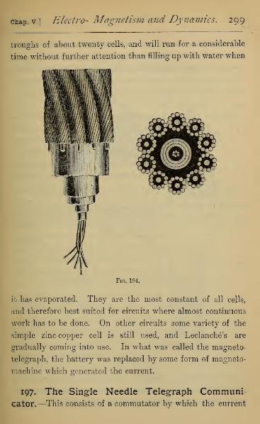
chap, v.] Electro- Magnetism and Dynamics. 299
troughs of about twenty cells, and will run for a considerable
time without further attention than filling up with water when
Fig. 194.
it has evaporated. They are the most constant of all cells,
and therefore best suited for circuits where almost continuous
work has to be done. On other circuits some variety of the
simple zinc-copper cell is still used, and Leclanch6's are
gradually coming into use. In what was called the magneto-
telegraph, the battery was replaced by some form of magneto-
machine which generated the current.
197. The Single Needle Telegraph Communi-cator.—This consists of a commutator by which the current

3oo Electricity. [Book III.
can be rapidly changed in direction or put out of circuit
when no message is being sent, at the same time allowing
a current to pass through it from the distant end of the line.
Fig. 195.
The diagram (Fig. 195) shows such a commutator. It
consists of two brass springs, having ivory buttons on their
ends. When at rest they press upwards against two metal
IEARTH LINE
—ft
LINE.
TTY&BATTERY
-T BATTERY
a DEPRESSED
— BATTERY
Fig. 196.
+ BATTERY
b DEPRESSED
studs in the metal cross-piece. When either is depressed, it
is released from contact with this cross-piece, but presses on
one of the two metal studs on another metal cross-piece,
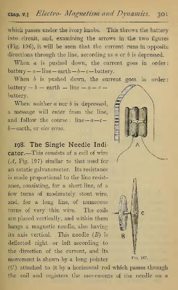
chap, v.] Electro- Magnetism and Dynamics. 30
1
which passes under the ivory knobs. This throws the battery
into circuit, and, examining the arrows in the two figures
(Fig. 196), it will be seen that the current runs in opposite
directions through the line, according as a or b is depressed.
When a is pushed down, the current goes in order:
battery~ a
—
line— earth—b—c— battery.
When b is pushed down, the current goes in order
:
battery — b — earth — line — a — c —battery.
When neither a nor b is depressed,
a message will enter from the line,
and follow the course: line—a— c—b— earth, or vice versa.
198: The Single Needle Indi-
cator.—This consists of a coil of wire
(A, Fig. 197) similar to that used for
an astatic galvanometer. Its resistance
is made proportional to the line resist-
ance, consisting, for a short line, of a
few turns of moderately stout wire,
and, for a long line, of numerous
turns of very thin wire. The coils
are placed vertically, and within them
hangs a magnetic needle, also having
its axis vertical. This needle (B) is
deflected right or left according to
the direction of the current, and its
movement is shown by a long pointer FlG - 197 -
(C) attached to it by a horizontal rod which passes through
the coil and registers the movements of the needle on a

?02 Electricity. [Book III.
dial outside. The motion of the pointer is usually checked
by two stops on the dial. (The dial is not shown in the
figure, being on the front of the instrument.)
199. Arrangement of Apparatus at Telegraph
Station.—The arrangement of these parts at each station
can be understood from the diagram (Fig. 198), which shows
either the sending or receiving station.
II II II II KFig. 198.
In addition to the essential parts described, there was
formerly an electric bell at each station to call the attention
of the clerk when a message is to be sent. This could easily
be done by a contact breaker, one branch of which contains
the bell, placed at any part of the line, between the communi-
cator and the earth, as shown in diagram (Fig. 198). The
clerk, when he leaves the telegraph-room, turns on his bell,
and any signal made by the clerk at the further end will then
cause the bell to ring. The bell is now seldom used, the click
of the needle against its stops being a sufficient call.
200. Codes of Telegraph Signals.—The code of

chap, v.] Electro Magnetism and Dynamics. 303
signals consists in denoting each letter, numeral, or sign by a
certain number of deflections of the needle to the right, and a
certain number to the left, those letters which occur most
frequently being denoted by the fewest strokes. In the
printing telegraph, which we consider next, the same code is
used, the stroke to the left being denoted by a dot (•), and
the stroke to the right by a dash (—). The alphabet on the
two systems is given side by side :
—
SingleNeedle.
Morse'sSystem.
SingleNeedle.
Morse'sSystem.
A \l N /S;
B /sss — ... ///
C Isis P s//\
D /ns. Q lis/
E > • R s/s .
F sv/s . . 8 sss
//s T /
H ssss .... U ss/ . . —I ss V s\s/ ... —J sill . - w sll .
K Isl — X /ss/ . _
L slss . . Y Is/1
M II Z //ss ,
For figures the following code is used :
—
Single Needle. Morse.
inn1 siIII
2 ss///
3 sss//
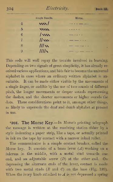
304 Electricity, [Book 111.
Single Needle.
4 SNS\/
5 VSSNS
6 /ssss
7 //SSV
8 ///ss
9 mis
Morse.
This code will well repay the trouble involved in learning.
Depending on two signals of great simplicity, it has already re-
ceivedvarious applications, and bids fair to become the universal
alphabet in cases where an ordinary written alphabet is un-
suitable. It can be made either visible by the movements of
a single finger, or audible by the use of two sounds of different
pitch, the longer movements or deeper sounds representing
the dashes, and the shorter movements or higher sounds the
dots. These considerations point to it, amongst other things,
as likely to supersede the deaf and dumb alphabet at present
in use.
*20I. The Morse Key.—In Morse's printing telegraph
the message is written at the receiving station either by a
style indenting a paper strip, like a tape, or actually printed
in ink on the tape by contact with a narrow inked roller.
The communicator is a simple contact breaker, called the
Morse key. It consists of a brass lever (A) working on a
fulcrum in the middle, with a metal stud towards one
end, and an adjustable screw (D) at the other end. On
depressing the alternate ends of the lever, contact is made
with two metal studs (B and G) on the base (Fig. 199).
When the ivory knob attached to A is not depressed a spring

chap, v.] Electro- Magnetism and Dynamics. 305
holds D constantly in contact with C. E and F are binding
screws connected with the fulcrum and the stud (7, and there
is a similar one on the opposite side connected with the stud
B. By means of these screw.-, B is connected with the local
battery, E with the line, and F with the indicator.
BATTERY^- -/-
> LINE.
In receiving a message from the distant station, the key is
left alone, the current passing from the line through E—A—C— indicator — earth.
In sending a message A is depressed, breaking contact
with the home indicator at 0, and introducing the battery
current at B, which now proceeds by the course, battery
—B—A—E— line, to the distant indicator, and makes on
the indicator a dot or dash according to the length of time
during which the key is held depressed.
*202. The Morse Indicator.—The Morse indicator is
made in a variety of forms, but consists essentially of two
parts,—a train of clockwork, by which the paper tape is payed
out between two friction rollers from a large horizontal or
vertical wheel, on which it is coiled, and an electro-mag-
netic arrangement by which dots and dashes are made on
the strip as it passes, according to the will of the distant
operator (Fig. 200). The coil of paper on the vertical wheel is
U

3o6 Electricity. Book m.
shown at A, and B, C are the friction rollers between which it
passes by the action of the clockwork in the case (D), which
can be started or stopped at will by removing or applying a
detent. F is an electro-magnet round which the current from
the line passes. It has a soft iron core, and is wound with
numerous turns of fine wire, having a resistance which varies
Fig. 200.
from 50 to 500 ohms, according to the conditions of the
circuit. Opposite the poles of the electro-magnet is a soft iron
armature carried on a brass lever, which turns round a pivot,
and has its motion upwards checked by a screw (a), against
which it is held when no current is passing by a spring (b).
The lever carries on its further end a steel style, pointing
towards the tape, and so adjusted that when the soft iron
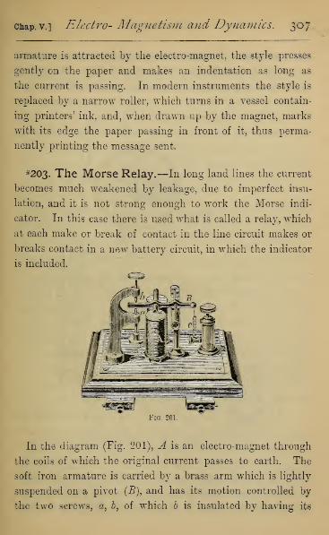
Chap, v.] Electro- Magnetism and Dynamics. 307
armature is attracted by the electro-magnet, the style presses
gently on the paper and makes an indentation as long as
the current is passing. In modern instruments the style is
replaced by a narrow roller, which turns in a vessel contain-
ing printers' ink, and, when drawn up by the magnet, marks
with its edge the paper passing in front of it, thus perma-
nently printing the message sent.
*203. The Morse Relay.—In long land lines the current
becomes much weakened by leakage, due to imperfect insu-
lation, and it is not strong enough to work the Morse indi-
cator. In this case there is used what is called a relay, which
at each make or break of contact in the line circuit makes or
breaks contact in a new battery circuit, in which the indicator
is included.
Fig. 201.
In the diagram (Fig. 201), A is an electro-magnet through
the coils of which the original current passes to earth. The
soft iron armature is carried by a brass arm which is lightly
suspended on a pivot (J3), and has its motion controlled by
the two screws, &, b, of which b is insulated by having its
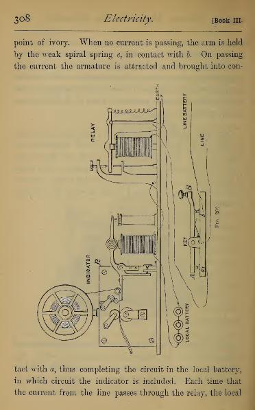
3o8 Electricity. [Book III.
point of ivory. When no current is passing, the arm is held
by the weak spiral spring c, in contact with b. On passing
the current the armature is attracted and brought into con-
tact with a, thus completing the circuit in the local battery,
in which circuit the indicator is included. Each time that
the current from the line passes through the relay, the local

chap, v.] Electro- Magnetism and Dynamics. 309
battery transmits a current through the electro-magnet of the
indicator, the two working therefore completely in sympathy.
In the case of long land lines there are a series of " relay
stations" where the message is not received and retransmitted,
but passed on with renewed energy by means of a relay. One
terminal of the local battery is to earth, and the other is con-
nected through the relay with the continued line. By this
means there is a continuous telegraph, without retransmission
by hand between London and Teheran, there being five relay
stations on the road.
The arrangement at each station of key, relay, and indicator
can be understood from the diagram (Fig. 202), remembering
that the same must be repeated at each end of the line.
^204. Morse Sounder.—The peculiar click made by the
armature either of the indicator or relay against its stops
enables an expert clerk to take down the message by ear as
it passes, only comparing afterwards with the tape to insure
accuracy. This depends on a slight difference in the click,
according as it is made by a momentary contact (for a dot),
or a prolonged contact (for a dash). On this principle is con-
structed the Morse Sounder, which is identical with the relay
in construction, but much smaller, and is used for military
telegraphy, or under conditions where economy of apparatus
is important.
*205- Electrostatic Induction in Cables.—As soon as
marine cables of great length came into use it was found that
signals transmitted by them suffered a remarkable retardation,
the making contact with the battery for an instant at one end
causing at the other a gradual rising and sinking again of the
current, occupying several seconds. This would make the rate

3io Electricity. [Book III.
of signalling very slow were it necessary to wait till each signal
had completely died away before transmitting the next.
The retardation is easily explained if we remember that the
core of the cable forms the inner coat of a Leyden jar of
enormous capacity, of which the conducting sea-water is the
outer coat. The effect of contact with the battery terminal is
to bring the core of the cable to a potential which near the
battery, nearly equals the potential of the battery terminal.
This can only be done by charging the Leyden jar. In
the case of a long cable this charging takes a finite time,
and on breaking contact, the Leyden jar is discharged
through the receiving galvanometer, and this again occupies
about the same time.
Fig. 203.
The effect can be illustrated by the apparatus of Fig. 203
which consists of a coil of cotton-covered wire, 20 or 30 yards
long, and about a tenth of an inch in diameter, coiled into a
solid coil, and afterwards dipped in melted paraffin to perfect
insulation. This represents the cable, and is placed in a
vessel of water, with one terminal exposed and insulated.
chap, v.] Electro- Magnetism and Dynamics, 311
The other terminal is connected through a galvanometer
with the contact breaker. Of the other two terminals of
the contact breaker, one is connected both with a battery
terminal and with a strip of metal sunk in the water, which
represents the Earth of the telegraph battery, and also with
one terminal of a battery. The other terminal of the
battery is connected simply with the third terminal of the
contact breaker. On turning the contact breaker handle to
the left, so as to bring the tongue into contact with the right-
hand terminal, the battery will charge the core of the wire
coil, and will cause a momentary deflection in the delicate
galvanometer. This is of interest, showing us that the
magnetic effects of a current are not confined to cases where
the electricity has a complete circuit in the ordinary sense,
but accompany any displacement whatever of the elec-
tricity. Quite instantaneously the charging current will
cease, and the galvanometer return to its zero. On turning
the handle to the right, the battery is thrown out, but the
galvanometer is deflected for an instant in the opposite direc-
tion to the deflection on charging, showing that the Leyden
jar formed by the core is being discharged through it.
The effect on the galvanometer is very much increased by
using, in place of the wire coils and water, a condenser made
of several hundred sheets of tinfoil, separated by paper im-
mersed in melted paraffin and pressed together when hot.
The alternate sheets are brought together by projecting flaps,
and connected with the two terminals of the condenser. Bymeans of a large number of such condensers an artificial cable
can be made, and all the effects of a real cable exactly repro-
duced.

312 Electricity. [Book m.
*2o6. Thomson's Marine Galvanometer.—To over-
come the difficulty presented by the very slow rate of cable
signalling, Sir W. Thomson invented his Marine Galvanometer,
a variety of the reflecting galvanometer, in which the oscilla-
tions of the needle are damped, the needle simply deflecting
right or left when a current is transmitted, and returning to
its zero without making oscillations about it, as in the
common form of the instrument. This of course does not
obviate the retardation of the signals noticed above, but
enables the clerks by practice to interpret the indications of
the galvanometer without waiting for each signal to die away
before another is transmitted, each observation depending
not only on the signal last sent, but on the twenty or thirty
preceding it.
*207- Thomson's Syphon Recorder.—This is an in-
strument by which the messages sent through a cable are
made self-recording. It consists of a tape payed out vertically,
much as in the Morse Indicator. Opposite the tape is a fine
capillary glass tube bent somewhat in the form of the letter S,
whose upper end hangs in a vessel containing ink, and whose
lower end is opposite the middle of the tape. The ink vessel is
electrified by a small frictional machine, worked by the clock-
work which pays out the tape ; and, according to the principle
of the electrical watering-pot (Art. 93), the ink will spurt out
from the tube on to the tape, making a straight line along it if
the syphon remain stationary. The syphon tube is attached
by fine silk threads to a peculiar kind of galvanometer, by
which it is deflected right or left according to the direction
and magnitude of the current sent through the cable. This
galvanometer consists of a coil of fine wire, through which the

chap, v.] Electro- Magnetism and Dynamics. o A o
cable current is sent, and which hangs suspended between the
poles of a powerful permanent magnet. This coil, owing to its
magnetic properties when traversed by a current, is deflected
in one direction or the other, according to the direction of the
currents, and to an amount directly proportional to the current
strength. By means of the attached silk threads, the move-
ment of the syphon tube is made proportional to the] move-
ment of the galvanometer coil, and the syphon recorder there-
fore gives a permanent register of every change in strength
or direction of the line current.
*208. Step by Step, or ABC Telegraph.—There is a
great variety of other telegraph machines used in various
parts of the world, including some in which the message is
actually printed in ordinary type. These depend on more
Fig. 204.
complex machinery, but involve no new principle in elec-
tricity. The only other form we shall refer to here is the ABCtelegraph, specially adapted for the use of persons who are
not familiar with any telegraphic code. The message is
received on a dial marked with the twenty-six letters of the
alphabet, a needle rotating always in the same direction, and
3 1
4
Electricity. Book in.
pausing at each letter which the distant operator wishes to
transmit. This, and all other "step by step" telegraphs,
require two parts,—a manipulator at the sending station, and
an indicator at the receiving station, with, of course, the usual
line and battery.
The Manipulator (Fig. 204) consists of a dial marked with
the letters of the alphabet and two additional spaces, which
can be used to denote the beginning and ending of a sentence.
Over the letters moves an arm, rotating about the centre of
the dial, having attached to it behind the dial a toothed
wheel, the number of teeth being half the number of letter
and other spaces round the dial. The teeth, by pressing a
spring, make contact in the line battery, when the arm is
opposite each alternate letter.
The indicator (Fig. 205) contains an electro-magnet, fur-
nished with a soft iron armature. This armature carries a
long arm, whose end is formed to act as an escapement
against a toothed wheel having the same number of teeth
as the wheel in the manipulator. The toothed wheel carries
an index hand, which moves over a dial whose divisions
correspond to those in the manipulator. Each time the
current passes the armature is attracted, and the detent
(Fig. 205, a) by its wedge-like action pushes on one tooth of
the wheel, and, on breaking, retains the next against the flat
end of the wedge. Thus in the making and breaking, the
index hand passes over two letters, just as in the manipulator.
To call attention to the instrument, a bell is attached to
the indicator (not shown in drawing), which can be put in or
out of circuit by a simple contact breaker.
There is also on the indicator a small button moving a
lever, by which the index hand can be moved over the letters
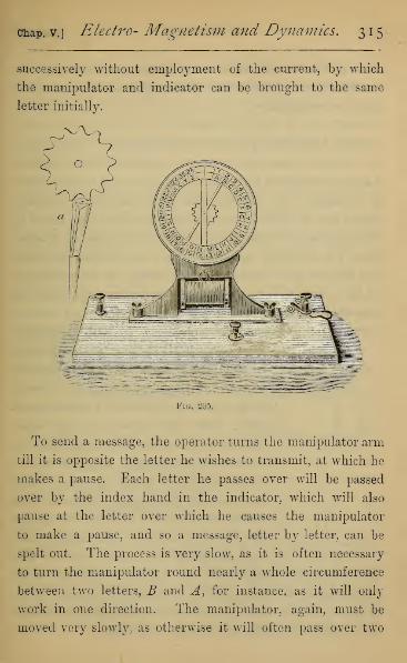
Chap, v.] Electro- Magnetism and Dynamics. 315
successively without employment of the current, by which
the manipulator and indicator can be brought to the same
letter initially.
Fig. 205.
To send a message, the operator turns the manipulator arm
till it is opposite the letter he wishes to transmit, at which he
makes a pause. Each letter he passes over will be passed
over by the index hand in the indicator, which will also
pause at the letter over which he causes the manipulator
to make a pause, and so a message, letter by letter, can be
spelt out. The process is very slow, as it is often necessary
to turn the manipulator round nearly a whole circumference
between two letters, B and A, for instance, as it will only
work in one direction. The manipulator, again, must be
moved very slowly, as otherwise it will often pass over two
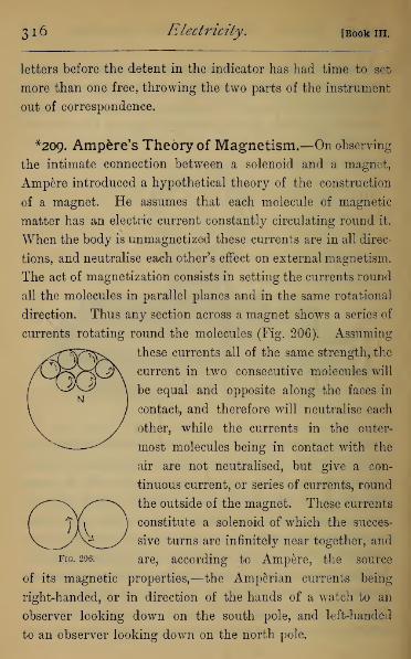
3 1
6
Electricity. [Book in.
letters before the detent in the indicator has had time to set
more than one free, throwing the two parts of the instrument
out of correspondence.
*209. Amp&re's Theory of Magnetism.—On observing
the intimate connection between a solenoid and a magnet,
Ampere introduced a hypothetical theory of the construction
of a magnet. He assumes that each molecule of magnetic
matter has an electric current constantly circulating round it.
When the body is unmagnetized these currents are in all direc-
tions, and neutralise each other's effect on external magnetism.
The act of magnetization consists in setting the currents round
all the molecules in parallel planes and in the same rotational
direction. Thus any section across a magnet shows a series of
currents rotating round the molecules (Fig. 206). Assuming
these currents all of the same strength, the
current in two consecutive molecules will
be equal and opposite along the faces in
contact, and therefore will neutralise each
other, while the currents in the outer-
most molecules being in contact with the
air are not neutralised, but give a con-
tinuous current, or series of currents, round
the outside of the magnet. These currents
constitute a solenoid of which the succes-
sive turns are infinitely near together, and
Fig. 206. are, according to Ampere, the source
of its magnetic properties,—the Amperian currents being
right-handed, or in direction of the hands of a watch to an
observer looking down on the south pole, and left-handed
to an observer looking down on the north pole.
GO

chap, v.] Electro- Magnetism and Dynamics. 317
All the relations between a magnet and electric currents
can, by means of the Amperian hypothesis, be reduced to
the actions of currents on each other, but they can be easily
explained by actions in the magnetic fields of the magnets,
demonstrable by experiment, while the Amperian currents
are only hypothetical.
210. The Magnetic Tick.—That the magnetization of
a bar is accompanied by some molecular movement is proved
by the magnetic tick which accompanies its magnetization
and demagnetization. The sound can be easily heard by
Fig. 207.
stretching a soft iron wire, about 1 metre long and a milli-
metre in diameter, over a sounding-board (Fig. 207 D, shows
a section), and surrounding the wire, through nearly its whole
length by a narrow glass tube, which is supported out of
contact with the wire. Round the glass tube is closely

3 1
8
Electricity. [Book m.
wound moderately stout insulated copper wire two or three
layers in depth. On connecting the ends of the copper wire
with the terminals of a battery of four or five Grove cells,
and placing any contact breaker in the circuit, a sound is
heard from the wire each time that contact is made or
broken.
On this principle a telephone capable of transmitting musical
notes is easily constructed. The notes are sung or sounded
through a mouthpiece into a box (A), whose upper surface is
closed by a thin sheet of metal (B) stretched tightly. Near
its centre is adjusted a screw (C) whose point all but touches
the metal membrane, and does touch it at each vibration of
the membrane, when a note is sounded into the mouthpiece.
The note depends simply on the number of vibrations per
second, and each of these vibrations makes and breaks contact
in a voltaic circuit. This circuit includes the electro-magnet
D, which gives the magnetic tick for each make and break of
contact, and reproduces the note sounded.
This telephone is commonly but inaccurately called by the
name of Eeis, who, about 1860, invented a telephone which
transmitted articulate speech as well as musical tones. His
receiver was on the principle of the receiver described above,
consisting of a knitting-needle surrounded by a coil of wire
mounted on a sounding-board. His transmitter was formed
on the model of the drum and bones of the human ear, and
he was thus led to an instrument identical in principle with
the carbon transmitter of the present telephone. (See Philipp
Eeis, Inventor of the Telephone, by Prof. S. P. Thomson, D.Sc.)
CHAPTER VI.
CURRENT INDUCTION.
21 i t Work done in the Electro-magnetic Field at
Expense of the Current.—In the experiments of the last
chapter, where movements of conductors or magnets take
place under electro-magnetic force, it appears from theory
that the work done during the movement is accompanied by
a diminution of the current while the movement lasts. This
falling off in most cases is so small, compared to the total
current passing, that it is rather difficult to show either by
including a rough galvanometer in the main circuit, or a
delicate one in a branch circuit. It can be shown by passing
the current from five Grove cells continuously through two
electro-magnets of horse-shoe form, and placing a delicate
galvanometer in a branch circuit, the galvanometer of
course being at considerable distance from the magnets.
If the electro-magnets be now held, one immediately above
the other, with contrary poles opposed at a distance of
1 or 2 inches, and the upper be allowed to fall on to the
lower, a movement of the galvanometer will be noted,
showing a slight momentary falling off of the current. Onlifting up suddenly the upper magnet, and separating it
from the lower, there will in the same way be seen a slight
increase of the current.
319
320 Electricity. [Book m.
*2i2 f Theoretical Explanation offoregoing Experi-
ment.—It will be worth while considering how the fall in
the current is a source of energy. Let / be the current when
the machine is at rest, and /' the current when the same
machine is in motion. Let also E be E.M.F. of the battery,
and R the resistance, which is the same in both cases. The
energy given out from the battery is in the two cases EIand ET (Art. 169), and the heat generated measured in
mechanical work is RI 2 and RI' 2 (Art. 169) each per second.
If T be the time in which a gram of zinc is consumed in the
battery with current 2, it will require a longer time, namely,
-pT9when the current is F. Hence the heat given out per
gram of zinc consumed will be in the two cases BI 2T and
RI' 2 x -p?\ and this latter is equal to RIFT, which is neces-
sarily less than RI 2T, if /' is less than I But the energy
given out from the battery must in both cases be the same,
since equal amounts of zinc are dissolved. Hence, when the
machine is in motion there is less energy given out in heat
than that abstracted from the battery by R(I 2—IF)T per
gram of zinc used. This energy then does the work in the
machine.
When work is done against electro-magnetic forces, the
current is increased, the work done on the system being
evolved from it as increased heat in the circuit.
213. Induced Currents.—Eeturning to the apparatus of
Arts. 177 and 178, in which we have the movement of a
magnet pole in the electro-magnetic field of a current, and
of a current in the magnetic field of a magnet, we will
replace the battery by a sensitive galvanometer, of course re-

Chap. VI.] Current Induction. 521
moved to a distance from the magnet (Fig. 208). On rotating
the magnet pole or the current by hand, the galvanometer
shows a current, and the direction of the current changes
with a change in the direction of rotation. We shall notice,
if we examine the direction of the current, that it is opposite
to the current which would have caused the actual rotation.
These are called induced currents ; they correspond with the
falling off in the current noticed above, and may in fact be
regarded in an algebraical sense as a falling off in the current,
when that current is zero.
mm uy
Fig. 20S
Since the induced current is opposite in direction to the
current which would have caused the motion, it is clear that
the electro-magnetic effect of the induced current is to oppose
the motion taking place in the field. This is one case of Lenz's
law, of which we will now give illustrations, by performing
backwards some of the experiments of last chapter.
X
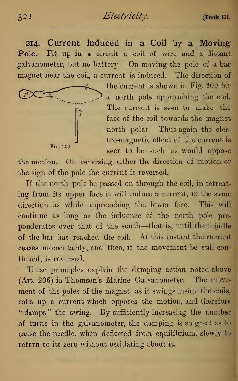
t
Fig. 209.
322 Electricity. [Book 111.
214. Current induced in a Coil by a MovingPole.—Fit up in a circuit a coil of wire and a distant
galvanometer, but no battery. On moving the pole of a bar
magnet near the coil, a current is induced. The direction of
the current is shown in Fig. 209 for
a north pole approaching the coil.
The current is seen to make the
face of the coil towards the magnet
north polar. Thus again the elec-
tro-magnetic effect of the current is
seen to be such as would oppose
the motion. On reversing either the direction of motion or
the sign of the pole the current is reversed.
If the north pole be passed on through the coil, in retreat-
ing from its upper face it will induce a current, in the same
direction as while approaching the lowTer face. This will
continue as long as the influence of the north pole pre-
ponderates over that of the south—that is, until the middle
of the bar has reached the coil. At this instant the current
ceases momentarily, and then, if the movement be still con-
tinued, is reversed.
These principles explain the damping action noted above
(Art. 206) in Thomson's Marine Galvanometer. The move-
ment of the poles of the magnet, as it swings inside the coils,
calls up a current which opposes the motion, and therefore
" damps " the swing. By sufficiently increasing the number
of turns in the galvanometer, the damping is so great as to
cause the needle, when deflected from equilibrium, slowly to
return to its zero without oscillating about it.

chap, vi.] Current Induction. 323
215, Induced Current in Barlow's Wheel.—If in
Barlow's wheel (Art. 179) the battery be replaced by a galva-
nometer (Fig. 210), and the wheel made to rotate, there will
be a current induced in the circuit, the directions of rotation
and of the current being shown by arrows. This current, if
acting independently, would cause the wheel to rotate in the
opposite direction.
Fio. 210.
216. Currents induced by Terrestrial Magnetism.
—Delezenne's Circle (Fig. 211) is adapted to show the
current induced in a wire coil under the induction of the
earth's magnetism. It will be remembered that a coil carry-
ing a current tends to set itself at right angles to the dip. Acoil capable of rotation about a diameter, which is placed at
right angles to the dip, will on continuous rotation be
traversed by an induced current, whose direction is changed
each time it reaches the position of equilibrium. If, then, by
means of the spring commutator (Fig. 211, a), we change the
direction of the current in the galvanometer relatively to its
direction in the coils at each half revolution, we have a con-
tinuous current in the galvanometer, whose amount depends
on the rapidity of rotation. We can by the mechanical
arrangement shown set the instrument so that the axis of
rotation is horizontal, vertical, or in any other position, in

3^4 Electricity. [Book in.
which cases the effective part of the earth's magnetism is the
component at right angles to the axis of rotation ; the induced
current vanishing when the axis of rotation is parallel to the
dip.
Fig. 211.
If we compare Delezenne's Circle with the coil of Fig. 187, c,
placed in the magnetic field, we can see that the induced
current is such as would cause the coil to rotate in the opposite
direction. The expression of this result may be modified by
adopting Faraday's conception of a finite number of lines of
magnetic force. In the position of equilibrium the circuit
contains the greatest number of lines of force (Art. 181), and
as we rotate the circuit up towards that position, the number
of lines of force enclosed by the circuit is increasing, and after
passing it the number is diminishing. When the number of
the earth's lines of force is increasing, the current will be
found left-handed to the lines of force, and. when diminishing
right-handed.

Chap. VI.] Current Induction. 3 2 5
217. Current induced by moving Parallel Con-
ductors.—We have observed that parallel currents attract
each other when in the same direction, and repel each other
when in opposite directions. To show that these movements
cause induced currents, take the pair of flat spirals of Art. 185,
and connect one with the battery while the other hangs
parallel to it, with its terminals attached to a galvanometer.
On moving either spiral towards the other, or from the other,
currents are induced in opposite directions, concurrent with
the battery current when the spirals recede from each other,
and opposite to it when they approach each other.
Fig. 212.
The same thing may be illustrated by thrusting a coil of
wire (Fig. 212) carrying a current inside a hollow coil consist-
ing of very many turns of fine wire with which a galvano-
meter alone is connected. When the spirals are approaching
each other, the induced will be inverse or opposite to the
battery current, but on withdrawing one from the other, the
326 Electricity. [Book 111.
current will be direct or in the same direction as the battery-
current.
The effect is much increased if the inner coil has a soft
iron core, making it an electro-magnet, since this enormously
increases the strength of the magnetic field in which the move-
ments are made.
218. Currents induced by changes in strength oi
the Magnetic Field.—We will first show that an induced
current passes through neighbouring conductors when a mag-
netic field is made or destroyed, by making or breaking contact
in a battery circuit. Using the apparatus of the last experiment
(Fig. 212), and placing the electro-magnet within the wire
coil, it will be seen that a current passes in the galvanometer
when contact is made or broken in the battery circuit. On
making contact, the current is inverse, and on breaking it is
direct.
These effects are also much increased by enclosing a soft
iron core in the battery coil.
We may, with the same apparatus, illustrate changes in the
strength of the magnetic field. For by short-circuiting the
battery current we can leave the electro-magnet in a branch
circuit of great or small resistance, and allow any part of the
current we please to traverse the electro-magnet. Induced
currents will be produced in the external coil whose directions
will be similar to those just named.
In all the foregoing experiments we notice that the induced
current tends, by its electro-magnetic effect, to oppose the
change taking place in the field, for the direct induced current
tends to strengthen the field when it is being weakened by
the falling off of the battery current, and the inverse induced
cuap. vij Current Indtiction.2>2 7
current tends to weaken the field when it is being strengthened
by a rise in the battery current.
219. Currents induced in Electromotors.—On the
same principles, it is clear that any form of electromotor may
be used to generate a current by means of movements of the
machinery brought about mechanically. This will even be
true in motors such as Froment's and G-riscomb's, where the
movements depend entirely on electro-magnets ; the residual
magnetism in the soft iron cores being always sufficient to
start a current, which then rises in compound interest ratio
as the rotation continues. This is the principle of all the
dynamo-machines now used for generating electricity for
lighting and other purposes.
220. The Extra Current or Galvanic Spark.—Onmaking and breaking the battery circuit, a bright spark is
noticed to pass between the terminals at the instant of making
and breaking. This cannot be due to the battery current, as
it only occurs momentarily when that current is made or
broken, and we shall find it has a much higher E.M.F. than
the battery current itself. On including a large coil of wire
or an electro-magnet in the circuit, the intensity of the spark
is very much increased, causing a brilliant flash if contact be
broken in a mercury cup.
This is no doubt the effect of an induced current in the
conductor itself, which behaves in this respect just like any
other conductor in the field, experiencing an induced inverse
current on closing, and an induced direct current on breaking
the battery current.
These currents were discovered by Faraday, and by him
were called the inverse and direct extra current respectively.

328 Electricity, [Book III.
To exhibit their direction by the galvanometer is not
easy, as they occur with the battery current, in the same
conductor. Faraday showed the direct extra current by
arranging a circuit containing a battery and an electro-magnet
(C in Fig. 213), and placing a galvanometer in a branch
circuit AGB (by means of the mercury cups A and J9),
A KM
Fig. 213.
which was therefore traversed by a certain fraction of the
battery current, causing the needle to deflect. By laying a
piece of cork or a brass weight on the galvanometer card he
blocked the needle, retaining the needle at zero, while the
battery current was passing. Contact was broken by lifting
the battery wire out of the mercury cup A or B, and the
direct extra current passed round the closed circuit ACBG.
Assuming the battery current to pass through the electro-
magnet in the direction ACB, and through the galvanometer
in the direction AGB, the direct induced current traverses
the galvanometer in the opposite direction to the battery
current. On breaking contact, therefore, the needle swings
chap, vi.] Current Induction. 329
away from its stop, thus proving the existence of the extra
current.
The high E.M.F. of the extra current may be shown in a
variety of ways. Thus, if the galvanometer in Fig. 213 be
replaced by the two hands of the operator, one finger being
placed on each cup, a sharp pricking sensation is felt when-
ever contact with the battery is made or broken in the mercury
cups. This sensation is increased by rapidly making and
breaking contact, as by rubbing the end of the battery wire
over the surface of a file, one end of which is held in the
mercury cup. That these effects are not due to the direct
battery current is shown by passing it through the body,
when no sensation whatever is produced. Next, replace the
galvanometer by a voltameter. The battery must be reduced,
if necessary, till no evolution of gas is caused in the branch
circuit by the steady battery current. If, now, the contact
be rapidly made and broken, small quantities of gas will be
given off continuously from both plates.
The direct extra current has always much higher E.M.F.
than the inverse, though the same amount of electricity
must pass in both. This is why the spark on breaking is
always much brighter than on making contact with the battery.
221. Lenz's Law.—All induced currents, such as we have
been experimenting upon, obey the Law of Lenz, to which
we have already alluded. It may be stated thus : If either a
conductor forming part of a closed circuit be moved in the magnetic
field, or the field in which the conductoi* is placed undergo any
change of strength, during the movement or change the conductor
is traversed by a current, ivhose electro-magnetic effect is to oppose
the movement of the cmductw w the change in the field.
330 Electricity. [Book m.
The following are but cases of the general law, which we
have already illustrated by experiment :
—
(1) If a north pole approach a closed circuit, the induced
current makes the face, opposite to the north pole, also
north-polar, so as to resist the advance of the pole (Art. 214).
(2) If a linear conductor forming part of a closed circuit
be moved across the lines of force, so that a figure in the
conductor looking along the lines of force is carried by the
motion to its left, the induced current will enter by its head
and leave by its heels (Art. 215).
(3) If a closed conductor carrying a current approach
towards a closed conductor not carrying a current, a current
will be induced in the latter conductor in opposite direction
to the battery current (Art. 217).
(4) If a conductor be moved so as to include fewer lines
of magnetic force, there will be a right-handed induced
current whose electro-magnetic effect is to increase the num-
ber of lines of force (Art. 216).
(5) If the strength of a current, or the magnetism of a
magnet, be diminished, every conductor in its field will
experience a current right-handed to the lines of force
(Art. 218).
(6) If the current be established in a conducting circuit,
an inverse extra current will be developed in the circuit
itself (Art. 220).
It is almost superfluous to remark that in each case a
reversal of the direction of motion or of the change also
reverses the direction of the induced current.
222. Currents induced in Solid Conductors movedin the Magnetic Field.—For the development of induced

Chap. VI.] Current Induction. 33i
currents it is not necessary to have wires forming closed
circuits, since induced currents occur whenever a conducting
mass is moved through a magnetic field across the lines of
force. This is easily shown by the resistance experienced in
drawing a metal sheet between the poles of a strong electro-
magnet. A piece of copper (usually shaped like a saw), on
being drawn through air between the poles of the electro-
magnet feels to the operator as if it were being drawn
through some viscous fluid like honey or treacle. This is
obviously due to the induced currents in the metal sheet which
oppose the motion.
The same thing is often shown by suspending a copper cube
by a fine string between the poles of the electro-magnet (Fig.
214). After putting torsion on the string, by rotating the cube
I
N
71
VFig. 214.
several times, it, when left to itself, with the magnet unmade,
spins rapidly round, untwisting the string. If while the string
is untwisting contact be made with the battery, the cube is
rapidly pulled up, as if it were meeting with resistance in the
air; but on breaking contact again it goes on spinning as before.
Before Faraday's discovery of induced currents, Arago had
observed that if a horizontal copper disc be rotated rapidly,
a magnet needle suspended by a fibre over its centre is

33 2 Electricity. [Book in.
deflected in the direction of rotation, and if the rotation is
rapid enough, the magnet also spins round, following the
motion of the disc.
223. Clarke's Magneto - Electric Machine or
Dynamo.—We proceed now to some practical applications
of induced currents. We take first the magneto-electric
machine or dynamo, all forms of which depend on the genera-
tion of electricity by the rapid movement of a conductor in a
magnetic field. As in describing telegraphic apparatus, we
shall confine ourselves to very few instruments.
Of these, Clarke's machine was one of the earliest; it
is very simple in construction, and still continues more or
less in use for medical purposes.
It consists (Fig. 215, a) of a single horse-shoe magnet, or a
battery of three magnets, in front of the poles of which
revolve on a spindle passing between them two bobbins of
wire (BC) containing soft iron cores.
Suppose we are looking down on the bobbins, and consider
the nature of the pole facing us. When opposite the north pole
of the permanent magnet, this pole is a north pole by induc-
tion, and vice versa. Hence the pole of the bobbin B in half a
revolution changes from north to south, that is, it will con-
tinually be losing north-polar magnetism. The current induced
in the bobbin therefore opposes the change, and circulates
round the coils in a direction against the hands of a watch.
For exactly the same reason, the current in the bobbin C,
which, in the same half revolution, goes from the south to the
north pole of the permanent magnet, will be with the hands
of a watch. The current in each bobbin is therefore reversed
at each half revolution.

Chap, VI,] Current Induction. 33JO
The arrangement of the bobbins is shown in section in
R
Pk. 215, b. The wires from the bobbins are brought to a pairis- <^>

334 Electricity. [Book in.
of common terminals in such a manner that both bobbins tend
to send a current in the same direction through the external
circuit. One of these terminals is connected with the metal
spindle, on which fits closely an ebonite cylinder carrying on
its surface two metal ferrules whose arrangement depends on
the use to which the machine is to be put ; they are shown by
D and E. One of them (D) should be connected by a screw
which passes through the ebonite with the metal spindle, and
thus with one terminal of the bobbins. The other terminal
is insulated from the spindle but connected with the ferrule
E. The current is carried away from the ferrules by metal
springs which continuously press against them as they revolve
(Fig. 215, a).
If the ferrules are complete circles running side by side
round the ebonite cylinder, the machine gives alternating
currents. If they are made the two halves of one ferrule
insulated from each other so that the same spring which is in
contact with D during one half its revolution is in contact
with E during the other half revolution, it is a commu-
tator reversing the current at each half revolution, and so
making a continuous current in the external circuit;just as
in Delezenne's Circle (Fig. 211).
For medical purposes, the principal current is short-circuited
at each half revolution, thus bringing in the direct and inverse
extra current in the external circuit, of which we have already
noticed the high E.M.F. and remarkable physiological action.
This is accomplished, where the two half ferrules D and Eare separated by a spiral line, making D broad where E is
narrow, and vice versa. The contact springs in part of the
revolution press one on D and the other on E, the current
then passing through the external circuit; at another part

Chap. VI.] Current Induction. 335
both at once press on D9when the current is short-circuited.
At the opposite part both press on E, again short-circuiting
the current.
The same effect is often obtained by simply connecting one
terminal of the wire with the metal of the spindle (F, Fig. 215,c),
the other being connected with an insulated ferrule (G) upon the
spindle. A spring (H) in connection with this latter ferrule
also presses against the spindle, and while it presses short-
circuits the current. By filing away the opposite faces of the
spindle to the form shown at K, the spring (H) ceases to
touch the spindle for a moment at each half revolution, and the
current suddenly passes through the external circuit (L—M).
These changes are accompanied by strong extra currents.
Fig. 216.
224. Siemens* Dynamo.—Much power is lost in
Clarke's machine through the bobbins never being in the
strongest part of the field, that is, between the magnet poles.
To remedy this defect, Siemens' armature (Fig. 216) was

33^ Electricity. [Bookin.
invented, consisting of a long iron framework (seen in section
Fig. 216, a) with the wire coiled in a long flat coil. This, being
narrow, can be made to rotate in a cylindrical cavity cut
between a row of north and south poles of permanent magnets.
Still further power was obtained by substituting electro- for
permanent magnets. The electro-magnets were at first
charged by an external machine or battery ; but it was soon
found that better results were obtained by diverting the
whole or part of the current induced in the armatures
through the electro-magnet coils. As was pointed out above,
the residual magnetism starts the current, which then rises
rapidly to its maximum for the given rate of rotation.
225. The Gramme Machine.—There is one other
machine whose armature is so peculiar in construction as
to deserve special notice, and it is the parent of a class of
machines now very widely used. This is the Gramme machine.
In it the armature revolves between the poles of a powerful
permanent or electro-magnet (M). It consists of a cylindrical
ring (Fig. 217, a) made of soft iron, upon which is coiled
a continuous wire, forming in itself an unbroken circuit.
This coil, at thirty-two points equally distributed along it, has
wires soldered to it (AB . . .), which are in connection with
thirty-two separate copper pieces (C), carefully insulated from
each other by mica plates, and surrounding the spindle of
the armature. Against this cylinder of separate copper pieces;
above and below it, press two metal brush collectors, which
are connected with the terminals (FG) of the machine.
To explain the action we will first consider it as an electro-
motor. Taking the dissected diagram (Fig. 218), the current-
enters by the terminal (A), and, through the brush G enters

Chap. VI.] Current Induction.
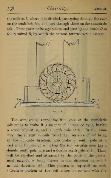
338 Electricity. [Book III.
the coils at b, where it is divided, part going through the coils
on the semicircle bca, and part through those on the semicircle
Ida. These parts unite again at a, and pass by the brush D to
the terminal B, by which the current returns to the battery
A
Fig. 218.
The wire coiled round the iron core of the semicircle
adb tends to make it a magnet of horse-shoe type, having
a south pole at a, and a north pole at b. In the same
way, the current in coils round the iron core of acb being
in the opposite direction, also make a south pole at a
and a north pole at 6. Thus the iron circular core has a
double south pole at a and a double north pole at b. These
will be repelled and attracted by the poles of the perma-
nent magnet, a being driven in the direction ac, and b
in the direction bd. This process is repeated as each
successive portion of the coil comes in contact with the

chap, vi.] Current Induction. 339
brush, and a continuous rotation is maintained in the direc-
tion a—c— b-d. 1
Applying Lenz's law, we see that if we cause the arma-
ture to revolve, an induced current is developed in opposite
direction to the battery current which would cause the rota-
tion. This is the action of the machine when used as a
dynamo.
In powerful machines electro-magnets are used for the
field magnets, and these may be charged by diverting
part or the whole of the current through them. But the
power of the machine is seen in a small model, turned by
hand, and weighing less than a hundredweight, by which
6 inches of thin platinum wire may be made red-hot, the
phenomena of electro-dynamics and electro-magnetism ex-
hibited, a series of small incandescent lamps lighted up well,
and a small arc lamp (of Browning's pattern) lighted up as
well as by eight or ten Grove cells.
226. The Incandescent Electric Lamp.—One of the
great uses for dynamo-machines in the future will probably
be the generation of electricity for lighting purposes, and it
will be convenient to say here a few words about this appli-
cation. There are two distinct modes of lighting,—by in-
candescent or glow lamps, and by the arc lamp,—besides one or
1 The present writer has lately made a model to illustrate the
above action of the Gramme ring. A circular coil of iron wire is
wound, as in the ring, with insulated copper wire, making a con-
tinuous coil. To this are soldered two wires at opposite extremities
of a diameter. This is supported on a simple framework of wood,and pivoted, with its plane horizontal, between the poles of a horse-
shoe magnet, the two straight wires dipping in the commutatorcup, which is placed axially between them, just as for the small
electro-magnet of Fig. 187, a. On passing the current of one or
two cells, the ring rotates rapidly.

340 Electi'icity. [Book III
two other methods which hold an intermediate place between
these two.
All the incandescent lamps (Fig. 219) at present in use
consist of one or more filaments of carbon (a), of horse-
shoe form, attached at their ends to stout platinum wires b, c,
which are fused through the glass of the small globe d.
These globes are exhausted by a Sprengel mercury pump,
and then hermetically sealed. By different inventors the
whole vegetable kingdom has been ransacked to find the
r~*
Fig. 219.
fibre which yields the most suitable carbon filament. These
are .heated (air being excluded) to expel water and gases, and
then compressed in a mould. The chief difference between
the lamps in use is the source and mode of preparation of
the carbon filament, and the nature of the residual gas.
These lamps can now be constructed of very uniform
resistance, and the most economical arrangement is that in
multiple arc (Fig. 220), all the lamps being hung between two
stout copper wires, which carry the battery current. In this
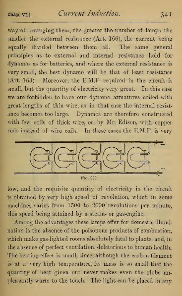
chap, vi.] Current Induction. 341
way of arranging them, the greater the number of lamps the
smaller the external resistance (Art. 166), the current being
equally divided between them all. The same general
principles as to external and internal resistance hold for
dynamos as for batteries, and where the external resistance is
very small, the best dynamo will be that of least resistance
(Art. 163). Moreover, the E.M.F. required in the circuit is
small, but the quantity of electricity very great. In this case
we are forbidden to have our dynamo armatures coiled with
great lengths of thin wire, as in that case the internal resist-
ance becomes too large. Dynamos are therefore constructed
with few coils of thick wire, or, by Mr. Edison, with copper
rods instead of wire coils. In these cases the E.M.F. is very
Fig. 220.
low. and the requisite quantity of electricity in the circuit
is obtained by very high speed of revolution, which in some
machines varies from 1500 to 2000 revolutions per minute,
this speed being attained by a steam- or gas-engine.
Among the advantages these lamps offer for domestic illumi-
nation is the absence of the poisonous products of combustion,
which make gas-lighted rooms absolutely fatal to plants, and, in
the absence of perfect ventilation, deleterious to human health.
The heating effect is small, since, although the carbon filament
is at a very high temperature, its mass is so small that the
quantity of heat given out never makes even the globe un-
pleasantly warm to the touch. The light can be placed in any

542 Electricity. [Book ill.
position, as under water, or in contact with inflammable
materials, even in mines, where the air itself forms an in-
flammable compound, without danger of fire. Even if the
globe were accidentally broken, the carbon would be burnt
up and the light extinguished instantaneously, before any
material, however near (except an inflammable gas), could
come in contact with its heated filament. Moreover, the low
E.M.F. of the current makes insu-
lation a matter of great ease, and
removes the peculiar dangers inci-
dent to electrical apparatus of high
potential when carelessly handled.
227. The Arc Lamp.—Witharc lights, the light appearsbetween
the extremities of two carbon rods,
which are kept at a slight distance
apart in air. The carbons are both
burnt away, though unequally, that
forming the positive terminal the
more rapidly. To prevent the re-
duction and extinction of the light
by the consuming of the carbons,
various forms of automatic regu-
lator have been invented. The
principle of them can be under
stood from the very simplest
—
that of the Browning lamp (Fig. 221).
Fig. 221.
Its simplicity
depends chiefly on the fact that the lower carbon is fixed,
but its position can be regulated by hand by means of the
milled head (A), which, acting on a lever, raises or de-
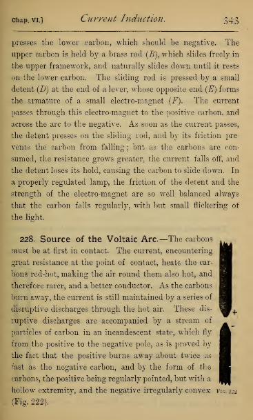
chap, vi.] Current Induction. 343
presses the lower carbon, which should be negative. The
upper carbon is held by a brass rod (B), which slides freely in
the upper framework, and naturally slides down until it rests
on the lower carbon. The sliding rod is pressed by a small
detent (D) at the end of a lever, whose opposite end (E) forms
the armature of a small electro-magnet (F). The current
passes through this electro-magnet to the positive carbon, and
across the arc to the negative. As soon as the current passes,
the detent presses on the sliding rod, and by its friction pre-
vents the carbon from falling; but as the carbons are con-
sumed, the resistance grows greater, the current falls off, and
the detent loses its hold, causing the carbon to slide down. In
a properly regulated lamp, the friction of the detent and the
strength of the electro-magnet are so well balanced always
that the carbon falls regularly, with but small flickering of
the light.
228. Source of the Voltaic Arc—The carbons
must be at first in contact. The current, encountering
great resistance at the point of contact, heats the car-
bons red-hot, making the air round them also hot, and
therefore rarer, and a better conductor. As the carbons
burn away, the current is still maintained by a series of
disruptive discharges through the hot air. These dis-
ruptive discharges are accompanied by a stream of
particles of carbon in an incandescent state, which fly
from the positive to the negative pole, as is proved by
the fact that the positive burns away about twice as
fast as the negative carbon, and by the form of the
carbons, the positive being regularly pointed, but with a
hollow extremity, and the negative irregularly convex fig. 22a
(Fig. 222).
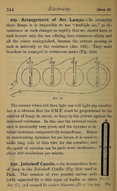
344 Electricity. [Book III.
229. Arrangement of Arc Lamps.—In arranging
these lamps it is impossible to use " multiple arc," as the
resistance in each changes so rapidly that we should have at
each instant only the one offering least resistance alight, and
all the others extinguished, because the current passing in
each is inversely as the resistance (Art. 166). They must
therefore be arranged in continuous series (Fig. 223).
Fig. 223.
The current which will then light one will light any number,
but it is obvious that the E.M.F. must be proportional to the
number of lamps in circuit, to keep up the current against the
increased resistance. In this case the external resist-
ance is necessarily very great, and the dynamo or in-
ternal resistance comparatively insignificant. Hence
in constructing dynamos for arc lamps, it is usual to
make long coils of thin wire for the armature, and
the speed of rotation can be made more moderate
—
about 400 revolutions per minute.
230. Jablokoff Candle.—An intermediate form
of lamp is the Jablokoff Candle (Fig. 224) used in
Paris. This consists of two parallel carbon rods
(AB) separated by a thin layer of kaolin or china
olay (C), and crossed by carbon filament (D) at the top.
D
i
Fig 224.
The

Chap, vi.] Current Induction. 345
voltaic arc is formed between the two carbons at first, and
by its heat makes the kaolin incandescent, tending to make
the light more steady. To secure an equal consumption of
both carbons, a form of dynamo which gives alternate
currents must be used. The principle will be understood
from Clarke's machine (Art. 223).
231. Induction Coils.—We have already noticed the
great E.M.F. possessed by certain induced currents, com-
pared to that of the battery current by which they are induced.
In the construction of an induction coil the aim is to heighten
as far as possible the E.M.F., so as to give us results compar-
able with those obtained by statical electricity. The prin-
ciple is this :—Make a primary circuit by a stout wire coiled a
few times round a bundle of soft iron wires, so as to make the
strongest electro-magnet possible for the dimensions. Bound
this place a secondary coil consisting of a vast number of
turns of thin wire. If we rapidly make and break contact
in the battery circuit, each time the electro-magnet is made
or unmade, an inverse or direct current passes in the
secondary coil. The E.M.F. of this current depends on (1)
the strength of the magnetic field; (2) the number of turns
in the wire of the secondary coil; (3) the rapidity with which
the current in the primary is made and broken.
The parts in an induction coil (Fig. 225) are, in addition to
the battery, (1) a commutator (A), by which the current is
admitted, and by which its direction can be reversed; (2) a
contact breaker (B), for alternately making and breaking
contact in the primary; (3) a condenser ((7), which makes the
breaking of contact more sudden; (4) the primary coil and core;
(5) the secondary coil, with insulated sliding terminals (GH).

346 Electricity. Book III.
The Commutator (Fig. 226).—This usually consists of a solid
ebonite cylinder, having holes at either end for admitting a
Fig. 225.
spindle in two parts. Upon its surface are fastened two
brass plates connected by wires with the two ends of the
10 CONTACT BREAKER
Fig. 226.
spindle, and against them press brass springs, which, by bind-

Chap. VI.] Current Induction, 347
ing-screws, are connected with the battery. The two up-
rights in which the spindle works are insulated from each
other, but connected with the contact breaker.
The Contact Breaker.—This in large coils is an indepen-
dent engine, but in small coils is worked by the electro-
magnet of the primary coil. The end (A) (Fig. 227)
of the core is a powerful magnet pole, and attracts the
hammer-shaped piece of soft iron (B) which is carried by
a stiff spring (C). On this stiff spring opposite to B is a
BA7TE.RY
Fig. 227.
metal stud, which makes contact by pressing against the
adjustable screw D. The passing of the current makes the
electro-magnet, which attracts B, and breaks the circuit in
doing so. B continues rapidly vibrating backwards and
forwards. The opposed surfaces must be of platinum, as any
other metal is rapidly oxidised, and the oxide acts as a
non-conductor to the current.
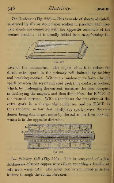
348 Electricity. [Book III.
The Condenser (Fig. 228).—This is made of sheets of tinfoil,
separated by silk or stout paper soaked in paraffin ; the alter-
nate sheets are connected with the opposite terminals of the
contact breaker. It is usually folded in a case, forming the
Fig. 228.
base of the instrument. The object of it is to reduce the
direct extra spark in the primary coil induced by making
and breaking contact. Without a condenser we have a bright
spark between the screw and stud each time contact is broken,
which, by prolonging the current, increases the time occupied
in destroying the magnet, and thus diminishes the E.M.F. of
the induced current. With a condenser the first effect of the
extra spark is to charge the condenser, and its E.M.F. is
thus rendered so low that hardly any spark passes, the con-
denser being discharged again by the extra spark on making,
which is in the opposite direction.
Fig. 229.
The Primary Coil (Fig. 229).—This is composed of a few
thicknesses of stout copper wire (£) surrounding a bundle of
soft iron wires (A). The inner coil is connected with the
battery through the contact breaker.

chap, vij Current Induction. 349
The Secondary Coil.—This (C) is coiled outside the primary
coil, very great care being taken to secure good insulation on
account of the high E.M.F. of the current passing through it.
Each wire is separated from its neighbour by some hard
insulator, and care taken that no two parts of the coil at
a great difference of potential shall be near to each other.
This is accomplished by dividing the secondary coil into
compartments by partitions of vulcanite, the coils in suc-
cessive compartments being connected in series, and the
current passing from the inside to the outside of one com-
partment, and from the outside to the inside of the next.
The length of wire on some secondary coils is as much as fifty
miles. The ends of the wire of the secondary coil are con-
nected to terminals which can be adjusted by a pair of in-
sulated handles.
232. Experiments with the Induction Coil.—Bylarge induction coils, sparks of length up to 2 feet have been
obtained. They appear continuous, but their discontinuous
character can be shown by rotating a coloured disk or a spoked
wheel under the illumination of the spark, and it will be seen
the colours or spokes do not blend, but stand separately, as
they could not do were the light continuous. When the
spark passes through a wide air space, the effect is probably
due almost wholly to the direct induced current, as this, by
its higher E.M.F., can break through a greater air space than
the inverse. This is shown if we connect the terminals of a
Leyden jar with the terminals of the secondary circuit, which,
if there be a large break in the wire through which the spark
has to pass, will be charged by the direct current, but with-
out this break the direct and inverse current passing in equal
quantities neutralise each other.

350 Electricity. [Bookin.
If we connect the platinum electrodes of a voltameter with
the terminals, water will be decomposed, but mixed gases
will be given off at both electrodes. If, however, we leave an
air space across which the spark breaks, we shall find the
gases, separated by the direct current only, collected at the
electrodes.
The power of the secondary spark can be much increased
by connecting the terminals with the inner and outer coats of
a Leyden jar. This condenses the spark, making fewer and
shorter sparks pass, but those sparks are of much increased
intensity. By this means metals and other substances can be
deflagrated for spectroscopic examination or other purposes.
Many chemical combinations can be made by the spark
from an induction coil. Thus a minute spark is sufficient to
cause hydrogen and oxygen to combine with explosive
violence, forming water. The passage of the current through
an hermetically sealed tube of air causes the oxygen and
nitrogen to combine, forming nitrous oxide.
233. Discharge through rarefied Gas.—When the
discharge takes place in air or any gas or vapour in a highly
rarefied state, we obtain remarkable luminous appearances.
A stream of coloured beams, formed of the gas in a state of
incandescence, appears to flow from the positive to the negative
terminal, and by examination with the spectroscope gives
the spectrum of the gas. Frequently the stream of light has
a stratified appearance, not yet well understood. The best
way of observing these phenomena is by Geissler's tubes.
These are made of glass tubes and bulbs (Fig. 230), in various
shapes, with platinum wires fused through them at two points.
After being filled with some gas, as air, hydrogen, etc., they are

chap, vl] Ctirrent Induction. 351
exhausted by the mercury pump, and hermetically sealed. On
connecting their terminals with the secondary coil, remark-
able streams of light are observed, more like the play of the
Aurora Borealis than any other natural phenomenon. In fact,
it is more than probable that the Aurora Borealis is produced
by a cause exactly analogous to these secondary discharges.
We have noticed that it always accompanies a magnetic
storm, during' which the magnetic elements all over the
earth show sudden changes, and earth currents appear in the
earth, either as the cause or consequence of these magnetic
changes. If we remember that air at a sufficient height must
be, on account of its rarity, a conductor of electricity, we
might expect currents to pass in this conducting envelope,
induced by changes in the earth's magnetism.
Fro. 230.
234. Graham Bell's Telephone.—One of the most
wonderful applications of induced currents in modern times
is found in Professor Graham Bell's telephone, which first
brought the telephone into general use.
To understand the telephone, we will first show two experi-
ments to prove the effect on which the telephone's action de-
pends, Take a narrow bobbin (Fig. 231) of thin wire, and place
it round the pole of a bar magnet, supported horizontally, in-
cluding a sensitive galvanometer in the circuit. On taking
a piece of thin plate iron, 2 or 3 inches in diameter, and
moving it towards the pole, we have an induced current

352 Electricity. [Book III.
in one direction, and on moving it away from the pole, we
have the induced current in the opposite direction. The
origin of these currents is easily understood. The iron plate
Fig. 231
becomes a magnet under the induction of the permanent
magnet, and on moving it towards the permanent magnet it
acts inductively upon it, altering its magnetism, and there-
fore causing an induced current.
Eemove now the galvanometer, and replace it by a similar
magnet, also surrounded near one of its poles with a narrow
bobbin of thin wire (Fig. 232). Opposite the pole of this
magnet suspend an equal iron plate (B) with a long straw
Fig. 232.
pointer attached (the suspension may be a pin passing through
the straw), placed so as not to be drawn into contact with
the magnet pole. If we now take the former iron plate (A),

chap, vl] Current Induction. 353
and move it about backwards and forwards with a regular
vibratory motion, we shall soon see the suspended plate
vibrating in sympathy with our movement of the first
plate. This is an exaggerated model of a pair of Bell tele-
phones, the first acting as transmitter, and the second as
receiver.
To understand how sounds are transmitted by this apparatus
we must remember that every sound consists of pulses com-
municated to the air, or the medium which conveys the sound,
the number of these pulses per second defining the pitch of
the note. It is clear, then, from the experiment, that if the
plate A be made to vibrate at a certain definite rate, the plate
B will vibrate at exactly the same rate, and therefore in
unison with it. That is to say, the note given out from Bwill be of exactly the same pitch as the note sounded at A,
But the instrument does more, reproducing not only the
pitch, but also what musicians call the quality of the note,
as well as the very complex modification and superposition
of notes on which articulate speech depends. These produce
on the transmitter a very complicated system of movements,
which are by the induced currents absolutely copied at the
receiver, the only difference being that the sound is very
much weaker, and its quality is affected by the natural vibra-
tion of the metal plates, which gives the sound a peculiar
nasal intonation.
The actual construction of the instrument, in which trans-
mitter and receiver are identical, is shown in section, Fig. 233.
A is a magnet about 4 inches long, and \ inch in diameter.
Eound one pole is wound a coil of wire (B), whose resistance is
from 70 to 350 ohms. The magnet and coil are protected by a
wooden case ((7), of which the thin part serves for holding the
z

354 Electricity, [Book III.
instrument in the hand. At the
broad end is the mouth-piece,
consisting of a wooden ring, con-
cave inwards, shaped like the
mouth of a stethoscope, and im-
mediately behind it a plate of
ferrotype iron (E) (i.e. the iron
plate used in the process known as
ferrotype photography), loosely
held by three screws, which leave
it free to vibrate. At a very
small distance behind this plate
is the pole of the magnet, whose
distance must be regulated by a
screw (F), and carefully adjusted
in each instrument. From the
coil the wires are brought through
the wooden case to two binding-
screws.1
With two of these instruments at opposite ends of a circuit
hundreds of miles in length, conversation can be carried on,
but the sound given out is so feeble that it is inaudible unless
the ear be placed in close proximity to the mouth of the
receiver. The instrument is also peculiarly liable to dis-
turbance from induction in the circuit ; the make or break
of contact in a telegraph wire, parallel to the telephone
wire, but 20 feet distant, causing a harsh grating sound
in the telephone, altogether overpowering the conversa-
tion. This is prevented by using a double wire, the return
1 It will be noticed that this instrument differs from the Reisreceiver (Art. 210) only in the addition of the iron plate.
Fig. 233.
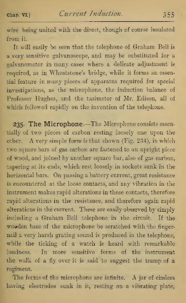
chap, vi.] Current Induction. 355
wire being united with the direct, though of course insulated
from it.
It will easily be seen that the telephone of Graham Bell is
a very sensitive galvanoscope, and may be substituted for a
galvanometer in many cases where a delicate adjustment is
required, as in Wheatstone's bridge, while it forms an essen-
tial feature in many pieces of apparatus required for special
investigations, as the microphone, the induction balance of
Professor Hughes, and the tasimeter of Mr. Edison, all of
which followed rapidly on the invention of the telephone.
235. The Microphone.—The Microphone consists essen-
tially of two pieces of carbon resting loosely one upon the
other. A very simple form is that shown (Fig. 234), in which
two square bars of gas carbon are fastened to an upright piece
of wood, and joined by another square bar, also of gas carbon,
tapering at its ends, which rest loosely in sockets sunk in the
horizontal bars. On passing a battery current, great resistance
is encountered at the loose contacts, and any vibration in the
instrument makes rapid alterations in these contacts, therefore
rapid alterations in the resistance, and therefore again rapid
alterations in the current. These are easily observed by simply
including a Graham Bell telephone in the circuit. If the
wooden base of the microphone be scratched with the finger-
nail a very harsh grating sound is produced in the telephone,
while the ticking of a watch is heard with remarkable
loudness. In more sensitive forms of the instrument
the walk of a fly over it is said to suggest the tramp of a
regiment.
The forms of the microphone are infinite. A jar of cinders
having electrodes sunk in it, resting on a vibrating plate,

356 Electricity. [Book III.
has been used with success, as also a heap of nails, or any
conductors or semi-conductors piled loosely together.
cn
Fig. 284.
The invention of the microphone following rapidly on that
of the telephone, led to attempts to use some form of the
microphone as a transmitter, and the telephone as a receiver
only. This idea though present in the loose platinum contact
of the Eeis receiver has received its practical accomplish-
ment in the loud-speaking Glower-Bell Telephone, used in the
Telephone Exchange. The transmitter is a wooden plate, on
the under-side of which is suspended a microphone (Fig. 235)
of peculiar form. The transmitter also contains a small
electro-magnet, which is included with the microphone in
the battery circuit. This seems to act by heightening the

Chap. VI.] Current Induction. 357
extra current which accompanies each change in the main
current. The receiver is a telephone of peculiar construction.
Fig. 235.
The inside is shown (Fig. 236, b), in which A is a strong
permanent magnet, over whose poles are two coils of wire
Fig. 236.
(B) with soft iron armatures. The varying strength of the
current in the coils alters the magnetism of the cores, and
358 Electricity. [Book in.
causes vibration in the plate of thin sheet-iron, which is
adjusted so as to be all but in contact with them. The plate
is held in the outside case (Fig. 236, a), which has an aperture
in the centre, through which the sound caused by the vibra-
tion of the plate escapes.
The sound from the Gower-Bell telephone is much louder
than that obtained from the ordinary Bell telephone, but it
can only be heard when the ear is placed within a few inches
of the receiver.
QUESTIONS ON BOOK III.
Chapters I.—IV.
1. Given that one litre of hydrogen at normal temperature and
pressure 1 weighs '08957 grams: find what volume of hydrogen is
given off for each gram of zinc consumed in each cell of the battery.
Ans.— 343 litre.
2. A litre of oxygen weighs 1*4298 grams. Find the weight of zinc
consumed in each cell of a battery before 100 cub. cm. of oxygen have
been collected in a voltameter.
Ans.—*581 gram.
3. In a decomposition of copper sulphate, it is found that *59 gram
of copper is separated. Find the amount of zinc consumed in each
cell of the battery.
Ans.—'606 gram.
4. Four Grove cells in compound series are used to decompose
hydrochloric acid. Find the total weight of zinc used in obtaining
one gram of chlorine.
Ans.— 3 66 gram.
1 It will be assumed throughout this Exercise that gases are at
normal temperature (0° C.) and pressure (760 mm. of mercury.)

Questions on Book III. 359
5. In the decomposition of hydrochloric acid find the volumes of
hydrogen and chlorine respectively separated when one gram of zinc
has been consumed in each cell of the battery. One litre of hydrogen
weighs '08957 gram.
Ans.—343 cub. cm. of each.
6. Draw the potential gradient for three cells in compound circuit
and no external resistance. Show from the gradient that the current
is the same as for a single cell.
7. Draw the potential gradient for three cells in compound circuit,
each separated from the next by a wire whose resistance equals that
of a single cell, a point midway between two cells being to earth.
8. Draw the potential gradient for one cell and for three cells in
simple circuit having the same external resistance. Show that if the
external resistance be large the current is nearly the same in both.
9. In a certain circuit the potential difference between the extremi-
ties of a resistance of 300 ohms is equal to 16 volts. Find the whole
E.M.F. if the total resistance in the circuit is 2400 ohms.
10. Find the current strength in a circuit with E.M.F. of 9 '8 volts
and resistance 5 ohms.
Ans.—1*96 amperes.
11. Find the resistance in a circuit if an E.M.F. of 10 volts gives a
current of 1 '6 amperes.
Ans.—6'25 ohms.
12. Find the E.M.F. if the current strength in the circuit be 3*5
amperes, and the resistance 24 ohms.
Ans.—84 volts.
13. It is found experimentally that one coulomb of electricity sets
free '0000105 gm. of hydrogen. Find in amperes the strength of a
current which has yielded '035 grm. of hydrogen in two minutes.
Ans.—27*7 amperes.
14. Find the weights of silver, chlorine, and copper which will be
set free by one coulomb of electricity.
Ans.—-001134 gram silver; '0003727 gram chlorine ; '0003318 gram
copper.
15. A current of two amperes passes for five minutes through a
voltameter : find the total weight of water decomposed.
Ans.—-0567 grams.

360 Questions on Book III.
16. A battery of several cells is included in a circuit with a volta-
meter and tangent galvanometer. After passing the current for five
,
minutes, *098 grams of hydrogen were collected, and the average read-
ing of the tangent galvanometer taken each ten seconds was 55°.
Find the current in amperes, and find the constant multiplier re-
quired to convert the galvanometer indication into current measure
in amperes.
Ans.—31*1 amperes: 21*8 nearly.
17. A battery of five cells when short-circuited with a galvanometer
of no resistance gives a deflection of 9°. On introducing 20 ohms
resistance the deflection sinks to 3°. Find the internal resistance of
the battery.
Ans.—10 ohms.
18. A single cell when short-circuited gives in a galvanometer 45°,
and when 2*5 ohms are introduced it falls to 26 \°. Find the sumof the resistances of the battery and galvanometer, and calculate the
galvanometer reading when five more ohms are introduced.
Ans.—2*5 ohms : 18J° nearly.
19. Using a sine galvanometer whose resistance is *3 ohm, a battery
gives 72° when short-circuited. On introducing 15 ohms resistance
the deflection falls to 36°. Find the resistance of the battery.
Ans.—24 ohms.
20. A battery short-circuited gives 54° deflection to a sine galvano-
meter. Find the reading of the galvanometer when the total resist-
ance is doubled.
Ans.—24° nearly.
21. A circuit, including battery and tangent galvanometer only,
gives a deflection of 63°. On introducing 20 ohms additional resist-
ance, the reading is 42°, and on introducing a coil of unknown
resistance in place of the 20 ohms, the reading is 25° : find the
resistance of the coil.
Ans.—54*5 ohms.
22. The resistance of the battery is known to be 24 ohms, and of
the tangent galvanometer *5 ohm. On short-circuiting the reading is
42°. On introducing a coil of wire the reading sinks to 25°. Find
the resistance of the coil.
Ans.—22*8 ohms.
Questions on Book III. 361
23. A battery cell gives a resistance of 4*5 ohms, and the (tangent)
galvanometer resistance is nil. On short-circuiting, the reading of
the galvanometer is 14J°. Find the reading on introducing 5 ohms
resistance.
Ans.—7°.
24. Find the resistance of a silver wire one metre long, and sectional
area '0007791 sq. cm. (British Wire Gauge, No. 30).
Ans.—'195 ohm.
25. Find the sectional area of a copper wire of which one meter
offers resistance 1 ohm.
Ans.—-0001642 sq. cm.
26. Find the length of a mercury column one sq. mm. in section,
whose resistance is 1 ohm.
Ans.—1*04 metre.
27. Find the ratio of the resistance of silver and platinum wires of
the same dimensions.
Ans.—1 to 6*02.
28. Find the internal resistance of a cell containing dilute sulphuric
acid (5 per cent, acid), the plates measuring 12 cm. by 8 cm., and
being separated by 2 cm.
Ans.— *1 ohm nearly.
29. Find the resistance of an iron telegraph wire, 30 kilometres long,
and whose sectional area is '1051 sq. cm. (B. W. G., No. 9).
Ans.—280*5 ohms.
30. Four cells, each of E.M.F. 1*8 volt, and resistance 1*5 ohm,
with a galvanometer of 3 ohms resistance, are fitted up in compound cir-
cuit with an external resistance of 23 ohms. Find the current strength.
Ans.—*225 ampere.
31. Compare the current with that obtained from one cell with the
same external conditions.
Ans.—As 55 : 16.
32. Six cells, each of E.M.F. 1'07 volt, and resistance 36 ohms,
with a galvanometer of *4 ohm resistance, are fitted up in simple
circuit with an external resistance of one ohm. Compare the current
with that obtained from one cell with the same external conditions.
Ans.—As 5 to 2.

362 Questions on Book III.
33. Five Bunsen cells, each of E.M.F. 1*8 volts, and internal re-
sistance 1*2 ohms, are used in compound circuit with a resistance of
24 ohms : find the current in absolute measure,
Ans.—*03 in absolute electro-magnetic units.
34. Will it be better to arrange six Daniell cells in simple or com-
pound circuit,' the resistance of each cell being *6 ohm, and the
external resistance 2*4 ohms ?
Ans.—Compound series.
35. Twenty-four cells, each of E.M.F. 1*6 volt, and of 2*4 ohmsresistance, are arranged in four rows. If the external resistance be
6 ohms, find the current strength.
Ans.—1 ampere.
36. Calculate the best arrangement of 48 cells, each of internal
resistance 1*5 ohms when the external resistance is 12 ohms.
Ans.—Either two rows or three rows.
37. Find the resistance in a divided circuit whose two branches
offer resistances 6 ohms and 30 ohms respectively.
Ans.—5 ohms.
38. What resistance is offered by a divided circuit of three branches,
in which there are resistances of 6, 8, and 24 ohms ?
Ans.—3 ohms.
39. The plates of a cell whose E.M.F. is 1*9 volt, and whose
resistance is 2*8 ohms, are joined by three wires whose resistances
are 2, and 3, and 6 ohms respectively. Find the current in each
branch.
Ans.— 25 ampere ; *16 ampere ; '083 ampere.
40. Find how many grams of water would be heated 1° C. by
immersing in it a wire coil whose resistance is 7 ohms, and passing
a current of *3 ampere for iive minutes, supposing all the heat
communicated to the water.
Ans.—45 grams.
41. Eight Daniell cells, of each of which the E.M.F. is 1 volt, and
resistance 3*5 volts, are arranged in compound circuit, and the ter-
minals joined by a wire of 35 ohms resistance, which is immersed in

Questions on Book III 363
a kilogram of water. Find the rise in temperature of the water after
the current has passed for ten minutes, supposing no heat to escape.
Ans.— '08° C.
Chapters V. and VI.
42. A straight bar magnet is placed in the field of a straight wire
traversed by a voltaic current. Explain the position which the
magnet will take up. If the direction of the current be reversed,
what change will take place in the magnet's position ?
43. A vertical wire carrying a current is brought near to different
parts of a magnet, suspended so as to move horizontally. Explain at
what parts of the surface attraction or repulsion will be shown.
44. A vertical wire carries an upward current. In what direction
would it be carried if free to move under the earth's magnetic field ?
45. A horizontal wire carries a current from east to west. In what
direction would it move under the action of the earth's magnetism ?
46. A straight wire is pivoted at one end so as to move freely in a
horizontal plane, and is traversed by a current which flows from the
pivot. Find the direction in which it will move under the earth's
magnetism.
47. A straight and thin bar magnet is held parallel to the surface
of water on which is a De la Eive's floating battery. Describe the
position which the floating battery would take up under the magnetic
force.
48. If a straight wire carrying a current be placed over the water
near the floating battery, what position will it take up ?
49. Describe how a coil of wire, traversed by a current, would place
itself if suspended between the poles of a horse-shoe magnet.
50. Show that a galvanometer could be constructed by means of a
coil of wire traversed by the current suspended between the poles of
a powerful horse-shoe magnet.

364 Questions on Book III.
51. How would a coil of wire, traversed by a current, place itself
if suspended within the core of another coil traversed by the same
current ?
52. A beaker is placed on one pole of an electro-magnet and filled
with liquid, which is traversed by a current from the centre to the
circumference. What motion would be observed in the liquid ?
53. A wide beaker is placed on one pole of an electro-magnet of
horse-shoe form, and filled with dilute acid. At the bottom of the
acid is put a zinc plate, and near its surface a copper plate, from both
of which insulated wires pass to outside. Show that on connecting
these wires together the liquid will begin to move.
54. When a wire is dipped into a small mercury cup on the pole of a
magnet, and the current passed through it, the mercury is often seen
to be rapidly rotating. How do you explain this ?
55. The two rails of an ordinary railway are insulated from each
other, but connected with the two terminals of a powerful battery, so
that the current passes through the rails to wheels and axles of the
carriages placed upon the line. Show that if the current were strong
enough, the carriages would move along the line under the magnetic
field of the earth, the direction of motion depending on the direction
of the battery current.
5Q. A vertical wire, forming part of a closed conductor, is movedrapidly from east to west : show the direction of the induced cur-
rents.
57. A horizontal wire, forming part of a closed circuit, is placed
east and west, and carried towards the north. What will be the
direction of the induced current ?
58. A copper hoop in a vertical plane is rapidly rotated about a
vertical diameter, and a magnet is suspended horizontally at its centre.
Show that the induced currents in the hoop will cause the magnet
to be deflected in the direction of the rotation.
59. A metal sheet, held vertically, is drawn between the poles of
an electro-magnet, its upper and lower edges being pressed by fixed
springs which are connected with an external galvanometer. Drawa diagram showing the direction of the current in the galvanometer.
Questions on Book III 365
60. A stream of liquid is flowing between the poles of an electro-
magnet. In what position would you place electrodes to test for an
induced current in the liquid ?
61. A soft iron horse-shoe coiled with wire has its extremities placed
opposite the poles of a horse-shoe magnet. If the ends of the wire
be connected with a galvanometer at a distance, what currents will
be observed on drawing the horse-shoe away from the magnet and
moving it towards the magnet again ?
62. Show that the swing of a compass-needle will be " damped " by
hanging in a metal box.
63. If insulated wire be coiled round a metal cylinder, show that
induced currents will travel round the cylinder at every change of
current in the wire. How would you prevent these currents without
abandoning metal as the material of which the cylinder is made ?

BOOK IV.
THERMO ELECTRICITY.
236. Definition of Thermo-Electricity.—If two rods
of different metals be soldered at their ends, and not in
contact elsewhere, on bringing the junctions to different
temperatures, a current of electricity flows round the cir-
cuit made by the two metals. To this current, and the
phenomena which accompany it, is given the name of Thermo-
Electricity.
237. Elementary Experiments.—The phenomenon,
which was discovered in 1821 by Professor Seebeck of Berlin,
is very easily shown by a strip of copper bent down at its
Fig. 237.
ends, and soldered to a bar of bismuth (Fig. 237), a magnet
being pivoted so as to swing freely between the copper and

368 Electricity. [Book IV.
bismuth. After placing the compound bar in the magnetic
meridian, so that the needle remains parallel to it, we observe,
on heating one junction with a spirit-lamp, that the needle
is immediately deflected, the direction of the deflection
proving that a current flows from the bismuth to the copper
through the hot junction. If, instead of heating with a
spirit-lamp, we cool this junction with ice, the magnet will be
deflected in the opposite direction.
The apparatus is made more sensitive by being arranged as
in Fig. 238, with a galvanometer of low resistance between
the binding-screws which are attached to the copper. In
this case the heat of the finger applied to one junction will
cause a considerable deflection in the galvanometer.
Fig. 238.
238. The Thermopile.—To still further increase the
sensitiveness, a number of couples are arranged in compound
series (Fig. 239, a), and are folded together as in Fig. 239, 6,
to bring all the junctions of the same kind into a small area,
generally in form a square. The instrument then forms the

Book IV.] Thermo-Electricity
.
369
essential part of a thermopile (Fig. 240), whose terminals
are joined in circuit with a delicate galvanometer of low re-
Fig. 239.
sistance. The cone of polished metal attached is useful in
experiments on radiant heat to limit the area from which the
radiations proceed on to the face of the thermopile. The
Fig. 240.
metals employed in the thermopile are usually bismuth and
antimony, which of all the more common metals give the
2 A
370 Electricity. [Book iv.
highest E.M.F. at ordinary temperatures, though a couple of
bismuth and tellurium would be of much higher power.
With a good thermopile a considerable deflection will be
given to the galvanometer by holding the hand a yard from
one face ; otherwise a heated poker, or the blackened surface
of a vessel containing hot water (Leslie's cube), may be em-
ployed. It was by help of the thermopile that Melloni and
Tyndall carried out their researches on radiant heat, and
that astronomers have been able to detect and measure the
heat reaching us from the moon and the brighter fixed
stars. This shows that it is in skilful hands infinitely the
most delicate thermometer we possess.
239. Thermo-electric Power and Diagram.—Seebeckthought that, with a given couple, the E.M.F. of the thermo-
electric current was proportional to the difference of tempera-
ture. Such is only the case if the mean of the temperatures
of the hot and cold junctions be constant. Thus, for each
pair of metals we may determine at each temperature the
E.M.F. in a circuit made of these metals, one junction being
half a degree above and the other half a degree below the
assigned temperature. This E.M.F. per degree of temperature
at a given temperature is defined to be the thermo-electric
power of that pair at that temperature.
Professor P. G-. Tait, by measuring the E.M.F. of pairs of
metals through the whole range of mercury thermometers,
has shown that in each pair the change in thermo-electric
power is proportional to the change in temperature. If,
therefore, we construct a figure in which horizontal lines re-
present temperatures, and vertical lines the thermo-electric
powers of a given couple, the extremities of the vertical lines

Book IV.] Thermo-Electricity
.
37i
would all lie on a straight line. Thus, in Fig. 241, if the base
line represent any metal (say lead), the thermo-electric power
of a lead-copper pair would be given by a line such as P' P,
and of a lead-iron pair by such a line as Q' Q, the lead being
positive to the iron through the part of the diagram where
the iron line is above the base line, and negative where be-
low it.
Fig. 241.
Moreover, it appears from experiment that if at a given
temperature we observe the thermo-electric power of two
metals A — B, and also that of a pair C—B, then their difference
will always give us the thermo-electric power of the pairA — C.
Consequently, if we draw one ordinate MPQ through the dia-
gram for the temperature OM, so that PM represents on our
assigned scale the thermo-electric power of Cu—Pb, and QMthat of Fe— Pb, then QP will represent the thermo-electric
power of Fe—Cu on the same scale.
Thus, taking as base line any metal (and there are theo-

372 Electricity. [Book iv.
retical reasons for choosing lead), each of the metals will be
represented through ordinary temperatures by a straight line,
and the thermo-electric power of any pair of metals can be
at once taken from the diagram by drawing an ordinate
through the assigned temperature, and measuring the dis-
tance between its section with the lines of the two metals.
Such a diagram has actually been constructed by P. G. Tait,
and Fig. 241 is a rough copy of the actual lead, copper,
and iron lines in his thermo-electric diagram.
To find the E.M.F. of a given pair with junctions at the
assigned temperature, we have only to find the thermo-
electric power at the mean of the two temperatures, and
multiply it by the range. Thus, if we require to find the
E.M.F. of the Fe— Cu pair with junctions at temperatures
denoted by M, M\ the thermo-electric power at the mean
temperature is | (PQ + P'Q'\ and the E.M.F. is therefore
i(PQ + P'Q') x (OM— OM'). But by ordinary geometry this
expresses the area of the trapeze Q'Q PF. Since throughout
the range copper is positive to iron, the direction of the
current is from copper to iron, through the hot junction, or
in the direction FPQQ'.
It will be noticed in the diagram that the Fe and Cu lines
intersect at a point N, whose temperature is about 284° C,
and therefore well within the range of experiment.
At this point Fe and Cu are neutral to each other, below
that temperature Cu being + to Fe, and above it — to Fe.
The existence of such a point was demonstrated first by
J. Cumming 1 soon after Seebeck's discovery. On arranging a
1 Late Professor of Chemistry in the University of Cambridge.
There is reason for believing that he independently discovered
Thermo-electricity.
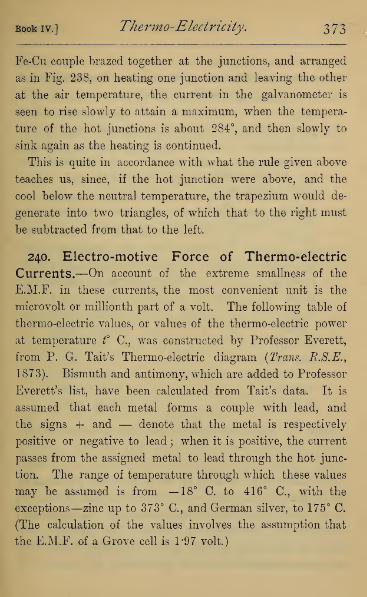
Book iv.] Thermo-Electricity. 373
Fe-Cu couple brazed together at the junctions, and arranged
as in Fig. 238, on heating one junction and leaving the other
at the air temperature, the current in the galvanometer is
seen to rise slowly to attain a maximum, when the tempera-
ture of the hot junctions is about 284°, and then slowly to
sink again as the heating is continued.
This is quite in accordance with what the rule given above
teaches us, since, if the hot junction were above, and the
cool below the neutral temperature, the trapezium would de-
generate into two triangles, of which that to the right must
be subtracted from that to the left.
240. Electro-motive Force of Thermo-electric
Currents.—On account of the extreme smallness of the
E.M.F. in these currents, the most convenient unit is the
microvolt or millionth part of a volt. The following table of
thermo-electric values, or values of the thermo-electric power
at temperature t° C, was constructed by Professor Everett,
from P. G. Tait's Thermo-electric diagram (Trans. R.S.E.,
1873). Bismuth and antimony, which are added to Professor
Everett's list, have been calculated from Tait's data. It is
assumed that each metal forms a couple with lead, and
the signs + and — denote that the metal is respectively
positive or negative to lead ; when it is positive, the current
passes from the assigned metal to lead through the hot junc-
tion. The range of temperature through which these values
may be assumed is from —18° C. to 416° C, with the
exceptions—zinc up to 373° C, and German silver, to 175° C.
(The calculation of the values involves the assumption that
the E.M.F. of a Grove cell is 197 volt.)
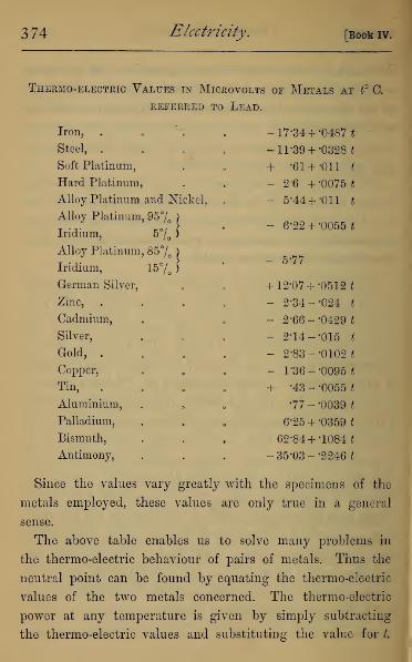
374 Electricity, [Book IV.
Thermo-electric Values in Microvolts of Metals at t° 0.
REFERRED TO LEAD.
Iron,
Steel, .
Soft Platinum,
Hard Platinum,
Alloy Platinum and Nickel,
Alloy Platinum, 95% )
Iridium, 5% J
Alloy Platinum, 85% )
Iridium, 15% )
German Silver,
Zinc,
Cadmium,
Silver,
Gold, .
Copper,
Tin,
Aluminium,
Palladium,
Bismuth,
Antimony,
-17*34 + -0487*
-11-39 + '0328*
+ -61 + -Oil t
- 2-6 +-0075*
- 5*44 + -Oil t
- 6*22 + -0055*
- 5-77
+ 12-07 + -0512*
- 2-34- -024 t
- 2-66- -0429 *
- 2*14- -015 t
- 2-83- -0102 t
- 1 '36- -0095 *
•43 - -0055 t
•77 --0039J
6-25 + -0359 t
62-84 + -1084 t
35-03 --2246*
+
Since the values vary greatly with the specimens of the
metals employed, these values are only true in a general
sense.
The above table enables us to solve many problems in
the thermo-electric behaviour of pairs of metals. Thus the
neutral point can be found by equating the thermo-electric
values of the two metals concerned. The thermo-electric
power at any temperature is given by simply subtracting
the thermo-electric values and substituting the value for L

Book iv.] Thermo-Electricity, 375
The E.M.F. of a couple of two metals is found by taking
their thermo-electric value at the mean of the temperatures
of the hot and cold junctions, and multiplying by the range
of temperature.
Example 1.—To find the neutral temperature of iron and
zinc, we have from the table
-17-34+ -0487*= -2-34 -024 if.
.-. -0727 £=15. .-. *=206°C.
Example 2.—To find the thermo-electric value of an iron-
zinc couple at temperature 100° 0.
Thermo-electric value for iron-zinc
= (-17-34+ -0487 *)-(-2-34- -024 t)
= _15 +-0727*
= —7*73 microvolts, when £=100.
Example 3.—To find the E.M.F. of an iron-zinc couple
when the junctions are at 15° C. and 185° C. respectively.
The mean of 15° C. and 185° is 100°, and thermo-electric
value at 100° of iron-zinc=7*73 by last example.
.-. E.M.F. = 7-73 x (185 -15)
= 7-73x170
= 1314 microvolts.
241. Thermo-electric Diagrams for Higher Tem-peratures.—P. G-. Tait has pushed his investigations into
the thermo-electric behaviour of metals to temperatures far
above the range of a mercurial thermometer. He finds in
several metals, especially iron and nickel, that the lines are
by no means straight. Thus iron has two neutral points
with lead, and it has certainly two and probably three neutral

37'6 Electricity. [Bookiv.
points with the platinum-iridium compound, whose line in
the diagram is parallel to the lead line. In working pro-
blems, therefore, temperature outside the range named must
not be considered as having any physical meaning.
242. Thermo-electric Currents in circuits of one
Metal.—Magnus has shown that if a circuit is formed of one
metal homogeneous throughout, no unequal heating can pro-
duce thermo-electric currents. In the case of a single metal,
when two parts are of different structure, as in hard and soft
iron, a current is produced just as if they were two metals,
on heating unequally the discontinuous portions. It seems
that any cause which gives rise to molecular change in the
wire may also give rise, on unequal heating, to currents of
electricity. Thus if part of a wire be twisted, or hammered,
or knotted, or magnetized, and heat applied on one side of
the changed part, currents can usually be detected in the
wire.
^243. The Peltier Effect.—On the general principle of
conservation of energy, it is clear that the thermo-electric
current is developed at the expense of the heat at the hot
junction—the tendency of the current, when no other work
is done, being to neutralise the differences of temperature
in the circuit, the hot junction being cooled, and perhaps
the cold junction heated.
That this is actually the case was proved by Peltier, who
showed that when a current from a voltaic element is passed
round a bismuth-antimony couple, that junction in which the
current goes from bismuth to antimony is cooled, and the
opposite junction heated • that is to say, the current cools

Book IV.] Thermo-Electricity. 377
that junction which, when heated, gives a current in the
direction of the battery current.
This is called the Peltier effect, and may be shown by two
bars,—one of bismuth (AB, Fig. 242) and the other of anti-
mony (CD), arranged in a cross, and soldered at the junction
E. If the current from one or two elements be sent from
Fig. 242.
A to C, it cools the junction. This cooling is best shown by
arranging the cross so that C, D are over mercury cups, and
the cross rocking on two Y's at A and B, either C or D may
dip into a cup, but not both at once. If a galvanometer be
connected with B and the mercury cup at Z>, and after passing
the current in direction ABC, the cross be rocked, there will
be a current in the galvanometer in the direction DEB, thus
proving a cooling at E.
*244. Theoretical Measure of the E.M.F. of a
Thermo-electric Couple.—If a battery be included in

3 78 Electricity. [Book iv.
any circuit of several metals it is theoretically easy to suppose
that the battery current continues until the thermo-electric
E.M.F. (caused by the heating and cooling of the junctions
and other parts of the circuit, according to Peltier's law),
balances the E.M.F. of the battery, when all current ceases.
If we also suppose the current very weak and the resistance
in the circuit inappreciable, the heat generated frictionally
(Art. 169) will be very small, and we may treat the whole
heat evolved as that due to the Peltier and similar effects.
The energy given out by the battery has in this case been
used up in heating and cooling the different parts of the circuit,
and must therefore be equivalent to the total heat evolved,
counting that absorbed negative. Now the energy given out
from the battery is measured by E I t, when E is the
E.M.F., I the current strength, and t the time. If I and t be
each unity, the E.M.F. is the measure of the energy given out,
and therefore equals the energy developed in the circuit per
unit time by unit current. Thus if we allow unit current
to pass round the circuit for unit time, the total heat evolved
(counting that absorbed negative), according to Peltier's law,
is equivalent to the E.M.F. of the thermo-electric circuit.
*245. The Thomson Effect.— Professor Cumming
observed that at the temperature 284° 0., at which the
iron and copper are neutral to each other—that is, at the
temperature represented by the point N on Fig. 241—the
Peltier effect vanishes.
From this Sir W. Thomson argued that if the hot junction
in an iron-copper couple be at 284° C, and the other at
any lower temperature, no heat is absorbed at the hotter
junction. We therefore have a thermo-electric current with-
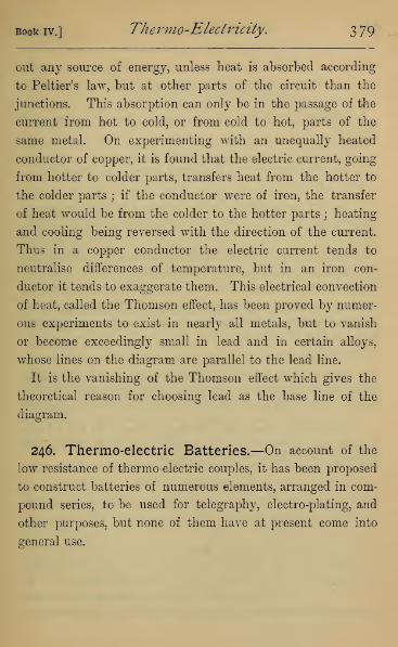
Book iv.] Thermo-Electricity. 3 79
out any source of energy, unless heat is absorbed according
to Peltier's law, but at other parts of the circuit than the
junctions. This absorption can only be in the passage of the
current from hot to cold, or from cold to hot, parts of the
same metal. On experimenting with an unequally heated
conductor of copper, it is found that the electric current, going
from hotter to colder parts, transfers heat from the hotter to
the colder parts ; if the conductor were of iron, the transfer
of heat would be from the colder to the hotter parts ; heating
and cooling being reversed with the direction of the current.
Thus in a copper conductor the electric current tends to
neutralise differences of temperature, but in an iron con-
ductor it tends to exaggerate them. This electrical convection
of heat, called the Thomson effect, has been proved by numer-
ous experiments to exist in nearly all metals, but to vanish
or become exceedingly small in lead and in certain alloys,
whose lines on the diagram are parallel to the lead line.
It is the vanishing of the Thomson effect which gives the
theoretical reason for choosing lead as the base line of the
diagram.
246. Thermo-electric Batteries.—On account of the
low resistance of thermo-electric couples, it has been proposed
to construct batteries of numerous elements, arranged in com-
pound series, to be used for telegraphy, electro-plating, and
other purposes, but none of them have at present come into
general use.

380 Questions on Book IV.
QUESTIONS ON BOOK IV.
1. Find the temperature of the neutral point of lead and soft
platinum.
Ans. -56°C.
2. Find the temperature of the neutral point of iron and copper.
Ans. 274° C,
3. Find the general thermo-electric value for a metal whose thermo-
electric power at 0° C. is —2*14, and at temperature 50° C. is - 2*89.
Ans. -2-14 --015*.
4. Find the E.M.F. of a soft platinum and iron pair, the tempera-
tures of whose junctions are 15° C. and 175° 0.
Ans. 2299 microvolts.
5. Find the number of bismuth-antimony pairs which will be re-
quired to give E.M.F. of 1 volt, the junctions being at temperatures
0° C. and 100° C.
Ans. 87.
6. Show that in a couple formed of two metals whose lines on the
thermo-electric diagram are parallel to each other, the E.M.F. is
directly proportional to the difference in temperature of the junctions.
7. Show that if in any couple the temperature of the hot junction
is at the same distance above the neutral temperature that the cold
junction is below it, no current will appear.
APPENDIX I.
ABSOLUTE UNITS IN C.G.S. SYSTEM.
247. Units and Measures.—The description of every
physical quantity consists of a number, and a concrete thing
of the same nature as that which is being described. Thus if
we say a certain distance is 20 inches, the numerical part
(twenty) expresses the ratio of the length to another length
(the inch), the description presupposing a common understand-
ing as to the nature of the inch. In this case the measure is
twenty, and the unit an inch. If instead of the inch we wish
to make the foot our unit, the measure is altered ; in fact, 20
inches equals § feet; or, again, equals § yards. Thus weobserve that the change of a unit changes all measures ex-
pressed in that unit, and the change in the measure is
inversely proportional to the change in the unit.
248. Fundamental Units.—The fundamental units,
from which all other units are derived, are those of length,
mass, and time. There is great diversity in the units of these
adopted in different countries, but the greatest care is taken
by all civilised states to legalise one, and only one, unit with
which all measures must be compared. Our own standard of
length is the yard, and is denned by Act of Parliament as the
distance between two transverse lines on two gold plugs in a
bar of bronze deposited in the office of the Exchequer, the
measure being taken when the bar is at 62° F.
The French standard of length is the metre, whose length

382 Electricity.[App .
was made to equal, as nearly as possible, the ten-millionth part
of the quadrantal arc of the earth in the longitude of Paris; but
since such a measurement can only be made within tolerably
wide errors of observation, the definition of the unit is the
distance between the ends of a bar of platinum made by
Borda, when the bar is at the temperature of melting ice.
The subdivisions of the metre are the tenth or decimetre, the
hundredth or centimetre, and the thousandth or millimetre.
For all scientific purposes the French system of measure is
used, owing largely to its being a decimal system. The unit
of length we adopt is the centimetre. Its length, referred to
British inches, is -3937043, or rather more than one-third of
an inch.
The British unit of mass is defined in the same way as the
mass of a certain weight of platinum deposited in the office
of the Exchequer, and denominated the Imperial Standard
Pound Avoirdupois. The grain troy is defined as the seven-
thousandth part of the pound avoirdupois.
The French standard is the mass of the Kilogramme des
Archives, made of platinum by Borda, and representing as
nearly as possible the mass of a cubic decimetre of distilled
water at temperature 4° 0.
The thousandth part of this, or the mass of a cubic centi-
metre of distilled water at 4° C, is chosen as the standard
of mass, and called the gramme. This is found to contain
15-43234874 grains troy.
These are defined in their respective Acts of Parliament as
standards of weight; but we see they are masses of metal,
and their weights depend on the attractive force of the
earth at the particular place where they are weighed, and
their weight must change as they are carried either to
places of different altitudes or different latitudes. If, how-
ever, any material body be balanced by an ordinary pair of
scales in vacuo against the standard weight, it will also
balance wherever the experiment be repeated, since the

i.] Absolute Units in C.G.S. System. 383
change of terrestrial gravitation will be equal on both the
weight and its counterpoise. Thus it appears that in our
ordinary commercial transactions, carried on by scales and
weights, we are really dealing with masses, and not with
weights, the so-called standards of weight being standards of
mass.
The unit employed for time is always the second of our
mean-time clocks. Since no clock-work can be made to go
uniformly for ever, the standard unit of time cannot be
defined as the second on a particular clock from which it can
always be reproduced. The regulation of the clock depends
on astronomical observations, and the constancy of the second
through vast lapses of time assumes that the rotation of the
earth is at a uniform rate, and also that the earth always
takes the same time for its orbital revolution. It is by no
means probable that either of these assumptions is true, though
no doubt both are sensibly true during hundreds of years.
249. Mechanical Units.—Having established these
three fundamental units— of length, the centimetre ; of time,
the second ; and of mass, the gramme, we are able to express
in terms of them every physical quantity whatever.
There are certain dynamical quantities which constantly
recur in all physical science, whose nature and measurement
we must briefly explain.
(1) Velocity is a property possessed by every moving
particle at each instant of its motion. To define it we must
know three things—the position of the particle in space, the
direction of its motion, and its speed, or the rate with which it
is moving. To represent the rate of motion we usually state
the distance the particle would go supposing it to retain its
present rate of motion for a certain time. Thus in speaking
of the motion of a railway train we usually state it in
miles per hour, meaning that if it continue moving for an
hour at its present rate it will go so many miles in the

384 Electricity. [app .
hour ; not of course assuming that it has actually gone that
distance in the hour, or will go that distance in the next hour.
If we speak of the rate of a body falling under gravity, or
of a cannon ball, we usually state it in feet per second.
It is very convenient for practical purposes to have manyunits of measurement, but for scientific purposes it is con-
venient to have only one, or at any rate to have units which
may be with the least possible trouble converted into our
assumed fundamental units. Thus we measure all velocities
in centimetres per second, and we speak of a velocity of one
centimetre per second as our unit velocity. Velocities can
then be expressed by simple numbers—a velocity of 1000
meaning that the body is moving at the rate of 1000 centi-
metres per second.
(2) Acceleration and Retardation.—If the velocity of a
particle is not uniform, it is at each instant either quickening
or slackening its speed. To discover this we must observe the
velocity at both ends of a certain interval, and find out
whether it has changed during the interval, and if so, by howmuch. Thus acceleration is usually measured by the increase
in velocity per second, not implying that the acceleration is
uniform during a second, but only representing the amount
by which the velocity would increase, supposing the increase
to go on uniformly for one second. An acceleration of 1000
would then mean that the body would have a velocity of
1000 cm. per second greater at the end than at the beginning
of a second during which the same acceleration was main-
tained. The unit of acceleration is therefore an acceleration
of one cm, per second every second.
The best illustration of uniform acceleration is afforded by
a body falling in vacuo near the surface of the earth. The
acceleration of gravity at the level of the sea in the latitude of
Paris is found to be 981, and will be sensibly the same at all
altitudes which differ by only a few hundreds of yards or
metres. This means that any particle falling toward the
i.] Absolute Units in C.GS. System. 385
earth increases its velocity by 981 cm. per second per second,
and if it be projected upwards from the earth it will suffer
retardation, or will lose velocity at exactly the same rate.
In England, feet and seconds have till recently been com-
monly used as units of length and time, and in terms of them
the measure of gravitation at London is taken to be 32*2,
denoting that the velocity of a falling body increases by 32*2
feet per second per second.
(3) Force is commonly defined as that which changes or
tends to change a body's state of rest or motion. This com-
prises all such physical magnitudes as weights, pressure,
tension, strains, etc. By the weight of a body we denote the
pull exerted by the earth upon it, or by it upon the earth, for
these two are equal and in contrary directions. We have
noted that, if unopposed, the weight of any body whatever
will alter its state of rest or motion in the vertical line by
981 units of velocity per second. Thus the change of motion
caused by gravitation is independent of the mass of the body
experimented on, but the pull of the earth, or the Force of
gravitation, is not independent of mass. For all experience
shows that if we suspend by a string a small mass, the string
assumes a state of tension, which prevents gravitation from
causing change of state ; but if we suspend a larger mass the
string can no longer bear the strain, and breaks, allowing
gravity to produce its change of state in the body. We are
thus led to see that the description of a force must express
the mass of the body as well as the acceleration it will, if un-
opposed, produce in the body. Thus a force of 10 lbs. must
mean a force which would produce in a mass of 10 lbs. the
same acceleration as gravity, that is, an acceleration of 32*2
feet per second per second, and this is shown experimentally
to be the same as would produce in a mass of 1 lb. an
acceleration of 322 (= 32*2 x 10) feet per second per second,
or in a mass of 322 lbs. an acceleration of 1 foot per second
per second.
2 B

386 Electricity. [App.
For scientific purposes we take our cm., gm. and second as
fundamental units of reference, and define our unit force as
the force which will produce in 1 gm. unit acceleration, or a
velocity of 1 cm. per second per second. This unit of force
we call a dyne,1 and the weight of a gram in the latitude
of Paris and at the level of the sea is 981 dynes.
(4) Work.—Work is said to be done whenever a mass is
carried through space in opposition to a force. Thus Watt
took as standard the work done in raising a pound against
the attraction of the earth through 1 foot, and this he called
a "foot-pound." It must be noticed that no work is done in
moving a body at right angles to the force acting. on it, as, for
instance, in carrying a body horizontally, unless it be done
against the resistance of the air or friction, since, could the
body be started on a perfectly smooth and level surface in
vacuo, it would move on for ever without the expenditure on
it of any work whatever.
In the absolute system we use cm. — dynes instead of foot-
pounds, the cm. — dyne being the work done in opposing
through a centimetre the force of 1 dyne, or in carrying
1 gram through a centimetre in opposition to a force which
unopposed would give it unit acceleration. This unit is
commonly now called an erg. 2 To find the number of ergs in
a foot-pound we notice that 1 lb. mass= 453 '593 gm. mass,
and 1 foot= 30*48 cm., and the acceleration of gravity =981units. Hence in carrying 1 lb. through a foot against earth's
pull, we carry 453*593 grams through 30*48 cm. against
981 units of force, which is the same work as expended in
carrying 453*593 x 30*48 x 981 grams through 1 cm. against
unit force,—that is to say, 1 foot-pound equals 13,560,000
ergs nearly.
(5) Energy, Kinetic and Potential.—The power of doing
work in an agent is called its energy, and the amount of
energy is simply measured by the number of units of work it
1 Greek, hvvayns=force. 2 Greek, epyov= work.

i.] Absolute Units in C.G.S. System. 387
is capable of doing. We may first have energy due to a
body's motion. A bullet flying through the air, on striking
against a block of wood, sinks into it till it is brought to
rest. The energy of the bullet caused it to do work, in
overcoming the resistance of the wood to disintegration, or
against the molecular cohesion of the wood. Now it can be
demonstrated mathematically that for every such case the
amount of work done by the moving body before it is brought
to rest equals half the product of the mass of the body
into the square of its velocity. If different parts of the
body are moving with different velocities, the total energy
may be taken as the sum of the energy of each particle
computed as explained above. This kind of energy, which a
body has in virtue of its motion, is commonly called Kinetic
Energy.
A body may, secondly, have energy, in virtue of position or
of work having been expended upon it, which is retained in
the body, and can be recovered at any future time. Thus
when a stone is carried up to a height and placed on the edge
of a cliff, work has been expended in carrying the stone,
without any change in the stone, except in respect to position
relatively to gravitation. A very slight touch may dislodge
the stone, and it will, in falling down, acquire kinetic energy,
which, when it reaches the level from which it was carried,
will exactly equal that expended in raising the stone. In
every form of catapult or bow used in archery, work is first
done against molecular forces in compressing the spring or
bending the bow; and on loosing the trigger or detent, a
large share of this energy is concentrated on the arrow or
other projectile, which thus acquires a high velocity. Were it
mechanically possible to bring all parts of the machine except
the projectile absolutely to rest at the instant when the pro
jectile leaves it, the energy of the projectile would numerically
equal the work done in compression. This kind of energy is
often called Potential Energy.

388 Electricity. [App.
The same general principles apply to other physical pheno
mena. Thus if work be expended in heating a body, the
energy of the heat is numerically the same as the work
expended in heating it. If work be done in making an
electrical separation or an electric current, the energy of
the separation or of the current is the same as the original
work done. These are only illustrations of the great principle
of conservation of energy, of which we find many applications
in electrical and magnetic phenomena.
(6.) Bate of Working.—The rate at which an agent works is
in practice expressed in horse power. The horse power was
defined by Watt to be the rate of working of an agent which
does 33,000 foot-pounds of work per minute. In conformity
with our notation, we should naturally express the rate of
working in ergs per second. To convert the horse power into
ergs per second, we notice that the horse power is 550 foot-
pounds per second, and the foot-pound is 13,560,000 ergs.
Hence the horse power is 550 x 13,560,000= 7*46 x 109 ergs
per second.

II.] Table of Natural Sines. 589
APPENDIX II.
TABLE of Natural Sines and Tangents of
Angles for each Degree.
03<o<o
£b<u
Q
1°
2°
3°
4°
5°
6°
7°
8°
9°
10°
11°
12°
13°
14°
15°
16°
17°
18°
19°
20°
21°
22°
23°
24°
25°
26°
27°
28°
29°
30°
<£>
toceS
EH
a>
260
P
6
m toaaEh
CO
&p
61°
62°
63°
a5
55
+3
toaa
•018
035052
070•087
•105
•122
•139
•156
•174
•191
•208
•225
•018
•035
•052
31°
32°
33°
34°
35°
36°
37°
38°
39°
515530545
•601
•625
•649
•875
•883
•891
1-804
1-881
1-963
2-0502-1452-246
070•087
•105
559574588
•675
•700
•727
64°
65°
66°
[67°68°
69°
70°
71°
72°
73°
•899
•906
•914
•123
•141
•158
602616629
•754
•781
•810
•9211
2-356
•927 2-475•934
i2-605
•176 40° 643 •839 •940 2-748
•194
•213
•231
•249
•268
•287
41°
42°
43°
656669682
•869
•900
•933
•946
•951
•956
2-9043-0783-271
•242
•259
•276
•292
•309
326
44°
45°
46°
47°
48°
49°
50°
51°
52°
53°
54°
55°
56°
57°
58°
59°
60°
695707719
•966
1-000
1-036
1-0721-111
11501-192
74°
75°
76°
77°
78°
79°
•961
•966
•970
•974
•978
•982
3-4873-732
40114-331
4-705
5 145
5-671
306•325
•344
•731
743755
342
358375•391
•364 766
777•788
799
80°|
-985
•384
404•425
1-235
1-2801-327
81°
82°
83°
84°
85°
86°
•988
•990
•993
6-314
7-115
8-144
•407
•423
•438
•454
•469
•485
•500
•445
•466
•488
809•819
829
•839
848857
1-3761-4281-483
•995
•996
•998
9-51411-43
14-30
19-08
28-6457-29
cc
•510
•532
554
1-5401-6001-664
1-732
87°1
-999
88° -999
89° -999
•577 •866 90° 1000

PRINTED BY T. AND A. CONSTABLE, PRINTERS TO HER MAJESTY,
AT THE EDINBURGH UNIVERSITY PRESS.


-V/\


mmLIBRARY OF CONGRESS
003 715 651 6
SsBBSBBSBhbbBr
JoBBBBflKafRMOB
HHHHH
SB
w&fiSS&i
^i^^^sm
Related Documents