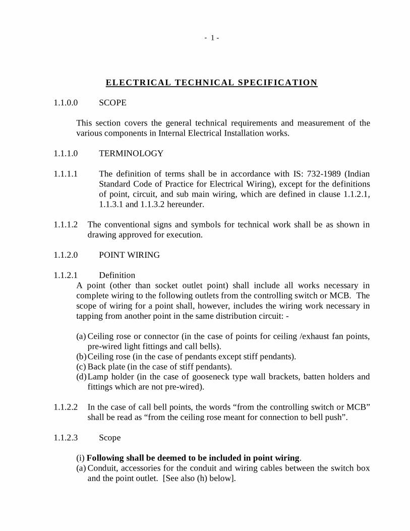
- 1 - ELECTRICAL TECHNICAL SPECIFICATION 1.1.0.0 SCOPE This section covers the general technical requirements and measurement of the various components in Internal Electrical Installation works. 1.1.1.0 TERMINOLOGY 1.1.1.1 The definition of terms shall be in accordance with IS: 732-1989 (Indian Standard Code of Practice for Electrical Wiring), except for the definitions of point, circuit, and sub main wiring, which are defined in clause 1.1.2.1, 1.1.3.1 and 1.1.3.2 hereunder. 1.1.1.2 The conventional signs and symbols for technical work shall be as shown in drawing approved for execution. 1.1.2.0 POINT WIRING 1.1.2.1 Definition A point (other than socket outlet point) shall include all works necessary in complete wiring to the following outlets from the controlling switch or MCB. The scope of wiring for a point shall, however, includes the wiring work necessary in tapping from another point in the same distribution circuit: - (a) Ceiling rose or connector (in the case of points for ceiling /exhaust fan points, pre-wired light fittings and call bells). (b) Ceiling rose (in the case of pendants except stiff pendants). (c) Back plate (in the case of stiff pendants). (d) Lamp holder (in the case of gooseneck type wall brackets, batten holders and fittings which are not pre-wired). 1.1.2.2 In the case of call bell points, the words “from the controlling switch or MCB” shall be read as “from the ceiling rose meant for connection to bell push”. 1.1.2.3 Scope (i) Following shall be deemed to be included in point wiring. (a) Conduit, accessories for the conduit and wiring cables between the switch box and the point outlet. [See also (h) below].

Welcome message from author
This document is posted to help you gain knowledge. Please leave a comment to let me know what you think about it! Share it to your friends and learn new things together.
Transcript
- 1 -
ELECTRICAL TECHNICAL SPECIFICATION 1.1.0.0 SCOPE
This section covers the general technical requirements and measurement of the various components in Internal Electrical Installation works.
1.1.1.0 TERMINOLOGY 1.1.1.1 The definition of terms shall be in accordance with IS: 732-1989 (Indian
Standard Code of Practice for Electrical Wiring), except for the definitions of point, circuit, and sub main wiring, which are defined in clause 1.1.2.1, 1.1.3.1 and 1.1.3.2 hereunder.
1.1.1.2 The conventional signs and symbols for technical work shall be as shown in
drawing approved for execution. 1.1.2.0 POINT WIRING 1.1.2.1 Definition
A point (other than socket outlet point) shall include all works necessary in complete wiring to the following outlets from the controlling switch or MCB. The scope of wiring for a point shall, however, includes the wiring work necessary in tapping from another point in the same distribution circuit: - (a) Ceiling rose or connector (in the case of points for ceiling /exhaust fan points,
pre-wired light fittings and call bells). (b) Ceiling rose (in the case of pendants except stiff pendants). (c) Back plate (in the case of stiff pendants). (d) Lamp holder (in the case of gooseneck type wall brackets, batten holders and
fittings which are not pre-wired).
1.1.2.2 In the case of call bell points, the words “from the controlling switch or MCB” shall be read as “from the ceiling rose meant for connection to bell push”.
1.1.2.3 Scope
(i) Following shall be deemed to be included in point wiring. (a) Conduit, accessories for the conduit and wiring cables between the switch box
and the point outlet. [See also (h) below].

- 2 -
(b) All fixing accessories such as clips, nails, screws, Phil plug, raw plug etc. as required.
(c) Metal switch boxes for control switches, regulators, sockets etc. recessed or surface type, and phenolic laminated sheet covers in case of piano type switches and outer & inner cover plates in case of modular type switches.
(d) Outlet boxes, junction boxes, pull-through boxes etc. but excluding metal boxes if any, provided with switchboards for loose wires/conduit terminations.
(e) Control switch as specified. (f) Ceiling rose or connector as required. (g) Connections to ceiling rose, connector, lamp holder, switch etc. (h) Interconnecting wiring between points on the same circuit, in the same switch
box or from another. (i) Protective (loop earthing) conductor from one metallic switch box to another in
the distribution circuits, and for socket outlets. (The length of protective conductor run along with the circuits/submains is excluded form the scope of points).
(j) Bushed conduit or porcelain tubing where wiring cables pass through wall etc (ii) Following shall be deemed to be included in group control point
wiring. a) Conduit, accessories for the conduit and wiring cables between the MCBDB to
the first point or wiring cable between points forming a group (providing MCB is not included in this scope).
b) All fixing accessories such as clips, nails, screws, Phil plug, rawl plug etc. as required.
c) Junction boxes, pull-through boxes etc. but excluding metal boxes if any, provided with MCBDB for loose wires/conduit terminations.
d) Ceiling rose or connector as required. e) Connections to ceiling rose, connector, MCB etc. f) Bushed conduit or porcelain tubing where wiring cables pass through wall etc
1.1.3.0 Measurement 1.1.3.1 Point Wiring (other than socket outlet points)
(i) Unless and otherwise specified, there shall be no linear measurement for point wiring for light points, fan points, exhaust fan points and call bell points. These shall be measured on unit basis by counting.
(ii) No separate measurement will be made for interconnections between points
in the same distribution circuit and for the circuit protective (loop earthing) conductors between metallic switch boxes.
- 3 -
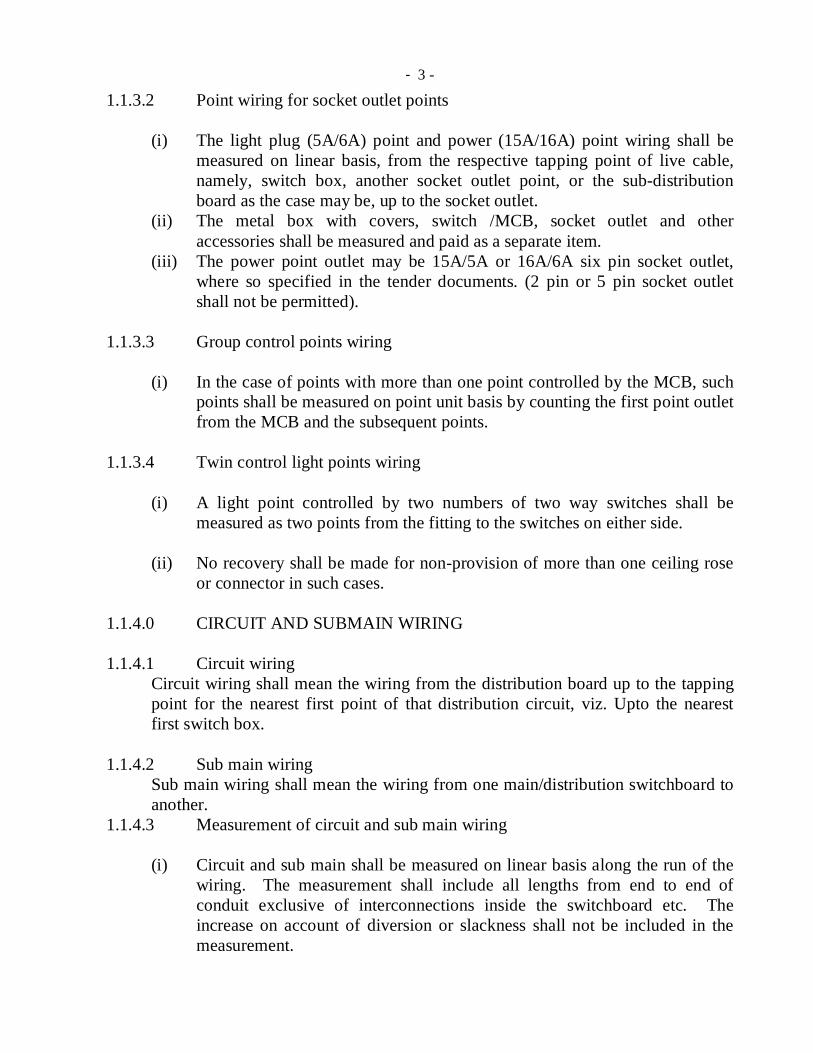
1.1.3.2 Point wiring for socket outlet points (i) The light plug (5A/6A) point and power (15A/16A) point wiring shall be
measured on linear basis, from the respective tapping point of live cable, namely, switch box, another socket outlet point, or the sub-distribution board as the case may be, up to the socket outlet.
(ii) The metal box with covers, switch /MCB, socket outlet and other accessories shall be measured and paid as a separate item.
(iii) The power point outlet may be 15A/5A or 16A/6A six pin socket outlet, where so specified in the tender documents. (2 pin or 5 pin socket outlet shall not be permitted).
1.1.3.3 Group control points wiring
(i) In the case of points with more than one point controlled by the MCB, such points shall be measured on point unit basis by counting the first point outlet from the MCB and the subsequent points.
1.1.3.4 Twin control light points wiring
(i) A light point controlled by two numbers of two way switches shall be measured as two points from the fitting to the switches on either side.
(ii) No recovery shall be made for non-provision of more than one ceiling rose
or connector in such cases. 1.1.4.0 CIRCUIT AND SUBMAIN WIRING 1.1.4.1 Circuit wiring
Circuit wiring shall mean the wiring from the distribution board up to the tapping point for the nearest first point of that distribution circuit, viz. Upto the nearest first switch box.
1.1.4.2 Sub main wiring
Sub main wiring shall mean the wiring from one main/distribution switchboard to another.
1.1.4.3 Measurement of circuit and sub main wiring
(i) Circuit and sub main shall be measured on linear basis along the run of the wiring. The measurement shall include all lengths from end to end of conduit exclusive of interconnections inside the switchboard etc. The increase on account of diversion or slackness shall not be included in the measurement.
- 4 -
(ii) The length of circuit wiring with two wires shall be measured from the distribution board to the first nearest switch box in the circuit irrespective of whether the neutral conductor is taken to switch box or not.
(iii) When wires of different circuit are grouped in a single conduit the same shall be measured on linear basis depending on the actual numbers and sizes of wires run.
(iv) When circuit wires and wires of point wiring are run in the same conduit, circuit wiring shall be measured on linear basis depending on the actual number and sizes of wires run in the existing conduit. As far as, practicable circuit wiring and pointing wiring shall be drawn in different conduit.
(v) Circuit wiring and sub-main shall not be run in the same conduit. (vi) Protective (loop earthing) conductors, which are run along the circuit wiring
and the sub main wiring, shall be measured on linear basis and paid for separately.
1.1.5.0 OTHER WIRING WORKS
(i) Except as specified above for point wiring, circuit wiring and sub main wiring, other types of wiring shall be measured separately on linear basis along the run of wiring depending on the actual number and sizes of wires run.
1.1.6.0 SYSTEM OF DISTRIBUTION AND WIRING 1.1.6.1 The main distribution board and branch distribution board shall be
controlled or provided with linked switch fuse unit or miniature circuit breaker (MCB) of specified rating on the phase or live conductor or combined phase and neutral control gear for incoming and out-going as indicated in the BOQ.
1.1.6.2 Distribution of sub-main and circuits
As per final approved single line diagram.
1.1.6.3 Balancing of Circuits
(i) The balancing of circuits in three wire or poly phase installations shall be arranged before hand to the satisfaction of the Engineer in charge.
1.1.6.4 Wiring System
(i) Unless and otherwise specified in the tender documents, wiring shall be done only by the “Looping system”. Phase or live conductors shall be looped at the switch boxes and neutral conductors at the point outlets.

- 5 -
(ii) Lights, fans and call bells shall be wired in the ‘lighting’ circuits. 15A/16A socket outlets and other power outlets shall be wired in the ‘Power’ circuits. 5A/6A socket outlets shall be wired in the ‘lighting circuits’.
(iii) The wiring throughout the installation shall be such that there is no break in the neutral wire except in the form of linked switchgear.
(iv) The wiring shall be segregated as Essential and non-essential in all the buildings in the airports except in the case of residential quarters.
1.1.6.5 Run of Wiring
(i) The type of wiring shall be as specified in tender documents, i.e. conduit. (ii) Surface wiring shall run, as far as possible, along the walls and ceiling so as
to be easily accessible for inspection. (iii) In no case, the open wiring shall be run above the false ceiling without the
approval of Engineer-in-charge. (iv) In all types of wiring, due consideration shall be given for neatness, good
appearance and safety. 1.1.6.6 Passing through walls or floors
(i) When wiring cables are to pass through a wall, these shall be taken through a protection (steel/PVC) pipe or porcelain tube of suitable size such that they pass through in a straight line without twist or cross in them on either end of such holes. The ends of metallic pipe shall be neatly bushed with porcelain, PVC or other approved material.
(ii) Where a wall pipe passes outside a building so as to be exposed to weather, the outer end shall be bell mouthed and turned downwards and properly bushed on the open end.
(iii) All floor openings for carrying any wiring shall be suitably sealed after installation.
1.1.6.7 Joints in wiring
(i) No bare conductor in phase and/or neutral or twisted joints in phase, neutral, and /or protective conductors in wiring shall be permitted.
(ii) There shall be no joints in the through-runs of cables. If the length of final circuit or sub main is more than the length of a standard coil, thus necessitating a through joint, such joints shall be made by means of approved mechanical connectors in suitable junction boxes.
(iii) Termination of multi-stranded conductors shall be done using suitable crimping type thimbles.
- 6 -
1.1.7.0 CONFORMITY TO IE ACT, IE RULES, AND STANDARDS
(i) All electrical works shall be carried out in accordance with the provisions of Indian Electricity Act, 1910 and Indian Electricity Rules, 1956, amended up to date.
(ii) The works shall also conform to relevant Indian Standard Codes of Practice (COP) for the type of work involved.
(iii) In all electrical installation works, relevant safety codes of practice shall be followed.
1.1.8.0 GENERAL REQUIREMENTS OF COMPONENTS 1.1.8.1 Quality of materials
All materials and equipments supplied by the contractor shall be new. They shall be of such design, size and material as to satisfactorily function under the rated conditions of operation and to withstand the environmental conditions at site.
1.1.8.2 Conformity to Standards
(a) All components shall conform to relevant Indian Standard Specification, wherever existing. However, for conduits, wiring cables, piano switches and socket outlets, ISI marked materials shall only be permitted.
(b) The Indian Standards, including amendments or revisions thereof upto the date of tender acceptance, shall be applicable.
1.1.8.3 Interchangeability
Similar parts of all switches, lamp holders, distribution fuse boards, switchgears, ceiling roses, brackets, pendants, fans and all other fittings of the same type shall be interchangeable in each installation.
1.1.9.0 CABLES 1.1.9.1 Wiring Cables
(i) Conductors of wiring cables (other than flexible cables) shall be of aluminium or copper, as specified.
(ii) Stranded aluminium conductor shall not be used in wiring cables up to and including 6-sq.mm size.

- 7 -
(iii) Unless and otherwise specified, copper conductor of size 1.5 sq mm and above used for wiring shall be stranded.
1.1.9.2 Flexible cables
(i) Conductor of flexible cables shall be of copper. The minimum cross sectional area of conductor for flexible cable shall be 0.0006 sq. inch (14/. 0076” or 14/0.193 mm).
(ii) Only 3 core flexible cables shall be used for connecting single-phase appliances.
(iii) Unless armour, or tough rubber, or PVC sheath mechanically protects the flexible cables, these shall not be used in workshops and other places where they are liable to mechanical damage.
(iv) Flexible cable connection to bell push from ceiling rose shall be taken
through steel conduit /metallic casing and capping. 1.1.10.0 WIRING ACCESSORIES 1.1.10.1 Control switches for points
(i) Combined switch cum socket shall not be permitted. (ii) Control switch shall be placed only in the live conductor of the circuit. No
single pole switch or fuse shall be inserted in the protective (earth) conductor, or earthed neutral conductor of the circuit.
1.1.10.2 Socket outlets
(i) 5A/6A and 15A/16A 6 pin socket outlets shall be installed at the following positions, unless otherwise specified. (a) Kitchen/Pantry 23 cm above working platform and away from the likely
positions of stove and sink. (b) Toilets in non-residential bldg. – 1.25 mt. above floor level. (c) At all other places – 23 cm above floor level.
1.1.10.3 Switch box covers Phenolic laminated sheet of 3 mm thick of approved shade shall be used for switch box covers in case of piano type switches. For Modular type switches/sockets suitable outer and inner cover plates as specified shall be provided over the standard box as recommended by the manufacturers of modular type switch/sockets and no separate sheet cover is required to be provided.

- 8 -
1.1.10.4 Ceiling rose
(i) A ceiling rose shall not be used on circuit the voltage of which normally exceeds 250V.
(ii) Only one flexible cord shall be connected to a ceiling rose. Specially designed ceiling roses shall be used for multiple pendants.
(iii) A ceiling rose shall not embody fuse terminal as an integral part of it. 1.1.10.5 Lamp holders
(i) The standard constructional feature of manufacturers (ISI approved) of lamp holders is acceptable. Where the lamp holders are part of light fixtures the holders shall be suitable for the type of lamps used.
1.1.11.0 FITTINGS
The type of fittings shall be as specified in BOQ of tender documents.
1.1.11.1 Indoor type fittings (i) The contractors shall supply the specified model and make of the fittings.
The standard constructional features of specified make and model as given in the tender document are acceptable.
(ii) Where conductors are required to be drawn through tube or channel leading to the fitting, the tube or channel must be free from sharp angles or projecting edge, and of such size as will enable them to be wired with the conductors used for the final circuit without removing the braiding or sheathing. As far as possible all such tubes or channels should be of sufficient size to permit looping back.
(iii) Pendants in verandahs and similar situations exposed to wind shall be of fixed rod type.
(iv) Fittings using discharge lamps shall be complete with power factor correction capacitors, either integrally or externally. An earth terminal with suitable marking shall be provided for each fitting for discharge lamps.
(v) Fittings shall be installed such that the lamp is at a height specified in approved drawings or as directed by the Engineer-in-charge.
(vi) Copper chokes of Fluorescent Tube light Fittings shall be of super low loss type (Not more than 6 watts) or as specified in BOQ.
- 9 -
1.1.12.0 CONTROL GEAR 1.1.12.1 General aspects
(i) All switch gear and distribution boards (DBs) shall be metal clad type, except those forming part of cubicle type switch boards, in which case the board design shall be such as not to permit direct contact.
(ii) The types, ratings and/or categories of switchgear and protective gear shall be as specified in the tender Schedule of work.
(iii) RCD (ELCBs) where specified, shall conform to the requirements of Current rating, fault rating, single phase or three-phase configuration and sensitivity laid down in the tender documents.
(iv) Each distribution board shall be provided with a circuit list giving details of each circuit, which it controls, and the current rating of the circuit.
1.1.12.2 MCB DISTRIBUTION BOARDS
i) The complete board shall be factory fabricated and ready for installation at
site. ii) The board shall be of wall mounted, cubical type construction, fabricated
out of 1.6 mm thick sheet steel, with stove enameled paint finish. iii) The board shall also be provided with a loose wire MS box with front cover
as a compartment for the complete width and depth of the board and of minimum height of 125mm in case of TPN DB’s and 100mm in case of SPN DB’s. Loose wire box shall be a part of MCB DB item and hence no payment will be made separately.
iv) The distribution board shall be of double door type and such a board shall have an inner and outer cover. The inner cover shall be made of 1.6 mm thick sheet steel with screws. The outer cover shall be of hinged type made of 1.6mm thick sheet steel. Only the knobs of the MCBs shall protrude out of the inner cover through openings neatly machine made for the purpose.
v) Knock out holes at the bottom, and detachable plate with knock out holes at the top of the board shall be provided.
vi) The board shall be complete with the following accessories: - (a) 200 A copper busbar(s). (b) Neutral link. (c) Common earth bar. (d) DIN bar for mounting MCBs.
vii) The standard constructional features of manufacturer for MCBDB is acceptable except for the thickness of sheet, provision of double door, bus bar capacity and loose wire box which shall be as specified.
- 10 -
1.1.12.3 MINIATURE CIRCUIT BREAKERS ( MCBs)
(a) ‘B’ Curve series MCBs shall be used only for normal ‘ lighting’ circuits. (b) ‘C’ Curve series MCBs shall be invariably used for motor loads, halogen
lamp fittings, sodium/ mercury discharge lamps and all ‘ power’ circuits. (c) Rating (as well as fault level KA), number of poles, type of MCB or
isolator, etc. shall be as specified in the BOQ of tender documents.
Supply & installation of MCB may be a part of MCBDB or a separate item as specified in BOQ.
1.1.13.0 SWITCH BOARDS- APPLICATION AND TYPES 1.1.13.1 SWITCH BOARD LOCATIONS – As per approved drawings 1.1.13.2 Cubicle type switchboards
The cubical type switchboard shall conform to the specifications for L.T panel.
1.1.13.3 SWITCH BOARD INSTALLATION (i) Unless and otherwise specified the distribution boards shall be installed so
that its bottom is not less than 1.25 mts from the floor level or as approved by the Engineer-in-Charge
(ii) Switchboard inside a residential quarter shall be installed such that the
operating knob/handle of the in-comer is at height of about 2 mts. (iii) Cubicle board shall be installed by suitable foundation bolts grouted in
floor/wall. Where cubicle boards are placed over the cable trench the panel shall be placed over a formed channel section, duly grouted as required. No extra cost for the channel and its grouting shall be paid separately.
(iv) There shall be a clear distance of 1m in front of the switchboards. The space behind the switchboards shall be either less than 20 cm or more than 75 cm. If there are any attachments or bare connections at the back of the switchboard, Rule 51 c of the Indian electricity rules shall apply.
(v) The connections between the switchgear mounting and the outgoing cable upto the wall shall be enclosed in a protection pipe.
(vi) Where it is required to terminate a number of conduits on a fixed board or cubicle board, it may be convenient to provide a suitable MS adopter box for the purpose. Such boxes shall be provided with the prior approval of the Engineer-in-charge and this will be paid for separately.
(vii) All wires to the boards shall be bushed at the entries to avoid damage to insulation.

- 11 -
(viii) No apparatus shall project beyond any edge of the panel. (ix) All unused holes in the boards and in the mountings shall be plugged
suitable to avoid entry of insects.
1.1.13.4 WIRING OF SWITCH BOARDS AND DISTRIBUTION BOARDS
(i) All connections between pieces of apparatus, and terminals on a board shall be neatly arranged in a definite sequence, following the arrangement of the apparatus mounted thereon, avoiding unnecessary crossings.
(ii) Cables and wiring shall be connected to terminals either by crimped lugs or thimbles.
(iii) The incoming and outgoing cables shall be neatly bunched / clamped such that the doors shall be capable of swinging as required.
1.1.13.5 MARKING OF APPARATUS
(i) Marking of earthed neutral conductor On the main switchgear, where the conductors include an earthed conductor of a two-wire system, or an earthed neutral conductor of a multi-wire system, or a conductor, which is to be connected thereto, an indication of a permanent nature shall be provided to identify the earthed neutral conductor. In this connection Rule 32 (1) of Indian Electricity Rules 1956 shall be referred to. The neutral conductor shall be black in colour. (ii) Main earthing terminal The main earthing terminal in the main switchboard shall be permanently marked as ‘SAFETY EARTH- DO NOT REMOVE”. (iii) Where a board has more than one switchgear, each such switchgear shall be
marked to indicate which section of the installation it controls. Where there is more than one main switch board in the building, each such switch board shall be marked to indicate which section of the installation and building it controls.
(iv) All distribution boards shall be marked “L” for lighting or ‘P’ for power,
and ‘E’ for essential ‘NE’ for non-essential as the case may be.
(v) When a board is connected to a voltage higher than 250V, all the terminals or leads of the apparatus mounted on it shall be marked in the following colours to indicate the different poles or phases to which the apparatus or its different terminals may have been connected.

- 12 -
A.C D.C Three phases- Red Three wire system.
Yellow & Blue 2 outer wires- Red &
Blue Neutral- Black Neutral – Black
(vi) Where a four wire, three-phase wiring is done, the neutral shall be in black and the other three wires in another colour.
(vii) All marking required under this rule shall be clear and permanent.
1.1.14.0 ATTACHEMENT OF FITTINGS AND ACCESSORIES 1.1.14.1 Conduit wiring system (i) All accessories like switches, socket outlets, call bell pushes and regulators shall
be fixed in flush pattern inside the switch/regulator boxes. Accessories like ceiling roses, brackets, batten holders, stiff pendants, etc. shall be fixed on metal outlet boxes.
(ii) Brass screws shall be used to fix the accessories to their bases. (iii) The switch box/ regulator box shall normally be mounted with their bottom 1.25m
from floor level, unless otherwise directed by the Engineer-in-charge. 1.1.14.2 FIXING TO WALLS AND CEILING
(i) PVC sleeves/dash fasteners should normally be used for fixing to walls or ceiling.
(ii) Plugging of walls or ceiling can be done in a better way where neatness is the first consideration. In all such cases, an approved type of asbestos or fiber fixing plug (rawl or Phil plug) with correct size of tools shall be used and done in a workmanlike manner.
1.1.14.3 FANS, REGULATORS AND CLAMPS 1.1.14.3.1 Ceiling fans
(i) Ceiling fans including their suspension shall conform to relevant Indian
Standards.
- 13 -
(ii) Any additional hardware items required for installation of ceiling fans including fan hooks/clamps as specified below, shall be provided as specified in BOQ as a separate item.
(iii) All ceiling fans shall be wired to ceiling roses or to special connector boxes, and suspended from hooks or shackles, with insulators between hooks and suspension rods. There shall be no joint in the suspension rod.
(iv) For wooden or steel joists and beams, the suspension shall consist of MS flat of size not less than 40 mm X 6mm, secured on the sides of the joists or beams by means of two coach screws of size not less than 5 cm for each flat. Where there is space above the beam, a through-bolt of size not less than 1.5cm dia shall be placed above the beam from which the flats are suspended. In the latter case, the flats shall be secured from movements by means of another bolt and nut at the bottom of the beam. A hook consisting of MS rod of size not less than 1.5 cm dia shall be inserted between the MS flat through oval holes on their sides. Alternatively, the flats may be bent inwards to hold tightly between them by means of a bolt and nut, a hook of ‘S’ form.
(v) In the case of ‘ I ’ beams, flats shall be shaped suitably to catch the flanges and shall be held together by means of a long bolt and nut.
(vi) For concrete roofs, a 12mm dia. MS rod in the shape of ’U’ with their vertical legs bent horizontally at the top at least 19cm on either side, and bound to the top reinforcement of the roof shall be used.
(vii) In buildings with concrete roofs having a low ceiling height, where the fan clamp mentioned under sub clause (vi) above cannot be used, or wherever specified, recessed type fan clamp inside a metallic box shall be used. The metallic box shall suitably be covered with 3mm thick phenolic laminated sheet.
(viii) Canopies on top of suspension rod shall effectively hide the suspension (ix) The leading in wire shall be of copper and nominal cross sectional area not
less than 1.5 sq. mm and shall be protected from abrasion. (x) All ceiling fans shall be hung at a height as directed by the Engineer –in
Charge. (xi) In the case of measurement of extra down rod for ceiling fan including
wiring, the same shall be measured in units of 10cm. Any length less than 5 cm shall be ignored.
(xii) The wiring of extra down rod shall be paid as supplying and drawing cable in existing conduit.
1.1.14.3.2 Exhaust fans
(i) Exhaust fans shall conform to relevant Indian Standards.

- 14 -
(ii) Exhaust fans shall be erected at the places indicated by the Engineer-in-charge. For fixing an exhaust fan, a circular hole shall be provided by AAI in the wall to suit the size of the frame, which shall be fixed by means of rag bolts embedded in the wall. The exhaust fan shall be connected to the exhaust fan point, which shall be wired as near to the hole as possible, by means of a flexible cord, care being taken to see that the blades rotate in the proper direction.
1.1.14.3.3 Regulators
The metallic body of regulators of ceiling fans/exhaust fans shall be connected to earth by protective conductor.
1.1.14.3.4 WORKMANSHIP
(i) Good workmanship is an essential requirement to be complied with. The entire work of manufacture/ fabrication, assembly and installation shall conform to sound engineering practice.
(ii) The work shall be carried out under the direct supervision of an engineer, employed by the contractor, who shall rectify then and there the defects pointed out by the Engineer-in-charge during the progress of work. The qualification of engineer or supervisor for over all supervision and to take instructions from the Engineer-in-Charge shall be as specified in the special conditions.
1.1.15.0 TESTING OF INSTALLATION
All the completed installations shall be tested as per specification for “Testing of Installation.”
1.1.15.1 DRAWINGS
(i) The work shall be carried out in accordance with the drawings enclosed with the tender documents and also in accordance with modification thereto from time to time as approved by the Engineer-in-charge or as per the drawing prepared by the contractor based on inventory and approved by Engineer-in-Charge.
(ii) All wiring diagrams shall be deemed to be ‘Drawings’ within the meaning of the term as used in the Conditions of Contract. They shall indicate the main switch board, the distribution boards (with circuit numbers controlled by them), the runs of various mains and sub-mains and the position of all points with their controls.

- 15 -
(iii) All circuits shall be indicated and numbered in the wiring diagram and all points shall be given the same number as the, circuit to which they are electrically connected.
1.1.16.0 COMMISSIONING ON COMPLETION 1.1.16.1 Before the workman leaves the work finally, he must make sure that the
installation is commissioned, after due testing.
1.1.16.2 COMPLETION PLAN AND COMPLETION CERTIFICATE
(i) For all works completion certificate after completion of work as required by AAI shall be submitted to the Engineer-in-charge.
(ii) Completion plan drawn to a suitable scale in tracing sheet with three blue print copies of the same shall also be submitted. (a) General layout of the building. (b) Locations of main switchboard and distribution boards. (c) Position of all points and their controls indicating the circuit numbers
controlled by them. (d) Types of fittings, viz. fluorescent, pendants, brackets, bulk, head, fans
and exhaust fans etc. (e) Name of work, job number, accepted tender reference, actual date of
completion, names of Division/Sub-division, and name of the firm who executed the work with their signature.
*************************

- 16 -
SECTION –2
SPECIFICATION
METALLIC CONDUIT WIRING SYSTEM 1.2.0.0 SCOPE
This chapter covers the detailed requirements for wiring work in metallic conduits. This chapter covers both surface and recessed types of works.
1.2.1.0 APPLICATION
(i) Conduit system used shall be Rigid. (ii) Flexible conduits may only be permitted for interconnections between
switchgear & DBs and conduit terminations in wall. 1.2.2.0 MATERIALS 1.2.2.1 Conduits
(i) All rigid conduit pipes shall be of steel and be ISI marked. The wall thickness shall be not less than 1.6mm (16SWG) for conduits upto 32 mm dia. And not less than 2mm (14SWG) for conduits above 32mm dia. These shall be solid drawn or reamed by welding, and finished with galvanised or stove enameled surface.
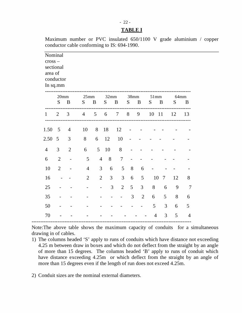
(ii) The maximum number of PVC insulated cables conforming to IS: 694-1990
that can be drawn in one conduit is given size wise in Table I., and the number of cables per conduit shall not be exceeded. Conduit sizes shall be selected accordingly in each run.
(iii) No steel conduit less than 20mm in diameter shall be used.
1.2.2.2 Conduit accessories
(i) The conduit wiring system shall be complete in all respects, including their accessories.
(ii) All conduit accessories shall be of threaded type, and under no circumstances pin grip type or clamp grip type accessories shall be used.
(iii) Bends, couplers etc. shall be solid type in recessed type of works and may be solid or inspection type as required, in surface type of works.
(iv) (a) Saddles for surface conduit work on wall shall not be less than 0.55mm (24 gauge) for conduits up to 25mm dia. and not less than 0.9mm (20

- 17 -
gauge) for larger diameter. The corresponding widths shall be 19 mm and 25mm. (b) The minimum width and the thickness of girder clips used for fixing conduits to steel joists, and clamps shall be as per Table -II.
1.2.2.3 Outlets
(i) The switch box or regulator box shall be made of metal on all sides, except on the front. In case of welded mild steel sheet boxes the wall thickness shall not be less than 1.2mm (18 gauge) for boxes up to a size of 20 cm X 30cm and above this size 1.6mm (16 gauge) thick MS boxes shall be used. The metallic boxes shall be duly painted with anticorrosive paint before erection as per Painting specification.
(ii) (a) Outlet boxes for Light/Power sockets shall be of size, as stipulated in the Bill of quantities (b) Where a large number of control switches and/or fan regulators are required to be installed at one place, these shall be installed in more than one outlet box adjacent to each other for ease of maintenance.
(iii) An earth terminal with stud and 2 metal washers shall be provided in each DB|MS box for termination of protective conductors and for connection to socket outlet/metallic body of fan regulator etc.
(iv) A metal strip shall be welded/screwed, to the metal box as support if fan regulators are to be fixed therein.
(v) Clear depth of the box shall not be less than 60mm, and this shall be increased suitably to accommodate mounting of fan regulators in flush pattern.
(vi) The fan regulators can also be mounted on the switch box coves, if so directed by the Engineer-in-charge.
(vii) The Size of the Switch Box in case of piano type switches shall be as below
a) Without any fan regulator/ Dimmer on the switch box: - The size of the switch box shall be minimum 75mm x 75mm x 60mm deep to accommodate the number of switches meeting spacing requirements mentioned below.
b) With electronic/resistance type fan regulator on the switch box: - The size of switch box shall be minimum 75mm x 75mm x 60mm to accommodate the No. of switches and fan regulators meeting the spacing requirements mentioned below.
Spacing requirements.
The spacing between any edge of live terminal of Switch/ Socket and the body shall not be less than 26mm at any point.
- 18 -
(viii) The Size of the Switch Box in case of modular type switches shall be as per manufacturer’s standard.
1.2.3.0 INSTALLATION. 1.2.3.1 Common aspects for recessed and surface conduit works.
(i) Conduit joints (a) The conduit work of each circuit or section shall be completed before the
cables are drawn in. (b) Conduit pipes shall be joined by means of screwed couplers and screwed
accessories only. Threads on conduit pipes in all cases shall be between 13 mm to 19mm long, sufficient to accommodate pipes to full threaded portion of couplers or accessories.
(c) Cut ends of conduit pipes shall have no sharp edges, nor any burrs left to avoid damage to the insulation of the conductors while pulling them through such pipes.
(d) The Engineer-in-charge, with a view to ensuring that the above provision has been carried out, may require that the separate lengths of conduit etc. after they have been prepared shall be submitted for inspection before being fixed.
(e) No bare threaded portion of conduit pipe shall be allowed, unless such bare threaded portion is treated with anticorrosive preservative or covered with approved plastic compound.
(ii) Bends in conduit (a) All necessary bends in the system, including diversion, shall be done either by
neatly bending the pipes without cracking with bending radius of not less than 7.5 cm, or alternatively, by inserting suitable solid or inspection type normal bends, elbows or similar fittings, or by fixing cast iron inspection boxes, whichever is most suitable.
(b) No length of conduit shall have more than the equivalent of four quarter bends from outlet to outlet.
(c) Conduit fittings shall be avoided as far as possible on conduit system exposed to weather. Where necessary, solid type fittings shall be used.
(iii) Outlets (a) All outlets such as switches, wall sockets etc. may be either flush mounting
type, or of surface mounting type, as specified in the additional specifications if any or as directed by the Engineer In- charge.
- 19 -
(b) All Piano type switches and accessories shall be fixed on the phenolic laminated sheet covers in flush pattern.
(iv) Painting after erection
After installation, all accessible surfaces of conduit pipes, fittings, switch and regulator boxes etc. shall be painted in compliance with the clauses under the Painting specification
1.2.3.2 Additional requirements for surface conduit work
(i) Painting before erection
The outer surface of conduit including all bends, unions, tees, junction boxes, etc. forming part of the conduit system, shall be adequately protected against rust, by painting with 2 coats of red oxide paint applied before they are fixed.
(ii) Fixing conduit on surface
(a) Conduit pipes shall be fixed by saddles, secured to suitable approved plugs with screws in an approved manner at an interval of not more than one metre, but on either side of the couplers or bends or similar fittings, saddles shall be fixed at a distance of 30 cm from the centre of such fittings.
(b) Where conduit pipes are to be laid along the trusses, steel joists etc. the same shall be secured by means of saddles or girder clips or clamps as required by the Engineer-in-charge.
(c) In long distance straight run of conduit, inspection type couplers at reasonable intervals shall be provided, or running threads with couplers and jam nuts shall be provided.
(iii) Fixing outlet boxes Only a portion of the switch box shall be sunk in the wall, the other portion being projected out for suitable entry of conduit pipes into the box.
1.2.3.3 Additional requirements for recessed conduit work
(i) Making chase (a) The chase in the wall shall be neatly made, and of ample dimensions to permit
the conduit to be fixed in the manner desired.
- 20 -
(b) In the case of building under construction, the conduits shall be buried in the wall before plastering, and shall be finished neatly after erection of conduit.
(c) In case of exposed brick / rubble masonry work, special care shall be taken to fix the conduit and accessories in position along with the building work.
(ii) Fixing conduits in chase
(a) The conduit pipe shall be fixed by means of staples, J-hooks, or by means of saddles, not more than 60 cm apart, or by any other approved means of fixing.
(b) All threaded joints of conduit pipes shall be treated with some approved preservative compound to secure protection against rust.
(iii) Fixing conduits in RCC work
(a) The conduit pipes shall be laid in position and fixed to the steel reinforcement bars by steel binding wires before the concreting is done. The conduit pipes shall be fixed firmly to the steel reinforcement bars to avoid their dislocation during pouring of cement concrete and subsequent tamping of the same.
(b) Fixing of standard bends or elbows shall be avoided as far as practicable, and all curves shall be maintained by bending the conduit pipe itself with a long radius, which will permit easy drawing in of conductors.
(iv) Fixing inspection boxes (a) Suitable inspection boxes to the minimum requirement shall be
provided to permit inspection, and to facilitate replacement of wires, if necessary. The distance between inspection/junction boxes shall not exceed 12.5 mts in a straight run.
(b) Location of inspection/junction boxes in RCC work should be identified by suitable means to avoid unnecessary chipping of the RCC slab subsequently to locate these boxes.
(c) These shall be mounted flush with the wall or ceiling concrete. Minimum 65 mm depth junction boxes shall be used in roof slabs and the depth of the boxes in other places shall be as per IS: 2667-1977.
(d) Suitable phenolic laminated sheet cover shall be provided on the inspection box.
(e) Suitable ventilating holes shall be provided in the inspection box covers.
(v) Fixing switch boxes and accessories Switch boxes shall be mounted flush with the wall. All outlets such as switches, socket outlets etc shall be flush mounting type, unless otherwise specified.

- 21 -
(vi) Fish wire To facilitate subsequent drawing of wires in the conduit, GI fish wire of 1.6mm/1.2mm (16/18 SWG) shall be provided alongwith the laying of the recessed conduit. (vii) Bunching of cables (a) Cables carrying direct current may, if desired, be bunched whatever their
polarity, but cables carrying alternating current, if installed in metal conduit shall always be bunched so that the outgoing and return cables are drawn into the same conduit.
(b) Where the distribution is for single phase loads only, conductors for these phases shall be drawn in one conduit.
(c) In case of three phase loads, separate conduits shall be run from the distribution boards to the load points or outlets as the case may be.
1.2.3.4 Earthing requirements
(i) The entire system of metallic conduit work, including the outlet boxes and other metallic accessories, shall be mechanically and electrically continuous by proper screwed joints, or by double check nuts at terminations. The conduit shall be continuous when passing through walls or floors.
(ii) Protective (loop earthing) conductor (s) shall be laid along the runs of the conduit between the metallic switch boxes and the distribution boards/switch boards, terminated thereto. These conductors shall be of such size and material as specified. Depending upon their size and material, the protective earth conductors shall be either drawn inside the conduits alongwith the cables, or shall be laid drawn outside the conduits. When laid external to the conduits, this shall be properly clamped with the conduit at regular intervals.
(iii) The protective conductors shall be terminated properly using earth studs, earth terminal block etc. as the case may be.
(iv) Gas or water pipe shall not be used as protective conductor (earth medium).
************
- 22 -
TABLE I
Maximum number or PVC insulated 650/1100 V grade aluminium / copper conductor cable conforming to IS: 694-1990.
Nominal cross – sectional area of conductor In sq.mm ------------------------------------------------------------------------------------
20mm 25mm 32mm 38mm 51mm 64mm S B S B S B S B S B S B
------------------------------------------------------------------------------------ 1 2 3 4 5 6 7 8 9 10 11 12 13 ------------------------------------------------------------------------------------
1.50 5 4 10 8 18 12 - - - - - -
2.50 5 3 8 6 12 10 - - - - - - 4 3 2 6 5 10 8 - - - - - -
6 2 - 5 4 8 7 - - - - - -
10 2 - 4 3 6 5 8 6 - - - -
16 - - 2 2 3 3 6 5 10 7 12 8
25 - - - - 3 2 5 3 8 6 9 7
35 - - - - - - 3 2 6 5 8 6
50 - - - - - - - - 5 3 6 5
70 - - - - - - - - 4 3 5 4 -------------------------------------------------------------------------------------------- Note:The above table shows the maximum capacity of conduits for a simultaneous drawing in of cables. 1) The columns headed ‘S’ apply to runs of conduits which have distance not exceeding
4.25 m between draw in boxes and which do not deflect from the straight by an angle of more than 15 degrees. The columns headed ‘B’ apply to runs of conduit which have distance exceeding 4.25m or which deflect from the straight by an angle of more than 15 degrees even if the length of run does not exceed 4.25m.
2) Conduit sizes are the nominal external diameters.

- 23 -
TABLE-II Girder clips or clamps ---------------------------------------------------------------------------------------- Size of conduit Width Thickness ----------------------------------------------------------------------------------------
(i) 20mm - - - - 19 mm 0.9 mm (20 SWG)
(ii) 25 mm - - - 19 mm 0.9 mm (20 SWG)
(iii)32 mm & above- - - 25 mm 1.2 mm ( 18 SWG)
----------------------------------------------------------------------------------------
- 24 -
SECTION – 3
SPECIFICATION FOR PAINTING
1.3.0.0 SCOPE
This chapter covers the requirements of painting work in internal electrical installations, carried out manually by brush. This does not cover spray painting work of factory made items.
1.3.1.0 PAINTING WORK IN GENERAL 1.3.1.1 Paints
Paints, oils, varnishes etc. of approved make, in original tin to the satisfaction of the Engineer-in –charge shall only be used.
1.3.1.2 Preparation of the surface
The surface shall be thoroughly cleaned and made free from dust or foreign matter before painting is started. The proposed surface may be inspected by the Engineer-in-charge before the paint is applied.
1.3.1.3 Application
(i) Paint shall be applied with brush. The paint shall be spread as smooth and even as possible. Particular care shall be paid to rivets, nuts, bolts and over-lapping. Before drawing out in smaller containers, it shall be continuously stirred with a smooth stick, while painting work is taken up.
(ii) Primer coat of anti-corrosive paint shall be given in the case of steel work, after preparing the surface. In all cases of painting work, finishing shall be with 2 coats of paint in approved shade.
(iii) Each coat shall be allowed to dry out sufficiently before a subsequent coat is applied.
1.3.1.4 Precautions
All furniture, fixture, glazing, floors etc. shall be protected by suitable covering. All stains, smears, splashing, dropping etc. shall be removed. While painting of wiring etc. it shall be ensured that the painting of wall and ceiling etc. is not spoiled in any way.
**********

- 25 -
SECTION –4
SPECIFICATION FOR EARTHING 1.4.0.0 SCOPE
This chapter covers the essential requirements of earthing system components and their installation. For details not covered in these specifications, IS Code of Practice on Earthing (IS: 3043-1987) shall be referred to.
1.4.1.0 APPLICATION i) The electrical distribution system is with earthed neutral (i.e. neutral earthed at the
transformer / generator end). In addition to the neutral earthing, provision is made for earthing the metallic body of equipments and non-current carrying metallic components in the sub-station, as well as in the internal/external electrical installations.
ii) Earthing system is also required for lightning protection, computer installations
etc. for functional reasons. iii) Earthing requirements are laid down in Indian Electricity Rules, 1956, as amended
from time to time, and in the Regulations of the Electricity Supply Authority concerned. These shall be complied with.
1.4.2.0 MATERIALS
The material of Earth electrode and earth conductor shall be as specified in BOQ
1.4.2.1.1 EARTH ELECTRODES
The type of earth electrode shall be any of the following. a) Plate/Pipe earth electrode as specified in BOQ.
- 26 -
1.4.2.1.2 Electrode materials and dimensions
The materials and minimum sizes of earth electrodes shall be as specified. 1.4.2.2 EARTHING CONDUCTOR i) The earthing conductor (protective conductor from earth electrode up to the main
earthing terminal/earth bus, as the case may be) shall be of the same material as the electrode, viz. GI or copper and in the form of wire or strip as specified. The size of earthing conductor shall be as specified.
1.4.2.3 HARDWARE ITEMS
All hardware items used for connecting the earthing conductor with the electrode shall be of GI in the case of GI pipe and GI plate earth electrodes, and forged tinned brass in case of copper plate electrodes.
1.4.2.4 Protective (Earth continuity/Loop earthing) Conductor
i) The material and size of protective conductors shall be as specified. ii) Unless otherwise specified, GI conductor should not be ordinarily used as
protective conductor within any circuit beyond a Distribution Board downstream.
1.4.3.0 Location for earth electrodes
i) Normally an earth electrode shall not be located closer than 1.5 m from any building. Care shall be taken to see that the excavation for earth electrode does not affect the foundation of the building; in such cases electrodes may be located further away from the building, with the prior approval of the Engineer-in-Charge.
ii) The location of the earth electrode will be such that the soil has a reasonable
chance of remaining moist as far as possible. Entrances, pavements and roadways, should be avoided for locating earth electrodes.
1.4.4.0 INSTALLATION 1.4.4.1 Electrodes 1.4.4.1.1 Various types of electrodes

- 27 -
i) a) Pipe electrode shall be buried in the ground vertically with its top at
not less than 20 cm below the ground level. The installation shall be carried out as shown in drawing.
b) In locations where the full length of pipe electrode is not possible to
be installed due to meeting a water table, hard soil or rock, the electrode may be reduced length, provided the required earth resistance result is achieved with or without additional electrodes, or any alternative method of earthing may be adopted, with the prior approval of the Engineer-in-charge. Pipe electrodes may also be installed in horizontal formation in such exceptional cases.
ii) Plate electrode shall be buried in ground with its faces vertical, and its
top not less than 3 m below the ground level. The installation shall be carried out as shown in drawing.
iii) When more than one electrode (plate/pipe) is to be installed, a
separation of not less than 2 m shall be maintained between two adjacent electrodes.
1.4.4.1.2 Artificial treatment of soil
When artificial treatment of soil is to be resorted to, the electrode shall be surrounded by charcoal/coke and salt and as indicated in enclosed drawings. In such cases, excavation for earth electrode shall be increased as per the dimensions indicated in these figures.
1.4.4.1.3 Watering arrangement
i) In the case of plate earth electrodes, a watering pipe of 20mm dia. medium class G.I. pipe shall be provided and attached to the electrodes as shown in the drawing and a funnel with mesh shall be provided on the top of this pipe for watering the earth.
ii) In the case of pipe electrodes, a 40 mm X 20 mm reducer shall be used for
fixing the funnel with mesh. iii) The watering funnel attachment shall be housed in a masonry enclosure of
size not less than 30 cm X 30 cm X 30 cm.
iv) A cast iron/MS frame with MS cover of 6 mm thick, and having locking arrangement shall be suitably embedded in the masonry enclosure.

- 28 -
1.4.4.2 Earthing conductor (Main earthing lead)
i) In the case of plate earth electrode, the earthing conductor shall be securely terminated on to the plate with two bolts, nuts, check nuts and washers.
ii) In the case of pipe earth electrode, wire type earthing conductor shall be
secured as indicated in drawing using a through bolt, nuts and washers and terminating socket.
iii) The earthing conductor from the electrode up to the building shall be
protected from mechanical injury by a medium class, 15 mm dia. GI pipe in the case of wire, and by a minimum of 40 mm dia, medium class GI pipe in the case of strip. The protection pipe in ground shall be buried at least 30cm deep (to be increased to 60 cm in case of road crossing and pavements). The portion within the building shall be fixed on walls.
iv) The earthing conductor shall be securely connected at the other end to the
earth stud/earth bar provided on the switch board by:
a) Soldered or preferably crimped lug, bolt, nut and washer in the case of wire, and,
b) Bolt, nut and washer in case of strip conductor.
1.4.4.3 Earth bus and main earthing terminal
i) In all installations, main earthing terminal shall be provided at the main
switchboard. This may be in the form of earth stud or single earth bar depending on the type of the switchboard.
ii) Following conductors shall be terminated on to the main earthing terminal.
a) Earth connection from electric supply company (where provided)
b) Earthing conductor from electrode.
c) Protective conductors.
d) Equi-potential bonding conductors.

- 29 -
1.4.4.4 Protective (Loop earthing/ earth continuity) conductor
i) Earth terminal of every switchboard in the distribution system shall be bonded to the earth bar/terminal of the upstream switch board by protective conductors.
ii) Two protective conductors shall be provided for a switchboard carrying a 3-
phase switchgear thereon. 1.4.5.0 Earth Resistance
i) The earth resistance at each electrode shall be measured. No earth electrode shall have a greater ohmic resistance than 5 ohms as measured by an approved earth testing apparatus. In rocky soil the resistance may be up to 8 ohms.
ii) Where the above stated earth resistance is not achieved, necessary improvement shall be made by additional provisions, such as additional electrode(s), different type of electrode, or artificial chemical treatment of soil etc., as may be directed by the Engineer-in-charge, at additional cost as per the provisions of the contract.
1.4.6.0 Marking
i) Earth bars/terminals at all switch boards shall be marked permanently, as "E".
ii) Main earthing terminal shall be marked "SAFETY EARTH - DO NOT DISCONNECT".
*************

- 30 -
FORM OF COMPLETION CERTIFICATE
I/We certify that the installation detailed below has been installed by me/us and tested and that to the best of my/our knowledge and belief it complies with Indian Electricity Rules, 1956, as well as the Contract Specifications. Electrical Installation at ____________________________________ Voltage and system of supply ________________________________ 1. Particulars of work :
(a) Internal Electrical Installation No. Total load Type or system of wiring
(i) Light point
(ii) Fan Point
(iii) Plug Point
(a) 3 pin 5 Amp.
(b) 3 pin 15 Amp. (b) Others
(b) If the work involves installation of underground cable. (i) Total length of underground cable & its size. (ii) No. of Joints : End joint : Tee joint: St. through joint:
- 31 -
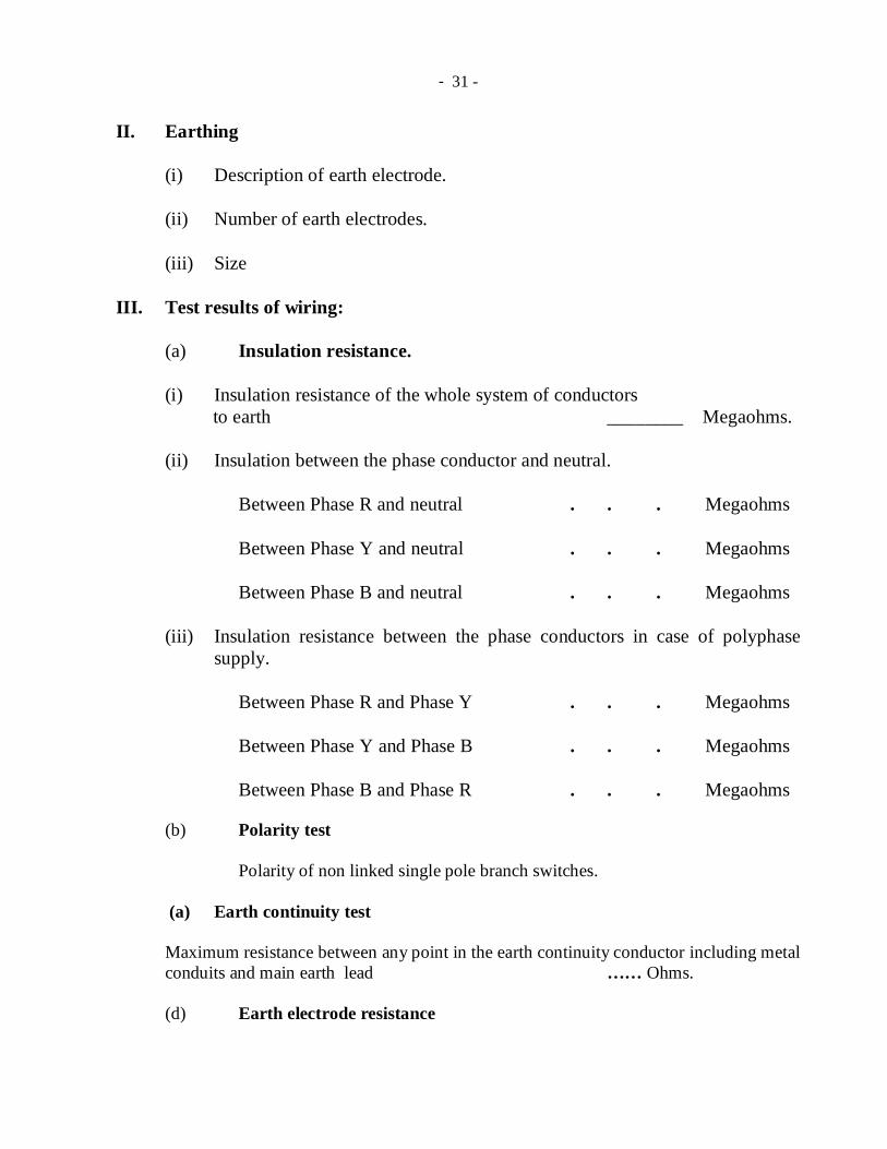
II. Earthing
(i) Description of earth electrode.
(ii) Number of earth electrodes.
(iii) Size III. Test results of wiring: (a) Insulation resistance.
(i) Insulation resistance of the whole system of conductors to earth ________ Megaohms.
(ii) Insulation between the phase conductor and neutral.
Between Phase R and neutral . . . Megaohms Between Phase Y and neutral . . . Megaohms Between Phase B and neutral . . . Megaohms
(iii) Insulation resistance between the phase conductors in case of polyphase supply.
Between Phase R and Phase Y . . . Megaohms Between Phase Y and Phase B . . . Megaohms Between Phase B and Phase R . . . Megaohms (b) Polarity test Polarity of non linked single pole branch switches.
(a) Earth continuity test Maximum resistance between any point in the earth continuity conductor including metal conduits and main earth lead …… Ohms. (d) Earth electrode resistance
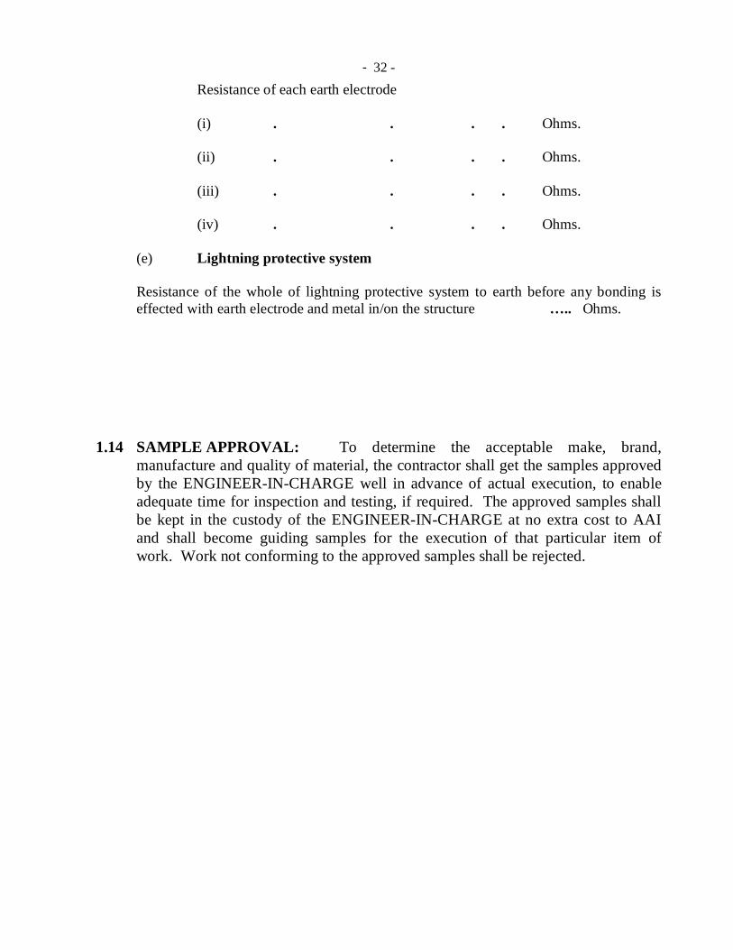
- 32 -
Resistance of each earth electrode (i) . . . . Ohms. (ii) . . . . Ohms. (iii) . . . . Ohms. (iv) . . . . Ohms. (e) Lightning protective system Resistance of the whole of lightning protective system to earth before any bonding is effected with earth electrode and metal in/on the structure ….. Ohms.
1.14 SAMPLE APPROVAL: To determine the acceptable make, brand,
manufacture and quality of material, the contractor shall get the samples approved by the ENGINEER-IN-CHARGE well in advance of actual execution, to enable adequate time for inspection and testing, if required. The approved samples shall be kept in the custody of the ENGINEER-IN-CHARGE at no extra cost to AAI and shall become guiding samples for the execution of that particular item of work. Work not conforming to the approved samples shall be rejected.
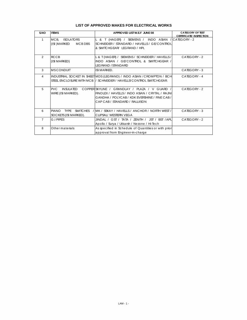
S.NO ITEMS APPROVED LIST W.E.F JUNE 08 CATEGORY OF TEST CERTIFICATE/ INSPECTION
1 MCB, ISOLATORS(ISI )MARKED MCB DBS
L & T (HAGER) / SIEMENS / INDO ASIAN /SCHNEIDER / STANDARD / HAVELLS / GE/CONTROL& SWITCHGEAR/ LEGRAND / HPL
CATEGORY - 2
2 RCCB(ISI MARKED)
L & T (HAGER) / SIEMENS / SCHNEIDER / HAVELLS /INDO ASIAN / GE/CONTROL & SWITCHGEAR /LEGRAND /STANDARD
CATEGORY - 2
3 MS CONDUIT ISI MARKED. CATEGORY - 3
4 INDUSTRIAL SOCKET IN SHEETSTEEL ENCLOSURE WITH MCB
MDS (LEGRAND) / INDO ASIAN /CROMPTON / BCH/ SCHNEIDER / HAVELLS/CONTROL SWITCHGEAR.
CATEGORY - 4
5 PVC INSULATED COPPERWIRE (ISI MARKED).
SKYLINE / GRANDLAY / PLAZA / V GUARD /FINOLEX / HAVELLS / INDO ASIAN / CRYTAL / RAJNIGANDHA / POLYCAB / KDK EVERSHINE / FINE CAB /CAP CAB / STANDARD / RALLIISON
CATEGORY - 2
6 PIANO TYPE SWITCHES /SOCKETS (ISI MARKED).
MK / SSKAY / HAVELLS / ANCHOR / NORTH WEST /CLIPSAL/ WESTERN VEGA
CATEGORY - 3
7 G.I PIPES JINDAL / GST / TATA / ZENITH / JST / BST /APLApollo / Surya / Utkarsh / Nezone / Hi-Tech
CATEGORY - 2
8 Other materials As specified in Schedule of Quantities or with priorapproval from Engineer-in-charge
LIST OF APPROVED MAKES FOR ELECTRICAL WORKS
LAM - 1 -
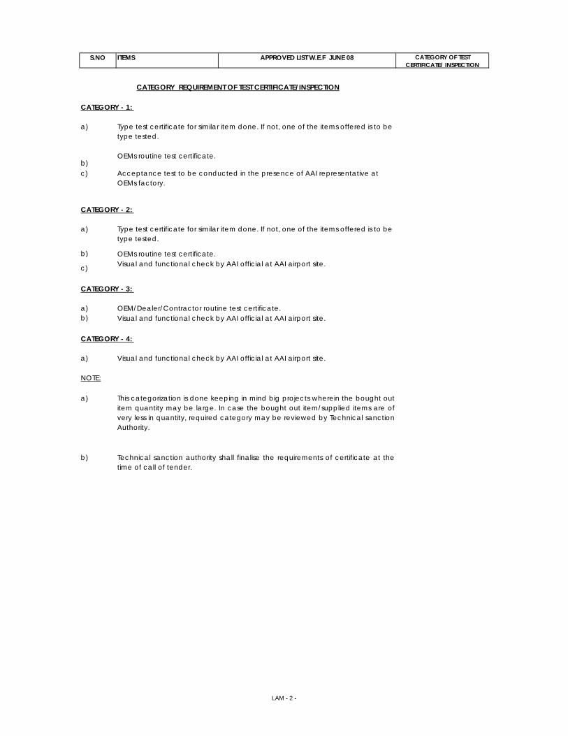
S.NO ITEMS APPROVED LIST W.E.F JUNE 08 CATEGORY OF TEST CERTIFICATE/ INSPECTION
CATEGORY - 1:
a)
b)c)
CATEGORY - 2:
a)
b)
c)
CATEGORY - 3:
a)b)
CATEGORY - 4:
a)
NOTE:
a)
b)
CATEGORY REQUIREMENT OF TEST CERTIFICATE/INSPECTION
OEMs routine test certificate.Visual and functional check by AAI official at AAI airport site.
OEM/Dealer/Contractor routine test certificate.
Type test certificate for similar item done. If not, one of the items offered is to be type tested.
OEMs routine test certificate.
Acceptance test to be conducted in the presence of AAI representative at OEMs factory.
Type test certificate for similar item done. If not, one of the items offered is to be type tested.
Visual and functional check by AAI official at AAI airport site.
This categorization is done keeping in mind big projects wherein the bought outitem quantity may be large. In case the bought out item/supplied items are ofvery less in quantity, required category may be reviewed by Technical sanctionAuthority.
Technical sanction authority shall finalise the requirements of certificate at thetime of call of tender.
Visual and functional check by AAI official at AAI airport site.
LAM - 2 -
Related Documents