ELECTRICAL SYSTEM SECTION EL MODIFICATION NOTICE: I Wiring diagrams have been changed. I Combination meter has been changed. I Headlamp has been changed. I Headlamp aiming control has been added. I Headlamp washer has been added. (For Europe) I A hazard reminder feature has been added to the multi-remote control system. (For Europe) I NATS (Nissan Anti-Theft System) has been changed. (For Europe) CONTENTS PRECAUTIONS ...............................................................4 Supplemental Restraint System (SRS) ″AIR BAG″ and ″SEAT BELT PRE-TENSIONER″ ...............4 POWER SUPPLY ROUTING ...........................................5 Schematic ....................................................................5 Wiring Diagram - POWER - ........................................6 BATTERY .......................................................................13 Service Data and Specifications (SDS).....................13 STARTING SYSTEM .....................................................14 Wiring Diagram - START -/M/T Models.....................14 Wiring Diagram - START -/LHD A/T Models .............15 Wiring Diagram - START -/RHD A/T Models ............16 Construction ...............................................................17 Service Data and Specifications (SDS).....................19 CHARGING SYSTEM ....................................................20 Wiring Diagram - CHARGE -/Diesel Engine and VG Engine .................................................................20 Wiring Diagram - CHARGE - (KA & Z engines)........21 Construction ...............................................................22 Service Data and Specifications (SDS).....................24 COMBINATION SWITCH...............................................25 Check .........................................................................25 HEADLAMP - Conventional Type - .............................26 Wiring Diagram - H/LAMP -/LHD Models..................26 Wiring Diagram - H/LAMP -/RHD Models .................28 Bulb Replacement .....................................................30 Aiming Adjustment .....................................................30 Low Beam..................................................................31 HEADLAMP - Daytime Light System - .......................32 Wiring Diagram - DTRL - ...........................................32 Bulb Replacement .....................................................35 Aiming Adjustment .....................................................35 HEADLAMP - Dim-dip Lamp System - .......................36 Wiring Diagram - DIMDIP - .......................................36 Bulb Replacement .....................................................39 Aiming Adjustment .....................................................39 HEADLAMP - Headlamp Aiming Control - .................40 Wiring Diagram - H/AIM - ..........................................40 PARKING, LICENSE AND TAIL LAMPS ......................42 Wiring Diagram - TAIL/L -/Except LHD Models for Europe ..................................................................42 Wiring Diagram - TAIL/L -/LHD Models for Europe .......................................................................44 STOP LAMP ..................................................................46 Wiring Diagram - STOP/L - .......................................46 BACK-UP LAMP............................................................47 Wiring Diagram - BACK/L -/M/T Models ...................47 Wiring Diagram - BACK/L -/A/T Models ....................49 REAR FOG LAMP .........................................................50 Wiring Diagram - R/FOG -/LHD Models....................50 Wiring Diagram - R/FOG -/RHD Models ...................51 TURN SIGNAL AND HAZARD WARNING LAMPS .....52 Wiring Diagram - TURN - ..........................................52 Trouble Diagnoses.....................................................54 ILLUMINATION ..............................................................55 Wiring Diagram - ILL -/LHD Models ..........................55 Wiring Diagram - ILL -/RHD Models..........................57 INTERIOR ROOM LAMP...............................................59 Wiring Diagram - ROOM/L - ......................................59 SPOT LAMP ..................................................................60 Wiring Diagram - INT/L - ...........................................60 METER AND GAUGES .................................................61 System Description ....................................................61 Combination Meter/With Tachometer ........................62 GI MA EM LC EC FE CL MT AT TF PD FA RA BR ST RS BT HA IDX EL-1

Welcome message from author
This document is posted to help you gain knowledge. Please leave a comment to let me know what you think about it! Share it to your friends and learn new things together.
Transcript

ELECTRICAL SYSTEM
SECTIONELMODIFICATION NOTICE:I Wiring diagrams have been changed.I Combination meter has been changed.I Headlamp has been changed.I Headlamp aiming control has been added.I Headlamp washer has been added. (For Europe)I A hazard reminder feature has been added to the multi-remote control system. (For Europe)I NATS (Nissan Anti-Theft System) has been changed. (For Europe)
CONTENTSPRECAUTIONS ...............................................................4
Supplemental Restraint System (SRS) ″AIRBAG″ and ″SEAT BELT PRE-TENSIONER″...............4
POWER SUPPLY ROUTING ...........................................5Schematic ....................................................................5Wiring Diagram - POWER - ........................................6
BATTERY .......................................................................13Service Data and Specifications (SDS).....................13
STARTING SYSTEM .....................................................14Wiring Diagram - START -/M/T Models.....................14Wiring Diagram - START -/LHD A/T Models .............15Wiring Diagram - START -/RHD A/T Models ............16Construction...............................................................17Service Data and Specifications (SDS).....................19
CHARGING SYSTEM ....................................................20Wiring Diagram - CHARGE -/Diesel Engine andVG Engine .................................................................20Wiring Diagram - CHARGE - (KA & Z engines)........21Construction...............................................................22Service Data and Specifications (SDS).....................24
COMBINATION SWITCH ...............................................25Check.........................................................................25
HEADLAMP - Conventional Type - .............................26Wiring Diagram - H/LAMP -/LHD Models..................26Wiring Diagram - H/LAMP -/RHD Models .................28Bulb Replacement .....................................................30Aiming Adjustment .....................................................30Low Beam..................................................................31
HEADLAMP - Daytime Light System - .......................32Wiring Diagram - DTRL -...........................................32Bulb Replacement .....................................................35Aiming Adjustment .....................................................35
HEADLAMP - Dim-dip Lamp System - .......................36Wiring Diagram - DIMDIP - .......................................36Bulb Replacement .....................................................39Aiming Adjustment .....................................................39
HEADLAMP - Headlamp Aiming Control - .................40Wiring Diagram - H/AIM - ..........................................40
PARKING, LICENSE AND TAIL LAMPS ......................42Wiring Diagram - TAIL/L -/Except LHD Modelsfor Europe ..................................................................42Wiring Diagram - TAIL/L -/LHD Models forEurope .......................................................................44
STOP LAMP ..................................................................46Wiring Diagram - STOP/L - .......................................46
BACK-UP LAMP ............................................................47Wiring Diagram - BACK/L -/M/T Models ...................47Wiring Diagram - BACK/L -/A/T Models ....................49
REAR FOG LAMP .........................................................50Wiring Diagram - R/FOG -/LHD Models....................50Wiring Diagram - R/FOG -/RHD Models ...................51
TURN SIGNAL AND HAZARD WARNING LAMPS .....52Wiring Diagram - TURN - ..........................................52Trouble Diagnoses.....................................................54
ILLUMINATION ..............................................................55Wiring Diagram - ILL -/LHD Models ..........................55Wiring Diagram - ILL -/RHD Models..........................57
INTERIOR ROOM LAMP ...............................................59Wiring Diagram - ROOM/L - ......................................59
SPOT LAMP ..................................................................60Wiring Diagram - INT/L - ...........................................60
METER AND GAUGES .................................................61System Description....................................................61Combination Meter/With Tachometer ........................62
GI
MA
EM
LC
EC
FE
CL
MT
AT
TF
PD
FA
RA
BR
ST
RS
BT
HA
IDX
EL-1

Combination Meter/Without Tachometer ...................63Schematic/With Tachometer ......................................64Schematic/Without Tachometer .................................65Construction...............................................................66Wiring Diagram - METER -/Gasoline Engine withTachometer ................................................................67Wiring Diagram - METER -/Gasoline Enginewithout Tachometer....................................................69Wiring Diagram - METER -/LHD Diesel EngineModels with Tachometer............................................70Wiring Diagram - METER -/RHD Diesel EngineModels with Tachometer............................................72Wiring Diagram - METER -/Diesel Engine withoutTachometer ................................................................74Meter/Gauge Operation and Odo/Trip MeterSegment Check in Diagnosis Mode..........................75Trouble Diagnoses/With Tachometer.........................76Trouble Diagnoses/Without Tachometer....................81
WARNING LAMPS ........................................................86Schematic/With Tachometer ......................................86Schematic/Without Tachometer .................................87Wiring Diagram - WARN -/Gasoline Engine withTachometer ................................................................88Wiring Diagram - WARN -/Gasoline Enginewithout Tachometer....................................................92Wiring Diagram - WARN -/Diesel Engine withTachometer ................................................................96Wiring Diagram - WARN -/Diesel Engine withoutTachometer ..............................................................100
A/T INDICATOR ...........................................................105Wiring Diagram - AT/IND -/RHD Models .................105
WARNING CHIME .......................................................106Wiring Diagram - CHIME -/Diesel Engine Exceptfor Europe, Australia and The Middle East .............106Wiring Diagram - CHIME -/LHD Models forEurope .....................................................................107Wiring Diagram - CHIME -/RHD Models forEurope .....................................................................108
FRONT WIPER AND WASHER ..................................109Wiring Diagram - WIPER -/With Intermittent forFloor-shift .................................................................109Wiring Diagram - WIPER -/Without Intermittentfor Floor-shift............................................................110Wiring Diagram - WIPER -/Without Intermittentfor RHD Column-shift Models..................................114
HEADLAMP WASHER ................................................116Wiring Diagram - HLC -...........................................116
HORN ...........................................................................117Wiring Diagram - HORN - .......................................117
CIGARETTE LIGHTER ................................................118Wiring Diagram - CIGAR -.......................................118
CLOCK .........................................................................119
Wiring Diagram - CLOCK -......................................119REAR WINDOW DEFOGGER AND MIRRORDEFOGGER .................................................................120
Wiring Diagram - DEF -...........................................120AUDIO ..........................................................................121
Wiring Diagram - AUDIO -/LHD Models Exceptfor Europe ................................................................121Wiring Diagram - AUDIO -/LHD Models forEurope .....................................................................124Wiring Diagram - AUDIO -/RHD Models Exceptfor EUROPE ............................................................125Wiring Diagram - AUDIO -/RHD Models forEurope .....................................................................126
AUDIO ANTENNA .......................................................127Power Antenna/Wiring Diagram - P/ANT -..............127
POWER DOOR MIRROR ............................................128Wiring Diagram - MIRROR -/LHD Models Exceptfor The Middle East .................................................128Wiring Diagram - MIRROR -/LHD Models for TheMiddle East ..............................................................129Wiring Diagram - MIRROR -/RHD Models..............130
HEATED SEAT ............................................................131Wiring Diagram - H/SEAT - .....................................131
POWER WINDOW .......................................................133Schematic/Without Interruption DetectionFunction ...................................................................133Schematic/With Interruption Detection Function .....134Wiring Diagram - WINDOW -/Without InterruptionDetection Function...................................................135Wiring Diagram - WINDOW -/With InterruptionDetection Function...................................................139Trouble Diagnoses/For Europe withoutInterruption Detection Function ...............................143Trouble Diagnoses/For Europe with InterruptionDetection Function...................................................144
POWER DOOR LOCK/EXCEPT FOR EUROPE ........146Wiring Diagram - D/LOCK -.....................................146
POWER DOOR LOCK/FOR EUROPE ........................148Wiring Diagram - D/LOCK -.....................................148
MULTI-REMOTE CONTROL SYSTEM/FOREUROPE ......................................................................150
System Description..................................................150MULTI-REMOTE CONTROL SYSTEM .......................151
Wiring Diagram - MULTI - .......................................151Trouble Diagnoses...................................................152ID Code Entry Procedure ........................................154Remote Controller Battery Replacement.................155
THEFT WARNING SYSTEM .......................................156Wiring Diagram - PRWIRE -....................................156
NATS (Nissan Anti-Theft System) .............................157Component Parts and Harness ConnectorLocation ...................................................................157
CONTENTS (Cont’d)
EL-2

System Description..................................................158System Composition................................................159Wiring Diagram - NATS -/LHD Models....................160Wiring Diagram - NATS -/RHD Diesel EngineModels .....................................................................161CONSULT-II .............................................................162Trouble Diagnoses...................................................164How to Replace NATS IMMU..................................175
LOCATION OF ELECTRICAL UNITS .........................177Engine Compartment...............................................177Passenger Compartment.........................................178
HARNESS LAYOUT ....................................................180Main Harness...........................................................180Engine Room Harness ............................................194Engine Control Harness/KA engine.........................202Engine Control Harness ..........................................204
Engine Harness .......................................................208Alternator Harness...................................................214Instrument Harness .................................................216Chassis Harness and Tail Harness .........................217Front Door Harness (LH side) .................................218Front Door Harness (RH side) ................................219Rear Door Harness..................................................220
WIRING DIAGRAM CODES (CELL CODES) .............221SUPER MULTIPLE JUNCTION (SMJ) ..................Foldout
Terminal Arrangement........................................FoldoutFUSE AND FUSIBLE LINK ...................................Foldout
Terminal Arrangement........................................FoldoutCONTROL UNITS ..................................................Foldout
Terminal Arrangement........................................FoldoutJOINT CONNECTOR (J/C) ...................................Foldout
Terminal Arrangement........................................Foldout
GI
MA
EM
LC
EC
FE
CL
MT
AT
TF
PD
FA
RA
BR
ST
RS
BT
HA
IDX
CONTENTS (Cont’d)
EL-3

Supplemental Restraint System (SRS) “AIRBAG” and “SEAT BELT PRE-TENSIONER”
The Supplemental Restraint System such as “AIR BAG” and “SEAT BELT PRE-TENSIONER” used along witha seat belt, helps to reduce the risk or severity of injury to the driver and front passenger in a frontal collision.The SRS system composition which is available to NISSAN MODEL D22 is as follows (The composition var-ies according to the destination and optional equipment.):Driver air bag module (located in the center of the steering wheel), front passenger air bag module (locatedon the instrument panel on passenger side), seat belt pre-tensioner, a diagnosis sensor unit, warning lamp,wiring harness and spiral cable.Information necessary to service the system safely is included in the RS section of this Service Manual.WARNING:I To avoid rendering the SRS inoperative, which could increase the risk of personal injury or death
in the event of a collision which would result in air bag inflation, all maintenance must be performedby an authorized NISSAN dealer.
I Improper maintenance, including incorrect removal and installation of the SRS, can lead to per-sonal injury caused by unintentional activation of the system. For removal of Spiral Cable and AirBag Module, see the RS section.
I Do not use electrical test equipment on any circuit related to the SRS unless instructed to in thisService Manual. SRS wiring harnesses can be identified by yellow harness connector.
PRECAUTIONS
EL-4

Schematic
GEL358A
POWER SUPPLY ROUTING
EL-5
GI
MA
EM
LC
EC
FE
CL
MT
AT
TF
PD
FA
RA
BR
ST
RS
BT
HA
IDX

Wiring Diagram — POWER —BATTERY POWER SUPPLY — IGNITION SWITCH IN ANY POSITION
GEL359A
POWER SUPPLY ROUTING
EL-6

GEL360A
POWER SUPPLY ROUTINGWiring Diagram — POWER — (Cont’d)
EL-7
GI
MA
EM
LC
EC
FE
CL
MT
AT
TF
PD
FA
RA
BR
ST
RS
BT
HA
IDX

GEL361A
POWER SUPPLY ROUTINGWiring Diagram — POWER — (Cont’d)
EL-8

ACCESSORY POWER SUPPLY — IGNITION SW. IN “ACC” OR “ON”
GEL362A
POWER SUPPLY ROUTINGWiring Diagram — POWER — (Cont’d)
EL-9
GI
MA
EM
LC
EC
FE
CL
MT
AT
TF
PD
FA
RA
BR
ST
RS
BT
HA
IDX

IGNITION POWER SUPPLY — IGNITION SW. IN “ON” AND/OR “START”
GEL363A
POWER SUPPLY ROUTINGWiring Diagram — POWER — (Cont’d)
EL-10

GEL364A
POWER SUPPLY ROUTINGWiring Diagram — POWER — (Cont’d)
EL-11
GI
MA
EM
LC
EC
FE
CL
MT
AT
TF
PD
FA
RA
BR
ST
RS
BT
HA
IDX

GEL365A
POWER SUPPLY ROUTINGWiring Diagram — POWER — (Cont’d)
EL-12

Service Data and Specifications (SDS)
Applied model
Europe General areas Australia
YD25 ZD30
Standard Option Standard
Type 110D26R 115D31R
Capacity V-AH 12-64 12-70
BATTERY
EL-13
GI
MA
EM
LC
EC
FE
CL
MT
AT
TF
PD
FA
RA
BR
ST
RS
BT
HA
IDX

Wiring Diagram — START —/M/T Models
GEL366A
STARTING SYSTEM
EL-14
Wiring Diagram — START —/LHD A/T Models
GEL236A
STARTING SYSTEM
EL-15
GI
MA
EM
LC
EC
FE
CL
MT
AT
TF
PD
FA
RA
BR
ST
RS
BT
HA
IDX

Wiring Diagram — START —/RHD A/T Models
GEL367A
STARTING SYSTEM
EL-16

Construction
MEL700P
MEL701P
STARTING SYSTEM
EL-17
GI
MA
EM
LC
EC
FE
CL
MT
AT
TF
PD
FA
RA
BR
ST
RS
BT
HA
IDX

MEL702P
STARTING SYSTEMConstruction (Cont’d)
EL-18

Service Data and Specifications (SDS)STARTER
Type
M2TS0571 M3T29482D S114-348A S114-295B S13-527B
MITSUBISHI HITACHI
Reduction Non-reduction Reduction
Applied model
2WD 4WD 2WD 4WD
YD25 Z24 ZD30
Standard Standard Option Standard
System voltage V 12
No-load
Terminal voltage V 11.0 11.5 11.0
Current A Less than 145 Less than 60 Less than 160*
Revolution rpm More than 3,200More than
6,500More than
7,000More than
6,000More than
3,300
Minimum diameter of commutator mm (in) 31.4 (1.236) 39.0 (1.535) 35.5 (1.398)
Minimum length of brush mm (in) 11.0 (0.433) 11.5 (0.453) 12.0 (0.472) 11.0 (0.433)
Brush spring tension N (kg, lb)26.7 - 36.1
(2.7 - 3.7, 6.0 - 8.2)
13.7 - 25.5(1.4 - 2.6,3.1 - 5.7)
17.7 - 21.6(1.8 - 2.2,4.0 - 4.9)
17.6 - 21.6(1.8 - 2.2,4.0 - 4.9)
28.4 - 34.3(2.9 - 3.5,6.4 - 7.7)
Clearance between bearing metal andarmature shaft mm (in)
Less than 0.2 (0.008) —
Clearance “” between pinion front edgeand pinion stopper mm (in)
—0.5 - 2.0
(0.020 - 0.079)0.3 - 2.5
(0.012 - 0.098)—
Movement “” in height of pinion assemblymm (in)
0.5 - 2.0(0.020 - 0.079)
—0.3 - 2.0
(0.01 - 0.079)
*: Includes magnet switch current.
STARTING SYSTEM
EL-19
GI
MA
EM
LC
EC
FE
CL
MT
AT
TF
PD
FA
RA
BR
ST
RS
BT
HA
IDX

Wiring Diagram — CHARGE —/Diesel Engineand VG Engine
GEL368A
CHARGING SYSTEM
EL-20

Wiring Diagram — CHARGE — (KA & Zengines)
GEL238A
CHARGING SYSTEM
EL-21
GI
MA
EM
LC
EC
FE
CL
MT
AT
TF
PD
FA
RA
BR
ST
RS
BT
HA
IDX

Construction
SEL544V
MEL703P
CHARGING SYSTEM
EL-22

MEL704P
CHARGING SYSTEMConstruction (Cont’d)
EL-23
GI
MA
EM
LC
EC
FE
CL
MT
AT
TF
PD
FA
RA
BR
ST
RS
BT
HA
IDX

Service Data and Specifications (SDS)ALTERNATOR
TypeA5TA5271 A7TA8471 A5TA5372 A3TB0699 LR160-745 LR160-728E
MITSUBISHI HITACHI
Applied model KA24DEZ24
YD25 ZD30 TD27, QD32Standard Option*
Nominal rating V-A 12-70 12-35 12-70 12-90 12-60
Ground polarity Negative
Minimum revolution under no-load(When 13.5V is applied) rpm
Less than 1,300 Less than 1,000
Hot output current(When 13.5V is applied) A/rpm
More than14/1,300
More than54/2,500
More than27/2,500
More than18/1,300
More than51/2,500
More than29/1,300
More than76/2,500
More than88/5,000
More than17/1,300
More than48/2,500
More than57/5,000
Regulated output voltage V 14.1 - 14.7
Minimum length of brushmm (in)
5.0 (0.20) 6.0 (0.236)
Brush spring pressureN (g, oz)
4.8 - 6.0 (487 - 612, 17.25 - 21.59) 1.0 - 3.43 (102 - 350, 3.60 - 12.34)
Slip ring minimum outer diametermm (in)
22.1 (0.870) 26.0 (1.024)
Rotor (Field coil) resistance Ω 2.5 - 2.9 2.7 - 3.2 2.5 - 2.9 2.1 - 2.5 2.6 2.58
*: Models with power steering and air conditioner
CHARGING SYSTEM
EL-24
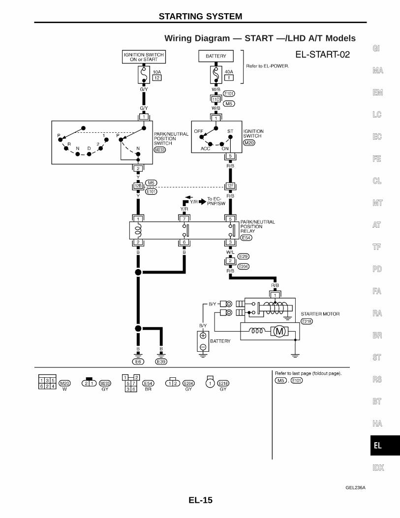
CheckRHD MODELS EXCEPT FOR EUROPE
HEL847B
COMBINATION SWITCH
EL-25
GI
MA
EM
LC
EC
FE
CL
MT
AT
TF
PD
FA
RA
BR
ST
RS
BT
HA
IDX

Wiring Diagram — H/LAMP —/LHD Models
GEL239A
HEADLAMP — Conventional Type —
EL-26

GEL240A
HEADLAMP — Conventional Type —Wiring Diagram — H/LAMP —/LHD Models(Cont’d)
EL-27
GI
MA
EM
LC
EC
FE
CL
MT
AT
TF
PD
FA
RA
BR
ST
RS
BT
HA
IDX

Wiring Diagram — H/LAMP —/RHD Models
GEL369A
HEADLAMP — Conventional Type —
EL-28

GEL370A
HEADLAMP — Conventional Type —Wiring Diagram — H/LAMP —/RHD Models(Cont’d)
EL-29
GI
MA
EM
LC
EC
FE
CL
MT
AT
TF
PD
FA
RA
BR
ST
RS
BT
HA
IDX

Bulb ReplacementThe headlamp is a semi-sealed beam type which uses a replace-able halogen bulb. The bulb can be replaced from the engine com-partment side without removing the headlamp body.I Grasp only the plastic base when handling the bulb. Never
touch the glass envelope.1. Disconnect the battery cable.2. Disconnect the harness connector from the back side of the
bulb.3. Pull off the rubber cap.4. Push and raise retaining pin to loosen it.5. Remove the headlamp bulb carefully. Do not shake or rotate
the bulb when removing it.6. Install in the reverse order of removal.CAUTION:Do not leave headlamp reflector without bulb for a long periodof time. Dust, moisture, smoke, etc. entering headlamp bodymay affect the performance of the headlamp. Remove head-lamp bulb from the headlamp reflector just before a replace-ment bulb is installed.
Aiming AdjustmentWhen performing headlamp aiming adjustment, use an aimingmachine, aiming wall screen or headlamp tester. Aimers should bein good repair, calibrated and operated in accordance with respec-tive operation manuals.If any aimer is not available, aiming adjustment can be done asfollows:For details, refer to the regulations in your own country.a. Keep all tires inflated to correct pressures.b. Place vehicle and tester on one and same flat surface.c. See that there is no-load in vehicle (coolant, engine oil
filled up to correct level and full fuel tank) other than thedriver (or equivalent weight placed in driver’s position).
CAUTION:Be sure aiming switch is set to “0” when performing aimingadjustment on vehicles equipped with headlamp aiming con-trol.
GEL452A
SEL596Y
SEL597Y
HEADLAMP — Conventional Type —
EL-30

Low Beam1. Turn headlamp low beam on.2. Use adjusting screws to perform aiming adjustment.I First tighten the adjusting screw all the way and then make
adjustment by loosening the screw.
I Adjust headlamps so that main axis of light is parallel tocenter line of body and is aligned with point P shown inillustration.
I Figure to the left shows headlamp aiming pattern for driv-ing on right side of road; for driving on left side of road,aiming pattern is reversed.
I Dotted lines in illustration show center of headlamp.“H”: Horizontal center line of headlamps“W L”: Distance between each headlamp center“L”: 5,000 mm (196.85 in)“C”: 65 mm (2.56 in)
GEL453A
GEL454A
SEL254I
HEADLAMP — Conventional Type —
EL-31
GI
MA
EM
LC
EC
FE
CL
MT
AT
TF
PD
FA
RA
BR
ST
RS
BT
HA
IDX

Wiring Diagram — DTRL —
GEL371A
HEADLAMP — Daytime Light System —
EL-32

GEL372A
HEADLAMP — Daytime Light System —Wiring Diagram — DTRL — (Cont’d)
EL-33
GI
MA
EM
LC
EC
FE
CL
MT
AT
TF
PD
FA
RA
BR
ST
RS
BT
HA
IDX

GEL373A
HEADLAMP — Daytime Light System —Wiring Diagram — DTRL — (Cont’d)
EL-34

Bulb ReplacementFor bulb replacement, refer to “HEADLAMP — Conventional Type—” EL-30.
Aiming AdjustmentFor aiming adjustment, refer to “HEADLAMP — Conventional Type—” EL-30.
HEADLAMP — Daytime Light System —
EL-35
GI
MA
EM
LC
EC
FE
CL
MT
AT
TF
PD
FA
RA
BR
ST
RS
BT
HA
IDX

Wiring Diagram — DIMDIP —
GEL374A
HEADLAMP — Dim-dip Lamp System —
EL-36
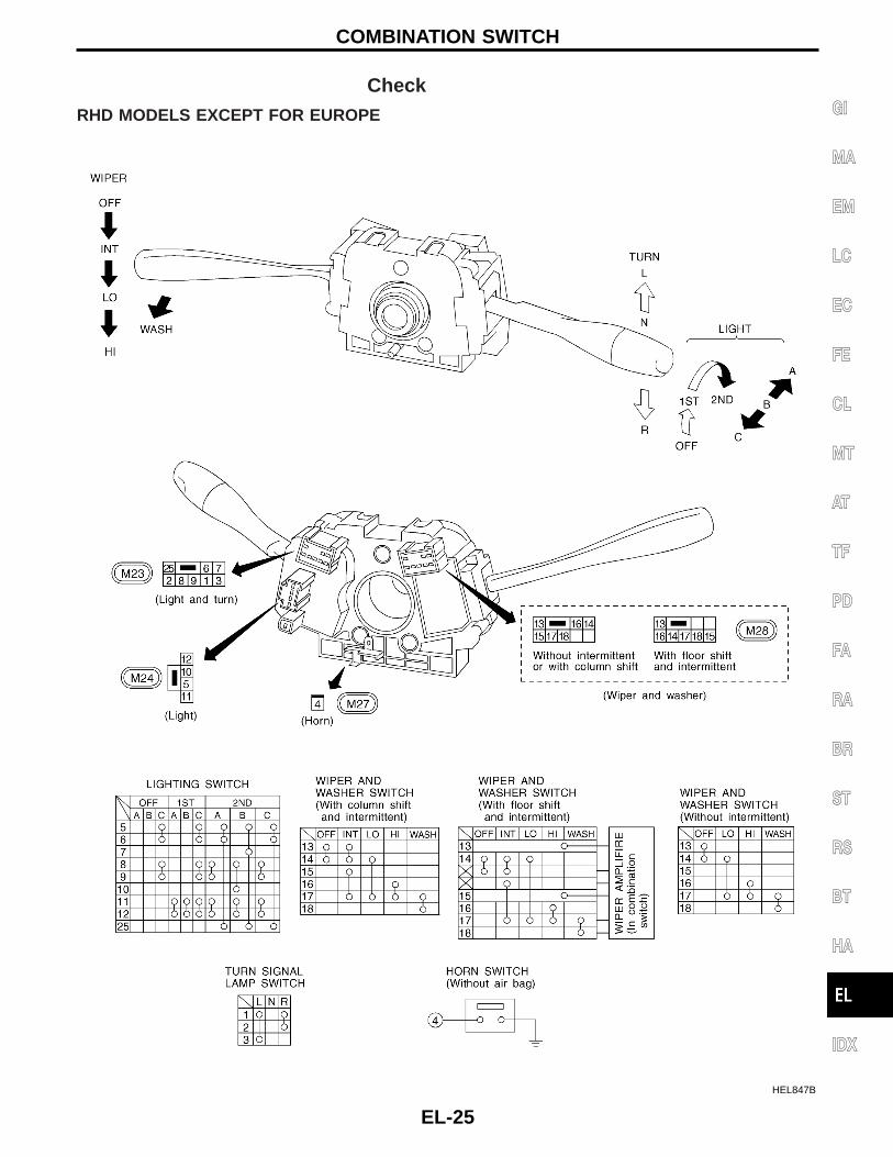
GEL375A
HEADLAMP — Dim-dip Lamp System —Wiring Diagram — DIMDIP — (Cont’d)
EL-37
GI
MA
EM
LC
EC
FE
CL
MT
AT
TF
PD
FA
RA
BR
ST
RS
BT
HA
IDX

GEL376A
HEADLAMP — Dim-dip Lamp System —Wiring Diagram — DIMDIP — (Cont’d)
EL-38

Bulb ReplacementFor bulb replacement, refer to EL-30.
Aiming AdjustmentFor aiming adjustment, refer to EL-30.
HEADLAMP — Dim-dip Lamp System —
EL-39
GI
MA
EM
LC
EC
FE
CL
MT
AT
TF
PD
FA
RA
BR
ST
RS
BT
HA
IDX

Wiring Diagram — H/AIM —
GEL377A
HEADLAMP — Headlamp Aiming Control —
EL-40

GEL378A
HEADLAMP — Headlamp Aiming Control —Wiring Diagram — H/AIM — (Cont’d)
EL-41
GI
MA
EM
LC
EC
FE
CL
MT
AT
TF
PD
FA
RA
BR
ST
RS
BT
HA
IDX

Wiring Diagram — TAIL/L —/Except LHDModels for Europe
GEL242A
PARKING, LICENSE AND TAIL LAMPS
EL-42

GEL460A
PARKING, LICENSE AND TAIL LAMPSWiring Diagram — TAIL/L —/Except LHDModels for Europe (Cont’d)
EL-43
GI
MA
EM
LC
EC
FE
CL
MT
AT
TF
PD
FA
RA
BR
ST
RS
BT
HA
IDX

Wiring Diagram — TAIL/L —/LHD Models forEurope
GEL379A
PARKING, LICENSE AND TAIL LAMPS
EL-44

GEL380A
PARKING, LICENSE AND TAIL LAMPSWiring Diagram — TAIL/L —/LHD Models forEurope (Cont’d)
EL-45
GI
MA
EM
LC
EC
FE
CL
MT
AT
TF
PD
FA
RA
BR
ST
RS
BT
HA
IDX

Wiring Diagram — STOP/L —
GEL461A
STOP LAMP
EL-46

Wiring Diagram — BACK/L —/M/T ModelsEXCEPT FOR VG ENGINE
GEL462A
BACK-UP LAMP
EL-47
GI
MA
EM
LC
EC
FE
CL
MT
AT
TF
PD
FA
RA
BR
ST
RS
BT
HA
IDX

FOR VG ENGINE
GEL381A
BACK-UP LAMPWiring Diagram — BACK/L —/M/T Models(Cont’d)
EL-48
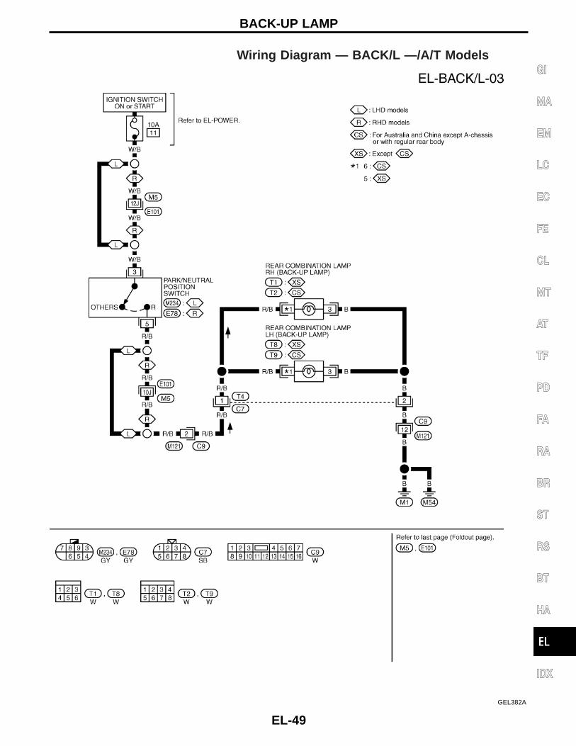
Wiring Diagram — BACK/L —/A/T Models
GEL382A
BACK-UP LAMP
EL-49
GI
MA
EM
LC
EC
FE
CL
MT
AT
TF
PD
FA
RA
BR
ST
RS
BT
HA
IDX

Wiring Diagram — R/FOG —/LHD Models
GEL383A
REAR FOG LAMP
EL-50

Wiring Diagram — R/FOG —/RHD Models
GEL384A
REAR FOG LAMP
EL-51
GI
MA
EM
LC
EC
FE
CL
MT
AT
TF
PD
FA
RA
BR
ST
RS
BT
HA
IDX
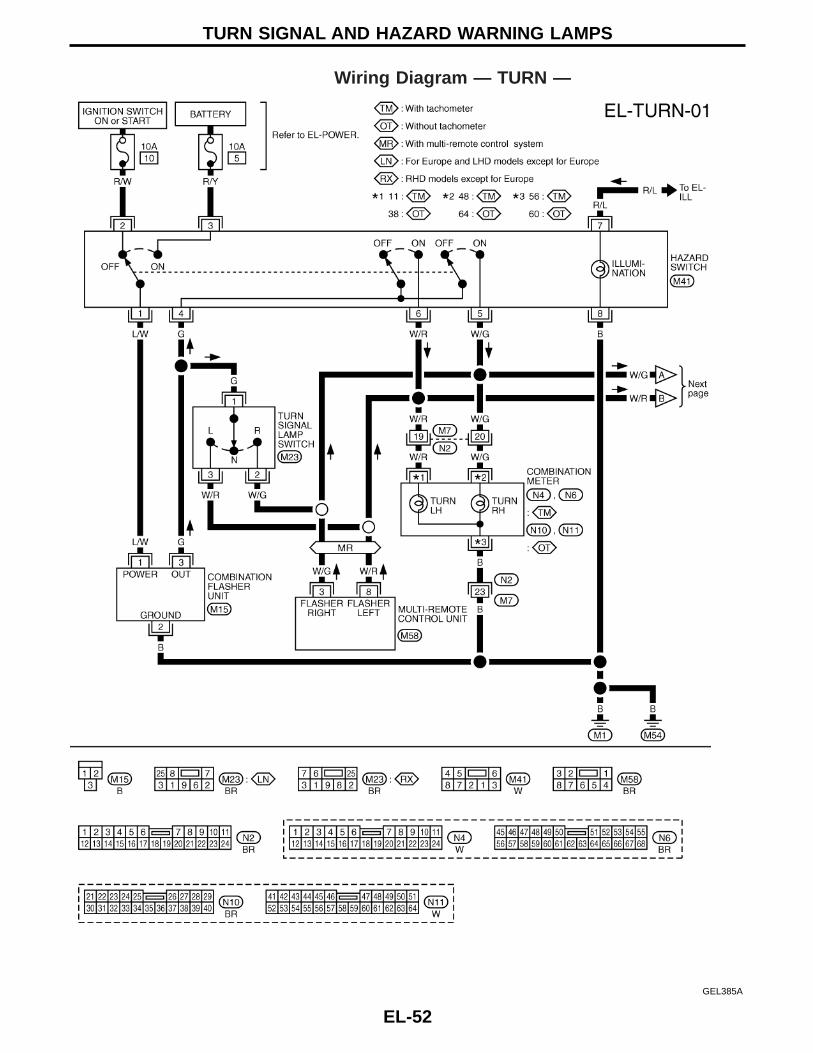
Wiring Diagram — TURN —
GEL385A
TURN SIGNAL AND HAZARD WARNING LAMPS
EL-52

GEL463A
TURN SIGNAL AND HAZARD WARNING LAMPSWiring Diagram — TURN — (Cont’d)
EL-53
GI
MA
EM
LC
EC
FE
CL
MT
AT
TF
PD
FA
RA
BR
ST
RS
BT
HA
IDX

Trouble Diagnoses
Symptom Possible cause Repair order
Turn signal and hazard warninglamps do not operate.
1. Hazard switch2. Combination flasher unit3. Open in combination flasher unit
circuit
1. Check hazard switch.2. Refer to combination flasher unit check.3. Check wiring to combination flasher unit for open cir-
cuit.
Turn signal lamps do not operatebut hazard warning lamps operate.
1. 10A fuse
2. Hazard switch3. Turn signal switch4. Open in turn signal switch circuit
1. Check 10A fuse (No. 10 , located in fuse block).Turn ignition switch ON and verify battery positivevoltage is present at terminal q2 (R/W) of hazardswitch.
2. Check hazard switch.3. Check turn signal switch.4. Check G wire between combination flasher unit and
turn signal switch for open circuit.
Hazard warning lamps do not oper-ate but turn signal lamps operate.
1. 10A fuse
2. Hazard switch3. Open in hazard switch circuit
1. Check 10A fuse (No. 5 , located in fuse block).Verify battery positive voltage is present at terminalq3 (R/Y) of hazard switch.
2. Check hazard switch.3. Check G wire between combination flasher unit and
hazard switch for open circuit.
Front or side turn signal lamp LHor RH does not operate.
1. Bulb2. Grounds E6 and E39
1. Check bulb.2. Check grounds E6 and E39 .
Rear turn signal lamp LH or RHdoes not operate.
1. Bulb2. Grounds M1 and M54
1. Check bulb.2. Check grounds M1 and M54 .
LH and RH turn indicators do notoperate.
1. Ground 1. Check grounds M1 and M54 .
LH or RH turn indicator does notoperate.
1. Bulb 1. Check bulb in combination meter.
TURN SIGNAL AND HAZARD WARNING LAMPS
EL-54

Wiring Diagram — ILL —/LHD Models
GEL249A
ILLUMINATION
EL-55
GI
MA
EM
LC
EC
FE
CL
MT
AT
TF
PD
FA
RA
BR
ST
RS
BT
HA
IDX

GEL386A
ILLUMINATIONWiring Diagram — ILL —/LHD Models (Cont’d)
EL-56

Wiring Diagram — ILL —/RHD Models
GEL387A
ILLUMINATION
EL-57
GI
MA
EM
LC
EC
FE
CL
MT
AT
TF
PD
FA
RA
BR
ST
RS
BT
HA
IDX

GEL388A
ILLUMINATIONWiring Diagram — ILL —/RHD Models (Cont’d)
EL-58

Wiring Diagram — ROOM/L —
GEL389A
INTERIOR ROOM LAMP
EL-59
GI
MA
EM
LC
EC
FE
CL
MT
AT
TF
PD
FA
RA
BR
ST
RS
BT
HA
IDX

Wiring Diagram — INT/L —
GEL252A
SPOT LAMP
EL-60

System DescriptionUNIFIED CONTROL METERI Speedometer, odo/trip meter, tachometer, fuel gauge and water temperature gauge are controlled totally
by control unit.I Digital meter is adopted for odo/trip meter.*
*The record of the odo meter is kept even if the battery cable is disconnected. The record of the trip meteris erased when the battery cable is disconnected.
I Odo/trip meter segment can be checked in diagnosis mode.I Meter/gauge can be checked in diagnosis mode.
HOW TO CHANGE THE DISPLAY FOR ODO/TRIP METER
Note:Turn ignition switch to the “ON” position to operate odo/trip meter.
SEL253V
METER AND GAUGES
EL-61
GI
MA
EM
LC
EC
FE
CL
MT
AT
TF
PD
FA
RA
BR
ST
RS
BT
HA
IDX

Combination Meter/With Tachometer
HEL890B
METER AND GAUGES
EL-62

Combination Meter/Without Tachometer
HEL891B
METER AND GAUGES
EL-63
GI
MA
EM
LC
EC
FE
CL
MT
AT
TF
PD
FA
RA
BR
ST
RS
BT
HA
IDX

Schematic/With Tachometer
GEL390A
METER AND GAUGES
EL-64
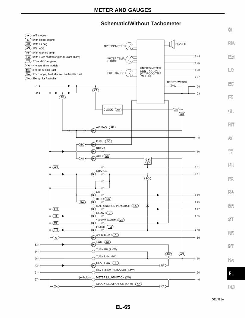
Schematic/Without Tachometer
GEL391A
METER AND GAUGES
EL-65
GI
MA
EM
LC
EC
FE
CL
MT
AT
TF
PD
FA
RA
BR
ST
RS
BT
HA
IDX

ConstructionWITH TACHOMETER
WITHOUT TACHOMETER
SEL450Y
JEL268Y
METER AND GAUGES
EL-66

Wiring Diagram — METER —/Gasoline Enginewith Tachometer
GEL392A
METER AND GAUGES
EL-67
GI
MA
EM
LC
EC
FE
CL
MT
AT
TF
PD
FA
RA
BR
ST
RS
BT
HA
IDX

GEL256A
METER AND GAUGESWiring Diagram — METER —/Gasoline Enginewith Tachometer (Cont’d)
EL-68

Wiring Diagram — METER —/Gasoline Enginewithout Tachometer
GEL397A
METER AND GAUGES
EL-69
GI
MA
EM
LC
EC
FE
CL
MT
AT
TF
PD
FA
RA
BR
ST
RS
BT
HA
IDX

Wiring Diagram — METER —/LHD DieselEngine Models with Tachometer
GEL393A
METER AND GAUGES
EL-70

GEL394A
METER AND GAUGESWiring Diagram — METER —/LHD DieselEngine Models with Tachometer (Cont’d)
EL-71
GI
MA
EM
LC
EC
FE
CL
MT
AT
TF
PD
FA
RA
BR
ST
RS
BT
HA
IDX

Wiring Diagram — METER —/RHD DieselEngine Models with Tachometer
GEL395A
METER AND GAUGES
EL-72

GEL396A
METER AND GAUGESWiring Diagram — METER —/RHD DieselEngine Models with Tachometer (Cont’d)
EL-73
GI
MA
EM
LC
EC
FE
CL
MT
AT
TF
PD
FA
RA
BR
ST
RS
BT
HA
IDX

Wiring Diagram — METER —/Diesel Enginewithout Tachometer
GEL398A
METER AND GAUGES
EL-74

Meter/Gauge Operation and Odo/Trip MeterSegment Check in Diagnosis ModeDIAGNOSIS FUNCTIONI Odo/trip meter segment can be checked in diagnosis mode.I Meters/gauges can be checked in diagnosis mode.
HOW TO ALTERNATE DIAGNOSIS MODE1. Turn ignition switch to ON and change odo/trip meter to “TRIP
A” or “TRIP B”.2. Turn ignition switch to OFF.3. Turn ignition switch to ON when pushing odo/trip meter switch.4. Confirm that trip meter indicates “000.0”.5. Push odo/trip meter switch more than three times within 5 sec-
onds.
6. All odo/trip meter segments should be turned on.NOTE: If some segments are not turned on, unified meter con-
trol unit with odo/trip meter should be replaced.At this point, the unified control meter is turned to diagnosismode.
7. Push odo/trip meter switch. Indication of each meter/gaugeshould be as shown left during pushing odo/trip meter switch ifit is no malfunctioning.
NOTE: It takes about a few seconds for indication of fuelgauge to become stable.
SEL110V
SEL111VA
SEL427W
METER AND GAUGES
EL-75
GI
MA
EM
LC
EC
FE
CL
MT
AT
TF
PD
FA
RA
BR
ST
RS
BT
HA
IDX

Trouble Diagnoses/With TachometerPRELIMINARY CHECK
*1:Meter/Gauge Operation and Odo/Trip Meter Segment Check in Diagno-sis Mode (EL-75)
*2:POWER SUPPLY AND GROUNDCIRCUIT CHECK (EL-77)
*3:Symptom Chart (EL-76)
SYMPTOM CHART
Symptom Possible causes Repair order
One of speedometer/fuel gauge/watertemp. gauge is malfunctioning. 1. Sensor signal
- Vehicle speed signal- Fuel gauge- Water temp. gauge
2. Unified meter control unit
1. Check the sensor for malfunctioningmeter/gauge. INSPECTION/VEHICLESPEED SIGNAL (Refer to EL section“Vehicle speed signal” in original Ser-vice Manual.)INSPECTION/FUEL LEVEL SENSORUNIT INSPECTION/THERMAL TRANS-MITTER
2. Replace unified meter control unit.
Multiple meter/gauge are malfunctioning.(except odo/trip meter)
Before starting trouble diagnoses below, perform PRELIMINARY CHECK, EL-76.
SEL269Y
METER AND GAUGES
EL-76
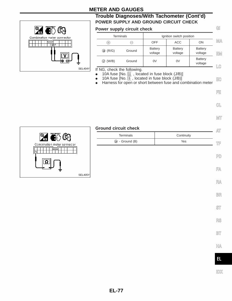
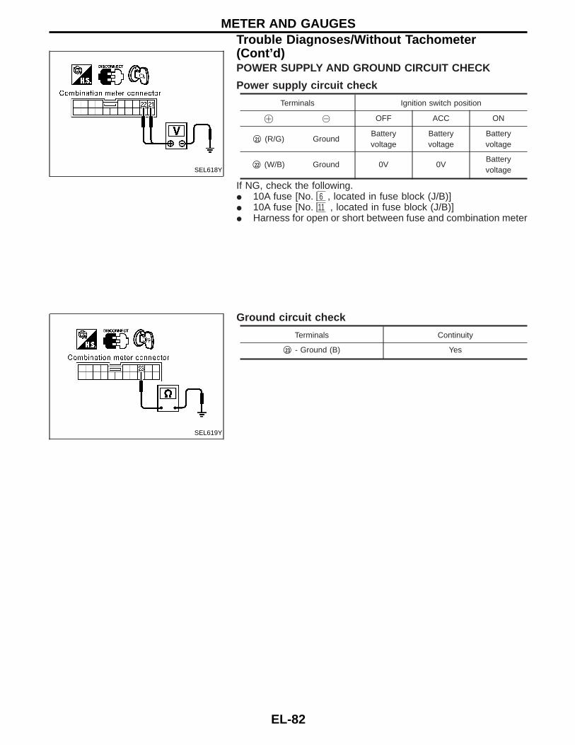
POWER SUPPLY AND GROUND CIRCUIT CHECK
Power supply circuit check
Terminals Ignition switch position
! @ OFF ACC ON
q18 (R/G) GroundBatteryvoltage
Batteryvoltage
Batteryvoltage
q17 (W/B) Ground 0V 0VBatteryvoltage
If NG, check the following.I 10A fuse [No. 11 , located in fuse block (J/B)]I 10A fuse [No. 6 , located in fuse block (J/B)]I Harness for open or short between fuse and combination meter
Ground circuit check
Terminals Continuity
q24 - Ground (B) Yes
SEL404Y
SEL405Y
METER AND GAUGESTrouble Diagnoses/With Tachometer (Cont’d)
EL-77
GI
MA
EM
LC
EC
FE
CL
MT
AT
TF
PD
FA
RA
BR
ST
RS
BT
HA
IDX

INSPECTION/VEHICLE SPEED SENSOR
Without ABS for the Middle East and Except for theMiddle East
CHECK VEHICLE SPEED SENSOROUTPUT.1. Remove vehicle speed sensor from
transmission.2. Check voltage between combination
meter connector N4 terminals q22 (W)and q23 (R) while quickly turning speedsensor pinion.Voltage: Approx. 0.5V
NG
EOK Vehicle speed sensor is
OK.
CHECK VEHICLE SPEED SENSOR.Check resistance between vehicle speedsensor connector E223 terminals q1 (W)and q2 (R).Resistance: Approx. 250 Ω
OK
ENG Replace vehicle speed
sensor.
Check harness for open or short betweencombination meter and vehicle speed sen-sor.
INSPECTION/ENGINE REVOLUTION SIGNAL
CHECK ECM OUTPUT.1. Start engine.2. Check voltage between combination
meter terminal q21 (W) and ground atidle and 2,000 rpm.Higher rpm = Higher voltageLower rpm = Lower voltageVoltage should change with rpm.
NG
EOK Engine revolution signal is
OK.
Check the following.I Harness for open or short between ECM
and combination meter
SEL406Y
SEL447VA
SEL407Y
H
H
H
METER AND GAUGESTrouble Diagnoses/With Tachometer (Cont’d)
EL-78

INSPECTION/FUEL LEVEL SENSOR UNIT
CHECK GROUND CIRCUIT FOR FUELLEVEL SENSOR UNIT.Check harness continuity between fuellevel sensor unit connector C3 terminalq1 (B) and ground.Continuity should exist.
OK
ENG Repair harness or connec-
tor.
CHECK GAUGE UNITS.Refer to EL section “FUEL LEVEL SEN-SOR UNIT” in original Service ManualPub. No. SM7E-0D22G1.
OK
ENG Repair or replace.
Refer to FE section of Ser-vice Manual Pub. No.SM7E-0D22G1.
CHECK HARNESS FOR OPEN ORSHORT.1. Disconnect combination connector and
fuel level sensor unit connector.2. Check continuity between combination
meter terminal q20 (Y/G) and fuel levelsensor unit connector C3 terminal q3(Y/G).
Continuity should exist.3. Check continuity between combination
meter terminal q20 (Y/G) and ground.Continuity should not exist.
OK
ENG Repair harness or connec-
tor.
Fuel level sensor unit is OK.
SEL639Y
SEL409Y
H
H
H
METER AND GAUGESTrouble Diagnoses/With Tachometer (Cont’d)
EL-79
GI
MA
EM
LC
EC
FE
CL
MT
AT
TF
PD
FA
RA
BR
ST
RS
BT
HA
IDX

INSPECTION/THERMAL TRANSMITTER
CHECK THERMAL TRANSMITTER.Refer to EL section “THERMAL TRANS-MITTER” in original Service Manual Pub.No. SM7E-0D22G1.
OK
ENG
Repair or replace.
CHECK HARNESS FOR OPEN ORSHORT.1. Disconnect combination connector and
thermal transmitter connector.2. Check continuity between combination
meter terminal q19 (Y/R) and thermaltransmitter connector E9 , M209 , E209terminal q1 .
Continuity should exist.3. Check continuity between combination
meter terminal q19 (Y/R) and ground.Continuity should not exist.
OK
ENG
Repair harness or connec-tor.
Thermal transmitter is OK.SEL410Y
H
H
METER AND GAUGESTrouble Diagnoses/With Tachometer (Cont’d)
EL-80

Trouble Diagnoses/Without TachometerPRELIMINARY CHECK
*1:Meter/Gauge Operation and Odo/Trip Meter Segment Check in Diagno-sis Mode (EL-75)
*2:POWER SUPPLY AND GROUNDCIRCUIT CHECK (EL-82)
*3:Symptom Chart (EL-81)
SYMPTOM CHART
Symptom Possible causes Repair order
One of speedometer/fuel gauge/watertemp. gauge is malfunctioning. 1. Sensor signal
- Vehicle speed signal- Fuel gauge- Water temp. gauge
2. Unified meter control unit
1. Check the sensor for malfunctioningmeter/gauge. INSPECTION/VEHICLESPEED SIGNAL (Refer to EL section“Vehicle speed signal” in original Ser-vice Manual.)INSPECTION/FUEL LEVEL SENSORUNIT INSPECTION/THERMAL TRANS-MITTER
2. Replace unified meter control unit.
Multiple meter/gauge are malfunctioning.(except odo/trip meter)
Before starting trouble diagnoses below, perform PRELIMINARY CHECK, EL-81.
SEL269Y
METER AND GAUGES
EL-81
GI
MA
EM
LC
EC
FE
CL
MT
AT
TF
PD
FA
RA
BR
ST
RS
BT
HA
IDX
POWER SUPPLY AND GROUND CIRCUIT CHECK
Power supply circuit check
Terminals Ignition switch position
! @ OFF ACC ON
q21 (R/G) GroundBatteryvoltage
Batteryvoltage
Batteryvoltage
q22 (W/B) Ground 0V 0VBatteryvoltage
If NG, check the following.I 10A fuse [No. 6 , located in fuse block (J/B)]I 10A fuse [No. 11 , located in fuse block (J/B)]I Harness for open or short between fuse and combination meter
Ground circuit check
Terminals Continuity
q23 - Ground (B) Yes
SEL618Y
SEL619Y
METER AND GAUGESTrouble Diagnoses/Without Tachometer(Cont’d)
EL-82

INSPECTION/VEHICLE SPEED SENSOR
Without ABS for the Middle East and Except for theMiddle East
CHECK VEHICLE SPEED SENSOROUTPUT.1. Remove vehicle speed sensor from
transmission.2. Check voltage between combination
meter connector N10 terminals q24 (W)and q37 (R) while quickly turning speedsensor pinion.Voltage: Approx. 0.5V
NG
EOK Vehicle speed sensor is
OK.
CHECK VEHICLE SPEED SENSOR.Check resistance between vehicle speedsensor connector E223 terminals q1 (W)and q2 (R).Resistance: Approx. 250 Ω
OK
ENG Replace vehicle speed
sensor.
Check harness for open or short betweencombination meter and vehicle speed sen-sor.
SEL620Y
SEL447VA
H
H
METER AND GAUGESTrouble Diagnoses/Without Tachometer(Cont’d)
EL-83
GI
MA
EM
LC
EC
FE
CL
MT
AT
TF
PD
FA
RA
BR
ST
RS
BT
HA
IDX
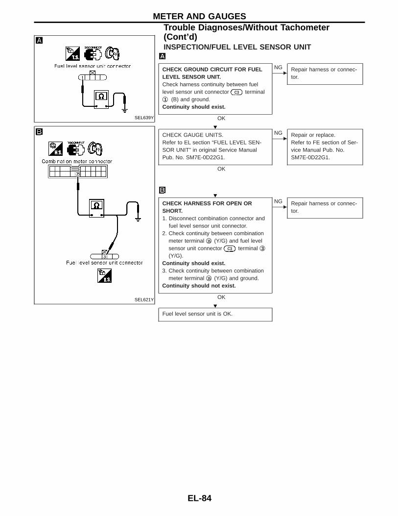
INSPECTION/FUEL LEVEL SENSOR UNIT
CHECK GROUND CIRCUIT FOR FUELLEVEL SENSOR UNIT.Check harness continuity between fuellevel sensor unit connector C3 terminalq1 (B) and ground.Continuity should exist.
OK
ENG Repair harness or connec-
tor.
CHECK GAUGE UNITS.Refer to EL section “FUEL LEVEL SEN-SOR UNIT” in original Service ManualPub. No. SM7E-0D22G1.
OK
ENG Repair or replace.
Refer to FE section of Ser-vice Manual Pub. No.SM7E-0D22G1.
CHECK HARNESS FOR OPEN ORSHORT.1. Disconnect combination connector and
fuel level sensor unit connector.2. Check continuity between combination
meter terminal q35 (Y/G) and fuel levelsensor unit connector C3 terminal q3(Y/G).
Continuity should exist.3. Check continuity between combination
meter terminal q35 (Y/G) and ground.Continuity should not exist.
OK
ENG Repair harness or connec-
tor.
Fuel level sensor unit is OK.
SEL639Y
SEL621Y
H
H
H
METER AND GAUGESTrouble Diagnoses/Without Tachometer(Cont’d)
EL-84

INSPECTION/THERMAL TRANSMITTER
CHECK THERMAL TRANSMITTER.Refer to EL section “THERMAL TRANS-MITTER” in original Service Manual Pub.No. SM7E-0D22G1.
OK
ENG
Repair or replace.
CHECK HARNESS FOR OPEN ORSHORT.1. Disconnect combination connector and
thermal transmitter connector.2. Check continuity between combination
meter terminal q34 (Y/R) and thermaltransmitter connector E9 , M209 , E209terminal q1 .
Continuity should exist.3. Check continuity between combination
meter terminal q34 (Y/R) and ground.Continuity should not exist.
OK
ENG
Repair harness or connec-tor.
Thermal transmitter is OK.SEL622Y
H
H
METER AND GAUGESTrouble Diagnoses/Without Tachometer(Cont’d)
EL-85
GI
MA
EM
LC
EC
FE
CL
MT
AT
TF
PD
FA
RA
BR
ST
RS
BT
HA
IDX

Schematic/With Tachometer
GEL399A
WARNING LAMPS
EL-86

Schematic/Without Tachometer
GEL408A
WARNING LAMPS
EL-87
GI
MA
EM
LC
EC
FE
CL
MT
AT
TF
PD
FA
RA
BR
ST
RS
BT
HA
IDX

Wiring Diagram — WARN —/Gasoline Enginewith Tachometer
GEL400A
WARNING LAMPS
EL-88

GEL401A
WARNING LAMPSWiring Diagram — WARN —/Gasoline Enginewith Tachometer (Cont’d)
EL-89
GI
MA
EM
LC
EC
FE
CL
MT
AT
TF
PD
FA
RA
BR
ST
RS
BT
HA
IDX

GEL402A
WARNING LAMPSWiring Diagram — WARN —/Gasoline Enginewith Tachometer (Cont’d)
EL-90

GEL403A
WARNING LAMPSWiring Diagram — WARN —/Gasoline Enginewith Tachometer (Cont’d)
EL-91
GI
MA
EM
LC
EC
FE
CL
MT
AT
TF
PD
FA
RA
BR
ST
RS
BT
HA
IDX

Wiring Diagram — WARN —/Gasoline Enginewithout Tachometer
GEL409A
WARNING LAMPS
EL-92

GEL410A
WARNING LAMPSWiring Diagram — WARN —/Gasoline Enginewithout Tachometer (Cont’d)
EL-93
GI
MA
EM
LC
EC
FE
CL
MT
AT
TF
PD
FA
RA
BR
ST
RS
BT
HA
IDX

GEL411A
WARNING LAMPSWiring Diagram — WARN —/Gasoline Enginewithout Tachometer (Cont’d)
EL-94

GEL412A
WARNING LAMPSWiring Diagram — WARN —/Gasoline Enginewithout Tachometer (Cont’d)
EL-95
GI
MA
EM
LC
EC
FE
CL
MT
AT
TF
PD
FA
RA
BR
ST
RS
BT
HA
IDX
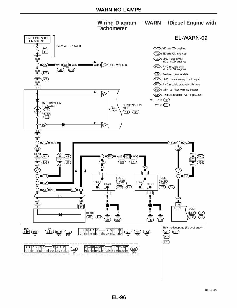
Wiring Diagram — WARN —/Diesel Engine withTachometer
GEL404A
WARNING LAMPS
EL-96

GEL405A
WARNING LAMPSWiring Diagram — WARN —/Diesel Engine withTachometer (Cont’d)
EL-97
GI
MA
EM
LC
EC
FE
CL
MT
AT
TF
PD
FA
RA
BR
ST
RS
BT
HA
IDX

GEL406A
WARNING LAMPSWiring Diagram — WARN —/Diesel Engine withTachometer (Cont’d)
EL-98

GEL407A
WARNING LAMPSWiring Diagram — WARN —/Diesel Engine withTachometer (Cont’d)
EL-99
GI
MA
EM
LC
EC
FE
CL
MT
AT
TF
PD
FA
RA
BR
ST
RS
BT
HA
IDX

Wiring Diagram — WARN —/Diesel Enginewithout Tachometer
GEL413A
WARNING LAMPS
EL-100

GEL414A
WARNING LAMPSWiring Diagram — WARN —/Diesel Enginewithout Tachometer (Cont’d)
EL-101
GI
MA
EM
LC
EC
FE
CL
MT
AT
TF
PD
FA
RA
BR
ST
RS
BT
HA
IDX

GEL415A
WARNING LAMPSWiring Diagram — WARN —/Diesel Enginewithout Tachometer (Cont’d)
EL-102

GEL416A
WARNING LAMPSWiring Diagram — WARN —/Diesel Enginewithout Tachometer (Cont’d)
EL-103
GI
MA
EM
LC
EC
FE
CL
MT
AT
TF
PD
FA
RA
BR
ST
RS
BT
HA
IDX

GEL417A
WARNING LAMPSWiring Diagram — WARN —/Diesel Enginewithout Tachometer (Cont’d)
EL-104

Wiring Diagram — AT/IND —/RHD Models
GEL418A
A/T INDICATOR
EL-105
GI
MA
EM
LC
EC
FE
CL
MT
AT
TF
PD
FA
RA
BR
ST
RS
BT
HA
IDX

Wiring Diagram — CHIME —/Diesel EngineExcept for Europe, Australia and The MiddleEast
FUEL FILTER WARNING BUZZER
GEL419A
WARNING CHIME
EL-106

Wiring Diagram — CHIME —/LHD Models forEurope
LIGHT WARNING BUZZER
GEL420A
WARNING CHIME
EL-107
GI
MA
EM
LC
EC
FE
CL
MT
AT
TF
PD
FA
RA
BR
ST
RS
BT
HA
IDX

Wiring Diagram — CHIME —/RHD Models forEurope
LIGHT WARNING BUZZER
GEL421A
WARNING CHIME
EL-108

Wiring Diagram — WIPER —/With Intermittentfor Floor-shift
LHD MODELS AND RHD MODELS FOR TD, QD ENGINES
GEL424A
FRONT WIPER AND WASHER
EL-109
GI
MA
EM
LC
EC
FE
CL
MT
AT
TF
PD
FA
RA
BR
ST
RS
BT
HA
IDX

Wiring Diagram — WIPER —/WithoutIntermittent for Floor-shift
LHD MODELS AND RHD MODELS FOR Z, TD, QD ENGINES
GEL422A
FRONT WIPER AND WASHER
EL-110

RHD MODELS KA, ZD ENGINES
GEL423A
FRONT WIPER AND WASHERWiring Diagram — WIPER —/WithoutIntermittent for Floor-shift (Cont’d)
EL-111
GI
MA
EM
LC
EC
FE
CL
MT
AT
TF
PD
FA
RA
BR
ST
RS
BT
HA
IDX

RHD MODELS EXCEPT FOR TD, QD ENGINES
GEL425A
FRONT WIPER AND WASHERWiring Diagram — WIPER —/WithoutIntermittent for Floor-shift (Cont’d)
EL-112

GEL426A
FRONT WIPER AND WASHERWiring Diagram — WIPER —/WithoutIntermittent for Floor-shift (Cont’d)
EL-113
GI
MA
EM
LC
EC
FE
CL
MT
AT
TF
PD
FA
RA
BR
ST
RS
BT
HA
IDX

Wiring Diagram — WIPER —/WithoutIntermittent for RHD Column-shift Models
GEL427A
FRONT WIPER AND WASHER
EL-114

GEL428A
FRONT WIPER AND WASHERWiring Diagram — WIPER —/WithoutIntermittent for RHD Column-shift Models(Cont’d)
EL-115
GI
MA
EM
LC
EC
FE
CL
MT
AT
TF
PD
FA
RA
BR
ST
RS
BT
HA
IDX

Wiring Diagram — HLC —
GEL429A
HEADLAMP WASHER
EL-116

Wiring Diagram — HORN —
GEL274A
HORN
EL-117
GI
MA
EM
LC
EC
FE
CL
MT
AT
TF
PD
FA
RA
BR
ST
RS
BT
HA
IDX

Wiring Diagram — CIGAR —
GEL275A
CIGARETTE LIGHTER
EL-118
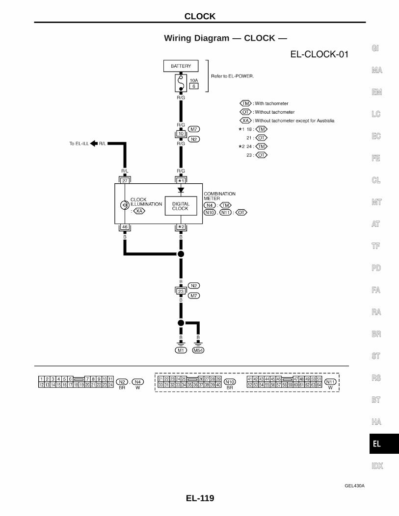
Wiring Diagram — CLOCK —
GEL430A
CLOCK
EL-119
GI
MA
EM
LC
EC
FE
CL
MT
AT
TF
PD
FA
RA
BR
ST
RS
BT
HA
IDX

Wiring Diagram — DEF —
GEL431A
REAR WINDOW DEFOGGER AND MIRROR DEFOGGER
EL-120

Wiring Diagram — AUDIO —/LHD ModelsExcept for Europe
WITH 1-SPEAKER
GEL432A
AUDIO
EL-121
GI
MA
EM
LC
EC
FE
CL
MT
AT
TF
PD
FA
RA
BR
ST
RS
BT
HA
IDX

WITH 2 OR 4 SPEAKERS
GEL433A
AUDIOWiring Diagram — AUDIO —/LHD ModelsExcept for Europe (Cont’d)
EL-122

GEL434A
AUDIOWiring Diagram — AUDIO —/LHD ModelsExcept for Europe (Cont’d)
EL-123
GI
MA
EM
LC
EC
FE
CL
MT
AT
TF
PD
FA
RA
BR
ST
RS
BT
HA
IDX

Wiring Diagram — AUDIO —/LHD Models forEurope
GEL435A
AUDIO
EL-124

Wiring Diagram — AUDIO —/RHD ModelsExcept for EUROPE
GEL436A
AUDIO
EL-125
GI
MA
EM
LC
EC
FE
CL
MT
AT
TF
PD
FA
RA
BR
ST
RS
BT
HA
IDX

Wiring Diagram — AUDIO —/RHD Models forEurope
GEL437A
AUDIO
EL-126

Power Antenna/Wiring Diagram — P/ANT —
GEL438A
AUDIO ANTENNA
EL-127
GI
MA
EM
LC
EC
FE
CL
MT
AT
TF
PD
FA
RA
BR
ST
RS
BT
HA
IDX

Wiring Diagram — MIRROR —/LHD ModelsExcept for The Middle East
GEL439A
POWER DOOR MIRROR
EL-128

Wiring Diagram — MIRROR —/LHD Models forThe Middle East
GEL466A
POWER DOOR MIRROR
EL-129
GI
MA
EM
LC
EC
FE
CL
MT
AT
TF
PD
FA
RA
BR
ST
RS
BT
HA
IDX

Wiring Diagram — MIRROR —/RHD Models
GEL440A
POWER DOOR MIRROR
EL-130

Wiring Diagram — H/SEAT —
GEL441A
HEATED SEAT
EL-131
GI
MA
EM
LC
EC
FE
CL
MT
AT
TF
PD
FA
RA
BR
ST
RS
BT
HA
IDX

GEL442A
HEATED SEATWiring Diagram — H/SEAT — (Cont’d)
EL-132

Schematic/Without Interruption DetectionFunction
GEL281A
POWER WINDOW
EL-133
GI
MA
EM
LC
EC
FE
CL
MT
AT
TF
PD
FA
RA
BR
ST
RS
BT
HA
IDX

Schematic/With Interruption Detection Function
GEL286A
POWER WINDOW
EL-134

Wiring Diagram — WINDOW —/WithoutInterruption Detection Function
GEL282A
POWER WINDOW
EL-135
GI
MA
EM
LC
EC
FE
CL
MT
AT
TF
PD
FA
RA
BR
ST
RS
BT
HA
IDX

GEL283A
POWER WINDOWWiring Diagram — WINDOW —/WithoutInterruption Detection Function (Cont’d)
EL-136
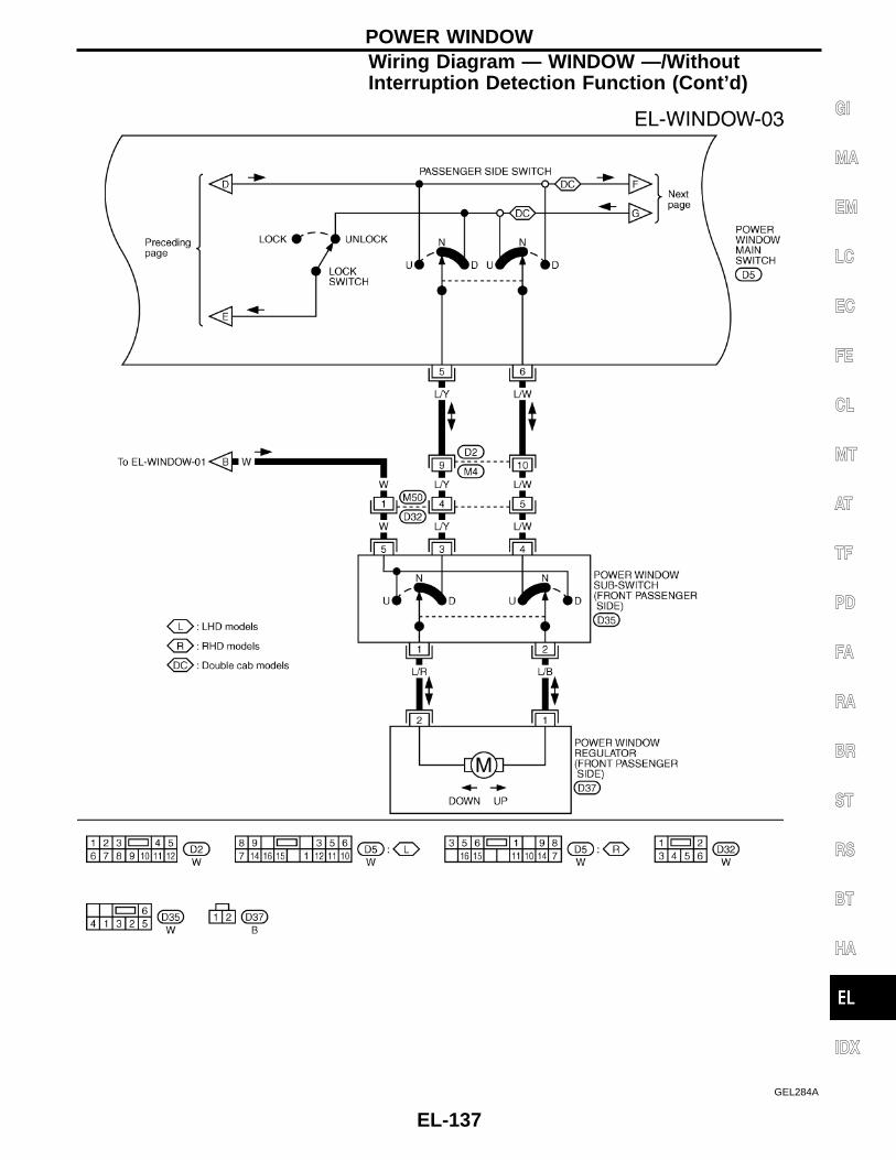
GEL284A
POWER WINDOWWiring Diagram — WINDOW —/WithoutInterruption Detection Function (Cont’d)
EL-137
GI
MA
EM
LC
EC
FE
CL
MT
AT
TF
PD
FA
RA
BR
ST
RS
BT
HA
IDX

GEL285A
POWER WINDOWWiring Diagram — WINDOW —/WithoutInterruption Detection Function (Cont’d)
EL-138

Wiring Diagram — WINDOW —/WithInterruption Detection Function
GEL287A
POWER WINDOW
EL-139
GI
MA
EM
LC
EC
FE
CL
MT
AT
TF
PD
FA
RA
BR
ST
RS
BT
HA
IDX

GEL288A
POWER WINDOWWiring Diagram — WINDOW —/WithInterruption Detection Function (Cont’d)
EL-140

GEL289A
POWER WINDOWWiring Diagram — WINDOW —/WithInterruption Detection Function (Cont’d)
EL-141
GI
MA
EM
LC
EC
FE
CL
MT
AT
TF
PD
FA
RA
BR
ST
RS
BT
HA
IDX

GEL290A
POWER WINDOWWiring Diagram — WINDOW —/WithInterruption Detection Function (Cont’d)
EL-142

Trouble Diagnoses/For Europe withoutInterruption Detection Function
Symptom Possible cause Repair order
None of the power windows can beoperated using any switch.
1. 40A fusible link and circuitbreaker-1
2. Grounds M1 and M54
3. Power window relay4. Open/short in power window
main switch circuit
1. Check 40A fusible link (letter c , located in fusible linkand fuse box) and circuit breaker-1, located in fuseblock. Turn ignition switch “ON” and verify battery posi-tive voltage is present at terminal q1 of power windowmain switch and terminal q5 of sub-switch.
2. Check grounds M1 and M54 .3. Check power window relay.4. Check harness between power window relay and
power window main switch for open/short circuit.
Driver side power window cannot beoperated but other windows can beoperated.
1. Driver side power window regula-tor circuit
2. Driver side power window regula-tor
1. Check harness between power window main switchand power window regulator for open or short circuit.
2. Check driver side power window regulator.
One or some of power windowexcept driver side power windowcannot be operated.
1. Power window sub-switch2. Passenger side power window
regulator3. Power window main switch4. Power window circuit
1. Check power window sub-switch.2. Check power window regulator of malfunctioning
power window.3. Check power window main switch.4-1. Check harnesses between power window main
switch and power window sub-switch for open/shortcircuit.
4-2. Check harnesses between power window sub-switch and power window regulator for open/shortcircuit.
Passenger power window cannot beoperated using power window mainswitch but can be operated by powerwindow sub-switch.
1. Power window main switch 1. Check power window main switch.
Driver side power window auto func-tion cannot be operated using powerwindow main switch.
1. Power window main switch 1. Check power window main switch.
POWER WINDOW
EL-143
GI
MA
EM
LC
EC
FE
CL
MT
AT
TF
PD
FA
RA
BR
ST
RS
BT
HA
IDX

Trouble Diagnoses/For Europe with InterruptionDetection Function
Symptom Possible cause Repair order
None of the power windows can beoperated using any switch.
1. 10A fuse, 40A fusible link
2. Ground circuit
3. Power window main switch
1. Check 10A fuse [No. 12 , located in fuse block (J/B)],40A fusible link (letter c , located in fuse and fusiblelink box).
2. Check ground circuit of power window main switchterminal q19 .
3. Check power window main switch.
Driver side power window cannot beoperated but other windows can beoperated.
1. Driver side power window regula-tor circuit
2. Driver side power window regula-tor
3. M52 circuit breaker-24. M52 circuit breaker-2 circuit
5. Power window main switch circuit
1. Check harness between power window main switchand driver side power window regulator for open orshort circuit.
2. Check driver side power window regulator.
3. Check M52 circuit breaker-2.4. Check harness between M52 circuit breaker-2 and
40A fusible link (letter c , located in fuse and fusiblelink box).
5-1. Check harness between power window main switchterminal q13 and 10A fuse [No. 12 , located in fuseblock (J/B)].
5-2. Check harness between power window main switchterminal q5 and M52 circuit breaker.
One or more power windows exceptdriver’s side window cannot be oper-ated.
1. Power window sub-switches2. Power window regulators3. Power window main switch4. Power window circuit
1. Check power window sub-switch.2. Check power window regulator.3. Check power window main switch.4-1. Check harnesses between power window main
switch and power window sub-switch for open/short circuit.
4-2. Check harnesses between power window sub-switch and power window regulator for open/short circuit.
Power windows except driver’s sidewindow cannot be operated usingpower window main switch but canbe operated by power window sub-switch.
1. Power window main switch 1. Check power window main switch.
Driver side power window automaticoperation does not function properly.
1. Power window main switch2. Encoder and limit switch
1. Check power window main switch.2. Check encoder and limit switch. (EL-145)
Timer control for supplying powerafter turning ignition switch to “OFF”does not operate properly. (Exceptmodels for Europe)
1. Driver side door switch circuit
2. Driver side door switch3. Ignition switch ON signal circuit
4. Power window main switch
1. Check harness between driver side door switch andpower window main switch.
2. Check driver side door switch.3. Check ignition switch ON signal circuit to power win-
dow main switch.4. Check power window main switch.
POWER WINDOW
EL-144

ENCODER AND LIMIT SWITCH CHECK
CHECK DOOR WINDOW SLIDEMECHANISMCheck the following.- Obstacles in window, glass molding, etc.- Worn or deformed glass molding- Door sash tilted too far inward or out-
ward- Door window regulator
OK
ENG
Remove obstacles orrepair door window slidemechanism.
CHECK POWER SUPPLY TO LIMITSWITCH1. Disconnect driver side power window
regulator connector.2. Turn ignition switch ON.3. Check voltage between power window
main switch terminal q9 and ground.Approx. 5V should exist.
OK
ENG
Replace power windowmain switch.
CHECK LIMIT SWITCH OPERATION1. Turn ignition switch OFF.2. Connect driver side power window
regulator connector.3. Turn ignition switch ON.4. Check voltage between power window
main switch terminal q9 and groundduring power window closing operation.
NG
EOK
CHECK ENCODERMeasure voltage betweenpower window main switchterminal q16 and groundwith oscilloscope whenpower window is in auto-matic closing operation.If check result is NG,replace power windowregulator motor (frontdriver side).If check result is OK,replace power windowmain switch.
RESET LIMIT SWITCHReset limit switch. Refer to BT section.Then check voltage between power win-dow main switch terminal q9 and groundduring power window closing operation atleast ten times.
OK
ENG
Replace power windowregulator motor (frontdriver side).
CHECK ENCODERMeasure voltage between power windowmain switch terminal q16 and ground withoscilloscope when power window is inautomatic closing operation.
OK
ENG
Replace power windowregulator motor (frontdriver side).
Replace power window main switch.
Terminal No. Condition Voltage (DCV)
q9
Approx. 15 mm(0.59 in) belowthe full closedposition to fullclosed position
Approx. 5
Other positions Approx. 0
Terminal No. Condition Voltage (DCV)
q9
Approx. 15 mm(0.59 in) belowthe full closedposition to fullclosed position
Approx. 5
Other positions Approx. 0
SEL408W
SEL407W
H
H
H
H
H
POWER WINDOWTrouble Diagnoses/For Europe with InterruptionDetection Function (Cont’d)
EL-145
GI
MA
EM
LC
EC
FE
CL
MT
AT
TF
PD
FA
RA
BR
ST
RS
BT
HA
IDX

Wiring Diagram — D/LOCK —
GEL291A
POWER DOOR LOCK/EXCEPT FOR EUROPE
EL-146

GEL292A
POWER DOOR LOCK/EXCEPT FOR EUROPEWiring Diagram — D/LOCK — (Cont’d)
EL-147
GI
MA
EM
LC
EC
FE
CL
MT
AT
TF
PD
FA
RA
BR
ST
RS
BT
HA
IDX

Wiring Diagram — D/LOCK —
GEL443A
POWER DOOR LOCK/FOR EUROPE
EL-148

GEL444A
POWER DOOR LOCK/FOR EUROPEWiring Diagram — D/LOCK — (Cont’d)
EL-149
GI
MA
EM
LC
EC
FE
CL
MT
AT
TF
PD
FA
RA
BR
ST
RS
BT
HA
IDX

System DescriptionFUNCTIONMulti-remote control system has the following function.I Door lockI Door unlockI Hazard reminder
LOCK OPERATIONWhen the LOCK signal is input to multi-remote control unit (the antenna of the system is combined with multi-remote control unit), ground is suppliedI through multi-remote control unit terminal q5I to smart entrance control unit terminal q4 .Then smart entrance control unit supplies power and ground to each door lock actuator.
UNLOCK OPERATIONWhen the UNLOCK signal is input to multi-remote control unit (the antenna of the system is combined withmulti-remote control unit), ground is suppliedI through multi-remote control unit terminal q6I to smart entrance control unit terminal q5 .Then smart entrance control unit supplies power and ground to each door lock actuator.
HAZARD REMINDERWhen the doors are locked or unlocked (signal from driver’s door unlock sensor) by multi-remote controller,power is suppliedI through multi-remote control unit terminals q3 and q8I to the hazard warning lampsThen hazard warning lamp flash as follows.I Lock operation: Flash onceI Unlock operation: Flash twice
MULTI-REMOTE CONTROLLER ID CODE ENTRYA maximum of four remote controllers can be entered. Any attempt to enter a remote controller will erase allID codes previously entered. Therefore, be sure to receive all remote controllers from the vehicle owner whenany ID code entry is performed.To enter ID code entry, the following signals must be input to the multi-remote control unit.I Ignition switch ON signalI Battery power supplyI Signal from remote controllerFor detailed procedure, refer to “ID Code Entry Procedure” in EL-154.
MULTI-REMOTE CONTROL SYSTEM/FOR EUROPE
EL-150

Wiring Diagram — MULTI —
GEL445A
MULTI-REMOTE CONTROL SYSTEM
EL-151
GI
MA
EM
LC
EC
FE
CL
MT
AT
TF
PD
FA
RA
BR
ST
RS
BT
HA
IDX

Trouble DiagnosesSYMPTOM CHART
Symptom Possible cause Diagnoses/service order
No doors can be locked or un-locked by remote control opera-tion. (See NOTE.)
1. Power door lock system2. Remote controller battery3. Door lock/unlock circuit
4. Ignition power supply circuit formulti-remote control unit
5. Power supply circuit for multi-re-mote control unit
6. Ground circuit for multi-remotecontrol unit
7. Remote controller
1. Check power door lock operation.2. Check remote controller battery. Refer to EL-155.3. Check harness for open or short between multi-remote
control unit and smart entrance control unit.4. Make sure battery voltage is present at terminal q4 of
multi-remote control unit while ignition switch is in IGNposition.
5. Make sure battery voltage is present at terminalq2 of multi-remote control unit.
6. Check continuity between terminal q1 of multi-remotecontrol unit and ground.
7. Replace remote controller. Refer to EL-154.
Hazard reminder does not operateproperly.
1. Hazard reminder output to haz-ard warning lamps
2. Hazard reminder circuit
3. Driver’s door unlock sensor
1. Check hazard reminder output to hazard warninglamps at terminals q3 and q8 of multi-remote controlunit.
2. Check the harness for open or short between hazardwarning lamps and multi-remote control unit.
3. Check driver’s door unlock sensor signal at terminalq7 of multi-remote control unit.
The new ID of remote controllercannot be entered.
1. Remote controller battery2. Ignition power supply circuit
for multi-remote control unit
3. Driver’s door unlock sensor
4. Remote controller
1. Check remote controller battery. Refer to EL-155.2. Make sure battery voltage is present at terminal q4 of
multi-remote control unit while ignition switch is in IGNposition.
3. Check driver’s door unlock sensor signal at terminalq7 of multi-remote control unit.
4. Replace remote controller. Refer to EL-154.
Refer to “MULTI-REMOTE CONTROL UNIT INSPECTION TABLE” on next page to check the control unit sig-nals.NOTE:I The lock operation of multi-remote control system does not activate with the ignition key ON position.
MULTI-REMOTE CONTROL SYSTEM
EL-152

MULTI-REMOTE CONTROL UNIT INSPECTION TABLE
TerminalNo.
Connections ConditionVoltage (V)
(approximatevalues)
1 Ground — —
2 Power source (BAT) — 12
3 Hazard warning lamp RH
Remote controller LOCK/UNLOCK button is pushed(All doors are closed and key is not in ignition key cylinder.)
12
Other than above condition 0
4 Ignition power supply Ignition switchOFF 0
ON or START 12
5 Lock signal
Remote controller LOCK button is pushed(All doors are closed and key is not in ignition key cylinder.)
0
Other than above condition 5
6 Unlock signal
Remote controller UNLOCK button is pushed(Key is not in ignition key cylinder.)
0
Other than above condition 5
7 Driver side door unlock sensor Driver side doorLocked 5
Unlocked 0
8 Hazard warning lamp LH
Remote controller LOCK/UNLOCK button is pushed(All doors are closed and key is not in ignition key cylinder.)
12
Other than above condition 0
SEL147X
MULTI-REMOTE CONTROL SYSTEMTrouble Diagnoses (Cont’d)
EL-153
GI
MA
EM
LC
EC
FE
CL
MT
AT
TF
PD
FA
RA
BR
ST
RS
BT
HA
IDX

ID Code Entry ProcedureActivation of the registration mode:
The vehicle must have been unlocked by either the multi-remote controller or a transponder OK signal (TPOK)from the vehicle’s immobilizer.Preparation: - Make sure all doors unlock.
- Make sure all multi-remote controllers to be registered are available.- Make sure the batteries of all multi-remote controllers are in a good condition.- Make sure all transmitting sources are out of the neighbourhood of the vehicle.- Make sure the battery of the vehicle is in a good condition.
F
Switch ignition-switch exactly six times from the “LOCK” to the “ON” position within 10 seconds and return theignition switch to the “LOCK” position (leaving the key in the ignition switch).
F
After 2 seconds the registration mode is activated. The turn signal lamps will flash twice.
OK
NG
Proceed with the registration mode.NOTEThe registration mode is operated when: I The ignition-switch is turned to the “ON” position.
I 4 multi remote controllers have been learned.I No multi-remote controller or ignition switch input is received within 120 sec-
onds.
Registration mode
Press and hold the “UNLOCK” button of the multi-remote controller.F
Press the “LOCK” button 3 times.
Release the “UNLOCK” button.E
If the multi-remote controllercode is registered correctly,the turn signal lamp will flashonce.
ENG
Do you want to register another multi-remote controller? (max. 4)
No Yes
FOK
G
After registration of the requested No. of multi-remote controller(s),confirm the ID-code(s) by switching the ignition switch to the “ON”position.
EIf the multi-remote controllerregistration is performedcorrectly, the turn signal lampwill flash twice.
Take the ignition key out of the ignition switch and confirm the function-ing of all multi-remote controllers by locking and unlocking the vehiclewith each of the multi-remote controllers.
F
OK NG
End
H
H
H
H
H
H
H
H
MULTI-REMOTE CONTROL SYSTEM
EL-154

Remote Controller Battery Replacement
SEL241X
MULTI-REMOTE CONTROL SYSTEM
EL-155
GI
MA
EM
LC
EC
FE
CL
MT
AT
TF
PD
FA
RA
BR
ST
RS
BT
HA
IDX

Wiring Diagram — PRWIRE —
GEL446A
THEFT WARNING SYSTEM
EL-156

Component Parts and Harness ConnectorLocation
NOTE:If customer reports a “No Start” condition, request ALL KEYS to be brought to the Dealer is case ofa NATS malfunction.
SEL598Y
NATS (Nissan Anti-Theft System)
EL-157
GI
MA
EM
LC
EC
FE
CL
MT
AT
TF
PD
FA
RA
BR
ST
RS
BT
HA
IDX

System DescriptionNATS has the following immobilizer functions:I Since only NATS ignition keys, whose ID nos. have been registered into the ECM and IMMU of NATS,
allow the engine to run, operation of a stolen vehicle without a NATS registered key is prevented by NATS.That is to say, NATS will immobilize the engine if someone tries to start it without the registered key ofNATS.
I This version of NATS has dongle unit to improve its anti-theft performance (RHD models for Europe).Dongle unit has its own ID which is registered into NATS IMMU. So it dongle unit is replaced, initializationmust be carried out.
I When malfunction of dongle unit is detected:— The security indicator lamp illuminates for about 15 minutes after ignition switch is turned to ON.— When dongle unit has a malfunction and the indicator lamp is illuminated, engine can not be started.
However, engine can be started only one time when security indicator turns off in about 15 minutesafter ignition switch is turned to ON.
I Both of the originally supplied ignition key IDs have been NATS registered.If requested by the vehicle owner, a maximum of five key IDs can be registered into the NATS compo-nents.
I The NATS security indicator (NATS security ind.) blinks when the ignition switch is in “OFF” or “ACC”position. Therefore, NATS warns outsiders that the vehicle is equipped with the anti-theft system.
I When NATS detects trouble, the security indicator lamp lights up as follows.
ConditionIGN ON and
With Dongle Without Dongle
Security Indicator Security Indicator
NATS malfunction (except dongle unit) isdetected
1. 6 times blinking2. Staying ON after ignition switch is
turned ONStaying ON
Only malfunction of dongle unit isdetected.
Staying ON for about 15 minutes afterignition switch is turned ON.
—
Malfunction of NATS and engine relatedparts are detected
1. 6 times blinking2. Staying ON after ignition switch is
turned ONStaying ON
Just after initialization of NATS 6 times blinking —
I NATS trouble diagnoses, system initialization and additional registration of other NATS ignition key IDsmust be carried out using CONSULT-II hardware and CONSULT-II NATS software.Regarding the procedures of NATS initialization and NATS ignition key ID registration, refer to CONSULT-IIoperation manual, NATS.
I When servicing a malfunction of the NATS (indicated by lighting up of security Indicator Lamp) orregistering another NATS ignition key ID no., it is necessary to re-register original key identifica-tion. Therefore, be sure to receive ALL KEYS from vehicle owner.
NATS (Nissan Anti-Theft System)
EL-158

System CompositionThe immobilizer function of the NATS consists of the following:I NATS ignition keyI NATS immobilizer control unit (NATS IMMU), located in the ignition key cylinderI Engine control module (ECM)I Dongle unit (RHD models for Europe)I NATS security indicator
SEL148X
NATS (Nissan Anti-Theft System)
EL-159
GI
MA
EM
LC
EC
FE
CL
MT
AT
TF
PD
FA
RA
BR
ST
RS
BT
HA
IDX

Wiring Diagram — NATS —/LHD Models
GEL447A
NATS (Nissan Anti-Theft System)
EL-160

Wiring Diagram — NATS —/RHD Diesel EngineModels
GEL449A
NATS (Nissan Anti-Theft System)
EL-161
GI
MA
EM
LC
EC
FE
CL
MT
AT
TF
PD
FA
RA
BR
ST
RS
BT
HA
IDX

CONSULT-IICONSULT-II INSPECTION PROCEDURE1. Turn ignition switch OFF.2. Insert NATS program card into CONSULT-II.Program cardAEN00A/B3. Connect CONSULT-II to Data link connector which is located
behind the fuse box cover.
4. Turn ignition switch ON.5. Touch “START”.
6. Perform each diagnostic test mode according to each serviceprocedure.
For further information, see the CONSULT-II Operation Manual,NATS.
SEL595Y
SEL617Y
SEL150X
NATS (Nissan Anti-Theft System)
EL-162
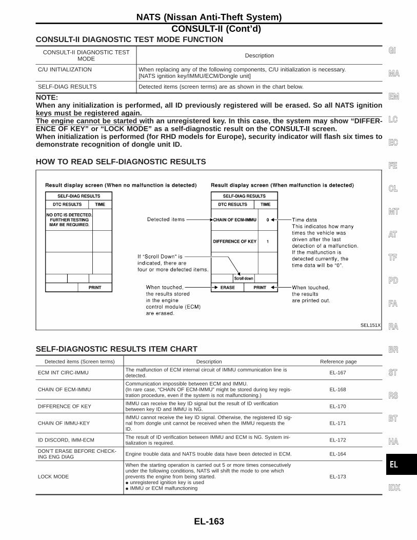
CONSULT-II DIAGNOSTIC TEST MODE FUNCTION
CONSULT-II DIAGNOSTIC TESTMODE Description
C/U INITIALIZATION When replacing any of the following components, C/U initialization is necessary.[NATS ignition key/IMMU/ECM/Dongle unit]
SELF-DIAG RESULTS Detected items (screen terms) are as shown in the chart below.
NOTE:When any initialization is performed, all ID previously registered will be erased. So all NATS ignitionkeys must be registered again.The engine cannot be started with an unregistered key. In this case, the system may show “DIFFER-ENCE OF KEY” or “LOCK MODE” as a self-diagnostic result on the CONSULT-II screen.When initialization is performed (for RHD models for Europe), security indicator will flash six times todemonstrate recognition of dongle unit ID.
HOW TO READ SELF-DIAGNOSTIC RESULTS
SELF-DIAGNOSTIC RESULTS ITEM CHART
Detected items (Screen terms) Description Reference page
ECM INT CIRC-IMMU The malfunction of ECM internal circuit of IMMU communication line isdetected. EL-167
CHAIN OF ECM-IMMUCommunication impossible between ECM and IMMU.(In rare case, “CHAIN OF ECM-IMMU” might be stored during key regis-tration procedure, even if the system is not malfunctioning.)
EL-168
DIFFERENCE OF KEY IMMU can receive the key ID signal but the result of ID verificationbetween key ID and IMMU is NG. EL-170
CHAIN OF IMMU-KEYIMMU cannot receive the key ID signal. Otherwise, the registered ID sig-nal from dongle unit cannot be received when the IMMU requests theID.
EL-171
ID DISCORD, IMM-ECM The result of ID verification between IMMU and ECM is NG. System ini-tialization is required. EL-172
DON’T ERASE BEFORE CHECK-ING ENG DIAG Engine trouble data and NATS trouble data have been detected in ECM. EL-164
LOCK MODE
When the starting operation is carried out 5 or more times consecutivelyunder the following conditions, NATS will shift the mode to one whichprevents the engine from being started.I unregistered ignition key is usedI IMMU or ECM malfunctioning
EL-173
SEL151X
NATS (Nissan Anti-Theft System)CONSULT-II (Cont’d)
EL-163
GI
MA
EM
LC
EC
FE
CL
MT
AT
TF
PD
FA
RA
BR
ST
RS
BT
HA
IDX

Trouble DiagnosesWORK FLOW
CHECK IN *NOTE: In rare case, “CHAIN OF ECM-IMMU” might be stored as a self-diagnostic result during key registration procedure, even if the sys-tem is not malfunctioning.
Listen to customer complaints or request. (Get symptoms)NOTE:If customer reports a “No start” condition, request ALLKEYS to be brought to the Dealer in case of a NATS mal-function.
TROUBLEKEY SERVICE REQUEST (Additional key ID registration)
HVerify the security indicator. INITIALIZATION
(Refer to CONSULT-II operationmanual NATS.)
EUsing the CONSULT-II program card for NATS check the“SELF-DIAG RESULTS” with CONSULT-II. F
Self-diagnostic results referring to NATS, but no informationabout engine self-diagnostic results is displayed on CONSULT-II.
Self-diagnostic results referring to NATS and “DON’T ERASEBEFORE CHECKING ENG DIAG” are displayed on CONSULT-II.(This means that engine trouble data has been detected inECM.)
Turn ignition switch “OFF”.
Repair NATS.(If necessary, carry out “C/U INITIALIZATION” with CONSULT-II.*)
Turn ignition switch “OFF”.
Turn ignition switch “ON”. Repair NATS according to self-diagnostic results referring toNATS.(If necessary, carry out “C/U INITIALIZATION” with CONSULT-II.*)
Erase the NATS “SELF-DIAG RESULTS” by using CONSULT-II.(Touch “ERASE”)
Do not erase the NATS “SELF-DIAG RESULTS” by usingCONSULT-II.
Start the engine. Check the engine “SELF-DIAG RESULTS” with CONSULT-II byusing the CONSULT-II generic program card.(Engine diagnostic software included)
F
NG Verify no lighting up of the security indicator.
OK
Repair engine control system (Refer to EC section.) when self-diagnostic results except “NATS MALFUNCTION” are detected.When only “NATS MALFUNCTION” is detected, erase the self-diagnostic results and go to the next step.
CHECK OUT Start the engine. Does the engine start properly?
OK
NG
Perform running test with CONSULT-II in engine “SELF-DIAGRESULTS” mode.
Erase the NATS and engine “SELF-DIAG RESULTS” by usingthe CONSULT-II program card for NATS and generic programcard.
NG Verify “NO DTC” displayed on the CONSULT-II screen.
OK
Start the engine.
CHECK OUT
H
H
H
H H
H
H H
H H
H H
H H
H H
H H
H H
H H
H
NATS (Nissan Anti-Theft System)
EL-164

SYMPTOM MATRIX CHART 1(Self-diagnosis related item)
SYMPTOMDisplayed “SELF-DIAG
RESULTS” on CONSULT-IIscreen.
DIAGNOSTIC PROCE-DURE
(Reference page)
SYSTEM(Malfunctioningpart or mode)
REFERENCE PART NO.OF ILLUSTRATION ONDIAGNOSTIC SYSTEM
DIAGRAM
I Security indicator lightingup*
I Engine does not start
ECM INT CIRC-IMMUPROCEDURE 1
(EL-167)ECM B
CHAIN OF ECM-IMMUPROCEDURE 2
(EL-168)
In rare case, “CHAIN OFECM-IMMU might be storedduring key registrationprocedure, even if the sys-tem is not malfunctioning.
—
Open circuit in battery volt-age line of IMMU circuit
C1
Open circuit in ignition lineof IMMU circuit
C2
Open circuit in ground lineof IMMU circuit
C3
Open circuit in communica-tion line between IMMU andECM
C4
Short circuit between IMMUand ECM communicationline and battery voltage line
C4
Short circuit between IMMUand ECM communicationline and ground line
C4
ECM B
IMMU A
DIFFERENCE OF KEYPROCEDURE 3
(EL-170)
Unregistered key D
IMMU A
CHAIN OF IMMU-KEYPROCEDURE 4
(EL-171)
Malfunction of key ID chip E
IMMU A
Open circuit in ground lineof dongle unit circuit
C6
Open or short circuit incommunication line betweenIMMU and dongle unit
C5
Dongle unit G
I Security indicator lightingup*
I Engine hard to start
ID DISCORD, IMM-ECMPROCEDURE 5
(EL-172)
System initialization has notyet been completed.
F
ECM B
LOCK MODEPROCEDURE 6
(EL-173)LOCK MODE D
*: When NATS detects trouble, the security indicator lights up while ignition key is in the “ON” position.*: When the vehicle is equipped with dongle unit, the security indicator blinks 6 times just after ignition switch is turned to ON. Then
the security indicator will light up while ignition key is in the ON position.
NATS (Nissan Anti-Theft System)Trouble Diagnoses (Cont’d)
EL-165
GI
MA
EM
LC
EC
FE
CL
MT
AT
TF
PD
FA
RA
BR
ST
RS
BT
HA
IDX

SYMPTOM MATRIX CHART 2(Non self-diagnosis related item)
SYMPTOMDIAGNOSTIC PROCEDURE
(Reference page)SYSTEM
(Malfunctioning part or mode)
REFERENCE PART NO. OFILLUSTRATION ON DIAG-
NOSTIC SYSTEM DIAGRAM
Security ind. does not light up.PROCEDURE 7
(EL-174)
Security ind. —
Open circuit between Fuse and NATS IMMU —
Continuation of initialization mode —
NATS IMMU A
Security ind. does not blinkjust after initialization even ifthe vehicle is equipped withdongle unit.
PROCEDURE 8(EL-175)
NATS might be initialized without connectingdongle unit properly.
—
Open circuit in ground line of dongle unit circuit C6
Security ind. does not blinkjust after ignition switch isturned to ON when some mal-function related to NATS isdetected even if the vehicle isequipped with dongle unit.
Open or short circuit in communication linebetween IMMU and dongle unit
C5
Dongle unit G
DIAGNOSTIC SYSTEM DIAGRAM
SEL028X
NATS (Nissan Anti-Theft System)Trouble Diagnoses (Cont’d)
EL-166

DIAGNOSTIC PROCEDURE 1Self-diagnostic results:“ECM INT CIRC-IMMU” displayed on CONSULT-II screen
Confirm SELF-DIAGNOSTIC RESULTS “ECM INT CIRC-IMMU” dis-played on CONSULT-II screen.Ref. part No. B.
Replace ECM.
Perform initialization with CONSULT-II.For the operation of initialization, refer to “CONSULT-II operationmanual NATS”.
SEL152X H
H
NATS (Nissan Anti-Theft System)Trouble Diagnoses (Cont’d)
EL-167
GI
MA
EM
LC
EC
FE
CL
MT
AT
TF
PD
FA
RA
BR
ST
RS
BT
HA
IDX

DIAGNOSTIC PROCEDURE 2Self-diagnostic results:“CHAIN OF ECM-IMMU” displayed on CONSULT-II screen
Confirm SELF-DIAGNOSTICRESULTS “CHAIN OF ECM-IMMU”* displayed on CONSULT-IIscreen.
OK
*: In rare case, “CHAIN OFECM-IMMU” might bestored during key registra-tion procedure, even if thesystem is not malfunction-ing.
CHECK POWER SUPPLY CIRCUIT FORIMMU.Check voltage between IMMU connector
M68 terminal q8 (W/L) and ground.Voltage: Battery voltage
OK
ENG Check the following:
I 20A fuse (No. 36 ,located in the fuse andfusible link box) (Dieselengine models)
I 10A fuse (No. 33 ,located in the fuse andfusible link box) (Gaso-line engine models)
I Harness for open orshort between fuse andIMMU connector
Ref. part No. C1
CHECK IGN SW. ON SIGNAL.Check voltage between IMMU connector
M68 terminal q7 (W/R) and ground whileignition switch is in the “ON” position.Voltage: Battery voltage
OK
ENG Check the following:
I 10A fuse [No. 21 ,located in the fuse block(J/B)]
I Harness for open orshort between fuse andIMMU connector
Ref. part No. C2
CHECK GROUND CIRCUIT FOR IMMU.Check harness continuity between IMMUconnector M68 terminal q4 (B) andground.Continuity should exist.
OK
ENG Repair harness.
Ref. part No. C3
CHECK COMMUNICATION ON OPENCIRCUIT.Check harness continuity between the fol-lowing ECM terminal and IMMU terminal.
ECM connector M32 terminal q65
(G/OR) or IMMU connector M68 ter-minal q1 (G/OR)
Continuity should exist.
OK
ENG Repair harness.
Ref. part No. C4
qA
SEL153X
SEL154XC
SEL155XC
SEL156XB
SEL610Y
H
H
H
H
H
NATS (Nissan Anti-Theft System)Trouble Diagnoses (Cont’d)
EL-168

qA
CHECK COMMUNICATION LINE BAT-TERY SHORT CIRCUIT.1. Disconnect ECM connector and IMMU
connector.2. Turn ignition switch to ON.3. Check voltage between ECM connector
M32 terminal q65 (G/OR) or IMMU con-nector M68 terminal q1 (G/OR) andground.No voltage should exist.
OK
ENG
Repair harness.Ref. part No. C4
CHECK COMMUNICATION LINEGROUND SHORT CIRCUIT.1. Disconnect ECM connector and IMMU
connector.2. Turn ignition switch OFF.3. Check continuity between ECM con-
nector M32 terminal q65 (G/OR) orIMMU connector M68 terminal q1(G/OR) and ground.Continuity should not exist.
OK
ENG
Repair harness.Ref. part No. C4
SIGNAL FROM ECM TO IMMU CHECK1. Check the signal between ECM con-
nector M32 terminal q65 (G/OR) andground with CONSULT-II or oscillo-scope when ignition switch is turned“ON”.
2. Make sure signals which are shown inthe figure below can be detected dur-ing 750 msec. just after ignition switchis turned “ON”.
OK
ENG I ECM is malfunctioning.
1. Replace ECM. Ref.part No. B
2. Perform initializationwith CONSULT-II.For the initializationprocedure, refer to“CONSULT-II operationmanual NATS”.
I IMMU is malfunctioning.1. Replace IMMU. Ref. part No. A2. Perform initialization with CONSULT-
II. For the initialization procedure,refer to “CONSULT-II operationmanual NATS”.
SEL611Y
SEL612Y
SEL193X
H
H
H
H
NATS (Nissan Anti-Theft System)Trouble Diagnoses (Cont’d)
EL-169
GI
MA
EM
LC
EC
FE
CL
MT
AT
TF
PD
FA
RA
BR
ST
RS
BT
HA
IDX

DIAGNOSTIC PROCEDURE 3Self-diagnostic results:“DIFFERENCE OF KEY” displayed on CONSULT-II screen
Confirm SELF-DIAGNOSTICRESULTS “DIFFERENCE OFKEY” displayed on CONSULT-IIscreen.
OK
PERFORM INITIALIZATION.Perform initialization with CONSULT-II.Re-register all NATS ignition key IDs.For the initialization procedure, refer to“CONSULT-II operation manual NATS”.
Initializationcompleted
Initializationwith CON-SULT-IIincomplete orfailed
E
I IMMU is mal-functioning.
1. ReplaceIMMU.Ref. part No.A
2. Perform initial-ization withCONSULT-II.For the initial-izationprocedure,refer to “CON-SULT-II opera-tion manualNATS”.
Start engine.
END.(The ignition key was unregistered.)Ref. part No. D
SEL163X
SEL566W
H
H
H
NATS (Nissan Anti-Theft System)Trouble Diagnoses (Cont’d)
EL-170

DIAGNOSTIC PROCEDURE 4Self-diagnostic results:“CHAIN OF IMMU-KEY” displayed on CONSULT-II screen
Confirm SELF-DIAGNOSTICRESULTS “CHAIN OF IMMU-KEY”displayed on CONSULT-II screen.
OK
CHECK NATS IGNITION KEY ID CHIP.Start engine with another registered NATSignition key.Does the engine start?
No
EYes
I Ignition key ID chip ismalfunctioning.
1. Replace the ignition key.Ref. part No. E
2. Perform initializationwith CONSULT-II.For the initializationprocedure, refer to“CONSULT-II operationmanual NATS”.
Is this vehicle equipped with dongle unit(RHD models for Europe)?
Yes
ENo
I IMMU is malfunctioning.1. Replace IMMU.
Ref part No. A2. Perform initialization
with CONSULT-II.For the initializationprocedure, refer to“CONSULT-II operationmanual NATS”.
CHECK HARNESS CONNECTOR CON-NECTION.Check the following harness connectorconnection. M68 , N12Does the engine start?
No
EYes
System is OK.(The malfunction is causedby improper connectorconnection.)
CHECK GROUND CIRCUIT FORDONGLE UNIT.Check continuity between dongle unit ter-minal q1 (B/W) and ground.Continuity should exist.
Yes
ENo
Repair harness.Ref. part No. C6
CHECK INTERFACE CIRCUIT.1. Check continuity between IMMU con-
nector M68 terminal q2 (P) and dongleunit terminal q7 (P) (Open circuitcheck)Continuity should exist.
2. Check continuity between IMMU con-nector M68 terminal q2 (P) andground. (Short circuit check)Continuity should not exist.
Yes
ENo
Repair harness.Ref. part No. C5
Dongle unit is malfunctioning.1. Replace dongle unit. Ref. part No. G2. Perform initialization with CONSULT-II.
For the initialization procedure, refer to“CONSULT-II operation manual NATS”.
SEL165X
SEL160XA
SEL161XA
SEL162XA
H
H
H
H
H
H
NATS (Nissan Anti-Theft System)Trouble Diagnoses (Cont’d)
EL-171
GI
MA
EM
LC
EC
FE
CL
MT
AT
TF
PD
FA
RA
BR
ST
RS
BT
HA
IDX

DIAGNOSTIC PROCEDURE 5Self-diagnostic results:“ID DISCORD, IMM-ECM” displayed on CONSULT-II screen
Confirm SELF-DIAGNOSTICRESULTS “ID DISCORD, IMM-ECM*” displayed on CONSULT-IIscreen.
* “ID DISCORD, IMM-ECM”:Registered ID of IMMU is indiscord with that of ECM.
PERFORM INITIALIZATION.Perform initialization with CONSULT-II.Re-register all NATS ignition key IDs.For the initialization procedure, refer to“CONSULT-II operation manual NATS”.
Initializationcompleted
Initializationwith CON-SULT-IIincomplete orfailed
E
I ECM is mal-functioning.
1. Replace ECM.Ref. part No.B
2. Perform initial-ization withCONSULT-II.For the initial-izationprocedure,refer to “CON-SULT-II opera-tion manualNATS”.
Start engine. (END)(System initialization was not completed.Ref. part No. F )
SEL166X
SEL566W
H
H
NATS (Nissan Anti-Theft System)Trouble Diagnoses (Cont’d)
EL-172

DIAGNOSTIC PROCEDURE 6Self-diagnostic results:“LOCK MODE” displayed on CONSULT-II screen
Confirm SELF-DIAGNOSTIC RESULTS“LOCK MODE” is displayed on CON-SULT-II screen.
1. Turn the ignition switch to OFF posi-tion.
2. Turn the ignition key switch to ON posi-tion with a registered key.(Do not start engine.) Wait 5 seconds.
3. Return the key to the OFF position.4. Repeat steps 2 and 3 twice (total of
three cycles).5. Start the engine.
Does the engine start?
No
EYes System is OK.
(Now the system isescaped from “LOCKMODE”.)
CHECK NATS IMMU INSTALLATION.Refer to “How to Replace NATS IMMU” inEL-175.
OK
ENG Reinstall NATS IMMU cor-
rectly.
PERFORM INITIALIZATION.Perform initialization with CONSULT-II.For the initialization procedure, refer to“CONSULT-II operation manual NATS”.Can the system be initialized?Note: If the initialization is incompleted or
failed, CONSULT-II showsmessage on the screen.
No
EYes System is OK.
Go to DIAGNOSTIC PROCEDURE 4,EL-171 to check “CHAIN OF IMMU-KEY”.
SEL167X
SEL566W
H
H
H
H
NATS (Nissan Anti-Theft System)Trouble Diagnoses (Cont’d)
EL-173
GI
MA
EM
LC
EC
FE
CL
MT
AT
TF
PD
FA
RA
BR
ST
RS
BT
HA
IDX

DIAGNOSTIC PROCEDURE 7“SECURITY IND. DOES NOT LIGHT UP”
Check 10A fuse [No. 6 , located in thefuse block (J/B)].
OK
ENG Replace fuse.
NATS INITIALIZATION1) Install the 10A fuse.2) Perform initialization with CON-
SULT-II.For the operation ofinitialization, refer to “CON-SULT-II operation manualNATS”.
Turn ignition switch “OFF”.
Start engine and turn ignition switch“OFF”.
Check the security ind. lighting.
NG
EOK END
Check voltage between security ind. con-nector M55 terminal q1 (R/G) andground.Voltage: Battery voltage
OK
ENG Check harness for open or
short between fuse andsecurity ind.
CHECK INDICATOR LAMP.
OK
ENG Repair harness.
CHECK NATS IMMU FUNCTION.1. Connect NATS IMMU connector M68 .2. Disconnect security ind. connector
M55 .3. Check continuity between NATS IMMU
connector M68 terminal q6 (L) andground.Continuity should exist intermit-tently.
OK
ENG NATS IMMU is malfunc-
tioning. Replace IMMU.
Perform initializa-tion with CON-SULT-II.For the operation ofinitialization, referto “CONSULT-IIoperation manualNATS”.
Check harness for open or short betweensecurity indicator and NATS IMMU.
SEL931UC
SEL164XA
H
H
H
H
H
H
H
H
H
NATS (Nissan Anti-Theft System)Trouble Diagnoses (Cont’d)
EL-174

DIAGNOSTIC PROCEDURE 8
CHECK GROUND CIRCUIT FORDONGLE UNIT.Check continuity between dongle unit con-nector N12 terminal q1 (B/W) andground.Continuity should exist.
Yes
ENo Repair harness.
Ref. part No. C6
CHECK INTERFACE CIRCUIT.1. Check continuity between IMMU con-
nector M68 terminal q2 (P) and dongleunit connector N12 terminal q7 (P).(Open circuit check)Continuity should exist.
2. Check continuity between IMMU con-nector M68 terminal q2 (P) andground. (Short circuit check)Continuity should exist.
Yes
ENo Repair harness.
Ref. part No. C5
Dongle unit is malfunctioning.1. Replace dongle unit.
Ref. part No. G2. Perform initialization with CONSULT-II.
For the initialization procedure, refer to“CONSULT-II operation manual NATS”.
How to Replace NATS IMMUNOTE:I If NATS IMMU is not installed correctly, NATS system will
not operate properly and SELF-DIAG RESULTS on CON-SULT-II screen will show “LOCK MODE”.
SEL160XA
SEL161XA
SEL162XA
SEL096WD
H
H
NATS (Nissan Anti-Theft System)Trouble Diagnoses (Cont’d)
EL-175
GI
MA
EM
LC
EC
FE
CL
MT
AT
TF
PD
FA
RA
BR
ST
RS
BT
HA
IDX

NOTE
NATS (Nissan Anti-Theft System)
EL-176

Engine Compartment
HEL848B
LOCATION OF ELECTRICAL UNITS
EL-177
GI
MA
EM
LC
EC
FE
CL
MT
AT
TF
PD
FA
RA
BR
ST
RS
BT
HA
IDX

Passenger Compartment
HEL849B
LOCATION OF ELECTRICAL UNITS
EL-178

RHD MODELS
HEL850B
LOCATION OF ELECTRICAL UNITSPassenger Compartment (Cont’d)
EL-179
GI
MA
EM
LC
EC
FE
CL
MT
AT
TF
PD
FA
RA
BR
ST
RS
BT
HA
IDX

Main HarnessINSTRUMENT PANEL — LHD MODELS
HEL851B
HARNESS LAYOUT
EL-180

HEL852B
HARNESS LAYOUTMain Harness (Cont’d)
EL-181
GI
MA
EM
LC
EC
FE
CL
MT
AT
TF
PD
FA
RA
BR
ST
RS
BT
HA
IDX

INSTRUMENT PANEL — RHD MODELS
HEL853B
HARNESS LAYOUTMain Harness (Cont’d)
EL-182

HEL854B
HARNESS LAYOUTMain Harness (Cont’d)
EL-183
GI
MA
EM
LC
EC
FE
CL
MT
AT
TF
PD
FA
RA
BR
ST
RS
BT
HA
IDX

BODY SIDE — LHD MODELS
HEL855B
HARNESS LAYOUTMain Harness (Cont’d)
EL-184

BODY SIDE — RHD MODELS
HEL856B
HARNESS LAYOUTMain Harness (Cont’d)
EL-185
GI
MA
EM
LC
EC
FE
CL
MT
AT
TF
PD
FA
RA
BR
ST
RS
BT
HA
IDX

ENGINE COMPARTMENT — LHD models/for Europe
HEL857B
HARNESS LAYOUTMain Harness (Cont’d)
EL-186

HEL858B
HARNESS LAYOUTMain Harness (Cont’d)
EL-187
GI
MA
EM
LC
EC
FE
CL
MT
AT
TF
PD
FA
RA
BR
ST
RS
BT
HA
IDX

ENGINE COMPARTMENT — KA ENGINE (LHD models Except for Europe)
HEL888B
HARNESS LAYOUTMain Harness (Cont’d)
EL-188

HEL859B
HARNESS LAYOUTMain Harness (Cont’d)
EL-189
GI
MA
EM
LC
EC
FE
CL
MT
AT
TF
PD
FA
RA
BR
ST
RS
BT
HA
IDX

ENGINE COMPARTMENT — Z, TD AND QD ENGINES (LHD models)
HEL860B
HARNESS LAYOUTMain Harness (Cont’d)
EL-190

ENGINE COMPARTMENT — YD ENGINE (LHD models)
HEL861B
HARNESS LAYOUTMain Harness (Cont’d)
EL-191
GI
MA
EM
LC
EC
FE
CL
MT
AT
TF
PD
FA
RA
BR
ST
RS
BT
HA
IDX

ENGINE COMPARTMENT — ZD ENGINE (LHD models)
HEL862B
HARNESS LAYOUTMain Harness (Cont’d)
EL-192

NOTE
HARNESS LAYOUT
EL-193
GI
MA
EM
LC
EC
FE
CL
MT
AT
TF
PD
FA
RA
BR
ST
RS
BT
HA
IDX

Engine Room HarnessLHD MODELS — GASOLINE ENGINE
HEL863B
HARNESS LAYOUT
EL-194

HEL864B
HARNESS LAYOUTEngine Room Harness (Cont’d)
EL-195
GI
MA
EM
LC
EC
FE
CL
MT
AT
TF
PD
FA
RA
BR
ST
RS
BT
HA
IDX

LHD MODELS — DIESEL ENGINE
HEL865B
HARNESS LAYOUTEngine Room Harness (Cont’d)
EL-196

HEL866B
HARNESS LAYOUTEngine Room Harness (Cont’d)
EL-197
GI
MA
EM
LC
EC
FE
CL
MT
AT
TF
PD
FA
RA
BR
ST
RS
BT
HA
IDX
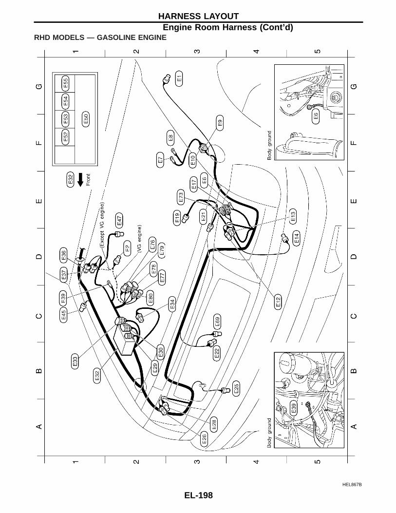
RHD MODELS — GASOLINE ENGINE
HEL867B
HARNESS LAYOUTEngine Room Harness (Cont’d)
EL-198

HEL868B
HARNESS LAYOUTEngine Room Harness (Cont’d)
EL-199
GI
MA
EM
LC
EC
FE
CL
MT
AT
TF
PD
FA
RA
BR
ST
RS
BT
HA
IDX

RHD MODELS — DIESEL ENGINE
HEL869B
HARNESS LAYOUTEngine Room Harness (Cont’d)
EL-200

HEL870B
HARNESS LAYOUTEngine Room Harness (Cont’d)
EL-201
GI
MA
EM
LC
EC
FE
CL
MT
AT
TF
PD
FA
RA
BR
ST
RS
BT
HA
IDX

Engine Control Harness/KA engine
HEL871B
HARNESS LAYOUT
EL-202

HEL872B
HARNESS LAYOUTEngine Control Harness/KA engine (Cont’d)
EL-203
GI
MA
EM
LC
EC
FE
CL
MT
AT
TF
PD
FA
RA
BR
ST
RS
BT
HA
IDX

Engine Control HarnessVG ENGINE
HEL873B
HARNESS LAYOUT
EL-204
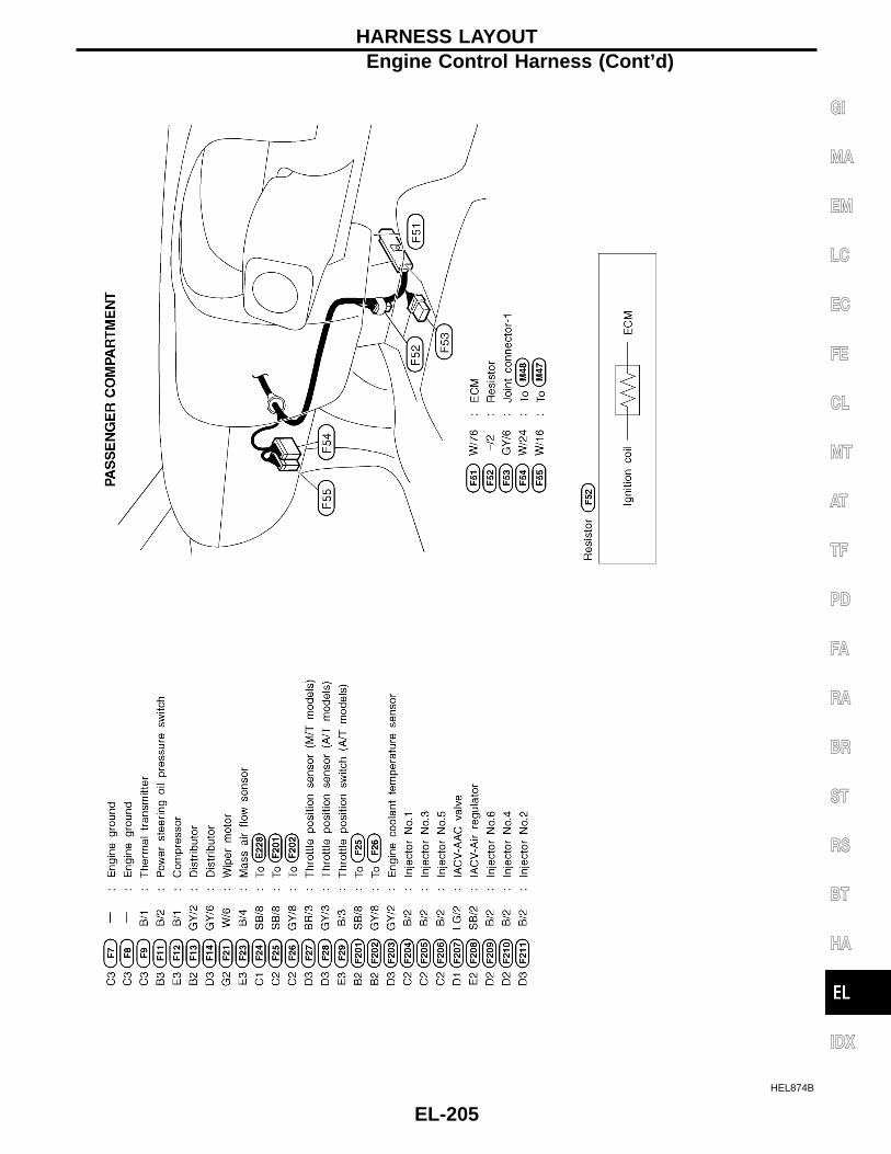
HEL874B
HARNESS LAYOUTEngine Control Harness (Cont’d)
EL-205
GI
MA
EM
LC
EC
FE
CL
MT
AT
TF
PD
FA
RA
BR
ST
RS
BT
HA
IDX

ENGINE COMPARTMENT — YD ENGINE (RHD models)
HEL875B
HARNESS LAYOUTEngine Control Harness (Cont’d)
EL-206

ENGINE COMPARTMENT — ZD ENGINE (RHD models)
HEL876B
HARNESS LAYOUTEngine Control Harness (Cont’d)
EL-207
GI
MA
EM
LC
EC
FE
CL
MT
AT
TF
PD
FA
RA
BR
ST
RS
BT
HA
IDX

Engine HarnessZ ENGINE
HEL807B
HARNESS LAYOUT
EL-208

KA ENGINE
HEL877B
HARNESS LAYOUTEngine Harness (Cont’d)
EL-209
GI
MA
EM
LC
EC
FE
CL
MT
AT
TF
PD
FA
RA
BR
ST
RS
BT
HA
IDX

VG ENGINE
HEL878B
HARNESS LAYOUTEngine Harness (Cont’d)
EL-210

TD AND QD ENGINES
HEL879B
HARNESS LAYOUTEngine Harness (Cont’d)
EL-211
GI
MA
EM
LC
EC
FE
CL
MT
AT
TF
PD
FA
RA
BR
ST
RS
BT
HA
IDX

YD ENGINE
HEL880B
HARNESS LAYOUTEngine Harness (Cont’d)
EL-212

ZD ENGINE
HEL881B
HARNESS LAYOUTEngine Harness (Cont’d)
EL-213
GI
MA
EM
LC
EC
FE
CL
MT
AT
TF
PD
FA
RA
BR
ST
RS
BT
HA
IDX

Alternator Harness
HEL808B
HARNESS LAYOUT
EL-214

YD AND ZD ENGINES
HEL882B
HARNESS LAYOUTAlternator Harness (Cont’d)
EL-215
GI
MA
EM
LC
EC
FE
CL
MT
AT
TF
PD
FA
RA
BR
ST
RS
BT
HA
IDX

Instrument HarnessLHD MODELS
RHD MODELSHEL809B
HEL883B
HARNESS LAYOUT
EL-216

Chassis Harness and Tail Harness
HEL889B
HARNESS LAYOUT
EL-217
GI
MA
EM
LC
EC
FE
CL
MT
AT
TF
PD
FA
RA
BR
ST
RS
BT
HA
IDX

Front Door Harness (LH side)LHD MODELS
RHD MODELSHEL811B
HEL885B
HARNESS LAYOUT
EL-218

Front Door Harness (RH side)LHD MODELS
RHD MODELSHEL812B
HEL884B
HARNESS LAYOUT
EL-219
GI
MA
EM
LC
EC
FE
CL
MT
AT
TF
PD
FA
RA
BR
ST
RS
BT
HA
IDX

Rear Door HarnessLH SIDE
RH SIDEHEL886B
HEL887B
HARNESS LAYOUT
EL-220

Use the chart below to find out what each wiring diagram codestands for.Refer to the wiring diagram code in the alphabetical index to findthe location (page number) of each wiring diagram.
Code Section Wiring Diagram Name
AAC/V EC IACV-AAC Valve
ABS BR Anti-lock Brake System
A/C, A HA Auto Air Conditioner
A/C, M HA Manual Air Conditioner
ACC/SW EC Accelerator Switch
A/CCOT EC Air Conditioner Control
AIRREG EC IACV-Air Regulator
APS EC Accelerator Position Sensor
AT/IND EL A/T Indicator
AUDIO EL Audio
BACK/L EL Back-up Lamp
BA/FTS ATBATT/A/T Fluid Temperature Sensorand TCM Power Supply
BOOST EC Turbocharger Boost Sensor
BRK/SW EC Brake Switch Signal
CHARGE EL Charging System
CHIME EL Warning Chime
CHOKE EC Automatic Choke
CIGAR EL Cigarette Lighter
CKPS EC Crankshaft Position Sensor
CLOCK EL Clock
CMPS EC Camshaft Position Sensor
COOL/F LC, EC Cooling Fan Control
DEF ELRear Window Defogger and MirrorDefogger
DIMDIP ELHeadlamp — With Dim-dip LampSystem
D/LOCK EL Power Door Lock
DTRL ELHeadlamp — With Daytime LightSystem
ECMRLY EC ECM Relay
ECTS ECEngine Coolant TemperatureSensor
EGRC/V EC EGRC — Solenoid Valve
EGVC/V EC EGR Volume Control Valve
ENGSS AT Engine Speed Signal
FCUT EC Fuel Cut Solenoid Valve
FICD EC IACV-FICD Solenoid Valve
FIPOT EC ISC-FI Pot
FPCM EC Fuel Pump Control Module
F/PUMP EC Fuel Pump
Code Section Wiring Diagram Name
GLOW EC Quick-glow System
H/AIM EL Headlamp Aiming Control
HEATER HA Heater
HEATUP EC Heat up Switch
H/LAMP EL Headlamp
HLC EL Headlamp Washer
HO2S EC Heated Oxygen Sensor
HORN EL Horn
H/SEAT EL Heated Seat
IATS EC Intake Air Temperature Sensor
IGN EC Ignition System
IGN/SG EC Ignition Signal
ILL EL Illumination
INJECT EC Injector
INJPMP ECElectronic Control Fuel InjectionPump
INT/L EL Spot Lamp
INT/V ECIntake Air Control Valve ControlSolenoid Valve
KS EC Knock Sensor
LOAD EC Electric Load Signal
LPSV AT Line Pressure Solenoid Valve
MAFS EC Mass Air Flow Sensor
MAIN EC, ATMain Power Supply and Ground Cir-cuit
METER ELSpeedometer, Tachometer, Temp.and Fuel Gauges
MIL/DL EC MIL and Data Link Connectors
MIRROR EL Power Door Mirror
MULTI EL Multi-remote Control System
NATS EL Nissan Anti-theft System
NONDTC AT Non-detectable Items
O2H1B1 EC Heated Oxygen Sensor 1 Heater
O2H2B1 EC Heated Oxygen Sensor 2 Heater
O2S1B1 EC Heated Oxygen Sensor 1
O2S2B1 EC Heated Oxygen Sensor 2
OVRCSV AT Overrun Clutch Solenoid Valve
P/ANT EL Power Antenna
PGC/V ECEVAP Canister PurgeControl Solenoid Valve
PLA EC Partial Load Advance Control
WIRING DIAGRAM CODES (CELL CODES)
EL-221
GI
MA
EM
LC
EC
FE
CL
MT
AT
TF
PD
FA
RA
BR
ST
RS
BT
HA
IDX
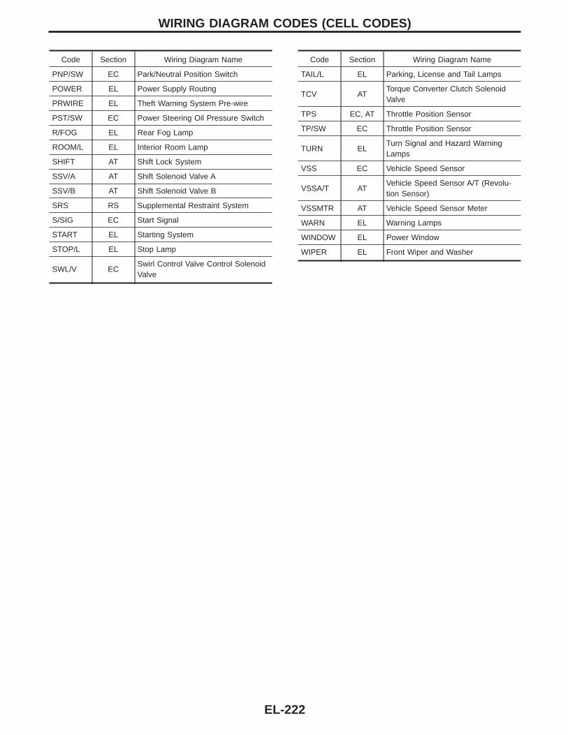
Code Section Wiring Diagram Name
PNP/SW EC Park/Neutral Position Switch
POWER EL Power Supply Routing
PRWIRE EL Theft Warning System Pre-wire
PST/SW EC Power Steering Oil Pressure Switch
R/FOG EL Rear Fog Lamp
ROOM/L EL Interior Room Lamp
SHIFT AT Shift Lock System
SSV/A AT Shift Solenoid Valve A
SSV/B AT Shift Solenoid Valve B
SRS RS Supplemental Restraint System
S/SIG EC Start Signal
START EL Starting System
STOP/L EL Stop Lamp
SWL/V ECSwirl Control Valve Control SolenoidValve
Code Section Wiring Diagram Name
TAIL/L EL Parking, License and Tail Lamps
TCV ATTorque Converter Clutch SolenoidValve
TPS EC, AT Throttle Position Sensor
TP/SW EC Throttle Position Sensor
TURN ELTurn Signal and Hazard WarningLamps
VSS EC Vehicle Speed Sensor
VSSA/T ATVehicle Speed Sensor A/T (Revolu-tion Sensor)
VSSMTR AT Vehicle Speed Sensor Meter
WARN EL Warning Lamps
WINDOW EL Power Window
WIPER EL Front Wiper and Washer
WIRING DIAGRAM CODES (CELL CODES)
EL-222
Related Documents