ELECTRICALSYSTEM CONTENTS CAUTIONSINSERVICING 7-3 COUPLER 7-3 CLAMP 7-3 FUSE 7-3 SEMI-CONDUCTOREQUIPPEDPART 7-3 BATTERY 7-4 CONNECTINGTHEBATTERY 7-4 WIRINGPROCEDURE 7-4 USINGTHEMULTICIRCUITTESTER 7-4 LOCATIONOFELECTRICALCOMPONENTS 7-5 CHARGINGSYSTEM 7-7 TROUBLESHOOTING 7-7 INSPECTION 7-9 STARTERSYSTEMANDSIDE-STAND/IGNITIONINTERLOCK SYSTEM 7-12 TROUBLESHOOTING 7-12 STARTERMOTORREMOVALANDDISASSEMBLY 7-13 STARTERMOTORINSPECTION 7-14 STARTERMOTORREASSEMBLY 7-15 STARTERRELAYINSPECTION 7-16 SIDE-STAND/IGNITIONINTERLOCKSYSTEMPARTS INSPECTION 7-17 IGNITIONSYSTEM 7-20 TROUBLESHOOTING 7-20 INSPECTION 7-22 COMBINATIONMETER 7-25 REMOVAL 7-25 PARTSNAME 7-26 OPERATINGPROCEDURE 7-26 ENGINECOOLANTTEMPERATUREMETERANDINDICATOR 7-28 LAMPS 7-31 HEADLIGHTANDPOSITIONLIGHT 7-31 BRAKELIGHT/TAILLIGHT,TURNSIGNALLIGHTAND LICENCEPLATELIGHT 7-32 RELAYS 7-33 TURNSIGNAL/SIDE-STANDRELAY 7-33 STARTERRELAY 7-33 FUELPUMPRELAY 7--33 SWITCHES 7-34 ELECTRICALSYSTEM 7-1 7

Welcome message from author
This document is posted to help you gain knowledge. Please leave a comment to let me know what you think about it! Share it to your friends and learn new things together.
Transcript

ELECTRICAL SYSTEM
CONTENTS
CAUTIONS IN SERVICING 7- 3COUPLER 7- 3CLAMP 7- 3FUSE 7- 3SEMI-CONDUCTOR EQUIPPED PART 7- 3BATTERY 7- 4CONNECTING THE BATTERY 7- 4WIRING PROCEDURE 7- 4USING THE MULTI CIRCUIT TESTER 7- 4
LOCATION OF ELECTRICAL COMPONENTS 7- 5CHARGING SYSTEM 7- 7
TROUBLE SHOOTING 7- 7INSPECTION 7- 9
STARTER SYSTEM AND SIDE-STAND/IGNITION INTERLOCKSYSTEM 7-12
TROUBLE SHOOTING 7-12STARTER MOTOR REMOVAL AND DISASSEMBLY7-13STARTER MOTOR INSPECTION 7-14STARTER MOTOR REASSEMBLY 7-15STARTER RELAY INSPECTION 7-16SIDE-STAND/IGNITION INTERLOCK SYSTEM PARTSINSPECTION 7-17
IGNITION SYSTEM 7-20TROUBLESHOOTING 7-20INSPECTION 7-22
COMBINATION METER 7-25REMOVAL 7-25PARTS NAME 7-26OPERATING PROCEDURE 7-26ENGINE COOLANT TEMPERATURE METER AND INDICATOR7-28
LAMPS 7-31HEADLIGHT AND POSITION LIGHT 7-31BRAKE LIGHT/TAILLIGHT, TURN SIGNAL LIGHT ANDLICENCE PLATE LIGHT 7-32
RELAYS 7-33TURN SIGNAL/SIDE-STAND RELAY 7-33STARTER RELAY 7-33FUEL PUMP RELA Y 7--33SWITCHES 7-34
ELECTRICAL SYSTEM 7-1
7

7-2 ELECTRICAL SYSTEM
ELECTRICAL SYSTEM
CONTENTS
BATTERY 7-36SPECIFICATIONS 7-36INITIAL CHARGING 7-36SERVICING 7-37RECHARGING OPERATION 7-38

CAUTIONS IN SERVICINGCOUPLER• With a lock type coupler, be sure to release the lock beforedisconnecting it and push it in fully till the lock works whenconnecting it .
•
When disconnecting the coupler, be sure to hold the coupleritself and do not pull the lead wires .
•
Inspect each terminal on the coupler for being loose or bent .•
Inspect each terminal for corrosion and contamination .
CLAMP•
Clamp the wire harness at such positions as indicated in"WIRE HARNESS ROUTING" . (C"-78-14)
•
Bend the clamp properly so that the wire harness is clampedsecurely .
•
In clamping the wire harness, use care not to allow it to hangdown.
•
Do not use wire or any other substitute for the band typeclamp .
FUSE•
When a fuse blows, always investigate the cause, correct itand then replace the fuse .
•
Do not use a fuse of a different capacity .•
Do not use wire or any other substitute for the fuse .
SEMI-CONDUCTOR EQUIPPED PART•
Be careful not to drop the part with a semi-conductor built insuch as a ECM .
•
When inspecting this part, follow inspection instruction strictly .Neglecting proper procedure may cause damage to this part .
ELECTRICAL SYSTEM 7- 3

7-4 ELECTRICAL SYSTEM
BATTERY• The MF battery used in this motorcycle does not require main-tenance (e .g ., electrolyte level inspection, distilled waterreplenishment) .
•
During normal charging, no hydrogen gas is produced . How-ever, if the battery is overcharged, hydrogen gas may be pro-duced. Therefore, be sure there are no fire or spark sources(e.g ., short circuit) nearby when charging the battery .
•
Be sure to recharge the battery in a well-ventilated and openarea .
• Note that the charging system for the MF battery is differentfrom that of a conventional battery . Do not replace the MFbattery with a conventional battery .
CONNECTING THE BATTERY• When disconnecting terminals from the battery for disassem-bly or servicing, be sure to disconnect the O battery leadwire, first .
•
When connecting the battery lead wires, be sure to connectthe OO battery lead wire first .
•
If the terminal is corroded, remove the battery, pour warmwater over it and clean it with a wire brush .
•
After connecting the battery, apply a light coat of grease to thebattery terminals .
•
Install the cover over the O battery terminal .
WIRING PROCEDURE•
Properly route the wire harness according to the "WIRE HAR-NESS ROUTING" section . (CJ8-14)
USING THE MULTI CIRCUIT TESTER• Properly use the multi circuit tester O and e probes .Improper use can cause damage to the motorcycle andtester .
•
If the voltage and current values are not known, begin mea-suring in the highest range .
•
When measuring the resistance, make sure that no voltage isapplied . If voltage is applied, the tester will be damaged .
•
After using the tester, be sure to turn the switch to the OFFposition .
CAUTION
Before using the multi circuit tester, read its instruc-tion manual .

~ 40
LOCATION OF ELECTRICAL COMPONENTS
•
Fuel pump (C14-68)02 CMP sensor (C'4-92)~3 IAP sensor (=4-91)•
Ignition coil (No . 1)05 Horn
® TO sensor (=4-93)4-93)07 Gear position switch•
Starter motor•
Oil pressure switch1o ECT sensor (f- 4-93)
ELECTRICAL SYSTEM 7-5

7-6 ELECTRICAL SYSTEM
90 Cooling fan thermo-switch (F-75-9)
O Battery•
Cooling fan (r-75-8) 10 ECM (Engine Control Module)•
Cooling fan motor switch coupler (=5-8)5-8) 11 Fuel pump relay•
Fuel injector (r--74-86) 0 AP sensor (=4-93)4-93)~5 TP sensor (=4-91)
13 Starter relay•
STP sensor (f"74-91) 14 Side-stand/turn signal relay•
Secondary throttle valve actuator (=4-51)4-51) 15 Fuse box•
IAT sensor (r--74-92) 16 Mode selection switch coupler
17 Ignition coil (No . 2)18 Regulator/rectifier19 Generator20 Speedometer sensor21 CKP sensor22 Side stand switch

j CHARGING SYSTEM
4)
4)
40
Generator
TROUBLE SHOOTING
Battery runs down quickly .Step 11) Check accessories which use excessive amounts of electricity .
Are accessories being installed?
YESNO
Remove accessories .Go to Step 2 .
Step 21) Check the battery for current leaks . (=7-9)
Is the battery for current leaks OK?
Regulator/rectifier
II
II
II
isI
I
I
I NI
.,~
SCR
lm
Step 31) Measure the charging voltage between the battery terminals. (11r7-9)
Is the battery charging of voltage OK?
ELECTRICAL SYSTEM 7-7
Ig .switch
a
m0J
<Continued on next page>
YES Go to Step 3 .
NO •
Short circuit of wire harness•
Faulty electrical equipment
YES •
Faulty battery•
Abnormal driving conditionNO Go to Step 4 .

7-8 ELECTRICAL SYSTEM
Step 41) Measure the resistance of the generator coil . (=7-1 0)
Is the resistance of generator coil OK?
YES
YESNO
Step 71) Inspect the wirings .
Are the wirings OK?
Go to Step 5 .NO
Faulty generator coil or disconnected lead ~^ .iros
Step 51) Measure the generator no-load voltage . (C_r7-10)
Is the generator no-load voltage OK?
Go to Step 6 .Faulty generator
Step 61) Inspect the regulator/rectifier . ( I"77-11)
Is the regulator/rectifier OK?
YESNO
Go to Step 7 .Faulty regulator/rectifier
Battery overcharge•
Faulty regulator/rectifier•
Faulty battery•
Poor contact of generator lead wire coupler
YES Faulty battery
NO •
Short circuit of wire harness•
Poor contact of couplers

jINSPECTION
BATTERY CURRENT LEAKAGE•
Remove the front seat. (=6-7)
•
Turn the ignition switch to the OFF position .
•
Disconnect the O battery lead wire .
Measure the current between the O battery terminal and the O
battery lead wire using the multi circuit tester. If the reading
exceeds the specified value, leakage is evident .
Battery current (leak) : Under 3 mA
09900-25008: Multi circuit tester set
~j Tester knob indication : Current (-, 20 mA)
CAUTION
* Because the current leak might be large, turn the
tester to high range first to avoid tester damage .
* Do not turn the ignition switch to the "ON" position
when measuring current .
When checking to find the excessive current leakage, remove
the couplers and connectors, one by one, checking each part .
REGULATED VOLTAGE•
Remove the front seat . (r'6-7)
•
Start the engine and keep it running at 5 000 r/min with the
dimmer switch turned HI position .
Measure the DC voltage between the O and O battery termi-
nals using the multi circuit tester . If the voltage is not within the
specified value, inspect the generator and regulator/rectifier .
(r--r7-1 1)
NOTE:
When making this test, be sure that the battery is in fully-
charged condition .
Charging output (Regulated voltage) :14.0 - 15.5 V at 5 000 r/m i n
. . 09900-25008 : Multi circuit tester set
Tester knob indication : Voltage (-)
ELECTRICAL SYSTEM 7-9

7.10 ELECTRICAL SYSTEM
GENERATOR COIL RESISTANCE•
Remove the front seat . ( F-76-7)•
Disconnect the generator coupler D.Measure the resistance among the three lead wires .If the resistance is not specified value, replace the stator with anew one. Also, check that the generator core is insulated .
['
Generator coil resistance : 0 .2 - 0.7 S2 (Yellow - Yellow)- S (Yellow - Ground)
09900-25008: Multi circuit tester set
ZJ Tester knob indication : Resistance (S2)
NOTE:When making above test, it is not necessary to remove the gen-erator.
GENERATOR NO-LOAD PERFORMANCE•
Disconnect the generator coupler . (Crabove)•
Don't disconnect the crankshaft position sensor coupler .•
Start the engine and keep it running at 5 000 r/min .
Using the multi circuit tester, measure the voltage among thethree lead wires .If the tester reads under the specified value, replace the genera-tor with a new one .
Generator no-load performance :75 V and more at 5 000 r/min (When engine is cold)
09900-25008 : Multi circuit tester set
Tester knob indication: Voltage (-)
AAA

I
REGULATOR/RECTIFIER•
Disconnect the couplers and remove the regulator/rectifier .
4)
Measure the voltage among the terminals using the multi circuit
tester as indicated in the table below . If the voltage is not within
the specified value, replace the regulator/rectifier with a new
one .
09900-25008 : Multi circuit tester set
~$ Tester knob indication : Diode test (-W)
Unit: V
B: Black, B/R : Black with Red trancer* More than 1 .4 V (tester's battery voltage)
NOTE:
If the tester reads under 1 .4 V when the tester probes are not
connected, replace the battery of multi circuit tester .
ELECTRICAL SYSTEM 7-11
O Probe of tester to :
g
~'
B/R 131 B2 B3 B/W
B/R 0.4 - 0.7 0.4 - 0.7 0.4 - 0 .7 0.5 - 1 .2
131 * * * 0.4-0.70
B2 * * * 0.4-0.7
a B3 0.4 - 0.7
OI B/W

7-12 ELECTRICAL SYSTEM
STARTER SYSTEM AND SIDE-STAND/IGNITION INTERLOCKSYSTEM
Startermotor
Starter relay
0
0 To ECM andignition coil
Y/G
B/YClutch leverposition switch
B/WIW
Starterbutton
Engine stopswitch
Ignitionswitch
Fuse (30 A)
rom
TROUBLE SHOOTINGStarter motor will not run .
Step 1
1) The transmission is in neutral . Grasp the clutch lever, turn on the ignition switch with the engine stopswitch in the "RUN" position .
2) Listen for a click from the starter relay when the starter button is pushed .Is a click sound heard?
YESNO
Go to Step 2 .Go to Step 3 .
Step 2
1) Check if the starter motor runs when its terminal is connected to the O battery terminal . (Do not use thin"wire" because a large amount of current flows .)Does the starter motor run?
<Continued on next page>
A Jrr
In
YES •
Faulty starter relay•
Loose or disconnected starter motor lead wireNO Faulty starter motor
Step 31) Measure the starter relay voltage at the starter relay connectors (between Y/G O+ and B/Y O) when the
starter button is pushed .Is the voltage OK?
Step 41) Check the starter relay . (F-t 7-1 6)
Is the starter relay OK?
YES
NO
Poor contact of the starter relay
Faulty starter relay
NOTE:The starter motor runs when the transmission is in neutral with the side-stand up or down, but does not runwhen the transmission is in any position other than neutral with the side-stand down .
2) Check the side-stand switch . (CIT7-17)Is the side-stand switch OK?
Engine does not turn though the starter motor runs .•
Faulty starter torque limiter (=3-64)
STARTER MOTOR REMOVAL ANDDISASSEMBLY•
Remove the under cowling . (=6-5)6-5)•
Disconnect the starter motor lead wire 90 and remove the
starter motor .
ELECTRICAL SYSTEM 7- 1 3
YES Go to Step 4 .
NO
•
Faulty ignition switch•
Faulty engine stop switch•
Faulty clutch lever position switch
•
Faulty gear position switch•
Faulty turn signal/side-stand relay•
Faulty starter button•
Poor contact of connector•
Open circuit in wire harness
YES •
Open circuit in wire harness•
Poor contact of connector
NO Faulty side-stand switch

7-14 ELECTRICAL SYSTEM
•
Disassemble the starter motor as shown in the illustration .
T 0-ring02 Housing©3 Armature•
WasherO5 0-ring•
Starter motor case07 Starter brush holder assembly•
0-ring
STARTER MOTOR INSPECTIONCARBON BRUSHInspect the brushes for abnormal wear, cracks, or smoothnessin the brush holder .If any damages are found, replace the brush assembly with anew one .
COMMUTATORInspect the commutator for discoloration, abnormal wear orundercut OA .
If abnormal wear is found, replace the armature with a new one .If the commutator surface is discolored, polish it with #400 sandpaper and wipe it using a clean dry cloth .If there is no undercut, scrape out the insulator 10 with a sawblade .
ARMATURE COIL INSPECTIONCheck for continuity between each segment, and between eachsegment and the armature shaft using the multi circuit tester .If there is no continuity between the segments or there is conti-nuity between the segments and shaft, replace the armaturewith a new one .
09900-25008: Multi circuit tester set
Tester knob indication: Continuity test ( •I )))i E0 e
V
i
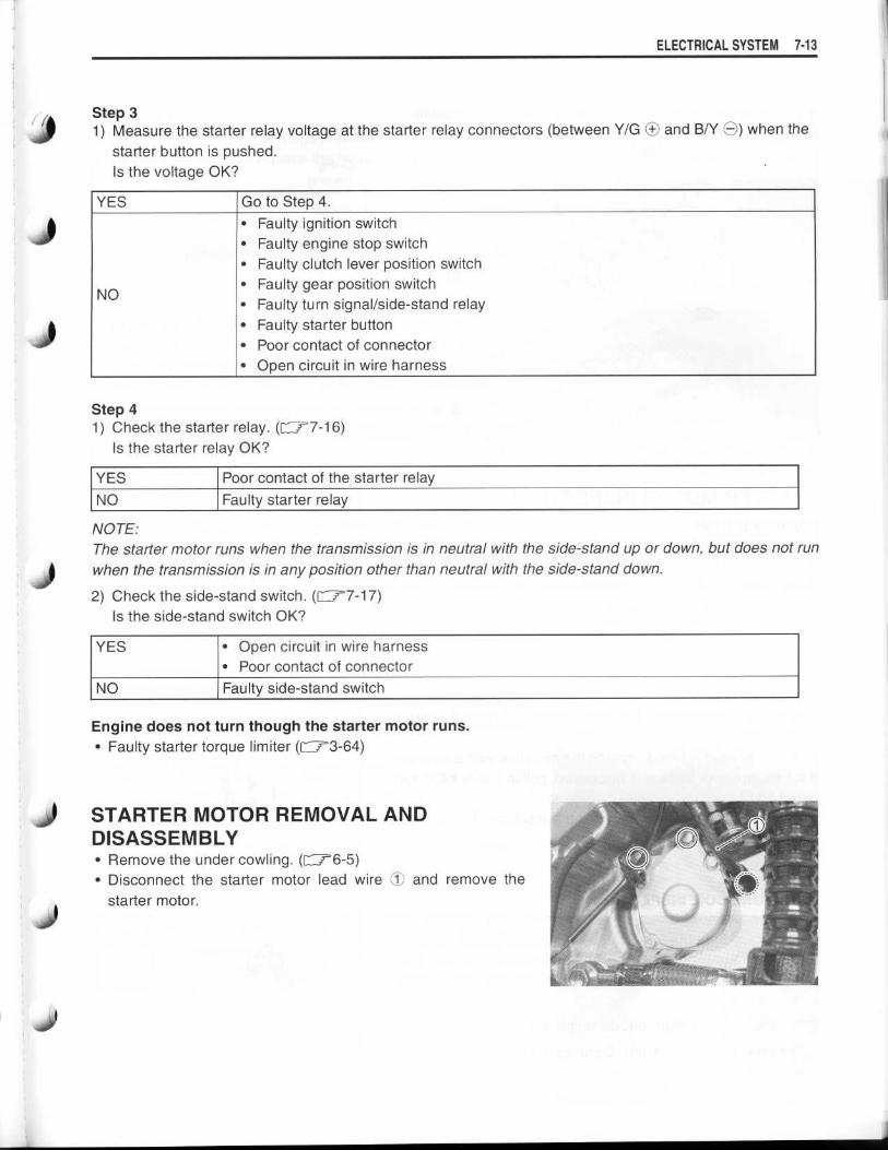
OIL SEAL INSPECTIONCheck the oil seal lip for damage or leakage .If any damage is found, replace the housing end .
J
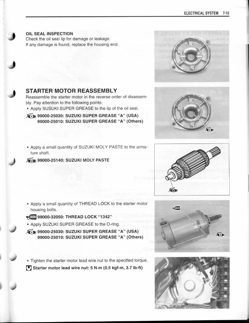
l STARTER MOTOR REASSEMBLYReassemble the starter motor in the reverse order of disassem-bly. Pay attention to the following points :•
Apply SUSUKI SUPER GREASE to the lip of the oil seal .
99000-25030: SUZUKI SUPER GREASE "A" (USA)99000-25010: SUZUKI SUPER GREASE "A" (Others)
•
Apply a small quantity of SUZUKI MOLY PASTE to the arma-ture shaft .
99000-25140: SUZUKI MOLY PASTE
•
Apply a small quantity of THREAD LOCK to the starter motorhousing bolts .
99000-32050 : THREAD LOCK "1342"
•
Apply SUZUKI SUPER GREASE to the O-ring .
99000-25030: SUZUKI SUPER GREASE "A" (USA)99000-25010: SUZUKI SUPER GREASE "A" (Others)
•
Tighten the starter motor lead wire nut to the specified torque .
19 Starter motor lead wire nut : 5 N .m (0.5 kgf-m, 3.7 Ib-ft)
ELECTRICAL SYSTEM 7- 1 5

7-16 ELECTRICAL SYSTEM
STARTER RELAY INSPECTION•
Remove the front seat . (F--r6-7)•
Disconnect the O battery lead wire from the battery .•
Disconnect the starter relay coupler 1O .•
Remove the starter relay cover 02 .
•
Disconnect the starter motor lead wire (s and battery leadwire ® .
•
Remove the starter relay 05 .
Apply 12 V to ® and © terminals and check for continuitybetween the positive and negative terminals using the multi cir-cuit tester . If the starter relay clicks and continuity is found, therelay is OK .
09900-25008 : Multi circuit tester set
Tester knob indication : Continuity test ( •~ l))
CAUTION
Do not apply a battery voltage to the starter relay formore than five seconds, since the relay coil may over-heat and damaged .
Measure the relay coil resistance between the terminals usingthe multi circuit tester . If the resistance is not within the specifiedvalue, replace the starter relay with a new one .
Starter relay resistance : 3 - 6 SZ
. . 09900-25008: Multi circuit tester set
~y Tester knob indication : Resistance (SZ)

J
SIDE-STAND/IGNITION INTERLOCKSYSTEM PARTS INSPECTIONCheck the interlock system for proper operation . If the interlocksystem does not operate properly, check each component fordamage or abnormalities . If any abnormality is found, replacethe component with a new one .
SIDE-STAND SWITCH•
Lift and support the fuel tank . (F-74-65)•
Disconnect the side-stand switch coupler and measure thevoltage between Green and Black/Yellow lead wires .
09900-25008: Multi circuit tester setP71 i Tester knob indication : Diode test (-~W)
NOTE:If the tester reads under 1.4 V when the tester probes are notconnected, replace its battery .
GEAR POSITION SWITCH•
Lift and support the fuel tank . (r-74-65)•
Disconnect the gear position switch coupler and check thecontinuity between Blue and Black with the transmission in"NEUTRAL" .
ON (Neutral)
OFF (Expect neutral)
CAUTION
Blue
0
Black
0
When disconnecting and connecting the gear positionswitch coupler, make sure to turn OFF the ignitionswitch, or electronic parts may get damaged .
ELECTRICAL SYSTEM 7- 1 7
Down
Green(O+ Probe)
Black/Yellow(O Probe)
ON(Side-stand up)
0 .4 - 0.6 V
OFF 1 .4 V and more(Side-stand down) (Tester's battery voltage)

7-18 ELECTRICAL SYSTEM
•
Connect the gear position switch coupler to the wiring har-
ness .
•
Turn the ignition switch to "ON" position and side-stand to
upright position .
Measure the voltage between Pink and Black lead wires using
the multi circuit tester when shifting the gearshift lever from low
to top .
Gear position switch voltage : 0.6 V and more
(* Low to top gear position)(Pink - Black)
(* Except neutral position)
09900-25008: Multi circuit tester set
09900-25009: Needle pointed probe set
1711 Tester knob indication : Voltage (--)
TURN SIGNAL/SIDE-STAND RELAYThe turn signal/side-stand relay is composed of the turn signal
relay, and the side-stand relay and diode .
•
Remove the front seat. (=6-7)6-7)
•
Remove the turn signal/side-stand relay .
SIDE-STAND RELAY INSPECTIONFirst check the insulation between O and O terminals with the
tester. Then apply 12 V to terminals OD and © ( O+ to O and O to
©) and check the continuity between OD and (e . If there is no
continuity, replace the turn signal/side-stand relay with a new
one .
09900-25008: Multi circuit tester set
Tester knob indication : Continuity test ( •) )))
. .
0 e

DIODE INSPECTIONJ
Measure the voltage between the terminals using the multi cir-cuit tester . Refer to the following table .
Unit: V
00000-
0
Probe of tester to : ©, ©OO
More than 1 .4 V©, ©
(Tester's batteryvoltage)
0.4-0 .6
09900-25008 : Multi circuit tester set
go Tester knob indication : Diode test (-W)
NOTE:If the multi circuit tester reads under 1 .4 V when the testerprobes are not connected, replace its battery .
ELECTRICAL SYSTEM 7- 1 9
iii© OO

7-20 ELECTRICAL SYSTEM
IGNITION SYSTEM
Throttlepositionsensor
Enginecoolant temp .sensor
Gearpositionswitch
m m
NOTE:
The fuel cut-off circuit is incorporated in this ECM in order to prevent over-running of engine . When engine
speed reaches 10 600 r/min, this circuit cuts off fuel at the fuel injector .
CAUTION
Under no load, the engine can run over 10 600 r/min, even if the fuel cut-off circuit is effective,
and it may cause engine damage . Do not run the engine without load over 10 600 r/min at any-
time .
TROUBLESHOOTINGNOTE:
Check that the transmission is in neutral and the engine stop switch is in the "RUN" position . Pull the clutch
lever. Check that the fuse is not blown and the battery is fully-charged before diagnosing .
No spark or poor sparkStep 11) Check the ignition system couplers for poor connections .
Is there connection in the ignition switch couplers?
YES Go to Step 2 .
NO
Poor connection of couplers
<Continued on next page>
V
Engine stop switch0
ECMb Side-
Ignitioncoil
standstandrelayPower
circuitsource
CKPsensor
Spark plug Fuse0#1I Wave form0I
1 0I
arrangementcircuit Ignitiont 0a 00 switch
CPU 0°o #2'ta
Fuse
Wave formarrangement
Cam positioncircuit Battery
sensor

Step 21) Measure the battery voltage between input lead wires (O/W and B/W) at the ECM with the ignition switch
in the "ON" position .Is the voltage OK?
Step 31) Measure the ignition coil primary peak voltage . ( f"77-22)
NOTE:This inspection method is applicable only with the multi circuit tester and the peak volt adaptor.
Is the peak voltage OK?
YESNO
Go to Step 4 .Go to Step 5 .
Step 41) Inspect the spark plugs. (=2-6)2-6)
Are the spark plugs OK?
Step 51) Inspect the ignition coils . (E177-23)
Are the ignition coils OK?
ELECTRICAL SYSTEM 7-21
YESNO
Go to Step 6 .Faulty ignition coil (-s)
Step 61) Measure the crankshaft position sensor peak voltage and its resistance .
NOTE:The crankshaft position sensor peak voltage inspection is applicable only with the mufti circuit tester andpeak volt adaptor.
Are the peak voltage and its resistance OK?
YES Go to Step 3 .
NO
•
Faulty ignition switch•
Faulty turn signal/side-stand relay•
Faulty engine stop switch•
Broken wire harness or poor connection of related circuit couplers
YES •
Poor connection of the spark plug cap (-s)•
Go to Step 5 .NO Faulty spark plug (-s)
YES •
Faulty ECM•
Poor connection of ignition couplersNO Faulty crankshaft position sensor

7-22 ELECTRICAL SYSTEM
INSPECTIONIGNITION COIL PRIMARY PEAK VOLTAGE•
Lift and support the fuel tank . (l1_,,--4-65)
•
Disconnect both of the spark plug caps . (f'72-6)
•
Connect new spark plugs to each spark plug cap and ground
them .
NOTE:
Make sure that all couplers and spark plugs are connected prop-
erly and the battery used is in fully-charged condition .
CAUTION
Avoid grounding the spark plugs and suppling the
electrical shock to the cylinder head cover (magne-
sium parts) in order to prevent the magnesium mate-
rial from damage .
Measure the No. 1 and No. 2 ignition coils primary peak voltage
in the following procedure .
•
Connect the multi circuit tester with peak voltage adaptor as
follows .
No . 1 ignition coil : OO Probe: Black terminal
•
Probe: Ground
No . 2 ignition coil : OO Probe: White/Blue terminal
•
Probe: Ground
NOTE:
Do not disconnect the ignition coil primary wire coupler .
09900-25008: Multi circuit tester set. .
CAUTION
Before using the multi circuit tester and peak volt
adaptor, be sure to refer to the appropriate instruction
manual .
•
Shift the transmission into neutral .
•
Allow the engine to crank for a few seconds, and then mea-
sure the ignition coil primary peak voltage .
•
Repeat the above procedure a few times and measure the
highest ignition coil primary peak voltage .
Ignition coil primary peak voltage : 200 V and more
Tester knob indication : Voltage (--)
A WARNING
While testing, do not touch the tester probes and
spark plugs to prevent receiving an electric shock .
•
If the peak voltage is lower than the specified values, inspect
the ignition coil . (F---r7-23)
r
In

J IGNITION COIL RESISTANCE
• Disconnect the spark plug caps .
Measure the ignition coil resistance in both the primary and sec-ondary windings . If the resistance is not within the standardrange, replace the ignition coil with a new one .
1
(
Ignition coil resistancePrimary : 2.8 - 4.2 S2 ((O terminal - S terminal)Secondary: 24 - 36 kL2 (Plug cap - O terminal)
09900-25008 : Multi circuit tester set
Tester knob indication: Resistance (4)
CKP SENSOR PEAK VOLTAGE•
Remove the front seat . (116-7)•
Disconnect the ECM coupler .
NOTE:Make sure that all of the couplers are connected properly andthe battery used is in fully-charged condition .
Measure the CKP sensor peak voltage in the following proce-dures .
•
Connect the multi circuit tester with peak volt adaptor as fol-lows .O Probe: Green/Blue lead wire9 Probe: Green lead wire
. . 09900-25008 : Multi circuit tester set
CAUTION
Before using the multi circuit tester and peak voltadaptor, be sure to refer to the appropriate instructionmanual .
ELECTRICAL SYSTEM 7- 23

7-24 ELECTRICAL SYSTEM
•
Shift the transmission into neutral .•
Allow the engine to crank for a few seconds, and then mea-sure the CKP sensor peak voltage .
•
Repeat the above procedure a few times and measure thehighest peak voltage .
[
CKP sensor peak voltage : 5 .0 V and moreIrPli Tester knob indication : Voltage (-)
If the peak voltage is lower than the specified values, check thepeak voltage at the CKP sensor lead wire coupler (Z .•
Disconnect the CKP sensor lead wire coupler and connect themulti circuit tester with the peak volt adaptor .•
Probe: Green lead wire•
Probe: Blue lead wire•
Measure the CKP sensor peak voltage at the CKP sensorlead wire coupler in the same manner as on the ECM coupler .
CKP sensor peak voltage : 5.0 V and more
~,~ Tester knob indication : Voltage (-)
If the peak voltage on the CKP sensor lead wire coupler is OKbut on the ECM coupler is out of specification, the wire harnessmust be replaced. If both peak voltages are out of specification,the CKP sensor must be replaced and re-checked .
CKP SENSOR RESISTANCEMeasure the resistance between the lead wires and ground . Ifthe resistance is not specified value, the CKP sensor must bereplaced .
CKP sensor resistance: 130 - 240 Q (Green - Blue)W Q (Green - Ground)
09900-25008: Multi circuit tester set
Tester knob indication : Resistance (S2)

COMBINATION METER
CAUTION
REMOVAL•
Remove the body cowling . (r--r6-6)•
Remove the meter panel mounting bolts and disconnect themeter coupler 1T .
•
When disconnecting and connecting the combina-
tion meter coupler, make sure to turn OFF the igni-
tion switch, or electronic parts may get damaged .•
Do not attempt to disassemble the combination
meter unit.
ELECTRICAL SYSTEM 7- 25
J) Conbination meter cover(2 Conbination meter unit

7-2 6 ELECTRICAL SYSTEM
PARTS NAME
10 Turn signal indicator light(2 Neutral indicator light(3 Indicator light (Oil, Temp ., FI)•
SELECT button•
Clock•
Coolant temperature/Fl display(7 Odo/Trip meter display•
ADJUST button~9 Fuel indicator light1o High beam indicator light
OPERATING PROCEDUREINITIAL DISPLAYWhen the ignition switch is turned to ON, the indicator lightand O come on, then ©9 goes out two seconds later .
NOTE:If the power supply is cut (e, g, when the battery is replaced) :* The speedometer, tripmeter and clock are displayed after theinitial display appears .
* Since the clock resets to "1 :00", it will need to be readjusted .
CHANGE THE DISPLAY MODEWith each press of the SELECT button, the display changesbetween odometer, tripmeter A and tripmeter B as shown .
A WARNING
Odometer-nTripmeter A~~ TripmeterB1-1
To avoid riding with only one hand, do not operate thebuttons while riding .
ODOMETER•
Displays the total distance travelled
TRIPMETER•
Displays the distance travelled since the tripmeter was lastreset
NOTE:The tripmeters A and B can be used independently.
•
Hold down the ADJUST button for two seconds to reset thetripmeter .

i
CLOCK•
Displays the time (hours and minutes) on a 12-hour clock•
Setting the time
10 Push the SELECT and ADJUST buttons simultaneously untilthe hour display starts blinking .
02 Adjust the hour display by pushing the ADJUST button .
NOTE:When the ADJUST button is kept depressed for more than twoseconds, the display progresses continuously.
03 Push the SELECT button . The setting that is blinking can bechanged .
® Adjust the minute display by pushing the ADJUST button .
($ Push the SELECT button to finish setting time .
TACHOMETER• The tachometer pointer operates one time as shown below toreset tachometer pointer, when connecting the battery ortachometer coupler .
ELECTRICAL SYSTEM 7-27
ADJ

7-28 ELECTRICAL SYSTEM
ENGINE COOLANT TEMPERATURE METERAND INDICATOR•
Disconnect the engine coolant temperature sensor coupler .
CAUTION
When connecting and disconnecting the engine cool-ant temp. sensor lead wire coupler, make sure to turnOFF the ignition switch, or electronic parts may getdamaged.
•
Connect the variable resistor OO between the terminals .•
Turn the ignition switch "ON" .•
Check the LCD and LED operations when the resistance isadjusted to the specified values .
If either one or all indications are abnormal, replace the combi-nation meter with a new one .
NOTE:If the engine stop switch is turned OFF while the ignition switchis ON, the LCD displays "CHEC" . But it is not malfunction .This condition implies that combination meter receives no signalfrom the ECM.In that case, they are restored to ordinary indication by turningthe engine stop switch RUN .
Variable resister
Enginecoolanttemp .sensor
ResistanceAO
LED © LCD © LCD 0 Watertemperature
Over 2.45 kS OFF --- Under 19 °CApprox .0.811 kS2
OFF "50" -Approx .50 °C
Approx .0 .1 kS2
ON "120"-"139" Flicker 120-139 0C
0c(Jumper wire)
ON "HI" Flicker Over 140 °C

1
• Connect 12 V battery and test bulb (12 V, 3 .4 W) to the fuel
level indicator switch as shown in the right illustrations . The
bulb should come on after several seconds if the switch is in
good condition .
• When the switch is immersed in water under the above condi-
tion, the bulb should go out . If the bulb remains it, replace the
unit with a new one .
FUEL LEVEL INDICATOR LIGHT INSPECTIONIf the fuel level indicator light does not function properly, check
the fuel level indicator switch and its lead wire/coupler .
If the fuel level indicator switch and its lead wire/coupler are all
right, replace the combination meter with a new one .
OIL PRESSURE INDICATOR
NOTE:
Before inspecting the oil pressure switch, check the engine oil
level . (rr2-15)
•
Remove the under cowling . (C 7-6-5)
•
Disconnect the oil pressure switch lead wire from the oil pres-
sure switch .
•
Turn the ignition switch "ON" position .
FUEL LEVEL INDICATOR SWITCH INSPECTION•
Remove the fuel pump assembly . (=4-69)4-69)
ELECTRICAL SYSTEM 7-29

7.30 ELECTRICAL SYSTEM
Check if the oil pressure indicator will light, when grounding thelead wire . If the oil pressure indicator does not function properly,replace the meter with a new one after checking the connectionof couplers .
SPEEDOMETERIf the speedometer, odometer or trip meter does not functionproperly, inspect the speedometer sensor and connection ofcoupler 1). If the speedometer sensor and connection are allright, replace the meter with a new one .
SPEEDOMETER SENSOR•
Disconnect speedometer sensor coupler .•
Remove the speedometer sensor (2 by removing its mountingbolt .
•
Connect 12 V battery, 10 kQ resistor and the multi circuittester as shown in the right illustration .
B/R: Black with Red tracerB/W: Black with White tracerB : Black
:. 09900-25008 : Multi circuit tester set
Tester knob indication: Voltage (=)
• Under above condition, if a suitable screwdriver touching thepick-up surface of the speedometer sensor is moved, thetester reading voltage changes (0 V - 12 V or 12 V - 0 V) . Ifthe tester reading voltage does not change, replace thespeedometer sensor with a new one .
NOTE:The highest voltage reading in this test will be the same as thatof battery voltage .

LAMPSHEADLIGHT AND POSITION LIGHT
l
BULB REPLACEMENTHeadlight•
Remove the headlight coupler and boot .
•
Unhook the holder spring 9I and replace the headlight bulb .
Position light•
Open the lids . (L & R)
•
Remove the position light couplers 10 . (L & R)
CAUTION
If you touch the bulb with your bare hands, clean thebulb with a cloth moistened with alcohol or soapy
water to prevent premature bulb failure .
ELECTRICAL SYSTEM 7-31
10 Head light12 V 60/55 W x 2
(2 Position light12 V 5 W x 2

7-32 ELECTRICAL SYSTEM
HEADLIGHT BEAM ADJUSTMENTAdjust the headlight beam, both vertical and horizontal .•
Turn the adjuster OA for the horizontal adjustment .
NOTE:To adjust the headlight beam, adjust the beam horizontally first,then adjust the vertically.
•
Turn the bolt © for the vertical adjustment .
BRAKE LIGHT/TAILLIGHT, TURN SIGNAL LIGHT AND LICENCE PLATELIGHT

RELAYSTURN SIGNAL/SIDE-STAND RELAYThe turn signal/side-stand relay is composed of the turn signal
relay, side-stand relay and diode .
INSPECTIONBefore removing the turn signal/side-stand relay, check the
operation of the turn signal light .
If the turn signal light does not illuminate, inspect the bulb, turn
signal switch and circuit connection .
If the bulb, turn signal switch and circuit connection are OK, the
turn signal relay may be faulty ; therefore, replace the turn signal/side-stand relay with a new one .
NOTE:
* Make sure that the battery is fully charged .
* Refer to page 7-17 for the side-stand relay and diode inspec-
tion .
STARTER RELAYr-77-1 6
FUEL PUMP RELAY17'4-69
ELECTRICAL SYSTEM 7-33
T)
SIDE-STAND RELAY
TURNSIGNALRELAY
4)

7-34 ELECTRICAL SYSTEM
SWITCHESIGNITION SWITCH REMOVAL•
Lift and support the fuel tank . (=4-65)
•
Remove the air cleaner box . (F--74-75)•
Disconnect the ignition switch coupler .
•
Remove the body cowling . (r-76-6)•
Remove the ignition switch mounting bolts with the special
tools .
09930-11920: Torx bit JT40H
09930-11940: Bit holder
CAUTION
When reusing the ignition switch bolt, clean thread and
apply THREAD LOCK .
99000-32050 : THREAD LOCK "1342"

J
J
Inspect each switch for continuity with the multi circuit tester . If any abnormality is found, replace the respec-tive switch assemblies with new ones .
09900-25008: Multi circuit tester set
DIMMER SWITCH
PASSING LIGHT SWITCHColor
Position
PUSH
0 Y
ENGINE STOP SWICH
STARTER BUTTONColor
Position O/W Y/G
ColorPosition Lg Lbl
ON 0 0OFF
ColorPosition B/R B/BI
OFFON 0 0
ColorPosition O/G W/B
OFFON 0 0
HAZARD
FRONT BRAKE SWITCH
REAR BRAKE SWITCH
CLUTCH LEVER POSITION SWITCHColor
B/Y
B/YPositionOFFON
OIL PRESSURE SWITCH
ELECTRICAL SYSTEM 7. 3 5
NOTE:Before inspecting the oil pressure switch, check theengine oil level. (C72-15)
WIRE COLOR
B
: BlackBr : BrownLbI : Light blueLg : Light green0 : OrangeR : RedY
: YellowW : White
B/BI : Black with Blue tracerB/W : Black with White tracerB/Y : Black with Yellow tracerB/R : Black with Red tracerG/Y : Green with Yellow tracerO/B : Orange with Black tracerO/G : Orange with Green tracerO/W : Orange with White tracerON :Orange with Yellow tracerW/B : White with Black tracerY/G : Yellow with Green tracer
IGNITION SWITCHColor
Position R 0 ON Br
ON
P
B
0
ColorPosition
W y 0
HI (=D) 0 0LO (D) 0 0
TURN SIGNAL SWITCHColor
Position Lg Lbl B
L 0 0PUSH
R 0 0
ColorPosition G/Y Ground
ON (engineis stopped) O O
OFF (engineis running)
ColorPosition O/B O/W
OFF (>Z)RUN (0) 0
PUSH 0
HORN BUTTONColor
Position13/131 B/W
PUSH 0

7-3 6 ELECTRICAL SYSTEM
BATTERYSPECIFICATIONS
Type designationCapacity
FTX14-BS12 V, 43 .2 kC (12 Ah)/10 HR
•
Anode plates•
Separator (fiberglass plate)•
Cathode plates•
Upper cover breather
© Stopper•
Filter
•
Terminal•
Safety valve
INITIAL CHARGINGFILLING ELECTROLYTE•
Remove the aluminum tape 10 sealing the battery electrolytefiller holes 02 .
•
Remove the caps (T .NOTE:* After filling the electrolyte completely, use the removed capsO3 as the sealed caps of battery filler holes .
* Do not remove or pierce the sealed areas ® of the electrolytecontainer.
• Insert the nozzles of the electrolyte container ($ into the bat-tery's electrolyte filler holes, holding the container firmly sothat it does not fall . Take precaution not to allow any of thefluid to spill .
IN
V

1
l
• Make sure air bubbles © are coming up each electrolyte con-tainer, and leave in this position for about more than 20 min-utes .
NOTE:
If on air bubbles are coming up from a filler port, tap the bottom
of the electrolyte container two or three times .
Never remove the container from the battery.
• After confirming that the electrolyte has entered the battery
completely, remove the electrolyte containers from the bat-tery. Wait for about more than 20 minutes .
• Insert the caps O7 into the filler holes, pressing in firmly so that
the top of the caps do not protrude above the upper surface ofthe battery's top cover .
CAUTION
•
Never use anything except the specified battery .
•
Once install the caps to the battery ; do not removethe caps .
•
Do not tap the caps with a hammer when installingthem .
ELECTRICAL SYSTEM 7-37
O 0 L) UoV U Oo 0
0U Oo00 Vo 0J° O U 0
GV oU
0O° o Go 0 0G
I H,I 0 G ~`

7-3 8 ELECTRICAL SYSTEM
•
For initial charging, use the charger specially designed for MF
battery .
CAUTION
• For charging the battery, make sure to use thecharger specially designed for MF battery. Other-
wise, the battery may be overcharged resulting in
shortened service life .
•
Do not remove the cap during charging .
•
Position the battery with the cap facing upward dur-
ing charging .
SERVICINGVisually inspect the surface of the battery container. If any signs
of cracking or electrolyte leakage from the sides of the battery
have occurred, replace the battery with a new one . If the battery
terminals are found to be coated with rust or an acidic whitepowdery substance, clean the battery terminals with sandpaper .
NOTE:
While recharging, do not remove the caps on the top of the bat-
tery.
Recharging time : 1 .4 A for 5 to 10 hours or 6 A for 1 hour
CAUTION
Be careful not to permit the charging current to
exceed 6 A at any time .
• After recharging, wait at least 30 minutes and then measure
the battery voltage using the multi circuit tester . If the battery
voltage is less than 12 .5 V, recharge the battery again . If the
battery voltage is still less than 12 .5 V after recharging,
replace the battery with a new one .
• When a battery is left unused for a long time, its voltage
needs to be regularly measured . When the motorcycle is not
used for more than one month (especially during the winter
season), measure the battery voltage at least once a month .
Charging period
Stop charging
0 10 20 30 40 50 60Time
(Minutes)
RECHARGING OPERATION(V)
•
Measure the battery voltage using the multi circuit tester . If 18is less
12 V 17the voltage reading
than the
(DC), recharge the16battery with a battery charger . 15
CAUTION 14 -13
When recharging the battery, remove the battery from 12
the motorcycle .
Related Documents