DOE Fundamentals ELECTRICAL SCIENCE Module 7 Basic AC Theory

Welcome message from author
This document is posted to help you gain knowledge. Please leave a comment to let me know what you think about it! Share it to your friends and learn new things together.
Transcript
DOE Fundamentals
ELECTRICAL SCIENCE
Module 7
Basic AC Theory
Electrical Science Basic AC Theory
i
TABLE OF CONTENTS
Table of Co nte nts
TABLE OF CONTENTS ................................................................................................... i
LIST OF FIGURES ...........................................................................................................ii
LIST OF TABLES ............................................................................................................ iii
REFERENCES ................................................................................................................iv
OBJECTIVES .................................................................................................................. v
AC GENERATION........................................................................................................... 1
Development of a Sine-Wave Output .......................................................................... 1
Summary ..................................................................................................................... 3
AC GENERATION ANALYSIS ........................................................................................ 4
Effective Values ........................................................................................................... 4
Phase Angle ................................................................................................................ 7
Voltage Calculations .................................................................................................... 8
Current Calculations .................................................................................................... 9
Frequency Calculations ............................................................................................... 9
Summary ................................................................................................................... 10
Electrical Science Basic AC Theory
ii
LIST OF FIGURES
Figure 1 Simple AC Generator ............................................................................... 1
Figure 2 Developing a Sine-Wave Voltage ............................................................ 2
Figure 3 Voltage Sine Wave .................................................................................. 4
Figure 4 Effective Value of Current ........................................................................ 6
Figure 5 Phase Relationship .................................................................................. 7

Electrical Science Basic AC Theory
iii
LIST OF TABLES
NONE
Electrical Science Basic AC Theory
iv
REFERENCES
Gussow, Milton, Schaum's Outline of Basic Electricity, 2nd Edition, McGraw-Hill.
Academic Program for Nuclear Power Plant Personnel, Volume I & II, Columbia,
MD: General Physics Corporation, Library of Congress Card #A 326517, 1982.
Sienko and Plane, Chemical Principles and Properties, 3rd Edition, McGraw-Hill.
Nasar and Unnewehr, Electromechanics and Electric Machines, 2nd Edition, John
Wiley and Sons.
Nooger and Neville Inc., Van Valkenburgh, Basic Electricity, Vol. 5, Hayden Book
Company.
Bode, H., 1977, Lead-Acid Batteries, John Wiley and Sons, New York
Lister, Eugene C., Electric Circuits and Machines, 5th Edition, McGraw-Hill.
Croft, Hartwell, and Summers, American Electricians’ Handbook, 16th Edition,
McGraw-Hill.
Mason, C. Russell, The Art and Science of Protective Relaying, John Wiley and
Sons.
Mileaf, Harry, Electricity One - Seven, Revised 2nd Edition, Prentice Hall.
Buban and Schmitt, Understanding Electricity and Electronics, 3rd Edition,
McGraw-Hill
Kidwell, Walter, Electrical Instruments and Measurements, McGraw-Hill.
Electrical Science Basic AC Theory
v
OBJECTIVES
TERMINAL OBJECTIVE
1.0 Given an alternating current (AC) waveform, DESCRIBE the relationship
between average and RMS values of voltage and current, and the angular
velocity within that waveform.
ENABLING OBJECTIVES
1.1 DESCRIBE the construction and operation of a simple AC generator.
1.2 EXPLAIN the development of a sine-wave output in an AC generator.
1.3 DEFINE the following terms in relation to AC generation:
a. Radians/second
b. Hertz
c. Period
1.4 DEFINE effective value of an AC current relative to DC current.
1.5 Given a maximum value, CALCULATE the effective (RMS) and average values
of AC voltage.
1.6 Given a diagram of two sine waves, DESCRIBE the phase relationship between
the two waves.
Electrical Science AC Generation Basic AC Theory
1
AC GENERATION
An understanding of how an AC generator develops an AC output will help
the student analyze the AC power generation process.
EO 1.1 DESCRIBE the construction and operation of a simple AC
generator.
EO 1.2 EXPLAIN the development of a sine-wave output in an AC
generator.
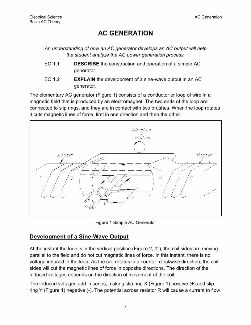
The elementary AC generator (Figure 1) consists of a conductor or loop of wire in a
magnetic field that is produced by an electromagnet. The two ends of the loop are
connected to slip rings, and they are in contact with two brushes. When the loop rotates
it cuts magnetic lines of force, first in one direction and then the other.
Figure 1 Simple AC Generator
Development of a Sine-Wave Output
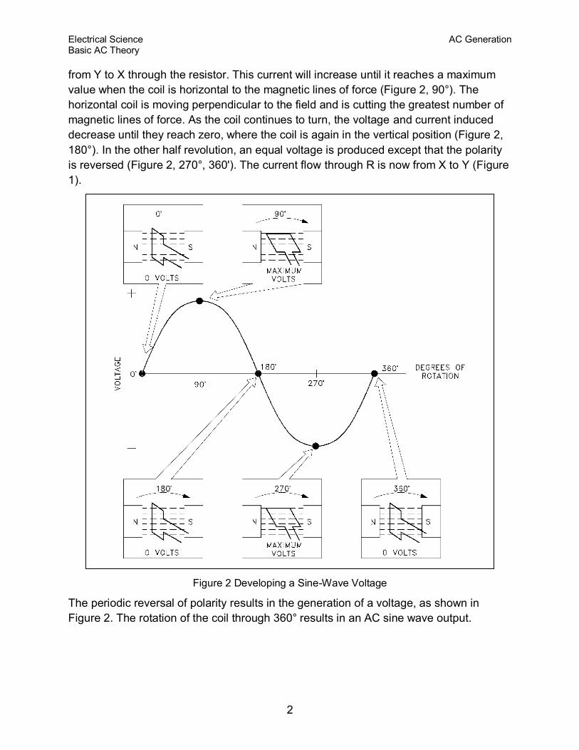
At the instant the loop is in the vertical position (Figure 2, 0°), the coil sides are moving
parallel to the field and do not cut magnetic lines of force. In this instant, there is no
voltage induced in the loop. As the coil rotates in a counter-clockwise direction, the coil
sides will cut the magnetic lines of force in opposite directions. The direction of the
induced voltages depends on the direction of movement of the coil.
The induced voltages add in series, making slip ring X (Figure 1) positive (+) and slip
ring Y (Figure 1) negative (-). The potential across resistor R will cause a current to flow
Electrical Science AC Generation Basic AC Theory
2
from Y to X through the resistor. This current will increase until it reaches a maximum
value when the coil is horizontal to the magnetic lines of force (Figure 2, 90°). The
horizontal coil is moving perpendicular to the field and is cutting the greatest number of
magnetic lines of force. As the coil continues to turn, the voltage and current induced
decrease until they reach zero, where the coil is again in the vertical position (Figure 2,
180°). In the other half revolution, an equal voltage is produced except that the polarity
is reversed (Figure 2, 270°, 360'). The current flow through R is now from X to Y (Figure
1).
Figure 2 Developing a Sine-Wave Voltage
The periodic reversal of polarity results in the generation of a voltage, as shown in
Figure 2. The rotation of the coil through 360° results in an AC sine wave output.
Electrical Science AC Generation Basic AC Theory
3
Summary
AC generation is summarized below.
AC Generation Summary
A simple generator consists of a conductor loop turning in a magnetic field,
cutting across the magnetic lines of force.
The sine wave output is the result of one side of the generator loop cutting
lines of force. In the first half turn of rotation this produces a positive current
and in the second half of rotation produces a negative current. This completes
one cycle of AC generation.
Electrical Science AC Generation Analysis Basic AC Theory
4
AC GENERATION ANALYSIS
Analysis of the AC power generation process and of the alternating
current we use in almost every aspect of our lives is necessary to better
understand how AC power is used in today's technology.
EO 1.3 DEFINE the following terms in relation to AC generation:
a. Radians/second
b. Hertz
c. Period
EO 1.4 DEFINE effective value of an AC current relative to DC current.
EO 1.5 Given a maximum value, CALCULATE the effective (RMS) and
average values of AC voltage.
EO 1.6 Given a diagram of two sine waves, DESCRIBE the phase
relationship between the two waves.
Effective Values
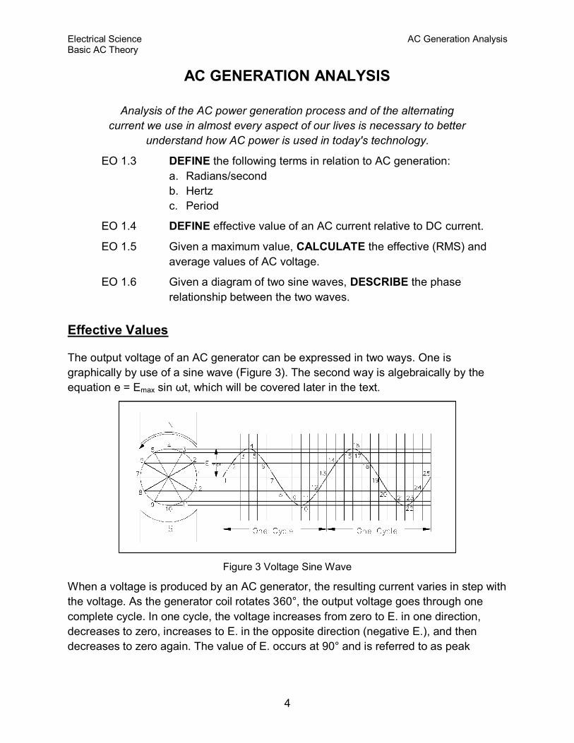
The output voltage of an AC generator can be expressed in two ways. One is
graphically by use of a sine wave (Figure 3). The second way is algebraically by the
equation e = Emax sin ωt, which will be covered later in the text.
Figure 3 Voltage Sine Wave
When a voltage is produced by an AC generator, the resulting current varies in step with
the voltage. As the generator coil rotates 360°, the output voltage goes through one
complete cycle. In one cycle, the voltage increases from zero to E. in one direction,
decreases to zero, increases to E. in the opposite direction (negative E.), and then
decreases to zero again. The value of E. occurs at 90° and is referred to as peak
Electrical Science AC Generation Analysis Basic AC Theory
5
voltage. The time it takes for the generator to complete one cycle is called the period,
and the number of cycles per second is called the frequency (measured in hertz).
One way to refer to AC voltage or current is by peak voltage (Ep) or peak current (Ip).
This is the maximum voltage or current for an AC sine wave.
Another value, the peak-to-peak value (Ep-p or Ip-p) is the magnitude of voltage, or
current range, spanned by the sine wave. However, the value most commonly used for
AC is effective value. Effective value of AC is the amount of AC that produces the same
heating effect as an equal amount of DC. In simpler terms, one ampere effective value
of AC will produce the same amount of heat in a conductor, in a given time, as one
ampere of DC. The heating effect of a given AC current is proportional to the square of
the current. Effective value of AC can be calculated by squaring all the amplitudes of the
sine wave over one period, taking the average of these values, and then taking the
square root. The effective value, being the root of the mean (average) square of the
currents, is known as the root-mean-square, or RMS value. In order to understand the
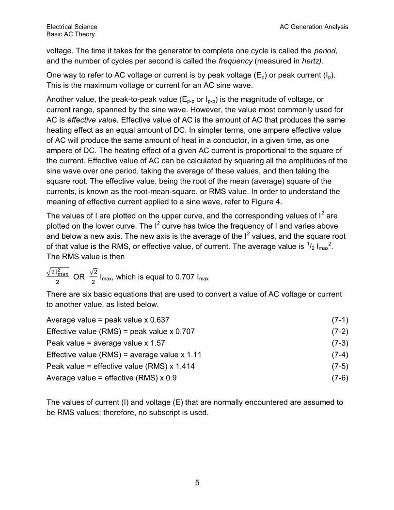
meaning of effective current applied to a sine wave, refer to Figure 4.
The values of I are plotted on the upper curve, and the corresponding values of I2 are
plotted on the lower curve. The I2 curve has twice the frequency of I and varies above
and below a new axis. The new axis is the average of the I2 values, and the square root
of that value is the RMS, or effective value, of current. The average value is 1/2 Imax2.
The RMS value is then
OR
Imax, which is equal to 0.707 Imax
There are six basic equations that are used to convert a value of AC voltage or current
to another value, as listed below.
Average value = peak value x 0.637 (7-1)
Effective value (RMS) = peak value x 0.707 (7-2)
Peak value = average value x 1.57 (7-3)
Effective value (RMS) = average value x 1.11 (7-4)
Peak value = effective value (RMS) x 1.414 (7-5)
Average value = effective (RMS) x 0.9 (7-6)
The values of current (I) and voltage (E) that are normally encountered are assumed to
be RMS values; therefore, no subscript is used.
Electrical Science AC Generation Analysis Basic AC Theory
6
Figure 4 Effective Value of Current
Another useful value is the average value of the amplitude during the positive half of the
cycle. Equation (7-7) is the mathematical relationship between Iav, Imax, and I.
Iav = 0.637 Imax = 0.90 I (7-7)
Equation (7-8) is the mathematical relationship between Eav , Emax, and E.
Eav = 0.637 Emax = 0.90 E (7-8)
Example 1: The peak value of voltage in an AC circuit is 200 V. What is the RMS
value of the voltage?
E = 0.707 Emax
E = 0.707 (200 V)
E = 141.4 V
Example 2: The peak current in an AC circuit is 10 amps. What is the average value of
current in the circuit?
Iav = 0.637 Imax
Iav = 0.637 (10 amps)
Iav = 6.37 amps
Electrical Science AC Generation Analysis Basic AC Theory
7
Phase Angle
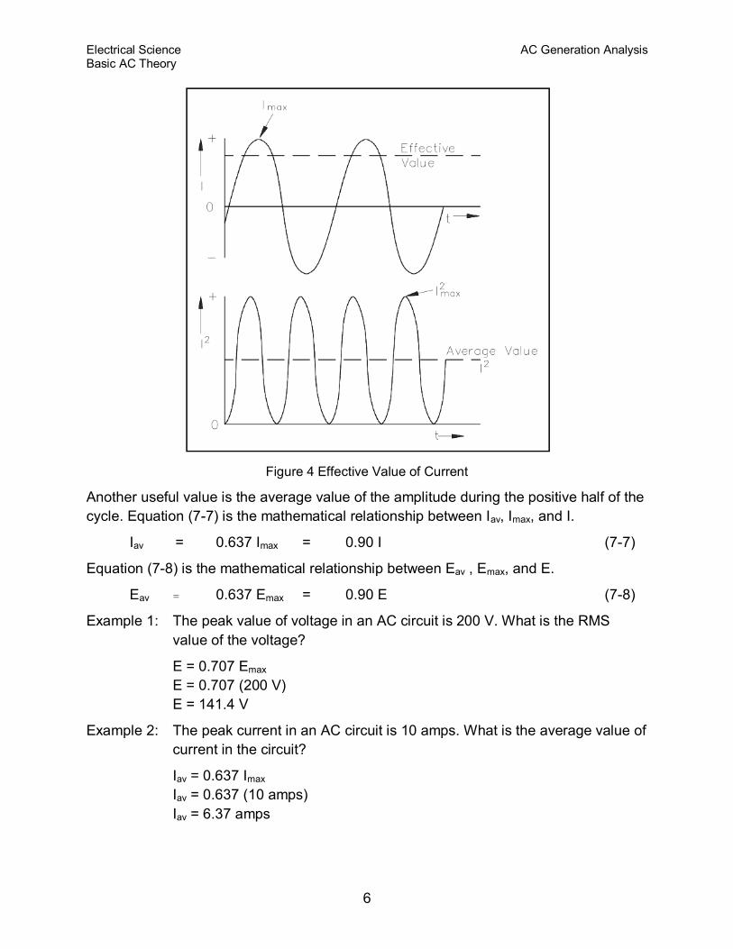
Phase angle is the fraction of a cycle, in degrees, that has gone by since a voltage or
current has passed through a given value. The given value is normally zero. Referring
back to Figure 3, take point 1 as the starting point or zero phase. The phase at Point 2
is 30°, Point 3 is 60°, Point 4 is 90°, and so on, until Point 13 where the phase is 360°,
or zero. A term more commonly used is phase difference. The phase difference can be
used to describe two different voltages that have the same frequency, which pass
through zero values in the same direction at different times. In Figure 5, the angles
along the axis indicate the phases of voltages e1 and e2 at any point in time. At 120°, e1
passes through the zero value, which is 60° ahead of e2 (e2 equals zero at 180°). The
voltage e1 is said to lead e2 by 60 electrical degrees, or it can be said that e2 lags el by
60 electrical degrees.
Figure 5 Phase Relationship
Phase difference is also used to compare two different currents or a current and a
voltage. If the phase difference between two currents, two voltages, or a voltage and a
current is zero degrees, they are said to be "in-phase." If the phase difference is an
amount other than zero, they are said to be "out-of-phase."
Electrical Science AC Generation Analysis Basic AC Theory
8
Voltage Calculations
Equation (7-9) is a mathematical representation of the voltage associated with any
particular orientation of a coil (inductor).
e = Emax sinӨ
max
(7-9)
where
e = induced EMF
Emax = maximum induced EMF
Ө = angle from reference (degrees or radians)
Example 1: What is the induced EMF in a coil producing a maximum EMF of 120 V
when the angle from reference is 45°?
e = Emax sinӨ
e = 120 V (sin 45°)
e = 84.84 V
The maximum induced voltage can also be called peak voltage Ep. If (t) is the time in
which the coil turns through the angle (Ө), then the angular velocity (ω) of the coil is
equal to Ө/t and is expressed in units of radians/sec. Equation (7-10) is the
mathematical representation of the angular velocity.
Ө = ω t (7-10)
where
ω = angular velocity (radians/sec)
t = time to turn through the angle from reference (sec)
Ө = angle from reference (radians)
Using substitution laws, a relationship between the voltage induced, the maximum
induced voltage, and the angular velocity can be expressed. Equation (7-11) is the
mathematical representation of the relationship between the voltage induced, the
maximum voltage, and the angular velocity, and is equal to the output of an AC
Generator.
e = Emax sin (ω t) (7-11)
where
e = Induced EMF (volts)
Emax = maximum induced EMF (volts)
ω = angular velocity (radians/sec)
t = time to turn through the angle from reference (sec)
Electrical Science AC Generation Analysis Basic AC Theory
9
Current Calculations
Maximum induced current is calculated in a similar fashion. Equation (7-12) is a
mathematical representation of the relationship between the maximum induced current
and the angular velocity.
i = Imax sin (ω t) (7-12)
where
i = induced current (amps)
Imax = maximum induced current (amps)
ω = angular velocity (radians/sec)
t = time to turn through the angle from reference (sec)
Frequency Calculations
The frequency of an alternating voltage or current can be related directly to the angular
velocity of a rotating coil. The units of angular velocity are radians per second, and 2π
radians is a full revolution. A radian is an angle that subtends an arc equal to the radius
of a circle. One radian equals 57.3 degrees. One cycle of the sine wave is generated
when the coil rotates 2π radians. Equation (7-13) is the mathematical relationship
between frequency (f) and the angular velocity (ω) in an AC circuit.
ω = 2π f (7-13)
where
ω= angular velocity (radians/sec)
f = frequency (HZ)
Example 1: The frequency of a 120 V AC circuit is 60 Hz. Find the following:
1. Angular velocity
2. Angle from reference at 1 msec
3. Induced EMF at that point
Solution:
1. ω = 2 π f
= 2 (3.14) (60Hz)
= 376.8 radians/sec
Electrical Science AC Generation Analysis Basic AC Theory
10
2. Ө = ω t
= (376.8 radian/sec) (.001 sec)
= 0.3768 radians
3. e = Emax sin Ө
= (120 V) sin(0.3768 radians)
= (120 V) (0.3679)
= 44.15 V
Summary
AC generation analysis is summarized below.
Voltage, Current, and Frequency Summary
The following terms relate to the AC cycle: radians/second, the velocity the loop
turns; hertz, the number of cycles in one second; period, the time to complete
one cycle.
Effective value of AC equals effective value of DC.
Root mean square (RMS) values equate AC to DC equivalents:
o I = 0.707 Imax = Effective Current
o E = 0.707 Emax = Effective Voltage
o Iav = 0.636 Imax = 0.9 I = Average Current
o Eav = 0.636 Emax = 0.9 E = Average Voltage
Phase angle is used to compare two wave forms. It references the start, or zero
point, of each wave. It compares differences by degrees of rotation. Wave forms
with the same start point are "in-phase" while wave forms "out-of-phase" either
lead or lag.
Related Documents