180 Electrical Safety Analyzer Users Guide PN 2185829 May 2008 © 2008 Fluke Corporation, All rights reserved. Printed in USA. Specifications subject to change without notice. All product names are trademarks of their respective companies.

Welcome message from author
This document is posted to help you gain knowledge. Please leave a comment to let me know what you think about it! Share it to your friends and learn new things together.
Transcript

180 Electrical Safety Analyzer
Users Guide
PN 2185829 May 2008 © 2008 Fluke Corporation, All rights reserved. Printed in USA. Specifications subject to change without notice. All product names are trademarks of their respective companies.
Warranty and Product Support
Fluke Biomedical warrants this instrument against defects in materials and workmanship for one year from the date of original purchase. During the war-ranty period, we will repair or at our option replace, at no charge, a product that proves to be defective, provided you return the product, shipping prepaid, to Fluke Biomedical. This warranty covers the original purchaser only and is not transferable. The warranty does not apply if the product has been damaged by accident or misuse or has been serviced or modified by anyone other than an authorized Fluke Biomedical service facility. NO OTHER WARRANTIES, SUCH AS FITNESS FOR A PARTICULAR PURPOSE, ARE EXPRESSED OR IMPLIED. FLUKE SHALL NOT BE LIABLE FOR ANY SPECIAL, INDIRECT, INCIDENTAL OR CONSEQUENTIAL DAMAGES OR LOSSES, INCLUDING LOSS OF DATA, ARISING FROM ANY CAUSE OR THEORY.
This warranty covers only serialized products and their accessory items that bear a distinct serial number tag. Recalibration of instruments is not covered under the warranty
This warranty gives you specific legal rights and you may also have other rights that vary in different jurisdictions. Since some jurisdictions do not allow the exclusion or limitation of an implied warranty or of incidental or conse-quential damages, this limitation of liability may not apply to you. If any pro-vision of this warranty is held invalid or unenforceable by a court or other de-cision-maker of competent jurisdiction, such holding will not affect the validity or enforceability of any other provision.
07/07
Notices
All Rights Reserved © Copyright 2007, Fluke Biomedical. No part of this publication may be reproduced, transmit-ted, transcribed, stored in a retrieval system, or translated into any language without the written permission of Fluke Biomedical.
Copyright Release Fluke Biomedical agrees to a limited copyright release that allows you to reproduce manuals and other printed materials for use in service training programs and other technical publications. If you would like other reproductions or distributions, submit a written request to Fluke Biomedical.
Unpacking and Inspection Follow standard receiving practices upon receipt of the instrument. Check the shipping carton for damage. If damage is found, stop unpacking the instrument. Notify the carrier and ask for an agent to be present while the instrument is unpacked. There are no special unpacking instructions, but be careful not to damage the instrument when unpacking it. Inspect the instrument for physi-cal damage such as bent or broken parts, dents, or scratches.
Technical Support For application support or answers to technical questions, either email [email protected] or call 1-800-648-7952 or 1-425-446-6945.
Claims Our routine method of shipment is via common carrier, FOB origin. Upon delivery, if physical damage is found, retain all packing materials in their original condition and contact the carrier immediately to file a claim. If the instrument is delivered in good physical condition but does not operate within specifications, or if there are any other problems not caused by shipping damage, please contact Fluke Biomedical or your local sales representative.
Standard Terms and Conditions Refunds and Credits
Please note that only serialized products and their accessory items (i.e., products and items bearing a distinct serial number tag) are eligible for partial refund and/or credit. Nonserialized parts and accessory items (e.g., cables, carrying cases, auxiliary modules, etc.) are not eligible for return or refund. Only products returned within 90 days from the date of original purchase are eligible for refund/credit. In order to receive a partial refund/credit of a product purchase price on a serialized product, the product must not have been damaged by the customer or by the carrier chosen by the customer to return the goods, and the product must be returned complete (meaning with all manuals, cables, accessories, etc.) and in “as new” and re-salable condition. Products not returned within 90 days of purchase, or products which are not in “as new” and resalable condition, are not eligible for credit return and will be returned to the cus-tomer. The Return Procedure (see below) must be followed to assure prompt refund/credit.
Restocking Charges Products returned within 30 days of original purchase are subject to a minimum restocking fee of 15 %. Products returned in excess of 30 days after purchase, but prior to 90 days, are subject to a minimum restocking fee of 20 %. Additional charges for damage and/or missing parts and acces-sories will be applied to all returns.

Return Procedure All items being returned (including all warranty-claim shipments) must be sent freight-prepaid to our factory location. When you return an instrument to Fluke Biomedical, we recommend using United Parcel Service, Federal Express, or Air Parcel Post. We also recommend that you insure your shipment for its actual replacement cost. Fluke Biomedical will not be responsible for lost shipments or instruments that are received in damaged condition due to improper packaging or handling. Use the original carton and packaging material for shipment. If they are not available, we rec-ommend the following guide for repackaging:
Use a double-walled carton of sufficient strength for the weight being shipped. Use heavy paper or cardboard to protect all instrument surfaces. Use nonabrasive
material around all projecting parts. Use at least four inches of tightly packed, industry-approved, shock-absorbent
material around the instrument. Returns for partial refund/credit: Every product returned for refund/credit must be accompanied by a Return Material Authoriza-tion (RMA) number, obtained from our Order Entry Group at 1-800-648-7952 or 1-425-446-6945. Repair and calibration: To find the nearest service center, go to www.flukebiomedical.com/service, or In the U.S.A.: Cleveland Calibration Lab Tel: 1-800-850-4606 Email: [email protected] Everett Calibration Lab Tel: 1-888-993-5853 Email: [email protected] In Europe, Middle East, and Africa: Eindhoven Calibration Lab Tel: +31-402-675300 Email: [email protected] In Asia: Everett Calibration Lab Tel: +425-446-6945 Email: [email protected]
Certification This instrument was thoroughly tested and inspected. It was found to meet Fluke Biomedical’s manufacturing specifications when it was shipped from the factory. Calibration measurements are traceable to the National Institute of Standards and Technology (NIST). Devices for which there are no NIST calibration standards are measured against in-house performance standards us-ing accepted test procedures.
WARNING Unauthorized user modifications or application beyond the published specifications may result in electrical shock hazards or improper operation. Fluke Biomedical will not be re-sponsible for any injuries sustained due to unauthorized equipment modifications.

Restrictions and Liabilities Information in this document is subject to change and does not represent a commitment by Fluke Biomedical. Changes made to the information in this document will be incorpo-rated in new editions of the publication. No responsibility is assumed by Fluke Biomedi-cal for the use or reliability of software or equipment that is not supplied by Fluke Bio-medical, or by its affiliated dealers.
Manufacturing Location The 180 Electrical Safety Analyzer is manufactured in Everett, Washington by Fluke Biomedical, 6920 Seaway Blvd., Everett, WA, U.S.A.


i
Table of Contents
Chapter Title Page
1 Introduction and Specifications.............................................. 1-1 Introduction .......................................................................................... 1-3
Simplicity.......................................................................................... 1-3 Versatility ......................................................................................... 1-3
General Safety Considerations.............................................................. 1-4 Symbols ............................................................................................ 1-4 Warnings and Cautions ..................................................................... 1-4
Key Features ......................................................................................... 1-6 Instrument Familiarity .......................................................................... 1-7 Specifications........................................................................................ 1-10 Accessories ........................................................................................... 1-12
2 Operation, Maintenance, and Service..................................... 2-1 Preliminary Steps.................................................................................. 2-3
Preparing the Analyzer for Use......................................................... 2-3 Verifying the Power Outlet Connections .......................................... 2-4
Measuring Line Voltage ....................................................................... 2-5 Measuring Device Current.................................................................... 2-6 Measuring Chassis Grounding Resistance ............................................ 2-7 Measuring Leakage Current.................................................................. 2-8
Ground Leakage Current................................................................... 2-8 Chassis (Enclosure) Leakage Current ............................................... 2-9 Lead-to-Ground (Patient Source) Current......................................... 2-10 Lead-to-Lead (Auxiliary) Current..................................................... 2-12 Lead Isolation (Patient Sink) Current ............................................... 2-13
Point-to-Point Measurements................................................................ 2-14 Leakage Current................................................................................ 2-14 Isolation Current ............................................................................... 2-15 Resistance ......................................................................................... 2-16
Maintenance.......................................................................................... 2-17 Avoiding Damage ............................................................................. 2-17 Cleaning............................................................................................ 2-17
Service and Calibration......................................................................... 2-18 Packing Instructions.......................................................................... 2-18 Shipping............................................................................................ 2-19
Appendices A Abbreviations................................................................................ A-1

180 Users Guide
ii
iii
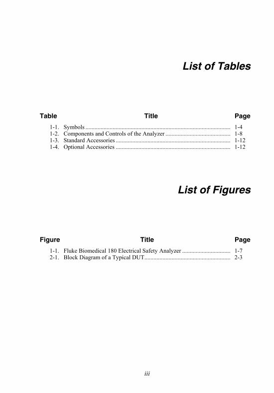
List of Tables
Table Title Page
1-1. Symbols ................................................................................................ 1-4 1-2. Components and Controls of the Analyzer ........................................... 1-8 1-3. Standard Accessories ............................................................................ 1-12 1-4. Optional Accessories ............................................................................ 1-12
List of Figures
Figure Title Page
1-1. Fluke Biomedical 180 Electrical Safety Analyzer ................................ 1-7 2-1. Block Diagram of a Typical DUT......................................................... 2-3

180 Users Guide
iv

1-1
Chapter 1 Introduction and Specifications
Contents Page
Introduction.................................................................................. 1-3 Simplicity ................................................................................. 1-3 Versatility ................................................................................. 1-3
General Safety Considerations ..................................................... 1-4 Symbols .................................................................................... 1-4 Warnings and Cautions............................................................. 1-4
Key Features ................................................................................ 1-6 Instrument Familiarity.................................................................. 1-7 Specifications ............................................................................... 1-10 Accessories................................................................................... 1-12

180 Users Guide
1-2

Introduction and Specifications Introduction 1
1-3
Introduction The Fluke Biomedical 180 Electrical Safety Analyzer, hereafter referred to as the “Analyzer”, is a highly versatile and portable instrument. It is used for the basic electrical safety evaluation of electrical systems, medical devices and physiological instrumentation. Its compact handheld size makes it an ideal addition to a service technician or engineer's toolbox for that "after service test" as well as serving as a bench top instrument for the laboratory. It does not sacrifice functions or accuracy, and its low cost permits putting one on each bench.
Simplicity
The Analyzer is simple to use. A single master function switch, directly labeled with the test to be performed, leads the user through a complete measurement procedure. A single range meter for each measurement avoids potential erroneous readings.
The Analyzer utilizes simple, yet sophisticated, electronics for true-rms measurement of current and voltage. Input impedance uses the AAMI ES1-1993 test load to compensate for high frequency components in the measurement. Resistance measurements are made with a four-wire Kelvin bridge to eliminate errors due to cable length and connector resistance.
Versatility
Unique to the Analyzer is its capability to make a broad range of point-to-point measurements. These include leakage current and/or voltage gradients and resistance between two points. Also, the Analyzer provides the voltage and measuring provision for the independent measurement of the isolation current of a device. Thus the Analyzer provides the additional versatility for evaluation of electrical systems, system installation, separate components, isolation of probes, transducers, and conventional leakage current measurements.

180 Users Guide
1-4
General Safety Considerations This instrument and related documentation must be reviewed for familiarization with safety markings and instructions before you operate the instrument.
Symbols
Table 1-1 describes the symbols used in association with this instrument.
Table 1-1. Symbols
Symbol Description
X Hazardous voltage
W Important information; refer to manual.
~ Do not dispose of this product as unsorted municipal waste. Go to Fluke’s website for recycling information.
CAT I
IEC Measurement Category I – CAT I equipment designed to protect against transients in equipment on circuits not directly connected to MAINS. Under no circumstances should the terminals of the Analyzer be connected to any MAINS voltage.
Warnings and Cautions
A Warning identifies hazardous conditions and actions that could cause bodily harm or death.
A Caution identifies conditions and actions that could damage the Analyzer, the equipment under test, or cause permanent loss of data.

Introduction and Specifications General Safety Considerations 1
1-5
XW Warning
To avoid possible electrical shock or personal injury, follow these guidelines:
• Disconnect all patient connections before connecting the device to be tested to the analyzer. Continued connection may jeopardize patient safety by possible application of measurement currents.
• Maintain care when making connections. Isolation test utilizes 120 or 240 V ac applied to patient leads or to external connections that are accessible to the tester. Although the voltage is current limited by 120 kΩ resistor per AAMI test procedure and is safe for healthy intact skin contact, it can be felt and can result in a startle reaction.
• Ensure the mains installation current rating is adequate for the device under test. If the device under test requires 20 A, the analyzer must be powered by a 20 A service to avoid overloading the mains installation.
W Caution
To avoid possible damage to the Analyzer, follow these guidelines:
• Perform the dual lead leakage test only with an optional black test lead with the clamp with the red insulation (Fluke Biomedical part numbers 2393448 or 2231563) in the jack labeled DUAL. Using a black test lead with the clamp with the black insulation in the DUAL jack may result in a blown internal fuse and false readings of 000 to 002 μA, requiring the unit to be returned for servicing.
Note
For point to point measurements, optional accessory cables must be purchased.
180 Users Guide
1-6
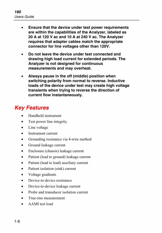
• Ensure that the device under test power requirements are within the capabilities of the Analyzer, labeled as 20 A at 120 V ac and 10 A at 240 V ac. The Analyzer requires that adapter cables match the appropriate connector for line voltages other than 120V.
• Do not leave the device under test connected and drawing high load current for extended periods. The Analyzer is not designed for continuous measurements and may overheat.
• Always pause in the off (middle) position when switching polarity from normal to reverse. Inductive loads of the device under test may create high voltage transients when trying to reverse the direction of current flow instantaneously.
Key Features • Handheld instrument • Test power line integrity • Line voltage • Instrument current • Grounding resistance via 4-wire method • Ground leakage current • Enclosure (chassis) leakage current • Patient (lead to ground) leakage current • Patient (lead to lead) auxiliary current • Patient isolation (sink) current • Voltage gradients • Device-to-device resistance • Device-to-device leakage current • Probe and transducer isolation current • True-rms measurement • AAMI test load

Introduction and Specifications Instrument Familiarity 1
1-7
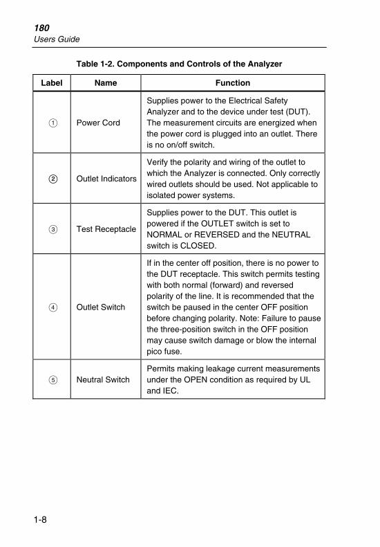
Instrument Familiarity The Analyzer is shown in Figure 1-1 , and Table 1-2 describes its labeled components.
ISO TEST
180ELECTRICAL SAFETY ANALYZER DUAL
HAZARDOUS LIVE
VOLTAGE DURING
ISO TEST
CHASSIS
NEUTRALCLOSED
OUTLETNORMAL
120 VOLTS 20 AMP
5 MINUTES MAX
OPEN
OPEN GND
REVPOLOUTLET
OK
REVERSED
OFF
ll
ll
C
C
la
rl
ra
V - LINE VOLTS
LEAD
A - CURRENT - RESISTANCE
- GROUND - CHASSISµA - DUAL
- LEAD -GND - LEAD -LEAD
LEAKAGE
la
all
5 4
6
11
12
3
2
1
7
10
9
8
fat01.eps
Figure 1-1. Fluke Biomedical 180 Electrical Safety Analyzer
180 Users Guide
1-8
Table 1-2. Components and Controls of the Analyzer
Label Name Function
A Power Cord
Supplies power to the Electrical Safety Analyzer and to the device under test (DUT). The measurement circuits are energized when the power cord is plugged into an outlet. There is no on/off switch.
B Outlet Indicators
Verify the polarity and wiring of the outlet to which the Analyzer is connected. Only correctly wired outlets should be used. Not applicable to isolated power systems.
C Test Receptacle
Supplies power to the DUT. This outlet is powered if the OUTLET switch is set to NORMAL or REVERSED and the NEUTRAL switch is CLOSED.
D Outlet Switch
If in the center off position, there is no power to the DUT receptacle. This switch permits testing with both normal (forward) and reversed polarity of the line. It is recommended that the switch be paused in the center OFF position before changing polarity. Note: Failure to pause the three-position switch in the OFF position may cause switch damage or blow the internal pico fuse.
E Neutral Switch Permits making leakage current measurements under the OPEN condition as required by UL and IEC.

Introduction and Specifications Instrument Familiarity 1
1-9
Table 1.2. Components and controls of the Analyzer (cont.)
F Lift Ground/ISO Test Switch
This is a dual-function momentary switch that must be held in position while performing the test. The OPEN GND position will open ground to the device for leakage current measurements. The ISO TEST position will energize the selected patient lead at 110 percent line voltage, current limited, to measure the isolation current when the main FUNCTION switch is in the LEAD ISO position. With the FUNCTION switch in the DUAL position, the isolation test voltage is supplied to the DUAL connector for measuring the isolation current of a probe or transducer.
G Function Switch
Provides direct, one-step selection of the measurement to be made. These are line V ac, instrument current, grounding resistance, ground (internal) and chassis (external) leakage currents, and the patient leakage currents. These include lead to ground (source), lead to lead (auxiliary) and isolation (sink) current. A dual position is provided to measure leakage current between two points or isolation current of probes and transducers independent of their instruments.
H Lead Switch
Directs the selected patient lead measurement to the desired lead. When testing a 10-lead device, a second pass will be required for the C leads.
I Meter
This is a large, ½ inch, high-contrast LCD, 3½-digit display of the measured parameter. This will read up to 1999 with decimal points added where required.
J
Universal Patient Lead Terminals
Provide means for connection of the patient leads for leakage current measurement.

180 Users Guide
1-10
Table 1.2. Components and controls of the Analyzer (cont.)
K Chassis Connector
Provides a means for inputting the chassis cable with its clip for connection to the DUT chassis or enclosure. The chassis ground resistance is measured with the FUNCTION switch in the RESISTANCE position, and the chassis leakage current is measured in the CHASSIS position.
L Dual Connector
Used to make point-to-point measurements with optional leads available for purchase. For leakage and voltage measurements, the black cable with the clamp with black insulation is attached to the CHASSIS connector, and the black cable with the clamp with red insulation to the DUAL connector. For point-to-point resistance measurements, the black cables with clamps with black insulation are attached to the DUAL and CHASSIS connectors.
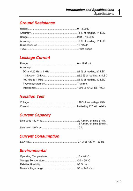
Specifications The following are specifications for the Analyzer. Please contact your Fluke Biomedical service representative for more information regarding the device specifications.
Line Voltage Range.....................................................................90 – 240 V ac 50/60 Hz Accuracy................................................................. ±3 % of reading, ±1 LSD
Load Current Range.....................................................................0 – 19.99 A Accuracy.................................................................±5 % of reading, ±1 LSD
Introduction and Specifications Specifications 1
1-11
Ground Resistance Range .................................................................... 0 – 2.00 Ω Accuracy ................................................................ ±1 % of reading, ±1 LSD Range .................................................................... 2.01 – 19.99 Ω Accuracy ................................................................ ±3 % of reading, ±1 LSD Current source ....................................................... 10 mA dc Type....................................................................... 4-wire bridge
Leakage Current Range .................................................................... 0 – 1999 μA Accuracy:
DC and 25 Hz to 1 kHz...................................... ±1 % of reading, ±3 LSD 1.0 kHz to 100 kHz ............................................ ±2.5 % of reading, ±3 LSD 100 kHz to 1 MHz .............................................. ±5 % of reading, ±3 LSD Type measurement............................................ True rms Impedance ......................................................... 1000 Ω, AAMI ESI 1993
Isolation Test Voltage................................................................... 110 % Line voltage ±5% Current................................................................... limited by 120 kΩ resistor
Current Capacity Line 90 to 140 V ac................................................ 20 A max. on time 5 min.
15 A max. on time 30 min. Line over 140 V ac................................................. 10 A
Current Consumption ESA 180................................................................. 0.1 A @ 120 V – 60 Hz
Environmental Operating Temperature ......................................... 15 – 40 °C Storage Temperature............................................. -20 – 65 °C Relative Humidity................................................... 90 % max. Mains voltage range .............................................. 90 to 240 V ac

180 Users Guide
1-12
Accessories The following are accessories for the Analyzer. To order, contact your Fluke Biomedical equipment dealer and use the Fluke Biomedical part numbers provided. Table 1-3 lists standard accessories shipped with the Analyzer; Table 1-4 lists optional accessories that must be ordered.
Table 1-3. Standard Accessories
Description Quantity Shipped Part Number
Users Guide 1 2185829
8-foot black cable – with large clamp with black insulation
1 2392409
Table 1-4. Optional Accessories
Description Part Number
8-foot black cable – with large clamp with black insulation (used for dual lead resistance)
2392409
16-foot black cable – with large clamp with black insulation
2392411
8-foot black cable – with large clamp with red insulation
2392448
16-foot black cable – with large clamp with red insulation
2231563
Soft carrying case 2248864
220 V Adapter kit 2185787

2-1
Chapter 2 Operation, Maintenance, and Service
Contents Page
Preliminary Steps ......................................................................... 2-3 Preparing the Analyzer for Use ................................................ 2-3 Verifying the Power Outlet Connections.................................. 2-4
Measuring Line Voltage............................................................... 2-5 Measuring Device Current ........................................................... 2-6 Measuring Chassis Grounding Resistance ................................... 2-7 Measuring Leakage Current ......................................................... 2-8
Ground Leakage Current .......................................................... 2-8 Chassis (Enclosure) Leakage Current....................................... 2-9 Lead-to-Ground (Patient Source) Current ................................ 2-10 Lead-to-Lead (Auxiliary) Current ............................................ 2-12 Lead Isolation (Patient Sink) Current ....................................... 2-13
Point-to-Point Measurements....................................................... 2-14 Leakage Current ....................................................................... 2-14 Isolation Current ....................................................................... 2-15 Resistance ................................................................................. 2-16
Maintenance ................................................................................. 2-17 Avoiding Damage..................................................................... 2-17 Cleaning.................................................................................... 2-17
Service and Calibration ................................................................ 2-18 Packing Instructions ................................................................. 2-18 Shipping.................................................................................... 2-19

180 Users Guide
2-2
Operation, Maintenance, and Service Preliminary Steps 2
2-3
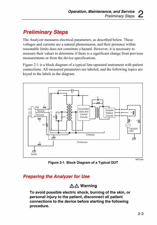
Preliminary Steps The Analyzer measures electrical parameters, as described below. These voltages and currents are a natural phenomenon, and their presence within reasonable limits does not constitute a hazard. However, it is necessary to measure their values to determine if there is a significant change from previous measurements or from the device specifications.
Figure 2-1 is a block diagram of a typical line-operated instrument with patient connections. All measured parameters are labeled, and the following topics are keyed to the labels in the diagram.
Hot
Neutral
Ground
Earth
Enclosure
Chassis
120/220VAC
GroundedData andControlCircuits
IsolatedPatientCircuits
IE
IL
ZI
RG
RL
VL
CL
CL
ZL
IC
IA
II IP
fat02.eps
Figure 2-1. Block Diagram of a Typical DUT
Preparing the Analyzer for Use
WX Warning
To avoid possible electric shock, burning of the skin, or personal injury to the patient, disconnect all patient connections to the device before starting the following procedure.

180 Users Guide
2-4
Prepare the Analyzer for use as follows:
1. To start from the same position each time, place the Analyzer's switches in the following starting positions:
FUNCTION switch V- LINE VOLTS
LEAD switch RL
NEUTRAL switch CLOSED
OUTLET switch OFF [center]
2. Plug the Analyzer into a properly rated outlet.
The Analyzer is equipped with a hospital-grade power plug. Grounding reliability can be achieved only when the Analyzer is connected to an equivalent power receptacle marked "Hospital Grade." Grounding is important for personnel safety and to make some of the tests offered by the Analyzer. Do not circumvent this step for any reason.
Verifying the Power Outlet Connections
Note
Not applicable to isolated power systems.
Three neon lamps indicate the polarity and condition of the outlet being used, as shown in the following chart:
REV ○ ● ○ ○ ● ● ● ● ● ○ ○ ○
OK ● ○ ○ ○ ● ●
Correct
wiring
Reverse
polarity
Open
ground Open hot
Open
neutral
Hot /
ground
reversed
Note
Review all power outlets that do not indicate "correct wiring" and have them corrected by a qualified electrician.
If the line is found faulty, correct the problem before proceeding. If the line checks OK, plug the device to be tested into the Analyzer's line receptacle.

Operation, Maintenance, and Service Measuring Line Voltage 2
2-5
WX Warning
To avoid electrical shock due to faulty DUT, DO NOT touch the metal chassis, any accessible conductive part, or terminal of the DUT with mains power applied until all applicable tests have been completed and the product is verified as compliant. Keep fingers behind guards on supplied test accessories and/or remove power from the DUT before making necessary connections.
Measuring Line Voltage Line Voltage [VL] is the mains power supplied by the electrical distribution system of the hospital. It is a three-wire system of HOT, NEUTRAL, and GROUND, with NEUTRAL, like GROUND, returned to true earth at their entry into the building.
The Analyzer measurement is made between the HOT and NEUTRAL wires via transformer coupling to isolate the measuring circuits from the line. As recommended, measurement of the line voltage with the device under test (DUT) OFF and then ON indicates whether the line is adequate for the device.
Use the following steps to measure line voltage:
1. From the recommended start position, with the FUNCTION switch in the V - LINE VOLTS position, observe that the meter displays the line voltage with a resolution of one volt.
VVAA
µAµA
LEAKAGE
- CURRENT- CURRENT- RESISTANCE- RESISTANCE
- GROUND- GROUND
- CHASSIS- CHASSIS
- LEAD -GND- LEAD -GND
- LEAD -LEAD- LEAD -LEAD
- LEAD ISO- LEAD ISO- DUAL- DUAL
- LINE VOLTS- LINE VOLTS- CURRENT- CURRENT- RESISTANCE- RESISTANCE
- GROUND- GROUND
- CHASSIS- CHASSIS
- LEAD -GND- LEAD -GND
- LEAD -LEAD- LEAD -LEAD
- LEAD ISO- LEAD ISO- DUAL- DUAL
fat03.eps
2. With the OUTLET switch in the NORMAL position and the DUT turned on, the meter continues to display line voltage, but under the load of the

180 Users Guide
2-6
device being tested. Depending on the device's operating current and the electrical supply wiring, the voltage differential may be significant.
3. Check the value under load against the device's ratings to ensure that the actual value remains within prescribed limits. An excessive drop also suggests that a dedicated line of increased capacity should be run to the instrument.
Measuring Device Current Device, or Instrument, Current [IL] is the current used by the DUT. When turned on, the device should be operated in its various modes to determine the worst condition to track. Verify that the current of the DUT is within the current rating of the Analyzer being used.
Measurement is made in the HOT wire via transformer coupling to ensure that the total current is measured, as it is possible that the NEUTRAL and GROUND wire could share the return path.
Use the following steps to measure device current:
1. Switch the FUNCTION switch to A - CURRENT. The meter displays the device's current to 19.99 A.
VVAA
µAµA
LEAKAGE
- CURRENT- CURRENT- RESISTANCE- RESISTANCE
- GROUND- GROUND
- CHASSIS- CHASSIS
- LEAD -GND- LEAD -GND
- LEAD -LEAD- LEAD -LEAD
- LEAD ISO- LEAD ISO- DUAL- DUAL
- LINE VOLTS- LINE VOLTS- CURRENT- CURRENT- RESISTANCE- RESISTANCE
- GROUND- GROUND
- CHASSIS- CHASSIS
- LEAD -GND- LEAD -GND
- LEAD -LEAD- LEAD -LEAD
- LEAD ISO- LEAD ISO- DUAL- DUAL
fat04.eps
2. Place the OUTLET switch in the NORMAL position; the NEUTRAL switch remains in the CLOSED position.
3. Turn on the device and place it in its maximum load condition to obtain the proper reading.
4. Log this data to note changes in values that indicate early problems.

Operation, Maintenance, and Service Measuring Chassis Grounding Resistance 2
2-7
Measuring Chassis Grounding Resistance
Note
This test is only applicable to devices utilizing three-wire (grounded) power cords.
Ground Wire Resistance [RG] (grounding resistance) is the resistance from the device's conductive "grounded" chassis to the grounding terminal on the receptacle into which it is plugged. The resistance is largely composed of the GROUND wire in the power cable and is directly proportional to its length.
Use the following steps to measure chassis grounding resistance:
1. Connect the standard cable supplied with unit that has a black cable with the clamp with black insulation to the CHASSIS connector on the front panel of the Analyzer.
2. Clamp the clip of the cable to the DUT's exposed chassis or the enclosure, if conductive. Resistance is measured between the clip on the black chassis cable and the grounding pin receptacle of the Analyzer.
Take care to ensure that bare metal is reached and that both jaws of the clip are in contact with the chassis. Metal labels or incidental conductive hardware should not be used for this test.
If a non-conducting enclosure is used and no chassis is readily accessible, a safety ground terminal can be used.
3. Once connection is made, rotate the FUNCTION switch to Ω - RESISTANCE and read its value directly in ohms to 19.99 Ω.
VVAA
µAµA
LEAKAGE
- CURRENT- CURRENT- RESISTANCE- RESISTANCE
- GROUND- GROUND
- CHASSIS- CHASSIS
- LEAD -GND- LEAD -GND
- LEAD -LEAD- LEAD -LEAD
- LEAD ISO- LEAD ISO- DUAL- DUAL
- LINE VOLTS- LINE VOLTS- CURRENT- CURRENT- RESISTANCE- RESISTANCE
- GROUND- GROUND
- CHASSIS- CHASSIS
- LEAD -GND- LEAD -GND
- LEAD -LEAD- LEAD -LEAD
- LEAD ISO- LEAD ISO- DUAL- DUAL
fat05.eps

180 Users Guide
2-8
Note
The OUTLET switch should be in the OFF (center) position for this measurement.
Measuring Leakage Current Leakage current is the flow of current through or over the surface of an insulating material or insulator. For example, if a person comes in contact with an operational device, leakage current is the amount of current that flows from the point where the person came in contact with the device product, through the person’s body, and back to ground. Measurement of leakage current is required on all mains power products.
Ground Leakage Current
Ground Leakage Current [IE] (internal chassis current) is the current that flows in the ground wire of the power cable to return the chassis leakage current to true earth ground. It is only applicable to devices utilizing three-wire (grounded) power cords.
This current does not constitute a hazard as long as the ground wire remains intact and the current does not become excessive. Leakage current is due to the proximity of the hot wire or line potential components to the chassis represented by ZL, a combination of capacitance, CL, and resistance, RL, components.
Note
The connection is made internally in the Analyzer, so no external connectors are required for this test.
Use the following steps to measure ground leakage current:
1. Set the FUNCTION switch to GROUND. The leakage current is displayed to 1999 μA (microamperes).

Operation, Maintenance, and Service Measuring Leakage Current 2
2-9
VVAA
µAµA
LEAKAGE
- CURRENT- CURRENT- RESISTANCE- RESISTANCE
- GROUND- GROUND
- CHASSIS- CHASSIS
- LEAD -GND- LEAD -GND
- LEAD -LEAD- LEAD -LEAD
- LEAD ISO- LEAD ISO- DUAL- DUAL
- LINE VOLTS- LINE VOLTS- CURRENT- CURRENT- RESISTANCE- RESISTANCE
- GROUND- GROUND
- CHASSIS- CHASSIS
- LEAD -GND- LEAD -GND
- LEAD -LEAD- LEAD -LEAD
- LEAD ISO- LEAD ISO- DUAL- DUAL
fat06.eps
2. Make measurements under all combinations of the OUTLET switch, NORMAL and REVERSE; the NEUTRAL switch CLOSED and OPEN; and with the device power turned ON and OFF. Power to the outlet is OFF when the NEUTRAL switch is in the OPEN position.
Note
Be sure to pause in the OFF (middle) position when switching the OUTLET switch from the NORMAL to the REVERSE position.
Chassis (Enclosure) Leakage Current
Chassis [Enclosure] Leakage Current [IC] flows between the accessible conductive chassis or enclosure and earth (ground) measured through a 1,000 Ω impedance.
The Analyzer measures chassis leakage from the exposed metal part on the DUT, through the black cable and the AAMI load, back to the ground.
Use the following steps to measure chassis leakage current:
1. Connect the standard cable (supplied with unit) that has a black cable with the clamp that has black insulation to the CHASSIS connector on the front of the Analyzer.
2. Clamp the clip on the cable in turn to accessible conductive sections of the chassis and the enclosure. Metal labels or incidental conductive hardware are not applicable for this test.
If a non-conducting enclosure is used, present standards require connection to the enclosure via a 200 cm² conductive foil in intimate contact with the enclosure. This can be accomplished with a 14 X 14 cm

180 Users Guide
2-10
(5.5 X 5.5 in) piece of aluminum foil taped to the surface and the cable clipped to the foil.
3. To make the measurement, place the FUNCTION switch in the CHASSIS position and read the display in microamperes.
VVAA
µAµA
LEAKAGE
- CURRENT- CURRENT- RESISTANCE- RESISTANCE
- GROUND- GROUND
- CHASSIS- CHASSIS
- LEAD -GND- LEAD -GND
- LEAD -LEAD- LEAD -LEAD
- LEAD ISO- LEAD ISO- DUAL- DUAL
- LINE VOLTS- LINE VOLTS- CURRENT- CURRENT- RESISTANCE- RESISTANCE
- GROUND- GROUND
- CHASSIS- CHASSIS
- LEAD -GND- LEAD -GND
- LEAD -LEAD- LEAD -LEAD
- LEAD ISO- LEAD ISO- DUAL- DUAL
fat07.eps
4. Make measurements under all combinations of the OUTLET switch, NORMAL and REVERSE; the GROUND switch CLOSED and OPEN; the NEUTRAL switch CLOSED and OPEN; and with the device power turned ON and OFF. Power to the outlet is OFF when the NEUTRAL switch is in the OPEN position.
Note
Be sure to pause in the OFF (middle) position when switching the OUTLET switch from the NORMAL to the REVERSE position.
Lead-to-Ground (Patient Source) Current
Lead-to-Ground [IP] (patient source) current would flow between an individual patient lead and ground if the patient were to come into contact with earth ground. An example is a patient with leads attached touching ground such as an electric bed.
Note
Although originally required only for devices incorporating intra-cardiac electrodes or conductive pathways directly to the heart, lead-to-ground current has found its way into standards for all devices having patient-applied parts.
Operation, Maintenance, and Service Measuring Leakage Current 2
2-11
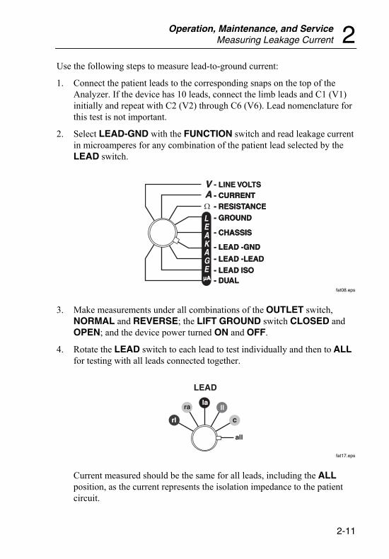
Use the following steps to measure lead-to-ground current:
1. Connect the patient leads to the corresponding snaps on the top of the Analyzer. If the device has 10 leads, connect the limb leads and C1 (V1) initially and repeat with C2 (V2) through C6 (V6). Lead nomenclature for this test is not important.
2. Select LEAD-GND with the FUNCTION switch and read leakage current in microamperes for any combination of the patient lead selected by the LEAD switch.
VVAA
µAµA
LEAKAGE
- CURRENT- CURRENT- RESISTANCE- RESISTANCE
- GROUND- GROUND
- CHASSIS- CHASSIS
- LEAD -GND- LEAD -GND
- LEAD -LEAD- LEAD -LEAD
- LEAD ISO- LEAD ISO- DUAL- DUAL
- LINE VOLTS- LINE VOLTS- CURRENT- CURRENT- RESISTANCE- RESISTANCE
- GROUND- GROUND
- CHASSIS- CHASSIS
- LEAD -GND- LEAD -GND
- LEAD -LEAD- LEAD -LEAD
- LEAD ISO- LEAD ISO- DUAL- DUAL
fat08.eps
3. Make measurements under all combinations of the OUTLET switch, NORMAL and REVERSE; the LIFT GROUND switch CLOSED and OPEN; and the device power turned ON and OFF.
4. Rotate the LEAD switch to each lead to test individually and then to ALL for testing with all leads connected together.
LEADLEAD
c
ra ll
rlrl
lala
allall
fat17.eps
Current measured should be the same for all leads, including the ALL position, as the current represents the isolation impedance to the patient circuit.

180 Users Guide
2-12
Lead-to-Lead (Auxiliary) Current
Lead-to-Lead [IA] (auxiliary) current flows from any patient lead to any other patient lead and to all other leads connected together. The current can be dc or ac or a combination of both. Measurements are made with a true-rms converter to provide the common base necessary for accurate readout with a variety of common wave forms.
Under normal conditions, the current is primarily input bias current, measurement current, or lead off sensing current. The worst-case condition is measured from the individual lead to all others connected together. This is the measurement made by the Analyzer.
Use the following steps to measure lead-to-lead current:
1. Connect the patient leads to the snaps on top of the Analyzer.
2. Set the FUNCTION switch in the LEAD-LEAD position.
VVAA
µAµA
LEAKAGE
- CURRENT- CURRENT- RESISTANCE- RESISTANCE
- GROUND- GROUND
- CHASSIS- CHASSIS
- LEAD -GND- LEAD -GND
- LEAD -LEAD- LEAD -LEAD
- LEAD ISO- LEAD ISO- DUAL- DUAL
- LINE VOLTS- LINE VOLTS- CURRENT- CURRENT- RESISTANCE- RESISTANCE
- GROUND- GROUND
- CHASSIS- CHASSIS
- LEAD -GND- LEAD -GND
- LEAD -LEAD- LEAD -LEAD
- LEAD ISO- LEAD ISO- DUAL- DUAL
fat09.eps
3. Make readings for individual leads, selecting by the LEAD switch. The single lead carrying the most current is the reference lead, RL, acting as the return for the other leads.
LEADLEAD
c
ra ll
rlrl
lala
allall
fat12.eps

Operation, Maintenance, and Service Measuring Leakage Current 2
2-13
Note
The ALL position has no meaning in this test.
4. Make measurements under all combinations of the OUTLET switch, NORMAL and REVERSE; GROUND CLOSED and the LIFT GROUND switch OPEN; and the device power turned ON and OFF.
5. If the DUT utilizes a 10-lead patient input, test each C (V) lead in turn, individually.
Lead Isolation (Patient Sink) Current
Lead Isolation [II] (patient sink) current would flow into the DUT if the patient were to come into contact with full line voltage. An example is an electric bed that has become ungrounded and has a short to the frame.
WX Warning
To avoid possible electric shock, burning of the skin, or personal injury to the patient, take care when handling the patient leads. High voltage, 110 percent of line volts, with respect to earth ground is accessible at the patient connections (snaps) during part of this test. The patient lead isolation current can flow in individual leads or all leads connected together if line volts come into contact with the patient.
Use the following steps to measure lead isolation current:
1. Attach the patient leads to the snaps on top of the Analyzer, making sure that ground is intact.
2. Set the FUNCTION switch in the LEAD ISO position.

180 Users Guide
2-14
VVAA
µAµA
LEAKAGE
- CURRENT- CURRENT- RESISTANCE- RESISTANCE
- GROUND- GROUND
- CHASSIS- CHASSIS
- LEAD -GND- LEAD -GND
- LEAD -LEAD- LEAD -LEAD
- LEAD ISO- LEAD ISO- DUAL- DUAL
- LINE VOLTS- LINE VOLTS- CURRENT- CURRENT- RESISTANCE- RESISTANCE
- GROUND- GROUND
- CHASSIS- CHASSIS
- LEAD -GND- LEAD -GND
- LEAD -LEAD- LEAD -LEAD
- LEAD ISO- LEAD ISO- DUAL- DUAL
fat10.eps
3. Test individual leads, selecting by the LEAD switch.
4. To apply the high voltage to the lead safely, press the LIFT GROUND/ISO TEST switch to ISO TEST. The current is limited with a 120 kΩ resistor for user protection.
5. While ISO TEST is energized, read the isolation current in microamperes.
6. Perform the test using the OUTLET switch in both NORMAL and REVERSE, the NEUTRAL switch CLOSED, and with the DUT ON and OFF.
Point-to-Point Measurements The Analyzer provides the capability of making point-to-point leakage current, isolation current, and resistance measurements between selected points, otherwise known as a dual lead measurement.
Note
Additional optional accessory cables must be purchased to perform these tests.
Leakage Current
Leakage Current between two points is also measured for permanently installed equipment as additional verification of the integrity of the installation. These measurements are equivalent, as the relationship between volts and current across 1,000 Ω is one mV per μA.
Operation, Maintenance, and Service Point-to-Point Measurements 2
2-15
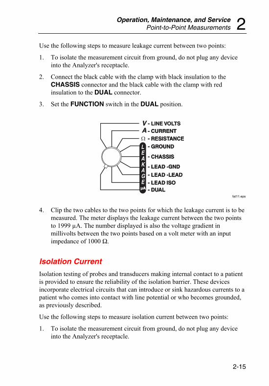
Use the following steps to measure leakage current between two points:
1. To isolate the measurement circuit from ground, do not plug any device into the Analyzer's receptacle.
2. Connect the black cable with the clamp with black insulation to the CHASSIS connector and the black cable with the clamp with red insulation to the DUAL connector.
3. Set the FUNCTION switch in the DUAL position.
VVAA
µAµA
LEAKAGE
- CURRENT- CURRENT- RESISTANCE- RESISTANCE
- GROUND- GROUND
- CHASSIS- CHASSIS
- LEAD -GND- LEAD -GND
- LEAD -LEAD- LEAD -LEAD
- LEAD ISO- LEAD ISO- DUAL- DUAL
- LINE VOLTS- LINE VOLTS- CURRENT- CURRENT- RESISTANCE- RESISTANCE
- GROUND- GROUND
- CHASSIS- CHASSIS
- LEAD -GND- LEAD -GND
- LEAD -LEAD- LEAD -LEAD
- LEAD ISO- LEAD ISO- DUAL- DUAL
fat11.eps
4. Clip the two cables to the two points for which the leakage current is to be measured. The meter displays the leakage current between the two points to 1999 µA. The number displayed is also the voltage gradient in millivolts between the two points based on a volt meter with an input impedance of 1000 Ω.
Isolation Current
Isolation testing of probes and transducers making internal contact to a patient is provided to ensure the reliability of the isolation barrier. These devices incorporate electrical circuits that can introduce or sink hazardous currents to a patient who comes into contact with line potential or who becomes grounded, as previously described.
Use the following steps to measure isolation current between two points:
1. To isolate the measurement circuit from ground, do not plug any device into the Analyzer's receptacle.
180 Users Guide
2-16
2. Connect the black cable with the clamp with black insulation to the CHASSIS connector and the black cable with the clamp with red insulation to the DUAL connector.
3. Toggle the LIFT GROUND/ISO TEST switch to ISO TEST to apply isolated line voltage between the two sides. The meter displays the isolation current that flows.
Note
The actual method for making connection to either side of the isolation barrier varies with the device to be tested; therefore, full details are not provided.
W X Warning
To avoid possible electric shock, burning of the skin, or personal injury take care when handling the cables. High voltage, 110 percent of line volts, will be accessible between the two cables when the LIFT GROUND/ISO TEST switch is in the ISO TEST position.
Resistance
Resistance measurements between two points are made to verify the integrity of permanently installed equipment whose ground cannot be broken to measure the chassis leakage current. These are usually high-power devices that can have high leakage currents and depend on the bonding of all chassis to a common point for safety.
To measure resistance between two points, follow the steps below:
1. Disconnect any device attached to the Analyzer instrument receptacle.
2. Turn off any electrical devices to be tested.
3. Connect two black cables with clamps with black insulation to the CHASSIS and DUAL connectors, and clip onto the two points to be measured.
4. Set the FUNCTION switch to Ω - RESISTANCE, and the display will show the resistance between the two points.

Operation, Maintenance, and Service Maintenance 2
2-17
VVAA
µAµA
LEAKAGE
- CURRENT- CURRENT- RESISTANCE- RESISTANCE
- GROUND- GROUND
- CHASSIS- CHASSIS
- LEAD -GND- LEAD -GND
- LEAD -LEAD- LEAD -LEAD
- LEAD ISO- LEAD ISO- DUAL- DUAL
- LINE VOLTS- LINE VOLTS- CURRENT- CURRENT- RESISTANCE- RESISTANCE
- GROUND- GROUND
- CHASSIS- CHASSIS
- LEAD -GND- LEAD -GND
- LEAD -LEAD- LEAD -LEAD
- LEAD ISO- LEAD ISO- DUAL- DUAL
fat05.eps
5. To compensate for possible dc components in the leakage current flowing between the two points, reverse the two clips and average the readings.
Maintenance The Analyzer requires little maintenance or special care; however, it is a calibrated measuring instrument and should be treated as such. The following describes how to maintain the Analyzer.
Avoiding Damage
Do not drop the instrument or subject it to any mechanical abuse that could cause a shift in the calibrated settings.
W Caution
To avoid damage to the Analyzer or adverse affects on its performance, follow these guidelines:
• Do not expose the system to temperature extremes. Ambient temperatures should remain between 15° C and 40° C. System performance may be adversely affected if temperatures fluctuate above or below this range.
Cleaning
Clean the exterior of the Analyzer occasionally with a cloth dampened with a mild detergent solution. Take care to keep liquids out of the device.
180 Users Guide
2-18
W Caution
To avoid damage to the Analyzer or adverse affects on its performance, clean it only by gently wiping down with a clean, lint-free cloth dampened with a mild detergent solution. Do not spray liquids on or immerse the unit.
Carefully wipe down the cables and inspect them for damage and deterioration of the insulation. Check the cable connections for integrity of the cable clamp and strain relief.
Service and Calibration If your new Analyzer fails to operate successfully, please contact Fluke Biomedical Service Center immediately, as indicated under “Warranty and Product Support.”
W Caution
To avoid damage to the Analyzer or adverse affects on its performance, allow only qualified technical personnel to service the Analyzer.
Annual calibration of the Analyzer by an authorized Fluke Biomedical Service Center is recommended. Fluke Biomedical Service Centers have the appropriate tools and procedures for performing calibrations as well as factory-authorized updates.
International customers should contact their Fluke Biomedical dealers for service/product support.
To obtain the name of your local dealer or service center, contact Fluke Biomedical as indicated under “Return Procedures, Repair and calibration.”
Packing Instructions
If repairs are required, return the Analyzer to the factory or the nearest service center, as follows:
1. Before returning the Analyzer for factory service, contact the Fluke Biomedical Service Center for a required Return Authorization Number.
2. Provide the following information:
Operation, Maintenance, and Service Service and Calibration 2
2-19
• The Analyzer serial number
• The specific steps that reproduce your problem
• A daytime phone number
• Your name/company
• A fax number (if available)
3. Pack the instrument carefully, using the original packing materials. If the original packing materials are not available, refer to “Return Procedures” for a list of preferred materials or contact Fluke Biomedical for replacement packing. Failure to pack the instrument properly could void your warranty.
Shipping
1. Place the Return Authorization Number in a prominent place on the outside of the packing box, and refer to the number in any correspondence with Fluke Biomedical Service.
2. Enclose your return address and Return Authorization Number.
3. Insure the unit for full retail value and ship to the nearest Fluke Biomedical service center.

180 Users Guide
2-20

Appendices
Appendix Title Page
A Abbreviations............................................................................... A-1

180 Users Guide

A-1
Appendix A Abbreviations
Abbreviations The following list includes abbreviations used in this document.
A ampere
ANSI American National Standards Institute
AAMI Association for the Advancement of Medical Instrumentation
dB decibel
°C degrees Celsius (centigrade)
DUT device under test
ECG electrocardiograph or electrocardiogram
EUT equipment under test
°F degrees Fahrenheit
Hz hertz
in inch
k kilo (103)
kHz kilohertz
kΩ kilohm
LED light-emitting diode
M meg(a) (106)
MHz megahertz
MΩ megohm
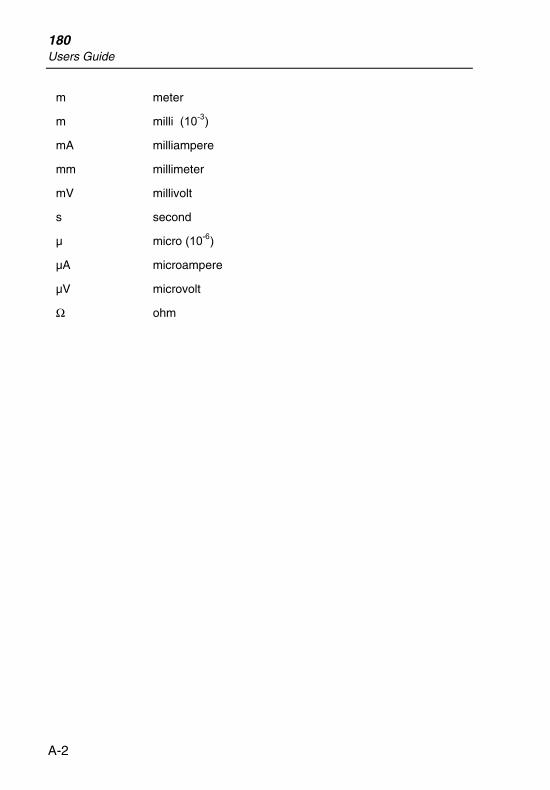
180 Users Guide
A-2
m meter
m milli (10-3)
mA milliampere
mm millimeter
mV millivolt
s second
µ micro (10-6)
µA microampere
µV microvolt
Ω ohm
Related Documents