Presented by, P.Sai Sarath Chandra

Welcome message from author
This document is posted to help you gain knowledge. Please leave a comment to let me know what you think about it! Share it to your friends and learn new things together.
Transcript

8/3/2019 Electrical Presentation
http://slidepdf.com/reader/full/electrical-presentation 1/20
Presented by,P.Sai Sarath Chandra

8/3/2019 Electrical Presentation
http://slidepdf.com/reader/full/electrical-presentation 2/20
This chapter introduces importantfundamental theorems of network analysis.They are theSuperposition theorem
Thévenin’s theorem
Norton’s theorem
Maximum power transfer theorem
Substitution Theorem
Millman’s theorem
Reciprocity theorem

8/3/2019 Electrical Presentation
http://slidepdf.com/reader/full/electrical-presentation 3/20
Used to find the solution to networks with twoor more sources that are not in series or parallel.
The current through, or voltage across, anelement in a network is equal to the algebraic
sum of the currents or voltages producedindependently by each source.
Since the effect of each source will bedetermined independently, the number ofnetworks to be analyzed will equal the numberof sources.

8/3/2019 Electrical Presentation
http://slidepdf.com/reader/full/electrical-presentation 4/20
The total power delivered to a resistive elementmust be determined using the total currentthrough or the total voltage across the elementand cannot be determined by a simple sum of thepower levels established by each source.
8/3/2019 Electrical Presentation
http://slidepdf.com/reader/full/electrical-presentation 5/20
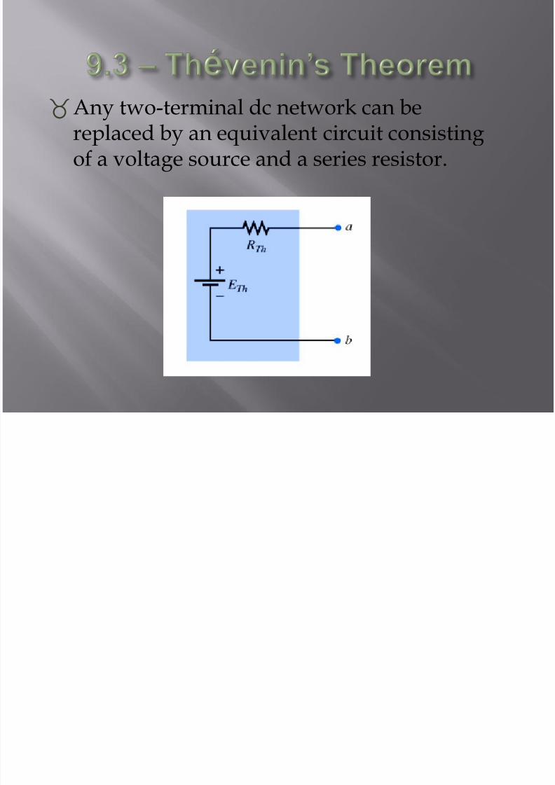
Any two-terminal dc network can bereplaced by an equivalent circuit consistingof a voltage source and a series resistor.

8/3/2019 Electrical Presentation
http://slidepdf.com/reader/full/electrical-presentation 6/20
Thévenin’s theorem can be used to: Analyze networks with sources that are not in series or
parallel.
Reduce the number of components required toestablish the same characteristics at the outputterminals.
Investigate the effect of changing a particularcomponent on the behavior of a network without
having to analyze the entire network after each change.

8/3/2019 Electrical Presentation
http://slidepdf.com/reader/full/electrical-presentation 7/20
Procedure to determine the proper values of RTh and ETh Preliminary
1. Remove that portion of the network across which theThévenin equation circuit is to be found. In the figurebelow, this requires that the load resistor R L be temporarily
removed from the network.
8/3/2019 Electrical Presentation
http://slidepdf.com/reader/full/electrical-presentation 8/20
2. Mark the terminals of the remaining two-terminalnetwork. (The importance of this step will becomeobvious as we progress through some complexnetworks.)
RTh:3. Calculate RTh by first setting all sources to zero (voltage
sources are replaced by short circuits, and currentsources by open circuits) and then finding the resultant
resistance between the two marked terminals. (If theinternal resistance of the voltage and/or current sourcesis included in the original network, it must remain whenthe sources are set to zero.)

8/3/2019 Electrical Presentation
http://slidepdf.com/reader/full/electrical-presentation 9/20
ETh:4. Calculate ETh by first returning all sources to their
original position and finding the open-circuit voltagebetween the marked terminals. (This step is invariably
the one that will lead to the most confusion and errors.In all cases, keep in mind that it is the open-circuitpotential between the two terminals marked in step 2.)

8/3/2019 Electrical Presentation
http://slidepdf.com/reader/full/electrical-presentation 10/20
Conclusion:5. Draw the Thévenin
equivalent circuit with
the portion of thecircuit previouslyremoved replacedbetween the terminalsof the equivalent
circuit. This step isindicated by theplacement of theresistor RL between theterminals of the
Thévenin equivalentcircuit.
Insert Figure 9.26(b)
8/3/2019 Electrical Presentation
http://slidepdf.com/reader/full/electrical-presentation 11/20
Experimental Procedures Two popular experimental procedures for
determining the parameters of the Théveninequivalent network:
Direct Measurement of ETh and RTh
For any physical network, the value of ETh can bedetermined experimentally by measuring the open-circuit voltage across the load terminals.
The value of RTh can then be determined by completingthe network with a variable resistance RL.

8/3/2019 Electrical Presentation
http://slidepdf.com/reader/full/electrical-presentation 12/20
Measuring VOC and ISC The Thévenin voltage is again determined by
measuring the open-circuit voltage across the terminalsof interest; that is, ETh = VOC . To determine R
Th, a short-
circuit condition is established across the terminals ofinterest and the current through the short circuit (Isc) ismeasured with an ammeter.
Using Ohm’s law:
RTh = Voc / Isc

8/3/2019 Electrical Presentation
http://slidepdf.com/reader/full/electrical-presentation 13/20
Norton’s theorem states the following:
Any two-terminal linear bilateral dc network can bereplaced by an equivalent circuit consisting of acurrent and a parallel resistor.
The steps leading to the proper values of IN andRN .
Preliminary steps:
1. Remove that portion of the network across which the
Norton equivalent circuit is found.2. Mark the terminals of the remaining two-terminal
network.

8/3/2019 Electrical Presentation
http://slidepdf.com/reader/full/electrical-presentation 14/20
Finding RN :
3. Calculate RN by first setting all sources to zero (voltagesources are replaced with short circuits, and currentsources with open circuits) and then finding theresultant resistance between the two marked terminals.
(If the internal resistance of the voltage and/or currentsources is included in the original network, it mustremain when the sources are set to zero.) Since RN = RTh the procedure and value obtained using the approach
described for Thévenin’s theorem will determine theproper value of RN .
8/3/2019 Electrical Presentation
http://slidepdf.com/reader/full/electrical-presentation 15/20
Finding IN :4. Calculate IN by first returning all the sources to their
original position and then finding the short-circuitcurrent between the marked terminals. It is the samecurrent that would be measured by an ammeterplaced between the marked terminals.
Conclusion:
5. Draw the Norton equivalent circuit with the portion
of the circuit previously removed replaced betweenthe terminals of the equivalent circuit.

8/3/2019 Electrical Presentation
http://slidepdf.com/reader/full/electrical-presentation 16/20
The maximum power transfertheorem states the following:
A load will receive maximum powerfrom a network when its total resistivevalue is exactly equal to the Théveninresistance of the network applied to the
load. That is,
RL = RTh

8/3/2019 Electrical Presentation
http://slidepdf.com/reader/full/electrical-presentation 17/20
For loads connected directly to a dcvoltage supply, maximum power willbe delivered to the load when the
load resistance is equal to the internalresistance of the source; that is, when:
RL = Rint

8/3/2019 Electrical Presentation
http://slidepdf.com/reader/full/electrical-presentation 18/20
Any number of parallel voltage sources can bereduced to one.
This permits finding the current through or voltageacross RL without having to apply a method such as
mesh analysis, nodal analysis, superposition and soon.
1. Convert all voltage sources to current sources.
2. Combine parallel current sources.
3. Convert the resulting current source to a voltage sourceand the desired single-source network is obtained.
8/3/2019 Electrical Presentation
http://slidepdf.com/reader/full/electrical-presentation 19/20
The substitution theorem states: If the voltage across and the current through any
branch of a dc bilateral network is known, this branchcan be replaced by any combination of elements that
will maintain the same voltage across and currentthrough the chosen branch.
Simply, for a branch equivalence, the terminalvoltage and current must be the same.

8/3/2019 Electrical Presentation
http://slidepdf.com/reader/full/electrical-presentation 20/20
The reciprocity theorem is applicable only tosingle-source networks and states the following: The current I in any branch of a network, due to a
single voltage source E anywhere in the network, will
equal the current through the branch in which thesource was originally located if the source is placed inthe branch in which the current I was originallymeasured.
The location of the voltage source and the resultingcurrent may be interchanged without a change in current
Related Documents


![Electrical Safety Presentation [NFPA 70E]](https://static.cupdf.com/doc/110x72/552f7e274a79595f328b45c8/electrical-safety-presentation-nfpa-70e.jpg)